Special Structures: Past, Present, and...
19
Special Structures: Past, Present, and Future Richard Bradshaw 1 ; David Campbell 2 ; Mousa Gargari 3 ; Amir Mirmiran 4 ; and Patrick Tripeny 5 Abstract: Special structures are landmarks and testimonials to the achievements of the structural engineering profession. They are true three-dimensional representations of our equilibrium equations and affirmations of our analytical techniques, design standards and construction practices. They include many types of structures, such as: space frames or grids; cable-and-strut and tensegrity; air-supported or air-inflated; self-erecting and deployable; cable net; tension membrane; lightweight geodesic domes; folded plates; and thin shells. This work celebrates the ASCE’s sesquicentennial by providing a historical perspective on how special structures have evolved, their state- of-practice in the dawn of the 21st century, and a projection of their potential trends and evolution into the future. DOI: 10.1061/ASCE0733-94452002128:6691 CE Database keywords: Domes, structural; Fabrics; Grid Systems; Membranes; Spacing; Plates; State-of-the-art reviews. Introduction The sesquicentennial of ASCE provides a great opportunity to assess the role of special structures in the structural engineering profession with a historical perspective on how these types of structures have evolved, their state-of-practice in the dawn of the 21st century, and a projection of their potential trends and evolu- tion into the future. From the Georgia Dome in Atlanta, the Livestock Pavilion in Raleigh, and Madison Square Garden in New York to the Olym- pic Stadium in Munich, and from the Pontiac Silverdome in Michigan to the Sydney Opera House in Australia and the Haj terminal in Saudi Arabia, special structures are landmarks and testimonials to the achievements of the structural engineering pro- fession Fig. 1. They are what makes us most interested in and proud of our profession and what binds us together with the ar- chitects and architectural and construction engineers in apprecia- tion of the art of structural design and construction. They are true 3D representations of our static and dynamic equilibrium equa- tions, and affirmations of our analytical techniques, design stan- dards, and construction practices. Each special structure is a pro- totype by itself, rather than a duplicate produced on an assembly line. Yet, it is not easy to qualify the term special structure, as perhaps loosely used in this paper. For the purpose of this paper, ‘‘special structure’’ refers to innovative long-span structural sys- tems, primarily roofs and enclosures to house human activities. More specifically, they include many types of structures, such as: space frames or grids; cable-and-strut and tensegrity; air- supported or air-inflated; self-erecting and deployable; cable net; tension membrane; geodesic domes; folded plates; and thin shells. We exclude tall buildings and long-span bridges, both of which are addressed separately. Thin shells and tension membranes are considered form- resistant structures, as they resist loads by virtue of their shape. Neither will function if flat, and both carry loads predominantly through in-plane stresses rather than by bending, granted that thin shells bend as well as compress. Other special structures resist loads mostly in flexure. The typical flat space frame or grid sup- ported by columns or walls acts primarily in flexure even though its individual members behave axially Fig. 2. Depending on the loads, top and bottom chords will be in tension or compression, similar to the flanges of an I-beam, and the diagonals acting in tension or compression carry the shear, much like the web of an I-beam Cuoco 1997. Structures that resist loads by bending may be categorized using span-to-depth ratio. For example, this ratio is about 20 for a typical wood joist; whereas, a timber beam with larger loads will have a ratio around 12. Steel bar joists usually run about 24, as do many wide-flange beams and reinforced concrete waffle slabs. Space frame is remarkable with as high a ratio as 35–40. On the other hand, span-to-depth ratio has no significance for form- resistant structures. A more useful measure for an arch is the span-to-rise or the span-to-thickness ratio Fig. 3. Efficient arches have span-to-rise ratios of 2–3 and span-to-thickness ratios of about 40. Larger span-to-rise ratios generally result in larger axial forces and require a smaller span-to-thickness ratio. Tensile structures are more efficient than arches because they do not buckle. The Verrazano Narrows Bridge in New York, for example, has a span-to-sag ratio of 10 and a span-to-thickness 1 Consultant, Richard R. Bradshaw, Inc., 17300 Ballinger, Northridge, CA 91325. 2 Principal and Chief Executive Officer, Geiger Engineers, 2 Executive Blvd., Ste. 410, Suffern, NY 10901. 3 Assistant Professor, Dept. of Construction Sciences, Univ. of Cincin- nati, Cincinnati, OH 45206. 4 Editor, Professor, Dept. of Civil Engineering, North Carolina State Univ., Raleigh, NC 27695. 5 Assistant Professor, Graduate School of Architecture, Univ. of Utah, 375 South 1530 East, Salt Lake City, UT 84112. Note. Associate Editor: C. Dale Buckner. Discussion open until No- vember 1, 2002. Separate discussions must be submitted for individual papers. To extend the closing date by one month, a written request must be filed with the ASCE Managing Editor. The manuscript for this paper was submitted for review and possible publication on November 8, 2001; approved on March 7, 2002. This paper is part of the Journal of Struc- tural Engineering, Vol. 128, No. 6, June 1, 2002. ©ASCE, ISSN 0733- 9445/2002/6-691–709/$8.00$.50 per page. JOURNAL OF STRUCTURAL ENGINEERING / JUNE 2002 / 691
Transcript of Special Structures: Past, Present, and...
Special Structures: Past, Present, and FutureRichard Bradshaw1; David Campbell2; Mousa Gargari3; Amir Mirmiran4; and Patrick Tripeny5
Abstract: Special structures are landmarks and testimonials to the achievements of the structural engineering profession. They are truethree-dimensional representations of our equilibrium equations and affirmations of our analytical techniques, design standards andconstruction practices. They include many types of structures, such as: space frames or grids; cable-and-strut and tensegrity; air-supportedor air-inflated; self-erecting and deployable; cable net; tension membrane; lightweight geodesic domes; folded plates; and thin shells. Thiswork celebrates the ASCE’s sesquicentennial by providing a historical perspective on how special structures have evolved, their state-of-practice in the dawn of the 21st century, and a projection of their potential trends and evolution into the future.
DOI: 10.1061/�ASCE�0733-9445�2002�128:6�691�
CE Database keywords: Domes, structural; Fabrics; Grid Systems; Membranes; Spacing; Plates; State-of-the-art reviews.
Introduction
The sesquicentennial of ASCE provides a great opportunity toassess the role of special structures in the structural engineeringprofession with a historical perspective on how these types ofstructures have evolved, their state-of-practice in the dawn of the21st century, and a projection of their potential trends and evolu-tion into the future.
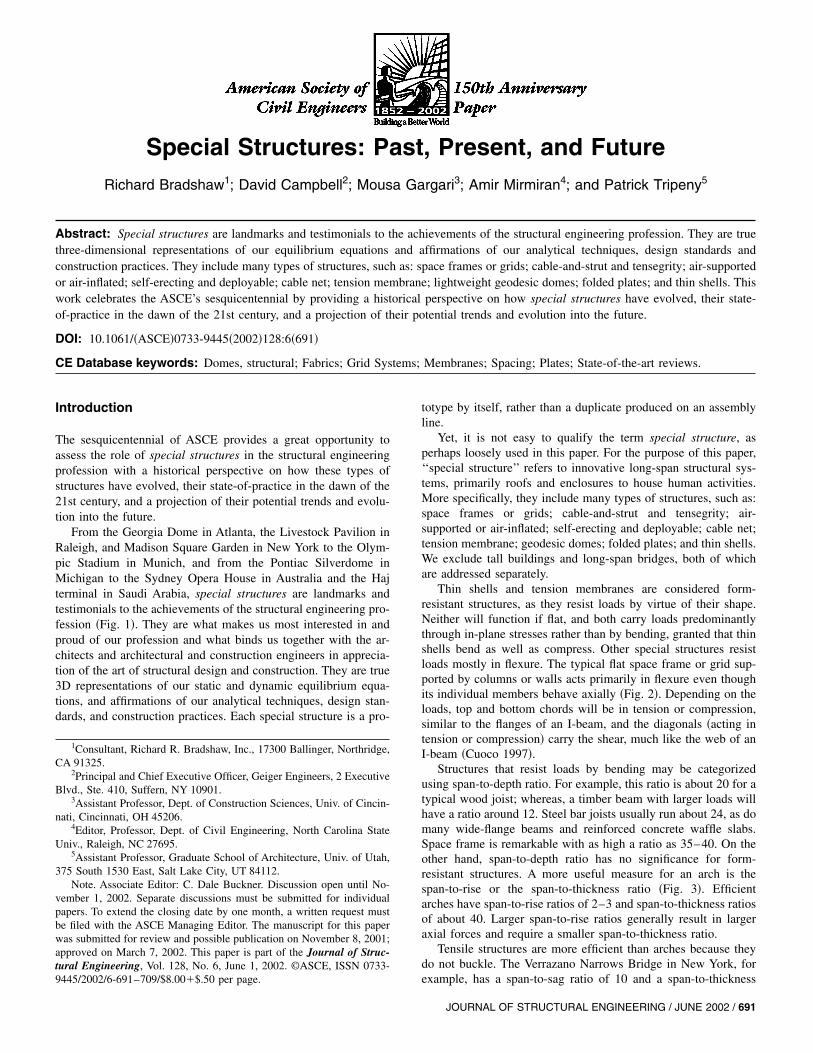
From the Georgia Dome in Atlanta, the Livestock Pavilion inRaleigh, and Madison Square Garden in New York to the Olym-pic Stadium in Munich, and from the Pontiac Silverdome inMichigan to the Sydney Opera House in Australia and the Hajterminal in Saudi Arabia, special structures are landmarks andtestimonials to the achievements of the structural engineering pro-fession �Fig. 1�. They are what makes us most interested in andproud of our profession and what binds us together with the ar-chitects and architectural and construction engineers in apprecia-tion of the art of structural design and construction. They are true3D representations of our static and dynamic equilibrium equa-tions, and affirmations of our analytical techniques, design stan-dards, and construction practices. Each special structure is a pro-
1Consultant, Richard R. Bradshaw, Inc., 17300 Ballinger, Northridge,CA 91325.
2Principal and Chief Executive Officer, Geiger Engineers, 2 ExecutiveBlvd., Ste. 410, Suffern, NY 10901.
3Assistant Professor, Dept. of Construction Sciences, Univ. of Cincin-nati, Cincinnati, OH 45206.
4Editor, Professor, Dept. of Civil Engineering, North Carolina StateUniv., Raleigh, NC 27695.
5Assistant Professor, Graduate School of Architecture, Univ. of Utah,375 South 1530 East, Salt Lake City, UT 84112.
Note. Associate Editor: C. Dale Buckner. Discussion open until No-vember 1, 2002. Separate discussions must be submitted for individualpapers. To extend the closing date by one month, a written request mustbe filed with the ASCE Managing Editor. The manuscript for this paperwas submitted for review and possible publication on November 8, 2001;approved on March 7, 2002. This paper is part of the Journal of Struc-tural Engineering, Vol. 128, No. 6, June 1, 2002. ©ASCE, ISSN 0733-9445/2002/6-691–709/$8.00�$.50 per page.
totype by itself, rather than a duplicate produced on an assemblyline.
Yet, it is not easy to qualify the term special structure, asperhaps loosely used in this paper. For the purpose of this paper,‘‘special structure’’ refers to innovative long-span structural sys-tems, primarily roofs and enclosures to house human activities.More specifically, they include many types of structures, such as:space frames or grids; cable-and-strut and tensegrity; air-supported or air-inflated; self-erecting and deployable; cable net;tension membrane; geodesic domes; folded plates; and thin shells.We exclude tall buildings and long-span bridges, both of whichare addressed separately.
Thin shells and tension membranes are considered form-resistant structures, as they resist loads by virtue of their shape.Neither will function if flat, and both carry loads predominantlythrough in-plane stresses rather than by bending, granted that thinshells bend as well as compress. Other special structures resistloads mostly in flexure. The typical flat space frame or grid sup-ported by columns or walls acts primarily in flexure even thoughits individual members behave axially �Fig. 2�. Depending on theloads, top and bottom chords will be in tension or compression,similar to the flanges of an I-beam, and the diagonals �acting intension or compression� carry the shear, much like the web of anI-beam �Cuoco 1997�.
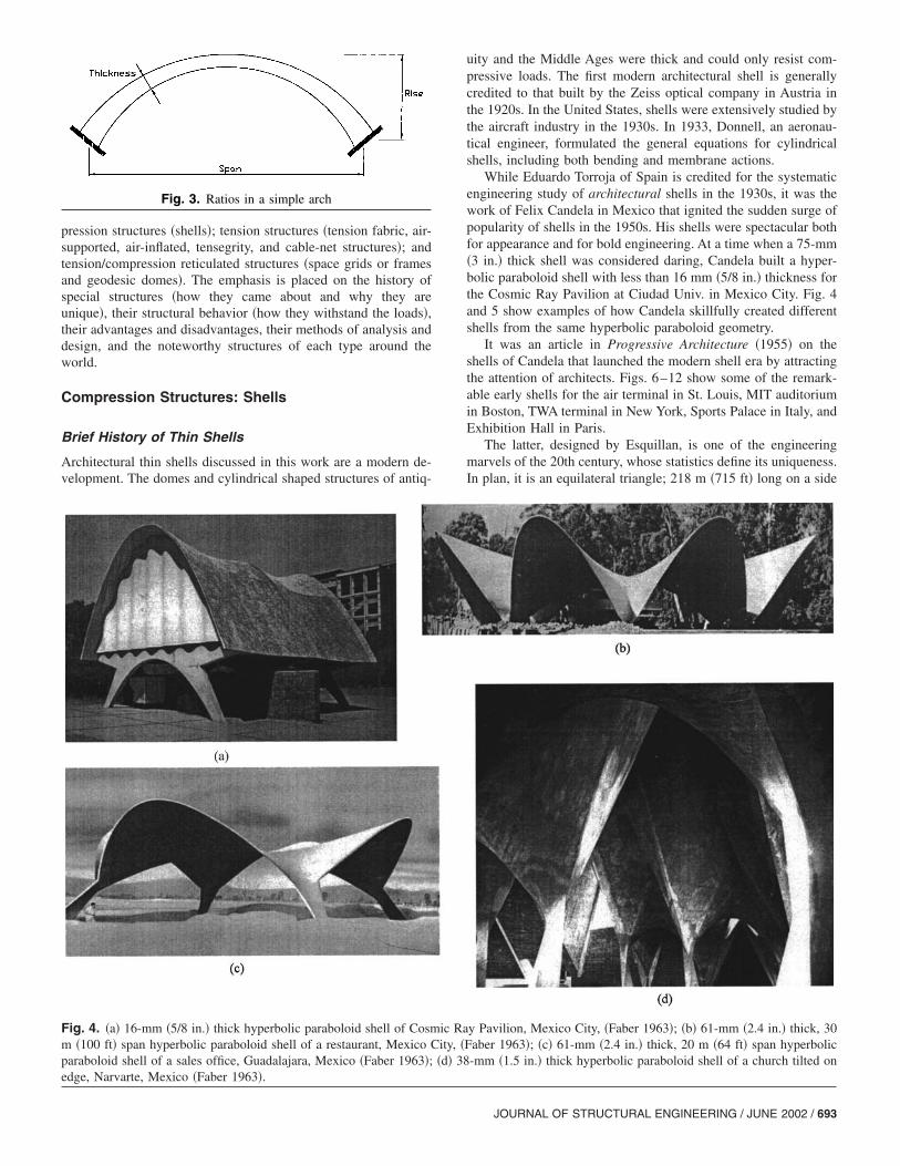
Structures that resist loads by bending may be categorizedusing span-to-depth ratio. For example, this ratio is about 20 for atypical wood joist; whereas, a timber beam with larger loads willhave a ratio around 12. Steel bar joists usually run about 24, as domany wide-flange beams and reinforced concrete waffle slabs.Space frame is remarkable with as high a ratio as 35–40. On theother hand, span-to-depth ratio has no significance for form-resistant structures. A more useful measure for an arch is thespan-to-rise or the span-to-thickness ratio �Fig. 3�. Efficientarches have span-to-rise ratios of 2–3 and span-to-thickness ratiosof about 40. Larger span-to-rise ratios generally result in largeraxial forces and require a smaller span-to-thickness ratio.
Tensile structures are more efficient than arches because theydo not buckle. The Verrazano Narrows Bridge in New York, forexample, has a span-to-sag ratio of 10 and a span-to-thickness
JOURNAL OF STRUCTURAL ENGINEERING / JUNE 2002 / 691
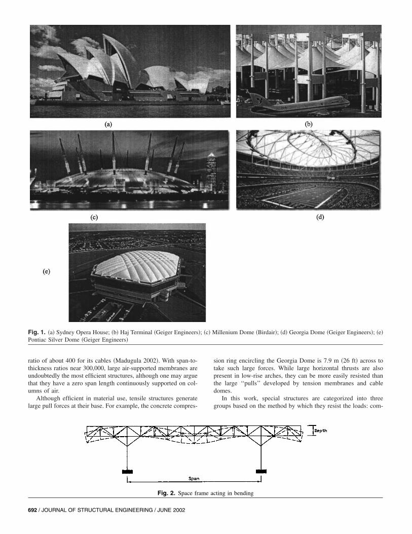
Fig. 1. �a� Sydney Opera House; �b� Haj Terminal �Geiger Engineers�; �c� Millenium Dome �Birdair�; �d� Georgia Dome �Geiger Engineers�; �e�Pontiac Silver Dome �Geiger Engineers�
ratio of about 400 for its cables �Madugula 2002�. With span-to-thickness ratios near 300,000, large air-supported membranes areundoubtedly the most efficient structures, although one may arguethat they have a zero span length continuously supported on col-umns of air.
Although efficient in material use, tensile structures generatelarge pull forces at their base. For example, the concrete compres-
sion ring encircling the Georgia Dome is 7.9 m �26 ft� across totake such large forces. While large horizontal thrusts are alsopresent in low-rise arches, they can be more easily resisted thanthe large ‘‘pulls’’ developed by tension membranes and cabledomes.
In this work, special structures are categorized into threegroups based on the method by which they resist the loads: com-
692 / JOURNAL
Fig. 2. Space frame acting in bending
OF STRUCTURAL ENGINEERING / JUNE 2002
pression structures �shells�; tension structures �tension fabric, air-supported, air-inflated, tensegrity, and cable-net structures�; andtension/compression reticulated structures �space grids or framesand geodesic domes�. The emphasis is placed on the history ofspecial structures �how they came about and why they areunique�, their structural behavior �how they withstand the loads�,their advantages and disadvantages, their methods of analysis anddesign, and the noteworthy structures of each type around theworld.
Compression Structures: Shells
Brief History of Thin Shells
Architectural thin shells discussed in this work are a modern de-velopment. The domes and cylindrical shaped structures of antiq-
uity and the Middle Ages were thick and could only resist com-pressive loads. The first modern architectural shell is generallycredited to that built by the Zeiss optical company in Austria inthe 1920s. In the United States, shells were extensively studied bythe aircraft industry in the 1930s. In 1933, Donnell, an aeronau-tical engineer, formulated the general equations for cylindricalshells, including both bending and membrane actions.
While Eduardo Torroja of Spain is credited for the systematicengineering study of architectural shells in the 1930s, it was thework of Felix Candela in Mexico that ignited the sudden surge ofpopularity of shells in the 1950s. His shells were spectacular bothfor appearance and for bold engineering. At a time when a 75-mm�3 in.� thick shell was considered daring, Candela built a hyper-bolic paraboloid shell with less than 16 mm �5/8 in.� thickness forthe Cosmic Ray Pavilion at Ciudad Univ. in Mexico City. Fig. 4and 5 show examples of how Candela skillfully created differentshells from the same hyperbolic paraboloid geometry.
It was an article in Progressive Architecture �1955� on theshells of Candela that launched the modern shell era by attractingthe attention of architects. Figs. 6–12 show some of the remark-able early shells for the air terminal in St. Louis, MIT auditoriumin Boston, TWA terminal in New York, Sports Palace in Italy, andExhibition Hall in Paris.
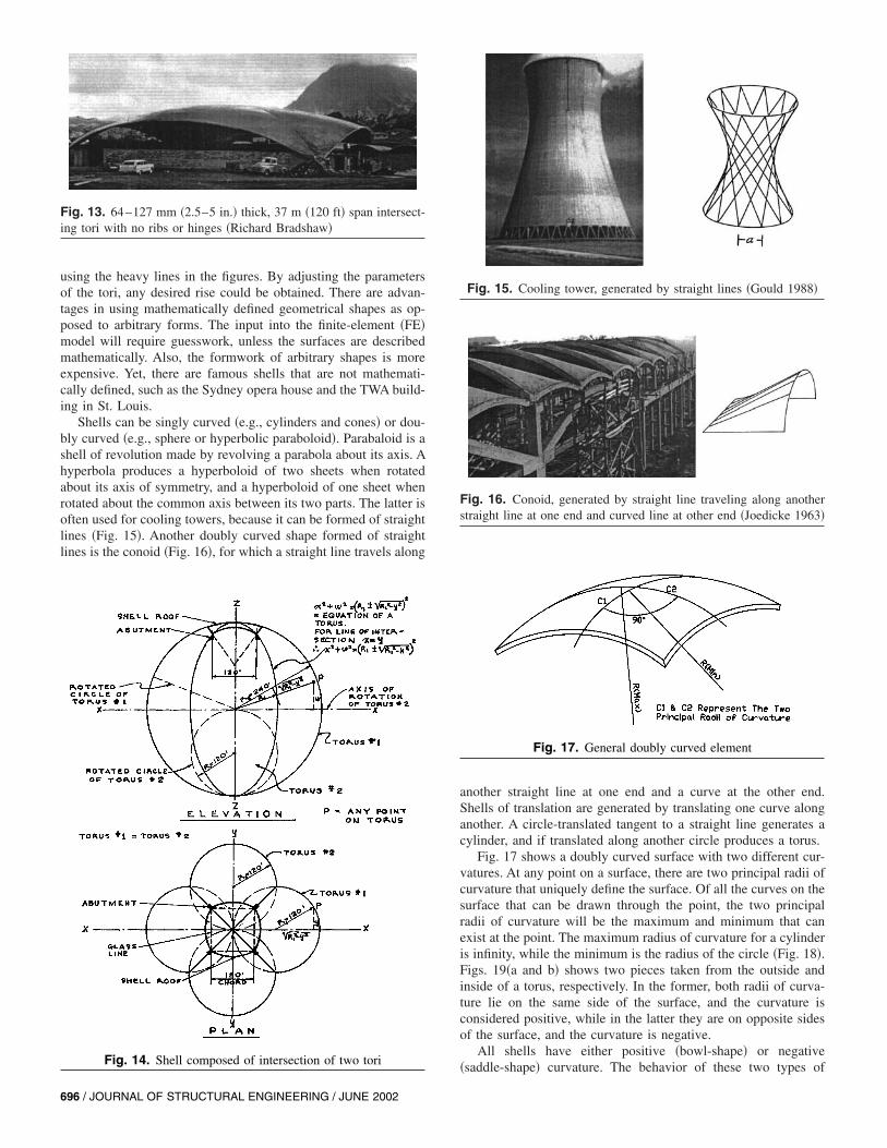
The latter, designed by Esquillan, is one of the engineeringmarvels of the 20th century, whose statistics define its uniqueness.In plan, it is an equilateral triangle; 218 m �715 ft� long on a side
Fig. 3. Ratios in a simple arch
Fig. 4. �a� 16-mm �5/8 in.� thick hyperbolic paraboloid shell of Cosmic Ray Pavilion, Mexico City, �Faber 1963�; �b� 61-mm �2.4 in.� thick, 30m �100 ft� span hyperbolic paraboloid shell of a restaurant, Mexico City, �Faber 1963�; �c� 61-mm �2.4 in.� thick, 20 m �64 ft� span hyperbolicparaboloid shell of a sales office, Guadalajara, Mexico �Faber 1963�; �d� 38-mm �1.5 in.� thick hyperbolic paraboloid shell of a church tilted onedge, Narvarte, Mexico �Faber 1963�.
JOURNAL OF STRUCTURAL ENGINEERING / JUNE 2002 / 693
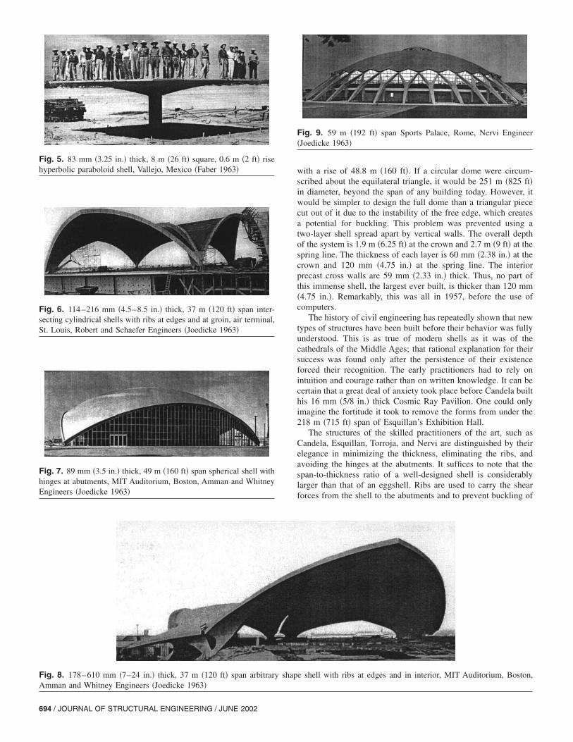
Fig. 5. 83 mm �3.25 in.� thick, 8 m �26 ft� square, 0.6 m �2 ft� risehyperbolic paraboloid shell, Vallejo, Mexico �Faber 1963�
Fig. 6. 114–216 mm �4.5–8.5 in.� thick, 37 m �120 ft� span inter-secting cylindrical shells with ribs at edges and at groin, air terminal,St. Louis, Robert and Schaefer Engineers �Joedicke 1963�
Fig. 7. 89 mm �3.5 in.� thick, 49 m �160 ft� span spherical shell withhinges at abutments, MIT Auditorium, Boston, Amman and WhitneyEngineers �Joedicke 1963�
694 / JOURNAL OF STRUCTURAL ENGINEERING / JUNE 2002
with a rise of 48.8 m �160 ft�. If a circular dome were circum-scribed about the equilateral triangle, it would be 251 m �825 ft�in diameter, beyond the span of any building today. However, itwould be simpler to design the full dome than a triangular piececut out of it due to the instability of the free edge, which createsa potential for buckling. This problem was prevented using atwo-layer shell spread apart by vertical walls. The overall depthof the system is 1.9 m �6.25 ft� at the crown and 2.7 m �9 ft� at thespring line. The thickness of each layer is 60 mm �2.38 in.� at thecrown and 120 mm �4.75 in.� at the spring line. The interiorprecast cross walls are 59 mm �2.33 in.� thick. Thus, no part ofthis immense shell, the largest ever built, is thicker than 120 mm�4.75 in.�. Remarkably, this was all in 1957, before the use ofcomputers.
The history of civil engineering has repeatedly shown that newtypes of structures have been built before their behavior was fullyunderstood. This is as true of modern shells as it was of thecathedrals of the Middle Ages; that rational explanation for theirsuccess was found only after the persistence of their existenceforced their recognition. The early practitioners had to rely onintuition and courage rather than on written knowledge. It can becertain that a great deal of anxiety took place before Candela builthis 16 mm �5/8 in.� thick Cosmic Ray Pavilion. One could onlyimagine the fortitude it took to remove the forms from under the218 m �715 ft� span of Esquillan’s Exhibition Hall.
The structures of the skilled practitioners of the art, such asCandela, Esquillan, Torroja, and Nervi are distinguished by theirelegance in minimizing the thickness, eliminating the ribs, andavoiding the hinges at the abutments. It suffices to note that thespan-to-thickness ratio of a well-designed shell is considerablylarger than that of an eggshell. Ribs are used to carry the shearforces from the shell to the abutments and to prevent buckling of
Fig. 9. 59 m �192 ft� span Sports Palace, Rome, Nervi Engineer�Joedicke 1963�
Fig. 8. 178–610 mm �7–24 in.� thick, 37 m �120 ft� span arbitrary shape shell with ribs at edges and in interior, MIT Auditorium, Boston,Amman and Whitney Engineers �Joedicke 1963�
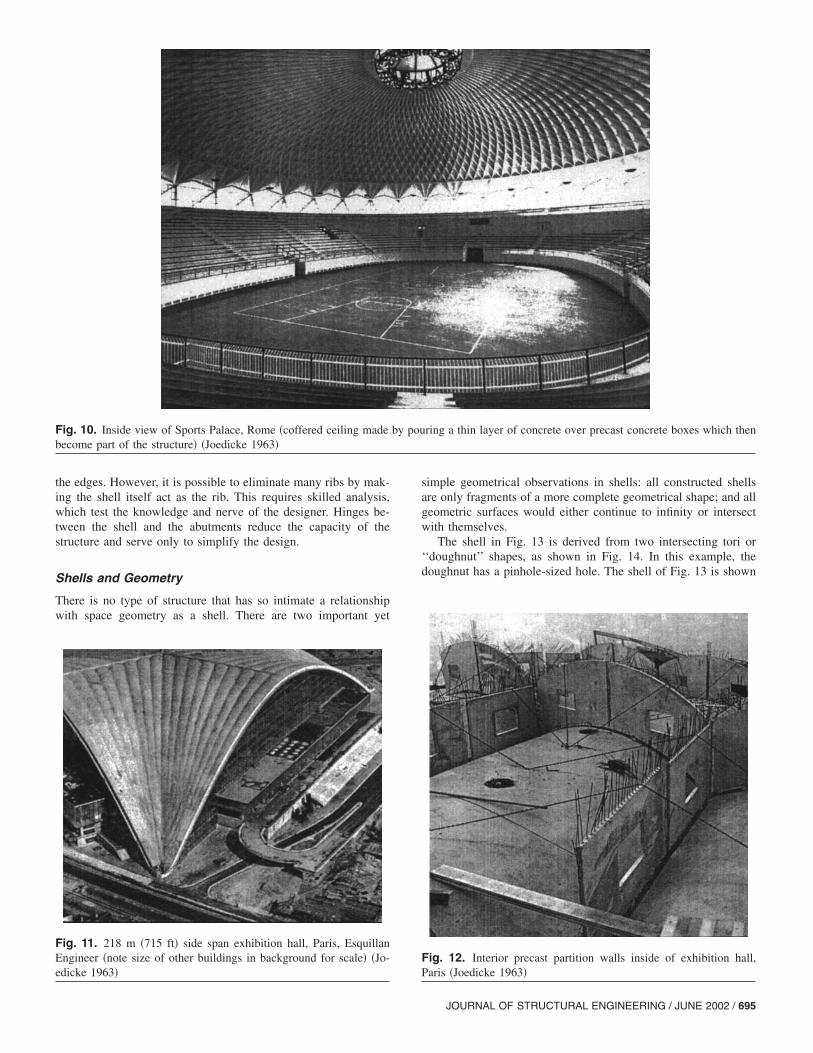
Fig. 10. Inside view of Sports Palace, Rome �coffered ceiling made by pouring a thin layer of concrete over precast concrete boxes which thenbecome part of the structure� �Joedicke 1963�
the edges. However, it is possible to eliminate many ribs by mak-ing the shell itself act as the rib. This requires skilled analysis,which test the knowledge and nerve of the designer. Hinges be-tween the shell and the abutments reduce the capacity of thestructure and serve only to simplify the design.
Shells and Geometry
There is no type of structure that has so intimate a relationshipwith space geometry as a shell. There are two important yet
simple geometrical observations in shells: all constructed shellsare only fragments of a more complete geometrical shape; and allgeometric surfaces would either continue to infinity or intersectwith themselves.
The shell in Fig. 13 is derived from two intersecting tori or‘‘doughnut’’ shapes, as shown in Fig. 14. In this example, thedoughnut has a pinhole-sized hole. The shell of Fig. 13 is shown
Fig. 11. 218 m �715 ft� side span exhibition hall, Paris, EsquillanEngineer �note size of other buildings in background for scale� �Jo-edicke 1963�
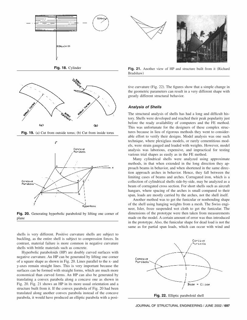
Fig. 12. Interior precast partition walls inside of exhibition hall,Paris �Joedicke 1963�
JOURNAL OF STRUCTURAL ENGINEERING / JUNE 2002 / 695
using the heavy lines in the figures. By adjusting the parametersof the tori, any desired rise could be obtained. There are advan-tages in using mathematically defined geometrical shapes as op-posed to arbitrary forms. The input into the finite-element �FE�model will require guesswork, unless the surfaces are describedmathematically. Also, the formwork of arbitrary shapes is moreexpensive. Yet, there are famous shells that are not mathemati-cally defined, such as the Sydney opera house and the TWA build-ing in St. Louis.
Shells can be singly curved �e.g., cylinders and cones� or dou-bly curved �e.g., sphere or hyperbolic paraboloid�. Parabaloid is ashell of revolution made by revolving a parabola about its axis. Ahyperbola produces a hyperboloid of two sheets when rotatedabout its axis of symmetry, and a hyperboloid of one sheet whenrotated about the common axis between its two parts. The latter isoften used for cooling towers, because it can be formed of straightlines �Fig. 15�. Another doubly curved shape formed of straightlines is the conoid �Fig. 16�, for which a straight line travels along
Fig. 13. 64–127 mm �2.5–5 in.� thick, 37 m �120 ft� span intersect-ing tori with no ribs or hinges �Richard Bradshaw�
Fig. 14. Shell composed of intersection of two tori
696 / JOURNAL OF STRUCTURAL ENGINEERING / JUNE 2002
another straight line at one end and a curve at the other end.Shells of translation are generated by translating one curve alonganother. A circle-translated tangent to a straight line generates acylinder, and if translated along another circle produces a torus.
Fig. 17 shows a doubly curved surface with two different cur-vatures. At any point on a surface, there are two principal radii ofcurvature that uniquely define the surface. Of all the curves on thesurface that can be drawn through the point, the two principalradii of curvature will be the maximum and minimum that canexist at the point. The maximum radius of curvature for a cylinderis infinity, while the minimum is the radius of the circle �Fig. 18�.Figs. 19�a and b� shows two pieces taken from the outside andinside of a torus, respectively. In the former, both radii of curva-ture lie on the same side of the surface, and the curvature isconsidered positive, while in the latter they are on opposite sidesof the surface, and the curvature is negative.
All shells have either positive �bowl-shape� or negative�saddle-shape� curvature. The behavior of these two types of
Fig. 15. Cooling tower, generated by straight lines �Gould 1988�
Fig. 16. Conoid, generated by straight line traveling along anotherstraight line at one end and curved line at other end �Joedicke 1963�
Fig. 17. General doubly curved element
shells is very different. Positive curvature shells are subject tobuckling, as the entire shell is subject to compression forces. Incontrast, material failure is more common in negative curvatureshells with brittle materials such as concrete.
Hyperbolic paraboloids �HP� are doubly curved surfaces withnegative curvature. An HP can be generated by lifting one cornerof a square shape as shown in Fig. 20. Lines parallel to the x- andy-axes remain straight lines. This is very important because thesurfaces can be formed with straight forms, which are much moreeconomical than curved forms. An HP can also be generated bytranslating a convex parabola along a concave one as shown inFig. 20. Fig. 21 shows an HP in its more usual orientation and astructure built from it. If the convex parabola of Fig. 20 had beentranslated along another convex parabola instead of the concaveparabola, it would have produced an elliptic parabola with a posi-
Fig. 18. Cylinder
Fig. 19. �a� Cut from outside torus; �b� Cut from inside torus
Fig. 20. Generating hyperbolic paraboloid by lifting one corner ofplane
tive curvature �Fig. 22�. The figures show that a simple change inthe geometric parameters can result in a very different shape withgreatly different structural behavior.
Analysis of Shells
The structural analysis of shells has had a long and difficult his-tory. Shells were developed and reached their peak popularity justbefore the ready availability of computers and the FE method.This was unfortunate for the designers of these complex struc-tures because in lieu of rigorous methods they went to consider-able effort to verify their designs. Model analysis was one suchtechnique, where plexiglass models, or rarely cementitious mod-els, were strain gauged and loaded with weights. However, modelanalysis was laborious, expensive, and impractical for testingvarious trial shapes as easily as in the FE method.
Many cylindrical shells were analyzed using approximatemethods, in that when extended in the long direction they ap-proach beams in behavior, and when shortened in the same direc-tion approach arches in behavior. Hence, they fall between thelimiting cases of beams and arches. Corrugated iron, which is acollection of cylindrical shells side-by-side, may be analyzed as abeam of corrugated cross section. For short shells such as aircrafthangars, where spacing of the arches is small compared to theirspan, loads are mostly carried by the arches, not the shell itself.
Another method was to get the funicular or nonbending shapeof the shell using hanging weights from a mesh. The Swiss engi-neer, Isler, froze suspended wet cloth to get the funicular. Thedimensions of the prototype were then taken from measurementsmade on the model. A certain amount of error was thus introducedin the prototype. Also, the funicular shape for dead load is not thesame as for partial span loads, which can occur with wind and
Fig. 21. Another view of HP and structure built from it �RichardBradshaw�
Fig. 22. Elliptic paraboloid shell
JOURNAL OF STRUCTURAL ENGINEERING / JUNE 2002 / 697
snow loads, where partial span loading frequently governs. Otherapproximate methods used were to figuratively cut out pieces ofthe shell and analyze them for static equilibrium. One advantageof these approximate methods was that they forced the designer todevelop an intuitive feel for the structural behavior of the shell,which is sometimes missing with the uncritical use of computers.
Of the more rigorous analytical methods, one can refer to theFE and the finite difference methods. In the FE method, the shellis cut into small pieces or finite elements and then ‘‘reassembled’’using equilibrium and compatibility. In contrast, the finite differ-ence method breaks down the governing equations of shells andsolves them to an approximate solution. Prior to the availability ofFE, some shells were analyzed by finite difference methods,which required a tedious convergence process without the use ofcomputers. Today FE methods prevail for shell analysis. The shellelement must consider anisotropy, creep, and the plastic flow ofconcrete. There have been failures of concrete shells after erectionand initial loading, where creep and plastic flow have played amajor role �Beles and Soare 1966�.
Shells are usually modeled using triangular or quadrilateralplane elements. The former could be used to approximate anysingly or doubly curved surface with positive or negative curva-ture, as the three corners of the element could always be made tofall on the shell. Although there are certain advantages to the useof quadrilateral elements, it is not always possible to approximatesurfaces with them. Fig. 23 represents a doubly curved shell withno axis of symmetry. This surface could be approximated to anydegree of accuracy with triangular elements. However, the samemay not be true for a quadrangular element, as they are given atwist that is not included in their derivation. The amount of twistdepends on the element size and the surface curvature. One char-acteristic of the hyperbolic paraboloid is that its twist is constantover the entire surface. Therefore, a flat quadrilateral cannot ex-actly fit its surface. The designer must estimate the consequencesof this effect and verify the permissible twist in the FE program.
The analysis of shells requires that the three conditions ofequilibrium, compatibility, and constitutive laws be satisfied si-multaneously. The latter are the stress-strain properties for thematerials of the shell. Most shells are designed with isotropicmaterials. With the development of advanced composites, theirorthotropic and anisotropic behavior must be considered. How-ever, composites have not been used for architectural shells todate. Roof structures are seldom designed for dynamic loads.Earthquake and wind loads may be treated as equivalent staticloads.
The above three conditions result in three partial differentialequations, two of the 2nd order and one of the 4th order, for the
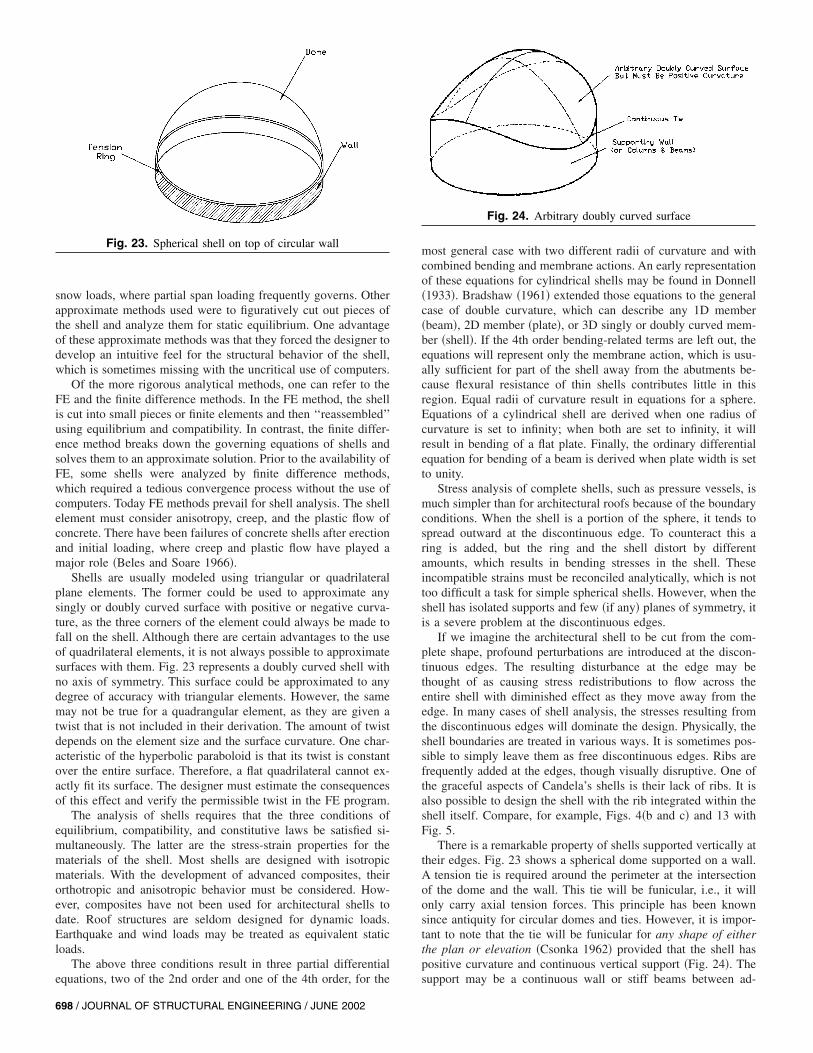
Fig. 23. Spherical shell on top of circular wall
698 / JOURNAL OF STRUCTURAL ENGINEERING / JUNE 2002
most general case with two different radii of curvature and withcombined bending and membrane actions. An early representationof these equations for cylindrical shells may be found in Donnell�1933�. Bradshaw �1961� extended those equations to the generalcase of double curvature, which can describe any 1D member�beam�, 2D member �plate�, or 3D singly or doubly curved mem-ber �shell�. If the 4th order bending-related terms are left out, theequations will represent only the membrane action, which is usu-ally sufficient for part of the shell away from the abutments be-cause flexural resistance of thin shells contributes little in thisregion. Equal radii of curvature result in equations for a sphere.Equations of a cylindrical shell are derived when one radius ofcurvature is set to infinity; when both are set to infinity, it willresult in bending of a flat plate. Finally, the ordinary differentialequation for bending of a beam is derived when plate width is setto unity.
Stress analysis of complete shells, such as pressure vessels, ismuch simpler than for architectural roofs because of the boundaryconditions. When the shell is a portion of the sphere, it tends tospread outward at the discontinuous edge. To counteract this aring is added, but the ring and the shell distort by differentamounts, which results in bending stresses in the shell. Theseincompatible strains must be reconciled analytically, which is nottoo difficult a task for simple spherical shells. However, when theshell has isolated supports and few �if any� planes of symmetry, itis a severe problem at the discontinuous edges.
If we imagine the architectural shell to be cut from the com-plete shape, profound perturbations are introduced at the discon-tinuous edges. The resulting disturbance at the edge may bethought of as causing stress redistributions to flow across theentire shell with diminished effect as they move away from theedge. In many cases of shell analysis, the stresses resulting fromthe discontinuous edges will dominate the design. Physically, theshell boundaries are treated in various ways. It is sometimes pos-sible to simply leave them as free discontinuous edges. Ribs arefrequently added at the edges, though visually disruptive. One ofthe graceful aspects of Candela’s shells is their lack of ribs. It isalso possible to design the shell with the rib integrated within theshell itself. Compare, for example, Figs. 4�b and c� and 13 withFig. 5.
There is a remarkable property of shells supported vertically attheir edges. Fig. 23 shows a spherical dome supported on a wall.A tension tie is required around the perimeter at the intersectionof the dome and the wall. This tie will be funicular, i.e., it willonly carry axial tension forces. This principle has been knownsince antiquity for circular domes and ties. However, it is impor-tant to note that the tie will be funicular for any shape of eitherthe plan or elevation �Csonka 1962� provided that the shell haspositive curvature and continuous vertical support �Fig. 24�. Thesupport may be a continuous wall or stiff beams between ad-
Fig. 24. Arbitrary doubly curved surface
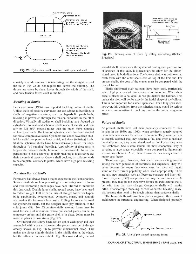
equately spaced columns. It is interesting that the straight parts ofthe tie in Fig. 25 do not require ties across the building. Thethrusts are taken by shear forces through the width of the shell,and only tension forces exist in the tie.
Buckling of Shells
Beles and Soare �1966� have reported buckling failure of shells.Unlike shells of positive curvature that are subject to buckling, inshells of negative curvature, such as hyperbolic paraboloids,buckling is prevented through the tension curvature in the otherdirection. Virtually all studies on shell buckling have focused oncylindrical, conical, and spherical shells made of metals, and usu-ally on full 360° models rather than the much more complexarchitectural shells. Buckling of spherical shells has been studiedfor radial compressive loads. Cylinders and cones have been stud-ied for radial compressive loads, axial, and shear �twisting� loads.Shallow spherical shells have been extensively tested for snap-through or ‘‘oil-canning’’ buckling. Applicability of these tests tolarge-scale concrete shells, however, is questionable. Initial im-perfections in shells can result in their buckling at loads far belowtheir theoretical capacity. Once a shell buckles, its collapse tendsto be complete, contrary to plates, which have high post-bucklingcapacity.
Construction of Shells
Formwork has always been a major expense in shell construction.Several methods such as precasting or shotcreting over balloonsand over reinforcing steel cages have been utilized to minimizethis drawback. Double layer shells, spread apart, have been usedto reduce weight. Full or partial use of straight forms for hyper-bolic paraboloids, hyperboloids, cylinders, cones, and conoidsalso makes the formwork less costly. Rolling forms can be usedfor cylindrical shells, but the designer must pay attention to thecold joints �Fig. 26�. Circumferentially moving forms may beused for shells of revolution, where pie-shaped pieces can act astemporary arches until the entire shell is in place. Joints must bemade in places of low stress �Fig. 27�.
Cylindrical shells have been cast on top of each other and thenassembled with a crane. However, the pieces must be of the ge-ometry shown in Fig. 28 to prevent dimensional creep. Thismakes the pieces slightly thicker in the middle than at the edges,
Fig. 25. Cylindrical shell combined with spherical shell
but the difference is undetectable. Fig. 28 shows a doubly curved
toroidal shell, which uses the system of casting one piece on topof another. In this case, it is necessary to allow for the dimen-sional creep in both directions. The bottom shell was built over anearth form with the other shells cast on top of the first one. Forprecast shells, the cost of the cranes must be compared with thecost of forms.
Shells shotcreted over balloons have been used, particularlywhere high precision of dimensions is not important. When shot-crete is placed on a balloon, the weight distorts the balloon. Thismeans the shell will not be exactly the initial shape of the balloon.This is not important for a small span shell. For a long span shell,however, this deviation from the spherical shape could be seriousas shells are sensitive to buckling due to the initial roughnesseffect.
Future of Shells
At present, shells have lost their popularity compared to theirheyday in the 1950s and 1960s, when architects eagerly adoptedthem as a new means for artistic expression. They were perhapsso eagerly adopted that they became a fad, and when a backlashinevitably set in, they were abandoned as quickly as they werefirst embraced. Shells were seldom the most economical way ofcovering a large space, especially when compared to lightweighttension membranes. Also, their formwork has always been amajor cost factor.
There are signs, however, that shells are attracting interestamong the new generation of architects and engineers. They willnever become the vogue they once were, but they will regainsome of their former popularity when used appropriately. Thereare also new materials such as fibercrete concrete and fiber rein-forced polymer �FRP� composites that may be used in shells. Atpresent, they may be too expensive for use in architectural shells,but with time that may change. Composite shells will requireortho- or anisotropic modeling, as well as careful buckling analy-sis, because they tend to be much thinner than concrete shells.
The future shells will take their place alongside other forms ofarchitecture in structural engineering. When designed properly,
Fig. 26. Showing reuse of forms by rolling scaffolding �RichardBradshaw�
Fig. 27. Use of pie-shaped opposing forms
JOURNAL OF STRUCTURAL ENGINEERING / JUNE 2002 / 699
Fig. 28. Corrugated torus shell geometry: �a� Overall view of shell; �b� Earth form for bottom shell; �c� shells cast on each other; �d� geometryof precasting showing the elimination of dimensional creep �Richard Bradshaw�
they are among the most beautiful and efficient of architecturalstructures. Even those who are not professionals can sense theflow of forces through them. They will present both problems tobe solved and opportunities to create for those who take the timeto understand them.
Tension Membrane Structures
History of Tension Structures
Tension structures include a wide variety of systems that are dis-tinguished by their reliance upon tensile only members to supportload. They have been employed throughout recorded history as inrope bridges and tents. However, large permanent tension struc-tures were generally a 19th century development in bridges and a20th century development in buildings. The design of large ten-sion membranes has been fully dependent upon the use of com-puters. Many of the developments in membranes have occurred inthe last 30 years, precisely because of the accessibility of power-ful computers. The pioneering work of Frei Otto was accom-plished using physical models, which, while they well illustratethe desired form of a membrane, are not conducive to the precisedetermination of the membrane’s structural characteristics in amanner necessary for the construction of large complex systems.
Large deployable membrane structures were used to covertouring public assembly events such as circuses and religious re-vival meetings in the 19th century. These were constructed of
700 / JOURNAL OF STRUCTURAL ENGINEERING / JUNE 2002
canvas and ropes with wood poles, as were contemporary tents. Itwas the fate of the ‘‘Big Top,’’ the Barnum and Bailey Circus’main auditorium tent that burned �Martin and Wilmeth 1988�,which created the most significant hurdle for membrane architec-ture in the United States: the issue of noncombustibility. Prior tothe introduction of noncombustible structural fabrics, membranestructures were nomadic, and subsequent to the ‘‘Big Top’’ fire,they were relatively small. There were exceptions: Frank LloydWright employed a tension membrane roof of canvas on hisschool and home, Taliesin West in Scottsdale, Ariz. in 1938. How-ever, permanent tension membrane architecture began in NorthAmerica in the 1970s.
Structural economy rather than aesthetics or architectural ex-pression initially drove the modern use of membrane structures inNorth America. Thus, it is not surprising that the development ofmodern membrane structures was, with some exceptions �mostnotably John Shaver, the first American architect to develop per-manent membrane architecture� primarily the work of engineers.However, these structures, like all spatial structures, are by theirnature uniquely expressive, creating architecture that was in someinstances a result rather than a goal.
Development of modern membrane structures began in thelater half of the 20th century, and communications in the fieldwere such that worldwide experience was quickly disseminated.The work of Frei Otto in Germany was particularly influential. Ashas been the case with other building technologies, World Expo-sitions, particularly EXPO ‘70 in Osaka, Japan, were of great
significance in the development of membrane structures aroundthe globe.
Simply considered, membrane structures were initially pur-sued in the United States for their cost-effectiveness. The firstpermanent membrane structures were the air-supported radar en-closures designed and built by Walter Bird �Fig. 29�, as early as1946. Walter Bird’s successes with these pneumatic structures ledto his founding of Birdair Structures in 1956.
Architectural membrane systems were a natural extension oftension structures of the 1950s and 1960s for long-span buildings.Fred Severud demonstrated the long-span potential of tensionstructures in benchmark projects such as the North Carolina StateFair Live Stock Pavilion in Raleigh, N.C., the Yale Univ. hockeyrink, New Haven, Conn., and Madison Square Garden, New York.Severud’s engineering practice was the incubator of membranestructure design in the United States. Designers of subsequenttension membranes included David Geiger, Horst Berger, PaulGossen, and for brief periods, Edmund Happold and Frei Otto.Another engineering pioneer of prestressed tension-based struc-tures was Lev Zetlin, who designed the Utica Memorial Audito-rium roof and the New York State and Travelers Insurance Pavil-ions at the 1964 New York World Fair. Architects such as EeroSaarenen successfully exploited the unique architecture of thesestructures to create new forms for buildings.
While tension structures of Severud and others demonstratedthe potential of such architecture in the United States, architec-tural membrane structures really began with EXPO ‘70 in Osaka,Japan, when David Geiger was commissioned to engineer theenclosure for the United States Pavilion. The initial pavilion de-sign was abandoned when the project was unable to secure asufficient appropriation from Congress. The pavilion program wasmaintained, but the project had to be realized for one-tenth of theoriginal budget. In response to this challenge, Geiger invented thelow profile cable-restrained, air-supported roof employing a su-perelliptical perimeter compression ring. This proved to be anexceedingly economical means of covering large clear spanspaces, and quite interestingly, within 15 years of its completion,this structural system was employed to cover more than half thedomed stadia in the world �Fig. 30�.
Following the success of the United States Pavilion project,David Geiger considered applying it to permanent structures.However, such applications required a strong, noncombustible,
Fig. 29. Walter Birdair atop a Birdair radome in 1956 �Birdair�
durable material. An existing coated fiberglass fabric product, pri-marily used for conveyor belts in commercial ovens, seemed tohave the desirable characteristics. David Geiger brought DuPontDe Nemours Company, Owens-Corning Fiberglass Corporationand Chemical Fabrics Corporation together to develop this mate-rial for architectural applications. Marking a new era of perma-nent tension membrane architecture, the resulting product, tefloncoated fiberglass, has since been employed around the world, asearly as 1973 and 1974 for the Student Center at La Verne Col-lege, Calif. and the Steve Lacey Field House, Milligan College,Johnson City, Tenn. Architect John Shaver designed both of thesebuildings.
Horst Berger and David Geiger worked together between 1969and 1984. While Geiger’s interest in membrane structures was fortheir structural efficiency and economy, Berger did much to dem-onstrate the aesthetic potential of tension membrane forms in ar-chitecture. Together, they developed analysis and design tools andtechniques indispensable in the design, documentation, and con-struction of complex tension structures.
Architects such as Paul Kennon of Caudill Rawlett and Scott,later known as CRS Sirrine, were quick to embrace membranearchitecture in the early 1970s and designed a number of land-mark projects. They explored the forms and the spaces created bythe unique translucent envelope of tension membranes. Raul deArmas and his colleagues at Skidmore, Owings & Merrill wereinstrumental in bringing the new membrane architecture to theattention of the world with the Haj Terminal at the Jeddah Inter-national Airport, Saudi Arabia. His design solution to the unprec-edented challenge of sheltering the Haj pilgrims while changingtransport modes to Mecca was simple and brilliant. Drawn totension membrane by the desire to create a translucent canopy, the
Fig. 30. Taoyuan Sports Arena, Taiwan, �a� outside view; �b� interiorof Geiger Cabledome �Geiger Engineers�
JOURNAL OF STRUCTURAL ENGINEERING / JUNE 2002 / 701
modular tent forms, which evolved in the final design, were mod-ern and at the same time reminiscent of the tents used for centu-ries by Haj pilgrims.
Canadian architect Eberhard Zeidler designed two landmarktension structures for EXPO ’86 in Vancouver, B.C.: the CanadaPavilion, now the convention hall at Canada Harbour Place, andthe Ontario Pavilion. Beginning with the Canada Place project,Eberhard Zeidler continued to explore the sculptural potential oftension membrane architecture beyond its structural origins.
The enclosure of large clear span space created great architec-tural opportunity for membrane structures. Early successes were aresult of the application of this building technology to the recentlyemerged American building type, the ‘‘domed’’ stadium.Uniquely North American until the late 1980s, covered stadiarequire roof spans without precedence. Membrane structures havebeen employed more often in covering sports stadia than anyother structural system. There is no other building type for whichthis is the case, due primarily to the economy of membrane struc-tures. Initially, the Geiger low profile, air-supported roof systemwas used. Later, shortcomings of air-supported roofs led Geiger toinvent a new system, the Cable Dome to cover a baseball stadiumin St. Petersburg, FL, combining his experience in membranestructures with Buckminster Fuller’s ideas of ‘‘tensegrity’’ and‘‘aspension.’’ These systems, their variants, and other tensionmembrane structures continue to be significant in covering longspan spaces.
Architecture
Not long after its development, the light translucency of coatedfiberglass became an obvious virtue, availing it as a cost-effectivesubstitute to glazing in many commercial projects across the con-tinent. Recently, Zeidler’s work has successfully combined trans-lucent tension membrane with glazing to enhance the day lightingas well as architectural composition. With noted exceptions, how-ever, the architecture of membrane structures has been little ex-plored in the United States beyond that driven by the economics.
Most architectural forms have developed from the nature oftraditional building materials. Building forms that developed froma material, say masonry, are quite often built of other materials.These forms create an architectural vocabulary well understoodby the general public. However, an architectural vernacular ofmembrane structures has yet to be established due to their recentdevelopment. As familiarity with tension membrane architectureincreases, they will be employed more often for their architecturalforms.
Applications
As with all spatial systems, tension membrane structures exploit3D forms to support load. However, tension structures are uniquein that they noticeably change form in response to loading. Thisattribute, which anyone who has walked on a trampoline has ex-perienced, is why tension membrane systems are almost exclu-sively employed as building enclosures, particularly roofs, ratherthan platforms or floors.
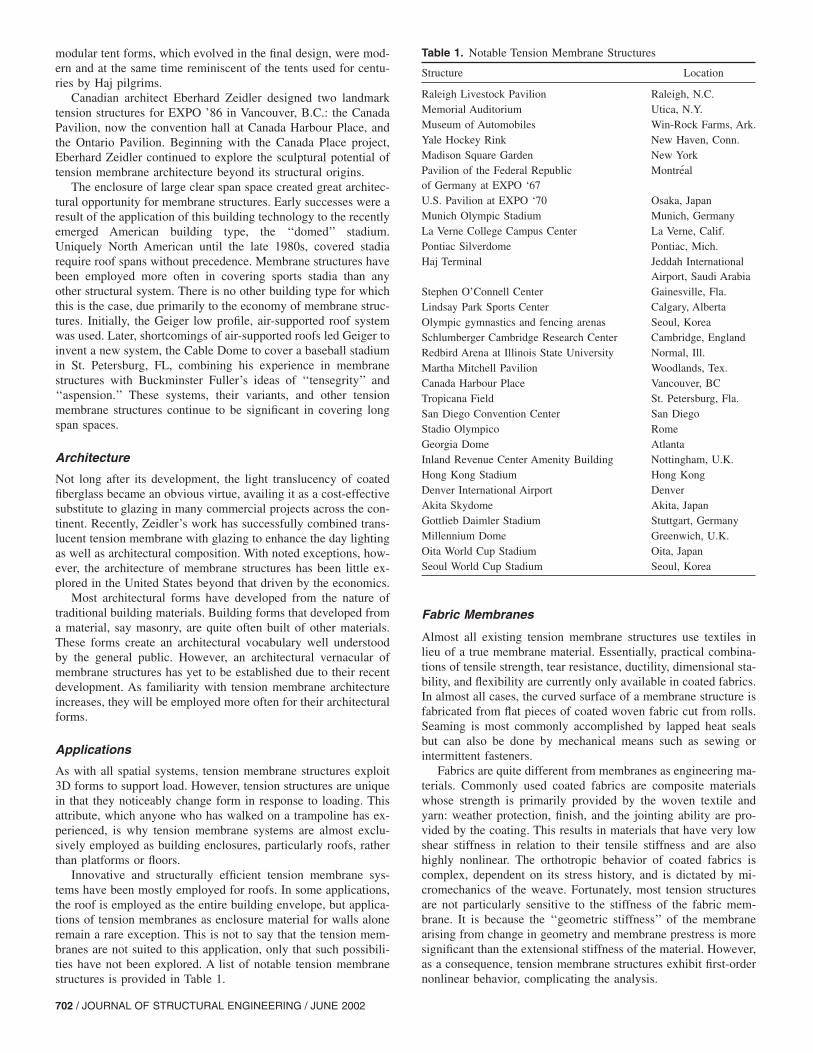
Innovative and structurally efficient tension membrane sys-tems have been mostly employed for roofs. In some applications,the roof is employed as the entire building envelope, but applica-tions of tension membranes as enclosure material for walls aloneremain a rare exception. This is not to say that the tension mem-branes are not suited to this application, only that such possibili-ties have not been explored. A list of notable tension membranestructures is provided in Table 1.
702 / JOURNAL OF STRUCTURAL ENGINEERING / JUNE 2002
Fabric Membranes
Almost all existing tension membrane structures use textiles inlieu of a true membrane material. Essentially, practical combina-tions of tensile strength, tear resistance, ductility, dimensional sta-bility, and flexibility are currently only available in coated fabrics.In almost all cases, the curved surface of a membrane structure isfabricated from flat pieces of coated woven fabric cut from rolls.Seaming is most commonly accomplished by lapped heat sealsbut can also be done by mechanical means such as sewing orintermittent fasteners.
Fabrics are quite different from membranes as engineering ma-terials. Commonly used coated fabrics are composite materialswhose strength is primarily provided by the woven textile andyarn: weather protection, finish, and the jointing ability are pro-vided by the coating. This results in materials that have very lowshear stiffness in relation to their tensile stiffness and are alsohighly nonlinear. The orthotropic behavior of coated fabrics iscomplex, dependent on its stress history, and is dictated by mi-cromechanics of the weave. Fortunately, most tension structuresare not particularly sensitive to the stiffness of the fabric mem-brane. It is because the ‘‘geometric stiffness’’ of the membranearising from change in geometry and membrane prestress is moresignificant than the extensional stiffness of the material. However,as a consequence, tension membrane structures exhibit first-ordernonlinear behavior, complicating the analysis.
Table 1. Notable Tension Membrane Structures
Structure Location
Raleigh Livestock Pavilion Raleigh, N.C.Memorial Auditorium Utica, N.Y.Museum of Automobiles Win-Rock Farms, Ark.Yale Hockey Rink New Haven, Conn.Madison Square Garden New YorkPavilion of the Federal Republicof Germany at EXPO ‘67
Montreal
U.S. Pavilion at EXPO ‘70 Osaka, JapanMunich Olympic Stadium Munich, GermanyLa Verne College Campus Center La Verne, Calif.Pontiac Silverdome Pontiac, Mich.Haj Terminal Jeddah International
Airport, Saudi ArabiaStephen O’Connell Center Gainesville, Fla.Lindsay Park Sports Center Calgary, AlbertaOlympic gymnastics and fencing arenas Seoul, KoreaSchlumberger Cambridge Research Center Cambridge, EnglandRedbird Arena at Illinois State University Normal, Ill.Martha Mitchell Pavilion Woodlands, Tex.Canada Harbour Place Vancouver, BCTropicana Field St. Petersburg, Fla.San Diego Convention Center San DiegoStadio Olympico RomeGeorgia Dome AtlantaInland Revenue Center Amenity Building Nottingham, U.K.Hong Kong Stadium Hong KongDenver International Airport DenverAkita Skydome Akita, JapanGottlieb Daimler Stadium Stuttgart, GermanyMillennium Dome Greenwich, U.K.Oita World Cup Stadium Oita, JapanSeoul World Cup Stadium Seoul, Korea
The primary ‘‘stress’’ directions of a fabric membrane are theweave directions of the textile: the warp and fill. The warp is thedirection of the yarns, which are spooled out lengthwise in theloom or weaving machine. The fill or weft is the yarn in the crossmachine direction, which ‘‘fills’’ in the weave. As a curved mem-brane surface is fabricated from flat pieces of fabric, the warp isgenerally parallel to the seams. Different weaves have differentmechanical qualities, which are primarily governed by the convo-lutions of the yarn and the initial state of crimp in the weave.Generally, the initial crimp in the warp is different from that ofthe fill. This results in different initial elongation properties in thewarp and fill direction. In general, elongation at service levelstresses is dominated by weave crimp, rather than strain of theyarn fibers. Consequently, elongation behavior in service hasmore to do with the weave than yarn characteristics. The coatingsemployed in most structural fabric tend to attenuate this behavior,especially for transient changes in strain. This results in responseto transient loads similar to membranes. However, as almost allcurrently employed coatings are polymeric in nature, the effectsof the coating diminish with load duration as creep of the coatingallows the yarn with its weave-dominated behavior to resist theloads.
All textiles have common attributes that are significant instructural applications. Tensile strength of fabrics is greater inuniaxial than in biaxial loading, and failure is almost always aresult of tear propagation rather than tensile rupture. This beliesthe fact that current design practice establishes membrane resis-tance solely on uniaxial strength. Tear propagation in textiles canbe roughly analogous to crack propagation in metals in directtension. Tears are initiated at cuts, abrasions, or other discontinui-ties and propagate when the force at the head of the tear reachesa critical value. Tear resistance is dependent on both yarn andweave properties.
Structural Forms
The surface forms of tension membrane structures are architec-turally unique. Because the load applied to the surface must beresisted by tensile stresses in the membrane, local curvature of thesurface is required. In order to ensure that stresses remain withinacceptable limits, it is usually desirable to establish initial curva-ture in the membrane. This requires that the membrane be placedin state of internal stress or ‘‘prestress.’’ The problem of findingprestress equilibrium forms for membrane structures is of greatinterest, making it important to understand the nature of the formsthat can be readily employed in tension structure architecture. Atthe risk of being somewhat simplistic, we may categorize some ofthe most common forms as follows:
• Conical ‘‘tent’’ shape, such as in the Haj Terminal, is a pre-stressed anticlastic surface;
• Ridge ‘‘tent’’ shape is an anticlastic form characterized by acatenary ridge line supporting the membranes between twopoint supports �masts� nominally at the edge of the structure.The same concept can be developed in a circular configura-tion;
• Pleated surface shape, where the membrane surface appearsfolded or pleated, to form an undulating surface of ridges andvalleys. This differs from the previous category in that thesurface is only slightly, if at all, anticlastic, and becomes syn-clastic when subjected to loads. Load is carried in one direc-tion;
• Saddle form is characterized by a single anticlastic surface;
• Vault form is anticlastic, and is usually supported by parallelor crossed arches; and
• Pneumatic forms are all synclastic, and the prestress is estab-lished by internal pressure on the membrane.These basic forms or their combinations have been used to
create a myriad of large structures. Tension membrane structureshave been successfully combined with tensile net, truss, and domesystems to create lightweight long-span structures. The use ofmembranes for these cable structures has the advantage over moreconventional building materials in that the membrane can wellaccommodate the relatively soft structures without a need for spe-cial jointing or releases.
Some of these systems such as the Tensegrity domes were firstrealized as tension membranes. These ‘‘domes’’ combine Buck-minster Fuller’s ideas of tensegrity and aspension and are com-prised of a network of continuous cables and ‘‘flying’’ struts pre-stressed within the confines of a perimeter compression ring.Similar in some respects to a spatial lenticular cable truss, exceptthat these structures rely upon nested tension rings or hoops ratherthan continuous bottom chords. The first tensegrity-type dome ofany scale was Geiger’s Cabledome for the Olympic GymnasticsArena in Seoul, Korea. He developed the Cabledome system inorder to achieve the virtues of his air-supported roof structureswithout the disadvantages of mechanical support. Two variants oftensegrity type domes have been realized to date, Geiger Cable-dome structures and the spatially triangulated dome variant pro-posed by Fuller and realized by Levy. Both of these have beenemployed in dome stadia with spans in excess of 200 m �656 ft�.These roof structures are unprecedented in their low mass. TheCabledome covering Tropicana Field in St. Petersburg, FL spans210 m �688 ft� with a unit weight of only 0.24 kN/m2 (5 lb/ft2),while it has allowable capacity to carry applied gravity loads of0.67 kN/m2 (14 lb/ft2) or 2.8 times its unit weight.
Design
Design of large and complex tension membrane structures is morereliant upon computers than most structural systems, as they defyclassical analysis. The nonlinear behavior of these structurescoupled with the need to determine prestressed forms to meetspecific design and boundary conditions as well as the loadinganalysis, necessitates a true ‘‘computer-aided’’ design and model-ing technique. The procedures for prestressing the system are de-termined in similar fashion. Finally, the templates used to cut andfabricate the fabric membrane surface are typically computer gen-erated. As with most design methodologies the process is itera-tive, such that anticipation of the results in the conception of astructure will reduce the general effort involved in the design andengineering of the system.
Tension membrane structures exhibit both geometric and ma-terial nonlinearities. The nature of tension membrane structures issuch that much of their stiffness is achieved by virtue of initialprestress in the membrane and its supporting components. Thisprestress is an internal stress condition usually prescribed by thedesigner to achieve the desired performance of the structure andmust be induced into the system in its construction.
Fabric membranes are selected for a given structure basedupon their strength, durability, fire performance, optical proper-ties, and finish. Standard practice is to establish the minimumrequired strength in the warp and fill based upon the uniaxial drystrip tensile strength of the material in the warp and fill. Minimumstrip tensile strengths during the expected life of the membraneare established as 5 times the maximum service stress due to the
JOURNAL OF STRUCTURAL ENGINEERING / JUNE 2002 / 703

worst service combination of prestress, dead load, live load, andsnow load or 4 times the maximum stress of the worst combina-tion of prestress, dead load, and wind load. Suitable tear resis-tance relies upon careful detailing, installation and inspection toeliminate stress concentrations and discontinuities, as well as toidentify and repair minor cuts and damage from installation andhandling. Cables are commonly employed in tension membranestructures.
Form Finding
In the simple case of air-supported structures, the prestress isachieved by loading a synclastic shaped membrane with a differ-ential air pressure. The simplest form of air-supported structurefor which the prestress can be easily determined is a sphericaldome. Assuming that the unit weight of the membrane is smallwith respect to the internal operating pressure, the membranestress at a given pressure is proportional to the radius of curvatureof the sphere. While analysis of such a structure under wind loadsis nontrivial, both membrane patterning and determination of pre-stress are easily accomplished without the aid of computing.Hence, it is not surprising that the first widely used air-supportedmembranes were the spherical air-domes.
Prestressed anticlastic tensile structures present a more diffi-cult problem. A wide variety of complex forms can be determinedfrom physical models. As demonstrated by Frei Otto, minimalsurfaces can be created using soap films. However, none of thesetechniques can precisely communicate to the fabricator the pre-stress and surface geometry information required to fabricate andstress the membrane shape. This became a pressing issue as de-sirable materials suitable for permanent structures, such as teflon-coated fiberglass fabric became available. Coated fiberglass fab-rics have desirable attributes such as their noncombustibility.However, they are significantly stiffer than other materials com-monly used in tension membrane structures and consequently re-quire greater precision in patterning. The development of algo-rithms for defining the surface form or shape of a general class ofprestressed networks was the key to the general exploitation oftension membranes in structures of significant scale. There is anumber of form-finding algorithms currently in use. All are itera-tive procedures, as follows:• The force density approach is a matrix method that solves
directly for the geometry of a general network of prestressedtensile components. Iterative techniques allow the designer toprescribe desired prestress conditions for cable and membraneelements,
• Alternatively, a matrix analysis algorithm can be employed forform finding. Basically, elements are assigned very low me-chanical stiffness and a prescribed prestress. Equilibrium ge-ometry is determined in an iterative analysis of the structure,and
• Another method of form finding in common use is the methodof dynamic relaxation with kinetic damping.While physical models can be utilized to study membrane
forms, the geometric and stress conditions of the membrane sur-face are almost exclusively determined by using computers. Datafrom form finding, typically comprised of connectivity, nodal ge-ometry, and element prestress represent a complete model de-scription of the membrane structure and the element properties.Consequently, shape results with the addition of element proper-ties can be employed directly in the analysis. Often, additionalelements, such as struts or beams, are added to create an analysismodel of a complete structural system.
704 / JOURNAL OF STRUCTURAL ENGINEERING / JUNE 2002
In order to fabricate the surface established in the form-findingprocess, it is necessary to establish cutting patterns. The problemis to determine the pattern of flat strips of fabric, which whenseamed together will approximate the form’s surface. As theshape geometry is determined for a prestressed condition, patternsmust be compensated for strain in the fabric. Compensated strippatterns are then used for cutting.
Structural Analysis
General analysis of all tension-based, specifically tension mem-brane structures requires geometric nonlinear techniques. It isnecessary to account for the change in the geometry of the struc-tural network. It has been demonstrated that deflection terms areof first-order significance in structural networks with initial pre-stress.
Typical matrix methods employ an iterative procedure usingthe Newton-Raphson method or a variant, often with a dampedsolution strategy. Common tensile structural systems initially gothrough strain softening but then exhibit strain hardening oncesufficient load is applied. Consequently, nonlinear solution strat-egies that anticipate strain hardening have been used with successto speed convergence in most common problems. The dynamicrelaxation method is also used with success for the general analy-sis of geometrically nonlinear problems. Most importantly, theprinciples of superposition do not apply to nonlinear systems.Therefore, all critical load combinations must be analyzed indi-vidually.
Material nonlinearity is rarely modeled, although it is inherentto most fabric materials. This is just as well, because materialproperties are often affected by stress history. While fabric mate-rial nonlinearity is typically not modeled, it will likely prove to beuseful when the mechanics of fabric failures are better understoodand utilized quantitatively in a limit states design approach. Thefabric is commonly modeled utilizing linear strain or constantstrain triangle membrane finite elements or a network of stringelements. These approaches have been widely used with success;each has attendant limitations that the analyst must consider.
Construction and Stressing Analysis
The ability to visualize, analyze, design, and fabricate complexmembrane forms can create difficult construction problems. Pre-stress is as much a property of tensile structures as element prop-erties and geometry. A prestressed state for a structural system canbe created in a computer model without regard for the manner inwhich the prestress would be developed in the structure. Conse-quently, with redundant structures, techniques are required to es-tablish the sequence of stressing to ensure that the structure willin fact realize the design prestressed state. Moreover, in manycomplex tensile systems, analysis of the stressing sequence isnecessary to assure that various components of the system are notover stressed during stressing.
A technique now commonly employed is the analytical disas-sembly of a prestressed structural system in reverse order ofstressing. The erection and stressing sequence of many complexprestressed structural systems can be determined in this manner.Generally, the accurate construction of many complex structuralsystems is only possible using appropriate software and suitabletechniques for the determination of the stressing sequence.
Space Grid Structures
A space grid structure �SGS� is a 3D system assembled of linearelements �Engel 1968�, so arranged that forces are transferred in a3D manner. The system is also called vector-active, which ismade up of two-force members whose primary internal forces areaxial tension or compression. A force applied on the space gridsystem, typically at a node, is distributed among the axial mem-bers. When SGSs have depth or thickness, they are commonlyreferred to as space frames, double-layer grids, or space trusses.Single layer semi-spherical space grids are commonly known asgeodesic domes.
The characteristics that make SGSs popular include: the abilityto create multipurpose column-free large architectural spaces;light weight reduces their susceptibility to seismic forces; use ofsmall elements facilitates their mass production, transportation,and handling; ease of assembly without highly skilled labor andwith limited access; aesthetic appeal, visual elegance, and inter-esting geometric patterns; and an open form that allows easy in-stallation of mechanical and electrical services. Since the 1940s,SGSs have been developed for the construction market, and havebeen used for exhibition halls, gymnasia, auditoria, swimmingpools, aircraft hangars, world’s fair pavilions, and mostly any-where that a large unobstructed space is required.
History of Space Grid Structures
Space frames or grids originated with railroad truss bridges in the19th century �Condit 1961�, although the truss system dates backmuch earlier. Railroad expansion not only brought the develop-ment of many common truss shapes, but also led to the develop-ment of modern truss analysis. Truss development led to an un-derstanding of how vector-based structures functioned, and to anunderstanding of the importance of the nodes.
Even though Alexander Graham Bell is recognized for theinvention of the space frame structures in the early 1900s�Wachsmann 1961�, it was August Foppl who published the firsttreatise, Theorie des Fachwerks, on space frame structures in1880 �Schueller 1983�. This treatise aided Gustave Eiffel with theanalysis of his tower in 1889. Bell’s obsession with the develop-ment of the first flying machines led him to investigate light struc-tural systems. He developed a series of kites that used a tetrahe-dral structure, and then built architectural objects such as awindbreak wall and an observation tower using the tetrahedralstructure �Mainstone 1975�.
The next step in the evolution of space frame structures wasthe development of the lamella structural system, invented in1908 by Zollinger in Germany and refined by Keiwitt in theUnited States �Schueller 1983�. The roof system is distinctive forits diamond-patterned vaulting, with the sides made of shortmembers of equal length referred to as lamellas. The nodal prin-ciples learned from joining large numbers of lamellas particularlybenefited the nodal development of space frame structures. Oneof the most notable lamella buildings was Nervi’s precast con-crete airplane hangar, which was constructed in 1938.
The first major commercial development of space frame struc-tures began in the late 1930s. In 1939 Attwood received a patentfor his space frame system �Condit 1961�, which later becameknown as the Unistrut system. In 1940 Mengeringhausen devel-oped a space frame system in Berlin �Schueller 1983�, which laterdeveloped into the MERO system. In 1945 Wachsmann andWeidlinger received a patent for their Mobilar system, which dif-fered significantly from the MERO and Unistrut systems in that
the nodes were not separated from the strut, and the geometry ofthe connection mechanism was not as rigid as in earlier systems.Throughout the 1940s and 1950s, these systems continued to berefined as others were being introduced, including the Triodeticsystem in Canada �Schueller 1983�.
Geodesic domes were developed in the 1940s and 1950s byFuller. The term geodesic refers to the shortest arc on a surfacejoining two points and was first studied by Bernoulli in 1697.Fuller studied the surfaces of a sphere or semisphere divided intolarge circles. Fuller’s motivation in pursuing these structures wasto develop an economical shape that could be used in all parts ofthe world. Geodesic domes have been developed from many ma-terials including wood, steel, aluminum, concrete, and bamboo.The geodesic domes that are considered a part of space grid struc-tures, such as the U.S. Pavilion at the 1967 Montreal World’s Fair,are those whose structure is along the arc joining two points.Geodesic domes whose structure is along the surface of the poly-gons defined by the arcs, such as the Kaiser Dome, are consideredshell structures.
The next major development for SGS came about with high-speed computers simplifying the FE analysis of complex struc-tures and computer aided manufacturing.
Systems
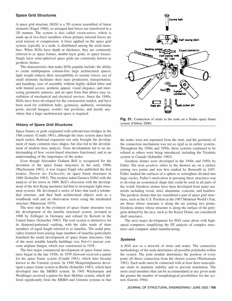
A SGS acts as a network of struts and nodes. The connectionmethodology of the node determines all possible polyhedra withinthe system. The joint module determines the position of everypoint off direct connection from the chosen system �Wachsmann1961�. Each node must be connected with at least three noncopla-nar struts to maintain stability and to prevent translation. Themore axial members that can be accommodated at any given nodethe greater the number of morphological possibilities for the sys-tem �Gerrits 1994�.
Fig. 31. Connection of struts to the node on a Nodus space framesystem �Chilton 2000�
JOURNAL OF STRUCTURAL ENGINEERING / JUNE 2002 / 705
The vast majority of buildings with space grids are designedusing one of many proprietary systems, such as A-Deck, Mero,Moduspan, Nodus, Ocatube, and Unistrut. This list by no meanscovers all of them. What makes each system unique �Fig. 31� isthe geometry of the node, how the struts are connected to thenodes, the method of manufacturing the nodes and struts, and thepolyhedral units possible with each system.
Very large space grids are commonly made from nonpropri-etary systems because of the economics of manufacturing. Whendesigning such a system, the engineer needs to pay particularattention to the connection of the members. The system must beable to handle the rotation of the node caused by nonconcentricaxial loads. It must also be able to handle the lack of fit of themembers that can lead to residual stresses within the system.
Materials
Most buildings with SGS are made of high strength or mild steeltubes with circular or square shapes as well as channels and spe-cial forms, either hot rolled or cold formed. Aluminum, wood,and composites have also been used in different cross sections.The nodes for steel and aluminum grids have been designed inseveral shapes and forms based on their strength and aesthetics, asdiscussed earlier. Timber is used in the form of round poles, sawnsquare sections, and glued laminated elements. Members of tim-ber grids are connected by metal pieces at their ends to each otheror to metal nodes. Fig. 32 shows the interior of a skew-chordTakenaka space truss for the roof of an auditorium. The membersare ‘‘pealer cores,’’ a by-product of the plywood industry, and thenodes are cast steel. Large reinforced concrete space truss struc-
Fig. 32. Skew-chord Takenaka space truss for a school auditorium,Ferndale, Wash., Geiger Engineers
Fig. 33. Mean axial stress versus effective axial strain for axiallyloaded struts �Gargari 1993�
Table 2. Notable Space Grid Structures
Structure Location Designer Year
Biosphere 2 Tucson, Ariz. Margaret Augustin, Phil Hawes, John Allen with PearceSystems International
1990
British Air 747 hanger at Heathrow Airport London Z.S. Makowski 1974Climatron St Louis R. Buckminster Fuller 1960Crystal Cathedral Garden Grove, Calif. Johnson/Burgee Architects and Severud, Peronne.
Szegezdy and Strum1980
Exhibition hall for PORTOPIA ’81 Port Island, Japan Masao Saitoh and Nikken Sekkei, Ltd 1980Ford Rotunda Building Dearborn, Mich. R. Buckminster Fuller 1953Grandstand Roof Split, Croatia Mero Systems 1978Javits Center New York James Freed of Pei Cobb Freed and Matthys Levy 1988Kansai Airport Osaka, Japan Renzo Piano Building Workshop with Ove Arup and
Partners1996
Louvre Pyramid Paris I.M. Pei of Pei Cobb Freed with Peter Rice 1989McCormick Place Convention Center Chicago C. F. Murphy Associates 1970Meishusama Hall Shiga, Japan Minoru Yamasaki and Associates and Yoshikatsu Tsuboi 1983Palafolls Sports Hall Barcelona, Spain Arata Isozaki, J. Marınez-Calzon 1991Sainsbury Visual Arts Center Univ. of East Anglia, U.K. Norman Foster Associates and Anthony Hunt Associates 1978Sant Jordi Sports Palace Barcelona, Spain Arata Isozaki and Mamoru Kawaguchi 1990Skydome Toronto Roderick Robbie and Adjeleian, Allen, Rubeli Limited 1989Union Tank Car Company Baton Rouge, La. R. Buckminster Fuller 1958United States Pavilion Montreal R. Buckminster Fuller 1967World Expo Building Osaka, Japan Kenzo Tange, Tomoo Fukuda and Koji Kamiya, and
Yoshikatsu Tsuboi1969
World Memorial Hall Kobe, Japan Mamoru Kawaguchi 1984
706 / JOURNAL OF STRUCTURAL ENGINEERING / JUNE 2002
tures, although heavy, have been built, for example, for pavilionsat a trade fair site in New Delhi, India.
Analysis and Design
SGSs are currently analyzed using linear elastic theory. The load-carrying capacity of a SGS is usually limited by the first memberor set of members to fail. Connections are either made of readilyavailable standard shapes or proprietary prefabricated pieces.Connection pieces are designed for structural efficiency or ap-pearance. It is assumed that the connections will be strong enoughso that any failure will take place in the struts or ties.
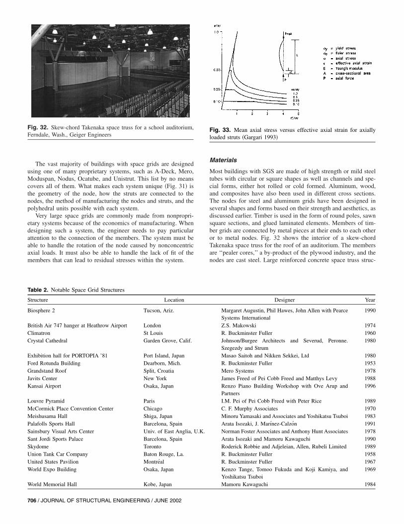
The struts and ties are treated as straight, axially loaded pin-ended members, for which the load-deformation relationship islinear up to buckling in compression or yielding in tension. Ten-sion members ideally would yield, but may rupture in a brittlemanner at the net section or at the connection. For slender com-pression members, there is a plateau at the maximum load in theload-deformation curve. However, when buckling stress is greaterthan one-half of the yield stress, failure of such members is sud-den. Fig. 33 is a theoretical load-deflection graph based on theassumption that yielding in the extreme compression fiber in astraight pin-ended column limits its capacity. Although idealistic,the graph serves the purpose of showing how the plateau changes
with slenderness. In the practical range of slenderness ratios, be-havior of the strut is brittle, and the collapse of the system can beinitiated by the buckling of a few members �Schmidt et al. 1982�.
There is a serious misconception in the behavior of a SGS.Although the members may be over-designed because of redun-dancy and sizing constraints, the structure may not be able toreach its full capacity predicted by elastic analysis. This occurswhen compression members with practical slenderness ratiosbuckle before their postbuckling reserve capacity could be devel-oped �Fig. 33�. Many attempts have been made to modify thebrittle behavior of a SGS, including �1� over-design of compres-sion members to ensure that tension members yield first; �2� re-lying on nonlinear behavior of eccentrically loaded diagonals toredistribute forces in the chords; and �3� stress redistribution bymeans of force-limiting devices.
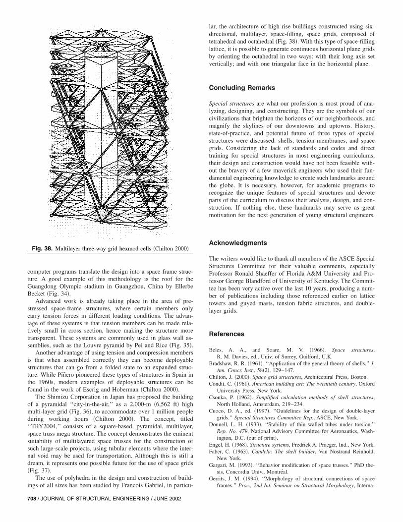
Future Direction of Space Grid Structures
Table 2 shows a list of notable SGSs in existence. The SGS willcontinue to develop with the extensive use of computers in bothmanufacturing and design. Computer aided manufacturing allowsthe cutting and drilling of elements with great precision, whilecomputer aided design can help explore unprecedented complexconfigurations and geometries. Recent computer design programshave allowed the design of nonplanar forms. Once the form is set,
Fig. 34. Guangdong Olympic Stadium in Guangzhou, China
Fig. 35. Louvre Pyramid by Pei and Rice �Patrick Tripeny�
Fig. 36. Futuristic City-in-the-Air �Chilton 2000�
Fig. 37. Futuristic transportation system �Chilton 2000�
JOURNAL OF STRUCTURAL ENGINEERING / JUNE 2002 / 707
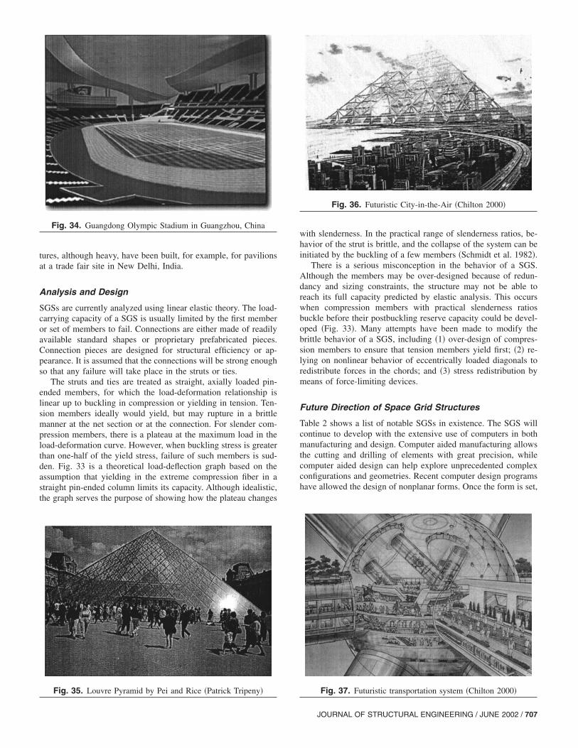
computer programs translate the design into a space frame struc-ture. A good example of this methodology is the roof for theGuangdong Olympic stadium in Guangzhou, China by EllerbeBecket �Fig. 34�.
Advanced work is already taking place in the area of pre-stressed space-frame structures, where certain members onlycarry tension forces in different loading conditions. The advan-tage of these systems is that tension members can be made rela-tively small in cross section, hence making the structure moretransparent. These systems are commonly used in glass wall as-semblies, such as the Louvre pyramid by Pei and Rice �Fig. 35�.
Another advantage of using tension and compression membersis that when assembled correctly they can become deployablestructures that can go from a folded state to an expanded struc-ture. While Pinero pioneered these types of structures in Spain inthe 1960s, modern examples of deployable structures can befound in the work of Escrig and Hoberman �Chilton 2000�.
The Shimizu Corporation in Japan has proposed the buildingof a pyramidal ‘‘city-in-the-air,’’ as a 2,000-m �6,562 ft� highmulti-layer grid �Fig. 36�, to accommodate over 1 million peopleduring working hours �Chilton 2000�. The concept, titled‘‘TRY2004,’’ consists of a square-based, pyramidal, multilayer,space truss mega structure. The concept demonstrates the eminentsuitability of multilayered space trusses for the construction ofsuch large-scale projects, using tubular elements where the inter-nal void may be used for transportation. Although this is still adream, it represents one possible future for the use of space grids�Fig. 37�.
The use of polyhedra in the design and construction of build-ings of all sizes has been studied by Francois Gabriel, in particu-
Fig. 38. Multilayer three-way grid hexmod cells �Chilton 2000�
708 / JOURNAL OF STRUCTURAL ENGINEERING / JUNE 2002
lar, the architecture of high-rise buildings constructed using six-directional, multilayer, space-filling, space grids, composed oftetrahedral and octahedral �Fig. 38�. With this type of space-fillinglattice, it is possible to generate continuous horizontal plane gridsby orienting the octahedral in two ways: with their long axis setvertically; and with one triangular face in the horizontal plane.
Concluding Remarks
Special structures are what our profession is most proud of ana-lyzing, designing, and constructing. They are the symbols of ourcivilizations that brighten the horizons of our neighborhoods, andmagnify the skylines of our downtowns and uptowns. History,state-of-practice, and potential future of three types of specialstructures were discussed: shells, tension membranes, and spacegrids. Considering the lack of standards and codes and directtraining for special structures in most engineering curriculums,their design and construction would have not been feasible with-out the bravery of a few maverick engineers who used their fun-damental engineering knowledge to create such landmarks aroundthe globe. It is necessary, however, for academic programs torecognize the unique features of special structures and devoteparts of the curriculum to discuss their analysis, design, and con-struction. If nothing else, these landmarks may serve as greatmotivation for the next generation of young structural engineers.
Acknowledgments
The writers would like to thank all members of the ASCE SpecialStructures Committee for their valuable comments, especiallyProfessor Ronald Shaeffer of Florida A&M University and Pro-fessor George Blandford of University of Kentucky. The Commit-tee has been very active over the last 10 years, producing a num-ber of publications including those referenced earlier on latticetowers and guyed masts, tension fabric structures, and double-layer grids.
References
Beles, A. A., and Soare, M. V. �1966�. Space structures,R. M. Davies, ed., Univ. of Surrey, Guilford, U.K.
Bradshaw, R. R. �1961�. ‘‘Application of the general theory of shells.’’ J.Am. Concr. Inst., 58�2�, 129–147.
Chilton, J. �2000�. Space grid structures, Architectural Press, Boston.Condit, C. �1961�. American building art: The twentieth century, Oxford
University Press, New York.Csonka, P. �1962�. Simplified calculation methods of shell structures,
North Holland, Amsterdam, 219–234.Cuoco, D. A., ed. �1997�. ‘‘Guidelines for the design of double-layer
grids.’’ Special Structures Committee Rep., ASCE, New York.Donnell, L. H. �1933�. ‘‘Stability of thin walled tubes under torsion.’’
Rep. No. 479, National Advisory Committee for Aeronautics, Wash-ington, D.C. �out of print�.
Engel, H. �1968�. Structure systems, Fredrick A. Praeger, Ind., New York.Faber, C. �1963�. Candela: The shell builder, Van Nostrand Reinhold,
New York.Gargari, M. �1993�. ‘‘Behavior modification of space trusses.’’ PhD the-
sis, Concordia Univ., Montreal.Gerrits, J. M. �1994�. ‘‘Morphology of structural connections of space
frames.’’ Proc., 2nd Int. Seminar on Structural Morphology, Interna-

tional Association for Shell and Spatial Structures, Institute for Light-weight Structures, Stuttgart, Germany, 47–56.
Gould, P. L. �1988�. Analysis of shells and plates, Springer, New York.Joedicke, J. �1963�. Shell architecture, Van Nostrand Reinhold,
New York.Madugula, M. S. ed. �2002�. ‘‘Dynamic response of lattice towers and
guyed masts.’’ Special Structures Committee Rep., ASCE, Reston, Va.Mainstone, R. �1975�. Developments in structural form, MIT Press, Cam-
bridge, Mass.
Martin, E., and Wilmeth, D. B. �1988�. Mud show: American tent circuslife, Univ. of New Mexico Press, Albuquerque, N.M.
Progressive Architecture. �1955�. New York.Schmidt, L. C., Morgan, P. R., and Hanaor, A. �1982�. ‘‘Ultimate load
testing of space trusses.’’ J. Struct. Div., 108�6�, 1324–1335.Schueller, W. �1983�. Horizontal-span building structures, Wiley, New
York.Wachsmann, K. �1961�. The turning point of building; Structure and de-
sign, T. E. Burton, translator, Van Nostrand Reinhold, New York.
JOURNAL OF STRUCTURAL ENGINEERING / JUNE 2002 / 709