Special Report, Standard Models for Variable Generation ... · PDF fileStandard Models for...
60
Special Report Standard Models for Variable Generation 5/18/10 Merrimack Station AR-1209
-
Upload
truongngoc -
Category
Documents
-
view
222 -
download
1
Transcript of Special Report, Standard Models for Variable Generation ... · PDF fileStandard Models for...

Special Report
Standard Models for Variable Generation
51810
Merrimack StationAR-1209
Table of Contents
Standard Models for Variable Generation
NNEERRCCrsquorsquoss MMiissssiioonn
The North American Electric Reliability Corporation (NERC) is an international regulatory authority for reliability of the bulk power system in North America NERC develops and enforces Reliability Standards assesses adequacy annually via a ten-year forecast and winter and summer forecasts monitors the bulk power system and educates trains and certifies industry personnel NERC is a self-regulatory organization subject to oversight by the US Federal Energy Regulatory Commission (FERC) and governmental authorities in Canada1
NERC assesses and reports on the reliability and adequacy of the North American bulk power system divided into the eight Regional Areas as shown on the map below (See Table A)
2 The users owners and operators of the bulk power system within these areas account for virtually all the electricity supplied in the US Canada and a portion of Baja California Norte Meacutexico
Note The highlighted area between SPP and SERC denotes overlapping Regional area boundaries For example some load serving entities participate in one Region and their associated transmission owneroperators in another
1 As of June 18 2007 the US Federal Energy Regulatory Commission (FERC) granted NERC the legal authority to enforce Reliability Standards with all US users owners and operators of the BPS and made compliance with those standards mandatory and enforceable In Canada NERC presently has memorandums of understanding in place with provincial authorities in Ontario New Brunswick Nova Scotia Queacutebec and Saskatchewan and with the Canadian National Energy Board NERC standards are mandatory and enforceable in Ontario and New Brunswick as a matter of provincial law NERC has an agreement with Manitoba Hydro making reliability standards mandatory for that entity and Manitoba has recently adopted legislation setting out a framework for standards to become mandatory for users owners and operators in the province In addition NERC has been designated as the ldquoelectric reliability organizationrdquo under Albertarsquos Transportation Regulation and certain reliability standards have been approved in that jurisdiction others are pending NERC and NPCC have been recognized as standards setting bodies by the Reacutegie de lrsquoeacutenergie of Queacutebec and Queacutebec has the framework in place for reliability standards to become mandatory Nova Scotia and British Columbia also have a framework in place for reliability standards to become mandatory and enforceable NERC is working with the other governmental authorities in Canada to achieve equivalent recognition
2 Note ERCOT and SPP are tasked with performing reliability self-assessments as they are regional planning and operating organizations SPP-RE (SPP ndash Regional Entity) and TRE (Texas Regional Entity) are functional entities to whom NERC delegates certain compliance monitoring and enforcement authorities
Table A NERC Regional Entities
ERCOT Electric Reliability Council of Texas
RFC ReliabilityFirst Corporation
FRCC Florida Reliability Coordinating Council
SERC SERC Reliability Corporation
MRO Midwest Reliability Organization
SPP Southern Power Pool Inc
NPCC Northeast Power Coordinating Council Inc
WECC Western Electricity Coordinating Council
Table of Contents
Standard Models for Variable Generation
TTaabbllee ooff CCoonntteennttss
Executive Summary i
1 Introduction 1
2 The Need for Models for Variable Generation 3
21 Steady-State and Fault Current Analysis 4
22 Time-Domain Positive Sequence Dynamic Models for Bulk Power System Stability Analysis 4
23 Detailed Three-phase Equipment Level Models 5
24 Summary 7
3 Present Status of Modeling Variable Generation 8
31 Wind Generation 8
311 WECCIEEE Effort for Generic Models 8
312 UWIG Generic Model Documentation and Validation Effort 13
313 IEC Effort for Generic Models 14
32 Photovoltaic Solar Generation 15
33 Solar Thermal 18
34 Tidal Generation 18
35 Other Resources 19
36 Summary 20
4 Present Status of Model Validation 21
41 What is Model Validation 21
42 Examples of Model Validation Efforts 23
421 Hydro- Queacutebec Example 23
422 GE Example ndash based on GErsquos work with client facilities 27
Table of Contents
Standard Models for Variable Generation
5 Summary amp Recommended Actions ndash Standards Implications 35
51 Applying the NERC Standards 36
52 NERC Standards Technical Issues 38
53 Final Recommendation 44
Appendix I Wind-Turbine Generation (WTG) Technologies 45
Acronyms 47
IVGTF Task 1-1 Roster 49
References and Further Reading 53
Executive Summary
i
Executive Summary
Existing state and federal energy policies including renewable portfolio standards (RPS) and production tax credits have driven development of wind plants in the US and Canada that presently comprise in excess of 35 GW of installed capacity This trend is projected to continue with the addition of many other forms of renewable technologies such as photovoltaics Furthermore other technologies like plug-in hybrid electric vehicles (PHEV) tidal-power systems etc are also on the horizon
Unlike traditional non-renewable resources the output of wind solar ocean and some hydro generation resources varies according to the availability of the primary fuel (wind sunlight and moving water) that cannot be reasonably stored Therefore these resources are considered variable following the availability of their primary fuel source
The North American Electric Reliability Corporation (NERC) is responsible for ensuring the reliability of the bulk power system in North America Anticipating the growth of variable generation in December 2007 the NERC Planning and Operating Committees created the Integration of Variable Generation Task Force (IVGTF) charging it with preparing a report [1] to identify the following
1) Technical considerations for integrating variable resources into the bulk powersystem
2) Specific actions practices and requirements including enhancements to existing ordevelopment of new reliability standards
One of the identified follow-up tasks from [1] was the need standard valid generic non-confidential and public power flow and stability models for variable generation technologies and for a task force to review existing NERC Modeling Data and Analysis (MOD) Standards to ensure high levels of variable generation can be simulated and appropriately addresses through the existing standards This document constitutes the results of this review performed by this Task Force A detailed discussion is provided of model and model validation in general followed by an account of the current status of models for various variable generation technologies Then a discussion is provided of the relevant NERC MOD standards and where they will need to be augmented to properly address variable generation
Thorough out this report reference is made to various forms of models (standard generic user-written 3-phase etc) It should be emphasized that the present and imminent need is to have models that are standard (ie a defined model structure used by all commercial software tools) publicly available and not specific to any particular design (ie ldquogenericrdquo and able to reasonably
Executive Summary
ii
represent key performance relevant to bulk power system studies) ndash this is the focus which is further elaborate in the report The process and need for model validation however applies to any and all levels of modeling
An earlier draft of this report and recommendations were presented to NERCrsquos Planning Committee at their March 2010 meeting The Committee members urged the IVGTF to pursue NERC reliability standard development Thus several NERC Standards Drafting Teams undertaking MOD Standard development will be contacted to present the recommendations from this report for their consideration and incorporation in subsequent updates
Introduction
1
1 Introduction
Existing state and federal energy policies including renewable portfolio standards (RPS) and production tax credits have driven development of wind plants in the US and Canada that presently comprise in excess of 35 GW of installed capacity This trend is projected to continue with the addition of many other forms of renewable technologies such as photovoltaics Furthermore other technologies like plug-in hybrid electric vehicles (PHEV) are also on the horizon
Unlike traditional non-renewable resources the output of wind solar ocean and some hydro generation resources varies according to the availability of the primary fuel (wind sunlight and moving water) that cannot be reasonably stored Therefore these resources are considered variable following the availability of their primary fuel source There are two overarching attributes of variable generation that can impact the reliability of the bulk power system if not properly addressed
1) Variability The output of variable generation changes according to the availability ofthe primary fuel resulting in fluctuations in the plant output on all time scales
2) Uncertainty The magnitude and timing of variable generation output is lesspredictable than for conventional generation
The North American Electric Reliability Corporation (NERC) is responsible for ensuring the reliability of the bulk power system in North America Anticipating the growth of variable generation in December 2007 the NERC Planning and Operating Committees created the Integration of Variable Generation Task Force (IVGTF) charging it with preparing a report [1] to identify the following
3) Technical considerations for integrating variable resources into the bulk powersystem
4) Specific actions practices and requirements including enhancements to existing ordevelopment of new reliability standards
One of the identified follow-up tasks from [1] was the need for the models for variable generation technologies For the purpose of completeness of this document the proposed action item Task 1-1 from [1] is repeated below
Introduction
2
Therefore the goal of this document is to address the above action item and to provide
1 The roadmap for development of valid generic non-confidential and public standardpower flow and stability (positive-sequence) models for variable generation technologiesNamely what is available at present and what is the path forward to developing anddeploying these models
2 The NERC standards implications and feedback on what further NERC action items maybe needed if any to address model application and validation as it relates to variablegeneration
Throughout this report reference is made to various forms of models (standard generic user-written 3-phase etc) The present and imminent requirement is to have models that are standard (ie a defined model structure used by all commercial software tools) publicly available and not specific to any particular design (ie ldquogenericrdquo and able to reasonably represent key performance relevant to bulk power system studies) ndash this is the focus which is further elaborated upon this report The process and need for model validation however applies to any and all levels of modeling
Item
Proposed Improvement Abstract Lead Deliverables Milestones
11 Standard valid generic non-confidential and public power flow and stability models (variable generation) are needed and must be developed enabling planners to maintain bulk power system reliability
Valid generic non-confidential and public standard power flow and stability (positive-sequence) models for variable generation technologies are needed Such models should be readily validated and publicly available to power utilities and all other industry stakeholders Model parameters should be provided by variable generation manufacturers and a common model validation standard across all technologies should be adopted The NERC Planning Committee should undertake a review of the appropriate Modeling Data and Analysis (MOD) Standards to ensure high levels of variable generation can be simulated Feedback to the group working on NERC Standardsrsquo Project 2007-09 will be provided
Ad Hoc group Members from IVGTF - Planning
Make recommendations and identify changes needed to NERCrsquos MOD Standards
Draft report readyby December2009 PC meeting
Final report withrecommendationsto PC forendorsement inFebruary 2010
Develop SARwith StandardsCommittee ifrequired
Characteristics of Power Systems amp Variable Generation
3
2 The Need for Models for Variable Generation
The planning and operation of large interconnected power systems in diverse regions in the North American continent is a complex task which requires daily analysis and computer model simulations System planners and operators use simulation studies to assess the potential impact of credible (and sometimes extreme) contingency scenarios and to assess the ability of the power system to withstand such events while remaining stable and intact (ie to avoid cascading outages) When a credible disturbance event is simulated in computer models of the power system and the observed result is unacceptable performance system planners andor operators must develop either operating strategies or planned equipment additions (eg line re-conductoring addition of shunt reactive compensation devices etc) to mitigate the potential problem To help ensure proper assessment of reliable performance and to minimize (as much as possible) capital investment models are required that reasonably represent actual equipment performance in simulations
The NERC Modeling Data and Analysis (MOD) Reliability Standards require Registered Entities to create procedures needed to develop maintain and report on models to analyze the steady-state and dynamic performance of the power system (MOD-011 and MOD-013) Equipment owners are required to provide steady-state and dynamic models (MOD-012) to the Regional Entities This information is required to build a reasonable representation of the interconnected system for planning purposes as stated in MOD-014 and MOD-0153
Therefore system models are required for generation equipment at three levels
Specifically models are required to perform powerflow short circuit and stability studies necessary to ensure bulk power system reliability
1 Models for assessing the steady-state behavior of the units and their fault currentcontributions for protection system analysis
2 Models for emulating the dynamic behavior of the units for bulk power system time-domain stability analysis
3 Detailed equipment-specific (3-phase) models for specialized studies
In this chapter the aforementioned three categories of models are described in detail focused on variable generation technologies
3 httpwwwnerccompagephpcid=2|20
Characteristics of Power Systems amp Variable Generation
4
21 Steady-State and Fault Current Analysis
Steady-state analysis in the context of bulk power system studies is primarily associated with power flow which determines the flow of power on transmission lines and transformers and the voltages at power system nodes (substations) Accurate calculations are essential in the planning and design of the interconnected power system to ensure that all equipment will be operated within its rated capability under various credible scenarios (including contingencies) These calculations are performed under various base-case conditions (ie all equipment generally in service) and contingency conditions that impact one or more power system elements such as a line generating unit or transformers out of service (eg for different system load conditions including peak load light load different seasons or different power transfer)
To assess the adequacy of protection system settings faults on transmission equipment are simulated and the settings for protection relays are evaluated as well as the calculated fault currents are compared to the current rating of circuit-breakers
Both these analyses are critical to the reliable operation of the power system To perform these analyses adequate models are needed for simulating the steady-state power flow and the fault current characteristics of generation equipment
22 Time-Domain Positive Sequence Dynamic Models for Bulk Power System Stability Analysis
Time-domain simulations are a key tool for assessing the reliability of the bulk power system assessing the stability of the system4
ldquoReliability of a power system refers to the probability of its satisfactory operation over the long run It denotes the ability to supply adequate electric service on a nearly continuous basis with few interruptions over an extended time period
Stability of a power system refers to the continuance of intact operation following a disturbance It depends on the operating condition and the nature of the physical disturbancerdquo
Similarly NERC defines stability as ldquoThe ability of an electric system to maintain a state of equilibrium during normal and abnormal conditions or disturbancesrdquo5
4 The definitions listed are quoted from P Kundur J Paserba V Ajjarapu G Andersson A Bose C Canizares N Hatziargyriou D Hill A Stankovic C Taylor T Van Cutsem and V Vittal ldquoDefinition and classification of power system stability IEEECIGRE joint task force on stability terms and definitionsrdquo IEEE Transactions on Power Systems Volume 19 Issue 3 Aug 2004 pp 1387 ndash 1401 (
httpieeexploreieeeorg)
Characteristics of Power Systems amp Variable Generation
5
Stability analysis is traditionally performed using positive-sequence models This includes models that focus on system simulation under assumed perfect balanced conditions (ie no imbalance in the 3-phase system voltages and currents) Furthermore the primary stability issues that are investigated (angular stability voltage stability frequency controlstability) for bulk power systems tend to be bounded within a small frequency band around the system fundamental frequency Positive sequence models are typically required to be valid in a range of roughly 01 Hz to about 3 Hz with the control system having validity up to 10 to 15 Hz to allow for investigating general control loop stability With these simplifying assumptions it has been historically easy to establish generic non-proprietary models for representing conventional generation and its controls Functional models that are non-proprietary and generic (ie applicable to any vendors equipment simply by changing the model parameters) are needed for the various variable generation technology A library of models to deal with each family of variable generation technology is required to support reliability assessment What is presently available and what must be further developed is discussed in the next chapter
Aside There are many cases were extended term analysis may be necessary in which case wind speed variations may be a needed input to the model For the purposes of typical stability analyses however where the study period spans over only several seconds wind speed is typically assumed to be constant
23 Detailed Three-phase Equipment Level Models
There are a number of potential interaction issues that may occasionally require detailed analysis [2] To perform this analysis detailed three-phase equipment models are required
Subsynchronous resonance (SSR) is a phenomenon whereby series compensation of a transmission line results in electrical resonance frequencies in the subsynchronous frequency range that can lead to destabilizing modes of mechanical torsional vibration on the turbine-generator shaft that fall in the frequency range of the electrical resonance6 These resonance phenomena are only of concern to generation technologies with a mechanical turbine-generator shaft that is coupled to the electrical system Type 1 2 and 3 Wind-Turbine Generation (WTG) may be susceptible7
5 Glossary of Terms Used in Reliability Standards
Clearly Type 4 (where the unit is decoupled from the electrical system) and technologies like PV have no such concerns SSR is less likely to affect wind turbines compared
httpwwwnerccomfilesGlossary_2009April20pdf Updated April 20 2009
6 P M Anderson B L Agrawal and J E Van Ness Subsynchronous Resonance in Power Systems IEEE Press New York 1990 PM Anderson and R G Farmer Series Compensation of Power Systems ISBN 1-888747-01-3 1996
7 See Appendix I for more information on these WTG configurations
Characteristics of Power Systems amp Variable Generation
6
to large conventional synchronous generators since the typical torsional mode for a wind turbine is quite low (around 1 to 4 Hz) Accordingly it would be quite unlikely that the level of series compensation in a system would be high enough to result in an electrical resonance that would interact with a low mechanical frequency8 A larger concern is induction machine self-excitation9
Another potential phenomenon related to torsional mechanical modes is device dependant subsynchronous oscillations often referred to in the literature as subsynchronous torsional interaction (SSTI) This was first observed at the Square Butte HVDC project in 1976
Some detailed 3-phase analysis and discussions with the wind turbine manufacturer on a case by case basis is prudent when installing wind near series compensated lines
10 SSTI is a phenomenon by which controls associated with power electronic based transmission equipment (eg SVC or HVDC) may introduce negative damping torques in the frequency range associated with the torsional mechanical modes of oscillation of nearby thermal turbine-generating units Again due to the relatively low frequency range for torsional modes of wind turbine this may not be a concern in most cases however where wind plants are closely coupled to a HVDC system analysis is prudent to ensure that control andor torsional interaction do not occur This analysis will typically require detailed three-phase models for both the wind plant and the HVDC system Also SSTI is not necessarily detrimental11 because in some cases torsional damping can be markedly improved through the application of power electronic devices One thermal power plant in the Western US grid uses a dedicated SVC for this purpose as a means of mitigating the effects of SSR 12
8 Note The electrical resonance needs to be in the range of 56 to 59 Hz on a 60 Hz system found in North America
A practical example of this is the Taiban Mesa wind plant located in New Mexico This wind plant is located electrically adjacent to a back-to-back HVDC station ndash Blackwater The detailed interconnection studies performed by ABB during the design of the wind plant showed that there was little risk of torsional interaction between the HVDC controls and the wind turbine generators This analysis required detailed equipment level (3-phase) models of the wind turbines the HVDC and transmission network
9 PM Anderson and R G Farmer Series Compensation of Power Systems ISBN 1-888747-01-3 1996 C F Wagner ldquoSelf-Excitation of Induction Motors with Series Capacitorsrdquo AIEE Transactions pp1241-1247 Vol 60 1941 (httpieeexploreieeeorg)
10 M Bahrman E Larsen R Piwko H Patel ldquoExperience with HVDC ndash Turbine Generator Torsional Interaction at Square Butterdquo IEEE Transactions on Power Apparatus and Systems Vol PAS-99 pp 966-975 MayJune 1980 (httpieeexploreieeeorg)
11 D Dickmander P Pourbeik T Tulkiewicz and Y Jiang-Haumlfner ldquoSSTI Characteristics of HVDC Lightrdquo White paper by ABB Inc December 2003
12 Pourbeik A Bostroumlm and B Ray ldquoModeling and Application Studies for a Modern Static VAr System Installationrdquo IEEE Transactions on Power Delivery Vol 21 No 1 January 2006 pp 368-377 (httpieeexploreieeeorg)
Characteristics of Power Systems amp Variable Generation
7
Other phenomena that may expose the shaft of a WTG to cyclical and significant transient torque pulsations may also be a concern For example nearby arc furnaces or high-speed re-closing on a transmission line emanating from the wind plant substation or repeated commutation failures on a nearby conventional line-commutated HVDC As a first step some simple transient stability analysis may be performed to estimate the expected step change in the electrical torque on a wind turbine generator due to the electrical event and the wind turbine manufacturer consulted to identify if the observed level of transient torque is a concern Based on consultation with the wind turbine manufacturer more detailed analysis may be required to assess if a potential problem exists and how it may be remedied
Another issue that may be of concern is the stability and behavior of variable generators in extremely weak short-circuit nodes of the power system and regions of the system that may be highly susceptible to islanding Again more detailed models than positive sequence stability representations may be needed to study these scenarios (eg to accurately review the potential for temporary over voltages upon islanding etc) Also in some cases and designs (eg Type 3 WTG) the behavior of the unit as it pertains to voltage-ride through during fault scenarios can be more onerous on the controls (ie controlling the DC bus voltage in the Type 3 WTG) for unbalanced fault scenarios as opposed to a balance 3-phase faults Thus 3-phase detailed equipment models are needed to assess these phenomena
Finally transient stability studies should be completed to ensure that basic control loops in the variable generation plants (eg central voltage control systems often deployed in doubly-fed and full-converter based wind plants that regulate voltage at the interconnecting substation by adjusting the reactive output of all wind turbines in the wind plant) do not interact or interfere with other nearby transmission and generation controls This often requires proper tuning of the controls
This brief section illustrates the need for the availability of detailed 3-phase equipment level models which cannot be generic These models are likely to be proprietary and may need to be used under non-disclosure agreements between the vendor and the plant developerutility Therefore it is important to recognize the need for these models so that they are developed and available to be easily deployed and used when such specialized studies are needed
24 Summary
This chapter has outlined the basic power generation plants models required power system analysis related to reliability assessment In addition these models need to be generic (ie the model structure applicable to any vendorrsquos equipment with only the variation of the model parameters to represent various vendor equipment) and non-proprietary (ie publicly available to all stakeholders) Adequate models readily exist for conventional synchronous generators but until recently have been unavailable for any variable generation technology In the next chapter the current status of models for all variable generation technologies is discussed
Transmission Planning amp Resource Adequacy
8
3 Present Status of Modeling Variable Generation
This chapter provides an overview of the models and modeling capability presently available In the summary of this chapter the gaps are identified and areas requiring further work are identified The modeling and model development discussed here is primarily for power system power flow short-circuit and stability analysis
Time-domain stability analysis is concerned with phenomena in the tens of milliseconds to several minutes time frame (see Figure 31)
Figure 31 Times of various phenomena of interest in power system studies (GE)
31 Wind Generation
311 WECCIEEE Effort for Generic Models
The size of individual WTGs has increased dramatically from several hundred kilowatts to multi-megawatt turbines The size of individual wind power plants has also increased significantly In the past a typical wind power plant consisted of several turbines Presently wind power plants
Switching Transients
Subsynchronous Resonance
Transient Stability
Small Signal Stability
Long-term Dynamics
TIME (seconds)
10-6 10-5 10-4 001
1 cycle
1041 1 10 100 1000
1 minute 1 hour
01
Transmission Planning amp Resource Adequacy
9
of several 100 MW and larger are being proposed By some projections13 as much as 300 GW (20 penetration) of wind generation capacity is forecast in the US by 2030 and NERC projects an increase of 229 GW of new wind generation installed capacity by 201814
Presently most wind turbine technologies use power electronics and advanced reactive power compensation as an integral part of wind turbine generator and wind power plant Under dynamic transients the behavior of modern wind turbines must be accurately simulated to predict the response of the wind power plant Misrepresentation of WTGs in transmission studies may threaten the reliability of power systems by either resulting in excessive overbuild of transmission systems due to pessimistic models or in deficient transmission system investment based on optimistic models
The increased penetration of renewable energy generation poses significant questions concerning the ability of the power system to maintain reliable operation
Turbine manufacturers have developed dynamic models for their wind turbines These dynamic models are typically user-written models in commercially available power system simulation software platforms (eg Siemens PTI PSSTME GE PSLFTM DigSILENT PowerFactory etc) Detailed three-phase equipment level models of WTGs used for internal design purposes are also often developed by manufacturers in either their own simulation platforms or commercial software tools including PSCADreg or Matlabreg Simulink
Unfortunately both these categories of models (the user-written positive-sequence models and the three-phase detailed equipment models) require significant input dataparameters considered to be proprietary by the turbine manufacturers and therefore are not freely available to the general public Access to these models usually requires a non-disclosure agreement (NDA) between the dynamic model user and the turbine manufacturers This agreement is only valid for a specific turbine model for a given period of time
In many cases it takes months to negotiate and to finalize the NDA Furthermore in some cases there are incompatibilities among turbine models developed by different turbine manufacturers which results in numerical interactions if multiple user-written models are incorporated into a single power system model for system analysis This makes the work of power system planners almost impossible The NDA are also usually bilateral which renders it impossible to share the information among the manufacturers to help resolve incompatibility problems Finally the NDAs make it difficult at best and impossible in some cases to share the models thereby potentially violating the NERC requirements for submitting models for system planning studies
13 httpwwwnrelgovdocsfy07osti40482pdf 14 httpwwwnerccomfiles2009_LTRApdf
Transmission Planning amp Resource Adequacy
10
With this back drop the WECC Wind Generator Modeling Group (WGMG) initiated the development of generic wind turbine models of the four (4) different types of wind turbines (see Appendix I for these four WTG designs) These four types of turbines currently hold the largest market share throughout the world WECC is interested in providing accurate and validated models of standard wind turbines that will be available in their database including the datasets to be used for testing the models and the methods for representing a wind power plant in power system studies These goals are being accomplished through the development and validation of standard models The standard models must be generic in nature ndash that is they must not require nor reveal proprietary data from the turbine manufacturers These improved standard (generic non-proprietary) dynamic models enable planners operators and engineers to perform the necessary transmission planning studies required to ensure system reliability
Currently the first generation of these generic WTG models for all four turbines types have been developed and are available as part of the main model library for the two most widely used commercial power system simulation tools in North America (ie Siemens PTI PSSTME GE PSLFTM)15
To date the first generation of generic models developed and released have focused on capturing the response of the units to electrical voltage disturbances on the transmission grid (grid faults) One deficiency particularly for the Type 1 and 2 models is the proper representation of unit responses to large system frequency excursions These models have not been verified due to the lack of data on actual turbine behavior under such circumstances and will require further development in consultation with turbine manufacturers
As a continuation of and in parallel with the WECC effort the Institute of Electronic and Electrical Engineers (IEEE) Power amp Energy Society (PES) has also established a Working Group to investigate WTG modeling issues The IEEE Working Group on Dynamic Performance of Wind Power Generation under the Power System Dynamic Performance Committee This Working Group is actively expanding the efforts of generic dynamic modeling for wind power plants focusing on modeling specifications disseminating methods and model validation
Finally as with all modeling exercises model development and validation are iterative processes requiring
bull Generic wind turbine models are to be made available to the public
15 PSSregE-320 Program Application Guide Volume II Chapter 21 PSSregE-320 Model Library Chapters 17 through 21 GE PSLF Users Manual v170_04 October 2009
Transmission Planning amp Resource Adequacy
11
bull Generic wind turbine models must be validated before release and public dissemination which is being pursued in WECC IEEE International Electrotechnical Commission (IEC) and other forums
bull Models should evolve and be revalidated as the technology progresses
bull Data from field measurement and monitoring for model validation can be a vital resource
A somewhat unique need in modeling variable generation (eg wind) is the need for methods required to develop equivalent models for large wind power plant In contrast to conventional fossil fuel and hydro power plants where plants are constituted by either a single large unit or at most a few large units a wind power plant can be made up of tens to more than a hundred WTGs For large scale power system simulations particularly in North America where the power system models are quite large it is often preferred to reduce the wind power plant to a single equivalent unit Accordingly techniques are needed for model aggregation and testing their validity ndash some significant progress has been made in this regard For example Figure 32 shows the technique developed for reducing the impedance of the wind power plant collector system into a single equivalent feeder impedance for representation of the wind power plant (WPP) by an aggregated single equivalent unit in power system studies
Figure 32 Example shows the method for reducing the impedance of a wind power plant collector system into a single equivalent impendence16
16 ldquoWECC Wind Generator Power Flow Modeling Guiderdquo (
httpwwwweccbizlibraryWECC20DocumentsDocuments20for20GeneratorsGenerator20Testing20ProgramWind20Generator20Power20Flow20Modeling20Guidepdf)
Transmission Planning amp Resource Adequacy
12
Figure 33 shows an example for dynamic simulations of aggregating the WPP into a single equivalent unit and an equivalent single impedance representing the entire collector system as compared to a detailed model representing the whole WPP unit-by-unit ndash the example shown assumes that all WTGs in the WPP are identical in cases where this is not true multiple equivalent units may be needed one for each WTG type As can be seen in this figure the results from the two simulations compare very well at the point of interconnection (which is what is shown) thus the equivalent aggregate is adequate for power system studies17
Figure 33 Example of time-domain simulations comparing a detailed model of a Wind Power Plant (ie representing the complete collector system and each WTG individually) versus a single-machine equivalent aggregate (ie the entire plant is represented by one equivalent unit and an equivalent impedance to represent the whole collector system)
17 Figure is from J Brochu R Gagnon and C Larose ldquoValidation of the WECC Single-Machine Equivalent Power Plantrdquo Presented at the IEEE PES DPWPG-WG Meeting at IEEE PSCE March 2009
P345 kV
Q345 kV
QWT = 0435 0 -0435
Transmission Planning amp Resource Adequacy
13
312 UWIG Generic Model Documentation and Validation Effort
The Utility Wind Integration Group (UWIG)18
The objectives of the project which will commence in early 2010 and run for a period of two years are to
under a US Department of Energy grant will be launching an effort to provide the basic documentation application and validation of generic models for wind turbines The goal of this project is to accelerate the appropriate use of generic wind turbine models for transmission network analysis
bull Complete characterization and documentation of the four generic models developed through an outgrowth of a WECC activity begun in 2005
bull Defining proposed enhancements to the generic wind turbine model structures that would allow representation of more advanced features including power control automatic curtailment inertial and governor response
bull Comparative testing of the generic models against more detailed (and sometimes proprietary) versions developed by turbine vendors
bull Developing recommended parameters for the generic models to best mimic the performance of specific commercial wind turbines
bull Documenting results of the comparative simulations in an application guide for users
bull Acquiring test data from all available sources for the purpose of validating the performance of the appropriately specified generic models in actual case studies
bull Conducting technology transfer activities in regional workshops for dissemination of knowledge and information gained and to engage electric power and wind industry personnel in the project while underway
18 The UWIG was established in 1989 to provide a forum for the critical analysis of wind technology for utility applications and to serve as a source of credible information on the status of wind technology and deployment The grouprsquos mission is to accelerate the development and application of good engineering and operational practices supporting the appropriate integration of wind power into the electric system It currently has more than 150 members spanning the United States Canada and around the world including investor-owned public power and rural electric cooperative utilities transmission system operators and associate member corporate government and academic organizations httpwwwuwigorgaboutuwightm
Transmission Planning amp Resource Adequacy
14
Maintaining communication and coordination with other ongoing activities and agencies engaged in this topic is another objective of the effort which will be critical for success
313 IEC Effort for Generic Models
The International Electrotechnical Commission (IEC) recently started a Working Group in October 2009 to address the development of generic and ldquostandardrdquo models for wind turbine generators19
Part 2 of this work will be focused on extending the modeling to allow for modeling of the entire wind power plant including wind power plant control and auxiliary equipment
The goal of this Working Group is to define standard dynamic simulation models for wind turbines and wind plants which are intended for use in power system and grid stability analyses and should be applicable for dynamic simulations of power system events including short circuits (low voltage ride through) loss of generation or loads and system separation The group is approaching this work in two parts Part 1 will focus on specifying dynamic simulation models for the generic wind turbine topologiesconceptsconfigurations presently in the market as well as specifying how these models may be modified as future technologiesconcepts are introduced The standard should also include procedures for validation of the models specified Another goal is that the models should be developed and specified at a fundamental level so they are independent of any specific software platform and can be adopted by any software vendor
Several members of this IEC Working Group are also members of the WECC and IEEE Working Groups (and this NERC Task Force) The three groups are clearly working in close collaboration to ensure maximum benefit to the industry globally and maximum sharing of knowledge already gained through the WECC and IEEE efforts
19 httpwwwiecchdynwwwfp=102140FSP_ORG_ID5613
Transmission Planning amp Resource Adequacy
15
32 Photovoltaic Solar Generation
Photovoltatic (PV) systems for power generation are quickly increasing becoming a significant portion of generation in some regions in North America PV or solar arrays are composed of a large number of solar cells connected in series and parallel These cells produce a DC voltage when they are exposed to sunlight due to the photo-voltaic effect20
Figure 34 shows the I-V characteristics of a cell at a constant temperature and various sun intensity or insolation levels
Figure 34 Current-Voltage characteristics of a solar cell for various insolation levels at a constant temperature (source [11]21
20 The photo-voltaic effect is the process by which an electric potential difference (voltage) is created in a material exposed to light (electromagnetic radiation) which then leads to the flow of electric current This process is directly related to the photo-electric effect but distinct from it in that in the case of the photo-electric effect electrons are ejected from the material surface upon being exposed to high enough frequency (energy) light whereas in the photo-voltaic effect the generated electrons are transferred across a material junction (eg PN junction in a photo-diode) resulting in the buildup of a voltage between two electrodes and the flow of direct current electricity
)
21 Solar Radiation Research Laboratory at the National Renewable Energy Laboratory (httpwwwnrelgovmidcsrrl_rsp)
Transmission Planning amp Resource Adequacy
16
Figure 35 shows that the current is limited when the cell is short-circuited (Voltage=0)
(a) (b) (c)
(d)
Figure 35 The concept of a solar array (a) a single solar cell (b) a series connection of solar cells (Nser = 3 and Npar = 1) and (c) a solar array (Nser = 3 and Npar = 2) The solar cell array(s) is then connected to a DC bus (d)
Figure 35 shows the concept of the solar cell up to the solar array To use the DC power generated by the PV array in an AC power system the DC power must be converted to 60 Hz AC in North America (50 Hz in some other regions in the world like Europe) There are several power electronic based converter concepts that can achieve this which can be classified into two general categories line-commutated converters (LCC) and self-commutated or more commonly
Vbus Iload
Ibus
Icap PV ARRAY
+
_
Transmission Planning amp Resource Adequacy
17
referred to as voltage-source converters (VSC) These technologies have been applied for decades and are well understood LCC use thyristors as their controlled switching device The switching on of a thyristors can be controlled while the turn-off time cannot be controlled and happens at the next AC waveform current zero crossing LCC systems must be operated in a network with an AC source and cannot operate to serve an isolated load In contrast VSC systems are self-commutating that is the power electronic switching devices used (eg integrated gate-commutated thyristors or IGCTs and insulated-gate bipolar transistors or IGBTs) are able to be completely controlled for both turn-on and turn-off and allow the VSC to completely control the AC waveform produced and adjust the power factor as seen on the AC side to within the current rating of the device Due to advances in the technology most power electronic converters employed in PV systems are of the VSC type22
From a modeling standpoint for power system studies there are some user-written manufacturer-specific models in existence as developed by various PV manufacturers Presently no generic or standard models exist
The WECC Working Group which has been addressing the development of generic WTG models will be extending its effort in 2010 to review developing generic PV models for dynamic simulations in stability studies As a starting point the grid side structure of the Type 4 WTG model may be used since it represents a VSC This is because PV is typically connected to the grid with a VSC and it will behave electrically similar to a Type 4 WTG that has a similar electrical interface with the gridmdashthis is from a grid perspective looking at the electric response and neglects any of the effects of the energy source
From a steady-state power flow and short-circuit analysis perspective the behavior of the PV technologies will behave in a similar fashion to a Type 4 WTG because of the VSC interface and because its power factor can be controlled based on the control functionality of the VSC design Its short-circuit response will be limited to the current limit effected by the VSC under grid fault conditions
The development of generic and standard PV models is presently a topic for further research This should be pursued imminently and much of what has been learnt from the WTG model development process should be leveraged
22 IEA-PVPS Grid-Connected Photovoltaic Power Systems Survey of Inverter and related Protection Equipment Report IEA PVPS T5-05 2002 December 2002 (httpwwwiea-pvpsorgproductsdownloadrep5_05pdf)
Transmission Planning amp Resource Adequacy
18
33 Solar Thermal
Solar thermal energy is based on harnessing the radiated heat of the sun for the purpose of producing electricity In broad terms there are presently two main ways of achieving this
1 Concentrating Solar Power (CSP) plants ndash in this case solar radiation is typically collected through a large number of mirrors (thus a large amount of solar radiation) which is then focused on a small area ndash the mirrors have tracking systems to follow the Sun The concentrated solar radiation heats a high temperature working fluid which then feeds a conventional steam-turbine generator From an electrical grid perspective the models needed to simulate the steady-state short-circuit and transient time-domain dynamics of such a generating unit are typically no different than standard synchronous generating units for fossil fuel plants
2 The Stirling Engine concept23
34 Tidal Generation
ndash in this design a parabolic mirror assembly concentrates the collected solar radiation on a sterling engine that sits at the focal point of the mirror assembly A Stirling engine is a reciprocating heat engine that operates based on the concept of cyclical compression and expansion of a working fluid As the working fluid expandscontracts it drives a piston that then turns a generator The engine is connected to an electrical generator that produces electric energy Once again for power system studies the units may be modeled using standard generator models However in this case a power plant would be constituted by a large number of small units (the typical Stirling engine is about 25 kW) in a large electrical collector system that collects the power and injects it into the utility grid ndash much like the collector system of a wind power plant Thus modeling the collector system (eg see Figure 32 for an aggregate model of a wind collector system) and any other devices in the collector system such as shunt reactive devices etc must be properly modeled
Tidal power generation derives energy directly from the motion of oceanic tides The gravitational pull of the Moon and Sun combined with the Earthrsquos rotation result in the generation of tides Tides generally occur with a period of roughly twelve hours and so most coastal areas experience two high and two low tides within every twenty-four hour period Tidal generation uses this phenomenon to generate energy Clearly the stronger the tides are either in tidal current velocity or the heightlevel of water the greater the potential amount of energy generation
23httpwwwstirlingenergycom Y Zhang and B Osborn ldquoSolar Dish-Stirling Power Plants and Related Grid Interconnection Issuesrdquo IEEE PES General Meeting 24-28 June 2007
Transmission Planning amp Resource Adequacy
19
Presently in North America tidal power is not a significant source of power in any region Some pilot programs exist for introducing the technology In April 2009 one was announced in Snohomish County Public Utility District in Washington State24
There are several options for harnessing tidal power One method is the use of turbines similar to wind turbines however the fluid (water) is much denser and requires a turbine with smaller and bulkier blades as shown in Figure 36 Most of these technologies typically use ACDCAC converter technology similar to a Type 4 wind turbine to convert the low frequency generated electricity to grid frequency AC electricity and interface with the power system Once this technology becomes more prevalent a starting point for development of a suitable model structure may be the Type 4 generic wind turbine models Understandably the energy source characteristics are quite different from wind power and significantly more predictable
Figure 36 One of the many concepts for tidal generation systems (courtesy of Marine Current Turbines Limited wwwmarineturbinescom)
35 Other Resources
There are several other emerging technologies and there are many complementary technologies (ie auxiliary to the variable generation resources but designed to help with their integration into the grid) including smoothly-controlled dynamic reactive devices (static VAr systems)
24 httpwwwsnopudcomPowerSupplytidaltidalpressashxp=1516amp756_na=46
Transmission Planning amp Resource Adequacy
20
energy storage technologies etc With respect to static VAr systems (SVCs and STATCOMs) there is an active WECC working group imminently addressing the issue of generic models for these devices25
36 Summary
The group has made substantial progress with the models defined and developed but currently undergoing testing and validation With regards to the other emerging technologies most tend to be power converter based (ie connected to the grid through a back-to-back frequency converter) and so their electrical behavior (neglecting the characteristics of the energy source) will be similar to Type 4 wind turbines Until these technologies mature the basic structure of other more mature converter based generation technologies can be a good starting point
This section has briefly presented the various types of variable generation and the present status of models and model development for power system studies Wind generation technologies being the most prevalent world-wide have the most mature models Through efforts started by WECC and being continued by IEEE and IEC generic standard models for the four main types of WTG technologies are being developed The first generation of these models has been released in two power system simulation software platforms most commonly used in North America Other emerging technologies (eg PV tidal power etc) can build on this effort to start developing generic models For example the WECC effort will be extending its scope in 2010 to look at PV model
From a NERC perspective the key items are
1 To emphasize and support efforts by WECC IEEE and IEC to develop and standardize generic models for these technologies for power system planning studies
2 To encourage manufacturers to familiarize themselves with the generic models being developed and be willing an able to supply parameters for these generic models to reasonably represent their equipment for power system stability studies As highlighted in Chapter 2 more detailed manufacturer specific models may be needed in special cases and for specialized studies
3 To encourage efforts aimed at model validation
4 To consider any augmentation or additions to reliability standards related to Modeling Data and Analysis (MOD) with respect to modeling and model validation of variable generation This is discussed in greater detail in section 5 of this report
25 httpwwwweccbizcommitteesStandingCommitteesPCCTSSMVWGSVCTFdefaultaspx
Present Status of Model Validation
21
4 Present Status of Model Validation
This chapter gives an overview of the model validation work that has been done hitherto as it relates to models for variable generation Necessarily the primary focus of this section is on wind turbine generator models since models for this resource are presently the most mature
41 What is Model Validation
Any and all models of a dynamic system always have limitations associated with them A model is a representation of reality it is an emulation ndash that is why it is called a model In developing a model first the question is asked as to the specified use of the model and the conditions it must reasonably emulate ndash this forms the basis of a model specification from which a model is developed The developed model establishes a certain structure with parameters which are adjustable in order to emulate different types of equipment or design of the modeled device Thus valid parameterization of the model to represent a particular manufacturerrsquos equipment is essential to support the particular scenarios to be analyzed
Model validation is often achieved through some form of testing either in a laboratoryfactory or in field There is a range of reasons for conducting tests for wind generation Each test has a unique set of objectives guiding the design of adequate testing practices
bull Performance Compliance Compliance to contractual requirements and grid codes are one reason to perform tests Interconnection requirements (usually included in plant Power Purchase Agreements and Interconnection Contracts) and grid codes typically outline specific technical criteria that must be met to allow a power plant to connect and operate on the grid Since these criteria point out specific levels to be met (for example voltage power factor and response time) tests may be designed with binary ldquopassfailrdquo objectives
bull Model Validation In much of the world power plants above a pre-defined size must be accurately represented with a dynamic simulation model used in stability analysis for operations and planning purposes As variable generation sources such as WPP are growing in size it is becoming increasingly important to have accurate variable generation specific models Tests may be performed to tune and verify simulation models to closely match the performance of actual equipment In the western US and Canada WECC has mandated that any plant with 20 MVA aggregate generation must be tested for model validation including large wind power plants For North America the imminent NERC MOD-026 standard presently under development will enforce model validation requirements throughout the North American region
Present Status of Model Validation
22
To achieve the goals of model validation there are three categories of tests that may be performed
bull Type Tests These are tests performed by the manufacturer or independent third-parties of representative equipment The intent is to demonstrate that a particular design of equipment exhibits specific performance and all other equipment of that same design is assumed to have the same performance Type tests can be
o Component Performed on specific functions or features in a power plant or generation equipment This could be for example testing the fault ride-through capability or reactive capability of a WTG where testing is performed at the component level
o Factory A systemic test of a major assembly (ie a drive train) or entire turbine-generator is performed under a controlled environment like a manufacturing facility to verify performance and validate assembly design
o Unit A systemic test of multiple components operating together (ie as entire operating WTG or WPP) with the specific intent of benchmarking a model or design as a type test For example tests performed in Europe under the WindTest program
bull Field Tests26
o Commissioning Tests performed on new equipment entering its period of commercial operation service
Tests performed by the power plant asset owner developer host utility manufacturer andor independent third-parties of specific operating equipment These tests are to demonstrate that a particular implementation design and installation of equipment exhibit specific performance
o Periodic Maintenance or Calibration Tests performed periodically after the plant is in commercial operation to verify that equipment continues to perform as well as it did during commissioning
26 See for example WSCC Control Work Group and Modeling amp Validation Work Group ldquoTest Guidelines for Synchronous Unit Dynamic Testing and Model Validationrdquo February 1997 (wwwweccbiz) and IEEE Task Force on Generator Model Validation Testing ldquoGuidelines for Generator Stability Model Validation Testingrdquo Proceedings of the IEEE PES General Meeting Tampa FL June 2007 (httpieeexploreieeeorg)
Present Status of Model Validation
23
o Periodic Model Validation Tests performed periodically after the plant is in commercial operation to verify that simulation models adequately represent actual plant performance (for example the periodic model validation testing required by WECC)
o Periodic Codes amp Standards Validation Tests performed periodically after the plant is in commercial operation to benchmark and validate plant performance per contractual requirements These tests are typically performed to obtain a permanent operating license for the power plant
bull On-Line Monitoring27
With these general concepts in mind the following subsections present some example cases studies of model validation and validation approaches for variable generation sources The examples emphasize WPP and WTG since wind generation is the present dominant variable generator sources in the North America continent
Other information of interest is from continuous data gathering based on ongoing performance of an operating power plant Data collected from external and unscheduled events including grid disturbances or in the case of WTG large changes in wind is particularly useful Monitoring also benchmarks performance under normal operation
42 Examples of Model Validation Efforts
421 Hydro- Queacutebec Example
The province of Queacutebec has vast wind energy potential Though wind energy generation in 2009 accounts for nearly 13 of the total installed capacity in the Queacutebec control area the penetration rate of wind energy generation will reach 10 by 2015 A total capacity of 528 MW is currently in operation and approximately 3000 MW are under development Five wind turbine manufacturers will supply the WTGs for the different projects under study
The configuration of the Hydro-Queacutebec transmission system is essentially radial Approximately 85 of the total installed generation feeding the system is located at distances up to 1300 km
27 See for example P Pourbeik ldquoAutomated Parameter Derivation for Power Plant Models From System Disturbance Datardquo Proceedings of the IEEE PES General Meeting Calgary Canada July 2009 (httpieeexploreieeeorg) This reference shows actual application of on-line disturbance monitoring to power plant model validation for conventional fossil fuel generation It may be feasible to apply similar algorithms and approaches for continuous re-validation of WTG and other variable generation technologies once generic standard models have been developed This is a current topic for research
Present Status of Model Validation
24
from the closest major load centers With this configuration the system transfer capability is mainly limited by stability constraints (transient stability and voltage stability) rather than congestion or thermal capacity of equipment hence the need for reliable models for wind power plants and all other generation
Stability studies are critical to determine the compensation equipment required to maintain the reliability of the power system when integrating new generation They are also essential for operation planning studies including control system design and tuning and determination of transfer capabilities
So far Hydro-Queacutebec has faced two major difficulties regarding user-written models provided by the wind turbine manufacturers First models often lack robustness and do not represent accurately some important features (convergence problems in low short-circuit network do not take into account frequency excursions do not represent secondary voltage regulation etc) Second model validation by the manufacturers is often incomplete not available or difficult to translate to real projects (different settings or software versions design of the collector system etc) In some cases these difficulties have lead Hydro-Queacutebec to build its own models (see Hypersim section below)
General validation test program
Since 2006 Hydro-Queacutebec has performed validation tests on WPP connected to its transmission system and a general validation test program was established in 200928
1 To demonstrate that WPP meet the Transmission Provider technical requirements related to wind generation
The power producer has the obligation to perform validation tests in order to demonstrate that its facilities meet the Transmission Provider requirements The purposes of this program are
2 To validate numerical models and parameters associated with the WPP specifically those given to the Transmission Provider by the power producer by comparing the model response to recordings taken during field tests
3 To confirm the electrical data of power producer facilities
The validation program is divided into seven functions to be validated
1 Primary voltage regulation
28 httpwwwhydroquebeccomtransenergiefrcommercepop_raccordement_transporthtml
Present Status of Model Validation
25
2 Undervoltage response (LVRT)
3 Inertial response
4 Secondary voltage regulation
5 Power factor
6 Maximum ramp rates
7 Power quality
The tests for the primary voltage regulation are performed on a single WTG and consist in producing instantaneous voltage variations of low amplitude on the terminal of the WTG and small voltage steps of limited duration injected directly into the WTG voltage control system Three-phase voltages and currents are recorded at the wind generator to measure the local dynamic response of a wind generator to a rapid voltage change and to verify that the response meets voltage regulation requirements The results are also used to set the model parameters (time constant and gain) used in dynamic simulations The tests regarding the secondary voltage regulation are similar but are conducted for the entire power plant
The validation test program includes LVRT tests on one generating unit to verify that requirements during undervoltage conditions are met The power producer has the responsibility to conduct the tests or to provide a complete report describing tests performed on an identical generating unit (same software version) to demonstrate that the requirements are met So far no LVRT tests were performed on site on WPP integrated on the Hydro-Queacutebec network However monitoring equipment has been installed at three locations in wind plants at their point of interconnection on a 345 kV feeder of the collector system and on one generating unit The monitoring system records signals either continuously or upon detecting variations occurring at the point of interconnection active power variations voltage sags and swells and system frequency excursions These signals are primarily voltages and currents but may also be mechanical variables or other signals
The field recordings recorded on the network can thereafter be used to validate the dynamic response of the models This is a time consuming effort that requires the collaboration of the manufacturers to modify the models if necessary Event recordings to-date have made possible suitable validation of two Hydro-Queacutebec Siemens PTI PSSregE models and one ElectroMagnetic Transients Program (EMTP) model
Inertial response requirements were not in defined for the projects started before 2005 Consequently existing wind plants do not have to fulfill them However the requirements have to be met for WPP to be commissioned in 2011 and after The corresponding validation tests consist in emulated frequency steps and ramps of limited duration Besides verifying the
Present Status of Model Validation
26
requirements the test results will be used to validate the parameters of the models and their dynamic response
The power factor and the maximum ramp rates modules are tested with all WTGs in service to verify that the requirements are met Power factor tests consist in supplying and absorbing a maximum amount of reactive power at different levels of active power Maximum ramp rate tests consist in performing a power plant shutdown sequence followed by a startup sequence These tests are not really used to validate the models but are rather helpful to fix model parameters
The last module regarding the power quality is not covered by scheduled testing but by means of a monitoring system that verifies harmonics and emission limits The recordings are compared to the report provided by the developers to verify if the requirements are met However they are not useful to validate the EMTP model since the WPP is represented by a single-wound generator and does not simulate the detailed collector bus system and individual wind turbine generators
Field tests department
Hydro-Queacutebec field-testing department (UMES) conducts a wide range of special tests and measurements for Hydro-Queacutebec and has done so for 30 years
To test WPP UMES installs a monitoring systems to record three-phase voltages and currents generally at three locations within the plant at the point of interconnection at the starting point of a 345 kV feeder of the collector system and at the terminals of a WTG connected to the same monitored feeder For extended model validation other signals within the wind turbine are monitored including the rotor side converter voltages and currents the network side converter currents and the DC bus voltage
High speed recorders with anti-aliasing filters are used Normally the sampling rate is 5 kHz with at least a 200 second window per event The monitoring system is reachable via an Ethernet connection for remote trigger and data retrieval UMES has also the responsibility to perform the data processing and analysis of the recordings in order to verify the compliance with the interconnection requirements and to extract relevant data for model validation
Present Status of Model Validation
27
Hypersim
The Hydro-Queacutebec Research Institute (IREQ)29 also has an important expertise in control system and wind generation modeling for extensive studies of electrical networks The simulation environment used is Hypersim a real-time simulator and powerful simulation tool that uses a highly detailed representation of the Hydro-Queacutebec network A full-transient detailed model of a Type 3 WTG was developed at IREQ using the MATLABreg SimPower Systems Toolbox The model was also implemented in EMTP and in the Hypersim real-time simulator30 This model is in the process of being validated with data processed by the UMES team The range of events recorded does not make it possible to validate the model completely and the design and parameters will continue to be adjusted to improve the representation of the wind turbines The validation of the MATLABreg model developed by IREQ was very useful to validate and improve Hydro-Queacutebecrsquos Siemens PTI PSSregE user model31
422 GE Example ndash based on GErsquos work with client facilities
In the case of the first example presented here a 10 MVar capacitor bank located at the 25kV WPP collector bus is switched off-line as an external physical stimulus Figure 41 shows detailed response to capacitor switching from the WindCONTROLreg The WindCONTROLreg system allows coordination of all on-line turbine-generators for plant-level fast and smooth voltage regulation at the point of interconnection (POI) located contractually at the 25kV substation bus The red curve (Q_ACTUAL [KVar]) shows that total plant reactive power initially drops after the switching action but the fast autonomous controls on each turbine generator quickly and stably respond to increase reactive power generated by individual turbines shown by the orange curve (Q_TURBINES [KVar]) The WindCONTROLreg command (Q_CMD) distributed to the turbines is shown in blue The response of Q_CMD is dominated by the gains of the voltage regulator portion of the WindCONTROLreg specifically the proportional gain Kpv and integral gain Kiv The difference between the response of the individual turbines (Q_TURBINES [KVar]) and the WindCONTROLreg command (Q_CMD) is due to the dynamics of the individual wind turbines The coordinated response of the wind plant and the individual
29 httpwwwhydroquebeccomtechnologyindexhtml 30 R Gagnon G Sybille SBernard D Pareacute S Casoria and C Larose ldquoModeling and Real-Time Simulation of a
Doubly-Fed Induction Generator Driven by a Wind Turbinerdquo IPST Conf Paper No IPST05-162 Montreacuteal Canada 2005 C Larose R Gagnon G Turmel P Giroux J Brochu D McNabb and D Lefebvre ldquoLarge Wind Farm Modeling Techniques for Power System Simulation Studiesrdquo in Proc 8th International Workshop on Large-Scale Integration of Wind Power into Power Systems Bremen Germany Oct 14-15 2009
31 C Langlois D Lefebvre L Dube and R Gagnon ldquoDeveloping a Type-III Wind Turbine Model for Stability Studies of the Hydro-Queacutebec Networkrdquo in Proc 8th International Workshop on Large-Scale Integration of Wind Power into Power Systems Bremen Germany Oct 14-15 2009
Present Status of Model Validation
28
turbines is multi-modal a fast initial response to address severe perturbations as well as a slower grid friendly refinement For purposes of this test the automatic control of the capacitor bank by WindCONTROLreg was disabled and manual switching was used as a stimulus to record individual WTG response
The detailed plot in Figure 42 shows a zoomed view of the response to step change in voltage at the WTG The very fast initial response will dominate and saturate the controls for big events The wind plant will do everything as quickly as it can to mitigate a large disturbance In this case the fast response took approximately 200 milliseconds The slow refined control then takes over to allow for coordination with other equipment and maintain post-disturbance stability This aggregate response also allows for a very abrupt action when needed and a grid-friendly refinement that maintains stability in less severe cases
The green curve in Figure 43 shows that when the capacitor is switched off-line the measured voltage at the point of interconnection (or POI) decreases due to reduced reactive power flowing into the grid The response of the individual WTGs is to rapidly increase reactive output to make up for the loss of reactive power supplied by the shunt capacitor The plant level control then responds to this initial under-voltage condition and attempts to restore the POI voltage by increasing each wind generatorrsquos reactive output by equal amounts until the plant voltage settles to the control set point determined by the operator The lower traces in Figure 43 show a gap during the period when the capacitor bank is online between total plant Q (Q_ACTUAL) and summation of Q out of each WTG (Q_TURBINES) This gap represents the capacitive reactance added by the shunt bank When the capacitor is switched offline the gap between Q_ACTUAL and Q_TURBINES closes and all reactive power is supplied solely from the WTGs The initial loss in plant reactive power is mitigated within approximately 15 seconds as each WTG settles to a new increased level operating point of reactive power This new increased reactive level for each WTG is the total Q increase from all units on-line in the plant divided by the total number of units online at the time of the test
Figure 44 shows a comparison between these measured values and the simulation results of the PSLF model Model outputs Qg Qplant Qcmd and Vreg correspond to measured Q_TURBINES Q_ACTUAL Q_CMD and U_LINELINE respectively This plot shows the model performance adequately represents what is happening in the field The response matches closely with a difference immediately following the switching operation being due to lower sampling rate in the measurement than in the GE PSLFreg simulation
Response to grid events demands relatively rapid control action Manual grid or plant operator changes in operating set-points do not normally demand fast response and indeed system behavior ought not to be rapidly disturbed by moving set-points Figure 45 shows the response of GE plant to 2 step in voltage reference The blue trace in the figure shows a well mannered response to the reference step The red trace is from the simulation model which matches very
Present Status of Model Validation
29
well In the blue trace after the perturbation occurring about 8 seconds after the reference change the plant supervisory control switched on a shunt capacitor to retain dynamic range on the wind turbines The switching perturbation is rapidly balanced by the turbines allowing the response to continue smoothly
Figure 41 10 MVar Capacitor removal response measured from WindCONTROLreg
Present Status of Model Validation
30
Figure 42 Wind turbine-generator level voltage step test response
Present Status of Model Validation
31
Figure 43 10 MVar Capacitor removal response ndash POI variables
Figure 44 10 MVar capacitor removal field test vs simulation results
Present Status of Model Validation
32
Figure 45 A different step test +- 2 step of voltage reference
The performance for grid fault events is of considerable interest in system planning Staging faults particularly severe ones on operating wind plants is difficult and expensive Figure 46 shows a comparison between a staged fault test and the (present) Siemens PTI PSSregE model of the GE 25 (full converter) WTG The fault event is quite severe a 3-phase 700ms of voltage depression to less than 20 of nominal at the high voltage terminal of the WTG unit transformer The measurement traces (on the left) include some of the signal noise characteristic of measurement and extraction of fundamental frequency positive sequence information from real high resolution measurements The simulation traces on the right are of course cleaner The match between test and simulation is of very high fidelity for phenomena relevant and legitimately examined with positive sequence simulation tools (ie greater than one cycle)
QPOI
VPOI
Measured = Blue Simulated = Red
Plant Capacitor Bank Switched On Automatically by WindCONTROL
+ 2 VrefStep
- 2 Vref Step
QPOI
VPOI
Measured = Blue Simulated = Red
Plant Capacitor Bank Switched On Automatically by WindCONTROL
+ 2 VrefStep
- 2 Vref Step
Present Status of Model Validation
33
Figure 46 GE 25 WTG Fault Test vs PSSe Model Performance
The discussion provide above is solely geared to hardware testing and validation however another highly valuable and legitimate means of providing validation of simulation models (for planning and otherwise) is to use more complex simulation software to validate simpler planning models Manufacturers normally have highly complex and highly proprietary models of their equipment These models are used among other things to design equipment and are normally physically based and must have sufficient fidelity for original equipment manufacturers (OEMs) to make sound engineering judgments for equipment design and application The OEMs are highly motivated to have these detailed high fidelity equipment level models These detailed models therefore can often be used to design test and validate simpler planning models to be used by the industry
There is a long accepted history in the power industry of this practice For example a typical (GE) gas turbine has on the order of 4000 state variables in the design model planning models typically have on the order of four state variables simplification is necessary and expected These design codes have been used to develop planning models of gas turbines Figure 47 below shows a comparison between a fault simulation using a GE design code (GE WindTrapreg) and the planning model in GE PSLFreg for a GE 15 (double fed machine) WTG
Present Status of Model Validation
34
Figure 47 Detailed Design Simulation (GE WindTRAPreg) vs GE PSLFreg Model Performance (active power during a severe fault for a GE 15 WTG)
-10
00
10
20
30
0 05 1 15 2
Time (Seconds)
Sin
gle
WTG
Rea
l Pow
er (M
WindtrapPSLF
Summary amp Recommended Actions
35
5 Summary amp Recommended Actions ndash Standards Implications
This document has presented a general overview of modeling and model validation as it pertains to variable generation resources Clearly to date the bulk of the experience and work has been on wind turbine generators Never-the-less similar approaches for modeling and model validation are being pursued for other variable generator technologies such as PV
Non-proprietary and publicly available models for the simulation of steady-state (power flow) short-circuit (fault calculations) and dynamic (time-domain simulations) behavior of such generation resources must be made readily available for use by power system planners Furthermore these models should be routinely validated to ensure proper representation of variable generation power plants in bulk power system studies A model is valid if its dynamic behavior is close enough to reality so that its influence on the network of interest (ie used for power system studies) is consistent with the fidelity of model structures and available data for the power system and other generation as it pertains to the phenomena of interest (ie in stability studies) That is perfect curve fitting is not necessary but to the extent possible erroneous model dynamics must not result in a notable over-design or under-design of the network
Each of the NERC standards discussed below in Section 52 address to aspects of meeting a standard (i) the technical requirement ie the need to define measure validate a model its parameters etc and (ii) the procedural requirements ie the functional model of how this technical requirement should be met reported and monitored The bulk of this working grouprsquos recommendations stated below address the technical requirements Variable generation is a new and quickly evolving technology and consideration should be given to the timing with which standards be implemented
Section 51 below first gives a summary of the planning process based on NERC standards to put the discussions in this report into context with the NERC standards Then in Section 52 we provided our recommendations and comments on the NERC existing and developing standards
Summary amp Recommended Actions
36
51 Applying the NERC Standards
The NERC standard FAC-001 (see Figure 51) should be expanded to clearly cover modeling requirements during the coordinated joint study phase of the Facility connection process Simple generic models of variable generation may be adequate for the IES phase and more detailed models may be needed for the IFS phase Validation of the simple and detailed model parameters may be needed during commissioning
Figure 51 Facility connection process
Interconnection Evaluation Study
Generator Interconnection
Request
Interconnection Facility Study
GO provides initial model
to TPPC
GO provides final model
to TPPC
GO signs Interconnection
Agreement and is put in-service
GO performs model amp
performance validation testing
TO develops Facility Interconnection requirements and requests models and data
of the GO at each process stage
FAC-001
Summary amp Recommended Actions
37
The generic model with associated parameters feed into the NERC model building process shown in Figure 52 As an example for WTG presently there is insufficient evidence of the accuracy of presently available generic models for WTG32
for all the various WTG manufacturers Some confirmation tests during commissioning or type tests or comparison simulation tests with a detailed model are necessary to get buy in from the Transmission OwnerPlanner As the technology matures and generic models are enhanced and associated data parameter sets are developed for specific machine types the new generic models will become more accepted as is the case with models of hydro or thermal plants
Figure 52 Annual NERC Model Development Process
32 PSSregE-320 Program Application Guide Volume II Chapter 21 PSSregE-320 Model Library Chapters 17 through 21 GE PSLF Users Manual v170_04 October 2009
Steady state data
developed
MOD-10
Dynamics data
developed
MOD-12
Reliability Region creates model
MOD-14
Reliability Region creates model
MOD-15
Reliability Region defines data
requirements
MOD-13
GO
TP
RP
Reliability Region defines data
requirements
MOD-11
Annual NERC Planning and
Operating Models
created and distributed to the industry
Summary amp Recommended Actions
38
The regional model building manuals developed as part of MOD-11 and MOD-13 must provide sufficient clarity to model variable generation These manuals may ask for best available models or generic models These models cover the operational time frame and the 10-year planning horizon The manuals do not currently cover the frequency for revalidating model data
While not included in the standards more emphasis is currently being placed on meeting the Eastern Interconnection Reliability Assessment Group (ERAG) model building manual requirements in addition to regional requirements
Figure 53 NERC Model Validation Process
The Regional Entities develop the test procedures and dictate testing frequency for the Generator Owners to follow The model data then feeds in to the annual NERC model building process
52 NERC Standards Technical Issues
One general comment is that the NERC Glossary of Terms would benefit from the term ldquoVariable Generationrdquo being include in it and appropriately defined A suitable definition can be found in the Phase I report of the IVGTF
Verify real power capability
MOD-24
GO
Verify reactive power capability
MOD-25
Verify generator excitation control model
MOD-26
Verify turbine governor model
MOD-27
Summary amp Recommended Actions
39
MOD-011 Regional Steady-State Data Requirements and Reporting Procedures
The technical requirement in this MOD reads
ldquoR12 Generating Units (including synchronous condensers pumped storage etc) location minimum and maximum Ratings (net Real and Reactive Power) regulated bus and voltage set point and equipment statusrdquo
This statement could be read to equally apply to variable generation as a source of generation However it may be prudent to explicitly include variable generation in this statement For example to change the sentence to
ldquoR12 Generating Units (including synchronous condensers pumped storage variable generation resources etc) location minimum and maximum Ratings (net Real and Reactive Power) regulated bus and voltage set point and equipment status For variable generation a suitable aggregate steady-state model of the collector system and equivalent unit representing the full plantrdquo
MOD-012 Dynamics Data for Transmission System Modeling and Simulation
This MOD equally applies to variable generation and needs no augmentation The requirements in the MOD are quite generic The requirements of this standard are dependent on and point to MOD 13 discussed below
MOD-013-1 RRO Dynamics Data Requirements and Reporting Procedures
This MOD explicitly discusses synchronous type generation It would be beneficial to include an explicit statement to cover variable generation For example
ldquoPlant-specific dynamics data shall be reported for variable generating units (eg wind turbine generators PV etc) such as the type of generating unit its interface with the grid and the appropriate model and model parameters to adequately represent unit dynamic response for bulk power system studies The typical size of a single variable generating unit (eg wind turbine generators PV array etc) is several hundreds of kilo-watts to several mega-watts Thus it may be acceptable for the total plant to be represented by an adequate aggregated model of the collector system and a single equivalent generating unit scaled up to represent the total name-plate capacity for each type of generating technology employed in the plant Furthermore models may need to be provided for other equipment installed in the collector system or at the point of interconnection such as reactive compensation devicesrdquo
Summary amp Recommended Actions
40
MOD-024-2 mdash Verification and Data Reporting of Generator Real Power Capability
This latest posting of this MOD posted for commenting on January 18th 2010 exempts variable generation from this requirement It states
ldquoVariable energy units such as wind generators solar and run of river hydro are exempt from the requirements of this Standardrdquo
For a variable generation plant the definition of Real Power Capability can be slightly challenging One way to view it is to see the total gross capability as the sum of the nameplate rating of all individual units within the plant eg for a wind power plant the total sum of the nameplate rating of all wind turbine generators in the plant However there must be two realizations (i) the amount of actual power injected into the grid at the point of interconnection requires a suitable representation of losses on the collector system and auxiliary loads and (ii) by its very nature variable generation is a highly variable energy source and thus it is quite rare to find point in time when all units in the plant are coincidentally at their peak nameplate capacity Finally the seasonal variable generation output variations need some discussion since they are quite different than conventional generation technologies
MOD-025-1 mdash Verification of Generator Gross and Net Reactive Power Capability
The technical requirement in this MOD reads
ldquoR15 Information to be reported
R151 Verified maximum gross and net Reactive Power capability (both lagging and leading) at Seasonal Real Power generating capabilities as reported in accordance with Reliability Standard MOD-024 Requirement 151
R152 Verified Reactive Power limitations such as generator terminal voltage limitations shorted rotor turns etc
R153 Verified Reactive Power of auxiliary loads
R154 Method of verification including date and conditionsrdquo
Note the above requirements are from the existing version of the standard MOD-025 is currently being enhanced
Although all of the above could equally apply to variable generation some clarification may be needed Namely variable generation reactive capability of the ldquopower plantrdquo is not entirely inherent in the individual generating units A variable generation power plant such as a wind power plant may contain many reactive power sources such as the individual generating units themselves (eg Type 3 or 4 WTG see Appendix I) discretely switched shunt reactive devices
Summary amp Recommended Actions
41
(eg shunt capacitors or reactors) smoothly controlled shunt reactive devices (eg SVC or STATCOM) or a combination of these devices Thus care should be taken as to how the total reactive capability of the power plant is defined and at what point (eg point of interconnection and whether this is defined as the high or low side of the substation transformer) Also it may not be practical under normal operating conditions to exercise the full reactive capability of the power plant (this is a known issue even with conventional synchronous generator plants) to test it thus it should suffice to demonstrate the plants reactive capability to the extent possible in the field and to then augment this with engineering calculations to derive the plants full reactive capability This is particularly true of variable generation because there is no control over the energy resource So for example a typical wind power plant may only achieve its name-plate rating for a hour or two during an entire year Thus it would not be possible to demonstrate the full reactive capability of the plant in the field Rather it should suffice to demonstrate the reactive capability of a single WTG and then to derive through engineering calculations (considering all other reactive devices in the plant such as SVC STATCOM etc) the total reactive capability of the plant These comments should be somehow used to appropriately modify MOD 25
MOD-026-1 mdash Verification of Models and Data for Generator Excitation System Functions ndash SECOND POSTING (and MOD 27)
MOD 26 (and MOD 27 Verification of Models and Data for TurbineGovernor and Load Control) are presently under development33
Presently these standards are tailored explicitly to deal with synchronous type generators since much of the language revolves around technology associated with synchronous generation (eg excitation system AVR power system stabilizers etc) Thus the following key items need to be clarified in these standards as they pertain to variable generation In addition the comments that follow apply to all components in a variable generation plant that may include devices such as the actual power generating units shunt compensation devices centralized control systems spanning the entire facility etc
These two standards deal specifically with the routine validation of generating unit dynamic models for power system stability studies
1 UnitPlant Size for Validation These MODrsquos specify the size of generating unit above which model validation is required It should be recognized that the typical size of a
33 MOD 26 and MOD 27 standards under development are found at httpwwwnerccomfilezstandardsGenerator-Verification-Project-2007-09html
Summary amp Recommended Actions
42
variable generation unit is in the hundreds of kilo-watts to several megawatts range Thus the language should be changed (or introduced) to indicate ldquonet power plantrdquo size
2 Validation of various technologies in a single plant Variable generation power plants can consist of multiple generation technologies For example a wind power plant may consist of WTGs of two different types Thus we need to consider the following points as they pertain to variable generation
a For a uniform variable generation plant (ie all generating units are of the same technology type) a single aggregate generator model representation should be sufficient
b For a significantly diverse variable generation plant the plant should be represented by multiple aggregated unit models representing each technology type
c Unique representation of a group of variable generation units as a single aggregated generator model representation should be based on
i The size of the group is a significant proportion of the total plant size (eg gt 20 of plant rating)
ii Each group should represent a unique characteristic (eg Type 1 WTG as compared to a Type 3 WTG)
3 Validation of different control layers Variable generation plants such as wind power plant may have several functional layers of control For example in a wind power plant with Type 3 WTGs we may have one level of closed loop voltage regulation at the terminals of the WTG a second slower control loop that regulates voltage at the point of interconnection (POI) and a third layer of control that coordinates the switching of shunt capacitors at the POI based on the reactive output of the individual WTGs In addition devices such as STATCOMs may be present at the POI Modeling and model validation should incorporate such devicescontrol layers to the extent that the dynamics of these functional layers are important for stability studies (see Figure 31)
4 Modeling and Model Validation Models are an emulation of actual equipment Not all model parameters necessarily translate to actual physical components or measureable features Judgment needs to be exercised in the modeling and validation process
a Models should be validated typically against the performance of an actual plant for a given eventdisturbance within the given operating range it is designed for
Summary amp Recommended Actions
43
b Models should state clearly the type and the range of events they have been designed to simulated and the limitation of the models beyond which the model deviates from the actual variable generation plant performance (eg a model developed to represent electrical transient behavior of a WTG may not be adequate for studying wind fluctuations over a many minute time frame)
c In general the best approach to model validation is to use field (or test bench) measurements of various disturbances that must exercise the different control functions to a wide range of operation points For example a model is not necessarily valid if the only a comparison between simulation results and field measurements for a single voltage step response is performed at one operating condition Ideally illustration of validation against recorded response to various system disturbances (faults frequency deviations etc) gives the greatest confidence in validation
d A model is valid if its dynamic behavior is close enough to reality so that its influence on the network of interest (ie used for power system studies) results in relatively negligible errors for the phenomena of interest (ie in stability studies) That is perfect curve fitting is not necessary but to the extent possible erroneous model dynamics must not result in a notable over-design or under-design of the network
5 Future functionality Due to the rapidly evolving nature of variable generation technologies variable generation models should be of a modular nature such that future functionality can be incorporated as much as possible into old model structures by adding a functional modular block For example presently Type 3 and 4 WTGs do not exhibit inertial response However at least one manufacturer now supplies a functional control addition that can emulate inertial response on these units Such functionality is likely to be made available soon by most vendors Thus a functional model block can be developed that can be added to the existing models for Type 3 and 4 WTGs to emulate the behavior of this additional control
6 Modeling of protection Variable generation much like conventional generation will have associated underover voltage and under-over frequency protection These should be modeled Attention should also be given to protective relay coordination with plant controls particularly in light of the nature of the grounding system within the variable generation plant (eg a wind power plant spans an entire collector system which can be grounded in several different ways and thus have various implications on protective relay coordination) Such coordination issues relate to the PRC and FAC-001 standards
Summary amp Recommended Actions
44
7 Issues related to the fuel source for variable generation For variable generation one needs to be cognizant of the variable nature of the energy source and thus the possible impracticality of performing model validation at a desired plant output but rather having to accept model validation at whatever plant output can be achieved at the time of testing or disturbance monitoring
8 Revalidation How often should models be revalidated
a Many variable generation technologies are rapidly changing for example in wind power plants new control software or new setting may be uploaded every year if not sooner
b If the changes are insignificant the existing dynamic models should be revalidated if possible as a matter of prudency ndash say within six months or so of a control system updateupgrade The changes (in parameters or dynamic model) should be reported to the local Reliability Entities
c If the changes are significant the existing dynamic models should be revalidated ndash say within three months or so after the updateupgrade The changes (which may include a new module new software etc) should be reported to the local Regional Entities
53 Final Recommendation
An earlier draft of this report and recommendations were presented to NERCrsquos Planning Committee at their March 2010 meeting The Committee members urged the IVGTF to pursue NERC reliability standard development Thus several NERC Standards Drafting Teams undertaking MOD Standard development will be contacted to present the recommendations from this report for their consideration and incorporation in subsequent updates The standard drafting teams for MOD-026 and MOD-027 are aiming to incorporate variable generation considerations in the next release of these draft standards
Appendix I Wind-Turbine Generation (WTG) Technologies
45
Appendix I Wind-Turbine Generation (WTG) Technologies
(a) Type 1 Wind Turbine-Generator Fixed Speed Induction Generator
(b) Type 2 Wind Turbine-Generator Variable Slip Induction Generator 34
34 IGBT R control = Resistor controlled by Insulated Gate Bi-Polar Transistor
3
GEAR BOX
INDUCTION GENERATOR TRANSFORMER
GRID
3
3GEAR BOX
WOUND ROTORINDUCTION GENERATOR TRANSFORMER
GRID
IGBT RControl
Rectifier
Appendix I Wind-Turbine Generation (WTG) Technologies
46
(c) Type 3 Wind Turbine-Generator Double-Fed Asynchronous Generator
(d) Type 4 Wind Turbine-Generator Full Power Conversion
3
3GEAR BOX
WOUND ROTORINDUCTION GENERATOR TRANSFORMER
GRID
IGBT POWER CONVERTORS
3
GEAR BOX
SYNCHRONOUSGENERATOR TRANSFORMER
GRID
Rectifier
33
IGBTInverter
Acronyms
47
Acronyms
CSP ndash Concentrating Solar Power
CIGRE - International Council on Large Electric Systems
DFAG ndash Doubly Fed Asynchronous Generator (also often referred to as DFIG ndash Doubly Fed Induction Generator)
FERC ndash Federal Energy Regulatory Commission
HVDC ndash High-Voltage Direct-Current transmission
IEC ndash International Electrotechnical Commission
IEEE ndash Institute of Electrical and Electronic Engineers
IGBT ndash Insulated-Gate Bipolar Transistor
IGCT ndash Insulated-Gate Commutated Thyristor
IVGTF ndash Integration of Variable Generation Task Force
ISO ndash Independent System Operator
LCC ndash Line-Commutated Converter
LVRT ndash Low-Voltage Ride-Through
MOD ndash Modeling Data and Analysis Standards
NERC ndash North American Electric Reliability Corporation
OEM ndash Original Equipment Manufacturer
PHEV ndash Plug-in Hybrid Electric Vehicle
PV ndash Photovoltaic
POI ndash Point of Interconnection
RPS ndash Renewable Portfolio Standard
RTO ndash Regional Transmission Operator
Acronyms
48
SAR ndash Standards Authorization Request (NERC process)
SCADA - Supervisory Control and Data Acquisition
SSTI ndash Subsynchronous Torsional Interaction
STATCOM ndash Static Compensator (voltage source converter based technology)
SVC ndash Static Var Compensator (thyristor based technology)
TSO ndash Transmission System Operator
VAr ndash volt-ampere reactive (standard units for reactive power)
VRT ndash Voltage Ride-Through
VSC ndash Voltage Source Converter
WPP ndash Wind Power Plant
WTG ndash Wind Turbine Generator
WECC ndash Western Electricity Coordinating Council
IVGTF Roster
49
IVGTF Task 1-1 Roster
Chair Pouyan Pourbeik
Technical Executive EPRI 942 Corridor Park Boulevard Knoxville Tennessee 37932
(919) 806-8126 ppourbeik epricom
Jay Caspary Director Transmission Development
Southwest Power Pool 415 North McKinley Suite 140 Little Rock Arkansas 72205
(501) 666-0376 (501) 666-0376 Fx jcasparyspporg
K R Chakravarthi
Southern Company Services Inc Southern Company Services Birmingham Alabama 35203
205-257-6125 205-257-1040 Fx krchakra southerncocom
Kieran Connolly
Manager Generation Scheduling
Bonneville Power Administration 905 NE 11th Avenue Portland Oregon 97232
(503) 230-4680 (503) 230-5377 Fx kpconnolly bpagov
Adam Flink
Engineer Midwest Reliability Organization 2774 Cleveland Ave Roseville Minnesota 55113
6515881705 (651) 855-1712 Fx adflink midwestreliabilityorg
David Jacobson
Interconnection amp Grid Supply Planning Engineer
Manitoba Hydro 12-1146 Waverly Street PO Box 815 Winnipeg Manitoba R3C 2P4
(204) 474-3765 (204) 477-4606 Fx dajacobson hydrombca
Charles-Eric
Langlois Jr Engineer
Hydro-Queacutebec TransEnergie 9e eacutetage Complexe Desjardins Tour Est Montreal Queacutebec H5B1H7
(514) 879-4100 ext 5441 (514) 879-4486 Fx LangloisCharles-Erichydroqcca
IVGTF Roster
50
David Marshall Project Manager
Southern Company Services Inc 600 N 18th Street Birmingham Alabama 35203
205-257-3326 205-257-1040 Fx dcmarsha southerncocom
Sophie Paquette
Transmission Planning Engineer
Hydro-Queacutebec TransEnergie 9e eacutetage Complexe Desjardins Tour Est 12th Floor Montreal Queacutebec H5B1H7
(514) 879-4100 ext 5423 (514) 879-4486 Fx paquettesophie hydroqcca
David C Schooley
Sr Engineer Commonwealth Edison Co 2 Lincoln Centre Oakbrook Terrace Illinois 60181
(630) 437-2773 davidschooley comedcom
Eric Thoms
Technical Lead - Transmission Access Planning
Midwest ISO Inc 1125 Energy Park Dr St Paul Minnesota 55108
(651) 632-8454 (651) 632-8417 Fx ethoms midwestisoorg
Observers Daniel Brooks
Manager Power Delivery System Studies
Electric Power Research Institute 942 Corridor Park Blvd Knoxville Tennessee 37932
(865) 218-8040 (865) 218-8001 Fx dbrooksepricom
Abraham Ellis
Principal Member of Technical Staff Renewable System Integration
Sandia National Laboratories 1515 Eubank SE Albuquerque New Mexico 87123
(505) 844-7717 (505) 844-2890 Fx aellis sandiagov
Ben Karlson
Sandia National Laboratories PO Box 5800 Albuquerque New Mexico 87185
(505) 803-3676 bkarlso sandiagov
Yuriy Kazachkov
Siemens Energy Inc 400 State Street Schenectady New York 12305
(518) 395-5132 (518) 346-2777 Fx yuriykazachkov siemenscom
Carl Lenox
Senior Staff Engineer Sunpower Corporation Systems 1414 Harbour Way South Richmond California 94804
(510) 260-8286 (510) 540-0552 Fx carllenox sunpowercorpcom
IVGTF Roster
51
Jason MacDowell
GE Energy 1 River Road Bldg 53 Schenectady New York 12345
(518) 385-2416 (518) 385-5703 Fx jasonmacdowell gecom
John Mead
Senior Staff Engineer Sunpower Corporation Systems 1414 Harbour Way South Richmond California 94804
(510) 260-8370 (510) 540-0552 Fx johnmead sunpowercorpcom
Nicholas W Miller
Director GE Energy 53-300Q 1 River Road Schenectady New York 12345
(518) 385-9865 (518) 385-5703 Fx nicholasmiller gecom
Eduard Muljadi
Senior Engineer National Renewable Energy Laboratory 1617 Cole Boulevard Golden Colorado 80401
(303) 384-6904 EduardMuljadi nrelgov
Mark OMalley
Professor of Electrical Engineering
University College Dublin R 157A Engineering amp Materials Science Centre University College Dublin Belfield Dublin 4
00353-1-716-1851 00353-1-283-0921 Fx markomalley ucdie
Subbaiah Pasupulati
Director of Technical Studies
Oak Creek Energy Systems Inc 14633 Willow Springs Road Mojave California 93501
(909) 241-9197 (661) 822-5991 Fx subbaiah oakcreekenergycom
Juan J Sanchez-
Gasca Principal Engineer
GE Energy 1 River Road Bldg 53-302E Schenectady New York 12345
(518) 385-5564 (518) 385-5703 Fx juansanchez psgecom
Steven Saylors
Chief Electrical Engineer
Vestas Americas 1881 SW Naito Parkway Portland Oregon 97201
(503) 327-2111 (503) 327-2001 Fx saylvestascom
IVGTF Roster
52
Robert Zavadil Vice President and Principal Consultant
EnerNex Corp 620 Mabry Hood Road Suite 300 Knoxville Tennessee 37932
(865) 218-4600 Ext 6149 (865) 218-8999 Fx bobzenernexcom
NERC Staff
Aaron Bennett Engineer Reliability Assessments
North American Electric Reliability Corporation 116-390 Village Boulevard Princeton New Jersey 08540-5721
(609) 524-7003 (609) 452-9550 Fx aaronbennett nercnet
Rhaiza Villafranca
Technical Analyst North American Electric Reliability Corporation 116-390 Village Boulevard Princeton New Jersey 08540-5721
(609) 452-8060 (609) 452-9550 Fx rhaizavillafranca nercnet
Mark G Lauby
Director Reliability Assessment and Performance Analysis
North American Electric Reliability Corporation 116-390 Village Boulevard Princeton New Jersey 08540-5721
(609) 524-7077 (609) 452-9550 Fx marklauby nercnet
References
53
References and Further Reading
[1] NERC Special Report Accommodation of High Levels of Variable Generation April 2009 httpwwwnerccomfilesIVGTF_Report_041609pdf
[2] CIGRE Technical Brochure 328 Modeling and Dynamic Behavior of Wind Generation as it Relates to Power System Control and Dynamic Performance Prepared by CIGRE WG C4601 August 2007 (available on-line at wwwe-cigreorg)
[3] ldquoWECC Wind Generator Power Flow Modeling Guiderdquo (httpwwwweccbizlibraryWECC20DocumentsDocuments20for20GeneratorsGenerator20Testing20ProgramWind20Generator20Power20Flow20Modeling20Guidepdf)
[4] G Lalor A Mullane and M J OrsquoMalley ldquoFrequency Control and Wind Turbine Technologiesrdquo IEEE Transactions on Power Systems Vol 20 pp 1903-1913 2005
[5] A Mullane and M J OrsquoMalley ldquoThe inertial-response of induction-machine based wind-turbinesrdquo IEEE Transactions on Power Systems Vol 20 pp 1496 ndash 1503 2005
[6] R Walling ldquoWind Plants of the Futurerdquo UWIG Oct 2008
[7] Hydro-Queacutebec TransEacutenergie ldquoTechnical requirements for the connection of generation facilities to the Hydro-Queacutebec transmission systemrdquo May 2006
[8] ESB National grid ldquoDynamic modeling of wind generation in Irelandrdquo January 2008
[9] N Miller K Clark R Delmerico and M Cardinal ldquoWindINERTIATM Inertial Response Option for GE Wind Turbine Generatorsrdquo Windpower 2009 Chicago IL May 4-7 2009
[10] R K Varma and S Auddy ldquoMitigation of Subsynchronous Oscillations in a Series Compensated Wind Farm with Static Var Compensatorrdquo Proceedings of the IEEE PES General Meeting 2006 Montreall Canada 2006
References
54
[11] Bialasiewicz J T Muljadi E Nix R G Drouilhet S Renewable Energy Power System Modular Simulator RPM-SIM Users Guide National Renewable Energy Laboratory March 2001 NRELTP-500-29721
[12] N Miller K Clark J MacDowell and W Barton Experience with Field and Factory Testing for Model Validation of GE Wind Plants European Wind Energy Conference amp Exhibition Brussels Belgium MarchApril 2008
[13] R J Piwko N W Miller and J M MacDowell ldquoField Testing and Model Validation of Wind Plantsrdquo IEEE-PES GM June 2008
- Executive Summary
- Introduction
- The Need for Models for Variable Generation
- Steady-State and Fault Current Analysis
- Time-Domain Positive Sequence Dynamic Models for Bulk Power System Stability Analysis
- Detailed Three-phase Equipment Level Models
- Summary
- Present Status of Modeling Variable Generation
- Wind Generation
-
- 311 WECCIEEE Effort for Generic Models
- 312 UWIG Generic Model Documentation and Validation Effort
- 313 IEC Effort for Generic Models
-
- Photovoltaic Solar Generation
- Solar Thermal
- Tidal Generation
- Other Resources
- Summary
- Present Status of Model Validation
- What is Model Validation
- Examples of Model Validation Efforts
-
- 421 Hydro- Queacutebec Example
- 422 GE Example ndash based on GErsquos work with client facilities
-
- Summary amp Recommended Actions ndash Standards Implications
- Applying the NERC Standards
- NERC Standards Technical Issues
- Final Recommendation
- Appendix I Wind-Turbine Generation (WTG) Technologies
- Acronyms
- IVGTF Task 1-1 Roster
- References and Further Reading
-
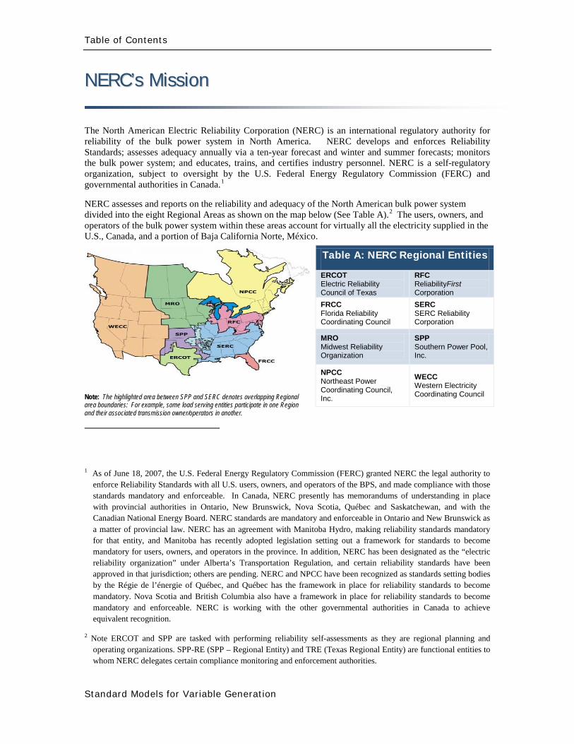
Table of Contents
Standard Models for Variable Generation
NNEERRCCrsquorsquoss MMiissssiioonn
The North American Electric Reliability Corporation (NERC) is an international regulatory authority for reliability of the bulk power system in North America NERC develops and enforces Reliability Standards assesses adequacy annually via a ten-year forecast and winter and summer forecasts monitors the bulk power system and educates trains and certifies industry personnel NERC is a self-regulatory organization subject to oversight by the US Federal Energy Regulatory Commission (FERC) and governmental authorities in Canada1
NERC assesses and reports on the reliability and adequacy of the North American bulk power system divided into the eight Regional Areas as shown on the map below (See Table A)
2 The users owners and operators of the bulk power system within these areas account for virtually all the electricity supplied in the US Canada and a portion of Baja California Norte Meacutexico
Note The highlighted area between SPP and SERC denotes overlapping Regional area boundaries For example some load serving entities participate in one Region and their associated transmission owneroperators in another
1 As of June 18 2007 the US Federal Energy Regulatory Commission (FERC) granted NERC the legal authority to enforce Reliability Standards with all US users owners and operators of the BPS and made compliance with those standards mandatory and enforceable In Canada NERC presently has memorandums of understanding in place with provincial authorities in Ontario New Brunswick Nova Scotia Queacutebec and Saskatchewan and with the Canadian National Energy Board NERC standards are mandatory and enforceable in Ontario and New Brunswick as a matter of provincial law NERC has an agreement with Manitoba Hydro making reliability standards mandatory for that entity and Manitoba has recently adopted legislation setting out a framework for standards to become mandatory for users owners and operators in the province In addition NERC has been designated as the ldquoelectric reliability organizationrdquo under Albertarsquos Transportation Regulation and certain reliability standards have been approved in that jurisdiction others are pending NERC and NPCC have been recognized as standards setting bodies by the Reacutegie de lrsquoeacutenergie of Queacutebec and Queacutebec has the framework in place for reliability standards to become mandatory Nova Scotia and British Columbia also have a framework in place for reliability standards to become mandatory and enforceable NERC is working with the other governmental authorities in Canada to achieve equivalent recognition
2 Note ERCOT and SPP are tasked with performing reliability self-assessments as they are regional planning and operating organizations SPP-RE (SPP ndash Regional Entity) and TRE (Texas Regional Entity) are functional entities to whom NERC delegates certain compliance monitoring and enforcement authorities
Table A NERC Regional Entities
ERCOT Electric Reliability Council of Texas
RFC ReliabilityFirst Corporation
FRCC Florida Reliability Coordinating Council
SERC SERC Reliability Corporation
MRO Midwest Reliability Organization
SPP Southern Power Pool Inc
NPCC Northeast Power Coordinating Council Inc
WECC Western Electricity Coordinating Council
Table of Contents
Standard Models for Variable Generation
TTaabbllee ooff CCoonntteennttss
Executive Summary i
1 Introduction 1
2 The Need for Models for Variable Generation 3
21 Steady-State and Fault Current Analysis 4
22 Time-Domain Positive Sequence Dynamic Models for Bulk Power System Stability Analysis 4
23 Detailed Three-phase Equipment Level Models 5
24 Summary 7
3 Present Status of Modeling Variable Generation 8
31 Wind Generation 8
311 WECCIEEE Effort for Generic Models 8
312 UWIG Generic Model Documentation and Validation Effort 13
313 IEC Effort for Generic Models 14
32 Photovoltaic Solar Generation 15
33 Solar Thermal 18
34 Tidal Generation 18
35 Other Resources 19
36 Summary 20
4 Present Status of Model Validation 21
41 What is Model Validation 21
42 Examples of Model Validation Efforts 23
421 Hydro- Queacutebec Example 23
422 GE Example ndash based on GErsquos work with client facilities 27
Table of Contents
Standard Models for Variable Generation
5 Summary amp Recommended Actions ndash Standards Implications 35
51 Applying the NERC Standards 36
52 NERC Standards Technical Issues 38
53 Final Recommendation 44
Appendix I Wind-Turbine Generation (WTG) Technologies 45
Acronyms 47
IVGTF Task 1-1 Roster 49
References and Further Reading 53
Executive Summary
i
Executive Summary
Existing state and federal energy policies including renewable portfolio standards (RPS) and production tax credits have driven development of wind plants in the US and Canada that presently comprise in excess of 35 GW of installed capacity This trend is projected to continue with the addition of many other forms of renewable technologies such as photovoltaics Furthermore other technologies like plug-in hybrid electric vehicles (PHEV) tidal-power systems etc are also on the horizon
Unlike traditional non-renewable resources the output of wind solar ocean and some hydro generation resources varies according to the availability of the primary fuel (wind sunlight and moving water) that cannot be reasonably stored Therefore these resources are considered variable following the availability of their primary fuel source
The North American Electric Reliability Corporation (NERC) is responsible for ensuring the reliability of the bulk power system in North America Anticipating the growth of variable generation in December 2007 the NERC Planning and Operating Committees created the Integration of Variable Generation Task Force (IVGTF) charging it with preparing a report [1] to identify the following
1) Technical considerations for integrating variable resources into the bulk powersystem
2) Specific actions practices and requirements including enhancements to existing ordevelopment of new reliability standards
One of the identified follow-up tasks from [1] was the need standard valid generic non-confidential and public power flow and stability models for variable generation technologies and for a task force to review existing NERC Modeling Data and Analysis (MOD) Standards to ensure high levels of variable generation can be simulated and appropriately addresses through the existing standards This document constitutes the results of this review performed by this Task Force A detailed discussion is provided of model and model validation in general followed by an account of the current status of models for various variable generation technologies Then a discussion is provided of the relevant NERC MOD standards and where they will need to be augmented to properly address variable generation
Thorough out this report reference is made to various forms of models (standard generic user-written 3-phase etc) It should be emphasized that the present and imminent need is to have models that are standard (ie a defined model structure used by all commercial software tools) publicly available and not specific to any particular design (ie ldquogenericrdquo and able to reasonably
Executive Summary
ii
represent key performance relevant to bulk power system studies) ndash this is the focus which is further elaborate in the report The process and need for model validation however applies to any and all levels of modeling
An earlier draft of this report and recommendations were presented to NERCrsquos Planning Committee at their March 2010 meeting The Committee members urged the IVGTF to pursue NERC reliability standard development Thus several NERC Standards Drafting Teams undertaking MOD Standard development will be contacted to present the recommendations from this report for their consideration and incorporation in subsequent updates
Introduction
1
1 Introduction
Existing state and federal energy policies including renewable portfolio standards (RPS) and production tax credits have driven development of wind plants in the US and Canada that presently comprise in excess of 35 GW of installed capacity This trend is projected to continue with the addition of many other forms of renewable technologies such as photovoltaics Furthermore other technologies like plug-in hybrid electric vehicles (PHEV) are also on the horizon
Unlike traditional non-renewable resources the output of wind solar ocean and some hydro generation resources varies according to the availability of the primary fuel (wind sunlight and moving water) that cannot be reasonably stored Therefore these resources are considered variable following the availability of their primary fuel source There are two overarching attributes of variable generation that can impact the reliability of the bulk power system if not properly addressed
1) Variability The output of variable generation changes according to the availability ofthe primary fuel resulting in fluctuations in the plant output on all time scales
2) Uncertainty The magnitude and timing of variable generation output is lesspredictable than for conventional generation
The North American Electric Reliability Corporation (NERC) is responsible for ensuring the reliability of the bulk power system in North America Anticipating the growth of variable generation in December 2007 the NERC Planning and Operating Committees created the Integration of Variable Generation Task Force (IVGTF) charging it with preparing a report [1] to identify the following
3) Technical considerations for integrating variable resources into the bulk powersystem
4) Specific actions practices and requirements including enhancements to existing ordevelopment of new reliability standards
One of the identified follow-up tasks from [1] was the need for the models for variable generation technologies For the purpose of completeness of this document the proposed action item Task 1-1 from [1] is repeated below
Introduction
2
Therefore the goal of this document is to address the above action item and to provide
1 The roadmap for development of valid generic non-confidential and public standardpower flow and stability (positive-sequence) models for variable generation technologiesNamely what is available at present and what is the path forward to developing anddeploying these models
2 The NERC standards implications and feedback on what further NERC action items maybe needed if any to address model application and validation as it relates to variablegeneration
Throughout this report reference is made to various forms of models (standard generic user-written 3-phase etc) The present and imminent requirement is to have models that are standard (ie a defined model structure used by all commercial software tools) publicly available and not specific to any particular design (ie ldquogenericrdquo and able to reasonably represent key performance relevant to bulk power system studies) ndash this is the focus which is further elaborated upon this report The process and need for model validation however applies to any and all levels of modeling
Item
Proposed Improvement Abstract Lead Deliverables Milestones
11 Standard valid generic non-confidential and public power flow and stability models (variable generation) are needed and must be developed enabling planners to maintain bulk power system reliability
Valid generic non-confidential and public standard power flow and stability (positive-sequence) models for variable generation technologies are needed Such models should be readily validated and publicly available to power utilities and all other industry stakeholders Model parameters should be provided by variable generation manufacturers and a common model validation standard across all technologies should be adopted The NERC Planning Committee should undertake a review of the appropriate Modeling Data and Analysis (MOD) Standards to ensure high levels of variable generation can be simulated Feedback to the group working on NERC Standardsrsquo Project 2007-09 will be provided
Ad Hoc group Members from IVGTF - Planning
Make recommendations and identify changes needed to NERCrsquos MOD Standards
Draft report readyby December2009 PC meeting
Final report withrecommendationsto PC forendorsement inFebruary 2010
Develop SARwith StandardsCommittee ifrequired
Characteristics of Power Systems amp Variable Generation
3
2 The Need for Models for Variable Generation
The planning and operation of large interconnected power systems in diverse regions in the North American continent is a complex task which requires daily analysis and computer model simulations System planners and operators use simulation studies to assess the potential impact of credible (and sometimes extreme) contingency scenarios and to assess the ability of the power system to withstand such events while remaining stable and intact (ie to avoid cascading outages) When a credible disturbance event is simulated in computer models of the power system and the observed result is unacceptable performance system planners andor operators must develop either operating strategies or planned equipment additions (eg line re-conductoring addition of shunt reactive compensation devices etc) to mitigate the potential problem To help ensure proper assessment of reliable performance and to minimize (as much as possible) capital investment models are required that reasonably represent actual equipment performance in simulations
The NERC Modeling Data and Analysis (MOD) Reliability Standards require Registered Entities to create procedures needed to develop maintain and report on models to analyze the steady-state and dynamic performance of the power system (MOD-011 and MOD-013) Equipment owners are required to provide steady-state and dynamic models (MOD-012) to the Regional Entities This information is required to build a reasonable representation of the interconnected system for planning purposes as stated in MOD-014 and MOD-0153
Therefore system models are required for generation equipment at three levels
Specifically models are required to perform powerflow short circuit and stability studies necessary to ensure bulk power system reliability
1 Models for assessing the steady-state behavior of the units and their fault currentcontributions for protection system analysis
2 Models for emulating the dynamic behavior of the units for bulk power system time-domain stability analysis
3 Detailed equipment-specific (3-phase) models for specialized studies
In this chapter the aforementioned three categories of models are described in detail focused on variable generation technologies
3 httpwwwnerccompagephpcid=2|20
Characteristics of Power Systems amp Variable Generation
4
21 Steady-State and Fault Current Analysis
Steady-state analysis in the context of bulk power system studies is primarily associated with power flow which determines the flow of power on transmission lines and transformers and the voltages at power system nodes (substations) Accurate calculations are essential in the planning and design of the interconnected power system to ensure that all equipment will be operated within its rated capability under various credible scenarios (including contingencies) These calculations are performed under various base-case conditions (ie all equipment generally in service) and contingency conditions that impact one or more power system elements such as a line generating unit or transformers out of service (eg for different system load conditions including peak load light load different seasons or different power transfer)
To assess the adequacy of protection system settings faults on transmission equipment are simulated and the settings for protection relays are evaluated as well as the calculated fault currents are compared to the current rating of circuit-breakers
Both these analyses are critical to the reliable operation of the power system To perform these analyses adequate models are needed for simulating the steady-state power flow and the fault current characteristics of generation equipment
22 Time-Domain Positive Sequence Dynamic Models for Bulk Power System Stability Analysis
Time-domain simulations are a key tool for assessing the reliability of the bulk power system assessing the stability of the system4
ldquoReliability of a power system refers to the probability of its satisfactory operation over the long run It denotes the ability to supply adequate electric service on a nearly continuous basis with few interruptions over an extended time period
Stability of a power system refers to the continuance of intact operation following a disturbance It depends on the operating condition and the nature of the physical disturbancerdquo
Similarly NERC defines stability as ldquoThe ability of an electric system to maintain a state of equilibrium during normal and abnormal conditions or disturbancesrdquo5
4 The definitions listed are quoted from P Kundur J Paserba V Ajjarapu G Andersson A Bose C Canizares N Hatziargyriou D Hill A Stankovic C Taylor T Van Cutsem and V Vittal ldquoDefinition and classification of power system stability IEEECIGRE joint task force on stability terms and definitionsrdquo IEEE Transactions on Power Systems Volume 19 Issue 3 Aug 2004 pp 1387 ndash 1401 (
httpieeexploreieeeorg)
Characteristics of Power Systems amp Variable Generation
5
Stability analysis is traditionally performed using positive-sequence models This includes models that focus on system simulation under assumed perfect balanced conditions (ie no imbalance in the 3-phase system voltages and currents) Furthermore the primary stability issues that are investigated (angular stability voltage stability frequency controlstability) for bulk power systems tend to be bounded within a small frequency band around the system fundamental frequency Positive sequence models are typically required to be valid in a range of roughly 01 Hz to about 3 Hz with the control system having validity up to 10 to 15 Hz to allow for investigating general control loop stability With these simplifying assumptions it has been historically easy to establish generic non-proprietary models for representing conventional generation and its controls Functional models that are non-proprietary and generic (ie applicable to any vendors equipment simply by changing the model parameters) are needed for the various variable generation technology A library of models to deal with each family of variable generation technology is required to support reliability assessment What is presently available and what must be further developed is discussed in the next chapter
Aside There are many cases were extended term analysis may be necessary in which case wind speed variations may be a needed input to the model For the purposes of typical stability analyses however where the study period spans over only several seconds wind speed is typically assumed to be constant
23 Detailed Three-phase Equipment Level Models
There are a number of potential interaction issues that may occasionally require detailed analysis [2] To perform this analysis detailed three-phase equipment models are required
Subsynchronous resonance (SSR) is a phenomenon whereby series compensation of a transmission line results in electrical resonance frequencies in the subsynchronous frequency range that can lead to destabilizing modes of mechanical torsional vibration on the turbine-generator shaft that fall in the frequency range of the electrical resonance6 These resonance phenomena are only of concern to generation technologies with a mechanical turbine-generator shaft that is coupled to the electrical system Type 1 2 and 3 Wind-Turbine Generation (WTG) may be susceptible7
5 Glossary of Terms Used in Reliability Standards
Clearly Type 4 (where the unit is decoupled from the electrical system) and technologies like PV have no such concerns SSR is less likely to affect wind turbines compared
httpwwwnerccomfilesGlossary_2009April20pdf Updated April 20 2009
6 P M Anderson B L Agrawal and J E Van Ness Subsynchronous Resonance in Power Systems IEEE Press New York 1990 PM Anderson and R G Farmer Series Compensation of Power Systems ISBN 1-888747-01-3 1996
7 See Appendix I for more information on these WTG configurations
Characteristics of Power Systems amp Variable Generation
6
to large conventional synchronous generators since the typical torsional mode for a wind turbine is quite low (around 1 to 4 Hz) Accordingly it would be quite unlikely that the level of series compensation in a system would be high enough to result in an electrical resonance that would interact with a low mechanical frequency8 A larger concern is induction machine self-excitation9
Another potential phenomenon related to torsional mechanical modes is device dependant subsynchronous oscillations often referred to in the literature as subsynchronous torsional interaction (SSTI) This was first observed at the Square Butte HVDC project in 1976
Some detailed 3-phase analysis and discussions with the wind turbine manufacturer on a case by case basis is prudent when installing wind near series compensated lines
10 SSTI is a phenomenon by which controls associated with power electronic based transmission equipment (eg SVC or HVDC) may introduce negative damping torques in the frequency range associated with the torsional mechanical modes of oscillation of nearby thermal turbine-generating units Again due to the relatively low frequency range for torsional modes of wind turbine this may not be a concern in most cases however where wind plants are closely coupled to a HVDC system analysis is prudent to ensure that control andor torsional interaction do not occur This analysis will typically require detailed three-phase models for both the wind plant and the HVDC system Also SSTI is not necessarily detrimental11 because in some cases torsional damping can be markedly improved through the application of power electronic devices One thermal power plant in the Western US grid uses a dedicated SVC for this purpose as a means of mitigating the effects of SSR 12
8 Note The electrical resonance needs to be in the range of 56 to 59 Hz on a 60 Hz system found in North America
A practical example of this is the Taiban Mesa wind plant located in New Mexico This wind plant is located electrically adjacent to a back-to-back HVDC station ndash Blackwater The detailed interconnection studies performed by ABB during the design of the wind plant showed that there was little risk of torsional interaction between the HVDC controls and the wind turbine generators This analysis required detailed equipment level (3-phase) models of the wind turbines the HVDC and transmission network
9 PM Anderson and R G Farmer Series Compensation of Power Systems ISBN 1-888747-01-3 1996 C F Wagner ldquoSelf-Excitation of Induction Motors with Series Capacitorsrdquo AIEE Transactions pp1241-1247 Vol 60 1941 (httpieeexploreieeeorg)
10 M Bahrman E Larsen R Piwko H Patel ldquoExperience with HVDC ndash Turbine Generator Torsional Interaction at Square Butterdquo IEEE Transactions on Power Apparatus and Systems Vol PAS-99 pp 966-975 MayJune 1980 (httpieeexploreieeeorg)
11 D Dickmander P Pourbeik T Tulkiewicz and Y Jiang-Haumlfner ldquoSSTI Characteristics of HVDC Lightrdquo White paper by ABB Inc December 2003
12 Pourbeik A Bostroumlm and B Ray ldquoModeling and Application Studies for a Modern Static VAr System Installationrdquo IEEE Transactions on Power Delivery Vol 21 No 1 January 2006 pp 368-377 (httpieeexploreieeeorg)
Characteristics of Power Systems amp Variable Generation
7
Other phenomena that may expose the shaft of a WTG to cyclical and significant transient torque pulsations may also be a concern For example nearby arc furnaces or high-speed re-closing on a transmission line emanating from the wind plant substation or repeated commutation failures on a nearby conventional line-commutated HVDC As a first step some simple transient stability analysis may be performed to estimate the expected step change in the electrical torque on a wind turbine generator due to the electrical event and the wind turbine manufacturer consulted to identify if the observed level of transient torque is a concern Based on consultation with the wind turbine manufacturer more detailed analysis may be required to assess if a potential problem exists and how it may be remedied
Another issue that may be of concern is the stability and behavior of variable generators in extremely weak short-circuit nodes of the power system and regions of the system that may be highly susceptible to islanding Again more detailed models than positive sequence stability representations may be needed to study these scenarios (eg to accurately review the potential for temporary over voltages upon islanding etc) Also in some cases and designs (eg Type 3 WTG) the behavior of the unit as it pertains to voltage-ride through during fault scenarios can be more onerous on the controls (ie controlling the DC bus voltage in the Type 3 WTG) for unbalanced fault scenarios as opposed to a balance 3-phase faults Thus 3-phase detailed equipment models are needed to assess these phenomena
Finally transient stability studies should be completed to ensure that basic control loops in the variable generation plants (eg central voltage control systems often deployed in doubly-fed and full-converter based wind plants that regulate voltage at the interconnecting substation by adjusting the reactive output of all wind turbines in the wind plant) do not interact or interfere with other nearby transmission and generation controls This often requires proper tuning of the controls
This brief section illustrates the need for the availability of detailed 3-phase equipment level models which cannot be generic These models are likely to be proprietary and may need to be used under non-disclosure agreements between the vendor and the plant developerutility Therefore it is important to recognize the need for these models so that they are developed and available to be easily deployed and used when such specialized studies are needed
24 Summary
This chapter has outlined the basic power generation plants models required power system analysis related to reliability assessment In addition these models need to be generic (ie the model structure applicable to any vendorrsquos equipment with only the variation of the model parameters to represent various vendor equipment) and non-proprietary (ie publicly available to all stakeholders) Adequate models readily exist for conventional synchronous generators but until recently have been unavailable for any variable generation technology In the next chapter the current status of models for all variable generation technologies is discussed
Transmission Planning amp Resource Adequacy
8
3 Present Status of Modeling Variable Generation
This chapter provides an overview of the models and modeling capability presently available In the summary of this chapter the gaps are identified and areas requiring further work are identified The modeling and model development discussed here is primarily for power system power flow short-circuit and stability analysis
Time-domain stability analysis is concerned with phenomena in the tens of milliseconds to several minutes time frame (see Figure 31)
Figure 31 Times of various phenomena of interest in power system studies (GE)
31 Wind Generation
311 WECCIEEE Effort for Generic Models
The size of individual WTGs has increased dramatically from several hundred kilowatts to multi-megawatt turbines The size of individual wind power plants has also increased significantly In the past a typical wind power plant consisted of several turbines Presently wind power plants
Switching Transients
Subsynchronous Resonance
Transient Stability
Small Signal Stability
Long-term Dynamics
TIME (seconds)
10-6 10-5 10-4 001
1 cycle
1041 1 10 100 1000
1 minute 1 hour
01
Transmission Planning amp Resource Adequacy
9
of several 100 MW and larger are being proposed By some projections13 as much as 300 GW (20 penetration) of wind generation capacity is forecast in the US by 2030 and NERC projects an increase of 229 GW of new wind generation installed capacity by 201814
Presently most wind turbine technologies use power electronics and advanced reactive power compensation as an integral part of wind turbine generator and wind power plant Under dynamic transients the behavior of modern wind turbines must be accurately simulated to predict the response of the wind power plant Misrepresentation of WTGs in transmission studies may threaten the reliability of power systems by either resulting in excessive overbuild of transmission systems due to pessimistic models or in deficient transmission system investment based on optimistic models
The increased penetration of renewable energy generation poses significant questions concerning the ability of the power system to maintain reliable operation
Turbine manufacturers have developed dynamic models for their wind turbines These dynamic models are typically user-written models in commercially available power system simulation software platforms (eg Siemens PTI PSSTME GE PSLFTM DigSILENT PowerFactory etc) Detailed three-phase equipment level models of WTGs used for internal design purposes are also often developed by manufacturers in either their own simulation platforms or commercial software tools including PSCADreg or Matlabreg Simulink
Unfortunately both these categories of models (the user-written positive-sequence models and the three-phase detailed equipment models) require significant input dataparameters considered to be proprietary by the turbine manufacturers and therefore are not freely available to the general public Access to these models usually requires a non-disclosure agreement (NDA) between the dynamic model user and the turbine manufacturers This agreement is only valid for a specific turbine model for a given period of time
In many cases it takes months to negotiate and to finalize the NDA Furthermore in some cases there are incompatibilities among turbine models developed by different turbine manufacturers which results in numerical interactions if multiple user-written models are incorporated into a single power system model for system analysis This makes the work of power system planners almost impossible The NDA are also usually bilateral which renders it impossible to share the information among the manufacturers to help resolve incompatibility problems Finally the NDAs make it difficult at best and impossible in some cases to share the models thereby potentially violating the NERC requirements for submitting models for system planning studies
13 httpwwwnrelgovdocsfy07osti40482pdf 14 httpwwwnerccomfiles2009_LTRApdf
Transmission Planning amp Resource Adequacy
10
With this back drop the WECC Wind Generator Modeling Group (WGMG) initiated the development of generic wind turbine models of the four (4) different types of wind turbines (see Appendix I for these four WTG designs) These four types of turbines currently hold the largest market share throughout the world WECC is interested in providing accurate and validated models of standard wind turbines that will be available in their database including the datasets to be used for testing the models and the methods for representing a wind power plant in power system studies These goals are being accomplished through the development and validation of standard models The standard models must be generic in nature ndash that is they must not require nor reveal proprietary data from the turbine manufacturers These improved standard (generic non-proprietary) dynamic models enable planners operators and engineers to perform the necessary transmission planning studies required to ensure system reliability
Currently the first generation of these generic WTG models for all four turbines types have been developed and are available as part of the main model library for the two most widely used commercial power system simulation tools in North America (ie Siemens PTI PSSTME GE PSLFTM)15
To date the first generation of generic models developed and released have focused on capturing the response of the units to electrical voltage disturbances on the transmission grid (grid faults) One deficiency particularly for the Type 1 and 2 models is the proper representation of unit responses to large system frequency excursions These models have not been verified due to the lack of data on actual turbine behavior under such circumstances and will require further development in consultation with turbine manufacturers
As a continuation of and in parallel with the WECC effort the Institute of Electronic and Electrical Engineers (IEEE) Power amp Energy Society (PES) has also established a Working Group to investigate WTG modeling issues The IEEE Working Group on Dynamic Performance of Wind Power Generation under the Power System Dynamic Performance Committee This Working Group is actively expanding the efforts of generic dynamic modeling for wind power plants focusing on modeling specifications disseminating methods and model validation
Finally as with all modeling exercises model development and validation are iterative processes requiring
bull Generic wind turbine models are to be made available to the public
15 PSSregE-320 Program Application Guide Volume II Chapter 21 PSSregE-320 Model Library Chapters 17 through 21 GE PSLF Users Manual v170_04 October 2009
Transmission Planning amp Resource Adequacy
11
bull Generic wind turbine models must be validated before release and public dissemination which is being pursued in WECC IEEE International Electrotechnical Commission (IEC) and other forums
bull Models should evolve and be revalidated as the technology progresses
bull Data from field measurement and monitoring for model validation can be a vital resource
A somewhat unique need in modeling variable generation (eg wind) is the need for methods required to develop equivalent models for large wind power plant In contrast to conventional fossil fuel and hydro power plants where plants are constituted by either a single large unit or at most a few large units a wind power plant can be made up of tens to more than a hundred WTGs For large scale power system simulations particularly in North America where the power system models are quite large it is often preferred to reduce the wind power plant to a single equivalent unit Accordingly techniques are needed for model aggregation and testing their validity ndash some significant progress has been made in this regard For example Figure 32 shows the technique developed for reducing the impedance of the wind power plant collector system into a single equivalent feeder impedance for representation of the wind power plant (WPP) by an aggregated single equivalent unit in power system studies
Figure 32 Example shows the method for reducing the impedance of a wind power plant collector system into a single equivalent impendence16
16 ldquoWECC Wind Generator Power Flow Modeling Guiderdquo (
httpwwwweccbizlibraryWECC20DocumentsDocuments20for20GeneratorsGenerator20Testing20ProgramWind20Generator20Power20Flow20Modeling20Guidepdf)
Transmission Planning amp Resource Adequacy
12
Figure 33 shows an example for dynamic simulations of aggregating the WPP into a single equivalent unit and an equivalent single impedance representing the entire collector system as compared to a detailed model representing the whole WPP unit-by-unit ndash the example shown assumes that all WTGs in the WPP are identical in cases where this is not true multiple equivalent units may be needed one for each WTG type As can be seen in this figure the results from the two simulations compare very well at the point of interconnection (which is what is shown) thus the equivalent aggregate is adequate for power system studies17
Figure 33 Example of time-domain simulations comparing a detailed model of a Wind Power Plant (ie representing the complete collector system and each WTG individually) versus a single-machine equivalent aggregate (ie the entire plant is represented by one equivalent unit and an equivalent impedance to represent the whole collector system)
17 Figure is from J Brochu R Gagnon and C Larose ldquoValidation of the WECC Single-Machine Equivalent Power Plantrdquo Presented at the IEEE PES DPWPG-WG Meeting at IEEE PSCE March 2009
P345 kV
Q345 kV
QWT = 0435 0 -0435
Transmission Planning amp Resource Adequacy
13
312 UWIG Generic Model Documentation and Validation Effort
The Utility Wind Integration Group (UWIG)18
The objectives of the project which will commence in early 2010 and run for a period of two years are to
under a US Department of Energy grant will be launching an effort to provide the basic documentation application and validation of generic models for wind turbines The goal of this project is to accelerate the appropriate use of generic wind turbine models for transmission network analysis
bull Complete characterization and documentation of the four generic models developed through an outgrowth of a WECC activity begun in 2005
bull Defining proposed enhancements to the generic wind turbine model structures that would allow representation of more advanced features including power control automatic curtailment inertial and governor response
bull Comparative testing of the generic models against more detailed (and sometimes proprietary) versions developed by turbine vendors
bull Developing recommended parameters for the generic models to best mimic the performance of specific commercial wind turbines
bull Documenting results of the comparative simulations in an application guide for users
bull Acquiring test data from all available sources for the purpose of validating the performance of the appropriately specified generic models in actual case studies
bull Conducting technology transfer activities in regional workshops for dissemination of knowledge and information gained and to engage electric power and wind industry personnel in the project while underway
18 The UWIG was established in 1989 to provide a forum for the critical analysis of wind technology for utility applications and to serve as a source of credible information on the status of wind technology and deployment The grouprsquos mission is to accelerate the development and application of good engineering and operational practices supporting the appropriate integration of wind power into the electric system It currently has more than 150 members spanning the United States Canada and around the world including investor-owned public power and rural electric cooperative utilities transmission system operators and associate member corporate government and academic organizations httpwwwuwigorgaboutuwightm
Transmission Planning amp Resource Adequacy
14
Maintaining communication and coordination with other ongoing activities and agencies engaged in this topic is another objective of the effort which will be critical for success
313 IEC Effort for Generic Models
The International Electrotechnical Commission (IEC) recently started a Working Group in October 2009 to address the development of generic and ldquostandardrdquo models for wind turbine generators19
Part 2 of this work will be focused on extending the modeling to allow for modeling of the entire wind power plant including wind power plant control and auxiliary equipment
The goal of this Working Group is to define standard dynamic simulation models for wind turbines and wind plants which are intended for use in power system and grid stability analyses and should be applicable for dynamic simulations of power system events including short circuits (low voltage ride through) loss of generation or loads and system separation The group is approaching this work in two parts Part 1 will focus on specifying dynamic simulation models for the generic wind turbine topologiesconceptsconfigurations presently in the market as well as specifying how these models may be modified as future technologiesconcepts are introduced The standard should also include procedures for validation of the models specified Another goal is that the models should be developed and specified at a fundamental level so they are independent of any specific software platform and can be adopted by any software vendor
Several members of this IEC Working Group are also members of the WECC and IEEE Working Groups (and this NERC Task Force) The three groups are clearly working in close collaboration to ensure maximum benefit to the industry globally and maximum sharing of knowledge already gained through the WECC and IEEE efforts
19 httpwwwiecchdynwwwfp=102140FSP_ORG_ID5613
Transmission Planning amp Resource Adequacy
15
32 Photovoltaic Solar Generation
Photovoltatic (PV) systems for power generation are quickly increasing becoming a significant portion of generation in some regions in North America PV or solar arrays are composed of a large number of solar cells connected in series and parallel These cells produce a DC voltage when they are exposed to sunlight due to the photo-voltaic effect20
Figure 34 shows the I-V characteristics of a cell at a constant temperature and various sun intensity or insolation levels
Figure 34 Current-Voltage characteristics of a solar cell for various insolation levels at a constant temperature (source [11]21
20 The photo-voltaic effect is the process by which an electric potential difference (voltage) is created in a material exposed to light (electromagnetic radiation) which then leads to the flow of electric current This process is directly related to the photo-electric effect but distinct from it in that in the case of the photo-electric effect electrons are ejected from the material surface upon being exposed to high enough frequency (energy) light whereas in the photo-voltaic effect the generated electrons are transferred across a material junction (eg PN junction in a photo-diode) resulting in the buildup of a voltage between two electrodes and the flow of direct current electricity
)
21 Solar Radiation Research Laboratory at the National Renewable Energy Laboratory (httpwwwnrelgovmidcsrrl_rsp)
Transmission Planning amp Resource Adequacy
16
Figure 35 shows that the current is limited when the cell is short-circuited (Voltage=0)
(a) (b) (c)
(d)
Figure 35 The concept of a solar array (a) a single solar cell (b) a series connection of solar cells (Nser = 3 and Npar = 1) and (c) a solar array (Nser = 3 and Npar = 2) The solar cell array(s) is then connected to a DC bus (d)
Figure 35 shows the concept of the solar cell up to the solar array To use the DC power generated by the PV array in an AC power system the DC power must be converted to 60 Hz AC in North America (50 Hz in some other regions in the world like Europe) There are several power electronic based converter concepts that can achieve this which can be classified into two general categories line-commutated converters (LCC) and self-commutated or more commonly
Vbus Iload
Ibus
Icap PV ARRAY
+
_
Transmission Planning amp Resource Adequacy
17
referred to as voltage-source converters (VSC) These technologies have been applied for decades and are well understood LCC use thyristors as their controlled switching device The switching on of a thyristors can be controlled while the turn-off time cannot be controlled and happens at the next AC waveform current zero crossing LCC systems must be operated in a network with an AC source and cannot operate to serve an isolated load In contrast VSC systems are self-commutating that is the power electronic switching devices used (eg integrated gate-commutated thyristors or IGCTs and insulated-gate bipolar transistors or IGBTs) are able to be completely controlled for both turn-on and turn-off and allow the VSC to completely control the AC waveform produced and adjust the power factor as seen on the AC side to within the current rating of the device Due to advances in the technology most power electronic converters employed in PV systems are of the VSC type22
From a modeling standpoint for power system studies there are some user-written manufacturer-specific models in existence as developed by various PV manufacturers Presently no generic or standard models exist
The WECC Working Group which has been addressing the development of generic WTG models will be extending its effort in 2010 to review developing generic PV models for dynamic simulations in stability studies As a starting point the grid side structure of the Type 4 WTG model may be used since it represents a VSC This is because PV is typically connected to the grid with a VSC and it will behave electrically similar to a Type 4 WTG that has a similar electrical interface with the gridmdashthis is from a grid perspective looking at the electric response and neglects any of the effects of the energy source
From a steady-state power flow and short-circuit analysis perspective the behavior of the PV technologies will behave in a similar fashion to a Type 4 WTG because of the VSC interface and because its power factor can be controlled based on the control functionality of the VSC design Its short-circuit response will be limited to the current limit effected by the VSC under grid fault conditions
The development of generic and standard PV models is presently a topic for further research This should be pursued imminently and much of what has been learnt from the WTG model development process should be leveraged
22 IEA-PVPS Grid-Connected Photovoltaic Power Systems Survey of Inverter and related Protection Equipment Report IEA PVPS T5-05 2002 December 2002 (httpwwwiea-pvpsorgproductsdownloadrep5_05pdf)
Transmission Planning amp Resource Adequacy
18
33 Solar Thermal
Solar thermal energy is based on harnessing the radiated heat of the sun for the purpose of producing electricity In broad terms there are presently two main ways of achieving this
1 Concentrating Solar Power (CSP) plants ndash in this case solar radiation is typically collected through a large number of mirrors (thus a large amount of solar radiation) which is then focused on a small area ndash the mirrors have tracking systems to follow the Sun The concentrated solar radiation heats a high temperature working fluid which then feeds a conventional steam-turbine generator From an electrical grid perspective the models needed to simulate the steady-state short-circuit and transient time-domain dynamics of such a generating unit are typically no different than standard synchronous generating units for fossil fuel plants
2 The Stirling Engine concept23
34 Tidal Generation
ndash in this design a parabolic mirror assembly concentrates the collected solar radiation on a sterling engine that sits at the focal point of the mirror assembly A Stirling engine is a reciprocating heat engine that operates based on the concept of cyclical compression and expansion of a working fluid As the working fluid expandscontracts it drives a piston that then turns a generator The engine is connected to an electrical generator that produces electric energy Once again for power system studies the units may be modeled using standard generator models However in this case a power plant would be constituted by a large number of small units (the typical Stirling engine is about 25 kW) in a large electrical collector system that collects the power and injects it into the utility grid ndash much like the collector system of a wind power plant Thus modeling the collector system (eg see Figure 32 for an aggregate model of a wind collector system) and any other devices in the collector system such as shunt reactive devices etc must be properly modeled
Tidal power generation derives energy directly from the motion of oceanic tides The gravitational pull of the Moon and Sun combined with the Earthrsquos rotation result in the generation of tides Tides generally occur with a period of roughly twelve hours and so most coastal areas experience two high and two low tides within every twenty-four hour period Tidal generation uses this phenomenon to generate energy Clearly the stronger the tides are either in tidal current velocity or the heightlevel of water the greater the potential amount of energy generation
23httpwwwstirlingenergycom Y Zhang and B Osborn ldquoSolar Dish-Stirling Power Plants and Related Grid Interconnection Issuesrdquo IEEE PES General Meeting 24-28 June 2007
Transmission Planning amp Resource Adequacy
19
Presently in North America tidal power is not a significant source of power in any region Some pilot programs exist for introducing the technology In April 2009 one was announced in Snohomish County Public Utility District in Washington State24
There are several options for harnessing tidal power One method is the use of turbines similar to wind turbines however the fluid (water) is much denser and requires a turbine with smaller and bulkier blades as shown in Figure 36 Most of these technologies typically use ACDCAC converter technology similar to a Type 4 wind turbine to convert the low frequency generated electricity to grid frequency AC electricity and interface with the power system Once this technology becomes more prevalent a starting point for development of a suitable model structure may be the Type 4 generic wind turbine models Understandably the energy source characteristics are quite different from wind power and significantly more predictable
Figure 36 One of the many concepts for tidal generation systems (courtesy of Marine Current Turbines Limited wwwmarineturbinescom)
35 Other Resources
There are several other emerging technologies and there are many complementary technologies (ie auxiliary to the variable generation resources but designed to help with their integration into the grid) including smoothly-controlled dynamic reactive devices (static VAr systems)
24 httpwwwsnopudcomPowerSupplytidaltidalpressashxp=1516amp756_na=46
Transmission Planning amp Resource Adequacy
20
energy storage technologies etc With respect to static VAr systems (SVCs and STATCOMs) there is an active WECC working group imminently addressing the issue of generic models for these devices25
36 Summary
The group has made substantial progress with the models defined and developed but currently undergoing testing and validation With regards to the other emerging technologies most tend to be power converter based (ie connected to the grid through a back-to-back frequency converter) and so their electrical behavior (neglecting the characteristics of the energy source) will be similar to Type 4 wind turbines Until these technologies mature the basic structure of other more mature converter based generation technologies can be a good starting point
This section has briefly presented the various types of variable generation and the present status of models and model development for power system studies Wind generation technologies being the most prevalent world-wide have the most mature models Through efforts started by WECC and being continued by IEEE and IEC generic standard models for the four main types of WTG technologies are being developed The first generation of these models has been released in two power system simulation software platforms most commonly used in North America Other emerging technologies (eg PV tidal power etc) can build on this effort to start developing generic models For example the WECC effort will be extending its scope in 2010 to look at PV model
From a NERC perspective the key items are
1 To emphasize and support efforts by WECC IEEE and IEC to develop and standardize generic models for these technologies for power system planning studies
2 To encourage manufacturers to familiarize themselves with the generic models being developed and be willing an able to supply parameters for these generic models to reasonably represent their equipment for power system stability studies As highlighted in Chapter 2 more detailed manufacturer specific models may be needed in special cases and for specialized studies
3 To encourage efforts aimed at model validation
4 To consider any augmentation or additions to reliability standards related to Modeling Data and Analysis (MOD) with respect to modeling and model validation of variable generation This is discussed in greater detail in section 5 of this report
25 httpwwwweccbizcommitteesStandingCommitteesPCCTSSMVWGSVCTFdefaultaspx
Present Status of Model Validation
21
4 Present Status of Model Validation
This chapter gives an overview of the model validation work that has been done hitherto as it relates to models for variable generation Necessarily the primary focus of this section is on wind turbine generator models since models for this resource are presently the most mature
41 What is Model Validation
Any and all models of a dynamic system always have limitations associated with them A model is a representation of reality it is an emulation ndash that is why it is called a model In developing a model first the question is asked as to the specified use of the model and the conditions it must reasonably emulate ndash this forms the basis of a model specification from which a model is developed The developed model establishes a certain structure with parameters which are adjustable in order to emulate different types of equipment or design of the modeled device Thus valid parameterization of the model to represent a particular manufacturerrsquos equipment is essential to support the particular scenarios to be analyzed
Model validation is often achieved through some form of testing either in a laboratoryfactory or in field There is a range of reasons for conducting tests for wind generation Each test has a unique set of objectives guiding the design of adequate testing practices
bull Performance Compliance Compliance to contractual requirements and grid codes are one reason to perform tests Interconnection requirements (usually included in plant Power Purchase Agreements and Interconnection Contracts) and grid codes typically outline specific technical criteria that must be met to allow a power plant to connect and operate on the grid Since these criteria point out specific levels to be met (for example voltage power factor and response time) tests may be designed with binary ldquopassfailrdquo objectives
bull Model Validation In much of the world power plants above a pre-defined size must be accurately represented with a dynamic simulation model used in stability analysis for operations and planning purposes As variable generation sources such as WPP are growing in size it is becoming increasingly important to have accurate variable generation specific models Tests may be performed to tune and verify simulation models to closely match the performance of actual equipment In the western US and Canada WECC has mandated that any plant with 20 MVA aggregate generation must be tested for model validation including large wind power plants For North America the imminent NERC MOD-026 standard presently under development will enforce model validation requirements throughout the North American region
Present Status of Model Validation
22
To achieve the goals of model validation there are three categories of tests that may be performed
bull Type Tests These are tests performed by the manufacturer or independent third-parties of representative equipment The intent is to demonstrate that a particular design of equipment exhibits specific performance and all other equipment of that same design is assumed to have the same performance Type tests can be
o Component Performed on specific functions or features in a power plant or generation equipment This could be for example testing the fault ride-through capability or reactive capability of a WTG where testing is performed at the component level
o Factory A systemic test of a major assembly (ie a drive train) or entire turbine-generator is performed under a controlled environment like a manufacturing facility to verify performance and validate assembly design
o Unit A systemic test of multiple components operating together (ie as entire operating WTG or WPP) with the specific intent of benchmarking a model or design as a type test For example tests performed in Europe under the WindTest program
bull Field Tests26
o Commissioning Tests performed on new equipment entering its period of commercial operation service
Tests performed by the power plant asset owner developer host utility manufacturer andor independent third-parties of specific operating equipment These tests are to demonstrate that a particular implementation design and installation of equipment exhibit specific performance
o Periodic Maintenance or Calibration Tests performed periodically after the plant is in commercial operation to verify that equipment continues to perform as well as it did during commissioning
26 See for example WSCC Control Work Group and Modeling amp Validation Work Group ldquoTest Guidelines for Synchronous Unit Dynamic Testing and Model Validationrdquo February 1997 (wwwweccbiz) and IEEE Task Force on Generator Model Validation Testing ldquoGuidelines for Generator Stability Model Validation Testingrdquo Proceedings of the IEEE PES General Meeting Tampa FL June 2007 (httpieeexploreieeeorg)
Present Status of Model Validation
23
o Periodic Model Validation Tests performed periodically after the plant is in commercial operation to verify that simulation models adequately represent actual plant performance (for example the periodic model validation testing required by WECC)
o Periodic Codes amp Standards Validation Tests performed periodically after the plant is in commercial operation to benchmark and validate plant performance per contractual requirements These tests are typically performed to obtain a permanent operating license for the power plant
bull On-Line Monitoring27
With these general concepts in mind the following subsections present some example cases studies of model validation and validation approaches for variable generation sources The examples emphasize WPP and WTG since wind generation is the present dominant variable generator sources in the North America continent
Other information of interest is from continuous data gathering based on ongoing performance of an operating power plant Data collected from external and unscheduled events including grid disturbances or in the case of WTG large changes in wind is particularly useful Monitoring also benchmarks performance under normal operation
42 Examples of Model Validation Efforts
421 Hydro- Queacutebec Example
The province of Queacutebec has vast wind energy potential Though wind energy generation in 2009 accounts for nearly 13 of the total installed capacity in the Queacutebec control area the penetration rate of wind energy generation will reach 10 by 2015 A total capacity of 528 MW is currently in operation and approximately 3000 MW are under development Five wind turbine manufacturers will supply the WTGs for the different projects under study
The configuration of the Hydro-Queacutebec transmission system is essentially radial Approximately 85 of the total installed generation feeding the system is located at distances up to 1300 km
27 See for example P Pourbeik ldquoAutomated Parameter Derivation for Power Plant Models From System Disturbance Datardquo Proceedings of the IEEE PES General Meeting Calgary Canada July 2009 (httpieeexploreieeeorg) This reference shows actual application of on-line disturbance monitoring to power plant model validation for conventional fossil fuel generation It may be feasible to apply similar algorithms and approaches for continuous re-validation of WTG and other variable generation technologies once generic standard models have been developed This is a current topic for research
Present Status of Model Validation
24
from the closest major load centers With this configuration the system transfer capability is mainly limited by stability constraints (transient stability and voltage stability) rather than congestion or thermal capacity of equipment hence the need for reliable models for wind power plants and all other generation
Stability studies are critical to determine the compensation equipment required to maintain the reliability of the power system when integrating new generation They are also essential for operation planning studies including control system design and tuning and determination of transfer capabilities
So far Hydro-Queacutebec has faced two major difficulties regarding user-written models provided by the wind turbine manufacturers First models often lack robustness and do not represent accurately some important features (convergence problems in low short-circuit network do not take into account frequency excursions do not represent secondary voltage regulation etc) Second model validation by the manufacturers is often incomplete not available or difficult to translate to real projects (different settings or software versions design of the collector system etc) In some cases these difficulties have lead Hydro-Queacutebec to build its own models (see Hypersim section below)
General validation test program
Since 2006 Hydro-Queacutebec has performed validation tests on WPP connected to its transmission system and a general validation test program was established in 200928
1 To demonstrate that WPP meet the Transmission Provider technical requirements related to wind generation
The power producer has the obligation to perform validation tests in order to demonstrate that its facilities meet the Transmission Provider requirements The purposes of this program are
2 To validate numerical models and parameters associated with the WPP specifically those given to the Transmission Provider by the power producer by comparing the model response to recordings taken during field tests
3 To confirm the electrical data of power producer facilities
The validation program is divided into seven functions to be validated
1 Primary voltage regulation
28 httpwwwhydroquebeccomtransenergiefrcommercepop_raccordement_transporthtml
Present Status of Model Validation
25
2 Undervoltage response (LVRT)
3 Inertial response
4 Secondary voltage regulation
5 Power factor
6 Maximum ramp rates
7 Power quality
The tests for the primary voltage regulation are performed on a single WTG and consist in producing instantaneous voltage variations of low amplitude on the terminal of the WTG and small voltage steps of limited duration injected directly into the WTG voltage control system Three-phase voltages and currents are recorded at the wind generator to measure the local dynamic response of a wind generator to a rapid voltage change and to verify that the response meets voltage regulation requirements The results are also used to set the model parameters (time constant and gain) used in dynamic simulations The tests regarding the secondary voltage regulation are similar but are conducted for the entire power plant
The validation test program includes LVRT tests on one generating unit to verify that requirements during undervoltage conditions are met The power producer has the responsibility to conduct the tests or to provide a complete report describing tests performed on an identical generating unit (same software version) to demonstrate that the requirements are met So far no LVRT tests were performed on site on WPP integrated on the Hydro-Queacutebec network However monitoring equipment has been installed at three locations in wind plants at their point of interconnection on a 345 kV feeder of the collector system and on one generating unit The monitoring system records signals either continuously or upon detecting variations occurring at the point of interconnection active power variations voltage sags and swells and system frequency excursions These signals are primarily voltages and currents but may also be mechanical variables or other signals
The field recordings recorded on the network can thereafter be used to validate the dynamic response of the models This is a time consuming effort that requires the collaboration of the manufacturers to modify the models if necessary Event recordings to-date have made possible suitable validation of two Hydro-Queacutebec Siemens PTI PSSregE models and one ElectroMagnetic Transients Program (EMTP) model
Inertial response requirements were not in defined for the projects started before 2005 Consequently existing wind plants do not have to fulfill them However the requirements have to be met for WPP to be commissioned in 2011 and after The corresponding validation tests consist in emulated frequency steps and ramps of limited duration Besides verifying the
Present Status of Model Validation
26
requirements the test results will be used to validate the parameters of the models and their dynamic response
The power factor and the maximum ramp rates modules are tested with all WTGs in service to verify that the requirements are met Power factor tests consist in supplying and absorbing a maximum amount of reactive power at different levels of active power Maximum ramp rate tests consist in performing a power plant shutdown sequence followed by a startup sequence These tests are not really used to validate the models but are rather helpful to fix model parameters
The last module regarding the power quality is not covered by scheduled testing but by means of a monitoring system that verifies harmonics and emission limits The recordings are compared to the report provided by the developers to verify if the requirements are met However they are not useful to validate the EMTP model since the WPP is represented by a single-wound generator and does not simulate the detailed collector bus system and individual wind turbine generators
Field tests department
Hydro-Queacutebec field-testing department (UMES) conducts a wide range of special tests and measurements for Hydro-Queacutebec and has done so for 30 years
To test WPP UMES installs a monitoring systems to record three-phase voltages and currents generally at three locations within the plant at the point of interconnection at the starting point of a 345 kV feeder of the collector system and at the terminals of a WTG connected to the same monitored feeder For extended model validation other signals within the wind turbine are monitored including the rotor side converter voltages and currents the network side converter currents and the DC bus voltage
High speed recorders with anti-aliasing filters are used Normally the sampling rate is 5 kHz with at least a 200 second window per event The monitoring system is reachable via an Ethernet connection for remote trigger and data retrieval UMES has also the responsibility to perform the data processing and analysis of the recordings in order to verify the compliance with the interconnection requirements and to extract relevant data for model validation
Present Status of Model Validation
27
Hypersim
The Hydro-Queacutebec Research Institute (IREQ)29 also has an important expertise in control system and wind generation modeling for extensive studies of electrical networks The simulation environment used is Hypersim a real-time simulator and powerful simulation tool that uses a highly detailed representation of the Hydro-Queacutebec network A full-transient detailed model of a Type 3 WTG was developed at IREQ using the MATLABreg SimPower Systems Toolbox The model was also implemented in EMTP and in the Hypersim real-time simulator30 This model is in the process of being validated with data processed by the UMES team The range of events recorded does not make it possible to validate the model completely and the design and parameters will continue to be adjusted to improve the representation of the wind turbines The validation of the MATLABreg model developed by IREQ was very useful to validate and improve Hydro-Queacutebecrsquos Siemens PTI PSSregE user model31
422 GE Example ndash based on GErsquos work with client facilities
In the case of the first example presented here a 10 MVar capacitor bank located at the 25kV WPP collector bus is switched off-line as an external physical stimulus Figure 41 shows detailed response to capacitor switching from the WindCONTROLreg The WindCONTROLreg system allows coordination of all on-line turbine-generators for plant-level fast and smooth voltage regulation at the point of interconnection (POI) located contractually at the 25kV substation bus The red curve (Q_ACTUAL [KVar]) shows that total plant reactive power initially drops after the switching action but the fast autonomous controls on each turbine generator quickly and stably respond to increase reactive power generated by individual turbines shown by the orange curve (Q_TURBINES [KVar]) The WindCONTROLreg command (Q_CMD) distributed to the turbines is shown in blue The response of Q_CMD is dominated by the gains of the voltage regulator portion of the WindCONTROLreg specifically the proportional gain Kpv and integral gain Kiv The difference between the response of the individual turbines (Q_TURBINES [KVar]) and the WindCONTROLreg command (Q_CMD) is due to the dynamics of the individual wind turbines The coordinated response of the wind plant and the individual
29 httpwwwhydroquebeccomtechnologyindexhtml 30 R Gagnon G Sybille SBernard D Pareacute S Casoria and C Larose ldquoModeling and Real-Time Simulation of a
Doubly-Fed Induction Generator Driven by a Wind Turbinerdquo IPST Conf Paper No IPST05-162 Montreacuteal Canada 2005 C Larose R Gagnon G Turmel P Giroux J Brochu D McNabb and D Lefebvre ldquoLarge Wind Farm Modeling Techniques for Power System Simulation Studiesrdquo in Proc 8th International Workshop on Large-Scale Integration of Wind Power into Power Systems Bremen Germany Oct 14-15 2009
31 C Langlois D Lefebvre L Dube and R Gagnon ldquoDeveloping a Type-III Wind Turbine Model for Stability Studies of the Hydro-Queacutebec Networkrdquo in Proc 8th International Workshop on Large-Scale Integration of Wind Power into Power Systems Bremen Germany Oct 14-15 2009
Present Status of Model Validation
28
turbines is multi-modal a fast initial response to address severe perturbations as well as a slower grid friendly refinement For purposes of this test the automatic control of the capacitor bank by WindCONTROLreg was disabled and manual switching was used as a stimulus to record individual WTG response
The detailed plot in Figure 42 shows a zoomed view of the response to step change in voltage at the WTG The very fast initial response will dominate and saturate the controls for big events The wind plant will do everything as quickly as it can to mitigate a large disturbance In this case the fast response took approximately 200 milliseconds The slow refined control then takes over to allow for coordination with other equipment and maintain post-disturbance stability This aggregate response also allows for a very abrupt action when needed and a grid-friendly refinement that maintains stability in less severe cases
The green curve in Figure 43 shows that when the capacitor is switched off-line the measured voltage at the point of interconnection (or POI) decreases due to reduced reactive power flowing into the grid The response of the individual WTGs is to rapidly increase reactive output to make up for the loss of reactive power supplied by the shunt capacitor The plant level control then responds to this initial under-voltage condition and attempts to restore the POI voltage by increasing each wind generatorrsquos reactive output by equal amounts until the plant voltage settles to the control set point determined by the operator The lower traces in Figure 43 show a gap during the period when the capacitor bank is online between total plant Q (Q_ACTUAL) and summation of Q out of each WTG (Q_TURBINES) This gap represents the capacitive reactance added by the shunt bank When the capacitor is switched offline the gap between Q_ACTUAL and Q_TURBINES closes and all reactive power is supplied solely from the WTGs The initial loss in plant reactive power is mitigated within approximately 15 seconds as each WTG settles to a new increased level operating point of reactive power This new increased reactive level for each WTG is the total Q increase from all units on-line in the plant divided by the total number of units online at the time of the test
Figure 44 shows a comparison between these measured values and the simulation results of the PSLF model Model outputs Qg Qplant Qcmd and Vreg correspond to measured Q_TURBINES Q_ACTUAL Q_CMD and U_LINELINE respectively This plot shows the model performance adequately represents what is happening in the field The response matches closely with a difference immediately following the switching operation being due to lower sampling rate in the measurement than in the GE PSLFreg simulation
Response to grid events demands relatively rapid control action Manual grid or plant operator changes in operating set-points do not normally demand fast response and indeed system behavior ought not to be rapidly disturbed by moving set-points Figure 45 shows the response of GE plant to 2 step in voltage reference The blue trace in the figure shows a well mannered response to the reference step The red trace is from the simulation model which matches very
Present Status of Model Validation
29
well In the blue trace after the perturbation occurring about 8 seconds after the reference change the plant supervisory control switched on a shunt capacitor to retain dynamic range on the wind turbines The switching perturbation is rapidly balanced by the turbines allowing the response to continue smoothly
Figure 41 10 MVar Capacitor removal response measured from WindCONTROLreg
Present Status of Model Validation
30
Figure 42 Wind turbine-generator level voltage step test response
Present Status of Model Validation
31
Figure 43 10 MVar Capacitor removal response ndash POI variables
Figure 44 10 MVar capacitor removal field test vs simulation results
Present Status of Model Validation
32
Figure 45 A different step test +- 2 step of voltage reference
The performance for grid fault events is of considerable interest in system planning Staging faults particularly severe ones on operating wind plants is difficult and expensive Figure 46 shows a comparison between a staged fault test and the (present) Siemens PTI PSSregE model of the GE 25 (full converter) WTG The fault event is quite severe a 3-phase 700ms of voltage depression to less than 20 of nominal at the high voltage terminal of the WTG unit transformer The measurement traces (on the left) include some of the signal noise characteristic of measurement and extraction of fundamental frequency positive sequence information from real high resolution measurements The simulation traces on the right are of course cleaner The match between test and simulation is of very high fidelity for phenomena relevant and legitimately examined with positive sequence simulation tools (ie greater than one cycle)
QPOI
VPOI
Measured = Blue Simulated = Red
Plant Capacitor Bank Switched On Automatically by WindCONTROL
+ 2 VrefStep
- 2 Vref Step
QPOI
VPOI
Measured = Blue Simulated = Red
Plant Capacitor Bank Switched On Automatically by WindCONTROL
+ 2 VrefStep
- 2 Vref Step
Present Status of Model Validation
33
Figure 46 GE 25 WTG Fault Test vs PSSe Model Performance
The discussion provide above is solely geared to hardware testing and validation however another highly valuable and legitimate means of providing validation of simulation models (for planning and otherwise) is to use more complex simulation software to validate simpler planning models Manufacturers normally have highly complex and highly proprietary models of their equipment These models are used among other things to design equipment and are normally physically based and must have sufficient fidelity for original equipment manufacturers (OEMs) to make sound engineering judgments for equipment design and application The OEMs are highly motivated to have these detailed high fidelity equipment level models These detailed models therefore can often be used to design test and validate simpler planning models to be used by the industry
There is a long accepted history in the power industry of this practice For example a typical (GE) gas turbine has on the order of 4000 state variables in the design model planning models typically have on the order of four state variables simplification is necessary and expected These design codes have been used to develop planning models of gas turbines Figure 47 below shows a comparison between a fault simulation using a GE design code (GE WindTrapreg) and the planning model in GE PSLFreg for a GE 15 (double fed machine) WTG
Present Status of Model Validation
34
Figure 47 Detailed Design Simulation (GE WindTRAPreg) vs GE PSLFreg Model Performance (active power during a severe fault for a GE 15 WTG)
-10
00
10
20
30
0 05 1 15 2
Time (Seconds)
Sin
gle
WTG
Rea
l Pow
er (M
WindtrapPSLF
Summary amp Recommended Actions
35
5 Summary amp Recommended Actions ndash Standards Implications
This document has presented a general overview of modeling and model validation as it pertains to variable generation resources Clearly to date the bulk of the experience and work has been on wind turbine generators Never-the-less similar approaches for modeling and model validation are being pursued for other variable generator technologies such as PV
Non-proprietary and publicly available models for the simulation of steady-state (power flow) short-circuit (fault calculations) and dynamic (time-domain simulations) behavior of such generation resources must be made readily available for use by power system planners Furthermore these models should be routinely validated to ensure proper representation of variable generation power plants in bulk power system studies A model is valid if its dynamic behavior is close enough to reality so that its influence on the network of interest (ie used for power system studies) is consistent with the fidelity of model structures and available data for the power system and other generation as it pertains to the phenomena of interest (ie in stability studies) That is perfect curve fitting is not necessary but to the extent possible erroneous model dynamics must not result in a notable over-design or under-design of the network
Each of the NERC standards discussed below in Section 52 address to aspects of meeting a standard (i) the technical requirement ie the need to define measure validate a model its parameters etc and (ii) the procedural requirements ie the functional model of how this technical requirement should be met reported and monitored The bulk of this working grouprsquos recommendations stated below address the technical requirements Variable generation is a new and quickly evolving technology and consideration should be given to the timing with which standards be implemented
Section 51 below first gives a summary of the planning process based on NERC standards to put the discussions in this report into context with the NERC standards Then in Section 52 we provided our recommendations and comments on the NERC existing and developing standards
Summary amp Recommended Actions
36
51 Applying the NERC Standards
The NERC standard FAC-001 (see Figure 51) should be expanded to clearly cover modeling requirements during the coordinated joint study phase of the Facility connection process Simple generic models of variable generation may be adequate for the IES phase and more detailed models may be needed for the IFS phase Validation of the simple and detailed model parameters may be needed during commissioning
Figure 51 Facility connection process
Interconnection Evaluation Study
Generator Interconnection
Request
Interconnection Facility Study
GO provides initial model
to TPPC
GO provides final model
to TPPC
GO signs Interconnection
Agreement and is put in-service
GO performs model amp
performance validation testing
TO develops Facility Interconnection requirements and requests models and data
of the GO at each process stage
FAC-001
Summary amp Recommended Actions
37
The generic model with associated parameters feed into the NERC model building process shown in Figure 52 As an example for WTG presently there is insufficient evidence of the accuracy of presently available generic models for WTG32
for all the various WTG manufacturers Some confirmation tests during commissioning or type tests or comparison simulation tests with a detailed model are necessary to get buy in from the Transmission OwnerPlanner As the technology matures and generic models are enhanced and associated data parameter sets are developed for specific machine types the new generic models will become more accepted as is the case with models of hydro or thermal plants
Figure 52 Annual NERC Model Development Process
32 PSSregE-320 Program Application Guide Volume II Chapter 21 PSSregE-320 Model Library Chapters 17 through 21 GE PSLF Users Manual v170_04 October 2009
Steady state data
developed
MOD-10
Dynamics data
developed
MOD-12
Reliability Region creates model
MOD-14
Reliability Region creates model
MOD-15
Reliability Region defines data
requirements
MOD-13
GO
TP
RP
Reliability Region defines data
requirements
MOD-11
Annual NERC Planning and
Operating Models
created and distributed to the industry
Summary amp Recommended Actions
38
The regional model building manuals developed as part of MOD-11 and MOD-13 must provide sufficient clarity to model variable generation These manuals may ask for best available models or generic models These models cover the operational time frame and the 10-year planning horizon The manuals do not currently cover the frequency for revalidating model data
While not included in the standards more emphasis is currently being placed on meeting the Eastern Interconnection Reliability Assessment Group (ERAG) model building manual requirements in addition to regional requirements
Figure 53 NERC Model Validation Process
The Regional Entities develop the test procedures and dictate testing frequency for the Generator Owners to follow The model data then feeds in to the annual NERC model building process
52 NERC Standards Technical Issues
One general comment is that the NERC Glossary of Terms would benefit from the term ldquoVariable Generationrdquo being include in it and appropriately defined A suitable definition can be found in the Phase I report of the IVGTF
Verify real power capability
MOD-24
GO
Verify reactive power capability
MOD-25
Verify generator excitation control model
MOD-26
Verify turbine governor model
MOD-27
Summary amp Recommended Actions
39
MOD-011 Regional Steady-State Data Requirements and Reporting Procedures
The technical requirement in this MOD reads
ldquoR12 Generating Units (including synchronous condensers pumped storage etc) location minimum and maximum Ratings (net Real and Reactive Power) regulated bus and voltage set point and equipment statusrdquo
This statement could be read to equally apply to variable generation as a source of generation However it may be prudent to explicitly include variable generation in this statement For example to change the sentence to
ldquoR12 Generating Units (including synchronous condensers pumped storage variable generation resources etc) location minimum and maximum Ratings (net Real and Reactive Power) regulated bus and voltage set point and equipment status For variable generation a suitable aggregate steady-state model of the collector system and equivalent unit representing the full plantrdquo
MOD-012 Dynamics Data for Transmission System Modeling and Simulation
This MOD equally applies to variable generation and needs no augmentation The requirements in the MOD are quite generic The requirements of this standard are dependent on and point to MOD 13 discussed below
MOD-013-1 RRO Dynamics Data Requirements and Reporting Procedures
This MOD explicitly discusses synchronous type generation It would be beneficial to include an explicit statement to cover variable generation For example
ldquoPlant-specific dynamics data shall be reported for variable generating units (eg wind turbine generators PV etc) such as the type of generating unit its interface with the grid and the appropriate model and model parameters to adequately represent unit dynamic response for bulk power system studies The typical size of a single variable generating unit (eg wind turbine generators PV array etc) is several hundreds of kilo-watts to several mega-watts Thus it may be acceptable for the total plant to be represented by an adequate aggregated model of the collector system and a single equivalent generating unit scaled up to represent the total name-plate capacity for each type of generating technology employed in the plant Furthermore models may need to be provided for other equipment installed in the collector system or at the point of interconnection such as reactive compensation devicesrdquo
Summary amp Recommended Actions
40
MOD-024-2 mdash Verification and Data Reporting of Generator Real Power Capability
This latest posting of this MOD posted for commenting on January 18th 2010 exempts variable generation from this requirement It states
ldquoVariable energy units such as wind generators solar and run of river hydro are exempt from the requirements of this Standardrdquo
For a variable generation plant the definition of Real Power Capability can be slightly challenging One way to view it is to see the total gross capability as the sum of the nameplate rating of all individual units within the plant eg for a wind power plant the total sum of the nameplate rating of all wind turbine generators in the plant However there must be two realizations (i) the amount of actual power injected into the grid at the point of interconnection requires a suitable representation of losses on the collector system and auxiliary loads and (ii) by its very nature variable generation is a highly variable energy source and thus it is quite rare to find point in time when all units in the plant are coincidentally at their peak nameplate capacity Finally the seasonal variable generation output variations need some discussion since they are quite different than conventional generation technologies
MOD-025-1 mdash Verification of Generator Gross and Net Reactive Power Capability
The technical requirement in this MOD reads
ldquoR15 Information to be reported
R151 Verified maximum gross and net Reactive Power capability (both lagging and leading) at Seasonal Real Power generating capabilities as reported in accordance with Reliability Standard MOD-024 Requirement 151
R152 Verified Reactive Power limitations such as generator terminal voltage limitations shorted rotor turns etc
R153 Verified Reactive Power of auxiliary loads
R154 Method of verification including date and conditionsrdquo
Note the above requirements are from the existing version of the standard MOD-025 is currently being enhanced
Although all of the above could equally apply to variable generation some clarification may be needed Namely variable generation reactive capability of the ldquopower plantrdquo is not entirely inherent in the individual generating units A variable generation power plant such as a wind power plant may contain many reactive power sources such as the individual generating units themselves (eg Type 3 or 4 WTG see Appendix I) discretely switched shunt reactive devices
Summary amp Recommended Actions
41
(eg shunt capacitors or reactors) smoothly controlled shunt reactive devices (eg SVC or STATCOM) or a combination of these devices Thus care should be taken as to how the total reactive capability of the power plant is defined and at what point (eg point of interconnection and whether this is defined as the high or low side of the substation transformer) Also it may not be practical under normal operating conditions to exercise the full reactive capability of the power plant (this is a known issue even with conventional synchronous generator plants) to test it thus it should suffice to demonstrate the plants reactive capability to the extent possible in the field and to then augment this with engineering calculations to derive the plants full reactive capability This is particularly true of variable generation because there is no control over the energy resource So for example a typical wind power plant may only achieve its name-plate rating for a hour or two during an entire year Thus it would not be possible to demonstrate the full reactive capability of the plant in the field Rather it should suffice to demonstrate the reactive capability of a single WTG and then to derive through engineering calculations (considering all other reactive devices in the plant such as SVC STATCOM etc) the total reactive capability of the plant These comments should be somehow used to appropriately modify MOD 25
MOD-026-1 mdash Verification of Models and Data for Generator Excitation System Functions ndash SECOND POSTING (and MOD 27)
MOD 26 (and MOD 27 Verification of Models and Data for TurbineGovernor and Load Control) are presently under development33
Presently these standards are tailored explicitly to deal with synchronous type generators since much of the language revolves around technology associated with synchronous generation (eg excitation system AVR power system stabilizers etc) Thus the following key items need to be clarified in these standards as they pertain to variable generation In addition the comments that follow apply to all components in a variable generation plant that may include devices such as the actual power generating units shunt compensation devices centralized control systems spanning the entire facility etc
These two standards deal specifically with the routine validation of generating unit dynamic models for power system stability studies
1 UnitPlant Size for Validation These MODrsquos specify the size of generating unit above which model validation is required It should be recognized that the typical size of a
33 MOD 26 and MOD 27 standards under development are found at httpwwwnerccomfilezstandardsGenerator-Verification-Project-2007-09html
Summary amp Recommended Actions
42
variable generation unit is in the hundreds of kilo-watts to several megawatts range Thus the language should be changed (or introduced) to indicate ldquonet power plantrdquo size
2 Validation of various technologies in a single plant Variable generation power plants can consist of multiple generation technologies For example a wind power plant may consist of WTGs of two different types Thus we need to consider the following points as they pertain to variable generation
a For a uniform variable generation plant (ie all generating units are of the same technology type) a single aggregate generator model representation should be sufficient
b For a significantly diverse variable generation plant the plant should be represented by multiple aggregated unit models representing each technology type
c Unique representation of a group of variable generation units as a single aggregated generator model representation should be based on
i The size of the group is a significant proportion of the total plant size (eg gt 20 of plant rating)
ii Each group should represent a unique characteristic (eg Type 1 WTG as compared to a Type 3 WTG)
3 Validation of different control layers Variable generation plants such as wind power plant may have several functional layers of control For example in a wind power plant with Type 3 WTGs we may have one level of closed loop voltage regulation at the terminals of the WTG a second slower control loop that regulates voltage at the point of interconnection (POI) and a third layer of control that coordinates the switching of shunt capacitors at the POI based on the reactive output of the individual WTGs In addition devices such as STATCOMs may be present at the POI Modeling and model validation should incorporate such devicescontrol layers to the extent that the dynamics of these functional layers are important for stability studies (see Figure 31)
4 Modeling and Model Validation Models are an emulation of actual equipment Not all model parameters necessarily translate to actual physical components or measureable features Judgment needs to be exercised in the modeling and validation process
a Models should be validated typically against the performance of an actual plant for a given eventdisturbance within the given operating range it is designed for
Summary amp Recommended Actions
43
b Models should state clearly the type and the range of events they have been designed to simulated and the limitation of the models beyond which the model deviates from the actual variable generation plant performance (eg a model developed to represent electrical transient behavior of a WTG may not be adequate for studying wind fluctuations over a many minute time frame)
c In general the best approach to model validation is to use field (or test bench) measurements of various disturbances that must exercise the different control functions to a wide range of operation points For example a model is not necessarily valid if the only a comparison between simulation results and field measurements for a single voltage step response is performed at one operating condition Ideally illustration of validation against recorded response to various system disturbances (faults frequency deviations etc) gives the greatest confidence in validation
d A model is valid if its dynamic behavior is close enough to reality so that its influence on the network of interest (ie used for power system studies) results in relatively negligible errors for the phenomena of interest (ie in stability studies) That is perfect curve fitting is not necessary but to the extent possible erroneous model dynamics must not result in a notable over-design or under-design of the network
5 Future functionality Due to the rapidly evolving nature of variable generation technologies variable generation models should be of a modular nature such that future functionality can be incorporated as much as possible into old model structures by adding a functional modular block For example presently Type 3 and 4 WTGs do not exhibit inertial response However at least one manufacturer now supplies a functional control addition that can emulate inertial response on these units Such functionality is likely to be made available soon by most vendors Thus a functional model block can be developed that can be added to the existing models for Type 3 and 4 WTGs to emulate the behavior of this additional control
6 Modeling of protection Variable generation much like conventional generation will have associated underover voltage and under-over frequency protection These should be modeled Attention should also be given to protective relay coordination with plant controls particularly in light of the nature of the grounding system within the variable generation plant (eg a wind power plant spans an entire collector system which can be grounded in several different ways and thus have various implications on protective relay coordination) Such coordination issues relate to the PRC and FAC-001 standards
Summary amp Recommended Actions
44
7 Issues related to the fuel source for variable generation For variable generation one needs to be cognizant of the variable nature of the energy source and thus the possible impracticality of performing model validation at a desired plant output but rather having to accept model validation at whatever plant output can be achieved at the time of testing or disturbance monitoring
8 Revalidation How often should models be revalidated
a Many variable generation technologies are rapidly changing for example in wind power plants new control software or new setting may be uploaded every year if not sooner
b If the changes are insignificant the existing dynamic models should be revalidated if possible as a matter of prudency ndash say within six months or so of a control system updateupgrade The changes (in parameters or dynamic model) should be reported to the local Reliability Entities
c If the changes are significant the existing dynamic models should be revalidated ndash say within three months or so after the updateupgrade The changes (which may include a new module new software etc) should be reported to the local Regional Entities
53 Final Recommendation
An earlier draft of this report and recommendations were presented to NERCrsquos Planning Committee at their March 2010 meeting The Committee members urged the IVGTF to pursue NERC reliability standard development Thus several NERC Standards Drafting Teams undertaking MOD Standard development will be contacted to present the recommendations from this report for their consideration and incorporation in subsequent updates The standard drafting teams for MOD-026 and MOD-027 are aiming to incorporate variable generation considerations in the next release of these draft standards
Appendix I Wind-Turbine Generation (WTG) Technologies
45
Appendix I Wind-Turbine Generation (WTG) Technologies
(a) Type 1 Wind Turbine-Generator Fixed Speed Induction Generator
(b) Type 2 Wind Turbine-Generator Variable Slip Induction Generator 34
34 IGBT R control = Resistor controlled by Insulated Gate Bi-Polar Transistor
3
GEAR BOX
INDUCTION GENERATOR TRANSFORMER
GRID
3
3GEAR BOX
WOUND ROTORINDUCTION GENERATOR TRANSFORMER
GRID
IGBT RControl
Rectifier
Appendix I Wind-Turbine Generation (WTG) Technologies
46
(c) Type 3 Wind Turbine-Generator Double-Fed Asynchronous Generator
(d) Type 4 Wind Turbine-Generator Full Power Conversion
3
3GEAR BOX
WOUND ROTORINDUCTION GENERATOR TRANSFORMER
GRID
IGBT POWER CONVERTORS
3
GEAR BOX
SYNCHRONOUSGENERATOR TRANSFORMER
GRID
Rectifier
33
IGBTInverter
Acronyms
47
Acronyms
CSP ndash Concentrating Solar Power
CIGRE - International Council on Large Electric Systems
DFAG ndash Doubly Fed Asynchronous Generator (also often referred to as DFIG ndash Doubly Fed Induction Generator)
FERC ndash Federal Energy Regulatory Commission
HVDC ndash High-Voltage Direct-Current transmission
IEC ndash International Electrotechnical Commission
IEEE ndash Institute of Electrical and Electronic Engineers
IGBT ndash Insulated-Gate Bipolar Transistor
IGCT ndash Insulated-Gate Commutated Thyristor
IVGTF ndash Integration of Variable Generation Task Force
ISO ndash Independent System Operator
LCC ndash Line-Commutated Converter
LVRT ndash Low-Voltage Ride-Through
MOD ndash Modeling Data and Analysis Standards
NERC ndash North American Electric Reliability Corporation
OEM ndash Original Equipment Manufacturer
PHEV ndash Plug-in Hybrid Electric Vehicle
PV ndash Photovoltaic
POI ndash Point of Interconnection
RPS ndash Renewable Portfolio Standard
RTO ndash Regional Transmission Operator
Acronyms
48
SAR ndash Standards Authorization Request (NERC process)
SCADA - Supervisory Control and Data Acquisition
SSTI ndash Subsynchronous Torsional Interaction
STATCOM ndash Static Compensator (voltage source converter based technology)
SVC ndash Static Var Compensator (thyristor based technology)
TSO ndash Transmission System Operator
VAr ndash volt-ampere reactive (standard units for reactive power)
VRT ndash Voltage Ride-Through
VSC ndash Voltage Source Converter
WPP ndash Wind Power Plant
WTG ndash Wind Turbine Generator
WECC ndash Western Electricity Coordinating Council
IVGTF Roster
49
IVGTF Task 1-1 Roster
Chair Pouyan Pourbeik
Technical Executive EPRI 942 Corridor Park Boulevard Knoxville Tennessee 37932
(919) 806-8126 ppourbeik epricom
Jay Caspary Director Transmission Development
Southwest Power Pool 415 North McKinley Suite 140 Little Rock Arkansas 72205
(501) 666-0376 (501) 666-0376 Fx jcasparyspporg
K R Chakravarthi
Southern Company Services Inc Southern Company Services Birmingham Alabama 35203
205-257-6125 205-257-1040 Fx krchakra southerncocom
Kieran Connolly
Manager Generation Scheduling
Bonneville Power Administration 905 NE 11th Avenue Portland Oregon 97232
(503) 230-4680 (503) 230-5377 Fx kpconnolly bpagov
Adam Flink
Engineer Midwest Reliability Organization 2774 Cleveland Ave Roseville Minnesota 55113
6515881705 (651) 855-1712 Fx adflink midwestreliabilityorg
David Jacobson
Interconnection amp Grid Supply Planning Engineer
Manitoba Hydro 12-1146 Waverly Street PO Box 815 Winnipeg Manitoba R3C 2P4
(204) 474-3765 (204) 477-4606 Fx dajacobson hydrombca
Charles-Eric
Langlois Jr Engineer
Hydro-Queacutebec TransEnergie 9e eacutetage Complexe Desjardins Tour Est Montreal Queacutebec H5B1H7
(514) 879-4100 ext 5441 (514) 879-4486 Fx LangloisCharles-Erichydroqcca
IVGTF Roster
50
David Marshall Project Manager
Southern Company Services Inc 600 N 18th Street Birmingham Alabama 35203
205-257-3326 205-257-1040 Fx dcmarsha southerncocom
Sophie Paquette
Transmission Planning Engineer
Hydro-Queacutebec TransEnergie 9e eacutetage Complexe Desjardins Tour Est 12th Floor Montreal Queacutebec H5B1H7
(514) 879-4100 ext 5423 (514) 879-4486 Fx paquettesophie hydroqcca
David C Schooley
Sr Engineer Commonwealth Edison Co 2 Lincoln Centre Oakbrook Terrace Illinois 60181
(630) 437-2773 davidschooley comedcom
Eric Thoms
Technical Lead - Transmission Access Planning
Midwest ISO Inc 1125 Energy Park Dr St Paul Minnesota 55108
(651) 632-8454 (651) 632-8417 Fx ethoms midwestisoorg
Observers Daniel Brooks
Manager Power Delivery System Studies
Electric Power Research Institute 942 Corridor Park Blvd Knoxville Tennessee 37932
(865) 218-8040 (865) 218-8001 Fx dbrooksepricom
Abraham Ellis
Principal Member of Technical Staff Renewable System Integration
Sandia National Laboratories 1515 Eubank SE Albuquerque New Mexico 87123
(505) 844-7717 (505) 844-2890 Fx aellis sandiagov
Ben Karlson
Sandia National Laboratories PO Box 5800 Albuquerque New Mexico 87185
(505) 803-3676 bkarlso sandiagov
Yuriy Kazachkov
Siemens Energy Inc 400 State Street Schenectady New York 12305
(518) 395-5132 (518) 346-2777 Fx yuriykazachkov siemenscom
Carl Lenox
Senior Staff Engineer Sunpower Corporation Systems 1414 Harbour Way South Richmond California 94804
(510) 260-8286 (510) 540-0552 Fx carllenox sunpowercorpcom
IVGTF Roster
51
Jason MacDowell
GE Energy 1 River Road Bldg 53 Schenectady New York 12345
(518) 385-2416 (518) 385-5703 Fx jasonmacdowell gecom
John Mead
Senior Staff Engineer Sunpower Corporation Systems 1414 Harbour Way South Richmond California 94804
(510) 260-8370 (510) 540-0552 Fx johnmead sunpowercorpcom
Nicholas W Miller
Director GE Energy 53-300Q 1 River Road Schenectady New York 12345
(518) 385-9865 (518) 385-5703 Fx nicholasmiller gecom
Eduard Muljadi
Senior Engineer National Renewable Energy Laboratory 1617 Cole Boulevard Golden Colorado 80401
(303) 384-6904 EduardMuljadi nrelgov
Mark OMalley
Professor of Electrical Engineering
University College Dublin R 157A Engineering amp Materials Science Centre University College Dublin Belfield Dublin 4
00353-1-716-1851 00353-1-283-0921 Fx markomalley ucdie
Subbaiah Pasupulati
Director of Technical Studies
Oak Creek Energy Systems Inc 14633 Willow Springs Road Mojave California 93501
(909) 241-9197 (661) 822-5991 Fx subbaiah oakcreekenergycom
Juan J Sanchez-
Gasca Principal Engineer
GE Energy 1 River Road Bldg 53-302E Schenectady New York 12345
(518) 385-5564 (518) 385-5703 Fx juansanchez psgecom
Steven Saylors
Chief Electrical Engineer
Vestas Americas 1881 SW Naito Parkway Portland Oregon 97201
(503) 327-2111 (503) 327-2001 Fx saylvestascom
IVGTF Roster
52
Robert Zavadil Vice President and Principal Consultant
EnerNex Corp 620 Mabry Hood Road Suite 300 Knoxville Tennessee 37932
(865) 218-4600 Ext 6149 (865) 218-8999 Fx bobzenernexcom
NERC Staff
Aaron Bennett Engineer Reliability Assessments
North American Electric Reliability Corporation 116-390 Village Boulevard Princeton New Jersey 08540-5721
(609) 524-7003 (609) 452-9550 Fx aaronbennett nercnet
Rhaiza Villafranca
Technical Analyst North American Electric Reliability Corporation 116-390 Village Boulevard Princeton New Jersey 08540-5721
(609) 452-8060 (609) 452-9550 Fx rhaizavillafranca nercnet
Mark G Lauby
Director Reliability Assessment and Performance Analysis
North American Electric Reliability Corporation 116-390 Village Boulevard Princeton New Jersey 08540-5721
(609) 524-7077 (609) 452-9550 Fx marklauby nercnet
References
53
References and Further Reading
[1] NERC Special Report Accommodation of High Levels of Variable Generation April 2009 httpwwwnerccomfilesIVGTF_Report_041609pdf
[2] CIGRE Technical Brochure 328 Modeling and Dynamic Behavior of Wind Generation as it Relates to Power System Control and Dynamic Performance Prepared by CIGRE WG C4601 August 2007 (available on-line at wwwe-cigreorg)
[3] ldquoWECC Wind Generator Power Flow Modeling Guiderdquo (httpwwwweccbizlibraryWECC20DocumentsDocuments20for20GeneratorsGenerator20Testing20ProgramWind20Generator20Power20Flow20Modeling20Guidepdf)
[4] G Lalor A Mullane and M J OrsquoMalley ldquoFrequency Control and Wind Turbine Technologiesrdquo IEEE Transactions on Power Systems Vol 20 pp 1903-1913 2005
[5] A Mullane and M J OrsquoMalley ldquoThe inertial-response of induction-machine based wind-turbinesrdquo IEEE Transactions on Power Systems Vol 20 pp 1496 ndash 1503 2005
[6] R Walling ldquoWind Plants of the Futurerdquo UWIG Oct 2008
[7] Hydro-Queacutebec TransEacutenergie ldquoTechnical requirements for the connection of generation facilities to the Hydro-Queacutebec transmission systemrdquo May 2006
[8] ESB National grid ldquoDynamic modeling of wind generation in Irelandrdquo January 2008
[9] N Miller K Clark R Delmerico and M Cardinal ldquoWindINERTIATM Inertial Response Option for GE Wind Turbine Generatorsrdquo Windpower 2009 Chicago IL May 4-7 2009
[10] R K Varma and S Auddy ldquoMitigation of Subsynchronous Oscillations in a Series Compensated Wind Farm with Static Var Compensatorrdquo Proceedings of the IEEE PES General Meeting 2006 Montreall Canada 2006
References
54
[11] Bialasiewicz J T Muljadi E Nix R G Drouilhet S Renewable Energy Power System Modular Simulator RPM-SIM Users Guide National Renewable Energy Laboratory March 2001 NRELTP-500-29721
[12] N Miller K Clark J MacDowell and W Barton Experience with Field and Factory Testing for Model Validation of GE Wind Plants European Wind Energy Conference amp Exhibition Brussels Belgium MarchApril 2008
[13] R J Piwko N W Miller and J M MacDowell ldquoField Testing and Model Validation of Wind Plantsrdquo IEEE-PES GM June 2008
- Executive Summary
- Introduction
- The Need for Models for Variable Generation
- Steady-State and Fault Current Analysis
- Time-Domain Positive Sequence Dynamic Models for Bulk Power System Stability Analysis
- Detailed Three-phase Equipment Level Models
- Summary
- Present Status of Modeling Variable Generation
- Wind Generation
-
- 311 WECCIEEE Effort for Generic Models
- 312 UWIG Generic Model Documentation and Validation Effort
- 313 IEC Effort for Generic Models
-
- Photovoltaic Solar Generation
- Solar Thermal
- Tidal Generation
- Other Resources
- Summary
- Present Status of Model Validation
- What is Model Validation
- Examples of Model Validation Efforts
-
- 421 Hydro- Queacutebec Example
- 422 GE Example ndash based on GErsquos work with client facilities
-
- Summary amp Recommended Actions ndash Standards Implications
- Applying the NERC Standards
- NERC Standards Technical Issues
- Final Recommendation
- Appendix I Wind-Turbine Generation (WTG) Technologies
- Acronyms
- IVGTF Task 1-1 Roster
- References and Further Reading
-
Table of Contents
Standard Models for Variable Generation
5 Summary amp Recommended Actions ndash Standards Implications 35
51 Applying the NERC Standards 36
52 NERC Standards Technical Issues 38
53 Final Recommendation 44
Appendix I Wind-Turbine Generation (WTG) Technologies 45
Acronyms 47
IVGTF Task 1-1 Roster 49
References and Further Reading 53
Executive Summary
i
Executive Summary
Existing state and federal energy policies including renewable portfolio standards (RPS) and production tax credits have driven development of wind plants in the US and Canada that presently comprise in excess of 35 GW of installed capacity This trend is projected to continue with the addition of many other forms of renewable technologies such as photovoltaics Furthermore other technologies like plug-in hybrid electric vehicles (PHEV) tidal-power systems etc are also on the horizon
Unlike traditional non-renewable resources the output of wind solar ocean and some hydro generation resources varies according to the availability of the primary fuel (wind sunlight and moving water) that cannot be reasonably stored Therefore these resources are considered variable following the availability of their primary fuel source
The North American Electric Reliability Corporation (NERC) is responsible for ensuring the reliability of the bulk power system in North America Anticipating the growth of variable generation in December 2007 the NERC Planning and Operating Committees created the Integration of Variable Generation Task Force (IVGTF) charging it with preparing a report [1] to identify the following
1) Technical considerations for integrating variable resources into the bulk powersystem
2) Specific actions practices and requirements including enhancements to existing ordevelopment of new reliability standards
One of the identified follow-up tasks from [1] was the need standard valid generic non-confidential and public power flow and stability models for variable generation technologies and for a task force to review existing NERC Modeling Data and Analysis (MOD) Standards to ensure high levels of variable generation can be simulated and appropriately addresses through the existing standards This document constitutes the results of this review performed by this Task Force A detailed discussion is provided of model and model validation in general followed by an account of the current status of models for various variable generation technologies Then a discussion is provided of the relevant NERC MOD standards and where they will need to be augmented to properly address variable generation
Thorough out this report reference is made to various forms of models (standard generic user-written 3-phase etc) It should be emphasized that the present and imminent need is to have models that are standard (ie a defined model structure used by all commercial software tools) publicly available and not specific to any particular design (ie ldquogenericrdquo and able to reasonably
Executive Summary
ii
represent key performance relevant to bulk power system studies) ndash this is the focus which is further elaborate in the report The process and need for model validation however applies to any and all levels of modeling
An earlier draft of this report and recommendations were presented to NERCrsquos Planning Committee at their March 2010 meeting The Committee members urged the IVGTF to pursue NERC reliability standard development Thus several NERC Standards Drafting Teams undertaking MOD Standard development will be contacted to present the recommendations from this report for their consideration and incorporation in subsequent updates
Introduction
1
1 Introduction
Existing state and federal energy policies including renewable portfolio standards (RPS) and production tax credits have driven development of wind plants in the US and Canada that presently comprise in excess of 35 GW of installed capacity This trend is projected to continue with the addition of many other forms of renewable technologies such as photovoltaics Furthermore other technologies like plug-in hybrid electric vehicles (PHEV) are also on the horizon
Unlike traditional non-renewable resources the output of wind solar ocean and some hydro generation resources varies according to the availability of the primary fuel (wind sunlight and moving water) that cannot be reasonably stored Therefore these resources are considered variable following the availability of their primary fuel source There are two overarching attributes of variable generation that can impact the reliability of the bulk power system if not properly addressed
1) Variability The output of variable generation changes according to the availability ofthe primary fuel resulting in fluctuations in the plant output on all time scales
2) Uncertainty The magnitude and timing of variable generation output is lesspredictable than for conventional generation
The North American Electric Reliability Corporation (NERC) is responsible for ensuring the reliability of the bulk power system in North America Anticipating the growth of variable generation in December 2007 the NERC Planning and Operating Committees created the Integration of Variable Generation Task Force (IVGTF) charging it with preparing a report [1] to identify the following
3) Technical considerations for integrating variable resources into the bulk powersystem
4) Specific actions practices and requirements including enhancements to existing ordevelopment of new reliability standards
One of the identified follow-up tasks from [1] was the need for the models for variable generation technologies For the purpose of completeness of this document the proposed action item Task 1-1 from [1] is repeated below
Introduction
2
Therefore the goal of this document is to address the above action item and to provide
1 The roadmap for development of valid generic non-confidential and public standardpower flow and stability (positive-sequence) models for variable generation technologiesNamely what is available at present and what is the path forward to developing anddeploying these models
2 The NERC standards implications and feedback on what further NERC action items maybe needed if any to address model application and validation as it relates to variablegeneration
Throughout this report reference is made to various forms of models (standard generic user-written 3-phase etc) The present and imminent requirement is to have models that are standard (ie a defined model structure used by all commercial software tools) publicly available and not specific to any particular design (ie ldquogenericrdquo and able to reasonably represent key performance relevant to bulk power system studies) ndash this is the focus which is further elaborated upon this report The process and need for model validation however applies to any and all levels of modeling
Item
Proposed Improvement Abstract Lead Deliverables Milestones
11 Standard valid generic non-confidential and public power flow and stability models (variable generation) are needed and must be developed enabling planners to maintain bulk power system reliability
Valid generic non-confidential and public standard power flow and stability (positive-sequence) models for variable generation technologies are needed Such models should be readily validated and publicly available to power utilities and all other industry stakeholders Model parameters should be provided by variable generation manufacturers and a common model validation standard across all technologies should be adopted The NERC Planning Committee should undertake a review of the appropriate Modeling Data and Analysis (MOD) Standards to ensure high levels of variable generation can be simulated Feedback to the group working on NERC Standardsrsquo Project 2007-09 will be provided
Ad Hoc group Members from IVGTF - Planning
Make recommendations and identify changes needed to NERCrsquos MOD Standards
Draft report readyby December2009 PC meeting
Final report withrecommendationsto PC forendorsement inFebruary 2010
Develop SARwith StandardsCommittee ifrequired
Characteristics of Power Systems amp Variable Generation
3
2 The Need for Models for Variable Generation
The planning and operation of large interconnected power systems in diverse regions in the North American continent is a complex task which requires daily analysis and computer model simulations System planners and operators use simulation studies to assess the potential impact of credible (and sometimes extreme) contingency scenarios and to assess the ability of the power system to withstand such events while remaining stable and intact (ie to avoid cascading outages) When a credible disturbance event is simulated in computer models of the power system and the observed result is unacceptable performance system planners andor operators must develop either operating strategies or planned equipment additions (eg line re-conductoring addition of shunt reactive compensation devices etc) to mitigate the potential problem To help ensure proper assessment of reliable performance and to minimize (as much as possible) capital investment models are required that reasonably represent actual equipment performance in simulations
The NERC Modeling Data and Analysis (MOD) Reliability Standards require Registered Entities to create procedures needed to develop maintain and report on models to analyze the steady-state and dynamic performance of the power system (MOD-011 and MOD-013) Equipment owners are required to provide steady-state and dynamic models (MOD-012) to the Regional Entities This information is required to build a reasonable representation of the interconnected system for planning purposes as stated in MOD-014 and MOD-0153
Therefore system models are required for generation equipment at three levels
Specifically models are required to perform powerflow short circuit and stability studies necessary to ensure bulk power system reliability
1 Models for assessing the steady-state behavior of the units and their fault currentcontributions for protection system analysis
2 Models for emulating the dynamic behavior of the units for bulk power system time-domain stability analysis
3 Detailed equipment-specific (3-phase) models for specialized studies
In this chapter the aforementioned three categories of models are described in detail focused on variable generation technologies
3 httpwwwnerccompagephpcid=2|20
Characteristics of Power Systems amp Variable Generation
4
21 Steady-State and Fault Current Analysis
Steady-state analysis in the context of bulk power system studies is primarily associated with power flow which determines the flow of power on transmission lines and transformers and the voltages at power system nodes (substations) Accurate calculations are essential in the planning and design of the interconnected power system to ensure that all equipment will be operated within its rated capability under various credible scenarios (including contingencies) These calculations are performed under various base-case conditions (ie all equipment generally in service) and contingency conditions that impact one or more power system elements such as a line generating unit or transformers out of service (eg for different system load conditions including peak load light load different seasons or different power transfer)
To assess the adequacy of protection system settings faults on transmission equipment are simulated and the settings for protection relays are evaluated as well as the calculated fault currents are compared to the current rating of circuit-breakers
Both these analyses are critical to the reliable operation of the power system To perform these analyses adequate models are needed for simulating the steady-state power flow and the fault current characteristics of generation equipment
22 Time-Domain Positive Sequence Dynamic Models for Bulk Power System Stability Analysis
Time-domain simulations are a key tool for assessing the reliability of the bulk power system assessing the stability of the system4
ldquoReliability of a power system refers to the probability of its satisfactory operation over the long run It denotes the ability to supply adequate electric service on a nearly continuous basis with few interruptions over an extended time period
Stability of a power system refers to the continuance of intact operation following a disturbance It depends on the operating condition and the nature of the physical disturbancerdquo
Similarly NERC defines stability as ldquoThe ability of an electric system to maintain a state of equilibrium during normal and abnormal conditions or disturbancesrdquo5
4 The definitions listed are quoted from P Kundur J Paserba V Ajjarapu G Andersson A Bose C Canizares N Hatziargyriou D Hill A Stankovic C Taylor T Van Cutsem and V Vittal ldquoDefinition and classification of power system stability IEEECIGRE joint task force on stability terms and definitionsrdquo IEEE Transactions on Power Systems Volume 19 Issue 3 Aug 2004 pp 1387 ndash 1401 (
httpieeexploreieeeorg)
Characteristics of Power Systems amp Variable Generation
5
Stability analysis is traditionally performed using positive-sequence models This includes models that focus on system simulation under assumed perfect balanced conditions (ie no imbalance in the 3-phase system voltages and currents) Furthermore the primary stability issues that are investigated (angular stability voltage stability frequency controlstability) for bulk power systems tend to be bounded within a small frequency band around the system fundamental frequency Positive sequence models are typically required to be valid in a range of roughly 01 Hz to about 3 Hz with the control system having validity up to 10 to 15 Hz to allow for investigating general control loop stability With these simplifying assumptions it has been historically easy to establish generic non-proprietary models for representing conventional generation and its controls Functional models that are non-proprietary and generic (ie applicable to any vendors equipment simply by changing the model parameters) are needed for the various variable generation technology A library of models to deal with each family of variable generation technology is required to support reliability assessment What is presently available and what must be further developed is discussed in the next chapter
Aside There are many cases were extended term analysis may be necessary in which case wind speed variations may be a needed input to the model For the purposes of typical stability analyses however where the study period spans over only several seconds wind speed is typically assumed to be constant
23 Detailed Three-phase Equipment Level Models
There are a number of potential interaction issues that may occasionally require detailed analysis [2] To perform this analysis detailed three-phase equipment models are required
Subsynchronous resonance (SSR) is a phenomenon whereby series compensation of a transmission line results in electrical resonance frequencies in the subsynchronous frequency range that can lead to destabilizing modes of mechanical torsional vibration on the turbine-generator shaft that fall in the frequency range of the electrical resonance6 These resonance phenomena are only of concern to generation technologies with a mechanical turbine-generator shaft that is coupled to the electrical system Type 1 2 and 3 Wind-Turbine Generation (WTG) may be susceptible7
5 Glossary of Terms Used in Reliability Standards
Clearly Type 4 (where the unit is decoupled from the electrical system) and technologies like PV have no such concerns SSR is less likely to affect wind turbines compared
httpwwwnerccomfilesGlossary_2009April20pdf Updated April 20 2009
6 P M Anderson B L Agrawal and J E Van Ness Subsynchronous Resonance in Power Systems IEEE Press New York 1990 PM Anderson and R G Farmer Series Compensation of Power Systems ISBN 1-888747-01-3 1996
7 See Appendix I for more information on these WTG configurations
Characteristics of Power Systems amp Variable Generation
6
to large conventional synchronous generators since the typical torsional mode for a wind turbine is quite low (around 1 to 4 Hz) Accordingly it would be quite unlikely that the level of series compensation in a system would be high enough to result in an electrical resonance that would interact with a low mechanical frequency8 A larger concern is induction machine self-excitation9
Another potential phenomenon related to torsional mechanical modes is device dependant subsynchronous oscillations often referred to in the literature as subsynchronous torsional interaction (SSTI) This was first observed at the Square Butte HVDC project in 1976
Some detailed 3-phase analysis and discussions with the wind turbine manufacturer on a case by case basis is prudent when installing wind near series compensated lines
10 SSTI is a phenomenon by which controls associated with power electronic based transmission equipment (eg SVC or HVDC) may introduce negative damping torques in the frequency range associated with the torsional mechanical modes of oscillation of nearby thermal turbine-generating units Again due to the relatively low frequency range for torsional modes of wind turbine this may not be a concern in most cases however where wind plants are closely coupled to a HVDC system analysis is prudent to ensure that control andor torsional interaction do not occur This analysis will typically require detailed three-phase models for both the wind plant and the HVDC system Also SSTI is not necessarily detrimental11 because in some cases torsional damping can be markedly improved through the application of power electronic devices One thermal power plant in the Western US grid uses a dedicated SVC for this purpose as a means of mitigating the effects of SSR 12
8 Note The electrical resonance needs to be in the range of 56 to 59 Hz on a 60 Hz system found in North America
A practical example of this is the Taiban Mesa wind plant located in New Mexico This wind plant is located electrically adjacent to a back-to-back HVDC station ndash Blackwater The detailed interconnection studies performed by ABB during the design of the wind plant showed that there was little risk of torsional interaction between the HVDC controls and the wind turbine generators This analysis required detailed equipment level (3-phase) models of the wind turbines the HVDC and transmission network
9 PM Anderson and R G Farmer Series Compensation of Power Systems ISBN 1-888747-01-3 1996 C F Wagner ldquoSelf-Excitation of Induction Motors with Series Capacitorsrdquo AIEE Transactions pp1241-1247 Vol 60 1941 (httpieeexploreieeeorg)
10 M Bahrman E Larsen R Piwko H Patel ldquoExperience with HVDC ndash Turbine Generator Torsional Interaction at Square Butterdquo IEEE Transactions on Power Apparatus and Systems Vol PAS-99 pp 966-975 MayJune 1980 (httpieeexploreieeeorg)
11 D Dickmander P Pourbeik T Tulkiewicz and Y Jiang-Haumlfner ldquoSSTI Characteristics of HVDC Lightrdquo White paper by ABB Inc December 2003
12 Pourbeik A Bostroumlm and B Ray ldquoModeling and Application Studies for a Modern Static VAr System Installationrdquo IEEE Transactions on Power Delivery Vol 21 No 1 January 2006 pp 368-377 (httpieeexploreieeeorg)
Characteristics of Power Systems amp Variable Generation
7
Other phenomena that may expose the shaft of a WTG to cyclical and significant transient torque pulsations may also be a concern For example nearby arc furnaces or high-speed re-closing on a transmission line emanating from the wind plant substation or repeated commutation failures on a nearby conventional line-commutated HVDC As a first step some simple transient stability analysis may be performed to estimate the expected step change in the electrical torque on a wind turbine generator due to the electrical event and the wind turbine manufacturer consulted to identify if the observed level of transient torque is a concern Based on consultation with the wind turbine manufacturer more detailed analysis may be required to assess if a potential problem exists and how it may be remedied
Another issue that may be of concern is the stability and behavior of variable generators in extremely weak short-circuit nodes of the power system and regions of the system that may be highly susceptible to islanding Again more detailed models than positive sequence stability representations may be needed to study these scenarios (eg to accurately review the potential for temporary over voltages upon islanding etc) Also in some cases and designs (eg Type 3 WTG) the behavior of the unit as it pertains to voltage-ride through during fault scenarios can be more onerous on the controls (ie controlling the DC bus voltage in the Type 3 WTG) for unbalanced fault scenarios as opposed to a balance 3-phase faults Thus 3-phase detailed equipment models are needed to assess these phenomena
Finally transient stability studies should be completed to ensure that basic control loops in the variable generation plants (eg central voltage control systems often deployed in doubly-fed and full-converter based wind plants that regulate voltage at the interconnecting substation by adjusting the reactive output of all wind turbines in the wind plant) do not interact or interfere with other nearby transmission and generation controls This often requires proper tuning of the controls
This brief section illustrates the need for the availability of detailed 3-phase equipment level models which cannot be generic These models are likely to be proprietary and may need to be used under non-disclosure agreements between the vendor and the plant developerutility Therefore it is important to recognize the need for these models so that they are developed and available to be easily deployed and used when such specialized studies are needed
24 Summary
This chapter has outlined the basic power generation plants models required power system analysis related to reliability assessment In addition these models need to be generic (ie the model structure applicable to any vendorrsquos equipment with only the variation of the model parameters to represent various vendor equipment) and non-proprietary (ie publicly available to all stakeholders) Adequate models readily exist for conventional synchronous generators but until recently have been unavailable for any variable generation technology In the next chapter the current status of models for all variable generation technologies is discussed
Transmission Planning amp Resource Adequacy
8
3 Present Status of Modeling Variable Generation
This chapter provides an overview of the models and modeling capability presently available In the summary of this chapter the gaps are identified and areas requiring further work are identified The modeling and model development discussed here is primarily for power system power flow short-circuit and stability analysis
Time-domain stability analysis is concerned with phenomena in the tens of milliseconds to several minutes time frame (see Figure 31)
Figure 31 Times of various phenomena of interest in power system studies (GE)
31 Wind Generation
311 WECCIEEE Effort for Generic Models
The size of individual WTGs has increased dramatically from several hundred kilowatts to multi-megawatt turbines The size of individual wind power plants has also increased significantly In the past a typical wind power plant consisted of several turbines Presently wind power plants
Switching Transients
Subsynchronous Resonance
Transient Stability
Small Signal Stability
Long-term Dynamics
TIME (seconds)
10-6 10-5 10-4 001
1 cycle
1041 1 10 100 1000
1 minute 1 hour
01
Transmission Planning amp Resource Adequacy
9
of several 100 MW and larger are being proposed By some projections13 as much as 300 GW (20 penetration) of wind generation capacity is forecast in the US by 2030 and NERC projects an increase of 229 GW of new wind generation installed capacity by 201814
Presently most wind turbine technologies use power electronics and advanced reactive power compensation as an integral part of wind turbine generator and wind power plant Under dynamic transients the behavior of modern wind turbines must be accurately simulated to predict the response of the wind power plant Misrepresentation of WTGs in transmission studies may threaten the reliability of power systems by either resulting in excessive overbuild of transmission systems due to pessimistic models or in deficient transmission system investment based on optimistic models
The increased penetration of renewable energy generation poses significant questions concerning the ability of the power system to maintain reliable operation
Turbine manufacturers have developed dynamic models for their wind turbines These dynamic models are typically user-written models in commercially available power system simulation software platforms (eg Siemens PTI PSSTME GE PSLFTM DigSILENT PowerFactory etc) Detailed three-phase equipment level models of WTGs used for internal design purposes are also often developed by manufacturers in either their own simulation platforms or commercial software tools including PSCADreg or Matlabreg Simulink
Unfortunately both these categories of models (the user-written positive-sequence models and the three-phase detailed equipment models) require significant input dataparameters considered to be proprietary by the turbine manufacturers and therefore are not freely available to the general public Access to these models usually requires a non-disclosure agreement (NDA) between the dynamic model user and the turbine manufacturers This agreement is only valid for a specific turbine model for a given period of time
In many cases it takes months to negotiate and to finalize the NDA Furthermore in some cases there are incompatibilities among turbine models developed by different turbine manufacturers which results in numerical interactions if multiple user-written models are incorporated into a single power system model for system analysis This makes the work of power system planners almost impossible The NDA are also usually bilateral which renders it impossible to share the information among the manufacturers to help resolve incompatibility problems Finally the NDAs make it difficult at best and impossible in some cases to share the models thereby potentially violating the NERC requirements for submitting models for system planning studies
13 httpwwwnrelgovdocsfy07osti40482pdf 14 httpwwwnerccomfiles2009_LTRApdf
Transmission Planning amp Resource Adequacy
10
With this back drop the WECC Wind Generator Modeling Group (WGMG) initiated the development of generic wind turbine models of the four (4) different types of wind turbines (see Appendix I for these four WTG designs) These four types of turbines currently hold the largest market share throughout the world WECC is interested in providing accurate and validated models of standard wind turbines that will be available in their database including the datasets to be used for testing the models and the methods for representing a wind power plant in power system studies These goals are being accomplished through the development and validation of standard models The standard models must be generic in nature ndash that is they must not require nor reveal proprietary data from the turbine manufacturers These improved standard (generic non-proprietary) dynamic models enable planners operators and engineers to perform the necessary transmission planning studies required to ensure system reliability
Currently the first generation of these generic WTG models for all four turbines types have been developed and are available as part of the main model library for the two most widely used commercial power system simulation tools in North America (ie Siemens PTI PSSTME GE PSLFTM)15
To date the first generation of generic models developed and released have focused on capturing the response of the units to electrical voltage disturbances on the transmission grid (grid faults) One deficiency particularly for the Type 1 and 2 models is the proper representation of unit responses to large system frequency excursions These models have not been verified due to the lack of data on actual turbine behavior under such circumstances and will require further development in consultation with turbine manufacturers
As a continuation of and in parallel with the WECC effort the Institute of Electronic and Electrical Engineers (IEEE) Power amp Energy Society (PES) has also established a Working Group to investigate WTG modeling issues The IEEE Working Group on Dynamic Performance of Wind Power Generation under the Power System Dynamic Performance Committee This Working Group is actively expanding the efforts of generic dynamic modeling for wind power plants focusing on modeling specifications disseminating methods and model validation
Finally as with all modeling exercises model development and validation are iterative processes requiring
bull Generic wind turbine models are to be made available to the public
15 PSSregE-320 Program Application Guide Volume II Chapter 21 PSSregE-320 Model Library Chapters 17 through 21 GE PSLF Users Manual v170_04 October 2009
Transmission Planning amp Resource Adequacy
11
bull Generic wind turbine models must be validated before release and public dissemination which is being pursued in WECC IEEE International Electrotechnical Commission (IEC) and other forums
bull Models should evolve and be revalidated as the technology progresses
bull Data from field measurement and monitoring for model validation can be a vital resource
A somewhat unique need in modeling variable generation (eg wind) is the need for methods required to develop equivalent models for large wind power plant In contrast to conventional fossil fuel and hydro power plants where plants are constituted by either a single large unit or at most a few large units a wind power plant can be made up of tens to more than a hundred WTGs For large scale power system simulations particularly in North America where the power system models are quite large it is often preferred to reduce the wind power plant to a single equivalent unit Accordingly techniques are needed for model aggregation and testing their validity ndash some significant progress has been made in this regard For example Figure 32 shows the technique developed for reducing the impedance of the wind power plant collector system into a single equivalent feeder impedance for representation of the wind power plant (WPP) by an aggregated single equivalent unit in power system studies
Figure 32 Example shows the method for reducing the impedance of a wind power plant collector system into a single equivalent impendence16
16 ldquoWECC Wind Generator Power Flow Modeling Guiderdquo (
httpwwwweccbizlibraryWECC20DocumentsDocuments20for20GeneratorsGenerator20Testing20ProgramWind20Generator20Power20Flow20Modeling20Guidepdf)
Transmission Planning amp Resource Adequacy
12
Figure 33 shows an example for dynamic simulations of aggregating the WPP into a single equivalent unit and an equivalent single impedance representing the entire collector system as compared to a detailed model representing the whole WPP unit-by-unit ndash the example shown assumes that all WTGs in the WPP are identical in cases where this is not true multiple equivalent units may be needed one for each WTG type As can be seen in this figure the results from the two simulations compare very well at the point of interconnection (which is what is shown) thus the equivalent aggregate is adequate for power system studies17
Figure 33 Example of time-domain simulations comparing a detailed model of a Wind Power Plant (ie representing the complete collector system and each WTG individually) versus a single-machine equivalent aggregate (ie the entire plant is represented by one equivalent unit and an equivalent impedance to represent the whole collector system)
17 Figure is from J Brochu R Gagnon and C Larose ldquoValidation of the WECC Single-Machine Equivalent Power Plantrdquo Presented at the IEEE PES DPWPG-WG Meeting at IEEE PSCE March 2009
P345 kV
Q345 kV
QWT = 0435 0 -0435
Transmission Planning amp Resource Adequacy
13
312 UWIG Generic Model Documentation and Validation Effort
The Utility Wind Integration Group (UWIG)18
The objectives of the project which will commence in early 2010 and run for a period of two years are to
under a US Department of Energy grant will be launching an effort to provide the basic documentation application and validation of generic models for wind turbines The goal of this project is to accelerate the appropriate use of generic wind turbine models for transmission network analysis
bull Complete characterization and documentation of the four generic models developed through an outgrowth of a WECC activity begun in 2005
bull Defining proposed enhancements to the generic wind turbine model structures that would allow representation of more advanced features including power control automatic curtailment inertial and governor response
bull Comparative testing of the generic models against more detailed (and sometimes proprietary) versions developed by turbine vendors
bull Developing recommended parameters for the generic models to best mimic the performance of specific commercial wind turbines
bull Documenting results of the comparative simulations in an application guide for users
bull Acquiring test data from all available sources for the purpose of validating the performance of the appropriately specified generic models in actual case studies
bull Conducting technology transfer activities in regional workshops for dissemination of knowledge and information gained and to engage electric power and wind industry personnel in the project while underway
18 The UWIG was established in 1989 to provide a forum for the critical analysis of wind technology for utility applications and to serve as a source of credible information on the status of wind technology and deployment The grouprsquos mission is to accelerate the development and application of good engineering and operational practices supporting the appropriate integration of wind power into the electric system It currently has more than 150 members spanning the United States Canada and around the world including investor-owned public power and rural electric cooperative utilities transmission system operators and associate member corporate government and academic organizations httpwwwuwigorgaboutuwightm
Transmission Planning amp Resource Adequacy
14
Maintaining communication and coordination with other ongoing activities and agencies engaged in this topic is another objective of the effort which will be critical for success
313 IEC Effort for Generic Models
The International Electrotechnical Commission (IEC) recently started a Working Group in October 2009 to address the development of generic and ldquostandardrdquo models for wind turbine generators19
Part 2 of this work will be focused on extending the modeling to allow for modeling of the entire wind power plant including wind power plant control and auxiliary equipment
The goal of this Working Group is to define standard dynamic simulation models for wind turbines and wind plants which are intended for use in power system and grid stability analyses and should be applicable for dynamic simulations of power system events including short circuits (low voltage ride through) loss of generation or loads and system separation The group is approaching this work in two parts Part 1 will focus on specifying dynamic simulation models for the generic wind turbine topologiesconceptsconfigurations presently in the market as well as specifying how these models may be modified as future technologiesconcepts are introduced The standard should also include procedures for validation of the models specified Another goal is that the models should be developed and specified at a fundamental level so they are independent of any specific software platform and can be adopted by any software vendor
Several members of this IEC Working Group are also members of the WECC and IEEE Working Groups (and this NERC Task Force) The three groups are clearly working in close collaboration to ensure maximum benefit to the industry globally and maximum sharing of knowledge already gained through the WECC and IEEE efforts
19 httpwwwiecchdynwwwfp=102140FSP_ORG_ID5613
Transmission Planning amp Resource Adequacy
15
32 Photovoltaic Solar Generation
Photovoltatic (PV) systems for power generation are quickly increasing becoming a significant portion of generation in some regions in North America PV or solar arrays are composed of a large number of solar cells connected in series and parallel These cells produce a DC voltage when they are exposed to sunlight due to the photo-voltaic effect20
Figure 34 shows the I-V characteristics of a cell at a constant temperature and various sun intensity or insolation levels
Figure 34 Current-Voltage characteristics of a solar cell for various insolation levels at a constant temperature (source [11]21
20 The photo-voltaic effect is the process by which an electric potential difference (voltage) is created in a material exposed to light (electromagnetic radiation) which then leads to the flow of electric current This process is directly related to the photo-electric effect but distinct from it in that in the case of the photo-electric effect electrons are ejected from the material surface upon being exposed to high enough frequency (energy) light whereas in the photo-voltaic effect the generated electrons are transferred across a material junction (eg PN junction in a photo-diode) resulting in the buildup of a voltage between two electrodes and the flow of direct current electricity
)
21 Solar Radiation Research Laboratory at the National Renewable Energy Laboratory (httpwwwnrelgovmidcsrrl_rsp)
Transmission Planning amp Resource Adequacy
16
Figure 35 shows that the current is limited when the cell is short-circuited (Voltage=0)
(a) (b) (c)
(d)
Figure 35 The concept of a solar array (a) a single solar cell (b) a series connection of solar cells (Nser = 3 and Npar = 1) and (c) a solar array (Nser = 3 and Npar = 2) The solar cell array(s) is then connected to a DC bus (d)
Figure 35 shows the concept of the solar cell up to the solar array To use the DC power generated by the PV array in an AC power system the DC power must be converted to 60 Hz AC in North America (50 Hz in some other regions in the world like Europe) There are several power electronic based converter concepts that can achieve this which can be classified into two general categories line-commutated converters (LCC) and self-commutated or more commonly
Vbus Iload
Ibus
Icap PV ARRAY
+
_
Transmission Planning amp Resource Adequacy
17
referred to as voltage-source converters (VSC) These technologies have been applied for decades and are well understood LCC use thyristors as their controlled switching device The switching on of a thyristors can be controlled while the turn-off time cannot be controlled and happens at the next AC waveform current zero crossing LCC systems must be operated in a network with an AC source and cannot operate to serve an isolated load In contrast VSC systems are self-commutating that is the power electronic switching devices used (eg integrated gate-commutated thyristors or IGCTs and insulated-gate bipolar transistors or IGBTs) are able to be completely controlled for both turn-on and turn-off and allow the VSC to completely control the AC waveform produced and adjust the power factor as seen on the AC side to within the current rating of the device Due to advances in the technology most power electronic converters employed in PV systems are of the VSC type22
From a modeling standpoint for power system studies there are some user-written manufacturer-specific models in existence as developed by various PV manufacturers Presently no generic or standard models exist
The WECC Working Group which has been addressing the development of generic WTG models will be extending its effort in 2010 to review developing generic PV models for dynamic simulations in stability studies As a starting point the grid side structure of the Type 4 WTG model may be used since it represents a VSC This is because PV is typically connected to the grid with a VSC and it will behave electrically similar to a Type 4 WTG that has a similar electrical interface with the gridmdashthis is from a grid perspective looking at the electric response and neglects any of the effects of the energy source
From a steady-state power flow and short-circuit analysis perspective the behavior of the PV technologies will behave in a similar fashion to a Type 4 WTG because of the VSC interface and because its power factor can be controlled based on the control functionality of the VSC design Its short-circuit response will be limited to the current limit effected by the VSC under grid fault conditions
The development of generic and standard PV models is presently a topic for further research This should be pursued imminently and much of what has been learnt from the WTG model development process should be leveraged
22 IEA-PVPS Grid-Connected Photovoltaic Power Systems Survey of Inverter and related Protection Equipment Report IEA PVPS T5-05 2002 December 2002 (httpwwwiea-pvpsorgproductsdownloadrep5_05pdf)
Transmission Planning amp Resource Adequacy
18
33 Solar Thermal
Solar thermal energy is based on harnessing the radiated heat of the sun for the purpose of producing electricity In broad terms there are presently two main ways of achieving this
1 Concentrating Solar Power (CSP) plants ndash in this case solar radiation is typically collected through a large number of mirrors (thus a large amount of solar radiation) which is then focused on a small area ndash the mirrors have tracking systems to follow the Sun The concentrated solar radiation heats a high temperature working fluid which then feeds a conventional steam-turbine generator From an electrical grid perspective the models needed to simulate the steady-state short-circuit and transient time-domain dynamics of such a generating unit are typically no different than standard synchronous generating units for fossil fuel plants
2 The Stirling Engine concept23
34 Tidal Generation
ndash in this design a parabolic mirror assembly concentrates the collected solar radiation on a sterling engine that sits at the focal point of the mirror assembly A Stirling engine is a reciprocating heat engine that operates based on the concept of cyclical compression and expansion of a working fluid As the working fluid expandscontracts it drives a piston that then turns a generator The engine is connected to an electrical generator that produces electric energy Once again for power system studies the units may be modeled using standard generator models However in this case a power plant would be constituted by a large number of small units (the typical Stirling engine is about 25 kW) in a large electrical collector system that collects the power and injects it into the utility grid ndash much like the collector system of a wind power plant Thus modeling the collector system (eg see Figure 32 for an aggregate model of a wind collector system) and any other devices in the collector system such as shunt reactive devices etc must be properly modeled
Tidal power generation derives energy directly from the motion of oceanic tides The gravitational pull of the Moon and Sun combined with the Earthrsquos rotation result in the generation of tides Tides generally occur with a period of roughly twelve hours and so most coastal areas experience two high and two low tides within every twenty-four hour period Tidal generation uses this phenomenon to generate energy Clearly the stronger the tides are either in tidal current velocity or the heightlevel of water the greater the potential amount of energy generation
23httpwwwstirlingenergycom Y Zhang and B Osborn ldquoSolar Dish-Stirling Power Plants and Related Grid Interconnection Issuesrdquo IEEE PES General Meeting 24-28 June 2007
Transmission Planning amp Resource Adequacy
19
Presently in North America tidal power is not a significant source of power in any region Some pilot programs exist for introducing the technology In April 2009 one was announced in Snohomish County Public Utility District in Washington State24
There are several options for harnessing tidal power One method is the use of turbines similar to wind turbines however the fluid (water) is much denser and requires a turbine with smaller and bulkier blades as shown in Figure 36 Most of these technologies typically use ACDCAC converter technology similar to a Type 4 wind turbine to convert the low frequency generated electricity to grid frequency AC electricity and interface with the power system Once this technology becomes more prevalent a starting point for development of a suitable model structure may be the Type 4 generic wind turbine models Understandably the energy source characteristics are quite different from wind power and significantly more predictable
Figure 36 One of the many concepts for tidal generation systems (courtesy of Marine Current Turbines Limited wwwmarineturbinescom)
35 Other Resources
There are several other emerging technologies and there are many complementary technologies (ie auxiliary to the variable generation resources but designed to help with their integration into the grid) including smoothly-controlled dynamic reactive devices (static VAr systems)
24 httpwwwsnopudcomPowerSupplytidaltidalpressashxp=1516amp756_na=46
Transmission Planning amp Resource Adequacy
20
energy storage technologies etc With respect to static VAr systems (SVCs and STATCOMs) there is an active WECC working group imminently addressing the issue of generic models for these devices25
36 Summary
The group has made substantial progress with the models defined and developed but currently undergoing testing and validation With regards to the other emerging technologies most tend to be power converter based (ie connected to the grid through a back-to-back frequency converter) and so their electrical behavior (neglecting the characteristics of the energy source) will be similar to Type 4 wind turbines Until these technologies mature the basic structure of other more mature converter based generation technologies can be a good starting point
This section has briefly presented the various types of variable generation and the present status of models and model development for power system studies Wind generation technologies being the most prevalent world-wide have the most mature models Through efforts started by WECC and being continued by IEEE and IEC generic standard models for the four main types of WTG technologies are being developed The first generation of these models has been released in two power system simulation software platforms most commonly used in North America Other emerging technologies (eg PV tidal power etc) can build on this effort to start developing generic models For example the WECC effort will be extending its scope in 2010 to look at PV model
From a NERC perspective the key items are
1 To emphasize and support efforts by WECC IEEE and IEC to develop and standardize generic models for these technologies for power system planning studies
2 To encourage manufacturers to familiarize themselves with the generic models being developed and be willing an able to supply parameters for these generic models to reasonably represent their equipment for power system stability studies As highlighted in Chapter 2 more detailed manufacturer specific models may be needed in special cases and for specialized studies
3 To encourage efforts aimed at model validation
4 To consider any augmentation or additions to reliability standards related to Modeling Data and Analysis (MOD) with respect to modeling and model validation of variable generation This is discussed in greater detail in section 5 of this report
25 httpwwwweccbizcommitteesStandingCommitteesPCCTSSMVWGSVCTFdefaultaspx
Present Status of Model Validation
21
4 Present Status of Model Validation
This chapter gives an overview of the model validation work that has been done hitherto as it relates to models for variable generation Necessarily the primary focus of this section is on wind turbine generator models since models for this resource are presently the most mature
41 What is Model Validation
Any and all models of a dynamic system always have limitations associated with them A model is a representation of reality it is an emulation ndash that is why it is called a model In developing a model first the question is asked as to the specified use of the model and the conditions it must reasonably emulate ndash this forms the basis of a model specification from which a model is developed The developed model establishes a certain structure with parameters which are adjustable in order to emulate different types of equipment or design of the modeled device Thus valid parameterization of the model to represent a particular manufacturerrsquos equipment is essential to support the particular scenarios to be analyzed
Model validation is often achieved through some form of testing either in a laboratoryfactory or in field There is a range of reasons for conducting tests for wind generation Each test has a unique set of objectives guiding the design of adequate testing practices
bull Performance Compliance Compliance to contractual requirements and grid codes are one reason to perform tests Interconnection requirements (usually included in plant Power Purchase Agreements and Interconnection Contracts) and grid codes typically outline specific technical criteria that must be met to allow a power plant to connect and operate on the grid Since these criteria point out specific levels to be met (for example voltage power factor and response time) tests may be designed with binary ldquopassfailrdquo objectives
bull Model Validation In much of the world power plants above a pre-defined size must be accurately represented with a dynamic simulation model used in stability analysis for operations and planning purposes As variable generation sources such as WPP are growing in size it is becoming increasingly important to have accurate variable generation specific models Tests may be performed to tune and verify simulation models to closely match the performance of actual equipment In the western US and Canada WECC has mandated that any plant with 20 MVA aggregate generation must be tested for model validation including large wind power plants For North America the imminent NERC MOD-026 standard presently under development will enforce model validation requirements throughout the North American region
Present Status of Model Validation
22
To achieve the goals of model validation there are three categories of tests that may be performed
bull Type Tests These are tests performed by the manufacturer or independent third-parties of representative equipment The intent is to demonstrate that a particular design of equipment exhibits specific performance and all other equipment of that same design is assumed to have the same performance Type tests can be
o Component Performed on specific functions or features in a power plant or generation equipment This could be for example testing the fault ride-through capability or reactive capability of a WTG where testing is performed at the component level
o Factory A systemic test of a major assembly (ie a drive train) or entire turbine-generator is performed under a controlled environment like a manufacturing facility to verify performance and validate assembly design
o Unit A systemic test of multiple components operating together (ie as entire operating WTG or WPP) with the specific intent of benchmarking a model or design as a type test For example tests performed in Europe under the WindTest program
bull Field Tests26
o Commissioning Tests performed on new equipment entering its period of commercial operation service
Tests performed by the power plant asset owner developer host utility manufacturer andor independent third-parties of specific operating equipment These tests are to demonstrate that a particular implementation design and installation of equipment exhibit specific performance
o Periodic Maintenance or Calibration Tests performed periodically after the plant is in commercial operation to verify that equipment continues to perform as well as it did during commissioning
26 See for example WSCC Control Work Group and Modeling amp Validation Work Group ldquoTest Guidelines for Synchronous Unit Dynamic Testing and Model Validationrdquo February 1997 (wwwweccbiz) and IEEE Task Force on Generator Model Validation Testing ldquoGuidelines for Generator Stability Model Validation Testingrdquo Proceedings of the IEEE PES General Meeting Tampa FL June 2007 (httpieeexploreieeeorg)
Present Status of Model Validation
23
o Periodic Model Validation Tests performed periodically after the plant is in commercial operation to verify that simulation models adequately represent actual plant performance (for example the periodic model validation testing required by WECC)
o Periodic Codes amp Standards Validation Tests performed periodically after the plant is in commercial operation to benchmark and validate plant performance per contractual requirements These tests are typically performed to obtain a permanent operating license for the power plant
bull On-Line Monitoring27
With these general concepts in mind the following subsections present some example cases studies of model validation and validation approaches for variable generation sources The examples emphasize WPP and WTG since wind generation is the present dominant variable generator sources in the North America continent
Other information of interest is from continuous data gathering based on ongoing performance of an operating power plant Data collected from external and unscheduled events including grid disturbances or in the case of WTG large changes in wind is particularly useful Monitoring also benchmarks performance under normal operation
42 Examples of Model Validation Efforts
421 Hydro- Queacutebec Example
The province of Queacutebec has vast wind energy potential Though wind energy generation in 2009 accounts for nearly 13 of the total installed capacity in the Queacutebec control area the penetration rate of wind energy generation will reach 10 by 2015 A total capacity of 528 MW is currently in operation and approximately 3000 MW are under development Five wind turbine manufacturers will supply the WTGs for the different projects under study
The configuration of the Hydro-Queacutebec transmission system is essentially radial Approximately 85 of the total installed generation feeding the system is located at distances up to 1300 km
27 See for example P Pourbeik ldquoAutomated Parameter Derivation for Power Plant Models From System Disturbance Datardquo Proceedings of the IEEE PES General Meeting Calgary Canada July 2009 (httpieeexploreieeeorg) This reference shows actual application of on-line disturbance monitoring to power plant model validation for conventional fossil fuel generation It may be feasible to apply similar algorithms and approaches for continuous re-validation of WTG and other variable generation technologies once generic standard models have been developed This is a current topic for research
Present Status of Model Validation
24
from the closest major load centers With this configuration the system transfer capability is mainly limited by stability constraints (transient stability and voltage stability) rather than congestion or thermal capacity of equipment hence the need for reliable models for wind power plants and all other generation
Stability studies are critical to determine the compensation equipment required to maintain the reliability of the power system when integrating new generation They are also essential for operation planning studies including control system design and tuning and determination of transfer capabilities
So far Hydro-Queacutebec has faced two major difficulties regarding user-written models provided by the wind turbine manufacturers First models often lack robustness and do not represent accurately some important features (convergence problems in low short-circuit network do not take into account frequency excursions do not represent secondary voltage regulation etc) Second model validation by the manufacturers is often incomplete not available or difficult to translate to real projects (different settings or software versions design of the collector system etc) In some cases these difficulties have lead Hydro-Queacutebec to build its own models (see Hypersim section below)
General validation test program
Since 2006 Hydro-Queacutebec has performed validation tests on WPP connected to its transmission system and a general validation test program was established in 200928
1 To demonstrate that WPP meet the Transmission Provider technical requirements related to wind generation
The power producer has the obligation to perform validation tests in order to demonstrate that its facilities meet the Transmission Provider requirements The purposes of this program are
2 To validate numerical models and parameters associated with the WPP specifically those given to the Transmission Provider by the power producer by comparing the model response to recordings taken during field tests
3 To confirm the electrical data of power producer facilities
The validation program is divided into seven functions to be validated
1 Primary voltage regulation
28 httpwwwhydroquebeccomtransenergiefrcommercepop_raccordement_transporthtml
Present Status of Model Validation
25
2 Undervoltage response (LVRT)
3 Inertial response
4 Secondary voltage regulation
5 Power factor
6 Maximum ramp rates
7 Power quality
The tests for the primary voltage regulation are performed on a single WTG and consist in producing instantaneous voltage variations of low amplitude on the terminal of the WTG and small voltage steps of limited duration injected directly into the WTG voltage control system Three-phase voltages and currents are recorded at the wind generator to measure the local dynamic response of a wind generator to a rapid voltage change and to verify that the response meets voltage regulation requirements The results are also used to set the model parameters (time constant and gain) used in dynamic simulations The tests regarding the secondary voltage regulation are similar but are conducted for the entire power plant
The validation test program includes LVRT tests on one generating unit to verify that requirements during undervoltage conditions are met The power producer has the responsibility to conduct the tests or to provide a complete report describing tests performed on an identical generating unit (same software version) to demonstrate that the requirements are met So far no LVRT tests were performed on site on WPP integrated on the Hydro-Queacutebec network However monitoring equipment has been installed at three locations in wind plants at their point of interconnection on a 345 kV feeder of the collector system and on one generating unit The monitoring system records signals either continuously or upon detecting variations occurring at the point of interconnection active power variations voltage sags and swells and system frequency excursions These signals are primarily voltages and currents but may also be mechanical variables or other signals
The field recordings recorded on the network can thereafter be used to validate the dynamic response of the models This is a time consuming effort that requires the collaboration of the manufacturers to modify the models if necessary Event recordings to-date have made possible suitable validation of two Hydro-Queacutebec Siemens PTI PSSregE models and one ElectroMagnetic Transients Program (EMTP) model
Inertial response requirements were not in defined for the projects started before 2005 Consequently existing wind plants do not have to fulfill them However the requirements have to be met for WPP to be commissioned in 2011 and after The corresponding validation tests consist in emulated frequency steps and ramps of limited duration Besides verifying the
Present Status of Model Validation
26
requirements the test results will be used to validate the parameters of the models and their dynamic response
The power factor and the maximum ramp rates modules are tested with all WTGs in service to verify that the requirements are met Power factor tests consist in supplying and absorbing a maximum amount of reactive power at different levels of active power Maximum ramp rate tests consist in performing a power plant shutdown sequence followed by a startup sequence These tests are not really used to validate the models but are rather helpful to fix model parameters
The last module regarding the power quality is not covered by scheduled testing but by means of a monitoring system that verifies harmonics and emission limits The recordings are compared to the report provided by the developers to verify if the requirements are met However they are not useful to validate the EMTP model since the WPP is represented by a single-wound generator and does not simulate the detailed collector bus system and individual wind turbine generators
Field tests department
Hydro-Queacutebec field-testing department (UMES) conducts a wide range of special tests and measurements for Hydro-Queacutebec and has done so for 30 years
To test WPP UMES installs a monitoring systems to record three-phase voltages and currents generally at three locations within the plant at the point of interconnection at the starting point of a 345 kV feeder of the collector system and at the terminals of a WTG connected to the same monitored feeder For extended model validation other signals within the wind turbine are monitored including the rotor side converter voltages and currents the network side converter currents and the DC bus voltage
High speed recorders with anti-aliasing filters are used Normally the sampling rate is 5 kHz with at least a 200 second window per event The monitoring system is reachable via an Ethernet connection for remote trigger and data retrieval UMES has also the responsibility to perform the data processing and analysis of the recordings in order to verify the compliance with the interconnection requirements and to extract relevant data for model validation
Present Status of Model Validation
27
Hypersim
The Hydro-Queacutebec Research Institute (IREQ)29 also has an important expertise in control system and wind generation modeling for extensive studies of electrical networks The simulation environment used is Hypersim a real-time simulator and powerful simulation tool that uses a highly detailed representation of the Hydro-Queacutebec network A full-transient detailed model of a Type 3 WTG was developed at IREQ using the MATLABreg SimPower Systems Toolbox The model was also implemented in EMTP and in the Hypersim real-time simulator30 This model is in the process of being validated with data processed by the UMES team The range of events recorded does not make it possible to validate the model completely and the design and parameters will continue to be adjusted to improve the representation of the wind turbines The validation of the MATLABreg model developed by IREQ was very useful to validate and improve Hydro-Queacutebecrsquos Siemens PTI PSSregE user model31
422 GE Example ndash based on GErsquos work with client facilities
In the case of the first example presented here a 10 MVar capacitor bank located at the 25kV WPP collector bus is switched off-line as an external physical stimulus Figure 41 shows detailed response to capacitor switching from the WindCONTROLreg The WindCONTROLreg system allows coordination of all on-line turbine-generators for plant-level fast and smooth voltage regulation at the point of interconnection (POI) located contractually at the 25kV substation bus The red curve (Q_ACTUAL [KVar]) shows that total plant reactive power initially drops after the switching action but the fast autonomous controls on each turbine generator quickly and stably respond to increase reactive power generated by individual turbines shown by the orange curve (Q_TURBINES [KVar]) The WindCONTROLreg command (Q_CMD) distributed to the turbines is shown in blue The response of Q_CMD is dominated by the gains of the voltage regulator portion of the WindCONTROLreg specifically the proportional gain Kpv and integral gain Kiv The difference between the response of the individual turbines (Q_TURBINES [KVar]) and the WindCONTROLreg command (Q_CMD) is due to the dynamics of the individual wind turbines The coordinated response of the wind plant and the individual
29 httpwwwhydroquebeccomtechnologyindexhtml 30 R Gagnon G Sybille SBernard D Pareacute S Casoria and C Larose ldquoModeling and Real-Time Simulation of a
Doubly-Fed Induction Generator Driven by a Wind Turbinerdquo IPST Conf Paper No IPST05-162 Montreacuteal Canada 2005 C Larose R Gagnon G Turmel P Giroux J Brochu D McNabb and D Lefebvre ldquoLarge Wind Farm Modeling Techniques for Power System Simulation Studiesrdquo in Proc 8th International Workshop on Large-Scale Integration of Wind Power into Power Systems Bremen Germany Oct 14-15 2009
31 C Langlois D Lefebvre L Dube and R Gagnon ldquoDeveloping a Type-III Wind Turbine Model for Stability Studies of the Hydro-Queacutebec Networkrdquo in Proc 8th International Workshop on Large-Scale Integration of Wind Power into Power Systems Bremen Germany Oct 14-15 2009
Present Status of Model Validation
28
turbines is multi-modal a fast initial response to address severe perturbations as well as a slower grid friendly refinement For purposes of this test the automatic control of the capacitor bank by WindCONTROLreg was disabled and manual switching was used as a stimulus to record individual WTG response
The detailed plot in Figure 42 shows a zoomed view of the response to step change in voltage at the WTG The very fast initial response will dominate and saturate the controls for big events The wind plant will do everything as quickly as it can to mitigate a large disturbance In this case the fast response took approximately 200 milliseconds The slow refined control then takes over to allow for coordination with other equipment and maintain post-disturbance stability This aggregate response also allows for a very abrupt action when needed and a grid-friendly refinement that maintains stability in less severe cases
The green curve in Figure 43 shows that when the capacitor is switched off-line the measured voltage at the point of interconnection (or POI) decreases due to reduced reactive power flowing into the grid The response of the individual WTGs is to rapidly increase reactive output to make up for the loss of reactive power supplied by the shunt capacitor The plant level control then responds to this initial under-voltage condition and attempts to restore the POI voltage by increasing each wind generatorrsquos reactive output by equal amounts until the plant voltage settles to the control set point determined by the operator The lower traces in Figure 43 show a gap during the period when the capacitor bank is online between total plant Q (Q_ACTUAL) and summation of Q out of each WTG (Q_TURBINES) This gap represents the capacitive reactance added by the shunt bank When the capacitor is switched offline the gap between Q_ACTUAL and Q_TURBINES closes and all reactive power is supplied solely from the WTGs The initial loss in plant reactive power is mitigated within approximately 15 seconds as each WTG settles to a new increased level operating point of reactive power This new increased reactive level for each WTG is the total Q increase from all units on-line in the plant divided by the total number of units online at the time of the test
Figure 44 shows a comparison between these measured values and the simulation results of the PSLF model Model outputs Qg Qplant Qcmd and Vreg correspond to measured Q_TURBINES Q_ACTUAL Q_CMD and U_LINELINE respectively This plot shows the model performance adequately represents what is happening in the field The response matches closely with a difference immediately following the switching operation being due to lower sampling rate in the measurement than in the GE PSLFreg simulation
Response to grid events demands relatively rapid control action Manual grid or plant operator changes in operating set-points do not normally demand fast response and indeed system behavior ought not to be rapidly disturbed by moving set-points Figure 45 shows the response of GE plant to 2 step in voltage reference The blue trace in the figure shows a well mannered response to the reference step The red trace is from the simulation model which matches very
Present Status of Model Validation
29
well In the blue trace after the perturbation occurring about 8 seconds after the reference change the plant supervisory control switched on a shunt capacitor to retain dynamic range on the wind turbines The switching perturbation is rapidly balanced by the turbines allowing the response to continue smoothly
Figure 41 10 MVar Capacitor removal response measured from WindCONTROLreg
Present Status of Model Validation
30
Figure 42 Wind turbine-generator level voltage step test response
Present Status of Model Validation
31
Figure 43 10 MVar Capacitor removal response ndash POI variables
Figure 44 10 MVar capacitor removal field test vs simulation results
Present Status of Model Validation
32
Figure 45 A different step test +- 2 step of voltage reference
The performance for grid fault events is of considerable interest in system planning Staging faults particularly severe ones on operating wind plants is difficult and expensive Figure 46 shows a comparison between a staged fault test and the (present) Siemens PTI PSSregE model of the GE 25 (full converter) WTG The fault event is quite severe a 3-phase 700ms of voltage depression to less than 20 of nominal at the high voltage terminal of the WTG unit transformer The measurement traces (on the left) include some of the signal noise characteristic of measurement and extraction of fundamental frequency positive sequence information from real high resolution measurements The simulation traces on the right are of course cleaner The match between test and simulation is of very high fidelity for phenomena relevant and legitimately examined with positive sequence simulation tools (ie greater than one cycle)
QPOI
VPOI
Measured = Blue Simulated = Red
Plant Capacitor Bank Switched On Automatically by WindCONTROL
+ 2 VrefStep
- 2 Vref Step
QPOI
VPOI
Measured = Blue Simulated = Red
Plant Capacitor Bank Switched On Automatically by WindCONTROL
+ 2 VrefStep
- 2 Vref Step
Present Status of Model Validation
33
Figure 46 GE 25 WTG Fault Test vs PSSe Model Performance
The discussion provide above is solely geared to hardware testing and validation however another highly valuable and legitimate means of providing validation of simulation models (for planning and otherwise) is to use more complex simulation software to validate simpler planning models Manufacturers normally have highly complex and highly proprietary models of their equipment These models are used among other things to design equipment and are normally physically based and must have sufficient fidelity for original equipment manufacturers (OEMs) to make sound engineering judgments for equipment design and application The OEMs are highly motivated to have these detailed high fidelity equipment level models These detailed models therefore can often be used to design test and validate simpler planning models to be used by the industry
There is a long accepted history in the power industry of this practice For example a typical (GE) gas turbine has on the order of 4000 state variables in the design model planning models typically have on the order of four state variables simplification is necessary and expected These design codes have been used to develop planning models of gas turbines Figure 47 below shows a comparison between a fault simulation using a GE design code (GE WindTrapreg) and the planning model in GE PSLFreg for a GE 15 (double fed machine) WTG
Present Status of Model Validation
34
Figure 47 Detailed Design Simulation (GE WindTRAPreg) vs GE PSLFreg Model Performance (active power during a severe fault for a GE 15 WTG)
-10
00
10
20
30
0 05 1 15 2
Time (Seconds)
Sin
gle
WTG
Rea
l Pow
er (M
WindtrapPSLF
Summary amp Recommended Actions
35
5 Summary amp Recommended Actions ndash Standards Implications
This document has presented a general overview of modeling and model validation as it pertains to variable generation resources Clearly to date the bulk of the experience and work has been on wind turbine generators Never-the-less similar approaches for modeling and model validation are being pursued for other variable generator technologies such as PV
Non-proprietary and publicly available models for the simulation of steady-state (power flow) short-circuit (fault calculations) and dynamic (time-domain simulations) behavior of such generation resources must be made readily available for use by power system planners Furthermore these models should be routinely validated to ensure proper representation of variable generation power plants in bulk power system studies A model is valid if its dynamic behavior is close enough to reality so that its influence on the network of interest (ie used for power system studies) is consistent with the fidelity of model structures and available data for the power system and other generation as it pertains to the phenomena of interest (ie in stability studies) That is perfect curve fitting is not necessary but to the extent possible erroneous model dynamics must not result in a notable over-design or under-design of the network
Each of the NERC standards discussed below in Section 52 address to aspects of meeting a standard (i) the technical requirement ie the need to define measure validate a model its parameters etc and (ii) the procedural requirements ie the functional model of how this technical requirement should be met reported and monitored The bulk of this working grouprsquos recommendations stated below address the technical requirements Variable generation is a new and quickly evolving technology and consideration should be given to the timing with which standards be implemented
Section 51 below first gives a summary of the planning process based on NERC standards to put the discussions in this report into context with the NERC standards Then in Section 52 we provided our recommendations and comments on the NERC existing and developing standards
Summary amp Recommended Actions
36
51 Applying the NERC Standards
The NERC standard FAC-001 (see Figure 51) should be expanded to clearly cover modeling requirements during the coordinated joint study phase of the Facility connection process Simple generic models of variable generation may be adequate for the IES phase and more detailed models may be needed for the IFS phase Validation of the simple and detailed model parameters may be needed during commissioning
Figure 51 Facility connection process
Interconnection Evaluation Study
Generator Interconnection
Request
Interconnection Facility Study
GO provides initial model
to TPPC
GO provides final model
to TPPC
GO signs Interconnection
Agreement and is put in-service
GO performs model amp
performance validation testing
TO develops Facility Interconnection requirements and requests models and data
of the GO at each process stage
FAC-001
Summary amp Recommended Actions
37
The generic model with associated parameters feed into the NERC model building process shown in Figure 52 As an example for WTG presently there is insufficient evidence of the accuracy of presently available generic models for WTG32
for all the various WTG manufacturers Some confirmation tests during commissioning or type tests or comparison simulation tests with a detailed model are necessary to get buy in from the Transmission OwnerPlanner As the technology matures and generic models are enhanced and associated data parameter sets are developed for specific machine types the new generic models will become more accepted as is the case with models of hydro or thermal plants
Figure 52 Annual NERC Model Development Process
32 PSSregE-320 Program Application Guide Volume II Chapter 21 PSSregE-320 Model Library Chapters 17 through 21 GE PSLF Users Manual v170_04 October 2009
Steady state data
developed
MOD-10
Dynamics data
developed
MOD-12
Reliability Region creates model
MOD-14
Reliability Region creates model
MOD-15
Reliability Region defines data
requirements
MOD-13
GO
TP
RP
Reliability Region defines data
requirements
MOD-11
Annual NERC Planning and
Operating Models
created and distributed to the industry
Summary amp Recommended Actions
38
The regional model building manuals developed as part of MOD-11 and MOD-13 must provide sufficient clarity to model variable generation These manuals may ask for best available models or generic models These models cover the operational time frame and the 10-year planning horizon The manuals do not currently cover the frequency for revalidating model data
While not included in the standards more emphasis is currently being placed on meeting the Eastern Interconnection Reliability Assessment Group (ERAG) model building manual requirements in addition to regional requirements
Figure 53 NERC Model Validation Process
The Regional Entities develop the test procedures and dictate testing frequency for the Generator Owners to follow The model data then feeds in to the annual NERC model building process
52 NERC Standards Technical Issues
One general comment is that the NERC Glossary of Terms would benefit from the term ldquoVariable Generationrdquo being include in it and appropriately defined A suitable definition can be found in the Phase I report of the IVGTF
Verify real power capability
MOD-24
GO
Verify reactive power capability
MOD-25
Verify generator excitation control model
MOD-26
Verify turbine governor model
MOD-27
Summary amp Recommended Actions
39
MOD-011 Regional Steady-State Data Requirements and Reporting Procedures
The technical requirement in this MOD reads
ldquoR12 Generating Units (including synchronous condensers pumped storage etc) location minimum and maximum Ratings (net Real and Reactive Power) regulated bus and voltage set point and equipment statusrdquo
This statement could be read to equally apply to variable generation as a source of generation However it may be prudent to explicitly include variable generation in this statement For example to change the sentence to
ldquoR12 Generating Units (including synchronous condensers pumped storage variable generation resources etc) location minimum and maximum Ratings (net Real and Reactive Power) regulated bus and voltage set point and equipment status For variable generation a suitable aggregate steady-state model of the collector system and equivalent unit representing the full plantrdquo
MOD-012 Dynamics Data for Transmission System Modeling and Simulation
This MOD equally applies to variable generation and needs no augmentation The requirements in the MOD are quite generic The requirements of this standard are dependent on and point to MOD 13 discussed below
MOD-013-1 RRO Dynamics Data Requirements and Reporting Procedures
This MOD explicitly discusses synchronous type generation It would be beneficial to include an explicit statement to cover variable generation For example
ldquoPlant-specific dynamics data shall be reported for variable generating units (eg wind turbine generators PV etc) such as the type of generating unit its interface with the grid and the appropriate model and model parameters to adequately represent unit dynamic response for bulk power system studies The typical size of a single variable generating unit (eg wind turbine generators PV array etc) is several hundreds of kilo-watts to several mega-watts Thus it may be acceptable for the total plant to be represented by an adequate aggregated model of the collector system and a single equivalent generating unit scaled up to represent the total name-plate capacity for each type of generating technology employed in the plant Furthermore models may need to be provided for other equipment installed in the collector system or at the point of interconnection such as reactive compensation devicesrdquo
Summary amp Recommended Actions
40
MOD-024-2 mdash Verification and Data Reporting of Generator Real Power Capability
This latest posting of this MOD posted for commenting on January 18th 2010 exempts variable generation from this requirement It states
ldquoVariable energy units such as wind generators solar and run of river hydro are exempt from the requirements of this Standardrdquo
For a variable generation plant the definition of Real Power Capability can be slightly challenging One way to view it is to see the total gross capability as the sum of the nameplate rating of all individual units within the plant eg for a wind power plant the total sum of the nameplate rating of all wind turbine generators in the plant However there must be two realizations (i) the amount of actual power injected into the grid at the point of interconnection requires a suitable representation of losses on the collector system and auxiliary loads and (ii) by its very nature variable generation is a highly variable energy source and thus it is quite rare to find point in time when all units in the plant are coincidentally at their peak nameplate capacity Finally the seasonal variable generation output variations need some discussion since they are quite different than conventional generation technologies
MOD-025-1 mdash Verification of Generator Gross and Net Reactive Power Capability
The technical requirement in this MOD reads
ldquoR15 Information to be reported
R151 Verified maximum gross and net Reactive Power capability (both lagging and leading) at Seasonal Real Power generating capabilities as reported in accordance with Reliability Standard MOD-024 Requirement 151
R152 Verified Reactive Power limitations such as generator terminal voltage limitations shorted rotor turns etc
R153 Verified Reactive Power of auxiliary loads
R154 Method of verification including date and conditionsrdquo
Note the above requirements are from the existing version of the standard MOD-025 is currently being enhanced
Although all of the above could equally apply to variable generation some clarification may be needed Namely variable generation reactive capability of the ldquopower plantrdquo is not entirely inherent in the individual generating units A variable generation power plant such as a wind power plant may contain many reactive power sources such as the individual generating units themselves (eg Type 3 or 4 WTG see Appendix I) discretely switched shunt reactive devices
Summary amp Recommended Actions
41
(eg shunt capacitors or reactors) smoothly controlled shunt reactive devices (eg SVC or STATCOM) or a combination of these devices Thus care should be taken as to how the total reactive capability of the power plant is defined and at what point (eg point of interconnection and whether this is defined as the high or low side of the substation transformer) Also it may not be practical under normal operating conditions to exercise the full reactive capability of the power plant (this is a known issue even with conventional synchronous generator plants) to test it thus it should suffice to demonstrate the plants reactive capability to the extent possible in the field and to then augment this with engineering calculations to derive the plants full reactive capability This is particularly true of variable generation because there is no control over the energy resource So for example a typical wind power plant may only achieve its name-plate rating for a hour or two during an entire year Thus it would not be possible to demonstrate the full reactive capability of the plant in the field Rather it should suffice to demonstrate the reactive capability of a single WTG and then to derive through engineering calculations (considering all other reactive devices in the plant such as SVC STATCOM etc) the total reactive capability of the plant These comments should be somehow used to appropriately modify MOD 25
MOD-026-1 mdash Verification of Models and Data for Generator Excitation System Functions ndash SECOND POSTING (and MOD 27)
MOD 26 (and MOD 27 Verification of Models and Data for TurbineGovernor and Load Control) are presently under development33
Presently these standards are tailored explicitly to deal with synchronous type generators since much of the language revolves around technology associated with synchronous generation (eg excitation system AVR power system stabilizers etc) Thus the following key items need to be clarified in these standards as they pertain to variable generation In addition the comments that follow apply to all components in a variable generation plant that may include devices such as the actual power generating units shunt compensation devices centralized control systems spanning the entire facility etc
These two standards deal specifically with the routine validation of generating unit dynamic models for power system stability studies
1 UnitPlant Size for Validation These MODrsquos specify the size of generating unit above which model validation is required It should be recognized that the typical size of a
33 MOD 26 and MOD 27 standards under development are found at httpwwwnerccomfilezstandardsGenerator-Verification-Project-2007-09html
Summary amp Recommended Actions
42
variable generation unit is in the hundreds of kilo-watts to several megawatts range Thus the language should be changed (or introduced) to indicate ldquonet power plantrdquo size
2 Validation of various technologies in a single plant Variable generation power plants can consist of multiple generation technologies For example a wind power plant may consist of WTGs of two different types Thus we need to consider the following points as they pertain to variable generation
a For a uniform variable generation plant (ie all generating units are of the same technology type) a single aggregate generator model representation should be sufficient
b For a significantly diverse variable generation plant the plant should be represented by multiple aggregated unit models representing each technology type
c Unique representation of a group of variable generation units as a single aggregated generator model representation should be based on
i The size of the group is a significant proportion of the total plant size (eg gt 20 of plant rating)
ii Each group should represent a unique characteristic (eg Type 1 WTG as compared to a Type 3 WTG)
3 Validation of different control layers Variable generation plants such as wind power plant may have several functional layers of control For example in a wind power plant with Type 3 WTGs we may have one level of closed loop voltage regulation at the terminals of the WTG a second slower control loop that regulates voltage at the point of interconnection (POI) and a third layer of control that coordinates the switching of shunt capacitors at the POI based on the reactive output of the individual WTGs In addition devices such as STATCOMs may be present at the POI Modeling and model validation should incorporate such devicescontrol layers to the extent that the dynamics of these functional layers are important for stability studies (see Figure 31)
4 Modeling and Model Validation Models are an emulation of actual equipment Not all model parameters necessarily translate to actual physical components or measureable features Judgment needs to be exercised in the modeling and validation process
a Models should be validated typically against the performance of an actual plant for a given eventdisturbance within the given operating range it is designed for
Summary amp Recommended Actions
43
b Models should state clearly the type and the range of events they have been designed to simulated and the limitation of the models beyond which the model deviates from the actual variable generation plant performance (eg a model developed to represent electrical transient behavior of a WTG may not be adequate for studying wind fluctuations over a many minute time frame)
c In general the best approach to model validation is to use field (or test bench) measurements of various disturbances that must exercise the different control functions to a wide range of operation points For example a model is not necessarily valid if the only a comparison between simulation results and field measurements for a single voltage step response is performed at one operating condition Ideally illustration of validation against recorded response to various system disturbances (faults frequency deviations etc) gives the greatest confidence in validation
d A model is valid if its dynamic behavior is close enough to reality so that its influence on the network of interest (ie used for power system studies) results in relatively negligible errors for the phenomena of interest (ie in stability studies) That is perfect curve fitting is not necessary but to the extent possible erroneous model dynamics must not result in a notable over-design or under-design of the network
5 Future functionality Due to the rapidly evolving nature of variable generation technologies variable generation models should be of a modular nature such that future functionality can be incorporated as much as possible into old model structures by adding a functional modular block For example presently Type 3 and 4 WTGs do not exhibit inertial response However at least one manufacturer now supplies a functional control addition that can emulate inertial response on these units Such functionality is likely to be made available soon by most vendors Thus a functional model block can be developed that can be added to the existing models for Type 3 and 4 WTGs to emulate the behavior of this additional control
6 Modeling of protection Variable generation much like conventional generation will have associated underover voltage and under-over frequency protection These should be modeled Attention should also be given to protective relay coordination with plant controls particularly in light of the nature of the grounding system within the variable generation plant (eg a wind power plant spans an entire collector system which can be grounded in several different ways and thus have various implications on protective relay coordination) Such coordination issues relate to the PRC and FAC-001 standards
Summary amp Recommended Actions
44
7 Issues related to the fuel source for variable generation For variable generation one needs to be cognizant of the variable nature of the energy source and thus the possible impracticality of performing model validation at a desired plant output but rather having to accept model validation at whatever plant output can be achieved at the time of testing or disturbance monitoring
8 Revalidation How often should models be revalidated
a Many variable generation technologies are rapidly changing for example in wind power plants new control software or new setting may be uploaded every year if not sooner
b If the changes are insignificant the existing dynamic models should be revalidated if possible as a matter of prudency ndash say within six months or so of a control system updateupgrade The changes (in parameters or dynamic model) should be reported to the local Reliability Entities
c If the changes are significant the existing dynamic models should be revalidated ndash say within three months or so after the updateupgrade The changes (which may include a new module new software etc) should be reported to the local Regional Entities
53 Final Recommendation
An earlier draft of this report and recommendations were presented to NERCrsquos Planning Committee at their March 2010 meeting The Committee members urged the IVGTF to pursue NERC reliability standard development Thus several NERC Standards Drafting Teams undertaking MOD Standard development will be contacted to present the recommendations from this report for their consideration and incorporation in subsequent updates The standard drafting teams for MOD-026 and MOD-027 are aiming to incorporate variable generation considerations in the next release of these draft standards
Appendix I Wind-Turbine Generation (WTG) Technologies
45
Appendix I Wind-Turbine Generation (WTG) Technologies
(a) Type 1 Wind Turbine-Generator Fixed Speed Induction Generator
(b) Type 2 Wind Turbine-Generator Variable Slip Induction Generator 34
34 IGBT R control = Resistor controlled by Insulated Gate Bi-Polar Transistor
3
GEAR BOX
INDUCTION GENERATOR TRANSFORMER
GRID
3
3GEAR BOX
WOUND ROTORINDUCTION GENERATOR TRANSFORMER
GRID
IGBT RControl
Rectifier
Appendix I Wind-Turbine Generation (WTG) Technologies
46
(c) Type 3 Wind Turbine-Generator Double-Fed Asynchronous Generator
(d) Type 4 Wind Turbine-Generator Full Power Conversion
3
3GEAR BOX
WOUND ROTORINDUCTION GENERATOR TRANSFORMER
GRID
IGBT POWER CONVERTORS
3
GEAR BOX
SYNCHRONOUSGENERATOR TRANSFORMER
GRID
Rectifier
33
IGBTInverter
Acronyms
47
Acronyms
CSP ndash Concentrating Solar Power
CIGRE - International Council on Large Electric Systems
DFAG ndash Doubly Fed Asynchronous Generator (also often referred to as DFIG ndash Doubly Fed Induction Generator)
FERC ndash Federal Energy Regulatory Commission
HVDC ndash High-Voltage Direct-Current transmission
IEC ndash International Electrotechnical Commission
IEEE ndash Institute of Electrical and Electronic Engineers
IGBT ndash Insulated-Gate Bipolar Transistor
IGCT ndash Insulated-Gate Commutated Thyristor
IVGTF ndash Integration of Variable Generation Task Force
ISO ndash Independent System Operator
LCC ndash Line-Commutated Converter
LVRT ndash Low-Voltage Ride-Through
MOD ndash Modeling Data and Analysis Standards
NERC ndash North American Electric Reliability Corporation
OEM ndash Original Equipment Manufacturer
PHEV ndash Plug-in Hybrid Electric Vehicle
PV ndash Photovoltaic
POI ndash Point of Interconnection
RPS ndash Renewable Portfolio Standard
RTO ndash Regional Transmission Operator
Acronyms
48
SAR ndash Standards Authorization Request (NERC process)
SCADA - Supervisory Control and Data Acquisition
SSTI ndash Subsynchronous Torsional Interaction
STATCOM ndash Static Compensator (voltage source converter based technology)
SVC ndash Static Var Compensator (thyristor based technology)
TSO ndash Transmission System Operator
VAr ndash volt-ampere reactive (standard units for reactive power)
VRT ndash Voltage Ride-Through
VSC ndash Voltage Source Converter
WPP ndash Wind Power Plant
WTG ndash Wind Turbine Generator
WECC ndash Western Electricity Coordinating Council
IVGTF Roster
49
IVGTF Task 1-1 Roster
Chair Pouyan Pourbeik
Technical Executive EPRI 942 Corridor Park Boulevard Knoxville Tennessee 37932
(919) 806-8126 ppourbeik epricom
Jay Caspary Director Transmission Development
Southwest Power Pool 415 North McKinley Suite 140 Little Rock Arkansas 72205
(501) 666-0376 (501) 666-0376 Fx jcasparyspporg
K R Chakravarthi
Southern Company Services Inc Southern Company Services Birmingham Alabama 35203
205-257-6125 205-257-1040 Fx krchakra southerncocom
Kieran Connolly
Manager Generation Scheduling
Bonneville Power Administration 905 NE 11th Avenue Portland Oregon 97232
(503) 230-4680 (503) 230-5377 Fx kpconnolly bpagov
Adam Flink
Engineer Midwest Reliability Organization 2774 Cleveland Ave Roseville Minnesota 55113
6515881705 (651) 855-1712 Fx adflink midwestreliabilityorg
David Jacobson
Interconnection amp Grid Supply Planning Engineer
Manitoba Hydro 12-1146 Waverly Street PO Box 815 Winnipeg Manitoba R3C 2P4
(204) 474-3765 (204) 477-4606 Fx dajacobson hydrombca
Charles-Eric
Langlois Jr Engineer
Hydro-Queacutebec TransEnergie 9e eacutetage Complexe Desjardins Tour Est Montreal Queacutebec H5B1H7
(514) 879-4100 ext 5441 (514) 879-4486 Fx LangloisCharles-Erichydroqcca
IVGTF Roster
50
David Marshall Project Manager
Southern Company Services Inc 600 N 18th Street Birmingham Alabama 35203
205-257-3326 205-257-1040 Fx dcmarsha southerncocom
Sophie Paquette
Transmission Planning Engineer
Hydro-Queacutebec TransEnergie 9e eacutetage Complexe Desjardins Tour Est 12th Floor Montreal Queacutebec H5B1H7
(514) 879-4100 ext 5423 (514) 879-4486 Fx paquettesophie hydroqcca
David C Schooley
Sr Engineer Commonwealth Edison Co 2 Lincoln Centre Oakbrook Terrace Illinois 60181
(630) 437-2773 davidschooley comedcom
Eric Thoms
Technical Lead - Transmission Access Planning
Midwest ISO Inc 1125 Energy Park Dr St Paul Minnesota 55108
(651) 632-8454 (651) 632-8417 Fx ethoms midwestisoorg
Observers Daniel Brooks
Manager Power Delivery System Studies
Electric Power Research Institute 942 Corridor Park Blvd Knoxville Tennessee 37932
(865) 218-8040 (865) 218-8001 Fx dbrooksepricom
Abraham Ellis
Principal Member of Technical Staff Renewable System Integration
Sandia National Laboratories 1515 Eubank SE Albuquerque New Mexico 87123
(505) 844-7717 (505) 844-2890 Fx aellis sandiagov
Ben Karlson
Sandia National Laboratories PO Box 5800 Albuquerque New Mexico 87185
(505) 803-3676 bkarlso sandiagov
Yuriy Kazachkov
Siemens Energy Inc 400 State Street Schenectady New York 12305
(518) 395-5132 (518) 346-2777 Fx yuriykazachkov siemenscom
Carl Lenox
Senior Staff Engineer Sunpower Corporation Systems 1414 Harbour Way South Richmond California 94804
(510) 260-8286 (510) 540-0552 Fx carllenox sunpowercorpcom
IVGTF Roster
51
Jason MacDowell
GE Energy 1 River Road Bldg 53 Schenectady New York 12345
(518) 385-2416 (518) 385-5703 Fx jasonmacdowell gecom
John Mead
Senior Staff Engineer Sunpower Corporation Systems 1414 Harbour Way South Richmond California 94804
(510) 260-8370 (510) 540-0552 Fx johnmead sunpowercorpcom
Nicholas W Miller
Director GE Energy 53-300Q 1 River Road Schenectady New York 12345
(518) 385-9865 (518) 385-5703 Fx nicholasmiller gecom
Eduard Muljadi
Senior Engineer National Renewable Energy Laboratory 1617 Cole Boulevard Golden Colorado 80401
(303) 384-6904 EduardMuljadi nrelgov
Mark OMalley
Professor of Electrical Engineering
University College Dublin R 157A Engineering amp Materials Science Centre University College Dublin Belfield Dublin 4
00353-1-716-1851 00353-1-283-0921 Fx markomalley ucdie
Subbaiah Pasupulati
Director of Technical Studies
Oak Creek Energy Systems Inc 14633 Willow Springs Road Mojave California 93501
(909) 241-9197 (661) 822-5991 Fx subbaiah oakcreekenergycom
Juan J Sanchez-
Gasca Principal Engineer
GE Energy 1 River Road Bldg 53-302E Schenectady New York 12345
(518) 385-5564 (518) 385-5703 Fx juansanchez psgecom
Steven Saylors
Chief Electrical Engineer
Vestas Americas 1881 SW Naito Parkway Portland Oregon 97201
(503) 327-2111 (503) 327-2001 Fx saylvestascom
IVGTF Roster
52
Robert Zavadil Vice President and Principal Consultant
EnerNex Corp 620 Mabry Hood Road Suite 300 Knoxville Tennessee 37932
(865) 218-4600 Ext 6149 (865) 218-8999 Fx bobzenernexcom
NERC Staff
Aaron Bennett Engineer Reliability Assessments
North American Electric Reliability Corporation 116-390 Village Boulevard Princeton New Jersey 08540-5721
(609) 524-7003 (609) 452-9550 Fx aaronbennett nercnet
Rhaiza Villafranca
Technical Analyst North American Electric Reliability Corporation 116-390 Village Boulevard Princeton New Jersey 08540-5721
(609) 452-8060 (609) 452-9550 Fx rhaizavillafranca nercnet
Mark G Lauby
Director Reliability Assessment and Performance Analysis
North American Electric Reliability Corporation 116-390 Village Boulevard Princeton New Jersey 08540-5721
(609) 524-7077 (609) 452-9550 Fx marklauby nercnet
References
53
References and Further Reading
[1] NERC Special Report Accommodation of High Levels of Variable Generation April 2009 httpwwwnerccomfilesIVGTF_Report_041609pdf
[2] CIGRE Technical Brochure 328 Modeling and Dynamic Behavior of Wind Generation as it Relates to Power System Control and Dynamic Performance Prepared by CIGRE WG C4601 August 2007 (available on-line at wwwe-cigreorg)
[3] ldquoWECC Wind Generator Power Flow Modeling Guiderdquo (httpwwwweccbizlibraryWECC20DocumentsDocuments20for20GeneratorsGenerator20Testing20ProgramWind20Generator20Power20Flow20Modeling20Guidepdf)
[4] G Lalor A Mullane and M J OrsquoMalley ldquoFrequency Control and Wind Turbine Technologiesrdquo IEEE Transactions on Power Systems Vol 20 pp 1903-1913 2005
[5] A Mullane and M J OrsquoMalley ldquoThe inertial-response of induction-machine based wind-turbinesrdquo IEEE Transactions on Power Systems Vol 20 pp 1496 ndash 1503 2005
[6] R Walling ldquoWind Plants of the Futurerdquo UWIG Oct 2008
[7] Hydro-Queacutebec TransEacutenergie ldquoTechnical requirements for the connection of generation facilities to the Hydro-Queacutebec transmission systemrdquo May 2006
[8] ESB National grid ldquoDynamic modeling of wind generation in Irelandrdquo January 2008
[9] N Miller K Clark R Delmerico and M Cardinal ldquoWindINERTIATM Inertial Response Option for GE Wind Turbine Generatorsrdquo Windpower 2009 Chicago IL May 4-7 2009
[10] R K Varma and S Auddy ldquoMitigation of Subsynchronous Oscillations in a Series Compensated Wind Farm with Static Var Compensatorrdquo Proceedings of the IEEE PES General Meeting 2006 Montreall Canada 2006
References
54
[11] Bialasiewicz J T Muljadi E Nix R G Drouilhet S Renewable Energy Power System Modular Simulator RPM-SIM Users Guide National Renewable Energy Laboratory March 2001 NRELTP-500-29721
[12] N Miller K Clark J MacDowell and W Barton Experience with Field and Factory Testing for Model Validation of GE Wind Plants European Wind Energy Conference amp Exhibition Brussels Belgium MarchApril 2008
[13] R J Piwko N W Miller and J M MacDowell ldquoField Testing and Model Validation of Wind Plantsrdquo IEEE-PES GM June 2008
- Executive Summary
- Introduction
- The Need for Models for Variable Generation
- Steady-State and Fault Current Analysis
- Time-Domain Positive Sequence Dynamic Models for Bulk Power System Stability Analysis
- Detailed Three-phase Equipment Level Models
- Summary
- Present Status of Modeling Variable Generation
- Wind Generation
-
- 311 WECCIEEE Effort for Generic Models
- 312 UWIG Generic Model Documentation and Validation Effort
- 313 IEC Effort for Generic Models
-
- Photovoltaic Solar Generation
- Solar Thermal
- Tidal Generation
- Other Resources
- Summary
- Present Status of Model Validation
- What is Model Validation
- Examples of Model Validation Efforts
-
- 421 Hydro- Queacutebec Example
- 422 GE Example ndash based on GErsquos work with client facilities
-
- Summary amp Recommended Actions ndash Standards Implications
- Applying the NERC Standards
- NERC Standards Technical Issues
- Final Recommendation
- Appendix I Wind-Turbine Generation (WTG) Technologies
- Acronyms
- IVGTF Task 1-1 Roster
- References and Further Reading
-
Executive Summary
i
Executive Summary
Existing state and federal energy policies including renewable portfolio standards (RPS) and production tax credits have driven development of wind plants in the US and Canada that presently comprise in excess of 35 GW of installed capacity This trend is projected to continue with the addition of many other forms of renewable technologies such as photovoltaics Furthermore other technologies like plug-in hybrid electric vehicles (PHEV) tidal-power systems etc are also on the horizon
Unlike traditional non-renewable resources the output of wind solar ocean and some hydro generation resources varies according to the availability of the primary fuel (wind sunlight and moving water) that cannot be reasonably stored Therefore these resources are considered variable following the availability of their primary fuel source
The North American Electric Reliability Corporation (NERC) is responsible for ensuring the reliability of the bulk power system in North America Anticipating the growth of variable generation in December 2007 the NERC Planning and Operating Committees created the Integration of Variable Generation Task Force (IVGTF) charging it with preparing a report [1] to identify the following
1) Technical considerations for integrating variable resources into the bulk powersystem
2) Specific actions practices and requirements including enhancements to existing ordevelopment of new reliability standards
One of the identified follow-up tasks from [1] was the need standard valid generic non-confidential and public power flow and stability models for variable generation technologies and for a task force to review existing NERC Modeling Data and Analysis (MOD) Standards to ensure high levels of variable generation can be simulated and appropriately addresses through the existing standards This document constitutes the results of this review performed by this Task Force A detailed discussion is provided of model and model validation in general followed by an account of the current status of models for various variable generation technologies Then a discussion is provided of the relevant NERC MOD standards and where they will need to be augmented to properly address variable generation
Thorough out this report reference is made to various forms of models (standard generic user-written 3-phase etc) It should be emphasized that the present and imminent need is to have models that are standard (ie a defined model structure used by all commercial software tools) publicly available and not specific to any particular design (ie ldquogenericrdquo and able to reasonably
Executive Summary
ii
represent key performance relevant to bulk power system studies) ndash this is the focus which is further elaborate in the report The process and need for model validation however applies to any and all levels of modeling
An earlier draft of this report and recommendations were presented to NERCrsquos Planning Committee at their March 2010 meeting The Committee members urged the IVGTF to pursue NERC reliability standard development Thus several NERC Standards Drafting Teams undertaking MOD Standard development will be contacted to present the recommendations from this report for their consideration and incorporation in subsequent updates
Introduction
1
1 Introduction
Existing state and federal energy policies including renewable portfolio standards (RPS) and production tax credits have driven development of wind plants in the US and Canada that presently comprise in excess of 35 GW of installed capacity This trend is projected to continue with the addition of many other forms of renewable technologies such as photovoltaics Furthermore other technologies like plug-in hybrid electric vehicles (PHEV) are also on the horizon
Unlike traditional non-renewable resources the output of wind solar ocean and some hydro generation resources varies according to the availability of the primary fuel (wind sunlight and moving water) that cannot be reasonably stored Therefore these resources are considered variable following the availability of their primary fuel source There are two overarching attributes of variable generation that can impact the reliability of the bulk power system if not properly addressed
1) Variability The output of variable generation changes according to the availability ofthe primary fuel resulting in fluctuations in the plant output on all time scales
2) Uncertainty The magnitude and timing of variable generation output is lesspredictable than for conventional generation
The North American Electric Reliability Corporation (NERC) is responsible for ensuring the reliability of the bulk power system in North America Anticipating the growth of variable generation in December 2007 the NERC Planning and Operating Committees created the Integration of Variable Generation Task Force (IVGTF) charging it with preparing a report [1] to identify the following
3) Technical considerations for integrating variable resources into the bulk powersystem
4) Specific actions practices and requirements including enhancements to existing ordevelopment of new reliability standards
One of the identified follow-up tasks from [1] was the need for the models for variable generation technologies For the purpose of completeness of this document the proposed action item Task 1-1 from [1] is repeated below
Introduction
2
Therefore the goal of this document is to address the above action item and to provide
1 The roadmap for development of valid generic non-confidential and public standardpower flow and stability (positive-sequence) models for variable generation technologiesNamely what is available at present and what is the path forward to developing anddeploying these models
2 The NERC standards implications and feedback on what further NERC action items maybe needed if any to address model application and validation as it relates to variablegeneration
Throughout this report reference is made to various forms of models (standard generic user-written 3-phase etc) The present and imminent requirement is to have models that are standard (ie a defined model structure used by all commercial software tools) publicly available and not specific to any particular design (ie ldquogenericrdquo and able to reasonably represent key performance relevant to bulk power system studies) ndash this is the focus which is further elaborated upon this report The process and need for model validation however applies to any and all levels of modeling
Item
Proposed Improvement Abstract Lead Deliverables Milestones
11 Standard valid generic non-confidential and public power flow and stability models (variable generation) are needed and must be developed enabling planners to maintain bulk power system reliability
Valid generic non-confidential and public standard power flow and stability (positive-sequence) models for variable generation technologies are needed Such models should be readily validated and publicly available to power utilities and all other industry stakeholders Model parameters should be provided by variable generation manufacturers and a common model validation standard across all technologies should be adopted The NERC Planning Committee should undertake a review of the appropriate Modeling Data and Analysis (MOD) Standards to ensure high levels of variable generation can be simulated Feedback to the group working on NERC Standardsrsquo Project 2007-09 will be provided
Ad Hoc group Members from IVGTF - Planning
Make recommendations and identify changes needed to NERCrsquos MOD Standards
Draft report readyby December2009 PC meeting
Final report withrecommendationsto PC forendorsement inFebruary 2010
Develop SARwith StandardsCommittee ifrequired
Characteristics of Power Systems amp Variable Generation
3
2 The Need for Models for Variable Generation
The planning and operation of large interconnected power systems in diverse regions in the North American continent is a complex task which requires daily analysis and computer model simulations System planners and operators use simulation studies to assess the potential impact of credible (and sometimes extreme) contingency scenarios and to assess the ability of the power system to withstand such events while remaining stable and intact (ie to avoid cascading outages) When a credible disturbance event is simulated in computer models of the power system and the observed result is unacceptable performance system planners andor operators must develop either operating strategies or planned equipment additions (eg line re-conductoring addition of shunt reactive compensation devices etc) to mitigate the potential problem To help ensure proper assessment of reliable performance and to minimize (as much as possible) capital investment models are required that reasonably represent actual equipment performance in simulations
The NERC Modeling Data and Analysis (MOD) Reliability Standards require Registered Entities to create procedures needed to develop maintain and report on models to analyze the steady-state and dynamic performance of the power system (MOD-011 and MOD-013) Equipment owners are required to provide steady-state and dynamic models (MOD-012) to the Regional Entities This information is required to build a reasonable representation of the interconnected system for planning purposes as stated in MOD-014 and MOD-0153
Therefore system models are required for generation equipment at three levels
Specifically models are required to perform powerflow short circuit and stability studies necessary to ensure bulk power system reliability
1 Models for assessing the steady-state behavior of the units and their fault currentcontributions for protection system analysis
2 Models for emulating the dynamic behavior of the units for bulk power system time-domain stability analysis
3 Detailed equipment-specific (3-phase) models for specialized studies
In this chapter the aforementioned three categories of models are described in detail focused on variable generation technologies
3 httpwwwnerccompagephpcid=2|20
Characteristics of Power Systems amp Variable Generation
4
21 Steady-State and Fault Current Analysis
Steady-state analysis in the context of bulk power system studies is primarily associated with power flow which determines the flow of power on transmission lines and transformers and the voltages at power system nodes (substations) Accurate calculations are essential in the planning and design of the interconnected power system to ensure that all equipment will be operated within its rated capability under various credible scenarios (including contingencies) These calculations are performed under various base-case conditions (ie all equipment generally in service) and contingency conditions that impact one or more power system elements such as a line generating unit or transformers out of service (eg for different system load conditions including peak load light load different seasons or different power transfer)
To assess the adequacy of protection system settings faults on transmission equipment are simulated and the settings for protection relays are evaluated as well as the calculated fault currents are compared to the current rating of circuit-breakers
Both these analyses are critical to the reliable operation of the power system To perform these analyses adequate models are needed for simulating the steady-state power flow and the fault current characteristics of generation equipment
22 Time-Domain Positive Sequence Dynamic Models for Bulk Power System Stability Analysis
Time-domain simulations are a key tool for assessing the reliability of the bulk power system assessing the stability of the system4
ldquoReliability of a power system refers to the probability of its satisfactory operation over the long run It denotes the ability to supply adequate electric service on a nearly continuous basis with few interruptions over an extended time period
Stability of a power system refers to the continuance of intact operation following a disturbance It depends on the operating condition and the nature of the physical disturbancerdquo
Similarly NERC defines stability as ldquoThe ability of an electric system to maintain a state of equilibrium during normal and abnormal conditions or disturbancesrdquo5
4 The definitions listed are quoted from P Kundur J Paserba V Ajjarapu G Andersson A Bose C Canizares N Hatziargyriou D Hill A Stankovic C Taylor T Van Cutsem and V Vittal ldquoDefinition and classification of power system stability IEEECIGRE joint task force on stability terms and definitionsrdquo IEEE Transactions on Power Systems Volume 19 Issue 3 Aug 2004 pp 1387 ndash 1401 (
httpieeexploreieeeorg)
Characteristics of Power Systems amp Variable Generation
5
Stability analysis is traditionally performed using positive-sequence models This includes models that focus on system simulation under assumed perfect balanced conditions (ie no imbalance in the 3-phase system voltages and currents) Furthermore the primary stability issues that are investigated (angular stability voltage stability frequency controlstability) for bulk power systems tend to be bounded within a small frequency band around the system fundamental frequency Positive sequence models are typically required to be valid in a range of roughly 01 Hz to about 3 Hz with the control system having validity up to 10 to 15 Hz to allow for investigating general control loop stability With these simplifying assumptions it has been historically easy to establish generic non-proprietary models for representing conventional generation and its controls Functional models that are non-proprietary and generic (ie applicable to any vendors equipment simply by changing the model parameters) are needed for the various variable generation technology A library of models to deal with each family of variable generation technology is required to support reliability assessment What is presently available and what must be further developed is discussed in the next chapter
Aside There are many cases were extended term analysis may be necessary in which case wind speed variations may be a needed input to the model For the purposes of typical stability analyses however where the study period spans over only several seconds wind speed is typically assumed to be constant
23 Detailed Three-phase Equipment Level Models
There are a number of potential interaction issues that may occasionally require detailed analysis [2] To perform this analysis detailed three-phase equipment models are required
Subsynchronous resonance (SSR) is a phenomenon whereby series compensation of a transmission line results in electrical resonance frequencies in the subsynchronous frequency range that can lead to destabilizing modes of mechanical torsional vibration on the turbine-generator shaft that fall in the frequency range of the electrical resonance6 These resonance phenomena are only of concern to generation technologies with a mechanical turbine-generator shaft that is coupled to the electrical system Type 1 2 and 3 Wind-Turbine Generation (WTG) may be susceptible7
5 Glossary of Terms Used in Reliability Standards
Clearly Type 4 (where the unit is decoupled from the electrical system) and technologies like PV have no such concerns SSR is less likely to affect wind turbines compared
httpwwwnerccomfilesGlossary_2009April20pdf Updated April 20 2009
6 P M Anderson B L Agrawal and J E Van Ness Subsynchronous Resonance in Power Systems IEEE Press New York 1990 PM Anderson and R G Farmer Series Compensation of Power Systems ISBN 1-888747-01-3 1996
7 See Appendix I for more information on these WTG configurations
Characteristics of Power Systems amp Variable Generation
6
to large conventional synchronous generators since the typical torsional mode for a wind turbine is quite low (around 1 to 4 Hz) Accordingly it would be quite unlikely that the level of series compensation in a system would be high enough to result in an electrical resonance that would interact with a low mechanical frequency8 A larger concern is induction machine self-excitation9
Another potential phenomenon related to torsional mechanical modes is device dependant subsynchronous oscillations often referred to in the literature as subsynchronous torsional interaction (SSTI) This was first observed at the Square Butte HVDC project in 1976
Some detailed 3-phase analysis and discussions with the wind turbine manufacturer on a case by case basis is prudent when installing wind near series compensated lines
10 SSTI is a phenomenon by which controls associated with power electronic based transmission equipment (eg SVC or HVDC) may introduce negative damping torques in the frequency range associated with the torsional mechanical modes of oscillation of nearby thermal turbine-generating units Again due to the relatively low frequency range for torsional modes of wind turbine this may not be a concern in most cases however where wind plants are closely coupled to a HVDC system analysis is prudent to ensure that control andor torsional interaction do not occur This analysis will typically require detailed three-phase models for both the wind plant and the HVDC system Also SSTI is not necessarily detrimental11 because in some cases torsional damping can be markedly improved through the application of power electronic devices One thermal power plant in the Western US grid uses a dedicated SVC for this purpose as a means of mitigating the effects of SSR 12
8 Note The electrical resonance needs to be in the range of 56 to 59 Hz on a 60 Hz system found in North America
A practical example of this is the Taiban Mesa wind plant located in New Mexico This wind plant is located electrically adjacent to a back-to-back HVDC station ndash Blackwater The detailed interconnection studies performed by ABB during the design of the wind plant showed that there was little risk of torsional interaction between the HVDC controls and the wind turbine generators This analysis required detailed equipment level (3-phase) models of the wind turbines the HVDC and transmission network
9 PM Anderson and R G Farmer Series Compensation of Power Systems ISBN 1-888747-01-3 1996 C F Wagner ldquoSelf-Excitation of Induction Motors with Series Capacitorsrdquo AIEE Transactions pp1241-1247 Vol 60 1941 (httpieeexploreieeeorg)
10 M Bahrman E Larsen R Piwko H Patel ldquoExperience with HVDC ndash Turbine Generator Torsional Interaction at Square Butterdquo IEEE Transactions on Power Apparatus and Systems Vol PAS-99 pp 966-975 MayJune 1980 (httpieeexploreieeeorg)
11 D Dickmander P Pourbeik T Tulkiewicz and Y Jiang-Haumlfner ldquoSSTI Characteristics of HVDC Lightrdquo White paper by ABB Inc December 2003
12 Pourbeik A Bostroumlm and B Ray ldquoModeling and Application Studies for a Modern Static VAr System Installationrdquo IEEE Transactions on Power Delivery Vol 21 No 1 January 2006 pp 368-377 (httpieeexploreieeeorg)
Characteristics of Power Systems amp Variable Generation
7
Other phenomena that may expose the shaft of a WTG to cyclical and significant transient torque pulsations may also be a concern For example nearby arc furnaces or high-speed re-closing on a transmission line emanating from the wind plant substation or repeated commutation failures on a nearby conventional line-commutated HVDC As a first step some simple transient stability analysis may be performed to estimate the expected step change in the electrical torque on a wind turbine generator due to the electrical event and the wind turbine manufacturer consulted to identify if the observed level of transient torque is a concern Based on consultation with the wind turbine manufacturer more detailed analysis may be required to assess if a potential problem exists and how it may be remedied
Another issue that may be of concern is the stability and behavior of variable generators in extremely weak short-circuit nodes of the power system and regions of the system that may be highly susceptible to islanding Again more detailed models than positive sequence stability representations may be needed to study these scenarios (eg to accurately review the potential for temporary over voltages upon islanding etc) Also in some cases and designs (eg Type 3 WTG) the behavior of the unit as it pertains to voltage-ride through during fault scenarios can be more onerous on the controls (ie controlling the DC bus voltage in the Type 3 WTG) for unbalanced fault scenarios as opposed to a balance 3-phase faults Thus 3-phase detailed equipment models are needed to assess these phenomena
Finally transient stability studies should be completed to ensure that basic control loops in the variable generation plants (eg central voltage control systems often deployed in doubly-fed and full-converter based wind plants that regulate voltage at the interconnecting substation by adjusting the reactive output of all wind turbines in the wind plant) do not interact or interfere with other nearby transmission and generation controls This often requires proper tuning of the controls
This brief section illustrates the need for the availability of detailed 3-phase equipment level models which cannot be generic These models are likely to be proprietary and may need to be used under non-disclosure agreements between the vendor and the plant developerutility Therefore it is important to recognize the need for these models so that they are developed and available to be easily deployed and used when such specialized studies are needed
24 Summary
This chapter has outlined the basic power generation plants models required power system analysis related to reliability assessment In addition these models need to be generic (ie the model structure applicable to any vendorrsquos equipment with only the variation of the model parameters to represent various vendor equipment) and non-proprietary (ie publicly available to all stakeholders) Adequate models readily exist for conventional synchronous generators but until recently have been unavailable for any variable generation technology In the next chapter the current status of models for all variable generation technologies is discussed
Transmission Planning amp Resource Adequacy
8
3 Present Status of Modeling Variable Generation
This chapter provides an overview of the models and modeling capability presently available In the summary of this chapter the gaps are identified and areas requiring further work are identified The modeling and model development discussed here is primarily for power system power flow short-circuit and stability analysis
Time-domain stability analysis is concerned with phenomena in the tens of milliseconds to several minutes time frame (see Figure 31)
Figure 31 Times of various phenomena of interest in power system studies (GE)
31 Wind Generation
311 WECCIEEE Effort for Generic Models
The size of individual WTGs has increased dramatically from several hundred kilowatts to multi-megawatt turbines The size of individual wind power plants has also increased significantly In the past a typical wind power plant consisted of several turbines Presently wind power plants
Switching Transients
Subsynchronous Resonance
Transient Stability
Small Signal Stability
Long-term Dynamics
TIME (seconds)
10-6 10-5 10-4 001
1 cycle
1041 1 10 100 1000
1 minute 1 hour
01
Transmission Planning amp Resource Adequacy
9
of several 100 MW and larger are being proposed By some projections13 as much as 300 GW (20 penetration) of wind generation capacity is forecast in the US by 2030 and NERC projects an increase of 229 GW of new wind generation installed capacity by 201814
Presently most wind turbine technologies use power electronics and advanced reactive power compensation as an integral part of wind turbine generator and wind power plant Under dynamic transients the behavior of modern wind turbines must be accurately simulated to predict the response of the wind power plant Misrepresentation of WTGs in transmission studies may threaten the reliability of power systems by either resulting in excessive overbuild of transmission systems due to pessimistic models or in deficient transmission system investment based on optimistic models
The increased penetration of renewable energy generation poses significant questions concerning the ability of the power system to maintain reliable operation
Turbine manufacturers have developed dynamic models for their wind turbines These dynamic models are typically user-written models in commercially available power system simulation software platforms (eg Siemens PTI PSSTME GE PSLFTM DigSILENT PowerFactory etc) Detailed three-phase equipment level models of WTGs used for internal design purposes are also often developed by manufacturers in either their own simulation platforms or commercial software tools including PSCADreg or Matlabreg Simulink
Unfortunately both these categories of models (the user-written positive-sequence models and the three-phase detailed equipment models) require significant input dataparameters considered to be proprietary by the turbine manufacturers and therefore are not freely available to the general public Access to these models usually requires a non-disclosure agreement (NDA) between the dynamic model user and the turbine manufacturers This agreement is only valid for a specific turbine model for a given period of time
In many cases it takes months to negotiate and to finalize the NDA Furthermore in some cases there are incompatibilities among turbine models developed by different turbine manufacturers which results in numerical interactions if multiple user-written models are incorporated into a single power system model for system analysis This makes the work of power system planners almost impossible The NDA are also usually bilateral which renders it impossible to share the information among the manufacturers to help resolve incompatibility problems Finally the NDAs make it difficult at best and impossible in some cases to share the models thereby potentially violating the NERC requirements for submitting models for system planning studies
13 httpwwwnrelgovdocsfy07osti40482pdf 14 httpwwwnerccomfiles2009_LTRApdf
Transmission Planning amp Resource Adequacy
10
With this back drop the WECC Wind Generator Modeling Group (WGMG) initiated the development of generic wind turbine models of the four (4) different types of wind turbines (see Appendix I for these four WTG designs) These four types of turbines currently hold the largest market share throughout the world WECC is interested in providing accurate and validated models of standard wind turbines that will be available in their database including the datasets to be used for testing the models and the methods for representing a wind power plant in power system studies These goals are being accomplished through the development and validation of standard models The standard models must be generic in nature ndash that is they must not require nor reveal proprietary data from the turbine manufacturers These improved standard (generic non-proprietary) dynamic models enable planners operators and engineers to perform the necessary transmission planning studies required to ensure system reliability
Currently the first generation of these generic WTG models for all four turbines types have been developed and are available as part of the main model library for the two most widely used commercial power system simulation tools in North America (ie Siemens PTI PSSTME GE PSLFTM)15
To date the first generation of generic models developed and released have focused on capturing the response of the units to electrical voltage disturbances on the transmission grid (grid faults) One deficiency particularly for the Type 1 and 2 models is the proper representation of unit responses to large system frequency excursions These models have not been verified due to the lack of data on actual turbine behavior under such circumstances and will require further development in consultation with turbine manufacturers
As a continuation of and in parallel with the WECC effort the Institute of Electronic and Electrical Engineers (IEEE) Power amp Energy Society (PES) has also established a Working Group to investigate WTG modeling issues The IEEE Working Group on Dynamic Performance of Wind Power Generation under the Power System Dynamic Performance Committee This Working Group is actively expanding the efforts of generic dynamic modeling for wind power plants focusing on modeling specifications disseminating methods and model validation
Finally as with all modeling exercises model development and validation are iterative processes requiring
bull Generic wind turbine models are to be made available to the public
15 PSSregE-320 Program Application Guide Volume II Chapter 21 PSSregE-320 Model Library Chapters 17 through 21 GE PSLF Users Manual v170_04 October 2009
Transmission Planning amp Resource Adequacy
11
bull Generic wind turbine models must be validated before release and public dissemination which is being pursued in WECC IEEE International Electrotechnical Commission (IEC) and other forums
bull Models should evolve and be revalidated as the technology progresses
bull Data from field measurement and monitoring for model validation can be a vital resource
A somewhat unique need in modeling variable generation (eg wind) is the need for methods required to develop equivalent models for large wind power plant In contrast to conventional fossil fuel and hydro power plants where plants are constituted by either a single large unit or at most a few large units a wind power plant can be made up of tens to more than a hundred WTGs For large scale power system simulations particularly in North America where the power system models are quite large it is often preferred to reduce the wind power plant to a single equivalent unit Accordingly techniques are needed for model aggregation and testing their validity ndash some significant progress has been made in this regard For example Figure 32 shows the technique developed for reducing the impedance of the wind power plant collector system into a single equivalent feeder impedance for representation of the wind power plant (WPP) by an aggregated single equivalent unit in power system studies
Figure 32 Example shows the method for reducing the impedance of a wind power plant collector system into a single equivalent impendence16
16 ldquoWECC Wind Generator Power Flow Modeling Guiderdquo (
httpwwwweccbizlibraryWECC20DocumentsDocuments20for20GeneratorsGenerator20Testing20ProgramWind20Generator20Power20Flow20Modeling20Guidepdf)
Transmission Planning amp Resource Adequacy
12
Figure 33 shows an example for dynamic simulations of aggregating the WPP into a single equivalent unit and an equivalent single impedance representing the entire collector system as compared to a detailed model representing the whole WPP unit-by-unit ndash the example shown assumes that all WTGs in the WPP are identical in cases where this is not true multiple equivalent units may be needed one for each WTG type As can be seen in this figure the results from the two simulations compare very well at the point of interconnection (which is what is shown) thus the equivalent aggregate is adequate for power system studies17
Figure 33 Example of time-domain simulations comparing a detailed model of a Wind Power Plant (ie representing the complete collector system and each WTG individually) versus a single-machine equivalent aggregate (ie the entire plant is represented by one equivalent unit and an equivalent impedance to represent the whole collector system)
17 Figure is from J Brochu R Gagnon and C Larose ldquoValidation of the WECC Single-Machine Equivalent Power Plantrdquo Presented at the IEEE PES DPWPG-WG Meeting at IEEE PSCE March 2009
P345 kV
Q345 kV
QWT = 0435 0 -0435
Transmission Planning amp Resource Adequacy
13
312 UWIG Generic Model Documentation and Validation Effort
The Utility Wind Integration Group (UWIG)18
The objectives of the project which will commence in early 2010 and run for a period of two years are to
under a US Department of Energy grant will be launching an effort to provide the basic documentation application and validation of generic models for wind turbines The goal of this project is to accelerate the appropriate use of generic wind turbine models for transmission network analysis
bull Complete characterization and documentation of the four generic models developed through an outgrowth of a WECC activity begun in 2005
bull Defining proposed enhancements to the generic wind turbine model structures that would allow representation of more advanced features including power control automatic curtailment inertial and governor response
bull Comparative testing of the generic models against more detailed (and sometimes proprietary) versions developed by turbine vendors
bull Developing recommended parameters for the generic models to best mimic the performance of specific commercial wind turbines
bull Documenting results of the comparative simulations in an application guide for users
bull Acquiring test data from all available sources for the purpose of validating the performance of the appropriately specified generic models in actual case studies
bull Conducting technology transfer activities in regional workshops for dissemination of knowledge and information gained and to engage electric power and wind industry personnel in the project while underway
18 The UWIG was established in 1989 to provide a forum for the critical analysis of wind technology for utility applications and to serve as a source of credible information on the status of wind technology and deployment The grouprsquos mission is to accelerate the development and application of good engineering and operational practices supporting the appropriate integration of wind power into the electric system It currently has more than 150 members spanning the United States Canada and around the world including investor-owned public power and rural electric cooperative utilities transmission system operators and associate member corporate government and academic organizations httpwwwuwigorgaboutuwightm
Transmission Planning amp Resource Adequacy
14
Maintaining communication and coordination with other ongoing activities and agencies engaged in this topic is another objective of the effort which will be critical for success
313 IEC Effort for Generic Models
The International Electrotechnical Commission (IEC) recently started a Working Group in October 2009 to address the development of generic and ldquostandardrdquo models for wind turbine generators19
Part 2 of this work will be focused on extending the modeling to allow for modeling of the entire wind power plant including wind power plant control and auxiliary equipment
The goal of this Working Group is to define standard dynamic simulation models for wind turbines and wind plants which are intended for use in power system and grid stability analyses and should be applicable for dynamic simulations of power system events including short circuits (low voltage ride through) loss of generation or loads and system separation The group is approaching this work in two parts Part 1 will focus on specifying dynamic simulation models for the generic wind turbine topologiesconceptsconfigurations presently in the market as well as specifying how these models may be modified as future technologiesconcepts are introduced The standard should also include procedures for validation of the models specified Another goal is that the models should be developed and specified at a fundamental level so they are independent of any specific software platform and can be adopted by any software vendor
Several members of this IEC Working Group are also members of the WECC and IEEE Working Groups (and this NERC Task Force) The three groups are clearly working in close collaboration to ensure maximum benefit to the industry globally and maximum sharing of knowledge already gained through the WECC and IEEE efforts
19 httpwwwiecchdynwwwfp=102140FSP_ORG_ID5613
Transmission Planning amp Resource Adequacy
15
32 Photovoltaic Solar Generation
Photovoltatic (PV) systems for power generation are quickly increasing becoming a significant portion of generation in some regions in North America PV or solar arrays are composed of a large number of solar cells connected in series and parallel These cells produce a DC voltage when they are exposed to sunlight due to the photo-voltaic effect20
Figure 34 shows the I-V characteristics of a cell at a constant temperature and various sun intensity or insolation levels
Figure 34 Current-Voltage characteristics of a solar cell for various insolation levels at a constant temperature (source [11]21
20 The photo-voltaic effect is the process by which an electric potential difference (voltage) is created in a material exposed to light (electromagnetic radiation) which then leads to the flow of electric current This process is directly related to the photo-electric effect but distinct from it in that in the case of the photo-electric effect electrons are ejected from the material surface upon being exposed to high enough frequency (energy) light whereas in the photo-voltaic effect the generated electrons are transferred across a material junction (eg PN junction in a photo-diode) resulting in the buildup of a voltage between two electrodes and the flow of direct current electricity
)
21 Solar Radiation Research Laboratory at the National Renewable Energy Laboratory (httpwwwnrelgovmidcsrrl_rsp)
Transmission Planning amp Resource Adequacy
16
Figure 35 shows that the current is limited when the cell is short-circuited (Voltage=0)
(a) (b) (c)
(d)
Figure 35 The concept of a solar array (a) a single solar cell (b) a series connection of solar cells (Nser = 3 and Npar = 1) and (c) a solar array (Nser = 3 and Npar = 2) The solar cell array(s) is then connected to a DC bus (d)
Figure 35 shows the concept of the solar cell up to the solar array To use the DC power generated by the PV array in an AC power system the DC power must be converted to 60 Hz AC in North America (50 Hz in some other regions in the world like Europe) There are several power electronic based converter concepts that can achieve this which can be classified into two general categories line-commutated converters (LCC) and self-commutated or more commonly
Vbus Iload
Ibus
Icap PV ARRAY
+
_
Transmission Planning amp Resource Adequacy
17
referred to as voltage-source converters (VSC) These technologies have been applied for decades and are well understood LCC use thyristors as their controlled switching device The switching on of a thyristors can be controlled while the turn-off time cannot be controlled and happens at the next AC waveform current zero crossing LCC systems must be operated in a network with an AC source and cannot operate to serve an isolated load In contrast VSC systems are self-commutating that is the power electronic switching devices used (eg integrated gate-commutated thyristors or IGCTs and insulated-gate bipolar transistors or IGBTs) are able to be completely controlled for both turn-on and turn-off and allow the VSC to completely control the AC waveform produced and adjust the power factor as seen on the AC side to within the current rating of the device Due to advances in the technology most power electronic converters employed in PV systems are of the VSC type22
From a modeling standpoint for power system studies there are some user-written manufacturer-specific models in existence as developed by various PV manufacturers Presently no generic or standard models exist
The WECC Working Group which has been addressing the development of generic WTG models will be extending its effort in 2010 to review developing generic PV models for dynamic simulations in stability studies As a starting point the grid side structure of the Type 4 WTG model may be used since it represents a VSC This is because PV is typically connected to the grid with a VSC and it will behave electrically similar to a Type 4 WTG that has a similar electrical interface with the gridmdashthis is from a grid perspective looking at the electric response and neglects any of the effects of the energy source
From a steady-state power flow and short-circuit analysis perspective the behavior of the PV technologies will behave in a similar fashion to a Type 4 WTG because of the VSC interface and because its power factor can be controlled based on the control functionality of the VSC design Its short-circuit response will be limited to the current limit effected by the VSC under grid fault conditions
The development of generic and standard PV models is presently a topic for further research This should be pursued imminently and much of what has been learnt from the WTG model development process should be leveraged
22 IEA-PVPS Grid-Connected Photovoltaic Power Systems Survey of Inverter and related Protection Equipment Report IEA PVPS T5-05 2002 December 2002 (httpwwwiea-pvpsorgproductsdownloadrep5_05pdf)
Transmission Planning amp Resource Adequacy
18
33 Solar Thermal
Solar thermal energy is based on harnessing the radiated heat of the sun for the purpose of producing electricity In broad terms there are presently two main ways of achieving this
1 Concentrating Solar Power (CSP) plants ndash in this case solar radiation is typically collected through a large number of mirrors (thus a large amount of solar radiation) which is then focused on a small area ndash the mirrors have tracking systems to follow the Sun The concentrated solar radiation heats a high temperature working fluid which then feeds a conventional steam-turbine generator From an electrical grid perspective the models needed to simulate the steady-state short-circuit and transient time-domain dynamics of such a generating unit are typically no different than standard synchronous generating units for fossil fuel plants
2 The Stirling Engine concept23
34 Tidal Generation
ndash in this design a parabolic mirror assembly concentrates the collected solar radiation on a sterling engine that sits at the focal point of the mirror assembly A Stirling engine is a reciprocating heat engine that operates based on the concept of cyclical compression and expansion of a working fluid As the working fluid expandscontracts it drives a piston that then turns a generator The engine is connected to an electrical generator that produces electric energy Once again for power system studies the units may be modeled using standard generator models However in this case a power plant would be constituted by a large number of small units (the typical Stirling engine is about 25 kW) in a large electrical collector system that collects the power and injects it into the utility grid ndash much like the collector system of a wind power plant Thus modeling the collector system (eg see Figure 32 for an aggregate model of a wind collector system) and any other devices in the collector system such as shunt reactive devices etc must be properly modeled
Tidal power generation derives energy directly from the motion of oceanic tides The gravitational pull of the Moon and Sun combined with the Earthrsquos rotation result in the generation of tides Tides generally occur with a period of roughly twelve hours and so most coastal areas experience two high and two low tides within every twenty-four hour period Tidal generation uses this phenomenon to generate energy Clearly the stronger the tides are either in tidal current velocity or the heightlevel of water the greater the potential amount of energy generation
23httpwwwstirlingenergycom Y Zhang and B Osborn ldquoSolar Dish-Stirling Power Plants and Related Grid Interconnection Issuesrdquo IEEE PES General Meeting 24-28 June 2007
Transmission Planning amp Resource Adequacy
19
Presently in North America tidal power is not a significant source of power in any region Some pilot programs exist for introducing the technology In April 2009 one was announced in Snohomish County Public Utility District in Washington State24
There are several options for harnessing tidal power One method is the use of turbines similar to wind turbines however the fluid (water) is much denser and requires a turbine with smaller and bulkier blades as shown in Figure 36 Most of these technologies typically use ACDCAC converter technology similar to a Type 4 wind turbine to convert the low frequency generated electricity to grid frequency AC electricity and interface with the power system Once this technology becomes more prevalent a starting point for development of a suitable model structure may be the Type 4 generic wind turbine models Understandably the energy source characteristics are quite different from wind power and significantly more predictable
Figure 36 One of the many concepts for tidal generation systems (courtesy of Marine Current Turbines Limited wwwmarineturbinescom)
35 Other Resources
There are several other emerging technologies and there are many complementary technologies (ie auxiliary to the variable generation resources but designed to help with their integration into the grid) including smoothly-controlled dynamic reactive devices (static VAr systems)
24 httpwwwsnopudcomPowerSupplytidaltidalpressashxp=1516amp756_na=46
Transmission Planning amp Resource Adequacy
20
energy storage technologies etc With respect to static VAr systems (SVCs and STATCOMs) there is an active WECC working group imminently addressing the issue of generic models for these devices25
36 Summary
The group has made substantial progress with the models defined and developed but currently undergoing testing and validation With regards to the other emerging technologies most tend to be power converter based (ie connected to the grid through a back-to-back frequency converter) and so their electrical behavior (neglecting the characteristics of the energy source) will be similar to Type 4 wind turbines Until these technologies mature the basic structure of other more mature converter based generation technologies can be a good starting point
This section has briefly presented the various types of variable generation and the present status of models and model development for power system studies Wind generation technologies being the most prevalent world-wide have the most mature models Through efforts started by WECC and being continued by IEEE and IEC generic standard models for the four main types of WTG technologies are being developed The first generation of these models has been released in two power system simulation software platforms most commonly used in North America Other emerging technologies (eg PV tidal power etc) can build on this effort to start developing generic models For example the WECC effort will be extending its scope in 2010 to look at PV model
From a NERC perspective the key items are
1 To emphasize and support efforts by WECC IEEE and IEC to develop and standardize generic models for these technologies for power system planning studies
2 To encourage manufacturers to familiarize themselves with the generic models being developed and be willing an able to supply parameters for these generic models to reasonably represent their equipment for power system stability studies As highlighted in Chapter 2 more detailed manufacturer specific models may be needed in special cases and for specialized studies
3 To encourage efforts aimed at model validation
4 To consider any augmentation or additions to reliability standards related to Modeling Data and Analysis (MOD) with respect to modeling and model validation of variable generation This is discussed in greater detail in section 5 of this report
25 httpwwwweccbizcommitteesStandingCommitteesPCCTSSMVWGSVCTFdefaultaspx
Present Status of Model Validation
21
4 Present Status of Model Validation
This chapter gives an overview of the model validation work that has been done hitherto as it relates to models for variable generation Necessarily the primary focus of this section is on wind turbine generator models since models for this resource are presently the most mature
41 What is Model Validation
Any and all models of a dynamic system always have limitations associated with them A model is a representation of reality it is an emulation ndash that is why it is called a model In developing a model first the question is asked as to the specified use of the model and the conditions it must reasonably emulate ndash this forms the basis of a model specification from which a model is developed The developed model establishes a certain structure with parameters which are adjustable in order to emulate different types of equipment or design of the modeled device Thus valid parameterization of the model to represent a particular manufacturerrsquos equipment is essential to support the particular scenarios to be analyzed
Model validation is often achieved through some form of testing either in a laboratoryfactory or in field There is a range of reasons for conducting tests for wind generation Each test has a unique set of objectives guiding the design of adequate testing practices
bull Performance Compliance Compliance to contractual requirements and grid codes are one reason to perform tests Interconnection requirements (usually included in plant Power Purchase Agreements and Interconnection Contracts) and grid codes typically outline specific technical criteria that must be met to allow a power plant to connect and operate on the grid Since these criteria point out specific levels to be met (for example voltage power factor and response time) tests may be designed with binary ldquopassfailrdquo objectives
bull Model Validation In much of the world power plants above a pre-defined size must be accurately represented with a dynamic simulation model used in stability analysis for operations and planning purposes As variable generation sources such as WPP are growing in size it is becoming increasingly important to have accurate variable generation specific models Tests may be performed to tune and verify simulation models to closely match the performance of actual equipment In the western US and Canada WECC has mandated that any plant with 20 MVA aggregate generation must be tested for model validation including large wind power plants For North America the imminent NERC MOD-026 standard presently under development will enforce model validation requirements throughout the North American region
Present Status of Model Validation
22
To achieve the goals of model validation there are three categories of tests that may be performed
bull Type Tests These are tests performed by the manufacturer or independent third-parties of representative equipment The intent is to demonstrate that a particular design of equipment exhibits specific performance and all other equipment of that same design is assumed to have the same performance Type tests can be
o Component Performed on specific functions or features in a power plant or generation equipment This could be for example testing the fault ride-through capability or reactive capability of a WTG where testing is performed at the component level
o Factory A systemic test of a major assembly (ie a drive train) or entire turbine-generator is performed under a controlled environment like a manufacturing facility to verify performance and validate assembly design
o Unit A systemic test of multiple components operating together (ie as entire operating WTG or WPP) with the specific intent of benchmarking a model or design as a type test For example tests performed in Europe under the WindTest program
bull Field Tests26
o Commissioning Tests performed on new equipment entering its period of commercial operation service
Tests performed by the power plant asset owner developer host utility manufacturer andor independent third-parties of specific operating equipment These tests are to demonstrate that a particular implementation design and installation of equipment exhibit specific performance
o Periodic Maintenance or Calibration Tests performed periodically after the plant is in commercial operation to verify that equipment continues to perform as well as it did during commissioning
26 See for example WSCC Control Work Group and Modeling amp Validation Work Group ldquoTest Guidelines for Synchronous Unit Dynamic Testing and Model Validationrdquo February 1997 (wwwweccbiz) and IEEE Task Force on Generator Model Validation Testing ldquoGuidelines for Generator Stability Model Validation Testingrdquo Proceedings of the IEEE PES General Meeting Tampa FL June 2007 (httpieeexploreieeeorg)
Present Status of Model Validation
23
o Periodic Model Validation Tests performed periodically after the plant is in commercial operation to verify that simulation models adequately represent actual plant performance (for example the periodic model validation testing required by WECC)
o Periodic Codes amp Standards Validation Tests performed periodically after the plant is in commercial operation to benchmark and validate plant performance per contractual requirements These tests are typically performed to obtain a permanent operating license for the power plant
bull On-Line Monitoring27
With these general concepts in mind the following subsections present some example cases studies of model validation and validation approaches for variable generation sources The examples emphasize WPP and WTG since wind generation is the present dominant variable generator sources in the North America continent
Other information of interest is from continuous data gathering based on ongoing performance of an operating power plant Data collected from external and unscheduled events including grid disturbances or in the case of WTG large changes in wind is particularly useful Monitoring also benchmarks performance under normal operation
42 Examples of Model Validation Efforts
421 Hydro- Queacutebec Example
The province of Queacutebec has vast wind energy potential Though wind energy generation in 2009 accounts for nearly 13 of the total installed capacity in the Queacutebec control area the penetration rate of wind energy generation will reach 10 by 2015 A total capacity of 528 MW is currently in operation and approximately 3000 MW are under development Five wind turbine manufacturers will supply the WTGs for the different projects under study
The configuration of the Hydro-Queacutebec transmission system is essentially radial Approximately 85 of the total installed generation feeding the system is located at distances up to 1300 km
27 See for example P Pourbeik ldquoAutomated Parameter Derivation for Power Plant Models From System Disturbance Datardquo Proceedings of the IEEE PES General Meeting Calgary Canada July 2009 (httpieeexploreieeeorg) This reference shows actual application of on-line disturbance monitoring to power plant model validation for conventional fossil fuel generation It may be feasible to apply similar algorithms and approaches for continuous re-validation of WTG and other variable generation technologies once generic standard models have been developed This is a current topic for research
Present Status of Model Validation
24
from the closest major load centers With this configuration the system transfer capability is mainly limited by stability constraints (transient stability and voltage stability) rather than congestion or thermal capacity of equipment hence the need for reliable models for wind power plants and all other generation
Stability studies are critical to determine the compensation equipment required to maintain the reliability of the power system when integrating new generation They are also essential for operation planning studies including control system design and tuning and determination of transfer capabilities
So far Hydro-Queacutebec has faced two major difficulties regarding user-written models provided by the wind turbine manufacturers First models often lack robustness and do not represent accurately some important features (convergence problems in low short-circuit network do not take into account frequency excursions do not represent secondary voltage regulation etc) Second model validation by the manufacturers is often incomplete not available or difficult to translate to real projects (different settings or software versions design of the collector system etc) In some cases these difficulties have lead Hydro-Queacutebec to build its own models (see Hypersim section below)
General validation test program
Since 2006 Hydro-Queacutebec has performed validation tests on WPP connected to its transmission system and a general validation test program was established in 200928
1 To demonstrate that WPP meet the Transmission Provider technical requirements related to wind generation
The power producer has the obligation to perform validation tests in order to demonstrate that its facilities meet the Transmission Provider requirements The purposes of this program are
2 To validate numerical models and parameters associated with the WPP specifically those given to the Transmission Provider by the power producer by comparing the model response to recordings taken during field tests
3 To confirm the electrical data of power producer facilities
The validation program is divided into seven functions to be validated
1 Primary voltage regulation
28 httpwwwhydroquebeccomtransenergiefrcommercepop_raccordement_transporthtml
Present Status of Model Validation
25
2 Undervoltage response (LVRT)
3 Inertial response
4 Secondary voltage regulation
5 Power factor
6 Maximum ramp rates
7 Power quality
The tests for the primary voltage regulation are performed on a single WTG and consist in producing instantaneous voltage variations of low amplitude on the terminal of the WTG and small voltage steps of limited duration injected directly into the WTG voltage control system Three-phase voltages and currents are recorded at the wind generator to measure the local dynamic response of a wind generator to a rapid voltage change and to verify that the response meets voltage regulation requirements The results are also used to set the model parameters (time constant and gain) used in dynamic simulations The tests regarding the secondary voltage regulation are similar but are conducted for the entire power plant
The validation test program includes LVRT tests on one generating unit to verify that requirements during undervoltage conditions are met The power producer has the responsibility to conduct the tests or to provide a complete report describing tests performed on an identical generating unit (same software version) to demonstrate that the requirements are met So far no LVRT tests were performed on site on WPP integrated on the Hydro-Queacutebec network However monitoring equipment has been installed at three locations in wind plants at their point of interconnection on a 345 kV feeder of the collector system and on one generating unit The monitoring system records signals either continuously or upon detecting variations occurring at the point of interconnection active power variations voltage sags and swells and system frequency excursions These signals are primarily voltages and currents but may also be mechanical variables or other signals
The field recordings recorded on the network can thereafter be used to validate the dynamic response of the models This is a time consuming effort that requires the collaboration of the manufacturers to modify the models if necessary Event recordings to-date have made possible suitable validation of two Hydro-Queacutebec Siemens PTI PSSregE models and one ElectroMagnetic Transients Program (EMTP) model
Inertial response requirements were not in defined for the projects started before 2005 Consequently existing wind plants do not have to fulfill them However the requirements have to be met for WPP to be commissioned in 2011 and after The corresponding validation tests consist in emulated frequency steps and ramps of limited duration Besides verifying the
Present Status of Model Validation
26
requirements the test results will be used to validate the parameters of the models and their dynamic response
The power factor and the maximum ramp rates modules are tested with all WTGs in service to verify that the requirements are met Power factor tests consist in supplying and absorbing a maximum amount of reactive power at different levels of active power Maximum ramp rate tests consist in performing a power plant shutdown sequence followed by a startup sequence These tests are not really used to validate the models but are rather helpful to fix model parameters
The last module regarding the power quality is not covered by scheduled testing but by means of a monitoring system that verifies harmonics and emission limits The recordings are compared to the report provided by the developers to verify if the requirements are met However they are not useful to validate the EMTP model since the WPP is represented by a single-wound generator and does not simulate the detailed collector bus system and individual wind turbine generators
Field tests department
Hydro-Queacutebec field-testing department (UMES) conducts a wide range of special tests and measurements for Hydro-Queacutebec and has done so for 30 years
To test WPP UMES installs a monitoring systems to record three-phase voltages and currents generally at three locations within the plant at the point of interconnection at the starting point of a 345 kV feeder of the collector system and at the terminals of a WTG connected to the same monitored feeder For extended model validation other signals within the wind turbine are monitored including the rotor side converter voltages and currents the network side converter currents and the DC bus voltage
High speed recorders with anti-aliasing filters are used Normally the sampling rate is 5 kHz with at least a 200 second window per event The monitoring system is reachable via an Ethernet connection for remote trigger and data retrieval UMES has also the responsibility to perform the data processing and analysis of the recordings in order to verify the compliance with the interconnection requirements and to extract relevant data for model validation
Present Status of Model Validation
27
Hypersim
The Hydro-Queacutebec Research Institute (IREQ)29 also has an important expertise in control system and wind generation modeling for extensive studies of electrical networks The simulation environment used is Hypersim a real-time simulator and powerful simulation tool that uses a highly detailed representation of the Hydro-Queacutebec network A full-transient detailed model of a Type 3 WTG was developed at IREQ using the MATLABreg SimPower Systems Toolbox The model was also implemented in EMTP and in the Hypersim real-time simulator30 This model is in the process of being validated with data processed by the UMES team The range of events recorded does not make it possible to validate the model completely and the design and parameters will continue to be adjusted to improve the representation of the wind turbines The validation of the MATLABreg model developed by IREQ was very useful to validate and improve Hydro-Queacutebecrsquos Siemens PTI PSSregE user model31
422 GE Example ndash based on GErsquos work with client facilities
In the case of the first example presented here a 10 MVar capacitor bank located at the 25kV WPP collector bus is switched off-line as an external physical stimulus Figure 41 shows detailed response to capacitor switching from the WindCONTROLreg The WindCONTROLreg system allows coordination of all on-line turbine-generators for plant-level fast and smooth voltage regulation at the point of interconnection (POI) located contractually at the 25kV substation bus The red curve (Q_ACTUAL [KVar]) shows that total plant reactive power initially drops after the switching action but the fast autonomous controls on each turbine generator quickly and stably respond to increase reactive power generated by individual turbines shown by the orange curve (Q_TURBINES [KVar]) The WindCONTROLreg command (Q_CMD) distributed to the turbines is shown in blue The response of Q_CMD is dominated by the gains of the voltage regulator portion of the WindCONTROLreg specifically the proportional gain Kpv and integral gain Kiv The difference between the response of the individual turbines (Q_TURBINES [KVar]) and the WindCONTROLreg command (Q_CMD) is due to the dynamics of the individual wind turbines The coordinated response of the wind plant and the individual
29 httpwwwhydroquebeccomtechnologyindexhtml 30 R Gagnon G Sybille SBernard D Pareacute S Casoria and C Larose ldquoModeling and Real-Time Simulation of a
Doubly-Fed Induction Generator Driven by a Wind Turbinerdquo IPST Conf Paper No IPST05-162 Montreacuteal Canada 2005 C Larose R Gagnon G Turmel P Giroux J Brochu D McNabb and D Lefebvre ldquoLarge Wind Farm Modeling Techniques for Power System Simulation Studiesrdquo in Proc 8th International Workshop on Large-Scale Integration of Wind Power into Power Systems Bremen Germany Oct 14-15 2009
31 C Langlois D Lefebvre L Dube and R Gagnon ldquoDeveloping a Type-III Wind Turbine Model for Stability Studies of the Hydro-Queacutebec Networkrdquo in Proc 8th International Workshop on Large-Scale Integration of Wind Power into Power Systems Bremen Germany Oct 14-15 2009
Present Status of Model Validation
28
turbines is multi-modal a fast initial response to address severe perturbations as well as a slower grid friendly refinement For purposes of this test the automatic control of the capacitor bank by WindCONTROLreg was disabled and manual switching was used as a stimulus to record individual WTG response
The detailed plot in Figure 42 shows a zoomed view of the response to step change in voltage at the WTG The very fast initial response will dominate and saturate the controls for big events The wind plant will do everything as quickly as it can to mitigate a large disturbance In this case the fast response took approximately 200 milliseconds The slow refined control then takes over to allow for coordination with other equipment and maintain post-disturbance stability This aggregate response also allows for a very abrupt action when needed and a grid-friendly refinement that maintains stability in less severe cases
The green curve in Figure 43 shows that when the capacitor is switched off-line the measured voltage at the point of interconnection (or POI) decreases due to reduced reactive power flowing into the grid The response of the individual WTGs is to rapidly increase reactive output to make up for the loss of reactive power supplied by the shunt capacitor The plant level control then responds to this initial under-voltage condition and attempts to restore the POI voltage by increasing each wind generatorrsquos reactive output by equal amounts until the plant voltage settles to the control set point determined by the operator The lower traces in Figure 43 show a gap during the period when the capacitor bank is online between total plant Q (Q_ACTUAL) and summation of Q out of each WTG (Q_TURBINES) This gap represents the capacitive reactance added by the shunt bank When the capacitor is switched offline the gap between Q_ACTUAL and Q_TURBINES closes and all reactive power is supplied solely from the WTGs The initial loss in plant reactive power is mitigated within approximately 15 seconds as each WTG settles to a new increased level operating point of reactive power This new increased reactive level for each WTG is the total Q increase from all units on-line in the plant divided by the total number of units online at the time of the test
Figure 44 shows a comparison between these measured values and the simulation results of the PSLF model Model outputs Qg Qplant Qcmd and Vreg correspond to measured Q_TURBINES Q_ACTUAL Q_CMD and U_LINELINE respectively This plot shows the model performance adequately represents what is happening in the field The response matches closely with a difference immediately following the switching operation being due to lower sampling rate in the measurement than in the GE PSLFreg simulation
Response to grid events demands relatively rapid control action Manual grid or plant operator changes in operating set-points do not normally demand fast response and indeed system behavior ought not to be rapidly disturbed by moving set-points Figure 45 shows the response of GE plant to 2 step in voltage reference The blue trace in the figure shows a well mannered response to the reference step The red trace is from the simulation model which matches very
Present Status of Model Validation
29
well In the blue trace after the perturbation occurring about 8 seconds after the reference change the plant supervisory control switched on a shunt capacitor to retain dynamic range on the wind turbines The switching perturbation is rapidly balanced by the turbines allowing the response to continue smoothly
Figure 41 10 MVar Capacitor removal response measured from WindCONTROLreg
Present Status of Model Validation
30
Figure 42 Wind turbine-generator level voltage step test response
Present Status of Model Validation
31
Figure 43 10 MVar Capacitor removal response ndash POI variables
Figure 44 10 MVar capacitor removal field test vs simulation results
Present Status of Model Validation
32
Figure 45 A different step test +- 2 step of voltage reference
The performance for grid fault events is of considerable interest in system planning Staging faults particularly severe ones on operating wind plants is difficult and expensive Figure 46 shows a comparison between a staged fault test and the (present) Siemens PTI PSSregE model of the GE 25 (full converter) WTG The fault event is quite severe a 3-phase 700ms of voltage depression to less than 20 of nominal at the high voltage terminal of the WTG unit transformer The measurement traces (on the left) include some of the signal noise characteristic of measurement and extraction of fundamental frequency positive sequence information from real high resolution measurements The simulation traces on the right are of course cleaner The match between test and simulation is of very high fidelity for phenomena relevant and legitimately examined with positive sequence simulation tools (ie greater than one cycle)
QPOI
VPOI
Measured = Blue Simulated = Red
Plant Capacitor Bank Switched On Automatically by WindCONTROL
+ 2 VrefStep
- 2 Vref Step
QPOI
VPOI
Measured = Blue Simulated = Red
Plant Capacitor Bank Switched On Automatically by WindCONTROL
+ 2 VrefStep
- 2 Vref Step
Present Status of Model Validation
33
Figure 46 GE 25 WTG Fault Test vs PSSe Model Performance
The discussion provide above is solely geared to hardware testing and validation however another highly valuable and legitimate means of providing validation of simulation models (for planning and otherwise) is to use more complex simulation software to validate simpler planning models Manufacturers normally have highly complex and highly proprietary models of their equipment These models are used among other things to design equipment and are normally physically based and must have sufficient fidelity for original equipment manufacturers (OEMs) to make sound engineering judgments for equipment design and application The OEMs are highly motivated to have these detailed high fidelity equipment level models These detailed models therefore can often be used to design test and validate simpler planning models to be used by the industry
There is a long accepted history in the power industry of this practice For example a typical (GE) gas turbine has on the order of 4000 state variables in the design model planning models typically have on the order of four state variables simplification is necessary and expected These design codes have been used to develop planning models of gas turbines Figure 47 below shows a comparison between a fault simulation using a GE design code (GE WindTrapreg) and the planning model in GE PSLFreg for a GE 15 (double fed machine) WTG
Present Status of Model Validation
34
Figure 47 Detailed Design Simulation (GE WindTRAPreg) vs GE PSLFreg Model Performance (active power during a severe fault for a GE 15 WTG)
-10
00
10
20
30
0 05 1 15 2
Time (Seconds)
Sin
gle
WTG
Rea
l Pow
er (M
WindtrapPSLF
Summary amp Recommended Actions
35
5 Summary amp Recommended Actions ndash Standards Implications
This document has presented a general overview of modeling and model validation as it pertains to variable generation resources Clearly to date the bulk of the experience and work has been on wind turbine generators Never-the-less similar approaches for modeling and model validation are being pursued for other variable generator technologies such as PV
Non-proprietary and publicly available models for the simulation of steady-state (power flow) short-circuit (fault calculations) and dynamic (time-domain simulations) behavior of such generation resources must be made readily available for use by power system planners Furthermore these models should be routinely validated to ensure proper representation of variable generation power plants in bulk power system studies A model is valid if its dynamic behavior is close enough to reality so that its influence on the network of interest (ie used for power system studies) is consistent with the fidelity of model structures and available data for the power system and other generation as it pertains to the phenomena of interest (ie in stability studies) That is perfect curve fitting is not necessary but to the extent possible erroneous model dynamics must not result in a notable over-design or under-design of the network
Each of the NERC standards discussed below in Section 52 address to aspects of meeting a standard (i) the technical requirement ie the need to define measure validate a model its parameters etc and (ii) the procedural requirements ie the functional model of how this technical requirement should be met reported and monitored The bulk of this working grouprsquos recommendations stated below address the technical requirements Variable generation is a new and quickly evolving technology and consideration should be given to the timing with which standards be implemented
Section 51 below first gives a summary of the planning process based on NERC standards to put the discussions in this report into context with the NERC standards Then in Section 52 we provided our recommendations and comments on the NERC existing and developing standards
Summary amp Recommended Actions
36
51 Applying the NERC Standards
The NERC standard FAC-001 (see Figure 51) should be expanded to clearly cover modeling requirements during the coordinated joint study phase of the Facility connection process Simple generic models of variable generation may be adequate for the IES phase and more detailed models may be needed for the IFS phase Validation of the simple and detailed model parameters may be needed during commissioning
Figure 51 Facility connection process
Interconnection Evaluation Study
Generator Interconnection
Request
Interconnection Facility Study
GO provides initial model
to TPPC
GO provides final model
to TPPC
GO signs Interconnection
Agreement and is put in-service
GO performs model amp
performance validation testing
TO develops Facility Interconnection requirements and requests models and data
of the GO at each process stage
FAC-001
Summary amp Recommended Actions
37
The generic model with associated parameters feed into the NERC model building process shown in Figure 52 As an example for WTG presently there is insufficient evidence of the accuracy of presently available generic models for WTG32
for all the various WTG manufacturers Some confirmation tests during commissioning or type tests or comparison simulation tests with a detailed model are necessary to get buy in from the Transmission OwnerPlanner As the technology matures and generic models are enhanced and associated data parameter sets are developed for specific machine types the new generic models will become more accepted as is the case with models of hydro or thermal plants
Figure 52 Annual NERC Model Development Process
32 PSSregE-320 Program Application Guide Volume II Chapter 21 PSSregE-320 Model Library Chapters 17 through 21 GE PSLF Users Manual v170_04 October 2009
Steady state data
developed
MOD-10
Dynamics data
developed
MOD-12
Reliability Region creates model
MOD-14
Reliability Region creates model
MOD-15
Reliability Region defines data
requirements
MOD-13
GO
TP
RP
Reliability Region defines data
requirements
MOD-11
Annual NERC Planning and
Operating Models
created and distributed to the industry
Summary amp Recommended Actions
38
The regional model building manuals developed as part of MOD-11 and MOD-13 must provide sufficient clarity to model variable generation These manuals may ask for best available models or generic models These models cover the operational time frame and the 10-year planning horizon The manuals do not currently cover the frequency for revalidating model data
While not included in the standards more emphasis is currently being placed on meeting the Eastern Interconnection Reliability Assessment Group (ERAG) model building manual requirements in addition to regional requirements
Figure 53 NERC Model Validation Process
The Regional Entities develop the test procedures and dictate testing frequency for the Generator Owners to follow The model data then feeds in to the annual NERC model building process
52 NERC Standards Technical Issues
One general comment is that the NERC Glossary of Terms would benefit from the term ldquoVariable Generationrdquo being include in it and appropriately defined A suitable definition can be found in the Phase I report of the IVGTF
Verify real power capability
MOD-24
GO
Verify reactive power capability
MOD-25
Verify generator excitation control model
MOD-26
Verify turbine governor model
MOD-27
Summary amp Recommended Actions
39
MOD-011 Regional Steady-State Data Requirements and Reporting Procedures
The technical requirement in this MOD reads
ldquoR12 Generating Units (including synchronous condensers pumped storage etc) location minimum and maximum Ratings (net Real and Reactive Power) regulated bus and voltage set point and equipment statusrdquo
This statement could be read to equally apply to variable generation as a source of generation However it may be prudent to explicitly include variable generation in this statement For example to change the sentence to
ldquoR12 Generating Units (including synchronous condensers pumped storage variable generation resources etc) location minimum and maximum Ratings (net Real and Reactive Power) regulated bus and voltage set point and equipment status For variable generation a suitable aggregate steady-state model of the collector system and equivalent unit representing the full plantrdquo
MOD-012 Dynamics Data for Transmission System Modeling and Simulation
This MOD equally applies to variable generation and needs no augmentation The requirements in the MOD are quite generic The requirements of this standard are dependent on and point to MOD 13 discussed below
MOD-013-1 RRO Dynamics Data Requirements and Reporting Procedures
This MOD explicitly discusses synchronous type generation It would be beneficial to include an explicit statement to cover variable generation For example
ldquoPlant-specific dynamics data shall be reported for variable generating units (eg wind turbine generators PV etc) such as the type of generating unit its interface with the grid and the appropriate model and model parameters to adequately represent unit dynamic response for bulk power system studies The typical size of a single variable generating unit (eg wind turbine generators PV array etc) is several hundreds of kilo-watts to several mega-watts Thus it may be acceptable for the total plant to be represented by an adequate aggregated model of the collector system and a single equivalent generating unit scaled up to represent the total name-plate capacity for each type of generating technology employed in the plant Furthermore models may need to be provided for other equipment installed in the collector system or at the point of interconnection such as reactive compensation devicesrdquo
Summary amp Recommended Actions
40
MOD-024-2 mdash Verification and Data Reporting of Generator Real Power Capability
This latest posting of this MOD posted for commenting on January 18th 2010 exempts variable generation from this requirement It states
ldquoVariable energy units such as wind generators solar and run of river hydro are exempt from the requirements of this Standardrdquo
For a variable generation plant the definition of Real Power Capability can be slightly challenging One way to view it is to see the total gross capability as the sum of the nameplate rating of all individual units within the plant eg for a wind power plant the total sum of the nameplate rating of all wind turbine generators in the plant However there must be two realizations (i) the amount of actual power injected into the grid at the point of interconnection requires a suitable representation of losses on the collector system and auxiliary loads and (ii) by its very nature variable generation is a highly variable energy source and thus it is quite rare to find point in time when all units in the plant are coincidentally at their peak nameplate capacity Finally the seasonal variable generation output variations need some discussion since they are quite different than conventional generation technologies
MOD-025-1 mdash Verification of Generator Gross and Net Reactive Power Capability
The technical requirement in this MOD reads
ldquoR15 Information to be reported
R151 Verified maximum gross and net Reactive Power capability (both lagging and leading) at Seasonal Real Power generating capabilities as reported in accordance with Reliability Standard MOD-024 Requirement 151
R152 Verified Reactive Power limitations such as generator terminal voltage limitations shorted rotor turns etc
R153 Verified Reactive Power of auxiliary loads
R154 Method of verification including date and conditionsrdquo
Note the above requirements are from the existing version of the standard MOD-025 is currently being enhanced
Although all of the above could equally apply to variable generation some clarification may be needed Namely variable generation reactive capability of the ldquopower plantrdquo is not entirely inherent in the individual generating units A variable generation power plant such as a wind power plant may contain many reactive power sources such as the individual generating units themselves (eg Type 3 or 4 WTG see Appendix I) discretely switched shunt reactive devices
Summary amp Recommended Actions
41
(eg shunt capacitors or reactors) smoothly controlled shunt reactive devices (eg SVC or STATCOM) or a combination of these devices Thus care should be taken as to how the total reactive capability of the power plant is defined and at what point (eg point of interconnection and whether this is defined as the high or low side of the substation transformer) Also it may not be practical under normal operating conditions to exercise the full reactive capability of the power plant (this is a known issue even with conventional synchronous generator plants) to test it thus it should suffice to demonstrate the plants reactive capability to the extent possible in the field and to then augment this with engineering calculations to derive the plants full reactive capability This is particularly true of variable generation because there is no control over the energy resource So for example a typical wind power plant may only achieve its name-plate rating for a hour or two during an entire year Thus it would not be possible to demonstrate the full reactive capability of the plant in the field Rather it should suffice to demonstrate the reactive capability of a single WTG and then to derive through engineering calculations (considering all other reactive devices in the plant such as SVC STATCOM etc) the total reactive capability of the plant These comments should be somehow used to appropriately modify MOD 25
MOD-026-1 mdash Verification of Models and Data for Generator Excitation System Functions ndash SECOND POSTING (and MOD 27)
MOD 26 (and MOD 27 Verification of Models and Data for TurbineGovernor and Load Control) are presently under development33
Presently these standards are tailored explicitly to deal with synchronous type generators since much of the language revolves around technology associated with synchronous generation (eg excitation system AVR power system stabilizers etc) Thus the following key items need to be clarified in these standards as they pertain to variable generation In addition the comments that follow apply to all components in a variable generation plant that may include devices such as the actual power generating units shunt compensation devices centralized control systems spanning the entire facility etc
These two standards deal specifically with the routine validation of generating unit dynamic models for power system stability studies
1 UnitPlant Size for Validation These MODrsquos specify the size of generating unit above which model validation is required It should be recognized that the typical size of a
33 MOD 26 and MOD 27 standards under development are found at httpwwwnerccomfilezstandardsGenerator-Verification-Project-2007-09html
Summary amp Recommended Actions
42
variable generation unit is in the hundreds of kilo-watts to several megawatts range Thus the language should be changed (or introduced) to indicate ldquonet power plantrdquo size
2 Validation of various technologies in a single plant Variable generation power plants can consist of multiple generation technologies For example a wind power plant may consist of WTGs of two different types Thus we need to consider the following points as they pertain to variable generation
a For a uniform variable generation plant (ie all generating units are of the same technology type) a single aggregate generator model representation should be sufficient
b For a significantly diverse variable generation plant the plant should be represented by multiple aggregated unit models representing each technology type
c Unique representation of a group of variable generation units as a single aggregated generator model representation should be based on
i The size of the group is a significant proportion of the total plant size (eg gt 20 of plant rating)
ii Each group should represent a unique characteristic (eg Type 1 WTG as compared to a Type 3 WTG)
3 Validation of different control layers Variable generation plants such as wind power plant may have several functional layers of control For example in a wind power plant with Type 3 WTGs we may have one level of closed loop voltage regulation at the terminals of the WTG a second slower control loop that regulates voltage at the point of interconnection (POI) and a third layer of control that coordinates the switching of shunt capacitors at the POI based on the reactive output of the individual WTGs In addition devices such as STATCOMs may be present at the POI Modeling and model validation should incorporate such devicescontrol layers to the extent that the dynamics of these functional layers are important for stability studies (see Figure 31)
4 Modeling and Model Validation Models are an emulation of actual equipment Not all model parameters necessarily translate to actual physical components or measureable features Judgment needs to be exercised in the modeling and validation process
a Models should be validated typically against the performance of an actual plant for a given eventdisturbance within the given operating range it is designed for
Summary amp Recommended Actions
43
b Models should state clearly the type and the range of events they have been designed to simulated and the limitation of the models beyond which the model deviates from the actual variable generation plant performance (eg a model developed to represent electrical transient behavior of a WTG may not be adequate for studying wind fluctuations over a many minute time frame)
c In general the best approach to model validation is to use field (or test bench) measurements of various disturbances that must exercise the different control functions to a wide range of operation points For example a model is not necessarily valid if the only a comparison between simulation results and field measurements for a single voltage step response is performed at one operating condition Ideally illustration of validation against recorded response to various system disturbances (faults frequency deviations etc) gives the greatest confidence in validation
d A model is valid if its dynamic behavior is close enough to reality so that its influence on the network of interest (ie used for power system studies) results in relatively negligible errors for the phenomena of interest (ie in stability studies) That is perfect curve fitting is not necessary but to the extent possible erroneous model dynamics must not result in a notable over-design or under-design of the network
5 Future functionality Due to the rapidly evolving nature of variable generation technologies variable generation models should be of a modular nature such that future functionality can be incorporated as much as possible into old model structures by adding a functional modular block For example presently Type 3 and 4 WTGs do not exhibit inertial response However at least one manufacturer now supplies a functional control addition that can emulate inertial response on these units Such functionality is likely to be made available soon by most vendors Thus a functional model block can be developed that can be added to the existing models for Type 3 and 4 WTGs to emulate the behavior of this additional control
6 Modeling of protection Variable generation much like conventional generation will have associated underover voltage and under-over frequency protection These should be modeled Attention should also be given to protective relay coordination with plant controls particularly in light of the nature of the grounding system within the variable generation plant (eg a wind power plant spans an entire collector system which can be grounded in several different ways and thus have various implications on protective relay coordination) Such coordination issues relate to the PRC and FAC-001 standards
Summary amp Recommended Actions
44
7 Issues related to the fuel source for variable generation For variable generation one needs to be cognizant of the variable nature of the energy source and thus the possible impracticality of performing model validation at a desired plant output but rather having to accept model validation at whatever plant output can be achieved at the time of testing or disturbance monitoring
8 Revalidation How often should models be revalidated
a Many variable generation technologies are rapidly changing for example in wind power plants new control software or new setting may be uploaded every year if not sooner
b If the changes are insignificant the existing dynamic models should be revalidated if possible as a matter of prudency ndash say within six months or so of a control system updateupgrade The changes (in parameters or dynamic model) should be reported to the local Reliability Entities
c If the changes are significant the existing dynamic models should be revalidated ndash say within three months or so after the updateupgrade The changes (which may include a new module new software etc) should be reported to the local Regional Entities
53 Final Recommendation
An earlier draft of this report and recommendations were presented to NERCrsquos Planning Committee at their March 2010 meeting The Committee members urged the IVGTF to pursue NERC reliability standard development Thus several NERC Standards Drafting Teams undertaking MOD Standard development will be contacted to present the recommendations from this report for their consideration and incorporation in subsequent updates The standard drafting teams for MOD-026 and MOD-027 are aiming to incorporate variable generation considerations in the next release of these draft standards
Appendix I Wind-Turbine Generation (WTG) Technologies
45
Appendix I Wind-Turbine Generation (WTG) Technologies
(a) Type 1 Wind Turbine-Generator Fixed Speed Induction Generator
(b) Type 2 Wind Turbine-Generator Variable Slip Induction Generator 34
34 IGBT R control = Resistor controlled by Insulated Gate Bi-Polar Transistor
3
GEAR BOX
INDUCTION GENERATOR TRANSFORMER
GRID
3
3GEAR BOX
WOUND ROTORINDUCTION GENERATOR TRANSFORMER
GRID
IGBT RControl
Rectifier
Appendix I Wind-Turbine Generation (WTG) Technologies
46
(c) Type 3 Wind Turbine-Generator Double-Fed Asynchronous Generator
(d) Type 4 Wind Turbine-Generator Full Power Conversion
3
3GEAR BOX
WOUND ROTORINDUCTION GENERATOR TRANSFORMER
GRID
IGBT POWER CONVERTORS
3
GEAR BOX
SYNCHRONOUSGENERATOR TRANSFORMER
GRID
Rectifier
33
IGBTInverter
Acronyms
47
Acronyms
CSP ndash Concentrating Solar Power
CIGRE - International Council on Large Electric Systems
DFAG ndash Doubly Fed Asynchronous Generator (also often referred to as DFIG ndash Doubly Fed Induction Generator)
FERC ndash Federal Energy Regulatory Commission
HVDC ndash High-Voltage Direct-Current transmission
IEC ndash International Electrotechnical Commission
IEEE ndash Institute of Electrical and Electronic Engineers
IGBT ndash Insulated-Gate Bipolar Transistor
IGCT ndash Insulated-Gate Commutated Thyristor
IVGTF ndash Integration of Variable Generation Task Force
ISO ndash Independent System Operator
LCC ndash Line-Commutated Converter
LVRT ndash Low-Voltage Ride-Through
MOD ndash Modeling Data and Analysis Standards
NERC ndash North American Electric Reliability Corporation
OEM ndash Original Equipment Manufacturer
PHEV ndash Plug-in Hybrid Electric Vehicle
PV ndash Photovoltaic
POI ndash Point of Interconnection
RPS ndash Renewable Portfolio Standard
RTO ndash Regional Transmission Operator
Acronyms
48
SAR ndash Standards Authorization Request (NERC process)
SCADA - Supervisory Control and Data Acquisition
SSTI ndash Subsynchronous Torsional Interaction
STATCOM ndash Static Compensator (voltage source converter based technology)
SVC ndash Static Var Compensator (thyristor based technology)
TSO ndash Transmission System Operator
VAr ndash volt-ampere reactive (standard units for reactive power)
VRT ndash Voltage Ride-Through
VSC ndash Voltage Source Converter
WPP ndash Wind Power Plant
WTG ndash Wind Turbine Generator
WECC ndash Western Electricity Coordinating Council
IVGTF Roster
49
IVGTF Task 1-1 Roster
Chair Pouyan Pourbeik
Technical Executive EPRI 942 Corridor Park Boulevard Knoxville Tennessee 37932
(919) 806-8126 ppourbeik epricom
Jay Caspary Director Transmission Development
Southwest Power Pool 415 North McKinley Suite 140 Little Rock Arkansas 72205
(501) 666-0376 (501) 666-0376 Fx jcasparyspporg
K R Chakravarthi
Southern Company Services Inc Southern Company Services Birmingham Alabama 35203
205-257-6125 205-257-1040 Fx krchakra southerncocom
Kieran Connolly
Manager Generation Scheduling
Bonneville Power Administration 905 NE 11th Avenue Portland Oregon 97232
(503) 230-4680 (503) 230-5377 Fx kpconnolly bpagov
Adam Flink
Engineer Midwest Reliability Organization 2774 Cleveland Ave Roseville Minnesota 55113
6515881705 (651) 855-1712 Fx adflink midwestreliabilityorg
David Jacobson
Interconnection amp Grid Supply Planning Engineer
Manitoba Hydro 12-1146 Waverly Street PO Box 815 Winnipeg Manitoba R3C 2P4
(204) 474-3765 (204) 477-4606 Fx dajacobson hydrombca
Charles-Eric
Langlois Jr Engineer
Hydro-Queacutebec TransEnergie 9e eacutetage Complexe Desjardins Tour Est Montreal Queacutebec H5B1H7
(514) 879-4100 ext 5441 (514) 879-4486 Fx LangloisCharles-Erichydroqcca
IVGTF Roster
50
David Marshall Project Manager
Southern Company Services Inc 600 N 18th Street Birmingham Alabama 35203
205-257-3326 205-257-1040 Fx dcmarsha southerncocom
Sophie Paquette
Transmission Planning Engineer
Hydro-Queacutebec TransEnergie 9e eacutetage Complexe Desjardins Tour Est 12th Floor Montreal Queacutebec H5B1H7
(514) 879-4100 ext 5423 (514) 879-4486 Fx paquettesophie hydroqcca
David C Schooley
Sr Engineer Commonwealth Edison Co 2 Lincoln Centre Oakbrook Terrace Illinois 60181
(630) 437-2773 davidschooley comedcom
Eric Thoms
Technical Lead - Transmission Access Planning
Midwest ISO Inc 1125 Energy Park Dr St Paul Minnesota 55108
(651) 632-8454 (651) 632-8417 Fx ethoms midwestisoorg
Observers Daniel Brooks
Manager Power Delivery System Studies
Electric Power Research Institute 942 Corridor Park Blvd Knoxville Tennessee 37932
(865) 218-8040 (865) 218-8001 Fx dbrooksepricom
Abraham Ellis
Principal Member of Technical Staff Renewable System Integration
Sandia National Laboratories 1515 Eubank SE Albuquerque New Mexico 87123
(505) 844-7717 (505) 844-2890 Fx aellis sandiagov
Ben Karlson
Sandia National Laboratories PO Box 5800 Albuquerque New Mexico 87185
(505) 803-3676 bkarlso sandiagov
Yuriy Kazachkov
Siemens Energy Inc 400 State Street Schenectady New York 12305
(518) 395-5132 (518) 346-2777 Fx yuriykazachkov siemenscom
Carl Lenox
Senior Staff Engineer Sunpower Corporation Systems 1414 Harbour Way South Richmond California 94804
(510) 260-8286 (510) 540-0552 Fx carllenox sunpowercorpcom
IVGTF Roster
51
Jason MacDowell
GE Energy 1 River Road Bldg 53 Schenectady New York 12345
(518) 385-2416 (518) 385-5703 Fx jasonmacdowell gecom
John Mead
Senior Staff Engineer Sunpower Corporation Systems 1414 Harbour Way South Richmond California 94804
(510) 260-8370 (510) 540-0552 Fx johnmead sunpowercorpcom
Nicholas W Miller
Director GE Energy 53-300Q 1 River Road Schenectady New York 12345
(518) 385-9865 (518) 385-5703 Fx nicholasmiller gecom
Eduard Muljadi
Senior Engineer National Renewable Energy Laboratory 1617 Cole Boulevard Golden Colorado 80401
(303) 384-6904 EduardMuljadi nrelgov
Mark OMalley
Professor of Electrical Engineering
University College Dublin R 157A Engineering amp Materials Science Centre University College Dublin Belfield Dublin 4
00353-1-716-1851 00353-1-283-0921 Fx markomalley ucdie
Subbaiah Pasupulati
Director of Technical Studies
Oak Creek Energy Systems Inc 14633 Willow Springs Road Mojave California 93501
(909) 241-9197 (661) 822-5991 Fx subbaiah oakcreekenergycom
Juan J Sanchez-
Gasca Principal Engineer
GE Energy 1 River Road Bldg 53-302E Schenectady New York 12345
(518) 385-5564 (518) 385-5703 Fx juansanchez psgecom
Steven Saylors
Chief Electrical Engineer
Vestas Americas 1881 SW Naito Parkway Portland Oregon 97201
(503) 327-2111 (503) 327-2001 Fx saylvestascom
IVGTF Roster
52
Robert Zavadil Vice President and Principal Consultant
EnerNex Corp 620 Mabry Hood Road Suite 300 Knoxville Tennessee 37932
(865) 218-4600 Ext 6149 (865) 218-8999 Fx bobzenernexcom
NERC Staff
Aaron Bennett Engineer Reliability Assessments
North American Electric Reliability Corporation 116-390 Village Boulevard Princeton New Jersey 08540-5721
(609) 524-7003 (609) 452-9550 Fx aaronbennett nercnet
Rhaiza Villafranca
Technical Analyst North American Electric Reliability Corporation 116-390 Village Boulevard Princeton New Jersey 08540-5721
(609) 452-8060 (609) 452-9550 Fx rhaizavillafranca nercnet
Mark G Lauby
Director Reliability Assessment and Performance Analysis
North American Electric Reliability Corporation 116-390 Village Boulevard Princeton New Jersey 08540-5721
(609) 524-7077 (609) 452-9550 Fx marklauby nercnet
References
53
References and Further Reading
[1] NERC Special Report Accommodation of High Levels of Variable Generation April 2009 httpwwwnerccomfilesIVGTF_Report_041609pdf
[2] CIGRE Technical Brochure 328 Modeling and Dynamic Behavior of Wind Generation as it Relates to Power System Control and Dynamic Performance Prepared by CIGRE WG C4601 August 2007 (available on-line at wwwe-cigreorg)
[3] ldquoWECC Wind Generator Power Flow Modeling Guiderdquo (httpwwwweccbizlibraryWECC20DocumentsDocuments20for20GeneratorsGenerator20Testing20ProgramWind20Generator20Power20Flow20Modeling20Guidepdf)
[4] G Lalor A Mullane and M J OrsquoMalley ldquoFrequency Control and Wind Turbine Technologiesrdquo IEEE Transactions on Power Systems Vol 20 pp 1903-1913 2005
[5] A Mullane and M J OrsquoMalley ldquoThe inertial-response of induction-machine based wind-turbinesrdquo IEEE Transactions on Power Systems Vol 20 pp 1496 ndash 1503 2005
[6] R Walling ldquoWind Plants of the Futurerdquo UWIG Oct 2008
[7] Hydro-Queacutebec TransEacutenergie ldquoTechnical requirements for the connection of generation facilities to the Hydro-Queacutebec transmission systemrdquo May 2006
[8] ESB National grid ldquoDynamic modeling of wind generation in Irelandrdquo January 2008
[9] N Miller K Clark R Delmerico and M Cardinal ldquoWindINERTIATM Inertial Response Option for GE Wind Turbine Generatorsrdquo Windpower 2009 Chicago IL May 4-7 2009
[10] R K Varma and S Auddy ldquoMitigation of Subsynchronous Oscillations in a Series Compensated Wind Farm with Static Var Compensatorrdquo Proceedings of the IEEE PES General Meeting 2006 Montreall Canada 2006
References
54
[11] Bialasiewicz J T Muljadi E Nix R G Drouilhet S Renewable Energy Power System Modular Simulator RPM-SIM Users Guide National Renewable Energy Laboratory March 2001 NRELTP-500-29721
[12] N Miller K Clark J MacDowell and W Barton Experience with Field and Factory Testing for Model Validation of GE Wind Plants European Wind Energy Conference amp Exhibition Brussels Belgium MarchApril 2008
[13] R J Piwko N W Miller and J M MacDowell ldquoField Testing and Model Validation of Wind Plantsrdquo IEEE-PES GM June 2008
- Executive Summary
- Introduction
- The Need for Models for Variable Generation
- Steady-State and Fault Current Analysis
- Time-Domain Positive Sequence Dynamic Models for Bulk Power System Stability Analysis
- Detailed Three-phase Equipment Level Models
- Summary
- Present Status of Modeling Variable Generation
- Wind Generation
-
- 311 WECCIEEE Effort for Generic Models
- 312 UWIG Generic Model Documentation and Validation Effort
- 313 IEC Effort for Generic Models
-
- Photovoltaic Solar Generation
- Solar Thermal
- Tidal Generation
- Other Resources
- Summary
- Present Status of Model Validation
- What is Model Validation
- Examples of Model Validation Efforts
-
- 421 Hydro- Queacutebec Example
- 422 GE Example ndash based on GErsquos work with client facilities
-
- Summary amp Recommended Actions ndash Standards Implications
- Applying the NERC Standards
- NERC Standards Technical Issues
- Final Recommendation
- Appendix I Wind-Turbine Generation (WTG) Technologies
- Acronyms
- IVGTF Task 1-1 Roster
- References and Further Reading
-
Introduction
1
1 Introduction
Existing state and federal energy policies including renewable portfolio standards (RPS) and production tax credits have driven development of wind plants in the US and Canada that presently comprise in excess of 35 GW of installed capacity This trend is projected to continue with the addition of many other forms of renewable technologies such as photovoltaics Furthermore other technologies like plug-in hybrid electric vehicles (PHEV) are also on the horizon
Unlike traditional non-renewable resources the output of wind solar ocean and some hydro generation resources varies according to the availability of the primary fuel (wind sunlight and moving water) that cannot be reasonably stored Therefore these resources are considered variable following the availability of their primary fuel source There are two overarching attributes of variable generation that can impact the reliability of the bulk power system if not properly addressed
1) Variability The output of variable generation changes according to the availability ofthe primary fuel resulting in fluctuations in the plant output on all time scales
2) Uncertainty The magnitude and timing of variable generation output is lesspredictable than for conventional generation
The North American Electric Reliability Corporation (NERC) is responsible for ensuring the reliability of the bulk power system in North America Anticipating the growth of variable generation in December 2007 the NERC Planning and Operating Committees created the Integration of Variable Generation Task Force (IVGTF) charging it with preparing a report [1] to identify the following
3) Technical considerations for integrating variable resources into the bulk powersystem
4) Specific actions practices and requirements including enhancements to existing ordevelopment of new reliability standards
One of the identified follow-up tasks from [1] was the need for the models for variable generation technologies For the purpose of completeness of this document the proposed action item Task 1-1 from [1] is repeated below
Introduction
2
Therefore the goal of this document is to address the above action item and to provide
1 The roadmap for development of valid generic non-confidential and public standardpower flow and stability (positive-sequence) models for variable generation technologiesNamely what is available at present and what is the path forward to developing anddeploying these models
2 The NERC standards implications and feedback on what further NERC action items maybe needed if any to address model application and validation as it relates to variablegeneration
Throughout this report reference is made to various forms of models (standard generic user-written 3-phase etc) The present and imminent requirement is to have models that are standard (ie a defined model structure used by all commercial software tools) publicly available and not specific to any particular design (ie ldquogenericrdquo and able to reasonably represent key performance relevant to bulk power system studies) ndash this is the focus which is further elaborated upon this report The process and need for model validation however applies to any and all levels of modeling
Item
Proposed Improvement Abstract Lead Deliverables Milestones
11 Standard valid generic non-confidential and public power flow and stability models (variable generation) are needed and must be developed enabling planners to maintain bulk power system reliability
Valid generic non-confidential and public standard power flow and stability (positive-sequence) models for variable generation technologies are needed Such models should be readily validated and publicly available to power utilities and all other industry stakeholders Model parameters should be provided by variable generation manufacturers and a common model validation standard across all technologies should be adopted The NERC Planning Committee should undertake a review of the appropriate Modeling Data and Analysis (MOD) Standards to ensure high levels of variable generation can be simulated Feedback to the group working on NERC Standardsrsquo Project 2007-09 will be provided
Ad Hoc group Members from IVGTF - Planning
Make recommendations and identify changes needed to NERCrsquos MOD Standards
Draft report readyby December2009 PC meeting
Final report withrecommendationsto PC forendorsement inFebruary 2010
Develop SARwith StandardsCommittee ifrequired
Characteristics of Power Systems amp Variable Generation
3
2 The Need for Models for Variable Generation
The planning and operation of large interconnected power systems in diverse regions in the North American continent is a complex task which requires daily analysis and computer model simulations System planners and operators use simulation studies to assess the potential impact of credible (and sometimes extreme) contingency scenarios and to assess the ability of the power system to withstand such events while remaining stable and intact (ie to avoid cascading outages) When a credible disturbance event is simulated in computer models of the power system and the observed result is unacceptable performance system planners andor operators must develop either operating strategies or planned equipment additions (eg line re-conductoring addition of shunt reactive compensation devices etc) to mitigate the potential problem To help ensure proper assessment of reliable performance and to minimize (as much as possible) capital investment models are required that reasonably represent actual equipment performance in simulations
The NERC Modeling Data and Analysis (MOD) Reliability Standards require Registered Entities to create procedures needed to develop maintain and report on models to analyze the steady-state and dynamic performance of the power system (MOD-011 and MOD-013) Equipment owners are required to provide steady-state and dynamic models (MOD-012) to the Regional Entities This information is required to build a reasonable representation of the interconnected system for planning purposes as stated in MOD-014 and MOD-0153
Therefore system models are required for generation equipment at three levels
Specifically models are required to perform powerflow short circuit and stability studies necessary to ensure bulk power system reliability
1 Models for assessing the steady-state behavior of the units and their fault currentcontributions for protection system analysis
2 Models for emulating the dynamic behavior of the units for bulk power system time-domain stability analysis
3 Detailed equipment-specific (3-phase) models for specialized studies
In this chapter the aforementioned three categories of models are described in detail focused on variable generation technologies
3 httpwwwnerccompagephpcid=2|20
Characteristics of Power Systems amp Variable Generation
4
21 Steady-State and Fault Current Analysis
Steady-state analysis in the context of bulk power system studies is primarily associated with power flow which determines the flow of power on transmission lines and transformers and the voltages at power system nodes (substations) Accurate calculations are essential in the planning and design of the interconnected power system to ensure that all equipment will be operated within its rated capability under various credible scenarios (including contingencies) These calculations are performed under various base-case conditions (ie all equipment generally in service) and contingency conditions that impact one or more power system elements such as a line generating unit or transformers out of service (eg for different system load conditions including peak load light load different seasons or different power transfer)
To assess the adequacy of protection system settings faults on transmission equipment are simulated and the settings for protection relays are evaluated as well as the calculated fault currents are compared to the current rating of circuit-breakers
Both these analyses are critical to the reliable operation of the power system To perform these analyses adequate models are needed for simulating the steady-state power flow and the fault current characteristics of generation equipment
22 Time-Domain Positive Sequence Dynamic Models for Bulk Power System Stability Analysis
Time-domain simulations are a key tool for assessing the reliability of the bulk power system assessing the stability of the system4
ldquoReliability of a power system refers to the probability of its satisfactory operation over the long run It denotes the ability to supply adequate electric service on a nearly continuous basis with few interruptions over an extended time period
Stability of a power system refers to the continuance of intact operation following a disturbance It depends on the operating condition and the nature of the physical disturbancerdquo
Similarly NERC defines stability as ldquoThe ability of an electric system to maintain a state of equilibrium during normal and abnormal conditions or disturbancesrdquo5
4 The definitions listed are quoted from P Kundur J Paserba V Ajjarapu G Andersson A Bose C Canizares N Hatziargyriou D Hill A Stankovic C Taylor T Van Cutsem and V Vittal ldquoDefinition and classification of power system stability IEEECIGRE joint task force on stability terms and definitionsrdquo IEEE Transactions on Power Systems Volume 19 Issue 3 Aug 2004 pp 1387 ndash 1401 (
httpieeexploreieeeorg)
Characteristics of Power Systems amp Variable Generation
5
Stability analysis is traditionally performed using positive-sequence models This includes models that focus on system simulation under assumed perfect balanced conditions (ie no imbalance in the 3-phase system voltages and currents) Furthermore the primary stability issues that are investigated (angular stability voltage stability frequency controlstability) for bulk power systems tend to be bounded within a small frequency band around the system fundamental frequency Positive sequence models are typically required to be valid in a range of roughly 01 Hz to about 3 Hz with the control system having validity up to 10 to 15 Hz to allow for investigating general control loop stability With these simplifying assumptions it has been historically easy to establish generic non-proprietary models for representing conventional generation and its controls Functional models that are non-proprietary and generic (ie applicable to any vendors equipment simply by changing the model parameters) are needed for the various variable generation technology A library of models to deal with each family of variable generation technology is required to support reliability assessment What is presently available and what must be further developed is discussed in the next chapter
Aside There are many cases were extended term analysis may be necessary in which case wind speed variations may be a needed input to the model For the purposes of typical stability analyses however where the study period spans over only several seconds wind speed is typically assumed to be constant
23 Detailed Three-phase Equipment Level Models
There are a number of potential interaction issues that may occasionally require detailed analysis [2] To perform this analysis detailed three-phase equipment models are required
Subsynchronous resonance (SSR) is a phenomenon whereby series compensation of a transmission line results in electrical resonance frequencies in the subsynchronous frequency range that can lead to destabilizing modes of mechanical torsional vibration on the turbine-generator shaft that fall in the frequency range of the electrical resonance6 These resonance phenomena are only of concern to generation technologies with a mechanical turbine-generator shaft that is coupled to the electrical system Type 1 2 and 3 Wind-Turbine Generation (WTG) may be susceptible7
5 Glossary of Terms Used in Reliability Standards
Clearly Type 4 (where the unit is decoupled from the electrical system) and technologies like PV have no such concerns SSR is less likely to affect wind turbines compared
httpwwwnerccomfilesGlossary_2009April20pdf Updated April 20 2009
6 P M Anderson B L Agrawal and J E Van Ness Subsynchronous Resonance in Power Systems IEEE Press New York 1990 PM Anderson and R G Farmer Series Compensation of Power Systems ISBN 1-888747-01-3 1996
7 See Appendix I for more information on these WTG configurations
Characteristics of Power Systems amp Variable Generation
6
to large conventional synchronous generators since the typical torsional mode for a wind turbine is quite low (around 1 to 4 Hz) Accordingly it would be quite unlikely that the level of series compensation in a system would be high enough to result in an electrical resonance that would interact with a low mechanical frequency8 A larger concern is induction machine self-excitation9
Another potential phenomenon related to torsional mechanical modes is device dependant subsynchronous oscillations often referred to in the literature as subsynchronous torsional interaction (SSTI) This was first observed at the Square Butte HVDC project in 1976
Some detailed 3-phase analysis and discussions with the wind turbine manufacturer on a case by case basis is prudent when installing wind near series compensated lines
10 SSTI is a phenomenon by which controls associated with power electronic based transmission equipment (eg SVC or HVDC) may introduce negative damping torques in the frequency range associated with the torsional mechanical modes of oscillation of nearby thermal turbine-generating units Again due to the relatively low frequency range for torsional modes of wind turbine this may not be a concern in most cases however where wind plants are closely coupled to a HVDC system analysis is prudent to ensure that control andor torsional interaction do not occur This analysis will typically require detailed three-phase models for both the wind plant and the HVDC system Also SSTI is not necessarily detrimental11 because in some cases torsional damping can be markedly improved through the application of power electronic devices One thermal power plant in the Western US grid uses a dedicated SVC for this purpose as a means of mitigating the effects of SSR 12
8 Note The electrical resonance needs to be in the range of 56 to 59 Hz on a 60 Hz system found in North America
A practical example of this is the Taiban Mesa wind plant located in New Mexico This wind plant is located electrically adjacent to a back-to-back HVDC station ndash Blackwater The detailed interconnection studies performed by ABB during the design of the wind plant showed that there was little risk of torsional interaction between the HVDC controls and the wind turbine generators This analysis required detailed equipment level (3-phase) models of the wind turbines the HVDC and transmission network
9 PM Anderson and R G Farmer Series Compensation of Power Systems ISBN 1-888747-01-3 1996 C F Wagner ldquoSelf-Excitation of Induction Motors with Series Capacitorsrdquo AIEE Transactions pp1241-1247 Vol 60 1941 (httpieeexploreieeeorg)
10 M Bahrman E Larsen R Piwko H Patel ldquoExperience with HVDC ndash Turbine Generator Torsional Interaction at Square Butterdquo IEEE Transactions on Power Apparatus and Systems Vol PAS-99 pp 966-975 MayJune 1980 (httpieeexploreieeeorg)
11 D Dickmander P Pourbeik T Tulkiewicz and Y Jiang-Haumlfner ldquoSSTI Characteristics of HVDC Lightrdquo White paper by ABB Inc December 2003
12 Pourbeik A Bostroumlm and B Ray ldquoModeling and Application Studies for a Modern Static VAr System Installationrdquo IEEE Transactions on Power Delivery Vol 21 No 1 January 2006 pp 368-377 (httpieeexploreieeeorg)
Characteristics of Power Systems amp Variable Generation
7
Other phenomena that may expose the shaft of a WTG to cyclical and significant transient torque pulsations may also be a concern For example nearby arc furnaces or high-speed re-closing on a transmission line emanating from the wind plant substation or repeated commutation failures on a nearby conventional line-commutated HVDC As a first step some simple transient stability analysis may be performed to estimate the expected step change in the electrical torque on a wind turbine generator due to the electrical event and the wind turbine manufacturer consulted to identify if the observed level of transient torque is a concern Based on consultation with the wind turbine manufacturer more detailed analysis may be required to assess if a potential problem exists and how it may be remedied
Another issue that may be of concern is the stability and behavior of variable generators in extremely weak short-circuit nodes of the power system and regions of the system that may be highly susceptible to islanding Again more detailed models than positive sequence stability representations may be needed to study these scenarios (eg to accurately review the potential for temporary over voltages upon islanding etc) Also in some cases and designs (eg Type 3 WTG) the behavior of the unit as it pertains to voltage-ride through during fault scenarios can be more onerous on the controls (ie controlling the DC bus voltage in the Type 3 WTG) for unbalanced fault scenarios as opposed to a balance 3-phase faults Thus 3-phase detailed equipment models are needed to assess these phenomena
Finally transient stability studies should be completed to ensure that basic control loops in the variable generation plants (eg central voltage control systems often deployed in doubly-fed and full-converter based wind plants that regulate voltage at the interconnecting substation by adjusting the reactive output of all wind turbines in the wind plant) do not interact or interfere with other nearby transmission and generation controls This often requires proper tuning of the controls
This brief section illustrates the need for the availability of detailed 3-phase equipment level models which cannot be generic These models are likely to be proprietary and may need to be used under non-disclosure agreements between the vendor and the plant developerutility Therefore it is important to recognize the need for these models so that they are developed and available to be easily deployed and used when such specialized studies are needed
24 Summary
This chapter has outlined the basic power generation plants models required power system analysis related to reliability assessment In addition these models need to be generic (ie the model structure applicable to any vendorrsquos equipment with only the variation of the model parameters to represent various vendor equipment) and non-proprietary (ie publicly available to all stakeholders) Adequate models readily exist for conventional synchronous generators but until recently have been unavailable for any variable generation technology In the next chapter the current status of models for all variable generation technologies is discussed
Transmission Planning amp Resource Adequacy
8
3 Present Status of Modeling Variable Generation
This chapter provides an overview of the models and modeling capability presently available In the summary of this chapter the gaps are identified and areas requiring further work are identified The modeling and model development discussed here is primarily for power system power flow short-circuit and stability analysis
Time-domain stability analysis is concerned with phenomena in the tens of milliseconds to several minutes time frame (see Figure 31)
Figure 31 Times of various phenomena of interest in power system studies (GE)
31 Wind Generation
311 WECCIEEE Effort for Generic Models
The size of individual WTGs has increased dramatically from several hundred kilowatts to multi-megawatt turbines The size of individual wind power plants has also increased significantly In the past a typical wind power plant consisted of several turbines Presently wind power plants
Switching Transients
Subsynchronous Resonance
Transient Stability
Small Signal Stability
Long-term Dynamics
TIME (seconds)
10-6 10-5 10-4 001
1 cycle
1041 1 10 100 1000
1 minute 1 hour
01
Transmission Planning amp Resource Adequacy
9
of several 100 MW and larger are being proposed By some projections13 as much as 300 GW (20 penetration) of wind generation capacity is forecast in the US by 2030 and NERC projects an increase of 229 GW of new wind generation installed capacity by 201814
Presently most wind turbine technologies use power electronics and advanced reactive power compensation as an integral part of wind turbine generator and wind power plant Under dynamic transients the behavior of modern wind turbines must be accurately simulated to predict the response of the wind power plant Misrepresentation of WTGs in transmission studies may threaten the reliability of power systems by either resulting in excessive overbuild of transmission systems due to pessimistic models or in deficient transmission system investment based on optimistic models
The increased penetration of renewable energy generation poses significant questions concerning the ability of the power system to maintain reliable operation
Turbine manufacturers have developed dynamic models for their wind turbines These dynamic models are typically user-written models in commercially available power system simulation software platforms (eg Siemens PTI PSSTME GE PSLFTM DigSILENT PowerFactory etc) Detailed three-phase equipment level models of WTGs used for internal design purposes are also often developed by manufacturers in either their own simulation platforms or commercial software tools including PSCADreg or Matlabreg Simulink
Unfortunately both these categories of models (the user-written positive-sequence models and the three-phase detailed equipment models) require significant input dataparameters considered to be proprietary by the turbine manufacturers and therefore are not freely available to the general public Access to these models usually requires a non-disclosure agreement (NDA) between the dynamic model user and the turbine manufacturers This agreement is only valid for a specific turbine model for a given period of time
In many cases it takes months to negotiate and to finalize the NDA Furthermore in some cases there are incompatibilities among turbine models developed by different turbine manufacturers which results in numerical interactions if multiple user-written models are incorporated into a single power system model for system analysis This makes the work of power system planners almost impossible The NDA are also usually bilateral which renders it impossible to share the information among the manufacturers to help resolve incompatibility problems Finally the NDAs make it difficult at best and impossible in some cases to share the models thereby potentially violating the NERC requirements for submitting models for system planning studies
13 httpwwwnrelgovdocsfy07osti40482pdf 14 httpwwwnerccomfiles2009_LTRApdf
Transmission Planning amp Resource Adequacy
10
With this back drop the WECC Wind Generator Modeling Group (WGMG) initiated the development of generic wind turbine models of the four (4) different types of wind turbines (see Appendix I for these four WTG designs) These four types of turbines currently hold the largest market share throughout the world WECC is interested in providing accurate and validated models of standard wind turbines that will be available in their database including the datasets to be used for testing the models and the methods for representing a wind power plant in power system studies These goals are being accomplished through the development and validation of standard models The standard models must be generic in nature ndash that is they must not require nor reveal proprietary data from the turbine manufacturers These improved standard (generic non-proprietary) dynamic models enable planners operators and engineers to perform the necessary transmission planning studies required to ensure system reliability
Currently the first generation of these generic WTG models for all four turbines types have been developed and are available as part of the main model library for the two most widely used commercial power system simulation tools in North America (ie Siemens PTI PSSTME GE PSLFTM)15
To date the first generation of generic models developed and released have focused on capturing the response of the units to electrical voltage disturbances on the transmission grid (grid faults) One deficiency particularly for the Type 1 and 2 models is the proper representation of unit responses to large system frequency excursions These models have not been verified due to the lack of data on actual turbine behavior under such circumstances and will require further development in consultation with turbine manufacturers
As a continuation of and in parallel with the WECC effort the Institute of Electronic and Electrical Engineers (IEEE) Power amp Energy Society (PES) has also established a Working Group to investigate WTG modeling issues The IEEE Working Group on Dynamic Performance of Wind Power Generation under the Power System Dynamic Performance Committee This Working Group is actively expanding the efforts of generic dynamic modeling for wind power plants focusing on modeling specifications disseminating methods and model validation
Finally as with all modeling exercises model development and validation are iterative processes requiring
bull Generic wind turbine models are to be made available to the public
15 PSSregE-320 Program Application Guide Volume II Chapter 21 PSSregE-320 Model Library Chapters 17 through 21 GE PSLF Users Manual v170_04 October 2009
Transmission Planning amp Resource Adequacy
11
bull Generic wind turbine models must be validated before release and public dissemination which is being pursued in WECC IEEE International Electrotechnical Commission (IEC) and other forums
bull Models should evolve and be revalidated as the technology progresses
bull Data from field measurement and monitoring for model validation can be a vital resource
A somewhat unique need in modeling variable generation (eg wind) is the need for methods required to develop equivalent models for large wind power plant In contrast to conventional fossil fuel and hydro power plants where plants are constituted by either a single large unit or at most a few large units a wind power plant can be made up of tens to more than a hundred WTGs For large scale power system simulations particularly in North America where the power system models are quite large it is often preferred to reduce the wind power plant to a single equivalent unit Accordingly techniques are needed for model aggregation and testing their validity ndash some significant progress has been made in this regard For example Figure 32 shows the technique developed for reducing the impedance of the wind power plant collector system into a single equivalent feeder impedance for representation of the wind power plant (WPP) by an aggregated single equivalent unit in power system studies
Figure 32 Example shows the method for reducing the impedance of a wind power plant collector system into a single equivalent impendence16
16 ldquoWECC Wind Generator Power Flow Modeling Guiderdquo (
httpwwwweccbizlibraryWECC20DocumentsDocuments20for20GeneratorsGenerator20Testing20ProgramWind20Generator20Power20Flow20Modeling20Guidepdf)
Transmission Planning amp Resource Adequacy
12
Figure 33 shows an example for dynamic simulations of aggregating the WPP into a single equivalent unit and an equivalent single impedance representing the entire collector system as compared to a detailed model representing the whole WPP unit-by-unit ndash the example shown assumes that all WTGs in the WPP are identical in cases where this is not true multiple equivalent units may be needed one for each WTG type As can be seen in this figure the results from the two simulations compare very well at the point of interconnection (which is what is shown) thus the equivalent aggregate is adequate for power system studies17
Figure 33 Example of time-domain simulations comparing a detailed model of a Wind Power Plant (ie representing the complete collector system and each WTG individually) versus a single-machine equivalent aggregate (ie the entire plant is represented by one equivalent unit and an equivalent impedance to represent the whole collector system)
17 Figure is from J Brochu R Gagnon and C Larose ldquoValidation of the WECC Single-Machine Equivalent Power Plantrdquo Presented at the IEEE PES DPWPG-WG Meeting at IEEE PSCE March 2009
P345 kV
Q345 kV
QWT = 0435 0 -0435
Transmission Planning amp Resource Adequacy
13
312 UWIG Generic Model Documentation and Validation Effort
The Utility Wind Integration Group (UWIG)18
The objectives of the project which will commence in early 2010 and run for a period of two years are to
under a US Department of Energy grant will be launching an effort to provide the basic documentation application and validation of generic models for wind turbines The goal of this project is to accelerate the appropriate use of generic wind turbine models for transmission network analysis
bull Complete characterization and documentation of the four generic models developed through an outgrowth of a WECC activity begun in 2005
bull Defining proposed enhancements to the generic wind turbine model structures that would allow representation of more advanced features including power control automatic curtailment inertial and governor response
bull Comparative testing of the generic models against more detailed (and sometimes proprietary) versions developed by turbine vendors
bull Developing recommended parameters for the generic models to best mimic the performance of specific commercial wind turbines
bull Documenting results of the comparative simulations in an application guide for users
bull Acquiring test data from all available sources for the purpose of validating the performance of the appropriately specified generic models in actual case studies
bull Conducting technology transfer activities in regional workshops for dissemination of knowledge and information gained and to engage electric power and wind industry personnel in the project while underway
18 The UWIG was established in 1989 to provide a forum for the critical analysis of wind technology for utility applications and to serve as a source of credible information on the status of wind technology and deployment The grouprsquos mission is to accelerate the development and application of good engineering and operational practices supporting the appropriate integration of wind power into the electric system It currently has more than 150 members spanning the United States Canada and around the world including investor-owned public power and rural electric cooperative utilities transmission system operators and associate member corporate government and academic organizations httpwwwuwigorgaboutuwightm
Transmission Planning amp Resource Adequacy
14
Maintaining communication and coordination with other ongoing activities and agencies engaged in this topic is another objective of the effort which will be critical for success
313 IEC Effort for Generic Models
The International Electrotechnical Commission (IEC) recently started a Working Group in October 2009 to address the development of generic and ldquostandardrdquo models for wind turbine generators19
Part 2 of this work will be focused on extending the modeling to allow for modeling of the entire wind power plant including wind power plant control and auxiliary equipment
The goal of this Working Group is to define standard dynamic simulation models for wind turbines and wind plants which are intended for use in power system and grid stability analyses and should be applicable for dynamic simulations of power system events including short circuits (low voltage ride through) loss of generation or loads and system separation The group is approaching this work in two parts Part 1 will focus on specifying dynamic simulation models for the generic wind turbine topologiesconceptsconfigurations presently in the market as well as specifying how these models may be modified as future technologiesconcepts are introduced The standard should also include procedures for validation of the models specified Another goal is that the models should be developed and specified at a fundamental level so they are independent of any specific software platform and can be adopted by any software vendor
Several members of this IEC Working Group are also members of the WECC and IEEE Working Groups (and this NERC Task Force) The three groups are clearly working in close collaboration to ensure maximum benefit to the industry globally and maximum sharing of knowledge already gained through the WECC and IEEE efforts
19 httpwwwiecchdynwwwfp=102140FSP_ORG_ID5613
Transmission Planning amp Resource Adequacy
15
32 Photovoltaic Solar Generation
Photovoltatic (PV) systems for power generation are quickly increasing becoming a significant portion of generation in some regions in North America PV or solar arrays are composed of a large number of solar cells connected in series and parallel These cells produce a DC voltage when they are exposed to sunlight due to the photo-voltaic effect20
Figure 34 shows the I-V characteristics of a cell at a constant temperature and various sun intensity or insolation levels
Figure 34 Current-Voltage characteristics of a solar cell for various insolation levels at a constant temperature (source [11]21
20 The photo-voltaic effect is the process by which an electric potential difference (voltage) is created in a material exposed to light (electromagnetic radiation) which then leads to the flow of electric current This process is directly related to the photo-electric effect but distinct from it in that in the case of the photo-electric effect electrons are ejected from the material surface upon being exposed to high enough frequency (energy) light whereas in the photo-voltaic effect the generated electrons are transferred across a material junction (eg PN junction in a photo-diode) resulting in the buildup of a voltage between two electrodes and the flow of direct current electricity
)
21 Solar Radiation Research Laboratory at the National Renewable Energy Laboratory (httpwwwnrelgovmidcsrrl_rsp)
Transmission Planning amp Resource Adequacy
16
Figure 35 shows that the current is limited when the cell is short-circuited (Voltage=0)
(a) (b) (c)
(d)
Figure 35 The concept of a solar array (a) a single solar cell (b) a series connection of solar cells (Nser = 3 and Npar = 1) and (c) a solar array (Nser = 3 and Npar = 2) The solar cell array(s) is then connected to a DC bus (d)
Figure 35 shows the concept of the solar cell up to the solar array To use the DC power generated by the PV array in an AC power system the DC power must be converted to 60 Hz AC in North America (50 Hz in some other regions in the world like Europe) There are several power electronic based converter concepts that can achieve this which can be classified into two general categories line-commutated converters (LCC) and self-commutated or more commonly
Vbus Iload
Ibus
Icap PV ARRAY
+
_
Transmission Planning amp Resource Adequacy
17
referred to as voltage-source converters (VSC) These technologies have been applied for decades and are well understood LCC use thyristors as their controlled switching device The switching on of a thyristors can be controlled while the turn-off time cannot be controlled and happens at the next AC waveform current zero crossing LCC systems must be operated in a network with an AC source and cannot operate to serve an isolated load In contrast VSC systems are self-commutating that is the power electronic switching devices used (eg integrated gate-commutated thyristors or IGCTs and insulated-gate bipolar transistors or IGBTs) are able to be completely controlled for both turn-on and turn-off and allow the VSC to completely control the AC waveform produced and adjust the power factor as seen on the AC side to within the current rating of the device Due to advances in the technology most power electronic converters employed in PV systems are of the VSC type22
From a modeling standpoint for power system studies there are some user-written manufacturer-specific models in existence as developed by various PV manufacturers Presently no generic or standard models exist
The WECC Working Group which has been addressing the development of generic WTG models will be extending its effort in 2010 to review developing generic PV models for dynamic simulations in stability studies As a starting point the grid side structure of the Type 4 WTG model may be used since it represents a VSC This is because PV is typically connected to the grid with a VSC and it will behave electrically similar to a Type 4 WTG that has a similar electrical interface with the gridmdashthis is from a grid perspective looking at the electric response and neglects any of the effects of the energy source
From a steady-state power flow and short-circuit analysis perspective the behavior of the PV technologies will behave in a similar fashion to a Type 4 WTG because of the VSC interface and because its power factor can be controlled based on the control functionality of the VSC design Its short-circuit response will be limited to the current limit effected by the VSC under grid fault conditions
The development of generic and standard PV models is presently a topic for further research This should be pursued imminently and much of what has been learnt from the WTG model development process should be leveraged
22 IEA-PVPS Grid-Connected Photovoltaic Power Systems Survey of Inverter and related Protection Equipment Report IEA PVPS T5-05 2002 December 2002 (httpwwwiea-pvpsorgproductsdownloadrep5_05pdf)
Transmission Planning amp Resource Adequacy
18
33 Solar Thermal
Solar thermal energy is based on harnessing the radiated heat of the sun for the purpose of producing electricity In broad terms there are presently two main ways of achieving this
1 Concentrating Solar Power (CSP) plants ndash in this case solar radiation is typically collected through a large number of mirrors (thus a large amount of solar radiation) which is then focused on a small area ndash the mirrors have tracking systems to follow the Sun The concentrated solar radiation heats a high temperature working fluid which then feeds a conventional steam-turbine generator From an electrical grid perspective the models needed to simulate the steady-state short-circuit and transient time-domain dynamics of such a generating unit are typically no different than standard synchronous generating units for fossil fuel plants
2 The Stirling Engine concept23
34 Tidal Generation
ndash in this design a parabolic mirror assembly concentrates the collected solar radiation on a sterling engine that sits at the focal point of the mirror assembly A Stirling engine is a reciprocating heat engine that operates based on the concept of cyclical compression and expansion of a working fluid As the working fluid expandscontracts it drives a piston that then turns a generator The engine is connected to an electrical generator that produces electric energy Once again for power system studies the units may be modeled using standard generator models However in this case a power plant would be constituted by a large number of small units (the typical Stirling engine is about 25 kW) in a large electrical collector system that collects the power and injects it into the utility grid ndash much like the collector system of a wind power plant Thus modeling the collector system (eg see Figure 32 for an aggregate model of a wind collector system) and any other devices in the collector system such as shunt reactive devices etc must be properly modeled
Tidal power generation derives energy directly from the motion of oceanic tides The gravitational pull of the Moon and Sun combined with the Earthrsquos rotation result in the generation of tides Tides generally occur with a period of roughly twelve hours and so most coastal areas experience two high and two low tides within every twenty-four hour period Tidal generation uses this phenomenon to generate energy Clearly the stronger the tides are either in tidal current velocity or the heightlevel of water the greater the potential amount of energy generation
23httpwwwstirlingenergycom Y Zhang and B Osborn ldquoSolar Dish-Stirling Power Plants and Related Grid Interconnection Issuesrdquo IEEE PES General Meeting 24-28 June 2007
Transmission Planning amp Resource Adequacy
19
Presently in North America tidal power is not a significant source of power in any region Some pilot programs exist for introducing the technology In April 2009 one was announced in Snohomish County Public Utility District in Washington State24
There are several options for harnessing tidal power One method is the use of turbines similar to wind turbines however the fluid (water) is much denser and requires a turbine with smaller and bulkier blades as shown in Figure 36 Most of these technologies typically use ACDCAC converter technology similar to a Type 4 wind turbine to convert the low frequency generated electricity to grid frequency AC electricity and interface with the power system Once this technology becomes more prevalent a starting point for development of a suitable model structure may be the Type 4 generic wind turbine models Understandably the energy source characteristics are quite different from wind power and significantly more predictable
Figure 36 One of the many concepts for tidal generation systems (courtesy of Marine Current Turbines Limited wwwmarineturbinescom)
35 Other Resources
There are several other emerging technologies and there are many complementary technologies (ie auxiliary to the variable generation resources but designed to help with their integration into the grid) including smoothly-controlled dynamic reactive devices (static VAr systems)
24 httpwwwsnopudcomPowerSupplytidaltidalpressashxp=1516amp756_na=46
Transmission Planning amp Resource Adequacy
20
energy storage technologies etc With respect to static VAr systems (SVCs and STATCOMs) there is an active WECC working group imminently addressing the issue of generic models for these devices25
36 Summary
The group has made substantial progress with the models defined and developed but currently undergoing testing and validation With regards to the other emerging technologies most tend to be power converter based (ie connected to the grid through a back-to-back frequency converter) and so their electrical behavior (neglecting the characteristics of the energy source) will be similar to Type 4 wind turbines Until these technologies mature the basic structure of other more mature converter based generation technologies can be a good starting point
This section has briefly presented the various types of variable generation and the present status of models and model development for power system studies Wind generation technologies being the most prevalent world-wide have the most mature models Through efforts started by WECC and being continued by IEEE and IEC generic standard models for the four main types of WTG technologies are being developed The first generation of these models has been released in two power system simulation software platforms most commonly used in North America Other emerging technologies (eg PV tidal power etc) can build on this effort to start developing generic models For example the WECC effort will be extending its scope in 2010 to look at PV model
From a NERC perspective the key items are
1 To emphasize and support efforts by WECC IEEE and IEC to develop and standardize generic models for these technologies for power system planning studies
2 To encourage manufacturers to familiarize themselves with the generic models being developed and be willing an able to supply parameters for these generic models to reasonably represent their equipment for power system stability studies As highlighted in Chapter 2 more detailed manufacturer specific models may be needed in special cases and for specialized studies
3 To encourage efforts aimed at model validation
4 To consider any augmentation or additions to reliability standards related to Modeling Data and Analysis (MOD) with respect to modeling and model validation of variable generation This is discussed in greater detail in section 5 of this report
25 httpwwwweccbizcommitteesStandingCommitteesPCCTSSMVWGSVCTFdefaultaspx
Present Status of Model Validation
21
4 Present Status of Model Validation
This chapter gives an overview of the model validation work that has been done hitherto as it relates to models for variable generation Necessarily the primary focus of this section is on wind turbine generator models since models for this resource are presently the most mature
41 What is Model Validation
Any and all models of a dynamic system always have limitations associated with them A model is a representation of reality it is an emulation ndash that is why it is called a model In developing a model first the question is asked as to the specified use of the model and the conditions it must reasonably emulate ndash this forms the basis of a model specification from which a model is developed The developed model establishes a certain structure with parameters which are adjustable in order to emulate different types of equipment or design of the modeled device Thus valid parameterization of the model to represent a particular manufacturerrsquos equipment is essential to support the particular scenarios to be analyzed
Model validation is often achieved through some form of testing either in a laboratoryfactory or in field There is a range of reasons for conducting tests for wind generation Each test has a unique set of objectives guiding the design of adequate testing practices
bull Performance Compliance Compliance to contractual requirements and grid codes are one reason to perform tests Interconnection requirements (usually included in plant Power Purchase Agreements and Interconnection Contracts) and grid codes typically outline specific technical criteria that must be met to allow a power plant to connect and operate on the grid Since these criteria point out specific levels to be met (for example voltage power factor and response time) tests may be designed with binary ldquopassfailrdquo objectives
bull Model Validation In much of the world power plants above a pre-defined size must be accurately represented with a dynamic simulation model used in stability analysis for operations and planning purposes As variable generation sources such as WPP are growing in size it is becoming increasingly important to have accurate variable generation specific models Tests may be performed to tune and verify simulation models to closely match the performance of actual equipment In the western US and Canada WECC has mandated that any plant with 20 MVA aggregate generation must be tested for model validation including large wind power plants For North America the imminent NERC MOD-026 standard presently under development will enforce model validation requirements throughout the North American region
Present Status of Model Validation
22
To achieve the goals of model validation there are three categories of tests that may be performed
bull Type Tests These are tests performed by the manufacturer or independent third-parties of representative equipment The intent is to demonstrate that a particular design of equipment exhibits specific performance and all other equipment of that same design is assumed to have the same performance Type tests can be
o Component Performed on specific functions or features in a power plant or generation equipment This could be for example testing the fault ride-through capability or reactive capability of a WTG where testing is performed at the component level
o Factory A systemic test of a major assembly (ie a drive train) or entire turbine-generator is performed under a controlled environment like a manufacturing facility to verify performance and validate assembly design
o Unit A systemic test of multiple components operating together (ie as entire operating WTG or WPP) with the specific intent of benchmarking a model or design as a type test For example tests performed in Europe under the WindTest program
bull Field Tests26
o Commissioning Tests performed on new equipment entering its period of commercial operation service
Tests performed by the power plant asset owner developer host utility manufacturer andor independent third-parties of specific operating equipment These tests are to demonstrate that a particular implementation design and installation of equipment exhibit specific performance
o Periodic Maintenance or Calibration Tests performed periodically after the plant is in commercial operation to verify that equipment continues to perform as well as it did during commissioning
26 See for example WSCC Control Work Group and Modeling amp Validation Work Group ldquoTest Guidelines for Synchronous Unit Dynamic Testing and Model Validationrdquo February 1997 (wwwweccbiz) and IEEE Task Force on Generator Model Validation Testing ldquoGuidelines for Generator Stability Model Validation Testingrdquo Proceedings of the IEEE PES General Meeting Tampa FL June 2007 (httpieeexploreieeeorg)
Present Status of Model Validation
23
o Periodic Model Validation Tests performed periodically after the plant is in commercial operation to verify that simulation models adequately represent actual plant performance (for example the periodic model validation testing required by WECC)
o Periodic Codes amp Standards Validation Tests performed periodically after the plant is in commercial operation to benchmark and validate plant performance per contractual requirements These tests are typically performed to obtain a permanent operating license for the power plant
bull On-Line Monitoring27
With these general concepts in mind the following subsections present some example cases studies of model validation and validation approaches for variable generation sources The examples emphasize WPP and WTG since wind generation is the present dominant variable generator sources in the North America continent
Other information of interest is from continuous data gathering based on ongoing performance of an operating power plant Data collected from external and unscheduled events including grid disturbances or in the case of WTG large changes in wind is particularly useful Monitoring also benchmarks performance under normal operation
42 Examples of Model Validation Efforts
421 Hydro- Queacutebec Example
The province of Queacutebec has vast wind energy potential Though wind energy generation in 2009 accounts for nearly 13 of the total installed capacity in the Queacutebec control area the penetration rate of wind energy generation will reach 10 by 2015 A total capacity of 528 MW is currently in operation and approximately 3000 MW are under development Five wind turbine manufacturers will supply the WTGs for the different projects under study
The configuration of the Hydro-Queacutebec transmission system is essentially radial Approximately 85 of the total installed generation feeding the system is located at distances up to 1300 km
27 See for example P Pourbeik ldquoAutomated Parameter Derivation for Power Plant Models From System Disturbance Datardquo Proceedings of the IEEE PES General Meeting Calgary Canada July 2009 (httpieeexploreieeeorg) This reference shows actual application of on-line disturbance monitoring to power plant model validation for conventional fossil fuel generation It may be feasible to apply similar algorithms and approaches for continuous re-validation of WTG and other variable generation technologies once generic standard models have been developed This is a current topic for research
Present Status of Model Validation
24
from the closest major load centers With this configuration the system transfer capability is mainly limited by stability constraints (transient stability and voltage stability) rather than congestion or thermal capacity of equipment hence the need for reliable models for wind power plants and all other generation
Stability studies are critical to determine the compensation equipment required to maintain the reliability of the power system when integrating new generation They are also essential for operation planning studies including control system design and tuning and determination of transfer capabilities
So far Hydro-Queacutebec has faced two major difficulties regarding user-written models provided by the wind turbine manufacturers First models often lack robustness and do not represent accurately some important features (convergence problems in low short-circuit network do not take into account frequency excursions do not represent secondary voltage regulation etc) Second model validation by the manufacturers is often incomplete not available or difficult to translate to real projects (different settings or software versions design of the collector system etc) In some cases these difficulties have lead Hydro-Queacutebec to build its own models (see Hypersim section below)
General validation test program
Since 2006 Hydro-Queacutebec has performed validation tests on WPP connected to its transmission system and a general validation test program was established in 200928
1 To demonstrate that WPP meet the Transmission Provider technical requirements related to wind generation
The power producer has the obligation to perform validation tests in order to demonstrate that its facilities meet the Transmission Provider requirements The purposes of this program are
2 To validate numerical models and parameters associated with the WPP specifically those given to the Transmission Provider by the power producer by comparing the model response to recordings taken during field tests
3 To confirm the electrical data of power producer facilities
The validation program is divided into seven functions to be validated
1 Primary voltage regulation
28 httpwwwhydroquebeccomtransenergiefrcommercepop_raccordement_transporthtml
Present Status of Model Validation
25
2 Undervoltage response (LVRT)
3 Inertial response
4 Secondary voltage regulation
5 Power factor
6 Maximum ramp rates
7 Power quality
The tests for the primary voltage regulation are performed on a single WTG and consist in producing instantaneous voltage variations of low amplitude on the terminal of the WTG and small voltage steps of limited duration injected directly into the WTG voltage control system Three-phase voltages and currents are recorded at the wind generator to measure the local dynamic response of a wind generator to a rapid voltage change and to verify that the response meets voltage regulation requirements The results are also used to set the model parameters (time constant and gain) used in dynamic simulations The tests regarding the secondary voltage regulation are similar but are conducted for the entire power plant
The validation test program includes LVRT tests on one generating unit to verify that requirements during undervoltage conditions are met The power producer has the responsibility to conduct the tests or to provide a complete report describing tests performed on an identical generating unit (same software version) to demonstrate that the requirements are met So far no LVRT tests were performed on site on WPP integrated on the Hydro-Queacutebec network However monitoring equipment has been installed at three locations in wind plants at their point of interconnection on a 345 kV feeder of the collector system and on one generating unit The monitoring system records signals either continuously or upon detecting variations occurring at the point of interconnection active power variations voltage sags and swells and system frequency excursions These signals are primarily voltages and currents but may also be mechanical variables or other signals
The field recordings recorded on the network can thereafter be used to validate the dynamic response of the models This is a time consuming effort that requires the collaboration of the manufacturers to modify the models if necessary Event recordings to-date have made possible suitable validation of two Hydro-Queacutebec Siemens PTI PSSregE models and one ElectroMagnetic Transients Program (EMTP) model
Inertial response requirements were not in defined for the projects started before 2005 Consequently existing wind plants do not have to fulfill them However the requirements have to be met for WPP to be commissioned in 2011 and after The corresponding validation tests consist in emulated frequency steps and ramps of limited duration Besides verifying the
Present Status of Model Validation
26
requirements the test results will be used to validate the parameters of the models and their dynamic response
The power factor and the maximum ramp rates modules are tested with all WTGs in service to verify that the requirements are met Power factor tests consist in supplying and absorbing a maximum amount of reactive power at different levels of active power Maximum ramp rate tests consist in performing a power plant shutdown sequence followed by a startup sequence These tests are not really used to validate the models but are rather helpful to fix model parameters
The last module regarding the power quality is not covered by scheduled testing but by means of a monitoring system that verifies harmonics and emission limits The recordings are compared to the report provided by the developers to verify if the requirements are met However they are not useful to validate the EMTP model since the WPP is represented by a single-wound generator and does not simulate the detailed collector bus system and individual wind turbine generators
Field tests department
Hydro-Queacutebec field-testing department (UMES) conducts a wide range of special tests and measurements for Hydro-Queacutebec and has done so for 30 years
To test WPP UMES installs a monitoring systems to record three-phase voltages and currents generally at three locations within the plant at the point of interconnection at the starting point of a 345 kV feeder of the collector system and at the terminals of a WTG connected to the same monitored feeder For extended model validation other signals within the wind turbine are monitored including the rotor side converter voltages and currents the network side converter currents and the DC bus voltage
High speed recorders with anti-aliasing filters are used Normally the sampling rate is 5 kHz with at least a 200 second window per event The monitoring system is reachable via an Ethernet connection for remote trigger and data retrieval UMES has also the responsibility to perform the data processing and analysis of the recordings in order to verify the compliance with the interconnection requirements and to extract relevant data for model validation
Present Status of Model Validation
27
Hypersim
The Hydro-Queacutebec Research Institute (IREQ)29 also has an important expertise in control system and wind generation modeling for extensive studies of electrical networks The simulation environment used is Hypersim a real-time simulator and powerful simulation tool that uses a highly detailed representation of the Hydro-Queacutebec network A full-transient detailed model of a Type 3 WTG was developed at IREQ using the MATLABreg SimPower Systems Toolbox The model was also implemented in EMTP and in the Hypersim real-time simulator30 This model is in the process of being validated with data processed by the UMES team The range of events recorded does not make it possible to validate the model completely and the design and parameters will continue to be adjusted to improve the representation of the wind turbines The validation of the MATLABreg model developed by IREQ was very useful to validate and improve Hydro-Queacutebecrsquos Siemens PTI PSSregE user model31
422 GE Example ndash based on GErsquos work with client facilities
In the case of the first example presented here a 10 MVar capacitor bank located at the 25kV WPP collector bus is switched off-line as an external physical stimulus Figure 41 shows detailed response to capacitor switching from the WindCONTROLreg The WindCONTROLreg system allows coordination of all on-line turbine-generators for plant-level fast and smooth voltage regulation at the point of interconnection (POI) located contractually at the 25kV substation bus The red curve (Q_ACTUAL [KVar]) shows that total plant reactive power initially drops after the switching action but the fast autonomous controls on each turbine generator quickly and stably respond to increase reactive power generated by individual turbines shown by the orange curve (Q_TURBINES [KVar]) The WindCONTROLreg command (Q_CMD) distributed to the turbines is shown in blue The response of Q_CMD is dominated by the gains of the voltage regulator portion of the WindCONTROLreg specifically the proportional gain Kpv and integral gain Kiv The difference between the response of the individual turbines (Q_TURBINES [KVar]) and the WindCONTROLreg command (Q_CMD) is due to the dynamics of the individual wind turbines The coordinated response of the wind plant and the individual
29 httpwwwhydroquebeccomtechnologyindexhtml 30 R Gagnon G Sybille SBernard D Pareacute S Casoria and C Larose ldquoModeling and Real-Time Simulation of a
Doubly-Fed Induction Generator Driven by a Wind Turbinerdquo IPST Conf Paper No IPST05-162 Montreacuteal Canada 2005 C Larose R Gagnon G Turmel P Giroux J Brochu D McNabb and D Lefebvre ldquoLarge Wind Farm Modeling Techniques for Power System Simulation Studiesrdquo in Proc 8th International Workshop on Large-Scale Integration of Wind Power into Power Systems Bremen Germany Oct 14-15 2009
31 C Langlois D Lefebvre L Dube and R Gagnon ldquoDeveloping a Type-III Wind Turbine Model for Stability Studies of the Hydro-Queacutebec Networkrdquo in Proc 8th International Workshop on Large-Scale Integration of Wind Power into Power Systems Bremen Germany Oct 14-15 2009
Present Status of Model Validation
28
turbines is multi-modal a fast initial response to address severe perturbations as well as a slower grid friendly refinement For purposes of this test the automatic control of the capacitor bank by WindCONTROLreg was disabled and manual switching was used as a stimulus to record individual WTG response
The detailed plot in Figure 42 shows a zoomed view of the response to step change in voltage at the WTG The very fast initial response will dominate and saturate the controls for big events The wind plant will do everything as quickly as it can to mitigate a large disturbance In this case the fast response took approximately 200 milliseconds The slow refined control then takes over to allow for coordination with other equipment and maintain post-disturbance stability This aggregate response also allows for a very abrupt action when needed and a grid-friendly refinement that maintains stability in less severe cases
The green curve in Figure 43 shows that when the capacitor is switched off-line the measured voltage at the point of interconnection (or POI) decreases due to reduced reactive power flowing into the grid The response of the individual WTGs is to rapidly increase reactive output to make up for the loss of reactive power supplied by the shunt capacitor The plant level control then responds to this initial under-voltage condition and attempts to restore the POI voltage by increasing each wind generatorrsquos reactive output by equal amounts until the plant voltage settles to the control set point determined by the operator The lower traces in Figure 43 show a gap during the period when the capacitor bank is online between total plant Q (Q_ACTUAL) and summation of Q out of each WTG (Q_TURBINES) This gap represents the capacitive reactance added by the shunt bank When the capacitor is switched offline the gap between Q_ACTUAL and Q_TURBINES closes and all reactive power is supplied solely from the WTGs The initial loss in plant reactive power is mitigated within approximately 15 seconds as each WTG settles to a new increased level operating point of reactive power This new increased reactive level for each WTG is the total Q increase from all units on-line in the plant divided by the total number of units online at the time of the test
Figure 44 shows a comparison between these measured values and the simulation results of the PSLF model Model outputs Qg Qplant Qcmd and Vreg correspond to measured Q_TURBINES Q_ACTUAL Q_CMD and U_LINELINE respectively This plot shows the model performance adequately represents what is happening in the field The response matches closely with a difference immediately following the switching operation being due to lower sampling rate in the measurement than in the GE PSLFreg simulation
Response to grid events demands relatively rapid control action Manual grid or plant operator changes in operating set-points do not normally demand fast response and indeed system behavior ought not to be rapidly disturbed by moving set-points Figure 45 shows the response of GE plant to 2 step in voltage reference The blue trace in the figure shows a well mannered response to the reference step The red trace is from the simulation model which matches very
Present Status of Model Validation
29
well In the blue trace after the perturbation occurring about 8 seconds after the reference change the plant supervisory control switched on a shunt capacitor to retain dynamic range on the wind turbines The switching perturbation is rapidly balanced by the turbines allowing the response to continue smoothly
Figure 41 10 MVar Capacitor removal response measured from WindCONTROLreg
Present Status of Model Validation
30
Figure 42 Wind turbine-generator level voltage step test response
Present Status of Model Validation
31
Figure 43 10 MVar Capacitor removal response ndash POI variables
Figure 44 10 MVar capacitor removal field test vs simulation results
Present Status of Model Validation
32
Figure 45 A different step test +- 2 step of voltage reference
The performance for grid fault events is of considerable interest in system planning Staging faults particularly severe ones on operating wind plants is difficult and expensive Figure 46 shows a comparison between a staged fault test and the (present) Siemens PTI PSSregE model of the GE 25 (full converter) WTG The fault event is quite severe a 3-phase 700ms of voltage depression to less than 20 of nominal at the high voltage terminal of the WTG unit transformer The measurement traces (on the left) include some of the signal noise characteristic of measurement and extraction of fundamental frequency positive sequence information from real high resolution measurements The simulation traces on the right are of course cleaner The match between test and simulation is of very high fidelity for phenomena relevant and legitimately examined with positive sequence simulation tools (ie greater than one cycle)
QPOI
VPOI
Measured = Blue Simulated = Red
Plant Capacitor Bank Switched On Automatically by WindCONTROL
+ 2 VrefStep
- 2 Vref Step
QPOI
VPOI
Measured = Blue Simulated = Red
Plant Capacitor Bank Switched On Automatically by WindCONTROL
+ 2 VrefStep
- 2 Vref Step
Present Status of Model Validation
33
Figure 46 GE 25 WTG Fault Test vs PSSe Model Performance
The discussion provide above is solely geared to hardware testing and validation however another highly valuable and legitimate means of providing validation of simulation models (for planning and otherwise) is to use more complex simulation software to validate simpler planning models Manufacturers normally have highly complex and highly proprietary models of their equipment These models are used among other things to design equipment and are normally physically based and must have sufficient fidelity for original equipment manufacturers (OEMs) to make sound engineering judgments for equipment design and application The OEMs are highly motivated to have these detailed high fidelity equipment level models These detailed models therefore can often be used to design test and validate simpler planning models to be used by the industry
There is a long accepted history in the power industry of this practice For example a typical (GE) gas turbine has on the order of 4000 state variables in the design model planning models typically have on the order of four state variables simplification is necessary and expected These design codes have been used to develop planning models of gas turbines Figure 47 below shows a comparison between a fault simulation using a GE design code (GE WindTrapreg) and the planning model in GE PSLFreg for a GE 15 (double fed machine) WTG
Present Status of Model Validation
34
Figure 47 Detailed Design Simulation (GE WindTRAPreg) vs GE PSLFreg Model Performance (active power during a severe fault for a GE 15 WTG)
-10
00
10
20
30
0 05 1 15 2
Time (Seconds)
Sin
gle
WTG
Rea
l Pow
er (M
WindtrapPSLF
Summary amp Recommended Actions
35
5 Summary amp Recommended Actions ndash Standards Implications
This document has presented a general overview of modeling and model validation as it pertains to variable generation resources Clearly to date the bulk of the experience and work has been on wind turbine generators Never-the-less similar approaches for modeling and model validation are being pursued for other variable generator technologies such as PV
Non-proprietary and publicly available models for the simulation of steady-state (power flow) short-circuit (fault calculations) and dynamic (time-domain simulations) behavior of such generation resources must be made readily available for use by power system planners Furthermore these models should be routinely validated to ensure proper representation of variable generation power plants in bulk power system studies A model is valid if its dynamic behavior is close enough to reality so that its influence on the network of interest (ie used for power system studies) is consistent with the fidelity of model structures and available data for the power system and other generation as it pertains to the phenomena of interest (ie in stability studies) That is perfect curve fitting is not necessary but to the extent possible erroneous model dynamics must not result in a notable over-design or under-design of the network
Each of the NERC standards discussed below in Section 52 address to aspects of meeting a standard (i) the technical requirement ie the need to define measure validate a model its parameters etc and (ii) the procedural requirements ie the functional model of how this technical requirement should be met reported and monitored The bulk of this working grouprsquos recommendations stated below address the technical requirements Variable generation is a new and quickly evolving technology and consideration should be given to the timing with which standards be implemented
Section 51 below first gives a summary of the planning process based on NERC standards to put the discussions in this report into context with the NERC standards Then in Section 52 we provided our recommendations and comments on the NERC existing and developing standards
Summary amp Recommended Actions
36
51 Applying the NERC Standards
The NERC standard FAC-001 (see Figure 51) should be expanded to clearly cover modeling requirements during the coordinated joint study phase of the Facility connection process Simple generic models of variable generation may be adequate for the IES phase and more detailed models may be needed for the IFS phase Validation of the simple and detailed model parameters may be needed during commissioning
Figure 51 Facility connection process
Interconnection Evaluation Study
Generator Interconnection
Request
Interconnection Facility Study
GO provides initial model
to TPPC
GO provides final model
to TPPC
GO signs Interconnection
Agreement and is put in-service
GO performs model amp
performance validation testing
TO develops Facility Interconnection requirements and requests models and data
of the GO at each process stage
FAC-001
Summary amp Recommended Actions
37
The generic model with associated parameters feed into the NERC model building process shown in Figure 52 As an example for WTG presently there is insufficient evidence of the accuracy of presently available generic models for WTG32
for all the various WTG manufacturers Some confirmation tests during commissioning or type tests or comparison simulation tests with a detailed model are necessary to get buy in from the Transmission OwnerPlanner As the technology matures and generic models are enhanced and associated data parameter sets are developed for specific machine types the new generic models will become more accepted as is the case with models of hydro or thermal plants
Figure 52 Annual NERC Model Development Process
32 PSSregE-320 Program Application Guide Volume II Chapter 21 PSSregE-320 Model Library Chapters 17 through 21 GE PSLF Users Manual v170_04 October 2009
Steady state data
developed
MOD-10
Dynamics data
developed
MOD-12
Reliability Region creates model
MOD-14
Reliability Region creates model
MOD-15
Reliability Region defines data
requirements
MOD-13
GO
TP
RP
Reliability Region defines data
requirements
MOD-11
Annual NERC Planning and
Operating Models
created and distributed to the industry
Summary amp Recommended Actions
38
The regional model building manuals developed as part of MOD-11 and MOD-13 must provide sufficient clarity to model variable generation These manuals may ask for best available models or generic models These models cover the operational time frame and the 10-year planning horizon The manuals do not currently cover the frequency for revalidating model data
While not included in the standards more emphasis is currently being placed on meeting the Eastern Interconnection Reliability Assessment Group (ERAG) model building manual requirements in addition to regional requirements
Figure 53 NERC Model Validation Process
The Regional Entities develop the test procedures and dictate testing frequency for the Generator Owners to follow The model data then feeds in to the annual NERC model building process
52 NERC Standards Technical Issues
One general comment is that the NERC Glossary of Terms would benefit from the term ldquoVariable Generationrdquo being include in it and appropriately defined A suitable definition can be found in the Phase I report of the IVGTF
Verify real power capability
MOD-24
GO
Verify reactive power capability
MOD-25
Verify generator excitation control model
MOD-26
Verify turbine governor model
MOD-27
Summary amp Recommended Actions
39
MOD-011 Regional Steady-State Data Requirements and Reporting Procedures
The technical requirement in this MOD reads
ldquoR12 Generating Units (including synchronous condensers pumped storage etc) location minimum and maximum Ratings (net Real and Reactive Power) regulated bus and voltage set point and equipment statusrdquo
This statement could be read to equally apply to variable generation as a source of generation However it may be prudent to explicitly include variable generation in this statement For example to change the sentence to
ldquoR12 Generating Units (including synchronous condensers pumped storage variable generation resources etc) location minimum and maximum Ratings (net Real and Reactive Power) regulated bus and voltage set point and equipment status For variable generation a suitable aggregate steady-state model of the collector system and equivalent unit representing the full plantrdquo
MOD-012 Dynamics Data for Transmission System Modeling and Simulation
This MOD equally applies to variable generation and needs no augmentation The requirements in the MOD are quite generic The requirements of this standard are dependent on and point to MOD 13 discussed below
MOD-013-1 RRO Dynamics Data Requirements and Reporting Procedures
This MOD explicitly discusses synchronous type generation It would be beneficial to include an explicit statement to cover variable generation For example
ldquoPlant-specific dynamics data shall be reported for variable generating units (eg wind turbine generators PV etc) such as the type of generating unit its interface with the grid and the appropriate model and model parameters to adequately represent unit dynamic response for bulk power system studies The typical size of a single variable generating unit (eg wind turbine generators PV array etc) is several hundreds of kilo-watts to several mega-watts Thus it may be acceptable for the total plant to be represented by an adequate aggregated model of the collector system and a single equivalent generating unit scaled up to represent the total name-plate capacity for each type of generating technology employed in the plant Furthermore models may need to be provided for other equipment installed in the collector system or at the point of interconnection such as reactive compensation devicesrdquo
Summary amp Recommended Actions
40
MOD-024-2 mdash Verification and Data Reporting of Generator Real Power Capability
This latest posting of this MOD posted for commenting on January 18th 2010 exempts variable generation from this requirement It states
ldquoVariable energy units such as wind generators solar and run of river hydro are exempt from the requirements of this Standardrdquo
For a variable generation plant the definition of Real Power Capability can be slightly challenging One way to view it is to see the total gross capability as the sum of the nameplate rating of all individual units within the plant eg for a wind power plant the total sum of the nameplate rating of all wind turbine generators in the plant However there must be two realizations (i) the amount of actual power injected into the grid at the point of interconnection requires a suitable representation of losses on the collector system and auxiliary loads and (ii) by its very nature variable generation is a highly variable energy source and thus it is quite rare to find point in time when all units in the plant are coincidentally at their peak nameplate capacity Finally the seasonal variable generation output variations need some discussion since they are quite different than conventional generation technologies
MOD-025-1 mdash Verification of Generator Gross and Net Reactive Power Capability
The technical requirement in this MOD reads
ldquoR15 Information to be reported
R151 Verified maximum gross and net Reactive Power capability (both lagging and leading) at Seasonal Real Power generating capabilities as reported in accordance with Reliability Standard MOD-024 Requirement 151
R152 Verified Reactive Power limitations such as generator terminal voltage limitations shorted rotor turns etc
R153 Verified Reactive Power of auxiliary loads
R154 Method of verification including date and conditionsrdquo
Note the above requirements are from the existing version of the standard MOD-025 is currently being enhanced
Although all of the above could equally apply to variable generation some clarification may be needed Namely variable generation reactive capability of the ldquopower plantrdquo is not entirely inherent in the individual generating units A variable generation power plant such as a wind power plant may contain many reactive power sources such as the individual generating units themselves (eg Type 3 or 4 WTG see Appendix I) discretely switched shunt reactive devices
Summary amp Recommended Actions
41
(eg shunt capacitors or reactors) smoothly controlled shunt reactive devices (eg SVC or STATCOM) or a combination of these devices Thus care should be taken as to how the total reactive capability of the power plant is defined and at what point (eg point of interconnection and whether this is defined as the high or low side of the substation transformer) Also it may not be practical under normal operating conditions to exercise the full reactive capability of the power plant (this is a known issue even with conventional synchronous generator plants) to test it thus it should suffice to demonstrate the plants reactive capability to the extent possible in the field and to then augment this with engineering calculations to derive the plants full reactive capability This is particularly true of variable generation because there is no control over the energy resource So for example a typical wind power plant may only achieve its name-plate rating for a hour or two during an entire year Thus it would not be possible to demonstrate the full reactive capability of the plant in the field Rather it should suffice to demonstrate the reactive capability of a single WTG and then to derive through engineering calculations (considering all other reactive devices in the plant such as SVC STATCOM etc) the total reactive capability of the plant These comments should be somehow used to appropriately modify MOD 25
MOD-026-1 mdash Verification of Models and Data for Generator Excitation System Functions ndash SECOND POSTING (and MOD 27)
MOD 26 (and MOD 27 Verification of Models and Data for TurbineGovernor and Load Control) are presently under development33
Presently these standards are tailored explicitly to deal with synchronous type generators since much of the language revolves around technology associated with synchronous generation (eg excitation system AVR power system stabilizers etc) Thus the following key items need to be clarified in these standards as they pertain to variable generation In addition the comments that follow apply to all components in a variable generation plant that may include devices such as the actual power generating units shunt compensation devices centralized control systems spanning the entire facility etc
These two standards deal specifically with the routine validation of generating unit dynamic models for power system stability studies
1 UnitPlant Size for Validation These MODrsquos specify the size of generating unit above which model validation is required It should be recognized that the typical size of a
33 MOD 26 and MOD 27 standards under development are found at httpwwwnerccomfilezstandardsGenerator-Verification-Project-2007-09html
Summary amp Recommended Actions
42
variable generation unit is in the hundreds of kilo-watts to several megawatts range Thus the language should be changed (or introduced) to indicate ldquonet power plantrdquo size
2 Validation of various technologies in a single plant Variable generation power plants can consist of multiple generation technologies For example a wind power plant may consist of WTGs of two different types Thus we need to consider the following points as they pertain to variable generation
a For a uniform variable generation plant (ie all generating units are of the same technology type) a single aggregate generator model representation should be sufficient
b For a significantly diverse variable generation plant the plant should be represented by multiple aggregated unit models representing each technology type
c Unique representation of a group of variable generation units as a single aggregated generator model representation should be based on
i The size of the group is a significant proportion of the total plant size (eg gt 20 of plant rating)
ii Each group should represent a unique characteristic (eg Type 1 WTG as compared to a Type 3 WTG)
3 Validation of different control layers Variable generation plants such as wind power plant may have several functional layers of control For example in a wind power plant with Type 3 WTGs we may have one level of closed loop voltage regulation at the terminals of the WTG a second slower control loop that regulates voltage at the point of interconnection (POI) and a third layer of control that coordinates the switching of shunt capacitors at the POI based on the reactive output of the individual WTGs In addition devices such as STATCOMs may be present at the POI Modeling and model validation should incorporate such devicescontrol layers to the extent that the dynamics of these functional layers are important for stability studies (see Figure 31)
4 Modeling and Model Validation Models are an emulation of actual equipment Not all model parameters necessarily translate to actual physical components or measureable features Judgment needs to be exercised in the modeling and validation process
a Models should be validated typically against the performance of an actual plant for a given eventdisturbance within the given operating range it is designed for
Summary amp Recommended Actions
43
b Models should state clearly the type and the range of events they have been designed to simulated and the limitation of the models beyond which the model deviates from the actual variable generation plant performance (eg a model developed to represent electrical transient behavior of a WTG may not be adequate for studying wind fluctuations over a many minute time frame)
c In general the best approach to model validation is to use field (or test bench) measurements of various disturbances that must exercise the different control functions to a wide range of operation points For example a model is not necessarily valid if the only a comparison between simulation results and field measurements for a single voltage step response is performed at one operating condition Ideally illustration of validation against recorded response to various system disturbances (faults frequency deviations etc) gives the greatest confidence in validation
d A model is valid if its dynamic behavior is close enough to reality so that its influence on the network of interest (ie used for power system studies) results in relatively negligible errors for the phenomena of interest (ie in stability studies) That is perfect curve fitting is not necessary but to the extent possible erroneous model dynamics must not result in a notable over-design or under-design of the network
5 Future functionality Due to the rapidly evolving nature of variable generation technologies variable generation models should be of a modular nature such that future functionality can be incorporated as much as possible into old model structures by adding a functional modular block For example presently Type 3 and 4 WTGs do not exhibit inertial response However at least one manufacturer now supplies a functional control addition that can emulate inertial response on these units Such functionality is likely to be made available soon by most vendors Thus a functional model block can be developed that can be added to the existing models for Type 3 and 4 WTGs to emulate the behavior of this additional control
6 Modeling of protection Variable generation much like conventional generation will have associated underover voltage and under-over frequency protection These should be modeled Attention should also be given to protective relay coordination with plant controls particularly in light of the nature of the grounding system within the variable generation plant (eg a wind power plant spans an entire collector system which can be grounded in several different ways and thus have various implications on protective relay coordination) Such coordination issues relate to the PRC and FAC-001 standards
Summary amp Recommended Actions
44
7 Issues related to the fuel source for variable generation For variable generation one needs to be cognizant of the variable nature of the energy source and thus the possible impracticality of performing model validation at a desired plant output but rather having to accept model validation at whatever plant output can be achieved at the time of testing or disturbance monitoring
8 Revalidation How often should models be revalidated
a Many variable generation technologies are rapidly changing for example in wind power plants new control software or new setting may be uploaded every year if not sooner
b If the changes are insignificant the existing dynamic models should be revalidated if possible as a matter of prudency ndash say within six months or so of a control system updateupgrade The changes (in parameters or dynamic model) should be reported to the local Reliability Entities
c If the changes are significant the existing dynamic models should be revalidated ndash say within three months or so after the updateupgrade The changes (which may include a new module new software etc) should be reported to the local Regional Entities
53 Final Recommendation
An earlier draft of this report and recommendations were presented to NERCrsquos Planning Committee at their March 2010 meeting The Committee members urged the IVGTF to pursue NERC reliability standard development Thus several NERC Standards Drafting Teams undertaking MOD Standard development will be contacted to present the recommendations from this report for their consideration and incorporation in subsequent updates The standard drafting teams for MOD-026 and MOD-027 are aiming to incorporate variable generation considerations in the next release of these draft standards
Appendix I Wind-Turbine Generation (WTG) Technologies
45
Appendix I Wind-Turbine Generation (WTG) Technologies
(a) Type 1 Wind Turbine-Generator Fixed Speed Induction Generator
(b) Type 2 Wind Turbine-Generator Variable Slip Induction Generator 34
34 IGBT R control = Resistor controlled by Insulated Gate Bi-Polar Transistor
3
GEAR BOX
INDUCTION GENERATOR TRANSFORMER
GRID
3
3GEAR BOX
WOUND ROTORINDUCTION GENERATOR TRANSFORMER
GRID
IGBT RControl
Rectifier
Appendix I Wind-Turbine Generation (WTG) Technologies
46
(c) Type 3 Wind Turbine-Generator Double-Fed Asynchronous Generator
(d) Type 4 Wind Turbine-Generator Full Power Conversion
3
3GEAR BOX
WOUND ROTORINDUCTION GENERATOR TRANSFORMER
GRID
IGBT POWER CONVERTORS
3
GEAR BOX
SYNCHRONOUSGENERATOR TRANSFORMER
GRID
Rectifier
33
IGBTInverter
Acronyms
47
Acronyms
CSP ndash Concentrating Solar Power
CIGRE - International Council on Large Electric Systems
DFAG ndash Doubly Fed Asynchronous Generator (also often referred to as DFIG ndash Doubly Fed Induction Generator)
FERC ndash Federal Energy Regulatory Commission
HVDC ndash High-Voltage Direct-Current transmission
IEC ndash International Electrotechnical Commission
IEEE ndash Institute of Electrical and Electronic Engineers
IGBT ndash Insulated-Gate Bipolar Transistor
IGCT ndash Insulated-Gate Commutated Thyristor
IVGTF ndash Integration of Variable Generation Task Force
ISO ndash Independent System Operator
LCC ndash Line-Commutated Converter
LVRT ndash Low-Voltage Ride-Through
MOD ndash Modeling Data and Analysis Standards
NERC ndash North American Electric Reliability Corporation
OEM ndash Original Equipment Manufacturer
PHEV ndash Plug-in Hybrid Electric Vehicle
PV ndash Photovoltaic
POI ndash Point of Interconnection
RPS ndash Renewable Portfolio Standard
RTO ndash Regional Transmission Operator
Acronyms
48
SAR ndash Standards Authorization Request (NERC process)
SCADA - Supervisory Control and Data Acquisition
SSTI ndash Subsynchronous Torsional Interaction
STATCOM ndash Static Compensator (voltage source converter based technology)
SVC ndash Static Var Compensator (thyristor based technology)
TSO ndash Transmission System Operator
VAr ndash volt-ampere reactive (standard units for reactive power)
VRT ndash Voltage Ride-Through
VSC ndash Voltage Source Converter
WPP ndash Wind Power Plant
WTG ndash Wind Turbine Generator
WECC ndash Western Electricity Coordinating Council
IVGTF Roster
49
IVGTF Task 1-1 Roster
Chair Pouyan Pourbeik
Technical Executive EPRI 942 Corridor Park Boulevard Knoxville Tennessee 37932
(919) 806-8126 ppourbeik epricom
Jay Caspary Director Transmission Development
Southwest Power Pool 415 North McKinley Suite 140 Little Rock Arkansas 72205
(501) 666-0376 (501) 666-0376 Fx jcasparyspporg
K R Chakravarthi
Southern Company Services Inc Southern Company Services Birmingham Alabama 35203
205-257-6125 205-257-1040 Fx krchakra southerncocom
Kieran Connolly
Manager Generation Scheduling
Bonneville Power Administration 905 NE 11th Avenue Portland Oregon 97232
(503) 230-4680 (503) 230-5377 Fx kpconnolly bpagov
Adam Flink
Engineer Midwest Reliability Organization 2774 Cleveland Ave Roseville Minnesota 55113
6515881705 (651) 855-1712 Fx adflink midwestreliabilityorg
David Jacobson
Interconnection amp Grid Supply Planning Engineer
Manitoba Hydro 12-1146 Waverly Street PO Box 815 Winnipeg Manitoba R3C 2P4
(204) 474-3765 (204) 477-4606 Fx dajacobson hydrombca
Charles-Eric
Langlois Jr Engineer
Hydro-Queacutebec TransEnergie 9e eacutetage Complexe Desjardins Tour Est Montreal Queacutebec H5B1H7
(514) 879-4100 ext 5441 (514) 879-4486 Fx LangloisCharles-Erichydroqcca
IVGTF Roster
50
David Marshall Project Manager
Southern Company Services Inc 600 N 18th Street Birmingham Alabama 35203
205-257-3326 205-257-1040 Fx dcmarsha southerncocom
Sophie Paquette
Transmission Planning Engineer
Hydro-Queacutebec TransEnergie 9e eacutetage Complexe Desjardins Tour Est 12th Floor Montreal Queacutebec H5B1H7
(514) 879-4100 ext 5423 (514) 879-4486 Fx paquettesophie hydroqcca
David C Schooley
Sr Engineer Commonwealth Edison Co 2 Lincoln Centre Oakbrook Terrace Illinois 60181
(630) 437-2773 davidschooley comedcom
Eric Thoms
Technical Lead - Transmission Access Planning
Midwest ISO Inc 1125 Energy Park Dr St Paul Minnesota 55108
(651) 632-8454 (651) 632-8417 Fx ethoms midwestisoorg
Observers Daniel Brooks
Manager Power Delivery System Studies
Electric Power Research Institute 942 Corridor Park Blvd Knoxville Tennessee 37932
(865) 218-8040 (865) 218-8001 Fx dbrooksepricom
Abraham Ellis
Principal Member of Technical Staff Renewable System Integration
Sandia National Laboratories 1515 Eubank SE Albuquerque New Mexico 87123
(505) 844-7717 (505) 844-2890 Fx aellis sandiagov
Ben Karlson
Sandia National Laboratories PO Box 5800 Albuquerque New Mexico 87185
(505) 803-3676 bkarlso sandiagov
Yuriy Kazachkov
Siemens Energy Inc 400 State Street Schenectady New York 12305
(518) 395-5132 (518) 346-2777 Fx yuriykazachkov siemenscom
Carl Lenox
Senior Staff Engineer Sunpower Corporation Systems 1414 Harbour Way South Richmond California 94804
(510) 260-8286 (510) 540-0552 Fx carllenox sunpowercorpcom
IVGTF Roster
51
Jason MacDowell
GE Energy 1 River Road Bldg 53 Schenectady New York 12345
(518) 385-2416 (518) 385-5703 Fx jasonmacdowell gecom
John Mead
Senior Staff Engineer Sunpower Corporation Systems 1414 Harbour Way South Richmond California 94804
(510) 260-8370 (510) 540-0552 Fx johnmead sunpowercorpcom
Nicholas W Miller
Director GE Energy 53-300Q 1 River Road Schenectady New York 12345
(518) 385-9865 (518) 385-5703 Fx nicholasmiller gecom
Eduard Muljadi
Senior Engineer National Renewable Energy Laboratory 1617 Cole Boulevard Golden Colorado 80401
(303) 384-6904 EduardMuljadi nrelgov
Mark OMalley
Professor of Electrical Engineering
University College Dublin R 157A Engineering amp Materials Science Centre University College Dublin Belfield Dublin 4
00353-1-716-1851 00353-1-283-0921 Fx markomalley ucdie
Subbaiah Pasupulati
Director of Technical Studies
Oak Creek Energy Systems Inc 14633 Willow Springs Road Mojave California 93501
(909) 241-9197 (661) 822-5991 Fx subbaiah oakcreekenergycom
Juan J Sanchez-
Gasca Principal Engineer
GE Energy 1 River Road Bldg 53-302E Schenectady New York 12345
(518) 385-5564 (518) 385-5703 Fx juansanchez psgecom
Steven Saylors
Chief Electrical Engineer
Vestas Americas 1881 SW Naito Parkway Portland Oregon 97201
(503) 327-2111 (503) 327-2001 Fx saylvestascom
IVGTF Roster
52
Robert Zavadil Vice President and Principal Consultant
EnerNex Corp 620 Mabry Hood Road Suite 300 Knoxville Tennessee 37932
(865) 218-4600 Ext 6149 (865) 218-8999 Fx bobzenernexcom
NERC Staff
Aaron Bennett Engineer Reliability Assessments
North American Electric Reliability Corporation 116-390 Village Boulevard Princeton New Jersey 08540-5721
(609) 524-7003 (609) 452-9550 Fx aaronbennett nercnet
Rhaiza Villafranca
Technical Analyst North American Electric Reliability Corporation 116-390 Village Boulevard Princeton New Jersey 08540-5721
(609) 452-8060 (609) 452-9550 Fx rhaizavillafranca nercnet
Mark G Lauby
Director Reliability Assessment and Performance Analysis
North American Electric Reliability Corporation 116-390 Village Boulevard Princeton New Jersey 08540-5721
(609) 524-7077 (609) 452-9550 Fx marklauby nercnet
References
53
References and Further Reading
[1] NERC Special Report Accommodation of High Levels of Variable Generation April 2009 httpwwwnerccomfilesIVGTF_Report_041609pdf
[2] CIGRE Technical Brochure 328 Modeling and Dynamic Behavior of Wind Generation as it Relates to Power System Control and Dynamic Performance Prepared by CIGRE WG C4601 August 2007 (available on-line at wwwe-cigreorg)
[3] ldquoWECC Wind Generator Power Flow Modeling Guiderdquo (httpwwwweccbizlibraryWECC20DocumentsDocuments20for20GeneratorsGenerator20Testing20ProgramWind20Generator20Power20Flow20Modeling20Guidepdf)
[4] G Lalor A Mullane and M J OrsquoMalley ldquoFrequency Control and Wind Turbine Technologiesrdquo IEEE Transactions on Power Systems Vol 20 pp 1903-1913 2005
[5] A Mullane and M J OrsquoMalley ldquoThe inertial-response of induction-machine based wind-turbinesrdquo IEEE Transactions on Power Systems Vol 20 pp 1496 ndash 1503 2005
[6] R Walling ldquoWind Plants of the Futurerdquo UWIG Oct 2008
[7] Hydro-Queacutebec TransEacutenergie ldquoTechnical requirements for the connection of generation facilities to the Hydro-Queacutebec transmission systemrdquo May 2006
[8] ESB National grid ldquoDynamic modeling of wind generation in Irelandrdquo January 2008
[9] N Miller K Clark R Delmerico and M Cardinal ldquoWindINERTIATM Inertial Response Option for GE Wind Turbine Generatorsrdquo Windpower 2009 Chicago IL May 4-7 2009
[10] R K Varma and S Auddy ldquoMitigation of Subsynchronous Oscillations in a Series Compensated Wind Farm with Static Var Compensatorrdquo Proceedings of the IEEE PES General Meeting 2006 Montreall Canada 2006
References
54
[11] Bialasiewicz J T Muljadi E Nix R G Drouilhet S Renewable Energy Power System Modular Simulator RPM-SIM Users Guide National Renewable Energy Laboratory March 2001 NRELTP-500-29721
[12] N Miller K Clark J MacDowell and W Barton Experience with Field and Factory Testing for Model Validation of GE Wind Plants European Wind Energy Conference amp Exhibition Brussels Belgium MarchApril 2008
[13] R J Piwko N W Miller and J M MacDowell ldquoField Testing and Model Validation of Wind Plantsrdquo IEEE-PES GM June 2008
- Executive Summary
- Introduction
- The Need for Models for Variable Generation
- Steady-State and Fault Current Analysis
- Time-Domain Positive Sequence Dynamic Models for Bulk Power System Stability Analysis
- Detailed Three-phase Equipment Level Models
- Summary
- Present Status of Modeling Variable Generation
- Wind Generation
-
- 311 WECCIEEE Effort for Generic Models
- 312 UWIG Generic Model Documentation and Validation Effort
- 313 IEC Effort for Generic Models
-
- Photovoltaic Solar Generation
- Solar Thermal
- Tidal Generation
- Other Resources
- Summary
- Present Status of Model Validation
- What is Model Validation
- Examples of Model Validation Efforts
-
- 421 Hydro- Queacutebec Example
- 422 GE Example ndash based on GErsquos work with client facilities
-
- Summary amp Recommended Actions ndash Standards Implications
- Applying the NERC Standards
- NERC Standards Technical Issues
- Final Recommendation
- Appendix I Wind-Turbine Generation (WTG) Technologies
- Acronyms
- IVGTF Task 1-1 Roster
- References and Further Reading
-
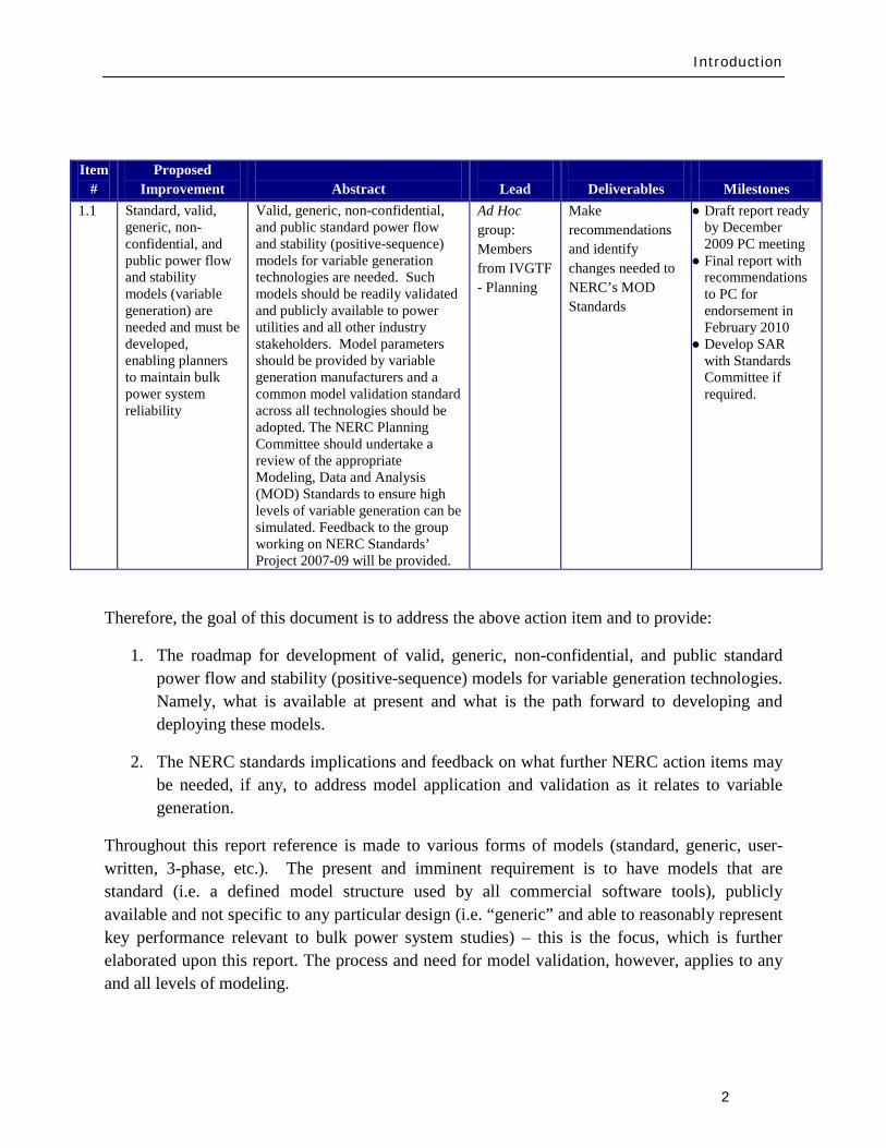
Characteristics of Power Systems amp Variable Generation
3
2 The Need for Models for Variable Generation
The planning and operation of large interconnected power systems in diverse regions in the North American continent is a complex task which requires daily analysis and computer model simulations System planners and operators use simulation studies to assess the potential impact of credible (and sometimes extreme) contingency scenarios and to assess the ability of the power system to withstand such events while remaining stable and intact (ie to avoid cascading outages) When a credible disturbance event is simulated in computer models of the power system and the observed result is unacceptable performance system planners andor operators must develop either operating strategies or planned equipment additions (eg line re-conductoring addition of shunt reactive compensation devices etc) to mitigate the potential problem To help ensure proper assessment of reliable performance and to minimize (as much as possible) capital investment models are required that reasonably represent actual equipment performance in simulations
The NERC Modeling Data and Analysis (MOD) Reliability Standards require Registered Entities to create procedures needed to develop maintain and report on models to analyze the steady-state and dynamic performance of the power system (MOD-011 and MOD-013) Equipment owners are required to provide steady-state and dynamic models (MOD-012) to the Regional Entities This information is required to build a reasonable representation of the interconnected system for planning purposes as stated in MOD-014 and MOD-0153
Therefore system models are required for generation equipment at three levels
Specifically models are required to perform powerflow short circuit and stability studies necessary to ensure bulk power system reliability
1 Models for assessing the steady-state behavior of the units and their fault currentcontributions for protection system analysis
2 Models for emulating the dynamic behavior of the units for bulk power system time-domain stability analysis
3 Detailed equipment-specific (3-phase) models for specialized studies
In this chapter the aforementioned three categories of models are described in detail focused on variable generation technologies
3 httpwwwnerccompagephpcid=2|20
Characteristics of Power Systems amp Variable Generation
4
21 Steady-State and Fault Current Analysis
Steady-state analysis in the context of bulk power system studies is primarily associated with power flow which determines the flow of power on transmission lines and transformers and the voltages at power system nodes (substations) Accurate calculations are essential in the planning and design of the interconnected power system to ensure that all equipment will be operated within its rated capability under various credible scenarios (including contingencies) These calculations are performed under various base-case conditions (ie all equipment generally in service) and contingency conditions that impact one or more power system elements such as a line generating unit or transformers out of service (eg for different system load conditions including peak load light load different seasons or different power transfer)
To assess the adequacy of protection system settings faults on transmission equipment are simulated and the settings for protection relays are evaluated as well as the calculated fault currents are compared to the current rating of circuit-breakers
Both these analyses are critical to the reliable operation of the power system To perform these analyses adequate models are needed for simulating the steady-state power flow and the fault current characteristics of generation equipment
22 Time-Domain Positive Sequence Dynamic Models for Bulk Power System Stability Analysis
Time-domain simulations are a key tool for assessing the reliability of the bulk power system assessing the stability of the system4
ldquoReliability of a power system refers to the probability of its satisfactory operation over the long run It denotes the ability to supply adequate electric service on a nearly continuous basis with few interruptions over an extended time period
Stability of a power system refers to the continuance of intact operation following a disturbance It depends on the operating condition and the nature of the physical disturbancerdquo
Similarly NERC defines stability as ldquoThe ability of an electric system to maintain a state of equilibrium during normal and abnormal conditions or disturbancesrdquo5
4 The definitions listed are quoted from P Kundur J Paserba V Ajjarapu G Andersson A Bose C Canizares N Hatziargyriou D Hill A Stankovic C Taylor T Van Cutsem and V Vittal ldquoDefinition and classification of power system stability IEEECIGRE joint task force on stability terms and definitionsrdquo IEEE Transactions on Power Systems Volume 19 Issue 3 Aug 2004 pp 1387 ndash 1401 (
httpieeexploreieeeorg)
Characteristics of Power Systems amp Variable Generation
5
Stability analysis is traditionally performed using positive-sequence models This includes models that focus on system simulation under assumed perfect balanced conditions (ie no imbalance in the 3-phase system voltages and currents) Furthermore the primary stability issues that are investigated (angular stability voltage stability frequency controlstability) for bulk power systems tend to be bounded within a small frequency band around the system fundamental frequency Positive sequence models are typically required to be valid in a range of roughly 01 Hz to about 3 Hz with the control system having validity up to 10 to 15 Hz to allow for investigating general control loop stability With these simplifying assumptions it has been historically easy to establish generic non-proprietary models for representing conventional generation and its controls Functional models that are non-proprietary and generic (ie applicable to any vendors equipment simply by changing the model parameters) are needed for the various variable generation technology A library of models to deal with each family of variable generation technology is required to support reliability assessment What is presently available and what must be further developed is discussed in the next chapter
Aside There are many cases were extended term analysis may be necessary in which case wind speed variations may be a needed input to the model For the purposes of typical stability analyses however where the study period spans over only several seconds wind speed is typically assumed to be constant
23 Detailed Three-phase Equipment Level Models
There are a number of potential interaction issues that may occasionally require detailed analysis [2] To perform this analysis detailed three-phase equipment models are required
Subsynchronous resonance (SSR) is a phenomenon whereby series compensation of a transmission line results in electrical resonance frequencies in the subsynchronous frequency range that can lead to destabilizing modes of mechanical torsional vibration on the turbine-generator shaft that fall in the frequency range of the electrical resonance6 These resonance phenomena are only of concern to generation technologies with a mechanical turbine-generator shaft that is coupled to the electrical system Type 1 2 and 3 Wind-Turbine Generation (WTG) may be susceptible7
5 Glossary of Terms Used in Reliability Standards
Clearly Type 4 (where the unit is decoupled from the electrical system) and technologies like PV have no such concerns SSR is less likely to affect wind turbines compared
httpwwwnerccomfilesGlossary_2009April20pdf Updated April 20 2009
6 P M Anderson B L Agrawal and J E Van Ness Subsynchronous Resonance in Power Systems IEEE Press New York 1990 PM Anderson and R G Farmer Series Compensation of Power Systems ISBN 1-888747-01-3 1996
7 See Appendix I for more information on these WTG configurations
Characteristics of Power Systems amp Variable Generation
6
to large conventional synchronous generators since the typical torsional mode for a wind turbine is quite low (around 1 to 4 Hz) Accordingly it would be quite unlikely that the level of series compensation in a system would be high enough to result in an electrical resonance that would interact with a low mechanical frequency8 A larger concern is induction machine self-excitation9
Another potential phenomenon related to torsional mechanical modes is device dependant subsynchronous oscillations often referred to in the literature as subsynchronous torsional interaction (SSTI) This was first observed at the Square Butte HVDC project in 1976
Some detailed 3-phase analysis and discussions with the wind turbine manufacturer on a case by case basis is prudent when installing wind near series compensated lines
10 SSTI is a phenomenon by which controls associated with power electronic based transmission equipment (eg SVC or HVDC) may introduce negative damping torques in the frequency range associated with the torsional mechanical modes of oscillation of nearby thermal turbine-generating units Again due to the relatively low frequency range for torsional modes of wind turbine this may not be a concern in most cases however where wind plants are closely coupled to a HVDC system analysis is prudent to ensure that control andor torsional interaction do not occur This analysis will typically require detailed three-phase models for both the wind plant and the HVDC system Also SSTI is not necessarily detrimental11 because in some cases torsional damping can be markedly improved through the application of power electronic devices One thermal power plant in the Western US grid uses a dedicated SVC for this purpose as a means of mitigating the effects of SSR 12
8 Note The electrical resonance needs to be in the range of 56 to 59 Hz on a 60 Hz system found in North America
A practical example of this is the Taiban Mesa wind plant located in New Mexico This wind plant is located electrically adjacent to a back-to-back HVDC station ndash Blackwater The detailed interconnection studies performed by ABB during the design of the wind plant showed that there was little risk of torsional interaction between the HVDC controls and the wind turbine generators This analysis required detailed equipment level (3-phase) models of the wind turbines the HVDC and transmission network
9 PM Anderson and R G Farmer Series Compensation of Power Systems ISBN 1-888747-01-3 1996 C F Wagner ldquoSelf-Excitation of Induction Motors with Series Capacitorsrdquo AIEE Transactions pp1241-1247 Vol 60 1941 (httpieeexploreieeeorg)
10 M Bahrman E Larsen R Piwko H Patel ldquoExperience with HVDC ndash Turbine Generator Torsional Interaction at Square Butterdquo IEEE Transactions on Power Apparatus and Systems Vol PAS-99 pp 966-975 MayJune 1980 (httpieeexploreieeeorg)
11 D Dickmander P Pourbeik T Tulkiewicz and Y Jiang-Haumlfner ldquoSSTI Characteristics of HVDC Lightrdquo White paper by ABB Inc December 2003
12 Pourbeik A Bostroumlm and B Ray ldquoModeling and Application Studies for a Modern Static VAr System Installationrdquo IEEE Transactions on Power Delivery Vol 21 No 1 January 2006 pp 368-377 (httpieeexploreieeeorg)
Characteristics of Power Systems amp Variable Generation
7
Other phenomena that may expose the shaft of a WTG to cyclical and significant transient torque pulsations may also be a concern For example nearby arc furnaces or high-speed re-closing on a transmission line emanating from the wind plant substation or repeated commutation failures on a nearby conventional line-commutated HVDC As a first step some simple transient stability analysis may be performed to estimate the expected step change in the electrical torque on a wind turbine generator due to the electrical event and the wind turbine manufacturer consulted to identify if the observed level of transient torque is a concern Based on consultation with the wind turbine manufacturer more detailed analysis may be required to assess if a potential problem exists and how it may be remedied
Another issue that may be of concern is the stability and behavior of variable generators in extremely weak short-circuit nodes of the power system and regions of the system that may be highly susceptible to islanding Again more detailed models than positive sequence stability representations may be needed to study these scenarios (eg to accurately review the potential for temporary over voltages upon islanding etc) Also in some cases and designs (eg Type 3 WTG) the behavior of the unit as it pertains to voltage-ride through during fault scenarios can be more onerous on the controls (ie controlling the DC bus voltage in the Type 3 WTG) for unbalanced fault scenarios as opposed to a balance 3-phase faults Thus 3-phase detailed equipment models are needed to assess these phenomena
Finally transient stability studies should be completed to ensure that basic control loops in the variable generation plants (eg central voltage control systems often deployed in doubly-fed and full-converter based wind plants that regulate voltage at the interconnecting substation by adjusting the reactive output of all wind turbines in the wind plant) do not interact or interfere with other nearby transmission and generation controls This often requires proper tuning of the controls
This brief section illustrates the need for the availability of detailed 3-phase equipment level models which cannot be generic These models are likely to be proprietary and may need to be used under non-disclosure agreements between the vendor and the plant developerutility Therefore it is important to recognize the need for these models so that they are developed and available to be easily deployed and used when such specialized studies are needed
24 Summary
This chapter has outlined the basic power generation plants models required power system analysis related to reliability assessment In addition these models need to be generic (ie the model structure applicable to any vendorrsquos equipment with only the variation of the model parameters to represent various vendor equipment) and non-proprietary (ie publicly available to all stakeholders) Adequate models readily exist for conventional synchronous generators but until recently have been unavailable for any variable generation technology In the next chapter the current status of models for all variable generation technologies is discussed
Transmission Planning amp Resource Adequacy
8
3 Present Status of Modeling Variable Generation
This chapter provides an overview of the models and modeling capability presently available In the summary of this chapter the gaps are identified and areas requiring further work are identified The modeling and model development discussed here is primarily for power system power flow short-circuit and stability analysis
Time-domain stability analysis is concerned with phenomena in the tens of milliseconds to several minutes time frame (see Figure 31)
Figure 31 Times of various phenomena of interest in power system studies (GE)
31 Wind Generation
311 WECCIEEE Effort for Generic Models
The size of individual WTGs has increased dramatically from several hundred kilowatts to multi-megawatt turbines The size of individual wind power plants has also increased significantly In the past a typical wind power plant consisted of several turbines Presently wind power plants
Switching Transients
Subsynchronous Resonance
Transient Stability
Small Signal Stability
Long-term Dynamics
TIME (seconds)
10-6 10-5 10-4 001
1 cycle
1041 1 10 100 1000
1 minute 1 hour
01
Transmission Planning amp Resource Adequacy
9
of several 100 MW and larger are being proposed By some projections13 as much as 300 GW (20 penetration) of wind generation capacity is forecast in the US by 2030 and NERC projects an increase of 229 GW of new wind generation installed capacity by 201814
Presently most wind turbine technologies use power electronics and advanced reactive power compensation as an integral part of wind turbine generator and wind power plant Under dynamic transients the behavior of modern wind turbines must be accurately simulated to predict the response of the wind power plant Misrepresentation of WTGs in transmission studies may threaten the reliability of power systems by either resulting in excessive overbuild of transmission systems due to pessimistic models or in deficient transmission system investment based on optimistic models
The increased penetration of renewable energy generation poses significant questions concerning the ability of the power system to maintain reliable operation
Turbine manufacturers have developed dynamic models for their wind turbines These dynamic models are typically user-written models in commercially available power system simulation software platforms (eg Siemens PTI PSSTME GE PSLFTM DigSILENT PowerFactory etc) Detailed three-phase equipment level models of WTGs used for internal design purposes are also often developed by manufacturers in either their own simulation platforms or commercial software tools including PSCADreg or Matlabreg Simulink
Unfortunately both these categories of models (the user-written positive-sequence models and the three-phase detailed equipment models) require significant input dataparameters considered to be proprietary by the turbine manufacturers and therefore are not freely available to the general public Access to these models usually requires a non-disclosure agreement (NDA) between the dynamic model user and the turbine manufacturers This agreement is only valid for a specific turbine model for a given period of time
In many cases it takes months to negotiate and to finalize the NDA Furthermore in some cases there are incompatibilities among turbine models developed by different turbine manufacturers which results in numerical interactions if multiple user-written models are incorporated into a single power system model for system analysis This makes the work of power system planners almost impossible The NDA are also usually bilateral which renders it impossible to share the information among the manufacturers to help resolve incompatibility problems Finally the NDAs make it difficult at best and impossible in some cases to share the models thereby potentially violating the NERC requirements for submitting models for system planning studies
13 httpwwwnrelgovdocsfy07osti40482pdf 14 httpwwwnerccomfiles2009_LTRApdf
Transmission Planning amp Resource Adequacy
10
With this back drop the WECC Wind Generator Modeling Group (WGMG) initiated the development of generic wind turbine models of the four (4) different types of wind turbines (see Appendix I for these four WTG designs) These four types of turbines currently hold the largest market share throughout the world WECC is interested in providing accurate and validated models of standard wind turbines that will be available in their database including the datasets to be used for testing the models and the methods for representing a wind power plant in power system studies These goals are being accomplished through the development and validation of standard models The standard models must be generic in nature ndash that is they must not require nor reveal proprietary data from the turbine manufacturers These improved standard (generic non-proprietary) dynamic models enable planners operators and engineers to perform the necessary transmission planning studies required to ensure system reliability
Currently the first generation of these generic WTG models for all four turbines types have been developed and are available as part of the main model library for the two most widely used commercial power system simulation tools in North America (ie Siemens PTI PSSTME GE PSLFTM)15
To date the first generation of generic models developed and released have focused on capturing the response of the units to electrical voltage disturbances on the transmission grid (grid faults) One deficiency particularly for the Type 1 and 2 models is the proper representation of unit responses to large system frequency excursions These models have not been verified due to the lack of data on actual turbine behavior under such circumstances and will require further development in consultation with turbine manufacturers
As a continuation of and in parallel with the WECC effort the Institute of Electronic and Electrical Engineers (IEEE) Power amp Energy Society (PES) has also established a Working Group to investigate WTG modeling issues The IEEE Working Group on Dynamic Performance of Wind Power Generation under the Power System Dynamic Performance Committee This Working Group is actively expanding the efforts of generic dynamic modeling for wind power plants focusing on modeling specifications disseminating methods and model validation
Finally as with all modeling exercises model development and validation are iterative processes requiring
bull Generic wind turbine models are to be made available to the public
15 PSSregE-320 Program Application Guide Volume II Chapter 21 PSSregE-320 Model Library Chapters 17 through 21 GE PSLF Users Manual v170_04 October 2009
Transmission Planning amp Resource Adequacy
11
bull Generic wind turbine models must be validated before release and public dissemination which is being pursued in WECC IEEE International Electrotechnical Commission (IEC) and other forums
bull Models should evolve and be revalidated as the technology progresses
bull Data from field measurement and monitoring for model validation can be a vital resource
A somewhat unique need in modeling variable generation (eg wind) is the need for methods required to develop equivalent models for large wind power plant In contrast to conventional fossil fuel and hydro power plants where plants are constituted by either a single large unit or at most a few large units a wind power plant can be made up of tens to more than a hundred WTGs For large scale power system simulations particularly in North America where the power system models are quite large it is often preferred to reduce the wind power plant to a single equivalent unit Accordingly techniques are needed for model aggregation and testing their validity ndash some significant progress has been made in this regard For example Figure 32 shows the technique developed for reducing the impedance of the wind power plant collector system into a single equivalent feeder impedance for representation of the wind power plant (WPP) by an aggregated single equivalent unit in power system studies
Figure 32 Example shows the method for reducing the impedance of a wind power plant collector system into a single equivalent impendence16
16 ldquoWECC Wind Generator Power Flow Modeling Guiderdquo (
httpwwwweccbizlibraryWECC20DocumentsDocuments20for20GeneratorsGenerator20Testing20ProgramWind20Generator20Power20Flow20Modeling20Guidepdf)
Transmission Planning amp Resource Adequacy
12
Figure 33 shows an example for dynamic simulations of aggregating the WPP into a single equivalent unit and an equivalent single impedance representing the entire collector system as compared to a detailed model representing the whole WPP unit-by-unit ndash the example shown assumes that all WTGs in the WPP are identical in cases where this is not true multiple equivalent units may be needed one for each WTG type As can be seen in this figure the results from the two simulations compare very well at the point of interconnection (which is what is shown) thus the equivalent aggregate is adequate for power system studies17
Figure 33 Example of time-domain simulations comparing a detailed model of a Wind Power Plant (ie representing the complete collector system and each WTG individually) versus a single-machine equivalent aggregate (ie the entire plant is represented by one equivalent unit and an equivalent impedance to represent the whole collector system)
17 Figure is from J Brochu R Gagnon and C Larose ldquoValidation of the WECC Single-Machine Equivalent Power Plantrdquo Presented at the IEEE PES DPWPG-WG Meeting at IEEE PSCE March 2009
P345 kV
Q345 kV
QWT = 0435 0 -0435
Transmission Planning amp Resource Adequacy
13
312 UWIG Generic Model Documentation and Validation Effort
The Utility Wind Integration Group (UWIG)18
The objectives of the project which will commence in early 2010 and run for a period of two years are to
under a US Department of Energy grant will be launching an effort to provide the basic documentation application and validation of generic models for wind turbines The goal of this project is to accelerate the appropriate use of generic wind turbine models for transmission network analysis
bull Complete characterization and documentation of the four generic models developed through an outgrowth of a WECC activity begun in 2005
bull Defining proposed enhancements to the generic wind turbine model structures that would allow representation of more advanced features including power control automatic curtailment inertial and governor response
bull Comparative testing of the generic models against more detailed (and sometimes proprietary) versions developed by turbine vendors
bull Developing recommended parameters for the generic models to best mimic the performance of specific commercial wind turbines
bull Documenting results of the comparative simulations in an application guide for users
bull Acquiring test data from all available sources for the purpose of validating the performance of the appropriately specified generic models in actual case studies
bull Conducting technology transfer activities in regional workshops for dissemination of knowledge and information gained and to engage electric power and wind industry personnel in the project while underway
18 The UWIG was established in 1989 to provide a forum for the critical analysis of wind technology for utility applications and to serve as a source of credible information on the status of wind technology and deployment The grouprsquos mission is to accelerate the development and application of good engineering and operational practices supporting the appropriate integration of wind power into the electric system It currently has more than 150 members spanning the United States Canada and around the world including investor-owned public power and rural electric cooperative utilities transmission system operators and associate member corporate government and academic organizations httpwwwuwigorgaboutuwightm
Transmission Planning amp Resource Adequacy
14
Maintaining communication and coordination with other ongoing activities and agencies engaged in this topic is another objective of the effort which will be critical for success
313 IEC Effort for Generic Models
The International Electrotechnical Commission (IEC) recently started a Working Group in October 2009 to address the development of generic and ldquostandardrdquo models for wind turbine generators19
Part 2 of this work will be focused on extending the modeling to allow for modeling of the entire wind power plant including wind power plant control and auxiliary equipment
The goal of this Working Group is to define standard dynamic simulation models for wind turbines and wind plants which are intended for use in power system and grid stability analyses and should be applicable for dynamic simulations of power system events including short circuits (low voltage ride through) loss of generation or loads and system separation The group is approaching this work in two parts Part 1 will focus on specifying dynamic simulation models for the generic wind turbine topologiesconceptsconfigurations presently in the market as well as specifying how these models may be modified as future technologiesconcepts are introduced The standard should also include procedures for validation of the models specified Another goal is that the models should be developed and specified at a fundamental level so they are independent of any specific software platform and can be adopted by any software vendor
Several members of this IEC Working Group are also members of the WECC and IEEE Working Groups (and this NERC Task Force) The three groups are clearly working in close collaboration to ensure maximum benefit to the industry globally and maximum sharing of knowledge already gained through the WECC and IEEE efforts
19 httpwwwiecchdynwwwfp=102140FSP_ORG_ID5613
Transmission Planning amp Resource Adequacy
15
32 Photovoltaic Solar Generation
Photovoltatic (PV) systems for power generation are quickly increasing becoming a significant portion of generation in some regions in North America PV or solar arrays are composed of a large number of solar cells connected in series and parallel These cells produce a DC voltage when they are exposed to sunlight due to the photo-voltaic effect20
Figure 34 shows the I-V characteristics of a cell at a constant temperature and various sun intensity or insolation levels
Figure 34 Current-Voltage characteristics of a solar cell for various insolation levels at a constant temperature (source [11]21
20 The photo-voltaic effect is the process by which an electric potential difference (voltage) is created in a material exposed to light (electromagnetic radiation) which then leads to the flow of electric current This process is directly related to the photo-electric effect but distinct from it in that in the case of the photo-electric effect electrons are ejected from the material surface upon being exposed to high enough frequency (energy) light whereas in the photo-voltaic effect the generated electrons are transferred across a material junction (eg PN junction in a photo-diode) resulting in the buildup of a voltage between two electrodes and the flow of direct current electricity
)
21 Solar Radiation Research Laboratory at the National Renewable Energy Laboratory (httpwwwnrelgovmidcsrrl_rsp)
Transmission Planning amp Resource Adequacy
16
Figure 35 shows that the current is limited when the cell is short-circuited (Voltage=0)
(a) (b) (c)
(d)
Figure 35 The concept of a solar array (a) a single solar cell (b) a series connection of solar cells (Nser = 3 and Npar = 1) and (c) a solar array (Nser = 3 and Npar = 2) The solar cell array(s) is then connected to a DC bus (d)
Figure 35 shows the concept of the solar cell up to the solar array To use the DC power generated by the PV array in an AC power system the DC power must be converted to 60 Hz AC in North America (50 Hz in some other regions in the world like Europe) There are several power electronic based converter concepts that can achieve this which can be classified into two general categories line-commutated converters (LCC) and self-commutated or more commonly
Vbus Iload
Ibus
Icap PV ARRAY
+
_
Transmission Planning amp Resource Adequacy
17
referred to as voltage-source converters (VSC) These technologies have been applied for decades and are well understood LCC use thyristors as their controlled switching device The switching on of a thyristors can be controlled while the turn-off time cannot be controlled and happens at the next AC waveform current zero crossing LCC systems must be operated in a network with an AC source and cannot operate to serve an isolated load In contrast VSC systems are self-commutating that is the power electronic switching devices used (eg integrated gate-commutated thyristors or IGCTs and insulated-gate bipolar transistors or IGBTs) are able to be completely controlled for both turn-on and turn-off and allow the VSC to completely control the AC waveform produced and adjust the power factor as seen on the AC side to within the current rating of the device Due to advances in the technology most power electronic converters employed in PV systems are of the VSC type22
From a modeling standpoint for power system studies there are some user-written manufacturer-specific models in existence as developed by various PV manufacturers Presently no generic or standard models exist
The WECC Working Group which has been addressing the development of generic WTG models will be extending its effort in 2010 to review developing generic PV models for dynamic simulations in stability studies As a starting point the grid side structure of the Type 4 WTG model may be used since it represents a VSC This is because PV is typically connected to the grid with a VSC and it will behave electrically similar to a Type 4 WTG that has a similar electrical interface with the gridmdashthis is from a grid perspective looking at the electric response and neglects any of the effects of the energy source
From a steady-state power flow and short-circuit analysis perspective the behavior of the PV technologies will behave in a similar fashion to a Type 4 WTG because of the VSC interface and because its power factor can be controlled based on the control functionality of the VSC design Its short-circuit response will be limited to the current limit effected by the VSC under grid fault conditions
The development of generic and standard PV models is presently a topic for further research This should be pursued imminently and much of what has been learnt from the WTG model development process should be leveraged
22 IEA-PVPS Grid-Connected Photovoltaic Power Systems Survey of Inverter and related Protection Equipment Report IEA PVPS T5-05 2002 December 2002 (httpwwwiea-pvpsorgproductsdownloadrep5_05pdf)
Transmission Planning amp Resource Adequacy
18
33 Solar Thermal
Solar thermal energy is based on harnessing the radiated heat of the sun for the purpose of producing electricity In broad terms there are presently two main ways of achieving this
1 Concentrating Solar Power (CSP) plants ndash in this case solar radiation is typically collected through a large number of mirrors (thus a large amount of solar radiation) which is then focused on a small area ndash the mirrors have tracking systems to follow the Sun The concentrated solar radiation heats a high temperature working fluid which then feeds a conventional steam-turbine generator From an electrical grid perspective the models needed to simulate the steady-state short-circuit and transient time-domain dynamics of such a generating unit are typically no different than standard synchronous generating units for fossil fuel plants
2 The Stirling Engine concept23
34 Tidal Generation
ndash in this design a parabolic mirror assembly concentrates the collected solar radiation on a sterling engine that sits at the focal point of the mirror assembly A Stirling engine is a reciprocating heat engine that operates based on the concept of cyclical compression and expansion of a working fluid As the working fluid expandscontracts it drives a piston that then turns a generator The engine is connected to an electrical generator that produces electric energy Once again for power system studies the units may be modeled using standard generator models However in this case a power plant would be constituted by a large number of small units (the typical Stirling engine is about 25 kW) in a large electrical collector system that collects the power and injects it into the utility grid ndash much like the collector system of a wind power plant Thus modeling the collector system (eg see Figure 32 for an aggregate model of a wind collector system) and any other devices in the collector system such as shunt reactive devices etc must be properly modeled
Tidal power generation derives energy directly from the motion of oceanic tides The gravitational pull of the Moon and Sun combined with the Earthrsquos rotation result in the generation of tides Tides generally occur with a period of roughly twelve hours and so most coastal areas experience two high and two low tides within every twenty-four hour period Tidal generation uses this phenomenon to generate energy Clearly the stronger the tides are either in tidal current velocity or the heightlevel of water the greater the potential amount of energy generation
23httpwwwstirlingenergycom Y Zhang and B Osborn ldquoSolar Dish-Stirling Power Plants and Related Grid Interconnection Issuesrdquo IEEE PES General Meeting 24-28 June 2007
Transmission Planning amp Resource Adequacy
19
Presently in North America tidal power is not a significant source of power in any region Some pilot programs exist for introducing the technology In April 2009 one was announced in Snohomish County Public Utility District in Washington State24
There are several options for harnessing tidal power One method is the use of turbines similar to wind turbines however the fluid (water) is much denser and requires a turbine with smaller and bulkier blades as shown in Figure 36 Most of these technologies typically use ACDCAC converter technology similar to a Type 4 wind turbine to convert the low frequency generated electricity to grid frequency AC electricity and interface with the power system Once this technology becomes more prevalent a starting point for development of a suitable model structure may be the Type 4 generic wind turbine models Understandably the energy source characteristics are quite different from wind power and significantly more predictable
Figure 36 One of the many concepts for tidal generation systems (courtesy of Marine Current Turbines Limited wwwmarineturbinescom)
35 Other Resources
There are several other emerging technologies and there are many complementary technologies (ie auxiliary to the variable generation resources but designed to help with their integration into the grid) including smoothly-controlled dynamic reactive devices (static VAr systems)
24 httpwwwsnopudcomPowerSupplytidaltidalpressashxp=1516amp756_na=46
Transmission Planning amp Resource Adequacy
20
energy storage technologies etc With respect to static VAr systems (SVCs and STATCOMs) there is an active WECC working group imminently addressing the issue of generic models for these devices25
36 Summary
The group has made substantial progress with the models defined and developed but currently undergoing testing and validation With regards to the other emerging technologies most tend to be power converter based (ie connected to the grid through a back-to-back frequency converter) and so their electrical behavior (neglecting the characteristics of the energy source) will be similar to Type 4 wind turbines Until these technologies mature the basic structure of other more mature converter based generation technologies can be a good starting point
This section has briefly presented the various types of variable generation and the present status of models and model development for power system studies Wind generation technologies being the most prevalent world-wide have the most mature models Through efforts started by WECC and being continued by IEEE and IEC generic standard models for the four main types of WTG technologies are being developed The first generation of these models has been released in two power system simulation software platforms most commonly used in North America Other emerging technologies (eg PV tidal power etc) can build on this effort to start developing generic models For example the WECC effort will be extending its scope in 2010 to look at PV model
From a NERC perspective the key items are
1 To emphasize and support efforts by WECC IEEE and IEC to develop and standardize generic models for these technologies for power system planning studies
2 To encourage manufacturers to familiarize themselves with the generic models being developed and be willing an able to supply parameters for these generic models to reasonably represent their equipment for power system stability studies As highlighted in Chapter 2 more detailed manufacturer specific models may be needed in special cases and for specialized studies
3 To encourage efforts aimed at model validation
4 To consider any augmentation or additions to reliability standards related to Modeling Data and Analysis (MOD) with respect to modeling and model validation of variable generation This is discussed in greater detail in section 5 of this report
25 httpwwwweccbizcommitteesStandingCommitteesPCCTSSMVWGSVCTFdefaultaspx
Present Status of Model Validation
21
4 Present Status of Model Validation
This chapter gives an overview of the model validation work that has been done hitherto as it relates to models for variable generation Necessarily the primary focus of this section is on wind turbine generator models since models for this resource are presently the most mature
41 What is Model Validation
Any and all models of a dynamic system always have limitations associated with them A model is a representation of reality it is an emulation ndash that is why it is called a model In developing a model first the question is asked as to the specified use of the model and the conditions it must reasonably emulate ndash this forms the basis of a model specification from which a model is developed The developed model establishes a certain structure with parameters which are adjustable in order to emulate different types of equipment or design of the modeled device Thus valid parameterization of the model to represent a particular manufacturerrsquos equipment is essential to support the particular scenarios to be analyzed
Model validation is often achieved through some form of testing either in a laboratoryfactory or in field There is a range of reasons for conducting tests for wind generation Each test has a unique set of objectives guiding the design of adequate testing practices
bull Performance Compliance Compliance to contractual requirements and grid codes are one reason to perform tests Interconnection requirements (usually included in plant Power Purchase Agreements and Interconnection Contracts) and grid codes typically outline specific technical criteria that must be met to allow a power plant to connect and operate on the grid Since these criteria point out specific levels to be met (for example voltage power factor and response time) tests may be designed with binary ldquopassfailrdquo objectives
bull Model Validation In much of the world power plants above a pre-defined size must be accurately represented with a dynamic simulation model used in stability analysis for operations and planning purposes As variable generation sources such as WPP are growing in size it is becoming increasingly important to have accurate variable generation specific models Tests may be performed to tune and verify simulation models to closely match the performance of actual equipment In the western US and Canada WECC has mandated that any plant with 20 MVA aggregate generation must be tested for model validation including large wind power plants For North America the imminent NERC MOD-026 standard presently under development will enforce model validation requirements throughout the North American region
Present Status of Model Validation
22
To achieve the goals of model validation there are three categories of tests that may be performed
bull Type Tests These are tests performed by the manufacturer or independent third-parties of representative equipment The intent is to demonstrate that a particular design of equipment exhibits specific performance and all other equipment of that same design is assumed to have the same performance Type tests can be
o Component Performed on specific functions or features in a power plant or generation equipment This could be for example testing the fault ride-through capability or reactive capability of a WTG where testing is performed at the component level
o Factory A systemic test of a major assembly (ie a drive train) or entire turbine-generator is performed under a controlled environment like a manufacturing facility to verify performance and validate assembly design
o Unit A systemic test of multiple components operating together (ie as entire operating WTG or WPP) with the specific intent of benchmarking a model or design as a type test For example tests performed in Europe under the WindTest program
bull Field Tests26
o Commissioning Tests performed on new equipment entering its period of commercial operation service
Tests performed by the power plant asset owner developer host utility manufacturer andor independent third-parties of specific operating equipment These tests are to demonstrate that a particular implementation design and installation of equipment exhibit specific performance
o Periodic Maintenance or Calibration Tests performed periodically after the plant is in commercial operation to verify that equipment continues to perform as well as it did during commissioning
26 See for example WSCC Control Work Group and Modeling amp Validation Work Group ldquoTest Guidelines for Synchronous Unit Dynamic Testing and Model Validationrdquo February 1997 (wwwweccbiz) and IEEE Task Force on Generator Model Validation Testing ldquoGuidelines for Generator Stability Model Validation Testingrdquo Proceedings of the IEEE PES General Meeting Tampa FL June 2007 (httpieeexploreieeeorg)
Present Status of Model Validation
23
o Periodic Model Validation Tests performed periodically after the plant is in commercial operation to verify that simulation models adequately represent actual plant performance (for example the periodic model validation testing required by WECC)
o Periodic Codes amp Standards Validation Tests performed periodically after the plant is in commercial operation to benchmark and validate plant performance per contractual requirements These tests are typically performed to obtain a permanent operating license for the power plant
bull On-Line Monitoring27
With these general concepts in mind the following subsections present some example cases studies of model validation and validation approaches for variable generation sources The examples emphasize WPP and WTG since wind generation is the present dominant variable generator sources in the North America continent
Other information of interest is from continuous data gathering based on ongoing performance of an operating power plant Data collected from external and unscheduled events including grid disturbances or in the case of WTG large changes in wind is particularly useful Monitoring also benchmarks performance under normal operation
42 Examples of Model Validation Efforts
421 Hydro- Queacutebec Example
The province of Queacutebec has vast wind energy potential Though wind energy generation in 2009 accounts for nearly 13 of the total installed capacity in the Queacutebec control area the penetration rate of wind energy generation will reach 10 by 2015 A total capacity of 528 MW is currently in operation and approximately 3000 MW are under development Five wind turbine manufacturers will supply the WTGs for the different projects under study
The configuration of the Hydro-Queacutebec transmission system is essentially radial Approximately 85 of the total installed generation feeding the system is located at distances up to 1300 km
27 See for example P Pourbeik ldquoAutomated Parameter Derivation for Power Plant Models From System Disturbance Datardquo Proceedings of the IEEE PES General Meeting Calgary Canada July 2009 (httpieeexploreieeeorg) This reference shows actual application of on-line disturbance monitoring to power plant model validation for conventional fossil fuel generation It may be feasible to apply similar algorithms and approaches for continuous re-validation of WTG and other variable generation technologies once generic standard models have been developed This is a current topic for research
Present Status of Model Validation
24
from the closest major load centers With this configuration the system transfer capability is mainly limited by stability constraints (transient stability and voltage stability) rather than congestion or thermal capacity of equipment hence the need for reliable models for wind power plants and all other generation
Stability studies are critical to determine the compensation equipment required to maintain the reliability of the power system when integrating new generation They are also essential for operation planning studies including control system design and tuning and determination of transfer capabilities
So far Hydro-Queacutebec has faced two major difficulties regarding user-written models provided by the wind turbine manufacturers First models often lack robustness and do not represent accurately some important features (convergence problems in low short-circuit network do not take into account frequency excursions do not represent secondary voltage regulation etc) Second model validation by the manufacturers is often incomplete not available or difficult to translate to real projects (different settings or software versions design of the collector system etc) In some cases these difficulties have lead Hydro-Queacutebec to build its own models (see Hypersim section below)
General validation test program
Since 2006 Hydro-Queacutebec has performed validation tests on WPP connected to its transmission system and a general validation test program was established in 200928
1 To demonstrate that WPP meet the Transmission Provider technical requirements related to wind generation
The power producer has the obligation to perform validation tests in order to demonstrate that its facilities meet the Transmission Provider requirements The purposes of this program are
2 To validate numerical models and parameters associated with the WPP specifically those given to the Transmission Provider by the power producer by comparing the model response to recordings taken during field tests
3 To confirm the electrical data of power producer facilities
The validation program is divided into seven functions to be validated
1 Primary voltage regulation
28 httpwwwhydroquebeccomtransenergiefrcommercepop_raccordement_transporthtml
Present Status of Model Validation
25
2 Undervoltage response (LVRT)
3 Inertial response
4 Secondary voltage regulation
5 Power factor
6 Maximum ramp rates
7 Power quality
The tests for the primary voltage regulation are performed on a single WTG and consist in producing instantaneous voltage variations of low amplitude on the terminal of the WTG and small voltage steps of limited duration injected directly into the WTG voltage control system Three-phase voltages and currents are recorded at the wind generator to measure the local dynamic response of a wind generator to a rapid voltage change and to verify that the response meets voltage regulation requirements The results are also used to set the model parameters (time constant and gain) used in dynamic simulations The tests regarding the secondary voltage regulation are similar but are conducted for the entire power plant
The validation test program includes LVRT tests on one generating unit to verify that requirements during undervoltage conditions are met The power producer has the responsibility to conduct the tests or to provide a complete report describing tests performed on an identical generating unit (same software version) to demonstrate that the requirements are met So far no LVRT tests were performed on site on WPP integrated on the Hydro-Queacutebec network However monitoring equipment has been installed at three locations in wind plants at their point of interconnection on a 345 kV feeder of the collector system and on one generating unit The monitoring system records signals either continuously or upon detecting variations occurring at the point of interconnection active power variations voltage sags and swells and system frequency excursions These signals are primarily voltages and currents but may also be mechanical variables or other signals
The field recordings recorded on the network can thereafter be used to validate the dynamic response of the models This is a time consuming effort that requires the collaboration of the manufacturers to modify the models if necessary Event recordings to-date have made possible suitable validation of two Hydro-Queacutebec Siemens PTI PSSregE models and one ElectroMagnetic Transients Program (EMTP) model
Inertial response requirements were not in defined for the projects started before 2005 Consequently existing wind plants do not have to fulfill them However the requirements have to be met for WPP to be commissioned in 2011 and after The corresponding validation tests consist in emulated frequency steps and ramps of limited duration Besides verifying the
Present Status of Model Validation
26
requirements the test results will be used to validate the parameters of the models and their dynamic response
The power factor and the maximum ramp rates modules are tested with all WTGs in service to verify that the requirements are met Power factor tests consist in supplying and absorbing a maximum amount of reactive power at different levels of active power Maximum ramp rate tests consist in performing a power plant shutdown sequence followed by a startup sequence These tests are not really used to validate the models but are rather helpful to fix model parameters
The last module regarding the power quality is not covered by scheduled testing but by means of a monitoring system that verifies harmonics and emission limits The recordings are compared to the report provided by the developers to verify if the requirements are met However they are not useful to validate the EMTP model since the WPP is represented by a single-wound generator and does not simulate the detailed collector bus system and individual wind turbine generators
Field tests department
Hydro-Queacutebec field-testing department (UMES) conducts a wide range of special tests and measurements for Hydro-Queacutebec and has done so for 30 years
To test WPP UMES installs a monitoring systems to record three-phase voltages and currents generally at three locations within the plant at the point of interconnection at the starting point of a 345 kV feeder of the collector system and at the terminals of a WTG connected to the same monitored feeder For extended model validation other signals within the wind turbine are monitored including the rotor side converter voltages and currents the network side converter currents and the DC bus voltage
High speed recorders with anti-aliasing filters are used Normally the sampling rate is 5 kHz with at least a 200 second window per event The monitoring system is reachable via an Ethernet connection for remote trigger and data retrieval UMES has also the responsibility to perform the data processing and analysis of the recordings in order to verify the compliance with the interconnection requirements and to extract relevant data for model validation
Present Status of Model Validation
27
Hypersim
The Hydro-Queacutebec Research Institute (IREQ)29 also has an important expertise in control system and wind generation modeling for extensive studies of electrical networks The simulation environment used is Hypersim a real-time simulator and powerful simulation tool that uses a highly detailed representation of the Hydro-Queacutebec network A full-transient detailed model of a Type 3 WTG was developed at IREQ using the MATLABreg SimPower Systems Toolbox The model was also implemented in EMTP and in the Hypersim real-time simulator30 This model is in the process of being validated with data processed by the UMES team The range of events recorded does not make it possible to validate the model completely and the design and parameters will continue to be adjusted to improve the representation of the wind turbines The validation of the MATLABreg model developed by IREQ was very useful to validate and improve Hydro-Queacutebecrsquos Siemens PTI PSSregE user model31
422 GE Example ndash based on GErsquos work with client facilities
In the case of the first example presented here a 10 MVar capacitor bank located at the 25kV WPP collector bus is switched off-line as an external physical stimulus Figure 41 shows detailed response to capacitor switching from the WindCONTROLreg The WindCONTROLreg system allows coordination of all on-line turbine-generators for plant-level fast and smooth voltage regulation at the point of interconnection (POI) located contractually at the 25kV substation bus The red curve (Q_ACTUAL [KVar]) shows that total plant reactive power initially drops after the switching action but the fast autonomous controls on each turbine generator quickly and stably respond to increase reactive power generated by individual turbines shown by the orange curve (Q_TURBINES [KVar]) The WindCONTROLreg command (Q_CMD) distributed to the turbines is shown in blue The response of Q_CMD is dominated by the gains of the voltage regulator portion of the WindCONTROLreg specifically the proportional gain Kpv and integral gain Kiv The difference between the response of the individual turbines (Q_TURBINES [KVar]) and the WindCONTROLreg command (Q_CMD) is due to the dynamics of the individual wind turbines The coordinated response of the wind plant and the individual
29 httpwwwhydroquebeccomtechnologyindexhtml 30 R Gagnon G Sybille SBernard D Pareacute S Casoria and C Larose ldquoModeling and Real-Time Simulation of a
Doubly-Fed Induction Generator Driven by a Wind Turbinerdquo IPST Conf Paper No IPST05-162 Montreacuteal Canada 2005 C Larose R Gagnon G Turmel P Giroux J Brochu D McNabb and D Lefebvre ldquoLarge Wind Farm Modeling Techniques for Power System Simulation Studiesrdquo in Proc 8th International Workshop on Large-Scale Integration of Wind Power into Power Systems Bremen Germany Oct 14-15 2009
31 C Langlois D Lefebvre L Dube and R Gagnon ldquoDeveloping a Type-III Wind Turbine Model for Stability Studies of the Hydro-Queacutebec Networkrdquo in Proc 8th International Workshop on Large-Scale Integration of Wind Power into Power Systems Bremen Germany Oct 14-15 2009
Present Status of Model Validation
28
turbines is multi-modal a fast initial response to address severe perturbations as well as a slower grid friendly refinement For purposes of this test the automatic control of the capacitor bank by WindCONTROLreg was disabled and manual switching was used as a stimulus to record individual WTG response
The detailed plot in Figure 42 shows a zoomed view of the response to step change in voltage at the WTG The very fast initial response will dominate and saturate the controls for big events The wind plant will do everything as quickly as it can to mitigate a large disturbance In this case the fast response took approximately 200 milliseconds The slow refined control then takes over to allow for coordination with other equipment and maintain post-disturbance stability This aggregate response also allows for a very abrupt action when needed and a grid-friendly refinement that maintains stability in less severe cases
The green curve in Figure 43 shows that when the capacitor is switched off-line the measured voltage at the point of interconnection (or POI) decreases due to reduced reactive power flowing into the grid The response of the individual WTGs is to rapidly increase reactive output to make up for the loss of reactive power supplied by the shunt capacitor The plant level control then responds to this initial under-voltage condition and attempts to restore the POI voltage by increasing each wind generatorrsquos reactive output by equal amounts until the plant voltage settles to the control set point determined by the operator The lower traces in Figure 43 show a gap during the period when the capacitor bank is online between total plant Q (Q_ACTUAL) and summation of Q out of each WTG (Q_TURBINES) This gap represents the capacitive reactance added by the shunt bank When the capacitor is switched offline the gap between Q_ACTUAL and Q_TURBINES closes and all reactive power is supplied solely from the WTGs The initial loss in plant reactive power is mitigated within approximately 15 seconds as each WTG settles to a new increased level operating point of reactive power This new increased reactive level for each WTG is the total Q increase from all units on-line in the plant divided by the total number of units online at the time of the test
Figure 44 shows a comparison between these measured values and the simulation results of the PSLF model Model outputs Qg Qplant Qcmd and Vreg correspond to measured Q_TURBINES Q_ACTUAL Q_CMD and U_LINELINE respectively This plot shows the model performance adequately represents what is happening in the field The response matches closely with a difference immediately following the switching operation being due to lower sampling rate in the measurement than in the GE PSLFreg simulation
Response to grid events demands relatively rapid control action Manual grid or plant operator changes in operating set-points do not normally demand fast response and indeed system behavior ought not to be rapidly disturbed by moving set-points Figure 45 shows the response of GE plant to 2 step in voltage reference The blue trace in the figure shows a well mannered response to the reference step The red trace is from the simulation model which matches very
Present Status of Model Validation
29
well In the blue trace after the perturbation occurring about 8 seconds after the reference change the plant supervisory control switched on a shunt capacitor to retain dynamic range on the wind turbines The switching perturbation is rapidly balanced by the turbines allowing the response to continue smoothly
Figure 41 10 MVar Capacitor removal response measured from WindCONTROLreg
Present Status of Model Validation
30
Figure 42 Wind turbine-generator level voltage step test response
Present Status of Model Validation
31
Figure 43 10 MVar Capacitor removal response ndash POI variables
Figure 44 10 MVar capacitor removal field test vs simulation results
Present Status of Model Validation
32
Figure 45 A different step test +- 2 step of voltage reference
The performance for grid fault events is of considerable interest in system planning Staging faults particularly severe ones on operating wind plants is difficult and expensive Figure 46 shows a comparison between a staged fault test and the (present) Siemens PTI PSSregE model of the GE 25 (full converter) WTG The fault event is quite severe a 3-phase 700ms of voltage depression to less than 20 of nominal at the high voltage terminal of the WTG unit transformer The measurement traces (on the left) include some of the signal noise characteristic of measurement and extraction of fundamental frequency positive sequence information from real high resolution measurements The simulation traces on the right are of course cleaner The match between test and simulation is of very high fidelity for phenomena relevant and legitimately examined with positive sequence simulation tools (ie greater than one cycle)
QPOI
VPOI
Measured = Blue Simulated = Red
Plant Capacitor Bank Switched On Automatically by WindCONTROL
+ 2 VrefStep
- 2 Vref Step
QPOI
VPOI
Measured = Blue Simulated = Red
Plant Capacitor Bank Switched On Automatically by WindCONTROL
+ 2 VrefStep
- 2 Vref Step
Present Status of Model Validation
33
Figure 46 GE 25 WTG Fault Test vs PSSe Model Performance
The discussion provide above is solely geared to hardware testing and validation however another highly valuable and legitimate means of providing validation of simulation models (for planning and otherwise) is to use more complex simulation software to validate simpler planning models Manufacturers normally have highly complex and highly proprietary models of their equipment These models are used among other things to design equipment and are normally physically based and must have sufficient fidelity for original equipment manufacturers (OEMs) to make sound engineering judgments for equipment design and application The OEMs are highly motivated to have these detailed high fidelity equipment level models These detailed models therefore can often be used to design test and validate simpler planning models to be used by the industry
There is a long accepted history in the power industry of this practice For example a typical (GE) gas turbine has on the order of 4000 state variables in the design model planning models typically have on the order of four state variables simplification is necessary and expected These design codes have been used to develop planning models of gas turbines Figure 47 below shows a comparison between a fault simulation using a GE design code (GE WindTrapreg) and the planning model in GE PSLFreg for a GE 15 (double fed machine) WTG
Present Status of Model Validation
34
Figure 47 Detailed Design Simulation (GE WindTRAPreg) vs GE PSLFreg Model Performance (active power during a severe fault for a GE 15 WTG)
-10
00
10
20
30
0 05 1 15 2
Time (Seconds)
Sin
gle
WTG
Rea
l Pow
er (M
WindtrapPSLF
Summary amp Recommended Actions
35
5 Summary amp Recommended Actions ndash Standards Implications
This document has presented a general overview of modeling and model validation as it pertains to variable generation resources Clearly to date the bulk of the experience and work has been on wind turbine generators Never-the-less similar approaches for modeling and model validation are being pursued for other variable generator technologies such as PV
Non-proprietary and publicly available models for the simulation of steady-state (power flow) short-circuit (fault calculations) and dynamic (time-domain simulations) behavior of such generation resources must be made readily available for use by power system planners Furthermore these models should be routinely validated to ensure proper representation of variable generation power plants in bulk power system studies A model is valid if its dynamic behavior is close enough to reality so that its influence on the network of interest (ie used for power system studies) is consistent with the fidelity of model structures and available data for the power system and other generation as it pertains to the phenomena of interest (ie in stability studies) That is perfect curve fitting is not necessary but to the extent possible erroneous model dynamics must not result in a notable over-design or under-design of the network
Each of the NERC standards discussed below in Section 52 address to aspects of meeting a standard (i) the technical requirement ie the need to define measure validate a model its parameters etc and (ii) the procedural requirements ie the functional model of how this technical requirement should be met reported and monitored The bulk of this working grouprsquos recommendations stated below address the technical requirements Variable generation is a new and quickly evolving technology and consideration should be given to the timing with which standards be implemented
Section 51 below first gives a summary of the planning process based on NERC standards to put the discussions in this report into context with the NERC standards Then in Section 52 we provided our recommendations and comments on the NERC existing and developing standards
Summary amp Recommended Actions
36
51 Applying the NERC Standards
The NERC standard FAC-001 (see Figure 51) should be expanded to clearly cover modeling requirements during the coordinated joint study phase of the Facility connection process Simple generic models of variable generation may be adequate for the IES phase and more detailed models may be needed for the IFS phase Validation of the simple and detailed model parameters may be needed during commissioning
Figure 51 Facility connection process
Interconnection Evaluation Study
Generator Interconnection
Request
Interconnection Facility Study
GO provides initial model
to TPPC
GO provides final model
to TPPC
GO signs Interconnection
Agreement and is put in-service
GO performs model amp
performance validation testing
TO develops Facility Interconnection requirements and requests models and data
of the GO at each process stage
FAC-001
Summary amp Recommended Actions
37
The generic model with associated parameters feed into the NERC model building process shown in Figure 52 As an example for WTG presently there is insufficient evidence of the accuracy of presently available generic models for WTG32
for all the various WTG manufacturers Some confirmation tests during commissioning or type tests or comparison simulation tests with a detailed model are necessary to get buy in from the Transmission OwnerPlanner As the technology matures and generic models are enhanced and associated data parameter sets are developed for specific machine types the new generic models will become more accepted as is the case with models of hydro or thermal plants
Figure 52 Annual NERC Model Development Process
32 PSSregE-320 Program Application Guide Volume II Chapter 21 PSSregE-320 Model Library Chapters 17 through 21 GE PSLF Users Manual v170_04 October 2009
Steady state data
developed
MOD-10
Dynamics data
developed
MOD-12
Reliability Region creates model
MOD-14
Reliability Region creates model
MOD-15
Reliability Region defines data
requirements
MOD-13
GO
TP
RP
Reliability Region defines data
requirements
MOD-11
Annual NERC Planning and
Operating Models
created and distributed to the industry
Summary amp Recommended Actions
38
The regional model building manuals developed as part of MOD-11 and MOD-13 must provide sufficient clarity to model variable generation These manuals may ask for best available models or generic models These models cover the operational time frame and the 10-year planning horizon The manuals do not currently cover the frequency for revalidating model data
While not included in the standards more emphasis is currently being placed on meeting the Eastern Interconnection Reliability Assessment Group (ERAG) model building manual requirements in addition to regional requirements
Figure 53 NERC Model Validation Process
The Regional Entities develop the test procedures and dictate testing frequency for the Generator Owners to follow The model data then feeds in to the annual NERC model building process
52 NERC Standards Technical Issues
One general comment is that the NERC Glossary of Terms would benefit from the term ldquoVariable Generationrdquo being include in it and appropriately defined A suitable definition can be found in the Phase I report of the IVGTF
Verify real power capability
MOD-24
GO
Verify reactive power capability
MOD-25
Verify generator excitation control model
MOD-26
Verify turbine governor model
MOD-27
Summary amp Recommended Actions
39
MOD-011 Regional Steady-State Data Requirements and Reporting Procedures
The technical requirement in this MOD reads
ldquoR12 Generating Units (including synchronous condensers pumped storage etc) location minimum and maximum Ratings (net Real and Reactive Power) regulated bus and voltage set point and equipment statusrdquo
This statement could be read to equally apply to variable generation as a source of generation However it may be prudent to explicitly include variable generation in this statement For example to change the sentence to
ldquoR12 Generating Units (including synchronous condensers pumped storage variable generation resources etc) location minimum and maximum Ratings (net Real and Reactive Power) regulated bus and voltage set point and equipment status For variable generation a suitable aggregate steady-state model of the collector system and equivalent unit representing the full plantrdquo
MOD-012 Dynamics Data for Transmission System Modeling and Simulation
This MOD equally applies to variable generation and needs no augmentation The requirements in the MOD are quite generic The requirements of this standard are dependent on and point to MOD 13 discussed below
MOD-013-1 RRO Dynamics Data Requirements and Reporting Procedures
This MOD explicitly discusses synchronous type generation It would be beneficial to include an explicit statement to cover variable generation For example
ldquoPlant-specific dynamics data shall be reported for variable generating units (eg wind turbine generators PV etc) such as the type of generating unit its interface with the grid and the appropriate model and model parameters to adequately represent unit dynamic response for bulk power system studies The typical size of a single variable generating unit (eg wind turbine generators PV array etc) is several hundreds of kilo-watts to several mega-watts Thus it may be acceptable for the total plant to be represented by an adequate aggregated model of the collector system and a single equivalent generating unit scaled up to represent the total name-plate capacity for each type of generating technology employed in the plant Furthermore models may need to be provided for other equipment installed in the collector system or at the point of interconnection such as reactive compensation devicesrdquo
Summary amp Recommended Actions
40
MOD-024-2 mdash Verification and Data Reporting of Generator Real Power Capability
This latest posting of this MOD posted for commenting on January 18th 2010 exempts variable generation from this requirement It states
ldquoVariable energy units such as wind generators solar and run of river hydro are exempt from the requirements of this Standardrdquo
For a variable generation plant the definition of Real Power Capability can be slightly challenging One way to view it is to see the total gross capability as the sum of the nameplate rating of all individual units within the plant eg for a wind power plant the total sum of the nameplate rating of all wind turbine generators in the plant However there must be two realizations (i) the amount of actual power injected into the grid at the point of interconnection requires a suitable representation of losses on the collector system and auxiliary loads and (ii) by its very nature variable generation is a highly variable energy source and thus it is quite rare to find point in time when all units in the plant are coincidentally at their peak nameplate capacity Finally the seasonal variable generation output variations need some discussion since they are quite different than conventional generation technologies
MOD-025-1 mdash Verification of Generator Gross and Net Reactive Power Capability
The technical requirement in this MOD reads
ldquoR15 Information to be reported
R151 Verified maximum gross and net Reactive Power capability (both lagging and leading) at Seasonal Real Power generating capabilities as reported in accordance with Reliability Standard MOD-024 Requirement 151
R152 Verified Reactive Power limitations such as generator terminal voltage limitations shorted rotor turns etc
R153 Verified Reactive Power of auxiliary loads
R154 Method of verification including date and conditionsrdquo
Note the above requirements are from the existing version of the standard MOD-025 is currently being enhanced
Although all of the above could equally apply to variable generation some clarification may be needed Namely variable generation reactive capability of the ldquopower plantrdquo is not entirely inherent in the individual generating units A variable generation power plant such as a wind power plant may contain many reactive power sources such as the individual generating units themselves (eg Type 3 or 4 WTG see Appendix I) discretely switched shunt reactive devices
Summary amp Recommended Actions
41
(eg shunt capacitors or reactors) smoothly controlled shunt reactive devices (eg SVC or STATCOM) or a combination of these devices Thus care should be taken as to how the total reactive capability of the power plant is defined and at what point (eg point of interconnection and whether this is defined as the high or low side of the substation transformer) Also it may not be practical under normal operating conditions to exercise the full reactive capability of the power plant (this is a known issue even with conventional synchronous generator plants) to test it thus it should suffice to demonstrate the plants reactive capability to the extent possible in the field and to then augment this with engineering calculations to derive the plants full reactive capability This is particularly true of variable generation because there is no control over the energy resource So for example a typical wind power plant may only achieve its name-plate rating for a hour or two during an entire year Thus it would not be possible to demonstrate the full reactive capability of the plant in the field Rather it should suffice to demonstrate the reactive capability of a single WTG and then to derive through engineering calculations (considering all other reactive devices in the plant such as SVC STATCOM etc) the total reactive capability of the plant These comments should be somehow used to appropriately modify MOD 25
MOD-026-1 mdash Verification of Models and Data for Generator Excitation System Functions ndash SECOND POSTING (and MOD 27)
MOD 26 (and MOD 27 Verification of Models and Data for TurbineGovernor and Load Control) are presently under development33
Presently these standards are tailored explicitly to deal with synchronous type generators since much of the language revolves around technology associated with synchronous generation (eg excitation system AVR power system stabilizers etc) Thus the following key items need to be clarified in these standards as they pertain to variable generation In addition the comments that follow apply to all components in a variable generation plant that may include devices such as the actual power generating units shunt compensation devices centralized control systems spanning the entire facility etc
These two standards deal specifically with the routine validation of generating unit dynamic models for power system stability studies
1 UnitPlant Size for Validation These MODrsquos specify the size of generating unit above which model validation is required It should be recognized that the typical size of a
33 MOD 26 and MOD 27 standards under development are found at httpwwwnerccomfilezstandardsGenerator-Verification-Project-2007-09html
Summary amp Recommended Actions
42
variable generation unit is in the hundreds of kilo-watts to several megawatts range Thus the language should be changed (or introduced) to indicate ldquonet power plantrdquo size
2 Validation of various technologies in a single plant Variable generation power plants can consist of multiple generation technologies For example a wind power plant may consist of WTGs of two different types Thus we need to consider the following points as they pertain to variable generation
a For a uniform variable generation plant (ie all generating units are of the same technology type) a single aggregate generator model representation should be sufficient
b For a significantly diverse variable generation plant the plant should be represented by multiple aggregated unit models representing each technology type
c Unique representation of a group of variable generation units as a single aggregated generator model representation should be based on
i The size of the group is a significant proportion of the total plant size (eg gt 20 of plant rating)
ii Each group should represent a unique characteristic (eg Type 1 WTG as compared to a Type 3 WTG)
3 Validation of different control layers Variable generation plants such as wind power plant may have several functional layers of control For example in a wind power plant with Type 3 WTGs we may have one level of closed loop voltage regulation at the terminals of the WTG a second slower control loop that regulates voltage at the point of interconnection (POI) and a third layer of control that coordinates the switching of shunt capacitors at the POI based on the reactive output of the individual WTGs In addition devices such as STATCOMs may be present at the POI Modeling and model validation should incorporate such devicescontrol layers to the extent that the dynamics of these functional layers are important for stability studies (see Figure 31)
4 Modeling and Model Validation Models are an emulation of actual equipment Not all model parameters necessarily translate to actual physical components or measureable features Judgment needs to be exercised in the modeling and validation process
a Models should be validated typically against the performance of an actual plant for a given eventdisturbance within the given operating range it is designed for
Summary amp Recommended Actions
43
b Models should state clearly the type and the range of events they have been designed to simulated and the limitation of the models beyond which the model deviates from the actual variable generation plant performance (eg a model developed to represent electrical transient behavior of a WTG may not be adequate for studying wind fluctuations over a many minute time frame)
c In general the best approach to model validation is to use field (or test bench) measurements of various disturbances that must exercise the different control functions to a wide range of operation points For example a model is not necessarily valid if the only a comparison between simulation results and field measurements for a single voltage step response is performed at one operating condition Ideally illustration of validation against recorded response to various system disturbances (faults frequency deviations etc) gives the greatest confidence in validation
d A model is valid if its dynamic behavior is close enough to reality so that its influence on the network of interest (ie used for power system studies) results in relatively negligible errors for the phenomena of interest (ie in stability studies) That is perfect curve fitting is not necessary but to the extent possible erroneous model dynamics must not result in a notable over-design or under-design of the network
5 Future functionality Due to the rapidly evolving nature of variable generation technologies variable generation models should be of a modular nature such that future functionality can be incorporated as much as possible into old model structures by adding a functional modular block For example presently Type 3 and 4 WTGs do not exhibit inertial response However at least one manufacturer now supplies a functional control addition that can emulate inertial response on these units Such functionality is likely to be made available soon by most vendors Thus a functional model block can be developed that can be added to the existing models for Type 3 and 4 WTGs to emulate the behavior of this additional control
6 Modeling of protection Variable generation much like conventional generation will have associated underover voltage and under-over frequency protection These should be modeled Attention should also be given to protective relay coordination with plant controls particularly in light of the nature of the grounding system within the variable generation plant (eg a wind power plant spans an entire collector system which can be grounded in several different ways and thus have various implications on protective relay coordination) Such coordination issues relate to the PRC and FAC-001 standards
Summary amp Recommended Actions
44
7 Issues related to the fuel source for variable generation For variable generation one needs to be cognizant of the variable nature of the energy source and thus the possible impracticality of performing model validation at a desired plant output but rather having to accept model validation at whatever plant output can be achieved at the time of testing or disturbance monitoring
8 Revalidation How often should models be revalidated
a Many variable generation technologies are rapidly changing for example in wind power plants new control software or new setting may be uploaded every year if not sooner
b If the changes are insignificant the existing dynamic models should be revalidated if possible as a matter of prudency ndash say within six months or so of a control system updateupgrade The changes (in parameters or dynamic model) should be reported to the local Reliability Entities
c If the changes are significant the existing dynamic models should be revalidated ndash say within three months or so after the updateupgrade The changes (which may include a new module new software etc) should be reported to the local Regional Entities
53 Final Recommendation
An earlier draft of this report and recommendations were presented to NERCrsquos Planning Committee at their March 2010 meeting The Committee members urged the IVGTF to pursue NERC reliability standard development Thus several NERC Standards Drafting Teams undertaking MOD Standard development will be contacted to present the recommendations from this report for their consideration and incorporation in subsequent updates The standard drafting teams for MOD-026 and MOD-027 are aiming to incorporate variable generation considerations in the next release of these draft standards
Appendix I Wind-Turbine Generation (WTG) Technologies
45
Appendix I Wind-Turbine Generation (WTG) Technologies
(a) Type 1 Wind Turbine-Generator Fixed Speed Induction Generator
(b) Type 2 Wind Turbine-Generator Variable Slip Induction Generator 34
34 IGBT R control = Resistor controlled by Insulated Gate Bi-Polar Transistor
3
GEAR BOX
INDUCTION GENERATOR TRANSFORMER
GRID
3
3GEAR BOX
WOUND ROTORINDUCTION GENERATOR TRANSFORMER
GRID
IGBT RControl
Rectifier
Appendix I Wind-Turbine Generation (WTG) Technologies
46
(c) Type 3 Wind Turbine-Generator Double-Fed Asynchronous Generator
(d) Type 4 Wind Turbine-Generator Full Power Conversion
3
3GEAR BOX
WOUND ROTORINDUCTION GENERATOR TRANSFORMER
GRID
IGBT POWER CONVERTORS
3
GEAR BOX
SYNCHRONOUSGENERATOR TRANSFORMER
GRID
Rectifier
33
IGBTInverter
Acronyms
47
Acronyms
CSP ndash Concentrating Solar Power
CIGRE - International Council on Large Electric Systems
DFAG ndash Doubly Fed Asynchronous Generator (also often referred to as DFIG ndash Doubly Fed Induction Generator)
FERC ndash Federal Energy Regulatory Commission
HVDC ndash High-Voltage Direct-Current transmission
IEC ndash International Electrotechnical Commission
IEEE ndash Institute of Electrical and Electronic Engineers
IGBT ndash Insulated-Gate Bipolar Transistor
IGCT ndash Insulated-Gate Commutated Thyristor
IVGTF ndash Integration of Variable Generation Task Force
ISO ndash Independent System Operator
LCC ndash Line-Commutated Converter
LVRT ndash Low-Voltage Ride-Through
MOD ndash Modeling Data and Analysis Standards
NERC ndash North American Electric Reliability Corporation
OEM ndash Original Equipment Manufacturer
PHEV ndash Plug-in Hybrid Electric Vehicle
PV ndash Photovoltaic
POI ndash Point of Interconnection
RPS ndash Renewable Portfolio Standard
RTO ndash Regional Transmission Operator
Acronyms
48
SAR ndash Standards Authorization Request (NERC process)
SCADA - Supervisory Control and Data Acquisition
SSTI ndash Subsynchronous Torsional Interaction
STATCOM ndash Static Compensator (voltage source converter based technology)
SVC ndash Static Var Compensator (thyristor based technology)
TSO ndash Transmission System Operator
VAr ndash volt-ampere reactive (standard units for reactive power)
VRT ndash Voltage Ride-Through
VSC ndash Voltage Source Converter
WPP ndash Wind Power Plant
WTG ndash Wind Turbine Generator
WECC ndash Western Electricity Coordinating Council
IVGTF Roster
49
IVGTF Task 1-1 Roster
Chair Pouyan Pourbeik
Technical Executive EPRI 942 Corridor Park Boulevard Knoxville Tennessee 37932
(919) 806-8126 ppourbeik epricom
Jay Caspary Director Transmission Development
Southwest Power Pool 415 North McKinley Suite 140 Little Rock Arkansas 72205
(501) 666-0376 (501) 666-0376 Fx jcasparyspporg
K R Chakravarthi
Southern Company Services Inc Southern Company Services Birmingham Alabama 35203
205-257-6125 205-257-1040 Fx krchakra southerncocom
Kieran Connolly
Manager Generation Scheduling
Bonneville Power Administration 905 NE 11th Avenue Portland Oregon 97232
(503) 230-4680 (503) 230-5377 Fx kpconnolly bpagov
Adam Flink
Engineer Midwest Reliability Organization 2774 Cleveland Ave Roseville Minnesota 55113
6515881705 (651) 855-1712 Fx adflink midwestreliabilityorg
David Jacobson
Interconnection amp Grid Supply Planning Engineer
Manitoba Hydro 12-1146 Waverly Street PO Box 815 Winnipeg Manitoba R3C 2P4
(204) 474-3765 (204) 477-4606 Fx dajacobson hydrombca
Charles-Eric
Langlois Jr Engineer
Hydro-Queacutebec TransEnergie 9e eacutetage Complexe Desjardins Tour Est Montreal Queacutebec H5B1H7
(514) 879-4100 ext 5441 (514) 879-4486 Fx LangloisCharles-Erichydroqcca
IVGTF Roster
50
David Marshall Project Manager
Southern Company Services Inc 600 N 18th Street Birmingham Alabama 35203
205-257-3326 205-257-1040 Fx dcmarsha southerncocom
Sophie Paquette
Transmission Planning Engineer
Hydro-Queacutebec TransEnergie 9e eacutetage Complexe Desjardins Tour Est 12th Floor Montreal Queacutebec H5B1H7
(514) 879-4100 ext 5423 (514) 879-4486 Fx paquettesophie hydroqcca
David C Schooley
Sr Engineer Commonwealth Edison Co 2 Lincoln Centre Oakbrook Terrace Illinois 60181
(630) 437-2773 davidschooley comedcom
Eric Thoms
Technical Lead - Transmission Access Planning
Midwest ISO Inc 1125 Energy Park Dr St Paul Minnesota 55108
(651) 632-8454 (651) 632-8417 Fx ethoms midwestisoorg
Observers Daniel Brooks
Manager Power Delivery System Studies
Electric Power Research Institute 942 Corridor Park Blvd Knoxville Tennessee 37932
(865) 218-8040 (865) 218-8001 Fx dbrooksepricom
Abraham Ellis
Principal Member of Technical Staff Renewable System Integration
Sandia National Laboratories 1515 Eubank SE Albuquerque New Mexico 87123
(505) 844-7717 (505) 844-2890 Fx aellis sandiagov
Ben Karlson
Sandia National Laboratories PO Box 5800 Albuquerque New Mexico 87185
(505) 803-3676 bkarlso sandiagov
Yuriy Kazachkov
Siemens Energy Inc 400 State Street Schenectady New York 12305
(518) 395-5132 (518) 346-2777 Fx yuriykazachkov siemenscom
Carl Lenox
Senior Staff Engineer Sunpower Corporation Systems 1414 Harbour Way South Richmond California 94804
(510) 260-8286 (510) 540-0552 Fx carllenox sunpowercorpcom
IVGTF Roster
51
Jason MacDowell
GE Energy 1 River Road Bldg 53 Schenectady New York 12345
(518) 385-2416 (518) 385-5703 Fx jasonmacdowell gecom
John Mead
Senior Staff Engineer Sunpower Corporation Systems 1414 Harbour Way South Richmond California 94804
(510) 260-8370 (510) 540-0552 Fx johnmead sunpowercorpcom
Nicholas W Miller
Director GE Energy 53-300Q 1 River Road Schenectady New York 12345
(518) 385-9865 (518) 385-5703 Fx nicholasmiller gecom
Eduard Muljadi
Senior Engineer National Renewable Energy Laboratory 1617 Cole Boulevard Golden Colorado 80401
(303) 384-6904 EduardMuljadi nrelgov
Mark OMalley
Professor of Electrical Engineering
University College Dublin R 157A Engineering amp Materials Science Centre University College Dublin Belfield Dublin 4
00353-1-716-1851 00353-1-283-0921 Fx markomalley ucdie
Subbaiah Pasupulati
Director of Technical Studies
Oak Creek Energy Systems Inc 14633 Willow Springs Road Mojave California 93501
(909) 241-9197 (661) 822-5991 Fx subbaiah oakcreekenergycom
Juan J Sanchez-
Gasca Principal Engineer
GE Energy 1 River Road Bldg 53-302E Schenectady New York 12345
(518) 385-5564 (518) 385-5703 Fx juansanchez psgecom
Steven Saylors
Chief Electrical Engineer
Vestas Americas 1881 SW Naito Parkway Portland Oregon 97201
(503) 327-2111 (503) 327-2001 Fx saylvestascom
IVGTF Roster
52
Robert Zavadil Vice President and Principal Consultant
EnerNex Corp 620 Mabry Hood Road Suite 300 Knoxville Tennessee 37932
(865) 218-4600 Ext 6149 (865) 218-8999 Fx bobzenernexcom
NERC Staff
Aaron Bennett Engineer Reliability Assessments
North American Electric Reliability Corporation 116-390 Village Boulevard Princeton New Jersey 08540-5721
(609) 524-7003 (609) 452-9550 Fx aaronbennett nercnet
Rhaiza Villafranca
Technical Analyst North American Electric Reliability Corporation 116-390 Village Boulevard Princeton New Jersey 08540-5721
(609) 452-8060 (609) 452-9550 Fx rhaizavillafranca nercnet
Mark G Lauby
Director Reliability Assessment and Performance Analysis
North American Electric Reliability Corporation 116-390 Village Boulevard Princeton New Jersey 08540-5721
(609) 524-7077 (609) 452-9550 Fx marklauby nercnet
References
53
References and Further Reading
[1] NERC Special Report Accommodation of High Levels of Variable Generation April 2009 httpwwwnerccomfilesIVGTF_Report_041609pdf
[2] CIGRE Technical Brochure 328 Modeling and Dynamic Behavior of Wind Generation as it Relates to Power System Control and Dynamic Performance Prepared by CIGRE WG C4601 August 2007 (available on-line at wwwe-cigreorg)
[3] ldquoWECC Wind Generator Power Flow Modeling Guiderdquo (httpwwwweccbizlibraryWECC20DocumentsDocuments20for20GeneratorsGenerator20Testing20ProgramWind20Generator20Power20Flow20Modeling20Guidepdf)
[4] G Lalor A Mullane and M J OrsquoMalley ldquoFrequency Control and Wind Turbine Technologiesrdquo IEEE Transactions on Power Systems Vol 20 pp 1903-1913 2005
[5] A Mullane and M J OrsquoMalley ldquoThe inertial-response of induction-machine based wind-turbinesrdquo IEEE Transactions on Power Systems Vol 20 pp 1496 ndash 1503 2005
[6] R Walling ldquoWind Plants of the Futurerdquo UWIG Oct 2008
[7] Hydro-Queacutebec TransEacutenergie ldquoTechnical requirements for the connection of generation facilities to the Hydro-Queacutebec transmission systemrdquo May 2006
[8] ESB National grid ldquoDynamic modeling of wind generation in Irelandrdquo January 2008
[9] N Miller K Clark R Delmerico and M Cardinal ldquoWindINERTIATM Inertial Response Option for GE Wind Turbine Generatorsrdquo Windpower 2009 Chicago IL May 4-7 2009
[10] R K Varma and S Auddy ldquoMitigation of Subsynchronous Oscillations in a Series Compensated Wind Farm with Static Var Compensatorrdquo Proceedings of the IEEE PES General Meeting 2006 Montreall Canada 2006
References
54
[11] Bialasiewicz J T Muljadi E Nix R G Drouilhet S Renewable Energy Power System Modular Simulator RPM-SIM Users Guide National Renewable Energy Laboratory March 2001 NRELTP-500-29721
[12] N Miller K Clark J MacDowell and W Barton Experience with Field and Factory Testing for Model Validation of GE Wind Plants European Wind Energy Conference amp Exhibition Brussels Belgium MarchApril 2008
[13] R J Piwko N W Miller and J M MacDowell ldquoField Testing and Model Validation of Wind Plantsrdquo IEEE-PES GM June 2008
- Executive Summary
- Introduction
- The Need for Models for Variable Generation
- Steady-State and Fault Current Analysis
- Time-Domain Positive Sequence Dynamic Models for Bulk Power System Stability Analysis
- Detailed Three-phase Equipment Level Models
- Summary
- Present Status of Modeling Variable Generation
- Wind Generation
-
- 311 WECCIEEE Effort for Generic Models
- 312 UWIG Generic Model Documentation and Validation Effort
- 313 IEC Effort for Generic Models
-
- Photovoltaic Solar Generation
- Solar Thermal
- Tidal Generation
- Other Resources
- Summary
- Present Status of Model Validation
- What is Model Validation
- Examples of Model Validation Efforts
-
- 421 Hydro- Queacutebec Example
- 422 GE Example ndash based on GErsquos work with client facilities
-
- Summary amp Recommended Actions ndash Standards Implications
- Applying the NERC Standards
- NERC Standards Technical Issues
- Final Recommendation
- Appendix I Wind-Turbine Generation (WTG) Technologies
- Acronyms
- IVGTF Task 1-1 Roster
- References and Further Reading
-
Characteristics of Power Systems amp Variable Generation
4
21 Steady-State and Fault Current Analysis
Steady-state analysis in the context of bulk power system studies is primarily associated with power flow which determines the flow of power on transmission lines and transformers and the voltages at power system nodes (substations) Accurate calculations are essential in the planning and design of the interconnected power system to ensure that all equipment will be operated within its rated capability under various credible scenarios (including contingencies) These calculations are performed under various base-case conditions (ie all equipment generally in service) and contingency conditions that impact one or more power system elements such as a line generating unit or transformers out of service (eg for different system load conditions including peak load light load different seasons or different power transfer)
To assess the adequacy of protection system settings faults on transmission equipment are simulated and the settings for protection relays are evaluated as well as the calculated fault currents are compared to the current rating of circuit-breakers
Both these analyses are critical to the reliable operation of the power system To perform these analyses adequate models are needed for simulating the steady-state power flow and the fault current characteristics of generation equipment
22 Time-Domain Positive Sequence Dynamic Models for Bulk Power System Stability Analysis
Time-domain simulations are a key tool for assessing the reliability of the bulk power system assessing the stability of the system4
ldquoReliability of a power system refers to the probability of its satisfactory operation over the long run It denotes the ability to supply adequate electric service on a nearly continuous basis with few interruptions over an extended time period
Stability of a power system refers to the continuance of intact operation following a disturbance It depends on the operating condition and the nature of the physical disturbancerdquo
Similarly NERC defines stability as ldquoThe ability of an electric system to maintain a state of equilibrium during normal and abnormal conditions or disturbancesrdquo5
4 The definitions listed are quoted from P Kundur J Paserba V Ajjarapu G Andersson A Bose C Canizares N Hatziargyriou D Hill A Stankovic C Taylor T Van Cutsem and V Vittal ldquoDefinition and classification of power system stability IEEECIGRE joint task force on stability terms and definitionsrdquo IEEE Transactions on Power Systems Volume 19 Issue 3 Aug 2004 pp 1387 ndash 1401 (
httpieeexploreieeeorg)
Characteristics of Power Systems amp Variable Generation
5
Stability analysis is traditionally performed using positive-sequence models This includes models that focus on system simulation under assumed perfect balanced conditions (ie no imbalance in the 3-phase system voltages and currents) Furthermore the primary stability issues that are investigated (angular stability voltage stability frequency controlstability) for bulk power systems tend to be bounded within a small frequency band around the system fundamental frequency Positive sequence models are typically required to be valid in a range of roughly 01 Hz to about 3 Hz with the control system having validity up to 10 to 15 Hz to allow for investigating general control loop stability With these simplifying assumptions it has been historically easy to establish generic non-proprietary models for representing conventional generation and its controls Functional models that are non-proprietary and generic (ie applicable to any vendors equipment simply by changing the model parameters) are needed for the various variable generation technology A library of models to deal with each family of variable generation technology is required to support reliability assessment What is presently available and what must be further developed is discussed in the next chapter
Aside There are many cases were extended term analysis may be necessary in which case wind speed variations may be a needed input to the model For the purposes of typical stability analyses however where the study period spans over only several seconds wind speed is typically assumed to be constant
23 Detailed Three-phase Equipment Level Models
There are a number of potential interaction issues that may occasionally require detailed analysis [2] To perform this analysis detailed three-phase equipment models are required
Subsynchronous resonance (SSR) is a phenomenon whereby series compensation of a transmission line results in electrical resonance frequencies in the subsynchronous frequency range that can lead to destabilizing modes of mechanical torsional vibration on the turbine-generator shaft that fall in the frequency range of the electrical resonance6 These resonance phenomena are only of concern to generation technologies with a mechanical turbine-generator shaft that is coupled to the electrical system Type 1 2 and 3 Wind-Turbine Generation (WTG) may be susceptible7
5 Glossary of Terms Used in Reliability Standards
Clearly Type 4 (where the unit is decoupled from the electrical system) and technologies like PV have no such concerns SSR is less likely to affect wind turbines compared
httpwwwnerccomfilesGlossary_2009April20pdf Updated April 20 2009
6 P M Anderson B L Agrawal and J E Van Ness Subsynchronous Resonance in Power Systems IEEE Press New York 1990 PM Anderson and R G Farmer Series Compensation of Power Systems ISBN 1-888747-01-3 1996
7 See Appendix I for more information on these WTG configurations
Characteristics of Power Systems amp Variable Generation
6
to large conventional synchronous generators since the typical torsional mode for a wind turbine is quite low (around 1 to 4 Hz) Accordingly it would be quite unlikely that the level of series compensation in a system would be high enough to result in an electrical resonance that would interact with a low mechanical frequency8 A larger concern is induction machine self-excitation9
Another potential phenomenon related to torsional mechanical modes is device dependant subsynchronous oscillations often referred to in the literature as subsynchronous torsional interaction (SSTI) This was first observed at the Square Butte HVDC project in 1976
Some detailed 3-phase analysis and discussions with the wind turbine manufacturer on a case by case basis is prudent when installing wind near series compensated lines
10 SSTI is a phenomenon by which controls associated with power electronic based transmission equipment (eg SVC or HVDC) may introduce negative damping torques in the frequency range associated with the torsional mechanical modes of oscillation of nearby thermal turbine-generating units Again due to the relatively low frequency range for torsional modes of wind turbine this may not be a concern in most cases however where wind plants are closely coupled to a HVDC system analysis is prudent to ensure that control andor torsional interaction do not occur This analysis will typically require detailed three-phase models for both the wind plant and the HVDC system Also SSTI is not necessarily detrimental11 because in some cases torsional damping can be markedly improved through the application of power electronic devices One thermal power plant in the Western US grid uses a dedicated SVC for this purpose as a means of mitigating the effects of SSR 12
8 Note The electrical resonance needs to be in the range of 56 to 59 Hz on a 60 Hz system found in North America
A practical example of this is the Taiban Mesa wind plant located in New Mexico This wind plant is located electrically adjacent to a back-to-back HVDC station ndash Blackwater The detailed interconnection studies performed by ABB during the design of the wind plant showed that there was little risk of torsional interaction between the HVDC controls and the wind turbine generators This analysis required detailed equipment level (3-phase) models of the wind turbines the HVDC and transmission network
9 PM Anderson and R G Farmer Series Compensation of Power Systems ISBN 1-888747-01-3 1996 C F Wagner ldquoSelf-Excitation of Induction Motors with Series Capacitorsrdquo AIEE Transactions pp1241-1247 Vol 60 1941 (httpieeexploreieeeorg)
10 M Bahrman E Larsen R Piwko H Patel ldquoExperience with HVDC ndash Turbine Generator Torsional Interaction at Square Butterdquo IEEE Transactions on Power Apparatus and Systems Vol PAS-99 pp 966-975 MayJune 1980 (httpieeexploreieeeorg)
11 D Dickmander P Pourbeik T Tulkiewicz and Y Jiang-Haumlfner ldquoSSTI Characteristics of HVDC Lightrdquo White paper by ABB Inc December 2003
12 Pourbeik A Bostroumlm and B Ray ldquoModeling and Application Studies for a Modern Static VAr System Installationrdquo IEEE Transactions on Power Delivery Vol 21 No 1 January 2006 pp 368-377 (httpieeexploreieeeorg)
Characteristics of Power Systems amp Variable Generation
7
Other phenomena that may expose the shaft of a WTG to cyclical and significant transient torque pulsations may also be a concern For example nearby arc furnaces or high-speed re-closing on a transmission line emanating from the wind plant substation or repeated commutation failures on a nearby conventional line-commutated HVDC As a first step some simple transient stability analysis may be performed to estimate the expected step change in the electrical torque on a wind turbine generator due to the electrical event and the wind turbine manufacturer consulted to identify if the observed level of transient torque is a concern Based on consultation with the wind turbine manufacturer more detailed analysis may be required to assess if a potential problem exists and how it may be remedied
Another issue that may be of concern is the stability and behavior of variable generators in extremely weak short-circuit nodes of the power system and regions of the system that may be highly susceptible to islanding Again more detailed models than positive sequence stability representations may be needed to study these scenarios (eg to accurately review the potential for temporary over voltages upon islanding etc) Also in some cases and designs (eg Type 3 WTG) the behavior of the unit as it pertains to voltage-ride through during fault scenarios can be more onerous on the controls (ie controlling the DC bus voltage in the Type 3 WTG) for unbalanced fault scenarios as opposed to a balance 3-phase faults Thus 3-phase detailed equipment models are needed to assess these phenomena
Finally transient stability studies should be completed to ensure that basic control loops in the variable generation plants (eg central voltage control systems often deployed in doubly-fed and full-converter based wind plants that regulate voltage at the interconnecting substation by adjusting the reactive output of all wind turbines in the wind plant) do not interact or interfere with other nearby transmission and generation controls This often requires proper tuning of the controls
This brief section illustrates the need for the availability of detailed 3-phase equipment level models which cannot be generic These models are likely to be proprietary and may need to be used under non-disclosure agreements between the vendor and the plant developerutility Therefore it is important to recognize the need for these models so that they are developed and available to be easily deployed and used when such specialized studies are needed
24 Summary
This chapter has outlined the basic power generation plants models required power system analysis related to reliability assessment In addition these models need to be generic (ie the model structure applicable to any vendorrsquos equipment with only the variation of the model parameters to represent various vendor equipment) and non-proprietary (ie publicly available to all stakeholders) Adequate models readily exist for conventional synchronous generators but until recently have been unavailable for any variable generation technology In the next chapter the current status of models for all variable generation technologies is discussed
Transmission Planning amp Resource Adequacy
8
3 Present Status of Modeling Variable Generation
This chapter provides an overview of the models and modeling capability presently available In the summary of this chapter the gaps are identified and areas requiring further work are identified The modeling and model development discussed here is primarily for power system power flow short-circuit and stability analysis
Time-domain stability analysis is concerned with phenomena in the tens of milliseconds to several minutes time frame (see Figure 31)
Figure 31 Times of various phenomena of interest in power system studies (GE)
31 Wind Generation
311 WECCIEEE Effort for Generic Models
The size of individual WTGs has increased dramatically from several hundred kilowatts to multi-megawatt turbines The size of individual wind power plants has also increased significantly In the past a typical wind power plant consisted of several turbines Presently wind power plants
Switching Transients
Subsynchronous Resonance
Transient Stability
Small Signal Stability
Long-term Dynamics
TIME (seconds)
10-6 10-5 10-4 001
1 cycle
1041 1 10 100 1000
1 minute 1 hour
01
Transmission Planning amp Resource Adequacy
9
of several 100 MW and larger are being proposed By some projections13 as much as 300 GW (20 penetration) of wind generation capacity is forecast in the US by 2030 and NERC projects an increase of 229 GW of new wind generation installed capacity by 201814
Presently most wind turbine technologies use power electronics and advanced reactive power compensation as an integral part of wind turbine generator and wind power plant Under dynamic transients the behavior of modern wind turbines must be accurately simulated to predict the response of the wind power plant Misrepresentation of WTGs in transmission studies may threaten the reliability of power systems by either resulting in excessive overbuild of transmission systems due to pessimistic models or in deficient transmission system investment based on optimistic models
The increased penetration of renewable energy generation poses significant questions concerning the ability of the power system to maintain reliable operation
Turbine manufacturers have developed dynamic models for their wind turbines These dynamic models are typically user-written models in commercially available power system simulation software platforms (eg Siemens PTI PSSTME GE PSLFTM DigSILENT PowerFactory etc) Detailed three-phase equipment level models of WTGs used for internal design purposes are also often developed by manufacturers in either their own simulation platforms or commercial software tools including PSCADreg or Matlabreg Simulink
Unfortunately both these categories of models (the user-written positive-sequence models and the three-phase detailed equipment models) require significant input dataparameters considered to be proprietary by the turbine manufacturers and therefore are not freely available to the general public Access to these models usually requires a non-disclosure agreement (NDA) between the dynamic model user and the turbine manufacturers This agreement is only valid for a specific turbine model for a given period of time
In many cases it takes months to negotiate and to finalize the NDA Furthermore in some cases there are incompatibilities among turbine models developed by different turbine manufacturers which results in numerical interactions if multiple user-written models are incorporated into a single power system model for system analysis This makes the work of power system planners almost impossible The NDA are also usually bilateral which renders it impossible to share the information among the manufacturers to help resolve incompatibility problems Finally the NDAs make it difficult at best and impossible in some cases to share the models thereby potentially violating the NERC requirements for submitting models for system planning studies
13 httpwwwnrelgovdocsfy07osti40482pdf 14 httpwwwnerccomfiles2009_LTRApdf
Transmission Planning amp Resource Adequacy
10
With this back drop the WECC Wind Generator Modeling Group (WGMG) initiated the development of generic wind turbine models of the four (4) different types of wind turbines (see Appendix I for these four WTG designs) These four types of turbines currently hold the largest market share throughout the world WECC is interested in providing accurate and validated models of standard wind turbines that will be available in their database including the datasets to be used for testing the models and the methods for representing a wind power plant in power system studies These goals are being accomplished through the development and validation of standard models The standard models must be generic in nature ndash that is they must not require nor reveal proprietary data from the turbine manufacturers These improved standard (generic non-proprietary) dynamic models enable planners operators and engineers to perform the necessary transmission planning studies required to ensure system reliability
Currently the first generation of these generic WTG models for all four turbines types have been developed and are available as part of the main model library for the two most widely used commercial power system simulation tools in North America (ie Siemens PTI PSSTME GE PSLFTM)15
To date the first generation of generic models developed and released have focused on capturing the response of the units to electrical voltage disturbances on the transmission grid (grid faults) One deficiency particularly for the Type 1 and 2 models is the proper representation of unit responses to large system frequency excursions These models have not been verified due to the lack of data on actual turbine behavior under such circumstances and will require further development in consultation with turbine manufacturers
As a continuation of and in parallel with the WECC effort the Institute of Electronic and Electrical Engineers (IEEE) Power amp Energy Society (PES) has also established a Working Group to investigate WTG modeling issues The IEEE Working Group on Dynamic Performance of Wind Power Generation under the Power System Dynamic Performance Committee This Working Group is actively expanding the efforts of generic dynamic modeling for wind power plants focusing on modeling specifications disseminating methods and model validation
Finally as with all modeling exercises model development and validation are iterative processes requiring
bull Generic wind turbine models are to be made available to the public
15 PSSregE-320 Program Application Guide Volume II Chapter 21 PSSregE-320 Model Library Chapters 17 through 21 GE PSLF Users Manual v170_04 October 2009
Transmission Planning amp Resource Adequacy
11
bull Generic wind turbine models must be validated before release and public dissemination which is being pursued in WECC IEEE International Electrotechnical Commission (IEC) and other forums
bull Models should evolve and be revalidated as the technology progresses
bull Data from field measurement and monitoring for model validation can be a vital resource
A somewhat unique need in modeling variable generation (eg wind) is the need for methods required to develop equivalent models for large wind power plant In contrast to conventional fossil fuel and hydro power plants where plants are constituted by either a single large unit or at most a few large units a wind power plant can be made up of tens to more than a hundred WTGs For large scale power system simulations particularly in North America where the power system models are quite large it is often preferred to reduce the wind power plant to a single equivalent unit Accordingly techniques are needed for model aggregation and testing their validity ndash some significant progress has been made in this regard For example Figure 32 shows the technique developed for reducing the impedance of the wind power plant collector system into a single equivalent feeder impedance for representation of the wind power plant (WPP) by an aggregated single equivalent unit in power system studies
Figure 32 Example shows the method for reducing the impedance of a wind power plant collector system into a single equivalent impendence16
16 ldquoWECC Wind Generator Power Flow Modeling Guiderdquo (
httpwwwweccbizlibraryWECC20DocumentsDocuments20for20GeneratorsGenerator20Testing20ProgramWind20Generator20Power20Flow20Modeling20Guidepdf)
Transmission Planning amp Resource Adequacy
12
Figure 33 shows an example for dynamic simulations of aggregating the WPP into a single equivalent unit and an equivalent single impedance representing the entire collector system as compared to a detailed model representing the whole WPP unit-by-unit ndash the example shown assumes that all WTGs in the WPP are identical in cases where this is not true multiple equivalent units may be needed one for each WTG type As can be seen in this figure the results from the two simulations compare very well at the point of interconnection (which is what is shown) thus the equivalent aggregate is adequate for power system studies17
Figure 33 Example of time-domain simulations comparing a detailed model of a Wind Power Plant (ie representing the complete collector system and each WTG individually) versus a single-machine equivalent aggregate (ie the entire plant is represented by one equivalent unit and an equivalent impedance to represent the whole collector system)
17 Figure is from J Brochu R Gagnon and C Larose ldquoValidation of the WECC Single-Machine Equivalent Power Plantrdquo Presented at the IEEE PES DPWPG-WG Meeting at IEEE PSCE March 2009
P345 kV
Q345 kV
QWT = 0435 0 -0435
Transmission Planning amp Resource Adequacy
13
312 UWIG Generic Model Documentation and Validation Effort
The Utility Wind Integration Group (UWIG)18
The objectives of the project which will commence in early 2010 and run for a period of two years are to
under a US Department of Energy grant will be launching an effort to provide the basic documentation application and validation of generic models for wind turbines The goal of this project is to accelerate the appropriate use of generic wind turbine models for transmission network analysis
bull Complete characterization and documentation of the four generic models developed through an outgrowth of a WECC activity begun in 2005
bull Defining proposed enhancements to the generic wind turbine model structures that would allow representation of more advanced features including power control automatic curtailment inertial and governor response
bull Comparative testing of the generic models against more detailed (and sometimes proprietary) versions developed by turbine vendors
bull Developing recommended parameters for the generic models to best mimic the performance of specific commercial wind turbines
bull Documenting results of the comparative simulations in an application guide for users
bull Acquiring test data from all available sources for the purpose of validating the performance of the appropriately specified generic models in actual case studies
bull Conducting technology transfer activities in regional workshops for dissemination of knowledge and information gained and to engage electric power and wind industry personnel in the project while underway
18 The UWIG was established in 1989 to provide a forum for the critical analysis of wind technology for utility applications and to serve as a source of credible information on the status of wind technology and deployment The grouprsquos mission is to accelerate the development and application of good engineering and operational practices supporting the appropriate integration of wind power into the electric system It currently has more than 150 members spanning the United States Canada and around the world including investor-owned public power and rural electric cooperative utilities transmission system operators and associate member corporate government and academic organizations httpwwwuwigorgaboutuwightm
Transmission Planning amp Resource Adequacy
14
Maintaining communication and coordination with other ongoing activities and agencies engaged in this topic is another objective of the effort which will be critical for success
313 IEC Effort for Generic Models
The International Electrotechnical Commission (IEC) recently started a Working Group in October 2009 to address the development of generic and ldquostandardrdquo models for wind turbine generators19
Part 2 of this work will be focused on extending the modeling to allow for modeling of the entire wind power plant including wind power plant control and auxiliary equipment
The goal of this Working Group is to define standard dynamic simulation models for wind turbines and wind plants which are intended for use in power system and grid stability analyses and should be applicable for dynamic simulations of power system events including short circuits (low voltage ride through) loss of generation or loads and system separation The group is approaching this work in two parts Part 1 will focus on specifying dynamic simulation models for the generic wind turbine topologiesconceptsconfigurations presently in the market as well as specifying how these models may be modified as future technologiesconcepts are introduced The standard should also include procedures for validation of the models specified Another goal is that the models should be developed and specified at a fundamental level so they are independent of any specific software platform and can be adopted by any software vendor
Several members of this IEC Working Group are also members of the WECC and IEEE Working Groups (and this NERC Task Force) The three groups are clearly working in close collaboration to ensure maximum benefit to the industry globally and maximum sharing of knowledge already gained through the WECC and IEEE efforts
19 httpwwwiecchdynwwwfp=102140FSP_ORG_ID5613
Transmission Planning amp Resource Adequacy
15
32 Photovoltaic Solar Generation
Photovoltatic (PV) systems for power generation are quickly increasing becoming a significant portion of generation in some regions in North America PV or solar arrays are composed of a large number of solar cells connected in series and parallel These cells produce a DC voltage when they are exposed to sunlight due to the photo-voltaic effect20
Figure 34 shows the I-V characteristics of a cell at a constant temperature and various sun intensity or insolation levels
Figure 34 Current-Voltage characteristics of a solar cell for various insolation levels at a constant temperature (source [11]21
20 The photo-voltaic effect is the process by which an electric potential difference (voltage) is created in a material exposed to light (electromagnetic radiation) which then leads to the flow of electric current This process is directly related to the photo-electric effect but distinct from it in that in the case of the photo-electric effect electrons are ejected from the material surface upon being exposed to high enough frequency (energy) light whereas in the photo-voltaic effect the generated electrons are transferred across a material junction (eg PN junction in a photo-diode) resulting in the buildup of a voltage between two electrodes and the flow of direct current electricity
)
21 Solar Radiation Research Laboratory at the National Renewable Energy Laboratory (httpwwwnrelgovmidcsrrl_rsp)
Transmission Planning amp Resource Adequacy
16
Figure 35 shows that the current is limited when the cell is short-circuited (Voltage=0)
(a) (b) (c)
(d)
Figure 35 The concept of a solar array (a) a single solar cell (b) a series connection of solar cells (Nser = 3 and Npar = 1) and (c) a solar array (Nser = 3 and Npar = 2) The solar cell array(s) is then connected to a DC bus (d)
Figure 35 shows the concept of the solar cell up to the solar array To use the DC power generated by the PV array in an AC power system the DC power must be converted to 60 Hz AC in North America (50 Hz in some other regions in the world like Europe) There are several power electronic based converter concepts that can achieve this which can be classified into two general categories line-commutated converters (LCC) and self-commutated or more commonly
Vbus Iload
Ibus
Icap PV ARRAY
+
_
Transmission Planning amp Resource Adequacy
17
referred to as voltage-source converters (VSC) These technologies have been applied for decades and are well understood LCC use thyristors as their controlled switching device The switching on of a thyristors can be controlled while the turn-off time cannot be controlled and happens at the next AC waveform current zero crossing LCC systems must be operated in a network with an AC source and cannot operate to serve an isolated load In contrast VSC systems are self-commutating that is the power electronic switching devices used (eg integrated gate-commutated thyristors or IGCTs and insulated-gate bipolar transistors or IGBTs) are able to be completely controlled for both turn-on and turn-off and allow the VSC to completely control the AC waveform produced and adjust the power factor as seen on the AC side to within the current rating of the device Due to advances in the technology most power electronic converters employed in PV systems are of the VSC type22
From a modeling standpoint for power system studies there are some user-written manufacturer-specific models in existence as developed by various PV manufacturers Presently no generic or standard models exist
The WECC Working Group which has been addressing the development of generic WTG models will be extending its effort in 2010 to review developing generic PV models for dynamic simulations in stability studies As a starting point the grid side structure of the Type 4 WTG model may be used since it represents a VSC This is because PV is typically connected to the grid with a VSC and it will behave electrically similar to a Type 4 WTG that has a similar electrical interface with the gridmdashthis is from a grid perspective looking at the electric response and neglects any of the effects of the energy source
From a steady-state power flow and short-circuit analysis perspective the behavior of the PV technologies will behave in a similar fashion to a Type 4 WTG because of the VSC interface and because its power factor can be controlled based on the control functionality of the VSC design Its short-circuit response will be limited to the current limit effected by the VSC under grid fault conditions
The development of generic and standard PV models is presently a topic for further research This should be pursued imminently and much of what has been learnt from the WTG model development process should be leveraged
22 IEA-PVPS Grid-Connected Photovoltaic Power Systems Survey of Inverter and related Protection Equipment Report IEA PVPS T5-05 2002 December 2002 (httpwwwiea-pvpsorgproductsdownloadrep5_05pdf)
Transmission Planning amp Resource Adequacy
18
33 Solar Thermal
Solar thermal energy is based on harnessing the radiated heat of the sun for the purpose of producing electricity In broad terms there are presently two main ways of achieving this
1 Concentrating Solar Power (CSP) plants ndash in this case solar radiation is typically collected through a large number of mirrors (thus a large amount of solar radiation) which is then focused on a small area ndash the mirrors have tracking systems to follow the Sun The concentrated solar radiation heats a high temperature working fluid which then feeds a conventional steam-turbine generator From an electrical grid perspective the models needed to simulate the steady-state short-circuit and transient time-domain dynamics of such a generating unit are typically no different than standard synchronous generating units for fossil fuel plants
2 The Stirling Engine concept23
34 Tidal Generation
ndash in this design a parabolic mirror assembly concentrates the collected solar radiation on a sterling engine that sits at the focal point of the mirror assembly A Stirling engine is a reciprocating heat engine that operates based on the concept of cyclical compression and expansion of a working fluid As the working fluid expandscontracts it drives a piston that then turns a generator The engine is connected to an electrical generator that produces electric energy Once again for power system studies the units may be modeled using standard generator models However in this case a power plant would be constituted by a large number of small units (the typical Stirling engine is about 25 kW) in a large electrical collector system that collects the power and injects it into the utility grid ndash much like the collector system of a wind power plant Thus modeling the collector system (eg see Figure 32 for an aggregate model of a wind collector system) and any other devices in the collector system such as shunt reactive devices etc must be properly modeled
Tidal power generation derives energy directly from the motion of oceanic tides The gravitational pull of the Moon and Sun combined with the Earthrsquos rotation result in the generation of tides Tides generally occur with a period of roughly twelve hours and so most coastal areas experience two high and two low tides within every twenty-four hour period Tidal generation uses this phenomenon to generate energy Clearly the stronger the tides are either in tidal current velocity or the heightlevel of water the greater the potential amount of energy generation
23httpwwwstirlingenergycom Y Zhang and B Osborn ldquoSolar Dish-Stirling Power Plants and Related Grid Interconnection Issuesrdquo IEEE PES General Meeting 24-28 June 2007
Transmission Planning amp Resource Adequacy
19
Presently in North America tidal power is not a significant source of power in any region Some pilot programs exist for introducing the technology In April 2009 one was announced in Snohomish County Public Utility District in Washington State24
There are several options for harnessing tidal power One method is the use of turbines similar to wind turbines however the fluid (water) is much denser and requires a turbine with smaller and bulkier blades as shown in Figure 36 Most of these technologies typically use ACDCAC converter technology similar to a Type 4 wind turbine to convert the low frequency generated electricity to grid frequency AC electricity and interface with the power system Once this technology becomes more prevalent a starting point for development of a suitable model structure may be the Type 4 generic wind turbine models Understandably the energy source characteristics are quite different from wind power and significantly more predictable
Figure 36 One of the many concepts for tidal generation systems (courtesy of Marine Current Turbines Limited wwwmarineturbinescom)
35 Other Resources
There are several other emerging technologies and there are many complementary technologies (ie auxiliary to the variable generation resources but designed to help with their integration into the grid) including smoothly-controlled dynamic reactive devices (static VAr systems)
24 httpwwwsnopudcomPowerSupplytidaltidalpressashxp=1516amp756_na=46
Transmission Planning amp Resource Adequacy
20
energy storage technologies etc With respect to static VAr systems (SVCs and STATCOMs) there is an active WECC working group imminently addressing the issue of generic models for these devices25
36 Summary
The group has made substantial progress with the models defined and developed but currently undergoing testing and validation With regards to the other emerging technologies most tend to be power converter based (ie connected to the grid through a back-to-back frequency converter) and so their electrical behavior (neglecting the characteristics of the energy source) will be similar to Type 4 wind turbines Until these technologies mature the basic structure of other more mature converter based generation technologies can be a good starting point
This section has briefly presented the various types of variable generation and the present status of models and model development for power system studies Wind generation technologies being the most prevalent world-wide have the most mature models Through efforts started by WECC and being continued by IEEE and IEC generic standard models for the four main types of WTG technologies are being developed The first generation of these models has been released in two power system simulation software platforms most commonly used in North America Other emerging technologies (eg PV tidal power etc) can build on this effort to start developing generic models For example the WECC effort will be extending its scope in 2010 to look at PV model
From a NERC perspective the key items are
1 To emphasize and support efforts by WECC IEEE and IEC to develop and standardize generic models for these technologies for power system planning studies
2 To encourage manufacturers to familiarize themselves with the generic models being developed and be willing an able to supply parameters for these generic models to reasonably represent their equipment for power system stability studies As highlighted in Chapter 2 more detailed manufacturer specific models may be needed in special cases and for specialized studies
3 To encourage efforts aimed at model validation
4 To consider any augmentation or additions to reliability standards related to Modeling Data and Analysis (MOD) with respect to modeling and model validation of variable generation This is discussed in greater detail in section 5 of this report
25 httpwwwweccbizcommitteesStandingCommitteesPCCTSSMVWGSVCTFdefaultaspx
Present Status of Model Validation
21
4 Present Status of Model Validation
This chapter gives an overview of the model validation work that has been done hitherto as it relates to models for variable generation Necessarily the primary focus of this section is on wind turbine generator models since models for this resource are presently the most mature
41 What is Model Validation
Any and all models of a dynamic system always have limitations associated with them A model is a representation of reality it is an emulation ndash that is why it is called a model In developing a model first the question is asked as to the specified use of the model and the conditions it must reasonably emulate ndash this forms the basis of a model specification from which a model is developed The developed model establishes a certain structure with parameters which are adjustable in order to emulate different types of equipment or design of the modeled device Thus valid parameterization of the model to represent a particular manufacturerrsquos equipment is essential to support the particular scenarios to be analyzed
Model validation is often achieved through some form of testing either in a laboratoryfactory or in field There is a range of reasons for conducting tests for wind generation Each test has a unique set of objectives guiding the design of adequate testing practices
bull Performance Compliance Compliance to contractual requirements and grid codes are one reason to perform tests Interconnection requirements (usually included in plant Power Purchase Agreements and Interconnection Contracts) and grid codes typically outline specific technical criteria that must be met to allow a power plant to connect and operate on the grid Since these criteria point out specific levels to be met (for example voltage power factor and response time) tests may be designed with binary ldquopassfailrdquo objectives
bull Model Validation In much of the world power plants above a pre-defined size must be accurately represented with a dynamic simulation model used in stability analysis for operations and planning purposes As variable generation sources such as WPP are growing in size it is becoming increasingly important to have accurate variable generation specific models Tests may be performed to tune and verify simulation models to closely match the performance of actual equipment In the western US and Canada WECC has mandated that any plant with 20 MVA aggregate generation must be tested for model validation including large wind power plants For North America the imminent NERC MOD-026 standard presently under development will enforce model validation requirements throughout the North American region
Present Status of Model Validation
22
To achieve the goals of model validation there are three categories of tests that may be performed
bull Type Tests These are tests performed by the manufacturer or independent third-parties of representative equipment The intent is to demonstrate that a particular design of equipment exhibits specific performance and all other equipment of that same design is assumed to have the same performance Type tests can be
o Component Performed on specific functions or features in a power plant or generation equipment This could be for example testing the fault ride-through capability or reactive capability of a WTG where testing is performed at the component level
o Factory A systemic test of a major assembly (ie a drive train) or entire turbine-generator is performed under a controlled environment like a manufacturing facility to verify performance and validate assembly design
o Unit A systemic test of multiple components operating together (ie as entire operating WTG or WPP) with the specific intent of benchmarking a model or design as a type test For example tests performed in Europe under the WindTest program
bull Field Tests26
o Commissioning Tests performed on new equipment entering its period of commercial operation service
Tests performed by the power plant asset owner developer host utility manufacturer andor independent third-parties of specific operating equipment These tests are to demonstrate that a particular implementation design and installation of equipment exhibit specific performance
o Periodic Maintenance or Calibration Tests performed periodically after the plant is in commercial operation to verify that equipment continues to perform as well as it did during commissioning
26 See for example WSCC Control Work Group and Modeling amp Validation Work Group ldquoTest Guidelines for Synchronous Unit Dynamic Testing and Model Validationrdquo February 1997 (wwwweccbiz) and IEEE Task Force on Generator Model Validation Testing ldquoGuidelines for Generator Stability Model Validation Testingrdquo Proceedings of the IEEE PES General Meeting Tampa FL June 2007 (httpieeexploreieeeorg)
Present Status of Model Validation
23
o Periodic Model Validation Tests performed periodically after the plant is in commercial operation to verify that simulation models adequately represent actual plant performance (for example the periodic model validation testing required by WECC)
o Periodic Codes amp Standards Validation Tests performed periodically after the plant is in commercial operation to benchmark and validate plant performance per contractual requirements These tests are typically performed to obtain a permanent operating license for the power plant
bull On-Line Monitoring27
With these general concepts in mind the following subsections present some example cases studies of model validation and validation approaches for variable generation sources The examples emphasize WPP and WTG since wind generation is the present dominant variable generator sources in the North America continent
Other information of interest is from continuous data gathering based on ongoing performance of an operating power plant Data collected from external and unscheduled events including grid disturbances or in the case of WTG large changes in wind is particularly useful Monitoring also benchmarks performance under normal operation
42 Examples of Model Validation Efforts
421 Hydro- Queacutebec Example
The province of Queacutebec has vast wind energy potential Though wind energy generation in 2009 accounts for nearly 13 of the total installed capacity in the Queacutebec control area the penetration rate of wind energy generation will reach 10 by 2015 A total capacity of 528 MW is currently in operation and approximately 3000 MW are under development Five wind turbine manufacturers will supply the WTGs for the different projects under study
The configuration of the Hydro-Queacutebec transmission system is essentially radial Approximately 85 of the total installed generation feeding the system is located at distances up to 1300 km
27 See for example P Pourbeik ldquoAutomated Parameter Derivation for Power Plant Models From System Disturbance Datardquo Proceedings of the IEEE PES General Meeting Calgary Canada July 2009 (httpieeexploreieeeorg) This reference shows actual application of on-line disturbance monitoring to power plant model validation for conventional fossil fuel generation It may be feasible to apply similar algorithms and approaches for continuous re-validation of WTG and other variable generation technologies once generic standard models have been developed This is a current topic for research
Present Status of Model Validation
24
from the closest major load centers With this configuration the system transfer capability is mainly limited by stability constraints (transient stability and voltage stability) rather than congestion or thermal capacity of equipment hence the need for reliable models for wind power plants and all other generation
Stability studies are critical to determine the compensation equipment required to maintain the reliability of the power system when integrating new generation They are also essential for operation planning studies including control system design and tuning and determination of transfer capabilities
So far Hydro-Queacutebec has faced two major difficulties regarding user-written models provided by the wind turbine manufacturers First models often lack robustness and do not represent accurately some important features (convergence problems in low short-circuit network do not take into account frequency excursions do not represent secondary voltage regulation etc) Second model validation by the manufacturers is often incomplete not available or difficult to translate to real projects (different settings or software versions design of the collector system etc) In some cases these difficulties have lead Hydro-Queacutebec to build its own models (see Hypersim section below)
General validation test program
Since 2006 Hydro-Queacutebec has performed validation tests on WPP connected to its transmission system and a general validation test program was established in 200928
1 To demonstrate that WPP meet the Transmission Provider technical requirements related to wind generation
The power producer has the obligation to perform validation tests in order to demonstrate that its facilities meet the Transmission Provider requirements The purposes of this program are
2 To validate numerical models and parameters associated with the WPP specifically those given to the Transmission Provider by the power producer by comparing the model response to recordings taken during field tests
3 To confirm the electrical data of power producer facilities
The validation program is divided into seven functions to be validated
1 Primary voltage regulation
28 httpwwwhydroquebeccomtransenergiefrcommercepop_raccordement_transporthtml
Present Status of Model Validation
25
2 Undervoltage response (LVRT)
3 Inertial response
4 Secondary voltage regulation
5 Power factor
6 Maximum ramp rates
7 Power quality
The tests for the primary voltage regulation are performed on a single WTG and consist in producing instantaneous voltage variations of low amplitude on the terminal of the WTG and small voltage steps of limited duration injected directly into the WTG voltage control system Three-phase voltages and currents are recorded at the wind generator to measure the local dynamic response of a wind generator to a rapid voltage change and to verify that the response meets voltage regulation requirements The results are also used to set the model parameters (time constant and gain) used in dynamic simulations The tests regarding the secondary voltage regulation are similar but are conducted for the entire power plant
The validation test program includes LVRT tests on one generating unit to verify that requirements during undervoltage conditions are met The power producer has the responsibility to conduct the tests or to provide a complete report describing tests performed on an identical generating unit (same software version) to demonstrate that the requirements are met So far no LVRT tests were performed on site on WPP integrated on the Hydro-Queacutebec network However monitoring equipment has been installed at three locations in wind plants at their point of interconnection on a 345 kV feeder of the collector system and on one generating unit The monitoring system records signals either continuously or upon detecting variations occurring at the point of interconnection active power variations voltage sags and swells and system frequency excursions These signals are primarily voltages and currents but may also be mechanical variables or other signals
The field recordings recorded on the network can thereafter be used to validate the dynamic response of the models This is a time consuming effort that requires the collaboration of the manufacturers to modify the models if necessary Event recordings to-date have made possible suitable validation of two Hydro-Queacutebec Siemens PTI PSSregE models and one ElectroMagnetic Transients Program (EMTP) model
Inertial response requirements were not in defined for the projects started before 2005 Consequently existing wind plants do not have to fulfill them However the requirements have to be met for WPP to be commissioned in 2011 and after The corresponding validation tests consist in emulated frequency steps and ramps of limited duration Besides verifying the
Present Status of Model Validation
26
requirements the test results will be used to validate the parameters of the models and their dynamic response
The power factor and the maximum ramp rates modules are tested with all WTGs in service to verify that the requirements are met Power factor tests consist in supplying and absorbing a maximum amount of reactive power at different levels of active power Maximum ramp rate tests consist in performing a power plant shutdown sequence followed by a startup sequence These tests are not really used to validate the models but are rather helpful to fix model parameters
The last module regarding the power quality is not covered by scheduled testing but by means of a monitoring system that verifies harmonics and emission limits The recordings are compared to the report provided by the developers to verify if the requirements are met However they are not useful to validate the EMTP model since the WPP is represented by a single-wound generator and does not simulate the detailed collector bus system and individual wind turbine generators
Field tests department
Hydro-Queacutebec field-testing department (UMES) conducts a wide range of special tests and measurements for Hydro-Queacutebec and has done so for 30 years
To test WPP UMES installs a monitoring systems to record three-phase voltages and currents generally at three locations within the plant at the point of interconnection at the starting point of a 345 kV feeder of the collector system and at the terminals of a WTG connected to the same monitored feeder For extended model validation other signals within the wind turbine are monitored including the rotor side converter voltages and currents the network side converter currents and the DC bus voltage
High speed recorders with anti-aliasing filters are used Normally the sampling rate is 5 kHz with at least a 200 second window per event The monitoring system is reachable via an Ethernet connection for remote trigger and data retrieval UMES has also the responsibility to perform the data processing and analysis of the recordings in order to verify the compliance with the interconnection requirements and to extract relevant data for model validation
Present Status of Model Validation
27
Hypersim
The Hydro-Queacutebec Research Institute (IREQ)29 also has an important expertise in control system and wind generation modeling for extensive studies of electrical networks The simulation environment used is Hypersim a real-time simulator and powerful simulation tool that uses a highly detailed representation of the Hydro-Queacutebec network A full-transient detailed model of a Type 3 WTG was developed at IREQ using the MATLABreg SimPower Systems Toolbox The model was also implemented in EMTP and in the Hypersim real-time simulator30 This model is in the process of being validated with data processed by the UMES team The range of events recorded does not make it possible to validate the model completely and the design and parameters will continue to be adjusted to improve the representation of the wind turbines The validation of the MATLABreg model developed by IREQ was very useful to validate and improve Hydro-Queacutebecrsquos Siemens PTI PSSregE user model31
422 GE Example ndash based on GErsquos work with client facilities
In the case of the first example presented here a 10 MVar capacitor bank located at the 25kV WPP collector bus is switched off-line as an external physical stimulus Figure 41 shows detailed response to capacitor switching from the WindCONTROLreg The WindCONTROLreg system allows coordination of all on-line turbine-generators for plant-level fast and smooth voltage regulation at the point of interconnection (POI) located contractually at the 25kV substation bus The red curve (Q_ACTUAL [KVar]) shows that total plant reactive power initially drops after the switching action but the fast autonomous controls on each turbine generator quickly and stably respond to increase reactive power generated by individual turbines shown by the orange curve (Q_TURBINES [KVar]) The WindCONTROLreg command (Q_CMD) distributed to the turbines is shown in blue The response of Q_CMD is dominated by the gains of the voltage regulator portion of the WindCONTROLreg specifically the proportional gain Kpv and integral gain Kiv The difference between the response of the individual turbines (Q_TURBINES [KVar]) and the WindCONTROLreg command (Q_CMD) is due to the dynamics of the individual wind turbines The coordinated response of the wind plant and the individual
29 httpwwwhydroquebeccomtechnologyindexhtml 30 R Gagnon G Sybille SBernard D Pareacute S Casoria and C Larose ldquoModeling and Real-Time Simulation of a
Doubly-Fed Induction Generator Driven by a Wind Turbinerdquo IPST Conf Paper No IPST05-162 Montreacuteal Canada 2005 C Larose R Gagnon G Turmel P Giroux J Brochu D McNabb and D Lefebvre ldquoLarge Wind Farm Modeling Techniques for Power System Simulation Studiesrdquo in Proc 8th International Workshop on Large-Scale Integration of Wind Power into Power Systems Bremen Germany Oct 14-15 2009
31 C Langlois D Lefebvre L Dube and R Gagnon ldquoDeveloping a Type-III Wind Turbine Model for Stability Studies of the Hydro-Queacutebec Networkrdquo in Proc 8th International Workshop on Large-Scale Integration of Wind Power into Power Systems Bremen Germany Oct 14-15 2009
Present Status of Model Validation
28
turbines is multi-modal a fast initial response to address severe perturbations as well as a slower grid friendly refinement For purposes of this test the automatic control of the capacitor bank by WindCONTROLreg was disabled and manual switching was used as a stimulus to record individual WTG response
The detailed plot in Figure 42 shows a zoomed view of the response to step change in voltage at the WTG The very fast initial response will dominate and saturate the controls for big events The wind plant will do everything as quickly as it can to mitigate a large disturbance In this case the fast response took approximately 200 milliseconds The slow refined control then takes over to allow for coordination with other equipment and maintain post-disturbance stability This aggregate response also allows for a very abrupt action when needed and a grid-friendly refinement that maintains stability in less severe cases
The green curve in Figure 43 shows that when the capacitor is switched off-line the measured voltage at the point of interconnection (or POI) decreases due to reduced reactive power flowing into the grid The response of the individual WTGs is to rapidly increase reactive output to make up for the loss of reactive power supplied by the shunt capacitor The plant level control then responds to this initial under-voltage condition and attempts to restore the POI voltage by increasing each wind generatorrsquos reactive output by equal amounts until the plant voltage settles to the control set point determined by the operator The lower traces in Figure 43 show a gap during the period when the capacitor bank is online between total plant Q (Q_ACTUAL) and summation of Q out of each WTG (Q_TURBINES) This gap represents the capacitive reactance added by the shunt bank When the capacitor is switched offline the gap between Q_ACTUAL and Q_TURBINES closes and all reactive power is supplied solely from the WTGs The initial loss in plant reactive power is mitigated within approximately 15 seconds as each WTG settles to a new increased level operating point of reactive power This new increased reactive level for each WTG is the total Q increase from all units on-line in the plant divided by the total number of units online at the time of the test
Figure 44 shows a comparison between these measured values and the simulation results of the PSLF model Model outputs Qg Qplant Qcmd and Vreg correspond to measured Q_TURBINES Q_ACTUAL Q_CMD and U_LINELINE respectively This plot shows the model performance adequately represents what is happening in the field The response matches closely with a difference immediately following the switching operation being due to lower sampling rate in the measurement than in the GE PSLFreg simulation
Response to grid events demands relatively rapid control action Manual grid or plant operator changes in operating set-points do not normally demand fast response and indeed system behavior ought not to be rapidly disturbed by moving set-points Figure 45 shows the response of GE plant to 2 step in voltage reference The blue trace in the figure shows a well mannered response to the reference step The red trace is from the simulation model which matches very
Present Status of Model Validation
29
well In the blue trace after the perturbation occurring about 8 seconds after the reference change the plant supervisory control switched on a shunt capacitor to retain dynamic range on the wind turbines The switching perturbation is rapidly balanced by the turbines allowing the response to continue smoothly
Figure 41 10 MVar Capacitor removal response measured from WindCONTROLreg
Present Status of Model Validation
30
Figure 42 Wind turbine-generator level voltage step test response
Present Status of Model Validation
31
Figure 43 10 MVar Capacitor removal response ndash POI variables
Figure 44 10 MVar capacitor removal field test vs simulation results
Present Status of Model Validation
32
Figure 45 A different step test +- 2 step of voltage reference
The performance for grid fault events is of considerable interest in system planning Staging faults particularly severe ones on operating wind plants is difficult and expensive Figure 46 shows a comparison between a staged fault test and the (present) Siemens PTI PSSregE model of the GE 25 (full converter) WTG The fault event is quite severe a 3-phase 700ms of voltage depression to less than 20 of nominal at the high voltage terminal of the WTG unit transformer The measurement traces (on the left) include some of the signal noise characteristic of measurement and extraction of fundamental frequency positive sequence information from real high resolution measurements The simulation traces on the right are of course cleaner The match between test and simulation is of very high fidelity for phenomena relevant and legitimately examined with positive sequence simulation tools (ie greater than one cycle)
QPOI
VPOI
Measured = Blue Simulated = Red
Plant Capacitor Bank Switched On Automatically by WindCONTROL
+ 2 VrefStep
- 2 Vref Step
QPOI
VPOI
Measured = Blue Simulated = Red
Plant Capacitor Bank Switched On Automatically by WindCONTROL
+ 2 VrefStep
- 2 Vref Step
Present Status of Model Validation
33
Figure 46 GE 25 WTG Fault Test vs PSSe Model Performance
The discussion provide above is solely geared to hardware testing and validation however another highly valuable and legitimate means of providing validation of simulation models (for planning and otherwise) is to use more complex simulation software to validate simpler planning models Manufacturers normally have highly complex and highly proprietary models of their equipment These models are used among other things to design equipment and are normally physically based and must have sufficient fidelity for original equipment manufacturers (OEMs) to make sound engineering judgments for equipment design and application The OEMs are highly motivated to have these detailed high fidelity equipment level models These detailed models therefore can often be used to design test and validate simpler planning models to be used by the industry
There is a long accepted history in the power industry of this practice For example a typical (GE) gas turbine has on the order of 4000 state variables in the design model planning models typically have on the order of four state variables simplification is necessary and expected These design codes have been used to develop planning models of gas turbines Figure 47 below shows a comparison between a fault simulation using a GE design code (GE WindTrapreg) and the planning model in GE PSLFreg for a GE 15 (double fed machine) WTG
Present Status of Model Validation
34
Figure 47 Detailed Design Simulation (GE WindTRAPreg) vs GE PSLFreg Model Performance (active power during a severe fault for a GE 15 WTG)
-10
00
10
20
30
0 05 1 15 2
Time (Seconds)
Sin
gle
WTG
Rea
l Pow
er (M
WindtrapPSLF
Summary amp Recommended Actions
35
5 Summary amp Recommended Actions ndash Standards Implications
This document has presented a general overview of modeling and model validation as it pertains to variable generation resources Clearly to date the bulk of the experience and work has been on wind turbine generators Never-the-less similar approaches for modeling and model validation are being pursued for other variable generator technologies such as PV
Non-proprietary and publicly available models for the simulation of steady-state (power flow) short-circuit (fault calculations) and dynamic (time-domain simulations) behavior of such generation resources must be made readily available for use by power system planners Furthermore these models should be routinely validated to ensure proper representation of variable generation power plants in bulk power system studies A model is valid if its dynamic behavior is close enough to reality so that its influence on the network of interest (ie used for power system studies) is consistent with the fidelity of model structures and available data for the power system and other generation as it pertains to the phenomena of interest (ie in stability studies) That is perfect curve fitting is not necessary but to the extent possible erroneous model dynamics must not result in a notable over-design or under-design of the network
Each of the NERC standards discussed below in Section 52 address to aspects of meeting a standard (i) the technical requirement ie the need to define measure validate a model its parameters etc and (ii) the procedural requirements ie the functional model of how this technical requirement should be met reported and monitored The bulk of this working grouprsquos recommendations stated below address the technical requirements Variable generation is a new and quickly evolving technology and consideration should be given to the timing with which standards be implemented
Section 51 below first gives a summary of the planning process based on NERC standards to put the discussions in this report into context with the NERC standards Then in Section 52 we provided our recommendations and comments on the NERC existing and developing standards
Summary amp Recommended Actions
36
51 Applying the NERC Standards
The NERC standard FAC-001 (see Figure 51) should be expanded to clearly cover modeling requirements during the coordinated joint study phase of the Facility connection process Simple generic models of variable generation may be adequate for the IES phase and more detailed models may be needed for the IFS phase Validation of the simple and detailed model parameters may be needed during commissioning
Figure 51 Facility connection process
Interconnection Evaluation Study
Generator Interconnection
Request
Interconnection Facility Study
GO provides initial model
to TPPC
GO provides final model
to TPPC
GO signs Interconnection
Agreement and is put in-service
GO performs model amp
performance validation testing
TO develops Facility Interconnection requirements and requests models and data
of the GO at each process stage
FAC-001
Summary amp Recommended Actions
37
The generic model with associated parameters feed into the NERC model building process shown in Figure 52 As an example for WTG presently there is insufficient evidence of the accuracy of presently available generic models for WTG32
for all the various WTG manufacturers Some confirmation tests during commissioning or type tests or comparison simulation tests with a detailed model are necessary to get buy in from the Transmission OwnerPlanner As the technology matures and generic models are enhanced and associated data parameter sets are developed for specific machine types the new generic models will become more accepted as is the case with models of hydro or thermal plants
Figure 52 Annual NERC Model Development Process
32 PSSregE-320 Program Application Guide Volume II Chapter 21 PSSregE-320 Model Library Chapters 17 through 21 GE PSLF Users Manual v170_04 October 2009
Steady state data
developed
MOD-10
Dynamics data
developed
MOD-12
Reliability Region creates model
MOD-14
Reliability Region creates model
MOD-15
Reliability Region defines data
requirements
MOD-13
GO
TP
RP
Reliability Region defines data
requirements
MOD-11
Annual NERC Planning and
Operating Models
created and distributed to the industry
Summary amp Recommended Actions
38
The regional model building manuals developed as part of MOD-11 and MOD-13 must provide sufficient clarity to model variable generation These manuals may ask for best available models or generic models These models cover the operational time frame and the 10-year planning horizon The manuals do not currently cover the frequency for revalidating model data
While not included in the standards more emphasis is currently being placed on meeting the Eastern Interconnection Reliability Assessment Group (ERAG) model building manual requirements in addition to regional requirements
Figure 53 NERC Model Validation Process
The Regional Entities develop the test procedures and dictate testing frequency for the Generator Owners to follow The model data then feeds in to the annual NERC model building process
52 NERC Standards Technical Issues
One general comment is that the NERC Glossary of Terms would benefit from the term ldquoVariable Generationrdquo being include in it and appropriately defined A suitable definition can be found in the Phase I report of the IVGTF
Verify real power capability
MOD-24
GO
Verify reactive power capability
MOD-25
Verify generator excitation control model
MOD-26
Verify turbine governor model
MOD-27
Summary amp Recommended Actions
39
MOD-011 Regional Steady-State Data Requirements and Reporting Procedures
The technical requirement in this MOD reads
ldquoR12 Generating Units (including synchronous condensers pumped storage etc) location minimum and maximum Ratings (net Real and Reactive Power) regulated bus and voltage set point and equipment statusrdquo
This statement could be read to equally apply to variable generation as a source of generation However it may be prudent to explicitly include variable generation in this statement For example to change the sentence to
ldquoR12 Generating Units (including synchronous condensers pumped storage variable generation resources etc) location minimum and maximum Ratings (net Real and Reactive Power) regulated bus and voltage set point and equipment status For variable generation a suitable aggregate steady-state model of the collector system and equivalent unit representing the full plantrdquo
MOD-012 Dynamics Data for Transmission System Modeling and Simulation
This MOD equally applies to variable generation and needs no augmentation The requirements in the MOD are quite generic The requirements of this standard are dependent on and point to MOD 13 discussed below
MOD-013-1 RRO Dynamics Data Requirements and Reporting Procedures
This MOD explicitly discusses synchronous type generation It would be beneficial to include an explicit statement to cover variable generation For example
ldquoPlant-specific dynamics data shall be reported for variable generating units (eg wind turbine generators PV etc) such as the type of generating unit its interface with the grid and the appropriate model and model parameters to adequately represent unit dynamic response for bulk power system studies The typical size of a single variable generating unit (eg wind turbine generators PV array etc) is several hundreds of kilo-watts to several mega-watts Thus it may be acceptable for the total plant to be represented by an adequate aggregated model of the collector system and a single equivalent generating unit scaled up to represent the total name-plate capacity for each type of generating technology employed in the plant Furthermore models may need to be provided for other equipment installed in the collector system or at the point of interconnection such as reactive compensation devicesrdquo
Summary amp Recommended Actions
40
MOD-024-2 mdash Verification and Data Reporting of Generator Real Power Capability
This latest posting of this MOD posted for commenting on January 18th 2010 exempts variable generation from this requirement It states
ldquoVariable energy units such as wind generators solar and run of river hydro are exempt from the requirements of this Standardrdquo
For a variable generation plant the definition of Real Power Capability can be slightly challenging One way to view it is to see the total gross capability as the sum of the nameplate rating of all individual units within the plant eg for a wind power plant the total sum of the nameplate rating of all wind turbine generators in the plant However there must be two realizations (i) the amount of actual power injected into the grid at the point of interconnection requires a suitable representation of losses on the collector system and auxiliary loads and (ii) by its very nature variable generation is a highly variable energy source and thus it is quite rare to find point in time when all units in the plant are coincidentally at their peak nameplate capacity Finally the seasonal variable generation output variations need some discussion since they are quite different than conventional generation technologies
MOD-025-1 mdash Verification of Generator Gross and Net Reactive Power Capability
The technical requirement in this MOD reads
ldquoR15 Information to be reported
R151 Verified maximum gross and net Reactive Power capability (both lagging and leading) at Seasonal Real Power generating capabilities as reported in accordance with Reliability Standard MOD-024 Requirement 151
R152 Verified Reactive Power limitations such as generator terminal voltage limitations shorted rotor turns etc
R153 Verified Reactive Power of auxiliary loads
R154 Method of verification including date and conditionsrdquo
Note the above requirements are from the existing version of the standard MOD-025 is currently being enhanced
Although all of the above could equally apply to variable generation some clarification may be needed Namely variable generation reactive capability of the ldquopower plantrdquo is not entirely inherent in the individual generating units A variable generation power plant such as a wind power plant may contain many reactive power sources such as the individual generating units themselves (eg Type 3 or 4 WTG see Appendix I) discretely switched shunt reactive devices
Summary amp Recommended Actions
41
(eg shunt capacitors or reactors) smoothly controlled shunt reactive devices (eg SVC or STATCOM) or a combination of these devices Thus care should be taken as to how the total reactive capability of the power plant is defined and at what point (eg point of interconnection and whether this is defined as the high or low side of the substation transformer) Also it may not be practical under normal operating conditions to exercise the full reactive capability of the power plant (this is a known issue even with conventional synchronous generator plants) to test it thus it should suffice to demonstrate the plants reactive capability to the extent possible in the field and to then augment this with engineering calculations to derive the plants full reactive capability This is particularly true of variable generation because there is no control over the energy resource So for example a typical wind power plant may only achieve its name-plate rating for a hour or two during an entire year Thus it would not be possible to demonstrate the full reactive capability of the plant in the field Rather it should suffice to demonstrate the reactive capability of a single WTG and then to derive through engineering calculations (considering all other reactive devices in the plant such as SVC STATCOM etc) the total reactive capability of the plant These comments should be somehow used to appropriately modify MOD 25
MOD-026-1 mdash Verification of Models and Data for Generator Excitation System Functions ndash SECOND POSTING (and MOD 27)
MOD 26 (and MOD 27 Verification of Models and Data for TurbineGovernor and Load Control) are presently under development33
Presently these standards are tailored explicitly to deal with synchronous type generators since much of the language revolves around technology associated with synchronous generation (eg excitation system AVR power system stabilizers etc) Thus the following key items need to be clarified in these standards as they pertain to variable generation In addition the comments that follow apply to all components in a variable generation plant that may include devices such as the actual power generating units shunt compensation devices centralized control systems spanning the entire facility etc
These two standards deal specifically with the routine validation of generating unit dynamic models for power system stability studies
1 UnitPlant Size for Validation These MODrsquos specify the size of generating unit above which model validation is required It should be recognized that the typical size of a
33 MOD 26 and MOD 27 standards under development are found at httpwwwnerccomfilezstandardsGenerator-Verification-Project-2007-09html
Summary amp Recommended Actions
42
variable generation unit is in the hundreds of kilo-watts to several megawatts range Thus the language should be changed (or introduced) to indicate ldquonet power plantrdquo size
2 Validation of various technologies in a single plant Variable generation power plants can consist of multiple generation technologies For example a wind power plant may consist of WTGs of two different types Thus we need to consider the following points as they pertain to variable generation
a For a uniform variable generation plant (ie all generating units are of the same technology type) a single aggregate generator model representation should be sufficient
b For a significantly diverse variable generation plant the plant should be represented by multiple aggregated unit models representing each technology type
c Unique representation of a group of variable generation units as a single aggregated generator model representation should be based on
i The size of the group is a significant proportion of the total plant size (eg gt 20 of plant rating)
ii Each group should represent a unique characteristic (eg Type 1 WTG as compared to a Type 3 WTG)
3 Validation of different control layers Variable generation plants such as wind power plant may have several functional layers of control For example in a wind power plant with Type 3 WTGs we may have one level of closed loop voltage regulation at the terminals of the WTG a second slower control loop that regulates voltage at the point of interconnection (POI) and a third layer of control that coordinates the switching of shunt capacitors at the POI based on the reactive output of the individual WTGs In addition devices such as STATCOMs may be present at the POI Modeling and model validation should incorporate such devicescontrol layers to the extent that the dynamics of these functional layers are important for stability studies (see Figure 31)
4 Modeling and Model Validation Models are an emulation of actual equipment Not all model parameters necessarily translate to actual physical components or measureable features Judgment needs to be exercised in the modeling and validation process
a Models should be validated typically against the performance of an actual plant for a given eventdisturbance within the given operating range it is designed for
Summary amp Recommended Actions
43
b Models should state clearly the type and the range of events they have been designed to simulated and the limitation of the models beyond which the model deviates from the actual variable generation plant performance (eg a model developed to represent electrical transient behavior of a WTG may not be adequate for studying wind fluctuations over a many minute time frame)
c In general the best approach to model validation is to use field (or test bench) measurements of various disturbances that must exercise the different control functions to a wide range of operation points For example a model is not necessarily valid if the only a comparison between simulation results and field measurements for a single voltage step response is performed at one operating condition Ideally illustration of validation against recorded response to various system disturbances (faults frequency deviations etc) gives the greatest confidence in validation
d A model is valid if its dynamic behavior is close enough to reality so that its influence on the network of interest (ie used for power system studies) results in relatively negligible errors for the phenomena of interest (ie in stability studies) That is perfect curve fitting is not necessary but to the extent possible erroneous model dynamics must not result in a notable over-design or under-design of the network
5 Future functionality Due to the rapidly evolving nature of variable generation technologies variable generation models should be of a modular nature such that future functionality can be incorporated as much as possible into old model structures by adding a functional modular block For example presently Type 3 and 4 WTGs do not exhibit inertial response However at least one manufacturer now supplies a functional control addition that can emulate inertial response on these units Such functionality is likely to be made available soon by most vendors Thus a functional model block can be developed that can be added to the existing models for Type 3 and 4 WTGs to emulate the behavior of this additional control
6 Modeling of protection Variable generation much like conventional generation will have associated underover voltage and under-over frequency protection These should be modeled Attention should also be given to protective relay coordination with plant controls particularly in light of the nature of the grounding system within the variable generation plant (eg a wind power plant spans an entire collector system which can be grounded in several different ways and thus have various implications on protective relay coordination) Such coordination issues relate to the PRC and FAC-001 standards
Summary amp Recommended Actions
44
7 Issues related to the fuel source for variable generation For variable generation one needs to be cognizant of the variable nature of the energy source and thus the possible impracticality of performing model validation at a desired plant output but rather having to accept model validation at whatever plant output can be achieved at the time of testing or disturbance monitoring
8 Revalidation How often should models be revalidated
a Many variable generation technologies are rapidly changing for example in wind power plants new control software or new setting may be uploaded every year if not sooner
b If the changes are insignificant the existing dynamic models should be revalidated if possible as a matter of prudency ndash say within six months or so of a control system updateupgrade The changes (in parameters or dynamic model) should be reported to the local Reliability Entities
c If the changes are significant the existing dynamic models should be revalidated ndash say within three months or so after the updateupgrade The changes (which may include a new module new software etc) should be reported to the local Regional Entities
53 Final Recommendation
An earlier draft of this report and recommendations were presented to NERCrsquos Planning Committee at their March 2010 meeting The Committee members urged the IVGTF to pursue NERC reliability standard development Thus several NERC Standards Drafting Teams undertaking MOD Standard development will be contacted to present the recommendations from this report for their consideration and incorporation in subsequent updates The standard drafting teams for MOD-026 and MOD-027 are aiming to incorporate variable generation considerations in the next release of these draft standards
Appendix I Wind-Turbine Generation (WTG) Technologies
45
Appendix I Wind-Turbine Generation (WTG) Technologies
(a) Type 1 Wind Turbine-Generator Fixed Speed Induction Generator
(b) Type 2 Wind Turbine-Generator Variable Slip Induction Generator 34
34 IGBT R control = Resistor controlled by Insulated Gate Bi-Polar Transistor
3
GEAR BOX
INDUCTION GENERATOR TRANSFORMER
GRID
3
3GEAR BOX
WOUND ROTORINDUCTION GENERATOR TRANSFORMER
GRID
IGBT RControl
Rectifier
Appendix I Wind-Turbine Generation (WTG) Technologies
46
(c) Type 3 Wind Turbine-Generator Double-Fed Asynchronous Generator
(d) Type 4 Wind Turbine-Generator Full Power Conversion
3
3GEAR BOX
WOUND ROTORINDUCTION GENERATOR TRANSFORMER
GRID
IGBT POWER CONVERTORS
3
GEAR BOX
SYNCHRONOUSGENERATOR TRANSFORMER
GRID
Rectifier
33
IGBTInverter
Acronyms
47
Acronyms
CSP ndash Concentrating Solar Power
CIGRE - International Council on Large Electric Systems
DFAG ndash Doubly Fed Asynchronous Generator (also often referred to as DFIG ndash Doubly Fed Induction Generator)
FERC ndash Federal Energy Regulatory Commission
HVDC ndash High-Voltage Direct-Current transmission
IEC ndash International Electrotechnical Commission
IEEE ndash Institute of Electrical and Electronic Engineers
IGBT ndash Insulated-Gate Bipolar Transistor
IGCT ndash Insulated-Gate Commutated Thyristor
IVGTF ndash Integration of Variable Generation Task Force
ISO ndash Independent System Operator
LCC ndash Line-Commutated Converter
LVRT ndash Low-Voltage Ride-Through
MOD ndash Modeling Data and Analysis Standards
NERC ndash North American Electric Reliability Corporation
OEM ndash Original Equipment Manufacturer
PHEV ndash Plug-in Hybrid Electric Vehicle
PV ndash Photovoltaic
POI ndash Point of Interconnection
RPS ndash Renewable Portfolio Standard
RTO ndash Regional Transmission Operator
Acronyms
48
SAR ndash Standards Authorization Request (NERC process)
SCADA - Supervisory Control and Data Acquisition
SSTI ndash Subsynchronous Torsional Interaction
STATCOM ndash Static Compensator (voltage source converter based technology)
SVC ndash Static Var Compensator (thyristor based technology)
TSO ndash Transmission System Operator
VAr ndash volt-ampere reactive (standard units for reactive power)
VRT ndash Voltage Ride-Through
VSC ndash Voltage Source Converter
WPP ndash Wind Power Plant
WTG ndash Wind Turbine Generator
WECC ndash Western Electricity Coordinating Council
IVGTF Roster
49
IVGTF Task 1-1 Roster
Chair Pouyan Pourbeik
Technical Executive EPRI 942 Corridor Park Boulevard Knoxville Tennessee 37932
(919) 806-8126 ppourbeik epricom
Jay Caspary Director Transmission Development
Southwest Power Pool 415 North McKinley Suite 140 Little Rock Arkansas 72205
(501) 666-0376 (501) 666-0376 Fx jcasparyspporg
K R Chakravarthi
Southern Company Services Inc Southern Company Services Birmingham Alabama 35203
205-257-6125 205-257-1040 Fx krchakra southerncocom
Kieran Connolly
Manager Generation Scheduling
Bonneville Power Administration 905 NE 11th Avenue Portland Oregon 97232
(503) 230-4680 (503) 230-5377 Fx kpconnolly bpagov
Adam Flink
Engineer Midwest Reliability Organization 2774 Cleveland Ave Roseville Minnesota 55113
6515881705 (651) 855-1712 Fx adflink midwestreliabilityorg
David Jacobson
Interconnection amp Grid Supply Planning Engineer
Manitoba Hydro 12-1146 Waverly Street PO Box 815 Winnipeg Manitoba R3C 2P4
(204) 474-3765 (204) 477-4606 Fx dajacobson hydrombca
Charles-Eric
Langlois Jr Engineer
Hydro-Queacutebec TransEnergie 9e eacutetage Complexe Desjardins Tour Est Montreal Queacutebec H5B1H7
(514) 879-4100 ext 5441 (514) 879-4486 Fx LangloisCharles-Erichydroqcca
IVGTF Roster
50
David Marshall Project Manager
Southern Company Services Inc 600 N 18th Street Birmingham Alabama 35203
205-257-3326 205-257-1040 Fx dcmarsha southerncocom
Sophie Paquette
Transmission Planning Engineer
Hydro-Queacutebec TransEnergie 9e eacutetage Complexe Desjardins Tour Est 12th Floor Montreal Queacutebec H5B1H7
(514) 879-4100 ext 5423 (514) 879-4486 Fx paquettesophie hydroqcca
David C Schooley
Sr Engineer Commonwealth Edison Co 2 Lincoln Centre Oakbrook Terrace Illinois 60181
(630) 437-2773 davidschooley comedcom
Eric Thoms
Technical Lead - Transmission Access Planning
Midwest ISO Inc 1125 Energy Park Dr St Paul Minnesota 55108
(651) 632-8454 (651) 632-8417 Fx ethoms midwestisoorg
Observers Daniel Brooks
Manager Power Delivery System Studies
Electric Power Research Institute 942 Corridor Park Blvd Knoxville Tennessee 37932
(865) 218-8040 (865) 218-8001 Fx dbrooksepricom
Abraham Ellis
Principal Member of Technical Staff Renewable System Integration
Sandia National Laboratories 1515 Eubank SE Albuquerque New Mexico 87123
(505) 844-7717 (505) 844-2890 Fx aellis sandiagov
Ben Karlson
Sandia National Laboratories PO Box 5800 Albuquerque New Mexico 87185
(505) 803-3676 bkarlso sandiagov
Yuriy Kazachkov
Siemens Energy Inc 400 State Street Schenectady New York 12305
(518) 395-5132 (518) 346-2777 Fx yuriykazachkov siemenscom
Carl Lenox
Senior Staff Engineer Sunpower Corporation Systems 1414 Harbour Way South Richmond California 94804
(510) 260-8286 (510) 540-0552 Fx carllenox sunpowercorpcom
IVGTF Roster
51
Jason MacDowell
GE Energy 1 River Road Bldg 53 Schenectady New York 12345
(518) 385-2416 (518) 385-5703 Fx jasonmacdowell gecom
John Mead
Senior Staff Engineer Sunpower Corporation Systems 1414 Harbour Way South Richmond California 94804
(510) 260-8370 (510) 540-0552 Fx johnmead sunpowercorpcom
Nicholas W Miller
Director GE Energy 53-300Q 1 River Road Schenectady New York 12345
(518) 385-9865 (518) 385-5703 Fx nicholasmiller gecom
Eduard Muljadi
Senior Engineer National Renewable Energy Laboratory 1617 Cole Boulevard Golden Colorado 80401
(303) 384-6904 EduardMuljadi nrelgov
Mark OMalley
Professor of Electrical Engineering
University College Dublin R 157A Engineering amp Materials Science Centre University College Dublin Belfield Dublin 4
00353-1-716-1851 00353-1-283-0921 Fx markomalley ucdie
Subbaiah Pasupulati
Director of Technical Studies
Oak Creek Energy Systems Inc 14633 Willow Springs Road Mojave California 93501
(909) 241-9197 (661) 822-5991 Fx subbaiah oakcreekenergycom
Juan J Sanchez-
Gasca Principal Engineer
GE Energy 1 River Road Bldg 53-302E Schenectady New York 12345
(518) 385-5564 (518) 385-5703 Fx juansanchez psgecom
Steven Saylors
Chief Electrical Engineer
Vestas Americas 1881 SW Naito Parkway Portland Oregon 97201
(503) 327-2111 (503) 327-2001 Fx saylvestascom
IVGTF Roster
52
Robert Zavadil Vice President and Principal Consultant
EnerNex Corp 620 Mabry Hood Road Suite 300 Knoxville Tennessee 37932
(865) 218-4600 Ext 6149 (865) 218-8999 Fx bobzenernexcom
NERC Staff
Aaron Bennett Engineer Reliability Assessments
North American Electric Reliability Corporation 116-390 Village Boulevard Princeton New Jersey 08540-5721
(609) 524-7003 (609) 452-9550 Fx aaronbennett nercnet
Rhaiza Villafranca
Technical Analyst North American Electric Reliability Corporation 116-390 Village Boulevard Princeton New Jersey 08540-5721
(609) 452-8060 (609) 452-9550 Fx rhaizavillafranca nercnet
Mark G Lauby
Director Reliability Assessment and Performance Analysis
North American Electric Reliability Corporation 116-390 Village Boulevard Princeton New Jersey 08540-5721
(609) 524-7077 (609) 452-9550 Fx marklauby nercnet
References
53
References and Further Reading
[1] NERC Special Report Accommodation of High Levels of Variable Generation April 2009 httpwwwnerccomfilesIVGTF_Report_041609pdf
[2] CIGRE Technical Brochure 328 Modeling and Dynamic Behavior of Wind Generation as it Relates to Power System Control and Dynamic Performance Prepared by CIGRE WG C4601 August 2007 (available on-line at wwwe-cigreorg)
[3] ldquoWECC Wind Generator Power Flow Modeling Guiderdquo (httpwwwweccbizlibraryWECC20DocumentsDocuments20for20GeneratorsGenerator20Testing20ProgramWind20Generator20Power20Flow20Modeling20Guidepdf)
[4] G Lalor A Mullane and M J OrsquoMalley ldquoFrequency Control and Wind Turbine Technologiesrdquo IEEE Transactions on Power Systems Vol 20 pp 1903-1913 2005
[5] A Mullane and M J OrsquoMalley ldquoThe inertial-response of induction-machine based wind-turbinesrdquo IEEE Transactions on Power Systems Vol 20 pp 1496 ndash 1503 2005
[6] R Walling ldquoWind Plants of the Futurerdquo UWIG Oct 2008
[7] Hydro-Queacutebec TransEacutenergie ldquoTechnical requirements for the connection of generation facilities to the Hydro-Queacutebec transmission systemrdquo May 2006
[8] ESB National grid ldquoDynamic modeling of wind generation in Irelandrdquo January 2008
[9] N Miller K Clark R Delmerico and M Cardinal ldquoWindINERTIATM Inertial Response Option for GE Wind Turbine Generatorsrdquo Windpower 2009 Chicago IL May 4-7 2009
[10] R K Varma and S Auddy ldquoMitigation of Subsynchronous Oscillations in a Series Compensated Wind Farm with Static Var Compensatorrdquo Proceedings of the IEEE PES General Meeting 2006 Montreall Canada 2006
References
54
[11] Bialasiewicz J T Muljadi E Nix R G Drouilhet S Renewable Energy Power System Modular Simulator RPM-SIM Users Guide National Renewable Energy Laboratory March 2001 NRELTP-500-29721
[12] N Miller K Clark J MacDowell and W Barton Experience with Field and Factory Testing for Model Validation of GE Wind Plants European Wind Energy Conference amp Exhibition Brussels Belgium MarchApril 2008
[13] R J Piwko N W Miller and J M MacDowell ldquoField Testing and Model Validation of Wind Plantsrdquo IEEE-PES GM June 2008
- Executive Summary
- Introduction
- The Need for Models for Variable Generation
- Steady-State and Fault Current Analysis
- Time-Domain Positive Sequence Dynamic Models for Bulk Power System Stability Analysis
- Detailed Three-phase Equipment Level Models
- Summary
- Present Status of Modeling Variable Generation
- Wind Generation
-
- 311 WECCIEEE Effort for Generic Models
- 312 UWIG Generic Model Documentation and Validation Effort
- 313 IEC Effort for Generic Models
-
- Photovoltaic Solar Generation
- Solar Thermal
- Tidal Generation
- Other Resources
- Summary
- Present Status of Model Validation
- What is Model Validation
- Examples of Model Validation Efforts
-
- 421 Hydro- Queacutebec Example
- 422 GE Example ndash based on GErsquos work with client facilities
-
- Summary amp Recommended Actions ndash Standards Implications
- Applying the NERC Standards
- NERC Standards Technical Issues
- Final Recommendation
- Appendix I Wind-Turbine Generation (WTG) Technologies
- Acronyms
- IVGTF Task 1-1 Roster
- References and Further Reading
-

Characteristics of Power Systems amp Variable Generation
5
Stability analysis is traditionally performed using positive-sequence models This includes models that focus on system simulation under assumed perfect balanced conditions (ie no imbalance in the 3-phase system voltages and currents) Furthermore the primary stability issues that are investigated (angular stability voltage stability frequency controlstability) for bulk power systems tend to be bounded within a small frequency band around the system fundamental frequency Positive sequence models are typically required to be valid in a range of roughly 01 Hz to about 3 Hz with the control system having validity up to 10 to 15 Hz to allow for investigating general control loop stability With these simplifying assumptions it has been historically easy to establish generic non-proprietary models for representing conventional generation and its controls Functional models that are non-proprietary and generic (ie applicable to any vendors equipment simply by changing the model parameters) are needed for the various variable generation technology A library of models to deal with each family of variable generation technology is required to support reliability assessment What is presently available and what must be further developed is discussed in the next chapter
Aside There are many cases were extended term analysis may be necessary in which case wind speed variations may be a needed input to the model For the purposes of typical stability analyses however where the study period spans over only several seconds wind speed is typically assumed to be constant
23 Detailed Three-phase Equipment Level Models
There are a number of potential interaction issues that may occasionally require detailed analysis [2] To perform this analysis detailed three-phase equipment models are required
Subsynchronous resonance (SSR) is a phenomenon whereby series compensation of a transmission line results in electrical resonance frequencies in the subsynchronous frequency range that can lead to destabilizing modes of mechanical torsional vibration on the turbine-generator shaft that fall in the frequency range of the electrical resonance6 These resonance phenomena are only of concern to generation technologies with a mechanical turbine-generator shaft that is coupled to the electrical system Type 1 2 and 3 Wind-Turbine Generation (WTG) may be susceptible7
5 Glossary of Terms Used in Reliability Standards
Clearly Type 4 (where the unit is decoupled from the electrical system) and technologies like PV have no such concerns SSR is less likely to affect wind turbines compared
httpwwwnerccomfilesGlossary_2009April20pdf Updated April 20 2009
6 P M Anderson B L Agrawal and J E Van Ness Subsynchronous Resonance in Power Systems IEEE Press New York 1990 PM Anderson and R G Farmer Series Compensation of Power Systems ISBN 1-888747-01-3 1996
7 See Appendix I for more information on these WTG configurations
Characteristics of Power Systems amp Variable Generation
6
to large conventional synchronous generators since the typical torsional mode for a wind turbine is quite low (around 1 to 4 Hz) Accordingly it would be quite unlikely that the level of series compensation in a system would be high enough to result in an electrical resonance that would interact with a low mechanical frequency8 A larger concern is induction machine self-excitation9
Another potential phenomenon related to torsional mechanical modes is device dependant subsynchronous oscillations often referred to in the literature as subsynchronous torsional interaction (SSTI) This was first observed at the Square Butte HVDC project in 1976
Some detailed 3-phase analysis and discussions with the wind turbine manufacturer on a case by case basis is prudent when installing wind near series compensated lines
10 SSTI is a phenomenon by which controls associated with power electronic based transmission equipment (eg SVC or HVDC) may introduce negative damping torques in the frequency range associated with the torsional mechanical modes of oscillation of nearby thermal turbine-generating units Again due to the relatively low frequency range for torsional modes of wind turbine this may not be a concern in most cases however where wind plants are closely coupled to a HVDC system analysis is prudent to ensure that control andor torsional interaction do not occur This analysis will typically require detailed three-phase models for both the wind plant and the HVDC system Also SSTI is not necessarily detrimental11 because in some cases torsional damping can be markedly improved through the application of power electronic devices One thermal power plant in the Western US grid uses a dedicated SVC for this purpose as a means of mitigating the effects of SSR 12
8 Note The electrical resonance needs to be in the range of 56 to 59 Hz on a 60 Hz system found in North America
A practical example of this is the Taiban Mesa wind plant located in New Mexico This wind plant is located electrically adjacent to a back-to-back HVDC station ndash Blackwater The detailed interconnection studies performed by ABB during the design of the wind plant showed that there was little risk of torsional interaction between the HVDC controls and the wind turbine generators This analysis required detailed equipment level (3-phase) models of the wind turbines the HVDC and transmission network
9 PM Anderson and R G Farmer Series Compensation of Power Systems ISBN 1-888747-01-3 1996 C F Wagner ldquoSelf-Excitation of Induction Motors with Series Capacitorsrdquo AIEE Transactions pp1241-1247 Vol 60 1941 (httpieeexploreieeeorg)
10 M Bahrman E Larsen R Piwko H Patel ldquoExperience with HVDC ndash Turbine Generator Torsional Interaction at Square Butterdquo IEEE Transactions on Power Apparatus and Systems Vol PAS-99 pp 966-975 MayJune 1980 (httpieeexploreieeeorg)
11 D Dickmander P Pourbeik T Tulkiewicz and Y Jiang-Haumlfner ldquoSSTI Characteristics of HVDC Lightrdquo White paper by ABB Inc December 2003
12 Pourbeik A Bostroumlm and B Ray ldquoModeling and Application Studies for a Modern Static VAr System Installationrdquo IEEE Transactions on Power Delivery Vol 21 No 1 January 2006 pp 368-377 (httpieeexploreieeeorg)
Characteristics of Power Systems amp Variable Generation
7
Other phenomena that may expose the shaft of a WTG to cyclical and significant transient torque pulsations may also be a concern For example nearby arc furnaces or high-speed re-closing on a transmission line emanating from the wind plant substation or repeated commutation failures on a nearby conventional line-commutated HVDC As a first step some simple transient stability analysis may be performed to estimate the expected step change in the electrical torque on a wind turbine generator due to the electrical event and the wind turbine manufacturer consulted to identify if the observed level of transient torque is a concern Based on consultation with the wind turbine manufacturer more detailed analysis may be required to assess if a potential problem exists and how it may be remedied
Another issue that may be of concern is the stability and behavior of variable generators in extremely weak short-circuit nodes of the power system and regions of the system that may be highly susceptible to islanding Again more detailed models than positive sequence stability representations may be needed to study these scenarios (eg to accurately review the potential for temporary over voltages upon islanding etc) Also in some cases and designs (eg Type 3 WTG) the behavior of the unit as it pertains to voltage-ride through during fault scenarios can be more onerous on the controls (ie controlling the DC bus voltage in the Type 3 WTG) for unbalanced fault scenarios as opposed to a balance 3-phase faults Thus 3-phase detailed equipment models are needed to assess these phenomena
Finally transient stability studies should be completed to ensure that basic control loops in the variable generation plants (eg central voltage control systems often deployed in doubly-fed and full-converter based wind plants that regulate voltage at the interconnecting substation by adjusting the reactive output of all wind turbines in the wind plant) do not interact or interfere with other nearby transmission and generation controls This often requires proper tuning of the controls
This brief section illustrates the need for the availability of detailed 3-phase equipment level models which cannot be generic These models are likely to be proprietary and may need to be used under non-disclosure agreements between the vendor and the plant developerutility Therefore it is important to recognize the need for these models so that they are developed and available to be easily deployed and used when such specialized studies are needed
24 Summary
This chapter has outlined the basic power generation plants models required power system analysis related to reliability assessment In addition these models need to be generic (ie the model structure applicable to any vendorrsquos equipment with only the variation of the model parameters to represent various vendor equipment) and non-proprietary (ie publicly available to all stakeholders) Adequate models readily exist for conventional synchronous generators but until recently have been unavailable for any variable generation technology In the next chapter the current status of models for all variable generation technologies is discussed
Transmission Planning amp Resource Adequacy
8
3 Present Status of Modeling Variable Generation
This chapter provides an overview of the models and modeling capability presently available In the summary of this chapter the gaps are identified and areas requiring further work are identified The modeling and model development discussed here is primarily for power system power flow short-circuit and stability analysis
Time-domain stability analysis is concerned with phenomena in the tens of milliseconds to several minutes time frame (see Figure 31)
Figure 31 Times of various phenomena of interest in power system studies (GE)
31 Wind Generation
311 WECCIEEE Effort for Generic Models
The size of individual WTGs has increased dramatically from several hundred kilowatts to multi-megawatt turbines The size of individual wind power plants has also increased significantly In the past a typical wind power plant consisted of several turbines Presently wind power plants
Switching Transients
Subsynchronous Resonance
Transient Stability
Small Signal Stability
Long-term Dynamics
TIME (seconds)
10-6 10-5 10-4 001
1 cycle
1041 1 10 100 1000
1 minute 1 hour
01
Transmission Planning amp Resource Adequacy
9
of several 100 MW and larger are being proposed By some projections13 as much as 300 GW (20 penetration) of wind generation capacity is forecast in the US by 2030 and NERC projects an increase of 229 GW of new wind generation installed capacity by 201814
Presently most wind turbine technologies use power electronics and advanced reactive power compensation as an integral part of wind turbine generator and wind power plant Under dynamic transients the behavior of modern wind turbines must be accurately simulated to predict the response of the wind power plant Misrepresentation of WTGs in transmission studies may threaten the reliability of power systems by either resulting in excessive overbuild of transmission systems due to pessimistic models or in deficient transmission system investment based on optimistic models
The increased penetration of renewable energy generation poses significant questions concerning the ability of the power system to maintain reliable operation
Turbine manufacturers have developed dynamic models for their wind turbines These dynamic models are typically user-written models in commercially available power system simulation software platforms (eg Siemens PTI PSSTME GE PSLFTM DigSILENT PowerFactory etc) Detailed three-phase equipment level models of WTGs used for internal design purposes are also often developed by manufacturers in either their own simulation platforms or commercial software tools including PSCADreg or Matlabreg Simulink
Unfortunately both these categories of models (the user-written positive-sequence models and the three-phase detailed equipment models) require significant input dataparameters considered to be proprietary by the turbine manufacturers and therefore are not freely available to the general public Access to these models usually requires a non-disclosure agreement (NDA) between the dynamic model user and the turbine manufacturers This agreement is only valid for a specific turbine model for a given period of time
In many cases it takes months to negotiate and to finalize the NDA Furthermore in some cases there are incompatibilities among turbine models developed by different turbine manufacturers which results in numerical interactions if multiple user-written models are incorporated into a single power system model for system analysis This makes the work of power system planners almost impossible The NDA are also usually bilateral which renders it impossible to share the information among the manufacturers to help resolve incompatibility problems Finally the NDAs make it difficult at best and impossible in some cases to share the models thereby potentially violating the NERC requirements for submitting models for system planning studies
13 httpwwwnrelgovdocsfy07osti40482pdf 14 httpwwwnerccomfiles2009_LTRApdf
Transmission Planning amp Resource Adequacy
10
With this back drop the WECC Wind Generator Modeling Group (WGMG) initiated the development of generic wind turbine models of the four (4) different types of wind turbines (see Appendix I for these four WTG designs) These four types of turbines currently hold the largest market share throughout the world WECC is interested in providing accurate and validated models of standard wind turbines that will be available in their database including the datasets to be used for testing the models and the methods for representing a wind power plant in power system studies These goals are being accomplished through the development and validation of standard models The standard models must be generic in nature ndash that is they must not require nor reveal proprietary data from the turbine manufacturers These improved standard (generic non-proprietary) dynamic models enable planners operators and engineers to perform the necessary transmission planning studies required to ensure system reliability
Currently the first generation of these generic WTG models for all four turbines types have been developed and are available as part of the main model library for the two most widely used commercial power system simulation tools in North America (ie Siemens PTI PSSTME GE PSLFTM)15
To date the first generation of generic models developed and released have focused on capturing the response of the units to electrical voltage disturbances on the transmission grid (grid faults) One deficiency particularly for the Type 1 and 2 models is the proper representation of unit responses to large system frequency excursions These models have not been verified due to the lack of data on actual turbine behavior under such circumstances and will require further development in consultation with turbine manufacturers
As a continuation of and in parallel with the WECC effort the Institute of Electronic and Electrical Engineers (IEEE) Power amp Energy Society (PES) has also established a Working Group to investigate WTG modeling issues The IEEE Working Group on Dynamic Performance of Wind Power Generation under the Power System Dynamic Performance Committee This Working Group is actively expanding the efforts of generic dynamic modeling for wind power plants focusing on modeling specifications disseminating methods and model validation
Finally as with all modeling exercises model development and validation are iterative processes requiring
bull Generic wind turbine models are to be made available to the public
15 PSSregE-320 Program Application Guide Volume II Chapter 21 PSSregE-320 Model Library Chapters 17 through 21 GE PSLF Users Manual v170_04 October 2009
Transmission Planning amp Resource Adequacy
11
bull Generic wind turbine models must be validated before release and public dissemination which is being pursued in WECC IEEE International Electrotechnical Commission (IEC) and other forums
bull Models should evolve and be revalidated as the technology progresses
bull Data from field measurement and monitoring for model validation can be a vital resource
A somewhat unique need in modeling variable generation (eg wind) is the need for methods required to develop equivalent models for large wind power plant In contrast to conventional fossil fuel and hydro power plants where plants are constituted by either a single large unit or at most a few large units a wind power plant can be made up of tens to more than a hundred WTGs For large scale power system simulations particularly in North America where the power system models are quite large it is often preferred to reduce the wind power plant to a single equivalent unit Accordingly techniques are needed for model aggregation and testing their validity ndash some significant progress has been made in this regard For example Figure 32 shows the technique developed for reducing the impedance of the wind power plant collector system into a single equivalent feeder impedance for representation of the wind power plant (WPP) by an aggregated single equivalent unit in power system studies
Figure 32 Example shows the method for reducing the impedance of a wind power plant collector system into a single equivalent impendence16
16 ldquoWECC Wind Generator Power Flow Modeling Guiderdquo (
httpwwwweccbizlibraryWECC20DocumentsDocuments20for20GeneratorsGenerator20Testing20ProgramWind20Generator20Power20Flow20Modeling20Guidepdf)
Transmission Planning amp Resource Adequacy
12
Figure 33 shows an example for dynamic simulations of aggregating the WPP into a single equivalent unit and an equivalent single impedance representing the entire collector system as compared to a detailed model representing the whole WPP unit-by-unit ndash the example shown assumes that all WTGs in the WPP are identical in cases where this is not true multiple equivalent units may be needed one for each WTG type As can be seen in this figure the results from the two simulations compare very well at the point of interconnection (which is what is shown) thus the equivalent aggregate is adequate for power system studies17
Figure 33 Example of time-domain simulations comparing a detailed model of a Wind Power Plant (ie representing the complete collector system and each WTG individually) versus a single-machine equivalent aggregate (ie the entire plant is represented by one equivalent unit and an equivalent impedance to represent the whole collector system)
17 Figure is from J Brochu R Gagnon and C Larose ldquoValidation of the WECC Single-Machine Equivalent Power Plantrdquo Presented at the IEEE PES DPWPG-WG Meeting at IEEE PSCE March 2009
P345 kV
Q345 kV
QWT = 0435 0 -0435
Transmission Planning amp Resource Adequacy
13
312 UWIG Generic Model Documentation and Validation Effort
The Utility Wind Integration Group (UWIG)18
The objectives of the project which will commence in early 2010 and run for a period of two years are to
under a US Department of Energy grant will be launching an effort to provide the basic documentation application and validation of generic models for wind turbines The goal of this project is to accelerate the appropriate use of generic wind turbine models for transmission network analysis
bull Complete characterization and documentation of the four generic models developed through an outgrowth of a WECC activity begun in 2005
bull Defining proposed enhancements to the generic wind turbine model structures that would allow representation of more advanced features including power control automatic curtailment inertial and governor response
bull Comparative testing of the generic models against more detailed (and sometimes proprietary) versions developed by turbine vendors
bull Developing recommended parameters for the generic models to best mimic the performance of specific commercial wind turbines
bull Documenting results of the comparative simulations in an application guide for users
bull Acquiring test data from all available sources for the purpose of validating the performance of the appropriately specified generic models in actual case studies
bull Conducting technology transfer activities in regional workshops for dissemination of knowledge and information gained and to engage electric power and wind industry personnel in the project while underway
18 The UWIG was established in 1989 to provide a forum for the critical analysis of wind technology for utility applications and to serve as a source of credible information on the status of wind technology and deployment The grouprsquos mission is to accelerate the development and application of good engineering and operational practices supporting the appropriate integration of wind power into the electric system It currently has more than 150 members spanning the United States Canada and around the world including investor-owned public power and rural electric cooperative utilities transmission system operators and associate member corporate government and academic organizations httpwwwuwigorgaboutuwightm
Transmission Planning amp Resource Adequacy
14
Maintaining communication and coordination with other ongoing activities and agencies engaged in this topic is another objective of the effort which will be critical for success
313 IEC Effort for Generic Models
The International Electrotechnical Commission (IEC) recently started a Working Group in October 2009 to address the development of generic and ldquostandardrdquo models for wind turbine generators19
Part 2 of this work will be focused on extending the modeling to allow for modeling of the entire wind power plant including wind power plant control and auxiliary equipment
The goal of this Working Group is to define standard dynamic simulation models for wind turbines and wind plants which are intended for use in power system and grid stability analyses and should be applicable for dynamic simulations of power system events including short circuits (low voltage ride through) loss of generation or loads and system separation The group is approaching this work in two parts Part 1 will focus on specifying dynamic simulation models for the generic wind turbine topologiesconceptsconfigurations presently in the market as well as specifying how these models may be modified as future technologiesconcepts are introduced The standard should also include procedures for validation of the models specified Another goal is that the models should be developed and specified at a fundamental level so they are independent of any specific software platform and can be adopted by any software vendor
Several members of this IEC Working Group are also members of the WECC and IEEE Working Groups (and this NERC Task Force) The three groups are clearly working in close collaboration to ensure maximum benefit to the industry globally and maximum sharing of knowledge already gained through the WECC and IEEE efforts
19 httpwwwiecchdynwwwfp=102140FSP_ORG_ID5613
Transmission Planning amp Resource Adequacy
15
32 Photovoltaic Solar Generation
Photovoltatic (PV) systems for power generation are quickly increasing becoming a significant portion of generation in some regions in North America PV or solar arrays are composed of a large number of solar cells connected in series and parallel These cells produce a DC voltage when they are exposed to sunlight due to the photo-voltaic effect20
Figure 34 shows the I-V characteristics of a cell at a constant temperature and various sun intensity or insolation levels
Figure 34 Current-Voltage characteristics of a solar cell for various insolation levels at a constant temperature (source [11]21
20 The photo-voltaic effect is the process by which an electric potential difference (voltage) is created in a material exposed to light (electromagnetic radiation) which then leads to the flow of electric current This process is directly related to the photo-electric effect but distinct from it in that in the case of the photo-electric effect electrons are ejected from the material surface upon being exposed to high enough frequency (energy) light whereas in the photo-voltaic effect the generated electrons are transferred across a material junction (eg PN junction in a photo-diode) resulting in the buildup of a voltage between two electrodes and the flow of direct current electricity
)
21 Solar Radiation Research Laboratory at the National Renewable Energy Laboratory (httpwwwnrelgovmidcsrrl_rsp)
Transmission Planning amp Resource Adequacy
16
Figure 35 shows that the current is limited when the cell is short-circuited (Voltage=0)
(a) (b) (c)
(d)
Figure 35 The concept of a solar array (a) a single solar cell (b) a series connection of solar cells (Nser = 3 and Npar = 1) and (c) a solar array (Nser = 3 and Npar = 2) The solar cell array(s) is then connected to a DC bus (d)
Figure 35 shows the concept of the solar cell up to the solar array To use the DC power generated by the PV array in an AC power system the DC power must be converted to 60 Hz AC in North America (50 Hz in some other regions in the world like Europe) There are several power electronic based converter concepts that can achieve this which can be classified into two general categories line-commutated converters (LCC) and self-commutated or more commonly
Vbus Iload
Ibus
Icap PV ARRAY
+
_
Transmission Planning amp Resource Adequacy
17
referred to as voltage-source converters (VSC) These technologies have been applied for decades and are well understood LCC use thyristors as their controlled switching device The switching on of a thyristors can be controlled while the turn-off time cannot be controlled and happens at the next AC waveform current zero crossing LCC systems must be operated in a network with an AC source and cannot operate to serve an isolated load In contrast VSC systems are self-commutating that is the power electronic switching devices used (eg integrated gate-commutated thyristors or IGCTs and insulated-gate bipolar transistors or IGBTs) are able to be completely controlled for both turn-on and turn-off and allow the VSC to completely control the AC waveform produced and adjust the power factor as seen on the AC side to within the current rating of the device Due to advances in the technology most power electronic converters employed in PV systems are of the VSC type22
From a modeling standpoint for power system studies there are some user-written manufacturer-specific models in existence as developed by various PV manufacturers Presently no generic or standard models exist
The WECC Working Group which has been addressing the development of generic WTG models will be extending its effort in 2010 to review developing generic PV models for dynamic simulations in stability studies As a starting point the grid side structure of the Type 4 WTG model may be used since it represents a VSC This is because PV is typically connected to the grid with a VSC and it will behave electrically similar to a Type 4 WTG that has a similar electrical interface with the gridmdashthis is from a grid perspective looking at the electric response and neglects any of the effects of the energy source
From a steady-state power flow and short-circuit analysis perspective the behavior of the PV technologies will behave in a similar fashion to a Type 4 WTG because of the VSC interface and because its power factor can be controlled based on the control functionality of the VSC design Its short-circuit response will be limited to the current limit effected by the VSC under grid fault conditions
The development of generic and standard PV models is presently a topic for further research This should be pursued imminently and much of what has been learnt from the WTG model development process should be leveraged
22 IEA-PVPS Grid-Connected Photovoltaic Power Systems Survey of Inverter and related Protection Equipment Report IEA PVPS T5-05 2002 December 2002 (httpwwwiea-pvpsorgproductsdownloadrep5_05pdf)
Transmission Planning amp Resource Adequacy
18
33 Solar Thermal
Solar thermal energy is based on harnessing the radiated heat of the sun for the purpose of producing electricity In broad terms there are presently two main ways of achieving this
1 Concentrating Solar Power (CSP) plants ndash in this case solar radiation is typically collected through a large number of mirrors (thus a large amount of solar radiation) which is then focused on a small area ndash the mirrors have tracking systems to follow the Sun The concentrated solar radiation heats a high temperature working fluid which then feeds a conventional steam-turbine generator From an electrical grid perspective the models needed to simulate the steady-state short-circuit and transient time-domain dynamics of such a generating unit are typically no different than standard synchronous generating units for fossil fuel plants
2 The Stirling Engine concept23
34 Tidal Generation
ndash in this design a parabolic mirror assembly concentrates the collected solar radiation on a sterling engine that sits at the focal point of the mirror assembly A Stirling engine is a reciprocating heat engine that operates based on the concept of cyclical compression and expansion of a working fluid As the working fluid expandscontracts it drives a piston that then turns a generator The engine is connected to an electrical generator that produces electric energy Once again for power system studies the units may be modeled using standard generator models However in this case a power plant would be constituted by a large number of small units (the typical Stirling engine is about 25 kW) in a large electrical collector system that collects the power and injects it into the utility grid ndash much like the collector system of a wind power plant Thus modeling the collector system (eg see Figure 32 for an aggregate model of a wind collector system) and any other devices in the collector system such as shunt reactive devices etc must be properly modeled
Tidal power generation derives energy directly from the motion of oceanic tides The gravitational pull of the Moon and Sun combined with the Earthrsquos rotation result in the generation of tides Tides generally occur with a period of roughly twelve hours and so most coastal areas experience two high and two low tides within every twenty-four hour period Tidal generation uses this phenomenon to generate energy Clearly the stronger the tides are either in tidal current velocity or the heightlevel of water the greater the potential amount of energy generation
23httpwwwstirlingenergycom Y Zhang and B Osborn ldquoSolar Dish-Stirling Power Plants and Related Grid Interconnection Issuesrdquo IEEE PES General Meeting 24-28 June 2007
Transmission Planning amp Resource Adequacy
19
Presently in North America tidal power is not a significant source of power in any region Some pilot programs exist for introducing the technology In April 2009 one was announced in Snohomish County Public Utility District in Washington State24
There are several options for harnessing tidal power One method is the use of turbines similar to wind turbines however the fluid (water) is much denser and requires a turbine with smaller and bulkier blades as shown in Figure 36 Most of these technologies typically use ACDCAC converter technology similar to a Type 4 wind turbine to convert the low frequency generated electricity to grid frequency AC electricity and interface with the power system Once this technology becomes more prevalent a starting point for development of a suitable model structure may be the Type 4 generic wind turbine models Understandably the energy source characteristics are quite different from wind power and significantly more predictable
Figure 36 One of the many concepts for tidal generation systems (courtesy of Marine Current Turbines Limited wwwmarineturbinescom)
35 Other Resources
There are several other emerging technologies and there are many complementary technologies (ie auxiliary to the variable generation resources but designed to help with their integration into the grid) including smoothly-controlled dynamic reactive devices (static VAr systems)
24 httpwwwsnopudcomPowerSupplytidaltidalpressashxp=1516amp756_na=46
Transmission Planning amp Resource Adequacy
20
energy storage technologies etc With respect to static VAr systems (SVCs and STATCOMs) there is an active WECC working group imminently addressing the issue of generic models for these devices25
36 Summary
The group has made substantial progress with the models defined and developed but currently undergoing testing and validation With regards to the other emerging technologies most tend to be power converter based (ie connected to the grid through a back-to-back frequency converter) and so their electrical behavior (neglecting the characteristics of the energy source) will be similar to Type 4 wind turbines Until these technologies mature the basic structure of other more mature converter based generation technologies can be a good starting point
This section has briefly presented the various types of variable generation and the present status of models and model development for power system studies Wind generation technologies being the most prevalent world-wide have the most mature models Through efforts started by WECC and being continued by IEEE and IEC generic standard models for the four main types of WTG technologies are being developed The first generation of these models has been released in two power system simulation software platforms most commonly used in North America Other emerging technologies (eg PV tidal power etc) can build on this effort to start developing generic models For example the WECC effort will be extending its scope in 2010 to look at PV model
From a NERC perspective the key items are
1 To emphasize and support efforts by WECC IEEE and IEC to develop and standardize generic models for these technologies for power system planning studies
2 To encourage manufacturers to familiarize themselves with the generic models being developed and be willing an able to supply parameters for these generic models to reasonably represent their equipment for power system stability studies As highlighted in Chapter 2 more detailed manufacturer specific models may be needed in special cases and for specialized studies
3 To encourage efforts aimed at model validation
4 To consider any augmentation or additions to reliability standards related to Modeling Data and Analysis (MOD) with respect to modeling and model validation of variable generation This is discussed in greater detail in section 5 of this report
25 httpwwwweccbizcommitteesStandingCommitteesPCCTSSMVWGSVCTFdefaultaspx
Present Status of Model Validation
21
4 Present Status of Model Validation
This chapter gives an overview of the model validation work that has been done hitherto as it relates to models for variable generation Necessarily the primary focus of this section is on wind turbine generator models since models for this resource are presently the most mature
41 What is Model Validation
Any and all models of a dynamic system always have limitations associated with them A model is a representation of reality it is an emulation ndash that is why it is called a model In developing a model first the question is asked as to the specified use of the model and the conditions it must reasonably emulate ndash this forms the basis of a model specification from which a model is developed The developed model establishes a certain structure with parameters which are adjustable in order to emulate different types of equipment or design of the modeled device Thus valid parameterization of the model to represent a particular manufacturerrsquos equipment is essential to support the particular scenarios to be analyzed
Model validation is often achieved through some form of testing either in a laboratoryfactory or in field There is a range of reasons for conducting tests for wind generation Each test has a unique set of objectives guiding the design of adequate testing practices
bull Performance Compliance Compliance to contractual requirements and grid codes are one reason to perform tests Interconnection requirements (usually included in plant Power Purchase Agreements and Interconnection Contracts) and grid codes typically outline specific technical criteria that must be met to allow a power plant to connect and operate on the grid Since these criteria point out specific levels to be met (for example voltage power factor and response time) tests may be designed with binary ldquopassfailrdquo objectives
bull Model Validation In much of the world power plants above a pre-defined size must be accurately represented with a dynamic simulation model used in stability analysis for operations and planning purposes As variable generation sources such as WPP are growing in size it is becoming increasingly important to have accurate variable generation specific models Tests may be performed to tune and verify simulation models to closely match the performance of actual equipment In the western US and Canada WECC has mandated that any plant with 20 MVA aggregate generation must be tested for model validation including large wind power plants For North America the imminent NERC MOD-026 standard presently under development will enforce model validation requirements throughout the North American region
Present Status of Model Validation
22
To achieve the goals of model validation there are three categories of tests that may be performed
bull Type Tests These are tests performed by the manufacturer or independent third-parties of representative equipment The intent is to demonstrate that a particular design of equipment exhibits specific performance and all other equipment of that same design is assumed to have the same performance Type tests can be
o Component Performed on specific functions or features in a power plant or generation equipment This could be for example testing the fault ride-through capability or reactive capability of a WTG where testing is performed at the component level
o Factory A systemic test of a major assembly (ie a drive train) or entire turbine-generator is performed under a controlled environment like a manufacturing facility to verify performance and validate assembly design
o Unit A systemic test of multiple components operating together (ie as entire operating WTG or WPP) with the specific intent of benchmarking a model or design as a type test For example tests performed in Europe under the WindTest program
bull Field Tests26
o Commissioning Tests performed on new equipment entering its period of commercial operation service
Tests performed by the power plant asset owner developer host utility manufacturer andor independent third-parties of specific operating equipment These tests are to demonstrate that a particular implementation design and installation of equipment exhibit specific performance
o Periodic Maintenance or Calibration Tests performed periodically after the plant is in commercial operation to verify that equipment continues to perform as well as it did during commissioning
26 See for example WSCC Control Work Group and Modeling amp Validation Work Group ldquoTest Guidelines for Synchronous Unit Dynamic Testing and Model Validationrdquo February 1997 (wwwweccbiz) and IEEE Task Force on Generator Model Validation Testing ldquoGuidelines for Generator Stability Model Validation Testingrdquo Proceedings of the IEEE PES General Meeting Tampa FL June 2007 (httpieeexploreieeeorg)
Present Status of Model Validation
23
o Periodic Model Validation Tests performed periodically after the plant is in commercial operation to verify that simulation models adequately represent actual plant performance (for example the periodic model validation testing required by WECC)
o Periodic Codes amp Standards Validation Tests performed periodically after the plant is in commercial operation to benchmark and validate plant performance per contractual requirements These tests are typically performed to obtain a permanent operating license for the power plant
bull On-Line Monitoring27
With these general concepts in mind the following subsections present some example cases studies of model validation and validation approaches for variable generation sources The examples emphasize WPP and WTG since wind generation is the present dominant variable generator sources in the North America continent
Other information of interest is from continuous data gathering based on ongoing performance of an operating power plant Data collected from external and unscheduled events including grid disturbances or in the case of WTG large changes in wind is particularly useful Monitoring also benchmarks performance under normal operation
42 Examples of Model Validation Efforts
421 Hydro- Queacutebec Example
The province of Queacutebec has vast wind energy potential Though wind energy generation in 2009 accounts for nearly 13 of the total installed capacity in the Queacutebec control area the penetration rate of wind energy generation will reach 10 by 2015 A total capacity of 528 MW is currently in operation and approximately 3000 MW are under development Five wind turbine manufacturers will supply the WTGs for the different projects under study
The configuration of the Hydro-Queacutebec transmission system is essentially radial Approximately 85 of the total installed generation feeding the system is located at distances up to 1300 km
27 See for example P Pourbeik ldquoAutomated Parameter Derivation for Power Plant Models From System Disturbance Datardquo Proceedings of the IEEE PES General Meeting Calgary Canada July 2009 (httpieeexploreieeeorg) This reference shows actual application of on-line disturbance monitoring to power plant model validation for conventional fossil fuel generation It may be feasible to apply similar algorithms and approaches for continuous re-validation of WTG and other variable generation technologies once generic standard models have been developed This is a current topic for research
Present Status of Model Validation
24
from the closest major load centers With this configuration the system transfer capability is mainly limited by stability constraints (transient stability and voltage stability) rather than congestion or thermal capacity of equipment hence the need for reliable models for wind power plants and all other generation
Stability studies are critical to determine the compensation equipment required to maintain the reliability of the power system when integrating new generation They are also essential for operation planning studies including control system design and tuning and determination of transfer capabilities
So far Hydro-Queacutebec has faced two major difficulties regarding user-written models provided by the wind turbine manufacturers First models often lack robustness and do not represent accurately some important features (convergence problems in low short-circuit network do not take into account frequency excursions do not represent secondary voltage regulation etc) Second model validation by the manufacturers is often incomplete not available or difficult to translate to real projects (different settings or software versions design of the collector system etc) In some cases these difficulties have lead Hydro-Queacutebec to build its own models (see Hypersim section below)
General validation test program
Since 2006 Hydro-Queacutebec has performed validation tests on WPP connected to its transmission system and a general validation test program was established in 200928
1 To demonstrate that WPP meet the Transmission Provider technical requirements related to wind generation
The power producer has the obligation to perform validation tests in order to demonstrate that its facilities meet the Transmission Provider requirements The purposes of this program are
2 To validate numerical models and parameters associated with the WPP specifically those given to the Transmission Provider by the power producer by comparing the model response to recordings taken during field tests
3 To confirm the electrical data of power producer facilities
The validation program is divided into seven functions to be validated
1 Primary voltage regulation
28 httpwwwhydroquebeccomtransenergiefrcommercepop_raccordement_transporthtml
Present Status of Model Validation
25
2 Undervoltage response (LVRT)
3 Inertial response
4 Secondary voltage regulation
5 Power factor
6 Maximum ramp rates
7 Power quality
The tests for the primary voltage regulation are performed on a single WTG and consist in producing instantaneous voltage variations of low amplitude on the terminal of the WTG and small voltage steps of limited duration injected directly into the WTG voltage control system Three-phase voltages and currents are recorded at the wind generator to measure the local dynamic response of a wind generator to a rapid voltage change and to verify that the response meets voltage regulation requirements The results are also used to set the model parameters (time constant and gain) used in dynamic simulations The tests regarding the secondary voltage regulation are similar but are conducted for the entire power plant
The validation test program includes LVRT tests on one generating unit to verify that requirements during undervoltage conditions are met The power producer has the responsibility to conduct the tests or to provide a complete report describing tests performed on an identical generating unit (same software version) to demonstrate that the requirements are met So far no LVRT tests were performed on site on WPP integrated on the Hydro-Queacutebec network However monitoring equipment has been installed at three locations in wind plants at their point of interconnection on a 345 kV feeder of the collector system and on one generating unit The monitoring system records signals either continuously or upon detecting variations occurring at the point of interconnection active power variations voltage sags and swells and system frequency excursions These signals are primarily voltages and currents but may also be mechanical variables or other signals
The field recordings recorded on the network can thereafter be used to validate the dynamic response of the models This is a time consuming effort that requires the collaboration of the manufacturers to modify the models if necessary Event recordings to-date have made possible suitable validation of two Hydro-Queacutebec Siemens PTI PSSregE models and one ElectroMagnetic Transients Program (EMTP) model
Inertial response requirements were not in defined for the projects started before 2005 Consequently existing wind plants do not have to fulfill them However the requirements have to be met for WPP to be commissioned in 2011 and after The corresponding validation tests consist in emulated frequency steps and ramps of limited duration Besides verifying the
Present Status of Model Validation
26
requirements the test results will be used to validate the parameters of the models and their dynamic response
The power factor and the maximum ramp rates modules are tested with all WTGs in service to verify that the requirements are met Power factor tests consist in supplying and absorbing a maximum amount of reactive power at different levels of active power Maximum ramp rate tests consist in performing a power plant shutdown sequence followed by a startup sequence These tests are not really used to validate the models but are rather helpful to fix model parameters
The last module regarding the power quality is not covered by scheduled testing but by means of a monitoring system that verifies harmonics and emission limits The recordings are compared to the report provided by the developers to verify if the requirements are met However they are not useful to validate the EMTP model since the WPP is represented by a single-wound generator and does not simulate the detailed collector bus system and individual wind turbine generators
Field tests department
Hydro-Queacutebec field-testing department (UMES) conducts a wide range of special tests and measurements for Hydro-Queacutebec and has done so for 30 years
To test WPP UMES installs a monitoring systems to record three-phase voltages and currents generally at three locations within the plant at the point of interconnection at the starting point of a 345 kV feeder of the collector system and at the terminals of a WTG connected to the same monitored feeder For extended model validation other signals within the wind turbine are monitored including the rotor side converter voltages and currents the network side converter currents and the DC bus voltage
High speed recorders with anti-aliasing filters are used Normally the sampling rate is 5 kHz with at least a 200 second window per event The monitoring system is reachable via an Ethernet connection for remote trigger and data retrieval UMES has also the responsibility to perform the data processing and analysis of the recordings in order to verify the compliance with the interconnection requirements and to extract relevant data for model validation
Present Status of Model Validation
27
Hypersim
The Hydro-Queacutebec Research Institute (IREQ)29 also has an important expertise in control system and wind generation modeling for extensive studies of electrical networks The simulation environment used is Hypersim a real-time simulator and powerful simulation tool that uses a highly detailed representation of the Hydro-Queacutebec network A full-transient detailed model of a Type 3 WTG was developed at IREQ using the MATLABreg SimPower Systems Toolbox The model was also implemented in EMTP and in the Hypersim real-time simulator30 This model is in the process of being validated with data processed by the UMES team The range of events recorded does not make it possible to validate the model completely and the design and parameters will continue to be adjusted to improve the representation of the wind turbines The validation of the MATLABreg model developed by IREQ was very useful to validate and improve Hydro-Queacutebecrsquos Siemens PTI PSSregE user model31
422 GE Example ndash based on GErsquos work with client facilities
In the case of the first example presented here a 10 MVar capacitor bank located at the 25kV WPP collector bus is switched off-line as an external physical stimulus Figure 41 shows detailed response to capacitor switching from the WindCONTROLreg The WindCONTROLreg system allows coordination of all on-line turbine-generators for plant-level fast and smooth voltage regulation at the point of interconnection (POI) located contractually at the 25kV substation bus The red curve (Q_ACTUAL [KVar]) shows that total plant reactive power initially drops after the switching action but the fast autonomous controls on each turbine generator quickly and stably respond to increase reactive power generated by individual turbines shown by the orange curve (Q_TURBINES [KVar]) The WindCONTROLreg command (Q_CMD) distributed to the turbines is shown in blue The response of Q_CMD is dominated by the gains of the voltage regulator portion of the WindCONTROLreg specifically the proportional gain Kpv and integral gain Kiv The difference between the response of the individual turbines (Q_TURBINES [KVar]) and the WindCONTROLreg command (Q_CMD) is due to the dynamics of the individual wind turbines The coordinated response of the wind plant and the individual
29 httpwwwhydroquebeccomtechnologyindexhtml 30 R Gagnon G Sybille SBernard D Pareacute S Casoria and C Larose ldquoModeling and Real-Time Simulation of a
Doubly-Fed Induction Generator Driven by a Wind Turbinerdquo IPST Conf Paper No IPST05-162 Montreacuteal Canada 2005 C Larose R Gagnon G Turmel P Giroux J Brochu D McNabb and D Lefebvre ldquoLarge Wind Farm Modeling Techniques for Power System Simulation Studiesrdquo in Proc 8th International Workshop on Large-Scale Integration of Wind Power into Power Systems Bremen Germany Oct 14-15 2009
31 C Langlois D Lefebvre L Dube and R Gagnon ldquoDeveloping a Type-III Wind Turbine Model for Stability Studies of the Hydro-Queacutebec Networkrdquo in Proc 8th International Workshop on Large-Scale Integration of Wind Power into Power Systems Bremen Germany Oct 14-15 2009
Present Status of Model Validation
28
turbines is multi-modal a fast initial response to address severe perturbations as well as a slower grid friendly refinement For purposes of this test the automatic control of the capacitor bank by WindCONTROLreg was disabled and manual switching was used as a stimulus to record individual WTG response
The detailed plot in Figure 42 shows a zoomed view of the response to step change in voltage at the WTG The very fast initial response will dominate and saturate the controls for big events The wind plant will do everything as quickly as it can to mitigate a large disturbance In this case the fast response took approximately 200 milliseconds The slow refined control then takes over to allow for coordination with other equipment and maintain post-disturbance stability This aggregate response also allows for a very abrupt action when needed and a grid-friendly refinement that maintains stability in less severe cases
The green curve in Figure 43 shows that when the capacitor is switched off-line the measured voltage at the point of interconnection (or POI) decreases due to reduced reactive power flowing into the grid The response of the individual WTGs is to rapidly increase reactive output to make up for the loss of reactive power supplied by the shunt capacitor The plant level control then responds to this initial under-voltage condition and attempts to restore the POI voltage by increasing each wind generatorrsquos reactive output by equal amounts until the plant voltage settles to the control set point determined by the operator The lower traces in Figure 43 show a gap during the period when the capacitor bank is online between total plant Q (Q_ACTUAL) and summation of Q out of each WTG (Q_TURBINES) This gap represents the capacitive reactance added by the shunt bank When the capacitor is switched offline the gap between Q_ACTUAL and Q_TURBINES closes and all reactive power is supplied solely from the WTGs The initial loss in plant reactive power is mitigated within approximately 15 seconds as each WTG settles to a new increased level operating point of reactive power This new increased reactive level for each WTG is the total Q increase from all units on-line in the plant divided by the total number of units online at the time of the test
Figure 44 shows a comparison between these measured values and the simulation results of the PSLF model Model outputs Qg Qplant Qcmd and Vreg correspond to measured Q_TURBINES Q_ACTUAL Q_CMD and U_LINELINE respectively This plot shows the model performance adequately represents what is happening in the field The response matches closely with a difference immediately following the switching operation being due to lower sampling rate in the measurement than in the GE PSLFreg simulation
Response to grid events demands relatively rapid control action Manual grid or plant operator changes in operating set-points do not normally demand fast response and indeed system behavior ought not to be rapidly disturbed by moving set-points Figure 45 shows the response of GE plant to 2 step in voltage reference The blue trace in the figure shows a well mannered response to the reference step The red trace is from the simulation model which matches very
Present Status of Model Validation
29
well In the blue trace after the perturbation occurring about 8 seconds after the reference change the plant supervisory control switched on a shunt capacitor to retain dynamic range on the wind turbines The switching perturbation is rapidly balanced by the turbines allowing the response to continue smoothly
Figure 41 10 MVar Capacitor removal response measured from WindCONTROLreg
Present Status of Model Validation
30
Figure 42 Wind turbine-generator level voltage step test response
Present Status of Model Validation
31
Figure 43 10 MVar Capacitor removal response ndash POI variables
Figure 44 10 MVar capacitor removal field test vs simulation results
Present Status of Model Validation
32
Figure 45 A different step test +- 2 step of voltage reference
The performance for grid fault events is of considerable interest in system planning Staging faults particularly severe ones on operating wind plants is difficult and expensive Figure 46 shows a comparison between a staged fault test and the (present) Siemens PTI PSSregE model of the GE 25 (full converter) WTG The fault event is quite severe a 3-phase 700ms of voltage depression to less than 20 of nominal at the high voltage terminal of the WTG unit transformer The measurement traces (on the left) include some of the signal noise characteristic of measurement and extraction of fundamental frequency positive sequence information from real high resolution measurements The simulation traces on the right are of course cleaner The match between test and simulation is of very high fidelity for phenomena relevant and legitimately examined with positive sequence simulation tools (ie greater than one cycle)
QPOI
VPOI
Measured = Blue Simulated = Red
Plant Capacitor Bank Switched On Automatically by WindCONTROL
+ 2 VrefStep
- 2 Vref Step
QPOI
VPOI
Measured = Blue Simulated = Red
Plant Capacitor Bank Switched On Automatically by WindCONTROL
+ 2 VrefStep
- 2 Vref Step
Present Status of Model Validation
33
Figure 46 GE 25 WTG Fault Test vs PSSe Model Performance
The discussion provide above is solely geared to hardware testing and validation however another highly valuable and legitimate means of providing validation of simulation models (for planning and otherwise) is to use more complex simulation software to validate simpler planning models Manufacturers normally have highly complex and highly proprietary models of their equipment These models are used among other things to design equipment and are normally physically based and must have sufficient fidelity for original equipment manufacturers (OEMs) to make sound engineering judgments for equipment design and application The OEMs are highly motivated to have these detailed high fidelity equipment level models These detailed models therefore can often be used to design test and validate simpler planning models to be used by the industry
There is a long accepted history in the power industry of this practice For example a typical (GE) gas turbine has on the order of 4000 state variables in the design model planning models typically have on the order of four state variables simplification is necessary and expected These design codes have been used to develop planning models of gas turbines Figure 47 below shows a comparison between a fault simulation using a GE design code (GE WindTrapreg) and the planning model in GE PSLFreg for a GE 15 (double fed machine) WTG
Present Status of Model Validation
34
Figure 47 Detailed Design Simulation (GE WindTRAPreg) vs GE PSLFreg Model Performance (active power during a severe fault for a GE 15 WTG)
-10
00
10
20
30
0 05 1 15 2
Time (Seconds)
Sin
gle
WTG
Rea
l Pow
er (M
WindtrapPSLF
Summary amp Recommended Actions
35
5 Summary amp Recommended Actions ndash Standards Implications
This document has presented a general overview of modeling and model validation as it pertains to variable generation resources Clearly to date the bulk of the experience and work has been on wind turbine generators Never-the-less similar approaches for modeling and model validation are being pursued for other variable generator technologies such as PV
Non-proprietary and publicly available models for the simulation of steady-state (power flow) short-circuit (fault calculations) and dynamic (time-domain simulations) behavior of such generation resources must be made readily available for use by power system planners Furthermore these models should be routinely validated to ensure proper representation of variable generation power plants in bulk power system studies A model is valid if its dynamic behavior is close enough to reality so that its influence on the network of interest (ie used for power system studies) is consistent with the fidelity of model structures and available data for the power system and other generation as it pertains to the phenomena of interest (ie in stability studies) That is perfect curve fitting is not necessary but to the extent possible erroneous model dynamics must not result in a notable over-design or under-design of the network
Each of the NERC standards discussed below in Section 52 address to aspects of meeting a standard (i) the technical requirement ie the need to define measure validate a model its parameters etc and (ii) the procedural requirements ie the functional model of how this technical requirement should be met reported and monitored The bulk of this working grouprsquos recommendations stated below address the technical requirements Variable generation is a new and quickly evolving technology and consideration should be given to the timing with which standards be implemented
Section 51 below first gives a summary of the planning process based on NERC standards to put the discussions in this report into context with the NERC standards Then in Section 52 we provided our recommendations and comments on the NERC existing and developing standards
Summary amp Recommended Actions
36
51 Applying the NERC Standards
The NERC standard FAC-001 (see Figure 51) should be expanded to clearly cover modeling requirements during the coordinated joint study phase of the Facility connection process Simple generic models of variable generation may be adequate for the IES phase and more detailed models may be needed for the IFS phase Validation of the simple and detailed model parameters may be needed during commissioning
Figure 51 Facility connection process
Interconnection Evaluation Study
Generator Interconnection
Request
Interconnection Facility Study
GO provides initial model
to TPPC
GO provides final model
to TPPC
GO signs Interconnection
Agreement and is put in-service
GO performs model amp
performance validation testing
TO develops Facility Interconnection requirements and requests models and data
of the GO at each process stage
FAC-001
Summary amp Recommended Actions
37
The generic model with associated parameters feed into the NERC model building process shown in Figure 52 As an example for WTG presently there is insufficient evidence of the accuracy of presently available generic models for WTG32
for all the various WTG manufacturers Some confirmation tests during commissioning or type tests or comparison simulation tests with a detailed model are necessary to get buy in from the Transmission OwnerPlanner As the technology matures and generic models are enhanced and associated data parameter sets are developed for specific machine types the new generic models will become more accepted as is the case with models of hydro or thermal plants
Figure 52 Annual NERC Model Development Process
32 PSSregE-320 Program Application Guide Volume II Chapter 21 PSSregE-320 Model Library Chapters 17 through 21 GE PSLF Users Manual v170_04 October 2009
Steady state data
developed
MOD-10
Dynamics data
developed
MOD-12
Reliability Region creates model
MOD-14
Reliability Region creates model
MOD-15
Reliability Region defines data
requirements
MOD-13
GO
TP
RP
Reliability Region defines data
requirements
MOD-11
Annual NERC Planning and
Operating Models
created and distributed to the industry
Summary amp Recommended Actions
38
The regional model building manuals developed as part of MOD-11 and MOD-13 must provide sufficient clarity to model variable generation These manuals may ask for best available models or generic models These models cover the operational time frame and the 10-year planning horizon The manuals do not currently cover the frequency for revalidating model data
While not included in the standards more emphasis is currently being placed on meeting the Eastern Interconnection Reliability Assessment Group (ERAG) model building manual requirements in addition to regional requirements
Figure 53 NERC Model Validation Process
The Regional Entities develop the test procedures and dictate testing frequency for the Generator Owners to follow The model data then feeds in to the annual NERC model building process
52 NERC Standards Technical Issues
One general comment is that the NERC Glossary of Terms would benefit from the term ldquoVariable Generationrdquo being include in it and appropriately defined A suitable definition can be found in the Phase I report of the IVGTF
Verify real power capability
MOD-24
GO
Verify reactive power capability
MOD-25
Verify generator excitation control model
MOD-26
Verify turbine governor model
MOD-27
Summary amp Recommended Actions
39
MOD-011 Regional Steady-State Data Requirements and Reporting Procedures
The technical requirement in this MOD reads
ldquoR12 Generating Units (including synchronous condensers pumped storage etc) location minimum and maximum Ratings (net Real and Reactive Power) regulated bus and voltage set point and equipment statusrdquo
This statement could be read to equally apply to variable generation as a source of generation However it may be prudent to explicitly include variable generation in this statement For example to change the sentence to
ldquoR12 Generating Units (including synchronous condensers pumped storage variable generation resources etc) location minimum and maximum Ratings (net Real and Reactive Power) regulated bus and voltage set point and equipment status For variable generation a suitable aggregate steady-state model of the collector system and equivalent unit representing the full plantrdquo
MOD-012 Dynamics Data for Transmission System Modeling and Simulation
This MOD equally applies to variable generation and needs no augmentation The requirements in the MOD are quite generic The requirements of this standard are dependent on and point to MOD 13 discussed below
MOD-013-1 RRO Dynamics Data Requirements and Reporting Procedures
This MOD explicitly discusses synchronous type generation It would be beneficial to include an explicit statement to cover variable generation For example
ldquoPlant-specific dynamics data shall be reported for variable generating units (eg wind turbine generators PV etc) such as the type of generating unit its interface with the grid and the appropriate model and model parameters to adequately represent unit dynamic response for bulk power system studies The typical size of a single variable generating unit (eg wind turbine generators PV array etc) is several hundreds of kilo-watts to several mega-watts Thus it may be acceptable for the total plant to be represented by an adequate aggregated model of the collector system and a single equivalent generating unit scaled up to represent the total name-plate capacity for each type of generating technology employed in the plant Furthermore models may need to be provided for other equipment installed in the collector system or at the point of interconnection such as reactive compensation devicesrdquo
Summary amp Recommended Actions
40
MOD-024-2 mdash Verification and Data Reporting of Generator Real Power Capability
This latest posting of this MOD posted for commenting on January 18th 2010 exempts variable generation from this requirement It states
ldquoVariable energy units such as wind generators solar and run of river hydro are exempt from the requirements of this Standardrdquo
For a variable generation plant the definition of Real Power Capability can be slightly challenging One way to view it is to see the total gross capability as the sum of the nameplate rating of all individual units within the plant eg for a wind power plant the total sum of the nameplate rating of all wind turbine generators in the plant However there must be two realizations (i) the amount of actual power injected into the grid at the point of interconnection requires a suitable representation of losses on the collector system and auxiliary loads and (ii) by its very nature variable generation is a highly variable energy source and thus it is quite rare to find point in time when all units in the plant are coincidentally at their peak nameplate capacity Finally the seasonal variable generation output variations need some discussion since they are quite different than conventional generation technologies
MOD-025-1 mdash Verification of Generator Gross and Net Reactive Power Capability
The technical requirement in this MOD reads
ldquoR15 Information to be reported
R151 Verified maximum gross and net Reactive Power capability (both lagging and leading) at Seasonal Real Power generating capabilities as reported in accordance with Reliability Standard MOD-024 Requirement 151
R152 Verified Reactive Power limitations such as generator terminal voltage limitations shorted rotor turns etc
R153 Verified Reactive Power of auxiliary loads
R154 Method of verification including date and conditionsrdquo
Note the above requirements are from the existing version of the standard MOD-025 is currently being enhanced
Although all of the above could equally apply to variable generation some clarification may be needed Namely variable generation reactive capability of the ldquopower plantrdquo is not entirely inherent in the individual generating units A variable generation power plant such as a wind power plant may contain many reactive power sources such as the individual generating units themselves (eg Type 3 or 4 WTG see Appendix I) discretely switched shunt reactive devices
Summary amp Recommended Actions
41
(eg shunt capacitors or reactors) smoothly controlled shunt reactive devices (eg SVC or STATCOM) or a combination of these devices Thus care should be taken as to how the total reactive capability of the power plant is defined and at what point (eg point of interconnection and whether this is defined as the high or low side of the substation transformer) Also it may not be practical under normal operating conditions to exercise the full reactive capability of the power plant (this is a known issue even with conventional synchronous generator plants) to test it thus it should suffice to demonstrate the plants reactive capability to the extent possible in the field and to then augment this with engineering calculations to derive the plants full reactive capability This is particularly true of variable generation because there is no control over the energy resource So for example a typical wind power plant may only achieve its name-plate rating for a hour or two during an entire year Thus it would not be possible to demonstrate the full reactive capability of the plant in the field Rather it should suffice to demonstrate the reactive capability of a single WTG and then to derive through engineering calculations (considering all other reactive devices in the plant such as SVC STATCOM etc) the total reactive capability of the plant These comments should be somehow used to appropriately modify MOD 25
MOD-026-1 mdash Verification of Models and Data for Generator Excitation System Functions ndash SECOND POSTING (and MOD 27)
MOD 26 (and MOD 27 Verification of Models and Data for TurbineGovernor and Load Control) are presently under development33
Presently these standards are tailored explicitly to deal with synchronous type generators since much of the language revolves around technology associated with synchronous generation (eg excitation system AVR power system stabilizers etc) Thus the following key items need to be clarified in these standards as they pertain to variable generation In addition the comments that follow apply to all components in a variable generation plant that may include devices such as the actual power generating units shunt compensation devices centralized control systems spanning the entire facility etc
These two standards deal specifically with the routine validation of generating unit dynamic models for power system stability studies
1 UnitPlant Size for Validation These MODrsquos specify the size of generating unit above which model validation is required It should be recognized that the typical size of a
33 MOD 26 and MOD 27 standards under development are found at httpwwwnerccomfilezstandardsGenerator-Verification-Project-2007-09html
Summary amp Recommended Actions
42
variable generation unit is in the hundreds of kilo-watts to several megawatts range Thus the language should be changed (or introduced) to indicate ldquonet power plantrdquo size
2 Validation of various technologies in a single plant Variable generation power plants can consist of multiple generation technologies For example a wind power plant may consist of WTGs of two different types Thus we need to consider the following points as they pertain to variable generation
a For a uniform variable generation plant (ie all generating units are of the same technology type) a single aggregate generator model representation should be sufficient
b For a significantly diverse variable generation plant the plant should be represented by multiple aggregated unit models representing each technology type
c Unique representation of a group of variable generation units as a single aggregated generator model representation should be based on
i The size of the group is a significant proportion of the total plant size (eg gt 20 of plant rating)
ii Each group should represent a unique characteristic (eg Type 1 WTG as compared to a Type 3 WTG)
3 Validation of different control layers Variable generation plants such as wind power plant may have several functional layers of control For example in a wind power plant with Type 3 WTGs we may have one level of closed loop voltage regulation at the terminals of the WTG a second slower control loop that regulates voltage at the point of interconnection (POI) and a third layer of control that coordinates the switching of shunt capacitors at the POI based on the reactive output of the individual WTGs In addition devices such as STATCOMs may be present at the POI Modeling and model validation should incorporate such devicescontrol layers to the extent that the dynamics of these functional layers are important for stability studies (see Figure 31)
4 Modeling and Model Validation Models are an emulation of actual equipment Not all model parameters necessarily translate to actual physical components or measureable features Judgment needs to be exercised in the modeling and validation process
a Models should be validated typically against the performance of an actual plant for a given eventdisturbance within the given operating range it is designed for
Summary amp Recommended Actions
43
b Models should state clearly the type and the range of events they have been designed to simulated and the limitation of the models beyond which the model deviates from the actual variable generation plant performance (eg a model developed to represent electrical transient behavior of a WTG may not be adequate for studying wind fluctuations over a many minute time frame)
c In general the best approach to model validation is to use field (or test bench) measurements of various disturbances that must exercise the different control functions to a wide range of operation points For example a model is not necessarily valid if the only a comparison between simulation results and field measurements for a single voltage step response is performed at one operating condition Ideally illustration of validation against recorded response to various system disturbances (faults frequency deviations etc) gives the greatest confidence in validation
d A model is valid if its dynamic behavior is close enough to reality so that its influence on the network of interest (ie used for power system studies) results in relatively negligible errors for the phenomena of interest (ie in stability studies) That is perfect curve fitting is not necessary but to the extent possible erroneous model dynamics must not result in a notable over-design or under-design of the network
5 Future functionality Due to the rapidly evolving nature of variable generation technologies variable generation models should be of a modular nature such that future functionality can be incorporated as much as possible into old model structures by adding a functional modular block For example presently Type 3 and 4 WTGs do not exhibit inertial response However at least one manufacturer now supplies a functional control addition that can emulate inertial response on these units Such functionality is likely to be made available soon by most vendors Thus a functional model block can be developed that can be added to the existing models for Type 3 and 4 WTGs to emulate the behavior of this additional control
6 Modeling of protection Variable generation much like conventional generation will have associated underover voltage and under-over frequency protection These should be modeled Attention should also be given to protective relay coordination with plant controls particularly in light of the nature of the grounding system within the variable generation plant (eg a wind power plant spans an entire collector system which can be grounded in several different ways and thus have various implications on protective relay coordination) Such coordination issues relate to the PRC and FAC-001 standards
Summary amp Recommended Actions
44
7 Issues related to the fuel source for variable generation For variable generation one needs to be cognizant of the variable nature of the energy source and thus the possible impracticality of performing model validation at a desired plant output but rather having to accept model validation at whatever plant output can be achieved at the time of testing or disturbance monitoring
8 Revalidation How often should models be revalidated
a Many variable generation technologies are rapidly changing for example in wind power plants new control software or new setting may be uploaded every year if not sooner
b If the changes are insignificant the existing dynamic models should be revalidated if possible as a matter of prudency ndash say within six months or so of a control system updateupgrade The changes (in parameters or dynamic model) should be reported to the local Reliability Entities
c If the changes are significant the existing dynamic models should be revalidated ndash say within three months or so after the updateupgrade The changes (which may include a new module new software etc) should be reported to the local Regional Entities
53 Final Recommendation
An earlier draft of this report and recommendations were presented to NERCrsquos Planning Committee at their March 2010 meeting The Committee members urged the IVGTF to pursue NERC reliability standard development Thus several NERC Standards Drafting Teams undertaking MOD Standard development will be contacted to present the recommendations from this report for their consideration and incorporation in subsequent updates The standard drafting teams for MOD-026 and MOD-027 are aiming to incorporate variable generation considerations in the next release of these draft standards
Appendix I Wind-Turbine Generation (WTG) Technologies
45
Appendix I Wind-Turbine Generation (WTG) Technologies
(a) Type 1 Wind Turbine-Generator Fixed Speed Induction Generator
(b) Type 2 Wind Turbine-Generator Variable Slip Induction Generator 34
34 IGBT R control = Resistor controlled by Insulated Gate Bi-Polar Transistor
3
GEAR BOX
INDUCTION GENERATOR TRANSFORMER
GRID
3
3GEAR BOX
WOUND ROTORINDUCTION GENERATOR TRANSFORMER
GRID
IGBT RControl
Rectifier
Appendix I Wind-Turbine Generation (WTG) Technologies
46
(c) Type 3 Wind Turbine-Generator Double-Fed Asynchronous Generator
(d) Type 4 Wind Turbine-Generator Full Power Conversion
3
3GEAR BOX
WOUND ROTORINDUCTION GENERATOR TRANSFORMER
GRID
IGBT POWER CONVERTORS
3
GEAR BOX
SYNCHRONOUSGENERATOR TRANSFORMER
GRID
Rectifier
33
IGBTInverter
Acronyms
47
Acronyms
CSP ndash Concentrating Solar Power
CIGRE - International Council on Large Electric Systems
DFAG ndash Doubly Fed Asynchronous Generator (also often referred to as DFIG ndash Doubly Fed Induction Generator)
FERC ndash Federal Energy Regulatory Commission
HVDC ndash High-Voltage Direct-Current transmission
IEC ndash International Electrotechnical Commission
IEEE ndash Institute of Electrical and Electronic Engineers
IGBT ndash Insulated-Gate Bipolar Transistor
IGCT ndash Insulated-Gate Commutated Thyristor
IVGTF ndash Integration of Variable Generation Task Force
ISO ndash Independent System Operator
LCC ndash Line-Commutated Converter
LVRT ndash Low-Voltage Ride-Through
MOD ndash Modeling Data and Analysis Standards
NERC ndash North American Electric Reliability Corporation
OEM ndash Original Equipment Manufacturer
PHEV ndash Plug-in Hybrid Electric Vehicle
PV ndash Photovoltaic
POI ndash Point of Interconnection
RPS ndash Renewable Portfolio Standard
RTO ndash Regional Transmission Operator
Acronyms
48
SAR ndash Standards Authorization Request (NERC process)
SCADA - Supervisory Control and Data Acquisition
SSTI ndash Subsynchronous Torsional Interaction
STATCOM ndash Static Compensator (voltage source converter based technology)
SVC ndash Static Var Compensator (thyristor based technology)
TSO ndash Transmission System Operator
VAr ndash volt-ampere reactive (standard units for reactive power)
VRT ndash Voltage Ride-Through
VSC ndash Voltage Source Converter
WPP ndash Wind Power Plant
WTG ndash Wind Turbine Generator
WECC ndash Western Electricity Coordinating Council
IVGTF Roster
49
IVGTF Task 1-1 Roster
Chair Pouyan Pourbeik
Technical Executive EPRI 942 Corridor Park Boulevard Knoxville Tennessee 37932
(919) 806-8126 ppourbeik epricom
Jay Caspary Director Transmission Development
Southwest Power Pool 415 North McKinley Suite 140 Little Rock Arkansas 72205
(501) 666-0376 (501) 666-0376 Fx jcasparyspporg
K R Chakravarthi
Southern Company Services Inc Southern Company Services Birmingham Alabama 35203
205-257-6125 205-257-1040 Fx krchakra southerncocom
Kieran Connolly
Manager Generation Scheduling
Bonneville Power Administration 905 NE 11th Avenue Portland Oregon 97232
(503) 230-4680 (503) 230-5377 Fx kpconnolly bpagov
Adam Flink
Engineer Midwest Reliability Organization 2774 Cleveland Ave Roseville Minnesota 55113
6515881705 (651) 855-1712 Fx adflink midwestreliabilityorg
David Jacobson
Interconnection amp Grid Supply Planning Engineer
Manitoba Hydro 12-1146 Waverly Street PO Box 815 Winnipeg Manitoba R3C 2P4
(204) 474-3765 (204) 477-4606 Fx dajacobson hydrombca
Charles-Eric
Langlois Jr Engineer
Hydro-Queacutebec TransEnergie 9e eacutetage Complexe Desjardins Tour Est Montreal Queacutebec H5B1H7
(514) 879-4100 ext 5441 (514) 879-4486 Fx LangloisCharles-Erichydroqcca
IVGTF Roster
50
David Marshall Project Manager
Southern Company Services Inc 600 N 18th Street Birmingham Alabama 35203
205-257-3326 205-257-1040 Fx dcmarsha southerncocom
Sophie Paquette
Transmission Planning Engineer
Hydro-Queacutebec TransEnergie 9e eacutetage Complexe Desjardins Tour Est 12th Floor Montreal Queacutebec H5B1H7
(514) 879-4100 ext 5423 (514) 879-4486 Fx paquettesophie hydroqcca
David C Schooley
Sr Engineer Commonwealth Edison Co 2 Lincoln Centre Oakbrook Terrace Illinois 60181
(630) 437-2773 davidschooley comedcom
Eric Thoms
Technical Lead - Transmission Access Planning
Midwest ISO Inc 1125 Energy Park Dr St Paul Minnesota 55108
(651) 632-8454 (651) 632-8417 Fx ethoms midwestisoorg
Observers Daniel Brooks
Manager Power Delivery System Studies
Electric Power Research Institute 942 Corridor Park Blvd Knoxville Tennessee 37932
(865) 218-8040 (865) 218-8001 Fx dbrooksepricom
Abraham Ellis
Principal Member of Technical Staff Renewable System Integration
Sandia National Laboratories 1515 Eubank SE Albuquerque New Mexico 87123
(505) 844-7717 (505) 844-2890 Fx aellis sandiagov
Ben Karlson
Sandia National Laboratories PO Box 5800 Albuquerque New Mexico 87185
(505) 803-3676 bkarlso sandiagov
Yuriy Kazachkov
Siemens Energy Inc 400 State Street Schenectady New York 12305
(518) 395-5132 (518) 346-2777 Fx yuriykazachkov siemenscom
Carl Lenox
Senior Staff Engineer Sunpower Corporation Systems 1414 Harbour Way South Richmond California 94804
(510) 260-8286 (510) 540-0552 Fx carllenox sunpowercorpcom
IVGTF Roster
51
Jason MacDowell
GE Energy 1 River Road Bldg 53 Schenectady New York 12345
(518) 385-2416 (518) 385-5703 Fx jasonmacdowell gecom
John Mead
Senior Staff Engineer Sunpower Corporation Systems 1414 Harbour Way South Richmond California 94804
(510) 260-8370 (510) 540-0552 Fx johnmead sunpowercorpcom
Nicholas W Miller
Director GE Energy 53-300Q 1 River Road Schenectady New York 12345
(518) 385-9865 (518) 385-5703 Fx nicholasmiller gecom
Eduard Muljadi
Senior Engineer National Renewable Energy Laboratory 1617 Cole Boulevard Golden Colorado 80401
(303) 384-6904 EduardMuljadi nrelgov
Mark OMalley
Professor of Electrical Engineering
University College Dublin R 157A Engineering amp Materials Science Centre University College Dublin Belfield Dublin 4
00353-1-716-1851 00353-1-283-0921 Fx markomalley ucdie
Subbaiah Pasupulati
Director of Technical Studies
Oak Creek Energy Systems Inc 14633 Willow Springs Road Mojave California 93501
(909) 241-9197 (661) 822-5991 Fx subbaiah oakcreekenergycom
Juan J Sanchez-
Gasca Principal Engineer
GE Energy 1 River Road Bldg 53-302E Schenectady New York 12345
(518) 385-5564 (518) 385-5703 Fx juansanchez psgecom
Steven Saylors
Chief Electrical Engineer
Vestas Americas 1881 SW Naito Parkway Portland Oregon 97201
(503) 327-2111 (503) 327-2001 Fx saylvestascom
IVGTF Roster
52
Robert Zavadil Vice President and Principal Consultant
EnerNex Corp 620 Mabry Hood Road Suite 300 Knoxville Tennessee 37932
(865) 218-4600 Ext 6149 (865) 218-8999 Fx bobzenernexcom
NERC Staff
Aaron Bennett Engineer Reliability Assessments
North American Electric Reliability Corporation 116-390 Village Boulevard Princeton New Jersey 08540-5721
(609) 524-7003 (609) 452-9550 Fx aaronbennett nercnet
Rhaiza Villafranca
Technical Analyst North American Electric Reliability Corporation 116-390 Village Boulevard Princeton New Jersey 08540-5721
(609) 452-8060 (609) 452-9550 Fx rhaizavillafranca nercnet
Mark G Lauby
Director Reliability Assessment and Performance Analysis
North American Electric Reliability Corporation 116-390 Village Boulevard Princeton New Jersey 08540-5721
(609) 524-7077 (609) 452-9550 Fx marklauby nercnet
References
53
References and Further Reading
[1] NERC Special Report Accommodation of High Levels of Variable Generation April 2009 httpwwwnerccomfilesIVGTF_Report_041609pdf
[2] CIGRE Technical Brochure 328 Modeling and Dynamic Behavior of Wind Generation as it Relates to Power System Control and Dynamic Performance Prepared by CIGRE WG C4601 August 2007 (available on-line at wwwe-cigreorg)
[3] ldquoWECC Wind Generator Power Flow Modeling Guiderdquo (httpwwwweccbizlibraryWECC20DocumentsDocuments20for20GeneratorsGenerator20Testing20ProgramWind20Generator20Power20Flow20Modeling20Guidepdf)
[4] G Lalor A Mullane and M J OrsquoMalley ldquoFrequency Control and Wind Turbine Technologiesrdquo IEEE Transactions on Power Systems Vol 20 pp 1903-1913 2005
[5] A Mullane and M J OrsquoMalley ldquoThe inertial-response of induction-machine based wind-turbinesrdquo IEEE Transactions on Power Systems Vol 20 pp 1496 ndash 1503 2005
[6] R Walling ldquoWind Plants of the Futurerdquo UWIG Oct 2008
[7] Hydro-Queacutebec TransEacutenergie ldquoTechnical requirements for the connection of generation facilities to the Hydro-Queacutebec transmission systemrdquo May 2006
[8] ESB National grid ldquoDynamic modeling of wind generation in Irelandrdquo January 2008
[9] N Miller K Clark R Delmerico and M Cardinal ldquoWindINERTIATM Inertial Response Option for GE Wind Turbine Generatorsrdquo Windpower 2009 Chicago IL May 4-7 2009
[10] R K Varma and S Auddy ldquoMitigation of Subsynchronous Oscillations in a Series Compensated Wind Farm with Static Var Compensatorrdquo Proceedings of the IEEE PES General Meeting 2006 Montreall Canada 2006
References
54
[11] Bialasiewicz J T Muljadi E Nix R G Drouilhet S Renewable Energy Power System Modular Simulator RPM-SIM Users Guide National Renewable Energy Laboratory March 2001 NRELTP-500-29721
[12] N Miller K Clark J MacDowell and W Barton Experience with Field and Factory Testing for Model Validation of GE Wind Plants European Wind Energy Conference amp Exhibition Brussels Belgium MarchApril 2008
[13] R J Piwko N W Miller and J M MacDowell ldquoField Testing and Model Validation of Wind Plantsrdquo IEEE-PES GM June 2008
- Executive Summary
- Introduction
- The Need for Models for Variable Generation
- Steady-State and Fault Current Analysis
- Time-Domain Positive Sequence Dynamic Models for Bulk Power System Stability Analysis
- Detailed Three-phase Equipment Level Models
- Summary
- Present Status of Modeling Variable Generation
- Wind Generation
-
- 311 WECCIEEE Effort for Generic Models
- 312 UWIG Generic Model Documentation and Validation Effort
- 313 IEC Effort for Generic Models
-
- Photovoltaic Solar Generation
- Solar Thermal
- Tidal Generation
- Other Resources
- Summary
- Present Status of Model Validation
- What is Model Validation
- Examples of Model Validation Efforts
-
- 421 Hydro- Queacutebec Example
- 422 GE Example ndash based on GErsquos work with client facilities
-
- Summary amp Recommended Actions ndash Standards Implications
- Applying the NERC Standards
- NERC Standards Technical Issues
- Final Recommendation
- Appendix I Wind-Turbine Generation (WTG) Technologies
- Acronyms
- IVGTF Task 1-1 Roster
- References and Further Reading
-
Characteristics of Power Systems amp Variable Generation
7
Other phenomena that may expose the shaft of a WTG to cyclical and significant transient torque pulsations may also be a concern For example nearby arc furnaces or high-speed re-closing on a transmission line emanating from the wind plant substation or repeated commutation failures on a nearby conventional line-commutated HVDC As a first step some simple transient stability analysis may be performed to estimate the expected step change in the electrical torque on a wind turbine generator due to the electrical event and the wind turbine manufacturer consulted to identify if the observed level of transient torque is a concern Based on consultation with the wind turbine manufacturer more detailed analysis may be required to assess if a potential problem exists and how it may be remedied
Another issue that may be of concern is the stability and behavior of variable generators in extremely weak short-circuit nodes of the power system and regions of the system that may be highly susceptible to islanding Again more detailed models than positive sequence stability representations may be needed to study these scenarios (eg to accurately review the potential for temporary over voltages upon islanding etc) Also in some cases and designs (eg Type 3 WTG) the behavior of the unit as it pertains to voltage-ride through during fault scenarios can be more onerous on the controls (ie controlling the DC bus voltage in the Type 3 WTG) for unbalanced fault scenarios as opposed to a balance 3-phase faults Thus 3-phase detailed equipment models are needed to assess these phenomena
Finally transient stability studies should be completed to ensure that basic control loops in the variable generation plants (eg central voltage control systems often deployed in doubly-fed and full-converter based wind plants that regulate voltage at the interconnecting substation by adjusting the reactive output of all wind turbines in the wind plant) do not interact or interfere with other nearby transmission and generation controls This often requires proper tuning of the controls
This brief section illustrates the need for the availability of detailed 3-phase equipment level models which cannot be generic These models are likely to be proprietary and may need to be used under non-disclosure agreements between the vendor and the plant developerutility Therefore it is important to recognize the need for these models so that they are developed and available to be easily deployed and used when such specialized studies are needed
24 Summary
This chapter has outlined the basic power generation plants models required power system analysis related to reliability assessment In addition these models need to be generic (ie the model structure applicable to any vendorrsquos equipment with only the variation of the model parameters to represent various vendor equipment) and non-proprietary (ie publicly available to all stakeholders) Adequate models readily exist for conventional synchronous generators but until recently have been unavailable for any variable generation technology In the next chapter the current status of models for all variable generation technologies is discussed
Transmission Planning amp Resource Adequacy
8
3 Present Status of Modeling Variable Generation
This chapter provides an overview of the models and modeling capability presently available In the summary of this chapter the gaps are identified and areas requiring further work are identified The modeling and model development discussed here is primarily for power system power flow short-circuit and stability analysis
Time-domain stability analysis is concerned with phenomena in the tens of milliseconds to several minutes time frame (see Figure 31)
Figure 31 Times of various phenomena of interest in power system studies (GE)
31 Wind Generation
311 WECCIEEE Effort for Generic Models
The size of individual WTGs has increased dramatically from several hundred kilowatts to multi-megawatt turbines The size of individual wind power plants has also increased significantly In the past a typical wind power plant consisted of several turbines Presently wind power plants
Switching Transients
Subsynchronous Resonance
Transient Stability
Small Signal Stability
Long-term Dynamics
TIME (seconds)
10-6 10-5 10-4 001
1 cycle
1041 1 10 100 1000
1 minute 1 hour
01
Transmission Planning amp Resource Adequacy
9
of several 100 MW and larger are being proposed By some projections13 as much as 300 GW (20 penetration) of wind generation capacity is forecast in the US by 2030 and NERC projects an increase of 229 GW of new wind generation installed capacity by 201814
Presently most wind turbine technologies use power electronics and advanced reactive power compensation as an integral part of wind turbine generator and wind power plant Under dynamic transients the behavior of modern wind turbines must be accurately simulated to predict the response of the wind power plant Misrepresentation of WTGs in transmission studies may threaten the reliability of power systems by either resulting in excessive overbuild of transmission systems due to pessimistic models or in deficient transmission system investment based on optimistic models
The increased penetration of renewable energy generation poses significant questions concerning the ability of the power system to maintain reliable operation
Turbine manufacturers have developed dynamic models for their wind turbines These dynamic models are typically user-written models in commercially available power system simulation software platforms (eg Siemens PTI PSSTME GE PSLFTM DigSILENT PowerFactory etc) Detailed three-phase equipment level models of WTGs used for internal design purposes are also often developed by manufacturers in either their own simulation platforms or commercial software tools including PSCADreg or Matlabreg Simulink
Unfortunately both these categories of models (the user-written positive-sequence models and the three-phase detailed equipment models) require significant input dataparameters considered to be proprietary by the turbine manufacturers and therefore are not freely available to the general public Access to these models usually requires a non-disclosure agreement (NDA) between the dynamic model user and the turbine manufacturers This agreement is only valid for a specific turbine model for a given period of time
In many cases it takes months to negotiate and to finalize the NDA Furthermore in some cases there are incompatibilities among turbine models developed by different turbine manufacturers which results in numerical interactions if multiple user-written models are incorporated into a single power system model for system analysis This makes the work of power system planners almost impossible The NDA are also usually bilateral which renders it impossible to share the information among the manufacturers to help resolve incompatibility problems Finally the NDAs make it difficult at best and impossible in some cases to share the models thereby potentially violating the NERC requirements for submitting models for system planning studies
13 httpwwwnrelgovdocsfy07osti40482pdf 14 httpwwwnerccomfiles2009_LTRApdf
Transmission Planning amp Resource Adequacy
10
With this back drop the WECC Wind Generator Modeling Group (WGMG) initiated the development of generic wind turbine models of the four (4) different types of wind turbines (see Appendix I for these four WTG designs) These four types of turbines currently hold the largest market share throughout the world WECC is interested in providing accurate and validated models of standard wind turbines that will be available in their database including the datasets to be used for testing the models and the methods for representing a wind power plant in power system studies These goals are being accomplished through the development and validation of standard models The standard models must be generic in nature ndash that is they must not require nor reveal proprietary data from the turbine manufacturers These improved standard (generic non-proprietary) dynamic models enable planners operators and engineers to perform the necessary transmission planning studies required to ensure system reliability
Currently the first generation of these generic WTG models for all four turbines types have been developed and are available as part of the main model library for the two most widely used commercial power system simulation tools in North America (ie Siemens PTI PSSTME GE PSLFTM)15
To date the first generation of generic models developed and released have focused on capturing the response of the units to electrical voltage disturbances on the transmission grid (grid faults) One deficiency particularly for the Type 1 and 2 models is the proper representation of unit responses to large system frequency excursions These models have not been verified due to the lack of data on actual turbine behavior under such circumstances and will require further development in consultation with turbine manufacturers
As a continuation of and in parallel with the WECC effort the Institute of Electronic and Electrical Engineers (IEEE) Power amp Energy Society (PES) has also established a Working Group to investigate WTG modeling issues The IEEE Working Group on Dynamic Performance of Wind Power Generation under the Power System Dynamic Performance Committee This Working Group is actively expanding the efforts of generic dynamic modeling for wind power plants focusing on modeling specifications disseminating methods and model validation
Finally as with all modeling exercises model development and validation are iterative processes requiring
bull Generic wind turbine models are to be made available to the public
15 PSSregE-320 Program Application Guide Volume II Chapter 21 PSSregE-320 Model Library Chapters 17 through 21 GE PSLF Users Manual v170_04 October 2009
Transmission Planning amp Resource Adequacy
11
bull Generic wind turbine models must be validated before release and public dissemination which is being pursued in WECC IEEE International Electrotechnical Commission (IEC) and other forums
bull Models should evolve and be revalidated as the technology progresses
bull Data from field measurement and monitoring for model validation can be a vital resource
A somewhat unique need in modeling variable generation (eg wind) is the need for methods required to develop equivalent models for large wind power plant In contrast to conventional fossil fuel and hydro power plants where plants are constituted by either a single large unit or at most a few large units a wind power plant can be made up of tens to more than a hundred WTGs For large scale power system simulations particularly in North America where the power system models are quite large it is often preferred to reduce the wind power plant to a single equivalent unit Accordingly techniques are needed for model aggregation and testing their validity ndash some significant progress has been made in this regard For example Figure 32 shows the technique developed for reducing the impedance of the wind power plant collector system into a single equivalent feeder impedance for representation of the wind power plant (WPP) by an aggregated single equivalent unit in power system studies
Figure 32 Example shows the method for reducing the impedance of a wind power plant collector system into a single equivalent impendence16
16 ldquoWECC Wind Generator Power Flow Modeling Guiderdquo (
httpwwwweccbizlibraryWECC20DocumentsDocuments20for20GeneratorsGenerator20Testing20ProgramWind20Generator20Power20Flow20Modeling20Guidepdf)
Transmission Planning amp Resource Adequacy
12
Figure 33 shows an example for dynamic simulations of aggregating the WPP into a single equivalent unit and an equivalent single impedance representing the entire collector system as compared to a detailed model representing the whole WPP unit-by-unit ndash the example shown assumes that all WTGs in the WPP are identical in cases where this is not true multiple equivalent units may be needed one for each WTG type As can be seen in this figure the results from the two simulations compare very well at the point of interconnection (which is what is shown) thus the equivalent aggregate is adequate for power system studies17
Figure 33 Example of time-domain simulations comparing a detailed model of a Wind Power Plant (ie representing the complete collector system and each WTG individually) versus a single-machine equivalent aggregate (ie the entire plant is represented by one equivalent unit and an equivalent impedance to represent the whole collector system)
17 Figure is from J Brochu R Gagnon and C Larose ldquoValidation of the WECC Single-Machine Equivalent Power Plantrdquo Presented at the IEEE PES DPWPG-WG Meeting at IEEE PSCE March 2009
P345 kV
Q345 kV
QWT = 0435 0 -0435
Transmission Planning amp Resource Adequacy
13
312 UWIG Generic Model Documentation and Validation Effort
The Utility Wind Integration Group (UWIG)18
The objectives of the project which will commence in early 2010 and run for a period of two years are to
under a US Department of Energy grant will be launching an effort to provide the basic documentation application and validation of generic models for wind turbines The goal of this project is to accelerate the appropriate use of generic wind turbine models for transmission network analysis
bull Complete characterization and documentation of the four generic models developed through an outgrowth of a WECC activity begun in 2005
bull Defining proposed enhancements to the generic wind turbine model structures that would allow representation of more advanced features including power control automatic curtailment inertial and governor response
bull Comparative testing of the generic models against more detailed (and sometimes proprietary) versions developed by turbine vendors
bull Developing recommended parameters for the generic models to best mimic the performance of specific commercial wind turbines
bull Documenting results of the comparative simulations in an application guide for users
bull Acquiring test data from all available sources for the purpose of validating the performance of the appropriately specified generic models in actual case studies
bull Conducting technology transfer activities in regional workshops for dissemination of knowledge and information gained and to engage electric power and wind industry personnel in the project while underway
18 The UWIG was established in 1989 to provide a forum for the critical analysis of wind technology for utility applications and to serve as a source of credible information on the status of wind technology and deployment The grouprsquos mission is to accelerate the development and application of good engineering and operational practices supporting the appropriate integration of wind power into the electric system It currently has more than 150 members spanning the United States Canada and around the world including investor-owned public power and rural electric cooperative utilities transmission system operators and associate member corporate government and academic organizations httpwwwuwigorgaboutuwightm
Transmission Planning amp Resource Adequacy
14
Maintaining communication and coordination with other ongoing activities and agencies engaged in this topic is another objective of the effort which will be critical for success
313 IEC Effort for Generic Models
The International Electrotechnical Commission (IEC) recently started a Working Group in October 2009 to address the development of generic and ldquostandardrdquo models for wind turbine generators19
Part 2 of this work will be focused on extending the modeling to allow for modeling of the entire wind power plant including wind power plant control and auxiliary equipment
The goal of this Working Group is to define standard dynamic simulation models for wind turbines and wind plants which are intended for use in power system and grid stability analyses and should be applicable for dynamic simulations of power system events including short circuits (low voltage ride through) loss of generation or loads and system separation The group is approaching this work in two parts Part 1 will focus on specifying dynamic simulation models for the generic wind turbine topologiesconceptsconfigurations presently in the market as well as specifying how these models may be modified as future technologiesconcepts are introduced The standard should also include procedures for validation of the models specified Another goal is that the models should be developed and specified at a fundamental level so they are independent of any specific software platform and can be adopted by any software vendor
Several members of this IEC Working Group are also members of the WECC and IEEE Working Groups (and this NERC Task Force) The three groups are clearly working in close collaboration to ensure maximum benefit to the industry globally and maximum sharing of knowledge already gained through the WECC and IEEE efforts
19 httpwwwiecchdynwwwfp=102140FSP_ORG_ID5613
Transmission Planning amp Resource Adequacy
15
32 Photovoltaic Solar Generation
Photovoltatic (PV) systems for power generation are quickly increasing becoming a significant portion of generation in some regions in North America PV or solar arrays are composed of a large number of solar cells connected in series and parallel These cells produce a DC voltage when they are exposed to sunlight due to the photo-voltaic effect20
Figure 34 shows the I-V characteristics of a cell at a constant temperature and various sun intensity or insolation levels
Figure 34 Current-Voltage characteristics of a solar cell for various insolation levels at a constant temperature (source [11]21
20 The photo-voltaic effect is the process by which an electric potential difference (voltage) is created in a material exposed to light (electromagnetic radiation) which then leads to the flow of electric current This process is directly related to the photo-electric effect but distinct from it in that in the case of the photo-electric effect electrons are ejected from the material surface upon being exposed to high enough frequency (energy) light whereas in the photo-voltaic effect the generated electrons are transferred across a material junction (eg PN junction in a photo-diode) resulting in the buildup of a voltage between two electrodes and the flow of direct current electricity
)
21 Solar Radiation Research Laboratory at the National Renewable Energy Laboratory (httpwwwnrelgovmidcsrrl_rsp)
Transmission Planning amp Resource Adequacy
16
Figure 35 shows that the current is limited when the cell is short-circuited (Voltage=0)
(a) (b) (c)
(d)
Figure 35 The concept of a solar array (a) a single solar cell (b) a series connection of solar cells (Nser = 3 and Npar = 1) and (c) a solar array (Nser = 3 and Npar = 2) The solar cell array(s) is then connected to a DC bus (d)
Figure 35 shows the concept of the solar cell up to the solar array To use the DC power generated by the PV array in an AC power system the DC power must be converted to 60 Hz AC in North America (50 Hz in some other regions in the world like Europe) There are several power electronic based converter concepts that can achieve this which can be classified into two general categories line-commutated converters (LCC) and self-commutated or more commonly
Vbus Iload
Ibus
Icap PV ARRAY
+
_
Transmission Planning amp Resource Adequacy
17
referred to as voltage-source converters (VSC) These technologies have been applied for decades and are well understood LCC use thyristors as their controlled switching device The switching on of a thyristors can be controlled while the turn-off time cannot be controlled and happens at the next AC waveform current zero crossing LCC systems must be operated in a network with an AC source and cannot operate to serve an isolated load In contrast VSC systems are self-commutating that is the power electronic switching devices used (eg integrated gate-commutated thyristors or IGCTs and insulated-gate bipolar transistors or IGBTs) are able to be completely controlled for both turn-on and turn-off and allow the VSC to completely control the AC waveform produced and adjust the power factor as seen on the AC side to within the current rating of the device Due to advances in the technology most power electronic converters employed in PV systems are of the VSC type22
From a modeling standpoint for power system studies there are some user-written manufacturer-specific models in existence as developed by various PV manufacturers Presently no generic or standard models exist
The WECC Working Group which has been addressing the development of generic WTG models will be extending its effort in 2010 to review developing generic PV models for dynamic simulations in stability studies As a starting point the grid side structure of the Type 4 WTG model may be used since it represents a VSC This is because PV is typically connected to the grid with a VSC and it will behave electrically similar to a Type 4 WTG that has a similar electrical interface with the gridmdashthis is from a grid perspective looking at the electric response and neglects any of the effects of the energy source
From a steady-state power flow and short-circuit analysis perspective the behavior of the PV technologies will behave in a similar fashion to a Type 4 WTG because of the VSC interface and because its power factor can be controlled based on the control functionality of the VSC design Its short-circuit response will be limited to the current limit effected by the VSC under grid fault conditions
The development of generic and standard PV models is presently a topic for further research This should be pursued imminently and much of what has been learnt from the WTG model development process should be leveraged
22 IEA-PVPS Grid-Connected Photovoltaic Power Systems Survey of Inverter and related Protection Equipment Report IEA PVPS T5-05 2002 December 2002 (httpwwwiea-pvpsorgproductsdownloadrep5_05pdf)
Transmission Planning amp Resource Adequacy
18
33 Solar Thermal
Solar thermal energy is based on harnessing the radiated heat of the sun for the purpose of producing electricity In broad terms there are presently two main ways of achieving this
1 Concentrating Solar Power (CSP) plants ndash in this case solar radiation is typically collected through a large number of mirrors (thus a large amount of solar radiation) which is then focused on a small area ndash the mirrors have tracking systems to follow the Sun The concentrated solar radiation heats a high temperature working fluid which then feeds a conventional steam-turbine generator From an electrical grid perspective the models needed to simulate the steady-state short-circuit and transient time-domain dynamics of such a generating unit are typically no different than standard synchronous generating units for fossil fuel plants
2 The Stirling Engine concept23
34 Tidal Generation
ndash in this design a parabolic mirror assembly concentrates the collected solar radiation on a sterling engine that sits at the focal point of the mirror assembly A Stirling engine is a reciprocating heat engine that operates based on the concept of cyclical compression and expansion of a working fluid As the working fluid expandscontracts it drives a piston that then turns a generator The engine is connected to an electrical generator that produces electric energy Once again for power system studies the units may be modeled using standard generator models However in this case a power plant would be constituted by a large number of small units (the typical Stirling engine is about 25 kW) in a large electrical collector system that collects the power and injects it into the utility grid ndash much like the collector system of a wind power plant Thus modeling the collector system (eg see Figure 32 for an aggregate model of a wind collector system) and any other devices in the collector system such as shunt reactive devices etc must be properly modeled
Tidal power generation derives energy directly from the motion of oceanic tides The gravitational pull of the Moon and Sun combined with the Earthrsquos rotation result in the generation of tides Tides generally occur with a period of roughly twelve hours and so most coastal areas experience two high and two low tides within every twenty-four hour period Tidal generation uses this phenomenon to generate energy Clearly the stronger the tides are either in tidal current velocity or the heightlevel of water the greater the potential amount of energy generation
23httpwwwstirlingenergycom Y Zhang and B Osborn ldquoSolar Dish-Stirling Power Plants and Related Grid Interconnection Issuesrdquo IEEE PES General Meeting 24-28 June 2007
Transmission Planning amp Resource Adequacy
19
Presently in North America tidal power is not a significant source of power in any region Some pilot programs exist for introducing the technology In April 2009 one was announced in Snohomish County Public Utility District in Washington State24
There are several options for harnessing tidal power One method is the use of turbines similar to wind turbines however the fluid (water) is much denser and requires a turbine with smaller and bulkier blades as shown in Figure 36 Most of these technologies typically use ACDCAC converter technology similar to a Type 4 wind turbine to convert the low frequency generated electricity to grid frequency AC electricity and interface with the power system Once this technology becomes more prevalent a starting point for development of a suitable model structure may be the Type 4 generic wind turbine models Understandably the energy source characteristics are quite different from wind power and significantly more predictable
Figure 36 One of the many concepts for tidal generation systems (courtesy of Marine Current Turbines Limited wwwmarineturbinescom)
35 Other Resources
There are several other emerging technologies and there are many complementary technologies (ie auxiliary to the variable generation resources but designed to help with their integration into the grid) including smoothly-controlled dynamic reactive devices (static VAr systems)
24 httpwwwsnopudcomPowerSupplytidaltidalpressashxp=1516amp756_na=46
Transmission Planning amp Resource Adequacy
20
energy storage technologies etc With respect to static VAr systems (SVCs and STATCOMs) there is an active WECC working group imminently addressing the issue of generic models for these devices25
36 Summary
The group has made substantial progress with the models defined and developed but currently undergoing testing and validation With regards to the other emerging technologies most tend to be power converter based (ie connected to the grid through a back-to-back frequency converter) and so their electrical behavior (neglecting the characteristics of the energy source) will be similar to Type 4 wind turbines Until these technologies mature the basic structure of other more mature converter based generation technologies can be a good starting point
This section has briefly presented the various types of variable generation and the present status of models and model development for power system studies Wind generation technologies being the most prevalent world-wide have the most mature models Through efforts started by WECC and being continued by IEEE and IEC generic standard models for the four main types of WTG technologies are being developed The first generation of these models has been released in two power system simulation software platforms most commonly used in North America Other emerging technologies (eg PV tidal power etc) can build on this effort to start developing generic models For example the WECC effort will be extending its scope in 2010 to look at PV model
From a NERC perspective the key items are
1 To emphasize and support efforts by WECC IEEE and IEC to develop and standardize generic models for these technologies for power system planning studies
2 To encourage manufacturers to familiarize themselves with the generic models being developed and be willing an able to supply parameters for these generic models to reasonably represent their equipment for power system stability studies As highlighted in Chapter 2 more detailed manufacturer specific models may be needed in special cases and for specialized studies
3 To encourage efforts aimed at model validation
4 To consider any augmentation or additions to reliability standards related to Modeling Data and Analysis (MOD) with respect to modeling and model validation of variable generation This is discussed in greater detail in section 5 of this report
25 httpwwwweccbizcommitteesStandingCommitteesPCCTSSMVWGSVCTFdefaultaspx
Present Status of Model Validation
21
4 Present Status of Model Validation
This chapter gives an overview of the model validation work that has been done hitherto as it relates to models for variable generation Necessarily the primary focus of this section is on wind turbine generator models since models for this resource are presently the most mature
41 What is Model Validation
Any and all models of a dynamic system always have limitations associated with them A model is a representation of reality it is an emulation ndash that is why it is called a model In developing a model first the question is asked as to the specified use of the model and the conditions it must reasonably emulate ndash this forms the basis of a model specification from which a model is developed The developed model establishes a certain structure with parameters which are adjustable in order to emulate different types of equipment or design of the modeled device Thus valid parameterization of the model to represent a particular manufacturerrsquos equipment is essential to support the particular scenarios to be analyzed
Model validation is often achieved through some form of testing either in a laboratoryfactory or in field There is a range of reasons for conducting tests for wind generation Each test has a unique set of objectives guiding the design of adequate testing practices
bull Performance Compliance Compliance to contractual requirements and grid codes are one reason to perform tests Interconnection requirements (usually included in plant Power Purchase Agreements and Interconnection Contracts) and grid codes typically outline specific technical criteria that must be met to allow a power plant to connect and operate on the grid Since these criteria point out specific levels to be met (for example voltage power factor and response time) tests may be designed with binary ldquopassfailrdquo objectives
bull Model Validation In much of the world power plants above a pre-defined size must be accurately represented with a dynamic simulation model used in stability analysis for operations and planning purposes As variable generation sources such as WPP are growing in size it is becoming increasingly important to have accurate variable generation specific models Tests may be performed to tune and verify simulation models to closely match the performance of actual equipment In the western US and Canada WECC has mandated that any plant with 20 MVA aggregate generation must be tested for model validation including large wind power plants For North America the imminent NERC MOD-026 standard presently under development will enforce model validation requirements throughout the North American region
Present Status of Model Validation
22
To achieve the goals of model validation there are three categories of tests that may be performed
bull Type Tests These are tests performed by the manufacturer or independent third-parties of representative equipment The intent is to demonstrate that a particular design of equipment exhibits specific performance and all other equipment of that same design is assumed to have the same performance Type tests can be
o Component Performed on specific functions or features in a power plant or generation equipment This could be for example testing the fault ride-through capability or reactive capability of a WTG where testing is performed at the component level
o Factory A systemic test of a major assembly (ie a drive train) or entire turbine-generator is performed under a controlled environment like a manufacturing facility to verify performance and validate assembly design
o Unit A systemic test of multiple components operating together (ie as entire operating WTG or WPP) with the specific intent of benchmarking a model or design as a type test For example tests performed in Europe under the WindTest program
bull Field Tests26
o Commissioning Tests performed on new equipment entering its period of commercial operation service
Tests performed by the power plant asset owner developer host utility manufacturer andor independent third-parties of specific operating equipment These tests are to demonstrate that a particular implementation design and installation of equipment exhibit specific performance
o Periodic Maintenance or Calibration Tests performed periodically after the plant is in commercial operation to verify that equipment continues to perform as well as it did during commissioning
26 See for example WSCC Control Work Group and Modeling amp Validation Work Group ldquoTest Guidelines for Synchronous Unit Dynamic Testing and Model Validationrdquo February 1997 (wwwweccbiz) and IEEE Task Force on Generator Model Validation Testing ldquoGuidelines for Generator Stability Model Validation Testingrdquo Proceedings of the IEEE PES General Meeting Tampa FL June 2007 (httpieeexploreieeeorg)
Present Status of Model Validation
23
o Periodic Model Validation Tests performed periodically after the plant is in commercial operation to verify that simulation models adequately represent actual plant performance (for example the periodic model validation testing required by WECC)
o Periodic Codes amp Standards Validation Tests performed periodically after the plant is in commercial operation to benchmark and validate plant performance per contractual requirements These tests are typically performed to obtain a permanent operating license for the power plant
bull On-Line Monitoring27
With these general concepts in mind the following subsections present some example cases studies of model validation and validation approaches for variable generation sources The examples emphasize WPP and WTG since wind generation is the present dominant variable generator sources in the North America continent
Other information of interest is from continuous data gathering based on ongoing performance of an operating power plant Data collected from external and unscheduled events including grid disturbances or in the case of WTG large changes in wind is particularly useful Monitoring also benchmarks performance under normal operation
42 Examples of Model Validation Efforts
421 Hydro- Queacutebec Example
The province of Queacutebec has vast wind energy potential Though wind energy generation in 2009 accounts for nearly 13 of the total installed capacity in the Queacutebec control area the penetration rate of wind energy generation will reach 10 by 2015 A total capacity of 528 MW is currently in operation and approximately 3000 MW are under development Five wind turbine manufacturers will supply the WTGs for the different projects under study
The configuration of the Hydro-Queacutebec transmission system is essentially radial Approximately 85 of the total installed generation feeding the system is located at distances up to 1300 km
27 See for example P Pourbeik ldquoAutomated Parameter Derivation for Power Plant Models From System Disturbance Datardquo Proceedings of the IEEE PES General Meeting Calgary Canada July 2009 (httpieeexploreieeeorg) This reference shows actual application of on-line disturbance monitoring to power plant model validation for conventional fossil fuel generation It may be feasible to apply similar algorithms and approaches for continuous re-validation of WTG and other variable generation technologies once generic standard models have been developed This is a current topic for research
Present Status of Model Validation
24
from the closest major load centers With this configuration the system transfer capability is mainly limited by stability constraints (transient stability and voltage stability) rather than congestion or thermal capacity of equipment hence the need for reliable models for wind power plants and all other generation
Stability studies are critical to determine the compensation equipment required to maintain the reliability of the power system when integrating new generation They are also essential for operation planning studies including control system design and tuning and determination of transfer capabilities
So far Hydro-Queacutebec has faced two major difficulties regarding user-written models provided by the wind turbine manufacturers First models often lack robustness and do not represent accurately some important features (convergence problems in low short-circuit network do not take into account frequency excursions do not represent secondary voltage regulation etc) Second model validation by the manufacturers is often incomplete not available or difficult to translate to real projects (different settings or software versions design of the collector system etc) In some cases these difficulties have lead Hydro-Queacutebec to build its own models (see Hypersim section below)
General validation test program
Since 2006 Hydro-Queacutebec has performed validation tests on WPP connected to its transmission system and a general validation test program was established in 200928
1 To demonstrate that WPP meet the Transmission Provider technical requirements related to wind generation
The power producer has the obligation to perform validation tests in order to demonstrate that its facilities meet the Transmission Provider requirements The purposes of this program are
2 To validate numerical models and parameters associated with the WPP specifically those given to the Transmission Provider by the power producer by comparing the model response to recordings taken during field tests
3 To confirm the electrical data of power producer facilities
The validation program is divided into seven functions to be validated
1 Primary voltage regulation
28 httpwwwhydroquebeccomtransenergiefrcommercepop_raccordement_transporthtml
Present Status of Model Validation
25
2 Undervoltage response (LVRT)
3 Inertial response
4 Secondary voltage regulation
5 Power factor
6 Maximum ramp rates
7 Power quality
The tests for the primary voltage regulation are performed on a single WTG and consist in producing instantaneous voltage variations of low amplitude on the terminal of the WTG and small voltage steps of limited duration injected directly into the WTG voltage control system Three-phase voltages and currents are recorded at the wind generator to measure the local dynamic response of a wind generator to a rapid voltage change and to verify that the response meets voltage regulation requirements The results are also used to set the model parameters (time constant and gain) used in dynamic simulations The tests regarding the secondary voltage regulation are similar but are conducted for the entire power plant
The validation test program includes LVRT tests on one generating unit to verify that requirements during undervoltage conditions are met The power producer has the responsibility to conduct the tests or to provide a complete report describing tests performed on an identical generating unit (same software version) to demonstrate that the requirements are met So far no LVRT tests were performed on site on WPP integrated on the Hydro-Queacutebec network However monitoring equipment has been installed at three locations in wind plants at their point of interconnection on a 345 kV feeder of the collector system and on one generating unit The monitoring system records signals either continuously or upon detecting variations occurring at the point of interconnection active power variations voltage sags and swells and system frequency excursions These signals are primarily voltages and currents but may also be mechanical variables or other signals
The field recordings recorded on the network can thereafter be used to validate the dynamic response of the models This is a time consuming effort that requires the collaboration of the manufacturers to modify the models if necessary Event recordings to-date have made possible suitable validation of two Hydro-Queacutebec Siemens PTI PSSregE models and one ElectroMagnetic Transients Program (EMTP) model
Inertial response requirements were not in defined for the projects started before 2005 Consequently existing wind plants do not have to fulfill them However the requirements have to be met for WPP to be commissioned in 2011 and after The corresponding validation tests consist in emulated frequency steps and ramps of limited duration Besides verifying the
Present Status of Model Validation
26
requirements the test results will be used to validate the parameters of the models and their dynamic response
The power factor and the maximum ramp rates modules are tested with all WTGs in service to verify that the requirements are met Power factor tests consist in supplying and absorbing a maximum amount of reactive power at different levels of active power Maximum ramp rate tests consist in performing a power plant shutdown sequence followed by a startup sequence These tests are not really used to validate the models but are rather helpful to fix model parameters
The last module regarding the power quality is not covered by scheduled testing but by means of a monitoring system that verifies harmonics and emission limits The recordings are compared to the report provided by the developers to verify if the requirements are met However they are not useful to validate the EMTP model since the WPP is represented by a single-wound generator and does not simulate the detailed collector bus system and individual wind turbine generators
Field tests department
Hydro-Queacutebec field-testing department (UMES) conducts a wide range of special tests and measurements for Hydro-Queacutebec and has done so for 30 years
To test WPP UMES installs a monitoring systems to record three-phase voltages and currents generally at three locations within the plant at the point of interconnection at the starting point of a 345 kV feeder of the collector system and at the terminals of a WTG connected to the same monitored feeder For extended model validation other signals within the wind turbine are monitored including the rotor side converter voltages and currents the network side converter currents and the DC bus voltage
High speed recorders with anti-aliasing filters are used Normally the sampling rate is 5 kHz with at least a 200 second window per event The monitoring system is reachable via an Ethernet connection for remote trigger and data retrieval UMES has also the responsibility to perform the data processing and analysis of the recordings in order to verify the compliance with the interconnection requirements and to extract relevant data for model validation
Present Status of Model Validation
27
Hypersim
The Hydro-Queacutebec Research Institute (IREQ)29 also has an important expertise in control system and wind generation modeling for extensive studies of electrical networks The simulation environment used is Hypersim a real-time simulator and powerful simulation tool that uses a highly detailed representation of the Hydro-Queacutebec network A full-transient detailed model of a Type 3 WTG was developed at IREQ using the MATLABreg SimPower Systems Toolbox The model was also implemented in EMTP and in the Hypersim real-time simulator30 This model is in the process of being validated with data processed by the UMES team The range of events recorded does not make it possible to validate the model completely and the design and parameters will continue to be adjusted to improve the representation of the wind turbines The validation of the MATLABreg model developed by IREQ was very useful to validate and improve Hydro-Queacutebecrsquos Siemens PTI PSSregE user model31
422 GE Example ndash based on GErsquos work with client facilities
In the case of the first example presented here a 10 MVar capacitor bank located at the 25kV WPP collector bus is switched off-line as an external physical stimulus Figure 41 shows detailed response to capacitor switching from the WindCONTROLreg The WindCONTROLreg system allows coordination of all on-line turbine-generators for plant-level fast and smooth voltage regulation at the point of interconnection (POI) located contractually at the 25kV substation bus The red curve (Q_ACTUAL [KVar]) shows that total plant reactive power initially drops after the switching action but the fast autonomous controls on each turbine generator quickly and stably respond to increase reactive power generated by individual turbines shown by the orange curve (Q_TURBINES [KVar]) The WindCONTROLreg command (Q_CMD) distributed to the turbines is shown in blue The response of Q_CMD is dominated by the gains of the voltage regulator portion of the WindCONTROLreg specifically the proportional gain Kpv and integral gain Kiv The difference between the response of the individual turbines (Q_TURBINES [KVar]) and the WindCONTROLreg command (Q_CMD) is due to the dynamics of the individual wind turbines The coordinated response of the wind plant and the individual
29 httpwwwhydroquebeccomtechnologyindexhtml 30 R Gagnon G Sybille SBernard D Pareacute S Casoria and C Larose ldquoModeling and Real-Time Simulation of a
Doubly-Fed Induction Generator Driven by a Wind Turbinerdquo IPST Conf Paper No IPST05-162 Montreacuteal Canada 2005 C Larose R Gagnon G Turmel P Giroux J Brochu D McNabb and D Lefebvre ldquoLarge Wind Farm Modeling Techniques for Power System Simulation Studiesrdquo in Proc 8th International Workshop on Large-Scale Integration of Wind Power into Power Systems Bremen Germany Oct 14-15 2009
31 C Langlois D Lefebvre L Dube and R Gagnon ldquoDeveloping a Type-III Wind Turbine Model for Stability Studies of the Hydro-Queacutebec Networkrdquo in Proc 8th International Workshop on Large-Scale Integration of Wind Power into Power Systems Bremen Germany Oct 14-15 2009
Present Status of Model Validation
28
turbines is multi-modal a fast initial response to address severe perturbations as well as a slower grid friendly refinement For purposes of this test the automatic control of the capacitor bank by WindCONTROLreg was disabled and manual switching was used as a stimulus to record individual WTG response
The detailed plot in Figure 42 shows a zoomed view of the response to step change in voltage at the WTG The very fast initial response will dominate and saturate the controls for big events The wind plant will do everything as quickly as it can to mitigate a large disturbance In this case the fast response took approximately 200 milliseconds The slow refined control then takes over to allow for coordination with other equipment and maintain post-disturbance stability This aggregate response also allows for a very abrupt action when needed and a grid-friendly refinement that maintains stability in less severe cases
The green curve in Figure 43 shows that when the capacitor is switched off-line the measured voltage at the point of interconnection (or POI) decreases due to reduced reactive power flowing into the grid The response of the individual WTGs is to rapidly increase reactive output to make up for the loss of reactive power supplied by the shunt capacitor The plant level control then responds to this initial under-voltage condition and attempts to restore the POI voltage by increasing each wind generatorrsquos reactive output by equal amounts until the plant voltage settles to the control set point determined by the operator The lower traces in Figure 43 show a gap during the period when the capacitor bank is online between total plant Q (Q_ACTUAL) and summation of Q out of each WTG (Q_TURBINES) This gap represents the capacitive reactance added by the shunt bank When the capacitor is switched offline the gap between Q_ACTUAL and Q_TURBINES closes and all reactive power is supplied solely from the WTGs The initial loss in plant reactive power is mitigated within approximately 15 seconds as each WTG settles to a new increased level operating point of reactive power This new increased reactive level for each WTG is the total Q increase from all units on-line in the plant divided by the total number of units online at the time of the test
Figure 44 shows a comparison between these measured values and the simulation results of the PSLF model Model outputs Qg Qplant Qcmd and Vreg correspond to measured Q_TURBINES Q_ACTUAL Q_CMD and U_LINELINE respectively This plot shows the model performance adequately represents what is happening in the field The response matches closely with a difference immediately following the switching operation being due to lower sampling rate in the measurement than in the GE PSLFreg simulation
Response to grid events demands relatively rapid control action Manual grid or plant operator changes in operating set-points do not normally demand fast response and indeed system behavior ought not to be rapidly disturbed by moving set-points Figure 45 shows the response of GE plant to 2 step in voltage reference The blue trace in the figure shows a well mannered response to the reference step The red trace is from the simulation model which matches very
Present Status of Model Validation
29
well In the blue trace after the perturbation occurring about 8 seconds after the reference change the plant supervisory control switched on a shunt capacitor to retain dynamic range on the wind turbines The switching perturbation is rapidly balanced by the turbines allowing the response to continue smoothly
Figure 41 10 MVar Capacitor removal response measured from WindCONTROLreg
Present Status of Model Validation
30
Figure 42 Wind turbine-generator level voltage step test response
Present Status of Model Validation
31
Figure 43 10 MVar Capacitor removal response ndash POI variables
Figure 44 10 MVar capacitor removal field test vs simulation results
Present Status of Model Validation
32
Figure 45 A different step test +- 2 step of voltage reference
The performance for grid fault events is of considerable interest in system planning Staging faults particularly severe ones on operating wind plants is difficult and expensive Figure 46 shows a comparison between a staged fault test and the (present) Siemens PTI PSSregE model of the GE 25 (full converter) WTG The fault event is quite severe a 3-phase 700ms of voltage depression to less than 20 of nominal at the high voltage terminal of the WTG unit transformer The measurement traces (on the left) include some of the signal noise characteristic of measurement and extraction of fundamental frequency positive sequence information from real high resolution measurements The simulation traces on the right are of course cleaner The match between test and simulation is of very high fidelity for phenomena relevant and legitimately examined with positive sequence simulation tools (ie greater than one cycle)
QPOI
VPOI
Measured = Blue Simulated = Red
Plant Capacitor Bank Switched On Automatically by WindCONTROL
+ 2 VrefStep
- 2 Vref Step
QPOI
VPOI
Measured = Blue Simulated = Red
Plant Capacitor Bank Switched On Automatically by WindCONTROL
+ 2 VrefStep
- 2 Vref Step
Present Status of Model Validation
33
Figure 46 GE 25 WTG Fault Test vs PSSe Model Performance
The discussion provide above is solely geared to hardware testing and validation however another highly valuable and legitimate means of providing validation of simulation models (for planning and otherwise) is to use more complex simulation software to validate simpler planning models Manufacturers normally have highly complex and highly proprietary models of their equipment These models are used among other things to design equipment and are normally physically based and must have sufficient fidelity for original equipment manufacturers (OEMs) to make sound engineering judgments for equipment design and application The OEMs are highly motivated to have these detailed high fidelity equipment level models These detailed models therefore can often be used to design test and validate simpler planning models to be used by the industry
There is a long accepted history in the power industry of this practice For example a typical (GE) gas turbine has on the order of 4000 state variables in the design model planning models typically have on the order of four state variables simplification is necessary and expected These design codes have been used to develop planning models of gas turbines Figure 47 below shows a comparison between a fault simulation using a GE design code (GE WindTrapreg) and the planning model in GE PSLFreg for a GE 15 (double fed machine) WTG
Present Status of Model Validation
34
Figure 47 Detailed Design Simulation (GE WindTRAPreg) vs GE PSLFreg Model Performance (active power during a severe fault for a GE 15 WTG)
-10
00
10
20
30
0 05 1 15 2
Time (Seconds)
Sin
gle
WTG
Rea
l Pow
er (M
WindtrapPSLF
Summary amp Recommended Actions
35
5 Summary amp Recommended Actions ndash Standards Implications
This document has presented a general overview of modeling and model validation as it pertains to variable generation resources Clearly to date the bulk of the experience and work has been on wind turbine generators Never-the-less similar approaches for modeling and model validation are being pursued for other variable generator technologies such as PV
Non-proprietary and publicly available models for the simulation of steady-state (power flow) short-circuit (fault calculations) and dynamic (time-domain simulations) behavior of such generation resources must be made readily available for use by power system planners Furthermore these models should be routinely validated to ensure proper representation of variable generation power plants in bulk power system studies A model is valid if its dynamic behavior is close enough to reality so that its influence on the network of interest (ie used for power system studies) is consistent with the fidelity of model structures and available data for the power system and other generation as it pertains to the phenomena of interest (ie in stability studies) That is perfect curve fitting is not necessary but to the extent possible erroneous model dynamics must not result in a notable over-design or under-design of the network
Each of the NERC standards discussed below in Section 52 address to aspects of meeting a standard (i) the technical requirement ie the need to define measure validate a model its parameters etc and (ii) the procedural requirements ie the functional model of how this technical requirement should be met reported and monitored The bulk of this working grouprsquos recommendations stated below address the technical requirements Variable generation is a new and quickly evolving technology and consideration should be given to the timing with which standards be implemented
Section 51 below first gives a summary of the planning process based on NERC standards to put the discussions in this report into context with the NERC standards Then in Section 52 we provided our recommendations and comments on the NERC existing and developing standards
Summary amp Recommended Actions
36
51 Applying the NERC Standards
The NERC standard FAC-001 (see Figure 51) should be expanded to clearly cover modeling requirements during the coordinated joint study phase of the Facility connection process Simple generic models of variable generation may be adequate for the IES phase and more detailed models may be needed for the IFS phase Validation of the simple and detailed model parameters may be needed during commissioning
Figure 51 Facility connection process
Interconnection Evaluation Study
Generator Interconnection
Request
Interconnection Facility Study
GO provides initial model
to TPPC
GO provides final model
to TPPC
GO signs Interconnection
Agreement and is put in-service
GO performs model amp
performance validation testing
TO develops Facility Interconnection requirements and requests models and data
of the GO at each process stage
FAC-001
Summary amp Recommended Actions
37
The generic model with associated parameters feed into the NERC model building process shown in Figure 52 As an example for WTG presently there is insufficient evidence of the accuracy of presently available generic models for WTG32
for all the various WTG manufacturers Some confirmation tests during commissioning or type tests or comparison simulation tests with a detailed model are necessary to get buy in from the Transmission OwnerPlanner As the technology matures and generic models are enhanced and associated data parameter sets are developed for specific machine types the new generic models will become more accepted as is the case with models of hydro or thermal plants
Figure 52 Annual NERC Model Development Process
32 PSSregE-320 Program Application Guide Volume II Chapter 21 PSSregE-320 Model Library Chapters 17 through 21 GE PSLF Users Manual v170_04 October 2009
Steady state data
developed
MOD-10
Dynamics data
developed
MOD-12
Reliability Region creates model
MOD-14
Reliability Region creates model
MOD-15
Reliability Region defines data
requirements
MOD-13
GO
TP
RP
Reliability Region defines data
requirements
MOD-11
Annual NERC Planning and
Operating Models
created and distributed to the industry
Summary amp Recommended Actions
38
The regional model building manuals developed as part of MOD-11 and MOD-13 must provide sufficient clarity to model variable generation These manuals may ask for best available models or generic models These models cover the operational time frame and the 10-year planning horizon The manuals do not currently cover the frequency for revalidating model data
While not included in the standards more emphasis is currently being placed on meeting the Eastern Interconnection Reliability Assessment Group (ERAG) model building manual requirements in addition to regional requirements
Figure 53 NERC Model Validation Process
The Regional Entities develop the test procedures and dictate testing frequency for the Generator Owners to follow The model data then feeds in to the annual NERC model building process
52 NERC Standards Technical Issues
One general comment is that the NERC Glossary of Terms would benefit from the term ldquoVariable Generationrdquo being include in it and appropriately defined A suitable definition can be found in the Phase I report of the IVGTF
Verify real power capability
MOD-24
GO
Verify reactive power capability
MOD-25
Verify generator excitation control model
MOD-26
Verify turbine governor model
MOD-27
Summary amp Recommended Actions
39
MOD-011 Regional Steady-State Data Requirements and Reporting Procedures
The technical requirement in this MOD reads
ldquoR12 Generating Units (including synchronous condensers pumped storage etc) location minimum and maximum Ratings (net Real and Reactive Power) regulated bus and voltage set point and equipment statusrdquo
This statement could be read to equally apply to variable generation as a source of generation However it may be prudent to explicitly include variable generation in this statement For example to change the sentence to
ldquoR12 Generating Units (including synchronous condensers pumped storage variable generation resources etc) location minimum and maximum Ratings (net Real and Reactive Power) regulated bus and voltage set point and equipment status For variable generation a suitable aggregate steady-state model of the collector system and equivalent unit representing the full plantrdquo
MOD-012 Dynamics Data for Transmission System Modeling and Simulation
This MOD equally applies to variable generation and needs no augmentation The requirements in the MOD are quite generic The requirements of this standard are dependent on and point to MOD 13 discussed below
MOD-013-1 RRO Dynamics Data Requirements and Reporting Procedures
This MOD explicitly discusses synchronous type generation It would be beneficial to include an explicit statement to cover variable generation For example
ldquoPlant-specific dynamics data shall be reported for variable generating units (eg wind turbine generators PV etc) such as the type of generating unit its interface with the grid and the appropriate model and model parameters to adequately represent unit dynamic response for bulk power system studies The typical size of a single variable generating unit (eg wind turbine generators PV array etc) is several hundreds of kilo-watts to several mega-watts Thus it may be acceptable for the total plant to be represented by an adequate aggregated model of the collector system and a single equivalent generating unit scaled up to represent the total name-plate capacity for each type of generating technology employed in the plant Furthermore models may need to be provided for other equipment installed in the collector system or at the point of interconnection such as reactive compensation devicesrdquo
Summary amp Recommended Actions
40
MOD-024-2 mdash Verification and Data Reporting of Generator Real Power Capability
This latest posting of this MOD posted for commenting on January 18th 2010 exempts variable generation from this requirement It states
ldquoVariable energy units such as wind generators solar and run of river hydro are exempt from the requirements of this Standardrdquo
For a variable generation plant the definition of Real Power Capability can be slightly challenging One way to view it is to see the total gross capability as the sum of the nameplate rating of all individual units within the plant eg for a wind power plant the total sum of the nameplate rating of all wind turbine generators in the plant However there must be two realizations (i) the amount of actual power injected into the grid at the point of interconnection requires a suitable representation of losses on the collector system and auxiliary loads and (ii) by its very nature variable generation is a highly variable energy source and thus it is quite rare to find point in time when all units in the plant are coincidentally at their peak nameplate capacity Finally the seasonal variable generation output variations need some discussion since they are quite different than conventional generation technologies
MOD-025-1 mdash Verification of Generator Gross and Net Reactive Power Capability
The technical requirement in this MOD reads
ldquoR15 Information to be reported
R151 Verified maximum gross and net Reactive Power capability (both lagging and leading) at Seasonal Real Power generating capabilities as reported in accordance with Reliability Standard MOD-024 Requirement 151
R152 Verified Reactive Power limitations such as generator terminal voltage limitations shorted rotor turns etc
R153 Verified Reactive Power of auxiliary loads
R154 Method of verification including date and conditionsrdquo
Note the above requirements are from the existing version of the standard MOD-025 is currently being enhanced
Although all of the above could equally apply to variable generation some clarification may be needed Namely variable generation reactive capability of the ldquopower plantrdquo is not entirely inherent in the individual generating units A variable generation power plant such as a wind power plant may contain many reactive power sources such as the individual generating units themselves (eg Type 3 or 4 WTG see Appendix I) discretely switched shunt reactive devices
Summary amp Recommended Actions
41
(eg shunt capacitors or reactors) smoothly controlled shunt reactive devices (eg SVC or STATCOM) or a combination of these devices Thus care should be taken as to how the total reactive capability of the power plant is defined and at what point (eg point of interconnection and whether this is defined as the high or low side of the substation transformer) Also it may not be practical under normal operating conditions to exercise the full reactive capability of the power plant (this is a known issue even with conventional synchronous generator plants) to test it thus it should suffice to demonstrate the plants reactive capability to the extent possible in the field and to then augment this with engineering calculations to derive the plants full reactive capability This is particularly true of variable generation because there is no control over the energy resource So for example a typical wind power plant may only achieve its name-plate rating for a hour or two during an entire year Thus it would not be possible to demonstrate the full reactive capability of the plant in the field Rather it should suffice to demonstrate the reactive capability of a single WTG and then to derive through engineering calculations (considering all other reactive devices in the plant such as SVC STATCOM etc) the total reactive capability of the plant These comments should be somehow used to appropriately modify MOD 25
MOD-026-1 mdash Verification of Models and Data for Generator Excitation System Functions ndash SECOND POSTING (and MOD 27)
MOD 26 (and MOD 27 Verification of Models and Data for TurbineGovernor and Load Control) are presently under development33
Presently these standards are tailored explicitly to deal with synchronous type generators since much of the language revolves around technology associated with synchronous generation (eg excitation system AVR power system stabilizers etc) Thus the following key items need to be clarified in these standards as they pertain to variable generation In addition the comments that follow apply to all components in a variable generation plant that may include devices such as the actual power generating units shunt compensation devices centralized control systems spanning the entire facility etc
These two standards deal specifically with the routine validation of generating unit dynamic models for power system stability studies
1 UnitPlant Size for Validation These MODrsquos specify the size of generating unit above which model validation is required It should be recognized that the typical size of a
33 MOD 26 and MOD 27 standards under development are found at httpwwwnerccomfilezstandardsGenerator-Verification-Project-2007-09html
Summary amp Recommended Actions
42
variable generation unit is in the hundreds of kilo-watts to several megawatts range Thus the language should be changed (or introduced) to indicate ldquonet power plantrdquo size
2 Validation of various technologies in a single plant Variable generation power plants can consist of multiple generation technologies For example a wind power plant may consist of WTGs of two different types Thus we need to consider the following points as they pertain to variable generation
a For a uniform variable generation plant (ie all generating units are of the same technology type) a single aggregate generator model representation should be sufficient
b For a significantly diverse variable generation plant the plant should be represented by multiple aggregated unit models representing each technology type
c Unique representation of a group of variable generation units as a single aggregated generator model representation should be based on
i The size of the group is a significant proportion of the total plant size (eg gt 20 of plant rating)
ii Each group should represent a unique characteristic (eg Type 1 WTG as compared to a Type 3 WTG)
3 Validation of different control layers Variable generation plants such as wind power plant may have several functional layers of control For example in a wind power plant with Type 3 WTGs we may have one level of closed loop voltage regulation at the terminals of the WTG a second slower control loop that regulates voltage at the point of interconnection (POI) and a third layer of control that coordinates the switching of shunt capacitors at the POI based on the reactive output of the individual WTGs In addition devices such as STATCOMs may be present at the POI Modeling and model validation should incorporate such devicescontrol layers to the extent that the dynamics of these functional layers are important for stability studies (see Figure 31)
4 Modeling and Model Validation Models are an emulation of actual equipment Not all model parameters necessarily translate to actual physical components or measureable features Judgment needs to be exercised in the modeling and validation process
a Models should be validated typically against the performance of an actual plant for a given eventdisturbance within the given operating range it is designed for
Summary amp Recommended Actions
43
b Models should state clearly the type and the range of events they have been designed to simulated and the limitation of the models beyond which the model deviates from the actual variable generation plant performance (eg a model developed to represent electrical transient behavior of a WTG may not be adequate for studying wind fluctuations over a many minute time frame)
c In general the best approach to model validation is to use field (or test bench) measurements of various disturbances that must exercise the different control functions to a wide range of operation points For example a model is not necessarily valid if the only a comparison between simulation results and field measurements for a single voltage step response is performed at one operating condition Ideally illustration of validation against recorded response to various system disturbances (faults frequency deviations etc) gives the greatest confidence in validation
d A model is valid if its dynamic behavior is close enough to reality so that its influence on the network of interest (ie used for power system studies) results in relatively negligible errors for the phenomena of interest (ie in stability studies) That is perfect curve fitting is not necessary but to the extent possible erroneous model dynamics must not result in a notable over-design or under-design of the network
5 Future functionality Due to the rapidly evolving nature of variable generation technologies variable generation models should be of a modular nature such that future functionality can be incorporated as much as possible into old model structures by adding a functional modular block For example presently Type 3 and 4 WTGs do not exhibit inertial response However at least one manufacturer now supplies a functional control addition that can emulate inertial response on these units Such functionality is likely to be made available soon by most vendors Thus a functional model block can be developed that can be added to the existing models for Type 3 and 4 WTGs to emulate the behavior of this additional control
6 Modeling of protection Variable generation much like conventional generation will have associated underover voltage and under-over frequency protection These should be modeled Attention should also be given to protective relay coordination with plant controls particularly in light of the nature of the grounding system within the variable generation plant (eg a wind power plant spans an entire collector system which can be grounded in several different ways and thus have various implications on protective relay coordination) Such coordination issues relate to the PRC and FAC-001 standards
Summary amp Recommended Actions
44
7 Issues related to the fuel source for variable generation For variable generation one needs to be cognizant of the variable nature of the energy source and thus the possible impracticality of performing model validation at a desired plant output but rather having to accept model validation at whatever plant output can be achieved at the time of testing or disturbance monitoring
8 Revalidation How often should models be revalidated
a Many variable generation technologies are rapidly changing for example in wind power plants new control software or new setting may be uploaded every year if not sooner
b If the changes are insignificant the existing dynamic models should be revalidated if possible as a matter of prudency ndash say within six months or so of a control system updateupgrade The changes (in parameters or dynamic model) should be reported to the local Reliability Entities
c If the changes are significant the existing dynamic models should be revalidated ndash say within three months or so after the updateupgrade The changes (which may include a new module new software etc) should be reported to the local Regional Entities
53 Final Recommendation
An earlier draft of this report and recommendations were presented to NERCrsquos Planning Committee at their March 2010 meeting The Committee members urged the IVGTF to pursue NERC reliability standard development Thus several NERC Standards Drafting Teams undertaking MOD Standard development will be contacted to present the recommendations from this report for their consideration and incorporation in subsequent updates The standard drafting teams for MOD-026 and MOD-027 are aiming to incorporate variable generation considerations in the next release of these draft standards
Appendix I Wind-Turbine Generation (WTG) Technologies
45
Appendix I Wind-Turbine Generation (WTG) Technologies
(a) Type 1 Wind Turbine-Generator Fixed Speed Induction Generator
(b) Type 2 Wind Turbine-Generator Variable Slip Induction Generator 34
34 IGBT R control = Resistor controlled by Insulated Gate Bi-Polar Transistor
3
GEAR BOX
INDUCTION GENERATOR TRANSFORMER
GRID
3
3GEAR BOX
WOUND ROTORINDUCTION GENERATOR TRANSFORMER
GRID
IGBT RControl
Rectifier
Appendix I Wind-Turbine Generation (WTG) Technologies
46
(c) Type 3 Wind Turbine-Generator Double-Fed Asynchronous Generator
(d) Type 4 Wind Turbine-Generator Full Power Conversion
3
3GEAR BOX
WOUND ROTORINDUCTION GENERATOR TRANSFORMER
GRID
IGBT POWER CONVERTORS
3
GEAR BOX
SYNCHRONOUSGENERATOR TRANSFORMER
GRID
Rectifier
33
IGBTInverter
Acronyms
47
Acronyms
CSP ndash Concentrating Solar Power
CIGRE - International Council on Large Electric Systems
DFAG ndash Doubly Fed Asynchronous Generator (also often referred to as DFIG ndash Doubly Fed Induction Generator)
FERC ndash Federal Energy Regulatory Commission
HVDC ndash High-Voltage Direct-Current transmission
IEC ndash International Electrotechnical Commission
IEEE ndash Institute of Electrical and Electronic Engineers
IGBT ndash Insulated-Gate Bipolar Transistor
IGCT ndash Insulated-Gate Commutated Thyristor
IVGTF ndash Integration of Variable Generation Task Force
ISO ndash Independent System Operator
LCC ndash Line-Commutated Converter
LVRT ndash Low-Voltage Ride-Through
MOD ndash Modeling Data and Analysis Standards
NERC ndash North American Electric Reliability Corporation
OEM ndash Original Equipment Manufacturer
PHEV ndash Plug-in Hybrid Electric Vehicle
PV ndash Photovoltaic
POI ndash Point of Interconnection
RPS ndash Renewable Portfolio Standard
RTO ndash Regional Transmission Operator
Acronyms
48
SAR ndash Standards Authorization Request (NERC process)
SCADA - Supervisory Control and Data Acquisition
SSTI ndash Subsynchronous Torsional Interaction
STATCOM ndash Static Compensator (voltage source converter based technology)
SVC ndash Static Var Compensator (thyristor based technology)
TSO ndash Transmission System Operator
VAr ndash volt-ampere reactive (standard units for reactive power)
VRT ndash Voltage Ride-Through
VSC ndash Voltage Source Converter
WPP ndash Wind Power Plant
WTG ndash Wind Turbine Generator
WECC ndash Western Electricity Coordinating Council
IVGTF Roster
49
IVGTF Task 1-1 Roster
Chair Pouyan Pourbeik
Technical Executive EPRI 942 Corridor Park Boulevard Knoxville Tennessee 37932
(919) 806-8126 ppourbeik epricom
Jay Caspary Director Transmission Development
Southwest Power Pool 415 North McKinley Suite 140 Little Rock Arkansas 72205
(501) 666-0376 (501) 666-0376 Fx jcasparyspporg
K R Chakravarthi
Southern Company Services Inc Southern Company Services Birmingham Alabama 35203
205-257-6125 205-257-1040 Fx krchakra southerncocom
Kieran Connolly
Manager Generation Scheduling
Bonneville Power Administration 905 NE 11th Avenue Portland Oregon 97232
(503) 230-4680 (503) 230-5377 Fx kpconnolly bpagov
Adam Flink
Engineer Midwest Reliability Organization 2774 Cleveland Ave Roseville Minnesota 55113
6515881705 (651) 855-1712 Fx adflink midwestreliabilityorg
David Jacobson
Interconnection amp Grid Supply Planning Engineer
Manitoba Hydro 12-1146 Waverly Street PO Box 815 Winnipeg Manitoba R3C 2P4
(204) 474-3765 (204) 477-4606 Fx dajacobson hydrombca
Charles-Eric
Langlois Jr Engineer
Hydro-Queacutebec TransEnergie 9e eacutetage Complexe Desjardins Tour Est Montreal Queacutebec H5B1H7
(514) 879-4100 ext 5441 (514) 879-4486 Fx LangloisCharles-Erichydroqcca
IVGTF Roster
50
David Marshall Project Manager
Southern Company Services Inc 600 N 18th Street Birmingham Alabama 35203
205-257-3326 205-257-1040 Fx dcmarsha southerncocom
Sophie Paquette
Transmission Planning Engineer
Hydro-Queacutebec TransEnergie 9e eacutetage Complexe Desjardins Tour Est 12th Floor Montreal Queacutebec H5B1H7
(514) 879-4100 ext 5423 (514) 879-4486 Fx paquettesophie hydroqcca
David C Schooley
Sr Engineer Commonwealth Edison Co 2 Lincoln Centre Oakbrook Terrace Illinois 60181
(630) 437-2773 davidschooley comedcom
Eric Thoms
Technical Lead - Transmission Access Planning
Midwest ISO Inc 1125 Energy Park Dr St Paul Minnesota 55108
(651) 632-8454 (651) 632-8417 Fx ethoms midwestisoorg
Observers Daniel Brooks
Manager Power Delivery System Studies
Electric Power Research Institute 942 Corridor Park Blvd Knoxville Tennessee 37932
(865) 218-8040 (865) 218-8001 Fx dbrooksepricom
Abraham Ellis
Principal Member of Technical Staff Renewable System Integration
Sandia National Laboratories 1515 Eubank SE Albuquerque New Mexico 87123
(505) 844-7717 (505) 844-2890 Fx aellis sandiagov
Ben Karlson
Sandia National Laboratories PO Box 5800 Albuquerque New Mexico 87185
(505) 803-3676 bkarlso sandiagov
Yuriy Kazachkov
Siemens Energy Inc 400 State Street Schenectady New York 12305
(518) 395-5132 (518) 346-2777 Fx yuriykazachkov siemenscom
Carl Lenox
Senior Staff Engineer Sunpower Corporation Systems 1414 Harbour Way South Richmond California 94804
(510) 260-8286 (510) 540-0552 Fx carllenox sunpowercorpcom
IVGTF Roster
51
Jason MacDowell
GE Energy 1 River Road Bldg 53 Schenectady New York 12345
(518) 385-2416 (518) 385-5703 Fx jasonmacdowell gecom
John Mead
Senior Staff Engineer Sunpower Corporation Systems 1414 Harbour Way South Richmond California 94804
(510) 260-8370 (510) 540-0552 Fx johnmead sunpowercorpcom
Nicholas W Miller
Director GE Energy 53-300Q 1 River Road Schenectady New York 12345
(518) 385-9865 (518) 385-5703 Fx nicholasmiller gecom
Eduard Muljadi
Senior Engineer National Renewable Energy Laboratory 1617 Cole Boulevard Golden Colorado 80401
(303) 384-6904 EduardMuljadi nrelgov
Mark OMalley
Professor of Electrical Engineering
University College Dublin R 157A Engineering amp Materials Science Centre University College Dublin Belfield Dublin 4
00353-1-716-1851 00353-1-283-0921 Fx markomalley ucdie
Subbaiah Pasupulati
Director of Technical Studies
Oak Creek Energy Systems Inc 14633 Willow Springs Road Mojave California 93501
(909) 241-9197 (661) 822-5991 Fx subbaiah oakcreekenergycom
Juan J Sanchez-
Gasca Principal Engineer
GE Energy 1 River Road Bldg 53-302E Schenectady New York 12345
(518) 385-5564 (518) 385-5703 Fx juansanchez psgecom
Steven Saylors
Chief Electrical Engineer
Vestas Americas 1881 SW Naito Parkway Portland Oregon 97201
(503) 327-2111 (503) 327-2001 Fx saylvestascom
IVGTF Roster
52
Robert Zavadil Vice President and Principal Consultant
EnerNex Corp 620 Mabry Hood Road Suite 300 Knoxville Tennessee 37932
(865) 218-4600 Ext 6149 (865) 218-8999 Fx bobzenernexcom
NERC Staff
Aaron Bennett Engineer Reliability Assessments
North American Electric Reliability Corporation 116-390 Village Boulevard Princeton New Jersey 08540-5721
(609) 524-7003 (609) 452-9550 Fx aaronbennett nercnet
Rhaiza Villafranca
Technical Analyst North American Electric Reliability Corporation 116-390 Village Boulevard Princeton New Jersey 08540-5721
(609) 452-8060 (609) 452-9550 Fx rhaizavillafranca nercnet
Mark G Lauby
Director Reliability Assessment and Performance Analysis
North American Electric Reliability Corporation 116-390 Village Boulevard Princeton New Jersey 08540-5721
(609) 524-7077 (609) 452-9550 Fx marklauby nercnet
References
53
References and Further Reading
[1] NERC Special Report Accommodation of High Levels of Variable Generation April 2009 httpwwwnerccomfilesIVGTF_Report_041609pdf
[2] CIGRE Technical Brochure 328 Modeling and Dynamic Behavior of Wind Generation as it Relates to Power System Control and Dynamic Performance Prepared by CIGRE WG C4601 August 2007 (available on-line at wwwe-cigreorg)
[3] ldquoWECC Wind Generator Power Flow Modeling Guiderdquo (httpwwwweccbizlibraryWECC20DocumentsDocuments20for20GeneratorsGenerator20Testing20ProgramWind20Generator20Power20Flow20Modeling20Guidepdf)
[4] G Lalor A Mullane and M J OrsquoMalley ldquoFrequency Control and Wind Turbine Technologiesrdquo IEEE Transactions on Power Systems Vol 20 pp 1903-1913 2005
[5] A Mullane and M J OrsquoMalley ldquoThe inertial-response of induction-machine based wind-turbinesrdquo IEEE Transactions on Power Systems Vol 20 pp 1496 ndash 1503 2005
[6] R Walling ldquoWind Plants of the Futurerdquo UWIG Oct 2008
[7] Hydro-Queacutebec TransEacutenergie ldquoTechnical requirements for the connection of generation facilities to the Hydro-Queacutebec transmission systemrdquo May 2006
[8] ESB National grid ldquoDynamic modeling of wind generation in Irelandrdquo January 2008
[9] N Miller K Clark R Delmerico and M Cardinal ldquoWindINERTIATM Inertial Response Option for GE Wind Turbine Generatorsrdquo Windpower 2009 Chicago IL May 4-7 2009
[10] R K Varma and S Auddy ldquoMitigation of Subsynchronous Oscillations in a Series Compensated Wind Farm with Static Var Compensatorrdquo Proceedings of the IEEE PES General Meeting 2006 Montreall Canada 2006
References
54
[11] Bialasiewicz J T Muljadi E Nix R G Drouilhet S Renewable Energy Power System Modular Simulator RPM-SIM Users Guide National Renewable Energy Laboratory March 2001 NRELTP-500-29721
[12] N Miller K Clark J MacDowell and W Barton Experience with Field and Factory Testing for Model Validation of GE Wind Plants European Wind Energy Conference amp Exhibition Brussels Belgium MarchApril 2008
[13] R J Piwko N W Miller and J M MacDowell ldquoField Testing and Model Validation of Wind Plantsrdquo IEEE-PES GM June 2008
- Executive Summary
- Introduction
- The Need for Models for Variable Generation
- Steady-State and Fault Current Analysis
- Time-Domain Positive Sequence Dynamic Models for Bulk Power System Stability Analysis
- Detailed Three-phase Equipment Level Models
- Summary
- Present Status of Modeling Variable Generation
- Wind Generation
-
- 311 WECCIEEE Effort for Generic Models
- 312 UWIG Generic Model Documentation and Validation Effort
- 313 IEC Effort for Generic Models
-
- Photovoltaic Solar Generation
- Solar Thermal
- Tidal Generation
- Other Resources
- Summary
- Present Status of Model Validation
- What is Model Validation
- Examples of Model Validation Efforts
-
- 421 Hydro- Queacutebec Example
- 422 GE Example ndash based on GErsquos work with client facilities
-
- Summary amp Recommended Actions ndash Standards Implications
- Applying the NERC Standards
- NERC Standards Technical Issues
- Final Recommendation
- Appendix I Wind-Turbine Generation (WTG) Technologies
- Acronyms
- IVGTF Task 1-1 Roster
- References and Further Reading
-
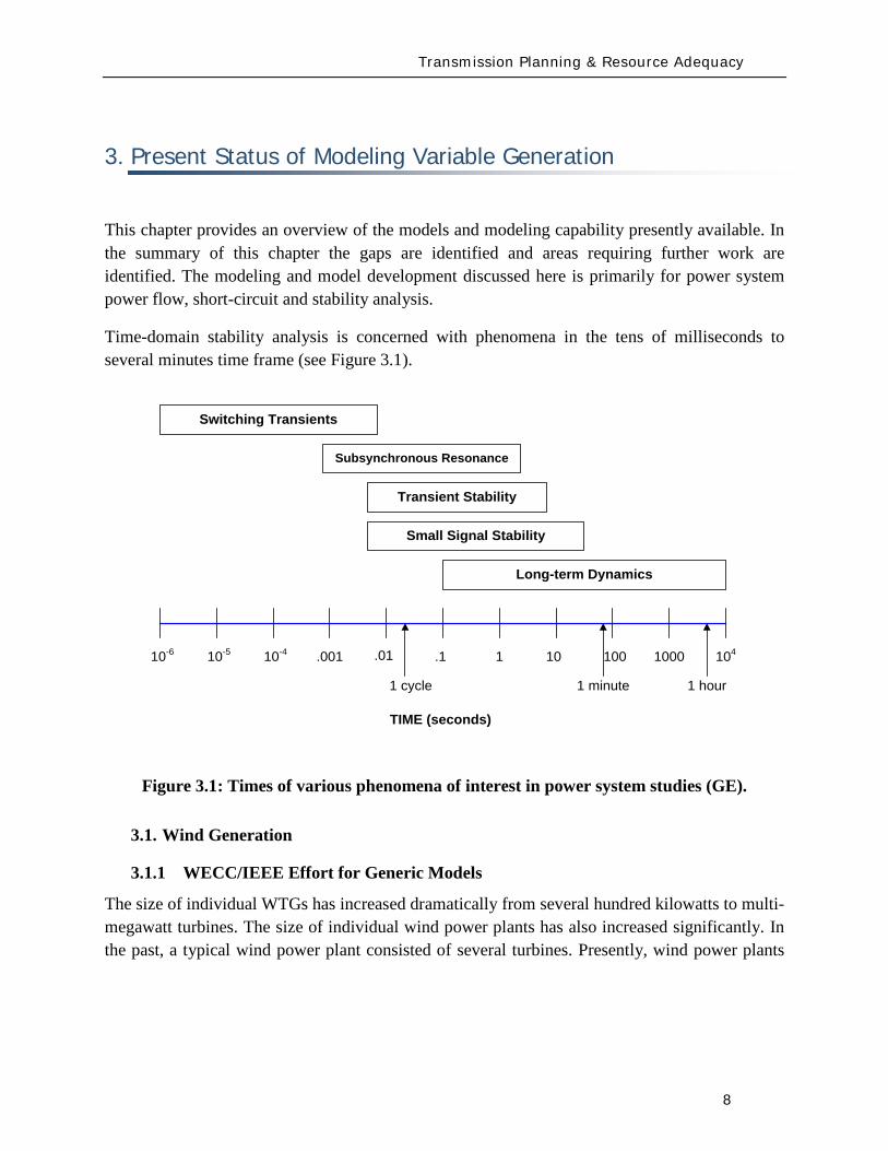
Transmission Planning amp Resource Adequacy
8
3 Present Status of Modeling Variable Generation
This chapter provides an overview of the models and modeling capability presently available In the summary of this chapter the gaps are identified and areas requiring further work are identified The modeling and model development discussed here is primarily for power system power flow short-circuit and stability analysis
Time-domain stability analysis is concerned with phenomena in the tens of milliseconds to several minutes time frame (see Figure 31)
Figure 31 Times of various phenomena of interest in power system studies (GE)
31 Wind Generation
311 WECCIEEE Effort for Generic Models
The size of individual WTGs has increased dramatically from several hundred kilowatts to multi-megawatt turbines The size of individual wind power plants has also increased significantly In the past a typical wind power plant consisted of several turbines Presently wind power plants
Switching Transients
Subsynchronous Resonance
Transient Stability
Small Signal Stability
Long-term Dynamics
TIME (seconds)
10-6 10-5 10-4 001
1 cycle
1041 1 10 100 1000
1 minute 1 hour
01
Transmission Planning amp Resource Adequacy
9
of several 100 MW and larger are being proposed By some projections13 as much as 300 GW (20 penetration) of wind generation capacity is forecast in the US by 2030 and NERC projects an increase of 229 GW of new wind generation installed capacity by 201814
Presently most wind turbine technologies use power electronics and advanced reactive power compensation as an integral part of wind turbine generator and wind power plant Under dynamic transients the behavior of modern wind turbines must be accurately simulated to predict the response of the wind power plant Misrepresentation of WTGs in transmission studies may threaten the reliability of power systems by either resulting in excessive overbuild of transmission systems due to pessimistic models or in deficient transmission system investment based on optimistic models
The increased penetration of renewable energy generation poses significant questions concerning the ability of the power system to maintain reliable operation
Turbine manufacturers have developed dynamic models for their wind turbines These dynamic models are typically user-written models in commercially available power system simulation software platforms (eg Siemens PTI PSSTME GE PSLFTM DigSILENT PowerFactory etc) Detailed three-phase equipment level models of WTGs used for internal design purposes are also often developed by manufacturers in either their own simulation platforms or commercial software tools including PSCADreg or Matlabreg Simulink
Unfortunately both these categories of models (the user-written positive-sequence models and the three-phase detailed equipment models) require significant input dataparameters considered to be proprietary by the turbine manufacturers and therefore are not freely available to the general public Access to these models usually requires a non-disclosure agreement (NDA) between the dynamic model user and the turbine manufacturers This agreement is only valid for a specific turbine model for a given period of time
In many cases it takes months to negotiate and to finalize the NDA Furthermore in some cases there are incompatibilities among turbine models developed by different turbine manufacturers which results in numerical interactions if multiple user-written models are incorporated into a single power system model for system analysis This makes the work of power system planners almost impossible The NDA are also usually bilateral which renders it impossible to share the information among the manufacturers to help resolve incompatibility problems Finally the NDAs make it difficult at best and impossible in some cases to share the models thereby potentially violating the NERC requirements for submitting models for system planning studies
13 httpwwwnrelgovdocsfy07osti40482pdf 14 httpwwwnerccomfiles2009_LTRApdf
Transmission Planning amp Resource Adequacy
10
With this back drop the WECC Wind Generator Modeling Group (WGMG) initiated the development of generic wind turbine models of the four (4) different types of wind turbines (see Appendix I for these four WTG designs) These four types of turbines currently hold the largest market share throughout the world WECC is interested in providing accurate and validated models of standard wind turbines that will be available in their database including the datasets to be used for testing the models and the methods for representing a wind power plant in power system studies These goals are being accomplished through the development and validation of standard models The standard models must be generic in nature ndash that is they must not require nor reveal proprietary data from the turbine manufacturers These improved standard (generic non-proprietary) dynamic models enable planners operators and engineers to perform the necessary transmission planning studies required to ensure system reliability
Currently the first generation of these generic WTG models for all four turbines types have been developed and are available as part of the main model library for the two most widely used commercial power system simulation tools in North America (ie Siemens PTI PSSTME GE PSLFTM)15
To date the first generation of generic models developed and released have focused on capturing the response of the units to electrical voltage disturbances on the transmission grid (grid faults) One deficiency particularly for the Type 1 and 2 models is the proper representation of unit responses to large system frequency excursions These models have not been verified due to the lack of data on actual turbine behavior under such circumstances and will require further development in consultation with turbine manufacturers
As a continuation of and in parallel with the WECC effort the Institute of Electronic and Electrical Engineers (IEEE) Power amp Energy Society (PES) has also established a Working Group to investigate WTG modeling issues The IEEE Working Group on Dynamic Performance of Wind Power Generation under the Power System Dynamic Performance Committee This Working Group is actively expanding the efforts of generic dynamic modeling for wind power plants focusing on modeling specifications disseminating methods and model validation
Finally as with all modeling exercises model development and validation are iterative processes requiring
bull Generic wind turbine models are to be made available to the public
15 PSSregE-320 Program Application Guide Volume II Chapter 21 PSSregE-320 Model Library Chapters 17 through 21 GE PSLF Users Manual v170_04 October 2009
Transmission Planning amp Resource Adequacy
11
bull Generic wind turbine models must be validated before release and public dissemination which is being pursued in WECC IEEE International Electrotechnical Commission (IEC) and other forums
bull Models should evolve and be revalidated as the technology progresses
bull Data from field measurement and monitoring for model validation can be a vital resource
A somewhat unique need in modeling variable generation (eg wind) is the need for methods required to develop equivalent models for large wind power plant In contrast to conventional fossil fuel and hydro power plants where plants are constituted by either a single large unit or at most a few large units a wind power plant can be made up of tens to more than a hundred WTGs For large scale power system simulations particularly in North America where the power system models are quite large it is often preferred to reduce the wind power plant to a single equivalent unit Accordingly techniques are needed for model aggregation and testing their validity ndash some significant progress has been made in this regard For example Figure 32 shows the technique developed for reducing the impedance of the wind power plant collector system into a single equivalent feeder impedance for representation of the wind power plant (WPP) by an aggregated single equivalent unit in power system studies
Figure 32 Example shows the method for reducing the impedance of a wind power plant collector system into a single equivalent impendence16
16 ldquoWECC Wind Generator Power Flow Modeling Guiderdquo (
httpwwwweccbizlibraryWECC20DocumentsDocuments20for20GeneratorsGenerator20Testing20ProgramWind20Generator20Power20Flow20Modeling20Guidepdf)
Transmission Planning amp Resource Adequacy
12
Figure 33 shows an example for dynamic simulations of aggregating the WPP into a single equivalent unit and an equivalent single impedance representing the entire collector system as compared to a detailed model representing the whole WPP unit-by-unit ndash the example shown assumes that all WTGs in the WPP are identical in cases where this is not true multiple equivalent units may be needed one for each WTG type As can be seen in this figure the results from the two simulations compare very well at the point of interconnection (which is what is shown) thus the equivalent aggregate is adequate for power system studies17
Figure 33 Example of time-domain simulations comparing a detailed model of a Wind Power Plant (ie representing the complete collector system and each WTG individually) versus a single-machine equivalent aggregate (ie the entire plant is represented by one equivalent unit and an equivalent impedance to represent the whole collector system)
17 Figure is from J Brochu R Gagnon and C Larose ldquoValidation of the WECC Single-Machine Equivalent Power Plantrdquo Presented at the IEEE PES DPWPG-WG Meeting at IEEE PSCE March 2009
P345 kV
Q345 kV
QWT = 0435 0 -0435
Transmission Planning amp Resource Adequacy
13
312 UWIG Generic Model Documentation and Validation Effort
The Utility Wind Integration Group (UWIG)18
The objectives of the project which will commence in early 2010 and run for a period of two years are to
under a US Department of Energy grant will be launching an effort to provide the basic documentation application and validation of generic models for wind turbines The goal of this project is to accelerate the appropriate use of generic wind turbine models for transmission network analysis
bull Complete characterization and documentation of the four generic models developed through an outgrowth of a WECC activity begun in 2005
bull Defining proposed enhancements to the generic wind turbine model structures that would allow representation of more advanced features including power control automatic curtailment inertial and governor response
bull Comparative testing of the generic models against more detailed (and sometimes proprietary) versions developed by turbine vendors
bull Developing recommended parameters for the generic models to best mimic the performance of specific commercial wind turbines
bull Documenting results of the comparative simulations in an application guide for users
bull Acquiring test data from all available sources for the purpose of validating the performance of the appropriately specified generic models in actual case studies
bull Conducting technology transfer activities in regional workshops for dissemination of knowledge and information gained and to engage electric power and wind industry personnel in the project while underway
18 The UWIG was established in 1989 to provide a forum for the critical analysis of wind technology for utility applications and to serve as a source of credible information on the status of wind technology and deployment The grouprsquos mission is to accelerate the development and application of good engineering and operational practices supporting the appropriate integration of wind power into the electric system It currently has more than 150 members spanning the United States Canada and around the world including investor-owned public power and rural electric cooperative utilities transmission system operators and associate member corporate government and academic organizations httpwwwuwigorgaboutuwightm
Transmission Planning amp Resource Adequacy
14
Maintaining communication and coordination with other ongoing activities and agencies engaged in this topic is another objective of the effort which will be critical for success
313 IEC Effort for Generic Models
The International Electrotechnical Commission (IEC) recently started a Working Group in October 2009 to address the development of generic and ldquostandardrdquo models for wind turbine generators19
Part 2 of this work will be focused on extending the modeling to allow for modeling of the entire wind power plant including wind power plant control and auxiliary equipment
The goal of this Working Group is to define standard dynamic simulation models for wind turbines and wind plants which are intended for use in power system and grid stability analyses and should be applicable for dynamic simulations of power system events including short circuits (low voltage ride through) loss of generation or loads and system separation The group is approaching this work in two parts Part 1 will focus on specifying dynamic simulation models for the generic wind turbine topologiesconceptsconfigurations presently in the market as well as specifying how these models may be modified as future technologiesconcepts are introduced The standard should also include procedures for validation of the models specified Another goal is that the models should be developed and specified at a fundamental level so they are independent of any specific software platform and can be adopted by any software vendor
Several members of this IEC Working Group are also members of the WECC and IEEE Working Groups (and this NERC Task Force) The three groups are clearly working in close collaboration to ensure maximum benefit to the industry globally and maximum sharing of knowledge already gained through the WECC and IEEE efforts
19 httpwwwiecchdynwwwfp=102140FSP_ORG_ID5613
Transmission Planning amp Resource Adequacy
15
32 Photovoltaic Solar Generation
Photovoltatic (PV) systems for power generation are quickly increasing becoming a significant portion of generation in some regions in North America PV or solar arrays are composed of a large number of solar cells connected in series and parallel These cells produce a DC voltage when they are exposed to sunlight due to the photo-voltaic effect20
Figure 34 shows the I-V characteristics of a cell at a constant temperature and various sun intensity or insolation levels
Figure 34 Current-Voltage characteristics of a solar cell for various insolation levels at a constant temperature (source [11]21
20 The photo-voltaic effect is the process by which an electric potential difference (voltage) is created in a material exposed to light (electromagnetic radiation) which then leads to the flow of electric current This process is directly related to the photo-electric effect but distinct from it in that in the case of the photo-electric effect electrons are ejected from the material surface upon being exposed to high enough frequency (energy) light whereas in the photo-voltaic effect the generated electrons are transferred across a material junction (eg PN junction in a photo-diode) resulting in the buildup of a voltage between two electrodes and the flow of direct current electricity
)
21 Solar Radiation Research Laboratory at the National Renewable Energy Laboratory (httpwwwnrelgovmidcsrrl_rsp)
Transmission Planning amp Resource Adequacy
16
Figure 35 shows that the current is limited when the cell is short-circuited (Voltage=0)
(a) (b) (c)
(d)
Figure 35 The concept of a solar array (a) a single solar cell (b) a series connection of solar cells (Nser = 3 and Npar = 1) and (c) a solar array (Nser = 3 and Npar = 2) The solar cell array(s) is then connected to a DC bus (d)
Figure 35 shows the concept of the solar cell up to the solar array To use the DC power generated by the PV array in an AC power system the DC power must be converted to 60 Hz AC in North America (50 Hz in some other regions in the world like Europe) There are several power electronic based converter concepts that can achieve this which can be classified into two general categories line-commutated converters (LCC) and self-commutated or more commonly
Vbus Iload
Ibus
Icap PV ARRAY
+
_
Transmission Planning amp Resource Adequacy
17
referred to as voltage-source converters (VSC) These technologies have been applied for decades and are well understood LCC use thyristors as their controlled switching device The switching on of a thyristors can be controlled while the turn-off time cannot be controlled and happens at the next AC waveform current zero crossing LCC systems must be operated in a network with an AC source and cannot operate to serve an isolated load In contrast VSC systems are self-commutating that is the power electronic switching devices used (eg integrated gate-commutated thyristors or IGCTs and insulated-gate bipolar transistors or IGBTs) are able to be completely controlled for both turn-on and turn-off and allow the VSC to completely control the AC waveform produced and adjust the power factor as seen on the AC side to within the current rating of the device Due to advances in the technology most power electronic converters employed in PV systems are of the VSC type22
From a modeling standpoint for power system studies there are some user-written manufacturer-specific models in existence as developed by various PV manufacturers Presently no generic or standard models exist
The WECC Working Group which has been addressing the development of generic WTG models will be extending its effort in 2010 to review developing generic PV models for dynamic simulations in stability studies As a starting point the grid side structure of the Type 4 WTG model may be used since it represents a VSC This is because PV is typically connected to the grid with a VSC and it will behave electrically similar to a Type 4 WTG that has a similar electrical interface with the gridmdashthis is from a grid perspective looking at the electric response and neglects any of the effects of the energy source
From a steady-state power flow and short-circuit analysis perspective the behavior of the PV technologies will behave in a similar fashion to a Type 4 WTG because of the VSC interface and because its power factor can be controlled based on the control functionality of the VSC design Its short-circuit response will be limited to the current limit effected by the VSC under grid fault conditions
The development of generic and standard PV models is presently a topic for further research This should be pursued imminently and much of what has been learnt from the WTG model development process should be leveraged
22 IEA-PVPS Grid-Connected Photovoltaic Power Systems Survey of Inverter and related Protection Equipment Report IEA PVPS T5-05 2002 December 2002 (httpwwwiea-pvpsorgproductsdownloadrep5_05pdf)
Transmission Planning amp Resource Adequacy
18
33 Solar Thermal
Solar thermal energy is based on harnessing the radiated heat of the sun for the purpose of producing electricity In broad terms there are presently two main ways of achieving this
1 Concentrating Solar Power (CSP) plants ndash in this case solar radiation is typically collected through a large number of mirrors (thus a large amount of solar radiation) which is then focused on a small area ndash the mirrors have tracking systems to follow the Sun The concentrated solar radiation heats a high temperature working fluid which then feeds a conventional steam-turbine generator From an electrical grid perspective the models needed to simulate the steady-state short-circuit and transient time-domain dynamics of such a generating unit are typically no different than standard synchronous generating units for fossil fuel plants
2 The Stirling Engine concept23
34 Tidal Generation
ndash in this design a parabolic mirror assembly concentrates the collected solar radiation on a sterling engine that sits at the focal point of the mirror assembly A Stirling engine is a reciprocating heat engine that operates based on the concept of cyclical compression and expansion of a working fluid As the working fluid expandscontracts it drives a piston that then turns a generator The engine is connected to an electrical generator that produces electric energy Once again for power system studies the units may be modeled using standard generator models However in this case a power plant would be constituted by a large number of small units (the typical Stirling engine is about 25 kW) in a large electrical collector system that collects the power and injects it into the utility grid ndash much like the collector system of a wind power plant Thus modeling the collector system (eg see Figure 32 for an aggregate model of a wind collector system) and any other devices in the collector system such as shunt reactive devices etc must be properly modeled
Tidal power generation derives energy directly from the motion of oceanic tides The gravitational pull of the Moon and Sun combined with the Earthrsquos rotation result in the generation of tides Tides generally occur with a period of roughly twelve hours and so most coastal areas experience two high and two low tides within every twenty-four hour period Tidal generation uses this phenomenon to generate energy Clearly the stronger the tides are either in tidal current velocity or the heightlevel of water the greater the potential amount of energy generation
23httpwwwstirlingenergycom Y Zhang and B Osborn ldquoSolar Dish-Stirling Power Plants and Related Grid Interconnection Issuesrdquo IEEE PES General Meeting 24-28 June 2007
Transmission Planning amp Resource Adequacy
19
Presently in North America tidal power is not a significant source of power in any region Some pilot programs exist for introducing the technology In April 2009 one was announced in Snohomish County Public Utility District in Washington State24
There are several options for harnessing tidal power One method is the use of turbines similar to wind turbines however the fluid (water) is much denser and requires a turbine with smaller and bulkier blades as shown in Figure 36 Most of these technologies typically use ACDCAC converter technology similar to a Type 4 wind turbine to convert the low frequency generated electricity to grid frequency AC electricity and interface with the power system Once this technology becomes more prevalent a starting point for development of a suitable model structure may be the Type 4 generic wind turbine models Understandably the energy source characteristics are quite different from wind power and significantly more predictable
Figure 36 One of the many concepts for tidal generation systems (courtesy of Marine Current Turbines Limited wwwmarineturbinescom)
35 Other Resources
There are several other emerging technologies and there are many complementary technologies (ie auxiliary to the variable generation resources but designed to help with their integration into the grid) including smoothly-controlled dynamic reactive devices (static VAr systems)
24 httpwwwsnopudcomPowerSupplytidaltidalpressashxp=1516amp756_na=46
Transmission Planning amp Resource Adequacy
20
energy storage technologies etc With respect to static VAr systems (SVCs and STATCOMs) there is an active WECC working group imminently addressing the issue of generic models for these devices25
36 Summary
The group has made substantial progress with the models defined and developed but currently undergoing testing and validation With regards to the other emerging technologies most tend to be power converter based (ie connected to the grid through a back-to-back frequency converter) and so their electrical behavior (neglecting the characteristics of the energy source) will be similar to Type 4 wind turbines Until these technologies mature the basic structure of other more mature converter based generation technologies can be a good starting point
This section has briefly presented the various types of variable generation and the present status of models and model development for power system studies Wind generation technologies being the most prevalent world-wide have the most mature models Through efforts started by WECC and being continued by IEEE and IEC generic standard models for the four main types of WTG technologies are being developed The first generation of these models has been released in two power system simulation software platforms most commonly used in North America Other emerging technologies (eg PV tidal power etc) can build on this effort to start developing generic models For example the WECC effort will be extending its scope in 2010 to look at PV model
From a NERC perspective the key items are
1 To emphasize and support efforts by WECC IEEE and IEC to develop and standardize generic models for these technologies for power system planning studies
2 To encourage manufacturers to familiarize themselves with the generic models being developed and be willing an able to supply parameters for these generic models to reasonably represent their equipment for power system stability studies As highlighted in Chapter 2 more detailed manufacturer specific models may be needed in special cases and for specialized studies
3 To encourage efforts aimed at model validation
4 To consider any augmentation or additions to reliability standards related to Modeling Data and Analysis (MOD) with respect to modeling and model validation of variable generation This is discussed in greater detail in section 5 of this report
25 httpwwwweccbizcommitteesStandingCommitteesPCCTSSMVWGSVCTFdefaultaspx
Present Status of Model Validation
21
4 Present Status of Model Validation
This chapter gives an overview of the model validation work that has been done hitherto as it relates to models for variable generation Necessarily the primary focus of this section is on wind turbine generator models since models for this resource are presently the most mature
41 What is Model Validation
Any and all models of a dynamic system always have limitations associated with them A model is a representation of reality it is an emulation ndash that is why it is called a model In developing a model first the question is asked as to the specified use of the model and the conditions it must reasonably emulate ndash this forms the basis of a model specification from which a model is developed The developed model establishes a certain structure with parameters which are adjustable in order to emulate different types of equipment or design of the modeled device Thus valid parameterization of the model to represent a particular manufacturerrsquos equipment is essential to support the particular scenarios to be analyzed
Model validation is often achieved through some form of testing either in a laboratoryfactory or in field There is a range of reasons for conducting tests for wind generation Each test has a unique set of objectives guiding the design of adequate testing practices
bull Performance Compliance Compliance to contractual requirements and grid codes are one reason to perform tests Interconnection requirements (usually included in plant Power Purchase Agreements and Interconnection Contracts) and grid codes typically outline specific technical criteria that must be met to allow a power plant to connect and operate on the grid Since these criteria point out specific levels to be met (for example voltage power factor and response time) tests may be designed with binary ldquopassfailrdquo objectives
bull Model Validation In much of the world power plants above a pre-defined size must be accurately represented with a dynamic simulation model used in stability analysis for operations and planning purposes As variable generation sources such as WPP are growing in size it is becoming increasingly important to have accurate variable generation specific models Tests may be performed to tune and verify simulation models to closely match the performance of actual equipment In the western US and Canada WECC has mandated that any plant with 20 MVA aggregate generation must be tested for model validation including large wind power plants For North America the imminent NERC MOD-026 standard presently under development will enforce model validation requirements throughout the North American region
Present Status of Model Validation
22
To achieve the goals of model validation there are three categories of tests that may be performed
bull Type Tests These are tests performed by the manufacturer or independent third-parties of representative equipment The intent is to demonstrate that a particular design of equipment exhibits specific performance and all other equipment of that same design is assumed to have the same performance Type tests can be
o Component Performed on specific functions or features in a power plant or generation equipment This could be for example testing the fault ride-through capability or reactive capability of a WTG where testing is performed at the component level
o Factory A systemic test of a major assembly (ie a drive train) or entire turbine-generator is performed under a controlled environment like a manufacturing facility to verify performance and validate assembly design
o Unit A systemic test of multiple components operating together (ie as entire operating WTG or WPP) with the specific intent of benchmarking a model or design as a type test For example tests performed in Europe under the WindTest program
bull Field Tests26
o Commissioning Tests performed on new equipment entering its period of commercial operation service
Tests performed by the power plant asset owner developer host utility manufacturer andor independent third-parties of specific operating equipment These tests are to demonstrate that a particular implementation design and installation of equipment exhibit specific performance
o Periodic Maintenance or Calibration Tests performed periodically after the plant is in commercial operation to verify that equipment continues to perform as well as it did during commissioning
26 See for example WSCC Control Work Group and Modeling amp Validation Work Group ldquoTest Guidelines for Synchronous Unit Dynamic Testing and Model Validationrdquo February 1997 (wwwweccbiz) and IEEE Task Force on Generator Model Validation Testing ldquoGuidelines for Generator Stability Model Validation Testingrdquo Proceedings of the IEEE PES General Meeting Tampa FL June 2007 (httpieeexploreieeeorg)
Present Status of Model Validation
23
o Periodic Model Validation Tests performed periodically after the plant is in commercial operation to verify that simulation models adequately represent actual plant performance (for example the periodic model validation testing required by WECC)
o Periodic Codes amp Standards Validation Tests performed periodically after the plant is in commercial operation to benchmark and validate plant performance per contractual requirements These tests are typically performed to obtain a permanent operating license for the power plant
bull On-Line Monitoring27
With these general concepts in mind the following subsections present some example cases studies of model validation and validation approaches for variable generation sources The examples emphasize WPP and WTG since wind generation is the present dominant variable generator sources in the North America continent
Other information of interest is from continuous data gathering based on ongoing performance of an operating power plant Data collected from external and unscheduled events including grid disturbances or in the case of WTG large changes in wind is particularly useful Monitoring also benchmarks performance under normal operation
42 Examples of Model Validation Efforts
421 Hydro- Queacutebec Example
The province of Queacutebec has vast wind energy potential Though wind energy generation in 2009 accounts for nearly 13 of the total installed capacity in the Queacutebec control area the penetration rate of wind energy generation will reach 10 by 2015 A total capacity of 528 MW is currently in operation and approximately 3000 MW are under development Five wind turbine manufacturers will supply the WTGs for the different projects under study
The configuration of the Hydro-Queacutebec transmission system is essentially radial Approximately 85 of the total installed generation feeding the system is located at distances up to 1300 km
27 See for example P Pourbeik ldquoAutomated Parameter Derivation for Power Plant Models From System Disturbance Datardquo Proceedings of the IEEE PES General Meeting Calgary Canada July 2009 (httpieeexploreieeeorg) This reference shows actual application of on-line disturbance monitoring to power plant model validation for conventional fossil fuel generation It may be feasible to apply similar algorithms and approaches for continuous re-validation of WTG and other variable generation technologies once generic standard models have been developed This is a current topic for research
Present Status of Model Validation
24
from the closest major load centers With this configuration the system transfer capability is mainly limited by stability constraints (transient stability and voltage stability) rather than congestion or thermal capacity of equipment hence the need for reliable models for wind power plants and all other generation
Stability studies are critical to determine the compensation equipment required to maintain the reliability of the power system when integrating new generation They are also essential for operation planning studies including control system design and tuning and determination of transfer capabilities
So far Hydro-Queacutebec has faced two major difficulties regarding user-written models provided by the wind turbine manufacturers First models often lack robustness and do not represent accurately some important features (convergence problems in low short-circuit network do not take into account frequency excursions do not represent secondary voltage regulation etc) Second model validation by the manufacturers is often incomplete not available or difficult to translate to real projects (different settings or software versions design of the collector system etc) In some cases these difficulties have lead Hydro-Queacutebec to build its own models (see Hypersim section below)
General validation test program
Since 2006 Hydro-Queacutebec has performed validation tests on WPP connected to its transmission system and a general validation test program was established in 200928
1 To demonstrate that WPP meet the Transmission Provider technical requirements related to wind generation
The power producer has the obligation to perform validation tests in order to demonstrate that its facilities meet the Transmission Provider requirements The purposes of this program are
2 To validate numerical models and parameters associated with the WPP specifically those given to the Transmission Provider by the power producer by comparing the model response to recordings taken during field tests
3 To confirm the electrical data of power producer facilities
The validation program is divided into seven functions to be validated
1 Primary voltage regulation
28 httpwwwhydroquebeccomtransenergiefrcommercepop_raccordement_transporthtml
Present Status of Model Validation
25
2 Undervoltage response (LVRT)
3 Inertial response
4 Secondary voltage regulation
5 Power factor
6 Maximum ramp rates
7 Power quality
The tests for the primary voltage regulation are performed on a single WTG and consist in producing instantaneous voltage variations of low amplitude on the terminal of the WTG and small voltage steps of limited duration injected directly into the WTG voltage control system Three-phase voltages and currents are recorded at the wind generator to measure the local dynamic response of a wind generator to a rapid voltage change and to verify that the response meets voltage regulation requirements The results are also used to set the model parameters (time constant and gain) used in dynamic simulations The tests regarding the secondary voltage regulation are similar but are conducted for the entire power plant
The validation test program includes LVRT tests on one generating unit to verify that requirements during undervoltage conditions are met The power producer has the responsibility to conduct the tests or to provide a complete report describing tests performed on an identical generating unit (same software version) to demonstrate that the requirements are met So far no LVRT tests were performed on site on WPP integrated on the Hydro-Queacutebec network However monitoring equipment has been installed at three locations in wind plants at their point of interconnection on a 345 kV feeder of the collector system and on one generating unit The monitoring system records signals either continuously or upon detecting variations occurring at the point of interconnection active power variations voltage sags and swells and system frequency excursions These signals are primarily voltages and currents but may also be mechanical variables or other signals
The field recordings recorded on the network can thereafter be used to validate the dynamic response of the models This is a time consuming effort that requires the collaboration of the manufacturers to modify the models if necessary Event recordings to-date have made possible suitable validation of two Hydro-Queacutebec Siemens PTI PSSregE models and one ElectroMagnetic Transients Program (EMTP) model
Inertial response requirements were not in defined for the projects started before 2005 Consequently existing wind plants do not have to fulfill them However the requirements have to be met for WPP to be commissioned in 2011 and after The corresponding validation tests consist in emulated frequency steps and ramps of limited duration Besides verifying the
Present Status of Model Validation
26
requirements the test results will be used to validate the parameters of the models and their dynamic response
The power factor and the maximum ramp rates modules are tested with all WTGs in service to verify that the requirements are met Power factor tests consist in supplying and absorbing a maximum amount of reactive power at different levels of active power Maximum ramp rate tests consist in performing a power plant shutdown sequence followed by a startup sequence These tests are not really used to validate the models but are rather helpful to fix model parameters
The last module regarding the power quality is not covered by scheduled testing but by means of a monitoring system that verifies harmonics and emission limits The recordings are compared to the report provided by the developers to verify if the requirements are met However they are not useful to validate the EMTP model since the WPP is represented by a single-wound generator and does not simulate the detailed collector bus system and individual wind turbine generators
Field tests department
Hydro-Queacutebec field-testing department (UMES) conducts a wide range of special tests and measurements for Hydro-Queacutebec and has done so for 30 years
To test WPP UMES installs a monitoring systems to record three-phase voltages and currents generally at three locations within the plant at the point of interconnection at the starting point of a 345 kV feeder of the collector system and at the terminals of a WTG connected to the same monitored feeder For extended model validation other signals within the wind turbine are monitored including the rotor side converter voltages and currents the network side converter currents and the DC bus voltage
High speed recorders with anti-aliasing filters are used Normally the sampling rate is 5 kHz with at least a 200 second window per event The monitoring system is reachable via an Ethernet connection for remote trigger and data retrieval UMES has also the responsibility to perform the data processing and analysis of the recordings in order to verify the compliance with the interconnection requirements and to extract relevant data for model validation
Present Status of Model Validation
27
Hypersim
The Hydro-Queacutebec Research Institute (IREQ)29 also has an important expertise in control system and wind generation modeling for extensive studies of electrical networks The simulation environment used is Hypersim a real-time simulator and powerful simulation tool that uses a highly detailed representation of the Hydro-Queacutebec network A full-transient detailed model of a Type 3 WTG was developed at IREQ using the MATLABreg SimPower Systems Toolbox The model was also implemented in EMTP and in the Hypersim real-time simulator30 This model is in the process of being validated with data processed by the UMES team The range of events recorded does not make it possible to validate the model completely and the design and parameters will continue to be adjusted to improve the representation of the wind turbines The validation of the MATLABreg model developed by IREQ was very useful to validate and improve Hydro-Queacutebecrsquos Siemens PTI PSSregE user model31
422 GE Example ndash based on GErsquos work with client facilities
In the case of the first example presented here a 10 MVar capacitor bank located at the 25kV WPP collector bus is switched off-line as an external physical stimulus Figure 41 shows detailed response to capacitor switching from the WindCONTROLreg The WindCONTROLreg system allows coordination of all on-line turbine-generators for plant-level fast and smooth voltage regulation at the point of interconnection (POI) located contractually at the 25kV substation bus The red curve (Q_ACTUAL [KVar]) shows that total plant reactive power initially drops after the switching action but the fast autonomous controls on each turbine generator quickly and stably respond to increase reactive power generated by individual turbines shown by the orange curve (Q_TURBINES [KVar]) The WindCONTROLreg command (Q_CMD) distributed to the turbines is shown in blue The response of Q_CMD is dominated by the gains of the voltage regulator portion of the WindCONTROLreg specifically the proportional gain Kpv and integral gain Kiv The difference between the response of the individual turbines (Q_TURBINES [KVar]) and the WindCONTROLreg command (Q_CMD) is due to the dynamics of the individual wind turbines The coordinated response of the wind plant and the individual
29 httpwwwhydroquebeccomtechnologyindexhtml 30 R Gagnon G Sybille SBernard D Pareacute S Casoria and C Larose ldquoModeling and Real-Time Simulation of a
Doubly-Fed Induction Generator Driven by a Wind Turbinerdquo IPST Conf Paper No IPST05-162 Montreacuteal Canada 2005 C Larose R Gagnon G Turmel P Giroux J Brochu D McNabb and D Lefebvre ldquoLarge Wind Farm Modeling Techniques for Power System Simulation Studiesrdquo in Proc 8th International Workshop on Large-Scale Integration of Wind Power into Power Systems Bremen Germany Oct 14-15 2009
31 C Langlois D Lefebvre L Dube and R Gagnon ldquoDeveloping a Type-III Wind Turbine Model for Stability Studies of the Hydro-Queacutebec Networkrdquo in Proc 8th International Workshop on Large-Scale Integration of Wind Power into Power Systems Bremen Germany Oct 14-15 2009
Present Status of Model Validation
28
turbines is multi-modal a fast initial response to address severe perturbations as well as a slower grid friendly refinement For purposes of this test the automatic control of the capacitor bank by WindCONTROLreg was disabled and manual switching was used as a stimulus to record individual WTG response
The detailed plot in Figure 42 shows a zoomed view of the response to step change in voltage at the WTG The very fast initial response will dominate and saturate the controls for big events The wind plant will do everything as quickly as it can to mitigate a large disturbance In this case the fast response took approximately 200 milliseconds The slow refined control then takes over to allow for coordination with other equipment and maintain post-disturbance stability This aggregate response also allows for a very abrupt action when needed and a grid-friendly refinement that maintains stability in less severe cases
The green curve in Figure 43 shows that when the capacitor is switched off-line the measured voltage at the point of interconnection (or POI) decreases due to reduced reactive power flowing into the grid The response of the individual WTGs is to rapidly increase reactive output to make up for the loss of reactive power supplied by the shunt capacitor The plant level control then responds to this initial under-voltage condition and attempts to restore the POI voltage by increasing each wind generatorrsquos reactive output by equal amounts until the plant voltage settles to the control set point determined by the operator The lower traces in Figure 43 show a gap during the period when the capacitor bank is online between total plant Q (Q_ACTUAL) and summation of Q out of each WTG (Q_TURBINES) This gap represents the capacitive reactance added by the shunt bank When the capacitor is switched offline the gap between Q_ACTUAL and Q_TURBINES closes and all reactive power is supplied solely from the WTGs The initial loss in plant reactive power is mitigated within approximately 15 seconds as each WTG settles to a new increased level operating point of reactive power This new increased reactive level for each WTG is the total Q increase from all units on-line in the plant divided by the total number of units online at the time of the test
Figure 44 shows a comparison between these measured values and the simulation results of the PSLF model Model outputs Qg Qplant Qcmd and Vreg correspond to measured Q_TURBINES Q_ACTUAL Q_CMD and U_LINELINE respectively This plot shows the model performance adequately represents what is happening in the field The response matches closely with a difference immediately following the switching operation being due to lower sampling rate in the measurement than in the GE PSLFreg simulation
Response to grid events demands relatively rapid control action Manual grid or plant operator changes in operating set-points do not normally demand fast response and indeed system behavior ought not to be rapidly disturbed by moving set-points Figure 45 shows the response of GE plant to 2 step in voltage reference The blue trace in the figure shows a well mannered response to the reference step The red trace is from the simulation model which matches very
Present Status of Model Validation
29
well In the blue trace after the perturbation occurring about 8 seconds after the reference change the plant supervisory control switched on a shunt capacitor to retain dynamic range on the wind turbines The switching perturbation is rapidly balanced by the turbines allowing the response to continue smoothly
Figure 41 10 MVar Capacitor removal response measured from WindCONTROLreg
Present Status of Model Validation
30
Figure 42 Wind turbine-generator level voltage step test response
Present Status of Model Validation
31
Figure 43 10 MVar Capacitor removal response ndash POI variables
Figure 44 10 MVar capacitor removal field test vs simulation results
Present Status of Model Validation
32
Figure 45 A different step test +- 2 step of voltage reference
The performance for grid fault events is of considerable interest in system planning Staging faults particularly severe ones on operating wind plants is difficult and expensive Figure 46 shows a comparison between a staged fault test and the (present) Siemens PTI PSSregE model of the GE 25 (full converter) WTG The fault event is quite severe a 3-phase 700ms of voltage depression to less than 20 of nominal at the high voltage terminal of the WTG unit transformer The measurement traces (on the left) include some of the signal noise characteristic of measurement and extraction of fundamental frequency positive sequence information from real high resolution measurements The simulation traces on the right are of course cleaner The match between test and simulation is of very high fidelity for phenomena relevant and legitimately examined with positive sequence simulation tools (ie greater than one cycle)
QPOI
VPOI
Measured = Blue Simulated = Red
Plant Capacitor Bank Switched On Automatically by WindCONTROL
+ 2 VrefStep
- 2 Vref Step
QPOI
VPOI
Measured = Blue Simulated = Red
Plant Capacitor Bank Switched On Automatically by WindCONTROL
+ 2 VrefStep
- 2 Vref Step
Present Status of Model Validation
33
Figure 46 GE 25 WTG Fault Test vs PSSe Model Performance
The discussion provide above is solely geared to hardware testing and validation however another highly valuable and legitimate means of providing validation of simulation models (for planning and otherwise) is to use more complex simulation software to validate simpler planning models Manufacturers normally have highly complex and highly proprietary models of their equipment These models are used among other things to design equipment and are normally physically based and must have sufficient fidelity for original equipment manufacturers (OEMs) to make sound engineering judgments for equipment design and application The OEMs are highly motivated to have these detailed high fidelity equipment level models These detailed models therefore can often be used to design test and validate simpler planning models to be used by the industry
There is a long accepted history in the power industry of this practice For example a typical (GE) gas turbine has on the order of 4000 state variables in the design model planning models typically have on the order of four state variables simplification is necessary and expected These design codes have been used to develop planning models of gas turbines Figure 47 below shows a comparison between a fault simulation using a GE design code (GE WindTrapreg) and the planning model in GE PSLFreg for a GE 15 (double fed machine) WTG
Present Status of Model Validation
34
Figure 47 Detailed Design Simulation (GE WindTRAPreg) vs GE PSLFreg Model Performance (active power during a severe fault for a GE 15 WTG)
-10
00
10
20
30
0 05 1 15 2
Time (Seconds)
Sin
gle
WTG
Rea
l Pow
er (M
WindtrapPSLF
Summary amp Recommended Actions
35
5 Summary amp Recommended Actions ndash Standards Implications
This document has presented a general overview of modeling and model validation as it pertains to variable generation resources Clearly to date the bulk of the experience and work has been on wind turbine generators Never-the-less similar approaches for modeling and model validation are being pursued for other variable generator technologies such as PV
Non-proprietary and publicly available models for the simulation of steady-state (power flow) short-circuit (fault calculations) and dynamic (time-domain simulations) behavior of such generation resources must be made readily available for use by power system planners Furthermore these models should be routinely validated to ensure proper representation of variable generation power plants in bulk power system studies A model is valid if its dynamic behavior is close enough to reality so that its influence on the network of interest (ie used for power system studies) is consistent with the fidelity of model structures and available data for the power system and other generation as it pertains to the phenomena of interest (ie in stability studies) That is perfect curve fitting is not necessary but to the extent possible erroneous model dynamics must not result in a notable over-design or under-design of the network
Each of the NERC standards discussed below in Section 52 address to aspects of meeting a standard (i) the technical requirement ie the need to define measure validate a model its parameters etc and (ii) the procedural requirements ie the functional model of how this technical requirement should be met reported and monitored The bulk of this working grouprsquos recommendations stated below address the technical requirements Variable generation is a new and quickly evolving technology and consideration should be given to the timing with which standards be implemented
Section 51 below first gives a summary of the planning process based on NERC standards to put the discussions in this report into context with the NERC standards Then in Section 52 we provided our recommendations and comments on the NERC existing and developing standards
Summary amp Recommended Actions
36
51 Applying the NERC Standards
The NERC standard FAC-001 (see Figure 51) should be expanded to clearly cover modeling requirements during the coordinated joint study phase of the Facility connection process Simple generic models of variable generation may be adequate for the IES phase and more detailed models may be needed for the IFS phase Validation of the simple and detailed model parameters may be needed during commissioning
Figure 51 Facility connection process
Interconnection Evaluation Study
Generator Interconnection
Request
Interconnection Facility Study
GO provides initial model
to TPPC
GO provides final model
to TPPC
GO signs Interconnection
Agreement and is put in-service
GO performs model amp
performance validation testing
TO develops Facility Interconnection requirements and requests models and data
of the GO at each process stage
FAC-001
Summary amp Recommended Actions
37
The generic model with associated parameters feed into the NERC model building process shown in Figure 52 As an example for WTG presently there is insufficient evidence of the accuracy of presently available generic models for WTG32
for all the various WTG manufacturers Some confirmation tests during commissioning or type tests or comparison simulation tests with a detailed model are necessary to get buy in from the Transmission OwnerPlanner As the technology matures and generic models are enhanced and associated data parameter sets are developed for specific machine types the new generic models will become more accepted as is the case with models of hydro or thermal plants
Figure 52 Annual NERC Model Development Process
32 PSSregE-320 Program Application Guide Volume II Chapter 21 PSSregE-320 Model Library Chapters 17 through 21 GE PSLF Users Manual v170_04 October 2009
Steady state data
developed
MOD-10
Dynamics data
developed
MOD-12
Reliability Region creates model
MOD-14
Reliability Region creates model
MOD-15
Reliability Region defines data
requirements
MOD-13
GO
TP
RP
Reliability Region defines data
requirements
MOD-11
Annual NERC Planning and
Operating Models
created and distributed to the industry
Summary amp Recommended Actions
38
The regional model building manuals developed as part of MOD-11 and MOD-13 must provide sufficient clarity to model variable generation These manuals may ask for best available models or generic models These models cover the operational time frame and the 10-year planning horizon The manuals do not currently cover the frequency for revalidating model data
While not included in the standards more emphasis is currently being placed on meeting the Eastern Interconnection Reliability Assessment Group (ERAG) model building manual requirements in addition to regional requirements
Figure 53 NERC Model Validation Process
The Regional Entities develop the test procedures and dictate testing frequency for the Generator Owners to follow The model data then feeds in to the annual NERC model building process
52 NERC Standards Technical Issues
One general comment is that the NERC Glossary of Terms would benefit from the term ldquoVariable Generationrdquo being include in it and appropriately defined A suitable definition can be found in the Phase I report of the IVGTF
Verify real power capability
MOD-24
GO
Verify reactive power capability
MOD-25
Verify generator excitation control model
MOD-26
Verify turbine governor model
MOD-27
Summary amp Recommended Actions
39
MOD-011 Regional Steady-State Data Requirements and Reporting Procedures
The technical requirement in this MOD reads
ldquoR12 Generating Units (including synchronous condensers pumped storage etc) location minimum and maximum Ratings (net Real and Reactive Power) regulated bus and voltage set point and equipment statusrdquo
This statement could be read to equally apply to variable generation as a source of generation However it may be prudent to explicitly include variable generation in this statement For example to change the sentence to
ldquoR12 Generating Units (including synchronous condensers pumped storage variable generation resources etc) location minimum and maximum Ratings (net Real and Reactive Power) regulated bus and voltage set point and equipment status For variable generation a suitable aggregate steady-state model of the collector system and equivalent unit representing the full plantrdquo
MOD-012 Dynamics Data for Transmission System Modeling and Simulation
This MOD equally applies to variable generation and needs no augmentation The requirements in the MOD are quite generic The requirements of this standard are dependent on and point to MOD 13 discussed below
MOD-013-1 RRO Dynamics Data Requirements and Reporting Procedures
This MOD explicitly discusses synchronous type generation It would be beneficial to include an explicit statement to cover variable generation For example
ldquoPlant-specific dynamics data shall be reported for variable generating units (eg wind turbine generators PV etc) such as the type of generating unit its interface with the grid and the appropriate model and model parameters to adequately represent unit dynamic response for bulk power system studies The typical size of a single variable generating unit (eg wind turbine generators PV array etc) is several hundreds of kilo-watts to several mega-watts Thus it may be acceptable for the total plant to be represented by an adequate aggregated model of the collector system and a single equivalent generating unit scaled up to represent the total name-plate capacity for each type of generating technology employed in the plant Furthermore models may need to be provided for other equipment installed in the collector system or at the point of interconnection such as reactive compensation devicesrdquo
Summary amp Recommended Actions
40
MOD-024-2 mdash Verification and Data Reporting of Generator Real Power Capability
This latest posting of this MOD posted for commenting on January 18th 2010 exempts variable generation from this requirement It states
ldquoVariable energy units such as wind generators solar and run of river hydro are exempt from the requirements of this Standardrdquo
For a variable generation plant the definition of Real Power Capability can be slightly challenging One way to view it is to see the total gross capability as the sum of the nameplate rating of all individual units within the plant eg for a wind power plant the total sum of the nameplate rating of all wind turbine generators in the plant However there must be two realizations (i) the amount of actual power injected into the grid at the point of interconnection requires a suitable representation of losses on the collector system and auxiliary loads and (ii) by its very nature variable generation is a highly variable energy source and thus it is quite rare to find point in time when all units in the plant are coincidentally at their peak nameplate capacity Finally the seasonal variable generation output variations need some discussion since they are quite different than conventional generation technologies
MOD-025-1 mdash Verification of Generator Gross and Net Reactive Power Capability
The technical requirement in this MOD reads
ldquoR15 Information to be reported
R151 Verified maximum gross and net Reactive Power capability (both lagging and leading) at Seasonal Real Power generating capabilities as reported in accordance with Reliability Standard MOD-024 Requirement 151
R152 Verified Reactive Power limitations such as generator terminal voltage limitations shorted rotor turns etc
R153 Verified Reactive Power of auxiliary loads
R154 Method of verification including date and conditionsrdquo
Note the above requirements are from the existing version of the standard MOD-025 is currently being enhanced
Although all of the above could equally apply to variable generation some clarification may be needed Namely variable generation reactive capability of the ldquopower plantrdquo is not entirely inherent in the individual generating units A variable generation power plant such as a wind power plant may contain many reactive power sources such as the individual generating units themselves (eg Type 3 or 4 WTG see Appendix I) discretely switched shunt reactive devices
Summary amp Recommended Actions
41
(eg shunt capacitors or reactors) smoothly controlled shunt reactive devices (eg SVC or STATCOM) or a combination of these devices Thus care should be taken as to how the total reactive capability of the power plant is defined and at what point (eg point of interconnection and whether this is defined as the high or low side of the substation transformer) Also it may not be practical under normal operating conditions to exercise the full reactive capability of the power plant (this is a known issue even with conventional synchronous generator plants) to test it thus it should suffice to demonstrate the plants reactive capability to the extent possible in the field and to then augment this with engineering calculations to derive the plants full reactive capability This is particularly true of variable generation because there is no control over the energy resource So for example a typical wind power plant may only achieve its name-plate rating for a hour or two during an entire year Thus it would not be possible to demonstrate the full reactive capability of the plant in the field Rather it should suffice to demonstrate the reactive capability of a single WTG and then to derive through engineering calculations (considering all other reactive devices in the plant such as SVC STATCOM etc) the total reactive capability of the plant These comments should be somehow used to appropriately modify MOD 25
MOD-026-1 mdash Verification of Models and Data for Generator Excitation System Functions ndash SECOND POSTING (and MOD 27)
MOD 26 (and MOD 27 Verification of Models and Data for TurbineGovernor and Load Control) are presently under development33
Presently these standards are tailored explicitly to deal with synchronous type generators since much of the language revolves around technology associated with synchronous generation (eg excitation system AVR power system stabilizers etc) Thus the following key items need to be clarified in these standards as they pertain to variable generation In addition the comments that follow apply to all components in a variable generation plant that may include devices such as the actual power generating units shunt compensation devices centralized control systems spanning the entire facility etc
These two standards deal specifically with the routine validation of generating unit dynamic models for power system stability studies
1 UnitPlant Size for Validation These MODrsquos specify the size of generating unit above which model validation is required It should be recognized that the typical size of a
33 MOD 26 and MOD 27 standards under development are found at httpwwwnerccomfilezstandardsGenerator-Verification-Project-2007-09html
Summary amp Recommended Actions
42
variable generation unit is in the hundreds of kilo-watts to several megawatts range Thus the language should be changed (or introduced) to indicate ldquonet power plantrdquo size
2 Validation of various technologies in a single plant Variable generation power plants can consist of multiple generation technologies For example a wind power plant may consist of WTGs of two different types Thus we need to consider the following points as they pertain to variable generation
a For a uniform variable generation plant (ie all generating units are of the same technology type) a single aggregate generator model representation should be sufficient
b For a significantly diverse variable generation plant the plant should be represented by multiple aggregated unit models representing each technology type
c Unique representation of a group of variable generation units as a single aggregated generator model representation should be based on
i The size of the group is a significant proportion of the total plant size (eg gt 20 of plant rating)
ii Each group should represent a unique characteristic (eg Type 1 WTG as compared to a Type 3 WTG)
3 Validation of different control layers Variable generation plants such as wind power plant may have several functional layers of control For example in a wind power plant with Type 3 WTGs we may have one level of closed loop voltage regulation at the terminals of the WTG a second slower control loop that regulates voltage at the point of interconnection (POI) and a third layer of control that coordinates the switching of shunt capacitors at the POI based on the reactive output of the individual WTGs In addition devices such as STATCOMs may be present at the POI Modeling and model validation should incorporate such devicescontrol layers to the extent that the dynamics of these functional layers are important for stability studies (see Figure 31)
4 Modeling and Model Validation Models are an emulation of actual equipment Not all model parameters necessarily translate to actual physical components or measureable features Judgment needs to be exercised in the modeling and validation process
a Models should be validated typically against the performance of an actual plant for a given eventdisturbance within the given operating range it is designed for
Summary amp Recommended Actions
43
b Models should state clearly the type and the range of events they have been designed to simulated and the limitation of the models beyond which the model deviates from the actual variable generation plant performance (eg a model developed to represent electrical transient behavior of a WTG may not be adequate for studying wind fluctuations over a many minute time frame)
c In general the best approach to model validation is to use field (or test bench) measurements of various disturbances that must exercise the different control functions to a wide range of operation points For example a model is not necessarily valid if the only a comparison between simulation results and field measurements for a single voltage step response is performed at one operating condition Ideally illustration of validation against recorded response to various system disturbances (faults frequency deviations etc) gives the greatest confidence in validation
d A model is valid if its dynamic behavior is close enough to reality so that its influence on the network of interest (ie used for power system studies) results in relatively negligible errors for the phenomena of interest (ie in stability studies) That is perfect curve fitting is not necessary but to the extent possible erroneous model dynamics must not result in a notable over-design or under-design of the network
5 Future functionality Due to the rapidly evolving nature of variable generation technologies variable generation models should be of a modular nature such that future functionality can be incorporated as much as possible into old model structures by adding a functional modular block For example presently Type 3 and 4 WTGs do not exhibit inertial response However at least one manufacturer now supplies a functional control addition that can emulate inertial response on these units Such functionality is likely to be made available soon by most vendors Thus a functional model block can be developed that can be added to the existing models for Type 3 and 4 WTGs to emulate the behavior of this additional control
6 Modeling of protection Variable generation much like conventional generation will have associated underover voltage and under-over frequency protection These should be modeled Attention should also be given to protective relay coordination with plant controls particularly in light of the nature of the grounding system within the variable generation plant (eg a wind power plant spans an entire collector system which can be grounded in several different ways and thus have various implications on protective relay coordination) Such coordination issues relate to the PRC and FAC-001 standards
Summary amp Recommended Actions
44
7 Issues related to the fuel source for variable generation For variable generation one needs to be cognizant of the variable nature of the energy source and thus the possible impracticality of performing model validation at a desired plant output but rather having to accept model validation at whatever plant output can be achieved at the time of testing or disturbance monitoring
8 Revalidation How often should models be revalidated
a Many variable generation technologies are rapidly changing for example in wind power plants new control software or new setting may be uploaded every year if not sooner
b If the changes are insignificant the existing dynamic models should be revalidated if possible as a matter of prudency ndash say within six months or so of a control system updateupgrade The changes (in parameters or dynamic model) should be reported to the local Reliability Entities
c If the changes are significant the existing dynamic models should be revalidated ndash say within three months or so after the updateupgrade The changes (which may include a new module new software etc) should be reported to the local Regional Entities
53 Final Recommendation
An earlier draft of this report and recommendations were presented to NERCrsquos Planning Committee at their March 2010 meeting The Committee members urged the IVGTF to pursue NERC reliability standard development Thus several NERC Standards Drafting Teams undertaking MOD Standard development will be contacted to present the recommendations from this report for their consideration and incorporation in subsequent updates The standard drafting teams for MOD-026 and MOD-027 are aiming to incorporate variable generation considerations in the next release of these draft standards
Appendix I Wind-Turbine Generation (WTG) Technologies
45
Appendix I Wind-Turbine Generation (WTG) Technologies
(a) Type 1 Wind Turbine-Generator Fixed Speed Induction Generator
(b) Type 2 Wind Turbine-Generator Variable Slip Induction Generator 34
34 IGBT R control = Resistor controlled by Insulated Gate Bi-Polar Transistor
3
GEAR BOX
INDUCTION GENERATOR TRANSFORMER
GRID
3
3GEAR BOX
WOUND ROTORINDUCTION GENERATOR TRANSFORMER
GRID
IGBT RControl
Rectifier
Appendix I Wind-Turbine Generation (WTG) Technologies
46
(c) Type 3 Wind Turbine-Generator Double-Fed Asynchronous Generator
(d) Type 4 Wind Turbine-Generator Full Power Conversion
3
3GEAR BOX
WOUND ROTORINDUCTION GENERATOR TRANSFORMER
GRID
IGBT POWER CONVERTORS
3
GEAR BOX
SYNCHRONOUSGENERATOR TRANSFORMER
GRID
Rectifier
33
IGBTInverter
Acronyms
47
Acronyms
CSP ndash Concentrating Solar Power
CIGRE - International Council on Large Electric Systems
DFAG ndash Doubly Fed Asynchronous Generator (also often referred to as DFIG ndash Doubly Fed Induction Generator)
FERC ndash Federal Energy Regulatory Commission
HVDC ndash High-Voltage Direct-Current transmission
IEC ndash International Electrotechnical Commission
IEEE ndash Institute of Electrical and Electronic Engineers
IGBT ndash Insulated-Gate Bipolar Transistor
IGCT ndash Insulated-Gate Commutated Thyristor
IVGTF ndash Integration of Variable Generation Task Force
ISO ndash Independent System Operator
LCC ndash Line-Commutated Converter
LVRT ndash Low-Voltage Ride-Through
MOD ndash Modeling Data and Analysis Standards
NERC ndash North American Electric Reliability Corporation
OEM ndash Original Equipment Manufacturer
PHEV ndash Plug-in Hybrid Electric Vehicle
PV ndash Photovoltaic
POI ndash Point of Interconnection
RPS ndash Renewable Portfolio Standard
RTO ndash Regional Transmission Operator
Acronyms
48
SAR ndash Standards Authorization Request (NERC process)
SCADA - Supervisory Control and Data Acquisition
SSTI ndash Subsynchronous Torsional Interaction
STATCOM ndash Static Compensator (voltage source converter based technology)
SVC ndash Static Var Compensator (thyristor based technology)
TSO ndash Transmission System Operator
VAr ndash volt-ampere reactive (standard units for reactive power)
VRT ndash Voltage Ride-Through
VSC ndash Voltage Source Converter
WPP ndash Wind Power Plant
WTG ndash Wind Turbine Generator
WECC ndash Western Electricity Coordinating Council
IVGTF Roster
49
IVGTF Task 1-1 Roster
Chair Pouyan Pourbeik
Technical Executive EPRI 942 Corridor Park Boulevard Knoxville Tennessee 37932
(919) 806-8126 ppourbeik epricom
Jay Caspary Director Transmission Development
Southwest Power Pool 415 North McKinley Suite 140 Little Rock Arkansas 72205
(501) 666-0376 (501) 666-0376 Fx jcasparyspporg
K R Chakravarthi
Southern Company Services Inc Southern Company Services Birmingham Alabama 35203
205-257-6125 205-257-1040 Fx krchakra southerncocom
Kieran Connolly
Manager Generation Scheduling
Bonneville Power Administration 905 NE 11th Avenue Portland Oregon 97232
(503) 230-4680 (503) 230-5377 Fx kpconnolly bpagov
Adam Flink
Engineer Midwest Reliability Organization 2774 Cleveland Ave Roseville Minnesota 55113
6515881705 (651) 855-1712 Fx adflink midwestreliabilityorg
David Jacobson
Interconnection amp Grid Supply Planning Engineer
Manitoba Hydro 12-1146 Waverly Street PO Box 815 Winnipeg Manitoba R3C 2P4
(204) 474-3765 (204) 477-4606 Fx dajacobson hydrombca
Charles-Eric
Langlois Jr Engineer
Hydro-Queacutebec TransEnergie 9e eacutetage Complexe Desjardins Tour Est Montreal Queacutebec H5B1H7
(514) 879-4100 ext 5441 (514) 879-4486 Fx LangloisCharles-Erichydroqcca
IVGTF Roster
50
David Marshall Project Manager
Southern Company Services Inc 600 N 18th Street Birmingham Alabama 35203
205-257-3326 205-257-1040 Fx dcmarsha southerncocom
Sophie Paquette
Transmission Planning Engineer
Hydro-Queacutebec TransEnergie 9e eacutetage Complexe Desjardins Tour Est 12th Floor Montreal Queacutebec H5B1H7
(514) 879-4100 ext 5423 (514) 879-4486 Fx paquettesophie hydroqcca
David C Schooley
Sr Engineer Commonwealth Edison Co 2 Lincoln Centre Oakbrook Terrace Illinois 60181
(630) 437-2773 davidschooley comedcom
Eric Thoms
Technical Lead - Transmission Access Planning
Midwest ISO Inc 1125 Energy Park Dr St Paul Minnesota 55108
(651) 632-8454 (651) 632-8417 Fx ethoms midwestisoorg
Observers Daniel Brooks
Manager Power Delivery System Studies
Electric Power Research Institute 942 Corridor Park Blvd Knoxville Tennessee 37932
(865) 218-8040 (865) 218-8001 Fx dbrooksepricom
Abraham Ellis
Principal Member of Technical Staff Renewable System Integration
Sandia National Laboratories 1515 Eubank SE Albuquerque New Mexico 87123
(505) 844-7717 (505) 844-2890 Fx aellis sandiagov
Ben Karlson
Sandia National Laboratories PO Box 5800 Albuquerque New Mexico 87185
(505) 803-3676 bkarlso sandiagov
Yuriy Kazachkov
Siemens Energy Inc 400 State Street Schenectady New York 12305
(518) 395-5132 (518) 346-2777 Fx yuriykazachkov siemenscom
Carl Lenox
Senior Staff Engineer Sunpower Corporation Systems 1414 Harbour Way South Richmond California 94804
(510) 260-8286 (510) 540-0552 Fx carllenox sunpowercorpcom
IVGTF Roster
51
Jason MacDowell
GE Energy 1 River Road Bldg 53 Schenectady New York 12345
(518) 385-2416 (518) 385-5703 Fx jasonmacdowell gecom
John Mead
Senior Staff Engineer Sunpower Corporation Systems 1414 Harbour Way South Richmond California 94804
(510) 260-8370 (510) 540-0552 Fx johnmead sunpowercorpcom
Nicholas W Miller
Director GE Energy 53-300Q 1 River Road Schenectady New York 12345
(518) 385-9865 (518) 385-5703 Fx nicholasmiller gecom
Eduard Muljadi
Senior Engineer National Renewable Energy Laboratory 1617 Cole Boulevard Golden Colorado 80401
(303) 384-6904 EduardMuljadi nrelgov
Mark OMalley
Professor of Electrical Engineering
University College Dublin R 157A Engineering amp Materials Science Centre University College Dublin Belfield Dublin 4
00353-1-716-1851 00353-1-283-0921 Fx markomalley ucdie
Subbaiah Pasupulati
Director of Technical Studies
Oak Creek Energy Systems Inc 14633 Willow Springs Road Mojave California 93501
(909) 241-9197 (661) 822-5991 Fx subbaiah oakcreekenergycom
Juan J Sanchez-
Gasca Principal Engineer
GE Energy 1 River Road Bldg 53-302E Schenectady New York 12345
(518) 385-5564 (518) 385-5703 Fx juansanchez psgecom
Steven Saylors
Chief Electrical Engineer
Vestas Americas 1881 SW Naito Parkway Portland Oregon 97201
(503) 327-2111 (503) 327-2001 Fx saylvestascom
IVGTF Roster
52
Robert Zavadil Vice President and Principal Consultant
EnerNex Corp 620 Mabry Hood Road Suite 300 Knoxville Tennessee 37932
(865) 218-4600 Ext 6149 (865) 218-8999 Fx bobzenernexcom
NERC Staff
Aaron Bennett Engineer Reliability Assessments
North American Electric Reliability Corporation 116-390 Village Boulevard Princeton New Jersey 08540-5721
(609) 524-7003 (609) 452-9550 Fx aaronbennett nercnet
Rhaiza Villafranca
Technical Analyst North American Electric Reliability Corporation 116-390 Village Boulevard Princeton New Jersey 08540-5721
(609) 452-8060 (609) 452-9550 Fx rhaizavillafranca nercnet
Mark G Lauby
Director Reliability Assessment and Performance Analysis
North American Electric Reliability Corporation 116-390 Village Boulevard Princeton New Jersey 08540-5721
(609) 524-7077 (609) 452-9550 Fx marklauby nercnet
References
53
References and Further Reading
[1] NERC Special Report Accommodation of High Levels of Variable Generation April 2009 httpwwwnerccomfilesIVGTF_Report_041609pdf
[2] CIGRE Technical Brochure 328 Modeling and Dynamic Behavior of Wind Generation as it Relates to Power System Control and Dynamic Performance Prepared by CIGRE WG C4601 August 2007 (available on-line at wwwe-cigreorg)
[3] ldquoWECC Wind Generator Power Flow Modeling Guiderdquo (httpwwwweccbizlibraryWECC20DocumentsDocuments20for20GeneratorsGenerator20Testing20ProgramWind20Generator20Power20Flow20Modeling20Guidepdf)
[4] G Lalor A Mullane and M J OrsquoMalley ldquoFrequency Control and Wind Turbine Technologiesrdquo IEEE Transactions on Power Systems Vol 20 pp 1903-1913 2005
[5] A Mullane and M J OrsquoMalley ldquoThe inertial-response of induction-machine based wind-turbinesrdquo IEEE Transactions on Power Systems Vol 20 pp 1496 ndash 1503 2005
[6] R Walling ldquoWind Plants of the Futurerdquo UWIG Oct 2008
[7] Hydro-Queacutebec TransEacutenergie ldquoTechnical requirements for the connection of generation facilities to the Hydro-Queacutebec transmission systemrdquo May 2006
[8] ESB National grid ldquoDynamic modeling of wind generation in Irelandrdquo January 2008
[9] N Miller K Clark R Delmerico and M Cardinal ldquoWindINERTIATM Inertial Response Option for GE Wind Turbine Generatorsrdquo Windpower 2009 Chicago IL May 4-7 2009
[10] R K Varma and S Auddy ldquoMitigation of Subsynchronous Oscillations in a Series Compensated Wind Farm with Static Var Compensatorrdquo Proceedings of the IEEE PES General Meeting 2006 Montreall Canada 2006
References
54
[11] Bialasiewicz J T Muljadi E Nix R G Drouilhet S Renewable Energy Power System Modular Simulator RPM-SIM Users Guide National Renewable Energy Laboratory March 2001 NRELTP-500-29721
[12] N Miller K Clark J MacDowell and W Barton Experience with Field and Factory Testing for Model Validation of GE Wind Plants European Wind Energy Conference amp Exhibition Brussels Belgium MarchApril 2008
[13] R J Piwko N W Miller and J M MacDowell ldquoField Testing and Model Validation of Wind Plantsrdquo IEEE-PES GM June 2008
- Executive Summary
- Introduction
- The Need for Models for Variable Generation
- Steady-State and Fault Current Analysis
- Time-Domain Positive Sequence Dynamic Models for Bulk Power System Stability Analysis
- Detailed Three-phase Equipment Level Models
- Summary
- Present Status of Modeling Variable Generation
- Wind Generation
-
- 311 WECCIEEE Effort for Generic Models
- 312 UWIG Generic Model Documentation and Validation Effort
- 313 IEC Effort for Generic Models
-
- Photovoltaic Solar Generation
- Solar Thermal
- Tidal Generation
- Other Resources
- Summary
- Present Status of Model Validation
- What is Model Validation
- Examples of Model Validation Efforts
-
- 421 Hydro- Queacutebec Example
- 422 GE Example ndash based on GErsquos work with client facilities
-
- Summary amp Recommended Actions ndash Standards Implications
- Applying the NERC Standards
- NERC Standards Technical Issues
- Final Recommendation
- Appendix I Wind-Turbine Generation (WTG) Technologies
- Acronyms
- IVGTF Task 1-1 Roster
- References and Further Reading
-
Transmission Planning amp Resource Adequacy
10
With this back drop the WECC Wind Generator Modeling Group (WGMG) initiated the development of generic wind turbine models of the four (4) different types of wind turbines (see Appendix I for these four WTG designs) These four types of turbines currently hold the largest market share throughout the world WECC is interested in providing accurate and validated models of standard wind turbines that will be available in their database including the datasets to be used for testing the models and the methods for representing a wind power plant in power system studies These goals are being accomplished through the development and validation of standard models The standard models must be generic in nature ndash that is they must not require nor reveal proprietary data from the turbine manufacturers These improved standard (generic non-proprietary) dynamic models enable planners operators and engineers to perform the necessary transmission planning studies required to ensure system reliability
Currently the first generation of these generic WTG models for all four turbines types have been developed and are available as part of the main model library for the two most widely used commercial power system simulation tools in North America (ie Siemens PTI PSSTME GE PSLFTM)15
To date the first generation of generic models developed and released have focused on capturing the response of the units to electrical voltage disturbances on the transmission grid (grid faults) One deficiency particularly for the Type 1 and 2 models is the proper representation of unit responses to large system frequency excursions These models have not been verified due to the lack of data on actual turbine behavior under such circumstances and will require further development in consultation with turbine manufacturers
As a continuation of and in parallel with the WECC effort the Institute of Electronic and Electrical Engineers (IEEE) Power amp Energy Society (PES) has also established a Working Group to investigate WTG modeling issues The IEEE Working Group on Dynamic Performance of Wind Power Generation under the Power System Dynamic Performance Committee This Working Group is actively expanding the efforts of generic dynamic modeling for wind power plants focusing on modeling specifications disseminating methods and model validation
Finally as with all modeling exercises model development and validation are iterative processes requiring
bull Generic wind turbine models are to be made available to the public
15 PSSregE-320 Program Application Guide Volume II Chapter 21 PSSregE-320 Model Library Chapters 17 through 21 GE PSLF Users Manual v170_04 October 2009
Transmission Planning amp Resource Adequacy
11
bull Generic wind turbine models must be validated before release and public dissemination which is being pursued in WECC IEEE International Electrotechnical Commission (IEC) and other forums
bull Models should evolve and be revalidated as the technology progresses
bull Data from field measurement and monitoring for model validation can be a vital resource
A somewhat unique need in modeling variable generation (eg wind) is the need for methods required to develop equivalent models for large wind power plant In contrast to conventional fossil fuel and hydro power plants where plants are constituted by either a single large unit or at most a few large units a wind power plant can be made up of tens to more than a hundred WTGs For large scale power system simulations particularly in North America where the power system models are quite large it is often preferred to reduce the wind power plant to a single equivalent unit Accordingly techniques are needed for model aggregation and testing their validity ndash some significant progress has been made in this regard For example Figure 32 shows the technique developed for reducing the impedance of the wind power plant collector system into a single equivalent feeder impedance for representation of the wind power plant (WPP) by an aggregated single equivalent unit in power system studies
Figure 32 Example shows the method for reducing the impedance of a wind power plant collector system into a single equivalent impendence16
16 ldquoWECC Wind Generator Power Flow Modeling Guiderdquo (
httpwwwweccbizlibraryWECC20DocumentsDocuments20for20GeneratorsGenerator20Testing20ProgramWind20Generator20Power20Flow20Modeling20Guidepdf)
Transmission Planning amp Resource Adequacy
12
Figure 33 shows an example for dynamic simulations of aggregating the WPP into a single equivalent unit and an equivalent single impedance representing the entire collector system as compared to a detailed model representing the whole WPP unit-by-unit ndash the example shown assumes that all WTGs in the WPP are identical in cases where this is not true multiple equivalent units may be needed one for each WTG type As can be seen in this figure the results from the two simulations compare very well at the point of interconnection (which is what is shown) thus the equivalent aggregate is adequate for power system studies17
Figure 33 Example of time-domain simulations comparing a detailed model of a Wind Power Plant (ie representing the complete collector system and each WTG individually) versus a single-machine equivalent aggregate (ie the entire plant is represented by one equivalent unit and an equivalent impedance to represent the whole collector system)
17 Figure is from J Brochu R Gagnon and C Larose ldquoValidation of the WECC Single-Machine Equivalent Power Plantrdquo Presented at the IEEE PES DPWPG-WG Meeting at IEEE PSCE March 2009
P345 kV
Q345 kV
QWT = 0435 0 -0435
Transmission Planning amp Resource Adequacy
13
312 UWIG Generic Model Documentation and Validation Effort
The Utility Wind Integration Group (UWIG)18
The objectives of the project which will commence in early 2010 and run for a period of two years are to
under a US Department of Energy grant will be launching an effort to provide the basic documentation application and validation of generic models for wind turbines The goal of this project is to accelerate the appropriate use of generic wind turbine models for transmission network analysis
bull Complete characterization and documentation of the four generic models developed through an outgrowth of a WECC activity begun in 2005
bull Defining proposed enhancements to the generic wind turbine model structures that would allow representation of more advanced features including power control automatic curtailment inertial and governor response
bull Comparative testing of the generic models against more detailed (and sometimes proprietary) versions developed by turbine vendors
bull Developing recommended parameters for the generic models to best mimic the performance of specific commercial wind turbines
bull Documenting results of the comparative simulations in an application guide for users
bull Acquiring test data from all available sources for the purpose of validating the performance of the appropriately specified generic models in actual case studies
bull Conducting technology transfer activities in regional workshops for dissemination of knowledge and information gained and to engage electric power and wind industry personnel in the project while underway
18 The UWIG was established in 1989 to provide a forum for the critical analysis of wind technology for utility applications and to serve as a source of credible information on the status of wind technology and deployment The grouprsquos mission is to accelerate the development and application of good engineering and operational practices supporting the appropriate integration of wind power into the electric system It currently has more than 150 members spanning the United States Canada and around the world including investor-owned public power and rural electric cooperative utilities transmission system operators and associate member corporate government and academic organizations httpwwwuwigorgaboutuwightm
Transmission Planning amp Resource Adequacy
14
Maintaining communication and coordination with other ongoing activities and agencies engaged in this topic is another objective of the effort which will be critical for success
313 IEC Effort for Generic Models
The International Electrotechnical Commission (IEC) recently started a Working Group in October 2009 to address the development of generic and ldquostandardrdquo models for wind turbine generators19
Part 2 of this work will be focused on extending the modeling to allow for modeling of the entire wind power plant including wind power plant control and auxiliary equipment
The goal of this Working Group is to define standard dynamic simulation models for wind turbines and wind plants which are intended for use in power system and grid stability analyses and should be applicable for dynamic simulations of power system events including short circuits (low voltage ride through) loss of generation or loads and system separation The group is approaching this work in two parts Part 1 will focus on specifying dynamic simulation models for the generic wind turbine topologiesconceptsconfigurations presently in the market as well as specifying how these models may be modified as future technologiesconcepts are introduced The standard should also include procedures for validation of the models specified Another goal is that the models should be developed and specified at a fundamental level so they are independent of any specific software platform and can be adopted by any software vendor
Several members of this IEC Working Group are also members of the WECC and IEEE Working Groups (and this NERC Task Force) The three groups are clearly working in close collaboration to ensure maximum benefit to the industry globally and maximum sharing of knowledge already gained through the WECC and IEEE efforts
19 httpwwwiecchdynwwwfp=102140FSP_ORG_ID5613
Transmission Planning amp Resource Adequacy
15
32 Photovoltaic Solar Generation
Photovoltatic (PV) systems for power generation are quickly increasing becoming a significant portion of generation in some regions in North America PV or solar arrays are composed of a large number of solar cells connected in series and parallel These cells produce a DC voltage when they are exposed to sunlight due to the photo-voltaic effect20
Figure 34 shows the I-V characteristics of a cell at a constant temperature and various sun intensity or insolation levels
Figure 34 Current-Voltage characteristics of a solar cell for various insolation levels at a constant temperature (source [11]21
20 The photo-voltaic effect is the process by which an electric potential difference (voltage) is created in a material exposed to light (electromagnetic radiation) which then leads to the flow of electric current This process is directly related to the photo-electric effect but distinct from it in that in the case of the photo-electric effect electrons are ejected from the material surface upon being exposed to high enough frequency (energy) light whereas in the photo-voltaic effect the generated electrons are transferred across a material junction (eg PN junction in a photo-diode) resulting in the buildup of a voltage between two electrodes and the flow of direct current electricity
)
21 Solar Radiation Research Laboratory at the National Renewable Energy Laboratory (httpwwwnrelgovmidcsrrl_rsp)
Transmission Planning amp Resource Adequacy
16
Figure 35 shows that the current is limited when the cell is short-circuited (Voltage=0)
(a) (b) (c)
(d)
Figure 35 The concept of a solar array (a) a single solar cell (b) a series connection of solar cells (Nser = 3 and Npar = 1) and (c) a solar array (Nser = 3 and Npar = 2) The solar cell array(s) is then connected to a DC bus (d)
Figure 35 shows the concept of the solar cell up to the solar array To use the DC power generated by the PV array in an AC power system the DC power must be converted to 60 Hz AC in North America (50 Hz in some other regions in the world like Europe) There are several power electronic based converter concepts that can achieve this which can be classified into two general categories line-commutated converters (LCC) and self-commutated or more commonly
Vbus Iload
Ibus
Icap PV ARRAY
+
_
Transmission Planning amp Resource Adequacy
17
referred to as voltage-source converters (VSC) These technologies have been applied for decades and are well understood LCC use thyristors as their controlled switching device The switching on of a thyristors can be controlled while the turn-off time cannot be controlled and happens at the next AC waveform current zero crossing LCC systems must be operated in a network with an AC source and cannot operate to serve an isolated load In contrast VSC systems are self-commutating that is the power electronic switching devices used (eg integrated gate-commutated thyristors or IGCTs and insulated-gate bipolar transistors or IGBTs) are able to be completely controlled for both turn-on and turn-off and allow the VSC to completely control the AC waveform produced and adjust the power factor as seen on the AC side to within the current rating of the device Due to advances in the technology most power electronic converters employed in PV systems are of the VSC type22
From a modeling standpoint for power system studies there are some user-written manufacturer-specific models in existence as developed by various PV manufacturers Presently no generic or standard models exist
The WECC Working Group which has been addressing the development of generic WTG models will be extending its effort in 2010 to review developing generic PV models for dynamic simulations in stability studies As a starting point the grid side structure of the Type 4 WTG model may be used since it represents a VSC This is because PV is typically connected to the grid with a VSC and it will behave electrically similar to a Type 4 WTG that has a similar electrical interface with the gridmdashthis is from a grid perspective looking at the electric response and neglects any of the effects of the energy source
From a steady-state power flow and short-circuit analysis perspective the behavior of the PV technologies will behave in a similar fashion to a Type 4 WTG because of the VSC interface and because its power factor can be controlled based on the control functionality of the VSC design Its short-circuit response will be limited to the current limit effected by the VSC under grid fault conditions
The development of generic and standard PV models is presently a topic for further research This should be pursued imminently and much of what has been learnt from the WTG model development process should be leveraged
22 IEA-PVPS Grid-Connected Photovoltaic Power Systems Survey of Inverter and related Protection Equipment Report IEA PVPS T5-05 2002 December 2002 (httpwwwiea-pvpsorgproductsdownloadrep5_05pdf)
Transmission Planning amp Resource Adequacy
18
33 Solar Thermal
Solar thermal energy is based on harnessing the radiated heat of the sun for the purpose of producing electricity In broad terms there are presently two main ways of achieving this
1 Concentrating Solar Power (CSP) plants ndash in this case solar radiation is typically collected through a large number of mirrors (thus a large amount of solar radiation) which is then focused on a small area ndash the mirrors have tracking systems to follow the Sun The concentrated solar radiation heats a high temperature working fluid which then feeds a conventional steam-turbine generator From an electrical grid perspective the models needed to simulate the steady-state short-circuit and transient time-domain dynamics of such a generating unit are typically no different than standard synchronous generating units for fossil fuel plants
2 The Stirling Engine concept23
34 Tidal Generation
ndash in this design a parabolic mirror assembly concentrates the collected solar radiation on a sterling engine that sits at the focal point of the mirror assembly A Stirling engine is a reciprocating heat engine that operates based on the concept of cyclical compression and expansion of a working fluid As the working fluid expandscontracts it drives a piston that then turns a generator The engine is connected to an electrical generator that produces electric energy Once again for power system studies the units may be modeled using standard generator models However in this case a power plant would be constituted by a large number of small units (the typical Stirling engine is about 25 kW) in a large electrical collector system that collects the power and injects it into the utility grid ndash much like the collector system of a wind power plant Thus modeling the collector system (eg see Figure 32 for an aggregate model of a wind collector system) and any other devices in the collector system such as shunt reactive devices etc must be properly modeled
Tidal power generation derives energy directly from the motion of oceanic tides The gravitational pull of the Moon and Sun combined with the Earthrsquos rotation result in the generation of tides Tides generally occur with a period of roughly twelve hours and so most coastal areas experience two high and two low tides within every twenty-four hour period Tidal generation uses this phenomenon to generate energy Clearly the stronger the tides are either in tidal current velocity or the heightlevel of water the greater the potential amount of energy generation
23httpwwwstirlingenergycom Y Zhang and B Osborn ldquoSolar Dish-Stirling Power Plants and Related Grid Interconnection Issuesrdquo IEEE PES General Meeting 24-28 June 2007
Transmission Planning amp Resource Adequacy
19
Presently in North America tidal power is not a significant source of power in any region Some pilot programs exist for introducing the technology In April 2009 one was announced in Snohomish County Public Utility District in Washington State24
There are several options for harnessing tidal power One method is the use of turbines similar to wind turbines however the fluid (water) is much denser and requires a turbine with smaller and bulkier blades as shown in Figure 36 Most of these technologies typically use ACDCAC converter technology similar to a Type 4 wind turbine to convert the low frequency generated electricity to grid frequency AC electricity and interface with the power system Once this technology becomes more prevalent a starting point for development of a suitable model structure may be the Type 4 generic wind turbine models Understandably the energy source characteristics are quite different from wind power and significantly more predictable
Figure 36 One of the many concepts for tidal generation systems (courtesy of Marine Current Turbines Limited wwwmarineturbinescom)
35 Other Resources
There are several other emerging technologies and there are many complementary technologies (ie auxiliary to the variable generation resources but designed to help with their integration into the grid) including smoothly-controlled dynamic reactive devices (static VAr systems)
24 httpwwwsnopudcomPowerSupplytidaltidalpressashxp=1516amp756_na=46
Transmission Planning amp Resource Adequacy
20
energy storage technologies etc With respect to static VAr systems (SVCs and STATCOMs) there is an active WECC working group imminently addressing the issue of generic models for these devices25
36 Summary
The group has made substantial progress with the models defined and developed but currently undergoing testing and validation With regards to the other emerging technologies most tend to be power converter based (ie connected to the grid through a back-to-back frequency converter) and so their electrical behavior (neglecting the characteristics of the energy source) will be similar to Type 4 wind turbines Until these technologies mature the basic structure of other more mature converter based generation technologies can be a good starting point
This section has briefly presented the various types of variable generation and the present status of models and model development for power system studies Wind generation technologies being the most prevalent world-wide have the most mature models Through efforts started by WECC and being continued by IEEE and IEC generic standard models for the four main types of WTG technologies are being developed The first generation of these models has been released in two power system simulation software platforms most commonly used in North America Other emerging technologies (eg PV tidal power etc) can build on this effort to start developing generic models For example the WECC effort will be extending its scope in 2010 to look at PV model
From a NERC perspective the key items are
1 To emphasize and support efforts by WECC IEEE and IEC to develop and standardize generic models for these technologies for power system planning studies
2 To encourage manufacturers to familiarize themselves with the generic models being developed and be willing an able to supply parameters for these generic models to reasonably represent their equipment for power system stability studies As highlighted in Chapter 2 more detailed manufacturer specific models may be needed in special cases and for specialized studies
3 To encourage efforts aimed at model validation
4 To consider any augmentation or additions to reliability standards related to Modeling Data and Analysis (MOD) with respect to modeling and model validation of variable generation This is discussed in greater detail in section 5 of this report
25 httpwwwweccbizcommitteesStandingCommitteesPCCTSSMVWGSVCTFdefaultaspx
Present Status of Model Validation
21
4 Present Status of Model Validation
This chapter gives an overview of the model validation work that has been done hitherto as it relates to models for variable generation Necessarily the primary focus of this section is on wind turbine generator models since models for this resource are presently the most mature
41 What is Model Validation
Any and all models of a dynamic system always have limitations associated with them A model is a representation of reality it is an emulation ndash that is why it is called a model In developing a model first the question is asked as to the specified use of the model and the conditions it must reasonably emulate ndash this forms the basis of a model specification from which a model is developed The developed model establishes a certain structure with parameters which are adjustable in order to emulate different types of equipment or design of the modeled device Thus valid parameterization of the model to represent a particular manufacturerrsquos equipment is essential to support the particular scenarios to be analyzed
Model validation is often achieved through some form of testing either in a laboratoryfactory or in field There is a range of reasons for conducting tests for wind generation Each test has a unique set of objectives guiding the design of adequate testing practices
bull Performance Compliance Compliance to contractual requirements and grid codes are one reason to perform tests Interconnection requirements (usually included in plant Power Purchase Agreements and Interconnection Contracts) and grid codes typically outline specific technical criteria that must be met to allow a power plant to connect and operate on the grid Since these criteria point out specific levels to be met (for example voltage power factor and response time) tests may be designed with binary ldquopassfailrdquo objectives
bull Model Validation In much of the world power plants above a pre-defined size must be accurately represented with a dynamic simulation model used in stability analysis for operations and planning purposes As variable generation sources such as WPP are growing in size it is becoming increasingly important to have accurate variable generation specific models Tests may be performed to tune and verify simulation models to closely match the performance of actual equipment In the western US and Canada WECC has mandated that any plant with 20 MVA aggregate generation must be tested for model validation including large wind power plants For North America the imminent NERC MOD-026 standard presently under development will enforce model validation requirements throughout the North American region
Present Status of Model Validation
22
To achieve the goals of model validation there are three categories of tests that may be performed
bull Type Tests These are tests performed by the manufacturer or independent third-parties of representative equipment The intent is to demonstrate that a particular design of equipment exhibits specific performance and all other equipment of that same design is assumed to have the same performance Type tests can be
o Component Performed on specific functions or features in a power plant or generation equipment This could be for example testing the fault ride-through capability or reactive capability of a WTG where testing is performed at the component level
o Factory A systemic test of a major assembly (ie a drive train) or entire turbine-generator is performed under a controlled environment like a manufacturing facility to verify performance and validate assembly design
o Unit A systemic test of multiple components operating together (ie as entire operating WTG or WPP) with the specific intent of benchmarking a model or design as a type test For example tests performed in Europe under the WindTest program
bull Field Tests26
o Commissioning Tests performed on new equipment entering its period of commercial operation service
Tests performed by the power plant asset owner developer host utility manufacturer andor independent third-parties of specific operating equipment These tests are to demonstrate that a particular implementation design and installation of equipment exhibit specific performance
o Periodic Maintenance or Calibration Tests performed periodically after the plant is in commercial operation to verify that equipment continues to perform as well as it did during commissioning
26 See for example WSCC Control Work Group and Modeling amp Validation Work Group ldquoTest Guidelines for Synchronous Unit Dynamic Testing and Model Validationrdquo February 1997 (wwwweccbiz) and IEEE Task Force on Generator Model Validation Testing ldquoGuidelines for Generator Stability Model Validation Testingrdquo Proceedings of the IEEE PES General Meeting Tampa FL June 2007 (httpieeexploreieeeorg)
Present Status of Model Validation
23
o Periodic Model Validation Tests performed periodically after the plant is in commercial operation to verify that simulation models adequately represent actual plant performance (for example the periodic model validation testing required by WECC)
o Periodic Codes amp Standards Validation Tests performed periodically after the plant is in commercial operation to benchmark and validate plant performance per contractual requirements These tests are typically performed to obtain a permanent operating license for the power plant
bull On-Line Monitoring27
With these general concepts in mind the following subsections present some example cases studies of model validation and validation approaches for variable generation sources The examples emphasize WPP and WTG since wind generation is the present dominant variable generator sources in the North America continent
Other information of interest is from continuous data gathering based on ongoing performance of an operating power plant Data collected from external and unscheduled events including grid disturbances or in the case of WTG large changes in wind is particularly useful Monitoring also benchmarks performance under normal operation
42 Examples of Model Validation Efforts
421 Hydro- Queacutebec Example
The province of Queacutebec has vast wind energy potential Though wind energy generation in 2009 accounts for nearly 13 of the total installed capacity in the Queacutebec control area the penetration rate of wind energy generation will reach 10 by 2015 A total capacity of 528 MW is currently in operation and approximately 3000 MW are under development Five wind turbine manufacturers will supply the WTGs for the different projects under study
The configuration of the Hydro-Queacutebec transmission system is essentially radial Approximately 85 of the total installed generation feeding the system is located at distances up to 1300 km
27 See for example P Pourbeik ldquoAutomated Parameter Derivation for Power Plant Models From System Disturbance Datardquo Proceedings of the IEEE PES General Meeting Calgary Canada July 2009 (httpieeexploreieeeorg) This reference shows actual application of on-line disturbance monitoring to power plant model validation for conventional fossil fuel generation It may be feasible to apply similar algorithms and approaches for continuous re-validation of WTG and other variable generation technologies once generic standard models have been developed This is a current topic for research
Present Status of Model Validation
24
from the closest major load centers With this configuration the system transfer capability is mainly limited by stability constraints (transient stability and voltage stability) rather than congestion or thermal capacity of equipment hence the need for reliable models for wind power plants and all other generation
Stability studies are critical to determine the compensation equipment required to maintain the reliability of the power system when integrating new generation They are also essential for operation planning studies including control system design and tuning and determination of transfer capabilities
So far Hydro-Queacutebec has faced two major difficulties regarding user-written models provided by the wind turbine manufacturers First models often lack robustness and do not represent accurately some important features (convergence problems in low short-circuit network do not take into account frequency excursions do not represent secondary voltage regulation etc) Second model validation by the manufacturers is often incomplete not available or difficult to translate to real projects (different settings or software versions design of the collector system etc) In some cases these difficulties have lead Hydro-Queacutebec to build its own models (see Hypersim section below)
General validation test program
Since 2006 Hydro-Queacutebec has performed validation tests on WPP connected to its transmission system and a general validation test program was established in 200928
1 To demonstrate that WPP meet the Transmission Provider technical requirements related to wind generation
The power producer has the obligation to perform validation tests in order to demonstrate that its facilities meet the Transmission Provider requirements The purposes of this program are
2 To validate numerical models and parameters associated with the WPP specifically those given to the Transmission Provider by the power producer by comparing the model response to recordings taken during field tests
3 To confirm the electrical data of power producer facilities
The validation program is divided into seven functions to be validated
1 Primary voltage regulation
28 httpwwwhydroquebeccomtransenergiefrcommercepop_raccordement_transporthtml
Present Status of Model Validation
25
2 Undervoltage response (LVRT)
3 Inertial response
4 Secondary voltage regulation
5 Power factor
6 Maximum ramp rates
7 Power quality
The tests for the primary voltage regulation are performed on a single WTG and consist in producing instantaneous voltage variations of low amplitude on the terminal of the WTG and small voltage steps of limited duration injected directly into the WTG voltage control system Three-phase voltages and currents are recorded at the wind generator to measure the local dynamic response of a wind generator to a rapid voltage change and to verify that the response meets voltage regulation requirements The results are also used to set the model parameters (time constant and gain) used in dynamic simulations The tests regarding the secondary voltage regulation are similar but are conducted for the entire power plant
The validation test program includes LVRT tests on one generating unit to verify that requirements during undervoltage conditions are met The power producer has the responsibility to conduct the tests or to provide a complete report describing tests performed on an identical generating unit (same software version) to demonstrate that the requirements are met So far no LVRT tests were performed on site on WPP integrated on the Hydro-Queacutebec network However monitoring equipment has been installed at three locations in wind plants at their point of interconnection on a 345 kV feeder of the collector system and on one generating unit The monitoring system records signals either continuously or upon detecting variations occurring at the point of interconnection active power variations voltage sags and swells and system frequency excursions These signals are primarily voltages and currents but may also be mechanical variables or other signals
The field recordings recorded on the network can thereafter be used to validate the dynamic response of the models This is a time consuming effort that requires the collaboration of the manufacturers to modify the models if necessary Event recordings to-date have made possible suitable validation of two Hydro-Queacutebec Siemens PTI PSSregE models and one ElectroMagnetic Transients Program (EMTP) model
Inertial response requirements were not in defined for the projects started before 2005 Consequently existing wind plants do not have to fulfill them However the requirements have to be met for WPP to be commissioned in 2011 and after The corresponding validation tests consist in emulated frequency steps and ramps of limited duration Besides verifying the
Present Status of Model Validation
26
requirements the test results will be used to validate the parameters of the models and their dynamic response
The power factor and the maximum ramp rates modules are tested with all WTGs in service to verify that the requirements are met Power factor tests consist in supplying and absorbing a maximum amount of reactive power at different levels of active power Maximum ramp rate tests consist in performing a power plant shutdown sequence followed by a startup sequence These tests are not really used to validate the models but are rather helpful to fix model parameters
The last module regarding the power quality is not covered by scheduled testing but by means of a monitoring system that verifies harmonics and emission limits The recordings are compared to the report provided by the developers to verify if the requirements are met However they are not useful to validate the EMTP model since the WPP is represented by a single-wound generator and does not simulate the detailed collector bus system and individual wind turbine generators
Field tests department
Hydro-Queacutebec field-testing department (UMES) conducts a wide range of special tests and measurements for Hydro-Queacutebec and has done so for 30 years
To test WPP UMES installs a monitoring systems to record three-phase voltages and currents generally at three locations within the plant at the point of interconnection at the starting point of a 345 kV feeder of the collector system and at the terminals of a WTG connected to the same monitored feeder For extended model validation other signals within the wind turbine are monitored including the rotor side converter voltages and currents the network side converter currents and the DC bus voltage
High speed recorders with anti-aliasing filters are used Normally the sampling rate is 5 kHz with at least a 200 second window per event The monitoring system is reachable via an Ethernet connection for remote trigger and data retrieval UMES has also the responsibility to perform the data processing and analysis of the recordings in order to verify the compliance with the interconnection requirements and to extract relevant data for model validation
Present Status of Model Validation
27
Hypersim
The Hydro-Queacutebec Research Institute (IREQ)29 also has an important expertise in control system and wind generation modeling for extensive studies of electrical networks The simulation environment used is Hypersim a real-time simulator and powerful simulation tool that uses a highly detailed representation of the Hydro-Queacutebec network A full-transient detailed model of a Type 3 WTG was developed at IREQ using the MATLABreg SimPower Systems Toolbox The model was also implemented in EMTP and in the Hypersim real-time simulator30 This model is in the process of being validated with data processed by the UMES team The range of events recorded does not make it possible to validate the model completely and the design and parameters will continue to be adjusted to improve the representation of the wind turbines The validation of the MATLABreg model developed by IREQ was very useful to validate and improve Hydro-Queacutebecrsquos Siemens PTI PSSregE user model31
422 GE Example ndash based on GErsquos work with client facilities
In the case of the first example presented here a 10 MVar capacitor bank located at the 25kV WPP collector bus is switched off-line as an external physical stimulus Figure 41 shows detailed response to capacitor switching from the WindCONTROLreg The WindCONTROLreg system allows coordination of all on-line turbine-generators for plant-level fast and smooth voltage regulation at the point of interconnection (POI) located contractually at the 25kV substation bus The red curve (Q_ACTUAL [KVar]) shows that total plant reactive power initially drops after the switching action but the fast autonomous controls on each turbine generator quickly and stably respond to increase reactive power generated by individual turbines shown by the orange curve (Q_TURBINES [KVar]) The WindCONTROLreg command (Q_CMD) distributed to the turbines is shown in blue The response of Q_CMD is dominated by the gains of the voltage regulator portion of the WindCONTROLreg specifically the proportional gain Kpv and integral gain Kiv The difference between the response of the individual turbines (Q_TURBINES [KVar]) and the WindCONTROLreg command (Q_CMD) is due to the dynamics of the individual wind turbines The coordinated response of the wind plant and the individual
29 httpwwwhydroquebeccomtechnologyindexhtml 30 R Gagnon G Sybille SBernard D Pareacute S Casoria and C Larose ldquoModeling and Real-Time Simulation of a
Doubly-Fed Induction Generator Driven by a Wind Turbinerdquo IPST Conf Paper No IPST05-162 Montreacuteal Canada 2005 C Larose R Gagnon G Turmel P Giroux J Brochu D McNabb and D Lefebvre ldquoLarge Wind Farm Modeling Techniques for Power System Simulation Studiesrdquo in Proc 8th International Workshop on Large-Scale Integration of Wind Power into Power Systems Bremen Germany Oct 14-15 2009
31 C Langlois D Lefebvre L Dube and R Gagnon ldquoDeveloping a Type-III Wind Turbine Model for Stability Studies of the Hydro-Queacutebec Networkrdquo in Proc 8th International Workshop on Large-Scale Integration of Wind Power into Power Systems Bremen Germany Oct 14-15 2009
Present Status of Model Validation
28
turbines is multi-modal a fast initial response to address severe perturbations as well as a slower grid friendly refinement For purposes of this test the automatic control of the capacitor bank by WindCONTROLreg was disabled and manual switching was used as a stimulus to record individual WTG response
The detailed plot in Figure 42 shows a zoomed view of the response to step change in voltage at the WTG The very fast initial response will dominate and saturate the controls for big events The wind plant will do everything as quickly as it can to mitigate a large disturbance In this case the fast response took approximately 200 milliseconds The slow refined control then takes over to allow for coordination with other equipment and maintain post-disturbance stability This aggregate response also allows for a very abrupt action when needed and a grid-friendly refinement that maintains stability in less severe cases
The green curve in Figure 43 shows that when the capacitor is switched off-line the measured voltage at the point of interconnection (or POI) decreases due to reduced reactive power flowing into the grid The response of the individual WTGs is to rapidly increase reactive output to make up for the loss of reactive power supplied by the shunt capacitor The plant level control then responds to this initial under-voltage condition and attempts to restore the POI voltage by increasing each wind generatorrsquos reactive output by equal amounts until the plant voltage settles to the control set point determined by the operator The lower traces in Figure 43 show a gap during the period when the capacitor bank is online between total plant Q (Q_ACTUAL) and summation of Q out of each WTG (Q_TURBINES) This gap represents the capacitive reactance added by the shunt bank When the capacitor is switched offline the gap between Q_ACTUAL and Q_TURBINES closes and all reactive power is supplied solely from the WTGs The initial loss in plant reactive power is mitigated within approximately 15 seconds as each WTG settles to a new increased level operating point of reactive power This new increased reactive level for each WTG is the total Q increase from all units on-line in the plant divided by the total number of units online at the time of the test
Figure 44 shows a comparison between these measured values and the simulation results of the PSLF model Model outputs Qg Qplant Qcmd and Vreg correspond to measured Q_TURBINES Q_ACTUAL Q_CMD and U_LINELINE respectively This plot shows the model performance adequately represents what is happening in the field The response matches closely with a difference immediately following the switching operation being due to lower sampling rate in the measurement than in the GE PSLFreg simulation
Response to grid events demands relatively rapid control action Manual grid or plant operator changes in operating set-points do not normally demand fast response and indeed system behavior ought not to be rapidly disturbed by moving set-points Figure 45 shows the response of GE plant to 2 step in voltage reference The blue trace in the figure shows a well mannered response to the reference step The red trace is from the simulation model which matches very
Present Status of Model Validation
29
well In the blue trace after the perturbation occurring about 8 seconds after the reference change the plant supervisory control switched on a shunt capacitor to retain dynamic range on the wind turbines The switching perturbation is rapidly balanced by the turbines allowing the response to continue smoothly
Figure 41 10 MVar Capacitor removal response measured from WindCONTROLreg
Present Status of Model Validation
30
Figure 42 Wind turbine-generator level voltage step test response
Present Status of Model Validation
31
Figure 43 10 MVar Capacitor removal response ndash POI variables
Figure 44 10 MVar capacitor removal field test vs simulation results
Present Status of Model Validation
32
Figure 45 A different step test +- 2 step of voltage reference
The performance for grid fault events is of considerable interest in system planning Staging faults particularly severe ones on operating wind plants is difficult and expensive Figure 46 shows a comparison between a staged fault test and the (present) Siemens PTI PSSregE model of the GE 25 (full converter) WTG The fault event is quite severe a 3-phase 700ms of voltage depression to less than 20 of nominal at the high voltage terminal of the WTG unit transformer The measurement traces (on the left) include some of the signal noise characteristic of measurement and extraction of fundamental frequency positive sequence information from real high resolution measurements The simulation traces on the right are of course cleaner The match between test and simulation is of very high fidelity for phenomena relevant and legitimately examined with positive sequence simulation tools (ie greater than one cycle)
QPOI
VPOI
Measured = Blue Simulated = Red
Plant Capacitor Bank Switched On Automatically by WindCONTROL
+ 2 VrefStep
- 2 Vref Step
QPOI
VPOI
Measured = Blue Simulated = Red
Plant Capacitor Bank Switched On Automatically by WindCONTROL
+ 2 VrefStep
- 2 Vref Step
Present Status of Model Validation
33
Figure 46 GE 25 WTG Fault Test vs PSSe Model Performance
The discussion provide above is solely geared to hardware testing and validation however another highly valuable and legitimate means of providing validation of simulation models (for planning and otherwise) is to use more complex simulation software to validate simpler planning models Manufacturers normally have highly complex and highly proprietary models of their equipment These models are used among other things to design equipment and are normally physically based and must have sufficient fidelity for original equipment manufacturers (OEMs) to make sound engineering judgments for equipment design and application The OEMs are highly motivated to have these detailed high fidelity equipment level models These detailed models therefore can often be used to design test and validate simpler planning models to be used by the industry
There is a long accepted history in the power industry of this practice For example a typical (GE) gas turbine has on the order of 4000 state variables in the design model planning models typically have on the order of four state variables simplification is necessary and expected These design codes have been used to develop planning models of gas turbines Figure 47 below shows a comparison between a fault simulation using a GE design code (GE WindTrapreg) and the planning model in GE PSLFreg for a GE 15 (double fed machine) WTG
Present Status of Model Validation
34
Figure 47 Detailed Design Simulation (GE WindTRAPreg) vs GE PSLFreg Model Performance (active power during a severe fault for a GE 15 WTG)
-10
00
10
20
30
0 05 1 15 2
Time (Seconds)
Sin
gle
WTG
Rea
l Pow
er (M
WindtrapPSLF
Summary amp Recommended Actions
35
5 Summary amp Recommended Actions ndash Standards Implications
This document has presented a general overview of modeling and model validation as it pertains to variable generation resources Clearly to date the bulk of the experience and work has been on wind turbine generators Never-the-less similar approaches for modeling and model validation are being pursued for other variable generator technologies such as PV
Non-proprietary and publicly available models for the simulation of steady-state (power flow) short-circuit (fault calculations) and dynamic (time-domain simulations) behavior of such generation resources must be made readily available for use by power system planners Furthermore these models should be routinely validated to ensure proper representation of variable generation power plants in bulk power system studies A model is valid if its dynamic behavior is close enough to reality so that its influence on the network of interest (ie used for power system studies) is consistent with the fidelity of model structures and available data for the power system and other generation as it pertains to the phenomena of interest (ie in stability studies) That is perfect curve fitting is not necessary but to the extent possible erroneous model dynamics must not result in a notable over-design or under-design of the network
Each of the NERC standards discussed below in Section 52 address to aspects of meeting a standard (i) the technical requirement ie the need to define measure validate a model its parameters etc and (ii) the procedural requirements ie the functional model of how this technical requirement should be met reported and monitored The bulk of this working grouprsquos recommendations stated below address the technical requirements Variable generation is a new and quickly evolving technology and consideration should be given to the timing with which standards be implemented
Section 51 below first gives a summary of the planning process based on NERC standards to put the discussions in this report into context with the NERC standards Then in Section 52 we provided our recommendations and comments on the NERC existing and developing standards
Summary amp Recommended Actions
36
51 Applying the NERC Standards
The NERC standard FAC-001 (see Figure 51) should be expanded to clearly cover modeling requirements during the coordinated joint study phase of the Facility connection process Simple generic models of variable generation may be adequate for the IES phase and more detailed models may be needed for the IFS phase Validation of the simple and detailed model parameters may be needed during commissioning
Figure 51 Facility connection process
Interconnection Evaluation Study
Generator Interconnection
Request
Interconnection Facility Study
GO provides initial model
to TPPC
GO provides final model
to TPPC
GO signs Interconnection
Agreement and is put in-service
GO performs model amp
performance validation testing
TO develops Facility Interconnection requirements and requests models and data
of the GO at each process stage
FAC-001
Summary amp Recommended Actions
37
The generic model with associated parameters feed into the NERC model building process shown in Figure 52 As an example for WTG presently there is insufficient evidence of the accuracy of presently available generic models for WTG32
for all the various WTG manufacturers Some confirmation tests during commissioning or type tests or comparison simulation tests with a detailed model are necessary to get buy in from the Transmission OwnerPlanner As the technology matures and generic models are enhanced and associated data parameter sets are developed for specific machine types the new generic models will become more accepted as is the case with models of hydro or thermal plants
Figure 52 Annual NERC Model Development Process
32 PSSregE-320 Program Application Guide Volume II Chapter 21 PSSregE-320 Model Library Chapters 17 through 21 GE PSLF Users Manual v170_04 October 2009
Steady state data
developed
MOD-10
Dynamics data
developed
MOD-12
Reliability Region creates model
MOD-14
Reliability Region creates model
MOD-15
Reliability Region defines data
requirements
MOD-13
GO
TP
RP
Reliability Region defines data
requirements
MOD-11
Annual NERC Planning and
Operating Models
created and distributed to the industry
Summary amp Recommended Actions
38
The regional model building manuals developed as part of MOD-11 and MOD-13 must provide sufficient clarity to model variable generation These manuals may ask for best available models or generic models These models cover the operational time frame and the 10-year planning horizon The manuals do not currently cover the frequency for revalidating model data
While not included in the standards more emphasis is currently being placed on meeting the Eastern Interconnection Reliability Assessment Group (ERAG) model building manual requirements in addition to regional requirements
Figure 53 NERC Model Validation Process
The Regional Entities develop the test procedures and dictate testing frequency for the Generator Owners to follow The model data then feeds in to the annual NERC model building process
52 NERC Standards Technical Issues
One general comment is that the NERC Glossary of Terms would benefit from the term ldquoVariable Generationrdquo being include in it and appropriately defined A suitable definition can be found in the Phase I report of the IVGTF
Verify real power capability
MOD-24
GO
Verify reactive power capability
MOD-25
Verify generator excitation control model
MOD-26
Verify turbine governor model
MOD-27
Summary amp Recommended Actions
39
MOD-011 Regional Steady-State Data Requirements and Reporting Procedures
The technical requirement in this MOD reads
ldquoR12 Generating Units (including synchronous condensers pumped storage etc) location minimum and maximum Ratings (net Real and Reactive Power) regulated bus and voltage set point and equipment statusrdquo
This statement could be read to equally apply to variable generation as a source of generation However it may be prudent to explicitly include variable generation in this statement For example to change the sentence to
ldquoR12 Generating Units (including synchronous condensers pumped storage variable generation resources etc) location minimum and maximum Ratings (net Real and Reactive Power) regulated bus and voltage set point and equipment status For variable generation a suitable aggregate steady-state model of the collector system and equivalent unit representing the full plantrdquo
MOD-012 Dynamics Data for Transmission System Modeling and Simulation
This MOD equally applies to variable generation and needs no augmentation The requirements in the MOD are quite generic The requirements of this standard are dependent on and point to MOD 13 discussed below
MOD-013-1 RRO Dynamics Data Requirements and Reporting Procedures
This MOD explicitly discusses synchronous type generation It would be beneficial to include an explicit statement to cover variable generation For example
ldquoPlant-specific dynamics data shall be reported for variable generating units (eg wind turbine generators PV etc) such as the type of generating unit its interface with the grid and the appropriate model and model parameters to adequately represent unit dynamic response for bulk power system studies The typical size of a single variable generating unit (eg wind turbine generators PV array etc) is several hundreds of kilo-watts to several mega-watts Thus it may be acceptable for the total plant to be represented by an adequate aggregated model of the collector system and a single equivalent generating unit scaled up to represent the total name-plate capacity for each type of generating technology employed in the plant Furthermore models may need to be provided for other equipment installed in the collector system or at the point of interconnection such as reactive compensation devicesrdquo
Summary amp Recommended Actions
40
MOD-024-2 mdash Verification and Data Reporting of Generator Real Power Capability
This latest posting of this MOD posted for commenting on January 18th 2010 exempts variable generation from this requirement It states
ldquoVariable energy units such as wind generators solar and run of river hydro are exempt from the requirements of this Standardrdquo
For a variable generation plant the definition of Real Power Capability can be slightly challenging One way to view it is to see the total gross capability as the sum of the nameplate rating of all individual units within the plant eg for a wind power plant the total sum of the nameplate rating of all wind turbine generators in the plant However there must be two realizations (i) the amount of actual power injected into the grid at the point of interconnection requires a suitable representation of losses on the collector system and auxiliary loads and (ii) by its very nature variable generation is a highly variable energy source and thus it is quite rare to find point in time when all units in the plant are coincidentally at their peak nameplate capacity Finally the seasonal variable generation output variations need some discussion since they are quite different than conventional generation technologies
MOD-025-1 mdash Verification of Generator Gross and Net Reactive Power Capability
The technical requirement in this MOD reads
ldquoR15 Information to be reported
R151 Verified maximum gross and net Reactive Power capability (both lagging and leading) at Seasonal Real Power generating capabilities as reported in accordance with Reliability Standard MOD-024 Requirement 151
R152 Verified Reactive Power limitations such as generator terminal voltage limitations shorted rotor turns etc
R153 Verified Reactive Power of auxiliary loads
R154 Method of verification including date and conditionsrdquo
Note the above requirements are from the existing version of the standard MOD-025 is currently being enhanced
Although all of the above could equally apply to variable generation some clarification may be needed Namely variable generation reactive capability of the ldquopower plantrdquo is not entirely inherent in the individual generating units A variable generation power plant such as a wind power plant may contain many reactive power sources such as the individual generating units themselves (eg Type 3 or 4 WTG see Appendix I) discretely switched shunt reactive devices
Summary amp Recommended Actions
41
(eg shunt capacitors or reactors) smoothly controlled shunt reactive devices (eg SVC or STATCOM) or a combination of these devices Thus care should be taken as to how the total reactive capability of the power plant is defined and at what point (eg point of interconnection and whether this is defined as the high or low side of the substation transformer) Also it may not be practical under normal operating conditions to exercise the full reactive capability of the power plant (this is a known issue even with conventional synchronous generator plants) to test it thus it should suffice to demonstrate the plants reactive capability to the extent possible in the field and to then augment this with engineering calculations to derive the plants full reactive capability This is particularly true of variable generation because there is no control over the energy resource So for example a typical wind power plant may only achieve its name-plate rating for a hour or two during an entire year Thus it would not be possible to demonstrate the full reactive capability of the plant in the field Rather it should suffice to demonstrate the reactive capability of a single WTG and then to derive through engineering calculations (considering all other reactive devices in the plant such as SVC STATCOM etc) the total reactive capability of the plant These comments should be somehow used to appropriately modify MOD 25
MOD-026-1 mdash Verification of Models and Data for Generator Excitation System Functions ndash SECOND POSTING (and MOD 27)
MOD 26 (and MOD 27 Verification of Models and Data for TurbineGovernor and Load Control) are presently under development33
Presently these standards are tailored explicitly to deal with synchronous type generators since much of the language revolves around technology associated with synchronous generation (eg excitation system AVR power system stabilizers etc) Thus the following key items need to be clarified in these standards as they pertain to variable generation In addition the comments that follow apply to all components in a variable generation plant that may include devices such as the actual power generating units shunt compensation devices centralized control systems spanning the entire facility etc
These two standards deal specifically with the routine validation of generating unit dynamic models for power system stability studies
1 UnitPlant Size for Validation These MODrsquos specify the size of generating unit above which model validation is required It should be recognized that the typical size of a
33 MOD 26 and MOD 27 standards under development are found at httpwwwnerccomfilezstandardsGenerator-Verification-Project-2007-09html
Summary amp Recommended Actions
42
variable generation unit is in the hundreds of kilo-watts to several megawatts range Thus the language should be changed (or introduced) to indicate ldquonet power plantrdquo size
2 Validation of various technologies in a single plant Variable generation power plants can consist of multiple generation technologies For example a wind power plant may consist of WTGs of two different types Thus we need to consider the following points as they pertain to variable generation
a For a uniform variable generation plant (ie all generating units are of the same technology type) a single aggregate generator model representation should be sufficient
b For a significantly diverse variable generation plant the plant should be represented by multiple aggregated unit models representing each technology type
c Unique representation of a group of variable generation units as a single aggregated generator model representation should be based on
i The size of the group is a significant proportion of the total plant size (eg gt 20 of plant rating)
ii Each group should represent a unique characteristic (eg Type 1 WTG as compared to a Type 3 WTG)
3 Validation of different control layers Variable generation plants such as wind power plant may have several functional layers of control For example in a wind power plant with Type 3 WTGs we may have one level of closed loop voltage regulation at the terminals of the WTG a second slower control loop that regulates voltage at the point of interconnection (POI) and a third layer of control that coordinates the switching of shunt capacitors at the POI based on the reactive output of the individual WTGs In addition devices such as STATCOMs may be present at the POI Modeling and model validation should incorporate such devicescontrol layers to the extent that the dynamics of these functional layers are important for stability studies (see Figure 31)
4 Modeling and Model Validation Models are an emulation of actual equipment Not all model parameters necessarily translate to actual physical components or measureable features Judgment needs to be exercised in the modeling and validation process
a Models should be validated typically against the performance of an actual plant for a given eventdisturbance within the given operating range it is designed for
Summary amp Recommended Actions
43
b Models should state clearly the type and the range of events they have been designed to simulated and the limitation of the models beyond which the model deviates from the actual variable generation plant performance (eg a model developed to represent electrical transient behavior of a WTG may not be adequate for studying wind fluctuations over a many minute time frame)
c In general the best approach to model validation is to use field (or test bench) measurements of various disturbances that must exercise the different control functions to a wide range of operation points For example a model is not necessarily valid if the only a comparison between simulation results and field measurements for a single voltage step response is performed at one operating condition Ideally illustration of validation against recorded response to various system disturbances (faults frequency deviations etc) gives the greatest confidence in validation
d A model is valid if its dynamic behavior is close enough to reality so that its influence on the network of interest (ie used for power system studies) results in relatively negligible errors for the phenomena of interest (ie in stability studies) That is perfect curve fitting is not necessary but to the extent possible erroneous model dynamics must not result in a notable over-design or under-design of the network
5 Future functionality Due to the rapidly evolving nature of variable generation technologies variable generation models should be of a modular nature such that future functionality can be incorporated as much as possible into old model structures by adding a functional modular block For example presently Type 3 and 4 WTGs do not exhibit inertial response However at least one manufacturer now supplies a functional control addition that can emulate inertial response on these units Such functionality is likely to be made available soon by most vendors Thus a functional model block can be developed that can be added to the existing models for Type 3 and 4 WTGs to emulate the behavior of this additional control
6 Modeling of protection Variable generation much like conventional generation will have associated underover voltage and under-over frequency protection These should be modeled Attention should also be given to protective relay coordination with plant controls particularly in light of the nature of the grounding system within the variable generation plant (eg a wind power plant spans an entire collector system which can be grounded in several different ways and thus have various implications on protective relay coordination) Such coordination issues relate to the PRC and FAC-001 standards
Summary amp Recommended Actions
44
7 Issues related to the fuel source for variable generation For variable generation one needs to be cognizant of the variable nature of the energy source and thus the possible impracticality of performing model validation at a desired plant output but rather having to accept model validation at whatever plant output can be achieved at the time of testing or disturbance monitoring
8 Revalidation How often should models be revalidated
a Many variable generation technologies are rapidly changing for example in wind power plants new control software or new setting may be uploaded every year if not sooner
b If the changes are insignificant the existing dynamic models should be revalidated if possible as a matter of prudency ndash say within six months or so of a control system updateupgrade The changes (in parameters or dynamic model) should be reported to the local Reliability Entities
c If the changes are significant the existing dynamic models should be revalidated ndash say within three months or so after the updateupgrade The changes (which may include a new module new software etc) should be reported to the local Regional Entities
53 Final Recommendation
An earlier draft of this report and recommendations were presented to NERCrsquos Planning Committee at their March 2010 meeting The Committee members urged the IVGTF to pursue NERC reliability standard development Thus several NERC Standards Drafting Teams undertaking MOD Standard development will be contacted to present the recommendations from this report for their consideration and incorporation in subsequent updates The standard drafting teams for MOD-026 and MOD-027 are aiming to incorporate variable generation considerations in the next release of these draft standards
Appendix I Wind-Turbine Generation (WTG) Technologies
45
Appendix I Wind-Turbine Generation (WTG) Technologies
(a) Type 1 Wind Turbine-Generator Fixed Speed Induction Generator
(b) Type 2 Wind Turbine-Generator Variable Slip Induction Generator 34
34 IGBT R control = Resistor controlled by Insulated Gate Bi-Polar Transistor
3
GEAR BOX
INDUCTION GENERATOR TRANSFORMER
GRID
3
3GEAR BOX
WOUND ROTORINDUCTION GENERATOR TRANSFORMER
GRID
IGBT RControl
Rectifier
Appendix I Wind-Turbine Generation (WTG) Technologies
46
(c) Type 3 Wind Turbine-Generator Double-Fed Asynchronous Generator
(d) Type 4 Wind Turbine-Generator Full Power Conversion
3
3GEAR BOX
WOUND ROTORINDUCTION GENERATOR TRANSFORMER
GRID
IGBT POWER CONVERTORS
3
GEAR BOX
SYNCHRONOUSGENERATOR TRANSFORMER
GRID
Rectifier
33
IGBTInverter
Acronyms
47
Acronyms
CSP ndash Concentrating Solar Power
CIGRE - International Council on Large Electric Systems
DFAG ndash Doubly Fed Asynchronous Generator (also often referred to as DFIG ndash Doubly Fed Induction Generator)
FERC ndash Federal Energy Regulatory Commission
HVDC ndash High-Voltage Direct-Current transmission
IEC ndash International Electrotechnical Commission
IEEE ndash Institute of Electrical and Electronic Engineers
IGBT ndash Insulated-Gate Bipolar Transistor
IGCT ndash Insulated-Gate Commutated Thyristor
IVGTF ndash Integration of Variable Generation Task Force
ISO ndash Independent System Operator
LCC ndash Line-Commutated Converter
LVRT ndash Low-Voltage Ride-Through
MOD ndash Modeling Data and Analysis Standards
NERC ndash North American Electric Reliability Corporation
OEM ndash Original Equipment Manufacturer
PHEV ndash Plug-in Hybrid Electric Vehicle
PV ndash Photovoltaic
POI ndash Point of Interconnection
RPS ndash Renewable Portfolio Standard
RTO ndash Regional Transmission Operator
Acronyms
48
SAR ndash Standards Authorization Request (NERC process)
SCADA - Supervisory Control and Data Acquisition
SSTI ndash Subsynchronous Torsional Interaction
STATCOM ndash Static Compensator (voltage source converter based technology)
SVC ndash Static Var Compensator (thyristor based technology)
TSO ndash Transmission System Operator
VAr ndash volt-ampere reactive (standard units for reactive power)
VRT ndash Voltage Ride-Through
VSC ndash Voltage Source Converter
WPP ndash Wind Power Plant
WTG ndash Wind Turbine Generator
WECC ndash Western Electricity Coordinating Council
IVGTF Roster
49
IVGTF Task 1-1 Roster
Chair Pouyan Pourbeik
Technical Executive EPRI 942 Corridor Park Boulevard Knoxville Tennessee 37932
(919) 806-8126 ppourbeik epricom
Jay Caspary Director Transmission Development
Southwest Power Pool 415 North McKinley Suite 140 Little Rock Arkansas 72205
(501) 666-0376 (501) 666-0376 Fx jcasparyspporg
K R Chakravarthi
Southern Company Services Inc Southern Company Services Birmingham Alabama 35203
205-257-6125 205-257-1040 Fx krchakra southerncocom
Kieran Connolly
Manager Generation Scheduling
Bonneville Power Administration 905 NE 11th Avenue Portland Oregon 97232
(503) 230-4680 (503) 230-5377 Fx kpconnolly bpagov
Adam Flink
Engineer Midwest Reliability Organization 2774 Cleveland Ave Roseville Minnesota 55113
6515881705 (651) 855-1712 Fx adflink midwestreliabilityorg
David Jacobson
Interconnection amp Grid Supply Planning Engineer
Manitoba Hydro 12-1146 Waverly Street PO Box 815 Winnipeg Manitoba R3C 2P4
(204) 474-3765 (204) 477-4606 Fx dajacobson hydrombca
Charles-Eric
Langlois Jr Engineer
Hydro-Queacutebec TransEnergie 9e eacutetage Complexe Desjardins Tour Est Montreal Queacutebec H5B1H7
(514) 879-4100 ext 5441 (514) 879-4486 Fx LangloisCharles-Erichydroqcca
IVGTF Roster
50
David Marshall Project Manager
Southern Company Services Inc 600 N 18th Street Birmingham Alabama 35203
205-257-3326 205-257-1040 Fx dcmarsha southerncocom
Sophie Paquette
Transmission Planning Engineer
Hydro-Queacutebec TransEnergie 9e eacutetage Complexe Desjardins Tour Est 12th Floor Montreal Queacutebec H5B1H7
(514) 879-4100 ext 5423 (514) 879-4486 Fx paquettesophie hydroqcca
David C Schooley
Sr Engineer Commonwealth Edison Co 2 Lincoln Centre Oakbrook Terrace Illinois 60181
(630) 437-2773 davidschooley comedcom
Eric Thoms
Technical Lead - Transmission Access Planning
Midwest ISO Inc 1125 Energy Park Dr St Paul Minnesota 55108
(651) 632-8454 (651) 632-8417 Fx ethoms midwestisoorg
Observers Daniel Brooks
Manager Power Delivery System Studies
Electric Power Research Institute 942 Corridor Park Blvd Knoxville Tennessee 37932
(865) 218-8040 (865) 218-8001 Fx dbrooksepricom
Abraham Ellis
Principal Member of Technical Staff Renewable System Integration
Sandia National Laboratories 1515 Eubank SE Albuquerque New Mexico 87123
(505) 844-7717 (505) 844-2890 Fx aellis sandiagov
Ben Karlson
Sandia National Laboratories PO Box 5800 Albuquerque New Mexico 87185
(505) 803-3676 bkarlso sandiagov
Yuriy Kazachkov
Siemens Energy Inc 400 State Street Schenectady New York 12305
(518) 395-5132 (518) 346-2777 Fx yuriykazachkov siemenscom
Carl Lenox
Senior Staff Engineer Sunpower Corporation Systems 1414 Harbour Way South Richmond California 94804
(510) 260-8286 (510) 540-0552 Fx carllenox sunpowercorpcom
IVGTF Roster
51
Jason MacDowell
GE Energy 1 River Road Bldg 53 Schenectady New York 12345
(518) 385-2416 (518) 385-5703 Fx jasonmacdowell gecom
John Mead
Senior Staff Engineer Sunpower Corporation Systems 1414 Harbour Way South Richmond California 94804
(510) 260-8370 (510) 540-0552 Fx johnmead sunpowercorpcom
Nicholas W Miller
Director GE Energy 53-300Q 1 River Road Schenectady New York 12345
(518) 385-9865 (518) 385-5703 Fx nicholasmiller gecom
Eduard Muljadi
Senior Engineer National Renewable Energy Laboratory 1617 Cole Boulevard Golden Colorado 80401
(303) 384-6904 EduardMuljadi nrelgov
Mark OMalley
Professor of Electrical Engineering
University College Dublin R 157A Engineering amp Materials Science Centre University College Dublin Belfield Dublin 4
00353-1-716-1851 00353-1-283-0921 Fx markomalley ucdie
Subbaiah Pasupulati
Director of Technical Studies
Oak Creek Energy Systems Inc 14633 Willow Springs Road Mojave California 93501
(909) 241-9197 (661) 822-5991 Fx subbaiah oakcreekenergycom
Juan J Sanchez-
Gasca Principal Engineer
GE Energy 1 River Road Bldg 53-302E Schenectady New York 12345
(518) 385-5564 (518) 385-5703 Fx juansanchez psgecom
Steven Saylors
Chief Electrical Engineer
Vestas Americas 1881 SW Naito Parkway Portland Oregon 97201
(503) 327-2111 (503) 327-2001 Fx saylvestascom
IVGTF Roster
52
Robert Zavadil Vice President and Principal Consultant
EnerNex Corp 620 Mabry Hood Road Suite 300 Knoxville Tennessee 37932
(865) 218-4600 Ext 6149 (865) 218-8999 Fx bobzenernexcom
NERC Staff
Aaron Bennett Engineer Reliability Assessments
North American Electric Reliability Corporation 116-390 Village Boulevard Princeton New Jersey 08540-5721
(609) 524-7003 (609) 452-9550 Fx aaronbennett nercnet
Rhaiza Villafranca
Technical Analyst North American Electric Reliability Corporation 116-390 Village Boulevard Princeton New Jersey 08540-5721
(609) 452-8060 (609) 452-9550 Fx rhaizavillafranca nercnet
Mark G Lauby
Director Reliability Assessment and Performance Analysis
North American Electric Reliability Corporation 116-390 Village Boulevard Princeton New Jersey 08540-5721
(609) 524-7077 (609) 452-9550 Fx marklauby nercnet
References
53
References and Further Reading
[1] NERC Special Report Accommodation of High Levels of Variable Generation April 2009 httpwwwnerccomfilesIVGTF_Report_041609pdf
[2] CIGRE Technical Brochure 328 Modeling and Dynamic Behavior of Wind Generation as it Relates to Power System Control and Dynamic Performance Prepared by CIGRE WG C4601 August 2007 (available on-line at wwwe-cigreorg)
[3] ldquoWECC Wind Generator Power Flow Modeling Guiderdquo (httpwwwweccbizlibraryWECC20DocumentsDocuments20for20GeneratorsGenerator20Testing20ProgramWind20Generator20Power20Flow20Modeling20Guidepdf)
[4] G Lalor A Mullane and M J OrsquoMalley ldquoFrequency Control and Wind Turbine Technologiesrdquo IEEE Transactions on Power Systems Vol 20 pp 1903-1913 2005
[5] A Mullane and M J OrsquoMalley ldquoThe inertial-response of induction-machine based wind-turbinesrdquo IEEE Transactions on Power Systems Vol 20 pp 1496 ndash 1503 2005
[6] R Walling ldquoWind Plants of the Futurerdquo UWIG Oct 2008
[7] Hydro-Queacutebec TransEacutenergie ldquoTechnical requirements for the connection of generation facilities to the Hydro-Queacutebec transmission systemrdquo May 2006
[8] ESB National grid ldquoDynamic modeling of wind generation in Irelandrdquo January 2008
[9] N Miller K Clark R Delmerico and M Cardinal ldquoWindINERTIATM Inertial Response Option for GE Wind Turbine Generatorsrdquo Windpower 2009 Chicago IL May 4-7 2009
[10] R K Varma and S Auddy ldquoMitigation of Subsynchronous Oscillations in a Series Compensated Wind Farm with Static Var Compensatorrdquo Proceedings of the IEEE PES General Meeting 2006 Montreall Canada 2006
References
54
[11] Bialasiewicz J T Muljadi E Nix R G Drouilhet S Renewable Energy Power System Modular Simulator RPM-SIM Users Guide National Renewable Energy Laboratory March 2001 NRELTP-500-29721
[12] N Miller K Clark J MacDowell and W Barton Experience with Field and Factory Testing for Model Validation of GE Wind Plants European Wind Energy Conference amp Exhibition Brussels Belgium MarchApril 2008
[13] R J Piwko N W Miller and J M MacDowell ldquoField Testing and Model Validation of Wind Plantsrdquo IEEE-PES GM June 2008
- Executive Summary
- Introduction
- The Need for Models for Variable Generation
- Steady-State and Fault Current Analysis
- Time-Domain Positive Sequence Dynamic Models for Bulk Power System Stability Analysis
- Detailed Three-phase Equipment Level Models
- Summary
- Present Status of Modeling Variable Generation
- Wind Generation
-
- 311 WECCIEEE Effort for Generic Models
- 312 UWIG Generic Model Documentation and Validation Effort
- 313 IEC Effort for Generic Models
-
- Photovoltaic Solar Generation
- Solar Thermal
- Tidal Generation
- Other Resources
- Summary
- Present Status of Model Validation
- What is Model Validation
- Examples of Model Validation Efforts
-
- 421 Hydro- Queacutebec Example
- 422 GE Example ndash based on GErsquos work with client facilities
-
- Summary amp Recommended Actions ndash Standards Implications
- Applying the NERC Standards
- NERC Standards Technical Issues
- Final Recommendation
- Appendix I Wind-Turbine Generation (WTG) Technologies
- Acronyms
- IVGTF Task 1-1 Roster
- References and Further Reading
-
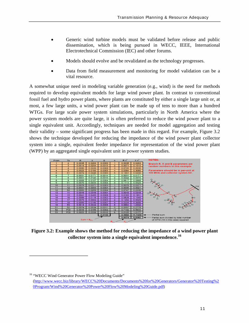
Transmission Planning amp Resource Adequacy
12
Figure 33 shows an example for dynamic simulations of aggregating the WPP into a single equivalent unit and an equivalent single impedance representing the entire collector system as compared to a detailed model representing the whole WPP unit-by-unit ndash the example shown assumes that all WTGs in the WPP are identical in cases where this is not true multiple equivalent units may be needed one for each WTG type As can be seen in this figure the results from the two simulations compare very well at the point of interconnection (which is what is shown) thus the equivalent aggregate is adequate for power system studies17
Figure 33 Example of time-domain simulations comparing a detailed model of a Wind Power Plant (ie representing the complete collector system and each WTG individually) versus a single-machine equivalent aggregate (ie the entire plant is represented by one equivalent unit and an equivalent impedance to represent the whole collector system)
17 Figure is from J Brochu R Gagnon and C Larose ldquoValidation of the WECC Single-Machine Equivalent Power Plantrdquo Presented at the IEEE PES DPWPG-WG Meeting at IEEE PSCE March 2009
P345 kV
Q345 kV
QWT = 0435 0 -0435
Transmission Planning amp Resource Adequacy
13
312 UWIG Generic Model Documentation and Validation Effort
The Utility Wind Integration Group (UWIG)18
The objectives of the project which will commence in early 2010 and run for a period of two years are to
under a US Department of Energy grant will be launching an effort to provide the basic documentation application and validation of generic models for wind turbines The goal of this project is to accelerate the appropriate use of generic wind turbine models for transmission network analysis
bull Complete characterization and documentation of the four generic models developed through an outgrowth of a WECC activity begun in 2005
bull Defining proposed enhancements to the generic wind turbine model structures that would allow representation of more advanced features including power control automatic curtailment inertial and governor response
bull Comparative testing of the generic models against more detailed (and sometimes proprietary) versions developed by turbine vendors
bull Developing recommended parameters for the generic models to best mimic the performance of specific commercial wind turbines
bull Documenting results of the comparative simulations in an application guide for users
bull Acquiring test data from all available sources for the purpose of validating the performance of the appropriately specified generic models in actual case studies
bull Conducting technology transfer activities in regional workshops for dissemination of knowledge and information gained and to engage electric power and wind industry personnel in the project while underway
18 The UWIG was established in 1989 to provide a forum for the critical analysis of wind technology for utility applications and to serve as a source of credible information on the status of wind technology and deployment The grouprsquos mission is to accelerate the development and application of good engineering and operational practices supporting the appropriate integration of wind power into the electric system It currently has more than 150 members spanning the United States Canada and around the world including investor-owned public power and rural electric cooperative utilities transmission system operators and associate member corporate government and academic organizations httpwwwuwigorgaboutuwightm
Transmission Planning amp Resource Adequacy
14
Maintaining communication and coordination with other ongoing activities and agencies engaged in this topic is another objective of the effort which will be critical for success
313 IEC Effort for Generic Models
The International Electrotechnical Commission (IEC) recently started a Working Group in October 2009 to address the development of generic and ldquostandardrdquo models for wind turbine generators19
Part 2 of this work will be focused on extending the modeling to allow for modeling of the entire wind power plant including wind power plant control and auxiliary equipment
The goal of this Working Group is to define standard dynamic simulation models for wind turbines and wind plants which are intended for use in power system and grid stability analyses and should be applicable for dynamic simulations of power system events including short circuits (low voltage ride through) loss of generation or loads and system separation The group is approaching this work in two parts Part 1 will focus on specifying dynamic simulation models for the generic wind turbine topologiesconceptsconfigurations presently in the market as well as specifying how these models may be modified as future technologiesconcepts are introduced The standard should also include procedures for validation of the models specified Another goal is that the models should be developed and specified at a fundamental level so they are independent of any specific software platform and can be adopted by any software vendor
Several members of this IEC Working Group are also members of the WECC and IEEE Working Groups (and this NERC Task Force) The three groups are clearly working in close collaboration to ensure maximum benefit to the industry globally and maximum sharing of knowledge already gained through the WECC and IEEE efforts
19 httpwwwiecchdynwwwfp=102140FSP_ORG_ID5613
Transmission Planning amp Resource Adequacy
15
32 Photovoltaic Solar Generation
Photovoltatic (PV) systems for power generation are quickly increasing becoming a significant portion of generation in some regions in North America PV or solar arrays are composed of a large number of solar cells connected in series and parallel These cells produce a DC voltage when they are exposed to sunlight due to the photo-voltaic effect20
Figure 34 shows the I-V characteristics of a cell at a constant temperature and various sun intensity or insolation levels
Figure 34 Current-Voltage characteristics of a solar cell for various insolation levels at a constant temperature (source [11]21
20 The photo-voltaic effect is the process by which an electric potential difference (voltage) is created in a material exposed to light (electromagnetic radiation) which then leads to the flow of electric current This process is directly related to the photo-electric effect but distinct from it in that in the case of the photo-electric effect electrons are ejected from the material surface upon being exposed to high enough frequency (energy) light whereas in the photo-voltaic effect the generated electrons are transferred across a material junction (eg PN junction in a photo-diode) resulting in the buildup of a voltage between two electrodes and the flow of direct current electricity
)
21 Solar Radiation Research Laboratory at the National Renewable Energy Laboratory (httpwwwnrelgovmidcsrrl_rsp)
Transmission Planning amp Resource Adequacy
16
Figure 35 shows that the current is limited when the cell is short-circuited (Voltage=0)
(a) (b) (c)
(d)
Figure 35 The concept of a solar array (a) a single solar cell (b) a series connection of solar cells (Nser = 3 and Npar = 1) and (c) a solar array (Nser = 3 and Npar = 2) The solar cell array(s) is then connected to a DC bus (d)
Figure 35 shows the concept of the solar cell up to the solar array To use the DC power generated by the PV array in an AC power system the DC power must be converted to 60 Hz AC in North America (50 Hz in some other regions in the world like Europe) There are several power electronic based converter concepts that can achieve this which can be classified into two general categories line-commutated converters (LCC) and self-commutated or more commonly
Vbus Iload
Ibus
Icap PV ARRAY
+
_
Transmission Planning amp Resource Adequacy
17
referred to as voltage-source converters (VSC) These technologies have been applied for decades and are well understood LCC use thyristors as their controlled switching device The switching on of a thyristors can be controlled while the turn-off time cannot be controlled and happens at the next AC waveform current zero crossing LCC systems must be operated in a network with an AC source and cannot operate to serve an isolated load In contrast VSC systems are self-commutating that is the power electronic switching devices used (eg integrated gate-commutated thyristors or IGCTs and insulated-gate bipolar transistors or IGBTs) are able to be completely controlled for both turn-on and turn-off and allow the VSC to completely control the AC waveform produced and adjust the power factor as seen on the AC side to within the current rating of the device Due to advances in the technology most power electronic converters employed in PV systems are of the VSC type22
From a modeling standpoint for power system studies there are some user-written manufacturer-specific models in existence as developed by various PV manufacturers Presently no generic or standard models exist
The WECC Working Group which has been addressing the development of generic WTG models will be extending its effort in 2010 to review developing generic PV models for dynamic simulations in stability studies As a starting point the grid side structure of the Type 4 WTG model may be used since it represents a VSC This is because PV is typically connected to the grid with a VSC and it will behave electrically similar to a Type 4 WTG that has a similar electrical interface with the gridmdashthis is from a grid perspective looking at the electric response and neglects any of the effects of the energy source
From a steady-state power flow and short-circuit analysis perspective the behavior of the PV technologies will behave in a similar fashion to a Type 4 WTG because of the VSC interface and because its power factor can be controlled based on the control functionality of the VSC design Its short-circuit response will be limited to the current limit effected by the VSC under grid fault conditions
The development of generic and standard PV models is presently a topic for further research This should be pursued imminently and much of what has been learnt from the WTG model development process should be leveraged
22 IEA-PVPS Grid-Connected Photovoltaic Power Systems Survey of Inverter and related Protection Equipment Report IEA PVPS T5-05 2002 December 2002 (httpwwwiea-pvpsorgproductsdownloadrep5_05pdf)
Transmission Planning amp Resource Adequacy
18
33 Solar Thermal
Solar thermal energy is based on harnessing the radiated heat of the sun for the purpose of producing electricity In broad terms there are presently two main ways of achieving this
1 Concentrating Solar Power (CSP) plants ndash in this case solar radiation is typically collected through a large number of mirrors (thus a large amount of solar radiation) which is then focused on a small area ndash the mirrors have tracking systems to follow the Sun The concentrated solar radiation heats a high temperature working fluid which then feeds a conventional steam-turbine generator From an electrical grid perspective the models needed to simulate the steady-state short-circuit and transient time-domain dynamics of such a generating unit are typically no different than standard synchronous generating units for fossil fuel plants
2 The Stirling Engine concept23
34 Tidal Generation
ndash in this design a parabolic mirror assembly concentrates the collected solar radiation on a sterling engine that sits at the focal point of the mirror assembly A Stirling engine is a reciprocating heat engine that operates based on the concept of cyclical compression and expansion of a working fluid As the working fluid expandscontracts it drives a piston that then turns a generator The engine is connected to an electrical generator that produces electric energy Once again for power system studies the units may be modeled using standard generator models However in this case a power plant would be constituted by a large number of small units (the typical Stirling engine is about 25 kW) in a large electrical collector system that collects the power and injects it into the utility grid ndash much like the collector system of a wind power plant Thus modeling the collector system (eg see Figure 32 for an aggregate model of a wind collector system) and any other devices in the collector system such as shunt reactive devices etc must be properly modeled
Tidal power generation derives energy directly from the motion of oceanic tides The gravitational pull of the Moon and Sun combined with the Earthrsquos rotation result in the generation of tides Tides generally occur with a period of roughly twelve hours and so most coastal areas experience two high and two low tides within every twenty-four hour period Tidal generation uses this phenomenon to generate energy Clearly the stronger the tides are either in tidal current velocity or the heightlevel of water the greater the potential amount of energy generation
23httpwwwstirlingenergycom Y Zhang and B Osborn ldquoSolar Dish-Stirling Power Plants and Related Grid Interconnection Issuesrdquo IEEE PES General Meeting 24-28 June 2007
Transmission Planning amp Resource Adequacy
19
Presently in North America tidal power is not a significant source of power in any region Some pilot programs exist for introducing the technology In April 2009 one was announced in Snohomish County Public Utility District in Washington State24
There are several options for harnessing tidal power One method is the use of turbines similar to wind turbines however the fluid (water) is much denser and requires a turbine with smaller and bulkier blades as shown in Figure 36 Most of these technologies typically use ACDCAC converter technology similar to a Type 4 wind turbine to convert the low frequency generated electricity to grid frequency AC electricity and interface with the power system Once this technology becomes more prevalent a starting point for development of a suitable model structure may be the Type 4 generic wind turbine models Understandably the energy source characteristics are quite different from wind power and significantly more predictable
Figure 36 One of the many concepts for tidal generation systems (courtesy of Marine Current Turbines Limited wwwmarineturbinescom)
35 Other Resources
There are several other emerging technologies and there are many complementary technologies (ie auxiliary to the variable generation resources but designed to help with their integration into the grid) including smoothly-controlled dynamic reactive devices (static VAr systems)
24 httpwwwsnopudcomPowerSupplytidaltidalpressashxp=1516amp756_na=46
Transmission Planning amp Resource Adequacy
20
energy storage technologies etc With respect to static VAr systems (SVCs and STATCOMs) there is an active WECC working group imminently addressing the issue of generic models for these devices25
36 Summary
The group has made substantial progress with the models defined and developed but currently undergoing testing and validation With regards to the other emerging technologies most tend to be power converter based (ie connected to the grid through a back-to-back frequency converter) and so their electrical behavior (neglecting the characteristics of the energy source) will be similar to Type 4 wind turbines Until these technologies mature the basic structure of other more mature converter based generation technologies can be a good starting point
This section has briefly presented the various types of variable generation and the present status of models and model development for power system studies Wind generation technologies being the most prevalent world-wide have the most mature models Through efforts started by WECC and being continued by IEEE and IEC generic standard models for the four main types of WTG technologies are being developed The first generation of these models has been released in two power system simulation software platforms most commonly used in North America Other emerging technologies (eg PV tidal power etc) can build on this effort to start developing generic models For example the WECC effort will be extending its scope in 2010 to look at PV model
From a NERC perspective the key items are
1 To emphasize and support efforts by WECC IEEE and IEC to develop and standardize generic models for these technologies for power system planning studies
2 To encourage manufacturers to familiarize themselves with the generic models being developed and be willing an able to supply parameters for these generic models to reasonably represent their equipment for power system stability studies As highlighted in Chapter 2 more detailed manufacturer specific models may be needed in special cases and for specialized studies
3 To encourage efforts aimed at model validation
4 To consider any augmentation or additions to reliability standards related to Modeling Data and Analysis (MOD) with respect to modeling and model validation of variable generation This is discussed in greater detail in section 5 of this report
25 httpwwwweccbizcommitteesStandingCommitteesPCCTSSMVWGSVCTFdefaultaspx
Present Status of Model Validation
21
4 Present Status of Model Validation
This chapter gives an overview of the model validation work that has been done hitherto as it relates to models for variable generation Necessarily the primary focus of this section is on wind turbine generator models since models for this resource are presently the most mature
41 What is Model Validation
Any and all models of a dynamic system always have limitations associated with them A model is a representation of reality it is an emulation ndash that is why it is called a model In developing a model first the question is asked as to the specified use of the model and the conditions it must reasonably emulate ndash this forms the basis of a model specification from which a model is developed The developed model establishes a certain structure with parameters which are adjustable in order to emulate different types of equipment or design of the modeled device Thus valid parameterization of the model to represent a particular manufacturerrsquos equipment is essential to support the particular scenarios to be analyzed
Model validation is often achieved through some form of testing either in a laboratoryfactory or in field There is a range of reasons for conducting tests for wind generation Each test has a unique set of objectives guiding the design of adequate testing practices
bull Performance Compliance Compliance to contractual requirements and grid codes are one reason to perform tests Interconnection requirements (usually included in plant Power Purchase Agreements and Interconnection Contracts) and grid codes typically outline specific technical criteria that must be met to allow a power plant to connect and operate on the grid Since these criteria point out specific levels to be met (for example voltage power factor and response time) tests may be designed with binary ldquopassfailrdquo objectives
bull Model Validation In much of the world power plants above a pre-defined size must be accurately represented with a dynamic simulation model used in stability analysis for operations and planning purposes As variable generation sources such as WPP are growing in size it is becoming increasingly important to have accurate variable generation specific models Tests may be performed to tune and verify simulation models to closely match the performance of actual equipment In the western US and Canada WECC has mandated that any plant with 20 MVA aggregate generation must be tested for model validation including large wind power plants For North America the imminent NERC MOD-026 standard presently under development will enforce model validation requirements throughout the North American region
Present Status of Model Validation
22
To achieve the goals of model validation there are three categories of tests that may be performed
bull Type Tests These are tests performed by the manufacturer or independent third-parties of representative equipment The intent is to demonstrate that a particular design of equipment exhibits specific performance and all other equipment of that same design is assumed to have the same performance Type tests can be
o Component Performed on specific functions or features in a power plant or generation equipment This could be for example testing the fault ride-through capability or reactive capability of a WTG where testing is performed at the component level
o Factory A systemic test of a major assembly (ie a drive train) or entire turbine-generator is performed under a controlled environment like a manufacturing facility to verify performance and validate assembly design
o Unit A systemic test of multiple components operating together (ie as entire operating WTG or WPP) with the specific intent of benchmarking a model or design as a type test For example tests performed in Europe under the WindTest program
bull Field Tests26
o Commissioning Tests performed on new equipment entering its period of commercial operation service
Tests performed by the power plant asset owner developer host utility manufacturer andor independent third-parties of specific operating equipment These tests are to demonstrate that a particular implementation design and installation of equipment exhibit specific performance
o Periodic Maintenance or Calibration Tests performed periodically after the plant is in commercial operation to verify that equipment continues to perform as well as it did during commissioning
26 See for example WSCC Control Work Group and Modeling amp Validation Work Group ldquoTest Guidelines for Synchronous Unit Dynamic Testing and Model Validationrdquo February 1997 (wwwweccbiz) and IEEE Task Force on Generator Model Validation Testing ldquoGuidelines for Generator Stability Model Validation Testingrdquo Proceedings of the IEEE PES General Meeting Tampa FL June 2007 (httpieeexploreieeeorg)
Present Status of Model Validation
23
o Periodic Model Validation Tests performed periodically after the plant is in commercial operation to verify that simulation models adequately represent actual plant performance (for example the periodic model validation testing required by WECC)
o Periodic Codes amp Standards Validation Tests performed periodically after the plant is in commercial operation to benchmark and validate plant performance per contractual requirements These tests are typically performed to obtain a permanent operating license for the power plant
bull On-Line Monitoring27
With these general concepts in mind the following subsections present some example cases studies of model validation and validation approaches for variable generation sources The examples emphasize WPP and WTG since wind generation is the present dominant variable generator sources in the North America continent
Other information of interest is from continuous data gathering based on ongoing performance of an operating power plant Data collected from external and unscheduled events including grid disturbances or in the case of WTG large changes in wind is particularly useful Monitoring also benchmarks performance under normal operation
42 Examples of Model Validation Efforts
421 Hydro- Queacutebec Example
The province of Queacutebec has vast wind energy potential Though wind energy generation in 2009 accounts for nearly 13 of the total installed capacity in the Queacutebec control area the penetration rate of wind energy generation will reach 10 by 2015 A total capacity of 528 MW is currently in operation and approximately 3000 MW are under development Five wind turbine manufacturers will supply the WTGs for the different projects under study
The configuration of the Hydro-Queacutebec transmission system is essentially radial Approximately 85 of the total installed generation feeding the system is located at distances up to 1300 km
27 See for example P Pourbeik ldquoAutomated Parameter Derivation for Power Plant Models From System Disturbance Datardquo Proceedings of the IEEE PES General Meeting Calgary Canada July 2009 (httpieeexploreieeeorg) This reference shows actual application of on-line disturbance monitoring to power plant model validation for conventional fossil fuel generation It may be feasible to apply similar algorithms and approaches for continuous re-validation of WTG and other variable generation technologies once generic standard models have been developed This is a current topic for research
Present Status of Model Validation
24
from the closest major load centers With this configuration the system transfer capability is mainly limited by stability constraints (transient stability and voltage stability) rather than congestion or thermal capacity of equipment hence the need for reliable models for wind power plants and all other generation
Stability studies are critical to determine the compensation equipment required to maintain the reliability of the power system when integrating new generation They are also essential for operation planning studies including control system design and tuning and determination of transfer capabilities
So far Hydro-Queacutebec has faced two major difficulties regarding user-written models provided by the wind turbine manufacturers First models often lack robustness and do not represent accurately some important features (convergence problems in low short-circuit network do not take into account frequency excursions do not represent secondary voltage regulation etc) Second model validation by the manufacturers is often incomplete not available or difficult to translate to real projects (different settings or software versions design of the collector system etc) In some cases these difficulties have lead Hydro-Queacutebec to build its own models (see Hypersim section below)
General validation test program
Since 2006 Hydro-Queacutebec has performed validation tests on WPP connected to its transmission system and a general validation test program was established in 200928
1 To demonstrate that WPP meet the Transmission Provider technical requirements related to wind generation
The power producer has the obligation to perform validation tests in order to demonstrate that its facilities meet the Transmission Provider requirements The purposes of this program are
2 To validate numerical models and parameters associated with the WPP specifically those given to the Transmission Provider by the power producer by comparing the model response to recordings taken during field tests
3 To confirm the electrical data of power producer facilities
The validation program is divided into seven functions to be validated
1 Primary voltage regulation
28 httpwwwhydroquebeccomtransenergiefrcommercepop_raccordement_transporthtml
Present Status of Model Validation
25
2 Undervoltage response (LVRT)
3 Inertial response
4 Secondary voltage regulation
5 Power factor
6 Maximum ramp rates
7 Power quality
The tests for the primary voltage regulation are performed on a single WTG and consist in producing instantaneous voltage variations of low amplitude on the terminal of the WTG and small voltage steps of limited duration injected directly into the WTG voltage control system Three-phase voltages and currents are recorded at the wind generator to measure the local dynamic response of a wind generator to a rapid voltage change and to verify that the response meets voltage regulation requirements The results are also used to set the model parameters (time constant and gain) used in dynamic simulations The tests regarding the secondary voltage regulation are similar but are conducted for the entire power plant
The validation test program includes LVRT tests on one generating unit to verify that requirements during undervoltage conditions are met The power producer has the responsibility to conduct the tests or to provide a complete report describing tests performed on an identical generating unit (same software version) to demonstrate that the requirements are met So far no LVRT tests were performed on site on WPP integrated on the Hydro-Queacutebec network However monitoring equipment has been installed at three locations in wind plants at their point of interconnection on a 345 kV feeder of the collector system and on one generating unit The monitoring system records signals either continuously or upon detecting variations occurring at the point of interconnection active power variations voltage sags and swells and system frequency excursions These signals are primarily voltages and currents but may also be mechanical variables or other signals
The field recordings recorded on the network can thereafter be used to validate the dynamic response of the models This is a time consuming effort that requires the collaboration of the manufacturers to modify the models if necessary Event recordings to-date have made possible suitable validation of two Hydro-Queacutebec Siemens PTI PSSregE models and one ElectroMagnetic Transients Program (EMTP) model
Inertial response requirements were not in defined for the projects started before 2005 Consequently existing wind plants do not have to fulfill them However the requirements have to be met for WPP to be commissioned in 2011 and after The corresponding validation tests consist in emulated frequency steps and ramps of limited duration Besides verifying the
Present Status of Model Validation
26
requirements the test results will be used to validate the parameters of the models and their dynamic response
The power factor and the maximum ramp rates modules are tested with all WTGs in service to verify that the requirements are met Power factor tests consist in supplying and absorbing a maximum amount of reactive power at different levels of active power Maximum ramp rate tests consist in performing a power plant shutdown sequence followed by a startup sequence These tests are not really used to validate the models but are rather helpful to fix model parameters
The last module regarding the power quality is not covered by scheduled testing but by means of a monitoring system that verifies harmonics and emission limits The recordings are compared to the report provided by the developers to verify if the requirements are met However they are not useful to validate the EMTP model since the WPP is represented by a single-wound generator and does not simulate the detailed collector bus system and individual wind turbine generators
Field tests department
Hydro-Queacutebec field-testing department (UMES) conducts a wide range of special tests and measurements for Hydro-Queacutebec and has done so for 30 years
To test WPP UMES installs a monitoring systems to record three-phase voltages and currents generally at three locations within the plant at the point of interconnection at the starting point of a 345 kV feeder of the collector system and at the terminals of a WTG connected to the same monitored feeder For extended model validation other signals within the wind turbine are monitored including the rotor side converter voltages and currents the network side converter currents and the DC bus voltage
High speed recorders with anti-aliasing filters are used Normally the sampling rate is 5 kHz with at least a 200 second window per event The monitoring system is reachable via an Ethernet connection for remote trigger and data retrieval UMES has also the responsibility to perform the data processing and analysis of the recordings in order to verify the compliance with the interconnection requirements and to extract relevant data for model validation
Present Status of Model Validation
27
Hypersim
The Hydro-Queacutebec Research Institute (IREQ)29 also has an important expertise in control system and wind generation modeling for extensive studies of electrical networks The simulation environment used is Hypersim a real-time simulator and powerful simulation tool that uses a highly detailed representation of the Hydro-Queacutebec network A full-transient detailed model of a Type 3 WTG was developed at IREQ using the MATLABreg SimPower Systems Toolbox The model was also implemented in EMTP and in the Hypersim real-time simulator30 This model is in the process of being validated with data processed by the UMES team The range of events recorded does not make it possible to validate the model completely and the design and parameters will continue to be adjusted to improve the representation of the wind turbines The validation of the MATLABreg model developed by IREQ was very useful to validate and improve Hydro-Queacutebecrsquos Siemens PTI PSSregE user model31
422 GE Example ndash based on GErsquos work with client facilities
In the case of the first example presented here a 10 MVar capacitor bank located at the 25kV WPP collector bus is switched off-line as an external physical stimulus Figure 41 shows detailed response to capacitor switching from the WindCONTROLreg The WindCONTROLreg system allows coordination of all on-line turbine-generators for plant-level fast and smooth voltage regulation at the point of interconnection (POI) located contractually at the 25kV substation bus The red curve (Q_ACTUAL [KVar]) shows that total plant reactive power initially drops after the switching action but the fast autonomous controls on each turbine generator quickly and stably respond to increase reactive power generated by individual turbines shown by the orange curve (Q_TURBINES [KVar]) The WindCONTROLreg command (Q_CMD) distributed to the turbines is shown in blue The response of Q_CMD is dominated by the gains of the voltage regulator portion of the WindCONTROLreg specifically the proportional gain Kpv and integral gain Kiv The difference between the response of the individual turbines (Q_TURBINES [KVar]) and the WindCONTROLreg command (Q_CMD) is due to the dynamics of the individual wind turbines The coordinated response of the wind plant and the individual
29 httpwwwhydroquebeccomtechnologyindexhtml 30 R Gagnon G Sybille SBernard D Pareacute S Casoria and C Larose ldquoModeling and Real-Time Simulation of a
Doubly-Fed Induction Generator Driven by a Wind Turbinerdquo IPST Conf Paper No IPST05-162 Montreacuteal Canada 2005 C Larose R Gagnon G Turmel P Giroux J Brochu D McNabb and D Lefebvre ldquoLarge Wind Farm Modeling Techniques for Power System Simulation Studiesrdquo in Proc 8th International Workshop on Large-Scale Integration of Wind Power into Power Systems Bremen Germany Oct 14-15 2009
31 C Langlois D Lefebvre L Dube and R Gagnon ldquoDeveloping a Type-III Wind Turbine Model for Stability Studies of the Hydro-Queacutebec Networkrdquo in Proc 8th International Workshop on Large-Scale Integration of Wind Power into Power Systems Bremen Germany Oct 14-15 2009
Present Status of Model Validation
28
turbines is multi-modal a fast initial response to address severe perturbations as well as a slower grid friendly refinement For purposes of this test the automatic control of the capacitor bank by WindCONTROLreg was disabled and manual switching was used as a stimulus to record individual WTG response
The detailed plot in Figure 42 shows a zoomed view of the response to step change in voltage at the WTG The very fast initial response will dominate and saturate the controls for big events The wind plant will do everything as quickly as it can to mitigate a large disturbance In this case the fast response took approximately 200 milliseconds The slow refined control then takes over to allow for coordination with other equipment and maintain post-disturbance stability This aggregate response also allows for a very abrupt action when needed and a grid-friendly refinement that maintains stability in less severe cases
The green curve in Figure 43 shows that when the capacitor is switched off-line the measured voltage at the point of interconnection (or POI) decreases due to reduced reactive power flowing into the grid The response of the individual WTGs is to rapidly increase reactive output to make up for the loss of reactive power supplied by the shunt capacitor The plant level control then responds to this initial under-voltage condition and attempts to restore the POI voltage by increasing each wind generatorrsquos reactive output by equal amounts until the plant voltage settles to the control set point determined by the operator The lower traces in Figure 43 show a gap during the period when the capacitor bank is online between total plant Q (Q_ACTUAL) and summation of Q out of each WTG (Q_TURBINES) This gap represents the capacitive reactance added by the shunt bank When the capacitor is switched offline the gap between Q_ACTUAL and Q_TURBINES closes and all reactive power is supplied solely from the WTGs The initial loss in plant reactive power is mitigated within approximately 15 seconds as each WTG settles to a new increased level operating point of reactive power This new increased reactive level for each WTG is the total Q increase from all units on-line in the plant divided by the total number of units online at the time of the test
Figure 44 shows a comparison between these measured values and the simulation results of the PSLF model Model outputs Qg Qplant Qcmd and Vreg correspond to measured Q_TURBINES Q_ACTUAL Q_CMD and U_LINELINE respectively This plot shows the model performance adequately represents what is happening in the field The response matches closely with a difference immediately following the switching operation being due to lower sampling rate in the measurement than in the GE PSLFreg simulation
Response to grid events demands relatively rapid control action Manual grid or plant operator changes in operating set-points do not normally demand fast response and indeed system behavior ought not to be rapidly disturbed by moving set-points Figure 45 shows the response of GE plant to 2 step in voltage reference The blue trace in the figure shows a well mannered response to the reference step The red trace is from the simulation model which matches very
Present Status of Model Validation
29
well In the blue trace after the perturbation occurring about 8 seconds after the reference change the plant supervisory control switched on a shunt capacitor to retain dynamic range on the wind turbines The switching perturbation is rapidly balanced by the turbines allowing the response to continue smoothly
Figure 41 10 MVar Capacitor removal response measured from WindCONTROLreg
Present Status of Model Validation
30
Figure 42 Wind turbine-generator level voltage step test response
Present Status of Model Validation
31
Figure 43 10 MVar Capacitor removal response ndash POI variables
Figure 44 10 MVar capacitor removal field test vs simulation results
Present Status of Model Validation
32
Figure 45 A different step test +- 2 step of voltage reference
The performance for grid fault events is of considerable interest in system planning Staging faults particularly severe ones on operating wind plants is difficult and expensive Figure 46 shows a comparison between a staged fault test and the (present) Siemens PTI PSSregE model of the GE 25 (full converter) WTG The fault event is quite severe a 3-phase 700ms of voltage depression to less than 20 of nominal at the high voltage terminal of the WTG unit transformer The measurement traces (on the left) include some of the signal noise characteristic of measurement and extraction of fundamental frequency positive sequence information from real high resolution measurements The simulation traces on the right are of course cleaner The match between test and simulation is of very high fidelity for phenomena relevant and legitimately examined with positive sequence simulation tools (ie greater than one cycle)
QPOI
VPOI
Measured = Blue Simulated = Red
Plant Capacitor Bank Switched On Automatically by WindCONTROL
+ 2 VrefStep
- 2 Vref Step
QPOI
VPOI
Measured = Blue Simulated = Red
Plant Capacitor Bank Switched On Automatically by WindCONTROL
+ 2 VrefStep
- 2 Vref Step
Present Status of Model Validation
33
Figure 46 GE 25 WTG Fault Test vs PSSe Model Performance
The discussion provide above is solely geared to hardware testing and validation however another highly valuable and legitimate means of providing validation of simulation models (for planning and otherwise) is to use more complex simulation software to validate simpler planning models Manufacturers normally have highly complex and highly proprietary models of their equipment These models are used among other things to design equipment and are normally physically based and must have sufficient fidelity for original equipment manufacturers (OEMs) to make sound engineering judgments for equipment design and application The OEMs are highly motivated to have these detailed high fidelity equipment level models These detailed models therefore can often be used to design test and validate simpler planning models to be used by the industry
There is a long accepted history in the power industry of this practice For example a typical (GE) gas turbine has on the order of 4000 state variables in the design model planning models typically have on the order of four state variables simplification is necessary and expected These design codes have been used to develop planning models of gas turbines Figure 47 below shows a comparison between a fault simulation using a GE design code (GE WindTrapreg) and the planning model in GE PSLFreg for a GE 15 (double fed machine) WTG
Present Status of Model Validation
34
Figure 47 Detailed Design Simulation (GE WindTRAPreg) vs GE PSLFreg Model Performance (active power during a severe fault for a GE 15 WTG)
-10
00
10
20
30
0 05 1 15 2
Time (Seconds)
Sin
gle
WTG
Rea
l Pow
er (M
WindtrapPSLF
Summary amp Recommended Actions
35
5 Summary amp Recommended Actions ndash Standards Implications
This document has presented a general overview of modeling and model validation as it pertains to variable generation resources Clearly to date the bulk of the experience and work has been on wind turbine generators Never-the-less similar approaches for modeling and model validation are being pursued for other variable generator technologies such as PV
Non-proprietary and publicly available models for the simulation of steady-state (power flow) short-circuit (fault calculations) and dynamic (time-domain simulations) behavior of such generation resources must be made readily available for use by power system planners Furthermore these models should be routinely validated to ensure proper representation of variable generation power plants in bulk power system studies A model is valid if its dynamic behavior is close enough to reality so that its influence on the network of interest (ie used for power system studies) is consistent with the fidelity of model structures and available data for the power system and other generation as it pertains to the phenomena of interest (ie in stability studies) That is perfect curve fitting is not necessary but to the extent possible erroneous model dynamics must not result in a notable over-design or under-design of the network
Each of the NERC standards discussed below in Section 52 address to aspects of meeting a standard (i) the technical requirement ie the need to define measure validate a model its parameters etc and (ii) the procedural requirements ie the functional model of how this technical requirement should be met reported and monitored The bulk of this working grouprsquos recommendations stated below address the technical requirements Variable generation is a new and quickly evolving technology and consideration should be given to the timing with which standards be implemented
Section 51 below first gives a summary of the planning process based on NERC standards to put the discussions in this report into context with the NERC standards Then in Section 52 we provided our recommendations and comments on the NERC existing and developing standards
Summary amp Recommended Actions
36
51 Applying the NERC Standards
The NERC standard FAC-001 (see Figure 51) should be expanded to clearly cover modeling requirements during the coordinated joint study phase of the Facility connection process Simple generic models of variable generation may be adequate for the IES phase and more detailed models may be needed for the IFS phase Validation of the simple and detailed model parameters may be needed during commissioning
Figure 51 Facility connection process
Interconnection Evaluation Study
Generator Interconnection
Request
Interconnection Facility Study
GO provides initial model
to TPPC
GO provides final model
to TPPC
GO signs Interconnection
Agreement and is put in-service
GO performs model amp
performance validation testing
TO develops Facility Interconnection requirements and requests models and data
of the GO at each process stage
FAC-001
Summary amp Recommended Actions
37
The generic model with associated parameters feed into the NERC model building process shown in Figure 52 As an example for WTG presently there is insufficient evidence of the accuracy of presently available generic models for WTG32
for all the various WTG manufacturers Some confirmation tests during commissioning or type tests or comparison simulation tests with a detailed model are necessary to get buy in from the Transmission OwnerPlanner As the technology matures and generic models are enhanced and associated data parameter sets are developed for specific machine types the new generic models will become more accepted as is the case with models of hydro or thermal plants
Figure 52 Annual NERC Model Development Process
32 PSSregE-320 Program Application Guide Volume II Chapter 21 PSSregE-320 Model Library Chapters 17 through 21 GE PSLF Users Manual v170_04 October 2009
Steady state data
developed
MOD-10
Dynamics data
developed
MOD-12
Reliability Region creates model
MOD-14
Reliability Region creates model
MOD-15
Reliability Region defines data
requirements
MOD-13
GO
TP
RP
Reliability Region defines data
requirements
MOD-11
Annual NERC Planning and
Operating Models
created and distributed to the industry
Summary amp Recommended Actions
38
The regional model building manuals developed as part of MOD-11 and MOD-13 must provide sufficient clarity to model variable generation These manuals may ask for best available models or generic models These models cover the operational time frame and the 10-year planning horizon The manuals do not currently cover the frequency for revalidating model data
While not included in the standards more emphasis is currently being placed on meeting the Eastern Interconnection Reliability Assessment Group (ERAG) model building manual requirements in addition to regional requirements
Figure 53 NERC Model Validation Process
The Regional Entities develop the test procedures and dictate testing frequency for the Generator Owners to follow The model data then feeds in to the annual NERC model building process
52 NERC Standards Technical Issues
One general comment is that the NERC Glossary of Terms would benefit from the term ldquoVariable Generationrdquo being include in it and appropriately defined A suitable definition can be found in the Phase I report of the IVGTF
Verify real power capability
MOD-24
GO
Verify reactive power capability
MOD-25
Verify generator excitation control model
MOD-26
Verify turbine governor model
MOD-27
Summary amp Recommended Actions
39
MOD-011 Regional Steady-State Data Requirements and Reporting Procedures
The technical requirement in this MOD reads
ldquoR12 Generating Units (including synchronous condensers pumped storage etc) location minimum and maximum Ratings (net Real and Reactive Power) regulated bus and voltage set point and equipment statusrdquo
This statement could be read to equally apply to variable generation as a source of generation However it may be prudent to explicitly include variable generation in this statement For example to change the sentence to
ldquoR12 Generating Units (including synchronous condensers pumped storage variable generation resources etc) location minimum and maximum Ratings (net Real and Reactive Power) regulated bus and voltage set point and equipment status For variable generation a suitable aggregate steady-state model of the collector system and equivalent unit representing the full plantrdquo
MOD-012 Dynamics Data for Transmission System Modeling and Simulation
This MOD equally applies to variable generation and needs no augmentation The requirements in the MOD are quite generic The requirements of this standard are dependent on and point to MOD 13 discussed below
MOD-013-1 RRO Dynamics Data Requirements and Reporting Procedures
This MOD explicitly discusses synchronous type generation It would be beneficial to include an explicit statement to cover variable generation For example
ldquoPlant-specific dynamics data shall be reported for variable generating units (eg wind turbine generators PV etc) such as the type of generating unit its interface with the grid and the appropriate model and model parameters to adequately represent unit dynamic response for bulk power system studies The typical size of a single variable generating unit (eg wind turbine generators PV array etc) is several hundreds of kilo-watts to several mega-watts Thus it may be acceptable for the total plant to be represented by an adequate aggregated model of the collector system and a single equivalent generating unit scaled up to represent the total name-plate capacity for each type of generating technology employed in the plant Furthermore models may need to be provided for other equipment installed in the collector system or at the point of interconnection such as reactive compensation devicesrdquo
Summary amp Recommended Actions
40
MOD-024-2 mdash Verification and Data Reporting of Generator Real Power Capability
This latest posting of this MOD posted for commenting on January 18th 2010 exempts variable generation from this requirement It states
ldquoVariable energy units such as wind generators solar and run of river hydro are exempt from the requirements of this Standardrdquo
For a variable generation plant the definition of Real Power Capability can be slightly challenging One way to view it is to see the total gross capability as the sum of the nameplate rating of all individual units within the plant eg for a wind power plant the total sum of the nameplate rating of all wind turbine generators in the plant However there must be two realizations (i) the amount of actual power injected into the grid at the point of interconnection requires a suitable representation of losses on the collector system and auxiliary loads and (ii) by its very nature variable generation is a highly variable energy source and thus it is quite rare to find point in time when all units in the plant are coincidentally at their peak nameplate capacity Finally the seasonal variable generation output variations need some discussion since they are quite different than conventional generation technologies
MOD-025-1 mdash Verification of Generator Gross and Net Reactive Power Capability
The technical requirement in this MOD reads
ldquoR15 Information to be reported
R151 Verified maximum gross and net Reactive Power capability (both lagging and leading) at Seasonal Real Power generating capabilities as reported in accordance with Reliability Standard MOD-024 Requirement 151
R152 Verified Reactive Power limitations such as generator terminal voltage limitations shorted rotor turns etc
R153 Verified Reactive Power of auxiliary loads
R154 Method of verification including date and conditionsrdquo
Note the above requirements are from the existing version of the standard MOD-025 is currently being enhanced
Although all of the above could equally apply to variable generation some clarification may be needed Namely variable generation reactive capability of the ldquopower plantrdquo is not entirely inherent in the individual generating units A variable generation power plant such as a wind power plant may contain many reactive power sources such as the individual generating units themselves (eg Type 3 or 4 WTG see Appendix I) discretely switched shunt reactive devices
Summary amp Recommended Actions
41
(eg shunt capacitors or reactors) smoothly controlled shunt reactive devices (eg SVC or STATCOM) or a combination of these devices Thus care should be taken as to how the total reactive capability of the power plant is defined and at what point (eg point of interconnection and whether this is defined as the high or low side of the substation transformer) Also it may not be practical under normal operating conditions to exercise the full reactive capability of the power plant (this is a known issue even with conventional synchronous generator plants) to test it thus it should suffice to demonstrate the plants reactive capability to the extent possible in the field and to then augment this with engineering calculations to derive the plants full reactive capability This is particularly true of variable generation because there is no control over the energy resource So for example a typical wind power plant may only achieve its name-plate rating for a hour or two during an entire year Thus it would not be possible to demonstrate the full reactive capability of the plant in the field Rather it should suffice to demonstrate the reactive capability of a single WTG and then to derive through engineering calculations (considering all other reactive devices in the plant such as SVC STATCOM etc) the total reactive capability of the plant These comments should be somehow used to appropriately modify MOD 25
MOD-026-1 mdash Verification of Models and Data for Generator Excitation System Functions ndash SECOND POSTING (and MOD 27)
MOD 26 (and MOD 27 Verification of Models and Data for TurbineGovernor and Load Control) are presently under development33
Presently these standards are tailored explicitly to deal with synchronous type generators since much of the language revolves around technology associated with synchronous generation (eg excitation system AVR power system stabilizers etc) Thus the following key items need to be clarified in these standards as they pertain to variable generation In addition the comments that follow apply to all components in a variable generation plant that may include devices such as the actual power generating units shunt compensation devices centralized control systems spanning the entire facility etc
These two standards deal specifically with the routine validation of generating unit dynamic models for power system stability studies
1 UnitPlant Size for Validation These MODrsquos specify the size of generating unit above which model validation is required It should be recognized that the typical size of a
33 MOD 26 and MOD 27 standards under development are found at httpwwwnerccomfilezstandardsGenerator-Verification-Project-2007-09html
Summary amp Recommended Actions
42
variable generation unit is in the hundreds of kilo-watts to several megawatts range Thus the language should be changed (or introduced) to indicate ldquonet power plantrdquo size
2 Validation of various technologies in a single plant Variable generation power plants can consist of multiple generation technologies For example a wind power plant may consist of WTGs of two different types Thus we need to consider the following points as they pertain to variable generation
a For a uniform variable generation plant (ie all generating units are of the same technology type) a single aggregate generator model representation should be sufficient
b For a significantly diverse variable generation plant the plant should be represented by multiple aggregated unit models representing each technology type
c Unique representation of a group of variable generation units as a single aggregated generator model representation should be based on
i The size of the group is a significant proportion of the total plant size (eg gt 20 of plant rating)
ii Each group should represent a unique characteristic (eg Type 1 WTG as compared to a Type 3 WTG)
3 Validation of different control layers Variable generation plants such as wind power plant may have several functional layers of control For example in a wind power plant with Type 3 WTGs we may have one level of closed loop voltage regulation at the terminals of the WTG a second slower control loop that regulates voltage at the point of interconnection (POI) and a third layer of control that coordinates the switching of shunt capacitors at the POI based on the reactive output of the individual WTGs In addition devices such as STATCOMs may be present at the POI Modeling and model validation should incorporate such devicescontrol layers to the extent that the dynamics of these functional layers are important for stability studies (see Figure 31)
4 Modeling and Model Validation Models are an emulation of actual equipment Not all model parameters necessarily translate to actual physical components or measureable features Judgment needs to be exercised in the modeling and validation process
a Models should be validated typically against the performance of an actual plant for a given eventdisturbance within the given operating range it is designed for
Summary amp Recommended Actions
43
b Models should state clearly the type and the range of events they have been designed to simulated and the limitation of the models beyond which the model deviates from the actual variable generation plant performance (eg a model developed to represent electrical transient behavior of a WTG may not be adequate for studying wind fluctuations over a many minute time frame)
c In general the best approach to model validation is to use field (or test bench) measurements of various disturbances that must exercise the different control functions to a wide range of operation points For example a model is not necessarily valid if the only a comparison between simulation results and field measurements for a single voltage step response is performed at one operating condition Ideally illustration of validation against recorded response to various system disturbances (faults frequency deviations etc) gives the greatest confidence in validation
d A model is valid if its dynamic behavior is close enough to reality so that its influence on the network of interest (ie used for power system studies) results in relatively negligible errors for the phenomena of interest (ie in stability studies) That is perfect curve fitting is not necessary but to the extent possible erroneous model dynamics must not result in a notable over-design or under-design of the network
5 Future functionality Due to the rapidly evolving nature of variable generation technologies variable generation models should be of a modular nature such that future functionality can be incorporated as much as possible into old model structures by adding a functional modular block For example presently Type 3 and 4 WTGs do not exhibit inertial response However at least one manufacturer now supplies a functional control addition that can emulate inertial response on these units Such functionality is likely to be made available soon by most vendors Thus a functional model block can be developed that can be added to the existing models for Type 3 and 4 WTGs to emulate the behavior of this additional control
6 Modeling of protection Variable generation much like conventional generation will have associated underover voltage and under-over frequency protection These should be modeled Attention should also be given to protective relay coordination with plant controls particularly in light of the nature of the grounding system within the variable generation plant (eg a wind power plant spans an entire collector system which can be grounded in several different ways and thus have various implications on protective relay coordination) Such coordination issues relate to the PRC and FAC-001 standards
Summary amp Recommended Actions
44
7 Issues related to the fuel source for variable generation For variable generation one needs to be cognizant of the variable nature of the energy source and thus the possible impracticality of performing model validation at a desired plant output but rather having to accept model validation at whatever plant output can be achieved at the time of testing or disturbance monitoring
8 Revalidation How often should models be revalidated
a Many variable generation technologies are rapidly changing for example in wind power plants new control software or new setting may be uploaded every year if not sooner
b If the changes are insignificant the existing dynamic models should be revalidated if possible as a matter of prudency ndash say within six months or so of a control system updateupgrade The changes (in parameters or dynamic model) should be reported to the local Reliability Entities
c If the changes are significant the existing dynamic models should be revalidated ndash say within three months or so after the updateupgrade The changes (which may include a new module new software etc) should be reported to the local Regional Entities
53 Final Recommendation
An earlier draft of this report and recommendations were presented to NERCrsquos Planning Committee at their March 2010 meeting The Committee members urged the IVGTF to pursue NERC reliability standard development Thus several NERC Standards Drafting Teams undertaking MOD Standard development will be contacted to present the recommendations from this report for their consideration and incorporation in subsequent updates The standard drafting teams for MOD-026 and MOD-027 are aiming to incorporate variable generation considerations in the next release of these draft standards
Appendix I Wind-Turbine Generation (WTG) Technologies
45
Appendix I Wind-Turbine Generation (WTG) Technologies
(a) Type 1 Wind Turbine-Generator Fixed Speed Induction Generator
(b) Type 2 Wind Turbine-Generator Variable Slip Induction Generator 34
34 IGBT R control = Resistor controlled by Insulated Gate Bi-Polar Transistor
3
GEAR BOX
INDUCTION GENERATOR TRANSFORMER
GRID
3
3GEAR BOX
WOUND ROTORINDUCTION GENERATOR TRANSFORMER
GRID
IGBT RControl
Rectifier
Appendix I Wind-Turbine Generation (WTG) Technologies
46
(c) Type 3 Wind Turbine-Generator Double-Fed Asynchronous Generator
(d) Type 4 Wind Turbine-Generator Full Power Conversion
3
3GEAR BOX
WOUND ROTORINDUCTION GENERATOR TRANSFORMER
GRID
IGBT POWER CONVERTORS
3
GEAR BOX
SYNCHRONOUSGENERATOR TRANSFORMER
GRID
Rectifier
33
IGBTInverter
Acronyms
47
Acronyms
CSP ndash Concentrating Solar Power
CIGRE - International Council on Large Electric Systems
DFAG ndash Doubly Fed Asynchronous Generator (also often referred to as DFIG ndash Doubly Fed Induction Generator)
FERC ndash Federal Energy Regulatory Commission
HVDC ndash High-Voltage Direct-Current transmission
IEC ndash International Electrotechnical Commission
IEEE ndash Institute of Electrical and Electronic Engineers
IGBT ndash Insulated-Gate Bipolar Transistor
IGCT ndash Insulated-Gate Commutated Thyristor
IVGTF ndash Integration of Variable Generation Task Force
ISO ndash Independent System Operator
LCC ndash Line-Commutated Converter
LVRT ndash Low-Voltage Ride-Through
MOD ndash Modeling Data and Analysis Standards
NERC ndash North American Electric Reliability Corporation
OEM ndash Original Equipment Manufacturer
PHEV ndash Plug-in Hybrid Electric Vehicle
PV ndash Photovoltaic
POI ndash Point of Interconnection
RPS ndash Renewable Portfolio Standard
RTO ndash Regional Transmission Operator
Acronyms
48
SAR ndash Standards Authorization Request (NERC process)
SCADA - Supervisory Control and Data Acquisition
SSTI ndash Subsynchronous Torsional Interaction
STATCOM ndash Static Compensator (voltage source converter based technology)
SVC ndash Static Var Compensator (thyristor based technology)
TSO ndash Transmission System Operator
VAr ndash volt-ampere reactive (standard units for reactive power)
VRT ndash Voltage Ride-Through
VSC ndash Voltage Source Converter
WPP ndash Wind Power Plant
WTG ndash Wind Turbine Generator
WECC ndash Western Electricity Coordinating Council
IVGTF Roster
49
IVGTF Task 1-1 Roster
Chair Pouyan Pourbeik
Technical Executive EPRI 942 Corridor Park Boulevard Knoxville Tennessee 37932
(919) 806-8126 ppourbeik epricom
Jay Caspary Director Transmission Development
Southwest Power Pool 415 North McKinley Suite 140 Little Rock Arkansas 72205
(501) 666-0376 (501) 666-0376 Fx jcasparyspporg
K R Chakravarthi
Southern Company Services Inc Southern Company Services Birmingham Alabama 35203
205-257-6125 205-257-1040 Fx krchakra southerncocom
Kieran Connolly
Manager Generation Scheduling
Bonneville Power Administration 905 NE 11th Avenue Portland Oregon 97232
(503) 230-4680 (503) 230-5377 Fx kpconnolly bpagov
Adam Flink
Engineer Midwest Reliability Organization 2774 Cleveland Ave Roseville Minnesota 55113
6515881705 (651) 855-1712 Fx adflink midwestreliabilityorg
David Jacobson
Interconnection amp Grid Supply Planning Engineer
Manitoba Hydro 12-1146 Waverly Street PO Box 815 Winnipeg Manitoba R3C 2P4
(204) 474-3765 (204) 477-4606 Fx dajacobson hydrombca
Charles-Eric
Langlois Jr Engineer
Hydro-Queacutebec TransEnergie 9e eacutetage Complexe Desjardins Tour Est Montreal Queacutebec H5B1H7
(514) 879-4100 ext 5441 (514) 879-4486 Fx LangloisCharles-Erichydroqcca
IVGTF Roster
50
David Marshall Project Manager
Southern Company Services Inc 600 N 18th Street Birmingham Alabama 35203
205-257-3326 205-257-1040 Fx dcmarsha southerncocom
Sophie Paquette
Transmission Planning Engineer
Hydro-Queacutebec TransEnergie 9e eacutetage Complexe Desjardins Tour Est 12th Floor Montreal Queacutebec H5B1H7
(514) 879-4100 ext 5423 (514) 879-4486 Fx paquettesophie hydroqcca
David C Schooley
Sr Engineer Commonwealth Edison Co 2 Lincoln Centre Oakbrook Terrace Illinois 60181
(630) 437-2773 davidschooley comedcom
Eric Thoms
Technical Lead - Transmission Access Planning
Midwest ISO Inc 1125 Energy Park Dr St Paul Minnesota 55108
(651) 632-8454 (651) 632-8417 Fx ethoms midwestisoorg
Observers Daniel Brooks
Manager Power Delivery System Studies
Electric Power Research Institute 942 Corridor Park Blvd Knoxville Tennessee 37932
(865) 218-8040 (865) 218-8001 Fx dbrooksepricom
Abraham Ellis
Principal Member of Technical Staff Renewable System Integration
Sandia National Laboratories 1515 Eubank SE Albuquerque New Mexico 87123
(505) 844-7717 (505) 844-2890 Fx aellis sandiagov
Ben Karlson
Sandia National Laboratories PO Box 5800 Albuquerque New Mexico 87185
(505) 803-3676 bkarlso sandiagov
Yuriy Kazachkov
Siemens Energy Inc 400 State Street Schenectady New York 12305
(518) 395-5132 (518) 346-2777 Fx yuriykazachkov siemenscom
Carl Lenox
Senior Staff Engineer Sunpower Corporation Systems 1414 Harbour Way South Richmond California 94804
(510) 260-8286 (510) 540-0552 Fx carllenox sunpowercorpcom
IVGTF Roster
51
Jason MacDowell
GE Energy 1 River Road Bldg 53 Schenectady New York 12345
(518) 385-2416 (518) 385-5703 Fx jasonmacdowell gecom
John Mead
Senior Staff Engineer Sunpower Corporation Systems 1414 Harbour Way South Richmond California 94804
(510) 260-8370 (510) 540-0552 Fx johnmead sunpowercorpcom
Nicholas W Miller
Director GE Energy 53-300Q 1 River Road Schenectady New York 12345
(518) 385-9865 (518) 385-5703 Fx nicholasmiller gecom
Eduard Muljadi
Senior Engineer National Renewable Energy Laboratory 1617 Cole Boulevard Golden Colorado 80401
(303) 384-6904 EduardMuljadi nrelgov
Mark OMalley
Professor of Electrical Engineering
University College Dublin R 157A Engineering amp Materials Science Centre University College Dublin Belfield Dublin 4
00353-1-716-1851 00353-1-283-0921 Fx markomalley ucdie
Subbaiah Pasupulati
Director of Technical Studies
Oak Creek Energy Systems Inc 14633 Willow Springs Road Mojave California 93501
(909) 241-9197 (661) 822-5991 Fx subbaiah oakcreekenergycom
Juan J Sanchez-
Gasca Principal Engineer
GE Energy 1 River Road Bldg 53-302E Schenectady New York 12345
(518) 385-5564 (518) 385-5703 Fx juansanchez psgecom
Steven Saylors
Chief Electrical Engineer
Vestas Americas 1881 SW Naito Parkway Portland Oregon 97201
(503) 327-2111 (503) 327-2001 Fx saylvestascom
IVGTF Roster
52
Robert Zavadil Vice President and Principal Consultant
EnerNex Corp 620 Mabry Hood Road Suite 300 Knoxville Tennessee 37932
(865) 218-4600 Ext 6149 (865) 218-8999 Fx bobzenernexcom
NERC Staff
Aaron Bennett Engineer Reliability Assessments
North American Electric Reliability Corporation 116-390 Village Boulevard Princeton New Jersey 08540-5721
(609) 524-7003 (609) 452-9550 Fx aaronbennett nercnet
Rhaiza Villafranca
Technical Analyst North American Electric Reliability Corporation 116-390 Village Boulevard Princeton New Jersey 08540-5721
(609) 452-8060 (609) 452-9550 Fx rhaizavillafranca nercnet
Mark G Lauby
Director Reliability Assessment and Performance Analysis
North American Electric Reliability Corporation 116-390 Village Boulevard Princeton New Jersey 08540-5721
(609) 524-7077 (609) 452-9550 Fx marklauby nercnet
References
53
References and Further Reading
[1] NERC Special Report Accommodation of High Levels of Variable Generation April 2009 httpwwwnerccomfilesIVGTF_Report_041609pdf
[2] CIGRE Technical Brochure 328 Modeling and Dynamic Behavior of Wind Generation as it Relates to Power System Control and Dynamic Performance Prepared by CIGRE WG C4601 August 2007 (available on-line at wwwe-cigreorg)
[3] ldquoWECC Wind Generator Power Flow Modeling Guiderdquo (httpwwwweccbizlibraryWECC20DocumentsDocuments20for20GeneratorsGenerator20Testing20ProgramWind20Generator20Power20Flow20Modeling20Guidepdf)
[4] G Lalor A Mullane and M J OrsquoMalley ldquoFrequency Control and Wind Turbine Technologiesrdquo IEEE Transactions on Power Systems Vol 20 pp 1903-1913 2005
[5] A Mullane and M J OrsquoMalley ldquoThe inertial-response of induction-machine based wind-turbinesrdquo IEEE Transactions on Power Systems Vol 20 pp 1496 ndash 1503 2005
[6] R Walling ldquoWind Plants of the Futurerdquo UWIG Oct 2008
[7] Hydro-Queacutebec TransEacutenergie ldquoTechnical requirements for the connection of generation facilities to the Hydro-Queacutebec transmission systemrdquo May 2006
[8] ESB National grid ldquoDynamic modeling of wind generation in Irelandrdquo January 2008
[9] N Miller K Clark R Delmerico and M Cardinal ldquoWindINERTIATM Inertial Response Option for GE Wind Turbine Generatorsrdquo Windpower 2009 Chicago IL May 4-7 2009
[10] R K Varma and S Auddy ldquoMitigation of Subsynchronous Oscillations in a Series Compensated Wind Farm with Static Var Compensatorrdquo Proceedings of the IEEE PES General Meeting 2006 Montreall Canada 2006
References
54
[11] Bialasiewicz J T Muljadi E Nix R G Drouilhet S Renewable Energy Power System Modular Simulator RPM-SIM Users Guide National Renewable Energy Laboratory March 2001 NRELTP-500-29721
[12] N Miller K Clark J MacDowell and W Barton Experience with Field and Factory Testing for Model Validation of GE Wind Plants European Wind Energy Conference amp Exhibition Brussels Belgium MarchApril 2008
[13] R J Piwko N W Miller and J M MacDowell ldquoField Testing and Model Validation of Wind Plantsrdquo IEEE-PES GM June 2008
- Executive Summary
- Introduction
- The Need for Models for Variable Generation
- Steady-State and Fault Current Analysis
- Time-Domain Positive Sequence Dynamic Models for Bulk Power System Stability Analysis
- Detailed Three-phase Equipment Level Models
- Summary
- Present Status of Modeling Variable Generation
- Wind Generation
-
- 311 WECCIEEE Effort for Generic Models
- 312 UWIG Generic Model Documentation and Validation Effort
- 313 IEC Effort for Generic Models
-
- Photovoltaic Solar Generation
- Solar Thermal
- Tidal Generation
- Other Resources
- Summary
- Present Status of Model Validation
- What is Model Validation
- Examples of Model Validation Efforts
-
- 421 Hydro- Queacutebec Example
- 422 GE Example ndash based on GErsquos work with client facilities
-
- Summary amp Recommended Actions ndash Standards Implications
- Applying the NERC Standards
- NERC Standards Technical Issues
- Final Recommendation
- Appendix I Wind-Turbine Generation (WTG) Technologies
- Acronyms
- IVGTF Task 1-1 Roster
- References and Further Reading
-
Transmission Planning amp Resource Adequacy
14
Maintaining communication and coordination with other ongoing activities and agencies engaged in this topic is another objective of the effort which will be critical for success
313 IEC Effort for Generic Models
The International Electrotechnical Commission (IEC) recently started a Working Group in October 2009 to address the development of generic and ldquostandardrdquo models for wind turbine generators19
Part 2 of this work will be focused on extending the modeling to allow for modeling of the entire wind power plant including wind power plant control and auxiliary equipment
The goal of this Working Group is to define standard dynamic simulation models for wind turbines and wind plants which are intended for use in power system and grid stability analyses and should be applicable for dynamic simulations of power system events including short circuits (low voltage ride through) loss of generation or loads and system separation The group is approaching this work in two parts Part 1 will focus on specifying dynamic simulation models for the generic wind turbine topologiesconceptsconfigurations presently in the market as well as specifying how these models may be modified as future technologiesconcepts are introduced The standard should also include procedures for validation of the models specified Another goal is that the models should be developed and specified at a fundamental level so they are independent of any specific software platform and can be adopted by any software vendor
Several members of this IEC Working Group are also members of the WECC and IEEE Working Groups (and this NERC Task Force) The three groups are clearly working in close collaboration to ensure maximum benefit to the industry globally and maximum sharing of knowledge already gained through the WECC and IEEE efforts
19 httpwwwiecchdynwwwfp=102140FSP_ORG_ID5613
Transmission Planning amp Resource Adequacy
15
32 Photovoltaic Solar Generation
Photovoltatic (PV) systems for power generation are quickly increasing becoming a significant portion of generation in some regions in North America PV or solar arrays are composed of a large number of solar cells connected in series and parallel These cells produce a DC voltage when they are exposed to sunlight due to the photo-voltaic effect20
Figure 34 shows the I-V characteristics of a cell at a constant temperature and various sun intensity or insolation levels
Figure 34 Current-Voltage characteristics of a solar cell for various insolation levels at a constant temperature (source [11]21
20 The photo-voltaic effect is the process by which an electric potential difference (voltage) is created in a material exposed to light (electromagnetic radiation) which then leads to the flow of electric current This process is directly related to the photo-electric effect but distinct from it in that in the case of the photo-electric effect electrons are ejected from the material surface upon being exposed to high enough frequency (energy) light whereas in the photo-voltaic effect the generated electrons are transferred across a material junction (eg PN junction in a photo-diode) resulting in the buildup of a voltage between two electrodes and the flow of direct current electricity
)
21 Solar Radiation Research Laboratory at the National Renewable Energy Laboratory (httpwwwnrelgovmidcsrrl_rsp)
Transmission Planning amp Resource Adequacy
16
Figure 35 shows that the current is limited when the cell is short-circuited (Voltage=0)
(a) (b) (c)
(d)
Figure 35 The concept of a solar array (a) a single solar cell (b) a series connection of solar cells (Nser = 3 and Npar = 1) and (c) a solar array (Nser = 3 and Npar = 2) The solar cell array(s) is then connected to a DC bus (d)
Figure 35 shows the concept of the solar cell up to the solar array To use the DC power generated by the PV array in an AC power system the DC power must be converted to 60 Hz AC in North America (50 Hz in some other regions in the world like Europe) There are several power electronic based converter concepts that can achieve this which can be classified into two general categories line-commutated converters (LCC) and self-commutated or more commonly
Vbus Iload
Ibus
Icap PV ARRAY
+
_
Transmission Planning amp Resource Adequacy
17
referred to as voltage-source converters (VSC) These technologies have been applied for decades and are well understood LCC use thyristors as their controlled switching device The switching on of a thyristors can be controlled while the turn-off time cannot be controlled and happens at the next AC waveform current zero crossing LCC systems must be operated in a network with an AC source and cannot operate to serve an isolated load In contrast VSC systems are self-commutating that is the power electronic switching devices used (eg integrated gate-commutated thyristors or IGCTs and insulated-gate bipolar transistors or IGBTs) are able to be completely controlled for both turn-on and turn-off and allow the VSC to completely control the AC waveform produced and adjust the power factor as seen on the AC side to within the current rating of the device Due to advances in the technology most power electronic converters employed in PV systems are of the VSC type22
From a modeling standpoint for power system studies there are some user-written manufacturer-specific models in existence as developed by various PV manufacturers Presently no generic or standard models exist
The WECC Working Group which has been addressing the development of generic WTG models will be extending its effort in 2010 to review developing generic PV models for dynamic simulations in stability studies As a starting point the grid side structure of the Type 4 WTG model may be used since it represents a VSC This is because PV is typically connected to the grid with a VSC and it will behave electrically similar to a Type 4 WTG that has a similar electrical interface with the gridmdashthis is from a grid perspective looking at the electric response and neglects any of the effects of the energy source
From a steady-state power flow and short-circuit analysis perspective the behavior of the PV technologies will behave in a similar fashion to a Type 4 WTG because of the VSC interface and because its power factor can be controlled based on the control functionality of the VSC design Its short-circuit response will be limited to the current limit effected by the VSC under grid fault conditions
The development of generic and standard PV models is presently a topic for further research This should be pursued imminently and much of what has been learnt from the WTG model development process should be leveraged
22 IEA-PVPS Grid-Connected Photovoltaic Power Systems Survey of Inverter and related Protection Equipment Report IEA PVPS T5-05 2002 December 2002 (httpwwwiea-pvpsorgproductsdownloadrep5_05pdf)
Transmission Planning amp Resource Adequacy
18
33 Solar Thermal
Solar thermal energy is based on harnessing the radiated heat of the sun for the purpose of producing electricity In broad terms there are presently two main ways of achieving this
1 Concentrating Solar Power (CSP) plants ndash in this case solar radiation is typically collected through a large number of mirrors (thus a large amount of solar radiation) which is then focused on a small area ndash the mirrors have tracking systems to follow the Sun The concentrated solar radiation heats a high temperature working fluid which then feeds a conventional steam-turbine generator From an electrical grid perspective the models needed to simulate the steady-state short-circuit and transient time-domain dynamics of such a generating unit are typically no different than standard synchronous generating units for fossil fuel plants
2 The Stirling Engine concept23
34 Tidal Generation
ndash in this design a parabolic mirror assembly concentrates the collected solar radiation on a sterling engine that sits at the focal point of the mirror assembly A Stirling engine is a reciprocating heat engine that operates based on the concept of cyclical compression and expansion of a working fluid As the working fluid expandscontracts it drives a piston that then turns a generator The engine is connected to an electrical generator that produces electric energy Once again for power system studies the units may be modeled using standard generator models However in this case a power plant would be constituted by a large number of small units (the typical Stirling engine is about 25 kW) in a large electrical collector system that collects the power and injects it into the utility grid ndash much like the collector system of a wind power plant Thus modeling the collector system (eg see Figure 32 for an aggregate model of a wind collector system) and any other devices in the collector system such as shunt reactive devices etc must be properly modeled
Tidal power generation derives energy directly from the motion of oceanic tides The gravitational pull of the Moon and Sun combined with the Earthrsquos rotation result in the generation of tides Tides generally occur with a period of roughly twelve hours and so most coastal areas experience two high and two low tides within every twenty-four hour period Tidal generation uses this phenomenon to generate energy Clearly the stronger the tides are either in tidal current velocity or the heightlevel of water the greater the potential amount of energy generation
23httpwwwstirlingenergycom Y Zhang and B Osborn ldquoSolar Dish-Stirling Power Plants and Related Grid Interconnection Issuesrdquo IEEE PES General Meeting 24-28 June 2007
Transmission Planning amp Resource Adequacy
19
Presently in North America tidal power is not a significant source of power in any region Some pilot programs exist for introducing the technology In April 2009 one was announced in Snohomish County Public Utility District in Washington State24
There are several options for harnessing tidal power One method is the use of turbines similar to wind turbines however the fluid (water) is much denser and requires a turbine with smaller and bulkier blades as shown in Figure 36 Most of these technologies typically use ACDCAC converter technology similar to a Type 4 wind turbine to convert the low frequency generated electricity to grid frequency AC electricity and interface with the power system Once this technology becomes more prevalent a starting point for development of a suitable model structure may be the Type 4 generic wind turbine models Understandably the energy source characteristics are quite different from wind power and significantly more predictable
Figure 36 One of the many concepts for tidal generation systems (courtesy of Marine Current Turbines Limited wwwmarineturbinescom)
35 Other Resources
There are several other emerging technologies and there are many complementary technologies (ie auxiliary to the variable generation resources but designed to help with their integration into the grid) including smoothly-controlled dynamic reactive devices (static VAr systems)
24 httpwwwsnopudcomPowerSupplytidaltidalpressashxp=1516amp756_na=46
Transmission Planning amp Resource Adequacy
20
energy storage technologies etc With respect to static VAr systems (SVCs and STATCOMs) there is an active WECC working group imminently addressing the issue of generic models for these devices25
36 Summary
The group has made substantial progress with the models defined and developed but currently undergoing testing and validation With regards to the other emerging technologies most tend to be power converter based (ie connected to the grid through a back-to-back frequency converter) and so their electrical behavior (neglecting the characteristics of the energy source) will be similar to Type 4 wind turbines Until these technologies mature the basic structure of other more mature converter based generation technologies can be a good starting point
This section has briefly presented the various types of variable generation and the present status of models and model development for power system studies Wind generation technologies being the most prevalent world-wide have the most mature models Through efforts started by WECC and being continued by IEEE and IEC generic standard models for the four main types of WTG technologies are being developed The first generation of these models has been released in two power system simulation software platforms most commonly used in North America Other emerging technologies (eg PV tidal power etc) can build on this effort to start developing generic models For example the WECC effort will be extending its scope in 2010 to look at PV model
From a NERC perspective the key items are
1 To emphasize and support efforts by WECC IEEE and IEC to develop and standardize generic models for these technologies for power system planning studies
2 To encourage manufacturers to familiarize themselves with the generic models being developed and be willing an able to supply parameters for these generic models to reasonably represent their equipment for power system stability studies As highlighted in Chapter 2 more detailed manufacturer specific models may be needed in special cases and for specialized studies
3 To encourage efforts aimed at model validation
4 To consider any augmentation or additions to reliability standards related to Modeling Data and Analysis (MOD) with respect to modeling and model validation of variable generation This is discussed in greater detail in section 5 of this report
25 httpwwwweccbizcommitteesStandingCommitteesPCCTSSMVWGSVCTFdefaultaspx
Present Status of Model Validation
21
4 Present Status of Model Validation
This chapter gives an overview of the model validation work that has been done hitherto as it relates to models for variable generation Necessarily the primary focus of this section is on wind turbine generator models since models for this resource are presently the most mature
41 What is Model Validation
Any and all models of a dynamic system always have limitations associated with them A model is a representation of reality it is an emulation ndash that is why it is called a model In developing a model first the question is asked as to the specified use of the model and the conditions it must reasonably emulate ndash this forms the basis of a model specification from which a model is developed The developed model establishes a certain structure with parameters which are adjustable in order to emulate different types of equipment or design of the modeled device Thus valid parameterization of the model to represent a particular manufacturerrsquos equipment is essential to support the particular scenarios to be analyzed
Model validation is often achieved through some form of testing either in a laboratoryfactory or in field There is a range of reasons for conducting tests for wind generation Each test has a unique set of objectives guiding the design of adequate testing practices
bull Performance Compliance Compliance to contractual requirements and grid codes are one reason to perform tests Interconnection requirements (usually included in plant Power Purchase Agreements and Interconnection Contracts) and grid codes typically outline specific technical criteria that must be met to allow a power plant to connect and operate on the grid Since these criteria point out specific levels to be met (for example voltage power factor and response time) tests may be designed with binary ldquopassfailrdquo objectives
bull Model Validation In much of the world power plants above a pre-defined size must be accurately represented with a dynamic simulation model used in stability analysis for operations and planning purposes As variable generation sources such as WPP are growing in size it is becoming increasingly important to have accurate variable generation specific models Tests may be performed to tune and verify simulation models to closely match the performance of actual equipment In the western US and Canada WECC has mandated that any plant with 20 MVA aggregate generation must be tested for model validation including large wind power plants For North America the imminent NERC MOD-026 standard presently under development will enforce model validation requirements throughout the North American region
Present Status of Model Validation
22
To achieve the goals of model validation there are three categories of tests that may be performed
bull Type Tests These are tests performed by the manufacturer or independent third-parties of representative equipment The intent is to demonstrate that a particular design of equipment exhibits specific performance and all other equipment of that same design is assumed to have the same performance Type tests can be
o Component Performed on specific functions or features in a power plant or generation equipment This could be for example testing the fault ride-through capability or reactive capability of a WTG where testing is performed at the component level
o Factory A systemic test of a major assembly (ie a drive train) or entire turbine-generator is performed under a controlled environment like a manufacturing facility to verify performance and validate assembly design
o Unit A systemic test of multiple components operating together (ie as entire operating WTG or WPP) with the specific intent of benchmarking a model or design as a type test For example tests performed in Europe under the WindTest program
bull Field Tests26
o Commissioning Tests performed on new equipment entering its period of commercial operation service
Tests performed by the power plant asset owner developer host utility manufacturer andor independent third-parties of specific operating equipment These tests are to demonstrate that a particular implementation design and installation of equipment exhibit specific performance
o Periodic Maintenance or Calibration Tests performed periodically after the plant is in commercial operation to verify that equipment continues to perform as well as it did during commissioning
26 See for example WSCC Control Work Group and Modeling amp Validation Work Group ldquoTest Guidelines for Synchronous Unit Dynamic Testing and Model Validationrdquo February 1997 (wwwweccbiz) and IEEE Task Force on Generator Model Validation Testing ldquoGuidelines for Generator Stability Model Validation Testingrdquo Proceedings of the IEEE PES General Meeting Tampa FL June 2007 (httpieeexploreieeeorg)
Present Status of Model Validation
23
o Periodic Model Validation Tests performed periodically after the plant is in commercial operation to verify that simulation models adequately represent actual plant performance (for example the periodic model validation testing required by WECC)
o Periodic Codes amp Standards Validation Tests performed periodically after the plant is in commercial operation to benchmark and validate plant performance per contractual requirements These tests are typically performed to obtain a permanent operating license for the power plant
bull On-Line Monitoring27
With these general concepts in mind the following subsections present some example cases studies of model validation and validation approaches for variable generation sources The examples emphasize WPP and WTG since wind generation is the present dominant variable generator sources in the North America continent
Other information of interest is from continuous data gathering based on ongoing performance of an operating power plant Data collected from external and unscheduled events including grid disturbances or in the case of WTG large changes in wind is particularly useful Monitoring also benchmarks performance under normal operation
42 Examples of Model Validation Efforts
421 Hydro- Queacutebec Example
The province of Queacutebec has vast wind energy potential Though wind energy generation in 2009 accounts for nearly 13 of the total installed capacity in the Queacutebec control area the penetration rate of wind energy generation will reach 10 by 2015 A total capacity of 528 MW is currently in operation and approximately 3000 MW are under development Five wind turbine manufacturers will supply the WTGs for the different projects under study
The configuration of the Hydro-Queacutebec transmission system is essentially radial Approximately 85 of the total installed generation feeding the system is located at distances up to 1300 km
27 See for example P Pourbeik ldquoAutomated Parameter Derivation for Power Plant Models From System Disturbance Datardquo Proceedings of the IEEE PES General Meeting Calgary Canada July 2009 (httpieeexploreieeeorg) This reference shows actual application of on-line disturbance monitoring to power plant model validation for conventional fossil fuel generation It may be feasible to apply similar algorithms and approaches for continuous re-validation of WTG and other variable generation technologies once generic standard models have been developed This is a current topic for research
Present Status of Model Validation
24
from the closest major load centers With this configuration the system transfer capability is mainly limited by stability constraints (transient stability and voltage stability) rather than congestion or thermal capacity of equipment hence the need for reliable models for wind power plants and all other generation
Stability studies are critical to determine the compensation equipment required to maintain the reliability of the power system when integrating new generation They are also essential for operation planning studies including control system design and tuning and determination of transfer capabilities
So far Hydro-Queacutebec has faced two major difficulties regarding user-written models provided by the wind turbine manufacturers First models often lack robustness and do not represent accurately some important features (convergence problems in low short-circuit network do not take into account frequency excursions do not represent secondary voltage regulation etc) Second model validation by the manufacturers is often incomplete not available or difficult to translate to real projects (different settings or software versions design of the collector system etc) In some cases these difficulties have lead Hydro-Queacutebec to build its own models (see Hypersim section below)
General validation test program
Since 2006 Hydro-Queacutebec has performed validation tests on WPP connected to its transmission system and a general validation test program was established in 200928
1 To demonstrate that WPP meet the Transmission Provider technical requirements related to wind generation
The power producer has the obligation to perform validation tests in order to demonstrate that its facilities meet the Transmission Provider requirements The purposes of this program are
2 To validate numerical models and parameters associated with the WPP specifically those given to the Transmission Provider by the power producer by comparing the model response to recordings taken during field tests
3 To confirm the electrical data of power producer facilities
The validation program is divided into seven functions to be validated
1 Primary voltage regulation
28 httpwwwhydroquebeccomtransenergiefrcommercepop_raccordement_transporthtml
Present Status of Model Validation
25
2 Undervoltage response (LVRT)
3 Inertial response
4 Secondary voltage regulation
5 Power factor
6 Maximum ramp rates
7 Power quality
The tests for the primary voltage regulation are performed on a single WTG and consist in producing instantaneous voltage variations of low amplitude on the terminal of the WTG and small voltage steps of limited duration injected directly into the WTG voltage control system Three-phase voltages and currents are recorded at the wind generator to measure the local dynamic response of a wind generator to a rapid voltage change and to verify that the response meets voltage regulation requirements The results are also used to set the model parameters (time constant and gain) used in dynamic simulations The tests regarding the secondary voltage regulation are similar but are conducted for the entire power plant
The validation test program includes LVRT tests on one generating unit to verify that requirements during undervoltage conditions are met The power producer has the responsibility to conduct the tests or to provide a complete report describing tests performed on an identical generating unit (same software version) to demonstrate that the requirements are met So far no LVRT tests were performed on site on WPP integrated on the Hydro-Queacutebec network However monitoring equipment has been installed at three locations in wind plants at their point of interconnection on a 345 kV feeder of the collector system and on one generating unit The monitoring system records signals either continuously or upon detecting variations occurring at the point of interconnection active power variations voltage sags and swells and system frequency excursions These signals are primarily voltages and currents but may also be mechanical variables or other signals
The field recordings recorded on the network can thereafter be used to validate the dynamic response of the models This is a time consuming effort that requires the collaboration of the manufacturers to modify the models if necessary Event recordings to-date have made possible suitable validation of two Hydro-Queacutebec Siemens PTI PSSregE models and one ElectroMagnetic Transients Program (EMTP) model
Inertial response requirements were not in defined for the projects started before 2005 Consequently existing wind plants do not have to fulfill them However the requirements have to be met for WPP to be commissioned in 2011 and after The corresponding validation tests consist in emulated frequency steps and ramps of limited duration Besides verifying the
Present Status of Model Validation
26
requirements the test results will be used to validate the parameters of the models and their dynamic response
The power factor and the maximum ramp rates modules are tested with all WTGs in service to verify that the requirements are met Power factor tests consist in supplying and absorbing a maximum amount of reactive power at different levels of active power Maximum ramp rate tests consist in performing a power plant shutdown sequence followed by a startup sequence These tests are not really used to validate the models but are rather helpful to fix model parameters
The last module regarding the power quality is not covered by scheduled testing but by means of a monitoring system that verifies harmonics and emission limits The recordings are compared to the report provided by the developers to verify if the requirements are met However they are not useful to validate the EMTP model since the WPP is represented by a single-wound generator and does not simulate the detailed collector bus system and individual wind turbine generators
Field tests department
Hydro-Queacutebec field-testing department (UMES) conducts a wide range of special tests and measurements for Hydro-Queacutebec and has done so for 30 years
To test WPP UMES installs a monitoring systems to record three-phase voltages and currents generally at three locations within the plant at the point of interconnection at the starting point of a 345 kV feeder of the collector system and at the terminals of a WTG connected to the same monitored feeder For extended model validation other signals within the wind turbine are monitored including the rotor side converter voltages and currents the network side converter currents and the DC bus voltage
High speed recorders with anti-aliasing filters are used Normally the sampling rate is 5 kHz with at least a 200 second window per event The monitoring system is reachable via an Ethernet connection for remote trigger and data retrieval UMES has also the responsibility to perform the data processing and analysis of the recordings in order to verify the compliance with the interconnection requirements and to extract relevant data for model validation
Present Status of Model Validation
27
Hypersim
The Hydro-Queacutebec Research Institute (IREQ)29 also has an important expertise in control system and wind generation modeling for extensive studies of electrical networks The simulation environment used is Hypersim a real-time simulator and powerful simulation tool that uses a highly detailed representation of the Hydro-Queacutebec network A full-transient detailed model of a Type 3 WTG was developed at IREQ using the MATLABreg SimPower Systems Toolbox The model was also implemented in EMTP and in the Hypersim real-time simulator30 This model is in the process of being validated with data processed by the UMES team The range of events recorded does not make it possible to validate the model completely and the design and parameters will continue to be adjusted to improve the representation of the wind turbines The validation of the MATLABreg model developed by IREQ was very useful to validate and improve Hydro-Queacutebecrsquos Siemens PTI PSSregE user model31
422 GE Example ndash based on GErsquos work with client facilities
In the case of the first example presented here a 10 MVar capacitor bank located at the 25kV WPP collector bus is switched off-line as an external physical stimulus Figure 41 shows detailed response to capacitor switching from the WindCONTROLreg The WindCONTROLreg system allows coordination of all on-line turbine-generators for plant-level fast and smooth voltage regulation at the point of interconnection (POI) located contractually at the 25kV substation bus The red curve (Q_ACTUAL [KVar]) shows that total plant reactive power initially drops after the switching action but the fast autonomous controls on each turbine generator quickly and stably respond to increase reactive power generated by individual turbines shown by the orange curve (Q_TURBINES [KVar]) The WindCONTROLreg command (Q_CMD) distributed to the turbines is shown in blue The response of Q_CMD is dominated by the gains of the voltage regulator portion of the WindCONTROLreg specifically the proportional gain Kpv and integral gain Kiv The difference between the response of the individual turbines (Q_TURBINES [KVar]) and the WindCONTROLreg command (Q_CMD) is due to the dynamics of the individual wind turbines The coordinated response of the wind plant and the individual
29 httpwwwhydroquebeccomtechnologyindexhtml 30 R Gagnon G Sybille SBernard D Pareacute S Casoria and C Larose ldquoModeling and Real-Time Simulation of a
Doubly-Fed Induction Generator Driven by a Wind Turbinerdquo IPST Conf Paper No IPST05-162 Montreacuteal Canada 2005 C Larose R Gagnon G Turmel P Giroux J Brochu D McNabb and D Lefebvre ldquoLarge Wind Farm Modeling Techniques for Power System Simulation Studiesrdquo in Proc 8th International Workshop on Large-Scale Integration of Wind Power into Power Systems Bremen Germany Oct 14-15 2009
31 C Langlois D Lefebvre L Dube and R Gagnon ldquoDeveloping a Type-III Wind Turbine Model for Stability Studies of the Hydro-Queacutebec Networkrdquo in Proc 8th International Workshop on Large-Scale Integration of Wind Power into Power Systems Bremen Germany Oct 14-15 2009
Present Status of Model Validation
28
turbines is multi-modal a fast initial response to address severe perturbations as well as a slower grid friendly refinement For purposes of this test the automatic control of the capacitor bank by WindCONTROLreg was disabled and manual switching was used as a stimulus to record individual WTG response
The detailed plot in Figure 42 shows a zoomed view of the response to step change in voltage at the WTG The very fast initial response will dominate and saturate the controls for big events The wind plant will do everything as quickly as it can to mitigate a large disturbance In this case the fast response took approximately 200 milliseconds The slow refined control then takes over to allow for coordination with other equipment and maintain post-disturbance stability This aggregate response also allows for a very abrupt action when needed and a grid-friendly refinement that maintains stability in less severe cases
The green curve in Figure 43 shows that when the capacitor is switched off-line the measured voltage at the point of interconnection (or POI) decreases due to reduced reactive power flowing into the grid The response of the individual WTGs is to rapidly increase reactive output to make up for the loss of reactive power supplied by the shunt capacitor The plant level control then responds to this initial under-voltage condition and attempts to restore the POI voltage by increasing each wind generatorrsquos reactive output by equal amounts until the plant voltage settles to the control set point determined by the operator The lower traces in Figure 43 show a gap during the period when the capacitor bank is online between total plant Q (Q_ACTUAL) and summation of Q out of each WTG (Q_TURBINES) This gap represents the capacitive reactance added by the shunt bank When the capacitor is switched offline the gap between Q_ACTUAL and Q_TURBINES closes and all reactive power is supplied solely from the WTGs The initial loss in plant reactive power is mitigated within approximately 15 seconds as each WTG settles to a new increased level operating point of reactive power This new increased reactive level for each WTG is the total Q increase from all units on-line in the plant divided by the total number of units online at the time of the test
Figure 44 shows a comparison between these measured values and the simulation results of the PSLF model Model outputs Qg Qplant Qcmd and Vreg correspond to measured Q_TURBINES Q_ACTUAL Q_CMD and U_LINELINE respectively This plot shows the model performance adequately represents what is happening in the field The response matches closely with a difference immediately following the switching operation being due to lower sampling rate in the measurement than in the GE PSLFreg simulation
Response to grid events demands relatively rapid control action Manual grid or plant operator changes in operating set-points do not normally demand fast response and indeed system behavior ought not to be rapidly disturbed by moving set-points Figure 45 shows the response of GE plant to 2 step in voltage reference The blue trace in the figure shows a well mannered response to the reference step The red trace is from the simulation model which matches very
Present Status of Model Validation
29
well In the blue trace after the perturbation occurring about 8 seconds after the reference change the plant supervisory control switched on a shunt capacitor to retain dynamic range on the wind turbines The switching perturbation is rapidly balanced by the turbines allowing the response to continue smoothly
Figure 41 10 MVar Capacitor removal response measured from WindCONTROLreg
Present Status of Model Validation
30
Figure 42 Wind turbine-generator level voltage step test response
Present Status of Model Validation
31
Figure 43 10 MVar Capacitor removal response ndash POI variables
Figure 44 10 MVar capacitor removal field test vs simulation results
Present Status of Model Validation
32
Figure 45 A different step test +- 2 step of voltage reference
The performance for grid fault events is of considerable interest in system planning Staging faults particularly severe ones on operating wind plants is difficult and expensive Figure 46 shows a comparison between a staged fault test and the (present) Siemens PTI PSSregE model of the GE 25 (full converter) WTG The fault event is quite severe a 3-phase 700ms of voltage depression to less than 20 of nominal at the high voltage terminal of the WTG unit transformer The measurement traces (on the left) include some of the signal noise characteristic of measurement and extraction of fundamental frequency positive sequence information from real high resolution measurements The simulation traces on the right are of course cleaner The match between test and simulation is of very high fidelity for phenomena relevant and legitimately examined with positive sequence simulation tools (ie greater than one cycle)
QPOI
VPOI
Measured = Blue Simulated = Red
Plant Capacitor Bank Switched On Automatically by WindCONTROL
+ 2 VrefStep
- 2 Vref Step
QPOI
VPOI
Measured = Blue Simulated = Red
Plant Capacitor Bank Switched On Automatically by WindCONTROL
+ 2 VrefStep
- 2 Vref Step
Present Status of Model Validation
33
Figure 46 GE 25 WTG Fault Test vs PSSe Model Performance
The discussion provide above is solely geared to hardware testing and validation however another highly valuable and legitimate means of providing validation of simulation models (for planning and otherwise) is to use more complex simulation software to validate simpler planning models Manufacturers normally have highly complex and highly proprietary models of their equipment These models are used among other things to design equipment and are normally physically based and must have sufficient fidelity for original equipment manufacturers (OEMs) to make sound engineering judgments for equipment design and application The OEMs are highly motivated to have these detailed high fidelity equipment level models These detailed models therefore can often be used to design test and validate simpler planning models to be used by the industry
There is a long accepted history in the power industry of this practice For example a typical (GE) gas turbine has on the order of 4000 state variables in the design model planning models typically have on the order of four state variables simplification is necessary and expected These design codes have been used to develop planning models of gas turbines Figure 47 below shows a comparison between a fault simulation using a GE design code (GE WindTrapreg) and the planning model in GE PSLFreg for a GE 15 (double fed machine) WTG
Present Status of Model Validation
34
Figure 47 Detailed Design Simulation (GE WindTRAPreg) vs GE PSLFreg Model Performance (active power during a severe fault for a GE 15 WTG)
-10
00
10
20
30
0 05 1 15 2
Time (Seconds)
Sin
gle
WTG
Rea
l Pow
er (M
WindtrapPSLF
Summary amp Recommended Actions
35
5 Summary amp Recommended Actions ndash Standards Implications
This document has presented a general overview of modeling and model validation as it pertains to variable generation resources Clearly to date the bulk of the experience and work has been on wind turbine generators Never-the-less similar approaches for modeling and model validation are being pursued for other variable generator technologies such as PV
Non-proprietary and publicly available models for the simulation of steady-state (power flow) short-circuit (fault calculations) and dynamic (time-domain simulations) behavior of such generation resources must be made readily available for use by power system planners Furthermore these models should be routinely validated to ensure proper representation of variable generation power plants in bulk power system studies A model is valid if its dynamic behavior is close enough to reality so that its influence on the network of interest (ie used for power system studies) is consistent with the fidelity of model structures and available data for the power system and other generation as it pertains to the phenomena of interest (ie in stability studies) That is perfect curve fitting is not necessary but to the extent possible erroneous model dynamics must not result in a notable over-design or under-design of the network
Each of the NERC standards discussed below in Section 52 address to aspects of meeting a standard (i) the technical requirement ie the need to define measure validate a model its parameters etc and (ii) the procedural requirements ie the functional model of how this technical requirement should be met reported and monitored The bulk of this working grouprsquos recommendations stated below address the technical requirements Variable generation is a new and quickly evolving technology and consideration should be given to the timing with which standards be implemented
Section 51 below first gives a summary of the planning process based on NERC standards to put the discussions in this report into context with the NERC standards Then in Section 52 we provided our recommendations and comments on the NERC existing and developing standards
Summary amp Recommended Actions
36
51 Applying the NERC Standards
The NERC standard FAC-001 (see Figure 51) should be expanded to clearly cover modeling requirements during the coordinated joint study phase of the Facility connection process Simple generic models of variable generation may be adequate for the IES phase and more detailed models may be needed for the IFS phase Validation of the simple and detailed model parameters may be needed during commissioning
Figure 51 Facility connection process
Interconnection Evaluation Study
Generator Interconnection
Request
Interconnection Facility Study
GO provides initial model
to TPPC
GO provides final model
to TPPC
GO signs Interconnection
Agreement and is put in-service
GO performs model amp
performance validation testing
TO develops Facility Interconnection requirements and requests models and data
of the GO at each process stage
FAC-001
Summary amp Recommended Actions
37
The generic model with associated parameters feed into the NERC model building process shown in Figure 52 As an example for WTG presently there is insufficient evidence of the accuracy of presently available generic models for WTG32
for all the various WTG manufacturers Some confirmation tests during commissioning or type tests or comparison simulation tests with a detailed model are necessary to get buy in from the Transmission OwnerPlanner As the technology matures and generic models are enhanced and associated data parameter sets are developed for specific machine types the new generic models will become more accepted as is the case with models of hydro or thermal plants
Figure 52 Annual NERC Model Development Process
32 PSSregE-320 Program Application Guide Volume II Chapter 21 PSSregE-320 Model Library Chapters 17 through 21 GE PSLF Users Manual v170_04 October 2009
Steady state data
developed
MOD-10
Dynamics data
developed
MOD-12
Reliability Region creates model
MOD-14
Reliability Region creates model
MOD-15
Reliability Region defines data
requirements
MOD-13
GO
TP
RP
Reliability Region defines data
requirements
MOD-11
Annual NERC Planning and
Operating Models
created and distributed to the industry
Summary amp Recommended Actions
38
The regional model building manuals developed as part of MOD-11 and MOD-13 must provide sufficient clarity to model variable generation These manuals may ask for best available models or generic models These models cover the operational time frame and the 10-year planning horizon The manuals do not currently cover the frequency for revalidating model data
While not included in the standards more emphasis is currently being placed on meeting the Eastern Interconnection Reliability Assessment Group (ERAG) model building manual requirements in addition to regional requirements
Figure 53 NERC Model Validation Process
The Regional Entities develop the test procedures and dictate testing frequency for the Generator Owners to follow The model data then feeds in to the annual NERC model building process
52 NERC Standards Technical Issues
One general comment is that the NERC Glossary of Terms would benefit from the term ldquoVariable Generationrdquo being include in it and appropriately defined A suitable definition can be found in the Phase I report of the IVGTF
Verify real power capability
MOD-24
GO
Verify reactive power capability
MOD-25
Verify generator excitation control model
MOD-26
Verify turbine governor model
MOD-27
Summary amp Recommended Actions
39
MOD-011 Regional Steady-State Data Requirements and Reporting Procedures
The technical requirement in this MOD reads
ldquoR12 Generating Units (including synchronous condensers pumped storage etc) location minimum and maximum Ratings (net Real and Reactive Power) regulated bus and voltage set point and equipment statusrdquo
This statement could be read to equally apply to variable generation as a source of generation However it may be prudent to explicitly include variable generation in this statement For example to change the sentence to
ldquoR12 Generating Units (including synchronous condensers pumped storage variable generation resources etc) location minimum and maximum Ratings (net Real and Reactive Power) regulated bus and voltage set point and equipment status For variable generation a suitable aggregate steady-state model of the collector system and equivalent unit representing the full plantrdquo
MOD-012 Dynamics Data for Transmission System Modeling and Simulation
This MOD equally applies to variable generation and needs no augmentation The requirements in the MOD are quite generic The requirements of this standard are dependent on and point to MOD 13 discussed below
MOD-013-1 RRO Dynamics Data Requirements and Reporting Procedures
This MOD explicitly discusses synchronous type generation It would be beneficial to include an explicit statement to cover variable generation For example
ldquoPlant-specific dynamics data shall be reported for variable generating units (eg wind turbine generators PV etc) such as the type of generating unit its interface with the grid and the appropriate model and model parameters to adequately represent unit dynamic response for bulk power system studies The typical size of a single variable generating unit (eg wind turbine generators PV array etc) is several hundreds of kilo-watts to several mega-watts Thus it may be acceptable for the total plant to be represented by an adequate aggregated model of the collector system and a single equivalent generating unit scaled up to represent the total name-plate capacity for each type of generating technology employed in the plant Furthermore models may need to be provided for other equipment installed in the collector system or at the point of interconnection such as reactive compensation devicesrdquo
Summary amp Recommended Actions
40
MOD-024-2 mdash Verification and Data Reporting of Generator Real Power Capability
This latest posting of this MOD posted for commenting on January 18th 2010 exempts variable generation from this requirement It states
ldquoVariable energy units such as wind generators solar and run of river hydro are exempt from the requirements of this Standardrdquo
For a variable generation plant the definition of Real Power Capability can be slightly challenging One way to view it is to see the total gross capability as the sum of the nameplate rating of all individual units within the plant eg for a wind power plant the total sum of the nameplate rating of all wind turbine generators in the plant However there must be two realizations (i) the amount of actual power injected into the grid at the point of interconnection requires a suitable representation of losses on the collector system and auxiliary loads and (ii) by its very nature variable generation is a highly variable energy source and thus it is quite rare to find point in time when all units in the plant are coincidentally at their peak nameplate capacity Finally the seasonal variable generation output variations need some discussion since they are quite different than conventional generation technologies
MOD-025-1 mdash Verification of Generator Gross and Net Reactive Power Capability
The technical requirement in this MOD reads
ldquoR15 Information to be reported
R151 Verified maximum gross and net Reactive Power capability (both lagging and leading) at Seasonal Real Power generating capabilities as reported in accordance with Reliability Standard MOD-024 Requirement 151
R152 Verified Reactive Power limitations such as generator terminal voltage limitations shorted rotor turns etc
R153 Verified Reactive Power of auxiliary loads
R154 Method of verification including date and conditionsrdquo
Note the above requirements are from the existing version of the standard MOD-025 is currently being enhanced
Although all of the above could equally apply to variable generation some clarification may be needed Namely variable generation reactive capability of the ldquopower plantrdquo is not entirely inherent in the individual generating units A variable generation power plant such as a wind power plant may contain many reactive power sources such as the individual generating units themselves (eg Type 3 or 4 WTG see Appendix I) discretely switched shunt reactive devices
Summary amp Recommended Actions
41
(eg shunt capacitors or reactors) smoothly controlled shunt reactive devices (eg SVC or STATCOM) or a combination of these devices Thus care should be taken as to how the total reactive capability of the power plant is defined and at what point (eg point of interconnection and whether this is defined as the high or low side of the substation transformer) Also it may not be practical under normal operating conditions to exercise the full reactive capability of the power plant (this is a known issue even with conventional synchronous generator plants) to test it thus it should suffice to demonstrate the plants reactive capability to the extent possible in the field and to then augment this with engineering calculations to derive the plants full reactive capability This is particularly true of variable generation because there is no control over the energy resource So for example a typical wind power plant may only achieve its name-plate rating for a hour or two during an entire year Thus it would not be possible to demonstrate the full reactive capability of the plant in the field Rather it should suffice to demonstrate the reactive capability of a single WTG and then to derive through engineering calculations (considering all other reactive devices in the plant such as SVC STATCOM etc) the total reactive capability of the plant These comments should be somehow used to appropriately modify MOD 25
MOD-026-1 mdash Verification of Models and Data for Generator Excitation System Functions ndash SECOND POSTING (and MOD 27)
MOD 26 (and MOD 27 Verification of Models and Data for TurbineGovernor and Load Control) are presently under development33
Presently these standards are tailored explicitly to deal with synchronous type generators since much of the language revolves around technology associated with synchronous generation (eg excitation system AVR power system stabilizers etc) Thus the following key items need to be clarified in these standards as they pertain to variable generation In addition the comments that follow apply to all components in a variable generation plant that may include devices such as the actual power generating units shunt compensation devices centralized control systems spanning the entire facility etc
These two standards deal specifically with the routine validation of generating unit dynamic models for power system stability studies
1 UnitPlant Size for Validation These MODrsquos specify the size of generating unit above which model validation is required It should be recognized that the typical size of a
33 MOD 26 and MOD 27 standards under development are found at httpwwwnerccomfilezstandardsGenerator-Verification-Project-2007-09html
Summary amp Recommended Actions
42
variable generation unit is in the hundreds of kilo-watts to several megawatts range Thus the language should be changed (or introduced) to indicate ldquonet power plantrdquo size
2 Validation of various technologies in a single plant Variable generation power plants can consist of multiple generation technologies For example a wind power plant may consist of WTGs of two different types Thus we need to consider the following points as they pertain to variable generation
a For a uniform variable generation plant (ie all generating units are of the same technology type) a single aggregate generator model representation should be sufficient
b For a significantly diverse variable generation plant the plant should be represented by multiple aggregated unit models representing each technology type
c Unique representation of a group of variable generation units as a single aggregated generator model representation should be based on
i The size of the group is a significant proportion of the total plant size (eg gt 20 of plant rating)
ii Each group should represent a unique characteristic (eg Type 1 WTG as compared to a Type 3 WTG)
3 Validation of different control layers Variable generation plants such as wind power plant may have several functional layers of control For example in a wind power plant with Type 3 WTGs we may have one level of closed loop voltage regulation at the terminals of the WTG a second slower control loop that regulates voltage at the point of interconnection (POI) and a third layer of control that coordinates the switching of shunt capacitors at the POI based on the reactive output of the individual WTGs In addition devices such as STATCOMs may be present at the POI Modeling and model validation should incorporate such devicescontrol layers to the extent that the dynamics of these functional layers are important for stability studies (see Figure 31)
4 Modeling and Model Validation Models are an emulation of actual equipment Not all model parameters necessarily translate to actual physical components or measureable features Judgment needs to be exercised in the modeling and validation process
a Models should be validated typically against the performance of an actual plant for a given eventdisturbance within the given operating range it is designed for
Summary amp Recommended Actions
43
b Models should state clearly the type and the range of events they have been designed to simulated and the limitation of the models beyond which the model deviates from the actual variable generation plant performance (eg a model developed to represent electrical transient behavior of a WTG may not be adequate for studying wind fluctuations over a many minute time frame)
c In general the best approach to model validation is to use field (or test bench) measurements of various disturbances that must exercise the different control functions to a wide range of operation points For example a model is not necessarily valid if the only a comparison between simulation results and field measurements for a single voltage step response is performed at one operating condition Ideally illustration of validation against recorded response to various system disturbances (faults frequency deviations etc) gives the greatest confidence in validation
d A model is valid if its dynamic behavior is close enough to reality so that its influence on the network of interest (ie used for power system studies) results in relatively negligible errors for the phenomena of interest (ie in stability studies) That is perfect curve fitting is not necessary but to the extent possible erroneous model dynamics must not result in a notable over-design or under-design of the network
5 Future functionality Due to the rapidly evolving nature of variable generation technologies variable generation models should be of a modular nature such that future functionality can be incorporated as much as possible into old model structures by adding a functional modular block For example presently Type 3 and 4 WTGs do not exhibit inertial response However at least one manufacturer now supplies a functional control addition that can emulate inertial response on these units Such functionality is likely to be made available soon by most vendors Thus a functional model block can be developed that can be added to the existing models for Type 3 and 4 WTGs to emulate the behavior of this additional control
6 Modeling of protection Variable generation much like conventional generation will have associated underover voltage and under-over frequency protection These should be modeled Attention should also be given to protective relay coordination with plant controls particularly in light of the nature of the grounding system within the variable generation plant (eg a wind power plant spans an entire collector system which can be grounded in several different ways and thus have various implications on protective relay coordination) Such coordination issues relate to the PRC and FAC-001 standards
Summary amp Recommended Actions
44
7 Issues related to the fuel source for variable generation For variable generation one needs to be cognizant of the variable nature of the energy source and thus the possible impracticality of performing model validation at a desired plant output but rather having to accept model validation at whatever plant output can be achieved at the time of testing or disturbance monitoring
8 Revalidation How often should models be revalidated
a Many variable generation technologies are rapidly changing for example in wind power plants new control software or new setting may be uploaded every year if not sooner
b If the changes are insignificant the existing dynamic models should be revalidated if possible as a matter of prudency ndash say within six months or so of a control system updateupgrade The changes (in parameters or dynamic model) should be reported to the local Reliability Entities
c If the changes are significant the existing dynamic models should be revalidated ndash say within three months or so after the updateupgrade The changes (which may include a new module new software etc) should be reported to the local Regional Entities
53 Final Recommendation
An earlier draft of this report and recommendations were presented to NERCrsquos Planning Committee at their March 2010 meeting The Committee members urged the IVGTF to pursue NERC reliability standard development Thus several NERC Standards Drafting Teams undertaking MOD Standard development will be contacted to present the recommendations from this report for their consideration and incorporation in subsequent updates The standard drafting teams for MOD-026 and MOD-027 are aiming to incorporate variable generation considerations in the next release of these draft standards
Appendix I Wind-Turbine Generation (WTG) Technologies
45
Appendix I Wind-Turbine Generation (WTG) Technologies
(a) Type 1 Wind Turbine-Generator Fixed Speed Induction Generator
(b) Type 2 Wind Turbine-Generator Variable Slip Induction Generator 34
34 IGBT R control = Resistor controlled by Insulated Gate Bi-Polar Transistor
3
GEAR BOX
INDUCTION GENERATOR TRANSFORMER
GRID
3
3GEAR BOX
WOUND ROTORINDUCTION GENERATOR TRANSFORMER
GRID
IGBT RControl
Rectifier
Appendix I Wind-Turbine Generation (WTG) Technologies
46
(c) Type 3 Wind Turbine-Generator Double-Fed Asynchronous Generator
(d) Type 4 Wind Turbine-Generator Full Power Conversion
3
3GEAR BOX
WOUND ROTORINDUCTION GENERATOR TRANSFORMER
GRID
IGBT POWER CONVERTORS
3
GEAR BOX
SYNCHRONOUSGENERATOR TRANSFORMER
GRID
Rectifier
33
IGBTInverter
Acronyms
47
Acronyms
CSP ndash Concentrating Solar Power
CIGRE - International Council on Large Electric Systems
DFAG ndash Doubly Fed Asynchronous Generator (also often referred to as DFIG ndash Doubly Fed Induction Generator)
FERC ndash Federal Energy Regulatory Commission
HVDC ndash High-Voltage Direct-Current transmission
IEC ndash International Electrotechnical Commission
IEEE ndash Institute of Electrical and Electronic Engineers
IGBT ndash Insulated-Gate Bipolar Transistor
IGCT ndash Insulated-Gate Commutated Thyristor
IVGTF ndash Integration of Variable Generation Task Force
ISO ndash Independent System Operator
LCC ndash Line-Commutated Converter
LVRT ndash Low-Voltage Ride-Through
MOD ndash Modeling Data and Analysis Standards
NERC ndash North American Electric Reliability Corporation
OEM ndash Original Equipment Manufacturer
PHEV ndash Plug-in Hybrid Electric Vehicle
PV ndash Photovoltaic
POI ndash Point of Interconnection
RPS ndash Renewable Portfolio Standard
RTO ndash Regional Transmission Operator
Acronyms
48
SAR ndash Standards Authorization Request (NERC process)
SCADA - Supervisory Control and Data Acquisition
SSTI ndash Subsynchronous Torsional Interaction
STATCOM ndash Static Compensator (voltage source converter based technology)
SVC ndash Static Var Compensator (thyristor based technology)
TSO ndash Transmission System Operator
VAr ndash volt-ampere reactive (standard units for reactive power)
VRT ndash Voltage Ride-Through
VSC ndash Voltage Source Converter
WPP ndash Wind Power Plant
WTG ndash Wind Turbine Generator
WECC ndash Western Electricity Coordinating Council
IVGTF Roster
49
IVGTF Task 1-1 Roster
Chair Pouyan Pourbeik
Technical Executive EPRI 942 Corridor Park Boulevard Knoxville Tennessee 37932
(919) 806-8126 ppourbeik epricom
Jay Caspary Director Transmission Development
Southwest Power Pool 415 North McKinley Suite 140 Little Rock Arkansas 72205
(501) 666-0376 (501) 666-0376 Fx jcasparyspporg
K R Chakravarthi
Southern Company Services Inc Southern Company Services Birmingham Alabama 35203
205-257-6125 205-257-1040 Fx krchakra southerncocom
Kieran Connolly
Manager Generation Scheduling
Bonneville Power Administration 905 NE 11th Avenue Portland Oregon 97232
(503) 230-4680 (503) 230-5377 Fx kpconnolly bpagov
Adam Flink
Engineer Midwest Reliability Organization 2774 Cleveland Ave Roseville Minnesota 55113
6515881705 (651) 855-1712 Fx adflink midwestreliabilityorg
David Jacobson
Interconnection amp Grid Supply Planning Engineer
Manitoba Hydro 12-1146 Waverly Street PO Box 815 Winnipeg Manitoba R3C 2P4
(204) 474-3765 (204) 477-4606 Fx dajacobson hydrombca
Charles-Eric
Langlois Jr Engineer
Hydro-Queacutebec TransEnergie 9e eacutetage Complexe Desjardins Tour Est Montreal Queacutebec H5B1H7
(514) 879-4100 ext 5441 (514) 879-4486 Fx LangloisCharles-Erichydroqcca
IVGTF Roster
50
David Marshall Project Manager
Southern Company Services Inc 600 N 18th Street Birmingham Alabama 35203
205-257-3326 205-257-1040 Fx dcmarsha southerncocom
Sophie Paquette
Transmission Planning Engineer
Hydro-Queacutebec TransEnergie 9e eacutetage Complexe Desjardins Tour Est 12th Floor Montreal Queacutebec H5B1H7
(514) 879-4100 ext 5423 (514) 879-4486 Fx paquettesophie hydroqcca
David C Schooley
Sr Engineer Commonwealth Edison Co 2 Lincoln Centre Oakbrook Terrace Illinois 60181
(630) 437-2773 davidschooley comedcom
Eric Thoms
Technical Lead - Transmission Access Planning
Midwest ISO Inc 1125 Energy Park Dr St Paul Minnesota 55108
(651) 632-8454 (651) 632-8417 Fx ethoms midwestisoorg
Observers Daniel Brooks
Manager Power Delivery System Studies
Electric Power Research Institute 942 Corridor Park Blvd Knoxville Tennessee 37932
(865) 218-8040 (865) 218-8001 Fx dbrooksepricom
Abraham Ellis
Principal Member of Technical Staff Renewable System Integration
Sandia National Laboratories 1515 Eubank SE Albuquerque New Mexico 87123
(505) 844-7717 (505) 844-2890 Fx aellis sandiagov
Ben Karlson
Sandia National Laboratories PO Box 5800 Albuquerque New Mexico 87185
(505) 803-3676 bkarlso sandiagov
Yuriy Kazachkov
Siemens Energy Inc 400 State Street Schenectady New York 12305
(518) 395-5132 (518) 346-2777 Fx yuriykazachkov siemenscom
Carl Lenox
Senior Staff Engineer Sunpower Corporation Systems 1414 Harbour Way South Richmond California 94804
(510) 260-8286 (510) 540-0552 Fx carllenox sunpowercorpcom
IVGTF Roster
51
Jason MacDowell
GE Energy 1 River Road Bldg 53 Schenectady New York 12345
(518) 385-2416 (518) 385-5703 Fx jasonmacdowell gecom
John Mead
Senior Staff Engineer Sunpower Corporation Systems 1414 Harbour Way South Richmond California 94804
(510) 260-8370 (510) 540-0552 Fx johnmead sunpowercorpcom
Nicholas W Miller
Director GE Energy 53-300Q 1 River Road Schenectady New York 12345
(518) 385-9865 (518) 385-5703 Fx nicholasmiller gecom
Eduard Muljadi
Senior Engineer National Renewable Energy Laboratory 1617 Cole Boulevard Golden Colorado 80401
(303) 384-6904 EduardMuljadi nrelgov
Mark OMalley
Professor of Electrical Engineering
University College Dublin R 157A Engineering amp Materials Science Centre University College Dublin Belfield Dublin 4
00353-1-716-1851 00353-1-283-0921 Fx markomalley ucdie
Subbaiah Pasupulati
Director of Technical Studies
Oak Creek Energy Systems Inc 14633 Willow Springs Road Mojave California 93501
(909) 241-9197 (661) 822-5991 Fx subbaiah oakcreekenergycom
Juan J Sanchez-
Gasca Principal Engineer
GE Energy 1 River Road Bldg 53-302E Schenectady New York 12345
(518) 385-5564 (518) 385-5703 Fx juansanchez psgecom
Steven Saylors
Chief Electrical Engineer
Vestas Americas 1881 SW Naito Parkway Portland Oregon 97201
(503) 327-2111 (503) 327-2001 Fx saylvestascom
IVGTF Roster
52
Robert Zavadil Vice President and Principal Consultant
EnerNex Corp 620 Mabry Hood Road Suite 300 Knoxville Tennessee 37932
(865) 218-4600 Ext 6149 (865) 218-8999 Fx bobzenernexcom
NERC Staff
Aaron Bennett Engineer Reliability Assessments
North American Electric Reliability Corporation 116-390 Village Boulevard Princeton New Jersey 08540-5721
(609) 524-7003 (609) 452-9550 Fx aaronbennett nercnet
Rhaiza Villafranca
Technical Analyst North American Electric Reliability Corporation 116-390 Village Boulevard Princeton New Jersey 08540-5721
(609) 452-8060 (609) 452-9550 Fx rhaizavillafranca nercnet
Mark G Lauby
Director Reliability Assessment and Performance Analysis
North American Electric Reliability Corporation 116-390 Village Boulevard Princeton New Jersey 08540-5721
(609) 524-7077 (609) 452-9550 Fx marklauby nercnet
References
53
References and Further Reading
[1] NERC Special Report Accommodation of High Levels of Variable Generation April 2009 httpwwwnerccomfilesIVGTF_Report_041609pdf
[2] CIGRE Technical Brochure 328 Modeling and Dynamic Behavior of Wind Generation as it Relates to Power System Control and Dynamic Performance Prepared by CIGRE WG C4601 August 2007 (available on-line at wwwe-cigreorg)
[3] ldquoWECC Wind Generator Power Flow Modeling Guiderdquo (httpwwwweccbizlibraryWECC20DocumentsDocuments20for20GeneratorsGenerator20Testing20ProgramWind20Generator20Power20Flow20Modeling20Guidepdf)
[4] G Lalor A Mullane and M J OrsquoMalley ldquoFrequency Control and Wind Turbine Technologiesrdquo IEEE Transactions on Power Systems Vol 20 pp 1903-1913 2005
[5] A Mullane and M J OrsquoMalley ldquoThe inertial-response of induction-machine based wind-turbinesrdquo IEEE Transactions on Power Systems Vol 20 pp 1496 ndash 1503 2005
[6] R Walling ldquoWind Plants of the Futurerdquo UWIG Oct 2008
[7] Hydro-Queacutebec TransEacutenergie ldquoTechnical requirements for the connection of generation facilities to the Hydro-Queacutebec transmission systemrdquo May 2006
[8] ESB National grid ldquoDynamic modeling of wind generation in Irelandrdquo January 2008
[9] N Miller K Clark R Delmerico and M Cardinal ldquoWindINERTIATM Inertial Response Option for GE Wind Turbine Generatorsrdquo Windpower 2009 Chicago IL May 4-7 2009
[10] R K Varma and S Auddy ldquoMitigation of Subsynchronous Oscillations in a Series Compensated Wind Farm with Static Var Compensatorrdquo Proceedings of the IEEE PES General Meeting 2006 Montreall Canada 2006
References
54
[11] Bialasiewicz J T Muljadi E Nix R G Drouilhet S Renewable Energy Power System Modular Simulator RPM-SIM Users Guide National Renewable Energy Laboratory March 2001 NRELTP-500-29721
[12] N Miller K Clark J MacDowell and W Barton Experience with Field and Factory Testing for Model Validation of GE Wind Plants European Wind Energy Conference amp Exhibition Brussels Belgium MarchApril 2008
[13] R J Piwko N W Miller and J M MacDowell ldquoField Testing and Model Validation of Wind Plantsrdquo IEEE-PES GM June 2008
- Executive Summary
- Introduction
- The Need for Models for Variable Generation
- Steady-State and Fault Current Analysis
- Time-Domain Positive Sequence Dynamic Models for Bulk Power System Stability Analysis
- Detailed Three-phase Equipment Level Models
- Summary
- Present Status of Modeling Variable Generation
- Wind Generation
-
- 311 WECCIEEE Effort for Generic Models
- 312 UWIG Generic Model Documentation and Validation Effort
- 313 IEC Effort for Generic Models
-
- Photovoltaic Solar Generation
- Solar Thermal
- Tidal Generation
- Other Resources
- Summary
- Present Status of Model Validation
- What is Model Validation
- Examples of Model Validation Efforts
-
- 421 Hydro- Queacutebec Example
- 422 GE Example ndash based on GErsquos work with client facilities
-
- Summary amp Recommended Actions ndash Standards Implications
- Applying the NERC Standards
- NERC Standards Technical Issues
- Final Recommendation
- Appendix I Wind-Turbine Generation (WTG) Technologies
- Acronyms
- IVGTF Task 1-1 Roster
- References and Further Reading
-
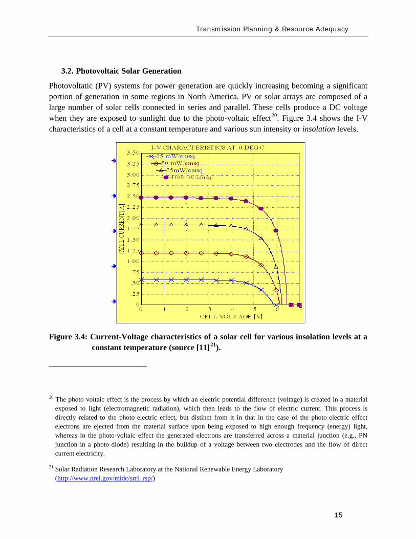
Transmission Planning amp Resource Adequacy
15
32 Photovoltaic Solar Generation
Photovoltatic (PV) systems for power generation are quickly increasing becoming a significant portion of generation in some regions in North America PV or solar arrays are composed of a large number of solar cells connected in series and parallel These cells produce a DC voltage when they are exposed to sunlight due to the photo-voltaic effect20
Figure 34 shows the I-V characteristics of a cell at a constant temperature and various sun intensity or insolation levels
Figure 34 Current-Voltage characteristics of a solar cell for various insolation levels at a constant temperature (source [11]21
20 The photo-voltaic effect is the process by which an electric potential difference (voltage) is created in a material exposed to light (electromagnetic radiation) which then leads to the flow of electric current This process is directly related to the photo-electric effect but distinct from it in that in the case of the photo-electric effect electrons are ejected from the material surface upon being exposed to high enough frequency (energy) light whereas in the photo-voltaic effect the generated electrons are transferred across a material junction (eg PN junction in a photo-diode) resulting in the buildup of a voltage between two electrodes and the flow of direct current electricity
)
21 Solar Radiation Research Laboratory at the National Renewable Energy Laboratory (httpwwwnrelgovmidcsrrl_rsp)
Transmission Planning amp Resource Adequacy
16
Figure 35 shows that the current is limited when the cell is short-circuited (Voltage=0)
(a) (b) (c)
(d)
Figure 35 The concept of a solar array (a) a single solar cell (b) a series connection of solar cells (Nser = 3 and Npar = 1) and (c) a solar array (Nser = 3 and Npar = 2) The solar cell array(s) is then connected to a DC bus (d)
Figure 35 shows the concept of the solar cell up to the solar array To use the DC power generated by the PV array in an AC power system the DC power must be converted to 60 Hz AC in North America (50 Hz in some other regions in the world like Europe) There are several power electronic based converter concepts that can achieve this which can be classified into two general categories line-commutated converters (LCC) and self-commutated or more commonly
Vbus Iload
Ibus
Icap PV ARRAY
+
_
Transmission Planning amp Resource Adequacy
17
referred to as voltage-source converters (VSC) These technologies have been applied for decades and are well understood LCC use thyristors as their controlled switching device The switching on of a thyristors can be controlled while the turn-off time cannot be controlled and happens at the next AC waveform current zero crossing LCC systems must be operated in a network with an AC source and cannot operate to serve an isolated load In contrast VSC systems are self-commutating that is the power electronic switching devices used (eg integrated gate-commutated thyristors or IGCTs and insulated-gate bipolar transistors or IGBTs) are able to be completely controlled for both turn-on and turn-off and allow the VSC to completely control the AC waveform produced and adjust the power factor as seen on the AC side to within the current rating of the device Due to advances in the technology most power electronic converters employed in PV systems are of the VSC type22
From a modeling standpoint for power system studies there are some user-written manufacturer-specific models in existence as developed by various PV manufacturers Presently no generic or standard models exist
The WECC Working Group which has been addressing the development of generic WTG models will be extending its effort in 2010 to review developing generic PV models for dynamic simulations in stability studies As a starting point the grid side structure of the Type 4 WTG model may be used since it represents a VSC This is because PV is typically connected to the grid with a VSC and it will behave electrically similar to a Type 4 WTG that has a similar electrical interface with the gridmdashthis is from a grid perspective looking at the electric response and neglects any of the effects of the energy source
From a steady-state power flow and short-circuit analysis perspective the behavior of the PV technologies will behave in a similar fashion to a Type 4 WTG because of the VSC interface and because its power factor can be controlled based on the control functionality of the VSC design Its short-circuit response will be limited to the current limit effected by the VSC under grid fault conditions
The development of generic and standard PV models is presently a topic for further research This should be pursued imminently and much of what has been learnt from the WTG model development process should be leveraged
22 IEA-PVPS Grid-Connected Photovoltaic Power Systems Survey of Inverter and related Protection Equipment Report IEA PVPS T5-05 2002 December 2002 (httpwwwiea-pvpsorgproductsdownloadrep5_05pdf)
Transmission Planning amp Resource Adequacy
18
33 Solar Thermal
Solar thermal energy is based on harnessing the radiated heat of the sun for the purpose of producing electricity In broad terms there are presently two main ways of achieving this
1 Concentrating Solar Power (CSP) plants ndash in this case solar radiation is typically collected through a large number of mirrors (thus a large amount of solar radiation) which is then focused on a small area ndash the mirrors have tracking systems to follow the Sun The concentrated solar radiation heats a high temperature working fluid which then feeds a conventional steam-turbine generator From an electrical grid perspective the models needed to simulate the steady-state short-circuit and transient time-domain dynamics of such a generating unit are typically no different than standard synchronous generating units for fossil fuel plants
2 The Stirling Engine concept23
34 Tidal Generation
ndash in this design a parabolic mirror assembly concentrates the collected solar radiation on a sterling engine that sits at the focal point of the mirror assembly A Stirling engine is a reciprocating heat engine that operates based on the concept of cyclical compression and expansion of a working fluid As the working fluid expandscontracts it drives a piston that then turns a generator The engine is connected to an electrical generator that produces electric energy Once again for power system studies the units may be modeled using standard generator models However in this case a power plant would be constituted by a large number of small units (the typical Stirling engine is about 25 kW) in a large electrical collector system that collects the power and injects it into the utility grid ndash much like the collector system of a wind power plant Thus modeling the collector system (eg see Figure 32 for an aggregate model of a wind collector system) and any other devices in the collector system such as shunt reactive devices etc must be properly modeled
Tidal power generation derives energy directly from the motion of oceanic tides The gravitational pull of the Moon and Sun combined with the Earthrsquos rotation result in the generation of tides Tides generally occur with a period of roughly twelve hours and so most coastal areas experience two high and two low tides within every twenty-four hour period Tidal generation uses this phenomenon to generate energy Clearly the stronger the tides are either in tidal current velocity or the heightlevel of water the greater the potential amount of energy generation
23httpwwwstirlingenergycom Y Zhang and B Osborn ldquoSolar Dish-Stirling Power Plants and Related Grid Interconnection Issuesrdquo IEEE PES General Meeting 24-28 June 2007
Transmission Planning amp Resource Adequacy
19
Presently in North America tidal power is not a significant source of power in any region Some pilot programs exist for introducing the technology In April 2009 one was announced in Snohomish County Public Utility District in Washington State24
There are several options for harnessing tidal power One method is the use of turbines similar to wind turbines however the fluid (water) is much denser and requires a turbine with smaller and bulkier blades as shown in Figure 36 Most of these technologies typically use ACDCAC converter technology similar to a Type 4 wind turbine to convert the low frequency generated electricity to grid frequency AC electricity and interface with the power system Once this technology becomes more prevalent a starting point for development of a suitable model structure may be the Type 4 generic wind turbine models Understandably the energy source characteristics are quite different from wind power and significantly more predictable
Figure 36 One of the many concepts for tidal generation systems (courtesy of Marine Current Turbines Limited wwwmarineturbinescom)
35 Other Resources
There are several other emerging technologies and there are many complementary technologies (ie auxiliary to the variable generation resources but designed to help with their integration into the grid) including smoothly-controlled dynamic reactive devices (static VAr systems)
24 httpwwwsnopudcomPowerSupplytidaltidalpressashxp=1516amp756_na=46
Transmission Planning amp Resource Adequacy
20
energy storage technologies etc With respect to static VAr systems (SVCs and STATCOMs) there is an active WECC working group imminently addressing the issue of generic models for these devices25
36 Summary
The group has made substantial progress with the models defined and developed but currently undergoing testing and validation With regards to the other emerging technologies most tend to be power converter based (ie connected to the grid through a back-to-back frequency converter) and so their electrical behavior (neglecting the characteristics of the energy source) will be similar to Type 4 wind turbines Until these technologies mature the basic structure of other more mature converter based generation technologies can be a good starting point
This section has briefly presented the various types of variable generation and the present status of models and model development for power system studies Wind generation technologies being the most prevalent world-wide have the most mature models Through efforts started by WECC and being continued by IEEE and IEC generic standard models for the four main types of WTG technologies are being developed The first generation of these models has been released in two power system simulation software platforms most commonly used in North America Other emerging technologies (eg PV tidal power etc) can build on this effort to start developing generic models For example the WECC effort will be extending its scope in 2010 to look at PV model
From a NERC perspective the key items are
1 To emphasize and support efforts by WECC IEEE and IEC to develop and standardize generic models for these technologies for power system planning studies
2 To encourage manufacturers to familiarize themselves with the generic models being developed and be willing an able to supply parameters for these generic models to reasonably represent their equipment for power system stability studies As highlighted in Chapter 2 more detailed manufacturer specific models may be needed in special cases and for specialized studies
3 To encourage efforts aimed at model validation
4 To consider any augmentation or additions to reliability standards related to Modeling Data and Analysis (MOD) with respect to modeling and model validation of variable generation This is discussed in greater detail in section 5 of this report
25 httpwwwweccbizcommitteesStandingCommitteesPCCTSSMVWGSVCTFdefaultaspx
Present Status of Model Validation
21
4 Present Status of Model Validation
This chapter gives an overview of the model validation work that has been done hitherto as it relates to models for variable generation Necessarily the primary focus of this section is on wind turbine generator models since models for this resource are presently the most mature
41 What is Model Validation
Any and all models of a dynamic system always have limitations associated with them A model is a representation of reality it is an emulation ndash that is why it is called a model In developing a model first the question is asked as to the specified use of the model and the conditions it must reasonably emulate ndash this forms the basis of a model specification from which a model is developed The developed model establishes a certain structure with parameters which are adjustable in order to emulate different types of equipment or design of the modeled device Thus valid parameterization of the model to represent a particular manufacturerrsquos equipment is essential to support the particular scenarios to be analyzed
Model validation is often achieved through some form of testing either in a laboratoryfactory or in field There is a range of reasons for conducting tests for wind generation Each test has a unique set of objectives guiding the design of adequate testing practices
bull Performance Compliance Compliance to contractual requirements and grid codes are one reason to perform tests Interconnection requirements (usually included in plant Power Purchase Agreements and Interconnection Contracts) and grid codes typically outline specific technical criteria that must be met to allow a power plant to connect and operate on the grid Since these criteria point out specific levels to be met (for example voltage power factor and response time) tests may be designed with binary ldquopassfailrdquo objectives
bull Model Validation In much of the world power plants above a pre-defined size must be accurately represented with a dynamic simulation model used in stability analysis for operations and planning purposes As variable generation sources such as WPP are growing in size it is becoming increasingly important to have accurate variable generation specific models Tests may be performed to tune and verify simulation models to closely match the performance of actual equipment In the western US and Canada WECC has mandated that any plant with 20 MVA aggregate generation must be tested for model validation including large wind power plants For North America the imminent NERC MOD-026 standard presently under development will enforce model validation requirements throughout the North American region
Present Status of Model Validation
22
To achieve the goals of model validation there are three categories of tests that may be performed
bull Type Tests These are tests performed by the manufacturer or independent third-parties of representative equipment The intent is to demonstrate that a particular design of equipment exhibits specific performance and all other equipment of that same design is assumed to have the same performance Type tests can be
o Component Performed on specific functions or features in a power plant or generation equipment This could be for example testing the fault ride-through capability or reactive capability of a WTG where testing is performed at the component level
o Factory A systemic test of a major assembly (ie a drive train) or entire turbine-generator is performed under a controlled environment like a manufacturing facility to verify performance and validate assembly design
o Unit A systemic test of multiple components operating together (ie as entire operating WTG or WPP) with the specific intent of benchmarking a model or design as a type test For example tests performed in Europe under the WindTest program
bull Field Tests26
o Commissioning Tests performed on new equipment entering its period of commercial operation service
Tests performed by the power plant asset owner developer host utility manufacturer andor independent third-parties of specific operating equipment These tests are to demonstrate that a particular implementation design and installation of equipment exhibit specific performance
o Periodic Maintenance or Calibration Tests performed periodically after the plant is in commercial operation to verify that equipment continues to perform as well as it did during commissioning
26 See for example WSCC Control Work Group and Modeling amp Validation Work Group ldquoTest Guidelines for Synchronous Unit Dynamic Testing and Model Validationrdquo February 1997 (wwwweccbiz) and IEEE Task Force on Generator Model Validation Testing ldquoGuidelines for Generator Stability Model Validation Testingrdquo Proceedings of the IEEE PES General Meeting Tampa FL June 2007 (httpieeexploreieeeorg)
Present Status of Model Validation
23
o Periodic Model Validation Tests performed periodically after the plant is in commercial operation to verify that simulation models adequately represent actual plant performance (for example the periodic model validation testing required by WECC)
o Periodic Codes amp Standards Validation Tests performed periodically after the plant is in commercial operation to benchmark and validate plant performance per contractual requirements These tests are typically performed to obtain a permanent operating license for the power plant
bull On-Line Monitoring27
With these general concepts in mind the following subsections present some example cases studies of model validation and validation approaches for variable generation sources The examples emphasize WPP and WTG since wind generation is the present dominant variable generator sources in the North America continent
Other information of interest is from continuous data gathering based on ongoing performance of an operating power plant Data collected from external and unscheduled events including grid disturbances or in the case of WTG large changes in wind is particularly useful Monitoring also benchmarks performance under normal operation
42 Examples of Model Validation Efforts
421 Hydro- Queacutebec Example
The province of Queacutebec has vast wind energy potential Though wind energy generation in 2009 accounts for nearly 13 of the total installed capacity in the Queacutebec control area the penetration rate of wind energy generation will reach 10 by 2015 A total capacity of 528 MW is currently in operation and approximately 3000 MW are under development Five wind turbine manufacturers will supply the WTGs for the different projects under study
The configuration of the Hydro-Queacutebec transmission system is essentially radial Approximately 85 of the total installed generation feeding the system is located at distances up to 1300 km
27 See for example P Pourbeik ldquoAutomated Parameter Derivation for Power Plant Models From System Disturbance Datardquo Proceedings of the IEEE PES General Meeting Calgary Canada July 2009 (httpieeexploreieeeorg) This reference shows actual application of on-line disturbance monitoring to power plant model validation for conventional fossil fuel generation It may be feasible to apply similar algorithms and approaches for continuous re-validation of WTG and other variable generation technologies once generic standard models have been developed This is a current topic for research
Present Status of Model Validation
24
from the closest major load centers With this configuration the system transfer capability is mainly limited by stability constraints (transient stability and voltage stability) rather than congestion or thermal capacity of equipment hence the need for reliable models for wind power plants and all other generation
Stability studies are critical to determine the compensation equipment required to maintain the reliability of the power system when integrating new generation They are also essential for operation planning studies including control system design and tuning and determination of transfer capabilities
So far Hydro-Queacutebec has faced two major difficulties regarding user-written models provided by the wind turbine manufacturers First models often lack robustness and do not represent accurately some important features (convergence problems in low short-circuit network do not take into account frequency excursions do not represent secondary voltage regulation etc) Second model validation by the manufacturers is often incomplete not available or difficult to translate to real projects (different settings or software versions design of the collector system etc) In some cases these difficulties have lead Hydro-Queacutebec to build its own models (see Hypersim section below)
General validation test program
Since 2006 Hydro-Queacutebec has performed validation tests on WPP connected to its transmission system and a general validation test program was established in 200928
1 To demonstrate that WPP meet the Transmission Provider technical requirements related to wind generation
The power producer has the obligation to perform validation tests in order to demonstrate that its facilities meet the Transmission Provider requirements The purposes of this program are
2 To validate numerical models and parameters associated with the WPP specifically those given to the Transmission Provider by the power producer by comparing the model response to recordings taken during field tests
3 To confirm the electrical data of power producer facilities
The validation program is divided into seven functions to be validated
1 Primary voltage regulation
28 httpwwwhydroquebeccomtransenergiefrcommercepop_raccordement_transporthtml
Present Status of Model Validation
25
2 Undervoltage response (LVRT)
3 Inertial response
4 Secondary voltage regulation
5 Power factor
6 Maximum ramp rates
7 Power quality
The tests for the primary voltage regulation are performed on a single WTG and consist in producing instantaneous voltage variations of low amplitude on the terminal of the WTG and small voltage steps of limited duration injected directly into the WTG voltage control system Three-phase voltages and currents are recorded at the wind generator to measure the local dynamic response of a wind generator to a rapid voltage change and to verify that the response meets voltage regulation requirements The results are also used to set the model parameters (time constant and gain) used in dynamic simulations The tests regarding the secondary voltage regulation are similar but are conducted for the entire power plant
The validation test program includes LVRT tests on one generating unit to verify that requirements during undervoltage conditions are met The power producer has the responsibility to conduct the tests or to provide a complete report describing tests performed on an identical generating unit (same software version) to demonstrate that the requirements are met So far no LVRT tests were performed on site on WPP integrated on the Hydro-Queacutebec network However monitoring equipment has been installed at three locations in wind plants at their point of interconnection on a 345 kV feeder of the collector system and on one generating unit The monitoring system records signals either continuously or upon detecting variations occurring at the point of interconnection active power variations voltage sags and swells and system frequency excursions These signals are primarily voltages and currents but may also be mechanical variables or other signals
The field recordings recorded on the network can thereafter be used to validate the dynamic response of the models This is a time consuming effort that requires the collaboration of the manufacturers to modify the models if necessary Event recordings to-date have made possible suitable validation of two Hydro-Queacutebec Siemens PTI PSSregE models and one ElectroMagnetic Transients Program (EMTP) model
Inertial response requirements were not in defined for the projects started before 2005 Consequently existing wind plants do not have to fulfill them However the requirements have to be met for WPP to be commissioned in 2011 and after The corresponding validation tests consist in emulated frequency steps and ramps of limited duration Besides verifying the
Present Status of Model Validation
26
requirements the test results will be used to validate the parameters of the models and their dynamic response
The power factor and the maximum ramp rates modules are tested with all WTGs in service to verify that the requirements are met Power factor tests consist in supplying and absorbing a maximum amount of reactive power at different levels of active power Maximum ramp rate tests consist in performing a power plant shutdown sequence followed by a startup sequence These tests are not really used to validate the models but are rather helpful to fix model parameters
The last module regarding the power quality is not covered by scheduled testing but by means of a monitoring system that verifies harmonics and emission limits The recordings are compared to the report provided by the developers to verify if the requirements are met However they are not useful to validate the EMTP model since the WPP is represented by a single-wound generator and does not simulate the detailed collector bus system and individual wind turbine generators
Field tests department
Hydro-Queacutebec field-testing department (UMES) conducts a wide range of special tests and measurements for Hydro-Queacutebec and has done so for 30 years
To test WPP UMES installs a monitoring systems to record three-phase voltages and currents generally at three locations within the plant at the point of interconnection at the starting point of a 345 kV feeder of the collector system and at the terminals of a WTG connected to the same monitored feeder For extended model validation other signals within the wind turbine are monitored including the rotor side converter voltages and currents the network side converter currents and the DC bus voltage
High speed recorders with anti-aliasing filters are used Normally the sampling rate is 5 kHz with at least a 200 second window per event The monitoring system is reachable via an Ethernet connection for remote trigger and data retrieval UMES has also the responsibility to perform the data processing and analysis of the recordings in order to verify the compliance with the interconnection requirements and to extract relevant data for model validation
Present Status of Model Validation
27
Hypersim
The Hydro-Queacutebec Research Institute (IREQ)29 also has an important expertise in control system and wind generation modeling for extensive studies of electrical networks The simulation environment used is Hypersim a real-time simulator and powerful simulation tool that uses a highly detailed representation of the Hydro-Queacutebec network A full-transient detailed model of a Type 3 WTG was developed at IREQ using the MATLABreg SimPower Systems Toolbox The model was also implemented in EMTP and in the Hypersim real-time simulator30 This model is in the process of being validated with data processed by the UMES team The range of events recorded does not make it possible to validate the model completely and the design and parameters will continue to be adjusted to improve the representation of the wind turbines The validation of the MATLABreg model developed by IREQ was very useful to validate and improve Hydro-Queacutebecrsquos Siemens PTI PSSregE user model31
422 GE Example ndash based on GErsquos work with client facilities
In the case of the first example presented here a 10 MVar capacitor bank located at the 25kV WPP collector bus is switched off-line as an external physical stimulus Figure 41 shows detailed response to capacitor switching from the WindCONTROLreg The WindCONTROLreg system allows coordination of all on-line turbine-generators for plant-level fast and smooth voltage regulation at the point of interconnection (POI) located contractually at the 25kV substation bus The red curve (Q_ACTUAL [KVar]) shows that total plant reactive power initially drops after the switching action but the fast autonomous controls on each turbine generator quickly and stably respond to increase reactive power generated by individual turbines shown by the orange curve (Q_TURBINES [KVar]) The WindCONTROLreg command (Q_CMD) distributed to the turbines is shown in blue The response of Q_CMD is dominated by the gains of the voltage regulator portion of the WindCONTROLreg specifically the proportional gain Kpv and integral gain Kiv The difference between the response of the individual turbines (Q_TURBINES [KVar]) and the WindCONTROLreg command (Q_CMD) is due to the dynamics of the individual wind turbines The coordinated response of the wind plant and the individual
29 httpwwwhydroquebeccomtechnologyindexhtml 30 R Gagnon G Sybille SBernard D Pareacute S Casoria and C Larose ldquoModeling and Real-Time Simulation of a
Doubly-Fed Induction Generator Driven by a Wind Turbinerdquo IPST Conf Paper No IPST05-162 Montreacuteal Canada 2005 C Larose R Gagnon G Turmel P Giroux J Brochu D McNabb and D Lefebvre ldquoLarge Wind Farm Modeling Techniques for Power System Simulation Studiesrdquo in Proc 8th International Workshop on Large-Scale Integration of Wind Power into Power Systems Bremen Germany Oct 14-15 2009
31 C Langlois D Lefebvre L Dube and R Gagnon ldquoDeveloping a Type-III Wind Turbine Model for Stability Studies of the Hydro-Queacutebec Networkrdquo in Proc 8th International Workshop on Large-Scale Integration of Wind Power into Power Systems Bremen Germany Oct 14-15 2009
Present Status of Model Validation
28
turbines is multi-modal a fast initial response to address severe perturbations as well as a slower grid friendly refinement For purposes of this test the automatic control of the capacitor bank by WindCONTROLreg was disabled and manual switching was used as a stimulus to record individual WTG response
The detailed plot in Figure 42 shows a zoomed view of the response to step change in voltage at the WTG The very fast initial response will dominate and saturate the controls for big events The wind plant will do everything as quickly as it can to mitigate a large disturbance In this case the fast response took approximately 200 milliseconds The slow refined control then takes over to allow for coordination with other equipment and maintain post-disturbance stability This aggregate response also allows for a very abrupt action when needed and a grid-friendly refinement that maintains stability in less severe cases
The green curve in Figure 43 shows that when the capacitor is switched off-line the measured voltage at the point of interconnection (or POI) decreases due to reduced reactive power flowing into the grid The response of the individual WTGs is to rapidly increase reactive output to make up for the loss of reactive power supplied by the shunt capacitor The plant level control then responds to this initial under-voltage condition and attempts to restore the POI voltage by increasing each wind generatorrsquos reactive output by equal amounts until the plant voltage settles to the control set point determined by the operator The lower traces in Figure 43 show a gap during the period when the capacitor bank is online between total plant Q (Q_ACTUAL) and summation of Q out of each WTG (Q_TURBINES) This gap represents the capacitive reactance added by the shunt bank When the capacitor is switched offline the gap between Q_ACTUAL and Q_TURBINES closes and all reactive power is supplied solely from the WTGs The initial loss in plant reactive power is mitigated within approximately 15 seconds as each WTG settles to a new increased level operating point of reactive power This new increased reactive level for each WTG is the total Q increase from all units on-line in the plant divided by the total number of units online at the time of the test
Figure 44 shows a comparison between these measured values and the simulation results of the PSLF model Model outputs Qg Qplant Qcmd and Vreg correspond to measured Q_TURBINES Q_ACTUAL Q_CMD and U_LINELINE respectively This plot shows the model performance adequately represents what is happening in the field The response matches closely with a difference immediately following the switching operation being due to lower sampling rate in the measurement than in the GE PSLFreg simulation
Response to grid events demands relatively rapid control action Manual grid or plant operator changes in operating set-points do not normally demand fast response and indeed system behavior ought not to be rapidly disturbed by moving set-points Figure 45 shows the response of GE plant to 2 step in voltage reference The blue trace in the figure shows a well mannered response to the reference step The red trace is from the simulation model which matches very
Present Status of Model Validation
29
well In the blue trace after the perturbation occurring about 8 seconds after the reference change the plant supervisory control switched on a shunt capacitor to retain dynamic range on the wind turbines The switching perturbation is rapidly balanced by the turbines allowing the response to continue smoothly
Figure 41 10 MVar Capacitor removal response measured from WindCONTROLreg
Present Status of Model Validation
30
Figure 42 Wind turbine-generator level voltage step test response
Present Status of Model Validation
31
Figure 43 10 MVar Capacitor removal response ndash POI variables
Figure 44 10 MVar capacitor removal field test vs simulation results
Present Status of Model Validation
32
Figure 45 A different step test +- 2 step of voltage reference
The performance for grid fault events is of considerable interest in system planning Staging faults particularly severe ones on operating wind plants is difficult and expensive Figure 46 shows a comparison between a staged fault test and the (present) Siemens PTI PSSregE model of the GE 25 (full converter) WTG The fault event is quite severe a 3-phase 700ms of voltage depression to less than 20 of nominal at the high voltage terminal of the WTG unit transformer The measurement traces (on the left) include some of the signal noise characteristic of measurement and extraction of fundamental frequency positive sequence information from real high resolution measurements The simulation traces on the right are of course cleaner The match between test and simulation is of very high fidelity for phenomena relevant and legitimately examined with positive sequence simulation tools (ie greater than one cycle)
QPOI
VPOI
Measured = Blue Simulated = Red
Plant Capacitor Bank Switched On Automatically by WindCONTROL
+ 2 VrefStep
- 2 Vref Step
QPOI
VPOI
Measured = Blue Simulated = Red
Plant Capacitor Bank Switched On Automatically by WindCONTROL
+ 2 VrefStep
- 2 Vref Step
Present Status of Model Validation
33
Figure 46 GE 25 WTG Fault Test vs PSSe Model Performance
The discussion provide above is solely geared to hardware testing and validation however another highly valuable and legitimate means of providing validation of simulation models (for planning and otherwise) is to use more complex simulation software to validate simpler planning models Manufacturers normally have highly complex and highly proprietary models of their equipment These models are used among other things to design equipment and are normally physically based and must have sufficient fidelity for original equipment manufacturers (OEMs) to make sound engineering judgments for equipment design and application The OEMs are highly motivated to have these detailed high fidelity equipment level models These detailed models therefore can often be used to design test and validate simpler planning models to be used by the industry
There is a long accepted history in the power industry of this practice For example a typical (GE) gas turbine has on the order of 4000 state variables in the design model planning models typically have on the order of four state variables simplification is necessary and expected These design codes have been used to develop planning models of gas turbines Figure 47 below shows a comparison between a fault simulation using a GE design code (GE WindTrapreg) and the planning model in GE PSLFreg for a GE 15 (double fed machine) WTG
Present Status of Model Validation
34
Figure 47 Detailed Design Simulation (GE WindTRAPreg) vs GE PSLFreg Model Performance (active power during a severe fault for a GE 15 WTG)
-10
00
10
20
30
0 05 1 15 2
Time (Seconds)
Sin
gle
WTG
Rea
l Pow
er (M
WindtrapPSLF
Summary amp Recommended Actions
35
5 Summary amp Recommended Actions ndash Standards Implications
This document has presented a general overview of modeling and model validation as it pertains to variable generation resources Clearly to date the bulk of the experience and work has been on wind turbine generators Never-the-less similar approaches for modeling and model validation are being pursued for other variable generator technologies such as PV
Non-proprietary and publicly available models for the simulation of steady-state (power flow) short-circuit (fault calculations) and dynamic (time-domain simulations) behavior of such generation resources must be made readily available for use by power system planners Furthermore these models should be routinely validated to ensure proper representation of variable generation power plants in bulk power system studies A model is valid if its dynamic behavior is close enough to reality so that its influence on the network of interest (ie used for power system studies) is consistent with the fidelity of model structures and available data for the power system and other generation as it pertains to the phenomena of interest (ie in stability studies) That is perfect curve fitting is not necessary but to the extent possible erroneous model dynamics must not result in a notable over-design or under-design of the network
Each of the NERC standards discussed below in Section 52 address to aspects of meeting a standard (i) the technical requirement ie the need to define measure validate a model its parameters etc and (ii) the procedural requirements ie the functional model of how this technical requirement should be met reported and monitored The bulk of this working grouprsquos recommendations stated below address the technical requirements Variable generation is a new and quickly evolving technology and consideration should be given to the timing with which standards be implemented
Section 51 below first gives a summary of the planning process based on NERC standards to put the discussions in this report into context with the NERC standards Then in Section 52 we provided our recommendations and comments on the NERC existing and developing standards
Summary amp Recommended Actions
36
51 Applying the NERC Standards
The NERC standard FAC-001 (see Figure 51) should be expanded to clearly cover modeling requirements during the coordinated joint study phase of the Facility connection process Simple generic models of variable generation may be adequate for the IES phase and more detailed models may be needed for the IFS phase Validation of the simple and detailed model parameters may be needed during commissioning
Figure 51 Facility connection process
Interconnection Evaluation Study
Generator Interconnection
Request
Interconnection Facility Study
GO provides initial model
to TPPC
GO provides final model
to TPPC
GO signs Interconnection
Agreement and is put in-service
GO performs model amp
performance validation testing
TO develops Facility Interconnection requirements and requests models and data
of the GO at each process stage
FAC-001
Summary amp Recommended Actions
37
The generic model with associated parameters feed into the NERC model building process shown in Figure 52 As an example for WTG presently there is insufficient evidence of the accuracy of presently available generic models for WTG32
for all the various WTG manufacturers Some confirmation tests during commissioning or type tests or comparison simulation tests with a detailed model are necessary to get buy in from the Transmission OwnerPlanner As the technology matures and generic models are enhanced and associated data parameter sets are developed for specific machine types the new generic models will become more accepted as is the case with models of hydro or thermal plants
Figure 52 Annual NERC Model Development Process
32 PSSregE-320 Program Application Guide Volume II Chapter 21 PSSregE-320 Model Library Chapters 17 through 21 GE PSLF Users Manual v170_04 October 2009
Steady state data
developed
MOD-10
Dynamics data
developed
MOD-12
Reliability Region creates model
MOD-14
Reliability Region creates model
MOD-15
Reliability Region defines data
requirements
MOD-13
GO
TP
RP
Reliability Region defines data
requirements
MOD-11
Annual NERC Planning and
Operating Models
created and distributed to the industry
Summary amp Recommended Actions
38
The regional model building manuals developed as part of MOD-11 and MOD-13 must provide sufficient clarity to model variable generation These manuals may ask for best available models or generic models These models cover the operational time frame and the 10-year planning horizon The manuals do not currently cover the frequency for revalidating model data
While not included in the standards more emphasis is currently being placed on meeting the Eastern Interconnection Reliability Assessment Group (ERAG) model building manual requirements in addition to regional requirements
Figure 53 NERC Model Validation Process
The Regional Entities develop the test procedures and dictate testing frequency for the Generator Owners to follow The model data then feeds in to the annual NERC model building process
52 NERC Standards Technical Issues
One general comment is that the NERC Glossary of Terms would benefit from the term ldquoVariable Generationrdquo being include in it and appropriately defined A suitable definition can be found in the Phase I report of the IVGTF
Verify real power capability
MOD-24
GO
Verify reactive power capability
MOD-25
Verify generator excitation control model
MOD-26
Verify turbine governor model
MOD-27
Summary amp Recommended Actions
39
MOD-011 Regional Steady-State Data Requirements and Reporting Procedures
The technical requirement in this MOD reads
ldquoR12 Generating Units (including synchronous condensers pumped storage etc) location minimum and maximum Ratings (net Real and Reactive Power) regulated bus and voltage set point and equipment statusrdquo
This statement could be read to equally apply to variable generation as a source of generation However it may be prudent to explicitly include variable generation in this statement For example to change the sentence to
ldquoR12 Generating Units (including synchronous condensers pumped storage variable generation resources etc) location minimum and maximum Ratings (net Real and Reactive Power) regulated bus and voltage set point and equipment status For variable generation a suitable aggregate steady-state model of the collector system and equivalent unit representing the full plantrdquo
MOD-012 Dynamics Data for Transmission System Modeling and Simulation
This MOD equally applies to variable generation and needs no augmentation The requirements in the MOD are quite generic The requirements of this standard are dependent on and point to MOD 13 discussed below
MOD-013-1 RRO Dynamics Data Requirements and Reporting Procedures
This MOD explicitly discusses synchronous type generation It would be beneficial to include an explicit statement to cover variable generation For example
ldquoPlant-specific dynamics data shall be reported for variable generating units (eg wind turbine generators PV etc) such as the type of generating unit its interface with the grid and the appropriate model and model parameters to adequately represent unit dynamic response for bulk power system studies The typical size of a single variable generating unit (eg wind turbine generators PV array etc) is several hundreds of kilo-watts to several mega-watts Thus it may be acceptable for the total plant to be represented by an adequate aggregated model of the collector system and a single equivalent generating unit scaled up to represent the total name-plate capacity for each type of generating technology employed in the plant Furthermore models may need to be provided for other equipment installed in the collector system or at the point of interconnection such as reactive compensation devicesrdquo
Summary amp Recommended Actions
40
MOD-024-2 mdash Verification and Data Reporting of Generator Real Power Capability
This latest posting of this MOD posted for commenting on January 18th 2010 exempts variable generation from this requirement It states
ldquoVariable energy units such as wind generators solar and run of river hydro are exempt from the requirements of this Standardrdquo
For a variable generation plant the definition of Real Power Capability can be slightly challenging One way to view it is to see the total gross capability as the sum of the nameplate rating of all individual units within the plant eg for a wind power plant the total sum of the nameplate rating of all wind turbine generators in the plant However there must be two realizations (i) the amount of actual power injected into the grid at the point of interconnection requires a suitable representation of losses on the collector system and auxiliary loads and (ii) by its very nature variable generation is a highly variable energy source and thus it is quite rare to find point in time when all units in the plant are coincidentally at their peak nameplate capacity Finally the seasonal variable generation output variations need some discussion since they are quite different than conventional generation technologies
MOD-025-1 mdash Verification of Generator Gross and Net Reactive Power Capability
The technical requirement in this MOD reads
ldquoR15 Information to be reported
R151 Verified maximum gross and net Reactive Power capability (both lagging and leading) at Seasonal Real Power generating capabilities as reported in accordance with Reliability Standard MOD-024 Requirement 151
R152 Verified Reactive Power limitations such as generator terminal voltage limitations shorted rotor turns etc
R153 Verified Reactive Power of auxiliary loads
R154 Method of verification including date and conditionsrdquo
Note the above requirements are from the existing version of the standard MOD-025 is currently being enhanced
Although all of the above could equally apply to variable generation some clarification may be needed Namely variable generation reactive capability of the ldquopower plantrdquo is not entirely inherent in the individual generating units A variable generation power plant such as a wind power plant may contain many reactive power sources such as the individual generating units themselves (eg Type 3 or 4 WTG see Appendix I) discretely switched shunt reactive devices
Summary amp Recommended Actions
41
(eg shunt capacitors or reactors) smoothly controlled shunt reactive devices (eg SVC or STATCOM) or a combination of these devices Thus care should be taken as to how the total reactive capability of the power plant is defined and at what point (eg point of interconnection and whether this is defined as the high or low side of the substation transformer) Also it may not be practical under normal operating conditions to exercise the full reactive capability of the power plant (this is a known issue even with conventional synchronous generator plants) to test it thus it should suffice to demonstrate the plants reactive capability to the extent possible in the field and to then augment this with engineering calculations to derive the plants full reactive capability This is particularly true of variable generation because there is no control over the energy resource So for example a typical wind power plant may only achieve its name-plate rating for a hour or two during an entire year Thus it would not be possible to demonstrate the full reactive capability of the plant in the field Rather it should suffice to demonstrate the reactive capability of a single WTG and then to derive through engineering calculations (considering all other reactive devices in the plant such as SVC STATCOM etc) the total reactive capability of the plant These comments should be somehow used to appropriately modify MOD 25
MOD-026-1 mdash Verification of Models and Data for Generator Excitation System Functions ndash SECOND POSTING (and MOD 27)
MOD 26 (and MOD 27 Verification of Models and Data for TurbineGovernor and Load Control) are presently under development33
Presently these standards are tailored explicitly to deal with synchronous type generators since much of the language revolves around technology associated with synchronous generation (eg excitation system AVR power system stabilizers etc) Thus the following key items need to be clarified in these standards as they pertain to variable generation In addition the comments that follow apply to all components in a variable generation plant that may include devices such as the actual power generating units shunt compensation devices centralized control systems spanning the entire facility etc
These two standards deal specifically with the routine validation of generating unit dynamic models for power system stability studies
1 UnitPlant Size for Validation These MODrsquos specify the size of generating unit above which model validation is required It should be recognized that the typical size of a
33 MOD 26 and MOD 27 standards under development are found at httpwwwnerccomfilezstandardsGenerator-Verification-Project-2007-09html
Summary amp Recommended Actions
42
variable generation unit is in the hundreds of kilo-watts to several megawatts range Thus the language should be changed (or introduced) to indicate ldquonet power plantrdquo size
2 Validation of various technologies in a single plant Variable generation power plants can consist of multiple generation technologies For example a wind power plant may consist of WTGs of two different types Thus we need to consider the following points as they pertain to variable generation
a For a uniform variable generation plant (ie all generating units are of the same technology type) a single aggregate generator model representation should be sufficient
b For a significantly diverse variable generation plant the plant should be represented by multiple aggregated unit models representing each technology type
c Unique representation of a group of variable generation units as a single aggregated generator model representation should be based on
i The size of the group is a significant proportion of the total plant size (eg gt 20 of plant rating)
ii Each group should represent a unique characteristic (eg Type 1 WTG as compared to a Type 3 WTG)
3 Validation of different control layers Variable generation plants such as wind power plant may have several functional layers of control For example in a wind power plant with Type 3 WTGs we may have one level of closed loop voltage regulation at the terminals of the WTG a second slower control loop that regulates voltage at the point of interconnection (POI) and a third layer of control that coordinates the switching of shunt capacitors at the POI based on the reactive output of the individual WTGs In addition devices such as STATCOMs may be present at the POI Modeling and model validation should incorporate such devicescontrol layers to the extent that the dynamics of these functional layers are important for stability studies (see Figure 31)
4 Modeling and Model Validation Models are an emulation of actual equipment Not all model parameters necessarily translate to actual physical components or measureable features Judgment needs to be exercised in the modeling and validation process
a Models should be validated typically against the performance of an actual plant for a given eventdisturbance within the given operating range it is designed for
Summary amp Recommended Actions
43
b Models should state clearly the type and the range of events they have been designed to simulated and the limitation of the models beyond which the model deviates from the actual variable generation plant performance (eg a model developed to represent electrical transient behavior of a WTG may not be adequate for studying wind fluctuations over a many minute time frame)
c In general the best approach to model validation is to use field (or test bench) measurements of various disturbances that must exercise the different control functions to a wide range of operation points For example a model is not necessarily valid if the only a comparison between simulation results and field measurements for a single voltage step response is performed at one operating condition Ideally illustration of validation against recorded response to various system disturbances (faults frequency deviations etc) gives the greatest confidence in validation
d A model is valid if its dynamic behavior is close enough to reality so that its influence on the network of interest (ie used for power system studies) results in relatively negligible errors for the phenomena of interest (ie in stability studies) That is perfect curve fitting is not necessary but to the extent possible erroneous model dynamics must not result in a notable over-design or under-design of the network
5 Future functionality Due to the rapidly evolving nature of variable generation technologies variable generation models should be of a modular nature such that future functionality can be incorporated as much as possible into old model structures by adding a functional modular block For example presently Type 3 and 4 WTGs do not exhibit inertial response However at least one manufacturer now supplies a functional control addition that can emulate inertial response on these units Such functionality is likely to be made available soon by most vendors Thus a functional model block can be developed that can be added to the existing models for Type 3 and 4 WTGs to emulate the behavior of this additional control
6 Modeling of protection Variable generation much like conventional generation will have associated underover voltage and under-over frequency protection These should be modeled Attention should also be given to protective relay coordination with plant controls particularly in light of the nature of the grounding system within the variable generation plant (eg a wind power plant spans an entire collector system which can be grounded in several different ways and thus have various implications on protective relay coordination) Such coordination issues relate to the PRC and FAC-001 standards
Summary amp Recommended Actions
44
7 Issues related to the fuel source for variable generation For variable generation one needs to be cognizant of the variable nature of the energy source and thus the possible impracticality of performing model validation at a desired plant output but rather having to accept model validation at whatever plant output can be achieved at the time of testing or disturbance monitoring
8 Revalidation How often should models be revalidated
a Many variable generation technologies are rapidly changing for example in wind power plants new control software or new setting may be uploaded every year if not sooner
b If the changes are insignificant the existing dynamic models should be revalidated if possible as a matter of prudency ndash say within six months or so of a control system updateupgrade The changes (in parameters or dynamic model) should be reported to the local Reliability Entities
c If the changes are significant the existing dynamic models should be revalidated ndash say within three months or so after the updateupgrade The changes (which may include a new module new software etc) should be reported to the local Regional Entities
53 Final Recommendation
An earlier draft of this report and recommendations were presented to NERCrsquos Planning Committee at their March 2010 meeting The Committee members urged the IVGTF to pursue NERC reliability standard development Thus several NERC Standards Drafting Teams undertaking MOD Standard development will be contacted to present the recommendations from this report for their consideration and incorporation in subsequent updates The standard drafting teams for MOD-026 and MOD-027 are aiming to incorporate variable generation considerations in the next release of these draft standards
Appendix I Wind-Turbine Generation (WTG) Technologies
45
Appendix I Wind-Turbine Generation (WTG) Technologies
(a) Type 1 Wind Turbine-Generator Fixed Speed Induction Generator
(b) Type 2 Wind Turbine-Generator Variable Slip Induction Generator 34
34 IGBT R control = Resistor controlled by Insulated Gate Bi-Polar Transistor
3
GEAR BOX
INDUCTION GENERATOR TRANSFORMER
GRID
3
3GEAR BOX
WOUND ROTORINDUCTION GENERATOR TRANSFORMER
GRID
IGBT RControl
Rectifier
Appendix I Wind-Turbine Generation (WTG) Technologies
46
(c) Type 3 Wind Turbine-Generator Double-Fed Asynchronous Generator
(d) Type 4 Wind Turbine-Generator Full Power Conversion
3
3GEAR BOX
WOUND ROTORINDUCTION GENERATOR TRANSFORMER
GRID
IGBT POWER CONVERTORS
3
GEAR BOX
SYNCHRONOUSGENERATOR TRANSFORMER
GRID
Rectifier
33
IGBTInverter
Acronyms
47
Acronyms
CSP ndash Concentrating Solar Power
CIGRE - International Council on Large Electric Systems
DFAG ndash Doubly Fed Asynchronous Generator (also often referred to as DFIG ndash Doubly Fed Induction Generator)
FERC ndash Federal Energy Regulatory Commission
HVDC ndash High-Voltage Direct-Current transmission
IEC ndash International Electrotechnical Commission
IEEE ndash Institute of Electrical and Electronic Engineers
IGBT ndash Insulated-Gate Bipolar Transistor
IGCT ndash Insulated-Gate Commutated Thyristor
IVGTF ndash Integration of Variable Generation Task Force
ISO ndash Independent System Operator
LCC ndash Line-Commutated Converter
LVRT ndash Low-Voltage Ride-Through
MOD ndash Modeling Data and Analysis Standards
NERC ndash North American Electric Reliability Corporation
OEM ndash Original Equipment Manufacturer
PHEV ndash Plug-in Hybrid Electric Vehicle
PV ndash Photovoltaic
POI ndash Point of Interconnection
RPS ndash Renewable Portfolio Standard
RTO ndash Regional Transmission Operator
Acronyms
48
SAR ndash Standards Authorization Request (NERC process)
SCADA - Supervisory Control and Data Acquisition
SSTI ndash Subsynchronous Torsional Interaction
STATCOM ndash Static Compensator (voltage source converter based technology)
SVC ndash Static Var Compensator (thyristor based technology)
TSO ndash Transmission System Operator
VAr ndash volt-ampere reactive (standard units for reactive power)
VRT ndash Voltage Ride-Through
VSC ndash Voltage Source Converter
WPP ndash Wind Power Plant
WTG ndash Wind Turbine Generator
WECC ndash Western Electricity Coordinating Council
IVGTF Roster
49
IVGTF Task 1-1 Roster
Chair Pouyan Pourbeik
Technical Executive EPRI 942 Corridor Park Boulevard Knoxville Tennessee 37932
(919) 806-8126 ppourbeik epricom
Jay Caspary Director Transmission Development
Southwest Power Pool 415 North McKinley Suite 140 Little Rock Arkansas 72205
(501) 666-0376 (501) 666-0376 Fx jcasparyspporg
K R Chakravarthi
Southern Company Services Inc Southern Company Services Birmingham Alabama 35203
205-257-6125 205-257-1040 Fx krchakra southerncocom
Kieran Connolly
Manager Generation Scheduling
Bonneville Power Administration 905 NE 11th Avenue Portland Oregon 97232
(503) 230-4680 (503) 230-5377 Fx kpconnolly bpagov
Adam Flink
Engineer Midwest Reliability Organization 2774 Cleveland Ave Roseville Minnesota 55113
6515881705 (651) 855-1712 Fx adflink midwestreliabilityorg
David Jacobson
Interconnection amp Grid Supply Planning Engineer
Manitoba Hydro 12-1146 Waverly Street PO Box 815 Winnipeg Manitoba R3C 2P4
(204) 474-3765 (204) 477-4606 Fx dajacobson hydrombca
Charles-Eric
Langlois Jr Engineer
Hydro-Queacutebec TransEnergie 9e eacutetage Complexe Desjardins Tour Est Montreal Queacutebec H5B1H7
(514) 879-4100 ext 5441 (514) 879-4486 Fx LangloisCharles-Erichydroqcca
IVGTF Roster
50
David Marshall Project Manager
Southern Company Services Inc 600 N 18th Street Birmingham Alabama 35203
205-257-3326 205-257-1040 Fx dcmarsha southerncocom
Sophie Paquette
Transmission Planning Engineer
Hydro-Queacutebec TransEnergie 9e eacutetage Complexe Desjardins Tour Est 12th Floor Montreal Queacutebec H5B1H7
(514) 879-4100 ext 5423 (514) 879-4486 Fx paquettesophie hydroqcca
David C Schooley
Sr Engineer Commonwealth Edison Co 2 Lincoln Centre Oakbrook Terrace Illinois 60181
(630) 437-2773 davidschooley comedcom
Eric Thoms
Technical Lead - Transmission Access Planning
Midwest ISO Inc 1125 Energy Park Dr St Paul Minnesota 55108
(651) 632-8454 (651) 632-8417 Fx ethoms midwestisoorg
Observers Daniel Brooks
Manager Power Delivery System Studies
Electric Power Research Institute 942 Corridor Park Blvd Knoxville Tennessee 37932
(865) 218-8040 (865) 218-8001 Fx dbrooksepricom
Abraham Ellis
Principal Member of Technical Staff Renewable System Integration
Sandia National Laboratories 1515 Eubank SE Albuquerque New Mexico 87123
(505) 844-7717 (505) 844-2890 Fx aellis sandiagov
Ben Karlson
Sandia National Laboratories PO Box 5800 Albuquerque New Mexico 87185
(505) 803-3676 bkarlso sandiagov
Yuriy Kazachkov
Siemens Energy Inc 400 State Street Schenectady New York 12305
(518) 395-5132 (518) 346-2777 Fx yuriykazachkov siemenscom
Carl Lenox
Senior Staff Engineer Sunpower Corporation Systems 1414 Harbour Way South Richmond California 94804
(510) 260-8286 (510) 540-0552 Fx carllenox sunpowercorpcom
IVGTF Roster
51
Jason MacDowell
GE Energy 1 River Road Bldg 53 Schenectady New York 12345
(518) 385-2416 (518) 385-5703 Fx jasonmacdowell gecom
John Mead
Senior Staff Engineer Sunpower Corporation Systems 1414 Harbour Way South Richmond California 94804
(510) 260-8370 (510) 540-0552 Fx johnmead sunpowercorpcom
Nicholas W Miller
Director GE Energy 53-300Q 1 River Road Schenectady New York 12345
(518) 385-9865 (518) 385-5703 Fx nicholasmiller gecom
Eduard Muljadi
Senior Engineer National Renewable Energy Laboratory 1617 Cole Boulevard Golden Colorado 80401
(303) 384-6904 EduardMuljadi nrelgov
Mark OMalley
Professor of Electrical Engineering
University College Dublin R 157A Engineering amp Materials Science Centre University College Dublin Belfield Dublin 4
00353-1-716-1851 00353-1-283-0921 Fx markomalley ucdie
Subbaiah Pasupulati
Director of Technical Studies
Oak Creek Energy Systems Inc 14633 Willow Springs Road Mojave California 93501
(909) 241-9197 (661) 822-5991 Fx subbaiah oakcreekenergycom
Juan J Sanchez-
Gasca Principal Engineer
GE Energy 1 River Road Bldg 53-302E Schenectady New York 12345
(518) 385-5564 (518) 385-5703 Fx juansanchez psgecom
Steven Saylors
Chief Electrical Engineer
Vestas Americas 1881 SW Naito Parkway Portland Oregon 97201
(503) 327-2111 (503) 327-2001 Fx saylvestascom
IVGTF Roster
52
Robert Zavadil Vice President and Principal Consultant
EnerNex Corp 620 Mabry Hood Road Suite 300 Knoxville Tennessee 37932
(865) 218-4600 Ext 6149 (865) 218-8999 Fx bobzenernexcom
NERC Staff
Aaron Bennett Engineer Reliability Assessments
North American Electric Reliability Corporation 116-390 Village Boulevard Princeton New Jersey 08540-5721
(609) 524-7003 (609) 452-9550 Fx aaronbennett nercnet
Rhaiza Villafranca
Technical Analyst North American Electric Reliability Corporation 116-390 Village Boulevard Princeton New Jersey 08540-5721
(609) 452-8060 (609) 452-9550 Fx rhaizavillafranca nercnet
Mark G Lauby
Director Reliability Assessment and Performance Analysis
North American Electric Reliability Corporation 116-390 Village Boulevard Princeton New Jersey 08540-5721
(609) 524-7077 (609) 452-9550 Fx marklauby nercnet
References
53
References and Further Reading
[1] NERC Special Report Accommodation of High Levels of Variable Generation April 2009 httpwwwnerccomfilesIVGTF_Report_041609pdf
[2] CIGRE Technical Brochure 328 Modeling and Dynamic Behavior of Wind Generation as it Relates to Power System Control and Dynamic Performance Prepared by CIGRE WG C4601 August 2007 (available on-line at wwwe-cigreorg)
[3] ldquoWECC Wind Generator Power Flow Modeling Guiderdquo (httpwwwweccbizlibraryWECC20DocumentsDocuments20for20GeneratorsGenerator20Testing20ProgramWind20Generator20Power20Flow20Modeling20Guidepdf)
[4] G Lalor A Mullane and M J OrsquoMalley ldquoFrequency Control and Wind Turbine Technologiesrdquo IEEE Transactions on Power Systems Vol 20 pp 1903-1913 2005
[5] A Mullane and M J OrsquoMalley ldquoThe inertial-response of induction-machine based wind-turbinesrdquo IEEE Transactions on Power Systems Vol 20 pp 1496 ndash 1503 2005
[6] R Walling ldquoWind Plants of the Futurerdquo UWIG Oct 2008
[7] Hydro-Queacutebec TransEacutenergie ldquoTechnical requirements for the connection of generation facilities to the Hydro-Queacutebec transmission systemrdquo May 2006
[8] ESB National grid ldquoDynamic modeling of wind generation in Irelandrdquo January 2008
[9] N Miller K Clark R Delmerico and M Cardinal ldquoWindINERTIATM Inertial Response Option for GE Wind Turbine Generatorsrdquo Windpower 2009 Chicago IL May 4-7 2009
[10] R K Varma and S Auddy ldquoMitigation of Subsynchronous Oscillations in a Series Compensated Wind Farm with Static Var Compensatorrdquo Proceedings of the IEEE PES General Meeting 2006 Montreall Canada 2006
References
54
[11] Bialasiewicz J T Muljadi E Nix R G Drouilhet S Renewable Energy Power System Modular Simulator RPM-SIM Users Guide National Renewable Energy Laboratory March 2001 NRELTP-500-29721
[12] N Miller K Clark J MacDowell and W Barton Experience with Field and Factory Testing for Model Validation of GE Wind Plants European Wind Energy Conference amp Exhibition Brussels Belgium MarchApril 2008
[13] R J Piwko N W Miller and J M MacDowell ldquoField Testing and Model Validation of Wind Plantsrdquo IEEE-PES GM June 2008
- Executive Summary
- Introduction
- The Need for Models for Variable Generation
- Steady-State and Fault Current Analysis
- Time-Domain Positive Sequence Dynamic Models for Bulk Power System Stability Analysis
- Detailed Three-phase Equipment Level Models
- Summary
- Present Status of Modeling Variable Generation
- Wind Generation
-
- 311 WECCIEEE Effort for Generic Models
- 312 UWIG Generic Model Documentation and Validation Effort
- 313 IEC Effort for Generic Models
-
- Photovoltaic Solar Generation
- Solar Thermal
- Tidal Generation
- Other Resources
- Summary
- Present Status of Model Validation
- What is Model Validation
- Examples of Model Validation Efforts
-
- 421 Hydro- Queacutebec Example
- 422 GE Example ndash based on GErsquos work with client facilities
-
- Summary amp Recommended Actions ndash Standards Implications
- Applying the NERC Standards
- NERC Standards Technical Issues
- Final Recommendation
- Appendix I Wind-Turbine Generation (WTG) Technologies
- Acronyms
- IVGTF Task 1-1 Roster
- References and Further Reading
-
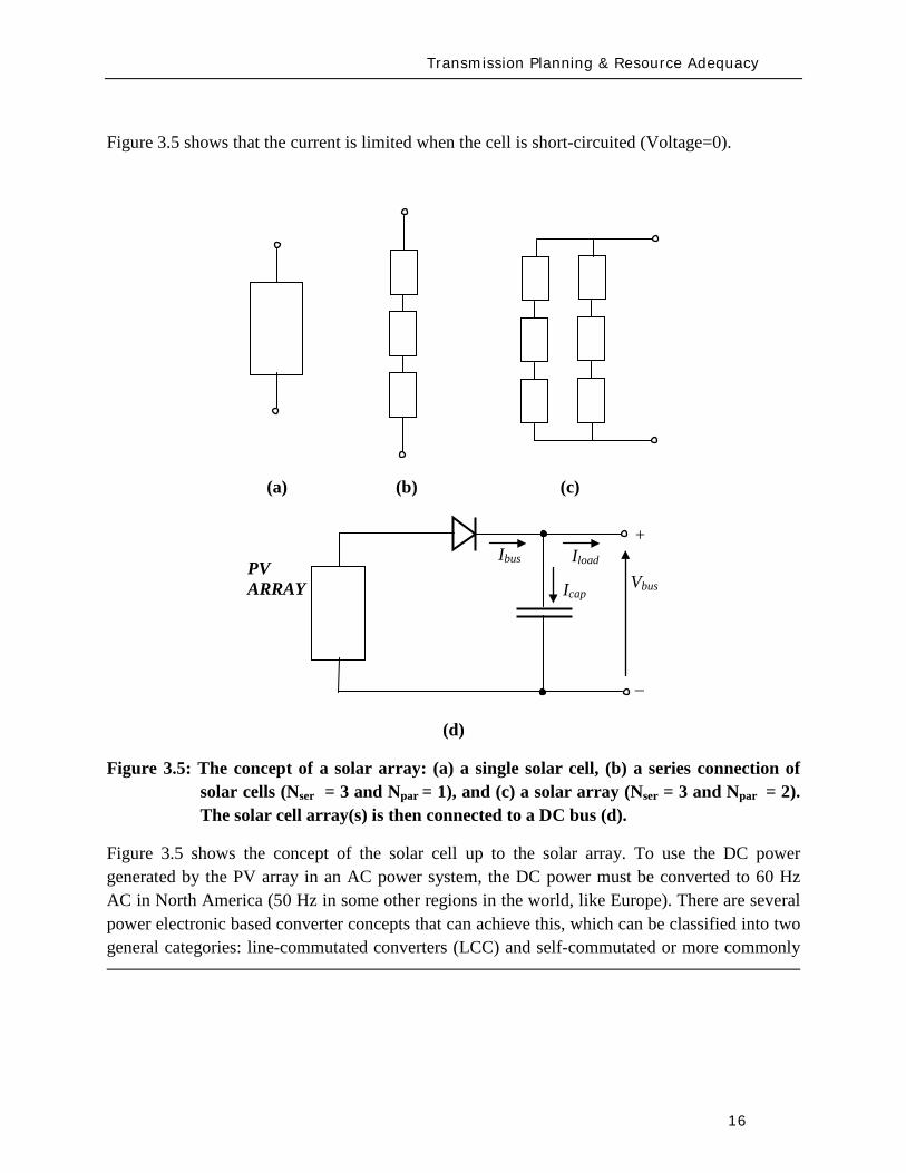
Transmission Planning amp Resource Adequacy
16
Figure 35 shows that the current is limited when the cell is short-circuited (Voltage=0)
(a) (b) (c)
(d)
Figure 35 The concept of a solar array (a) a single solar cell (b) a series connection of solar cells (Nser = 3 and Npar = 1) and (c) a solar array (Nser = 3 and Npar = 2) The solar cell array(s) is then connected to a DC bus (d)
Figure 35 shows the concept of the solar cell up to the solar array To use the DC power generated by the PV array in an AC power system the DC power must be converted to 60 Hz AC in North America (50 Hz in some other regions in the world like Europe) There are several power electronic based converter concepts that can achieve this which can be classified into two general categories line-commutated converters (LCC) and self-commutated or more commonly
Vbus Iload
Ibus
Icap PV ARRAY
+
_
Transmission Planning amp Resource Adequacy
17
referred to as voltage-source converters (VSC) These technologies have been applied for decades and are well understood LCC use thyristors as their controlled switching device The switching on of a thyristors can be controlled while the turn-off time cannot be controlled and happens at the next AC waveform current zero crossing LCC systems must be operated in a network with an AC source and cannot operate to serve an isolated load In contrast VSC systems are self-commutating that is the power electronic switching devices used (eg integrated gate-commutated thyristors or IGCTs and insulated-gate bipolar transistors or IGBTs) are able to be completely controlled for both turn-on and turn-off and allow the VSC to completely control the AC waveform produced and adjust the power factor as seen on the AC side to within the current rating of the device Due to advances in the technology most power electronic converters employed in PV systems are of the VSC type22
From a modeling standpoint for power system studies there are some user-written manufacturer-specific models in existence as developed by various PV manufacturers Presently no generic or standard models exist
The WECC Working Group which has been addressing the development of generic WTG models will be extending its effort in 2010 to review developing generic PV models for dynamic simulations in stability studies As a starting point the grid side structure of the Type 4 WTG model may be used since it represents a VSC This is because PV is typically connected to the grid with a VSC and it will behave electrically similar to a Type 4 WTG that has a similar electrical interface with the gridmdashthis is from a grid perspective looking at the electric response and neglects any of the effects of the energy source
From a steady-state power flow and short-circuit analysis perspective the behavior of the PV technologies will behave in a similar fashion to a Type 4 WTG because of the VSC interface and because its power factor can be controlled based on the control functionality of the VSC design Its short-circuit response will be limited to the current limit effected by the VSC under grid fault conditions
The development of generic and standard PV models is presently a topic for further research This should be pursued imminently and much of what has been learnt from the WTG model development process should be leveraged
22 IEA-PVPS Grid-Connected Photovoltaic Power Systems Survey of Inverter and related Protection Equipment Report IEA PVPS T5-05 2002 December 2002 (httpwwwiea-pvpsorgproductsdownloadrep5_05pdf)
Transmission Planning amp Resource Adequacy
18
33 Solar Thermal
Solar thermal energy is based on harnessing the radiated heat of the sun for the purpose of producing electricity In broad terms there are presently two main ways of achieving this
1 Concentrating Solar Power (CSP) plants ndash in this case solar radiation is typically collected through a large number of mirrors (thus a large amount of solar radiation) which is then focused on a small area ndash the mirrors have tracking systems to follow the Sun The concentrated solar radiation heats a high temperature working fluid which then feeds a conventional steam-turbine generator From an electrical grid perspective the models needed to simulate the steady-state short-circuit and transient time-domain dynamics of such a generating unit are typically no different than standard synchronous generating units for fossil fuel plants
2 The Stirling Engine concept23
34 Tidal Generation
ndash in this design a parabolic mirror assembly concentrates the collected solar radiation on a sterling engine that sits at the focal point of the mirror assembly A Stirling engine is a reciprocating heat engine that operates based on the concept of cyclical compression and expansion of a working fluid As the working fluid expandscontracts it drives a piston that then turns a generator The engine is connected to an electrical generator that produces electric energy Once again for power system studies the units may be modeled using standard generator models However in this case a power plant would be constituted by a large number of small units (the typical Stirling engine is about 25 kW) in a large electrical collector system that collects the power and injects it into the utility grid ndash much like the collector system of a wind power plant Thus modeling the collector system (eg see Figure 32 for an aggregate model of a wind collector system) and any other devices in the collector system such as shunt reactive devices etc must be properly modeled
Tidal power generation derives energy directly from the motion of oceanic tides The gravitational pull of the Moon and Sun combined with the Earthrsquos rotation result in the generation of tides Tides generally occur with a period of roughly twelve hours and so most coastal areas experience two high and two low tides within every twenty-four hour period Tidal generation uses this phenomenon to generate energy Clearly the stronger the tides are either in tidal current velocity or the heightlevel of water the greater the potential amount of energy generation
23httpwwwstirlingenergycom Y Zhang and B Osborn ldquoSolar Dish-Stirling Power Plants and Related Grid Interconnection Issuesrdquo IEEE PES General Meeting 24-28 June 2007
Transmission Planning amp Resource Adequacy
19
Presently in North America tidal power is not a significant source of power in any region Some pilot programs exist for introducing the technology In April 2009 one was announced in Snohomish County Public Utility District in Washington State24
There are several options for harnessing tidal power One method is the use of turbines similar to wind turbines however the fluid (water) is much denser and requires a turbine with smaller and bulkier blades as shown in Figure 36 Most of these technologies typically use ACDCAC converter technology similar to a Type 4 wind turbine to convert the low frequency generated electricity to grid frequency AC electricity and interface with the power system Once this technology becomes more prevalent a starting point for development of a suitable model structure may be the Type 4 generic wind turbine models Understandably the energy source characteristics are quite different from wind power and significantly more predictable
Figure 36 One of the many concepts for tidal generation systems (courtesy of Marine Current Turbines Limited wwwmarineturbinescom)
35 Other Resources
There are several other emerging technologies and there are many complementary technologies (ie auxiliary to the variable generation resources but designed to help with their integration into the grid) including smoothly-controlled dynamic reactive devices (static VAr systems)
24 httpwwwsnopudcomPowerSupplytidaltidalpressashxp=1516amp756_na=46
Transmission Planning amp Resource Adequacy
20
energy storage technologies etc With respect to static VAr systems (SVCs and STATCOMs) there is an active WECC working group imminently addressing the issue of generic models for these devices25
36 Summary
The group has made substantial progress with the models defined and developed but currently undergoing testing and validation With regards to the other emerging technologies most tend to be power converter based (ie connected to the grid through a back-to-back frequency converter) and so their electrical behavior (neglecting the characteristics of the energy source) will be similar to Type 4 wind turbines Until these technologies mature the basic structure of other more mature converter based generation technologies can be a good starting point
This section has briefly presented the various types of variable generation and the present status of models and model development for power system studies Wind generation technologies being the most prevalent world-wide have the most mature models Through efforts started by WECC and being continued by IEEE and IEC generic standard models for the four main types of WTG technologies are being developed The first generation of these models has been released in two power system simulation software platforms most commonly used in North America Other emerging technologies (eg PV tidal power etc) can build on this effort to start developing generic models For example the WECC effort will be extending its scope in 2010 to look at PV model
From a NERC perspective the key items are
1 To emphasize and support efforts by WECC IEEE and IEC to develop and standardize generic models for these technologies for power system planning studies
2 To encourage manufacturers to familiarize themselves with the generic models being developed and be willing an able to supply parameters for these generic models to reasonably represent their equipment for power system stability studies As highlighted in Chapter 2 more detailed manufacturer specific models may be needed in special cases and for specialized studies
3 To encourage efforts aimed at model validation
4 To consider any augmentation or additions to reliability standards related to Modeling Data and Analysis (MOD) with respect to modeling and model validation of variable generation This is discussed in greater detail in section 5 of this report
25 httpwwwweccbizcommitteesStandingCommitteesPCCTSSMVWGSVCTFdefaultaspx
Present Status of Model Validation
21
4 Present Status of Model Validation
This chapter gives an overview of the model validation work that has been done hitherto as it relates to models for variable generation Necessarily the primary focus of this section is on wind turbine generator models since models for this resource are presently the most mature
41 What is Model Validation
Any and all models of a dynamic system always have limitations associated with them A model is a representation of reality it is an emulation ndash that is why it is called a model In developing a model first the question is asked as to the specified use of the model and the conditions it must reasonably emulate ndash this forms the basis of a model specification from which a model is developed The developed model establishes a certain structure with parameters which are adjustable in order to emulate different types of equipment or design of the modeled device Thus valid parameterization of the model to represent a particular manufacturerrsquos equipment is essential to support the particular scenarios to be analyzed
Model validation is often achieved through some form of testing either in a laboratoryfactory or in field There is a range of reasons for conducting tests for wind generation Each test has a unique set of objectives guiding the design of adequate testing practices
bull Performance Compliance Compliance to contractual requirements and grid codes are one reason to perform tests Interconnection requirements (usually included in plant Power Purchase Agreements and Interconnection Contracts) and grid codes typically outline specific technical criteria that must be met to allow a power plant to connect and operate on the grid Since these criteria point out specific levels to be met (for example voltage power factor and response time) tests may be designed with binary ldquopassfailrdquo objectives
bull Model Validation In much of the world power plants above a pre-defined size must be accurately represented with a dynamic simulation model used in stability analysis for operations and planning purposes As variable generation sources such as WPP are growing in size it is becoming increasingly important to have accurate variable generation specific models Tests may be performed to tune and verify simulation models to closely match the performance of actual equipment In the western US and Canada WECC has mandated that any plant with 20 MVA aggregate generation must be tested for model validation including large wind power plants For North America the imminent NERC MOD-026 standard presently under development will enforce model validation requirements throughout the North American region
Present Status of Model Validation
22
To achieve the goals of model validation there are three categories of tests that may be performed
bull Type Tests These are tests performed by the manufacturer or independent third-parties of representative equipment The intent is to demonstrate that a particular design of equipment exhibits specific performance and all other equipment of that same design is assumed to have the same performance Type tests can be
o Component Performed on specific functions or features in a power plant or generation equipment This could be for example testing the fault ride-through capability or reactive capability of a WTG where testing is performed at the component level
o Factory A systemic test of a major assembly (ie a drive train) or entire turbine-generator is performed under a controlled environment like a manufacturing facility to verify performance and validate assembly design
o Unit A systemic test of multiple components operating together (ie as entire operating WTG or WPP) with the specific intent of benchmarking a model or design as a type test For example tests performed in Europe under the WindTest program
bull Field Tests26
o Commissioning Tests performed on new equipment entering its period of commercial operation service
Tests performed by the power plant asset owner developer host utility manufacturer andor independent third-parties of specific operating equipment These tests are to demonstrate that a particular implementation design and installation of equipment exhibit specific performance
o Periodic Maintenance or Calibration Tests performed periodically after the plant is in commercial operation to verify that equipment continues to perform as well as it did during commissioning
26 See for example WSCC Control Work Group and Modeling amp Validation Work Group ldquoTest Guidelines for Synchronous Unit Dynamic Testing and Model Validationrdquo February 1997 (wwwweccbiz) and IEEE Task Force on Generator Model Validation Testing ldquoGuidelines for Generator Stability Model Validation Testingrdquo Proceedings of the IEEE PES General Meeting Tampa FL June 2007 (httpieeexploreieeeorg)
Present Status of Model Validation
23
o Periodic Model Validation Tests performed periodically after the plant is in commercial operation to verify that simulation models adequately represent actual plant performance (for example the periodic model validation testing required by WECC)
o Periodic Codes amp Standards Validation Tests performed periodically after the plant is in commercial operation to benchmark and validate plant performance per contractual requirements These tests are typically performed to obtain a permanent operating license for the power plant
bull On-Line Monitoring27
With these general concepts in mind the following subsections present some example cases studies of model validation and validation approaches for variable generation sources The examples emphasize WPP and WTG since wind generation is the present dominant variable generator sources in the North America continent
Other information of interest is from continuous data gathering based on ongoing performance of an operating power plant Data collected from external and unscheduled events including grid disturbances or in the case of WTG large changes in wind is particularly useful Monitoring also benchmarks performance under normal operation
42 Examples of Model Validation Efforts
421 Hydro- Queacutebec Example
The province of Queacutebec has vast wind energy potential Though wind energy generation in 2009 accounts for nearly 13 of the total installed capacity in the Queacutebec control area the penetration rate of wind energy generation will reach 10 by 2015 A total capacity of 528 MW is currently in operation and approximately 3000 MW are under development Five wind turbine manufacturers will supply the WTGs for the different projects under study
The configuration of the Hydro-Queacutebec transmission system is essentially radial Approximately 85 of the total installed generation feeding the system is located at distances up to 1300 km
27 See for example P Pourbeik ldquoAutomated Parameter Derivation for Power Plant Models From System Disturbance Datardquo Proceedings of the IEEE PES General Meeting Calgary Canada July 2009 (httpieeexploreieeeorg) This reference shows actual application of on-line disturbance monitoring to power plant model validation for conventional fossil fuel generation It may be feasible to apply similar algorithms and approaches for continuous re-validation of WTG and other variable generation technologies once generic standard models have been developed This is a current topic for research
Present Status of Model Validation
24
from the closest major load centers With this configuration the system transfer capability is mainly limited by stability constraints (transient stability and voltage stability) rather than congestion or thermal capacity of equipment hence the need for reliable models for wind power plants and all other generation
Stability studies are critical to determine the compensation equipment required to maintain the reliability of the power system when integrating new generation They are also essential for operation planning studies including control system design and tuning and determination of transfer capabilities
So far Hydro-Queacutebec has faced two major difficulties regarding user-written models provided by the wind turbine manufacturers First models often lack robustness and do not represent accurately some important features (convergence problems in low short-circuit network do not take into account frequency excursions do not represent secondary voltage regulation etc) Second model validation by the manufacturers is often incomplete not available or difficult to translate to real projects (different settings or software versions design of the collector system etc) In some cases these difficulties have lead Hydro-Queacutebec to build its own models (see Hypersim section below)
General validation test program
Since 2006 Hydro-Queacutebec has performed validation tests on WPP connected to its transmission system and a general validation test program was established in 200928
1 To demonstrate that WPP meet the Transmission Provider technical requirements related to wind generation
The power producer has the obligation to perform validation tests in order to demonstrate that its facilities meet the Transmission Provider requirements The purposes of this program are
2 To validate numerical models and parameters associated with the WPP specifically those given to the Transmission Provider by the power producer by comparing the model response to recordings taken during field tests
3 To confirm the electrical data of power producer facilities
The validation program is divided into seven functions to be validated
1 Primary voltage regulation
28 httpwwwhydroquebeccomtransenergiefrcommercepop_raccordement_transporthtml
Present Status of Model Validation
25
2 Undervoltage response (LVRT)
3 Inertial response
4 Secondary voltage regulation
5 Power factor
6 Maximum ramp rates
7 Power quality
The tests for the primary voltage regulation are performed on a single WTG and consist in producing instantaneous voltage variations of low amplitude on the terminal of the WTG and small voltage steps of limited duration injected directly into the WTG voltage control system Three-phase voltages and currents are recorded at the wind generator to measure the local dynamic response of a wind generator to a rapid voltage change and to verify that the response meets voltage regulation requirements The results are also used to set the model parameters (time constant and gain) used in dynamic simulations The tests regarding the secondary voltage regulation are similar but are conducted for the entire power plant
The validation test program includes LVRT tests on one generating unit to verify that requirements during undervoltage conditions are met The power producer has the responsibility to conduct the tests or to provide a complete report describing tests performed on an identical generating unit (same software version) to demonstrate that the requirements are met So far no LVRT tests were performed on site on WPP integrated on the Hydro-Queacutebec network However monitoring equipment has been installed at three locations in wind plants at their point of interconnection on a 345 kV feeder of the collector system and on one generating unit The monitoring system records signals either continuously or upon detecting variations occurring at the point of interconnection active power variations voltage sags and swells and system frequency excursions These signals are primarily voltages and currents but may also be mechanical variables or other signals
The field recordings recorded on the network can thereafter be used to validate the dynamic response of the models This is a time consuming effort that requires the collaboration of the manufacturers to modify the models if necessary Event recordings to-date have made possible suitable validation of two Hydro-Queacutebec Siemens PTI PSSregE models and one ElectroMagnetic Transients Program (EMTP) model
Inertial response requirements were not in defined for the projects started before 2005 Consequently existing wind plants do not have to fulfill them However the requirements have to be met for WPP to be commissioned in 2011 and after The corresponding validation tests consist in emulated frequency steps and ramps of limited duration Besides verifying the
Present Status of Model Validation
26
requirements the test results will be used to validate the parameters of the models and their dynamic response
The power factor and the maximum ramp rates modules are tested with all WTGs in service to verify that the requirements are met Power factor tests consist in supplying and absorbing a maximum amount of reactive power at different levels of active power Maximum ramp rate tests consist in performing a power plant shutdown sequence followed by a startup sequence These tests are not really used to validate the models but are rather helpful to fix model parameters
The last module regarding the power quality is not covered by scheduled testing but by means of a monitoring system that verifies harmonics and emission limits The recordings are compared to the report provided by the developers to verify if the requirements are met However they are not useful to validate the EMTP model since the WPP is represented by a single-wound generator and does not simulate the detailed collector bus system and individual wind turbine generators
Field tests department
Hydro-Queacutebec field-testing department (UMES) conducts a wide range of special tests and measurements for Hydro-Queacutebec and has done so for 30 years
To test WPP UMES installs a monitoring systems to record three-phase voltages and currents generally at three locations within the plant at the point of interconnection at the starting point of a 345 kV feeder of the collector system and at the terminals of a WTG connected to the same monitored feeder For extended model validation other signals within the wind turbine are monitored including the rotor side converter voltages and currents the network side converter currents and the DC bus voltage
High speed recorders with anti-aliasing filters are used Normally the sampling rate is 5 kHz with at least a 200 second window per event The monitoring system is reachable via an Ethernet connection for remote trigger and data retrieval UMES has also the responsibility to perform the data processing and analysis of the recordings in order to verify the compliance with the interconnection requirements and to extract relevant data for model validation
Present Status of Model Validation
27
Hypersim
The Hydro-Queacutebec Research Institute (IREQ)29 also has an important expertise in control system and wind generation modeling for extensive studies of electrical networks The simulation environment used is Hypersim a real-time simulator and powerful simulation tool that uses a highly detailed representation of the Hydro-Queacutebec network A full-transient detailed model of a Type 3 WTG was developed at IREQ using the MATLABreg SimPower Systems Toolbox The model was also implemented in EMTP and in the Hypersim real-time simulator30 This model is in the process of being validated with data processed by the UMES team The range of events recorded does not make it possible to validate the model completely and the design and parameters will continue to be adjusted to improve the representation of the wind turbines The validation of the MATLABreg model developed by IREQ was very useful to validate and improve Hydro-Queacutebecrsquos Siemens PTI PSSregE user model31
422 GE Example ndash based on GErsquos work with client facilities
In the case of the first example presented here a 10 MVar capacitor bank located at the 25kV WPP collector bus is switched off-line as an external physical stimulus Figure 41 shows detailed response to capacitor switching from the WindCONTROLreg The WindCONTROLreg system allows coordination of all on-line turbine-generators for plant-level fast and smooth voltage regulation at the point of interconnection (POI) located contractually at the 25kV substation bus The red curve (Q_ACTUAL [KVar]) shows that total plant reactive power initially drops after the switching action but the fast autonomous controls on each turbine generator quickly and stably respond to increase reactive power generated by individual turbines shown by the orange curve (Q_TURBINES [KVar]) The WindCONTROLreg command (Q_CMD) distributed to the turbines is shown in blue The response of Q_CMD is dominated by the gains of the voltage regulator portion of the WindCONTROLreg specifically the proportional gain Kpv and integral gain Kiv The difference between the response of the individual turbines (Q_TURBINES [KVar]) and the WindCONTROLreg command (Q_CMD) is due to the dynamics of the individual wind turbines The coordinated response of the wind plant and the individual
29 httpwwwhydroquebeccomtechnologyindexhtml 30 R Gagnon G Sybille SBernard D Pareacute S Casoria and C Larose ldquoModeling and Real-Time Simulation of a
Doubly-Fed Induction Generator Driven by a Wind Turbinerdquo IPST Conf Paper No IPST05-162 Montreacuteal Canada 2005 C Larose R Gagnon G Turmel P Giroux J Brochu D McNabb and D Lefebvre ldquoLarge Wind Farm Modeling Techniques for Power System Simulation Studiesrdquo in Proc 8th International Workshop on Large-Scale Integration of Wind Power into Power Systems Bremen Germany Oct 14-15 2009
31 C Langlois D Lefebvre L Dube and R Gagnon ldquoDeveloping a Type-III Wind Turbine Model for Stability Studies of the Hydro-Queacutebec Networkrdquo in Proc 8th International Workshop on Large-Scale Integration of Wind Power into Power Systems Bremen Germany Oct 14-15 2009
Present Status of Model Validation
28
turbines is multi-modal a fast initial response to address severe perturbations as well as a slower grid friendly refinement For purposes of this test the automatic control of the capacitor bank by WindCONTROLreg was disabled and manual switching was used as a stimulus to record individual WTG response
The detailed plot in Figure 42 shows a zoomed view of the response to step change in voltage at the WTG The very fast initial response will dominate and saturate the controls for big events The wind plant will do everything as quickly as it can to mitigate a large disturbance In this case the fast response took approximately 200 milliseconds The slow refined control then takes over to allow for coordination with other equipment and maintain post-disturbance stability This aggregate response also allows for a very abrupt action when needed and a grid-friendly refinement that maintains stability in less severe cases
The green curve in Figure 43 shows that when the capacitor is switched off-line the measured voltage at the point of interconnection (or POI) decreases due to reduced reactive power flowing into the grid The response of the individual WTGs is to rapidly increase reactive output to make up for the loss of reactive power supplied by the shunt capacitor The plant level control then responds to this initial under-voltage condition and attempts to restore the POI voltage by increasing each wind generatorrsquos reactive output by equal amounts until the plant voltage settles to the control set point determined by the operator The lower traces in Figure 43 show a gap during the period when the capacitor bank is online between total plant Q (Q_ACTUAL) and summation of Q out of each WTG (Q_TURBINES) This gap represents the capacitive reactance added by the shunt bank When the capacitor is switched offline the gap between Q_ACTUAL and Q_TURBINES closes and all reactive power is supplied solely from the WTGs The initial loss in plant reactive power is mitigated within approximately 15 seconds as each WTG settles to a new increased level operating point of reactive power This new increased reactive level for each WTG is the total Q increase from all units on-line in the plant divided by the total number of units online at the time of the test
Figure 44 shows a comparison between these measured values and the simulation results of the PSLF model Model outputs Qg Qplant Qcmd and Vreg correspond to measured Q_TURBINES Q_ACTUAL Q_CMD and U_LINELINE respectively This plot shows the model performance adequately represents what is happening in the field The response matches closely with a difference immediately following the switching operation being due to lower sampling rate in the measurement than in the GE PSLFreg simulation
Response to grid events demands relatively rapid control action Manual grid or plant operator changes in operating set-points do not normally demand fast response and indeed system behavior ought not to be rapidly disturbed by moving set-points Figure 45 shows the response of GE plant to 2 step in voltage reference The blue trace in the figure shows a well mannered response to the reference step The red trace is from the simulation model which matches very
Present Status of Model Validation
29
well In the blue trace after the perturbation occurring about 8 seconds after the reference change the plant supervisory control switched on a shunt capacitor to retain dynamic range on the wind turbines The switching perturbation is rapidly balanced by the turbines allowing the response to continue smoothly
Figure 41 10 MVar Capacitor removal response measured from WindCONTROLreg
Present Status of Model Validation
30
Figure 42 Wind turbine-generator level voltage step test response
Present Status of Model Validation
31
Figure 43 10 MVar Capacitor removal response ndash POI variables
Figure 44 10 MVar capacitor removal field test vs simulation results
Present Status of Model Validation
32
Figure 45 A different step test +- 2 step of voltage reference
The performance for grid fault events is of considerable interest in system planning Staging faults particularly severe ones on operating wind plants is difficult and expensive Figure 46 shows a comparison between a staged fault test and the (present) Siemens PTI PSSregE model of the GE 25 (full converter) WTG The fault event is quite severe a 3-phase 700ms of voltage depression to less than 20 of nominal at the high voltage terminal of the WTG unit transformer The measurement traces (on the left) include some of the signal noise characteristic of measurement and extraction of fundamental frequency positive sequence information from real high resolution measurements The simulation traces on the right are of course cleaner The match between test and simulation is of very high fidelity for phenomena relevant and legitimately examined with positive sequence simulation tools (ie greater than one cycle)
QPOI
VPOI
Measured = Blue Simulated = Red
Plant Capacitor Bank Switched On Automatically by WindCONTROL
+ 2 VrefStep
- 2 Vref Step
QPOI
VPOI
Measured = Blue Simulated = Red
Plant Capacitor Bank Switched On Automatically by WindCONTROL
+ 2 VrefStep
- 2 Vref Step
Present Status of Model Validation
33
Figure 46 GE 25 WTG Fault Test vs PSSe Model Performance
The discussion provide above is solely geared to hardware testing and validation however another highly valuable and legitimate means of providing validation of simulation models (for planning and otherwise) is to use more complex simulation software to validate simpler planning models Manufacturers normally have highly complex and highly proprietary models of their equipment These models are used among other things to design equipment and are normally physically based and must have sufficient fidelity for original equipment manufacturers (OEMs) to make sound engineering judgments for equipment design and application The OEMs are highly motivated to have these detailed high fidelity equipment level models These detailed models therefore can often be used to design test and validate simpler planning models to be used by the industry
There is a long accepted history in the power industry of this practice For example a typical (GE) gas turbine has on the order of 4000 state variables in the design model planning models typically have on the order of four state variables simplification is necessary and expected These design codes have been used to develop planning models of gas turbines Figure 47 below shows a comparison between a fault simulation using a GE design code (GE WindTrapreg) and the planning model in GE PSLFreg for a GE 15 (double fed machine) WTG
Present Status of Model Validation
34
Figure 47 Detailed Design Simulation (GE WindTRAPreg) vs GE PSLFreg Model Performance (active power during a severe fault for a GE 15 WTG)
-10
00
10
20
30
0 05 1 15 2
Time (Seconds)
Sin
gle
WTG
Rea
l Pow
er (M
WindtrapPSLF
Summary amp Recommended Actions
35
5 Summary amp Recommended Actions ndash Standards Implications
This document has presented a general overview of modeling and model validation as it pertains to variable generation resources Clearly to date the bulk of the experience and work has been on wind turbine generators Never-the-less similar approaches for modeling and model validation are being pursued for other variable generator technologies such as PV
Non-proprietary and publicly available models for the simulation of steady-state (power flow) short-circuit (fault calculations) and dynamic (time-domain simulations) behavior of such generation resources must be made readily available for use by power system planners Furthermore these models should be routinely validated to ensure proper representation of variable generation power plants in bulk power system studies A model is valid if its dynamic behavior is close enough to reality so that its influence on the network of interest (ie used for power system studies) is consistent with the fidelity of model structures and available data for the power system and other generation as it pertains to the phenomena of interest (ie in stability studies) That is perfect curve fitting is not necessary but to the extent possible erroneous model dynamics must not result in a notable over-design or under-design of the network
Each of the NERC standards discussed below in Section 52 address to aspects of meeting a standard (i) the technical requirement ie the need to define measure validate a model its parameters etc and (ii) the procedural requirements ie the functional model of how this technical requirement should be met reported and monitored The bulk of this working grouprsquos recommendations stated below address the technical requirements Variable generation is a new and quickly evolving technology and consideration should be given to the timing with which standards be implemented
Section 51 below first gives a summary of the planning process based on NERC standards to put the discussions in this report into context with the NERC standards Then in Section 52 we provided our recommendations and comments on the NERC existing and developing standards
Summary amp Recommended Actions
36
51 Applying the NERC Standards
The NERC standard FAC-001 (see Figure 51) should be expanded to clearly cover modeling requirements during the coordinated joint study phase of the Facility connection process Simple generic models of variable generation may be adequate for the IES phase and more detailed models may be needed for the IFS phase Validation of the simple and detailed model parameters may be needed during commissioning
Figure 51 Facility connection process
Interconnection Evaluation Study
Generator Interconnection
Request
Interconnection Facility Study
GO provides initial model
to TPPC
GO provides final model
to TPPC
GO signs Interconnection
Agreement and is put in-service
GO performs model amp
performance validation testing
TO develops Facility Interconnection requirements and requests models and data
of the GO at each process stage
FAC-001
Summary amp Recommended Actions
37
The generic model with associated parameters feed into the NERC model building process shown in Figure 52 As an example for WTG presently there is insufficient evidence of the accuracy of presently available generic models for WTG32
for all the various WTG manufacturers Some confirmation tests during commissioning or type tests or comparison simulation tests with a detailed model are necessary to get buy in from the Transmission OwnerPlanner As the technology matures and generic models are enhanced and associated data parameter sets are developed for specific machine types the new generic models will become more accepted as is the case with models of hydro or thermal plants
Figure 52 Annual NERC Model Development Process
32 PSSregE-320 Program Application Guide Volume II Chapter 21 PSSregE-320 Model Library Chapters 17 through 21 GE PSLF Users Manual v170_04 October 2009
Steady state data
developed
MOD-10
Dynamics data
developed
MOD-12
Reliability Region creates model
MOD-14
Reliability Region creates model
MOD-15
Reliability Region defines data
requirements
MOD-13
GO
TP
RP
Reliability Region defines data
requirements
MOD-11
Annual NERC Planning and
Operating Models
created and distributed to the industry
Summary amp Recommended Actions
38
The regional model building manuals developed as part of MOD-11 and MOD-13 must provide sufficient clarity to model variable generation These manuals may ask for best available models or generic models These models cover the operational time frame and the 10-year planning horizon The manuals do not currently cover the frequency for revalidating model data
While not included in the standards more emphasis is currently being placed on meeting the Eastern Interconnection Reliability Assessment Group (ERAG) model building manual requirements in addition to regional requirements
Figure 53 NERC Model Validation Process
The Regional Entities develop the test procedures and dictate testing frequency for the Generator Owners to follow The model data then feeds in to the annual NERC model building process
52 NERC Standards Technical Issues
One general comment is that the NERC Glossary of Terms would benefit from the term ldquoVariable Generationrdquo being include in it and appropriately defined A suitable definition can be found in the Phase I report of the IVGTF
Verify real power capability
MOD-24
GO
Verify reactive power capability
MOD-25
Verify generator excitation control model
MOD-26
Verify turbine governor model
MOD-27
Summary amp Recommended Actions
39
MOD-011 Regional Steady-State Data Requirements and Reporting Procedures
The technical requirement in this MOD reads
ldquoR12 Generating Units (including synchronous condensers pumped storage etc) location minimum and maximum Ratings (net Real and Reactive Power) regulated bus and voltage set point and equipment statusrdquo
This statement could be read to equally apply to variable generation as a source of generation However it may be prudent to explicitly include variable generation in this statement For example to change the sentence to
ldquoR12 Generating Units (including synchronous condensers pumped storage variable generation resources etc) location minimum and maximum Ratings (net Real and Reactive Power) regulated bus and voltage set point and equipment status For variable generation a suitable aggregate steady-state model of the collector system and equivalent unit representing the full plantrdquo
MOD-012 Dynamics Data for Transmission System Modeling and Simulation
This MOD equally applies to variable generation and needs no augmentation The requirements in the MOD are quite generic The requirements of this standard are dependent on and point to MOD 13 discussed below
MOD-013-1 RRO Dynamics Data Requirements and Reporting Procedures
This MOD explicitly discusses synchronous type generation It would be beneficial to include an explicit statement to cover variable generation For example
ldquoPlant-specific dynamics data shall be reported for variable generating units (eg wind turbine generators PV etc) such as the type of generating unit its interface with the grid and the appropriate model and model parameters to adequately represent unit dynamic response for bulk power system studies The typical size of a single variable generating unit (eg wind turbine generators PV array etc) is several hundreds of kilo-watts to several mega-watts Thus it may be acceptable for the total plant to be represented by an adequate aggregated model of the collector system and a single equivalent generating unit scaled up to represent the total name-plate capacity for each type of generating technology employed in the plant Furthermore models may need to be provided for other equipment installed in the collector system or at the point of interconnection such as reactive compensation devicesrdquo
Summary amp Recommended Actions
40
MOD-024-2 mdash Verification and Data Reporting of Generator Real Power Capability
This latest posting of this MOD posted for commenting on January 18th 2010 exempts variable generation from this requirement It states
ldquoVariable energy units such as wind generators solar and run of river hydro are exempt from the requirements of this Standardrdquo
For a variable generation plant the definition of Real Power Capability can be slightly challenging One way to view it is to see the total gross capability as the sum of the nameplate rating of all individual units within the plant eg for a wind power plant the total sum of the nameplate rating of all wind turbine generators in the plant However there must be two realizations (i) the amount of actual power injected into the grid at the point of interconnection requires a suitable representation of losses on the collector system and auxiliary loads and (ii) by its very nature variable generation is a highly variable energy source and thus it is quite rare to find point in time when all units in the plant are coincidentally at their peak nameplate capacity Finally the seasonal variable generation output variations need some discussion since they are quite different than conventional generation technologies
MOD-025-1 mdash Verification of Generator Gross and Net Reactive Power Capability
The technical requirement in this MOD reads
ldquoR15 Information to be reported
R151 Verified maximum gross and net Reactive Power capability (both lagging and leading) at Seasonal Real Power generating capabilities as reported in accordance with Reliability Standard MOD-024 Requirement 151
R152 Verified Reactive Power limitations such as generator terminal voltage limitations shorted rotor turns etc
R153 Verified Reactive Power of auxiliary loads
R154 Method of verification including date and conditionsrdquo
Note the above requirements are from the existing version of the standard MOD-025 is currently being enhanced
Although all of the above could equally apply to variable generation some clarification may be needed Namely variable generation reactive capability of the ldquopower plantrdquo is not entirely inherent in the individual generating units A variable generation power plant such as a wind power plant may contain many reactive power sources such as the individual generating units themselves (eg Type 3 or 4 WTG see Appendix I) discretely switched shunt reactive devices
Summary amp Recommended Actions
41
(eg shunt capacitors or reactors) smoothly controlled shunt reactive devices (eg SVC or STATCOM) or a combination of these devices Thus care should be taken as to how the total reactive capability of the power plant is defined and at what point (eg point of interconnection and whether this is defined as the high or low side of the substation transformer) Also it may not be practical under normal operating conditions to exercise the full reactive capability of the power plant (this is a known issue even with conventional synchronous generator plants) to test it thus it should suffice to demonstrate the plants reactive capability to the extent possible in the field and to then augment this with engineering calculations to derive the plants full reactive capability This is particularly true of variable generation because there is no control over the energy resource So for example a typical wind power plant may only achieve its name-plate rating for a hour or two during an entire year Thus it would not be possible to demonstrate the full reactive capability of the plant in the field Rather it should suffice to demonstrate the reactive capability of a single WTG and then to derive through engineering calculations (considering all other reactive devices in the plant such as SVC STATCOM etc) the total reactive capability of the plant These comments should be somehow used to appropriately modify MOD 25
MOD-026-1 mdash Verification of Models and Data for Generator Excitation System Functions ndash SECOND POSTING (and MOD 27)
MOD 26 (and MOD 27 Verification of Models and Data for TurbineGovernor and Load Control) are presently under development33
Presently these standards are tailored explicitly to deal with synchronous type generators since much of the language revolves around technology associated with synchronous generation (eg excitation system AVR power system stabilizers etc) Thus the following key items need to be clarified in these standards as they pertain to variable generation In addition the comments that follow apply to all components in a variable generation plant that may include devices such as the actual power generating units shunt compensation devices centralized control systems spanning the entire facility etc
These two standards deal specifically with the routine validation of generating unit dynamic models for power system stability studies
1 UnitPlant Size for Validation These MODrsquos specify the size of generating unit above which model validation is required It should be recognized that the typical size of a
33 MOD 26 and MOD 27 standards under development are found at httpwwwnerccomfilezstandardsGenerator-Verification-Project-2007-09html
Summary amp Recommended Actions
42
variable generation unit is in the hundreds of kilo-watts to several megawatts range Thus the language should be changed (or introduced) to indicate ldquonet power plantrdquo size
2 Validation of various technologies in a single plant Variable generation power plants can consist of multiple generation technologies For example a wind power plant may consist of WTGs of two different types Thus we need to consider the following points as they pertain to variable generation
a For a uniform variable generation plant (ie all generating units are of the same technology type) a single aggregate generator model representation should be sufficient
b For a significantly diverse variable generation plant the plant should be represented by multiple aggregated unit models representing each technology type
c Unique representation of a group of variable generation units as a single aggregated generator model representation should be based on
i The size of the group is a significant proportion of the total plant size (eg gt 20 of plant rating)
ii Each group should represent a unique characteristic (eg Type 1 WTG as compared to a Type 3 WTG)
3 Validation of different control layers Variable generation plants such as wind power plant may have several functional layers of control For example in a wind power plant with Type 3 WTGs we may have one level of closed loop voltage regulation at the terminals of the WTG a second slower control loop that regulates voltage at the point of interconnection (POI) and a third layer of control that coordinates the switching of shunt capacitors at the POI based on the reactive output of the individual WTGs In addition devices such as STATCOMs may be present at the POI Modeling and model validation should incorporate such devicescontrol layers to the extent that the dynamics of these functional layers are important for stability studies (see Figure 31)
4 Modeling and Model Validation Models are an emulation of actual equipment Not all model parameters necessarily translate to actual physical components or measureable features Judgment needs to be exercised in the modeling and validation process
a Models should be validated typically against the performance of an actual plant for a given eventdisturbance within the given operating range it is designed for
Summary amp Recommended Actions
43
b Models should state clearly the type and the range of events they have been designed to simulated and the limitation of the models beyond which the model deviates from the actual variable generation plant performance (eg a model developed to represent electrical transient behavior of a WTG may not be adequate for studying wind fluctuations over a many minute time frame)
c In general the best approach to model validation is to use field (or test bench) measurements of various disturbances that must exercise the different control functions to a wide range of operation points For example a model is not necessarily valid if the only a comparison between simulation results and field measurements for a single voltage step response is performed at one operating condition Ideally illustration of validation against recorded response to various system disturbances (faults frequency deviations etc) gives the greatest confidence in validation
d A model is valid if its dynamic behavior is close enough to reality so that its influence on the network of interest (ie used for power system studies) results in relatively negligible errors for the phenomena of interest (ie in stability studies) That is perfect curve fitting is not necessary but to the extent possible erroneous model dynamics must not result in a notable over-design or under-design of the network
5 Future functionality Due to the rapidly evolving nature of variable generation technologies variable generation models should be of a modular nature such that future functionality can be incorporated as much as possible into old model structures by adding a functional modular block For example presently Type 3 and 4 WTGs do not exhibit inertial response However at least one manufacturer now supplies a functional control addition that can emulate inertial response on these units Such functionality is likely to be made available soon by most vendors Thus a functional model block can be developed that can be added to the existing models for Type 3 and 4 WTGs to emulate the behavior of this additional control
6 Modeling of protection Variable generation much like conventional generation will have associated underover voltage and under-over frequency protection These should be modeled Attention should also be given to protective relay coordination with plant controls particularly in light of the nature of the grounding system within the variable generation plant (eg a wind power plant spans an entire collector system which can be grounded in several different ways and thus have various implications on protective relay coordination) Such coordination issues relate to the PRC and FAC-001 standards
Summary amp Recommended Actions
44
7 Issues related to the fuel source for variable generation For variable generation one needs to be cognizant of the variable nature of the energy source and thus the possible impracticality of performing model validation at a desired plant output but rather having to accept model validation at whatever plant output can be achieved at the time of testing or disturbance monitoring
8 Revalidation How often should models be revalidated
a Many variable generation technologies are rapidly changing for example in wind power plants new control software or new setting may be uploaded every year if not sooner
b If the changes are insignificant the existing dynamic models should be revalidated if possible as a matter of prudency ndash say within six months or so of a control system updateupgrade The changes (in parameters or dynamic model) should be reported to the local Reliability Entities
c If the changes are significant the existing dynamic models should be revalidated ndash say within three months or so after the updateupgrade The changes (which may include a new module new software etc) should be reported to the local Regional Entities
53 Final Recommendation
An earlier draft of this report and recommendations were presented to NERCrsquos Planning Committee at their March 2010 meeting The Committee members urged the IVGTF to pursue NERC reliability standard development Thus several NERC Standards Drafting Teams undertaking MOD Standard development will be contacted to present the recommendations from this report for their consideration and incorporation in subsequent updates The standard drafting teams for MOD-026 and MOD-027 are aiming to incorporate variable generation considerations in the next release of these draft standards
Appendix I Wind-Turbine Generation (WTG) Technologies
45
Appendix I Wind-Turbine Generation (WTG) Technologies
(a) Type 1 Wind Turbine-Generator Fixed Speed Induction Generator
(b) Type 2 Wind Turbine-Generator Variable Slip Induction Generator 34
34 IGBT R control = Resistor controlled by Insulated Gate Bi-Polar Transistor
3
GEAR BOX
INDUCTION GENERATOR TRANSFORMER
GRID
3
3GEAR BOX
WOUND ROTORINDUCTION GENERATOR TRANSFORMER
GRID
IGBT RControl
Rectifier
Appendix I Wind-Turbine Generation (WTG) Technologies
46
(c) Type 3 Wind Turbine-Generator Double-Fed Asynchronous Generator
(d) Type 4 Wind Turbine-Generator Full Power Conversion
3
3GEAR BOX
WOUND ROTORINDUCTION GENERATOR TRANSFORMER
GRID
IGBT POWER CONVERTORS
3
GEAR BOX
SYNCHRONOUSGENERATOR TRANSFORMER
GRID
Rectifier
33
IGBTInverter
Acronyms
47
Acronyms
CSP ndash Concentrating Solar Power
CIGRE - International Council on Large Electric Systems
DFAG ndash Doubly Fed Asynchronous Generator (also often referred to as DFIG ndash Doubly Fed Induction Generator)
FERC ndash Federal Energy Regulatory Commission
HVDC ndash High-Voltage Direct-Current transmission
IEC ndash International Electrotechnical Commission
IEEE ndash Institute of Electrical and Electronic Engineers
IGBT ndash Insulated-Gate Bipolar Transistor
IGCT ndash Insulated-Gate Commutated Thyristor
IVGTF ndash Integration of Variable Generation Task Force
ISO ndash Independent System Operator
LCC ndash Line-Commutated Converter
LVRT ndash Low-Voltage Ride-Through
MOD ndash Modeling Data and Analysis Standards
NERC ndash North American Electric Reliability Corporation
OEM ndash Original Equipment Manufacturer
PHEV ndash Plug-in Hybrid Electric Vehicle
PV ndash Photovoltaic
POI ndash Point of Interconnection
RPS ndash Renewable Portfolio Standard
RTO ndash Regional Transmission Operator
Acronyms
48
SAR ndash Standards Authorization Request (NERC process)
SCADA - Supervisory Control and Data Acquisition
SSTI ndash Subsynchronous Torsional Interaction
STATCOM ndash Static Compensator (voltage source converter based technology)
SVC ndash Static Var Compensator (thyristor based technology)
TSO ndash Transmission System Operator
VAr ndash volt-ampere reactive (standard units for reactive power)
VRT ndash Voltage Ride-Through
VSC ndash Voltage Source Converter
WPP ndash Wind Power Plant
WTG ndash Wind Turbine Generator
WECC ndash Western Electricity Coordinating Council
IVGTF Roster
49
IVGTF Task 1-1 Roster
Chair Pouyan Pourbeik
Technical Executive EPRI 942 Corridor Park Boulevard Knoxville Tennessee 37932
(919) 806-8126 ppourbeik epricom
Jay Caspary Director Transmission Development
Southwest Power Pool 415 North McKinley Suite 140 Little Rock Arkansas 72205
(501) 666-0376 (501) 666-0376 Fx jcasparyspporg
K R Chakravarthi
Southern Company Services Inc Southern Company Services Birmingham Alabama 35203
205-257-6125 205-257-1040 Fx krchakra southerncocom
Kieran Connolly
Manager Generation Scheduling
Bonneville Power Administration 905 NE 11th Avenue Portland Oregon 97232
(503) 230-4680 (503) 230-5377 Fx kpconnolly bpagov
Adam Flink
Engineer Midwest Reliability Organization 2774 Cleveland Ave Roseville Minnesota 55113
6515881705 (651) 855-1712 Fx adflink midwestreliabilityorg
David Jacobson
Interconnection amp Grid Supply Planning Engineer
Manitoba Hydro 12-1146 Waverly Street PO Box 815 Winnipeg Manitoba R3C 2P4
(204) 474-3765 (204) 477-4606 Fx dajacobson hydrombca
Charles-Eric
Langlois Jr Engineer
Hydro-Queacutebec TransEnergie 9e eacutetage Complexe Desjardins Tour Est Montreal Queacutebec H5B1H7
(514) 879-4100 ext 5441 (514) 879-4486 Fx LangloisCharles-Erichydroqcca
IVGTF Roster
50
David Marshall Project Manager
Southern Company Services Inc 600 N 18th Street Birmingham Alabama 35203
205-257-3326 205-257-1040 Fx dcmarsha southerncocom
Sophie Paquette
Transmission Planning Engineer
Hydro-Queacutebec TransEnergie 9e eacutetage Complexe Desjardins Tour Est 12th Floor Montreal Queacutebec H5B1H7
(514) 879-4100 ext 5423 (514) 879-4486 Fx paquettesophie hydroqcca
David C Schooley
Sr Engineer Commonwealth Edison Co 2 Lincoln Centre Oakbrook Terrace Illinois 60181
(630) 437-2773 davidschooley comedcom
Eric Thoms
Technical Lead - Transmission Access Planning
Midwest ISO Inc 1125 Energy Park Dr St Paul Minnesota 55108
(651) 632-8454 (651) 632-8417 Fx ethoms midwestisoorg
Observers Daniel Brooks
Manager Power Delivery System Studies
Electric Power Research Institute 942 Corridor Park Blvd Knoxville Tennessee 37932
(865) 218-8040 (865) 218-8001 Fx dbrooksepricom
Abraham Ellis
Principal Member of Technical Staff Renewable System Integration
Sandia National Laboratories 1515 Eubank SE Albuquerque New Mexico 87123
(505) 844-7717 (505) 844-2890 Fx aellis sandiagov
Ben Karlson
Sandia National Laboratories PO Box 5800 Albuquerque New Mexico 87185
(505) 803-3676 bkarlso sandiagov
Yuriy Kazachkov
Siemens Energy Inc 400 State Street Schenectady New York 12305
(518) 395-5132 (518) 346-2777 Fx yuriykazachkov siemenscom
Carl Lenox
Senior Staff Engineer Sunpower Corporation Systems 1414 Harbour Way South Richmond California 94804
(510) 260-8286 (510) 540-0552 Fx carllenox sunpowercorpcom
IVGTF Roster
51
Jason MacDowell
GE Energy 1 River Road Bldg 53 Schenectady New York 12345
(518) 385-2416 (518) 385-5703 Fx jasonmacdowell gecom
John Mead
Senior Staff Engineer Sunpower Corporation Systems 1414 Harbour Way South Richmond California 94804
(510) 260-8370 (510) 540-0552 Fx johnmead sunpowercorpcom
Nicholas W Miller
Director GE Energy 53-300Q 1 River Road Schenectady New York 12345
(518) 385-9865 (518) 385-5703 Fx nicholasmiller gecom
Eduard Muljadi
Senior Engineer National Renewable Energy Laboratory 1617 Cole Boulevard Golden Colorado 80401
(303) 384-6904 EduardMuljadi nrelgov
Mark OMalley
Professor of Electrical Engineering
University College Dublin R 157A Engineering amp Materials Science Centre University College Dublin Belfield Dublin 4
00353-1-716-1851 00353-1-283-0921 Fx markomalley ucdie
Subbaiah Pasupulati
Director of Technical Studies
Oak Creek Energy Systems Inc 14633 Willow Springs Road Mojave California 93501
(909) 241-9197 (661) 822-5991 Fx subbaiah oakcreekenergycom
Juan J Sanchez-
Gasca Principal Engineer
GE Energy 1 River Road Bldg 53-302E Schenectady New York 12345
(518) 385-5564 (518) 385-5703 Fx juansanchez psgecom
Steven Saylors
Chief Electrical Engineer
Vestas Americas 1881 SW Naito Parkway Portland Oregon 97201
(503) 327-2111 (503) 327-2001 Fx saylvestascom
IVGTF Roster
52
Robert Zavadil Vice President and Principal Consultant
EnerNex Corp 620 Mabry Hood Road Suite 300 Knoxville Tennessee 37932
(865) 218-4600 Ext 6149 (865) 218-8999 Fx bobzenernexcom
NERC Staff
Aaron Bennett Engineer Reliability Assessments
North American Electric Reliability Corporation 116-390 Village Boulevard Princeton New Jersey 08540-5721
(609) 524-7003 (609) 452-9550 Fx aaronbennett nercnet
Rhaiza Villafranca
Technical Analyst North American Electric Reliability Corporation 116-390 Village Boulevard Princeton New Jersey 08540-5721
(609) 452-8060 (609) 452-9550 Fx rhaizavillafranca nercnet
Mark G Lauby
Director Reliability Assessment and Performance Analysis
North American Electric Reliability Corporation 116-390 Village Boulevard Princeton New Jersey 08540-5721
(609) 524-7077 (609) 452-9550 Fx marklauby nercnet
References
53
References and Further Reading
[1] NERC Special Report Accommodation of High Levels of Variable Generation April 2009 httpwwwnerccomfilesIVGTF_Report_041609pdf
[2] CIGRE Technical Brochure 328 Modeling and Dynamic Behavior of Wind Generation as it Relates to Power System Control and Dynamic Performance Prepared by CIGRE WG C4601 August 2007 (available on-line at wwwe-cigreorg)
[3] ldquoWECC Wind Generator Power Flow Modeling Guiderdquo (httpwwwweccbizlibraryWECC20DocumentsDocuments20for20GeneratorsGenerator20Testing20ProgramWind20Generator20Power20Flow20Modeling20Guidepdf)
[4] G Lalor A Mullane and M J OrsquoMalley ldquoFrequency Control and Wind Turbine Technologiesrdquo IEEE Transactions on Power Systems Vol 20 pp 1903-1913 2005
[5] A Mullane and M J OrsquoMalley ldquoThe inertial-response of induction-machine based wind-turbinesrdquo IEEE Transactions on Power Systems Vol 20 pp 1496 ndash 1503 2005
[6] R Walling ldquoWind Plants of the Futurerdquo UWIG Oct 2008
[7] Hydro-Queacutebec TransEacutenergie ldquoTechnical requirements for the connection of generation facilities to the Hydro-Queacutebec transmission systemrdquo May 2006
[8] ESB National grid ldquoDynamic modeling of wind generation in Irelandrdquo January 2008
[9] N Miller K Clark R Delmerico and M Cardinal ldquoWindINERTIATM Inertial Response Option for GE Wind Turbine Generatorsrdquo Windpower 2009 Chicago IL May 4-7 2009
[10] R K Varma and S Auddy ldquoMitigation of Subsynchronous Oscillations in a Series Compensated Wind Farm with Static Var Compensatorrdquo Proceedings of the IEEE PES General Meeting 2006 Montreall Canada 2006
References
54
[11] Bialasiewicz J T Muljadi E Nix R G Drouilhet S Renewable Energy Power System Modular Simulator RPM-SIM Users Guide National Renewable Energy Laboratory March 2001 NRELTP-500-29721
[12] N Miller K Clark J MacDowell and W Barton Experience with Field and Factory Testing for Model Validation of GE Wind Plants European Wind Energy Conference amp Exhibition Brussels Belgium MarchApril 2008
[13] R J Piwko N W Miller and J M MacDowell ldquoField Testing and Model Validation of Wind Plantsrdquo IEEE-PES GM June 2008
- Executive Summary
- Introduction
- The Need for Models for Variable Generation
- Steady-State and Fault Current Analysis
- Time-Domain Positive Sequence Dynamic Models for Bulk Power System Stability Analysis
- Detailed Three-phase Equipment Level Models
- Summary
- Present Status of Modeling Variable Generation
- Wind Generation
-
- 311 WECCIEEE Effort for Generic Models
- 312 UWIG Generic Model Documentation and Validation Effort
- 313 IEC Effort for Generic Models
-
- Photovoltaic Solar Generation
- Solar Thermal
- Tidal Generation
- Other Resources
- Summary
- Present Status of Model Validation
- What is Model Validation
- Examples of Model Validation Efforts
-
- 421 Hydro- Queacutebec Example
- 422 GE Example ndash based on GErsquos work with client facilities
-
- Summary amp Recommended Actions ndash Standards Implications
- Applying the NERC Standards
- NERC Standards Technical Issues
- Final Recommendation
- Appendix I Wind-Turbine Generation (WTG) Technologies
- Acronyms
- IVGTF Task 1-1 Roster
- References and Further Reading
-
Transmission Planning amp Resource Adequacy
18
33 Solar Thermal
Solar thermal energy is based on harnessing the radiated heat of the sun for the purpose of producing electricity In broad terms there are presently two main ways of achieving this
1 Concentrating Solar Power (CSP) plants ndash in this case solar radiation is typically collected through a large number of mirrors (thus a large amount of solar radiation) which is then focused on a small area ndash the mirrors have tracking systems to follow the Sun The concentrated solar radiation heats a high temperature working fluid which then feeds a conventional steam-turbine generator From an electrical grid perspective the models needed to simulate the steady-state short-circuit and transient time-domain dynamics of such a generating unit are typically no different than standard synchronous generating units for fossil fuel plants
2 The Stirling Engine concept23
34 Tidal Generation
ndash in this design a parabolic mirror assembly concentrates the collected solar radiation on a sterling engine that sits at the focal point of the mirror assembly A Stirling engine is a reciprocating heat engine that operates based on the concept of cyclical compression and expansion of a working fluid As the working fluid expandscontracts it drives a piston that then turns a generator The engine is connected to an electrical generator that produces electric energy Once again for power system studies the units may be modeled using standard generator models However in this case a power plant would be constituted by a large number of small units (the typical Stirling engine is about 25 kW) in a large electrical collector system that collects the power and injects it into the utility grid ndash much like the collector system of a wind power plant Thus modeling the collector system (eg see Figure 32 for an aggregate model of a wind collector system) and any other devices in the collector system such as shunt reactive devices etc must be properly modeled
Tidal power generation derives energy directly from the motion of oceanic tides The gravitational pull of the Moon and Sun combined with the Earthrsquos rotation result in the generation of tides Tides generally occur with a period of roughly twelve hours and so most coastal areas experience two high and two low tides within every twenty-four hour period Tidal generation uses this phenomenon to generate energy Clearly the stronger the tides are either in tidal current velocity or the heightlevel of water the greater the potential amount of energy generation
23httpwwwstirlingenergycom Y Zhang and B Osborn ldquoSolar Dish-Stirling Power Plants and Related Grid Interconnection Issuesrdquo IEEE PES General Meeting 24-28 June 2007
Transmission Planning amp Resource Adequacy
19
Presently in North America tidal power is not a significant source of power in any region Some pilot programs exist for introducing the technology In April 2009 one was announced in Snohomish County Public Utility District in Washington State24
There are several options for harnessing tidal power One method is the use of turbines similar to wind turbines however the fluid (water) is much denser and requires a turbine with smaller and bulkier blades as shown in Figure 36 Most of these technologies typically use ACDCAC converter technology similar to a Type 4 wind turbine to convert the low frequency generated electricity to grid frequency AC electricity and interface with the power system Once this technology becomes more prevalent a starting point for development of a suitable model structure may be the Type 4 generic wind turbine models Understandably the energy source characteristics are quite different from wind power and significantly more predictable
Figure 36 One of the many concepts for tidal generation systems (courtesy of Marine Current Turbines Limited wwwmarineturbinescom)
35 Other Resources
There are several other emerging technologies and there are many complementary technologies (ie auxiliary to the variable generation resources but designed to help with their integration into the grid) including smoothly-controlled dynamic reactive devices (static VAr systems)
24 httpwwwsnopudcomPowerSupplytidaltidalpressashxp=1516amp756_na=46
Transmission Planning amp Resource Adequacy
20
energy storage technologies etc With respect to static VAr systems (SVCs and STATCOMs) there is an active WECC working group imminently addressing the issue of generic models for these devices25
36 Summary
The group has made substantial progress with the models defined and developed but currently undergoing testing and validation With regards to the other emerging technologies most tend to be power converter based (ie connected to the grid through a back-to-back frequency converter) and so their electrical behavior (neglecting the characteristics of the energy source) will be similar to Type 4 wind turbines Until these technologies mature the basic structure of other more mature converter based generation technologies can be a good starting point
This section has briefly presented the various types of variable generation and the present status of models and model development for power system studies Wind generation technologies being the most prevalent world-wide have the most mature models Through efforts started by WECC and being continued by IEEE and IEC generic standard models for the four main types of WTG technologies are being developed The first generation of these models has been released in two power system simulation software platforms most commonly used in North America Other emerging technologies (eg PV tidal power etc) can build on this effort to start developing generic models For example the WECC effort will be extending its scope in 2010 to look at PV model
From a NERC perspective the key items are
1 To emphasize and support efforts by WECC IEEE and IEC to develop and standardize generic models for these technologies for power system planning studies
2 To encourage manufacturers to familiarize themselves with the generic models being developed and be willing an able to supply parameters for these generic models to reasonably represent their equipment for power system stability studies As highlighted in Chapter 2 more detailed manufacturer specific models may be needed in special cases and for specialized studies
3 To encourage efforts aimed at model validation
4 To consider any augmentation or additions to reliability standards related to Modeling Data and Analysis (MOD) with respect to modeling and model validation of variable generation This is discussed in greater detail in section 5 of this report
25 httpwwwweccbizcommitteesStandingCommitteesPCCTSSMVWGSVCTFdefaultaspx
Present Status of Model Validation
21
4 Present Status of Model Validation
This chapter gives an overview of the model validation work that has been done hitherto as it relates to models for variable generation Necessarily the primary focus of this section is on wind turbine generator models since models for this resource are presently the most mature
41 What is Model Validation
Any and all models of a dynamic system always have limitations associated with them A model is a representation of reality it is an emulation ndash that is why it is called a model In developing a model first the question is asked as to the specified use of the model and the conditions it must reasonably emulate ndash this forms the basis of a model specification from which a model is developed The developed model establishes a certain structure with parameters which are adjustable in order to emulate different types of equipment or design of the modeled device Thus valid parameterization of the model to represent a particular manufacturerrsquos equipment is essential to support the particular scenarios to be analyzed
Model validation is often achieved through some form of testing either in a laboratoryfactory or in field There is a range of reasons for conducting tests for wind generation Each test has a unique set of objectives guiding the design of adequate testing practices
bull Performance Compliance Compliance to contractual requirements and grid codes are one reason to perform tests Interconnection requirements (usually included in plant Power Purchase Agreements and Interconnection Contracts) and grid codes typically outline specific technical criteria that must be met to allow a power plant to connect and operate on the grid Since these criteria point out specific levels to be met (for example voltage power factor and response time) tests may be designed with binary ldquopassfailrdquo objectives
bull Model Validation In much of the world power plants above a pre-defined size must be accurately represented with a dynamic simulation model used in stability analysis for operations and planning purposes As variable generation sources such as WPP are growing in size it is becoming increasingly important to have accurate variable generation specific models Tests may be performed to tune and verify simulation models to closely match the performance of actual equipment In the western US and Canada WECC has mandated that any plant with 20 MVA aggregate generation must be tested for model validation including large wind power plants For North America the imminent NERC MOD-026 standard presently under development will enforce model validation requirements throughout the North American region
Present Status of Model Validation
22
To achieve the goals of model validation there are three categories of tests that may be performed
bull Type Tests These are tests performed by the manufacturer or independent third-parties of representative equipment The intent is to demonstrate that a particular design of equipment exhibits specific performance and all other equipment of that same design is assumed to have the same performance Type tests can be
o Component Performed on specific functions or features in a power plant or generation equipment This could be for example testing the fault ride-through capability or reactive capability of a WTG where testing is performed at the component level
o Factory A systemic test of a major assembly (ie a drive train) or entire turbine-generator is performed under a controlled environment like a manufacturing facility to verify performance and validate assembly design
o Unit A systemic test of multiple components operating together (ie as entire operating WTG or WPP) with the specific intent of benchmarking a model or design as a type test For example tests performed in Europe under the WindTest program
bull Field Tests26
o Commissioning Tests performed on new equipment entering its period of commercial operation service
Tests performed by the power plant asset owner developer host utility manufacturer andor independent third-parties of specific operating equipment These tests are to demonstrate that a particular implementation design and installation of equipment exhibit specific performance
o Periodic Maintenance or Calibration Tests performed periodically after the plant is in commercial operation to verify that equipment continues to perform as well as it did during commissioning
26 See for example WSCC Control Work Group and Modeling amp Validation Work Group ldquoTest Guidelines for Synchronous Unit Dynamic Testing and Model Validationrdquo February 1997 (wwwweccbiz) and IEEE Task Force on Generator Model Validation Testing ldquoGuidelines for Generator Stability Model Validation Testingrdquo Proceedings of the IEEE PES General Meeting Tampa FL June 2007 (httpieeexploreieeeorg)
Present Status of Model Validation
23
o Periodic Model Validation Tests performed periodically after the plant is in commercial operation to verify that simulation models adequately represent actual plant performance (for example the periodic model validation testing required by WECC)
o Periodic Codes amp Standards Validation Tests performed periodically after the plant is in commercial operation to benchmark and validate plant performance per contractual requirements These tests are typically performed to obtain a permanent operating license for the power plant
bull On-Line Monitoring27
With these general concepts in mind the following subsections present some example cases studies of model validation and validation approaches for variable generation sources The examples emphasize WPP and WTG since wind generation is the present dominant variable generator sources in the North America continent
Other information of interest is from continuous data gathering based on ongoing performance of an operating power plant Data collected from external and unscheduled events including grid disturbances or in the case of WTG large changes in wind is particularly useful Monitoring also benchmarks performance under normal operation
42 Examples of Model Validation Efforts
421 Hydro- Queacutebec Example
The province of Queacutebec has vast wind energy potential Though wind energy generation in 2009 accounts for nearly 13 of the total installed capacity in the Queacutebec control area the penetration rate of wind energy generation will reach 10 by 2015 A total capacity of 528 MW is currently in operation and approximately 3000 MW are under development Five wind turbine manufacturers will supply the WTGs for the different projects under study
The configuration of the Hydro-Queacutebec transmission system is essentially radial Approximately 85 of the total installed generation feeding the system is located at distances up to 1300 km
27 See for example P Pourbeik ldquoAutomated Parameter Derivation for Power Plant Models From System Disturbance Datardquo Proceedings of the IEEE PES General Meeting Calgary Canada July 2009 (httpieeexploreieeeorg) This reference shows actual application of on-line disturbance monitoring to power plant model validation for conventional fossil fuel generation It may be feasible to apply similar algorithms and approaches for continuous re-validation of WTG and other variable generation technologies once generic standard models have been developed This is a current topic for research
Present Status of Model Validation
24
from the closest major load centers With this configuration the system transfer capability is mainly limited by stability constraints (transient stability and voltage stability) rather than congestion or thermal capacity of equipment hence the need for reliable models for wind power plants and all other generation
Stability studies are critical to determine the compensation equipment required to maintain the reliability of the power system when integrating new generation They are also essential for operation planning studies including control system design and tuning and determination of transfer capabilities
So far Hydro-Queacutebec has faced two major difficulties regarding user-written models provided by the wind turbine manufacturers First models often lack robustness and do not represent accurately some important features (convergence problems in low short-circuit network do not take into account frequency excursions do not represent secondary voltage regulation etc) Second model validation by the manufacturers is often incomplete not available or difficult to translate to real projects (different settings or software versions design of the collector system etc) In some cases these difficulties have lead Hydro-Queacutebec to build its own models (see Hypersim section below)
General validation test program
Since 2006 Hydro-Queacutebec has performed validation tests on WPP connected to its transmission system and a general validation test program was established in 200928
1 To demonstrate that WPP meet the Transmission Provider technical requirements related to wind generation
The power producer has the obligation to perform validation tests in order to demonstrate that its facilities meet the Transmission Provider requirements The purposes of this program are
2 To validate numerical models and parameters associated with the WPP specifically those given to the Transmission Provider by the power producer by comparing the model response to recordings taken during field tests
3 To confirm the electrical data of power producer facilities
The validation program is divided into seven functions to be validated
1 Primary voltage regulation
28 httpwwwhydroquebeccomtransenergiefrcommercepop_raccordement_transporthtml
Present Status of Model Validation
25
2 Undervoltage response (LVRT)
3 Inertial response
4 Secondary voltage regulation
5 Power factor
6 Maximum ramp rates
7 Power quality
The tests for the primary voltage regulation are performed on a single WTG and consist in producing instantaneous voltage variations of low amplitude on the terminal of the WTG and small voltage steps of limited duration injected directly into the WTG voltage control system Three-phase voltages and currents are recorded at the wind generator to measure the local dynamic response of a wind generator to a rapid voltage change and to verify that the response meets voltage regulation requirements The results are also used to set the model parameters (time constant and gain) used in dynamic simulations The tests regarding the secondary voltage regulation are similar but are conducted for the entire power plant
The validation test program includes LVRT tests on one generating unit to verify that requirements during undervoltage conditions are met The power producer has the responsibility to conduct the tests or to provide a complete report describing tests performed on an identical generating unit (same software version) to demonstrate that the requirements are met So far no LVRT tests were performed on site on WPP integrated on the Hydro-Queacutebec network However monitoring equipment has been installed at three locations in wind plants at their point of interconnection on a 345 kV feeder of the collector system and on one generating unit The monitoring system records signals either continuously or upon detecting variations occurring at the point of interconnection active power variations voltage sags and swells and system frequency excursions These signals are primarily voltages and currents but may also be mechanical variables or other signals
The field recordings recorded on the network can thereafter be used to validate the dynamic response of the models This is a time consuming effort that requires the collaboration of the manufacturers to modify the models if necessary Event recordings to-date have made possible suitable validation of two Hydro-Queacutebec Siemens PTI PSSregE models and one ElectroMagnetic Transients Program (EMTP) model
Inertial response requirements were not in defined for the projects started before 2005 Consequently existing wind plants do not have to fulfill them However the requirements have to be met for WPP to be commissioned in 2011 and after The corresponding validation tests consist in emulated frequency steps and ramps of limited duration Besides verifying the
Present Status of Model Validation
26
requirements the test results will be used to validate the parameters of the models and their dynamic response
The power factor and the maximum ramp rates modules are tested with all WTGs in service to verify that the requirements are met Power factor tests consist in supplying and absorbing a maximum amount of reactive power at different levels of active power Maximum ramp rate tests consist in performing a power plant shutdown sequence followed by a startup sequence These tests are not really used to validate the models but are rather helpful to fix model parameters
The last module regarding the power quality is not covered by scheduled testing but by means of a monitoring system that verifies harmonics and emission limits The recordings are compared to the report provided by the developers to verify if the requirements are met However they are not useful to validate the EMTP model since the WPP is represented by a single-wound generator and does not simulate the detailed collector bus system and individual wind turbine generators
Field tests department
Hydro-Queacutebec field-testing department (UMES) conducts a wide range of special tests and measurements for Hydro-Queacutebec and has done so for 30 years
To test WPP UMES installs a monitoring systems to record three-phase voltages and currents generally at three locations within the plant at the point of interconnection at the starting point of a 345 kV feeder of the collector system and at the terminals of a WTG connected to the same monitored feeder For extended model validation other signals within the wind turbine are monitored including the rotor side converter voltages and currents the network side converter currents and the DC bus voltage
High speed recorders with anti-aliasing filters are used Normally the sampling rate is 5 kHz with at least a 200 second window per event The monitoring system is reachable via an Ethernet connection for remote trigger and data retrieval UMES has also the responsibility to perform the data processing and analysis of the recordings in order to verify the compliance with the interconnection requirements and to extract relevant data for model validation
Present Status of Model Validation
27
Hypersim
The Hydro-Queacutebec Research Institute (IREQ)29 also has an important expertise in control system and wind generation modeling for extensive studies of electrical networks The simulation environment used is Hypersim a real-time simulator and powerful simulation tool that uses a highly detailed representation of the Hydro-Queacutebec network A full-transient detailed model of a Type 3 WTG was developed at IREQ using the MATLABreg SimPower Systems Toolbox The model was also implemented in EMTP and in the Hypersim real-time simulator30 This model is in the process of being validated with data processed by the UMES team The range of events recorded does not make it possible to validate the model completely and the design and parameters will continue to be adjusted to improve the representation of the wind turbines The validation of the MATLABreg model developed by IREQ was very useful to validate and improve Hydro-Queacutebecrsquos Siemens PTI PSSregE user model31
422 GE Example ndash based on GErsquos work with client facilities
In the case of the first example presented here a 10 MVar capacitor bank located at the 25kV WPP collector bus is switched off-line as an external physical stimulus Figure 41 shows detailed response to capacitor switching from the WindCONTROLreg The WindCONTROLreg system allows coordination of all on-line turbine-generators for plant-level fast and smooth voltage regulation at the point of interconnection (POI) located contractually at the 25kV substation bus The red curve (Q_ACTUAL [KVar]) shows that total plant reactive power initially drops after the switching action but the fast autonomous controls on each turbine generator quickly and stably respond to increase reactive power generated by individual turbines shown by the orange curve (Q_TURBINES [KVar]) The WindCONTROLreg command (Q_CMD) distributed to the turbines is shown in blue The response of Q_CMD is dominated by the gains of the voltage regulator portion of the WindCONTROLreg specifically the proportional gain Kpv and integral gain Kiv The difference between the response of the individual turbines (Q_TURBINES [KVar]) and the WindCONTROLreg command (Q_CMD) is due to the dynamics of the individual wind turbines The coordinated response of the wind plant and the individual
29 httpwwwhydroquebeccomtechnologyindexhtml 30 R Gagnon G Sybille SBernard D Pareacute S Casoria and C Larose ldquoModeling and Real-Time Simulation of a
Doubly-Fed Induction Generator Driven by a Wind Turbinerdquo IPST Conf Paper No IPST05-162 Montreacuteal Canada 2005 C Larose R Gagnon G Turmel P Giroux J Brochu D McNabb and D Lefebvre ldquoLarge Wind Farm Modeling Techniques for Power System Simulation Studiesrdquo in Proc 8th International Workshop on Large-Scale Integration of Wind Power into Power Systems Bremen Germany Oct 14-15 2009
31 C Langlois D Lefebvre L Dube and R Gagnon ldquoDeveloping a Type-III Wind Turbine Model for Stability Studies of the Hydro-Queacutebec Networkrdquo in Proc 8th International Workshop on Large-Scale Integration of Wind Power into Power Systems Bremen Germany Oct 14-15 2009
Present Status of Model Validation
28
turbines is multi-modal a fast initial response to address severe perturbations as well as a slower grid friendly refinement For purposes of this test the automatic control of the capacitor bank by WindCONTROLreg was disabled and manual switching was used as a stimulus to record individual WTG response
The detailed plot in Figure 42 shows a zoomed view of the response to step change in voltage at the WTG The very fast initial response will dominate and saturate the controls for big events The wind plant will do everything as quickly as it can to mitigate a large disturbance In this case the fast response took approximately 200 milliseconds The slow refined control then takes over to allow for coordination with other equipment and maintain post-disturbance stability This aggregate response also allows for a very abrupt action when needed and a grid-friendly refinement that maintains stability in less severe cases
The green curve in Figure 43 shows that when the capacitor is switched off-line the measured voltage at the point of interconnection (or POI) decreases due to reduced reactive power flowing into the grid The response of the individual WTGs is to rapidly increase reactive output to make up for the loss of reactive power supplied by the shunt capacitor The plant level control then responds to this initial under-voltage condition and attempts to restore the POI voltage by increasing each wind generatorrsquos reactive output by equal amounts until the plant voltage settles to the control set point determined by the operator The lower traces in Figure 43 show a gap during the period when the capacitor bank is online between total plant Q (Q_ACTUAL) and summation of Q out of each WTG (Q_TURBINES) This gap represents the capacitive reactance added by the shunt bank When the capacitor is switched offline the gap between Q_ACTUAL and Q_TURBINES closes and all reactive power is supplied solely from the WTGs The initial loss in plant reactive power is mitigated within approximately 15 seconds as each WTG settles to a new increased level operating point of reactive power This new increased reactive level for each WTG is the total Q increase from all units on-line in the plant divided by the total number of units online at the time of the test
Figure 44 shows a comparison between these measured values and the simulation results of the PSLF model Model outputs Qg Qplant Qcmd and Vreg correspond to measured Q_TURBINES Q_ACTUAL Q_CMD and U_LINELINE respectively This plot shows the model performance adequately represents what is happening in the field The response matches closely with a difference immediately following the switching operation being due to lower sampling rate in the measurement than in the GE PSLFreg simulation
Response to grid events demands relatively rapid control action Manual grid or plant operator changes in operating set-points do not normally demand fast response and indeed system behavior ought not to be rapidly disturbed by moving set-points Figure 45 shows the response of GE plant to 2 step in voltage reference The blue trace in the figure shows a well mannered response to the reference step The red trace is from the simulation model which matches very
Present Status of Model Validation
29
well In the blue trace after the perturbation occurring about 8 seconds after the reference change the plant supervisory control switched on a shunt capacitor to retain dynamic range on the wind turbines The switching perturbation is rapidly balanced by the turbines allowing the response to continue smoothly
Figure 41 10 MVar Capacitor removal response measured from WindCONTROLreg
Present Status of Model Validation
30
Figure 42 Wind turbine-generator level voltage step test response
Present Status of Model Validation
31
Figure 43 10 MVar Capacitor removal response ndash POI variables
Figure 44 10 MVar capacitor removal field test vs simulation results
Present Status of Model Validation
32
Figure 45 A different step test +- 2 step of voltage reference
The performance for grid fault events is of considerable interest in system planning Staging faults particularly severe ones on operating wind plants is difficult and expensive Figure 46 shows a comparison between a staged fault test and the (present) Siemens PTI PSSregE model of the GE 25 (full converter) WTG The fault event is quite severe a 3-phase 700ms of voltage depression to less than 20 of nominal at the high voltage terminal of the WTG unit transformer The measurement traces (on the left) include some of the signal noise characteristic of measurement and extraction of fundamental frequency positive sequence information from real high resolution measurements The simulation traces on the right are of course cleaner The match between test and simulation is of very high fidelity for phenomena relevant and legitimately examined with positive sequence simulation tools (ie greater than one cycle)
QPOI
VPOI
Measured = Blue Simulated = Red
Plant Capacitor Bank Switched On Automatically by WindCONTROL
+ 2 VrefStep
- 2 Vref Step
QPOI
VPOI
Measured = Blue Simulated = Red
Plant Capacitor Bank Switched On Automatically by WindCONTROL
+ 2 VrefStep
- 2 Vref Step
Present Status of Model Validation
33
Figure 46 GE 25 WTG Fault Test vs PSSe Model Performance
The discussion provide above is solely geared to hardware testing and validation however another highly valuable and legitimate means of providing validation of simulation models (for planning and otherwise) is to use more complex simulation software to validate simpler planning models Manufacturers normally have highly complex and highly proprietary models of their equipment These models are used among other things to design equipment and are normally physically based and must have sufficient fidelity for original equipment manufacturers (OEMs) to make sound engineering judgments for equipment design and application The OEMs are highly motivated to have these detailed high fidelity equipment level models These detailed models therefore can often be used to design test and validate simpler planning models to be used by the industry
There is a long accepted history in the power industry of this practice For example a typical (GE) gas turbine has on the order of 4000 state variables in the design model planning models typically have on the order of four state variables simplification is necessary and expected These design codes have been used to develop planning models of gas turbines Figure 47 below shows a comparison between a fault simulation using a GE design code (GE WindTrapreg) and the planning model in GE PSLFreg for a GE 15 (double fed machine) WTG
Present Status of Model Validation
34
Figure 47 Detailed Design Simulation (GE WindTRAPreg) vs GE PSLFreg Model Performance (active power during a severe fault for a GE 15 WTG)
-10
00
10
20
30
0 05 1 15 2
Time (Seconds)
Sin
gle
WTG
Rea
l Pow
er (M
WindtrapPSLF
Summary amp Recommended Actions
35
5 Summary amp Recommended Actions ndash Standards Implications
This document has presented a general overview of modeling and model validation as it pertains to variable generation resources Clearly to date the bulk of the experience and work has been on wind turbine generators Never-the-less similar approaches for modeling and model validation are being pursued for other variable generator technologies such as PV
Non-proprietary and publicly available models for the simulation of steady-state (power flow) short-circuit (fault calculations) and dynamic (time-domain simulations) behavior of such generation resources must be made readily available for use by power system planners Furthermore these models should be routinely validated to ensure proper representation of variable generation power plants in bulk power system studies A model is valid if its dynamic behavior is close enough to reality so that its influence on the network of interest (ie used for power system studies) is consistent with the fidelity of model structures and available data for the power system and other generation as it pertains to the phenomena of interest (ie in stability studies) That is perfect curve fitting is not necessary but to the extent possible erroneous model dynamics must not result in a notable over-design or under-design of the network
Each of the NERC standards discussed below in Section 52 address to aspects of meeting a standard (i) the technical requirement ie the need to define measure validate a model its parameters etc and (ii) the procedural requirements ie the functional model of how this technical requirement should be met reported and monitored The bulk of this working grouprsquos recommendations stated below address the technical requirements Variable generation is a new and quickly evolving technology and consideration should be given to the timing with which standards be implemented
Section 51 below first gives a summary of the planning process based on NERC standards to put the discussions in this report into context with the NERC standards Then in Section 52 we provided our recommendations and comments on the NERC existing and developing standards
Summary amp Recommended Actions
36
51 Applying the NERC Standards
The NERC standard FAC-001 (see Figure 51) should be expanded to clearly cover modeling requirements during the coordinated joint study phase of the Facility connection process Simple generic models of variable generation may be adequate for the IES phase and more detailed models may be needed for the IFS phase Validation of the simple and detailed model parameters may be needed during commissioning
Figure 51 Facility connection process
Interconnection Evaluation Study
Generator Interconnection
Request
Interconnection Facility Study
GO provides initial model
to TPPC
GO provides final model
to TPPC
GO signs Interconnection
Agreement and is put in-service
GO performs model amp
performance validation testing
TO develops Facility Interconnection requirements and requests models and data
of the GO at each process stage
FAC-001
Summary amp Recommended Actions
37
The generic model with associated parameters feed into the NERC model building process shown in Figure 52 As an example for WTG presently there is insufficient evidence of the accuracy of presently available generic models for WTG32
for all the various WTG manufacturers Some confirmation tests during commissioning or type tests or comparison simulation tests with a detailed model are necessary to get buy in from the Transmission OwnerPlanner As the technology matures and generic models are enhanced and associated data parameter sets are developed for specific machine types the new generic models will become more accepted as is the case with models of hydro or thermal plants
Figure 52 Annual NERC Model Development Process
32 PSSregE-320 Program Application Guide Volume II Chapter 21 PSSregE-320 Model Library Chapters 17 through 21 GE PSLF Users Manual v170_04 October 2009
Steady state data
developed
MOD-10
Dynamics data
developed
MOD-12
Reliability Region creates model
MOD-14
Reliability Region creates model
MOD-15
Reliability Region defines data
requirements
MOD-13
GO
TP
RP
Reliability Region defines data
requirements
MOD-11
Annual NERC Planning and
Operating Models
created and distributed to the industry
Summary amp Recommended Actions
38
The regional model building manuals developed as part of MOD-11 and MOD-13 must provide sufficient clarity to model variable generation These manuals may ask for best available models or generic models These models cover the operational time frame and the 10-year planning horizon The manuals do not currently cover the frequency for revalidating model data
While not included in the standards more emphasis is currently being placed on meeting the Eastern Interconnection Reliability Assessment Group (ERAG) model building manual requirements in addition to regional requirements
Figure 53 NERC Model Validation Process
The Regional Entities develop the test procedures and dictate testing frequency for the Generator Owners to follow The model data then feeds in to the annual NERC model building process
52 NERC Standards Technical Issues
One general comment is that the NERC Glossary of Terms would benefit from the term ldquoVariable Generationrdquo being include in it and appropriately defined A suitable definition can be found in the Phase I report of the IVGTF
Verify real power capability
MOD-24
GO
Verify reactive power capability
MOD-25
Verify generator excitation control model
MOD-26
Verify turbine governor model
MOD-27
Summary amp Recommended Actions
39
MOD-011 Regional Steady-State Data Requirements and Reporting Procedures
The technical requirement in this MOD reads
ldquoR12 Generating Units (including synchronous condensers pumped storage etc) location minimum and maximum Ratings (net Real and Reactive Power) regulated bus and voltage set point and equipment statusrdquo
This statement could be read to equally apply to variable generation as a source of generation However it may be prudent to explicitly include variable generation in this statement For example to change the sentence to
ldquoR12 Generating Units (including synchronous condensers pumped storage variable generation resources etc) location minimum and maximum Ratings (net Real and Reactive Power) regulated bus and voltage set point and equipment status For variable generation a suitable aggregate steady-state model of the collector system and equivalent unit representing the full plantrdquo
MOD-012 Dynamics Data for Transmission System Modeling and Simulation
This MOD equally applies to variable generation and needs no augmentation The requirements in the MOD are quite generic The requirements of this standard are dependent on and point to MOD 13 discussed below
MOD-013-1 RRO Dynamics Data Requirements and Reporting Procedures
This MOD explicitly discusses synchronous type generation It would be beneficial to include an explicit statement to cover variable generation For example
ldquoPlant-specific dynamics data shall be reported for variable generating units (eg wind turbine generators PV etc) such as the type of generating unit its interface with the grid and the appropriate model and model parameters to adequately represent unit dynamic response for bulk power system studies The typical size of a single variable generating unit (eg wind turbine generators PV array etc) is several hundreds of kilo-watts to several mega-watts Thus it may be acceptable for the total plant to be represented by an adequate aggregated model of the collector system and a single equivalent generating unit scaled up to represent the total name-plate capacity for each type of generating technology employed in the plant Furthermore models may need to be provided for other equipment installed in the collector system or at the point of interconnection such as reactive compensation devicesrdquo
Summary amp Recommended Actions
40
MOD-024-2 mdash Verification and Data Reporting of Generator Real Power Capability
This latest posting of this MOD posted for commenting on January 18th 2010 exempts variable generation from this requirement It states
ldquoVariable energy units such as wind generators solar and run of river hydro are exempt from the requirements of this Standardrdquo
For a variable generation plant the definition of Real Power Capability can be slightly challenging One way to view it is to see the total gross capability as the sum of the nameplate rating of all individual units within the plant eg for a wind power plant the total sum of the nameplate rating of all wind turbine generators in the plant However there must be two realizations (i) the amount of actual power injected into the grid at the point of interconnection requires a suitable representation of losses on the collector system and auxiliary loads and (ii) by its very nature variable generation is a highly variable energy source and thus it is quite rare to find point in time when all units in the plant are coincidentally at their peak nameplate capacity Finally the seasonal variable generation output variations need some discussion since they are quite different than conventional generation technologies
MOD-025-1 mdash Verification of Generator Gross and Net Reactive Power Capability
The technical requirement in this MOD reads
ldquoR15 Information to be reported
R151 Verified maximum gross and net Reactive Power capability (both lagging and leading) at Seasonal Real Power generating capabilities as reported in accordance with Reliability Standard MOD-024 Requirement 151
R152 Verified Reactive Power limitations such as generator terminal voltage limitations shorted rotor turns etc
R153 Verified Reactive Power of auxiliary loads
R154 Method of verification including date and conditionsrdquo
Note the above requirements are from the existing version of the standard MOD-025 is currently being enhanced
Although all of the above could equally apply to variable generation some clarification may be needed Namely variable generation reactive capability of the ldquopower plantrdquo is not entirely inherent in the individual generating units A variable generation power plant such as a wind power plant may contain many reactive power sources such as the individual generating units themselves (eg Type 3 or 4 WTG see Appendix I) discretely switched shunt reactive devices
Summary amp Recommended Actions
41
(eg shunt capacitors or reactors) smoothly controlled shunt reactive devices (eg SVC or STATCOM) or a combination of these devices Thus care should be taken as to how the total reactive capability of the power plant is defined and at what point (eg point of interconnection and whether this is defined as the high or low side of the substation transformer) Also it may not be practical under normal operating conditions to exercise the full reactive capability of the power plant (this is a known issue even with conventional synchronous generator plants) to test it thus it should suffice to demonstrate the plants reactive capability to the extent possible in the field and to then augment this with engineering calculations to derive the plants full reactive capability This is particularly true of variable generation because there is no control over the energy resource So for example a typical wind power plant may only achieve its name-plate rating for a hour or two during an entire year Thus it would not be possible to demonstrate the full reactive capability of the plant in the field Rather it should suffice to demonstrate the reactive capability of a single WTG and then to derive through engineering calculations (considering all other reactive devices in the plant such as SVC STATCOM etc) the total reactive capability of the plant These comments should be somehow used to appropriately modify MOD 25
MOD-026-1 mdash Verification of Models and Data for Generator Excitation System Functions ndash SECOND POSTING (and MOD 27)
MOD 26 (and MOD 27 Verification of Models and Data for TurbineGovernor and Load Control) are presently under development33
Presently these standards are tailored explicitly to deal with synchronous type generators since much of the language revolves around technology associated with synchronous generation (eg excitation system AVR power system stabilizers etc) Thus the following key items need to be clarified in these standards as they pertain to variable generation In addition the comments that follow apply to all components in a variable generation plant that may include devices such as the actual power generating units shunt compensation devices centralized control systems spanning the entire facility etc
These two standards deal specifically with the routine validation of generating unit dynamic models for power system stability studies
1 UnitPlant Size for Validation These MODrsquos specify the size of generating unit above which model validation is required It should be recognized that the typical size of a
33 MOD 26 and MOD 27 standards under development are found at httpwwwnerccomfilezstandardsGenerator-Verification-Project-2007-09html
Summary amp Recommended Actions
42
variable generation unit is in the hundreds of kilo-watts to several megawatts range Thus the language should be changed (or introduced) to indicate ldquonet power plantrdquo size
2 Validation of various technologies in a single plant Variable generation power plants can consist of multiple generation technologies For example a wind power plant may consist of WTGs of two different types Thus we need to consider the following points as they pertain to variable generation
a For a uniform variable generation plant (ie all generating units are of the same technology type) a single aggregate generator model representation should be sufficient
b For a significantly diverse variable generation plant the plant should be represented by multiple aggregated unit models representing each technology type
c Unique representation of a group of variable generation units as a single aggregated generator model representation should be based on
i The size of the group is a significant proportion of the total plant size (eg gt 20 of plant rating)
ii Each group should represent a unique characteristic (eg Type 1 WTG as compared to a Type 3 WTG)
3 Validation of different control layers Variable generation plants such as wind power plant may have several functional layers of control For example in a wind power plant with Type 3 WTGs we may have one level of closed loop voltage regulation at the terminals of the WTG a second slower control loop that regulates voltage at the point of interconnection (POI) and a third layer of control that coordinates the switching of shunt capacitors at the POI based on the reactive output of the individual WTGs In addition devices such as STATCOMs may be present at the POI Modeling and model validation should incorporate such devicescontrol layers to the extent that the dynamics of these functional layers are important for stability studies (see Figure 31)
4 Modeling and Model Validation Models are an emulation of actual equipment Not all model parameters necessarily translate to actual physical components or measureable features Judgment needs to be exercised in the modeling and validation process
a Models should be validated typically against the performance of an actual plant for a given eventdisturbance within the given operating range it is designed for
Summary amp Recommended Actions
43
b Models should state clearly the type and the range of events they have been designed to simulated and the limitation of the models beyond which the model deviates from the actual variable generation plant performance (eg a model developed to represent electrical transient behavior of a WTG may not be adequate for studying wind fluctuations over a many minute time frame)
c In general the best approach to model validation is to use field (or test bench) measurements of various disturbances that must exercise the different control functions to a wide range of operation points For example a model is not necessarily valid if the only a comparison between simulation results and field measurements for a single voltage step response is performed at one operating condition Ideally illustration of validation against recorded response to various system disturbances (faults frequency deviations etc) gives the greatest confidence in validation
d A model is valid if its dynamic behavior is close enough to reality so that its influence on the network of interest (ie used for power system studies) results in relatively negligible errors for the phenomena of interest (ie in stability studies) That is perfect curve fitting is not necessary but to the extent possible erroneous model dynamics must not result in a notable over-design or under-design of the network
5 Future functionality Due to the rapidly evolving nature of variable generation technologies variable generation models should be of a modular nature such that future functionality can be incorporated as much as possible into old model structures by adding a functional modular block For example presently Type 3 and 4 WTGs do not exhibit inertial response However at least one manufacturer now supplies a functional control addition that can emulate inertial response on these units Such functionality is likely to be made available soon by most vendors Thus a functional model block can be developed that can be added to the existing models for Type 3 and 4 WTGs to emulate the behavior of this additional control
6 Modeling of protection Variable generation much like conventional generation will have associated underover voltage and under-over frequency protection These should be modeled Attention should also be given to protective relay coordination with plant controls particularly in light of the nature of the grounding system within the variable generation plant (eg a wind power plant spans an entire collector system which can be grounded in several different ways and thus have various implications on protective relay coordination) Such coordination issues relate to the PRC and FAC-001 standards
Summary amp Recommended Actions
44
7 Issues related to the fuel source for variable generation For variable generation one needs to be cognizant of the variable nature of the energy source and thus the possible impracticality of performing model validation at a desired plant output but rather having to accept model validation at whatever plant output can be achieved at the time of testing or disturbance monitoring
8 Revalidation How often should models be revalidated
a Many variable generation technologies are rapidly changing for example in wind power plants new control software or new setting may be uploaded every year if not sooner
b If the changes are insignificant the existing dynamic models should be revalidated if possible as a matter of prudency ndash say within six months or so of a control system updateupgrade The changes (in parameters or dynamic model) should be reported to the local Reliability Entities
c If the changes are significant the existing dynamic models should be revalidated ndash say within three months or so after the updateupgrade The changes (which may include a new module new software etc) should be reported to the local Regional Entities
53 Final Recommendation
An earlier draft of this report and recommendations were presented to NERCrsquos Planning Committee at their March 2010 meeting The Committee members urged the IVGTF to pursue NERC reliability standard development Thus several NERC Standards Drafting Teams undertaking MOD Standard development will be contacted to present the recommendations from this report for their consideration and incorporation in subsequent updates The standard drafting teams for MOD-026 and MOD-027 are aiming to incorporate variable generation considerations in the next release of these draft standards
Appendix I Wind-Turbine Generation (WTG) Technologies
45
Appendix I Wind-Turbine Generation (WTG) Technologies
(a) Type 1 Wind Turbine-Generator Fixed Speed Induction Generator
(b) Type 2 Wind Turbine-Generator Variable Slip Induction Generator 34
34 IGBT R control = Resistor controlled by Insulated Gate Bi-Polar Transistor
3
GEAR BOX
INDUCTION GENERATOR TRANSFORMER
GRID
3
3GEAR BOX
WOUND ROTORINDUCTION GENERATOR TRANSFORMER
GRID
IGBT RControl
Rectifier
Appendix I Wind-Turbine Generation (WTG) Technologies
46
(c) Type 3 Wind Turbine-Generator Double-Fed Asynchronous Generator
(d) Type 4 Wind Turbine-Generator Full Power Conversion
3
3GEAR BOX
WOUND ROTORINDUCTION GENERATOR TRANSFORMER
GRID
IGBT POWER CONVERTORS
3
GEAR BOX
SYNCHRONOUSGENERATOR TRANSFORMER
GRID
Rectifier
33
IGBTInverter
Acronyms
47
Acronyms
CSP ndash Concentrating Solar Power
CIGRE - International Council on Large Electric Systems
DFAG ndash Doubly Fed Asynchronous Generator (also often referred to as DFIG ndash Doubly Fed Induction Generator)
FERC ndash Federal Energy Regulatory Commission
HVDC ndash High-Voltage Direct-Current transmission
IEC ndash International Electrotechnical Commission
IEEE ndash Institute of Electrical and Electronic Engineers
IGBT ndash Insulated-Gate Bipolar Transistor
IGCT ndash Insulated-Gate Commutated Thyristor
IVGTF ndash Integration of Variable Generation Task Force
ISO ndash Independent System Operator
LCC ndash Line-Commutated Converter
LVRT ndash Low-Voltage Ride-Through
MOD ndash Modeling Data and Analysis Standards
NERC ndash North American Electric Reliability Corporation
OEM ndash Original Equipment Manufacturer
PHEV ndash Plug-in Hybrid Electric Vehicle
PV ndash Photovoltaic
POI ndash Point of Interconnection
RPS ndash Renewable Portfolio Standard
RTO ndash Regional Transmission Operator
Acronyms
48
SAR ndash Standards Authorization Request (NERC process)
SCADA - Supervisory Control and Data Acquisition
SSTI ndash Subsynchronous Torsional Interaction
STATCOM ndash Static Compensator (voltage source converter based technology)
SVC ndash Static Var Compensator (thyristor based technology)
TSO ndash Transmission System Operator
VAr ndash volt-ampere reactive (standard units for reactive power)
VRT ndash Voltage Ride-Through
VSC ndash Voltage Source Converter
WPP ndash Wind Power Plant
WTG ndash Wind Turbine Generator
WECC ndash Western Electricity Coordinating Council
IVGTF Roster
49
IVGTF Task 1-1 Roster
Chair Pouyan Pourbeik
Technical Executive EPRI 942 Corridor Park Boulevard Knoxville Tennessee 37932
(919) 806-8126 ppourbeik epricom
Jay Caspary Director Transmission Development
Southwest Power Pool 415 North McKinley Suite 140 Little Rock Arkansas 72205
(501) 666-0376 (501) 666-0376 Fx jcasparyspporg
K R Chakravarthi
Southern Company Services Inc Southern Company Services Birmingham Alabama 35203
205-257-6125 205-257-1040 Fx krchakra southerncocom
Kieran Connolly
Manager Generation Scheduling
Bonneville Power Administration 905 NE 11th Avenue Portland Oregon 97232
(503) 230-4680 (503) 230-5377 Fx kpconnolly bpagov
Adam Flink
Engineer Midwest Reliability Organization 2774 Cleveland Ave Roseville Minnesota 55113
6515881705 (651) 855-1712 Fx adflink midwestreliabilityorg
David Jacobson
Interconnection amp Grid Supply Planning Engineer
Manitoba Hydro 12-1146 Waverly Street PO Box 815 Winnipeg Manitoba R3C 2P4
(204) 474-3765 (204) 477-4606 Fx dajacobson hydrombca
Charles-Eric
Langlois Jr Engineer
Hydro-Queacutebec TransEnergie 9e eacutetage Complexe Desjardins Tour Est Montreal Queacutebec H5B1H7
(514) 879-4100 ext 5441 (514) 879-4486 Fx LangloisCharles-Erichydroqcca
IVGTF Roster
50
David Marshall Project Manager
Southern Company Services Inc 600 N 18th Street Birmingham Alabama 35203
205-257-3326 205-257-1040 Fx dcmarsha southerncocom
Sophie Paquette
Transmission Planning Engineer
Hydro-Queacutebec TransEnergie 9e eacutetage Complexe Desjardins Tour Est 12th Floor Montreal Queacutebec H5B1H7
(514) 879-4100 ext 5423 (514) 879-4486 Fx paquettesophie hydroqcca
David C Schooley
Sr Engineer Commonwealth Edison Co 2 Lincoln Centre Oakbrook Terrace Illinois 60181
(630) 437-2773 davidschooley comedcom
Eric Thoms
Technical Lead - Transmission Access Planning
Midwest ISO Inc 1125 Energy Park Dr St Paul Minnesota 55108
(651) 632-8454 (651) 632-8417 Fx ethoms midwestisoorg
Observers Daniel Brooks
Manager Power Delivery System Studies
Electric Power Research Institute 942 Corridor Park Blvd Knoxville Tennessee 37932
(865) 218-8040 (865) 218-8001 Fx dbrooksepricom
Abraham Ellis
Principal Member of Technical Staff Renewable System Integration
Sandia National Laboratories 1515 Eubank SE Albuquerque New Mexico 87123
(505) 844-7717 (505) 844-2890 Fx aellis sandiagov
Ben Karlson
Sandia National Laboratories PO Box 5800 Albuquerque New Mexico 87185
(505) 803-3676 bkarlso sandiagov
Yuriy Kazachkov
Siemens Energy Inc 400 State Street Schenectady New York 12305
(518) 395-5132 (518) 346-2777 Fx yuriykazachkov siemenscom
Carl Lenox
Senior Staff Engineer Sunpower Corporation Systems 1414 Harbour Way South Richmond California 94804
(510) 260-8286 (510) 540-0552 Fx carllenox sunpowercorpcom
IVGTF Roster
51
Jason MacDowell
GE Energy 1 River Road Bldg 53 Schenectady New York 12345
(518) 385-2416 (518) 385-5703 Fx jasonmacdowell gecom
John Mead
Senior Staff Engineer Sunpower Corporation Systems 1414 Harbour Way South Richmond California 94804
(510) 260-8370 (510) 540-0552 Fx johnmead sunpowercorpcom
Nicholas W Miller
Director GE Energy 53-300Q 1 River Road Schenectady New York 12345
(518) 385-9865 (518) 385-5703 Fx nicholasmiller gecom
Eduard Muljadi
Senior Engineer National Renewable Energy Laboratory 1617 Cole Boulevard Golden Colorado 80401
(303) 384-6904 EduardMuljadi nrelgov
Mark OMalley
Professor of Electrical Engineering
University College Dublin R 157A Engineering amp Materials Science Centre University College Dublin Belfield Dublin 4
00353-1-716-1851 00353-1-283-0921 Fx markomalley ucdie
Subbaiah Pasupulati
Director of Technical Studies
Oak Creek Energy Systems Inc 14633 Willow Springs Road Mojave California 93501
(909) 241-9197 (661) 822-5991 Fx subbaiah oakcreekenergycom
Juan J Sanchez-
Gasca Principal Engineer
GE Energy 1 River Road Bldg 53-302E Schenectady New York 12345
(518) 385-5564 (518) 385-5703 Fx juansanchez psgecom
Steven Saylors
Chief Electrical Engineer
Vestas Americas 1881 SW Naito Parkway Portland Oregon 97201
(503) 327-2111 (503) 327-2001 Fx saylvestascom
IVGTF Roster
52
Robert Zavadil Vice President and Principal Consultant
EnerNex Corp 620 Mabry Hood Road Suite 300 Knoxville Tennessee 37932
(865) 218-4600 Ext 6149 (865) 218-8999 Fx bobzenernexcom
NERC Staff
Aaron Bennett Engineer Reliability Assessments
North American Electric Reliability Corporation 116-390 Village Boulevard Princeton New Jersey 08540-5721
(609) 524-7003 (609) 452-9550 Fx aaronbennett nercnet
Rhaiza Villafranca
Technical Analyst North American Electric Reliability Corporation 116-390 Village Boulevard Princeton New Jersey 08540-5721
(609) 452-8060 (609) 452-9550 Fx rhaizavillafranca nercnet
Mark G Lauby
Director Reliability Assessment and Performance Analysis
North American Electric Reliability Corporation 116-390 Village Boulevard Princeton New Jersey 08540-5721
(609) 524-7077 (609) 452-9550 Fx marklauby nercnet
References
53
References and Further Reading
[1] NERC Special Report Accommodation of High Levels of Variable Generation April 2009 httpwwwnerccomfilesIVGTF_Report_041609pdf
[2] CIGRE Technical Brochure 328 Modeling and Dynamic Behavior of Wind Generation as it Relates to Power System Control and Dynamic Performance Prepared by CIGRE WG C4601 August 2007 (available on-line at wwwe-cigreorg)
[3] ldquoWECC Wind Generator Power Flow Modeling Guiderdquo (httpwwwweccbizlibraryWECC20DocumentsDocuments20for20GeneratorsGenerator20Testing20ProgramWind20Generator20Power20Flow20Modeling20Guidepdf)
[4] G Lalor A Mullane and M J OrsquoMalley ldquoFrequency Control and Wind Turbine Technologiesrdquo IEEE Transactions on Power Systems Vol 20 pp 1903-1913 2005
[5] A Mullane and M J OrsquoMalley ldquoThe inertial-response of induction-machine based wind-turbinesrdquo IEEE Transactions on Power Systems Vol 20 pp 1496 ndash 1503 2005
[6] R Walling ldquoWind Plants of the Futurerdquo UWIG Oct 2008
[7] Hydro-Queacutebec TransEacutenergie ldquoTechnical requirements for the connection of generation facilities to the Hydro-Queacutebec transmission systemrdquo May 2006
[8] ESB National grid ldquoDynamic modeling of wind generation in Irelandrdquo January 2008
[9] N Miller K Clark R Delmerico and M Cardinal ldquoWindINERTIATM Inertial Response Option for GE Wind Turbine Generatorsrdquo Windpower 2009 Chicago IL May 4-7 2009
[10] R K Varma and S Auddy ldquoMitigation of Subsynchronous Oscillations in a Series Compensated Wind Farm with Static Var Compensatorrdquo Proceedings of the IEEE PES General Meeting 2006 Montreall Canada 2006
References
54
[11] Bialasiewicz J T Muljadi E Nix R G Drouilhet S Renewable Energy Power System Modular Simulator RPM-SIM Users Guide National Renewable Energy Laboratory March 2001 NRELTP-500-29721
[12] N Miller K Clark J MacDowell and W Barton Experience with Field and Factory Testing for Model Validation of GE Wind Plants European Wind Energy Conference amp Exhibition Brussels Belgium MarchApril 2008
[13] R J Piwko N W Miller and J M MacDowell ldquoField Testing and Model Validation of Wind Plantsrdquo IEEE-PES GM June 2008
- Executive Summary
- Introduction
- The Need for Models for Variable Generation
- Steady-State and Fault Current Analysis
- Time-Domain Positive Sequence Dynamic Models for Bulk Power System Stability Analysis
- Detailed Three-phase Equipment Level Models
- Summary
- Present Status of Modeling Variable Generation
- Wind Generation
-
- 311 WECCIEEE Effort for Generic Models
- 312 UWIG Generic Model Documentation and Validation Effort
- 313 IEC Effort for Generic Models
-
- Photovoltaic Solar Generation
- Solar Thermal
- Tidal Generation
- Other Resources
- Summary
- Present Status of Model Validation
- What is Model Validation
- Examples of Model Validation Efforts
-
- 421 Hydro- Queacutebec Example
- 422 GE Example ndash based on GErsquos work with client facilities
-
- Summary amp Recommended Actions ndash Standards Implications
- Applying the NERC Standards
- NERC Standards Technical Issues
- Final Recommendation
- Appendix I Wind-Turbine Generation (WTG) Technologies
- Acronyms
- IVGTF Task 1-1 Roster
- References and Further Reading
-

Transmission Planning amp Resource Adequacy
19
Presently in North America tidal power is not a significant source of power in any region Some pilot programs exist for introducing the technology In April 2009 one was announced in Snohomish County Public Utility District in Washington State24
There are several options for harnessing tidal power One method is the use of turbines similar to wind turbines however the fluid (water) is much denser and requires a turbine with smaller and bulkier blades as shown in Figure 36 Most of these technologies typically use ACDCAC converter technology similar to a Type 4 wind turbine to convert the low frequency generated electricity to grid frequency AC electricity and interface with the power system Once this technology becomes more prevalent a starting point for development of a suitable model structure may be the Type 4 generic wind turbine models Understandably the energy source characteristics are quite different from wind power and significantly more predictable
Figure 36 One of the many concepts for tidal generation systems (courtesy of Marine Current Turbines Limited wwwmarineturbinescom)
35 Other Resources
There are several other emerging technologies and there are many complementary technologies (ie auxiliary to the variable generation resources but designed to help with their integration into the grid) including smoothly-controlled dynamic reactive devices (static VAr systems)
24 httpwwwsnopudcomPowerSupplytidaltidalpressashxp=1516amp756_na=46
Transmission Planning amp Resource Adequacy
20
energy storage technologies etc With respect to static VAr systems (SVCs and STATCOMs) there is an active WECC working group imminently addressing the issue of generic models for these devices25
36 Summary
The group has made substantial progress with the models defined and developed but currently undergoing testing and validation With regards to the other emerging technologies most tend to be power converter based (ie connected to the grid through a back-to-back frequency converter) and so their electrical behavior (neglecting the characteristics of the energy source) will be similar to Type 4 wind turbines Until these technologies mature the basic structure of other more mature converter based generation technologies can be a good starting point
This section has briefly presented the various types of variable generation and the present status of models and model development for power system studies Wind generation technologies being the most prevalent world-wide have the most mature models Through efforts started by WECC and being continued by IEEE and IEC generic standard models for the four main types of WTG technologies are being developed The first generation of these models has been released in two power system simulation software platforms most commonly used in North America Other emerging technologies (eg PV tidal power etc) can build on this effort to start developing generic models For example the WECC effort will be extending its scope in 2010 to look at PV model
From a NERC perspective the key items are
1 To emphasize and support efforts by WECC IEEE and IEC to develop and standardize generic models for these technologies for power system planning studies
2 To encourage manufacturers to familiarize themselves with the generic models being developed and be willing an able to supply parameters for these generic models to reasonably represent their equipment for power system stability studies As highlighted in Chapter 2 more detailed manufacturer specific models may be needed in special cases and for specialized studies
3 To encourage efforts aimed at model validation
4 To consider any augmentation or additions to reliability standards related to Modeling Data and Analysis (MOD) with respect to modeling and model validation of variable generation This is discussed in greater detail in section 5 of this report
25 httpwwwweccbizcommitteesStandingCommitteesPCCTSSMVWGSVCTFdefaultaspx
Present Status of Model Validation
21
4 Present Status of Model Validation
This chapter gives an overview of the model validation work that has been done hitherto as it relates to models for variable generation Necessarily the primary focus of this section is on wind turbine generator models since models for this resource are presently the most mature
41 What is Model Validation
Any and all models of a dynamic system always have limitations associated with them A model is a representation of reality it is an emulation ndash that is why it is called a model In developing a model first the question is asked as to the specified use of the model and the conditions it must reasonably emulate ndash this forms the basis of a model specification from which a model is developed The developed model establishes a certain structure with parameters which are adjustable in order to emulate different types of equipment or design of the modeled device Thus valid parameterization of the model to represent a particular manufacturerrsquos equipment is essential to support the particular scenarios to be analyzed
Model validation is often achieved through some form of testing either in a laboratoryfactory or in field There is a range of reasons for conducting tests for wind generation Each test has a unique set of objectives guiding the design of adequate testing practices
bull Performance Compliance Compliance to contractual requirements and grid codes are one reason to perform tests Interconnection requirements (usually included in plant Power Purchase Agreements and Interconnection Contracts) and grid codes typically outline specific technical criteria that must be met to allow a power plant to connect and operate on the grid Since these criteria point out specific levels to be met (for example voltage power factor and response time) tests may be designed with binary ldquopassfailrdquo objectives
bull Model Validation In much of the world power plants above a pre-defined size must be accurately represented with a dynamic simulation model used in stability analysis for operations and planning purposes As variable generation sources such as WPP are growing in size it is becoming increasingly important to have accurate variable generation specific models Tests may be performed to tune and verify simulation models to closely match the performance of actual equipment In the western US and Canada WECC has mandated that any plant with 20 MVA aggregate generation must be tested for model validation including large wind power plants For North America the imminent NERC MOD-026 standard presently under development will enforce model validation requirements throughout the North American region
Present Status of Model Validation
22
To achieve the goals of model validation there are three categories of tests that may be performed
bull Type Tests These are tests performed by the manufacturer or independent third-parties of representative equipment The intent is to demonstrate that a particular design of equipment exhibits specific performance and all other equipment of that same design is assumed to have the same performance Type tests can be
o Component Performed on specific functions or features in a power plant or generation equipment This could be for example testing the fault ride-through capability or reactive capability of a WTG where testing is performed at the component level
o Factory A systemic test of a major assembly (ie a drive train) or entire turbine-generator is performed under a controlled environment like a manufacturing facility to verify performance and validate assembly design
o Unit A systemic test of multiple components operating together (ie as entire operating WTG or WPP) with the specific intent of benchmarking a model or design as a type test For example tests performed in Europe under the WindTest program
bull Field Tests26
o Commissioning Tests performed on new equipment entering its period of commercial operation service
Tests performed by the power plant asset owner developer host utility manufacturer andor independent third-parties of specific operating equipment These tests are to demonstrate that a particular implementation design and installation of equipment exhibit specific performance
o Periodic Maintenance or Calibration Tests performed periodically after the plant is in commercial operation to verify that equipment continues to perform as well as it did during commissioning
26 See for example WSCC Control Work Group and Modeling amp Validation Work Group ldquoTest Guidelines for Synchronous Unit Dynamic Testing and Model Validationrdquo February 1997 (wwwweccbiz) and IEEE Task Force on Generator Model Validation Testing ldquoGuidelines for Generator Stability Model Validation Testingrdquo Proceedings of the IEEE PES General Meeting Tampa FL June 2007 (httpieeexploreieeeorg)
Present Status of Model Validation
23
o Periodic Model Validation Tests performed periodically after the plant is in commercial operation to verify that simulation models adequately represent actual plant performance (for example the periodic model validation testing required by WECC)
o Periodic Codes amp Standards Validation Tests performed periodically after the plant is in commercial operation to benchmark and validate plant performance per contractual requirements These tests are typically performed to obtain a permanent operating license for the power plant
bull On-Line Monitoring27
With these general concepts in mind the following subsections present some example cases studies of model validation and validation approaches for variable generation sources The examples emphasize WPP and WTG since wind generation is the present dominant variable generator sources in the North America continent
Other information of interest is from continuous data gathering based on ongoing performance of an operating power plant Data collected from external and unscheduled events including grid disturbances or in the case of WTG large changes in wind is particularly useful Monitoring also benchmarks performance under normal operation
42 Examples of Model Validation Efforts
421 Hydro- Queacutebec Example
The province of Queacutebec has vast wind energy potential Though wind energy generation in 2009 accounts for nearly 13 of the total installed capacity in the Queacutebec control area the penetration rate of wind energy generation will reach 10 by 2015 A total capacity of 528 MW is currently in operation and approximately 3000 MW are under development Five wind turbine manufacturers will supply the WTGs for the different projects under study
The configuration of the Hydro-Queacutebec transmission system is essentially radial Approximately 85 of the total installed generation feeding the system is located at distances up to 1300 km
27 See for example P Pourbeik ldquoAutomated Parameter Derivation for Power Plant Models From System Disturbance Datardquo Proceedings of the IEEE PES General Meeting Calgary Canada July 2009 (httpieeexploreieeeorg) This reference shows actual application of on-line disturbance monitoring to power plant model validation for conventional fossil fuel generation It may be feasible to apply similar algorithms and approaches for continuous re-validation of WTG and other variable generation technologies once generic standard models have been developed This is a current topic for research
Present Status of Model Validation
24
from the closest major load centers With this configuration the system transfer capability is mainly limited by stability constraints (transient stability and voltage stability) rather than congestion or thermal capacity of equipment hence the need for reliable models for wind power plants and all other generation
Stability studies are critical to determine the compensation equipment required to maintain the reliability of the power system when integrating new generation They are also essential for operation planning studies including control system design and tuning and determination of transfer capabilities
So far Hydro-Queacutebec has faced two major difficulties regarding user-written models provided by the wind turbine manufacturers First models often lack robustness and do not represent accurately some important features (convergence problems in low short-circuit network do not take into account frequency excursions do not represent secondary voltage regulation etc) Second model validation by the manufacturers is often incomplete not available or difficult to translate to real projects (different settings or software versions design of the collector system etc) In some cases these difficulties have lead Hydro-Queacutebec to build its own models (see Hypersim section below)
General validation test program
Since 2006 Hydro-Queacutebec has performed validation tests on WPP connected to its transmission system and a general validation test program was established in 200928
1 To demonstrate that WPP meet the Transmission Provider technical requirements related to wind generation
The power producer has the obligation to perform validation tests in order to demonstrate that its facilities meet the Transmission Provider requirements The purposes of this program are
2 To validate numerical models and parameters associated with the WPP specifically those given to the Transmission Provider by the power producer by comparing the model response to recordings taken during field tests
3 To confirm the electrical data of power producer facilities
The validation program is divided into seven functions to be validated
1 Primary voltage regulation
28 httpwwwhydroquebeccomtransenergiefrcommercepop_raccordement_transporthtml
Present Status of Model Validation
25
2 Undervoltage response (LVRT)
3 Inertial response
4 Secondary voltage regulation
5 Power factor
6 Maximum ramp rates
7 Power quality
The tests for the primary voltage regulation are performed on a single WTG and consist in producing instantaneous voltage variations of low amplitude on the terminal of the WTG and small voltage steps of limited duration injected directly into the WTG voltage control system Three-phase voltages and currents are recorded at the wind generator to measure the local dynamic response of a wind generator to a rapid voltage change and to verify that the response meets voltage regulation requirements The results are also used to set the model parameters (time constant and gain) used in dynamic simulations The tests regarding the secondary voltage regulation are similar but are conducted for the entire power plant
The validation test program includes LVRT tests on one generating unit to verify that requirements during undervoltage conditions are met The power producer has the responsibility to conduct the tests or to provide a complete report describing tests performed on an identical generating unit (same software version) to demonstrate that the requirements are met So far no LVRT tests were performed on site on WPP integrated on the Hydro-Queacutebec network However monitoring equipment has been installed at three locations in wind plants at their point of interconnection on a 345 kV feeder of the collector system and on one generating unit The monitoring system records signals either continuously or upon detecting variations occurring at the point of interconnection active power variations voltage sags and swells and system frequency excursions These signals are primarily voltages and currents but may also be mechanical variables or other signals
The field recordings recorded on the network can thereafter be used to validate the dynamic response of the models This is a time consuming effort that requires the collaboration of the manufacturers to modify the models if necessary Event recordings to-date have made possible suitable validation of two Hydro-Queacutebec Siemens PTI PSSregE models and one ElectroMagnetic Transients Program (EMTP) model
Inertial response requirements were not in defined for the projects started before 2005 Consequently existing wind plants do not have to fulfill them However the requirements have to be met for WPP to be commissioned in 2011 and after The corresponding validation tests consist in emulated frequency steps and ramps of limited duration Besides verifying the
Present Status of Model Validation
26
requirements the test results will be used to validate the parameters of the models and their dynamic response
The power factor and the maximum ramp rates modules are tested with all WTGs in service to verify that the requirements are met Power factor tests consist in supplying and absorbing a maximum amount of reactive power at different levels of active power Maximum ramp rate tests consist in performing a power plant shutdown sequence followed by a startup sequence These tests are not really used to validate the models but are rather helpful to fix model parameters
The last module regarding the power quality is not covered by scheduled testing but by means of a monitoring system that verifies harmonics and emission limits The recordings are compared to the report provided by the developers to verify if the requirements are met However they are not useful to validate the EMTP model since the WPP is represented by a single-wound generator and does not simulate the detailed collector bus system and individual wind turbine generators
Field tests department
Hydro-Queacutebec field-testing department (UMES) conducts a wide range of special tests and measurements for Hydro-Queacutebec and has done so for 30 years
To test WPP UMES installs a monitoring systems to record three-phase voltages and currents generally at three locations within the plant at the point of interconnection at the starting point of a 345 kV feeder of the collector system and at the terminals of a WTG connected to the same monitored feeder For extended model validation other signals within the wind turbine are monitored including the rotor side converter voltages and currents the network side converter currents and the DC bus voltage
High speed recorders with anti-aliasing filters are used Normally the sampling rate is 5 kHz with at least a 200 second window per event The monitoring system is reachable via an Ethernet connection for remote trigger and data retrieval UMES has also the responsibility to perform the data processing and analysis of the recordings in order to verify the compliance with the interconnection requirements and to extract relevant data for model validation
Present Status of Model Validation
27
Hypersim
The Hydro-Queacutebec Research Institute (IREQ)29 also has an important expertise in control system and wind generation modeling for extensive studies of electrical networks The simulation environment used is Hypersim a real-time simulator and powerful simulation tool that uses a highly detailed representation of the Hydro-Queacutebec network A full-transient detailed model of a Type 3 WTG was developed at IREQ using the MATLABreg SimPower Systems Toolbox The model was also implemented in EMTP and in the Hypersim real-time simulator30 This model is in the process of being validated with data processed by the UMES team The range of events recorded does not make it possible to validate the model completely and the design and parameters will continue to be adjusted to improve the representation of the wind turbines The validation of the MATLABreg model developed by IREQ was very useful to validate and improve Hydro-Queacutebecrsquos Siemens PTI PSSregE user model31
422 GE Example ndash based on GErsquos work with client facilities
In the case of the first example presented here a 10 MVar capacitor bank located at the 25kV WPP collector bus is switched off-line as an external physical stimulus Figure 41 shows detailed response to capacitor switching from the WindCONTROLreg The WindCONTROLreg system allows coordination of all on-line turbine-generators for plant-level fast and smooth voltage regulation at the point of interconnection (POI) located contractually at the 25kV substation bus The red curve (Q_ACTUAL [KVar]) shows that total plant reactive power initially drops after the switching action but the fast autonomous controls on each turbine generator quickly and stably respond to increase reactive power generated by individual turbines shown by the orange curve (Q_TURBINES [KVar]) The WindCONTROLreg command (Q_CMD) distributed to the turbines is shown in blue The response of Q_CMD is dominated by the gains of the voltage regulator portion of the WindCONTROLreg specifically the proportional gain Kpv and integral gain Kiv The difference between the response of the individual turbines (Q_TURBINES [KVar]) and the WindCONTROLreg command (Q_CMD) is due to the dynamics of the individual wind turbines The coordinated response of the wind plant and the individual
29 httpwwwhydroquebeccomtechnologyindexhtml 30 R Gagnon G Sybille SBernard D Pareacute S Casoria and C Larose ldquoModeling and Real-Time Simulation of a
Doubly-Fed Induction Generator Driven by a Wind Turbinerdquo IPST Conf Paper No IPST05-162 Montreacuteal Canada 2005 C Larose R Gagnon G Turmel P Giroux J Brochu D McNabb and D Lefebvre ldquoLarge Wind Farm Modeling Techniques for Power System Simulation Studiesrdquo in Proc 8th International Workshop on Large-Scale Integration of Wind Power into Power Systems Bremen Germany Oct 14-15 2009
31 C Langlois D Lefebvre L Dube and R Gagnon ldquoDeveloping a Type-III Wind Turbine Model for Stability Studies of the Hydro-Queacutebec Networkrdquo in Proc 8th International Workshop on Large-Scale Integration of Wind Power into Power Systems Bremen Germany Oct 14-15 2009
Present Status of Model Validation
28
turbines is multi-modal a fast initial response to address severe perturbations as well as a slower grid friendly refinement For purposes of this test the automatic control of the capacitor bank by WindCONTROLreg was disabled and manual switching was used as a stimulus to record individual WTG response
The detailed plot in Figure 42 shows a zoomed view of the response to step change in voltage at the WTG The very fast initial response will dominate and saturate the controls for big events The wind plant will do everything as quickly as it can to mitigate a large disturbance In this case the fast response took approximately 200 milliseconds The slow refined control then takes over to allow for coordination with other equipment and maintain post-disturbance stability This aggregate response also allows for a very abrupt action when needed and a grid-friendly refinement that maintains stability in less severe cases
The green curve in Figure 43 shows that when the capacitor is switched off-line the measured voltage at the point of interconnection (or POI) decreases due to reduced reactive power flowing into the grid The response of the individual WTGs is to rapidly increase reactive output to make up for the loss of reactive power supplied by the shunt capacitor The plant level control then responds to this initial under-voltage condition and attempts to restore the POI voltage by increasing each wind generatorrsquos reactive output by equal amounts until the plant voltage settles to the control set point determined by the operator The lower traces in Figure 43 show a gap during the period when the capacitor bank is online between total plant Q (Q_ACTUAL) and summation of Q out of each WTG (Q_TURBINES) This gap represents the capacitive reactance added by the shunt bank When the capacitor is switched offline the gap between Q_ACTUAL and Q_TURBINES closes and all reactive power is supplied solely from the WTGs The initial loss in plant reactive power is mitigated within approximately 15 seconds as each WTG settles to a new increased level operating point of reactive power This new increased reactive level for each WTG is the total Q increase from all units on-line in the plant divided by the total number of units online at the time of the test
Figure 44 shows a comparison between these measured values and the simulation results of the PSLF model Model outputs Qg Qplant Qcmd and Vreg correspond to measured Q_TURBINES Q_ACTUAL Q_CMD and U_LINELINE respectively This plot shows the model performance adequately represents what is happening in the field The response matches closely with a difference immediately following the switching operation being due to lower sampling rate in the measurement than in the GE PSLFreg simulation
Response to grid events demands relatively rapid control action Manual grid or plant operator changes in operating set-points do not normally demand fast response and indeed system behavior ought not to be rapidly disturbed by moving set-points Figure 45 shows the response of GE plant to 2 step in voltage reference The blue trace in the figure shows a well mannered response to the reference step The red trace is from the simulation model which matches very
Present Status of Model Validation
29
well In the blue trace after the perturbation occurring about 8 seconds after the reference change the plant supervisory control switched on a shunt capacitor to retain dynamic range on the wind turbines The switching perturbation is rapidly balanced by the turbines allowing the response to continue smoothly
Figure 41 10 MVar Capacitor removal response measured from WindCONTROLreg
Present Status of Model Validation
30
Figure 42 Wind turbine-generator level voltage step test response
Present Status of Model Validation
31
Figure 43 10 MVar Capacitor removal response ndash POI variables
Figure 44 10 MVar capacitor removal field test vs simulation results
Present Status of Model Validation
32
Figure 45 A different step test +- 2 step of voltage reference
The performance for grid fault events is of considerable interest in system planning Staging faults particularly severe ones on operating wind plants is difficult and expensive Figure 46 shows a comparison between a staged fault test and the (present) Siemens PTI PSSregE model of the GE 25 (full converter) WTG The fault event is quite severe a 3-phase 700ms of voltage depression to less than 20 of nominal at the high voltage terminal of the WTG unit transformer The measurement traces (on the left) include some of the signal noise characteristic of measurement and extraction of fundamental frequency positive sequence information from real high resolution measurements The simulation traces on the right are of course cleaner The match between test and simulation is of very high fidelity for phenomena relevant and legitimately examined with positive sequence simulation tools (ie greater than one cycle)
QPOI
VPOI
Measured = Blue Simulated = Red
Plant Capacitor Bank Switched On Automatically by WindCONTROL
+ 2 VrefStep
- 2 Vref Step
QPOI
VPOI
Measured = Blue Simulated = Red
Plant Capacitor Bank Switched On Automatically by WindCONTROL
+ 2 VrefStep
- 2 Vref Step
Present Status of Model Validation
33
Figure 46 GE 25 WTG Fault Test vs PSSe Model Performance
The discussion provide above is solely geared to hardware testing and validation however another highly valuable and legitimate means of providing validation of simulation models (for planning and otherwise) is to use more complex simulation software to validate simpler planning models Manufacturers normally have highly complex and highly proprietary models of their equipment These models are used among other things to design equipment and are normally physically based and must have sufficient fidelity for original equipment manufacturers (OEMs) to make sound engineering judgments for equipment design and application The OEMs are highly motivated to have these detailed high fidelity equipment level models These detailed models therefore can often be used to design test and validate simpler planning models to be used by the industry
There is a long accepted history in the power industry of this practice For example a typical (GE) gas turbine has on the order of 4000 state variables in the design model planning models typically have on the order of four state variables simplification is necessary and expected These design codes have been used to develop planning models of gas turbines Figure 47 below shows a comparison between a fault simulation using a GE design code (GE WindTrapreg) and the planning model in GE PSLFreg for a GE 15 (double fed machine) WTG
Present Status of Model Validation
34
Figure 47 Detailed Design Simulation (GE WindTRAPreg) vs GE PSLFreg Model Performance (active power during a severe fault for a GE 15 WTG)
-10
00
10
20
30
0 05 1 15 2
Time (Seconds)
Sin
gle
WTG
Rea
l Pow
er (M
WindtrapPSLF
Summary amp Recommended Actions
35
5 Summary amp Recommended Actions ndash Standards Implications
This document has presented a general overview of modeling and model validation as it pertains to variable generation resources Clearly to date the bulk of the experience and work has been on wind turbine generators Never-the-less similar approaches for modeling and model validation are being pursued for other variable generator technologies such as PV
Non-proprietary and publicly available models for the simulation of steady-state (power flow) short-circuit (fault calculations) and dynamic (time-domain simulations) behavior of such generation resources must be made readily available for use by power system planners Furthermore these models should be routinely validated to ensure proper representation of variable generation power plants in bulk power system studies A model is valid if its dynamic behavior is close enough to reality so that its influence on the network of interest (ie used for power system studies) is consistent with the fidelity of model structures and available data for the power system and other generation as it pertains to the phenomena of interest (ie in stability studies) That is perfect curve fitting is not necessary but to the extent possible erroneous model dynamics must not result in a notable over-design or under-design of the network
Each of the NERC standards discussed below in Section 52 address to aspects of meeting a standard (i) the technical requirement ie the need to define measure validate a model its parameters etc and (ii) the procedural requirements ie the functional model of how this technical requirement should be met reported and monitored The bulk of this working grouprsquos recommendations stated below address the technical requirements Variable generation is a new and quickly evolving technology and consideration should be given to the timing with which standards be implemented
Section 51 below first gives a summary of the planning process based on NERC standards to put the discussions in this report into context with the NERC standards Then in Section 52 we provided our recommendations and comments on the NERC existing and developing standards
Summary amp Recommended Actions
36
51 Applying the NERC Standards
The NERC standard FAC-001 (see Figure 51) should be expanded to clearly cover modeling requirements during the coordinated joint study phase of the Facility connection process Simple generic models of variable generation may be adequate for the IES phase and more detailed models may be needed for the IFS phase Validation of the simple and detailed model parameters may be needed during commissioning
Figure 51 Facility connection process
Interconnection Evaluation Study
Generator Interconnection
Request
Interconnection Facility Study
GO provides initial model
to TPPC
GO provides final model
to TPPC
GO signs Interconnection
Agreement and is put in-service
GO performs model amp
performance validation testing
TO develops Facility Interconnection requirements and requests models and data
of the GO at each process stage
FAC-001
Summary amp Recommended Actions
37
The generic model with associated parameters feed into the NERC model building process shown in Figure 52 As an example for WTG presently there is insufficient evidence of the accuracy of presently available generic models for WTG32
for all the various WTG manufacturers Some confirmation tests during commissioning or type tests or comparison simulation tests with a detailed model are necessary to get buy in from the Transmission OwnerPlanner As the technology matures and generic models are enhanced and associated data parameter sets are developed for specific machine types the new generic models will become more accepted as is the case with models of hydro or thermal plants
Figure 52 Annual NERC Model Development Process
32 PSSregE-320 Program Application Guide Volume II Chapter 21 PSSregE-320 Model Library Chapters 17 through 21 GE PSLF Users Manual v170_04 October 2009
Steady state data
developed
MOD-10
Dynamics data
developed
MOD-12
Reliability Region creates model
MOD-14
Reliability Region creates model
MOD-15
Reliability Region defines data
requirements
MOD-13
GO
TP
RP
Reliability Region defines data
requirements
MOD-11
Annual NERC Planning and
Operating Models
created and distributed to the industry
Summary amp Recommended Actions
38
The regional model building manuals developed as part of MOD-11 and MOD-13 must provide sufficient clarity to model variable generation These manuals may ask for best available models or generic models These models cover the operational time frame and the 10-year planning horizon The manuals do not currently cover the frequency for revalidating model data
While not included in the standards more emphasis is currently being placed on meeting the Eastern Interconnection Reliability Assessment Group (ERAG) model building manual requirements in addition to regional requirements
Figure 53 NERC Model Validation Process
The Regional Entities develop the test procedures and dictate testing frequency for the Generator Owners to follow The model data then feeds in to the annual NERC model building process
52 NERC Standards Technical Issues
One general comment is that the NERC Glossary of Terms would benefit from the term ldquoVariable Generationrdquo being include in it and appropriately defined A suitable definition can be found in the Phase I report of the IVGTF
Verify real power capability
MOD-24
GO
Verify reactive power capability
MOD-25
Verify generator excitation control model
MOD-26
Verify turbine governor model
MOD-27
Summary amp Recommended Actions
39
MOD-011 Regional Steady-State Data Requirements and Reporting Procedures
The technical requirement in this MOD reads
ldquoR12 Generating Units (including synchronous condensers pumped storage etc) location minimum and maximum Ratings (net Real and Reactive Power) regulated bus and voltage set point and equipment statusrdquo
This statement could be read to equally apply to variable generation as a source of generation However it may be prudent to explicitly include variable generation in this statement For example to change the sentence to
ldquoR12 Generating Units (including synchronous condensers pumped storage variable generation resources etc) location minimum and maximum Ratings (net Real and Reactive Power) regulated bus and voltage set point and equipment status For variable generation a suitable aggregate steady-state model of the collector system and equivalent unit representing the full plantrdquo
MOD-012 Dynamics Data for Transmission System Modeling and Simulation
This MOD equally applies to variable generation and needs no augmentation The requirements in the MOD are quite generic The requirements of this standard are dependent on and point to MOD 13 discussed below
MOD-013-1 RRO Dynamics Data Requirements and Reporting Procedures
This MOD explicitly discusses synchronous type generation It would be beneficial to include an explicit statement to cover variable generation For example
ldquoPlant-specific dynamics data shall be reported for variable generating units (eg wind turbine generators PV etc) such as the type of generating unit its interface with the grid and the appropriate model and model parameters to adequately represent unit dynamic response for bulk power system studies The typical size of a single variable generating unit (eg wind turbine generators PV array etc) is several hundreds of kilo-watts to several mega-watts Thus it may be acceptable for the total plant to be represented by an adequate aggregated model of the collector system and a single equivalent generating unit scaled up to represent the total name-plate capacity for each type of generating technology employed in the plant Furthermore models may need to be provided for other equipment installed in the collector system or at the point of interconnection such as reactive compensation devicesrdquo
Summary amp Recommended Actions
40
MOD-024-2 mdash Verification and Data Reporting of Generator Real Power Capability
This latest posting of this MOD posted for commenting on January 18th 2010 exempts variable generation from this requirement It states
ldquoVariable energy units such as wind generators solar and run of river hydro are exempt from the requirements of this Standardrdquo
For a variable generation plant the definition of Real Power Capability can be slightly challenging One way to view it is to see the total gross capability as the sum of the nameplate rating of all individual units within the plant eg for a wind power plant the total sum of the nameplate rating of all wind turbine generators in the plant However there must be two realizations (i) the amount of actual power injected into the grid at the point of interconnection requires a suitable representation of losses on the collector system and auxiliary loads and (ii) by its very nature variable generation is a highly variable energy source and thus it is quite rare to find point in time when all units in the plant are coincidentally at their peak nameplate capacity Finally the seasonal variable generation output variations need some discussion since they are quite different than conventional generation technologies
MOD-025-1 mdash Verification of Generator Gross and Net Reactive Power Capability
The technical requirement in this MOD reads
ldquoR15 Information to be reported
R151 Verified maximum gross and net Reactive Power capability (both lagging and leading) at Seasonal Real Power generating capabilities as reported in accordance with Reliability Standard MOD-024 Requirement 151
R152 Verified Reactive Power limitations such as generator terminal voltage limitations shorted rotor turns etc
R153 Verified Reactive Power of auxiliary loads
R154 Method of verification including date and conditionsrdquo
Note the above requirements are from the existing version of the standard MOD-025 is currently being enhanced
Although all of the above could equally apply to variable generation some clarification may be needed Namely variable generation reactive capability of the ldquopower plantrdquo is not entirely inherent in the individual generating units A variable generation power plant such as a wind power plant may contain many reactive power sources such as the individual generating units themselves (eg Type 3 or 4 WTG see Appendix I) discretely switched shunt reactive devices
Summary amp Recommended Actions
41
(eg shunt capacitors or reactors) smoothly controlled shunt reactive devices (eg SVC or STATCOM) or a combination of these devices Thus care should be taken as to how the total reactive capability of the power plant is defined and at what point (eg point of interconnection and whether this is defined as the high or low side of the substation transformer) Also it may not be practical under normal operating conditions to exercise the full reactive capability of the power plant (this is a known issue even with conventional synchronous generator plants) to test it thus it should suffice to demonstrate the plants reactive capability to the extent possible in the field and to then augment this with engineering calculations to derive the plants full reactive capability This is particularly true of variable generation because there is no control over the energy resource So for example a typical wind power plant may only achieve its name-plate rating for a hour or two during an entire year Thus it would not be possible to demonstrate the full reactive capability of the plant in the field Rather it should suffice to demonstrate the reactive capability of a single WTG and then to derive through engineering calculations (considering all other reactive devices in the plant such as SVC STATCOM etc) the total reactive capability of the plant These comments should be somehow used to appropriately modify MOD 25
MOD-026-1 mdash Verification of Models and Data for Generator Excitation System Functions ndash SECOND POSTING (and MOD 27)
MOD 26 (and MOD 27 Verification of Models and Data for TurbineGovernor and Load Control) are presently under development33
Presently these standards are tailored explicitly to deal with synchronous type generators since much of the language revolves around technology associated with synchronous generation (eg excitation system AVR power system stabilizers etc) Thus the following key items need to be clarified in these standards as they pertain to variable generation In addition the comments that follow apply to all components in a variable generation plant that may include devices such as the actual power generating units shunt compensation devices centralized control systems spanning the entire facility etc
These two standards deal specifically with the routine validation of generating unit dynamic models for power system stability studies
1 UnitPlant Size for Validation These MODrsquos specify the size of generating unit above which model validation is required It should be recognized that the typical size of a
33 MOD 26 and MOD 27 standards under development are found at httpwwwnerccomfilezstandardsGenerator-Verification-Project-2007-09html
Summary amp Recommended Actions
42
variable generation unit is in the hundreds of kilo-watts to several megawatts range Thus the language should be changed (or introduced) to indicate ldquonet power plantrdquo size
2 Validation of various technologies in a single plant Variable generation power plants can consist of multiple generation technologies For example a wind power plant may consist of WTGs of two different types Thus we need to consider the following points as they pertain to variable generation
a For a uniform variable generation plant (ie all generating units are of the same technology type) a single aggregate generator model representation should be sufficient
b For a significantly diverse variable generation plant the plant should be represented by multiple aggregated unit models representing each technology type
c Unique representation of a group of variable generation units as a single aggregated generator model representation should be based on
i The size of the group is a significant proportion of the total plant size (eg gt 20 of plant rating)
ii Each group should represent a unique characteristic (eg Type 1 WTG as compared to a Type 3 WTG)
3 Validation of different control layers Variable generation plants such as wind power plant may have several functional layers of control For example in a wind power plant with Type 3 WTGs we may have one level of closed loop voltage regulation at the terminals of the WTG a second slower control loop that regulates voltage at the point of interconnection (POI) and a third layer of control that coordinates the switching of shunt capacitors at the POI based on the reactive output of the individual WTGs In addition devices such as STATCOMs may be present at the POI Modeling and model validation should incorporate such devicescontrol layers to the extent that the dynamics of these functional layers are important for stability studies (see Figure 31)
4 Modeling and Model Validation Models are an emulation of actual equipment Not all model parameters necessarily translate to actual physical components or measureable features Judgment needs to be exercised in the modeling and validation process
a Models should be validated typically against the performance of an actual plant for a given eventdisturbance within the given operating range it is designed for
Summary amp Recommended Actions
43
b Models should state clearly the type and the range of events they have been designed to simulated and the limitation of the models beyond which the model deviates from the actual variable generation plant performance (eg a model developed to represent electrical transient behavior of a WTG may not be adequate for studying wind fluctuations over a many minute time frame)
c In general the best approach to model validation is to use field (or test bench) measurements of various disturbances that must exercise the different control functions to a wide range of operation points For example a model is not necessarily valid if the only a comparison between simulation results and field measurements for a single voltage step response is performed at one operating condition Ideally illustration of validation against recorded response to various system disturbances (faults frequency deviations etc) gives the greatest confidence in validation
d A model is valid if its dynamic behavior is close enough to reality so that its influence on the network of interest (ie used for power system studies) results in relatively negligible errors for the phenomena of interest (ie in stability studies) That is perfect curve fitting is not necessary but to the extent possible erroneous model dynamics must not result in a notable over-design or under-design of the network
5 Future functionality Due to the rapidly evolving nature of variable generation technologies variable generation models should be of a modular nature such that future functionality can be incorporated as much as possible into old model structures by adding a functional modular block For example presently Type 3 and 4 WTGs do not exhibit inertial response However at least one manufacturer now supplies a functional control addition that can emulate inertial response on these units Such functionality is likely to be made available soon by most vendors Thus a functional model block can be developed that can be added to the existing models for Type 3 and 4 WTGs to emulate the behavior of this additional control
6 Modeling of protection Variable generation much like conventional generation will have associated underover voltage and under-over frequency protection These should be modeled Attention should also be given to protective relay coordination with plant controls particularly in light of the nature of the grounding system within the variable generation plant (eg a wind power plant spans an entire collector system which can be grounded in several different ways and thus have various implications on protective relay coordination) Such coordination issues relate to the PRC and FAC-001 standards
Summary amp Recommended Actions
44
7 Issues related to the fuel source for variable generation For variable generation one needs to be cognizant of the variable nature of the energy source and thus the possible impracticality of performing model validation at a desired plant output but rather having to accept model validation at whatever plant output can be achieved at the time of testing or disturbance monitoring
8 Revalidation How often should models be revalidated
a Many variable generation technologies are rapidly changing for example in wind power plants new control software or new setting may be uploaded every year if not sooner
b If the changes are insignificant the existing dynamic models should be revalidated if possible as a matter of prudency ndash say within six months or so of a control system updateupgrade The changes (in parameters or dynamic model) should be reported to the local Reliability Entities
c If the changes are significant the existing dynamic models should be revalidated ndash say within three months or so after the updateupgrade The changes (which may include a new module new software etc) should be reported to the local Regional Entities
53 Final Recommendation
An earlier draft of this report and recommendations were presented to NERCrsquos Planning Committee at their March 2010 meeting The Committee members urged the IVGTF to pursue NERC reliability standard development Thus several NERC Standards Drafting Teams undertaking MOD Standard development will be contacted to present the recommendations from this report for their consideration and incorporation in subsequent updates The standard drafting teams for MOD-026 and MOD-027 are aiming to incorporate variable generation considerations in the next release of these draft standards
Appendix I Wind-Turbine Generation (WTG) Technologies
45
Appendix I Wind-Turbine Generation (WTG) Technologies
(a) Type 1 Wind Turbine-Generator Fixed Speed Induction Generator
(b) Type 2 Wind Turbine-Generator Variable Slip Induction Generator 34
34 IGBT R control = Resistor controlled by Insulated Gate Bi-Polar Transistor
3
GEAR BOX
INDUCTION GENERATOR TRANSFORMER
GRID
3
3GEAR BOX
WOUND ROTORINDUCTION GENERATOR TRANSFORMER
GRID
IGBT RControl
Rectifier
Appendix I Wind-Turbine Generation (WTG) Technologies
46
(c) Type 3 Wind Turbine-Generator Double-Fed Asynchronous Generator
(d) Type 4 Wind Turbine-Generator Full Power Conversion
3
3GEAR BOX
WOUND ROTORINDUCTION GENERATOR TRANSFORMER
GRID
IGBT POWER CONVERTORS
3
GEAR BOX
SYNCHRONOUSGENERATOR TRANSFORMER
GRID
Rectifier
33
IGBTInverter
Acronyms
47
Acronyms
CSP ndash Concentrating Solar Power
CIGRE - International Council on Large Electric Systems
DFAG ndash Doubly Fed Asynchronous Generator (also often referred to as DFIG ndash Doubly Fed Induction Generator)
FERC ndash Federal Energy Regulatory Commission
HVDC ndash High-Voltage Direct-Current transmission
IEC ndash International Electrotechnical Commission
IEEE ndash Institute of Electrical and Electronic Engineers
IGBT ndash Insulated-Gate Bipolar Transistor
IGCT ndash Insulated-Gate Commutated Thyristor
IVGTF ndash Integration of Variable Generation Task Force
ISO ndash Independent System Operator
LCC ndash Line-Commutated Converter
LVRT ndash Low-Voltage Ride-Through
MOD ndash Modeling Data and Analysis Standards
NERC ndash North American Electric Reliability Corporation
OEM ndash Original Equipment Manufacturer
PHEV ndash Plug-in Hybrid Electric Vehicle
PV ndash Photovoltaic
POI ndash Point of Interconnection
RPS ndash Renewable Portfolio Standard
RTO ndash Regional Transmission Operator
Acronyms
48
SAR ndash Standards Authorization Request (NERC process)
SCADA - Supervisory Control and Data Acquisition
SSTI ndash Subsynchronous Torsional Interaction
STATCOM ndash Static Compensator (voltage source converter based technology)
SVC ndash Static Var Compensator (thyristor based technology)
TSO ndash Transmission System Operator
VAr ndash volt-ampere reactive (standard units for reactive power)
VRT ndash Voltage Ride-Through
VSC ndash Voltage Source Converter
WPP ndash Wind Power Plant
WTG ndash Wind Turbine Generator
WECC ndash Western Electricity Coordinating Council
IVGTF Roster
49
IVGTF Task 1-1 Roster
Chair Pouyan Pourbeik
Technical Executive EPRI 942 Corridor Park Boulevard Knoxville Tennessee 37932
(919) 806-8126 ppourbeik epricom
Jay Caspary Director Transmission Development
Southwest Power Pool 415 North McKinley Suite 140 Little Rock Arkansas 72205
(501) 666-0376 (501) 666-0376 Fx jcasparyspporg
K R Chakravarthi
Southern Company Services Inc Southern Company Services Birmingham Alabama 35203
205-257-6125 205-257-1040 Fx krchakra southerncocom
Kieran Connolly
Manager Generation Scheduling
Bonneville Power Administration 905 NE 11th Avenue Portland Oregon 97232
(503) 230-4680 (503) 230-5377 Fx kpconnolly bpagov
Adam Flink
Engineer Midwest Reliability Organization 2774 Cleveland Ave Roseville Minnesota 55113
6515881705 (651) 855-1712 Fx adflink midwestreliabilityorg
David Jacobson
Interconnection amp Grid Supply Planning Engineer
Manitoba Hydro 12-1146 Waverly Street PO Box 815 Winnipeg Manitoba R3C 2P4
(204) 474-3765 (204) 477-4606 Fx dajacobson hydrombca
Charles-Eric
Langlois Jr Engineer
Hydro-Queacutebec TransEnergie 9e eacutetage Complexe Desjardins Tour Est Montreal Queacutebec H5B1H7
(514) 879-4100 ext 5441 (514) 879-4486 Fx LangloisCharles-Erichydroqcca
IVGTF Roster
50
David Marshall Project Manager
Southern Company Services Inc 600 N 18th Street Birmingham Alabama 35203
205-257-3326 205-257-1040 Fx dcmarsha southerncocom
Sophie Paquette
Transmission Planning Engineer
Hydro-Queacutebec TransEnergie 9e eacutetage Complexe Desjardins Tour Est 12th Floor Montreal Queacutebec H5B1H7
(514) 879-4100 ext 5423 (514) 879-4486 Fx paquettesophie hydroqcca
David C Schooley
Sr Engineer Commonwealth Edison Co 2 Lincoln Centre Oakbrook Terrace Illinois 60181
(630) 437-2773 davidschooley comedcom
Eric Thoms
Technical Lead - Transmission Access Planning
Midwest ISO Inc 1125 Energy Park Dr St Paul Minnesota 55108
(651) 632-8454 (651) 632-8417 Fx ethoms midwestisoorg
Observers Daniel Brooks
Manager Power Delivery System Studies
Electric Power Research Institute 942 Corridor Park Blvd Knoxville Tennessee 37932
(865) 218-8040 (865) 218-8001 Fx dbrooksepricom
Abraham Ellis
Principal Member of Technical Staff Renewable System Integration
Sandia National Laboratories 1515 Eubank SE Albuquerque New Mexico 87123
(505) 844-7717 (505) 844-2890 Fx aellis sandiagov
Ben Karlson
Sandia National Laboratories PO Box 5800 Albuquerque New Mexico 87185
(505) 803-3676 bkarlso sandiagov
Yuriy Kazachkov
Siemens Energy Inc 400 State Street Schenectady New York 12305
(518) 395-5132 (518) 346-2777 Fx yuriykazachkov siemenscom
Carl Lenox
Senior Staff Engineer Sunpower Corporation Systems 1414 Harbour Way South Richmond California 94804
(510) 260-8286 (510) 540-0552 Fx carllenox sunpowercorpcom
IVGTF Roster
51
Jason MacDowell
GE Energy 1 River Road Bldg 53 Schenectady New York 12345
(518) 385-2416 (518) 385-5703 Fx jasonmacdowell gecom
John Mead
Senior Staff Engineer Sunpower Corporation Systems 1414 Harbour Way South Richmond California 94804
(510) 260-8370 (510) 540-0552 Fx johnmead sunpowercorpcom
Nicholas W Miller
Director GE Energy 53-300Q 1 River Road Schenectady New York 12345
(518) 385-9865 (518) 385-5703 Fx nicholasmiller gecom
Eduard Muljadi
Senior Engineer National Renewable Energy Laboratory 1617 Cole Boulevard Golden Colorado 80401
(303) 384-6904 EduardMuljadi nrelgov
Mark OMalley
Professor of Electrical Engineering
University College Dublin R 157A Engineering amp Materials Science Centre University College Dublin Belfield Dublin 4
00353-1-716-1851 00353-1-283-0921 Fx markomalley ucdie
Subbaiah Pasupulati
Director of Technical Studies
Oak Creek Energy Systems Inc 14633 Willow Springs Road Mojave California 93501
(909) 241-9197 (661) 822-5991 Fx subbaiah oakcreekenergycom
Juan J Sanchez-
Gasca Principal Engineer
GE Energy 1 River Road Bldg 53-302E Schenectady New York 12345
(518) 385-5564 (518) 385-5703 Fx juansanchez psgecom
Steven Saylors
Chief Electrical Engineer
Vestas Americas 1881 SW Naito Parkway Portland Oregon 97201
(503) 327-2111 (503) 327-2001 Fx saylvestascom
IVGTF Roster
52
Robert Zavadil Vice President and Principal Consultant
EnerNex Corp 620 Mabry Hood Road Suite 300 Knoxville Tennessee 37932
(865) 218-4600 Ext 6149 (865) 218-8999 Fx bobzenernexcom
NERC Staff
Aaron Bennett Engineer Reliability Assessments
North American Electric Reliability Corporation 116-390 Village Boulevard Princeton New Jersey 08540-5721
(609) 524-7003 (609) 452-9550 Fx aaronbennett nercnet
Rhaiza Villafranca
Technical Analyst North American Electric Reliability Corporation 116-390 Village Boulevard Princeton New Jersey 08540-5721
(609) 452-8060 (609) 452-9550 Fx rhaizavillafranca nercnet
Mark G Lauby
Director Reliability Assessment and Performance Analysis
North American Electric Reliability Corporation 116-390 Village Boulevard Princeton New Jersey 08540-5721
(609) 524-7077 (609) 452-9550 Fx marklauby nercnet
References
53
References and Further Reading
[1] NERC Special Report Accommodation of High Levels of Variable Generation April 2009 httpwwwnerccomfilesIVGTF_Report_041609pdf
[2] CIGRE Technical Brochure 328 Modeling and Dynamic Behavior of Wind Generation as it Relates to Power System Control and Dynamic Performance Prepared by CIGRE WG C4601 August 2007 (available on-line at wwwe-cigreorg)
[3] ldquoWECC Wind Generator Power Flow Modeling Guiderdquo (httpwwwweccbizlibraryWECC20DocumentsDocuments20for20GeneratorsGenerator20Testing20ProgramWind20Generator20Power20Flow20Modeling20Guidepdf)
[4] G Lalor A Mullane and M J OrsquoMalley ldquoFrequency Control and Wind Turbine Technologiesrdquo IEEE Transactions on Power Systems Vol 20 pp 1903-1913 2005
[5] A Mullane and M J OrsquoMalley ldquoThe inertial-response of induction-machine based wind-turbinesrdquo IEEE Transactions on Power Systems Vol 20 pp 1496 ndash 1503 2005
[6] R Walling ldquoWind Plants of the Futurerdquo UWIG Oct 2008
[7] Hydro-Queacutebec TransEacutenergie ldquoTechnical requirements for the connection of generation facilities to the Hydro-Queacutebec transmission systemrdquo May 2006
[8] ESB National grid ldquoDynamic modeling of wind generation in Irelandrdquo January 2008
[9] N Miller K Clark R Delmerico and M Cardinal ldquoWindINERTIATM Inertial Response Option for GE Wind Turbine Generatorsrdquo Windpower 2009 Chicago IL May 4-7 2009
[10] R K Varma and S Auddy ldquoMitigation of Subsynchronous Oscillations in a Series Compensated Wind Farm with Static Var Compensatorrdquo Proceedings of the IEEE PES General Meeting 2006 Montreall Canada 2006
References
54
[11] Bialasiewicz J T Muljadi E Nix R G Drouilhet S Renewable Energy Power System Modular Simulator RPM-SIM Users Guide National Renewable Energy Laboratory March 2001 NRELTP-500-29721
[12] N Miller K Clark J MacDowell and W Barton Experience with Field and Factory Testing for Model Validation of GE Wind Plants European Wind Energy Conference amp Exhibition Brussels Belgium MarchApril 2008
[13] R J Piwko N W Miller and J M MacDowell ldquoField Testing and Model Validation of Wind Plantsrdquo IEEE-PES GM June 2008
- Executive Summary
- Introduction
- The Need for Models for Variable Generation
- Steady-State and Fault Current Analysis
- Time-Domain Positive Sequence Dynamic Models for Bulk Power System Stability Analysis
- Detailed Three-phase Equipment Level Models
- Summary
- Present Status of Modeling Variable Generation
- Wind Generation
-
- 311 WECCIEEE Effort for Generic Models
- 312 UWIG Generic Model Documentation and Validation Effort
- 313 IEC Effort for Generic Models
-
- Photovoltaic Solar Generation
- Solar Thermal
- Tidal Generation
- Other Resources
- Summary
- Present Status of Model Validation
- What is Model Validation
- Examples of Model Validation Efforts
-
- 421 Hydro- Queacutebec Example
- 422 GE Example ndash based on GErsquos work with client facilities
-
- Summary amp Recommended Actions ndash Standards Implications
- Applying the NERC Standards
- NERC Standards Technical Issues
- Final Recommendation
- Appendix I Wind-Turbine Generation (WTG) Technologies
- Acronyms
- IVGTF Task 1-1 Roster
- References and Further Reading
-
Present Status of Model Validation
27
Hypersim
The Hydro-Queacutebec Research Institute (IREQ)29 also has an important expertise in control system and wind generation modeling for extensive studies of electrical networks The simulation environment used is Hypersim a real-time simulator and powerful simulation tool that uses a highly detailed representation of the Hydro-Queacutebec network A full-transient detailed model of a Type 3 WTG was developed at IREQ using the MATLABreg SimPower Systems Toolbox The model was also implemented in EMTP and in the Hypersim real-time simulator30 This model is in the process of being validated with data processed by the UMES team The range of events recorded does not make it possible to validate the model completely and the design and parameters will continue to be adjusted to improve the representation of the wind turbines The validation of the MATLABreg model developed by IREQ was very useful to validate and improve Hydro-Queacutebecrsquos Siemens PTI PSSregE user model31
422 GE Example ndash based on GErsquos work with client facilities
In the case of the first example presented here a 10 MVar capacitor bank located at the 25kV WPP collector bus is switched off-line as an external physical stimulus Figure 41 shows detailed response to capacitor switching from the WindCONTROLreg The WindCONTROLreg system allows coordination of all on-line turbine-generators for plant-level fast and smooth voltage regulation at the point of interconnection (POI) located contractually at the 25kV substation bus The red curve (Q_ACTUAL [KVar]) shows that total plant reactive power initially drops after the switching action but the fast autonomous controls on each turbine generator quickly and stably respond to increase reactive power generated by individual turbines shown by the orange curve (Q_TURBINES [KVar]) The WindCONTROLreg command (Q_CMD) distributed to the turbines is shown in blue The response of Q_CMD is dominated by the gains of the voltage regulator portion of the WindCONTROLreg specifically the proportional gain Kpv and integral gain Kiv The difference between the response of the individual turbines (Q_TURBINES [KVar]) and the WindCONTROLreg command (Q_CMD) is due to the dynamics of the individual wind turbines The coordinated response of the wind plant and the individual
29 httpwwwhydroquebeccomtechnologyindexhtml 30 R Gagnon G Sybille SBernard D Pareacute S Casoria and C Larose ldquoModeling and Real-Time Simulation of a
Doubly-Fed Induction Generator Driven by a Wind Turbinerdquo IPST Conf Paper No IPST05-162 Montreacuteal Canada 2005 C Larose R Gagnon G Turmel P Giroux J Brochu D McNabb and D Lefebvre ldquoLarge Wind Farm Modeling Techniques for Power System Simulation Studiesrdquo in Proc 8th International Workshop on Large-Scale Integration of Wind Power into Power Systems Bremen Germany Oct 14-15 2009
31 C Langlois D Lefebvre L Dube and R Gagnon ldquoDeveloping a Type-III Wind Turbine Model for Stability Studies of the Hydro-Queacutebec Networkrdquo in Proc 8th International Workshop on Large-Scale Integration of Wind Power into Power Systems Bremen Germany Oct 14-15 2009
Present Status of Model Validation
28
turbines is multi-modal a fast initial response to address severe perturbations as well as a slower grid friendly refinement For purposes of this test the automatic control of the capacitor bank by WindCONTROLreg was disabled and manual switching was used as a stimulus to record individual WTG response
The detailed plot in Figure 42 shows a zoomed view of the response to step change in voltage at the WTG The very fast initial response will dominate and saturate the controls for big events The wind plant will do everything as quickly as it can to mitigate a large disturbance In this case the fast response took approximately 200 milliseconds The slow refined control then takes over to allow for coordination with other equipment and maintain post-disturbance stability This aggregate response also allows for a very abrupt action when needed and a grid-friendly refinement that maintains stability in less severe cases
The green curve in Figure 43 shows that when the capacitor is switched off-line the measured voltage at the point of interconnection (or POI) decreases due to reduced reactive power flowing into the grid The response of the individual WTGs is to rapidly increase reactive output to make up for the loss of reactive power supplied by the shunt capacitor The plant level control then responds to this initial under-voltage condition and attempts to restore the POI voltage by increasing each wind generatorrsquos reactive output by equal amounts until the plant voltage settles to the control set point determined by the operator The lower traces in Figure 43 show a gap during the period when the capacitor bank is online between total plant Q (Q_ACTUAL) and summation of Q out of each WTG (Q_TURBINES) This gap represents the capacitive reactance added by the shunt bank When the capacitor is switched offline the gap between Q_ACTUAL and Q_TURBINES closes and all reactive power is supplied solely from the WTGs The initial loss in plant reactive power is mitigated within approximately 15 seconds as each WTG settles to a new increased level operating point of reactive power This new increased reactive level for each WTG is the total Q increase from all units on-line in the plant divided by the total number of units online at the time of the test
Figure 44 shows a comparison between these measured values and the simulation results of the PSLF model Model outputs Qg Qplant Qcmd and Vreg correspond to measured Q_TURBINES Q_ACTUAL Q_CMD and U_LINELINE respectively This plot shows the model performance adequately represents what is happening in the field The response matches closely with a difference immediately following the switching operation being due to lower sampling rate in the measurement than in the GE PSLFreg simulation
Response to grid events demands relatively rapid control action Manual grid or plant operator changes in operating set-points do not normally demand fast response and indeed system behavior ought not to be rapidly disturbed by moving set-points Figure 45 shows the response of GE plant to 2 step in voltage reference The blue trace in the figure shows a well mannered response to the reference step The red trace is from the simulation model which matches very
Present Status of Model Validation
29
well In the blue trace after the perturbation occurring about 8 seconds after the reference change the plant supervisory control switched on a shunt capacitor to retain dynamic range on the wind turbines The switching perturbation is rapidly balanced by the turbines allowing the response to continue smoothly
Figure 41 10 MVar Capacitor removal response measured from WindCONTROLreg
Present Status of Model Validation
30
Figure 42 Wind turbine-generator level voltage step test response
Present Status of Model Validation
31
Figure 43 10 MVar Capacitor removal response ndash POI variables
Figure 44 10 MVar capacitor removal field test vs simulation results
Present Status of Model Validation
32
Figure 45 A different step test +- 2 step of voltage reference
The performance for grid fault events is of considerable interest in system planning Staging faults particularly severe ones on operating wind plants is difficult and expensive Figure 46 shows a comparison between a staged fault test and the (present) Siemens PTI PSSregE model of the GE 25 (full converter) WTG The fault event is quite severe a 3-phase 700ms of voltage depression to less than 20 of nominal at the high voltage terminal of the WTG unit transformer The measurement traces (on the left) include some of the signal noise characteristic of measurement and extraction of fundamental frequency positive sequence information from real high resolution measurements The simulation traces on the right are of course cleaner The match between test and simulation is of very high fidelity for phenomena relevant and legitimately examined with positive sequence simulation tools (ie greater than one cycle)
QPOI
VPOI
Measured = Blue Simulated = Red
Plant Capacitor Bank Switched On Automatically by WindCONTROL
+ 2 VrefStep
- 2 Vref Step
QPOI
VPOI
Measured = Blue Simulated = Red
Plant Capacitor Bank Switched On Automatically by WindCONTROL
+ 2 VrefStep
- 2 Vref Step
Present Status of Model Validation
33
Figure 46 GE 25 WTG Fault Test vs PSSe Model Performance
The discussion provide above is solely geared to hardware testing and validation however another highly valuable and legitimate means of providing validation of simulation models (for planning and otherwise) is to use more complex simulation software to validate simpler planning models Manufacturers normally have highly complex and highly proprietary models of their equipment These models are used among other things to design equipment and are normally physically based and must have sufficient fidelity for original equipment manufacturers (OEMs) to make sound engineering judgments for equipment design and application The OEMs are highly motivated to have these detailed high fidelity equipment level models These detailed models therefore can often be used to design test and validate simpler planning models to be used by the industry
There is a long accepted history in the power industry of this practice For example a typical (GE) gas turbine has on the order of 4000 state variables in the design model planning models typically have on the order of four state variables simplification is necessary and expected These design codes have been used to develop planning models of gas turbines Figure 47 below shows a comparison between a fault simulation using a GE design code (GE WindTrapreg) and the planning model in GE PSLFreg for a GE 15 (double fed machine) WTG
Present Status of Model Validation
34
Figure 47 Detailed Design Simulation (GE WindTRAPreg) vs GE PSLFreg Model Performance (active power during a severe fault for a GE 15 WTG)
-10
00
10
20
30
0 05 1 15 2
Time (Seconds)
Sin
gle
WTG
Rea
l Pow
er (M
WindtrapPSLF
Summary amp Recommended Actions
35
5 Summary amp Recommended Actions ndash Standards Implications
This document has presented a general overview of modeling and model validation as it pertains to variable generation resources Clearly to date the bulk of the experience and work has been on wind turbine generators Never-the-less similar approaches for modeling and model validation are being pursued for other variable generator technologies such as PV
Non-proprietary and publicly available models for the simulation of steady-state (power flow) short-circuit (fault calculations) and dynamic (time-domain simulations) behavior of such generation resources must be made readily available for use by power system planners Furthermore these models should be routinely validated to ensure proper representation of variable generation power plants in bulk power system studies A model is valid if its dynamic behavior is close enough to reality so that its influence on the network of interest (ie used for power system studies) is consistent with the fidelity of model structures and available data for the power system and other generation as it pertains to the phenomena of interest (ie in stability studies) That is perfect curve fitting is not necessary but to the extent possible erroneous model dynamics must not result in a notable over-design or under-design of the network
Each of the NERC standards discussed below in Section 52 address to aspects of meeting a standard (i) the technical requirement ie the need to define measure validate a model its parameters etc and (ii) the procedural requirements ie the functional model of how this technical requirement should be met reported and monitored The bulk of this working grouprsquos recommendations stated below address the technical requirements Variable generation is a new and quickly evolving technology and consideration should be given to the timing with which standards be implemented
Section 51 below first gives a summary of the planning process based on NERC standards to put the discussions in this report into context with the NERC standards Then in Section 52 we provided our recommendations and comments on the NERC existing and developing standards
Summary amp Recommended Actions
36
51 Applying the NERC Standards
The NERC standard FAC-001 (see Figure 51) should be expanded to clearly cover modeling requirements during the coordinated joint study phase of the Facility connection process Simple generic models of variable generation may be adequate for the IES phase and more detailed models may be needed for the IFS phase Validation of the simple and detailed model parameters may be needed during commissioning
Figure 51 Facility connection process
Interconnection Evaluation Study
Generator Interconnection
Request
Interconnection Facility Study
GO provides initial model
to TPPC
GO provides final model
to TPPC
GO signs Interconnection
Agreement and is put in-service
GO performs model amp
performance validation testing
TO develops Facility Interconnection requirements and requests models and data
of the GO at each process stage
FAC-001
Summary amp Recommended Actions
37
The generic model with associated parameters feed into the NERC model building process shown in Figure 52 As an example for WTG presently there is insufficient evidence of the accuracy of presently available generic models for WTG32
for all the various WTG manufacturers Some confirmation tests during commissioning or type tests or comparison simulation tests with a detailed model are necessary to get buy in from the Transmission OwnerPlanner As the technology matures and generic models are enhanced and associated data parameter sets are developed for specific machine types the new generic models will become more accepted as is the case with models of hydro or thermal plants
Figure 52 Annual NERC Model Development Process
32 PSSregE-320 Program Application Guide Volume II Chapter 21 PSSregE-320 Model Library Chapters 17 through 21 GE PSLF Users Manual v170_04 October 2009
Steady state data
developed
MOD-10
Dynamics data
developed
MOD-12
Reliability Region creates model
MOD-14
Reliability Region creates model
MOD-15
Reliability Region defines data
requirements
MOD-13
GO
TP
RP
Reliability Region defines data
requirements
MOD-11
Annual NERC Planning and
Operating Models
created and distributed to the industry
Summary amp Recommended Actions
38
The regional model building manuals developed as part of MOD-11 and MOD-13 must provide sufficient clarity to model variable generation These manuals may ask for best available models or generic models These models cover the operational time frame and the 10-year planning horizon The manuals do not currently cover the frequency for revalidating model data
While not included in the standards more emphasis is currently being placed on meeting the Eastern Interconnection Reliability Assessment Group (ERAG) model building manual requirements in addition to regional requirements
Figure 53 NERC Model Validation Process
The Regional Entities develop the test procedures and dictate testing frequency for the Generator Owners to follow The model data then feeds in to the annual NERC model building process
52 NERC Standards Technical Issues
One general comment is that the NERC Glossary of Terms would benefit from the term ldquoVariable Generationrdquo being include in it and appropriately defined A suitable definition can be found in the Phase I report of the IVGTF
Verify real power capability
MOD-24
GO
Verify reactive power capability
MOD-25
Verify generator excitation control model
MOD-26
Verify turbine governor model
MOD-27
Summary amp Recommended Actions
39
MOD-011 Regional Steady-State Data Requirements and Reporting Procedures
The technical requirement in this MOD reads
ldquoR12 Generating Units (including synchronous condensers pumped storage etc) location minimum and maximum Ratings (net Real and Reactive Power) regulated bus and voltage set point and equipment statusrdquo
This statement could be read to equally apply to variable generation as a source of generation However it may be prudent to explicitly include variable generation in this statement For example to change the sentence to
ldquoR12 Generating Units (including synchronous condensers pumped storage variable generation resources etc) location minimum and maximum Ratings (net Real and Reactive Power) regulated bus and voltage set point and equipment status For variable generation a suitable aggregate steady-state model of the collector system and equivalent unit representing the full plantrdquo
MOD-012 Dynamics Data for Transmission System Modeling and Simulation
This MOD equally applies to variable generation and needs no augmentation The requirements in the MOD are quite generic The requirements of this standard are dependent on and point to MOD 13 discussed below
MOD-013-1 RRO Dynamics Data Requirements and Reporting Procedures
This MOD explicitly discusses synchronous type generation It would be beneficial to include an explicit statement to cover variable generation For example
ldquoPlant-specific dynamics data shall be reported for variable generating units (eg wind turbine generators PV etc) such as the type of generating unit its interface with the grid and the appropriate model and model parameters to adequately represent unit dynamic response for bulk power system studies The typical size of a single variable generating unit (eg wind turbine generators PV array etc) is several hundreds of kilo-watts to several mega-watts Thus it may be acceptable for the total plant to be represented by an adequate aggregated model of the collector system and a single equivalent generating unit scaled up to represent the total name-plate capacity for each type of generating technology employed in the plant Furthermore models may need to be provided for other equipment installed in the collector system or at the point of interconnection such as reactive compensation devicesrdquo
Summary amp Recommended Actions
40
MOD-024-2 mdash Verification and Data Reporting of Generator Real Power Capability
This latest posting of this MOD posted for commenting on January 18th 2010 exempts variable generation from this requirement It states
ldquoVariable energy units such as wind generators solar and run of river hydro are exempt from the requirements of this Standardrdquo
For a variable generation plant the definition of Real Power Capability can be slightly challenging One way to view it is to see the total gross capability as the sum of the nameplate rating of all individual units within the plant eg for a wind power plant the total sum of the nameplate rating of all wind turbine generators in the plant However there must be two realizations (i) the amount of actual power injected into the grid at the point of interconnection requires a suitable representation of losses on the collector system and auxiliary loads and (ii) by its very nature variable generation is a highly variable energy source and thus it is quite rare to find point in time when all units in the plant are coincidentally at their peak nameplate capacity Finally the seasonal variable generation output variations need some discussion since they are quite different than conventional generation technologies
MOD-025-1 mdash Verification of Generator Gross and Net Reactive Power Capability
The technical requirement in this MOD reads
ldquoR15 Information to be reported
R151 Verified maximum gross and net Reactive Power capability (both lagging and leading) at Seasonal Real Power generating capabilities as reported in accordance with Reliability Standard MOD-024 Requirement 151
R152 Verified Reactive Power limitations such as generator terminal voltage limitations shorted rotor turns etc
R153 Verified Reactive Power of auxiliary loads
R154 Method of verification including date and conditionsrdquo
Note the above requirements are from the existing version of the standard MOD-025 is currently being enhanced
Although all of the above could equally apply to variable generation some clarification may be needed Namely variable generation reactive capability of the ldquopower plantrdquo is not entirely inherent in the individual generating units A variable generation power plant such as a wind power plant may contain many reactive power sources such as the individual generating units themselves (eg Type 3 or 4 WTG see Appendix I) discretely switched shunt reactive devices
Summary amp Recommended Actions
41
(eg shunt capacitors or reactors) smoothly controlled shunt reactive devices (eg SVC or STATCOM) or a combination of these devices Thus care should be taken as to how the total reactive capability of the power plant is defined and at what point (eg point of interconnection and whether this is defined as the high or low side of the substation transformer) Also it may not be practical under normal operating conditions to exercise the full reactive capability of the power plant (this is a known issue even with conventional synchronous generator plants) to test it thus it should suffice to demonstrate the plants reactive capability to the extent possible in the field and to then augment this with engineering calculations to derive the plants full reactive capability This is particularly true of variable generation because there is no control over the energy resource So for example a typical wind power plant may only achieve its name-plate rating for a hour or two during an entire year Thus it would not be possible to demonstrate the full reactive capability of the plant in the field Rather it should suffice to demonstrate the reactive capability of a single WTG and then to derive through engineering calculations (considering all other reactive devices in the plant such as SVC STATCOM etc) the total reactive capability of the plant These comments should be somehow used to appropriately modify MOD 25
MOD-026-1 mdash Verification of Models and Data for Generator Excitation System Functions ndash SECOND POSTING (and MOD 27)
MOD 26 (and MOD 27 Verification of Models and Data for TurbineGovernor and Load Control) are presently under development33
Presently these standards are tailored explicitly to deal with synchronous type generators since much of the language revolves around technology associated with synchronous generation (eg excitation system AVR power system stabilizers etc) Thus the following key items need to be clarified in these standards as they pertain to variable generation In addition the comments that follow apply to all components in a variable generation plant that may include devices such as the actual power generating units shunt compensation devices centralized control systems spanning the entire facility etc
These two standards deal specifically with the routine validation of generating unit dynamic models for power system stability studies
1 UnitPlant Size for Validation These MODrsquos specify the size of generating unit above which model validation is required It should be recognized that the typical size of a
33 MOD 26 and MOD 27 standards under development are found at httpwwwnerccomfilezstandardsGenerator-Verification-Project-2007-09html
Summary amp Recommended Actions
42
variable generation unit is in the hundreds of kilo-watts to several megawatts range Thus the language should be changed (or introduced) to indicate ldquonet power plantrdquo size
2 Validation of various technologies in a single plant Variable generation power plants can consist of multiple generation technologies For example a wind power plant may consist of WTGs of two different types Thus we need to consider the following points as they pertain to variable generation
a For a uniform variable generation plant (ie all generating units are of the same technology type) a single aggregate generator model representation should be sufficient
b For a significantly diverse variable generation plant the plant should be represented by multiple aggregated unit models representing each technology type
c Unique representation of a group of variable generation units as a single aggregated generator model representation should be based on
i The size of the group is a significant proportion of the total plant size (eg gt 20 of plant rating)
ii Each group should represent a unique characteristic (eg Type 1 WTG as compared to a Type 3 WTG)
3 Validation of different control layers Variable generation plants such as wind power plant may have several functional layers of control For example in a wind power plant with Type 3 WTGs we may have one level of closed loop voltage regulation at the terminals of the WTG a second slower control loop that regulates voltage at the point of interconnection (POI) and a third layer of control that coordinates the switching of shunt capacitors at the POI based on the reactive output of the individual WTGs In addition devices such as STATCOMs may be present at the POI Modeling and model validation should incorporate such devicescontrol layers to the extent that the dynamics of these functional layers are important for stability studies (see Figure 31)
4 Modeling and Model Validation Models are an emulation of actual equipment Not all model parameters necessarily translate to actual physical components or measureable features Judgment needs to be exercised in the modeling and validation process
a Models should be validated typically against the performance of an actual plant for a given eventdisturbance within the given operating range it is designed for
Summary amp Recommended Actions
43
b Models should state clearly the type and the range of events they have been designed to simulated and the limitation of the models beyond which the model deviates from the actual variable generation plant performance (eg a model developed to represent electrical transient behavior of a WTG may not be adequate for studying wind fluctuations over a many minute time frame)
c In general the best approach to model validation is to use field (or test bench) measurements of various disturbances that must exercise the different control functions to a wide range of operation points For example a model is not necessarily valid if the only a comparison between simulation results and field measurements for a single voltage step response is performed at one operating condition Ideally illustration of validation against recorded response to various system disturbances (faults frequency deviations etc) gives the greatest confidence in validation
d A model is valid if its dynamic behavior is close enough to reality so that its influence on the network of interest (ie used for power system studies) results in relatively negligible errors for the phenomena of interest (ie in stability studies) That is perfect curve fitting is not necessary but to the extent possible erroneous model dynamics must not result in a notable over-design or under-design of the network
5 Future functionality Due to the rapidly evolving nature of variable generation technologies variable generation models should be of a modular nature such that future functionality can be incorporated as much as possible into old model structures by adding a functional modular block For example presently Type 3 and 4 WTGs do not exhibit inertial response However at least one manufacturer now supplies a functional control addition that can emulate inertial response on these units Such functionality is likely to be made available soon by most vendors Thus a functional model block can be developed that can be added to the existing models for Type 3 and 4 WTGs to emulate the behavior of this additional control
6 Modeling of protection Variable generation much like conventional generation will have associated underover voltage and under-over frequency protection These should be modeled Attention should also be given to protective relay coordination with plant controls particularly in light of the nature of the grounding system within the variable generation plant (eg a wind power plant spans an entire collector system which can be grounded in several different ways and thus have various implications on protective relay coordination) Such coordination issues relate to the PRC and FAC-001 standards
Summary amp Recommended Actions
44
7 Issues related to the fuel source for variable generation For variable generation one needs to be cognizant of the variable nature of the energy source and thus the possible impracticality of performing model validation at a desired plant output but rather having to accept model validation at whatever plant output can be achieved at the time of testing or disturbance monitoring
8 Revalidation How often should models be revalidated
a Many variable generation technologies are rapidly changing for example in wind power plants new control software or new setting may be uploaded every year if not sooner
b If the changes are insignificant the existing dynamic models should be revalidated if possible as a matter of prudency ndash say within six months or so of a control system updateupgrade The changes (in parameters or dynamic model) should be reported to the local Reliability Entities
c If the changes are significant the existing dynamic models should be revalidated ndash say within three months or so after the updateupgrade The changes (which may include a new module new software etc) should be reported to the local Regional Entities
53 Final Recommendation
An earlier draft of this report and recommendations were presented to NERCrsquos Planning Committee at their March 2010 meeting The Committee members urged the IVGTF to pursue NERC reliability standard development Thus several NERC Standards Drafting Teams undertaking MOD Standard development will be contacted to present the recommendations from this report for their consideration and incorporation in subsequent updates The standard drafting teams for MOD-026 and MOD-027 are aiming to incorporate variable generation considerations in the next release of these draft standards
Appendix I Wind-Turbine Generation (WTG) Technologies
45
Appendix I Wind-Turbine Generation (WTG) Technologies
(a) Type 1 Wind Turbine-Generator Fixed Speed Induction Generator
(b) Type 2 Wind Turbine-Generator Variable Slip Induction Generator 34
34 IGBT R control = Resistor controlled by Insulated Gate Bi-Polar Transistor
3
GEAR BOX
INDUCTION GENERATOR TRANSFORMER
GRID
3
3GEAR BOX
WOUND ROTORINDUCTION GENERATOR TRANSFORMER
GRID
IGBT RControl
Rectifier
Appendix I Wind-Turbine Generation (WTG) Technologies
46
(c) Type 3 Wind Turbine-Generator Double-Fed Asynchronous Generator
(d) Type 4 Wind Turbine-Generator Full Power Conversion
3
3GEAR BOX
WOUND ROTORINDUCTION GENERATOR TRANSFORMER
GRID
IGBT POWER CONVERTORS
3
GEAR BOX
SYNCHRONOUSGENERATOR TRANSFORMER
GRID
Rectifier
33
IGBTInverter
Acronyms
47
Acronyms
CSP ndash Concentrating Solar Power
CIGRE - International Council on Large Electric Systems
DFAG ndash Doubly Fed Asynchronous Generator (also often referred to as DFIG ndash Doubly Fed Induction Generator)
FERC ndash Federal Energy Regulatory Commission
HVDC ndash High-Voltage Direct-Current transmission
IEC ndash International Electrotechnical Commission
IEEE ndash Institute of Electrical and Electronic Engineers
IGBT ndash Insulated-Gate Bipolar Transistor
IGCT ndash Insulated-Gate Commutated Thyristor
IVGTF ndash Integration of Variable Generation Task Force
ISO ndash Independent System Operator
LCC ndash Line-Commutated Converter
LVRT ndash Low-Voltage Ride-Through
MOD ndash Modeling Data and Analysis Standards
NERC ndash North American Electric Reliability Corporation
OEM ndash Original Equipment Manufacturer
PHEV ndash Plug-in Hybrid Electric Vehicle
PV ndash Photovoltaic
POI ndash Point of Interconnection
RPS ndash Renewable Portfolio Standard
RTO ndash Regional Transmission Operator
Acronyms
48
SAR ndash Standards Authorization Request (NERC process)
SCADA - Supervisory Control and Data Acquisition
SSTI ndash Subsynchronous Torsional Interaction
STATCOM ndash Static Compensator (voltage source converter based technology)
SVC ndash Static Var Compensator (thyristor based technology)
TSO ndash Transmission System Operator
VAr ndash volt-ampere reactive (standard units for reactive power)
VRT ndash Voltage Ride-Through
VSC ndash Voltage Source Converter
WPP ndash Wind Power Plant
WTG ndash Wind Turbine Generator
WECC ndash Western Electricity Coordinating Council
IVGTF Roster
49
IVGTF Task 1-1 Roster
Chair Pouyan Pourbeik
Technical Executive EPRI 942 Corridor Park Boulevard Knoxville Tennessee 37932
(919) 806-8126 ppourbeik epricom
Jay Caspary Director Transmission Development
Southwest Power Pool 415 North McKinley Suite 140 Little Rock Arkansas 72205
(501) 666-0376 (501) 666-0376 Fx jcasparyspporg
K R Chakravarthi
Southern Company Services Inc Southern Company Services Birmingham Alabama 35203
205-257-6125 205-257-1040 Fx krchakra southerncocom
Kieran Connolly
Manager Generation Scheduling
Bonneville Power Administration 905 NE 11th Avenue Portland Oregon 97232
(503) 230-4680 (503) 230-5377 Fx kpconnolly bpagov
Adam Flink
Engineer Midwest Reliability Organization 2774 Cleveland Ave Roseville Minnesota 55113
6515881705 (651) 855-1712 Fx adflink midwestreliabilityorg
David Jacobson
Interconnection amp Grid Supply Planning Engineer
Manitoba Hydro 12-1146 Waverly Street PO Box 815 Winnipeg Manitoba R3C 2P4
(204) 474-3765 (204) 477-4606 Fx dajacobson hydrombca
Charles-Eric
Langlois Jr Engineer
Hydro-Queacutebec TransEnergie 9e eacutetage Complexe Desjardins Tour Est Montreal Queacutebec H5B1H7
(514) 879-4100 ext 5441 (514) 879-4486 Fx LangloisCharles-Erichydroqcca
IVGTF Roster
50
David Marshall Project Manager
Southern Company Services Inc 600 N 18th Street Birmingham Alabama 35203
205-257-3326 205-257-1040 Fx dcmarsha southerncocom
Sophie Paquette
Transmission Planning Engineer
Hydro-Queacutebec TransEnergie 9e eacutetage Complexe Desjardins Tour Est 12th Floor Montreal Queacutebec H5B1H7
(514) 879-4100 ext 5423 (514) 879-4486 Fx paquettesophie hydroqcca
David C Schooley
Sr Engineer Commonwealth Edison Co 2 Lincoln Centre Oakbrook Terrace Illinois 60181
(630) 437-2773 davidschooley comedcom
Eric Thoms
Technical Lead - Transmission Access Planning
Midwest ISO Inc 1125 Energy Park Dr St Paul Minnesota 55108
(651) 632-8454 (651) 632-8417 Fx ethoms midwestisoorg
Observers Daniel Brooks
Manager Power Delivery System Studies
Electric Power Research Institute 942 Corridor Park Blvd Knoxville Tennessee 37932
(865) 218-8040 (865) 218-8001 Fx dbrooksepricom
Abraham Ellis
Principal Member of Technical Staff Renewable System Integration
Sandia National Laboratories 1515 Eubank SE Albuquerque New Mexico 87123
(505) 844-7717 (505) 844-2890 Fx aellis sandiagov
Ben Karlson
Sandia National Laboratories PO Box 5800 Albuquerque New Mexico 87185
(505) 803-3676 bkarlso sandiagov
Yuriy Kazachkov
Siemens Energy Inc 400 State Street Schenectady New York 12305
(518) 395-5132 (518) 346-2777 Fx yuriykazachkov siemenscom
Carl Lenox
Senior Staff Engineer Sunpower Corporation Systems 1414 Harbour Way South Richmond California 94804
(510) 260-8286 (510) 540-0552 Fx carllenox sunpowercorpcom
IVGTF Roster
51
Jason MacDowell
GE Energy 1 River Road Bldg 53 Schenectady New York 12345
(518) 385-2416 (518) 385-5703 Fx jasonmacdowell gecom
John Mead
Senior Staff Engineer Sunpower Corporation Systems 1414 Harbour Way South Richmond California 94804
(510) 260-8370 (510) 540-0552 Fx johnmead sunpowercorpcom
Nicholas W Miller
Director GE Energy 53-300Q 1 River Road Schenectady New York 12345
(518) 385-9865 (518) 385-5703 Fx nicholasmiller gecom
Eduard Muljadi
Senior Engineer National Renewable Energy Laboratory 1617 Cole Boulevard Golden Colorado 80401
(303) 384-6904 EduardMuljadi nrelgov
Mark OMalley
Professor of Electrical Engineering
University College Dublin R 157A Engineering amp Materials Science Centre University College Dublin Belfield Dublin 4
00353-1-716-1851 00353-1-283-0921 Fx markomalley ucdie
Subbaiah Pasupulati
Director of Technical Studies
Oak Creek Energy Systems Inc 14633 Willow Springs Road Mojave California 93501
(909) 241-9197 (661) 822-5991 Fx subbaiah oakcreekenergycom
Juan J Sanchez-
Gasca Principal Engineer
GE Energy 1 River Road Bldg 53-302E Schenectady New York 12345
(518) 385-5564 (518) 385-5703 Fx juansanchez psgecom
Steven Saylors
Chief Electrical Engineer
Vestas Americas 1881 SW Naito Parkway Portland Oregon 97201
(503) 327-2111 (503) 327-2001 Fx saylvestascom
IVGTF Roster
52
Robert Zavadil Vice President and Principal Consultant
EnerNex Corp 620 Mabry Hood Road Suite 300 Knoxville Tennessee 37932
(865) 218-4600 Ext 6149 (865) 218-8999 Fx bobzenernexcom
NERC Staff
Aaron Bennett Engineer Reliability Assessments
North American Electric Reliability Corporation 116-390 Village Boulevard Princeton New Jersey 08540-5721
(609) 524-7003 (609) 452-9550 Fx aaronbennett nercnet
Rhaiza Villafranca
Technical Analyst North American Electric Reliability Corporation 116-390 Village Boulevard Princeton New Jersey 08540-5721
(609) 452-8060 (609) 452-9550 Fx rhaizavillafranca nercnet
Mark G Lauby
Director Reliability Assessment and Performance Analysis
North American Electric Reliability Corporation 116-390 Village Boulevard Princeton New Jersey 08540-5721
(609) 524-7077 (609) 452-9550 Fx marklauby nercnet
References
53
References and Further Reading
[1] NERC Special Report Accommodation of High Levels of Variable Generation April 2009 httpwwwnerccomfilesIVGTF_Report_041609pdf
[2] CIGRE Technical Brochure 328 Modeling and Dynamic Behavior of Wind Generation as it Relates to Power System Control and Dynamic Performance Prepared by CIGRE WG C4601 August 2007 (available on-line at wwwe-cigreorg)
[3] ldquoWECC Wind Generator Power Flow Modeling Guiderdquo (httpwwwweccbizlibraryWECC20DocumentsDocuments20for20GeneratorsGenerator20Testing20ProgramWind20Generator20Power20Flow20Modeling20Guidepdf)
[4] G Lalor A Mullane and M J OrsquoMalley ldquoFrequency Control and Wind Turbine Technologiesrdquo IEEE Transactions on Power Systems Vol 20 pp 1903-1913 2005
[5] A Mullane and M J OrsquoMalley ldquoThe inertial-response of induction-machine based wind-turbinesrdquo IEEE Transactions on Power Systems Vol 20 pp 1496 ndash 1503 2005
[6] R Walling ldquoWind Plants of the Futurerdquo UWIG Oct 2008
[7] Hydro-Queacutebec TransEacutenergie ldquoTechnical requirements for the connection of generation facilities to the Hydro-Queacutebec transmission systemrdquo May 2006
[8] ESB National grid ldquoDynamic modeling of wind generation in Irelandrdquo January 2008
[9] N Miller K Clark R Delmerico and M Cardinal ldquoWindINERTIATM Inertial Response Option for GE Wind Turbine Generatorsrdquo Windpower 2009 Chicago IL May 4-7 2009
[10] R K Varma and S Auddy ldquoMitigation of Subsynchronous Oscillations in a Series Compensated Wind Farm with Static Var Compensatorrdquo Proceedings of the IEEE PES General Meeting 2006 Montreall Canada 2006
References
54
[11] Bialasiewicz J T Muljadi E Nix R G Drouilhet S Renewable Energy Power System Modular Simulator RPM-SIM Users Guide National Renewable Energy Laboratory March 2001 NRELTP-500-29721
[12] N Miller K Clark J MacDowell and W Barton Experience with Field and Factory Testing for Model Validation of GE Wind Plants European Wind Energy Conference amp Exhibition Brussels Belgium MarchApril 2008
[13] R J Piwko N W Miller and J M MacDowell ldquoField Testing and Model Validation of Wind Plantsrdquo IEEE-PES GM June 2008
- Executive Summary
- Introduction
- The Need for Models for Variable Generation
- Steady-State and Fault Current Analysis
- Time-Domain Positive Sequence Dynamic Models for Bulk Power System Stability Analysis
- Detailed Three-phase Equipment Level Models
- Summary
- Present Status of Modeling Variable Generation
- Wind Generation
-
- 311 WECCIEEE Effort for Generic Models
- 312 UWIG Generic Model Documentation and Validation Effort
- 313 IEC Effort for Generic Models
-
- Photovoltaic Solar Generation
- Solar Thermal
- Tidal Generation
- Other Resources
- Summary
- Present Status of Model Validation
- What is Model Validation
- Examples of Model Validation Efforts
-
- 421 Hydro- Queacutebec Example
- 422 GE Example ndash based on GErsquos work with client facilities
-
- Summary amp Recommended Actions ndash Standards Implications
- Applying the NERC Standards
- NERC Standards Technical Issues
- Final Recommendation
- Appendix I Wind-Turbine Generation (WTG) Technologies
- Acronyms
- IVGTF Task 1-1 Roster
- References and Further Reading
-
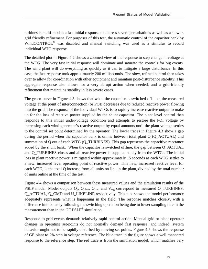
Present Status of Model Validation
28
turbines is multi-modal a fast initial response to address severe perturbations as well as a slower grid friendly refinement For purposes of this test the automatic control of the capacitor bank by WindCONTROLreg was disabled and manual switching was used as a stimulus to record individual WTG response
The detailed plot in Figure 42 shows a zoomed view of the response to step change in voltage at the WTG The very fast initial response will dominate and saturate the controls for big events The wind plant will do everything as quickly as it can to mitigate a large disturbance In this case the fast response took approximately 200 milliseconds The slow refined control then takes over to allow for coordination with other equipment and maintain post-disturbance stability This aggregate response also allows for a very abrupt action when needed and a grid-friendly refinement that maintains stability in less severe cases
The green curve in Figure 43 shows that when the capacitor is switched off-line the measured voltage at the point of interconnection (or POI) decreases due to reduced reactive power flowing into the grid The response of the individual WTGs is to rapidly increase reactive output to make up for the loss of reactive power supplied by the shunt capacitor The plant level control then responds to this initial under-voltage condition and attempts to restore the POI voltage by increasing each wind generatorrsquos reactive output by equal amounts until the plant voltage settles to the control set point determined by the operator The lower traces in Figure 43 show a gap during the period when the capacitor bank is online between total plant Q (Q_ACTUAL) and summation of Q out of each WTG (Q_TURBINES) This gap represents the capacitive reactance added by the shunt bank When the capacitor is switched offline the gap between Q_ACTUAL and Q_TURBINES closes and all reactive power is supplied solely from the WTGs The initial loss in plant reactive power is mitigated within approximately 15 seconds as each WTG settles to a new increased level operating point of reactive power This new increased reactive level for each WTG is the total Q increase from all units on-line in the plant divided by the total number of units online at the time of the test
Figure 44 shows a comparison between these measured values and the simulation results of the PSLF model Model outputs Qg Qplant Qcmd and Vreg correspond to measured Q_TURBINES Q_ACTUAL Q_CMD and U_LINELINE respectively This plot shows the model performance adequately represents what is happening in the field The response matches closely with a difference immediately following the switching operation being due to lower sampling rate in the measurement than in the GE PSLFreg simulation
Response to grid events demands relatively rapid control action Manual grid or plant operator changes in operating set-points do not normally demand fast response and indeed system behavior ought not to be rapidly disturbed by moving set-points Figure 45 shows the response of GE plant to 2 step in voltage reference The blue trace in the figure shows a well mannered response to the reference step The red trace is from the simulation model which matches very
Present Status of Model Validation
29
well In the blue trace after the perturbation occurring about 8 seconds after the reference change the plant supervisory control switched on a shunt capacitor to retain dynamic range on the wind turbines The switching perturbation is rapidly balanced by the turbines allowing the response to continue smoothly
Figure 41 10 MVar Capacitor removal response measured from WindCONTROLreg
Present Status of Model Validation
30
Figure 42 Wind turbine-generator level voltage step test response
Present Status of Model Validation
31
Figure 43 10 MVar Capacitor removal response ndash POI variables
Figure 44 10 MVar capacitor removal field test vs simulation results
Present Status of Model Validation
32
Figure 45 A different step test +- 2 step of voltage reference
The performance for grid fault events is of considerable interest in system planning Staging faults particularly severe ones on operating wind plants is difficult and expensive Figure 46 shows a comparison between a staged fault test and the (present) Siemens PTI PSSregE model of the GE 25 (full converter) WTG The fault event is quite severe a 3-phase 700ms of voltage depression to less than 20 of nominal at the high voltage terminal of the WTG unit transformer The measurement traces (on the left) include some of the signal noise characteristic of measurement and extraction of fundamental frequency positive sequence information from real high resolution measurements The simulation traces on the right are of course cleaner The match between test and simulation is of very high fidelity for phenomena relevant and legitimately examined with positive sequence simulation tools (ie greater than one cycle)
QPOI
VPOI
Measured = Blue Simulated = Red
Plant Capacitor Bank Switched On Automatically by WindCONTROL
+ 2 VrefStep
- 2 Vref Step
QPOI
VPOI
Measured = Blue Simulated = Red
Plant Capacitor Bank Switched On Automatically by WindCONTROL
+ 2 VrefStep
- 2 Vref Step
Present Status of Model Validation
33
Figure 46 GE 25 WTG Fault Test vs PSSe Model Performance
The discussion provide above is solely geared to hardware testing and validation however another highly valuable and legitimate means of providing validation of simulation models (for planning and otherwise) is to use more complex simulation software to validate simpler planning models Manufacturers normally have highly complex and highly proprietary models of their equipment These models are used among other things to design equipment and are normally physically based and must have sufficient fidelity for original equipment manufacturers (OEMs) to make sound engineering judgments for equipment design and application The OEMs are highly motivated to have these detailed high fidelity equipment level models These detailed models therefore can often be used to design test and validate simpler planning models to be used by the industry
There is a long accepted history in the power industry of this practice For example a typical (GE) gas turbine has on the order of 4000 state variables in the design model planning models typically have on the order of four state variables simplification is necessary and expected These design codes have been used to develop planning models of gas turbines Figure 47 below shows a comparison between a fault simulation using a GE design code (GE WindTrapreg) and the planning model in GE PSLFreg for a GE 15 (double fed machine) WTG
Present Status of Model Validation
34
Figure 47 Detailed Design Simulation (GE WindTRAPreg) vs GE PSLFreg Model Performance (active power during a severe fault for a GE 15 WTG)
-10
00
10
20
30
0 05 1 15 2
Time (Seconds)
Sin
gle
WTG
Rea
l Pow
er (M
WindtrapPSLF
Summary amp Recommended Actions
35
5 Summary amp Recommended Actions ndash Standards Implications
This document has presented a general overview of modeling and model validation as it pertains to variable generation resources Clearly to date the bulk of the experience and work has been on wind turbine generators Never-the-less similar approaches for modeling and model validation are being pursued for other variable generator technologies such as PV
Non-proprietary and publicly available models for the simulation of steady-state (power flow) short-circuit (fault calculations) and dynamic (time-domain simulations) behavior of such generation resources must be made readily available for use by power system planners Furthermore these models should be routinely validated to ensure proper representation of variable generation power plants in bulk power system studies A model is valid if its dynamic behavior is close enough to reality so that its influence on the network of interest (ie used for power system studies) is consistent with the fidelity of model structures and available data for the power system and other generation as it pertains to the phenomena of interest (ie in stability studies) That is perfect curve fitting is not necessary but to the extent possible erroneous model dynamics must not result in a notable over-design or under-design of the network
Each of the NERC standards discussed below in Section 52 address to aspects of meeting a standard (i) the technical requirement ie the need to define measure validate a model its parameters etc and (ii) the procedural requirements ie the functional model of how this technical requirement should be met reported and monitored The bulk of this working grouprsquos recommendations stated below address the technical requirements Variable generation is a new and quickly evolving technology and consideration should be given to the timing with which standards be implemented
Section 51 below first gives a summary of the planning process based on NERC standards to put the discussions in this report into context with the NERC standards Then in Section 52 we provided our recommendations and comments on the NERC existing and developing standards
Summary amp Recommended Actions
36
51 Applying the NERC Standards
The NERC standard FAC-001 (see Figure 51) should be expanded to clearly cover modeling requirements during the coordinated joint study phase of the Facility connection process Simple generic models of variable generation may be adequate for the IES phase and more detailed models may be needed for the IFS phase Validation of the simple and detailed model parameters may be needed during commissioning
Figure 51 Facility connection process
Interconnection Evaluation Study
Generator Interconnection
Request
Interconnection Facility Study
GO provides initial model
to TPPC
GO provides final model
to TPPC
GO signs Interconnection
Agreement and is put in-service
GO performs model amp
performance validation testing
TO develops Facility Interconnection requirements and requests models and data
of the GO at each process stage
FAC-001
Summary amp Recommended Actions
37
The generic model with associated parameters feed into the NERC model building process shown in Figure 52 As an example for WTG presently there is insufficient evidence of the accuracy of presently available generic models for WTG32
for all the various WTG manufacturers Some confirmation tests during commissioning or type tests or comparison simulation tests with a detailed model are necessary to get buy in from the Transmission OwnerPlanner As the technology matures and generic models are enhanced and associated data parameter sets are developed for specific machine types the new generic models will become more accepted as is the case with models of hydro or thermal plants
Figure 52 Annual NERC Model Development Process
32 PSSregE-320 Program Application Guide Volume II Chapter 21 PSSregE-320 Model Library Chapters 17 through 21 GE PSLF Users Manual v170_04 October 2009
Steady state data
developed
MOD-10
Dynamics data
developed
MOD-12
Reliability Region creates model
MOD-14
Reliability Region creates model
MOD-15
Reliability Region defines data
requirements
MOD-13
GO
TP
RP
Reliability Region defines data
requirements
MOD-11
Annual NERC Planning and
Operating Models
created and distributed to the industry
Summary amp Recommended Actions
38
The regional model building manuals developed as part of MOD-11 and MOD-13 must provide sufficient clarity to model variable generation These manuals may ask for best available models or generic models These models cover the operational time frame and the 10-year planning horizon The manuals do not currently cover the frequency for revalidating model data
While not included in the standards more emphasis is currently being placed on meeting the Eastern Interconnection Reliability Assessment Group (ERAG) model building manual requirements in addition to regional requirements
Figure 53 NERC Model Validation Process
The Regional Entities develop the test procedures and dictate testing frequency for the Generator Owners to follow The model data then feeds in to the annual NERC model building process
52 NERC Standards Technical Issues
One general comment is that the NERC Glossary of Terms would benefit from the term ldquoVariable Generationrdquo being include in it and appropriately defined A suitable definition can be found in the Phase I report of the IVGTF
Verify real power capability
MOD-24
GO
Verify reactive power capability
MOD-25
Verify generator excitation control model
MOD-26
Verify turbine governor model
MOD-27
Summary amp Recommended Actions
39
MOD-011 Regional Steady-State Data Requirements and Reporting Procedures
The technical requirement in this MOD reads
ldquoR12 Generating Units (including synchronous condensers pumped storage etc) location minimum and maximum Ratings (net Real and Reactive Power) regulated bus and voltage set point and equipment statusrdquo
This statement could be read to equally apply to variable generation as a source of generation However it may be prudent to explicitly include variable generation in this statement For example to change the sentence to
ldquoR12 Generating Units (including synchronous condensers pumped storage variable generation resources etc) location minimum and maximum Ratings (net Real and Reactive Power) regulated bus and voltage set point and equipment status For variable generation a suitable aggregate steady-state model of the collector system and equivalent unit representing the full plantrdquo
MOD-012 Dynamics Data for Transmission System Modeling and Simulation
This MOD equally applies to variable generation and needs no augmentation The requirements in the MOD are quite generic The requirements of this standard are dependent on and point to MOD 13 discussed below
MOD-013-1 RRO Dynamics Data Requirements and Reporting Procedures
This MOD explicitly discusses synchronous type generation It would be beneficial to include an explicit statement to cover variable generation For example
ldquoPlant-specific dynamics data shall be reported for variable generating units (eg wind turbine generators PV etc) such as the type of generating unit its interface with the grid and the appropriate model and model parameters to adequately represent unit dynamic response for bulk power system studies The typical size of a single variable generating unit (eg wind turbine generators PV array etc) is several hundreds of kilo-watts to several mega-watts Thus it may be acceptable for the total plant to be represented by an adequate aggregated model of the collector system and a single equivalent generating unit scaled up to represent the total name-plate capacity for each type of generating technology employed in the plant Furthermore models may need to be provided for other equipment installed in the collector system or at the point of interconnection such as reactive compensation devicesrdquo
Summary amp Recommended Actions
40
MOD-024-2 mdash Verification and Data Reporting of Generator Real Power Capability
This latest posting of this MOD posted for commenting on January 18th 2010 exempts variable generation from this requirement It states
ldquoVariable energy units such as wind generators solar and run of river hydro are exempt from the requirements of this Standardrdquo
For a variable generation plant the definition of Real Power Capability can be slightly challenging One way to view it is to see the total gross capability as the sum of the nameplate rating of all individual units within the plant eg for a wind power plant the total sum of the nameplate rating of all wind turbine generators in the plant However there must be two realizations (i) the amount of actual power injected into the grid at the point of interconnection requires a suitable representation of losses on the collector system and auxiliary loads and (ii) by its very nature variable generation is a highly variable energy source and thus it is quite rare to find point in time when all units in the plant are coincidentally at their peak nameplate capacity Finally the seasonal variable generation output variations need some discussion since they are quite different than conventional generation technologies
MOD-025-1 mdash Verification of Generator Gross and Net Reactive Power Capability
The technical requirement in this MOD reads
ldquoR15 Information to be reported
R151 Verified maximum gross and net Reactive Power capability (both lagging and leading) at Seasonal Real Power generating capabilities as reported in accordance with Reliability Standard MOD-024 Requirement 151
R152 Verified Reactive Power limitations such as generator terminal voltage limitations shorted rotor turns etc
R153 Verified Reactive Power of auxiliary loads
R154 Method of verification including date and conditionsrdquo
Note the above requirements are from the existing version of the standard MOD-025 is currently being enhanced
Although all of the above could equally apply to variable generation some clarification may be needed Namely variable generation reactive capability of the ldquopower plantrdquo is not entirely inherent in the individual generating units A variable generation power plant such as a wind power plant may contain many reactive power sources such as the individual generating units themselves (eg Type 3 or 4 WTG see Appendix I) discretely switched shunt reactive devices
Summary amp Recommended Actions
41
(eg shunt capacitors or reactors) smoothly controlled shunt reactive devices (eg SVC or STATCOM) or a combination of these devices Thus care should be taken as to how the total reactive capability of the power plant is defined and at what point (eg point of interconnection and whether this is defined as the high or low side of the substation transformer) Also it may not be practical under normal operating conditions to exercise the full reactive capability of the power plant (this is a known issue even with conventional synchronous generator plants) to test it thus it should suffice to demonstrate the plants reactive capability to the extent possible in the field and to then augment this with engineering calculations to derive the plants full reactive capability This is particularly true of variable generation because there is no control over the energy resource So for example a typical wind power plant may only achieve its name-plate rating for a hour or two during an entire year Thus it would not be possible to demonstrate the full reactive capability of the plant in the field Rather it should suffice to demonstrate the reactive capability of a single WTG and then to derive through engineering calculations (considering all other reactive devices in the plant such as SVC STATCOM etc) the total reactive capability of the plant These comments should be somehow used to appropriately modify MOD 25
MOD-026-1 mdash Verification of Models and Data for Generator Excitation System Functions ndash SECOND POSTING (and MOD 27)
MOD 26 (and MOD 27 Verification of Models and Data for TurbineGovernor and Load Control) are presently under development33
Presently these standards are tailored explicitly to deal with synchronous type generators since much of the language revolves around technology associated with synchronous generation (eg excitation system AVR power system stabilizers etc) Thus the following key items need to be clarified in these standards as they pertain to variable generation In addition the comments that follow apply to all components in a variable generation plant that may include devices such as the actual power generating units shunt compensation devices centralized control systems spanning the entire facility etc
These two standards deal specifically with the routine validation of generating unit dynamic models for power system stability studies
1 UnitPlant Size for Validation These MODrsquos specify the size of generating unit above which model validation is required It should be recognized that the typical size of a
33 MOD 26 and MOD 27 standards under development are found at httpwwwnerccomfilezstandardsGenerator-Verification-Project-2007-09html
Summary amp Recommended Actions
42
variable generation unit is in the hundreds of kilo-watts to several megawatts range Thus the language should be changed (or introduced) to indicate ldquonet power plantrdquo size
2 Validation of various technologies in a single plant Variable generation power plants can consist of multiple generation technologies For example a wind power plant may consist of WTGs of two different types Thus we need to consider the following points as they pertain to variable generation
a For a uniform variable generation plant (ie all generating units are of the same technology type) a single aggregate generator model representation should be sufficient
b For a significantly diverse variable generation plant the plant should be represented by multiple aggregated unit models representing each technology type
c Unique representation of a group of variable generation units as a single aggregated generator model representation should be based on
i The size of the group is a significant proportion of the total plant size (eg gt 20 of plant rating)
ii Each group should represent a unique characteristic (eg Type 1 WTG as compared to a Type 3 WTG)
3 Validation of different control layers Variable generation plants such as wind power plant may have several functional layers of control For example in a wind power plant with Type 3 WTGs we may have one level of closed loop voltage regulation at the terminals of the WTG a second slower control loop that regulates voltage at the point of interconnection (POI) and a third layer of control that coordinates the switching of shunt capacitors at the POI based on the reactive output of the individual WTGs In addition devices such as STATCOMs may be present at the POI Modeling and model validation should incorporate such devicescontrol layers to the extent that the dynamics of these functional layers are important for stability studies (see Figure 31)
4 Modeling and Model Validation Models are an emulation of actual equipment Not all model parameters necessarily translate to actual physical components or measureable features Judgment needs to be exercised in the modeling and validation process
a Models should be validated typically against the performance of an actual plant for a given eventdisturbance within the given operating range it is designed for
Summary amp Recommended Actions
43
b Models should state clearly the type and the range of events they have been designed to simulated and the limitation of the models beyond which the model deviates from the actual variable generation plant performance (eg a model developed to represent electrical transient behavior of a WTG may not be adequate for studying wind fluctuations over a many minute time frame)
c In general the best approach to model validation is to use field (or test bench) measurements of various disturbances that must exercise the different control functions to a wide range of operation points For example a model is not necessarily valid if the only a comparison between simulation results and field measurements for a single voltage step response is performed at one operating condition Ideally illustration of validation against recorded response to various system disturbances (faults frequency deviations etc) gives the greatest confidence in validation
d A model is valid if its dynamic behavior is close enough to reality so that its influence on the network of interest (ie used for power system studies) results in relatively negligible errors for the phenomena of interest (ie in stability studies) That is perfect curve fitting is not necessary but to the extent possible erroneous model dynamics must not result in a notable over-design or under-design of the network
5 Future functionality Due to the rapidly evolving nature of variable generation technologies variable generation models should be of a modular nature such that future functionality can be incorporated as much as possible into old model structures by adding a functional modular block For example presently Type 3 and 4 WTGs do not exhibit inertial response However at least one manufacturer now supplies a functional control addition that can emulate inertial response on these units Such functionality is likely to be made available soon by most vendors Thus a functional model block can be developed that can be added to the existing models for Type 3 and 4 WTGs to emulate the behavior of this additional control
6 Modeling of protection Variable generation much like conventional generation will have associated underover voltage and under-over frequency protection These should be modeled Attention should also be given to protective relay coordination with plant controls particularly in light of the nature of the grounding system within the variable generation plant (eg a wind power plant spans an entire collector system which can be grounded in several different ways and thus have various implications on protective relay coordination) Such coordination issues relate to the PRC and FAC-001 standards
Summary amp Recommended Actions
44
7 Issues related to the fuel source for variable generation For variable generation one needs to be cognizant of the variable nature of the energy source and thus the possible impracticality of performing model validation at a desired plant output but rather having to accept model validation at whatever plant output can be achieved at the time of testing or disturbance monitoring
8 Revalidation How often should models be revalidated
a Many variable generation technologies are rapidly changing for example in wind power plants new control software or new setting may be uploaded every year if not sooner
b If the changes are insignificant the existing dynamic models should be revalidated if possible as a matter of prudency ndash say within six months or so of a control system updateupgrade The changes (in parameters or dynamic model) should be reported to the local Reliability Entities
c If the changes are significant the existing dynamic models should be revalidated ndash say within three months or so after the updateupgrade The changes (which may include a new module new software etc) should be reported to the local Regional Entities
53 Final Recommendation
An earlier draft of this report and recommendations were presented to NERCrsquos Planning Committee at their March 2010 meeting The Committee members urged the IVGTF to pursue NERC reliability standard development Thus several NERC Standards Drafting Teams undertaking MOD Standard development will be contacted to present the recommendations from this report for their consideration and incorporation in subsequent updates The standard drafting teams for MOD-026 and MOD-027 are aiming to incorporate variable generation considerations in the next release of these draft standards
Appendix I Wind-Turbine Generation (WTG) Technologies
45
Appendix I Wind-Turbine Generation (WTG) Technologies
(a) Type 1 Wind Turbine-Generator Fixed Speed Induction Generator
(b) Type 2 Wind Turbine-Generator Variable Slip Induction Generator 34
34 IGBT R control = Resistor controlled by Insulated Gate Bi-Polar Transistor
3
GEAR BOX
INDUCTION GENERATOR TRANSFORMER
GRID
3
3GEAR BOX
WOUND ROTORINDUCTION GENERATOR TRANSFORMER
GRID
IGBT RControl
Rectifier
Appendix I Wind-Turbine Generation (WTG) Technologies
46
(c) Type 3 Wind Turbine-Generator Double-Fed Asynchronous Generator
(d) Type 4 Wind Turbine-Generator Full Power Conversion
3
3GEAR BOX
WOUND ROTORINDUCTION GENERATOR TRANSFORMER
GRID
IGBT POWER CONVERTORS
3
GEAR BOX
SYNCHRONOUSGENERATOR TRANSFORMER
GRID
Rectifier
33
IGBTInverter
Acronyms
47
Acronyms
CSP ndash Concentrating Solar Power
CIGRE - International Council on Large Electric Systems
DFAG ndash Doubly Fed Asynchronous Generator (also often referred to as DFIG ndash Doubly Fed Induction Generator)
FERC ndash Federal Energy Regulatory Commission
HVDC ndash High-Voltage Direct-Current transmission
IEC ndash International Electrotechnical Commission
IEEE ndash Institute of Electrical and Electronic Engineers
IGBT ndash Insulated-Gate Bipolar Transistor
IGCT ndash Insulated-Gate Commutated Thyristor
IVGTF ndash Integration of Variable Generation Task Force
ISO ndash Independent System Operator
LCC ndash Line-Commutated Converter
LVRT ndash Low-Voltage Ride-Through
MOD ndash Modeling Data and Analysis Standards
NERC ndash North American Electric Reliability Corporation
OEM ndash Original Equipment Manufacturer
PHEV ndash Plug-in Hybrid Electric Vehicle
PV ndash Photovoltaic
POI ndash Point of Interconnection
RPS ndash Renewable Portfolio Standard
RTO ndash Regional Transmission Operator
Acronyms
48
SAR ndash Standards Authorization Request (NERC process)
SCADA - Supervisory Control and Data Acquisition
SSTI ndash Subsynchronous Torsional Interaction
STATCOM ndash Static Compensator (voltage source converter based technology)
SVC ndash Static Var Compensator (thyristor based technology)
TSO ndash Transmission System Operator
VAr ndash volt-ampere reactive (standard units for reactive power)
VRT ndash Voltage Ride-Through
VSC ndash Voltage Source Converter
WPP ndash Wind Power Plant
WTG ndash Wind Turbine Generator
WECC ndash Western Electricity Coordinating Council
IVGTF Roster
49
IVGTF Task 1-1 Roster
Chair Pouyan Pourbeik
Technical Executive EPRI 942 Corridor Park Boulevard Knoxville Tennessee 37932
(919) 806-8126 ppourbeik epricom
Jay Caspary Director Transmission Development
Southwest Power Pool 415 North McKinley Suite 140 Little Rock Arkansas 72205
(501) 666-0376 (501) 666-0376 Fx jcasparyspporg
K R Chakravarthi
Southern Company Services Inc Southern Company Services Birmingham Alabama 35203
205-257-6125 205-257-1040 Fx krchakra southerncocom
Kieran Connolly
Manager Generation Scheduling
Bonneville Power Administration 905 NE 11th Avenue Portland Oregon 97232
(503) 230-4680 (503) 230-5377 Fx kpconnolly bpagov
Adam Flink
Engineer Midwest Reliability Organization 2774 Cleveland Ave Roseville Minnesota 55113
6515881705 (651) 855-1712 Fx adflink midwestreliabilityorg
David Jacobson
Interconnection amp Grid Supply Planning Engineer
Manitoba Hydro 12-1146 Waverly Street PO Box 815 Winnipeg Manitoba R3C 2P4
(204) 474-3765 (204) 477-4606 Fx dajacobson hydrombca
Charles-Eric
Langlois Jr Engineer
Hydro-Queacutebec TransEnergie 9e eacutetage Complexe Desjardins Tour Est Montreal Queacutebec H5B1H7
(514) 879-4100 ext 5441 (514) 879-4486 Fx LangloisCharles-Erichydroqcca
IVGTF Roster
50
David Marshall Project Manager
Southern Company Services Inc 600 N 18th Street Birmingham Alabama 35203
205-257-3326 205-257-1040 Fx dcmarsha southerncocom
Sophie Paquette
Transmission Planning Engineer
Hydro-Queacutebec TransEnergie 9e eacutetage Complexe Desjardins Tour Est 12th Floor Montreal Queacutebec H5B1H7
(514) 879-4100 ext 5423 (514) 879-4486 Fx paquettesophie hydroqcca
David C Schooley
Sr Engineer Commonwealth Edison Co 2 Lincoln Centre Oakbrook Terrace Illinois 60181
(630) 437-2773 davidschooley comedcom
Eric Thoms
Technical Lead - Transmission Access Planning
Midwest ISO Inc 1125 Energy Park Dr St Paul Minnesota 55108
(651) 632-8454 (651) 632-8417 Fx ethoms midwestisoorg
Observers Daniel Brooks
Manager Power Delivery System Studies
Electric Power Research Institute 942 Corridor Park Blvd Knoxville Tennessee 37932
(865) 218-8040 (865) 218-8001 Fx dbrooksepricom
Abraham Ellis
Principal Member of Technical Staff Renewable System Integration
Sandia National Laboratories 1515 Eubank SE Albuquerque New Mexico 87123
(505) 844-7717 (505) 844-2890 Fx aellis sandiagov
Ben Karlson
Sandia National Laboratories PO Box 5800 Albuquerque New Mexico 87185
(505) 803-3676 bkarlso sandiagov
Yuriy Kazachkov
Siemens Energy Inc 400 State Street Schenectady New York 12305
(518) 395-5132 (518) 346-2777 Fx yuriykazachkov siemenscom
Carl Lenox
Senior Staff Engineer Sunpower Corporation Systems 1414 Harbour Way South Richmond California 94804
(510) 260-8286 (510) 540-0552 Fx carllenox sunpowercorpcom
IVGTF Roster
51
Jason MacDowell
GE Energy 1 River Road Bldg 53 Schenectady New York 12345
(518) 385-2416 (518) 385-5703 Fx jasonmacdowell gecom
John Mead
Senior Staff Engineer Sunpower Corporation Systems 1414 Harbour Way South Richmond California 94804
(510) 260-8370 (510) 540-0552 Fx johnmead sunpowercorpcom
Nicholas W Miller
Director GE Energy 53-300Q 1 River Road Schenectady New York 12345
(518) 385-9865 (518) 385-5703 Fx nicholasmiller gecom
Eduard Muljadi
Senior Engineer National Renewable Energy Laboratory 1617 Cole Boulevard Golden Colorado 80401
(303) 384-6904 EduardMuljadi nrelgov
Mark OMalley
Professor of Electrical Engineering
University College Dublin R 157A Engineering amp Materials Science Centre University College Dublin Belfield Dublin 4
00353-1-716-1851 00353-1-283-0921 Fx markomalley ucdie
Subbaiah Pasupulati
Director of Technical Studies
Oak Creek Energy Systems Inc 14633 Willow Springs Road Mojave California 93501
(909) 241-9197 (661) 822-5991 Fx subbaiah oakcreekenergycom
Juan J Sanchez-
Gasca Principal Engineer
GE Energy 1 River Road Bldg 53-302E Schenectady New York 12345
(518) 385-5564 (518) 385-5703 Fx juansanchez psgecom
Steven Saylors
Chief Electrical Engineer
Vestas Americas 1881 SW Naito Parkway Portland Oregon 97201
(503) 327-2111 (503) 327-2001 Fx saylvestascom
IVGTF Roster
52
Robert Zavadil Vice President and Principal Consultant
EnerNex Corp 620 Mabry Hood Road Suite 300 Knoxville Tennessee 37932
(865) 218-4600 Ext 6149 (865) 218-8999 Fx bobzenernexcom
NERC Staff
Aaron Bennett Engineer Reliability Assessments
North American Electric Reliability Corporation 116-390 Village Boulevard Princeton New Jersey 08540-5721
(609) 524-7003 (609) 452-9550 Fx aaronbennett nercnet
Rhaiza Villafranca
Technical Analyst North American Electric Reliability Corporation 116-390 Village Boulevard Princeton New Jersey 08540-5721
(609) 452-8060 (609) 452-9550 Fx rhaizavillafranca nercnet
Mark G Lauby
Director Reliability Assessment and Performance Analysis
North American Electric Reliability Corporation 116-390 Village Boulevard Princeton New Jersey 08540-5721
(609) 524-7077 (609) 452-9550 Fx marklauby nercnet
References
53
References and Further Reading
[1] NERC Special Report Accommodation of High Levels of Variable Generation April 2009 httpwwwnerccomfilesIVGTF_Report_041609pdf
[2] CIGRE Technical Brochure 328 Modeling and Dynamic Behavior of Wind Generation as it Relates to Power System Control and Dynamic Performance Prepared by CIGRE WG C4601 August 2007 (available on-line at wwwe-cigreorg)
[3] ldquoWECC Wind Generator Power Flow Modeling Guiderdquo (httpwwwweccbizlibraryWECC20DocumentsDocuments20for20GeneratorsGenerator20Testing20ProgramWind20Generator20Power20Flow20Modeling20Guidepdf)
[4] G Lalor A Mullane and M J OrsquoMalley ldquoFrequency Control and Wind Turbine Technologiesrdquo IEEE Transactions on Power Systems Vol 20 pp 1903-1913 2005
[5] A Mullane and M J OrsquoMalley ldquoThe inertial-response of induction-machine based wind-turbinesrdquo IEEE Transactions on Power Systems Vol 20 pp 1496 ndash 1503 2005
[6] R Walling ldquoWind Plants of the Futurerdquo UWIG Oct 2008
[7] Hydro-Queacutebec TransEacutenergie ldquoTechnical requirements for the connection of generation facilities to the Hydro-Queacutebec transmission systemrdquo May 2006
[8] ESB National grid ldquoDynamic modeling of wind generation in Irelandrdquo January 2008
[9] N Miller K Clark R Delmerico and M Cardinal ldquoWindINERTIATM Inertial Response Option for GE Wind Turbine Generatorsrdquo Windpower 2009 Chicago IL May 4-7 2009
[10] R K Varma and S Auddy ldquoMitigation of Subsynchronous Oscillations in a Series Compensated Wind Farm with Static Var Compensatorrdquo Proceedings of the IEEE PES General Meeting 2006 Montreall Canada 2006
References
54
[11] Bialasiewicz J T Muljadi E Nix R G Drouilhet S Renewable Energy Power System Modular Simulator RPM-SIM Users Guide National Renewable Energy Laboratory March 2001 NRELTP-500-29721
[12] N Miller K Clark J MacDowell and W Barton Experience with Field and Factory Testing for Model Validation of GE Wind Plants European Wind Energy Conference amp Exhibition Brussels Belgium MarchApril 2008
[13] R J Piwko N W Miller and J M MacDowell ldquoField Testing and Model Validation of Wind Plantsrdquo IEEE-PES GM June 2008
- Executive Summary
- Introduction
- The Need for Models for Variable Generation
- Steady-State and Fault Current Analysis
- Time-Domain Positive Sequence Dynamic Models for Bulk Power System Stability Analysis
- Detailed Three-phase Equipment Level Models
- Summary
- Present Status of Modeling Variable Generation
- Wind Generation
-
- 311 WECCIEEE Effort for Generic Models
- 312 UWIG Generic Model Documentation and Validation Effort
- 313 IEC Effort for Generic Models
-
- Photovoltaic Solar Generation
- Solar Thermal
- Tidal Generation
- Other Resources
- Summary
- Present Status of Model Validation
- What is Model Validation
- Examples of Model Validation Efforts
-
- 421 Hydro- Queacutebec Example
- 422 GE Example ndash based on GErsquos work with client facilities
-
- Summary amp Recommended Actions ndash Standards Implications
- Applying the NERC Standards
- NERC Standards Technical Issues
- Final Recommendation
- Appendix I Wind-Turbine Generation (WTG) Technologies
- Acronyms
- IVGTF Task 1-1 Roster
- References and Further Reading
-
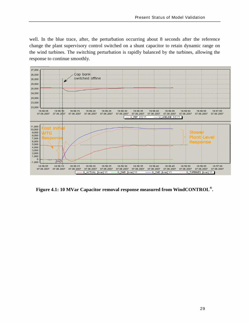
Present Status of Model Validation
29
well In the blue trace after the perturbation occurring about 8 seconds after the reference change the plant supervisory control switched on a shunt capacitor to retain dynamic range on the wind turbines The switching perturbation is rapidly balanced by the turbines allowing the response to continue smoothly
Figure 41 10 MVar Capacitor removal response measured from WindCONTROLreg
Present Status of Model Validation
30
Figure 42 Wind turbine-generator level voltage step test response
Present Status of Model Validation
31
Figure 43 10 MVar Capacitor removal response ndash POI variables
Figure 44 10 MVar capacitor removal field test vs simulation results
Present Status of Model Validation
32
Figure 45 A different step test +- 2 step of voltage reference
The performance for grid fault events is of considerable interest in system planning Staging faults particularly severe ones on operating wind plants is difficult and expensive Figure 46 shows a comparison between a staged fault test and the (present) Siemens PTI PSSregE model of the GE 25 (full converter) WTG The fault event is quite severe a 3-phase 700ms of voltage depression to less than 20 of nominal at the high voltage terminal of the WTG unit transformer The measurement traces (on the left) include some of the signal noise characteristic of measurement and extraction of fundamental frequency positive sequence information from real high resolution measurements The simulation traces on the right are of course cleaner The match between test and simulation is of very high fidelity for phenomena relevant and legitimately examined with positive sequence simulation tools (ie greater than one cycle)
QPOI
VPOI
Measured = Blue Simulated = Red
Plant Capacitor Bank Switched On Automatically by WindCONTROL
+ 2 VrefStep
- 2 Vref Step
QPOI
VPOI
Measured = Blue Simulated = Red
Plant Capacitor Bank Switched On Automatically by WindCONTROL
+ 2 VrefStep
- 2 Vref Step
Present Status of Model Validation
33
Figure 46 GE 25 WTG Fault Test vs PSSe Model Performance
The discussion provide above is solely geared to hardware testing and validation however another highly valuable and legitimate means of providing validation of simulation models (for planning and otherwise) is to use more complex simulation software to validate simpler planning models Manufacturers normally have highly complex and highly proprietary models of their equipment These models are used among other things to design equipment and are normally physically based and must have sufficient fidelity for original equipment manufacturers (OEMs) to make sound engineering judgments for equipment design and application The OEMs are highly motivated to have these detailed high fidelity equipment level models These detailed models therefore can often be used to design test and validate simpler planning models to be used by the industry
There is a long accepted history in the power industry of this practice For example a typical (GE) gas turbine has on the order of 4000 state variables in the design model planning models typically have on the order of four state variables simplification is necessary and expected These design codes have been used to develop planning models of gas turbines Figure 47 below shows a comparison between a fault simulation using a GE design code (GE WindTrapreg) and the planning model in GE PSLFreg for a GE 15 (double fed machine) WTG
Present Status of Model Validation
34
Figure 47 Detailed Design Simulation (GE WindTRAPreg) vs GE PSLFreg Model Performance (active power during a severe fault for a GE 15 WTG)
-10
00
10
20
30
0 05 1 15 2
Time (Seconds)
Sin
gle
WTG
Rea
l Pow
er (M
WindtrapPSLF
Summary amp Recommended Actions
35
5 Summary amp Recommended Actions ndash Standards Implications
This document has presented a general overview of modeling and model validation as it pertains to variable generation resources Clearly to date the bulk of the experience and work has been on wind turbine generators Never-the-less similar approaches for modeling and model validation are being pursued for other variable generator technologies such as PV
Non-proprietary and publicly available models for the simulation of steady-state (power flow) short-circuit (fault calculations) and dynamic (time-domain simulations) behavior of such generation resources must be made readily available for use by power system planners Furthermore these models should be routinely validated to ensure proper representation of variable generation power plants in bulk power system studies A model is valid if its dynamic behavior is close enough to reality so that its influence on the network of interest (ie used for power system studies) is consistent with the fidelity of model structures and available data for the power system and other generation as it pertains to the phenomena of interest (ie in stability studies) That is perfect curve fitting is not necessary but to the extent possible erroneous model dynamics must not result in a notable over-design or under-design of the network
Each of the NERC standards discussed below in Section 52 address to aspects of meeting a standard (i) the technical requirement ie the need to define measure validate a model its parameters etc and (ii) the procedural requirements ie the functional model of how this technical requirement should be met reported and monitored The bulk of this working grouprsquos recommendations stated below address the technical requirements Variable generation is a new and quickly evolving technology and consideration should be given to the timing with which standards be implemented
Section 51 below first gives a summary of the planning process based on NERC standards to put the discussions in this report into context with the NERC standards Then in Section 52 we provided our recommendations and comments on the NERC existing and developing standards
Summary amp Recommended Actions
36
51 Applying the NERC Standards
The NERC standard FAC-001 (see Figure 51) should be expanded to clearly cover modeling requirements during the coordinated joint study phase of the Facility connection process Simple generic models of variable generation may be adequate for the IES phase and more detailed models may be needed for the IFS phase Validation of the simple and detailed model parameters may be needed during commissioning
Figure 51 Facility connection process
Interconnection Evaluation Study
Generator Interconnection
Request
Interconnection Facility Study
GO provides initial model
to TPPC
GO provides final model
to TPPC
GO signs Interconnection
Agreement and is put in-service
GO performs model amp
performance validation testing
TO develops Facility Interconnection requirements and requests models and data
of the GO at each process stage
FAC-001
Summary amp Recommended Actions
37
The generic model with associated parameters feed into the NERC model building process shown in Figure 52 As an example for WTG presently there is insufficient evidence of the accuracy of presently available generic models for WTG32
for all the various WTG manufacturers Some confirmation tests during commissioning or type tests or comparison simulation tests with a detailed model are necessary to get buy in from the Transmission OwnerPlanner As the technology matures and generic models are enhanced and associated data parameter sets are developed for specific machine types the new generic models will become more accepted as is the case with models of hydro or thermal plants
Figure 52 Annual NERC Model Development Process
32 PSSregE-320 Program Application Guide Volume II Chapter 21 PSSregE-320 Model Library Chapters 17 through 21 GE PSLF Users Manual v170_04 October 2009
Steady state data
developed
MOD-10
Dynamics data
developed
MOD-12
Reliability Region creates model
MOD-14
Reliability Region creates model
MOD-15
Reliability Region defines data
requirements
MOD-13
GO
TP
RP
Reliability Region defines data
requirements
MOD-11
Annual NERC Planning and
Operating Models
created and distributed to the industry
Summary amp Recommended Actions
38
The regional model building manuals developed as part of MOD-11 and MOD-13 must provide sufficient clarity to model variable generation These manuals may ask for best available models or generic models These models cover the operational time frame and the 10-year planning horizon The manuals do not currently cover the frequency for revalidating model data
While not included in the standards more emphasis is currently being placed on meeting the Eastern Interconnection Reliability Assessment Group (ERAG) model building manual requirements in addition to regional requirements
Figure 53 NERC Model Validation Process
The Regional Entities develop the test procedures and dictate testing frequency for the Generator Owners to follow The model data then feeds in to the annual NERC model building process
52 NERC Standards Technical Issues
One general comment is that the NERC Glossary of Terms would benefit from the term ldquoVariable Generationrdquo being include in it and appropriately defined A suitable definition can be found in the Phase I report of the IVGTF
Verify real power capability
MOD-24
GO
Verify reactive power capability
MOD-25
Verify generator excitation control model
MOD-26
Verify turbine governor model
MOD-27
Summary amp Recommended Actions
39
MOD-011 Regional Steady-State Data Requirements and Reporting Procedures
The technical requirement in this MOD reads
ldquoR12 Generating Units (including synchronous condensers pumped storage etc) location minimum and maximum Ratings (net Real and Reactive Power) regulated bus and voltage set point and equipment statusrdquo
This statement could be read to equally apply to variable generation as a source of generation However it may be prudent to explicitly include variable generation in this statement For example to change the sentence to
ldquoR12 Generating Units (including synchronous condensers pumped storage variable generation resources etc) location minimum and maximum Ratings (net Real and Reactive Power) regulated bus and voltage set point and equipment status For variable generation a suitable aggregate steady-state model of the collector system and equivalent unit representing the full plantrdquo
MOD-012 Dynamics Data for Transmission System Modeling and Simulation
This MOD equally applies to variable generation and needs no augmentation The requirements in the MOD are quite generic The requirements of this standard are dependent on and point to MOD 13 discussed below
MOD-013-1 RRO Dynamics Data Requirements and Reporting Procedures
This MOD explicitly discusses synchronous type generation It would be beneficial to include an explicit statement to cover variable generation For example
ldquoPlant-specific dynamics data shall be reported for variable generating units (eg wind turbine generators PV etc) such as the type of generating unit its interface with the grid and the appropriate model and model parameters to adequately represent unit dynamic response for bulk power system studies The typical size of a single variable generating unit (eg wind turbine generators PV array etc) is several hundreds of kilo-watts to several mega-watts Thus it may be acceptable for the total plant to be represented by an adequate aggregated model of the collector system and a single equivalent generating unit scaled up to represent the total name-plate capacity for each type of generating technology employed in the plant Furthermore models may need to be provided for other equipment installed in the collector system or at the point of interconnection such as reactive compensation devicesrdquo
Summary amp Recommended Actions
40
MOD-024-2 mdash Verification and Data Reporting of Generator Real Power Capability
This latest posting of this MOD posted for commenting on January 18th 2010 exempts variable generation from this requirement It states
ldquoVariable energy units such as wind generators solar and run of river hydro are exempt from the requirements of this Standardrdquo
For a variable generation plant the definition of Real Power Capability can be slightly challenging One way to view it is to see the total gross capability as the sum of the nameplate rating of all individual units within the plant eg for a wind power plant the total sum of the nameplate rating of all wind turbine generators in the plant However there must be two realizations (i) the amount of actual power injected into the grid at the point of interconnection requires a suitable representation of losses on the collector system and auxiliary loads and (ii) by its very nature variable generation is a highly variable energy source and thus it is quite rare to find point in time when all units in the plant are coincidentally at their peak nameplate capacity Finally the seasonal variable generation output variations need some discussion since they are quite different than conventional generation technologies
MOD-025-1 mdash Verification of Generator Gross and Net Reactive Power Capability
The technical requirement in this MOD reads
ldquoR15 Information to be reported
R151 Verified maximum gross and net Reactive Power capability (both lagging and leading) at Seasonal Real Power generating capabilities as reported in accordance with Reliability Standard MOD-024 Requirement 151
R152 Verified Reactive Power limitations such as generator terminal voltage limitations shorted rotor turns etc
R153 Verified Reactive Power of auxiliary loads
R154 Method of verification including date and conditionsrdquo
Note the above requirements are from the existing version of the standard MOD-025 is currently being enhanced
Although all of the above could equally apply to variable generation some clarification may be needed Namely variable generation reactive capability of the ldquopower plantrdquo is not entirely inherent in the individual generating units A variable generation power plant such as a wind power plant may contain many reactive power sources such as the individual generating units themselves (eg Type 3 or 4 WTG see Appendix I) discretely switched shunt reactive devices
Summary amp Recommended Actions
41
(eg shunt capacitors or reactors) smoothly controlled shunt reactive devices (eg SVC or STATCOM) or a combination of these devices Thus care should be taken as to how the total reactive capability of the power plant is defined and at what point (eg point of interconnection and whether this is defined as the high or low side of the substation transformer) Also it may not be practical under normal operating conditions to exercise the full reactive capability of the power plant (this is a known issue even with conventional synchronous generator plants) to test it thus it should suffice to demonstrate the plants reactive capability to the extent possible in the field and to then augment this with engineering calculations to derive the plants full reactive capability This is particularly true of variable generation because there is no control over the energy resource So for example a typical wind power plant may only achieve its name-plate rating for a hour or two during an entire year Thus it would not be possible to demonstrate the full reactive capability of the plant in the field Rather it should suffice to demonstrate the reactive capability of a single WTG and then to derive through engineering calculations (considering all other reactive devices in the plant such as SVC STATCOM etc) the total reactive capability of the plant These comments should be somehow used to appropriately modify MOD 25
MOD-026-1 mdash Verification of Models and Data for Generator Excitation System Functions ndash SECOND POSTING (and MOD 27)
MOD 26 (and MOD 27 Verification of Models and Data for TurbineGovernor and Load Control) are presently under development33
Presently these standards are tailored explicitly to deal with synchronous type generators since much of the language revolves around technology associated with synchronous generation (eg excitation system AVR power system stabilizers etc) Thus the following key items need to be clarified in these standards as they pertain to variable generation In addition the comments that follow apply to all components in a variable generation plant that may include devices such as the actual power generating units shunt compensation devices centralized control systems spanning the entire facility etc
These two standards deal specifically with the routine validation of generating unit dynamic models for power system stability studies
1 UnitPlant Size for Validation These MODrsquos specify the size of generating unit above which model validation is required It should be recognized that the typical size of a
33 MOD 26 and MOD 27 standards under development are found at httpwwwnerccomfilezstandardsGenerator-Verification-Project-2007-09html
Summary amp Recommended Actions
42
variable generation unit is in the hundreds of kilo-watts to several megawatts range Thus the language should be changed (or introduced) to indicate ldquonet power plantrdquo size
2 Validation of various technologies in a single plant Variable generation power plants can consist of multiple generation technologies For example a wind power plant may consist of WTGs of two different types Thus we need to consider the following points as they pertain to variable generation
a For a uniform variable generation plant (ie all generating units are of the same technology type) a single aggregate generator model representation should be sufficient
b For a significantly diverse variable generation plant the plant should be represented by multiple aggregated unit models representing each technology type
c Unique representation of a group of variable generation units as a single aggregated generator model representation should be based on
i The size of the group is a significant proportion of the total plant size (eg gt 20 of plant rating)
ii Each group should represent a unique characteristic (eg Type 1 WTG as compared to a Type 3 WTG)
3 Validation of different control layers Variable generation plants such as wind power plant may have several functional layers of control For example in a wind power plant with Type 3 WTGs we may have one level of closed loop voltage regulation at the terminals of the WTG a second slower control loop that regulates voltage at the point of interconnection (POI) and a third layer of control that coordinates the switching of shunt capacitors at the POI based on the reactive output of the individual WTGs In addition devices such as STATCOMs may be present at the POI Modeling and model validation should incorporate such devicescontrol layers to the extent that the dynamics of these functional layers are important for stability studies (see Figure 31)
4 Modeling and Model Validation Models are an emulation of actual equipment Not all model parameters necessarily translate to actual physical components or measureable features Judgment needs to be exercised in the modeling and validation process
a Models should be validated typically against the performance of an actual plant for a given eventdisturbance within the given operating range it is designed for
Summary amp Recommended Actions
43
b Models should state clearly the type and the range of events they have been designed to simulated and the limitation of the models beyond which the model deviates from the actual variable generation plant performance (eg a model developed to represent electrical transient behavior of a WTG may not be adequate for studying wind fluctuations over a many minute time frame)
c In general the best approach to model validation is to use field (or test bench) measurements of various disturbances that must exercise the different control functions to a wide range of operation points For example a model is not necessarily valid if the only a comparison between simulation results and field measurements for a single voltage step response is performed at one operating condition Ideally illustration of validation against recorded response to various system disturbances (faults frequency deviations etc) gives the greatest confidence in validation
d A model is valid if its dynamic behavior is close enough to reality so that its influence on the network of interest (ie used for power system studies) results in relatively negligible errors for the phenomena of interest (ie in stability studies) That is perfect curve fitting is not necessary but to the extent possible erroneous model dynamics must not result in a notable over-design or under-design of the network
5 Future functionality Due to the rapidly evolving nature of variable generation technologies variable generation models should be of a modular nature such that future functionality can be incorporated as much as possible into old model structures by adding a functional modular block For example presently Type 3 and 4 WTGs do not exhibit inertial response However at least one manufacturer now supplies a functional control addition that can emulate inertial response on these units Such functionality is likely to be made available soon by most vendors Thus a functional model block can be developed that can be added to the existing models for Type 3 and 4 WTGs to emulate the behavior of this additional control
6 Modeling of protection Variable generation much like conventional generation will have associated underover voltage and under-over frequency protection These should be modeled Attention should also be given to protective relay coordination with plant controls particularly in light of the nature of the grounding system within the variable generation plant (eg a wind power plant spans an entire collector system which can be grounded in several different ways and thus have various implications on protective relay coordination) Such coordination issues relate to the PRC and FAC-001 standards
Summary amp Recommended Actions
44
7 Issues related to the fuel source for variable generation For variable generation one needs to be cognizant of the variable nature of the energy source and thus the possible impracticality of performing model validation at a desired plant output but rather having to accept model validation at whatever plant output can be achieved at the time of testing or disturbance monitoring
8 Revalidation How often should models be revalidated
a Many variable generation technologies are rapidly changing for example in wind power plants new control software or new setting may be uploaded every year if not sooner
b If the changes are insignificant the existing dynamic models should be revalidated if possible as a matter of prudency ndash say within six months or so of a control system updateupgrade The changes (in parameters or dynamic model) should be reported to the local Reliability Entities
c If the changes are significant the existing dynamic models should be revalidated ndash say within three months or so after the updateupgrade The changes (which may include a new module new software etc) should be reported to the local Regional Entities
53 Final Recommendation
An earlier draft of this report and recommendations were presented to NERCrsquos Planning Committee at their March 2010 meeting The Committee members urged the IVGTF to pursue NERC reliability standard development Thus several NERC Standards Drafting Teams undertaking MOD Standard development will be contacted to present the recommendations from this report for their consideration and incorporation in subsequent updates The standard drafting teams for MOD-026 and MOD-027 are aiming to incorporate variable generation considerations in the next release of these draft standards
Appendix I Wind-Turbine Generation (WTG) Technologies
45
Appendix I Wind-Turbine Generation (WTG) Technologies
(a) Type 1 Wind Turbine-Generator Fixed Speed Induction Generator
(b) Type 2 Wind Turbine-Generator Variable Slip Induction Generator 34
34 IGBT R control = Resistor controlled by Insulated Gate Bi-Polar Transistor
3
GEAR BOX
INDUCTION GENERATOR TRANSFORMER
GRID
3
3GEAR BOX
WOUND ROTORINDUCTION GENERATOR TRANSFORMER
GRID
IGBT RControl
Rectifier
Appendix I Wind-Turbine Generation (WTG) Technologies
46
(c) Type 3 Wind Turbine-Generator Double-Fed Asynchronous Generator
(d) Type 4 Wind Turbine-Generator Full Power Conversion
3
3GEAR BOX
WOUND ROTORINDUCTION GENERATOR TRANSFORMER
GRID
IGBT POWER CONVERTORS
3
GEAR BOX
SYNCHRONOUSGENERATOR TRANSFORMER
GRID
Rectifier
33
IGBTInverter
Acronyms
47
Acronyms
CSP ndash Concentrating Solar Power
CIGRE - International Council on Large Electric Systems
DFAG ndash Doubly Fed Asynchronous Generator (also often referred to as DFIG ndash Doubly Fed Induction Generator)
FERC ndash Federal Energy Regulatory Commission
HVDC ndash High-Voltage Direct-Current transmission
IEC ndash International Electrotechnical Commission
IEEE ndash Institute of Electrical and Electronic Engineers
IGBT ndash Insulated-Gate Bipolar Transistor
IGCT ndash Insulated-Gate Commutated Thyristor
IVGTF ndash Integration of Variable Generation Task Force
ISO ndash Independent System Operator
LCC ndash Line-Commutated Converter
LVRT ndash Low-Voltage Ride-Through
MOD ndash Modeling Data and Analysis Standards
NERC ndash North American Electric Reliability Corporation
OEM ndash Original Equipment Manufacturer
PHEV ndash Plug-in Hybrid Electric Vehicle
PV ndash Photovoltaic
POI ndash Point of Interconnection
RPS ndash Renewable Portfolio Standard
RTO ndash Regional Transmission Operator
Acronyms
48
SAR ndash Standards Authorization Request (NERC process)
SCADA - Supervisory Control and Data Acquisition
SSTI ndash Subsynchronous Torsional Interaction
STATCOM ndash Static Compensator (voltage source converter based technology)
SVC ndash Static Var Compensator (thyristor based technology)
TSO ndash Transmission System Operator
VAr ndash volt-ampere reactive (standard units for reactive power)
VRT ndash Voltage Ride-Through
VSC ndash Voltage Source Converter
WPP ndash Wind Power Plant
WTG ndash Wind Turbine Generator
WECC ndash Western Electricity Coordinating Council
IVGTF Roster
49
IVGTF Task 1-1 Roster
Chair Pouyan Pourbeik
Technical Executive EPRI 942 Corridor Park Boulevard Knoxville Tennessee 37932
(919) 806-8126 ppourbeik epricom
Jay Caspary Director Transmission Development
Southwest Power Pool 415 North McKinley Suite 140 Little Rock Arkansas 72205
(501) 666-0376 (501) 666-0376 Fx jcasparyspporg
K R Chakravarthi
Southern Company Services Inc Southern Company Services Birmingham Alabama 35203
205-257-6125 205-257-1040 Fx krchakra southerncocom
Kieran Connolly
Manager Generation Scheduling
Bonneville Power Administration 905 NE 11th Avenue Portland Oregon 97232
(503) 230-4680 (503) 230-5377 Fx kpconnolly bpagov
Adam Flink
Engineer Midwest Reliability Organization 2774 Cleveland Ave Roseville Minnesota 55113
6515881705 (651) 855-1712 Fx adflink midwestreliabilityorg
David Jacobson
Interconnection amp Grid Supply Planning Engineer
Manitoba Hydro 12-1146 Waverly Street PO Box 815 Winnipeg Manitoba R3C 2P4
(204) 474-3765 (204) 477-4606 Fx dajacobson hydrombca
Charles-Eric
Langlois Jr Engineer
Hydro-Queacutebec TransEnergie 9e eacutetage Complexe Desjardins Tour Est Montreal Queacutebec H5B1H7
(514) 879-4100 ext 5441 (514) 879-4486 Fx LangloisCharles-Erichydroqcca
IVGTF Roster
50
David Marshall Project Manager
Southern Company Services Inc 600 N 18th Street Birmingham Alabama 35203
205-257-3326 205-257-1040 Fx dcmarsha southerncocom
Sophie Paquette
Transmission Planning Engineer
Hydro-Queacutebec TransEnergie 9e eacutetage Complexe Desjardins Tour Est 12th Floor Montreal Queacutebec H5B1H7
(514) 879-4100 ext 5423 (514) 879-4486 Fx paquettesophie hydroqcca
David C Schooley
Sr Engineer Commonwealth Edison Co 2 Lincoln Centre Oakbrook Terrace Illinois 60181
(630) 437-2773 davidschooley comedcom
Eric Thoms
Technical Lead - Transmission Access Planning
Midwest ISO Inc 1125 Energy Park Dr St Paul Minnesota 55108
(651) 632-8454 (651) 632-8417 Fx ethoms midwestisoorg
Observers Daniel Brooks
Manager Power Delivery System Studies
Electric Power Research Institute 942 Corridor Park Blvd Knoxville Tennessee 37932
(865) 218-8040 (865) 218-8001 Fx dbrooksepricom
Abraham Ellis
Principal Member of Technical Staff Renewable System Integration
Sandia National Laboratories 1515 Eubank SE Albuquerque New Mexico 87123
(505) 844-7717 (505) 844-2890 Fx aellis sandiagov
Ben Karlson
Sandia National Laboratories PO Box 5800 Albuquerque New Mexico 87185
(505) 803-3676 bkarlso sandiagov
Yuriy Kazachkov
Siemens Energy Inc 400 State Street Schenectady New York 12305
(518) 395-5132 (518) 346-2777 Fx yuriykazachkov siemenscom
Carl Lenox
Senior Staff Engineer Sunpower Corporation Systems 1414 Harbour Way South Richmond California 94804
(510) 260-8286 (510) 540-0552 Fx carllenox sunpowercorpcom
IVGTF Roster
51
Jason MacDowell
GE Energy 1 River Road Bldg 53 Schenectady New York 12345
(518) 385-2416 (518) 385-5703 Fx jasonmacdowell gecom
John Mead
Senior Staff Engineer Sunpower Corporation Systems 1414 Harbour Way South Richmond California 94804
(510) 260-8370 (510) 540-0552 Fx johnmead sunpowercorpcom
Nicholas W Miller
Director GE Energy 53-300Q 1 River Road Schenectady New York 12345
(518) 385-9865 (518) 385-5703 Fx nicholasmiller gecom
Eduard Muljadi
Senior Engineer National Renewable Energy Laboratory 1617 Cole Boulevard Golden Colorado 80401
(303) 384-6904 EduardMuljadi nrelgov
Mark OMalley
Professor of Electrical Engineering
University College Dublin R 157A Engineering amp Materials Science Centre University College Dublin Belfield Dublin 4
00353-1-716-1851 00353-1-283-0921 Fx markomalley ucdie
Subbaiah Pasupulati
Director of Technical Studies
Oak Creek Energy Systems Inc 14633 Willow Springs Road Mojave California 93501
(909) 241-9197 (661) 822-5991 Fx subbaiah oakcreekenergycom
Juan J Sanchez-
Gasca Principal Engineer
GE Energy 1 River Road Bldg 53-302E Schenectady New York 12345
(518) 385-5564 (518) 385-5703 Fx juansanchez psgecom
Steven Saylors
Chief Electrical Engineer
Vestas Americas 1881 SW Naito Parkway Portland Oregon 97201
(503) 327-2111 (503) 327-2001 Fx saylvestascom
IVGTF Roster
52
Robert Zavadil Vice President and Principal Consultant
EnerNex Corp 620 Mabry Hood Road Suite 300 Knoxville Tennessee 37932
(865) 218-4600 Ext 6149 (865) 218-8999 Fx bobzenernexcom
NERC Staff
Aaron Bennett Engineer Reliability Assessments
North American Electric Reliability Corporation 116-390 Village Boulevard Princeton New Jersey 08540-5721
(609) 524-7003 (609) 452-9550 Fx aaronbennett nercnet
Rhaiza Villafranca
Technical Analyst North American Electric Reliability Corporation 116-390 Village Boulevard Princeton New Jersey 08540-5721
(609) 452-8060 (609) 452-9550 Fx rhaizavillafranca nercnet
Mark G Lauby
Director Reliability Assessment and Performance Analysis
North American Electric Reliability Corporation 116-390 Village Boulevard Princeton New Jersey 08540-5721
(609) 524-7077 (609) 452-9550 Fx marklauby nercnet
References
53
References and Further Reading
[1] NERC Special Report Accommodation of High Levels of Variable Generation April 2009 httpwwwnerccomfilesIVGTF_Report_041609pdf
[2] CIGRE Technical Brochure 328 Modeling and Dynamic Behavior of Wind Generation as it Relates to Power System Control and Dynamic Performance Prepared by CIGRE WG C4601 August 2007 (available on-line at wwwe-cigreorg)
[3] ldquoWECC Wind Generator Power Flow Modeling Guiderdquo (httpwwwweccbizlibraryWECC20DocumentsDocuments20for20GeneratorsGenerator20Testing20ProgramWind20Generator20Power20Flow20Modeling20Guidepdf)
[4] G Lalor A Mullane and M J OrsquoMalley ldquoFrequency Control and Wind Turbine Technologiesrdquo IEEE Transactions on Power Systems Vol 20 pp 1903-1913 2005
[5] A Mullane and M J OrsquoMalley ldquoThe inertial-response of induction-machine based wind-turbinesrdquo IEEE Transactions on Power Systems Vol 20 pp 1496 ndash 1503 2005
[6] R Walling ldquoWind Plants of the Futurerdquo UWIG Oct 2008
[7] Hydro-Queacutebec TransEacutenergie ldquoTechnical requirements for the connection of generation facilities to the Hydro-Queacutebec transmission systemrdquo May 2006
[8] ESB National grid ldquoDynamic modeling of wind generation in Irelandrdquo January 2008
[9] N Miller K Clark R Delmerico and M Cardinal ldquoWindINERTIATM Inertial Response Option for GE Wind Turbine Generatorsrdquo Windpower 2009 Chicago IL May 4-7 2009
[10] R K Varma and S Auddy ldquoMitigation of Subsynchronous Oscillations in a Series Compensated Wind Farm with Static Var Compensatorrdquo Proceedings of the IEEE PES General Meeting 2006 Montreall Canada 2006
References
54
[11] Bialasiewicz J T Muljadi E Nix R G Drouilhet S Renewable Energy Power System Modular Simulator RPM-SIM Users Guide National Renewable Energy Laboratory March 2001 NRELTP-500-29721
[12] N Miller K Clark J MacDowell and W Barton Experience with Field and Factory Testing for Model Validation of GE Wind Plants European Wind Energy Conference amp Exhibition Brussels Belgium MarchApril 2008
[13] R J Piwko N W Miller and J M MacDowell ldquoField Testing and Model Validation of Wind Plantsrdquo IEEE-PES GM June 2008
- Executive Summary
- Introduction
- The Need for Models for Variable Generation
- Steady-State and Fault Current Analysis
- Time-Domain Positive Sequence Dynamic Models for Bulk Power System Stability Analysis
- Detailed Three-phase Equipment Level Models
- Summary
- Present Status of Modeling Variable Generation
- Wind Generation
-
- 311 WECCIEEE Effort for Generic Models
- 312 UWIG Generic Model Documentation and Validation Effort
- 313 IEC Effort for Generic Models
-
- Photovoltaic Solar Generation
- Solar Thermal
- Tidal Generation
- Other Resources
- Summary
- Present Status of Model Validation
- What is Model Validation
- Examples of Model Validation Efforts
-
- 421 Hydro- Queacutebec Example
- 422 GE Example ndash based on GErsquos work with client facilities
-
- Summary amp Recommended Actions ndash Standards Implications
- Applying the NERC Standards
- NERC Standards Technical Issues
- Final Recommendation
- Appendix I Wind-Turbine Generation (WTG) Technologies
- Acronyms
- IVGTF Task 1-1 Roster
- References and Further Reading
-
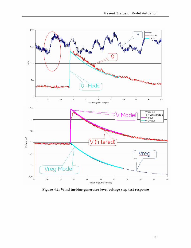
Present Status of Model Validation
30
Figure 42 Wind turbine-generator level voltage step test response
Present Status of Model Validation
31
Figure 43 10 MVar Capacitor removal response ndash POI variables
Figure 44 10 MVar capacitor removal field test vs simulation results
Present Status of Model Validation
32
Figure 45 A different step test +- 2 step of voltage reference
The performance for grid fault events is of considerable interest in system planning Staging faults particularly severe ones on operating wind plants is difficult and expensive Figure 46 shows a comparison between a staged fault test and the (present) Siemens PTI PSSregE model of the GE 25 (full converter) WTG The fault event is quite severe a 3-phase 700ms of voltage depression to less than 20 of nominal at the high voltage terminal of the WTG unit transformer The measurement traces (on the left) include some of the signal noise characteristic of measurement and extraction of fundamental frequency positive sequence information from real high resolution measurements The simulation traces on the right are of course cleaner The match between test and simulation is of very high fidelity for phenomena relevant and legitimately examined with positive sequence simulation tools (ie greater than one cycle)
QPOI
VPOI
Measured = Blue Simulated = Red
Plant Capacitor Bank Switched On Automatically by WindCONTROL
+ 2 VrefStep
- 2 Vref Step
QPOI
VPOI
Measured = Blue Simulated = Red
Plant Capacitor Bank Switched On Automatically by WindCONTROL
+ 2 VrefStep
- 2 Vref Step
Present Status of Model Validation
33
Figure 46 GE 25 WTG Fault Test vs PSSe Model Performance
The discussion provide above is solely geared to hardware testing and validation however another highly valuable and legitimate means of providing validation of simulation models (for planning and otherwise) is to use more complex simulation software to validate simpler planning models Manufacturers normally have highly complex and highly proprietary models of their equipment These models are used among other things to design equipment and are normally physically based and must have sufficient fidelity for original equipment manufacturers (OEMs) to make sound engineering judgments for equipment design and application The OEMs are highly motivated to have these detailed high fidelity equipment level models These detailed models therefore can often be used to design test and validate simpler planning models to be used by the industry
There is a long accepted history in the power industry of this practice For example a typical (GE) gas turbine has on the order of 4000 state variables in the design model planning models typically have on the order of four state variables simplification is necessary and expected These design codes have been used to develop planning models of gas turbines Figure 47 below shows a comparison between a fault simulation using a GE design code (GE WindTrapreg) and the planning model in GE PSLFreg for a GE 15 (double fed machine) WTG
Present Status of Model Validation
34
Figure 47 Detailed Design Simulation (GE WindTRAPreg) vs GE PSLFreg Model Performance (active power during a severe fault for a GE 15 WTG)
-10
00
10
20
30
0 05 1 15 2
Time (Seconds)
Sin
gle
WTG
Rea
l Pow
er (M
WindtrapPSLF
Summary amp Recommended Actions
35
5 Summary amp Recommended Actions ndash Standards Implications
This document has presented a general overview of modeling and model validation as it pertains to variable generation resources Clearly to date the bulk of the experience and work has been on wind turbine generators Never-the-less similar approaches for modeling and model validation are being pursued for other variable generator technologies such as PV
Non-proprietary and publicly available models for the simulation of steady-state (power flow) short-circuit (fault calculations) and dynamic (time-domain simulations) behavior of such generation resources must be made readily available for use by power system planners Furthermore these models should be routinely validated to ensure proper representation of variable generation power plants in bulk power system studies A model is valid if its dynamic behavior is close enough to reality so that its influence on the network of interest (ie used for power system studies) is consistent with the fidelity of model structures and available data for the power system and other generation as it pertains to the phenomena of interest (ie in stability studies) That is perfect curve fitting is not necessary but to the extent possible erroneous model dynamics must not result in a notable over-design or under-design of the network
Each of the NERC standards discussed below in Section 52 address to aspects of meeting a standard (i) the technical requirement ie the need to define measure validate a model its parameters etc and (ii) the procedural requirements ie the functional model of how this technical requirement should be met reported and monitored The bulk of this working grouprsquos recommendations stated below address the technical requirements Variable generation is a new and quickly evolving technology and consideration should be given to the timing with which standards be implemented
Section 51 below first gives a summary of the planning process based on NERC standards to put the discussions in this report into context with the NERC standards Then in Section 52 we provided our recommendations and comments on the NERC existing and developing standards
Summary amp Recommended Actions
36
51 Applying the NERC Standards
The NERC standard FAC-001 (see Figure 51) should be expanded to clearly cover modeling requirements during the coordinated joint study phase of the Facility connection process Simple generic models of variable generation may be adequate for the IES phase and more detailed models may be needed for the IFS phase Validation of the simple and detailed model parameters may be needed during commissioning
Figure 51 Facility connection process
Interconnection Evaluation Study
Generator Interconnection
Request
Interconnection Facility Study
GO provides initial model
to TPPC
GO provides final model
to TPPC
GO signs Interconnection
Agreement and is put in-service
GO performs model amp
performance validation testing
TO develops Facility Interconnection requirements and requests models and data
of the GO at each process stage
FAC-001
Summary amp Recommended Actions
37
The generic model with associated parameters feed into the NERC model building process shown in Figure 52 As an example for WTG presently there is insufficient evidence of the accuracy of presently available generic models for WTG32
for all the various WTG manufacturers Some confirmation tests during commissioning or type tests or comparison simulation tests with a detailed model are necessary to get buy in from the Transmission OwnerPlanner As the technology matures and generic models are enhanced and associated data parameter sets are developed for specific machine types the new generic models will become more accepted as is the case with models of hydro or thermal plants
Figure 52 Annual NERC Model Development Process
32 PSSregE-320 Program Application Guide Volume II Chapter 21 PSSregE-320 Model Library Chapters 17 through 21 GE PSLF Users Manual v170_04 October 2009
Steady state data
developed
MOD-10
Dynamics data
developed
MOD-12
Reliability Region creates model
MOD-14
Reliability Region creates model
MOD-15
Reliability Region defines data
requirements
MOD-13
GO
TP
RP
Reliability Region defines data
requirements
MOD-11
Annual NERC Planning and
Operating Models
created and distributed to the industry
Summary amp Recommended Actions
38
The regional model building manuals developed as part of MOD-11 and MOD-13 must provide sufficient clarity to model variable generation These manuals may ask for best available models or generic models These models cover the operational time frame and the 10-year planning horizon The manuals do not currently cover the frequency for revalidating model data
While not included in the standards more emphasis is currently being placed on meeting the Eastern Interconnection Reliability Assessment Group (ERAG) model building manual requirements in addition to regional requirements
Figure 53 NERC Model Validation Process
The Regional Entities develop the test procedures and dictate testing frequency for the Generator Owners to follow The model data then feeds in to the annual NERC model building process
52 NERC Standards Technical Issues
One general comment is that the NERC Glossary of Terms would benefit from the term ldquoVariable Generationrdquo being include in it and appropriately defined A suitable definition can be found in the Phase I report of the IVGTF
Verify real power capability
MOD-24
GO
Verify reactive power capability
MOD-25
Verify generator excitation control model
MOD-26
Verify turbine governor model
MOD-27
Summary amp Recommended Actions
39
MOD-011 Regional Steady-State Data Requirements and Reporting Procedures
The technical requirement in this MOD reads
ldquoR12 Generating Units (including synchronous condensers pumped storage etc) location minimum and maximum Ratings (net Real and Reactive Power) regulated bus and voltage set point and equipment statusrdquo
This statement could be read to equally apply to variable generation as a source of generation However it may be prudent to explicitly include variable generation in this statement For example to change the sentence to
ldquoR12 Generating Units (including synchronous condensers pumped storage variable generation resources etc) location minimum and maximum Ratings (net Real and Reactive Power) regulated bus and voltage set point and equipment status For variable generation a suitable aggregate steady-state model of the collector system and equivalent unit representing the full plantrdquo
MOD-012 Dynamics Data for Transmission System Modeling and Simulation
This MOD equally applies to variable generation and needs no augmentation The requirements in the MOD are quite generic The requirements of this standard are dependent on and point to MOD 13 discussed below
MOD-013-1 RRO Dynamics Data Requirements and Reporting Procedures
This MOD explicitly discusses synchronous type generation It would be beneficial to include an explicit statement to cover variable generation For example
ldquoPlant-specific dynamics data shall be reported for variable generating units (eg wind turbine generators PV etc) such as the type of generating unit its interface with the grid and the appropriate model and model parameters to adequately represent unit dynamic response for bulk power system studies The typical size of a single variable generating unit (eg wind turbine generators PV array etc) is several hundreds of kilo-watts to several mega-watts Thus it may be acceptable for the total plant to be represented by an adequate aggregated model of the collector system and a single equivalent generating unit scaled up to represent the total name-plate capacity for each type of generating technology employed in the plant Furthermore models may need to be provided for other equipment installed in the collector system or at the point of interconnection such as reactive compensation devicesrdquo
Summary amp Recommended Actions
40
MOD-024-2 mdash Verification and Data Reporting of Generator Real Power Capability
This latest posting of this MOD posted for commenting on January 18th 2010 exempts variable generation from this requirement It states
ldquoVariable energy units such as wind generators solar and run of river hydro are exempt from the requirements of this Standardrdquo
For a variable generation plant the definition of Real Power Capability can be slightly challenging One way to view it is to see the total gross capability as the sum of the nameplate rating of all individual units within the plant eg for a wind power plant the total sum of the nameplate rating of all wind turbine generators in the plant However there must be two realizations (i) the amount of actual power injected into the grid at the point of interconnection requires a suitable representation of losses on the collector system and auxiliary loads and (ii) by its very nature variable generation is a highly variable energy source and thus it is quite rare to find point in time when all units in the plant are coincidentally at their peak nameplate capacity Finally the seasonal variable generation output variations need some discussion since they are quite different than conventional generation technologies
MOD-025-1 mdash Verification of Generator Gross and Net Reactive Power Capability
The technical requirement in this MOD reads
ldquoR15 Information to be reported
R151 Verified maximum gross and net Reactive Power capability (both lagging and leading) at Seasonal Real Power generating capabilities as reported in accordance with Reliability Standard MOD-024 Requirement 151
R152 Verified Reactive Power limitations such as generator terminal voltage limitations shorted rotor turns etc
R153 Verified Reactive Power of auxiliary loads
R154 Method of verification including date and conditionsrdquo
Note the above requirements are from the existing version of the standard MOD-025 is currently being enhanced
Although all of the above could equally apply to variable generation some clarification may be needed Namely variable generation reactive capability of the ldquopower plantrdquo is not entirely inherent in the individual generating units A variable generation power plant such as a wind power plant may contain many reactive power sources such as the individual generating units themselves (eg Type 3 or 4 WTG see Appendix I) discretely switched shunt reactive devices
Summary amp Recommended Actions
41
(eg shunt capacitors or reactors) smoothly controlled shunt reactive devices (eg SVC or STATCOM) or a combination of these devices Thus care should be taken as to how the total reactive capability of the power plant is defined and at what point (eg point of interconnection and whether this is defined as the high or low side of the substation transformer) Also it may not be practical under normal operating conditions to exercise the full reactive capability of the power plant (this is a known issue even with conventional synchronous generator plants) to test it thus it should suffice to demonstrate the plants reactive capability to the extent possible in the field and to then augment this with engineering calculations to derive the plants full reactive capability This is particularly true of variable generation because there is no control over the energy resource So for example a typical wind power plant may only achieve its name-plate rating for a hour or two during an entire year Thus it would not be possible to demonstrate the full reactive capability of the plant in the field Rather it should suffice to demonstrate the reactive capability of a single WTG and then to derive through engineering calculations (considering all other reactive devices in the plant such as SVC STATCOM etc) the total reactive capability of the plant These comments should be somehow used to appropriately modify MOD 25
MOD-026-1 mdash Verification of Models and Data for Generator Excitation System Functions ndash SECOND POSTING (and MOD 27)
MOD 26 (and MOD 27 Verification of Models and Data for TurbineGovernor and Load Control) are presently under development33
Presently these standards are tailored explicitly to deal with synchronous type generators since much of the language revolves around technology associated with synchronous generation (eg excitation system AVR power system stabilizers etc) Thus the following key items need to be clarified in these standards as they pertain to variable generation In addition the comments that follow apply to all components in a variable generation plant that may include devices such as the actual power generating units shunt compensation devices centralized control systems spanning the entire facility etc
These two standards deal specifically with the routine validation of generating unit dynamic models for power system stability studies
1 UnitPlant Size for Validation These MODrsquos specify the size of generating unit above which model validation is required It should be recognized that the typical size of a
33 MOD 26 and MOD 27 standards under development are found at httpwwwnerccomfilezstandardsGenerator-Verification-Project-2007-09html
Summary amp Recommended Actions
42
variable generation unit is in the hundreds of kilo-watts to several megawatts range Thus the language should be changed (or introduced) to indicate ldquonet power plantrdquo size
2 Validation of various technologies in a single plant Variable generation power plants can consist of multiple generation technologies For example a wind power plant may consist of WTGs of two different types Thus we need to consider the following points as they pertain to variable generation
a For a uniform variable generation plant (ie all generating units are of the same technology type) a single aggregate generator model representation should be sufficient
b For a significantly diverse variable generation plant the plant should be represented by multiple aggregated unit models representing each technology type
c Unique representation of a group of variable generation units as a single aggregated generator model representation should be based on
i The size of the group is a significant proportion of the total plant size (eg gt 20 of plant rating)
ii Each group should represent a unique characteristic (eg Type 1 WTG as compared to a Type 3 WTG)
3 Validation of different control layers Variable generation plants such as wind power plant may have several functional layers of control For example in a wind power plant with Type 3 WTGs we may have one level of closed loop voltage regulation at the terminals of the WTG a second slower control loop that regulates voltage at the point of interconnection (POI) and a third layer of control that coordinates the switching of shunt capacitors at the POI based on the reactive output of the individual WTGs In addition devices such as STATCOMs may be present at the POI Modeling and model validation should incorporate such devicescontrol layers to the extent that the dynamics of these functional layers are important for stability studies (see Figure 31)
4 Modeling and Model Validation Models are an emulation of actual equipment Not all model parameters necessarily translate to actual physical components or measureable features Judgment needs to be exercised in the modeling and validation process
a Models should be validated typically against the performance of an actual plant for a given eventdisturbance within the given operating range it is designed for
Summary amp Recommended Actions
43
b Models should state clearly the type and the range of events they have been designed to simulated and the limitation of the models beyond which the model deviates from the actual variable generation plant performance (eg a model developed to represent electrical transient behavior of a WTG may not be adequate for studying wind fluctuations over a many minute time frame)
c In general the best approach to model validation is to use field (or test bench) measurements of various disturbances that must exercise the different control functions to a wide range of operation points For example a model is not necessarily valid if the only a comparison between simulation results and field measurements for a single voltage step response is performed at one operating condition Ideally illustration of validation against recorded response to various system disturbances (faults frequency deviations etc) gives the greatest confidence in validation
d A model is valid if its dynamic behavior is close enough to reality so that its influence on the network of interest (ie used for power system studies) results in relatively negligible errors for the phenomena of interest (ie in stability studies) That is perfect curve fitting is not necessary but to the extent possible erroneous model dynamics must not result in a notable over-design or under-design of the network
5 Future functionality Due to the rapidly evolving nature of variable generation technologies variable generation models should be of a modular nature such that future functionality can be incorporated as much as possible into old model structures by adding a functional modular block For example presently Type 3 and 4 WTGs do not exhibit inertial response However at least one manufacturer now supplies a functional control addition that can emulate inertial response on these units Such functionality is likely to be made available soon by most vendors Thus a functional model block can be developed that can be added to the existing models for Type 3 and 4 WTGs to emulate the behavior of this additional control
6 Modeling of protection Variable generation much like conventional generation will have associated underover voltage and under-over frequency protection These should be modeled Attention should also be given to protective relay coordination with plant controls particularly in light of the nature of the grounding system within the variable generation plant (eg a wind power plant spans an entire collector system which can be grounded in several different ways and thus have various implications on protective relay coordination) Such coordination issues relate to the PRC and FAC-001 standards
Summary amp Recommended Actions
44
7 Issues related to the fuel source for variable generation For variable generation one needs to be cognizant of the variable nature of the energy source and thus the possible impracticality of performing model validation at a desired plant output but rather having to accept model validation at whatever plant output can be achieved at the time of testing or disturbance monitoring
8 Revalidation How often should models be revalidated
a Many variable generation technologies are rapidly changing for example in wind power plants new control software or new setting may be uploaded every year if not sooner
b If the changes are insignificant the existing dynamic models should be revalidated if possible as a matter of prudency ndash say within six months or so of a control system updateupgrade The changes (in parameters or dynamic model) should be reported to the local Reliability Entities
c If the changes are significant the existing dynamic models should be revalidated ndash say within three months or so after the updateupgrade The changes (which may include a new module new software etc) should be reported to the local Regional Entities
53 Final Recommendation
An earlier draft of this report and recommendations were presented to NERCrsquos Planning Committee at their March 2010 meeting The Committee members urged the IVGTF to pursue NERC reliability standard development Thus several NERC Standards Drafting Teams undertaking MOD Standard development will be contacted to present the recommendations from this report for their consideration and incorporation in subsequent updates The standard drafting teams for MOD-026 and MOD-027 are aiming to incorporate variable generation considerations in the next release of these draft standards
Appendix I Wind-Turbine Generation (WTG) Technologies
45
Appendix I Wind-Turbine Generation (WTG) Technologies
(a) Type 1 Wind Turbine-Generator Fixed Speed Induction Generator
(b) Type 2 Wind Turbine-Generator Variable Slip Induction Generator 34
34 IGBT R control = Resistor controlled by Insulated Gate Bi-Polar Transistor
3
GEAR BOX
INDUCTION GENERATOR TRANSFORMER
GRID
3
3GEAR BOX
WOUND ROTORINDUCTION GENERATOR TRANSFORMER
GRID
IGBT RControl
Rectifier
Appendix I Wind-Turbine Generation (WTG) Technologies
46
(c) Type 3 Wind Turbine-Generator Double-Fed Asynchronous Generator
(d) Type 4 Wind Turbine-Generator Full Power Conversion
3
3GEAR BOX
WOUND ROTORINDUCTION GENERATOR TRANSFORMER
GRID
IGBT POWER CONVERTORS
3
GEAR BOX
SYNCHRONOUSGENERATOR TRANSFORMER
GRID
Rectifier
33
IGBTInverter
Acronyms
47
Acronyms
CSP ndash Concentrating Solar Power
CIGRE - International Council on Large Electric Systems
DFAG ndash Doubly Fed Asynchronous Generator (also often referred to as DFIG ndash Doubly Fed Induction Generator)
FERC ndash Federal Energy Regulatory Commission
HVDC ndash High-Voltage Direct-Current transmission
IEC ndash International Electrotechnical Commission
IEEE ndash Institute of Electrical and Electronic Engineers
IGBT ndash Insulated-Gate Bipolar Transistor
IGCT ndash Insulated-Gate Commutated Thyristor
IVGTF ndash Integration of Variable Generation Task Force
ISO ndash Independent System Operator
LCC ndash Line-Commutated Converter
LVRT ndash Low-Voltage Ride-Through
MOD ndash Modeling Data and Analysis Standards
NERC ndash North American Electric Reliability Corporation
OEM ndash Original Equipment Manufacturer
PHEV ndash Plug-in Hybrid Electric Vehicle
PV ndash Photovoltaic
POI ndash Point of Interconnection
RPS ndash Renewable Portfolio Standard
RTO ndash Regional Transmission Operator
Acronyms
48
SAR ndash Standards Authorization Request (NERC process)
SCADA - Supervisory Control and Data Acquisition
SSTI ndash Subsynchronous Torsional Interaction
STATCOM ndash Static Compensator (voltage source converter based technology)
SVC ndash Static Var Compensator (thyristor based technology)
TSO ndash Transmission System Operator
VAr ndash volt-ampere reactive (standard units for reactive power)
VRT ndash Voltage Ride-Through
VSC ndash Voltage Source Converter
WPP ndash Wind Power Plant
WTG ndash Wind Turbine Generator
WECC ndash Western Electricity Coordinating Council
IVGTF Roster
49
IVGTF Task 1-1 Roster
Chair Pouyan Pourbeik
Technical Executive EPRI 942 Corridor Park Boulevard Knoxville Tennessee 37932
(919) 806-8126 ppourbeik epricom
Jay Caspary Director Transmission Development
Southwest Power Pool 415 North McKinley Suite 140 Little Rock Arkansas 72205
(501) 666-0376 (501) 666-0376 Fx jcasparyspporg
K R Chakravarthi
Southern Company Services Inc Southern Company Services Birmingham Alabama 35203
205-257-6125 205-257-1040 Fx krchakra southerncocom
Kieran Connolly
Manager Generation Scheduling
Bonneville Power Administration 905 NE 11th Avenue Portland Oregon 97232
(503) 230-4680 (503) 230-5377 Fx kpconnolly bpagov
Adam Flink
Engineer Midwest Reliability Organization 2774 Cleveland Ave Roseville Minnesota 55113
6515881705 (651) 855-1712 Fx adflink midwestreliabilityorg
David Jacobson
Interconnection amp Grid Supply Planning Engineer
Manitoba Hydro 12-1146 Waverly Street PO Box 815 Winnipeg Manitoba R3C 2P4
(204) 474-3765 (204) 477-4606 Fx dajacobson hydrombca
Charles-Eric
Langlois Jr Engineer
Hydro-Queacutebec TransEnergie 9e eacutetage Complexe Desjardins Tour Est Montreal Queacutebec H5B1H7
(514) 879-4100 ext 5441 (514) 879-4486 Fx LangloisCharles-Erichydroqcca
IVGTF Roster
50
David Marshall Project Manager
Southern Company Services Inc 600 N 18th Street Birmingham Alabama 35203
205-257-3326 205-257-1040 Fx dcmarsha southerncocom
Sophie Paquette
Transmission Planning Engineer
Hydro-Queacutebec TransEnergie 9e eacutetage Complexe Desjardins Tour Est 12th Floor Montreal Queacutebec H5B1H7
(514) 879-4100 ext 5423 (514) 879-4486 Fx paquettesophie hydroqcca
David C Schooley
Sr Engineer Commonwealth Edison Co 2 Lincoln Centre Oakbrook Terrace Illinois 60181
(630) 437-2773 davidschooley comedcom
Eric Thoms
Technical Lead - Transmission Access Planning
Midwest ISO Inc 1125 Energy Park Dr St Paul Minnesota 55108
(651) 632-8454 (651) 632-8417 Fx ethoms midwestisoorg
Observers Daniel Brooks
Manager Power Delivery System Studies
Electric Power Research Institute 942 Corridor Park Blvd Knoxville Tennessee 37932
(865) 218-8040 (865) 218-8001 Fx dbrooksepricom
Abraham Ellis
Principal Member of Technical Staff Renewable System Integration
Sandia National Laboratories 1515 Eubank SE Albuquerque New Mexico 87123
(505) 844-7717 (505) 844-2890 Fx aellis sandiagov
Ben Karlson
Sandia National Laboratories PO Box 5800 Albuquerque New Mexico 87185
(505) 803-3676 bkarlso sandiagov
Yuriy Kazachkov
Siemens Energy Inc 400 State Street Schenectady New York 12305
(518) 395-5132 (518) 346-2777 Fx yuriykazachkov siemenscom
Carl Lenox
Senior Staff Engineer Sunpower Corporation Systems 1414 Harbour Way South Richmond California 94804
(510) 260-8286 (510) 540-0552 Fx carllenox sunpowercorpcom
IVGTF Roster
51
Jason MacDowell
GE Energy 1 River Road Bldg 53 Schenectady New York 12345
(518) 385-2416 (518) 385-5703 Fx jasonmacdowell gecom
John Mead
Senior Staff Engineer Sunpower Corporation Systems 1414 Harbour Way South Richmond California 94804
(510) 260-8370 (510) 540-0552 Fx johnmead sunpowercorpcom
Nicholas W Miller
Director GE Energy 53-300Q 1 River Road Schenectady New York 12345
(518) 385-9865 (518) 385-5703 Fx nicholasmiller gecom
Eduard Muljadi
Senior Engineer National Renewable Energy Laboratory 1617 Cole Boulevard Golden Colorado 80401
(303) 384-6904 EduardMuljadi nrelgov
Mark OMalley
Professor of Electrical Engineering
University College Dublin R 157A Engineering amp Materials Science Centre University College Dublin Belfield Dublin 4
00353-1-716-1851 00353-1-283-0921 Fx markomalley ucdie
Subbaiah Pasupulati
Director of Technical Studies
Oak Creek Energy Systems Inc 14633 Willow Springs Road Mojave California 93501
(909) 241-9197 (661) 822-5991 Fx subbaiah oakcreekenergycom
Juan J Sanchez-
Gasca Principal Engineer
GE Energy 1 River Road Bldg 53-302E Schenectady New York 12345
(518) 385-5564 (518) 385-5703 Fx juansanchez psgecom
Steven Saylors
Chief Electrical Engineer
Vestas Americas 1881 SW Naito Parkway Portland Oregon 97201
(503) 327-2111 (503) 327-2001 Fx saylvestascom
IVGTF Roster
52
Robert Zavadil Vice President and Principal Consultant
EnerNex Corp 620 Mabry Hood Road Suite 300 Knoxville Tennessee 37932
(865) 218-4600 Ext 6149 (865) 218-8999 Fx bobzenernexcom
NERC Staff
Aaron Bennett Engineer Reliability Assessments
North American Electric Reliability Corporation 116-390 Village Boulevard Princeton New Jersey 08540-5721
(609) 524-7003 (609) 452-9550 Fx aaronbennett nercnet
Rhaiza Villafranca
Technical Analyst North American Electric Reliability Corporation 116-390 Village Boulevard Princeton New Jersey 08540-5721
(609) 452-8060 (609) 452-9550 Fx rhaizavillafranca nercnet
Mark G Lauby
Director Reliability Assessment and Performance Analysis
North American Electric Reliability Corporation 116-390 Village Boulevard Princeton New Jersey 08540-5721
(609) 524-7077 (609) 452-9550 Fx marklauby nercnet
References
53
References and Further Reading
[1] NERC Special Report Accommodation of High Levels of Variable Generation April 2009 httpwwwnerccomfilesIVGTF_Report_041609pdf
[2] CIGRE Technical Brochure 328 Modeling and Dynamic Behavior of Wind Generation as it Relates to Power System Control and Dynamic Performance Prepared by CIGRE WG C4601 August 2007 (available on-line at wwwe-cigreorg)
[3] ldquoWECC Wind Generator Power Flow Modeling Guiderdquo (httpwwwweccbizlibraryWECC20DocumentsDocuments20for20GeneratorsGenerator20Testing20ProgramWind20Generator20Power20Flow20Modeling20Guidepdf)
[4] G Lalor A Mullane and M J OrsquoMalley ldquoFrequency Control and Wind Turbine Technologiesrdquo IEEE Transactions on Power Systems Vol 20 pp 1903-1913 2005
[5] A Mullane and M J OrsquoMalley ldquoThe inertial-response of induction-machine based wind-turbinesrdquo IEEE Transactions on Power Systems Vol 20 pp 1496 ndash 1503 2005
[6] R Walling ldquoWind Plants of the Futurerdquo UWIG Oct 2008
[7] Hydro-Queacutebec TransEacutenergie ldquoTechnical requirements for the connection of generation facilities to the Hydro-Queacutebec transmission systemrdquo May 2006
[8] ESB National grid ldquoDynamic modeling of wind generation in Irelandrdquo January 2008
[9] N Miller K Clark R Delmerico and M Cardinal ldquoWindINERTIATM Inertial Response Option for GE Wind Turbine Generatorsrdquo Windpower 2009 Chicago IL May 4-7 2009
[10] R K Varma and S Auddy ldquoMitigation of Subsynchronous Oscillations in a Series Compensated Wind Farm with Static Var Compensatorrdquo Proceedings of the IEEE PES General Meeting 2006 Montreall Canada 2006
References
54
[11] Bialasiewicz J T Muljadi E Nix R G Drouilhet S Renewable Energy Power System Modular Simulator RPM-SIM Users Guide National Renewable Energy Laboratory March 2001 NRELTP-500-29721
[12] N Miller K Clark J MacDowell and W Barton Experience with Field and Factory Testing for Model Validation of GE Wind Plants European Wind Energy Conference amp Exhibition Brussels Belgium MarchApril 2008
[13] R J Piwko N W Miller and J M MacDowell ldquoField Testing and Model Validation of Wind Plantsrdquo IEEE-PES GM June 2008
- Executive Summary
- Introduction
- The Need for Models for Variable Generation
- Steady-State and Fault Current Analysis
- Time-Domain Positive Sequence Dynamic Models for Bulk Power System Stability Analysis
- Detailed Three-phase Equipment Level Models
- Summary
- Present Status of Modeling Variable Generation
- Wind Generation
-
- 311 WECCIEEE Effort for Generic Models
- 312 UWIG Generic Model Documentation and Validation Effort
- 313 IEC Effort for Generic Models
-
- Photovoltaic Solar Generation
- Solar Thermal
- Tidal Generation
- Other Resources
- Summary
- Present Status of Model Validation
- What is Model Validation
- Examples of Model Validation Efforts
-
- 421 Hydro- Queacutebec Example
- 422 GE Example ndash based on GErsquos work with client facilities
-
- Summary amp Recommended Actions ndash Standards Implications
- Applying the NERC Standards
- NERC Standards Technical Issues
- Final Recommendation
- Appendix I Wind-Turbine Generation (WTG) Technologies
- Acronyms
- IVGTF Task 1-1 Roster
- References and Further Reading
-
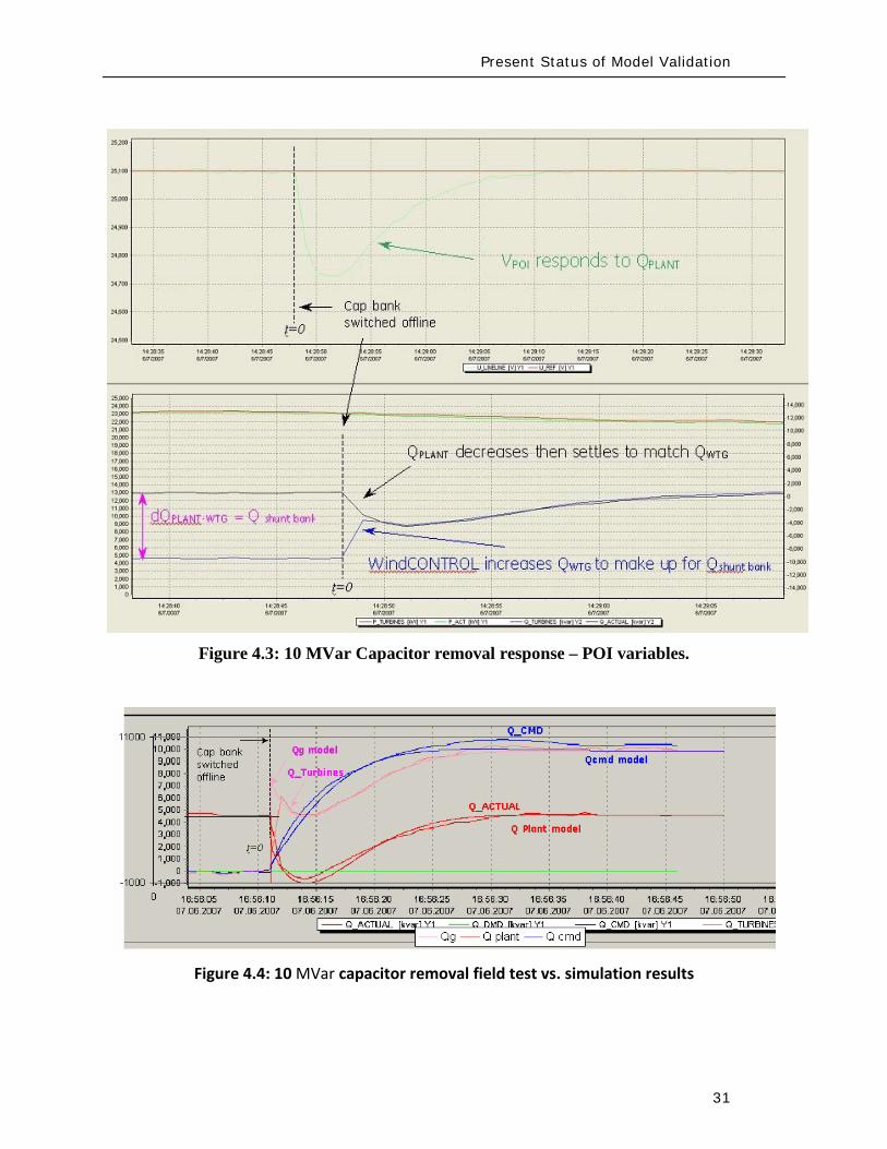
Present Status of Model Validation
33
Figure 46 GE 25 WTG Fault Test vs PSSe Model Performance
The discussion provide above is solely geared to hardware testing and validation however another highly valuable and legitimate means of providing validation of simulation models (for planning and otherwise) is to use more complex simulation software to validate simpler planning models Manufacturers normally have highly complex and highly proprietary models of their equipment These models are used among other things to design equipment and are normally physically based and must have sufficient fidelity for original equipment manufacturers (OEMs) to make sound engineering judgments for equipment design and application The OEMs are highly motivated to have these detailed high fidelity equipment level models These detailed models therefore can often be used to design test and validate simpler planning models to be used by the industry
There is a long accepted history in the power industry of this practice For example a typical (GE) gas turbine has on the order of 4000 state variables in the design model planning models typically have on the order of four state variables simplification is necessary and expected These design codes have been used to develop planning models of gas turbines Figure 47 below shows a comparison between a fault simulation using a GE design code (GE WindTrapreg) and the planning model in GE PSLFreg for a GE 15 (double fed machine) WTG
Present Status of Model Validation
34
Figure 47 Detailed Design Simulation (GE WindTRAPreg) vs GE PSLFreg Model Performance (active power during a severe fault for a GE 15 WTG)
-10
00
10
20
30
0 05 1 15 2
Time (Seconds)
Sin
gle
WTG
Rea
l Pow
er (M
WindtrapPSLF
Summary amp Recommended Actions
35
5 Summary amp Recommended Actions ndash Standards Implications
This document has presented a general overview of modeling and model validation as it pertains to variable generation resources Clearly to date the bulk of the experience and work has been on wind turbine generators Never-the-less similar approaches for modeling and model validation are being pursued for other variable generator technologies such as PV
Non-proprietary and publicly available models for the simulation of steady-state (power flow) short-circuit (fault calculations) and dynamic (time-domain simulations) behavior of such generation resources must be made readily available for use by power system planners Furthermore these models should be routinely validated to ensure proper representation of variable generation power plants in bulk power system studies A model is valid if its dynamic behavior is close enough to reality so that its influence on the network of interest (ie used for power system studies) is consistent with the fidelity of model structures and available data for the power system and other generation as it pertains to the phenomena of interest (ie in stability studies) That is perfect curve fitting is not necessary but to the extent possible erroneous model dynamics must not result in a notable over-design or under-design of the network
Each of the NERC standards discussed below in Section 52 address to aspects of meeting a standard (i) the technical requirement ie the need to define measure validate a model its parameters etc and (ii) the procedural requirements ie the functional model of how this technical requirement should be met reported and monitored The bulk of this working grouprsquos recommendations stated below address the technical requirements Variable generation is a new and quickly evolving technology and consideration should be given to the timing with which standards be implemented
Section 51 below first gives a summary of the planning process based on NERC standards to put the discussions in this report into context with the NERC standards Then in Section 52 we provided our recommendations and comments on the NERC existing and developing standards
Summary amp Recommended Actions
36
51 Applying the NERC Standards
The NERC standard FAC-001 (see Figure 51) should be expanded to clearly cover modeling requirements during the coordinated joint study phase of the Facility connection process Simple generic models of variable generation may be adequate for the IES phase and more detailed models may be needed for the IFS phase Validation of the simple and detailed model parameters may be needed during commissioning
Figure 51 Facility connection process
Interconnection Evaluation Study
Generator Interconnection
Request
Interconnection Facility Study
GO provides initial model
to TPPC
GO provides final model
to TPPC
GO signs Interconnection
Agreement and is put in-service
GO performs model amp
performance validation testing
TO develops Facility Interconnection requirements and requests models and data
of the GO at each process stage
FAC-001
Summary amp Recommended Actions
37
The generic model with associated parameters feed into the NERC model building process shown in Figure 52 As an example for WTG presently there is insufficient evidence of the accuracy of presently available generic models for WTG32
for all the various WTG manufacturers Some confirmation tests during commissioning or type tests or comparison simulation tests with a detailed model are necessary to get buy in from the Transmission OwnerPlanner As the technology matures and generic models are enhanced and associated data parameter sets are developed for specific machine types the new generic models will become more accepted as is the case with models of hydro or thermal plants
Figure 52 Annual NERC Model Development Process
32 PSSregE-320 Program Application Guide Volume II Chapter 21 PSSregE-320 Model Library Chapters 17 through 21 GE PSLF Users Manual v170_04 October 2009
Steady state data
developed
MOD-10
Dynamics data
developed
MOD-12
Reliability Region creates model
MOD-14
Reliability Region creates model
MOD-15
Reliability Region defines data
requirements
MOD-13
GO
TP
RP
Reliability Region defines data
requirements
MOD-11
Annual NERC Planning and
Operating Models
created and distributed to the industry
Summary amp Recommended Actions
38
The regional model building manuals developed as part of MOD-11 and MOD-13 must provide sufficient clarity to model variable generation These manuals may ask for best available models or generic models These models cover the operational time frame and the 10-year planning horizon The manuals do not currently cover the frequency for revalidating model data
While not included in the standards more emphasis is currently being placed on meeting the Eastern Interconnection Reliability Assessment Group (ERAG) model building manual requirements in addition to regional requirements
Figure 53 NERC Model Validation Process
The Regional Entities develop the test procedures and dictate testing frequency for the Generator Owners to follow The model data then feeds in to the annual NERC model building process
52 NERC Standards Technical Issues
One general comment is that the NERC Glossary of Terms would benefit from the term ldquoVariable Generationrdquo being include in it and appropriately defined A suitable definition can be found in the Phase I report of the IVGTF
Verify real power capability
MOD-24
GO
Verify reactive power capability
MOD-25
Verify generator excitation control model
MOD-26
Verify turbine governor model
MOD-27
Summary amp Recommended Actions
39
MOD-011 Regional Steady-State Data Requirements and Reporting Procedures
The technical requirement in this MOD reads
ldquoR12 Generating Units (including synchronous condensers pumped storage etc) location minimum and maximum Ratings (net Real and Reactive Power) regulated bus and voltage set point and equipment statusrdquo
This statement could be read to equally apply to variable generation as a source of generation However it may be prudent to explicitly include variable generation in this statement For example to change the sentence to
ldquoR12 Generating Units (including synchronous condensers pumped storage variable generation resources etc) location minimum and maximum Ratings (net Real and Reactive Power) regulated bus and voltage set point and equipment status For variable generation a suitable aggregate steady-state model of the collector system and equivalent unit representing the full plantrdquo
MOD-012 Dynamics Data for Transmission System Modeling and Simulation
This MOD equally applies to variable generation and needs no augmentation The requirements in the MOD are quite generic The requirements of this standard are dependent on and point to MOD 13 discussed below
MOD-013-1 RRO Dynamics Data Requirements and Reporting Procedures
This MOD explicitly discusses synchronous type generation It would be beneficial to include an explicit statement to cover variable generation For example
ldquoPlant-specific dynamics data shall be reported for variable generating units (eg wind turbine generators PV etc) such as the type of generating unit its interface with the grid and the appropriate model and model parameters to adequately represent unit dynamic response for bulk power system studies The typical size of a single variable generating unit (eg wind turbine generators PV array etc) is several hundreds of kilo-watts to several mega-watts Thus it may be acceptable for the total plant to be represented by an adequate aggregated model of the collector system and a single equivalent generating unit scaled up to represent the total name-plate capacity for each type of generating technology employed in the plant Furthermore models may need to be provided for other equipment installed in the collector system or at the point of interconnection such as reactive compensation devicesrdquo
Summary amp Recommended Actions
40
MOD-024-2 mdash Verification and Data Reporting of Generator Real Power Capability
This latest posting of this MOD posted for commenting on January 18th 2010 exempts variable generation from this requirement It states
ldquoVariable energy units such as wind generators solar and run of river hydro are exempt from the requirements of this Standardrdquo
For a variable generation plant the definition of Real Power Capability can be slightly challenging One way to view it is to see the total gross capability as the sum of the nameplate rating of all individual units within the plant eg for a wind power plant the total sum of the nameplate rating of all wind turbine generators in the plant However there must be two realizations (i) the amount of actual power injected into the grid at the point of interconnection requires a suitable representation of losses on the collector system and auxiliary loads and (ii) by its very nature variable generation is a highly variable energy source and thus it is quite rare to find point in time when all units in the plant are coincidentally at their peak nameplate capacity Finally the seasonal variable generation output variations need some discussion since they are quite different than conventional generation technologies
MOD-025-1 mdash Verification of Generator Gross and Net Reactive Power Capability
The technical requirement in this MOD reads
ldquoR15 Information to be reported
R151 Verified maximum gross and net Reactive Power capability (both lagging and leading) at Seasonal Real Power generating capabilities as reported in accordance with Reliability Standard MOD-024 Requirement 151
R152 Verified Reactive Power limitations such as generator terminal voltage limitations shorted rotor turns etc
R153 Verified Reactive Power of auxiliary loads
R154 Method of verification including date and conditionsrdquo
Note the above requirements are from the existing version of the standard MOD-025 is currently being enhanced
Although all of the above could equally apply to variable generation some clarification may be needed Namely variable generation reactive capability of the ldquopower plantrdquo is not entirely inherent in the individual generating units A variable generation power plant such as a wind power plant may contain many reactive power sources such as the individual generating units themselves (eg Type 3 or 4 WTG see Appendix I) discretely switched shunt reactive devices
Summary amp Recommended Actions
41
(eg shunt capacitors or reactors) smoothly controlled shunt reactive devices (eg SVC or STATCOM) or a combination of these devices Thus care should be taken as to how the total reactive capability of the power plant is defined and at what point (eg point of interconnection and whether this is defined as the high or low side of the substation transformer) Also it may not be practical under normal operating conditions to exercise the full reactive capability of the power plant (this is a known issue even with conventional synchronous generator plants) to test it thus it should suffice to demonstrate the plants reactive capability to the extent possible in the field and to then augment this with engineering calculations to derive the plants full reactive capability This is particularly true of variable generation because there is no control over the energy resource So for example a typical wind power plant may only achieve its name-plate rating for a hour or two during an entire year Thus it would not be possible to demonstrate the full reactive capability of the plant in the field Rather it should suffice to demonstrate the reactive capability of a single WTG and then to derive through engineering calculations (considering all other reactive devices in the plant such as SVC STATCOM etc) the total reactive capability of the plant These comments should be somehow used to appropriately modify MOD 25
MOD-026-1 mdash Verification of Models and Data for Generator Excitation System Functions ndash SECOND POSTING (and MOD 27)
MOD 26 (and MOD 27 Verification of Models and Data for TurbineGovernor and Load Control) are presently under development33
Presently these standards are tailored explicitly to deal with synchronous type generators since much of the language revolves around technology associated with synchronous generation (eg excitation system AVR power system stabilizers etc) Thus the following key items need to be clarified in these standards as they pertain to variable generation In addition the comments that follow apply to all components in a variable generation plant that may include devices such as the actual power generating units shunt compensation devices centralized control systems spanning the entire facility etc
These two standards deal specifically with the routine validation of generating unit dynamic models for power system stability studies
1 UnitPlant Size for Validation These MODrsquos specify the size of generating unit above which model validation is required It should be recognized that the typical size of a
33 MOD 26 and MOD 27 standards under development are found at httpwwwnerccomfilezstandardsGenerator-Verification-Project-2007-09html
Summary amp Recommended Actions
42
variable generation unit is in the hundreds of kilo-watts to several megawatts range Thus the language should be changed (or introduced) to indicate ldquonet power plantrdquo size
2 Validation of various technologies in a single plant Variable generation power plants can consist of multiple generation technologies For example a wind power plant may consist of WTGs of two different types Thus we need to consider the following points as they pertain to variable generation
a For a uniform variable generation plant (ie all generating units are of the same technology type) a single aggregate generator model representation should be sufficient
b For a significantly diverse variable generation plant the plant should be represented by multiple aggregated unit models representing each technology type
c Unique representation of a group of variable generation units as a single aggregated generator model representation should be based on
i The size of the group is a significant proportion of the total plant size (eg gt 20 of plant rating)
ii Each group should represent a unique characteristic (eg Type 1 WTG as compared to a Type 3 WTG)
3 Validation of different control layers Variable generation plants such as wind power plant may have several functional layers of control For example in a wind power plant with Type 3 WTGs we may have one level of closed loop voltage regulation at the terminals of the WTG a second slower control loop that regulates voltage at the point of interconnection (POI) and a third layer of control that coordinates the switching of shunt capacitors at the POI based on the reactive output of the individual WTGs In addition devices such as STATCOMs may be present at the POI Modeling and model validation should incorporate such devicescontrol layers to the extent that the dynamics of these functional layers are important for stability studies (see Figure 31)
4 Modeling and Model Validation Models are an emulation of actual equipment Not all model parameters necessarily translate to actual physical components or measureable features Judgment needs to be exercised in the modeling and validation process
a Models should be validated typically against the performance of an actual plant for a given eventdisturbance within the given operating range it is designed for
Summary amp Recommended Actions
43
b Models should state clearly the type and the range of events they have been designed to simulated and the limitation of the models beyond which the model deviates from the actual variable generation plant performance (eg a model developed to represent electrical transient behavior of a WTG may not be adequate for studying wind fluctuations over a many minute time frame)
c In general the best approach to model validation is to use field (or test bench) measurements of various disturbances that must exercise the different control functions to a wide range of operation points For example a model is not necessarily valid if the only a comparison between simulation results and field measurements for a single voltage step response is performed at one operating condition Ideally illustration of validation against recorded response to various system disturbances (faults frequency deviations etc) gives the greatest confidence in validation
d A model is valid if its dynamic behavior is close enough to reality so that its influence on the network of interest (ie used for power system studies) results in relatively negligible errors for the phenomena of interest (ie in stability studies) That is perfect curve fitting is not necessary but to the extent possible erroneous model dynamics must not result in a notable over-design or under-design of the network
5 Future functionality Due to the rapidly evolving nature of variable generation technologies variable generation models should be of a modular nature such that future functionality can be incorporated as much as possible into old model structures by adding a functional modular block For example presently Type 3 and 4 WTGs do not exhibit inertial response However at least one manufacturer now supplies a functional control addition that can emulate inertial response on these units Such functionality is likely to be made available soon by most vendors Thus a functional model block can be developed that can be added to the existing models for Type 3 and 4 WTGs to emulate the behavior of this additional control
6 Modeling of protection Variable generation much like conventional generation will have associated underover voltage and under-over frequency protection These should be modeled Attention should also be given to protective relay coordination with plant controls particularly in light of the nature of the grounding system within the variable generation plant (eg a wind power plant spans an entire collector system which can be grounded in several different ways and thus have various implications on protective relay coordination) Such coordination issues relate to the PRC and FAC-001 standards
Summary amp Recommended Actions
44
7 Issues related to the fuel source for variable generation For variable generation one needs to be cognizant of the variable nature of the energy source and thus the possible impracticality of performing model validation at a desired plant output but rather having to accept model validation at whatever plant output can be achieved at the time of testing or disturbance monitoring
8 Revalidation How often should models be revalidated
a Many variable generation technologies are rapidly changing for example in wind power plants new control software or new setting may be uploaded every year if not sooner
b If the changes are insignificant the existing dynamic models should be revalidated if possible as a matter of prudency ndash say within six months or so of a control system updateupgrade The changes (in parameters or dynamic model) should be reported to the local Reliability Entities
c If the changes are significant the existing dynamic models should be revalidated ndash say within three months or so after the updateupgrade The changes (which may include a new module new software etc) should be reported to the local Regional Entities
53 Final Recommendation
An earlier draft of this report and recommendations were presented to NERCrsquos Planning Committee at their March 2010 meeting The Committee members urged the IVGTF to pursue NERC reliability standard development Thus several NERC Standards Drafting Teams undertaking MOD Standard development will be contacted to present the recommendations from this report for their consideration and incorporation in subsequent updates The standard drafting teams for MOD-026 and MOD-027 are aiming to incorporate variable generation considerations in the next release of these draft standards
Appendix I Wind-Turbine Generation (WTG) Technologies
45
Appendix I Wind-Turbine Generation (WTG) Technologies
(a) Type 1 Wind Turbine-Generator Fixed Speed Induction Generator
(b) Type 2 Wind Turbine-Generator Variable Slip Induction Generator 34
34 IGBT R control = Resistor controlled by Insulated Gate Bi-Polar Transistor
3
GEAR BOX
INDUCTION GENERATOR TRANSFORMER
GRID
3
3GEAR BOX
WOUND ROTORINDUCTION GENERATOR TRANSFORMER
GRID
IGBT RControl
Rectifier
Appendix I Wind-Turbine Generation (WTG) Technologies
46
(c) Type 3 Wind Turbine-Generator Double-Fed Asynchronous Generator
(d) Type 4 Wind Turbine-Generator Full Power Conversion
3
3GEAR BOX
WOUND ROTORINDUCTION GENERATOR TRANSFORMER
GRID
IGBT POWER CONVERTORS
3
GEAR BOX
SYNCHRONOUSGENERATOR TRANSFORMER
GRID
Rectifier
33
IGBTInverter
Acronyms
47
Acronyms
CSP ndash Concentrating Solar Power
CIGRE - International Council on Large Electric Systems
DFAG ndash Doubly Fed Asynchronous Generator (also often referred to as DFIG ndash Doubly Fed Induction Generator)
FERC ndash Federal Energy Regulatory Commission
HVDC ndash High-Voltage Direct-Current transmission
IEC ndash International Electrotechnical Commission
IEEE ndash Institute of Electrical and Electronic Engineers
IGBT ndash Insulated-Gate Bipolar Transistor
IGCT ndash Insulated-Gate Commutated Thyristor
IVGTF ndash Integration of Variable Generation Task Force
ISO ndash Independent System Operator
LCC ndash Line-Commutated Converter
LVRT ndash Low-Voltage Ride-Through
MOD ndash Modeling Data and Analysis Standards
NERC ndash North American Electric Reliability Corporation
OEM ndash Original Equipment Manufacturer
PHEV ndash Plug-in Hybrid Electric Vehicle
PV ndash Photovoltaic
POI ndash Point of Interconnection
RPS ndash Renewable Portfolio Standard
RTO ndash Regional Transmission Operator
Acronyms
48
SAR ndash Standards Authorization Request (NERC process)
SCADA - Supervisory Control and Data Acquisition
SSTI ndash Subsynchronous Torsional Interaction
STATCOM ndash Static Compensator (voltage source converter based technology)
SVC ndash Static Var Compensator (thyristor based technology)
TSO ndash Transmission System Operator
VAr ndash volt-ampere reactive (standard units for reactive power)
VRT ndash Voltage Ride-Through
VSC ndash Voltage Source Converter
WPP ndash Wind Power Plant
WTG ndash Wind Turbine Generator
WECC ndash Western Electricity Coordinating Council
IVGTF Roster
49
IVGTF Task 1-1 Roster
Chair Pouyan Pourbeik
Technical Executive EPRI 942 Corridor Park Boulevard Knoxville Tennessee 37932
(919) 806-8126 ppourbeik epricom
Jay Caspary Director Transmission Development
Southwest Power Pool 415 North McKinley Suite 140 Little Rock Arkansas 72205
(501) 666-0376 (501) 666-0376 Fx jcasparyspporg
K R Chakravarthi
Southern Company Services Inc Southern Company Services Birmingham Alabama 35203
205-257-6125 205-257-1040 Fx krchakra southerncocom
Kieran Connolly
Manager Generation Scheduling
Bonneville Power Administration 905 NE 11th Avenue Portland Oregon 97232
(503) 230-4680 (503) 230-5377 Fx kpconnolly bpagov
Adam Flink
Engineer Midwest Reliability Organization 2774 Cleveland Ave Roseville Minnesota 55113
6515881705 (651) 855-1712 Fx adflink midwestreliabilityorg
David Jacobson
Interconnection amp Grid Supply Planning Engineer
Manitoba Hydro 12-1146 Waverly Street PO Box 815 Winnipeg Manitoba R3C 2P4
(204) 474-3765 (204) 477-4606 Fx dajacobson hydrombca
Charles-Eric
Langlois Jr Engineer
Hydro-Queacutebec TransEnergie 9e eacutetage Complexe Desjardins Tour Est Montreal Queacutebec H5B1H7
(514) 879-4100 ext 5441 (514) 879-4486 Fx LangloisCharles-Erichydroqcca
IVGTF Roster
50
David Marshall Project Manager
Southern Company Services Inc 600 N 18th Street Birmingham Alabama 35203
205-257-3326 205-257-1040 Fx dcmarsha southerncocom
Sophie Paquette
Transmission Planning Engineer
Hydro-Queacutebec TransEnergie 9e eacutetage Complexe Desjardins Tour Est 12th Floor Montreal Queacutebec H5B1H7
(514) 879-4100 ext 5423 (514) 879-4486 Fx paquettesophie hydroqcca
David C Schooley
Sr Engineer Commonwealth Edison Co 2 Lincoln Centre Oakbrook Terrace Illinois 60181
(630) 437-2773 davidschooley comedcom
Eric Thoms
Technical Lead - Transmission Access Planning
Midwest ISO Inc 1125 Energy Park Dr St Paul Minnesota 55108
(651) 632-8454 (651) 632-8417 Fx ethoms midwestisoorg
Observers Daniel Brooks
Manager Power Delivery System Studies
Electric Power Research Institute 942 Corridor Park Blvd Knoxville Tennessee 37932
(865) 218-8040 (865) 218-8001 Fx dbrooksepricom
Abraham Ellis
Principal Member of Technical Staff Renewable System Integration
Sandia National Laboratories 1515 Eubank SE Albuquerque New Mexico 87123
(505) 844-7717 (505) 844-2890 Fx aellis sandiagov
Ben Karlson
Sandia National Laboratories PO Box 5800 Albuquerque New Mexico 87185
(505) 803-3676 bkarlso sandiagov
Yuriy Kazachkov
Siemens Energy Inc 400 State Street Schenectady New York 12305
(518) 395-5132 (518) 346-2777 Fx yuriykazachkov siemenscom
Carl Lenox
Senior Staff Engineer Sunpower Corporation Systems 1414 Harbour Way South Richmond California 94804
(510) 260-8286 (510) 540-0552 Fx carllenox sunpowercorpcom
IVGTF Roster
51
Jason MacDowell
GE Energy 1 River Road Bldg 53 Schenectady New York 12345
(518) 385-2416 (518) 385-5703 Fx jasonmacdowell gecom
John Mead
Senior Staff Engineer Sunpower Corporation Systems 1414 Harbour Way South Richmond California 94804
(510) 260-8370 (510) 540-0552 Fx johnmead sunpowercorpcom
Nicholas W Miller
Director GE Energy 53-300Q 1 River Road Schenectady New York 12345
(518) 385-9865 (518) 385-5703 Fx nicholasmiller gecom
Eduard Muljadi
Senior Engineer National Renewable Energy Laboratory 1617 Cole Boulevard Golden Colorado 80401
(303) 384-6904 EduardMuljadi nrelgov
Mark OMalley
Professor of Electrical Engineering
University College Dublin R 157A Engineering amp Materials Science Centre University College Dublin Belfield Dublin 4
00353-1-716-1851 00353-1-283-0921 Fx markomalley ucdie
Subbaiah Pasupulati
Director of Technical Studies
Oak Creek Energy Systems Inc 14633 Willow Springs Road Mojave California 93501
(909) 241-9197 (661) 822-5991 Fx subbaiah oakcreekenergycom
Juan J Sanchez-
Gasca Principal Engineer
GE Energy 1 River Road Bldg 53-302E Schenectady New York 12345
(518) 385-5564 (518) 385-5703 Fx juansanchez psgecom
Steven Saylors
Chief Electrical Engineer
Vestas Americas 1881 SW Naito Parkway Portland Oregon 97201
(503) 327-2111 (503) 327-2001 Fx saylvestascom
IVGTF Roster
52
Robert Zavadil Vice President and Principal Consultant
EnerNex Corp 620 Mabry Hood Road Suite 300 Knoxville Tennessee 37932
(865) 218-4600 Ext 6149 (865) 218-8999 Fx bobzenernexcom
NERC Staff
Aaron Bennett Engineer Reliability Assessments
North American Electric Reliability Corporation 116-390 Village Boulevard Princeton New Jersey 08540-5721
(609) 524-7003 (609) 452-9550 Fx aaronbennett nercnet
Rhaiza Villafranca
Technical Analyst North American Electric Reliability Corporation 116-390 Village Boulevard Princeton New Jersey 08540-5721
(609) 452-8060 (609) 452-9550 Fx rhaizavillafranca nercnet
Mark G Lauby
Director Reliability Assessment and Performance Analysis
North American Electric Reliability Corporation 116-390 Village Boulevard Princeton New Jersey 08540-5721
(609) 524-7077 (609) 452-9550 Fx marklauby nercnet
References
53
References and Further Reading
[1] NERC Special Report Accommodation of High Levels of Variable Generation April 2009 httpwwwnerccomfilesIVGTF_Report_041609pdf
[2] CIGRE Technical Brochure 328 Modeling and Dynamic Behavior of Wind Generation as it Relates to Power System Control and Dynamic Performance Prepared by CIGRE WG C4601 August 2007 (available on-line at wwwe-cigreorg)
[3] ldquoWECC Wind Generator Power Flow Modeling Guiderdquo (httpwwwweccbizlibraryWECC20DocumentsDocuments20for20GeneratorsGenerator20Testing20ProgramWind20Generator20Power20Flow20Modeling20Guidepdf)
[4] G Lalor A Mullane and M J OrsquoMalley ldquoFrequency Control and Wind Turbine Technologiesrdquo IEEE Transactions on Power Systems Vol 20 pp 1903-1913 2005
[5] A Mullane and M J OrsquoMalley ldquoThe inertial-response of induction-machine based wind-turbinesrdquo IEEE Transactions on Power Systems Vol 20 pp 1496 ndash 1503 2005
[6] R Walling ldquoWind Plants of the Futurerdquo UWIG Oct 2008
[7] Hydro-Queacutebec TransEacutenergie ldquoTechnical requirements for the connection of generation facilities to the Hydro-Queacutebec transmission systemrdquo May 2006
[8] ESB National grid ldquoDynamic modeling of wind generation in Irelandrdquo January 2008
[9] N Miller K Clark R Delmerico and M Cardinal ldquoWindINERTIATM Inertial Response Option for GE Wind Turbine Generatorsrdquo Windpower 2009 Chicago IL May 4-7 2009
[10] R K Varma and S Auddy ldquoMitigation of Subsynchronous Oscillations in a Series Compensated Wind Farm with Static Var Compensatorrdquo Proceedings of the IEEE PES General Meeting 2006 Montreall Canada 2006
References
54
[11] Bialasiewicz J T Muljadi E Nix R G Drouilhet S Renewable Energy Power System Modular Simulator RPM-SIM Users Guide National Renewable Energy Laboratory March 2001 NRELTP-500-29721
[12] N Miller K Clark J MacDowell and W Barton Experience with Field and Factory Testing for Model Validation of GE Wind Plants European Wind Energy Conference amp Exhibition Brussels Belgium MarchApril 2008
[13] R J Piwko N W Miller and J M MacDowell ldquoField Testing and Model Validation of Wind Plantsrdquo IEEE-PES GM June 2008
- Executive Summary
- Introduction
- The Need for Models for Variable Generation
- Steady-State and Fault Current Analysis
- Time-Domain Positive Sequence Dynamic Models for Bulk Power System Stability Analysis
- Detailed Three-phase Equipment Level Models
- Summary
- Present Status of Modeling Variable Generation
- Wind Generation
-
- 311 WECCIEEE Effort for Generic Models
- 312 UWIG Generic Model Documentation and Validation Effort
- 313 IEC Effort for Generic Models
-
- Photovoltaic Solar Generation
- Solar Thermal
- Tidal Generation
- Other Resources
- Summary
- Present Status of Model Validation
- What is Model Validation
- Examples of Model Validation Efforts
-
- 421 Hydro- Queacutebec Example
- 422 GE Example ndash based on GErsquos work with client facilities
-
- Summary amp Recommended Actions ndash Standards Implications
- Applying the NERC Standards
- NERC Standards Technical Issues
- Final Recommendation
- Appendix I Wind-Turbine Generation (WTG) Technologies
- Acronyms
- IVGTF Task 1-1 Roster
- References and Further Reading
-
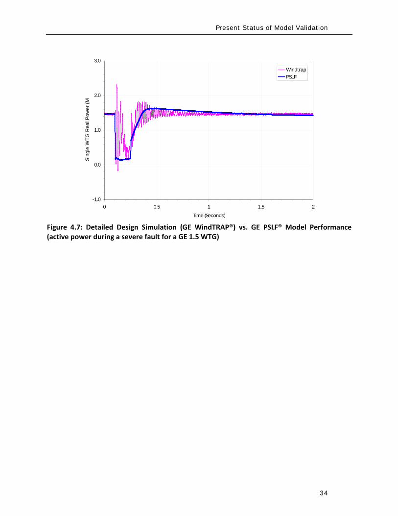
Present Status of Model Validation
34
Figure 47 Detailed Design Simulation (GE WindTRAPreg) vs GE PSLFreg Model Performance (active power during a severe fault for a GE 15 WTG)
-10
00
10
20
30
0 05 1 15 2
Time (Seconds)
Sin
gle
WTG
Rea
l Pow
er (M
WindtrapPSLF
Summary amp Recommended Actions
35
5 Summary amp Recommended Actions ndash Standards Implications
This document has presented a general overview of modeling and model validation as it pertains to variable generation resources Clearly to date the bulk of the experience and work has been on wind turbine generators Never-the-less similar approaches for modeling and model validation are being pursued for other variable generator technologies such as PV
Non-proprietary and publicly available models for the simulation of steady-state (power flow) short-circuit (fault calculations) and dynamic (time-domain simulations) behavior of such generation resources must be made readily available for use by power system planners Furthermore these models should be routinely validated to ensure proper representation of variable generation power plants in bulk power system studies A model is valid if its dynamic behavior is close enough to reality so that its influence on the network of interest (ie used for power system studies) is consistent with the fidelity of model structures and available data for the power system and other generation as it pertains to the phenomena of interest (ie in stability studies) That is perfect curve fitting is not necessary but to the extent possible erroneous model dynamics must not result in a notable over-design or under-design of the network
Each of the NERC standards discussed below in Section 52 address to aspects of meeting a standard (i) the technical requirement ie the need to define measure validate a model its parameters etc and (ii) the procedural requirements ie the functional model of how this technical requirement should be met reported and monitored The bulk of this working grouprsquos recommendations stated below address the technical requirements Variable generation is a new and quickly evolving technology and consideration should be given to the timing with which standards be implemented
Section 51 below first gives a summary of the planning process based on NERC standards to put the discussions in this report into context with the NERC standards Then in Section 52 we provided our recommendations and comments on the NERC existing and developing standards
Summary amp Recommended Actions
36
51 Applying the NERC Standards
The NERC standard FAC-001 (see Figure 51) should be expanded to clearly cover modeling requirements during the coordinated joint study phase of the Facility connection process Simple generic models of variable generation may be adequate for the IES phase and more detailed models may be needed for the IFS phase Validation of the simple and detailed model parameters may be needed during commissioning
Figure 51 Facility connection process
Interconnection Evaluation Study
Generator Interconnection
Request
Interconnection Facility Study
GO provides initial model
to TPPC
GO provides final model
to TPPC
GO signs Interconnection
Agreement and is put in-service
GO performs model amp
performance validation testing
TO develops Facility Interconnection requirements and requests models and data
of the GO at each process stage
FAC-001
Summary amp Recommended Actions
37
The generic model with associated parameters feed into the NERC model building process shown in Figure 52 As an example for WTG presently there is insufficient evidence of the accuracy of presently available generic models for WTG32
for all the various WTG manufacturers Some confirmation tests during commissioning or type tests or comparison simulation tests with a detailed model are necessary to get buy in from the Transmission OwnerPlanner As the technology matures and generic models are enhanced and associated data parameter sets are developed for specific machine types the new generic models will become more accepted as is the case with models of hydro or thermal plants
Figure 52 Annual NERC Model Development Process
32 PSSregE-320 Program Application Guide Volume II Chapter 21 PSSregE-320 Model Library Chapters 17 through 21 GE PSLF Users Manual v170_04 October 2009
Steady state data
developed
MOD-10
Dynamics data
developed
MOD-12
Reliability Region creates model
MOD-14
Reliability Region creates model
MOD-15
Reliability Region defines data
requirements
MOD-13
GO
TP
RP
Reliability Region defines data
requirements
MOD-11
Annual NERC Planning and
Operating Models
created and distributed to the industry
Summary amp Recommended Actions
38
The regional model building manuals developed as part of MOD-11 and MOD-13 must provide sufficient clarity to model variable generation These manuals may ask for best available models or generic models These models cover the operational time frame and the 10-year planning horizon The manuals do not currently cover the frequency for revalidating model data
While not included in the standards more emphasis is currently being placed on meeting the Eastern Interconnection Reliability Assessment Group (ERAG) model building manual requirements in addition to regional requirements
Figure 53 NERC Model Validation Process
The Regional Entities develop the test procedures and dictate testing frequency for the Generator Owners to follow The model data then feeds in to the annual NERC model building process
52 NERC Standards Technical Issues
One general comment is that the NERC Glossary of Terms would benefit from the term ldquoVariable Generationrdquo being include in it and appropriately defined A suitable definition can be found in the Phase I report of the IVGTF
Verify real power capability
MOD-24
GO
Verify reactive power capability
MOD-25
Verify generator excitation control model
MOD-26
Verify turbine governor model
MOD-27
Summary amp Recommended Actions
39
MOD-011 Regional Steady-State Data Requirements and Reporting Procedures
The technical requirement in this MOD reads
ldquoR12 Generating Units (including synchronous condensers pumped storage etc) location minimum and maximum Ratings (net Real and Reactive Power) regulated bus and voltage set point and equipment statusrdquo
This statement could be read to equally apply to variable generation as a source of generation However it may be prudent to explicitly include variable generation in this statement For example to change the sentence to
ldquoR12 Generating Units (including synchronous condensers pumped storage variable generation resources etc) location minimum and maximum Ratings (net Real and Reactive Power) regulated bus and voltage set point and equipment status For variable generation a suitable aggregate steady-state model of the collector system and equivalent unit representing the full plantrdquo
MOD-012 Dynamics Data for Transmission System Modeling and Simulation
This MOD equally applies to variable generation and needs no augmentation The requirements in the MOD are quite generic The requirements of this standard are dependent on and point to MOD 13 discussed below
MOD-013-1 RRO Dynamics Data Requirements and Reporting Procedures
This MOD explicitly discusses synchronous type generation It would be beneficial to include an explicit statement to cover variable generation For example
ldquoPlant-specific dynamics data shall be reported for variable generating units (eg wind turbine generators PV etc) such as the type of generating unit its interface with the grid and the appropriate model and model parameters to adequately represent unit dynamic response for bulk power system studies The typical size of a single variable generating unit (eg wind turbine generators PV array etc) is several hundreds of kilo-watts to several mega-watts Thus it may be acceptable for the total plant to be represented by an adequate aggregated model of the collector system and a single equivalent generating unit scaled up to represent the total name-plate capacity for each type of generating technology employed in the plant Furthermore models may need to be provided for other equipment installed in the collector system or at the point of interconnection such as reactive compensation devicesrdquo
Summary amp Recommended Actions
40
MOD-024-2 mdash Verification and Data Reporting of Generator Real Power Capability
This latest posting of this MOD posted for commenting on January 18th 2010 exempts variable generation from this requirement It states
ldquoVariable energy units such as wind generators solar and run of river hydro are exempt from the requirements of this Standardrdquo
For a variable generation plant the definition of Real Power Capability can be slightly challenging One way to view it is to see the total gross capability as the sum of the nameplate rating of all individual units within the plant eg for a wind power plant the total sum of the nameplate rating of all wind turbine generators in the plant However there must be two realizations (i) the amount of actual power injected into the grid at the point of interconnection requires a suitable representation of losses on the collector system and auxiliary loads and (ii) by its very nature variable generation is a highly variable energy source and thus it is quite rare to find point in time when all units in the plant are coincidentally at their peak nameplate capacity Finally the seasonal variable generation output variations need some discussion since they are quite different than conventional generation technologies
MOD-025-1 mdash Verification of Generator Gross and Net Reactive Power Capability
The technical requirement in this MOD reads
ldquoR15 Information to be reported
R151 Verified maximum gross and net Reactive Power capability (both lagging and leading) at Seasonal Real Power generating capabilities as reported in accordance with Reliability Standard MOD-024 Requirement 151
R152 Verified Reactive Power limitations such as generator terminal voltage limitations shorted rotor turns etc
R153 Verified Reactive Power of auxiliary loads
R154 Method of verification including date and conditionsrdquo
Note the above requirements are from the existing version of the standard MOD-025 is currently being enhanced
Although all of the above could equally apply to variable generation some clarification may be needed Namely variable generation reactive capability of the ldquopower plantrdquo is not entirely inherent in the individual generating units A variable generation power plant such as a wind power plant may contain many reactive power sources such as the individual generating units themselves (eg Type 3 or 4 WTG see Appendix I) discretely switched shunt reactive devices
Summary amp Recommended Actions
41
(eg shunt capacitors or reactors) smoothly controlled shunt reactive devices (eg SVC or STATCOM) or a combination of these devices Thus care should be taken as to how the total reactive capability of the power plant is defined and at what point (eg point of interconnection and whether this is defined as the high or low side of the substation transformer) Also it may not be practical under normal operating conditions to exercise the full reactive capability of the power plant (this is a known issue even with conventional synchronous generator plants) to test it thus it should suffice to demonstrate the plants reactive capability to the extent possible in the field and to then augment this with engineering calculations to derive the plants full reactive capability This is particularly true of variable generation because there is no control over the energy resource So for example a typical wind power plant may only achieve its name-plate rating for a hour or two during an entire year Thus it would not be possible to demonstrate the full reactive capability of the plant in the field Rather it should suffice to demonstrate the reactive capability of a single WTG and then to derive through engineering calculations (considering all other reactive devices in the plant such as SVC STATCOM etc) the total reactive capability of the plant These comments should be somehow used to appropriately modify MOD 25
MOD-026-1 mdash Verification of Models and Data for Generator Excitation System Functions ndash SECOND POSTING (and MOD 27)
MOD 26 (and MOD 27 Verification of Models and Data for TurbineGovernor and Load Control) are presently under development33
Presently these standards are tailored explicitly to deal with synchronous type generators since much of the language revolves around technology associated with synchronous generation (eg excitation system AVR power system stabilizers etc) Thus the following key items need to be clarified in these standards as they pertain to variable generation In addition the comments that follow apply to all components in a variable generation plant that may include devices such as the actual power generating units shunt compensation devices centralized control systems spanning the entire facility etc
These two standards deal specifically with the routine validation of generating unit dynamic models for power system stability studies
1 UnitPlant Size for Validation These MODrsquos specify the size of generating unit above which model validation is required It should be recognized that the typical size of a
33 MOD 26 and MOD 27 standards under development are found at httpwwwnerccomfilezstandardsGenerator-Verification-Project-2007-09html
Summary amp Recommended Actions
42
variable generation unit is in the hundreds of kilo-watts to several megawatts range Thus the language should be changed (or introduced) to indicate ldquonet power plantrdquo size
2 Validation of various technologies in a single plant Variable generation power plants can consist of multiple generation technologies For example a wind power plant may consist of WTGs of two different types Thus we need to consider the following points as they pertain to variable generation
a For a uniform variable generation plant (ie all generating units are of the same technology type) a single aggregate generator model representation should be sufficient
b For a significantly diverse variable generation plant the plant should be represented by multiple aggregated unit models representing each technology type
c Unique representation of a group of variable generation units as a single aggregated generator model representation should be based on
i The size of the group is a significant proportion of the total plant size (eg gt 20 of plant rating)
ii Each group should represent a unique characteristic (eg Type 1 WTG as compared to a Type 3 WTG)
3 Validation of different control layers Variable generation plants such as wind power plant may have several functional layers of control For example in a wind power plant with Type 3 WTGs we may have one level of closed loop voltage regulation at the terminals of the WTG a second slower control loop that regulates voltage at the point of interconnection (POI) and a third layer of control that coordinates the switching of shunt capacitors at the POI based on the reactive output of the individual WTGs In addition devices such as STATCOMs may be present at the POI Modeling and model validation should incorporate such devicescontrol layers to the extent that the dynamics of these functional layers are important for stability studies (see Figure 31)
4 Modeling and Model Validation Models are an emulation of actual equipment Not all model parameters necessarily translate to actual physical components or measureable features Judgment needs to be exercised in the modeling and validation process
a Models should be validated typically against the performance of an actual plant for a given eventdisturbance within the given operating range it is designed for
Summary amp Recommended Actions
43
b Models should state clearly the type and the range of events they have been designed to simulated and the limitation of the models beyond which the model deviates from the actual variable generation plant performance (eg a model developed to represent electrical transient behavior of a WTG may not be adequate for studying wind fluctuations over a many minute time frame)
c In general the best approach to model validation is to use field (or test bench) measurements of various disturbances that must exercise the different control functions to a wide range of operation points For example a model is not necessarily valid if the only a comparison between simulation results and field measurements for a single voltage step response is performed at one operating condition Ideally illustration of validation against recorded response to various system disturbances (faults frequency deviations etc) gives the greatest confidence in validation
d A model is valid if its dynamic behavior is close enough to reality so that its influence on the network of interest (ie used for power system studies) results in relatively negligible errors for the phenomena of interest (ie in stability studies) That is perfect curve fitting is not necessary but to the extent possible erroneous model dynamics must not result in a notable over-design or under-design of the network
5 Future functionality Due to the rapidly evolving nature of variable generation technologies variable generation models should be of a modular nature such that future functionality can be incorporated as much as possible into old model structures by adding a functional modular block For example presently Type 3 and 4 WTGs do not exhibit inertial response However at least one manufacturer now supplies a functional control addition that can emulate inertial response on these units Such functionality is likely to be made available soon by most vendors Thus a functional model block can be developed that can be added to the existing models for Type 3 and 4 WTGs to emulate the behavior of this additional control
6 Modeling of protection Variable generation much like conventional generation will have associated underover voltage and under-over frequency protection These should be modeled Attention should also be given to protective relay coordination with plant controls particularly in light of the nature of the grounding system within the variable generation plant (eg a wind power plant spans an entire collector system which can be grounded in several different ways and thus have various implications on protective relay coordination) Such coordination issues relate to the PRC and FAC-001 standards
Summary amp Recommended Actions
44
7 Issues related to the fuel source for variable generation For variable generation one needs to be cognizant of the variable nature of the energy source and thus the possible impracticality of performing model validation at a desired plant output but rather having to accept model validation at whatever plant output can be achieved at the time of testing or disturbance monitoring
8 Revalidation How often should models be revalidated
a Many variable generation technologies are rapidly changing for example in wind power plants new control software or new setting may be uploaded every year if not sooner
b If the changes are insignificant the existing dynamic models should be revalidated if possible as a matter of prudency ndash say within six months or so of a control system updateupgrade The changes (in parameters or dynamic model) should be reported to the local Reliability Entities
c If the changes are significant the existing dynamic models should be revalidated ndash say within three months or so after the updateupgrade The changes (which may include a new module new software etc) should be reported to the local Regional Entities
53 Final Recommendation
An earlier draft of this report and recommendations were presented to NERCrsquos Planning Committee at their March 2010 meeting The Committee members urged the IVGTF to pursue NERC reliability standard development Thus several NERC Standards Drafting Teams undertaking MOD Standard development will be contacted to present the recommendations from this report for their consideration and incorporation in subsequent updates The standard drafting teams for MOD-026 and MOD-027 are aiming to incorporate variable generation considerations in the next release of these draft standards
Appendix I Wind-Turbine Generation (WTG) Technologies
45
Appendix I Wind-Turbine Generation (WTG) Technologies
(a) Type 1 Wind Turbine-Generator Fixed Speed Induction Generator
(b) Type 2 Wind Turbine-Generator Variable Slip Induction Generator 34
34 IGBT R control = Resistor controlled by Insulated Gate Bi-Polar Transistor
3
GEAR BOX
INDUCTION GENERATOR TRANSFORMER
GRID
3
3GEAR BOX
WOUND ROTORINDUCTION GENERATOR TRANSFORMER
GRID
IGBT RControl
Rectifier
Appendix I Wind-Turbine Generation (WTG) Technologies
46
(c) Type 3 Wind Turbine-Generator Double-Fed Asynchronous Generator
(d) Type 4 Wind Turbine-Generator Full Power Conversion
3
3GEAR BOX
WOUND ROTORINDUCTION GENERATOR TRANSFORMER
GRID
IGBT POWER CONVERTORS
3
GEAR BOX
SYNCHRONOUSGENERATOR TRANSFORMER
GRID
Rectifier
33
IGBTInverter
Acronyms
47
Acronyms
CSP ndash Concentrating Solar Power
CIGRE - International Council on Large Electric Systems
DFAG ndash Doubly Fed Asynchronous Generator (also often referred to as DFIG ndash Doubly Fed Induction Generator)
FERC ndash Federal Energy Regulatory Commission
HVDC ndash High-Voltage Direct-Current transmission
IEC ndash International Electrotechnical Commission
IEEE ndash Institute of Electrical and Electronic Engineers
IGBT ndash Insulated-Gate Bipolar Transistor
IGCT ndash Insulated-Gate Commutated Thyristor
IVGTF ndash Integration of Variable Generation Task Force
ISO ndash Independent System Operator
LCC ndash Line-Commutated Converter
LVRT ndash Low-Voltage Ride-Through
MOD ndash Modeling Data and Analysis Standards
NERC ndash North American Electric Reliability Corporation
OEM ndash Original Equipment Manufacturer
PHEV ndash Plug-in Hybrid Electric Vehicle
PV ndash Photovoltaic
POI ndash Point of Interconnection
RPS ndash Renewable Portfolio Standard
RTO ndash Regional Transmission Operator
Acronyms
48
SAR ndash Standards Authorization Request (NERC process)
SCADA - Supervisory Control and Data Acquisition
SSTI ndash Subsynchronous Torsional Interaction
STATCOM ndash Static Compensator (voltage source converter based technology)
SVC ndash Static Var Compensator (thyristor based technology)
TSO ndash Transmission System Operator
VAr ndash volt-ampere reactive (standard units for reactive power)
VRT ndash Voltage Ride-Through
VSC ndash Voltage Source Converter
WPP ndash Wind Power Plant
WTG ndash Wind Turbine Generator
WECC ndash Western Electricity Coordinating Council
IVGTF Roster
49
IVGTF Task 1-1 Roster
Chair Pouyan Pourbeik
Technical Executive EPRI 942 Corridor Park Boulevard Knoxville Tennessee 37932
(919) 806-8126 ppourbeik epricom
Jay Caspary Director Transmission Development
Southwest Power Pool 415 North McKinley Suite 140 Little Rock Arkansas 72205
(501) 666-0376 (501) 666-0376 Fx jcasparyspporg
K R Chakravarthi
Southern Company Services Inc Southern Company Services Birmingham Alabama 35203
205-257-6125 205-257-1040 Fx krchakra southerncocom
Kieran Connolly
Manager Generation Scheduling
Bonneville Power Administration 905 NE 11th Avenue Portland Oregon 97232
(503) 230-4680 (503) 230-5377 Fx kpconnolly bpagov
Adam Flink
Engineer Midwest Reliability Organization 2774 Cleveland Ave Roseville Minnesota 55113
6515881705 (651) 855-1712 Fx adflink midwestreliabilityorg
David Jacobson
Interconnection amp Grid Supply Planning Engineer
Manitoba Hydro 12-1146 Waverly Street PO Box 815 Winnipeg Manitoba R3C 2P4
(204) 474-3765 (204) 477-4606 Fx dajacobson hydrombca
Charles-Eric
Langlois Jr Engineer
Hydro-Queacutebec TransEnergie 9e eacutetage Complexe Desjardins Tour Est Montreal Queacutebec H5B1H7
(514) 879-4100 ext 5441 (514) 879-4486 Fx LangloisCharles-Erichydroqcca
IVGTF Roster
50
David Marshall Project Manager
Southern Company Services Inc 600 N 18th Street Birmingham Alabama 35203
205-257-3326 205-257-1040 Fx dcmarsha southerncocom
Sophie Paquette
Transmission Planning Engineer
Hydro-Queacutebec TransEnergie 9e eacutetage Complexe Desjardins Tour Est 12th Floor Montreal Queacutebec H5B1H7
(514) 879-4100 ext 5423 (514) 879-4486 Fx paquettesophie hydroqcca
David C Schooley
Sr Engineer Commonwealth Edison Co 2 Lincoln Centre Oakbrook Terrace Illinois 60181
(630) 437-2773 davidschooley comedcom
Eric Thoms
Technical Lead - Transmission Access Planning
Midwest ISO Inc 1125 Energy Park Dr St Paul Minnesota 55108
(651) 632-8454 (651) 632-8417 Fx ethoms midwestisoorg
Observers Daniel Brooks
Manager Power Delivery System Studies
Electric Power Research Institute 942 Corridor Park Blvd Knoxville Tennessee 37932
(865) 218-8040 (865) 218-8001 Fx dbrooksepricom
Abraham Ellis
Principal Member of Technical Staff Renewable System Integration
Sandia National Laboratories 1515 Eubank SE Albuquerque New Mexico 87123
(505) 844-7717 (505) 844-2890 Fx aellis sandiagov
Ben Karlson
Sandia National Laboratories PO Box 5800 Albuquerque New Mexico 87185
(505) 803-3676 bkarlso sandiagov
Yuriy Kazachkov
Siemens Energy Inc 400 State Street Schenectady New York 12305
(518) 395-5132 (518) 346-2777 Fx yuriykazachkov siemenscom
Carl Lenox
Senior Staff Engineer Sunpower Corporation Systems 1414 Harbour Way South Richmond California 94804
(510) 260-8286 (510) 540-0552 Fx carllenox sunpowercorpcom
IVGTF Roster
51
Jason MacDowell
GE Energy 1 River Road Bldg 53 Schenectady New York 12345
(518) 385-2416 (518) 385-5703 Fx jasonmacdowell gecom
John Mead
Senior Staff Engineer Sunpower Corporation Systems 1414 Harbour Way South Richmond California 94804
(510) 260-8370 (510) 540-0552 Fx johnmead sunpowercorpcom
Nicholas W Miller
Director GE Energy 53-300Q 1 River Road Schenectady New York 12345
(518) 385-9865 (518) 385-5703 Fx nicholasmiller gecom
Eduard Muljadi
Senior Engineer National Renewable Energy Laboratory 1617 Cole Boulevard Golden Colorado 80401
(303) 384-6904 EduardMuljadi nrelgov
Mark OMalley
Professor of Electrical Engineering
University College Dublin R 157A Engineering amp Materials Science Centre University College Dublin Belfield Dublin 4
00353-1-716-1851 00353-1-283-0921 Fx markomalley ucdie
Subbaiah Pasupulati
Director of Technical Studies
Oak Creek Energy Systems Inc 14633 Willow Springs Road Mojave California 93501
(909) 241-9197 (661) 822-5991 Fx subbaiah oakcreekenergycom
Juan J Sanchez-
Gasca Principal Engineer
GE Energy 1 River Road Bldg 53-302E Schenectady New York 12345
(518) 385-5564 (518) 385-5703 Fx juansanchez psgecom
Steven Saylors
Chief Electrical Engineer
Vestas Americas 1881 SW Naito Parkway Portland Oregon 97201
(503) 327-2111 (503) 327-2001 Fx saylvestascom
IVGTF Roster
52
Robert Zavadil Vice President and Principal Consultant
EnerNex Corp 620 Mabry Hood Road Suite 300 Knoxville Tennessee 37932
(865) 218-4600 Ext 6149 (865) 218-8999 Fx bobzenernexcom
NERC Staff
Aaron Bennett Engineer Reliability Assessments
North American Electric Reliability Corporation 116-390 Village Boulevard Princeton New Jersey 08540-5721
(609) 524-7003 (609) 452-9550 Fx aaronbennett nercnet
Rhaiza Villafranca
Technical Analyst North American Electric Reliability Corporation 116-390 Village Boulevard Princeton New Jersey 08540-5721
(609) 452-8060 (609) 452-9550 Fx rhaizavillafranca nercnet
Mark G Lauby
Director Reliability Assessment and Performance Analysis
North American Electric Reliability Corporation 116-390 Village Boulevard Princeton New Jersey 08540-5721
(609) 524-7077 (609) 452-9550 Fx marklauby nercnet
References
53
References and Further Reading
[1] NERC Special Report Accommodation of High Levels of Variable Generation April 2009 httpwwwnerccomfilesIVGTF_Report_041609pdf
[2] CIGRE Technical Brochure 328 Modeling and Dynamic Behavior of Wind Generation as it Relates to Power System Control and Dynamic Performance Prepared by CIGRE WG C4601 August 2007 (available on-line at wwwe-cigreorg)
[3] ldquoWECC Wind Generator Power Flow Modeling Guiderdquo (httpwwwweccbizlibraryWECC20DocumentsDocuments20for20GeneratorsGenerator20Testing20ProgramWind20Generator20Power20Flow20Modeling20Guidepdf)
[4] G Lalor A Mullane and M J OrsquoMalley ldquoFrequency Control and Wind Turbine Technologiesrdquo IEEE Transactions on Power Systems Vol 20 pp 1903-1913 2005
[5] A Mullane and M J OrsquoMalley ldquoThe inertial-response of induction-machine based wind-turbinesrdquo IEEE Transactions on Power Systems Vol 20 pp 1496 ndash 1503 2005
[6] R Walling ldquoWind Plants of the Futurerdquo UWIG Oct 2008
[7] Hydro-Queacutebec TransEacutenergie ldquoTechnical requirements for the connection of generation facilities to the Hydro-Queacutebec transmission systemrdquo May 2006
[8] ESB National grid ldquoDynamic modeling of wind generation in Irelandrdquo January 2008
[9] N Miller K Clark R Delmerico and M Cardinal ldquoWindINERTIATM Inertial Response Option for GE Wind Turbine Generatorsrdquo Windpower 2009 Chicago IL May 4-7 2009
[10] R K Varma and S Auddy ldquoMitigation of Subsynchronous Oscillations in a Series Compensated Wind Farm with Static Var Compensatorrdquo Proceedings of the IEEE PES General Meeting 2006 Montreall Canada 2006
References
54
[11] Bialasiewicz J T Muljadi E Nix R G Drouilhet S Renewable Energy Power System Modular Simulator RPM-SIM Users Guide National Renewable Energy Laboratory March 2001 NRELTP-500-29721
[12] N Miller K Clark J MacDowell and W Barton Experience with Field and Factory Testing for Model Validation of GE Wind Plants European Wind Energy Conference amp Exhibition Brussels Belgium MarchApril 2008
[13] R J Piwko N W Miller and J M MacDowell ldquoField Testing and Model Validation of Wind Plantsrdquo IEEE-PES GM June 2008
- Executive Summary
- Introduction
- The Need for Models for Variable Generation
- Steady-State and Fault Current Analysis
- Time-Domain Positive Sequence Dynamic Models for Bulk Power System Stability Analysis
- Detailed Three-phase Equipment Level Models
- Summary
- Present Status of Modeling Variable Generation
- Wind Generation
-
- 311 WECCIEEE Effort for Generic Models
- 312 UWIG Generic Model Documentation and Validation Effort
- 313 IEC Effort for Generic Models
-
- Photovoltaic Solar Generation
- Solar Thermal
- Tidal Generation
- Other Resources
- Summary
- Present Status of Model Validation
- What is Model Validation
- Examples of Model Validation Efforts
-
- 421 Hydro- Queacutebec Example
- 422 GE Example ndash based on GErsquos work with client facilities
-
- Summary amp Recommended Actions ndash Standards Implications
- Applying the NERC Standards
- NERC Standards Technical Issues
- Final Recommendation
- Appendix I Wind-Turbine Generation (WTG) Technologies
- Acronyms
- IVGTF Task 1-1 Roster
- References and Further Reading
-
Summary amp Recommended Actions
35
5 Summary amp Recommended Actions ndash Standards Implications
This document has presented a general overview of modeling and model validation as it pertains to variable generation resources Clearly to date the bulk of the experience and work has been on wind turbine generators Never-the-less similar approaches for modeling and model validation are being pursued for other variable generator technologies such as PV
Non-proprietary and publicly available models for the simulation of steady-state (power flow) short-circuit (fault calculations) and dynamic (time-domain simulations) behavior of such generation resources must be made readily available for use by power system planners Furthermore these models should be routinely validated to ensure proper representation of variable generation power plants in bulk power system studies A model is valid if its dynamic behavior is close enough to reality so that its influence on the network of interest (ie used for power system studies) is consistent with the fidelity of model structures and available data for the power system and other generation as it pertains to the phenomena of interest (ie in stability studies) That is perfect curve fitting is not necessary but to the extent possible erroneous model dynamics must not result in a notable over-design or under-design of the network
Each of the NERC standards discussed below in Section 52 address to aspects of meeting a standard (i) the technical requirement ie the need to define measure validate a model its parameters etc and (ii) the procedural requirements ie the functional model of how this technical requirement should be met reported and monitored The bulk of this working grouprsquos recommendations stated below address the technical requirements Variable generation is a new and quickly evolving technology and consideration should be given to the timing with which standards be implemented
Section 51 below first gives a summary of the planning process based on NERC standards to put the discussions in this report into context with the NERC standards Then in Section 52 we provided our recommendations and comments on the NERC existing and developing standards
Summary amp Recommended Actions
36
51 Applying the NERC Standards
The NERC standard FAC-001 (see Figure 51) should be expanded to clearly cover modeling requirements during the coordinated joint study phase of the Facility connection process Simple generic models of variable generation may be adequate for the IES phase and more detailed models may be needed for the IFS phase Validation of the simple and detailed model parameters may be needed during commissioning
Figure 51 Facility connection process
Interconnection Evaluation Study
Generator Interconnection
Request
Interconnection Facility Study
GO provides initial model
to TPPC
GO provides final model
to TPPC
GO signs Interconnection
Agreement and is put in-service
GO performs model amp
performance validation testing
TO develops Facility Interconnection requirements and requests models and data
of the GO at each process stage
FAC-001
Summary amp Recommended Actions
37
The generic model with associated parameters feed into the NERC model building process shown in Figure 52 As an example for WTG presently there is insufficient evidence of the accuracy of presently available generic models for WTG32
for all the various WTG manufacturers Some confirmation tests during commissioning or type tests or comparison simulation tests with a detailed model are necessary to get buy in from the Transmission OwnerPlanner As the technology matures and generic models are enhanced and associated data parameter sets are developed for specific machine types the new generic models will become more accepted as is the case with models of hydro or thermal plants
Figure 52 Annual NERC Model Development Process
32 PSSregE-320 Program Application Guide Volume II Chapter 21 PSSregE-320 Model Library Chapters 17 through 21 GE PSLF Users Manual v170_04 October 2009
Steady state data
developed
MOD-10
Dynamics data
developed
MOD-12
Reliability Region creates model
MOD-14
Reliability Region creates model
MOD-15
Reliability Region defines data
requirements
MOD-13
GO
TP
RP
Reliability Region defines data
requirements
MOD-11
Annual NERC Planning and
Operating Models
created and distributed to the industry
Summary amp Recommended Actions
38
The regional model building manuals developed as part of MOD-11 and MOD-13 must provide sufficient clarity to model variable generation These manuals may ask for best available models or generic models These models cover the operational time frame and the 10-year planning horizon The manuals do not currently cover the frequency for revalidating model data
While not included in the standards more emphasis is currently being placed on meeting the Eastern Interconnection Reliability Assessment Group (ERAG) model building manual requirements in addition to regional requirements
Figure 53 NERC Model Validation Process
The Regional Entities develop the test procedures and dictate testing frequency for the Generator Owners to follow The model data then feeds in to the annual NERC model building process
52 NERC Standards Technical Issues
One general comment is that the NERC Glossary of Terms would benefit from the term ldquoVariable Generationrdquo being include in it and appropriately defined A suitable definition can be found in the Phase I report of the IVGTF
Verify real power capability
MOD-24
GO
Verify reactive power capability
MOD-25
Verify generator excitation control model
MOD-26
Verify turbine governor model
MOD-27
Summary amp Recommended Actions
39
MOD-011 Regional Steady-State Data Requirements and Reporting Procedures
The technical requirement in this MOD reads
ldquoR12 Generating Units (including synchronous condensers pumped storage etc) location minimum and maximum Ratings (net Real and Reactive Power) regulated bus and voltage set point and equipment statusrdquo
This statement could be read to equally apply to variable generation as a source of generation However it may be prudent to explicitly include variable generation in this statement For example to change the sentence to
ldquoR12 Generating Units (including synchronous condensers pumped storage variable generation resources etc) location minimum and maximum Ratings (net Real and Reactive Power) regulated bus and voltage set point and equipment status For variable generation a suitable aggregate steady-state model of the collector system and equivalent unit representing the full plantrdquo
MOD-012 Dynamics Data for Transmission System Modeling and Simulation
This MOD equally applies to variable generation and needs no augmentation The requirements in the MOD are quite generic The requirements of this standard are dependent on and point to MOD 13 discussed below
MOD-013-1 RRO Dynamics Data Requirements and Reporting Procedures
This MOD explicitly discusses synchronous type generation It would be beneficial to include an explicit statement to cover variable generation For example
ldquoPlant-specific dynamics data shall be reported for variable generating units (eg wind turbine generators PV etc) such as the type of generating unit its interface with the grid and the appropriate model and model parameters to adequately represent unit dynamic response for bulk power system studies The typical size of a single variable generating unit (eg wind turbine generators PV array etc) is several hundreds of kilo-watts to several mega-watts Thus it may be acceptable for the total plant to be represented by an adequate aggregated model of the collector system and a single equivalent generating unit scaled up to represent the total name-plate capacity for each type of generating technology employed in the plant Furthermore models may need to be provided for other equipment installed in the collector system or at the point of interconnection such as reactive compensation devicesrdquo
Summary amp Recommended Actions
40
MOD-024-2 mdash Verification and Data Reporting of Generator Real Power Capability
This latest posting of this MOD posted for commenting on January 18th 2010 exempts variable generation from this requirement It states
ldquoVariable energy units such as wind generators solar and run of river hydro are exempt from the requirements of this Standardrdquo
For a variable generation plant the definition of Real Power Capability can be slightly challenging One way to view it is to see the total gross capability as the sum of the nameplate rating of all individual units within the plant eg for a wind power plant the total sum of the nameplate rating of all wind turbine generators in the plant However there must be two realizations (i) the amount of actual power injected into the grid at the point of interconnection requires a suitable representation of losses on the collector system and auxiliary loads and (ii) by its very nature variable generation is a highly variable energy source and thus it is quite rare to find point in time when all units in the plant are coincidentally at their peak nameplate capacity Finally the seasonal variable generation output variations need some discussion since they are quite different than conventional generation technologies
MOD-025-1 mdash Verification of Generator Gross and Net Reactive Power Capability
The technical requirement in this MOD reads
ldquoR15 Information to be reported
R151 Verified maximum gross and net Reactive Power capability (both lagging and leading) at Seasonal Real Power generating capabilities as reported in accordance with Reliability Standard MOD-024 Requirement 151
R152 Verified Reactive Power limitations such as generator terminal voltage limitations shorted rotor turns etc
R153 Verified Reactive Power of auxiliary loads
R154 Method of verification including date and conditionsrdquo
Note the above requirements are from the existing version of the standard MOD-025 is currently being enhanced
Although all of the above could equally apply to variable generation some clarification may be needed Namely variable generation reactive capability of the ldquopower plantrdquo is not entirely inherent in the individual generating units A variable generation power plant such as a wind power plant may contain many reactive power sources such as the individual generating units themselves (eg Type 3 or 4 WTG see Appendix I) discretely switched shunt reactive devices
Summary amp Recommended Actions
41
(eg shunt capacitors or reactors) smoothly controlled shunt reactive devices (eg SVC or STATCOM) or a combination of these devices Thus care should be taken as to how the total reactive capability of the power plant is defined and at what point (eg point of interconnection and whether this is defined as the high or low side of the substation transformer) Also it may not be practical under normal operating conditions to exercise the full reactive capability of the power plant (this is a known issue even with conventional synchronous generator plants) to test it thus it should suffice to demonstrate the plants reactive capability to the extent possible in the field and to then augment this with engineering calculations to derive the plants full reactive capability This is particularly true of variable generation because there is no control over the energy resource So for example a typical wind power plant may only achieve its name-plate rating for a hour or two during an entire year Thus it would not be possible to demonstrate the full reactive capability of the plant in the field Rather it should suffice to demonstrate the reactive capability of a single WTG and then to derive through engineering calculations (considering all other reactive devices in the plant such as SVC STATCOM etc) the total reactive capability of the plant These comments should be somehow used to appropriately modify MOD 25
MOD-026-1 mdash Verification of Models and Data for Generator Excitation System Functions ndash SECOND POSTING (and MOD 27)
MOD 26 (and MOD 27 Verification of Models and Data for TurbineGovernor and Load Control) are presently under development33
Presently these standards are tailored explicitly to deal with synchronous type generators since much of the language revolves around technology associated with synchronous generation (eg excitation system AVR power system stabilizers etc) Thus the following key items need to be clarified in these standards as they pertain to variable generation In addition the comments that follow apply to all components in a variable generation plant that may include devices such as the actual power generating units shunt compensation devices centralized control systems spanning the entire facility etc
These two standards deal specifically with the routine validation of generating unit dynamic models for power system stability studies
1 UnitPlant Size for Validation These MODrsquos specify the size of generating unit above which model validation is required It should be recognized that the typical size of a
33 MOD 26 and MOD 27 standards under development are found at httpwwwnerccomfilezstandardsGenerator-Verification-Project-2007-09html
Summary amp Recommended Actions
42
variable generation unit is in the hundreds of kilo-watts to several megawatts range Thus the language should be changed (or introduced) to indicate ldquonet power plantrdquo size
2 Validation of various technologies in a single plant Variable generation power plants can consist of multiple generation technologies For example a wind power plant may consist of WTGs of two different types Thus we need to consider the following points as they pertain to variable generation
a For a uniform variable generation plant (ie all generating units are of the same technology type) a single aggregate generator model representation should be sufficient
b For a significantly diverse variable generation plant the plant should be represented by multiple aggregated unit models representing each technology type
c Unique representation of a group of variable generation units as a single aggregated generator model representation should be based on
i The size of the group is a significant proportion of the total plant size (eg gt 20 of plant rating)
ii Each group should represent a unique characteristic (eg Type 1 WTG as compared to a Type 3 WTG)
3 Validation of different control layers Variable generation plants such as wind power plant may have several functional layers of control For example in a wind power plant with Type 3 WTGs we may have one level of closed loop voltage regulation at the terminals of the WTG a second slower control loop that regulates voltage at the point of interconnection (POI) and a third layer of control that coordinates the switching of shunt capacitors at the POI based on the reactive output of the individual WTGs In addition devices such as STATCOMs may be present at the POI Modeling and model validation should incorporate such devicescontrol layers to the extent that the dynamics of these functional layers are important for stability studies (see Figure 31)
4 Modeling and Model Validation Models are an emulation of actual equipment Not all model parameters necessarily translate to actual physical components or measureable features Judgment needs to be exercised in the modeling and validation process
a Models should be validated typically against the performance of an actual plant for a given eventdisturbance within the given operating range it is designed for
Summary amp Recommended Actions
43
b Models should state clearly the type and the range of events they have been designed to simulated and the limitation of the models beyond which the model deviates from the actual variable generation plant performance (eg a model developed to represent electrical transient behavior of a WTG may not be adequate for studying wind fluctuations over a many minute time frame)
c In general the best approach to model validation is to use field (or test bench) measurements of various disturbances that must exercise the different control functions to a wide range of operation points For example a model is not necessarily valid if the only a comparison between simulation results and field measurements for a single voltage step response is performed at one operating condition Ideally illustration of validation against recorded response to various system disturbances (faults frequency deviations etc) gives the greatest confidence in validation
d A model is valid if its dynamic behavior is close enough to reality so that its influence on the network of interest (ie used for power system studies) results in relatively negligible errors for the phenomena of interest (ie in stability studies) That is perfect curve fitting is not necessary but to the extent possible erroneous model dynamics must not result in a notable over-design or under-design of the network
5 Future functionality Due to the rapidly evolving nature of variable generation technologies variable generation models should be of a modular nature such that future functionality can be incorporated as much as possible into old model structures by adding a functional modular block For example presently Type 3 and 4 WTGs do not exhibit inertial response However at least one manufacturer now supplies a functional control addition that can emulate inertial response on these units Such functionality is likely to be made available soon by most vendors Thus a functional model block can be developed that can be added to the existing models for Type 3 and 4 WTGs to emulate the behavior of this additional control
6 Modeling of protection Variable generation much like conventional generation will have associated underover voltage and under-over frequency protection These should be modeled Attention should also be given to protective relay coordination with plant controls particularly in light of the nature of the grounding system within the variable generation plant (eg a wind power plant spans an entire collector system which can be grounded in several different ways and thus have various implications on protective relay coordination) Such coordination issues relate to the PRC and FAC-001 standards
Summary amp Recommended Actions
44
7 Issues related to the fuel source for variable generation For variable generation one needs to be cognizant of the variable nature of the energy source and thus the possible impracticality of performing model validation at a desired plant output but rather having to accept model validation at whatever plant output can be achieved at the time of testing or disturbance monitoring
8 Revalidation How often should models be revalidated
a Many variable generation technologies are rapidly changing for example in wind power plants new control software or new setting may be uploaded every year if not sooner
b If the changes are insignificant the existing dynamic models should be revalidated if possible as a matter of prudency ndash say within six months or so of a control system updateupgrade The changes (in parameters or dynamic model) should be reported to the local Reliability Entities
c If the changes are significant the existing dynamic models should be revalidated ndash say within three months or so after the updateupgrade The changes (which may include a new module new software etc) should be reported to the local Regional Entities
53 Final Recommendation
An earlier draft of this report and recommendations were presented to NERCrsquos Planning Committee at their March 2010 meeting The Committee members urged the IVGTF to pursue NERC reliability standard development Thus several NERC Standards Drafting Teams undertaking MOD Standard development will be contacted to present the recommendations from this report for their consideration and incorporation in subsequent updates The standard drafting teams for MOD-026 and MOD-027 are aiming to incorporate variable generation considerations in the next release of these draft standards
Appendix I Wind-Turbine Generation (WTG) Technologies
45
Appendix I Wind-Turbine Generation (WTG) Technologies
(a) Type 1 Wind Turbine-Generator Fixed Speed Induction Generator
(b) Type 2 Wind Turbine-Generator Variable Slip Induction Generator 34
34 IGBT R control = Resistor controlled by Insulated Gate Bi-Polar Transistor
3
GEAR BOX
INDUCTION GENERATOR TRANSFORMER
GRID
3
3GEAR BOX
WOUND ROTORINDUCTION GENERATOR TRANSFORMER
GRID
IGBT RControl
Rectifier
Appendix I Wind-Turbine Generation (WTG) Technologies
46
(c) Type 3 Wind Turbine-Generator Double-Fed Asynchronous Generator
(d) Type 4 Wind Turbine-Generator Full Power Conversion
3
3GEAR BOX
WOUND ROTORINDUCTION GENERATOR TRANSFORMER
GRID
IGBT POWER CONVERTORS
3
GEAR BOX
SYNCHRONOUSGENERATOR TRANSFORMER
GRID
Rectifier
33
IGBTInverter
Acronyms
47
Acronyms
CSP ndash Concentrating Solar Power
CIGRE - International Council on Large Electric Systems
DFAG ndash Doubly Fed Asynchronous Generator (also often referred to as DFIG ndash Doubly Fed Induction Generator)
FERC ndash Federal Energy Regulatory Commission
HVDC ndash High-Voltage Direct-Current transmission
IEC ndash International Electrotechnical Commission
IEEE ndash Institute of Electrical and Electronic Engineers
IGBT ndash Insulated-Gate Bipolar Transistor
IGCT ndash Insulated-Gate Commutated Thyristor
IVGTF ndash Integration of Variable Generation Task Force
ISO ndash Independent System Operator
LCC ndash Line-Commutated Converter
LVRT ndash Low-Voltage Ride-Through
MOD ndash Modeling Data and Analysis Standards
NERC ndash North American Electric Reliability Corporation
OEM ndash Original Equipment Manufacturer
PHEV ndash Plug-in Hybrid Electric Vehicle
PV ndash Photovoltaic
POI ndash Point of Interconnection
RPS ndash Renewable Portfolio Standard
RTO ndash Regional Transmission Operator
Acronyms
48
SAR ndash Standards Authorization Request (NERC process)
SCADA - Supervisory Control and Data Acquisition
SSTI ndash Subsynchronous Torsional Interaction
STATCOM ndash Static Compensator (voltage source converter based technology)
SVC ndash Static Var Compensator (thyristor based technology)
TSO ndash Transmission System Operator
VAr ndash volt-ampere reactive (standard units for reactive power)
VRT ndash Voltage Ride-Through
VSC ndash Voltage Source Converter
WPP ndash Wind Power Plant
WTG ndash Wind Turbine Generator
WECC ndash Western Electricity Coordinating Council
IVGTF Roster
49
IVGTF Task 1-1 Roster
Chair Pouyan Pourbeik
Technical Executive EPRI 942 Corridor Park Boulevard Knoxville Tennessee 37932
(919) 806-8126 ppourbeik epricom
Jay Caspary Director Transmission Development
Southwest Power Pool 415 North McKinley Suite 140 Little Rock Arkansas 72205
(501) 666-0376 (501) 666-0376 Fx jcasparyspporg
K R Chakravarthi
Southern Company Services Inc Southern Company Services Birmingham Alabama 35203
205-257-6125 205-257-1040 Fx krchakra southerncocom
Kieran Connolly
Manager Generation Scheduling
Bonneville Power Administration 905 NE 11th Avenue Portland Oregon 97232
(503) 230-4680 (503) 230-5377 Fx kpconnolly bpagov
Adam Flink
Engineer Midwest Reliability Organization 2774 Cleveland Ave Roseville Minnesota 55113
6515881705 (651) 855-1712 Fx adflink midwestreliabilityorg
David Jacobson
Interconnection amp Grid Supply Planning Engineer
Manitoba Hydro 12-1146 Waverly Street PO Box 815 Winnipeg Manitoba R3C 2P4
(204) 474-3765 (204) 477-4606 Fx dajacobson hydrombca
Charles-Eric
Langlois Jr Engineer
Hydro-Queacutebec TransEnergie 9e eacutetage Complexe Desjardins Tour Est Montreal Queacutebec H5B1H7
(514) 879-4100 ext 5441 (514) 879-4486 Fx LangloisCharles-Erichydroqcca
IVGTF Roster
50
David Marshall Project Manager
Southern Company Services Inc 600 N 18th Street Birmingham Alabama 35203
205-257-3326 205-257-1040 Fx dcmarsha southerncocom
Sophie Paquette
Transmission Planning Engineer
Hydro-Queacutebec TransEnergie 9e eacutetage Complexe Desjardins Tour Est 12th Floor Montreal Queacutebec H5B1H7
(514) 879-4100 ext 5423 (514) 879-4486 Fx paquettesophie hydroqcca
David C Schooley
Sr Engineer Commonwealth Edison Co 2 Lincoln Centre Oakbrook Terrace Illinois 60181
(630) 437-2773 davidschooley comedcom
Eric Thoms
Technical Lead - Transmission Access Planning
Midwest ISO Inc 1125 Energy Park Dr St Paul Minnesota 55108
(651) 632-8454 (651) 632-8417 Fx ethoms midwestisoorg
Observers Daniel Brooks
Manager Power Delivery System Studies
Electric Power Research Institute 942 Corridor Park Blvd Knoxville Tennessee 37932
(865) 218-8040 (865) 218-8001 Fx dbrooksepricom
Abraham Ellis
Principal Member of Technical Staff Renewable System Integration
Sandia National Laboratories 1515 Eubank SE Albuquerque New Mexico 87123
(505) 844-7717 (505) 844-2890 Fx aellis sandiagov
Ben Karlson
Sandia National Laboratories PO Box 5800 Albuquerque New Mexico 87185
(505) 803-3676 bkarlso sandiagov
Yuriy Kazachkov
Siemens Energy Inc 400 State Street Schenectady New York 12305
(518) 395-5132 (518) 346-2777 Fx yuriykazachkov siemenscom
Carl Lenox
Senior Staff Engineer Sunpower Corporation Systems 1414 Harbour Way South Richmond California 94804
(510) 260-8286 (510) 540-0552 Fx carllenox sunpowercorpcom
IVGTF Roster
51
Jason MacDowell
GE Energy 1 River Road Bldg 53 Schenectady New York 12345
(518) 385-2416 (518) 385-5703 Fx jasonmacdowell gecom
John Mead
Senior Staff Engineer Sunpower Corporation Systems 1414 Harbour Way South Richmond California 94804
(510) 260-8370 (510) 540-0552 Fx johnmead sunpowercorpcom
Nicholas W Miller
Director GE Energy 53-300Q 1 River Road Schenectady New York 12345
(518) 385-9865 (518) 385-5703 Fx nicholasmiller gecom
Eduard Muljadi
Senior Engineer National Renewable Energy Laboratory 1617 Cole Boulevard Golden Colorado 80401
(303) 384-6904 EduardMuljadi nrelgov
Mark OMalley
Professor of Electrical Engineering
University College Dublin R 157A Engineering amp Materials Science Centre University College Dublin Belfield Dublin 4
00353-1-716-1851 00353-1-283-0921 Fx markomalley ucdie
Subbaiah Pasupulati
Director of Technical Studies
Oak Creek Energy Systems Inc 14633 Willow Springs Road Mojave California 93501
(909) 241-9197 (661) 822-5991 Fx subbaiah oakcreekenergycom
Juan J Sanchez-
Gasca Principal Engineer
GE Energy 1 River Road Bldg 53-302E Schenectady New York 12345
(518) 385-5564 (518) 385-5703 Fx juansanchez psgecom
Steven Saylors
Chief Electrical Engineer
Vestas Americas 1881 SW Naito Parkway Portland Oregon 97201
(503) 327-2111 (503) 327-2001 Fx saylvestascom
IVGTF Roster
52
Robert Zavadil Vice President and Principal Consultant
EnerNex Corp 620 Mabry Hood Road Suite 300 Knoxville Tennessee 37932
(865) 218-4600 Ext 6149 (865) 218-8999 Fx bobzenernexcom
NERC Staff
Aaron Bennett Engineer Reliability Assessments
North American Electric Reliability Corporation 116-390 Village Boulevard Princeton New Jersey 08540-5721
(609) 524-7003 (609) 452-9550 Fx aaronbennett nercnet
Rhaiza Villafranca
Technical Analyst North American Electric Reliability Corporation 116-390 Village Boulevard Princeton New Jersey 08540-5721
(609) 452-8060 (609) 452-9550 Fx rhaizavillafranca nercnet
Mark G Lauby
Director Reliability Assessment and Performance Analysis
North American Electric Reliability Corporation 116-390 Village Boulevard Princeton New Jersey 08540-5721
(609) 524-7077 (609) 452-9550 Fx marklauby nercnet
References
53
References and Further Reading
[1] NERC Special Report Accommodation of High Levels of Variable Generation April 2009 httpwwwnerccomfilesIVGTF_Report_041609pdf
[2] CIGRE Technical Brochure 328 Modeling and Dynamic Behavior of Wind Generation as it Relates to Power System Control and Dynamic Performance Prepared by CIGRE WG C4601 August 2007 (available on-line at wwwe-cigreorg)
[3] ldquoWECC Wind Generator Power Flow Modeling Guiderdquo (httpwwwweccbizlibraryWECC20DocumentsDocuments20for20GeneratorsGenerator20Testing20ProgramWind20Generator20Power20Flow20Modeling20Guidepdf)
[4] G Lalor A Mullane and M J OrsquoMalley ldquoFrequency Control and Wind Turbine Technologiesrdquo IEEE Transactions on Power Systems Vol 20 pp 1903-1913 2005
[5] A Mullane and M J OrsquoMalley ldquoThe inertial-response of induction-machine based wind-turbinesrdquo IEEE Transactions on Power Systems Vol 20 pp 1496 ndash 1503 2005
[6] R Walling ldquoWind Plants of the Futurerdquo UWIG Oct 2008
[7] Hydro-Queacutebec TransEacutenergie ldquoTechnical requirements for the connection of generation facilities to the Hydro-Queacutebec transmission systemrdquo May 2006
[8] ESB National grid ldquoDynamic modeling of wind generation in Irelandrdquo January 2008
[9] N Miller K Clark R Delmerico and M Cardinal ldquoWindINERTIATM Inertial Response Option for GE Wind Turbine Generatorsrdquo Windpower 2009 Chicago IL May 4-7 2009
[10] R K Varma and S Auddy ldquoMitigation of Subsynchronous Oscillations in a Series Compensated Wind Farm with Static Var Compensatorrdquo Proceedings of the IEEE PES General Meeting 2006 Montreall Canada 2006
References
54
[11] Bialasiewicz J T Muljadi E Nix R G Drouilhet S Renewable Energy Power System Modular Simulator RPM-SIM Users Guide National Renewable Energy Laboratory March 2001 NRELTP-500-29721
[12] N Miller K Clark J MacDowell and W Barton Experience with Field and Factory Testing for Model Validation of GE Wind Plants European Wind Energy Conference amp Exhibition Brussels Belgium MarchApril 2008
[13] R J Piwko N W Miller and J M MacDowell ldquoField Testing and Model Validation of Wind Plantsrdquo IEEE-PES GM June 2008
- Executive Summary
- Introduction
- The Need for Models for Variable Generation
- Steady-State and Fault Current Analysis
- Time-Domain Positive Sequence Dynamic Models for Bulk Power System Stability Analysis
- Detailed Three-phase Equipment Level Models
- Summary
- Present Status of Modeling Variable Generation
- Wind Generation
-
- 311 WECCIEEE Effort for Generic Models
- 312 UWIG Generic Model Documentation and Validation Effort
- 313 IEC Effort for Generic Models
-
- Photovoltaic Solar Generation
- Solar Thermal
- Tidal Generation
- Other Resources
- Summary
- Present Status of Model Validation
- What is Model Validation
- Examples of Model Validation Efforts
-
- 421 Hydro- Queacutebec Example
- 422 GE Example ndash based on GErsquos work with client facilities
-
- Summary amp Recommended Actions ndash Standards Implications
- Applying the NERC Standards
- NERC Standards Technical Issues
- Final Recommendation
- Appendix I Wind-Turbine Generation (WTG) Technologies
- Acronyms
- IVGTF Task 1-1 Roster
- References and Further Reading
-
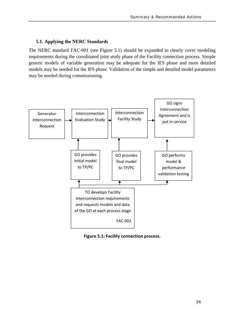
Summary amp Recommended Actions
36
51 Applying the NERC Standards
The NERC standard FAC-001 (see Figure 51) should be expanded to clearly cover modeling requirements during the coordinated joint study phase of the Facility connection process Simple generic models of variable generation may be adequate for the IES phase and more detailed models may be needed for the IFS phase Validation of the simple and detailed model parameters may be needed during commissioning
Figure 51 Facility connection process
Interconnection Evaluation Study
Generator Interconnection
Request
Interconnection Facility Study
GO provides initial model
to TPPC
GO provides final model
to TPPC
GO signs Interconnection
Agreement and is put in-service
GO performs model amp
performance validation testing
TO develops Facility Interconnection requirements and requests models and data
of the GO at each process stage
FAC-001
Summary amp Recommended Actions
37
The generic model with associated parameters feed into the NERC model building process shown in Figure 52 As an example for WTG presently there is insufficient evidence of the accuracy of presently available generic models for WTG32
for all the various WTG manufacturers Some confirmation tests during commissioning or type tests or comparison simulation tests with a detailed model are necessary to get buy in from the Transmission OwnerPlanner As the technology matures and generic models are enhanced and associated data parameter sets are developed for specific machine types the new generic models will become more accepted as is the case with models of hydro or thermal plants
Figure 52 Annual NERC Model Development Process
32 PSSregE-320 Program Application Guide Volume II Chapter 21 PSSregE-320 Model Library Chapters 17 through 21 GE PSLF Users Manual v170_04 October 2009
Steady state data
developed
MOD-10
Dynamics data
developed
MOD-12
Reliability Region creates model
MOD-14
Reliability Region creates model
MOD-15
Reliability Region defines data
requirements
MOD-13
GO
TP
RP
Reliability Region defines data
requirements
MOD-11
Annual NERC Planning and
Operating Models
created and distributed to the industry
Summary amp Recommended Actions
38
The regional model building manuals developed as part of MOD-11 and MOD-13 must provide sufficient clarity to model variable generation These manuals may ask for best available models or generic models These models cover the operational time frame and the 10-year planning horizon The manuals do not currently cover the frequency for revalidating model data
While not included in the standards more emphasis is currently being placed on meeting the Eastern Interconnection Reliability Assessment Group (ERAG) model building manual requirements in addition to regional requirements
Figure 53 NERC Model Validation Process
The Regional Entities develop the test procedures and dictate testing frequency for the Generator Owners to follow The model data then feeds in to the annual NERC model building process
52 NERC Standards Technical Issues
One general comment is that the NERC Glossary of Terms would benefit from the term ldquoVariable Generationrdquo being include in it and appropriately defined A suitable definition can be found in the Phase I report of the IVGTF
Verify real power capability
MOD-24
GO
Verify reactive power capability
MOD-25
Verify generator excitation control model
MOD-26
Verify turbine governor model
MOD-27
Summary amp Recommended Actions
39
MOD-011 Regional Steady-State Data Requirements and Reporting Procedures
The technical requirement in this MOD reads
ldquoR12 Generating Units (including synchronous condensers pumped storage etc) location minimum and maximum Ratings (net Real and Reactive Power) regulated bus and voltage set point and equipment statusrdquo
This statement could be read to equally apply to variable generation as a source of generation However it may be prudent to explicitly include variable generation in this statement For example to change the sentence to
ldquoR12 Generating Units (including synchronous condensers pumped storage variable generation resources etc) location minimum and maximum Ratings (net Real and Reactive Power) regulated bus and voltage set point and equipment status For variable generation a suitable aggregate steady-state model of the collector system and equivalent unit representing the full plantrdquo
MOD-012 Dynamics Data for Transmission System Modeling and Simulation
This MOD equally applies to variable generation and needs no augmentation The requirements in the MOD are quite generic The requirements of this standard are dependent on and point to MOD 13 discussed below
MOD-013-1 RRO Dynamics Data Requirements and Reporting Procedures
This MOD explicitly discusses synchronous type generation It would be beneficial to include an explicit statement to cover variable generation For example
ldquoPlant-specific dynamics data shall be reported for variable generating units (eg wind turbine generators PV etc) such as the type of generating unit its interface with the grid and the appropriate model and model parameters to adequately represent unit dynamic response for bulk power system studies The typical size of a single variable generating unit (eg wind turbine generators PV array etc) is several hundreds of kilo-watts to several mega-watts Thus it may be acceptable for the total plant to be represented by an adequate aggregated model of the collector system and a single equivalent generating unit scaled up to represent the total name-plate capacity for each type of generating technology employed in the plant Furthermore models may need to be provided for other equipment installed in the collector system or at the point of interconnection such as reactive compensation devicesrdquo
Summary amp Recommended Actions
40
MOD-024-2 mdash Verification and Data Reporting of Generator Real Power Capability
This latest posting of this MOD posted for commenting on January 18th 2010 exempts variable generation from this requirement It states
ldquoVariable energy units such as wind generators solar and run of river hydro are exempt from the requirements of this Standardrdquo
For a variable generation plant the definition of Real Power Capability can be slightly challenging One way to view it is to see the total gross capability as the sum of the nameplate rating of all individual units within the plant eg for a wind power plant the total sum of the nameplate rating of all wind turbine generators in the plant However there must be two realizations (i) the amount of actual power injected into the grid at the point of interconnection requires a suitable representation of losses on the collector system and auxiliary loads and (ii) by its very nature variable generation is a highly variable energy source and thus it is quite rare to find point in time when all units in the plant are coincidentally at their peak nameplate capacity Finally the seasonal variable generation output variations need some discussion since they are quite different than conventional generation technologies
MOD-025-1 mdash Verification of Generator Gross and Net Reactive Power Capability
The technical requirement in this MOD reads
ldquoR15 Information to be reported
R151 Verified maximum gross and net Reactive Power capability (both lagging and leading) at Seasonal Real Power generating capabilities as reported in accordance with Reliability Standard MOD-024 Requirement 151
R152 Verified Reactive Power limitations such as generator terminal voltage limitations shorted rotor turns etc
R153 Verified Reactive Power of auxiliary loads
R154 Method of verification including date and conditionsrdquo
Note the above requirements are from the existing version of the standard MOD-025 is currently being enhanced
Although all of the above could equally apply to variable generation some clarification may be needed Namely variable generation reactive capability of the ldquopower plantrdquo is not entirely inherent in the individual generating units A variable generation power plant such as a wind power plant may contain many reactive power sources such as the individual generating units themselves (eg Type 3 or 4 WTG see Appendix I) discretely switched shunt reactive devices
Summary amp Recommended Actions
41
(eg shunt capacitors or reactors) smoothly controlled shunt reactive devices (eg SVC or STATCOM) or a combination of these devices Thus care should be taken as to how the total reactive capability of the power plant is defined and at what point (eg point of interconnection and whether this is defined as the high or low side of the substation transformer) Also it may not be practical under normal operating conditions to exercise the full reactive capability of the power plant (this is a known issue even with conventional synchronous generator plants) to test it thus it should suffice to demonstrate the plants reactive capability to the extent possible in the field and to then augment this with engineering calculations to derive the plants full reactive capability This is particularly true of variable generation because there is no control over the energy resource So for example a typical wind power plant may only achieve its name-plate rating for a hour or two during an entire year Thus it would not be possible to demonstrate the full reactive capability of the plant in the field Rather it should suffice to demonstrate the reactive capability of a single WTG and then to derive through engineering calculations (considering all other reactive devices in the plant such as SVC STATCOM etc) the total reactive capability of the plant These comments should be somehow used to appropriately modify MOD 25
MOD-026-1 mdash Verification of Models and Data for Generator Excitation System Functions ndash SECOND POSTING (and MOD 27)
MOD 26 (and MOD 27 Verification of Models and Data for TurbineGovernor and Load Control) are presently under development33
Presently these standards are tailored explicitly to deal with synchronous type generators since much of the language revolves around technology associated with synchronous generation (eg excitation system AVR power system stabilizers etc) Thus the following key items need to be clarified in these standards as they pertain to variable generation In addition the comments that follow apply to all components in a variable generation plant that may include devices such as the actual power generating units shunt compensation devices centralized control systems spanning the entire facility etc
These two standards deal specifically with the routine validation of generating unit dynamic models for power system stability studies
1 UnitPlant Size for Validation These MODrsquos specify the size of generating unit above which model validation is required It should be recognized that the typical size of a
33 MOD 26 and MOD 27 standards under development are found at httpwwwnerccomfilezstandardsGenerator-Verification-Project-2007-09html
Summary amp Recommended Actions
42
variable generation unit is in the hundreds of kilo-watts to several megawatts range Thus the language should be changed (or introduced) to indicate ldquonet power plantrdquo size
2 Validation of various technologies in a single plant Variable generation power plants can consist of multiple generation technologies For example a wind power plant may consist of WTGs of two different types Thus we need to consider the following points as they pertain to variable generation
a For a uniform variable generation plant (ie all generating units are of the same technology type) a single aggregate generator model representation should be sufficient
b For a significantly diverse variable generation plant the plant should be represented by multiple aggregated unit models representing each technology type
c Unique representation of a group of variable generation units as a single aggregated generator model representation should be based on
i The size of the group is a significant proportion of the total plant size (eg gt 20 of plant rating)
ii Each group should represent a unique characteristic (eg Type 1 WTG as compared to a Type 3 WTG)
3 Validation of different control layers Variable generation plants such as wind power plant may have several functional layers of control For example in a wind power plant with Type 3 WTGs we may have one level of closed loop voltage regulation at the terminals of the WTG a second slower control loop that regulates voltage at the point of interconnection (POI) and a third layer of control that coordinates the switching of shunt capacitors at the POI based on the reactive output of the individual WTGs In addition devices such as STATCOMs may be present at the POI Modeling and model validation should incorporate such devicescontrol layers to the extent that the dynamics of these functional layers are important for stability studies (see Figure 31)
4 Modeling and Model Validation Models are an emulation of actual equipment Not all model parameters necessarily translate to actual physical components or measureable features Judgment needs to be exercised in the modeling and validation process
a Models should be validated typically against the performance of an actual plant for a given eventdisturbance within the given operating range it is designed for
Summary amp Recommended Actions
43
b Models should state clearly the type and the range of events they have been designed to simulated and the limitation of the models beyond which the model deviates from the actual variable generation plant performance (eg a model developed to represent electrical transient behavior of a WTG may not be adequate for studying wind fluctuations over a many minute time frame)
c In general the best approach to model validation is to use field (or test bench) measurements of various disturbances that must exercise the different control functions to a wide range of operation points For example a model is not necessarily valid if the only a comparison between simulation results and field measurements for a single voltage step response is performed at one operating condition Ideally illustration of validation against recorded response to various system disturbances (faults frequency deviations etc) gives the greatest confidence in validation
d A model is valid if its dynamic behavior is close enough to reality so that its influence on the network of interest (ie used for power system studies) results in relatively negligible errors for the phenomena of interest (ie in stability studies) That is perfect curve fitting is not necessary but to the extent possible erroneous model dynamics must not result in a notable over-design or under-design of the network
5 Future functionality Due to the rapidly evolving nature of variable generation technologies variable generation models should be of a modular nature such that future functionality can be incorporated as much as possible into old model structures by adding a functional modular block For example presently Type 3 and 4 WTGs do not exhibit inertial response However at least one manufacturer now supplies a functional control addition that can emulate inertial response on these units Such functionality is likely to be made available soon by most vendors Thus a functional model block can be developed that can be added to the existing models for Type 3 and 4 WTGs to emulate the behavior of this additional control
6 Modeling of protection Variable generation much like conventional generation will have associated underover voltage and under-over frequency protection These should be modeled Attention should also be given to protective relay coordination with plant controls particularly in light of the nature of the grounding system within the variable generation plant (eg a wind power plant spans an entire collector system which can be grounded in several different ways and thus have various implications on protective relay coordination) Such coordination issues relate to the PRC and FAC-001 standards
Summary amp Recommended Actions
44
7 Issues related to the fuel source for variable generation For variable generation one needs to be cognizant of the variable nature of the energy source and thus the possible impracticality of performing model validation at a desired plant output but rather having to accept model validation at whatever plant output can be achieved at the time of testing or disturbance monitoring
8 Revalidation How often should models be revalidated
a Many variable generation technologies are rapidly changing for example in wind power plants new control software or new setting may be uploaded every year if not sooner
b If the changes are insignificant the existing dynamic models should be revalidated if possible as a matter of prudency ndash say within six months or so of a control system updateupgrade The changes (in parameters or dynamic model) should be reported to the local Reliability Entities
c If the changes are significant the existing dynamic models should be revalidated ndash say within three months or so after the updateupgrade The changes (which may include a new module new software etc) should be reported to the local Regional Entities
53 Final Recommendation
An earlier draft of this report and recommendations were presented to NERCrsquos Planning Committee at their March 2010 meeting The Committee members urged the IVGTF to pursue NERC reliability standard development Thus several NERC Standards Drafting Teams undertaking MOD Standard development will be contacted to present the recommendations from this report for their consideration and incorporation in subsequent updates The standard drafting teams for MOD-026 and MOD-027 are aiming to incorporate variable generation considerations in the next release of these draft standards
Appendix I Wind-Turbine Generation (WTG) Technologies
45
Appendix I Wind-Turbine Generation (WTG) Technologies
(a) Type 1 Wind Turbine-Generator Fixed Speed Induction Generator
(b) Type 2 Wind Turbine-Generator Variable Slip Induction Generator 34
34 IGBT R control = Resistor controlled by Insulated Gate Bi-Polar Transistor
3
GEAR BOX
INDUCTION GENERATOR TRANSFORMER
GRID
3
3GEAR BOX
WOUND ROTORINDUCTION GENERATOR TRANSFORMER
GRID
IGBT RControl
Rectifier
Appendix I Wind-Turbine Generation (WTG) Technologies
46
(c) Type 3 Wind Turbine-Generator Double-Fed Asynchronous Generator
(d) Type 4 Wind Turbine-Generator Full Power Conversion
3
3GEAR BOX
WOUND ROTORINDUCTION GENERATOR TRANSFORMER
GRID
IGBT POWER CONVERTORS
3
GEAR BOX
SYNCHRONOUSGENERATOR TRANSFORMER
GRID
Rectifier
33
IGBTInverter
Acronyms
47
Acronyms
CSP ndash Concentrating Solar Power
CIGRE - International Council on Large Electric Systems
DFAG ndash Doubly Fed Asynchronous Generator (also often referred to as DFIG ndash Doubly Fed Induction Generator)
FERC ndash Federal Energy Regulatory Commission
HVDC ndash High-Voltage Direct-Current transmission
IEC ndash International Electrotechnical Commission
IEEE ndash Institute of Electrical and Electronic Engineers
IGBT ndash Insulated-Gate Bipolar Transistor
IGCT ndash Insulated-Gate Commutated Thyristor
IVGTF ndash Integration of Variable Generation Task Force
ISO ndash Independent System Operator
LCC ndash Line-Commutated Converter
LVRT ndash Low-Voltage Ride-Through
MOD ndash Modeling Data and Analysis Standards
NERC ndash North American Electric Reliability Corporation
OEM ndash Original Equipment Manufacturer
PHEV ndash Plug-in Hybrid Electric Vehicle
PV ndash Photovoltaic
POI ndash Point of Interconnection
RPS ndash Renewable Portfolio Standard
RTO ndash Regional Transmission Operator
Acronyms
48
SAR ndash Standards Authorization Request (NERC process)
SCADA - Supervisory Control and Data Acquisition
SSTI ndash Subsynchronous Torsional Interaction
STATCOM ndash Static Compensator (voltage source converter based technology)
SVC ndash Static Var Compensator (thyristor based technology)
TSO ndash Transmission System Operator
VAr ndash volt-ampere reactive (standard units for reactive power)
VRT ndash Voltage Ride-Through
VSC ndash Voltage Source Converter
WPP ndash Wind Power Plant
WTG ndash Wind Turbine Generator
WECC ndash Western Electricity Coordinating Council
IVGTF Roster
49
IVGTF Task 1-1 Roster
Chair Pouyan Pourbeik
Technical Executive EPRI 942 Corridor Park Boulevard Knoxville Tennessee 37932
(919) 806-8126 ppourbeik epricom
Jay Caspary Director Transmission Development
Southwest Power Pool 415 North McKinley Suite 140 Little Rock Arkansas 72205
(501) 666-0376 (501) 666-0376 Fx jcasparyspporg
K R Chakravarthi
Southern Company Services Inc Southern Company Services Birmingham Alabama 35203
205-257-6125 205-257-1040 Fx krchakra southerncocom
Kieran Connolly
Manager Generation Scheduling
Bonneville Power Administration 905 NE 11th Avenue Portland Oregon 97232
(503) 230-4680 (503) 230-5377 Fx kpconnolly bpagov
Adam Flink
Engineer Midwest Reliability Organization 2774 Cleveland Ave Roseville Minnesota 55113
6515881705 (651) 855-1712 Fx adflink midwestreliabilityorg
David Jacobson
Interconnection amp Grid Supply Planning Engineer
Manitoba Hydro 12-1146 Waverly Street PO Box 815 Winnipeg Manitoba R3C 2P4
(204) 474-3765 (204) 477-4606 Fx dajacobson hydrombca
Charles-Eric
Langlois Jr Engineer
Hydro-Queacutebec TransEnergie 9e eacutetage Complexe Desjardins Tour Est Montreal Queacutebec H5B1H7
(514) 879-4100 ext 5441 (514) 879-4486 Fx LangloisCharles-Erichydroqcca
IVGTF Roster
50
David Marshall Project Manager
Southern Company Services Inc 600 N 18th Street Birmingham Alabama 35203
205-257-3326 205-257-1040 Fx dcmarsha southerncocom
Sophie Paquette
Transmission Planning Engineer
Hydro-Queacutebec TransEnergie 9e eacutetage Complexe Desjardins Tour Est 12th Floor Montreal Queacutebec H5B1H7
(514) 879-4100 ext 5423 (514) 879-4486 Fx paquettesophie hydroqcca
David C Schooley
Sr Engineer Commonwealth Edison Co 2 Lincoln Centre Oakbrook Terrace Illinois 60181
(630) 437-2773 davidschooley comedcom
Eric Thoms
Technical Lead - Transmission Access Planning
Midwest ISO Inc 1125 Energy Park Dr St Paul Minnesota 55108
(651) 632-8454 (651) 632-8417 Fx ethoms midwestisoorg
Observers Daniel Brooks
Manager Power Delivery System Studies
Electric Power Research Institute 942 Corridor Park Blvd Knoxville Tennessee 37932
(865) 218-8040 (865) 218-8001 Fx dbrooksepricom
Abraham Ellis
Principal Member of Technical Staff Renewable System Integration
Sandia National Laboratories 1515 Eubank SE Albuquerque New Mexico 87123
(505) 844-7717 (505) 844-2890 Fx aellis sandiagov
Ben Karlson
Sandia National Laboratories PO Box 5800 Albuquerque New Mexico 87185
(505) 803-3676 bkarlso sandiagov
Yuriy Kazachkov
Siemens Energy Inc 400 State Street Schenectady New York 12305
(518) 395-5132 (518) 346-2777 Fx yuriykazachkov siemenscom
Carl Lenox
Senior Staff Engineer Sunpower Corporation Systems 1414 Harbour Way South Richmond California 94804
(510) 260-8286 (510) 540-0552 Fx carllenox sunpowercorpcom
IVGTF Roster
51
Jason MacDowell
GE Energy 1 River Road Bldg 53 Schenectady New York 12345
(518) 385-2416 (518) 385-5703 Fx jasonmacdowell gecom
John Mead
Senior Staff Engineer Sunpower Corporation Systems 1414 Harbour Way South Richmond California 94804
(510) 260-8370 (510) 540-0552 Fx johnmead sunpowercorpcom
Nicholas W Miller
Director GE Energy 53-300Q 1 River Road Schenectady New York 12345
(518) 385-9865 (518) 385-5703 Fx nicholasmiller gecom
Eduard Muljadi
Senior Engineer National Renewable Energy Laboratory 1617 Cole Boulevard Golden Colorado 80401
(303) 384-6904 EduardMuljadi nrelgov
Mark OMalley
Professor of Electrical Engineering
University College Dublin R 157A Engineering amp Materials Science Centre University College Dublin Belfield Dublin 4
00353-1-716-1851 00353-1-283-0921 Fx markomalley ucdie
Subbaiah Pasupulati
Director of Technical Studies
Oak Creek Energy Systems Inc 14633 Willow Springs Road Mojave California 93501
(909) 241-9197 (661) 822-5991 Fx subbaiah oakcreekenergycom
Juan J Sanchez-
Gasca Principal Engineer
GE Energy 1 River Road Bldg 53-302E Schenectady New York 12345
(518) 385-5564 (518) 385-5703 Fx juansanchez psgecom
Steven Saylors
Chief Electrical Engineer
Vestas Americas 1881 SW Naito Parkway Portland Oregon 97201
(503) 327-2111 (503) 327-2001 Fx saylvestascom
IVGTF Roster
52
Robert Zavadil Vice President and Principal Consultant
EnerNex Corp 620 Mabry Hood Road Suite 300 Knoxville Tennessee 37932
(865) 218-4600 Ext 6149 (865) 218-8999 Fx bobzenernexcom
NERC Staff
Aaron Bennett Engineer Reliability Assessments
North American Electric Reliability Corporation 116-390 Village Boulevard Princeton New Jersey 08540-5721
(609) 524-7003 (609) 452-9550 Fx aaronbennett nercnet
Rhaiza Villafranca
Technical Analyst North American Electric Reliability Corporation 116-390 Village Boulevard Princeton New Jersey 08540-5721
(609) 452-8060 (609) 452-9550 Fx rhaizavillafranca nercnet
Mark G Lauby
Director Reliability Assessment and Performance Analysis
North American Electric Reliability Corporation 116-390 Village Boulevard Princeton New Jersey 08540-5721
(609) 524-7077 (609) 452-9550 Fx marklauby nercnet
References
53
References and Further Reading
[1] NERC Special Report Accommodation of High Levels of Variable Generation April 2009 httpwwwnerccomfilesIVGTF_Report_041609pdf
[2] CIGRE Technical Brochure 328 Modeling and Dynamic Behavior of Wind Generation as it Relates to Power System Control and Dynamic Performance Prepared by CIGRE WG C4601 August 2007 (available on-line at wwwe-cigreorg)
[3] ldquoWECC Wind Generator Power Flow Modeling Guiderdquo (httpwwwweccbizlibraryWECC20DocumentsDocuments20for20GeneratorsGenerator20Testing20ProgramWind20Generator20Power20Flow20Modeling20Guidepdf)
[4] G Lalor A Mullane and M J OrsquoMalley ldquoFrequency Control and Wind Turbine Technologiesrdquo IEEE Transactions on Power Systems Vol 20 pp 1903-1913 2005
[5] A Mullane and M J OrsquoMalley ldquoThe inertial-response of induction-machine based wind-turbinesrdquo IEEE Transactions on Power Systems Vol 20 pp 1496 ndash 1503 2005
[6] R Walling ldquoWind Plants of the Futurerdquo UWIG Oct 2008
[7] Hydro-Queacutebec TransEacutenergie ldquoTechnical requirements for the connection of generation facilities to the Hydro-Queacutebec transmission systemrdquo May 2006
[8] ESB National grid ldquoDynamic modeling of wind generation in Irelandrdquo January 2008
[9] N Miller K Clark R Delmerico and M Cardinal ldquoWindINERTIATM Inertial Response Option for GE Wind Turbine Generatorsrdquo Windpower 2009 Chicago IL May 4-7 2009
[10] R K Varma and S Auddy ldquoMitigation of Subsynchronous Oscillations in a Series Compensated Wind Farm with Static Var Compensatorrdquo Proceedings of the IEEE PES General Meeting 2006 Montreall Canada 2006
References
54
[11] Bialasiewicz J T Muljadi E Nix R G Drouilhet S Renewable Energy Power System Modular Simulator RPM-SIM Users Guide National Renewable Energy Laboratory March 2001 NRELTP-500-29721
[12] N Miller K Clark J MacDowell and W Barton Experience with Field and Factory Testing for Model Validation of GE Wind Plants European Wind Energy Conference amp Exhibition Brussels Belgium MarchApril 2008
[13] R J Piwko N W Miller and J M MacDowell ldquoField Testing and Model Validation of Wind Plantsrdquo IEEE-PES GM June 2008
- Executive Summary
- Introduction
- The Need for Models for Variable Generation
- Steady-State and Fault Current Analysis
- Time-Domain Positive Sequence Dynamic Models for Bulk Power System Stability Analysis
- Detailed Three-phase Equipment Level Models
- Summary
- Present Status of Modeling Variable Generation
- Wind Generation
-
- 311 WECCIEEE Effort for Generic Models
- 312 UWIG Generic Model Documentation and Validation Effort
- 313 IEC Effort for Generic Models
-
- Photovoltaic Solar Generation
- Solar Thermal
- Tidal Generation
- Other Resources
- Summary
- Present Status of Model Validation
- What is Model Validation
- Examples of Model Validation Efforts
-
- 421 Hydro- Queacutebec Example
- 422 GE Example ndash based on GErsquos work with client facilities
-
- Summary amp Recommended Actions ndash Standards Implications
- Applying the NERC Standards
- NERC Standards Technical Issues
- Final Recommendation
- Appendix I Wind-Turbine Generation (WTG) Technologies
- Acronyms
- IVGTF Task 1-1 Roster
- References and Further Reading
-
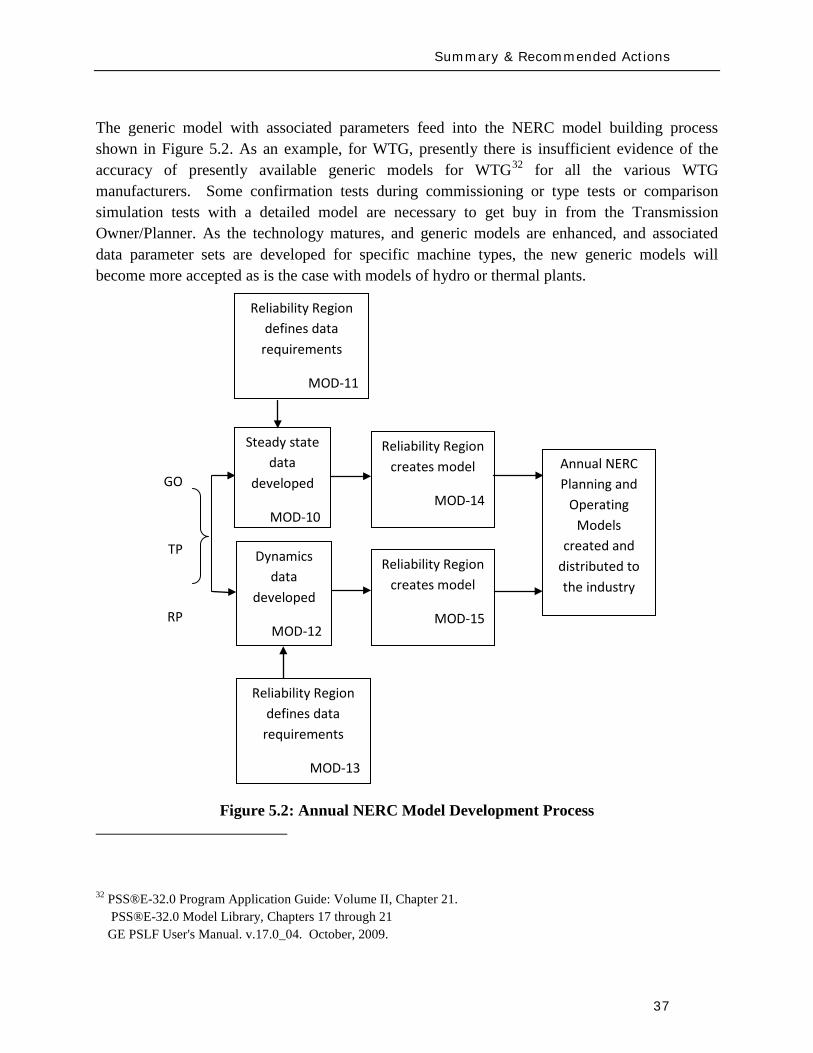
Summary amp Recommended Actions
37
The generic model with associated parameters feed into the NERC model building process shown in Figure 52 As an example for WTG presently there is insufficient evidence of the accuracy of presently available generic models for WTG32
for all the various WTG manufacturers Some confirmation tests during commissioning or type tests or comparison simulation tests with a detailed model are necessary to get buy in from the Transmission OwnerPlanner As the technology matures and generic models are enhanced and associated data parameter sets are developed for specific machine types the new generic models will become more accepted as is the case with models of hydro or thermal plants
Figure 52 Annual NERC Model Development Process
32 PSSregE-320 Program Application Guide Volume II Chapter 21 PSSregE-320 Model Library Chapters 17 through 21 GE PSLF Users Manual v170_04 October 2009
Steady state data
developed
MOD-10
Dynamics data
developed
MOD-12
Reliability Region creates model
MOD-14
Reliability Region creates model
MOD-15
Reliability Region defines data
requirements
MOD-13
GO
TP
RP
Reliability Region defines data
requirements
MOD-11
Annual NERC Planning and
Operating Models
created and distributed to the industry
Summary amp Recommended Actions
38
The regional model building manuals developed as part of MOD-11 and MOD-13 must provide sufficient clarity to model variable generation These manuals may ask for best available models or generic models These models cover the operational time frame and the 10-year planning horizon The manuals do not currently cover the frequency for revalidating model data
While not included in the standards more emphasis is currently being placed on meeting the Eastern Interconnection Reliability Assessment Group (ERAG) model building manual requirements in addition to regional requirements
Figure 53 NERC Model Validation Process
The Regional Entities develop the test procedures and dictate testing frequency for the Generator Owners to follow The model data then feeds in to the annual NERC model building process
52 NERC Standards Technical Issues
One general comment is that the NERC Glossary of Terms would benefit from the term ldquoVariable Generationrdquo being include in it and appropriately defined A suitable definition can be found in the Phase I report of the IVGTF
Verify real power capability
MOD-24
GO
Verify reactive power capability
MOD-25
Verify generator excitation control model
MOD-26
Verify turbine governor model
MOD-27
Summary amp Recommended Actions
39
MOD-011 Regional Steady-State Data Requirements and Reporting Procedures
The technical requirement in this MOD reads
ldquoR12 Generating Units (including synchronous condensers pumped storage etc) location minimum and maximum Ratings (net Real and Reactive Power) regulated bus and voltage set point and equipment statusrdquo
This statement could be read to equally apply to variable generation as a source of generation However it may be prudent to explicitly include variable generation in this statement For example to change the sentence to
ldquoR12 Generating Units (including synchronous condensers pumped storage variable generation resources etc) location minimum and maximum Ratings (net Real and Reactive Power) regulated bus and voltage set point and equipment status For variable generation a suitable aggregate steady-state model of the collector system and equivalent unit representing the full plantrdquo
MOD-012 Dynamics Data for Transmission System Modeling and Simulation
This MOD equally applies to variable generation and needs no augmentation The requirements in the MOD are quite generic The requirements of this standard are dependent on and point to MOD 13 discussed below
MOD-013-1 RRO Dynamics Data Requirements and Reporting Procedures
This MOD explicitly discusses synchronous type generation It would be beneficial to include an explicit statement to cover variable generation For example
ldquoPlant-specific dynamics data shall be reported for variable generating units (eg wind turbine generators PV etc) such as the type of generating unit its interface with the grid and the appropriate model and model parameters to adequately represent unit dynamic response for bulk power system studies The typical size of a single variable generating unit (eg wind turbine generators PV array etc) is several hundreds of kilo-watts to several mega-watts Thus it may be acceptable for the total plant to be represented by an adequate aggregated model of the collector system and a single equivalent generating unit scaled up to represent the total name-plate capacity for each type of generating technology employed in the plant Furthermore models may need to be provided for other equipment installed in the collector system or at the point of interconnection such as reactive compensation devicesrdquo
Summary amp Recommended Actions
40
MOD-024-2 mdash Verification and Data Reporting of Generator Real Power Capability
This latest posting of this MOD posted for commenting on January 18th 2010 exempts variable generation from this requirement It states
ldquoVariable energy units such as wind generators solar and run of river hydro are exempt from the requirements of this Standardrdquo
For a variable generation plant the definition of Real Power Capability can be slightly challenging One way to view it is to see the total gross capability as the sum of the nameplate rating of all individual units within the plant eg for a wind power plant the total sum of the nameplate rating of all wind turbine generators in the plant However there must be two realizations (i) the amount of actual power injected into the grid at the point of interconnection requires a suitable representation of losses on the collector system and auxiliary loads and (ii) by its very nature variable generation is a highly variable energy source and thus it is quite rare to find point in time when all units in the plant are coincidentally at their peak nameplate capacity Finally the seasonal variable generation output variations need some discussion since they are quite different than conventional generation technologies
MOD-025-1 mdash Verification of Generator Gross and Net Reactive Power Capability
The technical requirement in this MOD reads
ldquoR15 Information to be reported
R151 Verified maximum gross and net Reactive Power capability (both lagging and leading) at Seasonal Real Power generating capabilities as reported in accordance with Reliability Standard MOD-024 Requirement 151
R152 Verified Reactive Power limitations such as generator terminal voltage limitations shorted rotor turns etc
R153 Verified Reactive Power of auxiliary loads
R154 Method of verification including date and conditionsrdquo
Note the above requirements are from the existing version of the standard MOD-025 is currently being enhanced
Although all of the above could equally apply to variable generation some clarification may be needed Namely variable generation reactive capability of the ldquopower plantrdquo is not entirely inherent in the individual generating units A variable generation power plant such as a wind power plant may contain many reactive power sources such as the individual generating units themselves (eg Type 3 or 4 WTG see Appendix I) discretely switched shunt reactive devices
Summary amp Recommended Actions
41
(eg shunt capacitors or reactors) smoothly controlled shunt reactive devices (eg SVC or STATCOM) or a combination of these devices Thus care should be taken as to how the total reactive capability of the power plant is defined and at what point (eg point of interconnection and whether this is defined as the high or low side of the substation transformer) Also it may not be practical under normal operating conditions to exercise the full reactive capability of the power plant (this is a known issue even with conventional synchronous generator plants) to test it thus it should suffice to demonstrate the plants reactive capability to the extent possible in the field and to then augment this with engineering calculations to derive the plants full reactive capability This is particularly true of variable generation because there is no control over the energy resource So for example a typical wind power plant may only achieve its name-plate rating for a hour or two during an entire year Thus it would not be possible to demonstrate the full reactive capability of the plant in the field Rather it should suffice to demonstrate the reactive capability of a single WTG and then to derive through engineering calculations (considering all other reactive devices in the plant such as SVC STATCOM etc) the total reactive capability of the plant These comments should be somehow used to appropriately modify MOD 25
MOD-026-1 mdash Verification of Models and Data for Generator Excitation System Functions ndash SECOND POSTING (and MOD 27)
MOD 26 (and MOD 27 Verification of Models and Data for TurbineGovernor and Load Control) are presently under development33
Presently these standards are tailored explicitly to deal with synchronous type generators since much of the language revolves around technology associated with synchronous generation (eg excitation system AVR power system stabilizers etc) Thus the following key items need to be clarified in these standards as they pertain to variable generation In addition the comments that follow apply to all components in a variable generation plant that may include devices such as the actual power generating units shunt compensation devices centralized control systems spanning the entire facility etc
These two standards deal specifically with the routine validation of generating unit dynamic models for power system stability studies
1 UnitPlant Size for Validation These MODrsquos specify the size of generating unit above which model validation is required It should be recognized that the typical size of a
33 MOD 26 and MOD 27 standards under development are found at httpwwwnerccomfilezstandardsGenerator-Verification-Project-2007-09html
Summary amp Recommended Actions
42
variable generation unit is in the hundreds of kilo-watts to several megawatts range Thus the language should be changed (or introduced) to indicate ldquonet power plantrdquo size
2 Validation of various technologies in a single plant Variable generation power plants can consist of multiple generation technologies For example a wind power plant may consist of WTGs of two different types Thus we need to consider the following points as they pertain to variable generation
a For a uniform variable generation plant (ie all generating units are of the same technology type) a single aggregate generator model representation should be sufficient
b For a significantly diverse variable generation plant the plant should be represented by multiple aggregated unit models representing each technology type
c Unique representation of a group of variable generation units as a single aggregated generator model representation should be based on
i The size of the group is a significant proportion of the total plant size (eg gt 20 of plant rating)
ii Each group should represent a unique characteristic (eg Type 1 WTG as compared to a Type 3 WTG)
3 Validation of different control layers Variable generation plants such as wind power plant may have several functional layers of control For example in a wind power plant with Type 3 WTGs we may have one level of closed loop voltage regulation at the terminals of the WTG a second slower control loop that regulates voltage at the point of interconnection (POI) and a third layer of control that coordinates the switching of shunt capacitors at the POI based on the reactive output of the individual WTGs In addition devices such as STATCOMs may be present at the POI Modeling and model validation should incorporate such devicescontrol layers to the extent that the dynamics of these functional layers are important for stability studies (see Figure 31)
4 Modeling and Model Validation Models are an emulation of actual equipment Not all model parameters necessarily translate to actual physical components or measureable features Judgment needs to be exercised in the modeling and validation process
a Models should be validated typically against the performance of an actual plant for a given eventdisturbance within the given operating range it is designed for
Summary amp Recommended Actions
43
b Models should state clearly the type and the range of events they have been designed to simulated and the limitation of the models beyond which the model deviates from the actual variable generation plant performance (eg a model developed to represent electrical transient behavior of a WTG may not be adequate for studying wind fluctuations over a many minute time frame)
c In general the best approach to model validation is to use field (or test bench) measurements of various disturbances that must exercise the different control functions to a wide range of operation points For example a model is not necessarily valid if the only a comparison between simulation results and field measurements for a single voltage step response is performed at one operating condition Ideally illustration of validation against recorded response to various system disturbances (faults frequency deviations etc) gives the greatest confidence in validation
d A model is valid if its dynamic behavior is close enough to reality so that its influence on the network of interest (ie used for power system studies) results in relatively negligible errors for the phenomena of interest (ie in stability studies) That is perfect curve fitting is not necessary but to the extent possible erroneous model dynamics must not result in a notable over-design or under-design of the network
5 Future functionality Due to the rapidly evolving nature of variable generation technologies variable generation models should be of a modular nature such that future functionality can be incorporated as much as possible into old model structures by adding a functional modular block For example presently Type 3 and 4 WTGs do not exhibit inertial response However at least one manufacturer now supplies a functional control addition that can emulate inertial response on these units Such functionality is likely to be made available soon by most vendors Thus a functional model block can be developed that can be added to the existing models for Type 3 and 4 WTGs to emulate the behavior of this additional control
6 Modeling of protection Variable generation much like conventional generation will have associated underover voltage and under-over frequency protection These should be modeled Attention should also be given to protective relay coordination with plant controls particularly in light of the nature of the grounding system within the variable generation plant (eg a wind power plant spans an entire collector system which can be grounded in several different ways and thus have various implications on protective relay coordination) Such coordination issues relate to the PRC and FAC-001 standards
Summary amp Recommended Actions
44
7 Issues related to the fuel source for variable generation For variable generation one needs to be cognizant of the variable nature of the energy source and thus the possible impracticality of performing model validation at a desired plant output but rather having to accept model validation at whatever plant output can be achieved at the time of testing or disturbance monitoring
8 Revalidation How often should models be revalidated
a Many variable generation technologies are rapidly changing for example in wind power plants new control software or new setting may be uploaded every year if not sooner
b If the changes are insignificant the existing dynamic models should be revalidated if possible as a matter of prudency ndash say within six months or so of a control system updateupgrade The changes (in parameters or dynamic model) should be reported to the local Reliability Entities
c If the changes are significant the existing dynamic models should be revalidated ndash say within three months or so after the updateupgrade The changes (which may include a new module new software etc) should be reported to the local Regional Entities
53 Final Recommendation
An earlier draft of this report and recommendations were presented to NERCrsquos Planning Committee at their March 2010 meeting The Committee members urged the IVGTF to pursue NERC reliability standard development Thus several NERC Standards Drafting Teams undertaking MOD Standard development will be contacted to present the recommendations from this report for their consideration and incorporation in subsequent updates The standard drafting teams for MOD-026 and MOD-027 are aiming to incorporate variable generation considerations in the next release of these draft standards
Appendix I Wind-Turbine Generation (WTG) Technologies
45
Appendix I Wind-Turbine Generation (WTG) Technologies
(a) Type 1 Wind Turbine-Generator Fixed Speed Induction Generator
(b) Type 2 Wind Turbine-Generator Variable Slip Induction Generator 34
34 IGBT R control = Resistor controlled by Insulated Gate Bi-Polar Transistor
3
GEAR BOX
INDUCTION GENERATOR TRANSFORMER
GRID
3
3GEAR BOX
WOUND ROTORINDUCTION GENERATOR TRANSFORMER
GRID
IGBT RControl
Rectifier
Appendix I Wind-Turbine Generation (WTG) Technologies
46
(c) Type 3 Wind Turbine-Generator Double-Fed Asynchronous Generator
(d) Type 4 Wind Turbine-Generator Full Power Conversion
3
3GEAR BOX
WOUND ROTORINDUCTION GENERATOR TRANSFORMER
GRID
IGBT POWER CONVERTORS
3
GEAR BOX
SYNCHRONOUSGENERATOR TRANSFORMER
GRID
Rectifier
33
IGBTInverter
Acronyms
47
Acronyms
CSP ndash Concentrating Solar Power
CIGRE - International Council on Large Electric Systems
DFAG ndash Doubly Fed Asynchronous Generator (also often referred to as DFIG ndash Doubly Fed Induction Generator)
FERC ndash Federal Energy Regulatory Commission
HVDC ndash High-Voltage Direct-Current transmission
IEC ndash International Electrotechnical Commission
IEEE ndash Institute of Electrical and Electronic Engineers
IGBT ndash Insulated-Gate Bipolar Transistor
IGCT ndash Insulated-Gate Commutated Thyristor
IVGTF ndash Integration of Variable Generation Task Force
ISO ndash Independent System Operator
LCC ndash Line-Commutated Converter
LVRT ndash Low-Voltage Ride-Through
MOD ndash Modeling Data and Analysis Standards
NERC ndash North American Electric Reliability Corporation
OEM ndash Original Equipment Manufacturer
PHEV ndash Plug-in Hybrid Electric Vehicle
PV ndash Photovoltaic
POI ndash Point of Interconnection
RPS ndash Renewable Portfolio Standard
RTO ndash Regional Transmission Operator
Acronyms
48
SAR ndash Standards Authorization Request (NERC process)
SCADA - Supervisory Control and Data Acquisition
SSTI ndash Subsynchronous Torsional Interaction
STATCOM ndash Static Compensator (voltage source converter based technology)
SVC ndash Static Var Compensator (thyristor based technology)
TSO ndash Transmission System Operator
VAr ndash volt-ampere reactive (standard units for reactive power)
VRT ndash Voltage Ride-Through
VSC ndash Voltage Source Converter
WPP ndash Wind Power Plant
WTG ndash Wind Turbine Generator
WECC ndash Western Electricity Coordinating Council
IVGTF Roster
49
IVGTF Task 1-1 Roster
Chair Pouyan Pourbeik
Technical Executive EPRI 942 Corridor Park Boulevard Knoxville Tennessee 37932
(919) 806-8126 ppourbeik epricom
Jay Caspary Director Transmission Development
Southwest Power Pool 415 North McKinley Suite 140 Little Rock Arkansas 72205
(501) 666-0376 (501) 666-0376 Fx jcasparyspporg
K R Chakravarthi
Southern Company Services Inc Southern Company Services Birmingham Alabama 35203
205-257-6125 205-257-1040 Fx krchakra southerncocom
Kieran Connolly
Manager Generation Scheduling
Bonneville Power Administration 905 NE 11th Avenue Portland Oregon 97232
(503) 230-4680 (503) 230-5377 Fx kpconnolly bpagov
Adam Flink
Engineer Midwest Reliability Organization 2774 Cleveland Ave Roseville Minnesota 55113
6515881705 (651) 855-1712 Fx adflink midwestreliabilityorg
David Jacobson
Interconnection amp Grid Supply Planning Engineer
Manitoba Hydro 12-1146 Waverly Street PO Box 815 Winnipeg Manitoba R3C 2P4
(204) 474-3765 (204) 477-4606 Fx dajacobson hydrombca
Charles-Eric
Langlois Jr Engineer
Hydro-Queacutebec TransEnergie 9e eacutetage Complexe Desjardins Tour Est Montreal Queacutebec H5B1H7
(514) 879-4100 ext 5441 (514) 879-4486 Fx LangloisCharles-Erichydroqcca
IVGTF Roster
50
David Marshall Project Manager
Southern Company Services Inc 600 N 18th Street Birmingham Alabama 35203
205-257-3326 205-257-1040 Fx dcmarsha southerncocom
Sophie Paquette
Transmission Planning Engineer
Hydro-Queacutebec TransEnergie 9e eacutetage Complexe Desjardins Tour Est 12th Floor Montreal Queacutebec H5B1H7
(514) 879-4100 ext 5423 (514) 879-4486 Fx paquettesophie hydroqcca
David C Schooley
Sr Engineer Commonwealth Edison Co 2 Lincoln Centre Oakbrook Terrace Illinois 60181
(630) 437-2773 davidschooley comedcom
Eric Thoms
Technical Lead - Transmission Access Planning
Midwest ISO Inc 1125 Energy Park Dr St Paul Minnesota 55108
(651) 632-8454 (651) 632-8417 Fx ethoms midwestisoorg
Observers Daniel Brooks
Manager Power Delivery System Studies
Electric Power Research Institute 942 Corridor Park Blvd Knoxville Tennessee 37932
(865) 218-8040 (865) 218-8001 Fx dbrooksepricom
Abraham Ellis
Principal Member of Technical Staff Renewable System Integration
Sandia National Laboratories 1515 Eubank SE Albuquerque New Mexico 87123
(505) 844-7717 (505) 844-2890 Fx aellis sandiagov
Ben Karlson
Sandia National Laboratories PO Box 5800 Albuquerque New Mexico 87185
(505) 803-3676 bkarlso sandiagov
Yuriy Kazachkov
Siemens Energy Inc 400 State Street Schenectady New York 12305
(518) 395-5132 (518) 346-2777 Fx yuriykazachkov siemenscom
Carl Lenox
Senior Staff Engineer Sunpower Corporation Systems 1414 Harbour Way South Richmond California 94804
(510) 260-8286 (510) 540-0552 Fx carllenox sunpowercorpcom
IVGTF Roster
51
Jason MacDowell
GE Energy 1 River Road Bldg 53 Schenectady New York 12345
(518) 385-2416 (518) 385-5703 Fx jasonmacdowell gecom
John Mead
Senior Staff Engineer Sunpower Corporation Systems 1414 Harbour Way South Richmond California 94804
(510) 260-8370 (510) 540-0552 Fx johnmead sunpowercorpcom
Nicholas W Miller
Director GE Energy 53-300Q 1 River Road Schenectady New York 12345
(518) 385-9865 (518) 385-5703 Fx nicholasmiller gecom
Eduard Muljadi
Senior Engineer National Renewable Energy Laboratory 1617 Cole Boulevard Golden Colorado 80401
(303) 384-6904 EduardMuljadi nrelgov
Mark OMalley
Professor of Electrical Engineering
University College Dublin R 157A Engineering amp Materials Science Centre University College Dublin Belfield Dublin 4
00353-1-716-1851 00353-1-283-0921 Fx markomalley ucdie
Subbaiah Pasupulati
Director of Technical Studies
Oak Creek Energy Systems Inc 14633 Willow Springs Road Mojave California 93501
(909) 241-9197 (661) 822-5991 Fx subbaiah oakcreekenergycom
Juan J Sanchez-
Gasca Principal Engineer
GE Energy 1 River Road Bldg 53-302E Schenectady New York 12345
(518) 385-5564 (518) 385-5703 Fx juansanchez psgecom
Steven Saylors
Chief Electrical Engineer
Vestas Americas 1881 SW Naito Parkway Portland Oregon 97201
(503) 327-2111 (503) 327-2001 Fx saylvestascom
IVGTF Roster
52
Robert Zavadil Vice President and Principal Consultant
EnerNex Corp 620 Mabry Hood Road Suite 300 Knoxville Tennessee 37932
(865) 218-4600 Ext 6149 (865) 218-8999 Fx bobzenernexcom
NERC Staff
Aaron Bennett Engineer Reliability Assessments
North American Electric Reliability Corporation 116-390 Village Boulevard Princeton New Jersey 08540-5721
(609) 524-7003 (609) 452-9550 Fx aaronbennett nercnet
Rhaiza Villafranca
Technical Analyst North American Electric Reliability Corporation 116-390 Village Boulevard Princeton New Jersey 08540-5721
(609) 452-8060 (609) 452-9550 Fx rhaizavillafranca nercnet
Mark G Lauby
Director Reliability Assessment and Performance Analysis
North American Electric Reliability Corporation 116-390 Village Boulevard Princeton New Jersey 08540-5721
(609) 524-7077 (609) 452-9550 Fx marklauby nercnet
References
53
References and Further Reading
[1] NERC Special Report Accommodation of High Levels of Variable Generation April 2009 httpwwwnerccomfilesIVGTF_Report_041609pdf
[2] CIGRE Technical Brochure 328 Modeling and Dynamic Behavior of Wind Generation as it Relates to Power System Control and Dynamic Performance Prepared by CIGRE WG C4601 August 2007 (available on-line at wwwe-cigreorg)
[3] ldquoWECC Wind Generator Power Flow Modeling Guiderdquo (httpwwwweccbizlibraryWECC20DocumentsDocuments20for20GeneratorsGenerator20Testing20ProgramWind20Generator20Power20Flow20Modeling20Guidepdf)
[4] G Lalor A Mullane and M J OrsquoMalley ldquoFrequency Control and Wind Turbine Technologiesrdquo IEEE Transactions on Power Systems Vol 20 pp 1903-1913 2005
[5] A Mullane and M J OrsquoMalley ldquoThe inertial-response of induction-machine based wind-turbinesrdquo IEEE Transactions on Power Systems Vol 20 pp 1496 ndash 1503 2005
[6] R Walling ldquoWind Plants of the Futurerdquo UWIG Oct 2008
[7] Hydro-Queacutebec TransEacutenergie ldquoTechnical requirements for the connection of generation facilities to the Hydro-Queacutebec transmission systemrdquo May 2006
[8] ESB National grid ldquoDynamic modeling of wind generation in Irelandrdquo January 2008
[9] N Miller K Clark R Delmerico and M Cardinal ldquoWindINERTIATM Inertial Response Option for GE Wind Turbine Generatorsrdquo Windpower 2009 Chicago IL May 4-7 2009
[10] R K Varma and S Auddy ldquoMitigation of Subsynchronous Oscillations in a Series Compensated Wind Farm with Static Var Compensatorrdquo Proceedings of the IEEE PES General Meeting 2006 Montreall Canada 2006
References
54
[11] Bialasiewicz J T Muljadi E Nix R G Drouilhet S Renewable Energy Power System Modular Simulator RPM-SIM Users Guide National Renewable Energy Laboratory March 2001 NRELTP-500-29721
[12] N Miller K Clark J MacDowell and W Barton Experience with Field and Factory Testing for Model Validation of GE Wind Plants European Wind Energy Conference amp Exhibition Brussels Belgium MarchApril 2008
[13] R J Piwko N W Miller and J M MacDowell ldquoField Testing and Model Validation of Wind Plantsrdquo IEEE-PES GM June 2008
- Executive Summary
- Introduction
- The Need for Models for Variable Generation
- Steady-State and Fault Current Analysis
- Time-Domain Positive Sequence Dynamic Models for Bulk Power System Stability Analysis
- Detailed Three-phase Equipment Level Models
- Summary
- Present Status of Modeling Variable Generation
- Wind Generation
-
- 311 WECCIEEE Effort for Generic Models
- 312 UWIG Generic Model Documentation and Validation Effort
- 313 IEC Effort for Generic Models
-
- Photovoltaic Solar Generation
- Solar Thermal
- Tidal Generation
- Other Resources
- Summary
- Present Status of Model Validation
- What is Model Validation
- Examples of Model Validation Efforts
-
- 421 Hydro- Queacutebec Example
- 422 GE Example ndash based on GErsquos work with client facilities
-
- Summary amp Recommended Actions ndash Standards Implications
- Applying the NERC Standards
- NERC Standards Technical Issues
- Final Recommendation
- Appendix I Wind-Turbine Generation (WTG) Technologies
- Acronyms
- IVGTF Task 1-1 Roster
- References and Further Reading
-
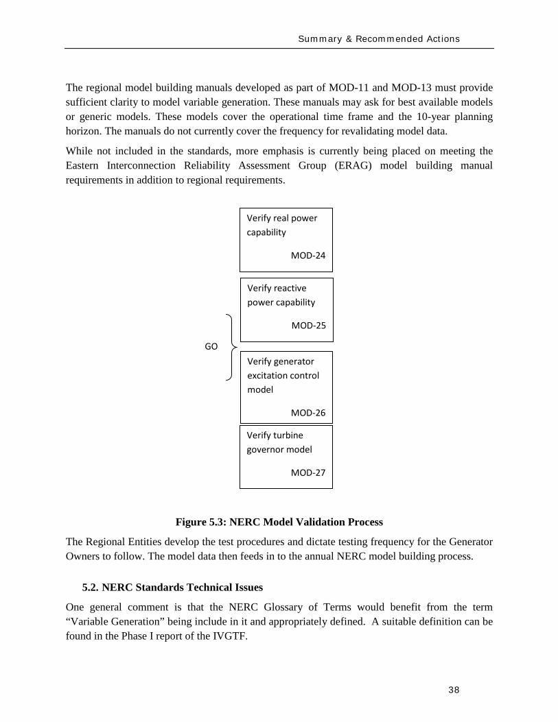
Summary amp Recommended Actions
39
MOD-011 Regional Steady-State Data Requirements and Reporting Procedures
The technical requirement in this MOD reads
ldquoR12 Generating Units (including synchronous condensers pumped storage etc) location minimum and maximum Ratings (net Real and Reactive Power) regulated bus and voltage set point and equipment statusrdquo
This statement could be read to equally apply to variable generation as a source of generation However it may be prudent to explicitly include variable generation in this statement For example to change the sentence to
ldquoR12 Generating Units (including synchronous condensers pumped storage variable generation resources etc) location minimum and maximum Ratings (net Real and Reactive Power) regulated bus and voltage set point and equipment status For variable generation a suitable aggregate steady-state model of the collector system and equivalent unit representing the full plantrdquo
MOD-012 Dynamics Data for Transmission System Modeling and Simulation
This MOD equally applies to variable generation and needs no augmentation The requirements in the MOD are quite generic The requirements of this standard are dependent on and point to MOD 13 discussed below
MOD-013-1 RRO Dynamics Data Requirements and Reporting Procedures
This MOD explicitly discusses synchronous type generation It would be beneficial to include an explicit statement to cover variable generation For example
ldquoPlant-specific dynamics data shall be reported for variable generating units (eg wind turbine generators PV etc) such as the type of generating unit its interface with the grid and the appropriate model and model parameters to adequately represent unit dynamic response for bulk power system studies The typical size of a single variable generating unit (eg wind turbine generators PV array etc) is several hundreds of kilo-watts to several mega-watts Thus it may be acceptable for the total plant to be represented by an adequate aggregated model of the collector system and a single equivalent generating unit scaled up to represent the total name-plate capacity for each type of generating technology employed in the plant Furthermore models may need to be provided for other equipment installed in the collector system or at the point of interconnection such as reactive compensation devicesrdquo
Summary amp Recommended Actions
40
MOD-024-2 mdash Verification and Data Reporting of Generator Real Power Capability
This latest posting of this MOD posted for commenting on January 18th 2010 exempts variable generation from this requirement It states
ldquoVariable energy units such as wind generators solar and run of river hydro are exempt from the requirements of this Standardrdquo
For a variable generation plant the definition of Real Power Capability can be slightly challenging One way to view it is to see the total gross capability as the sum of the nameplate rating of all individual units within the plant eg for a wind power plant the total sum of the nameplate rating of all wind turbine generators in the plant However there must be two realizations (i) the amount of actual power injected into the grid at the point of interconnection requires a suitable representation of losses on the collector system and auxiliary loads and (ii) by its very nature variable generation is a highly variable energy source and thus it is quite rare to find point in time when all units in the plant are coincidentally at their peak nameplate capacity Finally the seasonal variable generation output variations need some discussion since they are quite different than conventional generation technologies
MOD-025-1 mdash Verification of Generator Gross and Net Reactive Power Capability
The technical requirement in this MOD reads
ldquoR15 Information to be reported
R151 Verified maximum gross and net Reactive Power capability (both lagging and leading) at Seasonal Real Power generating capabilities as reported in accordance with Reliability Standard MOD-024 Requirement 151
R152 Verified Reactive Power limitations such as generator terminal voltage limitations shorted rotor turns etc
R153 Verified Reactive Power of auxiliary loads
R154 Method of verification including date and conditionsrdquo
Note the above requirements are from the existing version of the standard MOD-025 is currently being enhanced
Although all of the above could equally apply to variable generation some clarification may be needed Namely variable generation reactive capability of the ldquopower plantrdquo is not entirely inherent in the individual generating units A variable generation power plant such as a wind power plant may contain many reactive power sources such as the individual generating units themselves (eg Type 3 or 4 WTG see Appendix I) discretely switched shunt reactive devices
Summary amp Recommended Actions
41
(eg shunt capacitors or reactors) smoothly controlled shunt reactive devices (eg SVC or STATCOM) or a combination of these devices Thus care should be taken as to how the total reactive capability of the power plant is defined and at what point (eg point of interconnection and whether this is defined as the high or low side of the substation transformer) Also it may not be practical under normal operating conditions to exercise the full reactive capability of the power plant (this is a known issue even with conventional synchronous generator plants) to test it thus it should suffice to demonstrate the plants reactive capability to the extent possible in the field and to then augment this with engineering calculations to derive the plants full reactive capability This is particularly true of variable generation because there is no control over the energy resource So for example a typical wind power plant may only achieve its name-plate rating for a hour or two during an entire year Thus it would not be possible to demonstrate the full reactive capability of the plant in the field Rather it should suffice to demonstrate the reactive capability of a single WTG and then to derive through engineering calculations (considering all other reactive devices in the plant such as SVC STATCOM etc) the total reactive capability of the plant These comments should be somehow used to appropriately modify MOD 25
MOD-026-1 mdash Verification of Models and Data for Generator Excitation System Functions ndash SECOND POSTING (and MOD 27)
MOD 26 (and MOD 27 Verification of Models and Data for TurbineGovernor and Load Control) are presently under development33
Presently these standards are tailored explicitly to deal with synchronous type generators since much of the language revolves around technology associated with synchronous generation (eg excitation system AVR power system stabilizers etc) Thus the following key items need to be clarified in these standards as they pertain to variable generation In addition the comments that follow apply to all components in a variable generation plant that may include devices such as the actual power generating units shunt compensation devices centralized control systems spanning the entire facility etc
These two standards deal specifically with the routine validation of generating unit dynamic models for power system stability studies
1 UnitPlant Size for Validation These MODrsquos specify the size of generating unit above which model validation is required It should be recognized that the typical size of a
33 MOD 26 and MOD 27 standards under development are found at httpwwwnerccomfilezstandardsGenerator-Verification-Project-2007-09html
Summary amp Recommended Actions
42
variable generation unit is in the hundreds of kilo-watts to several megawatts range Thus the language should be changed (or introduced) to indicate ldquonet power plantrdquo size
2 Validation of various technologies in a single plant Variable generation power plants can consist of multiple generation technologies For example a wind power plant may consist of WTGs of two different types Thus we need to consider the following points as they pertain to variable generation
a For a uniform variable generation plant (ie all generating units are of the same technology type) a single aggregate generator model representation should be sufficient
b For a significantly diverse variable generation plant the plant should be represented by multiple aggregated unit models representing each technology type
c Unique representation of a group of variable generation units as a single aggregated generator model representation should be based on
i The size of the group is a significant proportion of the total plant size (eg gt 20 of plant rating)
ii Each group should represent a unique characteristic (eg Type 1 WTG as compared to a Type 3 WTG)
3 Validation of different control layers Variable generation plants such as wind power plant may have several functional layers of control For example in a wind power plant with Type 3 WTGs we may have one level of closed loop voltage regulation at the terminals of the WTG a second slower control loop that regulates voltage at the point of interconnection (POI) and a third layer of control that coordinates the switching of shunt capacitors at the POI based on the reactive output of the individual WTGs In addition devices such as STATCOMs may be present at the POI Modeling and model validation should incorporate such devicescontrol layers to the extent that the dynamics of these functional layers are important for stability studies (see Figure 31)
4 Modeling and Model Validation Models are an emulation of actual equipment Not all model parameters necessarily translate to actual physical components or measureable features Judgment needs to be exercised in the modeling and validation process
a Models should be validated typically against the performance of an actual plant for a given eventdisturbance within the given operating range it is designed for
Summary amp Recommended Actions
43
b Models should state clearly the type and the range of events they have been designed to simulated and the limitation of the models beyond which the model deviates from the actual variable generation plant performance (eg a model developed to represent electrical transient behavior of a WTG may not be adequate for studying wind fluctuations over a many minute time frame)
c In general the best approach to model validation is to use field (or test bench) measurements of various disturbances that must exercise the different control functions to a wide range of operation points For example a model is not necessarily valid if the only a comparison between simulation results and field measurements for a single voltage step response is performed at one operating condition Ideally illustration of validation against recorded response to various system disturbances (faults frequency deviations etc) gives the greatest confidence in validation
d A model is valid if its dynamic behavior is close enough to reality so that its influence on the network of interest (ie used for power system studies) results in relatively negligible errors for the phenomena of interest (ie in stability studies) That is perfect curve fitting is not necessary but to the extent possible erroneous model dynamics must not result in a notable over-design or under-design of the network
5 Future functionality Due to the rapidly evolving nature of variable generation technologies variable generation models should be of a modular nature such that future functionality can be incorporated as much as possible into old model structures by adding a functional modular block For example presently Type 3 and 4 WTGs do not exhibit inertial response However at least one manufacturer now supplies a functional control addition that can emulate inertial response on these units Such functionality is likely to be made available soon by most vendors Thus a functional model block can be developed that can be added to the existing models for Type 3 and 4 WTGs to emulate the behavior of this additional control
6 Modeling of protection Variable generation much like conventional generation will have associated underover voltage and under-over frequency protection These should be modeled Attention should also be given to protective relay coordination with plant controls particularly in light of the nature of the grounding system within the variable generation plant (eg a wind power plant spans an entire collector system which can be grounded in several different ways and thus have various implications on protective relay coordination) Such coordination issues relate to the PRC and FAC-001 standards
Summary amp Recommended Actions
44
7 Issues related to the fuel source for variable generation For variable generation one needs to be cognizant of the variable nature of the energy source and thus the possible impracticality of performing model validation at a desired plant output but rather having to accept model validation at whatever plant output can be achieved at the time of testing or disturbance monitoring
8 Revalidation How often should models be revalidated
a Many variable generation technologies are rapidly changing for example in wind power plants new control software or new setting may be uploaded every year if not sooner
b If the changes are insignificant the existing dynamic models should be revalidated if possible as a matter of prudency ndash say within six months or so of a control system updateupgrade The changes (in parameters or dynamic model) should be reported to the local Reliability Entities
c If the changes are significant the existing dynamic models should be revalidated ndash say within three months or so after the updateupgrade The changes (which may include a new module new software etc) should be reported to the local Regional Entities
53 Final Recommendation
An earlier draft of this report and recommendations were presented to NERCrsquos Planning Committee at their March 2010 meeting The Committee members urged the IVGTF to pursue NERC reliability standard development Thus several NERC Standards Drafting Teams undertaking MOD Standard development will be contacted to present the recommendations from this report for their consideration and incorporation in subsequent updates The standard drafting teams for MOD-026 and MOD-027 are aiming to incorporate variable generation considerations in the next release of these draft standards
Appendix I Wind-Turbine Generation (WTG) Technologies
45
Appendix I Wind-Turbine Generation (WTG) Technologies
(a) Type 1 Wind Turbine-Generator Fixed Speed Induction Generator
(b) Type 2 Wind Turbine-Generator Variable Slip Induction Generator 34
34 IGBT R control = Resistor controlled by Insulated Gate Bi-Polar Transistor
3
GEAR BOX
INDUCTION GENERATOR TRANSFORMER
GRID
3
3GEAR BOX
WOUND ROTORINDUCTION GENERATOR TRANSFORMER
GRID
IGBT RControl
Rectifier
Appendix I Wind-Turbine Generation (WTG) Technologies
46
(c) Type 3 Wind Turbine-Generator Double-Fed Asynchronous Generator
(d) Type 4 Wind Turbine-Generator Full Power Conversion
3
3GEAR BOX
WOUND ROTORINDUCTION GENERATOR TRANSFORMER
GRID
IGBT POWER CONVERTORS
3
GEAR BOX
SYNCHRONOUSGENERATOR TRANSFORMER
GRID
Rectifier
33
IGBTInverter
Acronyms
47
Acronyms
CSP ndash Concentrating Solar Power
CIGRE - International Council on Large Electric Systems
DFAG ndash Doubly Fed Asynchronous Generator (also often referred to as DFIG ndash Doubly Fed Induction Generator)
FERC ndash Federal Energy Regulatory Commission
HVDC ndash High-Voltage Direct-Current transmission
IEC ndash International Electrotechnical Commission
IEEE ndash Institute of Electrical and Electronic Engineers
IGBT ndash Insulated-Gate Bipolar Transistor
IGCT ndash Insulated-Gate Commutated Thyristor
IVGTF ndash Integration of Variable Generation Task Force
ISO ndash Independent System Operator
LCC ndash Line-Commutated Converter
LVRT ndash Low-Voltage Ride-Through
MOD ndash Modeling Data and Analysis Standards
NERC ndash North American Electric Reliability Corporation
OEM ndash Original Equipment Manufacturer
PHEV ndash Plug-in Hybrid Electric Vehicle
PV ndash Photovoltaic
POI ndash Point of Interconnection
RPS ndash Renewable Portfolio Standard
RTO ndash Regional Transmission Operator
Acronyms
48
SAR ndash Standards Authorization Request (NERC process)
SCADA - Supervisory Control and Data Acquisition
SSTI ndash Subsynchronous Torsional Interaction
STATCOM ndash Static Compensator (voltage source converter based technology)
SVC ndash Static Var Compensator (thyristor based technology)
TSO ndash Transmission System Operator
VAr ndash volt-ampere reactive (standard units for reactive power)
VRT ndash Voltage Ride-Through
VSC ndash Voltage Source Converter
WPP ndash Wind Power Plant
WTG ndash Wind Turbine Generator
WECC ndash Western Electricity Coordinating Council
IVGTF Roster
49
IVGTF Task 1-1 Roster
Chair Pouyan Pourbeik
Technical Executive EPRI 942 Corridor Park Boulevard Knoxville Tennessee 37932
(919) 806-8126 ppourbeik epricom
Jay Caspary Director Transmission Development
Southwest Power Pool 415 North McKinley Suite 140 Little Rock Arkansas 72205
(501) 666-0376 (501) 666-0376 Fx jcasparyspporg
K R Chakravarthi
Southern Company Services Inc Southern Company Services Birmingham Alabama 35203
205-257-6125 205-257-1040 Fx krchakra southerncocom
Kieran Connolly
Manager Generation Scheduling
Bonneville Power Administration 905 NE 11th Avenue Portland Oregon 97232
(503) 230-4680 (503) 230-5377 Fx kpconnolly bpagov
Adam Flink
Engineer Midwest Reliability Organization 2774 Cleveland Ave Roseville Minnesota 55113
6515881705 (651) 855-1712 Fx adflink midwestreliabilityorg
David Jacobson
Interconnection amp Grid Supply Planning Engineer
Manitoba Hydro 12-1146 Waverly Street PO Box 815 Winnipeg Manitoba R3C 2P4
(204) 474-3765 (204) 477-4606 Fx dajacobson hydrombca
Charles-Eric
Langlois Jr Engineer
Hydro-Queacutebec TransEnergie 9e eacutetage Complexe Desjardins Tour Est Montreal Queacutebec H5B1H7
(514) 879-4100 ext 5441 (514) 879-4486 Fx LangloisCharles-Erichydroqcca
IVGTF Roster
50
David Marshall Project Manager
Southern Company Services Inc 600 N 18th Street Birmingham Alabama 35203
205-257-3326 205-257-1040 Fx dcmarsha southerncocom
Sophie Paquette
Transmission Planning Engineer
Hydro-Queacutebec TransEnergie 9e eacutetage Complexe Desjardins Tour Est 12th Floor Montreal Queacutebec H5B1H7
(514) 879-4100 ext 5423 (514) 879-4486 Fx paquettesophie hydroqcca
David C Schooley
Sr Engineer Commonwealth Edison Co 2 Lincoln Centre Oakbrook Terrace Illinois 60181
(630) 437-2773 davidschooley comedcom
Eric Thoms
Technical Lead - Transmission Access Planning
Midwest ISO Inc 1125 Energy Park Dr St Paul Minnesota 55108
(651) 632-8454 (651) 632-8417 Fx ethoms midwestisoorg
Observers Daniel Brooks
Manager Power Delivery System Studies
Electric Power Research Institute 942 Corridor Park Blvd Knoxville Tennessee 37932
(865) 218-8040 (865) 218-8001 Fx dbrooksepricom
Abraham Ellis
Principal Member of Technical Staff Renewable System Integration
Sandia National Laboratories 1515 Eubank SE Albuquerque New Mexico 87123
(505) 844-7717 (505) 844-2890 Fx aellis sandiagov
Ben Karlson
Sandia National Laboratories PO Box 5800 Albuquerque New Mexico 87185
(505) 803-3676 bkarlso sandiagov
Yuriy Kazachkov
Siemens Energy Inc 400 State Street Schenectady New York 12305
(518) 395-5132 (518) 346-2777 Fx yuriykazachkov siemenscom
Carl Lenox
Senior Staff Engineer Sunpower Corporation Systems 1414 Harbour Way South Richmond California 94804
(510) 260-8286 (510) 540-0552 Fx carllenox sunpowercorpcom
IVGTF Roster
51
Jason MacDowell
GE Energy 1 River Road Bldg 53 Schenectady New York 12345
(518) 385-2416 (518) 385-5703 Fx jasonmacdowell gecom
John Mead
Senior Staff Engineer Sunpower Corporation Systems 1414 Harbour Way South Richmond California 94804
(510) 260-8370 (510) 540-0552 Fx johnmead sunpowercorpcom
Nicholas W Miller
Director GE Energy 53-300Q 1 River Road Schenectady New York 12345
(518) 385-9865 (518) 385-5703 Fx nicholasmiller gecom
Eduard Muljadi
Senior Engineer National Renewable Energy Laboratory 1617 Cole Boulevard Golden Colorado 80401
(303) 384-6904 EduardMuljadi nrelgov
Mark OMalley
Professor of Electrical Engineering
University College Dublin R 157A Engineering amp Materials Science Centre University College Dublin Belfield Dublin 4
00353-1-716-1851 00353-1-283-0921 Fx markomalley ucdie
Subbaiah Pasupulati
Director of Technical Studies
Oak Creek Energy Systems Inc 14633 Willow Springs Road Mojave California 93501
(909) 241-9197 (661) 822-5991 Fx subbaiah oakcreekenergycom
Juan J Sanchez-
Gasca Principal Engineer
GE Energy 1 River Road Bldg 53-302E Schenectady New York 12345
(518) 385-5564 (518) 385-5703 Fx juansanchez psgecom
Steven Saylors
Chief Electrical Engineer
Vestas Americas 1881 SW Naito Parkway Portland Oregon 97201
(503) 327-2111 (503) 327-2001 Fx saylvestascom
IVGTF Roster
52
Robert Zavadil Vice President and Principal Consultant
EnerNex Corp 620 Mabry Hood Road Suite 300 Knoxville Tennessee 37932
(865) 218-4600 Ext 6149 (865) 218-8999 Fx bobzenernexcom
NERC Staff
Aaron Bennett Engineer Reliability Assessments
North American Electric Reliability Corporation 116-390 Village Boulevard Princeton New Jersey 08540-5721
(609) 524-7003 (609) 452-9550 Fx aaronbennett nercnet
Rhaiza Villafranca
Technical Analyst North American Electric Reliability Corporation 116-390 Village Boulevard Princeton New Jersey 08540-5721
(609) 452-8060 (609) 452-9550 Fx rhaizavillafranca nercnet
Mark G Lauby
Director Reliability Assessment and Performance Analysis
North American Electric Reliability Corporation 116-390 Village Boulevard Princeton New Jersey 08540-5721
(609) 524-7077 (609) 452-9550 Fx marklauby nercnet
References
53
References and Further Reading
[1] NERC Special Report Accommodation of High Levels of Variable Generation April 2009 httpwwwnerccomfilesIVGTF_Report_041609pdf
[2] CIGRE Technical Brochure 328 Modeling and Dynamic Behavior of Wind Generation as it Relates to Power System Control and Dynamic Performance Prepared by CIGRE WG C4601 August 2007 (available on-line at wwwe-cigreorg)
[3] ldquoWECC Wind Generator Power Flow Modeling Guiderdquo (httpwwwweccbizlibraryWECC20DocumentsDocuments20for20GeneratorsGenerator20Testing20ProgramWind20Generator20Power20Flow20Modeling20Guidepdf)
[4] G Lalor A Mullane and M J OrsquoMalley ldquoFrequency Control and Wind Turbine Technologiesrdquo IEEE Transactions on Power Systems Vol 20 pp 1903-1913 2005
[5] A Mullane and M J OrsquoMalley ldquoThe inertial-response of induction-machine based wind-turbinesrdquo IEEE Transactions on Power Systems Vol 20 pp 1496 ndash 1503 2005
[6] R Walling ldquoWind Plants of the Futurerdquo UWIG Oct 2008
[7] Hydro-Queacutebec TransEacutenergie ldquoTechnical requirements for the connection of generation facilities to the Hydro-Queacutebec transmission systemrdquo May 2006
[8] ESB National grid ldquoDynamic modeling of wind generation in Irelandrdquo January 2008
[9] N Miller K Clark R Delmerico and M Cardinal ldquoWindINERTIATM Inertial Response Option for GE Wind Turbine Generatorsrdquo Windpower 2009 Chicago IL May 4-7 2009
[10] R K Varma and S Auddy ldquoMitigation of Subsynchronous Oscillations in a Series Compensated Wind Farm with Static Var Compensatorrdquo Proceedings of the IEEE PES General Meeting 2006 Montreall Canada 2006
References
54
[11] Bialasiewicz J T Muljadi E Nix R G Drouilhet S Renewable Energy Power System Modular Simulator RPM-SIM Users Guide National Renewable Energy Laboratory March 2001 NRELTP-500-29721
[12] N Miller K Clark J MacDowell and W Barton Experience with Field and Factory Testing for Model Validation of GE Wind Plants European Wind Energy Conference amp Exhibition Brussels Belgium MarchApril 2008
[13] R J Piwko N W Miller and J M MacDowell ldquoField Testing and Model Validation of Wind Plantsrdquo IEEE-PES GM June 2008
- Executive Summary
- Introduction
- The Need for Models for Variable Generation
- Steady-State and Fault Current Analysis
- Time-Domain Positive Sequence Dynamic Models for Bulk Power System Stability Analysis
- Detailed Three-phase Equipment Level Models
- Summary
- Present Status of Modeling Variable Generation
- Wind Generation
-
- 311 WECCIEEE Effort for Generic Models
- 312 UWIG Generic Model Documentation and Validation Effort
- 313 IEC Effort for Generic Models
-
- Photovoltaic Solar Generation
- Solar Thermal
- Tidal Generation
- Other Resources
- Summary
- Present Status of Model Validation
- What is Model Validation
- Examples of Model Validation Efforts
-
- 421 Hydro- Queacutebec Example
- 422 GE Example ndash based on GErsquos work with client facilities
-
- Summary amp Recommended Actions ndash Standards Implications
- Applying the NERC Standards
- NERC Standards Technical Issues
- Final Recommendation
- Appendix I Wind-Turbine Generation (WTG) Technologies
- Acronyms
- IVGTF Task 1-1 Roster
- References and Further Reading
-
Summary amp Recommended Actions
40
MOD-024-2 mdash Verification and Data Reporting of Generator Real Power Capability
This latest posting of this MOD posted for commenting on January 18th 2010 exempts variable generation from this requirement It states
ldquoVariable energy units such as wind generators solar and run of river hydro are exempt from the requirements of this Standardrdquo
For a variable generation plant the definition of Real Power Capability can be slightly challenging One way to view it is to see the total gross capability as the sum of the nameplate rating of all individual units within the plant eg for a wind power plant the total sum of the nameplate rating of all wind turbine generators in the plant However there must be two realizations (i) the amount of actual power injected into the grid at the point of interconnection requires a suitable representation of losses on the collector system and auxiliary loads and (ii) by its very nature variable generation is a highly variable energy source and thus it is quite rare to find point in time when all units in the plant are coincidentally at their peak nameplate capacity Finally the seasonal variable generation output variations need some discussion since they are quite different than conventional generation technologies
MOD-025-1 mdash Verification of Generator Gross and Net Reactive Power Capability
The technical requirement in this MOD reads
ldquoR15 Information to be reported
R151 Verified maximum gross and net Reactive Power capability (both lagging and leading) at Seasonal Real Power generating capabilities as reported in accordance with Reliability Standard MOD-024 Requirement 151
R152 Verified Reactive Power limitations such as generator terminal voltage limitations shorted rotor turns etc
R153 Verified Reactive Power of auxiliary loads
R154 Method of verification including date and conditionsrdquo
Note the above requirements are from the existing version of the standard MOD-025 is currently being enhanced
Although all of the above could equally apply to variable generation some clarification may be needed Namely variable generation reactive capability of the ldquopower plantrdquo is not entirely inherent in the individual generating units A variable generation power plant such as a wind power plant may contain many reactive power sources such as the individual generating units themselves (eg Type 3 or 4 WTG see Appendix I) discretely switched shunt reactive devices
Summary amp Recommended Actions
41
(eg shunt capacitors or reactors) smoothly controlled shunt reactive devices (eg SVC or STATCOM) or a combination of these devices Thus care should be taken as to how the total reactive capability of the power plant is defined and at what point (eg point of interconnection and whether this is defined as the high or low side of the substation transformer) Also it may not be practical under normal operating conditions to exercise the full reactive capability of the power plant (this is a known issue even with conventional synchronous generator plants) to test it thus it should suffice to demonstrate the plants reactive capability to the extent possible in the field and to then augment this with engineering calculations to derive the plants full reactive capability This is particularly true of variable generation because there is no control over the energy resource So for example a typical wind power plant may only achieve its name-plate rating for a hour or two during an entire year Thus it would not be possible to demonstrate the full reactive capability of the plant in the field Rather it should suffice to demonstrate the reactive capability of a single WTG and then to derive through engineering calculations (considering all other reactive devices in the plant such as SVC STATCOM etc) the total reactive capability of the plant These comments should be somehow used to appropriately modify MOD 25
MOD-026-1 mdash Verification of Models and Data for Generator Excitation System Functions ndash SECOND POSTING (and MOD 27)
MOD 26 (and MOD 27 Verification of Models and Data for TurbineGovernor and Load Control) are presently under development33
Presently these standards are tailored explicitly to deal with synchronous type generators since much of the language revolves around technology associated with synchronous generation (eg excitation system AVR power system stabilizers etc) Thus the following key items need to be clarified in these standards as they pertain to variable generation In addition the comments that follow apply to all components in a variable generation plant that may include devices such as the actual power generating units shunt compensation devices centralized control systems spanning the entire facility etc
These two standards deal specifically with the routine validation of generating unit dynamic models for power system stability studies
1 UnitPlant Size for Validation These MODrsquos specify the size of generating unit above which model validation is required It should be recognized that the typical size of a
33 MOD 26 and MOD 27 standards under development are found at httpwwwnerccomfilezstandardsGenerator-Verification-Project-2007-09html
Summary amp Recommended Actions
42
variable generation unit is in the hundreds of kilo-watts to several megawatts range Thus the language should be changed (or introduced) to indicate ldquonet power plantrdquo size
2 Validation of various technologies in a single plant Variable generation power plants can consist of multiple generation technologies For example a wind power plant may consist of WTGs of two different types Thus we need to consider the following points as they pertain to variable generation
a For a uniform variable generation plant (ie all generating units are of the same technology type) a single aggregate generator model representation should be sufficient
b For a significantly diverse variable generation plant the plant should be represented by multiple aggregated unit models representing each technology type
c Unique representation of a group of variable generation units as a single aggregated generator model representation should be based on
i The size of the group is a significant proportion of the total plant size (eg gt 20 of plant rating)
ii Each group should represent a unique characteristic (eg Type 1 WTG as compared to a Type 3 WTG)
3 Validation of different control layers Variable generation plants such as wind power plant may have several functional layers of control For example in a wind power plant with Type 3 WTGs we may have one level of closed loop voltage regulation at the terminals of the WTG a second slower control loop that regulates voltage at the point of interconnection (POI) and a third layer of control that coordinates the switching of shunt capacitors at the POI based on the reactive output of the individual WTGs In addition devices such as STATCOMs may be present at the POI Modeling and model validation should incorporate such devicescontrol layers to the extent that the dynamics of these functional layers are important for stability studies (see Figure 31)
4 Modeling and Model Validation Models are an emulation of actual equipment Not all model parameters necessarily translate to actual physical components or measureable features Judgment needs to be exercised in the modeling and validation process
a Models should be validated typically against the performance of an actual plant for a given eventdisturbance within the given operating range it is designed for
Summary amp Recommended Actions
43
b Models should state clearly the type and the range of events they have been designed to simulated and the limitation of the models beyond which the model deviates from the actual variable generation plant performance (eg a model developed to represent electrical transient behavior of a WTG may not be adequate for studying wind fluctuations over a many minute time frame)
c In general the best approach to model validation is to use field (or test bench) measurements of various disturbances that must exercise the different control functions to a wide range of operation points For example a model is not necessarily valid if the only a comparison between simulation results and field measurements for a single voltage step response is performed at one operating condition Ideally illustration of validation against recorded response to various system disturbances (faults frequency deviations etc) gives the greatest confidence in validation
d A model is valid if its dynamic behavior is close enough to reality so that its influence on the network of interest (ie used for power system studies) results in relatively negligible errors for the phenomena of interest (ie in stability studies) That is perfect curve fitting is not necessary but to the extent possible erroneous model dynamics must not result in a notable over-design or under-design of the network
5 Future functionality Due to the rapidly evolving nature of variable generation technologies variable generation models should be of a modular nature such that future functionality can be incorporated as much as possible into old model structures by adding a functional modular block For example presently Type 3 and 4 WTGs do not exhibit inertial response However at least one manufacturer now supplies a functional control addition that can emulate inertial response on these units Such functionality is likely to be made available soon by most vendors Thus a functional model block can be developed that can be added to the existing models for Type 3 and 4 WTGs to emulate the behavior of this additional control
6 Modeling of protection Variable generation much like conventional generation will have associated underover voltage and under-over frequency protection These should be modeled Attention should also be given to protective relay coordination with plant controls particularly in light of the nature of the grounding system within the variable generation plant (eg a wind power plant spans an entire collector system which can be grounded in several different ways and thus have various implications on protective relay coordination) Such coordination issues relate to the PRC and FAC-001 standards
Summary amp Recommended Actions
44
7 Issues related to the fuel source for variable generation For variable generation one needs to be cognizant of the variable nature of the energy source and thus the possible impracticality of performing model validation at a desired plant output but rather having to accept model validation at whatever plant output can be achieved at the time of testing or disturbance monitoring
8 Revalidation How often should models be revalidated
a Many variable generation technologies are rapidly changing for example in wind power plants new control software or new setting may be uploaded every year if not sooner
b If the changes are insignificant the existing dynamic models should be revalidated if possible as a matter of prudency ndash say within six months or so of a control system updateupgrade The changes (in parameters or dynamic model) should be reported to the local Reliability Entities
c If the changes are significant the existing dynamic models should be revalidated ndash say within three months or so after the updateupgrade The changes (which may include a new module new software etc) should be reported to the local Regional Entities
53 Final Recommendation
An earlier draft of this report and recommendations were presented to NERCrsquos Planning Committee at their March 2010 meeting The Committee members urged the IVGTF to pursue NERC reliability standard development Thus several NERC Standards Drafting Teams undertaking MOD Standard development will be contacted to present the recommendations from this report for their consideration and incorporation in subsequent updates The standard drafting teams for MOD-026 and MOD-027 are aiming to incorporate variable generation considerations in the next release of these draft standards
Appendix I Wind-Turbine Generation (WTG) Technologies
45
Appendix I Wind-Turbine Generation (WTG) Technologies
(a) Type 1 Wind Turbine-Generator Fixed Speed Induction Generator
(b) Type 2 Wind Turbine-Generator Variable Slip Induction Generator 34
34 IGBT R control = Resistor controlled by Insulated Gate Bi-Polar Transistor
3
GEAR BOX
INDUCTION GENERATOR TRANSFORMER
GRID
3
3GEAR BOX
WOUND ROTORINDUCTION GENERATOR TRANSFORMER
GRID
IGBT RControl
Rectifier
Appendix I Wind-Turbine Generation (WTG) Technologies
46
(c) Type 3 Wind Turbine-Generator Double-Fed Asynchronous Generator
(d) Type 4 Wind Turbine-Generator Full Power Conversion
3
3GEAR BOX
WOUND ROTORINDUCTION GENERATOR TRANSFORMER
GRID
IGBT POWER CONVERTORS
3
GEAR BOX
SYNCHRONOUSGENERATOR TRANSFORMER
GRID
Rectifier
33
IGBTInverter
Acronyms
47
Acronyms
CSP ndash Concentrating Solar Power
CIGRE - International Council on Large Electric Systems
DFAG ndash Doubly Fed Asynchronous Generator (also often referred to as DFIG ndash Doubly Fed Induction Generator)
FERC ndash Federal Energy Regulatory Commission
HVDC ndash High-Voltage Direct-Current transmission
IEC ndash International Electrotechnical Commission
IEEE ndash Institute of Electrical and Electronic Engineers
IGBT ndash Insulated-Gate Bipolar Transistor
IGCT ndash Insulated-Gate Commutated Thyristor
IVGTF ndash Integration of Variable Generation Task Force
ISO ndash Independent System Operator
LCC ndash Line-Commutated Converter
LVRT ndash Low-Voltage Ride-Through
MOD ndash Modeling Data and Analysis Standards
NERC ndash North American Electric Reliability Corporation
OEM ndash Original Equipment Manufacturer
PHEV ndash Plug-in Hybrid Electric Vehicle
PV ndash Photovoltaic
POI ndash Point of Interconnection
RPS ndash Renewable Portfolio Standard
RTO ndash Regional Transmission Operator
Acronyms
48
SAR ndash Standards Authorization Request (NERC process)
SCADA - Supervisory Control and Data Acquisition
SSTI ndash Subsynchronous Torsional Interaction
STATCOM ndash Static Compensator (voltage source converter based technology)
SVC ndash Static Var Compensator (thyristor based technology)
TSO ndash Transmission System Operator
VAr ndash volt-ampere reactive (standard units for reactive power)
VRT ndash Voltage Ride-Through
VSC ndash Voltage Source Converter
WPP ndash Wind Power Plant
WTG ndash Wind Turbine Generator
WECC ndash Western Electricity Coordinating Council
IVGTF Roster
49
IVGTF Task 1-1 Roster
Chair Pouyan Pourbeik
Technical Executive EPRI 942 Corridor Park Boulevard Knoxville Tennessee 37932
(919) 806-8126 ppourbeik epricom
Jay Caspary Director Transmission Development
Southwest Power Pool 415 North McKinley Suite 140 Little Rock Arkansas 72205
(501) 666-0376 (501) 666-0376 Fx jcasparyspporg
K R Chakravarthi
Southern Company Services Inc Southern Company Services Birmingham Alabama 35203
205-257-6125 205-257-1040 Fx krchakra southerncocom
Kieran Connolly
Manager Generation Scheduling
Bonneville Power Administration 905 NE 11th Avenue Portland Oregon 97232
(503) 230-4680 (503) 230-5377 Fx kpconnolly bpagov
Adam Flink
Engineer Midwest Reliability Organization 2774 Cleveland Ave Roseville Minnesota 55113
6515881705 (651) 855-1712 Fx adflink midwestreliabilityorg
David Jacobson
Interconnection amp Grid Supply Planning Engineer
Manitoba Hydro 12-1146 Waverly Street PO Box 815 Winnipeg Manitoba R3C 2P4
(204) 474-3765 (204) 477-4606 Fx dajacobson hydrombca
Charles-Eric
Langlois Jr Engineer
Hydro-Queacutebec TransEnergie 9e eacutetage Complexe Desjardins Tour Est Montreal Queacutebec H5B1H7
(514) 879-4100 ext 5441 (514) 879-4486 Fx LangloisCharles-Erichydroqcca
IVGTF Roster
50
David Marshall Project Manager
Southern Company Services Inc 600 N 18th Street Birmingham Alabama 35203
205-257-3326 205-257-1040 Fx dcmarsha southerncocom
Sophie Paquette
Transmission Planning Engineer
Hydro-Queacutebec TransEnergie 9e eacutetage Complexe Desjardins Tour Est 12th Floor Montreal Queacutebec H5B1H7
(514) 879-4100 ext 5423 (514) 879-4486 Fx paquettesophie hydroqcca
David C Schooley
Sr Engineer Commonwealth Edison Co 2 Lincoln Centre Oakbrook Terrace Illinois 60181
(630) 437-2773 davidschooley comedcom
Eric Thoms
Technical Lead - Transmission Access Planning
Midwest ISO Inc 1125 Energy Park Dr St Paul Minnesota 55108
(651) 632-8454 (651) 632-8417 Fx ethoms midwestisoorg
Observers Daniel Brooks
Manager Power Delivery System Studies
Electric Power Research Institute 942 Corridor Park Blvd Knoxville Tennessee 37932
(865) 218-8040 (865) 218-8001 Fx dbrooksepricom
Abraham Ellis
Principal Member of Technical Staff Renewable System Integration
Sandia National Laboratories 1515 Eubank SE Albuquerque New Mexico 87123
(505) 844-7717 (505) 844-2890 Fx aellis sandiagov
Ben Karlson
Sandia National Laboratories PO Box 5800 Albuquerque New Mexico 87185
(505) 803-3676 bkarlso sandiagov
Yuriy Kazachkov
Siemens Energy Inc 400 State Street Schenectady New York 12305
(518) 395-5132 (518) 346-2777 Fx yuriykazachkov siemenscom
Carl Lenox
Senior Staff Engineer Sunpower Corporation Systems 1414 Harbour Way South Richmond California 94804
(510) 260-8286 (510) 540-0552 Fx carllenox sunpowercorpcom
IVGTF Roster
51
Jason MacDowell
GE Energy 1 River Road Bldg 53 Schenectady New York 12345
(518) 385-2416 (518) 385-5703 Fx jasonmacdowell gecom
John Mead
Senior Staff Engineer Sunpower Corporation Systems 1414 Harbour Way South Richmond California 94804
(510) 260-8370 (510) 540-0552 Fx johnmead sunpowercorpcom
Nicholas W Miller
Director GE Energy 53-300Q 1 River Road Schenectady New York 12345
(518) 385-9865 (518) 385-5703 Fx nicholasmiller gecom
Eduard Muljadi
Senior Engineer National Renewable Energy Laboratory 1617 Cole Boulevard Golden Colorado 80401
(303) 384-6904 EduardMuljadi nrelgov
Mark OMalley
Professor of Electrical Engineering
University College Dublin R 157A Engineering amp Materials Science Centre University College Dublin Belfield Dublin 4
00353-1-716-1851 00353-1-283-0921 Fx markomalley ucdie
Subbaiah Pasupulati
Director of Technical Studies
Oak Creek Energy Systems Inc 14633 Willow Springs Road Mojave California 93501
(909) 241-9197 (661) 822-5991 Fx subbaiah oakcreekenergycom
Juan J Sanchez-
Gasca Principal Engineer
GE Energy 1 River Road Bldg 53-302E Schenectady New York 12345
(518) 385-5564 (518) 385-5703 Fx juansanchez psgecom
Steven Saylors
Chief Electrical Engineer
Vestas Americas 1881 SW Naito Parkway Portland Oregon 97201
(503) 327-2111 (503) 327-2001 Fx saylvestascom
IVGTF Roster
52
Robert Zavadil Vice President and Principal Consultant
EnerNex Corp 620 Mabry Hood Road Suite 300 Knoxville Tennessee 37932
(865) 218-4600 Ext 6149 (865) 218-8999 Fx bobzenernexcom
NERC Staff
Aaron Bennett Engineer Reliability Assessments
North American Electric Reliability Corporation 116-390 Village Boulevard Princeton New Jersey 08540-5721
(609) 524-7003 (609) 452-9550 Fx aaronbennett nercnet
Rhaiza Villafranca
Technical Analyst North American Electric Reliability Corporation 116-390 Village Boulevard Princeton New Jersey 08540-5721
(609) 452-8060 (609) 452-9550 Fx rhaizavillafranca nercnet
Mark G Lauby
Director Reliability Assessment and Performance Analysis
North American Electric Reliability Corporation 116-390 Village Boulevard Princeton New Jersey 08540-5721
(609) 524-7077 (609) 452-9550 Fx marklauby nercnet
References
53
References and Further Reading
[1] NERC Special Report Accommodation of High Levels of Variable Generation April 2009 httpwwwnerccomfilesIVGTF_Report_041609pdf
[2] CIGRE Technical Brochure 328 Modeling and Dynamic Behavior of Wind Generation as it Relates to Power System Control and Dynamic Performance Prepared by CIGRE WG C4601 August 2007 (available on-line at wwwe-cigreorg)
[3] ldquoWECC Wind Generator Power Flow Modeling Guiderdquo (httpwwwweccbizlibraryWECC20DocumentsDocuments20for20GeneratorsGenerator20Testing20ProgramWind20Generator20Power20Flow20Modeling20Guidepdf)
[4] G Lalor A Mullane and M J OrsquoMalley ldquoFrequency Control and Wind Turbine Technologiesrdquo IEEE Transactions on Power Systems Vol 20 pp 1903-1913 2005
[5] A Mullane and M J OrsquoMalley ldquoThe inertial-response of induction-machine based wind-turbinesrdquo IEEE Transactions on Power Systems Vol 20 pp 1496 ndash 1503 2005
[6] R Walling ldquoWind Plants of the Futurerdquo UWIG Oct 2008
[7] Hydro-Queacutebec TransEacutenergie ldquoTechnical requirements for the connection of generation facilities to the Hydro-Queacutebec transmission systemrdquo May 2006
[8] ESB National grid ldquoDynamic modeling of wind generation in Irelandrdquo January 2008
[9] N Miller K Clark R Delmerico and M Cardinal ldquoWindINERTIATM Inertial Response Option for GE Wind Turbine Generatorsrdquo Windpower 2009 Chicago IL May 4-7 2009
[10] R K Varma and S Auddy ldquoMitigation of Subsynchronous Oscillations in a Series Compensated Wind Farm with Static Var Compensatorrdquo Proceedings of the IEEE PES General Meeting 2006 Montreall Canada 2006
References
54
[11] Bialasiewicz J T Muljadi E Nix R G Drouilhet S Renewable Energy Power System Modular Simulator RPM-SIM Users Guide National Renewable Energy Laboratory March 2001 NRELTP-500-29721
[12] N Miller K Clark J MacDowell and W Barton Experience with Field and Factory Testing for Model Validation of GE Wind Plants European Wind Energy Conference amp Exhibition Brussels Belgium MarchApril 2008
[13] R J Piwko N W Miller and J M MacDowell ldquoField Testing and Model Validation of Wind Plantsrdquo IEEE-PES GM June 2008
- Executive Summary
- Introduction
- The Need for Models for Variable Generation
- Steady-State and Fault Current Analysis
- Time-Domain Positive Sequence Dynamic Models for Bulk Power System Stability Analysis
- Detailed Three-phase Equipment Level Models
- Summary
- Present Status of Modeling Variable Generation
- Wind Generation
-
- 311 WECCIEEE Effort for Generic Models
- 312 UWIG Generic Model Documentation and Validation Effort
- 313 IEC Effort for Generic Models
-
- Photovoltaic Solar Generation
- Solar Thermal
- Tidal Generation
- Other Resources
- Summary
- Present Status of Model Validation
- What is Model Validation
- Examples of Model Validation Efforts
-
- 421 Hydro- Queacutebec Example
- 422 GE Example ndash based on GErsquos work with client facilities
-
- Summary amp Recommended Actions ndash Standards Implications
- Applying the NERC Standards
- NERC Standards Technical Issues
- Final Recommendation
- Appendix I Wind-Turbine Generation (WTG) Technologies
- Acronyms
- IVGTF Task 1-1 Roster
- References and Further Reading
-

Summary amp Recommended Actions
41
(eg shunt capacitors or reactors) smoothly controlled shunt reactive devices (eg SVC or STATCOM) or a combination of these devices Thus care should be taken as to how the total reactive capability of the power plant is defined and at what point (eg point of interconnection and whether this is defined as the high or low side of the substation transformer) Also it may not be practical under normal operating conditions to exercise the full reactive capability of the power plant (this is a known issue even with conventional synchronous generator plants) to test it thus it should suffice to demonstrate the plants reactive capability to the extent possible in the field and to then augment this with engineering calculations to derive the plants full reactive capability This is particularly true of variable generation because there is no control over the energy resource So for example a typical wind power plant may only achieve its name-plate rating for a hour or two during an entire year Thus it would not be possible to demonstrate the full reactive capability of the plant in the field Rather it should suffice to demonstrate the reactive capability of a single WTG and then to derive through engineering calculations (considering all other reactive devices in the plant such as SVC STATCOM etc) the total reactive capability of the plant These comments should be somehow used to appropriately modify MOD 25
MOD-026-1 mdash Verification of Models and Data for Generator Excitation System Functions ndash SECOND POSTING (and MOD 27)
MOD 26 (and MOD 27 Verification of Models and Data for TurbineGovernor and Load Control) are presently under development33
Presently these standards are tailored explicitly to deal with synchronous type generators since much of the language revolves around technology associated with synchronous generation (eg excitation system AVR power system stabilizers etc) Thus the following key items need to be clarified in these standards as they pertain to variable generation In addition the comments that follow apply to all components in a variable generation plant that may include devices such as the actual power generating units shunt compensation devices centralized control systems spanning the entire facility etc
These two standards deal specifically with the routine validation of generating unit dynamic models for power system stability studies
1 UnitPlant Size for Validation These MODrsquos specify the size of generating unit above which model validation is required It should be recognized that the typical size of a
33 MOD 26 and MOD 27 standards under development are found at httpwwwnerccomfilezstandardsGenerator-Verification-Project-2007-09html
Summary amp Recommended Actions
42
variable generation unit is in the hundreds of kilo-watts to several megawatts range Thus the language should be changed (or introduced) to indicate ldquonet power plantrdquo size
2 Validation of various technologies in a single plant Variable generation power plants can consist of multiple generation technologies For example a wind power plant may consist of WTGs of two different types Thus we need to consider the following points as they pertain to variable generation
a For a uniform variable generation plant (ie all generating units are of the same technology type) a single aggregate generator model representation should be sufficient
b For a significantly diverse variable generation plant the plant should be represented by multiple aggregated unit models representing each technology type
c Unique representation of a group of variable generation units as a single aggregated generator model representation should be based on
i The size of the group is a significant proportion of the total plant size (eg gt 20 of plant rating)
ii Each group should represent a unique characteristic (eg Type 1 WTG as compared to a Type 3 WTG)
3 Validation of different control layers Variable generation plants such as wind power plant may have several functional layers of control For example in a wind power plant with Type 3 WTGs we may have one level of closed loop voltage regulation at the terminals of the WTG a second slower control loop that regulates voltage at the point of interconnection (POI) and a third layer of control that coordinates the switching of shunt capacitors at the POI based on the reactive output of the individual WTGs In addition devices such as STATCOMs may be present at the POI Modeling and model validation should incorporate such devicescontrol layers to the extent that the dynamics of these functional layers are important for stability studies (see Figure 31)
4 Modeling and Model Validation Models are an emulation of actual equipment Not all model parameters necessarily translate to actual physical components or measureable features Judgment needs to be exercised in the modeling and validation process
a Models should be validated typically against the performance of an actual plant for a given eventdisturbance within the given operating range it is designed for
Summary amp Recommended Actions
43
b Models should state clearly the type and the range of events they have been designed to simulated and the limitation of the models beyond which the model deviates from the actual variable generation plant performance (eg a model developed to represent electrical transient behavior of a WTG may not be adequate for studying wind fluctuations over a many minute time frame)
c In general the best approach to model validation is to use field (or test bench) measurements of various disturbances that must exercise the different control functions to a wide range of operation points For example a model is not necessarily valid if the only a comparison between simulation results and field measurements for a single voltage step response is performed at one operating condition Ideally illustration of validation against recorded response to various system disturbances (faults frequency deviations etc) gives the greatest confidence in validation
d A model is valid if its dynamic behavior is close enough to reality so that its influence on the network of interest (ie used for power system studies) results in relatively negligible errors for the phenomena of interest (ie in stability studies) That is perfect curve fitting is not necessary but to the extent possible erroneous model dynamics must not result in a notable over-design or under-design of the network
5 Future functionality Due to the rapidly evolving nature of variable generation technologies variable generation models should be of a modular nature such that future functionality can be incorporated as much as possible into old model structures by adding a functional modular block For example presently Type 3 and 4 WTGs do not exhibit inertial response However at least one manufacturer now supplies a functional control addition that can emulate inertial response on these units Such functionality is likely to be made available soon by most vendors Thus a functional model block can be developed that can be added to the existing models for Type 3 and 4 WTGs to emulate the behavior of this additional control
6 Modeling of protection Variable generation much like conventional generation will have associated underover voltage and under-over frequency protection These should be modeled Attention should also be given to protective relay coordination with plant controls particularly in light of the nature of the grounding system within the variable generation plant (eg a wind power plant spans an entire collector system which can be grounded in several different ways and thus have various implications on protective relay coordination) Such coordination issues relate to the PRC and FAC-001 standards
Summary amp Recommended Actions
44
7 Issues related to the fuel source for variable generation For variable generation one needs to be cognizant of the variable nature of the energy source and thus the possible impracticality of performing model validation at a desired plant output but rather having to accept model validation at whatever plant output can be achieved at the time of testing or disturbance monitoring
8 Revalidation How often should models be revalidated
a Many variable generation technologies are rapidly changing for example in wind power plants new control software or new setting may be uploaded every year if not sooner
b If the changes are insignificant the existing dynamic models should be revalidated if possible as a matter of prudency ndash say within six months or so of a control system updateupgrade The changes (in parameters or dynamic model) should be reported to the local Reliability Entities
c If the changes are significant the existing dynamic models should be revalidated ndash say within three months or so after the updateupgrade The changes (which may include a new module new software etc) should be reported to the local Regional Entities
53 Final Recommendation
An earlier draft of this report and recommendations were presented to NERCrsquos Planning Committee at their March 2010 meeting The Committee members urged the IVGTF to pursue NERC reliability standard development Thus several NERC Standards Drafting Teams undertaking MOD Standard development will be contacted to present the recommendations from this report for their consideration and incorporation in subsequent updates The standard drafting teams for MOD-026 and MOD-027 are aiming to incorporate variable generation considerations in the next release of these draft standards
Appendix I Wind-Turbine Generation (WTG) Technologies
45
Appendix I Wind-Turbine Generation (WTG) Technologies
(a) Type 1 Wind Turbine-Generator Fixed Speed Induction Generator
(b) Type 2 Wind Turbine-Generator Variable Slip Induction Generator 34
34 IGBT R control = Resistor controlled by Insulated Gate Bi-Polar Transistor
3
GEAR BOX
INDUCTION GENERATOR TRANSFORMER
GRID
3
3GEAR BOX
WOUND ROTORINDUCTION GENERATOR TRANSFORMER
GRID
IGBT RControl
Rectifier
Appendix I Wind-Turbine Generation (WTG) Technologies
46
(c) Type 3 Wind Turbine-Generator Double-Fed Asynchronous Generator
(d) Type 4 Wind Turbine-Generator Full Power Conversion
3
3GEAR BOX
WOUND ROTORINDUCTION GENERATOR TRANSFORMER
GRID
IGBT POWER CONVERTORS
3
GEAR BOX
SYNCHRONOUSGENERATOR TRANSFORMER
GRID
Rectifier
33
IGBTInverter
Acronyms
47
Acronyms
CSP ndash Concentrating Solar Power
CIGRE - International Council on Large Electric Systems
DFAG ndash Doubly Fed Asynchronous Generator (also often referred to as DFIG ndash Doubly Fed Induction Generator)
FERC ndash Federal Energy Regulatory Commission
HVDC ndash High-Voltage Direct-Current transmission
IEC ndash International Electrotechnical Commission
IEEE ndash Institute of Electrical and Electronic Engineers
IGBT ndash Insulated-Gate Bipolar Transistor
IGCT ndash Insulated-Gate Commutated Thyristor
IVGTF ndash Integration of Variable Generation Task Force
ISO ndash Independent System Operator
LCC ndash Line-Commutated Converter
LVRT ndash Low-Voltage Ride-Through
MOD ndash Modeling Data and Analysis Standards
NERC ndash North American Electric Reliability Corporation
OEM ndash Original Equipment Manufacturer
PHEV ndash Plug-in Hybrid Electric Vehicle
PV ndash Photovoltaic
POI ndash Point of Interconnection
RPS ndash Renewable Portfolio Standard
RTO ndash Regional Transmission Operator
Acronyms
48
SAR ndash Standards Authorization Request (NERC process)
SCADA - Supervisory Control and Data Acquisition
SSTI ndash Subsynchronous Torsional Interaction
STATCOM ndash Static Compensator (voltage source converter based technology)
SVC ndash Static Var Compensator (thyristor based technology)
TSO ndash Transmission System Operator
VAr ndash volt-ampere reactive (standard units for reactive power)
VRT ndash Voltage Ride-Through
VSC ndash Voltage Source Converter
WPP ndash Wind Power Plant
WTG ndash Wind Turbine Generator
WECC ndash Western Electricity Coordinating Council
IVGTF Roster
49
IVGTF Task 1-1 Roster
Chair Pouyan Pourbeik
Technical Executive EPRI 942 Corridor Park Boulevard Knoxville Tennessee 37932
(919) 806-8126 ppourbeik epricom
Jay Caspary Director Transmission Development
Southwest Power Pool 415 North McKinley Suite 140 Little Rock Arkansas 72205
(501) 666-0376 (501) 666-0376 Fx jcasparyspporg
K R Chakravarthi
Southern Company Services Inc Southern Company Services Birmingham Alabama 35203
205-257-6125 205-257-1040 Fx krchakra southerncocom
Kieran Connolly
Manager Generation Scheduling
Bonneville Power Administration 905 NE 11th Avenue Portland Oregon 97232
(503) 230-4680 (503) 230-5377 Fx kpconnolly bpagov
Adam Flink
Engineer Midwest Reliability Organization 2774 Cleveland Ave Roseville Minnesota 55113
6515881705 (651) 855-1712 Fx adflink midwestreliabilityorg
David Jacobson
Interconnection amp Grid Supply Planning Engineer
Manitoba Hydro 12-1146 Waverly Street PO Box 815 Winnipeg Manitoba R3C 2P4
(204) 474-3765 (204) 477-4606 Fx dajacobson hydrombca
Charles-Eric
Langlois Jr Engineer
Hydro-Queacutebec TransEnergie 9e eacutetage Complexe Desjardins Tour Est Montreal Queacutebec H5B1H7
(514) 879-4100 ext 5441 (514) 879-4486 Fx LangloisCharles-Erichydroqcca
IVGTF Roster
50
David Marshall Project Manager
Southern Company Services Inc 600 N 18th Street Birmingham Alabama 35203
205-257-3326 205-257-1040 Fx dcmarsha southerncocom
Sophie Paquette
Transmission Planning Engineer
Hydro-Queacutebec TransEnergie 9e eacutetage Complexe Desjardins Tour Est 12th Floor Montreal Queacutebec H5B1H7
(514) 879-4100 ext 5423 (514) 879-4486 Fx paquettesophie hydroqcca
David C Schooley
Sr Engineer Commonwealth Edison Co 2 Lincoln Centre Oakbrook Terrace Illinois 60181
(630) 437-2773 davidschooley comedcom
Eric Thoms
Technical Lead - Transmission Access Planning
Midwest ISO Inc 1125 Energy Park Dr St Paul Minnesota 55108
(651) 632-8454 (651) 632-8417 Fx ethoms midwestisoorg
Observers Daniel Brooks
Manager Power Delivery System Studies
Electric Power Research Institute 942 Corridor Park Blvd Knoxville Tennessee 37932
(865) 218-8040 (865) 218-8001 Fx dbrooksepricom
Abraham Ellis
Principal Member of Technical Staff Renewable System Integration
Sandia National Laboratories 1515 Eubank SE Albuquerque New Mexico 87123
(505) 844-7717 (505) 844-2890 Fx aellis sandiagov
Ben Karlson
Sandia National Laboratories PO Box 5800 Albuquerque New Mexico 87185
(505) 803-3676 bkarlso sandiagov
Yuriy Kazachkov
Siemens Energy Inc 400 State Street Schenectady New York 12305
(518) 395-5132 (518) 346-2777 Fx yuriykazachkov siemenscom
Carl Lenox
Senior Staff Engineer Sunpower Corporation Systems 1414 Harbour Way South Richmond California 94804
(510) 260-8286 (510) 540-0552 Fx carllenox sunpowercorpcom
IVGTF Roster
51
Jason MacDowell
GE Energy 1 River Road Bldg 53 Schenectady New York 12345
(518) 385-2416 (518) 385-5703 Fx jasonmacdowell gecom
John Mead
Senior Staff Engineer Sunpower Corporation Systems 1414 Harbour Way South Richmond California 94804
(510) 260-8370 (510) 540-0552 Fx johnmead sunpowercorpcom
Nicholas W Miller
Director GE Energy 53-300Q 1 River Road Schenectady New York 12345
(518) 385-9865 (518) 385-5703 Fx nicholasmiller gecom
Eduard Muljadi
Senior Engineer National Renewable Energy Laboratory 1617 Cole Boulevard Golden Colorado 80401
(303) 384-6904 EduardMuljadi nrelgov
Mark OMalley
Professor of Electrical Engineering
University College Dublin R 157A Engineering amp Materials Science Centre University College Dublin Belfield Dublin 4
00353-1-716-1851 00353-1-283-0921 Fx markomalley ucdie
Subbaiah Pasupulati
Director of Technical Studies
Oak Creek Energy Systems Inc 14633 Willow Springs Road Mojave California 93501
(909) 241-9197 (661) 822-5991 Fx subbaiah oakcreekenergycom
Juan J Sanchez-
Gasca Principal Engineer
GE Energy 1 River Road Bldg 53-302E Schenectady New York 12345
(518) 385-5564 (518) 385-5703 Fx juansanchez psgecom
Steven Saylors
Chief Electrical Engineer
Vestas Americas 1881 SW Naito Parkway Portland Oregon 97201
(503) 327-2111 (503) 327-2001 Fx saylvestascom
IVGTF Roster
52
Robert Zavadil Vice President and Principal Consultant
EnerNex Corp 620 Mabry Hood Road Suite 300 Knoxville Tennessee 37932
(865) 218-4600 Ext 6149 (865) 218-8999 Fx bobzenernexcom
NERC Staff
Aaron Bennett Engineer Reliability Assessments
North American Electric Reliability Corporation 116-390 Village Boulevard Princeton New Jersey 08540-5721
(609) 524-7003 (609) 452-9550 Fx aaronbennett nercnet
Rhaiza Villafranca
Technical Analyst North American Electric Reliability Corporation 116-390 Village Boulevard Princeton New Jersey 08540-5721
(609) 452-8060 (609) 452-9550 Fx rhaizavillafranca nercnet
Mark G Lauby
Director Reliability Assessment and Performance Analysis
North American Electric Reliability Corporation 116-390 Village Boulevard Princeton New Jersey 08540-5721
(609) 524-7077 (609) 452-9550 Fx marklauby nercnet
References
53
References and Further Reading
[1] NERC Special Report Accommodation of High Levels of Variable Generation April 2009 httpwwwnerccomfilesIVGTF_Report_041609pdf
[2] CIGRE Technical Brochure 328 Modeling and Dynamic Behavior of Wind Generation as it Relates to Power System Control and Dynamic Performance Prepared by CIGRE WG C4601 August 2007 (available on-line at wwwe-cigreorg)
[3] ldquoWECC Wind Generator Power Flow Modeling Guiderdquo (httpwwwweccbizlibraryWECC20DocumentsDocuments20for20GeneratorsGenerator20Testing20ProgramWind20Generator20Power20Flow20Modeling20Guidepdf)
[4] G Lalor A Mullane and M J OrsquoMalley ldquoFrequency Control and Wind Turbine Technologiesrdquo IEEE Transactions on Power Systems Vol 20 pp 1903-1913 2005
[5] A Mullane and M J OrsquoMalley ldquoThe inertial-response of induction-machine based wind-turbinesrdquo IEEE Transactions on Power Systems Vol 20 pp 1496 ndash 1503 2005
[6] R Walling ldquoWind Plants of the Futurerdquo UWIG Oct 2008
[7] Hydro-Queacutebec TransEacutenergie ldquoTechnical requirements for the connection of generation facilities to the Hydro-Queacutebec transmission systemrdquo May 2006
[8] ESB National grid ldquoDynamic modeling of wind generation in Irelandrdquo January 2008
[9] N Miller K Clark R Delmerico and M Cardinal ldquoWindINERTIATM Inertial Response Option for GE Wind Turbine Generatorsrdquo Windpower 2009 Chicago IL May 4-7 2009
[10] R K Varma and S Auddy ldquoMitigation of Subsynchronous Oscillations in a Series Compensated Wind Farm with Static Var Compensatorrdquo Proceedings of the IEEE PES General Meeting 2006 Montreall Canada 2006
References
54
[11] Bialasiewicz J T Muljadi E Nix R G Drouilhet S Renewable Energy Power System Modular Simulator RPM-SIM Users Guide National Renewable Energy Laboratory March 2001 NRELTP-500-29721
[12] N Miller K Clark J MacDowell and W Barton Experience with Field and Factory Testing for Model Validation of GE Wind Plants European Wind Energy Conference amp Exhibition Brussels Belgium MarchApril 2008
[13] R J Piwko N W Miller and J M MacDowell ldquoField Testing and Model Validation of Wind Plantsrdquo IEEE-PES GM June 2008
- Executive Summary
- Introduction
- The Need for Models for Variable Generation
- Steady-State and Fault Current Analysis
- Time-Domain Positive Sequence Dynamic Models for Bulk Power System Stability Analysis
- Detailed Three-phase Equipment Level Models
- Summary
- Present Status of Modeling Variable Generation
- Wind Generation
-
- 311 WECCIEEE Effort for Generic Models
- 312 UWIG Generic Model Documentation and Validation Effort
- 313 IEC Effort for Generic Models
-
- Photovoltaic Solar Generation
- Solar Thermal
- Tidal Generation
- Other Resources
- Summary
- Present Status of Model Validation
- What is Model Validation
- Examples of Model Validation Efforts
-
- 421 Hydro- Queacutebec Example
- 422 GE Example ndash based on GErsquos work with client facilities
-
- Summary amp Recommended Actions ndash Standards Implications
- Applying the NERC Standards
- NERC Standards Technical Issues
- Final Recommendation
- Appendix I Wind-Turbine Generation (WTG) Technologies
- Acronyms
- IVGTF Task 1-1 Roster
- References and Further Reading
-
Summary amp Recommended Actions
44
7 Issues related to the fuel source for variable generation For variable generation one needs to be cognizant of the variable nature of the energy source and thus the possible impracticality of performing model validation at a desired plant output but rather having to accept model validation at whatever plant output can be achieved at the time of testing or disturbance monitoring
8 Revalidation How often should models be revalidated
a Many variable generation technologies are rapidly changing for example in wind power plants new control software or new setting may be uploaded every year if not sooner
b If the changes are insignificant the existing dynamic models should be revalidated if possible as a matter of prudency ndash say within six months or so of a control system updateupgrade The changes (in parameters or dynamic model) should be reported to the local Reliability Entities
c If the changes are significant the existing dynamic models should be revalidated ndash say within three months or so after the updateupgrade The changes (which may include a new module new software etc) should be reported to the local Regional Entities
53 Final Recommendation
An earlier draft of this report and recommendations were presented to NERCrsquos Planning Committee at their March 2010 meeting The Committee members urged the IVGTF to pursue NERC reliability standard development Thus several NERC Standards Drafting Teams undertaking MOD Standard development will be contacted to present the recommendations from this report for their consideration and incorporation in subsequent updates The standard drafting teams for MOD-026 and MOD-027 are aiming to incorporate variable generation considerations in the next release of these draft standards
Appendix I Wind-Turbine Generation (WTG) Technologies
45
Appendix I Wind-Turbine Generation (WTG) Technologies
(a) Type 1 Wind Turbine-Generator Fixed Speed Induction Generator
(b) Type 2 Wind Turbine-Generator Variable Slip Induction Generator 34
34 IGBT R control = Resistor controlled by Insulated Gate Bi-Polar Transistor
3
GEAR BOX
INDUCTION GENERATOR TRANSFORMER
GRID
3
3GEAR BOX
WOUND ROTORINDUCTION GENERATOR TRANSFORMER
GRID
IGBT RControl
Rectifier
Appendix I Wind-Turbine Generation (WTG) Technologies
46
(c) Type 3 Wind Turbine-Generator Double-Fed Asynchronous Generator
(d) Type 4 Wind Turbine-Generator Full Power Conversion
3
3GEAR BOX
WOUND ROTORINDUCTION GENERATOR TRANSFORMER
GRID
IGBT POWER CONVERTORS
3
GEAR BOX
SYNCHRONOUSGENERATOR TRANSFORMER
GRID
Rectifier
33
IGBTInverter
Acronyms
47
Acronyms
CSP ndash Concentrating Solar Power
CIGRE - International Council on Large Electric Systems
DFAG ndash Doubly Fed Asynchronous Generator (also often referred to as DFIG ndash Doubly Fed Induction Generator)
FERC ndash Federal Energy Regulatory Commission
HVDC ndash High-Voltage Direct-Current transmission
IEC ndash International Electrotechnical Commission
IEEE ndash Institute of Electrical and Electronic Engineers
IGBT ndash Insulated-Gate Bipolar Transistor
IGCT ndash Insulated-Gate Commutated Thyristor
IVGTF ndash Integration of Variable Generation Task Force
ISO ndash Independent System Operator
LCC ndash Line-Commutated Converter
LVRT ndash Low-Voltage Ride-Through
MOD ndash Modeling Data and Analysis Standards
NERC ndash North American Electric Reliability Corporation
OEM ndash Original Equipment Manufacturer
PHEV ndash Plug-in Hybrid Electric Vehicle
PV ndash Photovoltaic
POI ndash Point of Interconnection
RPS ndash Renewable Portfolio Standard
RTO ndash Regional Transmission Operator
Acronyms
48
SAR ndash Standards Authorization Request (NERC process)
SCADA - Supervisory Control and Data Acquisition
SSTI ndash Subsynchronous Torsional Interaction
STATCOM ndash Static Compensator (voltage source converter based technology)
SVC ndash Static Var Compensator (thyristor based technology)
TSO ndash Transmission System Operator
VAr ndash volt-ampere reactive (standard units for reactive power)
VRT ndash Voltage Ride-Through
VSC ndash Voltage Source Converter
WPP ndash Wind Power Plant
WTG ndash Wind Turbine Generator
WECC ndash Western Electricity Coordinating Council
IVGTF Roster
49
IVGTF Task 1-1 Roster
Chair Pouyan Pourbeik
Technical Executive EPRI 942 Corridor Park Boulevard Knoxville Tennessee 37932
(919) 806-8126 ppourbeik epricom
Jay Caspary Director Transmission Development
Southwest Power Pool 415 North McKinley Suite 140 Little Rock Arkansas 72205
(501) 666-0376 (501) 666-0376 Fx jcasparyspporg
K R Chakravarthi
Southern Company Services Inc Southern Company Services Birmingham Alabama 35203
205-257-6125 205-257-1040 Fx krchakra southerncocom
Kieran Connolly
Manager Generation Scheduling
Bonneville Power Administration 905 NE 11th Avenue Portland Oregon 97232
(503) 230-4680 (503) 230-5377 Fx kpconnolly bpagov
Adam Flink
Engineer Midwest Reliability Organization 2774 Cleveland Ave Roseville Minnesota 55113
6515881705 (651) 855-1712 Fx adflink midwestreliabilityorg
David Jacobson
Interconnection amp Grid Supply Planning Engineer
Manitoba Hydro 12-1146 Waverly Street PO Box 815 Winnipeg Manitoba R3C 2P4
(204) 474-3765 (204) 477-4606 Fx dajacobson hydrombca
Charles-Eric
Langlois Jr Engineer
Hydro-Queacutebec TransEnergie 9e eacutetage Complexe Desjardins Tour Est Montreal Queacutebec H5B1H7
(514) 879-4100 ext 5441 (514) 879-4486 Fx LangloisCharles-Erichydroqcca
IVGTF Roster
50
David Marshall Project Manager
Southern Company Services Inc 600 N 18th Street Birmingham Alabama 35203
205-257-3326 205-257-1040 Fx dcmarsha southerncocom
Sophie Paquette
Transmission Planning Engineer
Hydro-Queacutebec TransEnergie 9e eacutetage Complexe Desjardins Tour Est 12th Floor Montreal Queacutebec H5B1H7
(514) 879-4100 ext 5423 (514) 879-4486 Fx paquettesophie hydroqcca
David C Schooley
Sr Engineer Commonwealth Edison Co 2 Lincoln Centre Oakbrook Terrace Illinois 60181
(630) 437-2773 davidschooley comedcom
Eric Thoms
Technical Lead - Transmission Access Planning
Midwest ISO Inc 1125 Energy Park Dr St Paul Minnesota 55108
(651) 632-8454 (651) 632-8417 Fx ethoms midwestisoorg
Observers Daniel Brooks
Manager Power Delivery System Studies
Electric Power Research Institute 942 Corridor Park Blvd Knoxville Tennessee 37932
(865) 218-8040 (865) 218-8001 Fx dbrooksepricom
Abraham Ellis
Principal Member of Technical Staff Renewable System Integration
Sandia National Laboratories 1515 Eubank SE Albuquerque New Mexico 87123
(505) 844-7717 (505) 844-2890 Fx aellis sandiagov
Ben Karlson
Sandia National Laboratories PO Box 5800 Albuquerque New Mexico 87185
(505) 803-3676 bkarlso sandiagov
Yuriy Kazachkov
Siemens Energy Inc 400 State Street Schenectady New York 12305
(518) 395-5132 (518) 346-2777 Fx yuriykazachkov siemenscom
Carl Lenox
Senior Staff Engineer Sunpower Corporation Systems 1414 Harbour Way South Richmond California 94804
(510) 260-8286 (510) 540-0552 Fx carllenox sunpowercorpcom
IVGTF Roster
51
Jason MacDowell
GE Energy 1 River Road Bldg 53 Schenectady New York 12345
(518) 385-2416 (518) 385-5703 Fx jasonmacdowell gecom
John Mead
Senior Staff Engineer Sunpower Corporation Systems 1414 Harbour Way South Richmond California 94804
(510) 260-8370 (510) 540-0552 Fx johnmead sunpowercorpcom
Nicholas W Miller
Director GE Energy 53-300Q 1 River Road Schenectady New York 12345
(518) 385-9865 (518) 385-5703 Fx nicholasmiller gecom
Eduard Muljadi
Senior Engineer National Renewable Energy Laboratory 1617 Cole Boulevard Golden Colorado 80401
(303) 384-6904 EduardMuljadi nrelgov
Mark OMalley
Professor of Electrical Engineering
University College Dublin R 157A Engineering amp Materials Science Centre University College Dublin Belfield Dublin 4
00353-1-716-1851 00353-1-283-0921 Fx markomalley ucdie
Subbaiah Pasupulati
Director of Technical Studies
Oak Creek Energy Systems Inc 14633 Willow Springs Road Mojave California 93501
(909) 241-9197 (661) 822-5991 Fx subbaiah oakcreekenergycom
Juan J Sanchez-
Gasca Principal Engineer
GE Energy 1 River Road Bldg 53-302E Schenectady New York 12345
(518) 385-5564 (518) 385-5703 Fx juansanchez psgecom
Steven Saylors
Chief Electrical Engineer
Vestas Americas 1881 SW Naito Parkway Portland Oregon 97201
(503) 327-2111 (503) 327-2001 Fx saylvestascom
IVGTF Roster
52
Robert Zavadil Vice President and Principal Consultant
EnerNex Corp 620 Mabry Hood Road Suite 300 Knoxville Tennessee 37932
(865) 218-4600 Ext 6149 (865) 218-8999 Fx bobzenernexcom
NERC Staff
Aaron Bennett Engineer Reliability Assessments
North American Electric Reliability Corporation 116-390 Village Boulevard Princeton New Jersey 08540-5721
(609) 524-7003 (609) 452-9550 Fx aaronbennett nercnet
Rhaiza Villafranca
Technical Analyst North American Electric Reliability Corporation 116-390 Village Boulevard Princeton New Jersey 08540-5721
(609) 452-8060 (609) 452-9550 Fx rhaizavillafranca nercnet
Mark G Lauby
Director Reliability Assessment and Performance Analysis
North American Electric Reliability Corporation 116-390 Village Boulevard Princeton New Jersey 08540-5721
(609) 524-7077 (609) 452-9550 Fx marklauby nercnet
References
53
References and Further Reading
[1] NERC Special Report Accommodation of High Levels of Variable Generation April 2009 httpwwwnerccomfilesIVGTF_Report_041609pdf
[2] CIGRE Technical Brochure 328 Modeling and Dynamic Behavior of Wind Generation as it Relates to Power System Control and Dynamic Performance Prepared by CIGRE WG C4601 August 2007 (available on-line at wwwe-cigreorg)
[3] ldquoWECC Wind Generator Power Flow Modeling Guiderdquo (httpwwwweccbizlibraryWECC20DocumentsDocuments20for20GeneratorsGenerator20Testing20ProgramWind20Generator20Power20Flow20Modeling20Guidepdf)
[4] G Lalor A Mullane and M J OrsquoMalley ldquoFrequency Control and Wind Turbine Technologiesrdquo IEEE Transactions on Power Systems Vol 20 pp 1903-1913 2005
[5] A Mullane and M J OrsquoMalley ldquoThe inertial-response of induction-machine based wind-turbinesrdquo IEEE Transactions on Power Systems Vol 20 pp 1496 ndash 1503 2005
[6] R Walling ldquoWind Plants of the Futurerdquo UWIG Oct 2008
[7] Hydro-Queacutebec TransEacutenergie ldquoTechnical requirements for the connection of generation facilities to the Hydro-Queacutebec transmission systemrdquo May 2006
[8] ESB National grid ldquoDynamic modeling of wind generation in Irelandrdquo January 2008
[9] N Miller K Clark R Delmerico and M Cardinal ldquoWindINERTIATM Inertial Response Option for GE Wind Turbine Generatorsrdquo Windpower 2009 Chicago IL May 4-7 2009
[10] R K Varma and S Auddy ldquoMitigation of Subsynchronous Oscillations in a Series Compensated Wind Farm with Static Var Compensatorrdquo Proceedings of the IEEE PES General Meeting 2006 Montreall Canada 2006
References
54
[11] Bialasiewicz J T Muljadi E Nix R G Drouilhet S Renewable Energy Power System Modular Simulator RPM-SIM Users Guide National Renewable Energy Laboratory March 2001 NRELTP-500-29721
[12] N Miller K Clark J MacDowell and W Barton Experience with Field and Factory Testing for Model Validation of GE Wind Plants European Wind Energy Conference amp Exhibition Brussels Belgium MarchApril 2008
[13] R J Piwko N W Miller and J M MacDowell ldquoField Testing and Model Validation of Wind Plantsrdquo IEEE-PES GM June 2008
- Executive Summary
- Introduction
- The Need for Models for Variable Generation
- Steady-State and Fault Current Analysis
- Time-Domain Positive Sequence Dynamic Models for Bulk Power System Stability Analysis
- Detailed Three-phase Equipment Level Models
- Summary
- Present Status of Modeling Variable Generation
- Wind Generation
-
- 311 WECCIEEE Effort for Generic Models
- 312 UWIG Generic Model Documentation and Validation Effort
- 313 IEC Effort for Generic Models
-
- Photovoltaic Solar Generation
- Solar Thermal
- Tidal Generation
- Other Resources
- Summary
- Present Status of Model Validation
- What is Model Validation
- Examples of Model Validation Efforts
-
- 421 Hydro- Queacutebec Example
- 422 GE Example ndash based on GErsquos work with client facilities
-
- Summary amp Recommended Actions ndash Standards Implications
- Applying the NERC Standards
- NERC Standards Technical Issues
- Final Recommendation
- Appendix I Wind-Turbine Generation (WTG) Technologies
- Acronyms
- IVGTF Task 1-1 Roster
- References and Further Reading
-

Appendix I Wind-Turbine Generation (WTG) Technologies
45
Appendix I Wind-Turbine Generation (WTG) Technologies
(a) Type 1 Wind Turbine-Generator Fixed Speed Induction Generator
(b) Type 2 Wind Turbine-Generator Variable Slip Induction Generator 34
34 IGBT R control = Resistor controlled by Insulated Gate Bi-Polar Transistor
3
GEAR BOX
INDUCTION GENERATOR TRANSFORMER
GRID
3
3GEAR BOX
WOUND ROTORINDUCTION GENERATOR TRANSFORMER
GRID
IGBT RControl
Rectifier
Appendix I Wind-Turbine Generation (WTG) Technologies
46
(c) Type 3 Wind Turbine-Generator Double-Fed Asynchronous Generator
(d) Type 4 Wind Turbine-Generator Full Power Conversion
3
3GEAR BOX
WOUND ROTORINDUCTION GENERATOR TRANSFORMER
GRID
IGBT POWER CONVERTORS
3
GEAR BOX
SYNCHRONOUSGENERATOR TRANSFORMER
GRID
Rectifier
33
IGBTInverter
Acronyms
47
Acronyms
CSP ndash Concentrating Solar Power
CIGRE - International Council on Large Electric Systems
DFAG ndash Doubly Fed Asynchronous Generator (also often referred to as DFIG ndash Doubly Fed Induction Generator)
FERC ndash Federal Energy Regulatory Commission
HVDC ndash High-Voltage Direct-Current transmission
IEC ndash International Electrotechnical Commission
IEEE ndash Institute of Electrical and Electronic Engineers
IGBT ndash Insulated-Gate Bipolar Transistor
IGCT ndash Insulated-Gate Commutated Thyristor
IVGTF ndash Integration of Variable Generation Task Force
ISO ndash Independent System Operator
LCC ndash Line-Commutated Converter
LVRT ndash Low-Voltage Ride-Through
MOD ndash Modeling Data and Analysis Standards
NERC ndash North American Electric Reliability Corporation
OEM ndash Original Equipment Manufacturer
PHEV ndash Plug-in Hybrid Electric Vehicle
PV ndash Photovoltaic
POI ndash Point of Interconnection
RPS ndash Renewable Portfolio Standard
RTO ndash Regional Transmission Operator
Acronyms
48
SAR ndash Standards Authorization Request (NERC process)
SCADA - Supervisory Control and Data Acquisition
SSTI ndash Subsynchronous Torsional Interaction
STATCOM ndash Static Compensator (voltage source converter based technology)
SVC ndash Static Var Compensator (thyristor based technology)
TSO ndash Transmission System Operator
VAr ndash volt-ampere reactive (standard units for reactive power)
VRT ndash Voltage Ride-Through
VSC ndash Voltage Source Converter
WPP ndash Wind Power Plant
WTG ndash Wind Turbine Generator
WECC ndash Western Electricity Coordinating Council
IVGTF Roster
49
IVGTF Task 1-1 Roster
Chair Pouyan Pourbeik
Technical Executive EPRI 942 Corridor Park Boulevard Knoxville Tennessee 37932
(919) 806-8126 ppourbeik epricom
Jay Caspary Director Transmission Development
Southwest Power Pool 415 North McKinley Suite 140 Little Rock Arkansas 72205
(501) 666-0376 (501) 666-0376 Fx jcasparyspporg
K R Chakravarthi
Southern Company Services Inc Southern Company Services Birmingham Alabama 35203
205-257-6125 205-257-1040 Fx krchakra southerncocom
Kieran Connolly
Manager Generation Scheduling
Bonneville Power Administration 905 NE 11th Avenue Portland Oregon 97232
(503) 230-4680 (503) 230-5377 Fx kpconnolly bpagov
Adam Flink
Engineer Midwest Reliability Organization 2774 Cleveland Ave Roseville Minnesota 55113
6515881705 (651) 855-1712 Fx adflink midwestreliabilityorg
David Jacobson
Interconnection amp Grid Supply Planning Engineer
Manitoba Hydro 12-1146 Waverly Street PO Box 815 Winnipeg Manitoba R3C 2P4
(204) 474-3765 (204) 477-4606 Fx dajacobson hydrombca
Charles-Eric
Langlois Jr Engineer
Hydro-Queacutebec TransEnergie 9e eacutetage Complexe Desjardins Tour Est Montreal Queacutebec H5B1H7
(514) 879-4100 ext 5441 (514) 879-4486 Fx LangloisCharles-Erichydroqcca
IVGTF Roster
50
David Marshall Project Manager
Southern Company Services Inc 600 N 18th Street Birmingham Alabama 35203
205-257-3326 205-257-1040 Fx dcmarsha southerncocom
Sophie Paquette
Transmission Planning Engineer
Hydro-Queacutebec TransEnergie 9e eacutetage Complexe Desjardins Tour Est 12th Floor Montreal Queacutebec H5B1H7
(514) 879-4100 ext 5423 (514) 879-4486 Fx paquettesophie hydroqcca
David C Schooley
Sr Engineer Commonwealth Edison Co 2 Lincoln Centre Oakbrook Terrace Illinois 60181
(630) 437-2773 davidschooley comedcom
Eric Thoms
Technical Lead - Transmission Access Planning
Midwest ISO Inc 1125 Energy Park Dr St Paul Minnesota 55108
(651) 632-8454 (651) 632-8417 Fx ethoms midwestisoorg
Observers Daniel Brooks
Manager Power Delivery System Studies
Electric Power Research Institute 942 Corridor Park Blvd Knoxville Tennessee 37932
(865) 218-8040 (865) 218-8001 Fx dbrooksepricom
Abraham Ellis
Principal Member of Technical Staff Renewable System Integration
Sandia National Laboratories 1515 Eubank SE Albuquerque New Mexico 87123
(505) 844-7717 (505) 844-2890 Fx aellis sandiagov
Ben Karlson
Sandia National Laboratories PO Box 5800 Albuquerque New Mexico 87185
(505) 803-3676 bkarlso sandiagov
Yuriy Kazachkov
Siemens Energy Inc 400 State Street Schenectady New York 12305
(518) 395-5132 (518) 346-2777 Fx yuriykazachkov siemenscom
Carl Lenox
Senior Staff Engineer Sunpower Corporation Systems 1414 Harbour Way South Richmond California 94804
(510) 260-8286 (510) 540-0552 Fx carllenox sunpowercorpcom
IVGTF Roster
51
Jason MacDowell
GE Energy 1 River Road Bldg 53 Schenectady New York 12345
(518) 385-2416 (518) 385-5703 Fx jasonmacdowell gecom
John Mead
Senior Staff Engineer Sunpower Corporation Systems 1414 Harbour Way South Richmond California 94804
(510) 260-8370 (510) 540-0552 Fx johnmead sunpowercorpcom
Nicholas W Miller
Director GE Energy 53-300Q 1 River Road Schenectady New York 12345
(518) 385-9865 (518) 385-5703 Fx nicholasmiller gecom
Eduard Muljadi
Senior Engineer National Renewable Energy Laboratory 1617 Cole Boulevard Golden Colorado 80401
(303) 384-6904 EduardMuljadi nrelgov
Mark OMalley
Professor of Electrical Engineering
University College Dublin R 157A Engineering amp Materials Science Centre University College Dublin Belfield Dublin 4
00353-1-716-1851 00353-1-283-0921 Fx markomalley ucdie
Subbaiah Pasupulati
Director of Technical Studies
Oak Creek Energy Systems Inc 14633 Willow Springs Road Mojave California 93501
(909) 241-9197 (661) 822-5991 Fx subbaiah oakcreekenergycom
Juan J Sanchez-
Gasca Principal Engineer
GE Energy 1 River Road Bldg 53-302E Schenectady New York 12345
(518) 385-5564 (518) 385-5703 Fx juansanchez psgecom
Steven Saylors
Chief Electrical Engineer
Vestas Americas 1881 SW Naito Parkway Portland Oregon 97201
(503) 327-2111 (503) 327-2001 Fx saylvestascom
IVGTF Roster
52
Robert Zavadil Vice President and Principal Consultant
EnerNex Corp 620 Mabry Hood Road Suite 300 Knoxville Tennessee 37932
(865) 218-4600 Ext 6149 (865) 218-8999 Fx bobzenernexcom
NERC Staff
Aaron Bennett Engineer Reliability Assessments
North American Electric Reliability Corporation 116-390 Village Boulevard Princeton New Jersey 08540-5721
(609) 524-7003 (609) 452-9550 Fx aaronbennett nercnet
Rhaiza Villafranca
Technical Analyst North American Electric Reliability Corporation 116-390 Village Boulevard Princeton New Jersey 08540-5721
(609) 452-8060 (609) 452-9550 Fx rhaizavillafranca nercnet
Mark G Lauby
Director Reliability Assessment and Performance Analysis
North American Electric Reliability Corporation 116-390 Village Boulevard Princeton New Jersey 08540-5721
(609) 524-7077 (609) 452-9550 Fx marklauby nercnet
References
53
References and Further Reading
[1] NERC Special Report Accommodation of High Levels of Variable Generation April 2009 httpwwwnerccomfilesIVGTF_Report_041609pdf
[2] CIGRE Technical Brochure 328 Modeling and Dynamic Behavior of Wind Generation as it Relates to Power System Control and Dynamic Performance Prepared by CIGRE WG C4601 August 2007 (available on-line at wwwe-cigreorg)
[3] ldquoWECC Wind Generator Power Flow Modeling Guiderdquo (httpwwwweccbizlibraryWECC20DocumentsDocuments20for20GeneratorsGenerator20Testing20ProgramWind20Generator20Power20Flow20Modeling20Guidepdf)
[4] G Lalor A Mullane and M J OrsquoMalley ldquoFrequency Control and Wind Turbine Technologiesrdquo IEEE Transactions on Power Systems Vol 20 pp 1903-1913 2005
[5] A Mullane and M J OrsquoMalley ldquoThe inertial-response of induction-machine based wind-turbinesrdquo IEEE Transactions on Power Systems Vol 20 pp 1496 ndash 1503 2005
[6] R Walling ldquoWind Plants of the Futurerdquo UWIG Oct 2008
[7] Hydro-Queacutebec TransEacutenergie ldquoTechnical requirements for the connection of generation facilities to the Hydro-Queacutebec transmission systemrdquo May 2006
[8] ESB National grid ldquoDynamic modeling of wind generation in Irelandrdquo January 2008
[9] N Miller K Clark R Delmerico and M Cardinal ldquoWindINERTIATM Inertial Response Option for GE Wind Turbine Generatorsrdquo Windpower 2009 Chicago IL May 4-7 2009
[10] R K Varma and S Auddy ldquoMitigation of Subsynchronous Oscillations in a Series Compensated Wind Farm with Static Var Compensatorrdquo Proceedings of the IEEE PES General Meeting 2006 Montreall Canada 2006
References
54
[11] Bialasiewicz J T Muljadi E Nix R G Drouilhet S Renewable Energy Power System Modular Simulator RPM-SIM Users Guide National Renewable Energy Laboratory March 2001 NRELTP-500-29721
[12] N Miller K Clark J MacDowell and W Barton Experience with Field and Factory Testing for Model Validation of GE Wind Plants European Wind Energy Conference amp Exhibition Brussels Belgium MarchApril 2008
[13] R J Piwko N W Miller and J M MacDowell ldquoField Testing and Model Validation of Wind Plantsrdquo IEEE-PES GM June 2008
- Executive Summary
- Introduction
- The Need for Models for Variable Generation
- Steady-State and Fault Current Analysis
- Time-Domain Positive Sequence Dynamic Models for Bulk Power System Stability Analysis
- Detailed Three-phase Equipment Level Models
- Summary
- Present Status of Modeling Variable Generation
- Wind Generation
-
- 311 WECCIEEE Effort for Generic Models
- 312 UWIG Generic Model Documentation and Validation Effort
- 313 IEC Effort for Generic Models
-
- Photovoltaic Solar Generation
- Solar Thermal
- Tidal Generation
- Other Resources
- Summary
- Present Status of Model Validation
- What is Model Validation
- Examples of Model Validation Efforts
-
- 421 Hydro- Queacutebec Example
- 422 GE Example ndash based on GErsquos work with client facilities
-
- Summary amp Recommended Actions ndash Standards Implications
- Applying the NERC Standards
- NERC Standards Technical Issues
- Final Recommendation
- Appendix I Wind-Turbine Generation (WTG) Technologies
- Acronyms
- IVGTF Task 1-1 Roster
- References and Further Reading
-
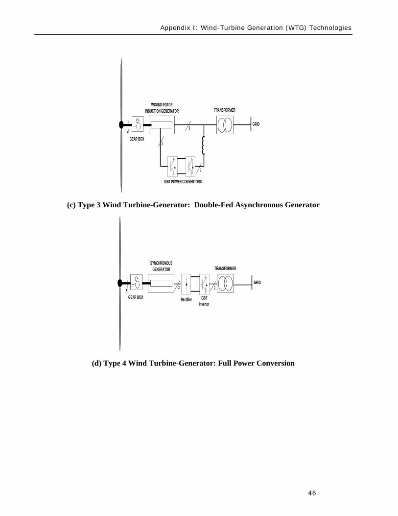
Appendix I Wind-Turbine Generation (WTG) Technologies
46
(c) Type 3 Wind Turbine-Generator Double-Fed Asynchronous Generator
(d) Type 4 Wind Turbine-Generator Full Power Conversion
3
3GEAR BOX
WOUND ROTORINDUCTION GENERATOR TRANSFORMER
GRID
IGBT POWER CONVERTORS
3
GEAR BOX
SYNCHRONOUSGENERATOR TRANSFORMER
GRID
Rectifier
33
IGBTInverter
Acronyms
47
Acronyms
CSP ndash Concentrating Solar Power
CIGRE - International Council on Large Electric Systems
DFAG ndash Doubly Fed Asynchronous Generator (also often referred to as DFIG ndash Doubly Fed Induction Generator)
FERC ndash Federal Energy Regulatory Commission
HVDC ndash High-Voltage Direct-Current transmission
IEC ndash International Electrotechnical Commission
IEEE ndash Institute of Electrical and Electronic Engineers
IGBT ndash Insulated-Gate Bipolar Transistor
IGCT ndash Insulated-Gate Commutated Thyristor
IVGTF ndash Integration of Variable Generation Task Force
ISO ndash Independent System Operator
LCC ndash Line-Commutated Converter
LVRT ndash Low-Voltage Ride-Through
MOD ndash Modeling Data and Analysis Standards
NERC ndash North American Electric Reliability Corporation
OEM ndash Original Equipment Manufacturer
PHEV ndash Plug-in Hybrid Electric Vehicle
PV ndash Photovoltaic
POI ndash Point of Interconnection
RPS ndash Renewable Portfolio Standard
RTO ndash Regional Transmission Operator
Acronyms
48
SAR ndash Standards Authorization Request (NERC process)
SCADA - Supervisory Control and Data Acquisition
SSTI ndash Subsynchronous Torsional Interaction
STATCOM ndash Static Compensator (voltage source converter based technology)
SVC ndash Static Var Compensator (thyristor based technology)
TSO ndash Transmission System Operator
VAr ndash volt-ampere reactive (standard units for reactive power)
VRT ndash Voltage Ride-Through
VSC ndash Voltage Source Converter
WPP ndash Wind Power Plant
WTG ndash Wind Turbine Generator
WECC ndash Western Electricity Coordinating Council
IVGTF Roster
49
IVGTF Task 1-1 Roster
Chair Pouyan Pourbeik
Technical Executive EPRI 942 Corridor Park Boulevard Knoxville Tennessee 37932
(919) 806-8126 ppourbeik epricom
Jay Caspary Director Transmission Development
Southwest Power Pool 415 North McKinley Suite 140 Little Rock Arkansas 72205
(501) 666-0376 (501) 666-0376 Fx jcasparyspporg
K R Chakravarthi
Southern Company Services Inc Southern Company Services Birmingham Alabama 35203
205-257-6125 205-257-1040 Fx krchakra southerncocom
Kieran Connolly
Manager Generation Scheduling
Bonneville Power Administration 905 NE 11th Avenue Portland Oregon 97232
(503) 230-4680 (503) 230-5377 Fx kpconnolly bpagov
Adam Flink
Engineer Midwest Reliability Organization 2774 Cleveland Ave Roseville Minnesota 55113
6515881705 (651) 855-1712 Fx adflink midwestreliabilityorg
David Jacobson
Interconnection amp Grid Supply Planning Engineer
Manitoba Hydro 12-1146 Waverly Street PO Box 815 Winnipeg Manitoba R3C 2P4
(204) 474-3765 (204) 477-4606 Fx dajacobson hydrombca
Charles-Eric
Langlois Jr Engineer
Hydro-Queacutebec TransEnergie 9e eacutetage Complexe Desjardins Tour Est Montreal Queacutebec H5B1H7
(514) 879-4100 ext 5441 (514) 879-4486 Fx LangloisCharles-Erichydroqcca
IVGTF Roster
50
David Marshall Project Manager
Southern Company Services Inc 600 N 18th Street Birmingham Alabama 35203
205-257-3326 205-257-1040 Fx dcmarsha southerncocom
Sophie Paquette
Transmission Planning Engineer
Hydro-Queacutebec TransEnergie 9e eacutetage Complexe Desjardins Tour Est 12th Floor Montreal Queacutebec H5B1H7
(514) 879-4100 ext 5423 (514) 879-4486 Fx paquettesophie hydroqcca
David C Schooley
Sr Engineer Commonwealth Edison Co 2 Lincoln Centre Oakbrook Terrace Illinois 60181
(630) 437-2773 davidschooley comedcom
Eric Thoms
Technical Lead - Transmission Access Planning
Midwest ISO Inc 1125 Energy Park Dr St Paul Minnesota 55108
(651) 632-8454 (651) 632-8417 Fx ethoms midwestisoorg
Observers Daniel Brooks
Manager Power Delivery System Studies
Electric Power Research Institute 942 Corridor Park Blvd Knoxville Tennessee 37932
(865) 218-8040 (865) 218-8001 Fx dbrooksepricom
Abraham Ellis
Principal Member of Technical Staff Renewable System Integration
Sandia National Laboratories 1515 Eubank SE Albuquerque New Mexico 87123
(505) 844-7717 (505) 844-2890 Fx aellis sandiagov
Ben Karlson
Sandia National Laboratories PO Box 5800 Albuquerque New Mexico 87185
(505) 803-3676 bkarlso sandiagov
Yuriy Kazachkov
Siemens Energy Inc 400 State Street Schenectady New York 12305
(518) 395-5132 (518) 346-2777 Fx yuriykazachkov siemenscom
Carl Lenox
Senior Staff Engineer Sunpower Corporation Systems 1414 Harbour Way South Richmond California 94804
(510) 260-8286 (510) 540-0552 Fx carllenox sunpowercorpcom
IVGTF Roster
51
Jason MacDowell
GE Energy 1 River Road Bldg 53 Schenectady New York 12345
(518) 385-2416 (518) 385-5703 Fx jasonmacdowell gecom
John Mead
Senior Staff Engineer Sunpower Corporation Systems 1414 Harbour Way South Richmond California 94804
(510) 260-8370 (510) 540-0552 Fx johnmead sunpowercorpcom
Nicholas W Miller
Director GE Energy 53-300Q 1 River Road Schenectady New York 12345
(518) 385-9865 (518) 385-5703 Fx nicholasmiller gecom
Eduard Muljadi
Senior Engineer National Renewable Energy Laboratory 1617 Cole Boulevard Golden Colorado 80401
(303) 384-6904 EduardMuljadi nrelgov
Mark OMalley
Professor of Electrical Engineering
University College Dublin R 157A Engineering amp Materials Science Centre University College Dublin Belfield Dublin 4
00353-1-716-1851 00353-1-283-0921 Fx markomalley ucdie
Subbaiah Pasupulati
Director of Technical Studies
Oak Creek Energy Systems Inc 14633 Willow Springs Road Mojave California 93501
(909) 241-9197 (661) 822-5991 Fx subbaiah oakcreekenergycom
Juan J Sanchez-
Gasca Principal Engineer
GE Energy 1 River Road Bldg 53-302E Schenectady New York 12345
(518) 385-5564 (518) 385-5703 Fx juansanchez psgecom
Steven Saylors
Chief Electrical Engineer
Vestas Americas 1881 SW Naito Parkway Portland Oregon 97201
(503) 327-2111 (503) 327-2001 Fx saylvestascom
IVGTF Roster
52
Robert Zavadil Vice President and Principal Consultant
EnerNex Corp 620 Mabry Hood Road Suite 300 Knoxville Tennessee 37932
(865) 218-4600 Ext 6149 (865) 218-8999 Fx bobzenernexcom
NERC Staff
Aaron Bennett Engineer Reliability Assessments
North American Electric Reliability Corporation 116-390 Village Boulevard Princeton New Jersey 08540-5721
(609) 524-7003 (609) 452-9550 Fx aaronbennett nercnet
Rhaiza Villafranca
Technical Analyst North American Electric Reliability Corporation 116-390 Village Boulevard Princeton New Jersey 08540-5721
(609) 452-8060 (609) 452-9550 Fx rhaizavillafranca nercnet
Mark G Lauby
Director Reliability Assessment and Performance Analysis
North American Electric Reliability Corporation 116-390 Village Boulevard Princeton New Jersey 08540-5721
(609) 524-7077 (609) 452-9550 Fx marklauby nercnet
References
53
References and Further Reading
[1] NERC Special Report Accommodation of High Levels of Variable Generation April 2009 httpwwwnerccomfilesIVGTF_Report_041609pdf
[2] CIGRE Technical Brochure 328 Modeling and Dynamic Behavior of Wind Generation as it Relates to Power System Control and Dynamic Performance Prepared by CIGRE WG C4601 August 2007 (available on-line at wwwe-cigreorg)
[3] ldquoWECC Wind Generator Power Flow Modeling Guiderdquo (httpwwwweccbizlibraryWECC20DocumentsDocuments20for20GeneratorsGenerator20Testing20ProgramWind20Generator20Power20Flow20Modeling20Guidepdf)
[4] G Lalor A Mullane and M J OrsquoMalley ldquoFrequency Control and Wind Turbine Technologiesrdquo IEEE Transactions on Power Systems Vol 20 pp 1903-1913 2005
[5] A Mullane and M J OrsquoMalley ldquoThe inertial-response of induction-machine based wind-turbinesrdquo IEEE Transactions on Power Systems Vol 20 pp 1496 ndash 1503 2005
[6] R Walling ldquoWind Plants of the Futurerdquo UWIG Oct 2008
[7] Hydro-Queacutebec TransEacutenergie ldquoTechnical requirements for the connection of generation facilities to the Hydro-Queacutebec transmission systemrdquo May 2006
[8] ESB National grid ldquoDynamic modeling of wind generation in Irelandrdquo January 2008
[9] N Miller K Clark R Delmerico and M Cardinal ldquoWindINERTIATM Inertial Response Option for GE Wind Turbine Generatorsrdquo Windpower 2009 Chicago IL May 4-7 2009
[10] R K Varma and S Auddy ldquoMitigation of Subsynchronous Oscillations in a Series Compensated Wind Farm with Static Var Compensatorrdquo Proceedings of the IEEE PES General Meeting 2006 Montreall Canada 2006
References
54
[11] Bialasiewicz J T Muljadi E Nix R G Drouilhet S Renewable Energy Power System Modular Simulator RPM-SIM Users Guide National Renewable Energy Laboratory March 2001 NRELTP-500-29721
[12] N Miller K Clark J MacDowell and W Barton Experience with Field and Factory Testing for Model Validation of GE Wind Plants European Wind Energy Conference amp Exhibition Brussels Belgium MarchApril 2008
[13] R J Piwko N W Miller and J M MacDowell ldquoField Testing and Model Validation of Wind Plantsrdquo IEEE-PES GM June 2008
- Executive Summary
- Introduction
- The Need for Models for Variable Generation
- Steady-State and Fault Current Analysis
- Time-Domain Positive Sequence Dynamic Models for Bulk Power System Stability Analysis
- Detailed Three-phase Equipment Level Models
- Summary
- Present Status of Modeling Variable Generation
- Wind Generation
-
- 311 WECCIEEE Effort for Generic Models
- 312 UWIG Generic Model Documentation and Validation Effort
- 313 IEC Effort for Generic Models
-
- Photovoltaic Solar Generation
- Solar Thermal
- Tidal Generation
- Other Resources
- Summary
- Present Status of Model Validation
- What is Model Validation
- Examples of Model Validation Efforts
-
- 421 Hydro- Queacutebec Example
- 422 GE Example ndash based on GErsquos work with client facilities
-
- Summary amp Recommended Actions ndash Standards Implications
- Applying the NERC Standards
- NERC Standards Technical Issues
- Final Recommendation
- Appendix I Wind-Turbine Generation (WTG) Technologies
- Acronyms
- IVGTF Task 1-1 Roster
- References and Further Reading
-
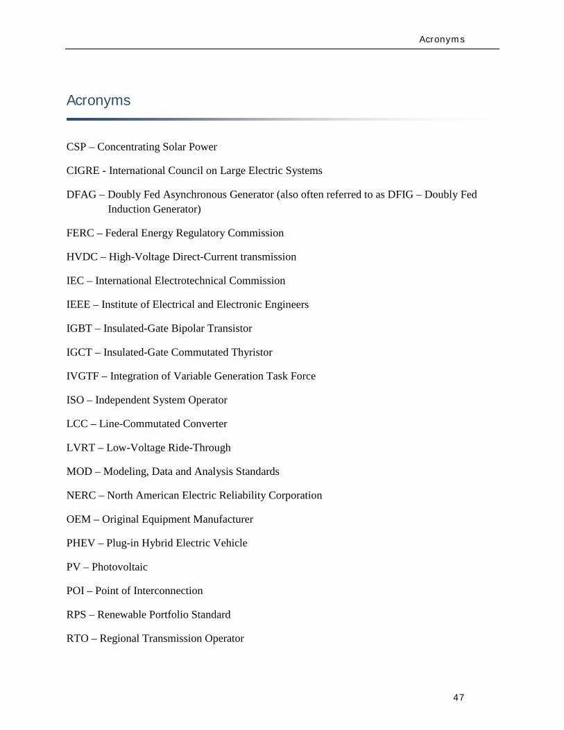
Acronyms
47
Acronyms
CSP ndash Concentrating Solar Power
CIGRE - International Council on Large Electric Systems
DFAG ndash Doubly Fed Asynchronous Generator (also often referred to as DFIG ndash Doubly Fed Induction Generator)
FERC ndash Federal Energy Regulatory Commission
HVDC ndash High-Voltage Direct-Current transmission
IEC ndash International Electrotechnical Commission
IEEE ndash Institute of Electrical and Electronic Engineers
IGBT ndash Insulated-Gate Bipolar Transistor
IGCT ndash Insulated-Gate Commutated Thyristor
IVGTF ndash Integration of Variable Generation Task Force
ISO ndash Independent System Operator
LCC ndash Line-Commutated Converter
LVRT ndash Low-Voltage Ride-Through
MOD ndash Modeling Data and Analysis Standards
NERC ndash North American Electric Reliability Corporation
OEM ndash Original Equipment Manufacturer
PHEV ndash Plug-in Hybrid Electric Vehicle
PV ndash Photovoltaic
POI ndash Point of Interconnection
RPS ndash Renewable Portfolio Standard
RTO ndash Regional Transmission Operator
Acronyms
48
SAR ndash Standards Authorization Request (NERC process)
SCADA - Supervisory Control and Data Acquisition
SSTI ndash Subsynchronous Torsional Interaction
STATCOM ndash Static Compensator (voltage source converter based technology)
SVC ndash Static Var Compensator (thyristor based technology)
TSO ndash Transmission System Operator
VAr ndash volt-ampere reactive (standard units for reactive power)
VRT ndash Voltage Ride-Through
VSC ndash Voltage Source Converter
WPP ndash Wind Power Plant
WTG ndash Wind Turbine Generator
WECC ndash Western Electricity Coordinating Council
IVGTF Roster
49
IVGTF Task 1-1 Roster
Chair Pouyan Pourbeik
Technical Executive EPRI 942 Corridor Park Boulevard Knoxville Tennessee 37932
(919) 806-8126 ppourbeik epricom
Jay Caspary Director Transmission Development
Southwest Power Pool 415 North McKinley Suite 140 Little Rock Arkansas 72205
(501) 666-0376 (501) 666-0376 Fx jcasparyspporg
K R Chakravarthi
Southern Company Services Inc Southern Company Services Birmingham Alabama 35203
205-257-6125 205-257-1040 Fx krchakra southerncocom
Kieran Connolly
Manager Generation Scheduling
Bonneville Power Administration 905 NE 11th Avenue Portland Oregon 97232
(503) 230-4680 (503) 230-5377 Fx kpconnolly bpagov
Adam Flink
Engineer Midwest Reliability Organization 2774 Cleveland Ave Roseville Minnesota 55113
6515881705 (651) 855-1712 Fx adflink midwestreliabilityorg
David Jacobson
Interconnection amp Grid Supply Planning Engineer
Manitoba Hydro 12-1146 Waverly Street PO Box 815 Winnipeg Manitoba R3C 2P4
(204) 474-3765 (204) 477-4606 Fx dajacobson hydrombca
Charles-Eric
Langlois Jr Engineer
Hydro-Queacutebec TransEnergie 9e eacutetage Complexe Desjardins Tour Est Montreal Queacutebec H5B1H7
(514) 879-4100 ext 5441 (514) 879-4486 Fx LangloisCharles-Erichydroqcca
IVGTF Roster
50
David Marshall Project Manager
Southern Company Services Inc 600 N 18th Street Birmingham Alabama 35203
205-257-3326 205-257-1040 Fx dcmarsha southerncocom
Sophie Paquette
Transmission Planning Engineer
Hydro-Queacutebec TransEnergie 9e eacutetage Complexe Desjardins Tour Est 12th Floor Montreal Queacutebec H5B1H7
(514) 879-4100 ext 5423 (514) 879-4486 Fx paquettesophie hydroqcca
David C Schooley
Sr Engineer Commonwealth Edison Co 2 Lincoln Centre Oakbrook Terrace Illinois 60181
(630) 437-2773 davidschooley comedcom
Eric Thoms
Technical Lead - Transmission Access Planning
Midwest ISO Inc 1125 Energy Park Dr St Paul Minnesota 55108
(651) 632-8454 (651) 632-8417 Fx ethoms midwestisoorg
Observers Daniel Brooks
Manager Power Delivery System Studies
Electric Power Research Institute 942 Corridor Park Blvd Knoxville Tennessee 37932
(865) 218-8040 (865) 218-8001 Fx dbrooksepricom
Abraham Ellis
Principal Member of Technical Staff Renewable System Integration
Sandia National Laboratories 1515 Eubank SE Albuquerque New Mexico 87123
(505) 844-7717 (505) 844-2890 Fx aellis sandiagov
Ben Karlson
Sandia National Laboratories PO Box 5800 Albuquerque New Mexico 87185
(505) 803-3676 bkarlso sandiagov
Yuriy Kazachkov
Siemens Energy Inc 400 State Street Schenectady New York 12305
(518) 395-5132 (518) 346-2777 Fx yuriykazachkov siemenscom
Carl Lenox
Senior Staff Engineer Sunpower Corporation Systems 1414 Harbour Way South Richmond California 94804
(510) 260-8286 (510) 540-0552 Fx carllenox sunpowercorpcom
IVGTF Roster
51
Jason MacDowell
GE Energy 1 River Road Bldg 53 Schenectady New York 12345
(518) 385-2416 (518) 385-5703 Fx jasonmacdowell gecom
John Mead
Senior Staff Engineer Sunpower Corporation Systems 1414 Harbour Way South Richmond California 94804
(510) 260-8370 (510) 540-0552 Fx johnmead sunpowercorpcom
Nicholas W Miller
Director GE Energy 53-300Q 1 River Road Schenectady New York 12345
(518) 385-9865 (518) 385-5703 Fx nicholasmiller gecom
Eduard Muljadi
Senior Engineer National Renewable Energy Laboratory 1617 Cole Boulevard Golden Colorado 80401
(303) 384-6904 EduardMuljadi nrelgov
Mark OMalley
Professor of Electrical Engineering
University College Dublin R 157A Engineering amp Materials Science Centre University College Dublin Belfield Dublin 4
00353-1-716-1851 00353-1-283-0921 Fx markomalley ucdie
Subbaiah Pasupulati
Director of Technical Studies
Oak Creek Energy Systems Inc 14633 Willow Springs Road Mojave California 93501
(909) 241-9197 (661) 822-5991 Fx subbaiah oakcreekenergycom
Juan J Sanchez-
Gasca Principal Engineer
GE Energy 1 River Road Bldg 53-302E Schenectady New York 12345
(518) 385-5564 (518) 385-5703 Fx juansanchez psgecom
Steven Saylors
Chief Electrical Engineer
Vestas Americas 1881 SW Naito Parkway Portland Oregon 97201
(503) 327-2111 (503) 327-2001 Fx saylvestascom
IVGTF Roster
52
Robert Zavadil Vice President and Principal Consultant
EnerNex Corp 620 Mabry Hood Road Suite 300 Knoxville Tennessee 37932
(865) 218-4600 Ext 6149 (865) 218-8999 Fx bobzenernexcom
NERC Staff
Aaron Bennett Engineer Reliability Assessments
North American Electric Reliability Corporation 116-390 Village Boulevard Princeton New Jersey 08540-5721
(609) 524-7003 (609) 452-9550 Fx aaronbennett nercnet
Rhaiza Villafranca
Technical Analyst North American Electric Reliability Corporation 116-390 Village Boulevard Princeton New Jersey 08540-5721
(609) 452-8060 (609) 452-9550 Fx rhaizavillafranca nercnet
Mark G Lauby
Director Reliability Assessment and Performance Analysis
North American Electric Reliability Corporation 116-390 Village Boulevard Princeton New Jersey 08540-5721
(609) 524-7077 (609) 452-9550 Fx marklauby nercnet
References
53
References and Further Reading
[1] NERC Special Report Accommodation of High Levels of Variable Generation April 2009 httpwwwnerccomfilesIVGTF_Report_041609pdf
[2] CIGRE Technical Brochure 328 Modeling and Dynamic Behavior of Wind Generation as it Relates to Power System Control and Dynamic Performance Prepared by CIGRE WG C4601 August 2007 (available on-line at wwwe-cigreorg)
[3] ldquoWECC Wind Generator Power Flow Modeling Guiderdquo (httpwwwweccbizlibraryWECC20DocumentsDocuments20for20GeneratorsGenerator20Testing20ProgramWind20Generator20Power20Flow20Modeling20Guidepdf)
[4] G Lalor A Mullane and M J OrsquoMalley ldquoFrequency Control and Wind Turbine Technologiesrdquo IEEE Transactions on Power Systems Vol 20 pp 1903-1913 2005
[5] A Mullane and M J OrsquoMalley ldquoThe inertial-response of induction-machine based wind-turbinesrdquo IEEE Transactions on Power Systems Vol 20 pp 1496 ndash 1503 2005
[6] R Walling ldquoWind Plants of the Futurerdquo UWIG Oct 2008
[7] Hydro-Queacutebec TransEacutenergie ldquoTechnical requirements for the connection of generation facilities to the Hydro-Queacutebec transmission systemrdquo May 2006
[8] ESB National grid ldquoDynamic modeling of wind generation in Irelandrdquo January 2008
[9] N Miller K Clark R Delmerico and M Cardinal ldquoWindINERTIATM Inertial Response Option for GE Wind Turbine Generatorsrdquo Windpower 2009 Chicago IL May 4-7 2009
[10] R K Varma and S Auddy ldquoMitigation of Subsynchronous Oscillations in a Series Compensated Wind Farm with Static Var Compensatorrdquo Proceedings of the IEEE PES General Meeting 2006 Montreall Canada 2006
References
54
[11] Bialasiewicz J T Muljadi E Nix R G Drouilhet S Renewable Energy Power System Modular Simulator RPM-SIM Users Guide National Renewable Energy Laboratory March 2001 NRELTP-500-29721
[12] N Miller K Clark J MacDowell and W Barton Experience with Field and Factory Testing for Model Validation of GE Wind Plants European Wind Energy Conference amp Exhibition Brussels Belgium MarchApril 2008
[13] R J Piwko N W Miller and J M MacDowell ldquoField Testing and Model Validation of Wind Plantsrdquo IEEE-PES GM June 2008
- Executive Summary
- Introduction
- The Need for Models for Variable Generation
- Steady-State and Fault Current Analysis
- Time-Domain Positive Sequence Dynamic Models for Bulk Power System Stability Analysis
- Detailed Three-phase Equipment Level Models
- Summary
- Present Status of Modeling Variable Generation
- Wind Generation
-
- 311 WECCIEEE Effort for Generic Models
- 312 UWIG Generic Model Documentation and Validation Effort
- 313 IEC Effort for Generic Models
-
- Photovoltaic Solar Generation
- Solar Thermal
- Tidal Generation
- Other Resources
- Summary
- Present Status of Model Validation
- What is Model Validation
- Examples of Model Validation Efforts
-
- 421 Hydro- Queacutebec Example
- 422 GE Example ndash based on GErsquos work with client facilities
-
- Summary amp Recommended Actions ndash Standards Implications
- Applying the NERC Standards
- NERC Standards Technical Issues
- Final Recommendation
- Appendix I Wind-Turbine Generation (WTG) Technologies
- Acronyms
- IVGTF Task 1-1 Roster
- References and Further Reading
-
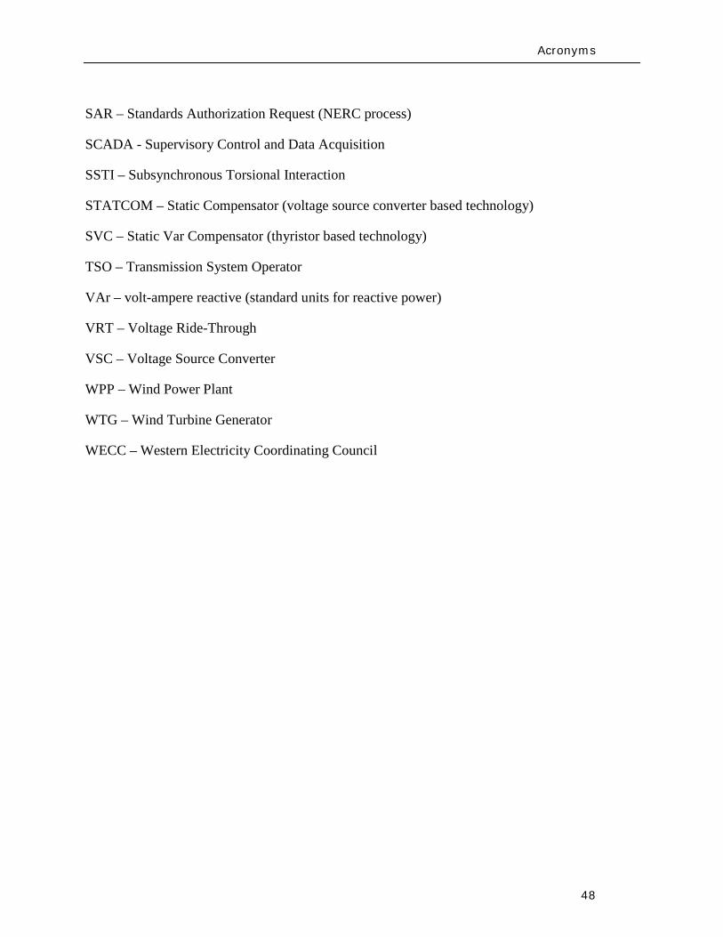
Acronyms
48
SAR ndash Standards Authorization Request (NERC process)
SCADA - Supervisory Control and Data Acquisition
SSTI ndash Subsynchronous Torsional Interaction
STATCOM ndash Static Compensator (voltage source converter based technology)
SVC ndash Static Var Compensator (thyristor based technology)
TSO ndash Transmission System Operator
VAr ndash volt-ampere reactive (standard units for reactive power)
VRT ndash Voltage Ride-Through
VSC ndash Voltage Source Converter
WPP ndash Wind Power Plant
WTG ndash Wind Turbine Generator
WECC ndash Western Electricity Coordinating Council
IVGTF Roster
49
IVGTF Task 1-1 Roster
Chair Pouyan Pourbeik
Technical Executive EPRI 942 Corridor Park Boulevard Knoxville Tennessee 37932
(919) 806-8126 ppourbeik epricom
Jay Caspary Director Transmission Development
Southwest Power Pool 415 North McKinley Suite 140 Little Rock Arkansas 72205
(501) 666-0376 (501) 666-0376 Fx jcasparyspporg
K R Chakravarthi
Southern Company Services Inc Southern Company Services Birmingham Alabama 35203
205-257-6125 205-257-1040 Fx krchakra southerncocom
Kieran Connolly
Manager Generation Scheduling
Bonneville Power Administration 905 NE 11th Avenue Portland Oregon 97232
(503) 230-4680 (503) 230-5377 Fx kpconnolly bpagov
Adam Flink
Engineer Midwest Reliability Organization 2774 Cleveland Ave Roseville Minnesota 55113
6515881705 (651) 855-1712 Fx adflink midwestreliabilityorg
David Jacobson
Interconnection amp Grid Supply Planning Engineer
Manitoba Hydro 12-1146 Waverly Street PO Box 815 Winnipeg Manitoba R3C 2P4
(204) 474-3765 (204) 477-4606 Fx dajacobson hydrombca
Charles-Eric
Langlois Jr Engineer
Hydro-Queacutebec TransEnergie 9e eacutetage Complexe Desjardins Tour Est Montreal Queacutebec H5B1H7
(514) 879-4100 ext 5441 (514) 879-4486 Fx LangloisCharles-Erichydroqcca
IVGTF Roster
50
David Marshall Project Manager
Southern Company Services Inc 600 N 18th Street Birmingham Alabama 35203
205-257-3326 205-257-1040 Fx dcmarsha southerncocom
Sophie Paquette
Transmission Planning Engineer
Hydro-Queacutebec TransEnergie 9e eacutetage Complexe Desjardins Tour Est 12th Floor Montreal Queacutebec H5B1H7
(514) 879-4100 ext 5423 (514) 879-4486 Fx paquettesophie hydroqcca
David C Schooley
Sr Engineer Commonwealth Edison Co 2 Lincoln Centre Oakbrook Terrace Illinois 60181
(630) 437-2773 davidschooley comedcom
Eric Thoms
Technical Lead - Transmission Access Planning
Midwest ISO Inc 1125 Energy Park Dr St Paul Minnesota 55108
(651) 632-8454 (651) 632-8417 Fx ethoms midwestisoorg
Observers Daniel Brooks
Manager Power Delivery System Studies
Electric Power Research Institute 942 Corridor Park Blvd Knoxville Tennessee 37932
(865) 218-8040 (865) 218-8001 Fx dbrooksepricom
Abraham Ellis
Principal Member of Technical Staff Renewable System Integration
Sandia National Laboratories 1515 Eubank SE Albuquerque New Mexico 87123
(505) 844-7717 (505) 844-2890 Fx aellis sandiagov
Ben Karlson
Sandia National Laboratories PO Box 5800 Albuquerque New Mexico 87185
(505) 803-3676 bkarlso sandiagov
Yuriy Kazachkov
Siemens Energy Inc 400 State Street Schenectady New York 12305
(518) 395-5132 (518) 346-2777 Fx yuriykazachkov siemenscom
Carl Lenox
Senior Staff Engineer Sunpower Corporation Systems 1414 Harbour Way South Richmond California 94804
(510) 260-8286 (510) 540-0552 Fx carllenox sunpowercorpcom
IVGTF Roster
51
Jason MacDowell
GE Energy 1 River Road Bldg 53 Schenectady New York 12345
(518) 385-2416 (518) 385-5703 Fx jasonmacdowell gecom
John Mead
Senior Staff Engineer Sunpower Corporation Systems 1414 Harbour Way South Richmond California 94804
(510) 260-8370 (510) 540-0552 Fx johnmead sunpowercorpcom
Nicholas W Miller
Director GE Energy 53-300Q 1 River Road Schenectady New York 12345
(518) 385-9865 (518) 385-5703 Fx nicholasmiller gecom
Eduard Muljadi
Senior Engineer National Renewable Energy Laboratory 1617 Cole Boulevard Golden Colorado 80401
(303) 384-6904 EduardMuljadi nrelgov
Mark OMalley
Professor of Electrical Engineering
University College Dublin R 157A Engineering amp Materials Science Centre University College Dublin Belfield Dublin 4
00353-1-716-1851 00353-1-283-0921 Fx markomalley ucdie
Subbaiah Pasupulati
Director of Technical Studies
Oak Creek Energy Systems Inc 14633 Willow Springs Road Mojave California 93501
(909) 241-9197 (661) 822-5991 Fx subbaiah oakcreekenergycom
Juan J Sanchez-
Gasca Principal Engineer
GE Energy 1 River Road Bldg 53-302E Schenectady New York 12345
(518) 385-5564 (518) 385-5703 Fx juansanchez psgecom
Steven Saylors
Chief Electrical Engineer
Vestas Americas 1881 SW Naito Parkway Portland Oregon 97201
(503) 327-2111 (503) 327-2001 Fx saylvestascom
IVGTF Roster
52
Robert Zavadil Vice President and Principal Consultant
EnerNex Corp 620 Mabry Hood Road Suite 300 Knoxville Tennessee 37932
(865) 218-4600 Ext 6149 (865) 218-8999 Fx bobzenernexcom
NERC Staff
Aaron Bennett Engineer Reliability Assessments
North American Electric Reliability Corporation 116-390 Village Boulevard Princeton New Jersey 08540-5721
(609) 524-7003 (609) 452-9550 Fx aaronbennett nercnet
Rhaiza Villafranca
Technical Analyst North American Electric Reliability Corporation 116-390 Village Boulevard Princeton New Jersey 08540-5721
(609) 452-8060 (609) 452-9550 Fx rhaizavillafranca nercnet
Mark G Lauby
Director Reliability Assessment and Performance Analysis
North American Electric Reliability Corporation 116-390 Village Boulevard Princeton New Jersey 08540-5721
(609) 524-7077 (609) 452-9550 Fx marklauby nercnet
References
53
References and Further Reading
[1] NERC Special Report Accommodation of High Levels of Variable Generation April 2009 httpwwwnerccomfilesIVGTF_Report_041609pdf
[2] CIGRE Technical Brochure 328 Modeling and Dynamic Behavior of Wind Generation as it Relates to Power System Control and Dynamic Performance Prepared by CIGRE WG C4601 August 2007 (available on-line at wwwe-cigreorg)
[3] ldquoWECC Wind Generator Power Flow Modeling Guiderdquo (httpwwwweccbizlibraryWECC20DocumentsDocuments20for20GeneratorsGenerator20Testing20ProgramWind20Generator20Power20Flow20Modeling20Guidepdf)
[4] G Lalor A Mullane and M J OrsquoMalley ldquoFrequency Control and Wind Turbine Technologiesrdquo IEEE Transactions on Power Systems Vol 20 pp 1903-1913 2005
[5] A Mullane and M J OrsquoMalley ldquoThe inertial-response of induction-machine based wind-turbinesrdquo IEEE Transactions on Power Systems Vol 20 pp 1496 ndash 1503 2005
[6] R Walling ldquoWind Plants of the Futurerdquo UWIG Oct 2008
[7] Hydro-Queacutebec TransEacutenergie ldquoTechnical requirements for the connection of generation facilities to the Hydro-Queacutebec transmission systemrdquo May 2006
[8] ESB National grid ldquoDynamic modeling of wind generation in Irelandrdquo January 2008
[9] N Miller K Clark R Delmerico and M Cardinal ldquoWindINERTIATM Inertial Response Option for GE Wind Turbine Generatorsrdquo Windpower 2009 Chicago IL May 4-7 2009
[10] R K Varma and S Auddy ldquoMitigation of Subsynchronous Oscillations in a Series Compensated Wind Farm with Static Var Compensatorrdquo Proceedings of the IEEE PES General Meeting 2006 Montreall Canada 2006
References
54
[11] Bialasiewicz J T Muljadi E Nix R G Drouilhet S Renewable Energy Power System Modular Simulator RPM-SIM Users Guide National Renewable Energy Laboratory March 2001 NRELTP-500-29721
[12] N Miller K Clark J MacDowell and W Barton Experience with Field and Factory Testing for Model Validation of GE Wind Plants European Wind Energy Conference amp Exhibition Brussels Belgium MarchApril 2008
[13] R J Piwko N W Miller and J M MacDowell ldquoField Testing and Model Validation of Wind Plantsrdquo IEEE-PES GM June 2008
- Executive Summary
- Introduction
- The Need for Models for Variable Generation
- Steady-State and Fault Current Analysis
- Time-Domain Positive Sequence Dynamic Models for Bulk Power System Stability Analysis
- Detailed Three-phase Equipment Level Models
- Summary
- Present Status of Modeling Variable Generation
- Wind Generation
-
- 311 WECCIEEE Effort for Generic Models
- 312 UWIG Generic Model Documentation and Validation Effort
- 313 IEC Effort for Generic Models
-
- Photovoltaic Solar Generation
- Solar Thermal
- Tidal Generation
- Other Resources
- Summary
- Present Status of Model Validation
- What is Model Validation
- Examples of Model Validation Efforts
-
- 421 Hydro- Queacutebec Example
- 422 GE Example ndash based on GErsquos work with client facilities
-
- Summary amp Recommended Actions ndash Standards Implications
- Applying the NERC Standards
- NERC Standards Technical Issues
- Final Recommendation
- Appendix I Wind-Turbine Generation (WTG) Technologies
- Acronyms
- IVGTF Task 1-1 Roster
- References and Further Reading
-
IVGTF Roster
50
David Marshall Project Manager
Southern Company Services Inc 600 N 18th Street Birmingham Alabama 35203
205-257-3326 205-257-1040 Fx dcmarsha southerncocom
Sophie Paquette
Transmission Planning Engineer
Hydro-Queacutebec TransEnergie 9e eacutetage Complexe Desjardins Tour Est 12th Floor Montreal Queacutebec H5B1H7
(514) 879-4100 ext 5423 (514) 879-4486 Fx paquettesophie hydroqcca
David C Schooley
Sr Engineer Commonwealth Edison Co 2 Lincoln Centre Oakbrook Terrace Illinois 60181
(630) 437-2773 davidschooley comedcom
Eric Thoms
Technical Lead - Transmission Access Planning
Midwest ISO Inc 1125 Energy Park Dr St Paul Minnesota 55108
(651) 632-8454 (651) 632-8417 Fx ethoms midwestisoorg
Observers Daniel Brooks
Manager Power Delivery System Studies
Electric Power Research Institute 942 Corridor Park Blvd Knoxville Tennessee 37932
(865) 218-8040 (865) 218-8001 Fx dbrooksepricom
Abraham Ellis
Principal Member of Technical Staff Renewable System Integration
Sandia National Laboratories 1515 Eubank SE Albuquerque New Mexico 87123
(505) 844-7717 (505) 844-2890 Fx aellis sandiagov
Ben Karlson
Sandia National Laboratories PO Box 5800 Albuquerque New Mexico 87185
(505) 803-3676 bkarlso sandiagov
Yuriy Kazachkov
Siemens Energy Inc 400 State Street Schenectady New York 12305
(518) 395-5132 (518) 346-2777 Fx yuriykazachkov siemenscom
Carl Lenox
Senior Staff Engineer Sunpower Corporation Systems 1414 Harbour Way South Richmond California 94804
(510) 260-8286 (510) 540-0552 Fx carllenox sunpowercorpcom
IVGTF Roster
51
Jason MacDowell
GE Energy 1 River Road Bldg 53 Schenectady New York 12345
(518) 385-2416 (518) 385-5703 Fx jasonmacdowell gecom
John Mead
Senior Staff Engineer Sunpower Corporation Systems 1414 Harbour Way South Richmond California 94804
(510) 260-8370 (510) 540-0552 Fx johnmead sunpowercorpcom
Nicholas W Miller
Director GE Energy 53-300Q 1 River Road Schenectady New York 12345
(518) 385-9865 (518) 385-5703 Fx nicholasmiller gecom
Eduard Muljadi
Senior Engineer National Renewable Energy Laboratory 1617 Cole Boulevard Golden Colorado 80401
(303) 384-6904 EduardMuljadi nrelgov
Mark OMalley
Professor of Electrical Engineering
University College Dublin R 157A Engineering amp Materials Science Centre University College Dublin Belfield Dublin 4
00353-1-716-1851 00353-1-283-0921 Fx markomalley ucdie
Subbaiah Pasupulati
Director of Technical Studies
Oak Creek Energy Systems Inc 14633 Willow Springs Road Mojave California 93501
(909) 241-9197 (661) 822-5991 Fx subbaiah oakcreekenergycom
Juan J Sanchez-
Gasca Principal Engineer
GE Energy 1 River Road Bldg 53-302E Schenectady New York 12345
(518) 385-5564 (518) 385-5703 Fx juansanchez psgecom
Steven Saylors
Chief Electrical Engineer
Vestas Americas 1881 SW Naito Parkway Portland Oregon 97201
(503) 327-2111 (503) 327-2001 Fx saylvestascom
IVGTF Roster
52
Robert Zavadil Vice President and Principal Consultant
EnerNex Corp 620 Mabry Hood Road Suite 300 Knoxville Tennessee 37932
(865) 218-4600 Ext 6149 (865) 218-8999 Fx bobzenernexcom
NERC Staff
Aaron Bennett Engineer Reliability Assessments
North American Electric Reliability Corporation 116-390 Village Boulevard Princeton New Jersey 08540-5721
(609) 524-7003 (609) 452-9550 Fx aaronbennett nercnet
Rhaiza Villafranca
Technical Analyst North American Electric Reliability Corporation 116-390 Village Boulevard Princeton New Jersey 08540-5721
(609) 452-8060 (609) 452-9550 Fx rhaizavillafranca nercnet
Mark G Lauby
Director Reliability Assessment and Performance Analysis
North American Electric Reliability Corporation 116-390 Village Boulevard Princeton New Jersey 08540-5721
(609) 524-7077 (609) 452-9550 Fx marklauby nercnet
References
53
References and Further Reading
[1] NERC Special Report Accommodation of High Levels of Variable Generation April 2009 httpwwwnerccomfilesIVGTF_Report_041609pdf
[2] CIGRE Technical Brochure 328 Modeling and Dynamic Behavior of Wind Generation as it Relates to Power System Control and Dynamic Performance Prepared by CIGRE WG C4601 August 2007 (available on-line at wwwe-cigreorg)
[3] ldquoWECC Wind Generator Power Flow Modeling Guiderdquo (httpwwwweccbizlibraryWECC20DocumentsDocuments20for20GeneratorsGenerator20Testing20ProgramWind20Generator20Power20Flow20Modeling20Guidepdf)
[4] G Lalor A Mullane and M J OrsquoMalley ldquoFrequency Control and Wind Turbine Technologiesrdquo IEEE Transactions on Power Systems Vol 20 pp 1903-1913 2005
[5] A Mullane and M J OrsquoMalley ldquoThe inertial-response of induction-machine based wind-turbinesrdquo IEEE Transactions on Power Systems Vol 20 pp 1496 ndash 1503 2005
[6] R Walling ldquoWind Plants of the Futurerdquo UWIG Oct 2008
[7] Hydro-Queacutebec TransEacutenergie ldquoTechnical requirements for the connection of generation facilities to the Hydro-Queacutebec transmission systemrdquo May 2006
[8] ESB National grid ldquoDynamic modeling of wind generation in Irelandrdquo January 2008
[9] N Miller K Clark R Delmerico and M Cardinal ldquoWindINERTIATM Inertial Response Option for GE Wind Turbine Generatorsrdquo Windpower 2009 Chicago IL May 4-7 2009
[10] R K Varma and S Auddy ldquoMitigation of Subsynchronous Oscillations in a Series Compensated Wind Farm with Static Var Compensatorrdquo Proceedings of the IEEE PES General Meeting 2006 Montreall Canada 2006
References
54
[11] Bialasiewicz J T Muljadi E Nix R G Drouilhet S Renewable Energy Power System Modular Simulator RPM-SIM Users Guide National Renewable Energy Laboratory March 2001 NRELTP-500-29721
[12] N Miller K Clark J MacDowell and W Barton Experience with Field and Factory Testing for Model Validation of GE Wind Plants European Wind Energy Conference amp Exhibition Brussels Belgium MarchApril 2008
[13] R J Piwko N W Miller and J M MacDowell ldquoField Testing and Model Validation of Wind Plantsrdquo IEEE-PES GM June 2008
- Executive Summary
- Introduction
- The Need for Models for Variable Generation
- Steady-State and Fault Current Analysis
- Time-Domain Positive Sequence Dynamic Models for Bulk Power System Stability Analysis
- Detailed Three-phase Equipment Level Models
- Summary
- Present Status of Modeling Variable Generation
- Wind Generation
-
- 311 WECCIEEE Effort for Generic Models
- 312 UWIG Generic Model Documentation and Validation Effort
- 313 IEC Effort for Generic Models
-
- Photovoltaic Solar Generation
- Solar Thermal
- Tidal Generation
- Other Resources
- Summary
- Present Status of Model Validation
- What is Model Validation
- Examples of Model Validation Efforts
-
- 421 Hydro- Queacutebec Example
- 422 GE Example ndash based on GErsquos work with client facilities
-
- Summary amp Recommended Actions ndash Standards Implications
- Applying the NERC Standards
- NERC Standards Technical Issues
- Final Recommendation
- Appendix I Wind-Turbine Generation (WTG) Technologies
- Acronyms
- IVGTF Task 1-1 Roster
- References and Further Reading
-

IVGTF Roster
51
Jason MacDowell
GE Energy 1 River Road Bldg 53 Schenectady New York 12345
(518) 385-2416 (518) 385-5703 Fx jasonmacdowell gecom
John Mead
Senior Staff Engineer Sunpower Corporation Systems 1414 Harbour Way South Richmond California 94804
(510) 260-8370 (510) 540-0552 Fx johnmead sunpowercorpcom
Nicholas W Miller
Director GE Energy 53-300Q 1 River Road Schenectady New York 12345
(518) 385-9865 (518) 385-5703 Fx nicholasmiller gecom
Eduard Muljadi
Senior Engineer National Renewable Energy Laboratory 1617 Cole Boulevard Golden Colorado 80401
(303) 384-6904 EduardMuljadi nrelgov
Mark OMalley
Professor of Electrical Engineering
University College Dublin R 157A Engineering amp Materials Science Centre University College Dublin Belfield Dublin 4
00353-1-716-1851 00353-1-283-0921 Fx markomalley ucdie
Subbaiah Pasupulati
Director of Technical Studies
Oak Creek Energy Systems Inc 14633 Willow Springs Road Mojave California 93501
(909) 241-9197 (661) 822-5991 Fx subbaiah oakcreekenergycom
Juan J Sanchez-
Gasca Principal Engineer
GE Energy 1 River Road Bldg 53-302E Schenectady New York 12345
(518) 385-5564 (518) 385-5703 Fx juansanchez psgecom
Steven Saylors
Chief Electrical Engineer
Vestas Americas 1881 SW Naito Parkway Portland Oregon 97201
(503) 327-2111 (503) 327-2001 Fx saylvestascom
IVGTF Roster
52
Robert Zavadil Vice President and Principal Consultant
EnerNex Corp 620 Mabry Hood Road Suite 300 Knoxville Tennessee 37932
(865) 218-4600 Ext 6149 (865) 218-8999 Fx bobzenernexcom
NERC Staff
Aaron Bennett Engineer Reliability Assessments
North American Electric Reliability Corporation 116-390 Village Boulevard Princeton New Jersey 08540-5721
(609) 524-7003 (609) 452-9550 Fx aaronbennett nercnet
Rhaiza Villafranca
Technical Analyst North American Electric Reliability Corporation 116-390 Village Boulevard Princeton New Jersey 08540-5721
(609) 452-8060 (609) 452-9550 Fx rhaizavillafranca nercnet
Mark G Lauby
Director Reliability Assessment and Performance Analysis
North American Electric Reliability Corporation 116-390 Village Boulevard Princeton New Jersey 08540-5721
(609) 524-7077 (609) 452-9550 Fx marklauby nercnet
References
53
References and Further Reading
[1] NERC Special Report Accommodation of High Levels of Variable Generation April 2009 httpwwwnerccomfilesIVGTF_Report_041609pdf
[2] CIGRE Technical Brochure 328 Modeling and Dynamic Behavior of Wind Generation as it Relates to Power System Control and Dynamic Performance Prepared by CIGRE WG C4601 August 2007 (available on-line at wwwe-cigreorg)
[3] ldquoWECC Wind Generator Power Flow Modeling Guiderdquo (httpwwwweccbizlibraryWECC20DocumentsDocuments20for20GeneratorsGenerator20Testing20ProgramWind20Generator20Power20Flow20Modeling20Guidepdf)
[4] G Lalor A Mullane and M J OrsquoMalley ldquoFrequency Control and Wind Turbine Technologiesrdquo IEEE Transactions on Power Systems Vol 20 pp 1903-1913 2005
[5] A Mullane and M J OrsquoMalley ldquoThe inertial-response of induction-machine based wind-turbinesrdquo IEEE Transactions on Power Systems Vol 20 pp 1496 ndash 1503 2005
[6] R Walling ldquoWind Plants of the Futurerdquo UWIG Oct 2008
[7] Hydro-Queacutebec TransEacutenergie ldquoTechnical requirements for the connection of generation facilities to the Hydro-Queacutebec transmission systemrdquo May 2006
[8] ESB National grid ldquoDynamic modeling of wind generation in Irelandrdquo January 2008
[9] N Miller K Clark R Delmerico and M Cardinal ldquoWindINERTIATM Inertial Response Option for GE Wind Turbine Generatorsrdquo Windpower 2009 Chicago IL May 4-7 2009
[10] R K Varma and S Auddy ldquoMitigation of Subsynchronous Oscillations in a Series Compensated Wind Farm with Static Var Compensatorrdquo Proceedings of the IEEE PES General Meeting 2006 Montreall Canada 2006
References
54
[11] Bialasiewicz J T Muljadi E Nix R G Drouilhet S Renewable Energy Power System Modular Simulator RPM-SIM Users Guide National Renewable Energy Laboratory March 2001 NRELTP-500-29721
[12] N Miller K Clark J MacDowell and W Barton Experience with Field and Factory Testing for Model Validation of GE Wind Plants European Wind Energy Conference amp Exhibition Brussels Belgium MarchApril 2008
[13] R J Piwko N W Miller and J M MacDowell ldquoField Testing and Model Validation of Wind Plantsrdquo IEEE-PES GM June 2008
- Executive Summary
- Introduction
- The Need for Models for Variable Generation
- Steady-State and Fault Current Analysis
- Time-Domain Positive Sequence Dynamic Models for Bulk Power System Stability Analysis
- Detailed Three-phase Equipment Level Models
- Summary
- Present Status of Modeling Variable Generation
- Wind Generation
-
- 311 WECCIEEE Effort for Generic Models
- 312 UWIG Generic Model Documentation and Validation Effort
- 313 IEC Effort for Generic Models
-
- Photovoltaic Solar Generation
- Solar Thermal
- Tidal Generation
- Other Resources
- Summary
- Present Status of Model Validation
- What is Model Validation
- Examples of Model Validation Efforts
-
- 421 Hydro- Queacutebec Example
- 422 GE Example ndash based on GErsquos work with client facilities
-
- Summary amp Recommended Actions ndash Standards Implications
- Applying the NERC Standards
- NERC Standards Technical Issues
- Final Recommendation
- Appendix I Wind-Turbine Generation (WTG) Technologies
- Acronyms
- IVGTF Task 1-1 Roster
- References and Further Reading
-
References
54
[11] Bialasiewicz J T Muljadi E Nix R G Drouilhet S Renewable Energy Power System Modular Simulator RPM-SIM Users Guide National Renewable Energy Laboratory March 2001 NRELTP-500-29721
[12] N Miller K Clark J MacDowell and W Barton Experience with Field and Factory Testing for Model Validation of GE Wind Plants European Wind Energy Conference amp Exhibition Brussels Belgium MarchApril 2008
[13] R J Piwko N W Miller and J M MacDowell ldquoField Testing and Model Validation of Wind Plantsrdquo IEEE-PES GM June 2008
- Executive Summary
- Introduction
- The Need for Models for Variable Generation
- Steady-State and Fault Current Analysis
- Time-Domain Positive Sequence Dynamic Models for Bulk Power System Stability Analysis
- Detailed Three-phase Equipment Level Models
- Summary
- Present Status of Modeling Variable Generation
- Wind Generation
-
- 311 WECCIEEE Effort for Generic Models
- 312 UWIG Generic Model Documentation and Validation Effort
- 313 IEC Effort for Generic Models
-
- Photovoltaic Solar Generation
- Solar Thermal
- Tidal Generation
- Other Resources
- Summary
- Present Status of Model Validation
- What is Model Validation
- Examples of Model Validation Efforts
-
- 421 Hydro- Queacutebec Example
- 422 GE Example ndash based on GErsquos work with client facilities
-
- Summary amp Recommended Actions ndash Standards Implications
- Applying the NERC Standards
- NERC Standards Technical Issues
- Final Recommendation
- Appendix I Wind-Turbine Generation (WTG) Technologies
- Acronyms
- IVGTF Task 1-1 Roster
- References and Further Reading
-