SPECIAL ELECTRIC MOTORS - ESCO Drives Your … · SPECIAL ELECTRIC MOTORS Technical List 25E. 2...
68
High-Speed Machining Motors Special Drives / High-Speed Direct Drives Flat Motors / Circular Saw Motors SPECIAL ELECTRIC MOTORS Technical List 25E
Transcript of SPECIAL ELECTRIC MOTORS - ESCO Drives Your … · SPECIAL ELECTRIC MOTORS Technical List 25E. 2...

High-Speed Machining Motors
Special Drives / High-Speed Direct Drives
Flat Motors / Circular Saw Motors
SPECIAL ELECTRIC MOTORS
Technical List 25E

Contact: (+49) 621/33090-0 www.perske.de2
PRECISION AND HIGH SPEED
As a financially independent, medium-sized, family-owned company, we manufacture specialty electric motors and induction motor elements, especially for high-speed operations.
With our own R&D department and the latest technical equipment, we are able to manufacture motors according to customized specifications and designs for our customers. Our quality products manufactured in Germany have proven themselves for decades, even under the toughest conditions. It’s no wonder that with our performance, we have become the leading supplier and partner for well-known original equipment manufacturers (OEM).
As a result, many customers from the industrial and trade sectors count on us and our technical support – and we’re proud of it. However, we don‘t stop there. We work hard to earn our customers‘ trust in our knowledge and consulting skills – every single day. Ultimately, we want to continue improving, too.
We keep you running!
We keep you running.
PERSKE ADVANTAGES AT A GLANCE
••• Precision and high speed for cost-effective production
••• Flexible design based on a modular system can adapt to different shaft ends and mounting dimensions
••• Customer-specific, application-oriented development results in optimized solutions
••• Best balance quality and smoothness with maximum precision ensure a long service life
••• Space-saving, installation-ready, compact design.
Flachmotor Typen: K, KN, KC
Flachmotor Typen: KR, KRSV
Vierkantmotor Type: V
Flat motorTypes: K, KN, and KC.Small axle height
Narrow shape Type: KRSmall axis distance
Rectangular motorType: VSurface cooling,also non-ventilated

Contact: (+49) 621/33090-0www.perske.de Contact: (+49) 621/33090-0www.perske.de 3
A1
High-speed machining motors
Special drives/ high-speed direct drives
Flat motors / Circular saw motors
General Information
Table of Contents
1 Basic design
2 Milling motors for cylindrical shaft tools
3 High-precision motors for hydro-clamp chuck systems
4 Motor spindles with HSK (hollow taper shank) tool holders
1 Synchronous motors
2 Direct drives
Increased dust / water protection
Induction motor elements ( stator and rotor )
1 Circular saw motors with saw blade flange
2 Circular saw motors with saw blade flange and brake
Technical informationPermissible shaft loadsProtection class and operating modesDesigns/calculation formulasInstructions for ordering replacement partsMotor checklist (for inquiries and orders)
Contact
9
20
30
33
40
42
46
51
56
64
A
B
C
Design criteria 4
Product philosophy 5
Selection guide 6
Motor selection with examples 8
Terms and Conditions for Sales and Deliveries

Contact: (+49) 621/33090-0 www.perske.deContact: (+49) 621/33090-0 www.perske.de4
Design criteria
A) Rules:Electrical design DIN EN 60034-1 (VDE 0530-1)Performance rating Thermal class FSite altitude < 1000 m above sea levelAmbient temperature 40°C max.Converter-fedinduction motors DIN VDE 0530-17 (VDE 0530-17)Mechanical design DIN EN 60034-7 (DE 0530-7)Protection class DIN EN 60034-5 (VDE 0530-5) IP 54 totally enclosed,
fan cooled terminal box, IP 55-ratedVibration level DIN EN 60034-14 (VDE 0530-14)
Veff
< 1.8 mm/s in the delivered stateBalancing Vibration level R or S in accordance with DIN ISO 2373 upon request
B) General:Low-Voltage Directive 2006/95/EC
Motors are intended for installation in machines according to Machine Directive 2006/42/EC, but are subject to the Low-Voltage Directive.
Energy efficiency IEC 600 34 – 30 : 2008; EuP Directive 640/2009 Scope: low-voltage motors connected directly to 50 or 60 Hz and continuous duty. Not included are motors exclusively built for converter operations as well as brake motors.
C) The following are possible upon request:Country-specific regulations USA NEMA MG1
Canada CSA C22.2 No. 100, file L.R 16865 for selected Types, upon request
Dust protection DIN EN 61241-1 (Zone 20-22) Increased dust protection in accordance with ATEX protection zone 22 for non-conductive dust
Note: performance data, rated voltage and frequency are not coded in the type - designation. These are indicated in plain text. The shaft design is provided in the drawings. The type designation does not provide complete order information!
Breakdown of Type designation
Example
Model series K, KN, KC, KR, V
S – Special motor based on customer specifications
Frame Size
Code for housing length
Code for electrical design
Pole number
Supplemental letter e.g. D – Double bearing Br – electromechanical brake
K … 61. 13 - 2 D Br
This catalog replaces earlier versions. All information was carefully compiled and checked. However, we cannot be held liable for any errors or incomplete information. Details may be subject to change due to technical advances.

Contact: (+49) 621/33090-0www.perske.de Contact: (+49) 621/33090-0www.perske.de 5
Design criteria Product Philosophy
Precision and high speed• Customer-specificdrivesolutions• High-speed,speed-adjustabledrives• Highoverloadcapacityandhighstallingtorque• Directtool-holding• Highradialandaxialrun-outprecision
in micron-level quality• Bestbalancequalityandrunningsmoothness• Allmotorsdevelopedandmanufacturedin-house
Quality made in Germany
... over 60 years of experience attest to our quality.
Special electric motors based on a modular design
High- or low-speed fan
Fan-side bearing shield, Flat or narrow shape
Stator: selectable frequency/voltage
Single-or dual-bearing, flat or narrow shape
Shaft end or direct tool holding based on customer requests
• Wood• Plastics• Metal• Composite materials• Stone
• Atomizers• Pumps• Fans• Compressors• Grinders• Test benches
Machining motors for Direct drives for
Features that no standard motor offers.

6 Contact: (+49) 621/33090-0 www.perske.de
Type Weight Rated output [kW]
[kg] S6-60% S 1
50 Hz 100 Hz 150 Hz 200 Hz 300 Hz 400 Hz 500 Hz
3,000 rpm 6,000 rpm 9,000 rpm 12,000 rpm 18,000 rpm 24,000 rpm 30,000 rpm
KN 21.05-2 1.8 - - 0.15 0.2 0.32 0.4 0.4
KN 22.08-2 2.1 - - 0.24 0.32 0.5 0.6 0.6
KN 23.10-2 2.9 - - 0.3 0.4 0.6 0.7 -
V 30.06-2 2.7 - 0.2 0.3 0.42 0.6 0.65 0.65
V 31.09-2 3.4 - 0.3 0.45 0.65 0.9 1.0 1.0
KR 35.1-2 (D) 4.0 - 0.3 0.5 0.7 0.9 1.0 -
KR 35.3-2 (D) 4.8 - 0.45 0.7 1.0 1.3 1.4 -
KR 35.5-2 (D) 5.8 0.28 0.6 1.0 1.4 1.9 2.0 -
KR 35.7-2 (D) 6.2 0.34 0.75 1.1 1.6 2.2 - -
KR 35.9-2 (D) 7.2 0.4 0.9 1.4 2.0 - - -
V 50.09-2 8.5 0.6 1.2 1.5 1.85 2.5 3.0 3.0
KN/KR 50.11-2 (D) 11.0 0.9 1.8 2.5 3.0 4.0 - -
KN/KR 51.14-2 (D) 12.5 1.3 2.4 3.5 4.0 5.0 - -
KN/KR 52.16-2 (D) 13.5 1.5 2.7 4.0 4.5 - - -
V 60.11-2 16.0 1.7 2.2 3.0 4.0 5.0 5.0 5.0
V 61.15-2 18.5 2.3 3.0 4.0 5.0 - - -
KN/KR 60.09-2 (D) 14.5 2.0 2.7 3.0 3.5 - - -
KN/KR 61.13-2 (D) 19.5 3.0 4.0 5.0 6.0 7.0 - -
KN/KR 62.18-2 (D) 22.0 4.0 5.5 6.0 7.0 - - -
KC 70.12-2 (D) 26.0 3.7 5.2 5.5 - - - -
KC 71.16-2 (D) 33.0 5.0 6.6 7.0 8.0* 10.0* - -
KC 71.20-2 (D) 38.0 6.5 8.0 9.0 10.0* 12.0* - -
KC 72.28-2 (D) 51.0 9.0 12.5 13.0 - - - -
K 81.23-2 (D) 69.0 11.0 16.0 18.0 - - - -
K 82.27-2 (D) 79.0 13.0 18.0 22.0 - - - -
K 83.37-2 (D) 91.0 18.0 25.0 - - - - -
K 91.31-2 (D) 106.0 20.0 25.0 30.0 - - - -
K 93.38-2 (D) 128.0 25.0 30.0 35.0 - - - -
Selection GuideSpecialty motors
Legend:Rated output based on thermal Class FWeights are approximate value for single- bearing unitsOutput figures in the columns are assigned to various electrical models of the corresponding frequency (D) Motor can be equipped with a single- or double bearing on the drive (tool) sideD = double-bearing only* Special KNO model – see milling motors, p. 29KR model, narrow design, see milling motors, p. 25-28 S6 - 60% rating for conventional use in sawing operations
4-pole motors available upon request

7Contact: (+49) 621/33090-0www.perske.de
Type Weight Rated output [kW]
[kg] S6-60% S 1
50 Hz 75 Hz 100 Hz 150 Hz 200 Hz 300 Hz
3,000 rpm 4,500 rpm 6,000 rpm 9,000 rpm 12,000 rpm 18,000 rpm
K 110.24-2 (D) 160.0 25.0 25.0 30.0 35.0 42.0 55.0
K 111.31-2 (D) 177.0 37.0 37.0 45.0 - - -
K 112.38-2 (D) 195.0 45.0 45.0 55.0 - - -
K 113.50-2 (D) 240.0 55.0 55.0 65.0 - - -
K 140.38-2 (D) 360.0 65.0 65.0 80.0 - - -
K 141.50-2 (D) 450.0 75.0 80.0 100.0 - - -
K 160.50-2 D 625.0 90.0 100.0 - - - -
K 162.60-2 D 750.0 120.0 125.0 - - - -
K 200.50-2 D 840.0 140.0 150.0 - - - -
K 202.60-2 D 900.0 170.0 175.0 - - - -
Selection GuideSpecialty motors
• Greater radial and axial run-out precision• Reinforced bearings compared to standard motors• Self-cooling by means of integrated fan• Labyrinth seal
• Balancing at rated speed• Voltage freely selectable• Converter operating mode• Variable speed
Specialshaft,toolmounting• Cylindrical with / without key with tight
rotational tolerance • Front or exterior threads• Interior taper (e.g., for holding collets) or exterior taper• High-precision for radial and axial runout in micron-
level quality• HSK-C for manual tool changes• HSK-F63 for automatic tool changes• Saw blade flange• Hollow shaft for lubricants or purge air
Bearings• Spindle or hybrid bearing based on speed and
precision requirements • Single or dual bearing on drive/tool side
Shockloads(e.g.,byflyingsaw)• Housing and bearing shield are welded steel
Balancing• Balancing at rated speed also for various
operating speeds • Vibration level R or S
Electrical connection• Choice of terminal box position (looking at shaft end):
front, rear, right, left, axial• Plug instead of terminal box up to rated current I
N ≤ 5 A
possible
Motorprotection,thermal• Winding: PTC, PT 100, bimetal switch, KTY sensor• Bearing: PTC, PT 100
Winding• Tropical insulation• Thermal Class H with thermal utilization based
on class F
Protectionagainstenvironmentalinfluences• Labyrinth seal in special models• Sealing air for bearings• Overpressure in the interior in the event of
increased humidity • Dust protection in accordance with ATEX Zone 22• Anti-condensation heating• Increased spray water protection
Add-on parts• Brake, electromechanical• Rpm indicator• Mounting flange according to customer specifications
Options at a glance
Main features of specialty motors

8 Contact: (+49) 621/33090-0 www.perske.de
A) Electrical requirementsThe performance charts are type-specific and show the motor’s maximum output for the associated frequency (speed). This always requires a particular winding configuration. The motors are then selected based on the operating requirements.
1) Fixed speedExample: 4 kW desired at 18,000 rpm Results in Type KN 50.11-2 on p. 6, column 300 Hz
2) Variable-speed operationHere, the required output is assigned to a given frequency. Example: 4 kW desired for a speed range of 6,000 to 18,000 rpm This request may require various motor configurations, e.g.,
2.1) Maximum output is required at 18,000 rpm and output may fall off below that.
“Constant torque” operating mode results in type KN 50.11-2 on p. 6, column 300 Hz with the following characteristics:
Motor Selection with Examples
2.2) Max. output is already required at 6,000 rpm, without output increase up to 18,000 rpm.
“Constant output” operating mode nowresults in a bigger motor, Type KN 61.13-2 on p. 6, column 100 Hz with the following characteristics:
B) Mechanical requirementsFor a given motor-size, the bearing limits the maximum possible shaft diameter. If the required shaft end is bigger, then a bigger motor must be selected than needed in terms of output. This shall be verified on a case-by-case basis. The indicated maximum shaft diameters do not correspond to the basic models. The associated maximum speed depends on the bearing and application. Further inquiry is necessary. The drawings depicted here are non-binding; all dimensions are in mm. The valid drawings are provided with the order confirmation.
Leistung / Power (kW)
kW
Strom / Current (A)
A
20
16
12
8
4
0
Strom / Current (A) A
20
16
12
8
4
0
kW
5
4
3
2
1
0
Leistung / Power (kW)

9
A1
Hig
h-s
pee
d
ma
chin
ing
mo
tors
** Custom shaft designs upon request. Contact: (+49) 621/33090-0www.perske.de
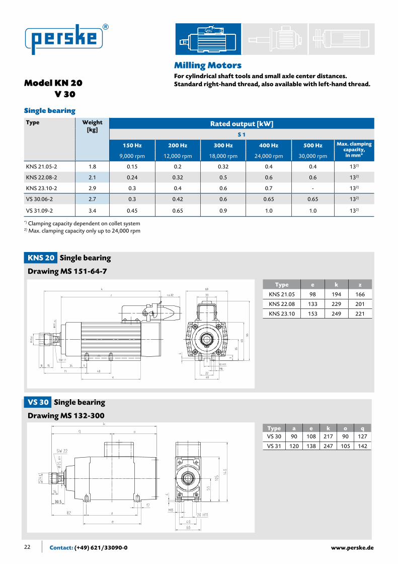
Type e k z
KN 21.05 98 200 166
KN 22.08 133 235 201
KN 23.10 153 255 221
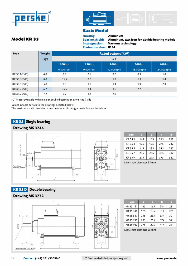
Housing: AluminumBearing shield: AluminumImpregnation: Vacuum technologyProtection class: IP 54
KN 20 Single-bearing
Drawing MS 151
Front thread according to order
Model KN 20 V 30
Type Weight Rated output [kW]
[kg] S 1
100 Hz 150 Hz 200 Hz 300 Hz 400 Hz 500 Hz
6,000 rpm 9,000 rpm 12,000 rpm 18,000 rpm 24,000 rpm 30,000 rpm
KN 21.05-2 1.8 - 0.15 0.2 0.32 0.4 0.4
KN 22.08-2 2.1 - 0.24 0.32 0.5 0.6 0.6
KN 23.10-2 2.9 - 0.3 0.4 0.6 0.7 -
V 30.06-2 2.7 0.2 0.3 0.42 0.6 0.65 0.65
V 31.09-2 3.4 0.3 0.45 0.65 0.9 1.0 1.0
Type a e k o q
V 30 90 108 217 90 127
V 31 120 138 247 105 142
V 30 Single-bearing
Drawing MS 132
Front thread according to order
16.1
Only available with single-bearing
Values in table pertain to the drawings depicted below. The maximum shaft diameter or customer-specific designs can influence the values.
Max. shaft diameter 20 mm
Max. shaft diameter 25 mm
Basic Model
10 ** Custom shaft designs upon request.Contact: (+49) 621/33090-0 www.perske.de
Type a e k z
KR 35.1 145 165 245 212
KR 35.3 175 195 275 242
KR 35.5 215 235 315 282
KR 35.7 235 255 335 302
KR 35.9 275 295 375 342
Housing: AluminumBearing shield: Aluminum,castironfordoublebearingmodelsImpregnation: Vacuum technologyProtection class: IP 54
KR 35 Single bearing
Drawing MS 3746
KR 35 D Double bearing
Drawing MS 3772
Front thread according to order
2.5
143.5
10.1
Front thread according to order
143.5
27.9
Type a e k z
KR 35.1 D 145 165 284 231
KR 35.3 D 175 195 314 261
KR 35.5 D 215 235 354 301
KR 35.7 D 235 255 374 321
KR 35.9 D 275 295 414 361
Model KR 35
Type Weight Rated output [kW]
[kg] S 1
100 Hz 150 Hz 200 Hz 300 Hz 400 Hz
6,000 rpm 9,000 rpm 12,000 rpm 18,000 rpm 24,000 rpm
KR 35.1-2 (D) 4.0 0.3 0.5 0.7 0.9 1.0
KR 35.3-2 (D) 4.8 0.45 0.7 1.0 1.3 1.4
KR 35.5-2 (D) 5.8 0.6 1.0 1.4 1.9 2.0
KR 35.7-2 (D) 6.2 0.75 1.1 1.6 2.2 -
KR 35.9-2 (D) 7.2 0.9 1.4 2.0 - -
Max. shaft diameter 25 mm
Max. shaft diameter 25 mm
(D) Motor available with single or double bearings on drive (tool) side
Values in table pertain to the drawings depicted below. The maximum shaft diameter or customer-specific designs can influence the values.
Basic Model

11
A1
Hig
h-s
pee
d
ma
chin
ing
mo
tors
** Custom shaft designs upon request. Contact: (+49) 621/33090-0www.perske.de
Type a e k
KN 50 195 213 330
KN 51 225 243 360
KN 52 245 263 380
Type a e k
KN 50 D 195 213 361
KN 51 D 225 243 391
KN 52 D 245 263 411
KN 50 Single-bearing
Drawing MS 170 A
KN 50 D Double-bearing
Drawing MS 4046
Housing: AluminumBearing shield: Cast ironImpregnation: Vacuum technologyProtection class: IP 54
Front thread according to order
Terminal box on right-hand side
M16
lh thr
ead
M12
rh thr
ead
32.9
Model KN 50
Type Weight Rated output [kW]
[kg] S 1
100 Hz 150 Hz 200 Hz 300 Hz
6,000 rpm 9,000 rpm 12,000 rpm 18,000 rpm
KN* 50.11-2 (D) 11.0 1.8 2.5 3.0 4.0
KN* 51.14-2 (D) 12.5 2.4 3.5 4.0 5.0
KN* 52.16-2 (D) 13.5 2.7 4.0 4.5 -
Max. shaft diameter 30 mm
Max. shaft diameter 30 mm
(D) Motor available with single or double bearings on drive (tool) side * KR model possible, see p. 26
Values in table pertain to the drawings depicted below. The maximum shaft diameter or customer-specific designs can influence the values.
Basic Model

12 ** Custom shaft designs upon request.Contact: (+49) 621/33090-0 www.perske.de
Housing: AluminumBearing shield: Aluminum for V50/cast iron for V60Impregnation: Vacuum technologyProtection class: IP 54
Model V 50 V 60
Type a e k o q
V 50 80 100 297 136 161
V 50
Drawing MS 113 A
Type a e k o q
V 60 90 115 320 145 175
V 61 130 155 360 165 195
V 60
Drawing MS 113 B
Front thread according to order
Terminal box on right-hand side
Front thread according to order
Terminal box on right-hand side
Type Weight Rated output [kW]
[kg] S 1
100 Hz 150 Hz 200 Hz 300 Hz 400 Hz 500 Hz
6,000 rpm 9,000 rpm 12,000 rpm 18,000 rpm 24,000 rpm 30,000 rpm
V 50.09-2 8.5 1.2 1.5 1.85 2.5 3.0 3.0
V 60.11-2 16.0 2.2 3.0 4.0 5.0 5.0 5.0
V 61.15-2 18.5 3.0 4.0 5.0 - - -
Max. shaft diameter 30 mm
Max. shaft diameter 30 mm
Only available with single bearing
Values in table pertain to the drawings depicted below. The maximum shaft diameter or customer-specific designs can influence the values.
Basic Model

13
A1
Hig
h-s
pee
d
ma
chin
ing
mo
tors
** Custom shaft designs upon request. Contact: (+49) 621/33090-0www.perske.de
Type a e k
KN 60 190 210 311
KN 61 220 240 341
KN 62 270 290 391
Type a e k
KN 60 D 190 210 361
KN 61 D 220 240 391
KN 62 D 270 290 441
KN 60 Single bearing
Drawing MS 170 B
KN 60 D Double bearing
Drawing MS 171
Housing: AluminumBearing shield: Cast ironImpregnation: Vacuum technologyProtection class: IP 54
Front thread according to order
Terminal box on right-hand side
M6x10 deep
27.5
Terminal box on right-hand side
M12
right
M16
left
M8x12 deep
32.9
Model KN 60
Type Weight Rated output [kW]
[kg] S 1
100 Hz 150 Hz 200 Hz 300 Hz
6,000 rpm 9,000 rpm 12,000 rpm 18,000 rpm
KN* 60.09-2 (D) 14.5 2.7 3.0 3.5 -
KN* 61.13-2 (D) 19.5 4.0 5.0 6.0 7.0
KN* 62.18-2 (D) 22.0 5.5 6.0 7.0 -
Max. shaft diameter 40 mm
Max. shaft diameter 35 mm
(D) Motor available with single or double bearings on drive (tool) side * KR model possible, see p. 28
Values in table pertain to the drawings depicted below. The maximum shaft diameter or customer-specific designs can influence the values.
Basic Model

14 ** Custom shaft designs upon request.Contact: (+49) 621/33090-0 www.perske.de
Housing: AluminumBearing shield: Cast ironImpregnation: Vacuum technologyProtection class: IP 54
Model KC 70
Type a e k
KC 70 260 310 415
KC 71 340 390 495
KC 72 420 470 575
Type a e k z
KC 70 D 260 315 447 271
KC 71 D 340 395 527 351
KC 72 D 420 475 607 431
KC 70 Single bearing
Drawing MS 652 - 44
KC 70 D Double bearing
Drawing MS 182 - 5
Terminal box on right-hand side
M16
rig
ht
M12
left
M8x12 deep
M16 right
M20 left
M8x15 deep
Terminal box on right-hand side
Type Weight Rated output [kW]
[kg] S 1
100 Hz 150 Hz 200 Hz 300 Hz
6,000 rpm 9,000 rpm 12,000 rpm 18,000 rpm
KC 70.12-2 (D) 26.0 5.2 5.5 - -
KC 71.16-2 (D) 33.0 6.6 7.0 8.0* 10.0*
KC 71.20-2 (D) 38.0 8.0 9.0 10.0* 12.0* KC 72.28-2 (D) 51.0 12.5 13.0 - -
Max. shaft diameter 40 mm
Max. shaft diameter 50 mm
* For KNO model, see milling motors pages 21 and 29 (D) Motor available with single or double bearings on drive (tool) side
Values in table pertain to the drawings depicted below. The maximum shaft diameter or customer-specific designs can influence the values.
Basic Model

15
A1
Hig
h-s
pee
d
ma
chin
ing
mo
tors
** Custom shaft designs upon request. Contact: (+49) 621/33090-0www.perske.de
Housing: Cast ironBearing shield: Cast ironImpregnation: Vacuum technologyProtection class: IP 54
Type a e k
K 81 D 460 492 615
K 82 D 510 542 665
K 83 D 570 602 725
K 80 Single bearing
Drawing MS 630 A453
M10x15 deep
Terminal box on right-hand side
Type a e k
K 81 460 492 600
K 82 510 542 650
K 83 570 602 710
K 80 D Double bearing
Drawing MS 630 A196
M16
rig
ht
M20
left
M8x20 deep
Terminal box on right-hand side
Model K 80
Type Weight Rated output [kW]
[kg] S 1
100 Hz 150 Hz
6,000 rpm 9,000 rpm
K 81.23-2 (D) 69.0 16.0 18.0
K 82.27-2 (D) 79.0 18.0 22.0
K 83.37-2 (D) 91.0 25.0 -
Max. shaft diameter 40 mm
Max. shaft diameter 60 mm
(D) Motor available with single or double bearings on drive (tool) side
Values in table pertain to the drawings depicted below. The maximum shaft diameter or customer-specific designs can influence the values.
Basic Model

16 ** Custom shaft designs upon request.Contact: (+49) 621/33090-0 www.perske.de
Housing: CastironforK91,steelforK93Bearing shield: Cast iron or steelImpregnation: Vacuum technologyProtection class: IP 54
Model K 90
Type Weight Rated output [kW]
[kg] S 1
100 Hz 150 Hz
6,000 rpm 9,000 rpm
K 91.31-2 (D) 106.0 25.0 30.0
K 93.38-2 (D) 128.0 30.0 35.0
K 90 D Double bearing
Drawing MS 630 B183
Terminal box on right-hand side
M12 x15 deep
K 90 Single bearing
Drawing MS 630 B182
M12x15 deep
Terminal box on right-hand side
Type a e k
K 91.31 525 566 680
K 93.38 615 656 770
Type a e k
K 91.31 D 525 567 682
K 93.38 D 615 657 772
Max. shaft diameter 50 mm
Max. shaft diameter 50 mm
(D) Motor available with single or double bearings on drive (tool) side
Values in table pertain to the drawings depicted below. The maximum shaft diameter or customer-specific designs can influence the values.
Basic Model

17
A1
Hig
h-s
pee
d
ma
chin
ing
mo
tors
** Custom shaft designs upon request. Contact: (+49) 621/33090-0www.perske.de
Housing: CastironforuptoK111,steelforK112& K 113Bearing shield: Cast iron or steelImpregnation: Vacuum technologyProtection class: IP 54
K 110 D Double bearing
Drawing MS 630 C154
M12 x15 deep
Terminal box on right-hand side
K 110 Single bearing
Drawing MS 630 C153
Terminal box on right-hand side
Type a e k
K 110 464 504 674
K 111 534 574 743
K 112 614 654 823
K 113 734 774 943
Type a e k
K 110 D 504 554 721
K 111 D 574 624 791
K 112 D 654 704 871
K 113 D 774 824 991
Model K 110
Type Weight Rated output [kW]
[kg] S 1
75 Hz 100 Hz
4,500 rpm 6,000 rpm
K 110.24-2 (D) 160.0 25.0 30.0
K 111.31-2 (D) 177.0 37.0 45.0
K 112.38-2 (D) 195.0 45.0 55.0
K 113.50-2 (D) 240.0 55.0 65.0
Max. shaft diameter 70 mm
Max. shaft diameter 80 mm
(D) Motor available with single or double bearings on drive (tool) side
Values in table pertain to the drawings depicted below. The maximum shaft diameter or customer-specific designs can influence the values.
Basic Model

18 ** Custom shaft designs upon request.Contact: (+49) 621/33090-0 www.perske.de
Housing: CastironuptoK140,steelforK141Bearing shield: Cast iron or steelImpregnation: Vacuum technologyProtection class: IP 54
Model K 140
Type Weight Rated output [kW]
[kg] S 1
75 Hz 100 Hz
4,500 rpm 6,000 rpm
K 140.38-2 (D) 360.0 65.0 80.0
K 141.50-2 (D) 450.0 80.0 100.0
K 140 Single bearing
Drawing MS 630 D60
Type a e k
K 140 670 720 983
K 141 855 905 1168
K 140 D Double bearing
Drawing MS 630 D61
Terminal box on right-hand side
Grease escape with dummy fitting, M32x1.5, sealed
Type a e k
K 140 D 650 704 963
K 141 D 835 889 1148
M12x25 deep
Terminal box on right-hand side
Max. shaft diameter 80 mm
Max. shaft diameter 85 mm
(D) Motor available with single or double bearings on drive (tool) side
Values in table pertain to the drawings depicted below. The maximum shaft diameter or customer-specific designs can influence the values.
Basic Model

19
A1
Hig
h-s
pee
d
ma
chin
ing
mo
tors
** Custom shaft designs upon request. Contact: (+49) 621/33090-0www.perske.de
A1
Hig
h-s
pee
dm
ach
inin
g m
oto
rs
Housing: SteelBearing shield: SteelImpregnation: Vacuum technologyProtection class: IP 54
Type a e k
K 160 D 815 895 1266
K 162 D 895 975 1346
K 160 D Double bearing
Drawing MS 3503
M6x30 deep
Terminal box, right side
M76x
4 left
/right
Type a e k k1
K 200 D 840 920 1301 1091
K 202 D 900 980 1361 1151
K 200 D Double bearing
Drawing MS 4452
M16x30 deep
Model K 160 K 200
Type Weight Rated output [kW]
[kg] S 1
75 Hz
4,500 rpm
K 160.50-2 D 625.0 100.0
K 162.60-2 D 750.0 125.0
K 200.50-2 D 840.0 150.0
K 202.60-2 D 900.0 175.0
Max. shaft diameter 115 mm
Max. shaft diameter 115 mm
Only available with double bearing
Values in table pertain to the drawings depicted below. The maximum shaft diameter or customer-specific designs can influence the values.
Basic Model

20 Contact: (+49) 621/33090-0 www.perske.de
GeneralYears of experience in the area of high-speed milling have resulted in the development of these compact milling motors. Robust milling spindles can accommodate collets up to 25 mm maimum. The stable bearing shields have an adjustment groove between the feet for proper mounting on the machine support. The dust extraction shroud can be easily attached thanks to holes and a centering diameter on the tool side.
OutputIn the selection tables, the performance is indicated for continuous duty (operating mode S1). For intermittent operations (operating mode S6 – 60%) commonly seen in milling, one can assume an approx. 20% higher output. Please inquire to obtain a binding statement.
BearingsBy using lifetime-lubricated bearings, the motors are maintenance-free and thereby easy to operate. The shaft end is free of play both radially and axially thanks to a precision spindle bearing. This robust yet precise bearing makes the motor less sensitive to minor residual unbalancing of the tools used. If necessary, hybrid bearings are used, which are especially suited for high speeds.
CoolingThe motors are self-cooled with a built-in fan. It operates as a function of the motor’s operating speed and makes it independent of other units. Noise generation is reduced to a large extent by the design of the air inlet and the fan. In special cases, separate ventilation is possible.
ToolholdingThe motors are designed for commercially available collets (2 – 25 mm). Safety notice: only one turning direction is permitted.
The motors with hydraulic chucks stand out thanks to the greatest run-out precision possible, secure tightening of the tool, and ease of operation. In addition, these spindles can be operated in left- or right-hand rotation.
Milling Motorsfor cylindrical shaft tools with no-play double bearingProtection class IP 54
A2

21
Hig
h-s
pee
d
ma
chin
ing
mo
tors
Contact: (+49) 621/33090-0www.perske.de
A2Type Weight
[kg]Rated output [kW]
S 1
150 Hz 200 Hz 300 Hz 400 Hz 500 Hz Max. clamping capacity,in mm*9,000 rpm 12,000 rpm 18,000 rpm 24,000 rpm 30,000 rpm
KNS 21.05-2 1.8 0.15 0.2 0.32 0.4 0.4 132)
KNS 22.08-2 2.1 0.24 0.32 0.5 0.6 0.6 132)
KNS 23.10-2 2.9 0.3 0.4 0.6 0.7 - 132)
VS 30.06-2 2.7 0.3 0.42 0.6 0.65 0.65 132)
VS 31.09-2 3.4 0.45 0.65 0.9 1.0 1.0 132)
VS 50.09-2 8.5 1.5 1.85 2.5 3.0 3.0 16
VS 60.11-2 16.0 3.0 4.0 5.0 5.0 5.0 16
VS 61.15-2 19.0 4.0 5.0 - - - 16
VUS 50.09-23) 8.0 0.55 0.8 1.0 1.0 16
VUS 60.11-23) 15.5 1.9 2.1 2.6 2.6 16
VUS 61.15-23) 18.0 2.6 2.8 - - 16
Double bearingKRS 35.1-2 D 4.5 0.5 0.7 0.9 1.0 13
KRS 35.3-2 D 5.3 0.7 1.0 1.3 1.4 13
KRS 35.5-2 D 6.3 1.0 1.4 1.9 2.0 13
KRS 35.7-2 D 6.7 1.1 1.6 2.2 - 13
KRS 35.9-2 D 7.7 1.4 2.0 - - 13
KRS 50.11-2 D 11.5 2.5 3.0 4.0 16
KRS 51.14-2 D 13.0 3.5 4.0 5.0 16
KRS 52.16-2 D 14.0 4.0 4.5 - 16
KRSV 51.14-2 D 13.5 3.5 4.0 5.0 25
KRSV 51.14-2 D1) 14.5 3.5 4.0 5.0 25
KRS 60.09-2 D 16.0 3.0 3.5 - 20
KRS 61.13-2 D 20.0 5.0 6.0 7.0 20
KRS 62.18-2 D 22.0 6.0 7.0 - 20
KRS 60.09-2 D 16.5 3.0 3.5 - 25
KRS 61.13-2 D 20.5 5.0 6.0 7.0 25
KRS 62.18-2 D 23.0 6.0 7.0 - 25
KRSV 61.13-2 D1) 24.0 5.0 6.0 7.0 25
KNOCS 71.16-2 D 35.0 7.0 8.0 10.0 20
KNOS 71.16-2 D 37.0 7.0 8.0 10.0 25
KNOCS 71.20-2 D 37.0 9.0 10.0 12.0 20
KNOS 71.20-2 D 39.0 9.0 10.0 12.0 25
Milling MotorsFor cylindrical shaft tools and small axle center distances. Standardright-handthread,alsoavailablewithleft-handthread.
Single bearing
*) clamping capacity dependent on collet system1) with hydraulic chuck2) max. clamping capacity only up to 24,000 rpm 3) non-ventilated, low noise
22 Contact: (+49) 621/33090-0 www.perske.de
Milling Motors For cylindrical shaft tools and small axle center distances. Standardright-handthread,alsoavailablewithleft-handthread.Model KN 20
V 30
KNS 20 Single bearing
Drawing MS 151-64-7
VS 30 Single bearing
Drawing MS 132-300
0.1
30.5
Type a e k o qVS 30 90 108 217 90 127
VS 31 120 138 247 105 142
Type Weight[kg]
Rated output [kW]S 1
150 Hz 200 Hz 300 Hz 400 Hz 500 Hz Max. clamping capacity,in mm*9,000 rpm 12,000 rpm 18,000 rpm 24,000 rpm 30,000 rpm
KNS 21.05-2 1.8 0.15 0.2 0.32 0.4 0.4 132)
KNS 22.08-2 2.1 0.24 0.32 0.5 0.6 0.6 132)
KNS 23.10-2 2.9 0.3 0.4 0.6 0.7 - 132)
VS 30.06-2 2.7 0.3 0.42 0.6 0.65 0.65 132)
VS 31.09-2 3.4 0.45 0.65 0.9 1.0 1.0 132)
*) Clamping capacity dependent on collet system
Single bearing
Type e k z
KNS 21.05 98 194 166
KNS 22.08 133 229 201
KNS 23.10 153 249 221
2) Max. clamping capacity only up to 24,000 rpm

23
Hig
h-s
pee
d
ma
chin
ing
mo
tors
Contact: (+49) 621/33090-0www.perske.de
A2
Milling Motors For cylindrical shaft tools and small axle center distances. Standardright-handthread,alsoavailablewithleft-handthread.
Terminal box on right-hand side
Collet 0Z.1833Clamping capacity 1 – 12
Steel special labyrinth
M27x
1.5
Model V 50 V 60
VS 50 Single bearing
Drawing MS 3675-5
VS 60 Single bearing
Drawing MS 3110-7
Type a e k o qVS 50 80 100 277 136 141
Type a e k o qVS 60 90 115 312 145 167
VS 61 130 155 352 165 187
Collet 0Z.1833Clamping capacity 1 – 13
Steel special labyrinth
Terminal box on right-hand side
M27x
1.5
Single bearing
Type Weight[kg]
Rated output [kW]S 1
150 Hz 200 Hz 300 Hz 400 Hz 500 Hz Max. clamping capacity,in mm*9,000 rpm 12,000 rpm 18,000 rpm 24,000 rpm 30,000 rpm
VS 50,09-2 8.5 1.5 1.85 2.5 3.0 3.0 16**
VS 60.11-2 16.0 3.0 4.0 5.0 5.0 5.0 16**
VS 61.15-2 19.0 4.0 5.0 - - - 16
*) Clamping capacity dependent on collet system**) Max. clamping capacity up to 24,000 rpm

Contact: (+49) 621/33090-0 www.perske.de24
Milling Motors For cylindrical shaft tools and small axle center distances. Standardright-handthread,alsoavailablewithleft-handthread.Model VU 50
VU 60
VUS 50 Single bearing
Drawing U 05/2436-1
VUS 60 Single bearing
Drawing U 06/2439-1
Type a e L L1
VUS 50 80 100 310 328
Type a e k k1
VUS 60 90 115 340 358
VUS 61 130 155 380 398
Collet 0Z.1833Chuck capacity 1 – 12
Collet 0Z.1833Chuck capacity 1 – 8
Terminal box on right-hand side
M27x
1.5
M20x
1.5
Collet 0Z.1833Chuck capacity 1 – 12
Collet 0Z.1833Chuck capacity 1 – 8
M27x
1.5
M20x
1.5
Type Weight[kg]
Rated output [kW]S 1
150 Hz 200 Hz 300 Hz 400 Hz Max. clampingcapacity,
in mm* 9,000 rpm 12,000 rpm 18,000 rpm 24,000 rpm
VUS 50.09-2 8.0 0.55 0.8 1.0 1.0 16
VUS 60.11-2 15.5 1.9 2.1 2.6 2.6 16
VUS 61.15-2 18.0 2.6 2.8 - - 16
*) Clamping capacity dependent on collet systemNon-ventilated, low noise
Single bearing
Contact: (+49) 621/33090-0 www.perske.de

Contact: (+49) 621/33090-0www.perske.de 25
Hig
h-s
pee
d
ma
chin
ing
mo
tors
Milling Motors For cylindrical shaft tools and small axle center distances. Standardright-handthread,alsoavailablewithleft-handthread.
A2
Model KRS 35
KRS 35 D Double bearing
Drawing MS 3870
Plug in front Plug in rearSide view depicted without collet and nut
apprx.10
apprx.20
Type a e k z z1
KRS 35.1 D 145 165 261 231 173
KRS 35.3 D 175 195 291 261 203
KRS 35.5 D 215 235 331 301 243
KRS 35.7 D 235 255 351 321 263
KRS 35.9 D 275 295 391 361 303
Double bearing
Type Weight[kg]
Rated output [kW]S 1
150 Hz 200 Hz 300 Hz 400 Hz Max. clampingcapacity,
in mm*9,000 rpm 12,000 rpm 18,000 rpm 24,000 rpm
KRS 35.1-2 D 4.5 0.5 0.7 0.9 1.0 13
KRS 35.3-2 D 5.3 0.7 1.0 1.3 1.4 13
KRS 35.5-2 D 6.3 1.0 1.4 1.9 2.0 13
KRS 35.7-2 D 6.7 1.1 1.6 2.2 - 13
KRS 35.9-2 D 7.7 1.4 2.0 - - 13
*) Clamping capacity dependent on collet system
Contact: (+49) 621/33090-0www.perske.de
26 Contact: (+49) 621/33090-0 www.perske.de
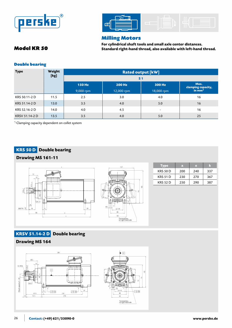
Milling Motors For cylindrical shaft tools and small axle center distances. Standardright-handthread,alsoavailablewithleft-handthread.Model KR 50
KRS 50 D Double bearing
Drawing MS 161-11
Type a e k
KRS 50 D 200 240 337
KRS 51 D 230 270 367
KRS 52 D 250 290 387
KRSV 51.14-2 D Double bearing
Drawing MS 164
Type Weight[kg]
Rated output [kW]S 1
150 Hz 200 Hz 300 Hz Max. clampingcapacity,
in mm*9,000 rpm 12,000 rpm 18,000 rpm
KRS 50.11-2 D 11.5 2.5 3.0 4.0 16
KRS 51.14-2 D 13.0 3.5 4.0 5.0 16
KRS 52.16-2 D 14.0 4.0 4.5 - 16
KRSV 51.14-2 D 13.5 3.5 4.0 5.0 25
*) Clamping capacity dependent on collet system
Double bearing
Terminal box on right-hand side
approx. 12
Chu
ck c
apac
ity
2 –
25
Terminal box on right-hand side

27
Hig
h-s
pee
d
ma
chin
ing
mo
tors
Contact: (+49) 621/33090-0www.perske.de
A2
Milling Motors For cylindrical shaft tools and small axle center distances.
Withhydraulicchucks,simpleoperation,andsuitable for left-/right-hand rotation
KRSV 61.13-2 D Double bearing
Drawing MS 3757
KRSV 51.14-2 D Double bearing
Drawing MS 164-7
Type Weight[kg]
Rated output [kW]S 1
150 Hz 200 Hz 300 Hz Max. clampingcapacity,
in mm*9,000 rpm 12,000 rpm 18,000 rpm
KRSV 51.14-2 D 14.5 3.5 4.0 5.0 25
KRSV 61.13-2 D 24.0 5.0 6.0 7.0 25
Double bearing
Model KR 50 KR 60
ø 25
tool
sha
ft to
lera
nce
min
imum
ø 25h
7 re
quir
ed
M8x15 deep
Requires minimum tool shaft tolerance of ø25 h7
Thread for cable fittings M20x1.5 / m16x1.5 sealed with dummy plugs
ETP HYDRO-GRIP GPW 25, actuated via tensioning screw with SW5 Allen wrench
Radial run-out of max. 0.02 mm measured using a concentricity test gauge at 100 mm from the front edge of the chuck system

28 Contact: (+49) 621/33090-0 www.perske.de
KRS 60 D Double bearing
Drawing MS 3903
Type a e k
KRS 60 D 190 230 370
KRS 61 D 220 260 400
KRS 62 D 270 310 450
Type a e k
KRS 60 D 190 230 369
KRS 61 D 220 260 399
KRS 62 D 270 310 449
Milling Motors For cylindrical shaft tools and small axle center distances. Standardright-handthread,alsoavailablewithleft-handthread.Model KR 60
KRS 60 D Double bearing
Drawing MS 4445
Type Weight[kg]
Rated output [kW]S 1
150 Hz 200 Hz 300 Hz Max. clampingcapacity,
in mm*9,000 rpm 12,000 rpm 18,000 rpm
KRS 60.09-2 D 16.0 3.0 3.5 - 20
KRS 61.13-2 D 20.0 5.0 6.0 7.0 20
KRS 62.18-2 D 22.0 6.0 7.0 - 20
KRS 60.09-2 D 16.5 3.0 3.5 - 25
KRS 61.13-2 D 20.5 5.0 6.0 7.0 25
KRS 62.18-2 D 23.0 6.0 7.0 - 25
Double bearing
Rego-Fix ER32 collet and UM/ER32 chuck (chuck capacity 1 – 20 ) Depicted without collet and nut
M8x15 deep
Terminal box on right-hand side
M40x
1.5
Collet 0Z.1836Chuck capacity 2 – 25
M8x15 deep
0.1
*) Clamping capacity dependent on collet system
29
Hig
h-s
pee
d
ma
chin
ing
mo
tors
Contact: (+49) 621/33090-0www.perske.de NAFTA: www.crpperske.com
A2
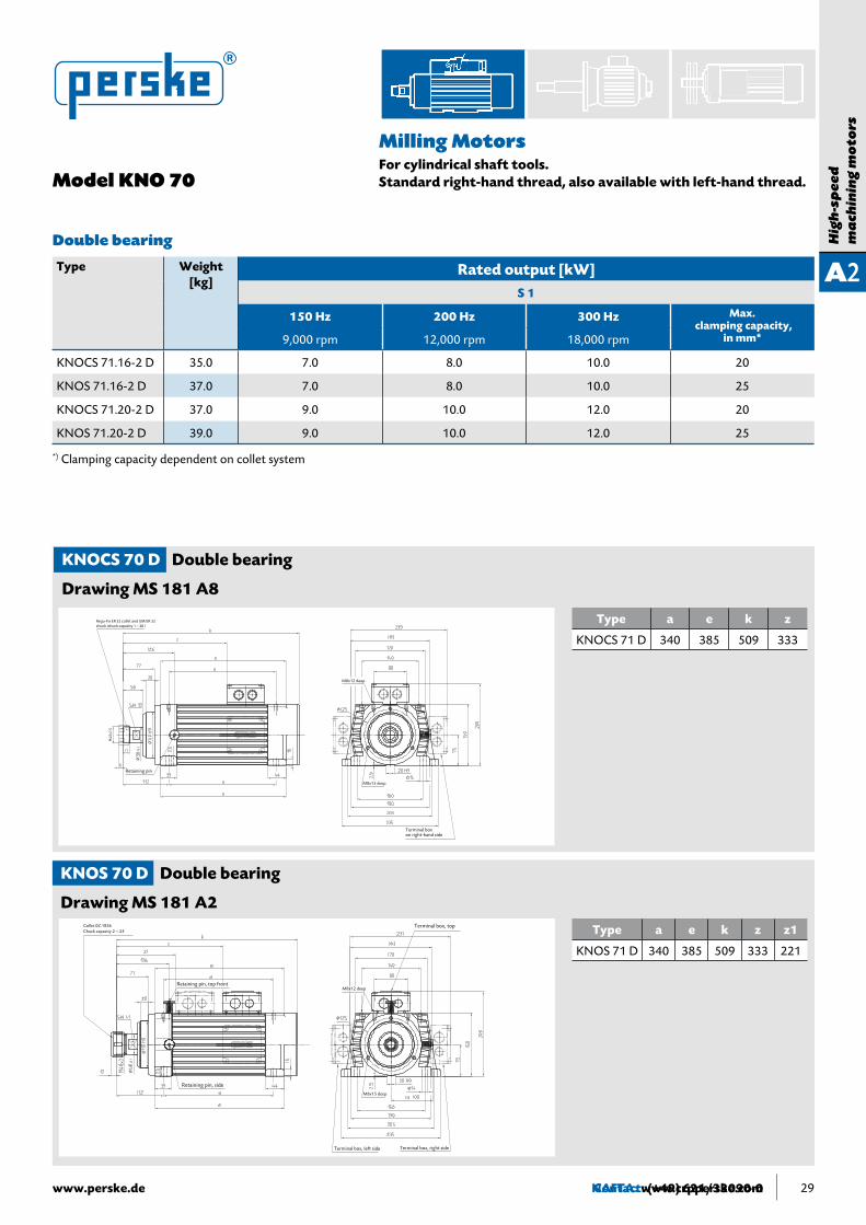
Milling Motors For cylindrical shaft tools. Standardright-handthread,alsoavailablewithleft-handthread.Model KNO 70
KNOS 70 D Double bearing
Drawing MS 181 A2
KNOCS 70 D Double bearing
Drawing MS 181 A8
Type a e k z z1
KNOS 71 D 340 385 509 333 221
Type a e k z
KNOCS 71 D 340 385 509 333
Type Weight[kg]
Rated output [kW]S 1
150 Hz 200 Hz 300 Hz Max. clampingcapacity,
in mm*9,000 rpm 12,000 rpm 18,000 rpm
KNOCS 71.16-2 D 35.0 7.0 8.0 10.0 20
KNOS 71.16-2 D 37.0 7.0 8.0 10.0 25
KNOCS 71.20-2 D 37.0 9.0 10.0 12.0 20
KNOS 71.20-2 D 39.0 9.0 10.0 12.0 25
*) Clamping capacity dependent on collet system
Double bearing
Rego-Fix ER 32 collet and UM/ER 32 chuck (chuck capacity 1 – 20 )
Retaining pin
M8x12 deep
M8x15 deep
Terminal box on right-hand side
M40x
1.5
Collet 0Z.1836Chuck capacity 2 – 25
Retaining pin, top front
Retaining pin, side
Terminal box, top
Terminal box, left side Terminal box, right side
M8x12 deep
M8x15 deep

30 Contact: (+49) 621/33090-0 www.perske.de30
High-Precision Motorsfor hydraulic chucks
Perske high-precision motors are developed especially for hydraulic chucks. By using a reinforced bearing with high-precision ball bearings and a stiffer spindle, outstanding axial and radial run-out can be achieved in micron-level quality.
In combination with our precision balancing, we offer smooth-running, maximum-precision drives that are especially well-suited for use with PKD tools and can substantially increase their service lives. The result is improved cost-effectiveness and availability.
Perske high-precision motors are characterized by
• Stiff motor spindles and precision bearings with double spindle bearings
• Ground and hardened shafts
• Radial and axial run-out precision ≤ 8 microns
• Uniform interface for milling and cutting tools
• Significantly longer tool service life
• No-play tool clamping
High-Precision Motors
Type Weight Rated output [kW][kg] S 1
100 Hz 150 Hz 200 Hz
6,000 rpm 9,000 rpm 12,000 rpm
KNS 51.14-2 D 13.5 2.4 3.5 4.0
KNS 61.13-2 D 20.0 4.0 5.0 6.0
KCS 71.16-2 D 35.0 6.6 7.0 -
KCS 71.20-2 D 40.0 8.0 9.0 -
KS 81.23-2 D 71.0 16.0 18.0 -
KS 82.27-2 D 82.0 18.0 22.0 -
A3

Contact: (+49) 621/33090-0www.perske.de 31
A3
Hig
h-S
pee
d
ma
chin
ing
Mo
tors
High-Precision Motorsfor hydraulic tool holders
Model KNS 50 KNS 60
Type Weight Rated output [kW][kg] S 1
100 Hz 150 Hz 200 Hz
6,000 rpm 9,000 rpm 12,000 rpm
KNS 51.14-2 D 13.5 2.4 3.5 4.0
KNS 61.13-2 D 20.0 4.0 5.0 6.0
KNS 50 D Double bearing
Drawing MS 3833-1
KNS 60 D Double bearing
Drawing MS 3946
Type a e k z
KNS 51 D 225 243 400 247
Type a e k z
KNS 61 D 220 260 421 264Retaining pin, side
Terminal box, right side

32 Contact: (+49) 621/33090-0 www.perske.de
High-Precision Motorsfor hydraulic tool holders
Type a e k z
KS 81 D 460 492 630 370
KS 82 D 510 542 680 420
Type a e k z
KCS 71 D 340 395 537 361
KCS 70 D Double bearing
Drawing MS 182A-191
Retaining pin, side
Mounting holes for transportation protection
M8x20 deep
Retaining pin, side
Terminal box, right side
Model KCS 70 KS 80
KS 80 D Double bearing
Drawing MS 630 A422-1
Type Weight Rated output [kW][kg] S 1
100 Hz 150 Hz
6,000 rpm 9,000 rpm
KCS 71.16-2 D 35.0 6.6 7.0
KCS 71.20-2 D 40.0 8.0 9.0
KS 81.23-2 D 71.0 16.0 18.0
KS 82.27-2 D 82.0 18.0 22.0

Service-Hotline: (+49) 621 / 33090-0 33
Hig
h-s
pee
d
ma
chin
ing
mo
tors
www.perske.de
A4Motor spindlesStandardized tool holding systems for:Manual quick tool changes according to DIN 69893-1 HSK-CAutomatic tool changes according to DIN 69893-6 HSK-F63
Specialflatmotors:provenmillingandcuttingdrivesfurtherenhanced
• High-performance asynchronous motor with high overload capacity
• Performance measured for S1 – continuous duty
•Robustmechanicaldesign,therebymakingitsuitableforheavytools
•Maintenance-free,no-play,lifetime-lubricatedbearing
•ProtectionclassIP54,surface-cooled
• Self-cooling through integrated fan
• High-quality vacuum impregnation of the winding
• Centering diameter for protective shroud
● Standardized tool holding
● Existing shaft tools can be used by means of adapters
● High degree of radial and axial stiffness
● Optimal radial and axial run-out precision
● Precisely defined and reproducible cutting edge position
● Short mounting/removal path for tool changes
● Easy to use
Advantages
Contact: (+49) 621/33090-0 www.perske.de34
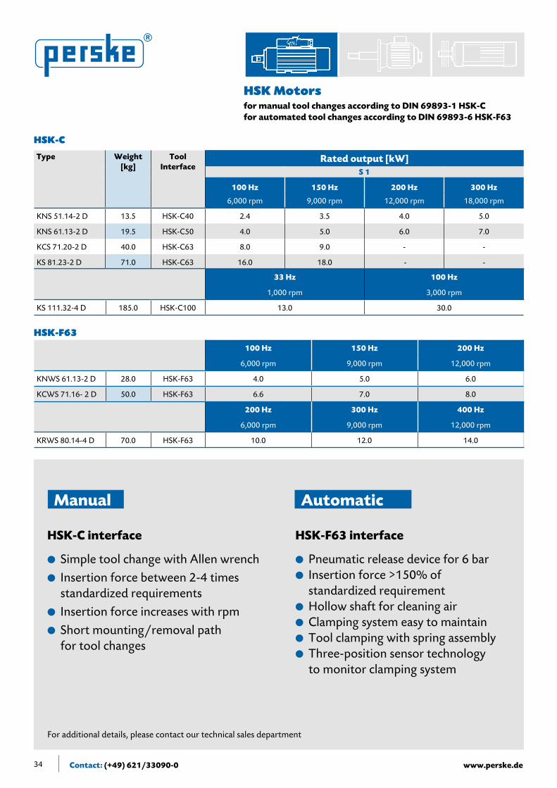
HSK Motorsfor manual tool changes according to DIN 69893-1 HSK-Cfor automated tool changes according to DIN 69893-6 HSK-F63
Type Weight[kg]
Tool Interface
Rated output [kW]S 1
100 Hz 150 Hz 200 Hz 300 Hz
6,000 rpm 9,000 rpm 12,000 rpm 18,000 rpm
KNS 51.14-2 D 13.5 HSK-C40 2.4 3.5 4.0 5.0
KNS 61.13-2 D 19.5 HSK-C50 4.0 5.0 6.0 7.0
KCS 71.20-2 D 40.0 HSK-C63 8.0 9.0 - -
KS 81.23-2 D 71.0 HSK-C63 16.0 18.0 - -
33 Hz 100 Hz
1,000 rpm 3,000 rpm
KS 111.32-4 D 185.0 HSK-C100 13.0 30.0
100 Hz 150 Hz 200 Hz
6,000 rpm 9,000 rpm 12,000 rpm
KNWS 61.13-2 D 28.0 HSK-F63 4.0 5.0 6.0
KCWS 71.16- 2 D 50.0 HSK-F63 6.6 7.0 8.0
200 Hz 300 Hz 400 Hz
6,000 rpm 9,000 rpm 12,000 rpm
KRWS 80.14-4 D 70.0 HSK-F63 10.0 12.0 14.0
HSK-C interface
● Simple tool change with Allen wrench● Insertion force between 2-4 times
standardized requirements ● Insertion force increases with rpm● Short mounting/removal path
for tool changes
HSK-F63 interface
● Pneumatic release device for 6 bar● Insertion force >150% of
standardized requirement● Hollow shaft for cleaning air● Clamping system easy to maintain● Tool clamping with spring assembly ● Three-position sensor technology
to monitor clamping system
For additional details, please contact our technical sales department
Manual Automatic
HSK-C
HSK-F63

Contact: (+49) 621/33090-0www.perske.de 35
Hig
h-S
pee
d
ma
chin
ing
Mo
tors
A4Type Weight
[kg]Tool
InterfaceRated output [kW]
S 1
100 Hz 150 Hz 200 Hz 300 Hz
6,000 rpm 9,000 rpm 12,000 rpm 18,000 rpm
KNS 51.14-2 D 13.5 HSK-C40 2.4 3.5 4.0 5.0
KNS 61.13-2 D 19.5 HSK-C50 4.0 5.0 6.0 7.0
KCS 71.20-2 D 40.0 HSK-C63 8.0 9.0 - -
KS 81.23-2 D 71.0 HSK-C63 16.0 18.0 - -
33 Hz 100 Hz
1,000 rpm 3,000 rpm
KS 111.32-4 D 185.0 HSK-C100 13.0 30.0
HSK Motorsfor manual tool changes according to DIN 69893-1 HSK – C
HSK-C40 interface with manual clamping set
Actuated on side with SW3 Allen wrench Terminal box, right side
HSK-C50 interface with manual clamping set
Actuated on side with SW4 Allen wrench
Terminal box, right side
M6x15 deep
KNS 51 D Double bearing
DrawingMS4232,shaftend:HSK-C40
KNS 61 D Double bearing
DrawingMS4266,shaftend:HSK-C50
Type a e k
KNS 51 D 225 243 342
Type a e k
KNS 61 D 220 260 360

Contact: (+49) 621/33090-0 www.perske.de36
HSK Motorsfor manual tool changes according to DIN 69893-1 HSK–C
HSK-C63 interface with manual clamping set
Actuated on side with SW5 Allen wrench
Terminal box, right side
M8x15 deep
HSK-C63 interface with manual clamping set
Actuated on side with SW5 Allen wrench
Terminal box, right side
M8x20 deep
KCS 71 D Double bearing
DrawingMS182-424,shaftend:HSK-C63
KS 81 D Double bearing
DrawingMS630A379,shaftend:HSK-C63
Type a e k z
KCS 71 D 340 395 474 298
Type a e k
KS 81 D 460 492 567
HSK-C100 interface with manual clamping set
Actuated on side with SW8 Allen wrench
Terminal box, right side
M12 x15 deep
Type a e k
KS 111 D 574 624 721
KS 111 D Double bearing
DrawingMS630C114,shaftend:HSK-C100

Contact: (+49) 621/33090-0www.perske.de 37
Hig
h-S
pee
d
ma
chin
ing
Mo
tors
A4
HSK Motorsfor automatic tool changes according to DIN 69893-6 HSK-F63
KNWS 61.13-2 D Double bearing
Drawing MS 4464
G 1/8 adapters forcompressed air at 6-8 bar
“Blow out”
“Clamping”
“Release”
HSK-F63 chuckSensor system connector plug
View A
Terminal box, right side
Type Weight[kg]
Tool Interface
Rated output [kW]S 1
100 Hz 6,000 rpm
150 Hz 9,000 rpm
200 Hz 12,000 rpm
KNWS 61.13-2 D 28.0 HSK-F63 4.0 5.0 6.0
KCWS 71.16- 2 D 50.0 HSK-F63 6.6 7.0 8.0
200 Hz 6,000 rpm
300 Hz 9,000 rpm
400 Hz 12,000 rpm
KRWS 80.14-4 D 70.0 HSK-F63 10.0 12.0 14.0

Contact: (+49) 621/33090-0 www.perske.de38
HSK Motors
KRWS 80.14-4 D Double bearing
Drawing MS 4475
for automatic tool changes according to DIN 69893-6 HSK-F63
KCWS 71.16-2 D Double bearing
Drawing MS 182-493-1
1
1
2
2
3
3
4
4
5
5
6
6
A A
B B
C C
D D
Status Datum Name
Datum Name
Gezeichnet
Kontrolliert
Norm
Diese Zeichnung ist Eigentum der Walter Perske GmbH,Friedrich-Ebert-Straße 80-84, 68167 MannheimSchutzrecht nach DIN 34 beachten! Werkstoff:
Allgemeintoleranzenn. DIN ISO 2768-1
Maßstab
Blatt
Gewicht:
Ersatz für: Ersetzt durch:
Flachmotor 24.06.2010 r.sternagel
1/1A3
KRWS 80.14 D
MS 4456-1 (KRWS 80.14 D).idw
Änderung
472
178
115
266
18
223
199
33.5
n13
56.5 31545
12M
15
71 280
150 15
0
"A"
In this areaCompressed air connection G1/8"Pressure: 6-8 bar- Release- Clamping- Blow out
Sensor system connector plug
View A
View "A"
A

Contact: (+49) 621/33090-0Internet: www.perske.de 39
B
Sp
ecia
l dri
ves
/
Hig
h-s
pee
d d
irec
t d
riv
es
For many years, Perske has specialized in developing and designing special electric motors. As a result, we have been able to gather valuable experience in many application areas that are very beneficial in regard to innovations.
Our partners are machine manufacturers domestically and abroad with whom we collaborate closely to develop demand-oriented, specially adapted drive solutions. The result is a diverse range of variants. They include mechanical features such as
• shafts,bearingshields,andmountingflanges
as well as electrical configurations pertaining to
• voltage,frequencies,speedresponsecharacteristics,etc.
The full range of possibilities cannot be depicted in this brochure.
To offer you an optimized, technical and cost-effective drive solution for you and your requirements, we ask that you please call us with your questions.
We offer from our range:
At 3,000 rpm up to 170 kW
At 18,000 rpm up to 55 kW
At 30,000 rpm up to 5 kW
We know that we can assist you with our expertise.
For the sake of offering some preliminary information, we would like to provide you with a few examples of drive solutions.
Special drives/ High-speed direct drives

Contact: (+49) 621/33090-0 www.perske.de40
In comparison to asynchronous motors, they offer a substantially higher power density. They are thus lighter and smaller than an asynchronous motor with comparable performance. As a result, this drive is especially well suited for highly dynamic or space-limited applications.
The high power density is achieved by high-quality, low-loss electroplates in the stators and rotors with rare earth magnets.
Perske offers a series of synchronous, no-feedback motors, which are also suitable as direct tool supports. By combining synchronous technology with our expertise in precision bearings, we can find special solutions for your needs.
Advantages/Properties
• Small,lightweightconstructionthankstoaveryhighpowerdensityWeight reduction by over 40% Performance increase by over 100%
• Energy-saving due to high efficiency Efficiency increase by up to 20%
• High overload capacity up to > 3 x rated torque
• Constant speed up to approx. three times the rated output
• Robust,lifetime-lubricated,maintenance-freebearing
• Easy to install since there is no speed feedback
Synchronous motors are powered by electronic frequency converters. The motor and converter must be carefully matched to each other to operate optimally.
Overload behavior and speed constancy are primarily dependent on the converter. We are able to provide assistance in tuning them at any time.
Synchronous Motors(permanent magnet excited)
B1

Contact: (+49) 621/33090-0www.perske.de 41
Synchronous Motors
Sp
ecia
l dri
ves
/H
igh
-sp
eed
dir
ect
dri
ves
B1
Type Weight Rated output [kW]
[kg] S 1
400 Hz 600 Hz
12,000 rpm 18,000 rpm
KN 21.04-4S 1.8 0.5 0.65
KN 22.08-4S 2.5 1.0 1.3
KN 24.12-4S 3.2 1.5 2.0
KR 35.1-4S 3.8 1.5 2.0
KR 35.5-4S 4.7 2.0 3.0
KR 35.7-4S 5.5 3.0 4.0
Front thread according to order
KN 20 S
Drawing MS 151-188
KR 35 S
Drawing MS 4490
We can provide you with additional performance specifications and speeds upon request. Available as direct drive or with direct tool holding system.
Type e k z
KN 21.04 S 93 200 166
KN 22.08 S 133 235 201
KN 24.12 S 173 275 241
Type a e k z
KR 35.1 S 145 165 245 212
KR 35.5 S 215 235 315 282
KR 35.7 S 235 255 335 302
Front thread according to order
2.5 143.5

Contact: (+49) 621/33090-0 www.perske.dewww.perske.de42
The treatment of various materials in the processing industry/process engineering realm requires drives that precisely meet the requirements. Speed-regulated drives, designed especially for converter operations, offer the right solution for these applications.
The converter helps to precisely adjust to the speed. The asynchronous motor combined with the converter also results in an extremely useful “side effect,” namely substantial energy savings, i.e., providing the most cost-effective solution.
PERSKE motors are designed together with the user according to the need profile, while also taking into account electrical data and ambient conditions.
More than 60 years of experience building machining motors made for high speeds and adverse operating conditions flow into each unit, and ensure a high degree of reliability and availability.
One should also note that the converters and motors must be tuned to each other.
From its comprehensive portfolio, Perske can offer you a wide selection of suitable direct drives and provide support in configuring them.
We would be pleased to show you examples of implemented and tested drive solutions.
How you benefit
• Direct drive with low maintenance since there
is no mechanical transmission
• Motors designed especially for converter operations
•Customer-specificperformance/speedadjustmentcapability
• High degree of energy efficiency with low-loss materials
•Avarietyofmodels,allavailablefromourportfolio
• Robust bearing
• Compact design
• Variable mounting flange upon request
•Speedsofupto30,000rpm
Direct Drivesfor foot- or flange-mounting
B2

Contact: (+49) 621/33090-0www.perske.de 43
B2
Sp
ecia
l dri
ves
/
Hig
h-s
pee
d d
irec
t d
riv
es
Welcher Text hier?
Texte noch liefern
The Perske modular system has motors that comply with increased dust protection requirements. A detailed inquiry is necessary so that the design can be adapted to special specifications.
The design takes into account the following criteria:
• Incidence of dust occurs only briefly if at all.
• The material-specific temperature class sets a maximum permissible temperature that is lower than the ignition temperature of the corresponding dust cloud or layer. The motor’s surface temperature may not exceed this temperature and generally requires a lower output of the corresponding motor size.
• Voltage fluctuations of ± 10% may not result in an unacceptable temperature increase.
• The motors must be equipped with a temperature monitoring system, e.g., thermistors.
• The motor housing must be grounded directly.
When inquiring, it is necessary to describe the dust material.
Especially when working with stone, the motors must be protected from water penetration. Perske delivers motors that meet this requirement and incorporate the following features:
• Hollow shaft for supplying spray to the tool’s center
• Specially sealed housing section interfaces
• Sealed cable inlet in the terminal box
• Shaft Labyrinth seals partially equipped with additional V- or O-rings.
Increased dust protectionfor ATEX 22 type protection zone with non-conductive dust
Increased water protection

Contact: (+49) 621/33090-0 www.perske.de44
Induction Motor, Stator Rotor Packages
GeneralPerske integrated motors are used to build high- and ultra-high-speed spindle and special drives. The integrated motor elements are brushless and thereby wear- and maintenance-free.
Additional advantages include:
– High efficiency and performance factor through the use of modern, low-loss materials
– Optimally balanceable thanks to a precisely designed die cast cage
The output depends on the size, speed, and type of cooling (water, air, or oil). To achieve high speeds, the integrated motors must have the frequency converter supply correspondingly high frequencies.
DesignPerske integrated motor elements consist of
a) A stator package with a high-quality, vacuum-impregnated winding (thermal class F), 400-mm-long winding con-nections made of Teflon-insulated braided wire, oil-resistant, stator-hole machined, winding with 3 thermistors upon request
b) A rotor package with a squirrel cage winding made of die cast aluminum, non-machined to allow an exact fit to the shaft
For production reasons, generally only complete packages, i.e., stator and rotor, are available.
OptionPerske rotor packages can also be supplied with a shaft.
PerformanceThe performance data is based on empirical values obtained for bearing friction and sufficient cooling to dissipate heat loss. Increased cooling makes higher outputs possible. The transient peak power possible is substantially higher. Please contact us to obtain further details.
Type-designation
Example Core length
Stator’s exterior diameter
Stator’s interior diameter
Diameter of rotor hole
Pole number
DKE 045 075.5/40/20-2

Contact: (+49) 621/33090-0www.perske.de 45
Fla
t M
oto
rs /
C
ircu
lar
Sa
w M
oto
rs
CFlat Motors / Circular Saw Motors• Perske circular saw motors have proven themselves in many years of use and under the most adverse operating
conditions as being extremely reliable.
• Due to their high overload capacity and high stalling torque (approx. 2-3 times the rated torque which is significantly higher than on standard motors), our motors can also overcome the increased high demands encountered in very non-homogenous material.
• A direct drive, without a separate saw blade shaft, may be the right design for an economical, cost-effective solution (also speed-adjustable).
• Available for right- or left-hand operation, with or without brakes, and variable terminal box position.
• Special shafts with large diameters, reinforced bearings, or extreme lengths are also possible.
• Special configurations with increased water protection may be available upon request.

Contact: (+49) 621/33090-0 www.perske.de46
Circular saw motors with saw blade flangefor sawing, drilling, and milling wood, plastics, and metalProtection class IP 54
Mechanical designThree-phase motor with squirrel cage rotorThe stable and aesthetically designed flat motors have an especially low loss of cutting depth thanks to their low center heights.TypeKN50,KN60,KC70:Especially flat housing made of die cast aluminum, bearing shields made of cast iron, and motors designed with laby-rinth seals on both sides.TypeK80,K90,K110,K140:Housing and bearing shields made of cast iron (welded steel for higher loads), and with borings to mount the protective shroud. The K 160 and K 200 models have their housings and bearing shields made of welded steel.
The shaft bearing consists of generously dimensioned grooved ball bearings. The drive-side bearing is designed as a fixed bearing, while the fan-side one is a self-aligning bearing. The bearings are dust-sealed for normal operating conditions. Permanent lubrication makes the motors of the KN 50, KN 60, KC 70 and K 80 maintenance-free and thus especially user-friendly.
When using the motors to cut plastics and metals, dust and chips are a major hazard for the bearings. For such operating conditions, the bearings can also be equipped with special labyrinth seals on the bearing shield upon request. Terminal boxes are normally located at the right front (when looking at the shaft end); however, they can be installed on the left side upon special request. The openings for the cable inlets can be turned 90 degrees with the terminal box if necessary. Flat motors for stonework are available upon request. Protection class IP 55 upon request.
Electrical designThe motors are designed according to DIN EN 60034-1 (VDE 0530, Part 1) guidelines. Based on normal use in sawing operations, the output for intermittent operations S6-60% is provided.Output measurement for thermal class F, high-quality vacuum impregnation, high stalling torque and high overload capacity, ambient temperature 40°C, and installation altitude < 1,000 m above sea level.High-quality insulating materials are used for the insulation. Vacuum impregnation uses state-of-the-art technology. The motors are also available with tropical insulation upon request. For installation in ambient temperatures above 40°C or at altitudes above 1,000 m above sea level, the motors will exhibit decreased performance.All motors can be designed for alternative voltages and frequencies. Please inquire if such cases apply to you, especially if foreign electrical connection regulations must be complied with. Depending on the type, the motors develop stalling torques of approx. 250-350% of the rated torque. As a result, the motors have a high transient overload capacity and are thus especially designed for adverse sawing operations. For the transient use of peak output, it is recommended to measure the fuse and the lines based on the resulting higher currents. We ask that you please contact us for further details.
C1

Contact: (+49) 621/33090-0www.perske.de 47
Fla
t M
oto
rs /
C
ircu
lar
Sa
w M
oto
rs
C1
Circular saw motors with saw blade flange
Rated output [kW] [HP]S6-60% Sawbladeflange Drawing
Type Weight[kg]
50 Hz3,000 rpm
60 Hz3,600 rpm
60 Hz3,600 rpm
Ømm
KN 50.11-2 11.0 0.9 1.1 1.5 80 MS 170 A177
KN 51.14-2 12.5 1.3 1.5 2.0 80 MS 170 A177
KN 52.16-2 13.5 1.5 1.7 2.3 80 MS 170 A177
KN 60.09-2 14.5 2.0 2.4 3.2 100 MS 3614-1
KN 61.13-2 19.5 3.0 3.5 4.7 100 MS 3614-1
KN 62.18-2 22.0 4.0 4.8 6.5 100 MS 3614-1
KC 70.12-2 26.0 3.7 4.4 6.0 120 MS 3862
KC 71.16-2 33.0 5.0 6.0 8.0 120 MS 3862
KC 71.20-2 38.0 6.5 7.5 10.0 120 MS 3862
KC 72.28-2 51.0 9.0 11.0 15.0 120 MS 3862
K 81.23-2 69.0 11.0 13.0 17.0 160 MS 630 A 397
K 82.27-2 79.0 13.0 15.0 20.0 160 MS 630 A 397
K 83.37-2 91.0 18.0 21.0 28.0 160 MS 630 A 397
K 91.31-2 106.0 20.0 25.0 34.0 180 MS 630 B 130
K 93.38-2 128.0 25.0 30.0 40.0 180 MS 630 B 130
K 110.24-2 160.0 25.0 30.0 40.0 200 MS 3954
K 111.31-2 177.0 37.0 43.0 58.0 200 MS 3954
K 112.38-2 195.0 45.0 52.0 70.0 200 MS 3954
K 113.50-2 240.0 55.0 65.0 87.0 200 MS 3954
K 140.38-2 360.0 65.0 78.0 105.0 300 MS 630 D 62
K 141.50-2 450.0 75.0 95.0 128.0 300 MS 630 D 62
K 160.50-2 D 625.0 90.0 110.0 150.0 Upon Request MS 3503
K 162.60-2 D 750.0 120.0 140.0 190.0 Upon Request MS 3503
K 200.50-2 D 840.0 140.0 170.0 230.0 Upon Request MS 4452
K 202.60-2 D 900.0 170.0 200.0 270.0 Upon Request MS 4452
Configurationfor1,500/1,800rpmwith4-polemotoravailableuponrequest

Contact: (+49) 621/33090-0 www.perske.de48
Circular saw motors with saw blade flange
Type a e k
KNS 50 195 213 332
KNS 51 225 243 362
KNS 52 245 263 382
KN 50
Drawing MS 170 A177
Type a e k
KNS 60 190 210 313
KNS 61 220 240 343
KNS 62 270 290 393
KN 60
Drawing MS 3614-1
Type a e k
KCS 70 260 310 415
KCS 71 340 390 495
KCS 72 420 470 575
KC 70
Drawing MS 3862
Depicted without saw blade flange and nut
Chuck width 1 – 5
M20
left/r
ight
Blade seat Ø30 h6 Terminal box, right side
Depicted without saw blade flange and nut
Chuck width 1 – 3
Blade seat Ø30 h6
M20
left/r
ight
Terminal box, right side
M6x10 deep
24.5
Depicted without saw blade flange and nut
Chuck width 1 – 5
Terminal box, right side
M8x12 deep

Contact: (+49) 621/33090-0www.perske.de 49
Fla
t M
oto
rs /
C
ircu
lar
Sa
w M
oto
rs
C1
Circular saw motors with saw blade flange
Type a e k
KS 81 460 492 610
KS 82 510 542 660
KS 83 570 602 720
K 80
Drawing MS 630 A397
Type a e k
KS 91.31 525 566 693
KS 93.38 615 656 783
K 90
Drawing MS 630 B130
Type a e k
KS 110 464 504 705
KS 111 534 574 775
KS 112 614 654 855
KS 113 734 774 975
K 110
Drawing MS 3954
Depicted without saw blade flange and nut
Chuck width 1 – 5mm
Front thread according to order
M10x15 deep
Terminal box, right side
Depicted without saw blade flange and nut
Chuck width 2 – 5 mmM12x15 deep
Terminal box, right side
Depicted without saw blade flange and nut
M12x25 deep
Terminal box, right side
M56x
4 left
/right

Contact: (+49) 621/33090-0 www.perske.de50
Circular saw motors with saw blade flange
Type a e k
K 140 670 720 1003
K 141 855 905 1188
K 140
Drawing MS 630 D62
Type a e k
K 160 D 815 895 1266
K 162 D 895 975 1346
K 160 D
Drawing MS 3503
K 200 D
Drawing MS 4452
Depicted without saw blade flange and nut
Chuck width 2 – 8 mm
M12x25 deep
Terminal box, right side
Blade seat Ø30 h6
M6x30 deep
Terminal box, right side
M76x
4 left/r
ight
M16x30 deep
Type a e k k1
KS 200 D 840 920 1301 1091
KS 202 D 900 980 1361 1151
also for milling toolSaw flange upon request
also for milling toolSaw flange upon request

Contact: (+49) 621/33090-0www.perske.de 51
Fla
t M
oto
rs /
C
ircu
lar
Sa
w M
oto
rs
C2
Circular saw motors with saw blade flange and brakeMechanical designThree-phase motor with squirrel cage rotor. Integrated electromechanical spring-pressure brake cooled by the motor’s fan. When turning the motor ON, the brake is powered also. Its powerful electromagnet lifts the brake disk and lets the motor run. When turning the power OFF, the strong springs located in the brake exert a high braking force on the friction disks and bring the motor to a standstill. This naturally also applies in the event of a power outage, since the motors have a fail-safe brake.
Electrical design of the motorAs on p. 46
Electrical design of the brakeSupply voltage: 230- or 400-V, single-phase alternating current. The electromagnet is configured for DC current and is fed via a rectifier that is located, along with the connection terminals of the motor and brake, in the motor terminal box. For the power supply, single-phase alternating current is required. Normally, this is drawn parallel from the motor terminal board and thereby has the same switching states for motor and brake, and thus also automatic interaction. For star/delta startups, the brake’s power supply must also be ensured in the event of a protective failover to prevent a transient, no-voltage state. However, if this is not possible because the motor voltage is deviating excessively from the brake’s rated voltage or because the speed regulation is fed in variably, then a separate power supply is necessary for the brake. In this case, the user should ensure that synchronous switching states (motor/brake) are provided. Please request a wiring diagram.
Safety NoteIf the brake motor is used as a circular saw motor, then in the event of braking, the saw blade would continue turning along with the outside flange and nut due to the rotational inertia and the nut would loosen on the thread with the corresponding results. Therefore, the nut is secured from loosening by a full-length fitted key that also applies to the external saw blade flange. The saw blade must then have a greater bore hole diameter than the shaft diameter, and rest on a spacer ring or corresponding flange bevel. It is especially pointed out that the brake is not suited to function as a holding device for tool changes (saw blade change).
Design of the brakeThe integrated standard brakes provide the following braking torque:Model KN 5… Br Braking torque 4 NmModel KN 6… Br Braking torque 3 NmModel KC 7… Br Braking torque 16 NmModel K 8... Br Braking torque 36 NmModel K 9... Br Braking torque 50 NmModel K 10... Br Braking torque 80 NmModel K 14... Br Braking torque 150 NmModel K 16... Br Braking torque 150 Nm
General validityThe electromechanical spring-activated brake shall be checked for the intended use. The strength, i.e., the service life, of the brake lining is dependent on the speed, switching frequency, and the mass moment of inertia.To perform a quick check, please provide: • Speed [rpm] at which the brake will be actuated• Switching frequency [switches per hour]• Mass moment of inertia of external load [kgm2]

Contact: (+49) 621/33090-0 www.perske.de52
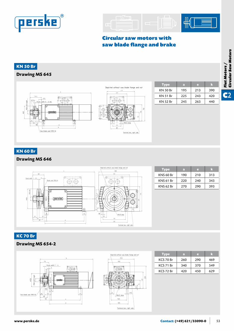
Circular saw motors with saw blade flange and brake
Type Weight[kg]
Rated output [kW] [HP]
S6-60%Saw blade
flangeDrawing
50 Hz3,000 rpm
60 Hz3,600 rpm
60 Hz3,600 rpm
Ømm
KN 50.11-2 Br 12.5 0.9 1.1 1.5 80 MS 645
KN 51.14-2 Br 14.0 1.3 1.5 2.0 80 MS 645
KN 52.16-2 Br 15.0 1.5 1.7 2.3 80 MS 645
KN 60.09-2 Br 15.5 1.8 2.2 2.9 100 MS 646
KN 61.13-2 Br 20.5 2.6 3.1 4.2 100 MS 646
KN 62.18-2 Br 23.0 3.5 4.2 5.6 100 MS 646
KC 70.12-2 Br 32.0 3.7 4.4 6.0 120 MS 654-2
KC 71.16-2 Br 39.0 5.0 6.0 8.0 120 MS 654-2
KC 71.20-2 Br 44.0 6.5 7.5 10.0 120 MS 654-2
KC 72.28-2 Br 57.0 9.0 11.0 15.0 120 MS 654-2
K 81.23-2 Br 77.0 11.0 13.0 17.0 160 MS 635
K 82.27-2 Br 87.0 13.0 15.0 20.0 160 MS 635
K 83.37-2 Br 99.0 18.0 21.0 28.0 160 MS 635
K 91.31-2 Br 120.0 20.0 25.0 34.0 180 MS 636
K 93.38-2 Br 145.0 25.0 30.0 40.0 180 MS 636
K 110.24-2 Br 175.0 25.0 30.0 40.0 200 MS 633 C
K 111.31-2 Br 190.0 37.0 43.0 58.0 200 MS 633 C
K 112.38-2 Br 205.0 45.0 52.0 70.0 200 MS 633 C
K 113.50-2 Br 255.0 55.0 65.0 87.0 200 MS 633 C
K 140.38-2 Br 400.0 65.0 78.0 105.0 300 MS 631-3
K 141.50-2 Br 460.0 75.0 95.0 128.0 300 MS 631-3
K 160.50-2 D Br 655.0 90.0 110.0 150.0 Upon request MS 639
K 162.60-2 D Br 780.0 120.0 140.0 190.0 Upon request MS 639
Configurationfor1,500/1,800rpmwith4-polemotoravailableuponrequest
Contact: (+49) 621/33090-0www.perske.de 53
C2
Fla
t M
oto
rs /
Cir
cula
r S
aw
Mo
tors
Circular saw motors with saw blade flange and brake
Type a e k
KN 50 Br 195 213 390
KN 51 Br 225 243 420
KN 52 Br 245 263 440
KN 50 Br
Drawing MS 645
Type a e k
KNS 60 Br 190 210 313
KNS 61 Br 220 240 343
KNS 62 Br 270 290 393
KN 60 Br
Drawing MS 646
Type a e k
KCS 70 Br 260 290 469
KCS 71 Br 340 370 549
KCS 72 Br 420 450 629
KC 70 Br
Drawing MS 654-2
Depicted without saw blade flange and nut
M8x12 deep
Terminal box, right side
Chuck width 0 – 6 mm
Saw blade seat Ø30 h6
M20
left
/right
Depicted without saw blade flange and nut
Chuck width 1 – 3.5
M6x10 deep
Terminal box, right side
Blade seat Ø30 h6
M20
left
M30
left
/right
Depicted without saw blade flange and nut
Chuck width 1 – 4
M8x12 deep
Terminal box, right side
Saw blade seat Ø60 h6

Contact: (+49) 621/33090-0 www.perske.de54
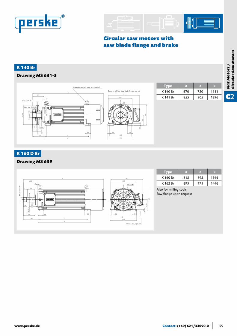
Circular saw motors with saw blade flange and brake
Type a e k
K 81 Br 420 455 695
K 82 Br 470 505 745
K 83 Br 530 565 805
K 80 Br
Drawing MS 635
Type a e k
K 91.31 Br 490 531 791
K 93.38 Br 580 621 881
Type a e k
K 110 Br 420 460 793
K 111 Br 490 530 863
K 112 Br 570 610 943
K 113 Br 690 730 1063
K 90 Br
Drawing MS 636
K 110 Br
Drawing MS 633 C
M30
left
/right
Depicted without saw blade flange and nut
Chuck width 1...4M10x15 deep
Saw blade seat Ø60 h6
M36
left
/right
Depicted without saw blade flange and nut
Chuck width 2 – 6M12x15 deep
Terminal box, right sideSaw blade seat Ø60 h6
M56x
4 left/r
ight
Depicted without saw blade flange and nut
Chuck width 0 – 8
M12x15 deep
Terminal box, right side
Saw blade seat Ø80 h6
Contact: (+49) 621/33090-0www.perske.de 55
C2
Fla
t M
oto
rs /
C
ircu
lar
Sa
w M
oto
rs
Circular saw motors with saw blade flange and brake
Type a e k
K 140 Br 670 720 1111
K 141 Br 855 905 1296
K 140 Br
Drawing MS 631-3
Type a e k
K 160 Br 815 895 1366
K 162 Br 895 975 1446
K 160 D Br
Drawing MS 639
Removable eye bolt (only for shipment)
Depicted without saw blade flange and nut
Chuck width 2 – 8
Blade seat Ø110 h6
M76x
4 left/r
ight
M16x30 deep
Terminal box, right side
Also for milling toolsSaw flange upon request

Technical informationPermissible shaft loadsTypes of protection and operating modesModels/Calculation formulasNotes about ordering partsMotor checklist (for inquiries and orders)
Terms and Conditions of Sale and DeliveryContact person
General Information
Contact: (+49) 621/33090-0 www.perske.de56

Technical informationImpregnationThe motors are impregnated in a vacuum impregnation process based on state-of-the-art technology. This method prevents air pockets in the winding and serves to increase the electrical strength of the winding against increased loads.
PerformancePerske motors are built for industrial use and designed to operate with a converter. The motor output is indicated for thermal class F and continuous duty (S1) or intermittent operation (S6-60%) and is valid for ambient temperatures up to 40°C and an installation altitude up to 1,000 m above sea level. When the motors are installed in ambient temperatures above 40°C or at altitudes above 1,000 m above sea level, the motor may exhibit decreased performance.
Operating with a static converterNote: If a static frequency converter is used to operate high-speed motors, then one must plan on thermal class F. The converter is to be tailored to the motor. The EMC guidelines shall be complied with. When operating static converters, one shall preferably seek a sine-shaped outlet voltage. Under certain conditions, smoothing reactors or filters may be necessary. DIN VDE 0530-17, (dated January 2007) shall be complied with. When operating converters at the motor’s rated frequency, the available torque is usually less than on sine-shaped voltages. This results from the heat increase stemming from the additional losses. For the rated frequency, the reduction coefficient fluctuates between 0 and 20% (DIN VDE 0530-17, Section 6).
BearingsThe motors have high-quality ball bearings whose specifications have been coordinated with the manufacturer. For high speeds, bearings with increased speed capability and special running smoothness are built into the motors. Normally, lifetime-lubricated bearings are used. This makes them user-friendly and almost maintenance-free. The drive-side bearing is a fixed bearing, while the fan-side bearing is a self-aligning bearing. The shafts are supported largely free of play by means of built-in corrugated springs, which enables close machining tolerances. Dual bearings on the tool-side are play-free and have proven themselves especially in milling and cutting. These bearings enable the absorption of high forces resulting from heavy tools or rapid feed rates.
Bearing and shaft loadsIn regard to the sizing of the drive shaft and bearing, radial and axial forces are generously compensated for. When the technical features are used as intended, a high degree of operational safety can be provided. The permissible values in accordance with the table on page 59 shall be complied with in configuring a given machine.
BalancingDespite the high speeds, meticulous dynamic balancing of the motors ensures smooth operation. In the delivered state, the vibration velocity V
eff is < 1.8 mm/s. For the bearing’s service life, balancing of the entire motor-and-tool
system is essential. For that reason, only balanced tools with a balance quality of at least G 6.3 shall be used. For heavier tools or higher speeds, a balance quality of G 2.5 may be necessary. Normally, full-key balancing is agreed upon, i.e., the entire inserted key and "F" shafts. Half-key balancing must be arranged separately. If a system is insufficiently balanced, one can expect the bearing to fail prematurely.
Safety and startup instructionsEnsure that the motors are installed, maintained, and repaired only by qualified personnel and that the safety provisions as well as local regulations are complied with. Startup and maintenance instructions shall be adhered to. If these startup instructions are not on hand, please request them by indicating the model type and the serial number.Low-voltage machines are components to be installed in machines in accordance with the Machine Directive 2006/42/EC. Startup is prohibited until the end product’s conformity with these guidelines has been ascertained.
Contact: (+49) 621/33090-0www.perske.de 57

Contact: (+49) 621/33090-0 www.perske.de58
Permissible shaft loads
To preclude mechanical overloading of the shaft and bearing, the overload capacity of the shaft end shall be limited to permissible values.
To quickly select a motor and estimate loads, a simplified load model shall be established (see Fig. 1). Here, the radial load, the axial load, and the distance of the load application point from the front side of the motor are the parameters that the user shall verify when selecting a motor.
For every motor size, a fixed axial load limit shall be pre-defined and the associated radial load limits as a function of the effective distance “a” shall be indicated. The catalog provides the values for the loads on the shaft end (a=L) or on half the mounting length (a=L/2). The information provided applies only for the indicated lengths. If loads engage beyond the shaft end, we recommend that our engineering department perform a separate test.
Fig. 1: Simplified load model. Fa = axial load, Fr = radial load.
Scope• The radial loads provided in the table are permissible during continuous duty and incorporate at least twice
the safety factor against the shaft’s fatigue fracture.
• All figures apply only for the shaft ends indicated in the table or motor spec sheets.
• The load application point must be within the mounting range on the shaft.
• Permissible loads are calculated for an extended service life of 15,000 operating hours of the bearing according to DIN ISO 281.
• The weight of the parts that the customer mounts on the shaft are not taken into consideration. For heavier weights, a separate test is advisable to avoid problems with the critical bending frequencies.
• The figures are calculated values and not a binding statement in the sense of guaranteed characteristics.
• The calculation is based on the installation position on Model B3.
Basic recommendationsTools or other customer components to be installed on the shaft must, at a minimum, meet a balance quality of G6.3 according to DIN ISO 1940-1. In special situations (large tool weight, high speeds), a balance quality of G2.5 or better may be necessary.
The load application point on the shaft should lie as close as possible to the motor since the load carrying capability is highest here. In practice, this means that tools or other components to be mounted by the customer should be clamped on the shaft as close as possible to the motor. In the design phase, this should be considered as early as possible.
Fr
a=L
Fa
a=L/2

Contact: (+49) 621/33090-0www.perske.de 59
Type Drawing Shaft end Permissible radial load Axial load Valid up to n
F_per_(a=L) F_per_(a=0,5L) Fa n =KN 21,05 MS 151 ø14x30 PF 450 N 500 N 200 N 18,000 rpm
KN 22.08 MS 151 ø14x30 PF 350 N 550 N 200 N 18,000 rpm
KN 23.10 MS 151 ø14x30 PF 300 N 400 N 200 N 18,000 rpm
V 30.06 MS 132 ø14x30 PF 500 N 550 N 200 N 18,000 rpm
V 31.09 MS 132 ø14x30 PF 500 N 550 N 200 N 18,000 rpm
KR 35.1 MS 3746 ø14x30 PF 550 N 850 N 300 N 18,000 rpm
KR 35.3 MS 3746 ø14x30 PF 550 N 850 N 300 N 18,000 rpm
KR 35.5 MS 3746 ø14x30 PF 550 N 900 N 300 N 18,000 rpm
KR 35.7 MS 3746 ø14x30 PF 550 N 900 N 300 N 18,000 rpm
KR 35.9 MS 3746 ø14x30 PF 600 N 900 N 300 N 12,000 rpm
KR 35.1 D MS 3772 ø25x50 PF 1100 N 1200 N 300 N 18,000 rpm
KR 35.3 D MS 3772 ø25x50 PF 1000 N 1200 N 300 N 18,000 rpm
KR 35.5 D MS 3772 ø25x50 PF 750 N 1200 N 300 N 18,000 rpm
KR 35.7 D MS 3772 ø25x50 PF 650 N 1000 N 300 N 18,000 rpm
KR 35.9 D MS 3772 ø25x50 PF 500 N 800 N 300 N 12,000 rpm
V 50.09 MS 113 A ø22x50 PF 900 N 1000 N 300 N 18,000 rpm
KN 50.11 MS 170A ø22x50 PF 1100 N 1500 N 300 N 12,000 rpm
KN 51.14 MS 170A ø22x50 PF 850 N 1400 N 300 N 12,000 rpm
KN 52.16 MS 170A ø22x50 PF 750 N 1200 N 300 N 12,000 rpm
KN 50.11 D MS 4046 ø30x68 PF 1100 N 1700 N 300 N 12,000 rpm
KN 51.14 D MS 4046 ø30x68 PF 950 N 1600 N 300 N 12,000 rpm
KN 52.16 D MS 4046 ø30x68 PF 850 N 1400 N 300 N 12,000 rpm
V 60.11 MS 113 B ø22x50 PF 750 N 800 N 400 N 18,000 rpm
V 61.15 MS 113 B ø22x50 PF 750 N 850 N 400 N 18,000 rpm
KN 60.09 MS 170B ø24x50 PF 1100 N 1200 N 400 N 12,000 rpm
KN 61.13 MS 170B ø24x50 PF 1100 N 1200 N 400 N 12,000 rpm
KN 62.18 MS 170B ø24x50 PF 1200 N 1300 N 400 N 12,000 rpm
KN 60.09 D MS 171 ø30x70 PF 1300 N 1900 N 400 N 12,000 rpm
KN 61.13 D MS 171 ø30x70 PF 1300 N 2000 N 400 N 12,000 rpm
KN 62.18 D MS 171 ø30x70 PF 1300 N 2000 N 400 N 12,000 rpm
KC 70.12 MS 652-44 ø35x68 PF 2300 N 2500 N 600 N 9,000 rpm
KC 71.16 MS 652-44 ø35x68 PF 2400 N 2600 N 600 N 9,000 rpm
KC 71.20 MS 652-44 ø35x68 PF 2400 N 2600 N 600 N 9,000 rpm
KC 72.28 MS 652-44 ø35x68 PF 2500 N 2700 N 600 N 9,000 rpm
KC 70.12 D MS 182-5 ø35x70 PF 2400 N 2600 N 600 N 9,000 rpm
KC 71.16 D MS 182-5 ø35x70 PF 2500 N 2800 N 600 N 9,000 rpm
KC 71.20 D MS 182-5 ø35x70 PF 2500 N 2800 N 600 N 9,000 rpm
KC 72.28 D MS 182-5 ø35x70 PF 2500 N 2800 N 600 N 9,000 rpm
K 81.23 MS 630 A397 ø30x81 Flange 2000 N 2900 N 800 N 6,000 rpm
K 82.27 MS 630 A397 ø30x81 Flange 1900 N 2700 N 800 N 6,000 rpm
K 83.37 MS 630 A397 ø30x81 Flange 1800 N 2400 N 800 N 6,000 rpm
K 81.23 D MS 630 A196 ø40x70 PF 2400 N 2600 N 800 N 6,000 rpm
K 82.27 D MS 630 A196 ø40x70 PF 2500 N 2600 N 800 N 6,000 rpm
K 83.37 D MS 630 A196 ø40x70 PF 2500 N 2700 N 800 N 6,000 rpm
K 91.31 MS 630 B130 ø40x93 Flange 4100 N 5000 N 1000 N 6,000 rpm
K 93.38 MS 630 B130 ø40x93 Flange 4000 N 5100 N 1000 N 6,000 rpm
K 110.24 MS 3954 ø60x117 Flange 6400 N 7700 N 1500 N 6,000 rpm
K 111.31 MS 3954 ø60x117 Flange 6000 N 7900 N 1500 N 6,000 rpm
K 112.38 MS 3954 ø60x117 Flange 4500 N 8000 N 1500 N 6,000 rpm
K 113.50 MS 3954 ø60x117 Flange 4200 N 8300 N 1500 N 6,000 rpm
K 140.38 MS 630 D62 ø80x140 Flange 11600 N 12200 N 2500 N 5,000 rpm
K 141.50 MS 630 D62 ø80x140 Flange 12000 N 12500 N 2500 N 5,000 rpm
K 160.50 D MS 3503 ø90x200 PF 13200 N 14200 N 4000 N 4,500 rpm
K 162.60 D MS 3503 ø90x200 PF 13500 N 14400 N 4000 N 4,500 rpm
K 200.50 D MS 4452 ø95x210 PF 13200 N 14200 N 4000 N 4,500 rpm
K 202.60 D MS 4452 ø95x210 PF 13400 N 14400 N 4000 N 4,500 rpm
Permissible shaft load

Contact: (+49) 621/33090-0 www.perske.de60
Protection Class and Operating Modes
The protection classes of electrical machines are indicated in letter symbols consisting of two letters and two digits. The following protection classes are generally used:
ProtectionclassesaccordingtoDINEN60034-5/VDE0530,Part5
OperatingmodesaccordingtoDINEN60034-1/VDE0530,Part1
Protection Class
1st number:contact protection
Protection against foreignobjects
2nd number: water protection
IP 00 No protection No protection No protection
IP 11 Against inadvertent large-surface area contact of interior components that are moving or under voltage
Against foreign objects having a diameter greater than 50 mm
Against water dripping vertically down from above
IP 23 Against contact with fingers Against medium-sized, solid foreign objects having a diameter greater than 12 mm
Against water spray from a vertical direction to 60°
IP 44 Against contact with tools, wires thicker than 1 mm
Against small, solid foreign objects having a diameter greater than 1 mm
Against water spray from all directions
IP 54 Complete protection against contact
Against harmful dust deposits Against water spray from all directions
IP 55 Complete protection against contact
Against harmful dust deposits Against water jets from all directions
Code Operating mode Additional explanation Additional information For exampleS 1 Continuous duty Constant rated output possible
S 2 Short-term operation Constant rated output possible with no-voltage pause and full cool-down
Activation time ED in minutes S 2 – 10 min
S 3 Intermittent operation Result of similar short-term loads with no-voltage pauses and full cool-down
Load duration ED in % of cycle period
S 3 – 40%
S 4 Intermittent operation influenced by startup
Result of startup, constant rated output, and no-voltage, recurring pauses
Load duration ED in % of cycle period
S 4 – 30%– 10 cycles
S 5 Intermittent operation influenced by startup and electrical braking
Result of startup, constant rated output, electrical braking, and no-voltage , recurring pauses
Load duration ED in % of cycle period
S 5 – 20%– 24 cycles
S 6 Continuous duty with intermit-tent loads
Result of constant rated output and idle mode, continuously repeated
Load duration in % of cycle period
S 6 – 60%
S 7 Uninterrupted operation with startup and braking
Result of startup, constant rated output, electrical braking. No stoppage, machine continuously under voltage.
S 8 Uninterrupted operation with pole-changing
Periods of various loads and speeds, continuously changing, without stoppage
For every speed, load and duration indicated separately
S 9 Intermittent operation influenced by startup and electrical braking and load changes
Non-periodic result of startup, vari-ous loads, speeds, and direction of rotation, electrical braking, and no-voltage stoppage of various lengths of time
Given this operating mode, a corresponding duration value is to be determined to specify the motor-type
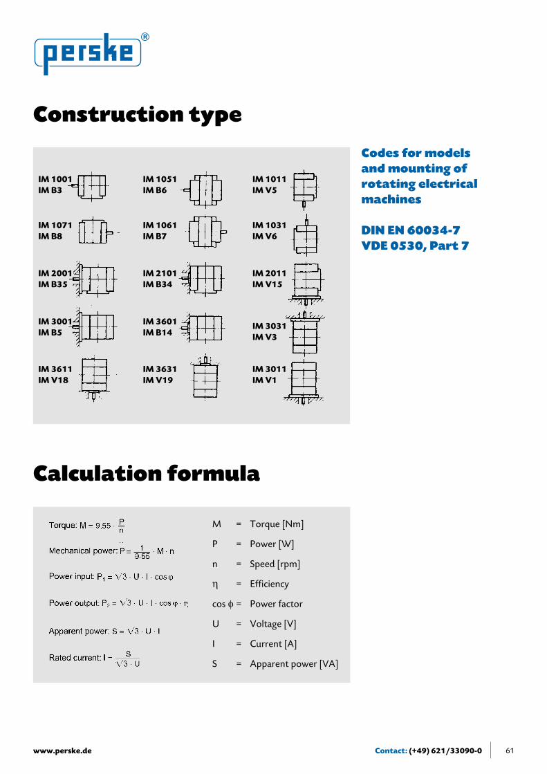
Contact: (+49) 621/33090-0www.perske.de 61
Construction type
IM 1001IM B3
IM 1051IM B6
IM 1011IM V5
IM 1071IM B8
IM 1061IM B7
IM 1031IM V6
IM 2001IM B35
IM 2101IM B34
IM 2011IM V15
IM 3001IM B5
IM 3601IM B14
IM 3031IM V3
IM 3611IM V18
IM 3631IM V19
IM 3011IM V1
Codes for models and mounting of rotating electrical machines
DIN EN 60034-7VDE 0530, Part 7
Calculation formula
M = Torque [Nm]
P = Power [W]
n = Speed [rpm]
η = Efficiency
cos ϕ = Power factor
U = Voltage [V]
I = Current [A]
S = Apparent power [VA]

Contact: (+49) 621/33090-0 www.perske.de
Shaft with Rotor, complete
Bearing shield, drive end A-side
Bearing shield, drive end A-side
Stand, complete
Bearing shield, non drive end B-side
Terminal box, cover
Terminal box, frame
Terminal box
Ventilation plate Fan cover
Bearing shield, non drive end B-side
62
Instructions for ordering parts
Principle schematic of motor’s main components
Rating plate
Note: Whenorderingparts,always provide the model-type and serial number.
This information is indicated on the rating plate (see below):
Motor-type
Serial number
Rated current [A]
Operation-modeRated frequency [Hz]Power factor
Speed [rpm]
Additional information
Rated power [kW]
Thermal class
Voltage [V] / Connection type
Protection-type

Contact: (+49) 621/33090-0www.perske.de 63
ToWalter Perske GmbHSales DepartmentFriedrich-Ebert-Strasse 80-8468167 MannheimTel. 0621/33090-0Fax 0621/33090-33E-mail [email protected]
Company __________________________________________________________
Processed by _______________________________________________________
Tel.: _____________________________ Fax: _____________________________
Street ______________________________________________________________
Postal code / city ___________________________________________________
E-mail______________________________________________________________
Same as serial no. _______________________________________________
Comments ____________________________________________________
________________________________________________________________
Enclosures _____________________________________________________ Date Company stamp
Motor checklist Inquiries Enclosure to Purchase order
New motor
Spare motor/Repeat order
A. 1. Shaft design
A. 2. Motor protection
Quantity Type According to catalogue page Drawing no.:
Quantity Type
Application Sawing Drilling Stonework Direct drive
Milling GrindingAmbient conditions Dry Wet
Regulation,rule DIN EN 60034-1 (VDE 0530-1) NEMA CSA
Output _______________ kW S1/S6-60% Special speed-output characteristics (attached)
Voltage _______________________V Frequency ________________ Hz Speed _________________ rpm
Model ________________________ Position of terminal box ____________________
Bearing arrangement Single bearing Double bearing
According to diagram (attached)
With saw flange Ø ______________ mm
cylindrical With key Without key
Diameter _________ mm length __________ mm without thread
Exterior thread size M ______ left right
Interior thread size M ______ left right
With thermistors
PT 100
With thermal contacts (bimetal break contact)
KTY
Collet design Max. clamping diameter Ø ________ mm
Collet ____________ Size ___________
Key ____________ Nut_____________
Electromagnetic brake
Wrench flat

Contact: (+49) 621/33090-0 www.perske.de
Terms and Conditions for Sales and DeliveriesGeneral InformationThe models depicted in the spec sheets of the preceding lists are the basic models of the respective motor. The illustrations are non-binding. Designs deviating from these are special configurations and are subject to surcharges. In the absence of any other agreement, we will charge the customary fee for all agreed upon modifications after signing of the contract.
PricesThe prices are considered to include delivery without installation or assembly, ex works, and not including packaging. Prices do not include the applicable statutory value-added tax.
Material SurchargeCopper
Complying with instructionsDuring operations, our operating instructions and lubricating guidelines shall be complied with. In particular, we wish to point out that all accident prevention and installation guidelines shall be strictly complied with at the location of the ordering/using party. We assume no liability for improper use. Special requirements pertaining to noise emissions shall be taken into account in designing the machine or system.
Terms and conditions for sales and deliveriesThe following shall apply: the “Electrical Industry’s General Delivery Terms for Goods and Services” (ZVEI), including the “retention of title” addendum as well as “Walter Perske GmbH’s General Terms for Sales of Goods and Services.” We reserve the right to modify the technical data. The sole place of fulfillment for all contractual or ex-contractual obligations stemming from the service contract is Mannheim. Upon publication of this list, all earlier editions shall no longer be valid.The terms and conditions for sales and deliveries can be viewed on the Internet or be mailed upon request.
Bid prices are based on a quotation for electrolyte copper (Cu-DEL-Notiz) of € 230.00 per 100 kg. For quotations above € 230.00 per 100 kg, the following surcharges will be assessed:
DEL quotation in € per 100 kg225 to below 275 1.2275 to below 325 2.5325 to below 375 3.5375 to below 425 4.5425 to below 475 5.5475 to below 525 6.5
Copper surcharge in % 525 to below 575 7.5575 to below 625 8.5625 to below 675 9.5675 to below 725 10.5725 to below 775 11.5
When calculating the copper surcharges, the DEL quotation of the order reception date is authoritative.
Other materialWe reserve the right to impose additional material surcharges.
64

Contact: (+49) 621/33090-0www.perske.de 65
Motor-collet correlation
motor type
OZ-type collet DIN 6388taper ratio 1:10
ER-type collet DIN 6449taper angle 8° max. speed
(rpm)OZ-type size
max. collet capacityER-type size
max. collet capacitymm inch mm inch
KN 21.05 OZ 1832 10 10 (1) 3/8" ER 20 20 13 (1) 1/2" 30,000KN 22.08 OZ 1832 10 10 (1) 3/8" ER 20 20 13 (1) 1/2" 30,000KN 23.10 OZ 1832 10 10 3/8" ER 20 20 13 1/2" 24,000
V 30.06 OZ 1832 10 10 (1) 3/8" ER 20 20 13 (1) 1/2" 30,000V 31.09 OZ 1832 10 10 (1) 3/8" ER 20 20 13 (1) 1/2" 30,000
KR 35.1 D OZ 1832 10 10 3/8" ER 20 20 13 1/2" 24,000KR 35.3 D OZ 1832 10 10 3/8" ER 20 20 13 1/2" 24,000KR 35.5 D OZ 1832 10 10 3/8" ER 20 20 13 1/2" 24,000KR 35.7 D OZ 1832 10 10 3/8" ER 20 20 13 1/2" 18,000KR 35.9 D OZ 1832 10 10 3/8" ER 20 20 13 1/2" 12,000
V/VU 50.09 OZ 1833 12 12 1/2" ER 25 25 16 5/8" 30,000
V/VU 60 .11 OZ 1833 12 12 1/2" ER 25 25 16 5/8" 30,000V/VU 61.15 OZ 1833 12 12 1/2" ER 25 25 16 5/8" 12,000
KR 50.11 D OZ 1833 12 12 1/2" ER 25 25 16 5/8" 18,000KR 51.14 D OZ 1833 12 12 1/2" ER 25 25 16 5/8" 18,000KR 52.16 D OZ 1833 12 12 1/2" ER 25 25 16 5/8" 12,000
KRSV 51.14 D OZ 1836 25 25 1" - - 18,000
KR 60.09 D OZ 1834 16 16 5/8" ER 32 32 20 3/4" 18,000KR 61.13 D OZ 1834 16 16 5/8" ER 32 32 20 3/4" 18,000KR 62.18 D OZ 1834 16 16 5/8" ER 32 32 20 3/4" 12,000
KRS 61.13-2 D OZ 1836 25 25 1" - - - 18,000
KC 70/71/72 OZ 1836 25 25 1" ER 32 32 20 3/4" 9,000KC 70/71/72 D OZ 1836 25 25 1" - - - - 9,000KNOC 71 D - - ER 32 32 20 3/4" 18,000KNO 71 D OZ 1836 25 25 1" - - - - 18,000(1) = the maximum collet capacity can only be used up to 24,000 rpm at the maximum.D = double bearing arrangement on tool sideThe maximum collet capacities and maximum speeds stated in the above list do not conform with all standardmotor versions but sometimes need special bearing arrangements.Only balanced tools are to be used. Depending on the weight of tool, restrictions may be necessary.
Measurements conversion table
power 1 HP = 0.7457 kW 1 kW = 1.341 Hp
length 1 inch = 25.4 mm 1 mm = 0.039 inchlength 1 ft = 304.8 mm 1 m = 3.28 ftweight 1 lb = 0.454 kg 1 kg = 2.20 lbstemperature °F = 9/5°C + 32 °C = (°F - 32) x 5/9pressure 1 psi = 68.95 mbar 1 mbar = 0.0145 psispeed 1 ft/s = 0.305 m/s 1 m/s = 3.28 ft/s

Contact: (+49) 621/33090-0 www.perske.de66
Notes

Walter Perske GmbHPostfach 10 25 51 68025 Mannheim
Friedrich-Ebert-Strasse 80-84 68167 Mannheim
Tel.: (+49) 621 33090-0 Fax: (+49) 621 33090-33
[email protected] www.perske.de
Headquarters
Registered corporate office: Mannheim, GermanyCommercial register number: HRB 3186 filed with Mannheim District Court TAX ID No.: DE 143 841 999Managing Director: Ulrich Perske

1/2012
Precision and high speed
Walter Perske GmbHPostfach 10 25 51 68025 Mannheim
Friedrich-Ebert-Strasse 80-84 68167 Mannheim
Tel.: (+49) 621 33090-0 Fax: (+49) 621 33090-33
[email protected] www.perske.de