SPD PRODUCT CATALOG - aptsurge.com · SPD PRODUCT CATALOG 2016 “Protecting the electronic world...
56
Surge Protective Devices www.aptsurge.com | 1.800.237.4567 | [email protected] SPD PRODUCT CATALOG 2016 “Protecting the electronic world from surges”
Transcript of SPD PRODUCT CATALOG - aptsurge.com · SPD PRODUCT CATALOG 2016 “Protecting the electronic world...
Surge Protective Devices
www.aptsurge.com | 1.800.237.4567 | [email protected]
SPD PRODUCT CATALOG2016
“Protecting the electronic world from surges”


SPD Sizing Chart .........................................................................................................................................................................................................................................5
Type 1 and Type 2 SPDs SPDEE Series ....................................................................................................................................................................................................................................................6
SPDEE DC Series ..........................................................................................................................................................................................................................................8
TEXCS Series ................................................................................................................................................................................................................................................10
TEXDS Series ................................................................................................................................................................................................................................................12
TEXAS Series ................................................................................................................................................................................................................................................14
TEXAL Series ...............................................................................................................................................................................................................................................16
TEXBS Series .................................................................................................................................................................................................................................................18
TEXBL Series .................................................................................................................................................................................................................................................20
Type 2 SPDs TE/HP Series (Modular) ....................................................................................................................................................................................................................22
TE/HPS Series (Modular) ..................................................................................................................................................................................................................24
TE/XGA Series (Modular) ...............................................................................................................................................................................................................26
TE/XMS Series (Non-Modular) ...................................................................................................................................................................................................28
Component Assembly SPDs (Type 1 & Type 2) TE/XRS Series ............................................................................................................................................................................................................................................30
TE/XRL Series ...........................................................................................................................................................................................................................................32
TE/XWS Series ........................................................................................................................................................................................................................................34
TE/XWL Series ........................................................................................................................................................................................................................................36
DIN-Rail: AC Power & DC PV ...................................................................................................................................................................................................38
Specialty SPDs S-Kit Series ...................................................................................................................................................................................................................................................40
iArrest Series .............................................................................................................................................................................................................................................42
Low Voltage Communication & DataBNCB5kA ......................................................................................................................................................................................................................................................44
BNCA10kA ..................................................................................................................................................................................................................................................45
BNC Guide ....................................................................................................................................................................................................................................................46
DIN-Rail: Popular Traffic / ITS .......................................................................................................................................................................................................47
DIN-Rail: Low Voltage .......................................................................................................................................................................................................................48
Medium Voltage SPDs MVF Series ...................................................................................................................................................................................................................................................50
What Electrical System is It? .....................................................................................................................................................................................................52
Frequently Asked Questions ......................................................................................................................................................................................................53
Don’t Leave your Home Unprotected .............................................................................................................................................................................54
Table of Contents

Advanced Protection Technologies, Inc.Advanced Protection Technologies, Inc. (APT) has been designing, manufacturing and selling Industrial, Commercial, Oil/Gas and Residential Surge Protective Devices (SPDs) since 1985. We are a privately held company with no debt that has been under the original ownership for the entire duration. What began as a small company of ten employees, selling to customers in Southeastern USA, has grown to become a global industry leader with over one hundred employees. Each member of the senior management team has been with the company for more than 15 years. APT has eight degreed Electrical Engineers on staff, an exceptionally trained technical sales team and a manufacturing team trained in the latest, state of the art, Lean manufacturing processes.
Surge Protective DevicesAPT has the most complete line of Low Voltage SPDs in the industry, with over 70,000 SKUs, used in applications such as Industrial, Commercial, Residential, Data/Communications and much more. Our low voltage products protect systems ranging from 5VDC to 600VAC, including all international voltage systems.
Our products are the number one specified SPD by oil producers and oil services companies worldwide. APT’s new (1000VAC - 4160VAC) Medium Voltage SPD, the first of its kind in the SPD industry, is commonly used to protect medium voltage motors at oil production wells, refineries, water/wastewater treatment plants and mining operations. There are currently no other UL listed Medium Voltage SPDs available in the industry.
Live Training - Earn PDHs & CEUs For over twenty years, APT has offered IEEE accredited Engineering Seminars where PDHs (qualified and approved by IEEE) can be earned that are recognized and accepted by most states, including the rigorous states, Florida and New York. This course starts with basics and proceeds through advanced topics including UL, IEEE & NEC and is standards-based, not sales-oriented. This may be the most efficient and comprehensive seven hours of SPD training available. Engineers appreciate the explanation of the science, art and marketing surrounding the surge industry.
“Protecting the
electronic world
from surges“
Top Notch Customer ServiceAPT has earned the respect from our clients by providing world class customer service. Frost & Sullivan has honored us for three years with awards for superior service and has ranked APT number one in the SPD three phase market. Our manufacturing processes are ISO 9001:2008 certified. We have two in-house testing labs that are ISO 17025 certified by UL to do portions of UL 1449 testing.
Local Growth & Worldwide PresenceIn 2007, APT’s growth strategy expanded from its base in the US Construction Market and began to focus on Alternative Energy, Oil/Gas, OEM and International Markets. APT has developed key relationships and a number of new products that will drive growth in these new markets for years to come. In 2010, APT growth hit 41% over the previous year. Following that trend, in 2011 we celebrated a 10,000 square foot manufacturing floor expansion. Several new positions were created ranging from front office administration to production assemblers to high level manufacturing personnel. We have settled into our new facility and implemented new workflow processes. Expansion continues as a number of new products are manufactured and new brand label agreements are finalized.
We are committed to becoming the number one supplier of three phase SPDs to the International marketplace. APT’s dedicated network of distributors and agents are currently promoting our products throughout Canada, Mexico, Central America, South America, Asia, Africa and the Middle East. Our proven track record and commitment to a long term business philosophy has pushed us to the forefront of Surge Protective Device manufacturing and distribution.
Private Labeling & MarketingAPT is the industry’s largest private label manufacturer of SPDs. Past and present brand label partners include Siemens Industry, Schneider Electric & Square D and American Power Conversion (APC). We regularly sell APT labeled products to other industry leaders such as Eaton, GE, ABB, Rockwell and a number of smaller niche market leaders.
Past, Present & Future
Advanced Protection Technologies
14550 58th Street NorthClearwater, FL 33760
Phone: 727.535.6339Fax: 727.539.8955
www.aptsurge.com
Advanced Protection Technologies, Inc. (APT) has been a worldwide leader in the surge suppression industry since 1985. Headquartered in Central Florida, heart of lightning activity, APT’s surge protection products have long set the standard for protection of commercial and industrial facilities.
In addition to superior products, APT has received numerous awards for customer service including the coveted Frost and Sullivan Market Engineering Award.
Our commitment to service and exceeding expectations comes from our people and sophisticated system integration. We value the client relationship and support it with integrity, responsiveness and technical excellence.
We are, “Professionals Serving Professionals”
ConstructionIndustrial/Commercial
OEMInternational
ITS/DOTSpecialty SalesMedium Voltage
Residential
WHY APT?
WHAT MARKETS DO WE SERVE?
Advanced Protection Technologies, Inc.Advanced Protection Technologies, Inc. (APT) has been designing, manufacturing and selling Industrial, Commercial, Oil/Gas and Residential Surge Protective Devices (SPDs) since 1985. We are a privately held company with no debt that has been under the original ownership for the entire duration. What began as a small company of ten employees, selling to customers in Southeastern USA, has grown to become a global industry leader with over one hundred employees. Each member of the senior management team has been with the company for more than 15 years. APT has eight degreed Electrical Engineers on staff, an exceptionally trained technical sales team and a manufacturing team trained in the latest, state of the art, Lean manufacturing processes.
Surge Protective DevicesAPT has the most complete line of Low Voltage SPDs in the industry, with over 70,000 SKUs, used in applications such as Industrial, Commercial, Residential, Data/Communications and much more. Our low voltage products protect systems ranging from 5VDC to 600VAC, including all international voltage systems.
Our products are the number one specified SPD by oil producers and oil services companies worldwide. APT’s new (1000VAC - 4160VAC) Medium Voltage SPD, the first of its kind in the SPD industry, is commonly used to protect medium voltage motors at oil production wells, refineries, water/wastewater treatment plants and mining operations. There are currently no other UL listed Medium Voltage SPDs available in the industry.
Live Training - Earn PDHs & CEUs For over twenty years, APT has offered IEEE accredited Engineering Seminars where PDHs (qualified and approved by IEEE) can be earned that are recognized and accepted by most states, including the rigorous states, Florida and New York. This course starts with basics and proceeds through advanced topics including UL, IEEE & NEC and is standards-based, not sales-oriented. This may be the most efficient and comprehensive seven hours of SPD training available. Engineers appreciate the explanation of the science, art and marketing surrounding the surge industry.
“Protecting the
electronic world
from surges“
Top Notch Customer ServiceAPT has earned the respect from our clients by providing world class customer service. Frost & Sullivan has honored us for three years with awards for superior service and has ranked APT number one in the SPD three phase market. Our manufacturing processes are ISO 9001:2008 certified. We have two in-house testing labs that are ISO 17025 certified by UL to do portions of UL 1449 testing.
Local Growth & Worldwide PresenceIn 2007, APT’s growth strategy expanded from its base in the US Construction Market and began to focus on Alternative Energy, Oil/Gas, OEM and International Markets. APT has developed key relationships and a number of new products that will drive growth in these new markets for years to come. In 2010, APT growth hit 41% over the previous year. Following that trend, in 2011 we celebrated a 10,000 square foot manufacturing floor expansion. Several new positions were created ranging from front office administration to production assemblers to high level manufacturing personnel. We have settled into our new facility and implemented new workflow processes. Expansion continues as a number of new products are manufactured and new brand label agreements are finalized.
We are committed to becoming the number one supplier of three phase SPDs to the International marketplace. APT’s dedicated network of distributors and agents are currently promoting our products throughout Canada, Mexico, Central America, South America, Asia, Africa and the Middle East. Our proven track record and commitment to a long term business philosophy has pushed us to the forefront of Surge Protective Device manufacturing and distribution.
Private Labeling & MarketingAPT is the industry’s largest private label manufacturer of SPDs. Past and present brand label partners include Siemens Industry, Schneider Electric & Square D and American Power Conversion (APC). We regularly sell APT labeled products to other industry leaders such as Eaton, GE, ABB, Rockwell and a number of smaller niche market leaders.
Past, Present & Future
Advanced Protection Technologies
14550 58th Street NorthClearwater, FL 33760
Phone: 727.535.6339Fax: 727.539.8955
www.aptsurge.com
Advanced Protection Advanced Protection TechnologiesTechnologies
14550 58th Street North14550 58th Street NorthClearwater, FL 33760Clearwater, FL 33760
Phone: 727.535.6339Phone: 727.535.6339Fax: 727.539.8955Fax: 727.539.8955
www.aptsurge.comwww.aptsurge.com
Advanced Protection Technologies, Inc.Advanced Protection Technologies, Inc. (APT) has been designing, manufacturing and selling Industrial, Commercial, Oil/Gas and Residential Surge Protective Devices (SPDs) since 1985. We are a privately held company with no debt that has been under the original ownership for the entire duration. What began as a small company of ten employees, selling to customers in Southeastern USA, has grown to become a global industry leader with over one hundred employees. Each member of the senior management team has been with the company for more than 15 years. APT has eight degreed Electrical Engineers on staff, an exceptionally trained technical sales team and a manufacturing team trained in the latest, state of the art, Lean manufacturing processes.
Surge Protective DevicesAPT has the most complete line of Low Voltage SPDs in the industry, with over 70,000 SKUs, used in applications such as Industrial, Commercial, Residential, Data/Communications and much more. Our low voltage products protect systems ranging from 5VDC to 600VAC, including all international voltage systems.
Our products are the number one specified SPD by oil producers and oil services companies worldwide. APT’s new (1000VAC - 4160VAC) Medium Voltage SPD, the first of its kind in the SPD industry, is commonly used to protect medium voltage motors at oil production wells, refineries, water/wastewater treatment plants and mining operations. There are currently no other UL listed Medium Voltage SPDs available in the industry.
Live Training - Earn PDHs & CEUs For over twenty years, APT has offered IEEE accredited Engineering Seminars where PDHs (qualified and approved by IEEE) can be earned that are recognized and accepted by most states, including the rigorous states, Florida and New York. This course starts with basics and proceeds through advanced topics including UL, IEEE & NEC and is standards-based, not sales-oriented. This may be the most efficient and comprehensive seven hours of SPD training available. Engineers appreciate the explanation of the science, art and marketing surrounding the surge industry.
“Protecting the
electronic world
from surges“
Top Notch Customer ServiceAPT has earned the respect from our clients by providing world class customer service. Frost & Sullivan has honored us for three years with awards for superior service and has ranked APT number one in the SPD three phase market. Our manufacturing processes are ISO 9001:2008 certified. We have two in-house testing labs that are ISO 17025 certified by UL to do portions of UL 1449 testing.
Local Growth & Worldwide PresenceIn 2007, APT’s growth strategy expanded from its base in the US Construction Market and began to focus on Alternative Energy, Oil/Gas, OEM and International Markets. APT has developed key relationships and a number of new products that will drive growth in these new markets for years to come. In 2010, APT growth hit 41% over the previous year. Following that trend, in 2011 we celebrated a 10,000 square foot manufacturing floor expansion. Several new positions were created ranging from front office administration to production assemblers to high level manufacturing personnel. We have settled into our new facility and implemented new workflow processes. Expansion continues as a number of new products are manufactured and new brand label agreements are finalized.
We are committed to becoming the number one supplier of three phase SPDs to the International marketplace. APT’s dedicated network of distributors and agents are currently promoting our products throughout Canada, Mexico, Central America, South America, Asia, Africa and the Middle East. Our proven track record and commitment to a long term business philosophy has pushed us to the forefront of Surge Protective Device manufacturing and distribution.
Private Labeling & MarketingAPT is the industry’s largest private label manufacturer of SPDs. Past and present brand label partners include Siemens Industry, Schneider Electric & Square D and American Power Conversion (APC). We regularly sell APT labeled products to other industry leaders such as Eaton, GE, ABB, Rockwell and a number of smaller niche market leaders.
Past, Present & Future
Advanced Protection Technologies
14550 58th Street NorthClearwater, FL 33760
Phone: 727.535.6339Fax: 727.539.8955
www.aptsurge.com
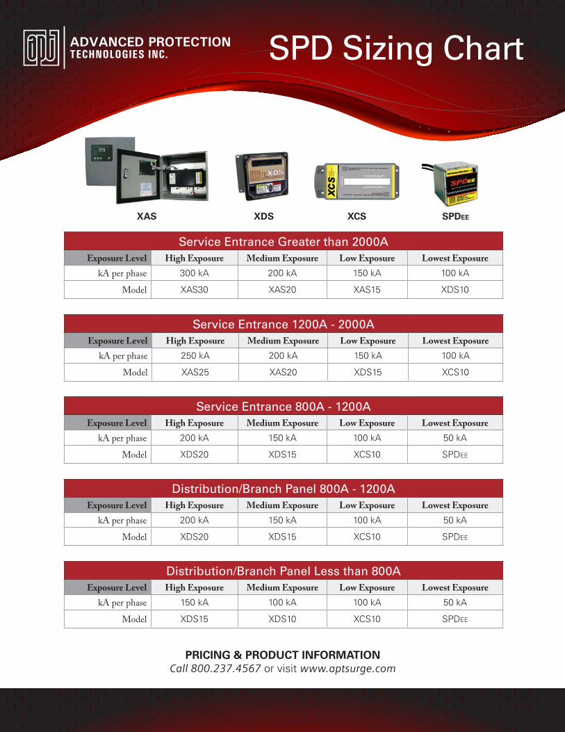
XAS XDS XCS SPDEE
PRICING & PRODUCT INFORMATIONCall 800.237.4567 or visit www.aptsurge.com
SPD Sizing Chart
Service Entrance Greater than 2000AExposure Level High Exposure Medium Exposure Low Exposure Lowest Exposure
kA per phase 300 kA 200 kA 150 kA 100 kA
Model XAS30 XAS20 XAS15 XDS10
Service Entrance 1200A - 2000AExposure Level High Exposure Medium Exposure Low Exposure Lowest Exposure
kA per phase 250 kA 200 kA 150 kA 100 kA
Model XAS25 XAS20 XDS15 XCS10
Service Entrance 800A - 1200AExposure Level High Exposure Medium Exposure Low Exposure Lowest Exposure
kA per phase 200 kA 150 kA 100 kA 50 kA
Model XDS20 XDS15 XCS10 SPDEE
Distribution/Branch Panel 800A - 1200AExposure Level High Exposure Medium Exposure Low Exposure Lowest Exposure
kA per phase 200 kA 150 kA 100 kA 50 kA
Model XDS20 XDS15 XCS10 SPDEE
Distribution/Branch Panel Less than 800AExposure Level High Exposure Medium Exposure Low Exposure Lowest Exposure
kA per phase 150 kA 100 kA 100 kA 50 kA
Model XDS15 XDS10 XCS10 SPDEE
Advanced Protection Technologies14550 58th Street North · Clearwater, Florida 33760(800) 237-4567 · (727) 535-6339 · Fax (727) 539-8955www.aptsurge.com · [email protected]
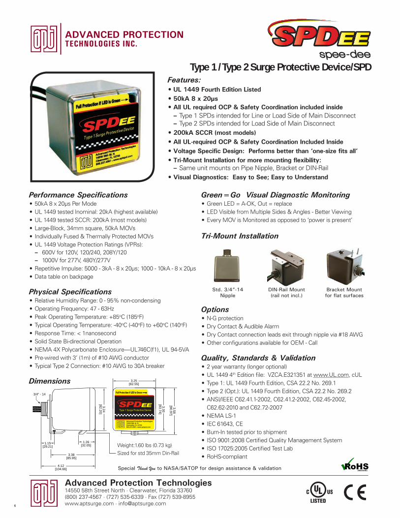
Green=Go Visual Diagnostic Monitoring• Green LED = A-OK, Out = replace• LED Visible from Multiple Sides & Angles - Better Viewing• Every MOV is Monitored as opposed to ‘power is present’
Tri-Mount Installation
Options• N-G protection • Dry Contact & Audible Alarm• Dry Contact connection leads exit through nipple via #18 AWG• Other configurations available for OEM - Call
Quality, Standards & Validation• 2 year warranty (longer optional)• UL 1449 4th Edition file: VZCA.E321351 at www.UL.com, cUL • Type 1: UL 1449 Fourth Edition, CSA 22.2 No. 269.1• Type 2 (Opt.): UL 1449 Fourth Edition, CSA 22.2 No. 269.2• ANSI/IEEE C62.41.1-2002, C62.41.2-2002, C62.45-2002,
C62.62-2010 and C62.72-2007• NEMA LS-1• IEC 61643, CE• Burn-In tested prior to shipment• ISO 9001:2008 Certified Quality Management System• ISO 17025:2005 Certified Test Lab• RoHS-compliant
Bracket Mount for flat surfaces
Std. 3/4”-14 Nipple
DIN-Rail Mount(rail not incl.)
Features:• UL 1449 Fourth Edition Listed• 50kA 8 x 20µs• All UL required OCP & Safety Coordination included inside
– Type 1 SPDs intended for Line or Load Side of Main Disconnect – Type 2 SPDs intended for Load Side of Main Disconnect
• 200kA SCCR (most models)• All UL-required OCP & Safety Coordination Included Inside• Voltage Specific Design: Performs better than ‘one-size fits all’• Tri-Mount Installation for more mounting flexibility:
– Same unit mounts on Pipe Nipple, Bracket or DIN-Rail• Visual Diagnostics: Easy to See; Easy to Understand
Special Thank You to NASA/SATOP for design assistance & validation
Performance Specifications• 50kA 8 x 20µs Per Mode• UL 1449 tested Inominal: 20kA (highest available)• UL 1449 tested SCCR: 200kA (most models) • Large-Block, 34mm square, 50kA MOVs• Individually Fused & Thermally Protected MOVs• UL 1449 Voltage Protection Ratings (VPRs):
– 600V for 120V, 120/240, 208Y/120 – 1000V for 277V, 480Y/277V
• Repetitive Impulse: 5000 - 3kA - 8 x 20µs; 1000 - 10kA - 8 x 20µs• Data table on backpage
Physical Specifications• Relative Humidity Range: 0 - 95% non-condensing• Operating Frequency: 47 - 63Hz• Peak Operating Temperature: +85oC (185oF)• Typical Operating Temperature: -40oC (-40oF) to +60oC (140oF)• Response Time: < 1nanosecond • Solid State Bi-directional Operation• NEMA 4X Polycarbonate Enclosure—UL746C(f1), UL 94-5VA• Pre-wired with 3’ (1m) of #10 AWG conductor• Typical Type 2 Connection: #10 AWG to 30A breaker
Dimensions
spee-deeType 1 / Type 2 Surge Protective Device/SPD
1.26[32.05]
3.24[82.20]
3.25[82.55]
3.58[90.97]
3.30[83.74]
3.38[85.95]
4.12[104.66]
3/4” - 14
1.15[29.21] Weight:1.60 lbs (0.73 kg)
Sized for std 35mm Din-Rail
6
Advanced Protection Technologies14550 58th Street North · Clearwater, Florida 33760
(800) 237-4567 · (727) 535-6339 · Fax (727) 539-8955www.aptsurge.com · [email protected]
1 P
OLE
/ S
ING
LE
Phase B (ORNG)Phase A (BLK)
Hot (BLK)Neutral (WHT) Ground (GRN)
Voltage Model Number Model Number
BLK
BLK
ORNG
WHT
BLK
BLK
ORNG
WHT
GRN
S50A240V3HN/A
Advanced Protection Technologies14550 58th St. N.Clearwater, FL 33760800.237.4567 X www.aptspd.com
Advanced Protection Technologies14550 58th St. N.Clearwater, FL 33760800.237.4567 X www.aptspd.com
v
Hot (BLK)Ground (GRN)
Neutral (WHT)
Phase B (BLK)Phase A (BLK)
Voltage Model Number Model Number
A
N
C
B
BLK
BLK
BLK
WHT
BLK
BLK
BLK
GRN
WHT
Advanced Protection Technologies14550 58th St. N.Clearwater, FL 33760800.237.4567 X www.aptspd.com
Advanced Protection Technologies14550 58th St. N.Clearwater, FL 33760800.237.4567 X www.aptspd.com
v
Phase A (BLK)
Phase B (BLK)Phase C (BLK)Ground (GRN)
Voltage Model Number
BLK
BLKBLK
GRN
S50A240V3D
Advanced Protection Technologies14550 58th St. N.Clearwater, FL 33760800.237.4567 X www.aptspd.com
v
Hot (BLK)
Hot (BLK)
Neutral (WHT)
Ground (GRN)
Voltage Model Number Model Number
}}
BLK
BLKWHT
BLK
BLKWHT
GRNAdvanced Protection Technologies14550 58th St. N.Clearwater, FL 33760800.237.4567 X www.aptspd.com
Advanced Protection Technologies14550 58th St. N.Clearwater, FL 33760800.237.4567 X www.aptspd.com
vv
Hot (BLK)
Neutral (WHT)
Ground (GRN)
Voltage Model Number Model Number
BLK
WHT
BLK
WHT
GRN
}Advanced Protection Technologies14550 58th St. N.Clearwater, FL 33760800.237.4567 X www.aptspd.com
Advanced Protection Technologies14550 58th St. N.Clearwater, FL 33760800.237.4567 X www.aptspd.com
v
N = N-G Protection
D = Dry Contact& Audible Alarm
2 = Type 2 SPD, including CSA 22.2, No. 269.2
Power Leads
Dry ContactLeads
Blue Gray
Red
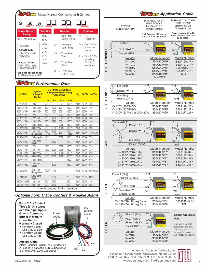
Performance Data
MODELSystem
Voltage & Config
UL 1449 Fourth Edition Voltage Protection Rating
VPR 3000A In SCCR MCOV
L-N L-L N-G* L-G*
S50A120V1P 120V 600 600* 1000* 20kA 200kA 150S50A120V2P 120V/240V 600 1000 600* 1000* 20kA 200kA 150S50A120V3Y 208Y/120V 600 1000 600* 1000* 20kA 200kA 150S50A127V1P 127V 700 600* 1200* 20kA 100kA 180S50A127V2P 127/254V 700 1200 600* 1200* 20kA 100kA 180S50A127V3Y 220Y/127V 700 1200 600* 1200* 20kA 100kA 180S50A220V1P 220V-1 pole 1200 1000* 1800* 20kA 200kA 320S50A220V3Y 380Y/220V 1200 2000 1000* 1800* 20kA 200kA 320
S50A240V3H 120/240V - Hi-Leg Delta
600/1200
1000/1500 600* 1000*
/1500* 20kA 200kA 150 / 320
S50A240V1P 240V-1 pole 1200 1000 1800 20kA 200kA 320
S50A240V3D 240V Delta -3 pole 1500 1200 20kA 200kA 320
S50A277V1P 277V 1200 1000* 1800* 20kA 200kA 320S50A277V2P 240/480V 1200 2000 1000* 1800* 20kA 200kA 320S50A277V3Y 480Y/277V 1200 2000 1000* 1800* 20kA 200kA 320S50A347V3Y 600Y/347V 1500 2500 1200* 2500* 20kA 200kA 420S50A480V1P 480V-1 pole 1800 20kA 200kA 550
S50A480V3D 480V Delta -3 pole 3000 1800 20kA 200kA 550
S50A480V3H 240/480V -Hi-Leg Delta
1200/1800 2500 20kA 200kA 320 / 550
S50A600V3D 600V Delta -3 pole 2500 2500 20kA 200kA 690
S100A120V2P 120/240V 600 1000 600 20kA 100kA 150S100A277V2P 240/480V 1000 1800 1000 20kA 100kA 320
* with optional N-G protection
Application Guide
SYSTEM CONFIGURATION
INSTALLED >10’(3M) FROM SERVICE ENTRANCE OR TRANSFORMER
INSTALLED AT OR NEAR SERVICE ENTRANCE OR TRANSFORMER
N-G Bonded - Does not require N-G protection
Downstream of N-G Bond - N-G protection
suggested
Optional Form C Dry Contact & Audible Alarm
Form C Dry Contact:Three (3) #18 wires exit the pipe nippleGray is Common, Blue is Normally Open, Red is Normally Closed• Normally Open:
Use Gray & Blue• Normally Closed:
Use Gray & Red
Corner Grounded Delta? Use same models & connect one SPD black & green to ground (diagnostics will function correctly)
10.16.17.lh.RevH # 8179
Audible Alarm:Alarm sounds when any protection is lost (If diagnostic LED extinguishes (i.e. problem), alarm will sound)
No cost accessories:8483 Supplementary label
1P = One Pole, Single Phase
2P = Two Pole, Split Phase
3Y = Three Pole Wye
3D = Three Pole Delta
3H = Three Pole Hi-Leg Delta
EXAMPLES:
S50A120V3Y 50kA, 120V, 3 pole (208Y/120V)
S50A277V3YN50kA, 277V, 3 pole (480Y/277V) with N-G
50 = 50kA/Phase120V
127V
220V
240V
277V
347V
480V
600V
S 50 A
MODEL NUMBER CONFIGURATOR & OPTIONS
(Default)
Surge Current Rating
Voltage System Options
DEL
TA
HI-L
EGW
YE
2 P
OLE
/ S
PLIT
7
Advanced Protection Technologies14550 58th Street North · Clearwater, Florida 33760(800) 237-4567 · (727) 535-6339 · Fax (727) 539-8955www.aptsurge.com · [email protected]
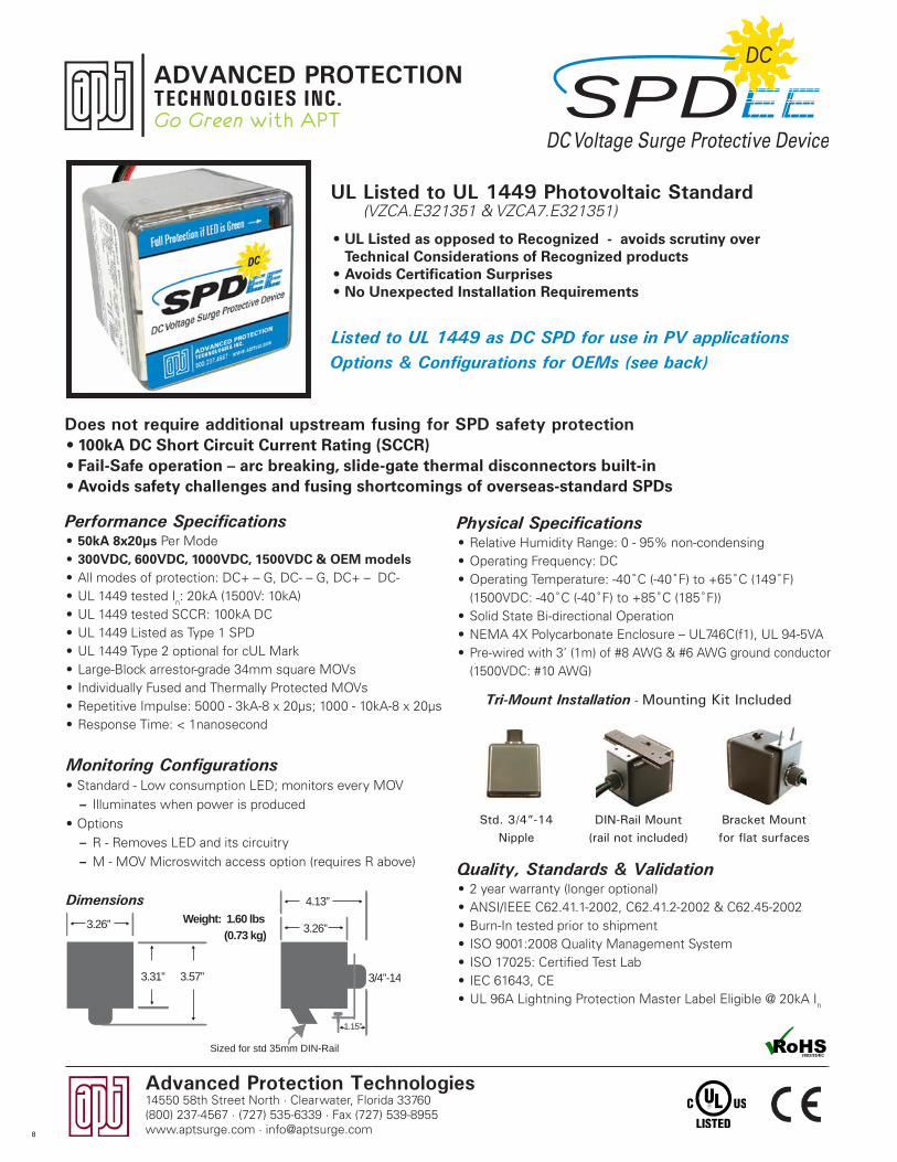
• UL Listed as opposed to Recognized - avoids scrutiny over Technical Considerations of Recognized products
• Avoids Certification Surprises• No Unexpected Installation Requirements
UL Listed to UL 1449 Photovoltaic Standard (VZCA.E321351 & VZCA7.E321351)
Bracket Mount for flat surfaces
Std. 3/4”-14 Nipple
DIN-Rail Mount(rail not included)
Tri-Mount Installation - Mounting Kit Included
Go Green with APT SPDEEDC Voltage Surge Protective Device
DC
Listed to UL 1449 as DC SPD for use in PV applicationsOptions & Configurations for OEMs (see back)
Does not require additional upstream fusing for SPD safety protection• 100kA DC Short Circuit Current Rating (SCCR)• Fail-Safe operation – arc breaking, slide-gate thermal disconnectors built-in• Avoids safety challenges and fusing shortcomings of overseas-standard SPDs
Performance Specifications• 50kA 8x20µs Per Mode• 300VDC, 600VDC, 1000VDC, 1500VDC & OEM models • All modes of protection: DC+ – G, DC- – G, DC+ – DC-• UL 1449 tested In: 20kA (1500V: 10kA)• UL 1449 tested SCCR: 100kA DC• UL 1449 Listed as Type 1 SPD• UL 1449 Type 2 optional for cUL Mark• Large-Block arrestor-grade 34mm square MOVs• Individually Fused and Thermally Protected MOVs• Repetitive Impulse: 5000 - 3kA-8 x 20µs; 1000 - 10kA-8 x 20µs• Response Time: < 1nanosecond
Physical Specifications• Relative Humidity Range: 0 - 95% non-condensing• Operating Frequency: DC• Operating Temperature: -40˚C (-40˚F) to +65˚C (149˚F)
(1500VDC: -40˚C (-40˚F) to +85˚C (185˚F))• Solid State Bi-directional Operation• NEMA 4X Polycarbonate Enclosure – UL746C(f1), UL 94-5VA• Pre-wired with 3’ (1m) of #8 AWG & #6 AWG ground conductor
(1500VDC: #10 AWG)
Monitoring Configurations• Standard - Low consumption LED; monitors every MOV
– Illuminates when power is produced• Options
– R - Removes LED and its circuitry – M - MOV Microswitch access option (requires R above) Quality, Standards & Validation
• 2 year warranty (longer optional)• ANSI/IEEE C62.41.1-2002, C62.41.2-2002 & C62.45-2002• Burn-In tested prior to shipment• ISO 9001:2008 Quality Management System• ISO 17025: Certified Test Lab • IEC 61643, CE• UL 96A Lightning Protection Master Label Eligible @ 20kA In
3.26” 3.26”
1.15”
4.13”
3/4”-14
Sized for std 35mm DIN-Rail
3.31” 3.57”
Weight: 1.60 lbs(0.73 kg)
Dimensions
8
9.16.15.lh.RevJ #8383
SPDEEDC Voltage Surge Protective Device
DC
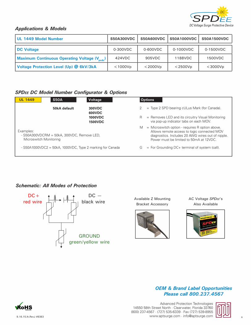
Applications & Models
UL 1449 Model Number S50A300VDC S50A600VDC S50A1000VDC S50A1500VDC
DC Voltage 0-300VDC 0-600VDC 0-1000VDC 0-1500VDC
Maximum Continuous Operating Voltage (Vpvdc) 424VDC 905VDC 1188VDC 1500VDC
Voltage Protection Level (Up) @ 6kV/3kA <1000Vp <2000Vp <2500Vp <3000Vp
SPDEE DC Model Number Configurator & OptionsUL 1449 S50A Voltage Options
2 = Type 2 SPD bearing cULus Mark (for Canada).
R = Removes LED and its circuitry Visual Monitoring via pop-up indicator tabs on each MOV.
M = Microswitch option - requires R option above. Allows remote access to logic connected MOV diagnostics. Includes 20 AWG wires out of nipple. Power must be limited to 50mA at 12VDC.
G = For Grounding DC+ terminal of system (call).
300VDC600VDC1000VDC1500VDC
50kA default
Schematic: All Modes of Protection
DC —black wire
DC+red wire
Examples: - S50A300VDCRM = 50kA, 300VDC, Remove LED, Microswitch Monitoring
- S50A1000VDC2 = 50kA, 1000VDC, Type 2 marking for Canada
Available Z Mounting Bracket Accessory
AC Voltage SPDEE’s Also Available
OEM & Brand Label Opportunities Please call 800.237.4567
GROUNDgreen/yellow wire
Advanced Protection Technologies14550 58th Street North · Clearwater, Florida 33760
(800) 237-4567 · (727) 535-6339 · Fax (727) 539-8955www.aptsurge.com · [email protected] 9
Advanced Protection Technologies14550 58th Street North · Clearwater, Florida 33760(800) 237-4567 · (727) 535-6339 · Fax (727) 539-8955www.aptsurge.com · [email protected]
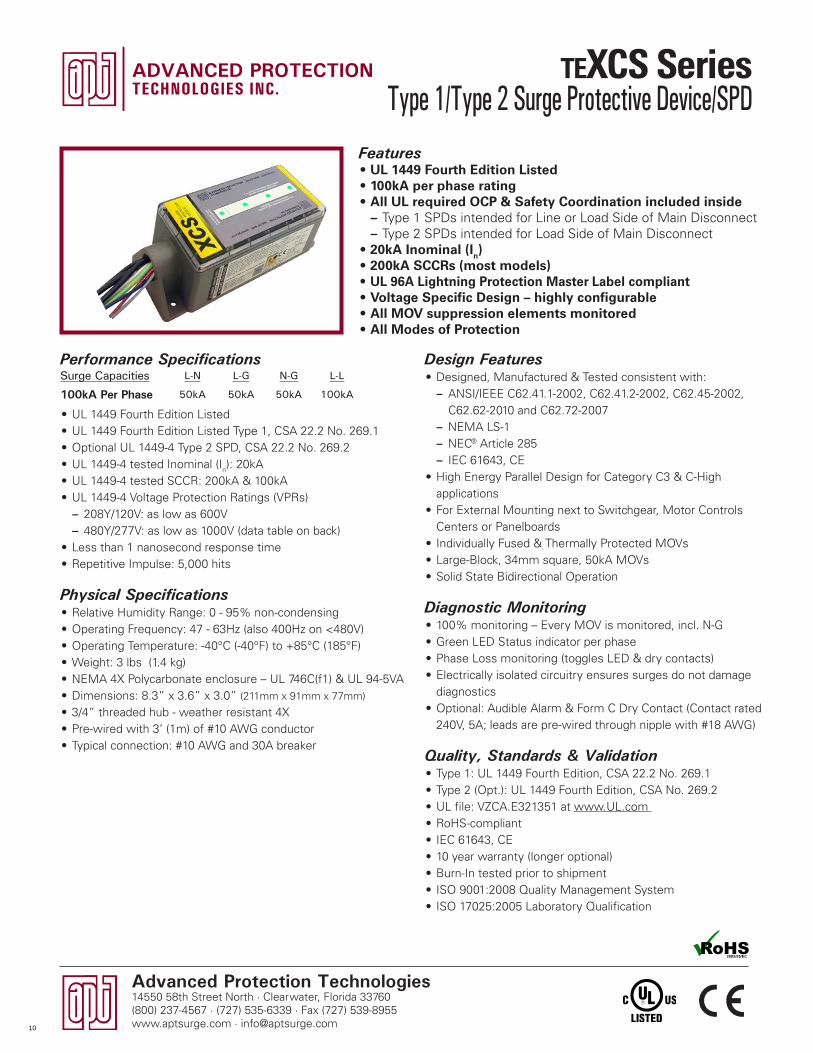
Design Features• Designed, Manufactured & Tested consistent with:
– ANSI/IEEE C62.41.1-2002, C62.41.2-2002, C62.45-2002, C62.62-2010 and C62.72-2007
– NEMA LS-1 – NEC® Article 285 – IEC 61643, CE
• High Energy Parallel Design for Category C3 & C-High applications
• For External Mounting next to Switchgear, Motor Controls Centers or Panelboards
• Individually Fused & Thermally Protected MOVs• Large-Block, 34mm square, 50kA MOVs• Solid State Bidirectional Operation
Diagnostic Monitoring• 100% monitoring – Every MOV is monitored, incl. N-G• Green LED Status indicator per phase• Phase Loss monitoring (toggles LED & dry contacts)• Electrically isolated circuitry ensures surges do not damage
diagnostics• Optional: Audible Alarm & Form C Dry Contact (Contact rated
240V, 5A; leads are pre-wired through nipple with #18 AWG)
Quality, Standards & Validation• Type 1: UL 1449 Fourth Edition, CSA 22.2 No. 269.1• Type 2 (Opt.): UL 1449 Fourth Edition, CSA No. 269.2• UL file: VZCA.E321351 at www.UL.com • RoHS-compliant• IEC 61643, CE• 10 year warranty (longer optional)• Burn-In tested prior to shipment• ISO 9001:2008 Quality Management System• ISO 17025:2005 Laboratory Qualification
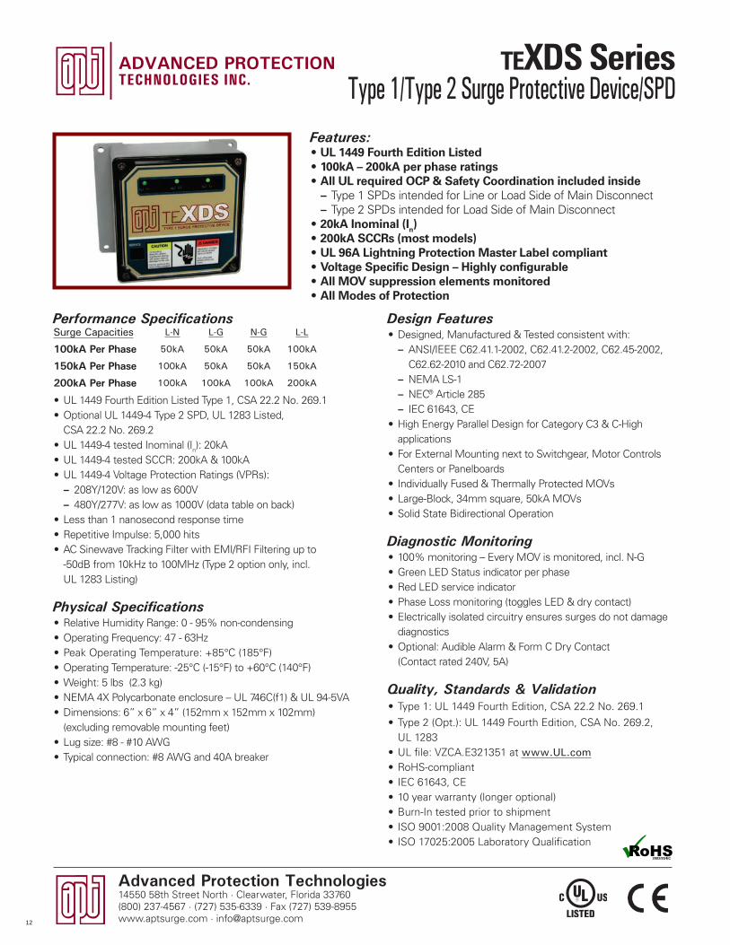
Features• UL 1449 Fourth Edition Listed• 100kA per phase rating• All UL required OCP & Safety Coordination included inside
– Type 1 SPDs intended for Line or Load Side of Main Disconnect – Type 2 SPDs intended for Load Side of Main Disconnect
• 20kA Inominal (In) • 200kA SCCRs (most models)• UL 96A Lightning Protection Master Label compliant• Voltage Specific Design – highly configurable• All MOV suppression elements monitored• All Modes of Protection
Performance Specifications
• UL 1449 Fourth Edition Listed• UL 1449 Fourth Edition Listed Type 1, CSA 22.2 No. 269.1• Optional UL 1449-4 Type 2 SPD, CSA 22.2 No. 269.2• UL 1449-4 tested Inominal (In): 20kA • UL 1449-4 tested SCCR: 200kA & 100kA• UL 1449-4 Voltage Protection Ratings (VPRs)
– 208Y/120V: as low as 600V – 480Y/277V: as low as 1000V (data table on back)
• Less than 1 nanosecond response time• Repetitive Impulse: 5,000 hits
Physical Specifications• Relative Humidity Range: 0 - 95% non-condensing• Operating Frequency: 47 - 63Hz (also 400Hz on <480V)• Operating Temperature: -40°C (-40°F) to +85°C (185°F)• Weight: 3 lbs (1.4 kg)• NEMA 4X Polycarbonate enclosure – UL 746C(f1) & UL 94-5VA• Dimensions: 8.3” x 3.6” x 3.0” (211mm x 91mm x 77mm)
• 3/4” threaded hub - weather resistant 4X• Pre-wired with 3’ (1m) of #10 AWG conductor• Typical connection: #10 AWG and 30A breaker
Surge Capacities L-N L-G N-G L-L
100kA Per Phase 50kA 50kA 50kA 100kA
Type 1/Type 2 Surge Protective Device/SPD
10
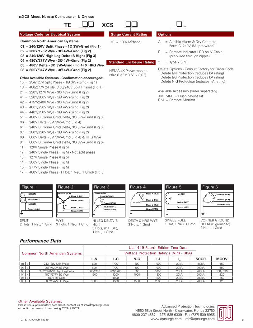
Common North American SystemsUL 1449 Fourth Edition Test Data
Voltage Protection Ratings (VPR - 3kA)
L-N L-G N-G L-L In SCCR MCOV01 = 240/120V Split Phase 600 700 500 1000 20kA 100kA 15002 = 208Y/120V 3� Wye 600 700 500 1000 20kA 200kA 15003 = 240Y/120V B High Leg Delta 600/1200 700/1200 500 1000 20kA 200kA 150 / 32004 = 480Y/277V 3� Wye 1200 1200 1000 1800 20kA 200kA 32005 = 480V 3� Delta - 1800 - 1800 20kA 200kA 55208 = 600Y/347V 3� Wye 1500 1500 1500 2500 20kA 200kA 420
TEXCS MODEL NUMBER CONFIGURATOR & OPTIONS
Voltage Code for Electrical System Surge Current Rating Options
TE ll XCS ll l...
Figure 1
SPLIT2 Hots, 1 Neu, 1 Grnd
Hot (BLK)
Hot (BLK)
Neutral (WHT)V
V
}}
Ground (GRN)
Figure 2
WYE3 Hots, 1 Neu, 1 Grnd
}
Phase A (BLK)Phase B (BLK)
Neutral (WHT)
Phase C (BLK)
Ground (GRN)
A
C
N
V
B
Figure 3
HI-LEG DELTA (B High)3 Hots, (B HIGH), 1 Neu, 1 Grnd
Phase A (BLK)Phase B (ORNG)
Neutral (WHT)
Phase C (BLK)
Ground (GRN)
}V
Figure 5
SINGLE POLE1 Hot, 1 Neu, 1 Grnd
V}Neutral (WHT)
Hot (BLK)
Ground (GRN)
Figure 4
DELTA & HRG WYE3 Hots, 1 Grnd
Phase A (BLK)
Phase C (BLK)
Phase B (BLK)
Ground (GRN)
}VFigure 6
CORNER GROUNDDELTA (B grounded)2 Hots, 1 Grnd
Phase A (BLK)
Phase C (BLK)
Ground (GRN)
V}
Standard Enclosure Rating
A = Audible Alarm & Dry Contacts Form C, 240V, 5A (pre-wired)
E = Remote Indicator LED on 6’ Cable (pre-wired through nipple)
2 = Type 2 SPD
Delete Options - Consult Factory for Order CodeDelete L-N Protection (reduces kA rating)Delete L-G Protection (reduces kA rating)Delete N-G Protection (reduces kA rating)
Available Accessory (order separately)XMFMKIT = Flush Mount KitRM = Remote Monitor
Other Available Systems - Confirmation encouraged:15 = 254/127V Split Phase - 1� 3W+Grnd (Fig 1)18 = 480/277V 2-Pole, (480/240V Split Phase) (Fig 1)21 = 220Y/127V Wye - 3� 4W+Grnd (Fig 2)41 = 520Y/300V Wye - 3� 4W+Grnd (Fig 2)42 = 415Y/240V Wye - 3� 4W+Grnd (Fig 2)43 = 400Y/230V Wye - 3� 4W+Grnd (Fig 2)44 = 440Y/250V Wye - 3� 4W+Grnd (Fig 2)51 = 480V B Corner Grnd Delta, 3� 3W+Grnd (Fig 6)06 = 240V Delta - 3� 3W+Grnd (Fig 4)61 = 240V B Corner Grnd Delta, 3� 3W+Grnd (Fig 6)07 = 380Y/220V Wye - 3� 4W+Grnd (Fig 2)09 = 600V Delta - 3� 3W+Grnd (Fig 4) & HRG Wye 91 = 600V B Corner Grnd Delta, 3� 3W+Grnd (Fig 6) 11 = 120V Single Phase (Fig 5)12 = 240V Single Phase (Fig 5) - Not split phase13 = 127V Single Phase (Fig 5)14 = 300V Single Phase (Fig 5)16 = 277V Single Phase (Fig 5)17 = 480V Single Phase (1 Hot, 1 Neu, 1 Grnd) (Fig 5)
10 = 100kA/PhaseCommon North American Systems:
01 = 240/120V Split Phase - 1Ø 3W+Grnd (Fig 1)02 = 208Y/120V Wye - 3Ø 4W+Grnd (Fig 2)03 = 240/120V High Leg Delta (B High) (Fig 3)04 = 480Y/277V Wye - 3Ø 4W+Grnd (Fig 2)05 = 480V Delta - 3Ø 3W+Grnd (Fig 4) & HRG Wye08 = 600Y/347V Wye - 3Ø 4W+Grnd (Fig 2) NEMA 4X Polycarbonate
(size 8.3” x 3.6” x 3.0”)
Performance Data
Other Available Systems:Please see supplementary data sheet, contact us at [email protected] or confirm at www.UL.com using CCN of VZCA.
10.16.17.lh.RevH #8389
Advanced Protection Technologies14550 58th Street North · Clearwater, Florida 33760
(800) 237-4567 · (727) 535-6339 · Fax (727) 539-8955www.aptsurge.com · [email protected] 11
Advanced Protection Technologies14550 58th Street North · Clearwater, Florida 33760(800) 237-4567 · (727) 535-6339 · Fax (727) 539-8955www.aptsurge.com · [email protected]
Design Features• Designed, Manufactured & Tested consistent with:
– ANSI/IEEE C62.41.1-2002, C62.41.2-2002, C62.45-2002, C62.62-2010 and C62.72-2007
– NEMA LS-1 – NEC® Article 285 – IEC 61643, CE
• High Energy Parallel Design for Category C3 & C-High applications
• For External Mounting next to Switchgear, Motor Controls Centers or Panelboards
• Individually Fused & Thermally Protected MOVs• Large-Block, 34mm square, 50kA MOVs• Solid State Bidirectional Operation
Diagnostic Monitoring• 100% monitoring – Every MOV is monitored, incl. N-G• Green LED Status indicator per phase• Red LED service indicator • Phase Loss monitoring (toggles LED & dry contact)• Electrically isolated circuitry ensures surges do not damage
diagnostics• Optional: Audible Alarm & Form C Dry Contact
(Contact rated 240V, 5A)
Quality, Standards & Validation• Type 1: UL 1449 Fourth Edition, CSA 22.2 No. 269.1
• Type 2 (Opt.): UL 1449 Fourth Edition, CSA No. 269.2, UL 1283
• UL file: VZCA.E321351 at www.UL.com• RoHS-compliant• IEC 61643, CE• 10 year warranty (longer optional)• Burn-In tested prior to shipment• ISO 9001:2008 Quality Management System• ISO 17025:2005 Laboratory Qualification
Features:• UL 1449 Fourth Edition Listed • 100kA – 200kA per phase ratings• All UL required OCP & Safety Coordination included inside
– Type 1 SPDs intended for Line or Load Side of Main Disconnect – Type 2 SPDs intended for Load Side of Main Disconnect
• 20kA Inominal (In) • 200kA SCCRs (most models)• UL 96A Lightning Protection Master Label compliant • Voltage Specific Design – Highly configurable• All MOV suppression elements monitored• All Modes of Protection
Performance Specifications
• UL 1449 Fourth Edition Listed Type 1, CSA 22.2 No. 269.1• Optional UL 1449-4 Type 2 SPD, UL 1283 Listed,
CSA 22.2 No. 269.2• UL 1449-4 tested Inominal (In): 20kA • UL 1449-4 tested SCCR: 200kA & 100kA• UL 1449-4 Voltage Protection Ratings (VPRs):
– 208Y/120V: as low as 600V – 480Y/277V: as low as 1000V (data table on back)
• Less than 1 nanosecond response time• Repetitive Impulse: 5,000 hits• AC Sinewave Tracking Filter with EMI/RFI Filtering up to
-50dB from 10kHz to 100MHz (Type 2 option only, incl. UL 1283 Listing)
Physical Specifications• Relative Humidity Range: 0 - 95% non-condensing• Operating Frequency: 47 - 63Hz• Peak Operating Temperature: +85°C (185°F)• Operating Temperature: -25°C (-15°F) to +60°C (140°F)• Weight: 5 lbs (2.3 kg)• NEMA 4X Polycarbonate enclosure – UL 746C(f1) & UL 94-5VA• Dimensions: 6” x 6” x 4” (152mm x 152mm x 102mm)
(excluding removable mounting feet)• Lug size: #8 - #10 AWG• Typical connection: #8 AWG and 40A breaker
Surge Capacities L-N L-G N-G L-L
100kA Per Phase 50kA 50kA 50kA 100kA
150kA Per Phase 100kA 50kA 50kA 150kA
200kA Per Phase 100kA 100kA 100kA 200kA
Type 1/Type 2 Surge Protective Device/SPD
12
Advanced Protection Technologies14550 58th Street North · Clearwater, Florida 33760
(800) 237-4567 · (727) 535-6339 · Fax (727) 539-8955www.aptsurge.com · [email protected]
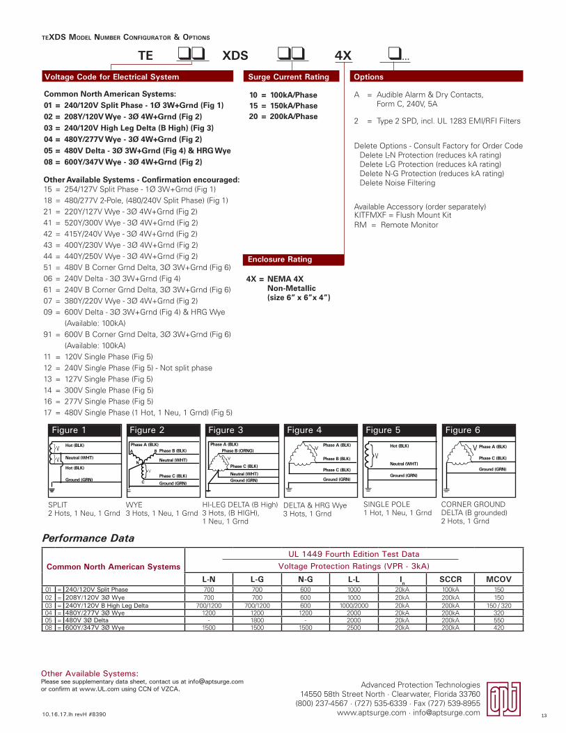
TEXDS MODEL NUMBER CONFIGURATOR & OPTIONS
Voltage Code for Electrical System Surge Current Rating Options
TE ll XDS ll 4X l...
Figure 1 Figure 2 Figure 3 Figure 4 Figure 5 Figure 6
SPLIT2 Hots, 1 Neu, 1 Grnd
HI-LEG DELTA (B High)3 Hots, (B HIGH), 1 Neu, 1 Grnd
SINGLE POLE1 Hot, 1 Neu, 1 Grnd
WYE3 Hots, 1 Neu, 1 Grnd
DELTA & HRG Wye3 Hots, 1 Grnd
CORNER GROUNDDELTA (B grounded)2 Hots, 1 Grnd
Common North American SystemsUL 1449 Fourth Edition Test Data
Voltage Protection Ratings (VPR - 3kA)
L-N L-G N-G L-L In SCCR MCOV01 = 240/120V Split Phase 700 700 600 1000 20kA 100kA 15002 = 208Y/120V 3Ø Wye 700 700 600 1000 20kA 200kA 15003 = 240Y/120V B High Leg Delta 700/1200 700/1200 600 1000/2000 20kA 200kA 150 / 32004 = 480Y/277V 3Ø Wye 1200 1200 1200 2000 20kA 200kA 32005 = 480V 3Ø Delta - 1800 - 2000 20kA 200kA 55008 = 600Y/347V 3Ø Wye 1500 1500 1500 2500 20kA 200kA 420
Hot (BLK)
Hot (BLK)
Neutral (WHT)V
V
}}
Ground (GRN)}
Phase A (BLK)Phase B (BLK)
Neutral (WHT)
Phase C (BLK)
Ground (GRN)
A
C
N
V
B
Phase A (BLK)Phase B (ORNG)
Neutral (WHT)
Phase C (BLK)
Ground (GRN)
}V V}Neutral (WHT)
Hot (BLK)
Ground (GRN)
Phase A (BLK)
Phase C (BLK)
Phase B (BLK)
Ground (GRN)
}V Phase A (BLK)
Phase C (BLK)
Ground (GRN)
V}
Enclosure Rating
A = Audible Alarm & Dry Contacts,Form C, 240V, 5A
2 = Type 2 SPD, incl. UL 1283 EMI/RFI Filters
Delete Options - Consult Factory for Order CodeDelete L-N Protection (reduces kA rating)Delete L-G Protection (reduces kA rating)Delete N-G Protection (reduces kA rating)Delete Noise Filtering
Available Accessory (order separately)KITFMXF = Flush Mount KitRM = Remote Monitor
Other Available Systems - Confirmation encouraged:15 = 254/127V Split Phase - 1� 3W+Grnd (Fig 1)18 = 480/277V 2-Pole, (480/240V Split Phase) (Fig 1) 21 = 220Y/127V Wye - 3� 4W+Grnd (Fig 2)41 = 520Y/300V Wye - 3� 4W+Grnd (Fig 2)42 = 415Y/240V Wye - 3� 4W+Grnd (Fig 2)43 = 400Y/230V Wye - 3� 4W+Grnd (Fig 2)44 = 440Y/250V Wye - 3� 4W+Grnd (Fig 2)51 = 480V B Corner Grnd Delta, 3� 3W+Grnd (Fig 6)06 = 240V Delta - 3� 3W+Grnd (Fig 4)61 = 240V B Corner Grnd Delta, 3� 3W+Grnd (Fig 6)07 = 380Y/220V Wye - 3� 4W+Grnd (Fig 2)09 = 600V Delta - 3� 3W+Grnd (Fig 4) & HRG Wye
(Available: 100kA)91 = 600V B Corner Grnd Delta, 3� 3W+Grnd (Fig 6)
(Available: 100kA)11 = 120V Single Phase (Fig 5)12 = 240V Single Phase (Fig 5) - Not split phase13 = 127V Single Phase (Fig 5)14 = 300V Single Phase (Fig 5)16 = 277V Single Phase (Fig 5)17 = 480V Single Phase (1 Hot, 1 Neu, 1 Grnd) (Fig 5)
10 = 100kA/Phase15 = 150kA/Phase20 = 200kA/Phase
Common North American Systems:01 = 240/120V Split Phase - 1Ø 3W+Grnd (Fig 1)02 = 208Y/120V Wye - 3Ø 4W+Grnd (Fig 2)03 = 240/120V High Leg Delta (B High) (Fig 3)04 = 480Y/277V Wye - 3Ø 4W+Grnd (Fig 2)05 = 480V Delta - 3Ø 3W+Grnd (Fig 4) & HRG Wye08 = 600Y/347V Wye - 3Ø 4W+Grnd (Fig 2)
4X = NEMA 4X Non-Metallic (size 6” x 6”x 4”)
Performance Data
Other Available Systems:Please see supplementary data sheet, contact us at [email protected] or confirm at www.UL.com using CCN of VZCA.
10.16.17.lh revH #8390 13

Advanced Protection Technologies14550 58th Street North · Clearwater, Florida 33760(800) 237-4567 · (727) 535-6339 · Fax (727) 539-8955www.aptsurge.com · [email protected]
Design Features• Designed, Manufactured & Tested consistent with:
– ANSI/IEEE C62.41.1-2002, C62.41.2-2002, C62.45-2002, C62.62-2010 and C62.72-2007
– NEMA LS-1 – NEC® Article 285 – IEC 61643
• High Energy Parallel Design for Category C3 & C-High applications• For External Mounting next to Switchgear, Motor Controls Centers or
Panelboards• Individually Fused & Thermally Protected MOVs• Large-Block, 34mm square, 50kA MOVs• Replaceable Module Construction• Solid State Bidirectional Operation
Physical Specifications• Relative Humidity Range: 0 - 95% non-condensing• Operating Frequency: 47-63Hz• Operating Temperature: -25°C (-15°F) to +60°C (140°F)• Weight: 24 lbs (11 kg)• Standard NEMA 1/12/3R/4 enclosure• Standard size: 12” x 12” x 7” (305mm x 305mm x 177mm)• Lug size: #2 - #14 AWG (w/opt. disconnect: #6 - #1/0) • Typical connection: #6 AWG and 60A breaker
Quality, Standards & Validation• Type 1: UL 1449 Fourth Edition, CSA 22.2 No. 269.1
• Type 2 (Opt.): UL 1449 Fourth Edition, CSA No. 269.2, UL 1283• UL file: VZCA.E321351 at www.UL.com• RoHS-compliant• IEC 61643, CE• 10 year warranty (longer optional)• Burn-In tested prior to shipment• ISO 9001:2008 Quality Management System• ISO 17025:2005 Laboratory Qualification
Features:• UL 1449 Fourth Edition Listed• 100kA – 500kA per phase ratings• All UL required OCP & Safety Coordination included inside
– Type 1 SPDs intended for Line or Load Side of Main Disconnect – Type 2 SPDs intended for Load Side of Main Disconnect
• 20kA Inominal• 200kA SCCRs (most models)• UL 96A Lightning Protection Master Label compliant• Voltage Specific Design – Highly configurable• All MOV suppression elements monitored• All Modes of Protection• Optional Rotary Disconnect SwitchPerformance Specifications
• UL 1449 Fourth Edition Listed Type 1, CSA 22.2 No. 269.1• Optional UL 1449-4 Type 2 SPD, UL 1283 Listed, CSA 22.2
No. 269.2• UL 1449-4 tested Inominal: 20kA• UL 1449-4 tested SCCR: 200kA & 100kA• UL 1449-4 Voltage Protection Ratings (VPRs):
– 208Y/120V: as low as 600V – 480Y/277V: as low as 1000V
• Less than 1 nanosecond response time• Repetitive Impulse: 5,000 hits• AC Sinewave Tracking Filter with EMI/RFI Filtering up to -50dB
from 10kHz to 100MHz (Type 2 option only, incl. UL 1283 Listing)
Diagnostic Monitoring• 100% monitoring – Every MOV is monitored, incl. N-G• Green LED Status indicator per phase• Red LED service indicator • Audible Alarm with Silence Switch• Test Function: toggles Red Service LED, Audible Alarm & Dry
Contact (if equipped)• N-G overvoltage detection• Phase Loss monitoring (toggles LED & dry contacts)• Electrically isolated circuitry ensures surges do not damage
diagnostics• Form C Dry Contacts, 240V, 5A (two sets)• Optional Surge Counter, six-digit LCD, with test function, reset &
no-maintenance Eprom memory
Surge Capacities L-N L-G N-G L-L
100kA Per Phase 50kA 50kA 50kA 100kA
150kA Per Phase 100kA 50kA 50kA 150kA
200kA Per Phase 100kA 100kA 100kA 200kA
250kA Per Phase 150kA 100kA 100kA 250kA
300kA Per Phase 150kA 150kA 150kA 300kA
400kA Per Phase 200kA 200kA 200kA 400kA
500kA Per Phase 250kA 250kA 250kA 500kA
Type 1/Type 2 Surge Protective Device/SPD
14
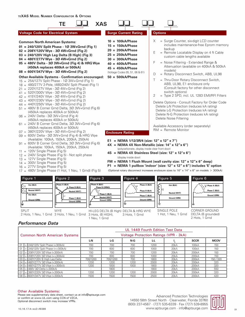
TEXAS MODEL NUMBER CONFIGURATOR & OPTIONS
Voltage Code for Electrical System Surge Current Rating Options
TE ll XAS ll ll l...
Common North American SystemsUL 1449 Fourth Edition Test Data
Voltage Protection Ratings (VPR - 3kA)L-N L-G N-G L-L In SCCR MCOV
01 = 240/120V Split Phase (<300kA) 700 700 700 1200 20kA 100kA 15001 = 240/120V Split Phase (=>300kA) 700 600 600 1000 20kA 100kA 15002 = 208Y/120V 3� Wye (<300kA) 700 700 700 1200 20kA 200kA 15002 = 208Y/120V 3� Wye (=>300kA) 700 600 600 1000 20kA 200kA 15003 = 240Y/120V B High Leg Delta 700/1200 700/1200 700 1800 20kA 200kA 150 / 32004 = 480Y/277V 3� Wye (<300kA) 1200 1200 1200 2000 20kA 200kA 32004 = 480Y/277V 3� Wye (=>300kA) 1200 1000 1000 1800 20kA 200kA 32005 = 480V 3� Delta (<300kA) - 1800 - 1800 20kA 200kA 55007 = 380Y/220V 3� Wye (<300kA) 1200 1200 1200 2000 20kA 200kA 32008 = 600Y/347V 3� Wye (<300kA) 1500 1500 1500 2500 20kA 200kA 420
Other Available Systems:Please see supplementary data sheet, contact us at [email protected] or confirm at www.UL.com using CCN of VZCA.Optional disconnect switch may increase VPRs.
Figure 1 Figure 2 Figure 3 Figure 4 Figure 5 Figure 6
SPLIT2 Hots, 1 Neu, 1 Grnd
HI-LEG DELTA (B High)3 Hots, (B HIGH), 1 Neu, 1 Grnd
SINGLE POLE1 Hot, 1 Neu, 1 Grnd
WYE3 Hots, 1 Neu, 1 Grnd
DELTA & HRG WYE3 Hots, 1 Grnd
CORNER GROUNDDELTA (B grounded)2 Hots, 1 Grnd
Hot (BLK)
Hot (BLK)
Neutral (WHT)V
V
}}
Ground (GRN)}
Phase A (BLK)Phase B (BLK)
Neutral (WHT)
Phase C (BLK)
Ground (GRN)
A
C
N
V
B
Phase A (BLK)Phase B (ORNG)
Neutral (WHT)
Phase C (BLK)
Ground (GRN)
}V V}Neutral (WHT)
Hot (BLK)
Ground (GRN)
Phase A (BLK)
Phase C (BLK)
Phase B (BLK)
Ground (GRN)
}V Phase A (BLK)
Phase C (BLK)
Ground (GRN)
V}
Enclosure Rating
X = Surge Counter, six-digit LCD counter includes maintenance-free Eprom memory backup
E = Remote Locatable Display on 4 ft Cable custom cable lengths available
F = Noise Filtering - Extended Range & Attenuation (available on 400kA & 500kA models)
D = Rotary Disconnect Switch, ABB, UL98
T = Thru-Door Rotary Disconnect Switch, ABB, UL98, E1 enclosure only(Consult factory for other disconnect switch options)
2 = Type 2 SPD, incl. UL 1283 EMI/RFI Filters
Delete Options - Consult Factory for Order CodeDelete L-N Protection (reduces kA rating)Delete L-G Protection (reduces kA rating)Delete N-G Protection (reduces kA rating)Delete Noise Filtering
Available Accessory (order separately)RM = Remote Monitor
Other Available Systems - Confirmation encouraged:15 = 254/127V Split Phase - 1� 3W+Grnd (Fig 1)18 = 480/277V 2-Pole, (480/240V Split Phase) (Fig 1) 21 = 220Y/127V Wye - 3� 4W+Grnd (Fig 2)41 = 520Y/300V Wye - 3� 4W+Grnd (Fig 2)42 = 415Y/240V Wye - 3� 4W+Grnd (Fig 2)43 = 400Y/230V Wye - 3� 4W+Grnd (Fig 2)44 = 440Y/250V Wye - 3� 4W+Grnd (Fig 2)51 = 480V B Corner Grnd Delta, 3� 3W+Grnd (Fig 6)
(450kA replaces 400kA or 500kA)06 = 240V Delta - 3� 3W+Grnd (Fig 4)
(450kA replaces 400kA or 500kA)61 = 240V B Corner Grnd Delta, 3� 3W+Grnd (Fig 6)
(450kA replaces 400kA or 500kA)07 = 380Y/220V Wye - 3� 4W+Grnd (Fig 2)09 = 600V Delta - 3� 3W+Grnd (Fig 4) & HRG Wye
(Available: 100kA, 150kA, 200kA, 250kA)91 = 600V B Corner Grnd Delta, 3� 3W+Grnd (Fig 6)
(Available: 100kA, 150kA, 200kA, 250kA)11 = 120V Single Phase (Fig 5)12 = 240V Single Phase (Fig 5) - Not split phase13 = 127V Single Phase (Fig 5)14 = 300V Single Phase (Fig 5)16 = 277V Single Phase (Fig 5)17 = 480V Single Phase (1 Hot, 1 Neu, 1 Grnd) (Fig 5)
10 = 100kA/Phase15 = 150kA/Phase20 = 200kA/Phase25 = 250kA/Phase30 = 300kA/Phase40 = 400kA/Phase45 = 450kA/Phase(Voltage Codes 05, 51, 06 & 61)
50 = 500kA/Phase
Common North American Systems:01 = 240/120V Split Phase - 1Ø 3W+Grnd (Fig 1)02 = 208Y/120V Wye - 3Ø 4W+Grnd (Fig 2)03 = 240/120V High Leg Delta (B High) (Fig 3)04 = 480Y/277V Wye - 3Ø 4W+Grnd (Fig 2)05 = 480V Delta - 3Ø 3W+Grnd (Fig 4) & HRG Wye
(450kA replaces 400kA or 500kA)08 = 600Y/347V Wye - 3Ø 4W+Grnd (Fig 2)
E1 = NEMA 1/12/3R/4 (size: 12” x 12” x 7”)4X = NEMA 4X Non-Metallic (size: 14” x 12”x 6”)
(polycarbonate, display inside clear front door)
4S = NEMA 4X Stainless Steel (size: 12" x 12"x 6")(display inside door)
FM = NEMA 1 Flush Mount (wall cavity size: 12” x 12”x 6” deep) P1 = NEMA 1 pullbox ‘indoor’ (size: 12” x 12” x 6”) includes ‘E’ option(Optional rotary disconnect increases enclosure sizes to 16” x 14” x 6” on models > 300kA)
Performance Data
10.16.17.lh revD #8386
Advanced Protection Technologies14550 58th Street North · Clearwater, Florida 33760
(800) 237-4567 · (727) 535-6339 · Fax (727) 539-8955www.aptsurge.com · [email protected] 15
Advanced Protection Technologies14550 58th Street North · Clearwater, Florida 33760(800) 237-4567 · (727) 535-6339 · Fax (727) 539-8955www.aptsurge.com · [email protected]
Design Features• Designed, Manufactured & Tested consistent with:
– ANSI/IEEE C62.41.1-2002, C62.41.2-2002, C62.45-2002, C62.62-2010 and C62.72-2007
– NEMA LS-1 – NEC® Article 285 – IEC 61643, CE
• High Energy Parallel Design for Category C3 & C-High applications
• For External Mounting next to Switchgear, Motor Controls Centers or Panelboards
• Individually Fused & Thermally Protected MOVs• Large-Block, 34mm square, 50kA MOVs• Replaceable Module Construction• Solid State Bidirectional Operation
Physical Specifications• Relative Humidity Range: 0 - 95% non-condensing• Operating Frequency: 47-63Hz• Operating Temperature: -25°C (-15°F) to +60°C (140°F)• Weight: 24 lbs (11 kg)• Standard NEMA 1/12/3R/4 enclosure• Standard size: 12” x 12” x 7” (305mm x 305mm x 177mm)
• Lug size: #2 - #14 AWG (w/opt. disconnect: #6 - #1/0)
• Typical connection: #6 AWG and 60A breaker
Quality, Standards & Validation• Type 1: UL 1449 Fourth Edition, CSA 22.2 No. 269.1• Type 2 (Opt.): UL 1449 Fourth Ed., CSA No. 269.2, UL 1283• UL file: VZCA.E321351 at www.UL.com• RoHS-compliant• IEC 61643, CE• 10 year warranty (longer optional)• Burn-In tested prior to shipment• ISO 9001:2008 Quality Management System• ISO 17025:2005 Laboratory Qualification
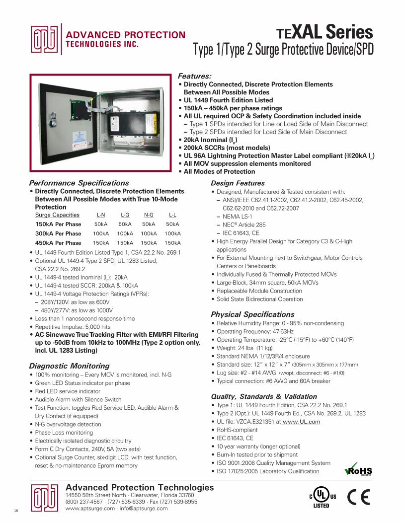
Features:• Directly Connected, Discrete Protection Elements
Between All Possible Modes• UL 1449 Fourth Edition Listed• 150kA – 450kA per phase ratings• All UL required OCP & Safety Coordination included inside
– Type 1 SPDs intended for Line or Load Side of Main Disconnect – Type 2 SPDs intended for Load Side of Main Disconnect
• 20kA Inominal (In)• 200kA SCCRs (most models)• UL 96A Lightning Protection Master Label compliant (@20kA In)• All MOV suppression elements monitored• All Modes of Protection
Performance Specifications• Directly Connected, Discrete Protection Elements
Between All Possible Modes with True 10-Mode Protection
• UL 1449 Fourth Edition Listed Type 1, CSA 22.2 No. 269.1• Optional UL 1449-4 Type 2 SPD, UL 1283 Listed,
CSA 22.2 No. 269.2• UL 1449-4 tested Inominal (In): 20kA• UL 1449-4 tested SCCR: 200kA & 100kA• UL 1449-4 Voltage Protection Ratings (VPRs):
– 208Y/120V: as low as 600V – 480Y/277V: as low as 1000V
• Less than 1 nanosecond response time• Repetitive Impulse: 5,000 hits• AC Sinewave True Tracking Filter with EMI/RFI Filtering
up to -50dB from 10kHz to 100MHz (Type 2 option only, incl. UL 1283 Listing)
Diagnostic Monitoring• 100% monitoring – Every MOV is monitored, incl. N-G• Green LED Status indicator per phase• Red LED service indicator • Audible Alarm with Silence Switch• Test Function: toggles Red Service LED, Audible Alarm &
Dry Contact (if equipped)• N-G overvoltage detection• Phase Loss monitoring• Electrically isolated diagnostic circuitry• Form C Dry Contacts, 240V, 5A (two sets)• Optional Surge Counter, six-digit LCD, with test function,
reset & no-maintenance Eprom memory
Surge Capacities L-N L-G N-G L-L
150kA Per Phase 50kA 50kA 50kA 50kA
300kA Per Phase 100kA 100kA 100kA 100kA
450kA Per Phase 150kA 150kA 150kA 150kA
Type 1/Type 2 Surge Protective Device/SPD
16
Advanced Protection Technologies14550 58th Street North · Clearwater, Florida 33760
(800) 237-4567 · (727) 535-6339 · Fax (727) 539-8955www.aptsurge.com · [email protected]
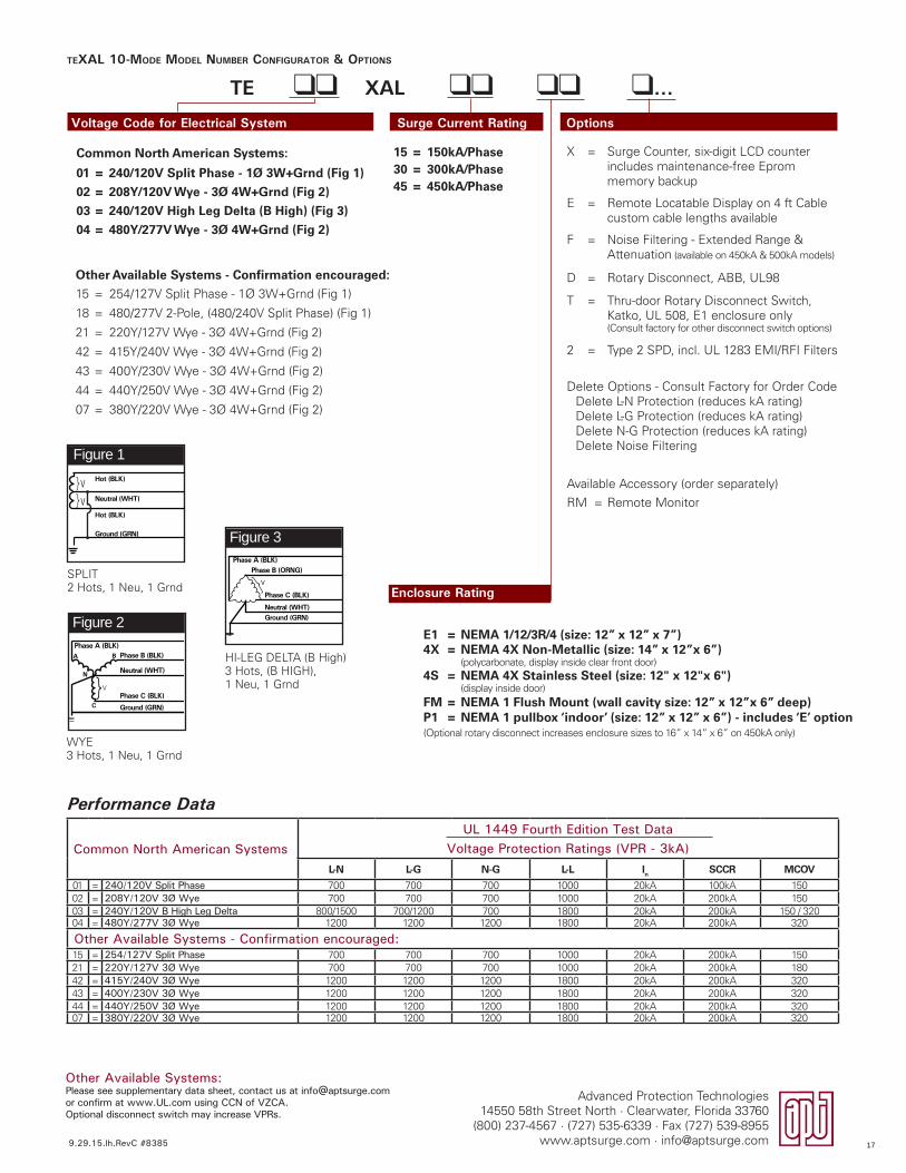
TEXAL 10-MODE MODEL NUMBER CONFIGURATOR & OPTIONS
Voltage Code for Electrical System Surge Current Rating Options
TE ll XAL ll ll l...
Common North American SystemsUL 1449 Fourth Edition Test Data
Voltage Protection Ratings (VPR - 3kA)L-N L-G N-G L-L In SCCR MCOV
01 = 240/120V Split Phase 700 700 700 1000 20kA 100kA 15002 = 208Y/120V 3Ø Wye 700 700 700 1000 20kA 200kA 15003 = 240Y/120V B High Leg Delta 800/1500 700/1200 700 1800 20kA 200kA 150 / 32004 = 480Y/277V 3Ø Wye 1200 1200 1200 1800 20kA 200kA 320
Other Available Systems - Confirmation encouraged: 15 = 254/127V Split Phase 700 700 700 1000 20kA 200kA 15021 = 220Y/127V 3Ø Wye 700 700 700 1000 20kA 200kA 18042 = 415Y/240V 3Ø Wye 1200 1200 1200 1800 20kA 200kA 32043 = 400Y/230V 3Ø Wye 1200 1200 1200 1800 20kA 200kA 32044 = 440Y/250V 3Ø Wye 1200 1200 1200 1800 20kA 200kA 32007 = 380Y/220V 3Ø Wye 1200 1200 1200 1800 20kA 200kA 320
Other Available Systems:Please see supplementary data sheet, contact us at [email protected] or confirm at www.UL.com using CCN of VZCA.Optional disconnect switch may increase VPRs.
Figure 1
SPLIT2 Hots, 1 Neu, 1 Grnd
Hot (BLK)
Hot (BLK)
Neutral (WHT)V
V
}}
Ground (GRN)
Figure 2
WYE3 Hots, 1 Neu, 1 Grnd
}
Phase A (BLK)Phase B (BLK)
Neutral (WHT)
Phase C (BLK)
Ground (GRN)
A
C
N
V
B
Figure 3
HI-LEG DELTA (B High)3 Hots, (B HIGH), 1 Neu, 1 Grnd
Phase A (BLK)Phase B (ORNG)
Neutral (WHT)
Phase C (BLK)
Ground (GRN)
}V Enclosure Rating
X = Surge Counter, six-digit LCD counter includes maintenance-free Eprom memory backup
E = Remote Locatable Display on 4 ft Cable custom cable lengths available
F = Noise Filtering - Extended Range & Attenuation (available on 450kA & 500kA models)
D = Rotary Disconnect, ABB, UL98
T = Thru-door Rotary Disconnect Switch, Katko, UL 508, E1 enclosure only(Consult factory for other disconnect switch options)
2 = Type 2 SPD, incl. UL 1283 EMI/RFI Filters
Delete Options - Consult Factory for Order CodeDelete L-N Protection (reduces kA rating)Delete L-G Protection (reduces kA rating)Delete N-G Protection (reduces kA rating)Delete Noise Filtering
Available Accessory (order separately)
RM = Remote Monitor
Other Available Systems - Confirmation encouraged:
15 = 254/127V Split Phase - 1� 3W+Grnd (Fig 1)
18 = 480/277V 2-Pole, (480/240V Split Phase) (Fig 1)
21 = 220Y/127V Wye - 3� 4W+Grnd (Fig 2)
42 = 415Y/240V Wye - 3� 4W+Grnd (Fig 2)
43 = 400Y/230V Wye - 3� 4W+Grnd (Fig 2)
44 = 440Y/250V Wye - 3� 4W+Grnd (Fig 2)
07 = 380Y/220V Wye - 3� 4W+Grnd (Fig 2)
15 = 150kA/Phase30 = 300kA/Phase45 = 450kA/Phase
Common North American Systems:
01 = 240/120V Split Phase - 1Ø 3W+Grnd (Fig 1)
02 = 208Y/120V Wye - 3Ø 4W+Grnd (Fig 2)
03 = 240/120V High Leg Delta (B High) (Fig 3)
04 = 480Y/277V Wye - 3Ø 4W+Grnd (Fig 2)
E1 = NEMA 1/12/3R/4 (size: 12” x 12” x 7”)4X = NEMA 4X Non-Metallic (size: 14” x 12”x 6”)
(polycarbonate, display inside clear front door) 4S = NEMA 4X Stainless Steel (size: 12" x 12"x 6")
(display inside door)FM = NEMA 1 Flush Mount (wall cavity size: 12” x 12”x 6” deep)P1 = NEMA 1 pullbox ‘indoor’ (size: 12” x 12” x 6”) - includes ‘E’ option(Optional rotary disconnect increases enclosure sizes to 16” x 14” x 6” on 450kA only)
Performance Data
9.29.15.lh.RevC #8385 17
Advanced Protection Technologies14550 58th Street North · Clearwater, Florida 33760(800) 237-4567 · (727) 535-6339 · Fax (727) 539-8955www.aptsurge.com · [email protected]
Design Features• Designed, Manufactured & Tested consistent with:
– ANSI/IEEE C62.41.1-2002, C62.41.2-2002, C62.45-2002, C62.62-2010 and C62.72-2007
– NEMA LS-1 – NEC® Article 285 – IEC 61643, CE
• High Energy Parallel Design for Category C3 & C-High applications• For External Mounting next to Switchgear, Motor Controls
Centers or Panelboards• Individually Fused & Thermally Protected MOVs• Large-Block, 34mm square, 50kA MOVs• Dual Replaceable Module Construction• Solid State Bidirectional Operation
Physical Specifications• Relative Humidity Range: 0 -95% non-condensing• Operating Frequency: 47-63Hz• Operating Temperature: -25°C (-15°F) to +60°C (140°F)• Weight: 52 lbs (23.6 kg)• Standard NEMA 1/12/3R/4 enclosure• Standard size: 20” x 20” x 7.5” (50.8cm x 50.8cm x 19cm)
• Lug size: #6 - #1/0 AWG• Typical connection: #6 AWG and 60A breaker
Quality, Standards & Validation• Type 1: UL 1449 Fourth Edition, CSA 22.2 No. 269.1• Type 2 (Opt.): UL 1449 Fourth Ed., CSA No. 269.2, UL 1283• UL file: VZCA.E321351 at www.UL.com• RoHS-compliant• IEC 61643, CE• 10 year warranty (longer optional)• Burn-In tested prior to shipment• ISO 9001:2008 Quality Management System• ISO 17025:2005 Laboratory Qualification
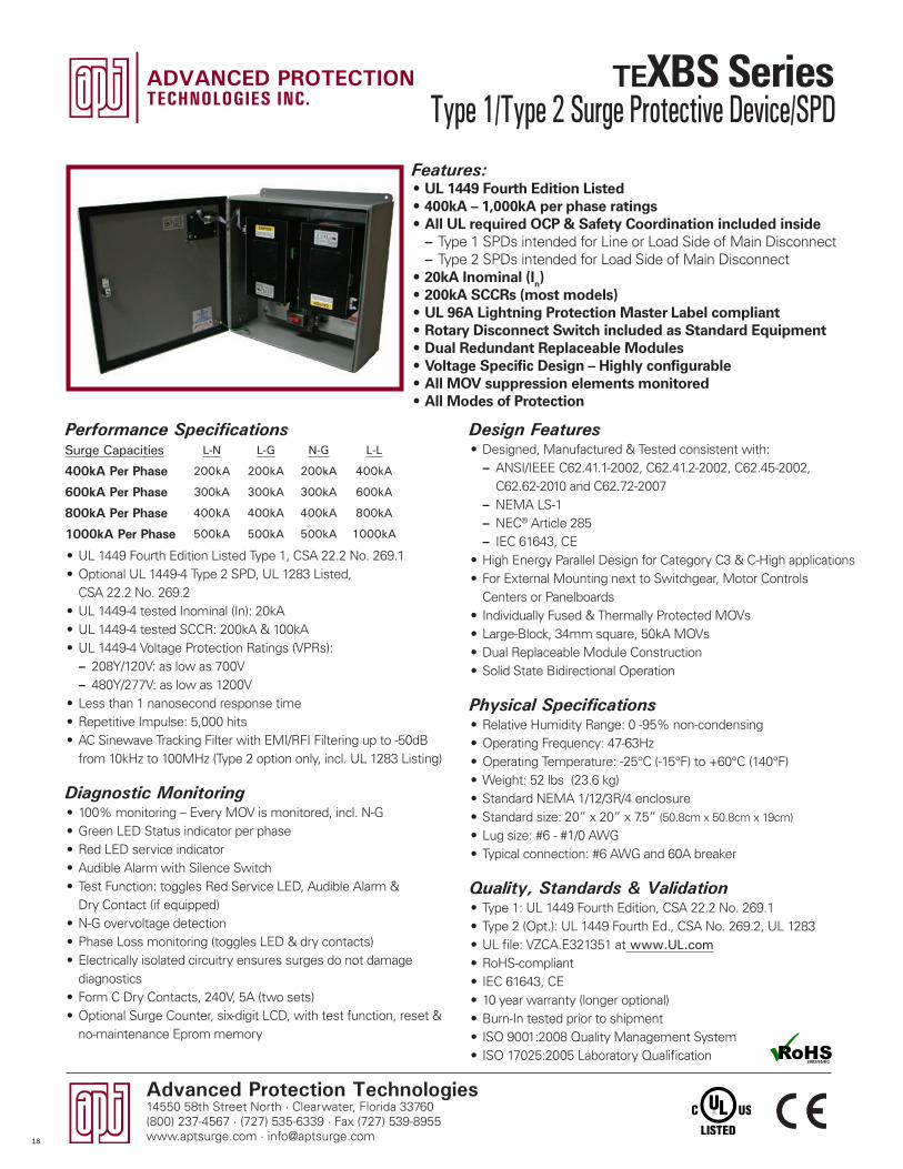
Features:• UL 1449 Fourth Edition Listed• 400kA – 1,000kA per phase ratings• All UL required OCP & Safety Coordination included inside
– Type 1 SPDs intended for Line or Load Side of Main Disconnect – Type 2 SPDs intended for Load Side of Main Disconnect
• 20kA Inominal (In)• 200kA SCCRs (most models)• UL 96A Lightning Protection Master Label compliant• Rotary Disconnect Switch included as Standard Equipment• Dual Redundant Replaceable Modules• Voltage Specific Design – Highly configurable• All MOV suppression elements monitored• All Modes of Protection
Performance Specifications
• UL 1449 Fourth Edition Listed Type 1, CSA 22.2 No. 269.1• Optional UL 1449-4 Type 2 SPD, UL 1283 Listed,
CSA 22.2 No. 269.2• UL 1449-4 tested Inominal (In): 20kA • UL 1449-4 tested SCCR: 200kA & 100kA• UL 1449-4 Voltage Protection Ratings (VPRs):
– 208Y/120V: as low as 700V – 480Y/277V: as low as 1200V
• Less than 1 nanosecond response time• Repetitive Impulse: 5,000 hits• AC Sinewave Tracking Filter with EMI/RFI Filtering up to -50dB
from 10kHz to 100MHz (Type 2 option only, incl. UL 1283 Listing)
Diagnostic Monitoring• 100% monitoring – Every MOV is monitored, incl. N-G• Green LED Status indicator per phase• Red LED service indicator • Audible Alarm with Silence Switch• Test Function: toggles Red Service LED, Audible Alarm &
Dry Contact (if equipped)• N-G overvoltage detection• Phase Loss monitoring (toggles LED & dry contacts)• Electrically isolated circuitry ensures surges do not damage
diagnostics• Form C Dry Contacts, 240V, 5A (two sets)• Optional Surge Counter, six-digit LCD, with test function, reset &
no-maintenance Eprom memory
Surge Capacities L-N L-G N-G L-L
400kA Per Phase 200kA 200kA 200kA 400kA
600kA Per Phase 300kA 300kA 300kA 600kA
800kA Per Phase 400kA 400kA 400kA 800kA
1000kA Per Phase 500kA 500kA 500kA 1000kA
Type 1/Type 2 Surge Protective Device/SPD
18
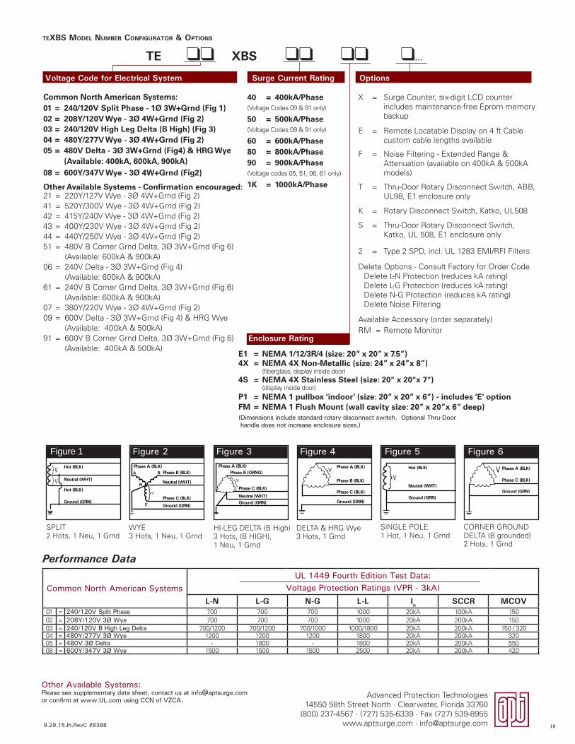
Figure 6
CORNER GROUNDDELTA (B grounded)2 Hots, 1 Grnd
Phase A (BLK)
Phase C (BLK)
Ground (GRN)
V}
TEXBS MODEL NUMBER CONFIGURATOR & OPTIONS
Voltage Code for Electrical System Surge Current Rating Options
TE ll XBS ll ll l...
Figure 2 Figure 3
HI-LEG DELTA (B High)3 Hots, (B HIGH), 1 Neu, 1 Grnd
WYE3 Hots, 1 Neu, 1 Grnd
Common North American SystemsUL 1449 Fourth Edition Test Data:
Voltage Protection Ratings (VPR - 3kA)
L-N L-G N-G L-L In SCCR MCOV01 = 240/120V Split Phase 700 700 700 1000 20kA 100kA 15002 = 208Y/120V 3Ø Wye 700 700 700 1000 20kA 200kA 15003 = 240/120V B High Leg Delta 700/1200 700/1200 700/1000 1000/1800 20kA 200kA 150 / 32004 = 480Y/277V 3Ø Wye 1200 1200 1200 1800 20kA 200kA 32005 = 480V 3Ø Delta - 1800 - 1800 20kA 200kA 55008 = 600Y/347V 3Ø Wye 1500 1500 1500 2500 20kA 200kA 420
}
Phase A (BLK)Phase B (BLK)
Neutral (WHT)
Phase C (BLK)
Ground (GRN)
A
C
N
V
B
Phase A (BLK)Phase B (ORNG)
Neutral (WHT)
Phase C (BLK)
Ground (GRN)
}V
Figure 5
SINGLE POLE1 Hot, 1 Neu, 1 Grnd
V}Neutral (WHT)
Hot (BLK)
Ground (GRN)
Figure 4
DELTA & HRG Wye3 Hots, 1 Grnd
Phase A (BLK)
Phase C (BLK)
Phase B (BLK)
Ground (GRN)
}V
Enclosure Rating
Performance Data
Other Available Systems - Confirmation encouraged:21 = 220Y/127V Wye - 3� 4W+Grnd (Fig 2)41 = 520Y/300V Wye - 3� 4W+Grnd (Fig 2)42 = 415Y/240V Wye - 3� 4W+Grnd (Fig 2)43 = 400Y/230V Wye - 3� 4W+Grnd (Fig 2)44 = 440Y/250V Wye - 3� 4W+Grnd (Fig 2)51 = 480V B Corner Grnd Delta, 3� 3W+Grnd (Fig 6)
(Available: 600kA & 900kA)06 = 240V Delta - 3� 3W+Grnd (Fig 4)
(Available: 600kA & 900kA)61 = 240V B Corner Grnd Delta, 3� 3W+Grnd (Fig 6)
(Available: 600kA & 900kA)07 = 380Y/220V Wye - 3� 4W+Grnd (Fig 2)09 = 600V Delta - 3� 3W+Grnd (Fig 4) & HRG Wye
(Available: 400kA & 500kA)91 = 600V B Corner Grnd Delta, 3� 3W+Grnd (Fig 6)
(Available: 400kA & 500kA)
40 = 400kA/Phase(Voltage Codes 09 & 91 only)
50 = 500kA/Phase(Voltage Codes 09 & 91 only)
60 = 600kA/Phase80 = 800kA/Phase90 = 900kA/Phase(Voltage codes 05, 51, 06, 61 only)
1K = 1000kA/Phase
Common North American Systems:01 = 240/120V Split Phase - 1Ø 3W+Grnd (Fig 1)02 = 208Y/120V Wye - 3Ø 4W+Grnd (Fig 2)03 = 240/120V High Leg Delta (B High) (Fig 3)04 = 480Y/277V Wye - 3Ø 4W+Grnd (Fig 2)05 = 480V Delta - 3Ø 3W+Grnd (Fig4) & HRG Wye
(Available: 400kA, 600kA, 900kA)08 = 600Y/347V Wye - 3Ø 4W+Grnd (Fig2)
E1 = NEMA 1/12/3R/4 (size: 20” x 20” x 7.5”)4X = NEMA 4X Non-Metallic (size: 24” x 24”x 8”)
(fiberglass, display inside door) 4S = NEMA 4X Stainless Steel (size: 20" x 20"x 7")
(display inside door)P1 = NEMA 1 pullbox ‘indoor’ (size: 20” x 20” x 6”) - includes ‘E’ optionFM = NEMA 1 Flush Mount (wall cavity size: 20” x 20”x 6” deep)(Dimensions include standard rotary disconnect switch. Optional Thru-Door handle does not increase enclosure sizes.)
X = Surge Counter, six-digit LCD counter includes maintenance-free Eprom memory backup
E = Remote Locatable Display on 4 ft Cable custom cable lengths available
F = Noise Filtering - Extended Range & Attenuation (available on 400kA & 500kA models)
T = Thru-Door Rotary Disconnect Switch, ABB, UL98, E1 enclosure only
K = Rotary Disconnect Switch, Katko, UL508
S = Thru-Door Rotary Disconnect Switch, Katko, UL 508, E1 enclosure only
2 = Type 2 SPD, incl. UL 1283 EMI/RFI Filters
Delete Options - Consult Factory for Order CodeDelete L-N Protection (reduces kA rating)Delete L-G Protection (reduces kA rating)Delete N-G Protection (reduces kA rating)Delete Noise Filtering
Available Accessory (order separately)RM = Remote Monitor
.
Other Available Systems:Please see supplementary data sheet, contact us at [email protected] or confirm at www.UL.com using CCN of VZCA.
9.29.15.lh.RevC #8388
Advanced Protection Technologies14550 58th Street North · Clearwater, Florida 33760
(800) 237-4567 · (727) 535-6339 · Fax (727) 539-8955www.aptsurge.com · [email protected]
Figure 1
SPLIT2 Hots, 1 Neu, 1 Grnd
Hot (BLK)
Hot (BLK)
Neutral (WHT)V
V
}}
Ground (GRN)
19
Advanced Protection Technologies14550 58th Street North · Clearwater, Florida 33760(800) 237-4567 · (727) 535-6339 · Fax (727) 539-8955www.aptsurge.com · [email protected]
Design Features• Designed, Manufactured & Tested consistent with:
– ANSI/IEEE C62.41.1-2002, C62.41.2-2002, C62.45-2002, C62.62-2010 and C62.72-2007
– NEMA LS-1 – NEC® Article 285 – IEC 61643, CE
• High Energy Parallel Design for Category C3 & C-High applications• For External Mounting next to Switchgear, Motor Controls Centers
or Panelboards• Individually Fused & Thermally Protected MOVs• Large-Block, 34mm square, 50kA MOVs• Dual Redundant Replaceable Module Construction• Solid State Bidirectional Operation
Physical Specifications• Relative Humidity Range: 0 -95% non-condensing• Operating Frequency: 47-63Hz• Operating Temperature: -25°C (-15°F) to +60°C (140°F)• Weight: 52 lbs (23.6 kg)• Standard NEMA 1/12/3R/4 enclosure• Standard size: 20” x 20” x 7.5” (50.8cm x 50.8cm x 19cm)
• Lug size: #6 - #1/0 AWG• Typical connection: #6 AWG and 60A breaker
Quality, Standards & Validation• Type 1: UL 1449 Fourth Edition, CSA 22.2 No. 269.1• Type 2 (Opt.): UL 1449 Fourth Ed., CSA No. 269.2, UL 1283• UL file: VZCA.E321351 at www.UL.com• RoHS-compliant• IEC 61643, CE• 10 year warranty (longer optional)• Burn-In tested prior to shipment• ISO 9001:2008 Quality Management System• ISO 17025:2005 Laboratory Qualification
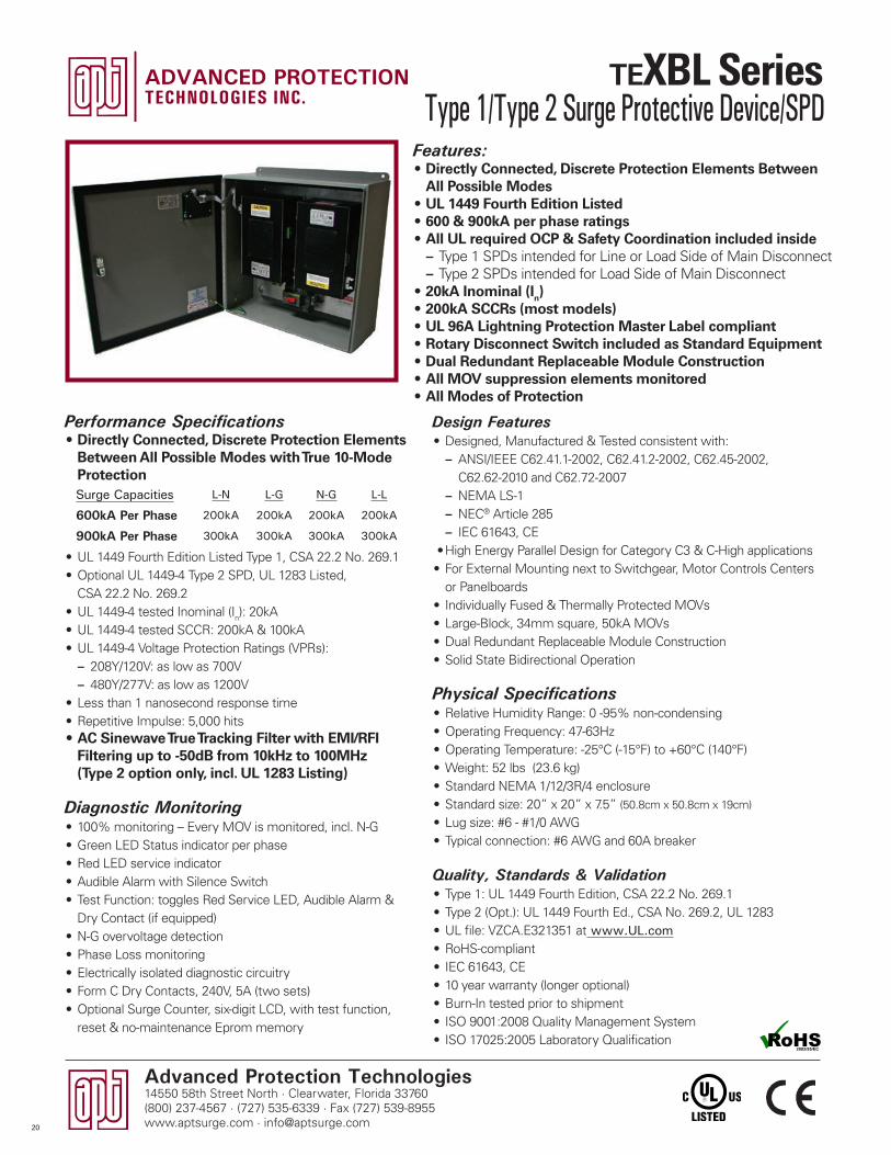
Features:• Directly Connected, Discrete Protection Elements Between
All Possible Modes• UL 1449 Fourth Edition Listed• 600 & 900kA per phase ratings• All UL required OCP & Safety Coordination included inside
– Type 1 SPDs intended for Line or Load Side of Main Disconnect – Type 2 SPDs intended for Load Side of Main Disconnect
• 20kA Inominal (In)• 200kA SCCRs (most models)• UL 96A Lightning Protection Master Label compliant• Rotary Disconnect Switch included as Standard Equipment• Dual Redundant Replaceable Module Construction• All MOV suppression elements monitored• All Modes of Protection
Performance Specifications• Directly Connected, Discrete Protection Elements
Between All Possible Modes with True 10-Mode Protection
• UL 1449 Fourth Edition Listed Type 1, CSA 22.2 No. 269.1• Optional UL 1449-4 Type 2 SPD, UL 1283 Listed,
CSA 22.2 No. 269.2• UL 1449-4 tested Inominal (In): 20kA• UL 1449-4 tested SCCR: 200kA & 100kA• UL 1449-4 Voltage Protection Ratings (VPRs):
– 208Y/120V: as low as 700V – 480Y/277V: as low as 1200V
• Less than 1 nanosecond response time• Repetitive Impulse: 5,000 hits• AC Sinewave True Tracking Filter with EMI/RFI
Filtering up to -50dB from 10kHz to 100MHz (Type 2 option only, incl. UL 1283 Listing)
Diagnostic Monitoring• 100% monitoring – Every MOV is monitored, incl. N-G• Green LED Status indicator per phase• Red LED service indicator • Audible Alarm with Silence Switch• Test Function: toggles Red Service LED, Audible Alarm &
Dry Contact (if equipped)• N-G overvoltage detection• Phase Loss monitoring• Electrically isolated diagnostic circuitry• Form C Dry Contacts, 240V, 5A (two sets)• Optional Surge Counter, six-digit LCD, with test function,
reset & no-maintenance Eprom memory
Surge Capacities L-N L-G N-G L-L
600kA Per Phase 200kA 200kA 200kA 200kA
900kA Per Phase 300kA 300kA 300kA 300kA
Type 1/Type 2 Surge Protective Device/SPD
20

Advanced Protection Technologies14550 58th Street North · Clearwater, Florida 33760
(800) 237-4567 · (727) 535-6339 · Fax (727) 539-8955www.aptsurge.com · [email protected]
TEXBL 10-MODE MODEL NUMBER CONFIGURATOR & OPTIONS
Voltage Code for Electrical System Surge Current Rating Options
TE ll XBL ll ll l...
Figure 3 Figure 4 Figure 5 Figure 6
Common North American SystemsUL 1449 Fourth Edition Test Data
Voltage Protection Ratings (VPR - 3kA)L-N L-G N-G L-L In SCCR MCOV
01 = 240/120V Wye 700 700 700 1200 20kA 100kA 15002 = 208Y/120V 3� Wye 700 700 700 1200 20kA 200kA 15003 = 240Y/120V B High Leg Delta 700/1200 700/1200 700 1200/1800 20kA 200kA 150 / 32004 = 480Y/277V 3� Wye 1200 1200 1200 1800 20kA 200kA 320
Less Common & Specialty42 = 415V/240V 3� Wye 1200 1200 1200 1800 20kA 200kA 32043 = 400V/230V 3� Wye 1200 1200 1200 1800 20kA 200kA 32044 = 440V/250V 3� Wye 1200 1200 1200 1800 20kA 200kA 32007 = 380V/220V 3� Wye 1200 1200 1200 1800 20kA 200kA 320
Other Available Systems:Please see supplementary data sheet, contact us at [email protected] or confirm at www.UL.com using CCN of VZCA.
Enclosure Rating
Performance Data
X = Surge Counter, six-digit LCD counter includes maintenance-free Eprom memory backup
E = Remote Locatable Display on 4 ft Cable custom cable lengths available
F = Noise Filtering - Extended Range & Attenuation (available on 400kA & 500kA models)
T = Thru-Door Rotary Disconnect Switch, ABB, UL98, E1 enclosure only
K = Rotary Disconnect Switch, Katko, UL 508
S = Thru-Door Rotary Disconnect Switch, Katko, UL 508, E1 enclosure only
2 = Type 2 SPD, incl. UL 1283 EMI/RFI Filters
Delete Options - Consult Factory for Order CodeDelete L-N Protection (reduces kA rating)Delete L-G Protection (reduces kA rating)Delete N-G Protection (reduces kA rating)Delete Noise Filtering
Available Accessory (order separately)RM = Remote Monitor
Other Available Systems - Confirmation encouraged:
41 = 520Y/300V Wye - 3� 4W+Grnd (Fig 2)42 = 415Y/240V Wye - 3� 4W+Grnd (Fig 2)43 = 400Y/230V Wye - 3� 4W+Grnd (Fig 2)44 = 440Y/250V Wye - 3� 4W+Grnd (Fig 2)07 = 380Y/220V Wye - 3� 4W+Grnd (Fig 2)
60 = 600kA/Phase90 = 900kA/Phase
Common North American Systems:
01 = 240/120V Split Phase - 1Ø 3W+Grnd (Fig 1)
02 = 208Y/120V Wye - 3Ø 4W+Grnd (Fig 2)
03 = 240/120V High Leg Delta (B High) (Fig 3)
04 = 480Y/277V Wye - 3Ø 4W+Grnd (Fig 2)
E1 = NEMA 1/12/3R/4 (size: 20” x 20” x 7.5”)4X = NEMA 4X Non-Metallic (size: 24” x 24”x 8”)
(fiberglass, display inside door) 4S = NEMA 4X Stainless Steel (size: 20" x 20"x 7.5")
(display inside door)P1 = NEMA 1 pullbox ‘indoor’ (size: 20” x 20” x 6”) - includes ‘E’ optionFM = NEMA 1 Flush Mount (wall cavity size: 20” x 20”x 6” deep) (Dimensions include standard rotary disconnect switch. Optional Thru-Door handle does not increase enclosure sizes.)
Figure 1
SPLIT2 Hots, 1 Neu, 1 Grnd
Hot (BLK)
Hot (BLK)
Neutral (WHT)V
V
}}
Ground (GRN)
Figure 2
WYE3 Hots, 1 Neu, 1 Grnd
}
Phase A (BLK)Phase B (BLK)
Neutral (WHT)
Phase C (BLK)
Ground (GRN)
A
C
N
V
B
Figure 3
HI-LEG DELTA (B High)3 Hots, (B HIGH), 1 Neu, 1 Grnd
Phase A (BLK)Phase B (ORNG)
Neutral (WHT)
Phase C (BLK)
Ground (GRN)
}V
9.29.15.lh.RevB #8387 21
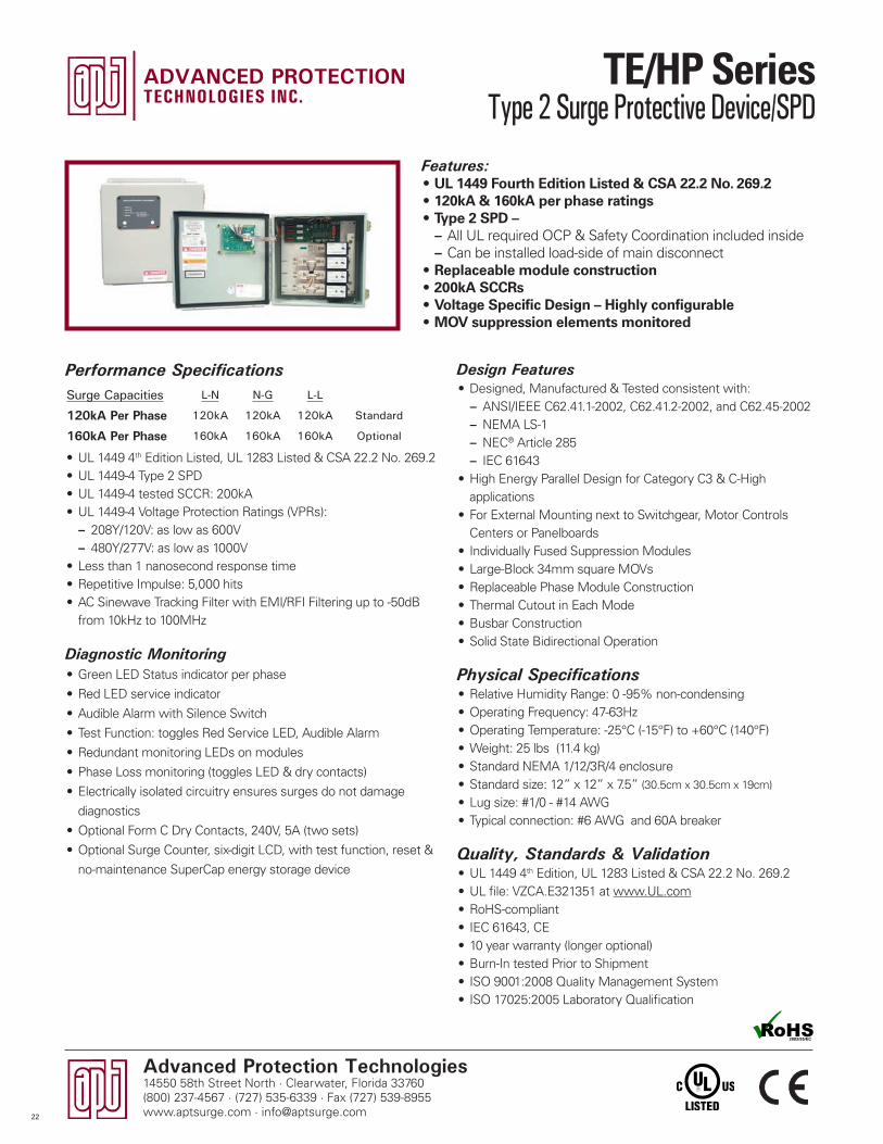
Advanced Protection Technologies14550 58th Street North · Clearwater, Florida 33760(800) 237-4567 · (727) 535-6339 · Fax (727) 539-8955www.aptsurge.com · [email protected]
Design Features• Designed, Manufactured & Tested consistent with:
– ANSI/IEEE C62.41.1-2002, C62.41.2-2002, and C62.45-2002 – NEMA LS-1 – NEC® Article 285 – IEC 61643
• High Energy Parallel Design for Category C3 & C-High applications
• For External Mounting next to Switchgear, Motor Controls Centers or Panelboards
• Individually Fused Suppression Modules• Large-Block 34mm square MOVs• Replaceable Phase Module Construction• Thermal Cutout in Each Mode• Busbar Construction• Solid State Bidirectional Operation
Physical Specifications• Relative Humidity Range: 0 -95% non-condensing• Operating Frequency: 47-63Hz• Operating Temperature: -25°C (-15°F) to +60°C (140°F)• Weight: 25 lbs (11.4 kg)• Standard NEMA 1/12/3R/4 enclosure• Standard size: 12” x 12” x 7.5” (30.5cm x 30.5cm x 19cm)
• Lug size: #1/0 - #14 AWG• Typical connection: #6 AWG and 60A breaker
Quality, Standards & Validation• UL 1449 4th Edition, UL 1283 Listed & CSA 22.2 No. 269.2• UL file: VZCA.E321351 at www.UL.com• RoHS-compliant• IEC 61643, CE• 10 year warranty (longer optional)• Burn-In tested Prior to Shipment• ISO 9001:2008 Quality Management System• ISO 17025:2005 Laboratory Qualification
Features:• UL 1449 Fourth Edition Listed & CSA 22.2 No. 269.2• 120kA & 160kA per phase ratings• Type 2 SPD –
– All UL required OCP & Safety Coordination included inside – Can be installed load-side of main disconnect
• Replaceable module construction• 200kA SCCRs• Voltage Specific Design – Highly configurable• MOV suppression elements monitored
Performance Specifications
• UL 1449 4th Edition Listed, UL 1283 Listed & CSA 22.2 No. 269.2• UL 1449-4 Type 2 SPD• UL 1449-4 tested SCCR: 200kA• UL 1449-4 Voltage Protection Ratings (VPRs):
– 208Y/120V: as low as 600V – 480Y/277V: as low as 1000V
• Less than 1 nanosecond response time• Repetitive Impulse: 5,000 hits• AC Sinewave Tracking Filter with EMI/RFI Filtering up to -50dB
from 10kHz to 100MHz
Diagnostic Monitoring• Green LED Status indicator per phase
• Red LED service indicator
• Audible Alarm with Silence Switch
• Test Function: toggles Red Service LED, Audible Alarm
• Redundant monitoring LEDs on modules
• Phase Loss monitoring (toggles LED & dry contacts)
• Electrically isolated circuitry ensures surges do not damage
diagnostics
• Optional Form C Dry Contacts, 240V, 5A (two sets)
• Optional Surge Counter, six-digit LCD, with test function, reset &
no-maintenance SuperCap energy storage device
Surge Capacities L-N N-G L-L
120kA Per Phase 120kA 120kA 120kA Standard
160kA Per Phase 160kA 160kA 160kA Optional
22
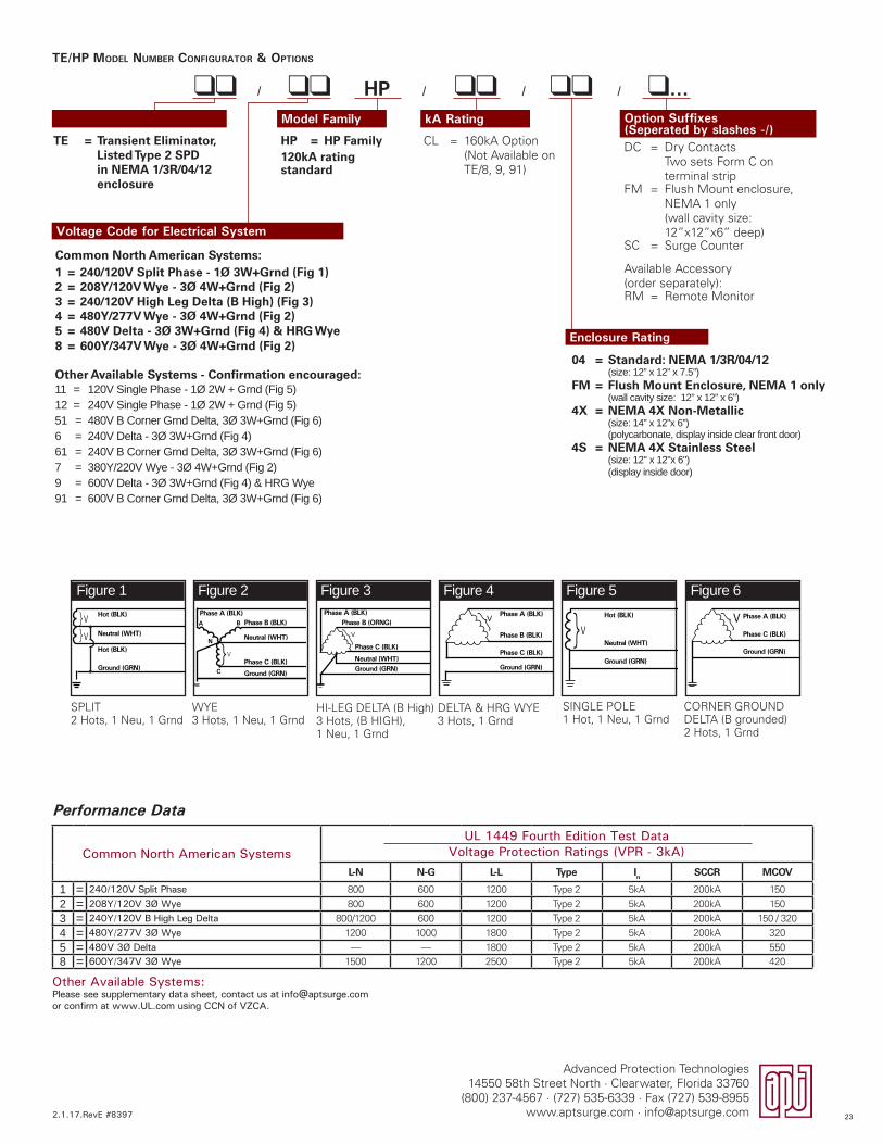
TE/HP MODEL NUMBER CONFIGURATOR & OPTIONS
Common North American SystemsUL 1449 Fourth Edition Test Data
Voltage Protection Ratings (VPR - 3kA)L-N N-G L-L Type In SCCR MCOV
1 = 240/120V Split Phase 800 600 1200 Type 2 5kA 200kA 150
2 = 208Y/120V 3Ø Wye 800 600 1200 Type 2 5kA 200kA 150
3 = 240Y/120V B High Leg Delta 800/1200 600 1200 Type 2 5kA 200kA 150 / 320
4 = 480Y/277V 3Ø Wye 1200 1000 1800 Type 2 5kA 200kA 320
5 = 480V 3Ø Delta — — 1800 Type 2 5kA 200kA 5508 = 600Y/347V 3Ø Wye 1500 1200 2500 Type 2 5kA 200kA 420
Other Available Systems:Please see supplementary data sheet, contact us at [email protected] or confirm at www.UL.com using CCN of VZCA.
Figure 1 Figure 2 Figure 3 Figure 4 Figure 5 Figure 6
SPLIT2 Hots, 1 Neu, 1 Grnd
HI-LEG DELTA (B High)3 Hots, (B HIGH), 1 Neu, 1 Grnd
SINGLE POLE1 Hot, 1 Neu, 1 Grnd
WYE3 Hots, 1 Neu, 1 Grnd
DELTA & HRG WYE3 Hots, 1 Grnd
CORNER GROUNDDELTA (B grounded)2 Hots, 1 Grnd
Hot (BLK)
Hot (BLK)
Neutral (WHT)V
V
}}
Ground (GRN)}
Phase A (BLK)Phase B (BLK)
Neutral (WHT)
Phase C (BLK)
Ground (GRN)
A
C
N
V
B
Phase A (BLK)Phase B (ORNG)
Neutral (WHT)
Phase C (BLK)
Ground (GRN)
}V V}Neutral (WHT)
Hot (BLK)
Ground (GRN)
Phase A (BLK)
Phase C (BLK)
Phase B (BLK)
Ground (GRN)
}V Phase A (BLK)
Phase C (BLK)
Ground (GRN)
V}
Performance Data
2.1.17.RevE #8397
Advanced Protection Technologies14550 58th Street North · Clearwater, Florida 33760
(800) 237-4567 · (727) 535-6339 · Fax (727) 539-8955www.aptsurge.com · [email protected]
TE = Transient Eliminator, Listed Type 2 SPD in NEMA 1/3R/04/12 enclosure
Voltage Code for Electrical System
Model Family kA Rating Option Suffixes (Seperated by slashes -/)DC = Dry Contacts
Two sets Form C on terminal strip
FM = Flush Mount enclosure, NEMA 1 only(wall cavity size: 12”x12”x6” deep)
SC = Surge Counter
Available Accessory (order separately):RM = Remote Monitor
CL = 160kA Option(Not Available on TE/8, 9, 91)
HP = HP Family120kA rating standard
ll / llHP / ll / ll / l...
Enclosure Rating
04 = Standard: NEMA 1/3R/04/12 (size: 12” x 12” x 7.5”)
FM = Flush Mount Enclosure, NEMA 1 only(wall cavity size: 12” x 12” x 6”)
4X = NEMA 4X Non-Metallic (size: 14” x 12”x 6”)(polycarbonate, display inside clear front door)
4S = NEMA 4X Stainless Steel (size: 12" x 12"x 6")(display inside door)
Other Available Systems - Confirmation encouraged:11 = 120V Single Phase - 1Ø 2W + Grnd (Fig 5)12 = 240V Single Phase - 1Ø 2W + Grnd (Fig 5)51 = 480V B Corner Grnd Delta, 3Ø 3W+Grnd (Fig 6)6 = 240V Delta - 3Ø 3W+Grnd (Fig 4)61 = 240V B Corner Grnd Delta, 3Ø 3W+Grnd (Fig 6)7 = 380Y/220V Wye - 3Ø 4W+Grnd (Fig 2)9 = 600V Delta - 3Ø 3W+Grnd (Fig 4) & HRG Wye 91 = 600V B Corner Grnd Delta, 3Ø 3W+Grnd (Fig 6)
Common North American Systems:1 = 240/120V Split Phase - 1Ø 3W+Grnd (Fig 1)2 = 208Y/120V Wye - 3Ø 4W+Grnd (Fig 2)3 = 240/120V High Leg Delta (B High) (Fig 3)4 = 480Y/277V Wye - 3Ø 4W+Grnd (Fig 2)5 = 480V Delta - 3Ø 3W+Grnd (Fig 4) & HRG Wye8 = 600Y/347V Wye - 3Ø 4W+Grnd (Fig 2)
23
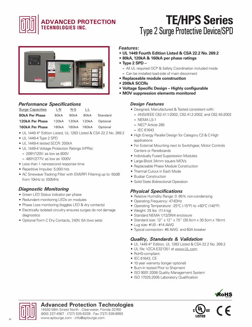
Advanced Protection Technologies14550 58th Street North · Clearwater, Florida 33760(800) 237-4567 · (727) 535-6339 · Fax (727) 539-8955www.aptsurge.com · [email protected]
Design Features• Designed, Manufactured & Tested consistent with:
– ANSI/IEEE C62.41.1-2002, C62.41.2-2002, and C62.45-2002 – NEMA LS-1 – NEC® Article 285 – IEC 61643
• High Energy Parallel Design for Category C3 & C-High applications
• For External Mounting next to Switchgear, Motor Controls Centers or Panelboards
• Individually Fused Suppression Modules• Large-Block 34mm square MOVs• Replaceable Phase Module Construction• Thermal Cutout in Each Mode• Busbar Construction• Solid State Bidirectional Operation
Physical Specifications• Relative Humidity Range: 0 -95% non-condensing• Operating Frequency: 47-63Hz• Operating Temperature: -25°C (-15°F) to +60°C (140°F)• Weight: 25 lbs (11.4 kg)• Standard NEMA 1/12/3R/4 enclosure• Standard size: 12” x 12” x 7.5” (30.5cm x 30.5cm x 19cm)• Lug size: #1/0 - #14 AWG• Typical connection: #6 AWG and 60A breaker
Quality, Standards & Validation• UL 1449 4th Edition, UL 1283 Listed & CSA 22.2 No. 269.2• UL file: VZCA.E321351 at www.UL.com• RoHS-compliant• IEC 61643, CE• 10 year warranty (longer optional)• Burn-In tested Prior to Shipment• ISO 9001:2008 Quality Management System• ISO 17025:2005 Laboratory Qualification
Features:• UL 1449 Fourth Edition Listed & CSA 22.2 No. 269.2• 80kA, 120kA & 160kA per phase ratings• Type 2 SPD –
– All UL required OCP & Safety Coordination included inside – Can be installed load-side of main disconnect
• Replaceable module construction• 200kA SCCRs• Voltage Specific Design – Highly configurable• MOV suppression elements monitored
Performance Specifications
• UL 1449 4th Edition Listed, UL 1283 Listed & CSA 22.2 No. 269.2• UL 1449-4 Type 2 SPD• UL 1449-4 tested SCCR: 200kA• UL 1449-4 Voltage Protection Ratings (VPRs):
– 208Y/120V: as low as 600V – 480Y/277V: as low as 1000V
• Less than 1 nanosecond response time• Repetitive Impulse: 5,000 hits• AC Sinewave Tracking Filter with EMI/RFI Filtering up to -50dB
from 10kHz to 100MHz
Diagnostic Monitoring• Green LED Status indicator per phase• Redundant monitoring LEDs on modules• Phase Loss monitoring (toggles LED & dry contacts)• Electrically isolated circuitry ensures surges do not damage
diagnostics• Optional Form C Dry Contacts, 240V, 5A (two sets)
Surge Capacities L-N N-G L-L
80kA Per Phase 80kA 80kA 80kA Standard
120kA Per Phase 120kA 120kA 120kA Optional
160kA Per Phase 160kA 160kA 160kA Optional
24
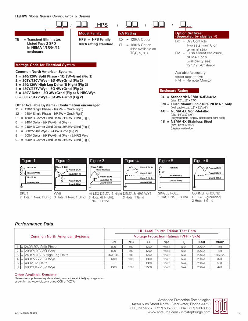
Advanced Protection Technologies14550 58th Street North · Clearwater, Florida 33760
(800) 237-4567 · (727) 535-6339 · Fax (727) 539-8955www.aptsurge.com · [email protected]
TE/HPS MODEL NUMBER CONFIGURATOR & OPTIONS
Common North American SystemsUL 1449 Fourth Edition Test Data
Voltage Protection Ratings (VPR - 3kA)L-N N-G L-L Type In SCCR MCOV
1 = 240/120V Split Phase 800 600 1200 Type 2 5kA 200kA 150
2 = 208Y/120V 3� Wye 800 600 1200 Type 2 5kA 200kA 150
3 = 240Y/120V B High Leg Delta 800/1200 600 1200 Type 2 5kA 200kA 150 / 320
4 = 480Y/277V 3� Wye 1200 1000 1800 Type 2 5kA 200kA 320
5 = 480V 3� Delta — — 1800 Type 2 5kA 200kA 550
8 = 600Y/347V 3� Wye 1500 1200 2500 Type 2 5kA 200kA 420
Other Available Systems:Please see supplementary data sheet, contact us at [email protected] or confirm at www.UL.com using CCN of VZCA.
Performance Data
TE = Transient Eliminator, Listed Type 2 SPD in NEMA 1/3R/04/12 enclosure
Voltage Code for Electrical System
Model Family kA Rating Option Suffixes (Seperated by slashes -/)DC = Dry Contacts
Two sets Form C on terminal strip
FM = Flush Mount enclosure, NEMA 1 only(wall cavity size: 12”x12”x6” deep)
Available Accessory (order separately):RM = Remote Monitor
CX = 120kA Option
CL = 160kA Option(Not Available on TE/8, 9, 91)
HPS = HPS Family80kA rating standard
ll / llHPS / ll / ll / l...
Enclosure Rating
04 = Standard: NEMA 1/3R/04/12 (size: 12” x 12” x 7.5”)
FM = Flush Mount Enclosure, NEMA 1 only(wall cavity size: 12” x 12” x 6”)
4X = NEMA 4X Non-Metallic (size: 14” x 12”x 6”)(polycarbonate, display inside clear front door)
4S = NEMA 4X Stainless Steel (size: 12" x 12"x 6")(display inside door)
Figure 1 Figure 2 Figure 3 Figure 4 Figure 5 Figure 6
SPLIT2 Hots, 1 Neu, 1 Grnd
HI-LEG DELTA (B High)3 Hots, (B HIGH), 1 Neu, 1 Grnd
SINGLE POLE1 Hot, 1 Neu, 1 Grnd
WYE3 Hots, 1 Neu, 1 Grnd
DELTA & HRG WYE3 Hots, 1 Grnd
CORNER GROUNDDELTA (B grounded)2 Hots, 1 Grnd
Hot (BLK)
Hot (BLK)
Neutral (WHT)V
V
}}
Ground (GRN)}
Phase A (BLK)Phase B (BLK)
Neutral (WHT)
Phase C (BLK)
Ground (GRN)
A
C
N
V
B
Phase A (BLK)Phase B (ORNG)
Neutral (WHT)
Phase C (BLK)
Ground (GRN)
}V V}Neutral (WHT)
Hot (BLK)
Ground (GRN)
Phase A (BLK)
Phase C (BLK)
Phase B (BLK)
Ground (GRN)
}V Phase A (BLK)
Phase C (BLK)
Ground (GRN)
V}
Other Available Systems - Confirmation encouraged:11 = 120V Single Phase - 1Ø 2W + Grnd (Fig 5)12 = 240V Single Phase - 1Ø 2W + Grnd (Fig 5)51 = 480V B Corner Grnd Delta, 3Ø 3W+Grnd (Fig 6)6 = 240V Delta - 3Ø 3W+Grnd (Fig 4)61 = 240V B Corner Grnd Delta, 3Ø 3W+Grnd (Fig 6)7 = 380Y/220V Wye - 3Ø 4W+Grnd (Fig 2)9 = 600V Delta - 3Ø 3W+Grnd (Fig 4) & HRG Wye 91 = 600V B Corner Grnd Delta, 3Ø 3W+Grnd (Fig 6)
Common North American Systems:1 = 240/120V Split Phase - 1Ø 3W+Grnd (Fig 1)2 = 208Y/120V Wye - 3Ø 4W+Grnd (Fig 2)3 = 240/120V High Leg Delta (B High) (Fig 3)4 = 480Y/277V Wye - 3Ø 4W+Grnd (Fig 2)5 = 480V Delta - 3Ø 3W+Grnd (Fig 4) & HRG Wye8 = 600Y/347V Wye - 3Ø 4W+Grnd (Fig 2)
2.1.17.RevE #8396 25
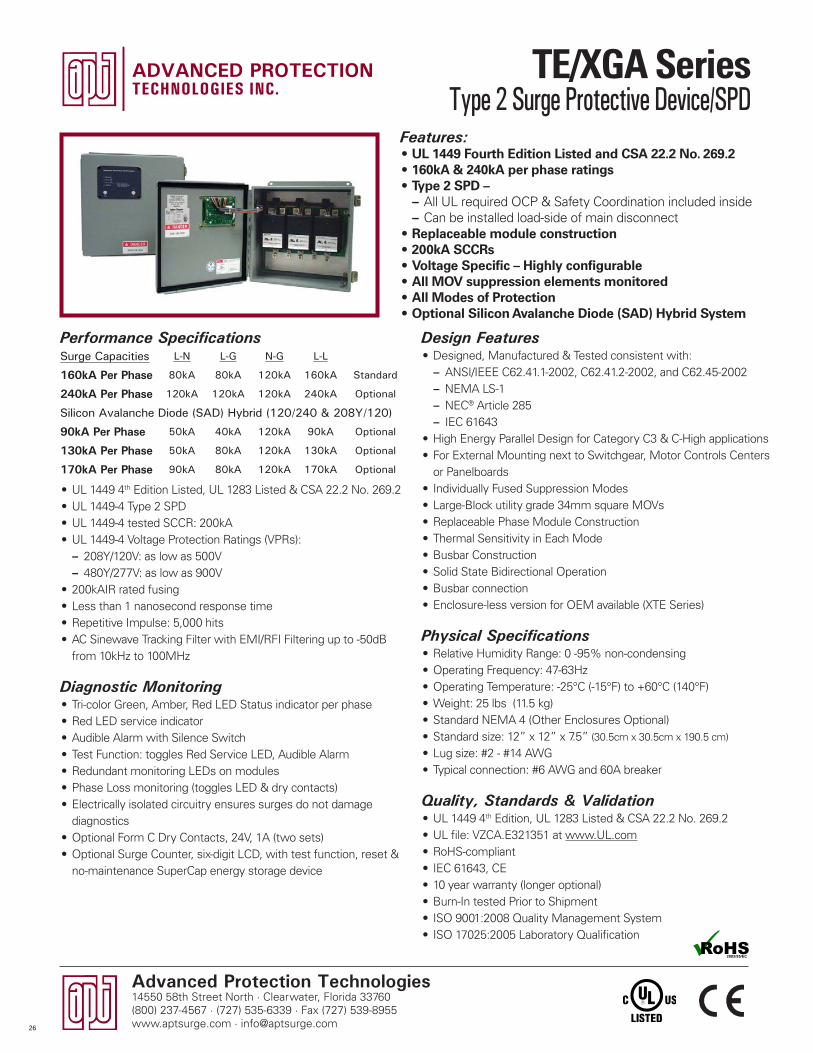
Advanced Protection Technologies14550 58th Street North · Clearwater, Florida 33760(800) 237-4567 · (727) 535-6339 · Fax (727) 539-8955www.aptsurge.com · [email protected]
Design Features• Designed, Manufactured & Tested consistent with:
– ANSI/IEEE C62.41.1-2002, C62.41.2-2002, and C62.45-2002 – NEMA LS-1 – NEC® Article 285 – IEC 61643
• High Energy Parallel Design for Category C3 & C-High applications• For External Mounting next to Switchgear, Motor Controls Centers
or Panelboards• Individually Fused Suppression Modes• Large-Block utility grade 34mm square MOVs• Replaceable Phase Module Construction• Thermal Sensitivity in Each Mode• Busbar Construction• Solid State Bidirectional Operation• Busbar connection• Enclosure-less version for OEM available (XTE Series)
Physical Specifications• Relative Humidity Range: 0 -95% non-condensing• Operating Frequency: 47-63Hz• Operating Temperature: -25°C (-15°F) to +60°C (140°F)• Weight: 25 lbs (11.5 kg)• Standard NEMA 4 (Other Enclosures Optional)• Standard size: 12” x 12” x 7.5” (30.5cm x 30.5cm x 190.5 cm)
• Lug size: #2 - #14 AWG• Typical connection: #6 AWG and 60A breaker
Quality, Standards & Validation• UL 1449 4th Edition, UL 1283 Listed & CSA 22.2 No. 269.2• UL file: VZCA.E321351 at www.UL.com• RoHS-compliant• IEC 61643, CE• 10 year warranty (longer optional)• Burn-In tested Prior to Shipment• ISO 9001:2008 Quality Management System• ISO 17025:2005 Laboratory Qualification
Features:• UL 1449 Fourth Edition Listed and CSA 22.2 No. 269.2• 160kA & 240kA per phase ratings• Type 2 SPD –
– All UL required OCP & Safety Coordination included inside – Can be installed load-side of main disconnect
• Replaceable module construction• 200kA SCCRs• Voltage Specific – Highly configurable• All MOV suppression elements monitored• All Modes of Protection• Optional Silicon Avalanche Diode (SAD) Hybrid System
Performance Specifications
• UL 1449 4th Edition Listed, UL 1283 Listed & CSA 22.2 No. 269.2• UL 1449-4 Type 2 SPD• UL 1449-4 tested SCCR: 200kA• UL 1449-4 Voltage Protection Ratings (VPRs):
– 208Y/120V: as low as 500V – 480Y/277V: as low as 900V
• 200kAIR rated fusing• Less than 1 nanosecond response time• Repetitive Impulse: 5,000 hits• AC Sinewave Tracking Filter with EMI/RFI Filtering up to -50dB
from 10kHz to 100MHz
Diagnostic Monitoring• Tri-color Green, Amber, Red LED Status indicator per phase• Red LED service indicator • Audible Alarm with Silence Switch• Test Function: toggles Red Service LED, Audible Alarm • Redundant monitoring LEDs on modules• Phase Loss monitoring (toggles LED & dry contacts)• Electrically isolated circuitry ensures surges do not damage
diagnostics• Optional Form C Dry Contacts, 24V, 1A (two sets)• Optional Surge Counter, six-digit LCD, with test function, reset &
no-maintenance SuperCap energy storage device
Surge Capacities L-N L-G N-G L-L
160kA Per Phase 80kA 80kA 120kA 160kA Standard
240kA Per Phase 120kA 120kA 120kA 240kA Optional
Silicon Avalanche Diode (SAD) Hybrid (120/240 & 208Y/120)
90kA Per Phase 50kA 40kA 120kA 90kA Optional
130kA Per Phase 50kA 80kA 120kA 130kA Optional
170kA Per Phase 90kA 80kA 120kA 170kA Optional
26

ll / llXGA / ll / ll / ll
TE = Transient Eliminator, Listed Type 2 SPD in NEMA 1 enclosure
XTE = Transient Eliminator, Recognized Type 2 Component Assembly SPD on backplane for installation within gear (display on 6’ cable)
Voltage Code for Electrical System
Model Family Options
TE/XGA MODEL NUMBER CONFIGURATOR & OPTIONS
Figure 1 Figure 2 Figure 3 Figure 4 Figure 5 Figure 6
SPLIT2 Hots, 1 Neu, 1 Grnd
HI-LEG DELTA (B High)3 Hots, (B HIGH), 1 Neu, 1 Grnd
SINGLE POLE1 Hot, 1 Neu, 1 Grnd
WYE3 Hots, 1 Neu, 1 Grnd
DELTA & HRG WYE3 Hots, 1 Grnd
CORNER GROUNDDELTA (B grounded)2 Hots, 1 Grnd
Common North American SystemsUL 1449 Fourth Edition Test Data
Voltage Protection Ratings (VPR - 3kA)L-N L-G N-G L-L Type In SCCR MCOV
01 = 240/120V Split Phase 600 600 600 900 Type 2 5kA 200kA 15002 = 208Y/120V 3� Wye 600 600 600 900 Type 2 5kA 200kA 15003 = 240Y/120V B High Leg Delta 600/900 600/900 600 900/1500 Type 2 5kA 200kA 150 / 32004 = 480Y/277V 3� Wye 900 900 800 1500 Type 2 5kA 200kA 32005 = 480V 3� Delta — 1500 — 1800 Type 2 5kA 200kA 55008 = 600Y/347V 3� Wye 1200 1500 1200 2500 Type 2 5kA 200kA 420
SAD Models01 = 240/120V Split Phase 500 600 600 800 Type 2 5kA 200kA 13802 = 208Y/120V 3� Wye 500 600 600 800 Type 2 5kA 200kA 138
Hot (BLK)
Hot (BLK)
Neutral (WHT)V
V
}}
Ground (GRN)}
Phase A (BLK)Phase B (BLK)
Neutral (WHT)
Phase C (BLK)
Ground (GRN)
A
C
N
V
B
Phase A (BLK)Phase B (ORNG)
Neutral (WHT)
Phase C (BLK)
Ground (GRN)
}V V}Neutral (WHT)
Hot (BLK)
Ground (GRN)
Phase A (BLK)
Phase C (BLK)
Phase B (BLK)
Ground (GRN)
}V Phase A (BLK)
Phase C (BLK)
Ground (GRN)
V}
/24 = 240kA Option
/09 = 090kA SAD option (120/240V & 208Y/120)
/13 = 130kA SAD option (120/240V & 208Y/120)
/17 = 170kA SAD option (120/240V & 208Y/120)
XGA = XGA Family160kA rating standard
Performance Data
Other Available Systems:Please see supplementary data sheet, contact us at [email protected] or confirm at www.UL.com using CCN of VZCA.
Other Available Systems - Confirmation encouraged:11 = 120V Single Phase - 1� 2W + Grnd (Fig 5)12 = 240V Single Phase - 1� 2W + Grnd (Fig 5)51 = 480V B Corner Grnd Delta, 3� 3W+Grnd (Fig 6)6 = 240V Delta - 3� 3W+Grnd (Fig 4)61 = 240V B Corner Grnd Delta, 3� 3W+Grnd (Fig 6)7 = 380Y/220V Wye - 3� 4W+Grnd (Fig 2)9 = 600V Delta - 3� 3W+Grnd (Fig 4) & HRG Wye 91 = 600V B Corner Grnd Delta, 3� 3W+Grnd (Fig 6)
Common North American Systems:1 = 240/120V Split Phase - 1Ø 3W+Grnd (Fig 1)2 = 208Y/120V Wye - 3Ø 4W+Grnd (Fig 2)3 = 240/120V High Leg Delta (B High) (Fig 3)4 = 480Y/277V Wye - 3Ø 4W+Grnd (Fig 2)5 = 480V Delta - 3Ø 3W+Grnd (Fig 4) & HRG Wye8 = 600Y/347V Wye - 3Ø 4W+Grnd (Fig 2) Enclosure Rating
Surge Current Rating
10.7.16lh.RevE #8391
Advanced Protection Technologies14550 58th Street North · Clearwater, Florida 33760
(800) 237-4567 · (727) 535-6339 · Fax (727) 539-8955www.aptsurge.com · [email protected]
/DC = Dry Contacts
Two sets Form C (24V, 1A)
/SC = Surge Counter, six digit LCD
Available Accessory (order separately):RM = Remote Monitor
04 = Standard: NEMA 1/3R/04/12 (size: 12” x 12” x 7.5”)
FM = Flush Mount Enclosure, NEMA 1 only(wall cavity size: 12” x 12” x 6”)
4X = NEMA 4X Non-Metallic (size: 14” x 12”x 6”)(polycarbonate, display inside clear front door)
4S = NEMA 4X Stainless Steel (size: 12" x 12" x 6")
(display inside door)
(Note: Enclosure-less version for OEM uses XTE prefix)
27
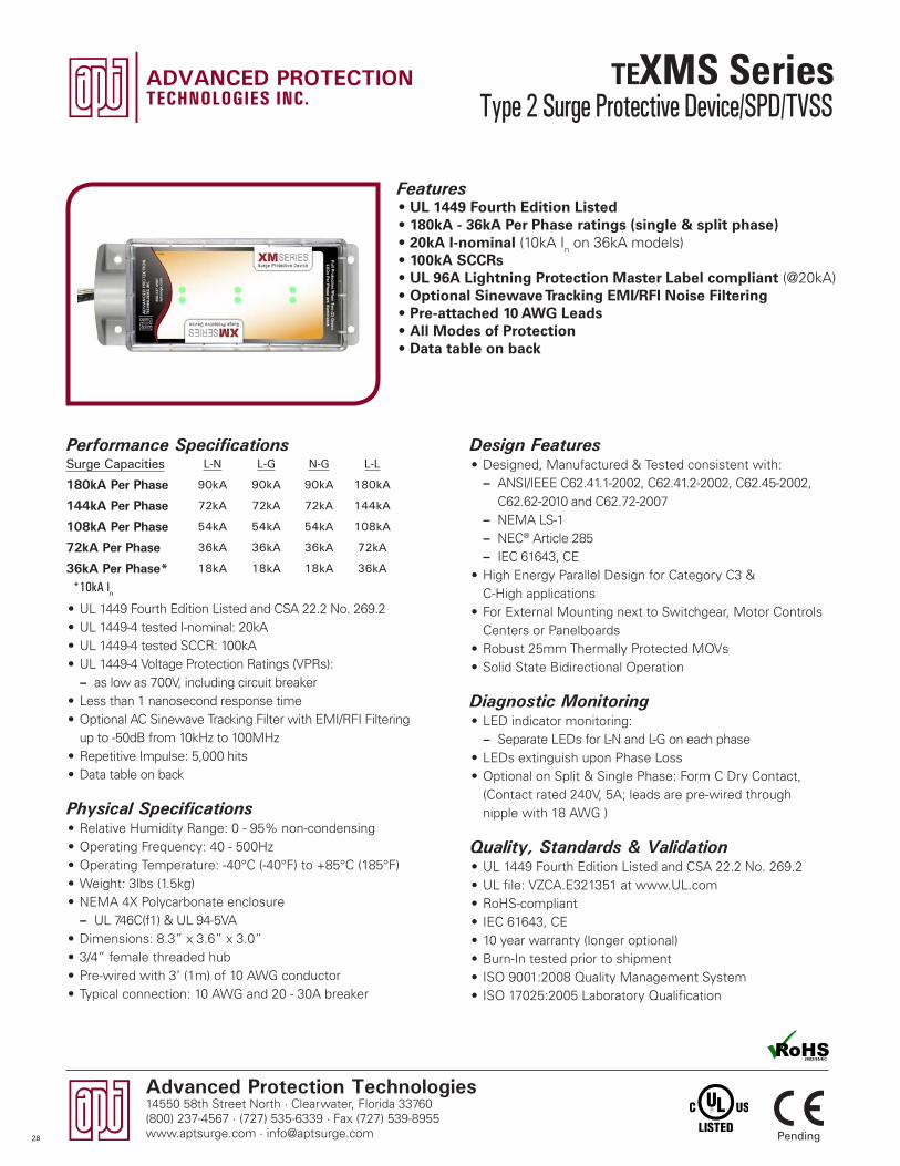
Advanced Protection Technologies14550 58th Street North · Clearwater, Florida 33760(800) 237-4567 · (727) 535-6339 · Fax (727) 539-8955www.aptsurge.com · [email protected]
Design Features• Designed, Manufactured & Tested consistent with:
– ANSI/IEEE C62.41.1-2002, C62.41.2-2002, C62.45-2002, C62.62-2010 and C62.72-2007 – NEMA LS-1 – NEC® Article 285 – IEC 61643, CE
• High Energy Parallel Design for Category C3 & C-High applications
• For External Mounting next to Switchgear, Motor Controls Centers or Panelboards
• Robust 25mm Thermally Protected MOVs• Solid State Bidirectional Operation
Diagnostic Monitoring• LED indicator monitoring:
– Separate LEDs for L-N and L-G on each phase• LEDs extinguish upon Phase Loss• Optional on Split & Single Phase: Form C Dry Contact,
(Contact rated 240V, 5A; leads are pre-wired through nipple with 18 AWG )
Quality, Standards & Validation• UL 1449 Fourth Edition Listed and CSA 22.2 No. 269.2• UL file: VZCA.E321351 at www.UL.com • RoHS-compliant• IEC 61643, CE• 10 year warranty (longer optional)• Burn-In tested prior to shipment• ISO 9001:2008 Quality Management System• ISO 17025:2005 Laboratory Qualification
Features• UL 1449 Fourth Edition Listed • 180kA - 36kA Per Phase ratings (single & split phase)• 20kA I-nominal (10kA In on 36kA models)• 100kA SCCRs• UL 96A Lightning Protection Master Label compliant (@20kA)• Optional Sinewave Tracking EMI/RFI Noise Filtering• Pre-attached 10 AWG Leads• All Modes of Protection• Data table on back
Performance Specifications
• UL 1449 Fourth Edition Listed and CSA 22.2 No. 269.2• UL 1449-4 tested I-nominal: 20kA • UL 1449-4 tested SCCR: 100kA• UL 1449-4 Voltage Protection Ratings (VPRs):
– as low as 700V, including circuit breaker• Less than 1 nanosecond response time• Optional AC Sinewave Tracking Filter with EMI/RFI Filtering
up to -50dB from 10kHz to 100MHz• Repetitive Impulse: 5,000 hits• Data table on back
Physical Specifications• Relative Humidity Range: 0 - 95% non-condensing• Operating Frequency: 40 - 500Hz• Operating Temperature: -40°C (-40°F) to +85°C (185°F)• Weight: 3lbs (1.5kg)• NEMA 4X Polycarbonate enclosure
– UL 746C(f1) & UL 94-5VA• Dimensions: 8.3” x 3.6” x 3.0” • 3/4” female threaded hub• Pre-wired with 3’ (1m) of 10 AWG conductor• Typical connection: 10 AWG and 20 - 30A breaker
Type 2 Surge Protective Device/SPD/TVSS
Pending
Surge Capacities L-N L-G N-G L-L
180kA Per Phase 90kA 90kA 90kA 180kA
144kA Per Phase 72kA 72kA 72kA 144kA
108kA Per Phase 54kA 54kA 54kA 108kA
72kA Per Phase 36kA 36kA 36kA 72kA
36kA Per Phase* 18kA 18kA 18kA 36kA
*10kA In
28
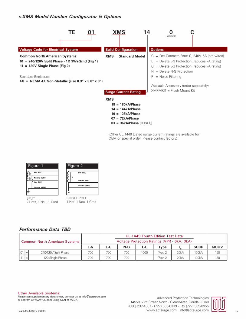
Common North American SystemsUL 1449 Fourth Edition Test Data
Voltage Protection Ratings (VPR - 6kV, 3kA)
L-N L-G N-G L-L Type In SCCR MCOV01 = 240/120V Split Phase 700 700 700 1000 Type 2 20kA 100kA 150
11 = 120 Single Phase 700 700 700 – Type 2 20kA 100kA 150
TEXMS Model Number Configurator & Options
Voltage Code for Electrical System Build Configuration Options
TE 01 XMS 14 0 C
Figure 1
SPLIT2 Hots, 1 Neu, 1 Grnd
Hot (BLK)
Hot (BLK)
Neutral (WHT)V
V
}}
Ground (GRN)
Figure 2
SINGLE POLE1 Hot, 1 Neu, 1 Grnd
V}Neutral (WHT)
Hot (BLK)
Ground (GRN)
Surge Current Rating
C = Dry Contacts Form C, 240V, 5A (pre-wired)
L = Delete L-N Protection (reduces kA rating)G = Delete L-G Protection (reduces kA rating)
N = Delete N-G Protection
F = Noise Filtering
Available Accessory (order separately)XMFMKIT = Flush Mount Kit
XMS = Standard Model
18 = 180kA/Phase14 = 144kA/Phase10 = 108kA/Phase07 = 72kA/Phase03 = 36kA/Phase (10kA In)
(Other UL 1449 Listed surge current ratings are available for OEM or special order. Please contact factory)
Common North American Systems:
01 = 240/120V Split Phase - 1Ø 3W+Grnd (Fig 1)11 = 120V Single Phase (Fig 2)
XMS
Performance Data TBD
Other Available Systems:Please see supplementary data sheet, contact us at [email protected] or confirm at www.UL.com using CCN of VZCA.
9.29.15.lh.RevD #8814
Advanced Protection Technologies14550 58th Street North · Clearwater, Florida 33760
(800) 237-4567 · (727) 535-6339 · Fax (727) 539-8955www.aptsurge.com · [email protected]
4X = NEMA 4X Non-Metallic (size 8.3” x 3.6” x 3”)Standard Enclosure:
(Default)
29
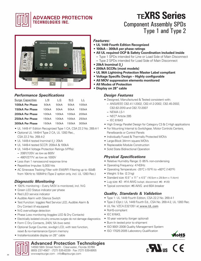
Advanced Protection Technologies14550 58th Street North · Clearwater, Florida 33760(800) 237-4567 · (727) 535-6339 · Fax (727) 539-8955wwwaptsurge.com · [email protected]
Component Assembly SPDsType 1 and Type 2
Design Features• Designed, Manufactured & Tested consistent with:
– ANSI/IEEE C62.41.1-2002, C62.41.2-2002, C62.45-2002, C62.62-2010 and C62.72-2007
– NEMA LS-1 – NEC® Article 285 – IEC 61643
• High Energy Parallel Design for Category C3 & C-High applications• For Mounting Internal to Switchgear, Motor Controls Centers,
Panelboards or Control Panels• Individually Fused & Thermally Protected MOVs• Large-Block 34mm square MOVs• Replaceable Module Construction• Solid State Bidirectional Operation
Physical Specifications• Relative Humidity Range: 0 -95% non-condensing• Operating Frequency: 47-63Hz• Operating Temperature: -25°C (-15°F) to +60°C (140°F)• Weight: 5 lbs (2.3 kg)• Standard size: 6.5” x 11” x 4.5” (16.5cm x 29.9cm x 11.4cm)
• Lug size: #2 - #14 AWG (w/opt. disconnect: #6 - #1/0)
• Typical connection: #6 AWG and 60A breaker
Quality, Standards & Validation• Type 1: UL 1449 Fourth Edition, CSA 22.2 No. 269.4-1• Type 2 (Opt.): UL 1449 Fourth Ed., CSA No. 269.4-2, UL 1283 Rec.• UL file: VZCA.E321351 at www.UL.com• RoHS-compliant• IEC 61643, • 10 year warranty (longer optional)• Burn-In tested prior to shipment• ISO 9001:2008 Quality Management System• ISO 17025:2005 Laboratory Qualification
Features:• UL 1449 Fourth Edition Recognized• 100kA – 300kA per phase ratings• All UL required OCP & Safety Coordination included inside
– Type 1 SPDs intended for Line or Load Side of Main Disconnect – Type 2 SPDs intended for Load Side of Main Disconnect
• 20kA Inominal (In) • 200kA SCCRs (most models)• UL 96A Lightning Protection Master Label compliant • Voltage Specific Design – Highly configurable• All MOV suppression elements monitored• All Modes of Protection• Display on 28” cable
Performance Specifications
• UL 1449 4th Edition Recognized Type 1 CA, CSA 22.2 No. 269.4-1• Optional UL 1449-4 Type 2 CA, UL 1283 Rec.,
CSA 22.2 No. 269.4-2• UL 1449-4 tested Inominal (In): 20kA• UL 1449-4 tested SCCR: 200kA & 100kA• UL 1449-4 Voltage Protection Ratings (VPRs):
– 208Y/120V: as low as 600V – 480Y/277V: as low as 1000V
• Less than 1 nanosecond response time• Repetitive Impulse: 5,000 hits• AC Sinewave Tracking Filter with EMI/RFI Filtering up to -50dB
from 10kHz to 100MHz (Type 2 option only, incl. UL 1283 Rec.)
Diagnostic Monitoring• 100% monitoring – Every MOV is monitored, incl. N-G• Green LED Status indicator per phase• Red LED service indicator • Audible Alarm with Silence Switch• Test Function: toggles Red Service LED, Audible Alarm &
Dry Contact (if equipped)• N-G overvoltage detection• Phase Loss monitoring (toggles LED & Dry Contacts)• Electrically isolated circuitry ensures surges do not damage diagnostics• Form C Dry Contacts, 240V, 5A (two sets)• Optional Surge Counter, six-digit LCD, with test function,
reset & no-maintenance Eprom memory• Installer-locatable display on 28” cable
Surge Capacities L-N L-G N-G L-L
100kA Per Phase 50kA 50kA 50kA 100kA
150kA Per Phase 100kA 50kA 50kA 150kA
200kA Per Phase 100kA 100kA 100kA 200kA
250kA Per Phase 150kA 100kA 100kA 250kA
300kA Per Phase 150kA 150kA 150kA 300kA
30
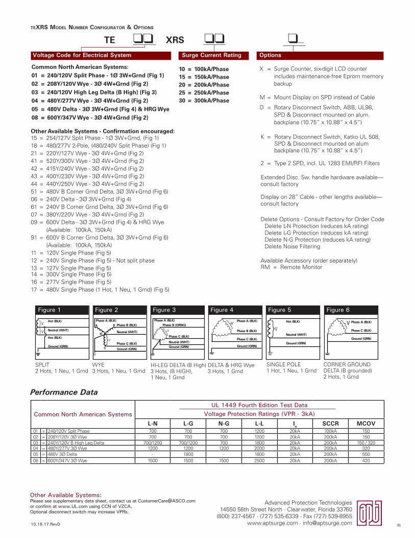
Advanced Protection Technologies14550 58th Street North · Clearwater, Florida 33760
(800) 237-4567 · (727) 535-6339 · Fax (727) 539-8955www.aptsurge.com · [email protected]
TEXRS MODEL NUMBER CONFIGURATOR & OPTIONS
Voltage Code for Electrical System Surge Current Rating Options
TE ll XRS ll l...
Common North American SystemsUL 1449 Fourth Edition Test Data
Voltage Protection Ratings (VPR - 3kA)
L-N L-G N-G L-L In SCCR MCOV01 = 240/120V Split Phase 700 700 700 1200 20kA 100kA 15002 = 208Y/120V 3� Wye 700 700 700 1200 20kA 200kA 15003 = 240Y/120V B High Leg Delta 700/1200 700/1200 700 1800 20kA 200kA 150 / 32004 = 480Y/277V 3� Wye 1200 1200 1200 2000 20kA 200kA 32005 = 480V 3� Delta - 1800 - 1800 20kA 200kA 55008 = 600Y/347V 3� Wye 1500 1500 1500 2500 20kA 200kA 420
X = Surge Counter, six-digit LCD counter includes maintenance-free Eprom memory backup
M = Mount Display on SPD instead of Cable
D = Rotary Disconnect Switch, ABB, UL98, SPD & Disconnect mounted on alum. backplane (10.75” x 10.88” x 4.5”)
K = Rotary Disconnect Switch, Katko UL 508, SPD & Disconnect mounted on alum backplane (10.75” x 10.88” x 4.5”)
2 = Type 2 SPD, incl. UL 1283 EMI/RFI Filters
Extended Disc. Sw. handle hardware available—consult factory
Display on 28” Cable - other lengths available— consult factory
Delete Options - Consult Factory for Order CodeDelete L-N Protection (reduces kA rating)Delete L-G Protection (reduces kA rating)Delete N-G Protection (reduces kA rating)Delete Noise Filtering
Available Accessory (order separately)RM = Remote Monitor
10 = 100kA/Phase15 = 150kA/Phase20 = 200kA/Phase25 = 250kA/Phase30 = 300kA/Phase
Common North American Systems:
01 = 240/120V Split Phase - 1Ø 3W+Grnd (Fig 1)
02 = 208Y/120V Wye - 3Ø 4W+Grnd (Fig 2)
03 = 240/120V High Leg Delta (B High) (Fig 3)
04 = 480Y/277V Wye - 3Ø 4W+Grnd (Fig 2)
05 = 480V Delta - 3Ø 3W+Grnd (Fig 4) & HRG Wye
08 = 600Y/347V Wye - 3Ø 4W+Grnd (Fig 2)
Performance Data
Figure 1 Figure 2 Figure 3 Figure 4 Figure 5 Figure 6
SPLIT2 Hots, 1 Neu, 1 Grnd
HI-LEG DELTA (B High)3 Hots, (B HIGH), 1 Neu, 1 Grnd
SINGLE POLE1 Hot, 1 Neu, 1 Grnd
WYE3 Hots, 1 Neu, 1 Grnd
DELTA & HRG Wye3 Hots, 1 Grnd
CORNER GROUNDDELTA (B grounded)2 Hots, 1 Grnd
Hot (BLK)
Hot (BLK)
Neutral (WHT)V
V
}}
Ground (GRN)}
Phase A (BLK)Phase B (BLK)
Neutral (WHT)
Phase C (BLK)
Ground (GRN)
A
C
N
V
B
Phase A (BLK)Phase B (ORNG)
Neutral (WHT)
Phase C (BLK)
Ground (GRN)
}V V}Neutral (WHT)
Hot (BLK)
Ground (GRN)
Phase A (BLK)
Phase C (BLK)
Phase B (BLK)
Ground (GRN)
}V Phase A (BLK)
Phase C (BLK)
Ground (GRN)
V}
Other Available Systems - Confirmation encouraged:15 = 254/127V Split Phase - 1� 3W+Grnd, (Fig 1)18 = 480/277V 2-Pole, (480/240V Split Phase) (Fig 1)21 = 220Y/127V Wye - 3� 4W+Grnd (Fig 2)41 = 520Y/300V Wye - 3� 4W+Grnd (Fig 2)42 = 415Y/240V Wye - 3� 4W+Grnd (Fig 2)43 = 400Y/230V Wye - 3� 4W+Grnd (Fig 2)44 = 440Y/250V Wye - 3� 4W+Grnd (Fig 2)51 = 480V B Corner Grnd Delta, 3� 3W+Grnd (Fig 6)06 = 240V Delta - 3� 3W+Grnd (Fig 4)61 = 240V B Corner Grnd Delta, 3� 3W+Grnd (Fig 6)07 = 380Y/220V Wye - 3� 4W+Grnd (Fig 2)09 = 600V Delta - 3� 3W+Grnd (Fig 4) & HRG Wye
(Available: 100kA, 150kA)91 = 600V B Corner Grnd Delta, 3� 3W+Grnd (Fig 6)
(Available: 100kA, 150kA)11 = 120V Single Phase (Fig 5)12 = 240V Single Phase (Fig 5) - Not split phase13 = 127V Single Phase (Fig 5)14 = 300V Single Phase (Fig 5)16 = 277V Single Phase (Fig 5)17 = 480V Single Phase (1 Hot, 1 Neu, 1 Grnd) (Fig 5)
Other Available Systems:Please see supplementary data sheet, contact us at [email protected] or confirm at www.UL.com using CCN of VZCA.Optional disconnect switch may increase VPRs.
10.16.17.RevD 31
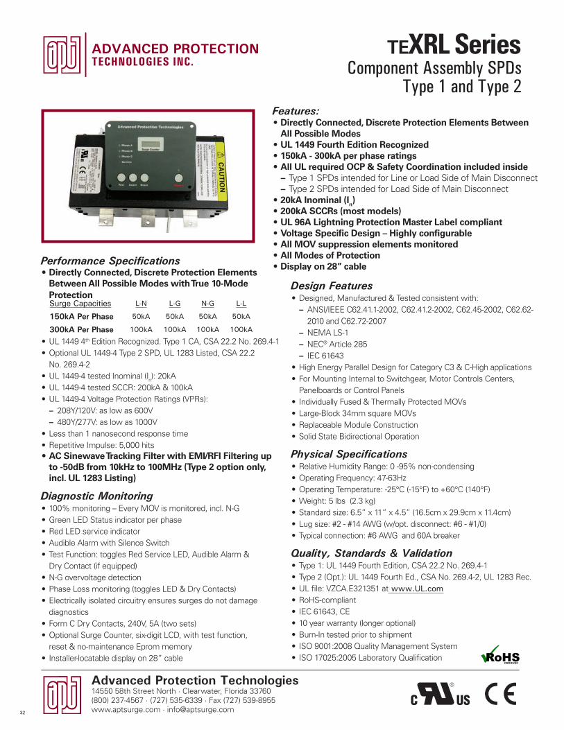
Advanced Protection Technologies14550 58th Street North · Clearwater, Florida 33760(800) 237-4567 · (727) 535-6339 · Fax (727) 539-8955www.aptsurge.com · [email protected]
Design Features• Designed, Manufactured & Tested consistent with:
– ANSI/IEEE C62.41.1-2002, C62.41.2-2002, C62.45-2002, C62.62-2010 and C62.72-2007
– NEMA LS-1 – NEC® Article 285 – IEC 61643
• High Energy Parallel Design for Category C3 & C-High applications• For Mounting Internal to Switchgear, Motor Controls Centers,
Panelboards or Control Panels• Individually Fused & Thermally Protected MOVs• Large-Block 34mm square MOVs• Replaceable Module Construction• Solid State Bidirectional Operation
Physical Specifications• Relative Humidity Range: 0 -95% non-condensing• Operating Frequency: 47-63Hz• Operating Temperature: -25°C (-15°F) to +60°C (140°F)• Weight: 5 lbs (2.3 kg)• Standard size: 6.5” x 11” x 4.5” (16.5cm x 29.9cm x 11.4cm)• Lug size: #2 - #14 AWG (w/opt. disconnect: #6 - #1/0)• Typical connection: #6 AWG and 60A breaker
Quality, Standards & Validation• Type 1: UL 1449 Fourth Edition, CSA 22.2 No. 269.4-1• Type 2 (Opt.): UL 1449 Fourth Ed., CSA No. 269.4-2, UL 1283 Rec.• UL file: VZCA.E321351 at www.UL.com• RoHS-compliant• IEC 61643, CE• 10 year warranty (longer optional)• Burn-In tested prior to shipment• ISO 9001:2008 Quality Management System• ISO 17025:2005 Laboratory Qualification
Features:• Directly Connected, Discrete Protection Elements Between
All Possible Modes• UL 1449 Fourth Edition Recognized • 150kA - 300kA per phase ratings• All UL required OCP & Safety Coordination included inside
– Type 1 SPDs intended for Line or Load Side of Main Disconnect – Type 2 SPDs intended for Load Side of Main Disconnect
• 20kA Inominal (In) • 200kA SCCRs (most models)• UL 96A Lightning Protection Master Label compliant• Voltage Specific Design – Highly configurable• All MOV suppression elements monitored• All Modes of Protection• Display on 28” cablePerformance Specifications
• Directly Connected, Discrete Protection Elements Between All Possible Modes with True 10-Mode Protection
• UL 1449 4th Edition Recognized. Type 1 CA, CSA 22.2 No. 269.4-1• Optional UL 1449-4 Type 2 SPD, UL 1283 Listed, CSA 22.2
No. 269.4-2• UL 1449-4 tested Inominal (In): 20kA• UL 1449-4 tested SCCR: 200kA & 100kA• UL 1449-4 Voltage Protection Ratings (VPRs):
– 208Y/120V: as low as 600V – 480Y/277V: as low as 1000V
• Less than 1 nanosecond response time• Repetitive Impulse: 5,000 hits• AC Sinewave Tracking Filter with EMI/RFI Filtering up
to -50dB from 10kHz to 100MHz (Type 2 option only, incl. UL 1283 Listing)
Diagnostic Monitoring• 100% monitoring – Every MOV is monitored, incl. N-G• Green LED Status indicator per phase• Red LED service indicator • Audible Alarm with Silence Switch• Test Function: toggles Red Service LED, Audible Alarm &
Dry Contact (if equipped)• N-G overvoltage detection• Phase Loss monitoring (toggles LED & Dry Contacts)• Electrically isolated circuitry ensures surges do not damage
diagnostics• Form C Dry Contacts, 240V, 5A (two sets)• Optional Surge Counter, six-digit LCD, with test function,
reset & no-maintenance Eprom memory• Installer-locatable display on 28” cable
Surge Capacities L-N L-G N-G L-L
150kA Per Phase 50kA 50kA 50kA 50kA
300kA Per Phase 100kA 100kA 100kA 100kA
Component Assembly SPDsType 1 and Type 2
32

TEXRL 10-MODE MODEL NUMBER CONFIGURATOR & OPTIONS
Voltage Code for Electrical System Surge Current Rating Options
TE ll XRL ll l...
Figure 1 Figure 2 Figure 3
SPLIT2 Hots, 1 Neu, 1 Grnd
HI-LEG DELTA (B High)3 Hots, (B HIGH), 1 Neu, 1 Grnd
WYE3 Hots, 1 Neu, 1 Grnd
Common North American SystemsUL 1449 Fourth Edition Test Data
Voltage Protection Ratings (VPR - 3kA)L-N L-G N-G L-L In SCCR MCOV
01 = 240/120V Split Phase 700 700 700 1000 20kA 100kA 15002 = 208Y/120V 3Ø Wye 700 700 700 1000 20kA 200kA 15003 = 240Y/120V B High Leg Delta 800/1500 700/1200 700 1800 20kA 200kA 150 / 32004 = 480Y/277V 3Ø Wye 1200 1200 1200 1800 20kA 200kA 320
Other Available Systems - Confirmation Encouraged:15 = 254/127V Split Phase 700 700 700 1000 20kA 100kA 18021 = 220Y/127V 3Ø Wye 700 700 700 1000 20kA 100kA 18042 = 415Y/240V 3Ø Wye 1200 1200 1200 1800 20kA 200kA 32043 = 400Y/230V 3Ø Wye 1200 1200 1200 1800 20kA 200kA 32044 = 440Y/250V 3Ø Wye 1200 1200 1200 1800 20kA 200kA 32007 = 380Y/220V 3Ø Wye 1200 1200 1200 1800 20kA 200kA 320
Other Available Systems:Please see supplementary data sheet, contact us at [email protected] or confirm at www.UL.com using CCN of VZCA.Optional disconnect may increase VPRs.
Hot (BLK)
Hot (BLK)
Neutral (WHT)V
V
}}
Ground (GRN)}
Phase A (BLK)Phase B (BLK)
Neutral (WHT)
Phase C (BLK)
Ground (GRN)
A
C
N
V
B
Phase A (BLK)Phase B (ORNG)
Neutral (WHT)
Phase C (BLK)
Ground (GRN)
}V
X = Surge Counter, six-digit LCD counter includes maintenance-free Eprom memory backup
M = Mount Display on SPD instead of cable
D = Rotary Disconnect Switch, ABB, UL98, SPD & Disconnect mounted on alum. backplane (10.75” x 10.88” x 4.5”)
K = Rotary Disconnect Switch, Katko UL 508, SPD & Disconnect mounted on alum. backplane (10.75” x 10.88” x 4.5”)
2 = Type 2 SPD, incl. UL 1283 EMI/RFI Filters
Extended Disc. Sw. handle hardware available—consult factory
Display on 28” Cable - other lengths available—consult factory
Delete Options - Consult Factory for Order CodeDelete L-N Protection (reduces kA rating)Delete L-G Protection (reduces kA rating)Delete N-G Protection (reduces kA rating)Delete Noise Filtering
Available Accessory (order separately)RM = Remote Monitor
Other Available Systems - Confirmation encouraged:15 = 254/127V Split Phase - 1� 3W+Grnd, (Fig 1)18 = 480/277V 2-Pole, (480/240V Split Phase) (Fig 1) 21 = 220Y/127V Wye - 3� 4W+Grnd (Fig 2)42 = 415Y/240V Wye - 3� 4W+Grnd (Fig 2)43 = 400Y/230V Wye - 3� 4W+Grnd (Fig 2)44 = 440Y/250V Wye - 3� 4W+Grnd (Fig 2)07 = 380Y/220V Wye - 3� 4W+Grnd (Fig 2)
15 = 150kA/Phase30 = 300kA/Phase
Common North American Systems:
01 = 240/120V Split Phase - 1Ø 3W+Grnd, (Fig 1)
02 = 208Y/120V Wye - 3Ø 4W+Grnd, (Fig 2)
03 = 240/120V High Leg Delta (B High), (Fig 3)
04 = 480Y/277V Wye - 3Ø 4W+Grnd, (Fig 2)
Performance Data
10.16.17.lh.RevD #8392
Advanced Protection Technologies14550 58th Street North · Clearwater, Florida 33760
(800) 237-4567 · (727) 535-6339 · Fax (727) 539-8955www.aptsurge.com · [email protected] 33
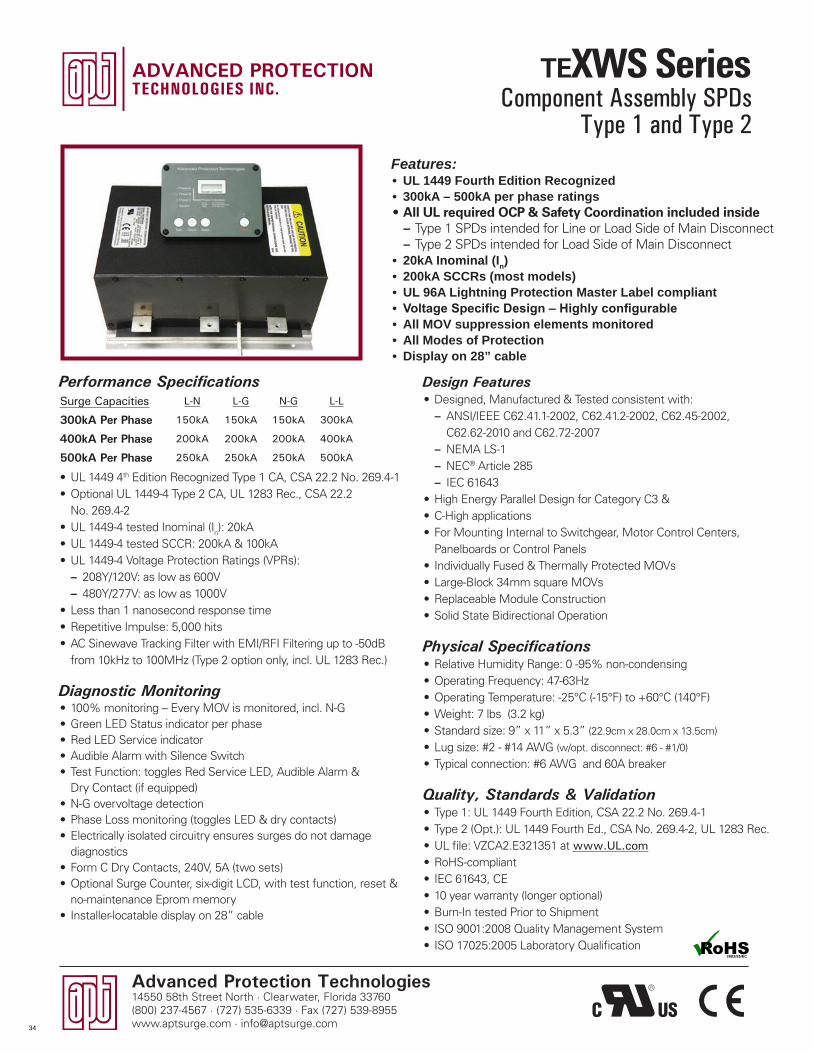
Advanced Protection Technologies14550 58th Street North · Clearwater, Florida 33760(800) 237-4567 · (727) 535-6339 · Fax (727) 539-8955www.aptsurge.com · [email protected]
Design Features• Designed, Manufactured & Tested consistent with:
– ANSI/IEEE C62.41.1-2002, C62.41.2-2002, C62.45-2002, C62.62-2010 and C62.72-2007
– NEMA LS-1 – NEC® Article 285 – IEC 61643
• High Energy Parallel Design for Category C3 & • C-High applications• For Mounting Internal to Switchgear, Motor Control Centers,
Panelboards or Control Panels• Individually Fused & Thermally Protected MOVs• Large-Block 34mm square MOVs• Replaceable Module Construction• Solid State Bidirectional Operation
Physical Specifications• Relative Humidity Range: 0 -95% non-condensing• Operating Frequency: 47-63Hz• Operating Temperature: -25°C (-15°F) to +60°C (140°F)• Weight: 7 lbs (3.2 kg)• Standard size: 9” x 11” x 5.3” (22.9cm x 28.0cm x 13.5cm)
• Lug size: #2 - #14 AWG (w/opt. disconnect: #6 - #1/0)
• Typical connection: #6 AWG and 60A breaker
Quality, Standards & Validation• Type 1: UL 1449 Fourth Edition, CSA 22.2 No. 269.4-1• Type 2 (Opt.): UL 1449 Fourth Ed., CSA No. 269.4-2, UL 1283 Rec.• UL file: VZCA2.E321351 at www.UL.com• RoHS-compliant• IEC 61643, CE• 10 year warranty (longer optional)• Burn-In tested Prior to Shipment• ISO 9001:2008 Quality Management System• ISO 17025:2005 Laboratory Qualification
Features:• UL 1449 Fourth Edition Recognized• 300kA – 500kA per phase ratings• All UL required OCP & Safety Coordination included inside
– Type 1 SPDs intended for Line or Load Side of Main Disconnect – Type 2 SPDs intended for Load Side of Main Disconnect
• 20kA Inominal (In)• 200kA SCCRs (most models)• UL 96A Lightning Protection Master Label compliant• Voltage Specific Design – Highly configurable• All MOV suppression elements monitored• All Modes of Protection• Display on 28” cable
Performance Specifications
• UL 1449 4th Edition Recognized Type 1 CA, CSA 22.2 No. 269.4-1• Optional UL 1449-4 Type 2 CA, UL 1283 Rec., CSA 22.2
No. 269.4-2• UL 1449-4 tested Inominal (In): 20kA• UL 1449-4 tested SCCR: 200kA & 100kA• UL 1449-4 Voltage Protection Ratings (VPRs):
– 208Y/120V: as low as 600V – 480Y/277V: as low as 1000V
• Less than 1 nanosecond response time• Repetitive Impulse: 5,000 hits• AC Sinewave Tracking Filter with EMI/RFI Filtering up to -50dB
from 10kHz to 100MHz (Type 2 option only, incl. UL 1283 Rec.)
Diagnostic Monitoring• 100% monitoring – Every MOV is monitored, incl. N-G• Green LED Status indicator per phase• Red LED Service indicator • Audible Alarm with Silence Switch• Test Function: toggles Red Service LED, Audible Alarm &
Dry Contact (if equipped)• N-G overvoltage detection• Phase Loss monitoring (toggles LED & dry contacts)• Electrically isolated circuitry ensures surges do not damage
diagnostics• Form C Dry Contacts, 240V, 5A (two sets)• Optional Surge Counter, six-digit LCD, with test function, reset &
no-maintenance Eprom memory• Installer-locatable display on 28” cable
Surge Capacities L-N L-G N-G L-L
300kA Per Phase 150kA 150kA 150kA 300kA
400kA Per Phase 200kA 200kA 200kA 400kA
500kA Per Phase 250kA 250kA 250kA 500kA
Component Assembly SPDsType 1 and Type 2
34
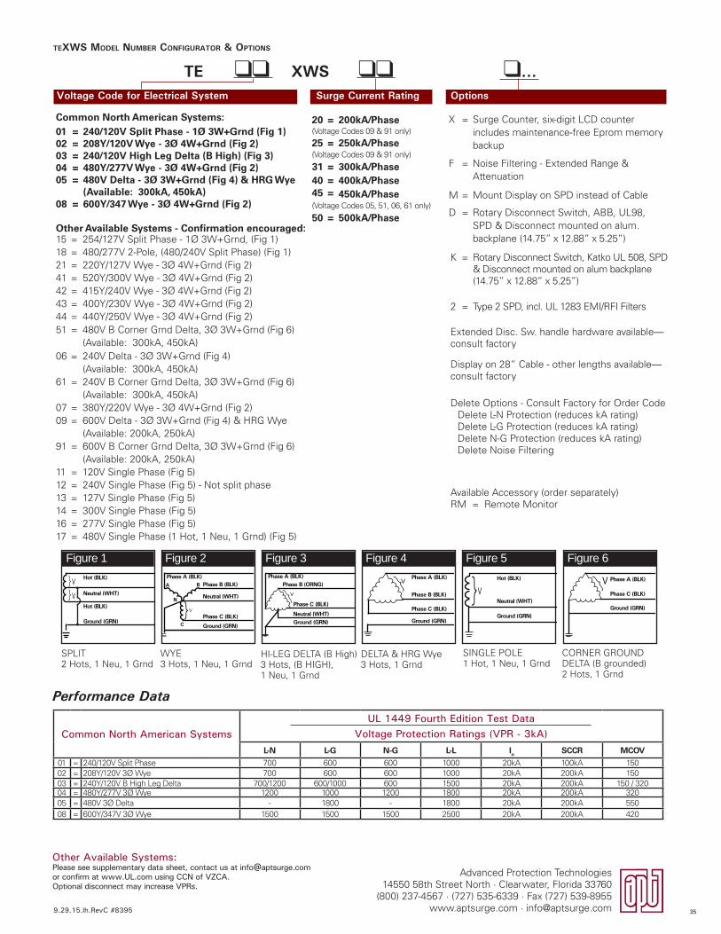
Advanced Protection Technologies14550 58th Street North · Clearwater, Florida 33760
(800) 237-4567 · (727) 535-6339 · Fax (727) 539-8955www.aptsurge.com · [email protected]
TEXWS MODEL NUMBER CONFIGURATOR & OPTIONS
Voltage Code for Electrical System Surge Current Rating Options
TE ll XWS ll l...
Common North American SystemsUL 1449 Fourth Edition Test Data
Voltage Protection Ratings (VPR - 3kA)L-N L-G N-G L-L In SCCR MCOV
01 = 240/120V Split Phase 700 600 600 1000 20kA 100kA 15002 = 208Y/120V 3� Wye 700 600 600 1000 20kA 200kA 15003 = 240Y/120V B High Leg Delta 700/1200 600/1000 600 1500 20kA 200kA 150 / 32004 = 480Y/277V 3� Wye 1200 1000 1200 1800 20kA 200kA 32005 = 480V 3� Delta - 1800 - 1800 20kA 200kA 55008 = 600Y/347V 3� Wye 1500 1500 1500 2500 20kA 200kA 420
Other Available Systems:Please see supplementary data sheet, contact us at [email protected] or confirm at www.UL.com using CCN of VZCA.Optional disconnect may increase VPRs.
X = Surge Counter, six-digit LCD counter includes maintenance-free Eprom memory backup
F = Noise Filtering - Extended Range & Attenuation
M = Mount Display on SPD instead of Cable
D = Rotary Disconnect Switch, ABB, UL98, SPD & Disconnect mounted on alum. backplane (14.75” x 12.88” x 5.25”)
K = Rotary Disconnect Switch, Katko UL 508, SPD & Disconnect mounted on alum backplane (14.75” x 12.88” x 5.25”)
2 = Type 2 SPD, incl. UL 1283 EMI/RFI Filters
Extended Disc. Sw. handle hardware available—consult factory
Display on 28” Cable - other lengths available—consult factory
Delete Options - Consult Factory for Order CodeDelete L-N Protection (reduces kA rating)Delete L-G Protection (reduces kA rating)Delete N-G Protection (reduces kA rating)Delete Noise Filtering
Available Accessory (order separately)RM = Remote Monitor
20 = 200kA/Phase(Voltage Codes 09 & 91 only)
25 = 250kA/Phase(Voltage Codes 09 & 91 only)
31 = 300kA/Phase40 = 400kA/Phase45 = 450kA/Phase(Voltage Codes 05, 51, 06, 61 only)
50 = 500kA/Phase
Common North American Systems:01 = 240/120V Split Phase - 1Ø 3W+Grnd (Fig 1)02 = 208Y/120V Wye - 3Ø 4W+Grnd (Fig 2)03 = 240/120V High Leg Delta (B High) (Fig 3)04 = 480Y/277V Wye - 3Ø 4W+Grnd (Fig 2)05 = 480V Delta - 3Ø 3W+Grnd (Fig 4) & HRG Wye
(Available: 300kA, 450kA)08 = 600Y/347 Wye - 3Ø 4W+Grnd (Fig 2)
Performance Data
Figure 1 Figure 2 Figure 3 Figure 4 Figure 5 Figure 6
SPLIT2 Hots, 1 Neu, 1 Grnd
HI-LEG DELTA (B High)3 Hots, (B HIGH), 1 Neu, 1 Grnd
SINGLE POLE1 Hot, 1 Neu, 1 Grnd
WYE3 Hots, 1 Neu, 1 Grnd
DELTA & HRG Wye3 Hots, 1 Grnd
CORNER GROUNDDELTA (B grounded)2 Hots, 1 Grnd
Hot (BLK)
Hot (BLK)
Neutral (WHT)V
V
}}
Ground (GRN)}
Phase A (BLK)Phase B (BLK)
Neutral (WHT)
Phase C (BLK)
Ground (GRN)
A
C
N
V
B
Phase A (BLK)Phase B (ORNG)
Neutral (WHT)
Phase C (BLK)
Ground (GRN)
}V V}Neutral (WHT)
Hot (BLK)
Ground (GRN)
Phase A (BLK)
Phase C (BLK)
Phase B (BLK)
Ground (GRN)
}V Phase A (BLK)
Phase C (BLK)
Ground (GRN)
V}
Other Available Systems - Confirmation encouraged:15 = 254/127V Split Phase - 1� 3W+Grnd, (Fig 1)18 = 480/277V 2-Pole, (480/240V Split Phase) (Fig 1) 21 = 220Y/127V Wye - 3� 4W+Grnd (Fig 2)41 = 520Y/300V Wye - 3� 4W+Grnd (Fig 2)42 = 415Y/240V Wye - 3� 4W+Grnd (Fig 2)43 = 400Y/230V Wye - 3� 4W+Grnd (Fig 2)44 = 440Y/250V Wye - 3� 4W+Grnd (Fig 2)51 = 480V B Corner Grnd Delta, 3� 3W+Grnd (Fig 6)
(Available: 300kA, 450kA)06 = 240V Delta - 3� 3W+Grnd (Fig 4)
(Available: 300kA, 450kA)61 = 240V B Corner Grnd Delta, 3� 3W+Grnd (Fig 6)
(Available: 300kA, 450kA)07 = 380Y/220V Wye - 3� 4W+Grnd (Fig 2)09 = 600V Delta - 3� 3W+Grnd (Fig 4) & HRG Wye
(Available: 200kA, 250kA)91 = 600V B Corner Grnd Delta, 3� 3W+Grnd (Fig 6)
(Available: 200kA, 250kA)11 = 120V Single Phase (Fig 5)12 = 240V Single Phase (Fig 5) - Not split phase13 = 127V Single Phase (Fig 5)14 = 300V Single Phase (Fig 5)16 = 277V Single Phase (Fig 5)17 = 480V Single Phase (1 Hot, 1 Neu, 1 Grnd) (Fig 5)
9.29.15.lh.RevC #8395 35

Advanced Protection Technologies14550 58th Street North · Clearwater, Florida 33760(800) 237-4567 · (727) 535-6339 · Fax (727) 539-8955www.aptsurge.com · [email protected]
Design Features• Designed, Manufactured & Tested consistent with:
– ANSI/IEEE C62.41.1-2002, C62.41.2-2002, C62.45-2002, C62.62-2010 and C62.72-2007
– NEMA LS-1 – NEC® Article 285 – IEC 61643
• High Energy Parallel Design for Category C3 & C-High applications• For Mounting Internal to Switchgear, Motor Controls Centers,
Panelboards and Control Panels• Individually Fused & Thermally Protected MOVs• Large-Block 34mm square MOVs• Replaceable Module Construction• Solid State Bidirectional Operation
Physical Specifications• Relative Humidity Range: 0 -95% non-condensing• Operating Frequency: 47-63Hz• Operating Temperature: -25°C (-15°F) to +60°C (140°F)• Weight: 7 lbs (3.2 kg)• Standard size: 9” x 11” x 5.3” (22.9cm x 28.0cm x 13.5cm)• Lug size: #2 - #14 AWG (w/opt. disconnect: #6 - #1/0)• Typical connection: #6 AWG and 60A breaker
Quality, Standards & Validation• Type 1: UL 1449 Fourth Edition, CSA 22.2 No. 269.4-1• Type 2 (Opt.): UL 1449 Fourth Ed., CSA No. 269.4-2, UL 1283 Rec.• UL file: VZCA2.E321351 at www.UL.com• RoHS-compliant• IEC 61643, CE• 10 year warranty (longer optional)• Burn-In tested Prior to Shipment• ISO 9001:2008 Quality Management System• ISO 17025:2005 Laboratory Qualification
Features:• Directly Connected, Discrete Protection Elements Between All
Possible Modes• UL 1449 Fourth Edition Recognized• 300kA - 450kA per phase ratings• All UL required OCP & Safety Coordination included inside
– Type 1 SPDs intended for Line or Load Side of Main Disconnect – Type 2 SPDs intended for Load Side of Main Disconnect
• 20kA Inominal (In)• 200kA SCCRs (most models)• UL 96A Lightning Protection Master Label compliant• Voltage Specific Design – Highly configurable• All MOV suppression elements monitored• All Modes of Protection• Display on 28” cable
Performance Specifications• Directly Connected, Discrete Protection Elements
Between All Possible Modes with True 10-Mode Protection
• UL 1449 4th Edition Recognized Type 1 CA, CSA 22.2 No. 269.4-1• Optional UL 1449-4 Type 2 CA, UL 1283 Rec., CSA 22.2
No. 269.4-2• UL 1449-4 tested Inominal (In): 20kA• UL 1449-4 tested SCCR: 200kA & 100kA• UL 1449-4 Voltage Protection Ratings (VPRs):
– 208Y/120V: as low as 600V – 480Y/277V: as low as 1000V
• Less than 1 nanosecond response time• Repetitive Impulse: 5,000 hits• AC Sinewave Tracking Filter with EMI/RFI Filtering up
to -50dB from 10kHz to 100MHz (Type 2 option only, incl. UL 1283 Rec.)
Diagnostic Monitoring• 100% monitoring – Every MOV is monitored, incl. N-G• Green LED Status indicator per phase• Red LED service indicator • Audible Alarm with Silence Switch• Test Function: toggles red service LED, audible alarm & dry
contact (if equipped)• N-G overvoltage detection• Phase Loss monitoring (toggles LED & dry contacts)• Electrically isolated circuitry ensures surges do not damage diagnostics• Form C Dry Contacts, 240V, 5A (two sets)• Optional Surge Counter, six-digit LCD, with test function, reset &
no-maintenance Eprom memory• Installer-locatable display on 28” cable
Surge Capacities L-N L-G N-G L-L
300kA Per Phase 100kA 100kA 100kA 100kA
450kA Per Phase 150kA 150kA 150kA 150kA
Component Assembly SPDsType 1 and Type 2
36
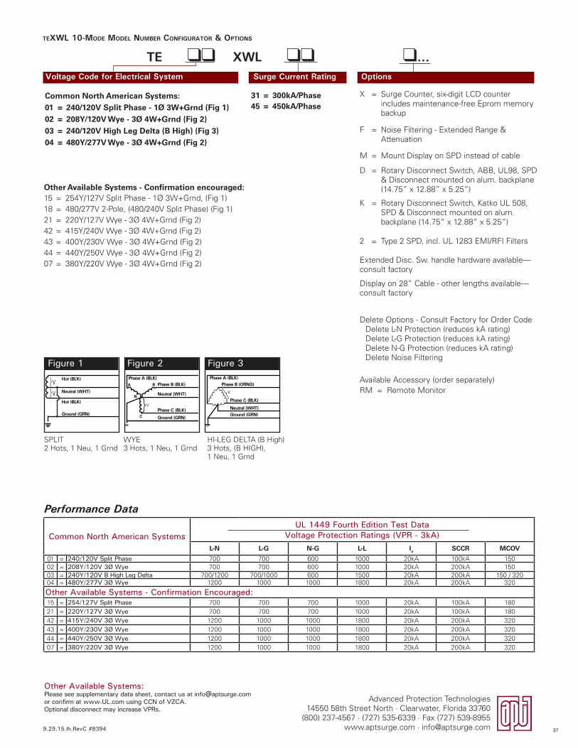
Advanced Protection Technologies14550 58th Street North · Clearwater, Florida 33760
(800) 237-4567 · (727) 535-6339 · Fax (727) 539-8955www.aptsurge.com · [email protected]
TEXWL 10-MODE MODEL NUMBER CONFIGURATOR & OPTIONS
Voltage Code for Electrical System Surge Current Rating Options
TE ll XWL ll l...
Figure 1 Figure 2 Figure 3
SPLIT2 Hots, 1 Neu, 1 Grnd
HI-LEG DELTA (B High)3 Hots, (B HIGH), 1 Neu, 1 Grnd
WYE3 Hots, 1 Neu, 1 Grnd
Common North American SystemsUL 1449 Fourth Edition Test Data
Voltage Protection Ratings (VPR - 3kA)L-N L-G N-G L-L In SCCR MCOV
01 = 240/120V Split Phase 700 700 600 1000 20kA 100kA 15002 = 208Y/120V 3Ø Wye 700 700 600 1000 20kA 200kA 15003 = 240Y/120V B High Leg Delta 700/1200 700/1000 600 1500 20kA 200kA 150 / 32004 = 480Y/277V 3Ø Wye 1200 1000 1000 1800 20kA 200kA 320
Other Available Systems - Confirmation Encouraged:15 = 254/127V Split Phase 700 700 700 1000 20kA 100kA 18021 = 220Y/127V 3Ø Wye 700 700 700 1000 20kA 100kA 18042 = 415Y/240V 3Ø Wye 1200 1000 1000 1800 20kA 200kA 32043 = 400Y/230V 3Ø Wye 1200 1000 1000 1800 20kA 200kA 32044 = 440Y/250V 3Ø Wye 1200 1000 1000 1800 20kA 200kA 32007 = 380Y/220V 3Ø Wye 1200 1000 1000 1800 20kA 200kA 320
Other Available Systems:Please see supplementary data sheet, contact us at [email protected] confirm at www.UL.com using CCN of VZCA.Optional disconnect may increase VPRs.
Hot (BLK)
Hot (BLK)
Neutral (WHT)V
V
}}
Ground (GRN)}
Phase A (BLK)Phase B (BLK)
Neutral (WHT)
Phase C (BLK)
Ground (GRN)
A
C
N
V
B
Phase A (BLK)Phase B (ORNG)
Neutral (WHT)
Phase C (BLK)
Ground (GRN)
}V
X = Surge Counter, six-digit LCD counter includes maintenance-free Eprom memory backup
F = Noise Filtering - Extended Range & Attenuation
M = Mount Display on SPD instead of cable
D = Rotary Disconnect Switch, ABB, UL98, SPD & Disconnect mounted on alum. backplane (14.75” x 12.88” x 5.25”)
K = Rotary Disconnect Switch, Katko UL 508, SPD & Disconnect mounted on alum. backplane (14.75” x 12.88” x 5.25”)
2 = Type 2 SPD, incl. UL 1283 EMI/RFI Filters
Extended Disc. Sw. handle hardware available—consult factory
Display on 28” Cable - other lengths available—consult factory
Delete Options - Consult Factory for Order CodeDelete L-N Protection (reduces kA rating)Delete L-G Protection (reduces kA rating)Delete N-G Protection (reduces kA rating)Delete Noise Filtering
Available Accessory (order separately)RM = Remote Monitor
Other Available Systems - Confirmation encouraged:15 = 254Y/127V Split Phase - 1� 3W+Grnd, (Fig 1)18 = 480/277V 2-Pole, (480/240V Split Phase) (Fig 1) 21 = 220Y/127V Wye - 3� 4W+Grnd (Fig 2)42 = 415Y/240V Wye - 3� 4W+Grnd (Fig 2)43 = 400Y/230V Wye - 3� 4W+Grnd (Fig 2)44 = 440Y/250V Wye - 3� 4W+Grnd (Fig 2)07 = 380Y/220V Wye - 3� 4W+Grnd (Fig 2)
31 = 300kA/Phase45 = 450kA/Phase
Common North American Systems:01 = 240/120V Split Phase - 1Ø 3W+Grnd (Fig 1)02 = 208Y/120V Wye - 3Ø 4W+Grnd (Fig 2)03 = 240/120V High Leg Delta (B High) (Fig 3)04 = 480Y/277V Wye - 3Ø 4W+Grnd (Fig 2)
Performance Data
9.29.15.lh.RevC #8394 37
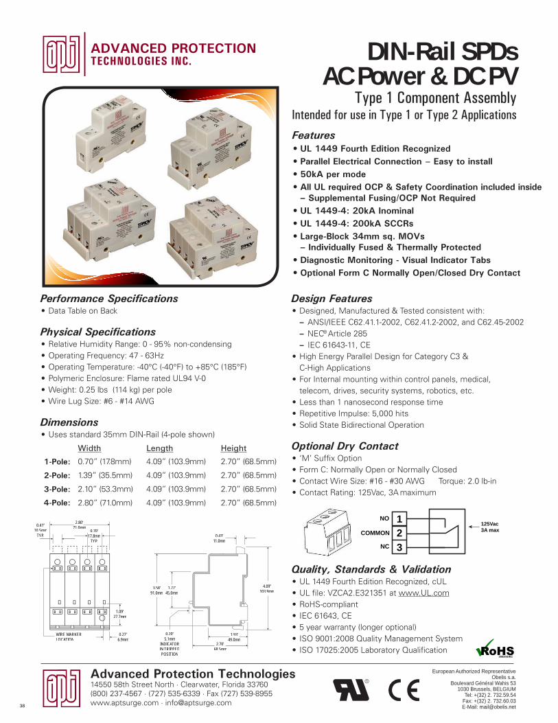
Advanced Protection Technologies14550 58th Street North · Clearwater, Florida 33760(800) 237-4567 · (727) 535-6339 · Fax (727) 539-8955www.aptsurge.com · [email protected]
Design Features• Designed, Manufactured & Tested consistent with:
– ANSI/IEEE C62.41.1-2002, C62.41.2-2002, and C62.45-2002 – NEC® Article 285 – IEC 61643-11, CE
• High Energy Parallel Design for Category C3 & C-High Applications
• For Internal mounting within control panels, medical, telecom, drives, security systems, robotics, etc.
• Less than 1 nanosecond response time• Repetitive Impulse: 5,000 hits• Solid State Bidirectional Operation
Optional Dry Contact• ‘M’ Suffix Option• Form C: Normally Open or Normally Closed• Contact Wire Size: #16 - #30 AWG Torque: 2.0 lb-in• Contact Rating: 125Vac, 3A maximum
Quality, Standards & Validation• UL 1449 Fourth Edition Recognized, cUL• UL file: VZCA2.E321351 at www.UL.com • RoHS-compliant• IEC 61643, CE• 5 year warranty (longer optional)• ISO 9001:2008 Quality Management System• ISO 17025:2005 Laboratory Qualification
Features• UL 1449 Fourth Edition Recognized• Parallel Electrical Connection – Easy to install • 50kA per mode• All UL required OCP & Safety Coordination included inside
– Supplemental Fusing/OCP Not Required• UL 1449-4: 20kA Inominal • UL 1449-4: 200kA SCCRs• Large-Block 34mm sq. MOVs
– Individually Fused & Thermally Protected• Diagnostic Monitoring - Visual Indicator Tabs• Optional Form C Normally Open/Closed Dry Contact
Performance Specifications• Data Table on Back
Physical Specifications• Relative Humidity Range: 0 - 95% non-condensing• Operating Frequency: 47 - 63Hz• Operating Temperature: -40°C (-40°F) to +85°C (185°F)• Polymeric Enclosure: Flame rated UL94 V-0• Weight: 0.25 lbs (114 kg) per pole• Wire Lug Size: #6 - #14 AWG
Dimensions• Uses standard 35mm DIN-Rail (4-pole shown)
Width Length Height
1-Pole: 0.70” (17.8mm) 4.09” (103.9mm) 2.70” (68.5mm)
2-Pole: 1.39” (35.5mm) 4.09” (103.9mm) 2.70” (68.5mm)
3-Pole: 2.10” (53.3mm) 4.09” (103.9mm) 2.70” (68.5mm)
4-Pole: 2.80” (71.0mm) 4.09” (103.9mm) 2.70” (68.5mm)
123
NO
COMMON125Vac3A max
NC
WIRE MARKERLOCATION
2.80”71.0mm0.41”
10.5mmTYP.
0.70”17.8mm
TYP.
1.09”27.7mm
0.27”6.9mm
0.20”5.1mm
INDICATORIN TRIPPEDPOSITION
2.70”68.5mm
1.93”49.0mm
4.09”103.9mm
0.43”11.0mm
1.77”45.0mm
3.58”91.0mm
DIN-Rail SPDs AC Power & DC PV
Type 1 Component AssemblyIntended for use in Type 1 or Type 2 Applications
European Authorized RepresentativeObelis s.a.
Boulevard Général Wahis 531030 Brussels, BELGIUM
Tel: +(32) 2. 732.59.54Fax: +(32) 2. 732.60.03E-Mail: [email protected]
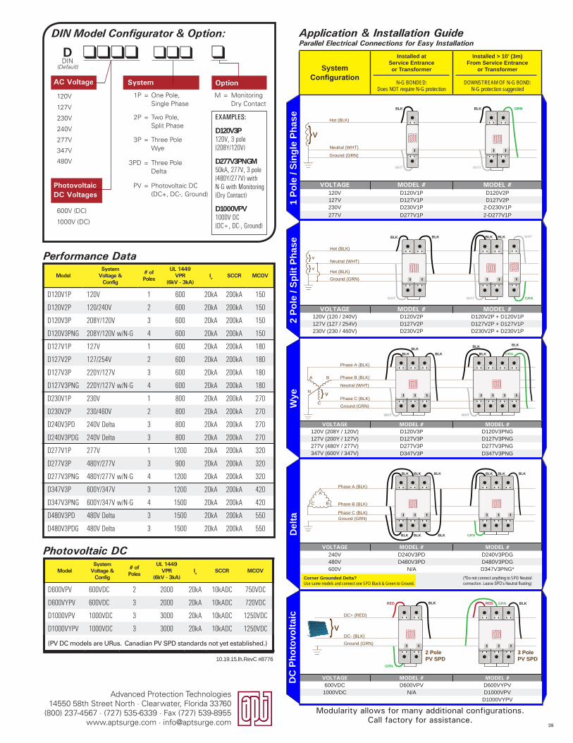
Advanced Protection Technologies14550 58th Street North · Clearwater, Florida 33760
(800) 237-4567 · (727) 535-6339 · Fax (727) 539-8955www.aptsurge.com · [email protected]
M = MonitoringDry Contact
Application & Installation GuideParallel Electrical Connections for Easy Installation
10.19.15.lh.RevC #8776
1P = One Pole, Single Phase
2P = Two Pole, Split Phase
3P = Three Pole Wye
3PD = Three Pole Delta
PV = Photovoltaic DC (DC+, DC-, Ground)
EXAMPLES:
D120V3P 120V, 3 pole (208Y/120V)
D277V3PNGM50kA, 277V, 3 pole (480Y/277V) with N-G with Monitoring (Dry Contact)
D1000VPV 1000V DC (DC+, DC-, Ground)
120V
127V
230V
240V
277V
347V
480V
600V (DC)
1000V (DC)
DDIN Model Configurator & Option:
Photovoltaic DC Voltages
System Option
Modularity allows for many additional configurations.Call factory for assistance.
DIN (Default)
AC Voltage
System Configuration
Installed at Service Entrance or Transformer
N-G BONDED: Does NOT require N-G protection
Installed > 10’ (3m) From Service Entrance
or Transformer
DOWNSTREAM OF N-G BOND: N-G protection suggested
VOLTAGE MODEL # MODEL #120V D120V1P D120V2P127V D127V1P D127V2P230V D230V1P 2-D230V1P277V D277V1P 2-D277V1P
VOLTAGE MODEL # MODEL #120V (120 / 240V) D120V2P D120V2P + D120V1P127V (127 / 254V) D127V2P D127V2P + D127V1P230V (230 / 460V) D230V2P D230V2P + D230V1P
VOLTAGE MODEL # MODEL #120V (208Y / 120V) D120V3P D120V3PNG127V (200Y / 127V) D127V3P D127V3PNG277V (480Y / 277V) D277V3P D277V3PNG347V (600Y / 347V) D347V3P D347V3PNG
VOLTAGE MODEL # MODEL #240V D240V3PD D240V3PDG480V D480V3PD D480V3PDG600V N/A D347V3PNG*
(*Do not connect anything to SPD Neutral connection. Leave SPD’s Neutral floating)
VOLTAGE MODEL # MODEL #600VDC D600VPV D600VYPV
1000VDC N/A D1000VPVD1000VYPV
1 Po
le /
Sing
le P
hase
Del
taD
C P
hoto
volta
icW
ye
GRN
C
N
Ground (GRN)
A B
Neutral (WHT)
Phase B (BLK)
Phase A (BLK)
Phase C (BLK)
BLKBLK
BLK
BLK
BLK
BLK
WHT WHT
Hot (BLK)
Ground (GRN)
Neutral (WHT)
BLK
WHT
BLK
WHT
GRN
A
C B
Ground (GRN)
Phase A (BLK)
Phase B (BLK)
Phase C (BLK)
BLK
BLK
BLK BLK BLK BLK BLK
BLK BLK GRN
2 Po
le /
Split
Pha
se
BLK BLK
WHT
BLK
Hot (BLK)
Hot (BLK)
Neutral (WHT)
Ground (GRN)
BLK
WHT GRN
WHT
GRN BLK
GRN
DC+ (RED)
DC- (BLK)Ground (GRN)
2 Pole PV SPD
3 Pole PV SPD
RED REDBLK
ModelSystem
Voltage & Config
# ofPoles
UL 1449VPR
(6kV - 3kA)In SCCR MCOV
D600VPV 600VDC 2 2000 20kA 10kADC 750VDC
D600VYPV 600VDC 3 2000 20kA 10kADC 720VDC
D1000VPV 1000VDC 3 3000 20kA 10kADC 1250VDC
D1000VYPV 1000VDC 3 3000 20kA 10kADC 1250VDC
(PV DC models are URus. Canadian PV SPD standards not yet established.)
Photovoltaic DC
ModelSystem
Voltage & Config
# ofPoles
UL 1449VPR
(6kV - 3kA)In SCCR MCOV
D120V1P 120V 1 600 20kA 200kA 150
D120V2P 120/240V 2 600 20kA 200kA 150
D120V3P 208Y/120V 3 600 20kA 200kA 150
D120V3PNG 208Y/120V w/N-G 4 600 20kA 200kA 150
D127V1P 127V 1 600 20kA 200kA 180
D127V2P 127/254V 2 600 20kA 200kA 180
D127V3P 220Y/127V 3 600 20kA 200kA 180
D127V3PNG 220Y/127V w/N-G 4 600 20kA 200kA 180
D230V1P 230V 1 800 20kA 200kA 270
D230V2P 230/460V 2 800 20kA 200kA 270
D240V3PD 240V Delta 3 800 20kA 200kA 270
D240V3PDG 240V Delta 3 800 20kA 200kA 270
D277V1P 277V 1 1200 20kA 200kA 320
D277V3P 480Y/277V 3 900 20kA 200kA 320
D277V3PNG 480Y/277V w/N-G 4 1200 20kA 200kA 320
D347V3P 600Y/347V 3 1200 20kA 200kA 420
D347V3PNG 600Y/347V w/N-G 4 1500 20kA 200kA 420
D480V3PD 480V Delta 3 1500 20kA 200kA 550
D480V3PDG 480V Delta 3 1500 20kA 200kA 550
Performance Data
Corner Grounded Delta? Use same models and connect one SPD Black & Green to Ground.
39
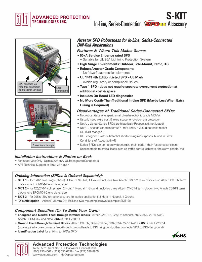
Advanced Protection Technologies14550 58th Street North · Clearwater, Florida 33760(800) 237-4567 · (727) 535-6339 · Fax (727) 539-8955www.aptsurge.com · [email protected]
Component Specifics (Or To Build Your Own):• Energized and Neutral Feed-Through Terminal Blocks: Altech CMC1-2, Gray, tri-connect, 600V, 35A, 22-10 AWG,
Altech EPCMC1-2 end plate, cЯUus, file E220514• Ground Feed-Through Terminal Blocks: Altech CGT6N, Green/Yellow, 600V, 35A, 22-10 AWG, cЯUus, file E220514 (two required – one connects feed-through ground leads to DIN rail ground, other connects SPD to DIN-Rail ground)• Identification Label for affixing to SPDEE SPD.
Features & Where This Makes Sense:• 50kA Service Entrance rated SPD
– Suitable for UL 96A Lightning Protection System• High Surge Environments: Outdoor, Pole-Mount, Traffic, ITS• Robust Arrestor Grade Components
– No ‘dwarf’ suppression elements• UL 1449 4th Edition Listed SPD – UL Mark
– Avoids regulatory or compliance issues• Type 1 SPD - does not require separate overcurrent protection at
additional cost & space• Includes On-Board LED diagnostics• No More Costly Than Traditional In-Line SPD (Maybe Less When Extra
Fusing is Required)
Disadvantages of Traditional Series-Connected SPDs:• Not robust (take one apart: small dwarf/electronic grade MOVs)• Usually need extra cost & extra space for overcurrent protection• Not UL Listed (Series SPDs are historically Recognized, not Listed)• Not UL Recognized (dangerous? - mfg knew it would not pass recent UL 1449 changes?) • UL Recognized with substantial shortcomings?(‘Surprises’ buried in File’s
Conditions of Acceptability?) • Series SPDs can completely deenergize their loads if their fuse/breaker clears.
Unacceptable to critical loads such as traffic control cabinets, fire alarm panels, etc.
Arrestor SPD Robustness for In-Line, Series-Connected DIN-Rail Applications
Load conductors
Ordering Information (SPDee is Ordered Separately):• SKIT 1 – for 120V (true single phase): 1 Hot, 1 Neutral, 1 Ground Includes two Altech CMC1-2 term blocks, two Altech CGT6N term
blocks, one EPCMC-1-2 end plate, label• SKIT 2 – for 120/240V (split phase): 2 Hots, 1 Neutral, 1 Ground Includes three Altech CMC1-2 term blocks, two Altech CGT6N term
blocks, one EPCMC-1-2 end plate, label• SKIT 3 – for 208Y/120V (three phase, rare for series application): 3 Hots, 1 Neutral, 1 Ground • ‘D’ suffix option – Adds 6” 35mm DIN-Rail and two mounting screws (example: SKIT1D)
Installation Instructions & Photos on Back• For Indoor Use Only - Up to 600V, 35A, UL Recognized Connectors• APT Technical Support at (800) 237-4567
Power feeds through
SPD connects via feed-thru connection on Std 35mm DIN Rail
40
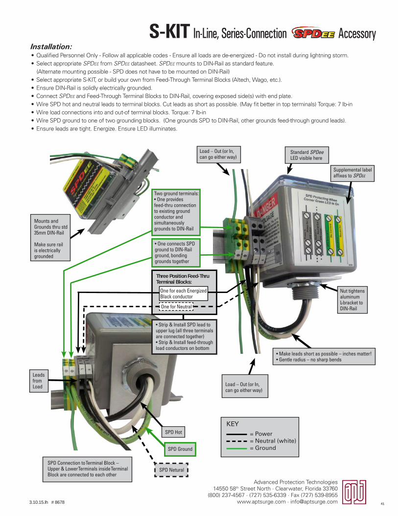
Advanced Protection Technologies14550 58th Street North · Clearwater, Florida 33760
(800) 237-4567 · (727) 535-6339 · Fax (727) 539-8955www.aptsurge.com · [email protected]
Installation:• Qualified Personnel Only - Follow all applicable codes - Ensure all loads are de-energized - Do not install during lightning storm.• Select appropriate SPDEE from SPDEE datasheet. SPDEE mounts to DIN-Rail as standard feature. (Alternate mounting possible - SPD does not have to be mounted on DIN-Rail)• Select appropriate S-KIT, or build your own from Feed-Through Terminal Blocks (Altech, Wago, etc.).• Ensure DIN-Rail is solidly electrically grounded.• Connect SPDEE and Feed-Through Terminal Blocks to DIN-Rail, covering exposed side(s) with end plate. • Wire SPD hot and neutral leads to terminal blocks. Cut leads as short as possible. (May fit better in top terminals) Torque: 7 lb-in• Wire load connections into and out-of terminal blocks. Torque: 7 lb-in• Wire SPD ground to one of two grounding blocks. (One grounds SPD to DIN-Rail, other grounds feed-through ground leads).• Ensure leads are tight. Energize. Ensure LED illuminates.
Load – Out (or In, can go either way)
• Make leads short as possible – inches matter!• Gentle radius – no sharp bends
• Strip & Install SPD lead to upper lug (all three terminals are connected together)• Strip & Install feed-through load conductors on bottom
Load – Out (or In, can go either way)
SPD Connection to Terminal Block – Upper & Lower Terminals inside Terminal Block are connected to each other
SPD Ground
SPD Hot
SPD Netural
Two ground terminals:• One provides feed-thru connection to existing ground conductor and simultaneously grounds to DIN-Rail
• One connects SPD ground to DIN-Rail ground, bonding grounds together
Supplemental label affixes to SPDEE
Standard SPDee LED visible here
Three Position Feed-Thru Terminal Blocks:
Nut tightens aluminum L-bracket to DIN-Rail
Mounts and Grounds thru std 35mm DIN-Rail
Make sure rail is electrically grounded
Leads from Load
One for each Energized Black conductor
One for Neutral
KEY= Power= Neutral (white)= Ground
3.10.15.lh # 8678 41
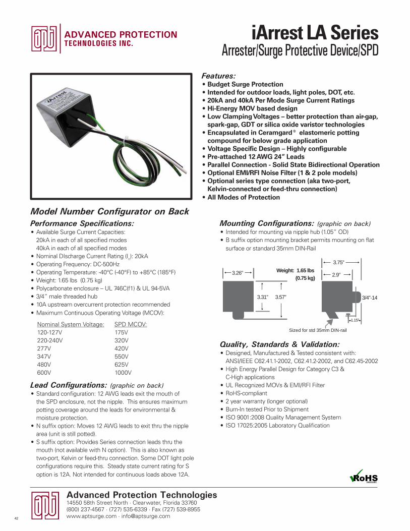
Advanced Protection Technologies14550 58th Street North · Clearwater, Florida 33760(800) 237-4567 · (727) 535-6339 · Fax (727) 539-8955www.aptsurge.com · [email protected]
Mounting Configurations: (graphic on back)• Intended for mounting via nipple hub (1.05” OD)• B suffix option mounting bracket permits mounting on flat
surface or standard 35mm DIN-Rail
Quality, Standards & Validation:• Designed, Manufactured & Tested consistent with:
ANSI/IEEE C62.41.1-2002, C62.41.2-2002, and C62.45-2002• High Energy Parallel Design for Category C3 &
C-High applications• UL Recognized MOVs & EMI/RFI Filter• RoHS-compliant• 2 year warranty (longer optional)• Burn-In tested Prior to Shipment• ISO 9001:2008 Quality Management System• ISO 17025:2005 Laboratory Qualification
Features:• Budget Surge Protection • Intended for outdoor loads, light poles, DOT, etc.• 20kA and 40kA Per Mode Surge Current Ratings• Hi-Energy MOV based design• Low Clamping Voltages – better protection than air-gap,
spark-gap, GDT or silica oxide varistor technologies• Encapsulated in Ceramgard® elastomeric potting
compound for below grade application • Voltage Specific Design – Highly configurable• Pre-attached 12 AWG 24” Leads• Parallel Connection - Solid State Bidirectional Operation• Optional EMI/RFI Noise Filter (1 & 2 pole models)• Optional series type connection (aka two-port,
Kelvin-connected or feed-thru connection)• All Modes of Protection
Performance Specifications:• Available Surge Current Capacities:
20kA in each of all specified modes 40kA in each of all specified modes
• Nominal DIscharge Current Rating (In): 20kA• Operating Frequency: DC-500Hz• Operating Temperature: -40°C (-40°F) to +85°C (185°F)• Weight: 1.65 lbs (0.75 kg)• Polycarbonate enclosure – UL 746C(f1) & UL 94-5VA• 3/4” male threaded hub• 10A upstream overcurrent protection recommended• Maximum Continuous Operating Voltage (MCOV):
Lead Configurations: (graphic on back)• Standard configuration: 12 AWG leads exit the mouth of
the SPD enclosure, not the nipple. This ensures maximum potting coverage around the leads for environmental & moisture protection.
• N suffix option: Moves 12 AWG leads to exit thru the nipple area (unit is still potted).
• S suffix option: Provides Series connection leads thru the mouth (not available with N option). This is also known as two-port, Kelvin or feed-thru connection. Some DOT light pole configurations require this. Steady state current rating for S option is 12A. Not intended for continuous loads above 12A.
3.26” 2.9”
1.15”
3.75”
3/4”-14
Sized for std 35mm DIN-rail
3.31” 3.57”
Weight: 1.65 lbs(0.75 kg)
Model Number Configurator on Back
Nominal System Voltage: SPD MCOV:120-127V 175V220-240V 320V277V 420V347V 550V480V 625V600V 1000V
42
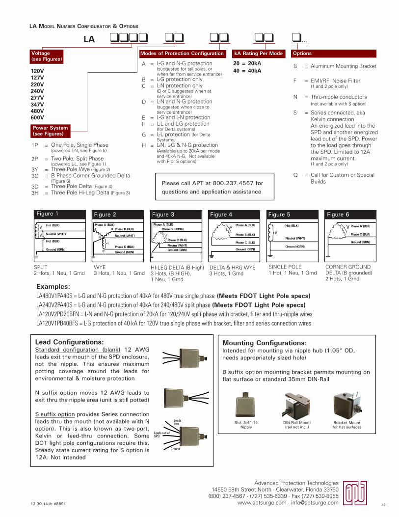
Advanced Protection Technologies14550 58th Street North · Clearwater, Florida 33760
(800) 237-4567 · (727) 535-6339 · Fax (727) 539-8955www.aptsurge.com · [email protected]
LA llll ll ll lll...
LA MODEL NUMBER CONFIGURATOR & OPTIONS
Figure 1
SPLIT2 Hots, 1 Neu, 1 Grnd
HI-LEG DELTA (B High)3 Hots, (B HIGH), 1 Neu, 1 Grnd
SINGLE POLE1 Hot, 1 Neu, 1 Grnd
WYE3 Hots, 1 Neu, 1 Grnd
DELTA & HRG WYE3 Hots, 1 Grnd
Hot (BLK)
Hot (BLK)
Neutral (WHT)V
V
}}
Ground (GRN)
Figure 2
}
Phase A (BLK)Phase B (BLK)
Neutral (WHT)
Phase C (BLK)
Ground (GRN)
A
C
N
V
B
Figure 3
Phase A (BLK)Phase B (ORNG)
Neutral (WHT)
Phase C (BLK)
Ground (GRN)
}V
Figure 5
V}Neutral (WHT)
Hot (BLK)
Ground (GRN)
Figure 4
Phase A (BLK)
Phase C (BLK)
Phase B (BLK)
Ground (GRN)
}V
CORNER GROUNDDELTA (B grounded)2 Hots, 1 Grnd
Figure 6
Phase A (BLK)
Phase C (BLK)
Ground (GRN)
V}
B = Aluminum Mounting Bracket
F = EMI/RFI Noise Filter (1 and 2 pole only)
N = Thru-nipple conductors (not available with S option)
S = Series connected, aka Kelvin connection An energized lead into the SPD and another energized lead out of the SPD. Power to the load goes through the SPD. Limited to 12A maximum current. (1 and 2 pole only)
Q = Call for Custom or Special Builds
A = L-G and N-G protection(suggested for tall poles, or when far from service entrance)
B = L-G protection only C = L-N protection only
(B or C suggested when at service entrance)
D = L-N and N-G protection(suggested when close to service entrance)
E = L-G and L-N protectionF = L-L and L-G protection
(for Delta systems)G = L-L protection (for Delta
Systems)H = L-N, L-G & N-G protection
(Available up to 20kA per mode and 40kA N-G, Not available with F or S options)
1P = One Pole, Single Phase (powered L-N, see Figure 5)
2P = Two Pole, Split Phase (powered L-L, see Figure 1)
3Y = Three Pole Wye (Figure 2)
3C = B Phase Corner Grounded Delta (Figure 6)
3D = Three Pole Delta (Figure 4)
3H = Three Pole Hi-Leg Delta (Figure 3)
20 = 20kA40 = 40kA120V
127V220V240V277V347V480V600V
12.30.14.lh #8691
Voltage (see Figures)
OptionskA Rating Per Mode
Power System(see Figures)
Modes of Protection Configuration
Examples:LA480V1PA40S = L-G and N-G protection of 40kA for 480V true single phase (Meets FDOT Light Pole specs)LA240V2PA40S = L-G and N-G protection of 40kA for 240/480V split phase (Meets FDOT Light Pole specs)LA120V2PD20BFN = L-N and N-G protection of 20kA for 120/240V split phase with bracket, filter and thru-nipple wiresLA120V1PB40BFS = L-G protection of 40 kA for 120V true single phase with bracket, filter and series connection wires
Mounting Configurations: Intended for mounting via nipple hub (1.05” OD, needs appropriately sized hole)
B suffix option mounting bracket permits mounting on flat surface or standard 35mm DIN-Rail
Bracket Mount for flat surfaces
Std. 3/4”-14 Nipple
DIN-Rail Mount(rail not incl.)
Lead Configurations:Standard configuration (blank) 12 AWG leads exit the mouth of the SPD enclosure, not the nipple. This ensures maximum potting coverage around the leads for environmental & moisture protection
N suffix option moves 12 AWG leads to exit thru the nipple area (unit is still potted)
S suffix option provides Series connection leads thru the mouth (not available with N option). This is also known as two-port, Kelvin or feed-thru connection. Some DOT light pole configurations require this. Steady state current rating for S option is 12A. Not intended
Leads into
Ground
Leads out of SPD
Please call APT at 800.237.4567 for questions and application assistance
43
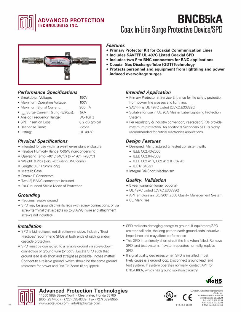
Intended Application • Primary Protector at Service Entrance for life safety protection
from power line crosses and lightning.• SAVFFF is UL 497C Listed (QVKC.E303380)• Suitable for use in UL 96A Master Label Lightning Protection
System• Per regulatory & industry convention, cascaded SPDs provide
maximum protection. An additional Secondary SPD is highly recommended for critical electronics applications.
Design Features• Designed, Manufactured & Tested consistent with:
– IEEE C62.43-2005 – IEEE C62.64-2009 – IEEE C62.41.1, C62.41.2 & C62.45 – IEC 61643-21
• Integral Fail-Short Mechanism
Quality, Validation• 5 year warranty (longer optional)• UL 497C Listed (QVKC.E303380)• APT employs an ISO 9001:2008 Quality Management System• CE Mark: Yes
Features• Primary Protector Kit for Coaxial Communication Lines• Includes SAVFFF UL 497C Listed Coaxial SPD• Includes two F to BNC connectors for BNC applications• Coaxial Gas Discharge Tube (GDT) Technology• Protects personnel and equipment from lightning and power
induced overvoltage surges
Performance Specifications• Breakdown Voltage: 150V• Maximum Operating Voltage: 100V• Maximum Signal Current: 300mA• Imax Surge Current Rating (8/20µs): 5kA• Analog Frequency Range: DC-1GHz• SPD Insertion Loss: 0.2 dB typical• Response Time: <25ns• Listing: UL 497C
Physical Specifications• Intended for use within a weather-resistant enclosure• Relative Humidity Range: 0-95% non-condensing• Operating Temp: -40°C (-40°C) to +176°F (+80°C)• Weight: 0.2lbs (56g) (excluding BNC conn.)• Length: 3.0” (76mm long)• Metallic Case• Female F Connectors• Two (2) F-BNC connectors included• Pin-Grounded Shield Mode of Protection
Grounding• Requires reliable ground• SPD may be grounded via its legs with screw connections, or via
screw terminal that accepts up to 8 AWG (wire and attachment screws not included)
Installation• SPD is bidirectional; not direction-sensitive. Industry ‘Best
Practices’ recommend SPDs at both ends of cabling and/or cascade protection.
• SPD must be connected to a reliable ground via screw-down connection or ground wire (or both). Locate SPD such that ground lead is as short and straight as possible. Inches matter! Connect to a reliable ground, which should be the same ground reference for power and Pan-Tilt-Zoom (if equipped).
• SPD redirects damaging energy to ground. If equipment/SPD are atop tall pole, the long path to earth ground adds inductive impedance and may affect performance
• This SPD intentionally short-circuit the line when failed. Remove SPD, and test system. If system operates normally, replace SPD.
• If signal quality decreases when SPD is installed, most likely cause is a ground loop. Disconnect ground lead, and test system. If system operates normally, contact APT for BNCA10kA, which has ground isolation circuitry.
3.10.15.lh #8619
Advanced Protection Technologies14550 58th Street North · Clearwater, Florida 33760(800) 237-4567 · (727) 535-6339 · Fax (727) 539-8955www.aptsurge.com · [email protected]
European Authorized RepresentativeObelis s.a.
Boulevard Général Wahis 531030 Brussels, BELGIUM
Tel: +(32) 2. 732.59.54Fax: +(32) 2. 732.60.03E-Mail: [email protected]
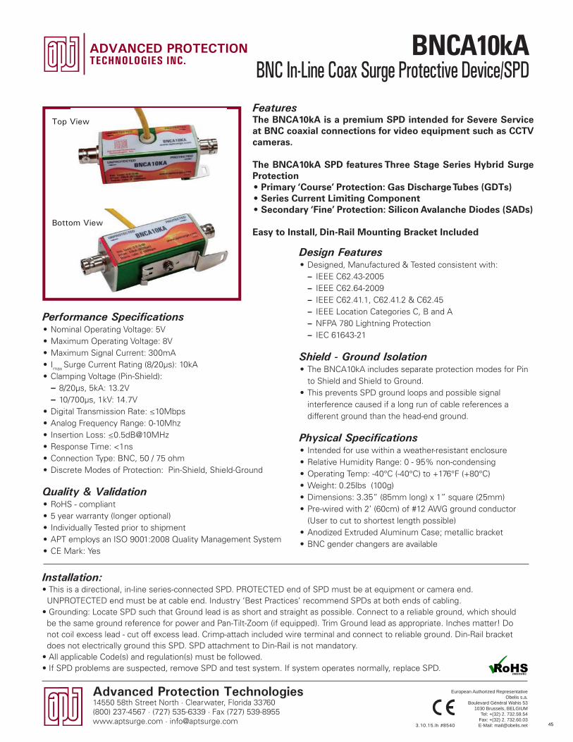
Advanced Protection Technologies14550 58th Street North · Clearwater, Florida 33760(800) 237-4567 · (727) 535-6339 · Fax (727) 539-8955www.aptsurge.com · [email protected]
Design Features• Designed, Manufactured & Tested consistent with:
– IEEE C62.43-2005 – IEEE C62.64-2009 – IEEE C62.41.1, C62.41.2 & C62.45 – IEEE Location Categories C, B and A – NFPA 780 Lightning Protection – IEC 61643-21
Shield - Ground Isolation• The BNCA10kA includes separate protection modes for Pin
to Shield and Shield to Ground.• This prevents SPD ground loops and possible signal
interference caused if a long run of cable references a different ground than the head-end ground.
Physical Specifications• Intended for use within a weather-resistant enclosure• Relative Humidity Range: 0 - 95% non-condensing• Operating Temp: -40°C (-40°C) to +176°F (+80°C)• Weight: 0.25lbs (100g)• Dimensions: 3.35” (85mm long) x 1” square (25mm) • Pre-wired with 2’ (60cm) of #12 AWG ground conductor
(User to cut to shortest length possible)• Anodized Extruded Aluminum Case; metallic bracket• BNC gender changers are available
FeaturesThe BNCA10kA is a premium SPD intended for Severe Service at BNC coaxial connections for video equipment such as CCTV cameras.
The BNCA10kA SPD features Three Stage Series Hybrid Surge Protection• Primary ‘Course’ Protection: Gas Discharge Tubes (GDTs) • Series Current Limiting Component• Secondary ‘Fine’ Protection: Silicon Avalanche Diodes (SADs)
Easy to Install, Din-Rail Mounting Bracket Included
Performance Specifications• Nominal Operating Voltage: 5V• Maximum Operating Voltage: 8V• Maximum Signal Current: 300mA• Imax Surge Current Rating (8/20µs): 10kA• Clamping Voltage (Pin-Shield):
– 8/20µs, 5kA: 13.2V – 10/700µs, 1kV: 14.7V
• Digital Transmission Rate: ≤10Mbps• Analog Frequency Range: 0-10Mhz• Insertion Loss: ≤0.5dB@10MHz• Response Time: <1ns• Connection Type: BNC, 50 / 75 ohm• Discrete Modes of Protection: Pin-Shield, Shield-Ground
Quality & Validation• RoHS - compliant• 5 year warranty (longer optional)• Individually Tested prior to shipment• APT employs an ISO 9001:2008 Quality Management System• CE Mark: Yes
Installation:• This is a directional, in-line series-connected SPD. PROTECTED end of SPD must be at equipment or camera end. UNPROTECTED end must be at cable end. Industry ‘Best Practices’ recommend SPDs at both ends of cabling.• Grounding: Locate SPD such that Ground lead is as short and straight as possible. Connect to a reliable ground, which should be the same ground reference for power and Pan-Tilt-Zoom (if equipped). Trim Ground lead as appropriate. Inches matter! Do not coil excess lead - cut off excess lead. Crimp-attach included wire terminal and connect to reliable ground. Din-Rail bracket does not electrically ground this SPD. SPD attachment to Din-Rail is not mandatory.• All applicable Code(s) and regulation(s) must be followed.• If SPD problems are suspected, remove SPD and test system. If system operates normally, replace SPD.
3.10.15.lh #8540
Top View
Bottom View
European Authorized RepresentativeObelis s.a.
Boulevard Général Wahis 531030 Brussels, BELGIUM
Tel: +(32) 2. 732.59.54Fax: +(32) 2. 732.60.03E-Mail: [email protected] 45
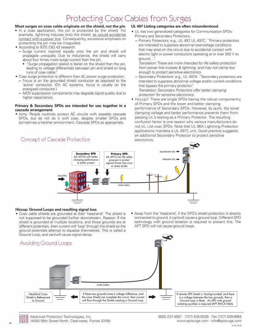
(800) 237-4567 · (727) 535-6339 · Fax (727) 539-8955www.aptsurge.com · [email protected]
Advanced Protection Technologies, Inc.14550 58th Street North, Clearwater, Florida 33760
SPD SPD
SPD
SPD
BUILDING
SECONDARY SPD
PRIMARY SPD
COAX CABLE
Secondary SPD (UL 497A) with better clamping performance
to better protect
Primary SPD (UL 497C) for life safety
purposes to protect against Power line cross
or direct stroke
Protecting Coax Cables from SurgesMost surges on coax cable originate on the shield, not the pin.• In a coax application, the pin is protected by the shield. For
example, lightning induces onto the shield, as would accidental contact with a power line. Consequently, excessive emphasis on protecting the pin may be misguided.
• According to IEEE C62.43 research: – Surge current injected equally onto the pin and shield will propagate unequally. Due to inductance, the shield will carry about four times more surge current than the pin. • “Surge propagation speed is faster on the shield than the pin,
leading to voltage differentials between pin and shield on long runs of coax cable.”
• Coax surge protection is different than AC power surge protection: – Focus is on the grounded shield conductor as opposed to the ‘active’ conductor. (On AC systems, focus is usually on the energized conductor.)
– MOV suppression components may degrade signal quality due to higher capacitance.
Primary & Secondary SPDs are intended for use together in a cascade arrangement.• Irony: People routinely protect AC circuits with sizeable cascade
SPDs, but do not do it with coax, despite smaller SPDs and sometimes a harsher environment. Cascade SPDs as appropriate.
UL 497 Listing categories are often misunderstood.• UL has two generalized categories for Communication SPDs:
Primary and Secondary Protectors. – Primary Protectors: e.g., UL 497, UL 497C. “Primary protectors are intended to suppress abnormal overvoltage conditions that may exist on the circuit due to accidental contact with electric light or power conductors operating at or over 300 V to ground…”.Translation: These are more intended for life safety protection from power line crosses & lightning, and may not clamp low enough to protect sensitive electronics.
– Secondary Protectors: e.g., UL 497A. “Secondary protectors are intended to suppress abnormal voltage and/or current conditions that bypass the primary protector.”Translation: Secondary Protectors offer better clamping protection for sensitive electronics.
• Hiccup?: There are single SPDs having the robust componentry of Primary SPDs and the lower and better clamping performance of Secondary SPDs. However, by quirk, the lower clamping voltage and better performance prevents them from passing UL’s testing as a Primary Protector. The resulting confusion factor is one reason why various manufacturers do not UL List coax SPDs. Note that UL 96A Lightning Protection applications mandate a UL 497C unit. Good practice suggests an additional Secondary Protector to protect sensitive electronics.
Hiccup: Ground Loops and resulting signal loss• Coax cable shields are grounded at their ‘head-end’. The shield is
not supposed to be grounded further downstream. Reason: If the shield is grounded at multiple locations, and those grounds are at different potentials, then current will ‘loop’ through the shield as the ground potentials attempt to equalize themselves. This is called a Ground Loop, and can/will cause signal decay.
• Away from the ‘head-end’, if the SPD’s shield protection is directly connected to ground, it can/will cause a ground loop. Different SPD technology with ground isolation is required to prevent this. The APT SPD will not cause ground loops.
Concept of Cascade Protection
Avoiding Ground Loops
SPD
SPD
If these two grounds have a voltage difference, and the coax Shield can complete the circuit, then current will flow through the Shield creating a Ground Loop.
COMMUNICATION EQUIPMENT
Head-End Coax Shield is Referenced
to Ground
If remote SPD shield is ‘hard-grounded’ and there is a voltage between the two grounds, then a Ground Loop is likely. An SPD with ground
isolating qualities is required (APT BNCA10kA).
COAX CABLE
3.10.15.lh46
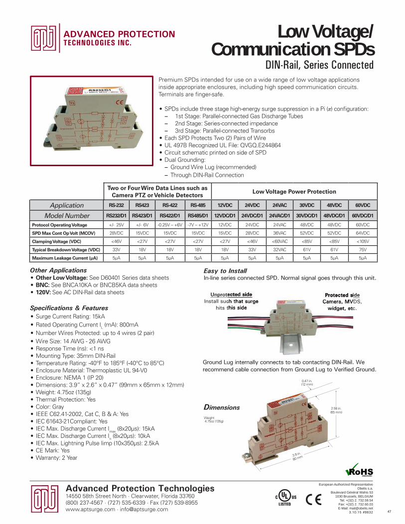
Advanced Protection Technologies14550 58th Street North · Clearwater, Florida 33760(800) 237-4567 · (727) 535-6339 · Fax (727) 539-8955www.aptsurge.com · [email protected]
0.47 in.(12 mm)
2.56 in.(65 mm)
Two or Four Wire Data Lines such as Camera PTZ or Vehicle Detectors
Low Voltage Power Protection
Application RS-232 RS423 RS-422 RS-485 12VDC 24VDC 24VAC 30VDC 48VDC 60VDC
Model Number RS232/D1 RS423/D1 RS422/D1 RS485/D1 12VDC/D1 24VDC/D1 24VAC/D1 30VDC/D1 48VDC/D1 60VDC/D1
Protocol Operating Voltage +/- 25V +/- 6V -0.25V – +6V -7V – +12V 12VDC 24VDC 24VAC 48VDC 48VDC 60VDC
SPD Max Cont Op Volt (MCOV) 28VDC 15VDC 15VDC 15VDC 15VDC 28VDC 36VAC 52VDC 52VDC 64VDC
Clamping Voltage (VDC) <46V <27V <27V <27V <27V <46V <60VAC <85V <85V <105V
Typical Breakdown Voltage (VDC) 33V 18V 18V 18V 18V 33V 32VAC 61V 61V 75V
Maximum Leakage Current (µA) 5µA 5µA 5µA 5µA 5µA 5µA 5µA 5µA 5µA 5µA
Premium SPDs intended for use on a wide range of low voltage applications inside appropriate enclosures, including high speed communication circuits. Terminals are finger-safe.
• SPDs include three stage high-energy surge suppression in a Pi (π) configuration: – 1st Stage: Parallel-connected Gas Discharge Tubes – 2nd Stage: Series-connected impedance – 3rd Stage: Parallel-connected Transorbs
• Each SPD Protects Two (2) Pairs of Wire• UL 497B Recognized UL File: QVGQ.E244864• Circuit schematic printed on side of SPD• Dual Grounding:
– Ground Wire Lug (recommended) – Through DIN-Rail Connection
Other Applications• Other Low Voltage: See D60401 Series data sheets• BNC: See BNCA10KA or BNCB5KA data sheets• 120V: See AC DIN-Rail data sheets
Specifications & Features• Surge Current Rating: 15kA• Rated Operating Current IL (mA): 800mA • Number Wires Protected: up to 4 wires (2 pair)• Wire Size: 14 AWG - 26 AWG• Response Time (ns): <1 ns• Mounting Type: 35mm DIN-Rail• Temperature Rating: -40°F to 185°F (-40°C to 85°C)• Enclosure Material: Thermoplastic UL 94-V0• Enclosure: NEMA 1 (IP 20)• Dimensions: 3.9” x 2.6” x 0.47” (99mm x 65mm x 12mm)• Weight: 4.75oz (135g)• Thermal Protection: Yes• Color: Gray• IEEE C62.41-2002, Cat C, B & A: Yes• IEC 61643-21Compliant: Yes• IEC Max. Discharge Current Imax (8x20µs): 15kA• IEC Max. Discharge Current In (8x20µs): 10kA• IEC Max. Lightning Pulse Iimp (10x350µs): 2.5kA• CE Mark: Yes• Warranty: 2 Year
Dimensions
Easy to InstallIn-line series connected SPD. Normal signal goes through this unit.
Unprotected sideInstall such that surge
hits this side
Protected sideCamera, MVDS,
widget, etc.
Ground Lug internally connects to tab contacting DIN-Rail. We recommend cable connection from Ground Lug to Verified Ground.
3.10.15 #8632
Unprotected sideUnprotected sideInstall such that surge
hits this side
Protected sideCamera, MVDS,
widget, etc.
Weight: 4.75oz (135g)
3.9 in.
80 mm
European Authorized RepresentativeObelis s.a.
Boulevard Général Wahis 531030 Brussels, BELGIUM
Tel: +(32) 2. 732.59.54Fax: +(32) 2. 732.60.03E-Mail: [email protected]
Low Voltage/Communication SPDs
DIN-Rail, Series Connected
47
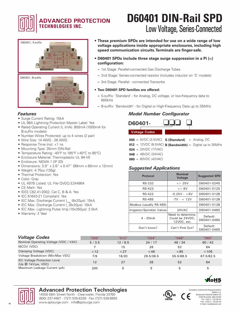
Advanced Protection Technologies14550 58th Street North · Clearwater, Florida 33760(800) 237-4567 · (727) 535-6339 · Fax (727) 539-8955www.aptsurge.com · [email protected]
Model Number Configurator
Voltage Codes
D60401- llll
S (Standard) = Analog, DC
B (Bandwidth) = Digital up to 35MHz
005 = 5VDC (3.5VAC)
012 = 12VDC (8.5VAC)
024 = 24VDC (17VAC)
048 = 48VDC (34VAC)
060 = 60VDC (42VAC)
• These premium SPDs are intended for use on a wide range of low voltage applications inside appropriate enclosures, including high speed communication circuits. Terminals are finger-safe.
• D60401 SPDs include three stage surge suppression in a Pi (π) configuration:
– 1st Stage: Parallel-connected Gas Discharge Tubes
– 2nd Stage: Series-connected resistor (includes inductor on ‘S’ models)
– 3rd Stage: Parallel - connected Transorbs
• Two D60401 SPD families are offered:
– S-suffix: ‘Standard’ - for Analog, DC voltage, or low-frequency data to 600kHz
– B-suffix: ‘Bandwidth’ - for Digital or High-Frequency Data up to 35MHz
D60401, S-suffix
D60401, B-suffix
"005" "012" "024" "048" "060"Nominal Operating Voltage (VDC / VAC) 5 / 3.5 12 / 8.5 24 / 17 48 / 34 60 / 42MCOV (VDC) 7 15 28 52 64Clamping Voltage (VDC) <12 <27 <46 <85 <105 Voltage Breakdown (Min/Max VDC) 7/9 16/20 29.5/36.5 55.5/68.5 67.5/82.5IEC Voltage Protection Level (Up @ 1kV/µs, VDC)
12 27 28 52 64
Maximum Leakage Current (µA) 200 5 5 5 5
Protocol Nominal Voltage Suggested SPD
RS-232 +/- 25V D60401-024S
RS-423 +/- 6V D60401-012S
RS-422 -0.25V - +6V D60401-012B
RS-485 -7V - + 12V D60401-012B
Modbus (usually RS-485) D60401-012B
Irrigation/Sprinkler Valves 24VAC D60401-048S
4 - 20mANeed to determine.Could be 24VDC,
12VDC, etc.
Default: D60401-048S
Don’t know? Can’t Find Out? Default: D60401-048S
Suggested Applications
Features• Surge Current Rating: 15kA• UL 96A Lightning Protection Master Label: Yes• Rated Operating Current IL (mA): 800mA (1000mA for
B-suffix models)• Number Wires Protected: up to 4 wires (2 pair)• Wire Size: 14 AWG - 26 AWG• Response Time (ns): <1 ns• Mounting Type: 35mm DIN-Rail• Temperature Rating: -40°F to 185°F (-40°C to 85°C)• Enclosure Material: Thermoplastic UL 94-V0• Enslosure: NEMA 1 (IP 20)• Dimensions: 3.9” x 2.6” x 0.47” (99mm x 65mm x 12mm)• Weight: 4.75oz (135g)• Thermal Protection: Yes• Color: Gray• UL 497B Listed: UL File QVGQ.E244864• CE Mark: Yes• IEEE C62.41-2002, Cat C, B & A: Yes• IEC 61643-21 Compliant: Yes• IEC Max. Discharge Current Imax (8x20µs): 15kA• IEC Max. Discharge Current In (8x20µs): 10kA• IEC Max. Lightning Pulse Iimp (10x350µs): 2.5kA• Warranty: 2 Year
Voltage Codes
European Authorized RepresentativeObelis s.a.
Boulevard Général Wahis 531030 Brussels, BELGIUM
Tel: +(32) 2. 732.59.54Fax: +(32) 2. 732.60.03E-Mail: [email protected]
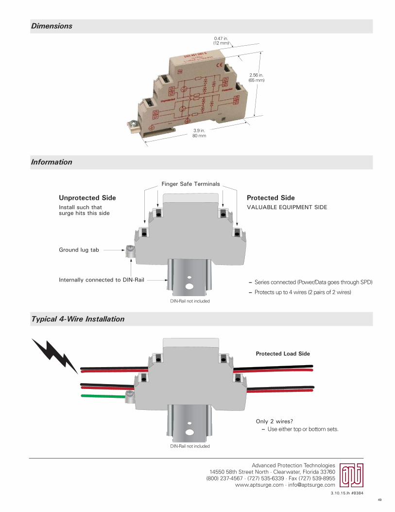
Advanced Protection Technologies14550 58th Street North · Clearwater, Florida 33760
(800) 237-4567 · (727) 535-6339 · Fax (727) 539-8955www.aptsurge.com · [email protected]
Finger Safe Terminals
Dimensions
Information
Typical 4-Wire Installation
DIN-Rail not included
0.47 in.(12 mm)
Unprotected SideInstall such that surge hits this side
Ground lug tab
Only 2 wires? – Use either top or bottom sets.
Internally connected to DIN-Rail
VALUABLE EQUIPMENT SIDE
Protected Side
Protected Load Side
– Series connected (Power/Data goes through SPD)
– Protects up to 4 wires (2 pairs of 2 wires)
DIN-Rail not included
3.9 in.80 mm
2.56 in.(65 mm)
3.10.15.lh #8384
49
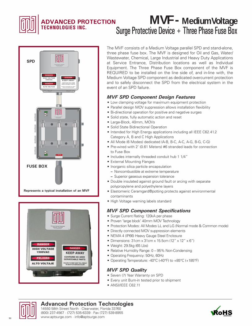
Advanced Protection Technologies14550 58th Street North · Clearwater, Florida 33760(800) 237-4567 · (727) 535-6339 · Fax (727) 539-8955www.aptsurge.com · [email protected]
MVF SPD Component Design Features• Low clamping voltage for maximum equipment protection• Parallel design MOV suppression allows installation flexibility • Bi-directional operation for positive and negative surges• Solid state, fully automatic action and reset• Large-Block, 40mm, MOVs• Solid State Bidirectional Operation• Intended for High Energy applications including all IEEE C62.41.2
Category A, B and C High Applications• All Mode (6 Modes) dedicated (A-B, B-C, A-C, A-G, B-G, C-G)• Pre-wired with 2’ (0.61 Meters) #6 stranded leads for connection
to Fuse Box• Includes internally threaded conduit hub 1 1/4”• External Mounting Flanges• Inorganic silica particle encapsulation
– Noncombustible at extreme temperature – Superior gaseous expansion tolerance
• Double insulated against ground fault or arcing with separate polypropylene and polyethylene layers
• Elastomeric Ceramgard®potting protects against environmental contaminants
• High Voltage warning labels standard
MVF SPD Component Specifications• Surge Current Rating: 120kA per phase• Proven ‘large block’ 40mm MOV Technology • Protection Modes: All Modes L-L and L-G (Normal mode & Common mode)• Directly connected MOV suppression elements• NEMA 4 (IP66) Heavy Gauge Steel Enclosure • Dimensions: 31cm x 31cm x 15.5cm (12” x 12” x 6”)• Weight: 29.5kg (65 Lbs)• Relative Humidity Range: 0 – 95% Non-Condensing• Operating Frequency: 50Hz, 60Hz• Operating Temperature: -40°C (-40°F) to +85°C (+185°F)
MVF SPD Quality• Seven (7) Year Warranty on SPD• Every unit Burn-in tested prior to shipment• ANSI/IEEE C62.11
The MVF consists of a Medium Voltage parallel SPD and stand-alone, three phase fuse box. The MVF is designed for Oil and Gas, Water/Wastewater, Chemical, Large Industrial and Heavy Duty Applications at Service Entrance, Distribution locations as well as Individual Equipment. The Three Phase Fuse Box component of the MVF is REQUIRED to be installed on the line side of, and in-line with, the Medium Voltage SPD component as dedicated overcurrent protection and to safely disconnect the SPD from the electrical system in the event of an SPD failure.
HIGH VOLTAGE
HIGH VOLTAGE1500VAC KEEP AWAY
CONTAINS NO USERSERVICEABLE PARTS
FAILURE TO KEEP AWAY WILL RESULTIN DEATH OR SERIOUS INJURYALTO VOLTAJE
DANGER
DANGER
DANGER
#8518
Advanced Protection TechnologiesClearwater, Florida USA
www.aptsurge.com
#8518
Advanced Protection TechnologiesClearwater, Florida USA
www.aptsurge.com
Represents a typical installation of an MVF
FUSE BOX
SPD
MVF - Medium VoltageSurge Protective Device + Three Phase Fuse Box
50
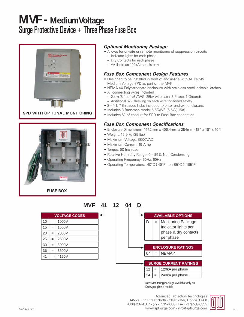
7.5.16.lh RevF
Advanced Protection Technologies14550 58th Street North · Clearwater, Florida 33760
(800) 237-4567 · (727) 535-6339 · Fax (727) 539-8955www.aptsurge.com · [email protected]
Optional Monitoring Package• Allows for on-site or remote monitoring of suppression circuits
– Indicator lights for each phase – Dry Contacts for each phase – Available on 120kA models only
Fuse Box Component Design Features• Designed to be installed in front of and in-line with APT’s MV
Medium Voltage SPD as part of the MVF.• NEMA 4X Polycarbonate enclosure with stainless steel lockable latches.• All connecting wires included
– 2.4m (8 ft) of #6 AWG, 25kV wire each (3 Phase, 1 Ground). – Additional 6kV sleeving on each wire for added safety.
• 2 – 1 ¼ ” threaded hubs included to enter and exit enclosure.• Includes 3 Bussman model 5.5CAVE (5.5kV, 15A).• Includes 6” of conduit for SPD to Fuse Box connection.
Fuse Box Component Specifications• Enclosure Dimensions: 457.2mm x 406.4mm x 254mm (18” x 16” x 10”)• Weight: 15.9 kg (35 lbs)• Maximum Voltage: 5500VAC• Maximum Current: 15 Amp• Torque: 80 Inch-Lbs• Relative Humidity Range: 0 – 95% Non-Condensing• Operating Frequency: 50Hz, 60Hz• Operating Temperature: -40°C (-40°F) to +85°C (+185°F)
MVF - Medium VoltageSurge Protective Device + Three Phase Fuse Box
VOLTAGE CODES10 = 1000V15 = 1500V20 = 2000V25 = 2500V30 = 3000V36 = 3600V41 = 4160V
SURGE CURRENT RATINGS12 = 120kA per phase24 = 240kA per phase
ENCLOSURE RATINGS04 = NEMA 4
AVAILABLE OPTIONSD = Monitoring Package:
Indicator lights per phase & dry contacts per phase
Note: Monitoring Package available only on 120kA per phase models
12 04 D41MVF
FUSE BOX
SPD WITH OPTIONAL MONITORING
51
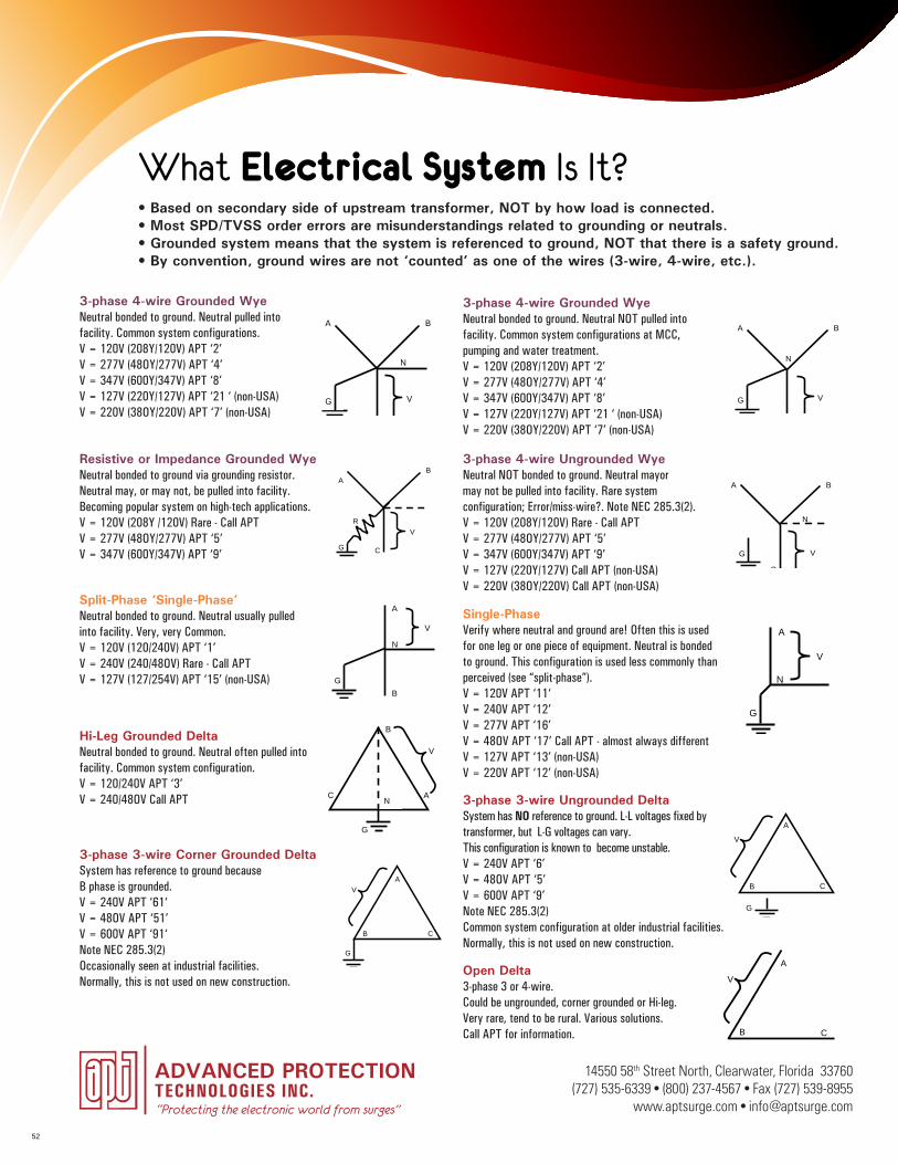
What Electrical System Is It?
3-phase 4-wire Grounded WyeNeutral bonded to ground. Neutral pulled into facility. Common system configurations.V = 120V (208Y/120V) APT ‘2’V = 277V (48OY/277V) APT ‘4’V = 347V (600Y/347V) APT ‘8’V = 127V (220Y/127V) APT ‘21 ‘ (non-USA)V = 220V (38OY/220V) APT ‘7’ (non-USA)
What Electrical System Is It? � Based on secondary side of upstream transformer, NOT by how load is connected � Most SPD/TVSS misorders are misunderstandings related to grounding or neutrals � Grounded system means that the system is referenced to ground, NOT that there is a safety ground � By convention, ground wires are not ‘counted’ as one of the wires (3-wire, 4-wire, etc.)
3-phase 4-wire Grounded Wye Neutral bonded to ground Neutral pulled into facility Common system configuration V = 120V (208Y/120V) APT ‘2’ V = 277V (480Y/277V) APT ‘4’ V = 347V (600Y/347V) APT ‘8’ V = 127V (220Y/127V) APT ‘21’ (non-USA) V = 220V (380Y/220V) APT ‘7’ (non-USA)
3-phase 3-wire Ungrounded DeltaSystem has no reference to ground L-L voltages fixed by transformer, but L-G voltages can vary; Known to become unstable.V = 240V APT ‘6’ V = 480V APT ‘5’ V = 600V APT ‘9’ Note NEC 285.3(2) Common system configuration at older industrial facilities, normally not used on new construction
3-phase 3-wire Corner Grounded Delta System has reference to ground because B phase is grounded V = 240V APT ‘61’ V = 480V APT ‘51’ V = 600V APT ‘91’ Note NEC 285.3(2) Occasionally seen at industrial facilities, normally not used on new construction
Hi-Leg Grounded Delta Neutral bonded to ground Neutral often pulled into facility Common system configuration V = 120/240V APT ‘3’ V = 240/480V Call’
Resistive or Impedance Grounded Wye Neutral bonded to ground via grounding resistor Neutral may, or may not, be pulled into facility Becoming popular system on high-tech V = 120V (208Y/120V) Rare - Call V = 277V (480Y/277V) APT ‘5’ V = 347V (600Y/347V) APT ‘9’
Open Delta3-phase 3 or 4-wire Could be ungrounded, corner grounded or Hi-leg Very rare, tend to be rural Various solutions, Call for info
C
BA
G
N
V
3-phase 4-wire Grounded WyeNeutral bonded to ground Neutral NOT pulled into facility Common system configuration at MCC, pumping and water treatment V = 120V (208Y/120V) APT ‘2’ V = 277V (480Y/277V) APT ‘4’ V = 347V (600Y/347V) APT ‘8’ V = 127V (220Y/127V) APT ‘21’ (non-USA) V = 220V (380Y/220V) APT ‘7’ (non-USA)
3-phase 4-wire Ungrounded WyeNeutral NOT bonded to ground Neutral may or may not be pulled into facility Rare system configuration; Error/miss-wire? Note NEC 285.3(2), V = 120V (208Y/120V) Rare - Call V = 277V (480Y/277V) APT ‘5’ V = 347V (600Y/347V) APT ‘9’ V = 127V (220Y/127V) Call (non-USA) V = 220V (380Y/220V) Call (non-USA)
C
BA
N
G V
C
BA
G
N
V
A
GB
N
V
R
C
B
G
A
V
A
G
N
V
Split-Phase ‘Single-Phase’Neutral bonded to ground Neutral usually pulled into facility Very, very Common V = 120V (120/240V) APT ‘1’ V = 240V (240/480V) Rare - Call V = 127V (127/254V) APT ‘15’ (non-USA)
Single-Phase Verify where Neutral and Ground are! Often for one leg or one piece of equip. Neutral bonded to ground Less common than perceived! V = 120V APT ‘11’ V = 240V APT ‘12’ V = 277V APT ‘16’ V = 480V APT ‘17’ Call – almost always different V = 127V APT ‘13’ (non-USA) V = 220V APT ‘12’ (non-USA)
B
A
G
NC
G
A
B C
V
A
B C
V
G
A
B C
VV
Rev Date: 3/16/09 Voltage Diagrams RevC
3-phase 4-wire Grounded WyeNeutral bonded to ground. Neutral NOT pulled into facility. Common system configurations at MCC, pumping and water treatment.V = 120V (208Y/120V) APT ‘2’V = 277V (48OY/277V) APT ‘4’V = 347V (600Y/347V) APT ‘8’V = 127V (220Y/127V) APT ‘21 ‘ (non-USA)V = 220V (38OY/220V) APT ‘7’ (non-USA)
Resistive or Impedance Grounded WyeNeutral bonded to ground via grounding resistor.Neutral may, or may not, be pulled into facility.Becoming popular system on high-tech applications.V = 120V (208Y /120V) Rare - Call APTV = 277V (48OY/277V) APT ‘5’V = 347V (600Y/347V) APT ‘9’
What Electrical System Is It? � Based on secondary side of upstream transformer, NOT by how load is connected � Most SPD/TVSS misorders are misunderstandings related to grounding or neutrals � Grounded system means that the system is referenced to ground, NOT that there is a safety ground � By convention, ground wires are not ‘counted’ as one of the wires (3-wire, 4-wire, etc.)
3-phase 4-wire Grounded Wye Neutral bonded to ground Neutral pulled into facility Common system configuration V = 120V (208Y/120V) APT ‘2’ V = 277V (480Y/277V) APT ‘4’ V = 347V (600Y/347V) APT ‘8’ V = 127V (220Y/127V) APT ‘21’ (non-USA) V = 220V (380Y/220V) APT ‘7’ (non-USA)
3-phase 3-wire Ungrounded DeltaSystem has no reference to ground L-L voltages fixed by transformer, but L-G voltages can vary; Known to become unstable.V = 240V APT ‘6’ V = 480V APT ‘5’ V = 600V APT ‘9’ Note NEC 285.3(2) Common system configuration at older industrial facilities, normally not used on new construction
3-phase 3-wire Corner Grounded Delta System has reference to ground because B phase is grounded V = 240V APT ‘61’ V = 480V APT ‘51’ V = 600V APT ‘91’ Note NEC 285.3(2) Occasionally seen at industrial facilities, normally not used on new construction
Hi-Leg Grounded Delta Neutral bonded to ground Neutral often pulled into facility Common system configuration V = 120/240V APT ‘3’ V = 240/480V Call’
Resistive or Impedance Grounded Wye Neutral bonded to ground via grounding resistor Neutral may, or may not, be pulled into facility Becoming popular system on high-tech V = 120V (208Y/120V) Rare - Call V = 277V (480Y/277V) APT ‘5’ V = 347V (600Y/347V) APT ‘9’
Open Delta3-phase 3 or 4-wire Could be ungrounded, corner grounded or Hi-leg Very rare, tend to be rural Various solutions, Call for info
C
BA
G
N
V
3-phase 4-wire Grounded WyeNeutral bonded to ground Neutral NOT pulled into facility Common system configuration at MCC, pumping and water treatment V = 120V (208Y/120V) APT ‘2’ V = 277V (480Y/277V) APT ‘4’ V = 347V (600Y/347V) APT ‘8’ V = 127V (220Y/127V) APT ‘21’ (non-USA) V = 220V (380Y/220V) APT ‘7’ (non-USA)
3-phase 4-wire Ungrounded WyeNeutral NOT bonded to ground Neutral may or may not be pulled into facility Rare system configuration; Error/miss-wire? Note NEC 285.3(2), V = 120V (208Y/120V) Rare - Call V = 277V (480Y/277V) APT ‘5’ V = 347V (600Y/347V) APT ‘9’ V = 127V (220Y/127V) Call (non-USA) V = 220V (380Y/220V) Call (non-USA)
C
BA
N
G V
C
BA
G
N
V
A
GB
N
V
R
C
B
G
A
V
A
G
N
V
Split-Phase ‘Single-Phase’Neutral bonded to ground Neutral usually pulled into facility Very, very Common V = 120V (120/240V) APT ‘1’ V = 240V (240/480V) Rare - Call V = 127V (127/254V) APT ‘15’ (non-USA)
Single-Phase Verify where Neutral and Ground are! Often for one leg or one piece of equip. Neutral bonded to ground Less common than perceived! V = 120V APT ‘11’ V = 240V APT ‘12’ V = 277V APT ‘16’ V = 480V APT ‘17’ Call – almost always different V = 127V APT ‘13’ (non-USA) V = 220V APT ‘12’ (non-USA)
B
A
G
NC
G
A
B C
V
A
B C
V
G
A
B C
VV
Rev Date: 3/16/09 Voltage Diagrams RevC
3-phase 4-wire Ungrounded WyeNeutral NOT bonded to ground. Neutral mayor may not be pulled into facility. Rare system configuration; Error/miss-wire?. Note NEC 285.3(2).V = 120V (208Y/120V) Rare - Call APTV = 277V (48OY/277V) APT ‘5’V = 347V (600Y/347V) APT ‘9’V = 127V (220Y/127V) Call APT (non-USA)V = 220V (38OY/220V) Call APT (non-USA)
Split-Phase ‘Single-Phase’Neutral bonded to ground. Neutral usually pulled into facility. Very, very Common.V = 120V (120/240V) APT ‘1’V = 240V (240/48OV) Rare - Call APTV = 127V (127/254V) APT ‘15’ (non-USA)
What Electrical System Is It? � Based on secondary side of upstream transformer, NOT by how load is connected � Most SPD/TVSS misorders are misunderstandings related to grounding or neutrals � Grounded system means that the system is referenced to ground, NOT that there is a safety ground � By convention, ground wires are not ‘counted’ as one of the wires (3-wire, 4-wire, etc.)
3-phase 4-wire Grounded Wye Neutral bonded to ground Neutral pulled into facility Common system configuration V = 120V (208Y/120V) APT ‘2’ V = 277V (480Y/277V) APT ‘4’ V = 347V (600Y/347V) APT ‘8’ V = 127V (220Y/127V) APT ‘21’ (non-USA) V = 220V (380Y/220V) APT ‘7’ (non-USA)
3-phase 3-wire Ungrounded DeltaSystem has no reference to ground L-L voltages fixed by transformer, but L-G voltages can vary; Known to become unstable.V = 240V APT ‘6’ V = 480V APT ‘5’ V = 600V APT ‘9’ Note NEC 285.3(2) Common system configuration at older industrial facilities, normally not used on new construction
3-phase 3-wire Corner Grounded Delta System has reference to ground because B phase is grounded V = 240V APT ‘61’ V = 480V APT ‘51’ V = 600V APT ‘91’ Note NEC 285.3(2) Occasionally seen at industrial facilities, normally not used on new construction
Hi-Leg Grounded Delta Neutral bonded to ground Neutral often pulled into facility Common system configuration V = 120/240V APT ‘3’ V = 240/480V Call’
Resistive or Impedance Grounded Wye Neutral bonded to ground via grounding resistor Neutral may, or may not, be pulled into facility Becoming popular system on high-tech V = 120V (208Y/120V) Rare - Call V = 277V (480Y/277V) APT ‘5’ V = 347V (600Y/347V) APT ‘9’
Open Delta3-phase 3 or 4-wire Could be ungrounded, corner grounded or Hi-leg Very rare, tend to be rural Various solutions, Call for info
C
BA
G
N
V
3-phase 4-wire Grounded WyeNeutral bonded to ground Neutral NOT pulled into facility Common system configuration at MCC, pumping and water treatment V = 120V (208Y/120V) APT ‘2’ V = 277V (480Y/277V) APT ‘4’ V = 347V (600Y/347V) APT ‘8’ V = 127V (220Y/127V) APT ‘21’ (non-USA) V = 220V (380Y/220V) APT ‘7’ (non-USA)
3-phase 4-wire Ungrounded WyeNeutral NOT bonded to ground Neutral may or may not be pulled into facility Rare system configuration; Error/miss-wire? Note NEC 285.3(2), V = 120V (208Y/120V) Rare - Call V = 277V (480Y/277V) APT ‘5’ V = 347V (600Y/347V) APT ‘9’ V = 127V (220Y/127V) Call (non-USA) V = 220V (380Y/220V) Call (non-USA)
C
BA
N
G V
C
BA
G
N
V
A
GB
N
V
R
C
B
G
A
V
A
G
N
V
Split-Phase ‘Single-Phase’Neutral bonded to ground Neutral usually pulled into facility Very, very Common V = 120V (120/240V) APT ‘1’ V = 240V (240/480V) Rare - Call V = 127V (127/254V) APT ‘15’ (non-USA)
Single-Phase Verify where Neutral and Ground are! Often for one leg or one piece of equip. Neutral bonded to ground Less common than perceived! V = 120V APT ‘11’ V = 240V APT ‘12’ V = 277V APT ‘16’ V = 480V APT ‘17’ Call – almost always different V = 127V APT ‘13’ (non-USA) V = 220V APT ‘12’ (non-USA)
B
A
G
NC
G
A
B C
V
A
B C
V
G
A
B C
VV
Rev Date: 3/16/09 Voltage Diagrams RevC
Single-PhaseVerify where neutral and ground are! Often this is used for one leg or one piece of equipment. Neutral is bonded to ground. This configuration is used less commonly than perceived (see “split-phase”).V = 120V APT ‘11‘V = 240V APT ‘12’V = 277V APT ‘16’V = 48OV APT ‘17’ Call APT - almost always differentV = 127V APT ‘13’ (non-USA)V = 220V APT ‘12’ (non-USA)
What Electrical System Is It? � Based on secondary side of upstream transformer, NOT by how load is connected � Most SPD/TVSS misorders are misunderstandings related to grounding or neutrals � Grounded system means that the system is referenced to ground, NOT that there is a safety ground � By convention, ground wires are not ‘counted’ as one of the wires (3-wire, 4-wire, etc.)
3-phase 4-wire Grounded Wye Neutral bonded to ground Neutral pulled into facility Common system configuration V = 120V (208Y/120V) APT ‘2’ V = 277V (480Y/277V) APT ‘4’ V = 347V (600Y/347V) APT ‘8’ V = 127V (220Y/127V) APT ‘21’ (non-USA) V = 220V (380Y/220V) APT ‘7’ (non-USA)
3-phase 3-wire Ungrounded DeltaSystem has no reference to ground L-L voltages fixed by transformer, but L-G voltages can vary; Known to become unstable.V = 240V APT ‘6’ V = 480V APT ‘5’ V = 600V APT ‘9’ Note NEC 285.3(2) Common system configuration at older industrial facilities, normally not used on new construction
3-phase 3-wire Corner Grounded Delta System has reference to ground because B phase is grounded V = 240V APT ‘61’ V = 480V APT ‘51’ V = 600V APT ‘91’ Note NEC 285.3(2) Occasionally seen at industrial facilities, normally not used on new construction
Hi-Leg Grounded Delta Neutral bonded to ground Neutral often pulled into facility Common system configuration V = 120/240V APT ‘3’ V = 240/480V Call’
Resistive or Impedance Grounded Wye Neutral bonded to ground via grounding resistor Neutral may, or may not, be pulled into facility Becoming popular system on high-tech V = 120V (208Y/120V) Rare - Call V = 277V (480Y/277V) APT ‘5’ V = 347V (600Y/347V) APT ‘9’
Open Delta3-phase 3 or 4-wire Could be ungrounded, corner grounded or Hi-leg Very rare, tend to be rural Various solutions, Call for info
C
BA
G
N
V
3-phase 4-wire Grounded WyeNeutral bonded to ground Neutral NOT pulled into facility Common system configuration at MCC, pumping and water treatment V = 120V (208Y/120V) APT ‘2’ V = 277V (480Y/277V) APT ‘4’ V = 347V (600Y/347V) APT ‘8’ V = 127V (220Y/127V) APT ‘21’ (non-USA) V = 220V (380Y/220V) APT ‘7’ (non-USA)
3-phase 4-wire Ungrounded WyeNeutral NOT bonded to ground Neutral may or may not be pulled into facility Rare system configuration; Error/miss-wire? Note NEC 285.3(2), V = 120V (208Y/120V) Rare - Call V = 277V (480Y/277V) APT ‘5’ V = 347V (600Y/347V) APT ‘9’ V = 127V (220Y/127V) Call (non-USA) V = 220V (380Y/220V) Call (non-USA)
C
BA
N
G V
C
BA
G
N
V
A
GB
N
V
R
C
B
G
A
V
A
G
N
V
Split-Phase ‘Single-Phase’Neutral bonded to ground Neutral usually pulled into facility Very, very Common V = 120V (120/240V) APT ‘1’ V = 240V (240/480V) Rare - Call V = 127V (127/254V) APT ‘15’ (non-USA)
Single-Phase Verify where Neutral and Ground are! Often for one leg or one piece of equip. Neutral bonded to ground Less common than perceived! V = 120V APT ‘11’ V = 240V APT ‘12’ V = 277V APT ‘16’ V = 480V APT ‘17’ Call – almost always different V = 127V APT ‘13’ (non-USA) V = 220V APT ‘12’ (non-USA)
B
A
G
NC
G
A
B C
V
A
B C
V
G
A
B C
VV
Rev Date: 3/16/09 Voltage Diagrams RevC
Hi-Leg Grounded DeltaNeutral bonded to ground. Neutral often pulled into facility. Common system configuration.V = 120/240V APT ‘3’V = 240/48OV Call APT
What Electrical System Is It? � Based on secondary side of upstream transformer, NOT by how load is connected � Most SPD/TVSS misorders are misunderstandings related to grounding or neutrals � Grounded system means that the system is referenced to ground, NOT that there is a safety ground � By convention, ground wires are not ‘counted’ as one of the wires (3-wire, 4-wire, etc.)
3-phase 4-wire Grounded Wye Neutral bonded to ground Neutral pulled into facility Common system configuration V = 120V (208Y/120V) APT ‘2’ V = 277V (480Y/277V) APT ‘4’ V = 347V (600Y/347V) APT ‘8’ V = 127V (220Y/127V) APT ‘21’ (non-USA) V = 220V (380Y/220V) APT ‘7’ (non-USA)
3-phase 3-wire Ungrounded DeltaSystem has no reference to ground L-L voltages fixed by transformer, but L-G voltages can vary; Known to become unstable.V = 240V APT ‘6’ V = 480V APT ‘5’ V = 600V APT ‘9’ Note NEC 285.3(2) Common system configuration at older industrial facilities, normally not used on new construction
3-phase 3-wire Corner Grounded Delta System has reference to ground because B phase is grounded V = 240V APT ‘61’ V = 480V APT ‘51’ V = 600V APT ‘91’ Note NEC 285.3(2) Occasionally seen at industrial facilities, normally not used on new construction
Hi-Leg Grounded Delta Neutral bonded to ground Neutral often pulled into facility Common system configuration V = 120/240V APT ‘3’ V = 240/480V Call’
Resistive or Impedance Grounded Wye Neutral bonded to ground via grounding resistor Neutral may, or may not, be pulled into facility Becoming popular system on high-tech V = 120V (208Y/120V) Rare - Call V = 277V (480Y/277V) APT ‘5’ V = 347V (600Y/347V) APT ‘9’
Open Delta3-phase 3 or 4-wire Could be ungrounded, corner grounded or Hi-leg Very rare, tend to be rural Various solutions, Call for info
C
BA
G
N
V
3-phase 4-wire Grounded WyeNeutral bonded to ground Neutral NOT pulled into facility Common system configuration at MCC, pumping and water treatment V = 120V (208Y/120V) APT ‘2’ V = 277V (480Y/277V) APT ‘4’ V = 347V (600Y/347V) APT ‘8’ V = 127V (220Y/127V) APT ‘21’ (non-USA) V = 220V (380Y/220V) APT ‘7’ (non-USA)
3-phase 4-wire Ungrounded WyeNeutral NOT bonded to ground Neutral may or may not be pulled into facility Rare system configuration; Error/miss-wire? Note NEC 285.3(2), V = 120V (208Y/120V) Rare - Call V = 277V (480Y/277V) APT ‘5’ V = 347V (600Y/347V) APT ‘9’ V = 127V (220Y/127V) Call (non-USA) V = 220V (380Y/220V) Call (non-USA)
C
BA
N
G V
C
BA
G
N
V
A
GB
N
V
R
C
B
G
A
V
A
G
N
V
Split-Phase ‘Single-Phase’Neutral bonded to ground Neutral usually pulled into facility Very, very Common V = 120V (120/240V) APT ‘1’ V = 240V (240/480V) Rare - Call V = 127V (127/254V) APT ‘15’ (non-USA)
Single-Phase Verify where Neutral and Ground are! Often for one leg or one piece of equip. Neutral bonded to ground Less common than perceived! V = 120V APT ‘11’ V = 240V APT ‘12’ V = 277V APT ‘16’ V = 480V APT ‘17’ Call – almost always different V = 127V APT ‘13’ (non-USA) V = 220V APT ‘12’ (non-USA)
B
A
G
NC
G
A
B C
V
A
B C
V
G
A
B C
VV
Rev Date: 3/16/09 Voltage Diagrams RevC
3-phase 3-wire Ungrounded DeltaSystem has NO reference to ground. L-L voltages fixed by transformer, but L-G voltages can vary. This configuration is known to become unstable.V = 240V APT ‘6’V = 48OV APT ‘5’V = 600V APT ‘9’Note NEC 285.3(2)Common system configuration at older industrial facilities. Normally, this is not used on new construction.
What Electrical System Is It? � Based on secondary side of upstream transformer, NOT by how load is connected � Most SPD/TVSS misorders are misunderstandings related to grounding or neutrals � Grounded system means that the system is referenced to ground, NOT that there is a safety ground � By convention, ground wires are not ‘counted’ as one of the wires (3-wire, 4-wire, etc.)
3-phase 4-wire Grounded Wye Neutral bonded to ground Neutral pulled into facility Common system configuration V = 120V (208Y/120V) APT ‘2’ V = 277V (480Y/277V) APT ‘4’ V = 347V (600Y/347V) APT ‘8’ V = 127V (220Y/127V) APT ‘21’ (non-USA) V = 220V (380Y/220V) APT ‘7’ (non-USA)
3-phase 3-wire Ungrounded DeltaSystem has no reference to ground L-L voltages fixed by transformer, but L-G voltages can vary; Known to become unstable.V = 240V APT ‘6’ V = 480V APT ‘5’ V = 600V APT ‘9’ Note NEC 285.3(2) Common system configuration at older industrial facilities, normally not used on new construction
3-phase 3-wire Corner Grounded Delta System has reference to ground because B phase is grounded V = 240V APT ‘61’ V = 480V APT ‘51’ V = 600V APT ‘91’ Note NEC 285.3(2) Occasionally seen at industrial facilities, normally not used on new construction
Hi-Leg Grounded Delta Neutral bonded to ground Neutral often pulled into facility Common system configuration V = 120/240V APT ‘3’ V = 240/480V Call’
Resistive or Impedance Grounded Wye Neutral bonded to ground via grounding resistor Neutral may, or may not, be pulled into facility Becoming popular system on high-tech V = 120V (208Y/120V) Rare - Call V = 277V (480Y/277V) APT ‘5’ V = 347V (600Y/347V) APT ‘9’
Open Delta3-phase 3 or 4-wire Could be ungrounded, corner grounded or Hi-leg Very rare, tend to be rural Various solutions, Call for info
C
BA
G
N
V
3-phase 4-wire Grounded WyeNeutral bonded to ground Neutral NOT pulled into facility Common system configuration at MCC, pumping and water treatment V = 120V (208Y/120V) APT ‘2’ V = 277V (480Y/277V) APT ‘4’ V = 347V (600Y/347V) APT ‘8’ V = 127V (220Y/127V) APT ‘21’ (non-USA) V = 220V (380Y/220V) APT ‘7’ (non-USA)
3-phase 4-wire Ungrounded WyeNeutral NOT bonded to ground Neutral may or may not be pulled into facility Rare system configuration; Error/miss-wire? Note NEC 285.3(2), V = 120V (208Y/120V) Rare - Call V = 277V (480Y/277V) APT ‘5’ V = 347V (600Y/347V) APT ‘9’ V = 127V (220Y/127V) Call (non-USA) V = 220V (380Y/220V) Call (non-USA)
C
BA
N
G V
C
BA
G
N
V
A
GB
N
V
R
C
B
G
A
V
A
G
N
V
Split-Phase ‘Single-Phase’Neutral bonded to ground Neutral usually pulled into facility Very, very Common V = 120V (120/240V) APT ‘1’ V = 240V (240/480V) Rare - Call V = 127V (127/254V) APT ‘15’ (non-USA)
Single-Phase Verify where Neutral and Ground are! Often for one leg or one piece of equip. Neutral bonded to ground Less common than perceived! V = 120V APT ‘11’ V = 240V APT ‘12’ V = 277V APT ‘16’ V = 480V APT ‘17’ Call – almost always different V = 127V APT ‘13’ (non-USA) V = 220V APT ‘12’ (non-USA)
B
A
G
NC
G
A
B C
V
A
B C
V
G
A
B C
VV
Rev Date: 3/16/09 Voltage Diagrams RevC
3-phase 3-wire Corner Grounded DeltaSystem has reference to ground because B phase is grounded.V = 240V APT ‘61‘V = 48OV APT ‘51’V = 600V APT ‘91‘Note NEC 285.3(2)Occasionally seen at industrial facilities.Normally, this is not used on new construction.
Open Delta3-phase 3 or 4-wire.Could be ungrounded, corner grounded or Hi-leg.Very rare, tend to be rural. Various solutions. Call APT for information.
What Electrical System Is It? � Based on secondary side of upstream transformer, NOT by how load is connected � Most SPD/TVSS misorders are misunderstandings related to grounding or neutrals � Grounded system means that the system is referenced to ground, NOT that there is a safety ground � By convention, ground wires are not ‘counted’ as one of the wires (3-wire, 4-wire, etc.)
3-phase 4-wire Grounded Wye Neutral bonded to ground Neutral pulled into facility Common system configuration V = 120V (208Y/120V) APT ‘2’ V = 277V (480Y/277V) APT ‘4’ V = 347V (600Y/347V) APT ‘8’ V = 127V (220Y/127V) APT ‘21’ (non-USA) V = 220V (380Y/220V) APT ‘7’ (non-USA)
3-phase 3-wire Ungrounded DeltaSystem has no reference to ground L-L voltages fixed by transformer, but L-G voltages can vary; Known to become unstable.V = 240V APT ‘6’ V = 480V APT ‘5’ V = 600V APT ‘9’ Note NEC 285.3(2) Common system configuration at older industrial facilities, normally not used on new construction
3-phase 3-wire Corner Grounded Delta System has reference to ground because B phase is grounded V = 240V APT ‘61’ V = 480V APT ‘51’ V = 600V APT ‘91’ Note NEC 285.3(2) Occasionally seen at industrial facilities, normally not used on new construction
Hi-Leg Grounded Delta Neutral bonded to ground Neutral often pulled into facility Common system configuration V = 120/240V APT ‘3’ V = 240/480V Call’
Resistive or Impedance Grounded Wye Neutral bonded to ground via grounding resistor Neutral may, or may not, be pulled into facility Becoming popular system on high-tech V = 120V (208Y/120V) Rare - Call V = 277V (480Y/277V) APT ‘5’ V = 347V (600Y/347V) APT ‘9’
Open Delta3-phase 3 or 4-wire Could be ungrounded, corner grounded or Hi-leg Very rare, tend to be rural Various solutions, Call for info
C
BA
G
N
V
3-phase 4-wire Grounded WyeNeutral bonded to ground Neutral NOT pulled into facility Common system configuration at MCC, pumping and water treatment V = 120V (208Y/120V) APT ‘2’ V = 277V (480Y/277V) APT ‘4’ V = 347V (600Y/347V) APT ‘8’ V = 127V (220Y/127V) APT ‘21’ (non-USA) V = 220V (380Y/220V) APT ‘7’ (non-USA)
3-phase 4-wire Ungrounded WyeNeutral NOT bonded to ground Neutral may or may not be pulled into facility Rare system configuration; Error/miss-wire? Note NEC 285.3(2), V = 120V (208Y/120V) Rare - Call V = 277V (480Y/277V) APT ‘5’ V = 347V (600Y/347V) APT ‘9’ V = 127V (220Y/127V) Call (non-USA) V = 220V (380Y/220V) Call (non-USA)
C
BA
N
G V
C
BA
G
N
V
A
GB
N
V
R
C
B
G
A
V
A
G
N
V
Split-Phase ‘Single-Phase’Neutral bonded to ground Neutral usually pulled into facility Very, very Common V = 120V (120/240V) APT ‘1’ V = 240V (240/480V) Rare - Call V = 127V (127/254V) APT ‘15’ (non-USA)
Single-Phase Verify where Neutral and Ground are! Often for one leg or one piece of equip. Neutral bonded to ground Less common than perceived! V = 120V APT ‘11’ V = 240V APT ‘12’ V = 277V APT ‘16’ V = 480V APT ‘17’ Call – almost always different V = 127V APT ‘13’ (non-USA) V = 220V APT ‘12’ (non-USA)
B
A
G
NC
G
A
B C
V
A
B C
V
G
A
B C
VV
Rev Date: 3/16/09 Voltage Diagrams RevC
“Protecting the electronic world from surges”
14550 58th Street North, Clearwater, Florida 33760(727) 535-6339 • (800) 237-4567 • Fax (727) 539-8955
www.aptsurge.com • [email protected]
• Based on secondary side of upstream transformer, NOT by how load is connected.• Most SPD/TVSS order errors are misunderstandings related to grounding or neutrals.• Grounded system means that the system is referenced to ground, NOT that there is a safety ground.• By convention, ground wires are not ‘counted’ as one of the wires (3-wire, 4-wire, etc.).
52
Frequently Asked QuestionsWHAT IS AN SPD?SPD is an abbreviation for “Surge Protective Device.” An SPD is a device that attenuates (reduces in magnitude) random, high energy, short duration electrical power anomalies caused by utilities, atmospheric phenomena or inductive loads.
Such anomalies occur in the form of voltage and current spikes with a duration of less than half an AC cycle. These high energy power spikes can damage sensitive electronic equipment, such as computers, instrumentation and process controllers.
WHERE ARE SURGE SUPPRESSORS INSTALLED?AC surge suppressors are typically installed in the following areas: 1. a utility service entrance for protection of an entire facility.2. in distribution panelboards and switchboards for protection of sensitive downstream loads.3. connected to a wall outlet for individual protection of a specific piece of equipment, such as a computer or solid-state controller
WHAT FEATURES SHOULD BE CONSIDERED WHEN SELECTING A SURGE SUPPRESSOR?Two important areas to consider during the selection of a surge suppressor are performance and safety. The performance of a surge suppressor is measured in surge current capacity and clamping voltage. Safety should also be a priority in this selection process. The individual suppression circuit should be fused to clear an inoperative MOV during an extreme transient event and provide overcurrent protection for the surge suppressor during a fault condition.
SPACE IS A CONCERN, DOES APT OFFER SOLUTIONS FOR DIN-RAIL APPLICATIONS?Yes. APT offers a wide range of DIN-Rail SPD solutions. Our AC products range from 120V to 600V. In addition, we have a series of DC and low voltage DIN-Rail surge suppressors. Our SPDee product is also DIN-Rail mountable.
I AM A SYSTEMS INTEGRATOR AND BUILD CUSTOM FABRICATIONS. WHAT DOES APT OFFER THAT WOULD PROTECT MY SOLUTIONS?We have a hard wired SPD solution for every type of panelboard, switchgear, motorcontrol and PLC application. Within our line of products we offer external, internal, modular and non-modular configurations. We also custom design.
WHAT SURGE CURRENT CAPACITY IS REQUIRED?Surge current capacity is dependent on the application and the amount of required protection. The selection of the proper surge suppressor is not an exact science and cannot be scientifically calculated from a standard algorithm.
Questions to consider when specifying the proper surge current capacity for surge a surge suppressor include: • What is the geographic location of the facility and its susceptibility to lightning? (For example, Florida is a high-lightning area; California is a low-lightning area.)• Is the facility in a rural or urban setting?• Is the facility the tallest building around?• Is the facility at the end of the utility grid?• If it is an existing facility, what is its power quality history?
DOES APT OFFER SPD PRODUCTS FOR RENEWABLE ENERGY APPLICATIONS?Yes. APT offers a variety of solutions that can accommodate both the needs of the wind and solar markets.
WHAT ARE YOUR STANDARD LEAD-TIMES?Our normal ship date is no more than 10 days from the receipt of the purchase order on custom builds and same day shipping for the most common modular and non-modular inventory units ordered before 2:00 pm EST.
WHY WOULD I BUY FROM APT?As a leading manufacturer of quality U.S. made products, our highly trained design engineers have designed SPD products that are of high quality, low in cost and contain the highest level of performance and safety features! You are working directly with the manufacturer. Who knows our product better than we do?
53
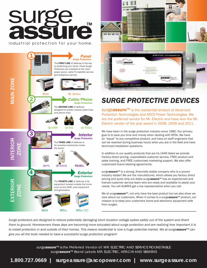
1.800.727.0669 | [email protected] | www.surgeassure.com
surgeassure™ is the Preferred Vendor of: MR. ELECTRIC AND SERVICE ROUNDTABLEsurgeassure™ Brand Labels: MR. ELECTRIC, HITACHI AND SIEMENS
MAI
N Z
ON
EIN
TER
IOR
ZO
NE
EXTE
RIO
R
ZON
E
surgeassure™ is the residential division of Advanced Protection Technologies and ASCO Power Technologies. We are the preferred vendor for Mr. Electric and have won the Mr. Electric vendor of the year award in 2008, 2009 and 2011.
We have been in the surge protection industry since 1985. Our primary goal is to save you time and money when dealing with SPDs. We have an “equal” to any competitive product, and have on staff engineers that can be reached during business hours when you are in the fi eld and have technical/installation questions.
In addition to our quality products that are UL-1449 listed we provide Factory-direct pricing, unparalleled customer service, FREE product and sales training, and FREE customized marketing support. We also offer customized brand labeling agreements.
surgeassure™ is a strong, fi nancially stable company who is a proven industry leader! We are the manufacturer, which allows you factory direct pricing and quick ship out dates surgeassure™ has an experienced and trained customer service team who are ready and available to assist your needs. You will ALWAYS get a live representative when you call.
We at surgeassure™, not only have the best product but we also show we care about our customers. When it comes to a surgeassure™ product, our mission is to keep your customers home and electronic equipment safe from surges.
S50A SA Series
Interior Surge Protectors
Cable/Phone Surge Protectors
Panel Surge Protectors
Exterior Surge Protectors
The FIRST LINE of defense is the key to protecting your home. Panel Surge Protectors are installed at the main power panel, cable TV/satellite service and telephone service.
The SECOND LINE of defense designed to protect coaxial cable lines and phone lines.
The THIRD LINE of defense is for sensitive electronics inside the home.
The FOURTH LINE of defense is for equipment located outside the home such as the HVAC, pool equipment and generators.
1
2
3
4
S50A SPDEE SPDEE DC
SAVFFF
SAP1 SP-6TVN PS-6DL
SATH2 SATHW2
SAP1 SP-6TVN PS-6DL
and telephone service.
Surge protectors are designed to reduce potentially damaging short duration voltage spikes safely out of the system and divert them to ground. Homeowners these days are becoming more educated about surge protection and are realizing how important it is to install protection in and outside of their homes. This means residential is now a huge potential market. We at surgeassure™ can give you all the tools needed to have a successful surge protection program!
SURGE PROTECTIVE DEVICES
54

14550 58th Street North, Clearwater, FL 33760
FOR TECHNICAL OR APPLICATION QUESTIONS, CONTACT:
800.237.4567
www.aptsurge.com10.27.17.RevL