![MONTAGE Supplimentary Manual - usa.yamaha.com · Logic Pro 1 [Logic Pro X] [Preferences] [Advanced] checkmark [Show Advanced Tools]. 2 [Logic Pro X] [Control Surfaces] [Setup…]](https://static.fdocuments.net/doc/165x107/5c4f0fea93f3c35438548b18/montage-supplimentary-manual-usa-logic-pro-1-logic-pro-x-preferences.jpg)
SPCway Setup guide - KNX & Logic Integration
35
SPCway Setup Guide V1.2.0 EN www.KNXlogic.eu Page 1 SPCway Setup guide In this document you find information on the following topics In this document you find information on the following topics ............................................................. 1 1 Create the EDP client on the SPC panel .......................................................................................... 3 2 Hook up the SPCway........................................................................................................................ 5 3 Logon to the SPCway website ......................................................................................................... 5 4 Configure the network IP address ................................................................................................... 7 5 Configure the Device physical KNX address .................................................................................... 8 6 Set the EDP client settings in the SPCway ....................................................................................... 9 7 Configure the communication objects and group addresses ....................................................... 10 7.1 General info ........................................................................................................................... 11 7.2 Event ...................................................................................................................................... 13 7.3 Status ..................................................................................................................................... 15 7.4 Command .............................................................................................................................. 17 8 Modbus.......................................................................................................................................... 19 8.1 Modbus configuration ........................................................................................................... 19 8.1.1 Modbus connection....................................................................................................... 19 8.1.2 Communication objects................................................................................................. 20 8.1.3 Profile parameters ......................................................................................................... 20 8.2 Modbus profile ...................................................................................................................... 21 8.3 Application level datatypes ................................................................................................... 22 9 Interface language ......................................................................................................................... 24 10 Supplementary features ............................................................................................................ 25 10.1 KNX Objects ........................................................................................................................... 25 10.2 Objects Logging ..................................................................................................................... 26 10.3 Alerts, Logs and Error log ...................................................................................................... 26 11 Advanced settings ..................................................................................................................... 27 11.1 Hostname .............................................................................................................................. 27 11.2 KNX-IP router & filtering........................................................................................................ 27
Transcript of SPCway Setup guide - KNX & Logic Integration
SPCway Setup Guide V1.2.0 EN www.KNXlogic.eu Page 1
SPCwaySetupguideIn this document you find information on the following topics
In this document you find information on the following topics ............................................................. 1
1 Create the EDP client on the SPC panel .......................................................................................... 3
2 Hook up the SPCway........................................................................................................................ 5
3 Logon to the SPCway website ......................................................................................................... 5
4 Configure the network IP address................................................................................................... 7
5 Configure the Device physical KNX address .................................................................................... 8
6 Set the EDP client settings in the SPCway ....................................................................................... 9
7 Configure the communication objects and group addresses ....................................................... 10
7.1 General info........................................................................................................................... 11
7.2 Event...................................................................................................................................... 13
7.3 Status..................................................................................................................................... 15
7.4 Command .............................................................................................................................. 17
8 Modbus.......................................................................................................................................... 19
8.1 Modbus configuration........................................................................................................... 19
8.1.1 Modbus connection....................................................................................................... 19
8.1.2 Communication objects................................................................................................. 20
8.1.3 Profile parameters......................................................................................................... 20
8.2 Modbus profile ...................................................................................................................... 21
8.3 Application level datatypes ................................................................................................... 22
9 Interface language......................................................................................................................... 24
10 Supplementary features............................................................................................................ 25
10.1 KNX Objects ........................................................................................................................... 25
10.2 Objects Logging ..................................................................................................................... 26
10.3 Alerts, Logs and Error log ...................................................................................................... 26
11 Advanced settings ..................................................................................................................... 27
11.1 Hostname .............................................................................................................................. 27
11.2 KNX-IP router & filtering........................................................................................................ 27

SPCway Setup Guide V1.2.0 EN www.KNXlogic.eu Page 2
11.3 Advanced General settings.................................................................................................... 28
Annex 1: Event definitions .................................................................................................................... 29
Annex 2: Status definitions.................................................................................................................... 34
Annex 3: Command definitions ............................................................................................................. 35
For a typical setup, you only need to go through steps 1 till 7.

SPCway Setup Guide V1.2.0 EN www.KNXlogic.eu Page 3
1 Create the EDP client on the SPC panelThe first step to do is to define an EDP receiver configuration for the SPCway, inside the SPC panel.
The manual will focus on the use of the web interface to do so, but it is equally possible with theother SPC configuration tools.
First logon locally to the SPC website as Engineer and go into ‘Full Engineer’ mode.
Then go to Communications > Reporting > EDP.
Click on the general ‘Settings’ button in order to:
- Verify the EDP is enabled- To set/modify/consult & note to SPC EDP Panel ID
Click Save and Back to return to the EDP window.
Click the Add button to open the EDP Receiver editing window.
The following parameters are particularly important:
- Receiver Id: this is the SPCway EDP ID. E.g.: 99- Protocol version: Version 2- Commands enable: check if you want to send commands to the SPC panel- Network enable: check- Network protocol: TCP/IP- Receiver IP address: the IP address you will assign to the SPCway, e.g.: 192.168.255.110- Receiver IP port: the port the SPCway needs to listen on: e.g. 50000- Always connected: check- Primary receiver: check, if events are needed. See note below- Event filter: turn on those events you need. IP Network congestion might be a consideration
not to enable all events. See note below.
Note: events are used for true event forwarding, but also to optimise fast status updates (~100ms). Iffor instance zone events are filtered, then the zone updates will have a typical maximal 2s lag.
Before logging off, do not forget to exit from the ‘Full Engineer’ mode.
The 4 values indicated in bold red above are needed to configure the SPCway.

SPCway Setup Guide V1.2.0 EN www.KNXlogic.eu Page 4
This is what the form would typically look like:

SPCway Setup Guide V1.2.0 EN www.KNXlogic.eu Page 5
2 Hook up the SPCwayThree connections are to be made
1) Power supply to the ‘DC 24V + & -‘ terminals.Any supply in the 12-24DVC range is OK, typical power consumption is ~1Watt. Either use aseparate PSU to power your SPCway, or use the 12V from the panel to provide power asshown below. (make sure to consider power consumption in the battery load calculation)
2) LAN: plug in your Ethernet cable to connect the SPCway to the same LAN and subnet as theSPC panel.
3) KNX-EIB: Optionally, connect the KNX bus cable to the SPCway. You can also connect to thebus line (or to several lines in larger installations) through the KNX-IP (EIBnet/IP) protocol.
You device is now starting up, give it about one minute.
3 Logon to the SPCway websiteDefault configuration information of the SPCway:
Parameter ValueDefault IP address Fixed IP: 192.168.0.10
Subnet: 255.255.255.0Configuration login:Username & password admin & adminHostname: SPCway
Assure your pc (or tablet) is on the same subnet as your SPCway. In other words, it needs a similar IPaddress: 192.168.0.xxx. You can do so by configuring a fixed IP address for your LAN adapter(example 192.168.0.9).
Google for ‘assign static IP address windows’ or ‘assign static IP address iPad’ if you needassistance with that.
Now open your browser and surf to http://192.168.0.10 or to http://SPCway.local/

SPCway Setup Guide V1.2.0 EN www.KNXlogic.eu Page 6
All common configuration can be accessed from the ‘KNX & SPC configuration’ page.
The ’System configuration’ page is only needed for very specific tasks or when instructed to do so.
Note: the use of the Hostname to surf to the device (SPCway.local by default) will only work from atablet/pc/phone with ‘zero config support’:
- Apple enabled devices: iPad, iPhone, Mac or PC with iTunes- Android devices: Android is gradually adding ‘zero config support’ to its operating system.
From a device which is not yet enabled: install the free app ‘ZeroConf Browser’. Under HTTPyou’ll find the SPCway with its IP-number. Surf to that IP number with any internet browser.
- From a PC without any Apple support: install ‘Bonjour for Windows’ from Apple (or installiTunes) and proceed as above.
- From a Linux device: assure you have a ‘zero config service’ running such as Ahavi

SPCway Setup Guide V1.2.0 EN www.KNXlogic.eu Page 7
4 Configure the network IP addressYou will probably want a different network IP address. Contact your network administrator if youneed assistance.
From the homepage open the ‘KNX & SPC configuration’ and log in.
Select tab Utilities->System->IP interface. (or Network->Interfaces in the System) and click on thefirst and only interface ‘eth0’ to get the configuration window:
This will open the interface configuration form:
Now set the IP address in line with the EDP client IP address you entered earlier in the SPC panel.

SPCway Setup Guide V1.2.0 EN www.KNXlogic.eu Page 8
5 Configure the Device physical KNX address
The physical KNX/EIB address configuration is done through the web interface. ETS is not needed toconfigure the device.
From the Configuration page, go to: tab ‘Utilities’ -> System -> ‘KNX connection’ (or from the Systempage -> Network -> KNX connection)
1) KNX address (physical address): assign in line with your KNX line addressing.2) Mode: If you have the KNX/EIB bus connected directly to the SPCway (on the red & black
sugar), then ‘Mode’ needs to be set to ‘TP-UART’. If you want to connect through KNX-IPwithout a direct bus connection, then put ‘Mode’ on ‘EIBnet/IP routing’
3) KNX IP features: with a TP KNX/EIB connection, you can switch on/off the KNX-IP features ifyou wish. (when using any other mode, KNX IP is always required)
You should not need to change the other settings in this tab.
Note: when logging in to the configuration page, you will be prompted with a warning if noTP connection was found while mode is set to TP-UART. When confirming the popup, theconfiguration will be changed (mode= EIBnet/IP routing, KNX-IP features=enabled).
When neither communication over TP or KNX-IP is possible,an error will be flagged in the Configuration page, at thebottom right corner:

SPCway Setup Guide V1.2.0 EN www.KNXlogic.eu Page 9
6 Set the EDP client settings in the SPCwayFrom the configuration homepage select the ‘KNX SPC config’ tab.
Select the listing of ‘General’ parameters:
Here you can set the three remaining EDP client settings as configured in the SPC.
To set a parameter, click in the listing, fill in the value in the popup window and click Save.
Once all three parameters are set, click the ‘Reload configuration’ button (see above) in order toactivate the changes.
Look in the Alerts tab to see if a stable connection is established.
You can now click the ‘Panel config. data’ button to see the element info retrieved from the panel.This info gets updated automatically every 10 minutes.

SPCway Setup Guide V1.2.0 EN www.KNXlogic.eu Page 10
7 Configure the communication objects and group addressesThe SPCway offers the possibility to create group addresses in a very flexible way. Even for a smallinstallation (4xxx based) one can easily imagine over thousand different communication objects tosuit every possible need you might have.
Due to this extreme flexibility, communication objects and group addresses are configured throughthe web interface. ETS cannot be used to configure the device.
There are three types of communication objects you can create:
- Events (SPC -> KNX/Modbus)- Statuses (SPC -> KNX/Modbus)- Commands (KNX/Modbus -> SPC)
A status is an information regarding the state of an element. An essential concept of a state, is that astate is always valid. Any event that invalidates the state (as defined) will result in a change of state.The only limitation on this is related to the polling and update frequency of a state. For moreinformation regarding status update frequency see ‘11.3 Advanced General settings’.
Events and Commands are linked to an event of the SPC panel. An essential concept of an event isthat it is only valid at the moment of the event. It loses is meaning immediately after that momentbecause another event can have occurred invalidating the former event. Example: a command ‘armperimeter’ @ 10:00:00 only means that at that moment such command was raised (and may or maynot have changed a state of the SPC). Looking at the value of the command @ 10:00:01 doesn’t tellanything about the state of the SPC panel, since another command might have been given in themean while (through another KNX command, direct user interaction, …)
Terminology:
1) Further in this document, the term element is used. Referring to such element, refers to oneof the ‘assets’ managed by the SPC panel: a zone, an area, a door, a user, an output, acamera, an expander, a node or a modem.
2) When referring to the element type ‘Output’, we refer to the broadest meaning of the term,in line with the SPC Installation manual term ‘Output’ : a Mapping gate (see section‘Configuring advanced settings’ of the SPC Installation manual). Such a mapping gate may belinked inside the SPC panel to a physical output, but this is not required.
For the first 5 element types listed above, the SPCway will get the list of configured elements fromthe SPC panel. This information is consultable on the ‘Panel config. data’ button and in the formcontrol tip texts.

SPCway Setup Guide V1.2.0 EN www.KNXlogic.eu Page 11
7.1 General infoFor each type of communication objects there is a separate listing on the ‘KNX SPC config’ tab. Clickthe button to show the listing.
To add a new communication object, click ‘Add new’
From the listing you can:
- edit the object: click any text field on the row- duplicate a communication object: click the duplication icon of the row- activate/deactivate a communication object: click the red/green round- delete a communication object: click the dele icon of the row- sort the objects: click on the required sort field in the header.
Editing generalities
When editing or creating a new communication object an edit form will appear:
The first field is always the ‘Class’. Since there are many commands, events and statuses, the Classallows to reduce the long list and find what you need faster.
The second field is always the selected event, status or command.
For most of the fields, there are control tip text boxes that appear when moving your cursor/mouseover the field. They give additional help to fill in the field. Example: when you need to fill in a zone ID,the tip text will show the list of all existing zones in the panel.

SPCway Setup Guide V1.2.0 EN www.KNXlogic.eu Page 12
‘Active’ field: you can have the communication object active or inactive. When inactive, the SPCwaywill not consider the communication object.
‘Description’ field: a free text field.
After making changes, you need to ‘Reload’ the configuration in order to take effect.

SPCway Setup Guide V1.2.0 EN www.KNXlogic.eu Page 13
7.2 EventEvents are raised on a given moment and indicate that something happens at a given moment intime. Once the event has been sent on the KNX bus, the last value of the event will persist, however,this might no longer represent the actual status. Events are in line with the SIA event definitions.
There are 135 different types of events distributed over 15 classes. See annex 1 for more informationon the possible events.
After selecting the Class and Event field:
i. Specify the element ID: most events are raised for a specific Element type (see annex 1). Inmost cases you can identify for which element you want to create a communication object.This is what you put in the third form field.Allowed values:
a. a single element ID: e.g. ‘2’ to report an event on door 2 onlyb. a comma separated list of element ID: e.g. ‘2, 4’c. ‘*’ to trigger the communication object on all elements
ii. Filter, for specific events: a limited number of events can be filtered even further becausethey are associated with a secondary element type (see annex 1). E.g., the door open eventcan be filtered on the user who triggers the event.When filtering is possible, the field in the form will be enabled after choosing the event type.If filtering is possible then the Filter field is mandatory. The Field description indicates onwhat element type you can filter, e.g. ‘Filter on Area ID’.Allowed values:
a. The filter can only be one element ID.b. If you do not want filtering, set it to ‘*’.
Note: If you want to filter on multiple ID’s, then duplicate the communication objectconfiguration and modify the filter value.
iii. ‘KNX group address’, ‘KNX data type’: specify on which group address and with what datatype the event needs to be reported.Even if you only need the Modbus side of the interface you still have to specify these values:the Modbus object (register/coil) definition is mirrored with the KNX objects.
iv. ‘KNX value’: the value to be sent when the event occurs. It can be :a. an explicit numeric value (in line with data type) e.g. ‘1’b. an explicit string value (data type string required)c. IV: ID Value = textual description/name of ID (data type string required)d. FV: Filter Value = textual description/name of the Filter (data type string required), if
presente. SV: SIA 2 letter code, followed by the ID Value (data type string required)f. SI: SIA 2 letter code, followed by the ID number (data type string required)g. TS: the TimeStamp of the event in time of the SPC panel (data type time required)

SPCway Setup Guide V1.2.0 EN www.KNXlogic.eu Page 14
Note: multiple events can report to the same address. In that case different events cansend different values
Note: one event can be linked to multiple communication objects. It the event is raised, allobjects will be verified and sent when applicable.

SPCway Setup Guide V1.2.0 EN www.KNXlogic.eu Page 15
7.3 StatusA status describes at any moment in time the actual state of an element or the system.
A status telegram is, by default, only sent when the status changes. The gateway will also respond toa read request on the configured group address.
There are 25 types of states grouped in 6 classes.
The status form upper part is similar to the event form, see section General info above.
The specific fields for the status communication objects are:
i. ‘Possible values’: this lists the native possible values of the status. Information only, seeAnnex 2. When there is no limitative list of possible values, this field is blank; e.g. the nameof a User.
ii. ‘Status type’: defines what needs to be done with the raw status value received from the SPCpanel. Possible values:- ‘Status string’: try to convert the raw value to a string and then send,- ‘Status value’: try to convert to a numeric value, then send,- ‘Converted’: define a conversion table. For every possible predefined value you can specifywhat value needs to be send.
iii. ‘Conversion table’: the button will enable when the Converted status type was selected. Thisopens a form such as this (for the example form above):

SPCway Setup Guide V1.2.0 EN www.KNXlogic.eu Page 16
Note: after the ‘Status type’ based convention, the gateway will try to translate the valueinto a KNX telegram of the specified KNX data type, and send it on the KNX bus.
iv. ‘Resend interval’: if specified, the telegram will be resend periodically with this interval(seconds), even if the value did not change.
v. ‘Resend @ value’: if a ‘resend interval’ is specified, and if also this value is specified, then theresend will only occur if the value to be send corresponds to the ‘Resend @ value’. If leftblank, the periodic resend will occur for any value.

SPCway Setup Guide V1.2.0 EN www.KNXlogic.eu Page 17
7.4 CommandThe SPCway can send 22 different types of commands, grouped in 5 classes. See Annex 3 for a list ofthese commands.
Upon receiving a value or telegram on the KNX bus or Modbus, the command will be executed on thepanel. Optionally a command feedback can be reported on a feedback communication object.
The status form upper part is similar to the event form, see section General info above.
On top of the generic fields like the Class and the command name, the command specific fields are:
i. ‘Element ID’: for most commands, it needs to be specific on which element (e.g. which door)it needs to be applied. This can be :
a. one element ID,b. a comma separated list of element ID’s: the command is applied to all listed,c. the predefined value ‘CV’ = Command Value: the value received on the command
object is used as element ID for the command
ii. ‘Option’: on certain specific commands a second option argument is needed (see annex 3).When available, the option field becomes enabled and is mandatory.Allowed values are:
a. the explicit value to be used, e.g. ‘1’ for audio message 1b. the predefined value ‘CV’ = Command Value: the value received on the command
object is used as option for the command
iii. ‘Send value filter’: when specified, the command will only be executed when the commandtelegram value corresponds to the value. If not matching, then the command request isdiscarded for this configuration (and reported on the feedback).

SPCway Setup Guide V1.2.0 EN www.KNXlogic.eu Page 18
iv. ‘KNX feedback object’: when a group address is specified, it creates a communication objectto report the error/success of the command. The datatype of this communication object isalways 8bit-Unsigned Integer. Possible values are:
a. 0 = successb. 2 = error, due to configurationc. 12 = error, panel in full engineer moded. 13 = error, panel not ready to receive such commande. 14 = error, command not enabledf. 15 = error, command not implementedg. 16 = command not initiated: filtered out (Send value filter)h. 17 = command issued but no panel reply
Advanced ETSIn case you want to rely on certain advanced ETS functions (filter tables) then use a dummyKNX device to virtually assign group addresses. Read the similar instructions in the document‘ComfoWay – KNX and ETS usage’ which you find on our website.

SPCway Setup Guide V1.2.0 EN www.KNXlogic.eu Page 19
8 Modbus
8.1 Modbus configurationThe Modbus configuration consists of three aspects:
- The modbus connection- The Modbus communication objects- The Modbus profile parameters
8.1.1 Modbus connectionThe Modbus connection can be configured with 4 parameters.
In the General configuration settings, the following modbus parameters are available. They can beadded by using the ‘Add’ button.
modbus.connect.type
Meaning: identification of the physical/logical layer of the communication.
Allowed values: rtu or tcp; rtu uses the rs-485 terminals
Default (if not specified): tcp
modbus.connect.params
Meaning: configuration of the communication.
Allowed values: a comma separated list of parameter-value pairs: parameter=’value’.
The allowed parameters depend on the modbus.connect.type setting
o In case of rtu : rsport: which physical serial port to use RS485 or RS232
Default value: RS485 baud
Allowed values: 110, 300, 600, 1200, 2400, 4800, 9600, 19200, 38400, 57600,115200, 230400, 460800, 500000Default value: 9600
databitsDefault Value: 8
stopbitsDefault Value: 1
parity: the parity bit usedAllowed values: E (even), O (odd), N (none)Default Value: E
duplex: the duplex setting usedAllowed values: H (half), F (full)Default Value: H

SPCway Setup Guide V1.2.0 EN www.KNXlogic.eu Page 20
o In case of tcp : ip : IP address or FQN of master/server
Default value: 192.168.0.20 ipport: IP port listening for Modbus communication
Default value: 502
modbus.connect.slaveid
Meaning: identification the Modbus slave-id of the SPCway
Allowed values: integer values
Default (if not specified): 10
modbus.connect.disabled
Meaning: used to enable/disable the Modbus feature
Allowed values: true or false
Default (if not specified): false
8.1.2 Communication objectsThe application layer Modbus communication objects are mirrored on the KNX communicationobjects: they are identical to the KNX communication objects as configured on the ‘KNX SPC config’tab, resulting in the automatically generated Objects listed on the ‘KNX objects’ tab.
Objects added manually on the KNX objects tab, or added by the KNX buss sniffer, but which are notthe SPC configured objects will be mirrored in the Modbus profile.
8.1.3 Profile parametersThe following parameters can also be added tot he ‘General’ parameters.
modbus.profile.usecoils
Meaning: indicates if coils are to be used (for the ‘bit’ application data type objects), oralways use registers including for ‘bit’ objects.
Allowed values: true or false
Default (if not specified): false

SPCway Setup Guide V1.2.0 EN www.KNXlogic.eu Page 21
modbus.profile.stable
Meaning: indicates how the Modbus profile file and addresses needs to be organized. In a‘stable’ profile, the object base address only depends on the internal configuration ID of theobject. As a result, in such profile the addresses of objects will never change when changing(adding/deleting/modifying) the SPCway objects configuration. In a ‘non stable’ profile theobjects are grouped per coil/register datatype, Read/Write property and applicationdatatype. This results in an easier to read profile. Small changes are unlikely to modify theaddresses of the objects, but large changes will most certainly change also Modbusaddresses of unmodified objetcs.
Allowed values: true or false
Default (if not specified): false
8.2 Modbus profileThe Modbus objects are mirrored with the KNX objects. All Modbus relevant data of these objectsare stored in a ‘modbus profile’.
From the SPC KNX config tab the description of the Modbus interface in terms of communicationobjects can be downloaded through the appropriated button.
The profile can be downloaded as text/html or as a csv file for easy editing.
Note: in any case, only the readable-writeable coils and registers are used. In other words: only‘discrete inputs’ and ‘holding registers’ are used. ‘Coils’ and ‘input registers’ are not used. The‘Read/Write’ property of an object does not change that.
The profile is a table with the following columns, each representing a property of the objects listed asrows :
- Name: name of the communication object, identical to the name found/generated in the‘KNX objects’ tab
- Type: indicates if the raw Modbus datetype used is a coil or register.- Read/Write: indicates if the object is R = Read only or W(R) = Write / Read. This property has
no raw Modbus meaning (see note above). It only has a meaning at application level: when avalue is written to a ‘discrete coil’ or ‘holding register’ which is not of type ‘W’, the receivedvalue will be dropped by the SPCway and the internal data table will not be updated (whenreading the value subsequently, it will still hold the old internally written value)
- Address : the Modbus address of the first element of the object, in the ‘true sense’ of theprotocol description. One object can be represented by several elements (see Length),depending on application data type used (see Data Type)
- Address: the 2nd address columns holds a combination of the object Modbus type numberand the address number.
- Data Type: the application datatype use to represent the object value (see next chapter)

SPCway Setup Guide V1.2.0 EN www.KNXlogic.eu Page 22
- Length: the number of elements (coils or registers) to represent this object. The addressrange start with the ‘Address’ and continues till offset ‘Length -1’, relative to the ‘Address’
- ID: internal unique and fixed ID of the object. When the option ‘stable profile’ is used, the‘Address’ solely depends on this ‘ID’.
- GA : KNX object Group Address, corresponding to this object, as listed in the ‘KNX Objects’tab
8.3 Application level datatypesThe Modbus protocol only consists of 2 formal base datatypes: bit (=coil) and 2-byte (=register)
However, on application level one or more bits/bytes are given a specific meaning. How to interpretethese bits/bytes is determined by the application level datatypes. The datatypes used in the modbusinterface are specified below.
All register example values in in hexadecimal notation where the 16 bits are listed as 4 4-bit hexvalues with a ‘h’ suffix: 1234h = 1*16^3 + 2*16^2 +3*16^+4
Note: when an application datatype such as uint16 is used, is doesn’t mean that all integer valuesthat can be represented are valid values: this depends on the objects settings in the KNX SPCconfiguration.
The following application datatypes are currently used in the Modbus interface:
- bit- uint16- uint32- string14- datetime
bit: represents a binary value 1 or 0 equivalent to true or false. Depending on themodbus.profile.usecoils parameter, this datatype is mapped to either 1 coil or 1 register. When aregister is used only the LSB is considered.
coil offset 0: bit
register offset 0: LSB
examples: A001h= true, 26F0h = false
uint16: this datatype is mapped to 1 register. It represents an integer value 0-65535
register offset 0 : integer 2byte value
example: 1001h = 1*16^3 + 1
uint32: this datatype is mapped to 2 registers. It represents an integer value 0 – 4294967295
register offset 0 : Least Significant 2-Byte value
register offset 1 : Most Significant 2-Byte value (is shifted 16 bits)

SPCway Setup Guide V1.2.0 EN www.KNXlogic.eu Page 23
example: 0001h 1001h = 1 + (1*16^3 + 1)* 2^16
datetime: this datatype is mapped to 7 registers. It represents a time and date indication
register offset 0 : Byte representing year
register offset 1 : Byte representing month
register offset 2 : Byte representing day
register offset 3 : Byte representing weekday (1-7 = sun-sat)
register offset 4 : Byte representing hours
register offset 5 : Byte representing minutes
register offset 6 : Byte representing seconds
example: 07DFh 0003h 0009h 0004h 000Ch 0005h 0010h
= 12:05:16 Wednesday 9 March 2015
Note: there is no KNX datatype that can hold both time and date in a single object. As a resultnot all subvalues of the type will contain data. In case of a dt.time KNX datatype object onlythe last 4 contain info (others ‘0’). In case of dt.date only the 3 first contain info (other ‘0’)
string14: this datatype is mapped to 7 registers. It represents a 14 character string in 7bit ASCII codes
register offset 0 : MSByte = char 2; LSByte = char 1
…
register offset 6 : MSByte = char 14; LSByte = char 13
example: 6854h 7369h 6920h 2073h 6574h 7473h 0021h = ‘This is test!’
SPCway Setup Guide V1.2.0 EN www.KNXlogic.eu Page 24
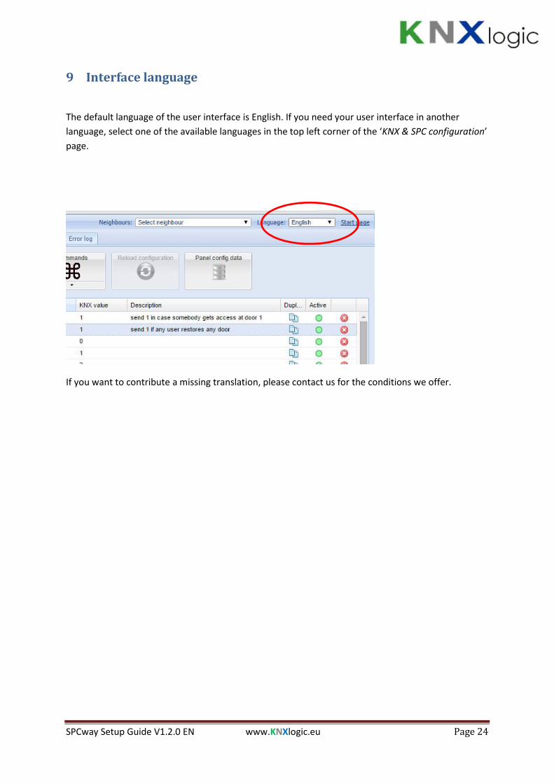
9 Interface language
The default language of the user interface is English. If you need your user interface in anotherlanguage, select one of the available languages in the top left corner of the ‘KNX & SPC configuration’page.
If you want to contribute a missing translation, please contact us for the conditions we offer.

SPCway Setup Guide V1.2.0 EN www.KNXlogic.eu Page 25
10 Supplementary features
10.1 KNX ObjectsA list of all managed KNX objects can be found in the KNX objects tab
In this tab you can:
- Consult the existing KNX objects,- Add objects (which are not parts of the SPCway configuration)- Modify object settings.
Note: for those objects created by the SPCway, you should not change the settings such asname or data type. When you do, they will be reset by the SPCway protocol daemon aftersome time.You can modify filtering.
- Write a value to the KNX bus: click on the ‘set value’ icon to the right of the row listing.- Delete objects: again, for objects created by the SPCway: you should not delete. When an
object is no longer configured, the SPCway daemon will remove it for you.- Filter the list by the panel on the left.
Object naming
When creating the objects the SPCway will try to give a clear name to facilitate the use of the ‘KNXobjects’ tab and the Logging tab. When multiple events/status/command are linked to one object,this is indicated by ‘(# n)’, where n is the number of links.

SPCway Setup Guide V1.2.0 EN www.KNXlogic.eu Page 26
Automatic object discovery
If you which, you can have the SPCway discover and list all KNX objects it detects on the bus. For thatpurpose you need to activate the buss sniffer. Go to the Utilities tab->’General Configuration’->’Bussniffer’.
10.2 Objects LoggingAll objects which are listed in the KNX objects tab, and for which the logging is activated, will belogged in the SPCway. The size of the Log can be set in the Utilities tab.
You can use the left pane to filter the log.
10.3 Alerts, Logs and Error logIn the interface you will also find three tabs which you normally do not need once everything runsfine. However, in order set up the SPCway, this can provide helpful information.
In normal operation, there will be very little messages in these three tabs.
However, if configuration issues are found, these will be reported here.
Example: if the EDP ID of the connected SPC panel does not match the configured ID, the connectionwill be stopped and reported in the Alerts.
This provides helpful information to diagnose the configuration.
If needed you can increase the verbosity of the alerts and logging. See the advanced settings sectionfor more details.

SPCway Setup Guide V1.2.0 EN www.KNXlogic.eu Page 27
11 Advanced settings
11.1 Hostname
You can change the hostname (ie ’SPCway’): ‘Sytem Configuration’ -> Menu ‘System’ -> ‘Hostname’
If you don’t use an internal DNS service, then you can use the hostname of your SPCway.Simply go to http://SPCway.local/ and all Apple enabled pc’s and tablets will find yourSPCway on the network. On Android, install the free ‘Zero Config Browser’ to easily find yourSPCway
If you have an internal DNS, then the network administrator can define a network name andIP-lease for your device.
11.2 KNX-IP router & filteringThe SPCway can be used as a KNX-IP router with advances filtering features.
When KNX-IP features are enabled, all telegram will be exchanged between the TP and the IP side.
In order to limit traffic in either or both directions, filters can be defined. These can be defined at:
- high level: go to the System configuration page -> Network -> KNX connection. Then modifythe filtering tabs accordingly. If you need further assistance then please contact us for adetailed explanation,
- Object level: in the KNX objects tab of the ‘KNX & SPC configuration’ page, you can specify forevery KNX object if and in which direction it can pass.

SPCway Setup Guide V1.2.0 EN www.KNXlogic.eu Page 28
11.3 Advanced General settingsThe following additional General parameters can be specified in the ‘General’ section of the the ‘KNXSPC config’ tab:
- DEBUG: when a value >0 is set, this will increase the amount of information that will be putin the alerts and logging tabs. This can help when diagnosing problems. It is suggested to notset the DEBUG value to a value larger than 1 for normal user purposes. Higher values aretargeted for specialist review. The amount of logging will be so extensive that it can degraderesponsiveness of the SPCway.
- UpdateInt.xxxx: For every type of element, there is a default polling interval for statusupdates. On top of that, updates are also triggered based of monitoring of specific relatedevents. For network performance reasons, and depending on event management strategies,it might be necessary to reduce the default intervals. This can be achieved by specifyingthese general parameters.If all events are forwarded to the SPCway (event forwarding active and no event filtering inthe SPC panel), then increasing the default polling intervals should have no functional effect.The default values are:
o Zone: 2so Area: 4so Door: 2so Output: 2so System: 2so User: 600s
SPCway Setup Guide V1.2.0 EN www.KNXlogic.eu Page 29
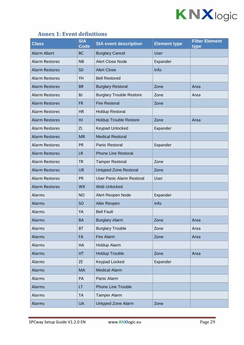
Annex 1: Event definitionsClass SIA
Code SIA event description Element type Filter Elementtype
Alarm Abort BC Burglary Cancel User
Alarm Restores NB Alert Close Node Expander
Alarm Restores SD Alert Close Info
Alarm Restores YH Bell Restored
Alarm Restores BR Burglary Restoral Zone Area
Alarm Restores BJ Burglary Trouble Restore Zone Area
Alarm Restores FR Fire Restoral Zone
Alarm Restores HR Holdup Restoral
Alarm Restores HJ Holdup Trouble Restore Zone Area
Alarm Restores ZL Keypad Unlocked Expander
Alarm Restores MR Medical Restoral
Alarm Restores PR Panic Restoral Expander
Alarm Restores LR Phone Line Restoral
Alarm Restores TR Tamper Restoral Zone
Alarm Restores UR Untyped Zone Restoral Zone
Alarm Restores PR User Panic Alarm Restoral User
Alarm Restores WX Web Unlocked
Alarms NO Alert Reopen Node Expander
Alarms SO Aller Reopen Info
Alarms YA Bell Fault
Alarms BA Burglary Alarm Zone Area
Alarms BT Burglary Trouble Zone Area
Alarms FA Fire Alarm Zone Area
Alarms HA Holdup Alarm
Alarms HT Holdup Trouble Zone Area
Alarms ZE Keypad Locked Expander
Alarms MA Medical Alarm
Alarms PA Panic Alarm
Alarms LT Phone Line Trouble
Alarms TA Tamper Alarm
Alarms UA Untyped Zone Alarm Zone

SPCway Setup Guide V1.2.0 EN www.KNXlogic.eu Page 30
Class SIACode SIA event description Element type Filter Element
typeAlarms WW Web Locked
Confirmed alarms BV Burglary Verified Area
Doors DC Access Closed Door User
Doors DD Access Denied Door User
Doors DG Access Granted Door User
Doors DO Access Open Door User
Doors DF Door Forced Door User
Doors DN Door Left Open Door User
Doors DR Door Restoral Door User
Doors ZA Reader Locked Door
Doors ZB Reader Unlocked Door
Doors DX Request to Exit Door
Doors AU Unknown Card Door
Early / Late CK Early Close User
Early / Late OK Early Open User
Early / Late OT Late To Close Area
Early / Late CT Late to Open AreaFault or TamperRestores AR AC Restoral
Fault or TamperRestores YK Communications Restoral Modem
Fault or TamperRestores EN Expansion Missing Restore Expander
Fault or TamperRestores ER Expansion Restoral Expander
Fault or TamperRestores EJ Expansion Tamper Restore
Fault or TamperRestores FJ Fire Trouble Restore Zone Area
Fault or TamperRestores MJ Medical Trouble Restore Zone
Fault or TamperRestores XZ Network Restoral
Fault or TamperRestores PJ Panic Trouble Restore Zone
Fault or TamperRestores YQ Power Supply Restored
Fault or TamperRestores XG PSU Battery Low Restoral Expander

SPCway Setup Guide V1.2.0 EN www.KNXlogic.eu Page 31
Class SIACode SIA event description Element type Filter Element
typeFault or TamperRestores XC PSU Output LV Close Expander
Fault or TamperRestores OV PSU Tamper Close Expander
Fault or TamperRestores XH RF Interference Restoral Zone
Fault or TamperRestores XJ RF Receiver Tamper Restoral Zone
Fault or TamperRestores YR System Battery Restoral
Fault or TamperRestores UJ Untyped Trouble Restore Zone Area
Fault or TamperRestores XR Wireless Battery Low Restoral
Faults or Tampers AT AC Trouble
Faults or Tampers YS Communications Trouble Modem
Faults or Tampers EM Expansion Device Missing Expander
Faults or Tampers ES Expansion Device Tamper
Faults or Tampers ET Expansion Trouble Expander
Faults or Tampers FT Fire Trouble Zone Area
Faults or Tampers HF Hardware Fault
Faults or Tampers MT Medical Trouble Zone
Faults or Tampers XY Network Fault
Faults or Tampers PT Panic Trouble Zone
Faults or Tampers YP Power Supply Trouble
Faults or Tampers XK PSU Battery Discharged Expander
Faults or Tampers XD PSU Battery Low Expander
Faults or Tampers XB PSU Output LV Open Expander
Faults or Tampers OU PSU Tamper Open Expander
Faults or Tampers XQ RF Interference Zone
Faults or Tampers XS RF Receiver Tamper Zone
Faults or Tampers YT System Battery Trouble
Faults or Tampers UT Untyped Zone Trouble Zone Area
Faults or Tampers XT Wireless Battery Low
Inhibit and Isolate BB Burglary Bypass Zone User
Inhibit and Isolate BU Burglary Unbypass Zone User
Inhibit and Isolate FB Fire Bypass Zone User

SPCway Setup Guide V1.2.0 EN www.KNXlogic.eu Page 32
Class SIACode SIA event description Element type Filter Element
typeInhibit and Isolate FU Fire Unbypass Zone User
Inhibit and Isolate HB Holdup bypass Zone User
Inhibit and Isolate HU Holdup Unbypass Zone User
Inhibit and Isolate MB Medical Bypass Zone User
Inhibit and Isolate MU Medical Unbypass Zone User
Inhibit and Isolate PB Panic Bypass Zone User
Inhibit and Isolate PU Panic Unbypass Zone User
Inhibit and Isolate TB Tamper Bypass Zone
Inhibit and Isolate TU Tamper Unbypass Zone
Inhibit and Isolate UB Untyped Zone Bypass Zone User
Inhibit and Isolate UU Untyped Zone Unbypass Zone User
Network NT Network Failure
Other JA Code Tamper Expander
Other LB Local Program
Other LX Local Programming Ended
Other RR Power up
Other JT Time changed
Other ZG User accessing end User Node
Other JP User accessing system begin User Node
Other JV User Code Changed
Other JX User Code Deleted
Other TC Walktest End Area
Other ZK Walktest Start Area
Other TP Zone Walked Zone
Other (Non- Standard) CV Camera offline Camera
Other (Non- Standard) CU Camera online Camera
Setting and Unsetting CG Close Area Area User
Setting and Unsetting CS Closing Keyswitch Zone
Setting and Unsetting CL Closing Report User
Setting and Unsetting CI Fail to Close Area
Setting and Unsetting OG Open Area Area
Setting and Unsetting OS Opening Keyswitch Zone Area

SPCway Setup Guide V1.2.0 EN www.KNXlogic.eu Page 33
Class SIACode SIA event description Element type Filter Element
typeSetting and Unsetting OP Opening Report User
Setting and Unsetting NL Perimeter Armed Area User
Setting and Unsetting CQ Remote Closing User
Setting and Unsetting OQ Remote Opening User
Unfiltered RP Automatic EDP-Modem Test Modem
Unfiltered RX Manual EDP-Modem Test User
Zone State Changes ZC Zone Close Zone Area
Zone State Changes ZD Zone Disconnect Zone Area
Zone State Changes ZF Zone Fault Zone Area
Zone State Changes ZM Zone Masked Zone Area
Zone State Changes ZO Zone Open Zone Area
Zone State Changes ZI Zone Out Of Bounds Zone Area
Zone State Changes ZX Zone Short Zone Area
Zone State Changes ZN Zone Unstable Zone Area

SPCway Setup Guide V1.2.0 EN www.KNXlogic.eu Page 34
Annex 2: Status definitionsClass Status name Element Type Possible predefined values
Area Area mode Area Unset, Partset_A, Partset_B, FullsetArea Area name Area
Door Door status DoorNORMAL, LOCKED, UNLOCKED,OPEN_TOO_LONG, LEFT_OPEN,FORCED, TAMPER, OFFLINE
Door Door Zone state Door OPEN, CLOSED, SHORT, DISCON,DCSUB, OFFLINE
Door Door name DoorOutput Output status Output 1, 0System Panel product name SystemSystem Panel Firmware version SystemSystem Panel Product ID SystemSystem Full engineer mode active System 1, 0System System Tampered System 1, 0System System General fault System 1, 0System System Mains fault System 1, 0System System Battery fault System 1, 0System System Ext. Bell active System 1, 0System System Ext. Strobe active System 1, 0System System Int. Bell active System 1, 0System Modem 1 not responding System 1, 0System Modem 1 Line fault System 1, 0System Modem 2 not responding System 1, 0System Modem 2 Line fault System 1, 0User User name User
Zone Zone state Zone
OPEN, CLOSED, ALARM, ISOLATE,MASKED, INHIBIT, SOAK, OFFLINE,DCSUB, TROUBLE, SHORT, DISCON,FAULT
Zone Zone type Zone
ALARM, ENTRYEXIT, EXITTERM,FIRE, FIREX, LINE, PANIC, HOLDUP,TAMPER, FAULT1, FAULT_HOLDUP,FAULT_WARNING, TECH, MEDIC,KEYARM, SHUNT, XSHUNT,LOCKSUP, SEISMIC, ALL OKAY,SETTING_AUTH, LOCK_ELEMENT,GLASS
Zone Zone name Zone

SPCway Setup Guide V1.2.0 EN www.KNXlogic.eu Page 35
Annex 3: Command definitions
Class Command Name Element type Option
Area Force Set Area Area
Area Partset A an area Area
Area Partset B an area Area
Area Set an area Area
Area Unset an area Area
Verification Zone Audio Challenge Verification Zone Number of the Audiomessage to be played
Door De-inhibit door zones Door
Door De-isolate door zones Door
Door Inhibit door zones Door
Door Isolate door zones Door
Door Lock a door Door
Door Open a door momentarily Door
Door Open a door permanently Door
Door Set a door to normal mode Door
Output Reset outputs Output
Output Set outputs Output
System Restore alerts System
System Silence All Bells System
User N/A User
Zone De-inhibit zones Zone
Zone De-isolate zones Zone
Zone Inhibit zones Zone
Zone Isolate zones Zone