spc / rpc - EMG Pickups€¦ · Diagram #1 Powering up the pickups: If your existing active pickup...
4
0.025 LOG FREQ (kHz) 10 10 dB/div Dimensions: .975 .650 0.025 LOG FREQ (kHz) 10 10 dB/div INPUT GROUND GROUND OUTPUT V++ SPC / RPC SPECIFICATIONS Input Impedance (Ohms) 250K Input Referred Noise -130dbV Output Impedance (Ohms) 2K Current @ 9V (Microamps) 980 Battery Life (Hours) 250 Maximum Supply (Volts DC) 18 INSTALLATION INFORMATION EMG MODELS: SPC / RPC (ACTIVE/PASSIVE PICKUP INPUTS) Warranty All EMG Pickups and accessories are warranted for a period of two years. This warranty does not cover failure due to improper installation, abuse or damage. If upon examination the pickup is determined to be defective, a replacement will be made. Warranty replacement products are covered by this same warranty. This warranty covers only those pickups and accessories sold by authorized EMG Dealers. This warranty is not transferable. © 2009 Copyright EMG INC. All Rights Reserved. PO BOX 4394 SANTA ROSA, CA 95402 USA P (707) 525-9941 F (707) 575-7046 EMGPICKUPS.COM 0230-0160A Frequency Response: EMG-SPC 1.325 .400 .309 (8mm P .75) GENERAL OPERATION: The SPC and RPC are active EQ circuits for guitar. The SPC is a mid-range boost. The RPC is a low cut/high boost. The graphs below illustrate the effects of the controls. The thick black line displays the effect with the control all the way up (clockwise). The flat black line illustrates the effect with the control all the way down (counter-clockwise) in the bypass mode. The controls are continuously variable from flat to maximum effect. The SPC and RPC are wired in series with the signal path, so there is an input and output. Both controls feature buffered inputs and can be used with passive pickups. Connector for EMG Active Tone controls and accessories. Pin 1 Input Pin 2 Ground for Input Pin 3 Ground for Output Pin 4 Output Pin 5 V+ Supply EMG-RPC 1 2 3 4 5 1 2 3 4 5 INCLUDED: 1 SPC or RPC Control 1 Battery Clip with Buss Connector 1 Stereo Output Jack (Battery Switching) 2 Interconnect cables
Transcript of spc / rpc - EMG Pickups€¦ · Diagram #1 Powering up the pickups: If your existing active pickup...
0.025 LOG FREQ (kHz) 10 1
0 d
B/d
iv
Dimensions:
.975
.650
0.025 LOG FREQ (kHz) 10
10
dB
/d
iv
INPUTGROUNDGROUNDOUTPUTV++
SPC / RPC
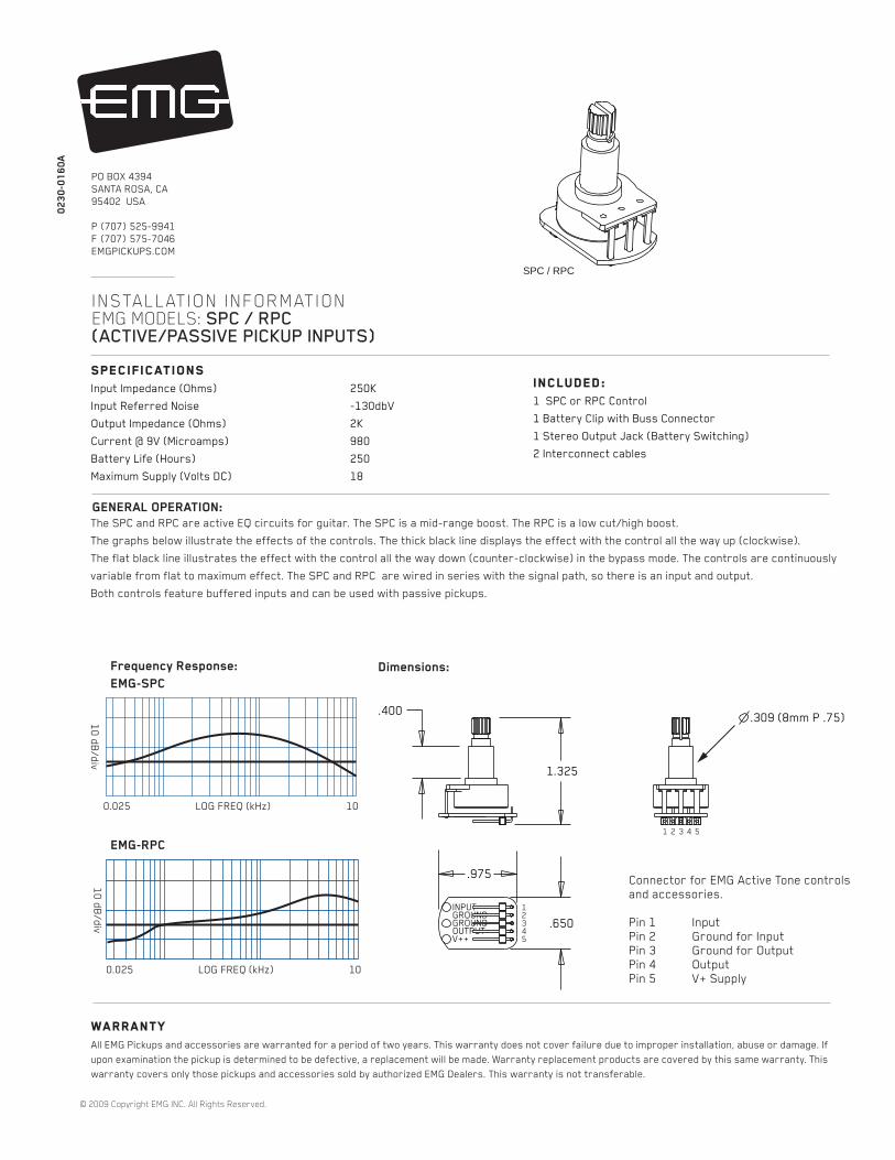
SPECIFICATIONSInput Impedance (Ohms) 250K
Input Referred Noise -130dbV
Output Impedance (Ohms) 2K
Current @ 9V (Microamps) 980
Battery Life (Hours) 250
Maximum Supply (Volts DC) 18
INSTALLATION INFORMATION EMG MODELS: SPC / RPC(ACTIVE/PASSIVE PICKUP INPUTS)
WarrantyAll EMG Pickups and accessories are warranted for a period of two years. This warranty does not cover failure due to improper installation, abuse or damage. If
upon examination the pickup is determined to be defective, a replacement will be made. Warranty replacement products are covered by this same warranty. This
warranty covers only those pickups and accessories sold by authorized EMG Dealers. This warranty is not transferable.
© 2009 Copyright EMG INC. All Rights Reserved.
PO BOX 4394
SANTA ROSA, CA
95402 USA
P (707) 525-9941
F (707) 575-7046
EMGPICKUPS.COM
02
30
-01
60
A
Frequency Response:
EMG-SPC
1.325
.400.309 (8mm P .75)
GENERAL OPERATION:
The SPC and RPC are active EQ circuits for guitar. The SPC is a mid-range boost. The RPC is a low cut/high boost.
The graphs below illustrate the effects of the controls. The thick black line displays the effect with the control all the way up (clockwise).
The flat black line illustrates the effect with the control all the way down (counter-clockwise) in the bypass mode. The controls are continuously
variable from flat to maximum effect. The SPC and RPC are wired in series with the signal path, so there is an input and output.
Both controls feature buffered inputs and can be used with passive pickups.
Connector for EMG Active Tone controls
and accessories.
Pin 1 Input
Pin 2 Ground for Input
Pin 3 Ground for Output
Pin 4 Output
Pin 5 V+ Supply
EMG-RPC
12345
1 2 3 4 5
INCLUDED:1 SPC or RPC Control
1 Battery Clip with Buss Connector
1 Stereo Output Jack (Battery Switching)
2 Interconnect cables

Diagram #1
Powering up the pickups:If your existing active pickup cables don’t have the connector for the
power buss, simply use some needle nose pliers and pull out the
V+ header and solder the RED Wires of the EMG Pickups to any
of the pins on the header. Also, don’t forget to solder the RED Wire
of the battery clip to one of the header pins of the buss as well.
Like all EMG Accessory products, the SPC and RPC use a 5-pin connector.
Diagram #1 to the right shows how the plug-in connectors are installed.
Be sure to reverse the input connector as shown.
Since there are a variety of installations in which the SPC or RPC can be installed it
is impossible to show every installation in this data sheet. Some of the simpler
installations have been chosen. More diagrams are available at our website
http://www.emgpickups.com.
Diagrams #2 and #3 illustrate installations that have a single pickup and
do not use a selection switch.
Page 3 has diagrams that have 2 pickups and a selection switch.
Page 4 has diagrams that have 3 pickups and use the B161v4 five position
selection switch/buss. If you have the B161v4, refer to that data sheet where
more options regarding the 3-pickup instruments are available.
Keep in mind that all of the EMG Accessory controls can be substituted for one
another since they all have buffered inputs and utilize the same 5-pin connnector.
So, if you decide you would rather use the EXG instead of the SPC, simply unplug
the SPC and replace it with the EXG.
Installation Instructions:
EMG Models: SPC and RPC
SPC / RPC Page 2
Solder RED wires from both
EMG Pickups and the
RED wire of the Battery Clip
and re-insert the Header
into the insulation cover
1 2 3
Note: Reversed connector! Pins 1 and 2 are reversed.
Make sure the connectors are plugged on as shown.
All of the EMG Active controls use the same 5-pin connector
shown below.
Diagram #2
One Pickup
One Volume
One SPC or RPC
OUTPUT
T
R
SFROM PICKUP
BATTERY
NEG (-)
RED
RED
BATTERY
BUSS
OUTPUT CABLE
MASTER
VOLUME
- 9V +
SPC or RPC
ACTIVE TONE
RED
MASTER TONE
(PASSIVE)
Diagram #3
One Pickup
One Volume
One Master Tone (Passive)
One SPC or RPC
OUTPUT
T
R
SFROM PICKUP
BATTERY
NEG (-)
RED
RED
BATTERY
BUSS
OUTPUT CABLE
MASTER
VOLUME
- 9V +
SPC or RPC
ACTIVE TONE
RED
NOTE:
REVERSED CONNECTOR
NOTE:
REVERSED CONNECTOR
If you are installing EMG-HZ Passive Pickups refer to
their diagrams. The Red Wire of the HZ Pickup is NOT
for battery power, it is a coil wire.
MASTER TONE
(PASSIVE)
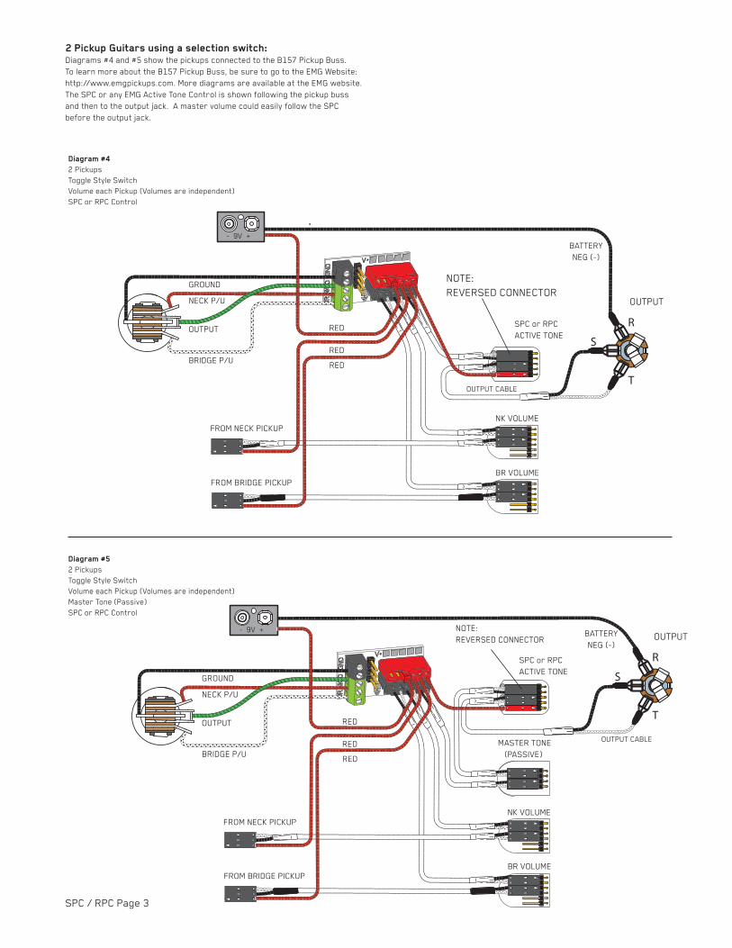
2 Pickup Guitars using a selection switch:Diagrams #4 and #5 show the pickups connected to the B157 Pickup Buss.
To learn more about the B157 Pickup Buss, be sure to go to the EMG Website:
http://www.emgpickups.com. More diagrams are available at the EMG website.
The SPC or any EMG Active Tone Control is shown following the pickup buss
and then to the output jack. A master volume could easily follow the SPC
before the output jack.
SPC / RPC Page 3
OUTPUT
T
R
S
NK VOLUME
FROM NECK PICKUP
FROM BRIDGE PICKUP
BR VOLUME
BATTERY
NEG (-)
Diagram #4
2 Pickups
Toggle Style Switch
Volume each Pickup (Volumes are independent)
SPC or RPC Control
OUTPUT CABLE
RED
RED
RED
GROUND
BRIDGE P/U
NECK P/U
OUTPUT
NOTE:
REVERSED CONNECTOR
- 9V +
SPC or RPC
ACTIVE TONE
NK VOLUME
FROM NECK PICKUP
FROM BRIDGE PICKUP
BR VOLUME
BATTERY
NEG (-)
Diagram #5
2 Pickups
Toggle Style Switch
Volume each Pickup (Volumes are independent)
Master Tone (Passive)
SPC or RPC Control
OUTPUT CABLE
RED
RED
RED
GROUND
BRIDGE P/U
NECK P/U
OUTPUT
NOTE:
REVERSED CONNECTOR
- 9V +OUTPUT
T
R
S
SPC or RPC
ACTIVE TONE

VOLUME CONTROL
Diagram #6
Volume Control
Tone (Passive)
SPC Control
TONE CONTROL
(PASSIVE)
SPC CONTROL
OUTPUT TO JACK
VOLUME CONTROL
Diagram #7
Tone (Passive)
SPC Control
Volume Control
TONE CONTROL
(PASSIVE)
SPC CONTROL
OUTPUT TO JACK
SPC / RPC Page 4
3 Pickup Guitars using a selection switch:Diagrams #6, #7 show a typical installation with a Volume/Tone/SPC in a
“daisy-chain” series wiring. The only difference between the the diagrams
is the order in which the controls are wired. The diagrams yield the same
results. The diagrams have been edited to show the SPC input, output,
and power (9V+). The pickup inputs, battery, and “ring”contact to the jack
have been omitted for clarity.
All diagrams show the B161 5-Position switch buss. To learn more
about the B161 5-Position switch Buss, go to the EMG Website:
http://www.emgpickups.com.
Refer to Diagram #6
Start by installing the SPC or RPC as shown in Diagram #6.
1) Plug a coax cable from the output switch to the Volume control.
2) Plug a coax cable from the Volume control to the Tone control.
3) Plug a coax cable from the Tone control to the input of the SPC.
Be sure to reverse the connector on the input of the SPC as shown.
4) Plug the output cable from the SPC to the output jack.
5) Plug the Red wire from the SPC to one of the supply pins on the
B161 Switch Buss.
Be sure the 3 shunts are installed on the bypass header of the
B161 switch or you won’t get any output from the guitar.
Refer to Diagram #7
Start by installing the SPC or RPC as shown in Diagram #7.
1) Plug a coax cable from the output switch to the Tone control.
2) Plug a coax cable from the Tone control to the input of the SPC.
Be sure to reverse the connector on the input of the SPC as shown.
3) Plug a coax cable from the output of the SPC to the Volume control.
4) Plug the output cable from the Volume control to the output jack.
5) Plug the Red wire from the SPC to one of the supply pins on the
B161 Switch Buss.
Be sure the 3 shunts are installed on the bypass header of the
B161 switch or you won’t get any output from the guitar.
Refer to Diagram #8
Diagram #8 shows 2 active controls installed: SPC and VLPF. This is
the same as the X Series Pickups that use an active tone (VLPF)
and adding the SPC Control.
Start by installing the SPC or RPC as shown in Diagram #8.
1) Plug a coax cable from the output switch to the Volume control.
2) Plug a coax cable from the Volume control to the input of the VLPF.
Be sure to reverse the connector on the input of the VLPF as shown.
3) Plug a coax cable from the output of the VLPF to the input of the SPC.
Be sure to reverse the connector on the input of the SPC as shown.
4) Plug the output cable from the SPC to the output jack.
5) Plug the Red wires from both the VLPF and SPC to the extra 9V+
supply pins on the B161 Switch Buss.
Be sure the 3 shunts are installed on the bypass header of the
B161 switch or you won’t get any output from the guitar.
VOLUME CONTROL
Diagram #8
Volume Control
Tone (Active VLPF)
SPC Control
TONE CONTROL
(ACTIVE VLPF) SPC CONTROL
OUTPUT TO JACK
NOTE:
REVERSED CONNECTOR
NOTE:
REVERSED CONNECTOR
NOTE:
REVERSED CONNECTORS