Spatial tuning of negative and positive Poisson’s ratio...
8
Spatial tuning of negative and positive Poisson’s ratio in a multi-layer scaffold Pranav Soman a,1 , Jin Woo Lee a,1 , Ameya Phadke b , Shyni Varghese b , Shaochen Chen a,⇑ a Department of NanoEngineering, University of California, San Diego, 9500 Gilman Drive, Atkinson Hall, MC-0448, La Jolla, CA 92093, USA b Department of Bioengineering, University of California, San Diego, 9500 Gilman Drive, Powell-Focht Bioengineering Hall, MC-0412, La Jolla, CA 92093, USA article info Article history: Received 22 November 2011 Received in revised form 11 March 2012 Accepted 21 March 2012 Available online 28 March 2012 Keywords: Poisson’s ratio Biomaterials Tissue engineering Porous scaffolds Poly(ethylene) glycol abstract While elastic modulus is tunable in tissue engineering scaffolds, it is substantially more challenging to tune the Poisson’s ratio of scaffolds. In certain biological applications, scaffolds with a tunable Poisson’s ratio may be more suitable for emulating the behavior of native tissue mechanics. Here, we design and fabricate a scaffold, which exhibits simultaneous negative and positive Poisson’s ratio behavior. Cus- tom-made digital micro-mirror device stereolithography was used to fabricate single- and multiple-layer scaffolds using polyethylene glycol-based biomaterial. These scaffolds are composed of pore structures having special geometries, and deformation mechanisms, which can be tuned to exhibit both negative Poisson’s ratio (NPR) and positive Poisson’s ratio (PPR) behavior in a side-to-side or top-to-bottom con- figuration. Strain measurement results demonstrate that analytical deformation models and simulations accurately predict the Poisson’s ratios of both the NPR and PPR regions. This hybrid Poisson’s ratio prop- erty can be imparted to any photocurable material, and potentially be applicable in a variety of biomed- ical applications. Ó 2012 Acta Materialia Inc. Published by Elsevier Ltd. All rights reserved. 1. Introduction Elastic modulus and Poisson’s ratio of a tissue engineering scaf- fold directly reflect its ability to handle various loading conditions, and must be tailored to match the attributes of the target tissue [1,2]. Ideally, the elastic response of a biomaterial should be opti- mized for the intended application; this requires control over pore size and architecture, while ensuring optimal environmental acces- sibility and interconnectedness of the pore network. Although stiff- ness of biomaterials themselves can be tuned by modifying properties such as cross-link density and swelling ratio [3,4], it is substantially more challenging to tune the Poisson’s ratio of scaf- folds. Poisson’s ratio, which essentially describes the deformations in the transverse direction, is an important parameter, determining the complete elastic response of any biomaterial. While stiffness measurements alone do not fully characterize a scaffold’s elastic behavior, no attempt has been made to tune the Poisson’s ratio, and all the biomaterials used in the field exhibit a fixed positive Poisson’s ratio (PPR). A PPR scaffold contracts in the transverse direction with axial loading. On the other hand, a tunable negative Poisson’s ratio (NPR) scaffold would expand in both the axial and transverse directions simultaneously, the magnitude depending on the deformation geometry and mechanics of the scaffold. A scaf- fold with NPR or ‘‘auxetic’’ property would allow a biomaterial to expand or compress uniformly or non-uniformly in the axial and transverse directions. For naturally occurring materials that exhibit auxetic behavior [5–20], the unusual NPR behavior seems to be an intrinsic property of the material and cannot be tuned according to specific applications. In some tissue engineering applications, scaffolds having a tun- able hybrid NPR-PPR property may better mimic the elastic behav- ior of the native tissue [21–28]. For example, the sub-endothelial axially aligned fiber layer of bovine carotid arteries was observed to thicken in response to a circumferential strain, indicating a NPR or auxetic behavior [29]. Recently, it has been demonstrated that injection of new heart cells to repair damaged heart tissue re- sulted in premature death of implanted cells due to the mechanical biaxial squeezing action of the contracting myocardium [30]. A hy- brid scaffold with NPR/PPR properties may be ideally suited for tis- sue engineering applications which require biaxial expansion; the NPR nature of the scaffold would cause concurrent deformations with the beating of the heart [31]. In tissue engineering, one must have the capability to precisely tune the magnitude and polarity (positive or negative) of Poisson’s ratio to match the properties of the specific tissue being regenerated. In the past, NPR behavior has been achieved in polyurethane foams by annealing the foams in a compressed state, which naturally causes a re-organization in their cellular microstructure. These techniques, however, cannot be utilized to exercise a fine degree of control over the magnitude of the Poisson’s ratio. Man-made NPR materials can be constructed by patterning materials with an artificial lattice of rib-containing unit cells (pores), which tune Poisson’s ratio by their shape and 1742-7061/$ - see front matter Ó 2012 Acta Materialia Inc. Published by Elsevier Ltd. All rights reserved. http://dx.doi.org/10.1016/j.actbio.2012.03.035 ⇑ Corresponding author. E-mail address: [email protected] (S. Chen). 1 These authors contributed equally. Acta Biomaterialia 8 (2012) 2587–2594 Contents lists available at SciVerse ScienceDirect Acta Biomaterialia journal homepage: www.elsevier.com/locate/actabiomat
Transcript of Spatial tuning of negative and positive Poisson’s ratio...

Acta Biomaterialia 8 (2012) 2587–2594
Contents lists available at SciVerse ScienceDirect
Acta Biomaterialia
journal homepage: www.elsevier .com/locate /actabiomat
Spatial tuning of negative and positive Poisson’s ratio in a multi-layer scaffold
Pranav Soman a,1, Jin Woo Lee a,1, Ameya Phadke b, Shyni Varghese b, Shaochen Chen a,⇑a Department of NanoEngineering, University of California, San Diego, 9500 Gilman Drive, Atkinson Hall, MC-0448, La Jolla, CA 92093, USAb Department of Bioengineering, University of California, San Diego, 9500 Gilman Drive, Powell-Focht Bioengineering Hall, MC-0412, La Jolla, CA 92093, USA
a r t i c l e i n f o
Article history:Received 22 November 2011Received in revised form 11 March 2012Accepted 21 March 2012Available online 28 March 2012
Keywords:Poisson’s ratioBiomaterialsTissue engineeringPorous scaffoldsPoly(ethylene) glycol
1742-7061/$ - see front matter � 2012 Acta Materialhttp://dx.doi.org/10.1016/j.actbio.2012.03.035
⇑ Corresponding author.E-mail address: [email protected] (S. Chen).
1 These authors contributed equally.
a b s t r a c t
While elastic modulus is tunable in tissue engineering scaffolds, it is substantially more challenging totune the Poisson’s ratio of scaffolds. In certain biological applications, scaffolds with a tunable Poisson’sratio may be more suitable for emulating the behavior of native tissue mechanics. Here, we design andfabricate a scaffold, which exhibits simultaneous negative and positive Poisson’s ratio behavior. Cus-tom-made digital micro-mirror device stereolithography was used to fabricate single- and multiple-layerscaffolds using polyethylene glycol-based biomaterial. These scaffolds are composed of pore structureshaving special geometries, and deformation mechanisms, which can be tuned to exhibit both negativePoisson’s ratio (NPR) and positive Poisson’s ratio (PPR) behavior in a side-to-side or top-to-bottom con-figuration. Strain measurement results demonstrate that analytical deformation models and simulationsaccurately predict the Poisson’s ratios of both the NPR and PPR regions. This hybrid Poisson’s ratio prop-erty can be imparted to any photocurable material, and potentially be applicable in a variety of biomed-ical applications.
� 2012 Acta Materialia Inc. Published by Elsevier Ltd. All rights reserved.
1. Introduction
Elastic modulus and Poisson’s ratio of a tissue engineering scaf-fold directly reflect its ability to handle various loading conditions,and must be tailored to match the attributes of the target tissue[1,2]. Ideally, the elastic response of a biomaterial should be opti-mized for the intended application; this requires control over poresize and architecture, while ensuring optimal environmental acces-sibility and interconnectedness of the pore network. Although stiff-ness of biomaterials themselves can be tuned by modifyingproperties such as cross-link density and swelling ratio [3,4], it issubstantially more challenging to tune the Poisson’s ratio of scaf-folds. Poisson’s ratio, which essentially describes the deformationsin the transverse direction, is an important parameter, determiningthe complete elastic response of any biomaterial. While stiffnessmeasurements alone do not fully characterize a scaffold’s elasticbehavior, no attempt has been made to tune the Poisson’s ratio,and all the biomaterials used in the field exhibit a fixed positivePoisson’s ratio (PPR). A PPR scaffold contracts in the transversedirection with axial loading. On the other hand, a tunable negativePoisson’s ratio (NPR) scaffold would expand in both the axial andtransverse directions simultaneously, the magnitude dependingon the deformation geometry and mechanics of the scaffold. A scaf-fold with NPR or ‘‘auxetic’’ property would allow a biomaterial to
ia Inc. Published by Elsevier Ltd. A
expand or compress uniformly or non-uniformly in the axial andtransverse directions. For naturally occurring materials that exhibitauxetic behavior [5–20], the unusual NPR behavior seems to be anintrinsic property of the material and cannot be tuned according tospecific applications.
In some tissue engineering applications, scaffolds having a tun-able hybrid NPR-PPR property may better mimic the elastic behav-ior of the native tissue [21–28]. For example, the sub-endothelialaxially aligned fiber layer of bovine carotid arteries was observedto thicken in response to a circumferential strain, indicating aNPR or auxetic behavior [29]. Recently, it has been demonstratedthat injection of new heart cells to repair damaged heart tissue re-sulted in premature death of implanted cells due to the mechanicalbiaxial squeezing action of the contracting myocardium [30]. A hy-brid scaffold with NPR/PPR properties may be ideally suited for tis-sue engineering applications which require biaxial expansion; theNPR nature of the scaffold would cause concurrent deformationswith the beating of the heart [31]. In tissue engineering, one musthave the capability to precisely tune the magnitude and polarity(positive or negative) of Poisson’s ratio to match the properties ofthe specific tissue being regenerated. In the past, NPR behaviorhas been achieved in polyurethane foams by annealing the foamsin a compressed state, which naturally causes a re-organizationin their cellular microstructure. These techniques, however, cannotbe utilized to exercise a fine degree of control over the magnitudeof the Poisson’s ratio. Man-made NPR materials can be constructedby patterning materials with an artificial lattice of rib-containingunit cells (pores), which tune Poisson’s ratio by their shape and
ll rights reserved.
2588 P. Soman et al. / Acta Biomaterialia 8 (2012) 2587–2594
deformation mechanisms [12,14,16,32–37]. Well-defined strain-dependent Poisson’s ratios have been described analytically usingseveral unit-cell models [12,37–40]. In this work, we design andfabricate scaffolds having adjacent regions of NPR and PPR prop-erty using polyethylene glycol (PEG). We use a custom-made stere-olithography fabrication system to impart precise cellulargeometries and deformation mechanisms to tune Poisson’s ratioon single as well as dual-layer scaffolds using a side-to-side anda top-to-bottom configuration. The experimental results matchwell with established analytical models in the literature and defor-mation simulations. Lastly, we demonstrate cytocompatibility ofthese hybrid scaffolds with human mesenchymal stem cells.
2. Materials and methods
2.1. Preparation of photocurable precursors
Poly(ethylene glycol) diacrylate (PEGDA, Mw = 700), acrylic acid(AA), and 2,2,6,6-tetramethylpiperidine 1-oxyl (TEMPO, free-radi-cal quencher) were obtained from Sigma-Aldrich. PhotoinitiatorIrgacure 2959 and TINUVIN 234 UV-dye were obtained from CibaChemistry. TINUVIN 234 is a UV-absorbing agent, which was usedto reduce the curing depth of the monomers and adjust the thick-ness of the microstructures in the digital micro-mirror device ste-reolithography (DMD-SL)-based layer-by-layer fabrication process.TEMPO, on the other hand, enhances the contrast of the UV-curingprocess and optimizes feature resolution at the projection plane.First, 5% (w/v) acrylic acid (AA) was mixed with 95% (w/v)
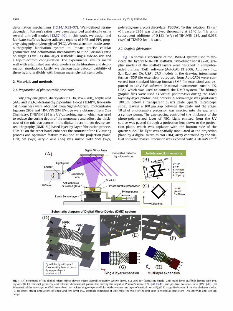
Fig. 1. (A) Schematic of the digital micro-mirror device micro-stereolithography systemregions. (B, C) Unit-cell geometry and relevant dimensional parameters having the negSchematic of the two-layer scaffold assembled by stacking single-layer scaffolds with a co(G, H) stress–strain simulations of single and two-layer PEG scaffolds composed of unitdeep).
poly(ethylene glycol) diacrylate (PEGDA). To this solution, 1% (w/v) Irgacure 2959 was dissolved thoroughly at 35 �C for 1 h, withsubsequent additions of 0.15% (w/v) of TINUVIN 234, and 0.01%(w/v) of TEMPO for 1 h each.
2.2. Scaffold fabrication
Fig. 1A shows a schematic of the DMD-SL system used to fab-ricate the hybrid NPR-PPR scaffolds. Two-dimensional (2-D) gra-phic models of the scaffold layers were designed in computer-aided drafting (CAD) software (AutoCAD LT 2006; Autodesk Inc.,San Raphael, CA, USA). CAD models in the drawing interchangeformat (DXF file extension, outputted from AutoCAD) were con-verted into standard bitmap format (BMP file extension) and ex-ported to LabVIEW software (National Instruments, Austin, TX,USA), which was used to control the DMD system. The bitmapgraphic files were used as virtual photomasks during the DMDlayer-by-layer photocuring process. A servo-stage was positioned100 lm below a transparent quartz plate (quartz microscopeslide), leaving a 100 lm gap between the plate and the stage.10 ll of photocurable precursor was injected into the gap witha syringe pump. The gap-spacing controlled the thickness of thephoto-polymerized layer of PEG. Light emitted from the UVsource was passed through a projection lens down to the projec-tion plane, which was coplanar with the bottom side of thequartz slide. The light was spatially modulated at the projectionplane by a digital micro-mirror (DM) array controlled by the vir-tual software masks. Precursor was exposed with a 50 mW cm�2
(DMD-SL) used for fabricating single- and multi-layer scaffolds having NPR-PPRative Poisson’s ratio (NPR) [44,45,49], and positive Poisson’s ratio (PPR) [43]. (D)
nnecting layer of vertical posts (P); (E, F) magnified views of the double-layer stacks.cells (the walls of the unit cells (denoted as struts) are �40 lm wide and 100 lm

P. Soman et al. / Acta Biomaterialia 8 (2012) 2587–2594 2589
dose of UV light for 5.5 s to solidify select locations of the PEG.After a layer was fabricated, uncured reactants were washedaway with deionized water. To create a second layer, the stagewas translated downwards (�100-lm) until the top of the previ-ously formed structure was �100 lm below the quartz slide.Once again, fresh precursor was pumped into the 100 lm gap,and was selectively cured using another software mask. The stepswere repeated using a combination of software masks until athree-dimensional (3-D) multi-layer scaffold was constructed.
2.3. Stress–strain finite element simulations
AutoCAD LT was used to design the 2-D scaffold layers with thedesired unit-cell structures. The unit-cell structures were designedfrom analytical models proposed in the literature. The 2-D modelswere imported into Solidworks (Solidworks 2009, Dassault Systè-mes SolidWorks Corp., Concord, MA, USA) and extruded to form3-D models of the single and two-layer scaffolds. The 3-D modelswere utilized to simulate the elastic stress–strain (deformation)behavior of the hybrid scaffolds using a finite element analysis(also conducted with Solidworks; Fig. 1G and H). We choose theproperties of PEG from the Solidworks database, with elastic mod-ulus and density of 7.057 MPa and 1.12 g ml�1 respectively. Thesimulations allowed us to determine if the unit-cell structureswould, theoretically, yield a NPR-PPR behavior as desired. The sim-ulations were performed in the same way in which the strainexperiments were conducted.
2.4. Strain testing
Strain tests were conducted to determine the Poisson’s ratiosof the single-layer and double-layer scaffolds as a function of true(instantaneous) axial strain. The scaffolds were loaded into ahome-made strain measurement system by fixing one of theirends on an immovable stage while fixing their other end on amovable single-axis (axial direction) nano-positioning stage. Thestage was connected to a motorized servo-actuator (CMA-25CCCLClosed-Loop DC Servo-actuator, Newport Corp., Irvine, CA, USA)that was capable of providing motion in 200 nm incrementalsteps with a rate of motion of �1 mm min�1. The actuator wasdriven and controlled by an axis-motion controller (ESP300 AxisMotion Controller and Driver, Newport Corp., Irvine, CA, USA) thatprovided stable and precise movement along with a programma-ble Lab View interface (LabView™, National Instruments, Austin,TX, USA). A ‘‘pulling’’ axial tensile stress was applied to the endof the PEG scaffolds, attached to the movable stage, by the motionof the actuator while the other end of the scaffolds, which werefixed to the immovable stage, remained still. The axial stressesexerted on the constructs ultimately caused them to strain inthe axial direction. In-plane movement of the construct in the ax-ial and transverse directions was observed with a color CCD cam-era system with magnifying optics (CV-S3200P CCD camera, JAIInc., San Jose, CA, USA; magnifying camera optics, Edmund Indus-trial Optics, Barrington, NJ, USA). Three experiments were con-ducted for the single layer hybrid scaffolds while twoexperiments were conducted on the double-layer scaffolds. Stillimages were recorded with the CCD camera for precise levels oftravel of the actuator stage. Axial and transverse strains wereestimated by measuring the displacement in the axial and trans-verse directions, respectively. Digitizer software (GetData GraphDigitizer 2.24, http://www.getdata-graph-digitizer.com) was usedto digitize the optical images so that the displacements could beaccurately determined based on the undeformed in-plane dimen-sions of the constructs. Digitized scanning electron microscopy(SEM) images were used to determine the undeformeddimensions.
To observe the vertical movement of the scaffold, we used anin-house stage system. A 2 mm ceramic (Al2O3) bead was attachedto the end of the tip at the arm of vertical stage. The position of thebead was matched with PPR or NPR regions of the hybrid scaffoldsusing an X–Y axis stage (Newport Corp., Irvine, CA, USA). By therotation of the manual micrometer (Edmund optics, Barrington,NJ, USA) installed vertical stage, the bead was vertically pushedagainst the hybrid scaffold and top and side view optical imageswere captured.
2.5. Calculation of Poisson’s ratios
To calculate Poisson’s ratios, we evaluated the overall trans-verse elastic deformation of the scaffolds resulting from axialstrains. We determined Poisson’s ratios using Eq. (1) [41]:
txy ¼ �ey
exð1Þ
where ey is transverse strain resulting from an axial strain ex. Thesubscripts x and y denote the axial and transverse strain directions,respectively, in a 2-D Cartesian coordinate system with orthogonalx- and y-axes. Note that we calculated in-plane values of Poisson’sratio resulting from in-plane strains. Poisson’s ratio was determinedfrom values of true strain. Total true strain, ei, was calculated by Eq.(2) (for any in-plane coordinate direction):
ei ¼ lnLi
L0
� �¼P
iln
Li
Li�1
� �þ ei�1
� �ð2Þ
where i ¼ 1; 2; 3; :::;n and denotes the current strain state, L1 is thecurrent specimen length for strain state i, and L0 is the initial unde-formed specimen length.
2.6. Cell culture and immunofluorescent staining
PEG scaffolds containing acrylic acid moieties were activated byincubating them in a working solution of 0.15 M 1-ethyl-3-[3-dimethylaminopropyl] carbodiimide hydrochloride (EDC) and0.12 M N-hydoxysuccinimide (NHS) in 2-[morpholino]ethanesul-fonic acid (MES) buffer at pH 5 for 2 h. Scaffolds were briefly rinsedwith phosphate-buffered saline (PBS) (pH 7.4), immersed in a10 lg ml�1 solution of human plasma fibronectin (GIBCO) in PBS(24 h at 4 �C), briefly rinsed with PBS and sterilized by exposureto a germicidal UV lamp for 30 min.
Human mesenchymal stem cells derived from adult bone mar-row (Health Sciences Center, Texas A & M University) were cul-tured in growth medium consisting of high glucose DMEM(GIBCO), 10% fetal bovine serum (Hyclone, Atlanta Biologicals),1% L-glutamine (GIBCO) and 50 units ml�1 penicillin/streptomycin,and passaged at 60–70% confluence. Cells were cultured at 37 �C,5% CO2. After four passages, cells were seeded on the fibronectin-conjugated scaffolds at 500,000 cells ml�1 (30 ll or 15,000 cellsper sample) and allowed to attach for 3 h. After 1 week of culture,cell-seeded scaffolds were fixed in 4% paraformaldehyde in PBS for10 min. Samples were permeabilized in blocking buffer consistingof 3% bovine serum albumin, 0.1% Triton-X 100 in PBS for 30 min.Samples were then incubated with Alexa Fluor 488 phallodin(Invitrogen) to stain filamentous actin. After briefly washing thesamples in PBS to remove unbound antibody, samples weremounted on glass slides with mounting medium containing 40,6-diamidino-2-phenylindole (DAPI) (Vectashield, Vector Laborato-ries) to stain nuclei. Samples were visualized by fluorescencemicroscopy using a Zeiss Observer A1 microscope equipped withan X-Cite 120 (EXFO) mercury lamp.
2590 P. Soman et al. / Acta Biomaterialia 8 (2012) 2587–2594
2.7. Scanning electron microscopy
The scaffolds were sputter coated with 8 nm thick iridium usingEmitech K575X, and examined in a field emission environmentalscanning electron microscope, FEI XL30 ESEM FEG, operated at10 kV using high vacuum mode. To investigate any swelling orshrinking effects due to the vacuum conditions during the SEMmeasurement, we also carried out series of ethanol baths (startingconcentration from 50% to 100%, 15 min for each step) followed bycritical point drying (CPD, Tousimis AutoSamdri 815A), sputtercoating, and finally SEM imaging. We did not see any noticeableswelling or shrinking differences between the two processes.
3. Results
Fig. 1A shows schematic of the digital micro-mirror device ste-reolithography (DMD-SL) system used for fabricating the hybridscaffolds with positive and negative Poisson’s ratio. The geometryand relevant dimensions of unit cells with negative Poisson’s ratio(NPR) and positive Poisson’s ratio (PPR) behavior were used tomake dynamic photo-images for the DMD-SL system (Fig 1B).The intact rib model (PPR) and the reentrant honeycomb design(NPR) were adapted from models reported in the literature [42–45]. The NPR structure is formed by changing the four side angles(angle f) between the vertices (struts) in a six-sided honeycomb,with some additional modifications to the ratio of the two riblengths, L1 and L2 [39,46]. In this work, we choose to apply strainsalong the X–X axis (Fig. 1B, b = 0); however, strain-dependent Pois-son’s ratio can also be tuned by simply changing the direction ofloading (anisotropic) relative to the orientation of the unit-cellshape (angle b in Fig. 1B). We choose angle f = 40�, but this anglecan be altered if we want to tune the magnitude of Poisson’s ratio.Unlike the NPR reentrant structure, the PPR intact rib structuredoes not depend on the direction of loading. The material walls
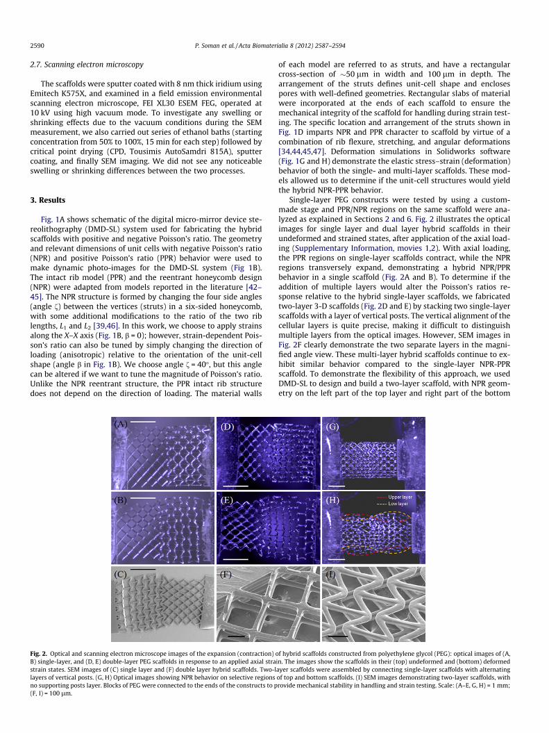
Fig. 2. Optical and scanning electron microscope images of the expansion (contraction) oB) single-layer, and (D, E) double-layer PEG scaffolds in response to an applied axial straistrain states. SEM images of (C) single layer and (F) double layer hybrid scaffolds. Two-llayers of vertical posts. (G, H) Optical images showing NPR behavior on selective regionsno supporting posts layer. Blocks of PEG were connected to the ends of the constructs to p(F, I) = 100 lm.
of each model are referred to as struts, and have a rectangularcross-section of �50 lm in width and 100 lm in depth. Thearrangement of the struts defines unit-cell shape and enclosespores with well-defined geometries. Rectangular slabs of materialwere incorporated at the ends of each scaffold to ensure themechanical integrity of the scaffold for handling during strain test-ing. The specific location and arrangement of the struts shown inFig. 1D imparts NPR and PPR character to scaffold by virtue of acombination of rib flexure, stretching, and angular deformations[34,44,45,47]. Deformation simulations in Solidworks software(Fig. 1G and H) demonstrate the elastic stress–strain (deformation)behavior of both the single- and multi-layer scaffolds. These mod-els allowed us to determine if the unit-cell structures would yieldthe hybrid NPR-PPR behavior.
Single-layer PEG constructs were tested by using a custom-made stage and PPR/NPR regions on the same scaffold were ana-lyzed as explained in Sections 2 and 6. Fig. 2 illustrates the opticalimages for single layer and dual layer hybrid scaffolds in theirundeformed and strained states, after application of the axial load-ing (Supplementary Information, movies 1,2). With axial loading,the PPR regions on single-layer scaffolds contract, while the NPRregions transversely expand, demonstrating a hybrid NPR/PPRbehavior in a single scaffold (Fig. 2A and B). To determine if theaddition of multiple layers would alter the Poisson’s ratios re-sponse relative to the hybrid single-layer scaffolds, we fabricatedtwo-layer 3-D scaffolds (Fig. 2D and E) by stacking two single-layerscaffolds with a layer of vertical posts. The vertical alignment of thecellular layers is quite precise, making it difficult to distinguishmultiple layers from the optical images. However, SEM images inFig. 2F clearly demonstrate the two separate layers in the magni-fied angle view. These multi-layer hybrid scaffolds continue to ex-hibit similar behavior compared to the single-layer NPR-PPRscaffold. To demonstrate the flexibility of this approach, we usedDMD-SL to design and build a two-layer scaffold, with NPR geom-etry on the left part of the top layer and right part of the bottom
f hybrid scaffolds constructed from polyethylene glycol (PEG): optical images of (A,n. The images show the scaffolds in their (top) undeformed and (bottom) deformed
ayer scaffolds were assembled by connecting single-layer scaffolds with alternatingof top and bottom scaffolds. (I) SEM images demonstrating two-layer scaffolds, withrovide mechanical stability in handling and strain testing. Scale: (A–E, G, H) = 1 mm;

P. Soman et al. / Acta Biomaterialia 8 (2012) 2587–2594 2591
scaffold (Fig. 2I). Optical images demonstrate expected deforma-tion behavior; the NPR parts in both top and bottom layer expandlaterally, while the PPR parts shrink with axial loading (Fig. 2G andH). Optical images show minor differences in elastic behavior ofthese scaffolds, probably because of lack of the connecting postlayer (P) for these scaffolds.
Fig. 3A plots the Poisson’s ratios of both the PPR and NPR re-gions on a single-layer scaffold as a function of stage displacement.Poisson’s ratios of the hybrid structures were calculated by mea-suring the overall strains in the x- and y-directions. (Eq. (1)). Theexperimental Poisson’s ratios for the single-layer hybrid scaffold
Fig. 4. Fluorescence microscopy images of human mesenchymal stem cells on (A, D) posCells growing in scaffold voids and along scaffold struts in NPR region. (D) Cells growingNPR region (inset: SEM of scaffold struts). Scale bars represent (A, B) 250 lm and (C, D,
Fig. 3. Experimental values of Poisson’s ratio as a function of (A) stage displacement forsingle-layer (0–0.5) and (D) true strain for two-layer scaffolds. Three strain-dependeexperiments were performed for each two-layer construct; each strain test was conduct
showed slight increase for both PPR part (0.7 to 1.2) as well asNPR parts (�1.1 to �0.5) for increasing values of stage displace-ment (Fig. 3A). Total true strain was determined by summing con-tributions of incremental strains (Eq. (2)).True strain was used inour calculations of Poisson’s ratio, as opposed to engineering strain,due to the magnitudes of the strains involved in our experiments.Our strain-dependent Poisson’s ratio data for the hybrid scaffoldsmatch well with the analytical models reported in the literature(Fig. 3B). The simple hinging model reported by Gibson and Ashby[44] state that the magnitude of the negative Poisson’s ratio de-pends upon both f and the ratio L2/L1 (Fig. 1B). From the optical
itive Poisson ratio (PPR) region and (B, C, E) negative Poisson ratio (NPR) region. (C)along scaffold struts (inset: SEM of scaffold struts) in PPR region. (E) Cells seeded onE) 125 lm. Green: actin filaments; blue: nuclei; pink: scaffold struts.
single-layer (0–500 lm), (B) true strain for a single-layer (0–0.3), (C) true strain fornt experiments were performed for each type of single-layer construct and twoed with a different sample. Separate experiments are denoted by color in the plots.
2592 P. Soman et al. / Acta Biomaterialia 8 (2012) 2587–2594
images for the NPR region, at zero strain, angle f is �40� (L2/L1 = 1.33) and therefore, in our case, the magnitude of the lateralexpansion (NPR behavior) solely depends on angle f as it varieswith increased axial strain. Our experimental values (�1.1 to�0.5) are very similar to those predicted by the analytical model(�1 to �0.7) for the reported axial strains (Fig. 3B). The single-layerintact rib constructs demonstrated experimental Poisson’s ratios,which varied from slightly below 0.7 to over 1.2 in a linear fashionfor axial strains from�0 to 0.3. In our case, the PPR part had c = 90�and b = 45� (Fig. 1C). The optical images for the intact rib or PPRpart of the hybrid scaffold (Fig. 2B) appear to confirm the Smithmodel [43], since most of the deformation is caused by hingingof angle c, causing a change in the pore shape from square to ob-long. In one of the experiments, we applied a strain up to 0.5(Fig. 3C). In this case, however, as f P 90� (dotted line in Fig. 3C)the NPR part of the scaffold relinquishes its auxetic (or NPR) char-acteristic and behaves like a normal material. Overall, the Poisson’sratio results for both PPR and NPR regions were determinate andtunable by virtue of their well-defined cellular meshwork, and ap-pear to be consistent for all the single-layer hybrid scaffolds(Fig. 3B). The geometry and spatial arrangement of the pores con-trolled the polarity and magnitude of the Poisson’s ratio of the hy-brid scaffolds, and the results matched well with previous stress–strain analytical models. This demonstrates the flexibility of theDMD-SL platform for tuning the magnitude and polarity of thePoisson’s ratio by simply imparting specific strut configuration.
Using the fabrication approach depicted in Fig. 1D–F, we built adouble-layer hybrid scaffold, with two separate hybrid layers (C1,C2) connected by an alternating layer of vertical posts (P)(Fig. 2D–F). For the two-layer hybrid scaffolds, the NPR and PPR re-gions exhibit a Poisson’s ratio between �0.8 to �0.3 and 1.5 to 0.7respectively, for true strains up to 0.2 (Fig. 3D). Comparing theoptical images (Fig. 2) of the single- and double-layer hybrid
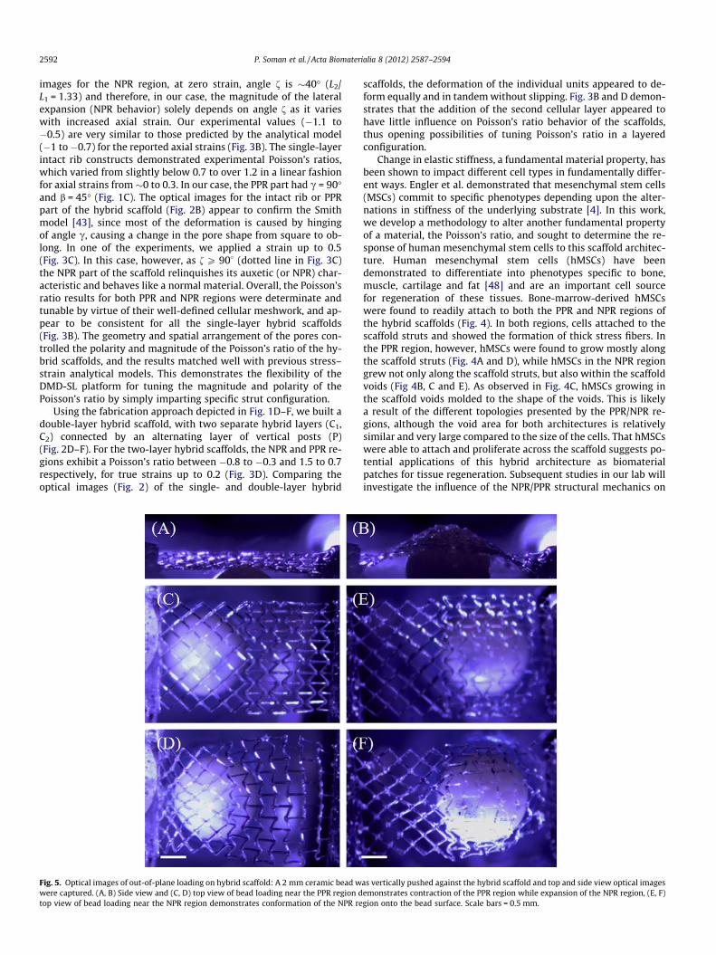
Fig. 5. Optical images of out-of-plane loading on hybrid scaffold: A 2 mm ceramic bead wwere captured. (A, B) Side view and (C, D) top view of bead loading near the PPR region dtop view of bead loading near the NPR region demonstrates conformation of the NPR re
scaffolds, the deformation of the individual units appeared to de-form equally and in tandem without slipping. Fig. 3B and D demon-strates that the addition of the second cellular layer appeared tohave little influence on Poisson’s ratio behavior of the scaffolds,thus opening possibilities of tuning Poisson’s ratio in a layeredconfiguration.
Change in elastic stiffness, a fundamental material property, hasbeen shown to impact different cell types in fundamentally differ-ent ways. Engler et al. demonstrated that mesenchymal stem cells(MSCs) commit to specific phenotypes depending upon the alter-nations in stiffness of the underlying substrate [4]. In this work,we develop a methodology to alter another fundamental propertyof a material, the Poisson’s ratio, and sought to determine the re-sponse of human mesenchymal stem cells to this scaffold architec-ture. Human mesenchymal stem cells (hMSCs) have beendemonstrated to differentiate into phenotypes specific to bone,muscle, cartilage and fat [48] and are an important cell sourcefor regeneration of these tissues. Bone-marrow-derived hMSCswere found to readily attach to both the PPR and NPR regions ofthe hybrid scaffolds (Fig. 4). In both regions, cells attached to thescaffold struts and showed the formation of thick stress fibers. Inthe PPR region, however, hMSCs were found to grow mostly alongthe scaffold struts (Fig. 4A and D), while hMSCs in the NPR regiongrew not only along the scaffold struts, but also within the scaffoldvoids (Fig 4B, C and E). As observed in Fig. 4C, hMSCs growing inthe scaffold voids molded to the shape of the voids. This is likelya result of the different topologies presented by the PPR/NPR re-gions, although the void area for both architectures is relativelysimilar and very large compared to the size of the cells. That hMSCswere able to attach and proliferate across the scaffold suggests po-tential applications of this hybrid architecture as biomaterialpatches for tissue regeneration. Subsequent studies in our lab willinvestigate the influence of the NPR/PPR structural mechanics on
as vertically pushed against the hybrid scaffold and top and side view optical imagesemonstrates contraction of the PPR region while expansion of the NPR region, (E, F)gion onto the bead surface. Scale bars = 0.5 mm.
P. Soman et al. / Acta Biomaterialia 8 (2012) 2587–2594 2593
MSC differentiation towards a particular linage and effects ongene/protein expression. Finally, we assessed the out-of-planeloading of the hybrid scaffold using a vertical custom-made stage.A 2 mm ceramic bead was vertically pushed against the hybridscaffold and top and side view optical images were captured(Fig. 5 and Supplementary Information, movie 3). Bead loadingnear the PPR region demonstrates contraction of the PPR regionwhile expansion and conformation of the NPR region to the beadsurface. This indicates that such biological hybrid patches can findpotential applications in wound management, especially for treat-ing pressure ulcers, as these patches can conform to the swelling.
4. Discussion
The technique described in this paper allows precise spatialtuning of Poisson’s ratio of photocurable biomaterials, withoutchanging their intrinsic elastic modulus [47]. Mechanical proper-ties, including elastic stiffness, fatigue and creep, are macro-prop-erties and will depend on the biomaterial used for the fabricationof hybrid scaffolds. We have also imparted this hybrid propertyto 20% PEGDA biomaterial, which is about 8 times more elasticthan the one used in this work. (For elastic stiffness, compressivestrain moduli were calibrated using a Perkin Elmer thermome-chanical analyzer – data not included). Tuning Poisson’s ratio in amulti-layered scaffold, combined with embedded drugs/growthfactor, can be extremely versatile for a variety of biomedical appli-cations. Hybrid scaffolds may be more suitable for emulating thebehavior of certain tissues and supporting and transmitting forcesto the host site and would likely better integrate with native tis-sues. For example, hybrid scaffolds can be used to design arterialgrafts, since it has been shown that the sub-endothelium of bovinecarotid arteries behaves in a NPR or auxetic manner [29]. Similarly,a cell-seeded heart patch with hybrid NPR-PPR property would beable to withstand the compressive and stretching forces generatedduring myocardial contraction (�10,000 heart beats per day) at thesuture site [31]. This study, for the first time, demonstrates thedevelopment of biomaterials wherein both the elastic modulus aswell as Poisson’s ratio (in essence, the complete elastic response)can be tailored to the targeted response. As long as the deforma-tions to the material remain elastic, Poisson’s ratio is controlled so-lely by the structure of the pores and not the intrinsic properties ofthe material making up the geometry, and therefore allows similarelastic behavior at various resolutions (nano-to-macro).
5. Conclusion
In summary, we constructed hybrid single-layer and double-layer PEG scaffolds, which exhibit tunable Poisson’s ratio behavior,in accordance with existing analytical models found in the litera-ture. The integration of human mesenchymal stem cells with hy-brid scaffolds demonstrates the feasibility of utilizing thesescaffolds for biological applications, which require biaxial straincharacteristics.
6. Supplementary section (SI)
This includes movies 1–3 and movie captions. For analyticalsolutions of (a) reentrant unit cell or NPR part and (b) the intact-rib or PPR part, please refer to the SI of Ref. [37].
Acknowledgements
The project described was supported by Award NumberR01EB012597 from the National Institute of Biomedical Imagingand Bioengineering and a Grant (CMMI-1130894) from the
National Science Foundation. We thank Intel’s High Education Pro-gram for the computer support.
Appendix A. Figures with essential colour discrimination
Certain figures in this article, particularly Figs. 1–5, are difficultto interpret in black and white. The full colour images can be foundin the on-line version, at http://dx.doi.org/10.1016/j.actbio.2012.03.035.
Appendix B. Supplementary data
Supplementary data associated with this article can be found, inthe online version, at http://dx.doi.org/10.1016/j.actbio. 2012.03.035.
References
[1] Blitterswijk CV. Tissue engineering. Boston: Amsterdam; 2008.[2] Gibson LJ, Ashby MF. Cellular solids: structure and properties. Cambridge, New
York: Cambridge University Press; 1997.[3] Khademhosseini A, Langer R. Microengineered hydrogels for tissue
engineering. Biomaterials 2007;28(34):5087–92.[4] Engler AJ, Sen S, Sweeney HL, Discher DE. Matrix elasticity directs stem cell
lineage specification. Cell 2006;126(4):677–89.[5] Williams JL, Lewis JL. Properties and an anisotropic model of cancellous bone
from the proximal tibial epiphysis. J Biomech Eng–T ASME 1982;104(1):50–6.[6] Keskar NR, Chelikowsky JR. Negative Poisson ratios in crystalline SiO2 from
first-principles calculations. Nature 1992;358(6383):222–4.[7] Baughman RH, Shacklette JM, Zakhidov AA, Stafstrom S. Negative Poisson’s
ratios as a common feature of cubic metals. Nature 1998;392(6674):362–5.[8] Gunton DJ, Saunders GA. Young’s modulus and Poisson’s ratio of arsenic,
antimony and bismuth. J Mater Sci 1972;7(9):1061.[9] Baughman RH, Galvao DS. Crystalline networks with unusual predicted
mechanical and thermal properties. Nature 1993;365(6448):735–7.[10] Gardner GB, Venkataraman D, Moore JS, Lee S. Spontaneous assembly of a
hinged coordination network. Nature 1995;374(6525):792–5.[11] Hall LJ, Coluci VR, Galvao DS, Kozlov ME, Zhang M, Dantas SO, et al. Sign
change of Poisson’s ratio for carbon nanotube sheets. Science 2008;25,2008;320(5875):504–7.
[12] Lakes R. Foam structures with a negative Poissons ratio. Science1987;235(4792):1038–40.
[13] Choi JB, Lakes RS. Nonlinear properties of metallic cellular materials with anegative Poisson’s ratio. J Mater Sci 1992;27(19):5375–81.
[14] Choi JB, Lakes RS. Nonlinear properties of polymer cellular materials with anegative Poisson’s ratio. J Mater Sci 1992;27(17):4678–84.
[15] Milton GW. Composite materials with Poisson’s ratios close to �1. J Mech PhysSolids 1992;40(5):1105–37.
[16] Alderson KL, Evans KE. The fabrication of microporous polyethylene having anegative Poisson’s ratio. Polymer 1992;33(20):4435–8.
[17] Caddock BD, Evans KE. Microporous materials with negative Poisson’s ratios. 1.Microstructure and mechanical properties. J Phys D Appl Phys1989;22(12):1877–82.
[18] Evans KE, Caddock BD. Microporous materials with negative Poisson’s ratios. 2.Mechanisms and interpretation. J Phys D Appl Phys 1989;22(12):1883–7.
[19] Baughman RH, Dantas SO, Stafstrom S, Zakhidov AA, Mitchell TB, Dubin DHE.Negative Poisson’s ratios for extreme states of matter. Science2000;288(5473):2018–22.
[20] Lakes R. Materials science: deformations in extreme matter. Science2000;288(5473):1976–7.
[21] Chen XG, Brodland GW. Mechanical determinants of epithelium thickness inearly-stage embryos. J Mech Behav Biomed Mater 2009;2(5):494–501.
[22] Timmins LH, Wu QF, Yeh AT, Moore JE, Greenwald SE. Structuralinhomogeneity and fiber orientation in the inner arterial media. Am JPhysiol Heart Circ Physiol 2010;298(5):H1537–45.
[23] Williams JL, Lewis JL. Properties and an anisotropic model of cancellous bonefrom the proximal tibial epiphysis. J Biomech Eng - Trans ASME1982;104(1):50–6.
[24] Burriesci GP (IT), Bergamasco G (Torino, IT), inventor; Sorin Biomedica Cardio,assignee. Annuloplasty prosthesis with an auxetic structure, United States,2007.
[25] Lin CY, Kikuchi N, Hollister SJ. A novel method for biomaterial scaffold internalarchitecture design to match bone elastic properties with desired porosity. JBiomech 2004;37(5):623–36.
[26] Lakes R. Materials science: a broader view of membranes. Nature2001;414(6863):503–4.
[27] Jackman RJ, Brittain ST, Adams A, Prentiss MG, Whitesides GM. Design andfabrication of topologically complex, three-dimensional microstructures.Science 1998;280(5372):2089–91.
2594 P. Soman et al. / Acta Biomaterialia 8 (2012) 2587–2594
[28] Veronda DR, Westmann RA. Mechanical characterization of skin-finitedeformations. J Biomech 1970;3(1):111–22, IN119, 123–4.
[29] Timmins LH, Wu Q, Yeh AT, Moore JE, Jr., Greenwald SE. Structuralinhomogeneity and fiber orientation in the inner arterial media. Am JPhysiol Heart Circ Physiol 2010;298(5):H1537–45.
[30] Teng CJ, Luo J, Chiu RCJ, Shum-Tim D. Massive mechanical loss of microsphereswith direct intramyocardial injection in the beating heart: Implications forcellular cardiomyoplasty. J Thorac Cardiovasc Surg 2006;132(3):628–32.
[31] Jawad H, Lyon AR, Harding SE, Ali NN, Boccaccini AR. Myocardial tissueengineering. British Med Bull 2008;87(1):31–47.
[32] Burns S. Negative Poisson’s ratio materials. Science 1987;238(4826):551.[33] Baughman RH, Stafstram S, Cui C, Dantas SO. Materials with negative
compressibilities in one or more dimensions. Science 1998;279(5356):1522–4.
[34] Evans KE, Nkansah MA, Hutchinson IJ, Rogers SC. Molecular network design.Nature 1991;353(6340):124.
[35] Rothenburg L, Berlin AI, Bathurst RJ. Microstructure of isotropic materials withnegative Poisson’s ratio. Nature 1991;354(6353):470–2.
[36] Choi JB, Lakes RS. Nonlinear-analysis of the Poisson’s ratio of negativePoisson’s ratio foams. J Compos Mater 1995;29(1):113–28.
[37] Fozdar DY, Soman P, Lee JW, Han L-H, Chen S. Three-dimensional polymerconstructs exhibiting a tunable negative Poisson’s ratio. Adv Funct Mater2011;21(14):2712–20.
[38] Evans KE, Alderson A. Auxetic materials: functional materials and structuresfrom lateral thinking! Adv Mater 2000;12(9):617–28.
[39] Gibson LJ, Ashby MF, Schajer GS, Robertson CI. The mechanics of two-dimensional cellular materials. Proc Royal Soc Lond Series A - Math Phys EngSci 1982;382(1782):25–42.
[40] Almgren RF. An isotropic 3-dimensional structure with Poisson ratio = �1. JElast 1985;15(4):427–30.
[41] Eisenstadt MM. Introduction to mechanical properties of materials. 1sted. New York: Macmillan; 1971.
[42] Gaspar N, Ren XJ, Smith CW, Grima JN, Evans KE. Novel honeycombs withauxetic behaviour. Acta Mater 2005;53(8):2439–45.
[43] Smith CW, Grima JN, Evans KE. A novel mechanism for generating auxeticbehaviour in reticulated foams: missing rib foam model. Acta Mater2000;48(17):4349–56.
[44] Gibson LJ, Ashby MF. Cellular solids: structure and properties. 2nded. Cambridge: Cambridge University Press; 1997.
[45] Masters IG, Evans KE. Models for the elastic deformation of honeycombs.Compos Struct 1996;35(4):403–22.
[46] Masters IG, Evans KE. Models for the elastic deformation of honeycombs.Compos Struct 1996;35(4):403–22.
[47] Gibson LJ, Ashby MF, Schajer GS, Robertson CI. The mechanics of two-dimensional cellular materials. P Roy Soc Lond A Mater1982;382(1782):25–42.
[48] Hwang Y, Phadke A, Varghese S. Engineered microenvironments formusculoskeletal differentiation of stem cells. Regen Med 2011;6(4):505–24.
[49] Almgren RF. An isotropic three-dimensional structure with Poisson’sratio = �1. J Elast 1985;15(4):427–30.