SPAJANJE BAKRENIH ELEKTRIČNIH KONTAKATA MIKRO … · 167 spajanje bakrenih elektriČnih kontakata...
8
167 SPAJANJE BAKRENIH ELEKTRIČNIH KONTAKATA MIKRO ZAVARIVANJEM TRENJEM ROTIRAJUĆIM ALATOM MICRO FRICTION STIR WELDING OF COPPER ELECTRICAL CONTACTS Damjan Klobčar Janez Tušek Faculty of Mechanical Engineering, University of Ljubljana, Aškerčeva 6, 1000 Ljubljana, Slovenia Milan Bizjak Matija Bušić Vladka Lešer Faculty of Natural Sciences, Department of Materials and Metallurgy, University of Ljubljana, Aškerčeva cesta 12, 1000 Ljubljana, Slovenia Faculty of Mechanical Engineering and Naval Architecture, Ivana Lučića 5, 10002 Zagreb, p.p. 102, Croatia Faculty of Health Sciences Novo mesto, Na Loko 2, 8000 Novo mesto, Slovenia Kjučne rječi: mikro zavarivanje trenjem rotirajućim alatom, Cu ETP, vlačno ispitivanje, mikrostruktura, pogreške u zavarenim spojevima Keywords: micro friction stir welding (FSW), Cu ETP, tensile test, microstructure, welding defects Sažetak: Industrija električnih uređaja koristi visokovodljive vrste bakra kao što su CuOF, CuETP, CuOFP i CuAg 0.02 u proizvodnji različitih elektroničkih proizvoda. Spajanje bakra ili njegovih legura je zahtjevan proces prvenstveno radi ograničene zavarljivosti konvencionalnim tehnologijama zavarivanja kao što su elektrolučno zavarivanje, elektrootporno zavarivanje i lasersko zavarivanje. Zavarivanje navedenim tehnologijama otežano je radi odlične električne i toplinske vodljivosti bakra i niskog električnog otpora. Zavarljivost ovog materijala bolja je ako se koristi zavarivanje trenjem rotirajućim alatom, ultrazvučno ili zavarivanje vibracijom. U ovom radu analizirano je mikro zavarivanje trenjem rotirajućim alatom električnih kontakta. Različiti alati korišteni su za zavarivanje i parametri postupka su izmjenjivani kao bi se dobio prihvatljiv zavar. Tipične pogreške su procijenjene i definiran je optimalni izgled alata i parametri postupka. Izmjerena je Vickers mikrotvrdoća te je definiran utjecaj parametara postupka na promjenu tvrdoće u zavarenom spoju. Abstract: Electrical industry is using high electro conductive copper likes CuOF, CuETP, CuOFP and CuAg 0.02 for production of different electronic products. Joining of copper or its alloys is difficult since the weldability of materials is limited using conventional welding technologies like arc welding and resistance welding or laser welding due to their properties like, good electrical and temperature conductivity and low electrical resistance. Weldability of these materials is better using friction welding technology, ultrasonic technology or vibrational technology. In this paper micro Friction Stir Welding (FSW) of electrical contacts is investigated. Different FSW tools are used and welding parameters are tested in order to find the welding parameters at which a sound weld could be obtained. Typical welding defects are evaluated and optimal welding parameters and tools are defined. A Vickers microhardness was measured and reveals the influence of welding parameters on the change of hardness.
Transcript of SPAJANJE BAKRENIH ELEKTRIČNIH KONTAKATA MIKRO … · 167 spajanje bakrenih elektriČnih kontakata...
167
SPAJANJE BAKRENIH ELEKTRIČNIH KONTAKATA MIKRO ZAVARIVANJEM TRENJEM ROTIRAJUĆIM ALATOM
MICRO FRICTION STIR WELDING OF COPPER ELECTRICAL CONTACTS
Damjan Klobčar Janez Tušek
Faculty of Mechanical Engineering, University of Ljubljana, Aškerčeva 6, 1000 Ljubljana, Slovenia
Milan Bizjak
Matija Bušić Vladka Lešer
Faculty of Natural Sciences, Department of Materials and Metallurgy, University of Ljubljana, Aškerčeva cesta 12, 1000 Ljubljana, Slovenia
Faculty of Mechanical Engineering and Naval Architecture, Ivana Lučića 5, 10002 Zagreb, p.p. 102, Croatia Faculty of Health Sciences Novo mesto, Na Loko 2, 8000 Novo mesto, Slovenia
Kjučne rječi: mikro zavarivanje trenjem rotirajućim alatom, Cu ETP, vlačno ispitivanje, mikrostruktura, pogreške u zavarenim spojevima Keywords: micro friction stir welding (FSW), Cu ETP, tensile test, microstructure, welding defects Sažetak: Industrija električnih uređaja koristi visokovodljive vrste bakra kao što su CuOF, CuETP, CuOFP i CuAg 0.02 u proizvodnji različitih elektroničkih proizvoda. Spajanje bakra ili njegovih legura je zahtjevan proces prvenstveno radi ograničene zavarljivosti konvencionalnim tehnologijama zavarivanja kao što su elektrolučno zavarivanje, elektrootporno zavarivanje i lasersko zavarivanje. Zavarivanje navedenim tehnologijama otežano je radi odlične električne i toplinske vodljivosti bakra i niskog električnog otpora. Zavarljivost ovog materijala bolja je ako se koristi zavarivanje trenjem rotirajućim alatom, ultrazvučno ili zavarivanje vibracijom. U ovom radu analizirano je mikro zavarivanje trenjem rotirajućim alatom električnih kontakta. Različiti alati korišteni su za zavarivanje i parametri postupka su izmjenjivani kao bi se dobio prihvatljiv zavar. Tipične pogreške su procijenjene i definiran je optimalni izgled alata i parametri postupka. Izmjerena je Vickers mikrotvrdoća te je definiran utjecaj parametara postupka na promjenu tvrdoće u zavarenom spoju. Abstract: Electrical industry is using high electro conductive copper likes CuOF, CuETP, CuOFP and CuAg 0.02 for production of different electronic products. Joining of copper or its alloys is difficult since the weldability of materials is limited using conventional welding technologies like arc welding and resistance welding or laser welding due to their properties like, good electrical and temperature conductivity and low electrical resistance. Weldability of these materials is better using friction welding technology, ultrasonic technology or vibrational technology. In this paper micro Friction Stir Welding (FSW) of electrical contacts is investigated. Different FSW tools are used and welding parameters are tested in order to find the welding parameters at which a sound weld could be obtained. Typical welding defects are evaluated and optimal welding parameters and tools are defined. A Vickers microhardness was measured and reveals the influence of welding parameters on the change of hardness.
168
1. INTRODUCTION Components for electrical and electronic devices are usually made of oxygen-free copper (Cu OF), electrolytic tough pitch copper (Cu ETP), oxygen-free electronic copper (Cu OFE) or oxygen free phosphorus copper (Cu OFP) due to their high electrical conductivity, high thermal conductivity and the ability to work harden. Since these components are usually connected to other components their joining is needed. These coppers could be joined using different joining technologies [1]. Bolting and riveting is used when dismantling is needed. Adhesive bonding is applied when low joint strength is needed and smaller electrical and thermal conductivity is acceptable. Soft or hard soldering is selected based on the joint type and joint strength needed [1]. Fusion welding (manual metal arc welding, tungsten inert gas welding, metal inert gas welding, plasma gas welding, electron beam welding, laser welding) is used when high joint strength and high electrical conductivity is needed [2]. Electrical resistance welding enables moderate lap joint strength but the process is difficult due to high electrical conductivity of the joint [3, 4]. Ultrasonic welding, vibrational welding, friction welding (linear, rotational, friction stir welding (FSW)) enables good joint properties (electrical and thermal conductivity, strength) and the processes are usually used for high production series in tight tolerances. Diffusion welding is slow but enables good joint properties [5]. Roll bonding is applicable for high production series while cold pressure welding is usually used for extension of different profiles [1, 6, 7]. The process can be used for joining other materials like Al-alloys where a good knowledge of material data is of highest importance for forming process [8] and further use of the component [9]. For roll bonding process quality tool steels [10, 11] are used due to their exposure to high working temperatures. At fusion welding defects can occur due to high thermal conductivity of copper, therefore preheating is necessary for thicknesses above 3 mm, when using argon shielding. In the heat-affected zone (HAZ) of wrought Cu ETP high temperatures could permit diffusion and migration of oxide particles causing the porosity in HAZ. A rapid welding is thus needed to restrict overall heating. At shielding gas welding deoxidation is prevented using argon, helium or nitrogen shielding gasses. The selection of optimal technology depends on many factors especially on the size of the production series, type of the joint and required properties. FSW of copper requires much higher heat input compared to welding of aluminium alloys due to greater dissipation of heat through the workpiece [12-14]. At lower heat input weld defects like elongated cavities usually occur but at higher heat input oxidation of weld surface is present [13]. FSW has been successfully used to weld 50 mm thick copper canisters for containment of nuclear waste [15]. FSW welding of Cu ETP at temperatures between 460 – 530 °C enables formation of sound welds, with ~ 70 HV and strains three times longer that in the base metal [16, 17]. Defect free FSW welds were also obtained with low heat input FSW at which the joint ultimate tensile strength achieved almost 100 % of the base metal [18]. The fracture mechanisms and characteristics of four regions were also defined. Leal et al. [19] established that the torque, the microstructure, hardness and the formation of weld defects are influenced mainly by tool rotation speed and in less by the traverse speed and shoulder cavity. Analysis of friction stir processing (FSP) of Cu-DHP showed that the tool geometry, processing parameters and heat exchange conditions determine grain size and mechanical properties of stirred zone. The grain size increases with decreasing traverse speed, and with increasing rotational speed [20]. The paper presents an analysis of FSW of Cu ETP in a lap and butt joint. This research explores the influence of tool design and welding parameters on the produced joint. The results showed that the grain size in the nugget zone is greatly reduced compared to the base metal and the joint tensile strength was thus improved.
169
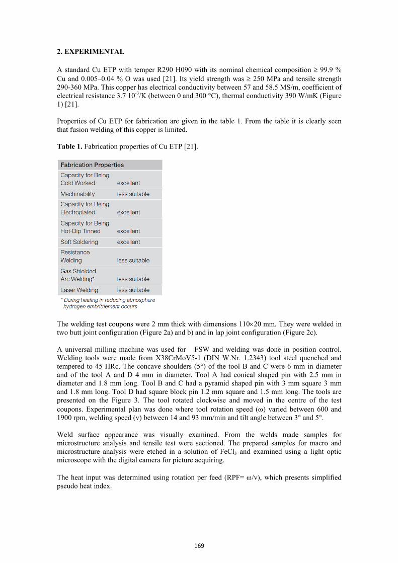
2. EXPERIMENTAL A standard Cu ETP with temper R290 H090 with its nominal chemical composition 99.9 % Cu and 0.005–0.04 % O was used [21]. Its yield strength was 250 MPa and tensile strength 290-360 MPa. This copper has electrical conductivity between 57 and 58.5 MS/m, coefficient of electrical resistance 3.7 10-3/K (between 0 and 300 °C), thermal conductivity 390 W/mK (Figure 1) [21]. Properties of Cu ETP for fabrication are given in the table 1. From the table it is clearly seen that fusion welding of this copper is limited. Table 1. Fabrication properties of Cu ETP [21].
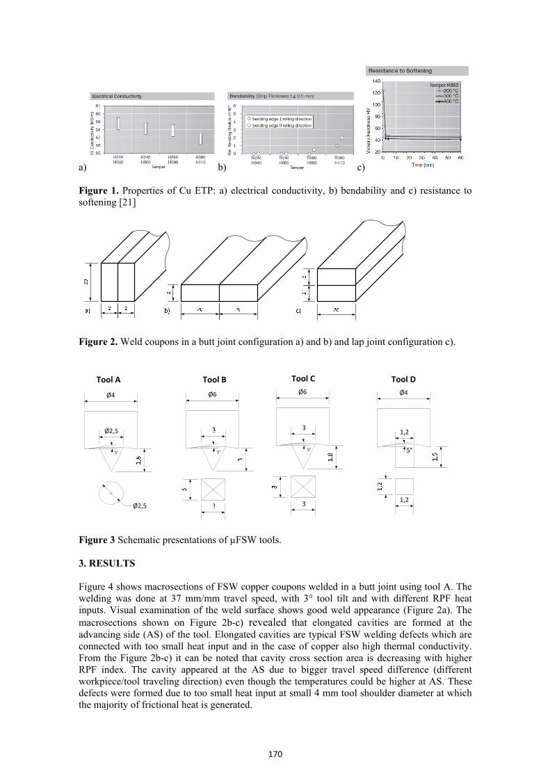
The welding test coupons were 2 mm thick with dimensions 11020 mm. They were welded in two butt joint configuration (Figure 2a) and b) and in lap joint configuration (Figure 2c). A universal milling machine was used for �FSW and welding was done in position control. Welding tools were made from X38CrMoV5-1 (DIN W.Nr. 1.2343) tool steel quenched and tempered to 45 HRc. The concave shoulders (5°) of the tool B and C were 6 mm in diameter and of the tool A and D 4 mm in diameter. Tool A had conical shaped pin with 2.5 mm in diameter and 1.8 mm long. Tool B and C had a pyramid shaped pin with 3 mm square 3 mm and 1.8 mm long. Tool D had square block pin 1.2 mm square and 1.5 mm long. The tools are presented on the Figure 3. The tool rotated clockwise and moved in the centre of the test coupons. Experimental plan was done where tool rotation speed () varied between 600 and 1900 rpm, welding speed (v) between 14 and 93 mm/min and tilt angle between 3° and 5°. Weld surface appearance was visually examined. From the welds made samples for microstructure analysis and tensile test were sectioned. The prepared samples for macro and microstructure analysis were etched in a solution of FeCl3 and examined using a light optic microscope with the digital camera for picture acquiring. The heat input was determined using rotation per feed (RPF= /v), which presents simplified pseudo heat index.
170
a) b) c) Figure 1. Properties of Cu ETP: a) electrical conductivity, b) bendability and c) resistance to softening [21]
Figure 2. Weld coupons in a butt joint configuration a) and b) and lap joint configuration c).
1,2
1,2
Ø4
Tool D
5°
Ø2,5
Ø4
5°
Ø2,5
Tool A
Ø6
5°
Tool B
3
Ø6
3
5°
Tool C
Figure 3 Schematic presentations of µFSW tools. 3. RESULTS Figure 4 shows macrosections of FSW copper coupons welded in a butt joint using tool A. The welding was done at 37 mm/mm travel speed, with 3° tool tilt and with different RPF heat inputs. Visual examination of the weld surface shows good weld appearance (Figure 2a). The macrosections shown on Figure 2b-c) revealed that elongated cavities are formed at the advancing side (AS) of the tool. Elongated cavities are typical FSW welding defects which are connected with too small heat input and in the case of copper also high thermal conductivity. From the Figure 2b-c) it can be noted that cavity cross section area is decreasing with higher RPF index. The cavity appeared at the AS due to bigger travel speed difference (different workpiece/tool traveling direction) even though the temperatures could be higher at AS. These defects were formed due to too small heat input at small 4 mm tool shoulder diameter at which the majority of frictional heat is generated.
171
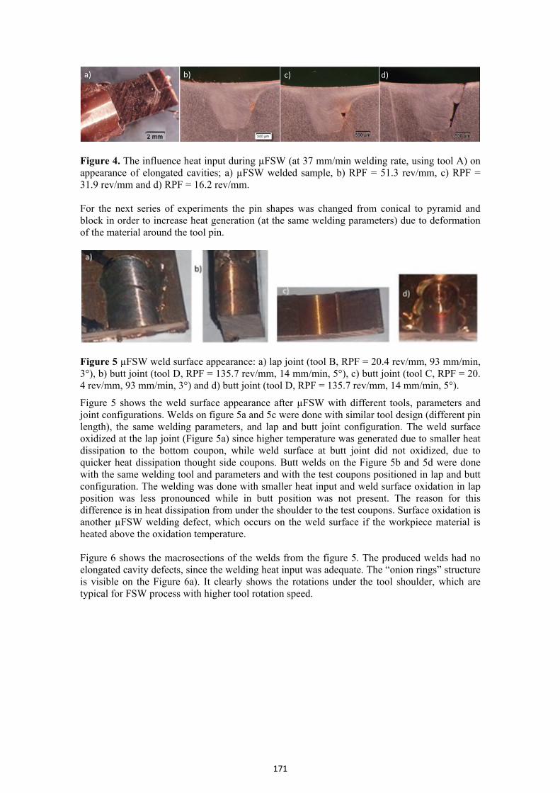
Figure 4. The influence heat input during µFSW (at 37 mm/min welding rate, using tool A) on appearance of elongated cavities; a) µFSW welded sample, b) RPF = 51.3 rev/mm, c) RPF = 31.9 rev/mm and d) RPF = 16.2 rev/mm. For the next series of experiments the pin shapes was changed from conical to pyramid and block in order to increase heat generation (at the same welding parameters) due to deformation of the material around the tool pin.
Figure 5 µFSW weld surface appearance: a) lap joint (tool B, RPF = 20.4 rev/mm, 93 mm/min, 3°), b) butt joint (tool D, RPF = 135.7 rev/mm, 14 mm/min, 5°), c) butt joint (tool C, RPF = 20. 4 rev/mm, 93 mm/min, 3°) and d) butt joint (tool D, RPF = 135.7 rev/mm, 14 mm/min, 5°).
Figure 5 shows the weld surface appearance after µFSW with different tools, parameters and joint configurations. Welds on figure 5a and 5c were done with similar tool design (different pin length), the same welding parameters, and lap and butt joint configuration. The weld surface oxidized at the lap joint (Figure 5a) since higher temperature was generated due to smaller heat dissipation to the bottom coupon, while weld surface at butt joint did not oxidized, due to quicker heat dissipation thought side coupons. Butt welds on the Figure 5b and 5d were done with the same welding tool and parameters and with the test coupons positioned in lap and butt configuration. The welding was done with smaller heat input and weld surface oxidation in lap position was less pronounced while in butt position was not present. The reason for this difference is in heat dissipation from under the shoulder to the test coupons. Surface oxidation is another µFSW welding defect, which occurs on the weld surface if the workpiece material is heated above the oxidation temperature. Figure 6 shows the macrosections of the welds from the figure 5. The produced welds had no elongated cavity defects, since the welding heat input was adequate. The “onion rings” structure is visible on the Figure 6a). It clearly shows the rotations under the tool shoulder, which are typical for FSW process with higher tool rotation speed.
172
Figure 6 µFSW weld macrostructure of a) lap joint (tool B, RPF = 20.4 rev/mm, 93 mm/min, 3°), b) butt joint (tool D, RPF = 135.7 rev/mm, 14 mm/min, 5°), c) butt joint (tool C, RPF = 20.4 rev/mm, 93 mm/min, 3°) and d) butt joint (tool D, RPF = 135.7 rev/mm, 14 mm/min, 5°).
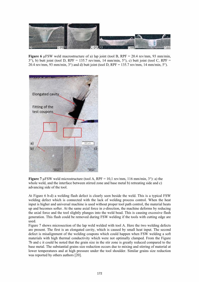
Figure 7 µFSW weld microstructure (tool A, RPF = 10,1 rev/mm, 116 mm/min, 3°): a) the whole weld, and the interface between stirred zone and base metal b) retreating side and c) advancing side of the tool. At Figure 6 b-d) a welding flash defect is clearly seen beside the weld. This is a typical FSW welding defect which is connected with the lack of welding process control. When the heat input is higher and universal machine is used without proper tool path control, the material heats up and becomes softer. At the same axial force in z-direction, the machine deforms by reducing the axial force and the tool slightly plunges into the weld bead. This is causing excessive flash generation. This flash could be removed during FSW welding if the tools with cutting edge are used. Figure 7 shows microsection of the lap weld welded with tool A. Here the two welding defects are present. The first is an elongated cavity, which is caused by small heat input. The second defect is misalignment of the welding coupons which could happen when FSW welding a soft materials with high thermal conductivity which were not optimally clamped. From the Figure 7b and c it could be noted that the grain size in the stir zone is greatly reduced compared to the base metal. The substantial grains size reduction occurs due to mixing and stirring of material at lower temperatures and at high pressure under the tool shoulder. Similar grains size reduction was reported by others authors [20].
173
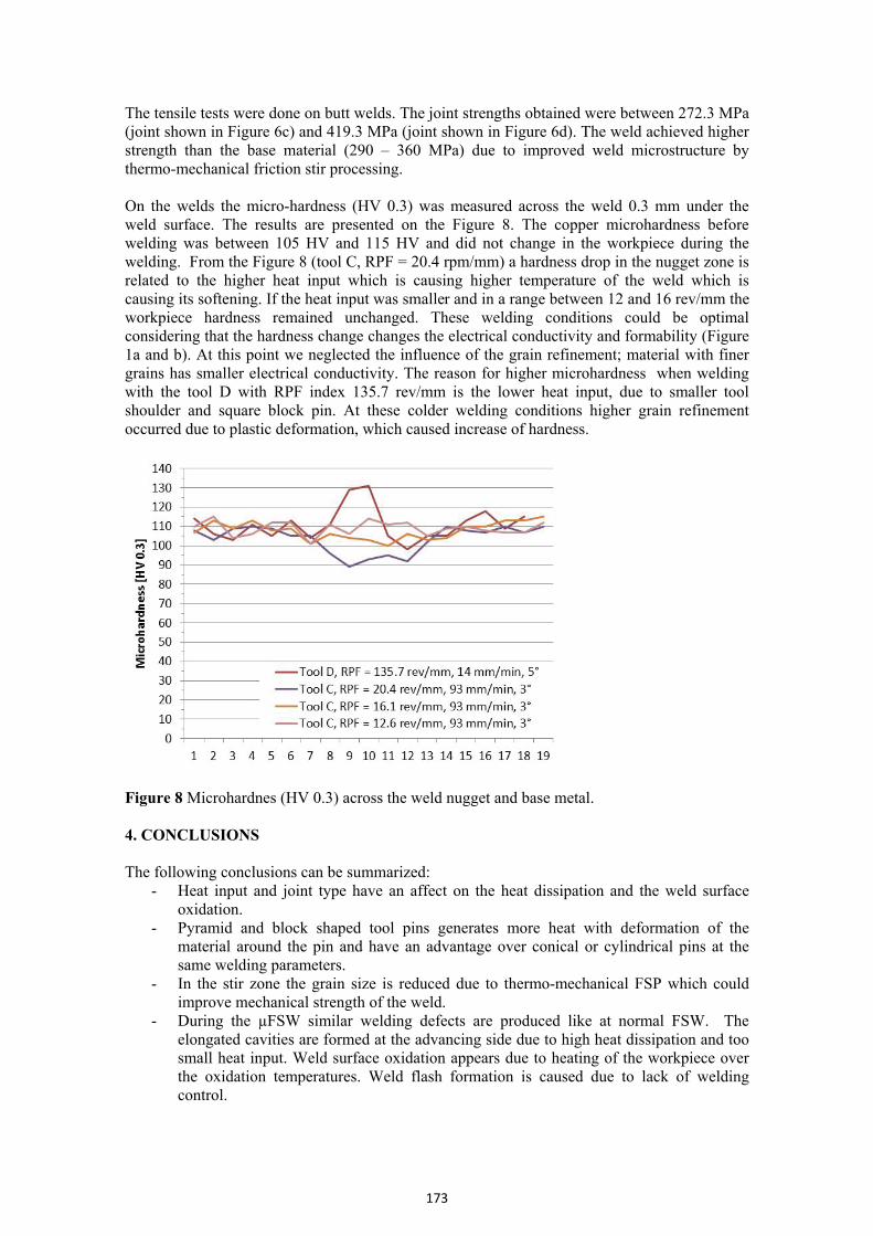
The tensile tests were done on butt welds. The joint strengths obtained were between 272.3 MPa (joint shown in Figure 6c) and 419.3 MPa (joint shown in Figure 6d). The weld achieved higher strength than the base material (290 – 360 MPa) due to improved weld microstructure by thermo-mechanical friction stir processing. On the welds the micro-hardness (HV 0.3) was measured across the weld 0.3 mm under the weld surface. The results are presented on the Figure 8. The copper microhardness before welding was between 105 HV and 115 HV and did not change in the workpiece during the welding. From the Figure 8 (tool C, RPF = 20.4 rpm/mm) a hardness drop in the nugget zone is related to the higher heat input which is causing higher temperature of the weld which is causing its softening. If the heat input was smaller and in a range between 12 and 16 rev/mm the workpiece hardness remained unchanged. These welding conditions could be optimal considering that the hardness change changes the electrical conductivity and formability (Figure 1a and b). At this point we neglected the influence of the grain refinement; material with finer grains has smaller electrical conductivity. The reason for higher microhardness when welding with the tool D with RPF index 135.7 rev/mm is the lower heat input, due to smaller tool shoulder and square block pin. At these colder welding conditions higher grain refinement occurred due to plastic deformation, which caused increase of hardness.
Figure 8 Microhardnes (HV 0.3) across the weld nugget and base metal. 4. CONCLUSIONS The following conclusions can be summarized:
- Heat input and joint type have an affect on the heat dissipation and the weld surface oxidation.
- Pyramid and block shaped tool pins generates more heat with deformation of the material around the pin and have an advantage over conical or cylindrical pins at the same welding parameters.
- In the stir zone the grain size is reduced due to thermo-mechanical FSP which could improve mechanical strength of the weld.
- During the µFSW similar welding defects are produced like at normal FSW. The elongated cavities are formed at the advancing side due to high heat dissipation and too small heat input. Weld surface oxidation appears due to heating of the workpiece over the oxidation temperatures. Weld flash formation is caused due to lack of welding control.
174
- Optimal welding conditions were obtained for the tool with 6 mm tool shoulder, which were at RPF between 12 and 17 rpm/mm at welding speed of 93 mm/min.
Acknowledgement The authors wish to thank Boris Bell, Nataša Rant and Nika Breskvar and for the help at experimental work. The research was sponsored by Slovenian Research Agency under the grant L2-4183. REFERENCES [1] L. Brown, CDA Publication No 98, (1994), 1-64. [2] M. Pleterski, J. Tušek, T. Muhič, L. Kosec, J. of Mater. Sci. & Technol., 27 (2011) 8, 707-
713. [3] J. S. Agapiou, T. A. Perry, J. of Manuf. Proc., 15 (2013) 4, 549-557. [4] S. Simončič, P. Podržaj, Meas. Sci. Technol., 23 (2012) 6, 1-7. [5] A. A. Shirzadi, E. R. Wallach, Sci. Technol. Weld. Join., 9 (2004) 1, 37-40. [6] M. Gojić, L. Vrsalović, S. Kožuh, A. C. Kneissl, I. Anžel, S. Gudić, B. Kosec, M. Kliškić,
J. Alloys Comp., 509 (2011) 41, 9782-9790. [7] H. Dyja, S. Mróz, A. Milenin, J. Mater. Proc. Technol., 153-154 (2004), 100-107. [8] T. Pepelnjak, V. Magoč, B. Barišić,. Metalurgija, 51 (2012) 2, 153-156. [9] M. Šimic, M. Debevec, N. Herakovič, J. Mecha. Eng., (in print), DOI:10.5545/sv-
jme.2013.1104. [10] J. Brnić, M. Čanađija, G. Turkalj, D. Lanc, T. Pepelnjak, B. Barišić, G. Vukelić, M. Brčić,
Mater. Manuf. Process. 24 (2009) 7/8, 758-762. [11] A. Nagode, G. Klančnik, H. Schwarczova, B. Kosec, M. Gojić, L. Kosec, Eng Fail. Anal.,
23 (2012), 82-89. [12] R. Nandan, T. DebRoy and H. K. D. H. Bhadeshia, Progress Mater. Sci., (2008) 980-1023. [13] J. Teimournezhad, A. Masoumi, Sci. Technol. Weld. Join., 15 (2010) 2, 166-170. [14] W. M. Thomas, K. I. Johnson, C. S. Wiesner, Adv. Eng. Mater., 5 (2003) 7, 485-490. [15] L. Cederqvist, C.D. Sorensen, A.P. Reynolds, T. Öberg, Sci. Technol. Weld. Join., 14
(2009) 2, 178-184. [16] Y.M. Hwang, P.L. Fan, C.H. Lin, J. Mater. Proc. Technol., 210 (2010) 12, 1667-1672. [17] W.-B. Lee, S.-B. Jung, Mater. Letters, 58 (2004) 6, 1041-1046. [18] H.J. Liu, J.J. Shen, Y.X. Huang, L.Y. Kuang, C. Liu, C. Li, Sci. Technol. Weld. Join., 14
(2009) 6, 577-583. [19] R.M. Leal, N. Sakharova, P. Vilaça, D.M. Rodrigues, A. Loureiro, Sci. Technol. Weld.
Join., 16 (2011) 2, 146-152. [20] I. Galvao, A. Loureiro, D.M. Rodrigues, Advanc. Mater. Resear., 445 (2012), 631-636. [21] Wieland-K32, in, Wieland, pp. 2.