SPACEPOWER FR-EE STON STIRLING ENGINE S DY FR-EE_STON STIRLING ENGINE S / t ttt DY t ... 3.3 Heat...
146
B=.m = m ¸ = ! .i NASACR-1822i8 MTI 89TR6 m i- -- Contractor Final Report SPACEPOWER FR-EE_STON STIRLING ENGINE S / t ttt DY t Prepared for: NASA-Lewis Research Center -21000 Brookpark Road --_--'Cleveland, Ohio 42U35 Prepared under: Contract NAS3-25148 E n 7 Prepared by: Mechanical Technology Incorporated -- 968 Albany-Shaker Road _Latham, New York 121 !0 1 October- 1989 https://ntrs.nasa.gov/search.jsp?R=19890069851 2018-06-21T20:39:11+00:00Z
-
Upload
nguyenkhue -
Category
Documents
-
view
218 -
download
1
Transcript of SPACEPOWER FR-EE STON STIRLING ENGINE S DY FR-EE_STON STIRLING ENGINE S / t ttt DY t ... 3.3 Heat...
B=.m
=
m ¸=
!.i
NASACR-1822i8
MTI 89TR6
m
i-
-- Contractor Final Report
SPACEPOWER FR-EE_STON
STIRLING ENGINE S/
t ttt
DY
t
Prepared for:
NASA-Lewis Research Center
-21000 Brookpark Road
--_--'Cleveland, Ohio 42U35
Prepared under:
Contract NAS3-25148
E
n
7
Prepared by:
Mechanical Technology Incorporated
-- 968 Albany-Shaker Road
_Latham, New York 121 !0
1 October- 1989
https://ntrs.nasa.gov/search.jsp?R=19890069851 2018-06-21T20:39:11+00:00Z

w
m
m
I
w
u
Z ]- :_ 7 :
.... _=_

I=_4
w
z
_,===,==)
TABLE OF CONTENTS
SECTION
LIST OF FIGURES .............................................................
LIST OF TABLES ..............................................................
PAGE
ix
.o,Xlll
PRECEDING PAGE BLANK NOT FILMED
-V-
1.0 INTRODUCTION .......................................................... 1-1
1.1 Introduction and Summary ............................................... 1-11-61.2 Conclusions ..........................................................
1.3 Recommendations ..................................................... 1-9
2.0 ENGINE CONCEPT EVALUATION AND SELECTION ........................... 2-1
2.1 Design Requirements ................................................... 2-1
2.2 Engine Concepts ....................................................... 2-12.2.1 Modular Heat Exchangers .......................................... 2-2
2.2.2 Radial-Flow Heat Exchangers ........................................ 2-7
2.3 Scaling Considerations .................................................. 2-132.3.1 Structural Aspects ................................................ 2-13
2.3.2 Thermodynamic Aspects ........................................... 2-15
2.3.3 Heat Pipes ...................................................... 2-152.3.4 Alternator ....................................................... 2-15
2.3.5 Dynamic Balancer ................................................ 2-15
2.4 Concept Comparisons ................................................... 2-15
2.4.1 Engine Geometry ................................................. 2-162.4.2 Performance ..................................................... 2-20
2.4.3 Specific Mass .................................................... 2-21
2.4.4 Scalability ...................................................... 2-212.4.5 Risk ........................................................... 2-23
2.5 Concept Selection ...................................................... 2-23
3.0 DESIGN FEASIBILITY OF 150-kW_ FPSE/LA RADIAL-FLOW ENGINE DESIGN ..... 3-13.1 Pressure Vessel Assembly ............................................... 3-1
3.2 Displacer Drive Assembly ............................................... 3-8
3.3 Heat Exchanger Assembly ............................................... 3-11
3.4 Heat Transport Systems ................................................. 3-133.4.1 Heater Heat Pipes ................................................ 3-13
3.4.2 Coolant System .................................................. 3-16
3.5 Alternator Assembly and Power Piston ..................................... 3-16
3.6 Dynamic Balancer Assembly ............................................. 3-18
4.0 PARAMETRIC STUDY ...................................................... 4-1
4.1 Parametric Study Requirements and Procedure ................................ 4-1
4.2 Power Module Analysis .................................................. 4-2
4.2.1 Engine Thermodynamics and Dynamics ............................... 4-2
4.2.2 Thermal Analysis ................................................. 4-9
4.2.3 Altemator Analysis ................................................ 4-14
4.2.4 Dynamic Balancer Analysis ......................................... 4-31
SECTION
5.0
TABLE OFCONTENTS (Continued)
6.0
PAGE
4.3 Results .............................................................. 4-40
4.3.1 General Performance Characteristics .................................. 4-40
4.3.2 Heat Exchanger Temperature Ratio Sensitivity...., ..................... 4-404.3.3 Power Level Sensitivity ............................................ 4-44
4.3.4 Results for Opposed Power Modules Without Dynamic Bal_cer ........... 4-44
4.4 Empirical Equation - Empirical Relationship Between System Thermal Efficiencyand System Specific Mass, System Power Output, and Temperature Ratio .......... 4-59
ALTERNATIVE CONFIGURATIONS 5-1
5.1 Multicylinder An'angement .............................................. 5-1
5.1.1 Renia ConfigurationFPSE/LA Description ............................. 5-1
5.1.2 Thermodynamics ................................................. 5-3
5.2 Alternative Power Takeoff ........................ , ...................... 5-3
MAXIMUM ACHIEVABLE POWER LEVEL PER CYLINDER. i, .................. 6-16.1 Task Objective ........................................................ 6-1
6.2 Summary ...... . ..................................................... 6-1
6.3 Technical Discussion ................................................... 6-1
6.3.1 Seal Clearances .................................................. 6-1
6.3.2 Ratio of Bearing Length to Diameter .................................. 6-5
6.3.3 Heat Pipes ...................................................... 6-5
6.3.4 Heat Exchanger Relative Location ................................... 6-56.3.5 Vibration Absorber ............................................... 6-5
6.3.6 Alternator ....................................................... 6-8
Large-Engine Design Problems ........................................... 6-86.4
7.0 REFERENCES*''**'''*''''''*'''''''''''*.-..,o-,,-.**...i,,.,.***,, , .... 7-1
m[
m
m
J
i.1
li_:l-
II
g
i ¸ ._
V
L_
I J
m
I
L_
-vi- _---

H
w
E
k..--.,
"_w-"
u
NUMBER
LIST OF FIGURES _ "
PAGE
1-1
1-2
1-3
1-4
1-5
1-6
2-12-2
2-3a
2-3b
2-4
2-5
2-6
2-7
2-8
2-92-10
2-11
3-13-2
3-3
3-4
3-5
3-6
3-73-8
3-9
3-10
3-11
3-124-1
4-2
4-3
4-4
4-5
4-6
4-7
4-8
4-9
Engine Configuration with Finned Modular Heat Exchangers .................... 1-2
Engine Configuration with Shell-and-Tube Modular Heat Exchangers ............. 1-3
Engine Configuration with Radial-Flow Heat Exchangers ....................... 1-4
Conceptual Stifling Space Engine (CSSE) ................................... 1-5
Multicylinder Free-Piston Stifling Engine Conceptual Design .................... 1-7
Magnetic Linear-to-Rotary Converter Configuration ........................... 1-8
Layout of Annular Design ............................................... 2-3Finned Heater Heat-Pipe Schematic ........................................ 2-4
Pumped Loop Cooler Concept - Internal Coolant .............................. 2-5
Pumped Loop Cooler Concept - External Coolant ............................. 2-6Finned Module Performance versus Module Diameter and Power ................. 2-8
Finned Module Specific Mass versus Module Diameter and Power Level ........... 2-9
Finned Module Heater Wall Temperature Drop versus Module Diameterand Power Level ..................................................... 2-10
Shell-and-Tube Module Performance versus Module Diameter and Power Level ..... 2-1 I
Shell-and-Tube Module Specific Mass versus Module Diameter and Power Level .... 2-12
Radial Engine Heat Exchanger Detail ...................................... 2-14Power Module Efficiency and Specific Mass versus Net Power .................. 2-22
Branched Heat-Pipe Heater Arrangement in Radial Engine ...................... 2-24
150-kW_ Free-Piston Stifling Engine/Linear Alternator ......................... 3-2Materials for Space Power Free-Piston Stifling Engine Scaling Study .............. 3-3
Stress-Rupture Data Extrapolated from 1000-hr Data Using Larson-Miller Parameter. 3-4
Yield Strength - High-Temperature Alloy ................................... 3-5Bimetallic (lnco-625/Inco-718) Hot-End Pressure Vessel ....................... 3-6Inco-713 Hot-End Pressure Vessel with Lock Joint ............................ 3-7
Typical Displacer Drive Design ........................................... 3-9
Coupling Detail for Hydrodynamic Gas Bearings ............................. 3-10
Segmented Regenerator Wall Concept Schematic ............................. 3-12
Ideal Heat Pipe Based on Engine Heater Requirements ......................... 3-14
Compression-Creep Curves as Compared to Tension-Creep Curve for Udimet 700... 3-15
Radial Engine Cooler Coolant Flow Schematic ............................... 3-17
150-kW_ Radial Engine Indicated Efficiency versus Hot-to-Cold VolumeAmplitude Ratio ..................................................... 4-4
150-kW e Baseline Design. Indicated Efficiency versus Displacer-to-PistonPhase Angle ......................................................... 4-5
150-kW e Baseline Design. Normalized Power versus Displacer-to-PistonPhase Angle ......................................................... 4-6
Power Module Specific Mass and Efficiency versus Engine Mean Pressure ......... 4-8
Power Module Efficiency and Specific Mass versus Operating Frequency .......... 4-10
Diagram of an Arterial Heat Pipe with Sintered Powder Wick and Arteries ......... 4-11
Power Transport Limits of a 2.22-cm ID Sodium Heat Pipe as a Function of
Heat Pipe Vapor Temperatures .......................................... 4-12
Heat-Pipe Performance Limits versus Heat-Pipe Diameter ...................... 4-13
NaK Bulk Temperature Drop versus NaK Mass Flow .......................... 4-15
-vii-

LIST OF FIGURES (Continued)
NUMBER PAGE
4-10
4-11
4-12
4-13
4-14
4-15
4-16
4-17
4-18
4-194 -20
4-21
4-22
4-23
4-24
4-25
4-26
4-27
4-28
4-29
4-30
4-31
4-324-33
4-34
4-35
4-36
4-37
4-38
4-39
4-40
4-414-42
4-43
NaK Film Temperature Drop versus NaK Mass Flow as a Function of
Coolant Tube Diameter .... 4-16
NaK Pump Head versus Flow Rate as a Function of Coolant Tube Diameter ........ 4-17
Total NaK Flow Loss Including Entrance/Exit and Manifolds versus NaK
Mass _ow as a Function of C_lant Tube Diameter .......................... 4-18
150-kW c Baseline Alternator ............................................. 4-23
Radial Flux Density in Gap versus Axial Position ............................. 4-24
Radial Flux Density Outside of Coil versus Axial Position - __ 4-25
Axial Flux Density Across Segment No. 1 Center versus Radial Position ........... 4-26Axial Flux Density Across Segment No. 2 Center versus Radial Position ........... 4-27
150-kWc Baseline Alternator ............................................. 4-28Radial Flux Density in Gap versus Axial Position 4-29
Radial Flux Density Outside of Coil versus Axial Position... ................... 4-30Axial Flux I_nsityAcross Segment No. 1 centerversus Radial Position ........... 4-32
Axial Flux Density Across Segment No. 2 center versus Radial=Position ........... 4-33
150-kW. Alternator ... ................... .... .......................... 4-34
Plunger at Position of Maximum Stator Flux Density - Radial Flux in Outer
Stator versus Axial Location ............................................ 4-35
Dynamic Balancer Analytical Model and Governing Equation ................... 4-36
Power Module Casing Vibration versus Balancer Loss ......................... 4-37
Balancer Total Specific Mass versus Required Casing Vibration Amplitude ......... 4-39
150-kW c Power Module Parametric Study Performance Map .................... 4-41
75-kW c Power Module Parametric Study Performance Map ..................... 4-4225-kW_ Power Module Parametric Study Performance Map ..................... 4-43
Power Module Relative Efficiency versus Net Power .......................... 4-45
Power Module Specific Mass versus Net Power .............................. 4-46
150-kW c Power Module (Temperature Ratio = 2.0) Optimized for Maximum
Efficiency/Specific Mass. Performance and Specific Mass Summary ............ 4-47
75-kW e Power Module (Temperature Ratio = 2.0) for Maximum Efficiency.Performance and Specific Mass Summary ................................. 4-48
25-kW Power Module (Temperature Ratio = 2.0) Optimized for MaximumEfficiency. Performance and Specific Mass Summary ........................ 4-49
150-kWe Power Module (Temperature Ratio = 2.0) Optimized for Minimum
Specific Mass. Performance and Specific Mass Summary 4-50
150-kW e Power Module (Temperature Ratio = 1.7) Optimized for Maximum
Efficiency. Performance and Specific Mass Summary ........................ 4-51
150-kW e Power Module (Temperature Ratio = 2.0) Optimized for Maximum
Efficiency, Performance and Specific Mass Summary ........................ 4-52
150-kW e Power Module (Temperature Ratio = 2.5) Optimized for MaximumEfficiency. Performance and Specific Mass Summary ........................ 4-53
150-kW c Power Module (Temperature Ratio = 3.0) Optimized for Maximum
Efficiency. Performance and Specific Mass Summary ........................ 4-54Power Module Relative Efficiency versus Net Power .......................... 4-55
Power Module Specific Mass versus Net Power .............................. 4-56
FPSE Scaling Study - Double-Ended Radial Engine with Straight Main Heat Pipes... 4-57
W
i
l
i
W F
W
_m
i
I
-VIII-
:3
2:
: = =
i _--.f
L 2
NUMBER
4-44
4-45
4-46
4-47
5-1
6-1
6-2
6-3
LiST OF FIGURES (Continuedi _ '°
PAGE
FPSE Scaling Study - Double-Ended Radial Engine with Bent Main Heat Pipes ..... 4-58
Two 150-kW c Opposed Power Modules ..................................... 4-60
Two 75-kW e Opposed Power Modules ..................................... 4-61
Two 25-kW c Opposed Power Modules ..................................... 4-62
Typical Renia Engine Configuration ....................................... 5-2
500-kW e FPSE/LA Layout ............................................... 6-2
Single-Cylinder Power Module Scaleup Specific Mass versus Power Level ......... 6-6
Single-Cylinder Power Module Scaleup Efficiency versus Power Level ............ 6-7
2
Li '
4
2
ft..--*'
V
w
-ix-
r_r
m
iP
lid
m
m
J
qJ
-- 2
j _
i
W
J
,m
iml

t
,r-, ,
%
LIST OF TABLES
NUMBERPAGE
2-1 Preliminary Engine Geometric Parameters - Used in Concept Selection ............ 2-17
2-2 Preliminary Engine Performance Predictions - Used in Concept Selection .......... 2-18
2-3 Preliminary Specific Mass Summary - Used in Concept Selection ................ 2-194-1 Results of Second-Order Alternator Analysis Using LPMMA Computer Program .... 4-20
4-2 Results of Third-Order Alternator Analysis Using Flux Computer Program ......... 4-22
4-3 Dynamic Balance Unit - Performance and Mass Penalties ....................... 4-38
4-4 Empirical Equation for Power Module Performance ........................... 4-64
4-5 Empirical Equation Coefficients ........................................... 4-65
4-6 Empirical Equation and Coefficients for Power Module Performance Operating
at Specified Power Levels .............................................. 4-66
5-1
5-2
6-16-2
Multicylinder FPSE/LA (Renia Configuration) Summary ....................... 5-4FPSE with Magnetic Coupling and Rotary Alternator - Summary ................. 5-6
500-kW e Power Module Operating Conditions and Geometry .................... 6-3
500-kW e Power Module Performance Summary .............................. 6-4
__---'%E
k..-
r N
m
PRECEDING PAGE BLANK NOT FILMED
-xi-

m
IWw
.qP
m__
ql
_P
m _
IB
_ii
um
_w
m
- i
J
mB
r_
u
_ r
im
m
I----?+
W
B
t
m
1.0 INTRODUCTION
1.! Introduction and Summary
This work was completed as part of the NASA CSTI High-Capacity Power Program on Conversion Sys-
tems for Nuclear Applications. The NASA effort is part of the overall SP-100 program, which is a com-
bined DOD/DOE/NASA program to develop nuclear power for space. Stifling engines have been identi-
fied as a growth option for the SP-100 power system, offering increased power output and lower systemmass and radiator area.
The free-piston Stifling engine (FPSE) is a candidate power conversion unit for space-power applications
using either nuclear or solar heat sources. NASA-Lewis Research Center (NASA-LeRC) is funding de-
sign and development programs for 25 kW-electric (kW c) FPSEs, which represent the highest poweroutput FPSE systems to date. The need for even higher output FPSEs exists for use in space-power sys-
tems requiring increasing amounts of electrical power. This space-power module scaling study had two
main objectives. The first objective was to determine the design feasibility of a single-cylinder FPSE
with a linear alternator (LA) producing 100 to 150 kWh. The second objective was to determine theparametric relationships between efficiency, specific mass, power output, and temperature ratio for a
power output range of 25 to 150 kW_ and a temperature ratio range of 1.7 to 3.0.
This introductory section of the report summarizes work done in the study, and presents the main conclu-sions. Recommendations are then made for future work needed to address key technology areas and for
continued design work on high-power FPSE/LA power systems.
Three engine concepts were considered for the study: two designs with modular heat exchangers (as
shown in Figures 1-1, 1-2), and a new design with radial-flow heat exchangers (depicted in Figure 1-3),which was ultimately selected.
All of the concepts use sodium heat-pipe heat transport to the heater, and NaK (sodium-potassium eutectic
mixture) pumped loop heat rejection from the cooler. The modular heat exchanger engine concepts were
derivative of the conceptual Stifling Space Engine (CSSE) 25-kW_ power module design [1]* (see Figure1-4). The CSSE design featured modular heat exchangers connected to the engine expansion and compres-
sion spaces via ducts. The heater heat pipes are externally finned with the engine gas flowing between fins,parallel to the heat pipe axis. The regenerator is a full disk, and the cooler is similar to the heater, but withNaK flowing over the outside of the module.
The first concept considered in this study (see Figure 1-1) is similar to the CSSE design, but is modified
by using separate ducts to the modules to reduce thermal stresses. The second modular heat exchanger
concept (see Figure 1-2) improved thermodynamic performance by using a shell-and-tube-type heaterand cooler. The heater heat pipe uses condensing sodium on the shell side of the heater tubes, with wicks
on each tube connected with a "wick-bridge" to carry the condensate back to the heat-pipe evaporator.
The cooler is a NaK pumped loop on the shell side, but can also use a heat-pipe arrangement similar tothe heater.
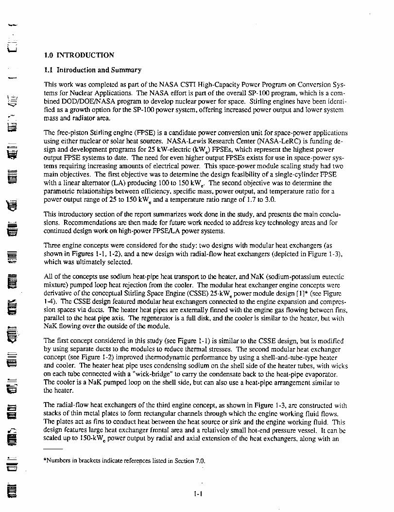
The radial-flow heat exchangers of the third engine concept, as shown in Figure 1-3, are constructed with
stacks of thin metal plates to form rectangular channels through which the engine working fluid flows.
The plates act as fins to conduct heat between the heat source or sink and the engine working fluid. This
design features large heat exchanger frontal area and a relatively small hot-end pressure vessel. It can bescaled up to 150-kW_ power output by radial and axial extension of the heat exchangers, along with an
*Numbers in brackets indicate references listed in Section 7.0.
W 1-1

i
I
Displacer
Hot
Manifold
Duct
Figure 1-1.
Sodium _W
Heat Pipe -._
m
89702
Engine Configuration with Finned Modular Heat Exchangers
Lr_
B
AR-
U
g
12 i

• = .
_E
Outlet
r -h-A _ _ NaK InletWick Bridge _ ,4_
Artery.. /_'_'_---___ LI I,FI
=- l i IlilL#\Sodium Heat Pipe \ '_[[ ",'_\,_..__.._ _ i/.:1_,'1 /_
Evaporator ,_[ iiii___Heate_ _?II II"* Cooler
Manifold DuctHeater
Manifold Duct
Section B-B
f
V
L
Sodium Passages
Wick
_Tub leeve
e
Sheet
Tube
Detail C
Section A-A
Figure 1-2. Engine Configuration with SheU-and-Tube Modular Heat Exchangers
Wick
Bridge
89767
w
1-3

l_====
i!
ilrj
m
Ill
Sodium
Heat Pipe
Heater/
Cooler
DisL
L
Power Pi,,
L_
Unear Alternator
\
-- //
881173
Figure 1-3. Engine Configuration with Radial-Flow Heat Exchangers
W
m
W
mW
1-4=--

L_
m
U
l
i
E
W
Balance Unit
Moving MagnetAssembly
I ;
Power Piston Linear Alternator
/.
/l-J \ !"Heater
Regenerator
Figure 1-4. Conceptual Stirling Space Engine (CSSE)
Displacer
1-5
Sodium Heat Pipe
881246

increase in displacer, power piston, and altemator diameters. Consistent performance and specific mass
are attained over a power range of 25 to 150 kWh.
A detailed description of these concepts and a comparison of predicted performance is provided in Sec-tion 2.0. All of the concepts were able to meet design requirements at power levels up to 150 kW e at a heat
exchanger temperature ratio of 2.0. The radial design presented the most favorable trends of efficiency and
specific mass with increasing power level, displaying moderate material and fabrication risks.
Details of the radial-flow engine design are provided in Section 3.0, which contains descriptions of the
heat exchangers and heat transport systems, mechanical drive systems, linear alternator, dynamic balan-
cer, and pressure vessel.
The parametric study forms the core of the scaling study, with 36 power module optimizations performed
over a power output range from 25 to 150 kW e at heat exchanger temperature ratios from 1.7 to 3.0.Section 4.0 discusses the power module analyses performedin_upport of the study. The parametricstudy results are presented in the form of power module thermal efficiency versus power module specific
mass, with power output and heat exchanger temperature ratio as parameters. The results of the study are
fit by an empirical equation tO be used as an input in future system stud|es.
To conclude the technical study of FPSE power modules capable of delivering 150 kW e alternative con-
figurations to the single-cylinder, direct-coupled linear alternator approach were evaluated and compared tothe baseline concept. The results of this work are covered in Section 5.0. Based on the scope of the pro-
gram, this task was limited to brief evaluation of only two configurations: a multicylinder Renia configura-
tion FPSE, depicted in Figure 1-5, and a rotary alternator connected to the baseline 150-kW_ FPSE enginethrough a magnetic coupling (see Figure 1-6). The multicylinder arrangement showed potential for lowerspecific mass than the baseline single-cylinder configuration, but the requirement for a low-loss appendix
gap seal increases the design complexity. The indirect-connected configuration does not offer significantperformance or weight improvements, and requires a linear displacer motor for power module stability.
The single-cylinder FPSE/LA is considered the best design approach. Further potential performance
improvements may be achieved through use of a balanced opposed engine configuration to eliminate the
penalties associated with the dynamic balance unit.
The parametric study results indicate that single-cylinder power modules meeting the design requirements
can be designed for power levels greater than 150 kWe. To determine the maximum feasible power output,
NASA elected to perform an optional task in the contract. The results of this work, reported in Section 6.0,show that a single-cylinder power module operating at a temperature ratio of 2.0 can be scaled in size from
150 kWe up to 500 kW e, but with declining efficiency and increasing specific mass.
1.2 Conclusions
The performance and specific mass values generated by this study are based on conceptual designs, butconsiderable effort was made to analyze the power module in sufficient detail to reduce uncertainties in
mass calculations to a 5 tO 10% level. Engine performance calculations have a 10% uncertainty due to
the differences between the actual three-dimensional flow in Stifling engine heat exchangers and the
one-dimensional analysis used for the thermodynamic model of the engine.
The main conclusions drawn from the design work and results of the scaling study are summarizedbelow:
• A single-cylinder FPSE/LA generating 150 kWe and meeting program goals is feasible based on thisconceptual design study.
1-6
mI
m
m
m
Il
V
m
m
tV
I
!
!

T"! ° _""
m
Pressure
Vessel
Alternator
Cylinders
Heater
Head
W,m
i
m
Figure 1-5. Multicylinder Free-Piston Stirling Engine Conceptual Design
89745
m
W
1-7

i
i
\
\ S
\
N\ S
\
S//
N /
N//
S /
J
m
J
V
c
Figure 1-6. Magnetic Linear-to-Rotary Converter Configuration
8g735ma
i
IW
I
in
R
I
1-8
i
U
F_
2
Z
V
L
g
The radial-flow heat exchanger engine concept has better performance and weight characteristics with
increasing power level than the modular CSSE-type engine concepts. Each of the three heat exchanger
concepts considered allows power module scaling to the 150-kW_ power level with acceptable specific
mass and efficiency.
Power module efficiency increases with power level from 25 to 150 kW e, but specific mass increases
as well.
Relative efficiency (fraction of Camot efficiency) increases and specific mass decreases with increas-
ing heat exchanger temperature ratio.
Selection of the "best" power module design point cannot be made without information on the overall
system trade-offs between power module mass and efficiency. Power module efficiency can be in-
creased at the expense of increased specific mass.
Alternator tuning capacitors do not have a major impact on power module specific mass over the
power range of the study.
The dynamic balancer (including both moving mass and structure) increases power module specific
mass by 20 to 30% (relative to an unbalanced single-cylinder power module). An adaptive pressurecontrol system is required for the balancer to adjust for changes in balancer dynamic tuning.
Items that require further attention include fabrication of branched heat pipes, material compatibility
with liquid metals, material welding, flow distribution in the heat exchangers, control of the closeclearances of bearings and seals (tolerance stackups, thermal distortion), alternator plunger length and
stiffness, high-temperature alternator materials, and the hydrodynamic bearing spin motor and cou-
pling designs.
The alternative configurations considered in this study (multicylinder FPSE/LA, FPSE coupled to
rotary alternator) have technical drawbacks that require additional design work. The probability of
performance improvements over the single-cylinder FPSE/LA approach is considered low.
Joining the single-cylinder engines in an in-line, opposed configuration provides a dynamically bal-anced module without the balancer mass and efficiency penalties. The structure required to join the
engines adds approximately 0.2 kg/kW_ to the basic power module specific mass.
The radial engine design can be scaled up to 500 kW_ at a temperature ratio of 2.0, at which point the
power module specific mass exceeds 10 kg/kW_.
1.3 Recommendations
Recommendations for future work related to high-power FPSE/LA power systems are summarized
below. Included are key technology areas that require further design or evaluation.
* Perform detailed design and analysis of branched heat pipes. Fabricate and test branched sodium heat
pipes at 1050 K.
• Study sodium compatibility with potential heat pipe materials.
• Fabricate and test radial-flow heat exchangers in an engine test rig.
• Perform characterization tests of alternator materials (magnets, laminations, and insulation) at 250 to
300°C operating temperature.
• Perform a detailed design study of a spin motor and coupling.
• Perform a preliminary design of a single-cylinder, 150-kW e FPSE/LA.
1-9

_Ji
Ik--
m
w
I
i
mmm
w_
.L_.-
I :
_U
mm
_uB
l
W

J
D
,_.lt,rv-_
m
u
L
m
2.0 ENGINE CONCEPT EVALUATION AND SELECTION
The primary objective of this study was to evaluate the feasibility of increasing the power output of a
single-cylinder (single piston, single displace0 FPSE/LA from the 25-kW e level of current SSE design
activity up to 150 kW c. This required answers to the following questions:
• How do FPSEs scale with power?. What mechanical and/or performance limitations determine
the maximum feasible power level?
• How do linear alternators scale?
• How do heat transport systems scale?
• How does the dynamic balancer scale?
• What engine design concept provides good performance, low specific mass, acceptable level ofrisk, and can be scaled to increased power level in a straightforward manner?.
In the course of answering these questions, several concepts were evaluated. The 25-kW_ CSSE designwith modular heat exchangers, shown in Figure 1-4, provided the starting point, but initial work revealed
both mechanical and thermodynamic shortcomings in the design. Design modifications led to the separate
duct concept and two modular designs: finned heat exchangers (depicted in Figure 1-1) and shell-and-tube
heat exchangers (depicted in Figure 1-2). These were followed by a new engine concept with radial-flow
heat exchangers (see Figure 1-3), which eliminated the fabrication risks associated with Inco-713 used inthe hot end of the modular designs. A detailed discussion of the engine concepts is provided in Section 2.2.
2.1 Design Requirements
The design requirements specified in the work statement were as follows:
• Configuration: Single-cylinder FPSE (single piston, single displacer) with linear alternator and
tuning capacitors if required
• .Power module thermal efficiency (net electrical output power/heat input): >--20%
• Power module specific mass: 5 to 8 kg/kW_
• Heater gas-side metal wall temperature: 1050 K
• Cooler gas-side metal wall temperature: 525 K
• Hot-end material: superalloy
• Design life: 7 years (60,000 hr)
• Engine working fluid: helium
• Altemator output voltage: >__100V
• Maximum power module vibration amplitude: 0.0038 cm
• Hot-end heat transport system: heat pipe with sodium working fluid
• Cold-end heat rejection system: pumped loop with NaK working fluid.
2.2 Engine Concepts
The selection of an engine concept capable of scaling over a wide range of power levels involves both
mechanical and thermodynamic considerations. The principal focus of this study is on displacer-type
FPSEs, and all of the concepts considered have a similar displacer drive assembly. The main differences
between concepts are in the configurations of the heat exchangers and the pressure vessel.
2-1
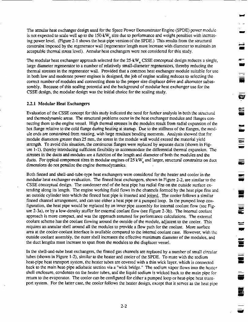
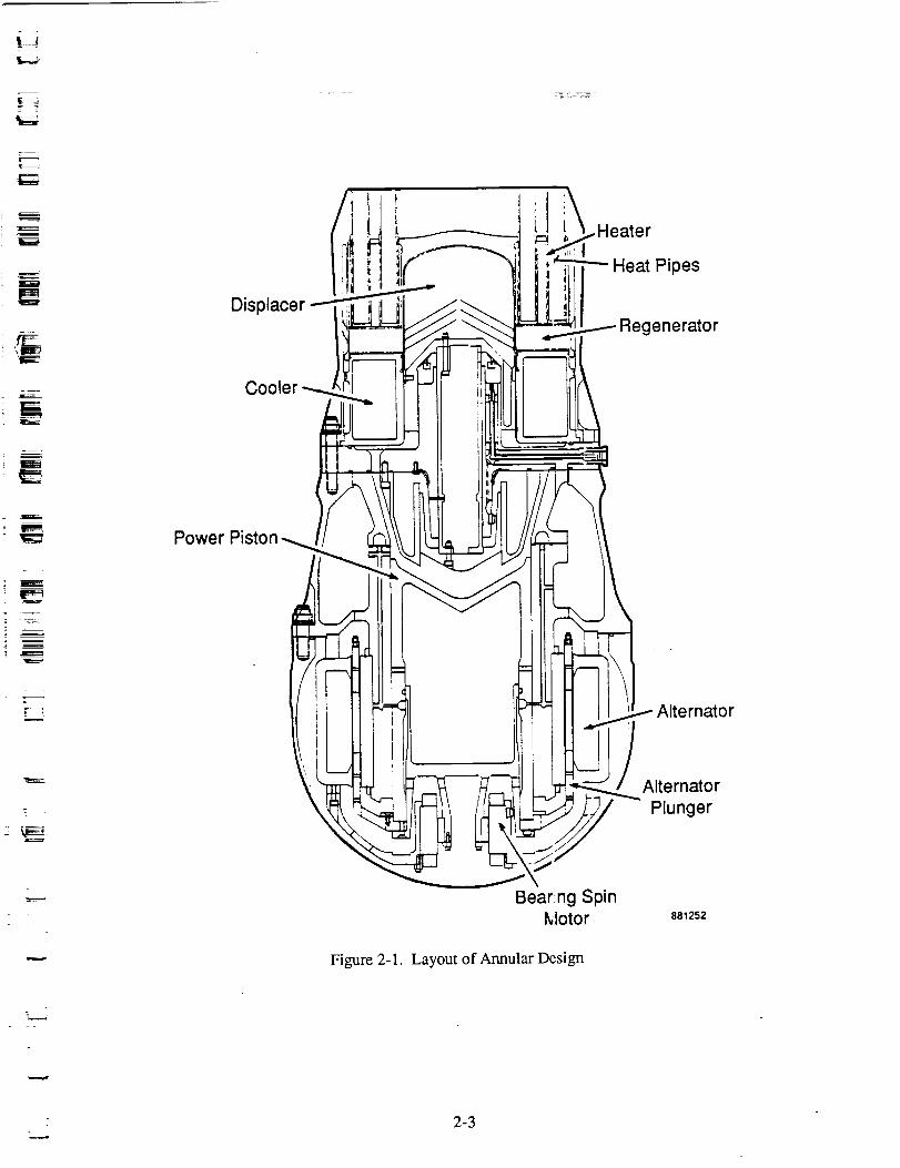
TheannularheatexchangerdesignusedfortheSpacePowerDemonstratorEngine(SPDE)powermoduleisnotexpectedto scalewellupto the150-kWesizeduetoperformanceandweightpenaltieswith increas-ingpowerlevel. (Figure2-1showstheheat-pipeversionof theSPDE.)Thisresultsfromthestructuralconstraintimposedbytheregeneratorwall (regeneratorlengthmustincreasewithdiametertomaintainanacceptablethermalstresslevel).Annularheatexchangerswerenotconsideredforthisstudy.
Themodularheatexchangerapproachselectedforthe25-kWeCSSEconceptualdesignreducesasingle,largediameterregeneratortoanumberof relativelysmall-diameterregenerators,therebyreducingthethermalstressesin theregeneratorwall. Providedthatacommonheatexchangermodulesuitableforuseinbothlow andmoderatepowerenginesisdesigned,thejobof enginescalingreducesto selectingthecorrectnumberof modulesandconnectingthemto thepropersizedisplacerdriveandalternatorsubas-sembly.Becauseof thisscalingpotentialandthebackgroundof modularheatexchangerusefortheCSSEdesign,themodulardesignwastheinitialchoicefor thescalingstudy.
2.2.1 Modular Heat Exchangers
Evaluation of the CSSE concept for this study indicated the need for further analysis in both the structural
and thermodynamic areas. The structural problems occur in the heat exchanger modules and flanges con-
necting them to the engine vessel. High thermal stresses in the modules result from radial expansion of thehot flange relative to the cold flange during heating at startup. Due to the stiffness of the flanges, the mod-
ule ends are constrained from rotating, with large resultant bending moments. Analysis showed that for
module diameters greater than 25 mm, the stress in the module wall would exceed the material yieldstrength. To avoid this situation, the continuous flanges were replaced by separate ducts (shown in Fig-
ure 1-1), thereby introducing sufficient flexibility to accommodate the differential thermal expansion. The
stresses in the ducts and modules are a function of the length and diameter of both the modules and the
ducts. For typical component sizes in modular engines of 25 kW_ and larger, structural constraints on ductdimensions do not penalize the engine thermodynamics.
Both finned and shell-and-tube-type heat exchangers were considered for the heater and cooler in the
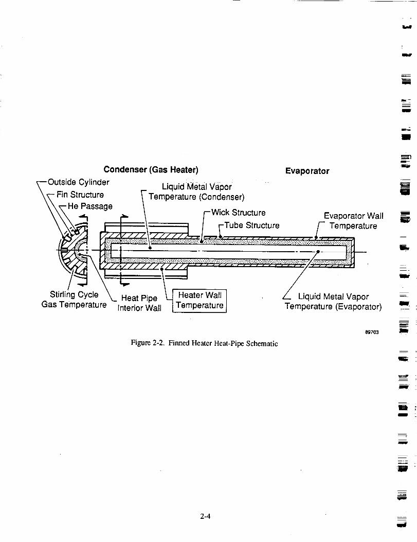
modular heat exchanger evaluation. The finned heat exchangers, shown in Figure 2-2, are similar to the
CSSE conceptual design. The condenser end of the heat pipe has radial fins on the outside surface ex-
tending along its length. The engine working fluid flOWS in the ch_els formed by the heat pipe fins and
an outside cylinder into which the f'mned heat pipe is inserted and joined, The cooler follows a similar
finned channel arrangement, and can use either a heat pipe or a pumped loop. In the pumped loop con-
figuration, the heat pipe would be replaced by an inner pipe assembly for internal coolant flow (see Fig-ure 2-3a), or by a low-density stuffer for external coolant flow (see Figure 2-3b). The intemal coolant
approach is more compact, and was the approach assumed for performance calculations. The external
coolant scheme has the coolant flowing around the outside of the module, adjacent to the cooler. This
requires an annular shell around all the modules to provide a flow path for the coolant. More surface
area at the cooler-coolant interface is available compared to the internal coolant case. However, with theoutside coolant assembly, the outer shell increases the effective maximum diameter of the modules, and
the duct lengths must increase to span from the modules to the displacer vessel.
In the shell-and-tube heat exchangers, the finned gas channels are replaced by a number of small circulartubes (shown in Figure 1-2), similar to the heater and cooler of the SPDE. To mate with the sodium
heat-pipe heat transport system, the heater tubes are covered with a thin wick layer, which is connected
back to the main heat-pipe adiabatic section via a "wick bridge." The sodium vapor flows into the heatcr
shell enclosure, condenses on the heater tubes, and the liquid sodium is wicked back to the main pipe for
return to the evaporator. The cooler can be configured for either a pumped loop or heat-pipe heat trans-
port system. For the latter case, the cooler follows the heater design, except that it serves as the heat pipe
2-2
I
i
lU
mn
g
m
nlw
m
m
w
I
m
RW
u
w
IF
II
i
iI
l
l
i
J
_s
i
Displacer---ii!
t
Cooler _.
Power Piston w
IJ
f i
I
i
Bear!ng SpinMotor
Alternator
Alternator
Plunger
881252
Figure 2-1. Layout of Annular Design
7
2-3
i8'
m
m
m
Condenser (Gas Heater) Evaporator
/_...Outside Cylinder _ Liquid Metal Vapor
Fin Structure Temperature (Condenser)He Passage _ .... .
""1 - r_ / /--wick Structure Evaporator Wall
j'_'_t I / [-Tube Structure r Temperaturer/__',-/,-N_..]._,, .............. _. ....
.ea,er a,,.Gas Temperature Interior Wall[ Temperature Temperature (Evaporator)
89703
Figure 2-2. Finned Heater Heat-Pipe Schematic
h
U
W
W
m
m
m
m
m
m
,m -m
2-4
mf

t. '
¢_. ;
r --E
'[==¢_
Era====
liH IFlow.
I
Coolant Return
Manifold
Regenerator
Coolant Outlet
Coolant Ifilet
A-A89774
Figure 2-3a. Pumped Loop Cooler Concept - Internal Coolant
2-5

Bounce SpacePressure
Gas
He Flow
Cold-End Heat Exchanger
High-StrengthShell
High Thermal Conductivity
Sleeve (Fins)
Low Density"Stuffer"
PassageClose-Out
Tube
f- Fins He Flow
Passages
Regenerator
I
w
N
m
_==
g
m
Coolant Flow Arrangement
CoolantFlow
Inlet m
Heat Exchanger
F Baffle
Side View
Heat ExchangerModule
Manifolds
Modules _let and Outlet)
Engine Pressure__/ _ _ SectorVessel Partition (4)
End View
Figure 2-3b. Pumped Loop Cooler Concept - External Coolant89765
W
m
l
m
=
m
W
W
2-6 _
1ira

L= =
.d
i
'IF'-"-.
I
L
N
evaporator, rather than condenser. Boiling limits in the heat pipe evaporation may force the cooler to
longer-than-optimal length, but this is not expected to eliminate the cooler heat-pipe concept from con-
sideration. For the pumped loop case considered in this study, liquid NaK would flow transverse to the
tubes on the shell side.
For both modular configurations, the regenerator is a full cylindrical disk between the heater and cooler
assemblies. In order to provide a straight load path in the module outside pressure vessel wall, the heater
and cooler outside diameters are approximately equal to the regenerator outside diameter.
Thermodynamic performance of a 25-kW e engine using the finned modules of the CSSE design was ap-proximately 30% below requirements, as determined by analysis using MTI's harmonic code. Module
optimization and characterization were required to improve performance and to facilitate the scaling of
the engine power output from 25 to 150 kWh. This allowed selection of the best module size and heatexchanger geometry to meet the design requirements over a range of power levels. The modules were
optimized for maximum indicated engine efficiency. For the finned heat exchangers, the channel width,
height, and fin thickness were optimized; for the shell-and-tube configuration, the number of heater andcooler tubes and tube inside diameters were optimized. For both cases the heater and cooler lengths were
fixed at 60 mm based on previous experience, which shows improved performance with shorter heat
exchangers. The 60-mm length was selected as a practical minimum due to heat pipe performance limits
and pressure drop limits in the coolant pumped loop. The screen regenerator wire diameter was fixed at
25.4 I.tm. The regenerator porosity and length-to-diameter ratio (L/D) were optimized for all cases.
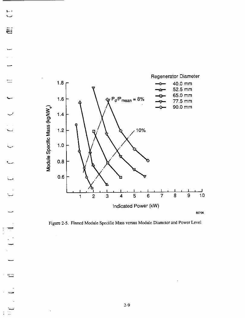
The optimization results, presented in Figures 2-4 through 2-8, led to the selection of 90-mm diameter
modules driven at 9% pressure amplitude as the best choice for both module types. As seen in the figures,
indicated engine efficiency increases with increasing regenerator diameter, but at the expense of increased
module specific mass. For a regenerator diameter greater than 90 mm, there is a diminishing efficiency
gain due to an increased pumping loss fraction (pumping loss per net thermodynamic power generated).
The pumping loss increases because of the increasing regenerator length (due to the structural constraint of
regenerator wall L/D ratio). Figures 2-4 through 2-6 show the indicated engine efficiency, specific mass,
and heat-pipe wall temperature drop for the finned heat exchanger module as a function of power level and
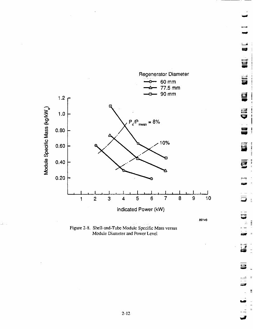
module diameter. Figures 2-7 and 2-8 show similar results for the shell-and-tube module (tube wall AT is
very low and is not shown). In selecting the best module size for each configuration, the trade betweenmodule power level and efficiency as a function of pressure amplitude was evaluated. In view of the design
goal of 150 kW_ per engine, the higher power modules are preferred since the manifolding and packagingof fewer modules is easier.
The indicated power of the 90-mm diameter finned module is 3.8 kW, compared to 5 kW for the shell-
and-tube configuration module. Therefore, the finned module engine requires one third more modules
than the shell-and-tube module engine for the same engine power output. A single shell-and-tube modulehas about the same mass as a single finned module.
Performance details of the modular configurations are provided in Section 2.4.
2.2.2 RadlaI-Flow Heat Exchangers
The modular engine designs described above require a very high-strength, high-temperature superalloy such
as Inco-713 for the hot pressure vessel in order to achieve acceptable engine specific mass. The hot pres-
sure vessel includes the displacer pressure vessel, the module vessels, and the hot connecting ducts. The
welding of Inco-713 has not been demonstrated for components of these shapes and poses a design risk.
2-7

W
l
v
34
32
30
e-
.m
.u
LU"10'_ 26.._.__.'1oC
-- 24
28
22
Pc/Pmean = 8%
1 10%
Regenerator Diameter
•-e-- 40.0 mm
52.5 mm
65.0 mm
77.5 mm
90.0 mm
1 _ 2 3 4 5 6 7 8 9
Indicated Power (kW)
Figure 2-4. Finned Module Performance versus Module Diameter and Power
10
89705
_r===zw
w
w
w
B
tg
B
U
m
m
Ig
2-8
L
1.8
1.6
1.4
it)
1.2
._o
o 1.0
03
= 0.8"130
0.6
Figure 2-5.
Pc/Pmean = 8%
, I , I , I I I , I I
1 2 3 4 5
10%
Regenerator Diameter
•-e-- 40.0 mm
52.5 mm
65.0 mm
77.5 mm--_- 90.0 mm
I , I , I , I , I6 7 8 9 10
Indicated Power (kW)
89706
Finned Module Specific Mass versus Module Diameter and Power Level
J
2-9

il
m
140
120
10080
60
40
20
Regenerator Diameter
40.0 mm52.5 mmm
65.0 mm
77.5 mm
-8- 90.0 mm
!
I , I , I , I l I , I , I , I i I1 2 3 4 5 6 7 8 9
Indicated Power (kW)
Figure 2-6. Finned Module Heater Wall Temperature Drop versusModule Diameter and Power Level
I
10
89707
i. I!
w
_ .=
_J
I !
L.=.,--
= 1
z _
2-10

%...,.
-...j
,.m
t--Q)
omtO
:I=LU
"0
"10c
m
39
38
37
36
35
34
33
, L i
I
Regenerator Diameter
60.0 mm
--_- 77.5 mm
90.0 mm
Pc/Pmean = 8%
a
I , I , 1 II_'¢ I I I ,
2 3 4 5 6 7
Indicated Power (kW)
I
8
Figure 2-7. Shell-and Tube Module Performance versusModule Diameter and Power Level
I , I
9 10
897O8
z
2-11
1.2
1.0
0.80
"_ 0.60
._ 0.40
0.20
Regenerator Diameter
•--e-- 60 mm77.5 mm
90ramB
Pc/Pme_ - 8%
10%
, I , I , I , I , I , I , I , ! , 1 , I
1 2 3 4 5 6 7 8 9 10
Indicated Power (kW)
Figure 2-8. Shell-and-Tube Module Specific Mass versusModule Diameter and Power Level
89749
U
'=i
= _ .
m
t=_l
i |EL-
W"
W
iiF
2-12
w
To avoid the use of Inco-713, the radial-flow engine (shown in Figure 1-3) was designed with a relatively
small section of pressure vessel operating at the full heater temperature. By restricting the heater heat
pipes to a small diameter at the penetration through the pressure vessel, the mass of the hot pressure ves-
sel does not dominate the overall engine specific mass. Lower strength superaUoys such as Inco-625,
which has good weldability, can then be used.
The primary difference between the configurations of the modular and radial engines is the arrangement
and location of the heat exchangers. The modular heat exchangers are located outside of the displacer
pressure vessel, and the gas flows parallel with the displacer axis. The radial engine heat exchangers are
positioned within the pressure vessel, close to the expansion space, with the working fluid flowing
radially with respect to the displacer. By locating the heat exchangers within the main pressure vessel,
the heat exchanger wails are loaded only by the alternating pressure of the engine cycle, instead of the
full engine pressure (mean plus alternating), which the modular walls see. This design feature results in
significant mass reduction for the radial engine.
Details of the radial engine heat exchanger construction are shown in Figure 2-9. In the heater and
cooler, the gas flows in rectangular passages formed by an assembly of thin metal plates. Full annular
plates are altemately stacked with smaller plate sections that are evenly spaced, circumferentially, to
form the gas channels. Continuous end plates are used to enclose the heater, regenerator, and cooler, and
form a boundary between the working spaces and the surrounding mean pressure regions. The regenera-
tor wall incorporates a bellows type of construction to reduce thermal stresses. All of the heat exchanger
plates are punched with holes to accept the heat pipes and coolant pipes, and the assembly is furnace-
brazed to seal the spaces between plates and provide a good thermal connection between plates and pipes.
As shown in Figure 2-9, the heat pipes are arranged in groups of three, although this can vary depending on
whether the design criteria is for maximum efficiency or minimum specific mass (see Section 4.0). The
regenerator in the radial engine is an annulus with the same axial length as both the heater and cooler. This
provides an easy means of increasing the heat exchanger frontal area by increasing the heat exchanger axialdimension. Further details of the radial engine heat exchangers are provided in Section 3.3.
2.3 Scaling Considerations
As mentioned in the introduction, power module scaling from 25 to 150 kW_ requires consideration ofhow each of the power module subassemblies scale. This includes structural, thermodynamic, dynamic,and electromagnetic aspects of the system.
2.3.1 Structural Aspects
For the modular heat exchanger engines, the assembly of modules into a full engine requires consideration
of module spacing and ducting. Since displacer diameter varies with the square root of engine power, andengine power increases in direct proportion to the number of modules, the displacer perimeter available per
module varies inversely with the square root of power. For a 25-kW e engine, 8 of the finned modules, or 6of the shell-and-tube modules, are required. Assuming a 160-mm diameter displacer, there are 63 mm of
perimeter per module for the finned module, and 84 mm per module for the shell-and-tube module. These
perimeters allow sufficient space to easily accommodate ducts, both structurally and thermodynamically.
However, when scaled to 150 kwh, the available perimeter for the finned module drops by 1/_1-6to 26 mm,
which is insufficient to allow adequate duct size with good remaining structural material between ducts.
The same is true with the shell-and-tube module, which has just 34 mm of available circumference permodule.
2-13

m
.ea
Heat Pipes
Heat Pipe Wall --_
x5 Scale
Heat PipeOutside
Diameter
Heat Pipe Coreand Wick
// //
/ i //
// / /
/ / / i
//
//
/" /
Circumferential GapBetween Pipes
0.25-mm Plate
_ 0.75-mm Plate
x 0.75-mm
IsO anne,s
Section A-A 897O9
Figure 2-9. Radial Engine Heat Exchanger Detail
i
n
I
I
i
i
l
i
_=i
!mI
m
n
m
J
NI
!i
l2-14

W
m
A solution to this problem is to gang the modules together in groups of two to four, with single ducts
connecting each group to the working spaces (see Figure I-1). Sufficient displacer perimeter is thenavailable per duct, even though the duct diameter increases. Depending on the size and number of
groups, they can be arranged on a single circle or staggered into an inner and outer circle.
Scaling of the radial heat exchanger engine requires that the heater heat-pipe penetrations through the
pressure vessel be maintained on a sufficiently small diameter to keep the mass of the hot structureacceptably small.
2.3.2 Thermodynamic Aspects
Since the geometry of the modular engine heat exchangers is not varied with power level (only the num-ber of modules is varied), the modular heat exchanger thermodynamics do not change with power level
for constant volume amplitudes at the module faces. However, there is a thermodynamic penalty with
larger power levels due to the increased duct volume required to connect the modules to the engine pres-sure vessel.
For the radial engine, the heat exchangers are scaled to achieve the optimization objectives at a givenpower level, and there are no fundamental heat exchanger scaling penalties.
As detailed in Section 2.4.1, seal clearances increase with increased engine size. Since, for constant
stroke, the engine power varies with piston diameter squared, and piston seal leakage loss varies with
piston seal clearance cubed, the leakage loss increases proportional with [engine power] 3/2 (for constant
seal L/D). Thus, seal leakage has a tendency to limit the engine pressure amplitude at higher power lev-els to avoid major performance penalties.
2.3.3 Heat Pipes
Heat pipe performance limits, as discussed in Section 4.2, set the heat-pipe diameter and length. For
increased power level, the number of heat pipes scale directly, therefore heat-pipe specific mass isconstant.
2.3.4 Alternator
From first-order altemator analysis, magnet mass increases linearly proportional with power. Coil area is
independent of power, depending only on efficiency. Based on these trends, altemator specific mass
decreases slightly with increasing power level (magnet specific mass is constant, copper and iron specificmasses decrease).
2.3.5 Dynamic Balancer
Dynamic balancer size is set by the engine unbalanced force, which is due primarily to the power piston
and altemator plunger. To the first-order, for constant power piston and alternator plunger (magnet) spe-
cific mass, the balance specific mass is constant. Actual required balance mass depends on balancerlosses, as discussed in Section 4.2.4.
2.4 Concept Comparisons
Following preliminary performance analyses of the finned module engine, shell-and-tube module engine,and radial engine, a detailed comparison of the geometry, performance, and specific mass breakdowns of
2-15

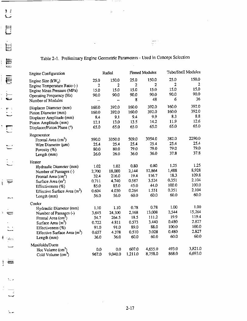
theconfigurationsatthe25-and150-kW_powerlevelswasmadeandpresentedtoNASA-LeRC.Tables2-1through2-3summarizetheresults.NotethattheradialenginegeometriesgiveninTable2-1arefromthepreliminaryanalysisperformedatthatstageoftheprogram.Theoptimizedradialenginede-signsdevelopedlaterin theprogramdonotexactlymatchtheseearlydesigns.
All numberswerebasedonconceptualdesignswithoutdetailedengineperformanceoptimization,allow-inggeneralcomparisonstobemadebasedonbasicdesignfeatures.All threeengineconceptswereevaluatedwith identicaldisplacerandpistondiameters(160-mmdiameterat25kW;392-mmdiameterat150kW),withadisplacer-to-pistonstrokeratioof 0'7. Noattemptwasmadeatthetimeto selecttheoptimumcombinationof pistonareaandstroke.
Forcomparisonpurposes,theconceptswereevaluatedatthesameindicatedpowerlevels(30and180kWt).Sincethecalculatedmechanicalefficienciesof theenginesvariedslightly,thelistedelectricalpowersdonotexactlymatchthe25-or 150-kW_goals.TheefficiencyandspecificmassvaluesinTables2-2and2-3donotincludetheeffectsof thedynamicbalancerassembly.
A discussionof theinformationpresentedin thetablesisgivenbelow.Thecomparisonof enginegeome-triesiscoveredfirst,followedbythermodynamicandmechanicalefficiencies,enginelosses,thermalcharacteristics,andspecificmasses.
2.4.1 Engine Geometry
The comparisons of the geometries of the three designs are concentrated on those areas where significantdifferences occur, primarily in the heat exchangers. Since all of the engine concepts have a similar dis-
placer assembly and alternator assembly, these areas are not compared. The displacer and power pistonseal clearances are set to 12.7-I.tm radial clearance for piston diameters up to 152 mm, and increase
linearly with diameter for sizes greater than 152 mm. Thus, for the 392-mm piston diameters used for
the 150-kW c engines, the seal clearance is (392/152 x 12.7 = 32.8 lain. For concentric seals, as in thedisplacer drive, the outer seal clearance is increased by 30% to allow for tolerance stackups.
2.4.1.1 Heat Exchangers. Since the radial engine heat exchanger geomeIry is not strongly coupled
to the engine structural requirements, large frontal areas for all heat exchangers (heater, cooler, and
regenerator) are possible without excessive structural weight penalty. The heat exchanger surface areasare also high, and relatively short heat exchangers (in the direction of flow) can be used. As shown in
Table 2-1, for a given power output the frontal and surface areas of the radial engine heat exchangersexceed those of both the modular engines.
The shell-and-tube module has less actual heat exchanger surface area than the finned module, but lower
heater fin effectiveness gives the finned module the lowest effective heater surface area. In the cooler,the f'mned module uses copper fins and the effective surface area exceeds that of the shell-and-tube
module.
2.4.1.2 Manifold/Ducts. The radial engine has no hot ducts*, and its long cold duct has a similar vol-ume to the manifold volumes in the modular engines. The finned module engine has more manifold
volume than the shell-and-tube module engine because of the greater number of modules used. When
scaled up to 150 kW e the finned module manifolds become longer than the shell-and-tube's because ofthe greater circle diameter needed for 48 modules, compared to 36 modules.
*The expansion space is connected to the heater via formed sheet metal which, depending on the location of the heatexchangers relative to the displacer, can add significant hot volume.
2-16
W
m
w
W
UW
i
Aw
U
J
I
l
mB
!l
I
m
=__
m
l=
U
m
01w
m
W
FM
E
E :7
Table 2-1. Preliminary Engine Geometric Parameters - Used in Concept Selection
Engine Configuration Radial
Engine Size (kWe) 25.0 150.0
Engine Temperature Ratio (-) 2 2
Engine Mean Pressure (MPa) 15.0 15.0
Operating Frequency (Hz) 90.0 90.0Number of Modules ....
Displacer Diameter (mm) 16010 392.0
Piston Diameter (mm) 160.0 392.0
Displacer Amplitude (mm) 8.4 9.1
Piston Amplitude (ram) 12.1 13.0
Displacer/Piston Phase (o) 65.0 65.0
RegeneratorFrontal Area (cm 2) 590.0 3350.0
Wire Diameter (lam) 25.4 25.4
Porosity (%) 80.0 80.0
Length (ram) 26.0 26.0
Heater
Hydraulic Diameter (mm) 1.02 1.02
Number of Passages (-) 2,700 18,000Frontal Area (cm') 32.4 216.0Surface Area (m 2) 0.711 4.740
Effectiveness (%) 85.0 85.0Effective Surface Area (m 2) 0.604 4.030
Length (ram) 56.0 56.0
Cooler
Hydraulic Diameter (mm) 1.10 1.10
Number of Passa§es (-) 3,645 24,300Frontal Area (cm) 54.7 264.5
Surface Area (m 2) 0.722 4.811
Effectiveness (%) 91.0 91.0
Effective Surface Area (m 2) 0.657 4.378
Length (mm) 36.0 36.0
Manifolds/Ducts
Hot Volume (cm 3) 0.0 0.0
Cold Volume (cm 3) 967.0 9,040.0
Finned Modules Tube/Shell Modules
25.0 150.0 25.0 150.0
2 2 2 2
15.0 15.0 15.0 15.0
90.0 90.0 90.0 90.0
8 48 6 36
160.0 392.0 160.0 392.0
160.0 392.0 160.0 392.0
9.4 9.9 8.3 8.8
13.5 14.2 11.9 12.6
65.0 65.0 65.0 65.0
509.0 3054.0 382.0 2290.0
25.4 25.4 25.4 25.4
79.0 79.0 79.0 79.0
36.0 36.0 37.8 37.8
0.80 0.80 1.25 1.25
2,144 12,864 1,488 8,92819.4 116.7 18.3 109.8
0.587 3.524 0.351 2.104
45.0 44.0 100.0 100.0
0.264 1.551 0.351 2.104
60.0 60.0 60.0 60.0
0.78 0.78 1.00 1.00
2,168 13,008 2,544 15,26418.5 111.2 19.9 119.4
0.573 3.440 0.480 2.827
89.0 88.0 100.0 100.0
0.510 3.028 0.480 2.827
60.0 60.0 60.0 60.0
607.0 4,655.0 493.0 3,821.0
1,211.0 8,758.0 868.0 6,693.0
z
2-17

i
i
Table 2-2. Preliminary Engine Performance Predictions - Used in Concept Selection
Engine Configuration Radial Finned Modules Tube/Shell Modules
Indicated Power (kW) 30.0 180.0 30.0 180.0 30.0 180.0
Electrical Power (kW¢) 25.4 147.9 24.9 143.2 25.4 147.9
Indicated Efficiency (%) 34.0 34.0 33.0 32.0 36.0 34.0
Displacer Mechanical Efficiency (%) 95.0 94.0 95.0 94.0 95.0 94.0
Piston Mechanical Efficiency (%) 97.0 95.0 95.0 92.0 97.0 95.0
Alternator Efficiency (%) 92.0 92.0 92.0 92.0 92.0 92.0
Power Module Efficiency
(Including Linear Alternator) (%) 29.0 28.0 27.0 25.0 31.0 28.0
Engine Pressure Swing
PamplitadJPmua (%) 9.1 8.7 8.6 8.5 9.1 8.8
Heater
Heat Flux Per Channel (W) 27.0 25.0 42.0 43.0 57.0 59.0
AT_ .... ,a (°C) 25.0 23.0 39.0 39.0 31.0 31.0
AT,,_a (°C) 52.0 52.0 33.0 34.0 5.0 5.0
Cooler
Heat Flux Per Channel (W)
ATs._._ (°C)
ATwd (°C)
(Tn/'rc)_g,_o, (-)
12.0 11.0 28.0 28.0 23.0 23.0
16.0 15.0 10.0 I0.0 12.0 12.0
17.0 17.0 59.0 60.0 2.0 3.0
1.76 1.75 1.84 1.84 1.84 1.84
W
U
W
W
I
m
J
I
m
Note: Performance predictions are based on unoptimized conceptual designs. Efficiencies for new engineshave an uncertainty of 15%.
I
I
m
2-18
is
F
M
Table 2-3. Preliminary Specific Mass Summary - Used in Concept Selection
Engine Configuration
Engine Size (kWh)
Radial
25 150
Finned Modules Tube/Shell Modules
25 150 25 150
Specific Mass &g&W_)
Component
Heater 0.76 0.79 0.60 0.60 0.39 0.39
Regenerator 0.15 0.11 0.21 0.21 0.16 0.16Cooler 0.31 0.25 0.35 0.35 0.34 0.34
Manifolds --* --* 0.15 0.19 0.13 0.15
Displacer Pressure Vessel 1.20 1.00 0.72 1.11 0.72 1.11Cold Pressure Vessel 0.99 0.85 0.62 0.68 0.62 0.68
Displacer Assembly 0.36 0.56 0.36 0.56 0.36 0.56
Piston Assembly 0.37 0.55 0.37 0.55 0.37 0.55
Alternator Assembly 1.47 1.34 1.47 1.34 1.47 1.34
Miscellaneous Sla'ucture 0.50 0.50 0.50 0.50 0.50 0.50
Total Specific Mass 6.11 5.95 5.35 6.09 5.06 5.78
*The manifold between the cooler and compression space in the radial engine is integral with the
internal engine structure and is included with the displacer assembly mass.
Note: Component masses are calculated from conceptual designs. Specific masseshave an uncertainty of 20%.
J
E
B
E_ 2-19
2.4.1.3 Engine Dead Volume. The radial engine and shell-and-tube module engine have similar deadvolumes. The finned module engine has more dead volume, due to the greater number of modules and
ducts. Increased engine dead volume requires a larger engine displacement to produce the same engine
power.
2.4.2 Performance
2.4.2.1 Indicated Engine Efficiency. The radial and modular engines have similar indicated efficien-
cies. At the 25-kW c engine size, the shell-and-tube module engine holds a two-point efficiency advan-tage over the radial engine (due primarily to a higher regenerator temperature ratio), and a three-point
advantage over the finned module engine (due to lower pumping and hysteresis losses).
The indicated efficiency of the modular engines decreases with increased engine size due to percentage
increases in both pumping and leakage losses. The radial engine indicated efficiency remains nearlyconstant with increased size because the small pumping loss percentage increase is offset by a decrease in
the wall conduction losses as a fraction of engine heat input.
2.4.2.2 Mechanical Efficiency. The displacer and piston mechanical efficiencies represent the gas
spring (hysteresis and seal leakage) and porting losses. The finned module engine has lower mechanicalefficiency due to its higher engine displacement. Increased engine displacement results in higher gas
spring and/or leakage losses and reduced mechanical efficiency.
When the engines are scaled to larger sizes, the gas spring seal clearances increase proportional with
piston diameter, as discussed above, and the gas spring losses increase.
2.4.2.3 Engine Losses. The pumping loss is much lower in the radial engine than in the engines with
modules due to the large heat exchanger flow areas in the radial engine. The pumping loss as a fraction
of engine power increases slightly with increased engine size because of increases in engine dead vol-ume. This dead volume must be overcome with increased displacement, thereby increasing the heat ex-
changer mass flow rate per power generated.
The compression space seal leakage is similar for all the engine configurations, showing a large increase
between the 25- and 150-kW e engines because of the increased seal clearances.
The conduction losses in the radial engine regenerator matrix are higher than in the modular engines
because of the increased regenerator frontal area and shorter regenerator length. However, the regenera-
tor wall in the radial design cames the pressure amplitude only, and wall thickness does not increase with
engine size _ in the modular engines. Therefore, wall conduction is much less in the radial engine, par-
ticularly at high power levels.
2.4.2.4 Wall Temperature Drop. Temperature drops through the heat exchanger walls are lowest in the
shell-and-tube engine because of the relatively thin walls of the tubes, but are not prohibitively high for
any of the designs.
For this initial concept comparison, Inco-625 was assumed for the pressure structure surrounding the heat
pipes in the radial engine. The 52°C wall drop for the radial heater includes 10°C through the nickel
block between the heat pipe and gas channel.
The cooler in the finned module consists of an Inco-718 inner pressure wall with a finned copper sleeve
around it. The outer module wall is continued down from the regenerator. The coolant pipe or heat pipe
2-20
U
u
J
Ml
i
D
J
mB
I
m
m
i
M
m
W
l
m
I
I
lF!m
I!I
U
B
g

m
L_ .
Igggg_
m
is assumed to be on the inside of the inner wall. The relatively large temperature drop through the wall is
due to its poor thermal conductivity and low surface area.
2.4.2.5 Gas-Wall AT. In the heater, the finned module has the largest film temperature drop because of
the small effective surface area. In the cooler, copper fins were assumed for the finned module engines,
and aluminum fins were assumed for the radial engine, resulting in high surface effectiveness for both.
Despite the fact that the radial engine has the largest effective cooler surface area, it has the largest
ATg_s waUbecause of a low heat transfer coefficient (large frontal area results in low flow velocity andreduced heat transfer coefficient).
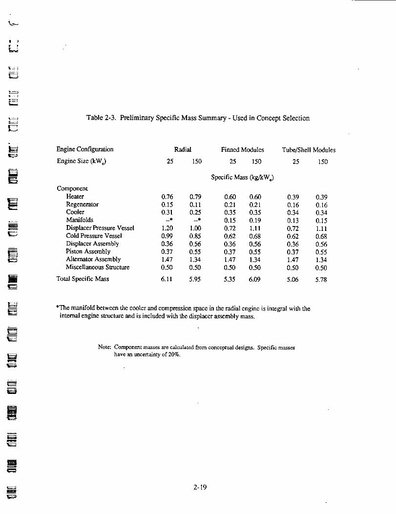
2.4.3 Specific Mass
The three engine configurations have similar total specific mass, as shown in Table 2-3". The radial
engine heater is heavier than the modular engine heaters because of the large heat exchanger volume.
The displacer pressure vessel mass for the radial engine includes the cylinder around the displacer, the
structure that forms the duct between the cooler and displacer flange, and the outer pressure vessel fromthe bottom of the cooler to the hot end. For the modular engines, the displacer pressure vessel mass in-
cludes the main pressure vessel around the displacer and the displacer flange. The radial engine uses
Inco-625 for the hot section of the head, and therefore pays a mass penalty compared to the modular en-
gines, which use the stronger Inco-713 for the hot structure. However, the risks of joining Inco-713 areavoided.
The radial engine specific mass as calculated for the concept selection decreases with engine size. This
occurs mainly because the hot portion of the displacer pressure vessel does not scale up proportionally
with the engine since it is restricted to a relatively small portion of the vessel. The more detailed radialengine designs performed later in the parametric study portion of the program show a slight increase in
power module specific mass with power level.
The modular engine's specific mass increases with engine size because of the increase in pressure vessel
specific mass.
The shell-and-tube module heat exchangers have a lower specific mass than the finned module heat ex-
changers because more power is generated per shell-and-tube module. Thus, fewer shell-and-tube
modules are necessary.
2.4.4 Scalability
The change in power module efficiency and specific mass (excluding balancer) with power level for the
three concepts is shown in Figure 2-I0. The radial engine shows good relationships of performance andspecific mass with increasing power output. The modular engines both show decreasing efficiency and
increasing specific mass at higher power levels. Based on these preliminary scaled predictions, all three
concepts can achieve the design requirements at 150-kW e power output. The radial engine is most attrac-tive for higher power requirements because of its excellent and nearly constant efficiency and specificmass.
*Table 2-3 specific mass totals do not include the balancer assembly mass.
2-21

m
7
32-
"10 q)O .m
$_ 28-
OnE
(1)¢...
24-
0
Radial
_ules
i I I I I I
25 50 75 100 125 150
l
g
=r=.m
i
m
m
m
lg
I
m
_4
Net Power (kWe)
89710 m
Figure 2-10. Power Module Efficiency and Specific Mass* versus Net Power i
g
m
*Does not include balancer assembly specific mass.
2-22
[]l
lmm
D

). J
H
-,,,_....
2.4.5 Risk
All of the engine concepts introduce risk because of the departure from past FPSE designs. This study isdirected to incorporate technology expected to be available in the early 1990s. Particular risks associated
with specific design features are listed below.
2.4.5.1 Materials and Joining. The modular engines use Inco-713 for the hot sections of the engine
(displacer pressure vessel, hot duct, heater, and regenerator wall) in order to achieve acceptable specificmass. The welding of Inco-713 is considered very difficult and has not been demonstrated on similarhardware. This is considered a design risk, pending successful demonstration Of the welding technique.
On the radial engine, the Inco-713 material risk on the pressure vessel is avoided by using Inco-625 andInco-718, but there are risks associated with the heat pipe material (HS-31), which does not weld well.
Finally, an all-welded version of the shell-and-tube module would have to be demonstrated. It is felt that
you cannot braze the many small tubes and have these joints remain leakproof in a 1050 K liquid sodium
environment for seven-year lifetimes.
2.4.5.2 Heat Pipes. The use of externally wicked tubes for the shell-and-tube module heater requires a
development program before committing to a design. Although Thermacore* believes such a heat pipe is
feasible, it must be considered a risk.
The radial engine uses a branched heat pipe in the heater (see Figure 2-11). Branched heat pipes for this
application will require development. Liquid metal compatibility with each of these three concepts mustalso be addressed.
2.5 Concept Selection
Based on the comparison of the finned module engine, the shell-and-tube module engine, and the radial
engine, the best overall characteristics over a range of powers are achieved with the radial engine design. It
provides the best compromise between good performance and moderate complexity, arid offers the most
flexibility in scaling. It also offers the possibility of achieving power levels in excess of 150 kW e at accept-able values of specific mass and efficiency. The risks associated with the design can be diminished by per-
forming heat pipe development work prior to executing a detailed design. The radial-flow engine designforms the basis for the parametric section of the study. The details of the 150-KW e radial engine designs
are presented in Section 3.0, followed by details of the parametric study in Section 4.0.
l
r
*Thermacore, of Lancaster, PA, performed preliminary heat pipe design work for MTI on the Space Power Research
Engine (SPRE) program.
2-23

i
(To Heat Pipe
Evaporator
Heat Pipe Branches Pdma_ Heat Pipe
i
m
i
i
m
i
D
-- =
w
=
J
I
Heat Pipe Condenser(Engine Heater Se_ion)"
Figure 2-1 l. Branched Heat-Pipe Heater Arrangement in Radial Engine
89764
i
i=
D
m
I
g
2-24
It...Jt
i::
_====n
r
r
F;
3.0 DESIGN FEASIBILITY OF 150-kW e FPSE/LA RADIAL-FLOW ENGINE DESIGN
After selection of the radial engine concept, power module optimizations and design layouts were per-
formed for both minimum specific mass and maximum efficiency configurations for 150-kW_ output and
a temperature ratio equaling 2.0.
The design objectives (power module thermal efficiency greater than 20% with specific mass less than
8 kg/kW e) were demonstrated at 150 kWh. The minimum specific mass design had a net efficiency of26% and a specific mass of 5.5 kg/kW_. The maximum efficiency design achieved 34% net efficiency,
but at the expense of increased mass, with a specific mass of 9.2 kg/kW_.
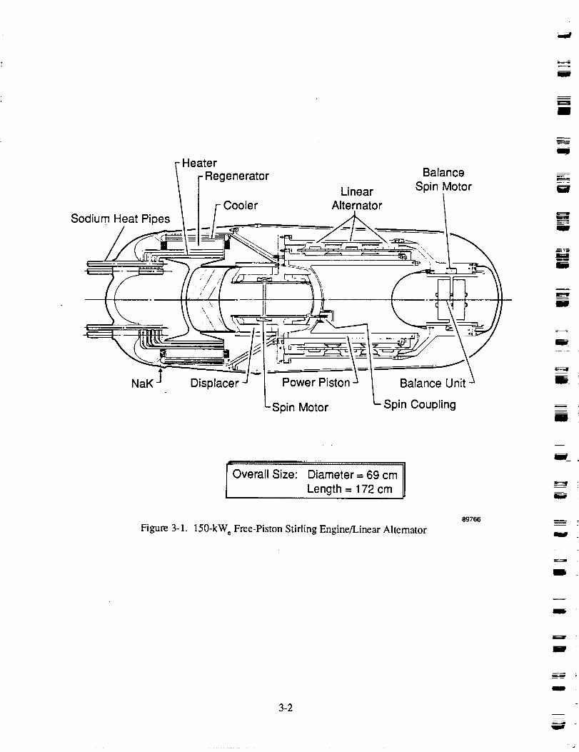
The maximum efficiency design is shown in Figure 3-1. Note that this design is significantly different
from the initial scaled design listed in Table 2-1. Figure 3-2 shows the materials selected for the princi-
pal power module components. Details of the general radial engine design are given in the followingsections, broken down into the pressure vessel, displacer drive, heat exchanger, alternator, and balancer
assemblies.
3.1 Pressure Vessel Assembly
All of the subassemblies are contained within the pressure vessel assembly, which consists of the hot-end
and cold-end ,¢essels. The structural criteria for the pressure vessel design require that the membrane
stresses in the wall due to pressure do not exceed 2/3 yield or 1/2 ultimate stress at the cold end, and 2/3
rupture stress at the hot end.
Design studies of the hot-end pressure vessel were made considering both cast and wrought superalloys.The cast Inco-713 material has one of the highest 60,000-hr creep rupture strengths* of the superalloys at
the 1050 K design temperature, but is difficult to weld. The wrought Inco-625 material is easily weldable,
but has only moderate rupture strength and low yield strength (which is important in the cold section of thevessel). The wrought Inco-718 material also has good weldability and very high yield strength, but has low
rupture strength. These material properties are summarized in Figures 3-3 and 3-4.
Due to the Inco-713 joining difficulties, the use of wrought alloys was desired for the hot-end vessel. Tominimize weight, a bimetallic head was designed with a low-ratio (1.25:1) ellipsoid shape, using a hemi-
spherical section between heat-pipe penetration (see Figure 3-5). The hot portion is made from Inco-625welded to an Inco-718 outer section. The weld joint is located in the vessel midway between the heat-
pipe penetration zone and the cooler outside diameter. Although the hot section is heavy, use of the high
yield strength Inco-718 for the larger diameter cold section results in considerable weight savings. Thecalculated mass of the 625/718 head for the preliminary 150-kW_ design was 171 kg at a mean pressure
of 15 MPa.
To determine if weight could be significantly reduced by using Inco-713 for the hot-end vessel, an al-ternate head was designed, as shown in Figure 3-6. A 2:1 ellipsoid shape gave the minimum mass for the
head, calculated to be 92 kg at a mean pressure of t5 MPa. To avoid the welding problem, a tapered,
self-locking joint was designed to carry the axial pressure blow-off loads, with a braze joint between theInco-713 and Inco-718 serving mainly to seal the vessel. Despite a significantly lighter vessel, the lock
joint ring adds considerable mass (estimated to be 70 kg). The total weight (including lock ring) of 162
kg is only slightly less than that of the 625/718 head. Welding Inco-713 would allow considerable
weight savings by eliminating the lock ring. Friction welding of Inco-713 has been demonstrated with
*Estimated from limited data based on the Larson-Miller time-temperature parameter.
i
II
Sodium Heat Pipes
Heater
- Regenerator
Linear
Alternator
Balance
Spin Motor
m
J
J
mH
ii
I
NaK Displacer Power Piston
Spin Motor
Balance Unit
Spin Coupling
l
I
..... :7 ............ :Tnggz l
Overall Size: Diameter = 69 cm 1| Length = 172 cm
Figure 3-1. 150-kW_ Free-Piston Stirling Engine/Linear Altemator89766
i
m
i
3-2
m
m
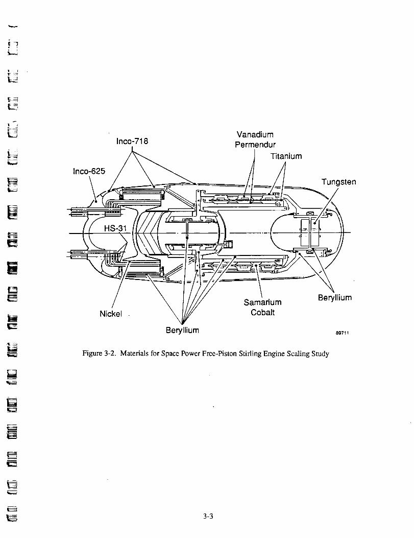
=
r_
Inco-625
Inco-718Vanadium
Permendur
1 Titanium
Tungsten
HS-31
m
H
[]
r-m
Nickel
Figure 3-2.
Beryllium
Samarium
Cobalt
Beryllium
89711
Materials for Space Power Free-Piston Stifling Engine Scaling Study
3-3

,,,1,,¢
m
W
e-
e--
tr
100
80
60
40
20
0
Time = 60,000 hrII
• _I
I
I
I I I I I I
850 900 950 1000 1050 1100
Temperature (K)
89712
Figure 3-3. Stress-Rupture Data Extrapolated from 1000-hr
Data Using Larson-Miner Parameter
w
b--
l
w
-- =
W
D _
i_===al
W
J
W
3-4 H

-4L.._.
- 2
i;" 4
2
180
160
140
120
_" 100
C._ 80
O3"o.2 60>-
40
2O
00
m
Inco-625 (Wrought)
! I I I I I I I100 200 300 400 500 600 700 800
Temperature (°C)
Figure 3-4. Yield Strength - High-Temperature Alloy
89713
3-5
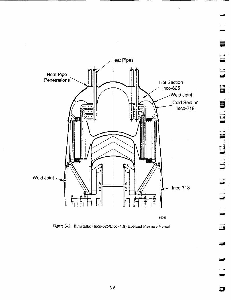
I
11
=11
:fl
Heat Pipes
NI Hot Section
Inco-625
Weld Joint
Cold Section
Inco-718
Weld Joint
Inco-718
89763
Figure 3-5. Bimetallic (Inco-625/Inco-718) Hot-End Pressure Vessel
M
Fil
W i
Bi
i
lI
_J
{-
M
= _
!
3-6

_A
Heat-Pipe
-- PenetrationZoneill
Inco-713-LC
3-LC -- (Plated)
_ Braze Material
! _ L° I_'__ _ (Spray or Foil)- ck Joint Inco-718
DetailII
\\
II
//
J
-Inco-718
Figure 3-6. Inco-713-LC Hot-End Pressure Vessel with Lock Joint
89715
i
turbine wheels, but development would be required to establish the welding procedure for a large-
diameter pressure vessel. Based on the reduced risk with the wrought alloys, the bimetallic head wasselected.
The bottom pressure vessel, which surrounds the displacer drive, alternator assembly, and balancer, is madefrom Inco-718, selected for its high strength and nonmagnetic characteristics. The end section is hemi-
spherical, thereby allowing half the thickness as the cylindrical middle section. The vessel is welded to theinco-718 section of the hot-end vessel at the maximum diameter location, adjacent to the middle of the
displacer post.
3.2 Displacer Drive Assembly
The displacer drive assembly, shown in Figure 3-7, is similar to the posted displacer drives used on the
SPDE and the earlier engineering model engine at MTI. The moving part of the assembly includes the
dome at the hot end, which is welded to the support cone and skirt. The cone is bolted to one end of the
rod, and the gas spring piston is bolted to the other end. The rod moves within the bore of the stationary
post and flange member, to which the gas spring cylinder is attached.
The displacer gas springs are designed with nearly equal stiffness, thereby balancing the displacer inertiawith the lowest total gas spring loss. The upper spring comprises the volume between the support cone
and the post, the volume between the support cone and the pressure cap, and the portion of the inside of
the displacer rod that lies above the dividing bulkhead. The position of the pressure cap can be adjustedto achieve the requiredspring stiffness.
The lower spring uses the lower inside portion of the displacer rod and continues out to the gas spring
cylinder. Additional volume can be added, as required, by hollowing out the post. All of the "cold" parts
of the displacer assembly are made from beryllium to minimize mass and gas spring losses. Inconel is
used for the displacer dome-and radiation shields.
An electric induction motor is used to spin the displacer, which creates hydrodynamic gas fiims for its sup-
port. The spin motor design uses the rod of the:dlspiacer as the rotor, with the stator windings fixed in a
slot in the post wall (see Figure 3-1). This design takes advantage of the electrical conductivity of the
beryllium rod and uses no rotor windings, therefore adding no additional mass to the displacer. Eddy cur-
rents are induced in the beryllium rod by the rotating magnetic field set up by the stator windings, and the
rod is dragged around with some slip. The motor efficiency is expected to be rather low (50%), but the
required spin power for the 150-kW_ engine is small (150 W). Therefore, dissipation of the motor losses isnot expected to result in significant temperature gradients in the displacer drive. To avoid the addition of a
separate spin motor for the power piston, the piston is coupled to the displacer. The coupling is a simple set
of magnets arranged to repel (see Figure 3-8), but provides no axial coupling force. Two couplings are
used to provide adequate torque for startup and to dynamically balance the spinning pistons.
The motor and coupling were sized to handle the frictional loads of the displacer and power piston atstartup, assuming horizontal attitude with 1-g gravity field (for ground testing). In order to reduce the
start-up torque load to a reasonable level, the use of a hard nickel-boron coating on the bearing surfaces
was assumed. Coefficients of friction as low as 0.05 have been reported for this coating [2]. The running
torque is due only to bearing drag (negligible) and windage.
The estimated coupling specific mass is 0.01 kg/kW e for the displacer and 0.015 kg/kW¢ for the piston.
w
Wl
i
i
W
m
W
.,_=
mi
m
m!
u
W
ml
3-8
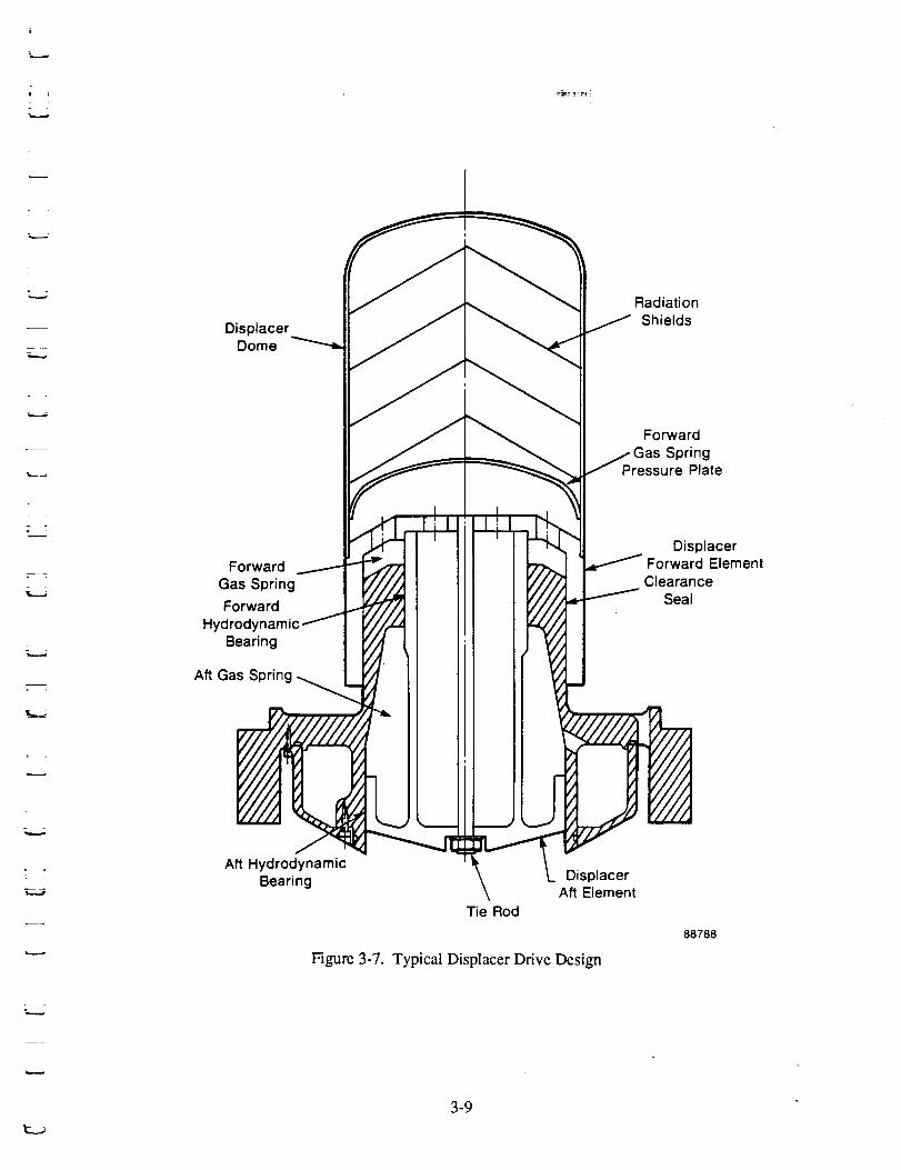
L...j
--4
Displacer
Radiation
Dome _ ___ Shields
J I _ II For.ard___ II /GasSpring
-_ I __-_4_ Pressure Plate
._.J_ '_ _i';', .LjTM.f, II I _, Displacer
Forward/ - _ III _ _ ForwardElementGas Spring _'/// II I '///7 ClearanceII Y///,._ SealForward
Hydrodynamic/ i
Bearing
Aft Gas Spring _
Aft HydrodynamicBearing \ L Displacer
\ Aft ElementTie Rod
88788
Figure 3-7. Typical Displacer Drive Design
3-9

ii
i
\Power Piston
Plunger Rod and
Magnet Attached
to Displacer
ction A-A
Magnets Attachedto Piston
89714
Figure 3-8. Coupling Detail for Hydrodynamic Gas Bearings
J
g
m
m
i
_=_m
m
i
I
m
I
HI
J
I
m
3-10

r
,k_.._.,
7 :
3.3 Heat Exchanger Assembly
The heat exchangers of the radial engine form an annular assembly. The heater is encircled by the
regenerator, which in turn is surrounded by the cooler. The engine working fluid flows radially in and
out through the heat exchangers, giving the engine configuration its name. As mentioned in Section 2.2,
the heater and cooler are constructed from stacks of thin metal plates, spaced to form gas-flow passages
arranged in a radially spoke-like pattern. The heater heat pipes and cooler coolant pipes are inserted into
holes through the stack of plates, and the assembly is furnace-brazed to form a compact heat exchanger
unit. The radial distance between pipes and the distance between the pipe surface and the gas channel
base are set to 1 mm to provide a reasonable plate web. This distance also minimizes the temperature
drop between engine gas and the heat source, or sink.
For the heater, nickel-201 is used for the plates because of its good thermal conductivity, giving a heater
surface effectiveness greater than 85%. Beryllium is the material selected for the cooler plates because
of its good thermal conductivity and low density. The cooler surface effectiveness is greater than 90%.
Beryllium replaces the aluminum used for the cooler fins during the concept selection phase because of a
better thermal expansion match with the surrounding structure.
Since the heat exchangers are located inside of the engine pressure vessel, the heat exchanger walls (end
plates) are subjected to only the engine pressure amplitude, typically 10 to 15% of mean pressure. This
results in considerable weight savings compared to the modular heat exchanger walls, which carry the
full pressure load. The radial temperature gradient across the regenerator wall does introduce a difficult
stress condition, but analysis has shown that a bellows type of segmented wall (shown in Figure 3-9)
allows for the radial expansion of the regenerator with acceptable stress levels. The minimum radial
length of the regenerator from stress considerations is govemed by the regenerator diameter and the tem-
perature difference between heater and cooler. For an engine temperature ratio of 2.0, the minimum
regenerator length is 8% of the mean regenerator diameter. The minimum regenerator length increases
with increasing temperature ratio.
The regenerator matrix can be constructed by rolling screen around a mandrel of the same diameter as the
outside of the heater. Another approach is to use felt metal, which can be easily fabricated to the desired
shape. In engine tests, felt metal regenerators have produced thermodynamic performance similar to
screen regenerators.
The dimensions of the heat exchangers vary considerably between the minimum mass and maximum
efficiency designs. For example, at the 150-kW e power level at a temperature ratio of 2.0, the axialheight of the heat exchangers varies from 140 mm for the minimum mass design to 200 mm for the maxi-
mum efficiency design.
The inside diameter of the heater was minimized for the minimum mass designs since the hot-end pres-
sure vessel diameter is set by the outside diameter of the cooler, and the cooler diameter changes with
heater diameter. The requirements of the heat transport systems and their close relationship with heat
exchanger size are discussed in the following sections.
_--.5
, , 3-11

g
m
m
m
m
m
Rings _
Flexure
Plates
!
J
w
m
m
m
I
B
m
m
ICooler
End Plate
mm m
m
Regenerator Wall
m m m
m m
m m
m m
m
n
w
Heater
End Plate
ii
m
li
Figure 3-9. Segmented Regenerator Wall Concept Schematic
89716
w
u3-12

:2 ]
L _
7
7 -
T 7
_ I
rr.,...d
3.4 Heat Transport Systems
a
3.4.1 Heater Heat Pipes
To provide a uniform gas-side heater wail temperature while minimizing the temperature drop between
the heat source and the engine working fluid (helium), the ideal heat-pipe heater interface* for the radial
engine configuration would consist of narrow, oblong-shaped heat pipes with the helium flowing past the
long wall, as sketched in Figure 3-10. The temperature drop would then only be across the heat-pipewall, and the heat would be distributed at an even temperature to the helium. However, the heat-pipe
walls must carry the full engine pressure, and noncircular tubes do not make efficient pressure vessels.The oblong pipe would require internal supports and thick walls, resulting in excessive heat-pipe weight
and large wall temperature drop.
In order to achieve a relatively even temperature distribution along the gas channels, round heat pipes of
a small diameter are used. This minimizes the distance between heat pipe and channel. The minimumheat-pipe inside diameter based on current technology** is 9.5 mm. Heat-pipe performance predictionsare discussed in Section 4.2.
In order to maintain reasonable specific mass of the engine pressure vessel, the diameter of penetrations
through the vessel in the hot zone must be kept small. Increasing the penetration diameter results in adirect mass increase of the spherical-shaped hot section of the pressure vessel. Therefore, the number of
penetrations must be minimized.
For all of the engine designs investigated in the parametric analysis portion of this study, the number of
penetrations giving reasonable pressure-vessel specific mass was less than the number of small-diameterheat pipes needed in the heater. Therefore, it was necessary to branch the main pipes that penetrate the
vessel into the smaller pipes that mate with the heater, as shown in Figure 2-11. At the 25-kW_ engine
size, the number of heat-pipe branches per main pipe is three. When the engine is scaled to 150 kWh, thediameter of the main pipes must be increased to keep the penetration diameter small relative to the vesseldiameter outboard of the cooler. For constant axial heat flux density in the main pipes, the number of
main pipes increases at a slower rate than the power level. However, because the branch pipe diameter
was fixed at 9.5 mm, the number of branch pipes increases proportional with power level. Thus, the
number of branch pipes per main pipe must increase with power level, increasing to six at 150 kWh. Theconcept of using branched heat pipes is not totally new, but is not standard practice and requires develop-ment testing.
Selection of the heat-pipe wall material was another difficult area. Several material options were investi-
gated in the course of the engine design. The high engine mean pressure causes compressive hoop stressin the pipe wall. Therefore, compressive creep and buckling of the heat pipes must be considered. The
material strength requirements are based on the stress-rupture strength and 1% creep strength at an aver-age material temperature of 1100 K. Since test data on the compressive creep of superalloys is very
sparse, the more typical tensile creep data was used for design calculations. However, available test dataon UDIMET 700 shows compressive creep to be significantly lower than tensile creep (see Figure 3-11).
The pipes were designed with a safety factor of 1.5 using the tensile creep-rupture data, so the designmay prove to be conservative. Compressive creep tests need to be performed on selected materials to
establish a less conservative design basis. For buckling, a safety factor of 2.5 was used due to the largeuncertainties in prediction of the onset of buckling. For all designs in the study, creep rupture of the heat
pipes was the limiting constraint.
*Based on the engine heater frontal area and surface area requirements for good performance.**Based on Thermacore information for arterial heat pipes.
3-13

J
m
Heat Pipe
Helium Flow
J
M
I
m
I
m
89717
Figure 3-10. Ideal Heat Pipe Based on Engine Heater Requirements
M
W
m
U
U
g
B
W3-14

Z 7
_ =
L
H
H
m
1.0
0,8
.__ 0.6
_ 0.40
0.2
0 0
Udimet 700: Machined from Bar Stock1400°F, 80 ksi Axial Stress
I I I
10 20 30
Time (hr)
!4O
881012
Figure 3-1 I. Compression-Creep Curves as Compared toTension-Creep Curve for Udimet 700
w: s_d
3-15

The materials considered for the heat-pipe wall included the nickel-based superalloys Inco-713 and
Inco-625, and the cobalt-based superalloys HS-31 and HS-25". Due to the welding difficulties associ-ated with Inco-713, it was eliminated from consideration. Heat-pipe wall temperature drop and wall
compatibility with sodium were the main concerns in material selection. Wall thickness and wall WT(assuming 2.5-kW heat load per pipe, 9.5-ram heat-pipe ID, and 100-ram condenser length) for the mate-rials considered are as follows:
Heat Pipe Material Wall Thickness (mm) Wall AT (°C)
HS-31 1.18 34.0
HS-25 1.79 52.0Inco-625 2.17 69.0
Based on NASA-LeRC recommendation, a large wall AT is unattractive due to increased sodium corro-
sion with increasing temperature. The wall AT can be reduced by increasing the heat transfer area, but itis done at the expense of increased engine mass, both directly and indirectly. The former is due to in-
creased heat exchanger size, while the latter is due to the increase in engine volume. The increase in
engine volume requires an increase in engine displacement to maintain engine pressure amplitude andpower generation (larger pistons or longer stroke, leading to increased engine structural mass). Note thata less conservative design basis for compressive creep would also reduce the wall thickness and AT.
The cobalt alloys are reported to have reasonably good compatibility with liquid metals [3], and no pro-tective corrosion liner is assumed necessary. Nickel-based alloys are reported to be more susceptible to
attack and would require some protection.
Based on these considerations, HS-31 was selected as the heat-pipe wall material. HS-31 is a cast alloy
with relatively poor welding characteristics. However, according to material specialists contacted during
this study, acceptable welds are possible with tight control of alloy composition.
3.4.2 Coolant System
The coolant system for this study was specified by NASA-LeRC to be a pumped NaK loop. The primaryflow restriction on the engine side of the loop is the penetration through the pressure vessel wall. For the
baseline 150-kW c design, a maximum of twenty-eight 38-mm diameter penetrations are allowed based onstructural requirements for the load-carrying capability of the vessel, with 14 inlets and outlets each in
the same plane. As shown in Figure 3-12, each inlet feeds two groups of coolant tubes in the cooler,connected in series.
Details on the selection of the coolant tube diameter and NaK mass flow rate are discussed in Section 4.2.
3.5 Alternator Assembly and Power Piston
The alternator assembly is composed of the power piston and cylinder, around which is wrapped the
moving-magnet, permanent-magnet alternator (see Figure 3-1). The altemator plunger is cylindrical in
shape and cantilevered off the back of the power piston in a reflexed fashion. The power piston and cyl-
inder are straight bore designs to permit the use of very tight clearance-to-diameter ratios. The hydro-dynamic piston bearing is incorporated into the bore area. The altemator inner stator is attached to the
outside of the power piston cylinder. The outer stator is attached to a lightweight support cylinder, which
is bolted to the main engine flange.
*The cobalt alloys are also known as X-40 and L-605, respectively.
3-16
1
J
H
m
W
W
m
B
D
I
N
I
U
w
H
J
m
_ I
mf
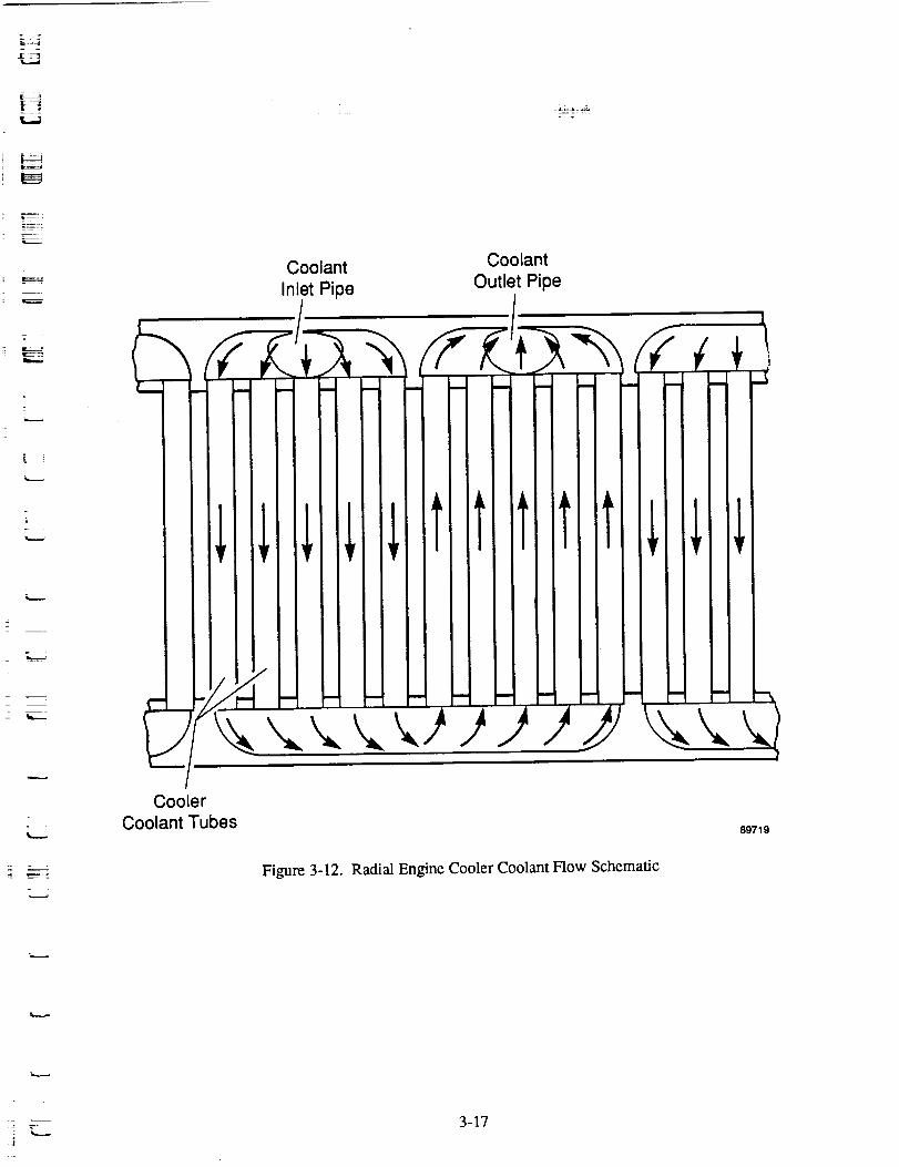
=
=
L.-
Coolant
inlet Pipe
Coolant
Outlet Pipe
-/Cooler
Coolant Tubes 89719
Figure 3-12. Radial Engine Cooler Coolant Flow Schematic
z___3-17

The altemator plunger moves between the inner and outer stators in the gap, which for the baseline
150-kW e design is 11 mm. Samarium-cobalt permanent magnets make up most of the plunger, with the
magnet thickness filling 80% of the gap. The magnets are radially magnetized, with four magnet rings of
altemating polarity per coil section. The plunger is structurally strengthened with a titanium cage madeof struts and end rings. This strength is necessary to support the magnets, which have little tensile
strength against the inertial forces due to axial reciprocation, and to provide circumferential stiffness.
The struts have a rectangular section with round threaded ends to attach to the end rings. They occupyapproximately 5% of the plunger cross section (magnets make up the remaining 95%).
The stators are made of Vanadium Permendur ('l-Iyperco-50) tapered laminations (0.36-mm averagethickness). The outer stator laminations are tapered to minimize the space between laminations at the
outside edge and to reduce the stator OD. The coil slot is rectangular in cross section, which allows theuse of square wire to give an increased packing factor. However, circular wire was assumed for thisstudy, with a packing factor of 60%.
The power piston is supported on a hydrodynamic gas bearing at the outside diameter of the piston. Thepower piston seal clearance is set to 12.7-1am radial clearance for piston diameters up to 152 mm, and
increases linearly with diameter thereafter. The piston and cylinder are made from beryllium.
Depending on the stiffness requirements, the piston gas spring can be designed to use just the piston inte-rior, or the entire volume around the alternator out to the pressure vessel as well as the piston interior. In
the former case, an inside piston cylinder is required in addition to the primary cylinder, with the inner
cylinder supported by a connecting piece bolted to the end of the alternator support cylinder. Since the
inner cylinder is positioned relative to the altemator support, the inner seal clearance is increased by 30%to allow for tolerance stackup.
3.6 Dynamic Balancer Assembly
The balancer assembly includes the dynamic balance mass, balance cylinder and gas springs, and supportconnections (see Figure 3-1). The balance cylinder is supported by a connecting structure that bolts to
the end of the alternator stator support. The balance cylinder and the structure of the balance mass pistonare made from beryllium. Bolted to the center web of the balance piston is a disc of heavy material
(tungsten or depleted uranium), which provides the bulk of the balance mass. The balance piston is sup-ported on a hydrodynamic bearing and is spun by an independent induction spin motor of similar con-
struction to the displacer/piston spin motor. Two balancer gas springs are used, with the required stiff-ness divided equally between them. The seal between gas springs is a clearance seal and also acts as the
bearing surface. Pressure caps for the gas springs are attached to the balance cylinder.
J
U
I
J
W
I
U
m
W
I
J
U
U
3-18hi

K_,_-
I,...d
E-.
11..__3
-- !
[]
kSr
4.0 PARAMETRIC STUDY
The scaling and parametric analysis tasks of this study required analysis of the power module perform-ance and specific mass, as well as analyses of the power module subsystems. This section summarizes
all of the analytical work performed in support of these tasks, followed by discussion of the parametricstudy results.
4.1 Parametric Study Requirements and Procedure
The first 150-kW¢ radial engine layouts were for minimum mass and maximum efficiency configurations ata temperature ratio of 2.0. These layouts were completed to demonstrate the design feasibility of a single-
cylinder FPSF_A,A producing 150 kW e. This required addressing all aspects of the engine and alternator
design to the level required to demonstrate concept feasibility and determine component masses. With
feasibility demonstrated, characteristics of designs at other operating points were generated by performingdesign optimizations to meet the particular design objective, as explained below.
The goal of the parametric study was to determine the relationships between power module thermal
efficiency, power module specific mass, power output, and temperature ratio. This entailed performing
a parametric study of power module performance over a temperature ratio range of 1.7 to 3.0, and over
a power range from 25 to 150 kwh. Plots of the results were made and an empirical relationship was
derived for power module thermal efficiency as a function of power module specific mass, power output,and temperature ratio.
The 12 operating points for the study were defined as follows: three power levels - 25, 75, and 150 kWh,
with four temperature ratios (1.7, 2.0, 2.5, and 3.0) at each power level. Separate power module optimi-zations were performed at each operating point for each of the following goals:
• Maximum power module thermal efficiency
• Minimum power module specific mass
• Maximum ratio of power module thermal efficiency to power module specific mass (referred toas the baseline designs).
With three power module optimizations performed at each operating point, a total of 36 design optimiza-tions were required.
In order to evaluate power module characteristics, performance predictions were required of the engine
thermodynamics, engine mechanical systems, and alternator, as well as calculations of power module
specific mass. A computer model of the engine/alternator geometry was developed that enabled calcula-tion of the power module weight as a function of component sizes. The heat exchanger geometries were
specified through input variables. The power module optimizations involved varying the heat exchanger
parameters to achieve the optimization objective (maximum efficiency, minimum mass, or baselinedesign).
The heat exchanger parameters varied in the optimizations define the geometry of the heat exchangersand connecting ducts, as follows:
Heater and Cooler
-- Flow passage dimensions (height, width, and length)-- Fin thickness
-- Number of parallel passages
4-1

m
• Regenerator-- Frontal area
-- Length
Porosity
• Connecting Ducts-- How area
-- Hydraulic diameter.
These parameters were automatically varied by the code to search for the maximum or minimum of the
objective function. The engine operating conditions (mean pressure, frequency, and piston strokes) were
manually selected at each operating point to maintain control over the design.
The optimization procedure used by the code involved the following steps:
1. Select optimization parameter, calculate power module performance for starting value.
2. Vary parameter between preselected lower and upper bounds, calculating performance at each
point. Select parameter value that results in the maximum or minimum of the objectivefunction.
3. Repeat Steps 1 and 2 for each selected optimization parameter.
4. Repeat passes through set of optimization parameters until performance is unchanged between
successive sweeps.
5. Return data file incorporating the set of optimized par_eters.
The 36 operating points of the study were for single-cylinder engines using dynamic balancer assembliesfor vibration control. If two identical power modules are connected in an opposed, in-line configuration,
the resulting power module is dynamically balanced and the balance unit becomes unnecessary. The
performance and specific mass of opposed power modules (at twice the power levels, e.g., 50, 150, and
300 kW_ per power module) are reported in Section 4.4.
Each calculation of power module performance requires calculations of thermodynamic, gas spring,
alternator, and balancer performance. Module net power output is held constant for each point in the
optimization via adjustments of engine displacement (piston diameters).
4.2 Power Module Analysis
4.2.1 Engine Thermodynamics and Dynamics
The thermodynamic analysis of the power module was performed using the MTI harmonic analysis code
HFAST. Generation of power module characteristics over a range of specific mass levels required 36
engine optimizations, as discussed in Section 4.1.
Helium was specified as the engine working fluid in the design specifications. The heater metal tempera-
ture was specified as 1050 K (gas-side wall temperature), with the cooler wall temperature a function of
the specified temperature ratio at a given operating point.
4.2.1.1 Piston and Displacer Stroke and Phase Angle. Prior to performing the opfimizations, the rela-
tionship between expansion volume amplitude and compression volume amplitude was investigated todetermine the ratio giving the best performance. This relationship was then held fixed for all design points.
N
U
mII
m
I
B
U
m
I
m
B
l
!
m
I
IF
4-2

- zL.==a
5----
Figure 4-1 shows indicated engine efficiency as a function of AVJAV¢I where AV e is the expansion space
volume amplitude (displacer hot side area multiplied by displacer stroke amplitude), and AV e is the com-
pression volume amplitude due to the power piston (piston area multiplied by piston stroke amplitude).
The maximum efficiency occurs in the range of AVJAV¢ = 0.55 to 0.7, which holds over the entire range ofdifferent mean pressure and frequency conditions considered in the study. For all points in the study, the
value of AVJAV¢ was set to 0.7 based on the good efficiency level and the similarity with previous FPSEdesigns. This amplitude ratio can be achieved by various combinations of piston and displacer diametersand strokes, and selection of the "best" stroke-diameter relationship involves mechanical as well as thermo-
dynamic considerations.
A smaller piston diameter and a longer stroke result in increased gas spring losses. Piston mass decreases
with decreasing diameter, but not enough to offset the decreasing gas spring stiffness. Therefore, the gas
spring pressure amplitude must be increased. An increase in gas spring pressure amplitude results in highergas spring hysteresis loss. Gas spring seal leakage can increase or decrease, depending on the rate of
change in seal clearance with diameter. On the compression space side of the piston, the seal leakage dropswith decreasing piston diameter. The selection of piston stroke is made based on the trade-off between
engine and gas spring losses, power module specific mass, dynamic tuning requirements, and alternatorconsiderations. Discussion of the altemator is provided in Section 4.2.3.
The displacer gas spring losses also increase with increasing stroke, while the engine thermodynamic lossesdecrease (expansion space hysteresis loss drops due to decreasing surface area, appendix gap enthalpy flux
drops due to decreased leakage, but shuttle conduction loss increases). The mass of the displacer driveassembly drops with increasing stroke, but increased stroke increases the length of the displacer drive and
makes the beating design more difficult. Based on trade-offs of these considerations, the largest displacerstroke that would accommodate a reasonable displacer drive design was desired for all operating points in
the study.
The displacer-to-piston phase angle (_)d) was set to 65 ° for all points in the study based on considerations ofefficiency and power generation (Figures 4-2 and 4-3). Engine efficiency increases at lower Cd because ofdecreasing mass flow through the heat exchangers and lower pumping loss in the engine. On the other sideof the coin, the power generated by the engine for a given piston displacement is maximum for q_d0f75 tO
90 °, and decreases with decreasing phase angle. Thus, the selection of Cd reduces to a trade between effi-
ciency and specific mass, and the choice of Ca = 65° is valid over the entire range of operating conditionconsidered in the study.
To maintain the desired power during optimizations, the piston area and displacer area were automati-
cally adjusted. The piston and displacer strokes were selected for each point in the study prior to the
optimization, taking the engine thermodynamic and mechanical efficiencies and power module specificmass into consideration.
4.2.1.2 Heat Exchanger Considerations. The selection of the channel and fin dimensions for the heat
exchangers was made automatically by the optimization code based on considerations of thermodynamicefficiency (dependent on fm effectiveness, hydraulic diameter, flow area) and heat exchanger specific
mass. For the heater, use of nickel for the fins resulted in a high fin effectiveness, and therefore allowed
a significant increase in surface area from that of the fin base area. For example, the 150-kW e baselinedesign used fins with a length- (to the middle of the helium flow channel) to-thickness ratio of approxi-
mately 4. The resulting hydraulic diameter (flow area per unit wetted perimeter) of the heater channelswas very small as compared to that achieved with previous engine designs (0.5 mm versus 1.25 mm for
the SPDE shell-and-tube heater), resulting in higher heat transfer and improved efficiency. The specificsof flow passage dimensions varied between different optimization points, but small hydraulic diameter
resulted for all points.
_ 4-3
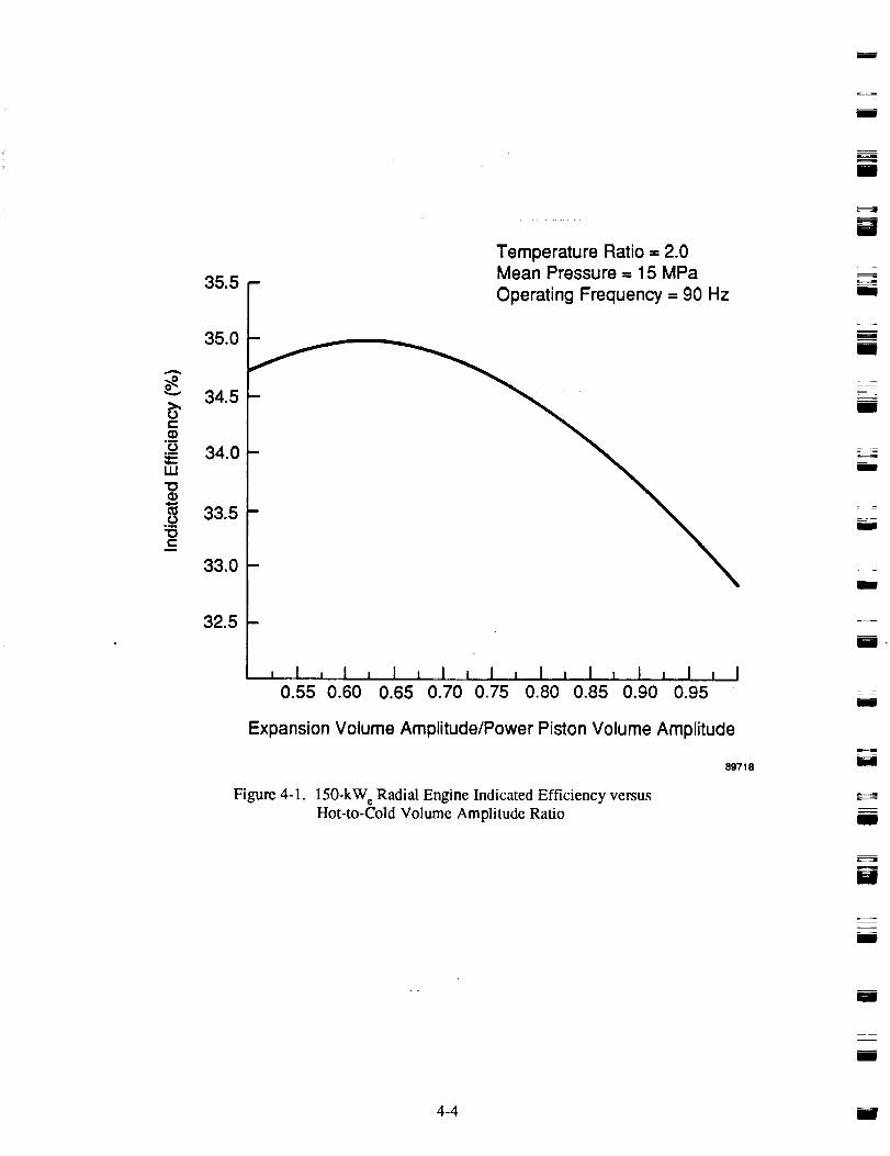
m
I
II
35.5
35.0
34.5
_ 34.0W
_ 33.5_c
33.0
32.5
Temperature Ratio = 2.0Mean Pressure = 15 MPa
Operating Frequency = 90 Hz
, ! , I , I I I I I , I 1 I i I l I 1 I0.55 0.60 0.65 0.70 0.75 0.80 0.85 0.90 0.95
Expansion Volume Amplitude/Power Piston Volume Amplitude
Figure 4-1. 150-kW e Radial Engine Indicated Efficiency versus
Hot-to-Cold Volume Amplitude Ratio
89718
M
m
!
mm
mm
l
mm
mE,
mI
m
I
_===4=
N
mm
mE
mm
4-4 I

w
!-÷5
,b
L
v
t-_)
o__)
UJ
"O())
Oo_
t-
37
36
35
34
33
32
31
Temperature Ratio = 2.0Mean Pressure = 15 MPa
Operating Frequency -- 75 Hz
r
D
I , I , I
50 55 6O
D.
I
!
I!
!
, I , I ,
65 70I , I , I ' I , I
75 80 85 90 95
Displacer-to-Piston Phase Angle (°)
89720
Figure 4-2. 150-kW e Baseline Design. Indicated Efficiency versusDisplacer-to-Piston Phase Angle
4-5

a=
i
1.10
o_ 1.05
._ 1.00
0.95
0.90
0.
0.85
0.80
r I
i
Temperature Ratio -- 2.0Mean Pressure = 15 MPa lJ
_ Operating Frequency = 75 Hz
M
C i'ciVil .
/ -W
!=
, ! , I , I , , I , I , I , i ,_50 55 60 65 70 75 80 85 90 95
Figure 4-3.
Displacer-to-Piston Phase Angle (o)
150-kW e Baseline Design. Normalized Power versus
Displacer-to-Piston Phase Angle
891021
i
_lm
u
i
i
4-6
i
i

w
L
w
E
U
H
m
D
it
In the cooler, high-conductivity copper was initially considered for the f'm material, but the cooler specific
mass was undesirably high. Aluminum and beryllium have low density and high thermal conductivity,resulting in high fin effectiveness and low mass. Beryllium was selected as the prime material due to theclose match of thermal expansion coefficient with the Inconel coolant tubes. Similar to the heater, the
cooler hydraulic diameter is quite small relative to other designs.
The frontal area of the regenerator has a major impact on the thermodynamic performance of the engine,and the radial engine allows incorporation of a large regenerator frontal area. Also, due to the reduced
regenerator wall constraint because of the flexure arrangement (discussed in Section 3.3), a relativelyshort regenerator in the direction of flow is possible.
Significant changes were made in heat exchanger size between the minimum mass and maximum efficien-
cy designs. For minimum specific mass, the heat exchanger's axial length was shortened to the minimumlength at which the heater wall temperature drop equaled 40°C (considered the maximum desirable AT) or
the heat-pipe heat flux exceeded the maximum limit set by the heat-pipe design. The inside diameter of the
heater was set by the number of heat pipes and their arrangement. In general, the minimum mass was
achieved when, for the required number of heat-pipe legs, the number of primary heat pipes was mini-mized. That required putting more legs per primary heat pipe, subject to the drop in efficiency withincreasing heater channel length.
For some of the minimum specific mass designs, the mass was minimized by moving the heat exchangersup above the top of the displacer piston, thus allowing the inside diameter of the heater to be less than the
displacer diameter. This reduced the outside diameter of the heat exchangers, and therefore the pressurevessel diameter. However, the length of the pressure vessel must be increased to accommodate the ele-
vated location of the heat exchangers, and this arrangement results in lower mass only when the extramass due to increased pressure vessel length is less than the mass savings due to reduced diameter.
For maximum efficiency, the heat exchanger axial length was increased until the rate of efficiency in-crease with specific mass increase (Aq/A SM) became unacceptably low.
The heat exchanger dimensions varied considerably over the temperature ratios of the study. Increasingthe temperature ratio decreases the heat exchanger height, primarily because the engine thermal effi-ciency increases. These changes reduce the required heat flux through both the heater and cooler.
4.2.1.3 Mean Pressure. The effect of mean pressure on power module efficiency and specific mass wasevaluated for the 150-kW_ design at a frequency of 90 Hz and a temperature ratio of 2.0 (see Figure 4-4).
This showed minimum specific mass occurring at 11 MPa mean pressure. The reason for the strong de-pendence of specific mass on mean pressure is the decoupling of the upper pressure vessel size fromengine displacement, explained in the following paragraphs.
To avoid exceeding the heat pipe operating limits, the number and diameter of the heat-pipe legs in the
heater are bounded by minimum values. For a given heat-pipe arrangement in the heater (for example
the legs arranged radially, three deep), the minimum circle diameter is then set. For the 150-kW c base-line design, this tumed out to be larger than the displacer diameter. Thus the engine displacement can be
increased or decreased (within limits) without forcing a change in diameters of the heat exchangers orupper pressure vessel. For a decrease in design mean pressure, the pressure vessel thickness drops inproportion, and since the increase in displacer piston size required to maintain power does not affect heat
exchanger and pressure vessel diameter (until the inner heater diameter is reached), the pressure vessel
mass drops. This drop in vessel mass is partially offset by increased mass of the displacer and pistonsubassemblies and the cold end pressure vessel. However, as shown in Figure 4-4, the power module
specific mass drops with decreasing mean pressure, reaching a minimum at 11 MPa. The drop in specificmass is accompanied by a modest drop in efficiency.
k
4-7
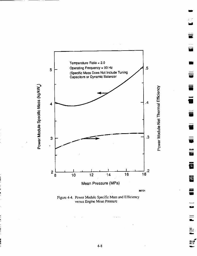
I
W
m
5
4
3
2
I Temperature Ratio = 2.0
_ Operating Frequency = 90 Hz .,_(Specific Mass Does Not Include Tuning ._
B
_._
, I i I , I L I8 10 12 14 16
Mean Pressure (MPa)
Figure 4-4.
.5
#-
z
.3
o
.2
89721
Power Module Specific Mass and Efficiency
versus Engine Mean Pressure
18
M
l
g
ii
I
IB
i
I
l
lI
t
I
I
mm
W
I
4-8LL==_
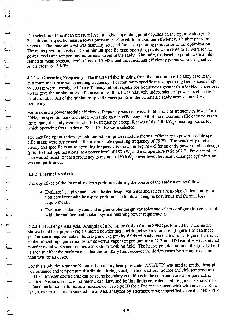
z
.7 ;
r _
k...
r7
? •
L
V
.r
The selection of the mean pressure level at a given operating point depends on the optimization goals.
For minimum specific mass, a lower pressure is selected; for maximum efficiency, a higher pressure is
selected. The pressure level was manually selected for each operating point prior to the optimization.The mean pressure levels of the minimum specific mass operating points were close to 11 MPa for all
power levels and temperature ratios considered in the study. Similarly, the baseline points were all de-signed at mean pressure levels close to 13 MPa, and the maximum efficiency points were designed atlevels close to 15 MPa.
4.2.1.4 Operating Frequency. The main variable in going from the maximum efficiency case to theminimum mass case was operating frequency. For minimum specific mass, operating frequencies of up
to 110 Hz were investigated, but efficiency fell off rapidly for frequencies greater than 90 Hz. Therefore,
90 Hz gave the minimum specific mass, a result that was relatively independent of power level and tem-
perature ratio. All of the minimum specific mass points in the parametric study were set at 90-Hz
frequency.
For maximum power module efficiency, frequency was decreased to 60 Hz. For frequencies lower than
60Hz, the specific mass increased with little gain in efficiency. All of the maximum efficiency points in
the parametric study were set at 60-Hz frequency, except for two of the 150-kW e operating points for
which operating frequencies of 58 and 55 Hz were selected.
The baseline optimizations (maximum ratio of power module thermal efficiency to power module spe-cific mass) were performed at the intermediate operating frequency of 75 Hz. The sensitivity of effi-
ciency and specific mass to operating frequency is shown in Figure 4-5 for an early power module design
(prior to final optimizations) at a power level of 150 kW_ and a temperature ratio of 2.0. Power modulesize was adjusted for each frequency to maintain 150-kW_ power level, but heat exchanger optimization
was not performed.
4.2.2 Thermal Analysis
The objectives of the thermal analysis performed during the course of the study were as follows:
• Evaluate heat pipe and engine heater design variables and select a heat-pipe design configura-tion consistent with heat-pipe performance limits and engine heat input and thermal loss
requirements.
• Evaluate coolant system and engine cooler design variables and select configuration consistent
with thermal loss and coolant system pumping power requirements.
4.2.2.1 Heat-Pipe Analysis. Analysis of a heat-pipe design for the SPRE performed by Thermacore
showed that heat pipes using a sintered powder metal wick and sintered arteries (Figure 4-6) can meet
performance requirements in both 0-g and 1-g gravity fields with adverse inclinations. Figure 4-7 showsa plot of heat-pipe performance limits versus vapor temperature for a 22.2-mm ID heat pipe with sintered
powder metal wicks and arteries and sodium working fluid. The heat-pipe orientation in the gravity fieldis seen to affect the performance, but the capillary limit exceeds the design target by a margin of morethan two for all cases.
For this study the Argonne National Laboratory heat-pipe code (ANL/HTP) was used to predict heat-pipe
performance and temperature distribution during steady-state operation. Source and sink temperaturesand heat transfer coefficients can be set as boundary conditions in the code and varied for parametric
studies. Viscous, sonic, entrainment, capillary, and boiling limits are calculated. Figure 4-8 shows cal-
culated performance limits as a function of heat-pipe ID for a fine-mesh screen wick with arteries. Simi-lar characteristics to the sintered metal wick analyzed by Thermacore were specified since the ANL/HTP
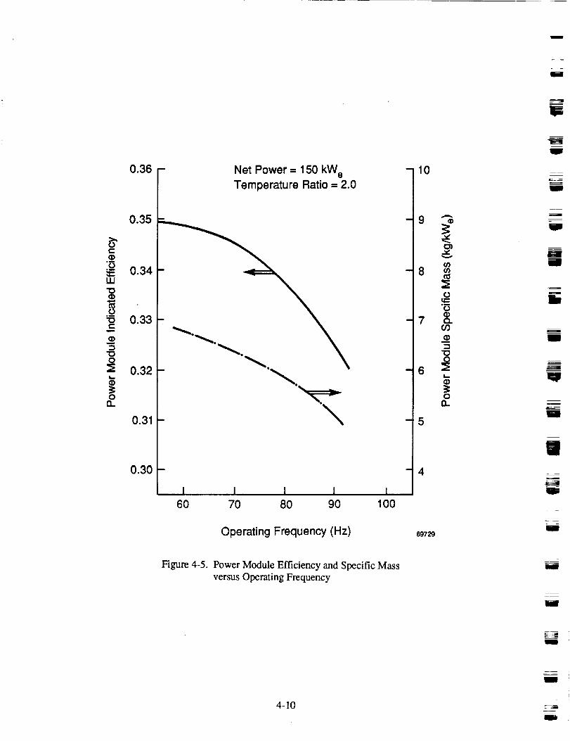
: =
m
W
!
U
0.36
0.35
0.34UJ
_ 0.33
0.32L_
no0.31
0.30
- TNeetmPpOTa_ru_e150tikoW__e2.0 -
I I, I I l60 70 8O 9O 100
Operating Frequency (Hz)
10
7
'i5
4
89729
7==_.J
==i
m
lit
I
lip
I
g
W
ill
U
Figure 4-5. Power Module Efficiency and Specific Mass
versus Operating Frequency
4-10
I "
I

Lw
r
-'.w-J
Vapor Space
Liqui_ Artery
Powder Metal Wick
Figure 4-6.
89722
Diagram of an Arterial Heat Pipe withSintered Powder Wick and Arteries
4-11

l
20-
t,-
Q)
O0.
16
12
n
4-
I
B
Capillary Limit(Zero Gravity)
Boiling Limit
Sonic LimittI
I
I
II
II
600
Capillary Limit(1 g Horizontal)
\Capillary Limit(1 g Vertical)
Range
Design Power
E!
Design Power
0 I I400 800 1000
Vapor Tempera'ure (°C)
89723
Figure 4-7. Power Transport Limits of a 2.22-cm ID Sodium Heat Pipe
as a Function of Heat Pipe Vapor Temperatures
k,.--
I
J
i
W
=
W
W
m
4-12 r=-

v
L_
10
9
v
6E
x 5
LL
4-1-
"_ 3x
<2
0
(800°C Vapor Temperature)
ODesign Point
Boiling Limit
Capillary Limit
D
i i I I0 1 2 3
I I I4 5 6
Heat-Pipe Inside Diameter (cm)
Figure 4-8. Heat-Pipe Performance Limits versus Heat-Pipe Diameter
89724
4-13

code cannot handle sintered wicks. Thermacore recommended 9.5 mm as the minimum heat-pipe IDbased on manufacturing constraints for arterial heat pipes. The minimum predicted heat flux limit for
this diameter heat Pipe is the entrainment limit, which is close to the capillary limit. Using a heat-pipedesign safety factor of 2, the 9.5-mm pipe ID is acceptable.
4.2.2.2 Coolant System Analysis. Selection of the NaK coolant tube diameter and NaK flow rate
depends on the trade-offs between temperature drops (bulk and film), pump head, and coolant pumping
power requirements. The coolant pumps are assumed to be hermetically sealed, electromagnetic pumps,which have a low efficiency and low pressure head capability. Since the coolant system power require-
ments do not enter into the efficiency calculations of the power module, the temperature drops weregiven more weight in the evaluation. The NaK mass flow rate was set to limit the bulk NaK AT across
the cooler to 15°C, thereby providing a fairy uniform cooler metal temperature.
Sizing of the coolant tubes involves selection of the minimum diameter (smaller diameter reduces the
NaK fill AT and increases the cooler flow area on the helium side) without excessive pressure drop.Since the mean cooler diameter is greater than the mean heater diameter in the radial engine design, the
cooler is less restricted than the heater on both the engine side (cooler frontal area) and the coolant side.
Figures 4-9 through 4-12 show NaK temperature drops (AT_ = Tout - Tin; ATi_lm-- Twau - TNaK) , pres-sure drop (cooler core drop and estimated loop loss), and total coolant loop pumping power for the
150-kW e baseline design, as a function of NaK mass flow rate and coolant tube inside diameter. Thecoolant loop was undefined, and 10 velocity-heads of pressure drop were assumed for the calculations.
A tube ID of 6.35 mm was selected for all design points in the study, with a maximum pump head of35 kPa. NaK mass flow rate was scaled proportional with engine power level; the total NaK mass flow
rate for the 150-kW e baseline design is 25 kg/sec.
4.2.3 Alternator Analysis
Based on previous work performed at MTI, permanent magnet linear altemators result in higher effi-ciency and lower specific mass than external-wound, dc-field linear alternators.
The design of the permanent magnet linear altemator for this study was based on three levels of analysis.The first-order analysis, based on a simple model for a moving permanent magnet alternator, providedthe basic alternator scaling rules and generation of the base altemator dimensions. As a check on the
first-order design, a second-order MTI code (LPMMA), based on a thin gap analysis, was used for de-
tailed alternator loss calculations on the 150-kW e baseline design at a temperature ratio of 2.0. To com-plete the analysis, commercial third-order finite element codes (FLUX and MAXWELL) were used tocalculate structural losses and perform detailed flux mapping for the baseline design. The results of the
detailed analysis were then applied to all of the design points of the study.
The first-order model sizes the iron and copper based on specified power level, efficiency, stroke, frequen-
cy, and plunger diameter, Prescribed values for altemator and structural eddy-current losses (calculatedusing finite-element codes) are used to determine the loss available for copper (I2R) and core losses. Con-straints on the alternator sizing that were used to avoid unworkable designs are listed below:
• Minimum radial gap between inner and outer stators = 8 mm (structural)
• Magnet plunger thickness to gap ratio = 0.8 (sidepull - bearing loads)
• Plunger structural frame = 5% of plunger cross section (structural)
• Pole width = magnet width = plunger stroke (optimal performance)
• Inner stator ID = piston cylinder OD (geometry)
• Coil packing factor = 60% (insulation thickness; fabrication)
m !
Im
m
II
m
m
I
m
_g
i
4-14

4
z
t •
: E_z
l Et'_I m _,
. _T"_L_ "
f
V
A
OOv
l--
v
z
7O
60
5O
40
30
2O
150-kW e Baseline Engine Design
Engine Temperature Ratio = 2.0
Engine Heat Rejection = 410 kW
10
, I i I , I , I , I , I _ I , I , l , I
15 20 25 30 35 40 45 50 55 60
" NaK Mass Flow Rate (kg/sec)
Figure 4-9. NaK Bulk Temperature Drop versus NaK Mass Flow
89725
4-15

EEY
z
35
30
25
20
15
10
5
150-kW e Baseline Engine Design
Engine Temperature Ratio = 2.0
Engine Heat Rejection = 410 kW
Coolant Tube ID
12 mm
10 mm ....
8 mm_
--_""'_ 4 mm-
I , 1 , 1 , I , I ! I , I I I , i , !15 20 25 30 35 40 45 50 55 60
NaK (kg/s)
Figure 4-10. NaK Film Temperature Drop versus NaK Mass Flowas a Function of Coolant Tube Diameter
8g7_
I
m"- i
i
J
m
qiw
m
J
4-16 IIW
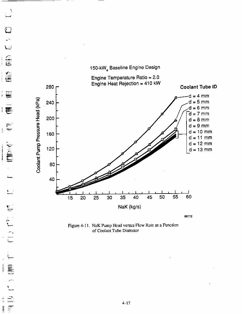
i
-1-2O903
Q.¢3.E
13.
c
OO
280
240
2OO
160
120
8O
40
150-kW e Baseline Engine Design
Engine Temperature Ratio = 2.0
Engine Heat Rejection -- 410 kWCoolant Tube ID
_d = 4 mm=5mm=6mm=7mm
d=8mm
d=9mm
d-10mm
d=11 mm
d-- 12mm
d=13mm
15 20 25 30 35 40 45 50 55
NaK (kg/s)
Figure 4-11. NaK Pump Head versus Flow Rate as a Functionof Coolant Tube Diameter
60
89772
\-
,=,.._..-
,,.,,...,-
i| ::
4-17

14
12
1003o
_o 8LL
V
z 6
4
2
15 20 25 30
Figure 4-12.
150-kW e Baseline Engine Design
Engine Temperature Ratio = 2.0
Coolant Tube ID
=4ram
d=5mm
d=6mm
=7mm
d=8mm
d=9mm
d=10mm
d-ll mmd-- 12 mm
d---13mm
i I , I , I , i , I , I35 40 45 50 55 60
NaK (kg/s)
89727
Total NaK Flow Loss Including Entrance/Exit and Manifolds versus
NaK Mass Flow as a Function of Coolant Tube Diameter
E
/ t t.m
zmV
! E
II E
mm
U_
A
_L
4-18
m

,...d
r
z
E -,5
L..2
i
7._--
L
• 13m_x= 1.0, where 13is the ratio of inductance voltage drop to magnet-induced voltage (selected
based on power module stability criteria)
• Maximum flux density in stator laminations = 2.2 T (tesla) (saturation)
• Magnet demagnetization limit based on magnet B-H curve at temperature of TCooler + 50°C.
For temperature ratio of 1.7, alternator cooling must provide sufficient cooling to maintainmagnet temperature at same temperature as for temperature ratio of 2.0 (magnet material).
The inputs to the first-order analysis are the power level, number of alternator sections, plunger strokeand diameter, operating frequency, alternator efficiency, eddy-current losses, and terminal voltage. For
designs with multiple altemator sections, the coils were assumed to be electrically connected in series.The first-order design of the alternator is independent of the alternator voltage level. The alternator volt-
age level was selected for each power level based primarily on consideration of coil wire diameter. Thenumber of wire turns in the coil varies proportionally with voltage level. The minimum voltage level is
set by coil winding considerations (wire diameter increases with decreasing voltage; large wire is more
difficult to wind). At high voltage levels corona discharge from the alternator becomes a problem, and a
maximum voltage level of 1000 V was set for all designs.
Tuning capacitor size is also set by the alternator voltage level. Aluminum foil capacitors with teflondielectric were assumed for capacitor mass calculations. The dielectric strength and voltage level deter-
mine the dielectric thickness, and the capacitor area is set by the dielectric constant, dielectric thickness,
and required tuning capacitance. The foil thickness is based on trade-off between mass and efficiency(I2R loss in the capacitor increases with decreasing foil thickness). The 25-, 75-, and 150-kW¢ alternator
designs in the study used voltage levels of 200, 400, and 600 V, respectively. The capacitor specific
mass for all designs was calculated to be 0.2 kg/kW_.
Magnet and coil eddy-current losses were prescribed to be 1% of the alternator input (shaft) power, andstructural losses were set at 2%. Net alternator efficiency was set to 92% for the maximum efficiency
designs, 90% for the minimum specific mass designs, and 91% for the baseline designs.
The calculated output from the first-order analysis includes
• The dimensions of the plunger, stators, and coil
• The mass of the magnets, copper, and iron• Wire size and number of turns
• Copper and iron losses• Current, inductance, series tuning capacitance, and capacitor mass.
The first-order analysis routine attempts to select a gap-to-stroke ratio resulting in 13= 1.0. If the gap
required to achieve 13= 1 is less than the minimum acceptable gap, then the gap is set to the minimum,and the inductance ratio falls below 1. In general, a lower 13results in a higher altemator specific mass.
However, system stability fails with increasing 13. A good compromise between performance, stability,
and specific mass is achieved with 13= 1, so this was selected as the maximum acceptable inductance
level.
The prescribed loss values used in the first-order alternator analysis were backed up with the second-order and third-order analyses. Table 4-1 shows LPMMA code calculations for the basic altemator
losses of the 150-kW e baseline design at a temperature ratio of 2.0. The losses match the first-order cal-culations very closely. The coil I2R loss is identical to the first-order calculated coil loss. The alternator
eddy losses are 1.1% (versus 1% prescribed). The stator hysteresis loss is 0.6% (versus 0.5% from the
first-order calculation).
4-19
W
Table 4-1. Results of Second-Order Altemator Analysis Using LPMMA Computer Program(150 kW c, Three-Section Baseline Altemator; Engine Temperature Ratio = 2.0)
* Calculated Alternator Loss Breakdown:
Alternator Loss Per Alternator
Component Section ON)
Coil-- I2R 3033.0
-- Eddy Current 243.0
Magnets-- Hysteresis 19.0-- Eddy Current 347.0
Stators
-- Hysteresis 314.0
-- Eddy Current 27.0
Total 3983.0
• Calculated Alternator Efficiency = 92.8% (Excluding Structural Losses)
I
HMIR
J
_i_ _ --
4-20
Z

_._.2
| _
t_ -
lb....--
Vi
Table 4-2 shows the third-order code calculations made with the commercial code FLUX for the struc-
tural losses of the 150-kW e baseline design at a temperature ratio of 2.0. Structural losses are calculated
for the piston cylinder and alternator support cylinder. The outer pressure vessel was not included in the
analysis since it is made of nonmagnetic material and there is a relatively large gap between it and theouter stator. The total calculated structural loss is very low (0.1% versus 2% assumed), but is probably
significantly under-predicted since the finite-element grid used for the calculation was too coarse. Due tothe financial limitations of this study, additional runs with reduced mesh size could not be made.
However, it is expected that structural losses will not exceed the 2% allocated.
Third-order analysis made with the commercial code MAXWELL was used to generate detailed magne-
tic flux maps and to calculate flux distribution in various locations of the alternator. Two coil sections of
the three-section, 150-kW_ baseline alternator design at a temperature ratio of 2.0 were analyzed to check
for interactions between adjacent sections.
The flux distribution was first calculated at the maximum stroke position of the plunger (all the way in,
toward the engine compression space) with no coil current. Figure 4-13 shows the flux distribution in thetwo alternator sections that were analyzed. For this case the top magnet ring of each section was com-
pletely outside the gap, while the third magnet ring was located directly under the coil slot. The second andforth magnets drive the flux counterclockwise around the coil. The radial flux density in the gap as a func-
tion of axial position along the plunger is plotted in Figure 4-14, with zero position corresponding to the
upper end of the top magnet. The coordinate system is defined such that positive flux is to the right in Fig-ure 4-13. As seen from the closer spacing of the flux lines on the lower pole of each section, the flux den-
sity is higher there than under the upper poles because of the flux leakage across the slot and down to the
magnet under the slot. The flux density values are approximately 21% lower across the upper pole faces
because of the leakage.
Figure 4-15 shows the radial flux density as a function of axial position along a line parallel with the
plunger, cutting the outer stator at the point of minimum iron cross section, just beyond the top of the
pole "shoe." The flux densities are higher than at the pole faces because of less iron area. The upper and
lower poles have nearly equal flux levels (1.24 T versus 1.28 T) at this location since there is very little
flux leakage from the stator arm on the outside of the coil.
The axial flux density across the center of each section analyzed is shown in Figures 4-16 and 4-17. Theinner and outer stators have nearly equal flux densities, with very little difference between alternator
sections, indicating little interaction.
The second case analyzed was with the plunger at midstroke position with full design-point coil current.The calculated flux distribution for this case is shown in Figure 4-18. The first and third magnets oppose
the current-induced flux, resulting in the skewed flux lines. Since the lower half of the second magnet is
under the slot and not the pole face, there is a significant flux leakage across the comer of the slot. Fig-
ure 4-19 shows the radial flux density in the gap along the plunger, indicating fairly even flux densities
across the upper and lower pole faces and similar results for the top and bottom alternator sections.
Figure 4-20 shows the radial flux density as a function of axial position along a line parallel with the
plunger, again cutting the outer stator at the point of minimum iron cross section. The flux densities arehigher than for the first case (maximum stroke plunger position), indicating that the current-induced flux
is greater than the magnet-induced flux, but the flux densities are below the iron saturation level.*
-._._.
*Vanadium Permedur (Hyperco-50), the assumed lamination material, saturates at a flux level of approximately
2.4 T. For design purposes, a limit of 2.2 T was selected.
4-21

Table4-2. Resultsof Third-OrderAlternatorAnalysisUsingFluxComputerProgram(150kWc,Three-SectionBaselineAlternator;EngineTemperatureRatio= 2.0)
* MaximumFluxDensityinStator= 2.1T
• CalculatedStructuralEddy-CurrentLosses(TotalAlternator):
Component Loss
Piston Cylinder 98.0Alternator Support 62.0
Total 160.0
• Net Alternator Efficiency = 92.7% (Including LPMMA Calculated Alternator Losses)
• First-Order Analysis Efficiency = 91%
• Calculated structural eddy-current losses are based on limited finite-elementanalysis. Additional analysis is recommended.
m
!i
W
I
Ul
l
I
2 m
U
I
W
4-22
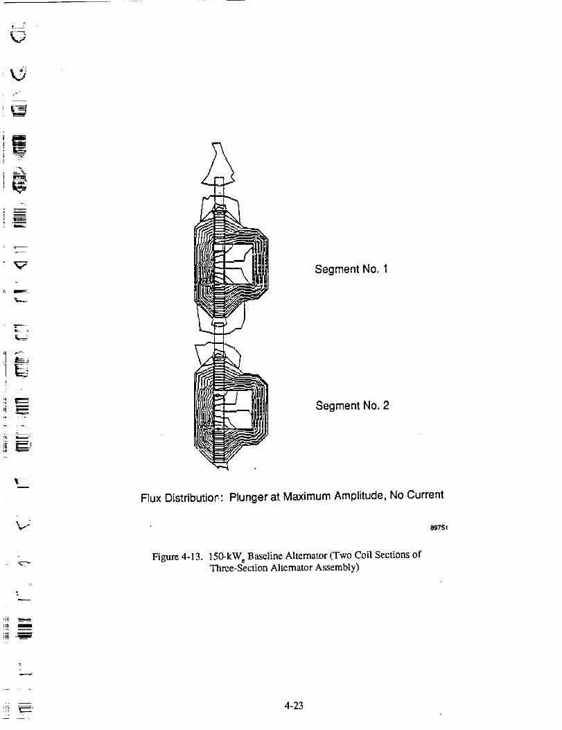
-_tl 7'
kj
TI mi
i u
Segment No. 1
L&_-_¸¸
t
-±Segment No. 2
Flux Distdbutio_ • Plunger at Maximum Amplitude, No Current
89751
Figure 4-13. 150-kW_ Baseline Alternator (Two Coil Sections ofThree-Section Alternator Assembly)
_ _-..--m
,.. _, 4-23

v
._z,O3e-
¢3X._=kl,.
8.64e-001
5.55e-001 - ÷
2.45e-001
-6.53e-002,
-3.75e-001
-6.85e-001
0.00e+000
%
+
÷ +
+ +
÷
+
+
÷
+
+ + ÷ +
÷
+i
+ + +
+ + +
+ + ÷ +
+ ÷
÷ ÷
+
+
÷
÷
+ +
6.40e+001 1.28e+002 1.92e+002 2.56e+002
Axial Location Along Plunger (mm)
(0.0 Corresponds to Top End of Plunger in Figure 4o13)
89752
Figure 4-14. Radial Flux Density in Gap versus Axial Position
(Plunger at Maximum Amplitude, No Coil Current)
L
o
=
w
Eg
4-24
z
w

-.--...=w
E
l
ffl
t'--
x
It-
1.28e+000
7.76e-001
2.73e-001
-2.31e-001
-7.34e-001
-1.24e+0000.00e+000
÷ ÷ ÷
÷ ÷ +
+ ÷ ÷
÷ ÷ ÷
----------L.__
÷
÷ ÷
÷ +
÷ ÷
÷ ÷
6.60e+001
I I
÷ ÷ ÷ ÷
÷ ÷ ÷ ÷ ÷
÷ ÷ + ÷ +
÷ ÷ ÷ ÷ ÷
÷ + +
÷ ÷ ÷
÷ ÷ ÷
÷ ÷ ÷
÷
t
I I
÷
\+l
÷
÷
÷ __--
1.32e+002 1.98e+002 2.64e+002
Axial Location Along Plunger
(0.0 Refers to Top of Plunger in Figure 4-13)
89753
Figure 4-15. Radial Flux Density Outside of Coil versus Axial Position
(Plunger at Maximum Amplitude, No Coil, Current)
t
:r. . s _
_m
4-25
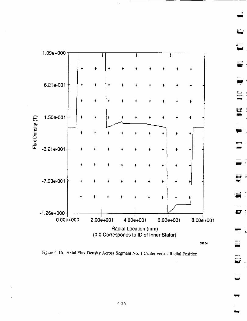
1=m
A
O3t--(D
E3X
_=LL
1.09e+000
6.21 e-001
1.50e-001
-3.21e-001
-7.93e-001
-1.26e+000
0.00e+000
÷
÷ ÷
÷ 4,
I I
÷ ÷ ÷ + ÷ ÷ ÷
÷ ÷ ÷ ÷ ÷ ÷ ÷
÷ ÷ ÷ ÷ 4, ÷ ÷
÷ ÷ ÷ + ÷
+ ÷ + ÷ ÷
÷ ÷ ÷ + ÷ ÷ ÷
÷ ÷ ÷ ÷ ÷ ÷ ÷
+ ÷ ÷ ÷ ÷ ÷ ÷
÷ ÷ ÷ ÷ ÷ + ÷
F r2.00e+001 4.00e+001
÷ ÷
÷
÷
6.00e+001
Radial Location (mm)
(0.0 Corresponds to ID of Inner Stator)
÷
8.00e+001
89754
Figure 4-16. Axial Flux Density Across Segment No. 1 Center versus Radial Position
W
N
m
Tm
_= _
E--
',IIW
4-26i
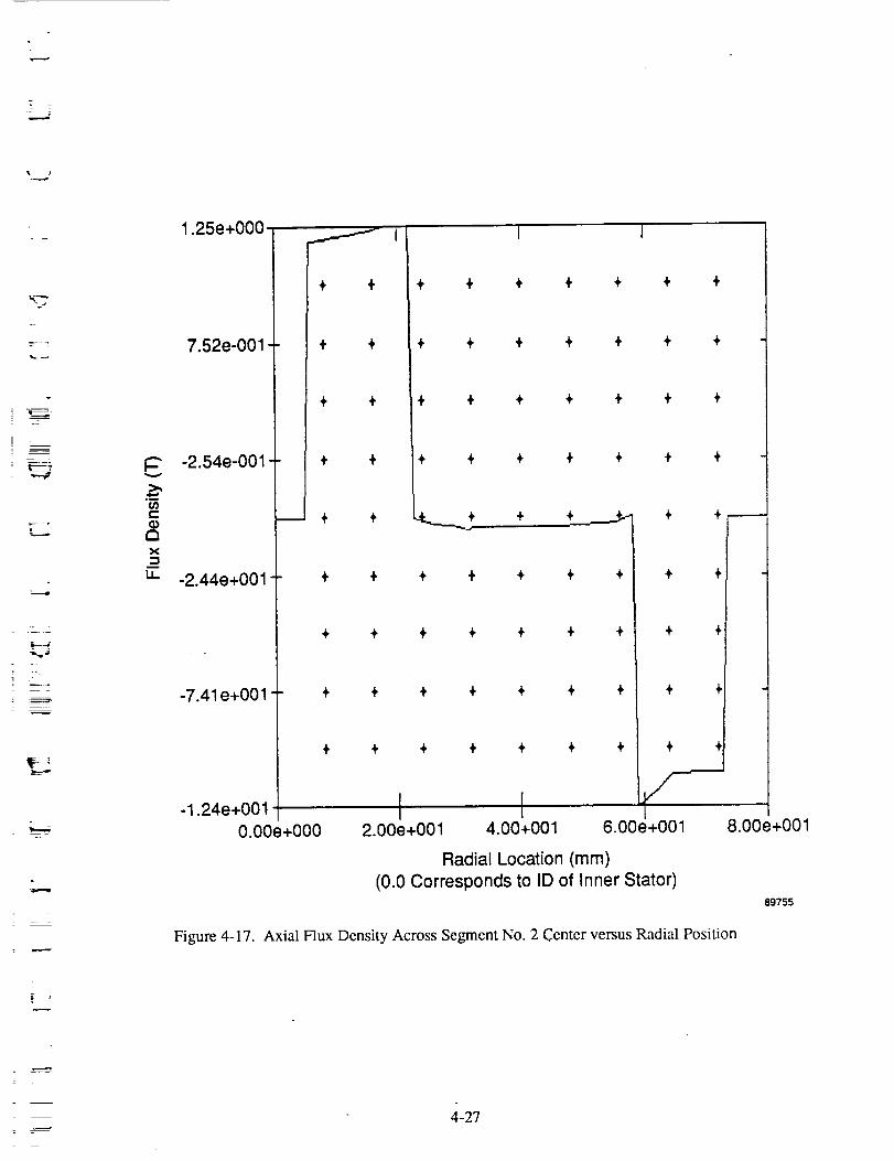
___________________..
,,...#
i
I--
Or}t-
E3x
LI.
1.25e+000
7.52e-001
-2.54e-001
-2.44e+001
-7.41e+001
-1.24e+001
._,.___----
O.OOe+O00
÷ ÷
÷ ÷
÷ ÷
÷ ÷
÷ ÷
÷
÷
I 1
÷ + ÷ ÷ + ÷ ÷
÷ ÷ ÷ ÷ + ÷ ÷
+ ÷ ÷ ÷ ÷ ÷ ÷
÷ ÷ ÷ ÷ ÷ + ÷
.*._._._ ÷
÷ +
÷ ÷
÷ ÷
÷ +
+ ÷.._+_._._ + +
÷ ÷ ÷1 ÷ ÷
÷ ÷ ÷ I ÷ ÷
I÷ ÷ ÷ t ÷ ÷
I÷ ÷ ÷ I ÷ ÷
I2.00e+001 4.00+001 6.00e+001
Radial Location (mm)
(0.0 Corresponds to ID of Inner Stator)
8.00e+001
89755
Figure 4-17. Axial Flux Density Across Segment No. 2 Center versus Radial Position
4-27
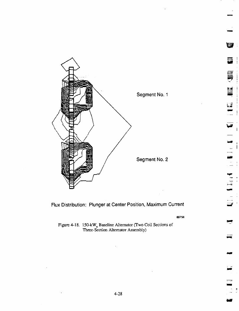
m
Segment No. 1
Segment No. 2
Flux Distribution: Plunger at Center Position, Maximum Current
I
H
llmW'
Figure 4-18. 150-kW_ Baseline Altemator (Two Coil Sections ofThree-Section Alternator Assembly)
89756
4
4-28
i
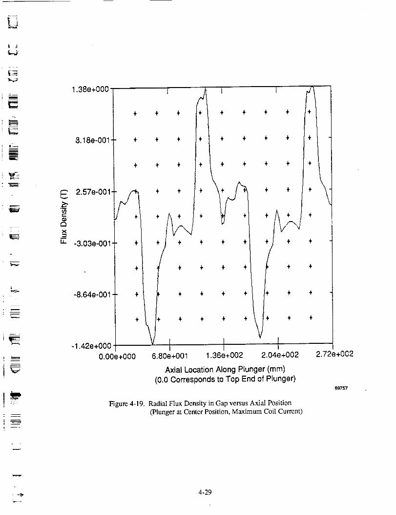
., 4,
B
ml
E
i
V
t--
ax_=i1
1.38e+000
8.18e-001-
2.57e-001'
-3.03e-001-
-8.64e-001
-1.42e+000
÷ + ÷
+ ÷ ÷
+ ÷ ÷
0.00e+000
÷
Figure 4-19.
4
÷
÷
÷
÷
I I
÷ + ÷ ÷
+ + ÷ +
÷ + ÷ +
÷ ÷
÷ ÷
÷ ÷ +
+ + +
_
÷
+i -1
÷
,\+
V
+
+ ÷ ÷ + + ÷ ÷
÷ ÷ + + + ÷ ÷
I I I6.80e+001 1.36e+002 2.04e+002
Axial Location Along Plunger (mm)
(0.0 Corresponds to Top End of Plunger)
Radial Flux Density in Gap versus Axial Position
(Plunger at Center Position, Maximum Coil Current)
2.72e+002
89757
4-29

I
v
C
ax
ii
1.65e+000
9.91e-001
3.28e-001
-3.35e-001
-9.98e-001
-1.66e+000
0.00e+000
Figure 4-20.
I I 1
+
+
+ + + + ÷
+ + + ÷ +
+ + + + .)
+ ,!. + + +
÷ + ÷ +
+ + + ÷ +
÷ ÷ ÷ ÷ ÷
+ ÷ ,t. ÷ +
m
÷
+
÷ + +
÷ ÷ ÷
÷ + +
+ + +
I 1I6.60e+001 1.32e+002 1.98e+002
Axial Location Along Plunger (mm)
(0.0 Corresponds to Top End of Plunger)
Radial Flux Density Outside of Coil versus Axial Position
2.64e+002
89758
mE;
..=_==_= _,==_
mm
m
m
F
m
m
m
m
4-30
W
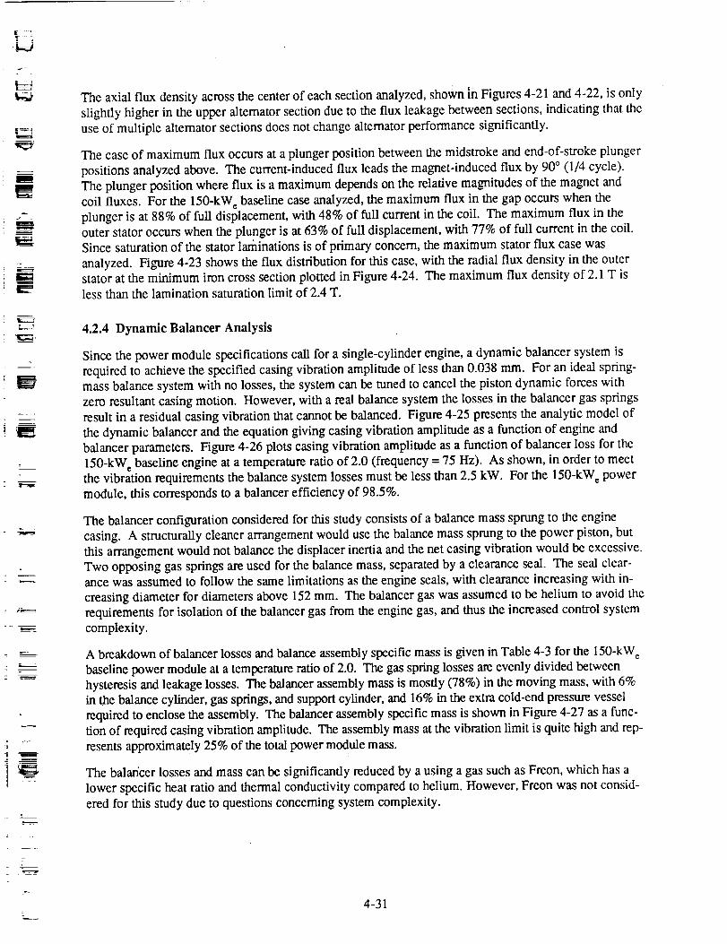
f
=
. °L
w
B
9
r_
r
j2-
The axial flux density across the center of each section analyzed, shown _fl Figures 4-21 and 4-22, is only
slightly higher in the upper alternator section due to the flux leakage between sections, indicating that the
use of multiple alternator sections does not change alternator performance significantly.
The case of maximum flux occurs at a plunger position between the midstroke and end-of-stroke plunger
positions analyzed above. The current-induced flux leads the magnet-induced flux by 90 ° (1/4 cycle).
The plunger position where flux is a maximum depends on the relative magnitudes of the magnet and
coil fluxes. For the 150-kW_ baseline case analyzed, the maximum flux in the gap occurs when theplunger is at 88% of full displacement, with 48% of full current in the coil. The maximum flux in the
outer stator occurs when the plunger is at 63% of full displacement, with 77% of full current in the coil.Since saturation of the stator laminations is of primary concern, the maximum stator flux case was
analyzed. Figure 4-23 shows the flux distribution for this case, with the radial flux density in the outerstator at the minimum iron cross section plotted in Figure 4-24. The maximum flux density of 2.1 T is
less than the lamination saturation limit of 2.4 T.
4.2.4 Dynamic Balancer Analysis
Since the power module specifications call for a single-cylinder engine, a dynamic balancer system is
required to achieve the specified casing vibration amplitude of less than 0.038 mm. For an ideal spring-mass balance system with no losses, the system can be tuned to cancel the piston dynamic forces with
zero resultant casing motion. However, with a real balance system the losses in the balancer gas springs
result in a residual casing vibration that cannot be balanced. Figure 4-25 presents the analytic model of
the dynamic balancer and the equation giving casing vibration amplitude as a function of engine and
balancer parameters. Figure 4-26 plots casing vibration amplitude as a function of balancer loss for the
150-kW_ baseline engine at a temperature ratio of 2.0 (frequency = 75 Hz). As shown, in order to meetthe vibration requirements the balance system losses must be less than 2.5 kW. For the 150-kW_ power
module, this corresponds to a balancer efficiency of 98.5%.
The balancer configuration considered for this study consists of a balance mass sprung to the engine
casing. A structurally cleaner arrangement would use the balance mass sprung to the power piston, but
this arrangement would not balance the displacer inertia and the net casing vibration would be excessive.
Two opposing gas springs are used for the balance mass, separated by a clearance seal. The seal clear-ance was assumed to follow the same limitations as the engine seals, with clearance increasing with in-
creasing diameter for diameters above 152 mm. The balancer gas was assumed to be helium to avoid the
requirements for isolation of the balancer gas from the engine gas, and thus the increased control system
complexity.
A breakdown of balancer losses and balance assembly specific mass is given in Table 4-3 for the 150-kW e
baseline power module at a temperature ratio of 2.0. The gas spring losses are evenly divided between
hysteresis and leakage losses. The balancer assembly mass is mostly (78%) in the moving mass, with 6%in the balance cylinder, gas springs, and support cylinder, and 16% in the extra cold-end pressure vessel
required to enclose the assembly. The balancer assembly specific mass is shown in Figure 4-27 as a func-
tion of required casing vibration amplitude. The assembly mass at the vibration limit is quite high and rep-
resents approximately 25% of the total power module mass.
The balancer losses and mass can be significantly reduced by a using a gas such as Freon, which has a
lower specific heat ratio and thermal conductivity compared to helium. However, Freon was not consid-
ered for this study due to questions concerning system complexity.
4-31

m
A
I--
u)C
aX
i
LI.
1.66e+000
9.86e-001
3.18e-001
-3.51e-001
-1.02e+000
÷ ÷
÷ ÷
÷ ÷
÷ ÷
÷ +
÷ ÷
I I I
÷ ÷ ÷ ÷ ÷ ÷ ÷
÷ ÷ ÷ ÷ ÷ ÷ ÷
+ + ÷ + + + +
÷ ÷ ÷ ÷ ÷ ÷
÷ ÷ ÷ ÷
÷ t, + ÷
÷ ÷ + +
÷ ÷ ÷ +
÷ ÷ ÷ ÷
I I ,O.OOe+O00 1.80e+001 3.60e+001 5.40e+001
Figure 4-21.
Radi,al Location (mm)
(0.0 Correspcnds to ID of Inner Stator)
m
Axial Flux Density Across Segment No. 1 Center versus Radial Position
7.20e+001
89759
--7
Um_
m*W
'ran
I
h
r,,m
I
m
m
Em_
m_B
4-32
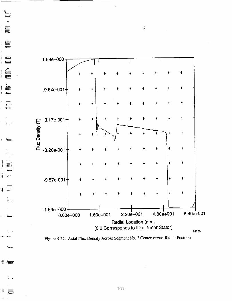
i J
m
: F'
C
121X
U.
1.59e+000
9.54e-001
3.17e-001
-3.20e-001
-9.57e-001
-1.59e+000
0.00e+000
Figure 4-22.
÷ ÷
÷ ÷
÷ ÷
+ +
÷ ÷
÷ ÷
I I I
÷ ÷ ÷ ÷ ÷ + ÷
÷ ÷ ÷ ÷ ÷ ÷ ÷
+ ÷ ÷ ÷ ÷ + +
÷ ÷ ÷ ÷ + + +
"_+ .,. + ÷
÷ ÷ ÷ ÷ ÷
÷ ÷ ÷ ÷ ÷ ÷ ÷
+ ÷ + ÷ ÷ ÷ ÷
÷ ÷ ÷ ÷ ÷ ÷ ÷
I I I1.60e+001 3.20e+001 4.80e+001
Radial Location (mml,
÷ ÷
÷ ÷
÷ ÷
÷ ÷
/
6.40e+001
(0.0 Corresponds to ID of Inner Stator)
Axial Flux Density Across Segment No. 2 Center versus Radial Position
89760
=
4-33
m
W
l
I
J
Flux Distribution: Plunger at Position of Maximum Stator Flux Density
Figure 4-23. 150-kW e Altemator (Two Coil Sections ofThree-Section Alternator Assembly)
897t_2
m
U
h
m
._r,,d
4-34
m

,lc,_.
L__
F
i _= --
t--
03i-
X_=LL
2.08e+000
1.24e+000
4.08e-001
-4.27e-001
-1.26e+000
-2.10e+000
+ ÷
+
÷ ÷
÷ ÷
÷ ÷ ÷
I I
+ ÷ ÷ ÷ ÷ ÷
÷ ÷ ÷ ÷ ÷ ÷
+ ÷ ÷ ÷ ÷ ÷
÷ ÷ ÷ ÷ ÷ ÷
÷ ----d'--- t ÷
+ ÷ ÷ ÷ + ÷
+ ÷ ÷ ÷ ÷ ÷
÷ ÷ + ÷ ÷ ÷
÷ ÷ ÷ ÷ ÷
÷
t÷ ÷
÷ ÷
÷ ÷
÷ +
/'\
0.00e+000 5.04e+001 1.01e+002 1.51e+002 2.01e+002
Axial Position Along Plunger (mm)
(0.0 Corresponds to Top End of Plunger)
Figure 4-24. Plunger at Position of Maximum Stator Flux Density - Radial
Flux Density in Outer Stator versus Axial Location
89761
,..-_
4-35
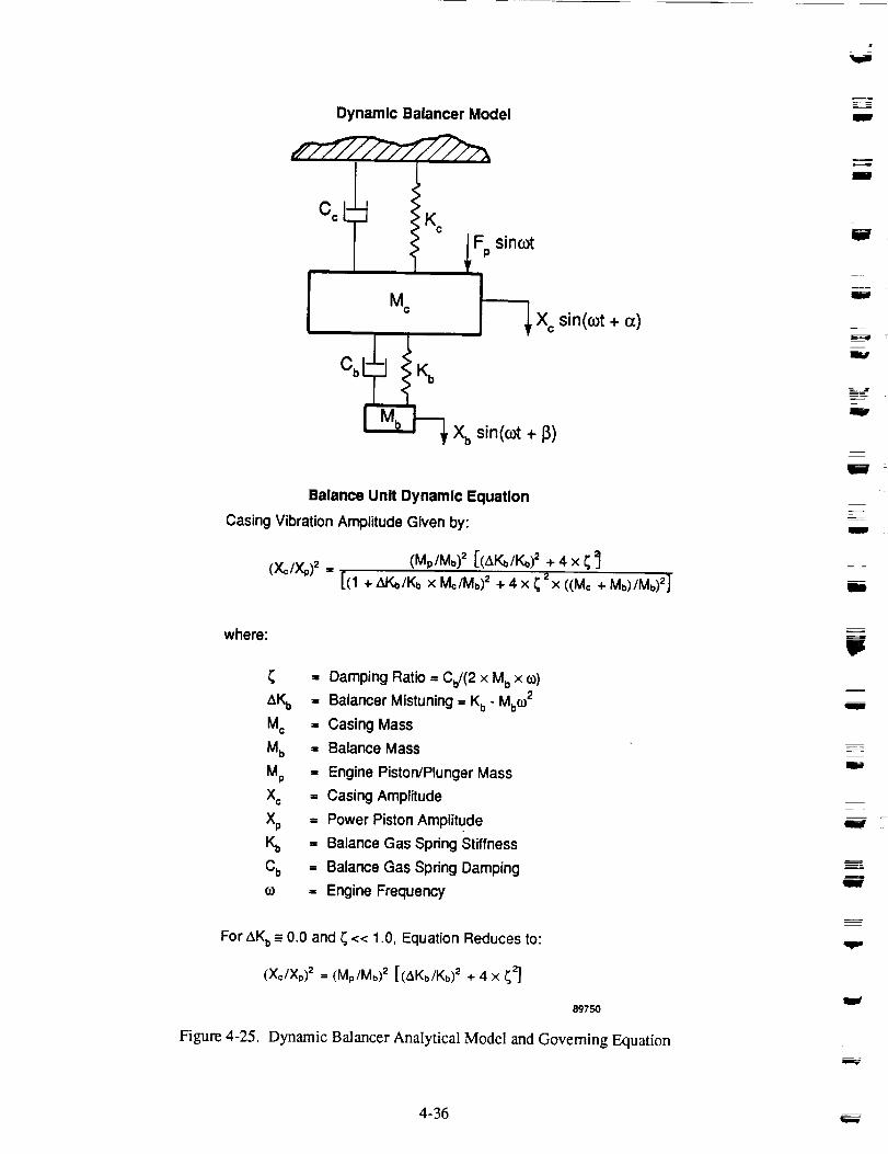
Dynamic Balancer Model
Mc
Fp sincot
J_--_ X c sin(cot + o_)
Xb sin(cot + 13)
Balance Unit Dynamic Equation
Casing Vibration Amplitude Given by:
(Mp/Mb) = [(tLKb/Kb)2 + 4 x _
(Xc/XP)= = [(1 + AKb/Kb x Mc/Mb)2 + 4 x _ 2x ((Me + Mb)/Mb)2]
m
w
L
m
E--
W
wit
I
m
UB
where:
= Damping Ratio = Cb/(2 x Mb x co)
AKb = Balancer Mistuning = Kb- Mb(O2
Mc = Casing Mass
Mb = Balance Mass
Mp = Engine Piston/Plunger Mass
Xc = Casing Amplitude
Xp = Power Piston Amplitude
Kb = Balance Gas Spring Stiffness
Cb = Balance Gas Spdng Damping
o0 = Engine Frequency
For AKb= 0.0 and _ << 1.0, Equation Reduces to:
(X¢/Xp)2 = (M./Mb) 2 [(t_Kb/Kb)2 + 4 x _zj
8975O
Figure 4-25. Dynamic Balancer Analytical Model and Goveming Equation
111
J
mW
4-36
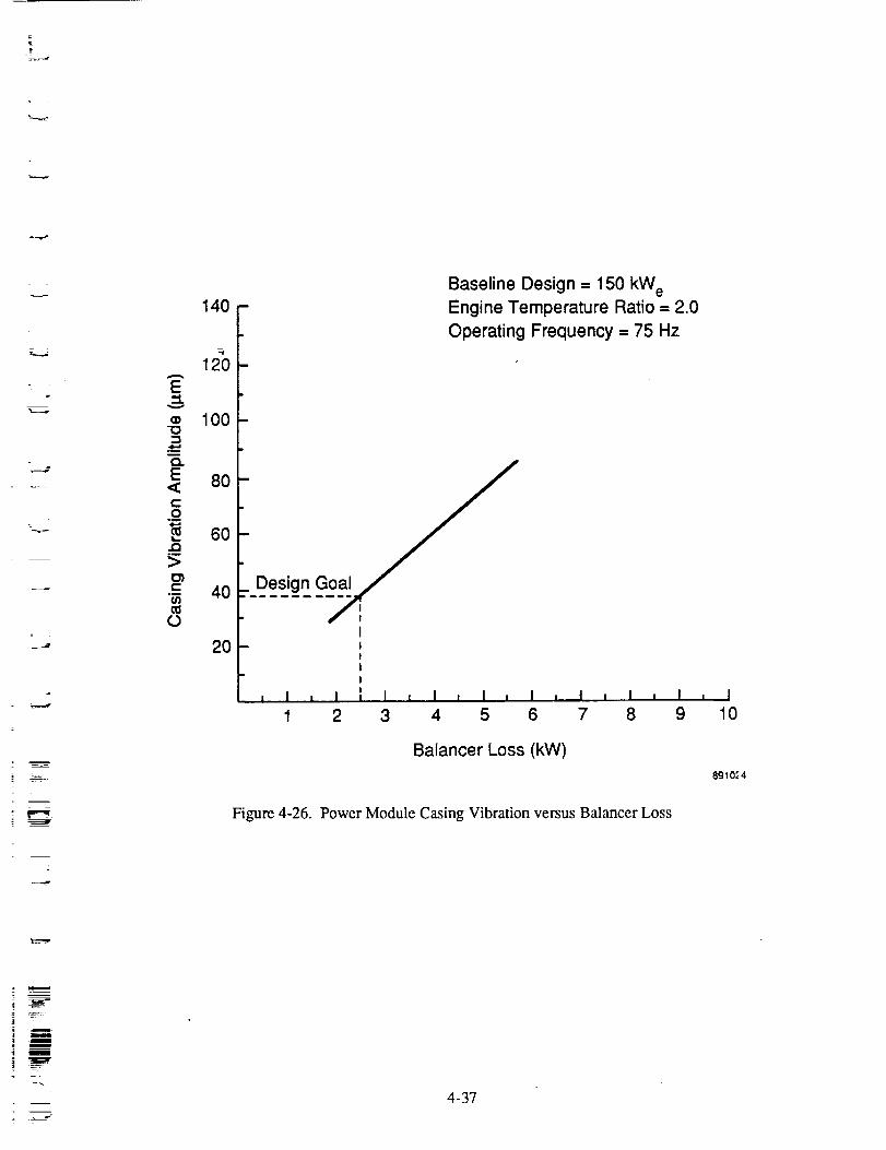
,t
z :
z
140
120
E
_ 100
E 80<Co
6o°_
>
•_- 40ffl
o
2O
Baseline Design ---150 kW eEngine Temperature Ratio = 2.0
Operating Frequency = 75 Hz
Design
II!II
i I i I !, I , I , I , I , I , I
1 2 3 4 5 6 7 8
Balancer Loss (kW)
I I
9
Figure 4-26. Power Module Casing Vibration versus Balancer Loss
I
10
8910_4
| ii
!w
. J
4-37

Table 4-3. Dynamic Balance Unit - Performance and Mass Penalties*
• Balance Gas Spring Losses (kW)
-- Hysteresis 1.21-- Leakage 1.20-- Porting 0.10-- Total 2.51
_ m
l
= --
w
I
• Balance Unit Specific Mass (kg/kW,,)
-- Moving Mass 1.29
-- Cylinder and Structure 0.11-- Pressure Vessel 0.26-- Total 1.66
*At baseline 150 kWc design point, engine temperature ratio = 2.0
w
l
w
I
4-38

t
-...=_..
3.5
3.0
(_ 2.5
•_ 2.0
1.5
1.0
OI-
0.5
Baseline Design -- 150 kW e
Engine Temperature Ratio = 2.0
- Operating Frequency = 75 Hz
'- Note: Total specific mass of balancer includes the._mm moving mass, structure for the balancer, and the(D
- a increased pressure vessel required to accommodatethe balancer.
, I , I , I , I: , I , I , I , I , I , I32 34 36 38 40 42 44 46 48 50
Required Casing Vibration Amplitude (p.m)
Figure 4-27. Balancer Total Specific Mass versus Required
Casing Vibration Amplitude
89728
4-39
4.3 Results
The terminology used to report the results of the parametric study is based on the latest formulation of
efficiency standards for Stifling engine systems [4], originally defined in J. L. Crowley's paper [5], and
subsequently modified for adoption by the Stifling Engine Committee of ASME. These standards have
not yet been adopted, and may be subject to further revisions.
Accuracy of the results of this study is expected to be within 10% on power and efficiency, and within
5-10% on specific mass. For the performance predictions of opposed power modules (without the dy-
namic balancer), the parametric study results of the single-cylinder power modules with balancers weremodified as reported in Section 4.3.4, but similar accuracy is expected.
The results of the parametric study are presented in Figures 4-28 through 4-30. Power module relative
thermal efficiency (thermal efficiency ÷ Camot effÉciency) is plotted as a function of power module spe-
cific mass for each power level, with temperature ratio as a parameter. Note that power module thermal
efficiency includes the alternator efficiency. The curves at each temperature ratio and power level are
def'med by the three optimization points. The curves were drawn using the empirical equation developed
to correlate the results (see Section 4.4). Since a quadratic relationship was used to map efficiency as a
function of specific mass at constant temperature ratio and power level, the curves are of similar shape.
Discussion of the results is divided into three sections:
• General performance characteristics (relationships between efficiency and specific mass for all
operating points)
• Heat exchanger temperature ratio sensitivity
• Power level sensitivity.
4.3.1 General Performance Characteristics
As seen in Figures 4-28 through 4-30, efficiency increases with increasing specific mass for all tempera-
ture ratios and all power levels. There is a diminishing gain in efficiency with increasing specific mass,as seen by the decreasing slope at the fight end of each curve.
The maximum efficiency point on each curve represents the highest power module thermal efficiencythat could be attained without unreasonable mass increase. For example, efficiency could be increased
slightly by raising the engine mean pressure to 18 MPa, but would result in a large increase in specificmass, which was considered unreasonable.
The minimum specific mass point on each curve represents the lowest achievable power module specificmass. An increase in operating frequency results in decreasing engine efficiency. For frequencies
greater than 90 Hz, the increased engine displacement required to maintain the power level causes an
increase in specific mass. Since the curves are generated from only three points and fit with a quadratic
relationship, they should not be extrapolated beyond the end points.
4.3.2 Heat Exchanger Temperature Ratio Sensitivity
As seen in Figures 4-28 through 4-30, the percentage of Camot efficiency increases with increasing tem-perature ratio for constant specific mass, and specific mass decreases with increasing temperature ratio
for constant efficiency.
w
F__
w
W
W
I
W
J
w
W
4-40

0.8
0.7
"6 0.6
0.5
_" 0.4.i0
LU 0.3
"00
0.2
o 0.1n
Temperature Ratio = 3.0_
_" 2.0 _1,7
l
0 I I _ I = I i I I I I I0 2.0 4.0 6.0 8.0 10.0 12.0
Power Module Specific Mass (kg/kWe)
Figure 4-28. 150-kW¢ Power Module Parametric Study Performance Map
891026
i
4-41
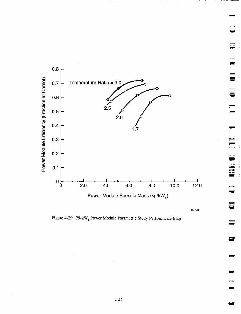
I
m
0.8
0.7
o 0.6
_ 0.5
_ 0.4
m 0.3
_ 0.2L_
o 0.1-0.
D
0er tur 2_ / /
2.0
1.7
0 i I i I i ! = I i I0 2.0 4.0 6.0 8.0 10.0
Power Module Specific Mass (kg/kWe)
Figure 4-29. 75-kW e Power Module Parametric Study Performance Map
I12.0
89773
m
I
z
mi
r
i
i
F
i
m
i
W
4 -42
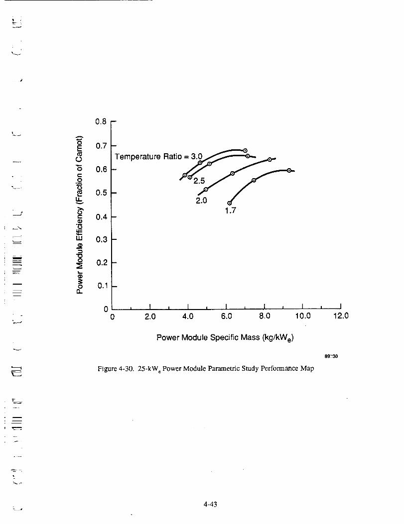
r
0.8
A
0E 0.7
0.6
_ 0.5
" 0.4
.m
uJ 0.3
"10
o 0.2
(D
o 0.1n
m
Temperature Ratio = _3'0__
1.7
0 , I , I , 1 , .I , I0 2.0 4.0 6.0 8.0 10.0
Power Module Specific Mass (kg/kWe)
Figure 4-30. 25-kW e Power Module Parametric Study Performance Map
I12.0
z
I \
4-43

BasedontherelationshipbetweentemperatureratioandCamotefficiency,TlCamot= (TR- 1)/TR,for aconstantpowerleveltheheatinput(andthereforeenginesize)variesasaninversefunctionof tempera-tureratio,Qin= TR/(TR- 1). Thisexplainstherelativespecificmassincreaseasthetemperatureratiodropsfrom3.0to 1.7.
Breakdownsof the performance and specific mass calculations show increases in all of the subsystem
efficiencies with increasing temperature ratio, except for the alternator efficiency, which was held fixed.
The mechanical efficiency increases because of the decrease in required engine displacement, and the
corresponding drop in moving mass and gas spring requirements. All power module components havedecreasing specific mass with increase in temperature ratio because of the overall reduction in enginesize.
For a temperature ratio of 1.7, there was, as expected, a substantial increase in specific mass from a tem-
perature ratio of 2. The drop in engine efficiency forces increases in engine displacement to maintain
power, and the entire engine package increases in size.
4.3.3 Power Level Sensitivity
The change in efficiency and specific mass with engine power level is seen in Figures 4-31 and 4-32 forthe power modules optimized for maximum efficiency. As shown, the efficiency increases with increas-
ing power level, with a larger increase at higher temperature ratio. The specific mass also increases with
increasing power level. The reason for the increase in efficiency is seen by looking at the sample effi-
ciency and specific mass breakdowns given for different engines in Figures 4-33 through 4-40. At the
lower power level, the heat-pipe requirements limit the frontal area of the heat exchangers, and the ther-
modynamic efficiency is lower than at 150 kW e, where the increased diameter results in increased frontal
area. Due to the drop in cycle efficiency, the mechanical efficiency is also lower at 25 kW c because ofthe increased displacement required to make up for the efficiency loss.
The specific mass of the 25-kW e engine is lower than the higher power designs primarily because of the
placement of the heat exchangers. Most of the weight savings occurs in the engine pressure vessel,
which is at a relatively smaller diameter (compared to the .displacer diameter) in the 25-kW_ design.
Figures 4-41 and 4-42 show the performance as a function of power level for the power modules opti-mized for minimum specific mass. The overall trends are similar to those for the maximum efficiencypower modules, but the sensitivities of efficiency and specific mass to power level are different. The
efficiency growth as a function of power level for the minimum mass designs is less pronounced than forthe maximum efficiency designs because increased efficiency was not the optimization goal. However,
the specific mass growth with power level for the minimum mass designs was reduced relative to the
maximum efficiency designs. For temperature ratios of 3.0, 2.5, and 2.0, the increase in specific mass
with power level was very small. For all designs at a temperature ratio of 1.7 however, there is a strong
dependence of specific mass on power level, owing to the mass penalties required in satisfying design
constraints (heat-pipe heat flux limits, vibration level) at the low temperature ratio condition.
4.3.4 Results for Opposed Power Modules Without Dynamic Balancer
The manner in which to join two identical single-cylinder power modules to obtain a dynamically bal-
anced opposed power module was investigated. Attachment at either the hot ends or cold ends is possible,
but the former results in the least additional structural mass and the shortest gas path for thermodynamic
connection of the two engines. Design layouts of two hot-end structural attachments were made (Figures
4-43 and 4-44), differing in the heat-pipe design and penetration paths through the pressure vessel.
liW
m
m
J
J
m
J
m
tim
u
J
J
m
m
i
I
m
I
g
4-44

;. ]
__ =
x-
-,____,
t-
(3ql,.,-
Or"
.915
LI.
c:
(.)
LLI
O
On
0.80
0.75
0.70
0.65
0.60
0.55
0
Points Optimized for MaximumSystem Efficiency
Temperature Ratio = 3.0
2.52.0
1.7
, I i I t ! J I0 50 100 150 200
Net Power (kWe)
Figure 4-3 l. Power Module Relative Efficiency versus Net Power
89731
E
4-45

u
I
m
i
14
12
"" 10(/)ct)
.o_ 8o_
O
o0 6
'100
Ig
0Q.
Points Optimized for Maximum System Efficiency
D
2-
00
Temperature Ratio = 1.7
, 2.0
2.53.0
I ._, i, I _ i ..50 100 150
Net Power (kWe)
Figure 4-32. Power Module Specific Mass versus Net Power
I
2OO
89734
BiW
mn
I
U
m
l
III
Im
g
|m
m
III
m
m
II
I
I
II
4-46
mii
J
I
m

t_ :
177 cm
p
65 cm
__tlm_ qtj_ C9.n__rtZ_q]n_tNet Output Power -, 150 kWeMaximum (Efficiency/Specific Mass)
Mean Pressure ,= 13 MPa
Temperature Ratlo ,- 2.0Operatlng Frequency - 75 HzPlston Stroke ,= 31 mm
Displacer Stroke - 31 rnmDisplacer-Piston Phase -= 65"Coslng Vlbratlon Amplltude - 38 _m (1.5 mil)
Efficiency BreqkdownPower Module Thermal Efficiency =, 30.4Mechanical Efficiency =, 96.4 _¢Alternator Efficiency - 91 ZBdoncer Efficiency - 98.5Auxiliary Efficiency ,, 99.8 Z
Power Module (Total) ,= 7.19 kg/kWePressure Vessel - 1.96 kg/_WeHeat Exchanger - 0.78 kg/kWeStructural - 1.04 kgt/kWeDlsplacer- 0.18 kg/kWePiston =, 0.22 kg,/_WeAlternator - 1.35 kg/l_WeBalancer =, 1.66 kg/kWe
89741
Figure 4-33. 150-kW e Power Module (Temperature Ratio = 2.0) Optimized for MaximumEfficiency/Specific Mass. Performance and Specific Mass Summary
*._-" 4-47

lira
i
il
m
m
I
!
li
m
II141
41
cm
cm
Net Output Power - 75 kWeMaximum Thermal Efficiency
.O_o l__g.__C_ond)tIon=Mean Pressure =, 15 MPaTemperature RaUo =, 2.0Operating Frequency =, 60 HzPiston Stroke ,= 40 mmDisplacer Stroke =, 40 rnmDisplacer-Piston Phase = 65"Casing Vibration Amplltude == 36 j_m (1.5 roll)
Power Module Thermal Efficiency =, 33.5Mechanical Efficiency =, 96.7 ZAlternatorEfficiency =, 92 ZBcdonoer Efficiency ,= 98.4 ZAuxiliary Efficiency == 99.1
Power Module (Total) 8.40 kg/_WePressure Ves=ml =, 2.43 kg/kWeHeat Exchanger - 1.33 kg/kWeStructural == 0.98 kg/kWeDisplacer ,= 0.12 kg/kWePl=ton = 0.18 kg/_WeAlternator =, 1.67 kg/kWeBaloncer = 1.69 kg/_kWe
6m
m
I
!m
W
"Rg
U
Figure 4-34. 75-kW_ Power Module (Temperature Ratio = 2.0) for Maximum
Efficiency. Performance and Specific Mass Summary
8g743
m
lIB
mm
W
m
!D
II
II
m
4-48 j
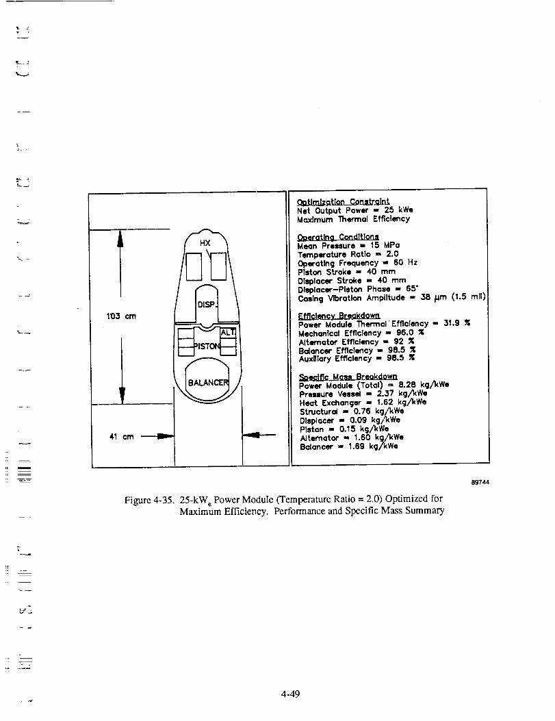
! J
103 cm
41 cm
L_.
Net Output Power - 25 kWeMaximum Thermal Efficiency
Mean Pressure ,, 15 MPoTemperature Ratio ,, 2.0Operating Frequency -, 60 HzPTston Stroke ,, 40 mmDisplacer Stroke ,, 40 mmDisplacer-Piston Phase - 65"Casing Vibration Amplitude ,, 38 /jm (1.5 roll)
Power Module ThermalEfficiency - 31.9 RMechanical Efficiency ,, 96.0Alternator Efficiency ,- 92Balancer Efficiency - 98.5Auxiliary Efficiency - 98.5 Z
Power Module (Total) ,- 8.28 kg/kWePressure Vessel ,, 2.37 kg/kWeHeat Exchanger - 1.62 kg/kWeStructural ,, 0.76 kg/kWeDisplacer ,_ 0.09 kg/_WePiston ,, 0.15 kg/kWe
ARernator - 1.60 kg/kWeBalancer 1.69 kg/kWe
Figure 4-35. 25-kW_ Power Module (Temperature Ratio = 2.0) Optimized forMaximum Efficiency. Performance and Specific Mass Summary
89744
r
_2
4-49

W
m
W
188 cm
F
62 cm
HX
.O_tJm!_o_tJ_ _Consrt_tntNet Output Power -- 150 kWeMinimum Specific Mass
Dg.er_g_t]o_L_C_oodJt_onsMean Pressure = 12 MPo
Temperature Ratio = 2.0Operating Frequency == 90 HzPiston Stroke = 31 mm
Displacer Stroke -= 31 mmDisplacer-Piston Phase -, 65"
Casing VtbroUon Amplitude - 38 /jm (1.5 mN
Power Module Thermal Efficiency = 26.3Mechanical Efficiency = 95.0 RAlternator Efficiency =, 90 RBalancer Efficiency == 97.8Auxglory Efficiency = 99.8
Power Module (Total) -= 5.60 kg/kWePressure Vessel =, 1.27 kg/kWeHeat Exchanger =, 0.59 kg/%WeStructural =, 0.96 kg/kWeDisplacer == 0.15 kg/kWePiston -, 0.21 kg/kWe
Altemat.or = 1.14 kg/kWeBalancer 1.29 kg/kWe
J
.=-4
W
W
l
U
i
g
m89742 -1
Figure 4-36. 150-kW e Power Module (Temperature Ratio = 2.0) Optimized for Minimum
Specific Mass. Performance and Specific Mass Summarym
i
m
4-50

H
184 cm
Net Output Power - 150 kWeMaximum Thermal Efficiency
DpercL!ng__JLMean Pressure ,= 15 MPo
Temperature Ratio - 1.7Operating Frequency - 58 HzPiston Stroke =, 40 mm
Displacer Stroke =, 40 mmDlsplacer-PIaton Phase =, 65*Casing Vibration Amplitude - 38 Fire (1.5 rail)
_ownPower Module Thermal Efficiency - 26.0Mechanical Efficiency- 96.1Alternator Efflclency - 92 ZBaloncer Efficiency - 98.2Auxiliary Efficiency =, 99.1
Power Module (Total) : 11.22 kg/kWePressure Vessel 3.30 kg/kWeHeat Exchanger " 1.48 kg/kWe
Structural - 1.30 kg/kWeDisplacer ,- 0.23 kg,/kWePiston =, 0.37 kg/kWeAlternator ,, 1.87 kg/'_WeBalancer =, 2.64 kg/kWe
Figure 4-37. 150-kW e Power Module (Temperature Ratio = 1.7) Optimized forMaximum Efficiency. Performance and Specific Mass Summary
89737
4-51

m
u
g
w
U
J
172 cm
E
?
.__l;ImJz,.._Een_.¢_.ee.__t,.r,..ql_r_Net Output Power - 150 kWeMaximum Thermal Efficiency
Mean Pressure ,, 15 MPoTemperature Ratio - 2.0Operating Frequency ,- 58 HzPiston Stroke -- 40 mmDl_olacer Stroke = 40 mmDisplacer-Piston Phase ,= 65"Casing Vibration Amplitude = 38 Hm (1.5 re=l)
Efffclencx BreakdownPower Module Thermal Efficiency -, 34.0Mechanical Efficiency = g7.0 RAlternator Efficiency - 92 ¢
Baloncer Efficiency == 98.5 RAuxiliary Efficiency 99.1 Z
=_l_dff_q_Mglt._B reokdownPower Module (Total) == 9.22 kg/kWePressure Vessel -- 3.09 kg/kWeHeat Exchanger'- 1.27 kg/kWeStructural == 0.96 kg/kWeDisplacer =, 0.17 kg/kWePtston -, 0.23 kg/kWeAlternator - 1.73 kg/kWeBoloncer - 1.65 kg/kWe
P====m
g
Figure 4-38. 150-kW e Power Module (Temperature Ratio = 2.0) Optimized for
Maximum Efficiency. Performance and Specific Mass Summary
89738 111
Ul
= --
I
l
4-52

tIi
173 cm
"xI_
F
--L- -J71 cm
Oa.Umiz_traWntNet Output Power - 150 kWeMoxlmum ThefTnal Efficiency
Mean Pressure = 15 MPoTemperature Ratio = 2.5Operating Frequency =, 58 HzPiston Stroke == 40 mmDisplacer Stroke =, 40 mmDlsplacer-Piston Phase ,= 65"Cosing Vroratlon Amplitude - 38 _m (1.5 roll)
EfficlQl_,_LB.reokdownPower Module l_termol Efficiency - 43.4Mechonic_ Efficiency - 97.7 RAlternotor Efficiency - 92Bolonce¢ Efficlency -- 99.2 ZAuxUlory Efficiency == 99.8
Power Module (Total) = 8.82 kg/_WePressure Vessel 3.00 kg/kWeHeot Exchanger _, 1.26 kg/kWe
Structural == 0.88 kg/kWeDlsplocer ,= 0.1,3 kg/kWePiston == 0.17 kg/kWeAlternator =, 1.55 kg/kWeBolencer ,= 1.83 kg/_We
Figure 4-39. 150-kW c Power Module (Temperature Ratio = 2.5) Optimized forMaximum Efficiency. Performance and Specific Mass Summary
89739
____ 4-53
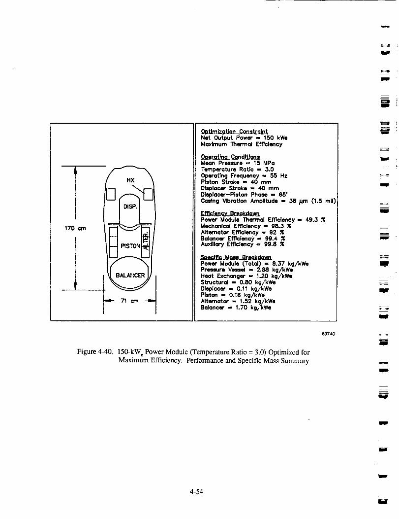
W
S
WD
m
170 cm
PISTO._
BALAHCER
Net Output Power - 150 kWeMaximum Thermal Efficiency
.0_Tn_g_ ¢_oodl_tJ_lMean Pressure =, 15 MPoTemperature Ratlo ,= 3.0Operating Frequency ,= 55 HzPiston Stroke = 40 mmDlsplocer Stroke ,= 40 mmDisplacer-Piston PhoN == 65"Casing Vibration Amplitude - 38 /Jm (1.5 m_l)
Eff]rJ_,.v_Br_kCo_j1Power Module Thermal Efficiency ,- 49.3 ,*1;Meahonlcal Efficiency ,, 98.3 ZAlternator Efficiency- 92 ZBolancer Efflclency ,- g9.4Auxiliary Efficiency =, 99.8
Power Module (Total) = &37 kg/l(WePressure Vessel -, 2.88 kg/kWeHeat Exchanger -, 1.20 kg/kWeStructural = 0.80 kg/_(WeOTsp;acer -, 0.11 kg/_,(WePIston -, 0.16 kg/kWeAlternator -, 1.52 kg/l(WeBalancer ,- 1.70 kgi_We
89740
Figure 4-40. 150-kW e Power Module (Temperature Ratio = 3.0) Optimized for
Maximum Efficiency. Performance and Specific Mass Summary
J
I
_ I
W
mm
--=
m
J
u
m
l
m
4-54
W

i---!wi
= m
:. i
3C
OO
c-O
.m
It.
C
OR
._o:I::Ill
"10O
I,..
O
O¢L
0.65
0.60
0.55
0.50
0.45
0.40
Points Optimized for Minimum System Mass
Temperature Ratio = 3.0
2.5
2.0
1.7
i I i I , ! i I0 50 100 150 200
Figure 4-41.
Net Power (kW e)
Power Module Relative Efficiency versus Net Power
89733
4-55

w
I
14
"_ 12
_o
_ 6
4
00- 2-
Points Optimized for Minimum System Mass
1.7
2.0- 2.5
- _ 3.0
O0 , I , I = I , I50 100 150 200
Net Power (kWe)
Figure 4-42. Power Module Specific Mass versus Net Power
89732
W_
I i
W
g
I
IBW
m
I
I
!
I
m
W
4-56 Jw

j
____.
,:r
agu
\\\ \
I
Figure 4-43. FPSE Scaling Study - Double-Ended Radial Engine
with Straight Main Heat Pipes
4-57

//
/
89777
i
l;I
J
m
m
I
U
m
Figure 4-44. FPSE Scaling Study - Double-Ended Radial Engine
with Bent Main Heat Pipes
mm
4-58W

VE J
t: =.
The design shown in Figure 4-43 used straight sections of the main heat pipes, with pipes from the op-
posed engine meeting in a central evaporator region. To avoid thermal expansion problems, the opposing
heat pipes were separated by a small gap.
The domed section of the pressure vessel used in the single-cylinder designs was replaced with the cylindri-
cal vessel inboard of the heat-pipe evaporators. The irregular shape of the pressure vessel in the central
section was not considered structurally sound, and a second design, shown in Figure 4-44, was developed.
A thick-walled cylindrical vessel was used, with the heat pipes bent and exiting the vessel radially. By
bending the heat pipes, the two engines can be moved closer together, and the length of the duct connect-
ing the two expansion spaces is reduced from that of the first approach.
Based on the shortened duct length and improved structural design, the second configuration was selected
for the purposes of calculating the specific mass of an opposed power module. The additional specificmass relative' to a single-cylinder module (without balancer) is 0.2 kg/kW c
To obtain the resultant specific mass of the opposed power modules, this 0.2 kgjkW_ was added to the
calculated specific mass values for the single-cylinder power module designs, and the dynamic balancer
assembly specific mass was subtracted. The efficiency penalty of the connecting duct was negligablysmall.
The efficiencies of the opposed power modules were simply the calculated efficiency values for the
single-cylinder power module designs divided by the dynamic balancer efficiencies.
Figures 4-45 through 4-47 show the power module efficiency versus specific mass curves for the opposed
power modules. The net power output of the opposed power modules is twice that of the single-cylinder
power modules. Comparison with the results for the single-cylinder power module including dynamicbalance assembly shows that the balancer increases power module specific mass by 20-30%, but has only
a small impact on power module efficiency.
4.4 Empirical Equation - Empirical Relationship Between Power Module Thermal Efficiency and
Power Module Specific Mass, Net Power Output, and Temperature Ratio
Empirical equations were developed relating the power module relative net thermal efficiency (fraction of
Camot), 11,to the power module specific mass, SM(kg/kW,), net power output, Pn (kWh), and heat ex-
changer temperature ratio, TR. One equation was developed for the single-cylinder power module withdynamic balancer, and one for the opposed power module. The 36 optimization points from the parametric
study were used as the data base for the equations, with the efficiency and specific mass values modified for
the second equation as noted in Section 4.3.3, and the power levels doubled.
Using a multiple linear regression analysis routine, the data were fit using quadratic functional relation-
ships for SM and Pn' and a cubic functional relationship for TR:
rl = f(SM) x g(Pn) x hCI"R)
where
f(SM) = Fo + F i SM + F2 SM 2
g(Pn) = Go + G1 Pn + G2 Pn2
h(TR) = H 0 + H l TR + .I7I2 TR 2 + H 3 TR 3
4-59
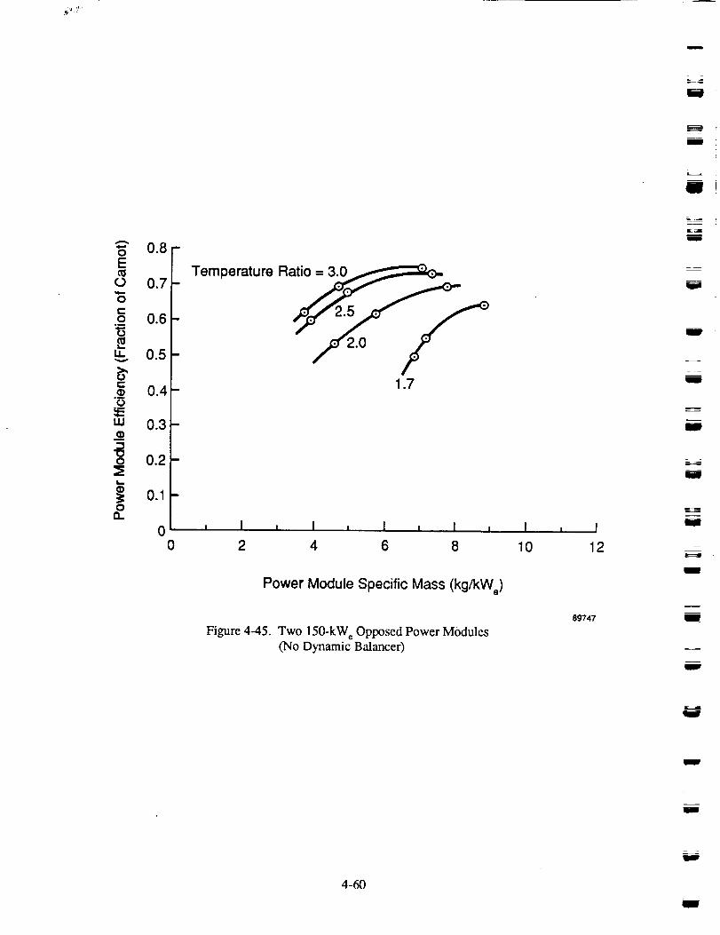
ii
m
ii
_ _
I
W
I
J
m
mIll
lil
J
J
w
='o 0.8-
0.7
.__ 0.6
0.5
t-0.4
°_OE--Lu 0.3lID
_ 0.2
L--
_ 0.10
a.
0
Temperature Ratio =3.0_
,t /_ 1.7
, ! , I , I I I , I , I
2 4 6 8 10 12
Power Module Specific Mass (kg/kWe)
Figure 4-45. Two 150-kW e Opposed Power Modules(No Dynamic Balancer)
89747
m
W
4-60
i
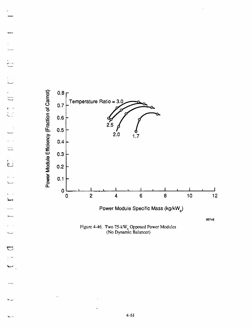
=r ?
t
0.8
0.7
.-_ 0.6
0.5
c-o 0.4"i5
w 0.3
o 0.2
_ 0.10
0
D
Temperature Rat_2.5 _'_
2.0 1.7
, I , I , I , i
0 2 4 6 8
Power Module Specific Mass (kg/kWe)
Figure 4-46. Two 75-kWe Opposed Power Modules(No Dynamic Balancer)
I , I
10 12
89748
v,=._.,J
-___ 4-61

I
m
g
0.8
c_ 0.7"6
8 0.6
0.5
0.4
uJm 0.3
_ 0.2
• 0.10a.
0
m
Temperature Rati_
2.0 _
- 1.7
, ! , I , i ...... I
0 2 4 6 8
Power Module Specific Mass (kg/kWe)
Figure 4-47. Two 25-kW c Opposed Power Modules(No Dynamic Balancer)
1 , I
10 12
89746
i
WlW
I
g
i
i
I
Ii
D
m
J
m
t
4-62
B
i

L
!
The resulting equation, having 36 terms when expanded, is presented in Table 4-4. A listing of the curvefitcoefficients for both the single-cylinder power module with dynamic balancer and the opposed power
module is given in Table 4-5. The coefficients must be used as listed (without roundoff) to enable a good
match with the parametric study results.
A separate empirical equation was developed (see Table 4-6) relating the power module relative net ther-
mal efficiency to the power module specific mass and the heat exchanger temperature ratio for each of
the three power levels of the study.
Figures 4-28 through 4-30 plot the parametric study results (11versus SM) for the single-cylinder power
module with dynamic balancer. The study results are shown as points, with the lines showing the pre-
dicted efficiency using the empirical equation. Figures 4-36 through 4-38 show similar plots for the
opposed power module results.
LJ
4-63

--4
m
U
,w
7.---
g
w
U
J
Table 4-4.
Defining:
_q
SM
PnTR
Empirical Equation for Power Module Performance
= Power module relative thermal efficiency (% of Camot)
= Power module specific mass (kg/kWe)
= Net power output (kW,)
= Engine heat exchanger temperature ratio
The empirical equation correlating the parametric study data for both the single-cylinderpower module and the opposed power module follows:
C1TR3SM2Pn 2 + C2TR2SM2Pn2 + C3TR" SM2Pn 2 + C4SM2Pn 2 + C5TR3SM • Pn 2 +
C6TR2SM • Pn 2 + C7TR" SM" Pn 2 + CsSM. Pn 2 + C9TR3Pn 2 + C10TREPn 2 + CI IT R • pn 2 +
C,2Pn 2 + CI3TR3SM2pn + CI4TR2SM2pn + ClsTR • SM2pn + C,6SM2Pn + CI7TR3SM • Pn +
C24Pn + C25TRSSM 2 + C26TR2SM 2 + C27TR • SM 2 + C28SM 2 + C29TR3SM + C30TR2SM +
C31TR • SM + C325M + C33TR 3 + C34TR 2 + C35TR + C36
J
m
m
w
4-64

Table 4-5. Empirical Equation Coefficients
• --L
N
[]
|
|
! _]-'
__.--
The 36 coefficients to the empirical equation (Table 4-4) are listed below according to the column
headings for both power module configurations.
Single-Cylinder Power Module; Net Power Output: 25-150 kW e
C1-C12 C13-C24 C25-C36
0.0000098126717665
-0.0000637899866933
0.0001314383596679
-0.0000831982928165-0.0001070690918442
0.0006779935352504-0.0013353629589081
0.0007714376539985
0.0002654406564558-0.0016037282210588
0.0028897151160238
-0.0013380782065787
-0.0016329804199243
0.0104733696192269
-0.02114079426539430.0129288569125929
0.0147095409843797
-0.0879397940635658
0.1565998914837785
-0.0713870059425583
-0.0179266268831351
0.0653517398685111
0.0292806595266200-0.2035176538874985
0.0890683179779442
-0.6201434716902405
1.3961589355952988
-1.0190148425084742
-1.0495845437253557
7.3201968939974229
-16.5148661844430649
12.0952368836848549
2.9801288845948442
-20.903617775439897747.5575315482910810
-34.6706282623105153
Opposed Power Module; Net Power Output: 50-300 kW e
C1-C12 C13-C24 C25-C36
0.0000034032833664-0.0000218412667305
0.0000437741181410
-0.0000256019867646
-0.0000279566619235
0.0001714350325242-0.0003156829610467
0.0001490999830328
0.0000470175725501
-0.0002575752474368
0.0003634104541441-0.0000201920576890
-0.0010875921861443
0.0068410851961330-0.0132359745435727
0.0071580510664109
0.0065222672217835
-0.03534127544052800.0487993690371502
-0.00105267066787820.0016662937919611
-0.04636368062347170.2121982920741097
-0.2717606249352293
0.1213563790573966
-0.84356898697732801.8868908638134485
-1.3502897815778780
-1.1092895625624735
7.6879896739497617-17.0981398150323685
12.12948627425356562.3039537954144507
-15.9131421819329262
35.1995043821637523-24.1889054574081115
4-65

Table4-6. EmpiricalEquationandCoefficientsforPowerModulePerformanceOperatingatSpecifiedPowerLevels
Def'ming:1] =SM =TR =
Powermodulerelativethermalefficiency(%of Carnot)Powermodulespecificmass(kg/kW_)Engineheatexchangertemperatureratio
Theempiricalequationcorrelatingtheparametricstudydataisasfollows:
1"1= CITR3SM 2 + C2TR2SM 2 + C3TR SM 2 + C4SM 2 + C5TR3SM + C6TR2SM + C7TR SM +
CsSM + C9TR 3 + CloTR 2 + CIlTR + C12
Coefficients for each of three specified power levels of the single-cylinder and opposed power
modules are listed below in order from C l through C12:
P.= 25 kW_
0.0543767273338744
-0.3981779728928814
0.9497880537528545
-0.7477923527039820-0.7487642015184974
5.5454480019398034
-13.434470746666193010.7927102688699961
2.6978636228013784
-20.2721544168889523
50.0956199839711189-40.5948684886097908
Single-Cylinder Power Module
Pn = 75 kW_
0.0217910651699640
-0.19345942539803220.5499401388224214
-0.5173409711569548
-0.5486326115205884
4.5384259750135243-12.2812909670174122
11.0805482417345047
3.1287355609238148
-25.0232085287570953
66.0082285404205322
-57.4611422158777714
P.= 150 kW_
0.0649063697346719
-0.4844127294054488
1.1824028883129358
-0.9516478939913213-1.2522079625632614
9.3840823275968432
-23.0705490373075008
18.7445332072675228
6.2635496223811060
-47.1847417689859867
116.9682205878198150-95.3050359934568405
Opposed Power Module (No Balancer)
P,=SOkWo
0.0754849781660596
-0.5561178939969977
1.3345274319872260
-1.0563921951688826
-0.8530678562819958
6.3495134832337499-15.4473787657916546
12.4496026984415948
2.5048124163877219
-18.8752643316984177
46.7179451212286949
-37.8274168483912945
Pn = 150 kW e
0.0347914268786553
-0.3088347089942545
0.8864123404491693
-0.8526268238201737-0.7599743725731969
6.2440865896642208
-16.8811010830104351
15.3263352923095226
3.6117932465858757
-28.6631373427808285
75.2059834115207195
-65.4073204956948757
P.= 300kW
0.1013742261857260-0.7569574338849634
1.8557691334281117
-1.5070532704703510
-1.6687089691404253
12.5147599689662457
-30.8697955980896950
25.2326835468411446
7.0354234625119716
-53.0040186382830143
131.5659328773617740-107.5343781299889090
B
l
g
Q
I
g
u
W
W
m
J
4-66

7
_i
k..-,
L_.__
5.0 ALTERNATIVE CONFIGURATIONS
The purpose of Task III in the Statement of Work was to review alternative FPSE configurations that
may offer advantages over the FPSE/LA configuration for a power output of 100 to 150 kW e. Due to thelimited available time to perform this task, it was agreed at the start of the program that the alternative
configurations would be limited to the following two cases: (1) multicylinder FPSE (Renia configura-tion), and (2) alternative power takeoff using a magnetic coupling and rotary alternator. The results ofthe brief review of these concepts, summarized below, show the FPSE]LA configuration to be the best
choice for meeting the design requirements.
5.1 Multicylinder Arrangement
The possible motivations for using multicylinder FPSEs for this application are as follows:
• For 100- to 150-kW_ power output, the piston size in an eight-cylinder, double-acting Renia
configuration engine is close to current practice
• Potentially compact configuration -- reduced specific mass
• Simple mechanical design
• Naturally balanced
• Good load stability characteristics.
5.1.1 Renia Configuration FPSE/LA Description
The general arrangement of a four-cylinder Renia engine configuration is shown in Figure 5-1. Thearrangement investigated for this study is shown in a rough cutaway sketch in Figure 1-5. The engine is
composed of eight hot-cylinder assemblies welded between two base plates, forming an octagonal array.Each hot-cylinder assembly is comprised of an expansion cylinder, heater, regenerator, and cooler section.
The hot-cylinder assemblies are alternately reversed (i.e., the first assembly has the expansion cylinder-heater-regenerator-cooler, while the adjacent assembly has the cooler-regenerator-heater-expansion
cylinder, etc.). The double-acting piston fits in the expansion cylinder pressure vessel, the cold end of
which attaches to the base plate. The cold end of the piston fits in a cold cylinder, which is bolted to the
base plate. A rod attached to the cold piston face passes through the base plate and drives a gas spring pis-ton and the alternator plunger. The gas spring cylinder is bolted to the back side of the base plate, and thealternator stator attaches to the cylinder. The gas spring/alternator assembly is mounted within a pressure
vessel that is sealed by welding to the base plates.
With proper adjustment of heat exchanger and piston lengths, the hot sections of the hot cylinder assem-bly all line up in a central zone between base plates, thus isolating the attachment points at the cylinderends from the hot zone. Shell-and-tube type heaters and coolers would be used, with wicks on the shell
side of the heater tubes, connected to sodium heat pipes. The cooler would be part of a NaK pumped-
loop heat rejection system.
The piston is supported on hydrodynamic gas beatings and is spun by a small motor located in the gas
spring cylinder. The seals in the engine are all close-clearance, nonrubbing seals.
This Renia arrangement is thermodynamically attractive because the flow path from expansion to com-
pression spaces is straight and clean, with no hot ducting and only a short cold duct connecting the coolcrof one assembly to the compression space of the adjacent cylinder. Also, the power module actually
consists of two opposed Renia engines, each composed of four double-acting pistons moving at 90 °
phase separation. Dynamic vibration of the assembly can be nominally balanced by running the engines
5-1

I
m
B
m_
UWorking Gas in One of the Cycles of a
Four-Cylinder Stifling Engine Module
89736
Figure 5-1. Typical Renia Engine Configuration
N
I
I
I
J
i
U
ID
g
Wl
I
i
5-2
m
mlm
__:-°
m
in phase, thereby internally canceling the forces from the reciprocating masses. Perfect balance is onlyachieved, however, for identical cycle-to-cycle dynamic, thermodynamic, and electrical parameters.
Since some variation in parameters is expected, some degree of dynamic imbalance and system vibration
will be experienced. For a 150-kW e power module with a specific mass of 6 kg/kW e, a dynamic imbal-
ance equal to 20% of the mass of one piston would be required to result in a free vibration casing ampli-
tude of 0.038 mm. Since this is a large imbalance, it is expected that the opposed engine configuration
could easily meet the maximum vibration level requirements.
5.1.2 Thermodynamics
Analysis of the thermodynamic performance of the Renia FPSE was performed using the MTI harmonic
analysis code. Table 5-1 shows the operating conditions, predicted performance, and estimated specificmass of this concept. The power module thermal efficiency of 30% is comparable to the single-cylinder
baseline design. The engine-indicated efficiency is slightly lower than that for the baseline case, while
the mechanical efficiency is greater since the number of seals and gas springs per cylinder is less. The
performance predictions do not account for increased appendix gap seal loss, which is described below.
The estimated power module specific mass is slightly lower than that for the baseline design.
The drawback to this configuration is the appendix gap seal requirements. In a displacer-type FPSE, the
pressure gradient across the appendix gap seal is only the heat exchanger pressure drop, and a relativelyloose clearance seal can be used. In a Renia engine the expansion volume pressure at the top of a piston
is 90 ° out of phase with the compression space pressure at the bottom of the piston. This occurs becausethe two volumes are in different thermodynamic cycles. Therefore, the appendix gap seal AP in the
Renia engine is the fidl engine pressure amplitude, and the use of a clearance seal introduces a large loss
on the engine. This loss is not simply a leakage loss, but also enthalpy flux, since the gas entering the
seal from the appendix gap is at a higher temperature than the compression space gas.
One possible solution to the enthalpy flux loss would be to route the leakage flow through a regenerator,but this introduces added complexity to the system and requires fianher evaluation. Use of a contacting
piston ring would greatly reduce the leakage problem, but compromises the machine life.
Because of this appendix gap difficulty, the Renia FPSE concept is not a recommended engine configura-
tion as an improvement over the single-cylinder FPSE/LA configuration.
5.2 Alternative Power Takeoff
The baseline FPSEA.A used in this study is a direct-connected configuration -- a configuration in which the
reciprocating piston of the engine is directly coupled to the reciprocating plunger of the linear ahemator.This configuration provides a mechanically simple convertor unit with good electrical efficiency and rea-
sonably low specific mass. However, the inherent synchronous tie between the linear alternator electricalfrequency and the engine mechanical frequency forces a design compromise in the selection of power
module operating frequency. The engine favors a low frequency for efficiency reasons, and the alternator
favors a high frequency for mass reasons. This compromise penalizes the power module efficiency, and
imposes a mass penalty on the alternator and downstream power conditioning components such as the
tuning capacitors and, if required, the rectifier filtering system.
5-3

J
I
Im
R
J
Table 5-1. Multicylinder FPSE/LA (Renia Configuration) Summary
Operating Conditions
• Mean Pressure
• Frequency
• Engine Temperature Ratio
• Piston Stroke
Performance
• Net Output Power
• Power Module Thermal Efficiency
• Indicated Engine Efficiency
• Mechanical Efficiency
• Alternator Efficiency
Specific Mass
• Power Module (Total)
• Pressure Vessel and Structure
• Engine Internals
• Alternators
15 MPa
9O Hz
2.0
31 mm
150 kWc30%
34%
96%
92%
6.3 kg/kW_
1.9 kg/kW¢
2.9 kg/kW_
1.5 kg/kW°
u i
g
B
Q
U
J
i
W
m
u
U
u
5-4
U
W

r
r
i!
!
z.__
In earlier FPSE/LA systems, the alternator specific mass ranged from 2 to 3 kg/kW_. This range indi-
cated the possibility of significant mass reduction by use of an indirect-connected configuration. In such
a configuration, a linear-to-rotary convertor (see Figure 1-6) is interposed between the engine and a con-ventional rotary alternator. The synchronous tie inherent in the direct-connected configuration is thus
: broken, and the altemator electrical frequency can be increased above the engine mechanical frequency
by using multiple poles. The critical component in this system is the linear-to-rotary convertor. The
weight, efficiency, and reliability debits associated with this component must not outweigh the creditsobtained by breaking the synchronous tie. In addition, the convertor must integrate with the engine and
altemator from stability, operational, mechanical, and structural points of view.
For the baseline configuration of this study, the alternator specific mass has been reduced to less than
1.5 kg/kWe* making the potential benefits associated with an indirect-connected configuration relativelysmall.
A permanent magnet coupling/rotary alternator was evaluated and compared with the baseline system.Table 5-2 shows the operating conditions, predicted performance, and estimated specific mass of this
concept. The power module thermal efficiency of 30% is comparable to the single-cylinder baseline
design. The engine indicated efficiency and mechanical efficiency are the same as the baseline case
(since the same engine is assumed). The converter loss is due to eddy currents induced in the converterback iron, and amounts to 5% of the total engine power. The alternator efficiency was estimated based
on an advanced 16-p61e permanent magnet rotary alternator. The power module specific mass was esti-
mated to be over 7 kg/kW e with the balancer assembly included, giving similar characteristics as the
single-cylinder FPSE/LA baseline design.
The efficiency and specific mass values for this concept include allocation for a displacer linear drivemotor, which is required to stabilize the power module. The system is unstable without a displacer motor
because, if the engine-alternator coupling is lost, there is no sink to dissipate engine power. With the
addition of a reasonably robust displacer motor, the displacer power is absorbed and the system is stabi-
lized. This requirement adds complexity to the power module and impacts the displacer drive and engine
structural designs. The engine specific mass would increase to accommodate the motor in the pressure
vessel.
Based on the displacer motor requirement and the failure of this configuration to improve on the baseline
FPSE/LA performance characteristics, it is not recommended as a preferred configuration.
*Based on available data for magnet properties at operating temperature, and assuming 60% coil packing factor.
Requirements of high-temperature wire insulation may reduce available packing factor and increase alternator size.
5-5

i
Table 5-2. FPSE with Magnetic Coupling and Rotary Alternator - Summary
=,__
U
g
Operating Conditions
• Mean Pressure 13 MPa
• Frequency 75 Hz
• Temperature Ratio 2.0
• Stroke 31 mm
Performance
• Net Output Power 150 kW_
• Power Module Thermal Efficiency 30%
• Indicated Engine Efficiency 35%
• Mechanical Efficiency 94%
• Converter Efficiency 95%
• Alternator Efficiency 95%
Specific Mass
• Power Module (Total) 7.4 kg/kW_
• Engine 4.4 kg/kW_
• Converter 0.7 kg/kW_
• Alternator 1.0 kg/kW_
• Balancer 1.4 kg/kW_
U
I
m
U
s
J
5-6w

/
i
i!
|
l
= =_
\
6.0 MAXIMUM ACHIEVABLE POWER LEVEL PER CYLINDER
6.1 Task Objective
The objective of this task was to determine the maximum feasible electrical power output that can be
achieved in a single-cylinder radial engine configuration under the following constraints:
• Heater-to-cooler wall temperature ratio of 2.0 (1050 K/525 K)
• Power module net thermal efficiency greater than or equal to 20%
• Design life of 7 years
• Maximum power module vibration level of 0.0038 cm
• Power module specific mass less than or equal to 10 kg/kW,.
6.2 Summary
The 150-kW c baseline power module configuration was analytically scaled up to 500 kW e. At this powerlevel, the power module specific mass reached the design constraint of 10 kg/kW c. Higher power levelscould not be achieved without exceeding the specified specific mass limit. The power module net thermal
efficiency at this power level is predicted to be 25% (50% of Camot). The limiting factors in the power
scale-up are the increasing pressure-vessel specific mass and the heat exchanger pumping loss, which at the
500-kW c power level is over 40% of the net thermodynamic power generated by the engine. Figure 6-1shows the layout of the 500-kW c engine. Table 6-1 shows the operating conditions and details of the en-
gine geometry. Table 6-2 shows the predicted power module performance and specific mass breakdown.
6.3 Technical Discussion
The computer codes developed during the first phase of the scaling study were used without modifica-tion. The power module scaling was performed under the following additional constraints:
• Minimum bearing length-to-diameter ratio = 1.0 "
• The displacer and power piston seal clearances increase linearly with diameter for sizes greaterthan 152 mm. At a diameter of 152 mm, the radial seal clearance was set at 12.7 grn. For con-
centric seals, as in the displacer drive, the outer seal clearance was increased by 30% to allow
for tolerance stackups
• Maximum heat-pipe axial flux level = 4.5 kW/cm 2.
The 150-kW_ baseline power module design at a temperature ratio of 2.0 was analytically scaled up in
50-kW e increments. At each power point the engine geometry and operating parameters were optimizedto maximize the ratio of power module efficiency to specific mass. Explanations for the decrease in
power module performance (efficiency and specific power) with increasing power level are contained in
the following subsections.
6.3.1 Seal Clearances
Higher power levels require larger engine swept volume and therefore larger power piston and displacerdiameters. From manufacturing considerations, larger piston and displacer diameters require larger seal
clearances, as reflected in the seal clearance constraint mentioned above. Since the leakage loss varies
with clearance cubed, the leakage loss increases much faster than the engine power. This results in a
significant efficiency penalty withincreasing power level. To limit the leakage losses to an acceptable
6-1

I
m
m
m
lib
I
E=::=m
m
PowerPiston
I- Regenerator _- Linear Balance
C°°ler-_ / Heater \IT / _.,_/=/_ "_Alternat°r _- Unit
•Displacer Motor BalanceCoupling Spin Motor
89781
Figure 6-1. 500-kW e FPSE/LA Layout
m
m
J
I
J
m
J
l
Nm
6-2

2
Table 6-1. 500-kW e Power Module Operating Conditions and Geometry
H
m
m
F==_
=
Operating Conditions
Pm (bar)Frequency (Hz)
Heater Wall Temperature (K)
Cooler Wall Temperature (K)
Geometry
Engine Size (kWe)Displacer Diameter (mm)
Piston Diameter (mm)
Displacer Amplitude (mm)Piston Amplitude (mm)
Displacer/Piston Phase (deg)
Balance Piston Diameter (mm)
Balance Pistson Amplitude (mm)
Regenerator
Frontal Area (cm 2)
Wire Diameter (lain)
Porosity (%)
Radial Length (mm)
Axial Length (ram)
Heater
Hydraulic Diameter (mm)
No. of Passages (-)Frontal Area (cm 2)
Surface Area (m 2)
Effectiveness (%)
Effective Surface Area (m 2)
Radial Length (mm)
Cooler
Hydraulic Diameter (mm)
No. of Passages (-)Frontal Area (cm 2)
Surface Area (m 2)
Effectiveness (%)
Effective Surface Area (m E)
Radial Length (mm)
Manifolds/Ducts
Cold Volume (m 3)
125
70
1050525
500
535
74525.7
22
80
925
8.0
6280
25.4
84.9
63.8
250
1.13
27,000366
9.9393
9.20
76
0.45
117,000681
16.385
13.9
27.0
0.04
6-3

Table6-2. 500-kW_PowerModulePerformanceSummary
EnginePressureAmplitude(bar)HeatInput(kWt)IndicatedPower(kW)DisplacerMechanicalLoss(kW)PistonMechanicalLoss(kW)BalancerLossSuppliedbyEngine(kW)GrossEnginePower(kW)AlternatorLoss(kW)GrossAlternatorPower(kW)BalancerMotorPower(kW)
NetOutputPower(kWe)IndicatedEfficiency(%)NetThermalEfficiency(%)
SpecificMassBreakdown(kg/kWe)PressureVessel- HotPressureVessel- Cold
HeatExchangersDisplacerAssemblyPistonAssemblyStructureAlternatorAssemblyBalancerAssemblyMiscellaneous
Total
17.2194662427.618.913564.551513.513.550032.125.7
1.151.751.130.640.630.651.312.230.20
9.69
I
m
m
m
w
m
m
m
m
L _
H
m
m
m
m
I
m
W
U
6-4
Iil
W

. =
[z_:J
i
L
:]
-I
level from a performance viewpoint, pressure amplitude in the engine is decreased with increasing power
level (leakage losses are proportional to pressure amplitude squared). This results in an increase in specific
mass with increasing power level.
6.3.2 Ratio of Bearing Length to Diameter
From purely performance considerations, scaling of power by area maintains a constant specific mass
and efficiency over the power range. This is possible because the engine and gas spring pressure wavesas well as the basic thermodynamic parameters (friction and heat transfer coefficients, fluid temperatures,
and velocities) remain constant. However, in practice, scaling purely by area is not possible because of
manufacturing, mechanical operation, and heat-input and heat-reject considerations. Consider a power
piston reciprocating in a cylinder. Due to side loads on the power piston there is a tendency for the
power piston to tilt about on its axis. If the tilt angle is large, the power piston can jam in the cylinder.
One way to avoid the piston lock-up is to make the piston length-to-diameter ratio at least 1.0. There-
fore, scaling power by area increase (strokes held fixed) under the minimum length-to-diameter con-straint will result in a significant increase in specific mass with increase in power level. In order to limit
the increase in specific mass to an acceptable level, the power piston, displacer, and vibration absorber
strokes were increased with increasing power level, which resulted in higher gas spring losses. Gas
spring stiffness is directly proportional to piston area and pressure amplitude, and is inversely propor-tional to stroke. Therefore, to compensate for the increase in stroke and decrease in piston area (relative
to the piston area with constant stroke), the gas spring pressure amplitude must be increased, with an
increase in gas spring losses.
6.3.3 Heat Pipes
The required heat-pipe cross-sectional area increases linearly with increasing power level. Since the
displacer diameter was not increased linearly with power level, the number of heat-pipe branches (permain heat pipe) had to be increased in the radial direction. The number of heat-pipe "legs" was increased
from 3 at '150-kW c power level to 4 at 200 kW e, 5 at 300 kWc, and 6 at 500 kW e. However this resultedin an increased heater passage length, thereby increasing the heat exchanger pumping losses. Figures 6-2
and 6-3 show the power module specific mass and efficiency-versus-power level, with the number of
heat-pipe legs in the radial direction as a parameter. As shown, rearrangement of the heat pipes becomesattractive when the power module specific mass can be reduced without an excessive efficiency penalty.
6.3.4 Heat Exchanger Relative Location
The heat exchanger assembly in the 150-kW c baseline design was positioned such that the top of the
displacer dome was even with the middle of the heat exchanger. With increasing power level, the heat
exchanger assembly was moved down relative to the displacer to decrease pressure vessel length. Thismodification also provided a more favorable manifold flow distribution.
6.3.5 Vibration Absorber
The balancer stroke was increased with increasing power level to maintain reasonable specific mass. This
resulted in increased balancer gas spring pressure amplitude, and therefore increased power loss. In order
to meet the casing vibration constraint, the balancer drive motor power increased from 500 W at the
200-kW, power module power level, to 12 kW_ at the 500-kW_ power module power level.
6-5

= =
U
i
m
12
10
_ 8-
-._ 7--
0
m
5 I0.10
Figure 6-2.
No. of Heat PipeBranches Per Section
-,-e-- 3
4
5
•-m-- 6
Engine Temperature Ratio -- 2.0
,, I i I i I , I i I0.20 0.30 0.40 0.50 0.60
Net Power (MWe)
89784
Single-Cylinder Power Module Sc_eup S_cific Mass versus Power Level
i
i
I
I
i
m
i
i
I
I
L-
I
m
I
6-6U

,,---=
[]
_º- 7;
tO¢:
O
Iii
E
I--
Z
32
31
30
29
28
27
26
No. of Heat PipeBranches Per Section
---e-- 3
4
•--(z)-- 5
6
Engine Temperature Ratio = 2.0
25 , I , I _ I , ! = IO. 10 0.20 0.30 0.40 0.50 0.60
IL ------_
W
Net Power (MWe)
89783
Figure 6-3. Single-Cylinder Power Module Scaleup Efficiency versus Power Level
H
6-7
m
6.3.6 Alternator
The 150-kW c alternator configuration (three stator sections) was maintained for all higher power levels.Use of more than three sections was mechanically unattractive, and resulted in a large increase in plunger
mass and overall specific mass.
6.4 Large-Engine Design Problems
Potential problem areas of the 500-kW c power module design that require further evaluation include the
following.
• Although the seal clearance was increased linearly with piston (and displacer) diameter, main-
taining tight tolerances at large diameters (635 mm) may present manufacturing difficulties.
• Thermal distortion may occur in large parts due to thermal gradients. Detailed thermal analysis
must be performed to determine the effect of heat dissipation due to gas spring and seal leakage
losses.
• High power loss may occur in the vibration absorber tuning motor. Detailed cooling analysis
needs to be performed.
• Windage losses due to rotation of the displacer, power piston, alternator plunger, and vibrationabsorber need to assessed.
• Increased performance uncertainty is present due to increased pumping losses. At the 500-kW e
power level, pumping losses are as high as 40% of the indicated power. Therefore, net avail-
able power is very sensitive to uncertainties in friction coefficients and velocity head drops. Ifthe pumping losses are limited to a maximum of 20% (upper limit in MTI's past designs) of
indicated power, the maximum feasible power level would be only 250 kWh.
i
M
m
m
lib
m
R
m
m
i
i
u
ii
U
u
i
m
i
6-8
B
i

r
L_
L_
r _
7.0 REFERENCES
1. Penswick, L. Barry: 1050 K Stifling Space Engine Design. NASA CR-182149, 1988.
2. Smith, J. Gerald_ Nibron Nickel Boron Wear Resistant Coatings. Pure Coatings, Inc., West Palm
Beach, Florida. 1983 ASM Metals Congress, Philadelphia, Pa., 1983.
3. Sinclair, J. H.: Compatibility of Several Iron, Cobalt, and Nickel-Base Alloys with Refluxing Potas-
sium at 1800°F. NASA TM X-1617, Lewis Research Center, Cleveland, Ohio, August 1968.
4. Efficiency Standards for Stirling Engine Systems. A Proposal for Modifications to J. L. Crowley's
paper (ORNL/CON-131) for adoption by the Stifling Engine Committee of the American Society of
Mechanical Engineers, August 1986.
5. Crowley, J. L.: Efficiency Terms for Stifling Engines. ORNL/CON-31, June 1983.
= }
i. !
L
!
L
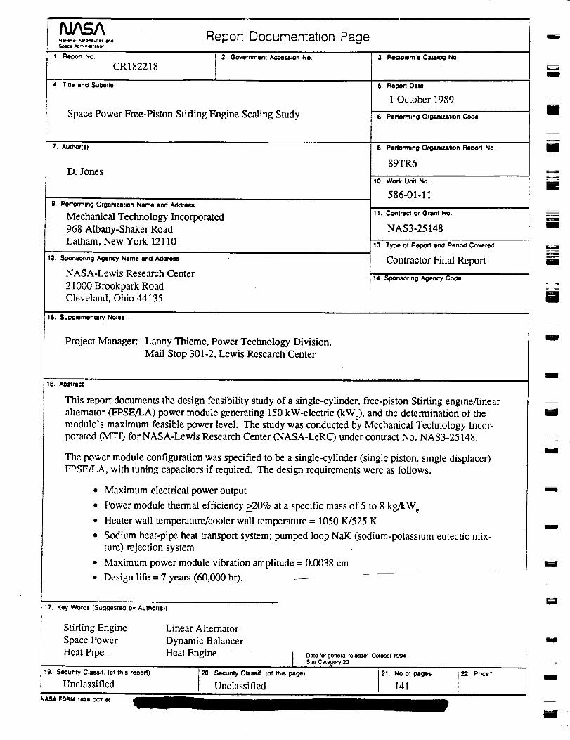
m
NUlOn_ A4Pr_SulICS L_
Soace _*n,_rihO_
I. neoon NO.
CR 182218
4, Title and Subtitle
Report Documentation Page
J 2. Government/_ceMmn No. 3 _,p_ents Catalog No.
5. Ro_n Dste
1 October 1989
Space Power Free-Piston Stirling Engine Scaling Study
7. Author(s)
D. Jones
g. Performing Orgamzabon Name and A_lreu
Mechanical Technology Incorporated
968 Albany-Shaker RoadLatham, New York 12110
12. Spons_nng Agency Name Ind Addre-,,l
NASA-Lewis Research Center
21000 Brookpark RoadCleveland, Ohio 44135
6. P•d'onmlng OrganizatiOn Cooe
8. Performing Orgiu'uz,ttmn ReDort No.
89TR6
10. Work Unit NO.
586-01- l 1
1I. Commct or Grlnt No.
NAS3-25148
13. Type of Report _ Per_ _ere_
Contractor Final Report
14. Sgonsonng Agency Coae
15. Supplementary Notes
Project Manager: Lanny Thieme, Power Technology Division,
Mall Stop 301-2, Lewis Research Center
16. Al_tric't
This report documents the design feasibility study of a single-cylinder, free-piston Stifling engine/linear
altemator (FPSE/LA) power module generating 150 kW-electric (kWe), and the determination of themodule's maximum feasible power level. The study was conducted by Mechanical Technology Incor-porated (MTI) for NASA-Lewis Research Center (NASA-LeRC) under contract No. NAS3-25148.
The power module configuration was specified to be a single-cylinder (single piston, single displacer)
FPSE/LA, with tuning capacitors if required. The design requirements were as follows:
* Maximum electrical power output
• Power module thermal efficiency >20% at a specific mass of 5 to 8 kg/kWe
• Heater wall temperature/cooler wall temperature = 1050 K/525 K
• Sodium heat-pipe heat transport system; pumped loop NaK (sodium-potassium eutectic mix-
ture) rejection system
• Maximum power module vibration amplitude = 0.0038 cm
• Design life = 7 years (60,000 hr). ---
17. Key Woros (Suggestea by Author(s))
Stirling Engine
Space Power
Heat Pipe
Linear Altemator
Dynamic Balancer
Heat Enginet Date for general release: October I gg4Star Category" 20
19. Secumy Cmssif. (of mls re0ort)
Unclassifiedi
NASA FORM _I2S OCT116
20. SeCurl_ Cla_if. (of this Nge)Unclassified 21. No141of_g_
i
i
m
mm
m
J
I
mm
i
[]
i
IBm
J
U
m
mE
i
i
i
i

¥
k...._
m
i
The results of the study show that a single-cylinder FPSE/LA is capable of meeting program goals and
has attractive scaling attributes over the power range from 25 to 150 kW e. Scaling beyond the 150-kW_
power level, the power module efficiency fails and the power module specific mass reaches 10 kg/kW at
a power output of 500 kW,.
A discussion of scaling rules for the engine, alternator, and heat transport systems is presented, along
with a detailed description of the conceptual design of a 150-kW, power module that meets the require-
ments. Included is a discussion of the design of a dynamic balance system.
A parametric study of power module performance conducted over the power output range of 25 to 150 kW e
for temperature ratios of 1.7, 2.0, 2.5, and 3.0 is presented and discussed. The results show that as the tem-
perature ratio decreases, the efficiency falls and specific mass increases. At a temperature ratio of 1.7, the
150-kW e power module cannot satisfy both efficiency and specific mass goals. As the power level in-
creases from 25 to 150 kW e at a fixed temperature ratio, power module efficiency is seen to increaseslightly, but at the expense of increased specific mass. An empirical equation relating power module ther-
mal efficiency as a function of power module specific mass, power output, and temperature ratio is
developed.
Altemative configurations to the single-cylinder, direct-coupled linear alternator approach are also
evaluated, but are shown to have technical drawbacks that lessen their attractiveness.
The dynamic balance assembly mass (moving mass and structure) represents 20 to 30% of the total
single-cylinder power module mass. Joining two modules in a balanced opposed configuration elimi-nates the need for the balancer, and a hot-end junction can be made without significant addition of struc-tural mass. Recommendations are made for evaluation of advanced heat pipe concepts, tests of radial-
flow heat exchangers, and evaluation of high-temperature alternator materials.
m
I
qb
II
m
M
ml
mE
I
IB
MI
m
_-z-_1
IB
mm
ID
lira
U
g
imm
W