
Space Debris Measurements using the Advanced … · Space Debris Measurements using the Advanced...
13
Space Debris Measurements using the Advanced Modular Incoherent Scatter Radar Michael J Nicolls SRI International, Center for Geospace Studies ABSTRACT The Advanced Modular Incoherent Scatter Radar (AMISR) is a modular, mobile UHF phased-array radar facility developed and used for scientific studies of the ionosphere. The radars are completely remotely operated and allow for pulse-to-pulse beam steering over their field-of-view. A satellite and debris tracking capability fully interleaved with scientific operations has been developed, and the AMISR systems are now used to routinely observe a large number of LEO space debris. The system makes use of wide-bandwidth radar pulses and coherent processing to detect objects as small as 5-10 cm in size through LEO, achieving a range resolution better than 20 meters for LEO targets. The interleaved operations allow for ionospheric effects on UHF space debris measurements, such as dispersion, to be assessed. The radar architecture, interleaved operations, and impact of space weather on the measurements are discussed. 1 INTRODUCTION Radar probing is the most powerful means of studying the low-Earth orbit (LEO) satellite and space debris environment. There is no other technique capable of providing high-fidelity observations on the large number of objects in LEO. The radars comprising the US Space Surveillance Network (SSN) are high-resolution systems that contribute the bulk of the publicly available information on the space environment. Radar systems capable of meeting the demanding power-aperture requirements for detecting small LEO objects are generally costly to design, build, set up, and operate. However, another community operates large-aperture, high- power radars that can provide information on the space-debris environment – the scientific community in both the US and Europe. In particular, the US National Science Foundation (NSF) and the European Incoherent Scatter Scientific Association (EISCAT) operate a network of Geospace Facilities used to probe the upper atmosphere and ionosphere. The US network consists of high-power, large-aperture, sensitive radars including the L-band Sondrestrom radar in Greenland, the UHF Millstone Hill Radar in Massachusetts, the UHF Arecibo Observatory in Puerto Rico, and the VHF Jicamarca Radio Observatory in Peru. Most recently, the NSF funded the design and construction of a modern phased-array radar called the Advanced Modular Incoherent Scatter Radar (AMISR). AMISR systems are UHF phased-array radars comprised of building-block-like panels for modularity and relocatability, designed with the intention of deploying systems to many locations to pursue new avenues of scientific research. The AMISR systems are completely remotely operated and allow for pulse-to-pulse beam steering over their field- of-view, resulting in great flexibility for satellite and debris studies. Moreover, the flexible software-based operations allow for the interleaving of different experiments on a pulse-to-pulse basis. This capability has been applied for the purposes of detecting and refining the orbits of satellites and space debris that appear in the public catalogue. In this paper, we describe the AMISR system and present some results from its satellite and debris tracking studies. 2 AMISR SYSTEM DESCRIPTION 2.1 General Incoherent scatter radar (ISR) is one of the most powerful remote-sensing technologies for probing the ionospheric plasma. ISRs measure many of the parameters needed to describe the state and energy balance of this plasma (e.g., electron number density, electron and ion temperatures, bulk ion motion, ion masses, and ion-neutral collision frequency). Furthermore, they do this in a spatially resolved sense over regions extending hundreds of kilometers in the hemisphere centered on the radar, and can measure the variations in the ionospheric state continuously over timescales from hours to days. Time resolutions can be as short as a few seconds per altitude profile and a few minutes for measurements spanning a range of altitudes and ground distances from the ISR.
-
Upload
vuongkhanh -
Category
Documents
-
view
215 -
download
0
Transcript of Space Debris Measurements using the Advanced … · Space Debris Measurements using the Advanced...
Space Debris Measurements using the Advanced Modular Incoherent Scatter Radar
Michael J Nicolls SRI International, Center for Geospace Studies
ABSTRACT The Advanced Modular Incoherent Scatter Radar (AMISR) is a modular, mobile UHF phased-array radar facility developed and used for scientific studies of the ionosphere. The radars are completely remotely operated and allow for pulse-to-pulse beam steering over their field-of-view. A satellite and debris tracking capability fully interleaved with scientific operations has been developed, and the AMISR systems are now used to routinely observe a large number of LEO space debris. The system makes use of wide-bandwidth radar pulses and coherent processing to detect objects as small as 5-10 cm in size through LEO, achieving a range resolution better than 20 meters for LEO targets. The interleaved operations allow for ionospheric effects on UHF space debris measurements, such as dispersion, to be assessed. The radar architecture, interleaved operations, and impact of space weather on the measurements are discussed.
1 INTRODUCTION Radar probing is the most powerful means of studying the low-Earth orbit (LEO) satellite and space debris environment. There is no other technique capable of providing high-fidelity observations on the large number of objects in LEO. The radars comprising the US Space Surveillance Network (SSN) are high-resolution systems that contribute the bulk of the publicly available information on the space environment. Radar systems capable of meeting the demanding power-aperture requirements for detecting small LEO objects are generally costly to design, build, set up, and operate. However, another community operates large-aperture, high-power radars that can provide information on the space-debris environment – the scientific community in both the US and Europe. In particular, the US National Science Foundation (NSF) and the European Incoherent Scatter Scientific Association (EISCAT) operate a network of Geospace Facilities used to probe the upper atmosphere and ionosphere. The US network consists of high-power, large-aperture, sensitive radars including the L-band Sondrestrom radar in Greenland, the UHF Millstone Hill Radar in Massachusetts, the UHF Arecibo Observatory in Puerto Rico, and the VHF Jicamarca Radio Observatory in Peru. Most recently, the NSF funded the design and construction of a modern phased-array radar called the Advanced Modular Incoherent Scatter Radar (AMISR). AMISR systems are UHF phased-array radars comprised of building-block-like panels for modularity and relocatability, designed with the intention of deploying systems to many locations to pursue new avenues of scientific research. The AMISR systems are completely remotely operated and allow for pulse-to-pulse beam steering over their field-of-view, resulting in great flexibility for satellite and debris studies. Moreover, the flexible software-based operations allow for the interleaving of different experiments on a pulse-to-pulse basis. This capability has been applied for the purposes of detecting and refining the orbits of satellites and space debris that appear in the public catalogue. In this paper, we describe the AMISR system and present some results from its satellite and debris tracking studies.
2 AMISR SYSTEM DESCRIPTION
2.1 General Incoherent scatter radar (ISR) is one of the most powerful remote-sensing technologies for probing the ionospheric plasma. ISRs measure many of the parameters needed to describe the state and energy balance of this plasma (e.g., electron number density, electron and ion temperatures, bulk ion motion, ion masses, and ion-neutral collision frequency). Furthermore, they do this in a spatially resolved sense over regions extending hundreds of kilometers in the hemisphere centered on the radar, and can measure the variations in the ionospheric state continuously over timescales from hours to days. Time resolutions can be as short as a few seconds per altitude profile and a few minutes for measurements spanning a range of altitudes and ground distances from the ISR.
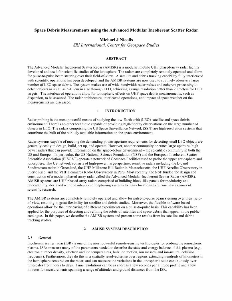
AMISR systems are modular, remotely operated, UHF 2D phased-array radars comprised of a number of building block-like panels. SRI International, with funding from the NSF, developed the AMISR technology. SRI designed, constructed, and now operates and manages, two AMISR facilities that are used to study the upper atmosphere and observe space-weather events. One operates at the Poker Flat Research Range in Alaska, and is named the Poker Flat Incoherent Scatter Radar (PFISR). It was deployed in 2006 (see Figure 2.1, top left). Two AMISR faces have been deployed to Resolute Bay, Nunavut, Canada and are named RISR-N and RISR-C (see Figure 2.1, top right). These radars are used for basic ionospheric and space weather research. AMISR’s modular configuration was designed for relative ease of relocation so that upper atmospheric activity can be studied around the globe. Remote operation and electronic beam steering allow researchers to operate and position the radar beam on a pulse-to-pulse basis to accurately measure rapidly changing space-weather events. AMISR is the only ISR in operation capable of electronic pulse-to-pulse beam steering, and this is enabled by the phased-array antenna. This rapid steering capability allows scientists to resolve temporal/spatial ambiguities inherent in measurements from mechanically steered dish-based systems. PFISR is continuously operated and has an up-time of greater than 95%. This is especially significant since the system is based on remote, unattended operations in an arctic environment. Smaller AMISR systems have been deployed at the High Altitude Auroral Research Program (HAARP) in Gakona, Alaska (Figure 2.1, bottom right) and at the Jicamarca Radio Observatory outside of Lima, Peru (Figure 2.1, bottom left).
2.2 AMISR Architecture and Specifications The AMISR concept entails the use of many identical electronic subsystems, yielding a high degree of redundancy and a robust response to hardware failures. The systems have on the whole proven to be very reliable, as evidenced by PFISR’s up-time of greater than 95%. Individual components have experienced the anticipated rate of failures, but individual failures do not take down the entire system. In a practical sense, this means that while failures do
Figure 2.1 (Top Left) The Poker Flat Incoherent Scatter Radar (PFISR) 128-panel AMISR system. (Top Right) The Resolute Bay Incoherent Scatter Radar (RISR-N) 121-panel AMISR system. (Bottom Left) The 14-panel AMISR system at the Jicamarca Radio Observatory in Peru. (Bottom Right) The 16-panel AMISR system at the High Altitude Auroral Research Program (HAARP).

occur in the complex electronics, they can be addressed during planned maintenance. This redundancy is largely responsible for AMISR’s amenability to unattended remote operations. We are not aware of any systems with similar capabilities that can be operated with so little on-site staffing.
Figure 2.2 AMISR system components The AMISR systems are highly modular. The subsystems operate synchronously via a combination of Ethernet/software constructs and specialized hardware signaling. Figure 2.2 shows the components of an AMISR system. The overall control of the system is driven from an Operation and Control Center (OCC) that houses general-purpose computers as well as low-level RF-signal conditioning modules that comprise the AMISR Control System (ACS). Physically, the OCC is an environmentally controlled shelter or building available for on-site operators (visiting during planned maintenance trips), though most interactions with the system in fact occur over the local area network whether the operator is in the OCC or not. The OCC also houses the data acquisition channels, and contains the source for the transmitted waveforms and receives RF signals from the array. RF transmit signals are distributed to array elements using a corporate feed network on the face and the timing signals pass through a set of fiber-optic cables. The prime power for the radar is routed through two Utility Distribution Unit (UDU) vans. The radar runs off aircraft-standard 400-Hz power, which is generated by FMC JetPower units, one for every 16 AMISR panels, and up to four power units are located in an UDU van. The majority of radar components are distributed on the steel array support structure. A full radar face consists of one hundred twenty-eight identical AMISR panels nominally arranged in a densely packed and roughly square configuration. Each panel contains a Panel Control Unit (PCU) for state control and for monitoring the condition of the 32 Antenna Element Units (AEUs) on that panel. The PCUs each include a fully programmable Linux computer so that the functionality of the array can be adjusted and upgraded over time. Each AEU consists of low-level RF circuitry for phase control on transmit and receive, a low-noise amplifier that sets the overall system receive sensitivity, a Solid State Power Amplifier (SSPA) to generate the transmitter RF, a power supply, and digital control and communications electronics.
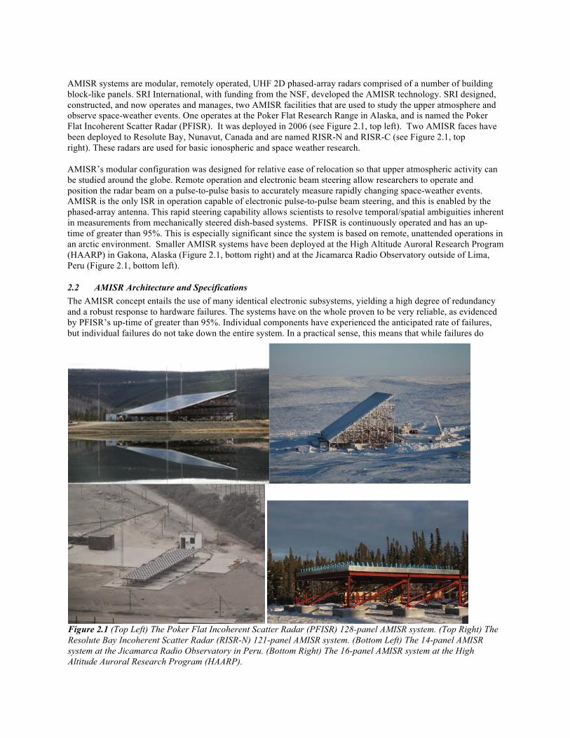
A standard AMISR face contains 128 identical panels, arranged in a 30x30 meter roughly square configuration on a steel superstructure. That organization yields a total of 4096 AEUs, each transmitting at 500 Watts, producing a total peak transmit power of approximately 2 MW. The SSPAs are capable of transmitting a pulse length of up to 2 ms with a 10% duty cycle and operate in a frequency range of 430 to 450 MHz. A variety of different phase coding schemes can be applied to the pulse. The system specifications are listed in Table 2.1.
The electronically formed beam for a full face has a ~1.1o beam width and can be steered on a pulse-to-pulse basis to over 10,000 preset locations within the field-of-view. The field-of-view is determined by the grating-lobe-free scan region of the array, which is depicted in Figure 2.3 for PFISR at three different altitudes. The star-shaped pattern is a result of the hexagonal arrangement of the elements. The phasing is done via a physical-path time-delay board located within each AEU. The time-delay weights for each steering direction are preprogrammed and loaded on demand into the delay shifters at the start of each pulse. Phase calibration is performed using near-field sources combined with electromagnetic modeling. The calibration is verified by listening to radio stars and other noise sources as well as tracking satellites. During normal operations, a calibration signal is injected to measure the system noise. In addition, a telemetry stream is captured from each AEU consisting of measurements of voltage, current, temperature and estimates of forward and reflected power. These are stored for long term monitoring of the system health.
AMISR is remotely operated and runs autonomously for a majority of the time. The system software is based around a modular framework called the Data Transport Network [1], which orchestrates the large number of processes that are responsible for communicating with the various hardware subsystems, health and status monitoring, data collection, and experiment scheduling. A set of web-based displays allow for monitoring of the system performance and real-time data products. The autonomous operations are based on a set of prioritized schedules. For further details of this setup, see Reference [2].
Table 2.1 AMISR system specifications Specification AMISR Frequency of Operation 430-450 MHz Pulse length 1 us – 2 ms Max RF Duty Cycle 10% Steering Pulse-to-pulse over +/-25-35o System Temperature ~120 K Specification AMISR panel AMISR 32-panel face
(representative of future deployments for satellite tracking)
AMISR 128-panel face (PFISR)
Peak Power 16 kW 512 kW 2.05 MW Antenna Aperture ~5.6 m2 ~180 m2 ~715 m2 Antenna Gain ~20 dBi ~35 dBi ~41 dBi Peak Effective Isotropically Radiated Power (EIRP)
2.5 MW 80 MW 320 MW
Smallest detectable object at 1000 km slant-range with 0.1 second integration
13 m 7 cm 3 cm
Figure 2.3 Grating-lobe free region of PFISR at 100, 300, and 500 km altitude.

2.3 AMISR Sensitivity The sensitivity of an AMISR system to an object of a given diameter depends on a number of factors, which were enumerated in Reference [3]. Most critically, an AMISR system’s sensitivity will depend on the number of radar panels and be highly dependent on the slant-range to the target and the coherent integration time. Figure 2.4 shows the minimum detectable RCS for two levels of integration time – 20 ms and 200 ms (corresponding to 1 and 10 radar pulses, respectively). These plots indicate that a 128-panel AMISR system can detect 5-cm objects at 1300 km slant-range with a 20-ms integration time. This altitude is increased to nearly 2500 km with 200-ms integration time. A 32-panel AMISR system is capable of detecting 10-cm objects at 1500-km slant-range with a reasonable integration time. The last row of Table 2.1 shows the minimum object size detectable at 1000-km range with a 100-ms integration time.
Figure 2.4 Minimum detectable radar cross-section as a function of the number of panels and the slant-range to the target for (left) a 20-ms integration time and (right) a 200-ms integration time. The dashed line show contours of constant diameter using the RCS model described in Reference [3].
3 AMISR FOR SATELLITE AND DEBRIS TRACKING
3.1 Incoherent Scattering Owing to their transmit power and gain, AMISR systems are sensitive to reflections from satellites and space debris. This is demonstrated in Figure 3.1, which shows line-of-sight (LOS) velocities measured by RISR-N over a 24-hour period from five different look directions. The velocities generally represent the bulk motion of the ions that comprise the ionospheric plasma. However, the signals are replete with satellite clutter above 400-km altitude.
Incoherent scatter (IS) is thermal backscatter from ionospheric electrons (e.g., see Reference [4]). The incoherent scatter backscatter cross-section is given by [4]
� = �e(1+↵2)(1+Te/Ti+↵2)
where σe is the radar cross-section of an electron, Te and Ti are the electron and ion temperatures, and α is a wavelength-dependent plasma Debye-length term. The total received power is then proportional to the total number of electrons within the illuminated volume, and thus the electron number density Ne, as well as the power-aperture product. The received power decreases as 1/R2,
Ps / PtAeffNe�R2
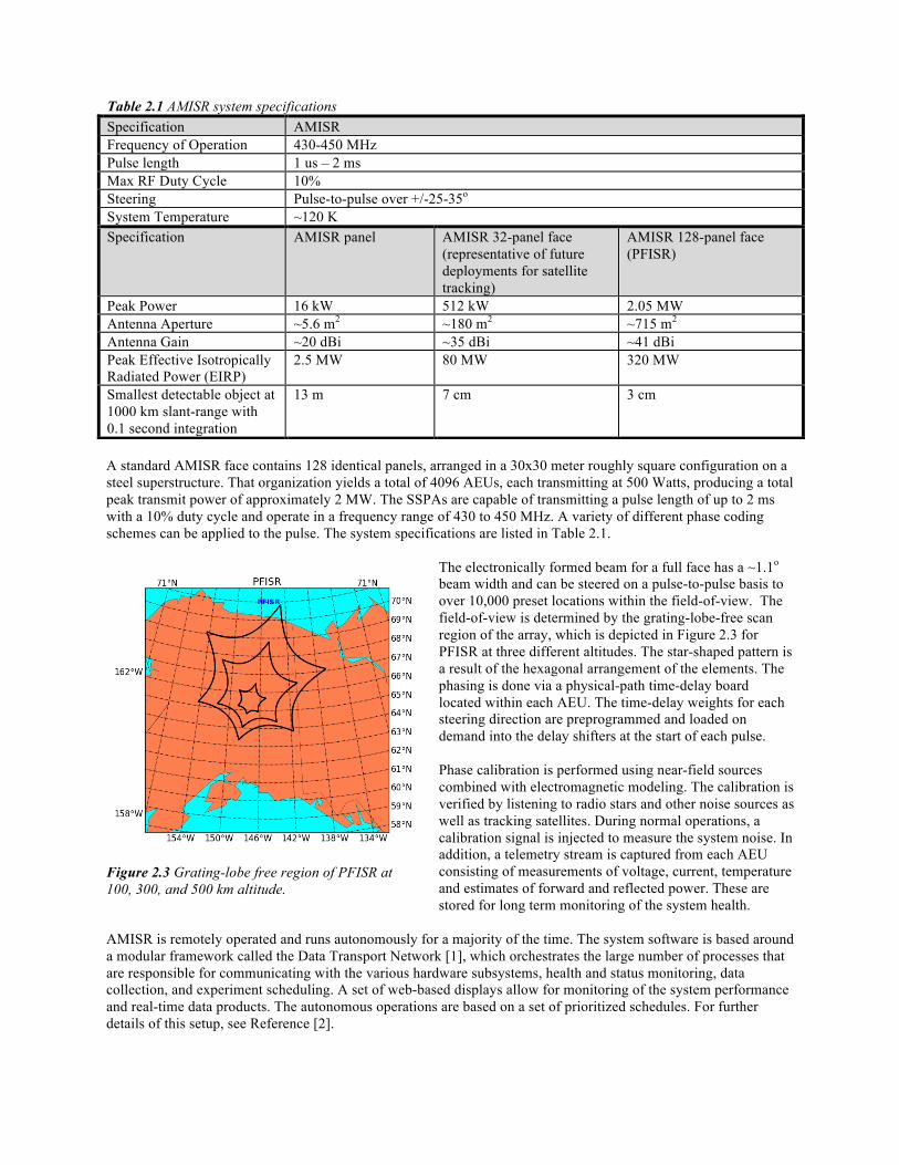
The end result is that ISRs can effectively profile the electron number density, as well as other properties of the medium through interpretation of the IS Doppler spectrum [4]. For the purposes of satellite and space debris tracking, electron-density measurements are critical for correcting range measurements for ionospheric delays in the UHF band. To first order, the phase delay incurred by electromagnetic waves through the ionosphere is 40.3 TEC / f2, where TEC is the total electron content (units of electrons per m2) and f is the operating frequency (in Hz). Two-way range delays are in the range of 10-100 meters, and highly variable because of variability in high-latitude ionospheric conditions. The direct Ne measurements provided by the ISR technique allow for correction of the range measurements to a level of accuracy not achievable by modeling or other means.
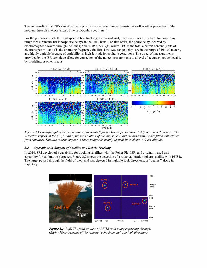
3.2 Operations in Support of Satellite and Debris Tracking In 2014, SRI developed a capability for tracking satellites with the Poker Flat ISR, and originally used this capability for calibration purposes. Figure 3.2 shows the detection of a radar calibration sphere satellite with PFISR. The target passed through the field-of-view and was detected in multiple look directions, or “beams,” along its trajectory.
Figure 3.2 (Left) The field-of-view of PFISR with a target passing through. (Right) Measurements of the returned echo from multiple look directions.
Figure 3.1 Line-of-sight velocities measured by RISR-N for a 24-hour period from 5 different look directions. The velocities represent the projection of the bulk motion of the ionosphere, but the observations are filled with clutter from satellites. Satellite returns appear in these images as nearly vertical lines above 400-km altitude.
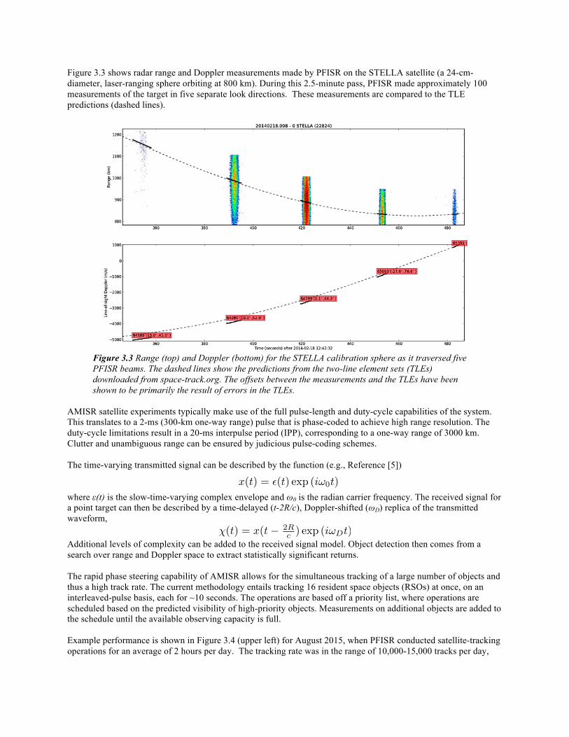
Figure 3.3 shows radar range and Doppler measurements made by PFISR on the STELLA satellite (a 24-cm-diameter, laser-ranging sphere orbiting at 800 km). During this 2.5-minute pass, PFISR made approximately 100 measurements of the target in five separate look directions. These measurements are compared to the TLE predictions (dashed lines).
Figure 3.3 Range (top) and Doppler (bottom) for the STELLA calibration sphere as it traversed five PFISR beams. The dashed lines show the predictions from the two-line element sets (TLEs) downloaded from space-track.org. The offsets between the measurements and the TLEs have been shown to be primarily the result of errors in the TLEs.
AMISR satellite experiments typically make use of the full pulse-length and duty-cycle capabilities of the system. This translates to a 2-ms (300-km one-way range) pulse that is phase-coded to achieve high range resolution. The duty-cycle limitations result in a 20-ms interpulse period (IPP), corresponding to a one-way range of 3000 km. Clutter and unambiguous range can be ensured by judicious pulse-coding schemes. The time-varying transmitted signal can be described by the function (e.g., Reference [5]) where ε(t) is the slow-time-varying complex envelope and ω0 is the radian carrier frequency. The received signal for a point target can then be described by a time-delayed (t-2R/c), Doppler-shifted (ωD) replica of the transmitted waveform,
�(t) = x(t� 2Rc ) exp (i!Dt)
Additional levels of complexity can be added to the received signal model. Object detection then comes from a search over range and Doppler space to extract statistically significant returns. The rapid phase steering capability of AMISR allows for the simultaneous tracking of a large number of objects and thus a high track rate. The current methodology entails tracking 16 resident space objects (RSOs) at once, on an interleaved-pulse basis, each for ~10 seconds. The operations are based off a priority list, where operations are scheduled based on the predicted visibility of high-priority objects. Measurements on additional objects are added to the schedule until the available observing capacity is full. Example performance is shown in Figure 3.4 (upper left) for August 2015, when PFISR conducted satellite-tracking operations for an average of 2 hours per day. The tracking rate was in the range of 10,000-15,000 tracks per day,
x(t) = ✏(t) exp (i!0t)
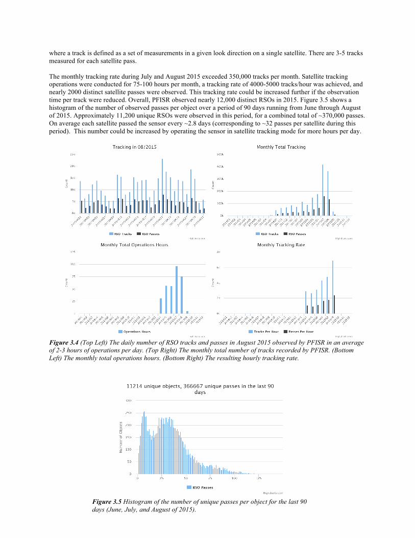
where a track is defined as a set of measurements in a given look direction on a single satellite. There are 3-5 tracks measured for each satellite pass. The monthly tracking rate during July and August 2015 exceeded 350,000 tracks per month. Satellite tracking operations were conducted for 75-100 hours per month, a tracking rate of 4000-5000 tracks/hour was achieved, and nearly 2000 distinct satellite passes were observed. This tracking rate could be increased further if the observation time per track were reduced. Overall, PFISR observed nearly 12,000 distinct RSOs in 2015. Figure 3.5 shows a histogram of the number of observed passes per object over a period of 90 days running from June through August of 2015. Approximately 11,200 unique RSOs were observed in this period, for a combined total of ~370,000 passes. On average each satellite passed the sensor every ~2.8 days (corresponding to ~32 passes per satellite during this period). This number could be increased by operating the sensor in satellite tracking mode for more hours per day.
Figure 3.4 (Top Left) The daily number of RSO tracks and passes in August 2015 observed by PFISR in an average of 2-3 hours of operations per day. (Top Right) The monthly total number of tracks recorded by PFISR. (Bottom Left) The monthly total operations hours. (Bottom Right) The resulting hourly tracking rate.
Figure 3.5 Histogram of the number of unique passes per object for the last 90 days (June, July, and August of 2015).
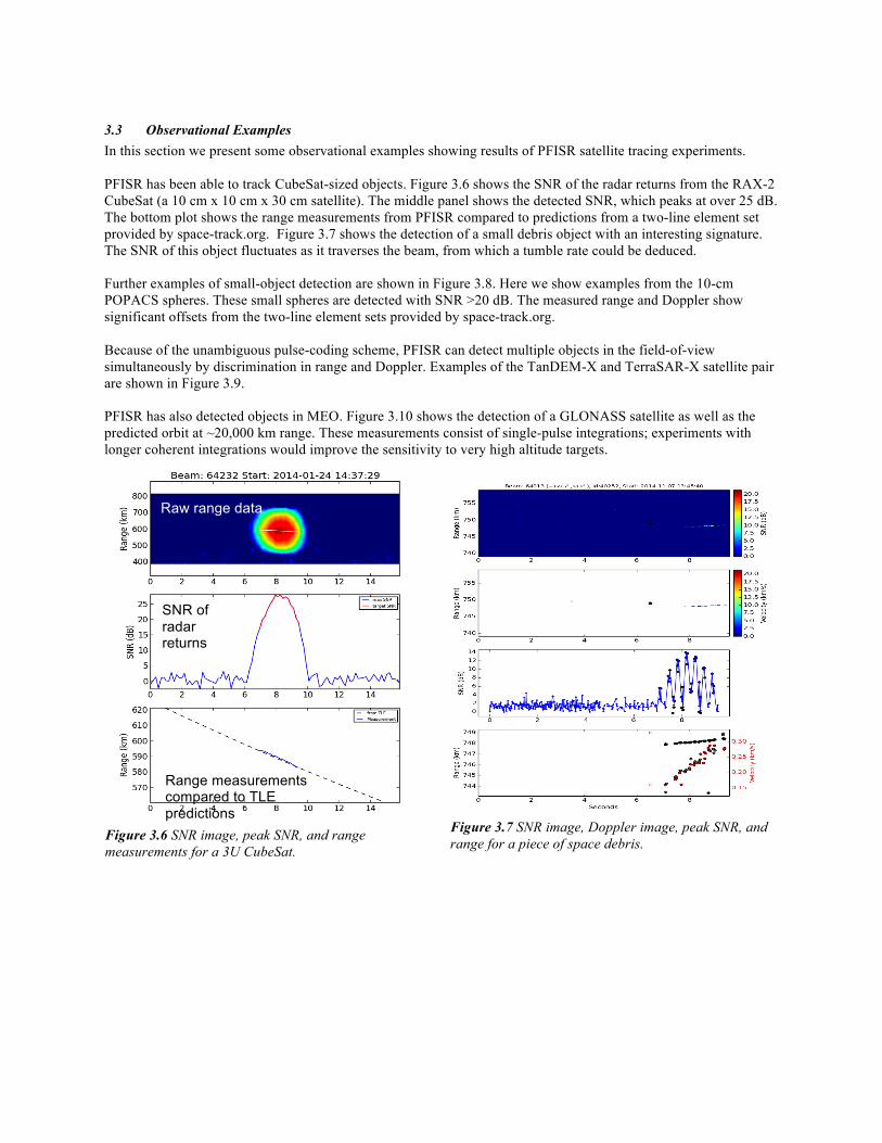
3.3 Observational Examples In this section we present some observational examples showing results of PFISR satellite tracing experiments. PFISR has been able to track CubeSat-sized objects. Figure 3.6 shows the SNR of the radar returns from the RAX-2 CubeSat (a 10 cm x 10 cm x 30 cm satellite). The middle panel shows the detected SNR, which peaks at over 25 dB. The bottom plot shows the range measurements from PFISR compared to predictions from a two-line element set provided by space-track.org. Figure 3.7 shows the detection of a small debris object with an interesting signature. The SNR of this object fluctuates as it traverses the beam, from which a tumble rate could be deduced. Further examples of small-object detection are shown in Figure 3.8. Here we show examples from the 10-cm POPACS spheres. These small spheres are detected with SNR >20 dB. The measured range and Doppler show significant offsets from the two-line element sets provided by space-track.org. Because of the unambiguous pulse-coding scheme, PFISR can detect multiple objects in the field-of-view simultaneously by discrimination in range and Doppler. Examples of the TanDEM-X and TerraSAR-X satellite pair are shown in Figure 3.9. PFISR has also detected objects in MEO. Figure 3.10 shows the detection of a GLONASS satellite as well as the predicted orbit at ~20,000 km range. These measurements consist of single-pulse integrations; experiments with longer coherent integrations would improve the sensitivity to very high altitude targets.
Figure 3.6 SNR image, peak SNR, and range measurements for a 3U CubeSat.
Figure 3.7 SNR image, Doppler image, peak SNR, and range for a piece of space debris.
Raw range data
SNR of radar returns
Range measurements compared to TLE predictions
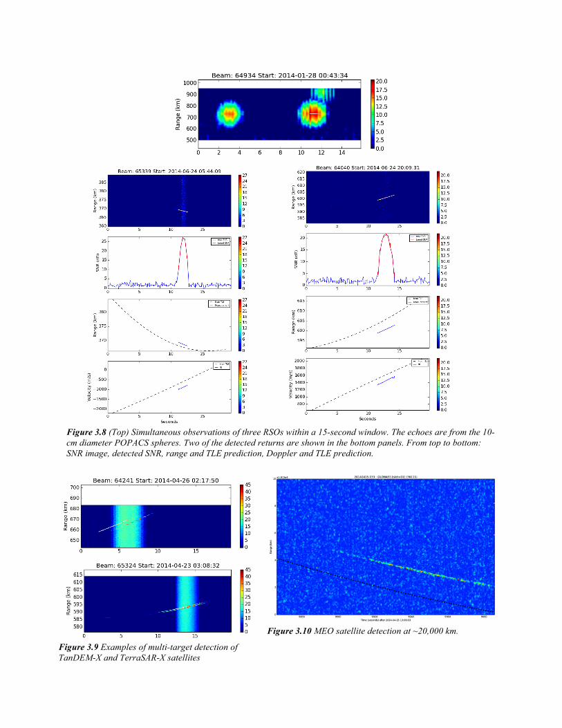
Figure 3.8 (Top) Simultaneous observations of three RSOs within a 15-second window. The echoes are from the 10-cm diameter POPACS spheres. Two of the detected returns are shown in the bottom panels. From top to bottom: SNR image, detected SNR, range and TLE prediction, Doppler and TLE prediction.
Figure 3.9 Examples of multi-target detection of TanDEM-X and TerraSAR-X satellites
Figure 3.10 MEO satellite detection at ~20,000 km.
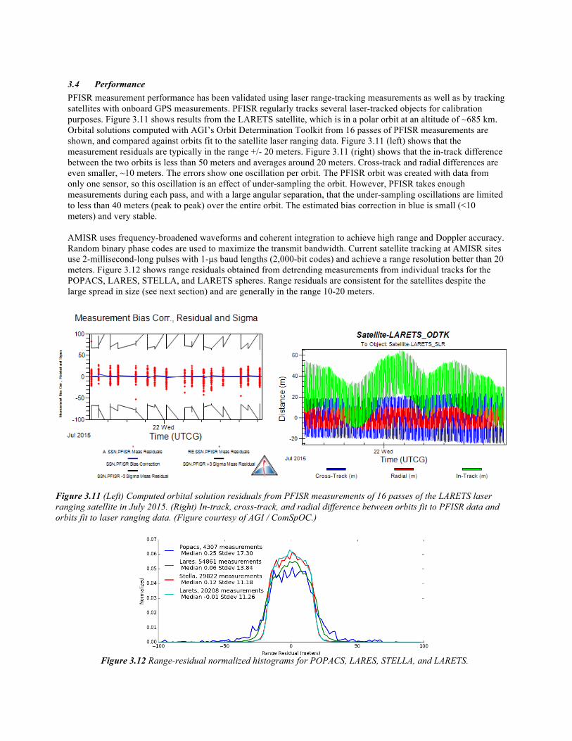
3.4 Performance PFISR measurement performance has been validated using laser range-tracking measurements as well as by tracking satellites with onboard GPS measurements. PFISR regularly tracks several laser-tracked objects for calibration purposes. Figure 3.11 shows results from the LARETS satellite, which is in a polar orbit at an altitude of ~685 km. Orbital solutions computed with AGI’s Orbit Determination Toolkit from 16 passes of PFISR measurements are shown, and compared against orbits fit to the satellite laser ranging data. Figure 3.11 (left) shows that the measurement residuals are typically in the range +/- 20 meters. Figure 3.11 (right) shows that the in-track difference between the two orbits is less than 50 meters and averages around 20 meters. Cross-track and radial differences are even smaller, ~10 meters. The errors show one oscillation per orbit. The PFISR orbit was created with data from only one sensor, so this oscillation is an effect of under-sampling the orbit. However, PFISR takes enough measurements during each pass, and with a large angular separation, that the under-sampling oscillations are limited to less than 40 meters (peak to peak) over the entire orbit. The estimated bias correction in blue is small (<10 meters) and very stable. AMISR uses frequency-broadened waveforms and coherent integration to achieve high range and Doppler accuracy. Random binary phase codes are used to maximize the transmit bandwidth. Current satellite tracking at AMISR sites use 2-millisecond-long pulses with 1-µs baud lengths (2,000-bit codes) and achieve a range resolution better than 20 meters. Figure 3.12 shows range residuals obtained from detrending measurements from individual tracks for the POPACS, LARES, STELLA, and LARETS spheres. Range residuals are consistent for the satellites despite the large spread in size (see next section) and are generally in the range 10-20 meters.
Figure 3.12 Range-residual normalized histograms for POPACS, LARES, STELLA, and LARETS.
Figure 3.11 (Left) Computed orbital solution residuals from PFISR measurements of 16 passes of the LARETS laser ranging satellite in July 2015. (Right) In-track, cross-track, and radial difference between orbits fit to PFISR data and orbits fit to laser ranging data. (Figure courtesy of AGI / ComSpOC.)
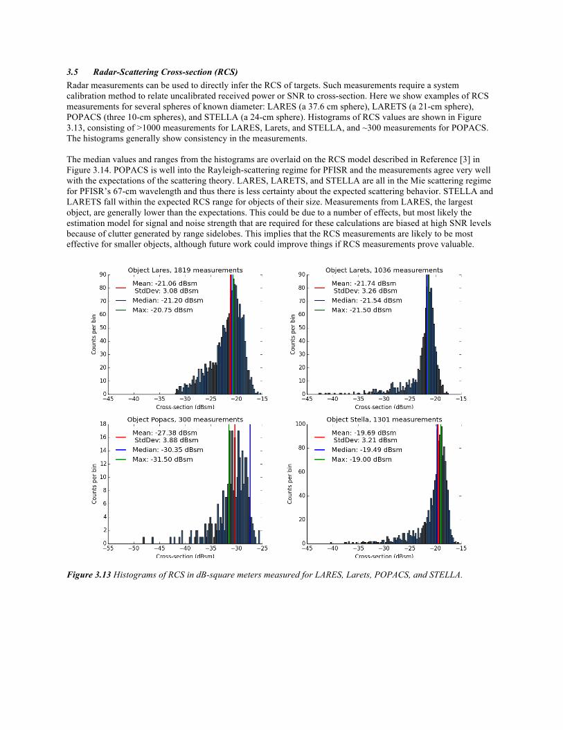
3.5 Radar-Scattering Cross-section (RCS) Radar measurements can be used to directly infer the RCS of targets. Such measurements require a system calibration method to relate uncalibrated received power or SNR to cross-section. Here we show examples of RCS measurements for several spheres of known diameter: LARES (a 37.6 cm sphere), LARETS (a 21-cm sphere), POPACS (three 10-cm spheres), and STELLA (a 24-cm sphere). Histograms of RCS values are shown in Figure 3.13, consisting of >1000 measurements for LARES, Larets, and STELLA, and ~300 measurements for POPACS. The histograms generally show consistency in the measurements. The median values and ranges from the histograms are overlaid on the RCS model described in Reference [3] in Figure 3.14. POPACS is well into the Rayleigh-scattering regime for PFISR and the measurements agree very well with the expectations of the scattering theory. LARES, LARETS, and STELLA are all in the Mie scattering regime for PFISR’s 67-cm wavelength and thus there is less certainty about the expected scattering behavior. STELLA and LARETS fall within the expected RCS range for objects of their size. Measurements from LARES, the largest object, are generally lower than the expectations. This could be due to a number of effects, but most likely the estimation model for signal and noise strength that are required for these calculations are biased at high SNR levels because of clutter generated by range sidelobes. This implies that the RCS measurements are likely to be most effective for smaller objects, although future work could improve things if RCS measurements prove valuable.
Figure 3.13 Histograms of RCS in dB-square meters measured for LARES, Larets, POPACS, and STELLA.

Figure 3.14 Overlay of median RCS values and range on the RCS model described in Reference [3].
4 SUMMARY AND FUTURE WORK In this paper we have summarized the capabilities of AMISR for space debris and satellite tracking. This radar system was originally developed for ionospheric science and has been demonstrated to be an extremely capable tool for satellite tracking. SRI developed an interleaved operating mode so that scientific and satellite-tracking missions can be conducted concurrently. AMISR’s electronic steering capability enables it to observe greater than 4000 satellites per hour. Its scientific heritage gives it the ability to precisely correct for ionospheric delays in satellite measurements, one of the major sources of range biases at UHF. These corrections, and its large peak power, enables AMISR to track satellites with 20-meter range resolution. AMISR was designed to be highly redundant and remotely operated so that systems can be placed around the globe in locations of interest for science. The data products will be of use to satellite operators interested in high quality, prioritized satellite and debris observations.
5 REFERENCES [1] T. A. Valentic, "The Data Transport Network: A Usenet-Based Approach For Data Retrieval From Remote Field
Sites," AGU Fall Meeting Abstracts, p. A7, 2005. [2] T. Valentic et al., "AMISR the advanced modular incoherent scatter radar," in 2013 IEEE International
Symposium on Phased Array Systems & Technology, Boston, MA, pp. 659-663. [3] D. Oltrogge, P. North, and M. Nicolls, "Multi-phenomenology Observation Network Evaluation Tool
(MONET)," in AMOS 2014, Wailea, Maui. [4] J. V. Evans, "Theory and practice of ionosphere study by Thomson scatter radar," Proceedings of the IEEE, vol.
57, no. 4, pp. 496-530, 1969. [5] J. Markkanen, M. Lehtinen, and M. Landgraf, "Real-time space debris monitoring with EISCAT," Advances in
Space Research, vol. 35, no. 7, pp. 1197-1209, 2005.
6 ACKNOWLEDGMENTS This work was supported by the US National Science Foundation under NSF Cooperative Agreement AGS-1133009. MJN acknowledges the contributions of John Kelly and the entire AMISR team at SRI International as well as the close collaboration with Analytical Graphics Inc. and ComSpOC. MJN acknowledges Dr. Daniel Ceperley (SRI International) for a careful reading of this manuscript.


