
SP8011 LTE User Manual - DIYTrade.com...of LTE system simulator, LTE signal generator and LTE signal...
246
SP8011 LTE User Manual V V 2 2 . . 0 0 Beijing StartPoint Technology Co., Ltd
Transcript of SP8011 LTE User Manual - DIYTrade.com...of LTE system simulator, LTE signal generator and LTE signal...

SP8011 LTE User Manual
VV22..00
BBeeiijjiinngg SSttaarrttPPooiinntt TTeecchhnnoollooggyy CCoo..,, LLttdd

Beijing StarPort Technology Co., Ltd.
i
COPYRIGHT NOTICES Beijing StartPoint Technology Co., [email protected] right, all rights reserved.
Unless permitted by Beijing StartPoint Technology Co., Ltd in writing, any person or entity shall not alter or extract any part of this manual in any form.

Beijing StarPort Technology Co., Ltd.
ii
TABLE OF CONTENTS
COPYRIGHT NOTICES .................................................................................................................................................... I
1. FOREWORD .............................................................................................................................................................. 1
1.1.PRODUCT OVERVIEW ............................................................................................................................................. 1
1.2.USER MANUAL CONTENTS ...................................................................................................................................... 2
1.3.VOCABULARY ......................................................................................................................................................... 2
2. CALL HANDLING .................................................................................................................................................... 5
2.1.LTE PRINCIPLE ...................................................................................................................................................... 5
2.2.LTE SYSTEM ARCHITECTURE ................................................................................................................................ 5
2.2.1.E-UTRAN structure...................................................................................................................................... 6
2.2.2.LTE air interface (Uu) structure .................................................................................................................. 6
2.2.3.LTE channel ................................................................................................................................................. 6
2.2.4.Frequency and channel number .................................................................................................................. 8
2.3.OPERATION MODES ................................................................................................................................................ 10
2.3.1.Active Cell Mode ......................................................................................................................................... 10
2.3.2.LTE Analyze Mode ..................................................................................................................................... 11
2.3.3.CW mode ..................................................................................................................................................... 12
2.3.4.Cell Off mode .............................................................................................................................................. 12
2.4.PROTOCOL STACK CONFIGURATION ...................................................................................................................... 12
2.4.1.Cell configuration ....................................................................................................................................... 14
2.4.2.Uplink and downlink configuration ........................................................................................................... 18
2.4.3.Call configuration ...................................................................................................................................... 36
2.5.CALLING PROCESS ............................................................................................................................................... 37
2.5.1.Calling state ................................................................................................................................................ 37
2.5.2.Position update ........................................................................................................................................... 38
2.5.3.Establishment of connection to the UE ..................................................................................................... 38
2.6.TERMINAL INFORMATION ...................................................................................................................................... 39
2.6.1.Basic terminal information ........................................................................................................................ 39
3. TEST ITEMS ............................................................................................................................................................ 40
3.1.TEST ITEMS OVERVIEW .......................................................................................................................................... 40
3.2.GENERAL DESCRIPTION OF TEST ITEMS ................................................................................................................ 41
3.2.1.Adjacent channel leakage power ratio test ................................................................................................ 41

Beijing StarPort Technology Co., Ltd.
iii
3.2.2.Automatic frequency calibration test (TDD Burst Frequency Calibrate) ................................................ 49
3.2.3.Automatic power calibration test (TDD Burst Power Calibrate) .............................................................. 51
3.2.4.Aggregate power control tolerance test ...................................................................................................... 55
3.2.5.Absolute power control tolerance test (Aggregate Power Tolerance) ....................................................... 59
3.2.6.Throughput capacity test (UL & DL Throughput) .................................................................................... 63
3.2.7.Channel state information report test (Channel State Information) ........................................................ 67
3.2.8.Continuous wave test (Continuous Wave) ................................................................................................. 72
3.2.9.Fast power calibration test (Fast Power Calibration) ............................................................................... 73
3.2.10.Frequency error test (Frequency Error) .................................................................................................. 76
3.2.11.Minimum output power test (Minimum Output Power) .......................................................................... 80
3.2.12.Occupied bandwidth test (Occupied Bandwidth) ..................................................................................... 84
3.2.13.Performance test (Performance Test) ...................................................................................................... 89
3.2.14.ON/OFF time mask test (ON/OFF Time Mask) ...................................................................................... 94
3.2.15.Relative power control tolerance test (Relative Power Tolerance) ........................................................ 103
3.2.16.Spectrum emission mask test (Spectrum Emission Mask) .................................................................... 113
3.2.17.Spectrum monitoring test (Spectrum Monitor) ...................................................................................... 120
3.2.18.Transmit power test (Transmit Power) ................................................................................................... 125
3.2.19.Transmit signal quality test (Transmit Signal Quality) ......................................................................... 135
3.2.20.Terminal report results test (UE Report) ............................................................................................... 151
4. SYSTEM CONFIGURATION .............................................................................................................................. 153
4.1.SYSTEM PARAMETER CONFIGURATION ............................................................................................................... 153
4.1.1.SYS Tim parameter setting ....................................................................................................................... 153
4.1.2.Ref Frequency parameter setting ............................................................................................................. 154
4.1.3.RF Port parameter setting ........................................................................................................................ 155
4.1.4.Connect Detect parameter setting ............................................................................................................ 156
4.1.5.Master-slave instrument parameter setting ............................................................................................. 157
4.1.6.GPIB Address parameter setting .............................................................................................................. 160
4.1.7.IP Address parameter setting ................................................................................................................... 160
4.1.8.System Information parameter setting ..................................................................................................... 160
4.1.9.Protocol Revision parameter setting ........................................................................................................ 162
4.1.10.Print Screen parameter setting ............................................................................................................... 162
4.1.11.Delete parameter configuration ............................................................................................................. 163
5. MANUAL OPERATION ....................................................................................................................................... 164
5.1.SP8011 PANEL OVERVIEW .................................................................................................................................... 164

Beijing StarPort Technology Co., Ltd.
iv
5.1.1.Front panel view illustration .................................................................................................................... 164
5.1.2.Back panel view illustration ..................................................................................................................... 166
5.2.SETTING PRIOR TO EQUIPMENT EMPLOYMENT ................................................................................................... 167
5.3.PROTOCOL STACK PARAMETER SETTING ............................................................................................................ 169
5.3.1.Setting call parameters ............................................................................................................................. 169
5.3.2.Setting call control parameters ................................................................................................................ 175
5.3.3.Setting basic configuration parameters ................................................................................................... 175
5.3.4.Setting cell parameters ............................................................................................................................. 176
5.3.5.Setting authentication parameters ........................................................................................................... 176
5.3.6.Setting other parameters .......................................................................................................................... 177
5.3.7.Setting the uplink channel parameters .................................................................................................... 178
5.3.8.Setting the downlink channel parameters ............................................................................................... 180
5.3.9.Setting switch parameters ......................................................................................................................... 184
5.4.CALL HANDLING OPERATION ............................................................................................................................... 184
5.4.1.Setting the terminal target call state ........................................................................................................ 184
5.4.2.Terminal registration ................................................................................................................................ 185
5.4.3.Connection establishment ........................................................................................................................ 186
5.4.4.Disconnection ........................................................................................................................................... 187
5.5.TEST ITEM TEST OPERATIONS .............................................................................................................................. 188
5.5.1.Test operations steps ................................................................................................................................. 188
5.5.2.One Touch function .................................................................................................................................. 190
5.6.OTHER OPERATIONS ............................................................................................................................................ 200
5.6.1.Help mode ................................................................................................................................................. 200
5.6.2.Local/Remote mode .................................................................................................................................. 201
5.6.3.Print Screen function ............................................................................................................................... 202
5.6.4.Register function ...................................................................................................................................... 203
5.6.5.Shift function ............................................................................................................................................ 205
5.6.6.Preset function .......................................................................................................................................... 206
6. SP8011 SELF-CHECK ........................................................................................................................................... 208
6.1.RF SELF-CHECK ................................................................................................................................................... 208
6.2.BASE-BAND MODULATION-DEMODULATION FUNCTION SELF-CHECK ................................................................ 211
7. FTP SERVICE TEST ............................................................................................................................................. 218
7.1.HARDWARE ENVIRONMENT FOR SERVICE TESTING ............................................................................................ 218
7.2.SOFTWARE ENVIRONMENT FOR SERVICE TESTING ............................................................................................. 218

Beijing StarPort Technology Co., Ltd.
v
7.2.1.Server’s Jerf setting .................................................................................................................................. 218
7.2.2.Client’s Jperf setting ................................................................................................................................. 220
7.3.SERVICE TESTING OPERATION STEPS .................................................................................................................. 222
8. PRODUCTION DATA PLATE ............................................................................................................................. 226
9. PRODUCTION SPECIFICATIONS .................................................................................................................... 227
9.1.LTE SYSTEM TECHNICAL INDEX ........................................................................................................................ 227
9.2.BASIC TECHNICAL INDEX ..................................................................................................................................... 227
10. FAQ .......................................................................................................................................................................... 229
10.1.OUT-OF-SYNCHRONIZATION HANDLING OF OUTPUT POWER FOR CONTINUOUS/ DISCONTINUOUS
TRANSMISSION ................................................................................................................................................... 229
10.1.1.How to config N313 T313 N315 ............................................................................................................. 229
10.1.2.Why set the parameters N313, T313 AND N315, the tests are still dropping ....................................... 229
10.1.3.The difference between the OOS and the DOOS ................................................................................... 229
10.2.TRANSMIT ON/OFF TIME MASK ....................................................................................................................... 229
10.2.1.Why upper power limit and lower power limit appears fail .................................................................. 229
10.3.SP8011 PANEL INTRODUCTION .......................................................................................................................... 229
10.3.1.Whether need to set protocol parameters during the OLPC fast test and how many times to power on
the UE during the three cases ............................................................................................................... 229
10.3.2.Why the case 3 always fail during the OLPC test .................................................................................. 230
10.3.3.What is the difference between the fast test and the normal test .......................................................... 230
10.4.HSDPA TEST ...................................................................................................................................................... 230
10.4.1.Whether the SP8011 support the HSDPA test and how to test .............................................................. 230
10.4.2.Whether the HSDPA test should be added to the manufacture test and how to test............................. 230
10.5.TERMINAL PERFORMANCE TEST ...................................................................................................................... 231
10.5.1.Whether the SP8011 supports controlling the terminal into the LOOPBACK test or activate the
ACK/NACK test mode according to the cases in the 3GPP 34.122 chapter 7 and how to config ....... 231
10.6.UPDATE THE SP8011 .................................................................................................................................. 231
11. SECURITY INFORMATION OVERVIEW ........................................................................................................ 237
11.1.WORK ENVIRONMENT ........................................................................................................................................ 237
11.2.NOTES ................................................................................................................................................................. 237
11.3.PRODUCT CERTIFICATION .................................................................................................................................. 237
11.4.DECLARATION .................................................................................................................................................... 237
11.5.WARRANTY REMARKS ........................................................................................................................................ 237
11.6.MAINTENANCE AND TECHNICAL SUPPORT ........................................................................................................ 238

Beijing StarPort Technology Co., Ltd.
vi
11.7.HANDLE WITH CARE .......................................................................................................................................... 238
11.8.SAFETY SYMBOLS ............................................................................................................................................... 239

Beijing StarPort Technology Co., Ltd.
1
1. Foreword
1.1. PRODUCT OVERVIEW SP8011 is an integrated LTE terminal tester (hereinafter referred to as “SP8011” for short) resulting from
independent research and development of Beijing StartPoint Technology Co., Ltd. SP8011 integrates the functions of LTE system simulator, LTE signal generator and LTE signal analyzer into one instrument. When working as a LTE system simulator, the instrument is able to do LTE terminal calling, call connection establishment, call connection release and the like functions; when serving as a LTE signal generator, it provides downlink physical channel for the LTE system, and generates LTE Burst signal and CW signal; when operating as a LTE analyzer, it functions to provide power control, conduct Terminal RF conformance tests and so on. Meanwhile, SP8011 also features remote control and various peripheral interfaces, adaptively accommodating various instruments, to conduct system integration test sufficiently.
SP8011 is widely applicable to LTE chip manufacturing, LTE terminal design and R&D, LTE terminal approval, LTE terminal manufacturing, LTE terminal maintenance and other fields.
Its product functions go as follows:
Table 1.1-1 SP8011 functional description Function classification Functional description
LTE system simulator
1. Signaling flow
System broadcast message routing and change;
Initial terminal connection registration, including
complete authentication and security protection;
Network-to-terminal calling and on-hook;
Support system broadcast messages including MIB,
SB1~SIB11;
RMC signaling flow;
2. Service types
Channel bandwidth, supporting 1.4M, 3M, 5M, 10M,
15M, & 20M;
Resource block (RB), supporting configuration of any
number under different bandwidths;
Modulation mode, supporting QPSK, 16QAM, & 64QAM;
Typical RMC configuration under the protocol;
3. Power control;
Real-time power control, including open-loop power
control, uplink and downlink closed-loop power control,
where the uplink power control module can be defined

Beijing StarPort Technology Co., Ltd.
2
by the user.
LTE signal generator
1. It generates signals for all downlink physical channels in
accordance with the 3GPP protocol, supporting the
parameter configuration of multiple physical channels, so as
to flexibly accommodate protocol stacks and meet various
test demands;
2. It generates LTE Burst signals defined by the user; and
3. It generates CW waves.
LTE terminal signal analyzer
It supports terminal index tests and performance tests specified by the 3GPP TS 36.521-1 protocol, with various clock synchronization interface and frame synchronization interface to help SP8011 to conduct system integration test.
1.2. USER MANUAL CONTENTS This user manual covers overall product application information for users, including call handling, tests,
system configuration, manual operation, and so on, whose details are elaborated in the following chapters as shown in the table of contents:
Table 1.2-1 User manual contents
Chapter number and title Contents overview
Chapter I Foreword Product contents, user manual contents, glossary and so on
Chapter II Call handling LTE principle, system architecture, operating mode, protocol stack configuration, calling process, terminal information and so on
Chapter III Tests Introduction to 3GPP protocol tests, and description of SP8011 tests Chapter IV System settings System information settings
Chapter V Manual operation Introduction to SP8011 panel, protocol stack parameter setting operation, call handling operation, test item testing operation and other operations
Chapter VI SP8011 self-checking Introduction to instrument self-checking
Chapter VII Security information overview
SP8011 work environment, notes, warranty statement, maintenance, technical support and its approvals
1.3. VOCABULARY Table 5.1-1 The vocabulary
English abbreviation English description Chinese description
ACS Adjacent Channel Selectivity Adjacent Channel Selectivity ARQ Automatic Repeat-reQues Automatic Repeat-reQues BCCH Broadcast Control Channel Broadcast Control Channel BCH Broadcast Channel Broadcast Channel CCCH Common Control Channel Common Control Channel CP Cyclic Prefix Cyclic Prefix CQI Channel Quality Indicator Channel Quality Indicator C-RNTI Cell-Radio Network Temporary Identifier Cell-Radio Network Temporary Identifier CSG Closed Subsrciber Group Closed Subsrciber Group dB Decibels Decibels

Beijing StarPort Technology Co., Ltd.
3
dBc Decibels relative to the carrier level Decibels relative to the carrier level dBm Decibels relative to 1 mW Decibels relative to 1 mW DCCH Dedicated Control Channel Dedicated Control Channel DCI Downlink Control Information Downlink Control Information DL DownLink DownLink DL-SCH Downlink Shared Channel Downlink Shared Channel DSP Digital Signal Processor Digital Signal Processor EARFCN E-UTRA Absolute Radio Frequency Channel Number E-UTRA Absolute Radio Frequency Channel
Number EPC Evolved Packet Core Evolved Packet Core EPRE Energy Per Resource Element Energy Per Resource Element EPS Evolved Packet System Evolved Packet System E-UTRA Evolved UMTS Terrestrial Radio Access Evolved UMTS Terrestrial Radio Access E-UTRAN Evolved UMTS Terrestrial Radio Access Network Evolved UMTS Terrestrial Radio Access
Network EVM Error Vector Magnitude Error Vector Magnitude FDD Frequency Division Duplex Frequency Division Duplex FRC Fixed Reference Channel Fixed Reference Channel FSTD Frequency-Shift Time Diversity Frequency-Shift Time Diversity GPIB General Purpose Interface Bus General Purpose Interface Bus HARQ Hybrid ARQ Hybrid ARQ HD-FDD Half- Duplex FDD Half- Duplex FDD IMEI International Mobile Equipment Identity International Mobile Equipment Identity IMSI International Mobile Subscriber Identity International Mobile Subscriber Identity ISI Inter-Symbol Interference Inter-Symbol Interference ICI Inter-Carrier Interference Inter-Carrier Interference LAC Local Area Code Local Area Code LAN Local Area Network Local Area Network MAC Medium Access Control Medium Access Control MBSFN Multimedia Broadcast Multicast Service Multimedia Broadcast Multicast Service MCC Mobile Country Code Mobile Country Code MCCH Multicast Control Channel Multicast Control Channel MCH Multicast Vhannel Multicast Vhannel MCS Modulation and Coding Scheme Modulation and Coding Scheme MME Mobility Management Entity Mobility Management Entity MNC Mobile Network Code Mobile Network Code MSR Maximum Sensitivity Reduction Maximum Sensitivity Reduction MTCH Multicast Traffic Channel Multicast Traffic Channel NAS Non-Access Stratum Non-Access Stratum OCNG OFDMA Channel Noise Generator OFDMA Channel Noise Generator OFDMA Orthogonal Frequency Division Multiple Access Orthogonal Frequency Division Multiple
Access OOB Out-of-band Out-of-band PA Power Amplifier Power Amplifier PBCH Physical Broadcast Channel Physical Broadcast Channel PC Power Control Power Control PCMAX The measured configured maximum UE output
power. The measured configured maximum UE output power.
PCCH Paging Control Channel Paging Control Channel

Beijing StarPort Technology Co., Ltd.
4
PCH Paging Channel Paging Channel PCFICH Physical Control Format Indicator Channel Physical Control Format Indicator Channel PDCCH Physical Downlink Control Channel Physical Downlink Control Channel PDCP Packet Data Convergence Protocol Packet Data Convergence Protocol PDSCH Physical Downlink Shared Channel Physical Downlink Shared Channel PHICH Physical HARQ Indicated Channel Physical HARQ Indicated Channel PHY Physical Layer Physical Layer PLMN Public Land Mobile Network Public Land Mobile Network PMCH Physical Multicast Channel Physical Multicast Channel PMI Precoding Matrix Indicator Precoding Matrix Indicator PRACH Physical Random Access Channel Physical Random Access Channel PRB Physical Resource Block Physical Resource Block PSS Primary Synchronization Signal Primary Synchronization Signal PUCCH Physical Uplink Control Channel Physical Uplink Control Channel PUSCH Physical Uplink Shared Channel Physical Uplink Shared Channel PXI PCI eXtensions for Instrumentation PCI eXtensions for Instrumentation OBW Occupied Bandwidth Occupied Bandwidth RAC Route Area Code Route Area Code RACH Random Access Channel Random Access Channel RE Resource Element Resource Element REFSENS Reference Sensitivity Power Level Reference Sensitivity Power Level RF Radio Frequency Radio Frequency RLC Radio Link Control Radio Link Control RMC Reference Measure Channel Reference Measure Channel RMS Root Mean Square Root Mean Square RRC Radio Resource Control Radio Resource Control RS Reference Signal Reference Signal SAP Service Access Point Service Access Point SFBC Space-Frequency Block Coding Space-Frequency Block Coding SFN System Frame Number System Frame Number SNR Signal-to-Noise Ratio Signal-to-Noise Ratio SR Scheduling Request Scheduling Request SSS Secondary Synchronization Signal Secondary Synchronization Signal TAC Tracking Area Code Tracking Area Code TDD Time Division Duplex Time Division Duplex LTE Time Divsion Long Term Evolution Time Divsion Long Term Evolution TMSI Temorary Mobile Subscriber Identity Temorary Mobile Subscriber Identity TPC Transmit Power Control Transmit Power Control TPMI Transmitted Precoding Matrix Indicator Transmitted Precoding Matrix Indicator TSQ Transmit Signal Quality Transmit Signal Quality UE User Equipment User Equipment UL UpLink UpLink UL-SCH Uplink Shared Channel Uplink Shared Channel UMTS Universal Mobile Telecommunications System Universal Mobile Telecommunications System UTRA UMTS Terrestrial Radio Access UMTS Terrestrial Radio Access UTRAN UMTS Terrestrial Radio Access Network UMTS Terrestrial Radio Access Network

Beijing StarPort Technology Co., Ltd.
5
2. CALL HANDLING
2.1. LTE PRINCIPLE The LTE technology is a further development from TD-SCDMA. Based on the basic multiple access technology,
LTE replaces CDMA with OFDM, and introduces the MIMO technology into the smart antenna, which forms up the advanced technology of smart antenna + MIMO, and at the same time maintains the original technical features and superiority of special time slot, synchronization and the like of TD-SCDMA. In addition to considerable improvement on performance, it has maximized the smooth evolution from the TD-SCDMA and enhanced network to the LTE network.
To meet the demand for system capacity, performance index, transmission delay, deployment, service quality, complexity, network architecture and costs by LTE, the LTE system has made important revolutionary improvement on the TD-SCDMA system in terms of network architecture, air interface protocol, and key physical layer technology.
(1) In terms of access network, the system features frequency converting network architecture, with simplified network interface and optimized network element function division;
(2) In terms of air interface high layer protocol stack, the system simplifies the information channel mapping
mode and the RRC protocol status, optimizes the RRC signaling flow, and reduces the delay on the control plane and the user plane; in view of the characteristics of grouped data packet transmission, the system optimizes the resource allocation and scheduling mechanism to further enhance the transmission efficiency.
(3) In terms of air interface physical layer, the system supports variable transmission bandwidth, to adaptively configure the bandwidth under various settings, employs the OFDM-based multiple access and its transmission mode, brings in advanced multi-antenna technology to enhance the system capacity, and optimizes and upgrades the grouped data scheduling transmission-based physical layer process.
2.2. LTE SYSTEM ARCHITECTURE
E-UTRAN UE EPC Access Stratum
Non- Access Stratum
Radio (Uu)
S1
Radio proto- cols (1)
Radio proto- cols (1)
S1 proto cols (2)
S1 proto cols (2)
Fig. 2.2.1-1 LTE system architecture
(1) For the definition of radio interface protocol, please refer to TS 36.2xx and TS 36.3xx;
(2) For the definition of S1 interface protocol, please refer to TS 36.41x.
The network structure of the LTE communication system consists of three main components: Mobile User Equipment (UE), Evolved UMTS Terrestrial Radio Access (E-UTRAN) and Evolved Package Core (EPC).

Beijing StarPort Technology Co., Ltd.
6
2.2.1. E-UTRAN structure The LTE access network is only made up of the evolved node B (eNode B), which provides the E-UTRA
control plane and the User plane protocol terminating point to UE. The LTE access network and Evolved Package Core(EPC) are connected via S1 interface.
eNB
EPC
S1 S1
X2 EUTRAN eNB
Fig. 2.2.1-1 E-UTRAN structure
2.2.2. LTE air interface (Uu) structure eNB
PHY
UE
PHY
MAC
RLC
MAC
MME
RLC
NAS NAS
RRC RRC
PDCP PDCP
Fig. 2.2.2 1 Air interface (Uu) structure
The Uu interface is the one between E-UTRAN and UE, which is also known as “radio interface”, and the Uu interface mainly consists of the physical layer (L1), the data link layer (L2) and the network layer (L3).
L1: Physical layer PHY
L2: Data link layer
Media access control layer MAC
Radio link control layer RLC
Packet data convergence protocol layer PDCP
L3: Network layer
Radio resource control layer RRC
2.2.3. LTE channel For the LTE system channel, this section mainly explains the transmission layer and the physical layer. The
transmission channel as the service to the upper layer provided by the physical layer describes how to transmit information via the air interface, and is the transmission channel between the physical layer and the MAC layer, and the physical layer is the air transmission channel between the physical entity and reciprocal physical entity, and the mapping relation between the transmission channel the physical channel is shown in Table 2.2.3.1.
Table 2.2.3-1 Transmission channel mapping on the physical channel

Beijing StarPort Technology Co., Ltd.
7
Transmission channel Physical channel
UL-SCH PUSCH
RACH PRACH
BCH PBCH
MCH PMCH
PCH PDSCH
DL-SCH
PUCCH
PDCCH
PCFICH
PHICH
2.2.3.1. Transmission channel
Down link transmission channel
MCH——Multicast channel
DL-SCH——Down link shared channel
BCH——Broadcast channel
PCH——Paging channel
Up link transmission channel
UL-SCH——Up link shared channel
RACH——Random access channel
2.2.3.2. Physical channel
Down link physical channel
PDSCH——Physical down link shared channel
It works to carry the data from DL-SCH (Down link shared channel) and PCH (Paging channel), which based on the OFDMA technology is able to adaptively configure time domain, frequency domain and code domain, and divides data into blocks, and makes use of the scheduling mechanism to reuse multiple data.
Scheduling unit: RB (resource block), time domain lasting for one time slot length (0.5ms), and frequency domain including 12 subcarrier wave (12x15=180kHz).
PMCH——Physical multicast channel
For carrying multicast information.
PDCCH——Physical down link control channel
For carrying down link control information, e.g. scheduling signals.
PBCH——Physical broadcast channel
For carrying important system information, e.g. system down link bandwidth, system frame number and so on.
PCFICH—Physical control format indicator channel
Beijing StarPort Technology Co., Ltd.
8
For indicating the symbolic number for each subframe control area.
PHICH——Physical HARQ indicator channel
For carrying information about whether the uplink service has correctly received the ACK/NAK feedback.
Up link physical channel
PRACH——Physical random access channel
For making resource request upon the UE uplink access synchronization or the uplink data arrival.
PUSCH——Physical up link shared channel
For carrying data from the transmission channel, including service data, upper layer signals and so on.
PUCCH——Physical up link control channel
For carrying uplink control information, including carrying the down link transmitted Hybrid ARQ ACK/NAKs, the Scheduling Request (SR) and the CQI reports.
2.2.4. Frequency and channel number
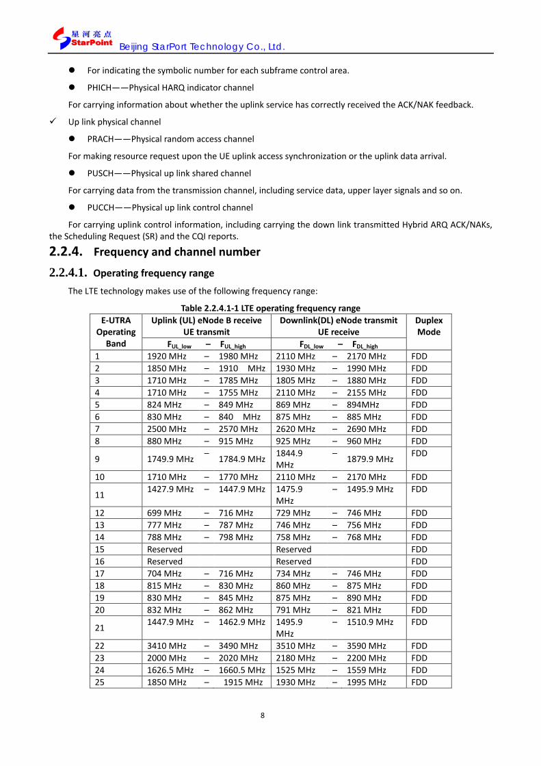
2.2.4.1. Operating frequency range
The LTE technology makes use of the following frequency range:
Table 2.2.4.1-1 LTE operating frequency range E-UTRA
Operating Band
Uplink (UL) eNode B receive UE transmit
Downlink(DL) eNode transmit UE receive
Duplex Mode
FUL_low – FUL_high FDL_low – FDL_high 1 1920 MHz – 1980 MHz 2110 MHz – 2170 MHz FDD 2 1850 MHz – 1910 MHz 1930 MHz – 1990 MHz FDD 3 1710 MHz – 1785 MHz 1805 MHz – 1880 MHz FDD 4 1710 MHz – 1755 MHz 2110 MHz – 2155 MHz FDD 5 824 MHz – 849 MHz 869 MHz – 894MHz FDD 6 830 MHz – 840 MHz 875 MHz – 885 MHz FDD 7 2500 MHz – 2570 MHz 2620 MHz – 2690 MHz FDD 8 880 MHz – 915 MHz 925 MHz – 960 MHz FDD
9 1749.9 MHz – 1784.9 MHz 1844.9 MHz
– 1879.9 MHz FDD
10 1710 MHz – 1770 MHz 2110 MHz – 2170 MHz FDD
11 1427.9 MHz – 1447.9 MHz 1475.9 MHz
– 1495.9 MHz FDD
12 699 MHz – 716 MHz 729 MHz – 746 MHz FDD 13 777 MHz – 787 MHz 746 MHz – 756 MHz FDD 14 788 MHz – 798 MHz 758 MHz – 768 MHz FDD 15 Reserved Reserved FDD 16 Reserved Reserved FDD 17 704 MHz – 716 MHz 734 MHz – 746 MHz FDD 18 815 MHz – 830 MHz 860 MHz – 875 MHz FDD 19 830 MHz – 845 MHz 875 MHz – 890 MHz FDD 20 832 MHz – 862 MHz 791 MHz – 821 MHz FDD
21 1447.9 MHz – 1462.9 MHz 1495.9 MHz
– 1510.9 MHz FDD
22 3410 MHz – 3490 MHz 3510 MHz – 3590 MHz FDD 23 2000 MHz – 2020 MHz 2180 MHz – 2200 MHz FDD 24 1626.5 MHz – 1660.5 MHz 1525 MHz – 1559 MHz FDD 25 1850 MHz – 1915 MHz 1930 MHz – 1995 MHz FDD

Beijing StarPort Technology Co., Ltd.
9
... 33 1900 MHz – 1920 MHz 1900 MHz – 1920 MHz TDD 34 2010 MHz – 2025 MHz 2010 MHz – 2025 MHz TDD 35 1850 MHz – 1910 MHz 1850 MHz – 1910 MHz TDD 36 1930 MHz – 1990 MHz 1930 MHz – 1990 MHz TDD 37 1910 MHz – 1930 MHz 1910 MHz – 1930 MHz TDD 38 2570 MHz – 2620 MHz 2570 MHz – 2620 MHz TDD 39 1880 MHz – 1920 MHz 1880 MHz – 1920 MHz TDD 40 2300 MHz – 2400 MHz 2300 MHz – 2400 MHz TDD 41 2496 MHz - 2690 MHz 2496 MHz - 2690 MHz TDD 42 3400 MHz – 3600 MHz 3400 MHz – 3600 MHz TDD 43 3600 MHz – 3800 MHz 3600 MHz – 3800 MHz TDD
Remarks:
①. Frequency range 33, 34 and 40 are the ranges for global roaming services planned for TDD;
②. Frequency 35, 36 and 37 are the TDD frequency ranges planned for the United States;
③. Frequency 38 is the TDD frequency range planned for Europe;
④. Frequency 39 is the TDD frequency range planned for China.
2.2.4.2. Carrier frequency and its point
The LTE carrier frequency is assigned via EARFCN, which is the absolute radio frequency channel number employed in LTE, represented by 16bit, and numbered 0~65535, where 0~35999 are reserved for E-UTRA FDD, and LTE is numbered from 36000. The relation between the center carrier frequency (MHz) and EARFCN is expressed as follows:
FDL = FDL_low + 0.1(NDL – NOffs-DL) FUL = FUL_low + 0.1(NUL – NOffs-UL)
Table 5.1.1.1-1 Carrier frequency and Frequency point correspondence relationship
Band Downlink Uplink
FDL_low(MHz) NOffs-DL Range of NDL FUL_low (MHz) NOffs-UL Range of NUL 1 2110 0 0 – 599 1920 18000 18000 – 18599 2 1930 600 600119
9 1850 18600 18600 – 19199
3 1805 1200 1200 – 1949 1710 19200 19200 – 19949 4 2110 1950 1950 – 2399 1710 19950 19950 – 20399 5 869 2400 2400 – 2649 824 20400 20400 – 20649 6 875 2650 2650 – 2749 830 20650 20650 – 20749 7 2620 2750 2750 – 3449 2500 20750 20750 – 20449 8 925 3450 3450 – 3799 880 21450 21450 – 21799 9 1844.9 3800 3800 – 4149 1749.9 21800 21800 – 22149 10 2110 4150 4150 – 4749 1710 22150 22150 – 22749 11 1475.9 4750 4750 – 4949 1427.9 22750 22750 – 22949 12 729 5010 5010 – 5179 699 23010 23010 – 23179 13 746 5180 5180 – 5279 777 23180 23180 – 23279 14 758 5280 5280 – 5379 788 23280 23280 – 23379 … 17 734 5730 5730 – 5849 704 23730 23730 – 23849 18 860 5850 5850 – 5999 815 23850 23850 – 23999 19 875 6000 6000 – 6149 830 24000 24000 – 24149 20 791 6150 6150 – 6449 832 24150 24150 – 24449 21 1495.9 6450 6450 – 6599 1447.9 24450 24450 – 24599 22 3510 6600 6600 – 7399 3410 24600 24600 – 25399

Beijing StarPort Technology Co., Ltd.
10
23 2180 7500 7500 – 7699 2000 25500 25500 – 25699 24 1525 7700 7700 - 8039 1626.5 25700 25700 – 26039 25 1930 8040 8040 - 8689 1850 26040 26040 - 26689 ... 33 1900 36000 36000 –36199 1900 36000 36000 – 36199 34 2010 36200 36200 –36349 2010 36200 36200 – 36349 35 1850 36350 36350 –36949 1850 36350 36350 – 36949 36 1930 36950 36950 –37549 1930 36950 36950 – 37549 37 1910 37550 37550 –37749 1910 37550 37550 – 37749 38 2570 37750 37750 –38249 2570 37750 37750 – 38249 39 1880 38250 38250 –38649 1880 38250 38250 – 38649 40 2300 38650 38650 –39649 2300 38650 38650 – 39649 41 2496 39650 39650 - 41589 2496 39650 39650 - 41589 42 3400 41590 41590 – 43589 3400 41590 41590 – 43589 43 3600 43590 43590 – 45589 3600 43590 43590 – 45589
2.3. OPERATION MODES SP8011 boasts of four modes: Active Cell Mode, LTE Analyse Mode, CW Mode and Cell Off Mode. The four
operation modes are elaborated as follows.
2.3.1. Active Cell Mode When SP8011 is in the Active Cell Mode, the call connection between SP8011 and terminals is able to be
established. The call connection can be either initiated by SP8011 or by the terminal. When the call connection between SP8011 and terminals are established, subscribers can use SP8011 to test the radio frequency indexes of the terminal transmitter and receiver.
The Active Cell Mode provides the signaling connection between SP8011 and terminals, i.e. complete signal interaction passways between them have been established to realize call connection. SP8011 is able to provide a series of radio frequency index test items for the terminal transmitter and the receiver as required by the 3GPP 36.521-1 protocol. When in the Active Cell Mode, SP8011 is able to perform the following operations:
Terminal cell registration;
SP8011 - terminal call connection establishment;
Terminal radio frequency index test;
SP8011 - terminal call connection release. Some parameters applied to the Active Cell Mode cannot be modified under this operating mode. Only when
the operating mode is set as Cell Off, can these parameters be modified.

Beijing StarPort Technology Co., Ltd.
11
Table 2.2.4.2 1 Test functions supported by SP8011 under the Active Cell operating mode
Functional classification Test Items
Transmitter index test
Transmit power test
Minimum output power test
On/off time mode test
Absolute power control test
Relative power control test
Aggregate power control tolerance
Frequency error test
Transmission signal quality test
Occupied bandwidth test
Spectrum emission mask test
Adjacent channel leakage power ratio
Spectrum monitor test
Receiver index test Throughput capacity test
Performance index test
PDSCH demodulation (Cell-Specific Reference Symbols)
PDSCH demodulation (User-Specific Reference Symbols)
PCFICH/PDCCH demodulation
PHICH demodulation
Reporting of Channel State Information test Channel status information test
2.3.2. LTE Analyze Mode Under the LTE Analyze Mode, it is defaulted that SP8011 does not transmit any down link signal, or conduct
call connection with terminals, with no synchronization mechanism between SP8011 and terminals. In this operating mode, SP8011 is able to fulfill the follow functions:
ACLR (Adjacent Channel Leakage power Ratio);
AFC (Auto frequency calibration test);
APC (Auto power calibration test);
DEVM (Downlink error vector magnitude for SP8011 self-check);
OBW (Occupied bandwidth test);
OOTM (On/off time mode test);
SEM (Spectrum Emission Mask test);
SM (spectrum monitor);
TP (Transmit power test);

Beijing StarPort Technology Co., Ltd.
12
TSQ (Transmit signal quality test). If it is required to send specific LTE signal waveform in the LTE Analyze mode, corresponding configurati0on
can be made by the “NSFT” button in this mode.
2.3.3. CW mode In the CW mode, SP8011 is equal to a CW signal generator, and the following test items can be followed to
perform the CW power and frequency test:
CW (signal frequency and power test).
2.3.4. Cell Off mode The Cell Off mode and Active Cell mode share the same parameters, and some of them can be modified only
in the Cell Off mode, not in the Active Cell mode. Before the establishment of SP8011 - terminal call connection, the call parameters, cell parameters, uplink
and downlink configuration parameters and so on can be configured in the Cell Off mode. After configuration, it can be switched to the Active Cell mode for registration and call connection.
In the Cell Off mode, SP8011 will turn off the transmitter, and all call parameters, Cell parameters and physical channel parameters can only be set in the Active Cell mode. No test can be conducted in the Cell Off mode.
2.4. PROTOCOL STACK CONFIGURATION The protocol stack configuration consists of cell parameters configuration, uplink and downlink configuration,
and the definitions, ranges and settings of cells, and uplink and downlink and other parameters are elaborated in this section.
Table 5.1.1.1-2 The protocol stack parameters list
Parameters name In chapters
and sections Position for SP8011
TDD basic parameters configuration
SubframeAssignment
2.4.1.1 The second page for Call Control
SpecialSubframePatterns UL-CyclicPrefixLength
AdditionalSpectrumEmission
TimeAlignmentTimerCommon Tcell SfnOffset TransmissionMode CodebookSubsetRestriction TransmitAntennaSelection p-Max
Cell parameters
AccessPointName
2.4.1.2 The second page for Call Control
Cell-Identity PhysicalCellId PLMN IMEI AutoGetIMSI IMSI TMSI P-TMSI M_TMSI csg-Indication csg-Identity

Beijing StarPort Technology Co., Ltd.
13
MME_GroupId MME_Code TrackingAreaCode LocationAreaCode CellConfigCapability C_RNTI
Authentication parameters
Auth-Key
2.4.1.3 The second page for Call Control
Auth-RAND Auth-AMF NAS-CipheringAlgorithm NAS-IntegrityProtAlgorithm RRC-CipheringAlgorithm RRC-IntegrityProtAlgorithm Authentication-Procedure AuthResCheck NasSMC-Procedure NasSecurityHeader AsSMC-Procedure
Other parameters
T300
2.4.1.4 The second page for Call Control
T301 T310 N310 T311 N311 maxHARQ-Msg3Tx SI-Periodicity SI-WindowLength modificationPeriodCoeff numberOfRA-Preambles preamblesGroupAConfig powerRampingStep preambleInitialReceivedTargetPower preambleTransMax ra-ResponseWindowSize mac-ContentionResolutionTimer RAR_TA defaultPagingCycle Paging-NB cellReservedForOperatorUse cellBarred intraFreqReselection q-RxLevMin FilterCoefficient
Uplink configuration
Channel Schedule
2.4.2.1
The third page for Call Para PRACH
The third page for Call Control
PUCCH PUSCH SRS CQI SR Power Control Type The third page for Call Para Target Power Value The third page for Call Para

Beijing StarPort Technology Co., Ltd.
14
Target Power Threshold The third page for Call Para
User Define UL Config for the third page Call control
Downlink configuration
Cell-Specific RS
2.4.2.2
Channel Level for the second page Cal Para
PSS_RA SSS_RA PBCH_RA PBCH_RB PCFICH_RB PDCCH_RA PDCCH_RB PHICH_RA PHICH_RB PDSCH_RA PDSCH_RB PHICH
the fourth page fo Call Control
PCFICH PDCCH PBCH PDSCH PMCH OCNG State
OCNG for the second page Cal Para OCNG_RA
OCNG_RB State AWGN for the second page Cal
Para Power Offset
User Define DL Config for the first page Call Control
Call configuration
Cell Power
2.4.3
the first page for Call Para
Ref Input Level Operating Band EARFCN System Bandwidth Line Loss RS EPRE
the second page for Call Para Center Frequency Trigger Mode
2.4.1. Cell configuration 2.4.1.1. Basic configuration parameters
Subframe Assignment (subframe assignment, only for TDD) Subframe Assignment: subframe assignment, with parameter range: sa0, sa1, sa2, sa3, sa4, sa5, sa6, and
default value: sa1.
Special Subframe Patterns (Special subframe configuration, only for TDD) Special Subframe Patterns: Special subframe configuration, with parameter range: ssp0, ssp1, ssp2, ssp3,
ssp4, ssp5, ssp6, ssp7, ssp8, and default value: ssp7.
UL-Cyclic Prefix Length (Uplink CP length) UL-Cyclic Prefix Length: Uplink CP length, with parameter range: len1, len2, and default value: len1..
Additional Spectrum Emission (Additional spectrum emission)

Beijing StarPort Technology Co., Ltd.
15
Additional Spectrum Emission: Additional spectrum emission, with integers as parameter type, ranging: 1~32, and default value: 1. .
Time Alignment Timer Common (TA timer) Time Alignment Timer Common: TA timer, with parameter range: sf500, sf750, sf1280, sf1920, sf2560,
sf5120, sf10240, asn1-infinity, and default value: sf750.
Tcell (Cell time information) Tcell: Cell time information, with parameter range: 0~307199 and default value: 0.
Sfn Offset (SFN offset) Sfn Offset: SFN offset, with parameter range: 0~1023 and default value: 0.
Transmission Mode (Antenna transmission mode) TransmissionMode:Antennatransmissionmode,withparameterrange:Tm1_1An_singleantenna,Tm2_2An_tran
smitdiversity,Tm2_4An_transmitdiversity,Tm3_2An_transmitdiversity_openloop,Tm3_4An_ransmitdiversity_openloop,Tm4_2An_closed_loop,Tm4_4An_closed_loop,Tm5_multi_user_NotSupport,Tm6_2An_closed_loop_one_layer,Tm6_4An_closed_loop_one_layer,Tm7_1An_singleantenna,Tm7_2An_transmitdiversity,Tm7_4An_transmitdiversity,and default value: Tm1_1An_singleantenna.
Codebook Subset Restriction (Codebook set) Codebook Subset Restriction: Codebook set, with parameter range corresponding to the binary number of
the currently configured antenna number from 2 to 16, which cannot be configured currently.
Transmit Antenna Selection (Transmission antenna selection) Transmit Antenna Selection:Transmission
Antenna selection,with parameter range:release/setup_closedLoop/setup_openLoop, and default value: release.
p-Max (UE transmission power upper limit) p-Max: UE transmission power upper limit, with parameter range-30~33, and default interface
display”-”before configuration.
2.4.1.2. Cell parameters Conditions for parameter availability: In the Cell Off mode, all parameters are available, while some are
available when call connection is established.
Access Point Name (Access point name) Access Point Name: Access point name, with parameter type: Octonary number system, string length: 100,
and default value:‘0123456789’.
Cell-Identity (cell ID) Cell-Identity: Cell ID, with parameter type: integers, ranging: 0~268435455, and default value: 256.
Physical Cell ID (Physical cell ID) Physical Cell ID: Physical cell ID, with parameter type: integers, ranging: 0~503, and default value: 0.
PLMN-Identity (PLMN, service cell PLMN) PLMN-Identity: Service cell PLMN, including MCC (Mobile country code) and MNC (Mobile network
code) .The parameter type is decimal system character string, with string length: 5~ 6 and the first three characters for MCC and the last two (three) for NCC.
IMEI (International Mobile Equipment Identity ) IMEI: International mobile equipment identity, with parameter type: Five binary number, ranging: 0~11111,
and default value: 00101.
Auto Get IMSI Set up automatic acquisition of IMSI or configuration to be done by the user. During normal processing, IMSI is obtained from terminals, and the instrument is added with IMSI manual
input, due to poor performance for some terminals to read IMSI, and the instrument accommodates subscriber manual input of the IMSI value matching the IMSI card of UE.
IMSI (International Mobile Subscriber Identification Number, symbols distinguishing mobile subscribers)

Beijing StarPort Technology Co., Ltd.
16
IMEI: symbols distinguishing mobile subscribers, with parameter type: 15-figure integers, ranging: 0~999999999999999, and the default value: 001010123456789.
TMSI (Temporary Mobile Subscriber Identity , temporary mobile subscriber identity number) TMSI: Temporary mobile subscriber identity number, with default value: 0, which cannot be altered for the
time being.
P-TMSI (Packet Temperate Mobile Subscription Identity , packet temperate mobile subscription identity number)
P-TMSI: Packet temporary mobile subscriber identity number, with default value: 0, which cannot be altered for the time being.
M_TMSI (MME-TMSI, the only code marking the subscriber in MME) M_TMSI: The only code in MME marking the subscriber, assigned by MME, and valid only in the scope of
MME, which is defaulted at 0 and cannot be altered for the time being.
csg-Indication (CSG indication) csg-Indication: CSG indication, which , which is defaulted at 0 and cannot be altered for the time being.
csg-Identity (CSG identity ) csg-Identity: CSG identity, with parameter type: Binary system character string with length of 27 figures.
MME_GroupId (MME group ID) MME_GroupId: MME group ID, with parameter type: Binary system character string with length 16 figures ,
and is defaulted at‘0000000000000001’.
MME_Code (MME Code, Mobility Management Entity Code, mobile management entity code) MME_Code: mobile management entity code, with parameter type: Binary system character string with
length 8 figures , and is defaulted at‘00000001’.
Tracking Area Code (TAC, Tracking area code) Tracking Area Code: Tracking area code, with parameter type: Binary system character string with length 16
figures , and is defaulted at‘0000000000000001’.
Location Area Code (NAS LAC, location area code) Access Point Name: Location area code, with parameter type: Octonary number system, string length: 2, and
is defaulted at ‘0001'.
Cell Config Capability (Cell capacity) Cell Config Capability :Cell capacity, with parameter range: broadcast Only Cell/minimum Uplink
Cell/fullCell,and default value: fullCell.
C_RNTI (C-RNTI, Cell Radio Network Temporary Identify, cell radio network temporary identity) C_RNTI: Cell radio network temporary identity, with parameter type: Binary system character string with
length 16 figures , and is defaulted at '0001000000000001'.
2.4.1.3. Authentication parameters The authentication parameters include: Auth-KEY, Auth-RAND, Auth-AMF,
NAS-CipheringAlgorithm,NAS-IntegrityProtAlgorithm,RRC-CipheringAlgorithm, RRC-IntegrityProtAlgorithm,Authentication-Procedure,AuthResCheck, NasSMC-Procedure, NasSecurityHeader, AsSMC-Procedure and so on, which can be elaborated as follows:
Auth-KEY: Fixed authentication key K, with parameter type: Binary system character string with length 128 figures , and is defaulted at ‘0001020304050 60708090A0B0C0D0E0F’ (expressed in hexadecimal) ;
Auth-RAND: Random number RAND, with parameter type: Binary system character string with length 128 figures ,and is defaulted at ‘A3DE0 C6D363E30C364A4078F1BF8D577’ (expressed in hexadecimal) ;
Auth-AMF: Authentification management field, with parameter type: Binary system character string with length 16 figures , and is defaulted at‘1010101 010101010’;
NAS-Ciphering Algorithm: NAS plus decipherment algorithm, with parameter range: EEA0, 128-EEA1,

Beijing StarPort Technology Co., Ltd.
17
128-EEA2, and default value: EEA0;
NAS-IntegrityProtAlgorithm: NAS integrity protection algorithm, with parameter range:EIA0, 128-EIA1, 128-EIA2, and default value: EIA0;
RRC-CipheringAlgorithm: RRC plus decipherment algorithm, with parameter range: EEA0, 128-EEA1, 128-EEA2, and default value: EEA0; For details, please refer to protocol: 3GPP TS33.401[5.1.3.2].
RRC-IntegrityProtAlgorithm: RRC integrity protection algorithm, with parameter range:EIA0, 128-EIA1, 128-EIA2, and default value: EEA0; for details, please refer to protocol: 3GPP TS33.401 [5.1.4.2].
Authentication-Procedure: Authentication procedure switch, with parameter range: TRUE/FALSE, default value: TRUE, and TRUE to carry out the authentication procedure.
AuthResCheck: Authentication response check switch, with parameter range: TRUE/FALSE, default value: FALSE, and FALSE to turn off the authentication procedure.
NasSMC-Procedure: NAS safe mode control procedure switch, with parameter range: TRUE/FALSE, default value: TRUE, and TRUE selected to test and verify the RS value in the authentication response for verifying the terminal response (Only when the USIM test card is employed can it support RES verification) .
NasSecurityHeader: NAS security header switch, with parameter range: TRUE/FALSE, default value: TRUE, and TRUE selected to carry out RES verification.
AsSMC-Procedure: AS security header switch, with parameter range: TRUE/FALSE, default value: TRUE, and TRUE selected to carry out the NAS security mode procedure.
2.4.1.4. Other parameters Other parameters include T300, T301, T310, N310, T311, N311, maxHARQ-Msg3Tx, SI-Periodicity,
SI-WindowLength, modificationPeriodCoeff , numberOfRA-Preambles , preamblesGroupAConfig , powerRampingStep , preambleInitialReceivedTargetPower , preambleTransMax , ra-ResponseWindowSize , mac-ContentionResolutionTimer , RAR_TA , defaultPagingCycle , Paging-NB , cellReservedForOperatorUse , cellBarred , intraFreqReselection , q-RxLevMin , FilterCoefficient and so on, which are elaborated as follows:
T300: RRC timer, for configuring T300 timer, which is defaulted at ms1000, and cannot be reset for the time being.
T301: RRC timer, for configuring T301 timer, which is defaulted at ms1000, and cannot be reset for the time being.
T310: RRC timer, for configuring T310 timer, which is defaulted at ms1000, and cannot be reset for the time being.
N310: The maximum indication times of continuous synchronization loss of the physical layer, which is defaulted at n1 and cannot be reset for the time being.
T311: RRC timer, for configuring T311 timer, which is defaulted at ms1000, and cannot be reset for the time being.
N311: The maximum indication times of continuous synchronization of the physical layer, which is defaulted at n1 and cannot be reset for the time being.
maxHARQ-Msg3Tx: msg3 maximum transmission times, for configuring the maximum transmission times of MSG3 for the primary random access of terminal, which is defaulted at n1 and cannot be reset for the time being.
SI-Periodicity: System information period, for configuring the system information cycle of broadcast information, which is defaulted at 4 and cannot be reset for the time being.
SI-WindowLength: System information window length, for configuring the system information window length of broadcast information, which is defaulted at ms20 and cannot be reset for the time being.
modificationPeriodCoeff: Broadcast modification period, for configuring the broadcast modification period, which is defaulted at n4 and cannot be reset for the time being.
numberOfRA-Preambles: The total number available for random access to preamble, for configuring the total
Beijing StarPort Technology Co., Ltd.
18
number for random access to preamble, which is defaulted at n52 and cannot be reset for the time being.
preamblesGroupAConfig:Parameter configuration for random access to preamble group A, for configuring the number available for random access to preamble group A, which is defaulted at omit and cannot be reset for the time being.
powerRampingStep: Power ramping factor, for configuring the power ramping factor, with parameter range: dB0, dB2, dB4, dB6, and is defaulted at dB0.
preambleInitialReceivedTargetPower: Initial preamble power, for configuring the initial preamble power, with parameter range: dBm-120, dBm-118, dBm-116, dBm-114, dBm-112, dBm-110, dBm-108, dBm-106, dBm-104, dBm-102, dBm-100, dBm-98, dBm-96, dBm-94, dBm-92, dBm-90, and is defaulted at dBm-104.
preambleTransMax: Maximum preamble transmission times, for configuring the maximum preamble transmission times, which is defaulted at n6 and cannot be reset for the time being.
ra-ResponseWindowSize: Random access response window size, for configuring the random access response window size, which is defaulted at sf10 and cannot be reset for the time being.
mac-ContentionResolutionTimer: Contention resolution timer, for configuring the duration of the contention resolution timer, which is defaulted at sf48 and cannot be reset for the time being.
RAR_TA: RACH response’s TA, which is defaulted at 0 and cannot be reset for the time being.
defaultPagingCycle: Paging cycle, for configuring the paging cycle ,which is defaulted at rf128 and cannot be reset for the time being.
Paging-NB: Paging time calculation parameter, for calculating the paging time, which is defaulted at oneT and cannot be reset for the time being.
cellReservedForOperatorUse: Current cell reserved for the operator, which is defaulted at notReserved and cannot be reset for the time being.
cellBarred: Whether the current cell available for access, which is defaulted at notBarred and cannot be reset for the time being.
intraFreqReselection: When the highest cell status is Barred or regarded as Barred by UE, for controlling the UE to conduct reselection of cells of the same frequency, which is defaulted at notAllowed and cannot be reset for the time being.
q-RxLevMin: Requirements for minimum reception within the cell, expressed by dBm, which is defaulted at -53 and cannot be reset for the time being.
FilterCoefficient: Filter coefficient during RSRP test, for calculating the line loss, with parameter range: fc0, fc1, fc2, fc3, fc4, fc5, fc6, fc7, fc8, fc9, fc10, fc11, fc12, fc13, fc14, fc15, fc16, fc17, fc18, fc19, spare1, and is defaulted at fc3.
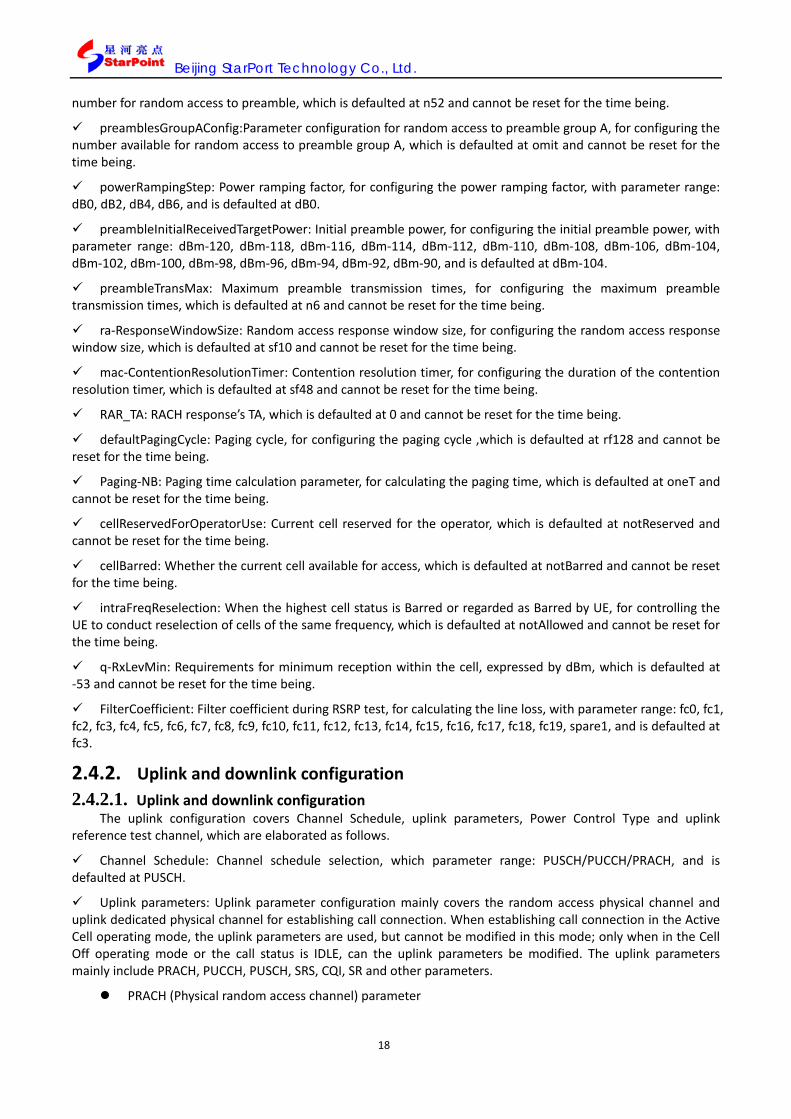
2.4.2. Uplink and downlink configuration 2.4.2.1. Uplink and downlink configuration
The uplink configuration covers Channel Schedule, uplink parameters, Power Control Type and uplink reference test channel, which are elaborated as follows.
Channel Schedule: Channel schedule selection, which parameter range: PUSCH/PUCCH/PRACH, and is defaulted at PUSCH.
Uplink parameters: Uplink parameter configuration mainly covers the random access physical channel and uplink dedicated physical channel for establishing call connection. When establishing call connection in the Active Cell operating mode, the uplink parameters are used, but cannot be modified in this mode; only when in the Cell Off operating mode or the call status is IDLE, can the uplink parameters be modified. The uplink parameters mainly include PRACH, PUCCH, PUSCH, SRS, CQI, SR and other parameters.
PRACH (Physical random access channel) parameter

Beijing StarPort Technology Co., Ltd.
19
PRACH parameters include rootSequenceIndex, prach-ConfigIndex, highSpeedFlag, zeroCorrelationZoneConfig, prach-FreqOffset, deltaPreambleMsg3 and so on, which are elaborated as follows:
rootSequenceIndex: Zero correlation root sequence index, with integer parameters, ranging: 0~837, and is defaulted at 0; For details, please refer to 3GPP TS36.211 [5.7.1].
prach-ConfigIndex: Pre- PRACH header sequence index, with integer parameters, ranging: 0~63, and is defaulted at 3; For details, please refer to 3GPP TS36.211 [5.7.1].
highSpeedFlag: Indicating constraint set/free set, with parameter range: true/false, and is defaulted at false; For details, please refer to protocol 3GPP TS36.211 [5.7.2].
zeroCorrelationZoneConfig: : The parameter configured by the upper layer, i.e. Ncs configuration, with integer parameters, ranging: 0~15, and is defaulted at 0; for details, please refer to 3GPP TS36.211 [5.7.2].
prach-FreqOffset: The first resource block index number of PRACH mapping within the current frame/the physical resource block sequence number given by the high layer, with integer parameters, ranging: 0~94, and is defaulted at 8; For details, please refer to Protocol 3GPP TS36.211 [5.7.1].
deltaPreambleMsg3 ( 3_preamble Msg∆ ) : : The parameter configured by the upper layer, with integer
parameters, ranging: -1~6, and is defaulted at 4; for details, please refer to Protocol 3GPP TS36.213 [5.1.1.1].
PUCCH (Physical uplink control channel)
PUCCH parameters include repetitionFactor, n1PUCCH-AN-Rep, tdd-AckNackFeedbackMode, deltaPUCCH-Shift, nRB-CQI, nCS-AN, p0-NominalPUCCH, deltaF-PUCCH-Format1, deltaF-PUCCH-Format1b, deltaF-PUCCH-Format2, deltaF-PUCCH-Format2a, deltaF-PUCCH-Format2b and so on, which are elaborated as follows:
repetitionFactor ( ANRepN ) :The parameter configured by the upper layer,ranging:n2, n4, n6, and is
defaulted at n2; it is configurable during setup; for details, please refer to Protocol 3GPP TS36.213 [10.1].
n1PUCCH-AN-Rep ( (1)ANRepPUCCH,n ) : The parameter configured by the upper layer, with integer
parameters, ranging:0~2047, and is defaulted at 0; it is configurable during setup; for details, please refer to Protocol 3GPP TS36.213 [10.1].
tdd-AckNackFeedbackMode: Indicating one of the TDD ACK/NACK feedback modes is employed, with parameter range: bundling/ multiplexing, and is defaulted at bundling; For details, please refer to Protocol 3GPP TS36.213 [7.3].
deltaPUCCH-Shift ( PUCCHShift∆ ) :The parameter configured by the upper layer, with integer parameters,
ranging:ds1, ds2, ds3, and is defaulted at ds2; for details, please refer to Protocol 3GPP TS36.211 [5.4.1].
nRB-CQI ( )2(RBN ) : The parameter configured by the upper layer, with integer parameters, ranging:
0~98, and is defaulted at 8; for details, please refer to Protocol 3GPP TS36.211 [5.4].
nCS-AN ( )1(CSN ) : The parameter configured by the upper layer, with integer parameters, ranging:
0~7, and is defaulted at 6; for details, please refer to Protocol 3GPP TS36.211 [5.4].
n1PUCCH-AN ( (1)PUCCHn ) : Resource block index, which is a parameter configured by the upper layer;
for details, please see Protocol 3GPP TS36.211 [5.4].
p0-NominalPUCCH ( PUCCHO_NOMINAL_P ) : The parameter configured by the upper layer, with integer
parameters, ranging:-127~-96, and is defaulted at -117; For details, please refer to Protocol 3GPP

Beijing StarPort Technology Co., Ltd.
20
TS36.213 [5.1.2.1].
p0-UE-PUCCH: The parameter configured by the upper layer, with integer parameters, ranging:{-8,…,7}, and is defaulted at 1; For details, please refer to Protocol 3GPP TS36.213 [5.2.1.1].
deltaF-PUCCH-FormatX ( )(F_PUCCH F∆ ) : Corresponding PUCCH format 1, 1b, 2, 2a and 2b, i.e.
deltaF-PUCCH-Format1, deltaF-PUCCH-Format1b, deltaF-PUCCH-Format2, deltaF-PUCCH-Format2a, deltaF-PUCCH-Format2b, where deltaF-2 corresponds to -2 dB, deltaF0 corresponds to 0 dB and son on; for details, please refer to Protocol 3GPP TS36.213 [5.1.2]:
deltaF-PUCCH-Format1: Parameter range: deltaF-2/deltaF0/deltaF2, and default value: deltaF0;
deltaF-PUCCH-Format1b: Parameter range: deltaF1/deltaF3/deltaF5, and default value: deltaF3;
deltaF-PUCCH-Format2: Parameter range: deltaF-2/deltaF0/deltaF1/deltaF2, and default value: deltaF0;
deltaF-PUCCH-Format2a: Parameter range: deltaF-2/deltaF0/deltaF2, and default value: deltaF0;
deltaF-PUCCH-Format2b: Parameter range: deltaF-2/deltaF0/deltaF2, and default value: deltaF0.
PUSCH (Physical uplink shared channel) PUSCH parameters include n-SB, hoppingMode, pusch-HoppingOffset, enable64QAM,
groupHoppingEnabled, groupAssignmentPUSCH, sequenceHoppingEnabled, cyclicShift, p0-NominalPUSCH, alpha and so on, which are elaborated as follows.
n-SB(Nsb): The parameter configured on the upper layer, which is an integer, ranging: 1~4, and is defaulted at 1; for details, please refer to Protocol 3GPP TS36.211 [5.3.4].
hoppingMode: The parameter configured on the upper layer, which ranges: which ranges: interSubFrame/intraAndInterSubFrame, and is defaulted at ds2; for details, please refer to Protocol 3GPP TS36.211 [5.3.4].
pusch-HoppingOffset( PUCCHRBN ): The parameter configured on the upper layer, which is an integer,
ranging: 0~98, and is defaulted at 16; for details, please refer to Protocol 3GPP TS36.211 [5.3.4].
enable64QAM: Whether it allows 64QAM, which ranges: true/false, and is defaulted at false; for details, please refer to Protocol 3GPP TS36.213 [8.6.1].
groupHoppingEnabled: The parameter configured on the upper layer, which ranges: true/false, and is defaulted at true; for details, please refer to Protocol 3GPP TS36.211 [5.5.1.3].
groupAssignmentPUSCH(∆SS): The parameter configured on the upper layer, which is an integer, ranging: 0~29, and is defaulted at 0; for details, please refer to Protocol 3GPP TS36.211 [5.5.1.3].
sequenceHoppingEnabled: The parameter configured on the upper layer, which ranges: true/false, and is defaulted at false; for details, please refer to Protocol 3GPP TS36.211 [5.5.1.4].
cyclicShift: The parameter configured on the upper layer, which is an integer, ranging: 0~7, and is defaulted at 6; for details, please refer to Protocol 3GPP TS36.211 [5.5.2.1.14].
p0-NominalPUSCH( )(PUSCHO_NOMINAL_ jP ): The parameter configured on the upper layer, which is
an integer, ranging: -126~24, and is defaulted at -85; for details, please refer to Protocol 3GPP TS36.213 [5.1.1.1].
alpha(α ): The parameter configured on the upper layer, which is an integer, ranging: al0/al04/al05/al06/al07/al08/al09/al1, and is defaulted at a108; for details, please refer to Protocol

Beijing StarPort Technology Co., Ltd.
21
3GPP TS36.213 [5.1.1.1].
p0-UE-PUSCH( O_UE_PUSCHP ): The parameter configured on the upper layer, which ranges: {-8,…,7},
and is defaulted at 1; for details, please refer to Protocol 3GPP TS36.213[5.1.1.1].
SRS (Sounding reference signal)
SRS parameters include SRS Common Config, srs-Bandwidth, srs-HoppingBandwidth, freqDomainPosition, duration, srs-ConfigIndex, transmissionComb, cyclicShift, srs-BandwidthConfig, srs-SubframeConfig, ackNackSRS-SimultaneousTransmission, srs-MaxUpPts and so on, which are elaborated as follows.
SRS Common Config: The structural body, which ranges: release/setup, and is defaulted at setup.
When SRS Common Config is setup, we can set up the four parameters of srs-BandwidthConfig, srs-SubframeConfig, ackNackSRS-SimultaneousTransmission, srs-MaxUpPts.
srs-BandwidthConfig( SRSC ): The base station SRS bandwidth configuration, with the parameter configured on the upper layer, which is an integer, ranging: bw0/bw1/bw2/bw3/bw4/bw5/bw6/bw7, and is defaulted at bw0; for details, please refer to Protocol 3GPP TS36.211 [5.5.3.2].
srs-SubframeConfig: SRS subframe configuration, with the parameter configured on the upper layer, ranging: sc0/sc1/sc2/sc3/sc4/sc5/sc6/sc7/sc8/sc9/sc10/sc11/sc12/sc13/sc14/sc15, and is defaulted at sc0, for details, please refer to Protocol 3GPP TS36.211 [5.5.3.3].
ackNackSRS-SimultaneousTransmission: Whether SRS and ACK/NACK are transmitted simultaneously, which ranges: true/false, and is defaulted at false; for details, please refer to Protocol 3GPP TS36.213 [8.2].
srs-MaxUpPts: Whether SRS signals are transmitted on UpPTS, which ranges: true/omit, and is defaulted at omit.
SRS Dedicated Config: The structural body, which ranges: release/setup, and is defaulted at setup.
When SRS Common Config is setup, we can set up the seven parameters of srs-Bandwidth, srs-HoppingBandwidth, freqDomainPosition, duration, srs-ConfigIndex, transmissionComb, cyclicShift.
srs-Bandwidth( SRSB ): UE user equipment SRS bandwidth, which is configured on the upper layer, which is an integer, ranging: bw0/bw1/bw2/bw3, and is defaulted at bw3; it is configurable during setup, and greyed out during release; for details, please refer to Protocol 3GPP TS36.213 [5.5.3.2].
srs-HoppingBandwidth( hopb): SRS hopping bandwidth, which is configured on the upper layer,
ranging: hbw0/hbw1/hbw2/hbw3, and is defaulted at hbw0; it is configurable during setup, and greyed out during release; for details, please refer to Protocol 3GPP TS36.213 [5.5.3.2].
freqDomainPosition( RRCn ): SRS signal radio frequency domain bandwidth, which is configured on the upper layer, ranging: 0~23, and is defaulted at 0; it is configurable during setup, and greyed out during release; for details, please refer to Protocol 3GPP TS36.213 [5.5.3.2].
duration: SRS signal continuous mode, which ranges: true/false. When true, the SRS signal is transmitted on each frame, and when false, the SRS signal is transmitted only on one single frame. The default value is true, and the parameter is configurable during setup, and greyed out during release; for details, please refer to Protocol 3GPP TS36.213 [8.2].
srs-ConfigIndex(ISRS): SRS configuration number, which is an integer, ranging: 0~1023, and is defaulted at 31; it is configurable during setup, and greyed out during release; for details, please refer to Protocol 3GPP TS36.213 [8.2].

Beijing StarPort Technology Co., Ltd.
22
transmissionComb( TCk ): SRS transmission frequency comb, which is configured on the upper layer, ranging: 0~1, and is defaulted at 0; it is configurable during setup, and greyed out during release; for details, please refer to Protocol 3GPP TS36.211[5.5.3.2].
cyclicShift: Sequence cyclic shift, which is configured on the upper layer, ranging: cs0/cs1/cs2/cs3/cs4/cs5/cs6/cs7, and is defaulted at cs0; it is configurable during setup, and greyed out during release; for details, please refer to Protocol 3GPP TS36.211[5.5.2.1.1].
SfnOffset: SRS offset, which ranges: 0~15 and default value: 3.
CQI (Channel quality indicator) CQI parameters include CQI ReportConfig, cqi-PUCCH-ResourceIndex, cqi-pmi-ConfigIndex,
cqi-FormatIndicator Periodic, subbandCQI-k, ri-ConfigIndex and simultaneousAckNackAndCQI, which are elaborated as follows.
CQI ReportConfig: The structural body, which ranges: release/setup, and is defaulted at release.
When CQI ReportConfig is setup, the five parameters of cqi-PUCCH-ResourceIndex, cqi-pmi- ConfigIndex, cqi-FormatIndicator Periodic, ri-ConfigIndex, simultaneousAckNackAndCQI can be set up.
cqi-PUCCH-ResourceIndex()2(
PUCCHn ): The UE parameter configured on the upper layer, which is an integer, ranging: 0~1185, and is defaulted at 0; it is configurable during setup, and greyed out during release; for details, please refer to Protocol 3GPP TS36.213 [7.2].
cqi-pmi-ConfigIndex(ICQI/PMI): CQI/PMI duration and offset configuration number ICQI/PMI, which is an integer, ranging: 0~1023, and is defaulted at 24; it is configurable during setup, and greyed out during release; for details, please refer to Protocol 3GPP TS36.213 [table7.2.2-1C].
cqi-FormatIndicatorPeriodic: PUCCH CQI feedback type, which is configured on the upper layer, ranging: widebandCQI/subbandCQI; it is configurable during setup, and greyed out during release; for details, please refer to Protocol 3GPP TS36.213 [7.2.2].
subbandCQI-k: Subband CQI parameter k setting, which is configured on the upper layer, which are integers and ranging: 1~4, and is defaulted at: 1. Conditions for availability: It is configurable during subbandCQI, and greyed out during widebandCQI; for details, please refer to Protocol 3GPP TS36.213 [7.2.2].
ri-ConfigIndex(IRI) : RI configuration number IRI, which is an integer, ranging: 0~1023, and is defaulted at 484; it is configurable during setup, and greyed out during release; for details, please refer to Protocol 3GPP TS36.213 [7.2.2].
simultaneousAckNackAndCQI: The parameters configured on the upper layer, which ranges: TRUE/FALSE, and is defaulted at TRUE; it is configurable during setup, and greyed out during release; for details, please refer to Protocol 3GPP TS36.213 [10.1].
SR (Scheduling request)
sr_PUCCH_ResourceIndex: Calculation of the PUCCH resources during SR transmission, which ranges: 0~2047, and is defaulted at 20 when 5MHz, and 41 when 10MHZ, 62 when 15MHz, and 84 when 20MHz.
sr_ConfigIndex: The parameter for looking up the table for SR periodicity and SR subframe offset, which is an integer, ranging: 0~157, and is defaulted at 27.
Power Control Type: Power control mode, which ranges: Max/TPC0/Min/Target Power, and is defaulted at Max.
When “Max” selected, the instrument side will transmit continuous power up commands, and the control terminal power will reach the maximum value;
When “TPC0” selected, the instrument side will transmit continuous power hold command, and

Beijing StarPort Technology Co., Ltd.
23
the control terminal power will hold the current power value;
When “Min” selected, the instrument side will transmit continuous power down command, and the control terminal power will reach the minimum value;
When : “Target Power” selected, Target Power Value and Target Power Threshold parameters can be configured, which are described as follows;
Target Power Value: The terminal uplink power is controlled at given value, and when the user is Connected and at Target Power, the terminal Target Power value can be set, and SP8010 will control the transmit power of the terminal at the given power value, and the interface screen will real time display the current terminal transmit power, and the parameter ranges: -60.00dBm~27.00dBm, and is defaulted at -20.00dBm.
Target Power Threshold: Target power threshold, which ranges: 0.65dBm~10.0dBm, and is defaulted at 3.2dBm.
Uplink reference measurement channel:
For details, please see 2.4.2.3.
2.4.2.2. Downlink configuration The downlink configuration covers downlink signal power, downlink physical channel parameter, downlink
interference channel, AWGN and Downlink Reference Measurement Channel, which are elaborated as follows:
Downlink signal power:
The downlink signal power parameter configuration mainly covers Cell Power, Cell-Specific RS, PSS_RA, SSS_RA, PBCH_RA, PBCH_RB, PCFICH_RB, PDCCH_RA, PDCCH_RB, PHICH_RA, PHICH_RB, PDSCH_RA and PDSCH_RB.
Cell Power: Cell power, which is related to IN/OUT in different testing modes, and is defaulted at -54.21dBm, and has the following specific range:
IN/OUT and CW setting: CELL POWER is -140~-5, and RSEPRE is -140~-5;
IN/OUT and Active setting: CELL POWER is -139.21~-5.26, and RSEPRE is -170~-36.05; OUT and CW setting: CELL POWER is -140~2, and RSEPRE is -140~2;
OUT and CW setting: CELL POWER is -139.21~1.74, RSEPRE is -170~-29.05;
Cell-Specific RS: Setting the relative value between the cell-specific reference signal and the cell power, which ranges: -30.00 ~ 0.00 dB, and is defaulted at 0.00 dB.
PSS_RA: Setting the EPRE relative value between PSS_RA and Cell-Specific RS, which ranges: -30.00 ~ 0.00 dB, and is defaulted at 0 .00dB.
SSS_RA: Setting the EPRE relative value between SSS_RA and Cell-Specific RS, which ranges: -30.00 ~ 0.00 dB, and is defaulted at 0 .00dB.
PBCH_RA: Setting the EPRE relative value between PBCH_RA and Cell-Specific RS, which ranges: -30.00 ~ 0.00 dB, and is defaulted at 0 .00dB.
PBCH_RB: Setting the EPRE relative value between PBCH_RB and Cell-Specific RS, which ranges: -30.00 ~ 0.00 dB, and is defaulted at 0 .00dB.
PCFICH _RB: Setting the EPRE relative value between PBCH_RB and Cell-Specific RS, which ranges: -30.00 ~ 0.00 dB, and is defaulted at 0 .00dB..
PDCCH_RA: Setting the EPRE relative value between PDCCH_RA and Cell-Specific RS, which ranges: -30.00 ~ 0.00 dB, and is defaulted at 0 .00dB..
PDCCH_RB: Setting the EPRE relative value between PDCCH_RB and Cell-Specific RS, which ranges: -30.00 ~ 0.00 dB, and is defaulted at 0 .00dB..

Beijing StarPort Technology Co., Ltd.
24
PHICH_RA: Setting the EPRE relative value between PBCH_RA and Cell-Specific RS, which ranges: -30.00 ~ 0.00 dB, and is defaulted at 0 .00dB.
PHICH_RB: Setting the EPRE relative value between PBCH_RB and Cell-Specific RS, which ranges: -30.00 ~ 0.00 dB, and is defaulted at 0 .00dB.
PDSCH_RA: Setting the EPRE relative value between PDSCH_RA and Cell-Specific RS, which ranges: PA={-6, -4.77, -3, -1.77, 0, 1, 2, 3} in the unit of dB, and is defaulted at 0 .00dB..When transmitting via four antenna, and the MIMO mode in Diversity, this selectable set is PA+10lg (2); and for other cases, the selectable set is PA.
PDSCH_RB: Setting the EPRE relative value between PDSCH_RB and Cell-Specific RS, which is defaulted at 0 .00dB. It does not support manual input, but features direct display of PDSCH_RB calculated based on the PDSCH_RA setting.
Downlink physical channel parameters:
The downlink physical channel parameters configuration mainly covers PHICH, PCFICH, PDCCH, PBCH, PDSCH, PMCH and other information channels.
PHICH (Physical HARQ indicator channel)
PHICH parameters include phich-Duration, phich-Resource and so on, which are elaborated as follows.
phich-Duration: PHICH duration, which ranges: normal/extended, and is defaulted at normal; for details, please refer to Protocol 3GPP TS36.211 [6.9.3].
phich-Resource: PHICH resource, which ranges: oneSixth/half/one/two, and is defaulted at one; for details, please refer to Protocol 3GPP TS36.211 [6.9].
PCFICH (Physical control format indicator channel)
PHICH parameters include Cfi and so on, which are elaborated as follows.
Cfi: Format control indicator, which is an integer, ranging: 1~3, and is defaulted at 2; for details, please refer to 3GPP TS36.212 [5.3.4].
PDCCH (Physical downlink control channel)
The PDCCH is greyed out, so the user has no access.
PBCH (Physical broadcast channel)
The PBCH is greyed out, so the user has no access.
PDSCH (Physical downlink shared channel)
PDSCH parameters include referenceSignalPower, p-band so on, which are elaborated as follows.
referenceSignalPower: Reference signal power, which provides the downlink reference signal EPRE, which is an integer, ranging -60~50, and is defaulted at 18; for details, please refer to Protocol 3GPP TS36.213[5.2].
p-b( BP ): The parameter configured on the upper layer, which is an integer, ranging: 0~3, and is defaulted at 0; for details, please refer to Protocol 3GPP TS36.213 [5.2].
PMCH (Physical Multicast channel)
The PMCH is greyed out, so the user has no access.
Downlink interference channel: The channel sees OCNG interference, and as defined in the 3GPP protocol,
iγ functions to meter the power spectral density of OFDM channel noise interference.
Setting OCNG mode and various OCNG parameters, including:
OCNG State: Setting the OCNG state, to ON / OFF, which is not available in the TDD Analyse or CW mode.

Beijing StarPort Technology Co., Ltd.
25
OCNG_RA: Setting OCNG_RA, which is not available in the TDD Analyse or CW mode.
OCNG_RB: Setting OCNG_RB, which is not available in the TDD Analyse or CW mode.
AWGN: Gaussian white noise setting, including the two items of Sate and Power Offset (dB).
Downlink Reference Measurement Channel:
For details, please see 2.4.2.3.
2.4.2.3. RMC and uplink and downlink subframe configuration
The RMC and uplink and downlink subframe configuration covers the two components of RMC and SubFrame Config, which are respectively applied to the RMC and user-defined parameters.
RMC(Reference Measurement Channel):
RMC(Reference Measurement Channel) refers to reference measurement channel, which is defined in accordance with the Protocol. After RMC configuration, all uplink subframes shall be scheduled into unified configuration in line with different “Subframe Assignment”, and the uplink RMC is defaulted at QPSK_18RB, and the downlink TX RMC is not to be configured, but defaulted at N/A.
RMC scheduling
When selecting the PUSCH channel, the subframe 2 channel type is PUSCH, and other uplink subframe configuration is in line with subframe 2;
When selecting PUCCH, please go through the same process of PUSCH.
When selecting PRACH, there is no need to schedule the uplink subframe.
MCS setting
The setting of MCS1 is based on and restricted to the transmission mode, and only when in dicode can they are modifiable, while in monocode, they are set at N/A (in dicode only when TM4_2A, and TM5_1D);
MCS, RB and the like are only applicable under the channel types of PUSCH, PDSCH and N/A, and not available at all when scheduling other channels;
Uplink and downlink subframe-associated scheduling
For uplink scheduling of PUSCH, only PUSCH channels are to be scheduled;
For downlink scheduling of PHICH, to do uplink scheduling of corresponding PUSCH, TDD and FDD feature different associated subframes;
The PUSCH in FDD is the fourth 4-subframe before PHICH.
For details of the PHICH and PUSCH associated scheduling in TDD, please see the following table.
SA0
PHICH (Downlink subframe number) PUSCH(Uplink subframe number) 0 4 1 7 5 9 6 2
Note: When simultaneously scheduling the subframe 2, 3and9 under sa0, due to being controlled by the same DCI0, subframe 2 and 9 will be scheduled into the same state; and when simultaneously scheduling the subframe4, 7and 8, also due to being controlled by the same DCI0, subframe 4 and 7 will also be scheduled into the same state. In such a case, subrame 2 and 9 configuration must be the same, while subframe 4 and 7 configuration the same, too; or wrong information will be returned, and the intermediate page will be given with corresponding listing in red.
SA1

Beijing StarPort Technology Co., Ltd.
26
PHICH(Downlink subframe number) PUSCH(Uplink subframe number) 0(Null for channel selection) 1 7 4 8 5(Null for channel selection) 6 2 9 3
SA2 PHICH(Downlink subframe number) PUSCH(Uplink subframe number)
0(Null for channel selection) 1(Null for channel selection) 3 7 4(Null for channel selection) 5(Null for channel selection) 6(Null for channel selection) 8 2 9(Null for channel selection)
SA3 PHICH(Downlink subframe number) PUSCH(Uplink subframe number)
0 4 1(Null for channel selection) 5(Null for channel selection) 6(Null for channel selection) 8 2 9 3
SA4 PHICH(Downlink subframe number) PUSCH(Uplink subframe number)
0(Null for channel selection) 1(Null for channel selection) 4(Null for channel selection) 5(Null for channel selection) 6(Null for channel selection) 8 2 9 3
SA5 PHICH(Downlink subframe number) PUSCH(Uplink subframe number)
0(Null for channel selection) 1(Null for channel selection) 3(Null for channel selection) 4(Null for channel selection) 5(Null for channel selection) 6(Null for channel selection) 7(Null for channel selection) 8 2 9(Null for channel selection)
SA6 PHICH(Downlink subframe number) PUSCH(Uplink subframe number)
0 4
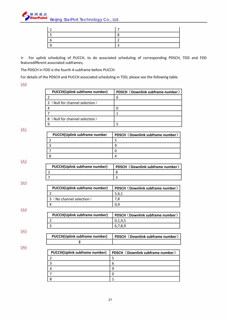
Beijing StarPort Technology Co., Ltd.
27
1 7 5 8 6 2 9 3
For uplink scheduling of PUCCH, to do associated scheduling of corresponding PDSCH, TDD and FDD featuredifferent associated subframes;
The PDSCH in FDD is the fourth 4-subframe before PUCCH.
For details of the PDSCH and PUCCH associated scheduling in TDD, please see the following table.
SA0
PUCCH(Uplink subframe number) PDSCH(Downlink subframe number) 2 6 3(Null for channel selection) 4 0 7 1 8(Null for channel selection) 9 5
SA1 PUCCH(Uplink subframe number PDSCH(Downlink subframe number)
2 5 3 9 7 0 8 4
SA2 PUCCH(Uplink subframe number) PDSCH(Downlink subframe number)
2 8 7 3
SA3 PUCCH(Uplink subframe number) PDSCH(Downlink subframe number)
2 5,6,1 3(No channel selection) 7,8 4 0,9
SA4 PUCCH(Uplink subframe number) PDSCH(Downlink subframe number)
2 0,1,4,5 3 6,7,8,9
SA5 PUCCH(Uplink subframe number) PDSCH(Downlink subframe number)
2 SA6
PUCCH(Uplink subframe number) PDSCH(Downlink subframe number) 2 5 3 6 4 9 7 0 8 1

Beijing StarPort Technology Co., Ltd.
28
Selection of uplink RMC (Take TDD QPSK FULL RB as examples)
1. In the Cell Off mode, press key F5, and modify the channel bandwidth into 20MHZ, and in the Active Cell operation mode, establish call connection to terminals.
Fig. 2.4.2-1 Call connection to terminals in the bandwidth of 20M
2. Press key F9 and select RMC;

Beijing StarPort Technology Co., Ltd.
29
Fig. 2.4.2-2 The interface upon RMC selected
3. Press key F7, and take turns to select UL RMC\QPSK FULL RB to complete the subframe scheduling;

Beijing StarPort Technology Co., Ltd.
30
Fig. 2.4.2 -3 The interface upon QPSK FULL RB selected
SubFrameConfig (User-defined parameter configuration): The SubFrameConfigfunctions to schedule all subframes, and in TDD, to fit different Subframe Assignments,
all subframes can be configured with different channels, and by default Subframe 2 follows the uplink RMC default configuration for parameter configuration (to conduct PUSCH signal scheduling), and Subframe 3, 7 and 8, although configured with parameters, are not given channel scheduling, and the downlink subframe is not to be configured;
Uplink subframe configuration: If the uplink subframe isselected, its parameters go and are described as follows:
Channel: Uplink channel type of this subframe scheduling, which features optional parameters: “N/A”, bn
“PUSCH” and”PUCCH”. When “N/A” selected, this subframe is not to be scheduled.
MOD: Modulation mode, with parameter range: QPSK and 16QAM, and is defaulted at QPSK.
MCS0, MCS1: Modulation code mode, with its parameter range dependent on MOD: QPSK, 0~11 and 29; 16QAM, 12~17 and 30. When MCS1 corresponds to the dicode, the uplink subframe is not available, and is defaulted at “N/A”.
RB Num: RB number, with its parameter range dependent on the system bandwidth configuration, 20M: 1~100, 15M: 1~75, 10M: 1~50, 5M: 1~25, 3M: 1~15, 1.4M: 1~6, and is defaulted at 25. .
RB Start: RB start position, with its parameter range dependent on the system bandwidth configuration, 20M:0~99, 15M:0~74, 10M:0~49, 5M:0~24, 1.4M:0~5, and is defaulted at 0.
RBG Index (Dec):When the identification configuration format is type0, the user is allowed to conduct discontinuous configuration of RB, and the minimum unit for user configuration is RBG, and when

Beijing StarPort Technology Co., Ltd.
31
“TransmissionMode “ is set at Tm2_1, Tm3_2A, Tm4_2, Tm7_1, they can conduct configuration. BGIindex is the UINT type,32bit in total, and for example, if the current system RB is 100,RGGIndex Bit Number = 25, and the 25 bits are the lower 25 bits of UINT type RBGIindex, from left to right. Suppose they are mapped on the RB of (0-51), and RBGIndex is 0x01fff000 (i.e. 33550336 converted into the decimal system). Note: The configurable RB number is the integral multiple of P or the integral multiple + 2, and when the RB number is the integral multiple of P + 2, the last bit of RBG Index represents 2 RBs, where P is listed in the following table:
Table 2.4.2.3-1 Subframe scheduling interface after R.1 TDD selected
System Bandwidth(MHz)
1.4 3 5 10 15 20
(RB Number)(N)
6 15 25 50 75 100
(P) RBG size 1 2 2 3 4 4
RBGIndex Bit Number
6 8 13 17 19 25
Note: There is relevance between the RB start position and the RB num:
20M: RB start position + RB number <=100
15M: RB start position + RB number <=75
10M: RB start position + RB number <=50
5M: RB start position + RB number <=25
3M: RB start position + RB number <=15
1.4M: RB start position + RB number <=6
Downlink subframe configuration:
SubFrameConfigfunctions to conduct scheduling for all subframes, and for different Subframe Assignments, all subframes can be configured with different channel types.
If downlink subframes are selected, their parameters are described as follows:
Channel: Downlink channel type of this subframe scheduling, which features optional parameters: “N/A”,
“PDSCH” and”PDCCH”. When “N/A” selected, this subframeis not to be scheduled.
MOD: Modulation mode, with parameter range: QPSK, 16QAM, and 64QAM and is defaulted at QPSK.
MCS0, MCS1: Modulation code mode, with its parameter range dependent on MOD: QPSK, 0~10 and 29; 16QAM, 11~12 and 30. When MCS1 corresponds to the dicode, the uplink subframe is not available, and is defaulted at “N/A”.
RB Num: RB number, with its parameter range dependent on the system bandwidth configuration, 20M: 1~100, 15M: 1~75, 10M: 1~50, 5M: 1~25, 3M: 1~15, 1.4M: 1~6, and is defaulted at 25. .
RB Start: RB start position, with its parameter range dependent on the system bandwidth configuration, 20M:0~99, 15M:0~74, 10M:0~49, 5M:0~24, 1.4M:0~5, and is defaulted at 0.
RBG Index (Dec):Identification configuration formattype0, when the user is allowed to conduct discontinuous configuration of RB, and the minimum unit for user configuration is RBG; when the “TransmissionMode “ is set at Tm2_1, Tm3_2A, Tm4_2, Tm7_1, they can conduct configuration. BGIindex is the UINT type,32bit in total, and for

Beijing StarPort Technology Co., Ltd.
32
example, if the current system RB is 100,RGGIndex Bit Number = 25, and the 25 bits are the lower 25 bits of UINT type RBGIindex, from left to right. Suppose they are mapped on the RB of (0-51), and RBGIndex is 0x01fff000 (i.e. 33550336 converted into the decimal system) .
Note: There exists relevance between the RB start position and the RB num:
20M: RB start position + RB number <=100
15M: RB start position + RB number <=75
10M: RB start position + RB number <=50
5M: RB start position + RB number <=25
3M: RB start position + RB number <=15
1.4M: RB start position + RB number <=6
SubFrameConfig procedures (Take TDD 20M bandwidth, and maximum throughput as example, to explain Terminal TM500)
Note: To ensure maximum throughput, the configuration mode featuring maximum downlink subframe number Sa5 (DSUDDDDDDD)needs to be selected, and the special subframe MCS is configured at 27, and other downlink subframes have 28 for their MCS configuration, and the RB number is 100, and the RBG Index is 33554431.
1. In the Cell Off mode, enter the System Config page, to modify the antenna number into LTE 2AN;
Fig. 2.4.2-4 The interface upon antenna number modified
2. Enter into the Home page, press the MORE key on the right to enter into the second page of Call Control pages, and change the subframe configuration mode into Sa5;

Beijing StarPort Technology Co., Ltd.
33
Fig. 2.4.2-5 The interface upon Sa5 selected
3. Modify the transmission mode into Tm4_2;

Beijing StarPort Technology Co., Ltd.
34
Fig. 2.4.2-6 The interface upon the transmission mode changed into Tm4_2
4. In the Active Cell mode, establish the call connection to the terminal, and configure the subframe in accordance with the requirements in the remarks;

Beijing StarPort Technology Co., Ltd.
35
Fig. 2.4.2-7 The interface upon the subframe configured
5. Enter into the Throughput page, and observe the throughput rate, as shown below:
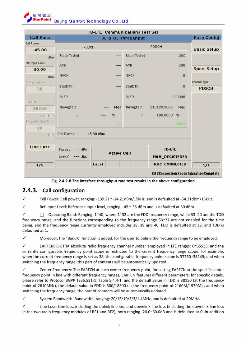
Beijing StarPort Technology Co., Ltd.
36
Fig. 2.4.2-8 The interface throughput rate test results in the above configuration
2.4.3. Call configuration Cell Power: Cell power, ranging: -139.21~ -14.21dBm/15kHz, and is defaulted at -54.21dBm/15kHz.
Ref Input Level: Reference input level, ranging: -45 ~ 35 dBm and is defaulted at 30 dBm.
Operating Band: Ranging: 1~40, where 1~32 are the FDD frequency range, while 33~40 are the TDD frequency range, and the functions corresponding to the frequency range 33~37 are not enabled for the time being, and the frequency range currently employed includes 38, 39 and 40, FDD is defaulted at 38, and TDD is defaulted at 1.
Moreover, the “BandX” function is added, for the user to define the frequency range to be employed.
EARFCN: E-UTRA absolute radio frequency channel number employed in LTE ranges: 0~65535, and the currently configurable frequency point scope is restricted to the current frequency range scope; for example, when the current frequency range is set as 38, the configurable frequency point scope is 37750~38249; and when switching the frequency range, this part of contents will be automatically updated.
Center Frequency: The EARFCN at each center frequency point, for setting EARFCN at the specific center frequency point.In line with different frequency ranges, EARFCN features different parameters; for specific details, please refer to Protocol 3GPP TS36.521-1: Table 5.4.4-1, and the default value in TDD is 38150 (at the frequency point of 2610MHz), the default value in FDD is 500/18500 (at the frequency point of 2160M/1970M) , and when switching the frequency range, the part of contents will be automatically updated.
System Bandwidth: Bandwidth, ranging: 20/15/10/5/3/1.4MHz, and is defaulted at 20MHz.
Line Loss: Line loss, including the uplink line loss and downlink line loss (including the downlink line loss in the two radio frequency modules of RF1 and RF2), both ranging -20.0~60.0dB and is defaulted at 0. In addition
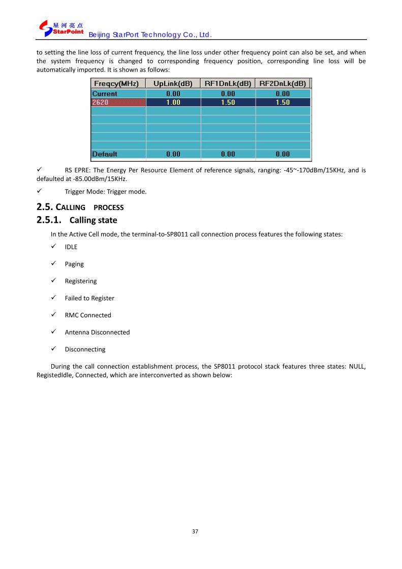
Beijing StarPort Technology Co., Ltd.
37
to setting the line loss of current frequency, the line loss under other frequency point can also be set, and when the system frequency is changed to corresponding frequency position, corresponding line loss will be automatically imported. It is shown as follows:
RS EPRE: The Energy Per Resource Element of reference signals, ranging: -45~-170dBm/15KHz, and is defaulted at -85.00dBm/15KHz.
Trigger Mode: Trigger mode.
2.5. CALLING PROCESS 2.5.1. Calling state
In the Active Cell mode, the terminal-to-SP8011 call connection process features the following states:
IDLE
Paging
Registering
Failed to Register
RMC Connected
Antenna Disconnected
Disconnecting
During the call connection establishment process, the SP8011 protocol stack features three states: NULL, RegistedIdle, Connected, which are interconverted as shown below:

Beijing StarPort Technology Co., Ltd.
38
Fig. 2.5.1-1 SP8011 protocol stack states conversion and flow
The SP8011 protocol stack states conversion and flow are described as follows: (Marked in line with the number in the above figure).
1. When SP8011 operates the first time and enters into the Active Cell state, or enters into the Active Cell state via the CellOff state, it starts to transmit broadcast messages, and after connection to the terminal, the user can turn on the terminal device to conduct regular registration, upon which the system enters into the Registed Idle state.
2. In the Registed Idle mode, regular call connection (MT or MO) can be conducted, and upon establishment, the system enters into the Connected state;
3. In the Registed Idle state, reset the network-side state (i.e. do CellOff first, and then redo ActiveCell), to return to the Null state;
4. In the Connected state, conduct normal on-hook to release call connection and return to the Registed Idle state;
5. In the Connected state, reset the network-side state (i.e. do CellOff first, and then redoActiveCell), to return to the Null state.
2.5.2. Position update Once the UE selects a cell, it will decide whether there is any need to conduct registration with the network.
The UE makes use of MNC, MCC and TAC cell broadcast to identify whether the cell is new.
The UE registration is fulfilled through an attachment process.During the registration process, the UE makes use of its identity to conduct communication with the network. The UE identification includes its IMSI and IMEI. SP8011 assigns one TMSI among the attached reception messages to the UE. The IMSI or TMSI of the UE is employed to call the UE.
Upon registration completed, the UE information window will display the registration data received from the UE, like terminal category, IMSI and so on.
2.5.3. Establishment of connection to the UE SP8011 calling connection
NULL
Registed Idle
Connected
1
2
3
4
5

Beijing StarPort Technology Co., Ltd.
39
When TMSI is employed to call the UE, during attachment/position updating, one TMSI must be assigned to the UE. Then, the SP8011 can function as the calling side to call the UE. Currently, SP8011 supports TMSI-employed calling to the terminal.
2.6. TERMINAL INFORMATION
2.6.1. Basic terminal information During the terminal registration to SP8011, the terminal will report a series of information. The information
can be inquired by GPIB command or displayed on the SP8011 screen.
IMSI: International mobile subscriber identity code (for the network to call the UE).
IMEI: International mobile equipment identity code.
UE Category: UE category.
Fig.2.6.1-1 The state upon terminal registration

Beijing StarPort Technology Co., Ltd.
40
3. TEST ITEMS 3.1. TEST ITEMS OVERVIEW
SP8011 supports the transmitter and receiver characteristics tests specified in Protocol 3GPP TS 36.521-1, and the transmitter and receiver characteristics test items specified in the Protocol are listed as follows.
Table 3.1-1 Terminal transmitter and receiver characteristics test items
Section 36.521-1
Protocol test name SP8011 test name
Transmitter characteristics tests (6 Transmitter Characteristics)
6.2.2 Maximum output power
Transmit Power 6.2.3 Maximum Power Reduction
6.2.4 Additional Maximum Power Reduction
6.2.5 Configured UE transmitted Output Power
6.3.2 Minimum output power Minimum Output Power
6.3.3 Transmit OFF power
ON/OFF time mask 6.3.4.1 Transmitter ON/OFF time mask
6.3.4.2.1 PRACH ON/OFF time mask
6.3.4.2.2 SRS ON/OFF time mask
6.3.5.1 Absolute power control Absolute Power Tolerance
6.3.5.2 Relative power control Relative Power Tolerance
6.3.5.3 Aggregate power control Aggregate Power Control Tolerance
6.5.1 Frequency error Frequency Error
6.5.2.1 Error Vector Magnitude
Transmit Signal Quality 6.5.2.2 Carrier leakage
6.5.2.3 In-band emissions for non allocated RB
6.5.2.4 Frequency spectrum flatness
6.6.1 Occupied bandwidth Occupied Bandwidth
6.6.2.1 Spectrum Emission Mask Spectrum Emission Mask
6.6.2.3 Adjacent channel leakage power ratio Adjacent Channel Leakage Power Ratio
Receiver characteristics tests (7 Receiver Characteristics)
7.3 Reference sensitivity level
UL & DL Throughput
7.4 Maximum input level
7.5 Adjacent channel selectivity*
7.6 Blocking characteristic*
7.7 Receiver spurious response*
7.8 Receiver intermodulation*
Performance tests (8 Performance Requirement)
8.2 PDSCHdemodulation (Cell-specific reference signal) Performance Test

Beijing StarPort Technology Co., Ltd.
41
8.3 PDSCH demodulation (User-specific reference signal)
8.4 PCFICH/PDCCH demodulation
8.5 PHICH demodulation
8.6 PBCH demodulation**
Channel state information tests (9 Reporting of Channel State Information)
9.2 CQI Reporting under AWGN conditions
Channel State Information 9.3 CQI Reporting under fading conditions
9.4 PMI reporting
9.5 RI reporting
Note 1: The test items marked by “*” need to be performed with SP8011 in collaboration with other instruments.
Note2: The test items marked in “**” are not required in the current protocol (TS 36.521-1v950) for the time being.
In addition, SP8011 is also added with some tests in the signaling and non-signaling test mode, like “Spectrum Monitor” functions to support simple spectrum analysis of TDD-LTE signals; added with “TDD Burst Frequency Calibrate”, “TDD Burst Power Calibrate” in the non-signaling mode to support auto UE calibration in the non-signaling mode; added with test items like Adjacent Channel Leakage Power Ratio”, “Occupied Bandwidth”, “ON/OFF time mask”, “Spectrum Emission Mask”, “Transmit Power”, and “Transmit Signal Quality” in the non-signaling mode to work with the terminal for scheduling and sending uplink signals to conduct corresponding tests; added with “Downlink EVM” in the non-signaling mode for instrument self-check; and added with “Continuous Wave” in the CW mode for detecting CW signals. The “UE Report” test item is also addedto report the tests results on the terminal.
3.2. GENERAL DESCRIPTION OF TEST ITEMS
3.2.1. Adjacent channel leakage power ratio test 3.2.1.1. Test item definition
In the Active Cell mode, SP8011, upon establishment of call connection to the terminal, is set to the power-control type (Item 1 on Page 3 of Call Para) of “MAX”, where this test can be conducted. The parameters in 3GPP TS36.521-1 related to this test can be correspondingly set up, upon the terminal’s establishment of call connection.
The adjacent channel leakage power ratio is the ratio of the current channel transmit power to the adjacent channel radiation power. This test item helps to evaluate whether the UE transmitter has unacceptable interference on the adjacent channel. This test, as an example, has conducted leakage ratio test on adjacent channels of E0UTRA and UTRA. Protocol 3Gpp has the minimum conformance requirements for the ACLR indexes of LTE terminals as follows, and by default in SP8011 these requirements shall be followed to conduct PASS and FAIL tests on test results.
Table 3.2.1.1-1 Minimum conformance requirements
Channel bandwidth / E-UTRAACLR1 / measurement bandwidth 1.4
MHz 3.0
MHz 5
MHz 10
MHz 15
MHz 20
MHz E-UTRAACLR1 30 dB 30 dB 30 dB 30 dB 30 dB 30 dB
Adjacent channel centre frequency offset (in MHz) +1.4/-1.4 +3.0/-3.0 +5/-5 +10/-10 +15/-15 +20/-20
UTRAACLR1 33 dB 33 dB 33 dB 33 dB 33 dB 33 dB Adjacent channel centre frequency
offset (in MHz) 1.5 2.3 3.3 5.8 8.3 10.8
UTRAACLR2 - - 36 dB 36 dB 36 dB 36 dB

Beijing StarPort Technology Co., Ltd.
42
Adjacent channel centre frequency offset (in MHz) - - 4.9 7.4 9.9 12.4
3.2.1.2. Parameter configuration The parameter configuration covers the configuration of SP8011 parameters and the setting of test item
parameters by the user. SP8011 parameter configuration This test item supports the channel bandwidth of 1.4M~20M, and the modulation mode: Uplink QPSK/16QAM, downlink QPSK/16QAM/64QAM. As regulated by Protocol 3GPP TS 36.521-1, SP8011 has specific parameter configuration as follows.
Table 3.2.1.2-1 SP8011 adjacent leakage ratio test parameter configuration Category Configuration parameters Parameters configuration value
Cell power Cell Power -54.21dBm Input reference level Ref Level 30.00dBm
Power control type UE Target Power Off
Power Control Type MAX
Physical channel power(Channel Level)
Cell-Specific RS 0 PSS_RA 0 SSS_RA 0
PBCH_RA 0 PBCH_RB 0
PCFICH_RB 0 PDCCH_RA 0 PDCCH_RB 0 PHICH_RA 0 PHICH_RB 0 PDSCH_RA 0 PDSCH_RB 0
Uplink channel schedule selection Channel Schedule PUSCH
Parameter configuration of test items by the user As needed for the test, the user can set ACLR test parameters, which include Basic Setup, Spec. Setup, Graph Ctrl, ACLR Display and Sync. Parameter, as elaborated below: Basic Setup parameter setting
Basic Setup functions to set up the basic parameters of the test, which include:
Average Count: Average test times, for setting the average times of tests results;
Subframe No.: The subframe number of the tested uplink, for setting the uplink subframe number of the tested uplink;
Trigger Arm: Trigger mode, including Single (single test)and Continuous (continuous test) ;
Power Class: Power class, for setting up power class, which does not support other power class tests for the time being;
Time Out: Timeout limit, for setting the maximum time limit for not receiving the uplink data before test termination during the test process.

Beijing StarPort Technology Co., Ltd.
43
Fig. 3.2.1.2-1 Adjacent leakage ratio test: Basic Setup parameter setting
Table 3.2.1.2-2 Adjacent leakage ratio test: Basic Setup parameter description Parameter description
Parameter range Default value Unit Remarks
Average Count 1 ~ 999 1 NA Average times
Subframe No. 2, 3, 7, 8, 2 NA
Subframe number of the tested uplink
Trigger Arm Single / Continuous Continuous NA Trigger mode
Power Class 1~4 3 NA
Power class, not supporting other power class tests for the time being
Time Out 1 ~ 20 20 S Timeout limit
Spec. Setup parameter setting
Spec. Setup refers to the index threshold mask, i.e. the criteria to judge whether the test has passed, and the user can define the mask themselves. The parameters to be set up include:
Requirement Type: Configuration of the test criteria, which is defaulted at Min Requirements, where other parameters in the Spec. Setup are not configurable, and the default value corresponds to the Minimum conformance requirements in protocol 3GPP; when the Requirement Type is set at Test Requirement, other parameters in the Spec. Setup are not configurable, and the default value is corresponding to the Test requirement in Protocol 3GPP; when Requirement Type is Manual, other parameters are configurable and the user can set the

Beijing StarPort Technology Co., Ltd.
44
following parameters;
Lower UTRA ACLR1(dB): The lowest(frequency) UTRA adjacent power ratio threshold;
Lower UTRA ACLR2(dB): The second lowest (frequency) UTRA adjacent power ratio threshold;
Upper UTRA ACLR1(dB): The highest (frequency) UTRA adjacent power ratio threshold;
Upper UTRA ACLR2dB): The second highest (frequency) UTRA adjacent power ratio threshold;
LowerE_UTRA ACLR(dB): Lower (frequency) E-UTRA adjacent power ratio threshold;
UpperE_UTRAACLR(dB): Upper (frequency) E-UTRA adjacent power ratio threshold.
Fig. 3.2.1.2-2 Adjacent leakage ratio Mask Threshold parameter setting
Table 3.2.1.2-3 Adjacent leakage ratio Mask Threshold parameter setting remarks Parameter
description Parameter range Default value Unit Remarks
Requirement Type
Min Requirements\ Test Requirements \Manual
Min Requirements NA Index criteria type
Lower UTRA ACLR1(dB) 60.0~0.0 33.0 dB The lowest(frequency) UTRA adjacent power ratio threshold
Lower UTRA ACLR2(dB) 60.0~0.0 36.0 dB The second lowest (frequency) UTRA adjacent power ratio threshold
Upper UTRA ACLR1(dB) 60.0~0.0 33.0 dB The highest (frequency) UTRA adjacent power ratio threshold;
Upper UTRA ACLR2(dB) 60.0~0.0 36.0 dB The second highest (frequency) UTRA adjacent power ratio

Beijing StarPort Technology Co., Ltd.
45
threshold
Lower E_UTRA ACLR(dB) 60.0~0.0 30.0 dB
Lower (frequency) E-UTRA adjacent power ratio threshold , X is displayed th current configuration channel bandwidth.
Upper E_UTRA ACLR(dB) 60.0~0.0 30.0 dB
Upper (frequency) E-UTRA adjacent power ratio threshold, X is displayed th current configuration channel bandwidth.
Graph Ctrl. Parameter setting
Graph Ctrl. Functions to conduct graphic control setting, and the user can define this mask themselves. The parameters to be set up include:
X Axis Maximum(MHz): Setting the maximum value on the X axis in the graphic interface;
X Axis Minimum(MHz): Setting the minimum value on the X axis in the graphic interface;
Y Axis Maximum(dB): Setting the maximum value on the Y axis in the graphic interface;
Y Axis Minimum(dB): Setting the minimum value on the Y axis in the graphic interface.
Fig. 3.2.1.2-3 Adjacent leakage ratio Graph Ctrl. parameter setting
Table 3.2.1.2-4Adjacent leakage ratio Graph Ctrl. parameter setting remarks Parameter description
Parameter range Default value Unit Remarks
X Axis Maximum(MHz)
-30~30 30 MHz Setting the maximum value on the X axis in the graphic

Beijing StarPort Technology Co., Ltd.
46
interface
X Axis Minimum(MHz)
-30~30 -30 MHz Setting the Minimum value on the X axis in the graphic interface
Y Axis Maximum(dB)
-120~20 5 dB Setting the maximum value on the Y axis in the graphic interface
Y Axis Minimum(dB)
-120~20 -75 dB Setting the Minimum value on the Y axis in the graphic interface
ACLR Display parameter setting
ACLR Display functsions to conduct adjacent channel display setting, ranging: E-UTRA/UTRA/ALL, for switching between three graphic display modes, and is defaulted at ALL, whose corresponding contents display goes as follows:
E-UTRA: Only E-UTRA adjacent channels are displayed in the graphics;
UTRA: Only UTRA adjacent channels are displayed in the graphics;
ALL: All adjacent results tested are displayed. Sync. Parameter setting
In the menu of Sync. Parameter, it is not available in the Signaling mode, while it functions to configure the synchronization parameters of uplink signals. When the tested uplink signal-related parameters are consistent with the parameters set in the menu, i.e. the test items have successful synchronization with test items (the synchronization state in the interface is marked and displayed as “PASS”, and the test item can be done with corresponding tests, and the synchronization signal is one LTE uplink subframe.
Corresponding parameter functions in the menu go as follows:
Cell ID: Setting the physical layer cell ID of the synchronized signal;
RB Num: Setting the RB number of the synchronized signal;
RB Start: Setting the start position of the synchronized signal;
Subframe NO.: Setting SubframeNo.X of the synchronized signal;
GroupHopEnable: Setting the frequency hopping of the synchronized signal set to the Enable state;
SequenceHopEnable: Setting the frequency hopping of the synchronized signal sequence to the Enable state;
NPRSEnable: Setting the NPRS parameter to the Enable state;
N1_DMRS: Setting the value of the N1_DMRS parameter;
N2_DMRS: Setting the value of the N2_DMRS parameter;
Delta Sequence Shift: Setting the Delta Sequence Shift value.

Beijing StarPort Technology Co., Ltd.
47
Fig. 3.2.1.2-4 Adjacent leakage ratio test Sync. Parameter parameter setting
Fig.3.2.1.2-5Adjacent leakage ratio test Sync. Parametersetting remarks Parameter description Parameter range Default value Unit Remarks
Cell ID 0~503 0 无 PHY cell ID
RB Num 0~100 25 无 RB number
RB Start 0~99 0 无 RB start position Subframe NO. 0~10 2 无 Tested subframe number GroupHopEnable ON/OFF ON 无 GroupHopEnable status SequenceHopEnable ON/OFF OFF 无 SequenceHopEnable status NPRSEnable ON/OFF ON 无 NPRS parameter Enable status N1_DMRS 0~11 0 无 N1_DMRS value N2_DMRS 0~11 0 无 N2_DMRS value
3.2.1.3. Test operations
1. In the Active Cell operating mode, press the key More (page flipping) on the left side to enter into the third page for Call Para (call parameters) configuration, and the bottom of the menu on the right side displays 3/5; press the key F1, and set the “Power Control Type” as “Max”;
2. If required to configure RB number, modulation mode and uplink RMC according to Protocol 3GPP: TS36.521-1, we can conduct configuration in UL Config and RMC upon call connection establishment, as elaborated in 5.3.5; we can also select “Spectrum Emissions” in “One Touch”, and select the subitem of “Adjacent Channel Leakage power Ratio @QPSK 100RB @Pumax” to conduct corresponding configuration in accordance with the Test Configuration Table in Protocol TS36.521-1.

Beijing StarPort Technology Co., Ltd.
48
3. And then press the key Selection in the test key zone on the front panel, and select Adjacent Channel Leakage in the popup window, and enable this test item;
4. Press the keys F7\ F8\ F9\ F10, and set Basic Setup\Spec. Setup\Graph Ctrl\ACLR Display parameters, which are elaborated in 3.2.1.2; upon setup, press the key Cancel to shut the parameter setting window;
5. Press the key F11 in the TD-Analyse mode, and set Sync. Parameters,Sync. Parameters, which are elaborated in 3.2.1.2; upon setup, press the key Cancel and shut the parameter setting window;
6. Press the key Single or Continuous in the test key zone on the front panel to conduct single or continuous tests;
7. Press the key Stop in the test key zone on the front panel to terminal the test;
8. The test results are displayed in graphics and figures, which are elaborated in 3.2.1.4.
3.2.1.4. Test results
The test results will be displayed on the SP8011 screen in graphics and figures, and when the test results meet the protocol requirements, it will display “PASS”, which means it has passed the test, or it will display “FAIL”, which means it has failed.
Fig. 3.2.1-1 Adjacent channel leakage ratio test results
Table 3.2.1.4-1 Adjacent channel leakage ratio test results remarks
Central display zone Data remarks
Yellow histogram
ACLR test results, the transparent yellow parts on both sides are the E-UTRA channels, while the non-transparent yellow parts on both sides are UTRA channels.
Green curve Protocol index mask
X-axis and x-coordinate data Frequency offset value, in the unit of MHz

Beijing StarPort Technology Co., Ltd.
49
Y-axis and y-coordinate data Main channel-relative power magnitude, in the unit of dB
ACP (dBm) Absolute power of current channel and all adjacent channels
ACLR (dBc) ACLR test results data
SYNC State In the signaling state, the parameter always displays “___”, while in the non-signalingstate,it represents the signal-synchronous state: PASS or FAIL.
Test Count ACLR average test times
TimeOut It indicates whether it has exceeded the time limit.
PASS/FAIL It indicates whether it has passed the test. Note: The span scope is the triple of the current channel bandwidth.
3.2.2. Automatic frequency calibration test (TDD Burst Frequency Calibrate)
3.2.2.1. Test item definition
This test can be conducted only in the LTE Analyze mode. It can be conducted upon configuration of the UE via GPIB or other ways.
3.2.2.2. Parameter configuration
The parameter configuration covers the configuration of SP8011 parameters and the setting of test item parameters by the user.
SP8011 Parameter configuration
This test item supports the channel bandwidth of 1.4M~20M, and the modulation mode: Uplink QPSK/16QAM, downlink QPSK/16QAM/64QAM.
SP8011 has the following specific parameter configuration. Fig. 3.2.2.2-1 SP8011 automatic frequency calibration test parameter configuration
Category Configuration parameters Parameters configuration value
Cell power Cell Power -54.21dBm Input reference level Ref Level 30.00dBm
Power control type UE Target Power Off
Power Control Type MAX
Physical channel power(Channel Level)
Cell-Specific RS 0 PSS_RA 0 SSS_RA 0
PBCH_RA 0 PBCH_RB 0
PCFICH_RB 0 PDCCH_RA 0 PDCCH_RB 0 PHICH_RA 0 PHICH_RB 0 PDSCH_RA 0 PDSCH_RB 0

Beijing StarPort Technology Co., Ltd.
50
Uplink channel schedule selection Channel Schedule PUSCH
Parameter configuration of test items by the user
As needed for the test, the user can set AFC test parameters, which include Basic Setup, Sync.Parameters, as elaborated below:
Basic Setup parameter setting (in the Analyse mode)
Basic Setup functions to set the basic parameters of the test item including Average Count, Trigger Arm, which are elaborated in 3.2.1.2.
Sync.Parameters setting (the same to that in 3.2.1.2)
3.2.2.3. Test operations
1. After configuration of the UE as needed, set the uplink RB number and make it in line with the UE.
2. Press the Selection in the test key zone on the front panel in the LTE Analyse mode, and select TDD Burst Frequency Calibrate in the popup window, and enable this test item;
3. Press the key F7, and set the Basic Setup, Basic Setup parameters, which are elaborated in 3.2.2.2; upon setup, press the key Cancel and shut the parameter setting window;
4. Press the key Single or Continuous in the test key zone on the front panel to conduct single or continuous tests;
5. Press the key Stop in the test key zone on the front panel to terminal the test;
6. The test results are displayed in graphics and figures, which are elaborated in 3.2.2.4.

Beijing StarPort Technology Co., Ltd.
51
3.2.2.4. Test results
Fig. 3.2.2-1 Automatic frequency calibration test results
Table 3.2.2.4-1 Automatic frequency calibration test results remarks Central display zone Data remarks
Center Frequency Current center frequency.
Average Average frequency offset value.
Maximum Maximum frequency offset value.
Minimum Minimum frequency offset value.
Test Count Average test times.
TimeOut It indicates whether the test has exceeded the time limit.
3.2.3. Automatic power calibration test (TDD Burst Power Calibrate)
3.2.3.1. Test item definition
This test can be conducted only in the LTE Analyze mode. It can be conducted upon configuration of the UE via GPIB or other ways.
3.2.3.2. Parameter configuration
The parameter configuration covers the configuration of SP8011 parameters and the setting of test item parameters by the user.
SP8011 Parameter configuration

Beijing StarPort Technology Co., Ltd.
52
This test item supports the channel bandwidth of 1.4M~20M and the modulation mode: Uplink QPSK/16QAM, downlink QPSK/16QAM/64QAM.
SP8011 has the following specific parameter configuration.
Table 3.2.3.2 1 SP8011 automatic power calibration test parameter configuration Category Configuration parameters Parameters configuration value
Cell power Cell Power -54.21dBm Input reference level Ref Level 30.00dBm
Power control type UE Target Power Off
Power Control Type MAX
Physical channel power(Channel Level)
Cell-Specific RS 0 PSS_RA 0 SSS_RA 0
PBCH_RA 0 PBCH_RB 0
PCFICH_RB 0 PDCCH_RA 0 PDCCH_RB 0 PHICH_RA 0 PHICH_RB 0 PDSCH_RA 0 PDSCH_RB 0
Uplink channel schedule selection Channel Schedule PUSCH
Parameter configuration of test items by the user
As needed for the test, the user can set APC test parameters, which include Basic Setup, Graph Ctrl., Marker State, Marker X, and Sync.Parameters, as elaborated below:
Basic Setup parameter setting
Basic Setup functions to set the basic parameters of the test item including SubFrame Count, Trigger Arm, Time Out, which are elaborated in 3.2.1.2.
Graph Ctrl. Parameter setting
Graph Ctrl. functions to conduct graphic control setting, and the user can define this mask themselves. The parameters to be set up include:
X Axis Maximum: Setting the maximum value on the X axis in the graphic interface;
X Axis Minimum: Setting the minimum value on the X axis in the graphic interface;
Y Axis Maximum(dBm):Setting the maximum value on the Y axis in the graphic interface;
Y Axis Minimum(dBm): Setting the minimum value on the Y axis in the graphic interface.

Beijing StarPort Technology Co., Ltd.
53
Fig. 3.2.3-1 Automatic power calibration Graph Ctrl. Parameter setting
Table 3.2.3.2-2 Automatic power calibration Graph Ctrl. Parameter setting remarks Parameter description
Parameter range Default value Unit Remarks
X Axis Maximum 0~300 50 dB Setting the maximum value on the X axis in the graphic interface
X Axis Minimum 0~300 0 dB Setting the Minimum value on the X axis in the graphic interface
Y Axis Maximum(dBm) -120~50 30 dBm
Setting the maximum value on the Y axis in the graphic interface
Y Axis Minimum(dBm) -120~50 -80 dBm
Setting the Minimum value on the Y axis in the graphic interface
Marker parameter setting
Marker is the switch to set the Marker display, ranging: On / Off, On means to display Marker; Off means not to display Marker.
Marker X parameter setting
Marker X means to display the subframe power indicated by the current Marker X. When the Marker is On, it can be set to Marker X, with the parameter ranging: 0~ the tested subframe number, and is defaulted at 0. Turn
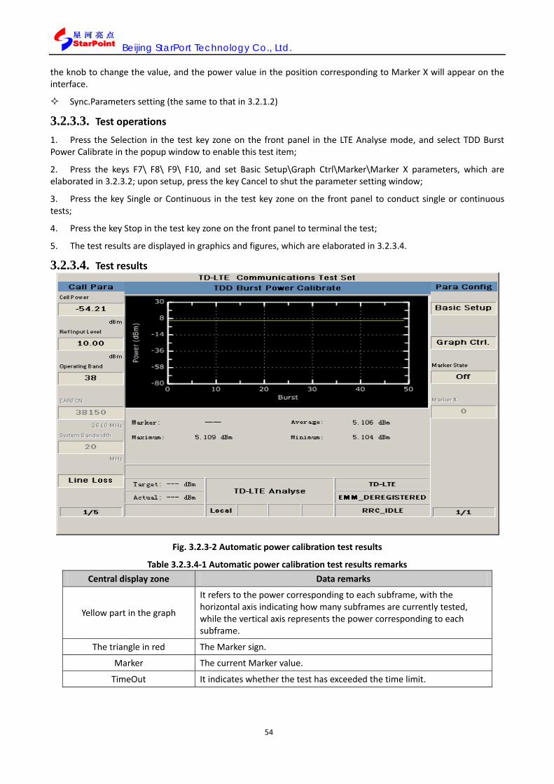
Beijing StarPort Technology Co., Ltd.
54
the knob to change the value, and the power value in the position corresponding to Marker X will appear on the interface.
Sync.Parameters setting (the same to that in 3.2.1.2)
3.2.3.3. Test operations
1. Press the Selection in the test key zone on the front panel in the LTE Analyse mode, and select TDD Burst Power Calibrate in the popup window to enable this test item;
2. Press the keys F7\ F8\ F9\ F10, and set Basic Setup\Graph Ctrl\Marker\Marker X parameters, which are elaborated in 3.2.3.2; upon setup, press the key Cancel to shut the parameter setting window;
3. Press the key Single or Continuous in the test key zone on the front panel to conduct single or continuous tests;
4. Press the key Stop in the test key zone on the front panel to terminal the test;
5. The test results are displayed in graphics and figures, which are elaborated in 3.2.3.4.
3.2.3.4. Test results
Fig. 3.2.3-2 Automatic power calibration test results
Table 3.2.3.4-1 Automatic power calibration test results remarks Central display zone Data remarks
Yellow part in the graph
It refers to the power corresponding to each subframe, with the horizontal axis indicating how many subframes are currently tested, while the vertical axis represents the power corresponding to each subframe.
The triangle in red The Marker sign.
Marker The current Marker value.
TimeOut It indicates whether the test has exceeded the time limit.
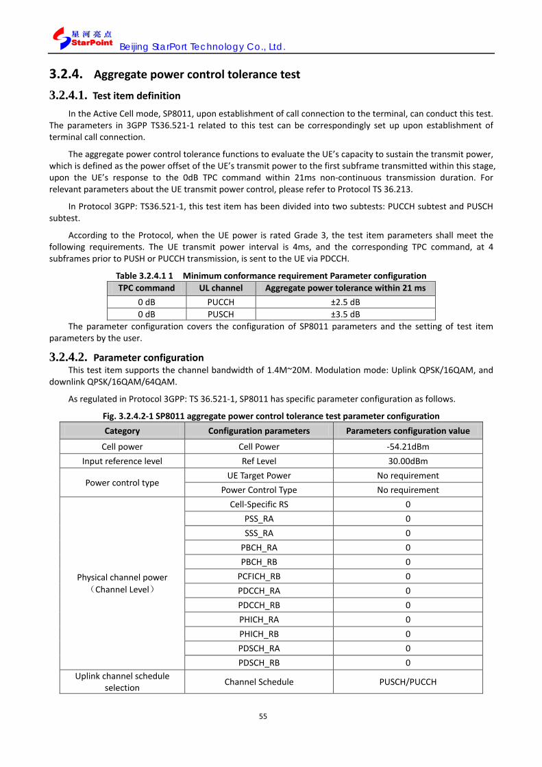
Beijing StarPort Technology Co., Ltd.
55
3.2.4. Aggregate power control tolerance test
3.2.4.1. Test item definition
In the Active Cell mode, SP8011, upon establishment of call connection to the terminal, can conduct this test. The parameters in 3GPP TS36.521-1 related to this test can be correspondingly set up upon establishment of terminal call connection.
The aggregate power control tolerance functions to evaluate the UE’s capacity to sustain the transmit power, which is defined as the power offset of the UE’s transmit power to the first subframe transmitted within this stage, upon the UE’s response to the 0dB TPC command within 21ms non-continuous transmission duration. For relevant parameters about the UE transmit power control, please refer to Protocol TS 36.213.
In Protocol 3GPP: TS36.521-1, this test item has been divided into two subtests: PUCCH subtest and PUSCH subtest.
According to the Protocol, when the UE power is rated Grade 3, the test item parameters shall meet the following requirements. The UE transmit power interval is 4ms, and the corresponding TPC command, at 4 subframes prior to PUSH or PUCCH transmission, is sent to the UE via PDCCH.
Table 3.2.4.1 1 Minimum conformance requirement Parameter configuration TPC command UL channel Aggregate power tolerance within 21 ms
0 dB PUCCH ±2.5 dB 0 dB PUSCH ±3.5 dB
The parameter configuration covers the configuration of SP8011 parameters and the setting of test item parameters by the user.
3.2.4.2. Parameter configuration This test item supports the channel bandwidth of 1.4M~20M. Modulation mode: Uplink QPSK/16QAM, and
downlink QPSK/16QAM/64QAM.
As regulated in Protocol 3GPP: TS 36.521-1, SP8011 has specific parameter configuration as follows.
Fig. 3.2.4.2-1 SP8011 aggregate power control tolerance test parameter configuration Category Configuration parameters Parameters configuration value
Cell power Cell Power -54.21dBm Input reference level Ref Level 30.00dBm
Power control type UE Target Power No requirement
Power Control Type No requirement
Physical channel power(Channel Level)
Cell-Specific RS 0 PSS_RA 0 SSS_RA 0
PBCH_RA 0 PBCH_RB 0
PCFICH_RB 0 PDCCH_RA 0 PDCCH_RB 0 PHICH_RA 0 PHICH_RB 0 PDSCH_RA 0 PDSCH_RB 0
Uplink channel schedule selection Channel Schedule PUSCH/PUCCH

Beijing StarPort Technology Co., Ltd.
56
Note: In any power control type of SP8011, this test can be conducted, and if test is required in the protocol, it can be set in the type of “Target” to configure the target power value in accordance with the protocol requirements. Parameter configuration of test items by the user
As needed for the test, the user can set APCT test parameters, which include Basic Setup, Spec. Setup, Graph Ctrl. and Channel Type, as elaborated below:
Basic Setup parameter setting
Basic Setup works to set the basic parameters of the test item including Trigger Arm, Power Class and Time Out, which are elaborated in 3.2.1.2.
Spec. Setup parameter setting
Spec. Setup refers to the index threshold mask, i.e. the criteria to judge whether the test has passed, and the user can define the mask themselves. The parameters to be set up include:
Requirement Type: Configuration of the test criteria, which is defaulted at Min Requirements, where other parameters in the Spec. Setup is not configurable, and the default value corresponds to the Minimum conformance requirements in protocol 3GPP; when Requirement Type is set at Test Requirement, other parameters in the Spec. Setup are not configurable, and the default value is corresponding to the Test requirement in Protocol 3GPP; when Requirement Type is Manual, other parameters are configurable and the user can set the following parameters:
PUSCH Tolerance(dB): PUSCH channel power control tolerance;
PUCCH Tolerance (dB): PUCCH channel power control tolerance.
Fig. 3.2.4-1 Aggregate power control tolerance test Spec. Setup parameter setting
Table 3.2.4.2-2 Aggregate power control tolerance test Spec. Setup parameter setting remarks
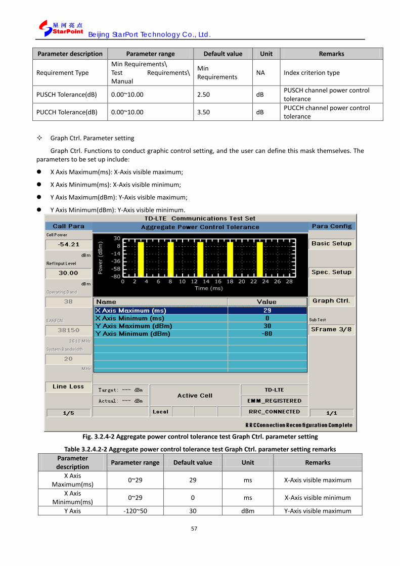
Beijing StarPort Technology Co., Ltd.
57
Parameter description Parameter range Default value Unit Remarks
Requirement Type Min Requirements\ Test Requirements\ Manual
Min Requirements NA Index criterion type
PUSCH Tolerance(dB) 0.00~10.00 2.50 dB PUSCH channel power control tolerance
PUCCH Tolerance(dB) 0.00~10.00 3.50 dB PUCCH channel power control tolerance
Graph Ctrl. Parameter setting
Graph Ctrl. Functions to conduct graphic control setting, and the user can define this mask themselves. The parameters to be set up include:
X Axis Maximum(ms): X-Axis visible maximum;
X Axis Minimum(ms): X-Axis visible minimum;
Y Axis Maximum(dBm): Y-Axis visible maximum;
Y Axis Minimum(dBm): Y-Axis visible minimum.
Fig. 3.2.4-2 Aggregate power control tolerance test Graph Ctrl. parameter setting
Table 3.2.4.2-2 Aggregate power control tolerance test Graph Ctrl. parameter setting remarks Parameter description Parameter range Default value Unit Remarks
X Axis Maximum(ms) 0~29 29 ms X-Axis visible maximum
X Axis Minimum(ms) 0~29 0 ms X-Axis visible minimum
Y Axis -120~50 30 dBm Y-Axis visible maximum
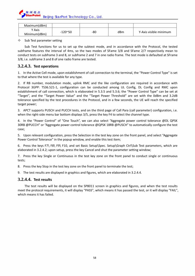
Beijing StarPort Technology Co., Ltd.
58
Maximum(dBm) Y Axis
Minimum(dBm) -120~50 -80 dBm Y-Axis visible minimum
Sub Test parameter setting
Sub Test functions for us to set up the subtest mode, and in accordance with the Protocol, the tested subframe features the interval of 4ms, so the two modes of SFame 3/8 and SFame 2/7 respectively mean to conduct tests on subframe 3 and 8, or subframe 2 and 7 in one radio frame. The test mode is defaulted at SFrame 3/8, i.e. subframe 3 and 8 of one radio frame are tested.
3.2.4.3. Test operations
1. In the Active Cell mode, upon establishment of call connection to the terminal, the “Power Control Type" is set to that where the test is available for any type.
2. If RB number, modulation mode, uplink RMC and the like configuration are required in accordance with Protocol 3GPP: TS36.521-1, configuration can be conducted among UL Config, DL Config and RMC upon establishment of call connection, which is elaborated in 5.3.5 and 5.3.6; the “Power Control Type” can be set at “Target”, and the “Target Power Value” and the “Target Power Threshold” are set with the 0dBm and 3.2dB tolerance specified by the test procedures in the Protocol, and in a few seconds, the UE will reach the specified target power;
3. APCT supports PUSCH and PUCCH tests, and on the third page of Call Para (call parameter) configuration, i.e. when the right-side menu bar bottom displays 3/5, press the key F4 to select the channel type.
4. In the “Power Control” of “One Touch”, we can also select “Aggregate power control tolerance @DL QPSK 30RB @PUCCH” or “Aggregate power control tolerance @QPSK 18RB @PUSCH” to automatically configure the test case;
5. Upon relevant configuration, press the Selection in the test key zone on the front panel, and select “Aggregate Power Control Tolerance” in the popup window, and enable this test item;
6. Press the keys F7\ F8\ F9\ F10, and set Basic Setup\Spec. Setup\Graph Ctrl\Sub Test parameters, which are elaborated in 3.2.4.2; upon setup, press the key Cancel and shut the parameter setting window;
7. Press the key Single or Continuous in the test key zone on the front panel to conduct single or continuous tests;
8. Press the key Stop in the test key zone on the front panel to terminate the test;
9. The test results are displayed in graphics and figures, which are elaborated in 3.2.4.4.
3.2.4.4. Test results
The test results will be displayed on the SP8011 screen in graphics and figures, and when the test results meet the protocol requirements, it will display “PASS”, which means it has passed the test, or it will display “FAIL”, which means it has failed.
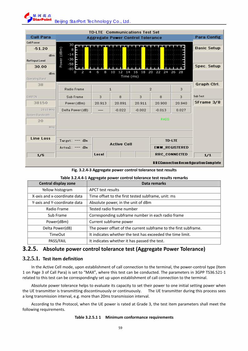
Beijing StarPort Technology Co., Ltd.
59
Fig. 3.2.4-3 Aggregate power control tolerance test results
Table 3.2.4.4-1 Aggregate power control tolerance test results remarks Central display zone Data remarks
Yellow histogram APCT test results X-axis and x-coordinate data Time offset to the first tested subframe, unit: ms Y-axis and Y-coordinate data Absolute power, in the unit of dBm
Radio Frame Tested radio frame number Sub Frame Corresponding subframe number in each radio frame
Power(dBm) Current subframe power Delta Power(dB) The power offset of the current subframe to the first subframe.
TimeOut It indicates whether the test has exceeded the time limit. PASS/FAIL It indicates whether it has passed the test.
3.2.5. Absolute power control tolerance test (Aggregate Power Tolerance)
3.2.5.1. Test item definition
In the Active Cell mode, upon establishment of call connection to the terminal, the power-control type (Item 1 on Page 3 of Call Para) is set to “MAX”, where this test can be conducted. The parameters in 3GPP TS36.521-1 related to this test can be correspondingly set up upon establishment of call connection to the terminal.
Absolute power tolerance helps to evaluate its capacity to set their power to one initial setting power when the UE transmitter is transmitting discontinuously or continuously. The UE transmitter during this process sees a long transmission interval, e.g. more than 20ms transmission interval.
According to the Protocol, when the UE power is rated at Grade 3, the test item parameters shall meet the following requirements.
Table 3.2.5.1 1 Minimum conformance requirements

Beijing StarPort Technology Co., Ltd.
60
Conditions Tolerance Normal conditions ± 9.0 dB Extreme conditions ± 12.0 dB
3.2.5.2. Parameter configuration
The parameter configuration covers the configuration of SP8011 parameters and the setting of test item parameters by the user.
Parameter configuration
This test item supports the channel bandwidth of 1.4M~20M. Modulation mode: Uplink QPSK/16QAM, and downlink QPSK/16QAM/64QAM.
As regulated in Protocol 3GPP: TS 36.521-1, SP8011 has specific parameter configuration as follows.
Fig. 3.2.5.2-1 SP8011 absolute power control tolerance test parameter configuration Category Configurable parameters Parameters configuration value
Cell power Cell Power -54.21dBm Input reference level Ref Level 30.00dBm
Power control type UE Target Power Off
Power Control Type TPC0
Physical channel power(Channel Level)
Cell-Specific RS 0 PSS_RA 0 SSS_RA 0
PBCH_RA 0 PBCH_RB 0
PCFICH_RB 0 PDCCH_RA 0 PDCCH_RB 0 PHICH_RA 0 PHICH_RB 0 PDSCH_RA 0 PDSCH_RB 0
Uplink channel schedule selection Channel Schedule PUSCH/PUCCH
Parameter configuration of test items by the user
As needed during the absolute power control tolerance test, the user can set APT test parameters, which include Basic Setup and Spec. Setup, as elaborated below:
Basic Setup parameter setting
Basic Setup works to set the basic parameters of the test item including Power Class and Time Out, which are elaborated in 3.2.1.2.
Spec. Setup parameter setting
Spec. Setup refers to the index threshold mask, i.e. the criteria to judge whether the test has passed, and the user can define the mask themselves. The parameters to be set up include:
Requirement: Configuration of the test criteria, which is defaulted at Min Requirements, where other parameters in the Spec. Setup is not configurable, and the default value corresponds to the Minimum conformance requirements in protocol 3GPP; when the Requirement Type is set at Test Requirement, other

Beijing StarPort Technology Co., Ltd.
61
parameters in the Spec. Setup are not configurable, and the default value is corresponding to the Test requirement in Protocol 3GPP; when Requirement Type is Manual, other parameters are configurable and the user can set the following parameters:
Expected Measured Power Threshold: Expected power threshold (on normal conditions), for configuring the expected power threshold by default.
Fig. 3.2.5-1 Absolute power control tolerance test Spec. Setup parameter setting
Table 3.2.5.2-2 Absolute power control tolerance test Spec. Setup parameter setting remarks Parameter description
Parameter range Default value Unit Remarks
Requirements Type Min Requirement/ Test Requirement/
Manual Min Requirement NA Index criterion type
Expected Measured Power Threshold -20.00~20.00 9.00 dB
Expected power threshold(Normal)
3.2.5.3. Test operations 1. In the Active Cell operating mode, press the key More (page flipping) on the left side to enter into the third page for Call Para (call parameters) configuration, and the bottom of the menu on the right side displays 3/5; press the key F1, and set the “Power Control Type” as “TPC0”;
2. If RB number, modulation mode, uplink RMC and the like configuration are required in accordance with Protocol 3GPP: TS36.521-1, configuration can be conducted among UL Config and RMC upon establishment of call connection, which is elaborated in 5.3.5;
3. For the parameter “p0-NominalPUSCH” in the test points required in Protocol TS36.521-1, we can enter into the third page for Call Control, and when the bottom of the menu on the right side displays 3/5, press the key F1,

Beijing StarPort Technology Co., Ltd.
62
and set corresponding parameters in “PUSCH” as -93 or -105;
4. We can also select “Power Control Absolute power tolerance \n @QPSK 100RB @p0-NominalPUSCH -93” or “Power Control Absolute power tolerance \n @QPSK 100RB @p0-NominalPUSCH -105” in “Power Control” of “One Touch” and directly complete corresponding configuration;
5. Upon relevant configuration, press the Selection in the test key zone on the front panel, and select “Absolute Power Tolerance” in the popup window, and enable this test item;
6. Press the key F7\F8, and set the Basic Setup\Spec. Setup, which are elaborated in 3.2.5.2; upon setup, press the key Cancel and shut the parameter setting window;
7. Press the key Single or Continuous in the test key zone on the front panel to conduct single or continuous tests;
8. Press the key Stop in the test key zone on the front panel to terminate the test;
9. The test results are displayed in graphics and figures, which are elaborated in 3.2.5.4. 3.2.5.4. Test results
The test results will be displayed on the SP8011 screen in figures, and when the test results meet the protocol requirements, it will display “PASS”, which means it has passed the test, or it will display “FAIL”, which means it has failed.
Fig. 3.2.5-2 Absolute power control tolerance test results
Fig. 3.2.5.4-1 Absolute power control tolerance test results remarks Central display zone Data remarks
Power Control Absolute Power Actually measured UE power.
Expected Measured Power(Ppusch(i)) The expected UE transmit power calculated based on the current configuration.
Equation in the box Equation for calculating the expected UE transmit power.
PCMAX Configuring the maximum UE output power
10*log10(M_PUSCH(i)) The parameter for calculating the expected power parameter: M_PUSCH(i) is the currently configured RB number, which is defaulted at 25 in the instrument.

Beijing StarPort Technology Co., Ltd.
63
P_O_PUSCH(j) Initial value of PUSCH power, configurable parameter (on the third page for “Call Ctrl", press the button “PUSCH” to set parameter “p0-NominalPUSCH”), which is defaulted at -85dBm.
a(j)
Path loss compensating factor, cell-specific parameter, which is defaulted at 0.8. Configurable parameter (on the third page for “Call Ctrl”, press the button “PUSCH” to set parameter “alpha”), which is defaulted at 0.8.
PL Downlink path loss, PL = referenceSignalPower – higher layer filtered RSRP
△TF(i)
It represents different power offset corresponding to different MCS modes, which are indicated by the upper layer signals. In the current configuration of SP8011, this parameter is 0, which means to shut the function of adjusting the power in line with MCS.
f(i) The power adjustment value of the aggregate value mode corresponding to the TPC command.
TimeOut It indicates whether the test has exceeded the time limit.
PASS/FAIL It indicates whether it has passed the test.
3.2.6. Throughput capacity test (UL & DL Throughput)
3.2.6.1. Test item definition In the Active Cell mode, SP8011, upon establishment of call connection to the terminal, can conduct this test.
The parameters in 3GPP TS36.521-1 related to this test can be correspondingly set up upon establishment of call connection to the terminal.
Throughput refers to the transmission rate of digital signals within one radio frame, i.e. kb per second. This test list helps to test Reference sensitivity level and Maximum input level in receiver tests, which can work with other instruments and apparatuses to conduct Adjacent Channel Selectivity (ACS), Blocking characteristics, Spurious response, Intermodulation characteristics and Spurious emissions tests.
3.2.6.2. Parameter configuration The parameter configuration covers the configuration of SP8011 parameters and the setting of test item
parameters by the user. SP8011 Parameter configuration
This test item supports the channel bandwidth of 1.4M~20M. Modulation mode: Uplink QPSK/16QAM, and downlink QPSK/16QAM/64QAM. As regulated in Protocol 3GPP: TS 36.521-1, SP8011 has specific parameter configuration as follows.
Table 3.2.6.2 1 SP8011 block error rate test parameter configuration Category Configurable parameters Parameters configuration value
Cell power Cell Power -54.21dBm Input reference level Ref Level 30.00dBm
Power control type UE Target Power No requirement
Power Control Type No requirement
Physical channel power(Channel Level)
Cell-Specific RS 0 PSS_RA 0 SSS_RA 0
PBCH_RA 0 PBCH_RB 0
PCFICH_RB 0 PDCCH_RA 0

Beijing StarPort Technology Co., Ltd.
64
PDCCH_RB 0 PHICH_RA 0 PHICH_RB 0 PDSCH_RA 0 PDSCH_RB 0
Uplink channel schedule selection Channel Schedule PUSCH
Parameter configuration of test items by the user
As needed during throughput test, the user can set throughout test parameters, which include Basic Setup, Spec. Setup, and Channel Type, as elaborated below:
Basic Setup parameter setting
Basic Setup helps to set up the basic parameters of test items, which include PUSCH Frame Number, PDSCH Frame Number, Trigger Arm and Time Out, as elaborated below:
PUSCH Frame Number: PUSCH channel radio frame number;
PDSCH Frame Number: PDSCH channel radio frame number;
Trigger Arm: Trigger mode, including Single( single test)和 Continuous( continuous test);
Time Out: Timeout limit, for setting the maximum time limit for not receiving the uplink data before test termination during the test process;
Fig. 3.2.6-1 Throughput rate test Basic Setup parameters setting

Beijing StarPort Technology Co., Ltd.
65
Table 3.2.6.2-2 Throughput rate test Basic Setup parameters setting remarks Parameter description Parameter range Default value Unit Remarks
PUSCH Frame Number 1~500000 200 NA PUSCH channel radio frame number
PDSCH Frame Number 1 ~ 500000 200 NA PDSCH channel radio frame number
Time Out 1 ~ 20 20 s Time Out
Trigger Arm Single / Continuous Single NA Trigger Arm
Spec. Setup parameter setting
Spec. Setup refers to the index threshold mask, i.e. the criteria to judge whether the test has passed, and the user can define the mask themselves. The parameters to be set up include:
PUSCH Throughput Request: PUSCH channel throughput test requirements;
PDSCH Throughput Request: PDSCH channel throughput test requirements;
Fig. 3.2.6-2 Throughput rate test Basic Setup parameters setting
Table 3.2.6.2-3 Throughput rate test Spec. Setup parameters setting remarks Parameter description Parameter range Default value Unit Remarks
PUSCH Throughput Request(%) 0~100 95.00 NA PUSCH channel throughput test requirements
PDSCH Throughput Request(%) 0~100 95.00 NA PDSCH channel throughput test requirements

Beijing StarPort Technology Co., Ltd.
66
Channel Type parameters setting
Channel Type helps to select test channel configuration, which ranges: PDSCH/PUSCH/ALL and is defaulted at PDSCH. The options have the following implications:
PDSCH: Only for testing downlink throughput;
PUSCH: Only for testing uplink throughput;
ALL: For simultaneous testing of uplink and downlink throughput.
3.2.6.3. Test operations
1. In the Active Cell operating mode, enter into the first page for Call Para (call parameters) configuration, select any next-line “RMC”, or schedule any PDSCH via UserDefine.
2. Press the Selection in the test key zone on the front panel, and select UL & DL Throughput in the popup window, and enable this test item;
3. For this test item, different RB numbers will see different test results; press the key Stop to stop the test item, and then press the key Home to return to the initial interface, to enter into DL Config in Call Control to change the test RB value, and then enter into UL & DL Throughput to conduct tests;
4. Press the key Stop in the test key zone on the front panel to terminate the test;
5. The test results are displayed in graphics and figures, which are elaborated in 3.2.6.4.
3.2.6.4. Test results
The test results will be displayed on the SP8011 screen in figures, and when the test results meet the protocol requirements, it will display “PASS”, which means it has passed the test, or it will display “FAIL”, which means it has failed.

Beijing StarPort Technology Co., Ltd.
67
Fig. 3.2.6-3 Block error rate test results
Table 3.2.6.4-1 Block error rate test results remarks Central display zone Data remarks
Blocks tested(PDSCH) Tested block Number ACK(PDSCH) ACK Number NACK(PDSCH) NACK Number StatDTX(PDSCH) StatDTX Number BLER(PDSCH) Block error rate Throughput(PDSCH) Throughput %(PDSCH) The maximum throughput% PASS/FAIL(PDSCH) If it is pass for the throughput test Blocks tested(PUSCH) Tested block Number ACK(PUSCH) ACK Number NACK(PUSCH) NACK Number StatDTX(PUSCH) StatDTX Number BLER(PUSCH) Block error rate Throughput(PUSCH) Throughput %(PUSCH) The maximum throughput% PASS/FAIL(PUSCH) If it is pass for the throughput test TimeOut It is displayed if the time is out for test
3.2.7. Channel state information report test (Channel State Information)
3.2.7.1. Test item definition
The channel state report test mainly covers:
CQI report under the AWGN conditions
The wideband CQI report precision on nonselective frequency condition can be measured by the following two parameters: (1) reported CQI variance, (2) error rate for downlink data reception and transmission with transmission block corresponding to the reported CQI.
Measurement of these parameters can help ascertain whether the CQI value reported from the terminal can be in line with the CQI value defined in Protocol TS 36.213: 7.2.3.
CQI report on fading condition
The sub-band CQI report precision can be measured by the following two parameters: (1) Whether the CQI value correctly reflects the sub-band signal-to-noise ratio, (2) The Throughput promotion rate with sub-band and transmission block corresponding to the reported sub-band CQI to conduct data reception and transmission, and random selection of sub-band to conduct data reception and transmission. Moreover, measuring broadband CQI report variance on fading condition can verify whether the broadband CQI report meet the requirements from the opposite perspective.
PMI reporting
The PMI report precision is measured by precoding gain, which is measured based on the comparison of the downlink data transmission Throughput upon precoding of the PMI array reported from the UE, and the Throughtput during random selection of the encoding matrix. In this type of test items, transmission mode 6 (single layer closed loop SDM) and corresponding FRC are employed in a unified manner. Generally, the Throughput gain is represented by the following equation:
rnd
ue
tt
=γ

Beijing StarPort Technology Co., Ltd.
68
Where, as a rule rndt is around 60%, and its corresponding SNR value is represented by rndSNR , and the
Throughput value when uet is rndSNR and the UE reported PMI is employed to precode. RI reporting
The RI report precision is measured by precoding gain, which is measured based on the comparison of the downlink data transmission Throughput upon precoding of the RI real-time adjusted precoding matrix reported from the UE, and the Throughput during the RI-fixed real-time adjusted precoding matrix. The test aims at checking whether the terminal feedback RI value correctly reflects the transmission of the radio transmission channel. In the test item, transmission mode 4 is employed in a unified manner, and specific CodebookSubSetRestriction is specified.
3.2.7.2. Parameter configuration
The parameter configuration covers the configuration of SP8011 parameters and the setting of test item parameters by the user.
SP8011 Parameter configuration
This test item supports the channel bandwidth of 1.4M~20M. Modulation mode: Uplink QPSK/16QAM, and downlink QPSK/16QAM/64QAM..
As regulated in Protocol 3GPP: TS 36.521-1, SP8011 has specific parameter configuration as follows. Table 3.2.7.2-1 SP8011 channel state information report test parameter configuration
Category Configurable parameters Parameters configuration value
Cell power Cell Power -54.21dBm Input reference level Ref Level 30.00dBm
Power control type UE Target Power No requirement
Power Control Type No requirement
Physical channel power(Channel Level)
Cell-Specific RS 0 PSS_RA 0 SSS_RA 0
PBCH_RA 0 PBCH_RB 0
PCFICH_RB 0 PDCCH_RA 0 PDCCH_RB 0 PHICH_RA 0 PHICH_RB 0 PDSCH_RA 0 PDSCH_RB 0
Uplink channel schedule selection Channel Schedule PUSCH
Parameter configuration of test items by the user
As needed for the test, the user can set channel state information report test parameters, which include Basic Setup, Spec. Setup, Sub Test and Subband Index, as elaborated below:
Basic Setup parameter setting
Basic Setup works to set the basic parameters of the test item including Trigger and Time Out, which are elaborated in 3.2.1.2.

Beijing StarPort Technology Co., Ltd.
69
Spec. Setup parameter setting
Spec. Setup refers to the index threshold mask, i.e. the criteria to judge whether the test has passed, and the user can define the mask themselves. The parameters to be set up include:
Requirement Type: Configuration of the test criteria, which is defaulted at Min Requirements, where other parameters in the Spec. Setup is not configurable, and the default value corresponds to the Minimum conformance requirements in protocol 3GPP; when Requirement Type is set at Test Requirement, other parameters in the Spec. Setup are not configurable, and the default value is corresponding to the Test requirement in Protocol 3GPP; when Requirement Type is Manual, other parameters are configurable and the user can set the following parameters:
Wideband Median Range: CQI Wideband Median tolerance;
Wideband Occurrence MIN: Minimum value occurrence probability;
BLER Threshold: Block error rate required for tests.
Fig. 3.2.7-1 Channel state information test Spec. Setup parameters setting
Table 3.2.7.2 -2 Channel state information test Spec. Setup parameters setting remarks Parameter description Parameter range Default value Unit Remarks
Requirement Type
Min Requirements/
Test Requirements/
Manual
Min Requirements NA Index criterion type
Wideband Median Range 1~15 1 NA CQI Wideband Median tolerance
Wideband Occurrence MIN 0.00~1.00 0.90 NA Minimum value
occurrence probability BLER Threshold 0.00~1.00 0.10 NA Block error rate required

Beijing StarPort Technology Co., Ltd.
70
for tests.
Sub Test parameter setting
The channel state information report test supports the following sub-test types.
Fig. 3.2.7-2 Channel state information test Spec. Setup parameters setting
Table 3.2.7.2 -3 Channel state information test Spec. Setup parameters setting remarks Parameter description Remarks
AWGN PUCCH 1-0 CQI Reporting under AWGN conditions FADING PUSCH 3-0 CQI Reporting under fading conditions FADING PUCCH 1-0 CQI Reporting under fading conditions
PUSCH FSI 3-0 CQI reporting under frequency-selective interference fading conditions
PMI PUSCH 3-1 Precoding matrix-indicated data report PMI PUSCH 1-2 Precoding matrix-indicated data report RI PUSCH 3-1 Grade-indicated data report
Subband parameter setting
Currently, this parameter is not configurable, but defaulted at 0.

Beijing StarPort Technology Co., Ltd.
71
3.2.7.3. Test operations
1. In the Active Cell operating mode, press the key More (page flipping) on the left side to enter into the third page for Call Para (call parameters) configuration, and the bottom of the menu on the right side displays 3/5; press the key F1, and set the “Power Control Type” as “Max”, “TPC0” or “Target”, and then press the Selection in the test key zone on the front panel, and select Channel State Information in the popup window, and enable this test item;
2. Press the keys F7\ F8\ F9, and set Basic Setup\Spec. Setup\Sub Test, and Basic Setup parameters are elaborated in 3.2.7.2; upon setup, press the key Cancel and shut the parameter setting window;
3. Press the key Single or Continuous in the test key part on the front panel to conduct single or continuous tests;
4. Press the key Stop in the test key part on the front panel to terminate the test;
5. The test results are displayed in graphics and figures, which are elaborated in 3.2.7.4.
3.2.7.4. Test results The test results will be displayed on the SP8011 screen in graphics and figures, and when the test results
meet the protocol requirements, it will display “PASS”, which means it has passed the test, or it will display “FAIL”, which means it has failed.
Fig. 3.2.7-3 Channel state information report test results
Table 3.2.7.4-1 Channel state information report test results remarks
Central display zone Data remarks
CQI processing flow It indicates the test procedures and results of the CQI subtests
Median CQI CQI value

Beijing StarPort Technology Co., Ltd.
72
3.2.8. Continuous wave test (Continuous Wave)
3.2.8.1. Test item definition
In the CW mode, SP8011 can conduct frequency and power tests on CW signals. As needed for the test, the user can set CW test parameters, which include Basic Setup, as elaborated below.
3.2.8.2. Parameter configuration
As needed for the test, the user can set test item parameters, which include Basic Setup, as elaborated below:
Basic Setup works to set the basic parameters of the test item including Time Out and Trigger Arm, which are elaborated in 3.2.1.2.
3.2.8.3. Test operations
The continuous wave test is conducted in the CW mode, where SP8011 can test received CW waves, and the test procedures go as follows:
1. Press the key Setup in the call key zone on the front panel, and switch SP8011 to the calling page;
2. Press F7, and set the Operation Mode and enter into the CW operation mode.
3. Press the key Selection on the test key zone of the front panel, and select Continuous Wave, and enable this test item;
4. Press the key F7, and set the Basic Setup parameters, which are elaborated in 3.2.8.2; upon setup, press the key Cancel and shut the parameter setting window;
5. Press the key Single or Continuous in the test key zone on the front panel to conduct single or continuous tests;
6. Press the key Stop in the test key zone on the front panel to terminate the test;
7. The test results are displayed in graphics and figures, which are elaborated in 3.2.8.3.
3.2.8.4. Test results
The test results will be displayed in figures on the SP8011 screen.

Beijing StarPort Technology Co., Ltd.
73
Fig. 3.2.8-1 Continuous wave test results
Fig. 3.2.8.4-1 Continuous wave test results remarks Central display zone Data remarks
Peak Power Frequency CW peak power frequency.
Peak Power CW peal power.
3.2.9. Fast power calibration test (Fast Power Calibration) 3.2.9.1. Test item definition
LTE fast power calibration (LTE_FDT) can help conduct fast calibration function on terminal power.
In this mode, integrated instrument and terminals see fast power calibration (Fast Device Time), and this scheme supports GPIB remote control only, which, based on the radio frequency board’s Listmode function, makes good use of all subframes of one radio frame, and conduct calibration on different power points and frequency points, so as to reduce the test duration and lower test costs. Setting GPIB commands works to configure the uplink test sequence and downlink test sequence, and complete radio frequency Listmode parameter setup, and activate fast calibration measurement to calibrate APC and AGC in parallel.
There are three LTE_FDT operation modes: MODE_A, MODE_B and MODE_C.
MODE_A: In this mode, the instrument side launches broadcast, which is detected by the terminal, which then return rigger signals; upon the instrument side’s confirmation of rigger signal reception, the test starts.
MODE_B: In this mode, the terminal side sends out trigger signals at fixed subframe, and the instrument detects the signal and adjusts the clock to synchronize the terminal, before the test starts.

Beijing StarPort Technology Co., Ltd.
74
MODE_C: In this mode, the instrument side follows the configured test sequence to directly transmit downlink signals, and at the same time detect uplink signals, and the terminal automatically detects downlink signals.
3.2.9.2. Parameter configuration The parameter configuration covers the configuration of SP8011 parameters and the setting of test item
parameters by the user.
SP8011 Parameter configuration
This test item supports the channel bandwidth of 1.4M~20M. Modulation mode: Uplink QPSK/16QAM, and downlink QPSK/16QAM/64QAM.
As regulated in Protocol 3GPP: TS 36.521-1, SP8011 has specific parameter configuration as follows. Table 3.2.9.2 1 SP8011 channel state information report test parameter configuration
Category Configurable parameters Parameters configuration value
Cell power Cell Power -54.21dBm Input reference level Ref Level 30.00dBm
Power control type UE Target Power No requirement Power Control Type No requirement
Physical channel power(Channel Level)
Cell-Specific RS 0 PSS_RA 0 SSS_RA 0 PBCH_RA 0 PBCH_RB 0 PCFICH_RB 0 PDCCH_RA 0 PDCCH_RB 0 PHICH_RA 0 PHICH_RB 0 PDSCH_RA 0 PDSCH_RB 0
Uplink channel schedule selection Channel Schedule PUSCH
Parameter configuration of test items by the user
As needed for the test, the user can set channel state information report test parameters, which include Basic Setup, Y Range, Marker and Marker X, as elaborated below:
Basic Setup parameter setting
Basic Setup works to set the basic parameters of the test item including Time Out, which is elaborated in 3.2.1.2. Y Rang parameter configuration
Y Rang refers to Y Axis setup, covering Y Range Bottom, Y Range Top and Y Range Step. The details go as follows:
Y Range Bottom: Set up the minimum value along Y Axis;
Y Range Bottom: Set up the maximum value along Y Axis;
Y Range Bottom: Set up the interval along Y Axis.

Beijing StarPort Technology Co., Ltd.
75
Marker parameter setting
Masker is the switch to set the Marker display, ranging: On / Off, On means to display Marker; Off means not to display Marker.
Marker X parameter setting
Marker X works to set Marker x-coordinate value when Marker employed, which ranges: 0 ~3000us and is defaulted at 0. Turn the knob to change the value, and the power value in the position corresponding to Marker X will be displayed on the interface.
3.2.9.3. Test operations 1. Connect the instrument to the upper computer via GPIB card, and the upper computer runs program set in Mode to ensure the terminals are in line with the maximum user demand;
2. Press the key Stepup in the call key zone on the front panel, and switch SP8011 to the calling page;
3. Press F7, and set the Operation Mode and enter into the LTE Analyse operation mode;
4. Press the key Selection in the test key zone on the front panel, and select Fast Power Calibrate, and enable this test item;
5. Press the key F7, and set the Basic Setup parameters; upon setup, press the key Cancel and shut the parameter setting window;
6. Press the key Stop in the test key zone on the front panel to terminate the test;
7. The test results are displayed in graphics and figures, which are elaborated in 3.2.9.4. 3.2.9.4. Test results
Fig. 3.2.9-1 FPCalibration test results
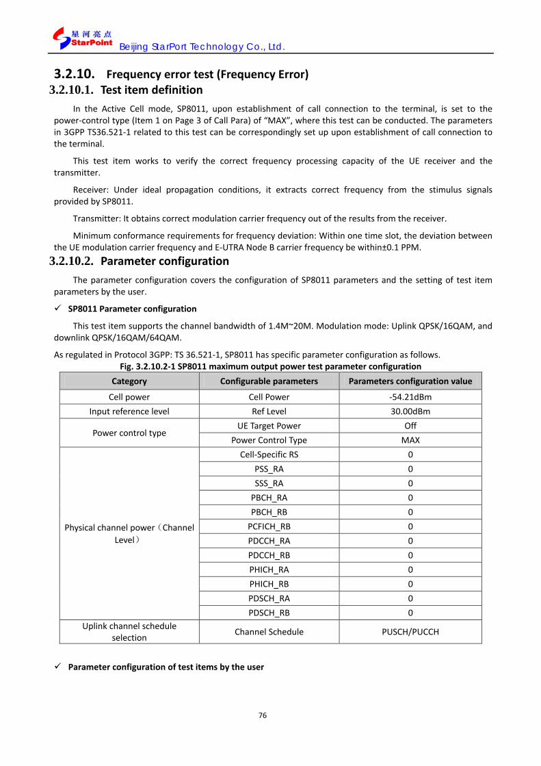
Beijing StarPort Technology Co., Ltd.
76
3.2.10. Frequency error test (Frequency Error) 3.2.10.1. Test item definition
In the Active Cell mode, SP8011, upon establishment of call connection to the terminal, is set to the power-control type (Item 1 on Page 3 of Call Para) of “MAX”, where this test can be conducted. The parameters in 3GPP TS36.521-1 related to this test can be correspondingly set up upon establishment of call connection to the terminal.
This test item works to verify the correct frequency processing capacity of the UE receiver and the transmitter.
Receiver: Under ideal propagation conditions, it extracts correct frequency from the stimulus signals provided by SP8011.
Transmitter: It obtains correct modulation carrier frequency out of the results from the receiver.
Minimum conformance requirements for frequency deviation: Within one time slot, the deviation between the UE modulation carrier frequency and E-UTRA Node B carrier frequency be within±0.1 PPM.
3.2.10.2. Parameter configuration The parameter configuration covers the configuration of SP8011 parameters and the setting of test item
parameters by the user.
SP8011 Parameter configuration
This test item supports the channel bandwidth of 1.4M~20M. Modulation mode: Uplink QPSK/16QAM, and downlink QPSK/16QAM/64QAM.
As regulated in Protocol 3GPP: TS 36.521-1, SP8011 has specific parameter configuration as follows. Fig. 3.2.10.2-1 SP8011 maximum output power test parameter configuration
Category Configurable parameters Parameters configuration value
Cell power Cell Power -54.21dBm Input reference level Ref Level 30.00dBm
Power control type UE Target Power Off
Power Control Type MAX
Physical channel power(Channel Level)
Cell-Specific RS 0 PSS_RA 0 SSS_RA 0
PBCH_RA 0 PBCH_RB 0
PCFICH_RB 0 PDCCH_RA 0 PDCCH_RB 0 PHICH_RA 0 PHICH_RB 0 PDSCH_RA 0 PDSCH_RB 0
Uplink channel schedule selection Channel Schedule PUSCH/PUCCH
Parameter configuration of test items by the user

Beijing StarPort Technology Co., Ltd.
77
As needed for the test, the user can set frequency error test item parameters, which include Basic Setup, Spec. Setup, Graph Ctrl. and Channel Type, as elaborated below:
Basic Setup parameter setting
Basic Setup works to set the basic parameters of the test item including Average Count, Trigger Arm, Power Class, Time Out, which are elaborated in 3.2.1.2.
Spec. Setup parameter setting
Spec. Setup refers to the index threshold mask, i.e. the criteria to judge whether the test has passed, and the user can define the mask themselves. The parameters to be set up include:
Requirement Type: Configuration of the test criteria, which is defaulted at Min Requirements, where other parameters in the Spec. Setup is not configurable, and the default value corresponds to the Minimum conformance requirements in protocol 3GPP; when Requirement Type is set at Test Requirement, other parameters in the Spec. Setup are not configurable, and the default value is corresponding to the Test requirement in Protocol 3GPP; when Requirement Type is Manual, other parameters are configurable and the user can set the following parameters:
Frequency Error( PPM): Frequency error ratio;
Fig. 3.2.10-1 Block error rate test Basic Setup parameters setting
Table 3.2.10.2-2 Block error rate test Spec. Setup parameters setting remarks
Parameter description Parameter range Default value Unit Remarks
Requirement Type Min Requirements/ Test Requirements/
Manual Min Requirements NA Index criterion type

Beijing StarPort Technology Co., Ltd.
78
Frequency Error(PPM) 0~100 0.10 PPM Frequency error ratio
3.2.10.3. Test operations 1. In the Active Cell operating mode, press the key More (page flipping) on the left side to enter into the third page for Call Para (call parameters) configuration, and the bottom of the menu on the right side displays 3/5; press the key F1, and set the “Power Control Type” as “Max”.
2. If RB number, modulation mode, uplink RMC and the like configuration are required in accordance with Protocol 3GPP: TS36.521-1, configuration can be conducted among UL Config, DL Config and RMC upon establishment of call connection, which is elaborated in 5.3.5 and 5.3.6;
3. We can also select “Frequency Error @UL QPSK 100RB @DL QPSK 100RB @Pumax” out of “FER & EVM” on “One Touch”, to directly complete corresponding configuration;
4. Upon corresponding configuration, press the Selection in the test key zone on the front panel, and select “Frequency Error” in the popup window, and enable this test item;
5. Press the key F7, and set the Basic Setup parameters, which are elaborated in 4.1.7.1; upon setup, press the key Cancel and shut the parameter setting window;
6. Press the key F8, and set the Spec. Setup parameters, which are elaborated in 4.1.7.2; upon setup, press the key Cancel and shut the parameter setting window;
7. Press the key Single or Continuous in the test key zone on the front panel to conduct single or continuous tests;
8. Press the key Stop in the test key zone on the front panel to terminate the test;
9. The test results are displayed in graphics and figures, which are elaborated in 3.2.10.4. 3.2.10.4. Test results
The test results will be displayed on the SP8011 screen in figures, and when the test results meet the protocol requirements, it will display “PASS”, which means it has passed the test, or it will display “FAIL”, which means it has failed.

Beijing StarPort Technology Co., Ltd.
79
Fig. 3.2.10-2 Frequency error test results
Table 3.2.6.4-1 Frequency error test results remarks Central display zone Data remarks
Frequency Error
Current Currently tested frequency error.
Maximum Maximum frequency error during multiple average measurement.
Minimum Minimum frequency error during multiple average measurement.
Average Average frequency error during multiple average measurement.
Frequency Stability
Current Currently tested subfrequency stability.
Maximum Maximum frequency stability during multiple average measurement.
Minimum Minimum frequency stability during multiple average measurement.
Average Average frequency stability during multiple average measurement.
Test Count Average FERR test times. TimeOut It indicates whether the test has exceeded the time limit. PASS/FAIL It indicates whether it has passed the test.

Beijing StarPort Technology Co., Ltd.
80
3.2.11. Minimum output power test (Minimum Output Power)
3.2.11.1. Test item definition
In the Active Cell mode, SP8011, upon establishment of call connection to the terminal, is set to the power-control type (Item 1 on Page 3 of Call Para) of “MIN”, where this test can be conducted. The parameters in 3GPP TS36.521-1 related to this test can be correspondingly set up upon establishment of terminal call connection.
The minimum output power test functions to verify the minimum output power of the UE and check out whether its dynamic range is restricted below the protocol-designated value.
According to the Protocol, when the UE power is rated at Category 3, the test item parameters shall meet the following requirements.
Table 3.2.11.1-1 Minimum output power minimum conformance requirements Channel bandwidth / minimum output power / measurement
bandwidth 1.4 MHz
3.0 MHz
5 MHz
10 MHz
15 MHz
20 MHz
Minimum output power -40 dBm
3.2.11.2. Parameter configuration
The parameter configuration covers the configuration of SP8011 parameters and the setting of test item parameters by the user.
This test item supports the channel bandwidth of 1.4M~20M. Modulation mode: Uplink QPSK/16QAM, and downlink QPSK/16QAM/64QAM.
SP8011 parameter configuration Fig. 3.2.11.2 1 SP8011 minimum output power test parameter configuration
Category Configurable parameters Parameters configuration value
Cell power Cell Power -54.21dBm Input reference level Ref Level -10.00dBm
Power control type UE Target Power Off
Power Control Type MIN
Physical channel power(Channel Level)
Cell-Specific RS 0 PSS_RA 0 SSS_RA 0
PBCH_RA 0 PBCH_RB 0
PCFICH_RB 0 PDCCH_RA 0 PDCCH_RB 0 PHICH_RA 0 PHICH_RB 0 PDSCH_RA 0 PDSCH_RB 0
Uplink channel schedule selection Channel Schedule PUSCH/PUCCH

Beijing StarPort Technology Co., Ltd.
81
Parameter configuration of test items by the user
As needed for the test, the user can set MIOP test parameters, which include Basic Setup and Spec. Setup, as elaborated below:
Basic Setup parameter setting (The same to that in 3.2.1.2)
Basic Setup works to set the basic parameters of the test item including Average Count, Subframe No, Trigger Arm、Power Class and Time Out, which are elaborated in 3.2.1.2.
Spec. Setup parameter setting
Spec. Setup refers to the index threshold mask, i.e. the criteria to judge whether the test has passed, and whether the user can define the mask themselves.
Requirement Type: Configuration of the test criteria, which is defaulted at Min Requirements, where other parameters in the Spec. Setup is not configurable, and the default value corresponds to the Minimum conformance requirements in protocol 3GPP; when the Requirement Type is set at Test Requirement, other parameters in the Spec. Setup are not configurable, and the default value is corresponding to the Test requirement in Protocol 3GPP; when Requirement Type is Manual, other parameters are configurable and the user can set the following parameters;
Minimum Output Power, minimum output power threshold, as in the Test Requirements/Minimum Conformance Requirements mode, the parameters are not configurable, but fixed at -40/-39dBm; and in the Manual mode, the user can set the parameter range: -100~-20;
Fig. 3.2.11-1 Minimum output power test Spec. Setup parameter setting
Table 3.2.11.2-2 Minimum output power test Spec. Setup parameter setting remarks

Beijing StarPort Technology Co., Ltd.
82
Parameter description Parameter range Default value Unit Remarks
Requirements Type
Min Requirements/
Test Requirements/
Manual
Min Requirements NA Index criterion type
Minimum Output Power -100.00~-20.00 -40.00/-39.00 dBm Minimum output power threshold
3.2.11.3. Test operations
1. In the Active Cell operation mode, press the key More (page flipping) on the left side to enter into the third page for Call Para (call parameters) configuration, and the bottom of the menu on the right side displays 3/5; press the key F1, and set the “Power Control Type” as “Min”;
2. If RB number, modulation mode, uplink RMC and the like configuration are required by Protocol 3GPP: TS36.521-1, configuration can be conducted among UL Config, DL Config and RMC upon establishment of call connection, which is elaborated in 5.3.5;
3. You can select “Minimum Output Power @QPSK 100RB” from “Output Power Dyna.” on “One Touch” to directly complete relevant configuration;
4. Upon relevant configuration, press the Selection in the test key zone on the front panel, and select “Minimum Output Power” in the popup window, and enable this test item;
Fig. 3.2.11-2 Minimum output power test
5. Press the key F7\F8, and set the Basic Setup\Spec. Setup, which are elaborated in 3.2.11.2; upon setup, press

Beijing StarPort Technology Co., Ltd.
83
the key Cancel and shut the parameter setting window;
6. Press the key Single or Continuous in the test key zone on the front panel to conduct single or continuous test;
7. Press the key Stop in the test key zone on the front panel to terminate the test;
8. The test results are displayed in graphics and data, which are elaborated in 3.2.11.4. 3.2.11.4. Test results
The test results will be displayed on the SP8011 screen in figures, and when the test results meet the protocol requirements, it will display “PASS”, which means it has passed the test, or it will display “FAIL”, which means it has failed.
Fig. 3.2.11-3 Minimum output power test results
Table 3.2.11.4-1 Minimum output power test results remarks
Central display zone Data remarks
Average Average test value during multiple average measurement.
Maximum Maximum value during multiple average measurement.
Minimum Minimum value during multiple average measurement.
Test Count Test times.
TimeOut It indicates whether the test has exceeded the time limit.
PASS/FAIL It indicates whether it has passed the test.

Beijing StarPort Technology Co., Ltd.
84
3.2.12. Occupied bandwidth test (Occupied Bandwidth)
3.2.12.1. Test item definition
In the Active Cell mode, SP8011, upon establishment of call connection to the terminal, is set to the power-control type (Item 1 on Page 3 of Call Para) of “MAX”, where this test can be conducted. The parameters in 3GPP TS36.521-1 related to this test can be correspondingly set up upon the terminal establishment of call connection.
The channel bandwidth, centered on the center frequency of the designated channel, is the relevant frequency bandwidth which includes 99% of total transmitted energy. Corresponding to different signal channel bandwidth settings, LTE, on the condition of full RB configuration, occupies the bandwidth within 1.4M、3M、5M、
10M、15M and 20M, which are elaborated in the following table. Table 3.2.12.1-1 Minimum conformance requirements/test requirements
Occupied channel bandwidth / channel bandwidth 1.4 MHz
3.0 MHz
5 MHz
10 MHz
15 MHz
20 MHz
Channel bandwidth [MHz] 1.4 3 5 10 15 20
3.2.12.2. Parameter configuration
The parameter configuration covers the configuration of SP8011 parameters and the setting of test item parameters by the user.
SP8011 Parameter configuration
This test item supports the channel bandwidth of 1.4M~20M. Modulation mode: Uplink QPSK/16QAM, and downlink QPSK/16QAM/64QAM.
As regulated in Protocol 3GPP: TS 36.521-1, SP8011 has specific parameter configuration as follows. Table 3.2.12.2-1 SP8011 occupied bandwidth test parameter configuration
Category Configurable parameters Parameters configuration value
Cell power Cell Power -54.21dBm Input reference level Ref Level 30.00dBm
Power control type UE Target Power Off Power Control Type MAX
Physical channel power(Channel Level)
Cell-Specific RS 0 PSS_RA 0 SSS_RA 0 PBCH_RA 0 PBCH_RB 0 PCFICH_RB 0 PDCCH_RA 0 PDCCH_RB 0 PHICH_RA 0 PHICH_RB 0 PDSCH_RA 0 PDSCH_RB 0
Uplink channel schedule selection Channel Schedule PUSCH/PUCCH/PRACH

Beijing StarPort Technology Co., Ltd.
85
Parameter configuration of test items by the user
As needed for the test, the user can set occupied bandwidth test parameters, which include Basic Setup、Spec. Setup、Graph Ctrl and Sync. Parameter, as elaborated below:
Basic Setup parameter setting
Basic Setup works to set the basic parameters of the test item including Average Count, Subframe No, Trigger Arm、Power Class and Time Out, which are elaborated in 3.2.1.2.
Spec. Setup parameter setting
Spec. Setup refers to the index threshold mask, i.e. the criteria to judge whether the test has passed, and the user can define the mask themselves. The parameters to be set up include:
Requirement Type: Configuration of the test criteria, which is defaulted at Min Requirements, where other parameters in the Spec. Setup is not configurable, and the default value corresponds to the Minimum conformance requirements in protocol 3GPP; when Requirement Type is set at Test Requirement, other parameters in the Spec. Setup are not configurable, and the default value is corresponding to the Test requirement in Protocol 3GPP; when Requirement Type is Manual, other parameters are configurable and the user can set the following parameters;
Channel Bandwidth: Configuring the channel bandwidth;
Occupied Power Ratio: Configuring the power ratio, so as to test the signal bandwidth out of the occupied ratio of power;
Fig. 3.2.12-1 Occupied bandwidth test Basic Setup parameter setting

Beijing StarPort Technology Co., Ltd.
86
Fig. 3.2.12.2 2 Occupied bandwidth test Value Setup parameter setting remarks
Parameter description Parameter range Default value Unit Remarks
Requirement
Type
Min Requirement/
Test Requirement/
Manual
Min Requirement NA Index criterion type
Channel Bandwidth 0.00~20.00 20.00 MHz Channel Bandwidth
Occupied Power Ratio 0.00~100.00 99.00 % Occupied Power
Ratio
Graph Ctrl. Parameter setting
Graph Ctrl. Functions to conduct graphic control setting, and the user can define this mask themselves. The parameters to be set up include:
X Axis Maximum(MHz): X-Axis visible maximum;
X Axis Minimum(ms): X-Axis visible minimum;
Y Axis Maximum(dBm): Y-Axis visible maximum;
Y Axis Minimum (dBm): Y-Axis visible minimum.
Fig. 3.2.12-2 Occupied bandwidth test Graph Ctrl. parameter setting
Fig. 3.2.12.2-3 Occupied bandwidth test Graph Ctrl. parameter setting remarks

Beijing StarPort Technology Co., Ltd.
87
Parameter description
Parameter range Default value Unit Remarks
X Axis Maximum(MHz) -30.00~30.00 30.00 MHz X-Axis visible maximum
X Axis Minimum(MHz) -30.00~30.00 -30.00 MHz X-Axis visible minimum
Y Axis Maximum(dBm) -120~50 20 dBm Y-Axis visible maximum
Y Axis Minimum(dBm) -120~50 -80 dBm Y-Axis visible minimum
Sync. Parameter setting (the same to that in 3.2.1.2)
3.2.12.3. Test operations
1. In the Active Cell operation mode, press the key More (page flipping) on the left side to enter into the third page for Call Para (call parameters) configuration, and the bottom of the menu on the right side displays 3/5; press the key F1, and set the “Power Control Type” as “Max”;
2. If RB number, modulation mode, uplink RMC and the like configuration are required in accordance with Protocol 3GPP: TS36.521-1, configuration can be conducted among UL Config, DL Config and RMC upon establishment of call connection, which is elaborated in 5.3.5;
3. You can select “Occupied bandwidth @QPSK 100RB @Pumax” from “Spectrum Emissions” On “One Touch” to directly complete relevant configuration;
4. Upon relevant configuration, press the Selection in the test key zone on the front panel, and select “Occupied Bandwidth” in the popup window, and enable this test item;
5. Press the keys F7\ F8\ F9, and set Basic Setup\Spec. Setup\Graph Ctrl parameters, which are elaborated in 3.2.12.2; upon setup, press the key Cancel and shut the parameter setting window;
6. Press the keys F10, in the TD-Analyse mode, and set Sync. Parameters, Sync. Parameters, which are elaborated in 3.2.12.2; upon setup, press the key Cancel and shut the parameter setting window;
7. Press the key Single or Continuous in the test key zone on the front panel to conduct single or continuous tests;
8. Press the key Stop in the test key zone on the front panel to terminate the test;
9. The test results are displayed in graphics and data, which are elaborated in 3.2.12.4.
3.2.12.4. Test results
The test results will be displayed on the SP8011 screen in graphics and figures, and when the test results meet the protocol requirements, it will display “PASS”, which means it has passed the test, or it will display “FAIL”, which means it has failed.
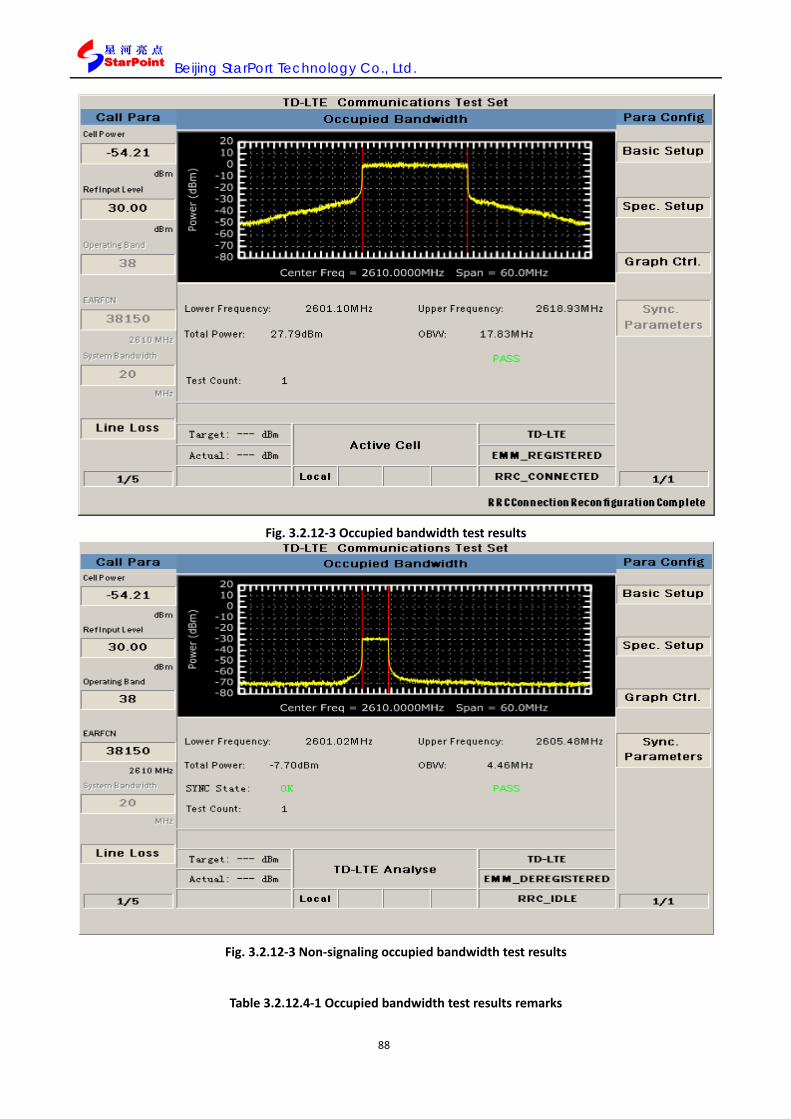
Beijing StarPort Technology Co., Ltd.
88
Fig. 3.2.12-3 Occupied bandwidth test results
Fig. 3.2.12-3 Non-signaling occupied bandwidth test results
Table 3.2.12.4-1 Occupied bandwidth test results remarks
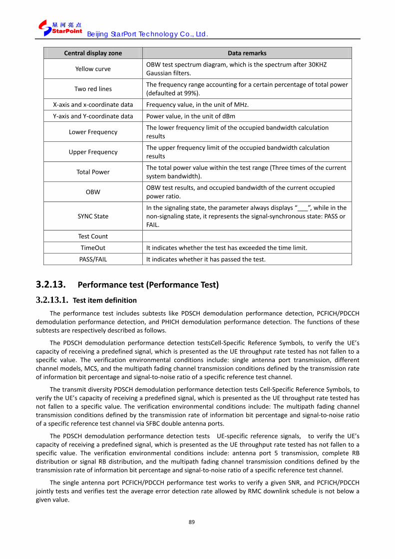
Beijing StarPort Technology Co., Ltd.
89
Central display zone Data remarks
Yellow curve OBW test spectrum diagram, which is the spectrum after 30KHZ Gaussian filters.
Two red lines The frequency range accounting for a certain percentage of total power (defaulted at 99%).
X-axis and x-coordinate data Frequency value, in the unit of MHz.
Y-axis and Y-coordinate data Power value, in the unit of dBm
Lower Frequency The lower frequency limit of the occupied bandwidth calculation results
Upper Frequency The upper frequency limit of the occupied bandwidth calculation results
Total Power The total power value within the test range (Three times of the current system bandwidth).
OBW OBW test results, and occupied bandwidth of the current occupied power ratio.
SYNC State In the signaling state, the parameter always displays “___”, while in the non-signaling state, it represents the signal-synchronous state: PASS or FAIL.
Test Count
TimeOut It indicates whether the test has exceeded the time limit.
PASS/FAIL It indicates whether it has passed the test.
3.2.13. Performance test (Performance Test)
3.2.13.1. Test item definition
The performance test includes subtests like PDSCH demodulation performance detection, PCFICH/PDCCH demodulation performance detection, and PHICH demodulation performance detection. The functions of these subtests are respectively described as follows.
The PDSCH demodulation performance detection testsCell-Specific Reference Symbols, to verify the UE’s capacity of receiving a predefined signal, which is presented as the UE throughput rate tested has not fallen to a specific value. The verification environmental conditions include: single antenna port transmission, different channel models, MCS, and the multipath fading channel transmission conditions defined by the transmission rate of information bit percentage and signal-to-noise ratio of a specific reference test channel.
The transmit diversity PDSCH demodulation performance detection tests Cell-Specific Reference Symbols, to verify the UE’s capacity of receiving a predefined signal, which is presented as the UE throughput rate tested has not fallen to a specific value. The verification environmental conditions include: The multipath fading channel transmission conditions defined by the transmission rate of information bit percentage and signal-to-noise ratio of a specific reference test channel via SFBC double antenna ports.
The PDSCH demodulation performance detection tests UE-specific reference signals, to verify the UE’s capacity of receiving a predefined signal, which is presented as the UE throughput rate tested has not fallen to a specific value. The verification environmental conditions include: antenna port 5 transmission, complete RB distribution or signal RB distribution, and the multipath fading channel transmission conditions defined by the transmission rate of information bit percentage and signal-to-noise ratio of a specific reference test channel.
The single antenna port PCFICH/PDCCH performance test works to verify a given SNR, and PCFICH/PDCCH jointly tests and verifies test the average error detection rate allowed by RMC downlink schedule is not below a given value.

Beijing StarPort Technology Co., Ltd.
90
The PCFICH/PDCCH transmission diversity performance test works to verify a given SNR on the transmission diversity conditions and PCFICH/PDCCH jointly tests and verifies test the average error detection rate allowed by RMC downlink schedule is not below a given value.
Single antenna port PHICH performance test works to verify the RMC-specific mixing indicator error rate on single antenna port of given SNR, to tests the PHICH demodulation performance.
The PHICH transmission diversity performance test works to verify the RMC-specific mixing indicator error rate on transmission diversity of given SNR, to tests the PHICH demodulation performance.
3.2.13.2. Parameter configuration
The parameter configuration covers the configuration of SP8011 parameters and the setting of test item parameters by the user.
SPB8010B Parameter configuration
This test item supports the channel bandwidth of 1.4M~20M. Modulation mode: Uplink QPSK/16QAM, and downlink QPSK/16QAM/64QAM.
As regulated in Protocol 3GPP: TS 36.521-1, SP8011 has specific parameter configuration as follows. Table3.2.13.2-1 SP8011 PTEST test parameter configuration
Category Configurable parameters Parameters configuration value
Cell power Cell Power -54.21dBm Input reference level Ref Level 30.00dBm
Power control type UE Target Power No requirement
Power Control Type No requirement
Physical channel power(Channel Level)
Cell-Specific RS 0 PSS_RA 0 SSS_RA 0
PBCH_RA 0 PBCH_RB 0
PCFICH_RB 0 PDCCH_RA 0 PDCCH_RB 0 PHICH_RA 0 PHICH_RB 0 PDSCH_RA 0 PDSCH_RB 0
Uplink channel schedule selection Channel Schedule PUSCH
Parameter configuration of test items by the user
As needed for the test, the user can set PTTEST test parameters, which include Basic Setup, Spec. Setup and Channel Type, as elaborated below.
For performance test definitions, implications and test results details, please refer to 3.2.13; for test procedures details, please refer to 5.5.2.13.
Basic Setup parameter setting
Basic Setup works to set the basic parameters of the test item including Frame Number, Trigger and Time Out, which are elaborated in 3.2.1.2.

Beijing StarPort Technology Co., Ltd.
91
Spec. Setup parameter setting
Spec. Setup refers to the index threshold mask, i.e. the criteria to judge whether the test has passed, and the user can define the mask themselves. The parameters to be set up include:
Throughput Request: Throughput test requirements;
Pm-dsg: Probability of miss-detection of the Downlink Scheduling Grant test requirements;
Pm-an: Probability of miss-detecting an ACK for a NACK test requirements
Fig. 3.2.13-1 Performance test General Parameter setting
Fig. 3.2.13.2-2 Performance test General Parameter setting remarks
Parameter description Parameter
range Default value Unit Remarks
Throughput Request(%) 0~100 95.00 % Throughput test requirements
Pm-dsg 0~1.00 0.01 无
Probability of miss-detection of the
Downlink Scheduling Grant test
requirements
Pm-an 0~1.000 0.001 无 Probability of miss-detecting an ACK for a NACK test requirements

Beijing StarPort Technology Co., Ltd.
92
Channel Type parameter setting
Channel Type refers to test channel selection, which ranges: PDSCH/PDCCH/PHICH.
3.2.13.3. Test operations
1. In the Active Cell operation mode, RMC is selected as required by the Protocol;
2. Press the Selection in the test key zone on the front panel, and select Performance Test in the popup window, and enable this test item;
3. In line with different test purposes, the channel type can be selected as PDSCH\PDCCH\PHICH;
4. Press the Selection in the test key zone on the front panel, and select Performance Test in the popup window, and enable this test item;
5. Press the key Single or Continuous in the test key part on the front panel to conduct single or continuous tests;
6. Press the key Stop in the test key part on the front panel to terminal the test;
7. The test results are displayed in graphics and data, which are elaborated in 3.2.13.4.
3.2.13.4. Test results
The test results will be displayed on the SP8011 screen in graphics and figures, and when the test results meet the protocol requirements, it will display “PASS”, which means it has passed the test, or it will display “FAIL”, which means it has failed.
Fig. 3.2.13-2 PDSCH performance test results

Beijing StarPort Technology Co., Ltd.
93
Fig. 3.2.13-3 PDCCH channel test results

Beijing StarPort Technology Co., Ltd.
94
Fig. 3.2.13-4 PHICH channel test results
Table 3.2.13.4-1 Performance test results remarks
Central display zone Data remarks
Blocks tested Tested block number。Codeword1\Codeword 2 is distinguished the test resulted for two codewords
ACK ACK Number NACK NACK Number StatDTX StatDTX Number Throughput Throughput Pm-dsg Probability of miss-detection of the Downlink Scheduling Grant test Pm-an Probability of miss-detecting an ACK for a NACK test TimeOut It is displayed if the time is out for test PASS/FAIL It is displayed if the result is pass
3.2.14. ON/OFF time mask test (ON/OFF Time Mask)
3.2.14.1. Test item definition
The ON/OFF time mask test includes the three subtests of transmitter on/off time mask test (GOTM), PRACH ON/OFF time mask test (POTM) and SRS ON/OFF time mask test.

Beijing StarPort Technology Co., Ltd.
95
In the Active Cell mode, SP8011, upon establishment of call connection to the terminal, can conduct this test. The parameters in 3GPP TS36.521-1 related to this test can be correspondingly set up upon the terminal’s establishment of call connection.
N.B.: The above three tests can respectively conduct the transmit OFF power test (Transmit OFF Power, TOFP) and obtain relevant test results.
Transmitter ON/OFF time mask (GOTM)
N.B.: The transmitter ON/OFF time mask test can conduct the transmit OFF power test (Transmit OFF Power, TOFP) and obtain relevant test results.
The transmitter ON/OFF time mask functions to verify whether the UE transmitter can turn on or off its transmit power during the transient period. For one, this test verifies whether, during the transmitter’s On Power period, the UE power is within the On Power tolerance. Secondly, this test verifies whether, during the transmitter OFF Power period, the UE power is below the power threshold.
Table 3.2.14.1-1 Test requirements Channel bandwidth / minimum output power / measurement
bandwidth 1.4 MHz
3.0 MHz
5 MHz
10 MHz
15 MHz
20 MHz
Transmit OFF power -48.5dBm Expected Transmission ON Measured power
-20.2 ± 7.5
-14.2 ± 7.5
-11.2 ± 7.5
-9.4 ± 7.5 -8.2 ± 7.5 -7.6 ± 7.5
PRACH ON/OFF time mask (POTM)
The PRACH ON/OFF time mask test item is similar to the general transmitter ON/OFF time mask, for testing whether its transmitter meet the test index demand during the ON and OFF period, when the UE is transmitting PRACH.
Table 3.2.14.1-2 Test requirements Channel bandwidth / Output Power / measurement bandwidth
1.4 MHz
3.0 MHz
5 MHz
10 MHz
15 MHz
20 MHz
Transmit OFF power ≤ -48.5 dBm Expected PRACH Transmission ON Measured power -1± 7.5 -1 ± 7.5 -1 ± 7.5 -1 ± 7.5 -1 ± 7.5 -1 ± 7.5
SRS ON/OFF time mask (SOTM)
The SRS ON/OFF time mask test item is similar to the general transmitter ON/OFF time mask, for testing whether its transmitter meet the test index demand during the ON and OFF period, when the UE is transmitting SRS.
Table 3.2.14.1-3 Test requirements Channel bandwidth / Output Power [dBm] / measurement bandwidth
1.4 MHz
3.0 MHz
5 MHz
10 MHz
15 MHz
20 MHz
Transmit OFF power ≤ -48.5 dBm Expected SRS Transmission ON Measured power -1± 7.5 -1 ± 7.5 -1 ± 7.5 -1 ± 7.5 -1 ± 7.5 -1 ± 7.5

Beijing StarPort Technology Co., Ltd.
96
3.2.14.2. Parameter configuration
The parameter configuration covers the configuration of SP8011 parameters and the setting of test item parameters by the user.
SP8011 Parameter configuration
This test item supports the channel bandwidth of 1.4M~20M. Modulation mode: Uplink QPSK/16QAM, and downlink QPSK/16QAM/64QAM.
As regulated in Protocol 3GPP: TS 36.521-1, SP8011 has specific parameter configuration as follows. Table 3.2.14.2-1 SP8011 ON/OFF time mask test parameter configuration
Category Configurable parameters Parameters configuration value
Cell power Cell Power -54.21dBm Input reference level Ref Level 30.00dBm
Power control type UE Target Power No requirement Power Control Type No requirement
Physical channel power(Channel Level)
Cell-Specific RS 0 PSS_RA 0 SSS_RA 0 PBCH_RA 0 PBCH_RB 0 PCFICH_RB 0 PDCCH_RA 0 PDCCH_RB 0 PHICH_RA 0 PHICH_RB 0 PDSCH_RA 0 PDSCH_RB 0
Uplink channel schedule selection Channel Schedule PUSCH/PRACH
Note 1: Currently, in any power control type, the ON/OFF time mask test can be conducted; when the power control type is set as “TPC0”, the Test can be conducted in accordance with Protocol TS 36.521-1v950.
Parameter configuration of test items by the user
As needed for the test, the user can set OOTM test parameters, which include Basic Setup、Spec. Setup、Graph Ctrl、Test Type、Marker、Marker X and Sync. Parameter, as elaborated below:
Basic Setup parameter setting (The same to that in 3.2.1.2)
Basic Setup works to set the basic parameters of the test item including Trigger and Time Out, which are elaborated in 3.2.1.2.
Spec. Setup parameter setting
Spec. Setup refers to the index threshold mask, i.e. the criteria to judge whether the test has passed, and the user can define the mask themselves. The parameters to be set up include:
Requirement Type: Configuration of the test criteria, which is defaulted at Min Requirements, where other parameters in the Spec. Setup is not configurable, and the default value corresponds to the Minimum conformance requirements in protocol 3GPP; when Requirement Type is set at Test Requirement, other parameters in the Spec. Setup are not configurable, and the default value is corresponding to the Test requirement in Protocol 3GPP; when Requirement Type is Manual, other parameters are configurable and the user can set the following parameters;

Beijing StarPort Technology Co., Ltd.
97
ON Power Tolerance(dB): ON power tolerance;
General OFF Power(dBm): General mode OFF power threshold;
PRACH OFF Power(dBm): PRACH mode OFF power limit;
SRS OFF Power (dBm): SRS mode OFF power limit.

Beijing StarPort Technology Co., Ltd.
98
Fig. 3.2.14-1 ON/OFF time mask test Spec. Setup parameter setting
Table 3.2.14.2-2 ON/OFF time mask test Spec. Setup parameter setting remarks Parameter description Parameter range Default value Unit Remarks
Requirements Type Min Requirements\ Test Requirements\ Manual
Min Requirements NA Index criterion type
ON Power Tolerance 0.00~15.00 6.50 dB ON power tolerance General OFF Power -120.00~0.00 -50.00 dBm General mode OFF power
PRACH OFF Power -120.00~0.00 -50.00 dBm PRACH mode OFF power threshold
SRS OFF Power -120.00~0.00 -50.00 dBm SRS mode OFF power threshold
Graph Ctrl. Parameter setting
Graph Ctrl. Functions to conduct graphic control setting, and the user can define this mask themselves. The parameters to be set up include:
Subframe Details: For section-wise display of ON/OFF power change, with setting range: Complete/Rising/Falling/Useful. Complete: For displaying the complete diagram; Rising: displaying the power off/on process; Falling: displaying the power on/off process; and Useful: displaying the on power;
X Axis Maximum(us): X-Axis visible maximum;
X Axis Minimum(us): X-Axis visible minimum;
Y Axis Maximum(ms): Y-Axis visible maximum;

Beijing StarPort Technology Co., Ltd.
99
Y Axis Minimum (dBm): Y-Axis visible minimum.
Fig. 3.2.14-2 ON/OFF time mask test Graph Ctrl. parameter setting
Table 3.2.14.2-3 ON/OFF time mask test Graph Ctrl. parameter setting remarks Parameter description
Parameter range Default value Unit Remarks
Subframe Details Complete/Rising/Falling/Useful
Complete NA display the ON/OFF power variation with section method
X Axis Maximum(us) 0~3000 3000 us X-Axis visible maximum X Axis Minimum(us) 0~3000 0 us X-Axis visible minimum Y Axis Maximum(dBm) -120~50 20 dBm Y-Axis visible maximum Y Axis Minimum(dBm) -120~50 -80 dBm Y-Axis visible minimum
Marker parameter setting
Masker is the switch to set the Marker display, ranging: On / Off, On means to display Marker; Off means not to display Marker.
Marker X parameter setting
Marker X works to set Marker x-coordinate value when Marker employed, which ranges: 0~3000us and is defaulted at 0. Turn the knob to change the value, and the power value in the position corresponding to Marker X will appear on the interface.
Sync. Parameter setting (the same to that in 3.2.1.2) 3.2.14.3. Test operations
1. In the Active Cell operation mode, press the key More (page flipping) on the left side to enter into the third page for Call Para (call parameters) configuration, and the bottom of the menu on the right side displays 3/5; press

Beijing StarPort Technology Co., Ltd.
100
the key F1, and set the “Power Control Type” as “TPC0” and then press the Selection in the test key zone on the front panel, and select ON/OFF Time Mask in the popup window, and enable this test item;
The OOTM test includes the tests of four data PUSCH\ SRS\PUCCH\ PRACH which are elaborated as follows: PUSCH OOTM test: Change the Power Control Type into “TPC0” and directly enter into OOTM before testing the data through the PUSCH channel; After PUSCH OOTM test, please restore p0-NominalPUSCH back to the default value -85. SRS OOTM test: Change the Power Control Type into “TPC0”, modify the parameter srs-ConfigIndex out of SRS in the parameter configuration on the right into 0, change the uplink subframe schedule as ALL OFF, and reenter OOTM before testing the data in the SRS channel; Upon SRS OOTM test completed, enable the uplink subframe 2 scheduling, and restore srs-ConfigIndex back to the defaulted configuration of 31. PUCCH OOTM test: Change the Power Control Type into “TPC0”, set the channel scheduling as PUCCH, reenter OOTM before testing the data via the PUCCH channel; Upon PUCCH OOTM test completed, restore the channel scheduling as PUSCH, and restore p0-NominalPUCCH back to the defaulted: -117. PRACH OOTM test: Change the Power Control Type into “TPC0”, set the channel scheduling as PRACH, and reenter into OOTM before testing the data via the PRACH channel; Upon PRACH OOTM test completed, restore the channel scheduling as PUSCH>
2. Press the keys F7\ F8\ F9\ F10\F11, and set Basic Setup\Spec. Setup\Graph Ctrl\Marker\Masker X parameters, which are elaborated in 3.2.14.2; upon setup, press the key Cancel and shut the parameter setting window;
3. Press the keys F12 in the TD-Analyse mode, and set Sync. Parameters, which are elaborated in 3.2.14.2; upon setup, press the key Cancel and shut the parameter setting window;
4. Press the key Single or Continuous in the test key zone on the front panel to conduct single or continuous tests;
5. Press the key Stop in the test key zone on the front panel to terminate the test;
6. The test results are displayed in graphics and data, which are elaborated in 3.2.14.4. 3.2.14.4. Test results
The test results will be displayed on the SP8011 screen in graphics and figures, and when the test results meet the protocol requirements, it will display “PASS”, which means it has passed the test, or it will display “FAIL”, which means it has failed.
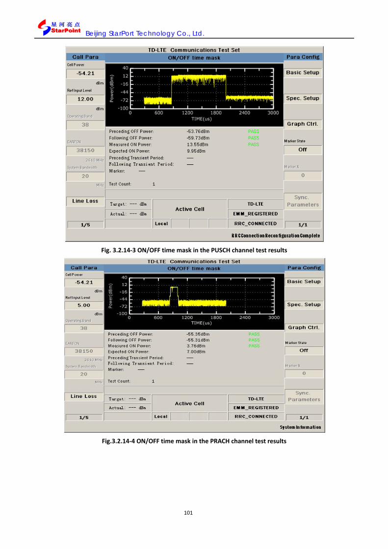
Beijing StarPort Technology Co., Ltd.
101
Fig. 3.2.14-3 ON/OFF time mask in the PUSCH channel test results
Fig.3.2.14-4 ON/OFF time mask in the PRACH channel test results

Beijing StarPort Technology Co., Ltd.
102
Fig. 3.2.14-5 ON/OFF time mask in SRS channel test results
Fig. 3.2.14-6 ON/OFF time mask in non-signaling mode test results
Table 3.2.14.4-1 ON/OFF time mask test results remarks

Beijing StarPort Technology Co., Ltd.
103
Central display zone Data remarks
Yellow graph OOTM test results, i.e. the time domain power spectrum of the UE.
X-axis and x-coordinate data Time, in the unit of: us. Y-axis and Y-coordinate data Power value, in the unit of dBm
The triangle in red Marker sign, which is displayed when the Marker State is “ON”.
Preceding OFF Power OFF power value prior to the UE ON power. Following OFF Power OFF power value after the UE ON power. Measured ON Power Actually measured UE ON power value.
Expected ON Power The expected UE ON power calculated based on the current configuration.
Preceding Transient Period The transient time prior to the ON power. Following Transient Period The transient time after the ON power. Marker The power value corresponding to Marker X.
SYNC State In the signaling state, the parameter always displays “___”, while in the non-signaling state, it represents the signal-synchronous state: PASS or FAIL.
Test Count It indicates the test times. TimeOut It indicates whether the test has exceeded the time limit. PASS/FAIL It indicates whether it has passed the test.
(Yellow exclamation mark)
It indicates whether the configuration is line with that in the Test Requirements, i.e. whether it meets the requirements in the Test Configuration Table; if not, this prompt will pop up.
3.2.15. Relative power control tolerance test (Relative Power Tolerance)
3.2.15.1. Test item definition
In the Active Cell mode, SP8011, upon establishment of call connection to the terminal, can conduct this test. The parameters in 3GPP TS36.521-1 related to this test can be correspondingly set up upon establishment of terminal call connection.
Relative power tolerance evaluates the UE transmitter’s capacity of adjusting the current transmit power, defined as the offset of the actually adjusted power to the set adjusted power. This index functions to measure the UE transmitter fine-adjustment transmit power precision after power step specified in the closed-loop power control.
The relative power control tolerance test includes three subtest types: ramping up, ramping down and alternating. The subtests: ramping up and ramping down, based on different RB change positions, can be divided on mode A, B and C.
Based on Protocol 3GPP TS36.521-1, the E-UTRA system features the maximum output power category of 3, where this test has the following index requirements.
Table 3.2.15.1-1 Minimum conformance requirements (on normal conditions)
Power step P (Up or down) [dB]
All combinations of PUSCH and PUCCH transitions [dB]
All combinations of PUSCH/PUCCH and SRS transitions between sub-frames [dB]
PRACH [dB]
ΔP < 2 ±2.5 (Note 3) ±3.0 ±2.5

Beijing StarPort Technology Co., Ltd.
104
2 ≤ ΔP < 3 ±3.0 ±4.0 ±3.0 3 ≤ ΔP < 4 ±3.5 ±5.0 ±3.5 4 ≤ ΔP ≤ 10 ±4.0 ±6.0 ±4.0 10 ≤ ΔP < 15 ±5.0 ±8.0 ±5.0 15 ≤ ΔP ±6.0 ±9.0 ±6.0
3.2.15.2. Parameter configuration
The parameter configuration covers the configuration of SP8011 parameters and the setting of test item parameters by the user.
SP8011 Parameter configuration
This test item supports the channel bandwidth of 1.4M~20M. Modulation mode: Uplink QPSK/16QAM, and downlink QPSK/16QAM/64QAM.
As regulated in Protocol 3GPP: TS 36.521-1, SP8011 has specific parameter configuration as follows. Table 3.2.15.2 1 SP8011 relative power control tolerance test parameter configuration
Category Configurable parameters Parameters configuration value
Cell power Cell Power -54.21dBm Input reference level Ref Level 30.00dBm
Power control type UE Target Power No requirement Power Control Type No requirement
Physical channel power(Channel Level)
Cell-Specific RS 0 PSS_RA 0 SSS_RA 0 PBCH_RA 0 PBCH_RB 0 PCFICH_RB 0 PDCCH_RA 0 PDCCH_RB 0 PHICH_RA 0 PHICH_RB 0 PDSCH_RA 0 PDSCH_RB 0
Uplink channel schedule selection Channel Schedule PUSCH
Parameter configuration of test items by the user
As needed for the test, the user can set RPT test parameters, which include Basic Setup、Spec. Setup、Graph Ctrl.、Sub Test、User Define、Marker State、Marker X and View Change, as elaborated below:
Basic Setup parameter setting
Basic Setup works to set the basic parameters of the test item including Trigger Arm、Power Class and Time Out, which are elaborated in 3.2.1.2.
Spec. Setup parameter setting
Spec. Setup refers to the index threshold mask, i.e. the criteria to judge whether the test has passed, and the user can define the mask themselves. The parameters to be set up include:

Beijing StarPort Technology Co., Ltd.
105
Requirement Type: Configuration of the test criteria, which is defaulted at Min Requirements, where other parameters in the Spec. Setup is not configurable, and the default value corresponds to the Minimum conformance requirements in protocol 3GPP; when the Requirement Type is set at Test Requirement, other parameters in the Spec. Setup are not configurable, and the default value is corresponding to the Test requirement in Protocol 3GPP; when Requirement Type is Manual, other parameters are configurable and the user can set the following parameters:
PUSCH and PUCCH △P≤1: various PUSCH and PUCCH combination, with power step less than the relative power tolerance of 1;
PUSCH and PUCCH △P≤2: various PUSCH and PUCCH combination, with power step less than the relative power tolerance of 2;
PUSCH and PUCCH 2≤ △P<3: various PUSCH and PUCCH combination, with power step being the relative power tolerance within the [2,3) interval;
PUSCH and PUCCH 3≤△P<4: various PUSCH and PUCCH combination, with power step being the relative power tolerance within the [3,4) interval;
PUSCH and PUCCH 4≤ △P<10: various PUSCH and PUCCH combination, with power step being the relative power tolerance within the [4,10) interval;
PUSCH and PUCCH 10≤ △P<15: various PUSCH and PUCCH combination, with power step being the relative power tolerance within the [4, 10) interval;
PUSCH and PUCCH 15≤△P: various PUSCH and PUCCH combination, with power step more than the relative power tolerance of 15;
PUSCH/PUCCH and SRS △P≤2: various PUSCH/PUCCH and SRS subframe over-combination, with power step less than the relative power tolerance of 2dB;
PUSCH/PUCCH and SRS 2≤ △P<3: various PUSCH/PUCCH and SRS subframe over-combination, with power step being the relative power tolerance within the[2,3) interval;
PUSCH/PUCCH and SRS 3≤ △P<4: various PUSCH/PUCCH and SRS subframe over-combination, with power step being the relative power tolerance within the[3, 4) interval;
PUSCH/PUCCH and SRS 4≤△P<10: various PUSCH/PUCCH and SRS subframe over-combination, with power step being the relative power tolerance within the[4, 10) interval;
PUSCH/PUCCH and SRS 10≤△P<15: various PUSCH/PUCCH and SRS subframe over-combination, with power step being the relative power tolerance within the[10, 15) interval;
PUSCH/PUCCH and SRS 15≤△P: various PUSCH/PUCCH and SRS subframe over-combination, with power step more than the relative power tolerance of 15;
PRACH △P<2: PRACH power step less than the relative power tolerance of 2;
PRACH 2≤△P<3: PRACH power step being the relative power tolerance within the [2,3) interval;
PRACH 3≤△P<4: PRACH power step being the relative power tolerance within the [3,4) interval;
PRACH 4≤△P<10: PRACH power step being the relative power tolerance within the [4,10) interval;
PRACH 10≤△P<15: PRACH power step being the relative power tolerance within the [10, 15) interval;
PRACH 15≤△P: PRACH power step more than the relative power tolerance of 15;

Beijing StarPort Technology Co., Ltd.
106
Fig. 3.2.15-1 Relative power control tolerance test Spec. Setup parameter setting
Table 3.2.15.2-2 Absolute power control tolerance test Spec. Setup parameter setting remarks
Parameter description Parameter range Default value Unit Remarks
Requirement Type Min Requirements\ Test Requirements\
Manual
min Requirements NA Index judging criteria type
PUSCH and PUCCH △P<2 0~10.00 2.50 dB
Various PUSCH and PUCCH combination, with power step less than the relative power tolerance of 1;
PUSCH and PUCCH 2≤△P <3 0~10.00 3.00 dB
Various PUSCH and PUCCH combination, with power step less than the relative power tolerance of 2;
PUSCH and PUCCH 3≤△P<4 0~10.00 3.50 dB
Various PUSCH and PUCCH combination, with power step being the relative power tolerance within the [3,4) interval;
PUSCH and PUCCH 4≤△P <10 0~10.00 4.00 dB
Various PUSCH and PUCCH combination, with power step being the relative power tolerance within the [4.10) interval;

Beijing StarPort Technology Co., Ltd.
107
PUSCH and PUCCH 10≤△P<15 0~10.00 5.00 dB
Various PUSCH and PUCCH combination, with power step being the relative power tolerance within the [10.15) interval;
PUSCH and PUCCH 15≤△P 0~10.00 6.00 dB
Various PUSCH and PUCCH combination, with power step less than the relative power tolerance of 1;
PUSCH/PUCCH and SRS △P<2 0~10.00 3.00 dB
Various PUSCH/PUCCH and SRS subframe over-combination, with power step less than the relative power tolerance of 2dB;
PUSCH/PUCCH and SRS 2≤△P<3 0~10.00 4.00 dB
Various PUSCH/PUCCH and SRS subframe over-combination, with power step being the relative power tolerance within the [2,3) interval;
PUSCH/PUCCH and SRS 3≤△P<4 0~10.00 5.00 dB
Various PUSCH/PUCCH and SRS subframe over-combination, with power step being the relative power tolerance within the [3.4) interval;
PUSCH/PUCCH and SRS 4≤△P<10 0~10.00 6.00 dB
Various PUSCH/PUCCH and SRS subframe over-combination, with power step being the relative power tolerance within the [4.10) interval;
PUSCH/PUCCH and SRS 10≤△P<15 0~10.00 8.00 dB
Various PUSCH/PUCCH and SRS subframe over-combination, with power step being the relative power tolerance within the [10.15) interval;
PUSCH/PUCCH and SRS 15≤△P 0~10.00 9.00 dB
Various PUSCH/PUCCH and SRS subframe over-combination, with power step more than the relative power tolerance of 15;
PRACH △P <2 0~10.00 2.50 dB PRACH power step less than the relative power tolerance of 2;
PRACH 2≤△P<3 0~10.00 3.00 dB PRACH power step being the relative power tolerance within the [2.3) interval;
PRACH 3≤△P<4 0~10.00 3.50 dB PRACH power step being the relative power tolerance within the [3.4) interval;
PRACH 4≤△P<10 0~10.00 4.00 dB PRACH power step being the relative power tolerance within the [4.10) interval;
PRACH 10≤△P<15 0~10.00 5.00 dB PRACH power step being the relative power tolerance within the [10.15) interval;
PRACH 15≤△P 0~10.00 6.00 dB PRACH power step more than the relative power tolerance of 15.

Beijing StarPort Technology Co., Ltd.
108
Graph Ctrl. Parameter setting
Graph Ctrl. Functions to conduct graphic control setting, and the user can define this mask themselves. The parameters to be set up include:
Y Axis Maximum(ms): Y-Axis visible maximum;
Y Axis Minimum (dBm): Y-Axis visible minimum.
Fig. 3.2.15-2 Relative power control tolerance test Graph Ctrl. parameter setting
Table 3.2.15.2-3 Relative power control tolerance test Graph Ctrl. parameter setting remarks Parameter description
Parameter range Default value Unit Remarks
Y Axis Maximum(dBm)
-120~50 30 dBm Y-Axis visible maximum
Y Axis Minimum(dBm)
-120~50 -60 dBm Y-Axis visible minimum
Sub Test parameter setting
Sub Test refers to subtest mode selection setting, with its basic parameters including:

Beijing StarPort Technology Co., Ltd.
109
Fig.3.2.15-3 Relative power control tolerance test Spec. Setup parameter setting
User Define parameter setting
User Define works to do user-defined test item parameter setting, which is configurable in Type1~Type7, and it is valid when Sub Test selected. Basic parameter setting includes:
RBNUM. Before Change: In accordance with Protocol 3GPP TS36.521-1, the test process will see one time of RB number change, and this parameter is the value before the RB change, which ranges: {1,2,3,4,5,6,8,9,10,12,15,16,18,20,24,25,27,30,32,36,40,45,48,50,54,60,64,72, 75,80,81,90,96,100};
RBNUM. After Change: In accordance with Protocol 3GPP TS36.521-1, the test process will see one time of RB number change, and this parameter is the value after the RB change, which ranges: {1,2,3,4,5,6,8,9,10,12,15,16,18,20,24,25,27,30,32,36,40,45,48,50,54,60,64,72,75, 80,81,90,96,100};
RB Change Position: Change the RB position, which ranges: 1~100;
TPC Type: TPC type, which ranges: {-1,0,3,1};
Initial Power: Terminal initial power.

Beijing StarPort Technology Co., Ltd.
110
Fig. 3.2.15-4 Relative power control tolerance test User Define parameter setting
Table 3.2.15.2-4 Relative power control tolerance test User Define parameter setting remarks
Parameter description Parameter range Default value
Unit Remarks
RBNUM. Before Change {1,2,3,4,5,6,8,9,10,12,15,16,18,20, 24,25,27,30,32,36,40,45,48,50,54, 60,64,72,75,80,81,90,96,100}
Change with Sub Test variation
NA Value before RB change
RBNUM. After Change NA Value after RB change
RB Change Position 1~100 NA Change RB position
TPC Type {-1,0,3,1} NA TPC type Initial Power NA dBm UE initial power
Marker Sate setting
Masker State is the switch to set the Marker display, ranging: On / Off, On means to display Marker; Off means not to display Marker.
Marker X parameter setting
Marker X works to set Marker x-coordinate value when Marker employed, which ranges: 1~40 and is defaulted at 1. Turn the knob to change the value, and the power value in the position corresponding to Marker X will appear on the interface.

Beijing StarPort Technology Co., Ltd.
111
View Change parameter setting
View Change works to do the display mode setting, which ranges: Graph/Text, where the Graph mode conducts drawing, and the Text mode will display the test results in table, and this button is greyed out for the time being.
N.B.: Marker, Marker X and View Change—all are on the second page of the right-side column; press the key More to flip pages and see the display of 2/2 at the bottom of the right-side column.
3.2.15.3. Test procedures
1. In the Active Cell operation mode, press the key Selection in the test key zone on the front panel, and select Relative Power Tolerance in the popup window, and enable this test item, which in any power control type can conduct the test;
2. Press the keys F7\ F8\ F9\ F10, and set Basic Setup\Spec. Setup\Graph Ctrl\Sub Test, and the Basic Setup parameters are elaborated in 3.2.15.2; upon setup, press the key Cancel and shut the parameter setting window;
3. Select power control TYPE 1~7, the power control type will be changed corresponding; on the conditions of Type 1~7, all parameters in User Define can be set; when Sub Test selected as Type X, the test can be conducted in accordance with the User Defined configuration.
4. Press the key F11, and set User Define, and the User Define parameter is elaborated in 4.1.5.5; upon setup, press the key Cancel and shut the parameter setting window;
5. Press the key More on the right side, and flip pages on the right side of the display screen;
6. Press the key F7\F8, and set the Marker State\Masker X, which are elaborated in 3.2.15.2; upon setup, press the key Cancel and shut the parameter setting window;
7. Press the key Single or Continuous in the test key zone on the front panel to conduct single or continuous tests;
8. Press the key Stop in the test key part on the front panel to terminal the test;
9. The test results are displayed in graphics and data, which are elaborated in 3.2.15.4.
3.2.15.4. Test results
The test results will be displayed on the SP8011 screen in graphics, and when the test results meet the protocol requirements, it will display “PASS”, which means it has passed the test, or it will display “FAIL”, which means it has failed.
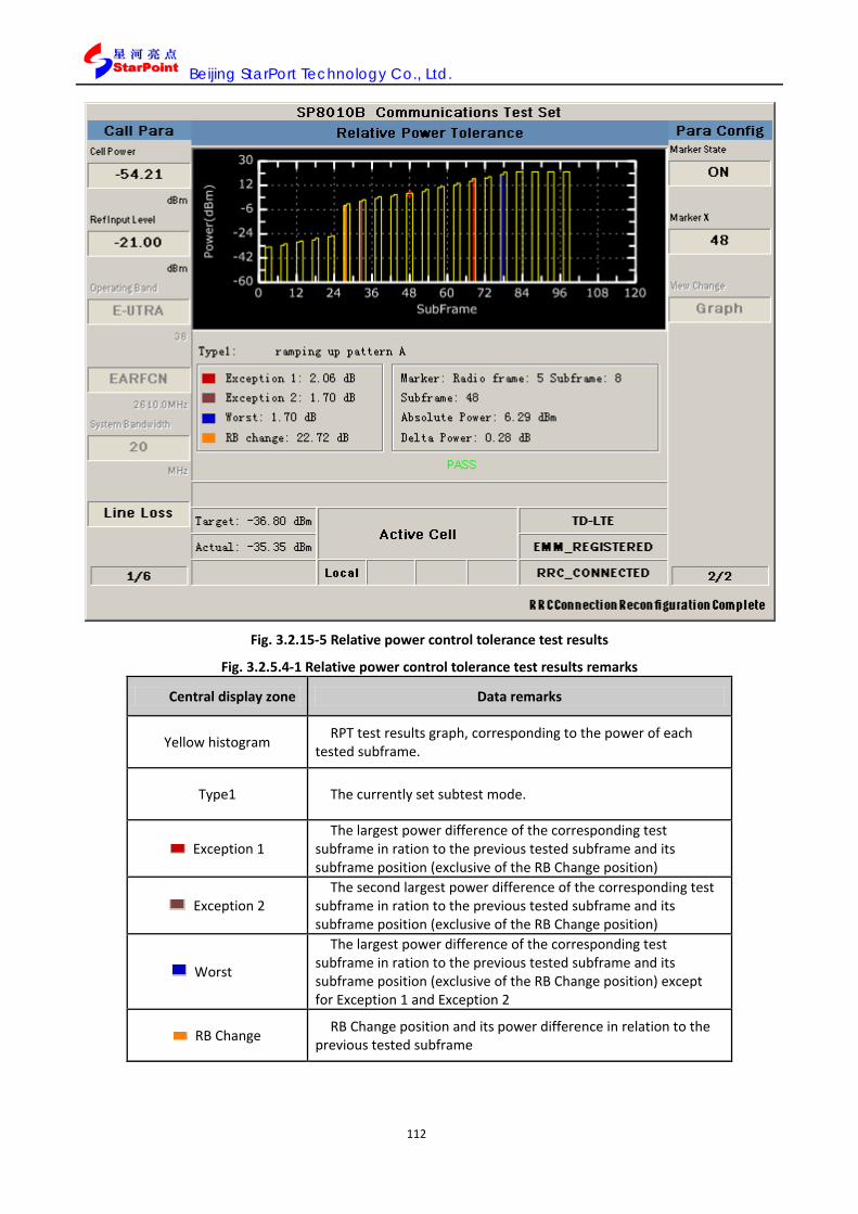
Beijing StarPort Technology Co., Ltd.
112
Fig. 3.2.15-5 Relative power control tolerance test results
Fig. 3.2.5.4-1 Relative power control tolerance test results remarks
Central display zone Data remarks
Yellow histogram RPT test results graph, corresponding to the power of each tested subframe.
Type1 The currently set subtest mode.
Exception 1 The largest power difference of the corresponding test
subframe in ration to the previous tested subframe and its subframe position (exclusive of the RB Change position)
Exception 2 The second largest power difference of the corresponding test
subframe in ration to the previous tested subframe and its subframe position (exclusive of the RB Change position)
Worst
The largest power difference of the corresponding test subframe in ration to the previous tested subframe and its subframe position (exclusive of the RB Change position) except for Exception 1 and Exception 2
RB Change RB Change position and its power difference in relation to the previous tested subframe

Beijing StarPort Technology Co., Ltd.
113
Marker The power at the current (radio frame: X1 subframe: X2)
position, and it is displayed in the bottom table when the Marker State is set at “ON”.
Absolute Power Corresponding to the actual power value at the current Marker position.
Relative Power The relative power difference between the current Marker position and the previo0us tested subframe.
Expected Delta Power The expected relative power calculated based on the current test configuration.
TimeOut It indicates whether the test has exceeded the time limit.
PASS/FAIL It indicates whether it has passed the test.
3.2.16. Spectrum emission mask test (Spectrum Emission Mask)
3.2.16.1. Test item definition
In the Active Cell mode, SP8011, upon establishment of call connection to the terminal, is set to the power-control type (Item 1 on Page 3 of Call Para) of “MAX”, where this test can be conducted. The parameters in 3GPP TS36.521-1 related to this test can be correspondingly set up upon establishment of terminal call connection.
The spectrum emission mask test works to evaluate whether the UE transmit power has exceeded the transmission level specified under specific channel bandwidth. This test item is applicable to the frequency within
the scope starting from given E-UTRA channel bandwidth boundary.
The additional spectrum emission mask test works to evaluate whether the UE transmit power against specific scene (the terminal accepting additional spurious requirements) has exceeded the transmission level
specified under specific channel bandwidth. This test item is applicable to the frequency within the scope starting from given E-UTRA channel bandwidth boundary.
Note:
1. refers to the frequency difference between the filter center frequency and the E-UTRA signal bandwidth edge (upper and lower edges);
2. Additional spurious value NS parameter has fixed relation with the tested frequency range, signal bandwidth and RB occupancy, which is shown in Table 3.2.18.1 3.
3. Different NS parameters have different values, as shown by the example of NS_01.
OOBf∆
OOBf∆
OOBf∆
OOBf∆

Beijing StarPort Technology Co., Ltd.
114
Spectrum emission limit (dBm)/ Channel bandwidth
ΔfOOB
(MHz)
1.4
MHz
3.0
MHz
5
MHz
10
MHz
15
MHz
20
MHz
Measurement
bandwidth
± 0-1 -10 -13 -15 -18 -20 -21 30 kHz
± 1-2.5 -10 -10 -10 -10 -10 -10 1 MHz
± 2.5-2.8 -25 -10 -10 -10 -10 -10 1 MHz
± 2.8-5 -10 -10 -10 -10 -10 1 MHz
± 5-6 -25 -13 -13 -13 -13 1 MHz
± 6-10 -25 -13 -13 -13 1 MHz
± 10-15 -25 -13 -13 1 MHz
± 15-20 -25 -13 1 MHz
± 20-25 -25 1 MHz
3.2.16.2. Parameter configuration
The parameter configuration covers the configuration of SP8011 parameters and the setting of test item parameters by the user.
SP8011 Parameter configuration
This test item supports the channel bandwidth of 1.4M~20M. Modulation mode: Uplink QPSK/16QAM, and downlink QPSK/16QAM/64QAM.
As regulated in Protocol 3GPP: TS 36.521-1, SP8011 has specific parameter configuration as follows. Table 3.2.16.2-1 SP8011 Frequency spectrum emission mask test parameter configuration
Category Configurable parameters Parameters configuration value
Cell power Cell Power -54.21dBm Input reference level Ref Level 30.00dBm
Power control type UE Target Power Off Power Control Type MAX
Physical channel power(Channel Level)
Cell-Specific RS 0 PSS_RA 0 SSS_RA 0 PBCH_RA 0 PBCH_RB 0 PCFICH_RB 0 PDCCH_RA 0 PDCCH_RB 0 PHICH_RA 0 PHICH_RB 0 PDSCH_RA 0

Beijing StarPort Technology Co., Ltd.
115
PDSCH_RB 0 Uplink channel schedule
selection Channel Schedule PUSCH
Parameter configuration of test items by the user
As needed for the test, the user can set SEM test parameters, which include Basic Setup、Spec. Setup、Graph Ctrl.、Marker State、Marker X and Sync. Parameter, as elaborated below:
Basic Setup parameter setting
Basic Setup works to set the basic parameters of the test item including Average Count, Subframe No, Trigger Arm、Power Class and Time Out, which are elaborated in 3.2.1.2.
Spec. Setup parameter setting
Spec. Setup refers to the index threshold mask, i.e. the criteria to judge whether the test has passed, and the user can define the mask themselves. The parameters to be set up include:
Requirement Type: Configuration of the test criteria, which is defaulted at Min Requirements, where other parameters in the Spec. Setup is not configurable, and the default value corresponds to the Minimum conformance requirements in protocol 3GPP; when the Requirement Type is set at Test Requirement, other parameters in the Spec. Setup are not configurable, and the default value is corresponding to the Test requirement in Protocol 3GPP; when Requirement Type is Manual, other parameters are configurable and the user can set the following parameters:
Δfoob, i.e. ΔfOOB, the outside emission frequency starting from the upper/lower edges of the channel bandwidth. This item is a table entry of remarks, which is greyed out and not available by default;
-1~0, 0~1: Power under specific channel bandwidth when the frequency difference between the filter center frequency and the E-UTRA channel bandwidth edge is measured as 0~10MHz;
-2.5~1, 1~2.5: Power under specific channel bandwidth when the frequency difference between the filter center frequency and the E-UTRA channel bandwidth edge is measured as 1~2.5MHz;
-2.8~2.5, 2.5~2.8: Power under specific channel bandwidth when the frequency difference between the filter center frequency and the E-UTRA channel bandwidth edge is measured as 2.5~2.8MHz;
-5~-2.8, 2.8~5: Power under specific channel bandwidth when the frequency difference between the filter center frequency and the E-UTRA channel bandwidth edge is measured as 2.8~5MHz;
-6~-5, 5~6: Power under specific channel bandwidth when the frequency difference between the filter center frequency and the E-UTRA channel bandwidth edge is measured as 5~6MHz;
-10~-6, 6~10: Power under specific channel bandwidth when the frequency difference between the filter center frequency and the E-UTRA channel bandwidth edge is measured as 6~10MHz;
-15~-10, 10~15: Power under specific channel bandwidth when the frequency difference between the filter center frequency and the E-UTRA channel bandwidth edge is measured as 10~15MHz;
-20~-15, 15~20 :Power under specific channel bandwidth when the frequency difference between the filter center frequency and the E-UTRA channel bandwidth edge is measured as 15~20MHz;
-25~-20, 20~25 :Power under specific channel bandwidth when the frequency difference between the filter center frequency and the E-UTRA channel bandwidth edge is measured as 20~25MHz.

Beijing StarPort Technology Co., Ltd.
116
Fig. 3.2.16-1 Frequency spectrum emission mask test Spec. Setup parameter setting
Table 3.2.16.2-2 Frequency spectrum emission mask test Spec. Setup parameter setting remarks Parameter description
Parameter range Default value Unit Remarks
Requirements Type
Min Requirements/ Test Requirements/ Manual
Min Requirements NA Index criterion type
Δfoob NA NA NA Table list illustration
-1~0,0~1 -30.0~0.0 -21.00 dBm
Power under specific channel bandwidth when the frequency difference between the filter center frequency and the E-UTRA channel bandwidth edge is measured as 0~10MHz;
-2.5~-1,1~2.5 -30.0~0.0 -10.00 dBm
Power under specific channel bandwidth when the frequency difference between the filter center frequency and the E-UTRA channel bandwidth edge is measured as 1~2.5MHz;
-2.8~-2.5 ,2.5~2.8
-30.0~0.0 -10.00 dBm Power under specific channel bandwidth when the frequency difference between the filter center frequency and the E-UTRA channel bandwidth edge is measured as 2.5~2.8MHz;
-5~-2.8,2.8~5 -30.0~0.0 -10.00 dBm Power under specific channel bandwidth when the

Beijing StarPort Technology Co., Ltd.
117
frequency difference between the filter center frequency and the E-UTRA channel bandwidth edge is measured as 2.8~5MHz;率
-6~-5,5~6 -30.0~0.0 -13.00 dBm Power under specific channel bandwidth when the frequency difference between the filter center frequency and the E-UTRA channel bandwidth edge is measured as 5~6MHz;
-10~-6,6~10 -30.0~0.0 -13.00 dBm
Power under specific channel bandwidth when the frequency difference between the filter center frequency and the E-UTRA channel bandwidth edge is measured as 6~10MHz;
-15~-10,10~15 -30.0~0.0 -13.00 dBm
Power under specific channel bandwidth when the frequency difference between the filter center frequency and the E-UTRA channel bandwidth edge is measured as 10~15MHz
-20~-15,15~20 -30.0~0.0 -13.00 dBm
Power under specific channel bandwidth when the frequency difference between the filter center frequency and the E-UTRA channel bandwidth edge is measured as 15~20MHz
-25~-20,20~25 -30.0~0.0 -25.00 dBm Power under specific channel bandwidth when the frequency difference between the filter center frequency and the E-UTRA channel bandwidth edge is measured as 20~25MHz.
Graph Ctrl. Parameter setting
Graph Ctrl. Functions to conduct graphic control setting, and the user can define this mask themselves. The parameters to be set up include:
X Axis Maximum(MHz): X-Axis visible maximum;
X Axis Minimum(ms): X-Axis visible minimum;
Y Axis Maximum(ms): Y-Axis visible maximum;
Y Axis Minimum (dBm): Y-Axis visible minimum.

Beijing StarPort Technology Co., Ltd.
118
Fig. 3.2.16-2 Frequency spectrum mask test Graph Ctrl. parameter setting
Fig. 3.2.16.2 3 Frequency spectrum mask test Graph Ctrl. parameter setting remarks Parameter description
Parameter range Default value Unit Remarks
X Axis Maximum(MHz) 2550~2660 2650 MHz X-Axis visible maximum
X Axis Minimum(MHz) 2550~2660 2570 MHz X-Axis visible minimum
Y Axis Maximum(dBm) -120~50 -5 dBm Y-Axis visible maximum
Y Axis Minimum(dBm) -120~50 -85 dBm Y-Axis visible minimum
Marker Sate setting
Marker Sate works to set the Marker display, ranging: On / Off, On means to display the Marker; Off means not to display the Marker. Turn the knob to change the Marker position, and the power value and frequency value where the Marker is located will be displayed on the interface.
Marker X parameter setting
Marker X works to set Marker x-coordinate value when Marker employed, which ranges: 0 ~3000us and is defaulted at 0. Turn the knob on the panel to change the value, and the power value in the position corresponding to Marker X will be displayed on the interface.
Sync. Parameter setting (the same to that in 3.2.1.2)
3.2.16.3. Test operations
1. In the Active Cell operation mode, press the key More (page flipping) on the left side to enter into the third page for Call Para (call parameters) configuration, and the bottom of the menu on the right side displays 3/6; press the key F1, and set the “Power Control Type” as “Max”;
2. If RB number, modulation mode, uplink RMC and the like configuration are required in accordance with

Beijing StarPort Technology Co., Ltd.
119
Protocol 3GPP: TS36.521-1, configuration can be conducted among UL Config, DL Config and RMC upon establishment of call connection, which is elaborated in 5.3.5;
3. You can also select “Spectrum Emissions” in the “One Touch”, and choose the subitem of “Spectrum Emission Mask @QPSK 100RB @Pumax” to conduct relevant configuration according to the Test Configuration Table in Protocol TS36.521-1.
4. Upon relevant configuration, press the Selection in the test key zone on the front panel, and select “Spectrum Emission Mask” in the popup window, and enable this test item;
5. Press the keys F7\ F8\ F9\ F10\F11, and set Basic Setup\Spec. Setup\Graph Ctrl\Marker State\Marker X parameters, which are elaborated in 3.2.16.2; upon setup, press the key Cancel and shut the parameter setting window;
6. Press the keys F12 in the TD-Analyse mode, and set Sync. Parameters, Sync. Parameters, which are elaborated in 3.2.16.2; upon setup, press the key Cancel and shut the parameter setting window;
7. Press the key Single or Continuous in the test key zone on the front panel to conduct single or continuous tests;
8. Press the key Stop in the test key zone on the front panel to terminate the test;
9. The test results are displayed in graphics and data, which are elaborated in 3.2.16.4.
3.2.16.4. Test results
The test results will be displayed on the SP8011 screen in graphics and figures, and when the test results meet the protocol requirements, it will display “PASS”, which means it has passed the test, or it will display “FAIL”, which means it has failed.
Fig. 3.2.16-3 Frequency spectrum emission mask test results
Table 3.2.16.4-1 Frequency spectrum emission mask test results remarks
Central display zone Data remarks

Beijing StarPort Technology Co., Ltd.
120
Yellow curve SEM test power spectrum diagram.
Green curve Mask set in the Spec. Setup, which is defaulted as Minimum conformance requirement.
X-axis and x-coordinate
data Frequency offset value, in the unit of MHz
Y-axis and Y-coordinate
data
Corresponding to the power value after the filter at the spectral line, in the unit of dBm.
Freq Range SEM Worst point frequency interval
Level SEM Worst point power value
Freq SEM Worst point value
Margin The difference between the SEM Worst point amplitude and the mask
Test Count Average test times
Marker It displays the power value corresponding to the Marker X point, when the Marker Sate is “ON”.
TimeOut It indicates whether the test has exceeded the time limit.
PASS/FAIL It indicates whether it has passed the test.
3.2.17. Spectrum monitoring test (Spectrum Monitor)
3.2.17.1. Test item definition Spectrum Monitor works to draw the spectrum diagram of one subframe within 15MHz around the center
frequency, and the test can be conducted in the Active Cell or LTE Analyse mode. The test helps to observe the spectrum diagram of specified subframe.
3.2.17.2. Parameter configuration The parameter configuration includes the configuration of SP8011 parameters and the setting of test item parameters by the user.
SP8011 Parameter configuration This test item supports the channel bandwidth of 1.4M~20M. Modulation mode: Uplink QPSK/16QAM, and
downlink QPSK/16QAM/64QAM. SP8011 has the following specific parameter configuration.
Table 3.2.6.2 1 SP8011 spectrum monitoring test parameter configuration
Category Configurable parameters Parameters configuration value
Cell power Cell Power -54.21dBm Input reference level Ref Level 30.00dBm
Power control type UE Target Power ON、OFF
Power Control Type Anyone
Physical channel power(Channel Level)
Cell-Specific RS 0 PSS_RA 0
OOBf∆

Beijing StarPort Technology Co., Ltd.
121
SSS_RA 0 PBCH_RA 0 PBCH_RB 0
PCFICH_RB 0 PDCCH_RA 0 PDCCH_RB 0 PHICH_RA 0 PHICH_RB 0 PDSCH_RA 0 PDSCH_RB 0
Uplink channel schedule selection Channel Schedule PUSCH/PUCCH/PRACH
Parameter configuration of test items by the user As needed for the test, the user can set SM test parameters, which include Basic Setup, Graph Ctrl., Peak
Search and Sync. Parameter, as elaborated below: For spectrum monitoring test definitions, implications and test results details, please refer to 3.2.17; for test
procedures details, please refer to 5.5.2.17. Basic Setup parameter setting Basic Setup works to set the basic parameters of the test item including Average Count, Subframe No, Trigger Arm and Time Out, which are elaborated in 3.2.1.2. Graph Ctrl. Parameter setting
Graph Ctrl. Functions to conduct graphic control setting, and the user can define this mask themselves. The parameters to be set up include:
Frequency Offset Start(MHz):X-Axis start frequency offset;
Frequency Offset Stop(MHz):X-Axis stop frequency offset;
Y Axis Maximum(ms):Y-Axis visible maximum;
Y Axis Minimum(dBm):Y-Axis visible minimum.

Beijing StarPort Technology Co., Ltd.
122
Fig. 3.2.17-1 Spectrum monitoring test Graph Ctrl. parameter setting
Table 3.2.17.2-2 Spectrum monitoring test Graph Ctrl. parameter setting remarks
Parameter description Parameter
range Default value Unit Remarks
Frequency Offset Start(MHz) -15.00~15.00 -10.00 MHz X-Axis start frequency offset
Frequency Offset Stop(MHz) -15.00~15.00 10.00 MHz X-Axis stop frequency offset
Y Axis Maximum(dBm) -120~50 20 dBm Y-Axis visible maximum Y Axis Minimum(dBm) -120~50 -80 dBm Y-Axis visible minimum
Peak Search parameter setting Peak Search works to set waveform specific point marking parameters, of which the basic ones include:
Peak State: Peak point ON/OFF setting, which is ranging: ON/OFF. When ON, the peak point marking function is enabled; when OFF, the peak point marking function is disabled;
Marker X: Mark position setting. When the Peak Sate is OFF, specific points can be set, and the power value of Marker X can be obtained; when the Peak Sate is ON, this parameter cannot be set, and the peak point of the data diagram can be obtained.

Beijing StarPort Technology Co., Ltd.
123
Fig. 3.2.17-2 Spectrum monitoring test Peak Search parameter setting
Table 3.2.17.2-3 Spectrum monitoring test Peak Search parameter setting remarks
Parameter description Parameter range Default value Unit Remarks
Peak State ON/OFF OFF NA Peak point ON/OFF
Peak Offset Start(KHz) Within 10MHz around the center frequency of the current diagram
-10000 kHz PeakSearch frequency start
Peak Offset Stop (KHz) Within 10MHz around the center frequency of the current diagram
10000 kHz PeakSearch frequency stop
Marker X Within 15MHz around the center frequency of the current diagram
2610000 kHz Mark position
Sync. Parameter setting (the same to that in 3.2.1.2)
3.2.17.3. Test operations
1. Press the key Selection in the test key zone on the front panel in the Active Cell or LTE Analyse mode, and select “Spectrum Monitor” in the popup window, and enable this test item;
2. Press the keys F7\ F8\ F9, and set Basic Setup\ Graph Ctrl\ Peak Search parameters, which are elaborated in
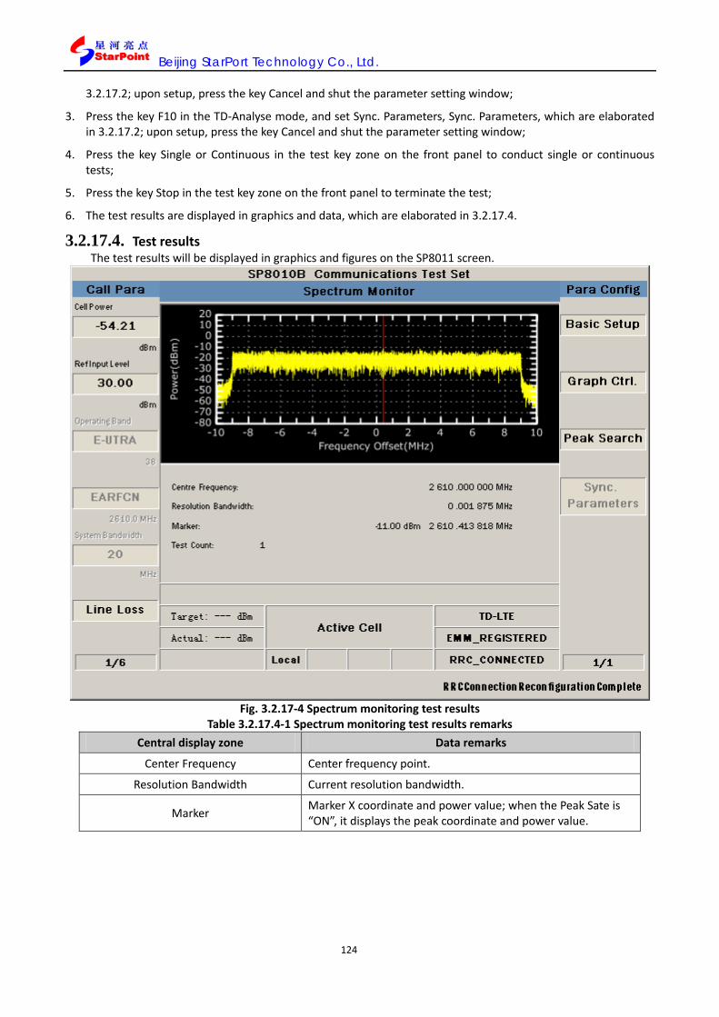
Beijing StarPort Technology Co., Ltd.
124
3.2.17.2; upon setup, press the key Cancel and shut the parameter setting window;
3. Press the key F10 in the TD-Analyse mode, and set Sync. Parameters, Sync. Parameters, which are elaborated in 3.2.17.2; upon setup, press the key Cancel and shut the parameter setting window;
4. Press the key Single or Continuous in the test key zone on the front panel to conduct single or continuous tests;
5. Press the key Stop in the test key zone on the front panel to terminate the test;
6. The test results are displayed in graphics and data, which are elaborated in 3.2.17.4.
3.2.17.4. Test results The test results will be displayed in graphics and figures on the SP8011 screen.
Fig. 3.2.17-4 Spectrum monitoring test results
Table 3.2.17.4-1 Spectrum monitoring test results remarks Central display zone Data remarks
Center Frequency Center frequency point.
Resolution Bandwidth Current resolution bandwidth.
Marker Marker X coordinate and power value; when the Peak Sate is “ON”, it displays the peak coordinate and power value.

Beijing StarPort Technology Co., Ltd.
125
3.2.18. Transmit power test (Transmit Power)
3.2.18.1. Test item definition The transmit power test covers: the four tests of maximum output power (UE Maximum Output Power),
maximum power reduction (Maximum Power Reduction(MPR)), additional maximum power reduction (Additional Maximum Power Reduction (A-MPR) and configured transmit power (Configured UE transmitted Output Power) .
In the Active Cell mode, SP8011, upon establishment of call connection to the terminal, is set to the power-control type (Item 1 on Page 3 of Call Para) of “MAX”, where this test can be conducted. The parameters in 3GPP TS36.521-1 related to this test can be correspondingly set up upon establishment of terminal call connection.
Maximum output power (MOP)
The maximum output power test functions to verify the maximum output power of the UE and check out whether its dynamic range is restricted below the protocol-designated value and within specified deviation. Excessive UE maximum output power will affect other neighboring channels or the system, while excessive low minimum output power will reduce the signal coverage.
According to Protocol 3GPP TS36.521-1, when the UE power is rated at Category 3, the test item parameters feature the following requirements.
Table 5.1.1.1-1 Minimum conformance requirements EUTRA band
Class 1 (dBm)
Tolerance (dB)
Class 2 (dBm)
Tolerance (dB)
Class 3 (dBm)
Tolerance (dB)
Class 4 (dBm)
Tolerance (dB)
1 23 ±2 2 23 ±22 3 23 ±22 4 23 ±2 5 23 ±2 6 23 ±2 7 23 ±22 8 23 ±22 9 23 ±2 10 23 ±2 11 23 ±2 12 23 ±22 13 23 ±2 14 23 ±2 … 17 23 ±2 18 23 ±2 19 23 ±2 20 23 ±22 21 23 ±2 22 23 +2/-3.52 23 23 ±2 24 23 ±2 25 23 ±22 ... 33 23 ±2 34 23 ±2 35 23 ±2 36 23 ±2 37 23 ±2 38 23 ±2

Beijing StarPort Technology Co., Ltd.
126
39 23 ±2 40 23 ±2 41 23 ±2 42 23 +2/-3 43 23 +2/-3 …
Maximum power reduction (MPR)
The maximum power reduction is the allowed reduction of the UE maximum output power, under the impact of high order modulation, transmit bandwidth configuration and other factors. In different work frequency ranges, the third category of UE features the maximum output power specification of 23dBm. The resource block in the QPSK modulation mode, when the RB number is beyond some given value, allows 1dB power reduction; in the 16QAM modulation mode, based on different RB numbers, allows 1dB or 2dB power reductions.
According to Protocol 3GPP TS36.521-1, when the UE power is rated at Category 3, the test item parameters feature the following requirements.
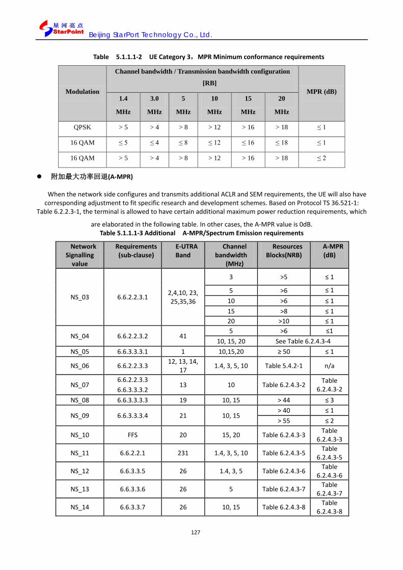
Beijing StarPort Technology Co., Ltd.
127
Table 5.1.1.1-2 UE Category 3,MPR Minimum conformance requirements
Modulation
Channel bandwidth / Transmission bandwidth configuration
[RB] MPR (dB)
1.4
MHz
3.0
MHz
5
MHz
10
MHz
15
MHz
20
MHz
QPSK > 5 > 4 > 8 > 12 > 16 > 18 ≤ 1
16 QAM ≤ 5 ≤ 4 ≤ 8 ≤ 12 ≤ 16 ≤ 18 ≤ 1
16 QAM > 5 > 4 > 8 > 12 > 16 > 18 ≤ 2
附加最大功率回退(A-MPR)
When the network side configures and transmits additional ACLR and SEM requirements, the UE will also have corresponding adjustment to fit specific research and development schemes. Based on Protocol TS 36.521-1:
Table 6.2.2.3-1, the terminal is allowed to have certain additional maximum power reduction requirements, which
are elaborated in the following table. In other cases, the A-MPR value is 0dB. Table 5.1.1.1-3 Additional A-MPR/Spectrum Emission requirements
Network Signalling
value
Requirements (sub-clause)
E-UTRA Band
Channel bandwidth
(MHz)
Resources Blocks(NRB)
A-MPR (dB)
NS_03 6.6.2.2.3.1 2,4,10, 23, 25,35,36
3 >5 ≤ 1
5 >6 ≤ 1 10 >6 ≤ 1 15 >8 ≤ 1 20 >10 ≤ 1
NS_04 6.6.2.2.3.2 41 5 >6 ≤1
10, 15, 20 See Table 6.2.4.3-4 NS_05 6.6.3.3.3.1 1 10,15,20 ≥ 50 ≤ 1
NS_06 6.6.2.2.3.3 12, 13, 14, 17 1.4, 3, 5, 10 Table 5.4.2-1 n/a
NS_07 6.6.2.2.3.3
13 10 Table 6.2.4.3-2 Table 6.2.4.3-2 6.6.3.3.3.2
NS_08 6.6.3.3.3.3 19 10, 15 > 44 ≤ 3
NS_09 6.6.3.3.3.4 21 10, 15 > 40 ≤ 1 > 55 ≤ 2
NS_10 FFS 20 15, 20 Table 6.2.4.3-3 Table 6.2.4.3-3
NS_11 6.6.2.2.1 231 1.4, 3, 5, 10 Table 6.2.4.3-5 Table 6.2.4.3-5
NS_12 6.6.3.3.5 26 1.4, 3, 5 Table 6.2.4.3-6 Table 6.2.4.3-6
NS_13 6.6.3.3.6 26 5 Table 6.2.4.3-7 Table 6.2.4.3-7
NS_14 6.6.3.3.7 26 10, 15 Table 6.2.4.3-8 Table 6.2.4.3-8

Beijing StarPort Technology Co., Ltd.
128
NS_15 6.6.3.3.9 26 1.4, 3, 5, 10, 15 Table 6.2.4.3-9 Table
6.2.4.3-9, Table
6.2.4.3-10 Table
6.2.4.3-10
Configured transmitted output power (CTOP)
The configured transmitted output power test functions to verify the UE configured transmitted output power PCMAX does not exceed the least value of PEMAX and PUMAX. Where, PEMAX refers to the UE allowed maximum transmitted output power specified on the upper layer, i.e. the p-Max value of SystemInformationBlockType1, while PUMAX refers to the maximum transmitted output power, i.e. the MPR- and A-MPR-corrected power.
According to Protocol 3GPP TS36.521-1, when the UE power is rated at Category 3, the test item parameters feature the following requirements.
Table 5.1.1.1-4 Minimum conformance requirements
PCMAX
(dBm)
Tolerance T(PCMAX)
(dB)
21 ≤ PCMAX ≤ 23 2.0
20 ≤ PCMAX < 21 2.5
19 ≤ PCMAX < 20 3.5
18 ≤ PCMAX < 19 4.0
13 ≤ PCMAX < 18 5.0
8 ≤ PCMAX < 13 6.0
-40 ≤ PCMAX < 8 7.0
3.2.18.2. Parameter configuration The parameter configuration includes the configuration of SP8011 parameters and the setting of test item
parameters by the user. This test item supports the channel bandwidth of 1.4M~20M. Modulation mode: Uplink QPSK/16QAM, and
downlink QPSK/16QAM/64QAM. SP1080B Parameter configuration
Table 5.1.1.1-3 SP8011 transmission signal power test paremeters configuration Category Configurable parameters Parameters configuration value
Cell power Cell Power -54.21dBm Input reference level Ref Level 30.00dBm
Power control type UE Target Power Off
Power Control Type MAX
Physical channel power(Channel Level)
Cell-Specific RS 0 PSS_RA 0 SSS_RA 0
PBCH_RA 0 PBCH_RB 0
PCFICH_RB 0

Beijing StarPort Technology Co., Ltd.
129
PDCCH_RA 0 PDCCH_RB 0 PHICH_RA 0 PHICH_RB 0 PDSCH_RA 0 PDSCH_RB 0
Uplink channel schedule selection Channel Schedule PUSCH
Parameter configuration of test items by the user
When SP8011 conduct the test, the user can set the test item parameters in accordance with the test requirements. Configurable parameters are: Basic Setup, Spec. Setup and Sync. Parameter, which are elaborated as follows:
Basic Setup parameter setting Basic Setup works to set the basic parameters of the test item including Average Count, Subframe No,
Trigger Arm, Power Class and Time Out, which are elaborated in 3.2.1.2. Spec. Setup parameter setting
Spec. Setup refers to the index threshold mask, i.e. the criteria to judge whether the test has passed, and the user can define the mask themselves. The parameters to be set up include:
Requirement Type:Configuration of the test criteria, which is defaulted at Min Requirements, where other parameters in the Spec. Setup is not configurable, and the default value corresponds to the Minimum conformance requirements in protocol 3GPP; when the Requirement Type is set at Test Requirement, other parameters in the Spec. Setup are not configurable, and the default value is corresponding to the Test requirement in Protocol 3GPP;when Requirement Type is Manual, other parameters are configurable and the user can set the following parameters:
PCMAX: i.e. PCMAX, the configured maximum power of the UE test. This item is a table entry of remarks, which is greyed out and not available by default;
21≤PCMAX<23: The tolerance within the tested power range as required for minimum conformance;
20≤PCMAX<21: The tolerance within the tested power range as required for minimum conformance;
19≤PCMAX<20: The tolerance within the tested power range as required for minimum conformance;
18≤PCMAX<19: The tolerance within the tested power range as required for minimum conformance;
13≤PCMAX<18: The tolerance within the tested power range as required for minimum conformance;
8≤PCMAX<13: The tolerance within the tested power range as required for minimum conformance;
-40≤PCMAX<8: The tolerance within the tested power range as required for minimum conformance.
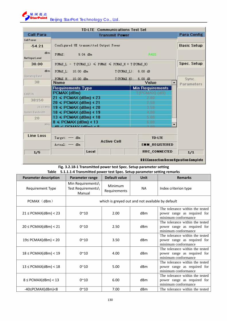
Beijing StarPort Technology Co., Ltd.
130
Fig. 3.2.18-1 Transmitted power test Spec. Setup parameter setting
Table 5.1.1.1-4 Transmitted power test Spec. Setup parameter setting remarks Parameter description Parameter range Default value Unit Remarks
Requirement Type Min Requirements\ Test Requirements\
Manual
Minimum Requirements NA Index criterion type
PCMAX(dBm) which is greyed out and not available by default
21 ≤ PCMAX(dBm) < 23 0~10 2.00 dBm The tolerance within the tested power range as required for minimum conformance
20 ≤ PCMAX(dBm) < 21 0~10 2.50 dBm The tolerance within the tested power range as required for minimum conformance
19≤ PCMAX(dBm) < 20 0~10 3.50 dBm The tolerance within the tested power range as required for minimum conformance
18 ≤ PCMAX(dBm) < 19 0~10 4.00 dBm The tolerance within the tested power range as required for minimum conformance
13 ≤ PCMAX(dBm) < 18 0~10 5.00 dBm The tolerance within the tested power range as required for minimum conformance
8 ≤ PCMAX(dBm) < 13 0~10 6.00 dBm The tolerance within the tested power range as required for minimum conformance
-40≤PCMAX(dBm)<8 0~10 7.00 dBm The tolerance within the tested

Beijing StarPort Technology Co., Ltd.
131
power range as required for minimum conformance
Sync. Parameter setting (the same to that in 3.2.1.2)
3.2.18.3. Test operations
1. In the Active Cell operation mode, press the key More (page flipping) on the left side to enter into the third page for Call Para (call parameters) configuration, and the bottom of the menu on the right side displays 3/6; press the key F1, and set the “Power Control Type” as “Max”;
2. To conduct “UE Maximum Output Power”\”Maximum Power Reduction (MPR)”\-related tests, RB number, modulation mode, uplink RMC and the like configuration are required in accordance with Protocol 3GPP: TS36.521-1, and configuration can be conducted among UL Config and RMC upon establishment of call connection, which is elaborated in 5.3.5;
3. To conduct “Additional Maximum Power Reduction (A-MPR)”-related tests, RB number, modulation mode, uplink RMC and the like configuration are required in accordance with Protocol 3GPP: TS36.521-1, and configuration can be conducted among UL Config and RMC upon establishment of call connection, which is elaborated in 5.3.5, where the parameter “additionalSpectrumEmission” is on the second page of Call Control, and when the menu on the right displays 2/4, please press the Ket F1 and conduct setting in “General Config”; Note: this test needs to be conducted in corresponding frequency range.
4. To conduct “Configured UE transmitted Output Power”-related tests, RB number, modulation mode, uplink RMC and the like configuration are required in accordance with Protocol 3GPP: TS36.521-1, and configuration can be conducted among UL Config and RMC upon establishment of call connection, which is elaborated in 5.3.5, where the parameter-Max” is on the second page of Call Control, and when the menu on the right displays 2/4, please press the Ket F1 and conduct setting in “General Config”.
5. You can also select “UE Maximum Output Power @QPSK 1RB”or “UE Maximum Output Power @QPSK 18RB”of “Transmit Power” in “One Touch”, to complete corresponding “UE Maximum Output Power” configuration;
Or, in the same position, you can select “Maximum Power Reduction (MPR) @QPSK 18RB”, “Maximum Power Reduction (MPR) @QPSK 100RB”, “Maximum Power Reduction (MPR) @16QAM 18RB” or “Maximum Power Reduction (MPR) @16QAM 100RB” to conduct corresponding “Maximum Power Reduction (MPR)” configuration;
Or in the same position, you can choose “Configured UE transmitted Output Power @QPSK 18RB @p-Max -10”, “Configured UE transmitted Output Power @QPSK 18RB @p-Max 10” or “Configured UE transmitted Output Power @QPSK 18RB @p-Max 15” to complete corresponding “Configured UE transmitted Output Power “configuration.
6. Upon configuration as needed, press the Selection in the test key zone on the front panel, and select “Transmit Power” in the popup window, and enable this test item;
7. Press the key F7, and set the Basic Setup\Spec. Setup, and the Basic Setup parameters are elaborated in 3.2.18.2; upon setup, press the key Cancel and shut the parameter setting window;
8. Press the key F9 in the TD-Analyse mode, and set Sync. Parameters, Sync. Parameters, which are elaborated in 3.2.18.2; upon setup, press the key Cancel and shut the parameter setting window;
9. Press the key Single or Continuous in the test key zone on the front panel to conduct single or continuous tests;
10. Press the key Stop in the test key zone on the front panel to terminate the test;
11. The test results are displayed in graphics and data, which are elaborated in 3.2.18.4.

Beijing StarPort Technology Co., Ltd.
132
3.2.18.4. Test results The test results will be displayed on the SP8011 screen in graphics and figures, and when the test results
meet the protocol requirements, it will display “PASS”, which means it has passed the test, or it will display “FAIL”, which means it has failed.
The three subtests of this test item have respective tests conditions as follows:
Maximum output power (MOP): The test is conducted on the condition of QPSK and RB Num<18;
Maximum power reduction: The test is conducted on the condition of QPSK, RB ≥ 18 or 16QAM;
Configured transmitted output power (CTOP): The test is conducted upon UR response after the p-Max value is modified (ranging: -30~33);
Additional maximum power reduction (A-MPR): The test is conducted in different NS, and corresponding frequencies and RB configuration.
Fig. 3.2.18-2 Maximum output power test results

Beijing StarPort Technology Co., Ltd.
133
Fig.3.2.18-3 Maximum output power reduction test results
Fig. 3.2.18-4 Configured transmitted output power test results

Beijing StarPort Technology Co., Ltd.
134
Fig.3.2.18-5 Additional maximum power reduction test results
Fig. 3.2.18-6 Non-signaling transmitted output power test results
Table 3.2.18.4 1 Transmit power test results remarks

Beijing StarPort Technology Co., Ltd.
135
Central display zone Data remarks
The first line Current test item(UE Maximum Output Power、 Maximum Power Reduction、Additional Maximum Power Reduction (A-MPR)、Configured UE transmitted Output Power)。
PUMAX Current test power value。 PCMAX_L Display the current PCMAX_L。
T(PCMAX_L) Display the current T(PCMAX_L),corresponding PCMAX_L tolerance
PCMAX_H Display the current PCMAX_H。
T(PCMAX_H) Display the current T(PCMAX_H),corresponding PCMAX_H tolerance
PEMAX Display the current PEMAX。 MPR Display the current MPR。
A-MPR Display the current A-MPR。 P(PowerClass) Display the current PPowerClass。
ΔTc Display the current ΔTc。
SYNC State Parameter is displayed “——” all the time in signaling mode,and displayed the Sync status with signal in Non-Signaling mode,PASS or FAIL
Test Count Test times TimeOut It is displayed if the time is out for test PASS/FAIL It is displayed if the result is pass for test
3.2.19. Transmit signal quality test (Transmit Signal Quality)
3.2.19.1. Test item definition The transmit signal quality test includes the five tests of Frequency Error, Error Vector Magnitude, Carrier
leakage, In-band emissions for non-allocated RB and EVM equalizer spectrum flatness. In the Active Cell mode, upon establishment of call connection to the terminal, the tester is set to the
power-control type (Item 1 on Page 3 of Call Para) of “TPC” or “MAX”, where this test can be conducted. The parameters in 3GPP TS36.521-1 related to this test can be correspondingly set up upon the terminal’s establishment of call connection. Frequency error test (FERR)
This test item works to verify the correct frequency processing capacity of the UE receiver and the transmitter.
Receiver: On ideal broadcast conditions, it extracts correct frequency from the stimulus signals provided by SP8011.
Transmitter: It obtains correct modulation carrier frequency out of the results from the receiver. Minimum consistency requirements for frequency deviation: Within one time slot, the deviation between
the UE modulation carrier frequency and E-UTRA Node B carrier frequency be within±0.1 PPM. Error vector magnitude (EVM)
The error vector magnitude test works to check the difference between the reference wave form and the tested wave form. And their difference is the error vector magnitude.
The test wave needs to be further modified based on the absolute magnitude and absolute phase position of the TX chain. The EVM results are defined as the R.M.S of mean error vector power and average reference power after the front part IDFT, which is expressed in percentage (%).
Table 3.2.19.1-1 Minimum conformance requirements
Parameter Unit Average EVM Level Reference Signal EVM

Beijing StarPort Technology Co., Ltd.
136
Level
QPSK or BPSK % 17.5 [17.5] 16QAM % 12.5 [12.5]
Carrier leakage
Carrier leakage refers to the interference caused by crosstalk or DC offset, which is represented by the sine wave of un-modulated carrier frequency. This interference features constant amplitude and is independent from the signal amplitude. The signal I/Q component will cause interference on the subcarrier in the center, and have particularly significant impact when their amplitude is relatively low. This test item detects the modulation quality of the UE transmitter in the form of carrier leakage.
Table 3.2.19.1-2 Minimum conformance requirements Parameters Relative Limit (dBc)
Output power >0 dBm -25
-30 dBm ≤ Output power ≤0 dBm -20
-40 dBm ≤ Output power < -30 dBm -10
In-band emissions test for non-allocated resource block (In-band emissions for non-allocated RB)
The in-band emissions test works to detect the interference falling into the non-allocated resource block. The in-band emission is defined as the average of 12 carriers’ power, which is represented by the function
that the average power changes with the changing RM offset, starting from the allocated uplink transmitted RB edge. The in-band emissions test is the ratio of the non-allocated RB output power to the allocated RB output power of the UE.
Table 3.2.19.1-3 Minimum conformance requirements Parameter Description Unit Limit (Note 1) Applicable
Frequencies
General dB Any non-allocated
IQ Image dB -25 Image frequencies
Carrier leakage dBc
-25 Output power > 0 dBm
LO frequency -20 -30 dBm ≤ Output power ≤ 0 dBm
-10 -40 dBm ≤ Output power < -30 dBm
Spectrum flatness (EVM equalizer spectrum flatness)
The EVM equalizer spectrum flatness is detected based on the equalizer coefficient peak-to-peak value produced on the allocated uplink resource block during the EVM test process.
Table 3.2.19.1-4 Minimum conformance requirements
{
}RB
CRBsRB
CRBsRB
PkHzdBmLEVMLN
−−−∆⋅−−⋅
⋅−−−
180/57,/)1(53log20),/(log1025,30max
10
10

Beijing StarPort Technology Co., Ltd.
137
EVM equalizer Spectrum Flatness Relative Limit (dB)
If FUL_measurement - FUL_low ≥ 3MHz
and
If FUL_high - FUL_measurement ≥ 3 MHz
+2/-2
If FUL_measurement - FUL_low < 3 MHz
or
If FUL_high - FUL_measurement < 3 MHz
+3/-5
IQ imbalance (IQ Imbalance)
IQ Imbalance is generated by respective gain control of two I/Q signals during the mixer, filter and ADC process, which is represented by the imbalance of constellation point amplitude along the X-Axis and Y-Axis of the signal constellation diagram.
3.2.19.2. Parameter configuration The parameter configuration includes the configuration of SP8011 parameters and the setting of test item parameters by the user.
SP8011 Parameter configuration This test item supports the channel bandwidth of 1.4M~20M. Modulation mode: Uplink QPSK/16QAM, and
downlink QPSK/16QAM/64QAM. As regulated in Protocol 3GPP: TS 36.521-1, SP8011 has specific parameter configuration as follows.
Table 5.1.1.1-5 SP8011 transmissionsignal quality test parameters configuration
Category Configurable parameters Parameters configuration value
Cell power Cell Power -54.21dBm Input reference level Ref Level 30.00dBm
Power control type UE Target Power Off /ON
Power Control Type MAX/Target
Physical channel power(Channel Level)
Cell-Specific RS 0 PSS_RA 0 SSS_RA 0
PBCH_RA 0 PBCH_RB 0
PCFICH_RB 0 PDCCH_RA 0 PDCCH_RB 0 PHICH_RA 0 PHICH_RB 0 PDSCH_RA 0 PDSCH_RB 0
Uplink channel schedule selection Channel Schedule PUSCH/PUCCH/PRACH
Parameter configuration of test items by the user

Beijing StarPort Technology Co., Ltd.
138
As needed for the test, the user can set transmit signal quality test parameters, which include Basic Setup, Spec. Setup, Graph Ctrl., Test Channel, Change View, Marker State, Marker X, Sync. Parameter, Modulation window, as elaborated below: Basic Setup parameter setting Basic Setup works to set the basic parameters of the test item including Average Count, Trigger Arm, Power Class, Time Out, which are elaborated in 3.2.1.2. Spec. Setup parameter setting
Spec. Setup refers to the index threshold mask, i.e. the criteria to judge whether the test has passed, and the user can define the mask themselves. The parameters to be set up include:
Requirement Type:Configuration of the test criteria, which is defaulted at Min Requirements, where other parameters in the Spec. Setup is not configurable, and the default value corresponds to the Minimum conformance requirements in protocol 3GPP;when the Requirement Type is set at Test Requirement, other parameters in the Spec. Setup are not configurable, and the default value is corresponding to the Test requirement in Protocol 3GPP; when Requirement Type is Manual, other parameters are configurable and the user can set the following parameters:
Sub Requirements: Marking the following item as the reference value for determining relevant frequency error;
Frequency Error: Frequency error threshold;
Sub Requirements: Marking the following two items as the judgment criteria for determining relevant error vector magnitude;
QPSK or BPSK EVM: The EVM threshold in the BPSK or QPSK modulation mode via the PUSCH channel;
16QAM EVM: The EVM threshold in the 16QAM modulation mode via the PUSCH channel;
Sub Requirements: Marking the following four items as the reference value for determining relevant carrier leakage power;
UE Output Power: Marking the following three items as the scope of UE output power, which corresponds to the carrier leakage threshold within the scope in the Value.
(0,+∞):RCLP threshold 1;
[-30,0]:RCLP threshold 2;
[-40, 30]:RCLP threshold 3;
Sub Requirements: Marking the following four items as the reference value for determining relevant frequency spectrum flatness;
Range 1Max & 1Min Ripple: Frequency spectrum flatness threshold 1;
Range 2Max & 2Min Ripple: Frequency spectrum flatness threshold 2;
Range 1Max & 2Min Ripple: Frequency spectrum flatness threshold 2;
Range 2Max & 1Min Ripple: Frequency spectrum flatness threshold 4.

Beijing StarPort Technology Co., Ltd.
139
Fig. 3.2.19-1 Transmit signal quality test Spec. Setup parameter setting
Table 3.2.19.2-2 Transmit signal quality test Spec. Setup parameter setting remarks Parameter description Parameter range Default value Unit Remarks
Requirement Type
Min Requirements/
Test Requirements/
Manual
Minimum Requirements
NA Index judging criteria type
Sub Requirements NA NA NA Marking the following item as the reference value for determining relevant frequency error;
Frequency Error 0~1 0.1 PPM Frequency error threshold
Sub Requirements NA NA dB
Marking the following two items as the judgment criteria for determining relevant error vector magnitude;
QPSK or BPSK EVM 0.0~100.0 17.5 % The EVM threshold in the BPSK or QPSK modulation mode
16QAM EVM 0.0~100.0 12.5 % The EVM threshold in the 16QAM modulation mode
Sub Requirements NA NA NA
Marking the following four items as the reference value for determining relevant carrier leakage power;

Beijing StarPort Technology Co., Ltd.
140
UE Output Power NA Limit NA
Marking the following three items as the scope of UE output power, which corresponds to the carrier leakage threshold within the scope in the Value.
(0,+∞) -100.0~0.0 -25.0
dB Relative carrier leakage threshold 1
[-30,0] -100.0~0.0 -20.0 dBc Relative carrier leakage threshold 2
[-40,30) -100.0~0.0 -10.0 dBc Relative carrier leakage threshold 3
Sub Requirements NA ESF NA
Marking the following four items as the reference value for determining relevant frequency spectrum flatness;
Range 1Max & 1Min Ripple 0~10 4 dB Frequency spectrum flatness threshold 1
Range 2Max & 2Min Ripple 0~10 8 dB Frequency spectrum flatness threshold 2
Range 1Max & 2Min Ripple 0~10 5 dB Frequency spectrum flatness threshold 3
Range 2Max & 1Min Ripple 0~10 7 dB Frequency spectrum flatness threshold 4
Graph Ctrl. Parameter setting Graph Ctrl. Functions to conduct graphic control setting, and the user can define this mask themselves. The
parameters to be set up include:
IBE X Axis Maximum: Visible in-band emission X-Axis maximum within the non-resource block;
IBE X Axis Minimum: Visible in-band emission X-Axis Minimum within the non-resource block;
IBE Y Axis Maximum (dB): Visible in-band emission X-Axis maximum within the non-resource block;
IBE Y Axis Minimum (dB): Visible in-band emission X-Axis minimum within the non-resource block;
ESF X Axis Maximum: X-Axis visible frequency spectrum flatness maximum;
ESF X Axis Minimum: X-Axis visible frequency spectrum flatness minimum;
ESF Y Axis Maximum (dB): Y-Axis visible frequency spectrum flatness minimum;
ESF Y Axis Minimum (dB): Y-Axis visible frequency spectrum flatness minimum.

Beijing StarPort Technology Co., Ltd.
141
Fig. 5.1.1-1 Transmit signal quality test Graph Ctrl. parameter setting
Table 5.1.1.1-6ransmit signal quality test Graph Ctrl. parameter setting remarks
Parameter description Parameter range Default
value Unit Remarks
IBE X Axis Maximm 1~100 100 NA Visible in-band emission X-Axis
maximum within the non-resource block
IBE X Axis Minimm 0.00~15.00 1 NA Visible in-band emission X-Axis
Minimum within the non-resource block
IBE Y Axis Maximm(dB) -100~20 10 dB Visible in-band emission X-Axis
maximum within the non-resource block
IBE Y Axis Minimm(dB) -100~20 -60 dB Visible in-band emission X-Axis
minimum within the non-resource block

Beijing StarPort Technology Co., Ltd.
142
ESF X Axis Maximm 1~1200 1200 subcarrier X-Axis visible frequency spectrum
flatness maximum
ESF X Axis Minimm 1~1200 1 subcarrier X-Axis visible frequency spectrum
flatness minimum
ESF Y Axis Maximm(dB) -20~20 8 dB Y-Axis visible frequency spectrum
flatness minimum
ESF Y Axis Minimm(dB) -20~20 -8 dB Y-Axis visible frequency spectrum
flatness minimum
ANALysis X Maximm
_SLot:1~999 _SYMbol:1~699 _Carrier:1~1200
20 10 9
Slot symbol subcarrier
X-Axis Visible maximum for Sub- function
ANALysis X Minimm
_SLot:0~998 _SYMbol:0~6992 _Carrier:0~1199
0 0 - 9
Slot symbol subcarrier
X-Axis Visible Minimm for Sub- function
ANALysis Y Maximm(dB) 1~400 10 dB Y-Axis Visible maximum for Sub-
function
ANALysis Y Minimm(dB) 0~100 0 dB Y-Axis Visible Minimm for Sub-
function
Change View parameter setting
Change View refers to the graphic display of selected test results, which decided the displayed results and graphic contents with the Test Channel. Parameter range: Constellation / In-band Emission / Spectrum Flatness.
Based on the selection of Test Channel, this parameter available here is different. When the channel is PUSCH, the 3 options of Constellation/In-band Emission/Spectrum Flatness 3 are available; when the channel is PUCCH, the 2 options of Constellation / In-band Emission are available; and when the channel is PRACH, the 1 option of Constellation is available.

Beijing StarPort Technology Co., Ltd.
143
Fig. 3.2.19-3 Transmit signal quality test Change View parameter setting
Modulation Window setting Based on the Change View selection, when Change View is selected as Constellation, different parameter
is available here, or it will be greyed out. The defaulted constellation diagram is General, or different diagrams shall be drawn based on different options. When the channel is selected as PUSCH or PUCCH, several test types: General/EVM Vs. Slot /EVM Vs. Symbol/EVM Vs. Carrier/Phase Error Vs. Slot /Phase Error Vs. Symbol/Phase Error Vs. Carrier/Magnitude Error Vs. Slot /Magnitude Error Vs. Symbol/Magnitude Error Vs. Carrier are available, and when PRACH is selected, the above options feature the following several test types: General/EVM Vs. Carrier/Phase Error Vs. Carrier/Magnitude Error Vs. Carrier;

Beijing StarPort Technology Co., Ltd.
144
Fig. 3.2.19-4 Transmit signal quality test ModulationWindow parameter setting
Marker Sate setting Marker Sate works to set the Marker display, ranging: On / Off, On means to display the Marker; Off means
not to display the Marker. The Marker is a red triangle mark; turn the knob to change the Marker position, and the power value and frequency value where the Marker is located will be displayed on the interface. When Change View is Constellation, this option is greyed out. Marker X parameter setting
Marker X works to set Marker x-coordinate value when Marker employed, and the parameter range changes with the Change View parameter. Sync. Parameter setting (the same to that in 3.2.1.2)
3.2.19.3. Test operations
1. In the Active Cell operating mode, press the key More (page flipping) on the left side to enter into the third page for Call Para (call parameters) configuration, and the bottom of the menu on the right side displays 3/6; press the key F1, and set the “Power Control Type” as “Max” or “Target Power”;
2. The TSQ test items include all test cases in Protocol 3GPP: TS 36.521-1. If RB number, modulation mode, uplink RMC and the like configuration are required in the Protocol for tests, configuration can be conducted among UL Config, DL Config and RMC upon establishment of call connection, which is elaborated in 5.3.5 and 5.3.6;
3. When different types of channels are needed to be tested, please turn to the third page of Call Para (call parameter) configuration, and when the right-side menu bar bottom displays 3/4, press the key F4 to select the channel type;
4. Press the key Selection in the test key zone on the front panel, and select “Transmit Signal Quality” in the popup window, and enable this test item;

Beijing StarPort Technology Co., Ltd.
145
5. Under the defaulted configuration of the test items, you can directly obtain the test results and constellation diagrams of “Frequency Error”, “Error Vector Magnitude (EVM)” and “Carrier leakage, IQ Imbalance”; if you need to obtain the test results of “In-band emissions for non-allocated RB”, please press the key F10, to set the Change View parameter (which is elaborated in 3.2.19.2) and select “In-bandEmission” for if you need to obtain the test results of “EVM equalizer spectrum flatness”, please press the key F10, to set the Change View parameter (which is elaborated in 3.2.19.2) and select “SpectrumFlatness” for corresponding diagram and results; if you need to obtain relevant information about “EVM Vs. Slot/EVM Vs. Symbol/EVM Vs. Carrier/Phase Error Vs. Slot /Phase Error Vs. Symbol/Phase Error Vs. Carrier/Magnitude Error Vs. Slot /Magnitude Error Vs. Symbol/Magnitude Error Vs. Carrier “, please press the key F11 and select, to obtain relevant graphics and results;
6. Or you can select all options of “FER & EVM” and “Transmit Modulation “in “One Touch”, to complete the Test Configuration of all subtest items.
7. Press the keys F7\ F8\ F9\ F11\F12, and set Basic Setup\Spec. Setup\Graph Ctrl\Marker State\Marker X parameters, which are elaborated in 3.2.19.2; upon setup, press the key Cancel and shut the parameter setting window;
8. Press the key MORE in the TD-Analyse mode, and enter into the second page of the test item menu, and press the key F7 to set Sync. Parameters, Sync. Parameters, which are elaborated in 3.2.19.2; upon setup, press the key Cancel and shut the parameter setting window;
9. Press the key Single or Continuous in the test key zone on the front panel to conduct single or continuous tests;
10. Press the key Stop in the test key zone on the front panel to terminate the test;
11. The test results are displayed in graphics and data, which are elaborated in 3.2.19.4.
3.2.19.4. Test results The test results will be displayed on the SP8011 screen in graphics and figures, and when the test results
meet the protocol requirements, it will display “PASS”, which means it has passed the test, or it will display “FAIL”, which means it has failed.

Beijing StarPort Technology Co., Ltd.
146
Fig. 3.2.19-5 Transmit signal quality test—frequency error, error vector magnitude, carrier leakage, and IQ imbalance results
Table 3.2.19.4-1 Transmit signal quality test—frequency error, error vector magnitude, carrier leakage, and IQ imbalance results remarks
Central display zone Data remarks
Yellow graph and X-Axis and Y-Axis Modulation signal constellation diagram.
EVM Error vector magnitude.
Frequency Error Tested frequency error.
DMRS EVM DMRS error vector magnitude.
Carrier Leakage Carrier leakage.
IQ Imbalance IQ imbalance.
Test Count Test times.
TimeOut It indicates whether the test has exceeded the time limit.
PASS/FAIL It indicates whether it has passed the test.
Fig. 3.2.19-6 Transmit signal quality test—non-allocated resource block in-band emission results

Beijing StarPort Technology Co., Ltd.
147
Table 3.2.19.4-2 Transmit signal quality test—non-allocated resource block in-band emission results remarks Central display zone Data remarks
Purple graph Allocated RB power data.
Yellow graph Non-allocated RB power data.
Green line Power limit specified in the protocol.
The triangle in red The Marker sign.
X-axis and x-coordinate data RB number (1~100).
Y-axis and Y-coordinate data Power on corresponding RB (Unit: dB).
Marker It displays the relative power value corresponding to the Marker X point, when the Marker Sate is “ON”.
Test Count Test times.
TimeOut It indicates whether the test has exceeded the time limit.
PASS/FAIL It indicates whether it has passed the test.
Fig. 3.2.19-7 Transmit signal quality test—spectrum flatness results
Table 3.2.19.4-3 Transmit signal quality test—spectrum flatness results Central display zone Data remarks
Purple figure line EVM equalizer coefficient within the distributed RB.
Green circle Marking the maximum and the minimum values within the two ranges.
The triangle in red It displays the EVM equalizer coefficient corresponding to the Marker X point, when the Marker Sate is “ON”.
X-axis and x-coordinate data Subcarrier number (0~1200).

Beijing StarPort Technology Co., Ltd.
148
Y-axis and Y-coordinate data Equalizer coefficient (Unit: dB).
Ripple M to N M maximum to N minimum, 1 and 2 respectively representing Range 1 and Range 2.
Test Count Test times.
TimeOut It indicates whether the test has exceeded the time limit.
PASS/FAIL It indicates whether it has passed the test.
Fig. 3.2.19-8 Transmit signal quality test—EVM Vs. Slot results
Table 3.2.19.4-4 Transmit signal quality test—EVM Vs Slot results remarks Central display zone Data remarks
Yellow columnar line Testing the EVM value of each time slot of the subframe.
Slot Count Testing time slot number.
Marker Displaying the EVM value on the Marker position.
PASS/FAIL It indicates whether it has passed the test.
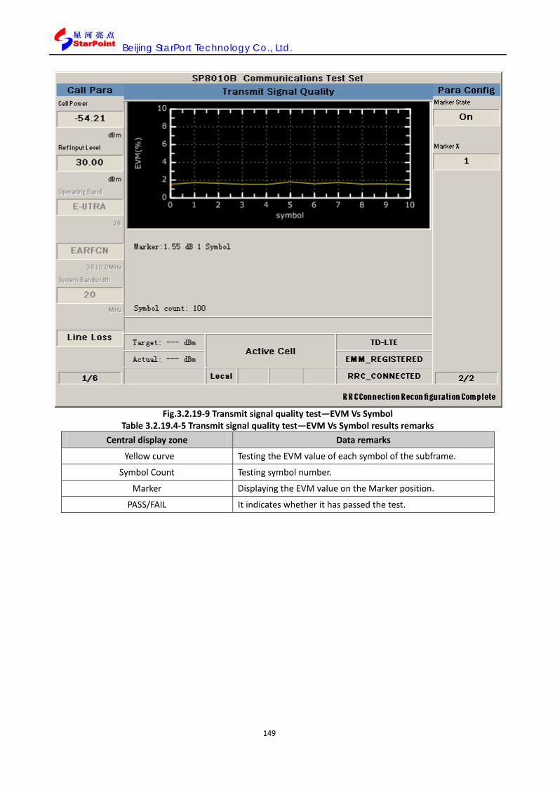
Beijing StarPort Technology Co., Ltd.
149
Fig.3.2.19-9 Transmit signal quality test—EVM Vs Symbol
Table 3.2.19.4-5 Transmit signal quality test—EVM Vs Symbol results remarks Central display zone Data remarks
Yellow curve Testing the EVM value of each symbol of the subframe.
Symbol Count Testing symbol number.
Marker Displaying the EVM value on the Marker position.
PASS/FAIL It indicates whether it has passed the test.
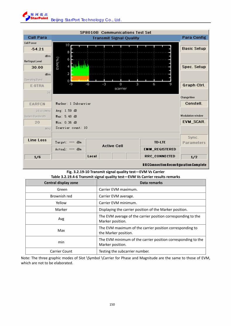
Beijing StarPort Technology Co., Ltd.
150
Fig. 3.2.19-10 Transmit signal quality test—EVM Vs Carrier
Table 3.2.19.4-6 Transmit signal quality test—EVM Vs Carrier results remarks Central display zone Data remarks
Green Carrier EVM maximum.
Brownish red Carrier EVM average.
Yellow Carrier EVM minimum.
Marker Displaying the carrier position of the Marker position.
Avg The EVM average of the carrier position corresponding to the Marker position.
Max The EVM maximum of the carrier position corresponding to the Marker position.
min The EVM minimum of the carrier position corresponding to the Marker position.
Carrier Count Testing the subcarrier number.
Note: The three graphic modes of Slot \Symbol \Carrier for Phase and Magnitude are the same to those of EVM, which are not to be elaborated.
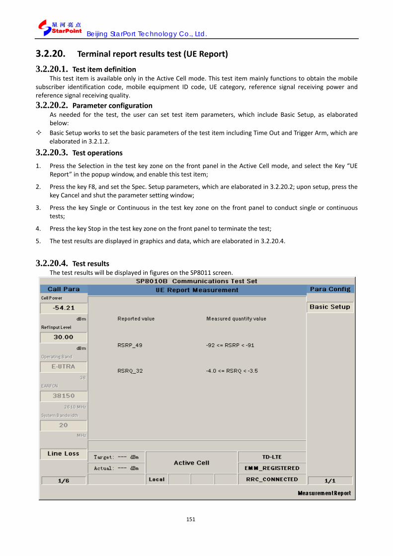
Beijing StarPort Technology Co., Ltd.
151
3.2.20. Terminal report results test (UE Report)
3.2.20.1. Test item definition This test item is available only in the Active Cell mode. This test item mainly functions to obtain the mobile
subscriber identification code, mobile equipment ID code, UE category, reference signal receiving power and reference signal receiving quality. 3.2.20.2. Parameter configuration
As needed for the test, the user can set test item parameters, which include Basic Setup, as elaborated below:
Basic Setup works to set the basic parameters of the test item including Time Out and Trigger Arm, which are elaborated in 3.2.1.2.
3.2.20.3. Test operations
1. Press the Selection in the test key zone on the front panel in the Active Cell mode, and select the Key “UE Report” in the popup window, and enable this test item;
2. Press the key F8, and set the Spec. Setup parameters, which are elaborated in 3.2.20.2; upon setup, press the key Cancel and shut the parameter setting window;
3. Press the key Single or Continuous in the test key zone on the front panel to conduct single or continuous tests;
4. Press the key Stop in the test key zone on the front panel to terminate the test;
5. The test results are displayed in graphics and data, which are elaborated in 3.2.20.4.
3.2.20.4. Test results
The test results will be displayed in figures on the SP8011 screen.

Beijing StarPort Technology Co., Ltd.
152
Fig. 3.2.20-1 UE Report test results
Table 3.2.20.4-1 UE Report test results remarks Central display zone Data remarks
RSRP_49 Reference signal receiving power
RSRQ_32 Reference signal receiving quality
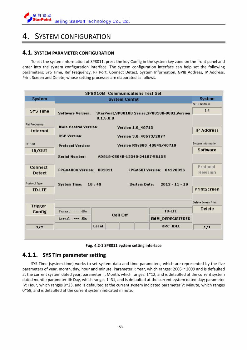
Beijing StarPort Technology Co., Ltd.
153
4. SYSTEM CONFIGURATION
4.1. SYSTEM PARAMETER CONFIGURATION To set the system information of SP8011, press the key Config in the system key zone on the front panel and
enter into the system configuration interface. The system configuration interface can help set the following parameters: SYS Time, Ref Frequency, RF Port, Connect Detect, System Information, GPIB Address, IP Address, Print Screen and Delete, whose setting processes are elaborated as follows.
Fug. 4.2-1 SP8011 system setting interface
4.1.1. SYS Tim parameter setting SYS Time (system time) works to set system data and time parameters, which are represented by the five
parameters of year, month, day, hour and minute. Parameter I: Year, which ranges: 2005 ~ 2099 and is defaulted at the current system dated year; parameter II: Month, which ranges: 1~12, and is defaulted at the current system dated month; parameter III: Day, which ranges 1~31, and is defaulted at the current system dated day; parameter IV: Hour, which ranges 0~23, and is defaulted at the current system indicated parameter V: Minute, which ranges 0~59, and is defaulted at the current system indicated minute.

Beijing StarPort Technology Co., Ltd.
154
Fig. 4.1.1-1 SP8011 SYS Time setting
4.1.2. Ref Frequency parameter setting Ref Frequency refers to the clock source setting parameter, for setting synchronous clock reference source,
and the user can choose to use internal or external clock source, which ranges: Internal / External and is defaulted at Internal. When Ref Frequency is set as Internal, the synchronous clock reference frequency is generated internally within SP8011; when Ref Frequency is set as External, the synchronous clock reference frequency is externally input.

Beijing StarPort Technology Co., Ltd.
155
Fig. 4.1.2-1 SP8011 Ref Frequency setting
4.1.3. RF Port parameter setting RF Port (RF port) works to set the output mode of RF port, and the user can select RF output frequency via
this parameter, which ranges: IN/OUT / OUT and is defaulted at IN/OUT. When RF Port is set as IN/OUT, the instrument IN/OUT port is the radio frequency input/output port; when RF Port is set as OUT, the instrument IN/OUT port is the radio frequency input port, and the instrument OUT port is the radio frequency output port.

Beijing StarPort Technology Co., Ltd.
156
Fig.4.1.3-1 SP8011 RF Port setting
4.1.4. Connect Detect parameter setting Connect Detect works to set whether to enable the system connect detect function, and the connect detect
duration of SP8011 is 10s, i.e. if the uplink signal cannot be detected within 10s, the instrument will be enabled with the disconnection detect processing mechanism. The parameter ranges: On / Off and is defaulted at Off; when Connect Detect is set at On, the connect detect function is enabled; when Connect Detect is set at Off, the connect detect function is disabled.

Beijing StarPort Technology Co., Ltd.
157
Fig.4.1.4-1 SP8011 Connect Detect setting
4.1.5. Master-slave instrument parameter setting The SP8011 system information provides cascade function, and when two instruments are required for
conducting cascade for four antenna, you can conduct master-slave instrument setting on SP8011. This parameter can only be set in the Cell Off state.
1.Cascade setting Back panel connection: To connect the master instrument CASCADE In/Out 2(USB port upper port) to the
slave CASCADE In/Out 1. 2.Master instrument setting
Setting antenna number, whose interface setting is shown in Fig. 4.1.5 1.

Beijing StarPort Technology Co., Ltd.
158
Fig. 4.1.5-1 NSFT Antenna number setting
Setting master-slave as Master, whose interface setting is shown in Fig. 4.1.5 2.
Fig. 4.1.5-2 Master-salve instrument setting
3.Salve instrument setting Set RefFrequency as External, whose selection interface is shown in Fig. 4.1.5-3.

Beijing StarPort Technology Co., Ltd.
159
Fig. 4.1.5-3 RefFrequency setting
Connect 10MHz OUT in the Master instrument and 10MHz IN in the slave instrument with double N wires. Select the Master-Salve as Salve, which is shown in Fig. 4.1.5-4.
Fig. 4.1.5-4 Master-salve instrument setting

Beijing StarPort Technology Co., Ltd.
160
4.1.6. GPIB Address parameter setting GPIB Address works to set the address of the instrument GPIB, which is an integer, ranging: 0 ~ 30 and
defaulted at 14.
4.1.7. IP Address parameter setting IP Address works to set the LAN connection IP address of SP8011, which ranges: character string made up of
15 characters, in the format of A.B.C.D, where A=0~126, and 128~223, B.C.=0~225, D=1~254; and is defaulted at:192.168.1.200.
Subnet Mask works to set the LAN connection subnet mask of SP8011, which ranges: character string made up of 15 characters, in the format of A.B.C.D, where A.B.C.D=0~255; and is defaulted at: 255.255.255.0.
Default Gateway works to set the LAN connection gateway of SP8011, which ranges: character string made up of 15 characters, in the format of A.B.C.D, where A= 0 ~ 223, B.C = 0 ~ 255, D = 1 ~ 254; and is defaulted at: NA.
Fig. 4.1.8-1 SP8011 IP Address setting
4.1.8. System Information parameter setting SP8011 system information includes the three components of system software, hardware and authorization
information, which are shown in the following figure:

Beijing StarPort Technology Co., Ltd.
161
Fig. 4.1.9-1 SP8011 system software information
Fig. 4.1.9-2 SP8011 system hardware information

Beijing StarPort Technology Co., Ltd.
162
Fig. 4.1.9-3 SP8011 system authentication information
4.1.9. Protocol Revision parameter setting Protocol Revision functions to set the corresponding protocol version of the current system, and this
function is invalid for the time being.
4.1.10. Print Screen parameter setting Print Screen works to set the system screenshot saving address, and upon screenshot operation, the picture
will be saved at the address set by Print Screen. The screenshot saving address ranges: 256 characters and is defaulted at Default.

Beijing StarPort Technology Co., Ltd.
163
Fig.4.1.11-1 SP8011 PrintScreen setting
4.1.11. Delete parameter configuration Delete refers to the screenshot delete operation, for deleting the system screen shot picture saved on the
instrument hardware.
Fig.4.1.12-1 SP8011 Print Screen Delete setting

Beijing StarPort Technology Co., Ltd.
164
5. MANUAL OPERATION The user can conduct operation on the front panel of SP8011, whose screen displays call processing functions
and test results. The user can also conduct remote control of SP8011, with GPIB command assistance.
5.1. SP8011 PANEL OVERVIEW 5.1.1. Front panel view illustration
Fig. 5.1.1 1 SP8011 front panel view
The front panel, as shown in the above figure, consists of eight zones, which are illustrated as follows:
5.1.1.1. Configuration key zone on the left The configuration key zone on the left includes F1~F6 and More, 7 keys altogether, with F1~F6 corresponding
to the six options of the menu on the left of the software interface, and More for page flip operation of the menu on the left.
5.1.1.2. Configuration key zone on the right The configuration key zone on the left includes F7~F12 and More, 7 keys altogether, with F7~F12
corresponding to the six options of the menu on the right of the software interface, and More for page flip operation of the menu on the right.
5.1.1.3. Test key zone The test key zone embraces Screen, Selection, Single, Continuous, Stop and Reset, 6 keys altogether, which
are respectively illustrated as follows in Table 5.1.1.3-1:

Beijing StarPort Technology Co., Ltd.
165
Table 5.1.1.4-1 Test key zone button functions
Button Functions
Switch to the test item page
Select the test items
Activate the test for once
Activate the test continuously
Stop the test
Reset the test item parameter
5.1.1.4. Call key zone The call key zone features the three keys of Setup, Recall and Save (Delete), which are illustrated as follows:
Table 5.1.1.5-1 Call key zone button functions
Button Functions
Switch to the call setting interface.
Load pre-saved settings
Save/delete settings
5.1.1.5. System key zone The system key zone features the three buttons of Config (PrntScrn), Local (Help) and Shift, which are
illustrated as follows:
Table 5.1.1.6-1 System key zone button functions
Button Functions
Switch to the system configuration interface /interface screenshot operation
Switch button functions
Switch to the Local mode/Help mode
5.1.1.6. Input selection key zone The input selection key zone features the number keys 0~9, decimal point, plus and minus sign, BKsp, Enter,
Cancel, four directions keys and knob, which are illustrated as follows:
Table 5.1.1.7-1 Input selection key zone button functions
Button Functions
Number keys 0~9, decimal point, plus and minus signs
For inputting parameters, where repeated input of +/- works to switch between the two signs
Backspace key, for correcting input parameters
Confirm the option selected or the parameter input
Cancel the pop-up dialog box or the input parameter
Direction button For moving the cursor upwards or downwards
Knob For moving the cursor location and confirming the option selected or the parameter input

Beijing StarPort Technology Co., Ltd.
166
5.1.1.7. Other zones In addition to the above key zones, there are also Power, Preset, Display screen, Power indicator and other
zones, which are illustrated respectively as follows:
Table 5.1-1 Other button functions
Button Functions
Instrument switch, for switching SP8011
Reset, for resetting parameters
Display screen Display SP8011 software interface
Power indicator Display the power state of SP8011, where green indication means the instrument is running, while red indication means the instrument is power-on, but has not started yet.
5.1.1.8. Front panel interface Table 5.1.1.9-1 Front panel interface illustration
Interface identification Functions
This N type port is the signal output port of SP8011 RF1, for transmitting RF1 signal.
This N type port is the signal input/output port of SP8011 RF1, for transmitting/receiving RF1 signal.
This N type port is the signal output port of SP8011 RF2, for transmitting RF2 signal.
This N type port is the signal input/output port of SP8011 RF2, for transmitting/receiving RF2 signal.
5.1.2. Back panel view illustration
Fig. 5.1.2-1 SP8011 back panel view
The figure above is the back panel view, which is illustrated as follows:
Table 5.1.2-1Back panel port illustration
Identification Functions

Beijing StarPort Technology Co., Ltd.
167
Power supply SP8011 power port (100~ 240 V ~ 5.0 A, 47 ~ 63 Hz, around Mainland China)
10MHz reference clock signal input port, for synchronizing multiple instruments
10MHz reference clock signal output port, for synchronizing multiple instruments
Audio input port, for receiving audio
Audio output port, for transmitting audio
Trigger signal input port, for synchronizing multiple instruments
Trigger signal output port, for synchronizing multiple instruments
For connecting USB devices
Backup ports
For connecting to the Ethernet network
For connecting GPIB devices
* N.B.: When applying USB storage devices to the instrument, please ensure the USB device is free of virus, to prevent virus invasion into the SP8011 system and fail the instrument.
5.2. SETTING PRIOR TO EQUIPMENT EMPLOYMENT
Fig. 5.2-1 SP8011 view
1. Start up and activate SP8011 integrated tester.

Beijing StarPort Technology Co., Ltd.
168
Check and ensure SP8011 has effective connection to AC mains supply;
Press the key Power to start up SP8011.
Fig. 5.2-2 SP8011 initial interface view
2. Initialize SP8011 integrated tester, and enter into the initial interface:
Initialize SP8011;
Enter into the initial interface of SP8011;
Fig. 5.2-3 SP8011 call connection state interface view
3. Connect terminals to SP8011 integrated tester, and conduct registration, call connection and testing:
Connect the terminal antenna to the IN/OUT port of SP8011 RF with RF cable;
Check and ensure correct connection between SP8011 and the terminal, and conduct registration, calling and testing upon the terminal startup, whose operations are illustrated in 5.4.
Note:
1. To ensure the stability of testing operation, please warm up the machine for at least 15 minutes before testing operation;
2. Upon connection the terminal to SP8011, please check and ensure correct and secure connection before

Beijing StarPort Technology Co., Ltd.
169
testing operation;
3. The user may choose to wire the equipment first before connecting to the mains supply.
5.3. PROTOCOL STACK PARAMETER SETTING 5.3.1. Setting call parameters
The call parameters include… and so on, whose definitions and scopes are shown in 2.4.2, and their setting process is elaborated as follows:
1. Upon being started up, SP8011 displays a default page as below:
Fig. 5.3.1-1 SP8011 initial page upon startup
2. Set the cell power: Press the key F1, to set the Cell Power; to alter this parameter, please update the RS EPRE setting;
3. Set the input reference level: Press the key F2, and set the Ref Input Level;
4. Set the frequency range, frequency point and center frequency: Press the key F3, to set the Operating Band (frequency range), which is available only in the Cell Off mode; upon setup, press the key Cancel to switch off the window; press the key F4 to set EARFCN (frequency point), which is defaulted at 38150(under the frequency of 2610MHz), which is available only when in the Cell Off mode the terminal is registered and connected, and enters into the IDLE state or upon the establishment of call connection; upon setup, please press the key Cancel, to switch off the parameter setting window; set the Operating Band as “Band X”, and press the key MORE on the left and enter into Page 2 for Call Para, and press F2 to set the Center Frequency, which is defaulted at 260.000MHz (When altering the Operating Band, it will automatically update this parameter); Upon setup, press the key Cancel to switch off the parameter setting window.

Beijing StarPort Technology Co., Ltd.
170
Fig. 5.3.1-2 Operating Band parameter setting interface
Fig. 5.3.1-3 Centre Frequency parameter interface

Beijing StarPort Technology Co., Ltd.
171
5. Set bandwidth: Press the key F5, to set the System Bandwidth, which is defaulted at 20MHz and is available only in the Cell Off mode;
Fig. 5.3.1-4 System Bandwidth parameter setting interface
6. Set line loss: Press the key F6 to set the Line Loss, setting the uplink and downlink line loss of RF1 and RF2, which can correspond to different frequency point settings; upon setup, press the key Cancel to switch off the parameter setting window;
Fig. 5.3.1-5 Line Loss parameter setting interface

Beijing StarPort Technology Co., Ltd.
172
7. Press the key More on the right (to flip pages), and enter into Page 2 for Call Para (call parameters) configuration, and the menu on the left displays 2/5, as shown below:
Fig. 5.3.1-6 Call Para Page 2/6 parameter interface
8. Set RS EPRE: Press the key F1, to set RS EPRE, which is defaulted at -85dBm/15KHz, and is available only in the Active Cell, LTE Analyse or Cell Off mode; altering this parameter will update the Cell Power.
9. Set the physical channel power: Press the key F3, to set the Channel Level parameters;
Fig. 5.3.1-7 Channel Level parameter interface
10. Set OCNG: Press the key F4, to set all parameters of OCNG, which is available only in the Active Cell or Cell Off mode.

Beijing StarPort Technology Co., Ltd.
173
Fig. 5.3.1-8 OCNG parameter interface
11. Set AWGN interference parameters: Press the key F5, to set all parameters of AWGN, which is available only in the Active Cell, LTE Analyse or Cell Off mode.
Fig. 5.3.1-9 AWGN parameter interface
12. Set the trigger mode: Press the key F6, to set all parameters of the Trigger Mode, which is available only in the LTE mode; and in the LTE Analyse mode, the signal is blind-tested, and the Trigger Mode parameters in the menu are for setting the monitoring mode as “Auto” auto monitoring or “Manual" setting mode; when “Manual” selected, the “Trigger Value (dBm)” parameters are based to set the power for signal detection;

Beijing StarPort Technology Co., Ltd.
174
Fig. 5.3.1-10 Trigger Mode parameter interface
13. Press the key More on the right (to flip pages), and enter into Page 3 for Call Para (call parameters) configuration, and the menu on the left displays 3/6, as shown below:
Fig. 5.3.1-11 Call Para Page 3/6 parameter interface
14. Set power control type: Press the key F1, to set the Power Control Type, which is defaulted at “MAX”, available only when the call connection is established but without running test items, or in the Cell Off mode;
15. Set target power value: Press the key F2, to set the Target Power Value, which is defaulted at -20dBm, and is available only when the current Power Control Type is target upon call connection and without running test items;
16. Set the target power threshold: Press the key F3, to set the Target Power Threshold, which is defaulted at 3.20dB, and set with the Target Power value to enable the uplink target power of the UE as: Target Power
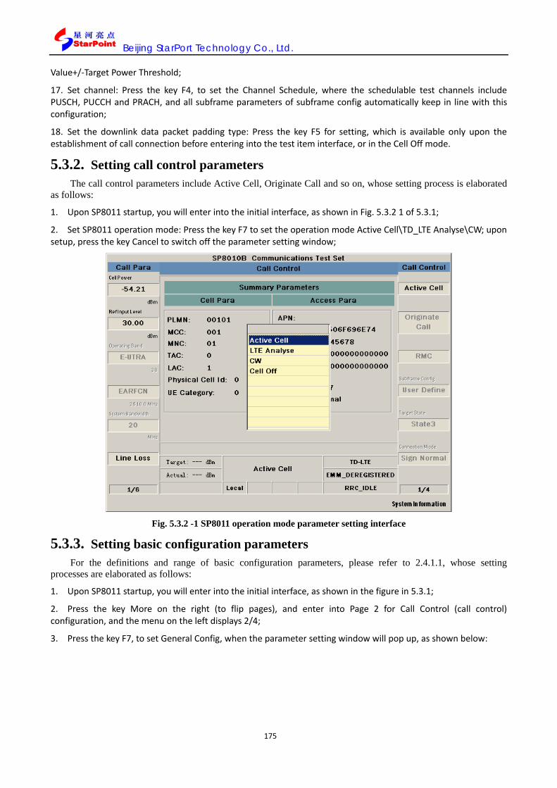
Beijing StarPort Technology Co., Ltd.
175
Value+/-Target Power Threshold;
17. Set channel: Press the key F4, to set the Channel Schedule, where the schedulable test channels include PUSCH, PUCCH and PRACH, and all subframe parameters of subframe config automatically keep in line with this configuration;
18. Set the downlink data packet padding type: Press the key F5 for setting, which is available only upon the establishment of call connection before entering into the test item interface, or in the Cell Off mode.
5.3.2. Setting call control parameters The call control parameters include Active Cell, Originate Call and so on, whose setting process is elaborated
as follows:
1. Upon SP8011 startup, you will enter into the initial interface, as shown in Fig. 5.3.2 1 of 5.3.1;
2. Set SP8011 operation mode: Press the key F7 to set the operation mode Active Cell\TD_LTE Analyse\CW; upon setup, press the key Cancel to switch off the parameter setting window;
Fig. 5.3.2 -1 SP8011 operation mode parameter setting interface
5.3.3. Setting basic configuration parameters For the definitions and range of basic configuration parameters, please refer to 2.4.1.1, whose setting
processes are elaborated as follows:
1. Upon SP8011 startup, you will enter into the initial interface, as shown in the figure in 5.3.1;
2. Press the key More on the right (to flip pages), and enter into Page 2 for Call Control (call control) configuration, and the menu on the left displays 2/4;
3. Press the key F7, to set General Config, when the parameter setting window will pop up, as shown below:
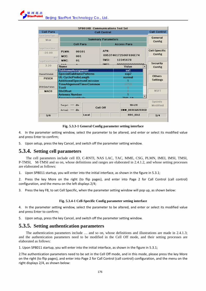
Beijing StarPort Technology Co., Ltd.
176
Fig. 5.3.3-1 General Config parameter setting interface
4. In the parameter setting window, select the parameter to be altered, and enter or select its modified value and press Enter to confirm;
5. Upon setup, press the key Cancel, and switch off the parameter setting window.
5.3.4. Setting cell parameters The cell parameters include cell ID, C-RNTI, NAS LAC, TAC, MME, CSG, PLMN, IMEI, IMSI, TMSI,
P-TMSI, M-TMSI and so on, whose definitions and ranges are elaborated in 2.4.1.2, and whose setting processes are elaborated as follows:
1. Upon SP8011 startup, you will enter into the initial interface, as shown in the figure in 5.3.1;
2. Press the key More on the right (to flip pages), and enter into Page 2 for Call Control (call control) configuration, and the menu on the left displays 2/4;
3. Press the key F8, to set Cell Specific, when the parameter setting window will pop up, as shown below:
Fig. 5.3.4-1 Cell-Specific Config parameter setting interface
4. In the parameter setting window, select the parameter to be altered, and enter or select its modified value and press Enter to confirm;
5. Upon setup, press the key Cancel, and switch off the parameter setting window.
5.3.5. Setting authentication parameters The authentication parameters include … and so on, whose definitions and illustrations are made in 2.4.1.3;
and the authentication parameters need to be modified in the Cell Off mode, and their setting processes are elaborated as follows:
1. Upon SP8011 startup, you will enter into the initial interface, as shown in the figure in 5.3.1;
2.The authentication parameters need to be set in the Cell Off mode, and in this mode, please press the key More on the right (to flip pages), and enter into Page 2 for Call Control (call control) configuration, and the menu on the right displays 2/4, as shown below:
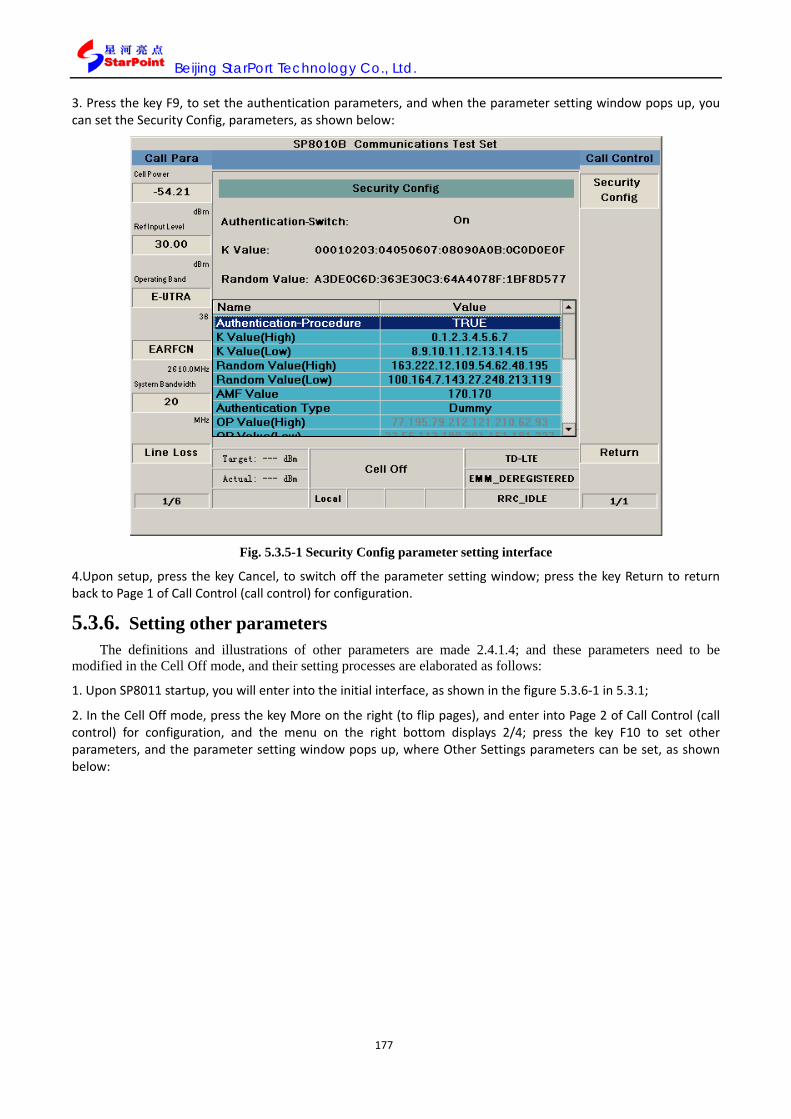
Beijing StarPort Technology Co., Ltd.
177
3. Press the key F9, to set the authentication parameters, and when the parameter setting window pops up, you can set the Security Config, parameters, as shown below:
Fig. 5.3.5-1 Security Config parameter setting interface
4.Upon setup, press the key Cancel, to switch off the parameter setting window; press the key Return to return back to Page 1 of Call Control (call control) for configuration.
5.3.6. Setting other parameters The definitions and illustrations of other parameters are made 2.4.1.4; and these parameters need to be
modified in the Cell Off mode, and their setting processes are elaborated as follows:
1. Upon SP8011 startup, you will enter into the initial interface, as shown in the figure 5.3.6-1 in 5.3.1;
2. In the Cell Off mode, press the key More on the right (to flip pages), and enter into Page 2 of Call Control (call control) for configuration, and the menu on the right bottom displays 2/4; press the key F10 to set other parameters, and the parameter setting window pops up, where Other Settings parameters can be set, as shown below:

Beijing StarPort Technology Co., Ltd.
178
Fig. 5.3.6-1 Others Settings parameter setting interface
3. Upon setup, press the key Cancel, to switch off the parameter setting window; press the key Return to return back to Page 1 of Call Control (call control) for configuration.
5.3.7. Setting the uplink channel parameters The uplink channel parameters include PRACH, PUCCH, PUSCH, SRS, CQI, SR and so on, whose
definitions and illustrations are elaborated in 2.4.2.1.The uplink channel parameters needed to be altered in the Cell Off mode or the IDLE state, and their setting processes are elaborated as follows:
1. In the Cell Off mode, enter into Page 1 of Call Control (call control) for configuration, as shown in Fig. 5.3.7 1 of Section 5.3.1.
2. The uplink channel can be set in the two modes of UserDefine and RMC, where please select F10 to enter the User Define interface;
3. Press the key F7~F11, to select corresponding subframe, and when the parameter setting window pops up, you can set the parameters of this subframe, as shown below:

Beijing StarPort Technology Co., Ltd.
179
Fig. 5.3.7-1 Subframe parameter setting interface
4. Upon setup, press the key Cancel, to switch off the parameter setting window; press the key Return to return back to Page 1 of Call Control (call control) for configuration;
5. Select F9 to enter into the RMC setting interface;
6. Select corresponding UL RMC as needed, as shown below:
Fig. 5.3.7-2 UL RMC parameter setting interface
7. Press the key More on the right (to flip pages) in the Cell Off mode, and enter into Page 3 of Call Control (call

Beijing StarPort Technology Co., Ltd.
180
control) for configuration, and the menu on the left displays 3/4, as shown below:
Fig. 5.3.7-3 Call Control Page 3/4 parameter interface
8. Press the key F7, to set the PUSCH parameters, wherethe physical uplink shared channel parameters can be set;
9. Press the key F8, to set the PUCCH parameters, where the physical uplink control channel
parameters can be set;
10. Press the key F9, to set the PRACH parameters, wherethe physical random access channel parameters can be set;
11. Press the key F10, to set the SRS parameters, where the sounding reference symbol parameters can be set;
12. Press the key F11, to set the CQI parameters, where the channel quality indicator parameters can be set;
13. Press the key F12, to set the SR parameters, where the schedule request parameters can be set.
5.3.8. Setting the downlink channel parameters The downlink parameters include PHICH, PCFICH, PDCCH, PBCH, PDSCH and PMCH parameters, whose
definitions and illustrations are made below: The downlink channel parameters need to be altered in the Cell Off mode or the IDLE state, and their setting processes are elaborated as follows:
1. Please follow the procedures in 5.3.5 and select DL RMC, when the following interface pops up:

Beijing StarPort Technology Co., Ltd.
181
Fig. 5.3.8-1 DL RMC parameter setting interface
As needed, different bandwidths can be correspondingly set to Rec. FRC\ TX.FRC\Per.FRC\CQI FRC\PHICH, and the five FRC configurations feature different parameters. It is shown as follows:
Fig. 5.3.8-2 Rec. FRC parameter setting interface

Beijing StarPort Technology Co., Ltd.
182
Fig. 5.3.8-3 TX. FRC parameter setting interface
Fig. 5.3.8-4 Per. FRC parameter setting interface

Beijing StarPort Technology Co., Ltd.
183
Fig. 5.3.8-5 PHICH parameter setting interface
Upon setup, press the key Cancel, to switch off the parameter setting window; press the key Return to return
back to Page 1 of RMC for configuration;
2. Press the key More on the right (to flip pages) in the Cell Off mode, and enter into Page 4 of Call Control (call control) for configuration, and the menu on the left displays 4/4, as shown below:
Fig. 5.3.8-6 Call Control Page 4/4 parameter interface
3. Press the key F7, to set the PDSCH parameters, where the physical downlink shared channel parameters can

Beijing StarPort Technology Co., Ltd.
184
be set;
4. Press the key F8, to set the PDCCH parameters, where the physical downlink control channel parameters can be set;
5. Press the key F9, to set the PBCH parameters, where the physical broadcast channel parameters can be set;
6. Press the key F10, to set the PCFICH parameters, where the physical control format indicator channel parameters can be set;
7. Press the key F11, to set the PHICH parameters, where the physical HARQ indicator channel parameters can be set;
8. Press the key F12, to set the PMCH parameters, where the physical multicast channel parameters can be set;
5.3.9. Setting switch parameters Protocol Type works to set the current instrument setting mode as TDD or FDD, whose setting operations go
as follows:
1. Upon SP8011 startup, you will enter into the initial interface, as shown in Fig. 5.3.2 1 of 5.3.1;
2. Switch the Config button to enter into the following interface, and select F5 to show the interface as shown in Fig. 5.3.9 1, to select the system needed;
Fig.5.3.9-1 SP8011 Protocol Type setting
5.4. CALL HANDLING OPERATION 5.4.1. Setting the terminal target call state
Please follow the table below to set the target call state of the terminal:

Beijing StarPort Technology Co., Ltd.
185
5.4.1-1 Setting the target call state table
5.4.2. Terminal registration The terminal restoration process features the following steps:
1. Upon startup, SP8011 is defaulted at the Cell Off state, which needs to be set in the Active Cell state; if it is needed to switch from other interfaces into the call page, please press the key Step-up in the call key zone on the front panel of SP8011;
2. Prior to registration, the right bottom of the state column displays EMM_DEREGISTERED, as shown below:
Fig. 5.4.2-1 Interface prior to registration
3. Connect the terminal to SP8011, whose specific procedures shown in 5.2;
4. Upon successful UE registration, the right bottom of the state column displays EMM_DEREGISTERED, as shown below:

Beijing StarPort Technology Co., Ltd.
186
Fig.5.4.2-2 Interface upon registration
5.4.3. Connection establishment Upon successful terminal registration, please establish connection, following the following operation steps:
1. Prior to connection, the right bottom of the state column displays RRC_IDLE, as shown below:
Fig. 5.4.3-1 Interface prior to connection
2. Press F8 to establish the Originate Call connection, upon which the state column right-bottom displays RRC_CONNECTED, as shown below:

Beijing StarPort Technology Co., Ltd.
187
Fig. 5.4.3-2 Interface upon connection
5.4.4. Disconnection Upon end of test, you can disconnect the terminal from SP8011, whose operation steps go as follows:
1. Press the key Step-up in the call key zone on the front panel of SP8011, and switch it to the calling page;
2. Press the key F8 (End Call) to disconnect the call;
3. Upon disconnection, SP8011 returns to the IDLE state in the Active Cell mode, as shown below:
Fig. 5.4.4-1 Disconnect the call and return to the IDLE state

Beijing StarPort Technology Co., Ltd.
188
N.B.: The disconnection process features a timeout handling mechanism, for which SP8011 defines an on-hook timer, which starts up when the on-hook flow begins, and ends when the on-hook flow ends. When the on-hook flow does not complete when the timer’s time limit, the on-hook timer times out, when SP8011 will pops up a prompt dialog box, where operation on any button works to cancel, and SP8011 returns to the IDLE state (the state of terminal registered). Currently, this timer features time limit of 15 s.
5.5. TEST ITEM TEST OPERATIONS 5.5.1. Test operations steps
The test operation steps include test item start, test item stop and test item switch, whose operations are elaborated as follows:
The test items in the non-signaling mode needs to be tested in the LTE Analyse mode, while the continuous wave (CW) needs to be conducted in the CW mode; the test items in the signaling mode need to conduct tests upon the establishment of connection of the terminal to SP8011 in the Active Cell mode. The details of call connection operations are elaborated in 5.4.
In the non-signaling mode, the test items include automatic power calibration (APC), automatic frequency calibration (AFC), occupied bandwidth test (OBW), transmit power (TP), ON/OFF time mask (OOTM), transmit signal quality (TSQ), spectrum emission mask test (SEm), adjacent leakage test ratio (ACLR) and spectrum monitoring (SM).
5.5.1.1. Test item start In the Active Cell operation mode, upon the establishment of call connection of the terminal to SP8011, in
accordance with the current set “PowerControl Type” (Item one on Page 3 of Call Para, which is defaulted as “MAX”), press the key Selection in the test key zone on the front panel to pop up the following test options window, where the following test items can be selected corresponding to different “PowerControl Type”:
In line with the “MAX” mode (defaulted mode), the test items include:
In line with the TPC0” mode, the test items include:
In line with the “MIN” mode, the test items include:
In line with the “Target” mode, the test items include:
Fig. 5.5.1-1 Test item selection interface

Beijing StarPort Technology Co., Ltd.
189
1. In the test item selection window, please select the test item, and press they key Enter or turn the knob to enable this test item;
2. Upon the test item enabled, the test results data will display on the SP8011 interface in graphics or figures.
5.5.1.2. Test item end 1. Upon end of test, you can follow one of the following approaches to stop the test item:
2. Press the key Selection in the test key zone on the front panel, and the test item selection window pops up, where you select the current test item, and press the key F10 (Stop) to end the current test item:
3. Press the key Stop in the test key zone on the front panel directly to stop the current test item.
5.5.1.3. Test items switch During the test process, you can switch between different test items as needed, during which SP8011 will stop
the current test item first and then start the new one. The test item switch operations go as follows;
1. Press the key Selection, and the test item selection window pops up, where you can select the new test item, as shown below:
Fig. 5.5.1.3-1 Test item switch interface
2. Press the key Enter or turn the knob to switch between test items, as shown below:

Beijing StarPort Technology Co., Ltd.
190
Fig. 5.5.1.3-2 Test item switch-complete interface
5.5.2. One Touch function Given that the parameters need to be configured for all tests in Protocol TS 36.521-1 are quite complex,
SP8011 is added with the “One Touch” function. With this function, you can complete all relevant configuration required in Protocol TS36.521-1, to avoid complex and troublesome operations.
Currently, the “One Touch” function of SP8011 is available upon call connection to the terminal via 20M bandwidth. It covers “PRACH Test Config.”, “Transmit Power”, “Output Power Dyna.”, “Power Control”, “Spectrum Emissions”, “FERR & EVM”, “Transmit Modulation”, “REFSENS”, “M.I.L.” and “C.S.I.”, 10 sets altogether, and the “Config. Details” and “Load Default” functions. For details, please see respective illustration.
The “One Touch” interface is shown below:

Beijing StarPort Technology Co., Ltd.
191
Fig. 5.5.2-1 Call Para Page 4/6 setting
Fig. 5.5.2-2 Call Para Page 5/6 setting

Beijing StarPort Technology Co., Ltd.
192
Fig. 5.5.2-3 Call Para Page 6/6 setting
1, PRACH Test Config. test set
Upon establishment of call connection to the terminal, click the function key MORE on the left, and you successfully log onto the “Once Touch” interface the minute the page displays 4/5, where you press F1 to pop up the interface as follows:
Fig. 5.5.2-4 PRACH Test Config. test set interface display
It covers the following test cases: (1)“PRACH ON/OFF Time Mask @prach-ConfigIndex 51”

Beijing StarPort Technology Co., Ltd.
193
(2)“PRACH EVM @RS EPRE -63dBm/15kHz @preambleInitialReceivedTargetPower dBm-120” (3)“PRACH EVM @RS EPRE -78dBm/15kHz @preambleInitialReceivedTargetPower dBm-90”
2. Transmit Power test set
Upon establishment of call connection to the terminal, click the function key MORE on the left, and you successfully log onto the “Once Touch” interface the minute the page displays 4/5, where you press F2 to pop up the interface as follows:
Fig. 5.5.2-5 Transmit Power test set interface display
It covers the following test cases: (1)“UE Maximum Output Power @QPSK 1RB” (2)“UE Maximum Output Power @QPSK 18RB” (3)“Maximum Power Reduction (MPR) @QPSK 18RB” (4)“Maximum Power Reduction (MPR) @QPSK 100RB” (5)“Maximum Power Reduction (MPR) @16QAM 18RB” (6)“Maximum Power Reduction (MPR) @16QAM 100RB” (7)“Configured UE transmitted Output Power @QPSK 18RB @p-Max -10” (8)“Configured UE transmitted Output Power @QPSK 18RB @p-Max 10”
(9)“Configured UE transmitted Output Power @QPSK 18RB @p-Max 15
3. Output Power Dyna. test set
Upon establishment of call connection to the terminal, click the function key MORE on the left, and you successfully log onto the “Once Touch” interface the minute the page displays 4/5, where you press F3 to pop up the interface as follows:

Beijing StarPort Technology Co., Ltd.
194
Fig. 5.5.2-6 Output Power Dyna. test set interface display
It covers the following test cases: (1)“Minimum Output Power @QPSK 100RB” (2)“General ON/OFF time mask @QPSK 100RB @p0-NominalPUSCH -105” (3)“SRS time mask”
4. Power Control test set
Upon establishment of call connection to the terminal, click the function key MORE on the left, and you successfully log onto the “Once Touch” interface the minute the page displays 4/5, where you press F4 to pop up the interface as follows:

Beijing StarPort Technology Co., Ltd.
195
Fig. 5.5.2-7 Power Control test set interface display
It covers the following test cases: (1)“Power Control Absolute power tolerance @QPSK 100RB @p0-NominalPUSCH -105” (2)“Power Control Absolute power tolerance @QPSK 100RB @p0-NominalPUSCH -93” (3)“Power Control Relative power tolerance @Ramping up PatternA @-36.8dBm +/- 3.2dB” (4)“Power Control Relative power tolerance @Ramping up PatternB @-36.8dBm +/- 3.2dB” (5)“Power Control Relative power tolerance @Ramping up PatternC @-36.8dBm +/- 3.2dB” (6)“Power Control Relative power tolerance @Ramping Down PatternA @18.0dBm +/- 3.2dB” (7)“Power Control Relative power tolerance @Ramping Down PatternB @18.0dBm +/- 3.2dB” (8)“Power Control Relative power tolerance @Ramping Down PatternC @18.0dBm +/- 3.2dB” (9)“Power Control Relative power tolerance @Alternating Pattern @-10.0dBm +/- 3.2dB” (10)“Aggregate power control tolerance @DL QPSK 30RB @PUCCH” (11)“Aggregate power control tolerance @QPSK 18RB @PUSCH”
5, Spectrum Emissions test set
Upon establishment of call connection to the terminal, click the function key MORE on the left, and you successfully log onto the “Once Touch” interface the minute the page displays 4/5, where you press F5 to pop up the interface as follows:

Beijing StarPort Technology Co., Ltd.
196
Fig. 5.5.2-8 Spectrum Emissions test set interface display
It covers the following test cases: (1)“Occupied bandwidth @QPSK 100RB @Pumax” (2)“Spectrum Emission Mask @QPSK 100RB @Pumax” (3)“Adjacent Channel Leakage power Ratio @QPSK 100RB @Pumax”
6, FERR & EVM test set
Upon establishment of call connection to the terminal, click the function key MORE on the left, and you successfully log onto the “Once Touch” interface the minute the page displays 5/5, where you press F1 to pop up the interface as follows:
Fig. 5.5.2-9 FERR & EVM test set interface display

Beijing StarPort Technology Co., Ltd.
197
It covers the following test cases: (1)“Frequency Error @UL QPSK 100RB @DL QPSK 100RB @Pumax” (2)“Error Vector Magnitude (EVM) @QPSK 100RB @PUSCH @Pumax” (3)“Error Vector Magnitude (EVM) @QPSK 18RB @PUSCH @Pumax” (4)“Error Vector Magnitude (EVM) @16QAM 100RB @PUSCH @Pumax” (5)“Error Vector Magnitude (EVM) @16QAM 18RB @PUSCH @Pumax” (6)“Error Vector Magnitude (EVM) @QPSK 100RB @PUSCH @–36.8dBm±3.2dB” (7)“Error Vector Magnitude (EVM) @QPSK 18RB @PUSCH @–36.8dBm±3.2dB” (8)“Error Vector Magnitude (EVM) @16QAM 100RB @PUSCH @–36.8dBm±3.2dB” (9)“Error Vector Magnitude (EVM) @16QAM 18RB @PUSCH @–36.8dBm±3.2dB” (10)“Error Vector Magnitude (EVM) @DL QPSK 30RB @PUCCH @Pumax” (11)“Error Vector Magnitude (EVM) @DL QPSK 30RB @PUCCH @–36.8dBm±3.2dB”
7. Transmit Modulation test set
Upon establishment of call connection to the terminal, click the function key MORE on the left, and you successfully log onto the “Once Touch” interface the minute the page displays 5/5, where you press F2 to pop up the interface as follows:
Fig. 5.5.2-10 Transmit Modulation test set interface display
It covers the following test cases: (1)“Carrier Leakage @QPSK 18RB @3.2dBm±3.2dB” (2)“Carrier Leakage @QPSK 18RB @-26.8dBm±3.2dB” (3)“Carrier Leakage @QPSK 18RB @-36.8dBm±3.2dB” (4)“In-band emissions for non allocated RB @QPSK 18RB @PUSCH @3.2dBm±3.2dB” (5)“In-band emissions for non allocated RB @QPSK 18RB @PUSCH @-26.8dBm±3.2dB” (6)“In-band emissions for non allocated RB @QPSK 18RB @PUSCH @-36.8dBm±3.2dB” (7)“In-band emissions for non allocated RB @DL QPSK 30RB @PUCCH @3.2dBm±3.2dB” (8)“In-band emissions for non allocated RB @DL QPSK 30RB @PUCCH @-26.8dBm±3.2dB” (9)“In-band emissions for non allocated RB @DL QPSK 30RB @PUCCH @-36.8dBm±3.2dB”
(10)“EVM equalizer spectrum flatness @QPSK 100RB @Pumax”

Beijing StarPort Technology Co., Ltd.
198
8, REFSENS test set
Upon establishment of call connection to the terminal, click the function key MORE on the left, and you successfully log onto the “Once Touch” interface the minute the page displays 5/5, where you press F3 to pop up the interface as follows:
Fig. 5.5.2-11 REFSENS test set interface display
It covers the following test cases: (1)“Reference Sensitivity Level @UL QPSK 100RB @DL QPSK 100RB @Pumax @REFSENS value
-94dBm”
9. M.I.L. test set
Upon establishment of call connection to the terminal, click the function key MORE on the left, and you successfully log onto the “Once Touch” interface the minute the page displays 5/5, where you press F4 to pop up the interface as follows:

Beijing StarPort Technology Co., Ltd.
199
Fig. 5.5.2-12 M.I.L. test set interface display
10. C.S.I. test set
Upon establishment of call connection to the terminal, click the function key MORE on the left, and you successfully log onto the “Once Touch” interface the minute the page displays 5/6, where you press F1 to pop up the interface as follows:
Fig. 5.5.2-13 C.S.I test set
10, Load Default function
Upon establishment of call connection to the terminal, click the function key MORE on the left, and you successfully log onto the “Once Touch” interface the minute the page displays 5/5, where you press F5i.e. the

Beijing StarPort Technology Co., Ltd.
200
button “Load Default”. This button works to restore the defaulted parameters of the system, to avoid one by one restoration of a series of parameters altered by “One Touch”.
The parameter settings needed for the “Load Default” button include: uplink channel type, RS EPRE, preambleInitialReceivedTargetPower, uplink power control type, uplink RMC, P-Max, p0-NominalPUSCH, uplink subframe 3 schedule, uplink subframe 7 schedule, uplink subframe 8 schedule, srs-ConfigIndex, RPT subtest mode, Receiver FRC, TX FRC, TargetPower target power value, TargetPower power control threshold, TSQ test results graphic display, OCNG state and reference level.
The button “Load Default” does not work to set test items.
11, Config. Details function
Upon establishment of call connection to the terminal, click the function key MORE on the left, and the minute the page displays 4/5 or 5/5, please press F5 i.e. the button “Config. Details”. This button works to display the parameter value modified for the test case in various test sets. The interface is shown as follows:
Fig. 5.5.2-14 Config. Details set interface display
5.6. OTHER OPERATIONS 5.6.1. Help mode
In the Help mode, SP8011 provides relevant GPIB command prompt functions for parameter setting, and when operating SP8011, the corresponding remote control commands will be displayed on the left bottom of the interface, so that the user can quickly find relevant GPIB command.
5.6.1.1. Help mode setting Please press the key Shift in the system key zone on the front panel, and press the key Local (Help) in the
system key zone on the front panel, to set SP8011 into the Help mode, when the interface state indicator column will display the word “Help”.
5.6.1.2. Main functions of the Help mode The Help mode features the GPIB command prompt function, and when in the Help mode, you can operate
on the front panel, and corresponding GPIB remote control commands will be displayed on the left bottom of the interface.

Beijing StarPort Technology Co., Ltd.
201
5.6.2. Local/Remote mode SP8011 features two control modes: local operation mode (Local mode) and remote control mode (Remote
mode). The two control modes are illustrated as follows.
5.6.2.1. Local operation mode (Local mode) In the Local mode, all buttons on the front panel of SP8011 are operable, where the user can operate and
control SP8011 manually. When operating in the Local mode, the control state indicator column on the interface of SP8011 displays the word “Local”, as shown below:
Fig. 5.6.2-1 Local mode display interface
5.6.2.2. Remote control mode (Remote mode) In the Remote mode, the user can conduct remote control of SP8011 by sending GPIB commands, where all
buttons on the front panel except for the Local Key and Power switch in the system key zone on the front panel are not available for operation. When operating in the Remote mode, the control state indicator column on the interface of SP8011 displays the word “Remote”, as shown below:

Beijing StarPort Technology Co., Ltd.
202
Fig. 5.6.2.2-1 Remote mode display interface
When SP8011 operating in the Remote mode, the user can press the key Local in the system key zone on the front panel to switch from the Remote mode to the Local mode.
5.6.3. Print Screen function SP8011 features two screenshot approaches: U-disk type and FTP type, which are illustrated as follows:
5.6.3.1. U-disk screenshot The U-disk screenshot includes the following operation steps:
1. Plug a U-disk into the USB port on the front panel of SP8011;
2. Press the key Config in the system key zone on the front panel, to enter into the system configuration interface;
3. Press the key F9 (PrintScreen) and set E:\ as the path for screenshots;
4. Return to the screenshot interface, and take turns to press the keys Shift and Config in the system zone to complete screenshot operations, and save the screenshot image into the U-disk in the format of .jpg.
* N.B.: When applying USB storage devices to the instrument, please ensure the USB device is free of virus, to prevent virus invasion into the SP8011 system and fail the instrument.
5.6.3.2. FTP screenshot The FTP screenshot includes the following operation steps:
1. Press the key Config in the system key zone on the front panel, to enter into the system configuration interface;
2. Press the key F11 (PrintScreen) and set Default as the path for screenshots;
3. Take turns to press the keys Shift and Config in the system zone on the front panel to conduct the screenshot operation, and the screenshot pictures will be saved into the default file in SP8011;

Beijing StarPort Technology Co., Ltd.
203
4. Connect SP8011 to a PC with network cable, and set the IP address of the PC to the same network segment of SP8011, and log in ftp://192.168.1.200/ (suppose the IP address of SP8011 is192.168.1.200), and input user name and password: pictures, to log in ftp before accessing pictures in the defaulted file of SP8011.
N.B.: The latest version of SP8011 features the function of accessing the current instrument screen display from the upper computer, when the user input corresponding GPIB commands to return the screenshot data in the JPG format.
5.6.4. Register function SP8011 embraces five built-in registers, which are identified by Save Register 1~5, and are in the two states of
Full and Empty; if the register state is Full, it means the register has saved the setting; if the register is in the state of Empty, it means the register does not save any setting. Operations on registers include: Save, Restore, Delete, and Rewrite and so on, whose operation steps are illustrated respectively as follows:
5.6.4.1. Save Savable settings
The settings that SP8011 can save include all static state or configurable function and parameters, such as:
Cell parameter (system ID, network ID and so on);
Call control parameter (system type, operating mode and so on);
Test item setting parameters (register state, test timeout limit and so on);
Call parameters (cell power, cell bandwidth and so on);
Config parameter (To be confirmed by Willie Song).
Unsavable settings
The settings SP8011 cannot save include the real-time trigger functions, such as the call or test item start function initiated by SP8011.
The operation steps to save the current settings of SP8011 go as follows:
1. On the initial interface of SP8011, press the key F5 (to be checked and verified), or directly check the key Recall in the call key zone on the front panel, when the register setting window pops up;
2. Select an empty register (in the state of Empty), press the key Save in the call key zone on the front panel, to save the current settings into the register, whose state changes from Empty to Full.
5.6.4.2. Restore To restore the SP8011 settings saved in the register, please follow the operation steps:
1. On the initial interface of SP8011, press the key F5, or directly check the key Recall in the call key zone on the front panel, when the register setting window pops up;
2. Select the register (in the state of Full), press the key Enter or turn the knob on the front panel to restore the saved settings.
5.6.4.3. Delete To delete the settings saved in the register, please follow the operation steps:
1. On the initial interface of SP8011, press the key F5, or directly check the key Recall in the call key zone on the front panel, when the register setting window pops up;
2. Select the register to delete, (the register in the state of Full), press the key Shift in the system key zone on the front panel, and press the key Delete (Save) in the call key zone, and the operation window will pop up;
3. Select “Yes” and press the key Enter or turn the knob on the front panel, to complete the Delete operation, and the register is in the state of Empty.

Beijing StarPort Technology Co., Ltd.
204
5.6.4.4. Rewrite To rewrite the register, i.e. to replace the previous settings saved in the register, please go through the
following operation steps:
1. On the initial interface of SP8011, press the key F5, or directly check the key Recall in the call key zone on the front panel, when the register setting window pops up;
2. Select the register which is currently in the Full state, press the key Save in the call key zone on the front panel of SP8011, and the following interface pops up:
3. Select “Yes” and press the key Enter or turn the knob on the front panel, to complete the register Rewrite function.
5.6.4.5. Log tracer Log output buttons, i.e. to control the output of Log files of L1, L2, L3, master control and measurement with
switches, and conduct save and access of all layers of Log in accordance with specified path. The operation interface is shown below:
Fig. 5.6.4.5-1 LogConfig display interface

Beijing StarPort Technology Co., Ltd.
205
Fig. 5.6.4.5-2 Meas display interface
Fig. 5.6.4.5-3 Measurement item Log switch display interface
5.6.5. Shift function It is pointless to operate the key Shift alone, as it is a button function toggle key, which only works to conduct
the Shift function in combinations like Shift +Help, Shift +Preset and so on.
Take the operation of the combination Shift+Help as an example to illustrate the function of the key Shift:
For the initial interface of SP8011, please see Fig. 5.6.5 1 I Section 5.3.1;

Beijing StarPort Technology Co., Ltd.
206
Press the key Shift in the system key zone on the front panel, as shown below:
Fig. 5.6.5-1 Interface upon Shift operation
Press the key Help in the system key zone on the front panel, as shown below:
Fig. 5.6.5-2 Help mode interface
5.6.6. Preset function In the Local operation mode, SP8011 features two reset functions: Partial reset and Total reset, whose
meanings and operations are illustrated as follows:
5.6.6.1. Partial reset Press the key Preset on the front panel of the instrument to reset partially, restoring the call parameters, cell
parameters and system parameters in the instrument back to the system default values, while all test item parameter settings remain unchanged. This function is available in all operating modes.

Beijing StarPort Technology Co., Ltd.
207
5.6.6.2. Total reset Press the key Shift on the front panel of the instrument first, and then press the key Preset to reset totally,
restoring the call parameters, cell parameters, test item parameters, system parameters and other parameters in the instrument back to the system default values. This function is available in all operating modes.

Beijing StarPort Technology Co., Ltd.
208
6. SP8011 SELF-CHECK 6.1. RF SELF-CHECK
Conducting CW continuous wave tests on SP8011 can help check whether the RF modules of SP8011 work smoothly; please go through the following operations:
1. Connect the RF IN/OUT port and RF OUT port of SP8011 with RF cable, as shown below:
Fig. 5.6.6-1 Connecting the RF IN/OUT port and RF OUT port of SP8011 with RF cable
2. Upon SP8011 startup, you will enter into the initial interface, as shown in the figure 5.6.6-1 in 5.3.1;
3. Press the key Config in the system key zone on the front panel, to enter into the system configuration interface, as shown below:
Fig. 6.1 2 SP8011 system configuration interface

Beijing StarPort Technology Co., Ltd.
209
4. Press the key F3 and set the RF Port as OUT, as shown below:
Fig. 6.1 3 system configuration RF Port interface
5. Press the key Stepup in the call key zone on the front panel, return to the call control interface, as shown in Fig. 5.6.6 3 of Section 5.3.1;
6. Press the key F7 and set the Operation mode as CW, as shown below:
Fig. 6.1 4 RF indicator self-check parameter setting interface
7. Upon RF indicator self-check parameter setting completed, SP8011 is in the CW mode, as shown below:

Beijing StarPort Technology Co., Ltd.
210
Fig. 5.6.6 4 Interface upon RF indicator self-check parameter setting completed
8. Press the Selection in the test key zone on the front panel, and select the test item Continuous Wave in the popup window, and enable this test item, which is shown below;
Fig. 6.1 6 Interface for starting up the CW wave test items
9. Press the key F1, setting Cell Power as -15.00dBm;
10. Press the key F2, setting Ref Input Level as -10.0.00dBm;
11. SP1010B will displays the following test results interface:

Beijing StarPort Technology Co., Ltd.
211
Fig. 6.1 7 RF indicator CW wave self-check results
12. Press the key Continuous in the test key zone on the front panel to conduct continuous test;
13. If the test results meet the following requirements, the RF indicators of SP8011 are normal;
The difference between the test results Peak Power Frequency value and current frequency value(UARFCN) is within ±5 Hz;
The difference between the test results Peak Power value and the current cell power (Cell Power) minus the line loss is ±1 dB;
For example: As the above test results show, the Peak Power Frequency value is 2610000000 Hz, and the current EARFCN value is 38150, i.e. the current frequency value 2610000000 Hz, and the difference between the two is within ±5 Hz; the Peak Power value is -15.88dBm, and the current Cell Power value is -15.00dBm, and the difference minus connecting line loss is within ±1 dB (the line loss employed is 0.5dB), which means that the SP8011 RF indicators are normal!
6.2. BASE-BAND MODULATION-DEMODULATION FUNCTION SELF-CHECK To conduct wave form quality tests on QPSK modulating signals can check whether the baseband signal
modulation and demodulation function of SP8011 operates smoothly. 8010B provides baseband signal quality for all RF ports of single antenna, double antenna and four antennas.
Specific operations go as follows:
1. Upon SP8011 startup, you will enter into the initial interface, as shown in Fig. 5.6.6 1 of section 5.3.1;
2. Press F1 to select the LTE Analyse test mode, as shown below:

Beijing StarPort Technology Co., Ltd.
212
Fig. 6.2-1 Select SP8011 LTE Analyse test mode
3. Press the key More on the right (to flip pages), and enter into Page 3 for Call Control for configuration, and the menu on the left displays 2/5, as shown below:
Fig. 6.2-2 Call Control 2/5 parameter interfaces
4. Press they key F11 to set NSFT, and set the PDSCH State in the popup window as ON, and the NSFT State as ON; set the number of antenna as needed; upon setup, please press they key Cancel, to switch off the parameter setting window (Note: when the NSFT State is ON, you cannot alter the parameters);

Beijing StarPort Technology Co., Ltd.
213
Fig. 6.2-3 NSFT setting interface
5. Set the CellPower at -10dBm, and the RefInputLevel at 10.
6. Press the key Home in the test key zone on the front panel, and return to the main interface; press the key Shift, and press the key Selection again, and choose Downlink EVM in the popup window to start this test item, as shown below:
Fig. 6.2-4 Interface for starting up the wave form quality test items
7. Select the RF port to be tested, and the interface setting is shown below.

Beijing StarPort Technology Co., Ltd.
214
Fig. 6.2-5 test RF port selection interface
8. SP1010B will display the following test results interface, as shown below.
Fig. 6.2-6 Base-band modulation-demodulation function self-check results
9. Test methods for different RF ports of single antenna, double antenna and four antenna
Test method for single antenna RF port 1
Configure 1~8, and observe the interface.

Beijing StarPort Technology Co., Ltd.
215
Test method for double antenna RF port 1 (2)
① In the Cell Off mode, configure the transmit mode as TM2_1A, whose setting interface is shown below:
Fig. 6.2-7 Setting up the transmit mode
② Configure 2~5
③ Set the RF Port at OUT, whose interface setting is shown below:
Fig. 6.2-8 Setting up RF Port
④ Connect RF1(RF2)OUT port and RF1IN/OUT port with double N lines;
⑤ Press the key Home in the test key zone on the front panel, and return to the main interface; press the key

Beijing StarPort Technology Co., Ltd.
216
Shift, and press the key Selection again, and choose Downlink EVM in the popup window to start this test item;
⑥ Select Port1 (2), observing the base band signal quality of RF port 1 (2).
Test method for four antenna RF port 1, 2, 3 and 4;
① Configure the Master-Slave table, as in 4.1.6.
② In the Cell Off mode, configure the transmit mode as TM2_1A, whose setting interface is shown as follows:
③ Configure 2~5;
④ Set the RF Port at OUT, whose interface setting is shown below:
⑤ Connect the master table RF1 IN\OUT and the master table RF1 OUT ports respectively, with double N lines;
⑥ Press the key Home in the test key zone on the front panel, and return to the main interface; press the key Shift, and press the key Selection again, and choose Downlink EVM in the popup window to start this test item;

Beijing StarPort Technology Co., Ltd.
217
⑦ Select Port1, observing the base band signal quality of RF port 1; SP8011 will display the RF1 baseband signal quality under the four antenna, as shown below:
⑧ Connect the master table RF1 IN\OUT and the master table RF2 OUT ports respectively, with double N lines;
⑨ Press the key Home in the test key zone on the front panel, and return to the main interface; press the key Shift, and press the key Selection again, and choose Downlink EVM in the popup window to start this test item;
⑩ Select Port2, observing the base band signal quality of RF Port2; Take turns to connect RF1 IN\OUT to the slave table RF1 OUT and RF2 OUT ports, select Port3 and Port4, observing the RF3 and RF4 baseband signal quality;
N.B.: Upon SP8011 self-check completed, please go through the following steps first to restore all instrument parameters to the defaulted value, to avoid impact on the test: 1, Set the RF Port of IN/OUT; 2. Press the keys Shift Preset on the front panel.

Beijing StarPort Technology Co., Ltd.
218
7. FTP SERVICE TEST 7.1. HARDWARE ENVIRONMENT FOR SERVICE TESTING
The service testing requires the following equipment: 2 computers, one operating as a server (Server), and the other as a client (Client); one SP8011 instrument, and one LTE terminal, whose connection and wiring are shown below:
(IP 地址=IP address 网关=gateway 网线=network cable 射频线=RF cable USB 线=USB cable 终端=Terminal Client=客户端)
Fig. 7.1- 1 Service testing hardware environment setup diagram
For service testing, the server and SP8011 are directly connected with network cable, with the server IP address set as: 10.0.0.1, and the gateway set as: 10.0.0.122, and the IP address of SP8011 access port connected to the server as 10.0.0.122 and the gateway set as10.0.0.1.
7.2. SOFTWARE ENVIRONMENT FOR SERVICE TESTING During service tests, Jperf software works to receive and transmit packets to complete the test. The Jperf
software needs to operate under the Java environment, which shall be installed into the computer without it previously. The service testing software environment setting covers the Server’s Jperf setting the Client’s Jpert setting.
7.2.1. Server’s Jerf setting The Server needs two enabled Jperf processes, one as the receiving end for test, and the other transmitting
end for test.
1. Set the receiving end on the Server;
Set the Modes of the receiving end on the Server;
Fig. 7.2.1-1 Setting the Modes of the receiving end on the Server
As shown above, select Sever, and set Num Connections at 1, and Listen Port at 5001.
Set the Transport layer of the receiving end on the Server;

Beijing StarPort Technology Co., Ltd.
219
Fig. 7.2.1-2 Setting the Transport layer of the receiving end on the Sever
Set the IP layer of the receiving end on the Server;
2. Set the receiving end on the Server;
Set the Modes of the receiving end on the Server;
Fig. 7.2.1-4 Setting the Modes of the transmitting end on the Server
Set the Application Layer of the receiving end on the Server;
Fig. 7.2.1-5 Setting the Application Layer of the transmitting end on the Server
Set the Transport layer of the receiving end on the Server;

Beijing StarPort Technology Co., Ltd.
220
Fig. 7.2.1-6 Setting the Transport layer of the transmitting end on the Server
As shown in the above figure, operate in the column circled in red line to set the transmit bandwidth, and the current version support up to 2MBytes/sec.
Set the IP layer of the transmitting end on the Server;
Fig. 7.2.1-7 Setting the IP layer of the transmitting end on the Server
7.2.2. Client’s Jperf setting The Client needs two enabled Jperf processes, one as the receiving end for test taking data from the server,
and the other transmitting end for test sending data to the server.
1. Set the receiving end on the Client;
Set the Modes of the receiving end on the Client;
Fig. 7.2.2-1 Setting the Modes of the receiving end on the Client
Set the Transport layer of the receiving end on the Client;

Beijing StarPort Technology Co., Ltd.
221
Fig. 7.2.2-2 Setting the Transport layer of the receiving end on the Client
Set the IP layer of the receiving end on the Client;
Fig. 7.2.2-3 Setting the IP layer of the receiving end on the Client
2. Set the transmitting end on the Client;
Set the Modes of the transmitting end on the Client;
Fig. 7.2.2-4 Setting the Modes of the transmitting end on the Client
Set the Application Layer of the transmitting end on the Client;
Fig. 7.2.2-5 Setting the Application Layer of the transmitting end on the Client

Beijing StarPort Technology Co., Ltd.
222
Set the Transport layer of the transmitting end on the Client;
Fig. 7.2.2-6 Setting the Transport layer of the transmitting end on the Client
Set the IP layer of the transmitting end on the Client;
Fig. 7.2.2-7 Setting the IP layer of the transmitting end on the Client
7.3. SERVICE TESTING OPERATION STEPS 1. Start up the instrument;
2. Enable the FTP test switch in the Cell Off state: MainCtrl Ftp Switch OFF →ON;
Fig. 7.3-1 FTP testing interface

Beijing StarPort Technology Co., Ltd.
223
3. Configure the empty port rate of the instrument;
Enable the downlink of subframe 0 and 1, and configure MCS to 15 and RB to 60;
Enable the uplink of subframe 2 and 3, and configure MCS to 15, and RB to 60, as shown below;
Fig. 7.3-2 SP8011 instrument subframe configuration interface
4. IN the Active Cell mode, connect the terminal;
5. Use the dial-up connection in the Client and make the terminal to conduct MO paging;
6. Conduct downlink rate test (the instrument interfaces to be displayed in the measurement items);
a) Upon successful connection of the terminal to the instrument, enable the receiving end of Jperf software on the Client, and click the red-circled button shown below;
Fig. 7.3-3 Jperf software receiving end on the Client
b) Upon successful connection of the terminal to the instrument, enable the receiving end of Jperf software on the Client, and click the red-line-circled button shown below;
Fig. 7.3-4 Jperf software transmitting end on the Client
c) Downlink test results;
Shown in the following figure are the test results of transmitting and receiving ends of downlink tests.

Beijing StarPort Technology Co., Ltd.
224
Fig. 7.3-5 Transmitting end test results of downlink tests
Fig. 7.3-6 Receiving end test results of downlink tests
1. Conduct uplink rate test (the instrument interfaces to be displayed in the measurement items);
a) Upon successful connection of the terminal to the instrument, enable the receiving end of Jperf software on the Server, and click the red-circled button shown below;

Beijing StarPort Technology Co., Ltd.
225
Fig. 7.3-7 Jperf software receiving end on the Server
b) Upon successful connection of the terminal to the instrument, enable the receiving end of Jperf software on the Server, and click the red-line-circled button shown above;
Fig. 7.3-8 Jperf software transmitting end on the Client
2. End of test
To end the test, please first switch off the sending process of the transmitting end, and switch off the receiving process of the receiving end. Upon the Jperf software disabled, you can switch off the Cell and end the service test, and the button for ending the transmitting or receiving processes is shown below.
Fig. 7.3-9 Ending transmitting or receiving operation
Note:
1. Uplink and down tests share similar processes;
2. Switch off the instrument fire wall prior to the test.

Beijing StarPort Technology Co., Ltd.
226
8. PRODUCTION DATA PLATE
Production Name: SP8010B Communications Test Set Products Model: SP8010B Input Ratings: 47 ~ 63 Hz 1.1 ~ 2.8 A AC: 90 ~ 264 V Ingress Protection: IP21 Tel: (86-10)62304490 Fax: (86-10)62360393 Address: 3/F, Building A, Wangjing Science Technology
Pioneer Park No.2,Li Ze Zhong Er Lu, Chaoyang District, Beijing, P.R.China, 100102
Manufacture Date: 2011-04-27 S/N: SP6010-5503
Production Name: SP8011 Communications Test Set Products Model: SP8011 Input Ratings: 47 ~ 63 Hz 1.1 ~ 2.8 A AC: 90 ~ 264 V Ingress Protection: IP21 Tel: (86-10)62304490 Fax: (86-10)62360393 Address: 3/F, Building A, Wangjing Science Technology Pioneer
Park No.2,Li Ze Zhong Er Lu, Chaoyang District, Beijing, P.R.China, 100102
Manufacture Date: 2011-03-18 S/N: SP6010MF-6440

Beijing StarPort Technology Co., Ltd.
227
9. PRODUCTION SPECIFICATIONS 9.1. LTE SYSTEM TECHNICAL INDEX Overall Parameters
Protocol standard 3GPP E-UTRA TDD Release 8(0912)
Sampling rate 30.72Mcps
Physical channel PBCH、PCFICH、PDSCH、PDCCH、PHICH、PRACH、PUCCH、PUSCH; PSS、SSS、DMRS、DL-RS
Support modulation method BPSK、QPSK、16QAM、64QAM;OFDMA、SC-FDMA Data rate Support UE-CAT 3 Max rate:DL 100Mbps、UL 50Mbps Bandwidth configuration Max 20MHz
Antenna configuration Single antenna、2*2 MIMO、4*2 MIMO(4*2 MIMO configuration need 2 SP8011 cascade )
Transmitter Index LTE signal output frequency range 400M ~ 2800MHz Frequency resolution 1 Hz LTE signal output power range -120 ~ -10dBm Output power resolution 0.01 dB Output LTE signal EVM < 1.5% Receiver Index LTE signal maximum safe input level +33dBm LTE signal input frequency range 400M ~ 2800MHz Frequency resolution 1 Hz LTE signal input power range -70 ~ +30 dBm Input power resolution 0.1dB
9.2. BASIC TECHNICAL INDEX Transmitter RF Index CW output frequency range 400 MHz ~ 2800 MHz Frequency resolution 1 Hz
CW output power range
400M~2100M -120 dBm ~ -5 dBm (RF IN / OUT port) 2100M~2800M -120dBm ~ -10dBm (RF IN / OUT port)
400M~2100M -120 dBm ~ 0 dBm (RF OUT port) 2100M~2800M -120dBm ~ -5dBm (RF OUT port)
Output power resolution 0.01 dB
CW output power tolerance
700M ~2800M
≥-90 dBm ±0.5dB
-90 dBm ~-120 dBm ±0.5dB
400M~700M ≥-90 dBm ±0.5dB -90 dBm ~-120 dBm ±0.8dB
Transmitter phase noise Offset 1MHz -90 dBc/Hz Offset 10MHz -140 dBc/Hz
VSWR(voltage standing wave ratio) IN/OUT port<1.20 OUT port<1.30
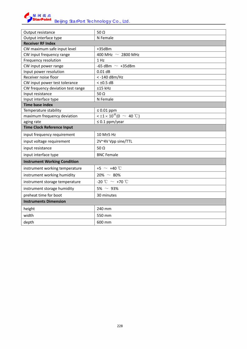
Beijing StarPort Technology Co., Ltd.
228
Output resistance 50 Ω Output interface type N Female Receiver RF Index CW maximum safe input level +35dBm CW input frequency range 400 MHz ~ 2800 MHz Frequency resolution 1 Hz CW input power range -65 dBm ~ +35dBm Input power resolution 0.01 dB Receiver noise floor < -140 dBm/Hz CW input power test tolerance < ±0.5 dB CW frequency deviation test range ±15 kHz Input resistance 50 Ω Input interface type N Female Time base index Temperature stability ≤ 0.01 ppm maximum frequency deviation < ±1 × 10⁻⁸ (0 ~ 40 ℃) aging rate ≤ 0.1 ppm/year Time Clock Reference Input
input frequency requirement 10 M±5 Hz input voltage requirement 2V~4V Vpp sine/TTL input resistance 50 Ω input interface type BNC Female Instrument Working Condition instrument working temperature +5 ~ +40 ℃ instrument working humidity 20% ~ 80% instrument storage temperature -20 ℃ ~ +70 ℃ instrument storage humidity 5% ~ 93% preheat time for boot 30 minutes Instruments Dimension
height 240 mm width 550 mm depth 600 mm

Beijing StarPort Technology Co., Ltd.
229
10. FAQ 10.1. OUT-OF-SYNCHRONIZATION HANDLING OF OUTPUT POWER FOR CONTINUOUS/ DISCONTINUOUS TRANSMISSION 10.1.1. How to config N313 T313 N315 The Parameters N313 T313 N315 must meet the following conditions:
(T313 + N313*TTI) > (Ta-b + 200 ms + Tc-d + Td-e + N315*TTI)
Note: The Transmission Time Interval of the DPCH of SP8011 is 20ms.
SP8011’s default config: N313 is 20; T313 is 15s; N315 is 1
10.1.2. Why set the parameters N313, T313 AND N315, the tests are still dropping
The test needs to add the AWGN signal. According to the protocol, the orI is -61dBm and the Ioc is -60dBm. When SP8011’s cell power is set, the power must exceed the sum of -61dBm and -60dBm. The sum of -61dBm and -60 dBm is -57dBm. When SP8011’s power is more than -57 dBm, the link will be maintained. When the power is too low, the terminal will always drop the line.
10.1.3. The difference between the OOS and the DOOS During the OOS test, the terminal transmits user data. During the DOOS test, the terminal transmits
Special Burst.
10.2. TRANSMIT ON/OFF TIME MASK 10.2.1. Why upper power limit and lower power limit appears fail
During the PVT test, if the lower power limit or upper power limit appeared fail, it means the power of
the transmission is over the range. According to the 3GPP 34.122, only the power limit of the on/off time is provided, for the transmission there is no limit. It can be set for the users. Except the two items, there is another result field for the whole PVT test. If this field shows pass, then the PVT test passes.
10.3. SP8011 PANEL INTRODUCTION 10.3.1. Whether need to set protocol parameters during the OLPC fast test and how many times to power on the UE during the three cases
When we use SP8011 to test terminal’s fast OLPC, the three cases’ default configurations meet the

Beijing StarPort Technology Co., Ltd.
230
protocol’s requirements. The three cases can be tested during the connected condition and it only need to power on the terminal once, so as to registering.
10.3.2. Why the case 3 always fail during the OLPC test When we use SP8011 to test the case 3 of OLPC, the cell power is -108dBm. Because the power is very
low, the test is susceptible to interference from other signals, it is easily to time out or fail. So the suggestion of testing OLPC case 3 is in the shielded room.
10.3.3. What is the difference between the fast test and the normal test In the fast test mode the OLPC is tested in connected condition. This test method meets the newest
protocol requirements. The normal test can be used during the terminal registering or connecting mode as the user’s requirements.
10.4. HSDPA TEST 10.4.1. Whether the SP8011 support the HSDPA test and how to test
SP8011 supports HSDPA for all the chipset manufacturers, for example STE, Spreadtrum and Leadcore technology etc. There are many customers using HSDPA test function. SP8011 can support HSDPA function by upgrading the software of the equipment.
10.4.2. Whether the HSDPA test should be added to the manufacture test and how to test
The HSDPA test should be added to the manufacture test.
The terminal product has matured and the scale of production is about to begin. HSDPA TDD terminal R & D and production has been all chip manufacturers and terminal manufacturers into the next strategic plan.SP8011 of StarPoint support protocol of R5 version, and widely used in research and development. It already debugs with every chip manufacturer. It is each terminal manufacturer, chip manufacturer and device manufacturers the right-hand man.
HSDPA is one of the most important function modules, therefore terminal manufacturer need to test HSDPA modules for simple and effectively. 3GPP protocol defines four test items for testing HSDPA functionality and performance, the four test items are:
9.3.1 HS-DSCH Throughput for Fixed Reference Channels
9.3.2 HS-DSCH Throughput for Variable Reference Channels
9.3.3 Reporting of HS-DSCH Channel Quality Indicator
9.3.4 HS-SCCH Detection Performance
According to the protocol the HSDPA test needs to build a complex test environment and it will consume the long time, it is obviously not suitable for the terminal manufacturers. Production line test should have a simple test environment, fast and efficient characteristics, for this we give the following recommendations:
For production lines with a SP8011 TD-SCDMA Terminal Tester, We will provide a Report of HS-DSCH CQI test. The test has the following characteristics:
The simple test of the test environment, channel emulator does not need to provide multi-path fading environment, SP8011 can complete the test.
The test is joined the AWGN environment. Testing process will involve all the key base-band HSDPA capabilities: AMC (QPSK, 16QAM demodulation capability), CQI report, HS-SCCH capture resolution and BLER (throughput), it can verify the full functionality of HSDPA terminals.
The test time is short, only about 20 seconds, with the terminal call up the time required for the entire test will not take more than 40 seconds required. Report of HS-DSCH CQI test of the above characteristics is the demand for production line testing, it can be obtained with minimal input validation on the full HSDPA functionality. Simple, fast and efficient of the test is very suitable for applications, also is maximum

Beijing StarPort Technology Co., Ltd.
231
cost-saving production.
10.5. TERMINAL PERFORMANCE TEST 10.5.1. Whether the SP8011 supports controlling the terminal into the LOOPBACK test or activate the ACK/NACK test mode according to the cases in the 3GPP 34.122 chapter 7 and how to config
SP8011 supports both loopback test mode and Ack/Nack test mode,on the different conditions (RMC12.2k、RMC64k、RMC144k、RMC384k). It uses different test mode to test BLER of the terminal. In RMC12.2 kbit/s RLC TM mode is used to test BLER (the loopback mode test BLER). In RMC64 kbit/s, RMC144 kbit/s, RMC384 kbit/s, RLC AM mode is used to test BLER (Ack/Nack test mode test BLER). As long as the business connections are established, SP8011 will control the terminal test mode as the test mode, without the need to set.
10.6. UPDATE THE SP8011 1. Start SPSUT
Run SPSUT.exe and you can see the splash window as below:
Figure 10.6.1 Splash Window

Beijing StarPort Technology Co., Ltd.
232
Figure 10.6.2 Startup Window
2. Select SP8011 IP address
3. After startup, you should determine which IP address to use for upgrading. Here, you can use default IP address, three IP addresses provided in dropdown list (192.168.1.200, 192.168.60.10 and 192.168.237.202), that the SP8011 instrument is using.
Figure 10.6.3 Choose default IP address
4. If the instrument uses another IP address accidently, you can also input it via clicking “Custom” radio box.
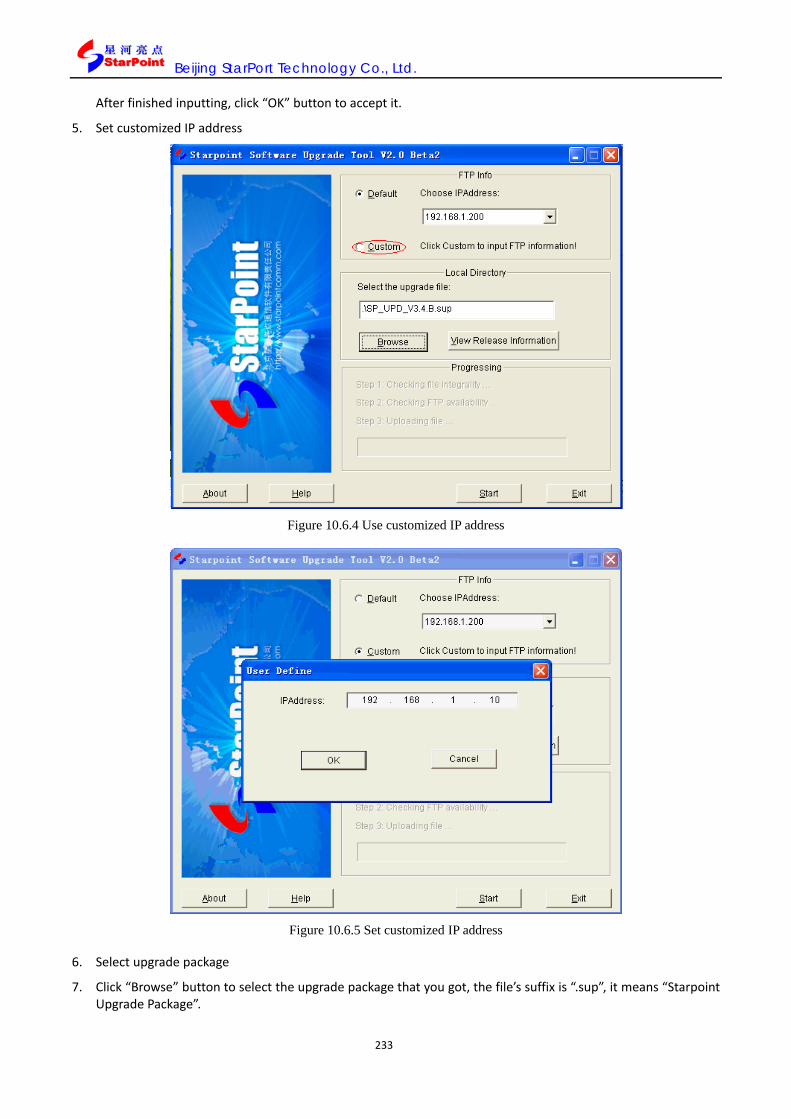
Beijing StarPort Technology Co., Ltd.
233
After finished inputting, click “OK” button to accept it.
5. Set customized IP address
Figure 10.6.4 Use customized IP address
Figure 10.6.5 Set customized IP address
6. Select upgrade package
7. Click “Browse” button to select the upgrade package that you got, the file’s suffix is “.sup”, it means “Starpoint Upgrade Package”.
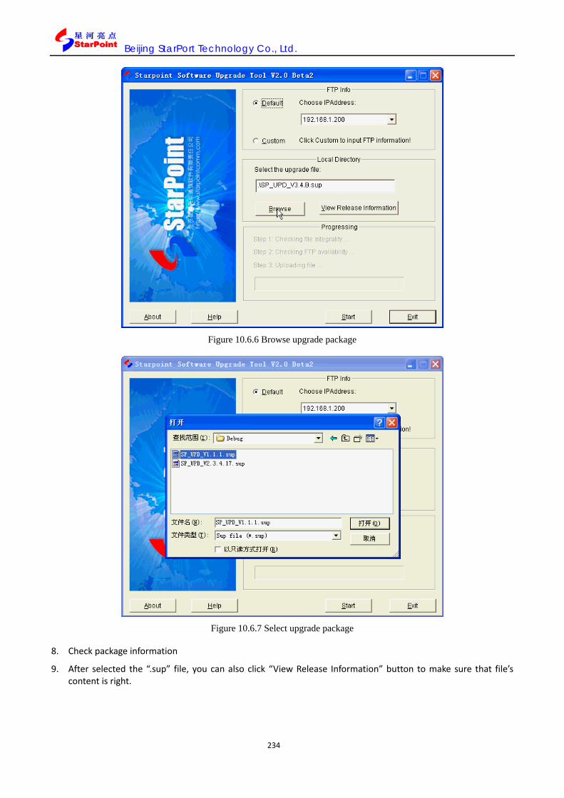
Beijing StarPort Technology Co., Ltd.
234
Figure 10.6.6 Browse upgrade package
Figure 10.6.7 Select upgrade package
8. Check package information
9. After selected the “.sup” file, you can also click “View Release Information” button to make sure that file’s content is right.

Beijing StarPort Technology Co., Ltd.
235
Figure 10.6.8 View release information
10. Here shows the check result.
Figure 10.6.9 Display package information
11. Upload package
12. Click “Start” button to start upgrade. Three steps will be taken including “Checking file integrality”, “Checking FTP availability” and “Uploading file”. These 3 steps can guarantee user uploading a verified file to instrument.

Beijing StarPort Technology Co., Ltd.
236

Beijing StarPort Technology Co., Ltd.
237
11. SECURITY INFORMATION OVERVIEW 11.1. WORK ENVIRONMENT 1. Environmental requirements: SP8011, as installation equipment class II, is expected to operate indoors under the condition of pollution level 2, with ambient temperature from +5℃ and +45℃, maximum relative humidity 80% and maximum altitude 2,000m.
2. Requirements for ventilation: Favorable ventilation shall be provided for SP8011 installed inside a cabinet, and forced ventilation shall be made for the condition where the total power consumption inside the cabinet is more than 800W.
3. Requirements for voltage: AC 90~ 264 V, 1.1~ 2.8 A, 47 ~ 63 Hz, for application around the People’s Republic of China).
11.2. NOTES 1. Three proofings: Please make efforts to ensure the equipment free of water, static or electromagnetic interference.
2. Fuse protector: Only specified common fusing, delay and the like fuse protectors of rated current and voltage shall be applied, and do not make use of any used or fixed fuse or short-circuit fuse holders shall be used to avoid possible electric shock or fire risk.
3. Voltage matching: Before power-on, please confirm the setting of SP8011 in line with current line voltage, and proper fuse installed and all protective measures taken; for identification, please refer to the external markings mentioned in Safety Symbols.
4. SP8011 grounding: To minimize the risk of electric shock, the rack and outer cover of SP8011 must be connected to the electric ground protection terminals. SP8011 must be provided with a grounding power cord to connect to the mains supply, and efforts shall be made to ensure secure connection of the grounding cord to the electric connection terminals (safety grounding) of power sockets. Disconnecting any grounding protective cords or any grounding protective terminals will present electric shock hazards resulting in personal injury or casualty.
5. Please dismantle the outer casing of SP8011: The operators are not allowed to dismantle the SP8011 outer casing. Only competent professional maintenance personnel can be designated to replace the components and internal adjustment; once any damage or hazard is seen on SP8011, please immediately stop operation and prevent disoperation, until professional maintenance personnel come to shoot the trouble.
6. No operation on the equipment in explosive surrounding: Please do not apply SP8011 under flammable gas or smoke environment.
11.3. PRODUCT CERTIFICATION Beijing StartPoint Technology Co., Ltd has been certified of ISO 9001 Quality Management System Certification by the International Standards Organization, bearing the certificate numbered: FFT.
SP8011 complies with the LTE Calibration Specifications by Center of Measurement of Ministry of Information Industry, the People’s Republic of China.
11.4. DECLARATION Beijing StartPoint Technology Co., Ltd herein states that the product before leaving the plant is in line with its published technical parameters.
11.5. WARRANTY REMARKS 1. Beijing StartPoint Technology Co., Ltd herein promises to provide warranty within the above mentioned warranty period, covering any material and technological defects on hardware, accessories and parts and

Beijing StarPort Technology Co., Ltd.
238
components. Within the warranty period, Beijing StartPoint Technology Co., Ltd, upon reception of notification of similar defect, will verify the defect at their own discretion, and decide on repair or replacement, and the products to replace the previous one might be brand-new or basically new.
2. Within the above warranty period, Beijing StartPoint Technology Co., Ltd guarantees that the equipment should work with proper installation and application, without material or technological defect that may result in failure to execute the program commands. Within the warranty period, Beijing StartPoint Technology Co., Ltd, upon reception of notification of similar defect, will replace the defective software medium that hinders the programming function.
3. Beijing StartPoint Technology Co., Ltd does not guarantee that the products it has produced will never break off or see any error. Within rational time limit, Beijing StartPoint Technology Co., Ltd is not in the position to maintain or replace any product covered by the warranty; the user has the rights to timely return the product and gets a full refund.
4. The warranty does not cover any defect due to the following causes: (a) Incorrect or inadequate maintenance and calibration; (b) Employment software, ports or parts and components not provided by Beijing StartPoint Technology Co., Ltd; (c) Unauthorized adjustment or misuse; (d) Operation on the equipment under the environment of technical parameters not specified; (e) Poor field preparations, handling or maintenance.
5. Beijing StartPoint Technology Co., Ltd shall not assume any liability for tangible assets losses, except for personal injuries or casualties directly caused by the products from Beijing StartPoint Technology Co., Ltd, and any compensation is subject to eligible court verdict.
6. Unless legally specified otherwise, the compensation specified herein in the statement shall be the only one made by the Company to the user. Beyond this, under any circumstances, Beijing StartPoint Technology Co., Ltd or its suppliers are not liable for any data loss, or direct, special, accidental, or subsequent losses (including income or data losses) or other losses, regardless of any contractual, civil or other legal provisions.
11.6. MAINTENANCE AND TECHNICAL SUPPORT Any adjustment, maintenance or repair work on SP8011 shall be done by competent professional maintenance personnel.
For inquiry during application, the user is welcome to contract use for technical support. Please reach us at:
Website: http://www.starpointcomm.com
Tel: 010-62304490/91/92
Fax: 010-62360393
Email: [email protected]
Address: 3/F, Building A, Wangling Sci-Tech Pioneer Park No.2, Lize Zhong Er Lu, Chaoyang District, Beijing, China
Postal code: 100102
11.7. HANDLE WITH CARE
1. Handle with care;
2. Don’t use hooks;
3. Don’t turn over ;
4. Not to be dropped;

Beijing StarPort Technology Co., Ltd.
239
5. Guard against damp;
6. Not to be thrown down;
7. Not to be packed under heavy cargo.
11.8. SAFETY SYMBOLS !
--Be careful!
--Electric shock hazard
--Grounding terminals
--AC power
--Machine frame or rack terminals
--Ready for power-on
N.B.: This User’s Manual provides information for reference only, which is subject to updating any time; the user, in want of the latest version, shall access our website: http://www.starpointcomm.com to download, or directly contact by telephone.


