SP3268-2 COYOTE® DTC8 for Drop Cable · PDF fileCOYOTE® DTC8 for Drop Cable...
16
1 COYOTE ® DTC8 for Drop Cable Distribution SEPTEMBER 2017 Be sure to read and completely understand this procedure before applying product. Be sure to select the proper PREFORMED TM product before application. NOMENCLATURE 2 1 3 4 1. Base (1) 2. Cover (1) 3. Collar (1) 4. End Plate (1) 5. Drop Cable Distribution Organizer (1) 6. Large Grommets (4) 7. Small Grommet (4) 8. Splice Tray (0 - 4) 9. Small Parts Bag (1) TOOLS REQUIRED • 3/8" & 7/16" sockets or can wrench • Fiber optic cable opening tools • 1/4" Nut driver or screwdriver • Phillips Head Screwdriver • Snips 5 6 7 8 9 © 2017 Preformed Line Products Company. All rights reserved. COYOTE ® DTC8 Mounting Bracket Kits Catalog Number Description Kit Image 8004104 COYOTE DTC8 Pole/Wall Mount Bracket Kit 8004105 COYOTE DTC8 Cable Storage Bracket Kit 8004108 COYOTE DTC8 Pedestal Mounting Bracket Kit 8004111 COYOTE DTC 4/6 Aerial Mounting Bracket Kit – Strand Applications 8004112 COYOTE DTC 4/6 Aerial Mounting Bracket Kit – ADSS Applications 80812501 Cover Lanyard Kit
Transcript of SP3268-2 COYOTE® DTC8 for Drop Cable · PDF fileCOYOTE® DTC8 for Drop Cable...
1
COYOTE® DTC8 for Drop Cable Distribution
SEPTEMBER 2017
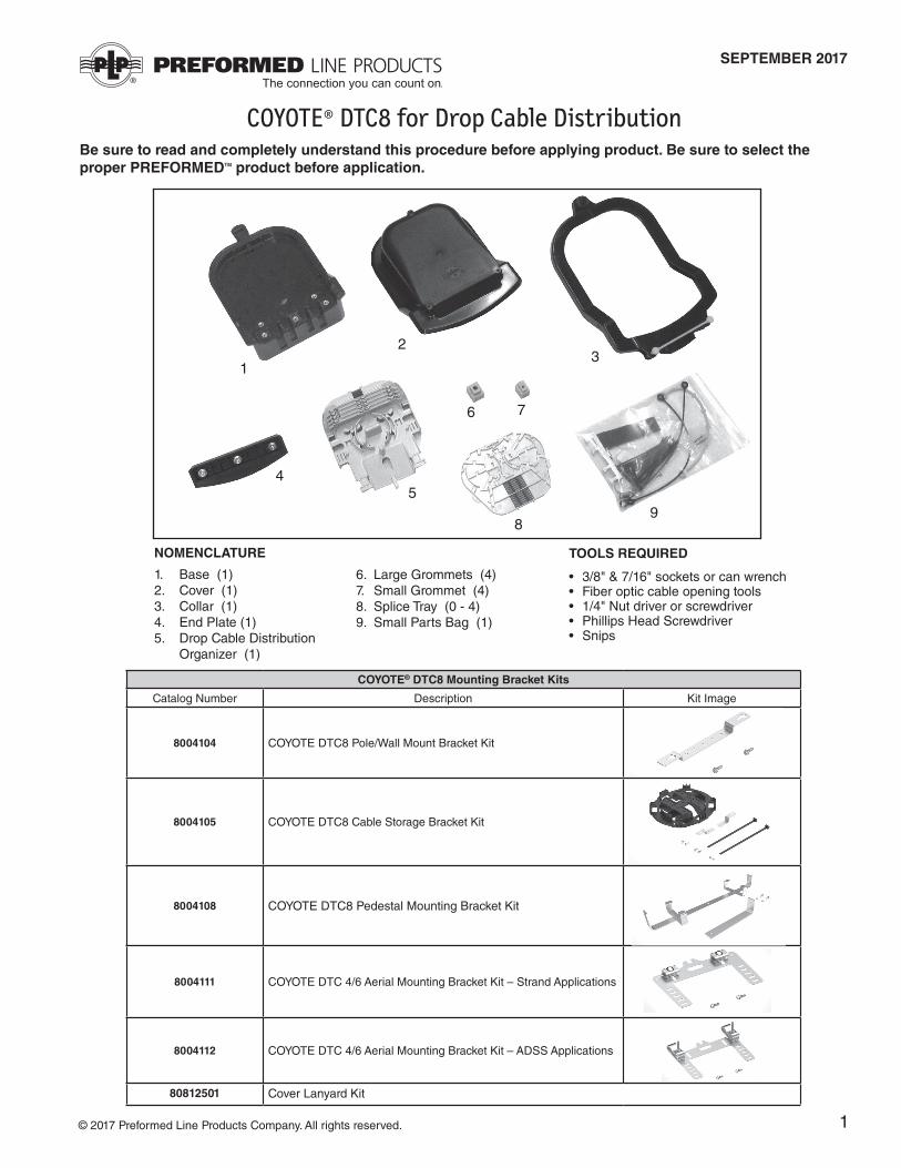
Be sure to read and completely understand this procedure before applying product. Be sure to select the proper PREFORMEDTM product before application.
NOMENCLATURE
2
13
4
1. Base (1)2. Cover (1)3. Collar (1)4. End Plate (1)5. Drop Cable Distribution Organizer (1)
6. Large Grommets (4) 7. Small Grommet (4) 8. Splice Tray (0 - 4) 9. Small Parts Bag (1)
TOOLS REQUIRED
• 3/8" & 7/16" sockets or can wrench • Fiber optic cable opening tools• 1/4" Nut driver or screwdriver • Phillips Head Screwdriver• Snips
5
6 7
89
© 2017 Preformed Line Products Company. All rights reserved.
COYOTE® DTC8 Mounting Bracket Kits
Catalog Number Description Kit Image
8004104 COYOTE DTC8 Pole/Wall Mount Bracket Kit
8004105 COYOTE DTC8 Cable Storage Bracket Kit
8004108 COYOTE DTC8 Pedestal Mounting Bracket Kit
8004111 COYOTE DTC 4/6 Aerial Mounting Bracket Kit – Strand Applications
8004112 COYOTE DTC 4/6 Aerial Mounting Bracket Kit – ADSS Applications
80812501 Cover Lanyard Kit

2
Feed and Branch Cable Preparation Step #2 Insert each cut cable in the appropri ate grommet. If the cable is express- ing fiber, slit the grommets as shown below, before installing the grommets over the cable. (See Step 1 for slit locations on each grommet).
Cut Cables
Expressed Cables
Step #1 Measure each cable to determine the diameter of the cable and select the proper grommet(s) for your application.
Large Grommet Selection
Cable Diameter
Range
A SOLID / PLUG
B
.170" - .220" (4.3 - 5.6 mm)
ROUND CABLES
C
.220" - .270" (5.6 - 6.9 mm)
ROUND CABLES
D
.270" - .320" (6.9 - 8.1 mm)
ROUND CABLES
E
.320" - .370" (8.1 - 9.4 mm)
ROUND CABLES
F
.370" - .420" (9.4 - 10.7 mm)
ROUND CABLES
G
.420" - .470" (10.7 - 11.9 mm)
ROUND CABLES
H
.470" - .550" (11.9 - 14.0 mm)
ROUND CABLES
J
.156" - .170" (4.0 mm - 4.3 mm)ROUND DROP
CABLES
K
.093" - .125" (2.4 - 3.2 mm) ROUND DROP
CABLES
L FLAT DROP CABLES ONLY
3
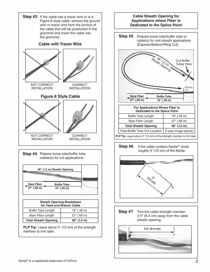
Step #4 Prepare loose tube/buffer tube cables(s) for cut applications.
Step #3 If the cable has a tracer wire or is a Figure 8 style cable, remove the ground wire or tracer wire from the portion of the cable that will be positioned in the grommet and insert the cable into the grommet.
Cable with Tracer Wire
NOT CORRECT INSTALLATION
CORRECT INSTALLATION
Figure 8 Style Cable
NOT CORRECT INSTALLATION
CORRECT INSTALLATION
46" (1.2 m) Sheath Opening
Bare Fiber27" (.69 m)
Buffer Tube19" (.48 m)
Sheath Opening Breakdownfor Feed and Branch Cable
Buffer Tube Length 19" (.48 m)
Bare Fiber Length 27" (.69 m)
Total Sheath Opening 46" (1.2 m)
PLP Tip: Leave about 5" (13 cm) of the strength member to trim later.
Step #5 Prepare loose tube/buffer tube or cable(s) for mid sheath applications (Express/Balloon/Ring Cut).
Cut BufferTubes Here
OFFICE/C.O.
46" 1.2 m)
Sheath Opening
X
Cable Sheath Opening for Applications where Fiber is
Dedicated to the Splice Point
Bare Fiber27" (.69 m)
Buffer Tube19" (.48 m)
For Applications Where Fiber is Dedicated to the Splice Point
Buffer Tube Length 19" (.48 m)
Bare Fiber Length 27" (.69 m)
Total Sheath Opening 46" (1.2 m)
Fiber/Buffer Tube Cut Location X (see image above)
PLP Tip: Leave about 5" (13 cm) of the strength member to trim later.
Step #6 If the cable contains Kevlar®, braid roughly 3" (7.2 cm) of the Kevlar.
Step #7 Trim the cable strength member 2.5" (6.4 cm) away from the cable sheath opening.
2.5" (6.4 cm)
3" (7.2 cm)
Kevlar® is a registered trademark of DuPont.

4
Step #10 Secure the cables to the organizer with hose clamps as shown below.
Step #13 Wrap the buffer tube(s) with felt and secure the buffer tube(s) to the organizer with 2 tie wraps.
Step #8 Install the strength member retention caps to the bottom of the organizer with the self-tapping screws that are provided.
Step #9 If the cable contains Kevlar®, wrap the braided Kevlar around the screw under the retention cap. Position the cable strength members under the cap and tighten down the screw to secure them.
Buffer Tube Routing for Feed Cables
Posts
Step #11 Route any expressed buffer tubes under the tabs located on the bottom of the organizer.
Tabs
Step #12 Route any buffer tubes with fibers to be spliced under the tabs once before routing them to the top of the organizer.
Buffer tube with fibers to be spliced
Felt
Attaching Feed Cables to Organizer
Strength Member Retention Caps
Kevlar® is a registered trademark of DuPont.
Expressed Buffer Tube
Tabs
Tie Wraps
5
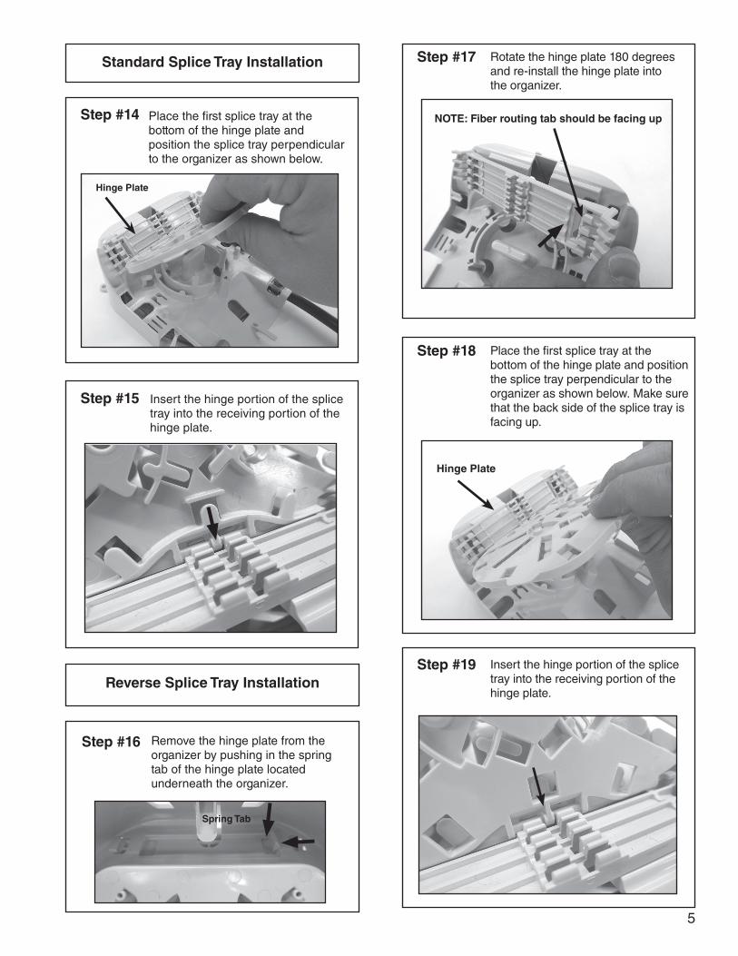
Step #15 Insert the hinge portion of the splice tray into the receiving portion of the hinge plate.
Standard Splice Tray Installation
Step #14 Place the first splice tray at the bottom of the hinge plate and position the splice tray perpendicular to the organizer as shown below.
Hinge Plate
Step #16 Remove the hinge plate from the organizer by pushing in the spring tab of the hinge plate located underneath the organizer.
Reverse Splice Tray Installation
Spring Tab
Step #17 Rotate the hinge plate 180 degrees and re-install the hinge plate into the organizer.
NOTE: Fiber routing tab should be facing up
Step #18 Place the first splice tray at the bottom of the hinge plate and position the splice tray perpendicular to the organizer as shown below. Make sure that the back side of the splice tray is facing up.
Hinge Plate
Step #19 Insert the hinge portion of the splice tray into the receiving portion of the hinge plate.
6
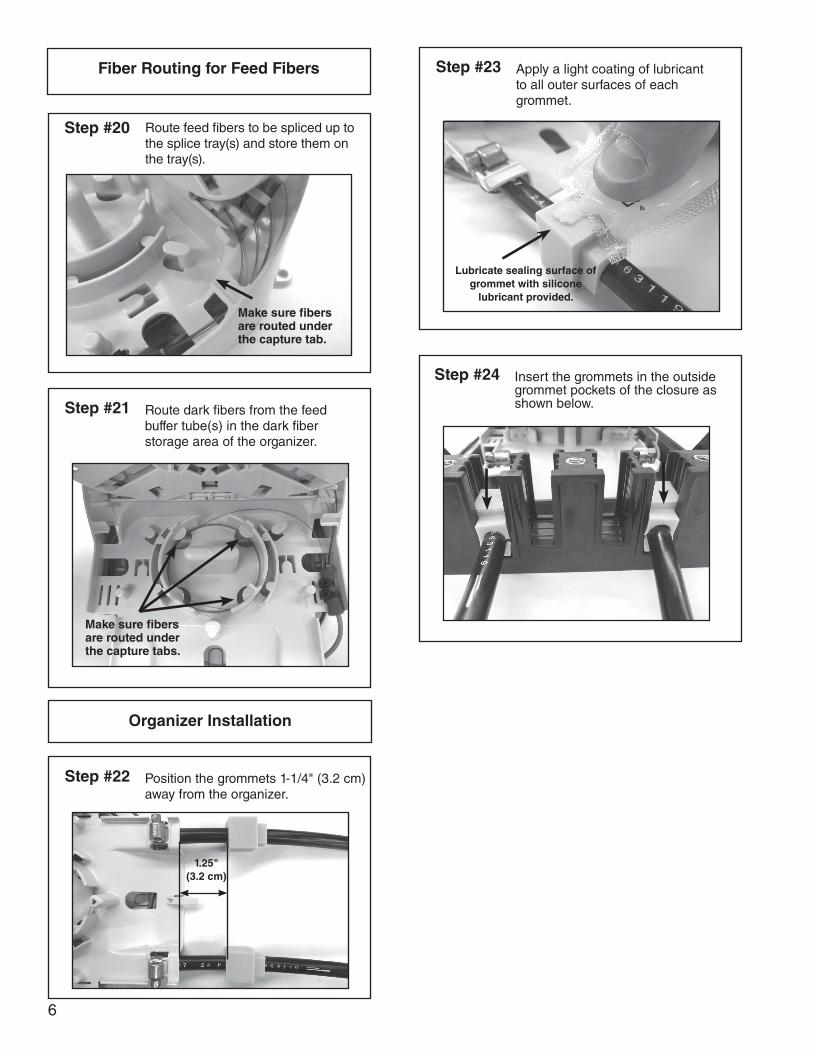
Step #21 Route dark fibers from the feed buffer tube(s) in the dark fiber storage area of the organizer.
Step #24 Insert the grommets in the outside grommet pockets of the closure as shown below.
Fiber Routing for Feed Fibers
Step #20 Route feed fibers to be spliced up to the splice tray(s) and store them on the tray(s).
Make sure fibers are routed under the capture tab.
Step #22 Position the grommets 1-1/4" (3.2 cm) away from the organizer.
Organizer Installation
Step #23 Apply a light coating of lubricant to all outer surfaces of each grommet.
Lubricate sealing surface of grommet with silicone
lubricant provided.
Make sure fibers are routed under the capture tabs.
1.25" (3.2 cm)
7
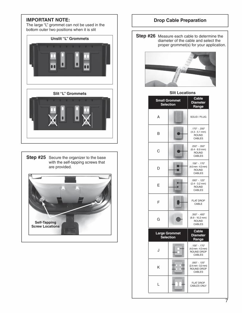
Step #25 Secure the organizer to the base with the self-tapping screws that are provided.
Self-Tapping Screw Locations
Step #26
Drop Cable Preparation
Measure each cable to determine the diameter of the cable and select the proper grommet(s) for your application.
IMPORTANT NOTE:The large “L” grommet can not be used in the bottom outer two positions when it is slit
Unslit “L” Grommets
Slit “L” Grommets Slit Locations
Large Grommet Selection
Cable Diameter
Range
J.156" - .170"
(4.0 mm - 4.3 mm)ROUND DROP
CABLES
K.093" - .125"
(2.4 mm - 3.2 mm)ROUND DROP
CABLES
L FLAT DROP CABLES ONLY
Small Grommet Selection
Cable Diameter
Range
A SOLID / PLUG
B.170" - .200"
(4.3 - 5.1 mm) ROUND CABLES
C.250" - .350"
(6.4 - 8.9 mm) ROUND CABLES
D.156" - .170"
(4.0 mm - 4.3 mm)ROUND CABLES
E.093" - .125"
(2.4 - 3.2 mm) ROUNDCABLES
F FLAT DROPCABLE
G.350" - .400"
(8.9 - 10.2 mm) ROUNDCABLES
8
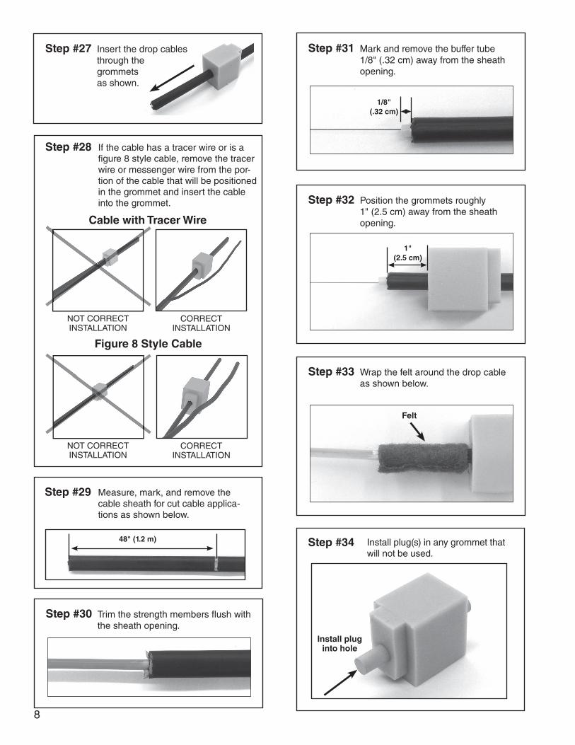
Step #30 Trim the strength members fl ush with the sheath opening.
Step #31 Mark and remove the buffer tube 1/8" (.32 cm) away from the sheath opening.
1/8" (.32 cm)
Step #32 Position the grommets roughly 1" (2.5 cm) away from the sheath opening.
1" (2.5 cm)
Step #33 Wrap the felt around the drop cable as shown below.
Felt
Step #34 Install plug(s) in any grommet that will not be used.
Install plug into hole
Step #28 If the cable has a tracer wire or is a fi gure 8 style cable, remove the tracer wire or messenger wire from the por-tion of the cable that will be positioned in the grommet and insert the cable into the grommet.
Cable with Tracer Wire
NOT CORRECT INSTALLATION
CORRECT INSTALLATION
Figure 8 Style Cable
NOT CORRECT INSTALLATION
CORRECT INSTALLATION
Step #29 Measure, mark, and remove the cable sheath for cut cable applica-tions as shown below.
48" (1.2 m)
Step #27 Insert the drop cables through the grommets as shown.
9
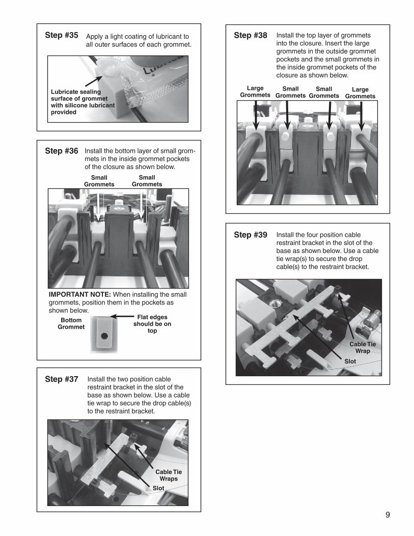
Step #35 Apply a light coating of lubricant to all outer surfaces of each grommet.
Lubricate sealing surface of grommet with silicone lubricant provided
Step #36 Install the bottom layer of small grom-mets in the inside grommet pockets of the closure as shown below.
Small Grommets
Small Grommets
BottomGrommet
Flat edges should be on
top
IMPORTANT NOTE: When installing the small grommets, position them in the pockets as shown below.
Step #37 Install the two position cable restraint bracket in the slot of the base as shown below. Use a cable tie wrap to secure the drop cable(s) to the restraint bracket.
Cable Tie Wraps
Step #38 Install the top layer of grommets into the closure. Insert the large grommets in the outside grommet pockets and the small grommets in the inside grommet pockets of the closure as shown below.
Small Grommets
Small Grommets
Large Grommets
Large Grommets
Step #39 Install the four position cable restraint bracket in the slot of the base as shown below. Use a cable tie wrap(s) to secure the drop cable(s) to the restraint bracket.
Slot
Cable Tie Wrap
Slot
10
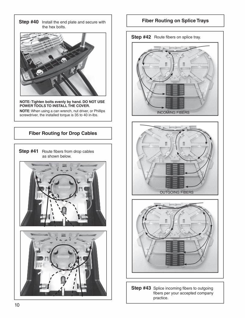
Step #40 Install the end plate and secure with the hex bolts.
NOTE: Tighten bolts evenly by hand. DO NOT USE POWER TOOLS TO INSTALL THE COVER.NOTE: When using a can wrench, nut driver, or Phillips screwdriver, the installed torque is 35 to 40 in-lbs.
Step #41 Route fibers from drop cables as shown below.
Fiber Routing for Drop Cables
Fiber Routing on Splice Trays
Step #43 Splice incoming fibers to outgoing fibers per your accepted company practice.
Step #42 Route fibers on splice tray.
INCOMING FIBERS
OUTGOING FIBERS
11
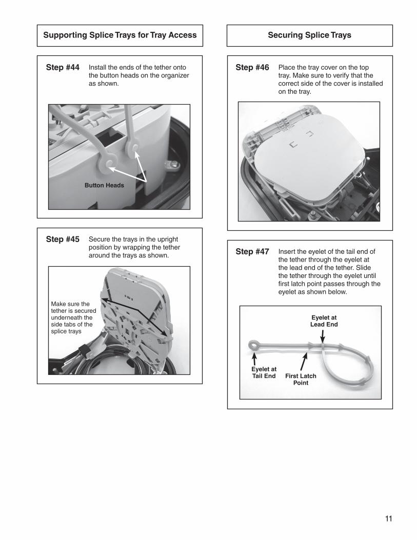
Supporting Splice Trays for Tray Access
Step #44 Install the ends of the tether onto the button heads on the organizer as shown.
Button Heads
Step #45 Secure the trays in the upright position by wrapping the tether around the trays as shown.
Make sure the tether is secured underneath the side tabs of the splice trays
Securing Splice Trays
Step #46 Place the tray cover on the top tray. Make sure to verify that the correct side of the cover is installed on the tray.
Step #47 Insert the eyelet of the tail end of the tether through the eyelet at the lead end of the tether. Slide the tether through the eyelet until first latch point passes through the eyelet as shown below.
Eyelet at Lead End
First Latch Point
Eyelet at Tail End
12
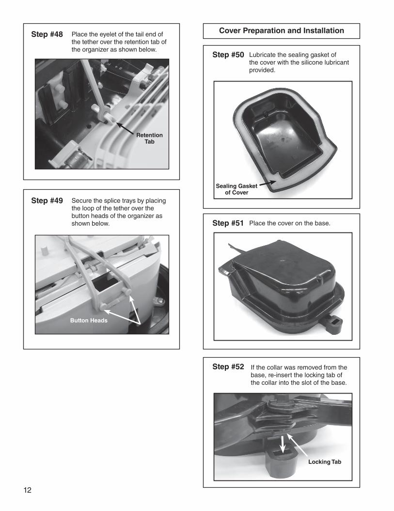
Step #50
Cover Preparation and Installation
Lubricate the sealing gasket of the cover with the silicone lubricant provided.
Sealing Gasket of Cover
Step #51 Place the cover on the base.
Step #52 If the collar was removed from the base, re-insert the locking tab of the collar into the slot of the base.
Step #48 Place the eyelet of the tail end of the tether over the retention tab of the organizer as shown below.
Retention Tab
Step #49 Secure the splice trays by placing the loop of the tether over the button heads of the organizer as shown below.
Button Heads
Locking Tab
13
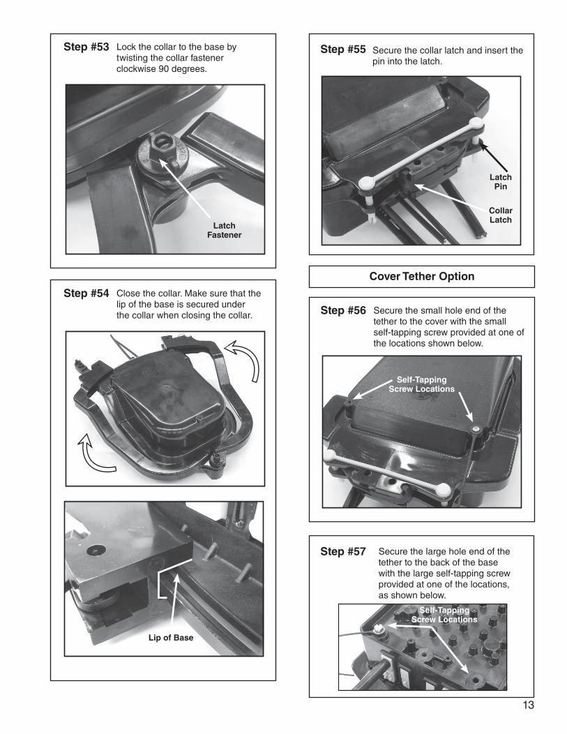
Step #55Step #53 Lock the collar to the base by twisting the collar fastener clockwise 90 degrees.
Latch Fastener
Step #54 Close the collar. Make sure that the lip of the base is secured under the collar when closing the collar.
Lip of Base
Secure the collar latch and insert the pin into the latch.
Latch Pin
Collar Latch
Cover Tether Option
Step #56 Secure the small hole end of the tether to the cover with the small self-tapping screw provided at one of the locations shown below.
Self-Tapping Screw Locations
Step #57 Secure the large hole end of the tether to the back of the base with the large self-tapping screw provided at one of the locations, as shown below.
Self-Tapping Screw Locations

14

15

16
SP3268-2P.O. Box 91129, Cleveland, Ohio 44101 • 440.461.5200 • www.preformed.com • e-mail: [email protected]
SAFETY CONSIDERATIONS
This application procedure is not intended to supersede any company construction or safety standards. This procedure is offered only to illustrate safe application for the individual. FAILURE TO FOLLOW THESE PROCEDURES MAY RESULT IN PERSONAL INJURY OR DEATH.
Do not modify this product under any circumstances.
This product is intended for use by trained technicians only. This product should not be used by anyone who is not familiar with, and not trained to use it.
When working in the area of energized lines, extra care should be taken to prevent accidental electrical contact.
For proper performance and personal safety, be sure to select the proper size PREFORMEDTM product before application.
PREFORMED products are precision devices. To insure proper performance, they should be stored in cartons under cover and handled carefully.