SP080 SP081 SP082 install - CacheFlylatemodel.cachefly.net/downloads/instructions/BMR-SP080.pdf10....
4
1 LOWERING SPRING INSTALLATION INSTRUCTIONS PART #’S: SP080, SP081, SP082, SP083, SP084, SP085, SP086, SP087, SP088, SP089 FRONT SPRINGS: 1. Lift vehicle and safely support with jack stands under the frame rails. 2. Remove the wheels/tires. 3. Remove the sway bar end links as shown in IMAGE 1. 4. Disconnect all brake sensor connectors from the strut body as shown in IMAGE 2. 5. Remove the caliper bolts and hang the caliper out of the way. (IMAGE 3) 6. Remove the (2) strut bolts at the spindle as shown in IMAGE 4.
Transcript of SP080 SP081 SP082 install - CacheFlylatemodel.cachefly.net/downloads/instructions/BMR-SP080.pdf10....
1
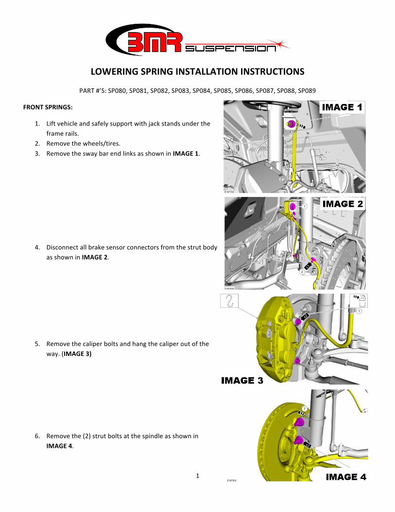
LOWERING SPRING INSTALLATION INSTRUCTIONS
PART #’S: SP080, SP081, SP082, SP083, SP084, SP085, SP086, SP087, SP088, SP089
FRONT SPRINGS:
1. Lift vehicle and safely support with jack stands under the frame rails.
2. Remove the wheels/tires. 3. Remove the sway bar end links as shown in IMAGE 1.
4. Disconnect all brake sensor connectors from the strut body as shown in IMAGE 2.
5. Remove the caliper bolts and hang the caliper out of the way. (IMAGE 3)
6. Remove the (2) strut bolts at the spindle as shown in IMAGE 4.
2
LOWERING SPRING INSTALLATION INSTRUCTIONS (Cont.)
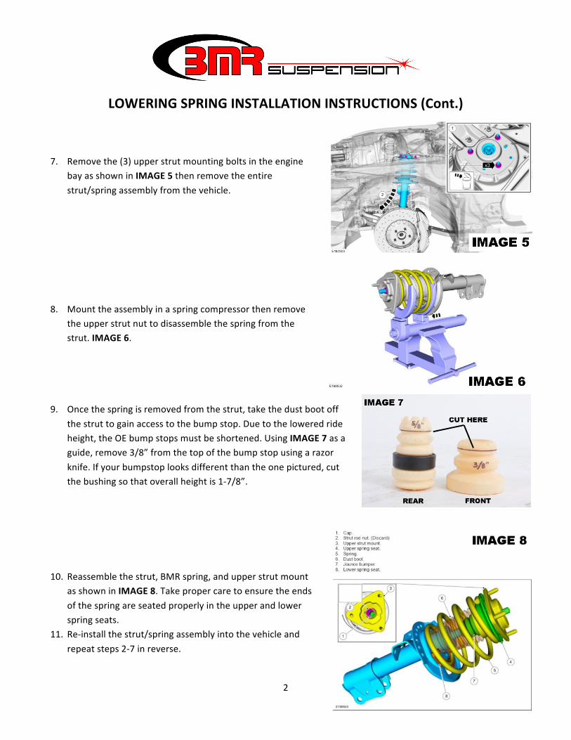
7. Remove the (3) upper strut mounting bolts in the engine bay as shown in IMAGE 5 then remove the entire strut/spring assembly from the vehicle.
8. Mount the assembly in a spring compressor then remove the upper strut nut to disassemble the spring from the strut. IMAGE 6.
9. Once the spring is removed from the strut, take the dust boot off the strut to gain access to the bump stop. Due to the lowered ride height, the OE bump stops must be shortened. Using IMAGE 7 as a guide, remove 3/8” from the top of the bump stop using a razor knife. If your bumpstop looks different than the one pictured, cut the bushing so that overall height is 1-‐7/8”.
10. Reassemble the strut, BMR spring, and upper strut mount as shown in IMAGE 8. Take proper care to ensure the ends of the spring are seated properly in the upper and lower spring seats.
11. Re-‐install the strut/spring assembly into the vehicle and repeat steps 2-‐7 in reverse.
3
LOWERING SPRING INSTALLATION INSTRUCTIONS (Cont.)
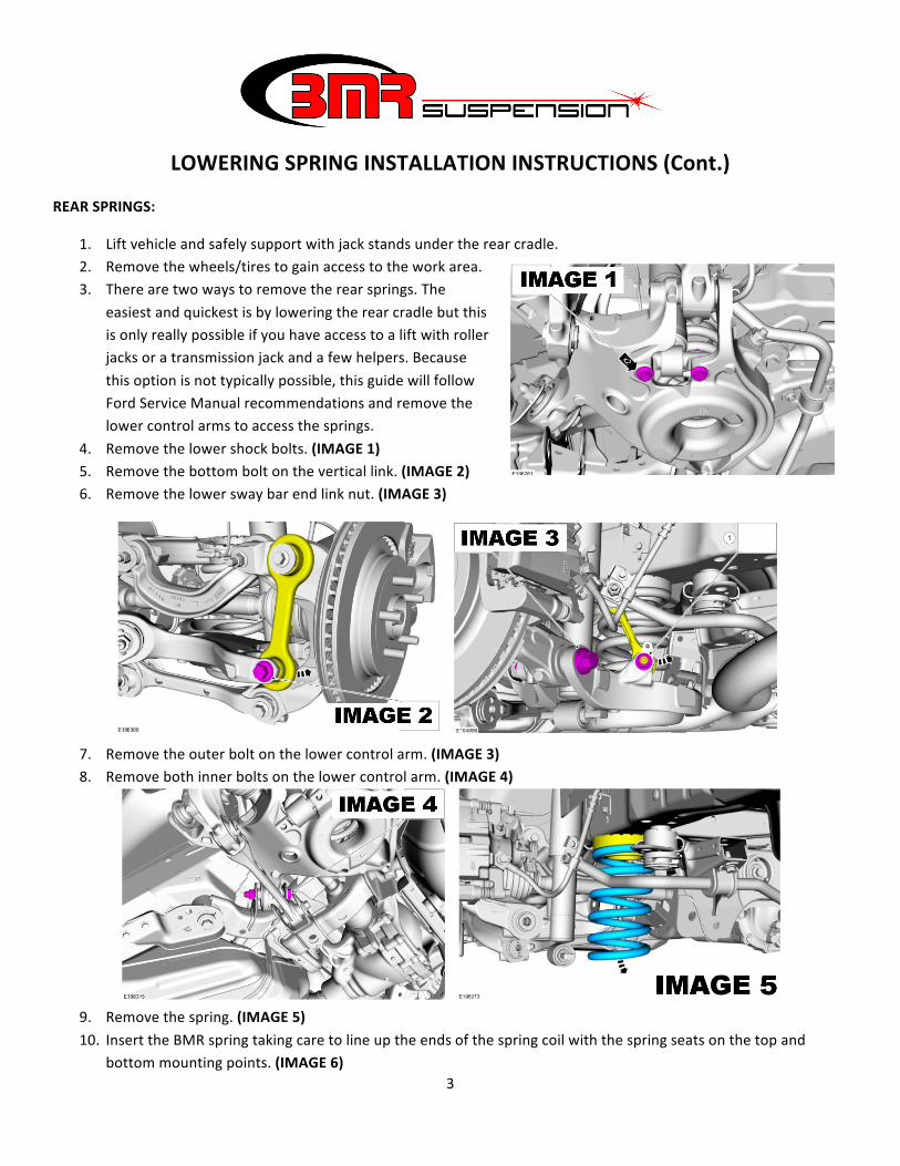
REAR SPRINGS:
1. Lift vehicle and safely support with jack stands under the rear cradle. 2. Remove the wheels/tires to gain access to the work area. 3. There are two ways to remove the rear springs. The
easiest and quickest is by lowering the rear cradle but this is only really possible if you have access to a lift with roller jacks or a transmission jack and a few helpers. Because this option is not typically possible, this guide will follow Ford Service Manual recommendations and remove the lower control arms to access the springs.
4. Remove the lower shock bolts. (IMAGE 1) 5. Remove the bottom bolt on the vertical link. (IMAGE 2) 6. Remove the lower sway bar end link nut. (IMAGE 3)
7. Remove the outer bolt on the lower control arm. (IMAGE 3) 8. Remove both inner bolts on the lower control arm. (IMAGE 4)
9. Remove the spring. (IMAGE 5) 10. Insert the BMR spring taking care to line up the ends of the spring coil with the spring seats on the top and
bottom mounting points. (IMAGE 6)
4
LOWERING SPRING INSTALLATION INSTRUCTIONS (Cont.)
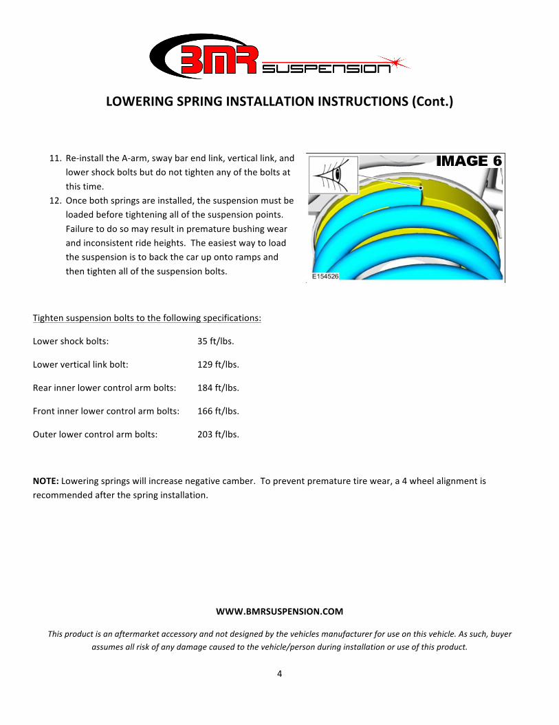
11. Re-‐install the A-‐arm, sway bar end link, vertical link, and lower shock bolts but do not tighten any of the bolts at this time.
12. Once both springs are installed, the suspension must be loaded before tightening all of the suspension points. Failure to do so may result in premature bushing wear and inconsistent ride heights. The easiest way to load the suspension is to back the car up onto ramps and then tighten all of the suspension bolts.
Tighten suspension bolts to the following specifications:
Lower shock bolts: 35 ft/lbs.
Lower vertical link bolt: 129 ft/lbs.
Rear inner lower control arm bolts: 184 ft/lbs.
Front inner lower control arm bolts: 166 ft/lbs.
Outer lower control arm bolts: 203 ft/lbs.
NOTE: Lowering springs will increase negative camber. To prevent premature tire wear, a 4 wheel alignment is recommended after the spring installation.
WWW.BMRSUSPENSION.COM
This product is an aftermarket accessory and not designed by the vehicles manufacturer for use on this vehicle. As such, buyer assumes all risk of any damage caused to the vehicle/person during installation or use of this product.