SP0276 Rev D Celltrol II Manual - Valley Instrument Rev D... · 2.11) Level ... Sys #1 pH Calibrate...
33
CELLTROL II BIOREACTOR CONTROL SYSTEM OPERATIONS MANUAL Document: SP0276 Rev D Celltrol II Manual Valley Instrument Company, Inc. Revision: C (610) 363-2650 Effective Date: 03/30/03 Written By: M. Magee Page 1 of 33 Operation Manual Celltrol II Bioreactor Control System
Transcript of SP0276 Rev D Celltrol II Manual - Valley Instrument Rev D... · 2.11) Level ... Sys #1 pH Calibrate...

CELLTROL II BIOREACTOR CONTROL SYSTEM OPERATIONS MANUAL Document: SP0276 Rev D Celltrol II Manual Valley Instrument Company, Inc. Revision: C (610) 363-2650 Effective Date: 03/30/03 Written By: M. Magee
Page 1 of 33
Operation Manual
Celltrol II Bioreactor Control System

CELLTROL II BIOREACTOR CONTROL SYSTEM OPERATIONS MANUAL Document: SP0276 Rev D Celltrol II Manual Valley Instrument Company, Inc. Revision: C (610) 363-2650 Effective Date: 03/30/03 Written By: M. Magee
Page 2 of 33
Table of Contents
1) Introduction .......................................................................................................................................................... 3
1.1) Scope of Document .................................................................................................................................... 3 1.2) Control System Overview ........................................................................................................................... 3 1.3) Introduction to Celltrol II .............................................................................................................................. 4 1.4) Acronyms .................................................................................................................................................... 5 1.5) Definitions ................................................................................................................................................... 5
2) Operator Interface (HMI) ..................................................................................................................................... 6
2.1) Screen Structure ......................................................................................................................................... 6 2.2) Screen Security........................................................................................................................................... 7 2.3) Screen Action Touch Cells.......................................................................................................................... 8 2.4) Main Screen................................................................................................................................................ 8 2.5) Navigator Screen ........................................................................................................................................ 9 2.6) System #1 & 2 Overview Screen ................................................................................................................ 9 2.7) System Access Screen ............................................................................................................................. 10 2.8) System Overview Screen.......................................................................................................................... 11 2.9) System Control Screen ............................................................................................................................. 12 2.10) System Setpoint Screen ........................................................................................................................... 13 2.11) Level.......................................................................................................................................................... 14 2.12) PH Calibration Screen .............................................................................................................................. 14 2.13) DO Calibration Screen .............................................................................................................................. 16 2.14) Auxiliary Setup Screen.............................................................................................................................. 17 2.15) Pump Priming Screen ............................................................................................................................... 18 2.16) Active Alarm Screen ................................................................................................................................. 19 2.17) Alarm History Screen ................................................................................................................................ 20 2.18) Alarm Pop Up Banner ............................................................................................................................... 20 2.19) Supervisor Screen .................................................................................................................................... 21 2.20) Security Screen......................................................................................................................................... 21 2.21) System PID Tuning Screen....................................................................................................................... 22 2.22) Calibration Screen .................................................................................................................................... 24 2.23) Pump Assignment Screen ........................................................................................................................ 24 2.24) Output Assignment Screen....................................................................................................................... 25 2.25) Alarm Setup Screen.................................................................................................................................. 26 2.26) OIT Configuration...................................................................................................................................... 27
3) Operation ........................................................................................................................................................... 27
3.1) Setup......................................................................................................................................................... 27 3.2) Configuration............................................................................................................................................. 27 3.3) Calibration................................................................................................................................................. 29 3.4) System Security and Login ....................................................................................................................... 32 3.5) Running a Process.................................................................................................................................... 32 3.6) Alarms....................................................................................................................................................... 32

CELLTROL II BIOREACTOR CONTROL SYSTEM OPERATIONS MANUAL Document: SP0276 Rev D Celltrol II Manual Valley Instrument Company, Inc. Revision: C (610) 363-2650 Effective Date: 03/30/03 Written By: M. Magee
Page 3 of 33
1) Introduction
1.1) Scope of Document
The purpose of this document is to provide operational instructions for the Programmable Logic Controller (PLC) based CellTrol II Bioreactor Control System. System set up, running and user calibration is detailed in this manual. Technical data such as electrical component calibration, software interfacing, schematics and basic fault finding will be covered in the “Celltrol II Technical Manual”. Each CellTrol II unit will vary depending on the number of channels and input / output configuration chosen. This manual is a generic manual, which covers all aspects of the Celltrol II. Some features may or may not be present in the unit purchased.
1.2) Control System Overview
The control system is made up of (1) Allen Bradley Micrologix 1500 Programmable Logic Controller (PLC) and (1) Allen Bradley HMI (Human-Machine Interface) Operator Interface. The control cabinet contains the PLC, HMI, probe signal conditioning transmitters, 115 VAC control outlets and fixed rate pumps (customer specified rates 1rpm, 4rpm or 10rpm and quantity, up to six). The Celltrol can be configured to accept a variety of analog probe signals from a cell culture vessel. Standard signals include but not limited to: pH, dissolved oxygen, temperature, weight, redox and tachometer feedback from the agitator. A digital input signal from a level probe can be used for antifoam addition or level control. The unit is available in a number of configurations to control up to two independent vessels.
Figure 1 – Flow diagram of the Celltrol II bioreactor control system.
CELLTROL II BIOREACTOR CONTROL SYSTEM OPERATIONS MANUAL Document: SP0276 Rev D Celltrol II Manual Valley Instrument Company, Inc. Revision: C (610) 363-2650 Effective Date: 03/30/03 Written By: M. Magee
Page 4 of 33
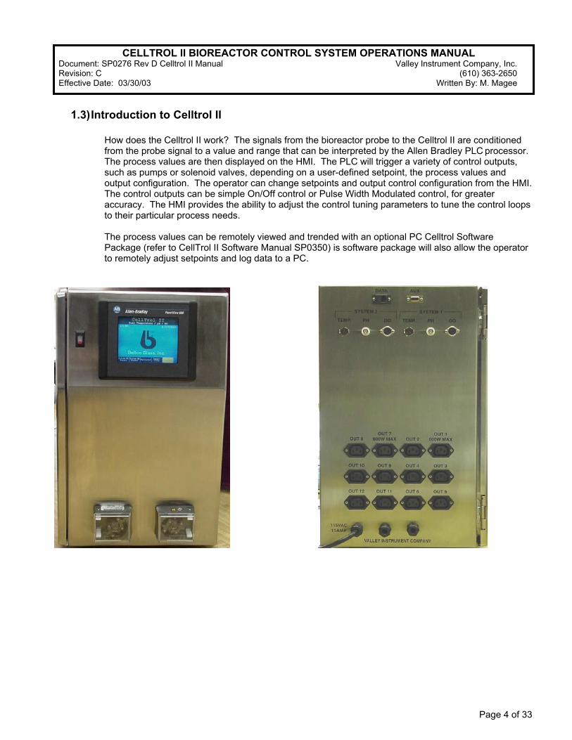
1.3) Introduction to Celltrol II
How does the Celltrol II work? The signals from the bioreactor probe to the Celltrol II are conditioned from the probe signal to a value and range that can be interpreted by the Allen Bradley PLC processor. The process values are then displayed on the HMI. The PLC will trigger a variety of control outputs, such as pumps or solenoid valves, depending on a user-defined setpoint, the process values and output configuration. The operator can change setpoints and output control configuration from the HMI. The control outputs can be simple On/Off control or Pulse Width Modulated control, for greater accuracy. The HMI provides the ability to adjust the control tuning parameters to tune the control loops to their particular process needs. The process values can be remotely viewed and trended with an optional PC Celltrol Software Package (refer to CellTrol II Software Manual SP0350) is software package will also allow the operator to remotely adjust setpoints and log data to a PC.

CELLTROL II BIOREACTOR CONTROL SYSTEM OPERATIONS MANUAL Document: SP0276 Rev D Celltrol II Manual Valley Instrument Company, Inc. Revision: C (610) 363-2650 Effective Date: 03/30/03 Written By: M. Magee
Page 5 of 33
1.4) Acronyms
AB Allen-Bradley HMI Human Machine Interface I/O Input/Output PC Personal Computer PID Proportional-Integral-Derivative control PLC Programmable Logic Controller PWM Pulse Width Modulation SOP Standard Operating Procedure BAS Building Automated System
1.5) Definitions
Analog Control – A control loop where the controller’s output varies within a specified range. The controller’s output regulates the control loop’s motor speed or actuator device position. Discrete Control – A control loop where the controller’s output changes from low to high or high to low depending on an input signal. The controller’s output either energizes or de-energizes an actuator. Energized – A device is considered energized when the PLC output that operates the device is on. Ladder Logic – A PLC Programming language, resembling electrical relay schematics. Loop – A loop is a logical group of one or more closely related control points, which interact with each other to perform a specific function. Panel View – An Allen Bradley series of Operator Interface Terminal. PID Control – Proportional-Integral-Derivative control where the controller’s output varies proportionally in response to a field device input. Pulse Width Modulation – Proportional-Integral-Derivative control where a discrete output is time proportioned on and off to achieve more accurate control. Human Machine Interface (HMI) – An interactive terminal from which an operator can control a process and view current data on specific processes.

CELLTROL II BIOREACTOR CONTROL SYSTEM OPERATIONS MANUAL Document: SP0276 Rev D Celltrol II Manual Valley Instrument Company, Inc. Revision: C (610) 363-2650 Effective Date: 03/30/03 Written By: M. Magee
Page 6 of 33
2) Operator Interface (HMI)
2.1) Screen Structure The operator interface (HMI), located on the front panel of the Celltrol II, is a color touch screen device which displays current process values, provides setpoint manipulation and output configuration. The touch cells are outlined areas on the screen, which when touched can perform one of the following: Navigate to another screen, allow entry of a numeric value or perform a control action. The HMI has several screens allowing the user to make the necessary changes for effective process control. Figure 2 represents a simplistic diagram of the screen hierarchy found on a standard Celltrol II unit. A navigation screen allows the operator to see all available screens and choose the desired screen. Passwords are still in effect.
Figure 2 – Celltrol II HMI screen hierarchy found on a standard Celltrol unit
CELLTROL II BIOREACTOR CONTROL SYSTEM OPERATIONS MANUAL Document: SP0276 Rev D Celltrol II Manual Valley Instrument Company, Inc. Revision: C (610) 363-2650 Effective Date: 03/30/03 Written By: M. Magee
Page 7 of 33
2.2) Screen Security
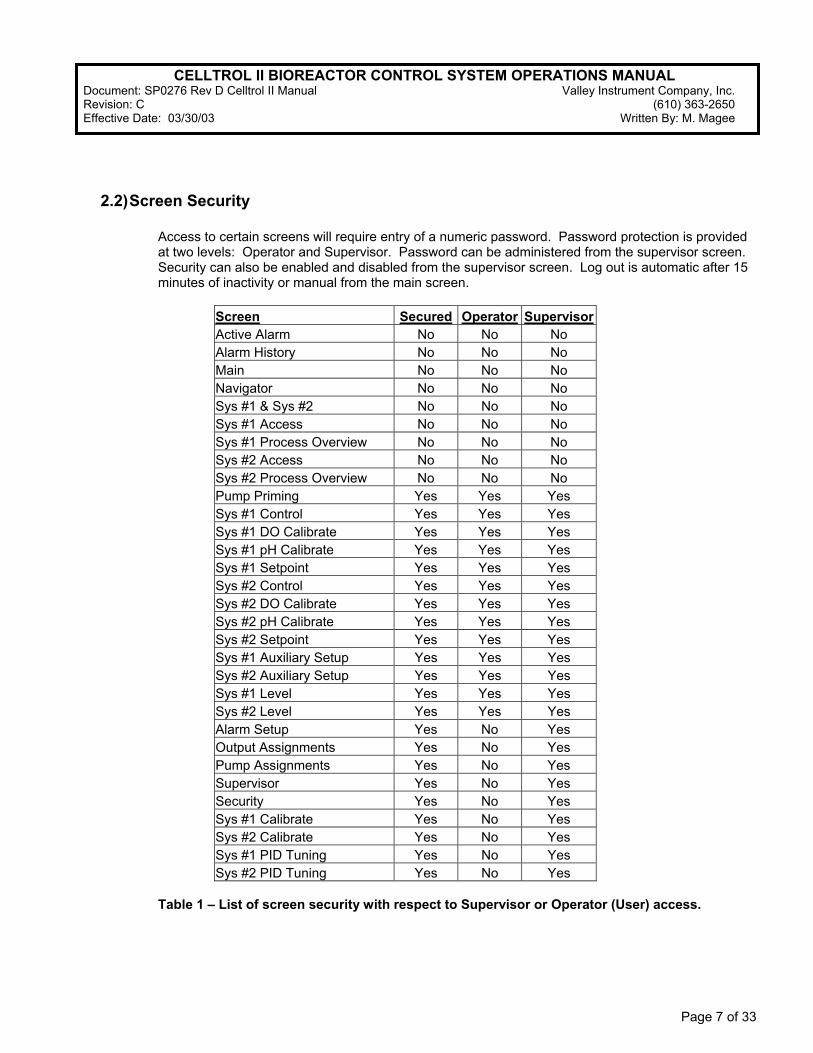
Access to certain screens will require entry of a numeric password. Password protection is provided at two levels: Operator and Supervisor. Password can be administered from the supervisor screen. Security can also be enabled and disabled from the supervisor screen. Log out is automatic after 15 minutes of inactivity or manual from the main screen.
Screen Secured Operator Supervisor Active Alarm No No No Alarm History No No No Main No No No Navigator No No No Sys #1 & Sys #2 No No No Sys #1 Access No No No Sys #1 Process Overview No No No Sys #2 Access No No No Sys #2 Process Overview No No No Pump Priming Yes Yes Yes Sys #1 Control Yes Yes Yes Sys #1 DO Calibrate Yes Yes Yes Sys #1 pH Calibrate Yes Yes Yes Sys #1 Setpoint Yes Yes Yes Sys #2 Control Yes Yes Yes Sys #2 DO Calibrate Yes Yes Yes Sys #2 pH Calibrate Yes Yes Yes Sys #2 Setpoint Yes Yes Yes Sys #1 Auxiliary Setup Yes Yes Yes Sys #2 Auxiliary Setup Yes Yes Yes Sys #1 Level Yes Yes Yes Sys #2 Level Yes Yes Yes Alarm Setup Yes No Yes Output Assignments Yes No Yes Pump Assignments Yes No Yes Supervisor Yes No Yes Security Yes No Yes Sys #1 Calibrate Yes No Yes Sys #2 Calibrate Yes No Yes Sys #1 PID Tuning Yes No Yes Sys #2 PID Tuning Yes No Yes
Table 1 – List of screen security with respect to Supervisor or Operator (User) access.

CELLTROL II BIOREACTOR CONTROL SYSTEM OPERATIONS MANUAL Document: SP0276 Rev D Celltrol II Manual Valley Instrument Company, Inc. Revision: C (610) 363-2650 Effective Date: 03/30/03 Written By: M. Magee
Page 8 of 33
2.3) Screen Action Touch Cells
2.3.1) Navigation Touch Cells typically located at the bottom of the HMI screen enable the user to proceed to the screen indicated in the touch cell. These cells can be easily identified by the gray color background and white text.
2.3.2) Numerical Entry Cells are used to enter data. An entry can be changed by pressing the desired cell and entering the value via the pop-up numerical panel. It is important to note that the decimal need not be entered in all situations and the desired numerical entry should be verified in the display before pressing the enter cell. Numerical entry cells can be easily identified be the dark blue background and yellow text.
2.3.3) Action Cells allow the user to perform an action or change state of a control function by scrolling through a predefined list of control assignment functions. These cells can be easily identified by the green background and white text.
2.4) Main Screen
2.4.1) Purpose: This screen allows the navigation to the operational screens. This is the start up screen. 2.4.2) Message Displays: The following messages will be displayed on this screen.
2.4.2.1) : Indicates there is a current active alarm on System #1. 2.4.2.2) : Indicates there is a current active alarm on System #2.
CELLTROL II BIOREACTOR CONTROL SYSTEM OPERATIONS MANUAL Document: SP0276 Rev D Celltrol II Manual Valley Instrument Company, Inc. Revision: C (610) 363-2650 Effective Date: 03/30/03 Written By: M. Magee
Page 9 of 33
2.4.3) Time and date Indicators: The current time and date will be displayed on this screen in engineering units. These can be changed on the OIT configuration screen.
2.4.4) Touch Cells: Following is a list of the available touch cells and the operating action.
2.4.4.1) : Depress to log out of current password level.
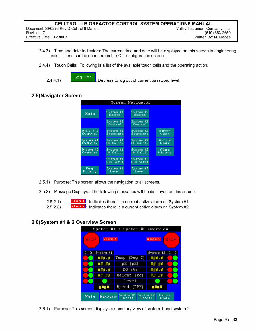
2.5) Navigator Screen
2.5.1) Purpose: This screen allows the navigation to all screens. 2.5.2) Message Displays: The following messages will be displayed on this screen.
2.5.2.1) : Indicates there is a current active alarm on System #1. 2.5.2.2) : Indicates there is a current active alarm on System #2.
2.6) System #1 & 2 Overview Screen
2.6.1) Purpose: This screen displays a summary view of system 1 and system 2.

CELLTROL II BIOREACTOR CONTROL SYSTEM OPERATIONS MANUAL Document: SP0276 Rev D Celltrol II Manual Valley Instrument Company, Inc. Revision: C (610) 363-2650 Effective Date: 03/30/03 Written By: M. Magee
Page 10 of 33
2.6.2) Message Displays: The following messages will be displayed on this screen.
2.6.2.1) : Indicates there is a current active alarm on System #1. 2.6.2.2) : Indicates there is a current active alarm on System #2.
2.6.3) System Control Status: Each of the systems will have a status indicator that will be Run or Stop. When Stop is indicated, no outputs will be On for this system
2.6.4) Process Value Displays: Temperature, pH, DO, Weight, Level and Speed will be displayed on the
unit regardless of the hardware installed. 2.6.5) Control Output Status: The control output status for each of the control loops will be displayed next
to the Process Value. will indicate On and will indicate Off. Indicates increase and indicates decrease.
2.7) System Access Screen
2.7.1) Purpose: This screen displays navigation buttons for System #1 or System #2. 2.7.2) Message Displays: The following messages will be displayed on this screen.
2.7.2.1) : Indicates there is a current active alarm on System #1. 2.7.2.2) : Indicates there is a current active alarm on System #2.

CELLTROL II BIOREACTOR CONTROL SYSTEM OPERATIONS MANUAL Document: SP0276 Rev D Celltrol II Manual Valley Instrument Company, Inc. Revision: C (610) 363-2650 Effective Date: 03/30/03 Written By: M. Magee
Page 11 of 33
2.8) System Overview Screen
2.8.1) Purpose: This screen allows viewing of current parameter values and setpoints, displays the current states of the outputs and allows all control to be turned On and Off from the System Control Touch Cell.
2.8.2) Message Displays: The following messages will be displayed on this screen.
2.8.2.1) : Indicates there is a current active alarm on System #1. 2.8.2.2) : Indicates there is a current active alarm on System #2.
2.8.2.3) : If the pH value is out of range, below 0 pH or above 14 pH, then a display message will indicate on this screen.
2.8.2.4) : If the DO value is out of range, below 0% or above 100%, a display message will indicate on this screen.
2.8.2.5) : If the temperature value is out of range, below 0° C or above 100° C, a display message will indicate on the screen.
2.8.2.6) : If the weight value is out of range, below 0 Kg or over loaded (depending on maximum capacity of the weight platform ordered), a display message will indicate on this screen.
2.8.3) : Depressing the System Control Touch cell will turn the control outputs ON/OFF for the system. This only turns the outputs ON if the output is set to Manual, Auto or Cascade and the set point is not met. This is beneficial for setup, cleanup and media addition to the bioreactor. Keeping the outputs OFF when not running will prevent a heating blanket to begin warming before the RTD is placed in the vessel or heating the media before the level comes in contact with the RTD when initially filling the reactor.
2.8.4) Process Value and Setpoint Displays: Temperature, pH, DO, Weight, Level and Speed will be
displayed on the unit regardless of the hardware installed.
2.8.5) Control Output Status: The control output status for each of the control loops will be displayed next to the Process Value. will indicate On and will indicate Off.
CELLTROL II BIOREACTOR CONTROL SYSTEM OPERATIONS MANUAL Document: SP0276 Rev D Celltrol II Manual Valley Instrument Company, Inc. Revision: C (610) 363-2650 Effective Date: 03/30/03 Written By: M. Magee
Page 12 of 33
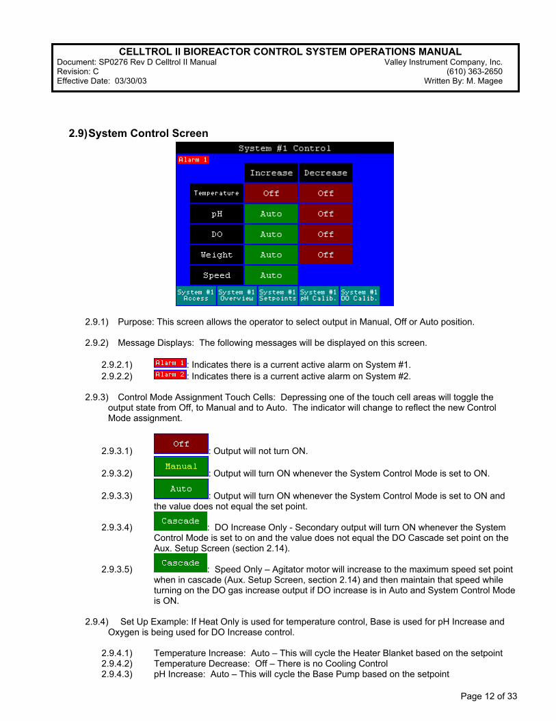
2.9) System Control Screen
2.9.1) Purpose: This screen allows the operator to select output in Manual, Off or Auto position. 2.9.2) Message Displays: The following messages will be displayed on this screen.
2.9.2.1) : Indicates there is a current active alarm on System #1. 2.9.2.2) : Indicates there is a current active alarm on System #2.
2.9.3) Control Mode Assignment Touch Cells: Depressing one of the touch cell areas will toggle the output state from Off, to Manual and to Auto. The indicator will change to reflect the new Control Mode assignment.
2.9.3.1) : Output will not turn ON.
2.9.3.2) : Output will turn ON whenever the System Control Mode is set to ON.
2.9.3.3) : Output will turn ON whenever the System Control Mode is set to ON and the value does not equal the set point.
2.9.3.4) : DO Increase Only - Secondary output will turn ON whenever the System Control Mode is set to on and the value does not equal the DO Cascade set point on the Aux. Setup Screen (section 2.14).
2.9.3.5) : Speed Only – Agitator motor will increase to the maximum speed set point when in cascade (Aux. Setup Screen, section 2.14) and then maintain that speed while turning on the DO gas increase output if DO increase is in Auto and System Control Mode is ON.
2.9.4) Set Up Example: If Heat Only is used for temperature control, Base is used for pH Increase and
Oxygen is being used for DO Increase control.
2.9.4.1) Temperature Increase: Auto – This will cycle the Heater Blanket based on the setpoint 2.9.4.2) Temperature Decrease: Off – There is no Cooling Control 2.9.4.3) pH Increase: Auto – This will cycle the Base Pump based on the setpoint
CELLTROL II BIOREACTOR CONTROL SYSTEM OPERATIONS MANUAL Document: SP0276 Rev D Celltrol II Manual Valley Instrument Company, Inc. Revision: C (610) 363-2650 Effective Date: 03/30/03 Written By: M. Magee
Page 13 of 33
2.9.4.4) pH Decrease: Off – There is no Acid Control 2.9.4.5) DO Increase: Auto – This will cycle the O2 solenoid valve based on the setpoint 2.9.4.6) DO Decrease: Off – There is no Nitrogen Control
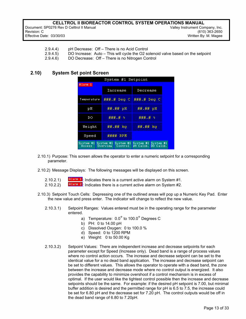
2.10) System Set point Screen
2.10.1) Purpose: This screen allows the operator to enter a numeric setpoint for a corresponding parameter.
2.10.2) Message Displays: The following messages will be displayed on this screen.
2.10.2.1) : Indicates there is a current active alarm on System #1. 2.10.2.2) : Indicates there is a current active alarm on System #2.
2.10.3) Setpoint Touch Cells: Depressing one of the outlined areas will pop up a Numeric Key Pad. Enter the new value and press enter. The indicator will change to reflect the new value.
2.10.3.1) Setpoint Ranges: Values entered must be in the operating range for the parameter
entered. a) Temperature: 0.0° to 100.0° Degrees C b) PH: 0 to 14.00 pH c) Dissolved Oxygen: 0 to 100.0 % d) Speed: 0 to 1200 RPM e) Weight: 0 to 50.00 Kg
2.10.3.2) Setpoint Values: There are independent increase and decrease setpoints for each parameter except for Speed (Increase only). Dead band is a range of process values where no control action occurs. The increase and decrease setpoint can be set to the identical value for a no dead band application. The increase and decrease setpoint can be set to different values. This allows the operator to operate with a dead band, the zone between the increase and decrease mode where no control output is energized. It also provides the capability to minimize overshoot if a control mechanism is in excess of optimal. If the user would like the tightest control possible then the increase and decrease setpoints should be the same. For example: if the desired pH setpoint is 7.00, but minimal buffer addition is desired and the permitted range for pH is 6.5 to 7.5, the increase could be set for 6.80 pH and the decrease set for 7.20 pH. The control outputs would be off in the dead band range of 6.80 to 7.20pH.
CELLTROL II BIOREACTOR CONTROL SYSTEM OPERATIONS MANUAL Document: SP0276 Rev D Celltrol II Manual Valley Instrument Company, Inc. Revision: C (610) 363-2650 Effective Date: 03/30/03 Written By: M. Magee
Page 14 of 33
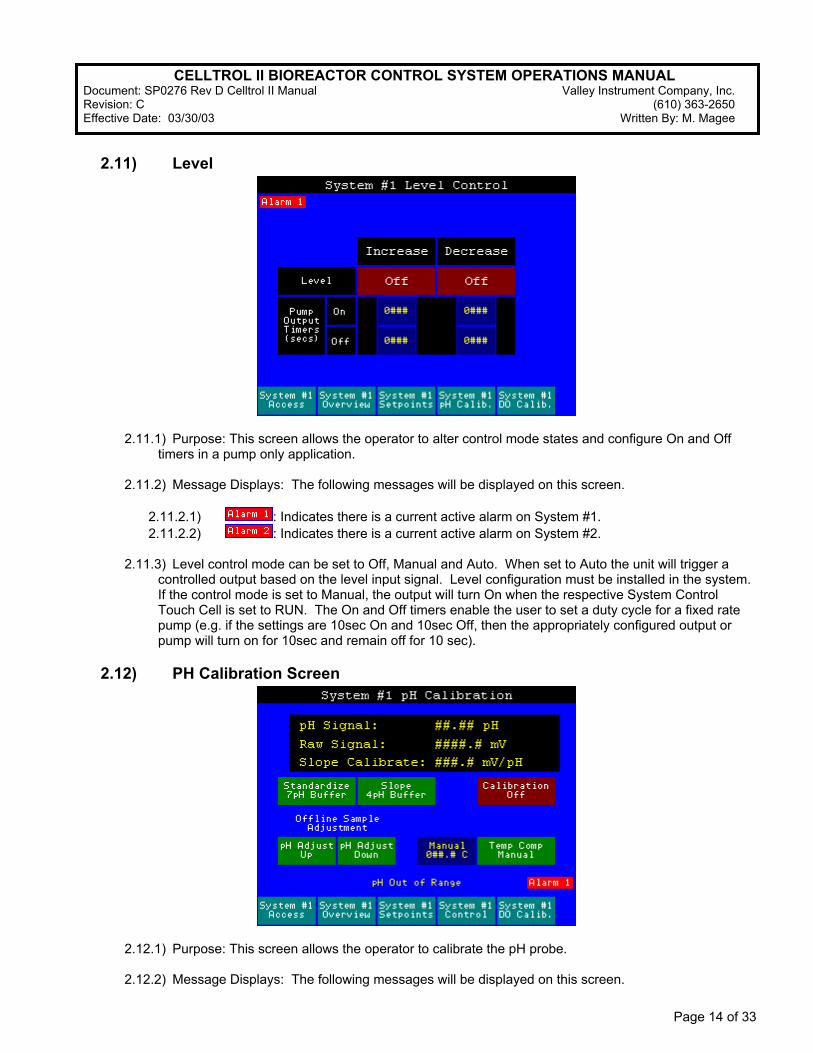
2.11) Level
2.11.1) Purpose: This screen allows the operator to alter control mode states and configure On and Off timers in a pump only application.
2.11.2) Message Displays: The following messages will be displayed on this screen.
2.11.2.1) : Indicates there is a current active alarm on System #1. 2.11.2.2) : Indicates there is a current active alarm on System #2.
2.11.3) Level control mode can be set to Off, Manual and Auto. When set to Auto the unit will trigger a controlled output based on the level input signal. Level configuration must be installed in the system. If the control mode is set to Manual, the output will turn On when the respective System Control Touch Cell is set to RUN. The On and Off timers enable the user to set a duty cycle for a fixed rate pump (e.g. if the settings are 10sec On and 10sec Off, then the appropriately configured output or pump will turn on for 10sec and remain off for 10 sec).
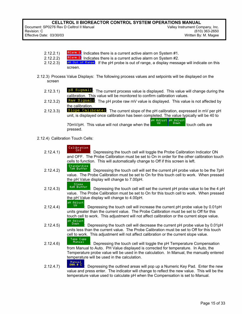
2.12) PH Calibration Screen
2.12.1) Purpose: This screen allows the operator to calibrate the pH probe. 2.12.2) Message Displays: The following messages will be displayed on this screen.
CELLTROL II BIOREACTOR CONTROL SYSTEM OPERATIONS MANUAL Document: SP0276 Rev D Celltrol II Manual Valley Instrument Company, Inc. Revision: C (610) 363-2650 Effective Date: 03/30/03 Written By: M. Magee
Page 15 of 33
2.12.2.1) : Indicates there is a current active alarm on System #1. 2.12.2.2) : Indicates there is a current active alarm on System #2. 2.12.2.3) : If the pH probe is out of range, a display message will indicate on this
screen.
2.12.3) Process Value Displays: The following process values and setpoints will be displayed on the screen
2.12.3.1) : The current process value is displayed. This value will change during the
calibration. This value will be monitored to confirm calibration values. 2.12.3.2) : The pH probe raw mV value is displayed. This value is not affected by
the calibration. 2.12.3.3) : The current slope of the pH calibration, expressed in mV per pH
unit, is displayed once calibration has been completed. The value typically will be 40 to
70mV/pH. This value will not change when the touch cells are pressed.
2.12.4) Calibration Touch Cells:
2.12.4.1) : Depressing the touch cell will toggle the Probe Calibration Indicator ON and OFF. The Probe Calibration must be set to On in order for the other calibration touch cells to function. This will automatically change to Off if this screen is left.
2.12.4.2) : Depressing the touch cell will set the current pH probe value to be the 7pH value. The Probe Calibration must be set to On for this touch cell to work. When pressed the pH Value display will change to 7.00pH.
2.12.4.3) : Depressing the touch cell will set the current pH probe value to be the 4 pH value. The Probe Calibration must be set to On for this touch cell to work. When pressed the pH Value display will change to 4.00pH.
2.12.4.4) : Depressing the touch cell will increase the current pH probe value by 0.01pH units greater than the current value. The Probe Calibration must be set to Off for this touch cell to work. This adjustment will not affect calibration or the current slope value.
2.12.4.5) : Depressing the touch cell will decrease the current pH probe value by 0.01pH units less than the current value. The Probe Calibration must be set to Off for this touch cell to work. This adjustment will not affect calibration or the current slope value.
2.12.4.6) : Depressing the touch cell will toggle the pH Temperature Compensation from Manual to Auto. PH Value displayed is corrected for temperature. In Auto, the Temperature probe value will be used in the calculation. In Manual, the manually entered temperature will be used in the calculation.
2.12.4.7) : Depressing the outlined areas will pop up a Numeric Key Pad. Enter the new value and press enter. The indicator will change to reflect the new value. This will be the temperature value used to calculate pH when the Compensation is set to Manual.
CELLTROL II BIOREACTOR CONTROL SYSTEM OPERATIONS MANUAL Document: SP0276 Rev D Celltrol II Manual Valley Instrument Company, Inc. Revision: C (610) 363-2650 Effective Date: 03/30/03 Written By: M. Magee
Page 16 of 33
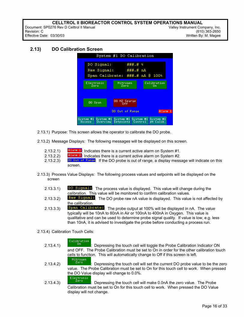
2.13) DO Calibration Screen
2.13.1) Purpose: This screen allows the operator to calibrate the DO probe. 2.13.2) Message Displays: The following messages will be displayed on this screen.
2.13.2.1) : Indicates there is a current active alarm on System #1. 2.13.2.2) : Indicates there is a current active alarm on System #2. 2.13.2.3) : If the DO probe is out of range, a display message will indicate on this
screen.
2.13.3) Process Value Displays: The following process values and setpoints will be displayed on the screen
2.13.3.1) : The process value is displayed. This value will change during the
calibration. This value will be monitored to confirm calibration values. 2.13.3.2) : The DO probe raw nA value is displayed. This value is not affected by
the calibration. 2.13.3.3) : The probe output at 100% will be displayed in nA. The value
typically will be 10nA to 80nA in Air or 100nA to 400nA in Oxygen. This value is qualitative and can be used to determine probe signal quality. If value is low, e.g. less than 10nA, it is advised to investigate the probe before conducting a process run.
2.13.4) Calibration Touch Cells:
2.13.4.1) : Depressing the touch cell will toggle the Probe Calibration Indicator ON and OFF. The Probe Calibration must be set to On in order for the other calibration touch cells to function. This will automatically change to Off if this screen is left.
2.13.4.2) : Depressing the touch cell will set the current DO probe value to be the zero value. The Probe Calibration must be set to On for this touch cell to work. When pressed the DO Value display will change to 0.0%.
2.13.4.3) : Depressing the touch cell will make 0.0nA the zero value. The Probe Calibration must be set to On for this touch cell to work. When pressed the DO Value display will not change.
CELLTROL II BIOREACTOR CONTROL SYSTEM OPERATIONS MANUAL Document: SP0276 Rev D Celltrol II Manual Valley Instrument Company, Inc. Revision: C (610) 363-2650 Effective Date: 03/30/03 Written By: M. Magee
Page 17 of 33
2.13.4.4) : Depressing the touch cell will set the current DO probe value to be the 100% value. The Probe Calibration must be set to On for this touch cell to work. When pressed the DO Value display will change to 100.0%.
2.13.4.5) : Depressing the touch cell will toggle the DO decrease output On/Off. This will allow the Nitrogen solenoid valve to open, if a nitrogen solenoid valve is being used in the system. This will automatically change to Off if this screen is left.
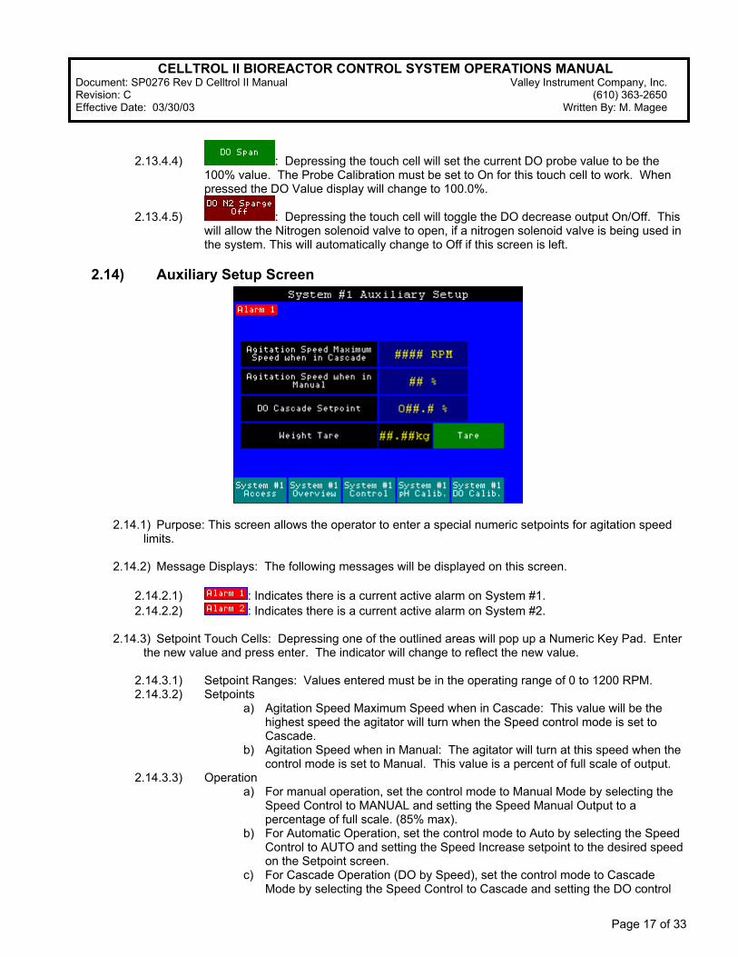
2.14) Auxiliary Setup Screen
2.14.1) Purpose: This screen allows the operator to enter a special numeric setpoints for agitation speed limits.
2.14.2) Message Displays: The following messages will be displayed on this screen.
2.14.2.1) : Indicates there is a current active alarm on System #1. 2.14.2.2) : Indicates there is a current active alarm on System #2.
2.14.3) Setpoint Touch Cells: Depressing one of the outlined areas will pop up a Numeric Key Pad. Enter the new value and press enter. The indicator will change to reflect the new value.
2.14.3.1) Setpoint Ranges: Values entered must be in the operating range of 0 to 1200 RPM. 2.14.3.2) Setpoints
a) Agitation Speed Maximum Speed when in Cascade: This value will be the highest speed the agitator will turn when the Speed control mode is set to Cascade.
b) Agitation Speed when in Manual: The agitator will turn at this speed when the control mode is set to Manual. This value is a percent of full scale of output.
2.14.3.3) Operation a) For manual operation, set the control mode to Manual Mode by selecting the
Speed Control to MANUAL and setting the Speed Manual Output to a percentage of full scale. (85% max).
b) For Automatic Operation, set the control mode to Auto by selecting the Speed Control to AUTO and setting the Speed Increase setpoint to the desired speed on the Setpoint screen.
c) For Cascade Operation (DO by Speed), set the control mode to Cascade Mode by selecting the Speed Control to Cascade and setting the DO control
CELLTROL II BIOREACTOR CONTROL SYSTEM OPERATIONS MANUAL Document: SP0276 Rev D Celltrol II Manual Valley Instrument Company, Inc. Revision: C (610) 363-2650 Effective Date: 03/30/03 Written By: M. Magee
Page 18 of 33
mode to Auto. The DO Increase set point also needs to be set to the desired value. The Speed setpoint will be a minimum of the current Speed set point and as the DO process value drops below the increase set point the agitation will increase to a maximum value of the Agitation Speed maximum when in Cascade setting.
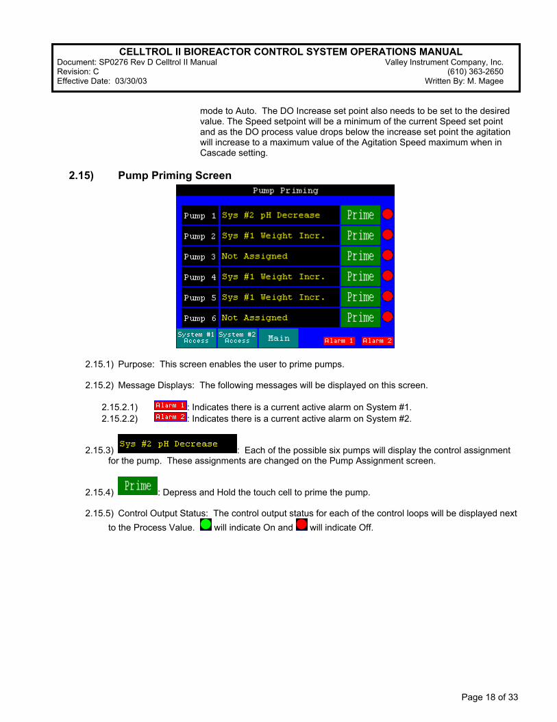
2.15) Pump Priming Screen
2.15.1) Purpose: This screen enables the user to prime pumps. 2.15.2) Message Displays: The following messages will be displayed on this screen.
2.15.2.1) : Indicates there is a current active alarm on System #1. 2.15.2.2) : Indicates there is a current active alarm on System #2.
2.15.3) : Each of the possible six pumps will display the control assignment for the pump. These assignments are changed on the Pump Assignment screen.
2.15.4) : Depress and Hold the touch cell to prime the pump.
2.15.5) Control Output Status: The control output status for each of the control loops will be displayed next to the Process Value. will indicate On and will indicate Off.
CELLTROL II BIOREACTOR CONTROL SYSTEM OPERATIONS MANUAL Document: SP0276 Rev D Celltrol II Manual Valley Instrument Company, Inc. Revision: C (610) 363-2650 Effective Date: 03/30/03 Written By: M. Magee
Page 19 of 33
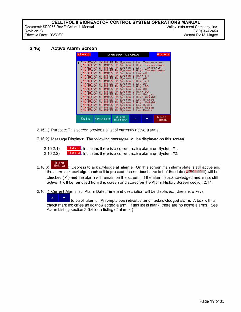
2.16) Active Alarm Screen
2.16.1) Purpose: This screen provides a list of currently active alarms. 2.16.2) Message Displays: The following messages will be displayed on this screen.
2.16.2.1) : Indicates there is a current active alarm on System #1. 2.16.2.2) : Indicates there is a current active alarm on System #2.
2.16.3) : Depress to acknowledge all alarms. On this screen if an alarm state is still active and the alarm acknowledge touch cell is pressed, the red box to the left of the date ( ) will be checked ( ) and the alarm will remain on the screen. If the alarm is acknowledged and is not still active, it will be removed from this screen and stored on the Alarm History Screen section 2.17.
2.16.4) Current Alarm list: Alarm Date, Time and description will be displayed. Use arrow keys
to scroll alarms. An empty box indicates an un-acknowledged alarm. A box with a check mark indicates an acknowledged alarm. If this list is blank, there are no active alarms. (See Alarm Listing section 3.6.4 for a listing of alarms.)
CELLTROL II BIOREACTOR CONTROL SYSTEM OPERATIONS MANUAL Document: SP0276 Rev D Celltrol II Manual Valley Instrument Company, Inc. Revision: C (610) 363-2650 Effective Date: 03/30/03 Written By: M. Magee
Page 20 of 33
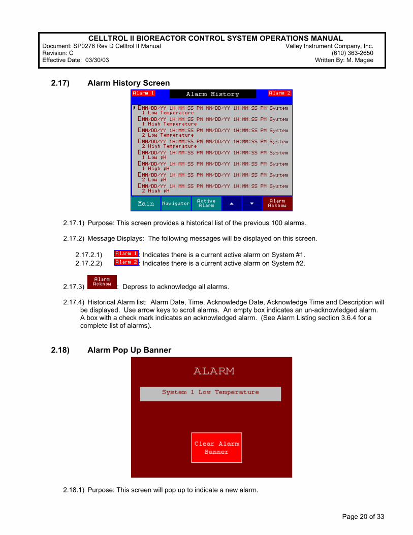
2.17) Alarm History Screen
2.17.1) Purpose: This screen provides a historical list of the previous 100 alarms. 2.17.2) Message Displays: The following messages will be displayed on this screen.
2.17.2.1) : Indicates there is a current active alarm on System #1. 2.17.2.2) : Indicates there is a current active alarm on System #2.
2.17.3) : Depress to acknowledge all alarms.
2.17.4) Historical Alarm list: Alarm Date, Time, Acknowledge Date, Acknowledge Time and Description will be displayed. Use arrow keys to scroll alarms. An empty box indicates an un-acknowledged alarm. A box with a check mark indicates an acknowledged alarm. (See Alarm Listing section 3.6.4 for a complete list of alarms).
2.18) Alarm Pop Up Banner
2.18.1) Purpose: This screen will pop up to indicate a new alarm.

CELLTROL II BIOREACTOR CONTROL SYSTEM OPERATIONS MANUAL Document: SP0276 Rev D Celltrol II Manual Valley Instrument Company, Inc. Revision: C (610) 363-2650 Effective Date: 03/30/03 Written By: M. Magee
Page 21 of 33
2.18.2) Alarm Display: Alarm description will be displayed. (See Alarm Listing section 3.6.4 for a listing of alarms.)
2.18.3) Clear Alarm Banner Touch Cell: Depress to Clear alarm banner. This will not acknowledge alarm.
In order to acknowledge the alarm see Active Alarm Screen section 2.16.
2.19) Supervisor Screen
2.19.1) Purpose: This screen will allow access to supervisor level screens. The user will need to enter a
supervisor password to navigate to this screen (refer to System Security and Login section 3.4). The factory default Supervisor password is 1234. User 1 through User 15 default passwords are the respective number designating the particular user (i.e. User 1’s password is factory set to “1”).
2.20) Security Screen
2.20.1) Purpose: This screen provides the ability to enable and disable security and to modify passwords. 2.20.2) Message Displays: The following messages will be displayed on this screen.
2.20.2.1) : Indicates there is a current active alarm on System #1. 2.20.2.2) : Indicates there is a current active alarm on System #2.
CELLTROL II BIOREACTOR CONTROL SYSTEM OPERATIONS MANUAL Document: SP0276 Rev D Celltrol II Manual Valley Instrument Company, Inc. Revision: C (610) 363-2650 Effective Date: 03/30/03 Written By: M. Magee
Page 22 of 33
2.20.3) Password Modification: Select operator password to modify by depressing the select operator
touch cell until the appropriate operator is displayed. Press new password touch cell. A pop up keypad will appear enabling the entry of a new password. Enter new password and press enter. Verify the password by then depressing the verify password touch cell, re-entering the password and pressing enter. The password for the selected operator has now been changed. Password can be 1 to 12 Numeric digits. Note: at no time will the password be displayed. Only operators with the Supervisor password can change any of the passwords.
2.20.4) Security Enable/Disable: Depress the Security Enable/Disable Touch Cell to turn the screen
security On and Off. If the CellTrol II is powered down the HMI defaults to Security Enable on power up.
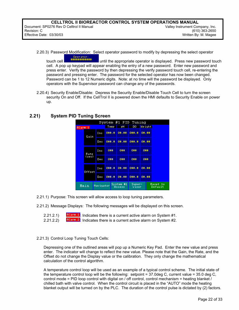
2.21) System PID Tuning Screen
2.21.1) Purpose: This screen will allow access to loop tuning parameters. 2.21.2) Message Displays: The following messages will be displayed on this screen.
2.21.2.1) : Indicates there is a current active alarm on System #1. 2.21.2.2) : Indicates there is a current active alarm on System #2.
2.21.3) Control Loop Tuning Touch Cells:
Depressing one of the outlined areas will pop up a Numeric Key Pad. Enter the new value and press enter. The indicator will change to reflect the new value. Please note that the Gain, the Rate, and the Offset do not change the Display value or the calibration. They only change the mathematical calculation of the control algorithm. A temperature control loop will be used as an example of a typical control scheme. The initial state of the temperature control loop will be the following: setpoint = 37.0deg C, current value = 35.0 deg C, control mode = PID loop control with digital on / off control, control mechanism = heating blanket / chilled bath with valve control. When the control circuit is placed in the “AUTO” mode the heating blanket output will be turned on by the PLC. The duration of the control pulse is dictated by (2) factors.
CELLTROL II BIOREACTOR CONTROL SYSTEM OPERATIONS MANUAL Document: SP0276 Rev D Celltrol II Manual Valley Instrument Company, Inc. Revision: C (610) 363-2650 Effective Date: 03/30/03 Written By: M. Magee
Page 23 of 33
First the gain controls the proportion of ON time versus OFF time of the pulse relevant to the deviation of the current value to the setpoint. Second the rate allows for an increased duty cycle without affecting the ratio between the ON time and OFF time. As the temperature begins to increase and approach the setpoint the ON time or heat output will begin to decrease with time whereas the OFF time will increase with time.
2.21.4) Control Loop Parameters
2.21.4.1) Gain The gain setting is entered in units for the control loop being modified. PH Gain is pH units, Temperature values are Degrees C, and Dissolved Oxygen Values are in %. The outputs will be pulse width modulated. The output will pulse ON for a percentage of time, depending on how far the value is from the setpoint. If the deviation is great enough, the output will be ON 100% of the time. This value is the Gain. For example, if the temperature setpoint is 37.0 Degrees C and the Gain is 3.0 Degrees C; when the value is less than 34.0 Degrees C (37.0 – 3.0 = 34.0) the increase output will be ON. When the value is between 34.0 and 37.0, the increase output will be turning ON and OFF, staying ON for less time the closer the value gets to the setpoint. When the value reaches or exceeds the setpoint, the increase output will be OFF. For ON/OFF control, with no modulation, set the gain to zero. The increase output will now be ON when the value is less than the setpoint and OFF when the value is equal to or greater than the setpoint. 2.21.4.2) Rate The rate setting is entered in seconds. If the Gain is greater than or equal to zero, the outputs will be pulse width modulated. The output will pulse ON for a percentage of time; depending on how far off the value is from the setpoint. For example, if the temperature setpoint is 37.0 Degrees C, the Gain is 3.0 Degrees and the Rate is 20 Seconds; when the value is less than 34.0 Degrees C (37.0 – 3.0 = 34.0) the increase output will be ON. When the value is 35.5 Degrees C, which is at 50% of the gain, the increase output will be ON for 10 seconds and OFF for 10 seconds. When the value is 36.25 Degrees C, which is at 25% of the gain, the increase output will be ON for 5 seconds and OFF for 15 seconds. 2.21.4.3) Offset The offset setting is entered in units for the control loop being modified. PH Gain is pH units, Temperature values are Degrees C, and Dissolved Oxygen Values are in %. Once the system has been under control for a time, the value may settle slightly above or below the setpoint value. The offset is used to make minor corrections. For example: once the temperature control has been running a time and has reached steady state, if the setpoint is 37.0 and the value has settled in at 36.8, enter 0.2 for the temperature Increase Offset. After stabilizing, the process value should rise to 37.0. If the set point is 37.0 and the value has settled in at 37.2, enter (-) 0.2 for the temperature Increase Offset. After stabilizing, the process value should drop to 37.0.
CELLTROL II BIOREACTOR CONTROL SYSTEM OPERATIONS MANUAL Document: SP0276 Rev D Celltrol II Manual Valley Instrument Company, Inc. Revision: C (610) 363-2650 Effective Date: 03/30/03 Written By: M. Magee
Page 24 of 33
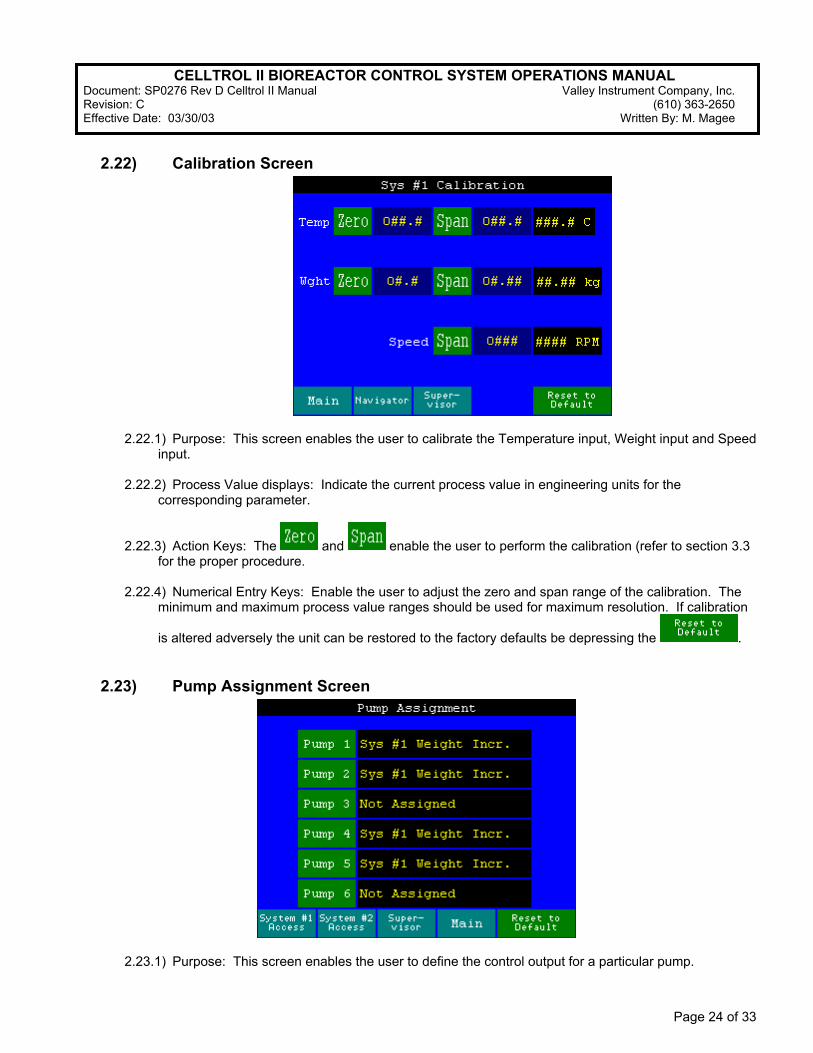
2.22) Calibration Screen
2.22.1) Purpose: This screen enables the user to calibrate the Temperature input, Weight input and Speed input.
2.22.2) Process Value displays: Indicate the current process value in engineering units for the
corresponding parameter.
2.22.3) Action Keys: The and enable the user to perform the calibration (refer to section 3.3 for the proper procedure.
2.22.4) Numerical Entry Keys: Enable the user to adjust the zero and span range of the calibration. The
minimum and maximum process value ranges should be used for maximum resolution. If calibration
is altered adversely the unit can be restored to the factory defaults be depressing the .
2.23) Pump Assignment Screen
2.23.1) Purpose: This screen enables the user to define the control output for a particular pump.
CELLTROL II BIOREACTOR CONTROL SYSTEM OPERATIONS MANUAL Document: SP0276 Rev D Celltrol II Manual Valley Instrument Company, Inc. Revision: C (610) 363-2650 Effective Date: 03/30/03 Written By: M. Magee
Page 25 of 33
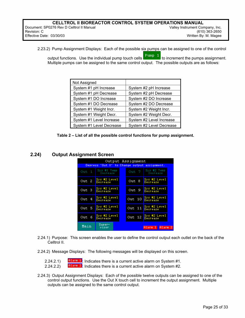
2.23.2) Pump Assignment Displays: Each of the possible six pumps can be assigned to one of the control
output functions. Use the individual pump touch cells to increment the pumps assignment. Multiple pumps can be assigned to the same control output. The possible outputs are as follows:
Not Assigned System #1 pH Increase System #2 pH Increase
System #1 pH Decrease System #2 pH Decrease
System #1 DO Increase System #2 DO Increase
System #1 DO Decrease System #2 DO Decrease
System #1 Weight Incr. System #2 Weight Incr. System #1 Weight Decr. System #2 Weight Decr. System #1 Level Increase System #2 Level Increase
System #1 Level Decrease System #2 Level Decrease
Table 2 – List of all the possible control functions for pump assignment.
2.24) Output Assignment Screen
2.24.1) Purpose: This screen enables the user to define the control output each outlet on the back of the Celltrol II.
2.24.2) Message Displays: The following messages will be displayed on this screen.
2.24.2.1) : Indicates there is a current active alarm on System #1. 2.24.2.2) : Indicates there is a current active alarm on System #2.
2.24.3) Output Assignment Displays: Each of the possible twelve outputs can be assigned to one of the
control output functions. Use the Out X touch cell to increment the output assignment. Multiple outputs can be assigned to the same control output.
CELLTROL II BIOREACTOR CONTROL SYSTEM OPERATIONS MANUAL Document: SP0276 Rev D Celltrol II Manual Valley Instrument Company, Inc. Revision: C (610) 363-2650 Effective Date: 03/30/03 Written By: M. Magee
Page 26 of 33
Not Assigned System #1 Temperature Decrease System #2 Temperature Decrease
System #1 pH Increase System #2 pH Increase
System #1 pH Decrease System #2 pH Decrease
System #1 DO Increase System #2 DO Increase
System #1 DO Decrease System #2 DO Decrease
System #1 DO Cascade System #2 DO Cascade
System #1 Weight Incr. System #2 Weight Incr. System #1 Weight Decr. System #2 Weight Decr. System #1 Level Increase System #2 Level Increase
System #1 Level Decrease System #2 Level Decrease
Table 3 – List of all the possible control functions for output assignment.
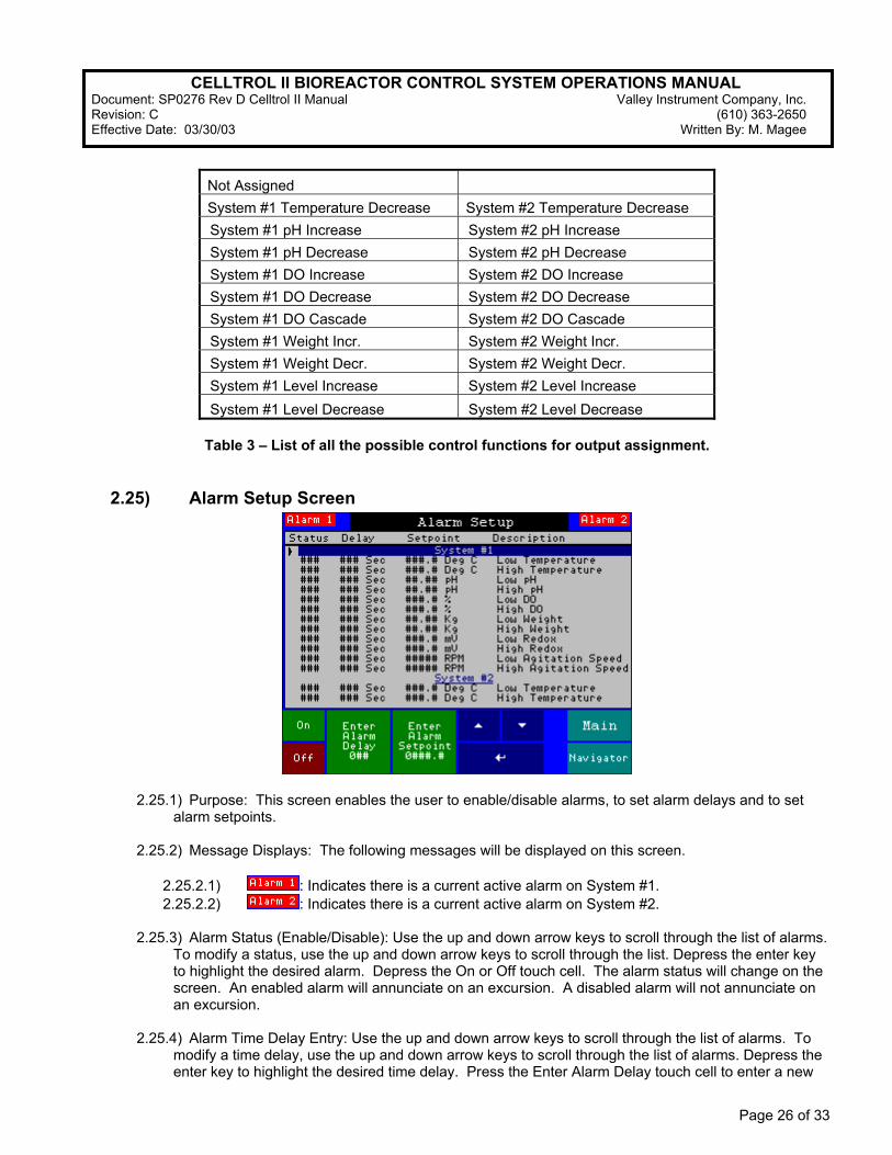
2.25) Alarm Setup Screen
2.25.1) Purpose: This screen enables the user to enable/disable alarms, to set alarm delays and to set alarm setpoints.
2.25.2) Message Displays: The following messages will be displayed on this screen.
2.25.2.1) : Indicates there is a current active alarm on System #1. 2.25.2.2) : Indicates there is a current active alarm on System #2.
2.25.3) Alarm Status (Enable/Disable): Use the up and down arrow keys to scroll through the list of alarms. To modify a status, use the up and down arrow keys to scroll through the list. Depress the enter key to highlight the desired alarm. Depress the On or Off touch cell. The alarm status will change on the screen. An enabled alarm will annunciate on an excursion. A disabled alarm will not annunciate on an excursion.
2.25.4) Alarm Time Delay Entry: Use the up and down arrow keys to scroll through the list of alarms. To
modify a time delay, use the up and down arrow keys to scroll through the list of alarms. Depress the enter key to highlight the desired time delay. Press the Enter Alarm Delay touch cell to enter a new
CELLTROL II BIOREACTOR CONTROL SYSTEM OPERATIONS MANUAL Document: SP0276 Rev D Celltrol II Manual Valley Instrument Company, Inc. Revision: C (610) 363-2650 Effective Date: 03/30/03 Written By: M. Magee
Page 27 of 33
value. A pop up keypad will appear. Enter a new value and depress enter. The new time delay will appear on the screen. The range is 0 to 999 seconds.
2.25.5) Alarm Setpoint Entry: Use the up and down arrow keys to scroll through the list of setpoints. To
modify a setpoint, use the up and down arrow keys to scroll through the list of setpoints. Depress the enter key to highlight the desired set point. A pop up keypad will appear. Enter a new setpoint and depress enter. The new setpoint will appear on the screen. If the value is out of range, the High or low range of the setpoint will be entered, depending if the value entered was too high or too low.
2.26) OIT Configuration
2.26.1) Purpose: This screen provides configuration access to the operator interface. The time and date used for the alarm display can be adjusted in the configuration. Consult the factory for additional information. If this screen is accessed press RUN to return to CellTrol II interface screens.
3) Operation
3.1) Setup
3.1.1) Connect CellTrol II to 115 VAC receptacle and switch main power switch located on the front of unit to the ON (I) position.
3.1.2) Navigate to the System #1 and System #2 overview screens and ensure the System Control Touch Cell (section 2.8.3) is in the STOP state.
3.1.3) Connect all appropriate probe and / or motor cables to the respective input connections on the back of the unit. All connectors are clearly labeled with the appropriate function and system designation.
3.1.4) Connect all control devices* (i.e. cooling valves, gas addition valves, tubing to pumps, etc.) to the respective IEC outlets on back of unit and pumps on the front. It may be necessary to refer to the Pump Assignment Screen Section 2.23 and the Output Configuration Screen section 2.24 to set desired control functionality to the outlets and pumps and confirm outlet designation.
3.1.5) Allow the unit to warm up for a minimum of an hour before operation or probe calibration. *Do not plug heater blanket in until confirming the System Control Touch Cell (section 2.8.3) is in the STOP state. It is necessary that the heating blanket only be connected to the “600 W” labeled outlets. Due to the increased current load by the heating blankets, the system may be damaged if not connected to these outlets.
3.2) Configuration 3.2.1) Go to the System Overview screen and insure System Control Touch Cell is in the STOP state
(section 2.8.3). 3.2.2) Go to the System Control Mode screen (section 2.9) and set the control state required for the
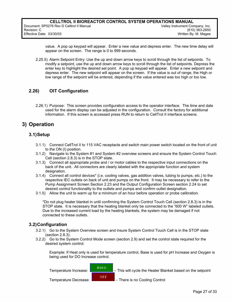
desired system control. Example: If Heat only is used for temperature control, Base is used for pH Increase and Oxygen is being used for DO Increase control.
Temperature Increase: – This will cycle the Heater Blanket based on the setpoint
Temperature Decrease: – There is no Cooling Control
CELLTROL II BIOREACTOR CONTROL SYSTEM OPERATIONS MANUAL Document: SP0276 Rev D Celltrol II Manual Valley Instrument Company, Inc. Revision: C (610) 363-2650 Effective Date: 03/30/03 Written By: M. Magee
Page 28 of 33
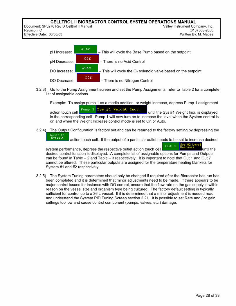
pH Increase: – This will cycle the Base Pump based on the setpoint
pH Decrease: – There is no Acid Control
DO Increase: – This will cycle the O2 solenoid valve based on the setpoint
DO Decrease: – There is no Nitrogen Control
3.2.3) Go to the Pump Assignment screen and set the Pump Assignments, refer to Table 2 for a complete list of assignable options.
Example: To assign pump 1 as a media addition, or weight increase, depress Pump 1 assignment
action touch cell until the Sys #1 Weight Incr. is displayed in the corresponding cell. Pump 1 will now turn on to increase the level when the System control is on and when the Weight Increase control mode is set to On or Auto.
3.2.4) The Output Configuration is factory set and can be returned to the factory setting by depressing the
action touch cell. If the output of a particular outlet needs to be set to increase desired
system performance, depress the respective outlet action touch cell until the desired control function is displayed. A complete list of assignable options for Pumps and Outputs can be found in Table – 2 and Table – 3 respectively. It is important to note that Out 1 and Out 7 cannot be altered. These particular outputs are assigned for the temperature heating blankets for System #1 and #2 respectively.
3.2.5) The System Tuning parameters should only be changed if required after the Bioreactor has run has
been completed and it is determined that minor adjustments need to be made. If there appears to be major control issues for instance with DO control, ensure that the flow rate on the gas supply is within reason on the vessel size and organism type being cultured. The factory default setting is typically sufficient for control up to a 36 L vessel. If it is determined that a minor adjustment is needed read and understand the System PID Tuning Screen section 2.21. It is possible to set Rate and / or gain settings too low and cause control component (pumps, valves, etc.) damage.
CELLTROL II BIOREACTOR CONTROL SYSTEM OPERATIONS MANUAL Document: SP0276 Rev D Celltrol II Manual Valley Instrument Company, Inc. Revision: C (610) 363-2650 Effective Date: 03/30/03 Written By: M. Magee
Page 29 of 33
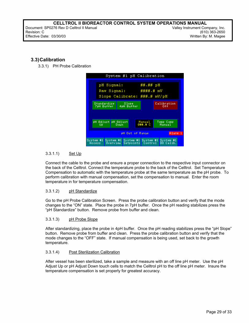
3.3) Calibration 3.3.1) PH Probe Calibration
3.3.1.1) Set Up Connect the cable to the probe and ensure a proper connection to the respective input connector on the back of the Celltrol. Connect the temperature probe to the back of the Celltrol. Set Temperature Compensation to automatic with the temperature probe at the same temperature as the pH probe. To perform calibration with manual compensation, set the compensation to manual. Enter the room temperature in for temperature compensation. 3.3.1.2) pH Standardize
Go to the pH Probe Calibration Screen. Press the probe calibration button and verify that the mode changes to the “ON” state. Place the probe in 7pH buffer. Once the pH reading stabilizes press the “pH Standardize” button. Remove probe from buffer and clean. 3.3.1.3) pH Probe Slope After standardizing, place the probe in 4pH buffer. Once the pH reading stabilizes press the “pH Slope” button. Remove probe from buffer and clean. Press the probe calibration button and verify that the mode changes to the “OFF” state. If manual compensation is being used, set back to the growth temperature. 3.3.1.4) Post Sterilization Calibration
After vessel has been sterilized, take a sample and measure with an off line pH meter. Use the pH Adjust Up or pH Adjust Down touch cells to match the Celltrol pH to the off line pH meter. Insure the temperature compensation is set properly for greatest accuracy.

CELLTROL II BIOREACTOR CONTROL SYSTEM OPERATIONS MANUAL Document: SP0276 Rev D Celltrol II Manual Valley Instrument Company, Inc. Revision: C (610) 363-2650 Effective Date: 03/30/03 Written By: M. Magee
Page 30 of 33
3.3.2) DO Probe Calibration
3.3.2.1) Set Up When calibrating a dissolved oxygen (DO) probe it is important to realize that the value (percentage in engineering units) displayed is relative to the calibration method. This means that the value displayed is not the absolute pO2% but a meaningful percentage that can be implemented to a cell culture process. In order to achieve a true pO2% reading the unit would need to be calibrated with oxygen. Given that the relative composition of oxygen in air is approximately 18% – 22%, the reading after calibration and the beginning of the run would be approximately 20%. The recommended procedure would be to span the DO probe to 100% at the beginning of the process after temperature, speed and airflow have been set. This provides a true process starting value and greater resolution (5X) of the parameter value. Connect the cable to the probe and ensure a proper connection to the respective input connector on the back of the Celltrol. Probe manufacturers have a recommended time for probe polarization. It is recommended for the Celltrol to be allowed to equilibrate for a minimum of (1) hour before calibration is attempted. 3.3.2.2) DO Probe Zero
A Nitrogen Probe Zero or an Electronic Probe Zero must be performed. Go to the DO Probe Calibration Screen. Nitrogen Zero: At this point the vessel should be sterilized and contain the growth medium. If nitrogen is being used to zero the probe ensure that nitrogen control valve is connected to proper output of the Celltrol. Press the nitrogen sparge button and verify that gas is sparging into the reactor. Press the probe calibration button and verify that the mode changes to the “ON” state. It may take a few hours for the value to equilibrate. Once the DO reading stabilizes press the “N2 Zero” button. Next press the “N2 Sparge” button to stop nitrogen flow. Then allow the reactor to equilibrate to the initial set of growth parameters; referring to the use of an overlay gas(ses) and / or sparge gas(ses) and respective flow rates. Electronic Zero: Press the probe calibration button and verify that the mode changes to the “ON” state. Press the “Electronic Zero” button. 3.3.2.3) DO Probe Span
CELLTROL II BIOREACTOR CONTROL SYSTEM OPERATIONS MANUAL Document: SP0276 Rev D Celltrol II Manual Valley Instrument Company, Inc. Revision: C (610) 363-2650 Effective Date: 03/30/03 Written By: M. Magee
Page 31 of 33
After zeroing, set the vessel up to normal growth parameters. The agitation, gas sparge, headspace sparge and temperature should be set to and at normal growth conditions. Allow to equilibrate for up to an hour or until the DO reading stabilizes. Once the DO reading stabilizes press the “DO Span” button. Press the probe calibration button and verify that the mode changes to the “OFF” state.
3.3.3) Temperature Probe Calibration Temperature calibration is accomplished from the HMI by navigating to the appropriate system calibration screen. The minimum and maximum values need to be set for best resolution (0.0° C and 100.0° C). If a different value is used for the Span value, it must be greater than the desired operating temperature. Then
with the RTD probe in an ice bath depress the touch cell. The process value should match the corresponding value in the numerical entry cell. Next with the RTD probe in a boiling water bath verify,
using an external temperature standard, 100.0° C and depress the touch cell. The process value should match the corresponding value in the numerical entry cell. If for any reason the calibration does not
appear to be correct, depress the touch cell and repeat the process. Once the reset is pressed it will reset all temperature, weight and speed values to the factory default 3.3.4) Weight Platform Calibration Weight calibration is accomplished from the HMI by navigating to the appropriate system calibration screen. The minimum and maximum values need to be set for best resolution (0.0 Kg and 30.00 Kg or 50.00Kg depending on weight platform ordered). A different value can be used for the Span value, but a very small value (< 15% of full scale) will affect accuracy and resolution. Once the scale based is
connected, without weight on the platform depress the touch cell. The process value should match the corresponding value in the numerical entry cell. Next with a calibration standard of the correct value
depress the touch cell. The process value should match the corresponding value in the numerical
entry cell. If for any reason the calibration does not appear to be correct, depress the touch cell and repeat the process. Once the reset is pressed it will reset all temperature, weight and speed values to the factory default. 3.3.5) Speed Calibration Speed calibration is accomplished from the HMI by navigating to the appropriate system calibration screen. The minimum and maximum values need to be set for best resolution (0.0 RPM and the maximum RPM output of the motor installed). A different value can be used for the Span value, but a value greater than the maximum operation speed is needed for proper control, accuracy and resolution. Once the motor is
connected and the motor is not turning depress the touch cell. The process value should match the corresponding value in the numerical entry cell. Next with the motor running at maximum speed setting
depress the touch cell. The process value should match the value in the numerical entry cell. When using the Maxon motor it is necessary to use the Manual output of 85% and a calibrated handheld tachometer to determine the span value. If for any reason the calibration does not appear to be correct,
depress the touch cell and repeat the process. Once the reset is pressed it will reset all temperature, weight and speed values to the factory default.
CELLTROL II BIOREACTOR CONTROL SYSTEM OPERATIONS MANUAL Document: SP0276 Rev D Celltrol II Manual Valley Instrument Company, Inc. Revision: C (610) 363-2650 Effective Date: 03/30/03 Written By: M. Magee
Page 32 of 33
3.4) System Security and Login
3.4.1) System Login An Operator will need to login onto the CellTrol II system in order to access any of the screens listed as secured as found in Table – 1. A pop up numerical key pad will enable the user to enter a numeric password. The CellTrol II has (16) independent operator logins. The first (15) are User 1 though User 15. A User entered password will only gain access to “Operator” secured screen as listed in Table – 1. The last login is the Supervisor. The Supervisor is able to access any screen in the system as well as alter passwords and disable / enable system security. If the Supervisor password is changed and forgotten, the PLC processor will have to be sent back to the factory for reactivation. It is of extreme importance to remember the supervisor password if changed.
The default Supervisor Password is 1234.
3.4.2) Password Entry and Modification Navigate to the Security Screen and when prompted to enter a password, enter the Supervisor Password 1234. In order to change a users’ password, the operator (with Supervisor access) will need to select the
appropriate User by depressing the touch cell until the desired user number is displayed. Depress the new password touch cell and enter the new numerical value in the pop up number pad. This password can be 1 to 12 digits in length. It will be necessary to verify the new password. This is accomplished by depressing the verify password touch cell and re-entering the new password chosen. A “Password Changed” message display will follow a successful sequence.
3.5) Running a Process 3.5.1) Go to the System Overview screen and set the system control to On. The system will be monitored
from this screen. 3.5.2) If after running for several hours, the process values do not match the setpoints to the desired
tolerance, the System Tuning Parameters may need to be adjusted. Do not attempt adjustment unless you are familiar with the Celltrol II. Refer to section 2.21 for more clarification.
3.5.3) Upon completion of the run, set the system control to Off.
3.6) Alarms
3.6.1) Alarm Overview
If alarm monitoring is desired the CellTrol II has the capability of local alarm logging. The controller can also interface to a facility system via supplied dry contacts. There are (2) independent dry contacts: one for System #1 and the other for System #2. These contact closures will trigger corresponding to the and displays. Consult the factory for connection to a building automated system (BAS).
3.6.2) Alarm Setup
First navigate to the Alarm Setup Screen. It will be necessary to enter the Supervisor level password to access this screen. Determine the parameters that will be alarmed and the settings. Select the parameter by depressing the up or down arrow keys. A cursor on the left hand side of the screen will index through the parameters. Once the cursor is next to the parameter of interest depress the enter touch cell to select. Once completed the state (ON of OFF) can be changed, the delay set or the alarm set point adjusted. The
CELLTROL II BIOREACTOR CONTROL SYSTEM OPERATIONS MANUAL Document: SP0276 Rev D Celltrol II Manual Valley Instrument Company, Inc. Revision: C (610) 363-2650 Effective Date: 03/30/03 Written By: M. Magee
Page 33 of 33
delay, in seconds, is a setting that the alarm condition must exceed before the alarm is triggered. The alarms will only be active once the System Control Touch Cell is in the RUN state.
3.6.3) Alarm Operation
All alarms have associated time delays. The bioreactor System Control Touch Cell associated with the alarm must be in the Run state. When an alarm condition exists for a period of time greater than the time delay setting for that alarm, the alarm will be activated. Once activated, the alarm banner will remain on the HMI until the Clear Alarm Banner is pressed. Once activated, the alarm output to the BAS system will remain on until the alarm condition no longer exists and has been acknowledged. All alarms will be logged in the alarm history of the Panel View operator interface. A maximum of 100 alarms will be stored. Alarms are stored in a First In, First Out manner. The active alarm screen will allow the operator to see which alarms are active.
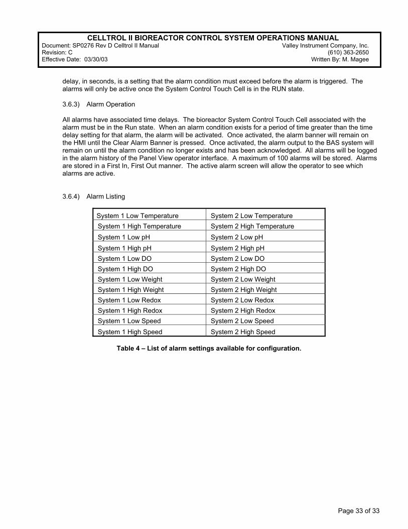
3.6.4) Alarm Listing
System 1 Low Temperature System 2 Low Temperature
System 1 High Temperature System 2 High Temperature
System 1 Low pH System 2 Low pH
System 1 High pH System 2 High pH
System 1 Low DO System 2 Low DO
System 1 High DO System 2 High DO
System 1 Low Weight System 2 Low Weight System 1 High Weight System 2 High Weight System 1 Low Redox System 2 Low Redox
System 1 High Redox System 2 High Redox
System 1 Low Speed System 2 Low Speed
System 1 High Speed System 2 High Speed
Table 4 – List of alarm settings available for configuration.