SP-eYe project - dror-aero.com load 3,945 lb 221 kts ... based on RF links between the vehicle and...
11
Team members Dumchin Andrey Lipchinsky Catherine Magrisso Leo Rubinfeld Matan Rashkovsky Sasha Vladimisrky Dmitry SP-eYe project: (Special Purpose Eye) UAV launched from the surveillance aircraft KingAir B200 Supervisor: Dror Artzi
Transcript of SP-eYe project - dror-aero.com load 3,945 lb 221 kts ... based on RF links between the vehicle and...

Team members
Dumchin Andrey
Lipchinsky Catherine
Magrisso Leo
Rubinfeld Matan
Rashkovsky Sasha
Vladimisrky Dmitry
SP-eYe project: ((SSpecial PPurpose EEye)
UAV launched from the surveillance aircraft KingAir B200
Supervisor: Dror Artzi
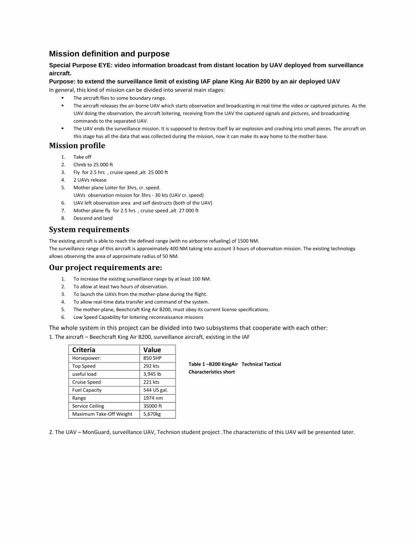
Mission definition and purpose
Special Purpose EYE: video information broadcast from distant location by UAV deployed from surveillance
aircraft.
Purpose: to extend the surveillance limit of existing IAF plane King Air B200 by an air deployed UAV
In general, this kind of mission can be divided into several main stages:
The aircraft flies to some boundary range.
The aircraft releases the air-borne UAV which starts observation and broadcasting in real time the video or captured pictures. As the
UAV doing the observation, the aircraft loitering, receiving from the UAV the captured signals and pictures, and broadcasting
commands to the separated UAV.
The UAV ends the surveillance mission. It is supposed to destroy itself by air explosion and crashing into small pieces. The aircraft on
this stage has all the data that was collected during the mission, now it can make its way home to the mother base.
Mission profile
1. Take off
2. Climb to 25 000 ft
3. Fly for 2.5 hrs , cruise speed ,alt 25 000 ft
4. 2 UAVs release
5. Mother plane Loiter for 3hrs, cr. speed.
UAVs observation mission for 3hrs - 30 kts (UAV cr. speed)
6. UAV left observation area and self destructs (both of the UAV)
7. Mother plane fly for 2.5 hrs , cruise speed ,alt 27 000 ft
8. Descend and land
System requirements
The existing aircraft is able to reach the defined range (with no airborne refueling) of 1500 NM.
The surveillance range of this aircraft is approximately 400 NM taking into account 3 hours of observation mission. The existing technology
allows observing the area of approximate radius of 50 NM.
Our project requirements are:
1. To increase the existing surveillance range by at least 100 NM.
2. To allow at least two hours of observation.
3. To launch the UAVs from the mother-plane during the flight.
4. To allow real-time data transfer and command of the system.
5. The mother-plane, Beechcraft King Air B200, must obey its current license specifications.
6. Low Speed Capability for loitering reconnaissance missions
The whole system in this project can be divided into two subsystems that cooperate with each other:
1. The aircraft – Beechcraft King Air B200, surveillance aircraft, existing in the IAF
2. The UAV – MonGuard, surveillance UAV, Technion student project .The characteristic of this UAV will be presented later.
Table 1 –B200 KingAir Technical Tactical
Characteristics short
Criteria Value Horsepower: 850 SHP
Top Speed 292 kts
useful load 3,945 lb
Cruise Speed 221 kts
Fuel Capacity 544 US gal.
Range 1974 nm
Service Ceiling 35000 ft
Maximum Take-Off Weight 5,670kg
UAV returning ability consideration One of the central considerations in the defined mission is whether the chosen UAV will be returnable or not. Whatever concept is chosen, it
must be maximally cost-efficient and, from the other side, it must fulfill as much as possible the system tactical requirements.
To get the optimal solution different criteria that are important for the defined mission were considered:
Fuel weight percentage
Landing equipment and related issues
Aerodynamics
Structure
Overall cost
Each of these criteria has its own benefits in both of concepts, but the overall review shown that the non-returnable concept is preferable for
current mission.
Transporting ways trade-offs
Considering, the transported UAV functions as a payload for the mother plane, it was decided to make a survey of existing planes designed for
transporting different payloads outside their cabin. Some of the considered layout configurations that were checked:
Upper position of load
Position on the wing’s pylon
Position inside the fuselage
Load in 'gondola' beneath the body Considering all the benefits and main issues of each of the named configurations, the less complicated configuration was needed; also the aim was to find the configuration that can be relatively easy fastened to the aircraft and low logistic support needed.
To meet all these requirements, it was decided to choose the 'gondola' solution.
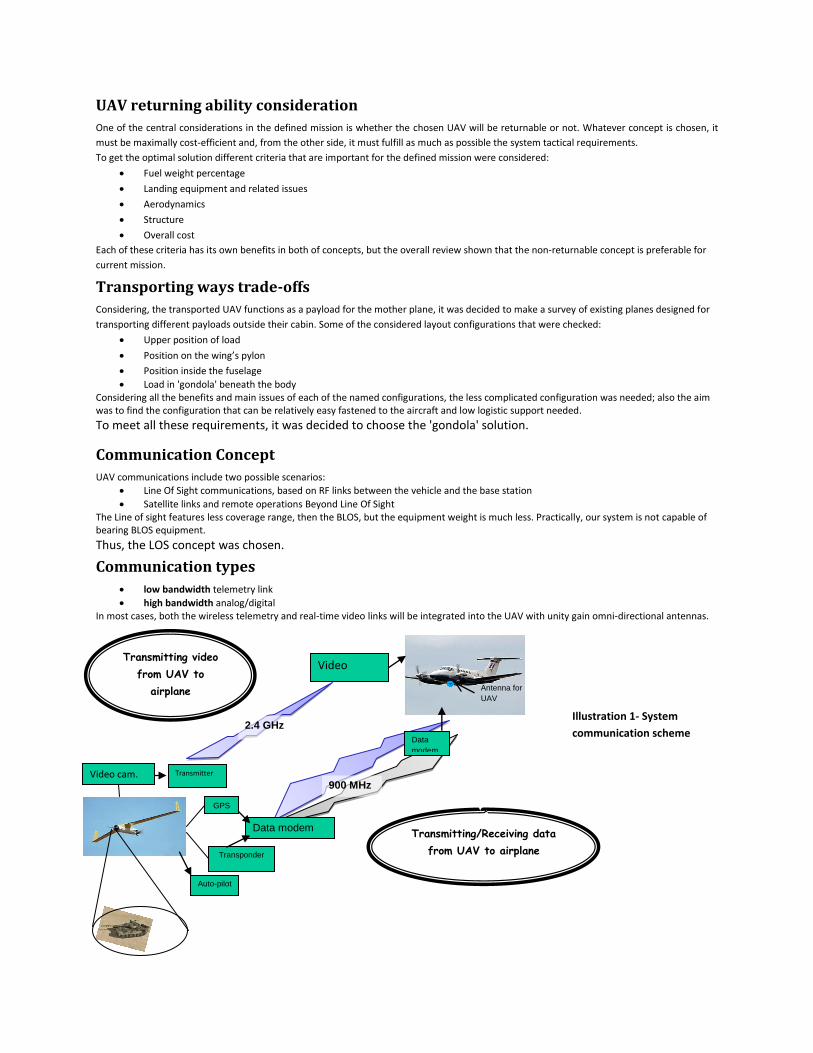
Communication Concept
UAV communications include two possible scenarios:
Line Of Sight communications, based on RF links between the vehicle and the base station
Satellite links and remote operations Beyond Line Of Sight The Line of sight features less coverage range, then the BLOS, but the equipment weight is much less. Practically, our system is not capable of bearing BLOS equipment.
Thus, the LOS concept was chosen.
Communication types
low bandwidth telemetry link
high bandwidth analog/digital In most cases, both the wireless telemetry and real-time video links will be integrated into the UAV with unity gain omni-directional antennas.
Transmitting/Receiving data
from UAV to airplane
GPS
Auto-pilot
Video cam.
900 MHz
2.4 GHz
Transponder
Data
modem
Antenna for
UAV
Transmitter
Video
receiver
Data modem
Transmitting video
from UAV to
airplane
Illustration 1- System
communication scheme

Video/Data transfer components selection The survey about existing equipment was made. The results and conclusions were: Several options were checked. Most of transmitters/receivers have very similar characteristics.
That's why, it was decided to use Israel-made systems.
details Component
Analog video (PAL, NTSC), audio, data Output power: 200mW-15W Bandwidth: 16Mhz, Frequency band: L, S, C, X, Ku Range: 150Km. Weight: 420gr
UAV transmitter: COMMTACT CTX-Series
Analog video (PAL, NTSC), audio, data Bandwidth: 16Mhz Frequency band: L,S,C Weight: 370gr
UAV receiver: COMMTACT CRX-Series
Frequency: 902-928Mhz, 2200-2500Mhz Height: 250 mm Weight: 0.14 kg
Omni-directional antenna: OMA-P2S102
Airplane Transmitter/Receiver
No existing airborne systems were found,
only ground systems, as shown below.
EO/IR Turret Selection
Through the large spectrum of existing turrets, two main groups can be defined – the heavy sensors and
the light sensors. Since our UAV is relatively little, the sensor has to be little.
The EO/IR turret we chose for our project was the MicroPOP, made by Israeli Air Industries.
Comparatively to others in the category, it was the heaviest turret, but its other advantages were
important:
excellent onboard stabilization(comparatively to the category)
1 sensor, refitable for day/night use – lowering the cost
small dimensions
low price (estimation)
Made in Israel - easier to get support.
Table 2 – Communication
components
Illustration 2– Micro Pop
turret

Illustration 4 – KingAir B200 limitations, side-view
Required antenna dimensions In order to achieve the communication between the UAV and the plane, the parabolic antenna has to be located beneath the aircraft.
Considering mission surveillance range and the communication components capabilities, required parabolic antenna dimensions and degrees of
freedom were determined:
Diameter, mm 500
Pitch, deg 90
Azimuth, deg 360
Max. Width, mm 640
Max. Height, mm 590
Max. Length, mm 640
* The maximum values determine the gondola main dimensions, so they are of great importance.
In order to receive data from 2 UAV-s simultaneously two antennas are required. Their relative location is important to prevent the disturbance
in the received data. The optimal location in our case was determined to be at opposite sides of 'gondola', at the distance of 2.5 m.
UAV Selection
It was decided to choose the most suitable UAV instead of building a new design. The choice was made among the existing UAVs to meet the
current mission requirements. The UAV that fulfills mission requirements is MONGuard, the Technion student project.
It has foldable wings, maximum weight of 50 kg, Service ceiling 10000 ft and folded dimensions ~ 2500x450x350 mm.
To meet the mission requirements internal configuration was changed. The UAV's center of gravity kept at the original location, thus all the
UAV's control devices remained the same.
Gondola position and internal layout
It was chosen to place the Gondola beneath the plane. This leads to limitations on its dimensions and longitudinal position.
Gear door at the front
Landing line on the rear
Landing gear ground clearance
Final 'gondola internal configuration & weights:
Component Weight, kg Picture
2x UAV (folded) 100
2x Antenna 60
2x BRU46
40
Doors opening mechanism
& wiring
14
Gondola shell 50
2x UAV's Protective Shell 40
Total 304
Illustration 3 – Parabolic
antenna required
operating volume
Height
limitation
1200
Rear
limitation
Front
limitation
Table 3– Antenna
dimensions
Table 4–'Gondola' component & weights

Wind tunnel model scaling There are 3 main limitations in design of an aircraft model for subsonic wind tunnel:
Model FCSA (Frontal Cross-Section Area) must not exceed 4% of tunnel’s cross section
Distance between model and tunnels’ walls not less than 15cm
The balance (measuring device) must fit to model cross section (not damage the original aerodynamics…)
Technion subsonic wind tunnel that was used is 1x1 m, cross section area 1 m².
Maximum diameter of standard balance is 20 mm.
To meet those requirements 1:25 scale was chosen
CAD model detailed design
The process of the model design building can be divided into several important stages: 1. Getting the Parasolid model. The model was provided by project supervisor. 2. Importing the model into SolidWorks work space. 3. Building problem components from scratch using plane’s pics and views. Some of the parts didn’t fit for further work, hence the
team created them on its own. The completed job was compared to the plane original drawings. 4. Design of the ‘gondola’. As it was shown previously ‘gondola’ dimensions and location were determined by its contents and plane’s
geometry. The main task of ‘gondola’ design was to gain the most smooth and faired geometry for the shell of those contents.
Wind tunnel model detailed design
Main sub-stages: 1. Changing the model scale, including the 'gondolas'. 2. Assembly generation from the mother plane 3D model, adjusting the new
assembly parts for rapid prototyping machine limitations. 3. Designing metal reinforcements, including the 'balance' connector. The shape of
model’s fuselage allowed creating unique balance connector that provides extra structural stiffness.
4. Designing all assembly part fasteners and connection ways.
Aerodynamics
Main stages: 1. Preliminary calculations. Basing on the plane and ‘gondola’ geometry the preliminary calculations of all the plane’s aerodynamics
derivatives were performed. 2. Wind tunnel test. The experiments that were performed:
sweep
sweep
sweep with constant roll angle
Smoke and tuft tests Two ‘gondolas’ of different length were tested in purpose to learn the effect of the length. Model of open gondola with UAVs in it were designed to study the flow fluctuation inside the gondola. All the tests were performed with all configurations of ‘gondola’.
3. Final calculation and conclusions. Basing on the test data the models actual aerodynamic derivatives determined. They were compared to preliminary calculation. The comparison is given in table below.
Illustration 6 – 3D model exploded view
Illustration 5 – ‘Balance’
connector

Derivatives Preliminary Final Annotation
LC No change -0.0002α-0.033 Expected not to change, the experiment show the no change in the lifting
slope but a slight change in zero angle lift coefficient (negative)
DC +5.1% +15% Due to the lack of correlation in Reynolds number the experimental data did not fit the expectations but more detailed research show that the preliminary calculations were precise.
MC -0.0013 0.0008α-0.0323 As it was expected, the slope does not change and the zero angle moment changes significantly due to the error in drag data.
NC
+6% +6% As expected.
YC
+3% +3.5% As expected.
RC
-9% 8.8% Same order as expected but it is in the opposite direction. The original plane has lower wing with dihedral. Usually, the flow above and below this wing during slip is not the same, so it generates unwanted roll, which is compensated with additional angle of dihedral. Adding gondola just below the wing stabilize the flow below it and cancels the unwanted roll effect, thus, the effectiveness of the additional dihedral rises, causing positive roll.
Some most important graphs
Smoke and tuft tests The initial purpose is to observe the flow inside of the open gondola with and without the UAVs inside. There two UAV release modes. The test shown that while the two UAVs are inside the 'gondola'(first release), the flow is smooth with minimum disturbance. On the other hand while before the second release with one UAV inside the 'gondola' the disturbances are significant. Flow streamlines presented below.
Table 4–Aerodynamic derivatives comparison
Illustration 7:a,b,c – Yaw moment, Roll moment, Pitch moment
Illustrations 8 – Unexpected drag results. Note the negligible effect of
the 'gondola' length

Those disturbances might affect the UAV's release sequence and might damage the UAV during this process. The team decided that those effects are to be avoided. It was decided to place baffle board between the two UAVs and only one door will be opened for each launch. Thus only one UAV will be exposed to the flow at each release.
Compensation of the additional windcock effect
The difference in the windcock effect between the plane with and without gondola is about 6%. Although it is relatively low number, it affects the flying qualities of the plane significantly. To compensate the unwanted effect it is proposed to add vertical fins at the rear part of the plane. The calculation that were performed shown that additional area of this fin has to be 0.05÷0.1 m².
Structural design of 'gondola' shell
In order to design the shell of the 'gondola', it's necessary to know the pressure and stress applied to the structure throughout all flight
conditions. Maximum pressure on such bodies may be estimated by the pressure of wing. After simple calculations we get that the maximum is
2300 Pa.
After deep research and consultation with experts were chosen 3 main types of skins for 'gondola' shell:
Aluminum- simple aluminum plate.
Enforced Aluminum- aluminum plate enforced by C beams attached to it.
Layered composite materials – Nomex (aramid fiber paper impregnated with a heat resistant resin) covered with fiber glass layers.
Analytic and FE method calculations were prepared to find the most mass efficient type.
Characteristic Aluminum
Composite
Nomex Fiber Glass
Young Modulus E , GPa 70 17 72
Density ρ, g/cm ³ 2.7 0.1 2.5
The results of calculations are that the simple aluminum plate (with 'gondola'-'s door dimensions) that can withstand the calculated maximum
pressure is 6mm thickness. The equivalent plate made from composite materials will lead to approximate 40% cut in weight. The equivalent
enforced aluminum plate (1 mm thickness plate with 1.5 mm C beams with distance 200 mm between them) –will lead to approximate 75%
cut in weight.
Thus the enforced aluminum was chosen
2
0
0.05
fin cg
fin tail
fin
Z Z
X X
S m
Illustration 11 – Example of compensating fins
Table 5–Materials specs
Illustration 9 a, b – Two modes of flow
streamlines in open 'gondola', one and
two UAV inside
Illustration 10 a,b – Only one door will be opened for
each release, baffle board between the two UAVs
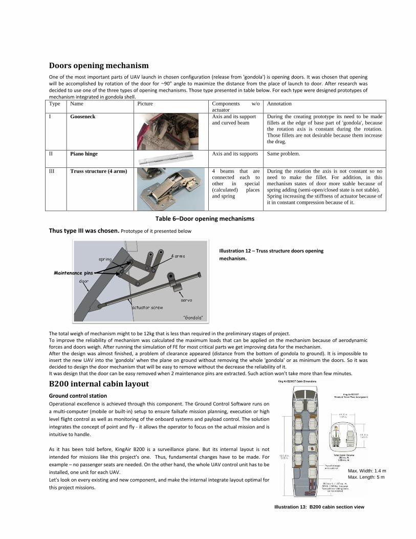
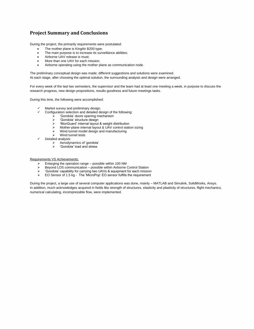
Illustration 13: B200 cabin section view
Doors opening mechanism
One of the most important parts of UAV launch in chosen configuration (release from 'gondola') is opening doors. It was chosen that opening will be accomplished by rotation of the door for ~90° angle to maximize the distance from the place of launch to door. After research was decided to use one of the three types of opening mechanisms. Those type presented in table below. For each type were designed prototypes of mechanism integrated in gondola shell. Type Name Picture Components w/o
actuator
Annotation
I Gooseneck
Axis and its support
and curved beam
During the creating prototype its need to be made
fillets at the edge of base part of 'gondola', because the rotation axis is constant during the rotation.
Those fillets are not desirable because them increase
the drag.
II Piano hinge
Axis and its supports Same problem.
III Truss structure (4 arms)
4 beams that are connected each to
other in special
(calculated) places and spring
During the rotation the axis is not constant so no need to make the fillet. For addition, in this
mechanism states of door more stable because of
spring adding (semi-open/closed state is not stable). Spring increasing the stiffness of actuator because of
it in constant compression because of it.
Thus type III was chosen. Prototype of it presented below
The total weigh of mechanism might to be 12kg that is less than required in the preliminary stages of project. To improve the reliability of mechanism was calculated the maximum loads that can be applied on the mechanism because of aerodynamic forces and doors weigh. After running the simulation of FE for most critical parts we get improving data for the mechanism. After the design was almost finished, a problem of clearance appeared (distance from the bottom of gondola to ground). It is impossible to insert the new UAV into the 'gondola' when the plane on ground without removing the whole 'gondola' or as minimum the doors. So it was decided to design the door mechanism that will be easy to remove without the decrease the reliability of it. It was design that the door can be easy removed when 2 maintenance pins are extracted. Such action won't take more than few minutes.
B200 internal cabin layout
Ground control station
Operational excellence is achieved through this component. The Ground Control Software runs on
a multi-computer (mobile or built-in) setup to ensure failsafe mission planning, execution or high
level flight control as well as monitoring of the onboard systems and payload control. The solution
integrates the concept of point and fly - it allows the operator to focus on the actual mission and is
intuitive to handle.
As it has been told before, KingAir B200 is a surveillance plane. But its internal layout is not
intended for missions like this project's one. Thus, fundamental changes have to be made. For
example – no passenger seats are needed. On the other hand, the whole UAV control unit has to be
installed, one unit for each UAV.
Let's look on every existing and new component, and make the internal integrate layout optimal for
this project missions.
Table 6–Door opening mechanisms
Max. Width: 1.4 m
Max. Length: 5 m
Maintenance pins
Illustration 12 – Truss structure doors opening
mechanism.

It is perfectly clear that such a great measures system cannot be inserted into the limited cabin space.
Thus, the proper control station has to be smaller.
Let's discuss the most important reason of having two operators for each UAV.
One operator controls the aircraft with a controller unit that consists of a display streaming video from the aircraft’s cameras and knobs/dials for controlling the aircraft.
Another operator uses the laptop to gather the intelligence data downloaded from the aircraft for analysis and dissemination to other nodes in the battlefield network.
In such a way of operating, the greatest control and recording abilities are achieved. Thus, foregoing
design will be done for pair-team UAV operators.
The following demonstration station was designed using SolidWorks in purpose to examine different possible configurations and choose the
optimal.
Some possible layouts were examined, each one has its unique
constraints and advantages, the trade-off between them was taken
into account, and, finally, the optimal option has been chosen.
This option didn't fit because of the table dimension – it is too short
for two operators.
In this illustration somewhat more effective layout is shown. This
order of necessary units allows allocating enough space for extra
equipment consoles. Also, the socket in the middle of the cabin is
taken into account. But the most important issue is the necessity
of free access to one (at least) of the existing exits for every
member of a crew.
So, the final design was based on this principle.
As it was mentioned, all the necessary constrains
are preserved in this configuration. The change
was made in locating the backside station to the
opposite wall of the fuselage – in order to allow
emergency exit free.
Illustration 14: Typical UAV ground control station
Illustration15: SolidWorks model for UAV control
station
Project Summary and Conclusions
During the project, the primarily requirements were postulated:
The mother plane is KingAir B200 type;
The main purpose is to increase its surveillance abilities;
Airborne UAV release is must;
More than one UAV for each mission;
Airborne operating using the mother plane as communication node.
The preliminary conceptual design was made; different suggestions and solutions were examined.
At each stage, after choosing the optimal solution, the surrounding analysis and design were arranged.
For every week of the last two semesters, the supervisor and the team had at least one meeting a week, in purpose to discuss the
research progress, new design propositions, results goodness and future meetings tasks.
During this time, the following were accomplished:
Market survey and preliminary design. Configuration selection and detailed design of the following:
‘Gondola’ doors opening mechanism ‘Gondola’ structure design ‘MonGuard’ internal layout & weight distribution Mother-plane internal layout & UAV control station sizing Wind tunnel model design and manufacturing Wind tunnel tests
Detailed analysis: Aerodynamics of ‘gondola’ ‘Gondola’ load and stress
Requirements VS Achievements:
Enlarging the operation range – possible within 100 NM Beyond LOS communication – possible within Airborne Control Station ‘Gondola’ capability for carrying two UAVs & equipment for each mission EO Sensor of 1.5 kg - The ‘MicroPop’ EO sensor fulfills the requirement
During the project, a large use of several computer applications was done, mainly – MATLAB and Simulink, SolidWorks, Ansys.
In addition, much acknowledges acquired in fields like strength of structures, elasticity and plasticity of structures, flight mechanics,
numerical calculating, incompressible flow, were implemented.