SOUTHERN NEVADA AMENDMENTS TO THE 2012 … Codes/2012_IBC...TO THE . 2012 INTERNATIONAL BUILDING...
99
SOUTHERN NEVADA AMENDMENTS TO THE 2012 INTERNATIONAL BUILDING CODE
Transcript of SOUTHERN NEVADA AMENDMENTS TO THE 2012 … Codes/2012_IBC...TO THE . 2012 INTERNATIONAL BUILDING...
SOUTHERN NEVADA AMENDMENTS
TO THE
2012 INTERNATIONAL BUILDING CODE
Southern Nevada Amendments IBC – General Page 2 of 99
PREFACE This document was developed by the Southern Nevada Building Officials’ International Building Code Committee and presents recommended amendments to the 2012 International Building Code (IBC) as published by the International Code Council (ICC). Participation in the 2012 IBC Committee was open to all interested parties. However, voting on amendment proposals was limited to one vote each for the seven Southern Nevada municipalities (Clark County, Henderson, Las Vegas, North Las Vegas, Boulder City, Pahrump, and Mesquite), the Clark County School District, and three industry representatives. All General Committee proceedings were conducted in accordance with Robert’s Rules of Order. The recommended amendments contained herein are not code unless adopted and codified by governmental jurisdictions. These amendments are not intended to prevent the use of any material or method of construction not specifically prescribed herein, provided any alternates have been approved and their use authorized by the Building Official. This document may be copied and used in whole or in part without permission or approval from the organizations listed on the cover page. ADOPTION BY CLARK COUNTY Adopted by action of the Clark County Commission on August 20, 2013 for correlation with the 2012 International Building Code. This document and the 2012 International Building Code shall be effective on July 7, 2014.
Southern Nevada Amendments IBC – General Page 3 of 99
TABLE OF CONTENTS Chapter 1 Scope and Administration ..................................................................................... 8 Section 202 Definitions ............................................................................................................ 8 Section 305.2.3 Six or Fewer Children In a Dwelling Unit. .................................................... 9 Section 308.6 Institutional Group I-4, Day Care Facilities. .................................................... 9 Section 308.6.1 Classification as Group 3. ............................................................................10 Section 308.6.3 Six or Fewer Persons Receiving Care. ........................................................10 Section 308.6.4 Six or Fewer Persons Receiving Care in a Dwelling Unit. .........................10 Section 310.4 Residential Group R-2. ....................................................................................10 Section 310.5 Residential Group R-3. ....................................................................................10 Section 402.4.1 Area and Types of Construction. .................................................................11 Section 403.1 Applicability. ....................................................................................................11 Section 403.3 Automatic Sprinkler System. ..........................................................................11 Section 403.4.7 Smoke Removal. ...........................................................................................12 Sections 403.5.2 Additional Exit Stairway. ............................................................................15 Section 403.5.3 Stairway Door Operation. .............................................................................15 Section 403.5.4 Smokeproof Enclosures. ............................................................................16 Section 403.6.1 Fire Service Access Elevator. ......................................................................16 Section 404.3 Smokeproof Enclosures .................................................................................16 Section 404.6 Enclosure of Atriums. .....................................................................................17 Section 405.8.1 Standby Power Loads. .................................................................................17 Section 405.9.1 Emergency Power Loads. ............................................................................17 Section 406.3.2 Area Increase. ...............................................................................................18 Section 406.3.4 Separation. ....................................................................................................18 Section 406.4.5.1 Floor Drains. ..............................................................................................19 Section 406.6.2 Ventilation. ....................................................................................................19 Section 406.8.2 Ventilation. ....................................................................................................20 Section 406.8.3.1 Floor Drains. ..............................................................................................20 Section 410.3.4 Proscenium Wall. ..........................................................................................20 Section 410.3.5.1 Activation. ..................................................................................................20 Section 410.7 Automatic Sprinkler System. ..........................................................................21 Amend Section 410.7 deleting Exception No. 1 and modifying Exception No. 2, as follows: ....................................................................................................................................21 Section 412.4.6 Fire Suppression. .........................................................................................21 Section 419.5 Fire Protection. ................................................................................................21
Southern Nevada Amendments IBC – General Page 4 of 99
Section 420.6 Visual Access. .................................................................................................21 Section 421.5 Ventilation. .......................................................................................................21 Section 507.2 Group F-2 or S-2, One Story. ..........................................................................22 Section 507.3 Sprinklered, One Story. ...................................................................................22 Section 703.4 Automatic Sprinklers. .....................................................................................23 Section 709.4 Continuity.........................................................................................................23 Section 713.13.3 Refuse, Recycling and Laundry Chute Access Rooms. ..........................24 Section 713.13.4 Termination Room. .....................................................................................24 Section 716.5.9 Door Closing. ................................................................................................24 Section 718.3.2 Groups R-1, R-2, R-3, and R-4. .....................................................................25 Section 718.4.2 Groups R-1 and R-2 ......................................................................................25 Section 718.5 Combustible Materials in Concealed Spaces in Type I or II Construction. .26 Section 803.11.2 Set-Out Construction. ................................................................................26 Section 803.13.1 Site-Fabricated Stretch Ceiling Systems. .................................................27 Section 806.1 General requirements. ....................................................................................27 Section 903.2 Where Required. ..............................................................................................27 Section 903.2.3 Group E. ........................................................................................................28 Section 903.2.8 Group R .........................................................................................................28 Section 903.3 Installation Requirements. ..............................................................................29 Section 903.4 Sprinkler system supervision and alarms. ....................................................29 Section 905.3.1 Height. ...........................................................................................................29 Section 905.9 Valve Supervision. ...........................................................................................29 Section 906.1 General. ............................................................................................................29 Section 907.2.7.1 Occupant Notification. ..............................................................................30 Section 907.2.13 High-Rise Buildings. ...................................................................................30 Section 907.2.13.1.1 Area Smoke Detection. .........................................................................30 Section 907.3 Fire Safety Functions. .....................................................................................31 Section 907.4 Initiating Devices. ............................................................................................31 Section 907.5 Occupant Notification Systems. .....................................................................31 Section 907.6 Installation. ......................................................................................................31 Section 909.5.2 Opening protection. .....................................................................................31 Section 909.16 Fire-Fighter’s Smoke Control Panel. ............................................................32 Section 909.17 System Response Time. ...............................................................................32 Section 909.18.8.3 Reports. ....................................................................................................33 Section 909.18.10 Alternative Testing Method. ....................................................................33 Section 909.20 Smokeproof Enclosures ...............................................................................33
Southern Nevada Amendments IBC – General Page 5 of 99
Section 909.20.5.1 Dampered Relief Opening. ......................................................................34 Section 911.1.3 Size. ...............................................................................................................34 Section 916 Fire Riser Room ..................................................................................................34 Section 1006.3 Emergency Power for Illumination. ..............................................................34 Section 1008.1.5 Floor Elevation. ...........................................................................................35 Section 1008.1.8 Door Arrangement. ....................................................................................35 Section 1008.1.9.11 Stairway Doors. .....................................................................................36 Section 1011.2 Floor-Level Exit Signs in Group R-1. ............................................................37 Table 1014.3 COMMON PATH OF EGRESS TRAVEL ............................................................37 Section 1015.1 Exits or Exit Access Doorways from Spaces. .............................................37 Section 1015.2.2 Three or More Exits or Exit Access Doorways. ........................................38 Section 1016.4 Corridor Increases. ........................................................................................38 Section 1022.4 Openings. .......................................................................................................38 Section 1028.6.2.3 Automatic Sprinklers. ..............................................................................39 Section 1109.16 Gaming Machines and Tables. ...................................................................39 Section 1203.1 General. ..........................................................................................................40 Section 1203.4.1 Ventilation Area Required. .........................................................................40 Section 1203.4.2.1 Bathrooms. ..............................................................................................40 Section 1203.6 Mechanical Ventilation. .................................................................................41 Section 1603.1 General. ..........................................................................................................42 Section 1609.1.1 Determination of Wind Loads. ...................................................................42 Section 1612.3 Establishment of Flood Hazard Areas. ........................................................43 Section 1613.1 Scope. ............................................................................................................44 Section 1613.3.2 Site Class Definitions. ................................................................................44 Section 1704.2.4 Report Requirement. .................................................................................45 Section 1704.4 Contractor Responsibility. ............................................................................45 Section 1704.5.1 Structural Observations for Seismic Resistance. ....................................46 Section 1705.3 Concrete Construction. .................................................................................46 Section 1705.4 Masonry Construction. ..................................................................................47 Section 1705.6 Soils. ...............................................................................................................47 Table 1705.6 ............................................................................................................................48 REQUIRED VERIFICATION AND INSPECTION OF SOILS ....................................................48 Section 1705.15 Exterior Insulation and Finish Systems (EIFS). .........................................48 Section 1705.18 Amusement and transportation systems special cases. ..........................49 Section 1803.2 Investigations Required. ...............................................................................49 Section 1803.3.2 Minimum Exploration Requirements. ........................................................49
Southern Nevada Amendments IBC – General Page 6 of 99
Section 1803.5.3 Expansive Soil. ...........................................................................................50 Section 1803.5.8 Compacted Fill Material. ............................................................................51 Section 1803.6 Reporting. ......................................................................................................51 Section 1804.3 Site Grading. ..................................................................................................53 Section 1804.3.1 Low Collapsible and Low Soluble Soil. .....................................................54 Section 1804.5 Compacted Fill Material. ...............................................................................54 Section 1805.2.1 Floors. .........................................................................................................54 Section 1807.2.3 Safety Factor. ..............................................................................................54 Section 1807.2.4 Slope Stability Analysis. ............................................................................55 Section 1808.6.1.1 Minimum Foundation Depth in Expansive Soils....................................55 Table 1808.6.1.1 .......................................................................................................................55 MINIMUM THICKENED EDGE OR FOUNDATION DEPTH1 ....................................................55 Section 1808.6.2 Slab-on-Ground Foundations. ...................................................................55 Table 1808.6.2 Post Tensioned Slab Criteria .........................................................................56 Critical 12 .................................................................................................................................56 Section 1808.8.7 Use of Non-Structural Slabs on Ground to Resist Bearing Loads. .........57 Section 1808.10 Minimum Distance to Ground Faulting. .....................................................57 Section 1809.4 Depth and Width of Footings. .......................................................................57 Section 1904.2 Concrete Properties. .....................................................................................58 Section 1905.1.9 ACI 318, Section D.3.3. ...............................................................................58 Section 1905.1.10 ACI 318, Section D.4.2.2. ..........................................................................59 Section 1907.1 General. ..........................................................................................................59 Section 2304.9 Connectors and Fasteners. ..........................................................................60 Section 2304.9.8 Bottom (sill) plate anchorage. ...................................................................60 Section 2308.9.8 Pipes in walls. .............................................................................................60 Section 2606.7 Light-Diffusing Systems. ..............................................................................60 Section 2611 Light-Transmitting Plastic Interior Signs. ......................................................61 Section 2612 Fiber-Reinforced Polymer. ...............................................................................62 Section 2902.2 Separate Facilities. ........................................................................................63 Section 3002.4 Elevator Car To Accommodate Ambulance Stretcher. ...............................64 Section 3003.1.3 Two Or More Elevators. ..............................................................................64 Section 3112 Cabanas. ..........................................................................................................64 Section 3113 Shade Structures. ............................................................................................66 Section 3306.2 Walkways. .....................................................................................................69 Section 3401.7 Automatic Sprinkler Systems in Existing Buildings. ..................................69 Section 3401.8 Fire Alarm Systems in Existing Buildings. ..................................................72
Southern Nevada Amendments IBC – General Page 7 of 99
Section 3405.2 Substantial Structural Damage To Vertical Elements Of The Lateral Force-Resisting System. ...................................................................................................................74 Section 3405.3.1 Lateral Force-Resisting Elements. ...........................................................74 Section H107.1.3 Area Limitation. ..........................................................................................74 Appendix J Grading ................................................................................................................75 Section J102.1 Definitions. .....................................................................................................75 Section J103.3 Hazards. .........................................................................................................76 Section J104.1 Submittal requirements. ................................................................................76 Section J104.2 Grading plan requirements. ..........................................................................77 Section J104.3 Geotechnical Report......................................................................................78 J104.3 Geotechnical report. A geotechnical report prepared by a registered design professional shall be provided. The report shall comply with Section 1803.6. .................78 Section J105 Inspections .......................................................................................................78 Appendix N Fences, Walls and Retaining Walls ...................................................................81 APPENDIX N ............................................................................................................................81 FENCES, WALLS AND RETAINING WALLS ..........................................................................81 Appendix O ..............................................................................................................................84 GUIDELINES FOR EVALUATING LIQUEFACTION HAZARDS IN NEVADA ..........................84 Appendix P Guidelines for Evaluating Potential Surface Fault Rupture/Land Subsidence Hazards in Nevada ..................................................................................................................91 GUIDELINES FOR EVALUATING POTENTIAL SURFACE FAULT RUPTURE/LAND SUBSIDENCE HAZARDS IN NEVADA ....................................................................................91
Southern Nevada Amendments IBC – General Page 8 of 99
Chapter 1 Scope and Administration
Delete Part 2 from Chapter 1 of the IBC. Delete Part 2 (“Administration and Enforcement”), including Sections 103 through 116 in their entirety, from Chapter 1.
Section 202 Definitions
Revise the definition of “High-Rise Building” in Section 202, as follows:
HIGH-RISE BUILDING. A building with an occupied floor located more than 55 feet (16 764 mm) above the lowest level of fire department vehicle access.
Amend Section 202 to add new definitions, as follows: [F] FIRE CODE OFFICIAL. The fire chief or other designated authority charged with the administration and enforcement of the International Fire Code, or a duly authorized representative. GAMING. To deal, operate, carry on, conduct, maintain or expose for play any game played with cards, dice, equipment or any mechanical, electromechanical or electronic device or machine for money, property, checks, credit or any representative of value except wherein occurring at private home or as operated by a charitable or educational organization. GAMING MACHINE TYPE. Categorization of gaming machines per type of game(s) played on them, including, but not limited to; slot machines, video poker, video keno or similar. GAMING TABLE TYPE. Categorization of gaming tables per the type of game(s) played on them, including, but are not limited to; baccarat, bingo, blackjack/21, craps, pai-gow, poker, roulette or similar. GAMING AREA(S). Single or multiple areas of a building or facility where gaming machines or tables are present and gaming occurs, including but not limited to: primary casino gaming areas, VIP gaming areas, high-roller gaming areas, bartops, lobbies, dedicated rooms or spaces such as in retail or restaurant establishments, sports books, tournament areas or similar.
Amend Section 202 to include the following new definitions, as follows:
INTERNATIONAL ENERGY CONSERVATION CODE. The Energy Conservation Code as amended and adopted by the local jurisdiction.
INTERNATIONAL EXISTING BUILDING CODE. The Existing Building Code as amended and adopted by the local jurisdiction.
INTERNATIONAL FIRE CODE. The Fire Code as amended and adopted by the local jurisdiction.
Southern Nevada Amendments IBC – General Page 9 of 99
INTERNATIONAL FUEL GAS CODE. The Fuel Gas Code as amended and adopted by the local jurisdiction.
INTERNATIONAL MECHANICAL CODE. The Mechanical Code as amended and adopted by the local jurisdiction.
INTERNATIONAL PLUMBING CODE. The Plumbing Code as amended and adopted by the local jurisdiction.
INTERNATIONAL PRIVATE SEWAGE DISPOSAL CODE. The Private Sewage Disposal Code as amended and adopted by the local jurisdiction.
INTERNATIONAL PROPERTY MAINTENANCE CODE. The Property Maintenance Code as amended and adopted by the local jurisdiction.
INTERNATIONAL RESIDENTIAL CODE. The Residential Code as amended and adopted by the local jurisdiction.
INTERNATIONAL WILDLAND-URBAN INTERFACE CODE. The Wildland-Urban Interface Code as amended and adopted by the local jurisdiction.
STRUCTURAL OBSERVATION. The visual observation of the structural system encompassing the structure, foundation elements and soils within the influence zone of the foundation elements by a registered design professional for general conformance to the approved construction documents. Structural observation does not include or waive the responsibility for the inspection required by Section 110, 1705 or other sections of this code.
Section 305.2.3 Six or Fewer Children In a Dwelling Unit.
Amend Sections 305.2.3, as follows:
305.2.3 Six or fewer children in a dwelling unit. A facility such as the above within a dwelling unit and having six or fewer children receiving such day care shall be classified as a Group R-3 occupancy or shall comply with the International Residential Code.
Section 308.6 Institutional Group I-4, Day Care Facilities.
Amend Section, 308.6, as follows:
308.6 Institutional Group I-4, day care facilities. This group shall include buildings and structures occupied by more than six persons of any age who receive custodial care for fewer than 24 hours per day by persons other than parents or guardians, relatives by blood, marriage or adoption, and in a place other than the home of the person cared for. This group shall include, but not be limited to, the following:
Adult day care Child day care
Southern Nevada Amendments IBC – General Page 10 of 99
Section 308.6.1 Classification as Group 3.
Amend Section, 308.6.1, as follows:
308.6.1 Classification as Group E. A child day care facility that provides care for more than six but no more than 100 children 2½ years or less of age, where the rooms in which the children are cared for are located on a level of exit discharge serving such rooms and each of these child care rooms has an exit door directly to the exterior, shall be classified as Group E. Section 308.6.3 Six or Fewer Persons Receiving Care.
Amend Section, 308.6.3, as follows:
308.6.3 Six or fewer persons receiving care. A facility having six or fewer persons receiving custodial care shall be classified as part of the primary occupancy.
Section 308.6.4 Six or Fewer Persons Receiving Care in a Dwelling Unit.
Amend Section, 308.6.4, as follows:
308.6.4 Six or fewer persons receiving care in a dwelling unit. A facility such as the above within a dwelling unit and having six or fewer persons receiving custodial care shall be classified as a Group R-3 occupancy or shall comply with the International Residential Code. Section 310.4 Residential Group R-2.
Amend Section 310.4 to include “Condominiums” in Residential Group R-2, as follows:
310.4 Residential Group R-2. Residential occupancies containing sleeping units or more than two dwelling units where the occupants are primarily permanent in nature, including:
Apartment houses Boarding houses (nontransient) with more than 16 occupants Condominiums (nontransient) Congregate living facilities (nontransient) with more than 16 occupants Convents Dormitories Fraternities and sororities Hotels (nontransient) Live/work units Monasteries Motels (nontransient) Vacation timeshare properties
Section 310.5 Residential Group R-3.
Amend Sections 310.5 and 310.5.1, as follows:
310.5 Residential Group R-3. Residential occupancies where the occupants are primarily permanent in nature and not classified as Group R-1, R-2, R-4 or I, including:
Southern Nevada Amendments IBC – General Page 11 of 99
Buildings that do not contain more than two dwelling units Boarding houses (nontransient) with 16 or fewer occupants Boarding houses (transient) with 10 or fewer occupants Care facilities that provide accommodations for six or fewer persons receiving care Congregate living facilities (nontransient) with 16 or fewer occupants Congregate living facilities (transient) with 10 or fewer occupants
310.5.1 Care facilities within a dwelling. Care facilities for six or fewer persons receiving care that are within a single-family dwelling are permitted to comply with the International Residential Code provided an automatic sprinkler system is installed in accordance with Section 903.3.1.3 or with Section P2904 of the International Residential Code.
Section 402.4.1 Area and Types of Construction.
Amend Section 402.4.1, as follows:
402.4.1 Area and types of construction. The building area of any covered mall or open mall building, including anchor buildings, of Types I, II, III, and IV construction shall not be limited provided the anchor buildings do not exceed three stories above grade plane. The construction type of open parking garages and enclosed parking garages shall comply with Sections 406.5 and 406.6, respectively.
Exception: The type of construction allowable building height and building area of anchor buildings greater than three stories above grade plane shall comply with Section 503, as modified by Sections 504 and 506.
Section 403.1 Applicability.
Amend Section 403.1, as follows:
403.1 Applicability. High-rise buildings shall comply with Sections 403.2 through 403.6.
Exception: The provisions of Sections 403.2 through 403.6 shall not apply to the following buildings and structures:
1. Airport traffic control towers in accordance with Section 412.3. 2. Open parking garages in accordance with Section 406.5. 4. Special industrial occupancies in accordance with Section 503.1.1.
Section 403.3 Automatic Sprinkler System.
Amend Section 403.3, as follows:
[F] 403.3 Automatic sprinkler system. Buildings and structures shall be equipped throughout with an automatic sprinkler system in accordance with Section 903.3.1.1 and a secondary water supply where required by Section 903.3.5.2.
Southern Nevada Amendments IBC – General Page 12 of 99
Exception: An automatic sprinkler system shall not be required in open parking garages in accordance with Section 406.5.
Section 403.4.7 Smoke Removal.
Amend Section 403.4.7, as follows: 403.4.7 Smoke removal. To facilitate smoke removal in post-fire salvage and overhaul operations, buildings and structures shall be equipped with natural or mechanical ventilation for removal of products of combustion in accordance with one of the following:
Exceptions:
1. Smoke removal is not required for building renovations where HVAC systems are not being modified.
2. Smoke removal systems are not required for remodels and alterations within existing
buildings where the area being remodeled or altered is provided with a smoke control approach consistent with the smoke control requirements of the existing building.
3. Where permitted by the fire code official, smoke removal systems are not required
for minor additions to existing buildings that are not already provided with smoke removal systems.
1. Easily identifiable, manually operable windows or panels shall be distributed around the
perimeter of each floor at not more than 50-foot (15 240 mm) intervals. The area of operable windows or panels shall not be less than 40 square feet (3.7 m2) per 50 linear feet (15 240 mm) of perimeter.
Exceptions:
1. In Group R-1 occupancies, each sleeping unit or suite having an exterior wall shall be permitted to be provided with 2 square feet (0.19 m2) of venting area in lieu of the area specified in Item 1.
2. Where permitted by the fire code official, windows of tempered glass shall be permitted to be fixed provided no coating or film is applied and that glazing can be cleared by firefighters.
3. Manually operable windows or panels are not required in Group R-1 and R-2 residential units provided the residential units comply with the passive requirements of Section 909 and all corridors between the residential units and the exit enclosures serving the residential units comply with Section 403.4.7, Item 3.
2. Mechanical air-handling equipment providing one exhaust air change every 15 minutes for the area involved. Return and exhaust air shall be moved directly to the outside without recirculation to other portions of the building. The air volume shall be calculated based upon the volume of the space between the floor and the floor or roof structure above. The exhaust air quantity shall be as measured at the exhaust fan.
Southern Nevada Amendments IBC – General Page 13 of 99
Exception: Smoke removal is not required for normally unoccupied areas such as mechanical equipment rooms, electrical rooms, storage rooms that do not exceed 500 square feet in area, elevator equipment rooms, or similar areas as approved by the building official.
3. A smoke control system that provides a minimum of one exhaust air change every 15
minutes is provided for the area involved upon manual activation of the smoke removal feature at the smoke control graphics panel. The volume of air shall be calculated based upon the volume of the space between the floor and the floor or roof structure above. The exhaust air quantity shall be as measured at the exhaust fan.
4. Any other approved design that will produce equivalent results where permitted by the
Authority Having Jurisdiction.
Add new Sections 403.4.7.1 through 403.4.7.3, as follows: 403.4.7.1 Design requirements. Smoke removal systems shall be capable of manual activation and shall be designed in accordance with Sections 403.4.7.1.1 through 403.4.7.1.4.
403.4.7.1.1 Fans. Fans shall be selected for stable performance based on normal temperature. Calculations and manufacturer’s fan curves shall be part of the documentation procedures. Fans shall be supported and restrained by noncombustible devices in accordance with the requirements of Chapter 16.
403.4.7.1.1.1 Fan belts. Belt-driven fans shall have 1.5 times the number of belts required for the design duty, with the minimum number of belts being two. 403.4.7.1.1.2 Fan motors. Motors driving fans shall not be operated beyond their nameplate horsepower (kilowatts), as determined from measurement of actual current draw, and shall have a minimum service factor of 1.15.
403.4.7.1.2 Ducts. Ducts shall be constructed and supported in accordance with the Uniform Mechanical Code. Exhaust ducts shall be leak tested to 1.5 times the maximum design pressure in accordance with nationally accepted practices. Measured leakage shall not exceed 5 percent of design flow. Results of such testing shall be a part of the special inspections report in accordance with Section 403.4.7.3.3.
Exception: Leakage testing shall not be required where the exhaust ducts are contained completely within the smoke removal zone they serve.
403.4.7.1.3 Power. The smoke removal system shall be supplied with two sources of power. Primary power shall be from the normal building power systems. Secondary power shall be from an approved standby source complying with Chapter 27 of this code.
Exception: Secondary power for the smoke removal system is not required where normal power can be automatically restored from the fire command center following a normal power shunt.
Southern Nevada Amendments IBC – General Page 14 of 99
403.4.7.1.3.1 Standby power source enclosure. The standby power source and its transfer switches shall be in a room separate from the normal power transformers and switch gears and ventilated directly to and from the exterior. The room shall be enclosed with not less than 1-hour fire barriers constructed in accordance with Section 707 or horizontal assemblies constructed in accordance with Section 711, or both. 403.4.7.1.3.2 Power sources and power surges. Elements of the smoke removal system relying on volatile memories shall be supplied with uninterruptable power sources of sufficient duration to span a 15-minute primary power interruption. Elements of the smoke removal system susceptible to power surges shall be suitably protected by conditioners, suppressors or other approved means. 403.4.7.1.3.3 Secondary power supply. The secondary power supply shall be sized to accommodate the electrical requirements of the two largest adjacent smoke removal zones simultaneously.
403.4.7.1.4 Status indicators and controls. Status indicators and controls for the smoke removal system shall be provided on a graphic control panel in the fire command center. The graphic control panel shall be designed in accordance with the International Fire Code and shall provide status of smoke removal fans and controls for the smoke removal systems. The control panel for the smoke removal system shall be permitted to operate through the building HVAC management system or the fire alarm system. The control panel for the smoke removal system shall not be required to be listed as smoke control equipment.
403.4.7.2 Control diagrams. The construction documents shall provide sufficient information and detail to adequately describe the elements of the design necessary for the proper implementation of the smoke removal systems. The construction documents shall include smoke removal system control diagrams that show all devices in the system and identify their location and function. The smoke removal system drawings shall be permitted to be combined with smoke control system drawings, where applicable. Approved copies of the smoke removal system control diagrams shall be maintained current and kept on file with the Authority Having Jurisdiction and in the fire command center in an approved format and manner. 403.4.7.3 Special inspections for smoke removal. Smoke removal systems shall be tested by a special inspector.
Exception: Special inspections shall not be required where smoke removal is achieved by natural ventilation in accordance with Section 403.4.7, Item 1. 403.4.7.3.1 Scope of testing. Special inspections shall be conducted in accordance with the following:
1. During erection of ductwork and prior to concealment for the purposes of leakage testing and recording device location. 2. Prior to occupancy and after sufficient completion for the purposes of exhaust air change rate measurements and control verification.
Southern Nevada Amendments IBC – General Page 15 of 99
403.4.7.3.2 Qualifications. Special inspection agencies for smoke removal shall have expertise in fire protection engineering, mechanical engineering and certification as air balancers. 403.4.7.3.3 Reports. A complete report of testing shall be prepared by the special inspector or special inspection agency. The report shall include identification of all devices by manufacturer, nameplate data, design values, measured values and identification tag or mark. The report shall be reviewed by the responsible registered design professional and, when satisfied that the design intent has been achieved, the responsible registered design professional shall seal, sign and date the report with a statement as follows:
“I have reviewed this report and by personal knowledge and on-site observation certify that the smoke removal system is in substantial compliance with the design intent, and to the best of my understanding complies with the requirements of the code.” 403.4.7.3.3.1 Report filing. A copy of the final report shall be filed with the Authority Having Jurisdiction and an identical copy shall be maintained in the fire command center.
Sections 403.5.2 Additional Exit Stairway.
Amend Section 403.5.2 and add new Section 403.5.2.1, as follows: 403.5.2 Additional exit stairway. For buildings other than Group R-2 that are more than 420 feet (128 000 mm) in building height, one additional exit stairway meeting the requirements of Sections 1009 and 1022 shall be provided in addition to the minimum number of exits required by Section 1021.1. The total width of any combination of remaining exit stairways with one exit stairway removed shall be not less than the total width required by Section 1005.1. Scissor stairs shall not be considered the additional exit stairway required by this section.
Exceptions:
1. An additional exit stairway shall not be required to be installed in buildings having elevators used for occupant self-evacuation in accordance with Section 3008.
2. The additional exit stairway shall not be required for redundancy to stairs serving
only those portions of the building 420 feet (128 m) or less in building height.
403.5.2.1 Multiple towers. For buildings containing multiple towers, the additional exit stairway shall only be required for those towers exceeding 420 feet (128 m) in building height. Section 403.5.3 Stairway Door Operation.
Amend Section 403.5.3, as follows: 403.5.3 Stairway door operation. Stairway doors other than the exit discharge doors shall be permitted to be locked from stairway side. Stairway doors that are locked from the stairway side shall be unlocked simultaneously without unlatching upon any of the following: a signal from the
Southern Nevada Amendments IBC – General Page 16 of 99
fire command center; activation of a fire alarm signal in an area served by the stairway; or failure of the power supply.
Exception: Upon approval of the building official, stairway doors opening directly into privately owned residential units or leased tenant spaces are permitted to unlock without unlatching only upon signal from the fire command center.
Section 403.5.4 Smokeproof Enclosures.
Amend Section 403.5.4, as follows: 403.5.4 Smokeproof enclosures. Every required exit stairway serving floors more than 55 feet (16 764 mm) above the lowest level of fire department vehicle access shall be a smokeproof enclosure in accordance with Sections 909.20 and 1022.10. Section 403.6.1 Fire Service Access Elevator.
Amend Section 403.6.1, as follows:
403.6.1 Fire service access elevator. In buildings with an occupied floor more than 120 feet (36 576 mm) above the lowest level of fire department vehicle access, no fewer than two fire service access elevators, or all elevators, whichever is less, shall be provided in accordance with Section 3007. Each fire service access elevator shall have a capacity of not less than 3500 pounds (1588 kg).
Exception: Where a building is provided with multiple ambulance stretcher sized elevator cars in accordance with Section 3002.4 and the table below, fire service access elevators shall not be required.
Table 403.6.1 Ambulance Stretcher Sized Elevator Cars Highest floor level served above lowest level of fire department access in feet (meters)
Number of elevator cars sized to accommodate an ambulance stretcher a.
120-599 (36.6m-182.6m) 3 600-899 (182.9m-274.0m) 4 900 and greater (274.3m) 5 a. A fire service access elevator installed in accordance with Section 403.6.1 shall be permitted to substitute for one of these elevators. Section 404.3 Smokeproof Enclosures Amend Section 404.3 deleting Exception Nos. 1 and 2, as follows: [F] 404.3 Automatic sprinkler protection. An approved automatic sprinkler system shall be installed throughout the entire building.
Southern Nevada Amendments IBC – General Page 17 of 99
Section 404.6 Enclosure of Atriums.
Revise Section 404.6, as follows:
404.6 Enclosure of atriums. Atrium spaces shall be separated from adjacent spaces by a 1-hour fire barrier constructed in accordance with Section 707 or a horizontal assembly constructed in accordance with Section 711, or both.
Exceptions:
1. A fire barrier is not required where a glass wall forming a smoke partition is provided. The glass wall shall comply with all of the following: 1.1 A separately zoned system of automatic sprinklers is provided along both
sides of the separation wall and doors, or on the room side only if there is not a walkway on the atrium side. The sprinklers shall be located between 4 inches and 12 inches (102 mm and 305 mm) away from the glass and at intervals along the glass not greater than 6 feet (1829 mm). The sprinkler system shall be designed so that the entire surface of the glass is wet upon activation of the sprinkler system without obstruction;
1.2 The glass wall shall be installed in a frame in a manner that the framing
system deflects without breaking (loading) the glass before the sprinkler system operates; and
1.3 Where glass doors are provided in the glass wall, they shall be either self-
closing or automatic-closing. 2. A fire barrier is not required where a glass-block wall assembly complying with
Section 2110 and having a ¾-hour fire protection rating is provided. 3. A fire barrier is not required between the atrium and the adjoining spaces of any
three floors of the atrium provided such spaces are accounted for in the design of the smoke control system.
Section 405.8.1 Standby Power Loads.
Amend Section 405.8.1, as follows: [F] 405.8.1 Standby power loads. The following loads are classified as standby power loads:
1. Smoke control system. 2. Ventilation and automatic fire detection equipment for smokeproof enclosures.
Standby power shall be provided for elevators in accordance with Section 3003.
Section 405.9.1 Emergency Power Loads.
Amend Section 405.9.1, as follows:
Southern Nevada Amendments IBC – General Page 18 of 99
[F] 405.9.1 Emergency power loads. The following loads are classified as emergency power loads:
1. Emergency voice/alarm communication systems. 2. Fire alarm systems. 3. Automatic fire detection systems. 4. Elevator car lighting. 5. Means of egress and exit sign illumination required by Chapter 10. 6. Electrically powered fire pumps.
Section 406.3.2 Area Increase.
Amend Sections 406.3.2 ,as follows: 406.3.2 Area increase. Group U occupancies used for the storage of private or pleasure-type motor vehicles where no repair work is completed or fuel is dispensed are permitted to be 3,000 square feet (279 m2) where the following provisions are met:
1. For a mixed occupancy building, the exterior wall and opening protection for the
Group U portion of the building shall be as required for the major occupancy of the building. For such a mixed occupancy building, the allowable floor area of the building shall be as permitted for the major occupancy contained therein.
2. For a building containing only a Group U occupancy, the exterior wall shall not be
required to have a fire-resistance rating and the area of openings shall not be limited where the fire separation distance is 5 feet (1524 mm) or more.
More than one 3,000-square-foot (279 m2) Group U occupancy shall be permitted to be in the same structure, provided each 3,000-square-foot (279 m2) area is separated by fire walls complying with Section 706.
Exception: Noncombustible carports may be of unlimited area when they are open on all sides, not over twelve feet (3658 mm) in height, and located a minimum of 5 feet (1524 mm) from any property line or assumed property line, measured from the roof edge.
Section 406.3.4 Separation. Amend section 406.3.4, as follows: 406.3.4 Separation. Separations shall comply with the following:
1. Unchanged. 2. Unchanged. 3. Unchanged. 4. Noncombustible carports do not require exterior wall and opening protection when
they are open on all sides, not over twelve feet (3658 mm) in height, and located a minimum of 5 feet (1524 mm) from any property line or assumed property line, as measured from the roof edge.
5. When a Group B, F, M, R, or S occupancy structure and a noncombustible carport are located on the same property with a minimum separation of ten feet (3048 mm)
Southern Nevada Amendments IBC – General Page 19 of 99
between the structure and the carport, as measured from the roof edges, exterior wall and opening protection is not required for either structure.
Section 406.4.5.1 Floor Drains.
Add new Section 406.4.5.1, as follows: 406.4.5.1 Floor drains. Where provided, floor drains installed in enclosed parking garages shall drain to an approved sand/oil separator in accordance with the International Plumbing Code. Section 406.6.2 Ventilation. Amend Section 406.6.2, as follows: 406.6.2 Ventilation. A mechanical ventilation system shall be provided in accordance with the Uniform Mechanical Code.
Exceptions:
1. A mechanical ventilation system shall not be required in an enclosed parking garage when openings complying with Section 406.5.2 are provided.
2. A mechanical ventilation system shall not be required in an enclosed parking
garage having a floor area of 1,000 ft2 or less and used for the storage of five (5) or less private motor vehicles.
406.6.2.1 Minimum ventilation. The mechanical ventilation system shall be capable of producing a ventilation rate of 0.75 cfm per square foot (0.0038 m3/s·m2) of floor area.
Exception: When approved by the Building Official, the mechanical ventilation system may be designed to exhaust a minimum of 14,000 cfm (6.61 m3/s) for each operating vehicle. Such system shall be based on the anticipated instantaneous movement rate of vehicles, but not less than 2.5 percent of the garage capacity, or one vehicle, whichever is greater.
406.6.2.2 Intermittent operation. The mechanical ventilation system shall not be required to operate continuously where approved automatic carbon monoxide sensing devices are provided to operate the system automatically to maintain a maximum average concentration of carbon monoxide of 50 parts per million during any eight-hour period, with a maximum concentration not greater than 200 parts per million for a period not exceeding one hour.
406.6.2.3 Occupied spaces accessory to public garages. Connecting offices, waiting rooms, ticket booths and similar uses that are accessory to a public garage shall be supplied with conditioned air and maintained at a positive pressure.
Southern Nevada Amendments IBC – General Page 20 of 99
Section 406.8.2 Ventilation.
Amend Section 406.8.2, as follows: 406.8.2 Ventilation. Repair garages shall be mechanically ventilated in accordance with the Uniform Mechanical Code. The ventilation system shall be controlled at the entrance to the garage.
406.8.2.1 Minimum ventilation. The mechanical ventilation system shall be capable of producing a ventilation rate of 1.5 cfm per square foot (0.0076 m3/s·m2) of floor area. Each engine repair stall shall be equipped with an exhaust pipe extension duct, extending to the outside of the building, which, if over 10 feet (3048 mm) in length, shall mechanically exhaust 300 cfm (0.142 m3/s). 406.8.2.2 Occupied spaces accessory to repair garages. Connecting offices, waiting rooms and similar uses that are accessory to a repair garage shall be supplied with conditioned air and maintained at a positive pressure.
Section 406.8.3.1 Floor Drains.
Add new Section 406.8.3.1, as follows: 406.8.3.1 Floor drains. Where provided, floor drains installed in repair garages shall drain to an approved sand/oil separator in accordance with the International Plumbing Code. Section 410.3.4 Proscenium Wall.
Amend Section 410.3.4, as follows:
410.3.4 Proscenium Wall. Where the stage height is greater than 50 feet (15 240 mm), all portions of the stage shall be completely separated from the seating area by a proscenium wall with not less than a 2-hour fire-resistance rating extending continuously from the foundation to the roof.
Exception: Where a stage is located in a building of Type I construction, the proscenium wall is permitted to extend continuously from a minimum 2-hour fire-resistance-rated floor slab of the space containing the stage to the roof or a minimum 2-hour fire-resistance-rated floor deck above. This exception shall not apply to buildings of Type IB construction in which the minimum fire-resistance ratings of the building elements in Table 601 have been reduced in accordance with Section 403.2.1.1.
Section 410.3.5.1 Activation.
Add new Section 410.3.5.1, as follows: 410.3.5.1 Activation. When provided, a fire curtain shall be activated by manual emergency operation, fusible link, rate-of-rise heat detection installed in accordance with Section 907.3 operating at a rate of temperature rise of 15 to 20ºF per minute (8 to 11ºC per minute), or signal

Southern Nevada Amendments IBC – General Page 21 of 99
of water flow from any automatic sprinkler system covering the stage as required by Section 410.7.
Section 410.7 Automatic Sprinkler System.
Amend Section 410.7 deleting Exception No. 1 and modifying Exception No. 2, as follows: [F] 410.7 Automatic sprinkler system. Stages shall be equipped with an automatic sprinkler system in accordance with Section 903.3.1.1. Sprinklers shall be installed under the roof and gridiron and under all catwalks and galleries over the stage. Sprinklers shall be installed in dressing rooms, performer lounges, shops and storerooms accessory to such stages.
Exceptions: 1. In buildings where an automatic sprinkler system is not otherwise required by
other sections of this code, sprinklers are not required for stages 1,000 square feet (93 m2) or less in area and 50 feet (15 240 mm) or less in height where curtains, scenery or other combustible hangings are not retractable vertically. Combustible hangings shall be limited to a single main curtain, borders, legs and a single backdrop.
2. Sprinklers are not required within portable orchestra enclosures on stages.
Section 412.4.6 Fire Suppression.
Amend Section 412.4.6 deleting the Exception, as follows:
[F] 412.4.6 Fire suppression. Aircraft hangars shall be provided with a fire suppression system designed in accordance with NFPA 409, based upon the classification for the hangar given in Table 412.4.6. Section 419.5 Fire Protection.
Amend Section 419.5, as follows:
[F] 419.5 Fire protection. The live/work unit shall be provided with a monitored fire alarm system where required by Section 907.2.9 and an automatic sprinkler system in accordance with Section 903.3.1.1 or 903.3.1.2. Section 420.6 Visual Access.
Add new Section 420.6, as follows: 420.6 Visual access. The primary entrance door of individual units in motels, hotels, apartment houses, condominiums, and vacation timeshare properties shall contain a means to allow the occupant to visually identify a visitor without opening the unit entry door. Section 421.5 Ventilation.
Amend Section 421.5, as follows:
Southern Nevada Amendments IBC – General Page 22 of 99
[F] 421.5 Ventilation. Cutoff rooms shall be provided with mechanical ventilation.
Exception: Where approved by the building official, natural ventilation shall be permitted in lieu of mechanical ventilation.
421.5.1 Ventilation rate. Mechanical ventilation of hydrogen cutoff rooms shall be provided at a minimum rate of 1 cubic foot per minute per 12 cubic feet [0.00138 m3/(s·m3)] of room volume. 421.5.2 Inlets and outlets. Hydrogen cutoff rooms shall be ventilated utilizing air supply inlets and exhaust outlets arranged to provide uniform air movement to the extent practical. Inlets shall be uniformly arranged on exterior walls near floor level. Outlets shall be located at the high point of the room in exterior walls or the roof. 421.5.3 Operation. The mechanical ventilation system shall operate continuously.
Exception: Where approved by the building official, ventilation shall be permitted to be by a mechanical ventilation system activated by a continuously monitoring flammable gas detection system that activates at a gas concentration of 25 percent of the lower flammable limit (LFL).
421.5.4 Shutdown. The gaseous hydrogen system shall be automatically shut down in the event of failure of the ventilation system.
Section 507.2 Group F-2 or S-2, One Story.
Amend Section 507.2, as follows: 507.2 Group F-2 or S-2, one story. The area of a Group F-2 or S-2 building no more than one story in height shall not be limited where the building is surrounded and adjoined by public ways or yards not less than 60 feet (18 288 mm) in width and the building is provided with an automatic sprinkler system throughout where required by Section 903.2 or the International Fire Code. Section 507.3 Sprinklered, One Story.
Amend Section 507.3, as follows: 507.3 Sprinklered, One Story. The area of a Group B, F, M or S building no more than one story above grade plane of any construction type, or the area of a Group A-4 building no more than one story above grade plane of other than Type V construction, shall not be limited where the building is provided with an automatic sprinkler system throughout in accordance with Section 903.3.1.1 and is surrounded and adjoined by public ways or yards not less than 60 feet (18 288 mm) in width.
Exceptions:
Buildings and structures of Type I and II construction for rack storage facilities that do not have access by the public shall not be limited in height, provided that such
Southern Nevada Amendments IBC – General Page 23 of 99
buildings conform to the requirements of Sections 507.3 and 903.3.1.1 and Chapter 32 of the International Fire Code.
Section 703.4 Automatic Sprinklers. Add exception to Section 703.4, as follows: Exception: A fire barrier, fire partition or smoke barrier may use non-rated glass and automatic sprinklers to achieve up to a 1-hour fire-resistance rating when all of the following are provided:
1. Automatic sprinklers are provided along both sides of the glazing and/or doors, or on the room side only if there is not a walkway on one side. The sprinklers shall be located between 4 inches and 12 inches (102 mm and 305 mm) away from the glass and at intervals along the glass not greater than 6 feet (1829 mm). The sprinkler system shall be designed so that the entire surface of the glass is wet upon activation of the sprinklers system without obstruction;
1.1. The glass wall shall be installed in a gasketed frame in a manner that the framing system deflects without breaking (loading) the glass before the sprinkler system operates; and
1.2. Where glass doors are provided in the glass wall, they shall be either self-closing or automatic-closing; and
1.3. The sprinklers used to protect the glass wall and/or doors along the fire barrier, fire partition or smoke barrier are served by systems separate from the sprinklers protecting the room or space. The system shall be dedicated to those sprinklers used to protect the fire barrier, fire partition or smoke barrier
1.4. The fire barrier, fire partition or smoke barrier does not exceed a 1-hour fire-resistance rating.
Section 709.4 Continuity. Revise Section 709.4 to read, as follows: 709.4 Continuity. Smoke barriers shall form an effective membrane continuous from outside wall to outside wall and from the top of the foundation or floor/ceiling assembly below to the underside of the floor or roof sheathing, deck or slab above, including continuity through concealed spaces, such as those found above suspended ceilings, and interstitial structural and mechanical spaces. The supporting construction shall be protected to afford the required fire-resistance rating of the wall or floor supported in buildings of other than Type IIB, IIIB or VB construction.
Exceptions:
1. Smoke-barrier walls are not required in interstitial spaces where such spaces are designed and constructed with ceilings that provide resistance to the passage of fire and smoke equivalent to that provided by the smoke-barrier walls.
Southern Nevada Amendments IBC – General Page 24 of 99
2. Smoke barriers used for elevator lobbies in accordance with Section 405.4.3, 3007.7.2 or
3008. 7.2 are not required to extend from outside wall to outside wall. 3. Smoke barriers used for areas of refuge in accordance with Section 1007.6.2 are not
required to extend from outside wall to outside wall. 4. Smoke barriers used for smoke control zone boundaries in accordance with Section 909.5
are not required to extend from outside wall to outside wall.
Section 713.13.3 Refuse, Recycling and Laundry Chute Access Rooms. Revise Section 713.13.3, as follows: 713.13.3 Refuse, recycling and laundry chute access rooms. Access openings for refuse, recycling and laundry chutes shall be located in rooms or compartments enclosed by not less than 1-hour fire barriers constructed in accordance with Section 707 or horizontal assemblies constructed in accordance with 711, or both. Openings into the access rooms shall be protected by opening protectives having a fire protection rating of not less than ¾ hour. Doors shall be self- or automatic-closing upon the detection of smoke in accordance with Section 716.5.9.3. The room or compartment shall be sized to allow the access door to the room or compartment to close and latch with the access panel to the refuse or laundry chute in any position.
Section 713.13.4 Termination Room. Revise Section 713.13.4 to read, as follows: 713.13.4 Termination room. Refuse, recycling and laundry chutes shall discharge into an enclosed room separated from the remainder of the building by fire barriers constructed in accordance with Section 707 or horizontal assemblies constructed in accordance with Section 711, or both. Construction shall be a minimum of 1-hour, but not less than the fire-resistance rating of the shaft enclosure. Openings into the termination room shall be protected by opening protectives having a fire protection rating equal to the protection required for the shaft enclosure. Doors shall be self- or automatic-closing upon the detection of smoke in accordance with Section 716.5.9.3. Refuse chutes shall not terminate in an incinerator room. Refuse, recycling and laundry rooms that are not provided with chutes need only comply with Table 509. Section 713.14.1 Elevator Lobby.
Revise Item 4.3 in Exception #4 of Section 713.14.1 to read, as follows: 4.3 Elevators serving floor levels over 55 feet (16 764 mm) above the lowest level of fire department vehicle access in high-rise buildings.
Section 716.5.9 Door Closing.
Revise Section 716.5.9 to read, as follows:
Southern Nevada Amendments IBC – General Page 25 of 99
716.5.9 Door closing. Fire doors in fire walls shall be automatic-closing in accordance with this section. Fire doors in other than fire walls shall be self- or automatic-closing in accordance with this section. Self-closing chute intake doors shall not fail in a “door open” position in the event of a closer failure.
Exceptions: 1. Fire doors located in common walls separating sleeping units in Group R-1 and between
dwelling units of transient nature in Group R-2 shall be permitted without automatic- or self-closing devices.
2. The elevator car doors and the associated hoistway enclosure doors at the floor level designated for recall in accordance with Section 3003.2 shall be permitted to remain open during Phase I emergency recall operation.
Section 718.3.2 Groups R-1, R-2, R-3, and R-4.
Revise Section 718.3.2 to read, as follows: 718.3.2 Groups R-1, R-2, R-3 and R-4. Draftstopping shall be provided in floor/ceiling spaces in Group R-1 buildings, in Group R-2 buildings with three or more dwelling units, in Group R-3 buildings with two dwelling units and in Group R-4 buildings. Draftstopping shall be located above and in line with the dwelling unit and sleeping unit separations. Exceptions:
1. Draftstopping is not required in buildings equipped throughout with an automatic sprinkler system in accordance with Section 903.3.1.1.
2. Draftstopping is not required in buildings equipped throughout with an automatic
sprinkler system in accordance with Section 903.3.1.2, provided that automatic sprinklers systems in accordance with Section 903.3.1.1 are also installed in the combustible concealed spaces where the draftstopping is being omitted.
Section 718.4.2 Groups R-1 and R-2 Revise Section 718.4.2 to read, as follows: 718.4.2 Groups R-1 and R-2. Draftstopping shall be provided in attics, mansards, overhangs or other concealed roof spaces of Group R-2 buildings with three or more dwelling units and in all Group R-1 buildings. Draftstopping shall be installed above, and in line with, sleeping unit and dwelling unit separation walls that do not extend to the underside of the roof sheathing above.
Exceptions:
1. Where corridor walls provide a sleeping unit or dwelling unit separation, draftstopping shall only be required above one of the corridor walls.
Southern Nevada Amendments IBC – General Page 26 of 99
2. Draftstopping is not required in buildings equipped throughout with an automatic sprinkler system in accordance with Section 903.3.1.1.
3. In occupancies in Group R-2 that do not exceed four stories in height, the attic space shall be subdivided by draftstops into areas not exceeding 3,000 square feet (279 m2) or above every two dwelling units, whichever is smaller.
4. Draftstopping is not required in buildings equipped throughout with an automatic sprinkler system in accordance with Section 903.3.1.2, provided that automatic sprinklers systems in accordance with Section 903.3.1.1 are also installed in the combustible concealed spaces where the draftstopping is being omitted.
Section 718.5 Combustible Materials in Concealed Spaces in Type I or II Construction. Revise Section 718.5 to read, as follows: 718.5 Combustible materials in concealed spaces in Type I or II construction. Combustible materials shall not be permitted in concealed spaces of buildings of Type I or II construction.
Exceptions:
1. Combustible materials in accordance with Section 603.
2. Combustible materials exposed within plenums complying with the Uniform Mechanical Code.
3. Class A interior finish materials classified in accordance with Section 803 where the concealed space is protected with fire sprinklers as required by the Fire Code when fire sprinklers are required in the building by another section in this code.
4. Combustible piping within partitions or shaft enclosures installed in accordance with the provisions of this code.
5. Combustible piping within concealed spaces installed in accordance with the Uniform Mechanical Code and the Uniform Plumbing Code.
6. Combustible insulation and covering on pipe and tubing, installed in concealed spaces other than plenums, complying with Section 720.7.
Section 803.11.2 Set-Out Construction. Revise Section 803.11.2 to read, as follows: 803.11.2 Set-Out Construction. Where walls and ceilings are required to be of fire-resistance-rated or noncombustible construction and walls are set out or ceilings are dropped distances greater than specified in Section 803.11.1, noncombustible materials, in accordance with Section 703.5, shall be used.
Southern Nevada Amendments IBC – General Page 27 of 99
Exceptions:
1. Where interior finish materials are protected on both sides by an automatic sprinkler system in accordance with Section 903.3.1.1.
2. Where interior finish materials are attached to noncombustible backing or furring strips installed as specified in Section 803.11.1.1.
3. The combustible void is filled with fiberglass or noncombustible insulation.
The remainder of the section remains unchanged.
Section 803.13.1 Site-Fabricated Stretch Ceiling Systems. Add a new Section 803.13.1, as follows: 803.13.1 Site-fabricated stretch ceiling systems. Where used as a dropped ceiling, the following shall apply:
1. In Types I and II construction, frames shall be of non-combustible materials.
2. Where automatic sprinkler protection in accordance with Section 903.3.1.1 or 903.3.1.2 is required beneath the panel, core materials shall be of non-combustible materials.
Section 806.1 General requirements. Revise the fourth paragraph of Section 806.1 to read, as follows: In Group B and M occupancies, fabric partitions suspended from the ceiling and not supported by the floor shall meet the flame propagation performance criteria in accordance with Section 806.2 and NFPA 701 or shall be noncombustible. In other than Group B and M occupancies, fabric partitions shall be in accordance with the type of construction required for the building.
Section 903.2 Where Required. Revise Section 903.2 to read, as follows: 903.2 Where required. Approved automatic sprinkler systems shall be provided throughout all new buildings and structures exceeding 5,000 sq ft (464 m2) in building area, regardless of occupancy type. Additionally, automatic sprinkler systems shall be provided in locations described in Section 903.2.1 through 903.2.12. For the application of Table 601 Footnote d, a required system shall be a sprinkler system that is required due to the occupancy-specific requirements of Section 903.2.1 through 903.2.12.
Southern Nevada Amendments IBC – General Page 28 of 99
Exceptions: 1. Open parking garages with no other occupancy above the open parking garage structure
are not required to be protected with automatic sprinklers.
2. Normally unoccupied Group U occupancies used for agricultural or livestock purposes accessory to and on the same lot as a single family dwelling.
If any fire area in a building or structure is provided with fire sprinklers, whether required or not, all fire areas in the building or structure shall be provided with fire sprinklers.
Exceptions: 1. Where a building is subdivided into separate buildings, each having a total building area
of less than 5,000 sq ft (464 m2), by 4-hour rated fire walls with no openings constructed in accordance with the IBC.
2. Special hazard areas that require sprinklers for certain uses, such as medical gas rooms, may be fire sprinkled without requiring additional fire sprinklers, when approved by the code official.
Section 903.2.3 Group E. Revise Section 903.2.3 to read, as follows: [F] 903.2.3 Group E. An automatic sprinkler system shall be provided for Group E occupancies where one of the following conditions exists:
1. The Group E fire areas have an occupant load of 50 or more. 2. Any portion of the Group E fire areas is below the lowest level of exit discharge. 3. Rooms used for kindergarten, first or second-grade pupils or for child care purposes, are
located above or below the first story. 4. Daycare facilities used for child care between the hours of 12:00 a.m. and 6:00 a.m.
Exception: An automatic sprinkler system is not required in any area below the lowest level of exit discharge serving that area where every classroom throughout the building has at least one exterior exit door at ground level.
Section 903.2.8 Group R Add an exception to Section 903.2.8 Group R as follows:
Exception: Group R-3 One- and Two-Family Dwelling Units unless required by specific use, size, or water service in this code, the International Fire Code, or the amendments.
Southern Nevada Amendments IBC – General Page 29 of 99
Section 903.3 Installation Requirements. Revise Section 903.3 to read, as follows: [F] 903.3 Installation requirements. Automatic sprinkler systems shall be designed and installed in accordance with the International Fire Code. All subsections to Section 903.3 are deleted
Section 903.4 Sprinkler system supervision and alarms. Revise Section 903.4 to read, as follows: [F] 903.4 Sprinkler system supervision and alarms. Sprinkler system supervision and alarms are regulated by the International Fire Code. All subsections to Section 903.4 are deleted
Section 905.3.1 Height. Revise Section 905.3.1 to read, as follows: [F] 905.3.1 Height. Approved Class I standpipe systems shall be installed throughout buildings where the floor level of the highest story is located more than 30 feet (9144 mm) above the lowest level of fire department vehicle access, or where the floor level of the lowest story is located more than 30 feet (9144 mm) below the highest level of fire department vehicle access. Exception: In determining the lowest level of fire department vehicle access, it shall not be required to consider:
1. Recessed loading docks for four vehicles or less; and 2. Conditions where topography makes access from the fire department vehicle to the building impractical or impossible.
Section 905.9 Valve Supervision. Revise Section 905.9 to read, as follows: [[F] 905.9 Valve supervision. Valves controlling water supplies for standpipe systems are regulated by the International Fire Code.
Section 906.1 General.
Southern Nevada Amendments IBC – General Page 30 of 99
Revise Section 906 to read, as follows: [F] 906.1 General. Portable fire extinguishers are regulated by the International Fire Code All subsections to 906 are deleted.
Section 907.2.7.1 Occupant Notification. Delete Section 907.2.7.1.
Section 907.2.13 High-Rise Buildings. Revise Section 907.2.13 to read, as follows: [F] 907.2.13 High-rise buildings. High-rise buildings shall be provided with an automatic smoke detection system in accordance with Section 907.2.13.1, a fire department communication system in accordance with Section 907.2.13.2 and an emergency voice/alarm communication system in accordance with Section 907.5.2.2. Exceptions:
1. Airport traffic control towers in accordance with Sections 907.2.22 and 412.
2. Open parking garages in accordance with Section 406.5.
3. Low-hazard special occupancies in accordance with Section 503.1.1.
Section 907.2.13.1.1 Area Smoke Detection. Revise Section 907.13.1.1 to read, as follows: [F] 907.2.13.1.1 Area smoke detection. Area smoke detectors shall be provided in accordance with this section. Smoke detectors shall be connected to an automatic fire alarm system. The activation of any detector required by this section shall activate the emergency voice/alarm communication system in accordance with Section 907.5.2.2. In addition to smoke detectors required by Sections 907.2.1 through 907.2.10, smoke detectors shall be located as follows:
1. In each mechanical equipment or similar room which is not provided with sprinkler protection.
2. In each elevator machine room and in elevator lobbies.
3. In each transformer, telephone equipment and information technology equipment room.
4. In each electrical room (i.e., a room designated and dedicated to electrical distribution).
Southern Nevada Amendments IBC – General Page 31 of 99
Exception: Mechanical equipment and similar rooms containing electrical equipment necessary for the operation of that equipment, such as motor control centers, variable frequency drives, service disconnect, building automation controls, and other similar electrical equipment are not required to be provided with smoke detection.
Section 907.3 Fire Safety Functions. Revise Section 907.3 to read, as follows: [F] 907.3 Fire safety functions. Automatic fire detectors utilized for the purpose of performing fire safety functions shall be regulated by the International Fire Code. All subsections to 907.3 are deleted.
Section 907.4 Initiating Devices. Revise Section 907.4 to read as follows: [F] 907.4 Initiating devices. Fire alarm initiating devices shall be regulated by the International Fire Code. All subsection to Section 907.4 are deleted
Section 907.5 Occupant Notification Systems. Revise Section 907.5 to read, as follows: [F] 907.5 Occupant notification systems. Occupant notification systems are regulated by the International Fire Code. All subsections to 907.5 are deleted.
Section 907.6 Installation. Revise Section 907.6 to read, as follows: [F] 907.6 Installation. Fire alarm system installation is regulated by the International Fire Code. All subsections to 907.6 are deleted.
Section 909.5.2 Opening protection. Add Section 909.5.2, Exception 6 to read, as follows:
Southern Nevada Amendments IBC – General Page 32 of 99
909.5.2 Opening protection. Openings in smoke barriers shall be protected by automatic-closing devices actuated by the required controls for the mechanical smoke control system. Door openings shall be protected by fire door assemblies complying with Section 716.5.3.
Exceptions:
1. Unchanged. 2. Unchanged. 3. Unchanged. 4. Unchanged. 5. Unchanged. 6. Door openings in smoke barriers shall be permitted to be protected by self-
closing fire doors in the following locations: 6.1 Guest rooms. 6.2 Individual dwelling units. 6.3 Mechanical rooms. 6.4 Elevator machine rooms. 6.5 Electrical rooms used exclusively for that purpose. 6.6 Doors typically maintained in a closed position as approved by the Building
Official.
Section 909.16 Fire-Fighter’s Smoke Control Panel. Revise Section 909.16 to read, as follows: [F] 909.16 Fire-fighter’s smoke control panel. The fire-fighter’s smoke control panels are regulated by the International Fire Code.
Section 909.17 System Response Time. Revise Section 909.17 to read, as follows: 909.17 System response time. Smoke-control system activation shall be initiated immediately after receipt of an appropriate automatic or manual activation command. Smoke control systems shall activate individual components (such as dampers and fans) in the sequence necessary to prevent physical damage to the fans, dampers, ducts and other equipment. For purposes of smoke control, the fire-fighter’s smoke control panel response time shall be the same for automatic or manual smoke control action initiated from any other building control point. The total response time, including that necessary for detection, shut-down of operating equipment and smoke control system startup, shall allow for full operational mode to be achieved before the conditions in the space exceed the design smoke condition. Upon receipt of an alarm condition at the fire alarm control panel, fans, dampers and automatic doors shall have achieved their proper operating state and final status shall be indicated at the smoke control panel within 90 seconds. Verification shall be reported in the required final report.
Southern Nevada Amendments IBC – General Page 33 of 99
Section 909.18.8.3 Reports. Revise Section 909.18.8.3 and 909.18.8.3.1 to read, as follows: 909.18.8.3 Reports. A complete report of testing shall be prepared by the special inspector or special inspection agency. The report shall include identification of all devices by manufacturer, nameplate data, design values, measured values and identification tag or mark. The report shall be reviewed by the responsible registered design professional and, when satisfied that the design intent has been achieved, the responsible registered design professional shall seal, sign and date the report with a statement as follows:
“I have reviewed this report and by personal knowledge and on-site observation certify that the applicable smoke control system(s) are in substantial compliance with the design intent, and to the best of my understanding complies with requirements of the code.”
909.18.8.3.1 Report filing. A copy of the final report shall be filed with the responsible code official and an identical copy shall be maintained in an approved location at the building.
Section 909.18.10 Alternative Testing Method. Add new Section 909.18.10 to read, as follows: 909.18.10 Alternative testing method. When required by the Code Official, theatrical smoke or other approved tracer gases shall be used during final acceptance testing to visually verify air movement.
Section 909.20 Smokeproof Enclosures Revise Section 909.20, as follows: 909.20 Smokeproof enclosures. Where required by Section 1022.10, a smokeproof enclosure shall be constructed in accordance with this section. A smokeproof enclosure shall consist of an enclosed interior exit stairway that conforms to Section 1022.2 and an open exterior balcony or pressurized stair and vestibule meeting the requirements of this section. Where access to the roof is required by the International Fire Code, such access shall be from the smokeproof enclosure where a smokeproof enclosure is required. Sections 909.20.1 through 909.20.3.3 remain without modification. Delete Sections 909.20.4 through 909.20.4.4 and replace as follows; 909.20.4 Pressurized stair and vestibule alternative. The provisions of Sections 909.20.4.1 through 909.20.4.3 shall apply to smokeproof enclosures using a pressurized stair and pressurized entrance vestibule.
Southern Nevada Amendments IBC – General Page 34 of 99
909.20.4.1 Vestibule doors. The door assembly from the building into the vestibule shall be a fire door assembly complying with Section 716.5. The door assembly from the vestibule to the stairway shall not have less than a 20-minute fire protection rating and meet the requirements for a smoke door assembly in accordance with Section 716.5.3. The door shall be installed in accordance with NFPA 105. 909.20.4.2 Pressure difference. The stair enclosure shall be pressurized to a minimum of 0.05 inch of water gage (12.44 Pa) positive pressure relative to the vestibule with all stairway doors closed under the maximum anticipated stack pressures. The vestibule with doors closed shall have a minimum of 0.05 inch of water gage (12.44 Pa) positive pressure relative to the fire floor. The pressure difference across doors shall not exceed 30 lbs (133-N) maximum force to begin opening the door. 909.20.4.3 Dampered relief opening. A controlled relief vent capable of discharging a minimum of 2,500 cfm (1180 L/s) of air at the design pressure difference shall be located in the upper portion of the pressurized exit enclosure.
Section 909.20.5.1 Dampered Relief Opening. Add Section 909.20.5.1 to read, as follows: 909.20.5.1 Dampered relief opening. A controlled relief vent capable of discharging a minimum of 2,500 cfm (1180 L/s) of air at the design pressure difference shall be located in the upper portion of the pressurized stair enclosure. Section 911.1.3 Size. Revise Section 911.1.3 to read, as follows: 911.1.3 Size. The room shall be a minimum of 0.015 percent of the total building area of the facility served or 200 square feet (19m2), whichever is greater, with a minimum dimension of 0.7 times the square root of the room area, or 10 feet (3048 mm), whichever is greater.
Section 916 Fire Riser Room Add new Section 916 to read, as follows: 916 Fire Riser Room. 916.1 Where required. A dedicated fire riser room shall be required in accordance with Section 916 of the International Fire Code. Section 1006.3 Emergency Power for Illumination.
Amend Section 1006.3, as follows:
Southern Nevada Amendments IBC – General Page 35 of 99
1006.3 Emergency power for illumination. The power supply for means of egress illumination shall normally be provided by the premises’ electrical supply.
In the event of power supply failure, an emergency electrical system shall automatically illuminate all of the following areas:
1. Aisles and unenclosed egress stairways in rooms and spaces that require two or more means of egress.
2. Corridors, interior exit stairways and ramps and exit passageways in buildings required to have two or more exits.
3. Exterior egress components at other than their levels of exit discharge until exit discharge is accomplished for buildings required to have two or more exits.
4. Interior exit discharge elements, as permitted in Section 1027.1, in buildings required to have two or more exits.
5. Exterior landings as required by Section 1008.1.6 for exit discharge doorways in buildings required to have two or more exits.
6. Electrical equipment rooms, fire command centers, fire pump rooms and generator rooms.
The emergency power system shall provide power for a duration of not less than 90 minutes and shall consist of storage batteries, unit equipment or an on-site generator. The installation of the emergency power system shall be in accordance with Section 2702.
Section 1008.1.5 Floor Elevation.
Amend Section 1008.1.5, as follows: 1008.1.5 Floor elevation. There shall be a floor or landing on each side of a door. Such floor or landing shall be at the same elevation on each side of the door. Landings shall be level except for exterior landings, which are permitted to have a slope not to exceed 0.25 unit vertical in 12 units horizontal (2-percent slope).
Exceptions:
1. Unchanged. 2. Unchanged. 3. Unchanged. 4. Unchanged. 5. Unchanged. 6. A single step with a maximum height of 7 inches (178 mm) is permitted for doors
serving building equipment rooms that are not normally occupied and are not required to be accessible by Chapter 11.
Section 1008.1.8 Door Arrangement.
Amend Section 1008.1.8, as follows:
Southern Nevada Amendments IBC – General Page 36 of 99
1008.1.8 Door arrangement. Space between two doors in a series shall be 48 inches (1219 mm) minimum plus the width of a door swinging into the space. Doors in a series shall swing either in the same direction or away from the space between the doors.
Exceptions:
1. The minimum distance between horizontal sliding power-operated doors in a series shall be 48 inches (1219 mm).
2. Storm and screen doors serving individual dwelling units in Groups R-2 and R-3 need not be spaced 48 inches (1219 mm) from the other door.
3. Doors within individual dwelling units in Groups R-2 and R-3 other than within Type A dwelling units.
4. The space between doors serving access vestibules of smokeproof enclosures shall be permitted to be in accordance with Section 909.20.1.
Section 1008.1.9.11 Stairway Doors.
Revise Section 1008.1.9.11, as follows:
1008.1.9.11 Stairway doors. Interior stairway means of egress doors shall be openable from both sides without the use of a key or special knowledge or effort.
Exceptions:
1. Unchanged
2. Unchanged
3. In stairways serving buildings other than high-rise buildings, doors are permitted to be locked from the side opposite the egress side, provided they are openable from the egress side. Except for exit discharge doors, the stairway doors shall be automatically unlocked simultaneously without unlatching upon any of the following: a signal from the fire command center, if present, or a signal by emergency personnel from an approved location inside the building; activation of a fire alarm system or a fire sprinkler system in an area served by the stairway; or failure of the power supply.
4. Unchanged
5. Unchanged
6. Upon approval of the building official, stairway doors opening directly into sleeping units, dwelling units or tenant spaces are permitted to be locked from the side opposite the egress side, provided they are openable from the egress side. The doors are permitted to unlock without unlatching only upon signal from the fire command center, if present, or a signal by emergency personnel from an approved location inside the building.
Southern Nevada Amendments IBC – General Page 37 of 99
Section 1011.2 Floor-Level Exit Signs in Group R-1.
Revise Section 1011.2, as follows: 1011.2 Floor-level exit signs in Group R-1. Where exit signs are required in Group R-1 occupancies by Section 1011.1, additional low-level exit signs shall be provided in all areas serving guestrooms in Group R-1 occupancies and shall comply with Section 1011.5.
The bottom of the sign shall be not less than 10 inches (254 mm) nor more than 18 inches (455mm) above the floor level. The sign shall be flush mounted to the door or wall. Where mounted on the wall, the edge of the sign shall be within 4 inches (102 mm) of the door frame on the latch side.
Table 1014.3 COMMON PATH OF EGRESS TRAVEL Amend Table 1014.3, as follows:
TABLE 1014.3 COMMON PATH OF EGRESS TRAVEL
OCCUPANCY
WITHOUT SPRINKLER SYSTEM (feet) WITH SPRINKLER
SYSTEM (feet) Occupancy Load
≤ 30 >30 B, S d 100 75 100 ª
U 100 75 75 ª F 75 75 100 ª
H-1, H-2, H-3 Not Permitted Not Permitted 25 ª R-1 75 75 125 b R-2 75 75 125 b
R-3 e 75 75 125 b I-3 100 100 100 ª
All others c,f 75 75 75 ª
Footnotes remain unchanged. Section 1015.1 Exits or Exit Access Doorways from Spaces.
Amend Section 1015.1, as follows: 1015.1 Exits or exit access doorways from spaces. Two exits or exit access doorways from any space shall be provided where one of the following conditions exits:
1. The occupant load of the space exceeds one of the values in Table 1015.1.
Exceptions:
1. In Group R-1, R-2 and R-3 occupancies, one means of egress is permitted within and from individual sleeping units or dwelling units with a maximum occupant load of 20 where the sleeping unit or dwelling unit is equipped throughout with an automatic sprinkler system in accordance with Section 903.3.1.1 or 903.3.1.2.
Southern Nevada Amendments IBC – General Page 38 of 99
2. Care suites in Group I-2 occupancies complying with Section 407.4.3.
2. The common path of egress travel exceeds one of the limitations of Section 1014.3.
3. Where required by Section 1015.3, 1015.4, 1015.5, or 1015.6.
Where a building contains mixed occupancies, each individual occupancy shall comply with the applicable requirements for that occupancy. Where applicable, cumulative occupant loads from adjacent occupancies shall be considered in accordance with the provisions of Section 1004.1.
Section 1015.2.2 Three or More Exits or Exit Access Doorways. Amend Section 1015.2.2, as follows: 1015.2.2 Three or more exits or exit access doorways. Where access to three or more exits is required, at least two exit doors or exit access doorways shall be arranged in accordance with the provisions of Section 1015.2.1. Additional exits or exit access doorways shall be distributed so that if one becomes blocked, the others will be available.
Section 1016.4 Corridor Increases.
Add new Section 1016.4, as follows: 1016.4 Corridor increases. The travel distances specified in Table 1016.2 may be increased up to an additional 100 feet (30 480 mm) provided that the last portion of exit access leading to the exit occurs within a minimum one-hour fire-resistance rated corridor. The length of such corridor shall not be less than the amount of increase taken, in feet (mm).
Section 1022.4 Openings.
Amend Section 1022.4. as follows: 1022.4 Openings. Interior exit stairway and ramp opening protectives shall be in accordance with the requirements of Section 716.
Openings in interior exit stairways and ramps other than unprotected exterior openings shall be limited to those necessary for exit access to the enclosure from normally occupied spaces and for egress from the enclosure. Elevators shall not open into interior exit stairways and ramps.
Exceptions:
1. In buildings required to comply with Section 403 or 405, each of the interior exit stairways serving a story with a floor surface located more than 55 feet (16 764 mm) above the lowest level of fire department vehicle access or more than 30
Southern Nevada Amendments IBC – General Page 39 of 99
feet (9144 mm) below the finished floor of the lowest level of exit discharge, and accessed by way of a vestibule in accordance with Section 909.20.4 for the stairway and vestibule pressurization alternative are permitted to provide a second vestibule providing access into the required vestibule for areas considered normally non-occupied spaces. The second vestibule is required to be constructed in accordance with Section 909.20 and provided with automatic-closing opening protection in accordance with Section 716. Smoke detection connected to the building fire alarm system shall be provided within the second vestibule.
2. In buildings required to comply with Section 403 or 405, each of the interior exit stairways serving a story with a floor surface located more than 55 feet (16 764 mm) above the lowest level of fire department vehicle access or more than 30 feet (9144 mm) below the finished floor of the lowest level of exit discharge, and designed in accordance with Section 909.20.5 (stair pressurization alternative) are permitted to provide a vestibule providing access into the interior exit stairway for areas considered normally non-occupied spaces. The vestibule is required to be constructed in accordance with Section 909.20 and provided with automatic-closing opening protection in accordance with Section 716. Smoke detection connected to the building fire alarm system shall be provided within the vestibule.
3. In buildings not required to comply with Sections 403 or 405, each of the interior exit stairways are permitted to provide a vestibule between the floor and the interior exit stairway for areas considered normally non-occupied spaces. The vestibule is required to be constructed in accordance with Section 909.20 and provided with automatic-closing opening protection in accordance with Section 716. Smoke detection shall be provided within the vestibule. Where a building fire alarm system is provided, the vestibule smoke detector(s) shall be connected to the building fire alarm system.
Section 1028.6.2.3 Automatic Sprinklers.
Amend Section 1028.6.2.3, as follows: 1028.6.2.3 Automatic sprinklers. Enclosed areas with walls and ceilings in buildings or structures containing smoke-protected assembly seating shall be protected with an approved automatic sprinkler system in accordance with Section 903.3.1.1.
Exceptions:
Outdoor seating facilities where seating and the means of egress in the seating area are essentially open to the outside.
Section 1109.16 Gaming Machines and Tables. Add new Section 1109.16, as follows: 1109.16 Gaming machines and tables. Where required, gaming machines and gaming tables shall be accessible and comply with this section and sections 1109.16.1 through 1109.16.2.
Southern Nevada Amendments IBC – General Page 40 of 99
1109.16.1 Quantity and disbursement. A minimum of two percent, but not less than one of each gaming machine type and gaming table type shall be made accessible per ICC A117.1. Where multiple gaming areas occur, accessible gaming machines and tables shall be dispersed among all gaming areas. 1109.16.2 Approach. Accessible gaming machines shall be provided with a Clear Floor Space and an Unobstructed High Forward Reach per ICC A117.1. Accessible gaming tables shall be provided with a Clear Floor Space, Obstructed High Forward Reach, and Forward Approach including Knee and Toe Clearance, per ICC A117.1.
Section 1203.1 General.
Amend Section 1203.1, as follows: 1203.1 General. Buildings shall be provided with natural ventilation in accordance with Section 1203.4, or mechanical ventilation in accordance with the Uniform Mechanical Code or Section 1203.6.
Where the air infiltration rate in a dwelling unit is less than 5 air changes per hour when tested with a blower door at a pressure 0.2 inch w.c. (50 Pa) in accordance with Section 402.4.1.2 of the International Energy Conservation Code, the dwelling unit shall be ventilated by mechanical means in accordance with Section 403 of the International Mechanical Code. Section 1203.4.1 Ventilation Area Required.
Add new Sections 1203.4.1.3, 1203.4.1.4, and 1203.4.1.5, as follows: 1203.4.1.3 Guest rooms and habitable rooms. Guest rooms and habitable rooms within a dwelling unit or congregate residence in R occupancies, when provided with natural ventilation by means of openable exterior openings, shall be provided with a minimum ventilation area of 5 square feet (0.46 m2). 1203.4.1.4 Bathrooms, water closets, laundry rooms and similar rooms in R occupancies. Bathrooms, water closet compartments, laundry rooms and similar rooms in R occupancies, when provided with natural ventilation by means of openable exterior openings, shall be provided with a minimum ventilation area of 1.5 square feet (0.14 m2). 1203.4.1.5 Toilet rooms. Toilet rooms, when provided with natural ventilation by means of openable exterior openings, shall be provided with a minimum ventilation area of 3 square feet (0.28 m2), or a vertical duct not less than 100 square inches (64 516 mm2) in area for the first water closet plus 50 square inches (32 258 mm2) of additional area for each additional water closet.
Section 1203.4.2.1 Bathrooms.
Delete Section 1203.4.2.1
Southern Nevada Amendments IBC – General Page 41 of 99
Section 1203.6 Mechanical Ventilation.
Add new Sections 1203.6 through 1203.6.5.2, as follows: 1203.6 Mechanical ventilation. Mechanically operated ventilation systems shall be in accordance with the Uniform Mechanical Code or Sections 1203.6.1 through 1203.6.5.
1203.6.1 General. In all enclosed portions of Groups A, B, E, F, H, I, M and S Occupancies customarily occupied by human beings, when mechanically operated ventilation systems are provided in lieu of required exterior openings for natural ventilation, such system shall be capable of supplying a minimum of 15 cubic feet per minute (7 L/s) of outside air per occupant in all portions of the building during such time as the building is occupied. If the velocity of the air at a register exceeds 10 feet per second (3 m/s), the register shall be placed more than 8 feet (2438 mm) above the floor directly beneath. Such exterior openings shall open directly onto a public way or a yard or court as set forth in Section 1206. In toilet rooms, if mechanically operated systems are to be utilized for required ventilation, such systems shall be capable of providing a complete change of air every 15 minutes. Such mechanically operated exhaust systems shall be connected directly to the outside, and the point of discharge shall be at least 3 feet (914 mm) from any opening that allows air entry into occupied portions of the building.
1203.6.2 Groups B, F, M and S Occupancies. In all buildings classified as Groups B, F, M and S Occupancies or portions thereof where Class I, II or III-A liquids are used, a mechanically operated exhaust ventilation system shall be provided sufficient to produce a minimum of six air changes per hour. Such exhaust ventilation shall be taken from a point at or near the floor level.
1203.6.3 Group H Occupancies. All Group H Occupancies shall comply with the International Fire Code, International Mechanical Code and Section 415. In Group H, Division 5 Occupancies, mechanical exhaust ventilation shall be provided in accordance with 415.10.1.6, 415.10.3.2, 415.10.5.8, 415.10.10.2 and other appropriate Sections of this code. Rooms, areas or spaces of Group H Occupancies in which explosive, corrosive, combustible, flammable or highly toxic dusts, mists, fumes, vapors or gases are or may be emitted due to the processing, use, handling or storage of materials shall be mechanically ventilated as required by Section 414.3, the International Fire Code, and the Uniform Mechanical Code.
1203.6.4 Group R Occupancies. In Group R Occupancies, in lieu of required exterior openings for natural ventilation, a mechanically operated ventilation system may be provided. Such system shall be capable of providing two air changes per hour in guest rooms, dormitories, habitable rooms and in public corridors with a minimum of 15 cubic feet per minute (7 L/s) of outside air per occupant during such time as the building is occupied. In lieu of required exterior openings for natural ventilation in bathrooms containing a bathtub, shower, or combination thereof, laundry rooms, and similar rooms, a mechanically operated ventilation system capable of providing a minimum of five air changes per hour shall be provided. Such systems shall be connected directly to the outside, and the point of discharge shall be at least 3 feet (914 mm) from any opening that allows air entry into occupied portions of the building. Bathrooms that contain only a water
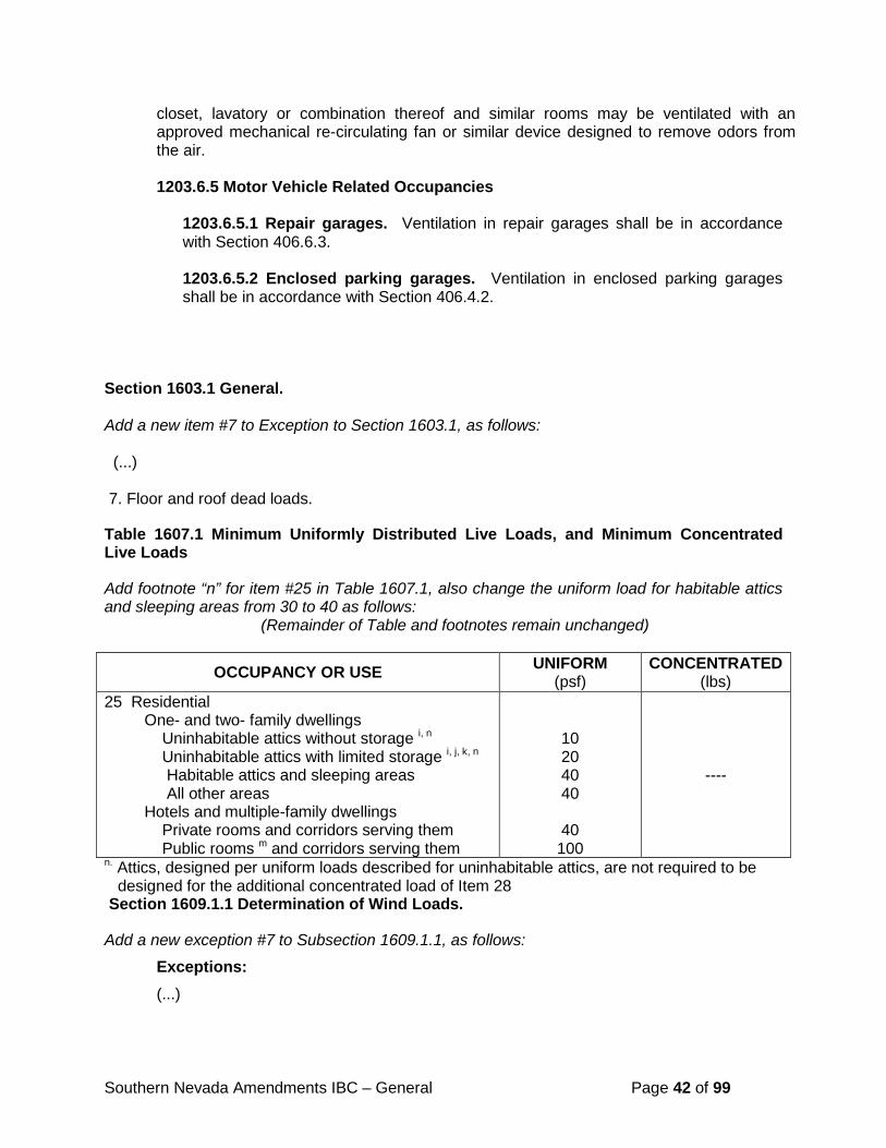
Southern Nevada Amendments IBC – General Page 42 of 99
closet, lavatory or combination thereof and similar rooms may be ventilated with an approved mechanical re-circulating fan or similar device designed to remove odors from the air.
1203.6.5 Motor Vehicle Related Occupancies
1203.6.5.1 Repair garages. Ventilation in repair garages shall be in accordance with Section 406.6.3. 1203.6.5.2 Enclosed parking garages. Ventilation in enclosed parking garages shall be in accordance with Section 406.4.2.
Section 1603.1 General. Add a new item #7 to Exception to Section 1603.1, as follows: (...) 7. Floor and roof dead loads.
Table 1607.1 Minimum Uniformly Distributed Live Loads, and Minimum Concentrated Live Loads
Add footnote “n” for item #25 in Table 1607.1, also change the uniform load for habitable attics and sleeping areas from 30 to 40 as follows: (Remainder of Table and footnotes remain unchanged)
OCCUPANCY OR USE UNIFORM (psf)
CONCENTRATED (lbs)
25 Residential One- and two- family dwellings Uninhabitable attics without storage i, n Uninhabitable attics with limited storage i, j, k, n Habitable attics and sleeping areas All other areas Hotels and multiple-family dwellings Private rooms and corridors serving them Public rooms m and corridors serving them
10 20 40 40
40 100
----
n. Attics, designed per uniform loads described for uninhabitable attics, are not required to be designed for the additional concentrated load of Item 28 Section 1609.1.1 Determination of Wind Loads.
Add a new exception #7 to Subsection 1609.1.1, as follows:
Exceptions: (...)
Southern Nevada Amendments IBC – General Page 43 of 99
7. Solid and freestanding walls up to and including 10’-0” above the highest adjacent grade and designed using the provisions of ASCE 7 section 29.4.1 need only consider CASE A of Figure 29.4-1 with a Cf factor equal to 1.40 and the resultant loading applied at the geometric center of the wall surfaces subject to the design wind loading.
Section 1610.1 Soil Lateral Loads
Revise Section 1610.1 and Subsection 1610.1.1, as follows: 1610.1 General. Foundation walls and retaining walls shall be designed to resist lateral soil loads. When a geotechnical investigation report is not required by the building official the design active pressure shall be 45 psf/ft and the at-rest pressure shall be 60 psf/ft. Foundation walls and other walls in which horizontal movement is restricted at the top shall be designed for at-rest pressure, unless specified otherwise in a geotechnical investigation report approved by the building official. Retaining walls free to move and rotate at the top shall be permitted to be designed for active pressure. Design lateral pressure from surcharge loads shall be added to the lateral earth pressure load. Design lateral pressure shall be increased if soils at the site are expansive. Foundation walls shall be designed to support the weight of the full hydrostatic pressure of undrained backfill unless a drainage system is installed in accordance with Sections 1805.4.2 and 1805.4.3.
Exception: Foundation walls extending not more than 8 feet (2438 mm) below grade and laterally supported at the top by flexible diaphragms shall be permitted to be designed for active pressure.
1610.1.1 Seismic load due to lateral earth pressure. All basement, foundation, and retaining walls in seismic design categories D, E, or F shall be designed to resist the seismic load due to the lateral earth pressure based on the following equations. For yielding walls: 3/8 (kH) (backfill soil unit weight) (H)2 (Equation 16-35a) For non-yielding walls: (kH) (backfill soil unit weight) (H)2 (Equation 16-35b) Where kH (peak ground acceleration) = SDS / 2.5 H = the height of the backfill behind the wall These equations represent the dynamic (seismic) lateral thrust. The point of application of the resultant dynamic thrust is taken at a height of 0.6H above the base of the wall. This is represented as an inverted trapezoidal pressure distribution. These equations apply to level backfill and walls that retain no more than 15 feet.
Section 1612.3 Establishment of Flood Hazard Areas.
Revise Section 1612.3, as follows:
1612.3 Establishment of flood hazard areas. To establish flood hazard areas, the applicable governing authority shall adopt a flood hazard map and supporting data. The flood hazard map shall include, at a minimum, areas of special flood hazard as identified by the Federal Emergency Management Agency in an engineering report entitled “The Flood Insurance Study
Southern Nevada Amendments IBC – General Page 44 of 99
for Clark County, Nevada and Incorporated Areas,” most current edition, as amended or revised with the accompanying Flood Insurance Rate Map (FIRM) and Flood Boundary and Floodway Map (FBFM) and related supporting data along with any revisions thereto. The adopted flood hazard map and supporting data are hereby adopted by reference and declared to be part of this section.
Section 1613.1 Scope.
Revise Exception #1 to Section 1613.1, as follows: 1613.1. Scope. Every structure, and portion thereof, including nonstructural components that are permanently attached to structures and their supports and attachments, shall be designed and constructed to resist the effects of earthquake motions in accordance with ASCE 7, excluding Chapter 14 and Appendix 11A. The seismic design category for a structure is permitted to be determined in accordance with Section 1613 or ASCE 7. Exceptions:
1. Detached one- and two-family dwellings, assigned to Seismic Design Category A, or B
2. The seismic-force-resisting system of wood-framed buildings that conform to the provisions of Section 2308 are not required to be analyzed as specified in this section.
3. Agricultural storage structures intended only for incidental human occupancy.
4. Structures that require special consideration of their response characteristics and environment that are not addressed by this code or ASCE 7 and for which other regulations provide seismic criteria, such as vehicular bridges, electrical transmission towers, hydraulic structures, buried utility lines and their appurtenances and nuclear reactors.
Section 1613.3.2 Site Class Definitions.
Revise Subsection 1613.3.2, as follows: 1613.3.2 Site class definitions. Based on the site soil properties, the site shall be classified as Site Class A, B, C, D, E, or F in accordance with Chapter 20 of ASCE 7. Where the soil properties are not known in sufficient detail to determine the site class, Site Class D shall be used unless the building official or geotechnical data determines Site Class E or F soils are present at the site. ASCE 7 states that Site Classes A and B, shall not be assigned to a site if there is more than 10 feet (3 m) of soil between the rock surface and the bottom of the spread footing or mat foundation. This provision shall be required when the average soil shear wave velocity, vs, within 10 feet of the foundation bottoms is less than 2,500 fps. When site class is determined in accordance with Chapter 20 ASCE 7, the frequency of evaluation shall be one per 40 acres or any portion thereof. A site class exploration within 1,000
Southern Nevada Amendments IBC – General Page 45 of 99
feet of the proposed site may be included in the total number of required explorations, but at least one exploration must be located within the site boundaries. Locations of site class explorations shall be determined by the registered design professional, but should be adequately spaced to classify the entire site. Additional site class explorations may be required by the building official if soil conditions are variable across the site. Where methods other than soil shear wave velocity testing are utilized, one test, Ni or sui, must be performed at ten foot intervals for the entire 100-foot exploration. Each distinctly different soil layer must also be tested. The same test used for a distinct soil layer may also be used for the ten foot interval provided the test interval does not exceed ten feet. The Site Class may be alternately determined from the Clark County Shear Wave Velocity Profile Map or the City of Henderson Seismic Site Class Map as follows: for projects that are exempt from the requirement for a Geotechnical Investigation per Section 1803.2 the Site Class can be determined directly from the referenced maps); for projects that must provide a Geotechnical Investigation per Section 1803.2, the Geotechnical Design Professional may determine site class directly from the referenced maps or any of the other accepted methods. 10 feet in depth, or cut/fill slopes greater than 10 feet in height) additional testing may be necessary and justified.
Section 1704.2 Special Inspections.
Revise Section 1704.2, Item #2 in Exception, as follows:
2. Unless otherwise required by the building official, special inspections are not required for detached 1 & 2 family dwellings and their Group U accessory structures, including, but not limited to, those listed in Section 312.1.
Section 1704.2.4 Report Requirement.
Revise Subsection 1704.2.4, as follows: 1704.2.4 Report requirement. Special inspectors shall keep records of required special inspections. The special inspector shall furnish inspection reports to the building official, and to the registered design professional in responsible charge. Reports shall indicate that work inspected was or was not completed in conformance to approved construction documents. Discrepancies shall be brought to the immediate attention of the contractor for correction. If they are not corrected, the discrepancies shall be brought to the attention of the building official and to the registered design professional in responsible charge in writing prior to the completion of that phase of the work. A final report documenting required special inspections and correction of any discrepancies noted in the inspections shall be submitted to the building official prior to the final inspection. Section 1704.4 Contractor Responsibility.
Revise Section 1704.4, as follows: 1704.4 Contractor responsibility. Each contractor responsible for the construction of a main wind- or seismic force resisting system, designated seismic system or a wind- or seismic-resisting component listed in the statement of special inspections shall submit a written statement of responsibility to the building official and the owner prior to permit issuance. The
Southern Nevada Amendments IBC – General Page 46 of 99
contractor’s statement of responsibility shall contain acknowledgement of awareness of the special requirements contained in the statement of special inspection. At the option of the building official, the contractor shall be responsible for hiring a third party inspection firm approved by the jurisdiction to perform special inspections to act as the contractor’s quality control on buildings designated as a high-rise building or a complex structure as determined by the building official. This third party inspection firm shall not be the same firm as the firm hired by the owner to perform the special inspections in accordance with Section 1704.1. Section 1704.5.1 Structural Observations for Seismic Resistance.
Revise Section 1704.5.1, as follows:
1704.5.1 Structural observations for seismic resistance. Structural observations shall be provided for those structures assigned to Seismic Design category D, E, or F, as determined in Section 1613, where one or more of the following conditions exist:
1. The structure is classified as Risk Category III or IV in accordance with Table 1604.5.
2. The height of the structure is greater than 75 feet (22,860 mm) above the base.
3. The structure is assigned to Seismic Design Category E, is classified as Risk Category I or II in accordance with Table 1604.5, and is greater than two stories above grade plane.
4. When so designated by the registered design professional responsible for the structural design.
Additionally, structural observations shall be provided when such observation is specifically required by the building official, regardless of the seismic design category. Section 1705.3 Concrete Construction.
Revise the exceptions in Section 1705.3, as follows: 1705.3 Concrete construction. The special inspections and verifications for concrete construction shall be as required by this section and Table 1705.3.
Exception: Special inspections shall not be required for:
1. Isolated spread and/or continuous concrete footings supporting walls of buildings three stories or less above grade plane that are fully supported on earth or rock where:
1.1 The footings are designed in accordance with Table 1809.7; or
1.2 The structural design of the footing is based on a specified compressive strength ,f 'c, no greater than 2,500 pounds per square inch (psi) (17.2

Southern Nevada Amendments IBC – General Page 47 of 99
MPa), regardless of the compressive strength specified in the construction documents or used in the footing construction.
2. Nonstructural concrete slabs supported directly on the ground, including prestressed slabs on grade, where the effective prestress in the concrete is less than 150 pounds per square inch (1.03 MPa).
3. Concrete patios, driveways and sidewalks, on grade.
Section 1705.4 Masonry Construction.
Revise the exceptions in Section 1705.4 as follows: 1705.4 Masonry construction. Masonry construction shall be inspected and verified in accordance with TMS 402/ACI 530/ASCE 5 and TMS 602/ACI 530.1/ASCE 6 quality assurance program requirements.
Exception: Special inspections shall not be required for:
1. Empirically designed masonry, glass unit masonry or masonry veneer designed by Section 2109, 2110, or Chapter 14, respectively, when they are part of structures classified as Risk Category I, II, or III in accordance with Section 1604.5.
2. Masonry fireplaces, masonry heaters or masonry chimneys installed or constructed in accordance with Section 2111, 2112, or 2113, respectively.
3. Masonry fences less than or equal to 8’-0” in height, retaining walls less than or equal to 6’-0” in height or combined masonry fences and retaining walls less than or equal to 14’-0” in overall height with the retaining wall portion less than or equal to 6’-0” in height and the fence portion less than or equal to 8'-0" in height provided that the walls are designed in accordance with Chapter 2 of TMS 402/ACI 530/ASCE 5 with allowable stresses for masonry reduced by one half and f’m does not exceed 1500 psi. Wall heights shall be measured from the top of footing to top of wall.
Section 1705.6 Soils.
Revise the exception in Section 1705.6, as follows:
Exception: Where Section 1803 does not require reporting of materials and procedures for fill placement, the in-place dry density of the compacted fill shall not be less than 90% of the maximum dry density at optimum moisture content determined in accordance with ASTM D 1557.
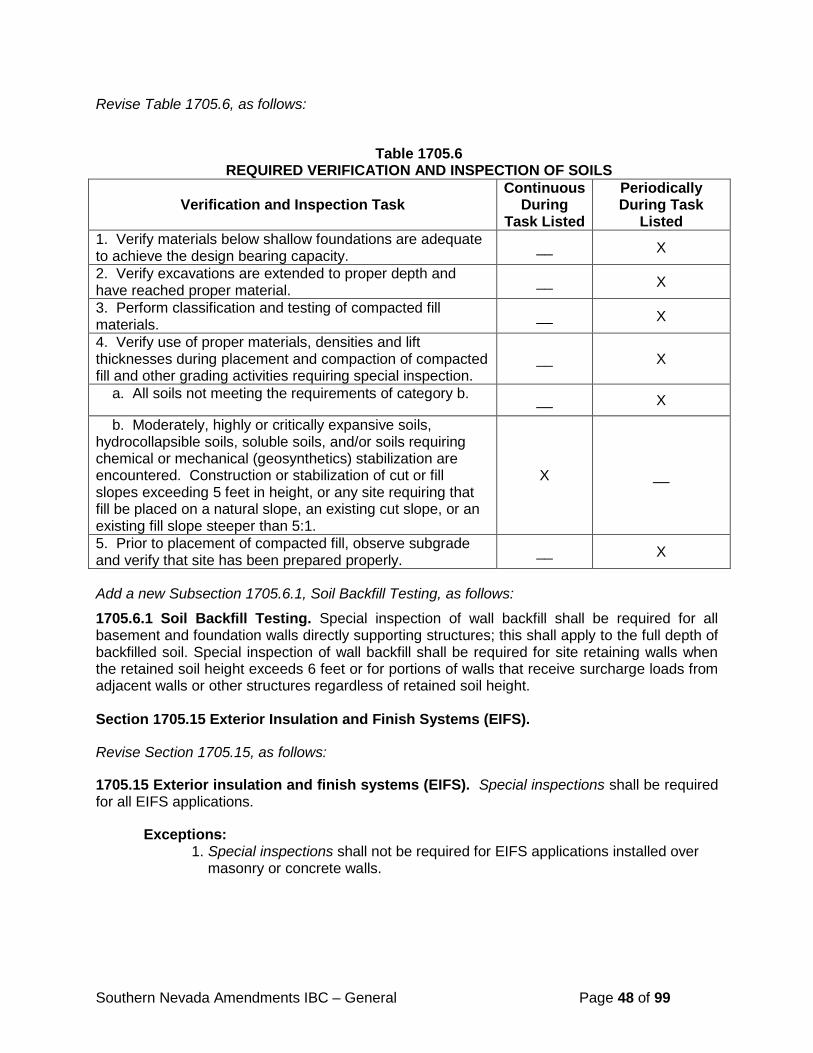
Southern Nevada Amendments IBC – General Page 48 of 99
Revise Table 1705.6, as follows:
Table 1705.6
REQUIRED VERIFICATION AND INSPECTION OF SOILS
Verification and Inspection Task Continuous
During Task Listed
Periodically During Task
Listed 1. Verify materials below shallow foundations are adequate to achieve the design bearing capacity. __ X
2. Verify excavations are extended to proper depth and have reached proper material. __ X
3. Perform classification and testing of compacted fill materials. __ X
4. Verify use of proper materials, densities and lift thicknesses during placement and compaction of compacted fill and other grading activities requiring special inspection.
__ X
a. All soils not meeting the requirements of category b. __ X
b. Moderately, highly or critically expansive soils, hydrocollapsible soils, soluble soils, and/or soils requiring chemical or mechanical (geosynthetics) stabilization are encountered. Construction or stabilization of cut or fill slopes exceeding 5 feet in height, or any site requiring that fill be placed on a natural slope, an existing cut slope, or an existing fill slope steeper than 5:1.
X __
5. Prior to placement of compacted fill, observe subgrade and verify that site has been prepared properly. __ X
Add a new Subsection 1705.6.1, Soil Backfill Testing, as follows:
1705.6.1 Soil Backfill Testing. Special inspection of wall backfill shall be required for all basement and foundation walls directly supporting structures; this shall apply to the full depth of backfilled soil. Special inspection of wall backfill shall be required for site retaining walls when the retained soil height exceeds 6 feet or for portions of walls that receive surcharge loads from adjacent walls or other structures regardless of retained soil height. Section 1705.15 Exterior Insulation and Finish Systems (EIFS).
Revise Section 1705.15, as follows:
1705.15 Exterior insulation and finish systems (EIFS). Special inspections shall be required for all EIFS applications.
Exceptions: 1. Special inspections shall not be required for EIFS applications installed over masonry or concrete walls.
Southern Nevada Amendments IBC – General Page 49 of 99
Section 1705.18 Amusement and transportation systems special cases.
Add a new Section 1705.18, as follows:
1705.18 Amusement and transportation systems special cases. When testing or verification is required by the manufacturer or specified by the building official, the testing and verification shall occur during the initial installation, operational testing and annual renewal of the certificate of operation.
Section 1803.2 Investigations Required.
Revise Section 1803.2, as follows:
1803.2 Investigations required. Geotechnical investigations shall be conducted in accordance with Sections 1803.3 through 1803.5. Geotechnical investigations shall be prepared by a registered design professional. Recommendations included in the report and approved by the building official shall be incorporated in the construction documents. Geotechnical investigations shall be required for all projects that require new foundations. Exceptions. At the option of the building official, the following projects may be exempted from having a geotechnical investigation
1. Single story structures, additions, or remodels with a footprint less than 600 square feet.
2. Fences. 3. Site retaining walls with a retained height of 4 feet or less 4. Mobile homes, trailers, modular buildings that do not have concrete or
masonry foundations. 5. Carports. 6. Signs, light poles, and communication towers less than 40 feet in height.
All projects exempt from a geotechnical report shall assume a maximum presumptive load bearing value of 1,000 psf for the vertical foundation pressure, 100 psf/ft for the lateral bearing pressure, 0.25 for the coefficient of friction for lateral sliding resistance, and an Exposure Class S2 (severe sulfate exposure level). These specified values for vertical foundation pressure and lateral bearing pressure may be increased by one-third where used with the alternate basic load combinations of Section 1605.3.2 that include wind or earthquake loads. Section 1803.3.2 Minimum Exploration Requirements. Add a new Subsection 1803.3.2, Minimum Exploration Requirements, as follows: 1803.3.2 Minimum Exploration Requirements. The minimum exploration requirements are as follows: The minimum depth of an exploration shall be fifteen feet. Exploration depth shall be increased as necessary to evaluate the suitability of the material within the foundation’s depth of influence as determined by the registered design professional. The explorations can be terminated should refusal be encountered. However, at least three-fourths of the required explorations
Southern Nevada Amendments IBC – General Page 50 of 99
shall be to the minimum depth. The geotechnical report shall clearly state the refusal criteria. When information regarding the proposed structure and the final grades is made available, the registered design professional shall determine if the explorations originally documented in the geotechnical report meet the depth requirements. The minimum number of explorations performed shall be as follows:
1. For areas less than or equal to one acre, a minimum of two explorations.
2. For areas greater than one acre, but less than five acres, a minimum of one exploration for the first acre and one for each additional two acres, or portion thereof.
3. For areas greater than five acres, but less than twenty acres, a minimum of three explorations plus one additional exploration for each three acres or fraction thereof above five.
4. For areas greater than twenty acres, a minimum of eight explorations plus one additional exploration for each five acres or fraction thereof above twenty.
Exceptions:
1. A minimum of one exploration is required for single story structures with a footprint less than 2000 square feet whose locations are known and only that area of the site is to be developed. This provision is limited to detached structures classified as Group U occupancy or building additions of any occupancy. The exploration shall be performed within the proposed footprint.
2. A minimum of one exploration is required for signs, light poles and communication towers whose locations are known and only that area of the site is to be developed. The exploration shall be performed within 50 feet of the proposed foundation for the structure.
Section 1803.5.3 Expansive Soil.
Revise Subsection 1803.5.3, and add two (2) new Subsections, 1803.5.3.1 and 1803.5.3.2, as follows:
1803.5.3 Expansive soil. In areas likely to have expansive soil, the building official shall require soil tests to determine where such soils do exist. Soils meeting all provisions of 1 through 4 shall be considered expansive, except that tests to show compliance with Items 1, 2, and 3 shall not be required if the test prescribed in Item 4 or 5 is conducted. All soils determined to be expansive by items 1 through 4 shall also conduct item 5 to determine the expansion classification level.
1. Plasticity index (PI) of 15 or greater, determined in accordance with ASTM D 4318. 2. More than 10 percent of the soil particles pass a No. 200 sieve (75 µm), determined
in accordance with ASTM D 422. 3. More than 10 percent of the soil particles are less than 5 micrometers in size,
determined in accordance with ASTM D 422. 4. Expansion index greater than 20, determined in accordance with ASTM D 4829.
Southern Nevada Amendments IBC – General Page 51 of 99
5. Soils may be determined to be expansive or non-expansive by the preceding methods or the standard 60 psf swell test.
1803.5.3.1 Expansion classification level. Expansive soils shall be classified in accordance with Table 1808.6.1.1. When soils are determined to be expansive special design consideration are required. In the event that expansive soil properties vary with depth the variation shall be included in the engineering analysis of the expansive soil’s effect on the structure. The foundation design and special inspection for grading/foundations shall be based upon results obtained from the standard 60 pound swell test. Refer to Section 1808.6 for additional requirements. 1803.5.3.2 Standard 60 pound swell test. The swell test samples shall be remolded to the in-place density required for the particular soil type as called for in the Geotechnical Investigation Report. The test samples shall be one inch thick and laterally confined by placing them in a consolidometer retaining ring constructed in accordance with ASTM D 2435. The swell test sample shall be oven dried at 60° C, and the sample shall be dried a minimum of eight (8) hours. The test samples shall be inundated with water and kept in a saturated moisture condition until measurable swelling or vertical movement ceases. The swell test shall use a 60 pounds per square foot surcharge load. The balance of the swell test will be per ASTM D 2435. Swell test results shall be interpreted using Table 1808.6.1.1
Section 1803.5.8 Compacted Fill Material.
Add new items #8 and #9 to Subsection 1803.5.8, as follows:
(...) 8. Flooding or jetting shall not be used to compact fill material that will support footings or
foundation systems. 9. Placement procedure for oversized fill material. No rock or similar irreducible material
with a maximum dimension greater than 12 inches shall be buried or placed in fills within five feet, measured vertically, from the bottom of the footing or lowest finished floor elevation, whichever is lower, within the building pad. Oversized fill material shall be placed so as to assure the filling of all voids with well-graded soil. Specific placement and inspection criteria shall be stated in the geotechnical investigation. Continuous special inspection will be required during placement of any oversized fill material.
Section 1803.6 Reporting.
Revise Section 1803.6 and add new items 11 through 28, as follows:
1803.6 Reporting. Where geotechnical investigations are required, a written report of the investigation shall be submitted to the building official by the owner or authorized agent at the time of permit application. The geotechnical report shall include, but need not be limited to, the following information:
1. A plot showing the location of the test borings, excavations, and/or investigations. The plot shall be dimensioned and shall show the approximate location of all existing and proposed structures.
2. A complete record of the soil boring and penetration test logs and soil samples.
Southern Nevada Amendments IBC – General Page 52 of 99
3. A record of the soil profile.
4. Depth to the water table, if encountered.
5. Recommendations for foundation type and design criteria, including but not limited to: bearing capacity of natural or compacted soil; provisions to mitigate the effects of expansive soils; mitigation of the effects of liquefaction, differential settlement, and varying soil strength; and the effects of adjacent loads
6. Expected total and differential settlement. Provide all test data and supporting calculations when the allowable foundation bearing pressure exceeds 4,000 psf.
7. Deep foundation information in accordance with Section 1803.5.5.
8. Special design and construction provisions for foundations of structures founded on expansive soils, as necessary.
9. Compacted fill material properties and testing in accordance with Section 1803.5.8.
10. Controlled low-strength material properties and testing in accordance with Section 1803.5.9.
11. Soil classification by the Unified Soil Classification System (ASTM D 2487). As an alternative, classification may be performed on a visual-manual basis (ASTM D 2488) in the field by an individual with: a degree in civil engineering; engineering geology; geologic engineering; or geology; or a Civil/Geological Engineer licensed in the State of Nevada. Backup data shall be included for at least one sample for every two (2) excavations and/or borings distributed among the prominent horizons in the soil profile. The backup data shall include a particle size distribution analysis, Atterberg limits and chemical tests for soil sulfates and soil chlorides.
12. Provide grading requirements for onsite and import soils (where applicable). Design recommendations for foundations, grading and earth retaining structures shall specifically address the suitability of onsite soils for use as fill material the potential negative impacts of the following adverse soil conditions including, but not limited to: collapsible soils, expansive soils (swell), soluble soils, corrosive soils (including sulfates and chlorides), chemical heave, and uncontrolled fill. The report shall include supporting test data and where any of these conditions are identified on-site, mitigating measures shall be provided based upon the identified conditions. The requirements for imported fill shall specifically address all of the above adverse conditions as well.
13. Where required by 1803.5.11, investigation of liquefaction hazards shall be performed in accordance with Appendix O “Guidelines for Evaluating Liquefaction Hazards in Nevada;” investigation of hazards associated with surface displacement due to faulting or seismically induced lateral spreading or lateral flow shall be performed in accordance with Appendix P “Guidelines for Evaluating Potential Surface Fault Rupture/Land Subsidence Hazards in Nevada.”
14. Trenching or other special procedures for determining fault and fissure(s) locations. The potential for differential movement across a fault and fissuring should be evaluated.
15. Where expansive soils are identified, classify the expansion level of the soil and specify the minimum embedment depth per Table 1808.6.1.1. When a post-tensioned slab-on-ground is recommended the geotechnical report must specify the all soil parameters as required by Section 1808.6.2.
Southern Nevada Amendments IBC – General Page 53 of 99
16. Procedures for mitigation for geological hazards.
17. Erosion control requirements, as applicable.
18. Geotechnical design considerations for drainage structures, as applicable.
19. Anticipated structural loads and type of proposed structure.
20. Address, if applicable, the possible impacts on adjoining properties and mitigating measures to be undertaken.
21. All lateral earth pressures and seismic forces shall be reported in psf/ft and distributions expressed in graphical form. All resulting forces must have a recommendation on wall placement location. Call out the mapped spectral response accelerations, SS and S1, and spectral response coefficients, SDS and SD1 assumed to calculate the distribution.
22. Site class per Section 1613.3.2, including all test data and supporting calculations.
23. Specify the soils category, and the level of special inspection required per Table 1705.6. The specified level of special inspection cannot be less than that required by Table 1705.6.
24. All geotechnical reports must be current within the last 12 months. Any report older than 12 months must be accompanied by a wet sealed update letter addressing the current site conditions based on a recent site visit.
25. Anticipated approximate cut and fill depths.
26. Caliche and cemented soils considerations, if encountered. Recommendations for the removal of caliche and cemented soils and/or the preparation and grading for foundations on caliche and cemented soils.
27. At the option of the building official, a completed copy of a geotechnical report checklist shall be included with every submittal.
28. A statement that the grading plans and foundation plans have been reviewed and are consistent with the stated geotechnical design criteria.
Section 1804.3 Site Grading.
Revise Section 1804.3, as follows:
1804.3 Site grading. The ground immediately adjacent to the foundation shall be sloped away from the building at a slope of not less than one unit vertical in 20 units horizontal (5-percent slope) for a minimum distance of 10 feet (3048 mm) measured perpendicular to the face of the wall. If physical obstructions or lot lines prohibit 10 feet (3048mm) of horizontal distance, a 5-percent slope shall be provided to an approved alternative method of diverting water away from the foundation. Swales used for this purpose shall be sloped a minimum of 1 percent along the flow line where located within 10 feet (3048mm) of the building foundation. Impervious surfaces within 10 feet (3048mm) of the building foundation shall be sloped a minimum of 2 percent away from the building. Exception: Where low expansive, low collapsible, low soluble soil conditions occur or where an exterior asphalt or concrete surface abuts a building, the slope of the ground away from the
Southern Nevada Amendments IBC – General Page 54 of 99
building foundation is permitted to be reduced to not less than one unit vertical in 48 units horizontal (2-percent slope). The procedure used to establish the final ground level adjacent to the foundation shall account for additional settlement of the backfill. Section 1804.3.1 Low Collapsible and Low Soluble Soil.
Add a new Subsection 1804.3.1 and a new Table 1804.3.1, as follows: 1804.3.1 Low collapsible and low soluble soil. Soils, after grading, shall be classified as low collapsible and low soluble in accordance with the Table 1804.3.1. Soils shall be classified as low expansive in accordance with Table 1808.6.1.1.
Table 1804.3.1
Soil Condition Criteria Applicable Test Method Low Collapsible 0 to < 3% ASTM D 2435-04 Low Soluble 0 to < 2% AWWA Standard Method 2540 (C) If, after the grading is completed, the anticipated total settlement (collapse, consolidation, and/or compression) exceeds 1 inch, then the soil cannot be classified as low collapsible.
Section 1804.5 Compacted Fill Material.
Revise the exception in Section 1804.5, as follows: Exception: When a geotechnical investigation is not required by the building official the in-place dry density within the building pad shall not be less than 90 percent of the maximum dry density at near optimum moisture content determined in accordance with ASTM D 1557.
Section 1805.2.1 Floors.
Revise Subsection 1805.2.1, as follows: 1805.2.1 Floors. Dampproofing materials for floors shall be installed between the floor and the base course required by Section 1805.4.1, except where a separate floor is provided above a concrete slab.
Where installed beneath the slab, dampproofing shall consist of not less than 10-mil (.010 inch; 0.254 mm) polyethylene conforming to ASTM E 1745 Class A requirements with joints lapped not less than 6 inches (152 mm) or other approved methods or materials. Where permitted to be installed on top of the slab, dampproofing shall consist of mopped-on bitumen, not less than 4-mil (.004 inch; 0.012 mm) polyethylene, or other approved methods or materials. Joints in the membrane shall be lapped and sealed in accordance with the manufacturer’s installation instructions.
Section 1807.2.3 Safety Factor.
Revise the exception in Subsection 1807.2.3, as follows:
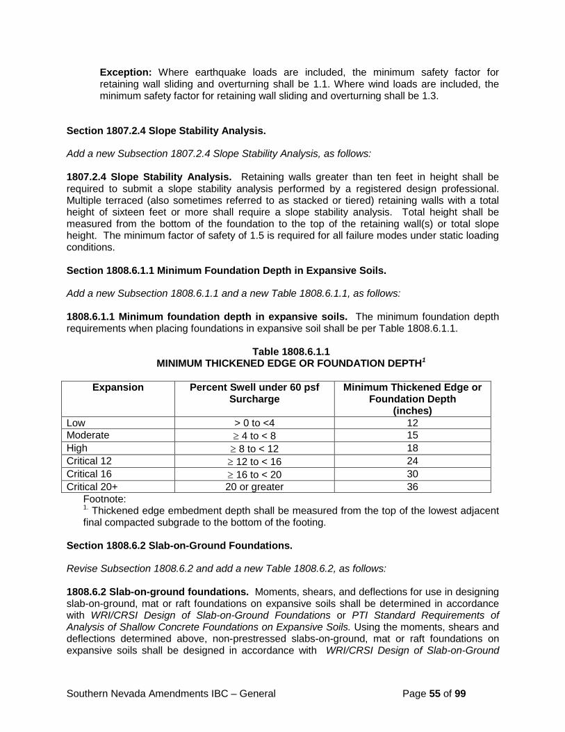
Southern Nevada Amendments IBC – General Page 55 of 99
Exception: Where earthquake loads are included, the minimum safety factor for retaining wall sliding and overturning shall be 1.1. Where wind loads are included, the minimum safety factor for retaining wall sliding and overturning shall be 1.3. Section 1807.2.4 Slope Stability Analysis.
Add a new Subsection 1807.2.4 Slope Stability Analysis, as follows: 1807.2.4 Slope Stability Analysis. Retaining walls greater than ten feet in height shall be required to submit a slope stability analysis performed by a registered design professional. Multiple terraced (also sometimes referred to as stacked or tiered) retaining walls with a total height of sixteen feet or more shall require a slope stability analysis. Total height shall be measured from the bottom of the foundation to the top of the retaining wall(s) or total slope height. The minimum factor of safety of 1.5 is required for all failure modes under static loading conditions. Section 1808.6.1.1 Minimum Foundation Depth in Expansive Soils.
Add a new Subsection 1808.6.1.1 and a new Table 1808.6.1.1, as follows: 1808.6.1.1 Minimum foundation depth in expansive soils. The minimum foundation depth requirements when placing foundations in expansive soil shall be per Table 1808.6.1.1.
Table 1808.6.1.1 MINIMUM THICKENED EDGE OR FOUNDATION DEPTH1
Expansion Percent Swell under 60 psf
Surcharge Minimum Thickened Edge or
Foundation Depth (inches)
Low > 0 to <4 12 Moderate ≥ 4 to < 8 15 High ≥ 8 to < 12 18 Critical 12 ≥ 12 to < 16 24 Critical 16 ≥ 16 to < 20 30 Critical 20+ 20 or greater 36
Footnote: 1. Thickened edge embedment depth shall be measured from the top of the lowest adjacent final compacted subgrade to the bottom of the footing.
Section 1808.6.2 Slab-on-Ground Foundations.
Revise Subsection 1808.6.2 and add a new Table 1808.6.2, as follows: 1808.6.2 Slab-on-ground foundations. Moments, shears, and deflections for use in designing slab-on-ground, mat or raft foundations on expansive soils shall be determined in accordance with WRI/CRSI Design of Slab-on-Ground Foundations or PTI Standard Requirements of Analysis of Shallow Concrete Foundations on Expansive Soils. Using the moments, shears and deflections determined above, non-prestressed slabs-on-ground, mat or raft foundations on expansive soils shall be designed in accordance with WRI/CRSI Design of Slab-on-Ground
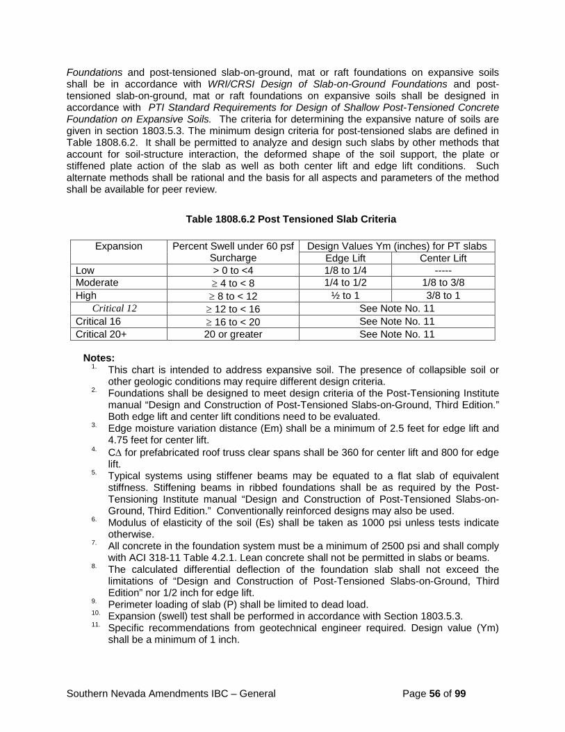
Southern Nevada Amendments IBC – General Page 56 of 99
Foundations and post-tensioned slab-on-ground, mat or raft foundations on expansive soils shall be in accordance with WRI/CRSI Design of Slab-on-Ground Foundations and post-tensioned slab-on-ground, mat or raft foundations on expansive soils shall be designed in accordance with PTI Standard Requirements for Design of Shallow Post-Tensioned Concrete Foundation on Expansive Soils. The criteria for determining the expansive nature of soils are given in section 1803.5.3. The minimum design criteria for post-tensioned slabs are defined in Table 1808.6.2. It shall be permitted to analyze and design such slabs by other methods that account for soil-structure interaction, the deformed shape of the soil support, the plate or stiffened plate action of the slab as well as both center lift and edge lift conditions. Such alternate methods shall be rational and the basis for all aspects and parameters of the method shall be available for peer review.
Table 1808.6.2 Post Tensioned Slab Criteria
Notes:
1. This chart is intended to address expansive soil. The presence of collapsible soil or other geologic conditions may require different design criteria.
2. Foundations shall be designed to meet design criteria of the Post-Tensioning Institute manual “Design and Construction of Post-Tensioned Slabs-on-Ground, Third Edition.” Both edge lift and center lift conditions need to be evaluated.
3. Edge moisture variation distance (Em) shall be a minimum of 2.5 feet for edge lift and 4.75 feet for center lift.
4. C∆ for prefabricated roof truss clear spans shall be 360 for center lift and 800 for edge lift.
5. Typical systems using stiffener beams may be equated to a flat slab of equivalent stiffness. Stiffening beams in ribbed foundations shall be as required by the Post-Tensioning Institute manual “Design and Construction of Post-Tensioned Slabs-on-Ground, Third Edition.” Conventionally reinforced designs may also be used.
6. Modulus of elasticity of the soil (Es) shall be taken as 1000 psi unless tests indicate otherwise.
7. All concrete in the foundation system must be a minimum of 2500 psi and shall comply with ACI 318-11 Table 4.2.1. Lean concrete shall not be permitted in slabs or beams.
8. The calculated differential deflection of the foundation slab shall not exceed the limitations of “Design and Construction of Post-Tensioned Slabs-on-Ground, Third Edition” nor 1/2 inch for edge lift.
9. Perimeter loading of slab (P) shall be limited to dead load. 10. Expansion (swell) test shall be performed in accordance with Section 1803.5.3. 11. Specific recommendations from geotechnical engineer required. Design value (Ym)
shall be a minimum of 1 inch.
Expansion Percent Swell under 60 psf Surcharge
Design Values Ym (inches) for PT slabs Edge Lift Center Lift
Low > 0 to <4 1/8 to 1/4 ----- Moderate ≥ 4 to < 8 1/4 to 1/2 1/8 to 3/8 High ≥ 8 to < 12 ½ to 1 3/8 to 1
Critical 12 ≥ 12 to < 16 See Note No. 11 Critical 16 ≥ 16 to < 20 See Note No. 11 Critical 20+ 20 or greater See Note No. 11
Southern Nevada Amendments IBC – General Page 57 of 99
12. For soil conditions where a low swell potential is determined, a BRAB Type II may be used.
Section 1808.8.7 Use of Non-Structural Slabs on Ground to Resist Bearing Loads.
Add a new Subsection 1808.8.7 as follows:
1808.8.7 Use of non-structural slabs on ground to resist bearing loads. Where bearing loads are proposed to be resisted by non-structural slabs on ground, all of the following conditions shall be satisfied:
1. Structural calculations shall be provided to show the slab can adequately support the proposed load.
2. The maximum allowable subgrade bearing pressure below the slab shall be no greater than 750psf, with no increases allowed for short duration loads, unless a greater value is justified in a geotechnical investigation report.
Section 1808.10 Minimum Distance to Ground Faulting.
Add a new section 1808.10 as follows: 1808.10 Minimum distance to ground faulting. The minimum distances from an occupied structure to ground faulting are as follows:
1. The minimum setback from a Holocene active fault shall be fifty (50) feet.
2. The minimum setback from a Quaternary active fault shall be five (5) feet.
3. No setback shall be imposed when the geotechnical report establishes that no fault or fault zone exists on the project.
4. For single lot single family residences, the fault location may be approximated by the geotechnical engineer through historical research. A setback of at least fifty (50) feet from each side of the historically approximated fault edge shall be established.
If, through exploration, the fault location is defined, historically approximated, or if the geotechnical report imposes a no-build zone, then the fault and the minimum setback shall be clearly shown to scale on the grading plan, plot plan, and final map; no portion of the foundation system shall be constructed within that zone. Section 1809.4 Depth and Width of Footings.
Revise Section 1809.4, as follows: 1809.4 Depth and width of footings. The minimum depth of footings below the undisturbed ground surface shall be 12 inches (305 mm). Where applicable, the requirements of Section 1809.5 shall also be satisfied. All excavations and the depth of any footing must be made below the lowest adjacent compacted subgrade to facilitate full embedment of the footing into the compacted subgrade prior to concrete placement unless otherwise recommended in the
Southern Nevada Amendments IBC – General Page 58 of 99
approved geotechnical investigation. The minimum width of footings shall be 12 inches (305 mm). Section 1904.2 Concrete Properties.
Delete the Exception in Section 1904.2, as follows: 1904.2 Concrete properties. Concrete mixtures shall conform to the most restrictive maximum water-cementitious materials ratios, maximum cementitious admixtures, minimum air-entrainment and minimum specified concrete compressive strength requirements of ACI 318 based on the exposure classes assigned in Section 1904.1.
Delete Table 1904.2
Delete Figure 1904.2
Section 1905.1.9 ACI 318, Section D.3.3.
Delete Section 1905.1.9 in its entirety and replace with the following:
1905.1.9 ACI 318, Section D.3.3. Modify ACI 318 Sections D.3.3.4.2, D.3.3.4.3 (d) and D.3.3.5.2 to read as follows: D.3.3.4.2 - Where the tensile component of the strength-level earthquake force applied to anchors exceeds 20 percent of the total factored anchor tensile force associated with the same load combination, anchors and their attachments shall be designed in accordance with D.3.3.4.3. The anchor design tensile strength shall be determined in accordance with D.3.3.4.4
Exception:
Anchors designed to resist wall out-of-plane forces with design strengths equal to or greater than the force determined in accordance with ASCE 7 Equation 12.11-1 or 12.14-10 shall be deemed to satisfy Section D.3.3.4.3 (d).
D.3.3.4.3 (d) – The anchor or group of anchors shall be designed for the maximum tension obtained from design load combinations that include E, with E increased by Ω0. The anchor design tensile strength shall be calculated from D.3.3.4.4. D.3.3.5.2 – Where the shear component of the strength-level earthquake force applied to anchors exceeds 20 percent of the total factored anchor shear force associated with the same load combination, anchors and their attachments shall be designed in accordance with D.3.3.5.3. The anchor design shear strength for resisting earthquake forces shall be determined in accordance with D.6.
Exceptions: 1. For the calculation of the in-plane shear strength of anchor bolts attaching wood sill
plates of bearing or non-bearing walls of light-frame wood structures to foundations or foundation stem walls, the in-plane shear strength in accordance with D.6.2 and D.6.3 need not be computed and D.3.3.5.3 shall be deemed to be satisfied provided all of the following are met:
1.1. The allowable in-plane shear strength of the anchor is determined in accordance with AF&PA NDS Table 11E for lateral design values parallel to grain.
Southern Nevada Amendments IBC – General Page 59 of 99
1.2. The maximum anchor nominal diameter is 5/8 inches (16 mm).
1.3. Anchor bolts are embedded into concrete a minimum of 7 inches (178 mm).
1.4. Anchor bolts are located a minimum of 1 3/4 inches (45 mm) from the edge of the concrete parallel to the length of the wood sill plate.
1.5. Anchor bolts are located a minimum of 15 anchor diameters from the edge of the concrete perpendicular to the length of the wood sill plate.
1.6. The sill plate is 2-inch or 3-inch nominal thickness.
2. For the calculation of the in-plane shear strength of anchor bolts attaching cold-formed steel track of bearing or non-bearing walls of light-frame construction to foundations or foundation stem walls, the in-plane shear strength in accordance with D.6.2 and D.6.3 need not be computed and D.3.3.5.3 shall be deemed to be satisfied provided all of the following are met:
2.1. The maximum anchor nominal diameter is 5/8 inches (16 mm).
2.2. Anchors are embedded into concrete a minimum of 7 inches (178 mm).
2.3. Anchors are located a minimum of 13/4 inches (45 mm) from the edge of the concrete parallel to the length of the track.
2.4. Anchors are located a minimum of 15 anchor diameters from the edge of the concrete perpendicular to the length of the track.
2.5. The track is 33 to 68 mil designation thickness. Allowable in-plane shear strength of exempt anchors, parallel to the edge of
concrete shall be permitted to be determined in accordance with AISI S100 Section E3.3.1.
3. In light-frame construction, bearing or nonbearing walls, shear strength of concrete
anchors less than or equal to 1 inch [25 mm] in diameter connecting sill plate or track to foundation or foundation stem wall need not satisfy D.3.3.5.3(a) through (c) when the design strength of the anchors is determined in accordance with D.6.2.1(c).
Section 1905.1.10 ACI 318, Section D.4.2.2. Delete Section 1905.1.10 in its entirety. Section 1907.1 General. Revise Section 1907.1, as follows: 1907.1 General. The thickness of concrete floor slabs supported directly on the ground shall not be less than 3-1/2 inches (89mm). A 10-mil (.010 inch;0.254 mm) polyethylene vapor retarder conforming to ASTM E 1745 Class A requirements with joints lapped not less than 6 inches (152 mm) shall be placed between the base course or subgrade and the concrete floor slab, or other approved equivalent methods shall be used to retard vapor transmission through the floor slab. Exception: A vapor retarder is not required:
Southern Nevada Amendments IBC – General Page 60 of 99
1. For detached structures accessory to occupancies in Group R-3, such as garages, utility buildings or other unheated facilities.
2. For unheated storage rooms having an area of less than 70 square feet (6.5m2) and carports attached to occupancies in Group R-3.
3. For buildings of other occupancies where migration of moisture through the slab from below will not be detrimental to the intended occupancy of the building.
4. From driveways, walks, patios and other flatwork which will not be enclosed at a later date.
5. Where approved based on local site conditions.
Section 2304.9 Connectors and Fasteners. Revise Section 2304.9, as follows: 2304.9 Connectors and fasteners. Connectors and fasteners shall comply with the applicable provisions of sections 2304.9.1 through 2304.9.8. Section 2304.9.8 Bottom (sill) Plate Anchorage.
Add a new Subsection 2304.9.8, as follows: 2304.9.8 Bottom (sill) plate anchorage. Where field conditions preclude the placement of the minimum bottom plate anchors, a registered design professional may provide a design for the attachment in accordance with accepted engineering practice. Section 2308.9.8 Pipes in Walls.
Revise Subsection 2308.9.8, as follows:
2308.9.8 Pipes in walls. Stud partitions containing plumbing, heating or other pipes shall be so framed and the joists underneath so spaced as to give proper clearance for the piping. Where a partition containing such piping runs parallel to the floor joists, the joists underneath such partitions shall be doubled and spaced to permit the passage of such pipes and shall be bridged. Where plumbing, heating or other pipes are placed in or partly in a partition, necessitating the cutting of the soles or plates, a metal tie not less than 0.058 inch (1.47mm) (16 galvanized gage) and 1 ½ inches (38mm) wide shall be fastened to each plate across and to each side of the opening with not less than six 1 ½” x 0.148” minimum nails. Section 2606.7 Light-Diffusing Systems. Revise subsections 2606.7.4 and 2606.7.5 to read, as follows: 2606.7.4 Fire suppression system. In buildings that are equipped throughout with an automatic sprinkler system in accordance with Section 903.3.1.1, plastic light-diffusing systems shall be protected both above and below unless the sprinkler system has been specifically approved for installation only above the light-diffusing system. Areas of light-diffusing systems that are protected in accordance with this section shall be limited to a maximum panel area of
Southern Nevada Amendments IBC – General Page 61 of 99
100 square feet with a maximum dimension of 15 feet. Adjacent panels shall be separated by at least 8 feet vertical and 4 feet horizontal. 2606.7.5 Electrical Luminaires. Light-transmitting plastic panels and light-diffuser panels that are installed in approved electrical luminaires shall comply with the requirements of Chapter 8 unless the light-transmitting plastic panels conform to the requirements of Section 2606.7.2. The area of approved light-transmitting plastic materials that are used in required exits or corridors shall not exceed the limitations listed in Sections 2606.7.3 and 2606.7.4 as applicable. Section 2611 Light-Transmitting Plastic Interior Signs. Revise Section 2611 to read, as follows: 2611.1 General. Light-transmitting plastic interior wall signs shall be limited as specified in Sections 2611.2 through 2611.5. Light-transmitting plastic interior signs shall also comply with Section 2606.
Exception: Light-transmitting plastic interior wall signs in covered mall buildings shall comply with Section 402.16.
2611.2 Aggregate Area. The aggregate area of signs shall not exceed 20 percent of the wall area.
Exception: Hanging or base supported signs. 2611.3 Separation. Signs shall be separated from each other by a minimum distance of 4 feet horizontal or 8 feet vertical. 2611.4 Maximum Area. The aggregate area of all light-transmitting plastics in each individual sign shall not exceed 24 square feet (2.23 m2).
Exceptions:
1. Signs are permitted to exceed an aggregate area of 24 square feet of light-transmitting plastics, provided the light-transmitting plastic meets all the following: a. does not exceed 100 square feet, b. is a minimum CC1 material, c. is installed in a building fully protected by automatic sprinklers in accordance with
Section 903.3.1.1, and d. is installed in a sign that is listed and labeled in accordance with nationally
recognized standards. 2. Signs exceeding the 100 square foot limitation of Exception 1 are permitted provided the
sign meets all the following: a. the height does not exceed 10 feet, b. the length does not exceed 60 feet, c. the area does not exceed 500 square feet, d. the light-transmitting plastic is a minimum CC1 material, e. is listed and labeled in accordance with nationally recognized standards, f. the space in which the sign is installed is protected with an automatic sprinkler
system of at least Ordinary Hazard Group 2, and
Southern Nevada Amendments IBC – General Page 62 of 99
g. a Fire Protection Report is provided to substantiate the preceding requirements are met.
2611.5 Encasement. Backs of wall mounted signs and non-illuminated portions of all signs regulated by this section shall be fully encased in metal.
Section 2612 Fiber-Reinforced Polymer. Revise Section 2612 to read, as follows: 2612.1 General. The provisions of this section shall govern the requirements and uses of fiber-reinforced polymer in and on buildings and structures. 2612.2 Labeling and Identification. Packages and containers of fiber-reinforced polymer and their components delivered to the job site shall bear the label of an approved agency showing the manufacturer’s name, product listing, product identification and information sufficient to determine that the end use will comply with the code requirements. 2612.3 Interior Finishes. Fiber-reinforced polymer used as interior finishes, decorative materials or trim shall comply with Chapter 8.
2612.3.1 Foam plastic cores. Fiber-reinforced polymer used as interior finish and which contains foam plastic cores shall comply with Chapter 8 and Chapter 26.
2612.4 Light-transmitting materials. Fiber-reinforced polymer used as light-transmitting materials shall comply with Sections 2606 through 2611 as required for the specific application. 2612.5 Exterior use. Fiber-reinforced polymer shall be permitted to be installed on the exterior walls of buildings of any type of construction when such polymers meet the requirements of Section 2603.5. Fireblocking shall be installed in accordance with Section 718.
Table 2902.1
Amend Table 2902.1 to include a new row for Casinos (Group A-2), as follows:
No.
CLA
SSIF
ICA
TIO
N
OC
CU
PAN
CY
DESCRIPTION WATER CLOSETS LAVATORIES
BA
THTU
BS/
SH
OW
ERS
DR
INK
ING
FO
UN
TAIN
S
OTHER
MALE FEMALE MALE FEMALE
1
Ass
embl
y
A-2d Casinos
1:1-100 3:1-50 1:1-200
- - 1
service sink
--- 4:51-100 2:201-400 2:101-200 6:101-200 3:401-750 3:201-400 8:201-400
Over 750, add one fixture for each additional 500
persons.
Over 400, add one fixture each additional 250
males, and one for each 150 females.
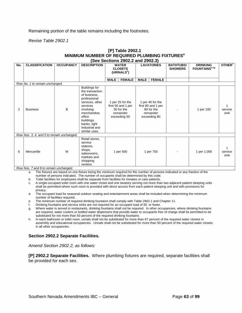
Southern Nevada Amendments IBC – General Page 63 of 99
Remaining portion of the table remains including the footnotes.
Revise Table 2902.1
[P] Table 2902.1 MINIMUM NUMBER OF REQUIRED PLUMBING FIXTURESa
(See Sections 2902.2 and 2902.3) No. CLASSIFICATION OCCUPANCY DESCRIPTION WATER
CLOSETS (URINALSh)
LAVATORIES BATHTUBS/ SHOWERS
DRINKING FOUNTAINSe,f,g
OTHERf
MALE FEMALE MALE FEMALE Row No. 1 to remain unchanged.
2 Business B
Buildings for the transaction of business, professional services, other services involving merchandise, office buildings, banks, light industrial and similar uses.
1 per 25 for the first 50 and 1 per
50 for the remainder
exceeding 50
1 per 40 for the first 80 and 1 per
80 for the remainder
exceeding 80
- 1 per 100 1
service sink
Row Nos. 3, 4, and 5 to remain unchanged.
6 Mercantile M
Retail stores, service stations, shops, salesrooms, markets and shopping centers
1 per 500 1 per 750 - 1 per 1,000 1
service sink
Row Nos. 7 and 8 to remain unchanged. a. The fixtures are based on one fixture being the minimum required for the number of persons indicated or any fraction of the
number of persons indicated. The number of occupants shall be determined by this code. b. Toilet facilities for employees shall be separate from facilities for inmates or care patients. c. A single-occupant toilet room with one water closet and one lavatory serving not more than two adjacent patient sleeping units
shall be permitted where such room is provided with direct access from each patient sleeping unit and with provisions for privacy.
d. The occupant load for seasonal outdoor seating and entertainment areas shall be included when determining the minimum number of facilities required.
e. The minimum number of required drinking fountains shall comply with Table 2902.1 and Chapter 11. f. Drinking fountains and service sinks are not required for an occupant load of 50 or fewer. g. Where water is served in restaurants, drinking fountains shall not be required. In other occupancies, where drinking fountains
are required, water coolers or bottled water dispensers that provide water to occupants free of charge shall be permitted to be substituted for not more than 50 percent of the required drinking fountains.
h. In each bathroom or toilet room, urinals shall not be substituted for more than 67 percent of the required water closets in assembly and educational occupancies. Urinals shall not be substituted for more than 50 percent of the required water closets in all other occupancies.
Section 2902.2 Separate Facilities.
Amend Section 2902.2, as follows: [P] 2902.2 Separate Facilities. Where plumbing fixtures are required, separate facilities shall be provided for each sex.
Southern Nevada Amendments IBC – General Page 64 of 99
Exceptions:
1. Separate facilities shall not be required for dwelling units and sleeping units.
2. Separate facilities shall not be required in structures or tenant spaces with a total occupant load, including both employees and customers, of 30 or less.
3. Separate facilities shall not be required in Group M occupancies in which the maximum occupant load is 100 or less.
4. Separate facilities shall not be required in Group B occupancies in which the maximum occupant load is 50 or less provided a single toilet facility is designed for use by no more than one person at a time.
Section 3002.4 Elevator Car To Accommodate Ambulance Stretcher.
Amend Section 3002.4, as follows:
3002.4 Elevator car to accommodate ambulance stretcher. Where elevators are provided in buildings four or more stories above, or four or more stories below, grade plane, at least one elevator, and no less than the minimum number specified in the exception to Section 403.6.1 when provided in lieu of fire service access elevators, shall be provided for fire department emergency access to all floors. The elevator car shall be of such a size and arrangement to accommodate an ambulance stretch 24 inches by 84 inches (601 mm by 2134 mm) with not less than 5-inch (127 mm) radius corners, in the horizontal, open position and shall be identified by the international symbol for emergency medical services (star of life). The symbol shall not be less than 3 inches (76 mm) in height and shall be placed inside on both sides of the hoistway door frame. Such elevators shall open into a lobby providing sufficient area to accommodate transport of a 24-inch by 84-inch (610 mm by 2134 mm) ambulance stretcher. Section 3003.1.3 Two Or More Elevators.
Amend Section 3003.1.3, as follows:
3003.1.3 Two or more elevators. Where two or more elevators are controlled by a common operating system, all elevators shall automatically transfer to standby power within 60 seconds after failure of normal power where the standby power source is of sufficient capacity to operate all elevators at the same time. Where the standby power source is not of sufficient capacity to operate all elevators at the same time, all elevators shall transfer to standby power in sequence, return to the designated landing and disconnect from the standby power source. After all elevators have been returned to the designated level, at least one elevator, and all elevators installed in accordance with the exception to Section 403.6.1, shall remain operable from the standby power source. Section 3112 Cabanas.
Add new Section 3112, as follows: 3112 Cabanas.
Southern Nevada Amendments IBC – General Page 65 of 99
3112.1 General. This section shall apply to cabanas on, or in close proximity to, buildings where the predominant building construction type would not otherwise allow cabanas to be constructed as membrane structures in accordance with Section 3102.3. Cabanas that are erected for a period of less than 180 days shall comply with the International Fire Code. 3112.2 Definitions. The following words and terms shall, for the purposes of this section, have the meanings shown herein: CABANA. A structure used for temporary shelter, comfort and privacy of occupants located on, or in close proximity to, a building. Cabanas shall not be used for retail sales, bar service, food preparation, storage, or overnight sleeping. CABANA GROUP. A group of individual cabanas that are not separated from each other as required within this section. The total area of the cabana group shall be used to determine code requirements for all cabanas contained within the cabana group. 3112.3 Design and Construction. Cabanas shall be designed and constructed to withstand wind or other lateral loads and live loads as required by Chapter 16 with due allowance for shape, open construction and similar features that relieve the pressures or loads. Structural members shall be protected to prevent deterioration.
3112.3.1 Frame. Cabanas shall be constructed of a rigid, noncombustible frame that is permanently mounted to the roof or deck on which it is located. 3112.3.2 Membrane Covering. The membrane covering of the cabana shall either be noncombustible in accordance with Section 703.4 or be tested by an approved agency and pass Test 2 of NFPA 701. 3112.3.3 Openness. Each cabana shall be provided with a minimum of one opening to an exterior egress route. Such opening shall provide a minimum unobstructed opening of 5 feet (1524 mm) wide by 7 feet (2134 mm) high. 3112.3.4 Height. The highest point of a cabana shall not exceed 20 feet (4572 mm). 3112.3.5 Area. The area of any single cabana or cabana group shall not exceed 1,000 square feet (46.45 m2).
Exception: The area of cabanas that are constructed entirely of noncombustible materials shall not exceed 2,000 square feet (92.90 m2). 3112.3.5.1 Subdivision. Subdivision of a cabana is permitted where subdivision of the cabana is provided by any material that is tested by an approved agency and passes Test 2 of NFPA 701.
3112.4 Location. Cabanas shall be located to minimize the hazard to the building, other cabanas, and the means of egress.
3112.4.1 Separation between cabanas. Cabanas shall be separated from all other cabanas by a minimum distance of 10 feet (3048 mm), as measured at the nearest horizontal projection. Where cabanas do not meet this spacing, the cabanas shall be
Southern Nevada Amendments IBC – General Page 66 of 99
considered a cabana group, and the cabana group shall meet the requirements set forth herein. 3112.4.2 Separation between cabana groups. Cabana groups shall be separated from all other cabanas by a minimum distance of 10 feet (3048 mm), as measured at the nearest horizontal projection. 3112.4.3 Separation to building. Cabanas shall be a minimum of 10 feet (3048 mm) from any wall or building opening, and shall not be located beneath any horizontal projection of the main building. 3112.4.4 Obstruction to means of egress. Cabanas shall be located and spaced such that the required means of egress is not obstructed by the cabanas for the entire height of the cabanas.
3112.5 Automatic sprinkler system. Cabanas and cabana groups shall be protected throughout with an automatic sprinkler system in accordance with Section 903.3.1.1.
Exception: An automatic sprinkler system shall not be required in cabanas or cabana groups that do not exceed 120 square feet (11.148 m2) in area.
3112.6 Cooking facilities. Cooking shall not be permitted within 20 feet (6096 mm) of a cabana or inside a cabana. 3112.7 Fuel-fired equipment. Fuel-fired equipment shall not be permitted within 20 feet (6096 mm) of a cabana or inside a cabana. 3112.8 Lighting. All lighting within or attached to cabanas shall be electric. Open flames for any purpose are prohibited within 20 feet (6096 mm) of a cabana or inside a cabana. 3112.9 Fire Protection Report. A Fire Protection Report shall be submitted and shall address the type of construction of the main structure and the cabana(s), the size of the cabana(s), fire protection systems for the cabana(s), and the impact of the cabana(s) on the means of egress.
Section 3113 Shade Structures.
Add new Section 3113.
3113 Shade Structures. 3113.1 General. This section shall apply to shade structures on, attached to, or in close proximity to buildings of Type I or Type II construction. Where shade structures are constructed as a cabana, membrane structure or separate building, compliance with this section is not required. Shade structures that are erected for a period of less than 180 days shall comply with the International Fire Code. 3113.2 Definitions. The following words or terms shall, for the purposes of this section, have the meanings shown herein.
Southern Nevada Amendments IBC – General Page 67 of 99
SHADE STRUCTURE. A shade structure is a structure with not less than 50 percent of its perimeter wall area unenclosed, has no interior partitions, and provides solar or weather protection for uses accessory to a building of any occupancy. Shade structures shall not apply to cabanas, canopies, roof structures over vehicle drive-through lanes (porte cocheres), parking facilities, playground structures, or industrial uses. SHADE STRUCTURE GROUP. A shade structure group is a group of individual shade structures that are not separated from each other by a minimum distance of 10 feet (3048 mm), as measured from the nearest horizontal projection. The total area of the shade structure group shall be used to determine code requirements for all shade structures within the shade structure group. 3113.3 Design and Construction. Shade structures shall be designed and constructed to withstand the wind and lateral loads and live loads as required by Chapter 16 with due allowance for shape, open construction and similar features that relieve the pressure of loads. Structural members shall be protected to prevent deterioration.
3113.3.1 Frames. Frames shall be non-rated, and noncombustible or wood of Type IV size. 3113.3.2 Shade Coverings. Shade coverings shall be of:
1. Noncombustible materials in accordance with Section 703.5; or
2. Wood of Type IV size; or
3. An approved covering that meets the fire propagation performance criteria of NFPA 701.
3113.3.3 Height. The height of a shade structure shall not exceed that allowed for the predominant building construction type, but shall not exceed 50 feet in height. 3113.3.4 Area. The area of shade structures shall be limited to the maximum allowable area for the predominant building construction type, including the area of such building, but in no case shall the shade structure exceed 10,000 square feet (929 m2).
Exception: Shade structures with combustible construction as outlined under Section 3113.3 shall be limited to no more than 5,000 square feet (464.52 m2).
3113.4 Location. Shade structures shall be allowed to be constructed on or attached to the building or may be free standing separated from the building.
3113.4.1 Separation between shade structures. Shade structures shall be separated from all other shade structures by a minimum distance of 10 feet (3048 mm), as measured at the nearest horizontal projection, regardless of the height of each horizontal projection. Where shade structures do not meet this spacing, the shade structures shall be considered a shade structure group, and the shade structure group shall meet the requirements set forth herein. 3113.4.2 Separation between shade structure groups. Shade structure groups shall be separated from all other shade structure groups by a minimum distance of 10 feet (3048
Southern Nevada Amendments IBC – General Page 68 of 99
mm), as measured at the nearest horizontal projection, regardless of the height of each horizontal projection.
3113.5 Means of Egress. Mean of egress shall comply with Chapter 10. Sufficient clearance and aisle widths shall be provided and maintained for means of egress that pass through the shade structure from any building or area. 3113.6 Automatic Sprinkler Systems. Shade structures and shade structure groups shall be protected by an automatic sprinkler system as specified in Chapter 9 for the appropriate hazard class.
Exceptions:
1. Shade structures attached to buildings not otherwise required to be protected by an automatic sprinkler system and where the shade structure does not increase the overall building area beyond 5,000 square feet (464.52 m²).
2. Where a slatted, lattice or fixed louvered shade structure roof system is not less than
50 percent open to the sky and not provided with a fabric or similar covering. 3. Entirely noncombustible shade structures that are located a minimum of 10 feet from
any wall, building opening, or adjacent shade structure; that do not exceed 1,000 square feet (92.91 m²) in area, and has not less than 100 percent of its perimeter wall area unenclosed.
4. Shade structures that are located a minimum of 10 feet from any wall, building
opening, or adjacent shade structure; that do not exceed 200 square feet (18.58 m2), or 400 square feet (37.16 m2) when comprised entirely of noncombustible materials.
3113.7 Fire Alarm & Detection System. Fire alarm notification appliances are required within shade structures where the predominant building includes an exit that discharges through the shade structure, or where the shade structure exits through the building. Fire alarm notification appliances are not required where the predominant building and shade structure exit independently of one another and where the use of the shade structure does not otherwise require notification appliances.
Shade structures shall be protected by fire detection systems as specified in Chapter 9 based on the applicable occupancy and use. Detection systems utilized as part of a suppression system shall be addressed in a Fire Protection Report as required by Section 3113.10.
3113.8 Fuel-Fired Equipment. Fuel-fired equipment shall not be permitted within 20 feet (6096 mm) of a shade structure or under a shade structure.
Exceptions:
1. Portable chafing dishes that utilize liquid fuel manufactured for its intended use. 2. Gas fired grills that are located a minimum of 10 feet (3048 mm) from the
predominant building may be within 20 feet (6096 mm) of, or under entirely noncombustible shade structures.
Southern Nevada Amendments IBC – General Page 69 of 99
3. Portable gas fired heaters that are located a minimum of 10 feet (3048 mm) from the predominant building may be within 20 feet (6096 mm) of, or under entirely noncombustible shade structures.
4. Gas fired fireplaces or fire pits that are located a minimum of 15 feet (3048 mm) from
the predominant building may be within 20 feet (6096 mm) of, or under entirely noncombustible shade structures.
3113.9 Lighting. All lighting within or attached to shade structures shall be electric. Open flames for any purpose other than those noted above are prohibited within 20 feet (6096 mm) of a shade structure or under a shade structure, unless approved by the authority having jurisdiction. 3113.10 Fire Protection Report. When required by the Building Official, a fire protection report shall be provided to address the type of construction of the predominant structure and the shade structure(s), the size and use of the shade structure(s), fire protection systems for the shade structure(s), and the impact of the shade structure(s) on the means of egress.
Section 3306.2 Walkways.
Revise Section 3306.2, as follows: 3306.2 Walkways. A walkway shall be provided for pedestrian travel in front of every construction and demolition site unless the applicable governing authority authorizes the sidewalk to be fenced or closed. Walkways shall be of sufficient width to accommodate the pedestrian traffic, but in no case shall they be less than 4 feet (1219 mm) in width. Walkways shall be provided with a durable walking surface. Walkways shall be accessible in accordance with Chapter 11 and shall be designed to support all imposed loads and in no case shall the design live load be less than 150 pounds per square foot (psf) (7.2 kN/m2). Sidewalks or walkways that lead from the public sidewalk to a building entrance where the general public may be at risk due to falling construction debris shall be similarly protected.
Section 3401.7 Automatic Sprinkler Systems in Existing Buildings.
Add Section 3401.7 to allow for partial coverage of automatic sprinkler systems in existing buildings, as follows: 3401.7 Automatic Sprinkler Systems in Existing Buildings. Automatic sprinkler systems in accordance with Section 903 and designed per the Fire Code shall be provided in existing structures without an approved fire sprinkler system at the locations described in Sections 3401.7.1 through 3401.7.3. Where these provisions result in buildings with only partial coverage from a fire sprinkler system, durable weatherproof signage shall be provided at the Fire Department Connection(s) clearly indicating that the building is partially protected with fire sprinklers and clearly identifying the portion(s) of the building covered by the fire sprinkler systems. Where required by the fire code official, the underground fire service and automatic sprinkler lead-in to the first portion of an existing building without an automatic sprinkler system shall be sized to a minimum Ordinary Hazard Group II sprinkler design for future expansion of the automatic sprinkler system to cover all other portions of the building.
Southern Nevada Amendments IBC – General Page 70 of 99
3401.7.1 Additions. Additions to any building shall comply with this Section and Section 3403.
3401.7.1.1 Addition adding an automatic sprinkler system. In existing buildings without an automatic fire sprinkler system and an automatic sprinkler system is provided for the building addition, required or not, the entire building shall be provided with an automatic sprinkler system.
Exceptions:
1. Other than occupancies of Group E Daycare, Group H, Group I, or Group R,
sprinklers are not required to be provided beyond the fire area of the addition where the addition fire area is separated from the reminder of the building by a fire barrier of not less than 2-hours, constructed in accordance with Section 707, and without openings.
2. In all occupancies, sprinklers are not required to be provided beyond the fire area of the addition when the addition fire area is separated from the existing building by 4-hour fire protection rated fire walls constructed in accordance with Section 706, and without openings.
3. When approved by the building official, special hazard areas that are required to have an automatic sprinkler system, such as medical gas rooms, do not require the remainder of the building to have an automatic sprinkler system.
3401.7.1.2 Addition without an automatic sprinkler system. An existing building without an automatic sprinkler system not otherwise required or provided in the building addition is not required to provide an automatic sprinkler system for the remainder of the building where any of the following conditions are met:
1. The building has a total area of less than 5,000 sq ft (464 m2) and the addition
does not cause the existing building to trigger automatic sprinkler system occupancy-specific requirements contained in Section 903.
2. Other than occupancies of Group E Daycare, Group H, Group I, or Group R, the
fire area containing the addition is separated from adjacent fire areas by a fire barrier of not less than 2-hours, constructed in accordance with Section 707, and without openings.
3. In all occupancies, automatic sprinkler systems are not required to be provided
outside the fire area of the addition where the addition’s fire area is separated from the existing building by 4-hour fire protection rated fire walls constructed in accordance with Section 706, and without openings.
3401.7.2 Alterations. Alterations within existing building shall comply with this Section and Section 3404.
3401.7.2.1 Alteration adding an automatic sprinkler system. An existing building without an automatic sprinkler system and for which an automatic sprinkler system is
Southern Nevada Amendments IBC – General Page 71 of 99
provided for an alteration, required or not, shall install an automatic sprinkler system for the entire building.
Exceptions:
1. Other than occupancies of Group E Daycare, Group H, Group I, or Group R, an automatic sprinkler system is not required to be provided beyond the fire area containing the alteration where it is separated from the reminder of the building by a fire barrier of not less than 2-hour fire protection rating, constructed in accordance with Section 707, and without openings.
2. In all occupancies, sprinklers are not required to be provided beyond the fire area of the alteration when the alteration fire area is separated from the existing building by 4-hour fire protection rated fire wall constructed in accordance with Section 706, and without openings.
3. When approved by the building official, special hazard areas that are required to have an automatic sprinkler system, such as medical gas rooms, do not require the remainder of the building to have an automatic sprinkler system.
3401.7.2.2 Alteration without an automatic sprinkler system. An existing building without an automatic sprinkler system and not otherwise required or provided in the alteration, is not required to be provided with an automatic sprinkler system.
3401.7.3 Change of Occupancy. A change of occupancy within an existing building shall comply with this Section and Section 3408.
3401.7.3.1 Change of Occupancy requiring an automatic sprinkler system. An existing building without an automatic sprinkler system and for which an automatic sprinkler system is provided for an area containing a change of occupancy, required or not, shall install an automatic sprinkler system for the entire building.
Exceptions:
1. Other than occupancies of Group E Daycare, Group H, Group I, or Group R, an automatic sprinkler system is not required to be provided beyond the fire area containing the alteration where it is separated from the reminder of the building by a fire barrier of not less than 2-hour fire protection rating, constructed in accordance with Section 707, and without openings.
2. In all occupancies, sprinklers are not required to be provided beyond the fire area of the alteration when the alteration fire area is separated from the existing building by 4-hour fire protection rated fire wall constructed in accordance with Section 706, and without openings.
3. When approved by the building official, special hazard areas that are required to have an automatic sprinkler system, such as medical gas rooms, do not require the remainder of the building to have an automatic sprinkler system.
3401.7.3.2 Nonsprinklered Change of Occupancy. An existing building without an
automatic sprinkler system not otherwise required or provided in the change of
Southern Nevada Amendments IBC – General Page 72 of 99
occupancy area is not required to provide an automatic sprinkler system for the remainder of the building area where any of the following conditions are met:
1. The building has a total area of less than 5,000 sq ft (464 m2) and the addition
does not cause the existing building to trigger automatic sprinkler system occupancy-specific requirements contained in Section 903.
2. Other than occupancies of Group E Daycare, Group H, Group I, or Group R, the
fire area containing the addition is separated from adjacent fire areas by a fire barrier of not less than 2-hours, constructed in accordance with Section 707, and without openings.
3. In all occupancies, automatic sprinkler systems are not required to be provided
outside the fire area of the addition where the addition’s fire area is separated from the existing building by 4-hour fire protection rated fire walls constructed in accordance with Section 706, and without openings.
4. When approved by the building official, a change in occupancy to an equal or
lesser hazard shall not require the installation of an automatic sprinkler system for any part of the building. To make such a determination, the building official may consider changes in occupant load, relative fire hazard and other relevant data.
Section 3401.8 Fire Alarm Systems in Existing Buildings.
Add new Section 3401.8, as follows: 3401.8 Fire Alarm Systems in Existing Buildings. Fire alarm systems, installed in accordance with Section 907 and the Fire Code, shall be provided in existing structures at the locations described in Sections 3401.8.1 through 3401.8.3.
3401.8.1 Additions. Additions to any building shall comply with this Section and Section 3403. In existing buildings where fire alarms are provided for the addition, whether required or not, coverage shall be extended to include the entire building.
Exceptions:
1. Other than occupancies of Group E Daycare, Group H, Group I, or Group R, fire alarm system coverage is not required beyond the fire area containing the addition where the addition fire area is separated from the reminder of the building by a fire barrier of not less than 2-hours, constructed in accordance with Section 707, with openings protected with automatic-closing devices.
2. In all occupancies, the addition of a Fire Wall in accordance with Section 706, with openings protected with automatic-closing devices, may be used to create a new fire area that separates the addition from the remainder of the building. The Fire Wall may either:
a. limit required fire alarm system coverage to include only the new fire area
containing the addition, or
Southern Nevada Amendments IBC – General Page 73 of 99
b. limit required fire alarm system coverage to include the new addition and other existing spaces adjacent to the addition that remain in the same fire area, or
c. eliminate the requirement to install a fire alarm system in accordance with the provisions of Section 907.2.
3401.8.2 Alterations. Existing buildings that undergo an alteration shall comply with this Section and Section 3404.
Exception: Alterations consisting solely of the removal and replacement or the covering of existing materials, elements, equipment, or fixtures using new materials, elements, equipment, or fixtures that serve the same purpose.
In existing buildings where fire alarms are provided for an alteration, whether required or not, coverage shall be extended to include the entire building.
Exceptions:
1. Other than occupancies of Group E Daycare, Group H, Group I, or Group R, fire alarm system coverage is not required beyond the fire area containing the alteration where the alteration fire area is separated from the reminder of the building by a fire barrier of not less than 2-hours, constructed in accordance with Section 707, and with openings protected with automatic-closing devices.
2. In all occupancies, the addition of a Fire Wall in accordance with Section 706,
with openings protected with automatic-closing devices, may be used to create a unique fire area to separate the alteration from the remainder of the building. The Fire Wall may either:
a. limit required fire alarm system coverage area to include only the fire area
containing the alteration, or
b. eliminate the requirement to install a fire alarm system in accordance with the provisions of Section 907.2.
3401.8.3 Change of Occupancy. Existing buildings that undergo a change of occupancy shall comply with this Section and Section 3408.
Exception: When approved by the building official, a change in occupancy to an equal or lesser hazard shall not require the installation of a fire alarm system for any part of the building. To make such a determination, the building official may consider changes in occupant load, relative fire hazard and other relevant data.
In existing buildings where fire alarms are provided for a change of occupancy, whether required or not, coverage shall be extended to include the entire building.
Exceptions:
1. Other than occupancies of Group E Daycare, Group H, Group I, or Group R, fire alarm system coverage is not required beyond the fire area containing the
Southern Nevada Amendments IBC – General Page 74 of 99
change of occupancy where the change of occupancy fire area is separated from the reminder of the building by a fire barrier of not less than 2-hours, constructed in accordance with Section 707, with openings protected with automatic-closing devices.
2. In all occupancies, the addition of a Fire Wall in accordance with Section 706,
with openings protected with automatic-closing devices, may be used to create a unique fire area to separate the portion of the building containing the change of use from the remainder of the building. The Fire Wall may either:
a. limit required fire alarm system coverage area to include only the fire area
containing the change of use, or b. eliminate the requirement to install a fire alarm system in accordance with the
provisions of Section 907.2. Section 3405.2 Substantial Structural Damage To Vertical Elements Of The Lateral Force-Resisting System.
Amend Section 3405.2, as follows: 3405.2 Substantial structural damage to vertical elements of the lateral force-resisting system. A building that has sustained substantial structural damage to the vertical elements of its lateral force-resisting system shall be evaluated and repaired in accordance with the applicable provisions of Sections 3405.2.1 through 3405.2.3. Section 3405.3.1 Lateral Force-Resisting Elements.
Amend Section 3405.3.1, as follows: 3405.3.1 Lateral force-resisting elements. Regardless of the level of damage to vertical elements of the lateral force-resisting system, if substantial structural damage to gravity load-carrying components was caused primarily by wind or earthquake effects, then the building shall be evaluated in accordance with Section 3405.2.1 and, if noncompliant, rehabilitated in accordance with Section 3405.2.3.
Appendices C, E, and I
Adopt Appendices C, E, and I in their entirety without amendment. Appendix H Signs Adopt Appendix H in its entirety with the following amendment: Section H107.1.3 Area Limitation. Add an exception to Section H107.1.3 as follows:
Exception: The area of plastic may be unlimited on a structurally independent sign provided the exterior walls of adjacent buildings are constructed in accordance with Table 602 and located;
Southern Nevada Amendments IBC – General Page 75 of 99
a.) a minimum of 10 feet from Type I building(s); and b.) a minimum of 10 feet, measured horizontally, from a building’s main entrance.
The separation distance from the sign and an adjacent building shall be a consideration for the rating of the building’s exterior walls. For the purpose of this exception, the fire resistance rating of the sign may be taken as 0 hours at any separation distance.
Appendix J Grading
Adopt Appendix J in its entirety with the following amendments:
Section J102.1 Definitions.
Revise the definition of “GRADING”, as follows:
GRADING. An excavation, inclusive of clearing and grubbing of vegetation, or fill or combination thereof.
Add new definitions in Section J102.1 for Building Pad, Certify, Fault, Holocene Active Fault, Quaternary Active Fault, Inactive Fault, Final Grading Report, Geotechnical Report (Soils Report), Pad Certification Report, Pad Recertification Report, Refusal, and Special Geotechnical Consideration Area, as follows: BUILDING PAD. The soil, cut or fill site, outlined by the area of the footprint of the building plus a minimum of 5 additional feet (1529 mm) to the exterior. This includes any type of foundation system for the structure. CERTIFY. Use of the word “certify” or “certification” constitutes an expression of professional opinion regarding those facts or findings which are the subject of the certification. FAULT. A fracture or zone of fracturing in geologic materials (soil or rock) along which there has been displacement of the sides relative to one another parallel to the fracture. FAULT, HOLOCENE ACTIVE. A fault with recognized activity within Holocene time (within the past 11,000 years). FAULT, QUATERNARY ACTIVE. A fault with recognized activity within Quaternary time (within the past 1.6 million years). FAULT INACTIVE. A fault without recognized activity within Quaternary time (within the past 1.6 million years). FINAL GRADING REPORT. A grading report stamped and signed by a registered design professional certifying that the building pad was constructed in conformance with the recommendations set forth in the geotechnical report. This report contains explicit information and data that verifies compliance with the geotechnical report of record including any approved supplements or addendums. GEOTECHNICAL REPORT (SOILS REPORT). Data and engineering recommendations resulting from site exploration which evaluates the soil conditions and general site
Southern Nevada Amendments IBC – General Page 76 of 99
characteristics and suitability of the site for the proposed construction. A registered design professional shall prepare and seal the report. PAD CERTIFICATION REPORT. An interim grading report stamped and signed by a registered design professional certifying that the building pad currently is in conformance with the recommendations set forth in the geotechnical report of record. PAD RECERTIFICATION REPORT. A report stamped and signed by a registered design professional certifying that the building pad currently is in conformance with the recommendations set forth in the geotechnical report of record. This report contains explicit information and data that verifies compliance to the geotechnical report of record including any approved supplements or addendums. REFUSAL. Refusal while advancing an exploration is recognized as defined by ASTM D 1586-08a. SPECIAL GEOTECHNICAL CONSIDERATION AREA. A portion of Clark County where additional geotechnical investigation requirements may apply. These areas are identified on the most recent edition of the “Clark County Soil Guidelines Reference Map(s)” as published by Clark County.
Section J103.3 Hazards.
Add a new Section J103.3 Hazards, as follows: J103.3 Hazards. Whenever the building official determines that any existing excavation or embankment or fill on private property has become a hazard to life and limb, or endangers property, or adversely affects the safety, use or stability of a public way, easement, storm sewer system, or drainage channel, the owner of the property upon which the excavation or fill is located, or other person or agent in control of said property, upon receipt of notice in writing from the building official, shall within the period specified therein repair or eliminate such excavation or embankment to eliminate the hazard and to be in conformance with the requirements of this code.
Section J104.1 Submittal requirements.
Revise Section J104.1, as follows: J104.1 Submittal requirements. In addition to the provisions of Section 105.3, the applicant shall state the estimated quantities of excavation and fill. All projects that require grading shall have a grading plan prepared, stamped, and signed by a registered design professional. Exception: At the option of the building official, if the structure is located outside of a flood hazard area the following projects may be exempted from having a grading plan. Projects exempted from a grading plan must still comply with the grading and drainage requirements in the IBC.
1. Single story structures, additions, or remodels with a footprint less than 600 square feet.
Southern Nevada Amendments IBC – General Page 77 of 99
2. Patio covers, decks, and canopies associated with a single family residence.
3. Mobile homes, trailers, modular buildings that do not have concrete or masonry foundations.
4. Carports.
5. Signs, light poles, and communication towers. Section J104.2 Grading plan requirements.
Revise Section J104.2 in its entirety, as follows: J104.2 Grading plan requirements. All grading plans shall be prepared, stamped, and signed by a registered design professional. The following items must be included on all grading plan submittals.
1. General vicinity of the proposed site.
2. Property limits and accurate contours of existing ground and details of terrain and area drainage.
3. Limiting dimensions, elevations or finish contours to be achieved by the grading, proposed drainage channels and related construction.
4. Location of any buildings or structures on the property where the work is to be performed and the location of any buildings or structures on land of adjacent owners that are within 100 feet of the property or that may be affected by the proposed grading operations.
5. Recommendations included in the geotechnical report shall be incorporated in the grading plans or specifications as follows:
a. Locations and dimensions of all cut and fill slopes,
b. Locations of all cross sections presented in the geotechnical report,
c. Locations and sizes of all recommended remedial measures such as buttress fills, stability fills, deep foundation systems, reinforced earth, retaining walls, etc.,
d. Location and layout of proposed subdrainage system.
6. A statement that the site shall be graded in accordance with the approved geotechnical report. This statement shall include the firm name that prepared the geotechnical report, the report number, and the date of the geotechnical report.
7. Locations of other existing topographic features either natural or man-made such as streets, drainage structures, pavements, walls, mining pits, etc.
8. The cut to fill transition line.
9. Positive drainage away from the foundation per Section 1804.3.
10. Details and cross sections at property lines, fence walls, retaining walls, berms, etc.
11. Elevation datum and benchmarks (NAVD 88).
12. Existing contours at least 100 feet beyond the property lines.
Southern Nevada Amendments IBC – General Page 78 of 99
13. Proposed finish contours or spot elevations at the property corners, building pad, and at swale flow lines.
14. Elevations of curbs or centerlines of roads or streets.
15. Earthwork quantities in cubic yards.
16. Finish floor elevations.
17. Details and cross sections of typical fill slopes and cut slopes.
18. Typical details of fill-over-natural slopes and fill-over-cut slopes where fill is to be placed on natural or cut slopes steeper than 5H:1V in accordance with Section J107.
19. Setback dimensions of cut and fill slopes from site boundaries per Section J108.
20. The placement of buildings and structures on and or adjacent to slopes steeper than 3H:1V (33.3% slope) shall be in accordance with Section 1808.7.
21. Provide terracing in accordance with Section J109 for slopes steeper than 3H:1V (33.3% slope).
22. Provide the locations and dimensions of all terrace drains for all slopes steeper than 3H:1V in accordance with Section J109.
23. The standard notes specified in the Las Vegas Valley Construction Site Best Management Practice Guidance Manual (most current edition).
24. Registered design professional original seal (wet seal), signature and date or a Records stamp and signature stating, “This is a true and exact copy of the original document on file in this office.”
Section J104.3 Geotechnical Report.
Revise Section J104.3, as follows:
J104.3 Geotechnical report. A geotechnical report prepared by a registered design professional shall be provided. The report shall comply with Section 1803.6.
Section J105 Inspections
Revise Section J105 in its entirety, as follows:
J105.1 General. Inspection of grading operations shall comply with the provisions of this section. The permittee shall be responsible for the work to be performed in accordance with the approved plans and specifications and in conformance with the provisions of this code. The owner or the owner’s agent shall engage an approved agency, if required by the Building Official.
J105.1.1 Completion of work and final reports. Report submittal shall be in compliance with Section 1704.1.2.
J105.1.2 Final Grading report. Upon completion of pad grading (or foundation excavation) and prior to a footing or foundation inspection, a Final Grading report shall be provided by an approved agency. Grading (or foundation excavation) shall be observed and tested by an approved agency. The approved agency shall prepare the report, signed by a registered
Southern Nevada Amendments IBC – General Page 79 of 99
design professional certifying that the grading and earthwork are complete and substantially comply with the requirements of the geotechnical report of record including any approved supplements or addenda. At the option of the Building Official, a Pad Certification report submitted in accordance with Section J105.1.3 may be accepted as an interim report prior to a footing or foundation inspection. A Final Grading report will then be required prior to receiving a Final Inspection. The Final Grading report itself will contain all applicable test data and analysis of the data. Specific project information is also required if there were any changes to the geotechnical report of record or unusual circumstances encountered during grading. The report shall also include the following information:
1. Compaction test results, requirements, locations, depth of backfill at test locations and names of technicians conducting the tests.
2. Moisture Density values and curves that include classifications for all soils used in the grading operation.
3. Description of structure or pad including the proposed use.
4. Grading plan showing approximate locations of tests, dates and depths of over-excavation observations, original contours and finish pad elevations.
5. Swell and solubility test requirements and results. This information shall be provided if required by the geotechnical report of record, elsewhere in the code, or if imported soils were utilized.
6. Type of foundation system applicable to work being certified (i.e. spread footings, strip footings, combination footings, drilled shafts etc.).
7. Import material used, source of import, and tests indicating compliance with the geotechnical report of record recommendations
8. Classification of Sulfate Exposure for foundation soils in relation to ACI 318-11 Section 4.2.1.
9. A statement describing the process of pad grading. Where applicable, this shall include, but not be limited to the minimum depth of over-excavation, blending operations, the use of import soils, nested aggregate, organics encountered, and removal of unsuitable soils.
10. The preceding requirements shall be presented for each pad or structure being certified. The Final Grading report remains valid for a maximum of six months after the completion of grading. The six month period begins at the first test date of the final test of the final lift of the structural pad. Once expired, a Pad Recertification report is required. J105.1.3 Pad Certification report. This letter/report is used as an interim document until a Final Grading report is completed (i.e., a Final Grading report for the entire project or a particular phase(s) of a project). The approved agency shall prepare this report signed by a registered design professional and certifying that the grading and earthwork are complete and substantially comply with the requirements of the geotechnical report of record including any approved supplements or addenda. Specific project information is also required if there were any changes to the geotechnical report of record or unusual circumstances encountered during grading. This report shall include the following information for each pad or structure:
Southern Nevada Amendments IBC – General Page 80 of 99
1. The first test date of the final test of the final lift.
2. Permit number and pad or structure description.
3. Classification of Sulfate Exposure for foundation soils in relation to ACI 318-11 Section 4.2.1.
4. Classification of foundation soil for expansive properties (i.e. non-expansive or results from standard 60 pounds per square foot swell test).
5. The name(s) of the approved special inspector(s) and any technicians that observed grading or foundation improvements.
This report remains valid for no longer than six months after the completion of grading. The six month period begins at the first test date of the final test of the final lift of the structural pad. Upon expiration, a Final Grading report and Pad Recertification report will be required. J105.1.4 Pad Recertification report. This report is required when a Final Grading report or Pad Certification report has expired or if required by the Building Official. The approved agency shall prepare this report signed by a registered design professional certifying the current suitability of the pad(s). The condition of the pad(s) is discussed, tests performed and their results are presented and discussed, and any additional grading or reworking is discussed. The conclusions are stated and based upon the current condition of the pad(s) compared to completion at original grading and a statement that the current condition of the pad(s) substantially complies with the requirements of the geotechnical report of record including any approved supplements or addenda. As a minimum, pad moisture data and standard sixty pounds per square foot swell test results, if applicable, are included in this report. The tests shall be conducted on a representative number of pads. The report remains valid for no longer than six months after the latest test date. Once expired, the pad(s) recertification will require an evaluation by a registered design professional to confirm the applicability of current site conditions. J105.1.5 Finished Floor Elevation Certificate. A registered design professional shall certify the lowest habitable finished floor elevation to the elevation on the approved plans upon completion of the slab inspection and placement or the placement of the final construction form for the finished floor. All certifications required by this section shall be provided to and accepted by the Building Official prior to performance of any additional inspections. The minimum finished floor elevation shall comply with the approved plans and the allowable tolerance shall be minus (-) 0.0 feet to plus (+) 0.3 feet of the finished floor elevation detailed on the approved plans. J105.1.6 Drainage Compliance Report. Upon completion of final grading, and prior to the final building inspection, a statement of compliance for drainage shall be provided by the registered design professional of record or the developer when approved by the building official. This report shall state that site conditions at the time of final construction provide positive drainage in compliance with the approved drainage plan or the plot and grading plan.
Southern Nevada Amendments IBC – General Page 81 of 99
When engineered drainage features, facilities, or structures are required by the approved plans, the registered design professional of record shall verify that installed and constructed elements are in compliance with the approved plans. This includes site detention, lot to lot drainage, and drainage conveyance devices. J105.1.7 Notification of Noncompliance. If in the course of fulfilling their respective duties under this appendix, the registered design professional or the approved agency finds that the work is not being done in conformance with this appendix or the approved plans the discrepancies shall be immediately reported in writing to the contractor, the permittee, and to the Building Official.
J105.2 Special Inspections. The special inspection requirements of Section 1704 shall apply to work performed under a grading permit where required by the Building Official.
Appendix N Fences, Walls and Retaining Walls
Add a new Appendix N Fences, walls and retaining walls, as follows:
APPENDIX N FENCES, WALLS AND RETAINING WALLS
N101 General N101.1 General. It shall be unlawful for any person, contractor, firm or corporation to erect, install, construct or replace any fence, wall or retaining wall contrary to the provisions of this code. N101.2 Applicable regulations. All regulations and requirements of the Building Code and any amendments, deletions and additions thereto shall apply to the erection, installation or construction of any fence, wall and/or retaining wall except that which may be inconsistent with this chapter. N102.0 DEFINITIONS N102.1 Definitions. For the purpose of this chapter, certain terms are defined as follows: CUT. See Excavation.
EXCAVATION. The removal of earth material by artificial means, also referred to as a cut.
FENCE. A structure of temporary or semi-permanent material such as wrought iron, wire, wood, screen, vinyl, plastic, etc… erected for purposes of enclosure, division of property or decoration.
FILL. The placement of earth materials by artificial means.
RETAINING WALL. Any wall that is used to resist the lateral displacement of earth or any other material with a difference in elevation of the material from one side to the other exceeding 24 inches (610 mm) in height.
ROCKERY WALL. A system of stacked rocks constructed to retain soil. See the Southern Nevada Building Officials Rockery Wall Construction Standards.
Southern Nevada Amendments IBC – General Page 82 of 99
WALL. A structure of stone, brick, masonry, concrete or other similar permanent material, raised to some height and erected for purposes of enclosure, division of property or decoration.
N103.0 PERMITS N103.1 Permits required. No fence, wall or retaining wall regulated by this code shall be erected, constructed, enlarged, altered, repaired, moved, improved, removed, converted or demolished unless a permit for each fence, wall or retaining wall is obtained from the Building Official. N103.2 Separate permits required. A separate permit is required for each parcel of land upon which a fence, wall or retaining wall is to be located. EXCEPTION: Only one permit is required for multiple fence(s), wall(s) and/or retaining
wall(s) constructed along property lines in connection with the development of a subdivision, provided that a legal description of the property is submitted together with a dimensioned plot plan showing the exact location of the fence, wall and/or retaining wall and all other recorded lot and easement lines.
N103.3 Application for a fence, wall or retaining wall permit. To obtain a permit, the applicant shall first file an application on a form furnished by the jurisdiction for that purpose. The application shall include the following:
1. The name and address of the owner of the real property upon which the fence, wall and/or retaining wall is to be located.
2. The type of material to be used for construction of the fence, wall, and/or retaining
wall.
3. The total length, height and square footage of each fence, wall and/or retaining wall.
4. The authorized agent to perform construction.
5. A dimensioned drawing that identifies the location of each fence, wall and/or retaining wall with respect to the property or lot lines, easements, streets, other rights-of-way. Existing construction and drainage features shall be clearly identified on the drawings.
6. The location of all light standards, gas and water meters, and fire hydrants.
7. Other information deemed pertinent by the Building Official.
N103.4 Drawings and specifications. Drawings and specifications required for retaining walls shall be prepared by a registered design professional. The design shall be in accordance with the applicable chapters of the IBC. Rockery walls shall be designed in accordance with the IBC and the Southern Nevada Building Officials Rockery Wall Construction Standards. Drawings or specifications for fences and walls need not be submitted unless required by the Building Official. Drawings and specifications shall be submitted for retaining walls showing that the retaining wall is designed in accordance with this code.
Southern Nevada Amendments IBC – General Page 83 of 99
N104.0 GENERAL REQUIREMENTS AND LIMITATIONS N104.1 General. General requirements and limitations shall be as follows:
1. No fence, wall and/or retaining wall shall be placed within a right-of-way unless granted permission by the authority having jurisdiction.
2. The height and location of a fence, wall and/or retaining wall shall comply with all
zoning ordinances and regulations of the authority having jurisdiction.
3. Fences, walls and/or retaining walls shall be constructed in accordance with published standards of the department or agency having authority of utility easements, when located within a utility easement for any light standard, gas meter, water meter, or fire hydrant.
4. Special inspection, if required, shall be in accordance with the IBC. Rockery walls
shall require special inspection in accordance with the IBC and the Southern Nevada Building Officials Rockery Wall Construction Guidelines.
N104.2 Required inspections
1. All footings shall be inspected to verify location to property line, structures, and
compliance to the approved plans and permit. Footings shall be excavated and cast against the earth.
2. Concrete foundations shall not be placed until footings have been inspected and
approved by the Building Official.
3. No wall and/or retaining wall shall be grouted until the reinforcing required has been inspected and approved by the Building Official.
4. No retaining wall shall be backfilled until verification of the required dampproofing,
when required, and drainage has been inspected and approved by the Building Official.
N104.3 Natural drainage. No permits shall be issued for fences, walls and/or retaining walls, which would block any natural flow path. N104.4 Prohibited materials. Walls, fences and retaining walls shall not be constructed of materials which impose a direct safety hazard, such as pointed posts, stakes or pickets, components intended for electrocution, embedded glass, nails, barbed or razor type wire, or other sharp, cutting objects. EXCEPTION: Manufactured barbed or razor wire may be used when its detailed use,
location, and construction requirements are approved by the authority having jurisdiction.
N105.0 IMPLEMENTATION N105.1 Implementation. The Building Official is empowered to formulate procedural guidelines to be used in implementing this chapter.
Southern Nevada Amendments IBC – General Page 84 of 99
Appendix O Guidelines for Evaluating Liquefaction Hazards in Nevada Add a new appendix O Guidelines for Evaluating Liquefaction Hazards in Nevada, as follows:
Appendix O GUIDELINES FOR EVALUATING LIQUEFACTION HAZARDS IN NEVADA
I. Introduction These guidelines were prepared by a subcommittee of the Geoscience Committee on Seismic Hazard Issues at the request of the Nevada Earthquake Safety Council, which is affiliated with the Nevada Division of Emergency Management, Department of Motor Vehicles and Public Safety, and Division of Special Services. Significant seismic hazards are present in Nevada. With the increase in population, the evaluation of liquefaction is becoming more important for land use planning and development. The intent of these guidelines is to provide a standardized minimum level of investigation for liquefaction in Nevada. They were prepared using established guidelines for liquefaction evaluation in California, and the current standard of practice in the greater metro Las Vegas, Reno, Sparks and Carson City areas. These guidelines were prepared by The Association of Engineering Geologists, Great Basin Section in Reno, Nevada and the Southwestern Section in Las Vegas, Nevada in conjunction with the Nevada Bureau of Mines and Geology, the University of Nevada, Reno, the University of Nevada Las Vegas, other Nevada professional geological/geotechnical engineering organizations, and the private geological/geotechnical engineering consulting community. This document provides general guidelines for evaluating, mitigating, and reporting of liquefaction hazards in Nevada. It is intended as a guide for performing liquefaction investigations and analyses, not as a prescriptive “standard”. Liquefaction hazard assessment requires considerable engineering and professional judgment. This document, therefore, should only be treated as a general guide. It is the consensus of the authors that the use of new or innovative practices should be encouraged and not be limited by this document. For specific details on undertaking the liquefaction evaluation the readers are advised to refer to a recent publication entitled “Recommended Procedures for Implementation of DMG Special Publication 117 – Guidelines for Analyzing and Mitigating Liquefaction in California” (Martin et al., 1999- Ref. 3). This publication is available through Southern California Earthquake Center, University of Southern California. II. When to Perform Analysis The investigation of sites for potential liquefaction shall be included in geotechnical investigations, when any one or more of the following factors apply: (1) where there is potential for liquefaction, or (3) where required by the governing agency, or (2) when requested by the client. III. Screening Investigations for Liquefaction Potential
Southern Nevada Amendments IBC – General Page 85 of 99
A. Introduction The purpose of screening investigations is to determine whether a given site has
obvious indicators of a low potential for liquefaction failure (e.g., bedrock near the surface or deep ground water without perched water zones), or whether a more comprehensive field investigation is necessary to determine the potential for damaging ground displacements during earthquakes.
B. Screening Investigations for Liquefaction Hazards should address the Following
Basic Questions:
1. Are potentially liquefiable soil types present? The vast majority of liquefaction hazards are associated with saturated sandy
and silty soils of low plasticity and density. Cohesive soils with clayey content (particle size < 0.005 mm) greater than 15% are generally not considered susceptible to soil liquefaction. Liquefaction typically occurs in cohesionless sands, silt, and fine-grained gravel deposits of Holocene to late Pleistocene age in areas where the ground water is shallow than about 50 feet. Some gravelly soils are vulnerable to liquefaction if encapsulation by impervious soils prevents rapid dissipation of seismically induced pore pressure.
2. If present, are the potentially liquefiable soils saturated or might they become
saturated? In order to be susceptible to liquefaction, potentially liquefiable soils must be
saturated or nearly saturated. Preliminary analysis of hydrologic conditions such as current, historical, and potential future depth(s) to subsurface water should be undertaken. Current groundwater level data, including perched water tables, may be obtained from permanent wells, driller's logs, and exploratory borings. Historical groundwater data can be found in reports by various government agencies, although such reports often provide information only on water from production zones and ignore shallower water.
3. Are the potentially liquefiable soils relatively shallow? In general, liquefaction hazards are most severe in the upper 50 feet of the
surface, but on a slope near a free face or where deep foundations go beyond that depth, liquefaction potential should be considered at greater depths. (Note that for site response characterization, the shear wave velocity of a potentially liquefiable deposit is characterized to a greater depth.)
4. Does the geometry of potentially liquefiable soils pose significant risks that
require further investigation? Thick deposits of liquefiable soils require further investigation. Additionally,
relatively thin seams of liquefiable soils, if laterally continuous over sufficient area, can represent potentially hazardous planes of weakness and sliding, and
Southern Nevada Amendments IBC – General Page 86 of 99
may thus pose a hazard with respect to lateral spreading and related ground displacements.
IV. Evaluation of Liquefaction Resistance Liquefaction investigations are best performed as part of a comprehensive investigation as outlined below. These Guidelines are to promote uniform evaluation of the resistance of soil to liquefaction.
A. Detailed Field Investigation
1. Engineering Geologic Investigations The engineering geologic investigations should include relative age, soil
classification (percentage of fines passing the #200 sieve and Plastic Index), three-dimensional distribution, and general nature of exposures of earth materials within the area. Surficial deposits should be described in terms of their general characteristics (including environment of deposition) and their relationship to present topography and drainage. Due care should be exercised in interpolating or extrapolating subsurface conditions. Engineering geologic investigations should determine:
a. The presence, soil type, gradation, and distribution (including depth) of
unconsolidated deposits; b. The age of unconsolidated deposits, especially for Quaternary Period units
(both Pleistocene and Holocene Epochs); c. Zones of flooding or historic liquefaction; and, d. The groundwater level to be used in the liquefaction analysis based on data
from well logs, boreholes, monitoring wells, geophysical investigations, or available maps.
2. Geotechnical Field Investigation The vast majority of liquefaction hazards are associated with sandy and/or silty
soils. For such soil types, there are currently two widely accepted approaches available for quantitative evaluation of the soil's resistance to liquefaction. These are: (a) correlation and analyses based on in-situ Standard Penetration Test (SPT) (ASTM D1586-92) data (see Ref. 3 for details), and (b) correlation and analyses based on in-situ Cone Penetration Test (CPT) (ASTM D3441-94) data. Both methods have relative advantages and disadvantages (see Table 1 below). Although either method will suffice for certain site conditions, there is considerable advantage to using them jointly. Another valid approach is the shear wave velocity based liquefaction hazard evaluation (Youd and Idriss, 1997; Andrus, et al. 1999).
3. Geotechnical Laboratory Testing
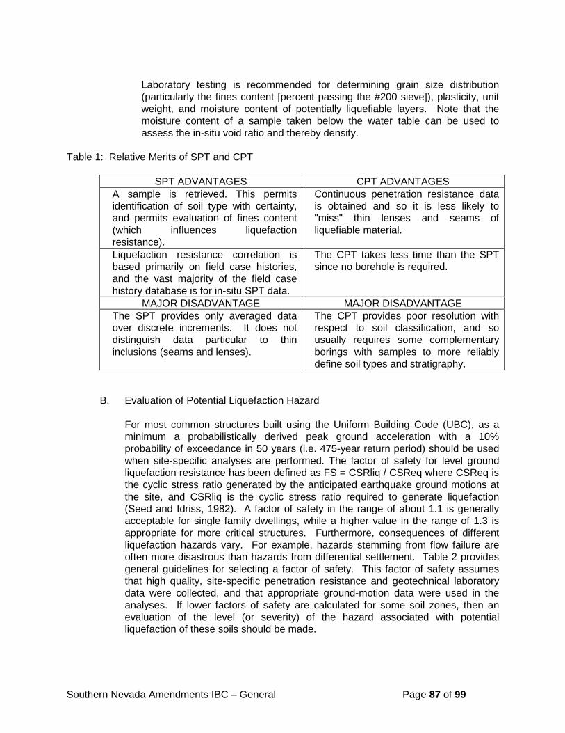
Southern Nevada Amendments IBC – General Page 87 of 99
Laboratory testing is recommended for determining grain size distribution
(particularly the fines content [percent passing the #200 sieve]), plasticity, unit weight, and moisture content of potentially liquefiable layers. Note that the moisture content of a sample taken below the water table can be used to assess the in-situ void ratio and thereby density.
Table 1: Relative Merits of SPT and CPT
SPT ADVANTAGES CPT ADVANTAGES
A sample is retrieved. This permits identification of soil type with certainty, and permits evaluation of fines content (which influences liquefaction resistance).
Continuous penetration resistance data is obtained and so it is less likely to "miss" thin lenses and seams of liquefiable material.
Liquefaction resistance correlation is based primarily on field case histories, and the vast majority of the field case history database is for in-situ SPT data.
The CPT takes less time than the SPT since no borehole is required.
MAJOR DISADVANTAGE MAJOR DISADVANTAGE The SPT provides only averaged data over discrete increments. It does not distinguish data particular to thin inclusions (seams and lenses).
The CPT provides poor resolution with respect to soil classification, and so usually requires some complementary borings with samples to more reliably define soil types and stratigraphy.
B. Evaluation of Potential Liquefaction Hazard
For most common structures built using the Uniform Building Code (UBC), as a minimum a probabilistically derived peak ground acceleration with a 10% probability of exceedance in 50 years (i.e. 475-year return period) should be used when site-specific analyses are performed. The factor of safety for level ground liquefaction resistance has been defined as FS = CSRliq / CSReq where CSReq is the cyclic stress ratio generated by the anticipated earthquake ground motions at the site, and CSRliq is the cyclic stress ratio required to generate liquefaction (Seed and Idriss, 1982). A factor of safety in the range of about 1.1 is generally acceptable for single family dwellings, while a higher value in the range of 1.3 is appropriate for more critical structures. Furthermore, consequences of different liquefaction hazards vary. For example, hazards stemming from flow failure are often more disastrous than hazards from differential settlement. Table 2 provides general guidelines for selecting a factor of safety. This factor of safety assumes that high quality, site-specific penetration resistance and geotechnical laboratory data were collected, and that appropriate ground-motion data were used in the analyses. If lower factors of safety are calculated for some soil zones, then an evaluation of the level (or severity) of the hazard associated with potential liquefaction of these soils should be made.
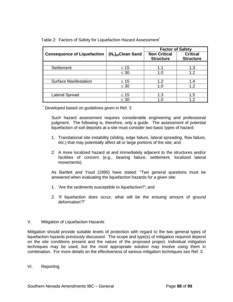
Southern Nevada Amendments IBC – General Page 88 of 99
Table 2: Factors of Safety for Liquefaction Hazard Assessment*
Factor of Safety
Consequence of Liquefaction (N1)60Clean Sand Non Critical Structure
Critical Structure
Settlement ≤ 15 1.1 1.3 ≤ 30 1.0 1.2 Surface Manifestation ≤ 15 1.2 1.4 ≤ 30 1.0 1.2 Lateral Spread ≤ 15 1.3 1.5 ≤ 30 1.0 1.2
* Developed based on guidelines given in Ref. 3
Such hazard assessment requires considerable engineering and professional judgment. The following is, therefore, only a guide. The assessment of potential liquefaction of soil deposits at a site must consider two basic types of hazard: 1. Translational site instability (sliding, edge failure, lateral spreading, flow failure,
etc.) that may potentially affect all or large portions of the site; and 2. A more localized hazard at and immediately adjacent to the structures and/or
facilities of concern (e.g., bearing failure, settlement, localized lateral movements).
As Bartlett and Youd (1995) have stated: "Two general questions must be answered when evaluating the liquefaction hazards for a given site: 1. 'Are the sediments susceptible to liquefaction?'; and 2. 'If liquefaction does occur, what will be the ensuing amount of ground
deformation'?" V. Mitigation of Liquefaction Hazards Mitigation should provide suitable levels of protection with regard to the two general types of liquefaction hazards previously discussed. The scope and type(s) of mitigation required depend on the site conditions present and the nature of the proposed project. Individual mitigation techniques may be used, but the most appropriate solution may involve using them in combination. For more details on the effectiveness of various mitigation techniques see Ref. 3. VI. Reporting
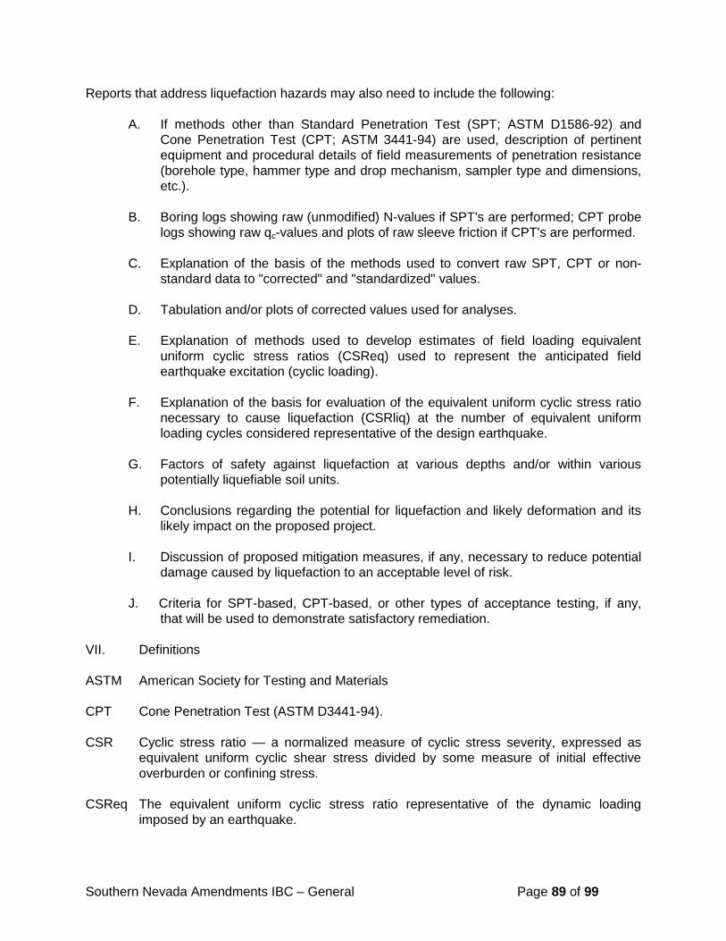
Southern Nevada Amendments IBC – General Page 89 of 99
Reports that address liquefaction hazards may also need to include the following:
A. If methods other than Standard Penetration Test (SPT; ASTM D1586-92) and Cone Penetration Test (CPT; ASTM 3441-94) are used, description of pertinent equipment and procedural details of field measurements of penetration resistance (borehole type, hammer type and drop mechanism, sampler type and dimensions, etc.).
B. Boring logs showing raw (unmodified) N-values if SPT's are performed; CPT probe
logs showing raw qc-values and plots of raw sleeve friction if CPT's are performed. C. Explanation of the basis of the methods used to convert raw SPT, CPT or non-
standard data to "corrected" and "standardized" values. D. Tabulation and/or plots of corrected values used for analyses. E. Explanation of methods used to develop estimates of field loading equivalent
uniform cyclic stress ratios (CSReq) used to represent the anticipated field earthquake excitation (cyclic loading).
F. Explanation of the basis for evaluation of the equivalent uniform cyclic stress ratio
necessary to cause liquefaction (CSRliq) at the number of equivalent uniform loading cycles considered representative of the design earthquake.
G. Factors of safety against liquefaction at various depths and/or within various
potentially liquefiable soil units. H. Conclusions regarding the potential for liquefaction and likely deformation and its
likely impact on the proposed project. I. Discussion of proposed mitigation measures, if any, necessary to reduce potential
damage caused by liquefaction to an acceptable level of risk. J. Criteria for SPT-based, CPT-based, or other types of acceptance testing, if any,
that will be used to demonstrate satisfactory remediation.
VII. Definitions ASTM American Society for Testing and Materials CPT Cone Penetration Test (ASTM D3441-94). CSR Cyclic stress ratio — a normalized measure of cyclic stress severity, expressed as
equivalent uniform cyclic shear stress divided by some measure of initial effective overburden or confining stress.
CSReq The equivalent uniform cyclic stress ratio representative of the dynamic loading
imposed by an earthquake.
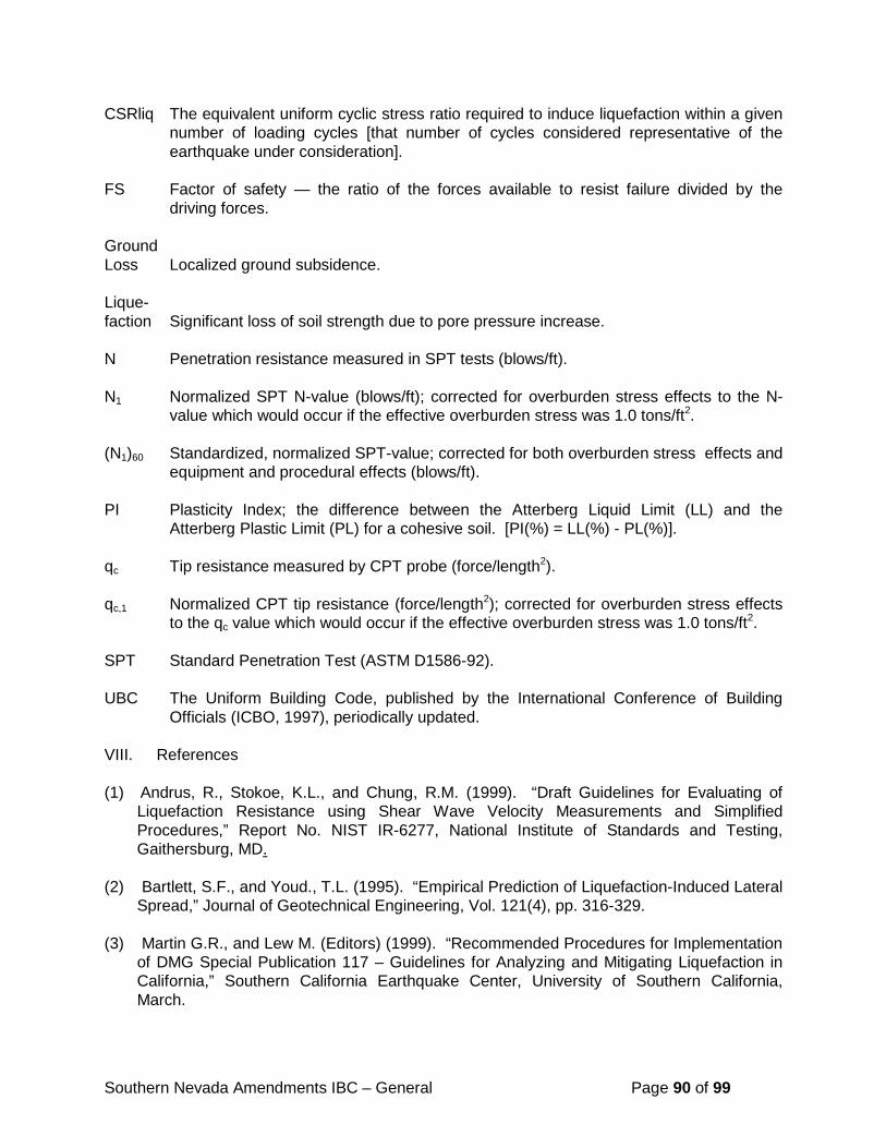
Southern Nevada Amendments IBC – General Page 90 of 99
CSRliq The equivalent uniform cyclic stress ratio required to induce liquefaction within a given number of loading cycles [that number of cycles considered representative of the earthquake under consideration].
FS Factor of safety — the ratio of the forces available to resist failure divided by the driving forces. Ground Loss Localized ground subsidence. Lique- faction Significant loss of soil strength due to pore pressure increase. N Penetration resistance measured in SPT tests (blows/ft). N1 Normalized SPT N-value (blows/ft); corrected for overburden stress effects to the N-
value which would occur if the effective overburden stress was 1.0 tons/ft2. (N1)60 Standardized, normalized SPT-value; corrected for both overburden stress effects and
equipment and procedural effects (blows/ft). PI Plasticity Index; the difference between the Atterberg Liquid Limit (LL) and the
Atterberg Plastic Limit (PL) for a cohesive soil. [PI(%) = LL(%) - PL(%)]. qc Tip resistance measured by CPT probe (force/length2). qc,1 Normalized CPT tip resistance (force/length2); corrected for overburden stress effects
to the qc value which would occur if the effective overburden stress was 1.0 tons/ft2. SPT Standard Penetration Test (ASTM D1586-92). UBC The Uniform Building Code, published by the International Conference of Building
Officials (ICBO, 1997), periodically updated. VIII. References (1) Andrus, R., Stokoe, K.L., and Chung, R.M. (1999). “Draft Guidelines for Evaluating of
Liquefaction Resistance using Shear Wave Velocity Measurements and Simplified Procedures,” Report No. NIST IR-6277, National Institute of Standards and Testing, Gaithersburg, MD.
(2) Bartlett, S.F., and Youd., T.L. (1995). “Empirical Prediction of Liquefaction-Induced Lateral
Spread,” Journal of Geotechnical Engineering, Vol. 121(4), pp. 316-329. (3) Martin G.R., and Lew M. (Editors) (1999). “Recommended Procedures for Implementation
of DMG Special Publication 117 – Guidelines for Analyzing and Mitigating Liquefaction in California,” Southern California Earthquake Center, University of Southern California, March.
Southern Nevada Amendments IBC – General Page 91 of 99
(4) National Research Council (NRC) (1985). “Liquefaction of Soils During Earthquakes,” Committee on Earthquake Engineering, National Research Council, Report No. CETS-EE-001.
(5) Seed, H.B., and Idriss, I.M. (1982). “Ground Motions and Soil Liquefaction During
Earthquakes,” Earthquake Engineering Research Institute (EERI) Monograph. (6) Youd, T.L., and Idriss, I.M. (Editors) (1997). “Proceedings of the NCEER Workshop on
Evaluation of Liquefaction Resistance of Soils,” Salt Lake City, NCEER Technical Report NCEER-97-0022, Buffalo, NY.
Accepted on 18 February 2000 (As taken from NESC Website 5/9/2012)
Appendix P Guidelines for Evaluating Potential Surface Fault Rupture/Land Subsidence Hazards in Nevada
Add a new Appendix P Guidelines for Evaluating Potential Surface Fault Rupture/Land Subsidence Hazards in Nevada, as follows:
Appendix P GUIDELINES FOR EVALUATING POTENTIAL SURFACE FAULT RUPTURE/LAND
SUBSIDENCE HAZARDS IN NEVADA
The Nevada Earthquake Safety Council recommends the use of the following Guidelines for Evaluating Potential Surface Fault Rupture/Land Subsidence Hazards. The Council recognizes that the governing standards are the current locally adopted codes and ordinances.
The Nevada Earthquake Safety Council facilitates public input, develops consensus about seismic issues within the public and private sectors, and is the public advisory body for state seismic policy and the Nevada Earthquake Risk Reduction Program of the Division of Emergency Management. The Board of Directors of the Council, which votes on policy recommendations, has 21 members, from both southern and northern Nevada, representing business and industry; city, county, and state governments, including the Assembly and Senate; geosciences; engineering; community organizations; universities; building officials; insurance; and primary-secondary education.
The first version of these guidelines was dated 30 July 1996; minor typographical errors were corrected on 24 November 1997. The Nevada Earthquake Safety Council approved this Revision 1 on 20 November 1998.
Jonathan G. Price Director/State Geologist, Nevada Bureau of Mines and Geology, and Secretary, Nevada Earthquake Safety Council
Southern Nevada Amendments IBC – General Page 92 of 99
Guidelines for Evaluating Potential Surface Fault Rupture/Land Subsidence Hazards in Nevada (Revision 1)
I. INTRODUCTION
These guidelines were prepared by a subcommittee of the Geoscience Committee on Seismic Hazard Issues at the request of the Nevada Earthquake Safety Council, which is affiliated with the Division of Emergency Management, Department of Motor Vehicles and Public Safety, Division of Special Services.
Significant seismic hazards are present in Nevada. With the increase in population, the evaluation of fault rupture and fissuring is becoming more important for land use planning and development. The intent of these guidelines is to provide a standardized minimum level of investigation for fault rupture and fissuring in Nevada. They were prepared using established guidelines for surface fault rupture evaluation in California and Utah, and the current standard of practice in the greater metro Las Vegas, Reno, Sparks and Carson City areas.
These guidelines were prepared by The Association of Engineering Geologists, Great Basin Section in Reno, Nevada and the Southwestern Section in Las Vegas, Nevada in conjunction with the Nevada Bureau of Mines and Geology, the University of Nevada, Reno, other Nevada professional geological organizations and the private geological consulting community.
II. WHEN TO PERFORM ANALYSIS
The investigation of sites for potential surface rupture or hazards due to differential subsidence and fissuring shall be included in all geotechnical investigations.
III. DESCRIPTION OF THE INVESTIGATION
A. INTRODUCTION
A competent professional should perform geologic investigations. Because of the complexity of this analysis, the competent professional performing each investigation must determine what is appropriate and necessary to obtain the highest quality information. The most useful technique at one site may be inappropriate for another site.
B. RESEARCH
Review of the region's seismic history, based on existing maps and technical literature.
1. Specific to Fault Rupture Hazard:
a. Historic earthquakes, epicenter locations, and magnitudes in the vicinity of the site.
b. Location of fault traces that may affect the site, including maps of faults and a discussion of the tectonics and other relationships of significance to the proposed construction.
Southern Nevada Amendments IBC – General Page 93 of 99
c. Location and chronology of other earthquake-induced features, such as settlement, landslides and liquefaction.
d. Review of local groundwater data (water-level fluctuations, groundwater impediments, water quality variations, or anomalies indicating possible faults).
2. Specific to Differential Subsidence and Fissure Hazard:
a. Identify and locate any faults, scarps, and fissures in the vicinity of the site.
b. Review available land level lines of past ground surface movement in the vicinity of the site, including degree of differential subsidence across nearby faults and proximity of regional subsidence bowls.
c. Review groundwater development in the vicinity including the location of nearby high-capacity wells. Review available well maintenance records of nearby wells for signs of possible subsidence-induced damage.
d. Review of subsurface units from available well driller's logs for nearby water wells and available historic water level data from nearby wells.
C. AERIAL PHOTOGRAPHS
Analysis should include interpretation of aerial photographs and other remotely sensed images for fault-related topography, vegetation, soil contrasts, and lineaments of possible fault or fissure origin. Where possible, analysis may include low-sun-angle aerial photography and/or aerial reconnaissance.
D. SURFACE INVESTIGATION
A competent professional shall inspect the site.
1. Non-Specific:
a. Mapping of surface features, including geologic units and structures and topographic features both on and beyond the site. For normal and strike-slip faults these features commonly include:
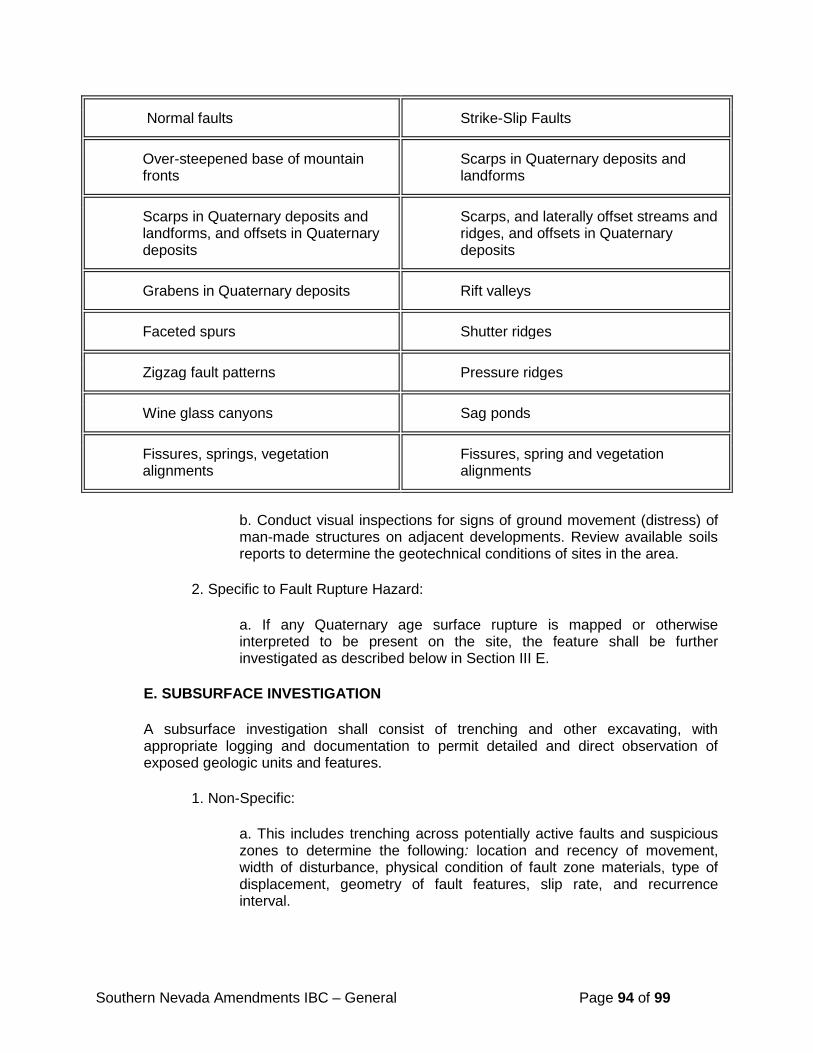
Southern Nevada Amendments IBC – General Page 94 of 99
Normal faults Strike-Slip Faults
Over-steepened base of mountain fronts
Scarps in Quaternary deposits and landforms
Scarps in Quaternary deposits and landforms, and offsets in Quaternary deposits
Scarps, and laterally offset streams and ridges, and offsets in Quaternary deposits
Grabens in Quaternary deposits Rift valleys
Faceted spurs Shutter ridges
Zigzag fault patterns Pressure ridges
Wine glass canyons Sag ponds
Fissures, springs, vegetation alignments
Fissures, spring and vegetation alignments
b. Conduct visual inspections for signs of ground movement (distress) of man-made structures on adjacent developments. Review available soils reports to determine the geotechnical conditions of sites in the area.
2. Specific to Fault Rupture Hazard:
a. If any Quaternary age surface rupture is mapped or otherwise interpreted to be present on the site, the feature shall be further investigated as described below in Section III E.
E. SUBSURFACE INVESTIGATION
A subsurface investigation shall consist of trenching and other excavating, with appropriate logging and documentation to permit detailed and direct observation of exposed geologic units and features.
1. Non-Specific:
a. This includes trenching across potentially active faults and suspicious zones to determine the following: location and recency of movement, width of disturbance, physical condition of fault zone materials, type of displacement, geometry of fault features, slip rate, and recurrence interval.
Southern Nevada Amendments IBC – General Page 95 of 99
b. Borings or test pits to collect data to evaluate depth and type of materials present, groundwater depth, and to verify fault-plane geometry. Data points should be sufficient in number and adequately spaced to permit correlations and interpretations.
c. Geophysical surveys conducted to facilitate the evaluation of the types of site materials and their physical properties, ground water conditions, and fault displacements.
2. Specific to Differential Subsidence and Fissure Hazard:
a. Detailed trench logging at the site should focus on determining the location and possible causes of fissuring. Compare trenches across fissures in areas on the site and in areas where fissures are not observed at the surface. Additional objectives should be determining the width of the fissure zones and the general geometry and depth of fissures. Analysis of trenches should help determine feasible means of site remediation.
F. SPECIAL INVESTIGATIVE METHODS
1. Special investigative methods may be used when conditions or critical structures demand a more intensive investigation.
a. Aerial reconnaissance overflights, including special photography.
b. Geodetic and strain measurements, micro-seismicity monitoring, or other monitoring techniques.
c. Radiometric age analysis (C14, K-Ar), stratigraphic correlation (fossils, mineralogy), soil profile development, paleomagnetism, or other age-dating techniques to identify age of faulted or unfaulted units or surfaces.
IV. SUGGESTED OUTLINE FOR POTENTIAL SURFACE RUPTURE SECTION OF GEOTECHNICAL INVESTIGATION REPORTS
The following subjects should be addressed, or at least considered, in any geologic report on faults. Some of the investigative methods described herein should be carried out beyond the site being investigated. It is not expected that all of the methods identified would be used in a single investigation.
A. TEXT
1. Purpose and scope of investigation.
2. Geologic setting.
3. Site description and conditions, including information on geologic units, aquifer conditions, graded and filled areas, vegetation, existing structures, and other
Southern Nevada Amendments IBC – General Page 96 of 99
factors that may affect the choice of investigative methods and the interpretation of data.
4. Methods of investigation utilized.
5. Conclusions.
a. Location (or absence) of all surface ruptures on or adjacent to the site.
b. Type of faults and nature of anticipated offset: Direction of relative displacement, and maximum possible displacement.
c. Statement of relative risk addressing the probability or relative potential for future surface displacement. This may be stated in semi-quantitative terms such as low, moderate, or high, or in terms of slip rates determined for specific fault segments.
d. Degree of confidence in, and limitations of, the data and conclusions.
6. Recommendations
a. Set-back distances from faults and fissures. State, Federal or local guidelines may dictate minimum standards otherwise; the minimum set-back distance for occupied structures from Holocene active faults shall be fifty (50) feet. Furthermore, no critical facility shall be placed directly over the trace of a Late Quaternary active fault. When necessary, set-back distances from fissures and Late Quaternary and Quaternary active faults will be recommended by the competent professional.
b. Provide mitigative measures for appropriate structures that cannot avoid crossing faults and fissures. Examples include, but are not limited to, critical pipelines, aqueducts, flood channels, railroads, and roadways.
c. Need for additional studies or inspection during construction.
B. REFERENCES
1. Literature and records cited or reviewed; citations should be complete.
2. Aerial photographs or images interpreted including type, date, scale, source, and index numbers.
3. Other sources of information, including well records, personal communications, and other data sources.
C. ILLUSTRATIONS
Illustrations are essential to the understanding of the report and to reduce the length of text.
Southern Nevada Amendments IBC – General Page 97 of 99
1. Location map - identify site locality, significant faults, geographic features, regional geology, seismic epicenters, and other pertinent data. A 1:24,000 scale is recommended.
2. Site development map. Show site boundaries, existing and proposed structures, graded areas, streets, exploratory trenches, borings, geophysical traverses, and other data. Recommended scale is 1 inch equals 200 feet (1:2,400) or larger.
3. Geologic map. Shows distribution of geologic units (if more than one), faults and other structures, geomorphic features, aerial photo lineaments, and springs, on topographic map at 1:24,000 scale or larger. Can be combined with C(1) or C(2).
4. Geologic cross-sections.
5. Logs of exploratory trenches and borings. Show details of observed features and conditions; should not be generalized or diagrammatic. Trench logs should show topography and geologic structure at the same horizontal and vertical scale.
6. Geophysical data and geologic interpretations.
7. Photographs of scarps, surface ruptures, trenches, samples, or other features that enhance understanding of the site conditions.
D. APPENDIX
Supporting data not included above (e.g., water well data).
E. AUTHENTICATION
Signature of competent professional who conducted the investigation.
V. DEFINITIONS
Active Fault: Active faults for the Basin and Range physiographic province are categorized as follows:
1. Holocene Active Fault - a fault that has moved within the last 10,000 years.
1. Late Quaternary Active Fault - a fault that has moved within the last 130,000 years. 2. Quaternary Active Fault - a fault that has moved within the last 1,600,000 years.
Competent Professional: A geological professional with an academic degree who is qualified to analyze geological data relevant to these guidelines, to make hazard recommendations, and to prepare a written geologic report on fault and/or fissure investigations for engineering purposes. The competent professional will have a minimum of three years demonstrated experience in conducting geologic site investigations, including fault or fissure hazard evaluations, for
Southern Nevada Amendments IBC – General Page 98 of 99
engineering purposes. The competent professional will satisfy the definition of Professional Geologist under Nevada State law (NRS 514.005).
Critical Facility: A building or structure that is considered critical to the function of the community or the project under consideration. Examples include, but are not limited to, hospitals, fire stations, emergency management operations centers, and schools.
Differential Land Subsidence: Subsidence across pre-existing faults.
Earth Fissure: Ground cracks or voids found in the near surface of the earth. Earth fissures in Nevada are believed to have formed in response to tensional or horizontal stresses from regional land subsidence or to ground shaking from earthquakes resulting in ground deformation or both.
Fault: A fracture or a zone of fracturing along which there has been displacement of the sides relative to one another parallel to the fracture.
Fault Line (Trace): The line or trace of a fault plane on the ground surface or on a reference plane formed by the intersection of a fault and the earth's surface.
Fault Scarp: A steep slope or cliff formed directly by movement along the fault and representing the exposed surface of a fault before modification by erosion and weathering.
Fault Zone: A fault expressed as a zone of numerous small fractures or angular rock fragments or fault gouge (finely ground rocks). A fault zone may be up to hundreds of meters wide.
Inactive Fault: A fault without recognized activity within Quaternary time (within the past 1,600,000 years).
Land Subsidence: The gradual downward settling or sinking of the earth's surface.
Lineament: Linear or curvilinear geomorphic feature interpreted to be of tectonic origin which does not clearly exhibit fault scarp characteristics and cannot be differentiated by age.
Occupied Structures: A structure for human occupancy is a building, as defined by the Uniform Building Code, which is expected to have a human occupancy rate of more than 2,000 man hours per year.
Set-Backs: Minimum distance a structure for human occupancy must be from a surface rupture.
Subsidence-Induced Movement: Renewed movement of a fault induced by historical land subsidence. Subsidence induced movement may occur on a fault regardless of earthquake activity on the fault.
Surface Rupture: A fracture or break in the ground surface resulting from faulting, fissuring, or land subsidence.
Southern Nevada Amendments IBC – General Page 99 of 99
VI. RELEVANT REFERENCES
To limit the length of this document, references relevant to these guidelines were not included. However, pertinent references associated with these guidelines are available online at the Nevada Bureau of Mines and Geology web site (www.nbmg.unr.edu).
(As taken from NESC Website 5/9/2012)