SOUTHERN CALIFORNIA EDISONdocketpublic.energy.ca.gov/PublicDocuments/Regulatory/Non Active... ·...
26
May 19, 2010 California Energy Commission Docket No. 09-AFC-8 1516 9 th St. Sacramento, CA 95814 Genesis Solar Energy Project - Docket Number 09-AFC-8 Docket Clerk: Enclosed for filing with this letter is one hard copy and one electronic copy of our Reasonably Foreseeable Development Scenario: Southern California Edison Colorado River Substation for the Genesis Solar Energy Project. Sincerely, Tricia Bernhardt Project Manager/Tetra Tech EC cc: Mike Monasmith /CEC Project Manager DATE MAY 19 2010 RECD. DOCKET 09-AFC-8 MAY 21 2010
Transcript of SOUTHERN CALIFORNIA EDISONdocketpublic.energy.ca.gov/PublicDocuments/Regulatory/Non Active... ·...

May 19, 2010 California Energy Commission Docket No. 09-AFC-8 1516 9th St. Sacramento, CA 95814 Genesis Solar Energy Project - Docket Number 09-AFC-8 Docket Clerk: Enclosed for filing with this letter is one hard copy and one electronic copy of our Reasonably Foreseeable Development Scenario: Southern California Edison Colorado River Substation for the Genesis Solar Energy Project. Sincerely,
Tricia Bernhardt Project Manager/Tetra Tech EC cc: Mike Monasmith /CEC Project Manager
DATE MAY 19 2010
RECD.
DOCKET09-AFC-8
MAY 21 2010

BEFORE THE ENERGY RESOURCES CONSERVATION AND DEVELOPMENT
COMMISSION OF THE STATE OF CALIFORNIA 1516 NINTH STREET, SACRAMENTO, CA 95814
1-800-822-6228 – WWW.ENERGY.CA.GOV
APPLICATION FOR CERTIFICATION FOR THE Docket No. 09-AFC-8 GENESIS SOLAR ENERGY PROJECT PROOF OF SERVICE (Revised 5/12/10) APPLICANT Ryan O’Keefe, Vice President Genesis Solar LLC 700 Universe Boulevard Juno Beach, Florida 33408 E-mail service preferred [email protected] Scott Busa/Project Director Meg Russel/Project Manager Duane McCloud/Lead Engineer NextEra Energy 700 Universe Boulvard Juno Beach, FL 33408 [email protected] [email protected] [email protected] E-mail service preferred Matt Handel/Vice President [email protected] Email service preferred Kenny Stein, Environmental Services Manager [email protected] Mike Pappalardo Permitting Manager 3368 Videra Drive Eugene, OR 97405 [email protected] Kerry Hattevik/Director West Region Regulatory Affairs 829 Arlington Boulevard El Cerrito, CA 94530 [email protected] APPLICANT’S CONSULTANTS Tricia Bernhardt/Project Manager Tetra Tech, EC 143 Union Boulevard, Ste 1010 Lakewood, CO 80228 [email protected]
James Kimura, Project Engineer Worley Parsons 2330 East Bidwell Street, Ste.150 Folsom, CA 95630 [email protected] COUNSEL FOR APPLICANT Scott Galati Galati & Blek, LLP 455 Capitol Mall, Ste. 350 Sacramento, CA 95814 [email protected] INTERESTED AGENCIES California-ISO [email protected] Allison Shaffer, Project Manager Bureau of Land Management Palm Springs South Coast Field Office 1201 Bird Center Drive Palm Springs, CA 92262 [email protected]
INTERVENORS California Unions for Reliable Energy (CURE) c/o: Tanya A. Gulesserian, Rachael E. Koss, Marc D. Joseph Adams Broadwell Joesph & Cardoza 601 Gateway Boulevard, Ste 1000 South San Francisco, CA 94080 [email protected] [email protected]
*Tom Budlong 5439 Soquel Drive 3216 Mandeville Cyn Rd. Los Angeles, CA 90049-1016 [email protected]
Californians for Renewable Energy, Inc. (CARE) Michael E. Boyd, President 5439 Soquel Drive Soquel, CA 95073-2659 [email protected] OTHER Alfredo Figueroa 424 North Carlton Blythe, CA 92225 [email protected]
ENERGY COMMISSION JAMES D. BOYD Commissioner and Presiding Member [email protected]
ROBERT WEISENMILLER Commissioner and Associate Member [email protected]
Kenneth Celli Hearing Officer [email protected]
Mike Monasmith Siting Project Manager [email protected]
Caryn Holmes Staff Counsel [email protected]
Robin Mayer Staff Counsel [email protected]
Jennifer Jennings Public Adviser’s Office [email protected]
*indicates change 1

I, Tricia Bernhardt, declare that on May 19, 2010, I served and filed copies of the Reasonably Foreseeable Development Scenario: Southern California Edison Colorado River Substation for the Genesis Solar Energy Project dated May 19, 2010. The original document, filed with the Docket Unit, is accompanied by a copy of the most recent Proof of Service list, located on the web page for this project at: [http://ww.energy.ca.gov/sitingcases/genesis_solar]. The documents have been sent to both the other parties in this proceeding (as shown on the Proof of Service list) and to the Commission’s Docket Unit, in the following manner: (Check all that Apply)
FOR SERVICE TO ALL OTHER PARTIES:
x sent electronically to all email addresses on the Proof of Service list;
x by personal delivery or by depositing in the United States mail at Sacramento, California with first-class postage thereon fully prepaid and addressed as provided on the Proof of Service list above to those addresses NOT marked “email preferred.”
AND
FOR FILING WITH THE ENERGY COMMISSION:
x sending an original paper copy and one electronic copy, mailed and emailed respectively, to the address below (preferred method);
OR depositing in the mail an original and 12 paper copies, as follows:
CALIFORNIA ENERGY COMMISSION Attn: Docket No. 09-AFC-8 1516 Ninth Street, MS-4 Sacramento, CA 95814-5512
[email protected] I declare under penalty of perjury that the foregoing is true and correct. Original Signed By:
Tricia Bernhardt

GENESIS SOLAR ENERGY PROJECT
REASONABLY FORSEEABLE DEVELOPMENT SCENARIO
SOUTHERN CALIFORNIA EDISON COLORADO RIVER SUBSTATION
Dated: May 19, 2010

INTRODUCTION
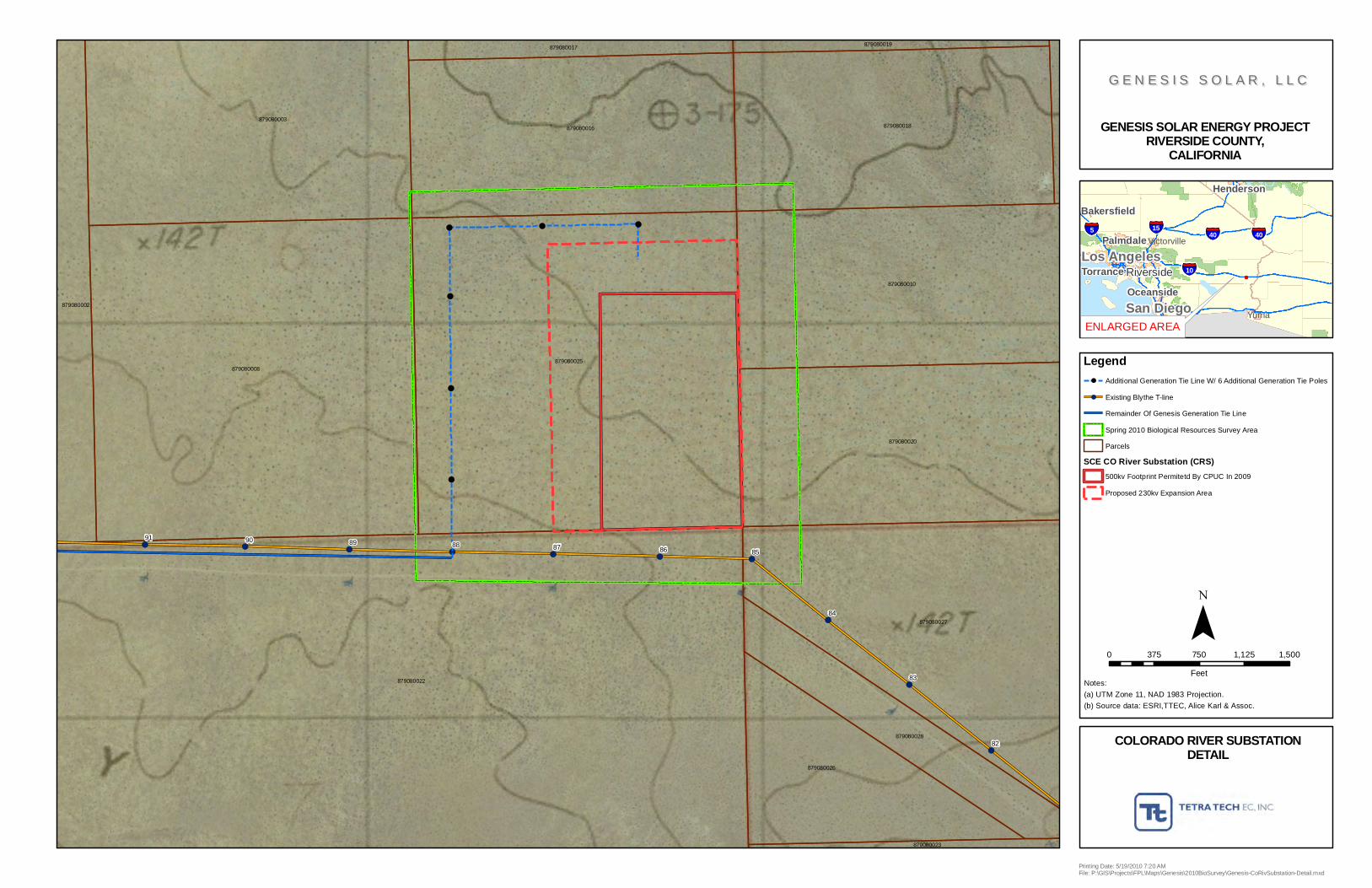
This document is intended to describe Southern California Edison's (SCE's) proposed 230 kV expansion of the already-permitted (but not yet constructed) 500 kV Colorado River Substation (CRS). Unlike the transmission line that would go from the Genesis Solar Energy Project’s (Genesis) power plant to the CRS (often referred to as the “gen-tie”), SCE's CRS is not part of the Genesis project description. Rather, the CRS is an SCE project that SCE would permit, construct, own and operate to serve several projects in the area. However, because the proposed expansion of the CRS is a reasonably foreseeable development scenario, a description of the expansion and any associated potential environmental impacts will be addressed in the NEPA and CEQA-equivalent documents being prepared by the BLM and the CEC for the Genesis project. In Figure A-1, the CRS facilities are presented in one color and the Genesis gen-tie is presented in another color to visually present where the Genesis Gen-tie ends and where SCE's CRS begins. Figure A-2 shows a close up of the CRS boundaries. This document presents a description of the reasonably foreseeable proposed 230 kV expansion of the CRS including disturbance foot print, the existing environment, and potential environmental impacts. Detailed environmental survey reports will be submitted under separate cover within the next several weeks. 1.0 COLORADO RIVER SUBSTATION EXPANSION PROJECT
DESCRIPTION 1.1 PROJECT OVERVIEW: 1.1.1 Description of Project Elements Southern California Edison (SCE) proposes to construct the Colorado River Substation Expansion (Project) near Blythe in Riverside County, California (Figure 1) to interconnect solar development projects in the Blythe area of the Mohave Desert to SCE’s previously approved Colorado River Substation. The Project site was one of three sites analyzed in the Devers – Palo Verde No. 2 500 kV Transmission Line (DPV2) Final Environmental Impact Statement (FEIS)/Environmental Impact Report (FEIR). The site was determined to be environmentally acceptable in the DPV2 FEIS/FEIR and was included in the Certificate of Public Convenience and Necessity (CPCN) issued by the California Public Utilities Commission (CPUC) for the DPV2 Project in CPCN Decision D.07-01-040, dated January 25, 2007. The following is a summary of the Colorado River Substation Expansion Project components common to multiple solar development projects that are described more fully in this document:
1
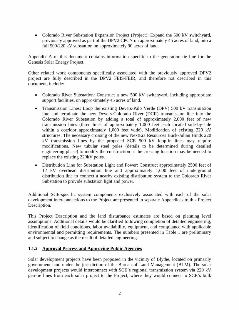
• Colorado River Substation Expansion Project (Project): Expand the 500 kV switchyard, previously approved as part of the DPV2 CPCN on approximately 45 acres of land, into a full 500/220 kV substation on approximately 90 acres of land.
Appendix A of this document contains information specific to the generation tie line for the Genesis Solar Energy Project. Other related work components specifically associated with the previously approved DPV2 project are fully described in the DPV2 FEIS/FEIR, and therefore not described in this document, include:
• Colorado River Substation: Construct a new 500 kV switchyard, including appropriate support facilities, on approximately 45 acres of land.
• Transmission Lines: Loop the existing Devers-Palo Verde (DPV) 500 kV transmission line and terminate the new Devers-Colorado River (DCR) transmission line into the Colorado River Substation by adding a total of approximately 2,000 feet of new transmission lines (three lines of approximately 1,000 feet each located side-by-side within a corridor approximately 1,000 feet wide), Modification of existing 220 kV structures: The necessary crossing of the new NextEra Resources Buck-Julian Hinds 220 kV transmission lines by the proposed SCE 500 kV loop-in lines may require modifications. New tubular steel poles (details to be determined during detailed engineering phase) to modify the construction at the crossing location may be needed to replace the existing 220kV poles.
• Distribution Line for Substation Light and Power: Construct approximately 2500 feet of 12 kV overhead distribution line and approximately 1,000 feet of underground distribution line to connect a nearby existing distribution system to the Colorado River Substation to provide substation light and power.
Additional SCE-specific system components exclusively associated with each of the solar development interconnections to the Project are presented in separate Appendices to this Project Description. This Project Description and the land disturbance estimates are based on planning level assumptions. Additional details would be clarified following completion of detailed engineering, identification of field conditions, labor availability, equipment, and compliance with applicable environmental and permitting requirements. The numbers presented in Table 1 are preliminary and subject to change as the result of detailed engineering. 1.1.2 Approval Process and Approving Public Agencies Solar development projects have been proposed in the vicinity of Blythe, located on primarily government land under the jurisdiction of the Bureau of Land Management (BLM). The solar development projects would interconnect with SCE’s regional transmission system via 220 kV gen-tie lines from each solar project to the Project, where they would connect to SCE’s bulk
2

transmission system via SCE’s previously approved Colorado River Substation, DPV and DCR 500 kV transmission lines. SCE would construct and own the Project. Each solar developer will submit an Application to the BLM for a Right-of-Way Grant for their specific solar project. If approved, the BLM will issue a Record of Decision and a Notice to Proceed allowing construction of the proposed solar development project under the administration of the BLM. Each solar developer may also submit a separate Application-For-Certification (AFC) to the California Energy Commission (CEC) for approval to construct their solar development project. The BLM and the CEC have agreed to work cooperatively and conduct joint National Environmental Policy Act (NEPA)/California Environmental Quality Act (CEQA) reviews of the solar development projects, including the solar developers’ substations and the Project. Prior to approval of the Project, the BLM and CEC will have a joint Environmental Impact Statement (EIS)/Environmental Impact Report (EIR) prepared by a third-party environmental consultant which analyzes the environmental impacts associated with each proposed solar development project. The CPUC will participate as a Reviewing Agency in the CEQA review of the Colorado River Substation Expansion Project’s components summarized in Section 1.1.1. It is anticipated that the BLM, the CEC, and the third party environmental consultant will work closely with the CPUC to ensure the Project is in compliance with CEQA. Other permits may also be required from other federal agencies (e.g. Federal Communication Commission, Federal Aviation Administration, etc.), state agencies (e.g. California Department of Transportation, Department of Toxic Substances Control, South Coast Air Quality Management District, etc.) and local agencies (e.g. Riverside County, cities and local fire departments, etc.) for the construction and operation of the proposed substation expansion. 1.1.3 Duration of Construction Activities and Projected Operation Date Construction of the Project elements identified in this document is expected to start in the fourth quarter of 2011 and would proceed through the projected substation operating date of approximately May 2013.1 1.2 PROJECT LOCATION: 1.2.1 Regional and Local Location The Project (Figure 1) would be located on an approximately 140 acre parcel of land located approximately 1.5 miles south of Interstate 10 and 4.75 miles east of Wileys Well Road, in the County of Riverside, California. The Project would be generally located in the eastern portion of the parcel. The approximate center of the Project would be at 33.59 degrees north and 114.82 degrees west. However, the specific location of the substation may shift up to 700 ft. to the west staying with the area encompassed by environmental surveys. 1 Proposed operating date and construction timeline is still under development and subject to regulatory approval timeline, Large Generator Interconnection Agreement execution and other matters.
3

1.2.2 Substation Site Land Use The proposed Project site is on a BLM-owned parcel that would be granted for use by SCE. The proposed location for the Project is designated Open Space-Rural in the Riverside County General Plan. Portions of the County’s eastern half are located within a Specific Area Plan boundary however; the proposed Project site is included in the Eastern Riverside County Areas that are not located within an Area Plan. The proposed Project site as well as the surrounding area is zoned Open Space-Rural (OS-RUR). Single-family residential uses are permitted at a density of one dwelling unit per 20 acres. 1.3 SUBSTATION DISCUSSION: 1.3.1 Introduction SCE proposes to construct the Project to interconnect the proposed solar development project(s) to SCE’s previously approved Colorado River Substation, DPV and DCR 500 kV transmission lines. The 500 kV transmission lines will connect to the Project by looping the lines into the previously approved Colorado River Substation. A 220 kV gen-tie line(s) would be extended from the solar development project(s) to the Project and associated expansion. 1.3.2 Substation Design and Equipment The Project along with the approved Colorado River Substation would be an initial 1120MVA 500/220kV substation measuring approximately 1,600 feet by 2,400 feet enclosed area to loop the DPV and DCR 500kV lines and provide for the solar developers’ 220 kV gen-tie line position(s). The substation and Project will be surrounded by a wall with two gates. 1.3.2.1 Development Plan The Project Plan is presented in Figure 2. 1.3.2.2 Electric and magnetic fields (EMF) A NEPA analysis does not commonly include a discussion of potential environmental impacts from electric and magnetic fields (EMF) due to the lack of a consensus among scientists that EMF exposure poses a risk to human health. Nor are there any CEQA standards regarding the analysis of potential human health risks caused by EMF exposure. However, the EIS prepared for this project is expected to contain a discussion of EMF to accommodate the public’s interest and concern regarding potential human health effects related to EMF exposure from transmission lines. Although there are no NEPA or CEQA standards regarding the analysis of potential human risks associated with EMF exposure, the CPUC reviewed and updated its EMF policy in 2006 (CPUC Decision 06-01-042) for California’s regulated electric utilities. This policy decision update reaffirmed the finding that state and federal public health regulatory agencies have not established a direct link between exposure to EMF and human health effects, and that the existing “no-cost and low-cost” precautionary-based EMF policy should be continued for electrical facilities. As the electrical infrastructure is upgraded in California, measures to reduce magnetic fields will be incorporated into the project design in accordance with the California
4

EMF Design Guidelines for Electrical Facilities, CPUC Decision 93-11-013 and CPUC Decision 06-01-042. Furthermore, the design of the proposed substation and transmission lines will incorporate “no-cost and low-cost” measures such as placing major substation electrical equipment away from the substation property lines to reduce magnetic fields. These measures would be documented in a project specific Field Management Plan. 1.3.3 Substation Construction 1.3.3.1 Grading and Drainage The Project would be prepared by clearing existing vegetation and installing a temporary chain-link fence to surround the construction site. The site would be graded in accordance with approved grading plans. The area to be enclosed by the proposed substation perimeter wall would be graded to a slope that varies between one and two percent and compacted to 90 percent of the maximum dry density. The Project site is located east of the Chuckwalla Dunes area and shows evidence of surface storm water runoff through the proposed site. While no designated Blue-line streams are located within the Project, it may still necessary to redirect surface water flow around one side of the substation. The combined Colorado River Substation and Project’s northern boundary may need to be protected from surface runoff by the installation of a berm designed to direct the flow around both sides of the substation pad. These drainage improvements would potentially disturb an area approximately 80 feet wide around three sides of the fenced in substation, resulting in a total permanent disturbance area of approximately 20 acres. Internal surface runoff would be directed towards a detention basin located at the south end of the substation. The basin would measure approximately 120 feet by 200 feet occupying approximately one-half acre and would be enclosed by an 8-foot high chain-link fence and one 20-foot wide double drive gate. The final site drainage design would be subject to the conditions of the grading permit obtained from the County of Riverside. Table 1 provides the approximate volume and type of earth materials to be used or disposed of at the Project site (within the substation wall and the required drainage structures outside/around the substation).
TABLE 1 COLORADO SUBSTATION EXPANSION SITE - GROUND SURFACE
IMPROVEMENT MATERIALS AND ESTIMATED VOLUMES
Element Material Approximate
Volume (yd3) (1) Site Cut (2) Site Fill (2)
Soil Soil
190,000 190,000
Waste Removal (export) Soil/Vegetation 20,000 Substation Equipment Foundations
Concrete 10,000
Equipment and cable trench excavations (3)
Soil 10,000
5

Cable Trenches (4) Concrete 200 Internal Driveway Asphalt concrete
Class II aggregate base 1,200 2,800
External Driveway Asphalt concrete Class II aggregate base
0 0
Substation Rock Surfacing
Rock, nominal 1 to 1-1/2 inch per SCE Standard
15,000
(1) The material volumes presented in Table 1 are for the 45 acre Project site work only. Additional material volumes needed for surface improvement of the 45 acre Colorado River Substation are included in the previously approved DPV2 FEIS/FEIR. (2) The design concept would be intended to balance the earthwork quantities, utilizing any site cut material as site fill material, where feasible. (3) Excavation “spoils” would be placed on site during the below-ground construction phase and used to the extent possible for the required on-site grading. (4) Standard cable trench elements are factory fabricated, delivered to the site and installed by crane. Intersections are cast-in-place concrete.
The numbers presented in Table 1 are preliminary and subject to change as the result of detailed engineering. 1.3.3.2 Staging Areas Additional temporary land disturbance (up to approximately 10 acres) adjacent to the Project may be necessary for temporary equipment storage and material staging areas associated with construction efforts. 1.3.3.3 Geotechnical Studies Prior to the start of construction, SCE expects to conduct a geotechnical study of the Project site and the transmission line routes that would include an evaluation of the depth to the water table, evidence of faulting, liquefaction potential, physical properties of subsurface soils, soil resistivity, slope stability, and the presence of hazardous materials. 1.3.3.4 Below Grade Construction After the Project site is graded, below grade facilities would be installed. Below grade facilities include a ground grid, underground conduit, trenches, and all required foundations. The design of the ground grid would be based on soil resistively measurements collected during the geotechnical investigation conducted prior to construction. 1.3.3.5 Equipment Installation Above grade installation of substation facilities associated with the Project (i.e., buses, circuit breakers and steel structures) would commence after the below grade structures are in place. 1.3.3.6 Hazards and Hazardous Materials Construction of the Project would require the limited use of hazardous materials, such as fuels, lubricants, and cleaning solvents. All hazardous materials would be stored, handled and used in accordance with applicable regulations. Material Safety Data Sheets would be made available at the construction site for all crew workers.
6

The Storm Water Pollution Prevention Plan prepared for the Colorado River Substation and Project would provide the locations for storage of hazardous materials during construction, as well as protective measures, notifications, and cleanup requirements for any incidental spills or other potential releases of hazardous materials. 1.3.3.7 Waste Management Construction of the Project would result in the generation of various waste materials that can be recycled and salvaged. Waste items and materials would be collected by construction crews and separated into roll off boxes at the materials staging area. All waste materials that are not recycled would be categorized by SCE in order to assure appropriate final disposal. Non-hazardous waste would be transported to local authorized waste management facilities. Soil excavated for the Project would either be used as fill or disposed of off-site at an approved licensed facility. 1.3.3.8 Post-Construction Cleanup Any damage to existing roads as a result of construction would be repaired once construction is complete, in accordance with local agency requirements. Following completion of construction activities, SCE would also restore all areas that were temporarily disturbed by construction of the Project to as close to preconstruction conditions as possible, or, where applicable, to the conditions agreed upon between the landowner and SCE. In addition, all construction materials and debris would be removed from the area and recycled or properly disposed of off-site at local authorized waste management facilities. SCE would conduct a final inspection to ensure that cleanup activities were successfully completed. 1.3.3.9 Land Disturbance Table 2 provides a preliminary estimate of temporary and permanent land disturbance related to construction of the Project (outside the substation fence and the required drainage structures outside/around the Project). The numbers presented in Table 2 are preliminary and subject to change as the result of detailed engineering.
TABLE 2 PROJECT CONSTRUCTION
ESTIMATED LAND DISTURBANCE SUMMARY (1) Construction
Activity Acres Temporarily
Disturbed Acres Permanently
Disturbed Substation Grading - 45.0 Drainage/Side Slopes - 20.0 Access Road - - Staging Area 10.0 - Total Acres Disturbed 10.0 65.0
(1) The land disturbance estimates presented in Table 2 are for the 45 acre Project site work only. Initial land disturbance for the 45 acre switchyard grading and access road are included as part of the DPV2 FEIS/FEIR.
7

1.3.3.10 Construction Equipment and Labor The estimated elements, materials, number of personnel and equipment required for construction of the Project are summarized below in Table 3 below. The numbers presented in Table 3 are preliminary and subject to change as the result of additional detailed engineering. In addition to the information provided in Table 3, a temporary office trailer and equipment trailer may be placed within the proposed construction area during the construction phase of the Project. Construction would be performed by either SCE construction crews or contractors, depending on the availability of SCE construction personnel at the time of construction. Contractor construction personnel would be managed by SCE construction management personnel. SCE anticipates a minimum of approximately 25 construction personnel working on any given day. SCE anticipates that crews would work concurrently whenever possible; however, the estimated deployment and number of crew members would be dependent upon city permitting, material availability, and construction scheduling. For example, electrical equipment (such as substation MEER, wiring, and circuit breaker) installation may occur while transmission line construction proceeds. Construction activities would generally be scheduled during daylight hours in accordance with applicable noise abatement ordinances. In the event construction activities need to occur on different days or hours, SCE would obtain variances as necessary from appropriate jurisdiction where the work would take place.
TABLE 3 PROJECT EQUIPMENT AND LABOR ESTIMATES (PRELIMINARY)
Activity and number of Personnel
Number of Work Days Equipment and Quantity
Duration of Use (Hours/Day)
Survey (2 people)
10 2-Survey Trucks (Gasoline) 8
Grading (8 people)
60 1-Dozer (Diesel) 2-Loader (Diesel) 1-Scraper (Diesel) 1-Grader (Diesel) 2-Water Truck (Diesel) 2-4X4 Backhoe (Diesel) 1-4X4 Tamper (Diesel) 1-Tool Truck (Gasoline) 1-Pickup 4X4 (Gasoline)
4 4 3 3 2 2 2 2 2
Fencing (4 people)
25 1-Bobcat (Diesel) 1-Flatbed Truck (Gasoline) 1-Crewcab Truck (Gasoline)
8 2 4
8

Activity and number of Personnel
Number of Work Days Equipment and Quantity
Duration of Use (Hours/Day)
Civil (8 people)
90 1-Excavator (Diesel) 1-Foundationauger (Diesel) 2-Backhoes (Diesel) 1-Dump truck (Diesel) 1-Skip Loader (Diesel) 1-Water Truck (Diesel) 2-Bobcat Skid Steer (Diesel) 1-Forklift (Propane) 1-17TonCrane (Diesel) 1-Tool Truck (Gasoline)
4 5 3 2 3 3 3 4
2 hours/day for 45 days
3 MEER (6 people)
60 1-Carry-all Truck (Gasoline) 1-tool truck (Gasoline) 1-Stake Truck (Gasoline)
3 2 2
Electrical (10) people)
120 2-Scissor Lifts (Propane) 2-Manlifts (Propane) 1-Reach Manlift (Propane) 1-15 ton Crane (Diesel) 1-Tool Trailer 3-Crew Trucks (Gasoline)
3 3 4 3 3 2
Wiring (6 people)
90 1-Manlift (Propane) 1-Tool Trailer
4 3
Maintenance Crew Equipment Check (2 people)
30 2-MaintenanceTrucks (Gasoline) 4
Testing (2 people)
90 1-Crew Truck (Gasoline) 3
Asphalting (6 people)
40 2-Paving Roller (Diesel) 1-Asphalt Paver (Diesel) 1-Stake Truck (Gasoline) 1-Tractor (Diesel) 1-Dump Truck (Diesel) 2-Crew Trucks (Gasoline) 1-Asphalt Curb Machine (Diesel)
4 4 4 3 3 2 3
9

WHOBSONWAY
18THAV
22ND AV
W HOBSONWAY
20TH AV
RA
NN
ELS
BLV
D
10TH AV
NICHOLIS ST
9TH AV
16TH AV
GREEN ST
15TH AV
DA
VE
ST
ME
GIN
AV
RIVERSIDE AV
HIB
LE
R A
V
FO
RD
DR
SEELEY AV
BU
CK
BLV
D
HA
IG D
R
EU
GE
NE
DR
ME
SA
DR
17TH AV
14TH AV
OLD STATE HWY
11TH AV
ODEN WY
KE
IM B
LVD
STEP
HE
NS
ON
BLV
D
·|}78
§̈¦10 §̈¦10
CITY OFBLYTHE
DEVERS-PALO VERDE 500 kV
RIVERSIDE COUNTY
FIGURE 1PROPOSED NEW SCE COLORADO RIVER
SUBSTATION SITE .
P:\G
ISD
ata\
Pro
ject
s\M
aste
rDat
a\M
ajor
Tra
nsm
issi
on P
roje
cts\
Red
Blu
ff S
ubst
atio
n P
roje
ct R
BS
P\2
010N
OT0
0000
0000
_Int
erco
nnec
tionM
aps\
CR
SP
_Fig
1_S
ite_L
ocat
ion_
v1.m
xd 4
/8/2
010
LegendFeatures depicted herein are planning level accuracy, and intended forinformational purposes only. Distances and locations may be distorted atthis scale. Always consult with the proper legal documents or agenciesregarding such features.© Real Properties - Survey and Mapping.
Aerial Microsoft Virtual Earth
0 0.5 10.25 Miles
Proposed Red Bluff Substation Sites
Existing 500kV Transmission Lines (SCE, 2009)
Freeways (TBM, 2008)
Highways (TBM, 2008)
Major Road (TBM, 2008)
Minor Road (TBM, 2008)
Railroad (TBM, 2008)Thomas Bros. Maps is a registered trademark of Rand McNally & Company.Reproduced with permission granted by Rand McNally & Company. © Rand McNally & Company. All rights reserved.
PROPOSED NEW SCECOLORADO RIVERSUBSTATION SITE

FIGURE 2PROPOSED NEW SCE COLORADO RIVER
SUBSTATION SITEDEVELOPMENT PLAN
P:\G
ISD
ata\
Pro
ject
s\M
aste
rDat
a\M
ajor
Tra
nsm
issi
on P
roje
cts\
Red
Blu
ff S
ubst
atio
n P
roje
ct R
BS
P\2
010N
OT0
0000
0000
_Int
erco
nnec
tionM
aps\
CR
SP
_Fig
2_S
iteD
evP
lan_
v1.m
xd 4
/8/2
010
Features depicted herein are planning level accuracy, and intended forinformational purposes only. Distances and locations may be distorted atthis scale. Always consult with the proper legal documents or agenciesregarding such features.© Real Properties - Survey and Mapping.
DESERT SOUTHWEST 500 KV T/L
SCE 500 KV RED BLUFF-COLORADO RIVER #1 T/L
BLYTHE ENERGY 220 KV T/L
SCE 500 KV COLORADO RIVER-PALO VERDE #1 T/L
SCE 500 KV LINE CONNECTIONS
SCE 500 KV RED BLUFF-COLORADO RIVER #2 T/L FUTURE SCE 500 KV COLORADO RIVER-PALO VERDE #2 T/L
200 KV SWITCHRACK
AA TRANSFORMER BANK
500-KV SWITCHRACK
.
0 500 1,000250 Feet
COLORADO RIVER SUBSTATIONSITE DEVELOPMENT PLAN
COLORADO RIVER SUBSTATION
ASSUMED GENERATION TIERIGHT-OF-WAY & LINE
THIS LAYOUT EXHIBIT IS BASED ON PLANNING LEVEL ASSUMPTIONS.THE EXTACT DETAILS WOULD BE DETERMINED FOLLOWING COMPLETION OF PRELIMINARY AND FINAL ENGINEERING,IDENTIFICATIONS OF FIELD CONDITIONS, AND COMPLIANCE WITH APPLICABLE ENVIRONMENTAL AND PERMITTING REQUIREMENTS.
ACCESS ROAD/ENTRANCE
500'1900'
2400'
600' 1000'
1600'
Approved by CPUC Decision (D.) 07-01-040,issued September 28, 2009
Parcel identified for use by proposed solar projects

10
APPENDIX A
PROJECT DESCRIPTION OF THE GENERATION INTERCONNECTION
FROM
NEXTERA ENERGY’S PROPOSED FORD DRY LAKE/GENESIS SOLAR ENERGY PROJECT
TO
SOUTHERN CALIFORNIA EDISON’S PROPOSED COLORADO RIVER
SUBSTATION

1.0 PROJECT DESCRIPTION OF THE GENERATION INTERCONNECTION FROM THE END OF THE GEN-TIE FROM NEXTERA ENERGY’S PROPOSED FORD DRY LAKE/GENESIS SOLAR ENERGY PROJECT TO SOUTHERN CALIFORNIA EDISON’S PROPOSED COLORADO RIVER SUBSTATION
1.1 PROJECT OVERVIEW 1.1.1 Description of Project Elements NextEra Energy Resources, LLC (Developer) proposes to construct, own, and operate the Ford Dry Lake/Genesis Solar Energy Project (Project). The Project site is located north of I-10 approximately 25 miles west of the city of Blythe, California, on lands managed by the Bureau of Land Management (BLM) in an unincorporated area of Riverside County, California (Figure 1). The project consists of two solar thermal electric generating facilities with a nominal net electrical output of 125 megawatts (MW) each for a total net electrical output of 250 MW. The project will utilize solar parabolic trough technology to generate electricity. The two 125MW solar thermal electric generating facilities will connect to a 220kV switchyard constructed by the Developer at the Project site. The Developer proposes to construct a 220 kV generation interconnection transmission line from the Developer’s switchyard at the Project site to the Southern California Edison (SCE) regional transmission grid at SCE’s proposed Colorado River Substation near Blythe (Figure A-1)). The following is a summary of the generation interconnection components:
• Generation Tie Line Connection: SCE would connect the Developer-built
220kV generation tie line (gen-tie) into the Colorado River Substation by installing the last span of conductor between the 220kV switchrack and the first Project transmission line structure north of the substation.
• Telecommunications Facilities: The Developer would utilize optical ground
wire (OPGW) on the interconnection generation tie-line and would terminate the fiber optics cables inside the Project substation. SCE would install the last span of fiber optics cable between the 220kV switchrack and the first Project transmission line structure north of Colorado River Substation. SCE would make the final terminations to associated communications equipment installed inside both SCE’s Colorado River Substation and the Project’s substation.
1.1.2 Duration of Construction Activities and Projected Operation Date Subject to execution of a Large Generation Generator Agreement (LGIA) between SCE, the Developer, and the California System Independent System Operator (CAISO), construction of the interconnection facilities identified in Section 1.1.1 are expected to occur in the first quarter of 2013.

1.1.3 220 kV Generation Tie-line Extension Design The proposed Colorado River Substation design includes bringing the final span from the Project 220 kV gen-tie line into the switchrack, just north of the Colorado River Substation (see Figure A-2). There would be a single-circuit lattice steel (LST) or tubular steel pole (TSP) structure just north of the Colorado River Substation for the connection of the Project gen-tie line to a 220 kV position inside the Colorado River Substation. While the Project 220 kV gen-tie line would initially carry 250 MW, the TSPs or LSTs are expected to be designed for maximum future load, potentially utilizing 2B-1590 kcmil “Lapwing” Aluminum Conductor Steel Reinforced (ACSR) conductor. SCE would work with the Developer to determine what conductor would be installed. The first structure constructed by the Developer would be located just north of the Colorado River Substation and would be a dead end structure. SCE would work with the Developer to integrate final design. SCE would construct, own, operate, and maintain the final span of the circuit from the substation dead end structure to the tower connection at the first Project structure (See Figure A-2). 1.1.4 Gen-tie Transmission Line Construction 1.1.4.1 Construction of 220kV Gen-tie Transmission Structure(s) The construction of the 220kV gen-tie structure to the north and west of the Colorado River Substation would be the responsibility of the Developer. 1.1.4.2 Wire Stringing of 220 kV Conductor Wire-stringing includes all activities associated with the installation of conductors. This activity includes the installation of primary conductor and overhead ground wire (OHGW), vibration dampeners, weights, spacers, and suspension and dead-end hardware assemblies. Insulators and stringing sheaves (rollers or travelers) are typically attached during the steel erection process. A standard wire-stringing plan includes a sequenced program of events starting with determination of wire pulls and wire pull equipment set-up positions. Advanced planning by supervision determines circuit outages, pulling times, and safety protocols needed for ensuring that safe and quick installation of wire is accomplished. Wire-stringing activities would be conducted in accordance with SCE specifications, which is similar to process methods detailed in Institute of Electrical and Electronics Engineers Standard (IEEE) 524-2003, Guide to the Installation of Overhead Transmission Line Conductors. Wire pulls are the length of any given continuous wire installation process between two selected points along the line. Wire pulls are selected, where possible, based on availability of dead-end structures at the ends of each pull, geometry of the line as affected by points of inflection, terrain, and suitability of stringing and splicing

equipment setups. In some cases, it may be preferable to select an equipment setup position between two suspension structures. Anchor rods would then be installed to provide dead-ending capability for wire sagging purposes, and also to provide a convenient splicing area. To ensure the safety of workers and the public, safety devices such as traveling grounds, temporary grounding grid/mats around stringing equipment, guard structures, and radio-equipped public safety roving vehicles and linemen would be in place prior to the initiation of wire-stringing activities. The following four steps describe the wire installation activities utilized by SCE:
• Step 1: Sock Line, Threading: Typically, a lightweight sock line is passed from structure to structure, which would be threaded through the wire rollers in order to engage a camlock device that would secure the pulling sock in the roller. This threading process would continue between all structures through the rollers of a particular set of spans selected for a conductor pull.
• Step 2: Pulling: The sock line would be used to pull in the conductor pulling
cable. The conductor pulling cable would be attached to the conductor using a special swivel joint to prevent damage to the wire and to allow the wire to rotate freely to prevent complications from twisting as the conductor unwinds off the reel. A piece of hardware known as a running board would be installed to properly feed the conductor into the roller; this device keeps the bundle conductor from wrapping during installation.
• Step 3: Splicing, Sagging, and Dead-ending: After the conductor is pulled in, the
conductor would be sagged to proper tension and dead-ended to structures.
• Step 4: Clipping-in, Spacers: After the conductor is dead-ended, the conductors would be secured to all tangent structures; a process called clipping in. Once this is complete, spacers would be attached between the bundled conductors of each phase to keep uniform separation between each conductor.
The dimensions of the area needed for the stringing setups associated with wire installation are variable and depends upon terrain. For this project, SCE estimates that an area of 150 feet by 500 feet (1.72 acres) would be optimal for tensioning equipment set-up sites. An area of 150 feet by 300 feet (1.03 acres) would be optimal for pulling and equipment set-up sites; however, crews can work from within slightly smaller areas when space is limited. Each stringing operation would include one puller positioned at one end and one tensioner and wire reel stand truck positioned at the other end. For stringing equipment that cannot be positioned at either side of a dead-end transmission structure, field snubs (i.e., anchoring and dead-end hardware) would be temporarily installed to sag conductor wire to the correct tension.

The puller and tensioner set-up locations require level areas to allow for maneuvering of the equipment. When possible, these locations would be located on existing level areas and existing roads to minimize the need for grading and cleanup. The final number and locations of the puller and tensioner sites would be determined during detailed engineering for the Proposed Project and the construction methods chosen by SCE or its Contractor. An overhead ground wire (OHGW) for shielding would be installed on the transmission line. The OHGW would be installed in the same manner as the conductor; it is typically installed in conjunction with the conductor, depending upon various factors, including line direction, inclination, and accessibility. 1.1.4.3 Land Disturbance Table A-1 below provides an estimate of temporary and permanent land disturbance areas related to construction of the gen-tie transmission lines. The numbers presented in Table A-1 are preliminary and subject to change as the result of detailed engineering.
TABLE A-1 COLORADO RIVER SUBSTATION
GEN-TIE TRANSMISSION LINE CONSTRUCTION – LAND DISTURBANCE
Project Feature Site
Quantity Disturbed Acreage
Calculation (L x W)
Acres Disturbed During
Construction
Acres Temporarily
Disturbed
Acres Permanently
Disturbed Install New 220 kV Gen-Tie Span to Switchrack (1)
1 150' x 300' 1.03 1.03 0.00
TOTAL ESTIMATED DISTURBED ACRES (2)
1.03 1.03 0.00
Notes to Table B-1: 1. Structure construction work, including foundation installation, structure assembly & erection is the responsibility of the Developer, and is therefore not described here. All disturbance herein is solely for the installation of the final SCE-owned span between the final structure and the substation 220kV switchrack. This work would require only temporary disturbance area to set up wire stringing and pulling equipment. 2. The disturbed acreage calculations are estimates based upon SCE’s preferred area of use for the described project feature, the width of the existing right-of-way, or the width of the proposed right-of-way and, they do not include any new access/spur road information; they are subject to revision based upon final engineering and review of the project by SCE's Construction Manager and/or Contractor awarded project. Note: All data provided in this table is based on planning level assumptions and may change following completion of more detailed engineering, identification of field conditions, availability of material, and equipment, and any environmental and/or permitting requirements.

TABLE A-2 CONSTRUCTION EQUIPMENT AND WORKFORCE ESTIMATES BY ACTIVITY
INSTALL NEW 220 KV TRANSMISSION LINE GEN-TIE COLORADO RIVER SUBSTATION PROJECT
WORK ACTIVITY ACTIVITY PRODUCTION
Primary Equipment Description
Estimated Horse-Power
ProbableFuel Type
Primary EquipmentQuantity
Estimated Workforce
EstimatedSchedule (Days)
Duration of Use
(Hrs/Day)
Estimated Production
Per Day
Install Conductor & GW (1) 20 2 0.1 Circuit Miles 1-Ton Crew Cab Truck, 4x4 300 Diesel 2 2 8
Wire Truck/Trailer 350 Diesel 2 2 2
Dump Truck (Trash) 350 Diesel 1 2 2
Rough Terrain Crane 350 Diesel 1 2 2
22-Ton Manitex 350 Diesel 2 2 8 30-Ton Line Truck 350 Diesel 4 2 6
Static Truck/ Tensioner 350 Diesel 1 2 6
Sock Line Puller 300 Diesel 1 1 6 Bull Wheel Puller 525 Diesel 1 1 6 580 Case Backhoe 120 Diesel 1 2 2 Lowboy Truck/Trailer 500 Diesel 2 2 2
0.37 Mile/Day
Crew Size Assumptions:
#1 Conductor & GW Installation = one 20-man crew 1.1.5 Telecommunication System Description A telecommunication system would be required in order to provide monitoring and remote operation capabilities of the electrical equipment at the Project Substation, and transmission line protection. To provide this system, SCE would build the following (subject to confirmation with Developer for the OPGW):
• Line protection, Supervisory Control and Data Acquisition (SCADA) and telecommunications circuit from the Project Substation to the Colorado River Substation and Devers Substation on an optical system utilizing optical ground wires (OPGW) on the 220 kV gen-tie line.
• SCE would construct a duct bank from the Colorado River Substation
mechanical-electrical equipment room (MEER) to the new transmission tower of the solar Developer’s 220kV generator tie line. The duct bank from the MEER

would contain one five inch duct. The trench would be dug 36 inches deep and 18 inches wide. The conduit would be laid in and then covered with slurry. The slurry would be covered with soil that came from the excavation. The total length of the duct is approximately 1,000 feet.
1.1.5.1 Land Disturbance Table A-3 provides a preliminary estimate of temporary and permanent land disturbance related to installation of the telecommunication system between the Colorado River Substation and the Project Substation. The numbers presented in Table A-3 are preliminary and subject to change as the result of detailed engineering.
TABLE A-3 COLORADO RIVER SUBSTATION –
NEXTERA FORD DRY LAKE/GENESIS SOLAR ENERGY PROJECT SUBSTATION
TELECOMMUNICATION SYSTEM CONSTRUCTION – ESTIMATED LAND DISTURBANCE
Construction Activity Acres Temporarily Disturbed Acres Permanently Disturbed Duct from Colorado River Substation telecom vault to first 220kV tower outside station (1)
0.03 -
Total Acres Disturbed 0.03 - (1) 1,000 feet long by 1.5 feet wide trench. 1.1.5.2 Construction Equipment and Labor See Table A-4 for the construction workforce and type of equipment expected to be used in constructing the proposed telecommunications facilities. The numbers presented in TableA-3 are preliminary and subject to change as the result of detailed engineering.
TABLE A- 4 COLORADO RIVER SUBSTATION –
NEXTERA FORD DRY LAKE/GENEIS SOLAR ENERGY PROJECT SUBSTATION
TELECOMMUNICATION SYSTEM CONSTRUCTION EQUIPMENT AND WORKFORCE ESTIMATES BY ACTIVITY
Construction Activity Number Of Personnel
Number Of Days Equipment Requirements
Trench Construction 5 4 2-crew trucks (gas/diesel) 1-backhoe (diesel) 1-stakebed truck (diesel) 1-concrete mixer (diesel)
Underground Fiber Cable Installation
5 2 1-crew trucks (gas/diesel) 2-line trucks (diesel)
Telecommunications Installation Crew
2 10 2-vans (gas)

Figure A-1

685000
685000
690000
690000
695000
695000
700000
700000
3715
000
3715
000
3720
000
3720
000
3725
000
3725
000
3730
000
3730
000 GENESIS SOLAR ENERGY PROJECT
RIVERSIDE COUNTY,CALIFORNIA
Notes:(a) UTM Zone 11, NAD 1983 Projection. (b) Source data: ESRI,TTEC, Alice Karl & Assoc.
¯0 2,500 5,000 7,500 10,000
Feet
Printing Date: 5/18/2010 2:07 PMFile: P:\GIS\Projects\FPL\Maps\Genesis\2010BioSurvey\Genesis-CoRivSubstation-Detail(1).mxd
Los Angeles
San Diego
Riverside
Palmdale
BakersfieldHenderson
OceansideTorrance
Yuma
Victorville§̈¦15
§̈¦10
§̈¦40§̈¦5§̈¦40
ENLARGED AREA
LegendExisting Blythe Energy Transmission Line
Genesis Generation Tie Line
Genesis Project Site
Facility Footprint
Proposed 230kv Expansion Area
500kv Footprint Permitetd By CPUC In 2009
Spring 2010 Biological Resources Survey Area
GENESIS GENERATION TIE INCOLORADO RIVER SUBSTATION
G E N E S I S S O L A R , L L CG E N E S I S S O L A R , L L C

Figure A-2
!(
!(
!(
!(
!(!(!(!(!(!(!(!(
!( !(!(
!(
!(
!(
82
83
84
85868788899091
879080022
879080002
879080008
879080003
879080025
879080017
879080016
879080023
879080027
879080028
879080026
879080010
879080020
879080018
879080019
GENESIS SOLAR ENERGY PROJECTRIVERSIDE COUNTY,
CALIFORNIA
Notes:(a) UTM Zone 11, NAD 1983 Projection. (b) Source data: ESRI,TTEC, Alice Karl & Assoc.
¯0 375 750 1,125 1,500
Feet
Printing Date: 5/19/2010 7:20 AMFile: P:\GIS\Projects\FPL\Maps\Genesis\2010BioSurvey\Genesis-CoRivSubstation-Detail.mxd
Los Angeles
San Diego
Riverside
Palmdale
BakersfieldHenderson
OceansideTorrance
Yuma
Victorville§̈¦15
§̈¦10
§̈¦40§̈¦5§̈¦40
ENLARGED AREA
LegendAdditional Generation Tie Line W/ 6 Additional Generation Tie Poles
Existing Blythe T-line
Remainder Of Genesis Generation Tie Line
Spring 2010 Biological Resources Survey Area
Parcels
SCE CO River Substation (CRS)500kv Footprint Permitetd By CPUC In 2009
Proposed 230kv Expansion Area
COLORADO RIVER SUBSTATIONDETAIL
G E N E S I S S O L A R , L L CG E N E S I S S O L A R , L L C
!(
!(