South Capitol Street Trail Draft Concept Plan Appendices
20
49 Appendix A Pinch Point Analysis Summary Table ....................................................... ...... 50 Appendix B Transportaon Study ................................................................................ ...... 52 Appendix C Phasing Plan ............................................................................................. ...... 64 Appendix D Cost Esmate ............................................................................................ ...... 65 Appendix E Design Criteria Table................................................................................. ...... 67 APPENDICES
-
Upload
anacostiawaterfront -
Category
Documents
-
view
8 -
download
3
description
South Capitol Street Trail Draft Concept Plan Appendices
Transcript of South Capitol Street Trail Draft Concept Plan Appendices

4949
Appendix A
Pinch Point Analysis Summary Table ....................................................... ...... 50
Appendix B
Transportation Study ................................................................................ ...... 52
Appendix C
Phasing Plan ............................................................................................. ...... 64
Appendix D
Cost Estimate ............................................................................................ ...... 65
Appendix E
Design Criteria Table ................................................................................. ...... 67
APPENDICES

50
LOS AM (PM)Delay and Speed AM
(PM)v/c ratio or density
AM (PM)Delay and Speed AM
(PM)v/c ratio or density
AM (PM)LOS AM (PM)
1 400 ft 7 NA2SB-1NB & 2
SB-2NB12-14 - None
- Bus stops - Military Base Wall - Existing 4' sidewalk
B ( C ) 13.4 sec. ( 20.9 sec. ) 0.47 ( 0.65 ) 13.8 (21.1) 0.48 (0.70) B ( C )
2 200 ft 9 NA 3 SB 12- Reduce qty of lanes - Reduce lane widths
- Military Base Wall - Bus stop - Guard Rail - Existing 4' sidewalk
B ( B ) 13.6 sec. ( 15.8 sec. ) 0.36 ( 0.42 ) 13.8 (15.5) 0.39 (0.47) B ( B )
3.1 800 ftfrom Defense Blvd./Overlook Ave to 300 ft north
12 NA 3 SB 11- Reduce storage for Rt turn - Reduce to two lanes
- Military Base Wall B ( C ) 10.6 sec (21.8 sec) 0.45 (0.68) 10.8 (14.8) 0.45 (0.76) B ( B )
3.2 1,400 ftfrom Overlook Ave/ I-295 gore point to 300 ft north of Defense Blvd/Overlook Ave intersection
9 NA 2 SB 11
- Reduce to one lane -Install yield control for Overlook -Slightly modify how gores overlap
- Light poles, signs & utilities - Military Base Wall
B ( B ) 13.6 sec (15.8 sc) 0.36 (0.42) 13.8 (15.5) 0.39 (0.47) B ( B )
3.3 1,300 ftfrom South Capitol St/Overlook Ave. gore point to Overlook Ave/ I-295 gore point
12 NA 1 SB 23 - Reduce single lane width- Light poles, signs & utilities - Military Base Wall -Ramp rqrs 18-19' width
A ( B ) 43.6 mph (49.2 mph)6.9 pc/mi/ln ( 16.1
pc/mi/ln )47.4 (46.1) 9.0 (13.0) A ( B )
4 250 ft 6 NA
3 SB lanes north of merge, to one ramp lane
11 - Reduce to two lanes- Light poles, signs & utilities - Military Base Wall
A ( B ) 43.6 mph ( 49.2 mph)6.9 pc/mi/ln ( 16.1
pc/mi/ln )46.8 (44.8) 6.4 (10.1) A ( F )
5 550 ft 8 NA2 SB lanes on
ramp11
- Reduce to one lane but bus stop will block that lane, at the north end of the ramp. Ramp ultimately merges to one lane
- Bus stop and sidewalk - Existing 4' sidewalk - Military Base Wall
B ( B ) 18.7 sec. ( 13.8 sec.) 0.77 ( 0.45 ) 30.7 (14.0) 0.98 (0.55) C ( B )
6 300 ft 4.5 NA3 SB lanes on
ramp11
- Reduce taper and storage length - Reduce qty of SB Lanes
- Military Base Wall B ( B ) 18.7 sec. ( 13.8 sec. ) 0.77 ( 0.45 ) 30.7 (14.0) 0.98 (0.55) C ( B )
7 200 ft 18 5 2 SB 11 - Reduce to one lane SB - Military Base Wall B ( C ) 25.4 mph ( 22.7 mph ) -- 42.3 (42.3) - B ( B )
8 200 ft 0 NA 3 NB, 2 SB 11 - Remove NB left turn lane
- Future Light Rail Stop at Northeast corner of S.Capitol Intersection (28' train track to curb)
C ( C ) 22.6 sec. ( 23.6 sec. ) 0.54 ( 0.58 ) 24.7 (25.8) 0.72 (0.69) C ( C )
Notes: NB = North BoundSB = South BoundTrail Separation = Distance from edge of trail towards a roadwayTrail Buffer = Distance from edge of trail towards an outside obstruction
Description Lane Widths (ft)
Nature of Capacity Reduction Measures
Constraints/ Comments
3 3,500 ft
South Capitol Street and Overlook Avenue diverge gore (from gore point to Overlook Avenue and
Defense Boulevard (S) intersection located approximately 4000 ft to
the south)
South of South Capitol Street and Malcolm X Boulevard intersection (from curb return to approximately 550 ft to the south)
North of South Capitol Street and Overlook Avenue diverge gore (from gore point to approximately 400 ft north of gore point)
South of South Capitol Street and Defense Boulevard (S) (from curb return to approximately 200 ft to the south)
Available Width (ft)
Shoulder Width (ft)
Number of Lanes
Approximately 400 ft north of Overlook Avenue and Laboratory Road/I-295 NB off-ramp to the connection with Shepherd Parkway under I-295 bridge structure
South Capitol Street/Overlook Avenue Trail Pinchpoint Analysis
Intersection of Defense Blvd (N), South Capitol St. & Firth Sterling Blvd. (Light Rail alignment 140+50)
Approximately 100 ft south of I-295 SB on-ramp merge gore to South Capitol Street
LocationExisting Traffic Operations
Length
Approximately 300 ft north of South Capitol Street and Malcolm X Boulevard intersection
Existing Conditions
2020 No-Build Intersection Capacity Analysis (existing geometry with forecasted traffic volumes)
Future Conditions
A p p E n D i x A : pinCh point AnAlysis summAry tABlE

51
LOS AM (PM)Delay and Speed AM
(PM)v/c ratio or density
AM (PM)Delay and Speed AM
(PM)v/c ratio or density
AM (PM)LOS AM (PM) LOS AM (PM)
Delay and Speed AM (PM)
v/c ratio or density AM (PM)
Delay and Speed AM (PM)
v/c ratio or density AM (PM)
LOS AM (PM)
- Avoid pinch point with a mid-block crossing and locate 10' trail on east side of Overlook Ave
10- Retain ex. config and use existing sidewalk (could remove one NB thru lane)
7 B ( C ) 13.0 sec. ( 21.3 sec. ) 0.47 ( 0.66 ) 13.7 (21.1) 0.49 (0.71) B ( C ) A
- Reduce to two 11' lanes w/ 10' trail, 8' separation, 3' buffer
21 B ( B ) 15.4 sec. ( 17.1 sec. ) 0.49 ( 0.60 ) 17.3 (18.0) 0.54 (0.68) B ( B )- Retain three 11' lanes w/ 6' trail, 4' separation, 2' buffer
12 A or B
3.1- Reduce to two 11' lanes w/ 10' trail, 10' separation, 3' buffer
23 B ( B ) 10.5 sec (18.1 sec) 0.45 (0.68) 10.7 (13.3) 0.45 (0.76) B ( B )- Retain ex. config w/ 6' trail, 4' separation, 2' buffer
12 A
3.2- Reduce to single 18' lane w/ 8' trail, 5' separation, 2' buffer
15 B ( B ) 15.4 sec (17.1 sec) 0.49 (0.60) 17.3 (18.0) 0.54 (0.68) B ( B )- Retain ex. config w/ 6' trail, 3' separation, no buffer
9 A
3.3- Reduce to 18' lane w/ 10' trail, 5' separation, 2' buffer
17- Retain ex. config w/8' trail, 4' separation, no buffer
12 A
- Reduce to 2 lanes w/ 10' trail, 5' separation, 2' buffer
17 A ( B ) 47.1 mph ( 47.0 mph)6.2 pc/mi/ln ( 19.1
pc/mi/ln )46.8 (44.8) 6.4 (10.1) A ( F ) - Retain ex. Config w/6' trail 6 A
- Reduce to 18' lane w/ 8' trail, 2' buffer, 4' separation/bus stop, potentially move bus stop
14 30.7 (14.0) 0.98 (0.55) C ( B )- Retain ex. config w/ 8' trail & relocate bus stop
8 A
- Reduce storage length w/ 8'-10' trail, 1'-5' separation, 1' buffer
10- Reduce to 2 lanes w/ 10' trail, 4'-8' separation/bus stop, 2' buffer
16 B ( B ) 19.9 sec. ( 15.6 sec.) 0.80 ( 0.52 ) 54.3 (17.8) 1.06 (0.69) D ( B ) B
- Reduce to 1 lane w/ 10' trail, 9' separation, 10' buffer
29 C ( E ) 23.6 mph ( 21.9 mph) -- 41.3 (41.1) - C ( C )- Retain ex. config w/ 10' trail, 5' separation, 3' buffer
18 B
- Reduce quantity of lanes to 2NB/ 2SB w/10' trail on westside of S.Cap.
11 C ( C ) 23.0 sec. ( 23.6sec.) 0.60 ( 0.58 ) 24.7 (25.8) 0.72 (0.69) C ( C )
- Reduce quantity of lanes to 2NB/ 2SB and shift roadway east 15' w/10' trail, 2' buffer to lt rail, 13' separation/bus stop on westside of S.Cap
24 C ( C ) 23.0 sec. ( 23.6sec.) 0.60 ( 0.58 ) 24.7 (25.8) 0.72 (0.69) C ( C ) A
Recommended Alternative
same as existing traffic operations
same as existing traffic operations
DescriptionAvailable Width (ft)
same as existing traffic operations
Available Width (ft)
same as existing traffic operations
same as existing traffic operations
same as existing traffic operations
same as existing traffic operations
Alternative Traffic OperationsAlternative Traffic Operations
Proposed Alternative A
Description
same as 2020 No-Build Intersection Capacity Analysis
same as 2020 No-Build Intersection Capacity Analysis
same as 2020 No-Build Intersection Capacity Analysis
same as 2020 No-Build Intersection Capacity Analysis
same as 2020 No-Build Intersection Capacity Analysis
same as 2020 No-Build Intersection Capacity Analysis
same as existing traffic operations
same as 2020 No-Build Intersection Capacity Analysis
same as existing traffic operations
same as existing traffic operations
Location
1
2
4
same as 2020 No-Build Intersection Capacity Analysis
same as 2020 No-Build Intersection Capacity Analysis
Future 2020 Intersection Capacity Analysis
Proposed Alternative B
Future 2020 Intersection Capacity Analysis
same as 2020 No-Build Intersection Capacity Analysis
5
6
7
8
same as existing traffic operations
3

52
6RXWK�&DSLWRO�6WUHHW�2YHUORRN�$YHQXH�7UDLO�²�7UDQVSRUWDWLRQ�6WXG\� S��
SOUTH CAPITOL STREET/ OVERLOOK AVENUE TRANSPORTATION STUDY I. INTRODUCTION The objective of this project is to develop a concept plan for the design of a trail alignment along South Capitol Street/Overlook Avenue in Southeast Washington, D.C. The purpose of this transportation study is to document existing, no-build, and build traffic conditions in the study area from Laboratory Road and DC Village north along Overlook Avenue/South Capitol Street to Defense Boulevard, NW and Firth Sterling Blvd. Analyses and evaluations as a part of this study provide an overview of the South Capitol Street and Overlook Avenue existing roadway geometry, traffic volumes, signal timing, phasing and travel time and delay data. An evaluation of the proposed trail design alternatives at locations along the trail alignment which create pinch points between existing features and South Capitol Street/Overlook Avenue have been analyzed to document the advantages/disadvantages of each scenario. II. STUDY AREA The study area for this project is located within the boundaries of Ward 8 in the southeast quadrant of Washington, D.C. Interstate 295 runs parallel to the South Capitol Street and Overlook Avenue on the eastern side of the corridors, Anacostia Naval Station & Boiling Air Force Base is situated to the west, and Barry Farm, St. Elizabeth’s Campus, Congress Heights, Bellevue, and Washington Highlands neighborhoods are situated to the east of the corridor. III. Existing Roadway Network Geometric data such as number of lanes, lane configuration, storage lengths, tapers and distances between intersections were field-measured and recorded. These measurements were cross-referenced to the aerial photography of the study area roadways and intersections. Additionally, traffic regulations such as turn restrictions, speed limits, and parking regulations were also noted. Figure 1 illustrates the lane configurations at the study intersections. Several major roadways extend through the study area and all influence the transportation network within the study area. Each is roadway with functional classification and other key characteristics of the roadway network are discussed below and summarized in Table 1.
I-295 (Anacostia Freeway) (Interstate highway) (50 mph), generally runs north-south within the study area. This I-295 section of the Anacostia Freeway also connects northeastward with the DC 295 section of the Anacostia Freeway/Kenilworth Avenue corridor, providing access to the Baltimore Washington Parkway. Firth Sterling Avenue is a four-lane collector road (25 mph) that runs southwest to northeast from South Capitol Street to Howard Rd. This road is a main route for motorists and pedestrians traveling between the Anacostia Naval Support Facility, the Anacostia Metrorail station, Historic Anacostia and the Barry Farm neighborhood. South Capitol Street/Overlook Avenue is classified as an expressway south of M Street and along the Frederick Douglass Memorial Bridge over the Anacostia River, where it continues south, parallel to I-295 (Anacostia Freeway). The classification of the roadway changes from expressway to minor arterial south of the South Capitol Street and Firth Sterling Avenue, SE
A p p E n D i x B : trAnsportAtion stuDy
6RXWK�&DSLWRO�6WUHHW�2YHUORRN�$YHQXH�7UDLO�²�7UDQVSRUWDWLRQ�6WXG\� S��
intersection. The posted speed limit is 35 mph north of Firth Sterling Avenue and 40 mph south of Firth Sterling Avenue. Malcolm X Avenue is a two to four-lane urban minor arterial (30 mph) that runs east-west and extends from 8th Street on the east, across MLK Avenue to South Capitol Street. Malcolm X connects directly with the main entrance gate of the Bolling Air Force Base at South Capitol Street. Parking is allowed on both sides of Malcolm X Avenue east of the I-295 on/off ramps. Defense Boulevard (South and North), MacDill Boulevard, Magazine Road, and Laboratory Road (25 mph) are all local access and internal circulation roads connecting the Anacostia Naval Air Station and Bolling Air Force Base to South Capitol Street/Overlook Avenue. Chesapeake Street is a local road (25 mph) connecting to Magazine Road and South Capitol Street at the entrance to Bolling Air Force Base.
Table 1. Key Characteristics of the Study Area Roadway Network
Roadway Classification AADT # of
Lanes Speed Limit
(mph) Divided/
Access Control On-street Parking
I-295 (Anacostia Freeway) Interstate Freeway
82,000 5/6 50 Yes/Yes No
Firth Sterling Avenue Collector 10,500 4 25 No/No Yes
South Capitol Street Major Arterial 26,000 4/5 35/40 Partial/No No
Overlook Avenue Minor Arterial 13,000 2 25 Partial/No No
Malcolm X Avenue Minor Arterial 12,500 2/4 30 No/No Yes
Defense Boulevard Major Collector N/A 4 25 No/No No
MacDill Boulevard Local N/A 2/4 25 Partial/No No
Magazine Road Local N/A 2 25 Partial/No No
Laboratory Road Local N/A 2 25 Yes/No Yes
Chesapeake Street Local 2,200 2 25 No/No Yes

53
6RXWK�&DSLWRO�6WUHHW�2YHUORRN�$YHQXH�7UDLO�²�7UDQVSRUWDWLRQ�6WXG\� S��
Figure 1. Study Area Intersection Lane Configurations
St. Elizabeth’s
Campus
Anacostia Naval Station & Bolling
Air Force Base
Congress Heights
Barry
Farm
Washington Highlands
Bellevue
DC Village
6RXWK�&DSLWRO�6WUHHW�2YHUORRN�$YHQXH�7UDLO�²�7UDQVSRUWDWLRQ�6WXG\� S��
III. Existing Traffic Conditions Within the study area turning movement count data was collected at six locations on typical weekdays (i.e., Tuesday, Wednesday, Thursday) during the AM (6:30 – 9:00) and PM (4:00 - 7:00) peak periods to verify current traffic conditions. Turning movement counts consisted of left turns, through, right turns as well as pedestrian and bicycle movements for each approach in 15-minute intervals.
The six locations where traffic data was collected were: 1. Laboratory Road and Shepherd Parkway 2. Overlook Avenue and Laboratory Road/I-295 NB off-ramp 3. Overlook Avenue and Magazine Road/Chesapeake Street 4. Overlook Avenue and Defense Boulevard (S) 5. South Capitol Street and Malcolm X Avenue/MacDill Blvd. 6. South Capitol Street and Defense Boulevard (N)/ Firth Sterling Avenue
The traffic data collected we cross-referenced to previous data from various transportation studies and the District Department of Transportation’s AADT publications in order to validate the traffic volumes in the area. Table 2 shows the peak hours at the study area intersections, and additional graphics illustrating the existing peak hour volumes can be found at the end of this study. The volumes for existing AM and PM peak hours were balanced for the consistency in the model. Overall, the directional distribution varies between approximately 55% and 70% favoring the inbound (southbound) and outbound (northbound) traffic during the AM and PM peaks, respectively. Also, within the project area there was some bicycle and pedestrian traffic at most intersections, with the heaviest peak hour pedestrian volumes occurring at the intersections of South Capitol Street at Malcolm X Avenue/ MacDill Boulevard, Overlook Avenue at Laboratory Road/ I-295 NB On/Off ramps and South Capitol Street at Defense Boulevard/Firth Sterling Avenue. Each of these intersections are adjacent to the primary entrances to the military base entrances. Attached at the end of this study are Figures 8A and 8B illustrating existing AM and PM traffic volumes. Table 2. Traffic Volumes - Intersection Peak Hours and Peak Hour Volumes
Intersection AM Peak
Hour (vehicular)
AM Peak Intersection Volumes
vehicles/(pedestrians)/[bikes]
PM Peak Hour
(vehicular)
PM Peak Intersection Volumes
vehicles/(pedestrians)/[bikes] Laboratory Road and Shepherd Parkway/I-295
6:30 – 7:30 1083 (0) [1] 4:30 – 5:30 428 (0) [0]
Overlook Avenue and Laboratory Road/I-295
6:30 – 7:30 1459 (5) [2] 4:30 – 5:30 1440 (13) [1]
Overlook Avenue and Magazine Road/
6:45 – 7:45 1393 (2) [0] 4:15 – 5:15 1198 (0) [0]
Overlook Avenue and Defense Boulevard (S)
6:30 – 7:30 1198 (0) [20] 4:30 – 5:30 1040 (1) [15]
South Capitol Street and Malcolm X Avenue/
6:30 – 7:30 2105 (27) [9] 4:00 – 5:00 2246 (11) [7]
South Capitol Street and Defense Boulevard (N) /Firth Sterling Avenue
7:00 – 8:00 2295 (6) [4] 4:00 – 5:00 2406 (8) [7]

54
6RXWK�&DSLWRO�6WUHHW�2YHUORRN�$YHQXH�7UDLO�²�7UDQVSRUWDWLRQ�6WXG\� S��
IV. Intersection Capacity and Level of Service The methodology of the Highway Capacity Manual (HCM) was used to evaluate capacity for all the intersections during the AM and PM peak hours. Performance measures of effectiveness for HCM intersection analysis include level of service, delay and volume-to-capacity ratio. The level of service (LOS) is a letter designation that corresponds to a certain range of roadway operating conditions. The levels of service range from ‘A’ to ‘F’, with ‘A’ indicating the best operating conditions and ‘F’ indicating the worst, or a failing, operating condition. The volume-to-capacity ratio (v/c ratio) is the ratio of current flow rate to the capacity of the intersection. This ratio is often used to determine how sufficient capacity is on a given roadway. Generally speaking, a ratio of 1.0 indicates that the roadway is operating at capacity. A ratio of greater than 1.0 indicates that the facility is operating above capacity as the number of vehicles exceeds the roadway capacity. The results of the intersection capacity analysis of the existing conditions indicate that all the study intersections, five signalized intersections and one unsignalized intersection are currently performing at a level of service C or better during both peak hours. The results are summarized in Table 3.
Table 3. Summary of Existing Intersection Capacity Analysis, AM (PM)
Intersection No. Intersection Control
Delay (secs/veh.)
V/C Ratio
Level of
Service
1 I-295 NB On/Off-ramps and Shepherd Parkway1 Stop 26.0 (10.6)
0.19 (0.07)
C (A)
2 Overlook Avenue and Laboratory Road Signal 13.4 (20.9)
0.47 (0.65)
B (C)
3 Overlook Avenue and Magazine Road/Chesapeake Street
Signal 10.6 (11.4) 0.45
(0.68) B (B)
4 Overlook Avenue and Defense Blvd Signal 13.6 (14.9)
0.36 (0.41)
B (B)
5 South Capitol Street and Malcolm X Avenue Signal 11.8 (11.5)
0.33 (0.35)
B (B)
6 South Capitol Street and MacDill Blvd Signal 18.7 (13.8)
0.77 (0.45)
B (B)
7 South Capitol Street and Defense Boulevard (N)/ Firth Sterling Avenue
Signal
22.6 (23.6)
0.54 (0.58)
C (C)
1- Stop-controlled Intersection; Level of Service, Delay, and v/c Ratio for critical movement only
6RXWK�&DSLWRO�6WUHHW�2YHUORRN�$YHQXH�7UDLO�²�7UDQVSRUWDWLRQ�6WXG\� S��
V. Growth of Regional Traffic In order to account for the traffic volumes with neither origin nor destination within the study area roadways, Annual Average Daily Traffic (AADT) volumes for South Capitol Street corridor were obtained from DDOT’s Traffic Volume Maps (2002, 2006, and 2007). Based on the volumes shown on the DDOT Traffic Volume Maps, the following Table 4 was developed. Table 4. AADT Volumes along Study Area Roadways
Roadway Location 2002
AADT 2006
AADT 2007
AADT
South Capitol Street North of Malcolm X Avenue 16,300 16,800 16,900*
South Capitol Street South of Malcolm X Avenue 11,700 14,000 13,800
Malcolm X Avenue East of I-295/South Capitol Street 14,500 N/A N/A
Malcolm X Avenue West of MLK Avenue 11,700 12,200 12,300
Overlook Avenue North of Chesapeake Street 11,700 12,200 12,500
Firth Sterling Avenue East of I-295/South Capitol Street 9,500 9,900 10,200
Firth Sterling Avenue West of Howard Road 11,800 12,300 12,600
*- DDOT Traffic Volume Map shows this volume as 25,900. The volume (16,900) shown in is presumed that DDOT Map had a typographical error, since volumes on the roadway network at other corridors in the study area seem to be stable (i.e., within 1%-5% annual increase/decrease)..
In addition to the AADT volumes shown in Table 4, engineering judgment was used to determine the approximated 1% annual growth rate, since the area is served by I-295 and I-395 freeways, and typically, the effect of regional growth factor is absorbed by these types of facilities, and the growth in through traffic on the local arterials are considered stable (i.e., within 1% to 2% annually). Based on the 2030 traffic forecasts included in the DDOT 11th Street Bridges EIS dated 2004, traffic on 11th Street Bridge is expected to grow approximately 33%, and regional traffic on I-295 within the vicinity is expected to grow between 9% and 18%. After evaluation of the traffic growth trends along the study area roadways, a conservative 10% growth rate (approximately 1% annual growth) was applied to the existing volumes to develop the 2020 baseline traffic volumes. In order to reflect the regional traffic characteristics, growth rates were applied to the through traffic on South Capitol Street and Overlook Avenue, not to the turning movements at the intersections along these corridors. Baseline Conditions (2020) After the growth factors were applied to the study area corridors, capacity analyses were conducted to establish the baseline conditions without background developments and future roadway and/or other geometric improvements. All of the study intersections are expected to continue operating at a LOS C or better during the AM and PM peak hours as illustrated in Table 5.

55
6RXWK�&DSLWRO�6WUHHW�2YHUORRN�$YHQXH�7UDLO�²�7UDQVSRUWDWLRQ�6WXG\� S��
Table 5. Summary of 2020 Baseline Intersection Capacity Analysis, AM (PM)
Intersection No.
Intersection Delay
(secs/veh.) V/C Ratio
Level of Service
1 I-295 NB On/Off-ramps and Shepherd Parkway1 26.0 (10.6) 0.19
(0.07) C (A)
2 Overlook Avenue and Laboratory Road 13.8 (21.0) 0.48
(0.69) B (C)
3 Overlook Avenue and Magazine Road/Chesapeake Street 10.4 (14.3) 0.45
(0.74) B (B)
4 Overlook Avenue and Defense Blvd 13.8 (15.1) 0.38 (0.44)
B (B)
5 South Capitol Street and Malcolm X Avenue 11.8 (11.5) 0.33 (0.35)
B (B)
6 South Capitol Street and MacDill Blvd 18.7 (13.8) 0.77
(0.45) B (B)
7 South Capitol Street and Defense Blvd (N)/ Firth Sterling Ave 23.3 (24.4) 0.57
(0.61) C (C)
Future Conditions/ Background Developments Growth within the study area and traffic volumes along South Capitol Street and Overlook Avenue are expected to be as a result of trips being generated by the planned/approved new developments and/or land use changes in the area. A detailed analysis of the proposed and approved new developments, expansions, and or additions in the study area was conducted. Table 6 shows the nearby background developments that are included for trip generation and distribution calculations, and the trip generation characteristics obtained from The DHS Headquarters Consolidation at St. Elizabeth’s - Transportation Management Program, December 4, 2008. All of the projected trips from the background developments were assigned to the roadway network using the trip distribution percentages as included in The DHS Headquarters Consolidation at St. Elizabeth’s - Transportation Management Program (shown in Figure 2 extracted from the St. Elizabeths FEIS). In addition, expected new trips for Bolling AFB are distributed to the existing gates as follows:
• South Capitol Street and Defense Boulevard (N)/Firth Sterling Avenue – 20% • South Capitol Street and MacDill Blvd/Malcolm X Ave – 60%
• Overlook Avenue and Magazine Road/Chesapeake Street – 10% • Overlook Avenue and Laboratory Road – 10%
6RXWK�&DSLWRO�6WUHHW�2YHUORRN�$YHQXH�7UDLO�²�7UDQVSRUWDWLRQ�6WXG\� S��
Table 6. Future Conditions/ Background Development Trip Generation
Development Land Use ITE
Code Units Variable
AM Peak Hour PM Peak Hour
Total Trips
Entering Exiting Total Trips
Entering Exiting
Barry Farm Subdivision
Apartments 222 Dwelling 1391 443 22% 97 78% 346 507 62% 314 38% 193
Barry Farm Subdivision Trips in Study Area Network* -- -- -- -- -- -- -- -- -- --
Bolling Air Force Base
(AFB)
Government Office
Complex 733 Employees 1300 793 89% 706 11% 87 1027 31% 318 69% 709
Bolling AFB Trips in Study Area Network** 397 89% 353 11% 44 514 31% 159 69% 354
St. Elizabeth’s West Campus 1532 83% 1278 16% 254 974 20% 203 79% 771
St. Elizabeth’s East Campus 349 79% 279 20% 70 243 20% 49 79% 194
* - Trips generated by this development will use intersections that are outside of the study area ** - Based on the detailed survey results and mode split analyses included in The DHS Headquarters Consolidation at St. Elizabeth’s - Transportation Management Program, December 4, 2008, 50% trip reduction (50% = 36% SOV + 3% non-AFB carpool + 10% AFB carpool + 1% drop-off) is applied to Bolling AFB trip generation to determine the number of vehicular trips.
Figure 2. Background Development Trip Distribution Percentages

56
6RXWK�&DSLWRO�6WUHHW�2YHUORRN�$YHQXH�7UDLO�²�7UDQVSRUWDWLRQ�6WXG\� S��
No-Build Conditions (2020) In combination with the forecasted traffic volumes anticipated for the nearby developments, applied to the existing roadway network under existing geometry a 2020 No-build conditions evaluation was completed. Based on the results as shown in Table 7, all of the study intersections are expected to continue operating at LOS C or better during the AM and PM peak hours, with no noticeable deterioration in delay and v/c ratios under the 2020 No-build traffic conditions. Table 7. Summary of 2020 No-Build Intersection Capacity Analysis, AM (PM)
Intersection No.
Intersection Delay
(secs/veh.) V/C Ratio
Level of Service
1 I-295 NB On/Off-ramps and Shepherd Parkway1 27.1 (10.7) 0.20 (0.07) C (A)
2 Overlook Avenue and Laboratory Road 13.8 (21.1) 0.48 (0.70) B (C)
3 Overlook Avenue and Magazine Road/Chesapeake Street 10.8 (14.8) 0.45 (0.76) B (B)
4 Overlook Avenue and Defense Blvd 13.8 (15.5) 0.39 (0.47) B (B)
5 South Capitol Street and Malcolm X Avenue 14.0 (10.3) 0.42 (0.44) B (B)
6 South Capitol Street and MacDill Blvd 30.7 (14.0) 0.98 (0.55) C (B)
7 South Capitol Street and Defense Blvd (N)/Firth Sterling Ave 24.7 (25.8) 0.72 (0.69) C (C)
Build Conditions A Build conditions evaluation of the study area roadway network under the proposed geometry and with the forecasted traffic volumes was completed. The build conditions analysis typically incorporates all relevant projects included within DDOT’s Constrained Long Range Plan (CLRP), however since neither the 11th Street Bridge Reconstruction nor South Capitol Street Bridge Reconstruction project, which are within the study area and included in the CLRP (FY 2010-2015 Six-year Transportation Improvement Plan, approved July 15, 2009), are fully funded for construction as of the time of this study, the build conditions analyses did not include effects of these projects in the study area roadway network. In addition, transportation improvement alternatives, as proposed in The DHS Headquarters Consolidation at St. Elizabeth’s FEIS, such as interchange reconfiguration at I-295/Malcolm X Avenue interchange, access road parallel to South Capitol Street on the east side of I-295 with a frontage to the planned West Campus, and intersection improvements at the South Capitol Street/Firth Sterling Avenue, are also not included in the build conditions analyses, since neither improvement proposed in this document is funded for construction as of the time of this study. However, it should be noted that the planned and/or proposed CLRP and St. Elizabeth’s FEIS improvements would potentially decrease traffic volumes within the South Capitol Street and Overlook Avenue corridors, since access to the St. Elizabeth’s East and West Campus would be provided off of Firth Sterling Avenue, frontage road with access to I-295, and new ramp reconfiguration at Malcolm X Avenue. All of the study intersections are expected to continue operating at LOS C or better during the AM and PM peak hours, with no noticeable deterioration in delay and v/c ratios, except the intersection of South Capitol Street and MacDill Boulevard, which is projected to operate at LOS D and with v/c ratio 1.06 during the AM peak hour. Deterioration of LOS at this intersection is a result of the southbound traffic (60% of the projected trips) for St. Elizabeth’s East and West Campus turning left at this intersection during the AM peak hour. Table 8 summarizes the 2020 build conditions.
6RXWK�&DSLWRO�6WUHHW�2YHUORRN�$YHQXH�7UDLO�²�7UDQVSRUWDWLRQ�6WXG\� S���
Table 8. Summary of 2020 Build Intersection Capacity Analysis, AM (PM) Intersection
No. Intersection
Delay (secs/veh.)
V/C Ratio Level of Service
1 I-295 NB On/Off-ramps and Shepherd Parkway1 27.1 (10.7) 0.20 (0.07) C (A)
2 Overlook Avenue and Laboratory Road 13.7 (21.7) 0.49 (0.71) B (C)
3 Overlook Avenue and Magazine Road/Chesapeake Street 10.7 (13.3) 0.45 (0.76) B (B)
4 Overlook Avenue and Defense Blvd 17.3 (18.0) 0.54 (0.68) B (B)
5 South Capitol Street and Malcolm X Avenue 11.6 (8.1) 0.42 (0.44) B (A)
6 South Capitol Street and MacDill Blvd 54.3 (17.8) 1.06 (0.69) D (B)
7 South Capitol Street and Defense Blvd (N)/Firth Sterling Ave 24.7 (25.8) 0.72 (0.69) C (C)
VI. Trail Alignment Pinch Point Locations
Based on the proposed trail alignment and existing field conditions along the South Capitol Street/Overlook Avenue corridor, several locations create pinch points between the existing roadway and adjacent military walls or other existing features. The following section evaluates each of the pinch point locations and identifies a recommended design alternative to provide sufficient space for the proposed trail and/or a minimum trail width within the pinch point section. Each of the pinch points are identified in Figure 3 and described in Table 9. A summary of the recommended alternatives is included in Table 19.
Figure 3. Pinch Point Locations

57
6RXWK�&DSLWRO�6WUHHW�2YHUORRN�$YHQXH�7UDLO�²�7UDQVSRUWDWLRQ�6WXG\� S���
Table 9. South Capitol Street Trail Pinch Points and Constraints
Pinch Point
Description Constraint
11 Approximately 400 ft north of Overlook Avenue and Laboratory Road/I-295 northbound off-ramp to Shepherd Parkway under I-295 bridge structure
• Bus stops • Military Base Wall
• Existing 4' sidewalk
2 South of Overlook Avenue and Defense Boulevard (S) intersection (from curb return to approximately 200 ft to the south)
• Military Base Wall • Bus stop
• Guard Rail • Existing 4' sidewalk
3
Overlook Avenue/ Defense Blvd intersection north to Overlook Ave/ South Capitol Street diverge gore.
3.1 From Overlook Ave/ Defense Blvd. intersection north 300 ft of the intersection
• Military Base Wall
3.2 From 300 ft north of the Overlook Ave/Defense Blvd. intersection to Overlook Ave/ I-295 gore point.
• Light poles, signs & utilities
• Military Base Wall
3.3 From Overlook Ave/ I-295 gore point north 1,300 ft to South Capitol St/Overlook Ave. gore
• Light poles, signs & utilities
• Military Base Wall • Ramp has 18-19' width
4 From Overlook Ave/ South Capitol Street gore point to approximately 400 ft north of South Capitol Street diverge gore
• Light poles, signs & utilities
• Military Base Wall
5 South of MacDill Boulevard/ Malcolm X Ave and South Capitol Street intersection from 550-ft south of intersection to curb return.
• Bus stop and sidewalk • Existing 4' sidewalk
• Military Base Wall
6 From MacDill Boulevard/ Malcolm X Ave and South Capitol Street intersection from intersection north 300 ft.
• Military Base Wall
7 From approximately 100 ft south of I-295 southbound on-ramp merge gore to 100 ft north of merge gore.
• Military Base Wall
8 From Defense Blvd (N)/Firth Sterling Boulevard and South Capitol Street intersection south 200 ft (Light Rail alignment 140+50)
• Future Trolley Stop at Northwest corner of intersection
6RXWK�&DSLWRO�6WUHHW�2YHUORRN�$YHQXH�7UDLO�²�7UDQVSRUWDWLRQ�6WXG\� S���
Table 10 summarizes the available width available at each of the pinch points and potential trail and roadway geometry/configuration alternatives. Table 10. Existing and Proposed Geometry
Pinch Point
Available Width (ft)
Shoulder Width
(ft)
Number of Lanes
Lane Widths
(ft)
Proposed Treatment and Potential Trail Geometry
Alternative A Alternative B
1 7’ NA 2SB-1NB & 2 SB-
2NB 12’–14’
Avoid pinch point with a mid-block crossing north of intersection and 10’ trail on eastside of Overlook Ave.
Retain existing sidewalk/trail alignment and retain existing sidewalks (could remove one NB thru lane).
2 9’ NA 3 SB 12’ Reduce to two 11’ lanes with 10’ trail, 8’ separation, and 3’ buffer.
Retain to three 11' lanes with 6' trail, 4' separation, and 2' buffer.
3
3.1 12’ NA 3 SB 11’ Reduce to two 11’ lanes with 10’ trail, 10’ separation, and 3’ buffer.
Retain existing configuration with 6' trail, 4' separation, and 2' buffer.
3.2 9’ NA 2 SB 11’ Reduce to one 18’ lane with 8’ trail, 5’ separation, and 2’ buffer.
Retain existing configuration with 6' trail, 3' separation, and no buffer.
3.3 12’ NA 1 SB 23’ Reduce lane width to 18’ with 10’ trail, 5’ separation, and 2’ buffer.
Retain existing configuration with 8' trail, 4' separation, and no buffer.
4 6’ NA
3 SB lanes north of merge to one ramp
lane
11’ Reduce to 2 lanes with 10' trail, 5' separation, and 2' buffer
Retain existing configuration with 6’ trail, no separation and no buffer.
5 8’ NA
1 SB lane and bus stop on ramp
22’ (total)
Reduce ramp lane width to 18’ with 8’ trail, 2’buffer, 4’ separation/bus stop. Potential to move bus stop to Pinch Point #6.
Retain existing configuration with 22’ ramp lane width and 8' trail & relocate bus stop.
6 4.5’ NA 3 SB lanes on ramp
11’
Reduce storage length with 8’to10’ trail, 1’ to 5’ separation/relocated bus stop from Pinch Point #5, and 1’ buffer.
Reduce to 2 lanes with 10' trail, 4’ to 8’ separation/relocated bus stop from Pinch Point #5, and 2' buffer.
7 18’ 5’ 2 SB 11’ Reduce to 1 lane with 10’ trail, 9’ separation, and 10’ buffer.
Retain existing configuration with 10' trail, 5' separation, and 3' buffer.
8 0’ NA 3 NB, 2
SB 11’
Reduce quantity of lanes to 2NB and 2SB with 10' trail on west side of South Capitol Street.
Reduce quantity of lanes to 2NB and 2SB, shift roadway east 15’ with 10' trail, 2’ buffer to light rail and 13’ separation/bus stop on west side of South Capitol Street.

58
6RXWK�&DSLWRO�6WUHHW�2YHUORRN�$YHQXH�7UDLO�²�7UDQVSRUWDWLRQ�6WXG\� S���
The following section discusses each pinch points and alternative analysis results based on potential mitigation measures, and Table 11 summarizes the comparison of the future no-build and build alternative analysis results at the pinch points. Table 11. Summary of Future No-build and Build Alternative Analysis Results – Pinch Points
Pinch Point
No-Build Conditions Build Conditions-Alternative A Build Conditions-Alternative B Delay
(sec/veh) V/C Ratio
or LOS
Delay (sec/veh)
V/C Ratio or
LOS
Delay (sec/veh)
V/C Ratio or
LOS or Speed
(mph) Density
(pc/mi/ln) or Speed
(mph) Density
(pc/mi/ln) or Speed
(mph) Density
(pc/mi/ln)
1 13.8 (21.1) 0.48 (0.70) B (C) Same as future no-build 13.7 (21.1) 0.49 (0.71) B ( C )
2 13.8 (15.5) 0.39 (0.47) B (B) 17.3 (18.0) 0.54 (0.68) B ( B ) Same as future no-build
3
3.1 10.8 (14.8) 0.45 (0.76) B (B) 10.7 (13.3) 0.45 (0.76) B ( B ) Same as future no-build
3.2 13.8 (15.5) 0.39 (0.47) B (B) 17.3 (18.0) 0.54 (0.68) B ( B ) Same as future no-build
3.3 47.4 (46.1) 9.0 (13.0) A (B) Same as future no-build Same as future no-build
4 46.8 (44.8) 6.4 (10.1) A (F) 46.8 (44.8) 6.4 (10.1) A (F) Same as future no-build
5 30.7 (14.0) 0.98 (0.55) C (B) 54.3 (17.8) 1.06 (0.69) D ( B ) Same as future no-build
6 30.7 (14.0) 0.98 (0.55) C (B) Same as future no-build 54.3 (17.8) 1.06 (0.69) D ( B )
7 42.3 (42.2) -- B (B) 41.3 (41.1) -- C ( C ) Same as future no-build
8 24.7 (25.8) 0.72 (0.69) C (C) 26.2 (25.9) 0.73 (0.69) C ( C ) 26.2 (25.9) 0.73 (0.69) C ( C )
Pinch Point #1 (Overlook Avenue & Laboratory Road) Pinch point 1 is at the intersection of Overlook Avenue and Laboratory Road. Alternative A at this location proposes to retain the existing configuration. Alternative B at this location includes eliminating one (1) northbound through lane, and changing it to one through lane with shared left and right turns; and reducing the width of southbound through lane with shared right turn from 12’ to 11’. The lane configuration for the proposed alternative is illustrated in Figure 4. Intersection capacity analysis was performed for the proposed alternative, using the HCM methodology. The results of the alternative analysis for both AM and PM peak hours are summarized in Table 12.
6RXWK�&DSLWRO�6WUHHW�2YHUORRN�$YHQXH�7UDLO�²�7UDQVSRUWDWLRQ�6WXG\� S���
Figure 4. Lane Configuration Diagram for Proposed Alternative for Pinch Point #1
Table 12. Comparison of Existing and Alternative Capacity Analysis at Pinch Point #1 [Overlook Avenue and Laboratory Road] AM (PM)
The results of the capacity analysis for this proposed alternative indicate that the intersection of Overlook Avenue and Laboratory Road will continue to operate at a Level of Service C or better during both AM and PM peak hours. Pinch Point #2 (Overlook Avenue & Defense Boulevard) The next identified pinch point is the intersection of Overlook Avenue and Defense Boulevard. Proposed measures for Alternative A at this intersection includes eliminating one (1) southbound through lane, and reducing the storage length for southbound right-turn lane at the intersection of Overlook Avenue and Magazine Road. The lane configuration for the proposed alternative is illustrated in Figure 5. Intersection capacity analysis was performed for the proposed alternative, using the HCM methodology. The results of the capacity analysis for this alternative indicate that the intersection of Overlook Avenue and Defense Boulevard will continue to operate at a Level of Service B for both AM and PM peak hours with a slightly increased delay of 15.4 sec/veh and 17.1 sec/veh during AM and PM peak hours, respectively. Alternative B consists of retaining the existing configuration, thus no further traffic analysis was performed for this alternative. The results of the alternative analyses are summarized in Table 13.
Condition Control Delay
(sec/veh) v/c Ratio
Level of Service
Existing Signal 13.4 (20.9) 0.47 (0.65) B (C)
Alternative A – retain existing configuration Same as existing configuration
Alternative B – retain existing configuration and eliminate one northbound thru lane on Overlook Avenue
Signal 13.0 (21.3) 0.47 (0.66) B (C)

59
6RXWK�&DSLWRO�6WUHHW�2YHUORRN�$YHQXH�7UDLO�²�7UDQVSRUWDWLRQ�6WXG\� S���
Using the HCM methodology, intersection and ramp diverge capacity analysis was performed for the aforementioned three sub-segments. The results of the capacity analysis results indicate that the ramp diverge is expected to operate at a Level of Service B or better during both AM and PM peak hours under the existing and proposed conditions. Both of the analyzed intersections are expected to operate at a Level of Service C or better during both AM and PM peak hours under the existing and proposed conditions. The results of the alternatives analyses for both the AM and PM peak hours are summarized in Table 14. Table 14. Summary of Alternatives Analysis for Pinch Point #3 [AM (PM)]
1 – Level of Service and Delay values reflect most accurate values based on optimizing the signal timing splits while maintaining same cycle lengths as under the existing conditions.
Pinch Point #4 (Overlook Avenue/ South Capitol Street gore point to 400’north) Pinch point 4 is the Overlook Ave/ South Capitol Street diverge to approximately 400 ft north of diverge. This location is constrained with utility poles, military base wall, signage, and limited right-of-way. Alternative A includes reducing the three (3) southbound lanes on South Capitol Street to two (2) lanes. This modification would accommodate a 10-ft trail, 5-ft separation area, and 2-ft buffer zone. The results of the capacity analysis for this alternative indicate that the diverge ramp at South Capitol Street to Overlook Avenue will continue to operate at a Level of Service A during both peak hours. Alternative B consists of retaining the existing configuration, thus no further traffic analysis was performed for this alternative. The results of the analysis is compared with existing conditions are summarized in Table 15.
Condition Control/ Segment
Delay (sec/veh) or Speed
(mph)
v/c Ratio or Density (pc/mi/ln)
Level of Service
Pinch Point 3.1 Delay
(sec/veh) v/c Ratio
Existing Signal 10.6 (21.8) 0.45 (0.68) B (C)
Alternative A - reduced southbound lanes on Overlook Avenue, 300 ft south of Overlook Avenue and Defense Blvd intersection
Signal1 10.5 (18.1) 0.45 (0.68) B (B)
Alternative B – retain existing configuration Same as existing conditions
Pinch Point 3.2 Delay
(sec/veh) v/c Ratio
Existing Signal 13.6 (15.8) 0.36 (0.42) B (B)
Alternative A - reduced southbound lanes on Overlook Avenue, 300 ft north of Overlook Avenue and Defense Blvd intersection
Signal1 15.4 (17.1) 0.49 (0.60) B (B)
Alternative B – retain existing configuration Same as existing conditions
Pinch Point 3.3 Speed (mph)
Density (pc/mi/ln)
Existing Ramp
Diverge 47.6 (46.8) 7.9 (11.9) A (B)
Alternative A - reduced ramp lane width Same as existing conditions Alternative B – retain existing configuration Same as existing conditions
6RXWK�&DSLWRO�6WUHHW�2YHUORRN�$YHQXH�7UDLO�²�7UDQVSRUWDWLRQ�6WXG\� S���
Figure 5. Lane Configuration Diagram for Proposed Alternative for Pinch Point #2
Table 13. Comparison of Existing and Alternative Capacity Analysis at Pinch Point #2 [Overlook Avenue and Defense Boulevard (S)] AM (PM)
1 – Level of Service and Delay values reflect most accurate values based on optimizing the signal timing splits while maintaining same cycle lengths as under the existing conditions.
Pinch Point #3 (Overlook Avenue/South Capitol Street gore point) The next identified pinch point is the section between Overlook Avenue/ South Capitol Street diverge ramp to intersection of South Capitol Street and Defense Boulevard. This section was analyzed under the following three (3) locations for their distinct characteristics and constraints.
• 3.1 - between Defense Blvd/Overlook Ave and 300 ft south of the intersection o Alternative A: reduce three (3) southbound lanes on Overlook Avenue to two (2) lanes
to a point of approximately 300 ft south of Overlook Avenue and Defense Boulevard intersection.
o Alternative B: retain existing configuration
• 3.2 - between Overlook Ave/ I-295 gore point to 300 ft north of Defense Blvd/Overlook Ave intersection
o Alternative A: reduce two (2) southbound lanes on Overlook Avenue to one (1) lane, starting approximately 300 ft north of Overlook Avenue and Defense Boulevard intersection.
o Alternative B: retain existing configuration • 3.3 - between South Capitol St/Overlook Ave gore point and Overlook Ave/ I-295 gore point
o Alternative A: reduce ramp lane width from 23 ft to 18 ft o Alternative B: retain existing configuration
Condition Control Delay
(sec/veh) v/c Ratio
Level of Service
Existing Signal 13.6 (15.8) 0.36 (0.42) B (B)
Alternative A – Eliminating one southbound through lane Signal1 15.4 (17.1) 0.49 (0.60) B (B)
Alternative B – retain existing configuration Same as existing configuration
60
6RXWK�&DSLWRO�6WUHHW�2YHUORRN�$YHQXH�7UDLO�²�7UDQVSRUWDWLRQ�6WXG\� S���
Table 15. Comparison of Existing and Alternative Capacity Analysis Results for Pinch Point #4
Pinch Point #5 (South Capitol Street & MacDill Blvd./Malcolm X Ave. south of intersection) The next identified pinch point is the segment to the south of South Capitol Street and MacDill Boulevard/Malcolm X Avenue intersection (approximately 750 ft). This location is constrained due to the combination of the bus stop located at the southwestern quadrant of the intersection (southbound - far side), and limited right-of-way along the segment. South Capitol Street southbound ramp lane is 22 ft wide and is shared with the bus stop. Alternative A at this pinch point includes reducing the existing ramp lane width from 22 ft to 18 ft and providing an 8-ft trail alignment with a 2-ft buffer, and 4-ft separation/bus stop area. Reducing the ramp lane width from 22 ft to 18 ft would not change the capacity of the ramp; therefore, no further analysis was performed for this alternative. Alternative B includes retaining the existing lane configuration and providing an 8-ft trail alignment with limited separation/buffer zone by delineating the lane where the bus stop is located, and, therefore, no further analysis was performed for this alternative. WMATA bus routes A9, W13, W14, P17, P18, and p19 run along South Capitol Street within the study area and they make scheduled stops at the subject bus stop. Bus route A9 runs with 10/15-minute headways during AM commuter hours and approximately 20/30-minute headways during PM commuter hours. The bus routes W13 and W14 run with 60-minute headways during both AM and PM commuter hours. Under either alternative scenario, the bus stop will be shared with the vehicular travel lane. Although not quantifiable with traditional analysis methodologies, there could be minimal interference expected under Alternative A, while the buses intermediately stop for loading and unloading passengers with a minimal dwelling time (i.e., 60 sec or less) at the bus stop.
Condition Qty of Lanes
Speed [mph]
AM (PM)
Density [pc/mi/ln] AM (PM)
LOS AM (PM)
Existing 3 47.1 (45.7) 6.2 (9.6) A (A)
Alternative A – reduce to two lanes 2 47.1 (45.7) 6.2 (9.6) A (A)
Alternative B – retain existing configuration Same as existing conditions
6RXWK�&DSLWRO�6WUHHW�2YHUORRN�$YHQXH�7UDLO�²�7UDQVSRUWDWLRQ�6WXG\� S���
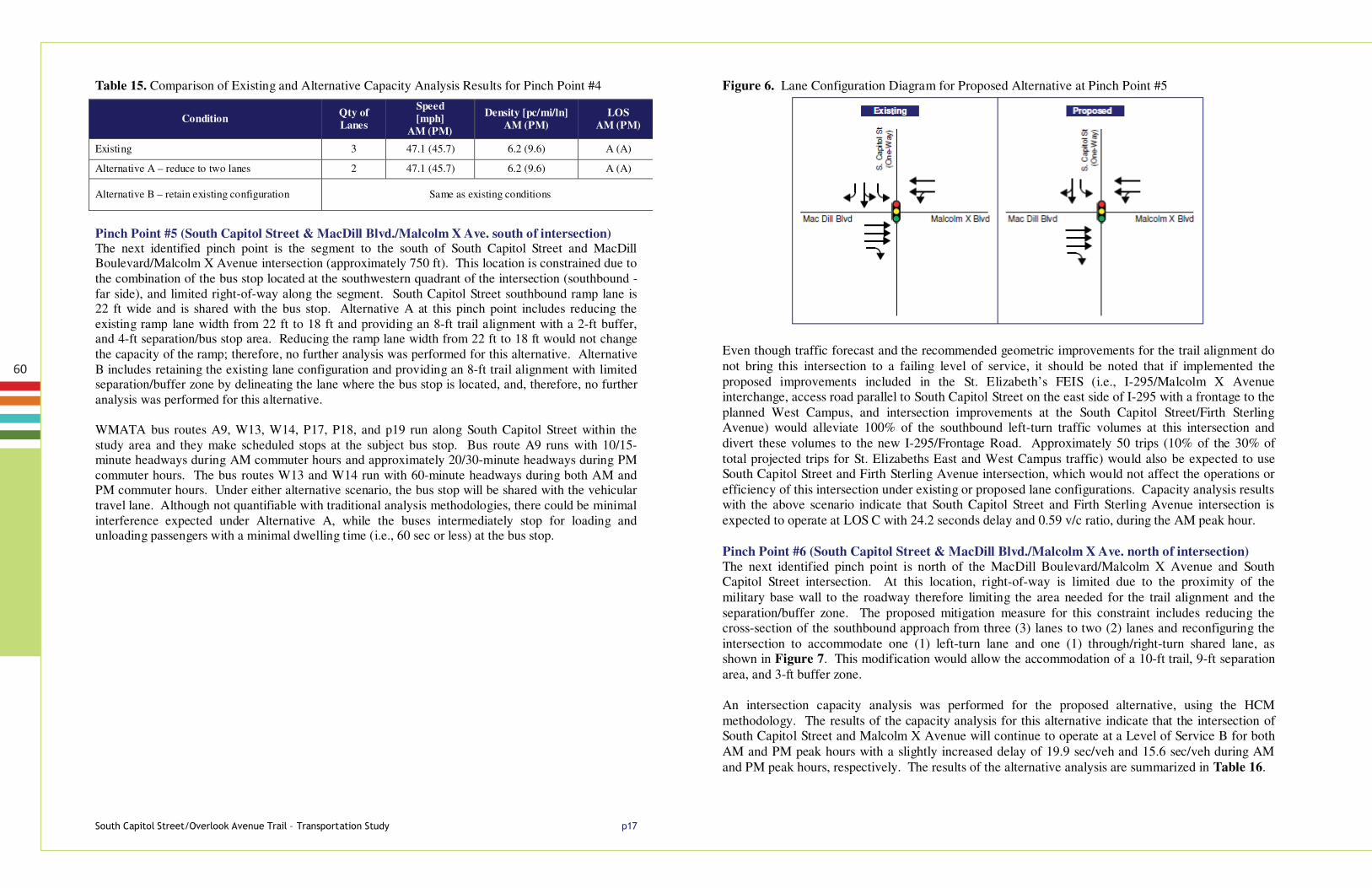
Figure 6. Lane Configuration Diagram for Proposed Alternative at Pinch Point #5
Even though traffic forecast and the recommended geometric improvements for the trail alignment do not bring this intersection to a failing level of service, it should be noted that if implemented the proposed improvements included in the St. Elizabeth’s FEIS (i.e., I-295/Malcolm X Avenue interchange, access road parallel to South Capitol Street on the east side of I-295 with a frontage to the planned West Campus, and intersection improvements at the South Capitol Street/Firth Sterling Avenue) would alleviate 100% of the southbound left-turn traffic volumes at this intersection and divert these volumes to the new I-295/Frontage Road. Approximately 50 trips (10% of the 30% of total projected trips for St. Elizabeths East and West Campus traffic) would also be expected to use South Capitol Street and Firth Sterling Avenue intersection, which would not affect the operations or efficiency of this intersection under existing or proposed lane configurations. Capacity analysis results with the above scenario indicate that South Capitol Street and Firth Sterling Avenue intersection is expected to operate at LOS C with 24.2 seconds delay and 0.59 v/c ratio, during the AM peak hour. Pinch Point #6 (South Capitol Street & MacDill Blvd./Malcolm X Ave. north of intersection) The next identified pinch point is north of the MacDill Boulevard/Malcolm X Avenue and South Capitol Street intersection. At this location, right-of-way is limited due to the proximity of the military base wall to the roadway therefore limiting the area needed for the trail alignment and the separation/buffer zone. The proposed mitigation measure for this constraint includes reducing the cross-section of the southbound approach from three (3) lanes to two (2) lanes and reconfiguring the intersection to accommodate one (1) left-turn lane and one (1) through/right-turn shared lane, as shown in Figure 7. This modification would allow the accommodation of a 10-ft trail, 9-ft separation area, and 3-ft buffer zone. An intersection capacity analysis was performed for the proposed alternative, using the HCM methodology. The results of the capacity analysis for this alternative indicate that the intersection of South Capitol Street and Malcolm X Avenue will continue to operate at a Level of Service B for both AM and PM peak hours with a slightly increased delay of 19.9 sec/veh and 15.6 sec/veh during AM and PM peak hours, respectively. The results of the alternative analysis are summarized in Table 16.

61
6RXWK�&DSLWRO�6WUHHW�2YHUORRN�$YHQXH�7UDLO�²�7UDQVSRUWDWLRQ�6WXG\� S���
Figure 7. Lane Configuration Diagram for Proposed Alternative at Pinch Point #6
Table 16. Comparison of Existing and Alternative Capacity Analysis at Pinch Point #6 [MacDill Blvd/Malcolm X Ave and South Capitol Street] AM (PM)
Pinch Point #7 (Malcolm X Ave to I-295 merge ramp) The next pinch point is the weaving segment between the exit ramp from South Capitol Street to Malcolm X Ave and the I – 295 southbound merge ramp to South Capitol Street. A capacity analysis for this weaving segment was performed by reducing the cross-section of existing weaving lanes from four (4) lanes to three (3) lanes for Alternative A. The results of the capacity analysis for this alternative indicate that the weaving segment between I-295 Southbound merge ramp to South Capitol Street and the exit ramp from South Capitol Street to Malcolm X Avenue would operate at a Level of Service B or better during both peak hours. Alternative B consists of retaining the existing configuration, thus no further traffic analysis was performed for this alternative. The results of the analysis for this proposed segment is compared with the analysis for existing conditions and summarized in Table 17.
Table 17. Comparison of Existing and Alternative Capacity Analysis Results for Pinch Point #7
Condition Control Delay
(secs/veh.) v/c Ratio
Level of Service
Existing Signal 18.7 (13.8) 0.77 (0.45) B (B)
Alternative A – Reduce vehicle turning lane storage length Same as existing conditions
Alternative B – Change southbound through and shared left turn lane to through and shared right turn lane
Signal 19.9 (15.6) 0.80 (0.52) B (B)
Condition No. of
Weaving Speed [mph]
LOS AM (PM)
Existing 4 43.3 (42.5) A (B)
Alternative A – reduce to one lane 3 42.6 (41.5) B (B)
Alternative B – retain existing configuration Same as existing conditions
6RXWK�&DSLWRO�6WUHHW�2YHUORRN�$YHQXH�7UDLO�²�7UDQVSRUWDWLRQ�6WXG\� S���
Pinch Point #8 Based on the results of the existing conditions analysis, two different alternatives with three traffic operations options were proposed at the intersection of South Capitol Street and Defense Boulevard (N)/ Firth Sterling Avenue. The proposed traffic operations for both alternatives are the same, thus each option could apply to either design alternative. The three traffic options proposed are as follows:
1. Option 1: This alternative includes eliminating the northbound exclusive left-turn lane, and changing it to two through lanes with shared left and right turns.
2. Option 2: This alternative includes eliminating one southbound through lane, and changing it to one through lane with a shared left-turn lane.
3. Option 3: This alternative includes eliminating one northbound through lane, and changing it to one through lane with a shared right-turn.
The lane configuration for each of the proposed alternatives is illustrated in Figure 8. Intersection capacity analysis was performed for the proposed three alternatives, using the HCM methodology. The results of the capacity analysis for the options indicate that the intersection of South Capitol Street and Defense Boulevard (N)/Firth Sterling Avenue would operate at a Level of Service C for both AM and PM peak hours under all three options. However, based on the Synchro analysis results, northbound through movements under Option 3 during the AM and southbound through movements under Option 2 during the PM peak hour show increased v/c ratios, which would indicate significantly increased queuing. This condition was also confirmed in the SimTraffic simulations under these alternatives. The results of the alternatives analyses for both the AM and PM peak hours are summarized in Table 18.
Figure 8. Pinch Point #8 Lane Configuration Diagrams for Proposed Options
Table 18. Summary of Alternatives Analysis for South Capitol Street and Defense Boulevard AM (PM)
OPTION Control Delay
(secs/veh.) v/c Ratio
Level of Service
Option 1- Eliminating northbound left-turn lane Signal 23.0 (23.6) 0.60 (0.58) C (C)
Option 2- Eliminating one southbound through lane Signal 22.5 (30.8) 0.54 (0.85) C (C)
Option 3- Eliminating one northbound through lane Signal 28.8 (24.1) 0.82 (0.58) C (C)

62
6RXWK�&DSLWRO�6WUHHW�2YHUORRN�$YHQXH�7UDLO�²�7UDQVSRUWDWLRQ�6WXG\� S���
VII. Recommended Alternatives Summary
Based on the analysis results, the following Table 21 shows the recommended alternatives for the study area pinch points: Table 21. Recommended Alternatives
Pinch Point
Description Alternative A Alternative B Preferred Alternativ
e
1
Approximately 400 ft north of Overlook Avenue and Laboratory Road/I-295 northbound off-ramp to Shepherd Parkway under I-295 bridge structure
- Avoid pinch point with a mid-block crossing and locate 10' trail on east side of Overlook Ave
- Retain existing. configuration and use existing sidewalk [could remove one NB through lane]
A
2
South of Overlook Avenue and Defense Boulevard (S) intersection (from curb return to approximately 200 ft to the south)
- Reduce to two 11' lanes with 10' trail, 8' separation, and 3' buffer
- Retain three 11' lanes with 6' trail, 4' separation, and 2' buffer
A
3
3.1 From Overlook Ave/ Defense Blvd. intersection north 300 ft of the intersection
- Reduce to two 11' lanes with 10' trail, 10' separation, 3' buffer
- Retain existing. configuration with 6' trail, 4' separation, 2' buffer
A
3.2 From 300 ft north of the Overlook Ave/Defense Blvd. intersection to Overlook Ave/ I-295 gore point.
- Reduce to single 18' lane with 8' trail, 5' separation, and 2' buffer
- Retain existing. configuration with 6' trail, 3' separation, and no buffer
A
3.3 From Overlook Ave/ I-295 gore point north 1,300 ft to South Capitol St/Overlook Ave. gore
- Reduce to 18' lane with 10' trail, 5' separation, and 2' buffer
- Retain existing. configuration with8' trail, 4' separation, and no buffer
A
4
From Overlook Ave/ South Capitol Street gore point to approximately 400 ft north of South Capitol Street diverge gore
- Reduce to 2 lanes with 10' trail, 5' separation, and 2' buffer
- Retain existing. configuration with 6' trail, no separation and no buffer
A
5
South of MacDill Boulevard/ Malcolm X Ave and South Capitol Street intersection from 550-ft south of intersection to curb return.
- Reduce to 1 lane with 8' trail, 2' buffer, 4' separation/bus stop, relocate bus stop to Pinch Point #6
- Retain existing. configuration w/ 8' trail and relocate bus stop
A
6
From MacDill Boulevard/ Malcolm X Ave and South Capitol Street intersection from intersection north 300 ft.
- Reduce storage length with 8'-10' trail, 1'-5' separation/relocated bus stop from Pinch Point #5, and 1' buffer
- Reduce to 2 lanes with 10' trail, 4'-8' separation/bus stop relocated from Pinch Point #5, and 2' buffer
B
7 From approximately 100 ft south of I-295 southbound on-ramp merge gore to 100 ft north of merge gore.
- Reduce to 1 lane with 10' trail, 9' separation, and 10' buffer
- Retain ex. configuration with 10' trail, 5' separation, and 3' buffer
B
8
From Defense Blvd (N)/Firth Sterling Boulevard and South Capitol Street intersection south 200 ft (Light Rail alignment 140+50)
- Reduce quantity of lanes to 2NB/ 2SB w/10' trail on west side of S. Capitol Street
- Reduce quantity of lanes to 2NB/ 2SB and shift roadway east 15' w/10' trail, 2' buffer to Light Rail, 13' separation/bus stop on west side of S. Capitol Street
A
Option 1 Option 2 Option 3
Option 1 Eliminate NB left-turn lane
Eliminate one SB through lane
Eliminate one NB through lane
6RXWK�&DSLWRO�6WUHHW�2YHUORRN�$YHQXH�7UDLO�²�7UDQVSRUWDWLRQ�6WXG\� S���
Table 19 summarizes the intersections with each pinch point alternative and Table 20 summarizes the comparison of the existing and alternative analysis results at the pinch points. Table 19. Summary of Existing and Alternative Analysis Results – Intersections
Int No. Intersection Existing Conditions Alternative A Alternative B
Delay (sec/veh)
V/C Ratio LOS
Delay (sec/veh)
V/C Ratio LOS
Delay (sec/veh)
V/C Ratio LOS
Int # 1 I-295 NB On/Off-ramps and Shepherd Parkway
26.0 (10.6)
0.19 (0.07)
C (A) Same as existing Same as existing
Int # 2 Overlook Avenue and
Laboratory Road 13.4
(20.9) 0.47
(0.65) B (C) Same as existing
13.0 (21.3)
0.47 (0.66)
B ( C )
Int # 3 Overlook Avenue and
Magazine Road/Chesapeake Street
10.6 (11.4)
0.45 (0.68)
B (B) 10.5
(18.1) 0.45
(0.68) B ( B ) Same as existing
Int # 4 Overlook Avenue and
Defense Blvd 13.6
(14.9) 0.36
(0.41) B (B)
15.4 (17.1)
0.49 (0.60)
B ( B ) Same as existing
Int # 5 S.Capitol Street and Malcolm X Avenue
11.8 (11.5)
0.33 (0.35)
B (B) Same as existing Same as existing
Int # 6 S.Capitol Street and
MacDill Blvd 18.7
(13.8) 0.77
(0.45) B (B) Same as existing
19.9 (15.6)
0.80 (0.52)
B ( B )
Int # 7 S.Capitol Street and
Defense Blvd (N)/ Firth Sterling Avenue
22.6 (23.6)
0.54 (0.58)
C (C) Same as existing Same as existing
Table 20. Summary of Existing and Alternative Analysis Results – Pinch Points
Pinch Point No.
Existing Conditions Alternative A Alternative B Delay
(sec/veh) V/C Ratio
or LOS
Delay (sec/veh)
V/C Ratio or
LOS
Delay (sec/veh)
V/C Ratio or
LOS or Speed
(mph) Density
(pc/mi/ln) or Speed
(mph) Density
(pc/mi/ln) or Speed
(mph) Density
(pc/mi/ln)
1 13.4 (20.9) 0.47 (0.65) B (C) Same as existing 13.0 (21.3) 0.47 (0.66) B ( C )
2 13.6 (15.8) 0.36 (0.42) B (B) 15.4 (17.1) 0.49 (0.60) B ( B ) Same as existing
3
3.1 10.6 (21.8) 0.45 (0.68) B (C) 10.5 (18.1) 0.45 (0.68) B ( B ) Same as existing
3.2 13.6 (15.8) 0.36 (0.42) B (B) 15.4 (17.1) 0.49 (0.60) B ( B ) Same as existing
3.3 47.6 (46.8) 7.9 (11.9) A (B) Same as existing Same as existing
4 47.1 (45.7) 6.2 (9.6) A (A) 47.1 (45.7) 6.2 (9.6) A ( A) Same as existing
5 18.7 (13.8) 0.77 (0.45) B (B) 19.9 (15.6) 0.80 (0.52) B ( B ) Same as existing
6 18.7 (13.8) 0.77 (0.45) B (B) Same as existing 19.9 (15.6) 0.80 (0.52) B ( B )
7 43.3 (42.5) -- A (B) 42.6 (41.5) -- B ( B ) Same as existing
8 22.6 (23.6) 0.54 (0.58) C (C) 23.0 (23.6) 0.60 (0.58) C ( C ) 23.0 (23.6) 0.60 (0.58) C ( C )

63
6RXWK�&DSLWRO�6WUHHW�2YHUORRN�$YHQXH�7UDLO�²�7UDQVSRUWDWLRQ�6WXG\� S���
Figure 8A. Existing AM Peak Hour Traffic Volumes
6RXWK�&DSLWRO�6WUHHW�2YHUORRN�$YHQXH�7UDLO�²�7UDQVSRUWDWLRQ�6WXG\� S���
Figure 8B. Existing PM Peak Hour Traffic Volumes

64
A p p E n D i x C : phAsinG plAn
65
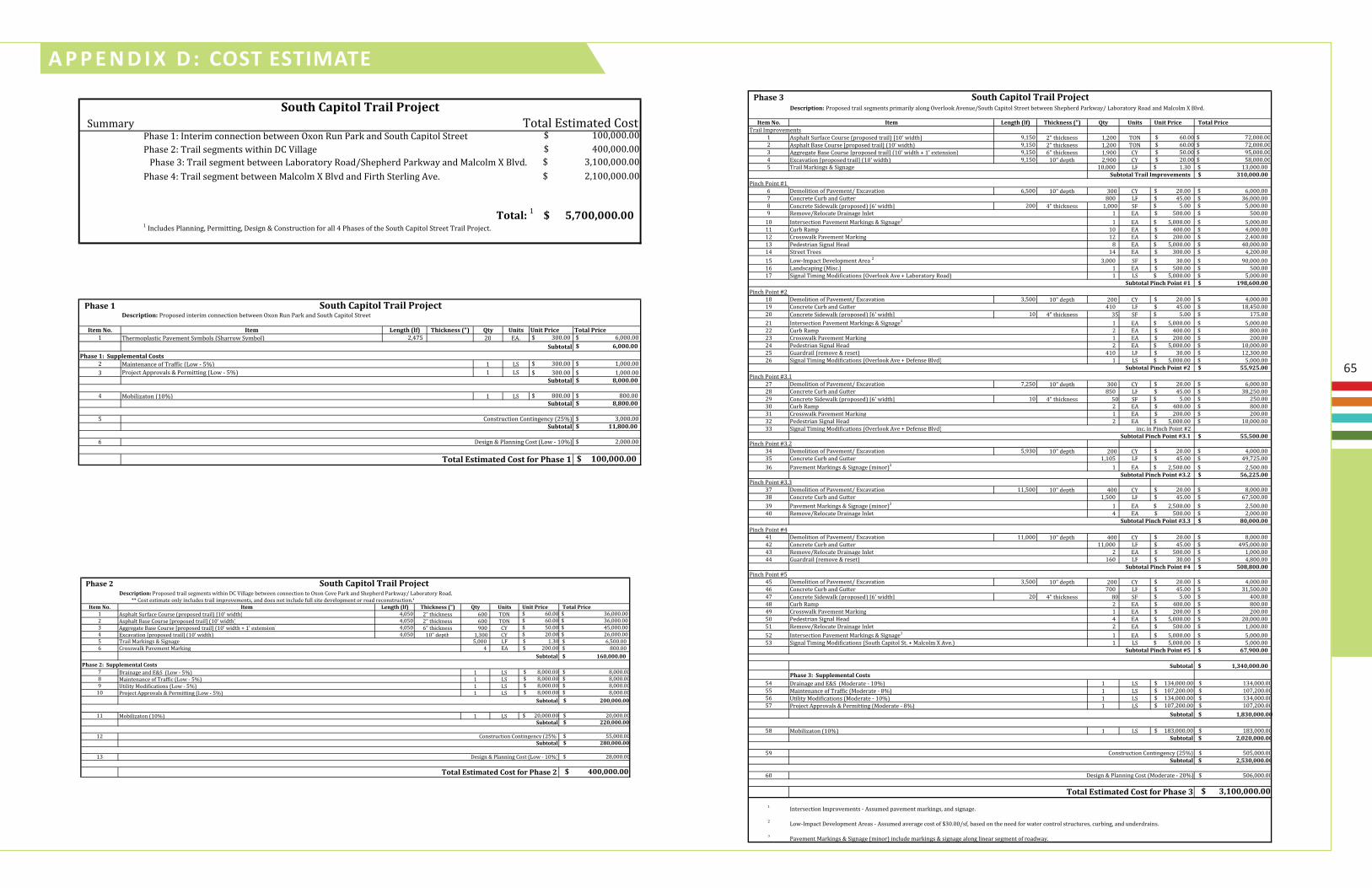
A p p E n D i x D : Cost EstimAtE
Summary Total Estimated Cost $ 100,000.00 $ 400,000.00 $ 3,100,000.00 $ 2,100,000.00
5,700,000.00$ 1 Includes Planning, Permitting, Design & Construction for all 4 Phases of the South Capitol Street Trail Project.
Phase 2: Trail segments within DC Village
Total: 1
South Capitol Trail Project
Phase 1: Interim connection between Oxon Run Park and South Capitol Street
Phase 3: Trail segment between Laboratory Road/Shepherd Parkway and Malcolm X Blvd.Phase 4: Trail segment between Malcolm X Blvd and Firth Sterling Ave.
Pha e
te o. te e th l Thic e t it it Price Total Price1 Thermoplastic Pavement Symbols Sharrow Symbol 2,4 20 EA. $ 300.00 $ ,000.00
$ ,000.00
2 Maintenance of Traffic Low 1 LS $ 300.00 $ 1,000.00 3 Project Approvals & Permitting Low 1 LS $ 300.00 $ 1,000.00
$ ,000.00
4 Mobili aton 10 1 LS $ 00.00 $ 00.00 $ , 00.00
$ 3,000.00 $ , 00.00
$ 2,000.00
$ 00,000.00 Total ti ate Co t or Pha e
Design & Planning Cost Low 10
South Capitol Trail Projecte criptio : Proposed interim connection between Oxon Run Park and South Capitol Street.
Construction Contingency 2Su total
Su total
Su total
Su total
Pha e : Supple e tal Co t
Pha e
Cost estimate only includes trail improvements, and does not include full site development or road reconstruction.te o. te e th l Thic e t it it Price Total Price
1 Asphalt Surface Course proposed trail 10 width 4,0 0 2 thickness 00 TO $ 0.00 $ 3 ,000.00 2 Asphalt Base Course proposed trail 10 width 4,0 0 2 thickness 00 TO $ 0.00 $ 3 ,000.00 3 Aggregate Base Course proposed trail 10 width 1 extension 4,0 0 thickness 00 C $ 0.00 $ 4 ,000.00 4 Excavation proposed trail 10 width 4,0 0 10 depth 1,300 C $ 20.00 $ 2 ,000.00
Trail Markings & Signage ,000 LF $ 1.30 , 00.00$ Crosswalk Pavement Marking 4 EA $ 200.00 00.00$
0,000.00$
1 LS $ ,000.00 $ ,000.00 1 LS $ ,000.00 $ ,000.00 1 LS $ ,000.00 $ ,000.00
10 1 LS $ ,000.00 $ ,000.00 $ 00,000.00
11 1 LS $ 20,000.00 $ 20,000.00 $ 0,000.00
12 $ ,000.00 $ 0,000.00
13 $ 2 ,000.00
$ 00,000.00
Construction Contingency 2 Su total
e criptio : Proposed trail segments within DC Village between connection to Oxon Cove Park and Shepherd Parkway/ Laboratory Road.South Capitol Trail Project
Su total
Su total
Su total
Drainage and E&S Low Maintenance of Traffic Low
Mobili aton 10
Pha e : Supple e tal Co t
tility Modifications Low Project Approvals & Permitting Low
Design & Planning Cost Low 10
Total ti ate Co t or Pha e
Pha e
te o. te e th l Thic e t it it Price Total Price
1 Asphalt Surface Course proposed trail 10 width ,1 0 2 thickness 1,200 TO $ 0.00 $ 2,000.00 2 Asphalt Base Course proposed trail 10 width ,1 0 2 thickness 1,200 TO $ 0.00 $ 2,000.00 3 Aggregate Base Course proposed trail 10 width 1 extension ,1 0 thickness 1, 00 C $ 0.00 $ ,000.00 4 Excavation proposed trail 10 width ,1 0 10 depth 2, 00 C $ 20.00 $ ,000.00
Trail Markings & Signage 10,000 LF 1.30$ 13,000.00$ Su total Trail pro e e t 0,000.00$
Demolition of Pavement/ Excavation , 00 10 depth 300 C 20.00$ ,000.00$ Concrete Curb and utter 00 LF 4 .00$ 3 ,000.00$ Concrete Sidewalk proposed width 200 4 thickness 1,000 SF .00$ ,000.00$ Remove/Relocate Drainage Inlet 1 EA 00.00$ 00.00$
10 Intersection Pavement Markings & Signage1 1 EA ,000.00$ ,000.00$ 11 Curb Ramp 10 EA 400.00$ 4,000.00$ 12 Crosswalk Pavement Marking 12 EA 200.00$ 2,400.00$ 13 Pedestrian Signal ead EA ,000.00$ 40,000.00$ 14 Street Trees 14 EA 300.00$ 4,200.00$ 1 Low Impact Development Area 2 3,000 SF 30.00$ 0,000.00$ 1 Landscaping Misc. 1 EA 00.00$ 00.00$ 1 Signal Timing Modifications Overlook Ave Laboratory Road 1 LS ,000.00$ ,000.00$
Su total Pi ch Poi t , 00.00$
1 Demolition of Pavement/ Excavation 3, 00 10 depth 200 C 20.00$ 4,000.00$ 1 Concrete Curb and utter 410 LF 4 .00$ 1 ,4 0.00$ 20 Concrete Sidewalk proposed width 10 4 thickness 3 SF .00$ 1 .00$ 21 Intersection Pavement Markings & Signage1 1 EA ,000.00$ ,000.00$ 22 Curb Ramp 2 EA 400.00$ 00.00$ 23 Crosswalk Pavement Marking 1 EA 200.00$ 200.00$ 24 Pedestrian Signal ead 2 EA ,000.00$ 10,000.00$ 2 uardrail remove & reset 410 LF 30.00$ 12,300.00$ 2 Signal Timing Modifications Overlook Ave Defense Blvd 1 LS ,000.00$ ,000.00$
Su total Pi ch Poi t 55, 5.00$
2 Demolition of Pavement/ Excavation ,2 0 10 depth 300 C 20.00$ ,000.00$ 2 Concrete Curb and utter 0 LF 4 .00$ 3 ,2 0.00$ 2 Concrete Sidewalk proposed width 10 4 thickness 0 SF .00$ 2 0.00$ 30 Curb Ramp 2 EA 400.00$ 00.00$ 31 Crosswalk Pavement Marking 1 EA 200.00$ 200.00$ 32 Pedestrian Signal ead 2 EA ,000.00$ 10,000.00$ 33 Signal Timing Modifications Overlook Ave Defense Blvd inc. in Pinch Point 2
Su total Pi ch Poi t . 55,500.00$
34 Demolition of Pavement/ Excavation , 30 10 depth 200 C 20.00$ 4,000.00$ 3 Concrete Curb and utter 1,10 LF 4 .00$ 4 , 2 .00$ 3 Pavement Markings & Signage minor 3 1 EA 2, 00.00$ 2, 00.00$
Su total Pi ch Poi t . 5 , 5.00$
3 Demolition of Pavement/ Excavation 11, 00 10 depth 400 C 20.00$ ,000.00$ 3 Concrete Curb and utter 1, 00 LF 4 .00$ , 00.00$ 3 Pavement Markings & Signage minor 3 1 EA 2, 00.00$ 2, 00.00$ 40 Remove/Relocate Drainage Inlet 4 EA 00.00$ 2,000.00$
Su total Pi ch Poi t . 0,000.00$
41 Demolition of Pavement/ Excavation 11,000 10 depth 400 C 20.00$ ,000.00$ 42 Concrete Curb and utter 11,000 LF 4 .00$ 4 ,000.00$ 43 Remove/Relocate Drainage Inlet 2 EA 00.00$ 1,000.00$ 44 uardrail remove & reset 1 0 LF 30.00$ 4, 00.00$
Su total Pi ch Poi t 50 , 00.00$
4 Demolition of Pavement/ Excavation 3, 00 10 depth 200 C 20.00$ 4,000.00$ 4 Concrete Curb and utter 00 LF 4 .00$ 31, 00.00$ 4 Concrete Sidewalk proposed width 20 4 thickness 0 SF .00$ 400.00$ 4 Curb Ramp 2 EA 400.00$ 00.00$ 4 Crosswalk Pavement Marking 1 EA 200.00$ 200.00$
0 Pedestrian Signal ead 4 EA ,000.00$ 20,000.00$ 1 Remove/Relocate Drainage Inlet 2 EA 00.00$ 1,000.00$ 2 Intersection Pavement Markings & Signage1 1 EA ,000.00$ ,000.00$ 3 Signal Timing Modifications South Capitol St. Malcolm X Ave. 1 LS ,000.00$ ,000.00$
Su total Pi ch Poi t 5 7, 00.00$
, 0,000.00$
4 1 LS $ 134,000.00 $ 134,000.00 1 LS $ 10 ,200.00 $ 10 ,200.00 1 LS $ 134,000.00 $ 134,000.00 1 LS $ 10 ,200.00 $ 10 ,200.00
$ , 0,000.00
1 LS $ 1 3,000.00 $ 1 3,000.00 $ ,0 0,000.00
$ 0 ,000.00 $ ,5 0,000.00
0 $ 0 ,000.00
$ , 00,000.00
1 Intersection Improvements Assumed pavement markings, and signage.2
3
South Capitol Trail Projecte criptio : Proposed trail segments primarily along Overlook Avenue/South Capitol Street between Shepherd Parkway/ Laboratory Road and Malcolm X Blvd.
Su total
Pha e : Supple e tal Co tDrainage and E&S Moderate 10
Trail Improvements
Pinch Point 3.2
Pinch Point 1
Pinch Point 2
Pinch Point 3.1
Pinch Point
Pinch Point 4
Pinch Point 3.3
Maintenance of Traffic Moderate tility Modifications Moderate 10
Project Approvals & Permitting Moderate Su total
Mobili aton 10
Total ti ate Co t or Pha e
Low Impact Development Areas Assumed average cost of $30.00/sf, based on the need for water control structures, curbing, and underdrains.
Pavement Markings & Signage minor include markings & signage along linear segment of roadway.
Su total
Construction Contingency 2 Su total
Design & Planning Cost Moderate 20
Pha e
te o. te e th l Thic e t it it Price Total PriceTrail Improvements
1 Asphalt Surface Course proposed trail 10 width ,400 2 thickness 1,100 TO $ 0.00 $ ,000.00 2 Asphalt Base Course proposed trail 10 width ,400 2 thickness 1,100 TO $ 0.00 $ ,000.00 3 Aggregate Base Course proposed trail 10 width 1 extension ,400 thickness 1, 00 C $ 0.00 $ 0,000.00 4 Excavation proposed trail 10 width ,400 10 depth 2, 00 C $ 20.00 $ 2,000.00
Trail Markings & Signage ,400 LF 1.30$ 10, 20.00$ 0,000.00$
Demolition of Pavement/ Excavation ,3 0 10 depth 200 C 20.00$ 4,000.00$ Concrete Curb and utter 20 LF 4 .00$ 23,400.00$ Concrete Sidewalk proposed width 11 4 thickness SF $ .00 32 .00$ Remove/Relocate Drainage Inlet 2 EA 00.00$ 1,000.00$
10 Curb Ramp 2 EA 400.00$ 00.00$ 11 Pedestrian Signal ead 4 EA ,000.00$ 20,000.00$ 12 Signal Timing Modifications South Capitol Street Malcolm X Ave inc. in Pinch Point
Su total Pi ch Poi t ,5 5.00$
13 uardrail remove & reset 410 LF 30.00$ 12,300.00$ Su total Pi ch Poi t 7 , 00.00$
14 Demolition of Pavement/ Excavation 3,000 10 depth 100 C 20.00$ 2,000.00$ 1 Concrete Curb and utter 00 LF 4 .00$ 2 ,000.00$ 1 Textured Asphalt/Pavers 2,300 SF .00$ 1 ,400.00$ 1 Remove/Relocate Drainage Inlet 2 EA 00.00$ 1,000.00$ 1 Intersection Pavement Markings & Signage1 1 EA ,000.00$ ,000.00$ 1 Curb Ramp 2 EA 400.00$ 00.00$ 20 Crosswalk Pavement Marking 4 EA 200.00$ 00.00$ 21 Pedestrian Signal ead EA ,000.00$ 40,000.00$ 22 Street Trees EA 300.00$ 1, 00.00$ 23 Landscaping Misc. 1 EA 00.00$ 00.00$ 24 Signal Timing Modifications South Capitol Street Firth Sterling Ave 1 LS ,000.00$ ,000.00$
Su total Pi ch Poi t 0 , 00.00$
Su total 0,000.00$
2 1 LS $ 4 ,000.00 $ 4 ,000.00 2 1 LS $ 3 , 00.00 $ 3 , 00.00 2 1 LS $ 4 ,000.00 $ 4 ,000.00 2 1 LS $ 3 , 00.00 $ 3 , 00.00
$ , 50,000.00
2 1 LS $ 12 ,000.00 $ 12 ,000.00 $ , 0,000.00
30 $ 34 ,000.00 $ ,7 0,000.00
31 $ 34 ,000.00
$ , 00,000.00
1 Intersection Improvements Assumed pavement markings, and signage.
South Capitol Trail Projecte criptio : Proposed trail segments along South Capitol Street between Malcolm X Blvd. and Firth Sterling Ave.
Su total
Drainage and E&S Moderate 10
Pinch Point
Pinch Point
Pinch Point
Pha e : Supple e tal Co t
Maintenance of Traffic Moderate tility Modifications Moderate 10
Project Approvals & Permitting Moderate Su total
Mobili aton 10
Total ti ate Co t or Pha e
Su total
Construction Contingency 2 Su total
Design & Planning Cost Moderate 20
66

67
A p p E n D i x E : DEsiGn CritEriA tABlE
Criteria recommended recommended range minimum ConsiderationsDesign Speed 18 mph 12 to 18 mph 12 mph min. Topography, user volumes and abilities
Trail Width 10-feet 10 to 14 feetAt intersections with heavy queuing, widen path to provide additional capacity
8-feet and 6-feet under rare occurrences Bicycle/ pedestrian user volumes, user safety, maintenance vehicle width (7-ft)
Trail Cross Slope 1% 0.5% to 2% 5% Max per AGODA1
2% Max per PROWAG2
Topography - Minimum Cross Slope Transitions 5-feet per 1% change in slope
HorizontalAlignment
Min. Curve Radius:27-feet min. at 12 mph36-feet min. at 14 mph47-feet min. at 16 mph60-feet min. at 18 mph
Topography
Vertical Align-ment
0 to 5% slope 5% max any distance2 8.3% max up to 200-feet1
10% max up to 30-feet1
12.5% max up to 10-feet1
3% max for unpaved surface trails1
Adjacent topography
Stopping Sight Distance
S = V2 30(f+/-G)
+ 3.67V
S = stopping distanceV = velocity (mph)f =friction coeff. (0.16)G =grade (ft/ft)
Per AASHTO Guidelines 3 Vertical alignment
Clearance(vertical)
10-feet 10-feet or greater 8-feet under constrained conditions Maintenance & emergency vehicle access
Trail/RoadSeparation
5-feet 5-feet or greater Less than 5-feet requires physical barrier railingseparation
Roadway speeds adjacent to trail
Trail Buffer 3-feet 3 to 5-feet Min. 2-feet graded area with max 6:1 slope for clear-ance from lateral obstructions. Min. 1-foot clearance where railings or fences are used.
Adjacent obstructions
Grading &Drainage(Adjacent to Trail)
Match adjacent topography to greatest extent possible while providing adequate drainage
Provide grading sufficient for sheet flow wherever possible or if necessary a side ditch of suitable dimension on uphill side of trail to intercept slope’s drainage. Where necessary provide culvert and catch-basins.
Adjacent topography and drainage conditions
Trail Surfaces Hard, all weather pavement surfaces(Asphalt or Concrete)
Adjacent facilities to provide universal access, maintenance
1 U.S. Access Board Architectural Barriers Act Accessibility Guidelines for Outdoor Developed Areas (AGODA) (2007)
2 U.S. Access Board Public Rights-Of-Way Accessibility Guidelines (PROWAG) (2005)
3 AASHTO Guide for the Development of Bicycle Facilities (AASHTO) (1999)