Sound transmission through lightweight double …jw12/JW PDFs/partitions.pdfJOURNAL OF SOUND AND...
31
JOURNAL OF SOUND AND VIBRATION Journal of Sound and Vibration 286 (2005) 817–847 Sound transmission through lightweight double-leaf partitions: theoretical modelling J. Wang a , T.J. Lu b, , J. Woodhouse b , R.S. Langley b , J. Evans c a School of Aeronautical Engineering, Queen’s University, Belfast, UK b Department of Engineering, University of Cambridge, Trumpington Street, Cambridge CB2 1PZ, UK c Banro Holdings Ltd., Manor Works, Pleck Road, Walsall, West Midlands WS2 9ES, UK Received 2 October 2003; received in revised form 8 October 2004; accepted 19 October 2004 Available online 22 December 2004 Abstract This paper presents theoretical modelling of the sound transmission loss through double-leaf lightweight partitions stiffened with periodically placed studs. First, by assuming that the effect of the studs can be replaced with elastic springs uniformly distributed between the sheathing panels, a simple smeared model is established. Second, periodic structure theory is used to develop a more accurate model taking account of the discrete placing of the studs. Both models treat incident sound waves in the horizontal plane only, for simplicity. The predictions of the two models are compared, to reveal the physical mechanisms determining sound transmission. The smeared model predicts relatively simple behaviour, in which the only conspicuous features are associated with coincidence effects with the two types of structural wave allowed by the partition model, and internal resonances of the air between the panels. In the periodic model, many more features are evident, associated with the structure of pass- and stop-bands for structural waves in the partition. The models are used to explain the effects of incidence angle and of the various system parameters. The predictions are compared with existing test data for steel plates with wooden stiffeners, and good agreement is obtained. r 2004 Elsevier Ltd. All rights reserved. ARTICLE IN PRESS www.elsevier.com/locate/jsvi 0022-460X/$ - see front matter r 2004 Elsevier Ltd. All rights reserved. doi:10.1016/j.jsv.2004.10.020 Corresponding author. Tel.: +44 1223 766316; fax: +44 1223 332662. E-mail address: [email protected] (T.J. Lu).
-
Upload
phamkhuong -
Category
Documents
-
view
239 -
download
0
Transcript of Sound transmission through lightweight double …jw12/JW PDFs/partitions.pdfJOURNAL OF SOUND AND...
ARTICLE IN PRESS
JOURNAL OFSOUND ANDVIBRATION
Journal of Sound and Vibration 286 (2005) 817–847
0022-460X/$ -
doi:10.1016/j.
�Correspon
E-mail add
www.elsevier.com/locate/jsvi
Sound transmission through lightweight double-leaf partitions:theoretical modelling
J. Wanga, T.J. Lub,�, J. Woodhouseb, R.S. Langleyb, J. Evansc
aSchool of Aeronautical Engineering, Queen’s University, Belfast, UKbDepartment of Engineering, University of Cambridge, Trumpington Street, Cambridge CB2 1PZ, UK
cBanro Holdings Ltd., Manor Works, Pleck Road, Walsall, West Midlands WS2 9ES, UK
Received 2 October 2003; received in revised form 8 October 2004; accepted 19 October 2004
Available online 22 December 2004
Abstract
This paper presents theoretical modelling of the sound transmission loss through double-leaf lightweightpartitions stiffened with periodically placed studs. First, by assuming that the effect of the studs can bereplaced with elastic springs uniformly distributed between the sheathing panels, a simple smeared model isestablished. Second, periodic structure theory is used to develop a more accurate model taking account ofthe discrete placing of the studs. Both models treat incident sound waves in the horizontal plane only, forsimplicity. The predictions of the two models are compared, to reveal the physical mechanisms determiningsound transmission. The smeared model predicts relatively simple behaviour, in which the only conspicuousfeatures are associated with coincidence effects with the two types of structural wave allowed by thepartition model, and internal resonances of the air between the panels. In the periodic model, many morefeatures are evident, associated with the structure of pass- and stop-bands for structural waves in thepartition. The models are used to explain the effects of incidence angle and of the various systemparameters. The predictions are compared with existing test data for steel plates with wooden stiffeners,and good agreement is obtained.r 2004 Elsevier Ltd. All rights reserved.
see front matter r 2004 Elsevier Ltd. All rights reserved.
jsv.2004.10.020
ding author. Tel.: +44 1223 766316; fax: +44 1223 332662.
ress: [email protected] (T.J. Lu).

ARTICLE IN PRESS
Nomenclature
A1, A2 amplitudes of waves in cavityc0 sound speed in aircB bending wave speed in panelDi bending stiffness of panelEi Young’s modulusf frequencyhi panel thicknessH separation distance between panelsI incident wave amplitudeIi incident sound intensityIt transmitted sound intensityIz second moment of area about z-axis of
studj
ffiffiffiffiffiffiffi�1
p
kx, ky wavenumber in x- and y-directionKt translational stiffness of studK 0
t uniformly distributed translational stiff-ness of stud
K 0r uniformly distributed rotational stiffness
of studKr rotational stiffness of studl web length of studL stud spacingmpi panel’s mass per unit areaM half stud mass per unit lengthMb bending momentp pressure perturbationR reflection wave amplitude
RL transmission losss0 equivalent stiffness of airt0 wall thickness of studt timeT transmitted wave amplitudeui fluid velocity of the sound waveWi panel deflectionsW i amplitude of panel deflectionsai,n deflection amplitudes of panelsbn amplitudes of reflected waves in the
incident half-space�n amplitudes of transmitted waves
through the front panelzn amplitudes of reflected waves from the
rear panelxn amplitudes of transmitted waves to the
transmitted half-space incidence angle,normally from 0 to 78
yb rotation anglenI Poisson’s ratior0 air densityri density of materialFI velocity potentialstðyÞ transmission coefficient at incidence
angle yt averaged transmission coefficient for all
possible incidence angleso angular frequencyZi material loss factors
J. Wang et al. / Journal of Sound and Vibration 286 (2005) 817–847818
1. Introduction
Partition walls consisting of cold-formed steel frames clad with plasterboard are widely used inbuilding construction. Compared with traditional masonry constructions, they are lighter, easier,and quicker to assemble, and leave a cleaner building site. However, they need greater skill todesign and construct, because the overall design (including strength, stiffness, and buckling) ismuch more complex. It is also more difficult to predict sound transmission loss (STL).
The simplest acoustic partitioning that has been studied is a double-leaf wall without structuralconnections [1–5]. This type of structure, if it could be built, would provide high STL. However,vertical beams called ‘‘studs’’ are needed for practical partitions to support structural loads, andthese decrease the STL and also complicate theoretical modelling. A typical lightweight partitionwithout sound-absorbent infill material is depicted in Fig. 1. Sound can travel through the air-gap

ARTICLE IN PRESS
Fig. 1. Illustration of a double-leaf partition wall with studs.
J. Wang et al. / Journal of Sound and Vibration 286 (2005) 817–847 819
between the two boards, and also the steel frame provides a structural route for soundtransmission. The frame alters the dynamic and sound radiation properties of each panel, andthus changes the sound transmission of the partition wall as a whole [4]. Although a real structurewill never be precisely periodic, periodic structure theory offers the most natural way to develop atheoretical model that takes account of the dominant features of the system [6–8]. Simplemodelling of this kind will be presented in this paper. The aim of the research is to establishphysically based models of sufficient accuracy that they can in due course be used in conjunctionwith optimisation techniques to design more efficient soundproofing partitions. The present paperrepresents only the first stage of this endeavour, since there are limitations to the modelsdeveloped here which will be explained later.
Sharp [9] has discussed sound transmission through a double panel with sound bridges, byanalysing the power radiated from a point- or line-loaded panel based on Cremer and Heckl’stheory [10] using the impedance method, leading to an empirical method for predicting the STL.However, this method does not provide a sufficiently complete understanding of STL mechanismsto allow acoustic optimisation to be performed. Desmet and Sas [11] presented a method offinding sound transmission properties of a finite double-leaf partition at low frequencies, byexperimental measurements as well as theoretical modelling based on Dowell’s modal couplingtheory [12]. Limited to low frequencies, this method is also not convenient for carrying out

ARTICLE IN PRESS
J. Wang et al. / Journal of Sound and Vibration 286 (2005) 817–847820
optimisation studies. Lin and Garrelick [13], inspired by the work of Evseev [14], made use ofGreen’s functions to solve the problem. In their work, the stud is assumed to be a rigid andmassless coupling between the panels. Later, Urusovskii [15] pointed out that the basic equationsof Lin and Garrelick [13] do not include the phase factor associated with the force exerted on theplates by the stud as a result of oblique incidence of a plane wave on the plates, nor is the massreactance of the stud taken into account. The method adopted in Ref. [15] to describe the flexuraldeflection of the plates has some common aspects with the space-harmonic approach proposed byMead [16] and Mead and Pujara [17]. However, the method still assumes that the studs join theplates rigidly, and does not take advantage of the periodicity of the system. In addition, nosolution procedure or numerical results for the STL were presented. Takahashi [18] discussedsound radiation from periodically connected double-plate structures under mechanical excitationforces. Three different types of structure are considered: point connected, point connected withrib-stiffening, and rib-connected. However, acoustic loading as well as resonances in the cavitywere ignored. Therefore, the results of Ref. [18] cannot be directly used to calculate soundtransmission through double-leaf partitions.
Mead [16,19] studied the vibration response and wave propagation in periodic structuresand discussed the characteristics of their propagation constants. Mead and Pujara[17] subsequently proposed to use space-harmonic expansions to study periodic partitions: theyused a two-dimensional (2D) model in which the panel is represented as a beam supported by regularly spaced elastic supports, which oppose both transverse displacement and rotation.This model is suitable for wave propagation perpendicular to the studs, i.e. in the horizontal planefor a partition wall. The response of the beam subjected to a homogeneous random convectedpressure field was then solved. However, Mead and Pujara [17] pointed out that although themethod has been devised for the estimation of sound radiation, acoustic effects were not actuallyincluded.
The space-harmonic method expresses the panel displacement and pressure field in terms of aseries of travelling-wave harmonic terms. For a double-leaf partition, the system equations can bedeveloped by combining the wave equation for sound waves in the incident, cavity andtransmitted regions with the two beam equations, the latter including lumped masses and springs(translational and torsional) to represent the stud effects. By coupling the acoustic and structuralvibrations with appropriate boundary conditions and then employing the virtual work principle,complete governing equations can be derived.
Mathur et al. [8] presented a theoretical model based on the space-harmonic approach tocalculate STL through periodically stiffened panels and stiffened double-leaf structures:schemes to impose the structure-acoustic interactions and convergence criteria of the solutionwere developed. However, no solution procedure was given nor were any numerical resultspresented.
Lee and Kim [20] adopted the approach proposed by Mead and Pujara [17] and the schemesdeveloped by Mathur et al. [8] to solve the vibro-acoustic equation of a single stiffened platesubjected to a plane wave input. An exact analysis procedure was developed to calculate the STLthrough an infinitely long elastic panel stiffened by periodic parallel beams. The present workextends this approach to double-leaf partitions stiffened with studs. For simplicity in this initialstudy, Mead’s assumption of a 2D model is retained. A complete, predictive model would need toallow for general oblique incidence of sound waves, but this is deferred to future work.

ARTICLE IN PRESS
J. Wang et al. / Journal of Sound and Vibration 286 (2005) 817–847 821
The overall aim of this research is to develop deterministic analytical tools, focusing on theperformance of key individual components and validated with experimental data, that canprovide a better physical understanding of the STL mechanisms in double-leaf partitions. Forsimplicity, the system is considered to be of infinite extent in the direction of the frames, and aharmonic incident wave in the horizontal plane is considered so that 1D periodic structure theorycan be applied. Two analytical models are developed, one based on replacing the studs withuniformly distributed elastic springs and the other with periodically placed discrete masses, andtranslational and rotational springs. For periodic modelling, the space-harmonic method isemployed. Material damping is introduced by using a complex Young’s modulus.
2. Smeared model
2.1. Derivation of smeared model
The smeared model for stud connections follows the approach used by Cremer and Heckl [10]to study impact sound insulation of floating floors; a similar but simpler model has been used byKropp and Rebillard [5] to study the airborne sound insulation of double wall constructions. Thisearlier work is extended here to give a consistent model which will relate in a very direct way to themore elaborate periodic model to be developed in the next section. For double-leaf partitions, thesmeared model assumes that the studs can be replaced by translational and rotational springsuniformly distributed between the two panels. The stud mass is also distributed over the panels.The model is directly relevant if the stud spacing is sufficiently small (smaller than half thewavelength). Furthermore, as becomes clear later, it can provide approximate ‘‘backbone’’solutions for the full problem.
2.1.1. System equations
For a stud of depth l, wall thickness t0; and Young’s modulus E, the force per unit length due toa stretch of the stud in the y-direction (see Figs. 1 and 2) by a distance Dl is Et0Dl=l: Consequently,each stud can be modelled as a spring of translational stiffness Kt ¼ Et0=l per unit length.Similarly, the stud has a rotational stiffness Kr which is estimated in this study by considering theweb bending of the stud:
Mb ¼ EIzyb=l � Kryb; (1)
where Iz ¼ t30=12 is the second moment of area about the z-axis, Mb is the bending moment, andyb is the rotation angle.
Fig. 2 depicts the double wall partition with stud connections and the corresponding smearedmodel. For simplicity, it is assumed that the studs are periodically distributed between twoinfinitely large panels, and not connected to each other in the transverse direction.
As illustrated in Fig. 2a, in the smeared model the studs are replaced by translational androtational springs of stiffness K 0
t and K 0r per unit area, uniformly distributed between the two
board panels. If the spacing between the studs is L, then K 0t ¼ Kt=L ¼ Et0=Ll and K 0
r ¼ Kr=L ¼
EIz=Ll: The panels are taken to be isotropic, with thickness ðh1; h2Þ; and mass per unit area (mp1;mp2), respectively (Fig. 2b). Under these assumptions, the governing equations of motion for the

ARTICLE IN PRESS
J. Wang et al. / Journal of Sound and Vibration 286 (2005) 817–847822
two panels are given by [5,21]
D1q4W 1ðx; tÞ
qx4þ mp1 þ
M
L
� �q2W 1ðx; tÞ
qt2þ K 0
tðW 1ðx; tÞ � W 2ðx; tÞÞ
� K 0r
q2
qx2ðW 1ðx; tÞ � W 2ðx; tÞÞ � jor0ðF1 � F2Þ ¼ 0; ð2aÞ
D2q4W 2ðx; tÞ
qx4þ mp2 þ
M
L
� �q2W 2ðx; tÞ
qt2þ K 0
tðW 2ðx; tÞ � W 1ðx; tÞÞ
� K 0r
q2
qx2ðW 2ðx; tÞ � W 1ðx; tÞÞ � jor0 F2 � F3ð Þ ¼ 0; ð2bÞ
where Fi describes the velocity potentials of the acoustic fields, as will be defined shortly, and Di isthe flexural stiffness of the panel:
Di ¼Eih
3i ð1 þ jZiÞ
12ð1 � n2i Þ
: (2c)
Here, Zi is the loss factor of the panel material [20], and Ei; ni are the Young’s modulus andPoisson’s ratio of the panel material. The loss factor depends strongly upon the type of material ofinterest: typical values from the literature are 0.00073–0.00153 for steel, 0.1–0.3 for plasterboard,and 0.0045–0.115 for wood [22]. It is also likely to depend on frequency. Significant terms in Eqs.(2a) and (b) are the third and fourth terms representing structural coupling, and the fifth termrepresenting air loading as well as airborne coupling.
The waves in the incident, cavity, and transmission regions can be expressed in terms of theirrespective velocity potentials:
F1 ¼ e�jkxxðIe�jkyy þ RejkyyÞejot; (3a)
Fig. 2. Side view of a double-leaf partition wall with studs: (a) schematic of the smearing process and (b) notation used
in the analysis.

ARTICLE IN PRESS
J. Wang et al. / Journal of Sound and Vibration 286 (2005) 817–847 823
F2 ¼ e�jkxxðA1e�jkyy þ A2e
jkyyÞejot; (3b)
F3 ¼ e�jkxxðTe�jkyyÞejot; (3c)
where o is the angular frequency, I, R, and T are, respectively, the amplitude of the incident,reflected, and transmitted waves, and A1; A2 are the amplitudes of waves in the air cavity. Theparticle speed of the wave is related to the velocity potential by ui ¼ �rFi ði ¼ 1; 2; 3Þ: Thecorresponding pressure perturbation can be expressed as [4,7]
p ¼ r0
qFqt
¼ jor0F (4)
as used in Eqs. (2a) and (b). The wavenumber components kx; ky are given in terms of the angle ofincidence y via
kx ¼ k sin y; ky ¼ k cos y; (5)
where k ¼ o=c0 and c0 is the speed of sound in air.Because the system is assumed to be infinite and homogeneous, the deflection of the two panels
takes the following forms:
W 1ðx; tÞ ¼ W 1e�jðkxx�otÞ; (6a)
W 2ðx; tÞ ¼ W 2e�jðkxx�otÞ: (6b)
At the air–panel interface the normal velocity is continuous, resulting in the following couplingequations:
�qF1
qy¼ joW 1; �
qF2
qy¼ joW 1 at y ¼ 0; (7a)
�qF2
qy¼ joW 2; �
qF3
qy¼ joW 2 at y ¼ H: (7b)
2.1.2. Solution to the system equations
The sound transmission coefficient is defined by
tðyÞ ¼T
I
��������2
: (8)
The procedure to calculate tðyÞ is as follows. Firstly, the boundary conditions, Eq. (7), arerewritten as
ðo=kyÞW 1 þ R ¼ I ;
ðo=kyÞW 1 � A1 þ A2 ¼ 0;
ðo=kyÞW 2 � A1e�jkyH þ A2e
jkyH ¼ 0;
ðo=kyÞW 2 � Te�jkyH ¼ 0:
(9)

ARTICLE IN PRESS
J. Wang et al. / Journal of Sound and Vibration 286 (2005) 817–847824
Eq. (2) then become
½D1k4x � o2mp1 þ K 0
t þ K 0rk
2x � Mo2
�L�W 1 � ðK 0
t þ K 0rk
2xÞW 2
� jor0R þ jor0ðA1 þ A2Þ ¼ jor0I
and
� ðK 0t þ K 0
rk2xÞW 1 þ ½D2k4
x � o2mp2 þ K 0t þ K 0
tk2x � Mo2
�L�W 2
� jor0ðA1e�jkyH þ A2e
jkyHÞ þ jor0Te�jkyH ¼ 0:
By introducing
a11 ¼ D1k4x � o2mp1 þ K 0
t þ K 0rk
2x � Mo2
�L �
2jo2r0ejkyH
kyðe�jkyH � ejkyHÞ; (10a)
a12 ¼2jo2r0
kyðe�jkyH � ejkyHÞ� K 0
t � K 0rk
2x ¼ a21; (10b)
a22 ¼ D2k4x � o2mp2 þ K 0
t þ K 0rk
2x � Mo2
�L �
2jo2r0ejkyH
kyðe�jkyH � ejkyHÞ; (10c)
the governing equations for panel motion can be expressed in matrix form as
a11 a12
a21 a22
" #W 1
W 2
( )¼
2jor0I
0
�: (11)
Finally, from Eq. (11),
W 2 ¼�2a12jor0I
a11a22 � a12a21
and
T ¼ ðo=kyÞW 2ejkyH ¼
�2a12jo2r0IejkyH
kyða11a22 � a12a21Þ
and hence
tðyÞ ¼�2a12jo2r0e
jkyH
kyða11a22 � a12a21Þ
��������2
: (12)
The diffuse field transmission coefficient averaged over all angles of incidence within theincident plane is [4]
t ¼
Rp=20
tðyÞ sin y cos ydy
Rp=20
sin y cos ydy
: (13)
Once t is found, the transmission loss may be calculated:
RL ¼ �10 log10 t: (14)

ARTICLE IN PRESS
J. Wang et al. / Journal of Sound and Vibration 286 (2005) 817–847 825
2.2. Results of smeared model
Fig. 3 shows an example of the predicted STL using the smeared model for a plane wave at 451incidence angle. The partition system consists of two identical 12.5mm thick gypsum boards(Young’s modulus E ¼ 7 � 109 N=m2; Poisson’s ratio n ¼ 0:3; density r ¼ 1200kg=m3) andperiodically distributed C-section steel studs (Young’s modulus Estud ¼ 210 � 109 N=m2; wallthickness t0 ¼ 0.5 mm). The distance between the two panels is H ¼ 50mm and the stud spacing isL ¼ 600mm. The translational stiffness of this particular design of the steel stud is given by
Kt ¼ Et0=l ¼ 2:1 � 109 N=m: (15)
The rotational stiffness of the stud is estimated as
Kr ¼ EIz=l ¼ 39:1Nm=rad: (16)
For uniformly distributed studs, the corresponding stiffnesses K 0t and K 0
r are
K 0t ¼ ðEt0Þ=ðlLÞ ¼ 3:125 � 109 N=m3; (17a)
K 0r ¼ ðEIzÞ=ðlLÞ ¼ 65:2N=rad: (17b)
The distributed mass of the studs is
M 0 ¼ 2M=L ¼ 0:884 kg=m2: (17c)
For this particular design the rotational stiffness and the stud mass have only a rather minorinfluence, but they are included for completeness.
Fig. 3 shows three curves of STL against frequency for this partition: the prediction of thecomplete smeared model, the prediction of the model with the stud properties (17) set to zero sothat only airborne sound transmission is possible, and, for comparison, the ‘‘mass-law’’ curve [4].As anticipated, both smeared model predictions follow the mass law at low frequencies, until aresonant phenomenon of one kind or another occurs which changes the sound transmission.Within the frequency range plotted, four frequencies of ‘‘resonance’’ occur, labelledf 1; f 2; f 3; and f 4: All four will be functions of the angle of incidence of the sound wave drivingthe partition.
The frequency f 1 is apparent only in the curve with airborne transmission alone. This is the so-called ‘‘mass-air-mass’’ resonance, at which the two panels move in opposite phase, bouncing onthe ‘‘spring’’ of the air in the gap with equivalent stiffness s0 ¼ ðr0c2
0Þ=H: If the sound waveexciting the partition had been at normal incidence, this resonance would therefore have occurredat the frequency
f 1ð0Þ ¼1
2p
ffiffiffiffiffiffiffiffiffiffiffiffiffiffiffiffiffiffiffiffiffiffiffiffiffiffiffis0ðmp1 þ mp2Þ
mp1mp2
s: (18)
With the assumed angle of incidence of 451 the frequency is raised somewhat, as will be illustratedshortly.
The frequency f 2 occurs in both smeared model curves. This is the ‘‘coincidence frequency’’ forthe panels, the frequency at which the wavelength of bending waves in the panels matches thetrace wavelength of the incident wave [23]. The lowest value of this frequency occurs for a sound

ARTICLE IN PRESS
0
20
40
60
80
100
120
140
10 100 1000 104
STL
(dB
)
Frequency (Hz)
f1 f
2
f3
f4
Fig. 3. STL for the smeared model for a wave incident at y ¼ 451. The system properties are given in Table 1. Solid line:
full smeared model; dotted line: smeared model without structural coupling; dashed line: mass-law transmission.
J. Wang et al. / Journal of Sound and Vibration 286 (2005) 817–847826
wave at grazing incidence, in which case the value would be
f 2ðp=2Þ ¼c20
2p12rð1 � n2Þ
Et2
�1=2
: (19)
The frequency is a little higher than this in Fig. 3, because of the assumed incidence angle.Finally, the two frequencies f 3; f 4 correspond to a different physical phenomenon again: they
are acoustic standing-wave resonances in the air-gap between the panels. There is a sequence ofsuch resonances, having successive integer numbers of half-wavelengths in the width of the gap.The lowest resonance will have one half-wavelength, and will occur (for normal incidence of thesound wave) at
f 3ð0Þ ¼ c0=ð2HÞ: (20)
Again, the resonance appears at a slightly higher frequency in the plots because of the assumedangle of incidence.
Fig. 4 shows the result of varying the incidence angle in the full smeared model, plotted both asa surface and a contour map. The solid curve of Fig. 3 corresponds to the section through thesurface of Fig. 4a at the incidence angle 451. It is clear from this figure that there are four curves

ARTICLE IN PRESS
Fig. 4. (a) The variation of the STL with incidence angle and frequency for the smeared model. (b) Contour map of
Fig. 4a.
J. Wang et al. / Journal of Sound and Vibration 286 (2005) 817–847 827
that correspond to low STL, labelled A, B, C, and D in Fig. 4b. Curves A and B correspond to theacoustic resonances f 3; f 4: Curve C corresponds to the coincidence frequency f 2:
Curve D does not reach the angle 451, so it was not seen in Fig. 3. To understand the origin ofthis curve it is convenient to examine the dispersion curves for bending waves travelling in thepartition. Since the two panels can move independently, coupled through the distributed springs,there are two types of possible travelling waves. Since for this example the partition is symmetric

ARTICLE IN PRESS
J. Wang et al. / Journal of Sound and Vibration 286 (2005) 817–847828
with respect to its centre plane, these two wave types consist of motion which is symmetricwith respect to this plane, and motion which is antisymmetric. Antisymmetric motion simplyimplies that the two panels move in synchrony, with no relative motion across the springs. Thedispersion characteristic is thus the same as for a single panel, as is plotted as the dash-dot curve inFig. 5.
Symmetric motion involves ‘‘breathing’’ displacements of the two panels. Waves of this kindcannot propagate below a cut-on frequency at the equivalent of the ‘‘mass-air-mass’’ frequency,which will be significantly higher than the expression (18) because of the stiffening effect of thesprings. Above this cut-on, the dispersion curve will show an approximately parabolic formsimilar to the curve for antisymmetric motion, and at very high frequencies, as panel bendingcomes to dominate the effect of the springs, the two curves tend to the same shape. The result isplotted as the solid line in Fig. 5.
Now consider an incident wave at a particular angle. The associated trace wavenumberwill appear as a straight line in this plot as frequency is varied: an example for an incidenceangle of 301 is shown as the dashed line in the figure. Wherever this straight line intersectsone of the panel dispersion curves, a ‘‘coincidence’’ effect occurs. The intersection with thedash-dot curve is the normal coincidence frequency, already discussed. Intersections withthe solid curve will correspond to coincidence with the symmetric waves in the partition,and this is the condition which generates the curve D in Fig. 4b. The shape of this curve can nowbe understood with reference to Fig. 5. As the angle of incidence is varied, the slope of thestraight line varies from zero (at normal incidence) to a slope equal to the inverse of thespeed of sound, shown as the dotted line in the figure. When the slope is low itintersects the dispersion curve twice and produces two ‘‘coincidence frequencies’’, whereasfor steeper slopes there are no intersections. The re-entrant shape of curve D is thusexplained.
3. Periodic model
3.1. Derivation of periodic model
Fig. 6 illustrates the periodic model of the partition. Each stud is modelled by translational androtational springs together with lumped masses. A plane wave is incident on the left panel in area1, which induces reflected waves, panel vibration, and transmitted waves into the cavity (area 2).The motion of the left panel is transferred to the right panel through the mechanical springs. Inaddition, the transmitted waves in the cavity become the incident waves on the right panel, whichinduce reflected waves in the cavity, motion of the right panel, and the final transmitted wave(area 3) through the partition.
To represent the panel vibration we make use of the key result of periodic structure theory, theBloch or Floquet theorem [6]. The free motion of such a system can be represented as the productof two functions: a spatially periodic function with a period L (the stud spacing), and a bay-to-baymultiplicative factor, linking the motion of corresponding points in adjacent bays. A convenientform for the present problem is to express the motion of each panel as a ‘‘space-harmonic

ARTICLE IN PRESS
0 2000 4000 6000 8000 10000
k xL
/π
Frequency (Hz)
16
14
12
10
8
6
4
2
0
Fig. 5. Dispersion characteristics of the smeared model. Solid line: symmetric motion; dot-dashed line: antisymmetric
motion; dashed line: acoustic wave at 301; dotted line: acoustic wave at 901.
J. Wang et al. / Journal of Sound and Vibration 286 (2005) 817–847 829
expansion’’, following Mead and Pujara [17]:
W 1ðx; tÞ ¼Xþ1
n¼�1
a1;ne�j½kxþ2np=L�xejot; (21a)
W 2ðx; tÞ ¼Xþ1
n¼�1
a2;ne�j½kxþ2np=L�xejot; (21b)
where W iðx; tÞ is the transverse displacement of the panel, coefficient ai;n is the amplitude of thenth ‘‘space harmonic’’, and kx is the component of the incident wavenumber in the x-direction,given by Eq. (5) as before. In Eq. (21), the terms with ½kx þ 2np=L�40 denote forward-travellingharmonic waves, while the terms with ½kx þ 2np=L�o0 denote backward-travelling waves.
In a similar fashion, velocity potentials in the three different areas can be represented by space-harmonic series [17]. The velocity potential at an arbitrary point in the incident half-space is given by
F1ðx; y; tÞ ¼ Ie�j½kxxþkyy�ot� þXþ1
�1
bne�j½ðkxþ2np=LÞx�kyny�ot�; (22)
where the first and second terms represent the velocity potential of the incident and reflected waves,respectively. Similarly, the velocity potential in the cavity can be written as
F2ðx; y; tÞ ¼Xþ1
n¼�1
�ne�j kxþ2np=Lð Þx�kyny�ot½ � þ
Xþ1n¼�1
zne�j kxþ2np=Lð Þx�kyny�ot½ �: (23)

ARTICLE IN PRESS
Φ 1 Φ 3
Kt
Kr ms
Left panel
Right panel
1 2 3
θ
y
x
One period
Fig. 6. A portion of the periodic double-leaf partition wall, and the notation used in the analysis.
J. Wang et al. / Journal of Sound and Vibration 286 (2005) 817–847830
In the transmitted area there is no reflected wave, so that
F3ðx; y; tÞ ¼Xþ1
n¼�1
xne�j kxþ2np=Lð Þx�kyny�ot½ �: (24)
Here, kyn is the wavenumber in the y-direction, which can be calculated from [8,20]
kyn ¼
ffiffiffiffiffiffiffiffiffiffiffiffiffiffiffiffiffiffiffiffiffiffiffiffiffiffiffiffiffiffiffiffiffiffiffiffiffiffiffiffiffiffiffiffioc
� �2
� kx þ2npL
� �2s
: (25)
When o=cojkx þ 2np=Lj the corresponding pressure waves become evanescent, and then the
appropriate sign convention is to replace jkyny in the exponent of Eq. (22) by þgyny; where gyn ¼ffiffiffiffiffiffiffiffiffiffiffiffiffiffiffiffiffiffiffiffiffiffiffiffiffiffiffiffiffiffiffiffiffiffiffiffiffiffiffiffiffiffiffiffiffiffiffiffiðkx þ 2np=LÞ2 � ðo=cÞ2
q: Corresponding changes are made to Eqs. (23) and (24).
By substituting Eqs. (21)–(24) into the continuity conditions, Eq. (7) and cancelling the factorejot one arrives at
kyIe�jkxx �Xþ1
�1
ðkynbn þ a1;nÞe�j kxþ2np=Lð Þx ¼ 0; (26a)
Xþ1
n¼�1
½kynð�n � znÞ � oa1;n�e�j kxþ2np=Lð Þx ¼ 0; (26b)
Xþ1
n¼�1
½kynð�ne�jkynH � zne
jkynHÞ � oa2;n�e�j kxþ2np=Lð Þx ¼ 0; (26c)
Xþ1
n¼�1
½kynxne�jkynH � oa2;n�e
�j kxþ2np=Lð Þx ¼ 0: (26d)

ARTICLE IN PRESS
J. Wang et al. / Journal of Sound and Vibration 286 (2005) 817–847 831
Because Eq. (26) should be valid at all values of x, the following relationships between themodal amplitudes are obtained:
b0 ¼ I � oa1;0
�ky; (27a)
bn ¼ �oa1;n
�kyn at na0; (27b)
�n ¼oða2;ne
jkynH � a1;ne2jkynHÞ
kynð1 � e2jkynHÞ; (27c)
zn ¼oða2;ne
jkynH � a1;nÞ
kynð1 � e2jkynHÞ; (27d)
xn ¼ oa2;nejkynH
�kyn: (27e)
The coefficients ai;n can be found by solving the system equations derived using the principle ofvirtual work for one bay of the partition [17,20]. The principle of virtual work states that the sumof the work done by all the elements in one bay of the system must equal zero when the system issubjected to any one of the virtual displacements [20]:
dW i ¼ dai;me�j kxþ2np=Lð Þx: (28)
The total virtual work is the sum of the virtual work of the two panel elements, the virtual workby the translational and rotational springs, and a contribution from the lumped mass of studs.
3.1.1. Virtual work of panel elementsThe equations governing the motion of the two panels are
D1q4W 1
qx4þ mp1
q2W 1
qt2� jor0ðF1 � F2Þ ¼ 0; (29a)
D2q4W 2
qx4þ mp2
q2W 2
qt2� jor0ðF2 � F3Þ ¼ 0; (29b)
where mpi is the panel mass per unit area. The virtual work contributed by the two panel elementscan then be represented as
dPp1 ¼
ZL
x¼0
D1q4W 1
qx4þ mp1
q2W 1
qt2� jor0ðF1 � F2Þ
� �dW �
1 dx at y ¼ 0; (30a)
dPp2 ¼
ZL
x¼0
D2q4W 2
qx4þ mp2
q2W 2
qt2� jor0ðF2 � F3Þ
� �dW �
2 dx at y ¼ H; (30b)

ARTICLE IN PRESS
J. Wang et al. / Journal of Sound and Vibration 286 (2005) 817–847832
where dW �i represents the complex conjugate of the virtual displacement in Eq. (28). With Eqs.
(21)–(24), Eq. (30) can be rewritten in terms of the amplitudes ai;n;bn; �n; zn:
3.1.2. Virtual work of translational springs
dPt1 ¼ KtðW 1ð0Þ � W 2ð0ÞÞda�1;m ¼ Kt
Xþ1
n¼�1
a1;n �Xþ1
n¼�1
a2;n
" #da�1;m; (31a)
dPt2 ¼ KtðW 2ð0Þ � W 1ð0ÞÞda�2;m ¼ Kt
Xþ1
n¼�1
a2;n �Xþ1
n¼�1
a1;n
" #da�2;m: (31b)
3.1.3. Virtual work of rotational springs
dPr1 ¼ KrðW01ð0Þ � W 0
2ð0ÞÞj kx þ2mp
L
� �da�1m
¼ Kr
Xþ1
n¼�1
a1;n kx þ2npL
� ��Xþ1
n¼�1
a2;n kx þ2npL
� �" #kx þ
2mpL
� �da�1;m; ð32aÞ
dPr2 ¼ KrðW02ð0Þ � W 0
1ð0ÞÞj kx þ2mp
L
� �da�2m
¼ Kr
Xþ1
n¼�1
a2;n kx þ2npL
� ��Xþ1
n¼�1
a1;n kx þ2npL
� �" #kx þ
2mpL
� �da�2m; ð32bÞ
where W 0ið0Þ ¼ qW ið0Þ=qx:
3.1.4. Virtual work of lumped masses
dPm1 ¼ �o2MW 1ð0Þda�1;m ¼ �o2MXþ1
n¼�1
a1;n
" #da�1;m; (33a)
dPm2 ¼ �o2MW 2ð0Þda�2;m ¼ �o2MXþ1
n¼�1
a2;n
" #da�2;m; (33b)
where 2M is the total mass of the stud per unit length.
3.1.5. Combined equation
Finally, from the principle of virtual work,
dPpi þ dPti þ dPri þ dPMi ¼ 0 ði ¼ 1; 2Þ; (34)
ARTICLE IN PRESS
J. Wang et al. / Journal of Sound and Vibration 286 (2005) 817–847 833
one obtains
D1 kx þ2mp
L
� �4
� mp1o2 �2jo2r0e
2jkymH
kymð1 � e2jkymHÞ
" #a1;m
þKt � o2M
L
Xþ1
n¼�1
a1;n
!þ
Kr
L
Xþ1
n¼�1
a1;n kx þ2npL
� �" #kx þ
2mpL
� �
�Kt
L
Xþ1
n¼�1
a2;n
!�
Kr
L
Xþ1
n¼�1
a2;n kx þ2npL
� �" #kx þ
2mpL
� �
þ2jo2r0e
jkymH
kymð1 � e2jkymHÞa2;m ¼
2jor0I ; m ¼ 0;
0; ma0
(ð35Þ
and
D2 kx þ2mp
L
� �4
� mp2o2 �2jo2r0e
2jkymH
kymð1 � e2jkymHÞ
" #a2;m þ
Kt � o2M
L
Xþ1
n¼�1
a2;n
!
þKr
L
Xþ1
n¼�1
a2;n kx þ2npL
� �" #kx þ
2mpL
� ��
Kt
L
Xþ1
n¼�1
a1;n
!
�Kr
L
Xþ1
n¼�1
a1;n kx þ2npL
� �" #kx þ
2mpL
� �þ
2jo2r0ejkymH
kymð1 � e2jkymHÞa1;m ¼ 0; ð36Þ
where use has been made of the coupling relations between the modal amplitudes of waves in airand flexural motion in panels defined in Eq. (27).
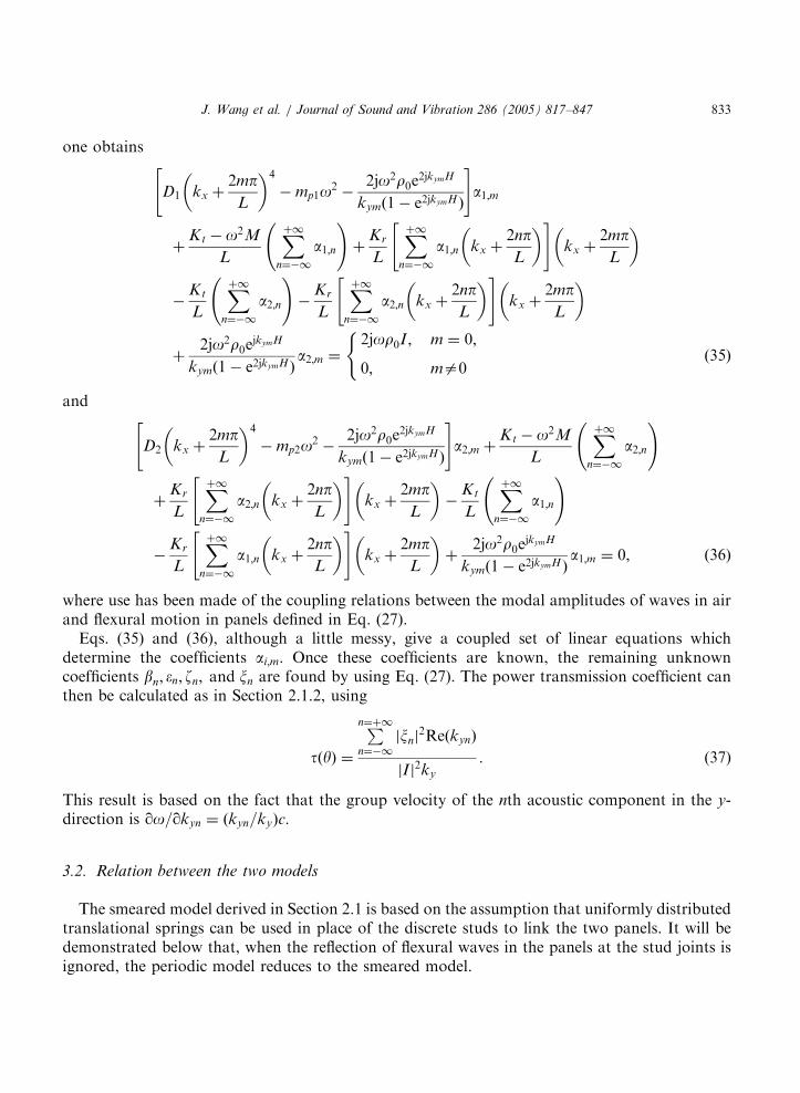
Eqs. (35) and (36), although a little messy, give a coupled set of linear equations whichdetermine the coefficients ai;m: Once these coefficients are known, the remaining unknowncoefficients bn; �n; zn; and xn are found by using Eq. (27). The power transmission coefficient canthen be calculated as in Section 2.1.2, using
tðyÞ ¼
Pn¼þ1
n¼�1
jxnj2ReðkynÞ
jI j2ky
: (37)
This result is based on the fact that the group velocity of the nth acoustic component in the y-direction is qo=qkyn ¼ ðkyn=kyÞc:
3.2. Relation between the two models
The smeared model derived in Section 2.1 is based on the assumption that uniformly distributedtranslational springs can be used in place of the discrete studs to link the two panels. It will bedemonstrated below that, when the reflection of flexural waves in the panels at the stud joints isignored, the periodic model reduces to the smeared model.
ARTICLE IN PRESS
J. Wang et al. / Journal of Sound and Vibration 286 (2005) 817–847834
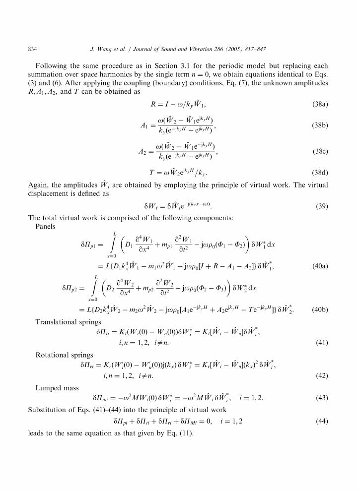
Following the same procedure as in Section 3.1 for the periodic model but replacing eachsummation over space harmonics by the single term n ¼ 0; we obtain equations identical to Eqs.(3) and (6). After applying the coupling (boundary) conditions, Eq. (7), the unknown amplitudesR;A1;A2; and T can be obtained as
R ¼ I � o=kyW 1; (38a)
A1 ¼oðW 2 � W 1e
jkyHÞ
kyðe�jkyH � ejkyHÞ; (38b)
A2 ¼oðW 2 � W 1e
�jkyHÞ
kyðe�jkyH � ejkyHÞ; (38c)
T ¼ oW 2ejkyH�
ky: (38d)
Again, the amplitudes W i are obtained by employing the principle of virtual work. The virtualdisplacement is defined as
dW i ¼ dW ie�jðkxx�otÞ: (39)
The total virtual work is comprised of the following components:Panels
dPp1 ¼
ZL
x¼0
D1q4W 1
qx4þ mp1
q2W 1
qt2� jor0ðF1 � F2Þ
� �dW �
1 dx
¼ LfD1k4xW 1 � m1o2W 1 � jor0½I þ R � A1 � A2�g dW
�
1; ð40aÞ
dPp2 ¼
ZL
x¼0
D2q4W 2
qx4þ mp2
q2W 2
qt2� jor0ðF2 � F3Þ
� �dW �
2 dx
¼ LfD2k4xW 2 � m2o2W 2 � jor0½A1e
�jkyH þ A2ejkyH � Te�jkyH �g dW
�
2: ð40bÞ
Translational springs
dPti ¼ KtðW ið0Þ � W nð0ÞÞdW �i ¼ Kt½W i � W n�dW
�
i ;
i; n ¼ 1; 2; ian: ð41Þ
Rotational springs
dPri ¼ KrðW0ið0Þ � W 0
nð0ÞÞjðkxÞ dW �i ¼ Kr½W i � W n�ðkxÞ
2 dW�
i ;
i; n ¼ 1; 2; ian: ð42Þ
Lumped mass
dPmi ¼ �o2MW ið0Þ dW �i ¼ �o2MW i dW
�
i ; i ¼ 1; 2: (43)
Substitution of Eqs. (41)–(44) into the principle of virtual work
dPpi þ dPti þ dPri þ dPMi ¼ 0; i ¼ 1; 2 (44)
leads to the same equation as that given by Eq. (11).

ARTICLE IN PRESS
J. Wang et al. / Journal of Sound and Vibration 286 (2005) 817–847 835
The above manipulation demonstrates that, when the reflected flexural wave at each stud pointis ignored, the periodic model is equivalent to the smeared model with air loading. Physically,when the studs are uniformly distributed across the whole panel area, the partition systembecomes homogeneous and all the reflected flexural waves from the stud points disappear.
3.3. Convergence check
The first stage of numerical calculation using the periodic model is to establish how many termsare needed to ensure convergence of the solution. Fig. 7a shows the plots of STL versus frequencyfor various numbers of terms, for a particular partition structure whose parameters are listed inTable 1. About 30 terms are needed for the solution to converge. To further demonstrate theconvergence, the following frequencies, f ¼ 200, 1000, 5000, and 10,000Hz are chosen and theirconvergence curves are shown in Figs. 7b. The number of terms needed in the calculationincreases with the frequency. At low frequencies, a few terms are enough to ensure theconvergence. At higher frequencies (�10,000Hz), 33 terms are needed to ensure the resulting error(�0.008 dB) is less than the pre-set error band of 0.01 dB.
Following Lee and Kim [20], it is assumed that once the solution converges at a givenfrequency, it converges for all lower frequencies. This assumption is valid for the example shownin Fig. 7, where the number of terms, 33, determined at the highest frequency of interest,10,000Hz, ensures that the solution converges for all other lower frequencies. The followingiteration strategy is thence employed. The STL is first calculated at the highest frequency ofinterest, with progressively more terms in the series expansion. The solution is deemed to haveconverged once the difference between the STLs calculated at two successive calculations fallswithin a pre-set error band: the corresponding number of terms is then used to calculate the STLat all other frequencies.
4. Results and discussion
The predictions from the smeared model are first compared with those from the periodic model,to explain the new physical phenomena introduced by the periodicity. To emphasise the maineffects, material damping is ignored in both models. Next, effects of the incidence angle arepresented for both models. Finally, to demonstrate the predictive capability of the periodic model,comparisons are made with recent experimental data on steel plates with wooden studs fromHongisto et al. [24].
4.1. Periodic model versus smeared model
Using the same partition system considered earlier, with parameter values as listed in Table 1,Fig. 8 shows the STL at 451 incidence angle predicted by the periodic model compared withthat predicted by the smeared model. The periodic model follows the general trend of thesmeared model, but it shows significant new features: peaks and dips in the STL relative tothe smooth variation of the simpler model. The studs are necessary components of the partitionin order to carry the structural loads, but it is clear that they behave like short circuits and cause

ARTICLE IN PRESS
0
5
10
15
20
25
30
35
40
10 100 1000 104
STL
(dB
)
Frequency (Hz)
5
10
15
20
25
30
35
40
45
0 10 20 30 40 50
STL
(dB
)
Number of terms
(a)
(b)
Fig. 7. Numerical convergence check for the system detailed in Table 1. (a) STL averaged over all possible incidence
angles plotted against frequency. Solid line: 33 terms used; dash-dotted line: 15 terms; dotted line: seven terms; dashed
line: one term. (b) STL averaged over all possible incidence angles plotted against number of terms used in the
calculation. Solid line: 200 Hz; dot-dashed line: 1000 Hz; dashed line: 5000Hz; dotted line: 10,000 Hz.
J. Wang et al. / Journal of Sound and Vibration 286 (2005) 817–847836
an increase of sound transmission in some frequency bands. The dips caused by the periodicproperties of the structure are very significant for STL of partitions, and it is important tounderstand their physical origin.

ARTICLE IN PRESS
Table 1
Panel dimensions and simulation data
Kt (N/m) 2.1� 109 Kr (Nm/rad) 39.1 M (kg) 0.265
L (m) 0.600 E1 (Pa) 7.0� 109 E2 (Pa) 7.0� 109
r0 (kg/m3) 1.21 r1 (kg/m3) 1200 r2 (kg/m3) 1200
h2 (m) 12.5� 10�3 h1 (m) 12.5� 10�3 Z1 0.1
Z2 0.1 n1 0.3 n2 0.3
c0 (m/s) 343
0
20
40
60
80
100
120
10 100 1000 104
STL
(dB
)
Frequency (Hz)
Fig. 8. Comparison of the STL yielded by the smeared and periodic models for the parameters listed in Table 1. Solid
line: smeared model; dashed line: periodic model.
J. Wang et al. / Journal of Sound and Vibration 286 (2005) 817–847 837
The dips in the STL curve correspond to frequencies where the incident sound wave undergoesa kind of resonance with the free-wave propagation of vibration in the panel. The effect isanalogous to the familiar ‘‘coincidence frequency’’ discussed in Section 2.2, but the spatialharmonics created by wave reflection at the studs introduce multiple possibilities for wavenumbermatching and ‘‘coincidence’’. To see what is happening it is necessary to examine briefly thestructure-borne vibration response of the periodic system. For simplicity, the effects of air loadingon the structural behaviour will be ignored for the moment. To include such effects makes themodelling more complicated without changing the qualitative picture.
Since the partition studied here has a symmetrical construction, the problem of structuralvibration transmission in the partition can be decomposed into two parts, one in which the twopanels move in a symmetrical way and one in which they move in an antisymmetrical way. Thesame argument was used earlier, in discussing Figs. 4 and 5. Symmetric motion (with respect to

ARTICLE IN PRESS
J. Wang et al. / Journal of Sound and Vibration 286 (2005) 817–847838
the symmetry plane running through the centre of the partition) means that the panels move in‘‘breathing’’ motion, both in or both out at a given position and a given time. For such motion,the stiffness of the studs imposes a strong constraint. Antisymmetric motion, on the other hand,involves the two panels moving in step. The studs are carried along by the panel motion, but sincethere is no relative motion at the two ends of a stud, the stud stiffness imposes no constraint. Themass of the studs has some influence on the motion, but this is small enough to be ignored for thepresent purpose.
The result is that the vibration propagation characteristics for antisymmetric motion areapproximately the same as for a single panel with no studs, but for symmetric motion they arealtered very significantly by the periodic studs. For the former case, a sinusoidal vibration canpropagate along the partition at any frequency, with a wavenumber/frequency relation, ordispersion curve, which is parabolic as seen in Fig. 5. For the latter case, the most important effectof the periodicity is to divide the frequency range into a sequence of ‘‘pass bands’’, wherevibration can propagate, and ‘‘stop bands’’, where it cannot (see, e.g., Refs. [6,7]). It is this patternof stop and pass bands that is responsible for the peaks and dips in the STL shown in Fig. 8.
The rotational stiffness of these particular studs produces a negligible effect, so that by far thestrongest effect, and the only one which need be kept here, is the translational stiffness of thestuds. The resulting model of symmetrical vibration of the partition is very simple: relative to thecentre plane of the partition, each panel vibrates as a beam restrained by periodically placedsprings to ‘‘ground’’. This problem can be solved easily, for example by the transfer matrixmethod as used by Mead [16] for similar problems. The result of the calculation is shown in Fig.9a, in which wavenumber is plotted against frequency. The pass bands for symmetrical motionappear as sinuous lines, because at a given frequency the travelling wave consists of a mixture ofrelated wavenumbers having the same general form as Eq. (21). The dispersion curve forantisymmetric motion is also shown. The sloping dashed line indicates the behaviour of theincident sound wave at 451. The shaded wedge indicates the region of the frequency/wavenumberplane in which waves in the partition can radiate sound. This wedge is bounded by the sound-speed lines corresponding to grazing incidence, parallel to the partition.
It is clear from Fig. 9a that within the frequency range plotted, the incident sound waves cannever excite the antisymmetric motion strongly enough to be resonant—this does not occur untilthe coincidence frequency. For the symmetric motion, though, there are intersections of thedispersion curves, one per pass band. At each of these intersections the incident sound wave canexcite panel vibration of sufficient amplitude that very strong sound transmission occurs, and thisis the cause of the dips in the STL curve. This is demonstrated in Figs. 9b and c. Fig. 9b shows the‘‘wrapped’’ version of Fig. 9a, obtained by ‘‘folding’’ the segments into the range 02p: Thisfolding process gives a compact diagram which is often useful in periodic structure theory [7]. It isanalogous to the effect of aliasing on the frequency spectrum of a sampled waveform: we are‘‘sampling’’ the spatial structure once per bay. Fig. 9c, on the same frequency scale, shows theSTL plot for this simplified problem with no stud mass or rotational stiffness, and no air couplingbetween the panels. It is immediately clear that the intersections labelled A, B, C, and Dcorrespond to the positions of dips in Fig. 9c.
The intersections labelled A0, B0, C0, and D0 correspond to the peaks in the STL curve. Thereason for this is much less obvious, since it is clear from Fig. 9a that these intersections are insome sense ‘‘not real’’, but an artefact of the wrapped plot. However, at these frequencies the

ARTICLE IN PRESS
0 100 200 300 400 500 600 700 800
k xL
/π
Freq uency (Hz)
A
B
C
D
A'
B'
C'
D'
1
0.8
0.6
0.4
0.2
0
0
10
20
30
40
50
60
70
80
0 100 200 300 400 500 600 700 800
STL
(dB
)
Frequency (Hz)
A
A'
B
B'
C
C'
D
D'
0 100 200 300 400 500 600 700 800
k xL
/π
Frequency (Hz)
4
3
2
1
0
-4
-3
-2
-1
(a)
(b)
(c)
Fig. 9. (a) Normalised wavenumber kxL=p plotted against frequency. Solid line: the pass bands for symmetric motion;
dot-dashed line: the dispersion curve for antisymmetric motion; dashed line: the dispersion curve for the incident sound
at y ¼ 451; shaded area: the region of the frequency/wavenumber plane for which bending waves in the partition can
radiate sound. (b) The ‘‘wrapped’’ version of Fig. 9a. The normalised wavenumber kxL=p is plotted against frequency.
Solid line: the pass bands for symmetric motion; dot-dashed line: the dispersion curve for antisymmetric motion; dashed
line: the dispersion curve for the incident sound at y ¼ 451. (c) STL plotted for the problem presented in Fig. 9a.
J. Wang et al. / Journal of Sound and Vibration 286 (2005) 817–847 839

ARTICLE IN PRESS
J. Wang et al. / Journal of Sound and Vibration 286 (2005) 817–847840
response of the panel exposed to the incident sound wave takes a particularly simple form inwhich only two terms of the sum in Eq. (21a) are needed: the directly driven term n ¼ 0 and theterm that satisfies the ‘‘coincidence’’ condition
D1½kx þ 2Np=L�4 ¼ mp1o2: (45)
The displacement of the driven panel is then
W 1 ¼ I jor0ejote�jkxx 1 � e�j2Npx=L
D1k4x � mp1o2
" #: (46)
This has nodal points at all the studs, so that no force is transmitted to the other panel, andtherefore no sound is radiated.
The panel becomes a perfect reflector of sound at these frequencies. Fig. 10 shows the patternsof panel displacement (at t ¼ nT ; where T ¼ 2p=o is the period of vibration) corresponding to thefirst few frequencies of peaks and dips in Fig. 9c. It is not a surprise that this symmetrical partitionmodel exhibits a sequence of frequencies of perfect reflection and perfect transmission: this is anexample of a rather general result for wave transmission through symmetrical coupling systems[25].
When the coupling through the internal air is added back into the model the picture becomessomewhat more complicated, as shown in Fig. 11. The same qualitative features can be seen as inFig. 9c: the main change is that there are extra dips in the STL curve, because the additionalcoupling through the air has made the structure of stop and pass bands more complicated. Thephysical explanation just given remains broadly correct.
Fig. 12 shows a series of STL calculations with the periodic model in which the stud spacingis varied while keeping the equivalent distributed stud stiffness K 0
t fixed at 3.125� 109 N/m3.The rotational stiffness is set to zero because it has virtually no influence on the STL resultsfor this particular design of stud. The curves are separated for clarity in the plot, and the resultof the smeared model is included at the bottom. As the stud spacing decreases the systemapproaches, as expected, the case represented by uniformly distributed stud stiffness, i.e. thesmeared model.
4.2. Effect of the incidence angle
For practical prediction of sound transmission performance, the results for a single angle ofincidence are only of limited significance. What is needed is an appropriate average over allincidence angles. Ideally, this should be an average over all angles in a 3D sense, but the theorypresented here only allows an average to be taken over angles in the plane normal to the studs.Fig. 13a shows the variation of STL with angle for the periodic mode for the same partitiondiscussed above. This figure can be compared with Fig. 4a, for the smeared model. Fig. 13b showsthe results of averaging over angle in both models.
It can be seen in Fig. 13a that the detailed features of the periodic model, discussed inthe previous section, vary with incidence angle. The pattern can be understood with reference toFig. 9b. The dips in the surface of Fig. 13a trace out portions of the pass bands, since theintersection points A, B, etc. move along the bands as the incidence angle is varied. Similarly, the

ARTICLE IN PRESS
Stud spacing
Stud spacing
Stud spacingStud spacing
Stud spacing
Stud spacing
(a) (b)
(c)
(e) (f)
(d)
Fig. 10. The panel displacements corresponding to the first few peak and trough frequencies shown in Fig. 9c. The
displacements are shown at a time corresponding to t ¼ nT ; where T is the period of the motion. (a) 83 Hz; (b) 117Hz;
(c) 203 Hz; (d) 301 Hz; (e) 363Hz; (f) 376 Hz.
J. Wang et al. / Journal of Sound and Vibration 286 (2005) 817–847 841
ridges in the surface trace out patterns recognisably related to the ‘‘wrapped’’ version of thepanel dispersion curve, like the dot-dashed line in Fig. 9b. Much of this detail is lost whenan average is taken over incidence angles, and the resulting curve in Fig. 13b follows the curve forthe smeared model much more closely than did the curves for individual incidence angles, such asseen in Fig. 8.

ARTICLE IN PRESS
0
10
20
30
40
50
60
70
80
0 100 200 300 400 500 600 700 800
STL
(dB
)
Frequency (Hz)
Fig. 11. STL plotted for the problem presented in Fig. 9a, with the addition of air in the cavity.
J. Wang et al. / Journal of Sound and Vibration 286 (2005) 817–847842
4.3. Comparison with measurements
Fig. 14 shows a comparison of the predictions from the periodic and smeared models developedhere with test data taken from Fig. 12 of Hongisto et al. [24] for a double-leaf partition consistingof two identical 2 mm thick steel plates (Young’s modulus 210 � 109 N=m2 and density7800 kg=m3) and wooden studs (thickness 120 nm and width 42 nm). The wooden studs areperiodically distributed, with stud spacing of 1100mm, and there is no sound absorbent present inthe cavity. The air density is r0 ¼ 1:25 kg=m3; and speed of sound is c0 ¼ 343m=s: The simulationconditions are listed in Table 2. The predicted STL is obtained by averaging over all incidenceangles.
From Fig. 14 it is seen that, although the STL curve predicted by the periodic theory isundulating due to the periodic nature of the model, it follows the correct trend of test data and,overall, the prediction agrees well with the data. Wooden studs are normally considered as rigid,since they have very high translational and rotational stiffness. The high stud stiffness causesstrong wave reflections, which is the underlying reason for the ‘‘wavy’’ shape of the STL curvepredicted by the periodic model. The smeared model yields a poor prediction of the STL for thiscase, as can be seen in Fig. 14. Better agreement of the present theories with experiment shouldprobably not be expected because of the 2D nature of the models. In the measurement, the soundfield was a fully diffuse 3D field.
5. Concluding remarks
Two analytic models have been developed to predict STL through double-leaf partition wallsstiffened with studs. The smeared model assumes that the studs can be modelled using uniformlydistributed springs and mass. In the periodic model, the studs are modelled as a set of periodicallydistributed lumped masses attached to the two panels, together with a set of periodically spaced

ARTICLE IN PRESS
10 100 1000 104
0
50
100
150
200 Decreasing stud spacing
Frequency (Hz)
STL
(dB
)
STL+40dB
STL+80dB
STL+120dB
STL+160dB
Fig. 12. STL for the periodic model for various stud spacings. Solid line: STL for smeared model ðK 0t ¼ 3:125 �
109 N=m3Þ; dot-dashed line: STL for periodic model with stud spacing 600 mm ðKt ¼ 1:875 � 109 N=m2Þ; dot-dot-
dashed line: stud spacing 300mm ðKt ¼ 0:9375 � 109 N=m2Þ; dashed line: stud spacing 150 mm ðKt ¼ 0:46875 �
109 N=m2Þ; dotted line: stud spacing 75 mm ðKt ¼ 0:234375 � 109 N=m2Þ:
J. Wang et al. / Journal of Sound and Vibration 286 (2005) 817–847 843
springs with rotational and translational stiffness. The dynamic equations that describe the vibro-acoustic responses of the system were established by using space-harmonic series expansions andthe principle of virtual work. The periodic model was shown to reduce to the smeared model if thereflected flexural waves at each stud connection are ignored. Convergence of the solution waschecked, and the minimum number of terms needed in the series expansion for the solution toconverge was obtained as a function of frequency. The predictions were compared with existingtest data for steel plates with wooden stiffeners, and reasonable agreement was obtained.
By studying representative numerical results from the two models, the various physicalmechanisms influencing STL were explored. The smeared model predicts relatively simplebehaviour, in which the only conspicuous features were associated with coincidence effects withthe two types of structural wave allowed by partition model, and internal resonances of the airbetween the panels. In the periodic model, many more features were evident, associated with thestructure of pass- and stop-bands for structural waves in the partition.

ARTICLE IN PRESS
Fig. 13. (a) The variation of the STL with incidence angle for the periodic model. (b) The average of the STL over
incidence angle for both the periodic and smeared models. Solid line: smeared model; dashed line: periodic model.
J. Wang et al. / Journal of Sound and Vibration 286 (2005) 817–847844
The main aim of the present investigation has been to establish analytical modelling for thestudy of sound transmission across double-leaf partitions, and to understand the underlyingphysics of the results obtained. The models presented here have made many simplifications. Thesound field was assumed to be restricted to the horizontal plane only, and many complicating

ARTICLE IN PRESS
0
10
20
30
40
50
60
10 100 1000 104
STL
(dB
)
Frequency (Hz)f1
f2
Fig. 14. Comparison of STL predictions from both the smeared model and the periodic model with test data taken
from Fig. 12 of Hongisto et al. [24]. Solid line: periodic model; dashed line: smeared model; small circles: experimental
measurements.
Table 2
Simulation data for steel plates with wooden studs
Kt (N/m) 2.99� 1010 Kr (Nm/rad) 1.5� 106 M (kg) 1.942
L (m) 1.100 E1 (Pa) 2� 1011 E2 (Pa) 2� 1011
r0 (kg/m3) 1.21 r1 (kg/m3) 7800 r2 (kg/m3) 7800
h2 (m) 2� 10�3 h1 (m) 2� 10�3 Z1 0.0006
Z2 0.0006 n1 0.28 n2 0.28
c0 (m/s) 343
J. Wang et al. / Journal of Sound and Vibration 286 (2005) 817–847 845
features of real partitions were disregarded: finite size of wall, connection details around the edges,joins between board panels, discrete screw fixings of panels to studs, exact periodicity of studspacings, and so on.
It is intended that these important details will be considered in future work which will extendthis study and open the way to optimisation of partition design for most effective soundproofing.Some of the features are relatively easy to incorporate, but others will require significant changes.In particular, relaxing the assumption of periodicity is difficult. Given the current state of theoriesof vibration of such structures, it would force the model either to become purely numerical, or else
ARTICLE IN PRESS
J. Wang et al. / Journal of Sound and Vibration 286 (2005) 817–847846
to become statistical in nature: see, e.g., Refs. [26,27]. Nevertheless, the qualitative effects expectedfrom non-periodicity are understood, so-called ‘‘Anderson localisation’’, and it will be aninteresting target for future research to quantify whether such effects are important for realisticbuilding structures.
Acknowledgements
The authors thank the UK Engineering and Physical Sciences Research Council and BanroHoldings Ltd. for financial support of this project.
References
[1] L. Beranek, G.A. Work, Sound transmission through multiple structures containing flexible blankets, Journal of
the Acoustical Society of America 21 (4) (1949) 419–428.
[2] A. London, Transmission of reverberant sound through double walls, Journal of the Acoustical Society of America
22 (2) (1950) 270–279.
[3] K.A. Mulholland, H.D. Parbrook, A. Cummings, The transmission loss of double panels, Journal of Sound and
Vibration 6 (3) (1967) 324–334.
[4] F. Fahy, Sound and Structural Vibration Radiation, Transmission and Response, Academic Press, London, 1987.
[5] W. Kropp, E. Rebillard, On the air-borne sound insulation of double wall constructions, Acta Acustica 85 (1999)
707–720.
[6] L. Brillouin, Wave Propagation in Periodic Structures, Dover, New York, 1953.
[7] D.J. Mead, Wave propagation in continuous periodic structures: research contributions from Southampton,
1964–1995, Journal of Sound and Vibration 190 (3) (1996) 495–524.
[8] G.P. Mathur, Bio.N. Tran, J.S. Bolton, N.-M. Shiau, Sound transmission through stiffened double-panel
structures lined with elastic porous materials, Proceedings of the 14th DGLR/AIAA Aero-Acoustics Conference,
1992, pp. 102–105.
[9] B.H. Sharp, Prediction methods for the sound transmission of building elements, Noise Control Engineering 11
(1978).
[10] L. Cremer, M. Hechl, Structure-Borne Sound: Structural Vibrations and Sound Radiation at Audio Frequencies
(translated and revised by E.E. Ungar), Springer, Berlin, 1973.
[11] W. Desmet, P. Sas, Sound transmission of finite double-panel partitions with sound absorbing material and panel
stiffeners, Proceedings of the First Joint CEAS/AIAA Aero-Acoustical Conference (16th AIAA Aero-Acoustical
Conference), AIAA-95-043, 1995.
[12] E.H. Dowell, G.F. Gorman III, D.A. Smith, Acoustoelasticity: general theory, acoustic natural mode and forced
response to sinusoidal excitation, including comparisons with experiment, Journal of Sound and Vibration 52 (4)
(1977) 519–542.
[13] G.-F. Lin, J.M. Garrelick, Sound transmission through periodically framed parallel plates, Journal of the
Acoustical Society of America 61 (1977) 1014–1018.
[14] V.N. Evseev, Sound radiation from an infinite plate with periodic inhomogeneities, Soviet Physics Acoustics 19
(1973) 345–351.
[15] I.A. Urusovskii, Sound transmission through two periodically framed parallel plates, Journal of Soviet Physics
Acoustics 38 (4) (1992) 411–413.
[16] D.J. Mead, Free wave propagation in periodically supported, infinite beams, Journal of Sound and Vibration 11 (2)
(1970) 181–197.
[17] D.J. Mead, K.K. Pujara, Space-harmonic analysis of periodically supported beams: response to convected random
loading, Journal of Sound and Vibration 14 (4) (1971) 525–541.

ARTICLE IN PRESS
J. Wang et al. / Journal of Sound and Vibration 286 (2005) 817–847 847
[18] D. Takahashi, Sound radiation from periodically connected harmonic double-plate structures, Journal of Sound
and Vibration 90 (4) (1983) 541–557.
[19] D.J. Mead, Vibration response and wave propagation in periodic structures, Journal of Engineering for Industry 93
(series B) (1971) 783–792.
[20] J.-H. Lee, J. Kim, Analysis of sound transmission through periodically stiffened panels by space harmonic
expansion method, Journal of Sound and Vibration 251 (2) (2002) 349–366.
[21] A.C. Nilsson, Some acoustical properties of floating floor constructions, Journal of the Acoustical Society of
America 61 (1977) 1533–1539.
[22] CES Selector Version 4.0, Granta Design Limited, Cambridge, UK.
[23] M.P. Norton, Fundamentals of Noise and Vibration Analysis for Engineers, Cambridge University Press,
Cambridge, 1989.
[24] V. Hongisto, M. Lindgren, R. Helenius, Sound insulation of walls—an experimental parametric study, Acta
Acustica 88 (2002) 904–923.
[25] D.J. Allwright, M. Blakemore, P.R. Brazier-Smith, J. Woodhouse, Vibration transmission through symmetric
resonant couplings, Philosophical Transactions of the Royal Society of London A 346 (1994) 511–524.
[26] C.H. Hodges, J. Woodhouse, Vibration isolation from irregularity in a nearly-periodic structure: theory and
measurements, Journal of the Acoustical Society of America 74 (1983) 894–905.
[27] C.H. Hodges, J. Woodhouse, Theories of noise and vibration transmission in complex structures, Reports on
Progress in Physics 49 (1986) 107–170.