Sound Generation Using Fujitsu Microcontrollers Microelectronics America, Inc. 1 Using Fujitsu...
14
Sound Generation Using Fujitsu Microcontrollers
Transcript of Sound Generation Using Fujitsu Microcontrollers Microelectronics America, Inc. 1 Using Fujitsu...
Sound GenerationUsing Fujitsu Microcontrollers
Fujitsu Microelectronics America Inc
ContentsIntroduction 1Purpose 1Some important Definitions connected with Sound 1Fujitsu Microcontrollers 2
Buzzer Function 2DTMF Generators 2Sound Generators 2Programmable Pulse Generator (PPG) 2
Peripheral Description and Applications 2Buzzer 2
Applications 3DTMF Generator 3
Applications 3Remote control 3Two-way radio 3
Sound Generator 4Example for configuring Sound Generator Registers 5Resolution of Sound generator 6Applications 6
Tone Generation by PPG 6Operation 7Resolution of PPG 7Applications 7
Speech Generation 7General Techniques and complexity of speech generation 8Speech by Sound generator 8
Simple Tone Generation Circuits 9Running Sample code and Demo Using Flash-CAN-100P-M06 Evaluation Board 9
Procedure 9Running Sample code and Demo Using Using F2MC 16LX Series Evaluation Board 10
Procedure 10Conclusion 11References 11
Fujitsu Microelectronics America Inc1
Using Fujitsu Microcontrollers
13
Purpose
This application note presents different ways of generating a tone note or a piece of Sound Melody using Fujitsu Microcontrollers The application note mainly focuses on sound generation using the Sound Generator and PPG (Programmable Pulse Generator) peripheral The sample code and demo discussed in this application note were programmed for MB90F594 device
The technology that generates sounds beyond the occasional beep and the annoying whir is still pretty new but in the short time since its implementation the quality of sound reproduction has improved dramatically and the demand for it has grown exponentially
What makes one sound different from the other
Waveform of a door slamming
This waveform is jerky and irregular resulting in a harsh sound Notice how it is loud (with big waves) at the start but then becomes soft (small waves) as it dies away
Waveform of a guitar string
This waveform makes the same transition from loud to soft as the first but otherwise is quite different The guitar string makes a continuous regular series of repeated cycles which we hear as a smooth and constant musical tone
This is the difference between a musical sound and a non-musical sound
Musical sounds are vibrations which are strongly regular When you hear a regular vibration your ear detects the frequency of the vibration and you perceive this as the pitch of a musical tone
Non-musical sounds are a complex mix of different (and changing) frequencies Your ear still follows these vibrations but there is no strong regularity from which you can pick up a musical tone
Some important Definitions connected with Sound
Sound lsquoSoundrsquo is the vibration of air particles which travels to your ears from the vibration of the object making the sound
Tone lsquoTonersquo is a single sound of definite recognizable pitch
Pitch lsquoPitchrsquo is a subjective impression of frequency
Note lsquoNotersquo is sometimes interchangeably used with expression Tone The note refers to any separate unit of sound usually with definite pitch
Fujitsu Microelectronics America Inc2
Fujitsu Microcontrollers
Fujitsu offers a wide range of microcontrollers include the Fujitsu Flexible Micro-Controller (F2MC) and Fujitsu RISC Controller (FR) series These devices have a wide variety of peripherals on chip such that can make sound such as Buzzer DTMF generator PPG and Sound Generator The application note briefly describes the Buzzer and DTMF generator but its main purpose is to explain SoundMelody creation using the Sound Generator peripheral and PPG peripheral
Before describing the Buzzer DTMF Generator PPG and Sound Generator itrsquos worthwhile to know the microcontrollers that have these functions
Buzzer Function
The MB891XX MB896XX MB89870 and MB89890 series and some members of the MB899xx series of microcontrollers have Buzzer Function built into the chip
DTMF Generators
The MB89173P173 MB89174A MB89175A the MB89820 series and the MB89890 series have both Buzzer and DTMF generators built in to the chip
Sound Generators
Some Fujitsu microcontrollers have the Sound Generator peripheral on the chip Within the F2MC - 16LX series the MB90420 MB90425GGA and MB90590 MB90390 and within the FR series MB91F362 has Sound generator
These products are intended for automotive and industrial applications
Programmable Pulse Generator (PPG)
Most Fujitsu microcontrollers have the Programmable Pulse Generator (PPG) peripheral Among F2MC 8L devices the MB89550 MB89560 MB89930 series are good examples Among F2MC-16 bit devices all have the PPG peripheral except the MB90660 and MB90240 series Among FR devices the MB91110 and MB91F360 series have this peripheral
Peripheral Description and Applications
Buzzer
Buzzer can produce a simple sound like key clicks to confirm key input The buzzer output function outputs signals (Square wave) that are used for the confirmation sound
Fujitsu devices have a programmable buzzer The buzzer frequency register is used to enable buzzer output and to select the frequency The clock source may be either time base timer or watch prescalar A selection of up to seven different frequencies is available as shown in the
Table 1 using the register setting When the appropriate values are set in the Buzzer register (BUZR) a square wave of the selected frequency is output at the devicersquos BUZ pin
BUZR Register This 8 bit register controls the operation of buzzer
lsquo000rsquo written to these bits Disable Buzzer output and Enables general purpose port operation
Figure 1 Block Diagram of Microcontroller with Buzzer
In Figure 1 the Microcontrollerrsquos PXX BUZR pin is connected to simple buzzer circuit As shown in the BUZR register configuration BUZ0 BUZ1 and BUZ2 are used both to enable buzzer output and to select output frequency The value lsquo000rsquo disables buzzer output and allows the buzzer port to function as normal port All other values are used to select frequencies according to Table 1
7 6 5 4 3 2 1 0
---- ---- ---- ---- ---- BUZ2 BUZ1 BUZ0
Fujitsu Microelectronics America Inc 3
Table 1
Applications
bull Industrial Time signaling Telecommunication Process Control Instrument panels Bus Escape doors off road vehicles Toy industry
bull Automotive Electric vehicles
bull Marine Panel warning Small vessels
bull Aircraft Panel warning
bull Household Apartments Condominiums home security systems
DTMF Generator
DTMF (Dual Tone Multi Frequency) is the signal to the telephone exchange that is generated when a user presses an ordinary telephones touch keys Its known as Touchtone phone (formerly a registered trademark of ATampT) DTMF has generally replaced loop disconnect (pulse) dialing One could have a single separate tone for each digit but there is always a chance that a random sound will be on the same frequency and trip up the system So if two tones represent a digit then a false signal is less likely to occur This is the basis for the Dual Tone in the DTMF With DTMF each key pressed on the phone generates two tones of specific frequencies So that a voice cant imitate tones one tone is generated from a high-frequency group of tones and the other from a low frequency group Table 2 shows the signals sent when touchtone phone keys are pressed
Table 2
The DTMF generator built on the microcontroller enables continuous DTMF transmission Output range includes all the CCITT tones 0 to 9 and A to D as listed in the above table It operates on the main crystal oscillator frequency The DTMF Control register and DTMF data register along with programmable OUTE bit control the operation of the DTMF generator
Applications
DTMF is a true interactive signaling format Apart from being used in standard telephones DTMF can be used in
Remote control
DTMF signals can be used to transmit over a radio and turn things on and off flash lights control motors cameras activate warning systems and turn on irrigation systems
Two-way radio
The special codes A to D tones available are very useful for preventing a standard telephone from being used to control remote devices These codes can give override status when used correctly in a two-way radio system Over two-way
BUZ2 BUZ1 BUZ0Clock Cycle Time
Buzzer Output Frequency
0 0 0 - General-purpose port operation
0 0 1 fCH213 997 Hz
0 1 0 fCH212 1953 Hz
0 1 1 fCH211 3906 Hz
1 0 0 fCH210 7813 Hz
1 0 1 fCL25 1024 Hz
1 1 0 fCL24 2048 Hz
1 1 1 fCL23 4096 Hz
Digit
Low Frequency HzHigh FrequencyHz
1 697 1209
2 697 1336
3 697 1477
4 770 1209
5 770 1336
6 770 1477
7 852 1209
8 852 1336
9 852 1477
0 941 1209
941 1336
941 1477
A 697 1633
B 770 1633
C 852 1633
D 941 1633
Fujitsu Microelectronics America Inc4
radios DTMF phone number can be transmitted The same phone number programmed will be available in a decoder hooked up to a radio receiver at a remote location When the decoder recognizes its phone number dialed in over the radio it wakes up and gets to work controlling the many things that have been hooked it up to
The tones heard at the start of some National News Broadcasts are DTMF tones sent out at the start of the broadcast to transfer (or alert to transfer) their audio onto the local affiliates airwaves Basically it turns on a master switch
Sound Generator
The Sound Generator is a song or melody generator Main effect is that frequency and amplitude can be decreased automatically without additional interrupts However interrupts are requested when increasing frequency or amplitude Warning sounds sounds generated when pressing keys and even melodies can be played with the generator It is much better than a simple PPGPWM because it reduces the number of interrupts required
Figure 2 Block diagram of Sound Generator
Sound Generator consists of the following main register blocks
Sound Control register (SGCR) Frequency Data register (SGFR) Amplitude Data Register (SGAR) Decrement Grade register (SGDR) Tone Count register (SGTR) PWM pulse generator Frequency counter Decrement counter and Tone Pulse counter
Due to this configuration the user has flexibility to program the microcontroller depending on his application and can produce sound or music with varying frequency and amplitude SGCR (Sound Control register) controls the operation status of the sound generator S0 and S1 bits of SGCR specify the clock input signals for the sound generator Sound generator can generate the tone wave at a specific frequency and count the number of the tones by setting the corresponding registers (Refer to Hardware Manual for details) The tone frequency can be determined by following equation
frequency and count the number of the tones by setting the corresponding registers (Refer to Hardware Manual for details) The tone frequency can be determined by following equation
The PWM frequency can be set as 625KHz 312KHz 156KHz and 78KHz when the system clock is 16MHz By changing the register reload value user can create varied tone frequencies
The SGFR (Frequency data register) stores the reload value for the frequency counter The stored value represents the frequency of the sound The register value is reloaded into the counter at every transition of the toggle signal
Figure 3 shows the tone signal regard to register value
Figure 3 Tone Signal
The amplitude of the tone depends on the value loaded in the SGAR (Amplitude data register) At the end of the every tone
)1(Re2 +times=
loadValue
cyPWMFrequenncyToneFreque
Fujitsu Microelectronics America Inc 5
cycle the register value is reloaded in to the PWM pulse generator SGDR (Decrement grade register) shown in the block diagram stores the reload value of the decrement counter and is prepared to automatically decrement the stored value in the SGAR This decrement operation is performed at the end of every tone cycle Through this operation automatic degradation of sound with minimum amount of CPU intervention is achieved
SGTR (Tone Count Register) stores the value for the tone pulse counter The counter accumulates the number of tone pulses (or number of decrement operations) When it reaches the reload value it sets the INT bit of SGCR If the INTE bit of SGCR is also set the sound generator signals an interrupt The count of the Tone Pulse Counter is also connected to the carry out from Decrement counter When SGTR is set to lsquorsquo0x00rsquo the tone pulse counter sets the INT bit of SGCR on every carry out from the decrement counter This type of operation reduces the frequency of interrupts
The number of accumulated tone pulses SGTR (or number of decrement operations) can be defined as
Sound generator has two outputs SGO and SGA The SGO is the sound generation output pin which is controlled by writing lsquo1rsquo to OE2 bit of SGCR SGO is mixed signal of tone and PWM pulse Writing lsquo0rsquo to the same configures this pin as general-purpose port pin SGA output is the PWM pulses from the PWM pulse generator representing the amplitude of the sound When OE1 bit of SGCR is set to lsquo1rsquo external pin is assigned as SGA output Otherwise this pin can be used as general-purpose port pin
For detailed register configuration refer to the hardware manual of the required series of microcontrollers
Example for configuring Sound Generator Registers
Table 3 shows an example of how to set the register value to create a scale using the above formula To achieve high tone frequency like 16KHz the maximum PWM Frequency 625KHz is chosen
Table 3
The sample project is written in C It also contains a small sound library for user reference as a part of lsquosoundcrsquo function A constant data byte in the form of an array as data structure is defined for each type of sound in the sample program which defines value for Sound Generator registers The sample array for defining a particular song called lsquoNotesrsquo is shown below which shows how to program registers to achieve the Note defined in Table 3
const BYTE __far Notes[ ] =
255 0x50 SGAR SGTR for all tones
29 255 AacuteFrequency (SGFR) the of Tone Pulses (SGDR) to produce lsquoDOrsquo sound
26 255 AacuteFrequency (SGFR) the of Tone Pulses (SGDR)to produce lsquoRErsquo sound
23 255 AacuteFrequency (SGFR) the of Tone Pulses (SGDR)to produce lsquoMIrsquo sound
21 255 AacuteFrequency (SGFR) the of Tone Pulses (SGDR)to produce lsquoFArsquo sound
19 255 AacuteFrequency (SGFR) the of Tone Pulses (SGDR)to produce lsquoSOrsquo sound
17 255 AacuteFrequency (SGFR) the of Tone Pulses (SGDR)to produce lsquoLArsquo sound
15 255 AacuteFrequency (SGFR) the of Tone Pulses (SGDR)to produce lsquoTIrsquo sound
14 255 AacuteFrequency (SGFR) the of Tone Pulses (SGDR)to produce lsquoDOrsquo sound
0 0x01 end of Note to load SGFR of Tone Pulses (SGDR)
NoteTone Frequency (Hz)
The Reload Value from the Formula (PWM = 625KHz)
The Actual Reload Value for Implementation(SGFR value)
DO 1050 2876 29
RE 1170 2571 26
MI 1310 2285 23
FA 1394 2142 21
SO 1560 1903 19
LA 1771 1665 17
TI 1984 1474 15
DOrsquo 2114 1378 14
Fujitsu Microelectronics America Inc6
The first row of the array represents the amplitude data and tone count value respectively The amplitude signifies the loudness of the tone These two parameters are set for all tones The note and the rhythm have been programmed in succession beginning with the second row to produce different frequency tones as calculated in Table 3 The SGAR (amplitude of tone) will either remain constant or will automatically decrement with control done by DEC bit of SGCR and SGDR (Decrement Grade register) Sound Generator will issue an interrupt when lsquo Notersquo is completed Interrupt service routine (ISR) written in the program services the interrupts
The sample table is a portion of sound named lsquoNotersquo The user can find other special tone and sound samples in the sample project
Resolution of Sound generator
Sound generator can generate the tone wave and count the number of the tones automatically by setting the corresponding register There are some limitations for generating the tone frequency since the normal sound frequency range is from 20Hz to 20KHz The resolution of the frequency between 100Hz and 4KHz generated by the sound generator is good Above and below this range resolution is poor The following Table 4 explains the resolution
Table 4
From the table you can see there is no difference for the actual tone frequency between 16KHz 20KHz and 14KHz The 16KHz is little bit higher than the normal range of sound frequency which can be heard by human being From the table the lower the frequency the better the accuracy that can be achieved Using on-chip sound generator can considerably reduce the code size and it is more efficient if the resolution of frequency meets application requirements
Applications
Mainly as song or melody generator in the following applications
bull Alarm sounds for the security and safety purposes
bull Musical doorbell
bull Door chimes and voice recorder
bull Alarm clock
bull Mobile phones and PDAs
bull Toys to make melodiesmusical sounds
bull Automotive industry ndash Door and window chimes etc
Tone Generation by PPG
Since the PPG is designed for general purpose use the frequency range being created is much wider Some microcontrollers like the MB90590 offer an 816-bit programmable pulse generator with three operation modes
They are
1) Independent two-channel 8-bit mode
2) 8-bit pre-scale + 8-bit mode
3) Single-channel 16-bit PPG mode
Unlike Sound Generator the PPG peripheral does not have the specific register to count the number of pulses In order to control the period of the tone the user should either use the reload timer or PPG interrupt routine to control the timing of the tone The output waveform is shown in Figure 4
Required Tone Frequencyof soundat PWM freq =625kHz
Reload Value from Formula( theoretical )
Actual Reload Value( SGFR value)
Actual Tone Frequency Outputof Sound Generator
20KHz 0562 1 15625KHz
16KHz 0953 1 15625KHz
14KHz 1232 1 15625KHz
12KHz 1604 2 10416KHz
8KHz 2906 3 7812KHz
4KHz 6812 7 3906KHz
2KHz 14625 15 1980KHz
1KHz 3025 30 0998KHz
500Hz 615 62 49898Hz
100Hz 3115 312 99997Hz
50Hz 6240 624 4948 Hz
Fujitsu Microelectronics America Inc 7
Figure 4 PPG Output Waveform
The pulse period can be calculated as following
T input clock timeL Low-level registers reload
ValueH High-level registers reload
ValueOperation
Each of the two 8 bit PPG units has two eight bit reload registers One reload register is for the L Pulse width (PRLL) and the other is for H Pulse width (PRLH) The values stored in these registers are reloaded into the 8 bit down counter (PCNT) from the PRLL and PRLH in turn The pin output value is inverted upon a reload caused by counter borrow This operation results in pulses of the specified L pulse width and H pulse width
The PPG can select from four count clock inputs using the peripheral clock or time base counter input The output pulse width as shown in above Figure 4 is the product of the value written in the ldquoreload register + 1rdquo and ldquocount clock periodrdquo
The PPG solution can be achieved by different ways using the above mentioned three types of operation modes depending on the user application The sample code is provided for reference using two independent 8-bit PPG modes using the MB90F594 device
For setting the registers and all the three operation mode configurations refer to the hardware manual of the required series of microcontroller Variable frequency and duty ratio pulse waveforms are output continuously during PPG operation The duty ratio is the ratio of the H level and L level durations in the pulse waveforms Once started PPG pulse waveform output does not stop until the stop operation is specified
Resolution of PPG
If the duty cycle of tone wave is 50 then L = H If for example 500ns clock source is chosen the table below shows register setting and the practically measured output
The waveform observed by an oscilloscope is continuous There exists some latency from the actual frequency of the pulse That is due to the interrupt routine Since the number of pulses cannot be directly controlled one has to generate an interrupt for each pulse period not only for counting the number of pulses but also for changing the tone frequency In order to make the actual frequency closer to the designed tone the user has to set the register value with the consideration of interrupt routine latency Resolution at higher frequency is possible but at the cost of higher frequency of interrupts
Applications
bull It can be used as Sound generator in the absence of Sound generator peripheral in many applications for tone gen-eration
bull As a General-purpose pulse generator
bull With external circuit this peripheral can be used as D A converter
bull Generates frequencies for use by remote control unit
Speech Generation
Can the Sound Generator produces speech Here is a brief discussion about speech frequencies of speech general techniques of speech production and possibilities of speech by sound Generator and its limitations
)1()1( +times++times= HTLTriodOnePulsePe
Designed Tone Frequency
The Reload Value from the Formula
The Actual Reload Value for Implementation
The Actual Frequency from PPG
The Observed Frequency from Oscilloscope
16KHz 615 0x3E 1587KHz 1562KHz
14KHz 704 0x46 1408KHz 1389KHz
12KHz 823 0x52 1204KHz 1191KHz
8KHz 124 0x7C 8KHz 806KHz
4KHz 249 0xF9 4KHz 4KHz
Fujitsu Microelectronics America Inc8
Language is one of the most important features that distinguishes humans from other animals and speech is the most important medium of language People have attempted over the centuries to build machines which imitate the sounds of speech It is in recent years with the advent of digital electronic technology that this goal has come closest to being achieved It has to be said that as yet no one has really succeeded in synthesizing a voice which is indistinguishable from a human voice
Speech generation is the process which allows the transformation of a string of phonetic symbols into a synthetic speech signal The quality of the result is a function of the quality of the string as well as of the quality of the generation process
Nearly all information in speech is in the range 200 Hz-8 kHz (The telephone carries only 300 Hz - 3 kHz but speech is reasonably intelligible and the telephone companys lsquoHold musicrsquo still sounds allowed) The pitch is determined by the spacing of harmonics as much as or more than by the fundamental Thus one can tell the pitch of a mans voice on the phone even though the fundamental frequency of that signal is not present Note the size of the vocal tract (~170 mm long) gives resonance gt ~ 500 Hz In fact a closed tube of this length is a functional approximation of the tract for the vowel er as in herd For this neutral vowel the first five resonance of the persons vocal tract are indeed at values of about 500 1500 2500 3500 and 4500 Hz
General Techniques and complexity of speech generation
In speech generation there are three basic techniques (in order of increasing complexity)
1) Waveform encoding
2) Analog formant frequency synthesis
3) Digital vocal tract modeling of speech
Each of these techniques will be described in brief detail
In Waveform encoding the computer simply becomes like a tape recorder it records phrases or words onto digital memory and then plays these phrases in the application software as necessary Needless to say providing a wide realm of possible phrases requires a considerable amount of memory storage especially if high quality recordings are desired High
quality recordings store sound details at shorter time intervals thereby producing more data to store However this technique has been proven to be useful for such applications as relaying the status of an automobile Your door is open Very little additional hardware is needed for this technique and since a human makes the initial recordings many of the obstacles in mimicking speech electronically are avoided
In the second basic technique for speech generation Formant frequency synthesis attempts to replicate the human vocal tract In this method band pass filters are summed together to act as the various audio filters in the oral cavity Obviously this method allows the flexibility to utter many different sounds in succession in reduced data storage However if our input is text these sounds appear very unnatural and sometimes unrecognizable due to the unintelligibility of the computer doesnrsquot have rules on how to pronounce written text and how to say it rhythmically Careful use of the phonetic alphabet is needed in most text-to-speech applications Yet if our computer input allows for words and phrases to be entered phonetically this method closely replicates our speech
The third technique is Digital voice tract modeling This method models the human vocal tract digitally The methods that support this technique are very mathematical in nature since they map the actions of the human vocal tract to equations The basic concept is that current information on a speech sample helps to estimate future information on the speech sample A humans speech inputted in the same manner as the waveform encoding synthesis technique is dissected into its various frequencies and vocal characteristics It is stored in this form which greatly reduces the memory storage A very visible example of this technique is Texas Instruments Speak and Spell childrens learning aid
Speech by Sound generator
As mentioned in earlier paragraphs nearly all information in speech is in the range of 200Hz-8 kHz with appropriate string of phonetic and prosodic symbols Fujitsu Sound macrorsquos resolution accuracy as analyzed in above Table 4 is between 100Hz to 4KHz If the user application lies within this range low-level speech with limited vocabulary can be produced One cannot play sampled speech or music The first characteristic of synthetic speech which a listener notices is its quality that is to say how closely the voice resembles a human
Fujitsu Microelectronics America Inc 9
one Speech is very complex and there are a number of factors that affect its quality
Generating Speech using this Sound Generator is more like a technique of lsquocopy synthesisrsquo If a limited vocabulary is required then this technique can be appropriate
The utterances with particular frequency and amplitude are stored in the respective registers These stored utterances make meaningful messages at lower frequency
Most applications require a much broader essentially unlimited vocabulary The designer of a speech generator synthesizer has to consider a number of competing requirements and quality is just one of them Speech synthesizers are now available which produce speech of a quality with affordable cost adequate for many applications Using the Sound Generator for speech synthesis then will not be very appropriate
Simple Tone Generation Circuits
Figure 5 shows two simple tone generation circuits One is connecting a speaker the other is connecting a resonating buzzer An input signal coming into the buzzer subsystem creates potential difference across the buzzer causing current to flow It is this flow of current that causes the buzzer to sound The user can also expand the circuits in order to achieve more precise and smooth sound by adding filters and amplifier circuits depending on the requirement of application The SGO signal shown in the below figure is the tone output of the sound generator It should be mentioned that SGO could be set as a mixed output which combined the tone frequency and PWM signal together If PPG peripheral is used then PPG output is connected to these circuits
Figure 5 Simple Tone Generation Circuits
Running Sample code and Demo Using Flash-CAN-100P-M06 Evaluation Board
The demo is presented on the Fujitsursquos lsquoFlash-CAN-100P-M06 Evaluation Boardrsquo with the MB90F594 microcontroller The following are required for this demo
bull FlashndashCAN-100P-M06 or Flash-CAN2-100P-M06 board with MB90F594 microcontroller (QFP-100 pin package)
bull Serial cable
bull Power Supply adaptor 7V to 12V dc
bull PC or laptop programming flash with the sample code
bull Speaker to listen to the tone generated
bull Application Sample code
bull Flash programming utility (FLASH510exe or FLASH500exe) This utility can be found in the Fujitsu Micro CD version 32A
For configuration and connections please refer to the Flash-CAN-100P-M06 board Hardware manual Sample codes lsquoMelodyrsquo and lsquoTonersquo are available for download from ldquohttpwwwfmafujitsucommcurdquo under Application Notes The procedure for programming the flash with sample code and running the demo is listed below The same procedure is used for both Sound Generator and PPG functions with respective sample codes programmed into Flash of the device used
Procedure
1 Connect power supply adapter to the Flash-CAN-100P-M06 evaluation board
2 Connect one end of the serial cable to X4 of the evaluation board ( 9 pin D sub male connector required) and the other end of the serial cable should be connected to computerrsquos COM port
3 Connect speaker to listen to the sound at the Sound generator output pin SGO which is pin 99 on evaluation board (Refer to Figure 5) Alternately connect the speaker to pin 28 of Evaluation board for PPG function
4 Confirm that the UART jumpers JP8 and JP7 are in P16 and Pi14 position
5 S3 is mode switch For flash programming make the
Fujitsu Microelectronics America Inc10
following settings on S3
1 ndash ON 5 - ON 7 - ON 8 - ON
2 ndash OFF 3 ndash OFF 4- -OFF 6 - OFF
6 Switch on the power supply to the evaluation board
7 Run the Flash programming utility on computer
8 The Flash programming utilityrsquos lsquoMicrocontroller with Flash memory writerrsquo appears on the screen It has a selection window for CPU speed COM port write file etc
9 On that screen select CPU as MB90F594 speed as 4MHz and name of the COM port used
10 Then left click mouse on DOWNLOAD icon
11 Once the down load is successful select the project file (sample code) to be programmed In this example select melodymhx or tonemhx from the sample code for Sound Generator peripheral or PPG peripheral appropriately
12 The flash programming can be done manually by left clicking on mouse to select
1) Erase 2) Blank check 3) Write + Verify (W) 4) Read + Compare respectively Each step should be successfully performed AUTO programming is also possible by left clicking mouse on AUTO icon
13 After successful Flash programming close the Flash Programming Utility
14 Change S3 switch setting as follows to run the demo
Only 3 ndash ON and all others are in OFF position
15 You can hear melodious sound from the speaker connected depending on the programmed Sample code for Sound Generator or PPG peripheral function
Running Sample code and Demo Using Using F2MC 16LX Series Evaluation Board
The demo is presented on the Fujitsursquos lsquoF2MC 16LX Series Evaluation Boardrsquo with the MB90F594 microcontroller The following are required for this demo
bull Evaluation board with MB90F594 microcontroller (QFP-100 pin package)
bull Serial cable
bull Power Supply adaptor 7V to 12V dc
bull PC or laptop programming flash with sample code
bull Speaker to listen to the tone generated
bull Application Sample code
bull Flash programming utility (FLASH510exe or FLASH500exe) This utility can be found in the Fujitsu Micro CD version 32A
For configuration and connections please refer to the F2MC 16LX series Evaluation board Hardware manual Sample codes are available for download from ldquohttpwwwfmafujitsucommcuembasprdquo under Application Notes The procedure for running the sample code is listed below The same procedure is used for both Sound Generator and PPG functions with respective sample codes programmed into Flash of the device used
Procedure
1 Connect power supply adapter to the evaluation board
2 Connect one end of the serial cable to X3 of the evaluation board ( 9 pin D sub male connector required) and the other end of the serial cable should be connected to computerrsquos COM port
3 Connect speaker to listen to the sound at the Sound generator output pin SGO which is pin 99 on evaluation board (Refer to Figure 5) Alternately connect the speaker to pin 2 of Evaluation board for PPG function
4 Confirm that the UART jumpers J7 and J8 are in PIN16 and PIN14 positions respectively
5 SW1 is mode switch For flash programming make the following settings on SW1
SW11 - ON SW1 2 - OFF SW13 - OFF SW14 - ON SW1 5 - ON SW16 - ON
6 Refer and follow the steps 6 to 13 of lsquoRunning the demo I) Using Flash - CAN-100P-M06 evaluation boardrsquo
7 Change SW1 switch setting as follows to run the demo Only SW13 ndash ON and all others are in OFF position
8 You can hear melodious sound from the speaker connected depending on the programmed Sample code for Sound Generator or PPG peripheral function
Fujitsu Microelectronics America Inc 11
Conclusion
This application note demonstrates the ability of Fujitsu microcontrollers to generate Sound using Buzzer DTMF Sound Generator and PPG peripheral for various applications It also discusses the possibility and limitations of generating speech using Sound Generator
References
bull MB90F594 Hardware Manual
bull lsquoFLASH-CAN-100P-M06 Evaluation Boardrsquo Manual and lsquoF2MC 16LX Series Evaluation Boardrsquo Manual
bull Fujitsu Micro CD Version 32A for Flash programming utility
FUJITSU MICROELECTRONICS AMERICA INCCorporate Headquarters1250 East Arques Avenue Sunnyvale California 94088-3470Tel (800) 866-8608 Fax (408) 737-5999 E-Mail inquiryfmafujitsucom Internet httpwwwfmafujitsucomE-mail fmicrcfmifujitsucom Internet httpwwwfujitsumicrocom
copy 2002 Fujitsu Microelectronics America IncAll rights reserved All company and productnames are trademarks or registeredtrademarks of their respective owners
EC-AN-20914-22002
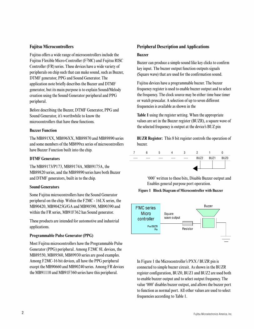
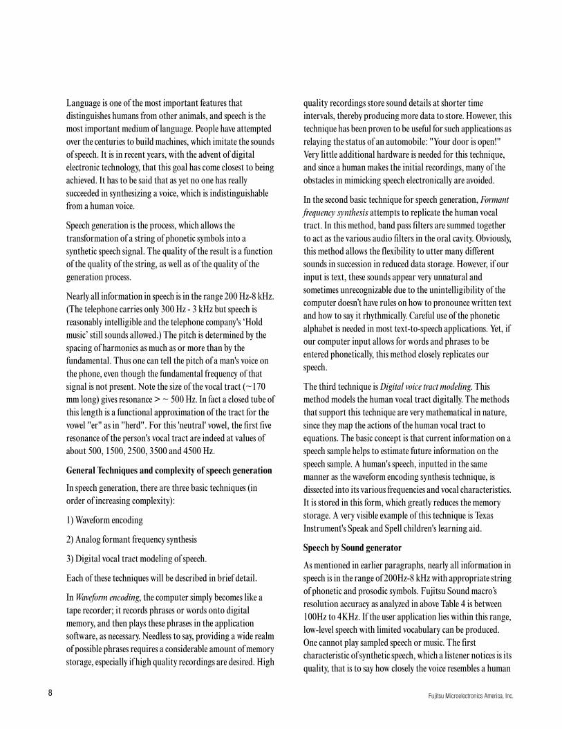