
SOP for QAG Method 6-10-05 · nebulizer configuration, nebulizer air flow and the flow of drying...
32
Standard Operating Procedure for Generating a Quantitative Multi-Metals Reference Aerosol with the CES QAG June 9, 2005 DRAFT Submitted to: The Environmental Protection Agency Research Triangle Park, NC Prepared by: Cooper Environmental Services, LLC 10180 SW Nimbus Blvd Suite J6 Portland, Oregon 97223
Transcript of SOP for QAG Method 6-10-05 · nebulizer configuration, nebulizer air flow and the flow of drying...

Standard Operating Procedure for Generating a Quantitative Multi-Metals Reference Aerosol with
the CES QAG
June 9, 2005
DRAFT
Submitted to:
The Environmental Protection Agency Research Triangle Park, NC
Prepared by:
Cooper Environmental Services, LLC 10180 SW Nimbus Blvd Suite J6
Portland, Oregon 97223

Standard Operating Procedure for Generating a Quantitative Multi-Metals Reference Aerosol with
the CES QAG
June 9, 2005
DRAFT
Submitted to:
The Environmental Protection Agency Research Triangle Park, NC
Prepared by:
J.A. Cooper, B.E. Johnsen, K. Petterson, C. A. Yanca, M. Nakanishi, D. Barth
Cooper Environmental Services 10180 SW Nimbus Blvd Suite J6
Portland, Oregon 97223

Standard Operating Procedure for Generating a Quantitative Multi-Metals Reference Aerosol with
the CES QAG
Prepared by:___________________________________ Date:_________ Catherine A. Yanca, Environmental Scientist Reviewed by: ___________________________________ Date:_________ Krag A. Petterson, Environmental Scientist Reviewed by: ___________________________________ Date:_________ Bruce E. Johnson, QA Manger Approved by: ___________________________________ Date:________ John A. Cooper, Director
Instrumental Method for a QAG: V1.0 Page i of vi
Executive Summary
The QAG is a reference aerosol generator that produces a NIST-traceable aerosol of known analyte concentration. In the QAG, a NIST-traceable or equivalent solution containing an analyte or analytes of interest is conveyed to an aspirator where it is combined with a gas and nebulized to form an aerosol of liquid droplets. The smaller droplets continue through the system and are dried. The resulting salt particles and/or vapors are then emitted from the system as a reference aerosol of known concentration. Specifically, the QAG is used to generate a NIST-traceable reference aerosol that contains a known concentration of metal. This method can be used to spike controlled and uncontrolled emissions as well as laboratory air for the purpose of evaluating the accuracy and precision of aerosol measurement methods and/or calibration of methods.
The QAG’s generated aerosol concentration ( a-QAGiC ) is process traceable to NIST through
the traceability of its components. The generated concentration is a function of the concentration of the solution standard ( s-QAG
iC ), total flow rate (Ft), rate of mass loss of the solution (Rm), and rate of vapor loss (Rv). Process traceability to NIST is established by using instruments that are NIST-traceable (e.g., calibrated with NIST standards) to measure these parameters. One exception is the standard solution used to generate the aerosol; solutions with NIST-traceable accuracies are either prepared in the laboratory or purchased from an outside vendor.
There are five major components of a nebulizer-based QAG, as described below:
1. The standard solution control system is required to transport the analyte-containing solution to the point of nebulization. This system is needed to regulate the flow of the solution from the reservoir to the nebulization cup and determine the solution mass loss rate. A peristaltic pump is included for cycling the NIST-traceable solution through the nebulizer cup as well as a laptop connected to a balance for measuring the mass loss of the solution.
2. The nebulizer air control system is used to establish and measure the flow, temperature, pressure and saturation of the air used in the nebulization process (i.e., nebulizer air). This section of the QAG uses filtered and saturated compressed air to create the initial solution droplet aerosol.
3. An ice bath for is needed to maintain the temperature of the nebulizer air at or near 32°F.
4. The nebulizer and vapor size control system is used for creation of the aerosol. It consists of three major components: the nebulizer cup, the nebulizer and nebulizer nozzle and the nebulizer settling-equilibrating chamber.
The nebulizer cup contains the standard solution. This solution is continuously circulated from the nebulizer cup to an external reservoir in order to minimize the impact of vapor loss on solution concentration and allow for determination of the solution mass loss rate. The standard solution is aerosolized by a nebulizer, located inside the nebulizer cup. The nebulization process creates a droplet spray containing
Instrumental Method for a QAG: V1.0 Page ii of vi
a wide range of droplet sizes. The largest droplets impact on the walls of the nebulizer cup and are recycled. The smaller droplets are entrained in the nebulizer air flow and pass into the settling-equilibration chamber. The function of the nebulizer settling-equilibration chamber is to remove and recycle all droplets greater than 30 µm in diameter as well as to assure droplet-vapor equilibrium at 32°F. Thus, the only droplets emitted into the drying chamber have diameters less than 30 µm and have been equilibrated with water vapor at 32°F.
5. The drying air and drying chamber with temperature and flow control is needed for drying the liquid aerosol into salt particles. Heated CDA (termed “drying air”) is introduced into the drying chamber for this purpose.
The final product of the QAG is an aerosol containing dried salt particles of the analyte or analytes. The concentration of the analytes in the aerosol and the concentration uncertainty are calculated from the QAG’s recorded parameters. The uncertainty of the generated aerosol concentration is determined using standard propagation of error techniques relevant to those parameters. The uncertainty values for the parameters are those listed as certified uncertainties by the manufacturers and/or NIST.

Instrumental Method for a QAG: V1.0 Page iii of vi
Table of Contents Executive Summary................................................................................................................. i
List of Symbols .........................................................................................................................v
List of Figures......................................................................................................................... vi
1.0 Principle and Applicability ........................................................................................ 1 1.1 Principle ................................................................................................................ 1
1.2 Applicability ......................................................................................................... 1
2.0 Range of Emission Characteristics............................................................................ 1 2.1 Concentration........................................................................................................ 1
2.2 Flow ...................................................................................................................... 1
2.3 Particle Size .......................................................................................................... 1
2.4 Temperature .......................................................................................................... 1
2.5 Species .................................................................................................................. 1
3.0 Definitions.................................................................................................................... 2
4.0 Operational Specifications ......................................................................................... 4 4.1 Nebulizing Air Flow Rate (Fe) ............................................................................. 4
4.2 Nebulizing Air Pressure (Pc)................................................................................. 4
4.3 Nebulizing Air Temperature ................................................................................. 4
4.4 Nebulizer Cup Temperature.................................................................................. 4
4.5 Ice Bath Temperature............................................................................................ 4
4.6 Drying Air Flow Rate ........................................................................................... 4
4.7 Drying Air Temperature ....................................................................................... 4
5.0 NIST-Traceable Specifications .................................................................................. 4
5.1 Mass Loss.............................................................................................................. 5
5.2 Flow Rate .............................................................................................................. 5
5.3 Rate of Vapor Loss ............................................................................................... 5
5.4 Solution................................................................................................................. 5
6.0 Apparatus .................................................................................................................... 6
6.1 Quantitative Aerosol Generator ............................................................................ 6
6.2 Standard Solution Control System........................................................................ 6
6.3 Nebulizer Air Control System .............................................................................. 7
6.4 Ice Bath ................................................................................................................. 8

Instrumental Method for a QAG: V1.0 Page iv of vi
6.5 Nebulizer and Vapor Size Control System ........................................................... 8
6.6 Drying Air and Drying Chamber System ............................................................. 9
7.0 Supplies ...................................................................................................................... 10 7.1 Standard Solutions .............................................................................................. 10
7.2 Compressed Air .................................................................................................. 11
7.3 Ice Bath ............................................................................................................... 11
8.0 Pre-Test Performance Evaluation Procedures....................................................... 11 8.1 Pre-Test Laboratory Preparation......................................................................... 11
8.2 Pre-Test Field Preparation .................................................................................. 12
8.3 Solution Concentration and Flow Rate Determination....................................... 13
8.4 Solution Sample .................................................................................................. 13
9.0 Generation of a Reference Aerosol with NIST-Traceable Accuracy ................... 13 9.1 System Preparation ............................................................................................. 13
9.2 Solution Exchange .............................................................................................. 14
9.3 Flow Rate and Temperature Adjustments........................................................... 14
9.4 Aerosol Generation and Performance Monitoring.............................................. 14
9.5 Documentation of Performance .......................................................................... 14
9.6 Shut-down........................................................................................................... 15
9.7 Post-Test Procedures........................................................................................... 15
10.0 Calculations ............................................................................................................... 15 10.1 Generated Aerosol Concentration....................................................................... 15
10.2 Generated Aerosol Concentration Uncertainty................................................... 16
10.3 Solution Concentration and Flow Rate Set Points.............................................. 17
10.4 Aerosol Emission Size ........................................................................................ 17
11.0 Documentation of Quality Control and Assurance ............................................... 18 11.1 Certifications....................................................................................................... 18
11.2 Field Data Records.............................................................................................. 18
12.0 Pollution Prevention ................................................................................................. 18
13.0 Waste Management .................................................................................................. 18
14.0 Figures and Tables.................................................................................................... 19
15.0 References.................................................................................................................. 23

Instrumental Method for a QAG: V1.0 Page v of vi
List of Symbols QAGa
iC − = Concentration of the ith element in the reference aerosol generated by the QAG. QAGs
iC − = Concentration of the ith element in the standard solution used for the QAG.
liqD = Diameter of the liquid droplets in the aerosol.
saltD = Diameter of the salt particles in the aerosol.
eF = Flow of expanded nebulizer air in the QAG.
tF = Total combined flow of the nebulizer air and drying air in the QAG.
vM = Mass of water vapor in a liter of saturated air.
cP = Absolute pressure of the compressed nebulizer air in the QAG.
eP = Pressure of the expanded nebulizer air in the QAG.
mR = Total rate of solution mass loss for the QAG.
vR = Rate of vapor loss of the QAG standard solution.
saltρ = Density of the analyte salt in the QAG.
ρliq = The density of the liquid droplet in the QAG. σ = One standard deviation.

Instrumental Method for a QAG: V1.0 Page vi of vi
List of Figures
Figure 1: A. Schematic of flow through QAG components. B. Overview of the set-up of the CES QAG.............................................................................................................. 19
Figure 2: Schematic of the CES QAG standard solution control system. .............................. 19
Figure 3: Schematic of the CES QAG nebulizer air control system....................................... 20
Figure 4: Schematic of the CES QAG nebulizer and droplet size control system. ................ 20
Figure 5: Schematic of the CES QAG drying air and drying chamber system. ..................... 21

Instrumental Method for a QAG: V1.0 Page 1 of 1
1.0 Principle and Applicability
1.1 Principle
A solution containing an analyte or analytes of interest is conveyed to an aspirator where it is combined with a gas and nebulized to form an aerosol of liquid droplets. The smaller droplets continue through the system and are dried. The resulting salt particles and/or vapors are then emitted from the system as a reference aerosol of NIST-traceable concentration.
1.2 Applicability
This method is applicable to spiking controlled and uncontrolled emissions as well as laboratory air for the purpose of evaluating the accuracy and precision of aerosol measurement methods and/or calibration of methods.
2.0 Range of Emission Characteristics
2.1 Concentration
The concentration of an analyte in the generator emissions can range between 0.001 and 1000µg/m³ depending on the solution concentration, nebulizer configuration and the total flow of air through the Cooper Environmental Services (CES) quantitative aerosol generator (QAG).
2.2 Flow
The total flow of emissions can range from 10 to 1000 slpm. Total flow is dependent on the nebulizer configuration, nebulizer air flow and the flow of drying air.
2.3 Particle Size
The size of the dried salt particles is determined by the solution concentration and the liquid droplet size. The QAG should be operated such that the estimated physical diameter of the salt particles is less than 3-4µm (Section 10.4).
2.4 Temperature
The output temperature of the QAG emissions can be set between 200 and 400°F. Temperatures downstream of the QAG must be above the dew point of the emitted aerosol but can be as high as the required application.
2.5 Species
The QAG principles are generally applicable to a wide range of analytes and solvents (organic and inorganic). However, the application described in this method is for inorganic

Instrumental Method for a QAG: V1.0 Page 2 of 2
metal salts in aqueous solutions. This can include soluble salts of elements ranging from atomic number 3 (Li) to 92 (U).
3.0 Definitions
Aerosol Generator System: System in which analytes contained within a solution are aerosolized, separated based on size, dried, and emitted.
Aerosol: A suspension of solids and/or liquids in a gas at various relative concentrations.
Analyte: A species (element, metal, etc.) of interest in an analytical method.
Analytically NIST Traceable Parameter: A parameter whose value is traceable to NIST through a measurement that is NIST traceable1.
Applicable Concentration Range: The range of concentrations over which a QRAG must be able to produce an aerosol of NIST-traceable or equivalent analyte concentration to be used for a given application.
Aspiration: The process by which a liquid is drawn from a reservoir through a narrow tube by creating a vacuum above the tube with fast moving air.
Atomization: The process of converting a liquid into small suspended droplets.
Certified Concentration Range: Range of concentrations for which the QAG is certified.
Drying Air: Air added to the QAG at the point of the drying chamber that is used to help dry the aerosolized liquid droplets into salt particles.
Generated Aerosol Concentration: The concentration of the aerosolized metal at the point of emission from the QAG. This concentration is a function of the solution concentration, total flow, rate of mass loss and rate of vapor loss; it can be calculated using Equation 1.
Key Component: A piece of equipment or instrument that measures any parameter used to determine the generated aerosol concentration.
Linearity: The degree to which two parameters are linearly related as determined by the value of the slope and correlation coefficient of a least squares regression analysis.
Main Flow: Flow of gas through the aerosol generator, transport/interface, and sampling system.
Make Up Flow (Air or Stack Gas): Flow of air and/or stack gas added after the aerosol is emitted from the QAG either before or as part of the transport/interface system.

Instrumental Method for a QAG: V1.0 Page 3 of 3
Nebulization: A size-limiting atomization process in which larger droplets are removed from the aerosol through impaction or sedimentation prior to being emitted from a nebulizer.
Nebulizer Air: Air flowing into the nebulizer that is combined with the NIST-traceable solution to create the aerosolized metals.
NIST: The National Institute of Standards and Technology, Gaithersburg, MD.
Particulate: A particle of solid or liquid matter.
Process NIST Traceable: A parameter whose value is traceable to NIST through a procedure, the steps of which are each NIST traceable1.
Quantitative Aerosol Generator (QAG): An aerosol generator system that uses analytes of known concentrations in aqueous solution to create aerosol emissions of known metal concentrations.
Quantitative Reference Aerosol Generator (QRAG): An aerosol generator which emits an aerosol of known analyte concentration that is NIST or equivalent traceable.
Sampling System: A collection of integrated components designed to collect a portion of an aerosol that accurately represents an analyte concentration.
Stability: Percent relative standard deviation of a value measured over an extended period of time.
Standard: Something established by authority, custom, or agreement for use as a rule or basis for comparison in measurement.
Standard deviation: A parameter that indicates the way in which a probability function or a probability density function is centered around its mean and that is equal to the square root of the moment in which the deviation from the mean is squared.
Total Flow: The combined flow of nebulizer air and drying air within the aerosol generation system. Total flow does not include air added to the transport system after the aerosol exits the QAG.
Traceability to NIST: A documented procedure by which a measured response is related to a standard with an accuracy defined by and certified by the National Institute of Standards Technology (NIST).
Traceability: A property of the result of a measurement or the value of a standard whereby it can be related to stated references, usually national or international standards, through an unbroken chain of comparisons all having stated uncertainties2.
Transport/Interface Component: That portion of a test arrangement that connects the QRAG to the point where the aerosol will be evaluated.

Instrumental Method for a QAG: V1.0 Page 4 of 4
Uncertainty: An indication of the degree of reliability of a value usually expressed statistically (probability) as a multiple of the standard deviation of a set of measurements. Unless otherwise stated, the uncertainty in a mean value of a series of measurements will be the standard deviation. In the case of values based on calculations, the uncertainty in the value is equal to the propagated uncertainty based on the uncertainties in the parameters used in the calculations.
4.0 Operational Specifications
The following operational specifications must be met to ensure the QAG is functioning properly and the generated aerosol concentration can be accurately determined.
4.1 Nebulizing Air Flow Rate (Fe)
The flow must be set between 10 and 11 liters per minute corrected to 32°F.
4.2 Nebulizing Air Pressure (Pc)
The pressure must fall in the range of 15 to 20 psi-gauge.
4.3 Nebulizing Air Temperature
The temperature of the nebulizing air must be between 32 and 33°F.
4.4 Nebulizer Cup Temperature
The nebulizer cup temperature must fall in the range of 30 to 34°F.
4.5 Ice Bath Temperature
The ice bath must be kept between 32 and 33°F.
4.6 Drying Air Flow Rate
The flow rate must be between 25 and 75 slpm.
4.7 Drying Air Temperature
The drying air temperature must be between 220 and 400°F.
5.0 NIST-Traceable Specifications
In addition to meeting the above operational specifications (Section 0), the QAG’s parameters must be confirmed as NIST-traceable. The generated aerosol concentration is

Instrumental Method for a QAG: V1.0 Page 5 of 5
process traceable to NIST through the traceability of the QAG’s key components1,2. The aerosol concentration is a function of the concentration of the solution standard, total flow rate, rate of mass loss of the solution, and rate of vapor loss (Equation 1 and Equation 2). This process traceability to NIST is established by meeting the following specifications:
5.1 Mass Loss
The QAG solution rate of mass loss (Rm) is determined by the balance, which must be calibrated in the field with NIST-traceable mass standards. Balance readings must be ± 1% of the standard value and certification of the mass standards must be current.
5.2 Flow Rate
The QAG’s flow parameters, total flow rate (Ft) and flow rate of the expanded nebulizer air (Fe, used to calculate the rate of vapor loss (Rv); Equation 2), are measured by flow meters. The flow meters must be calibrated to ± 2% in the field with a primary flow calibrator such as the DryCal®3. The NIST standard certification must be current.
5.3 Rate of Vapor Loss
The rate of vapor loss (Rv) is dependent on the temperature and pressure of the expanded nebulizing air (Pe) as well as the pressure of the compressed nebulizing air (Pc; Equation 2). In addition, the vapor loss rate requires that the nebulizing air be saturated with water vapor at 32°F. This is assured by measuring the temperature of the nebulizing air with a NIST-traceable thermometer to confirm that it is 32 ± 1°F. The condition of saturation is assured by first passing the nebulizer air through a bubbler at room temperature and then through a condenser at 32°F.
5.3.1 Temperature
The mass of water vapor in one liter of saturated air is a referenced value at 32°F4. The operator must confirm that the temperature of the nebulizing air is measured using a NIST-standardized thermometer with current certification.
5.3.2 Pressure
The operator must confirm that the ambient pressure and the absolute pressure of the compressed nebulizing air upstream of the nebulizer are measured using a NIST-traceable pressure gauge with current certification.
5.4 Solution
The analyte solution must be prepared using a NIST-traceable standard of the analyte(s). The operator must confirm that the standard certification has not expired.

Instrumental Method for a QAG: V1.0 Page 6 of 6
6.0 Apparatus
6.1 Quantitative Aerosol Generator
Use any aerosol generator to generate a reference aerosol that meets the specifications of this method. A schematic of the CES QAG is shown in Figure 1. The five major components of a nebulizer-based QAG include:
1. A standard solution control component required to regulate the flow of solution from the reservoir to the nebulization cup and determination of the solution mass loss rate.
2. A nebulizer air control component that establishes and measures the flow, temperature, pressure and saturation of the nebulizer air.
3. An ice bath for maintaining temperature of the nebulizer air at or near 32°F.
4. A nebulizer and vapor size control and equilibration.
5. A drying air and drying chamber with temperature and flow control.
6.2 Standard Solution Control System
This section of the QAG includes a peristaltic pump to cycle the NIST-traceable solution through the nebulizer cup and a laptop connected to a balance for measuring the mass loss of the solution (Figure 2).
6.2.1 Solution Reservoir
The solution reservoir must be large enough to hold a minimum of 1 liter of solution and small enough to fit completely and securely on the balance. It must be insulated with foam to prevent moisture from condensing on the outside of the reservoir. Note: it is important that the extraction and return of solution tubing not touch any part of the reservoir.
6.2.2 Solution Transport Line
Noroprene or equivalent tubing is used to transport the solution through the solution system.
6.2.3 Peristaltic Pump
A two-headed peristaltic pump is used to circulate the NIST-traceable solution between the solution reservoir and the nebulizer cup. The solution is pushed into the chamber at a rate of 15 ml/min and pulled out of the chamber at a rate of 17 ml/min.
6.2.4 Balance
The NIST-traceable solution and its reservoir are placed on a balance located next to the nebulizer/drying chamber assembly. The balance is used to measure the mass of the solution being condensed by the QAG.

Instrumental Method for a QAG: V1.0 Page 7 of 7
6.2.5 Computer
A computer is connected to the balance and is used to record the changing mass of the NIST-traceable solution continuously with custom software. These data are used to determine the rate of reservoir mass loss (Rm), which is the slope of the recorded reservoir mass over time.
6.3 Nebulizer Air Control System
This section of the QAG uses compressed air to create the initial solution droplet aerosol (Figure 3).
6.3.1 Nebulizing Air Lines
Stainless steel, PFA or equivalent tubing is used to transport the nebulizing air through the saturator, impinger, and nebulizer.
6.3.2 Filter Units
Filter units are used to remove oil and other particles from the nebulizing air.
6.3.3 Pressure Regulator
Downstream of the filter units, a precision pressure regulator is needed to control the pressure of air flowing into the QAG system to a nominal pressure of about 18 psi that is regulated to ± 0.5 psi-gauge.
6.3.4 Flow Meter
A flow meter is required for determining the flow rate of the compressed air which is used to calculate the flow rate of the expanded nebulization air (Fe). This flow rate which must be set to a pre-determined value based on the desired concentration of the aerosol emission (Section 10.3).
6.3.5 Ball Valve
A manual two-way ball valve is used to shut-off the flow of air to the nebulizer.
6.3.6 Ambient Temperature Saturator
The ambient temperature saturator is a bubbler half-filled with water. The nebulizer air is pushed through a PFA-coated stainless steel chamber and is bubbled through water to assure saturation with water vapor at room temperature. The saturator should be checked and refilled at least once a day.

Instrumental Method for a QAG: V1.0 Page 8 of 8
6.3.7 Condenser
Nebulizing air passing through the condenser is cooled to and saturated at approximately 32ºF. The condenser should be checked and emptied at least once a day.
6.3.8 Pressure Gauge
A NIST-traceable pressure gauge is used to measure the pressure of the compressed air flowing into the nebulizer (Pc).
6.4 Ice Bath
Downstream of the ambient temperature saturator, the nebulizer air is pushed into a container filled with ice and water maintained at approximately 32º F. The condenser, nebulizer cup (which contains the nebulizer), and nebulizer settling-equilibration chamber are all housed within this container. The container should have a thermocouple and thermometer for monitoring the temperature of the ice bath and a drain to remove water.
6.5 Nebulizer Droplet Size Control System
This section of the QAG consists of three major components (Figure 4):
1. Nebulizer and nebulizer nozzle
2. Nebulizer cup
3. Nebulizer settling-equilibrating chamber
6.5.1 Nebulizer and Nebulizer Nozzle
A NIST-traceable solution of known metal concentration is aerosolized by a nebulizer, such as a Collison nebulizer2, located inside the nebulizer cup (see Figure XX-2). The cooled and saturated nebulizing air leaves the condenser and is pushed through the nebulizer nozzles. The bottom of the nebulizer nozzle is located about 3/8 of an inch below the surface of the solution. The nebulizing air is forced across the surface of the capillary tube causing the solution to be drawn into the high velocity air stream. This process creates a droplet spray containing a wide range of droplet sizes. The largest droplets impact on the walls of the nebulizer cup and are recycled. The smaller droplets are entrained in the nebulizer air flow and pass into the settling-equilibration chamber.
6.5.2 Nebulizer Cup
The nebulizer cup contains the standard solution. This solution is continuously circulated from the nebulizer cup to the external reservoir in order to minimize the impact of vapor loss on solution concentration and allow for determination of the solution mass loss rate.

Instrumental Method for a QAG: V1.0 Page 9 of 9
A thermocouple attached to the nebulizer cup is connected to a NIST-traceable thermometer in order to measure the temperature of the cup. The temperature of the cup must be kept at 32°F, which is the effective temperature of Mv, the term for the mass of water vapor in one liter of saturated air.
6.5.3 Nebulizer Settling-Equilibration Chamber
The function of the nebulizer settling-equilibration chamber is to remove and recycle all droplets greater than 30 µm in diameter as well as to assure droplet-vapor equilibrium at 32°F. Thus, the only droplets emitted into the drying chamber have diameters less than 30 µm and have been equilibrated with water vapor at 32°F.
6.6 Drying Air and Drying Chamber System
The drying air is heated and used for drying the liquid aerosol into salt particles. In this part of the QAG, clean dry air (CDA) air is required (Figure 5).
6.6.1 Drying Air Lines
Stainless steel, PFA or equivalent tubing is used to transport the CDA through the tube heaters and into the drying chamber.
6.6.2 Filter Units
Filter units are used to remove oil and other particles from the drying air.
6.6.3 Pressure Regulator
The pressure regulator on the drying air line is used to adjust the flow of drying air to the desired flow rate.
6.6.4 Drying Air Flow Meter
The drying air flow meter is used to measure the drying air flow for the purpose of adjusting the pressure regulator.
6.6.5 Tube Heaters
The drying air is split into two lines downstream of the flow meter and each line is passed through a tube heater just before the air enters the drying chamber. Both heaters are maintained at 300 ± 20ºF.
6.6.6 Drying Air Ring
After being heated by the tube heaters, the drying air enters the drying chamber through a series of holes in the drying air ring. The air increases the drying rate of liquid droplets and acts as an air curtain that keeps the droplets from impacting the chamber walls.

Instrumental Method for a QAG: V1.0 Page 10 of 10
6.6.7 Drying Chamber
The nebulized liquid droplets from the nebulizer settling-equilibration chamber are combined with the drying air in the drying chamber, which is heated to approximately 250ºF. The droplets are dried in the chamber and the resulting aerosolized metals are emitted into the transport system.
6.6.8 Drying Chamber Heaters
The drying chamber is heated by a tape heater or a blanket heater maintained at approximately 250ºF.
6.6.9 Flow Meter
A flow meter is required for determining the total flow rate (Ft). The user can determine the total flow by either (1) measuring the drying air flow rate with a flow meter and adding this to the nebulizer air flow rate, or (2) measuring the main flow rate with a flow meter and subtracting all flows except the total flow.
7.0 Supplies
7.1 Standard Solutions
The QAG generates an aerosol with NIST-traceable accuracy based on the NIST-traceable accuracy of the standard solutions used. These solutions are consumed at a rate of about 5 to 10 ml/hour. An adequate supply of solutions at various concentrations required by a test plan should be prepared prior to the testing. The primary requirements of these solutions are that (1) the accuracy of the analyte concentrations be NIST-traceable (2) the solutions be stable over the period of their use and (3) the calculated diameter of the resulting dried salt particles be less than 4µm (Section 10.4).
7.1.1 NIST-Traceable Accuracy
Solutions with NIST-traceable accuracies can be prepared in the laboratory or purchased from an outside vendor. Solution accuracies are generally expected to be better than 0.5% at the 95% confidence level. At these accuracies, uncertainties in standard solution concentrations are insignificant contributors to the uncertainty of the generated aerosol concentration.
7.1.2 Standard Solution Stability
The stability of the standard solution over a period of months is generally assured if the metal analytes are prepared as nitrates in 1% nitric acid solutions. Other metal analyte salts and acids may be used, but stability needs to be documented either by laboratory testing or by vendor certification. Particular care should be taken when using standard solutions with multiple analytes to assure analyte stability.
Instrumental Method for a QAG: V1.0 Page 11 of 11
7.1.3 Solution Volume
The volume of standard solution prepared should generally be at least 2 liters or more. Although only a fraction of this volume might be used, the larger volume is required by the solution reservoir to minimize solution concentration increases due to evaporation over the test period. Under normal operating conditions, the solution concentration increase is less than 1% over test periods of about 10 hours, or about 0.1% per hour, which is usually insignificant for test periods of a few hours.
7.1.4 Analyte Concentration
The concentration of analytes in the standard solution is controlled so as to be less than the concentration that would result in dried salt particles with diameters greater than about 4µm (Section 10.4). With nitrates in nitric acid solutions, this will generally be the case if the dissolved solids are less than about 500 to 1000 ppm. A single metal analyte concentration of about 100 ppm will result in an aerosol concentration of about 100 µg/m3 if the typical QAG operating conditions are used with a total flow of about 100 slpm. Thus, the QAG can be used to generate aerosols with multiple analytes in range of EPA emission standards without generating salt particles greater than about 4µm in diameter that might otherwise have significant transport issues.
7.2 Compressed Air
The QAG requires at least 40 psi and 80 slpm (approximately 2 cfm) of instrument air. Between 10-12 lpm are needed to maintain the flow of nebulizing air and between 25 and 75 slpm are needed for the drying air flow, depending on the desired emission concentration. The selected compressed air source should be sufficient to meet the flow requirements for the desired tests runs.
7.3 Ice Bath
The QAG requires ice sufficient for filling the ice bath container and maintaining the temperature of the nebulizer air at 32°F for the duration of the test.
8.0 Pre-Test Performance Evaluation Procedures
8.1 Pre-Test Laboratory Preparation
The following system checks and preparations must be conducted in the laboratory prior to shipping and assembling the QAG at a test site.
8.1.1 Certification Check
Confirm that all required NIST-traceable certificates are valid.

Instrumental Method for a QAG: V1.0 Page 12 of 12
8.1.2 Operations Check
Confirm that the general operation of the QAG meets the manufacturer’s specifications.
8.1.3 Analyte Solution Preparation
Prepare a sufficient amount of analyte solution for the length of the test; for example, two liters of solution is sufficient for a 12-hour run.
8.2 Pre-Test Field Preparation
The following procedures must be conducted after receiving the QAG at the test site and prior to operating it in the field.
8.2.1 Physical Integrity Check
Check the QAG’s physical components to ensure no parts were damaged in shipping.
8.2.2 Assembly
Assemble the QAG per manufacturer’s instructions.
8.2.3 Operations Check and Calibration
Check the QAG’s operations to ensure that it meets the manufacturer’s specifications. Confirm that the pressure gauges used to measure the ambient air and nebulizing air pressures are NIST-certified and the certifications are current. Confirm that the thermometer used to measure the temperature of the nebulizing air is NIST-certified and the certificate is valid. In addition, calibrate the following components prior to installation and document all pre-test check results and readings:
Balance Calibration: Calibrate the balance using NIST-traceable masses; confirm that the readings are ±1% of the standard and the NIST certificates are current.
Flow Meter Calibration. Calibrate flow meter with a primary flow calibrator such as a DryCal®3; confirm that the readings are within 2% of the NIST-traceable certificate values.
8.2.4 Installation.
Install the QAG in the test facility per test plan requirements.
8.2.5 Pressure and Leak Check
The QAG system uses positive pressure, and the nebulizer air flow line must be leak checked before testing. Cap off the nebulizer air line just before the nebulizer,
Instrumental Method for a QAG: V1.0 Page 13 of 13
pressurize the line, and check for leaks using an appropriate leak indicator. Tighten any sections of the line where leaks are indicated.
8.2.6 Mass-Loss Evaluation
Before running the QAG with NIST-traceable solution, the operator must conduct a mass loss rate evaluation test. Follow the instructions below for starting and running the QAG with a NIST-traceable solution, and substitute a blank solution of 5% nitric acid and distilled water. Run the QAG for 3 to 5 hours using the blank; this also allows the QAG to thermally equilibrate. Calculate the slope and correlation coefficient for the decrease in the weight of the reservoir over the run period. The QAG is functioning properly if the slope is between 0.1 and 0.2 and the correlation coefficient is better than 0.99.
8.3 Solution Concentration and Flow Rate Determination
Using the equation for generated aerosol concentration (Equation 1), determine the necessary solution concentration and flow rates set points for the desired emission concentrations (see section 10.3).
8.4 Solution Sample
Collect and store a 50 ml sample of the analyte solution for possible quality assurance checks at a later time if necessary.
9.0 Generation of a Reference Aerosol with NIST-Traceable Accuracy
9.1 System Preparation
Connect the thermometers for the ice bath and nebulizer cup. Fill the ice bath container with ice, making sure it surrounds the impinger and nebulizer cup. If an ice bath is left from a previous run, drain the water and add enough ice to ensure that the temperature of the bath remains at 32 ± 1°F during the test run. While the ice bath is stabilizing, turn on the main flow pump. Adjust the flow to the rate specified in the test plan. Next, turn on the drying air flow and adjust the pressure regulator until the flow reaches the desired rate. Periodically check the drying air flow and readjust as necessary as it will tend to drop after the initial adjustment. Turn on the tube heaters and adjust the set point to 300°F. Switch on the drying chamber heaters to 125°F and start increasing the temperatures by 50°F increments to the set point. At this time, turn on any heaters associated with the transport system. When the cooler is full of ice, add water to 1” below the top of the cooler wall and insulate any gaps at the top of the cooler with foam. Continue to increase the temperature of the heaters throughout the solution exchange process described below until they reach their set points. Continue to monitor and adjust QAG operating parameters as necessary.
Instrumental Method for a QAG: V1.0 Page 14 of 14
9.2 Solution Exchange
The 5% nitric acid solution left in the bottom of the nebulizer cup after the mass loss evaluation must be cycled out of the system and replaced with the analyte solution. Using the tubes connecting the peristaltic pump to the reservoir, pump the distilled water out of the nebulizer cup and into an empty beaker while simultaneously pumping 300 ml of the analyte solution from another beaker into the chamber. When all of the analyte solution has been pumped through the chamber, place the remaining analyte solution in an empty reservoir, swirl gently, center the reservoir on the balance, and replace the peristaltic pump tubes. Gently lift the reservoir off the balance, zero the balance, and place the reservoir back down, taking care to ensure that the peristaltic pump tubes are not touching any part of the reservoir itself. Once the solution is pumping in and out of the reservoir, turn on the laptop and the balance software. Monitor the mass of the reservoir until it begins to fluctuate around a constant mean.
9.3 Flow Rate and Temperature Adjustments
At this point, the flow rates and heaters must be checked and adjusted again if necessary. During this process, turn on the sample system and bring it into equilibrium. The QAG system is in equilibrium when the operational specifications are met (Section 0), the total flow is stable, the flow of drying air is stable, and the heaters are operating at their set points.
9.4 Aerosol Generation and Performance Monitoring
When the QAG is in equilibrium, turn on the nebulizer flow by slowly opening the manual ball valve. Check to make sure the pressure regulator is controlling the flow at the flow set point (between 10 and 11 slpm) and adjust if necessary. When the nebulizer flow is on, the QAG is functioning as an aerosol generator. Check to ensure the pressure regulator and flow meter are stable at the desired set point. Monitor the performance of the QAG for the next 30 minutes, making minor adjustments if necessary. During this time, the sampling system results should also be monitored to ensure that system is functioning properly. The QAG should be checked again after 90 minutes of running time and any necessary minor adjustments should be made. Before leaving the QAG for any overnight runs, the operator should pack fresh ice into the cooler.
9.5 Documentation of Performance
The QAG’s performance must be documented using a data sheet such as Figure 6. Before beginning a test, fill out the top of the data sheet with the appropriate test information. Take a reading of the atmospheric pressure with a NIST-traceable pressure gauge and record this value, which is equivalent to the pressure of the expanded nebulizer air (Pe). After the QAG reaches equilibrium, the nebulizer flow is on, and the system is generating an aerosol, record the time and the following parameters: the temperature of the ice bath, the temperature of the nebulizer cup (for Mv), the nebulizer flow rate (Fe), the pressure of the nebulizer compressed air (Pc), the flow rate of the drying air, the pressure of the drying air, the temperature of the drying air (i.e., tube heater temperature), the total flow rate (Ft), room temperature, room

Instrumental Method for a QAG: V1.0 Section 10.0 Calculations Page 15 of 15
humidity, and the weight of the solution. Document new readings for these parameters every 1 hour. Also record bags of ice added and time as well as any necessary notes.
9.6 Shut-down
To turn the QAG off after testing, first close the manual ball valve on the nebulizing air line and shut off the flow. Turn off all of the heaters. Next, turn off the drying air flow and shut down the sampling system. Pump as much of the solution out of the droplet generating chamber as possible and turn off the peristaltic pump, balance, and laptop. Finally, shut off the main flow.
9.7 Post-Test Procedures
9.7.1 Balance Check
Check the balance calibration following the procedure described in Section 8.2.3.
9.7.2 Flow Meter Check
Check the flow meters calibrations following the procedure described in Section 8.2.3.
9.7.3 Ambient Pressure Reading
Take a final reading of the ambient pressure with a NIST-traceable pressure gauge.
9.7.4 Solution Sample
Collect and store an additional 50 ml sample of the analyte solution for possible quality assurance checks at a later time if necessary.
10.0 Calculations
10.1 Generated Aerosol Concentration
The following equation is used to calculate the generated aerosol concentration of the ith element ( a-QAG
iC ) from the QAG’s recorded parameters:
)R(RF
CC vmt
QAGsiQAGa
i −=−
−
Equation 1
Where:
s-QAGiC = Concentration of the ith element in the QAG’s NIST
traceable solution.

Instrumental Method for a QAG: V1.0 Page 16 of 16
Ft = Total flow, i.e., the combined flow of nebulizer air and drying air added within the aerosol generation system, determined by the flow meter located between the QAG and the transport system.
Rm = Measured rate of reservoir mass loss, determined as the slope of a linear least squares fit of the reservoir mass data over the period of a test or series of tests.
Rv = Rate of vapor loss is a calculated value based on the following equation:
⎟⎟⎠
⎞⎜⎜⎝
⎛−=
c
evev P
P1MFR
Equation 2
Where:
Fe = Flow rate of the expanded nebulization air as measured by the flow meter on the nebulizing air line.
Mv = Mass of water vapor in a liter of saturated air at 32 °F. This value has been well defined and documented3: Mv (32°F) = 4.847 mg/liter
Pe = Pressure of the expanded gas outside the nebulizer nozzle. Since the droplet generating chamber and the droplet size selector are open to the atmosphere, Pe is the atmospheric pressure recorded from the field barometer reading.
Pc = Absolute pressure of the compressed air upstream of the nebulizer nozzle, calculated by adding the atmospheric pressure to the gauge pressure.
10.2 Generated Aerosol Concentration Uncertainty.
The uncertainty of the generated aerosol concentration ( a-QAGiC
σ ) is determined using standard
propagation of error techniques5 relevant to the parameters of Equation 1. The uncertainty values for the parameters are those listed as certified uncertainties by the manufacturers and/or NIST. This procedure is consistent with those used at NIST6,7,8. The uncertainty of the generated aerosol concentration ( a-QAG
iC ) is calculated using the following equation:
2
vm
)R(R2
t
F
2
s-QAGi
CQAGaiC )R(R
σFσ
C
σCσ vmt
s-QAGi
a-QAGi ⎟⎟
⎠
⎞⎜⎜⎝
⎛−
+⎟⎟⎠
⎞⎜⎜⎝
⎛+⎟
⎟⎠
⎞⎜⎜⎝
⎛= −−
Equation 3

Instrumental Method for a QAG: V1.0 Section 10.0 Calculations Page 17 of 17
Where: ( ) ( )2R2
R)R(R vmvmσσσ +=−
Equation 4
and
2
c
e
PP12
v
M2
e
FvR
PP1
σ
Mσ
Fσ
Rσ c
e
ve
v
⎟⎟⎟⎟⎟
⎠
⎞
⎜⎜⎜⎜⎜
⎝
⎛
⎟⎟⎠
⎞⎜⎜⎝
⎛−
+⎟⎟⎠
⎞⎜⎜⎝
⎛+⎟⎟
⎠
⎞⎜⎜⎝
⎛=
⎟⎟⎠
⎞⎜⎜⎝
⎛−
Equation 5
and
2
c
P2
e
P
c
e
c
e
PP
PPPP
PP1
cec
e
⎟⎟⎠
⎞⎜⎜⎝
⎛+⎟⎟
⎠
⎞⎜⎜⎝
⎛=
⎟⎟⎠
⎞⎜⎜⎝
⎛−
⎟⎟⎠
⎞⎜⎜⎝
⎛− σσ
σ1
Equation 6
10.3 Solution Concentration and Flow Rate Set Points
To determine the required solution concentration and flow rate set points for given test run, select a desired concentration of the QAG’s aerosol emissions ( a-QAG
iC ). Use the expanded form of Equation 1:
⎥⎦
⎤⎢⎣
⎡⎟⎟⎠
⎞⎜⎜⎝
⎛−−=
−−
c
evem
t
QAGsiQAGa
i PP1MFR
FCC
Plug in the desired concentration ( a-QAGiC ), the estimated rate of mass loss (Rm; see also
section 8.3), the mass of water vapor in a liter of saturated air at 32 °F (Mv, 32 °F = 4.847 mg/liter), the pressure of the expanded nebulization air (Pe), and the absolute pressure of the compressed nebulizing air (Pc). Solve for an appropriate combination of solution concentration ( s-QAG
iC ) and flow rates, bearing in mind that total flow (Ft) equals the expanded flow of nebulizing air (Fe; which must be between 10 and 12 lpm) plus the drying air flow (which can range from 28 to 1990 lpm).
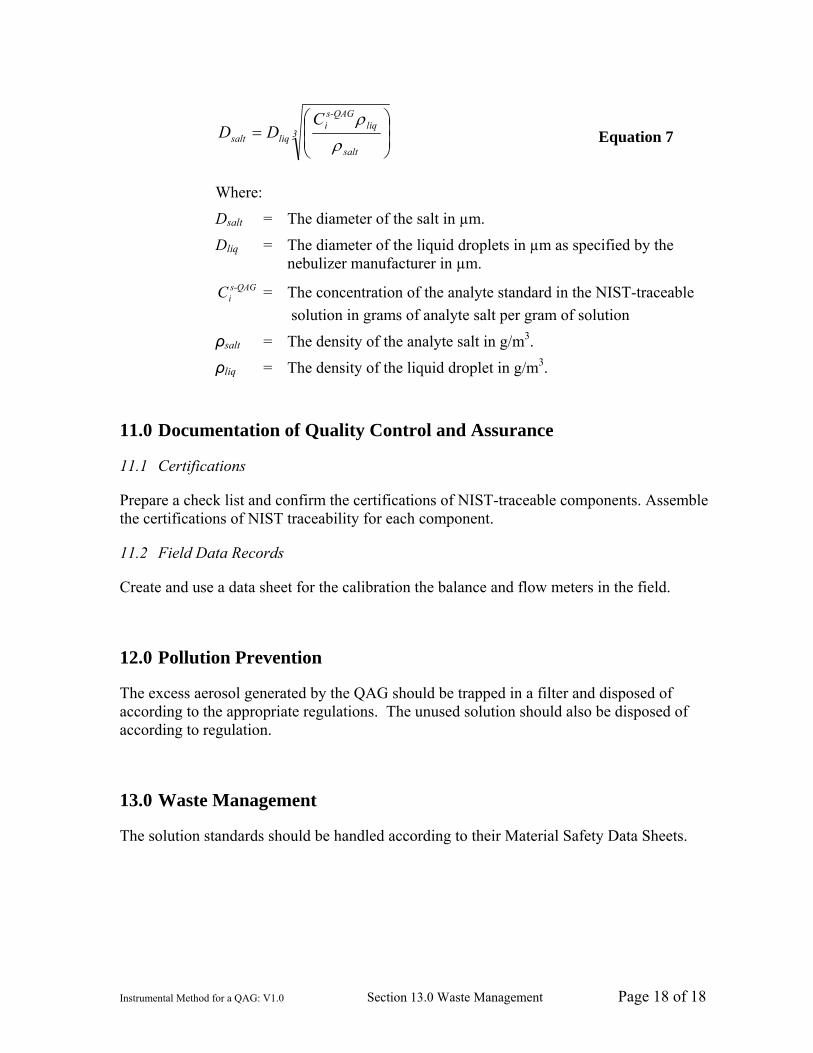
10.4 Aerosol Emission Size
Use the following equation to determine the size of the salt particles emitted by the QAG:
Instrumental Method for a QAG: V1.0 Section 13.0 Waste Management Page 18 of 18
3
salt
liqs-QAGi
liqsalt
CDD ⎟
⎟⎠
⎞⎜⎜⎝
⎛=
ρρ
Equation 7
Where:
Dsalt = The diameter of the salt in µm.
Dliq = The diameter of the liquid droplets in µm as specified by the nebulizer manufacturer in µm.
s-QAGiC = The concentration of the analyte standard in the NIST-traceable
solution in grams of analyte salt per gram of solution
ρsalt = The density of the analyte salt in g/m3.
ρliq = The density of the liquid droplet in g/m3.
11.0 Documentation of Quality Control and Assurance
11.1 Certifications
Prepare a check list and confirm the certifications of NIST-traceable components. Assemble the certifications of NIST traceability for each component.
11.2 Field Data Records
Create and use a data sheet for the calibration the balance and flow meters in the field.
12.0 Pollution Prevention
The excess aerosol generated by the QAG should be trapped in a filter and disposed of according to the appropriate regulations. The unused solution should also be disposed of according to regulation.
13.0 Waste Management
The solution standards should be handled according to their Material Safety Data Sheets.

Instrumental Method for a QAG: V1.0 Page 19 of 19
14.0 Figures and Tables
A. B.
Figure 1: A. Schematic of flow through QAG components. B. Overview of the set-up of the CES QAG.
Figure 2: Schematic of the CES QAG standard solution control system.

Instrumental Method for a QAG: V1.0 Page 20 of 20
Figure 3: Schematic of the CES QAG nebulizer air control system.
Figure 4: Schematic of the CES QAG nebulizer and droplet size control system.

Instrumental Method for a QAG: V1.0 Page 21 of 21
Figure 5: Schematic of the CES QAG drying air and drying chamber system.

Instrumental Method for a QAG: V1.0 Page 22 of 22
Op
erat
or:
So
ln. C
on
c:
Lo
cati
on
:
Sp
ikin
g:
No
tes:
# B
ags
Neb
. P
res.
(p
si)
Mak
e-U
p A
ir
Pre
ssu
re
(i
n. H
2O)
Tra
nsp
ort
T
emp
(°F
)
Mak
e-U
p
Air
Tem
p
(°F
)
Neb
. C
old
B
ath
(°F
)
Neb
. A
ir
(°F
)
Ad
ded
Ice
Sp
ike
So
ln.
Mas
s (g
)
Mak
e-U
p
Air
Flo
w
(slp
m)
Ro
om
T
emp
(°
F)
Ro
om
(R
H)
Sta
ck G
as
Flo
w
(lp
m)
Mai
n
Flo
w
(slp
m)
Neb
. C
up
(°
F)
Tim
e
Dat
a S
hee
t Q
AG
M-3
01 T
ests
Dat
e:
Sta
rt D
ate/
Tim
e:
Sto
p D
ate/
Tim
e:
Tim
e o
f R
eco
rd
Neb
. F
low
(l
pm
)
Figu
re 6
: Sam
ple
data
shee
t for
the
QA
G.

Instrumental Method for a QAG: V1.0 Page 23 of 23
15.0 References
1. Scott Specialty Gases. Scott Gas Mixtures Data: Gas and Liquid Mixture Basics. Plumsteadville, PA: Scott Specialty Gases; 2004.
2. Bureau International des Poids et Mesures, International Electrotechnical Commission, International Federation of Clinical Chemistry and Laboratory Medicine, International Organization for Standardization, International Union of Pure and Applied Chemistry International Union of Pure and Applied Physics, International Organization of Legal Metrology [BIPM, IEC, IFCC, ISO, IUPAC, IUPAP, OIML]. International Vocabulary of Basic and General Terms in Metrology (VIM). Geneva, Switzerland: BIPM, IEC, IFCC, ISO, IUPAC, IUPAP, OIML; 1993. Available from: ISO, Geneva, Switzerland; ISBN 92-67-01075-1.
3. Smithsonian Physical Tables, 9th Rev. Ed. Washington D.C.: Smithsonian Institution Press; 1954.
4. Scace, G.E. and J.T. Hodges. Uncertainty of the NIST Low Frost-Point Humidity Generator. Gaithersburg, MD: National Institute of Standards and Technology; 2004.
5. McClave, J.T., F.H. Dietrich, II, and T. Sincich. Statistics, 7th Ed. Upper Saddle River, NJ: Prentice Hall; 1997.
6. Taylor, B.N. and C.E. Kuyatt. Guidelines for Evaluating and Expressing the Uncertainty of NIST Measurement Results. Gaithersburg, MD: National Institute of Standards and Technology [NIST]; 1994. Available from: NIST, Gaithersburg, MD; TN 1297.
7. American National Standards Institute/National Conference of Standards Laboratories [ANSI/NCSL]. U.S. Guide to the Expression of Uncertainty in Measurement. Washington, D.C: ANSI/NCSL; 1997. Available from: NCSL International, Washington, D.C; Z540-2-1996.
8. May, K.R. The Collison nebulizer: description, performance and application. Aerosol Science 1973; 4: 253-243.


