
Sony Chassis Az1-l Training Manual
38
AZ1L Direct-View LCD Television Chassis Circuit Description and Troubleshooting Guide Training Manual MODELS: KDL22EX308 KDL32EX308 Course : CTV-68 KDL32EX308
Transcript of Sony Chassis Az1-l Training Manual
AZ1L Direct-View LCD Television Chassis
Circuit Description and Troubleshooting Guide
Training Manual
MODELS: KDL22EX308 KDL32EX308
Course : CTV-68
KDL32EX308
CTV-63 i
Power Supply ....................................................................... 4KDL22EX308 .......................................................................... 4KDL32EX308 .......................................................................... 4
Inverter ................................................................................. 4Switch Unit ........................................................................... 4HLR Board ........................................................................... 4
Chapter 3 – Troubleshooting .............................................. 7Introduction ...................................................................... 7Software Updates ............................................................ 7
Software Update Responsibility ........................................... 8Examples of Software Correctable Symptoms .................... 8Checking the Software Version ............................................ 8
Special Software Instructions for BAL Board or LCD Panel Replacement ............................................................... 9No Video ............................................................................ 10
Audio Troubleshooting ................................................... 14Power Supply Troubleshooting ...................................... 14
Completely Dead Set ............................................................ 14Won’t Power On .................................................................... 14
Backlight Issues ............................................................. 18No Backlight, No Shutdown ............................................... 18
Diagnostics History ........................................................ 18Circuit Board and Connector Locations ......................... 19
Chapter 4 – Appendix ........................................................ 24TCON Troubleshooting .................................................. 24
Chapter 1 – Introduction ..................................................... 1Overview .......................................................................... 1Features .......................................................................... 1
720p Panel ........................................................................... 1CCFL Backlighting ............................................................... 1BRAVIA™ Internet Video ..................................................... 1Enhanced Cross Media Bar (XMB) ...................................... 1USB2.0 Side Input ............................................................... 2HDMI 1.3 .............................................................................. 2
Consumer Electronics Control (CEC) ..................................... 2xvYCC ..................................................................................... 2Deep Color .............................................................................. 2
Bravia® Sync ....................................................................... 2Advanced Contrast Enhancer (ACE) ................................... 2Interactive Program Guide (IPG) ......................................... 2Digital Living Network Alliance (DLNA) ................................ 2RGB Ambient Sensor ........................................................... 2
Chapter 2 – Overall Circuit Descriptions ........................... 3Overview .......................................................................... 3Overall Circuit Description ............................................... 3
BAL Board ........................................................................... 3A/V Decoder IC9000 ............................................................... 3Audio Processing .................................................................... 3HDMI Switch ........................................................................... 3CPU ........................................................................................ 3LVDS Transmitter .................................................................... 3
Table of Contents
CTV-63 ii
Table of Contents (Continued)Introduction .................................................................... 24
LCD Panel Basics .............................................................. 24Gate Drivers ....................................................................... 27Source Drivers ................................................................... 27
Diagnosing a Failed TCON ............................................ 27TCON Failures ................................................................... 29
Troubleshooting a “DEAD” TCON ......................................... 29
Examples of Actual TCON Failures ................................... 31LCD Panel Failures ............................................................ 33
CTV-68 1
Chapter 1 – Introduction
OverviewThe AZ1L chassis is one of several designs for the 2010 model line of Sony Bravia® LCD televisions. Several models will be released incorporating this chassis. This training manual will cover the EX308 series consisting of the following models:
KDL22EX308
KDL32EX308
The chassis design revolves around the video processing circuits located on the BAL board. The key difference between models is determined by the size of the LCD panel and its manufacturing source. This manual will describe the new circuit features and individually describe the models based on these differences.
FeaturesSeveral new features are introduced in the EX-M chassis model lineup along with some carryovers from the previous year.
720p PanelThe EX308 models incorporate a native 1366 X 768 (WXGA) resolution panel. All video signals exit the video process circuits as 720p 60HZ. The RGB resolution is 8-bit to provide 256 levels of gray scale.
CCFL BacklightingMany of the 2010 Sony television models are introducing edge-lit LED backlighting. The EX308 series incorporates traditional cold-cathode fluorescent lamps (CCFL) to generate the necessary backlighting for the LCD panel. A self contained (direct) inverter circuit supplies the necessary high voltage to drive the backlight lamps.
Wireless Internet ReadyAn optional wireless network adapter is available to connect the television to a home network. These models have an Ethernet port on the rear for direct connection to the home network. Plugging the optional wireless network adapter into the USB2.0 port on the side of the television allows for wireless connectivity when conditions do not allow direct connections. The wireless adapter supports up to 802.11N.
BRAVIA™ Internet VideoOnce available as an optional device to connect to the television, this feature is now an integral part of the product. The rear of the television contains an Ethernet port to connect to a high speed network. Access to online music and video through partnered websites is possible.
Personalized “widgets” are small applications that can be placed on the screen and accessed with the touch of a button to bring up programming such as weather, stocks and sports information.
Enhanced Cross Media Bar (XMB)A new graphics user interface with rich 3-D graphics allowing the user to customize the setup of the television and to access various adjustments and control optional devices. Optional external devices can also be detected and displayed. One example would be when a USB storage device is plugged into the USB2.0 side input that contains JPEG format photos. The detection of the device will appear in the XMB graphics icons along with thumbnail views of the photos stored on the device. The photos can be viewed individually or be displayed as a slide show.
Chapter 1 - Introdcution
CTV-68 2
USB2.0 Side InputThis feature was available in selected 2008 models and allowed the viewing of JPEG formatted pictures and playback of MP3 audio files. The media content has been expanded this year to allow playback of MPEG1 and MPEG2 format video content. An optional wireless network adapter can be inserted to connect to a wireless home network.
HDMI 1.3This new version of HDMI introduces several new enhancements and features and the EX-1 chassis supports 3 of the new features.
Consumer Electronics Control (CEC)
A standardized protocol for the control of consumer electronics devices allows for communication and control via the HDMI cable on products that have this feature. Any brand of electronic equipment that is CEC compliant can communicate with another to generate operational commands. The Bravia Sync feature uses the CEC format to control other Sony devices in the system.
xvYCC
The previous color bandwidth limitations applied for compatibility with analog signals are no longer present with digital signals. This allows for 1.8 times more colors.
Deep Color
The previous HDMI specifications limited the RGB sample level to 24-bit. Deep Color expands this up to 48-bit giving the ability to generate a color depth of 2.8 trillion levels.
Bravia® SyncBy utilizing the CEC feature of HDMI 1.3, this feature allows the customer to easily control the various Sony devices within their home entertainment system provided that all of the other devices have this feature included.
Advanced Contrast Enhancer (ACE)By monitoring the overall level of the video signal, the backlights are dynamically controlled and reduced during low light level scenes to enhance the contrast ratio.
Interactive Program Guide (IPG)An interactive guide is included to provide continuously updated program information at no charge to the customer. The guide (provided by TV Guide) is part of the XMB graphics feature. Program material is updated from the local PBS station when the television is off.
Digital Living Network Alliance (DLNA)An industry standard networking protocol has been developed by leading manufacturers to allow other devices such as a compatible computer to communicate with the television via an Ethernet connection to your home network. This gives the ability to view photos, audio and movie content directly from your computer via the network. Future plans include the ability to download software updates for the television via the home network.
RGB Ambient SensorA sensor located on the lower left portion of the front bezel monitors ambient light levels to adjust the brightness and contrast level of the picture. This new version is also capable of measuring the color temperature of the ambient light to adjust the white balance of the displayed picture based on what type of light source is present in the room.
CTV-68 3
Chapter 2 – Overall Circuit Descriptions
OverviewThe primary circuits contained in the AZ1L chassis consists of a main circuit board (designated as the BAL board), power supply (GD1 Or G2LE) which varies based on the size of the LCD display, and the LCD panel assembly. The TCON circuit (normally mounted external to the LCD panel) is contained inside the panel assembly. The remaining small boards contain switches, sensors and LED’s.
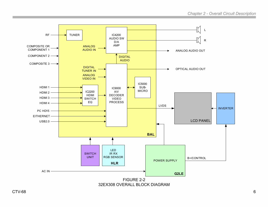
Overall Circuit DescriptionFigure 2-1 illustrates an overall block diagram of the KDL22EX308. Figure 2-2 illustrates an overall block diagram for the KDL32EX308. Both chassis designs share most of the same circuits with the power supply and high voltage circuits to supply the lamp voltages being the significant difference. Below is a description of the components and their function for the KDL22EX308.
BAL BoardCommon to all models utilizing the AZ1L chassis, the BAL board contains most of the video processing circuitry along with all audio processing. Control of the television is accomplished via CPU IC5000. Below is a list of the key components located on the BAL board.
A/V Decoder IC9000
This IC performs several functions including the following:
Tuner: The tuner is a combination ATSC/NTSC unit. It can receive traditional analog NTSC signals via cable or terrestrial along with ATSC digital signals via terrestrial (8VSB) or cable (64 or 256 QAM).
Analog Video Input Switch: The analog video is A/D converted and scaled (if necessary) to a 1920 X 1080p 60HZ resolution.
Digital Audio and Video Decoder: The MPEG2 and Digital Dolby audio streams are received from the tuner for decompression. All video sources which are not native 1280 X 720p 60HZ are scaled to this resolution. Digital audio content is output to IC4200 for processing and amplification.
Audio Processing
IC4200 selects and processes all audio sources. The audio content is processed digitally, amplified and sent to the speakers.
HDMI Switch
IC2000 functions as a switch for the 4 HDMI inputs. It also serves as an equalizer to match the low impedance of the input jacks to the high impedance of the input to IC9000. IC2000 also contains a shared memory for the EDID information for each HDMI input. When a particular HDMI input is selected, IC9000 loads the proper EDID information into the shared memory.
CPU
IC5000 controls most of the operation of the television. All user inputs are processed here. IC5000 also monitors key voltages and protection circuits to shut the unit down if a problem is detected.
LVDS Transmitter
Integrated into IC9000 is a Low Voltage Differential Signaling (LVDS) transmitter. This circuit converts the 8-bit parallel RGB video information into a set of high speed serial lines for noise-free transmission to the TCON board.
Chapter 2 - Overall Circuit Description
CTV-68 4
Power Supply
KDL22EX308
The KDL22EX308 utilizes the GD1 power supply board. There are 3 distinct sections on the power supply:
Standby Supply: Continuously operational as long as AC power is applied, the standby supply generates 3.3VDC for the circuits requiring power while the unit is turned off. An unregulated 15-volt line is present to provide power to the main relay, PFC and main power supply at turn-on.
Main Supply: Once the power supply receives a power-on command from the CPU on the BAL board, the main switching supply is turned on to provide a regulated 12V source, along with a dedicated un-regulated 15V for the audio circuits.
Inverter: The high voltage for the fluorescent backlights is generated by this circuit. Out-of-phase AC voltage of approximately 1000VRMS is applied to the balancer circuit. If the inverter circuit fails to start, for whatever reason, the unit will shut down with a 6-blink error code displayed by the timer LED.
KDL32EX308
Referring to Figure 2-2 the KDL32EX308 utilizes the G2LE power supply board. All of the other circuits are the same as the KDL22EX308 except for the following circuits:
There are 2 distinct sections on the power supply:
Standby Supply: Continuously operational as long as AC power is applied, the standby supply generates 3.3VDC for the circuits requiring power while the unit is turned off. An unregulated 15-volt line is present to provide power to the main relay, PFC and main power supply at turn-on.
Main Supply: Once the power supply receives a power-on command from the CPU on the BAL board, the main switching supply is turned on to provide a regulated 12V source, a dedicated un-regulated 15V for the audio circuits and an unregulated 24V source for the inverter circuit.
InverterThe inverter receives the unreg24V from the G2LE board and generates the required high voltage AC to power the backlight lamps. As of the writing of this manual, the inverter is not available as a replacement part. The LCD panel assembly must be replaced.
Switch UnitThis board contains the power, channel and volume up/down and menu buttons.
HLR BoardThe power, standby and timer LED’s are located on this board along with the IR remote receiver and ambient room light sensor for controlling backlight and RGB levels.

Chapter 2 - Overall Circuit Description
CTV-68 5
FIGURE 2-122EX308 OVERALL BLOCK DIAGRAM
COMPOSITE ORCOMPONENT 1
RF
COMPOSITE 3
COMPONENT 2
HDMI 1
PC HD15
POWER SUPPLYINVERTER
SWITCHUNIT
LEDIR RX
RGB SENSOR
LCD PANEL
BAL
GD1
HLR
L
R
ANALOG AUDIO OUT
OPTICAL AUDIO OUT
HDMI 3
IC4200AUDIO SW
D/AAMP
IC9000A/V
DECODERVIDEO
PROCESS
IC2200HDMI
SWITCHEQ
TUNER
ANALOG VIDEO IN
EITHERNET
USB2.0
ANALOG AUDIO IN
HDMI 2
HDMI 4LVDS
CCFL HV
AC IN
DIGITALTUNER IN
DIGITAL AUDIO
IC5000SUB-
MICRO
Chapter 2 - Overall Circuit Description
CTV-68 6
FIGURE 2-232EX308 OVERALL BLOCK DIAGRAM
COMPOSITE ORCOMPONENT 1
RF
COMPOSITE 3
COMPONENT 2
HDMI 1
PC HD15
POWER SUPPLY
SWITCHUNIT
LEDIR RX
RGB SENSOR
LCD PANEL
BAL
G2LE
HLR
L
R
ANALOG AUDIO OUT
OPTICAL AUDIO OUT
HDMI 3
IC4200AUDIO SW
D/AAMP
IC9000A/V
DECODERVIDEO
PROCESS
IC2200HDMI
SWITCHEQ
TUNER
ANALOG VIDEO IN
EITHERNET
USB2.0
ANALOG AUDIO IN
HDMI 2
HDMI 4LVDS
B+/CONTROL
AC IN
DIGITALTUNER IN
DIGITAL AUDIO
IC5000SUB-
MICRO
INVERTER
CTV-68 7
Chapter 3 – Troubleshooting
IntroductionMost troubleshooting of this chassis focuses on the 3 major components used:
• The Main Board (BAL)
• Power Supply (G1D or G2LE)
• LCD Panel
This chapter will provide practical troubleshooting procedures based on the various symptoms that will appear when a particular circuit fails to operate properly. Typical failure symptoms will be discussed along with troubleshooting flowcharts for each symptom.
Always remember to log on to the Sony technical support site at http://www.sony.com/asp to access the latest technical bulletins along with triage charts to quickly identify the most likely part to complete the repair based on the symptom.
Software UpdatesThe subject of software updates is a very important item to point out at this point. The televisions of today have advanced to the point where they are not simply a television anymore. They are evolving into devices that are designed to integrate with numerous other devices found in the home. Some examples are: Portable audio and video devices, still cameras, home computer networks and accessing the internet to name a few.
Communications with these varying devices requires that the television be compatible with varying communications protocols. Although standards are detailed for each of these protocols, the real world dictates that occasional errors may occur that could prevent devices from operating or communicating properly.
Keeping the software in the television up-to-date is a procedure that is normally handled by the owner of the television. Most customers who own computers and other digital devices are familiar with and are accustomed to updating the firmware and software in their products. If a customer contacts the Sony Customer Support Center and it is deemed to be correctable with a software update, the issue is handled at the customer level.
Software updates can be performed in the following ways:
• Manual Downloads: Software updates can be retrieved from the Sony Support Site at http://esupport.sony.com where they can be downloaded and placed on a USB thumb drive to be loaded into the product. The instructions for downloading the software file vary from chassis to chassis and sometimes from model to model. Read the instructions included with the software file to properly format the USB device, unzip the file (if necessary) and the procedure for loading the software into the television.
• Network Downloads: Internet software updates are becoming more prevalent as more and more models incorporate home network capabilities. This method is the most practical since the television will check for the latest version of software. The models using the AZ1L chassis provide the customer with a choice of turning the automatic software update feature on or off. If set to on, the television will lookup software information while the unit is in standby. If a newer version is available, it will be downloaded and installed without any input from the customer
• Built-in Tuner: OTA or cable sources having the proper station that is transmitting software update data packets. Although the ability to transmit software update is possible in this way, it is the least common and is reserved for particular situations where a critical update is “forced”, thereby updating the unit without any input from the customer.
Chapter 3 - Troubleshooting
CTV-68 8
FIGURE 3-1CHECKING THE SOFTWARE VERSION
Software Update ResponsibilitySoftware updates are designed to be performed by the customer. Warranty repairs in which the issue can be resolved by a software update are not reimbursable. Most issues involving software updates are handled by the customer service center and should not be directed to an authorized service center. It is the responsibility of the servicer to prevent service calls for issues that involve software updates. Exceptions to this are certain cases whereby the customer is unable or unwilling to perform the task. In this situation, the servicer will be notified and receive the proper authorization for reimbursement.
It is the servicer’s responsibility, however, to make certain that any unit requiring a legitimate service is running the latest software version and to install it if necessary.
Examples of Software Correctable SymptomsAlways check the Sony Technical Support site for any known and listed issues that are software related. Most symptoms that are correctable by software updates involve communications issues with other devices or minor glitches in the operation of a specific function. Below is a list of some of the symptoms that may be corrected with a software update:
• Fluctuations in picture brightness
• Intermittent picture freezing or noise
• Problems with certain inputs (especially HDMI)
• Intermittent or distorted audio
• Erratic remote control operation
• Unit turns on and off by itself
• Loss of color
• Internet connectivity
• Certain features not working correctly
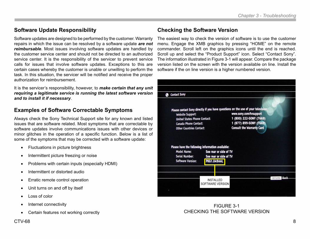
Checking the Software VersionThe easiest way to check the version of software is to use the customer menu. Engage the XMB graphics by pressing “HOME” on the remote commander. Scroll left on the graphics icons until the end is reached. Scroll up and select the “Product Support” icon. Select “Contact Sony”. The information illustrated in Figure 3-1 will appear. Compare the package version listed on the screen with the version available on line. Install the software if the on line version is a higher numbered version.
INSTALLED SOFTWARE VERSION
Chapter 3 - Troubleshooting
CTV-68 9
Special Software Instructions for BAL Board or LCD Panel ReplacementThe 2010 models utilize a “generic” type BAL board. In the past, many different main boards needed to be stocked due to differences in software requirements. The software loaded on the board was specific to the model and its features along with the type of LCD panel installed during production.
Replacement BAL boards will now be stocked with basic software. Once the replacement board is installed in the unit, the most current software is to be installed using a USB storage device containing the necessary software downloaded from the ASC support web page.
In addition to software installation for specific models, 2 items must be checked and adjusted in the service mode. The adjustments are Segment Data (model ID) and Destination (region ID). The procedures for the software installation are located on the ASC website (http://www.sony.com/asp). The adjustment procedures are located in the service manual.
This new method of supplying main boards significantly reduces the complexity of replacing LCD panels and main boards. Information about the LCD panel is stored on the TCON circuits. This information is automatically loaded onto the main board when the unit is powered up. The need to lookup data in the LCD panel manual is no longer necessary. With the correct software version and proper settings of the Segment and Destination data the BAL board and/or the TCON or LCD panel can be replaced more efficiently.
Chapter 3 - Troubleshooting
CTV-68 10
Video FailuresProblems that develop in the video circuits can appear as subtle or major distortions, a loss of one or more colors, improper video level, or a complete loss of video. When troubleshooting LCD display devices the problem must be isolated to 3 major components: The main board where the video processing is performed, the TCON board, or the LCD panel. In some cases the TCON may not be available as a separate component and replacement of the LCD panel is required to rectify a TCON problem.
Distortion in the video signal that affects all inputs can be challenging at times since any of the above mentioned components can cause this. Fortunately, each of these components tends to generate unique symptoms when a problem occurs. Some distortions may occur that could be caused by either of these components but a good understanding of the circuits and further investigation will isolate the suspected circuit. The following sections will cover the various scenarios of problems that may occur in the video processing circuits.
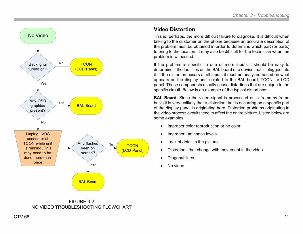
No VideoA “no video” complaint can be caused by a number of reasons. The first step is to determine if the condition is present from all input sources. If any video source is working properly, the TCON can be assumed to be OK. The backlights are also functioning properly. Although it is unusual for a backlight failure to cause a complete loss of video (the unit will shut down if a backlight power or open LED is detected) there have been cases where the backlights have failed to turn on without the unit shutting down.
If the loss of video occurs on all inputs, the problem will require additional diagnostic work. The presence of audio is an important sign to check for. Missing audio accompanying a loss of video helps to eliminate the TCON as the cause and would point to the BAL board as the culprit. If audio is present, the next step is to determine if the video loss is occurring in the video process circuits on the BAL board or the LVDS cable link from the BAL board to the TCON, or the TCON itself.
Service Tip: If a service call is made for a “no video” complaint, a warranty repair would require the technician to bring a BAL board to the location. The technician will install the board (hopefully the correct one) and if the video problem is not remedied, it is safe to assume the problem might reside in the TCON.
One method to test a TCON, which works rather well in most cases, is to remove the LVDS connector at the LCD panel (the TCON board is internal to this panel) while the unit is running. Be certain to release the lock tabs and handle the connector carefully to avoid damage.
Carefully insert and remove the connector while slightly rocking it. Observe the screen as you do this. If any activity appears on the screen (flashes, lines or patterns) The TCON is OK. The unit may shut down within a 10 to 20 second period because the protect circuits have detected a TCON failure. If this happens, simply re-insert the LVDS connector, turn the unit back on, and try the procedure again. Normally, you should be able to detect something on the screen within a matter of seconds.
The troubleshooting flowchart in Figure 3-2 should provide assistance in isolating the cause of the video loss.
Chapter 3 - Troubleshooting
CTV-68 11
FIGURE 3-2NO VIDEO TROUBLESHOOTING FLOWCHART
No Video
Backlights turned on?
Unplug LVDS connector at
TCON while unit is running . This may need to be done more than
once
Any flashes seen on screen?
Yes
No TCON(LCD Panel)
Any OSD graphics present?
No
BAL Board
No TCON(LCD Panel)
Yes
Yes
BAL Board
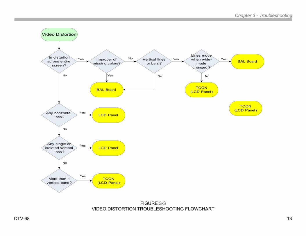
Video DistortionThis is, perhaps, the more difficult failure to diagnose. It is difficult when talking to the customer on the phone because an accurate description of the problem must be obtained in order to determine which part (or parts) to bring to the location. It may also be difficult for the technician when the problem is witnessed.
If the problem is specific to one or more inputs it should be easy to determine if the fault lies on the BAL board or a device that is plugged into it. If the distortion occurs at all inputs it must be analyzed based on what appears on the display and isolated to the BAL board, TCON, or LCD panel. These components usually cause distortions that are unique to the specific circuit. Below is an example of the typical distortions:
BAL Board: Since the video signal is processed on a frame-by-frame basis it is very unlikely that a distortion that is occurring on a specific part of the display panel is originating here. Distortion problems originating in the video process circuits tend to affect the entire picture. Listed below are some examples:
• Improper color reproduction or no color
• Improper luminance levels
• Lack of detail in the picture
• Distortions that change with movement in the video
• Diagonal lines
• No video

Chapter 3 - Troubleshooting
CTV-68 12
TCON: Since the TCON allocates the RGB video information based on specific timing information, the distortions tend to be fixed and usually appear as symmetrical patterns that occupy most (or a significant portion) of the display. Some examples of TCON errors:
• No video
• Thin vertical lines spanning most or all of the display
• More that one column of wide vertical columns which may appear black or any color, or may contain distorted video.
• Multi-colored vertical line patterns with a repetitive pattern
Service Tip: Whenever vertical lines of distortion appear, select an inactive input or disconnect the antenna in the tuner mode. The idea is to not have a high-definition signal as the source. This allows the picture zoom functions to operate.
Change the zoom mode from the remote commander. If the lines follow the normal and zoom modes the problem resides on the BAL board. If the lines remain fixed throughout the various zoom modes the TCON is at fault.
LCD Panel: Distortions originating from the LCD panel tend to be localized with the exception of horizontal line issues. A failure of a gate driver can cause a horizontal distortion with all video content below that point appearing distorted. Depending on which gate driver has failed the distortion may only cover a small area of the bottom of the screen or a large area of the screen if the driver failed near the top of the panel. With the exception of visible physical damage, listed below are some examples of LCD panel related distortions:
• Any single, thin vertical line (regardless of color)
• Any thin vertical lines isolated to a specific area of the screen
• A singe vertical column of lines of any color or containing distorted video
• Any fixed horizontal lines
• Blotches of black or improperly colored areas
• Ghosting of images in which the entire image is repeated one or more times
A thorough understanding of how the video is processed throughout the chain of circuits all the way to the panel is important. A past article written for the Sony Newsletter describes, in detail, how this process works. A copy of the article is included in the appendix section of this training manual.
The troubleshooting flowchart in Figure 3-3 will assist in isolating which component is causing the distortion.
Chapter 3 - Troubleshooting
CTV-68 13
FIGURE 3-3VIDEO DISTORTION TROUBLESHOOTING FLOWCHART
Video Distortion
Is distortion across entire
screen?
Any horizontal lines?
No
No
TCON(LCD Panel)
Yes
Yes
Improper of missing colors?
Yes
BAL Board
No Vertical linesor bars ?
No
YesLines move when wide-
mode changed ?
Yes
No
TCON(LCD Panel)
BAL Board
LCD Panel
Any single or isolated vertical
lines?
YesLCD Panel
More than 1 vertical band?
No
YesTCON
(LCD Panel)
Chapter 3 - Troubleshooting
CTV-68 14
Audio TroubleshootingSince all audio signals are input, processed and amplified by the BAL board, any issue involving the loss of audio or audio distortions which is present at all inputs would dictate that issue is remedied by replacement of the BAL board. It is possible that a software update might be required but it is very unusual for this to affect all sources. Once again, check with the Sony technical support website regarding this issue.
Audio problems that are input specific (especially the HDMI and digital sources such as the USB input and tuner) are more likely to point to the need for a software update and this is especially true if the problem is intermittent.
Power Supply TroubleshootingFailures in the power supply circuits that prevent the unit from turning on are caused by one of the following scenarios:
• Complete failure of the standby and main power supplies
• Failure of the main supply including the main switching regulator, PFC circuit, main relay and other components required to turn the circuits on.
• The power supply is not receiving a turn-on command from the CPU
Completely Dead Set
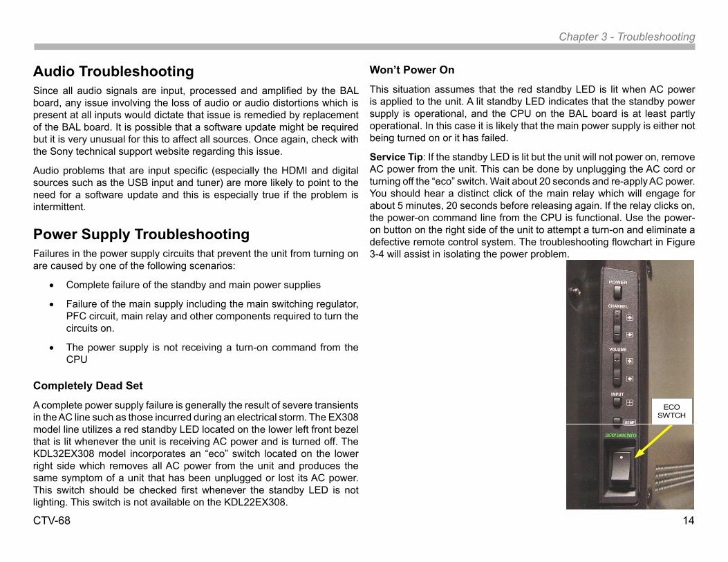
A complete power supply failure is generally the result of severe transients in the AC line such as those incurred during an electrical storm. The EX308 model line utilizes a red standby LED located on the lower left front bezel that is lit whenever the unit is receiving AC power and is turned off. The KDL32EX308 model incorporates an “eco” switch located on the lower right side which removes all AC power from the unit and produces the same symptom of a unit that has been unplugged or lost its AC power. This switch should be checked first whenever the standby LED is not lighting. This switch is not available on the KDL22EX308.
Won’t Power On
This situation assumes that the red standby LED is lit when AC power is applied to the unit. A lit standby LED indicates that the standby power supply is operational, and the CPU on the BAL board is at least partly operational. In this case it is likely that the main power supply is either not being turned on or it has failed.
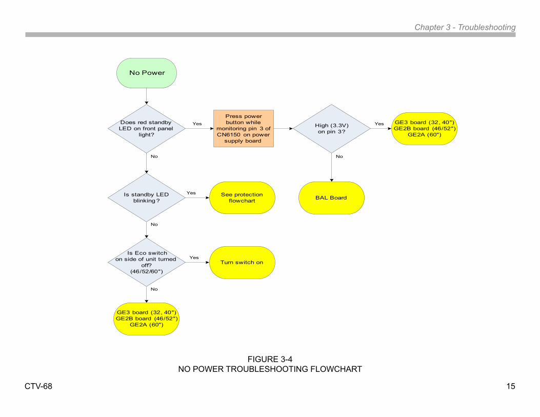
Service Tip: If the standby LED is lit but the unit will not power on, remove AC power from the unit. This can be done by unplugging the AC cord or turning off the “eco” switch. Wait about 20 seconds and re-apply AC power. You should hear a distinct click of the main relay which will engage for about 5 minutes, 20 seconds before releasing again. If the relay clicks on, the power-on command line from the CPU is functional. Use the power-on button on the right side of the unit to attempt a turn-on and eliminate a defective remote control system. The troubleshooting flowchart in Figure 3-4 will assist in isolating the power problem.
ECO SWTCH
Chapter 3 - Troubleshooting
CTV-68 15
No Power
Is standby LED blinking?
No
Yes GE3 board (32, 40")GE2B board (46/52")
GE2A (60")
No
See protection flowchart
Yes
Is Eco switchon side of unit turned
off?(46/52/60")
Does red standby LED on front panel
light?
Press power button while
monitoring pin 3 of CN6150 on power
supply board
High (3.3V)on pin 3?
Yes
No
BAL Board
YesTurn switch on
No
GE3 board (32, 40")GE2B board (46/52")
GE2A (60")
FIGURE 3-4NO POWER TROUBLESHOOTING FLOWCHART
Chapter 3 - Troubleshooting
CTV-68 16
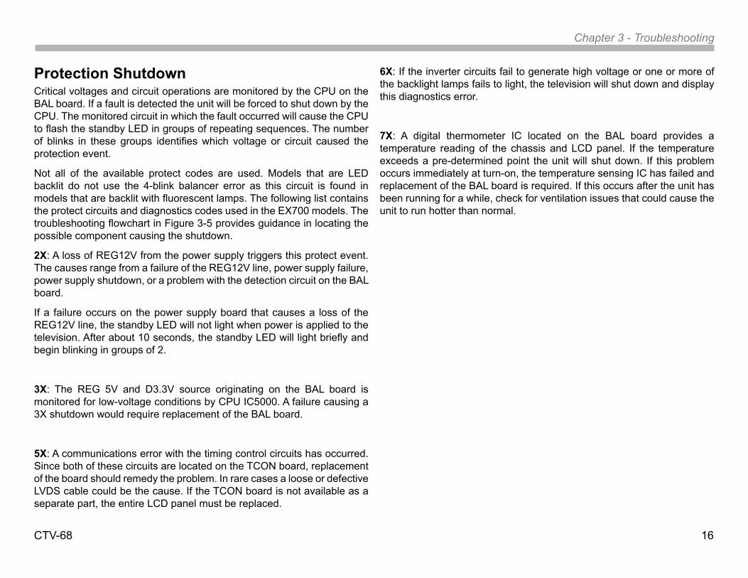
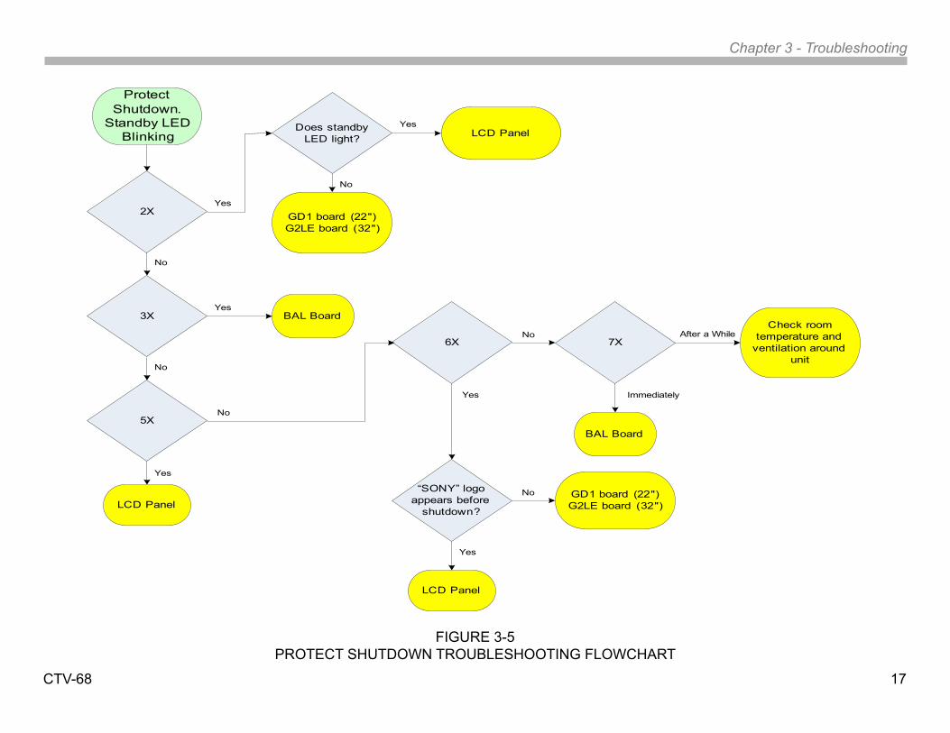
Protection ShutdownCritical voltages and circuit operations are monitored by the CPU on the BAL board. If a fault is detected the unit will be forced to shut down by the CPU. The monitored circuit in which the fault occurred will cause the CPU to flash the standby LED in groups of repeating sequences. The number of blinks in these groups identifies which voltage or circuit caused the protection event.
Not all of the available protect codes are used. Models that are LED backlit do not use the 4-blink balancer error as this circuit is found in models that are backlit with fluorescent lamps. The following list contains the protect circuits and diagnostics codes used in the EX700 models. The troubleshooting flowchart in Figure 3-5 provides guidance in locating the possible component causing the shutdown.
2X: A loss of REG12V from the power supply triggers this protect event. The causes range from a failure of the REG12V line, power supply failure, power supply shutdown, or a problem with the detection circuit on the BAL board.
If a failure occurs on the power supply board that causes a loss of the REG12V line, the standby LED will not light when power is applied to the television. After about 10 seconds, the standby LED will light briefly and begin blinking in groups of 2.
3X: The REG 5V and D3.3V source originating on the BAL board is monitored for low-voltage conditions by CPU IC5000. A failure causing a 3X shutdown would require replacement of the BAL board.
5X: A communications error with the timing control circuits has occurred. Since both of these circuits are located on the TCON board, replacement of the board should remedy the problem. In rare cases a loose or defective LVDS cable could be the cause. If the TCON board is not available as a separate part, the entire LCD panel must be replaced.
6X: If the inverter circuits fail to generate high voltage or one or more of the backlight lamps fails to light, the television will shut down and display this diagnostics error.
7X: A digital thermometer IC located on the BAL board provides a temperature reading of the chassis and LCD panel. If the temperature exceeds a pre-determined point the unit will shut down. If this problem occurs immediately at turn-on, the temperature sensing IC has failed and replacement of the BAL board is required. If this occurs after the unit has been running for a while, check for ventilation issues that could cause the unit to run hotter than normal.
Chapter 3 - Troubleshooting
CTV-68 17
FIGURE 3-5PROTECT SHUTDOWN TROUBLESHOOTING FLOWCHART
Protect Shutdown.
Standby LED Blinking
No
Yes
No
LCD Panel
Yes
2X
BAL Board3X
5X
Does standby LED light?
Yes
No
No
Yes
LCD Panel
6X
Yes
7XNo
Immediately
After a WhileCheck room
temperature and ventilation around
unit
GD1 board (22")G2LE board (32")
GD1 board (22")G2LE board (32")
BAL Board
“SONY” logo appears before
shutdown?
Yes
No
LCD Panel
Chapter 3 - Troubleshooting
CTV-68 18
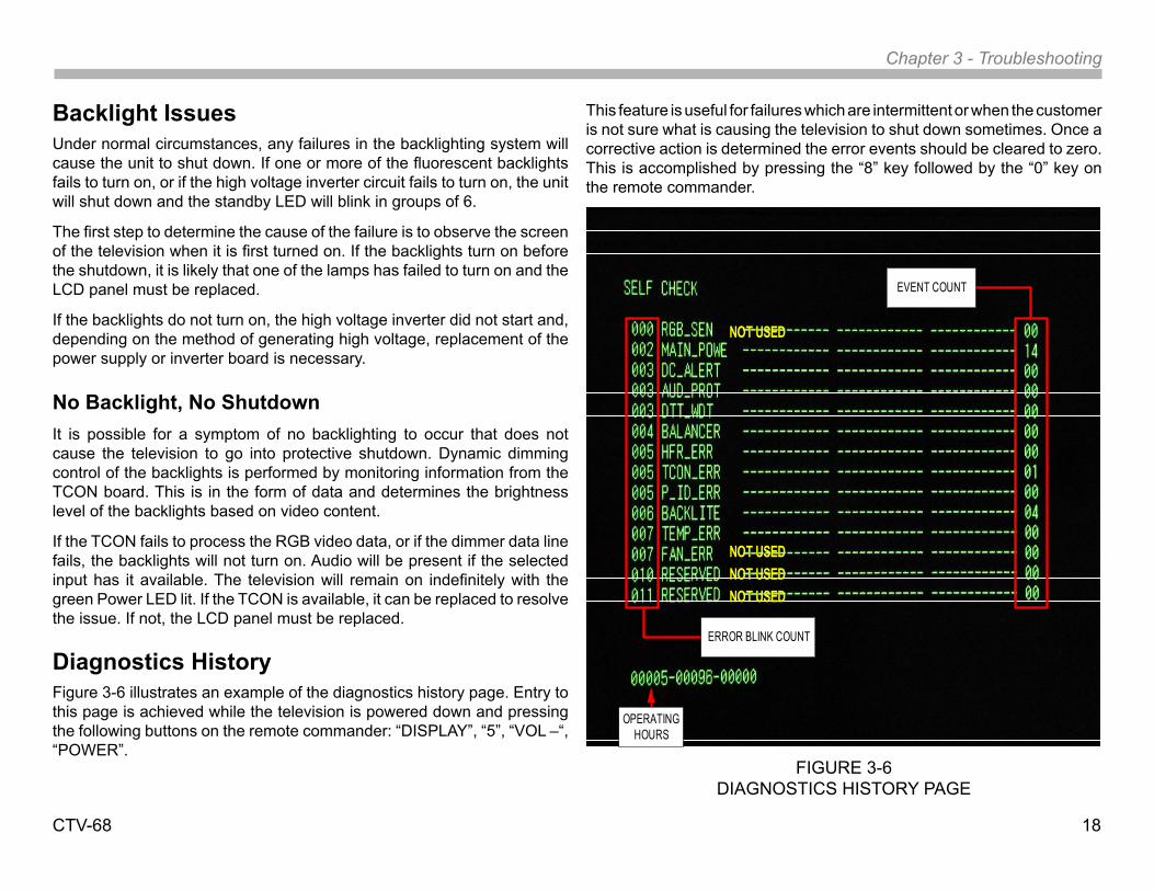
FIGURE 3-6DIAGNOSTICS HISTORY PAGE
Backlight IssuesUnder normal circumstances, any failures in the backlighting system will cause the unit to shut down. If one or more of the fluorescent backlights fails to turn on, or if the high voltage inverter circuit fails to turn on, the unit will shut down and the standby LED will blink in groups of 6.
The first step to determine the cause of the failure is to observe the screen of the television when it is first turned on. If the backlights turn on before the shutdown, it is likely that one of the lamps has failed to turn on and the LCD panel must be replaced.
If the backlights do not turn on, the high voltage inverter did not start and, depending on the method of generating high voltage, replacement of the power supply or inverter board is necessary.
No Backlight, No ShutdownIt is possible for a symptom of no backlighting to occur that does not cause the television to go into protective shutdown. Dynamic dimming control of the backlights is performed by monitoring information from the TCON board. This is in the form of data and determines the brightness level of the backlights based on video content.
If the TCON fails to process the RGB video data, or if the dimmer data line fails, the backlights will not turn on. Audio will be present if the selected input has it available. The television will remain on indefinitely with the green Power LED lit. If the TCON is available, it can be replaced to resolve the issue. If not, the LCD panel must be replaced.
Diagnostics HistoryFigure 3-6 illustrates an example of the diagnostics history page. Entry to this page is achieved while the television is powered down and pressing the following buttons on the remote commander: “DISPLAY”, “5”, “VOL –“, “POWER”.
This feature is useful for failures which are intermittent or when the customer is not sure what is causing the television to shut down sometimes. Once a corrective action is determined the error events should be cleared to zero. This is accomplished by pressing the “8” key followed by the “0” key on the remote commander.
ERROR BLINK COUNT
EVENT COUNT
OPERATING HOURS
NOT USED
NOT USEDNOT USEDNOT USED
Chapter 3 - Troubleshooting
CTV-68 19
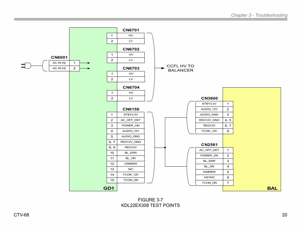
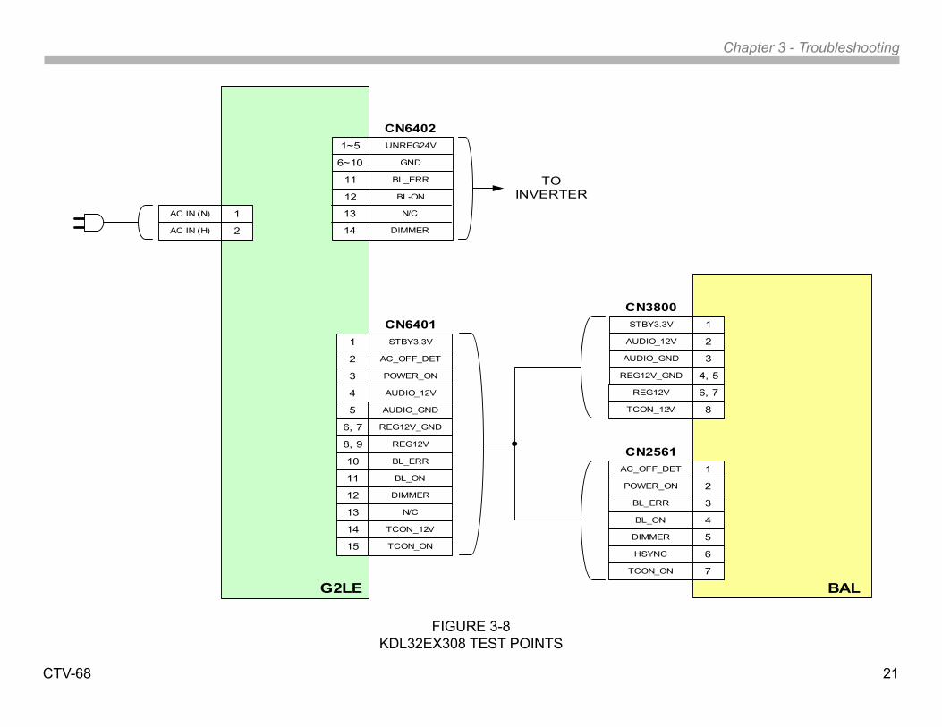
Test PointsThe drawing in Figure 3-7 contains the board-to-board connector and pin information for the KDL22EX308 to identify voltages, signal and control lines for troubleshooting purposes. Figure 3-8 illustrates the same information for the KDL32EX308. All critical voltages and control signals are easily accessed at the power supply board. Use this drawing in conjunction with the previously discussed troubleshooting techniques and flowcharts for testing operating voltages and control signals.
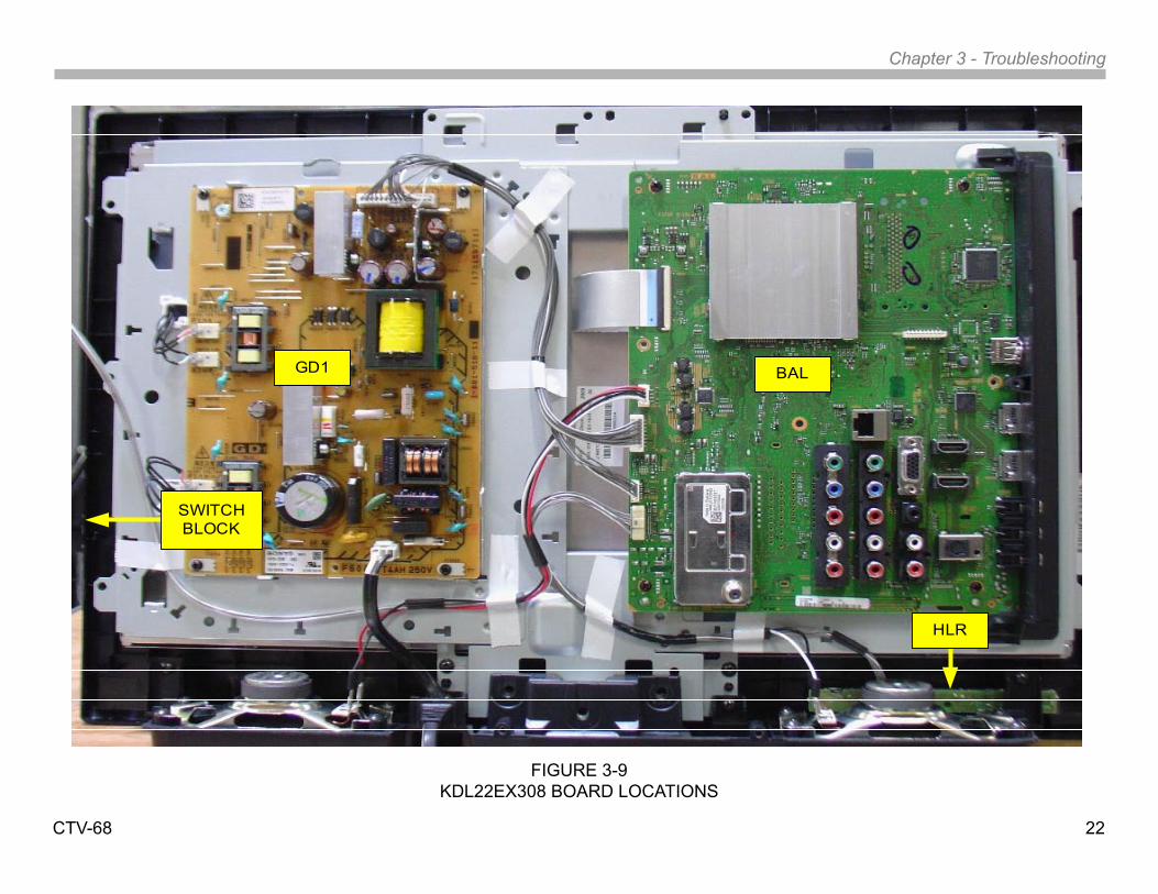
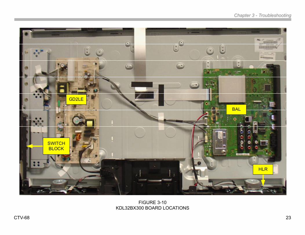
Circuit Board and Connector LocationsFigure 3-9 illustrates the rear of a KDL22EX308 with the cover removed. The location of the major circuit boards and connectors for voltage checks is provided. An illustration of the KDL32EX308 is shown in Figure 3-10
Chapter 3 - Troubleshooting
CTV-68 20
FIGURE 3-7KDL22EX308 TEST POINTS
HV1
STBY3.3V
AUDIO_12V
AC_OFF_DET
POWER_ON
1
2
3
4
AUDIO_GND
BL_ERR
REG12V_GND
REG12V
5
6, 7
8, 9
10
BL_ON
TCON_12V
DIMMER
N/C
11
12
13
14
TCON_ON15
CN6150STBY3.3V
REG12V_GND
AUDIO_12V
AUDIO_GND
1
2
3
4, 5
REG12V
TCON_12V
6, 7
8
AC_OFF_DET
BL_ON
POWER_ON
BL_ERR
1
2
3
4
DIMMER
HSYNC
TCON_ON
5
6
7
CN2561
CN3800
BALGD1
CN6701
CCFL HV TO BALANCER
2 LV
AC IN (N)
AC IN (H)
1
2
CN6001HV1
CN6702
2 LV
HV1
CN6703
2 LV
HV1
CN6704
2 LV
Chapter 3 - Troubleshooting
CTV-68 21
FIGURE 3-8KDL32EX308 TEST POINTS
UNREG24V
BL-ON
GND
BL_ERR
1~5
6~10
11
12
STBY3.3V
AUDIO_12V
AC_OFF_DET
POWER_ON
1
2
3
4
AUDIO_GND
BL_ERR
REG12V_GND
REG12V
5
6, 7
8, 9
10
BL_ON
TCON_12V
DIMMER
N/C
11
12
13
14
TCON_ON15
AC IN (N)
AC IN (H)
1
2
CN6401 STBY3.3V
REG12V_GND
AUDIO_12V
AUDIO_GND
1
2
3
4, 5
REG12V
TCON_12V
6, 7
8
AC_OFF_DET
BL_ON
POWER_ON
BL_ERR
1
2
3
4
DIMMER
HSYNC
TCON_ON
5
6
7
CN2561
CN3800
BALG2LE
N/C
DIMMER
13
14
CN6402
TO INVERTER
Chapter 3 - Troubleshooting
CTV-68 22
FIGURE 3-9KDL22EX308 BOARD LOCATIONS
GD1 BAL
HLR
SWITCH BLOCK
Chapter 3 - Troubleshooting
CTV-68 23
FIGURE 3-10KDL32BX300 BOARD LOCATIONS
GD2LE
BAL
HLR
SWITCH BLOCK
CTV-68 24
Chapter 4 – Appendix
TCON Troubleshooting
IntroductionBeginning in the fall of 2008, Sony announced the availability of limited TCON replacement boards to service LCD panels beginning with certain models going back to 2006. For many years technicians have been asking about the availability of these components. In the relatively small percentage of units that experienced a failure of the TCON board, replacement of the entire LCD panel was mandatory. This is not only costly from a warranty standpoint but it also makes it near impossible to justify an out-of-warranty repair since the replacement LCD panel can easily cost 2/3 or more of the price of the entire television.
The reason why TCON assemblies have not been available in the past was due to the large amount of correction data stored within NVM data points located on the board. Tolerance issues during the manufacture of the LCD panels required white balance, gamma, and uniformity corrections to compensate for these inherent production issues. There are other items for correct panel operation but the above mentioned items are the most critical.
Over the years, panel tolerances have improved dramatically and variances in uniformity have been reduced to the point where a TCON loaded with average data results in a satisfactory picture when installed as a replacement on a panel. Most Sony television models also have white balance data located on the video process board. Although the TCON is loaded with data to properly white balance the panel, the ability to adjust white balance from the B boards is present to compensate for shifts in white balancing due to panel aging and this mainly involves color balance shifting of the fluorescent backlight lamps which tend to shift towards the magenta spectrum as they age.
The main issue with previous LCD panel designs was the uniformity
adjustment data. Due to variances across the LCD panel it was impossible to achieve even white balance across the screen. For this reason, small zones across and down the LCD panel required individual white balance compensation. Without this correction the picture would have “blotches” of different color in sections of the screen. Better tolerances during manufacturing have reduced the reliance on this uniformity data and allows for the replacement of TCON boards with satisfactory results.
As mentioned in the beginning, not all LCD panels will have a TCON board available. This will mainly be determined by availability of components from the LCD panel vendor along with decisions by Sony based on sales quantity and failure history of the TCON assemblies. Most technicians have experienced the use of the LCD panel replacement manual. This manual was created to properly identify the type of LCD panel installed in a unit based on its serial number since some units changed to a different type of LCD panel during the manufacturing production. The plan is to use this document to also provide TCON information and whether one is available and, if available, which TCON is the proper replacement part for that particular panel.
LCD Panel BasicsLCD panels have steadily evolved over the last several years. New designs of the physical structure of the LCD crystals have greatly improved the contrast ratio and viewing angle. Quicker response times and increased refresh rates have helped to reduce the motion “smear” associated with LCD displays. Backlighting design has also aided in producing a picture with color temperatures to make the images as true as possible. With all these design improvements, one aspect of the LCD panel remains relatively the same: Processing of the video signal.
Chapter 4 - Appendix
CTV-68 25
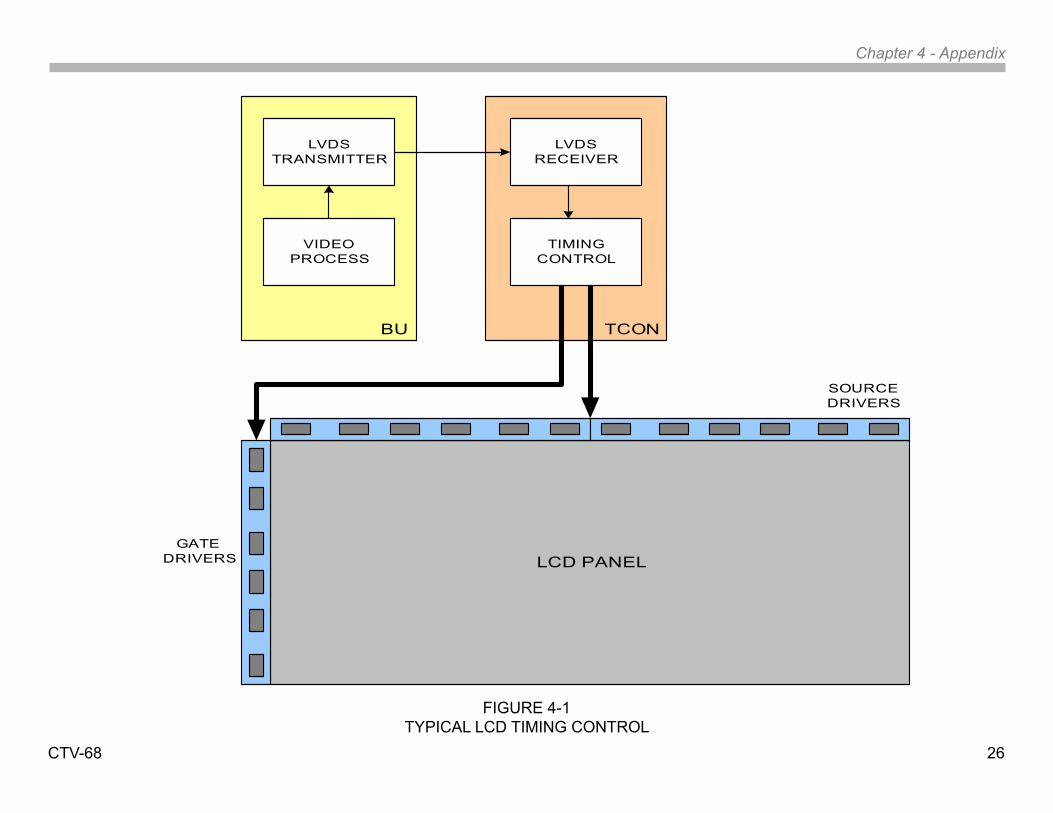
Figure 4-1 illustrates a typical LCD panel and the associated video processing circuits as found in the WAX3 chassis. The various formats and resolutions of video signals are processed on the BU1 board. All video signals exit the video processor in the native resolution of the LCD panel. In this design, the resolution is for a 1366 by 768 at 60HZ refresh rate panel. 48 horizontal lines are discarded to match up to the 720p resolution of the ATSC specifications so the video will exit as 720p.
The LCD panel used in this model processes 8-bit RGB video data. Before the video information can be sent to the TCON board it must be converted to a format that allows for practical and noise-free transmission. The large number of parallel lines to transmit the 8-bit RGB data would need to be sent on differential lines for noise reduction. This would require 48 lines just for the video. The TCON circuit also requires B+, ground connections, a communications bus, sync, and a clocking line transmitted differentially so we can see that up to 60 lines would be required for an 8-bit video signal and significantly more lines for a 10-bit processor. The practical way to transmit this information is to convert the parallel video data to a serial stream and this is accomplished by the Low-Voltage Differential Signaling (LVDS) transmitter.
The LVDS transmitter contains a circuit to serialize the parallel data. The parallel video information along with sync and clocking data are transmitted via twisted line pairs. Depending on the logic level, current is sent along one or the other of the twisted pair of wires. The receiving end of the wires is loaded with a resistor (usually around 100 to 120 ohms). The receiver detects the polarity of the voltage drop across the resistor to determine the logic level. The current level swings in the wire are about 3ma with a voltage differential of around 350mv. This allows for transmission of the video signal with minimal EMI.
The LVDS receiver on the TCON board converts the serialized data back to parallel. This data is processed by the timing control IC to allocate the RGB data into serial streams for processing by the LCD panel. The TCON transmits the pixel control data to the panel via flat, flexible circuit board cables which can number 2 or 4 depending on the bit rate and refresh timing of the panel. A 1366 X 768 panel requires about 180 lines to transmit control information and B+ from the TCON. This number of
control lines is not even close to the number of horizontal or vertical rows of pixels so the LCD panel must use this information to further expand the ability to turn on each individual crystal. The process will be explained in the gate and source driver paragraphs.
All of this is accomplished by the TCON board. The term “TCON” is short for Timing Control. Other LCD panel manufacturers may have a different name for this particular circuit but the term used by Sony will always be TCON.
Chapter 4 - Appendix
CTV-68 26
FIGURE 4-1TYPICAL LCD TIMING CONTROL
LCD PANELGATE
DRIVERS
SOURCE DRIVERS
LVDSTRANSMITTER
BU
LVDS RECEIVER
TCON
VIDEO PROCESS
TIMING CONTROL
Chapter 4 - Appendix
CTV-68 27
Gate DriversReferring to Figure 4-1, note the IC’s located along the side of the panel. These IC’s are mounted on a flexible cable(s) which are bonded to the LCD panel. Their function is to activate each row of pixels one at a time starting with the first line at the top. As each line is activated, the source drivers turn on the appropriate liquid crystals for the frame of video about to be displayed. This continues from top to bottom until the entire frame of video is displayed. The process is repeated for the next frame. This rate can vary from 60 times per second or be increased to 120 or 240 as found in the high-frame-rate panels.
Source DriversThese IC’s provide the control voltages to turn on each RGB segment of the vertical rows of pixels. In this example, the panel has a horizontal resolution of 1366 pixels. Each pixel is made up of a red, green and blue liquid crystal which means there are 4,098 columns to control.
The source drive IC’s contain shift registers along with buffer switches. Shift registers are used to convert serial data to parallel. By using this method, the TCON is able to transmit control information to each of the source drivers using serial data lines. If the TCON is transmitting 8-bit data to the panel, each data line is capable of controlling 256 lines exiting the source drivers. Understanding how the gate and source drivers work together makes it easier to observe a problem on the screen and determine if the failure is panel or TCON related.
Diagnosing a Failed TCONIn order for this concept to move forward successfully, it is important that the service industry be able to properly identify the symptoms of TCON issues to avoid unnecessary service calls and repair costs. Accurate analysis of TCON failures will reduce costs significantly (both in parts costs and time) when warranty repairs are involved and will reduce the number of COD repairs that are lost.
A good approach when determining a TCON failure is a good understanding of which symptoms ARE NOT caused by the TCON. Examples are as follows:
Video Process Failures: All video inputs received by the video process circuits are handled on a frame-by-frame basis. The video frames are converted and scaled to 8 or 10-bit RGB information. It is virtually impossible for the video process circuits to cause a problem on a specific area of the screen. Failures on this board usually appear as distortions, color level shifts, video level shifts, noise that involves the entire picture, or no picture at all. The TCON can generate symptoms that appear to be video process related but the video process circuits cannot produce the symptoms of a failed TCON circuit.
LVDS Cable Failures: Although problems with the LVDS cable or connectors can generate symptoms of TCON failures this usually tends to be intermittent and wiggling of the connectors will usually provoke a change in the symptom on the screen. LVDS cables and connectors have become rather robust over the past few years and most problems are caused by technicians who damage them and this is generally quite obvious upon close examination.
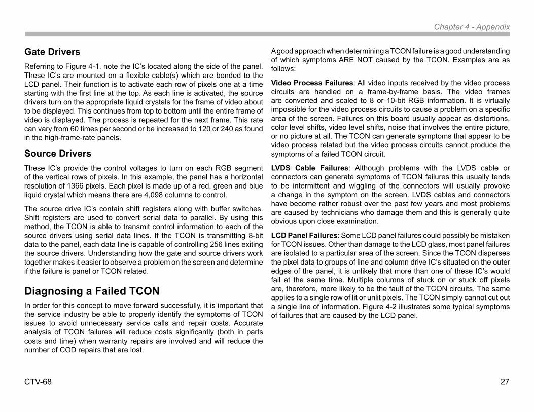
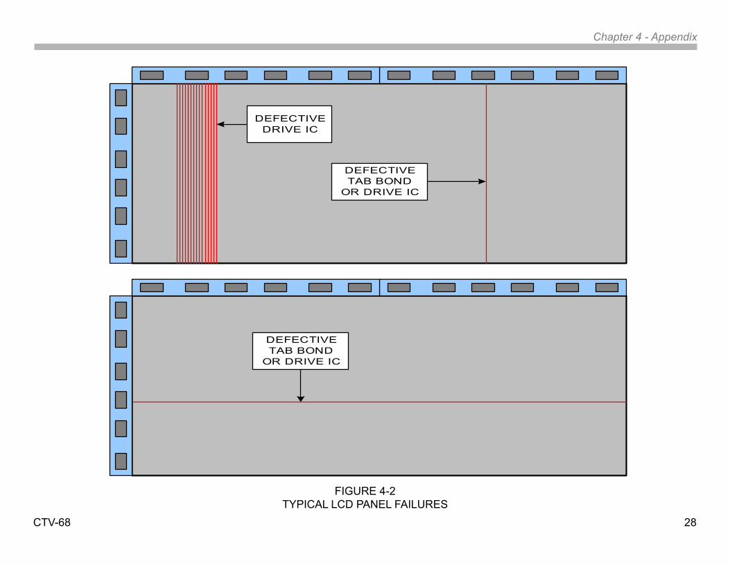
LCD Panel Failures: Some LCD panel failures could possibly be mistaken for TCON issues. Other than damage to the LCD glass, most panel failures are isolated to a particular area of the screen. Since the TCON disperses the pixel data to groups of line and column drive IC’s situated on the outer edges of the panel, it is unlikely that more than one of these IC’s would fail at the same time. Multiple columns of stuck on or stuck off pixels are, therefore, more likely to be the fault of the TCON circuits. The same applies to a single row of lit or unlit pixels. The TCON simply cannot cut out a single line of information. Figure 4-2 illustrates some typical symptoms of failures that are caused by the LCD panel.
Chapter 4 - Appendix
CTV-68 28
DEFECTIVE DRIVE IC
DEFECTIVE TAB BOND
OR DRIVE IC
DEFECTIVE TAB BOND
OR DRIVE IC
FIGURE 4-2TYPICAL LCD PANEL FAILURES
Chapter 4 - Appendix
CTV-68 29
Failures involving the LCD panel are usually displayed with the following symptoms:
• Physical damage such as cracks in the panel, a single pixel or group of pixels that always on or off, or random sections of the panel which are completely dark.
• Source driver failure. This symptom appears as a single vertical band around 1 to 2 inches (depending on the panel size) and can be black, white, or any other color. It can also contain video information with distortion. A single vertical line that is dark or colored. This may be due to a tab bonding failure from the IC to the panel but either cause requires the replacement of the panel.
• Gate driver failure. These IC’s operate in a “bucket brigade” fashion. As mentioned earlier, the gates drivers scan each horizontal line starting at the top. If any one of the gate drivers fails, all of the subsequent drivers below it will fail to operate properly. This symptom is usually indicated by normal video on the upper portion of the screen followed by distorted video from the point of the failed IC and downward.
• Any horizontal lines. The gate drivers are activated by a single source of timing information so any single horizontal line or groups or random horizontal lines are caused by an output failure from a gate driver or a loss of the tab bond to the panel.
TCON FailuresFailures in the timing control circuits of the TCON can produce symptoms of absolutely no video or generate lines and patterns that usually cover all or a substantial part of the screen. Determining if the TCON is the cause of a “no video” condition is a bit more difficult since there are no indications on the screen to analyze.
Troubleshooting a “DEAD” TCON
Many of the Sony television models over the last few years will detect a TCON that has completely failed. The communications data between the video process circuits and the TCON will cease to communicate if the TCON fails completely. This will cause the television to shut down and display a diagnostics code indicating a failure of the TCON. Not all chassis designs have this feature and it is not found on older models.
The typical scenario when this failure arises is for the technician to bring a video process board to the repair location. It is usually safe to assume that the problem lies on the TCON board if the replacement video board does not remedy the problem since it is highly unlikely that a replacement board with the same failure was received.
One trick to check most TCONS for functionality is to loosen the LVDS connector at the TCON (as shown In Figure 4-3) while the unit is turned on. Handle the LVDS connector with care and be certain to fully release the lock tabs. Gently rock the cable in and out of the connector while observing the screen for any response. Depending on the chassis, the symptoms of the screen may be gentle white flashes, intermittent colored lines, or a screen full of random patterns. The idea at this point is to provoke some kind of response on the screen. TCON boards that have failed will not usually generate any type of response on the screen.
Another helpful procedure is to rapidly heat and/or cool the TCON with hot air devices or circuit coolant and watch for patterns to appear on the screen.
Chapter 4 - Appendix
CTV-68 30
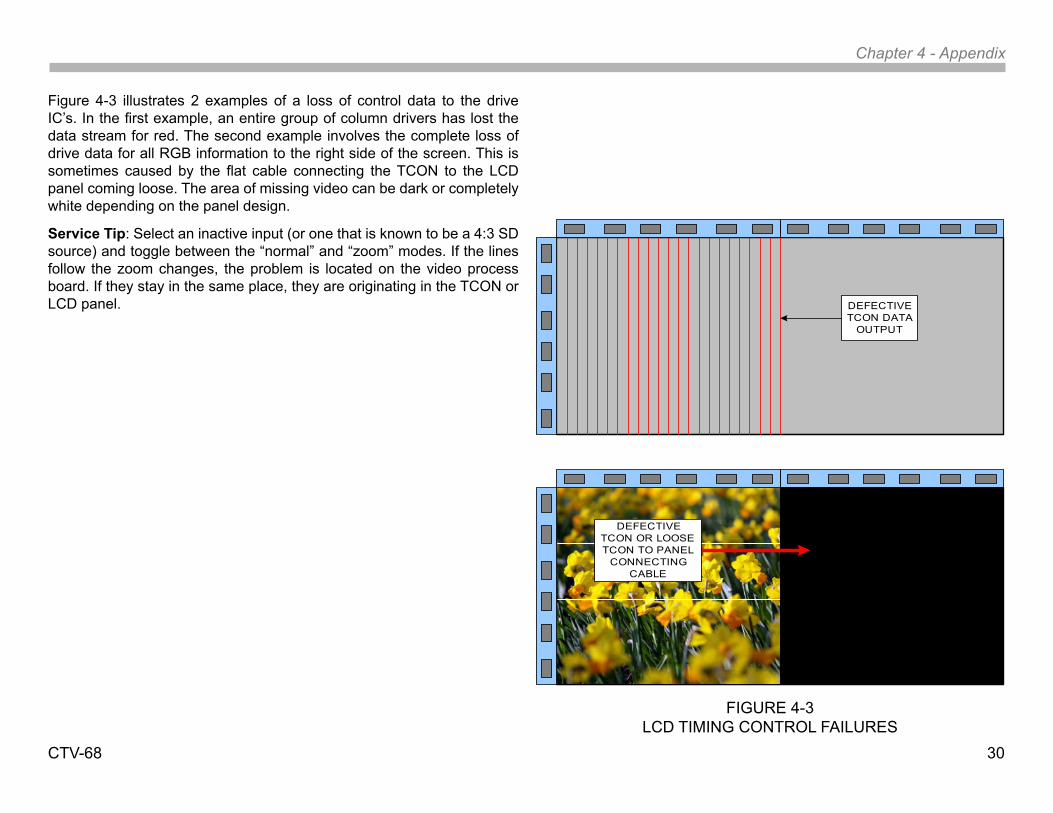
Figure 4-3 illustrates 2 examples of a loss of control data to the drive IC’s. In the first example, an entire group of column drivers has lost the data stream for red. The second example involves the complete loss of drive data for all RGB information to the right side of the screen. This is sometimes caused by the flat cable connecting the TCON to the LCD panel coming loose. The area of missing video can be dark or completely white depending on the panel design.
Service Tip: Select an inactive input (or one that is known to be a 4:3 SD source) and toggle between the “normal” and “zoom” modes. If the lines follow the zoom changes, the problem is located on the video process board. If they stay in the same place, they are originating in the TCON or LCD panel. DEFECTIVE
TCON DATA OUTPUT
DEFECTIVE TCON OR LOOSE TCON TO PANEL
CONNECTING CABLE
FIGURE 4-3LCD TIMING CONTROL FAILURES
Chapter 4 - Appendix
CTV-68 31
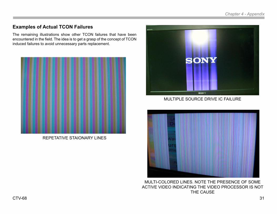
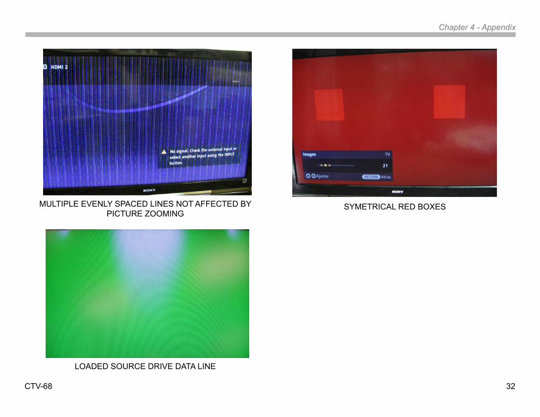
Examples of Actual TCON FailuresThe remaining illustrations show other TCON failures that have been encountered in the field. The idea is to get a grasp of the concept of TCON induced failures to avoid unnecessary parts replacement.
REPETATIVE STAIONARY LINES
MULTIPLE SOURCE DRIVE IC FAILURE
MULTI-COLORED LINES. NOTE THE PRESENCE OF SOME ACTIVE VIDEO INDICATING THE VIDEO PROCESSOR IS NOT
THE CAUSE
Chapter 4 - Appendix
CTV-68 32
MULTIPLE EVENLY SPACED LINES NOT AFFECTED BYPICTURE ZOOMING
LOADED SOURCE DRIVE DATA LINE
SYMETRICAL RED BOXES

Chapter 4 - Appendix
CTV-68 33
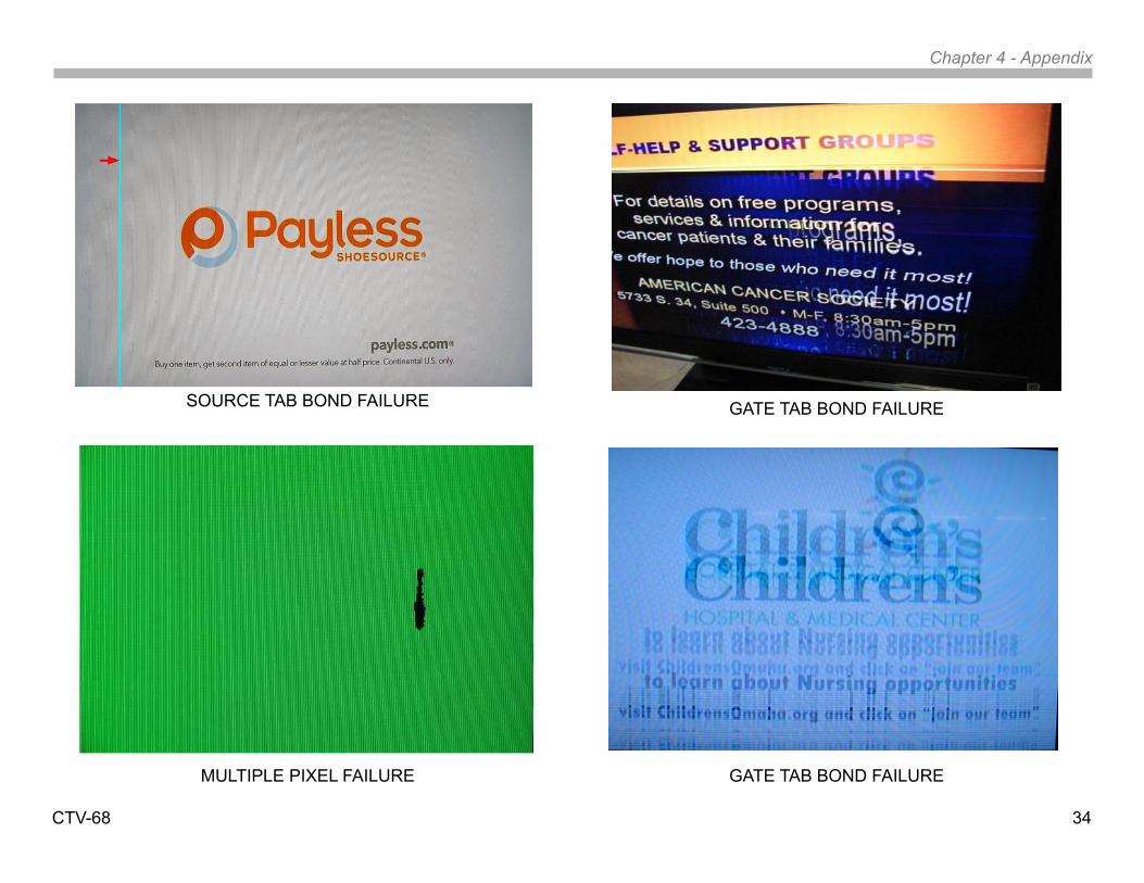
LCD Panel FailuresBelow are some photos of actual LCD panel failures. Note that most issues tend to be isolated to a certain area of the screen with the exception of failures of the source drivers. The source drivers can cause thin horizontal line issues and can also affect a large area of the screen.
SOURCE DRIVE IC FAILURE
GATE DRIVER FAILURE
GATE TAB BOND FAILURE
Chapter 4 - Appendix
CTV-68 34
SOURCE TAB BOND FAILURE
MULTIPLE PIXEL FAILURE
GATE TAB BOND FAILURE
GATE TAB BOND FAILURE
and i.Link are trademarks of Sony Electronics
2007 Sony Electornics, Inc.SEL Service Company
16530 Vill EsprilloNational Training Dept. MZ3215
San Diego, CA 92127Reproduction in whole or part without written permission is prohibited. All rights reserved
CTV68030810 3/10/10
![Sony Fe2 Chassis Kd28dx40u [ET]](https://static.fdocuments.net/doc/165x107/5535bcd64a7959361a8b46c3/sony-fe2-chassis-kd28dx40u-et.jpg)


![Sony Kv29sl40 Chassis Ba-4 [ET]](https://static.fdocuments.net/doc/165x107/54f7255e4a79591c638b470e/sony-kv29sl40-chassis-ba-4-et.jpg)


