
SONET Transmission Products S/DMS …npatrick/nortel-sdms-docs/N3RZH5WD.pdfSONET Transmission...
280
Planning Guide PG 99-14 *NTR710AA.0100* SONET Transmission Products S/DMS TransportNode OC-3/OC-12 NE—TBM Release 14.00 Planning Guide Document release: Issue 1.0 Date: Jan 2001
Transcript of SONET Transmission Products S/DMS …npatrick/nortel-sdms-docs/N3RZH5WD.pdfSONET Transmission...

Planning Guide PG 99-14
*NTR710AA.0100*
SONET Transmission Products
S/DMS TransportNodeOC-3/OC-12 NE—TBMRelease 14.00 Planning Guide
Document release: Issue 1.0Date: Jan 2001

2001 Nortel NetworksAll rights reserved
Printed in Canada
All information contained in this document is subject to change without notice. Northern Telecom reserves the right to make changes to equipment design or program components, as progress in engineering, manufacturing methods, or other circumstances may warrant.

i
ContentsIntroduction 1Supported Configurations for OC-3/OC-12 TBM Release 14.00 16
OC-3/OC-12 TBM Release 14.00 Summary of Features 17New and Enhanced Features 17Operation, Administration and Maintenance (OAM) Features 18
New and enhanced features 19Auto-In-Service 20
AINS functionality 21Facility Alarm Masking 24
DS1 Remote Test Unit 38Loopback configurations 39DS1 RTU capabilities 47User Interface 49DS1 RTU Logs 64Testing scenario 67In-Service Monitoring scenario 67
DS3 Enhancements 68OC-3 Tributary Synchronization Status Messaging 70OC-3 Tributary Protection Slot Provisioning Expansion 77Matched Nodes enhancements 78
ssquery tool 81Sonet/SDH Signal Mode Provisioning 86Ring-Link Parity Switch 91
Requirements 92In-Service NE Renumbering 92
Functional overview 94INM/Preside Application Platform and TL1 98
CLEI enhancements 105Software Upgrades to Release 14.00 106Upgrade Autoresume 108Healthcheck Enhancements 114Hardware Baseline File Delivery 114
Release 14.00 Planning Guide PG OC 99-14 Issue 1.0

ii Contents
Operation, Administration and Maintenance features 121Operation, Administration and Maintenance (OAM) Features 121
NE Name Expansion 123NE ID enhancements 127OPC name enhancements 131OPC Centralized User Administration (CUA) Enhancement 131Security Enhancements 131
Account activity information (nodal) 132Account activity information on SOC - wide (including both OPCs) basis 137Dormant Account Disabling 139Keyboard Autolock upon Inactivity 142Intrusion attempt handling 147New logs 151
TCP/IP Access Control 152User interface 154Engineering rules 155New and modified alarms 155New and modified logs 156
DCC Access Control 156User interface 158Clearing Access Violation Alarms on OPC or Network Element 159Engineering rules 159New and modified alarms 160New and modified logs 160
SelectNE Access Restriction Tool 161Functionality 161User interface 162Operational considerations 162
OPC Audit Trail 162OPC Security (SEC) Log contents 163Log access and protection 163New OPC Security Alarms 165Events to be logged 165New and modified logs and alarms 166Engineering rules 168
NE Audit Trail 169Secret NE Security (SECU) Logs 169Log valid/invalid login attempts and logouts 169Log user account activities 170Uploading the Security Logs to the OPC 170Reading SECU logs on the NE using the “Opensecret” command 171Engineering rules 172
NE Enhancements 172New and Enhanced NE Alarms 172PTSAMPLER CI tool enhancement 173
OPC Alarms Enhancements 174Alarms on an Inactive OPC 174Engineering rules 175Customized alarm on an NE 175
NE and OPC Area Address Provisioning 177
S/DMS TransportNode OC-3/OC-12 TBM PG OC 99-14 Issue 1.0

Contents iii
Reconfiguring the Data Communication Network (DCN) via Area Address manipulation 177
Introduction to Areas and Area Addresses 178OPC Area Address Provisioning dialog 181New Sync dialog and modified Transfer data to SLAT OPC dialog 183NE User Interface 185
Disabled Alarms Listing Tool 186User interface 186
Display of Configuration Mismatch Details 188User interface 188
Correction of Connection Mismatches in a Linear System 192Feature implementation 193
TL1 Enhancements 193TL1 Security 193TL1 Interface Router Services over TCP/IP 203TL1 Alarm Filtering 203Alarm reporting to the pointer network element TID 206Active alarm reporting to the newly activated OPC 207TL1 Support for AINS 209Extending the TL1 surveillance message set to include the new Release 14.00
commands 211Network element name and ID enhancements 212
Alarm listing enhancements (lasaldmp, lasdump) 213Solid-state OPC enhancements 213
Release 14.00 Baseline Requirements 215
OC-3/OC-12 TBM Base Features 217OC-3/OC-12 TBM Release 13.11/13.12 Features 217OC-3/OC-12 TBM Release 11.20 Features 221OC-3/OC-12 TBM Release 10.03 Features 224
Network Level Features 224New Features 225Enhancements 225TL1 Support 227Miscellaneous Improvements 227
OC-3/OC-12 TBM Release 9.01 Features 228Network Level Features 228New Features 228Enhancements 228Network Manager Release 4.01 Support 231TL1 Support 232OSI Support 234
OC-3/OC-12 TBM Release 8.10 Features 235Network Level Features 235New Features 236Enhancements 236Support for Network Manager Release 3.00 238TL1 Support 238
OC-3/OC-12 TBM Release 7.10 Features 240
Release 14.00 Planning Guide PG OC 99-14 Issue 1.0

iv Contents
Network Level Features 240OAM (Operation, Administration and Maintenance) 241
OC-3/OC-12 TBM Release 6.01 Features 243Network Level Features 243OAM (Operation, Administration and Maintenance) 244
OC-3/OC-12 TBM Release 5.01 Features 245Network Level Features 245OAM (Operation, Administration and Maintenance) Features 246
OC-3/OC-12 TBM Release 4.31 Features 247Network Level Features 247OAM (Operation, Administration and Maintenance) 247
OC-3/OC-12 TBM Features Introduced Prior to Release 4.31 248Operations Controller (OPC) 248External Synchronization Interface 248DS1/DS3 loopback 249DS3 parity correction 249Exerciser (DS1, DS3, OC-3/12) 249Performance Monitoring (DS3, OC-12) 250Configuration Ports 250Centralized System Surveillance/Maintenance 251Local Network Element Surveillance 254Software and Database Management 254
Engineering Documentation 257
Ordering Information 265Ordering Codes 265
Abbreviations 267
Appendix 1 Technical support and information 271
S/DMS TransportNode OC-3/OC-12 TBM PG OC 99-14 Issue 1.0

1 of 272
Introduction 1-This document describes the applications and functionality that are made possible through the OC-3/OC-12 TBM Release 14.00.
Network elements equipped with the OC-12 Virtual Tributary Bandwidth Management Optical Interface circuit pack (NT7E05) will be referred to as VTM based throughout this document. Network elements equipped with the Networking Interface circuit packs (NT7E01, NT7E02, NT7E33) will be referred to as NWK based throughout this document.
The key new features or enhancements offered by Release 14.00 are summarized below and listed in Table 1 starting on page 6.
• Auto-In-Service (AINS) allows customers to provision facilities and filter tributary side alarms which are raised against them when the facility is not immediately used by the end users. AINS enables tributary alarm masking when there is no valid signal applied to the input. As soon as a valid signal is applied, AINS goes into a user provisioned “start-up period”. When the “start-up period” expires, and a valid signal is still in place, AINS disables alarm masking, and the facility reverts back to its normal state. AINS then automatically turns itself off for that facility.
• DS1 Remote Test Unit allows a customer to perform remote DS1 testing and monitoring, thereby reducing operational costs when compared to the conventional method of performing digital testing by a local craftsperson with a testset.
• DS3 Enhancements allows networks to evolve to data oriented DS3 transmissions without impact on OA&M activities on the OC-3/OC-12 TBM system running Release 14.00 software. In addition, this feature eliminates the need for workarounds which were provided for C-bit parity signals, pre-Release 14.00.
Release 14.00 Planning Guide PG OC 99-14 Issue 1.0

2 of 272 Introduction
• OC-3 Tributary Synchronization Status Messaging (SSM) provides SSM on the OC-3 tributaries. This allows all subtending OC-3 NEs to use SSM when timing from OC-12 NEs. This feature provides the following benefit:
— reduced costs in subtending OC-3 equipment
• OC-3 Tributary Protection Slot Provisioning Expansion allows the customer to equip vacant OC-3 tributary protection slots with DS1, DS3, or STS-1 tributaries carrying traffic
• Matched Nodes enhancements (MNe) which include:
— two added user initiated protection requests at the Matched Nodes Service Selector: lockout of protection and manual switch
— additional information is provided in the OPC primary gateway service selector user interface dialog, the NE facility log and the “Inter-ring protection switch complete” alarm to show the switch trigger reasons
— service selector (SS) alarms are enhanced to include the STS channel number
• Sonet/SDH Signal Mode Provisioning allows selective programming of individual OC3 tributaries to drop SONET or SDH signal mode traffic. Shelf-wide (all OC3 tribs) SONET/SDH programming remains supported. The CI tool FWSBITCI is enhanced and an alarm is raised if incompatible hardware is inserted.
• Ring-Link Parity Switch away from the G1 optics occurs upon the detection of an STS-12 ring link parity error. If the OC-12 G2 optics are the cause of the ring link parity error, the automatic switch overrides the manual switch. The “STS-12 ring link parity error” alarm is raised as an “m,nsa” while the high speed protection switch is active. The “manual switch request” alarm and “protection switch complete” warning are also raised.
• In-Service NE Renumbering (ISNR) allows customers to change the NE ID associated with a shelf, without affecting traffic. Enhancements to ISNR include:
— delivered as part of the software load and the tool is invoked from the OPCUI screen
— a new OPC alarm “NE ID renumbering in progress” is raised
— configuration manager on OPC audits correct mismatch of NE IDs within a ring
— connection manager on OPC audits correct mismatch of NE IDs
• CLEI enhancements:
— the Equipment Shelf inventory screen on the network element user interface correctly displays CLEI, including cases where new CLEIs have been assigned for different versions of circuit packs with the same PEC.
S/DMS TransportNode OC-3/OC-12 TBM PG OC 99-14 Issue 1.0

Introduction 3 of 272
— incorrect CLEIs are automatically corrected after a software upgrade to OC-3/OC-12 TBM Release 14.00
— circuit packs added to a network element after a software upgrade to OC-3/OC-12 TBM Release 14.00 have their PEC and unique CLEI automatically retrieved and displayed on the Equipment Shelf Inventory screen on the network element user interface
— the new PECCLEI tool is used to add CLEI for circuit packs produced after OC-3/OC-12 TBM Release 14.00. The PECCLEI tool can also be used to delete, modify, or do a query on CLEI
• Software Upgrades to Release 14.00 offer the following enhancements:
— In-service upgrades from Release 11.20 and 13.11/13.12
— prechecks which verify the current software release running on the system and prevent the upgrade to start if the NEs in the SOC are not running the same release
— OPC software is able to sync the baseline tool alarms on both the primary and backup OPC
• Upgrades Autoresume reduces the need for manual intervention to resume the upgrade of a SOC. The following three items are added to the items list menu of the existing NUM tool in the OPCUI:
— “Cancel Pause”
— “Autoresume after”
— “Remove autoresume”
• Healthcheck enhancements. The following are the new Healthcheck enhancements introduced in Rel 14.00 (from Rel 13.12):
— Check NE Release: this check ensures that all NEs in the same SOC are running the same release. If the release in any of the NEs cannot be determined, or if it differs from that defined on the OPC, the status of the check is RED
— The check “Save to Tape” has been renamed to “Save OPC Data”, also, this check will not run if a Backup OPC is present
— Exerciser: this check is now included automatically when Healthcheck is run
— Performance: the customer should see improvements in the speed of the tool in this release
— A new classification for the active alarms in the system has been introduced in Release 14.00. The new GREEN (Non-Upgrade affecting) classification has been introduced in this release
— Upgrade Alarm Filter: the status of various tributary facility alarms in the “Upgrade Alarms” check has been changed to GREEN. Before Release 14.00, these alarms had a YELLOW status
Release 14.00 Planning Guide PG OC 99-14 Issue 1.0

4 of 272 Introduction
• Hardware Baseline File Delivery allows a user to create or modify the Customized (modified) Baseline File via Integrated Network Manager (INM) or Preside Application Platform prior to the system software upgrade. The user can distribute the Customized (modified) Baseline File from INM or Preside Application Platform to all destination OPCs along with the product release software, therefore eliminating the need to sequentially login to each destination OPC prior to upgrading the system.
• NE Name Expansion and ID enhancements provides the following:
— enhances the network element name from the current 13 character ASCII string to a 20 character string. In addition, the following tools and commands are enhanced to support an NE name as well as an NEid: selectne, nename, neldump, and socdump.
— extends the NE ID numeric value in the range 1 to 65534
— allows the network identifier (ID) and system ID for the network element to appear on the network element user interface with the network element ID. The network ID and system ID are no longer hardcoded to 1 and can be modified. Each ID can have a numeric value between 1 and 65534
• OPC Name Enhancement:
— extended OPC name to 9 characters
• OPC Centralized User Administration (CUA) enhancement includes:
— new user group ‘tech’
• Security Enhancements include:
— upon login to the OPC and NE, account activity information for the user on that node are displayed
— account activity information from all nodes in the span of control are summarized and displayed through the Centralized User Administration tool. The administrator is facilitated to view this information from the CUA
— user accounts are disabled if the account is not used for a preset number of days. (By default, this feature is disabled)
— keyboard is automatically locked out if there has been no input for a specified period of time (i.e. NE and OPC are locked out)
• TCP/IP Access Control feature allows for better control of user access to the TCP/IP network. This feature prevents unauthorized access to a TCP/IP network from the Operations Controller (OPC). Access to the TCP/IP network is limited to users with authorized access to selected IP addresses.
• Data Communication Channel (DCC) access control feature allows for better control of user access to the DCC network. This feature prevents unauthorized access to a DCC network from the Operations Controller
S/DMS TransportNode OC-3/OC-12 TBM PG OC 99-14 Issue 1.0

Introduction 5 of 272
(OPC). Access to the DCC network is limited to users with authorized access to selected network nodes.
• SelectNE Access Restriction Tool includes:
— enable/disable SelectNE through password protected CI
— disable SelectNE access on a per node level
— disable outward SelectNE sessions
— enable/disable status to survive NE restarts and powerdowns
— SelectNE disables inward direction
• OPC Audit Trail provides the capability to investigate authorized or unauthorized OPC activities after they have occurred. The OPC Audit Trail includes:
— a restricted version of the Event Browser
— generation of OPC Security (SEC) logs
— new OPC security alarms
• NE Audit Trail provides the capability to investigate authorized or unauthorized NE activities after they have occurred. The NE Audit Trail includes:
— a new logutil sub-command
— generation of NE Security (SEC) logs
• NE Enhancements include:
— new DS1/DS3/STS1 protection equipment out of service alarm
— new PM threshold capping active alarm
— PTSAMPLER CI tool enhanced to display the path trace values from the hardware
• OPC Alarm Enhancements include:
— alarms on an inactive OPC
— customized alarms on an NE
• NE and OPC Area Address Provisioning includes:
— removal of the default 49+0000 area address
— support for centralized area address provisioning on the OPC
— support for NE login across level 1 areas
• Disabled Alarms Listing Tool provides a new CI tool DISALCI to enlist all the disabled alarms on an NE.
• Display of Configuration Mismatch Details provides the user the option to view any OPC and NE mismatches prior to deciding on corrective action.
Release 14.00 Planning Guide PG OC 99-14 Issue 1.0

6 of 272 Introduction
• Connection Audit Enhancement in a Linear System provides the following capabilities:
— allows customers to conveniently detect mismatches in NE A and NE Z values in connections provisioned on linear systems and correct them
• TL1 Enhancements include:
— Message Based Security for TL1 interfaces
— AccuRing Architecture
— alarm reporting to the pointer network element TID
— active alarm reporting to the newly activated OPC
— TL1 support for AINS
• Alarms listings enhancements: The “lasaldmp” command copies a listing of alarms or current alarms into a log file. The “lasdump” command copies a listing of logs into a log file.
• Solid-state OPC enhancements: In previous OC-3/OC-12 TBM software releases, the user interfaces used the term “tape” for the digital data storage (DDS) tapes used to perform backup and restore operations on the operations controller (OPC). In OC-3/OC-12 TBM Release 14.00, the user interfaces refer to DDS tapes and solid-state OPC cartridges as “removable media”.
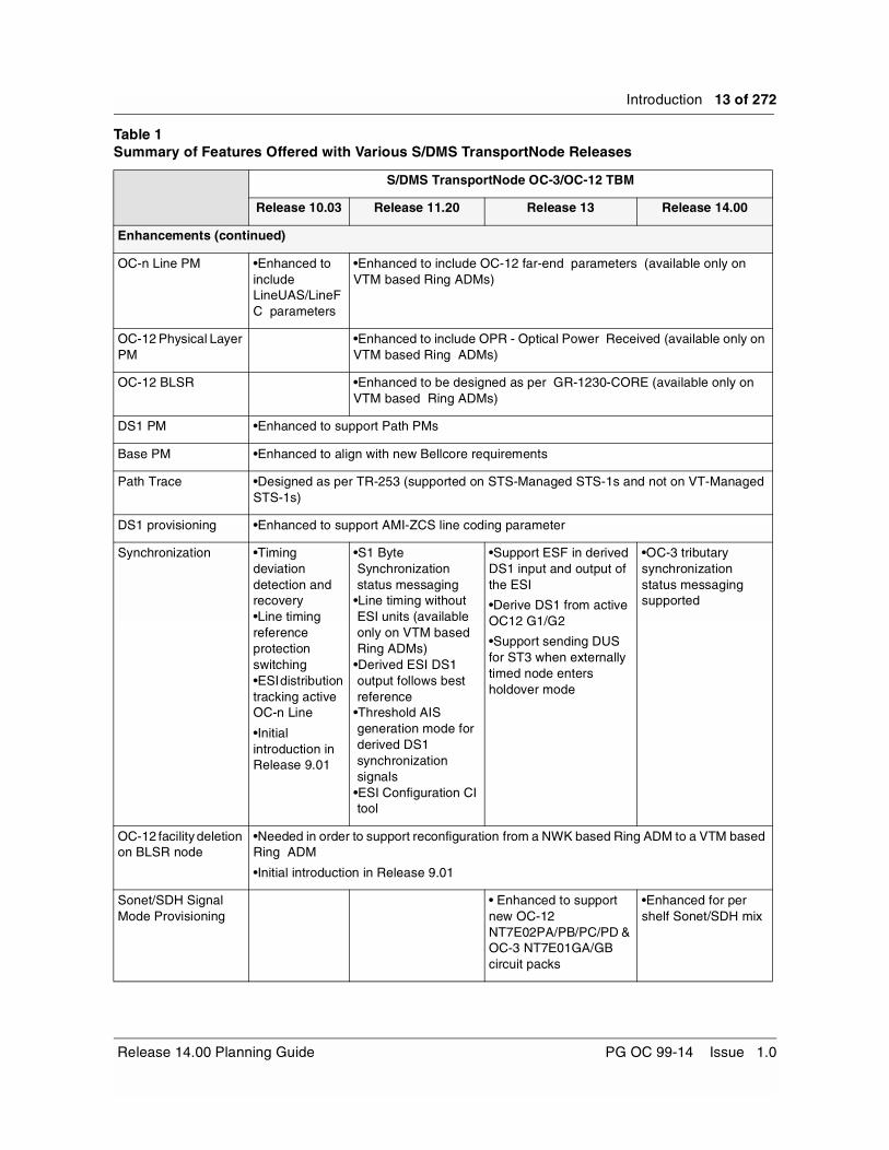
Table 1 Summary of Features Offered with Various S/DMS TransportNode Releases
S/DMS TransportNode OC-3/OC-12 TBM
Release 10.03 Release 11.20 Release 13 Release 14.00
Network Level Features
Matched Nodes on VTM BLSR
•Initial introduction
VT1.5 Time Slot Assignment (TSA) on OC-12 BLSR
•Initial introduction (available only on VTM based Ring ADMs)
STS-3c Capability in VTM Ring Systems
•Initial introduction
Matched Nodes on NWK BLSR
•Initial introduction
Data Communication Interoperability
•Initial introduction
S/DMS TransportNode OC-3 Express/ TBM Interworking
•Initial introduction
S/DMS TransportNode OC-3/OC-12 TBM PG OC 99-14 Issue 1.0

Introduction 7 of 272
New Features
Auto In-Service Facilities
•Initial introduction
DS1 Remote Test Unit
•Initial introduction
OC-3 Tributary protection slot provisioning expansion
•Partially introduced in Release 13.11/13.12.
•Fully supported
In-service NE Renumbering
•Partially introduced in Release 13.11/13.12
•Initial introduction
Hardware Baseline File Delivery
•Initial introduction
Select NE Access Restriction Tool
•Initial introduction
NE Audit Trail •Initial introduction
OPC Audit Trail •Initial introduction
NE and OPC Area Address Provisioning
•Initial introduction
Table 1 Summary of Features Offered with Various S/DMS TransportNode Releases
S/DMS TransportNode OC-3/OC-12 TBM
Release 10.03 Release 11.20 Release 13 Release 14.00
Release 14.00 Planning Guide PG OC 99-14 Issue 1.0

8 of 272 Introduction
New Features (continued)
Disabled Alarms Listing tool
•Initial introduction
Ring-Link Parity Switch
•Initial introduction
TCP/IP Access Control
•Initial introduction
DCC Access Control •Initial introduction
Matched Nodes In-service edit
•Initial introduction
STS and VT In-Service Rollover
•Initial introduction
TARP Transparency on the NE and TARP support on the OPC
•Initial introduction
Root-Like User •Initial introduction
OPC Support for OC-3 Express
•Initial introduction
OPC Alarms •Initial introduction •Enhanced to include alarms on an inactive OPC
OPC Linear Protection Switching Control
•Initial introduction
Log Archive (NE logs in Event Browser)
•Initial introduction
Hardware Baseline Tool
•Initial introduction
VT1.5 Path PMs •Initial introduction
STS-1 Path PM •Initial introduction (available only on VTM based Ring ADMs)
Provisionable Wait-to-Restore on OC-12 BLSR
•Initial introduction(available only on VTM based Ring ADMs)
OC-12 Circuit Pack Diagnostics from the User Interface
•Initial introduction(available only on VTM based Ring ADMs)
Table 1 Summary of Features Offered with Various S/DMS TransportNode Releases
S/DMS TransportNode OC-3/OC-12 TBM
Release 10.03 Release 11.20 Release 13 Release 14.00
S/DMS TransportNode OC-3/OC-12 TBM PG OC 99-14 Issue 1.0

Introduction 9 of 272
New Features (continued)
Recover Unidirectional Failure (RUF) in NWK Systems
•Initial introduction(available only on NWK based network elements)
•Feature disabled by default
NWK Ring to VTM Ring Reconfiguration
•Initial introduction
Adding/Deleting a VTM Ring Network Element
•Initial introduction
STS to VT Connection Conversion
•Initial introduction
STS-3c Connection Provisioning Conversion
•Initial introduction
OC-12 Virtual Tributary Bandwidth Management Optical Interface circuit pack (NT7E05)
•Initial introduction
Firmware Download to OC-12 VTM circuit pack and MIC
•Initial introduction
TCP/IP over X.25 •Initial introduction
BLSR Lockout commands
•Lockout of protection and Lockout of working commands
Enhancements
DS3 enhancements •Enhanced to support C-bit parity
Matched Nodes enhancements
•Enhanced to provide lockout of protection and manual switch
Table 1 Summary of Features Offered with Various S/DMS TransportNode Releases
S/DMS TransportNode OC-3/OC-12 TBM
Release 10.03 Release 11.20 Release 13 Release 14.00
Release 14.00 Planning Guide PG OC 99-14 Issue 1.0

10 of 272 Introduction
Enhancements (continued)
NE Name and ID expansion
•NE ID range increased from 4 to 5 digits
•NE name enhanced to a 20-character string
•NE ID range expanded from 1-32767 to 1-65534
•NE network ID and system ID no longer hardcoded to 1, and can be modified to be up to 65534
OPC name enhancement
•OPC name expanded to 9 characters
Firmware Download •Enhanced to provideManagement By Release
Software Upgrades •Enhanced to provideManagement By Release
•Enhanced to provide the Pause with Autoresume functionality
•Enhanced Healthchecks
Table 1 Summary of Features Offered with Various S/DMS TransportNode Releases
S/DMS TransportNode OC-3/OC-12 TBM
Release 10.03 Release 11.20 Release 13 Release 14.00
S/DMS TransportNode OC-3/OC-12 TBM PG OC 99-14 Issue 1.0

Introduction 11 of 272
Enhancements (continued)
CLEIs enhancements • circuit packs added to a network element after a software upgrade to OC-3/OC-12 TBM Release 14.00 have their PEC and unique CLEI automatically retrieved and displayed on the Equipment Shelf Inventory screen on the network element user interface
• the PECCLEI tool is used to add CLEI for circuit packs produced after OC-3/OC-12 TBM Release 14.00. The tool can also be used to delete, modify, or do a query on CLEI
Solid State OPC enhancements
•DDS tapes and OPC cartridges referred to as removable media
Performance Monitoring
•Enhanced to provide1-minute PM threshold & PM TCA Capping
•new “PM threshold capping active” alarm
Table 1 Summary of Features Offered with Various S/DMS TransportNode Releases
S/DMS TransportNode OC-3/OC-12 TBM
Release 10.03 Release 11.20 Release 13 Release 14.00
Release 14.00 Planning Guide PG OC 99-14 Issue 1.0

12 of 272 Introduction
Enhancements (continued)
AD-2000 •Year 2000 and beyond handling compliancy
OC-3 Express/OC-192 Remote Login
•Remote Login enhanced to allow login to OC-3 Express/OC-192
Telemetry •Enhanced to provide parallel telemetry momentary output closure & TBOS Test CI
Duplicate NE name and numeric identifier Alarms
•Alarm raised when duplicate NE numeric identifier detected in network•Alarm raised when duplicate NE name detected in network
OPC PM Collection •Enhanced to provide 15-minute OPC PM collection
OPC Centralized User Administration (CUA)
•Password complexity enhancement
•New user group ‘tech’
OPC/NE Security •Enhanced to provide physical port intrusion attempt handling, configurable password change notification period & 8 character password
•Enhanced to provide NE and OPC accountability information upon login, accountability information displayed through CNA, disabling of inactive accounts, NE and OPC keyboard lockout
•SelectNE enable/disable CI tool
NE Login Manager •Enhanced to provide support for OC-3 Express and OC-192
OPC Configuration Manager
•Enhanced to provide OC-12 to OC-192 connection support
•Enhanced to display configuration mismatch details
OPC Event Browser •Enhanced to provide more options/criteria for filtering
Enhancements to the cooling system
•Enhanced to provide the necessary cooling to support the new OC-12 VTM circuit pack (NT7E05)
Table 1 Summary of Features Offered with Various S/DMS TransportNode Releases
S/DMS TransportNode OC-3/OC-12 TBM
Release 10.03 Release 11.20 Release 13 Release 14.00
S/DMS TransportNode OC-3/OC-12 TBM PG OC 99-14 Issue 1.0
Introduction 13 of 272
Enhancements (continued)
OC-n Line PM •Enhanced to include LineUAS/LineFC parameters
•Enhanced to include OC-12 far-end parameters (available only on VTM based Ring ADMs)
OC-12 Physical Layer PM
•Enhanced to include OPR - Optical Power Received (available only on VTM based Ring ADMs)
OC-12 BLSR •Enhanced to be designed as per GR-1230-CORE (available only on VTM based Ring ADMs)
DS1 PM •Enhanced to support Path PMs
Base PM •Enhanced to align with new Bellcore requirements
Path Trace •Designed as per TR-253 (supported on STS-Managed STS-1s and not on VT-Managed STS-1s)
DS1 provisioning •Enhanced to support AMI-ZCS line coding parameter
Synchronization •Timing deviation detection and recovery•Line timing reference protection switching•ESI distribution tracking active OC-n Line
•Initial introduction in Release 9.01
•S1 Byte Synchronization status messaging
•Line timing without ESI units (available only on VTM based Ring ADMs)
•Derived ESI DS1 output follows best reference
•Threshold AIS generation mode for derived DS1 synchronization signals
•ESI Configuration CI tool
•Support ESF in derived DS1 input and output of the ESI
•Derive DS1 from active OC12 G1/G2
•Support sending DUS for ST3 when externally timed node enters holdover mode
•OC-3 tributary synchronization status messaging supported
OC-12 facility deletion on BLSR node
•Needed in order to support reconfiguration from a NWK based Ring ADM to a VTM based Ring ADM
•Initial introduction in Release 9.01
Sonet/SDH Signal Mode Provisioning
• Enhanced to support new OC-12 NT7E02PA/PB/PC/PD & OC-3 NT7E01GA/GB circuit packs
•Enhanced for per shelf Sonet/SDH mix
Table 1 Summary of Features Offered with Various S/DMS TransportNode Releases
S/DMS TransportNode OC-3/OC-12 TBM
Release 10.03 Release 11.20 Release 13 Release 14.00
Release 14.00 Planning Guide PG OC 99-14 Issue 1.0
14 of 272 Introduction
Enhancements (continued)
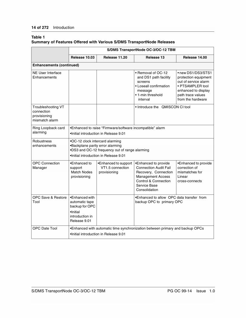
NE User Interface Enhancements
• Removal of OC-12 and DS1 path facility screens
• Loseall confirmation message
• 1-min threshold interval
• new DS1/DS3/STS1 protection equipment out of service alarm• PTSAMPLER tool enhanced to display path trace values from the hardware
Troubleshooting VT connection provisioning mismatch alarm
• Introduce the QMISCON CI tool
Ring Loopback card alarming
•Enhanced to raise “Firmware/software incompatible” alarm
•Initial introduction in Release 9.01
Robustness enhancements
•OC-12 clock intercard alarming•Backplane parity error alarming•DS3 and OC-12 frequency out of range alarming
•Initial introduction in Release 9.01
OPC Connection Manager
•Enhanced to support Match Nodes provisioning
•Enhanced to support VT1.5 connection provisioning
•Enhanced to provide Connection Audit Fail Recovery, Connection Management Access Control & Connection Service Base Consolidation
•Enhanced to provide correction of mismatches for Linear cross-connects
OPC Save & Restore Tool
•Enhanced with automatic tape backup for OPC
•Initial introduction in Release 9.01
•Enhanced to allow OPC data transfer from backup OPC to primary OPC
OPC Date Tool •Enhanced with automatic time synchronization between primary and backup OPCs
•Initial introduction in Release 9.01
Table 1 Summary of Features Offered with Various S/DMS TransportNode Releases
S/DMS TransportNode OC-3/OC-12 TBM
Release 10.03 Release 11.20 Release 13 Release 14.00
S/DMS TransportNode OC-3/OC-12 TBM PG OC 99-14 Issue 1.0

Introduction 15 of 272
TL1 Support (Columns indicate the TL1 enhancements provided with each release)
Surveillance Interface(NMA)
•Addition of new Matched Nodes and S/DMS TransportNode OC-3 Express/TBM First Alert autonomous alarm reporting
•Threshold crossing alerts and alarms for all new PM
parameters introduced by this release
•Extending the autonomous and non-autonomous messages to report
the new alarms introduced by this release•Modifications to the Synchronization
Switch commands OPR-SYNCNSW
and RLS-SYNCNSW to support 4 timing references
•15-minute PM Reporting•Support for VT1.5 and STS-1 facilities•Extending the autonomous and non-autonomous messages to report the new alarms introduced by this release•Exerciser request•Parallel telemetry momentary output contact closure•Provisionable PM Mode•TL1 interface using 7 layers OSI•Remote Software Delivery via FTAM
•TL1 support for AINS
Provisioning Interface(OPS)
•OC-3 tributary facility provisioning•Equipment provisioning•STS-3c cross connect provisioning
•Cross connect provisioning on BLSR
Miscellaneous Improvements
•TL1 over TCP/IP •TL1 over TCP/IP enhancements•TL1 Router for OC-3 Express•TL1 Interface Router Services and TL1 Interfaces Merge•Provisionable assignment of East and West for the TL1 AID to OC-12 G1 and G2
•TL1 security enhancements and creation of TL1 user group in CUA•TL1 Interface Router Services over TCP/IP•TL1 Alarm Filtering•Alarm reporting to the pointer network element TID•Active alarm reporting to the newly activated OPC•TL1 Interoperating Enhancements
Table 1 Summary of Features Offered with Various S/DMS TransportNode Releases
S/DMS TransportNode OC-3/OC-12 TBM
Release 10.03 Release 11.20 Release 13 Release 14.00
Release 14.00 Planning Guide PG OC 99-14 Issue 1.0
16 of 272 Introduction
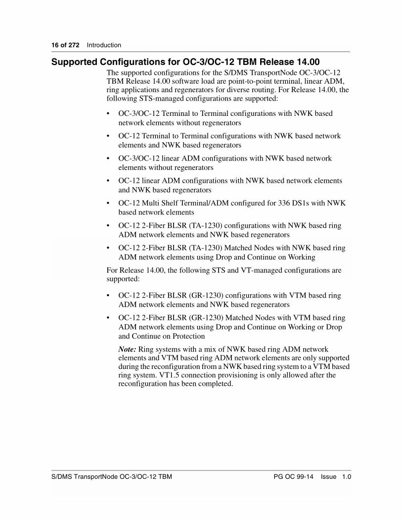
Supported Configurations for OC-3/OC-12 TBM Release 14.00The supported configurations for the S/DMS TransportNode OC-3/OC-12 TBM Release 14.00 software load are point-to-point terminal, linear ADM, ring applications and regenerators for diverse routing. For Release 14.00, the following STS-managed configurations are supported:
• OC-3/OC-12 Terminal to Terminal configurations with NWK based network elements without regenerators
• OC-12 Terminal to Terminal configurations with NWK based network elements and NWK based regenerators
• OC-3/OC-12 linear ADM configurations with NWK based network elements without regenerators
• OC-12 linear ADM configurations with NWK based network elements and NWK based regenerators
• OC-12 Multi Shelf Terminal/ADM configured for 336 DS1s with NWK based network elements
• OC-12 2-Fiber BLSR (TA-1230) configurations with NWK based ring ADM network elements and NWK based regenerators
• OC-12 2-Fiber BLSR (TA-1230) Matched Nodes with NWK based ring ADM network elements using Drop and Continue on Working
For Release 14.00, the following STS and VT-managed configurations are supported:
• OC-12 2-Fiber BLSR (GR-1230) configurations with VTM based ring ADM network elements and NWK based regenerators
• OC-12 2-Fiber BLSR (GR-1230) Matched Nodes with VTM based ring ADM network elements using Drop and Continue on Working or Drop and Continue on Protection
Note: Ring systems with a mix of NWK based ring ADM network elements and VTM based ring ADM network elements are only supported during the reconfiguration from a NWK based ring system to a VTM based ring system. VT1.5 connection provisioning is only allowed after the reconfiguration has been completed.
S/DMS TransportNode OC-3/OC-12 TBM PG OC 99-14 Issue 1.0

17 of 272
OC-3/OC-12 TBM Release 14.00 Summary of Features 2-
The OC-3/OC-12 TBM Release 14.00 software load provides the following new features:
New and Enhanced FeaturesTable 2 lists the new and enhanced features offered by Release 14.00 and identifies which page to refer to for feature details.
Table 2Release 14.00 Features
Feature Page
Auto-In-Service 20
DS1 Remote Test Unit 38
DS3 Enhancements 68
OC-3 Tributary Synchronization Status Messaging 70
OC-3 Tributary Protection Slot Provisioning Expansion 77
Matched Nodes enhancements 78
Sonet/SDH Signal Mode Provisioning 86
Ring-Link Parity Switch 91
In-Service NE Renumbering 92
CLEI enhancements 105
Software Upgrades to Release 14.00 106
Upgrade Autoresume 108
Healthcheck Enhancements 114
Hardware Baseline File Delivery 114
Release 14.00 Planning Guide PG OC 99-14 Issue 1.0

18 of 272 OC-3/OC-12 TBM Release 14.00 Summary of Features
Operation, Administration and Maintenance (OAM) FeaturesTable 3 lists the OAM features offered by Release 14.00, and identifies which page to refer to for feature details.
Table 3Release 14.00 OAM Features
Feature Page
NE Name Expansion 123
NE ID enhancements 127
OPC name enhancements 131
OPC Centralized User Administration (CUA) Enhancement 131
Security Enhancements 131
TCP/IP Access Control 152
DCC Access Control 156
SelectNE Access Restriction Tool 161
OPC Audit Trail 162
NE Audit Trail 169
NE Enhancements 172
OPC Alarms Enhancements 174
NE and OPC Area Address Provisioning 177
Disabled Alarms Listing Tool 186
Display of Configuration Mismatch Details 188
Correction of Connection Mismatches in a Linear System 192
TL1 Enhancements 193
Alarm listing enhancements (lasaldmp, lasdump) 213
Solid-state OPC enhancements 213
S/DMS TransportNode OC-3/OC-12 TBM PG OC 99-14 Issue 1.0

19 of 272
New and enhanced features 3-This section provides a description of the new and enhanced features offered with the OC-3/OC-12 TBM Release 14.00 software.
New and Enhanced Features:Table 4 lists the new and enhanced features offered by Release 14.00 and identifies which page to refer to for feature details.
Table 4Release 14.00 Features
Feature Page
Auto-In-Service 20
DS1 Remote Test Unit 38
DS3 Enhancements 68
OC-3 Tributary Synchronization Status Messaging 70
OC-3 Tributary Protection Slot Provisioning Expansion 77
Matched Nodes enhancements 78
Sonet/SDH Signal Mode Provisioning 86
Ring-Link Parity Switch 91
In-Service NE Renumbering 92
CLEI enhancements 105
Software Upgrades to Release 14.00 106
Upgrade Autoresume 108
Healthcheck Enhancements 114
Hardware Baseline File Delivery 114
Release 14.00 Planning Guide PG OC 99-14 Issue 1.0

20 of 272 New and enhanced features
Auto-In-ServiceThe Auto In Service (AINS) feature allows customers to provision facilities and filter tributary side alarms which are raised against them when the facility is not immediately used by the end users. This feature is proposed in order to solve typical problems, similar to the following. Operating companies sell DS1, DS3, STS-1 & OC-3 services to their customers and some customers do not start using the service right away. In this event, since the customer does not use the facility, an alarm is raised against it on the operating company’s side. If a number of facilities are provisioned but unused throughout the network, the number of alarms associated with these facilities would be large. As a result, it was difficult to effectively manage, maintain and troubleshoot the network problems.
Pre-Release 14.00, there were two mechanisms available to filter alarms, namely Alarm Provisioning and taking the facility Out Of Service (OOS), neither of which is practical to use in order to filter the alarms raised against the unused facility. Thus, there was a need for a feature to allow the Operating company to filter tributary side alarms raised against an unused facility. The AINS feature provides this mechanism.
The OC-12 platform supports this feature on DS1, DS3, STS-1 and OC-3 tributaries.
To summarize, AINS enables tributary alarm masking when there is no valid signal applied to the input. As soon as a valid signal is applied, AINS goes into a user provisioned “start-up period.” When the “start-up period” expires, and a valid signal is still in place, AINS disables alarm masking, and the facility reverts back to its normal state. AINS then automatically turns itself off for that facility.
S/DMS TransportNode OC-3/OC-12 TBM PG OC 99-14 Issue 1.0

New and enhanced features 21 of 272
AINS functionalityThe following functionality has been introduced by the AINS feature:
• Alarm filtering can be enabled or disabled through the AINS command, for the facility in context.
• Upon recovery of the facility, the alarm filtering functionality is automatically disabled (AINS goes to OFF state) after verifying that there is no failure on the facility for a certain provisionable time period, called the start-up period. The duration of start-up period is provisionable (refer to Table 5). The timer is reset if it is modified while the timer is active. It is restarted if appropriate i.e. if there are no faults against the facility.
Table 5Criteria for successful validation of a Start-Up period provisioning request
• If the facility fails while the facility is recovering, the start-up period is reset and the alarm filtering remains active.
• The length of the start-up period is provisionable on a per facility basis.
• The default start-up period is provisionable on a per network element basis.
• The default AINS status is set to OFF.
• The start-up period is specified in minutes (0 to 59), hours (0 to 23) and days (0 to 4).
• Editing of the start-up period while a facility is recovering results in the start-up period starting over with the newly provisioned value.
• An active start-up timer is cancelled when any of the events listed below occurs:
– AINS is disabled by the user.
– The facility is taken out of service
– A fault is raised against the facility. (Note that the alarm is masked by AINS, and that the PM alarms and alerts do not trigger the cancelling of the start-up timer.)
Units of Start-Up Period Minimum Value Maximum Value
Minutes 0 59
Hours 0 23
Days 0 4
Note 1: 0 day 0 hour 0 minute is not a valid input. As a result, it will be rejected
Note 2: 4 days x hours y minutes is only a valid input if x & y both are zero, anything else returns an error (that is, 4 days is the maximum value.)
Release 14.00 Planning Guide PG OC 99-14 Issue 1.0

22 of 272 New and enhanced features
• The AINS status may be enabled or disabled and the value of the start-up period may be modified, either when the facility is In Service (IS) or Out Of Service (OOS). The facility must however be In Service to take advantage of this feature. When a facility is in OOS state, enabling AINS causes the UI to display a warning message prior to enabling AINS. An Out Of Service facility with AINS enabled does not automatically recover, regardless of the condition of the signal.
• When the state of the facility is changed from IS to OOS (or vice versa), the AINS status including the timer is evaluated and then depending on the situation adequate action is taken. For example, if the facility is recovering (i.e timer is running) and the facility is put ‘OOS’, then the timer is cancelled, and the AINS status continues to remain ‘On’.
When AINS is provisioned ON for a facility but the facility is OOS, and when the facility state is changed to IS and there are no faults, then the start-up timer begins and the facility starts to recovers.
• The start-up period for the network element (NE), and the start-up period for the facilities are provisionable from a minimum of one minute, to a maximum of four days.
• The NE wide default start-up period is four hours.
• After auto-provisioning of a tributary, start-up period for that tributary is set to the NE wide value.
Figure 1 provides an example of a DS3 facility alarming with AINS turned on or off.
S/DMS TransportNode OC-3/OC-12 TBM PG OC 99-14 Issue 1.0

New and enhanced features 23 of 272
Figure 1 Examples of DS3 facility alarming with AINS turned on or off.
Automatic In ServiceDS3 G11 On NE1
Facility State
IS-Facility Fail-Traffic
IS Facility Fail-Traffic-AINS
IS-Traffic
IS-Traffic-ANSI*
*note:after the start-up period, AINS will turn itself off
Input
no signal
valid DS3signal
Alarm
LOS
none
none
none
AINS on
false
false
false
false
NE2
NE4
NE1NE3LOS
A DS3connectionbetween
NE1 & NE3is provisioned
DS3 G1port 1 DS3 G2
port 1
Release 14.00 Planning Guide PG OC 99-14 Issue 1.0

24 of 272 New and enhanced features
Facility Alarm MaskingThe checked alarms indicated in the tables that follow are masked until either the user disables the alarm masking by provisioning AINS to the OFF state, or the start-up period has been completed.
The AINS functionality masks the checked DS1 facility alarms indicated in Table 6.
Table 6AINS - DS1 facility alarm masking summary
DS1 facility Alarm AINS masking
Loopback
Rx loss of signal √
Rx bipolar violation exceeds 10E-3 √
Rx loss of frame √
Rx AIS √
Rx yellow √
VT Rx unequipped
VT Rx loss of pointer
VT Rx AIS
VT Rx RFI
STS1 Rx unequipped
STS1 Rx RFI
STS1 Rx path trace failure
STS1 signal label mismatch
S/DMS TransportNode OC-3/OC-12 TBM PG OC 99-14 Issue 1.0

New and enhanced features 25 of 272
The AINS functionality masks the checked DS3 facility alarms indicated in Table 7.
Table 7AINS - DS3 facility alarm masking summary
DS3 facility Alarm AINS masking
Loopback
Rx loss of signal √
Rx bipolar violation exceeds 10E-3 √
Rx loss of frame √
Rx AIS √
Frequency out of range √
Rx Parity error rate exceeds 10E-6 √
Tx loss of frame √
Tx AIS √
STS1 Rx unequipped
STS1 Rx RFI
STS1 Rx path trace failure
STS1 signal label mismatch
Release 14.00 Planning Guide PG OC 99-14 Issue 1.0

26 of 272 New and enhanced features
The AINS functionality masks the checked STS1 facility alarms indicated in Table 8.
The AINS functionality masks the checked OC-3 facility alarms indicated in Table 9.
Table 8AINS - STS1 facility alarm masking summary
STS1 facility Alarm AINS masking
Loopback
Rx loss of signal √
Rx bipolar violation exceeds 10E-3 √
Rx loss of frame √
Rx Line AIS √
Rx RFI √
STS1 Rx loss of pointer √
STS1 Rx AIS √
Table 9AINS - OC-3 facility alarm masking summary
OC-3 facility Alarm AINS masking
Rx loss of signal √
Loss of frame √
Signal fail √
Rx AIS √
Line RFI √
Signal degrade √
STS1 Rx loss of pointer √
STS1 Rx AIS √
S/DMS TransportNode OC-3/OC-12 TBM PG OC 99-14 Issue 1.0

New and enhanced features 27 of 272
When a facility is in AINS state, Performance Monitoring (PM) alerts/alarms indicated in Table 10 are masked.
Note: All TBOS bits corresponding to the alarms in Table 6 - Table 10 are masked when AINS is turned on.
Upgrades and RestartsThe AINS status and the start-up periods for the network element and the facilities are recovered after restarts and after upgrades of the software. After the restart, any newly created tributary facility takes the global default start-up period.
In progress start-up period recovery is not maintained over restarts and subsequent upgrades. The software re-evaluates each facility after the completion of the restart or upgrade, and restarts the start-up period recovery if necessary.
Once the system has been upgraded to Release 14.00, the AINS feature is disabled by default.
Table 10AINS - Facility PM alert/alarm masking summary
PM Alerts/Alarms AINS masking
DS1 Path Termination RX PM Alerts/Alarms
√
DS1 Line Termination RX PM Alerts/Alarms
√
VT1.5 Path Termination RX PM Alerts/Alarms
DS3 Path Termination RX PM Alerts/Alarms
√
DS3 Line Termination RX PM Alerts/Alarms
√
DS3 Path Termination TX PM Alerts/Alarms
√
STS1 Line Termination RX PM Alerts/Alarms
√
STS3 Line Termination RX PM Alerts/Alarms
√
OC-3 Span Termination RX PM Alerts/Alarms
√
Release 14.00 Planning Guide PG OC 99-14 Issue 1.0

28 of 272 New and enhanced features
User InterfaceThe provisioning of the start-up period and AINS status is supported from the MAPCI user interface, as well as through TL-1.
Provisioning and querying of the AINS status, the start-up period for the facility, and the default start-up period for the network element are supported through the MAPCI user interface. Select NE commands in MAPCI are supported for this feature, such that provisioning and querying of the AINS status is possible on a remote NE.
The AINS command and start-up period provisioning for the facilities may be done on a per facility basis, on all ports of a circuit pack group and on all circuit pack groups of a given type (DS1, DS3, STS-1 or OC-3).
The following information describes the changes to the MAPCI interface.
Facility Edit ScreenTable 11 below gives a detailed summary of the two new commands in the facility edit screen. The start-up period and the AINS status are the two new commands. All parameters are non-optional.
Table 11Facility Edit - Detailed Commands Syntax
Command Parameters Description
AINS<Status> Status = On/Off Enables or disables the alarm filtering capability.
StartPrd<Days><Hours><Minutes> Days = [0..4]
Hours = [0..23]
Minutes = [0..59]
Provisions the length of the Start-up Period for a facility.
Note: an input of 0 day, 0 hour, 0 minute is invalid. As a result, it will be rejected. 4 days, x hours, y minutes is a valid input only if x and y are both 0; any other value will be rejected.
S/DMS TransportNode OC-3/OC-12 TBM PG OC 99-14 Issue 1.0

New and enhanced features 29 of 272
The StartPrd command is available from the ALL facilities screens. The StartPrd command is also available on the edit screen of the facilities. The AINS status command is available from the ALL screens of the facilities as well as a single facility.
Figure 2, Figure 3, Figure 4, and Figure 5 display the actual facility edit screen of DS1, DS3, STS-1 and OC-3 tributaries respectively. All these figures are facilities with AINS enabled. AINS is part of the secondary state of a facility as indicated in the figures. Although the MAPCI user interface appends the AINS status onto the state field, it must be remembered that the primary state of the facility is the first entry in the state field. All others are secondary state indicators.
There is a new field in the facility screen that displays the provisionable “AINS Start-Up Period”. This field is placed below the “Alarm Encoding” field for DS1, “Framing” field for DS3, “Loopback” field for STS-1 and “Line SF Threshold” field for OC-3 facility. The start-up period display consists of the values and the units. The screen is updated when changes are detected in these fields through change notification with UI.
Figure 2DS1 facility edit screen
Release 14.00 Planning Guide PG OC 99-14 Issue 1.0

30 of 272 New and enhanced features
Figure 3DS3 facility edit screen
Figure 4STS-1 facility edit screen
S/DMS TransportNode OC-3/OC-12 TBM PG OC 99-14 Issue 1.0

New and enhanced features 31 of 272
Figure 5OC-3 facility edit screen
The execution of the AINS commands requires confirmation. The confirmation message for the command varies, depending on whether one facility is in context, or a group of facilities are in context. Some sample warning messages are shown in Table 12.
Table 12Warning messages for AINS status “ON” on DS3 facilities
Context Sample warning message
Single facility (see Note) Warning: This command disables the reporting of DS3 Facility alarms for the facility in context until valid traffic has been detected for the length of the provisioned AINS start-up period.
Please Confirm (“Yes” or “No”):
All ports on a CPG Warning: This command disables the reporting of alarms for ALL DS3 facilities in context. Alarm reporting is disabled for each facility until valid traffic has been detected for the length of the provisioned start-up period.
Please Confirm (“AINSAll” or “No”):
All circuit pack groups
Note: When a facility is OOS state and AINS is being enabled, an additional warning message is displayed i.e. “Warning: Facility is OOS. This command disables the reporting of DS3 Facility alarms for the facility in context until valid traffic has been detected for the length of the provisioned AINS start-up period. Please confirm (‘Yes’ or ‘No’)”
Release 14.00 Planning Guide PG OC 99-14 Issue 1.0

32 of 272 New and enhanced features
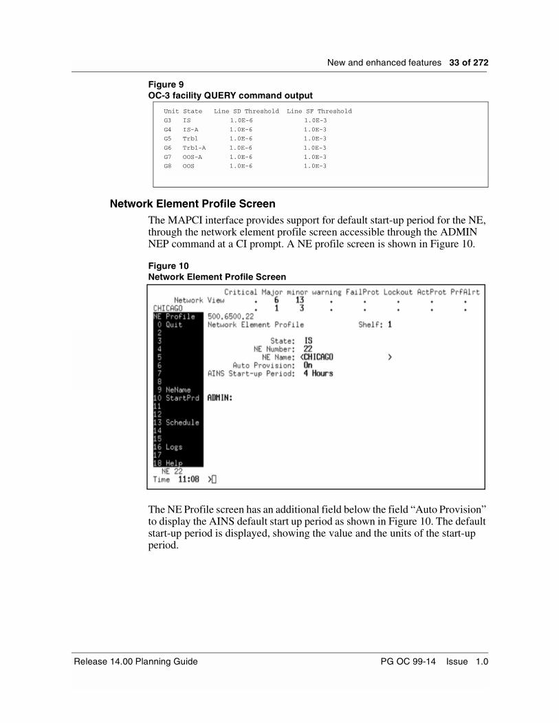
Facility Screen Query CommandThe query information may be accessed via the facility screen query command. The AINS status is shown in the state field.The query command available on the “facility” and “facility edit” screens display the AINS state as a part of the secondary state. The start-up period is not displayed due to text width restrictions. Figure 6, Figure 7, Figure 8, and Figure 9 show an example of the query command output for DS1, DS3, STS-1, OC-3 facilities which are IS Trbl-AINS, IS-AINS, IS, and IS Trbl.
Similar output is generated for OOS states. When a facility is OOS with fault or no fault and AINS enabled, the query command displays OOS-A or Trbl-A.
Figure 6DS1 facility QUERY command output
Figure 7DS3 facility QUERY command output
Figure 8STS1 facility QUERY command output
Unit Port State LCode LBO Lpback FrameFmt AlarmEnc Sync PMProv
G11 1 IS-A AMI Shrt None ESF Ones Asyn Enbl
G11 2 Trbl-A AMI Shrt None SF Ones Asyn Enbl
G11 3 IS AMI Shrt None SF Ones Asyn Enbl
G11 4 Trbl AMI Shrt None SF Ones Asyn Enbl
G11 5 OOS AMI Shrt None SF Ones Asyn Enbl
G11 6 OOS-A AMI Shrt None SF Ones Asyn Enbl
Unit Port State LCode LBO Lpback TxParity RxParity Framing
G1 1 IS B3ZS Shrt None Off Off On
G1 2 Trbl-A B3ZS Shrt None Off Off On
G1 3 IS-A B3ZS Shrt None Off Off On
G1 4 Trbl B3ZS Shrt None Off Off On
G1 5 OOS-A B3ZS Shrt None Off Off On
G1 6 OOS B3ZS Shrt None Off Off On
Unit Port State LCode LBO LpbackG2 1 IS B3ZS Shrt NoneG2 2 Trbl B3ZS Shrt NoneG2 3 IS-A B3ZS Shrt NoneG2 4 OOS B3ZS Shrt NoneG2 5 OOS-A B3ZS Shrt NoneG2 6 Trbl-A B3ZS Shrt None
S/DMS TransportNode OC-3/OC-12 TBM PG OC 99-14 Issue 1.0
New and enhanced features 33 of 272
Figure 9OC-3 facility QUERY command output
Network Element Profile ScreenThe MAPCI interface provides support for default start-up period for the NE, through the network element profile screen accessible through the ADMIN NEP command at a CI prompt. A NE profile screen is shown in Figure 10.
Figure 10Network Element Profile Screen
The NE Profile screen has an additional field below the field “Auto Provision” to display the AINS default start up period as shown in Figure 10. The default start-up period is displayed, showing the value and the units of the start-up period.
Unit State Line SD Threshold Line SF Threshold
G3 IS 1.0E-6 1.0E-3
G4 IS-A 1.0E-6 1.0E-3
G5 Trbl 1.0E-6 1.0E-3
G6 Trbl-A 1.0E-6 1.0E-3
G7 OOS-A 1.0E-6 1.0E-3
G8 OOS 1.0E-6 1.0E-3
Release 14.00 Planning Guide PG OC 99-14 Issue 1.0
34 of 272 New and enhanced features
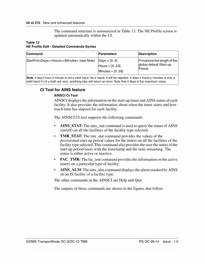
The command structure is summarized in Table 13. The NE Profile screen is updated automatically within the UI.
CI Tool for AINS featureAINSCI CI Tool
AINSCI displays the information on the start-up timer and AINS status of each facility. It also provides the information about when the timer starts and how much time has elapsed for each facility.
The AINSCI CI tool supports the following commands:
• AINS_STAT: The ains_stat command is used to query the status of AINS (on/off) on all the facilities of the facility type selected.
• TMR_STAT: The tmr_stat command provides the values of the provisioned start-up period values for the timers on all the facilities of the facility type selected. This command also provides the user the status of the start-up period timer with the timestamp and the time remaining. The status is either active or inactive.
• FAC_TMR: The fac_tmr command provides the information on the active timers on a particular type of facility.
• AINS_ALM: The ains_alm command displays the alarm masked by AINS on an IS facility of a facility type.
The other commands in the AINSCI are Help and Quit.
The outputs of these commands are shown in the figures that follow.
Table 13NE Profile Edit - Detailed Commands Syntax
Command Parameters Description
StartPrd<Days><Hours><Minutes> (see Note) Days = [0..4]
Hours = [0..23]
Minutes = [0..59]
Provisions the length of the global default Start-up Period.
Note: 0 day 0 hour 0 minute is not a valid input. As a result, it will be rejected. 4 days x hours y minutes is only a valid input if x & y both are zero, anything else will return an error. Note that 4 days is the maximum value.
S/DMS TransportNode OC-3/OC-12 TBM PG OC 99-14 Issue 1.0

New and enhanced features 35 of 272
Figure 11AINS_STAT command output for DS3 facilities
Figure 12TMR_STAT command output for DS3 facilities
Figure 13FAC_TMR command output for DS3 facilities
Figure 14AINS_ALM command output for DS3 facilities
>ains_stat DS3 all
Facility AINS Status
DS3 G1 1 Enabled
DS3 G1 2 Enabled
DS3 G1 3 Disabled
>tmr_stat DS3 all
Facility Start-up Period Status Start time Remaining time
Dy Hr Mn
DS3 G1 1 3 23 58 ACTIVE Apr 11 2000, 16:45 3 23 58
DS3 G1 2 4 0 0 INACTIVE Apr 11 2000, 16:46 - - -
>fac_tmr DS3
G1 G2 G3 G4
1 * . . .
2 . . . .
3 . . . .
>ains_alm DS3
Facility Alarm masked by AINS
DS3 G1 2 Rx loss of signal
Release 14.00 Planning Guide PG OC 99-14 Issue 1.0

36 of 272 New and enhanced features
Figure 15HELP command output
TL-1 InterfaceThis section includes all the TL-1 commands related to this feature. Two new TL-1 commands have been introduced for setting and retrieving the NE wide global default start-up period. The TL-1 edit and retrieve facility commands have been modified to support the two new attributes. Refer to the chapter “TL1 Support for AINS” on page 209 for more information.
Log OutputsLogs that are affected by the AINS feature are as follows:
NE Log
An NE402 log similar to the one shown in Figure 16 is generated when the global default start-up period is modified.
Figure 16Example of log generated when global start-up period is provisioned
>AINSCI help
AINSCI Auto In-Service CI tool
HELP Help commands for AINSCI
AINS_STAT Displays the AINS status
TMR_STAT Displays the Start-Up Timer status
FAC_TMR Displays the active Start-Up Timers on ALL DS1/DS3/STS1/OC-3 facilities
AINS_ALM Displays the alarms masked by AINS functionality
QUIT Quits AINSCI tool.
CM NE402 APR18 15:39:12 2900 INFO Data Change
Parameter Changed: Default Start-Up Period
Present: 10 Hours
Previous: 4 Hours
Network Id:1
System Id: 1
NE Id: 644
S/DMS TransportNode OC-3/OC-12 TBM PG OC 99-14 Issue 1.0
New and enhanced features 37 of 272
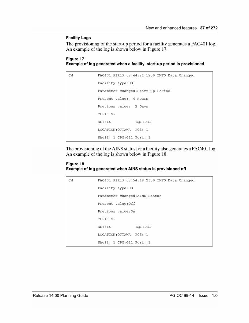
Facility Logs
The provisioning of the start-up period for a facility generates a FAC401 log. An example of the log is shown below in Figure 17.
Figure 17Example of log generated when a facility start-up period is provisioned
The provisioning of the AINS status for a facility also generates a FAC401 log. An example of the log is shown below in Figure 18.
Figure 18Example of log generated when AINS status is provisioned off
CM FAC401 APR13 08:44:21 1200 INFO Data Changed
Facility type:DS1
Parameter changed:Start-up Period
Present value: 4 Hours
Previous value: 2 Days
CLFI:ISP
NE:644 EQP:DS1
LOCATION:OTTAWA POS: 1
Shelf: 1 CPG:G11 Port: 1
CM FAC401 APR13 08:54:48 2300 INFO Data Changed
Facility type:DS1
Parameter changed:AINS Status
Present value:Off
Previous value:On
CLFI:ISP
NE:644 EQP:DS1
LOCATION:OTTAWA POS: 1
Shelf: 1 CPG:G11 Port: 1
Release 14.00 Planning Guide PG OC 99-14 Issue 1.0

38 of 272 New and enhanced features
DS1 Remote Test UnitThe DS1 Remote Test Unit (RTU) feature allows a customer to perform remote DS1 testing and monitoring, thereby reducing operational costs when compared to the conventional method of performing digital testing by a local craftsperson with a testset. This feature now allows the operating company to remotely test a DS1 before bringing it In-Service, without having to send a technician to the site with a testset. The remote testing and monitoring capability of a DS1 is performed without any external equipment. This feature is available only on the DS1 NT7E04EA Mapper.
Figure 19 provides a DS1 Remote Test Unit block diagram.
Figure 19DS1 Remote Test Unit functionality
DS1 Circuit (1 of 14) VT 1.5Side
LineSide
DTAUFM and AlarmMonitor
PM andAlarm
MonitorAnalog/DigitalInterface
SONETInterface
ControlLink
RTU
S/DMS TransportNode OC-3/OC-12 TBM PG OC 99-14 Issue 1.0
New and enhanced features 39 of 272
In the following text, testing implies SOURCING and MONITORING whereas monitoring implies MONITORING only. These two functionalities are available with the RTU and can be used independently.
The DS1 RTU allows testing or monitoring of any one of the 14 DS1 facilities per circuit pack. The RTU can be activated on the VT side only if a connection is provisioned for that facility. No connection is needed if the RTU is activated on the DS1 facility. The RTU can test or monitor traffic for only one facility per DS1 Mapper at a time. If the RTU is active on a facility, requests for deleting that facility is denied with proper indication. Testing/monitoring has to be terminated prior to deletion of a facility. In order for the RTU testing/monitoring to be available, the Equipment Primary State must be In-Service. Releasing the test pattern and returning the facility to In-Service restores customer traffic. Note that monitoring and sourcing can be used independently.
The DS1 RTU functionality is fully independent of the Far End Equipment, as long as it is SONET compliant and that it meets the ANSI T1-403, Bellcore GR-818 and GR-819 standards.
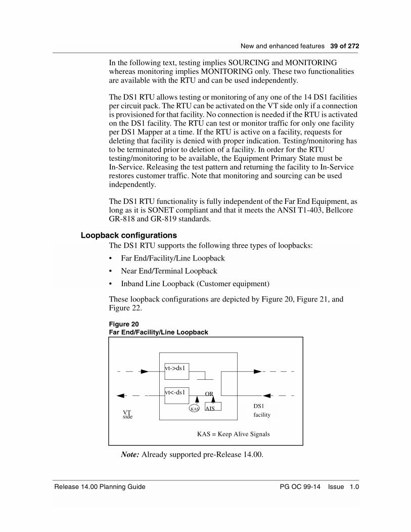
Loopback configurationsThe DS1 RTU supports the following three types of loopbacks:
• Far End/Facility/Line Loopback
• Near End/Terminal Loopback
• Inband Line Loopback (Customer equipment)
These loopback configurations are depicted by Figure 20, Figure 21, and Figure 22.
Figure 20Far End/Facility/Line Loopback
Note: Already supported pre-Release 14.00.
DS1
facilityVTside
vt->ds1
vt<-ds1
KAS AIS
OR
KAS = Keep Alive Signals
Release 14.00 Planning Guide PG OC 99-14 Issue 1.0

40 of 272 New and enhanced features
Figure 21Near End/Terminal Loopback
Note: Already supported pre-Release 14.00.
Figure 22Inband Line/External Loopback
Note: New to Release 14.00.
Figure 23Inband Line/External Loopback
Note: New to Release 14.00.
DS1 facilityV T sid e
v t-> d s 1
v t< -d s 1
K A S A IS.O R
~K A S
DS1 facility at the
customer site
ExternalLoopback
D S1 M ap per
T B M S h e lf
N ea r (D S 1 )NIU or CSU
~K A S
ExternalLoopback
N ear (D S 1) Far (D S 1)
N IU
T B M S h elfT B M S h e lf
D S1 M app erD S1 M ap per
DS1 facility at
customer site
S/DMS TransportNode OC-3/OC-12 TBM PG OC 99-14 Issue 1.0

New and enhanced features 41 of 272
When sending a request to establish or release an Inband Line loopback from the DS1 Mapper to the external DS1 customer equipment, the success of that request for remote Inband Line loopback depends on the customer equipment.
That is, the success of the Inband Line Loopback relies on the DS1 customer equipment being able to detect the In-Band Loopback Code. It implies that the Code coming from the DS1 Mapper over a twisted pair is read properly. This results in the enabling or disabling of the loopback. This functionality requires that the DS1 customer equipment supports InBand Loopback.
When the InBand Loopback request is sent towards the DS1 side (customer equipment side), there is an acknowledgment returned from the destination that the requested action took place. Note that the DS1 RTU is able to monitor the Inband Loopback codes on the DS1 (customer) side or the VT side.
DS1 RTU testing/monitoring configurationsThe DS1 RTU provides five types of testing/monitoring configurations:
• Near Direction Straight Away
• Far Direction Straight Away
• Looped Near End Monitor
• Looped Far End Monitor
• In Service Monitor
Note 1: The incoming line in the direction not under test are electrically terminated.
Note 2: The outgoing line in the direction not under test contains a KAS (Keep Alive Signal) in order to minimize network alarms while troubleshooting/testing DS1 facilities.
Note 3: All Keep Alive Signals are unframed.
Note 4: The KAS is AIS (default) or QRSS, chosen by the user.
Near Direction Straight AwayThe RTU is able to supervise signals in the Near-Away testing configuration with a signal detector (monitor) connected to an incoming signal from the Near direction, and a test signal (generator) connected to the outgoing in the same direction. Refer to Figure 24.
For the outgoing path of the VT path side (which is not under test), a KAS (AIS or QRSS) is connected to the outgoing path, while an appropriate electrical termination is connected to the incoming path. A request to operate an Inband Line loopback is sent toward the DS1 equipment at the near end, on the outgoing path of the DS1 equipment side. (If a request for Inband Line loopback is not available due to the external equipment, then the Inband Line Loopback should be done manually in the equipment.)
Release 14.00 Planning Guide PG OC 99-14 Issue 1.0

42 of 272 New and enhanced features
Figure 24Near Direction Straight-Away Mode
ExternalLoopback
NEAR TN FAR TN
KAS
POTPOT
KAS - Keep Alive Signal (QRS20)TN - OC-3/OC-12 Transport NodePOT - Point of Termination - Test Pattern & Signal Quality Monitor - Test Pattern Generator
DS1 Facility atCustomer Site
NIU or CSU
S/DMS TransportNode OC-3/OC-12 TBM PG OC 99-14 Issue 1.0

New and enhanced features 43 of 272
Far Direction Straight Away
The RTU is able to supervise signals in the Far-Away testing configuration with a signal detector (monitor) connected to an incoming signal from the Far direction, and a test signal (generator) connected to the outgoing in the same direction. Refer to Figure 25.
For the outgoing path of the DS1 equipment side (which is not under test), a KAS (AIS) is connected to the outgoing path, while an appropriate electrical termination is connected to the incoming path. The Inband Line loopback functionality is available when testing on the VT side. As well, a Terminal Loopback can be requested at the far end NE, or manually creating a loopback at the network demarcation device.
Figure 25Far Direction Straight-Away Mode
KAS - Keep Alive Signal (QRS20)TN - OC-3/OC-12 Transport NodePOT - Point of Termination - Test Pattern & Signal Quality Monitor - Test Pattern Generator
DS1 Facility atCustomer Site
ExternalLoopback
NEAR TN FAR TN
KAS
POTPOT
NIU
Release 14.00 Planning Guide PG OC 99-14 Issue 1.0

44 of 272 New and enhanced features
Looped Near End Monitor
The RTU is able to supervise signals in a Looped Near End Monitor configuration with a signal detector (monitor) connected to an incoming signal from the Near direction, and that same signal connected to the outgoing in that same direction through a facility loopback. Refer to Figure 26.
For the VT path side, which is not under test, a KAS is connected to the outgoing path, while an appropriate electrical termination is connected to the incoming path.
Figure 26Looped Near End Monitor Mode
NEAR TN FAR TN
KAS
POTPOT
VT - Side
KAS - Keep Alive Signal (QRS20)TN - OC-3/OC-12 Transport NodePOT - Point of Termination - Test Pattern & Signal Quality Monitor
DS1 Facility atCustomer Site
S/DMS TransportNode OC-3/OC-12 TBM PG OC 99-14 Issue 1.0

New and enhanced features 45 of 272
Looped Far End Monitor
The RTU is able to supervise signals in a Looped Far End Monitor configuration with a signal detector (monitor) connected to an incoming signal from the Far direction, and that same signal connected to the outgoing in that same direction, achieved through a terminal loopback. Refer to Figure 27.
For the DS1 equipment side, which is not under test, a KAS is connected to the outgoing path, while an appropriate electrical termination is connected to the incoming path.
Figure 27Looped Far End Monitor Mode
NEAR TNFAR TN
KAS
POTPOT
KAS - Keep Alive Signal (QRS20)TN - OC-3/OC-12 Transport NodePOT - Point of Termination
- Test Pattern & Signal Quality Monitor
DS1 Facility atCustomer Site
VT - Side
Release 14.00 Planning Guide PG OC 99-14 Issue 1.0

46 of 272 New and enhanced features
In-Service Monitor
The RTU is able to supervise signals in an In-Service Monitor configuration with a signal detector (monitor) connected to the incoming and an outgoing signal from the same direction. Refer to Figure 28.
Figure 28In Service Monitor
Note: In-Service Monitoring is performed one direction at a time, as specified by the user.
NEAR TN FAR TN POTPOT
TN - OC-3/OC-12 Transport NodePOT - Point of Termination
- Test Pattern & Signal Quality Monitor
DS1 Facility atCustomer Site
VT - Side
S/DMS TransportNode OC-3/OC-12 TBM PG OC 99-14 Issue 1.0

New and enhanced features 47 of 272
Operational considerationsTesting is referred as connecting a monitoring device and a test pattern generator to the incoming and outgoing path in the same direction (DS1 or VT1.5 side). Monitoring is referred as connecting a monitoring device to the incoming path from either direction (DS1 or VT1.5 side).
The testing is allowed only when the facility’s Primary State to be tested/monitored is Out Of Service (OOS). All testing commands against an In-Service facility, except the commands available for In-Service Monitoring, are rejected and the user is notified. Note that the remaining In-Service facilities on the Mapper under test are not affected during testing/monitoring.
The RTU can connect a test pattern generator to an outgoing testing path, VT1.5 or DS1 side (i.e., in either direction). As well, it can connect a measurement device to an incoming testing path, VT1.5 or DS1 side (i.e., can monitor in either direction).
The Inband Line Loopback codes can be sent framed or unframed. If framing is enabled, then the code is sent using the framing format provisioned for that channel. For configurations where an Inband Line Loopback is required on the customer equipment, this loopback has to be set up using any of the following methods:
• Using the DS1 RTU command to send a request for operating or releasing an Inband Line loopback.
• Requesting a loopback using the customer equipment interface, if available.
• Setting up a loopback manually.
The Inband Line Loopback codes required for loop-up and loop-down activities meet the ANSI T1-403 and Bellcore GR-818 and GR-819 standards.
DS1 RTU capabilitiesThe following Remote Test Unit Capabilities have been implemented in this DS1 RTU feature:
• Test Pattern Insertion and Detection
• Keep Alive Signal
• Logical Bit Error Insertion
• Frame Bit Error (FBE) Counter
• Send InBand Loopback Code
• Bit Error Rate (BER)
• CRC-6 Violations
Release 14.00 Planning Guide PG OC 99-14 Issue 1.0
48 of 272 New and enhanced features
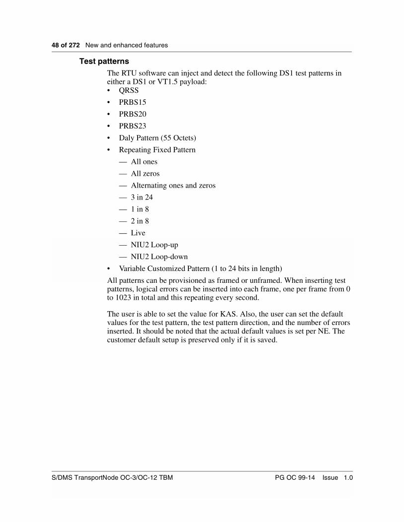
Test patternsThe RTU software can inject and detect the following DS1 test patterns in either a DS1 or VT1.5 payload:• QRSS
• PRBS15
• PRBS20
• PRBS23
• Daly Pattern (55 Octets)
• Repeating Fixed Pattern
— All ones
— All zeros
— Alternating ones and zeros
— 3 in 24
— 1 in 8
— 2 in 8
— Live
— NIU2 Loop-up
— NIU2 Loop-down
• Variable Customized Pattern (1 to 24 bits in length)
All patterns can be provisioned as framed or unframed. When inserting test patterns, logical errors can be inserted into each frame, one per frame from 0 to 1023 in total and this repeating every second.
The user is able to set the value for KAS. Also, the user can set the default values for the test pattern, the test pattern direction, and the number of errors inserted. It should be noted that the actual default values is set per NE. The customer default setup is preserved only if it is saved.
S/DMS TransportNode OC-3/OC-12 TBM PG OC 99-14 Issue 1.0

New and enhanced features 49 of 272
RestartsRTU testing/monitoring is terminated over any shelf restart.
Card removal and card insertionOn card removal, all tests are terminated. However, the test results and test configurations survive. The data results are available to the user as they were monitored until the card was pulled.
On card insertion, all testing or monitoring variables will remain unchanged and all previous test results will be retained.
Protection switchingOn a protection switch request against a Working Mapper where RTU is active, the bridging and switching on and off are handled as per normal, from a testing point of view. However, all testing/monitoring is terminated.
RTU testing is available on the Protection Mapper only when a protection switch is active and the Protection Mapper supports RTU Testing (NT7E04EA mapper). Note that the Working Mapper must also be EA Mapper. If the protection switch is dropped or released on the Protection Mapper, then all RTU activities on that Mapper are terminated, similar to card removal.
Upgrade conditionsWhen upgrading to Release 14.00, the RTU functionality is set to off by default.
When performing a backout from Release 14.00 to Release 13.11/13.12, no manual intervention is required. A backout from Release 14.00 to Release 11.2 requires some manual intervention. A CI tool (DS1MODCI) has been created to properly reinitialize all the hardware to the correct values.
User InterfaceThe screensThe DS1 RTU is accessible through the NE UI. The new DS1 RTU screen contains all the required commands to setup testing or monitoring of a facility. When trying to run the RTU on DS1 Mapper that does not support RTU, the UI displays a message in regards with the RTU functionality not being available for this type of DS1 mapper.
A new functionality command called “Test Func” has been added to the existing NE UI DS1 facility screen.
Release 14.00 Planning Guide PG OC 99-14 Issue 1.0
50 of 272 New and enhanced features
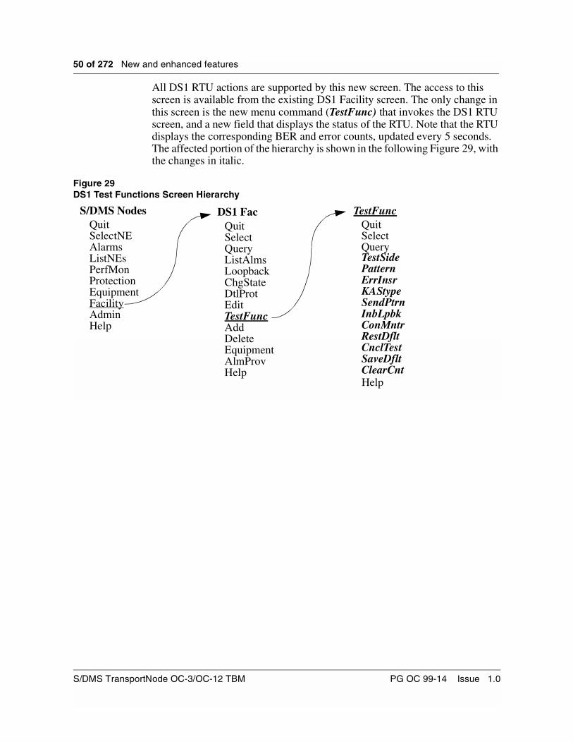
All DS1 RTU actions are supported by this new screen. The access to this screen is available from the existing DS1 Facility screen. The only change in this screen is the new menu command (TestFunc) that invokes the DS1 RTU screen, and a new field that displays the status of the RTU. Note that the RTU displays the corresponding BER and error counts, updated every 5 seconds. The affected portion of the hierarchy is shown in the following Figure 29, with the changes in italic.
Figure 29DS1 Test Functions Screen Hierarchy
S/DMS NodesQuitSelectNEAlarmsListNEsPerfMonProtection
DS1 FacQuitSelect
LoopbackChgStateDtlProt
TestFuncQuitSelect
TestSide
Edit
Query
PatternErrInsrKAStypeSendPtrnInbLpbkConMntrRestDfltCnclTestSaveDfltClearCnt
EquipmentFacilityAdminHelp
QueryListAlms
TestFuncAddDeleteEquipmentAlmProvHelp
Help
S/DMS TransportNode OC-3/OC-12 TBM PG OC 99-14 Issue 1.0

New and enhanced features 51 of 272
The Facility Screen
This screen displays the status of the DS1 Facilities. It also contains operation commands that pertain to the facility, including the new TestFunc command that invokes the RTU test screen and the new field that displays the RTU status. Refer to Figure 30 and Table 14.
Figure 30DS1 Facility screen
To enter this screen from the main menu, type:
Facility DS1 G1 1
or
Fa DS1 G1 1
or
16 DS1 G1 1
Release 14.00 Planning Guide PG OC 99-14 Issue 1.0
52 of 272 New and enhanced features
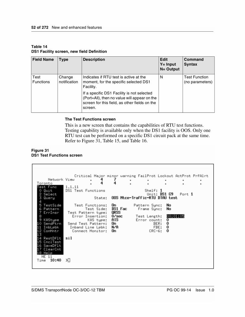
The Test Functions screen
This is a new screen that contains the capabilities of RTU test functions. Testing capability is available only when the DS1 facility is OOS. Only one RTU test can be performed on a specific DS1 circuit pack at the same time. Refer to Figure 31, Table 15, and Table 16.
Figure 31DS1 Test Functions screen
Table 14DS1 Facility screen, new field Definition
Field Name Type Description EditY= InputN= Output
Command Syntax
Test Functions
Change notification
Indicates if RTU test is active at the moment, for the specific selected DS1 Facility.
If a specific DS1 Facility is not selected (Port=All), then no value will appear on the screen for this field, as other fields on the screen.
N Test Function (no parameters)
S/DMS TransportNode OC-3/OC-12 TBM PG OC 99-14 Issue 1.0

New and enhanced features 53 of 272
To enter this screen from the DS1 Facility menu, type:
TESTFUNC, or TF, or 12
Table 15DS1 Test Functions screen, Fields Definitions
Field Name Type Description EditY= InputN= Output
Shelf Static This is the logical shelf in context. 1 to 2 numbers, left justified, high intensity text.
N
Unit Static Defines the specific circuit pack. CPG is in high intensity text.
N
Port Static Defines the specific DS1 facility port of the circuit pack.
The facility port is in high intensity text.
N
State Automatic Indicates the Primary and Secondary state of a facility N
Test Functions
Automatic Indicates if RTU test is active at the moment, for the specific selected DS1 Facility.
If a specific DS1 Facility is not selected (Port=All), then no value will appear on the screen for this field, as other fields on the screen.
N
Test Side Automatic Test Pattern transmission and Connect Monitor receive side. Indicates if the side under test is the DS1 Facility side (Copper side), or the VT Path (Optical side).
Y
KAS type Automatic The Keep Alive Signal (KAS) type that is transmitted on the outgoing path of the side that is not under test. <AIS/QRSS>
Y
Test Pattern type
Automatic The Test Signal type that is generated by the RTU, which can be: <QRSS, PRBS15, PRBS20, PRBS23, Daly, All Ones, All Zeros, Alternating Ones and Zeros, 3-IN-24, 1IN-8, 2-IN-8, Live, NIU2 Loop-up, NIU2 Loop-down, and Variable customized pattern>
Y
Error Insertion number
Automatic Number of errors per 1-second interval to be inserted to the generated test signal. <0-1023>
Y
Send Test Pattern
Automatic Indicates whether a test pattern is generated now, towards the outgoing path of the side under testing.
Y
Inband Line Loopback
Automatic Indicates whether the customer side equipment was requested by the RTU, to operate or release a loopback. The inband loopback type NIU or CSU is displayed, and the status is also displayed as pass of fail.
Y
Release 14.00 Planning Guide PG OC 99-14 Issue 1.0

54 of 272 New and enhanced features
Connect Monitoring
Automatic Indicates whether the measuring device is connected to the incoming path of the side that is under testing.
Y
Pattern Sync Automatic Indicates whether the measuring receiver is synchronized to the incoming expected pattern. In “Live” signals, shows “-” (dashed out).
N
Frame Sync Automatic For framed signals, indicate whether the incoming signal does not have a LOF failure. In unframed signals, shows “-”.
N
Test length Automatic The length (in hours:minutes:seconds format) of the current test. Range 00:00:00 to 99:59:59.
N
Error count Automatic An integer number that counts the number of errors occurred during the test interval. Exponential notation is used for large integers. In “Live” signals, shows “-”. Range 0 to 4.29E+9.
N
BER Automatic A non integer number. Representing the ratio between the number of error bits and the total number of bits during the test (i.e. the value in the Error count field is divided by the product of 1,544,000 and the number of seconds in the value of the Test length field). In “Live” signals, shows “-”. Range 0, 0E-10 to 9.999E-1, 1.
N
FBE Automatic An integer number that counts the number of occurrence of a framing bit error in the received frame bit pattern and applies to both SF and ESF DS1 paths. In unframed signals, shows “-”. ESF range 0 to 9.18E+7, other is 0 to 1.84E+8.
N
CRC-6 Automatic For DS1 ESF paths only, a CRC-6 error is the occurrence of a received CRC-6 code that is not identical to the corresponding locally calculated code. This field is not available (dashed out) when the Test Side is VT, framing format is ESF, and facility is ByteSynchronous. Range 0 to 1.84E+8.
N
Table 15DS1 Test Functions screen, Fields Definitions
Field Name Type Description EditY= InputN= Output
S/DMS TransportNode OC-3/OC-12 TBM PG OC 99-14 Issue 1.0

New and enhanced features 55 of 272
Table 16 lists all commands affected by this feature for the DS1 Test Functions screen.
Table 16DS1 Test Function screen, Command Definitions
When the facility state is IS, the complete list of commands is available, as listed in Table 16, except for the SendPtrn command.
When the facility state is OOS, the complete list of commands is available, as listed in Table 16.
Command: Select
The Select command selects the facility into context and display test functions parameters for the specific facility.
The syntax for the Select command is as follows:
Select <Unit> <Port #>
Command Name Type New/Changed/Deleted
Select MENU No change
Query MENU Changed
TestSide MENU New
Pattern MENU New
ErrInsr MENU New
KAStype MENU New
SendPtrn MENU New
InbLpbk MENU New
ConMntr MENU New
RestDflt MENU New
CnclTest MENU New
SaveDflt MENU New
ClearCnt MENU New
Help MENU Changed
Release 14.00 Planning Guide PG OC 99-14 Issue 1.0
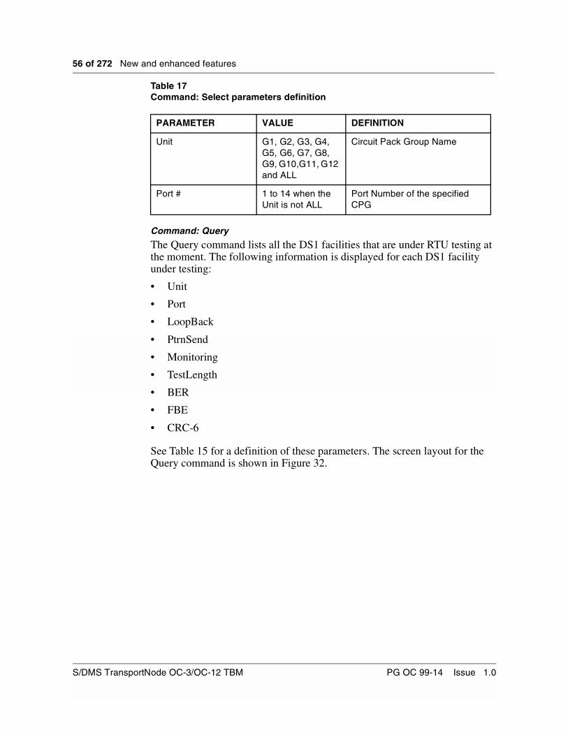
56 of 272 New and enhanced features
Table 17Command: Select parameters definition
Command: Query
The Query command lists all the DS1 facilities that are under RTU testing at the moment. The following information is displayed for each DS1 facility under testing:
• Unit
• Port
• LoopBack
• PtrnSend
• Monitoring
• TestLength
• BER
• FBE
• CRC-6
See Table 15 for a definition of these parameters. The screen layout for the Query command is shown in Figure 32.
PARAMETER VALUE DEFINITION
Unit G1, G2, G3, G4, G5, G6, G7, G8, G9, G10,G11, G12 and ALL
Circuit Pack Group Name
Port # 1 to 14 when the Unit is not ALL
Port Number of the specified CPG
S/DMS TransportNode OC-3/OC-12 TBM PG OC 99-14 Issue 1.0
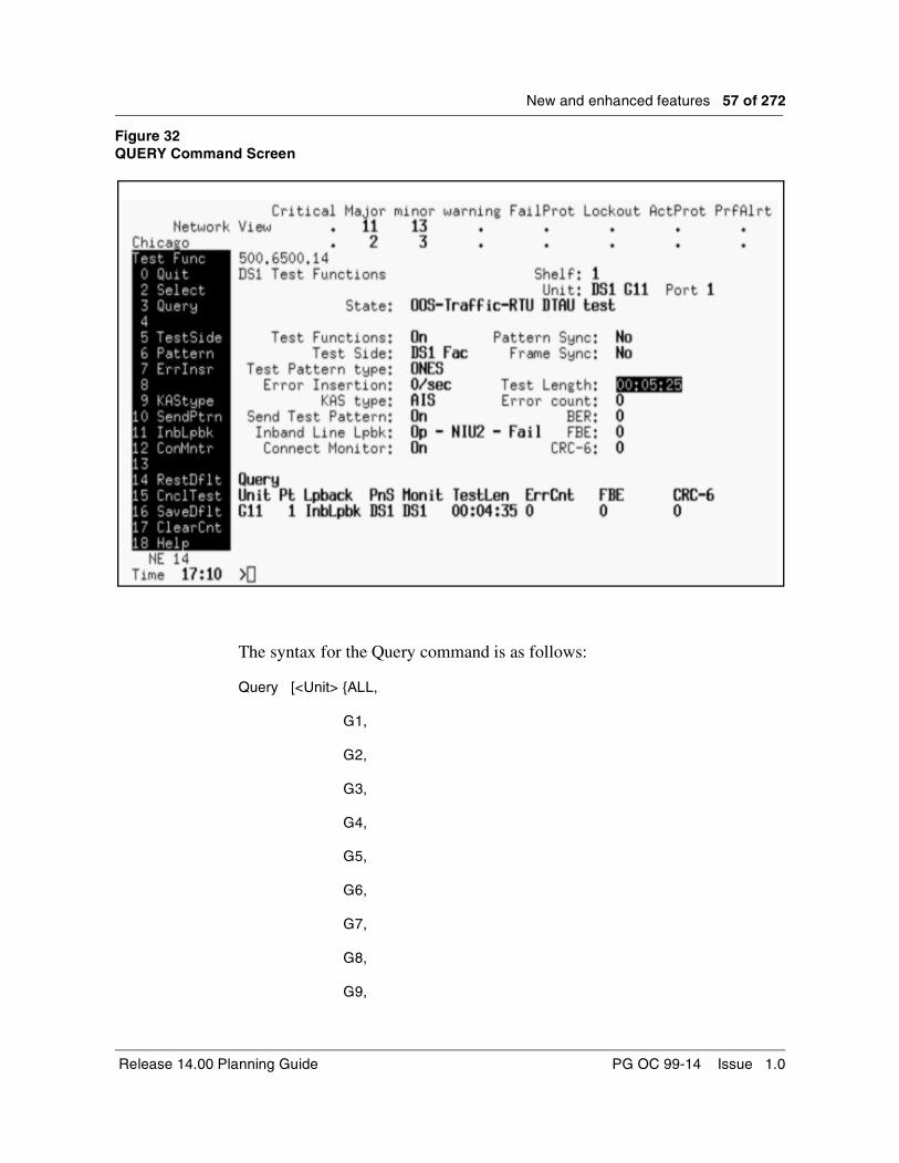
New and enhanced features 57 of 272
Figure 32QUERY Command Screen
The syntax for the Query command is as follows:
Query [<Unit> {ALL,
G1,
G2,
G3,
G4,
G5,
G6,
G7,
G8,
G9,
Release 14.00 Planning Guide PG OC 99-14 Issue 1.0

58 of 272 New and enhanced features
G10,
G11,
G12}]
Table 18Command: Query parameters definition
Command: TestSide
The TestSide command selects the side to be tested. This field is initialized to ‘DS1’. The user can choose other value (VT) as a default.
The syntax for the TestSide command is as follows:
TestSide <Test Side>
Table 19Command: TestSide parameters definition
Command: KAStype
The KAStype command chooses the Keep Alive Signal (KAS) type that is transmitted on the outgoing path of the side that is not under test.
Note 1: The QRSS option as a KAS signal, is always available except when the facility is in ByteSynchronous mode and the test side is set to DS1 facility. Trying to change the KAS signal to QRSS in these circumstances causes the command to be rejected.
Note 2: We refer to DS1/VT synchronization as the way the DS1 are being mapped into the VT Synchronous Payload Envelope (SPE). There are 3 modes available for mapping DS1 into VT1.5 and they are Byte Synchronous, Bit Synchronous and Asynchronous.
The syntax for the KAS type command is as follows:
KAStype <KAS type>
PARAMETER VALUE DEFINITION
Unit G1, G2, G3, G4, G5, G6, G7, G8, G9, G10,G11, G12 and ALL
Circuit Pack Group Name
PARAMETER VALUE DEFINITION
Test Side DS1 and VT The side that is selected for testing
S/DMS TransportNode OC-3/OC-12 TBM PG OC 99-14 Issue 1.0

New and enhanced features 59 of 272
Table 20Command: KAStype parameters definition
Command: Pattern
The Pattern command chooses the test signal type that is sent towards the side under test. This field is initialized to ‘QRSS’. The user can choose another value as a default.
The user is able to set the pattern to be framed or unframed using the facility provisioning. If framing is different than NULL, the frame format is the same as the format provisioned for the selected facility. If the channel is provisioned in byte-synchronous mode, the test pattern must have framing different than NULL.
The user is also prompted to select the pattern to be framed or unframed. If framing is enabled, the frame format is the same as the format provisioned for the selected facility. If the channel is provisioned in byte-synchronous mode, the test pattern must have framing enabled.
The syntax for the Pattern command is as follows:
Pattern <Pattern signal/Pattern query>
PARAMETER VALUE DEFINITION
KAS type AIS (default) and QRSS
The Keep Alive Signal type
Release 14.00 Planning Guide PG OC 99-14 Issue 1.0

60 of 272 New and enhanced features
Table 21Command: Pattern parameters definition
Once the user has decided to choose the Custom value for the pattern signal, different choices are provided. If the user types the command PATTERN QUERY, the present pattern value and customized pattern value for that facility are displayed. To select the current customized pattern value that is displayed, the user types the command PATTERN CUSTOM. On the other hand, if the user wants to enter a new custom pattern string, then the command PATTERN CUSTOM ‘<BIT STRING>’ is typed. Once the zeros and ones are entered, the actual pattern is displayed in the Test Pattern Type field and the Pattern command is terminated.
If a value different than “0 or 1” is entered, the user is advised that the only acceptable values are 0 or 1, and is prompted to enter the command again.
If the synchronization mode selected for that facility in the facility provisioning screen is Byte-Synchronous, then the <BIT STRING> length has to be a multiple of eight, for example 8, 16 or 24. Otherwise the Pattern Custom command is denied with an error message stating the Pattern value is not allowed with the Synchronization Mode.
A new Pattern Type called “Live” will be available. It’s suggested that when monitoring live traffic the customer select the Live Pattern Type. By doing so, the Pattern Sync, Error Count and BER counters will be disabled and dashed out due to the fact that the RTU can’t synchronize on a live (random) pattern.
Inband Line Loopback codes can be sent towards the VT Terminal Test Side to a Network Interface Unit (NIU) by selecting the Pattern Type to be NIU2LpUp or NIU2LpDn. These two Pattern types are only available if the Test Side selected is VT Terminal. The inband loopback signal can be utilized with any of the DS1 frame formats
PARAMETER VALUE DEFINITION
Pattern signal QRSS, PRBS15, PRBS20, PRBS23, Daly, Ones, Zeros, Alternating, 3IN24, 1IN8, 2IN8, Live, NIU2LpUp, NIU2LpDn, and Custom
The test pattern signal type
Pattern query QUERY Displays the current test pattern type and the current customized test pattern
S/DMS TransportNode OC-3/OC-12 TBM PG OC 99-14 Issue 1.0

New and enhanced features 61 of 272
The success of the Inband Line Loopback request on the VT Terminal side is indicated on the UI not by the same Inband Line Lpbk field used to indicate an Inband Line Loopback request on the DS1 facility side (described under Command : InbLpbk, on page 62), but by the Pattern Sync field. If the NIU2LpUp pattern type is sent towards the VT side (by selecting the pattern type NIU2LpUp, and connecting the test pattern generator); when the NIU loops-up, the Pattern Sync field will indicate YES. Note that the measuring device needs to be connected to see this indication. The user can then change the test pattern to any one of the other available patterns, to perform the testing. Then, by changing the pattern type sent to NIU2LpDn; once the NIU loops-down, then the Pattern Sync field will indicate NO.
Changing Pattern Type, once the RTU is active, is permitted. Once this attributes is changed, all test results will be reset.
Command: ErrInsr
The ErrInsr command chooses the number (n) of errors within the generated test signal. The first n frames in every 1-second interval suffers a single error. This field is initialized to ‘0’. The user can choose another value as a default.
The syntax for the ErrInsr command is as follows:
ErrInsr <Number of errors>
Changing the Number of Error Insertion attribute, once the RTU is active, is permitted. Once this attribute is changed, all test results will be reset.
Table 22Command: ErrInsr parameters definition
Command: SendPtrn
A test pattern generator is connected/disconnected to/from the outgoing path of the side that is going to be tested, and a KAS is connected/disconnected to/from the outgoing path of the other side. As a result we will Start/Stop sending the appropriate OOS signals, “VT unequipped” towards the VT side, and “DS1 AIS” toward the DS1 line.
If the facility is OOS, then once that command is executed, a minor non service affecting alarm called ‘RTU DTAU test in progress’ is raised.
The syntax for the SendPtrn command is as follows:
SendPtrn <Generate test signal>
PARAMETER VALUE DEFINITION
Number of errors 0 to 1023 Errors per 1 second interval
Release 14.00 Planning Guide PG OC 99-14 Issue 1.0

62 of 272 New and enhanced features
Table 23Command: SendPtrn definition
Command: InbLpbk
The InbLpbk command sends a request to operate or release an Inband Line Loopback towards the customer side equipment by sending the appropriate code word to the NIU or CSU (channel service unit). The inband loopback signal can be utilized with any of the DS1 frame formats. The InbLpbk command is available only if the test side is DS1.
The syntax for the InbLpbk command is as follows:
InbLpbk <Operate or Release> { OP <InBandLpbk Type> {CSU, NIU2} , RE}
The Inband Line Lpbk field is updated on the screen to show (from left to right) the Inband Line Loopback request (Operate or Release), followed by the type of loopback requested (CSU or NIU2), and the status of the request once it has been detected (Pass or Fail).
The command status, which is the result of the request, is displayed so the user can have an idea of the status of the testing setup. The value {Pass, Fail or N/A} is displayed on the right end side of the Inband Line Lpbk field. See Figure 32 on page 57. The N/A is displayed when the InbLpbk command is not being requested, and while the software determines if the request is Pass or Fail.
Note that the test pattern generator should be connected before the InbLpbk command can be operated.
Table 24Command: InbLpbk parameters definition
PARAMETER VALUE DEFINITION
Generate test signal OFF (default) and ON
Operate this functionality or release it
PARAMETER VALUE DEFINITION
Request Action RE (default) and OP
Operate this functionality or release it
Inband Loopback type CSU and NIU2 Send a request to CSU or NIU
Request Status PASS, FAIL and N/A
Display the status of the request
S/DMS TransportNode OC-3/OC-12 TBM PG OC 99-14 Issue 1.0
New and enhanced features 63 of 272
Command: ConMntr
The ON parameter is a measuring device that is connected to the incoming path of the side that is under testing. It resets the measurement attributes: Pattern Sync, Frame Sync, Test length, Error count, BER value, FBE count and CRC-6 count. It resets the attributes only when a status transition goes from OFF to ON. The ConMntr command displays these measurement results.
If the measuring device is already connected (i.e. the BER Monitoring Test field on the screen, is ‘ON’), then nothing new happens when set to ON again. If the parameter is set to OFF, the measuring device is disconnected from the path, so monitoring is stopped. All test results are still available and are still displayed on the Test Func screen after the measuring device is disconnected.
The ConMntr command raises a minor non service affecting alarm called ‘RTU DTAU test in progress’ independently of the facility status. If the alarm is already raised then nothing happens. This covers both cases for Testing and Is-Monitoring.
The syntax for the ConMntr command is as follows:
ConMntr <Status> {Off, On}
Table 25Command: ConMntr parameters definition
Command: RestDflt
The RestDflt command restores the user default values Test Side, Test Pattern type and Error Insertion previously stored for the NE using the SaveDflt command. This command also forces the KAS to become AIS.
The syntax for the RestDflt command is as follows:
RestDflt
Note that there are no parameters for this command.
PARAMETER VALUE DEFINITION
Monitor Status OFF (default) and ON
Stop monitoring (OFF) or reset the counters and start monitoring (ON)
Release 14.00 Planning Guide PG OC 99-14 Issue 1.0

64 of 272 New and enhanced features
Command: CnclTest
The CnclTest command cancels all test operations. It stops the error counts, BER, FBE and CRC-6 monitoring, sends “release Inband Line loopback” code if it was previously active on the DS1 side, stops test pattern transmission (only after the release code word was transmitted as required), and sends appropriate OOS signals (“VT unequipped” to the VT, and DS1 AIS towards the DS1 line).
This command is not denied for IS-Monitoring.The user is able to turn the monitor Off by using this command.
The syntax for the CnclTest command is as follows:
CnclTest
Note that there are no parameters for this command.
Command: SaveDflt
The SaveDflt command sets the default values for the Test Side, Test Pattern type and Error Insertion. This default setting is per NE, and applies to all DS1 NT7E04EA Mapper facilities on that NE.
The syntax for the SaveDflt command is as follows:
SaveDflt
Note that there are no parameters for this command.
Command: ClearCnt
The ClearCnt command clears all the counters. This command will only be available when all RTU activities are off.
The syntax for the ClearCnt command is as follows:
ClearCnt
Note that there are no parameters for this command.
DS1 RTU LogsLogs are generated, using the existing log utilities facility (FAC401), with new text strings. The logs are generated every time that any of the following test parameters are changed, or test functions are performed:
• Change of attribute Test Side— Display “Test Side” with either “DS1 facility” or “VT Path.”
• Change of attribute Pattern Type— Display “Pattern Type” with one of the following
S/DMS TransportNode OC-3/OC-12 TBM PG OC 99-14 Issue 1.0

New and enhanced features 65 of 272
– “QRSS”
– “PRBS2O”
– “PRSB15”
– “PRSB23”
– “Daly”
– “ONES”
– “ZEROS”
– “ALTERNATING”
– “3IN24”
– “1IN8”
– “2IN8”
– “CUSTOM PATTERN IS: FFF ” (where FFF is the custom pattern in HEX format)
– “LIVE”
– “NIU2LPUP”
– “NIU2LPDN”
• Change of attribute Number of Errors
— Display “Number of Errors” with “X” (where X is the range 0 - 1023)
• Change of attribute KAS Type— Display “KAS Type” with either “Alarm Indication Signal” or “QRSS”
• Change of action Pattern Insertion— Display “pattern Insertion” with either “Send Pattern” or “Disconnect
Pattern”
• Change of action Inband Line Loopback
— Display “Inband Line Loopback” with either “Operate Inband Line Loopback” or “Release Inband Line Loopback”
• Change of action Monitoring
— Display “Monitoring” with either “Connect Monitor” or “Disconnect Monitor”
Figure 33 provides an example of a FAC401 facility Log.
Figure 33Example of a Facility Log (FAC401)
CM FAC401 MAR02 21:56:23 6913 INFO Data Changed
Facility type:DS1
Release 14.00 Planning Guide PG OC 99-14 Issue 1.0
66 of 272 New and enhanced features
Parameter changed:Test Side
Present value:DS1 facility
Previous value:--------------------------------------
CLFI:
NE:636 EQP:DS1
LOCATION: POS: 1
Shelf: 1 CPG:G12 Port: 1
CM FAC401 MAR02 21:56:23 7014 INFO Data Changed
Facility type:DS1
Parameter changed:Monitoring
Present value:Disconnect Monitor
Previous value:--------------------------------------
CLFI:
NE:636 EQP:DS1
LOCATION: POS: 1
Shelf: 1 CPG:G12 Port: 1
CM FAC401 MAR02 21:56:23 7115 INFO Data Changed
Facility type:DS1
Parameter changed:KAS Type
Present value:Alarm Indication Signal
Previous value:--------------------------------------
CLFI:
NE:636 EQP:DS1
LOCATION: POS: 1
Shelf: 1 CPG:G12 Port: 1
CM FAC401 MAR02 21:56:23 7317 INFO Data Changed
Facility type:DS1
Parameter changed:Pattern Insertion
Present value:Disconnect Pattern
Previous value:--------------------------------------
CLFI:
NE:636 EQP:DS1
LOCATION: POS: 1
Shelf: 1 CPG:G12 Port: 1
CM FAC401 MAR02 17:38:32 6307 INFO Data Changed
Facility type:DS1
Parameter changed:Pattern Type
Present value:QRSS
Previous value:--------------------------------------
CLFI:
NE:636 EQP:DS1
S/DMS TransportNode OC-3/OC-12 TBM PG OC 99-14 Issue 1.0
New and enhanced features 67 of 272
LOCATION: POS: 1
Shelf: 1 CPG:G12 Port: 1
CM FAC401 MAR02 17:38:32 6408 INFO Data Changed
Facility type:DS1
Parameter changed:Number Of Errors
Present value:0
Previous value:--------------------------------------
CLFI:
NE:636 EQP:DS1
LOCATION: POS: 1
Shelf: 1 CPG:G12 Port: 1
Testing scenarioA typical test would be performed using the following steps:
• Go in the facility screen and put facility OOS.
• Select command TestFunc (12).
• Once in TestFunc screen, look at all the testing parameters and update them as required. The command RestDflt can be used to do so.
• Select the Test Side, the Test Pattern type, the Error Insertion number and the Keep Alive Signal type. At the end of this step, the command SaveDflt can be used to save these values as the user defaults.
• The saved values are Test Side, Test Pattern type and Error Insertion number. The KAS is not saved.
• The KAS type is forced to AIS once the user executes the command RestDflt.
• Using the command SendPtrn, insert your pattern in the selected test direction.
• If an Inband Line Loopback is required on the Network Interface Unit (NIU), on the near end DS1 side, request that operation using the command InbLpbk. Wait a few seconds to get the status of the Inband Line Loopback request. If satisfactory, then proceed to the next step, if not, then try again or attempt to set up the loopback manually.
• Start monitoring by using command ConMntr, which resets all counters and the timer.
• View your results on the TestFunc screen or by using the Query command.
• Once the test is over, use command CnclTest to stop and disconnect everything or execute the setup steps in reverse order.
In-Service Monitoring scenarioPerform the following steps:
Release 14.00 Planning Guide PG OC 99-14 Issue 1.0

68 of 272 New and enhanced features
• Make sure that the facility state is in IS.
Note: Even though the facility state is IS-TRBL, commands for Is-Monitoring are successful without any error.
• Select the side you want to monitor using the command Test Side.
• Select the test pattern type as “Live”.
• Using command ConMntr, connect the monitor. That step clears all counters and reset the timer.
• View your results on the TestFunc screen or by using the Query command.
If live traffic is being monitored, then the Pattern Sync, Error Count and BER fields are dashed out, because a non-fixed pattern cannot be monitored. The FBE is the only available counter, unless, if the framing format is ESF, then the CRC-6 counter is also available.
DS3 EnhancementsThe DS3 Enhancements allow networks to evolve to data oriented DS3 transmissions without impact on OA&M activities on the OC-3/OC-12 TBM system running Release 14.00 software. The new version of the DS3 mapper (NT7E08BA) is required in order to take advantage of this new feature.
Note: In the following text, the NT7E08AA mapper will be referred to as the AA mapper and the NT7E08BA mapper will be referred to has the BA mapper.
With Release 14.00, the BA mapper offers C-bit transparency compared to the AA mapper, thus, supporting the C-bit parity type signals without impact on the system’s OA&M activities. The DS3 AIS is equipped with the required M-bits, F-bits and P-bits. All the C-bits in the M frame are set to 0. The X-bits are set to 1. The information bits are set to 1010... repeating sequence, with a 1 immediately following any other control bit positions.
Additionally, the introduction of this DS3 enhancement feature eliminates the need for workarounds which were provided for C-bit parity signals, pre-Release 14.00.
Shelf configuration and protectionThe following attributes pertain to shelf configuration and protection for the BA mapper:• A shelf may contain any combination of AA and BA mappers.
• The BA mapper automatically runs in new mode beginning in Release 14.00.
• Other than the C-bit transparency, a BA mapper supports the exact same functionalities as an AA mapper.
S/DMS TransportNode OC-3/OC-12 TBM PG OC 99-14 Issue 1.0

New and enhanced features 69 of 272
• The operation of the BA mapper is transparent to OA&M functional areas.
• If the shelf contains at least 1 BA mapper in slot 11, 13, 15 or 17, then it is required that a BA mapper be found in protection slot 1 in order to prevent loss of transparency. If this requirement is violated and a protection switch is requested by a BA mapper, the C-bit transparency is lost until traffic is reverted back to the BA mapper. As a result, there is a new standing alarm (the Protection Hardware Incompatible alarm) in this case, as mentioned in the section “Alarms”, on page 70.
• If an AA mapper in slot 11, 13,15 or 17, receives a data pattern of 1010... repeating sequence and the AIS alarm is incorrectly raised, the alarm is suppressed after traffic is switched to protection slot 1, if it is occupied by a BA mapper.
• The AA and BA mappers are fully interchangeable regardless of the slot they occupy.
• While running Release 14.00 or later, if a BA mapper is replaced by an AA mapper in slot 11, 13, 15 or 17, the transparency is lost until such time that a BA mapper is re-inserted.
• The BA mapper in the OC-12 TBM system running Release 14.00 takes advantage of the same functionalities and provides identical C-bit transparency as the BA mapper in an OC-48 system running Release 16.
• The BA mapper is backwards compatible with all software releases prior to OC-3/OC-12 TBM Release 14.00, but in such cases, is not able to offer the C-bit transparency and therefore behaves like an AA mapper.
Elimination of workaroundsThe two workarounds that now are eliminated by the coupling of this DS3 new feature with the NT7E08BA mapper, are described in BBN10207. The two workarounds are the provisioning of framing to off, and deprovisioning of the related DS3 alarms.
If the current provisioning of any facility on an AA mapper is the result of workaround 1 (provisioning the framing to OFF), as described in BBN10207, then if the AA mapper is replaced with a BA mapper, the customer must reprovision the framing of the facility to “ON” in order to take advantage of the solution provided by this feature. These actions are service affecting since the facility has to be put Out-of-Service to edit the framing.
If the current provisioning of any facility on an AA mapper is the result of workaround 2 (Deprovisioning of the related DS3 facility alarms), described in BBN10207, then if the AA mapper is replaced with a BA mapper, the customer must reprovision the Rx AIS and Tx AIS alarms and return the Performance Monitoring thresholds to normal values in order to take advantage of the solution provided by the enhanced functionality. The PM thresholds involved in this workaround are PathES, PathSES, PathUAS, PathSAS, and PathFC. These actions are not service affecting.
Release 14.00 Planning Guide PG OC 99-14 Issue 1.0
70 of 272 New and enhanced features
AlarmsWhen a shelf contains at least one BA mapper in slot 11, 13, 15, or 17, then it is required that the BA mapper be found in protection slot 1, in order to prevent loss of transparency. When a violation of this requirement occurs, a new alarm called “Protection Hardware Incompatible” is raised, if enabled, against the mapper in protection slot 1. The alarm is a Warning, Non-Service affecting. This alarm is disabled by default and it is provisionable.
Upgrade conditionsWhen upgrading to Release 14.00, the enhanced functionality is set to on by default.
When performing a backout from Release 14.00 to Release 13.11/13.12 or Release 11.20, some manual intervention is required. A CI tool (DS3MODCI) has been created to properly reinitialize all the hardware to the correct values.
OC-3 Tributary Synchronization Status MessagingReleases prior to OC-3/OC-12 Release 14.00 support Synchronization Status Messaging (SSM). This new feature introduced in Release 14.00 transmits SSM on the OC-3 tributaries. This allows all subtending OC-3 equipment that supports SSM to use SSM coming from the OC-12.
The benefits of this feature may be summarized as follows:
• Reduced costs in subtending OC-3 equipment, such as OPTera Metro 3000 series— the availability of timing from OC-3 tributaries reduces the
requirement for BITS and SYNC card functionality in the subtending equipment.
• Improved system robustness— the quality selection is based on an actual signal, and not provisioned
information, resulting in the highest quality timing signal being used.
Background on Synchronization Status MessagingSONET Network Elements (NEs) are presented with several choices of where to derive their NE timing references. Typical timing references include external timing from Building Integrated Timing Supply (BITS), timing derived from SONET interfaces, an NE’s own internal clock and timing derived from tributaries as shown in Figure 34.
S/DMS TransportNode OC-3/OC-12 TBM PG OC 99-14 Issue 1.0

New and enhanced features 71 of 272
Figure 34Multiple Timing References
OC-12
SONET Tributary Reference
NEOC-12
BITS
Release 14.00 Planning Guide PG OC 99-14 Issue 1.0
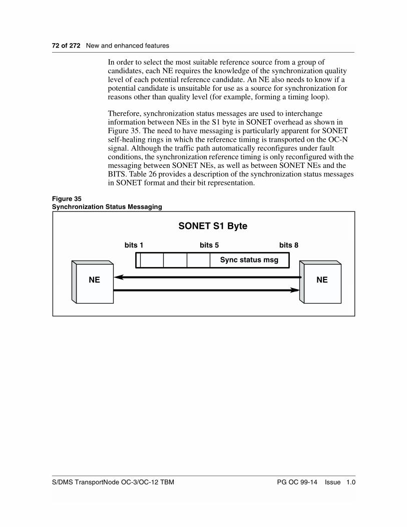
72 of 272 New and enhanced features
In order to select the most suitable reference source from a group of candidates, each NE requires the knowledge of the synchronization quality level of each potential reference candidate. An NE also needs to know if a potential candidate is unsuitable for use as a source for synchronization for reasons other than quality level (for example, forming a timing loop).
Therefore, synchronization status messages are used to interchange information between NEs in the S1 byte in SONET overhead as shown in Figure 35. The need to have messaging is particularly apparent for SONET self-healing rings in which the reference timing is transported on the OC-N signal. Although the traffic path automatically reconfigures under fault conditions, the synchronization reference timing is only reconfigured with the messaging between SONET NEs, as well as between SONET NEs and the BITS. Table 26 provides a description of the synchronization status messages in SONET format and their bit representation.
Figure 35Synchronization Status Messaging
SONET S1 Byte
NE NE
Sync status msg
bits 1 bits 5 bits 8
S/DMS TransportNode OC-3/OC-12 TBM PG OC 99-14 Issue 1.0

New and enhanced features 73 of 272
Table 26SONET Synchronization Message Set
Overview of OC-3 SSMThis feature transmits the synchronization status message (SSM) in the S1 byte of the SONET overhead of the OC-3 tribs. The transmitted SSM is equal to the quality level of the active timing reference. This is either the provisioned received quality level or, if there is no quality level provisioned, the actual received quality level. When the NE enters holdover or freerun, the transmitted SSM is equal to the holdover level of the SONET NE internal clock (e.g., “Traceable to Stratum 3 - Holdover” or “Traceable to SONET Minimum Clock - Self Timed” - SMC) or freerun. Listed below are the characteristics of the of the OC-3 Trib SSM feature:
• All transmit active OC-3 tribs facilities transmit a valid SSM.
• OC-3 out-of-service and transmit inactive facilities transmit DUS.
• On all configurations which support S1 byte synchronization status messaging, the SSM is automatically transmitted on all provisioned OC-3 tribs.
• Supports SSM on tributaries, not on OC-3 TBM primary rate optics.
• In unprotected mode, a fiber cut or an OC-12 circuit pack fail results in a failure of the OC-3 facility, and therefore a SSM of DUS is transmitted.
• The Tx SSM is the same for any active OC-3 trib, and therefore is unaffected by protection switches.
• This feature supports all configurations of NWK and VTM which currently support SSM.
Table 1
Description Acronym ANSI Quality Level SONET S1 BITS(bit5 - bits8)
Stratum 1 ST1 1 0001
Traceability Unknown STU 2 0000
Stratum 2 ST2 3 0111
Stratum 3 ST3 4 1010
Clock SMC 5 1100
Stratum 4 ST4 6 N/A
Don’t Use for Synchronization
DUS 7 1111
Reserved for Network Synchronization Use
RES User Assignable 1110
20ppm±
Release 14.00 Planning Guide PG OC 99-14 Issue 1.0
74 of 272 New and enhanced features
• If the quality level in the active timing reference changes, the NE inserts the correct SSM in all OC-3 trib transmitted SONET signals within 10 seconds.
• When the NE enters holdover or freerun, the SSM is changed within 10 seconds, indicating the holdover level of the SONET NE internal clock.
• When the NE recovers from holdover or freerun, the SSM does not change until the NE has completely resynchronized. The time to change the message is no longer than the recovery time, i.e., the sum of the requalification time and the locking time plus 10 seconds.
• The RX SSM on OC-3 tributaries is displayable. If the SSM is from an NE which does not support SSM, STU is displayed.
• On all restarts, the SSM is set to DUS, until a valid stratum level has been detected. The transmitted SSM value survives all warm, cold and reload restarts.
• Use of an OC-3 trib as a timing reference by an OC-12 NE remains unsupported.
• OC-3 line optics SSM remains unsupported.
Operational scenarioThe following is an example of an OPTera Metro 3000 series NE timing from an OC-3 tributary on a TBM. Refer to Figure 36. With OC-3 Trib SSM, the OPTera Metro 3000 can detect when the incoming clock signal stratum level from the TBM tributary changes, and thus the OPTera Metro 3000 can re-select its best-available timing reference.
S/DMS TransportNode OC-3/OC-12 TBM PG OC 99-14 Issue 1.0
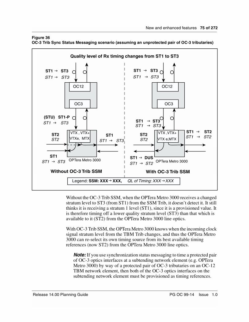
New and enhanced features 75 of 272
Figure 36OC-3 Trib Sync Status Messaging scenario (assuming an unprotected pair of OC-3 tributaries)
Without the OC-3 Trib SSM, when the OPTera Metro 3000 receives a changed stratum level to ST3 (from ST1) from the SSM Trib, it doesn’t detect it. It still thinks it is receiving a stratum 1 level (ST1), since it is a provisioned value. It is therefore timing off a lower quality stratum level (ST3) than that which is available to it (ST2) from the OPTera Metro 3000 line optics.
With OC-3 Trib SSM, the OPTera Metro 3000 knows when the incoming clock signal stratum level from the TBM Trib changes, and thus the OPTera Metro 3000 can re-select its own timing source from its best available timing references (now ST2) from the OPTera Metro 3000 line optics.
Note: If you use synchronization status messaging to time a protected pair of OC-3 optics interfaces at a subtending network element (e.g. OPTera Metro 3000) by way of a protected pair of OC-3 tributaries on an OC-12 TBM network element, then both of the OC-3 optics interfaces on the subtending network element must be provisioned as timing references.
Quality level of Rx timing changes from ST1 to ST3
ST1 ST3
ST1 ST3
ST1 g ST3
ST1 g ST3
ST1 g ST3ST1 g ST3
(STU) ST1-PST1 g ST3
ST2ST2
ST2ST2
ST1 g ST2 ST1 g ST2
ST1 g DUSST1 g ST2
ST1ST1 g ST3
g
g
gg
ST1ST1 g ST3
Without OC-3 Trib SSM With OC-3 Trib SSM
Legend: SSM: XXX XXX, QL of Timing: XXX XXX
OC12 OC12
OC3 OC3
OPTera Metro 3000
VTX , VTX+
VTXe, MTX
VTX ,VTX+
VTX e,MTX
OPTera Metro 3000
Release 14.00 Planning Guide PG OC 99-14 Issue 1.0

76 of 272 New and enhanced features
User interfaceThe CI has been modified to display the Rx/Tx quality levels of each of the provisioned OC-3 trib cards.
The SYNCMSGCI has been modified to support the edittx command. The edittx command first verifies that a user has ADMIN permission. The edittx command allows override of Tx quality level of each OC-12 line, OC-3 trib or ESI facilities outputs, as indicated by the user input.
The following describes the modifications in more detail.
Qrymsg command
The Qrymsg command in the SYNCMSGCI has been modified to display the Rx/Tx SSM of all provisioned OC-3 tribs. Example:
Facility State| Rx (P) | Tx (P) Comments -----------------+-----------+------------------- OC-12 G1 IS | STU | ST1 OC-12 G2 IS | STU (STU) | STU OC-3 G3 IS | STU | ST1 OC-3 G4 IS | DUS | ST1 OC-3 G7 IS | STU | ST1 (ST2) OC-3 G8 OOS | ST1 | DUS BITS A IS | ST1 | --- BITS B IS | STU (STU) | --- DS1 OUT G1 IS | --- | --- SF framingDS1 OUT G2 IS | --- | --- SF framing
S/DMS TransportNode OC-3/OC-12 TBM PG OC 99-14 Issue 1.0

New and enhanced features 77 of 272
Edittx commandA new command, edittx, has been added to SYNCMSGCI. It is available to users with Admin permission, and allows the user to override the transmitted value of the SSM for OC-12 line, OC-3 trib or ESI facilities outputs, g1out and g2out.
The SYNCMSGCI edittx command syntax is as follows:
edittx <service type><circuit pack group><quality level>
where
<service type> is OC-3, OC-12, g1out or g2out
<circuit pack group> is g3 to g8, g1s or g2s for OC-3, gl, g2, g1s or g2s for OC-12
<quality level> is st1, stu, st2, st3, smc, st4, dus; or auto is for removing any provisioned quality level
The following warning appears, and confirmation is requested prior to executing this command.
Warning: this command may affect service. Please confirm (“Yes” or “No”):
Note 1: Any changes to the provisioned SSM value of the OC-12 optics is reflected in the Reference Protection screen of the NE.
Note 2: Any changes to the transmitted quality level for OC-12 line, OC-3 trib, or ESI facilities outputs, g1out and g2out are logged in a FAC401 log.
Upgrades and OC-3 Trib SSMThis functionality is automatically activated upon upgrade of an NE to Release 14.00.
Any other NE type which supports SSM (i.e OPTera Metro 3000 series) and which is timed from a TBM OC-3 trib, has to clear the provisioned value of the SSM received from the TBM OC-3 trib, after the OC-12 TBM has been upgraded to Release 14.00 in order to take advantage of this feature.
OC-3 Tributary Protection Slot Provisioning ExpansionProvisioning rules have been expanded for OC-3 tributary protection slots. Prior to OC-3/OC-12 Release 14.00, when an OC-3 tributary had its protection slot vacant, it was not recommended that this slot be equipped with any other tributary type.
Release 14.00 now supports the equipping of vacant OC-3 tributary protection slots with DS1, DS3 or STS-1 tributaries carrying traffic.
Release 14.00 Planning Guide PG OC 99-14 Issue 1.0
78 of 272 New and enhanced features
Matched Nodes enhancementsThe Matched Nodes Enhancements (MNe) functionality provided by this feature adds two user initiated protection requests at the Matched Nodes Service Selector: lockout of protection and manual switch. It also provides additional information in the OPC primary gateway service selector user interface dialog, the NE facility log and the “Inter-ring protection switch complete” alarm to show the switch trigger reasons. The service selector (SS) related alarms are also enhanced to include the STS channel number to ease troubleshooting.
Lockout of Protection and Manual SwitchThe introduction of Lockout of Protection allows a customer to perform (operate/release) a lockout of protection from the OPC connection manager primary gateway selector status screen. By operating a lockout of protection on a service selector, the primary feed remains selected no matter what is the current status of both feeds.
The introduction of Manual Switch allows a customer to perform a manual switch from the OPC connection manager primary gateway selector status screen. By operating a service selector manual switch request, the secondary feed remains selected, unless the service selector is satisfying a higher priority request.
Table 27 shows the hierarchy of conditions for service selection.
Table 27Hierarchy of Conditions for Service Selection
Condition Priority
Lockout of Protection 1
Forced Switch 2
Path AIS, Path LOP or unequipped signal label (see Note 1)
3
Manual Switch 4
Note 1: unequipped signal label is detectable only on the secondary feed on VTM rings only
S/DMS TransportNode OC-3/OC-12 TBM PG OC 99-14 Issue 1.0

New and enhanced features 79 of 272
Figure 37 represents a typical MNE scenario.
Figure 37Typical MNE scenario
User interfaceThe customer is able to determine path status information and switch reasons from the OPC connection manager primary gateway selector status UI screen and the “ssquery” CI tool.
As part of this feature two new Matched Nodes (MN) alarms have been introduced. Also, the existing and the new service selector related alarms include the STS channel number in the unit field of the alarm summary screen.
Service Selector
OC-12 BLSRRing A
NE Z
NE Z
Pri
Sec
Pri
Sec SAP
OC-12 BLSRRing B
If the MN service selector detects Path AIS on the primary feed, theselector will select the secondary feed. While the secondary feed isactive, if the user operates a lockout of protection, the primary feedwill become active based on the path switching hierarchy
Before:38 F ac 1 O C 12 G 2
After:38 Fac 1 OC12 G2 Inter-ring forced switch request w, nsa3
Inter-ring forced switch request w, nsa
STS channel number
Release 14.00 Planning Guide PG OC 99-14 Issue 1.0
80 of 272 New and enhanced features
OPC Connection ManagerThe OPC Connection Manager’s Primary Gateway Selector Status screen has been enhanced to display current feed status and new switch reasons. Detail feed status includes, when detected, display of lockout of protection, forced switch, manual switch, AIS, or unequipped signal label(UNEQ). These codes replace the current “TRBL” indicator.
Note: The unequipped signal is only monitored on the secondary feed in VTM rings.
The OPC connection manager primary gateway selector status screen also displays the enhanced path status, and contains two new user initiated commands for lockout of protection and manual switch, as shown in Figure 38. Figure 39 shows the associated menu.
Figure 38OPC connection manager primary gateway selector status screen
S/DMS TransportNode OC-3/OC-12 TBM PG OC 99-14 Issue 1.0

New and enhanced features 81 of 272
Figure 39OPC connection manager primary gateway selector status screen menu
ssquery toolThe “ssquery” CI tool has been modified to display feed status and new switch reasons. Detail feed status includes, when detected, a display of AIS, or unequipped signal label(UNEQ). These codes replace the current “TRBL” indicator. For example:
Before:
After:
Prot. Pri Sec
STS CPG Scheme Active Status Status Force Auto
5 G2 DCW Sec TRBL . . *
Prot. Pri Sec
STS CPG Scheme Active Status Status Lck Force Auto Auto
5 G2 DCW Sec TRBL . . . * .
Release 14.00 Planning Guide PG OC 99-14 Issue 1.0

82 of 272 New and enhanced features
The NE “ssquery” CI tool also displays the new user initiated switch reasons (lockout and manual).
UpgradesNo service selector switching is performed until the upgrade of the primary gateway has been completed.
Upgrade to Release 14.00 maintains all existing Matched Nodes connections. Any existing Matched Nodes alarms will now contain the STS channel number.
New and enhanced alarms and logsThe customer can view the path switch reason (AIS, forced switch or manual switch) for the “Inter-ring protection switch complete” alarm by the Switch Trigger (SwTrig) field in the alarm details screen and FAC603 log.
A new alarm “Inter-ring lockout request” has been added to notify the user of a lockout of protection condition. It is raised on a per service selector basis as a non-service affecting minor alarm against the optical STS channel.
This alarm indicates that a Lockout of protection has been requested by the user. The alarm clears once the user releases the lockout request on the primary feed. The alarm format is illustrated by Table 28.
S/DMS TransportNode OC-3/OC-12 TBM PG OC 99-14 Issue 1.0

New and enhanced features 83 of 272
A new alarm “Inter-ring manual switch request” has been added to notify the user of a manual switch condition. It is raised on a per service selector basis as a non-service affecting minor alarm against the optical STS channel.
This alarm indicates that a Manual switch has been requested by the user from primary to secondary feed. The alarm clears once the user releases the manual switch on the primary feed. The alarm format is illustrated by Table 29.
Table 28Inter-ring lockout request alarm format
Detailed Alarm Reports
AlmRpt: 2 Raised
Address: OC-12 G1 chnl 3, 647 Shelf 1 m, nsa
Location: Frame ShPos1 10:08:12
Reason: Inter-ring lockout request 24 March 00
Trib: STS1 G1 1 Facility
Table 29Inter-ring lockout request alarm format
Detailed Alarm Reports
AlmRpt: 3 Raised
Address: OC-12 G1 chnl 5, 647 Shelf 1 m, nsa
Location: Frame ShPos1 11:09:22
Reason: Inter-ring manual switch request 02 April 00
Trib: STS1 G1 2 Facility
Release 14.00 Planning Guide PG OC 99-14 Issue 1.0

84 of 272 New and enhanced features
For the alarm details screen, the “Inter-ring protection switch complete” alarm has the “SwTrig” field enhanced so that it can display all the supported path switch reasons that may cause the inter-ring protection switch to occur. These include AIS, forced switch and manual switch.
The following matched nodes alarms include the STS channel number in all alarm screens:
Inter-ring protection switch complete (w, nsa)
Inter-ring both feeds fail (M, SA)
Inter-ring lockout request (m, nsa) (new alarm)Inter-ring forced switch request (m, nsa)
Inter-ring manual switch request (m, nsa) (new alarm)
For example,
Before:
42 Fac 1 OC-12 G2 Inter-ring both feeds fail M,SA
After:
42 Fac 1 OC-12 G2 5 Inter-ring both feeds fail M,SA
This field will be enhanced to show AIS,forced switch or manual switch.
S/DMS TransportNode OC-3/OC-12 TBM PG OC 99-14 Issue 1.0

New and enhanced features 85 of 272
The NE facility log (FAC603) entry for the “Inter-ring protection switch complete” alarm has been enhanced to contain the “SwTrig” field. This field displays all of the supported path switch reasons. These include AIS, forced switch and manual switch.
The information displayed in the “SwTrig” field of the “Inter-ring protection switch complete” on the alarm details screen and the FAC603 log is the same, which is as expected.
Release 14.00 Planning Guide PG OC 99-14 Issue 1.0

86 of 272 New and enhanced features
Sonet/SDH Signal Mode ProvisioningGeneral description of Sonet/SDH Signal Mode Provisioning
Some customers have a network requirement for an interface at OC-12 linear terminals between the SONET network and SDH signal mode traffic at the OC-3 (STM-1) rate. OC-12 Release 13 provided this interface capability on a shelf-wide basis i.e. all OC-3 tributaries dropped SDH signal mode traffic with no ability to mix SONET and SDH tributaries.
This Release 14.00 feature provides the ability for an OC-12 terminal Network Element to selectively drop SDH traffic on some OC-3 tributaries and SONET traffic on other OC-3 tributaries. Each provisioned OC-3 pair can be configured individually to modify, in the drop direction, the line overhead H1 byte SS bits to ‘10’ for SDH or ‘00’ (default) for SONET traffic. The high speed OC-12 traffic remains SONET and is unaffected. When a programmable OC-3 tributary (NT7E01GA, GB) is inserted, it looks at the high speed optics, if it is set to SDH, then OC-3 trib is set to SDH. If the high speed optics is set to SONET, then the OC-3 trib follows the setting of the mate OC-3 tributary, if it is set to SDH, then the mate is set to SDH.
In order to obtain this mixed mode functionality, the OC-3 tributary optics hardware must be baseline NT7E01GA, GB, which provides the programmability of the circuit pack as SONET or SDH. It can be configured to modify the SSbits in the drop direction regardless of what signal mode it receives on the backplane from the high speed optics. The ability to drop SDH traffic, either by programming the high-speed optics or by programming the tributary optics, is supported on OC-12 linear terminal network elements only.
The provisioning is managed through the CI tool FWSBITCI. The tool enables the user to query the existing SONET/SDH settings on the NE, determine if the circuit packs that are present in the shelf are programmable or not (both OC-12 and OC-3 optics), and modify the SS bit settings.
Any OC-12 SONET/SDH shelf-wide signal format programming will survive upgrades to Release 14.00. All OC-3 programming will default to the high speed optics setting, after the upgrade.
SONET/SDH mix functionalityThe Release 13 implementation provided a basic CI interface for programmingthe high speed OC-12 optics to drop SDH traffic onto the backplane, to be passed along unaltered by all the OC-3 tributaries on the shelf. The OC-12 optics hardware requirement was NT7E02XB, NA, NB or Px.
S/DMS TransportNode OC-3/OC-12 TBM PG OC 99-14 Issue 1.0

New and enhanced features 87 of 272
The Release 14.00 feature does not eliminate this ability to program SDH at the OC-12 optics. Shelf-wide SDH settings are still supported. However, OC-3 tributary specific programming overrides any shelf-wide settings for that tributary. This implies that a mixture of shelf-wide and tributary specific settings can co-exist.
When an inactive OC-12 circuit pack is inserted, it provisions its SONET/SDH setting from the active mate card. If the inserted card does not meet the baseline for SONET/SDH mix, then an alarm is raised.
The ability to drop SDH traffic, either by programming the high-speed optics or by programming the tributary optics, is supported on OC-12 linear terminal network elements only.
If a non-programmable card is inserted and has a SONET/SDH programmable mate (OC-3 NT7E01GA, GB, or OC-12 NT7E02XB, Px) with programming active, the EQP Hardware Software Incompatible alarm is raised against the new card. Switching activity to an incompatible OC-3 or OC-12 circuit pack from a programmed mate is not prevented. The ‘Hardware Software Incompatible’ alarm becomes C, SA.
User interfaceThe provisioning interface for the SONET/SDH signal format settings is the same as the that for the existing FWSBITCI CI tool, with the following modifications:
• The ‘help’ subcommand displays the new command structure. It also displays a general explanation of how to proceed with the tool and warnings about mixing shelf-wide and tributary specific SONET/SDH settings and provisioning appropriate STS-3c connections on SDH OC-3 tributaries.
• The existing ‘QuerySS’ subcommand has been changed to ‘Query’, and displays a map of provisioned high speed and low speed optics. It also displays the hardware compatibility for each, as well as the currently programmed and default SONET/SDH signal modes.
• The existing ‘SetSS’ subcommand has been changed to ‘SetSDH’. It allows the programming of the high speed optics and/or any optical tributaries. Attempts to program provisioned optics which do not support this capability result in the display of an appropriate hardware compatibility message. All commands to set SDH signal format require a confirmation before the change takes place.
• The existing ‘ResetSS’ subcommand has been changed to ‘SetSONET’. It allows the programming of any SDH optics back to SONET, and displays appropriate warnings. It requires a confirmation before the change takes place.
Release 14.00 Planning Guide PG OC 99-14 Issue 1.0

88 of 272 New and enhanced features
• STS-3c connections for SDH OC-3 tributaries are not enforced or alarmed. Customers must ensure that appropriate connections have been provisioned for the SDH signal mode OC-3 tributaries.
Operational scenariosProvisioning Shelf-wide SDHThis approach involves programming the high speed optics to drop SDH signal mode traffic to the backplane, which is passed on unaltered by all OC-3 tributaries on the shelf, including SONET/SDH programmable ones. Hardware vintage of the OC-3 optics is irrelevant.
OC-3 traffic is affected by this procedure until the subtending OC-3 equipment is provisioned as SDH and a STS-3c connection is setup. Traffic on all non-optical tributaries is not affected.
This procedure is comprised of the following steps:
• Verify that the high speed OC-12 optics support SDH programming. Enter FWSBITCI > Query.
• Provision STS-3c connections for all OC-3 tributaries.
• Program the OC-12 optics to drop SDH signal mode traffic. Enter FWSBITCI > SetSDH ALL
WARNING: Any OC-3 optics that have been specifically programmed to drop SONET signal mode traffic will be reprovisioned to SDH. This procedure overwrites any tributary specific SONET programming.
Provisioning Shelf-wide SONETThis procedure is used to program the high speed optics to drop SONET signal mode traffic to the backplane, which is passed on unaltered by all OC-3 tributaries on the shelf, including SONET/SDH programmable ones. The hardware vintage of the OC-3 tributaries is irrelevant.
OC-3 traffic is affected by this procedure until the subtending OC-3 equipment is provisioned as SONET accordingly. Traffic on all non-optical tributaries is not affected.
This procedure is comprised of the following steps:
• Verify that the high speed OC-12 optics support SONET/SDH programming (NT7E02NA, NB circuit packs are SDH only). Enter FWSBITCI > Query
• Deprovision the STS-3c connections if required.
• Program the OC-12 optics to drop SONET signal mode traffic. Enter FWSBITCI > SetSONET ALL
S/DMS TransportNode OC-3/OC-12 TBM PG OC 99-14 Issue 1.0
New and enhanced features 89 of 272
WARNING: Any OC-3 optics that have been specifically programmed to drop SDH signal mode traffic will be reprovisioned to SONET. This procedure will overwrite any tributary specific SDH programming.
Programming OC-3 tributary(s) to drop SDHThis procedure uses tributary specific programming to enable SDH signal mode traffic on an individual OC-3 tributary. The NE is not programmed to drop SDH traffic at a shelf level. The procedure can be repeated for any programmable OC-3 tributary on the NE.
OC-3 traffic on the specific tributary being programmed is affected by this procedure until the subtending OC-3 equipment is provisioned as SDH accordingly. All other tributaries on the shelf, including OC-3, are unaffected by this procedure.
This procedure is comprised of the following steps:
• Verify that the selected OC-3 tributary circuit packs are provisioned and meet the required hardware baseline for SDH/SONET capability. Enter FWSBITCI > Query.
• Provision a STS-3c connection for the selected OC-3 tributary.
• Program the OC-3 optics to drop SDH signal mode traffic. Enter FWSBITCI > SetSDH OC-3 Gn
Adding an OC-3 tributary to a SDH NEThis procedure is used to add a new OC-3 tributary in SDH mode to a shelf programmed as SDH at the high speed optics. The OC-3 hardware vintage used is irrelevant, however using SONET/SDH programmable hardware increases future provisioning flexibility.
This procedure is comprised of the following steps:
• Provision the new OC-3 tributary hardware according to standard provisioning procedures. The circuit packs default to the shelf SDH setting. No tributary specific programming is required.
• Provision a STS-3c connection for the new OC-3 tributary.
Programming OC-3 tributary(s) to drop SONETThis procedure uses tributary specific programming to enable SONET signal mode traffic on an individual OC-3 tributary in a shelf programmed as SDH at the high speed optics. The OC-3 optics must support SONET/SDH programming.
This procedure is comprised of the following steps:
Release 14.00 Planning Guide PG OC 99-14 Issue 1.0

90 of 272 New and enhanced features
• Verify that the selected OC-3 tributary circuit packs are provisioned and meet the required hardware baseline for SONET/SDH capability. Enter FWSBITCI > Query.
• Program the OC-3 optics to drop SONET signal mode traffic. Enter FWSBITCI > SetSONET OC-3 Gn
Re-programming an existing SDH-programmed OC-3 tributary to SONETThis procedure is used to change an existing OC-3 tributary programmed as SDH to SONET. Note that the state of the shelf-wide programming at the high speed optics is irrelevant as long as the OC-3 optics support SONET/SDH programming.
This procedure is comprised of the following steps:
• Verify that the selected OC-3 tributary is programmed as SDH. Enter FWSBITCI> Query
• Deprovision the STS-3c connections if required.
• Program the OC-3 optics to drop SONET signal mode traffic. Enter FWSBITCI> SetSONET OC-3 Gn
OC-3 circuit pack replacement - SONET/SDH considerationsThe insertion of a protection OC-3 circuit pack always cause it to provision its SONET/SDH signal mode according to its mate card. In all cases no manual signal mode provisioning is required.
If a non-programmable card is inserted and has a SONET/SDH programmable mate with programming active, the EQP Hardware Software Incompatible alarm is raised against the new card. The inserted card is available for protection switching but is not capable of carrying the programmed SONET/SDH signal mode traffic. Switching activity to the alarmed card results in traffic loss.
S/DMS TransportNode OC-3/OC-12 TBM PG OC 99-14 Issue 1.0

New and enhanced features 91 of 272
Ring-Link Parity SwitchRelease 14.00 introduces the Ring-Link Parity Switch feature.
Note: The Ring Link Parity Switch feature only applies to VTM Ring systems.
The Ring Link (R-link) passes incoming optical traffic between OC-12 VTM cards. All 12 STSs received by one VTM card are passed to the mate card. The "STS-12 ring link parity error" alarm is raised when traffic may be affected due to a fault on the R-link. With a high speed protection switch active, the failure is cleared as traffic no longer passes through the R-link.
The Ring Link Parity Switch feature works as follows:
Upon detection of an STS-12 ring link parity error, a manual high speed protection switch, located away from the G1 optics, is automatically activated. Prior to the high speed switch, the "STS12 ring link parity error" alarm is raised as a Critical alarm.
If "STS12 ring link parity error" alarm is raised against OC-12 G1 optics, it is lowered to an "m, nsa" alarm, and any affected traffic will be restored. A standing "manual switch request" alarm and "protection switch complete" warning are also raised.
If "STS12 ring link parity error" alarm is raised against OC-12 G2 optics, the auto manual switch away from G1 will restore the traffic, but the "STS12 ring link parity error" alarm will remain as "C, SA". The “manual switch request” alarm and “protection switch complete” warning are also raised.
The craftsperson should proceed by following the standard circuit pack replacement procedures for STS-12 ring link parity error mentioned in NTP. After successful circuit pack replacement, the Ring Link parity alarm is lowered.
Release 14.00 Planning Guide PG OC 99-14 Issue 1.0

92 of 272 New and enhanced features
RequirementsThe following functionalities are part of the implementation of this feature.
• The feature is enabled by default in TBM Release 14.00 software.
• The feature status remains unchanged across a reboot and all types of restarts.
• The feature status remains unchanged after any upgrades.
• The feature is not active during a reconfiguration. (Force switch active on ring)
• The feature only applies to a VTM system.
• The feature is not active if the node is in Passthrough state (An active switch present in the ring) to prevent ring segmentation, unless the switch request is in Wait To Restore (WTR) state.
• Manual switching pre-empts the WTR.
• Manual switching is automatically initiated once the STS-12 R-link parity error is detected either on a G1 card or G2 card.
• Traffic is always switched to G2 card regardless of which card detected the fault. Note that a higher priority switch on the G2 card pre-empts this action.
• The manual switching can only be released by a craftsperson or pre-empted by the higher priority protection switching.
Note: If the automatic manual switch is released before corrective actions have removed the cause of the “STS12 R-link parity error”, traffic will be affected.
In-Service NE RenumberingThe In-Service NE ID Renumbering (ISNR) feature allows customers to change the NE ID associated with a shelf, without affecting traffic.Currently, the NE ID is a unique number that identifies an NE inside a network and cannot be duplicated.
The recent mergers, acquisitions and operations restructuring of some customers has increased the importance of providing an efficient and simple ISNR procedure. As part of these mergers, it is likely that some nodes with the same NE ID will become part of the same network. In this event, the NE ID of one of the nodes will need to be changed to a new unique NE ID to avoid any NE ID duplication within the network. Figure 40 provides a graphical representation of such a scenario.
Note: For OC-12 Release 13.11/13.12 this method was delivered to our customers in a tape with an associated CAP. For Release 14.00, this method is delivered as part of the software load.
S/DMS TransportNode OC-3/OC-12 TBM PG OC 99-14 Issue 1.0

New and enhanced features 93 of 272
Figure 40NE numeric identifier duplication problem scenario
For OC-3/OC-12 TBM Release 14.00, the following changes have been made to the ISNR feature:
• The ISNR tool is delivered as part of the software load, and the tool is invoked from OPCUI screen.
• A new OPC alarm “NE ID Renumbering in progress” is raised.
• Configuration Manager Audit on OPC updates new NE number on other NE's in the ring.
• Connection Manager audit on the OPC updates new NE number in the connection data.
The benefits of In Service NE Renumbering can be summarized as follows:
• Provides an in-service mechanism to renumber the NE ID associated with an NE in a network.
• Preserves the commissioning and provisioning of data.
• Provides ease of use and integrated functionality in Release 14.00.
• Maintains consistency of operation with OC-48 systems.
• Enhances the functionality delivered in Release 13, as summarized in Table 30.
NE 1 NE 2
NE 3 NE 4
NE 4NE 5
NE 6NE 7
Network 1
Network 2
Network 1+2(Merged Network)
FROM TO
NE 1 NE 2
NE 3 NE 4
NE 4NE 5
NE 6NE 7
Merging
Duplicate NE numeric identifier.One NE numeric identifier has to change
Release 14.00 Planning Guide PG OC 99-14 Issue 1.0

94 of 272 New and enhanced features
Table 30Enhancements from ISNR Release 13 to ISNR Release 14.00
Functional overviewThe ISNR procedure is supported on all configurations of the OC-12 product line (NWK ring, VTM ring, Regenerator, Linear ADM, Terminal, OC-12 linear). The ISNR procedure is simple to use and is fairly automated. ISNR requires interaction with the OPC only (except that the procedure needs to login to the NE to record user profile data).
The NEIDs stored in the other NEs are modified when configuration and connection audits are issued from OPC. ISNR is an OPC tool invoked from the OPCUI, under restart tools. The ISNR procedure is available only to root or rootlike users. It changes all the NE ID instances on the NE from the old NE ID to the new NE ID. As well, it supports NE ID enhancements. The NE ID range supported is 1 to 65534.
During the ISNR procedure, there is a loss of OAM to the target NE. Furthermore, OAM to all the other NEs in the SOC is available only from the Backup OPC (if provisioned). Note that traffic, however, is not affected.
The configuration audit and connection audit correct the mismatch of NE IDs without causing any traffic loss or traffic hit within a ring. The NEIDs stored in the other NEs are modified when configuration and connection audits are issued from OPC. The ISNR procedure does not require the customer to manually edit the connections (STS1, STS1/VT managed pipe, VT1.5, STS3c, DS3/DS1, matched nodes DCP/DCW) terminating at the target NE and other NEs in the configuration. The ISNR procedure automatically modifies the connection maps on the OPC and on the NEs within the OPC SOC. That is, every A-Z parameters within a connection entity is modified to reflect the new NE ID number.
ISNR Release 13 ISNR Release 14.00
The tool was installed from tape. The tool is delivered in the load.
The tool was invoked from the command line.
The tool is invoked from the OPCUI.
There was no “ISNR in progress” alarm raised.
An OPC “ISNR in progress” alarm is raised.
S/DMS TransportNode OC-3/OC-12 TBM PG OC 99-14 Issue 1.0

New and enhanced features 95 of 272
Note that there is a limitation with connections across NEs in two different spans of control. The NE ID A (or Z) will not get updated in one OPC SOC if the NE ID A (or Z) in the other is changed using the Renumbering Procedure. The tool allows the user to renumber an NE not visible in the network. However only the connection and configuration information on the OPC is modified. The user is instructed to specifically modify the NE IDs on the NE concerned.
Note as well that if the customer uses the NE ID as part of the Connection or Facility Id, the customer has to manually change these Ids. That is, the In-service NE ID procedure does not change any Connection or Facility Ids.
For OAM activities during ISNR, it is the customer’s prerogative to prevent OAM on the target NE (that is, provisioning should be prevented on the NE.) It is also the customer’s prerogative to prevent In-service NE ID Renumbering during an upgrade.
The following describes further characteristics of the ISNR feature:
• The ISNR procedure supports the renumbering of only one NE at a time in an OPC SOC.
• The ISNR procedure preserves the contents of the NE database of the target NE (except NE IDs on the NE database are changed), and thus ensures restoration of the provisionable parameters of the target NE after the NE renumbering.
• The ISNR procedure automatically updates the datacom information on all the NEs to ensure that the renumbered NE is still accessible within the datacom network. Communications to the renumbered NE are also automatically enabled upon completion of the renumbering procedure.
• The target NE databases on the OPC are restored after the renumbering operation.
• Sequential renumbering of NE’s are allowed to run in one maintenance window.
OPC toolsThe ISNR procedure automatically modifies the data associated with any of the OPC UNIX based tools which use the NE ID and change the NE ID with respect to the target NE. The data on the OPC pertaining to the following tools are automatically modified, and the NE ID with respect to the target NE are changed:
• Connection and Configuration Manager data
• Protection Manager data
• Login Manager data
Release 14.00 Planning Guide PG OC 99-14 Issue 1.0

96 of 272 New and enhanced features
• Network Summary and Network Browser data
• Reboot Load Manager data
Note 1: The Protection Manager, the Connection and Configuration Manager, and the Login Manager should not be opened when a renumbering is in progress. When the tools are opened again after the renumbering, the change in NE ID will be reflected.
Note 2: Access to the Network Summary and Network Browser is not restricted during a renumbering operation. This tool automatically updates itself to reflect the new NE ID after an NE renumbering operation.
Scheduled tests like Protection Exerciser and NE database backups are not impacted by the renumbering operation. However, scheduled audits and datasyncs will impact the renumbering operation and are not supported during the ISNR procedure.
The ISNR procedure raises an alarm on the primary OPC, that the renumbering is in progress. The alarm is raised after the NE renumbering is initiated on the OPC, and is cleared after the renumbering is complete.
Upon completion of an ISNR procedure, no alarm associated with the old NE ID is visible from the TBOS interface ports. However, the same alarms which were associated with the old NE ID, are now associated with the new NE ID by the ISNR procedure. Also, upon completion of an ISNR procedure, all alarms associated with the old NE ID in the Alarm Monitor of the OPC are re-raised with the new NE ID.
Note: Information on alarms that have been cleared before the Renumbering operation are not modified. This tool automatically updates itself to reflect the new NE ID after an NE renumbering operation.
The Events that are displayed on the Event Browser of the OPC are associated with the new NE ID after the Renumbering operation.
Note: Any events associated with the old NE ID are not visible after a renumbering operation. If the NE has an alarm associated with it before ISNR, this alarm information appears in the Event Browser associated with the new NE ID after ISNR. This tool’s access is not restricted during a renumbering operation.This tool automatically updates itself to reflect the new NE ID after an NE renumbering operation.
S/DMS TransportNode OC-3/OC-12 TBM PG OC 99-14 Issue 1.0

New and enhanced features 97 of 272
Operational considerationsThe following are operational considerations when implementing the OC-12 In-Service NE Renumbering feature:
• The NE Renumbering procedure cannot be used to renumber an NE if the SOC of this NE contains incomplete nodal cross-connects across different SOC NEs, that is, for cross-connects provisioned from an external OSS (like TL1) between NEs in a different SOC.
• After the NE Renumbering procedure has started, if an automatic protection switch occurs, it has to be attended to only after the procedure has been completed.
All tools on the OPC need to be closed as a pre-requisite, before starting the renumbering procedure.
• An NE ID which is used as part of filters in the User Interface tools on the NE or OPC is not changed to reflect the new NE ID.
• If an NE is renumbered from A to B and if some other NE C is renumbered to A in the same SOC, then historical Event logs associated with the original NE A may become associated with the original NE C (which was renumbered to A).
Workaround: The user has to rely solely on timestamps to ascertain which actual (or physical) NE to which the log belongs.
• The user provisioned CUA access privileges on the OPC are not automatically updated by ISNR tools.
Workaround: The user has to use the manual procedure documented in the ISNR CAP to recover all CUA access privilege data after ISNR.
• Remote telemetry provisioned values on the OPC for the target NE are lost after ISNR.
Workaround: The user has to use the manual procedure documented to recover these provisioned values.
• Orderwire connections are dropped when the NE performs a restart warm, and cannot be re-established. The user needs to reinitialize the orderwire connection.
• Users cannot not use rlogin to renumber an NE.
• Failure to abide by the ISNR CAP could lead to service interruption.
• You cannot perform a restart reload on the NE being renumbered.
• The OPC should not be shut down during ISNR.
• The Renumbering procedure performs a ‘save to tape’ and ‘backup OPC data sync’ at the start and end of the Renumbering operation per SOC. Note that these must be performed manually.
Release 14.00 Planning Guide PG OC 99-14 Issue 1.0

98 of 272 New and enhanced features
• No other users should be logged into the target NE before and during the ISNR operation.
• The ISNR operation should not be started between 11:50pm and 12:10am.
• All TBOS data on the NE is preserved by the ISNR. However, remote telemetry data on the OPC is lost after ISNR
INM/Preside Application Platform and TL1Upon completion of an ISNR procedure, INM/Preside Application Platform modifies its internal data structures and changes the NE ID with respect to the target NE.
Upon completion of an ISNR procedure, no alarm associated with the old NE ID is visible from INM/Preside. The same alarms which were associated with the old NE ID, are now associated with the new NE ID.
The ISNR procedure automatically modifies the TL1 data and changes the NE ID with respect to the target NE. The ISNR automatically rewrites the TID with the new NE ID even if the TID was provisioned.
Upon completion of an ISNR procedure, no alarm associated with the old NE ID is visible from the TL1 interface. The same alarms which were associated with the old NE ID, are now associated with the new NE ID.
Performing an ISNRIn Release 14.00, the operation of an ISNR procedure is as follows:
Note: Before performing this procedure, the user must first perform a ‘save to tape’ and ‘Datasync to the backup OPC’, and manually record NE specific CUA parameters and remote telemetry parameters. This procedural information is documented in the ISNR section of the NTPs.
• Invoke the tool from OPCUI.
• Select the option to renumber an NE.
• Type in the old and new NE ID. This validates the input, and raises an OPC ‘NE ID Renumbering in progress’ alarm.
• Login to the NE being renumbered and perform renumbering on the target NE. This modifies the NE database.
• Manually decommission and recommission the NE being renumbered.
• Manually perform a configuration and connection audit and correct any mismatches to modify the NE database which shares the same configuration as the NE being renumbered.
• In the NE Renumbering tool, select the option to clean up the OPC when the NE renumbering is finished.
S/DMS TransportNode OC-3/OC-12 TBM PG OC 99-14 Issue 1.0

New and enhanced features 99 of 272
• Using the CUA tool, send the old user IDs and passwords to the renumbered NE.
• Manually perform a database backup from the NE being renumbered.
• Perform a ‘save to tape’ and ‘Datasync to the backup OPC.’
New Alarm for ISNRAn OPC alarm is raised when an NE renumbering is in progress. After the user launches the ISNR tool from OPC, the user selects the option to renumber an NE. The alarm is reported to the OPC Alarm Monitor screen after the tool verifies the input. Figure 41 shows this new alarm.
Figure 41NE ID Renumbering in progress alarm
The detailed alarm information is as follows:
• Text/Reason: NE ID renumbering is in progress
• Severity: Warning
• Service code: NonServiceAffecting
• Type: OPC
• Category/Class: Equipment
• Cause: An NE is being renumbered. Normal functionality of some tools on the OPC (e.g. Connection Manager, Configuration Manager, Backup Restore Manager, Reboot Load Manager, etc.) may be unavailable while this operation is in progress.
• Action: Complete the renumbering procedure. The alarm will clear when the last step of the procedure (when the user chooses the option to clean up
Release 14.00 Planning Guide PG OC 99-14 Issue 1.0
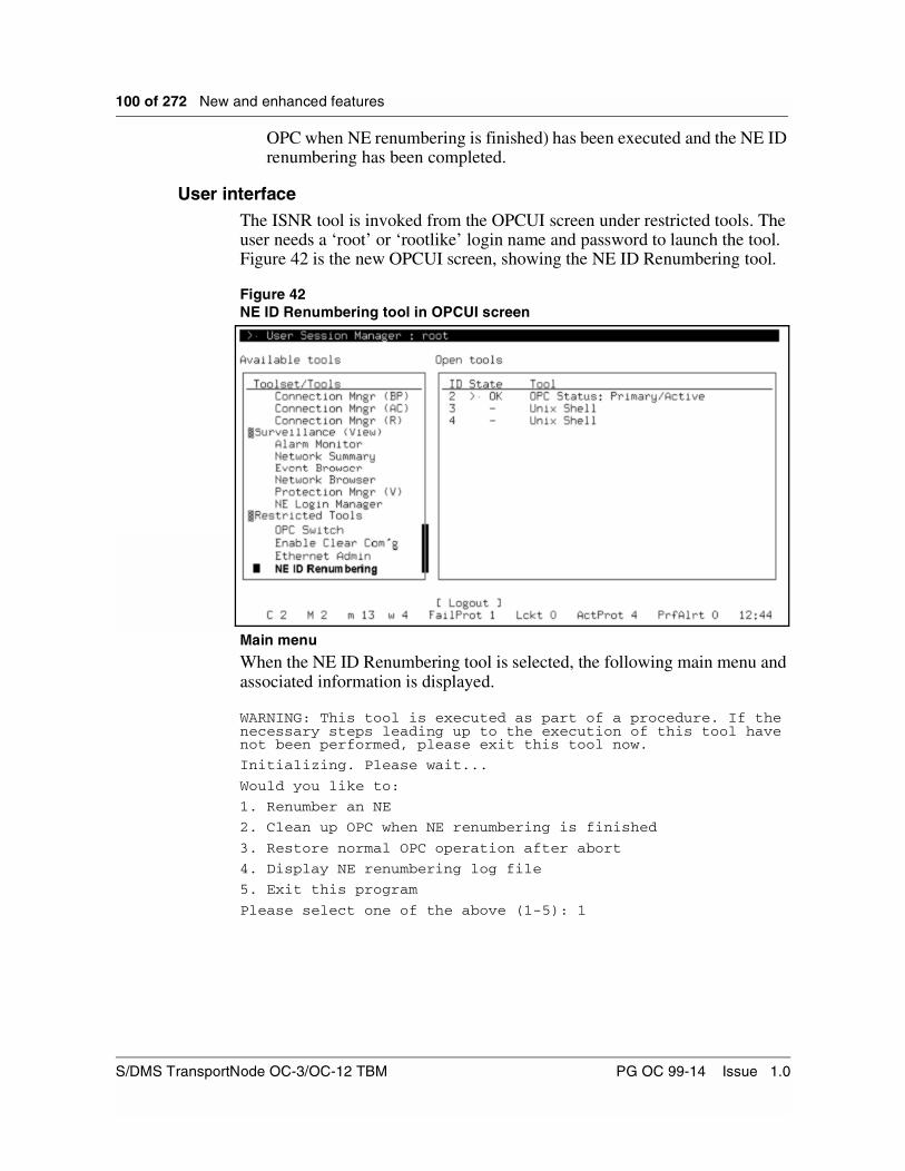
100 of 272 New and enhanced features
OPC when NE renumbering is finished) has been executed and the NE ID renumbering has been completed.
User interfaceThe ISNR tool is invoked from the OPCUI screen under restricted tools. The user needs a ‘root’ or ‘rootlike’ login name and password to launch the tool. Figure 42 is the new OPCUI screen, showing the NE ID Renumbering tool.
Figure 42NE ID Renumbering tool in OPCUI screen
Main menu
When the NE ID Renumbering tool is selected, the following main menu and associated information is displayed.
WARNING: This tool is executed as part of a procedure. If the necessary steps leading up to the execution of this tool have not been performed, please exit this tool now.
Initializing. Please wait...
Would you like to:
1. Renumber an NE
2. Clean up OPC when NE renumbering is finished
3. Restore normal OPC operation after abort
4. Display NE renumbering log file
5. Exit this program
Please select one of the above (1-5): 1
S/DMS TransportNode OC-3/OC-12 TBM PG OC 99-14 Issue 1.0
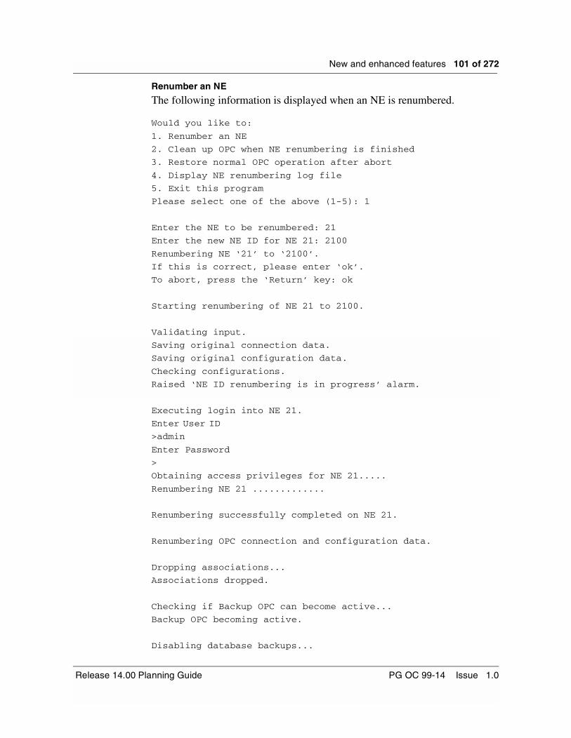
New and enhanced features 101 of 272
Renumber an NE
The following information is displayed when an NE is renumbered.
Would you like to:
1. Renumber an NE
2. Clean up OPC when NE renumbering is finished
3. Restore normal OPC operation after abort
4. Display NE renumbering log file
5. Exit this program
Please select one of the above (1-5): 1
Enter the NE to be renumbered: 21
Enter the new NE ID for NE 21: 2100
Renumbering NE ‘21’ to ‘2100’.
If this is correct, please enter ‘ok’.
To abort, press the ‘Return’ key: ok
Starting renumbering of NE 21 to 2100.
Validating input.
Saving original connection data.
Saving original configuration data.
Checking configurations.
Raised ‘NE ID renumbering is in progress’ alarm.
Executing login into NE 21.
Enter User ID
>admin
Enter Password
>
Obtaining access privileges for NE 21.....
Renumbering NE 21 .............
Renumbering successfully completed on NE 21.
Renumbering OPC connection and configuration data.
Dropping associations...
Associations dropped.
Checking if Backup OPC can become active...
Backup OPC becoming active.
Disabling database backups...
Release 14.00 Planning Guide PG OC 99-14 Issue 1.0
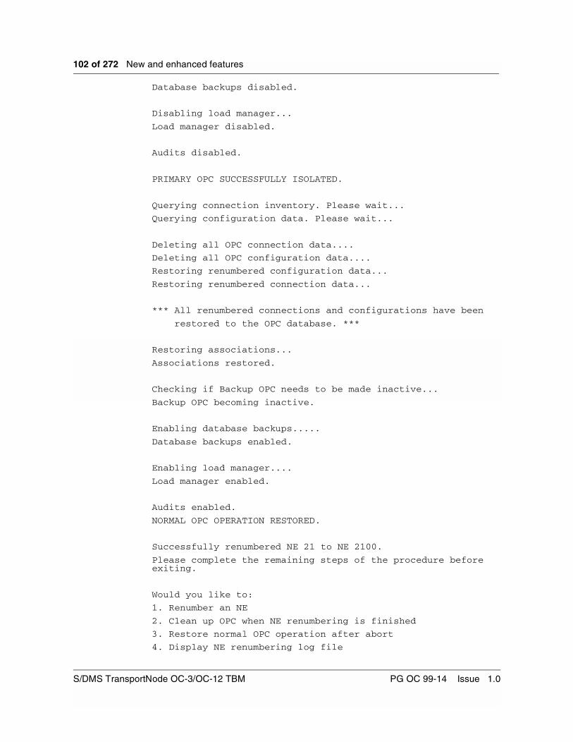
102 of 272 New and enhanced features
Database backups disabled.
Disabling load manager...
Load manager disabled.
Audits disabled.
PRIMARY OPC SUCCESSFULLY ISOLATED.
Querying connection inventory. Please wait...
Querying configuration data. Please wait...
Deleting all OPC connection data....
Deleting all OPC configuration data....
Restoring renumbered configuration data...
Restoring renumbered connection data...
*** All renumbered connections and configurations have been
restored to the OPC database. ***
Restoring associations...
Associations restored.
Checking if Backup OPC needs to be made inactive...
Backup OPC becoming inactive.
Enabling database backups.....
Database backups enabled.
Enabling load manager....
Load manager enabled.
Audits enabled.
NORMAL OPC OPERATION RESTORED.
Successfully renumbered NE 21 to NE 2100.
Please complete the remaining steps of the procedure before exiting.
Would you like to:
1. Renumber an NE
2. Clean up OPC when NE renumbering is finished
3. Restore normal OPC operation after abort
4. Display NE renumbering log file
S/DMS TransportNode OC-3/OC-12 TBM PG OC 99-14 Issue 1.0

New and enhanced features 103 of 272
5. Exit this program
Please select one of the above (1-5):
Clean up OPC
At the end of the NE Renumbering procedure, a “cleanup” of the OPC must be performed by selecting option 2 from the main menu. Doing so deletes any temporary files created during the renumbering, and clears the “NE ID Renumbering in Progress” alarm.
The following output is displayed.
Would you like to:
1. Renumber an NE
2. Clean up OPC when NE renumbering is finished
3. Restore normal OPC operation after abort
4. Display NE renumbering log file
5. Exit this program
Please select one of the above (1-5): 2
Removing temporary files...
‘NE ID renumbering is in progress’ alarm cleared.
Clean-up completed.
Would you like to:
1. Renumber an NE
2. Clean up OPC when NE renumbering is finished
3. Restore normal OPC operation after abort
4. Display NE renumbering log file
5. Exit this program
Please select one of the above (1-5): 5
Note: Renumbering of out-of-span NEs and regens is similar, except that when renumbering out-of-span NEs, only the OPC component is executed and the user does not log into the NE. When renumbering regens, only the NE component is executed but the OPC databases need not be modified (regens are not present in connections or configurations).
Abort NE Renumbering
If a “non-fatal” error occurs, the user is given the option to abort or continue.
An example of a “non-fatal” error is shown below. In this case, the inability to make the Backup OPC inactive is displayed. The renumbering was subsequently aborted.
(... previous interaction deleted...)
Dropping associations ...
Associations dropped.
Release 14.00 Planning Guide PG OC 99-14 Issue 1.0

104 of 272 New and enhanced features
Checking if Backup OPC can become active .............
Error: Failed to force Backup OPC to become active.
Disabling database backups ...
Database backups disabled.
Disabling load manager ...
Load manager disabled.
Audits disabled.
Isolating Primary OPC failed with 1 error(s) detected.
Please contact your next level of support to
determine whether NE renumbering can proceed.
Errors have been detected. Do you wish to abort (Y/N): y
*** PROGRAM ABORTED. ***
Would you like to:
1. Renumber an NE
2. Clean up OPC when NE renumbering is finished
3. Restore normal OPC operation after abort
4. Display NE renumbering log file
5. Exit this program
If the user decides to continue in spite of the error condition, execution of the script resumes from where the error was detected. If the user decides to abort, it may be necessary to restore normal OPC operation after an abort. This option restores the normal operation of critical software processes in case they had been taken out of services as the Primary OPC was being isolated. Note that the “NE ID renumbering in progress” alarm must be cleared as a separate step, even if normal OPC operation is restored.
LogsLogs are created on the /nerenum and /var/log/syslog directories on the primary OPC to keep track of ISNR activity.
S/DMS TransportNode OC-3/OC-12 TBM PG OC 99-14 Issue 1.0

New and enhanced features 105 of 272
CLEI enhancementsThe Common Language Equipment Identifiers (CLEIs) for circuit packs have the following enhancements:
• the Equipment Shelf inventory screen on the network element user interface correctly displays CLEI, including cases where new CLEIs have been assigned for different versions of circuit packs with the same PEC
• incorrect CLEIs are automatically corrected after a software upgrade to OC-3/OC-12 TBM Release 14.00
• circuit packs added to a network element after a software upgrade to OC-3/OC-12 TBM Release 14.00 have their PEC and unique CLEI automatically retrieved and displayed on the Equipment Shelf Inventory screen on the network element user interface
• the PECCLEI tool is new in Release 14.00, which has been introduced to allow for future flexibility for adding CLEI for circuit packs produced after OC-3/OC-12 TBM Release 14.00. The PECCLEI tool can also be used to delete, modify, or do a query on CLEI.
Release 14.00 Planning Guide PG OC 99-14 Issue 1.0

106 of 272 New and enhanced features
Software Upgrades to Release 14.00In-service single path software upgrades are supported to OC-3/OC-12 TBM Release 14.00 from the following software releases:
• OC-3/OC-12 TBM Release 11.20
• OC-3/OC-12 TBM Release 13.11
• OC-3/OC-12 TBM Release 13.12
The upgrade to TBM Release 14.00 from these releases can be performed using CAP OC 99-153.
Table 31 lists all the possible software upgrade paths, in order to reach Release 14.00.
Table 31Possible software upgrade paths
From To CAP number
4.xx 5.00 OC 93-114
4.21 6.01 OC 93-119
5.0 6.01 OC 93-119
7.10 OC 93-132
8.10 OC 94-148
6.01 7.10 OC 93-132
8.10 OC 94-148
9.01 OC 94-137
7.10 8.10 OC 94-148
9.01 OC 94-137
10.03 OC 94-158
8.10 9.01 OC 94-137
10.03 OC 94-158
11.20 OC 95-105
S/DMS TransportNode OC-3/OC-12 TBM PG OC 99-14 Issue 1.0

New and enhanced features 107 of 272
Upgrade enhancements
The following summarizes the enhancements that have been introduced as part of the Release 14.00 upgrades:
• Prechecks verify the current software release running on the system, and prevent the upgrade to start if the NEs in the SOC are not running the same release.
• The OPCs datasync the customized baseline file check information. The OPC software is able to sync the baseline tool alarms on both the primary and backup OPC.
The following must be considered when planning a system upgrade to TBM Release 14.00:
• The primary OPC must be equipped with a tape drive or cartridge drive.
• In a multi span-of-control system, each span is upgraded from its own OPC. Note that parallel span upgrades can be performed for these multi span systems.
• The OPC span consolidation (joining multiple OPC spans into a single span of control) can be performed once the upgrade has been completed.
Note that backout CAP OC 99-154 can be performed if an upgrade backout is required to release 11.20, 13.11, or 13.12, during the upgrade to Release 14.00.
9.01 10.03 OC 94-158
13.11/13.12 OC 98-164
10.03 11.20 OC 95-105
13.11/13.12 OC 98-164
11.20 13.11/13.12 OC 98-164
14.0 OC 99-153
13.11 14.0 OC 99-153
13.12 14.0 OC 99-153
Table 31Possible software upgrade paths
From To CAP number
Release 14.00 Planning Guide PG OC 99-14 Issue 1.0

108 of 272 New and enhanced features
Upgrade AutoresumeThe Autoresume feature consists of adding the following three items to the items list menu of the existing NUM tool in the OPCUI:
• “Cancel Pause”
• “Autoresume after”
• “Remove Autoresume”
Autoresume reduces the need for manual intervention to resume the upgrade of a SOC, at a given time. Autoresume may be set for a given time within a 24-hour period.
Setting an autoresume in NUM is similar to setting a regular pause, except that the autoresume is timed to resume the upgrade automatically at a specified time, within the next 24 hours. Autoresume, like a pause, can only be applied to a task item in the activation phase items list. It can be inserted anytime that the NUM User Interface window is open (see the user interface section which follows). However, an autoresume can only be applied before a task item in the activation phase items list, if the status of the task item is other than successful or in progress. Also, an autoresume cannot be inserted before or after a pause. The pause must be cancelled first.
Note that if the upgrade has not reached the autoresume when it times out, the autoresume will replace itself automatically with a regular pause.
Also, if an autoresume or pause is removed while the upgrade is paused by it, the upgrade remains paused unless resumed by the user. If the user exits the NUM application, the autoresume is removed automatically.
If the autoresume scheduled time is reached while the upgrade is paused by the autoresume, then the autoresume is removed and the upgrade is resumed automatically.
If the autoresume scheduled time is reached while the upgrade is not paused by the autoresume, then the autoresume will replace itself with a regular pause and will not attempt to resume the upgrade. The upgrade will now be paused indefinitely when the regular pause is reached.
S/DMS TransportNode OC-3/OC-12 TBM PG OC 99-14 Issue 1.0

New and enhanced features 109 of 272
User interfaceChanges have been made to the NUM user interface to introduce this new functionality. The list items menu is invoked on the NUM, when the cursor is placed in the list items dialog box. Figure 43 shows the new lists item menu.
Figure 43New list items menu
Release 14.00 Planning Guide PG OC 99-14 Issue 1.0

110 of 272 New and enhanced features
CommandsThe following sections describe the commands that are used in the list items menu.
Cancel Pause,
“Cancel pause” cancels any pause that may have been inserted.
Remove AutoResume
“Remove AutoResume” removes any Autoresume that may have been inserted.
AutoResume after
Once selected, “AutoResume after” provides a warning to the user regarding the effects of Autoresume. The user is prompted to enter valid values for the hour and minute parameters, as shown in Table 32.
If the user does not enter valid hour and minute values, another dialog box appears with an informative error message. Once the autoresume error dialog box is acknowledged by selecting OK, the user is returned to the autoresume dialog box. The user may then enter valid values and select OK or select Cancel.
The autoresume shows the time when it is scheduled to resume on the user screen in the NUM application, using military time (24 hour clock). This is similar to the OPC user interface clock display in the bottom right corner of the screen.
The system resumes the upgrade at the specified time if the upgrade is paused at the autoresume. At the time it resumes the upgrade, autoresume removes itself from the task items list.
If the upgrade has not reached the autoresume point by the scheduled time, autoresume replaces itself with a regular pause, and does not attempt to resume the upgrade. This upgrade is paused indefinitely when the regular pause is reached.
Table 32Parameters for the AutoResume after command
Parameter Value Definition
hour 0 to 23 hour setting for timeout
minute 0 to 59 minute setting for timeout
S/DMS TransportNode OC-3/OC-12 TBM PG OC 99-14 Issue 1.0

New and enhanced features 111 of 272
The user may perform any of the following actions:
• remove an autoresume, and replace it with a new one
• remove a pause, and replace it with an autoresume
• remove an autoresume, along with all pauses
• set an autoresume, along with one or more pauses
• set an autoresume, without a pause
• set no autoresume, but one or more pauses
Figure 44 demonstrates the Autoresume dialog box. In the example, the user is warned, and prompted for the hour and minute values of the autoresume time.
Figure 44Autoresume dialog box
Release 14.00 Planning Guide PG OC 99-14 Issue 1.0

112 of 272 New and enhanced features
Figure 45 shows an autoresume scheduled for 11:00 hours, about 9 minutes away from the present, based on the clock in the bottom right corner. The autoresume will only resume the upgrade if it has status “AR in effect” and is pausing the upgrade. At this time, it has status “AR standby” and it is not pausing the upgrade.
Figure 45NUM user interface, with autoresume set for 11:00 hours, standing by
S/DMS TransportNode OC-3/OC-12 TBM PG OC 99-14 Issue 1.0
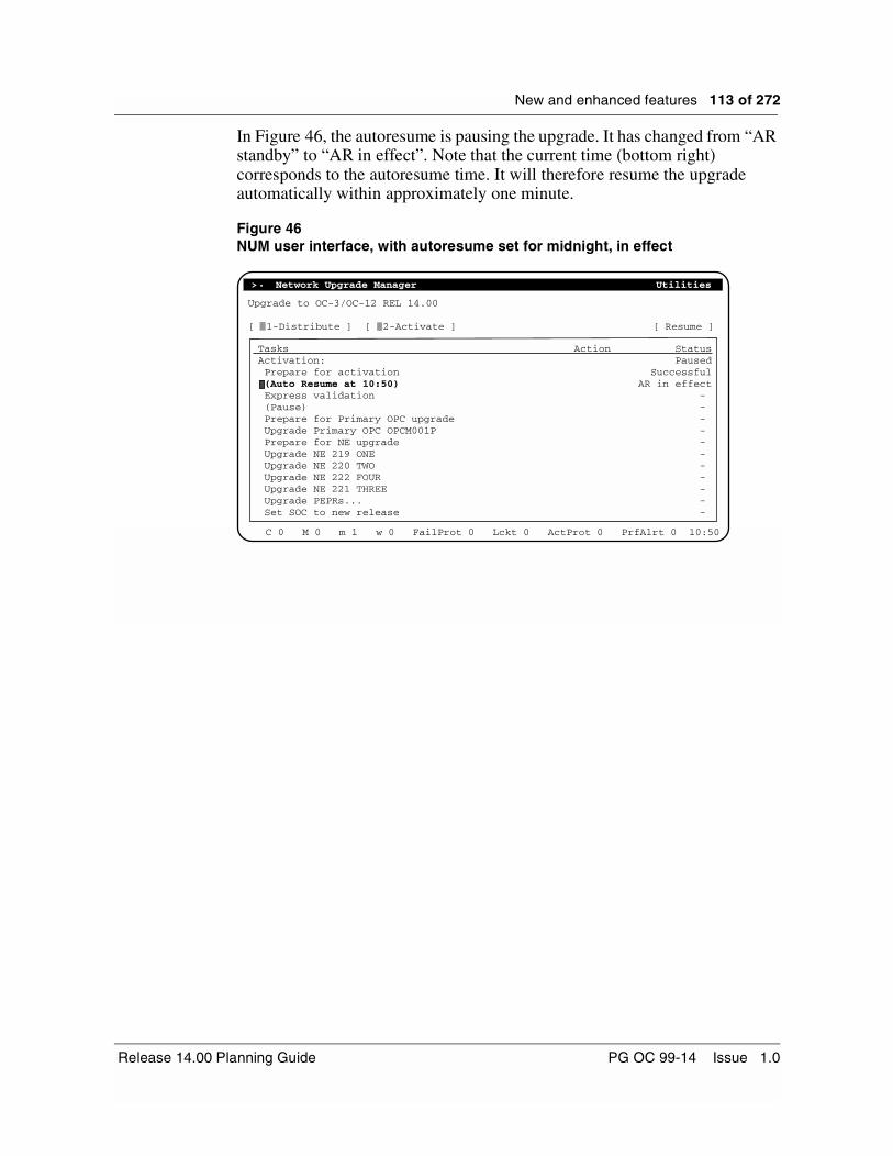
New and enhanced features 113 of 272
In Figure 46, the autoresume is pausing the upgrade. It has changed from “AR standby” to “AR in effect”. Note that the current time (bottom right) corresponds to the autoresume time. It will therefore resume the upgrade automatically within approximately one minute.
Figure 46NUM user interface, with autoresume set for midnight, in effect
> Network Upgrade Manager Utilities.
Upgrade to OC-3/OC-12 REL 14.00
[ 1-Distribute ] [ 2-Activate ] [ Resume ]
TasksActivation: Prepare for activation (Auto Resume at 10:50) Express validation (Pause) Prepare for Primary OPC upgrade Upgrade Primary OPC OPCM001P Prepare for NE upgrade Upgrade NE 219 ONE Upgrade NE 220 TWO Upgrade NE 222 FOUR Upgrade NE 221 THREE Upgrade PEPRs... Set SOC to new release
StatusPaused
SuccessfulAR in effect
- - - - - - - - - - -
Action
C 0 M 0 m 1 w 0 FailProt 0 Lckt 0 ActProt 0 PrfAlrt 0 10:50
Release 14.00 Planning Guide PG OC 99-14 Issue 1.0

114 of 272 New and enhanced features
Healthcheck EnhancementsThe following are new Healthcheck enhancements introduced in Rel 14.00 (from Rel 13.12).
• Check NE Release: this check ensures that all NEs in the same SOC are running the same release. If the release in any of the NEs cannot be determined, or if it differs from that defined on the OPC, the status of the check is RED.
• The check “Save to Tape” has been renamed to “Save OPC Data”, also, this check will not run if a Backup OPC is present.
• Exerciser: this check is now included automatically when Healthcheck is run.
• Performance: the customer should see improvements in the speed of the tool in this release.
• A new classification for the active alarms in the system has been introduced in Release 14.00. The new GREEN (Non-Upgrade affecting) classification has been introduced in this release.
• Upgrade Alarm Filter: the status of various tributary facility alarms in the “Upgrade Alarms” check has been changed to GREEN. Before Release 14.00, these alarms had a YELLOW status.
Hardware Baseline File DeliveryThe Hardware Baseline File delivery feature allows a user to create or modify the customized (modified) baseline file via INM (Integrated Network Manager) or Preside Application Platform, prior to the system software upgrade. The user can distribute the customized (modified) baseline file from INM or Preside Application Platform to all destination OPCs, along with the product release software. This eliminates the need of the user to sequentially login to each destination OPC in order to create or modify the customized (modified) baseline file locally prior to upgrading the system. This is achieved via the new Hardware Baseline File Editor available in the OPC Editor tool, provided by this feature.
The Hardware Baseline Tool residing on the OPC supports the hardware baseline check. Frequently, checks are performed at the network upgrade time, but they may also be scheduled to run at any other time for the network check purposes.
During the Baseline Check, all circuit packs are checked against a Nortel Networks Baseline File (NBF), delivered with the release software, to ensure they meet the minimum release required for the upgrade. This is a simple check of PEC codes and release numbers.
S/DMS TransportNode OC-3/OC-12 TBM PG OC 99-14 Issue 1.0

New and enhanced features 115 of 272
Due to the variety of the Nortel Networks products, the NBF does not always reflect the network inventory. As a result, the Baseline Check may fail. To solve this problem, users may create their own baseline file (Customized Baseline File - CBF) according to the current needs.This additional file is used while performing Hardware Baseline Check. Before Release 14.00, the creation of the Customized Baseline File was a manual process that had to be performed on each OPC in the network. The user had to login to each OPC that required a new Customized Baseline File, and using the Hardware Baseline Tool (HBT) create or modify the Baseline File.
Hardware Baseline File Delivery ensures that the Customized Baseline File will only need to be created once on one central location in the network.
This feature provides the Baseline File Editor that is installed and executed on the INM workstation or Preside Application Platform workstation. Using this Editor, the user can create or modify the Customized Baseline File for the selected OPC software release prior to the System Upgrade. Next, using standard INM or Preside Application Platform ESWD (Electronic SoftWare Delivery) functionality, the user can distribute the new Customized Baseline File to appropriate OPCs in the network along with the other OPC software required for the Network Upgrade. During the OPC upgrade time, the delivered Customized Baseline File is installed in the appropriate HBT directory and used for Baseline Check as a reference.
OPC Editor ToolThe OPC Editor Tool consists of the Hardware Baseline File Editor as shown in Figure 47. The Baseline File Editor provided by this activity is implemented as one of the editors available in the OPC Editor Tool.
The UI provided for Baseline File Editor is very similar to that of the Hardware Baseline Tool, since they both support the “modify baseline file” functionality.
Release 14.00 Planning Guide PG OC 99-14 Issue 1.0
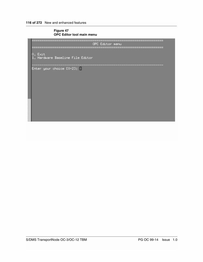
116 of 272 New and enhanced features
Figure 47OPC Editor tool main menu
S/DMS TransportNode OC-3/OC-12 TBM PG OC 99-14 Issue 1.0

New and enhanced features 117 of 272
OPC Editor Tool - delivery
The OPC Editor Tool has been added into the existing OPC delivery file, and this way stored on the OPC software release tape.
OPC Editor Tool - installation
The OPC Editor Tool is installed and executed on the INM or Preside Application Platform. The user receives the OPC software release tape and extracts the OPC software from the tape in the INM or Preside Application Platform opc-software release directory (using the standard operations like Query Tape and Extract Software). The OPC Editor Tool software package is part of INM or Preside Application Platform.
After the OPC release tape has been extracted by the user into the INM or Preside Application Platform opc-software release directory, the install.tar file is part of this directory. Then, using the standard UNIX commands, the user obtains the OPC Editor Tool installation script from the install.tar file. The script installs the OPC Editor Tool, and prepares the environment needed by the OPC Editor Tool for its operations.
The product, release and Nortel Networks Baseline File are required by the Baseline File Editor to create the Customized Baseline File. The installation script for the OPC Editor Tool obtains the product and release from the release.info file, present in the opc-product release directory. The script uses this software release to obtain the Nortel Networks Baseline File from the install.tar file. The Nortel Networks Baseline File is stored in the OPC Editor Tool working directory and later used as a reference.
The user can create or modify the Customized Baseline File only for the software release for which the OPC Editor Tool was installed.
Once the Tool environment is ready, the user is presented with the OPC Editor Tool main menu and can logon.
An error message is returned if the release.info file cannot be found in the opc-product-release directory (if it has not been installed). The user may continue working with OPC Editor Tool, but attempted use of the Baseline File Editor will result in an error message.
Note: The user must have Admin privileges to access the OPC Editor Tool.
Release 14.00 Planning Guide PG OC 99-14 Issue 1.0

118 of 272 New and enhanced features
Baseline File Editor toolFigure 48 shows the Baseline File Editor main menu.
Figure 48Baseline File Editor main menu
Using Baseline File Editor, the user is able to:
• modify the release of a card in a baseline file
• add a new card to a modified file
• delete a card from a modified baseline file
• view the modified baseline file
• delete the modified baseline file
• view the date of the last modification
• view Nortel Networks hardware baseline fileModify the release of a cardThe main purpose of the “modify the release of a card” menu item is to allow the user to modify a release for a card contained already in the Nortel Networks Baseline File. This screen is very similar to the one contained in the Hardware Baseline Tool on the OPC. However, this screen allows the user to specify and modify multi-cards (one by one without coming back to the main menu). This screen can also automatically save the modifications performed by the user to the OPC load. Once the user is finished making changes, the Customized (modified) Baseline File is created or updated, and automatically integrated with the OPC load.
HARDWARE BASELINE FILE EDITOR
-----------------------------------------------------------------------------------------1) modify the release of a card in a baseline file2) add a new card to a modified baseline file
4) view the modified baseline file
Enter your numeric choice [0-7]:
===================================================
===================================================
5) delete the modified baseline file6) view the date of the last modification
7) view Nortel hardware baseline file
0) return to OPC Editor menu
3) delete a card from a modified baseline file-----------------------------------------------------------------------------------------
-----------------------------------------------------------------------------------------
===================================================
S/DMS TransportNode OC-3/OC-12 TBM PG OC 99-14 Issue 1.0

New and enhanced features 119 of 272
Add a new card to the baselineThe main purpose of the “add a new card to the baseline” menu item is to allow the user to add new card(s) to the Customized (modified) Baseline File. This screen is very similar to one contained in the Hardware Baseline Tool on the OPC. However this one allows the user to specify and add multi-cards, one by one, without coming back to the main menu. The screen can also automatically save the modifications performed by the user to the OPC load. Once the user is finished making the changes, the Customized (modified) Baseline File is created or updated, and automatically integrated with the OPC load.
Delete a card from a modified baseline file
The main purpose of the “delete a card from a modified baseline file” menu item is to allow the user to delete card(s) already added to the Customized (Modifed) Baseline File. This screen is very similar to the one contained in the Hardware Baseline Tool on the OPC. However, this one allows the user to specify and delete multi-cards, one by one, without coming back to the main menu.
The screen can also automatically save the modifications performed by the user to the OPC load. Once the user is finished making the changes, the Customized (modified) Baseline File is either removed from the OPC load if all cards have been deleted by the user, or integrated back with the OPC load if there are any cards left.
View the modified baseline file
The main purpose of the “view the modified baseline file” menu item is to allow the user to view the Customized (modified) Baseline File. The user is not prompted for any actions.
Delete the modified baseline file
The main purpose of the “delete the modified baseline file” menu item is to allow the user to remove the Customized (modified) Baseline File from the OPC load. This menu item is used to delete the Customized Baseline File from the install.tar file, and from the OPC Editor Tool working directory, if found there.
View the date of the last modification
The main purpose of the “View the date of the last modification” menu item is to allow the user to read the date stamp of the last modification of the Customized (modified) Baseline File.
View Nortel Networks hardware baseline file
The main purpose of the “View Nortel Networks hardware baseline file menu” item is to allow the user to view the Nortel Networks Baseline File. The user is not prompted for any actions.
Release 14.00 Planning Guide PG OC 99-14 Issue 1.0
120 of 272 New and enhanced features
Upgrade ConsiderationsProcedure
The Hardware Baseline File Delivery feature is only applicable to those who use INM or Preside Application Platform. Once the customized baseline file has been saved on an INM or Preside Application Platform workstation, it can be delivered to each system that needs to be upgraded, so the baseline file does not need to be modified for each system separately.
Duration
This feature saves the time required to create the Customized Baseline File on each OPC in the network. Additionally, the Baseline File created by OPC Editor Tool limits the Hardware Baseline warnings at upgrade time. The user does not need to analyze the warnings in order to proceed with the upgrade.
Complexity
This feature makes the Upgrade simpler. The user does not need to modify the Hardware Baseline File on each OPC in the Network, since it is done once on the INM or Preside Application Platform workstation.
S/DMS TransportNode OC-3/OC-12 TBM PG OC 99-14 Issue 1.0

121 of 272
Operation, Administration and Maintenance features 4-
This section provides a description of the OA&M features offered with the OC-3/OC-12 TBM Release 14.00 software.
Operation, Administration and Maintenance (OAM) FeaturesTable 33 lists the OAM features offered by Release 14.00, and identifies which page to refer to for feature details.
Table 33Release 14.00 OAM Features
Feature Page
NE Name Expansion 123
NE ID enhancements 127
OPC name enhancements 131
OPC Centralized User Administration (CUA) Enhancement 131
Security Enhancements 131
TCP/IP Access Control 152
DCC Access Control 156
SelectNE Access Restriction Tool 161
OPC Audit Trail 162
NE Audit Trail 169
NE Enhancements 172
OPC Alarms Enhancements 174
NE and OPC Area Address Provisioning 177
Disabled Alarms Listing Tool 186
Display of Configuration Mismatch Details 188
Release 14.00 Planning Guide PG OC 99-14 Issue 1.0

122 of 272 Operation, Administration and Maintenance features
Correction of Connection Mismatches in a Linear System 192
TL1 Enhancements 193
Alarm listing enhancements (lasaldmp, lasdump) 213
Network element name and ID enhancements 212
Solid-state OPC enhancements 213
Table 33Release 14.00 OAM Features
Feature Page
S/DMS TransportNode OC-3/OC-12 TBM PG OC 99-14 Issue 1.0

Operation, Administration and Maintenance features 123 of 272
NE Name ExpansionPrior to the introduction of this feature, the network element name was a 13 character optional parameter. This parameter is used as the network element identifier, along with the obligatory parameter of NEid to uniquely identify a network element.
This feature enhances the network element name from the current 13 character ASCII string to 20 character string. The extended NE Name is displayed on all the NE UIs which currently displays a 13 character NE Name, and wherever possible on the OPC UI.
In UIs where it is not feasible to display the full 20-character NE Name due to space limitations, a truncated NE Name is displayed and the full NE Name is displayed in details screen, if available.
Note: The NE UI has been modified to display the full 20 character NE NAME on the banner line where <NEID NE Name> is displayed currently. The NE ID has been shifted to the next line, which is blank for most of the screens (this line is used for displaying some messages, which can be accommodated with the NEid on the same line).
INM/Preside graphical network topology “view” displays, INM/Preside displays up to 20 characters NE name below each NE ICON.
This activity also modifies the login tools and commands which accept only NEid as input to support NE name as well. Specifically, the following commands and tools have been affected:
• selectne
• nename
• neldump
• socdump
Release 14.00 Planning Guide PG OC 99-14 Issue 1.0

124 of 272 Operation, Administration and Maintenance features
selectne command
Prior to the introduction of this feature, the selectne command only accepted NEid as an input parameter. This command has been modified to accept both NEid and NE Name as input parameters (same as rlogin does).
The command syntax for the selectne is as follows:
SelectNE <nename> <NE NAME/neid>
Table 34 describes the parameter values for the selectne command.
Table 34Parameter values for the selectne command
nename command
The nename command is available to admin class of users and is issued from the NE UI. It is used to provision/edit NE NAME. This command has been enhanced to handle a 20 character NE NAME input.
The command syntax for the nename command is as follows:Nename <nename> STRING
neldump tool
The tool neldump dumps the logs (including the OPC logs) for all the NEs under the span of control of the OPC and is issued from the OPC UI.
PARAMETER VALUE DEFINITION
1 nename This indicates that the user will be supplying the NE Name for the selectne command. This parameter is optional (i.e.) the user can choose to issue the selectne command using the NEID of the target NE.
2 NE NAME The second parameter is the NE Name of the target NE, if the first parameter was’NENAME’. This parameter can be up to 20 characters long. It is not optional.
1 neid (1-65534) This indicates that the user is supplying the NE ID of the target NE. This parameter is optional in the sense that the user can choose to perform the selectne command using the NE Name of the target NE.
S/DMS TransportNode OC-3/OC-12 TBM PG OC 99-14 Issue 1.0

Operation, Administration and Maintenance features 125 of 272
Prior to the introduction of this feature, the output of the neldump did not display the NE name for each of the logs. With this feature, the output of neldump has been enhanced to display the 20 character NE name, for each of the logs from all the NEs under the span of control of the OPC.
socdump tool
The tool socdump dumps the list of NEs in the Span Of Control and is issued from the OPC UI.
Prior to the introduction of this feature, the output of socdump did not display the NE name (it listed only NEids). With this feature, the output of the socdump has been enhanced to display the 20 character NE name along with NEid for all the NEs under the span of control of the OPC.
Operational considerationsIf a system supporting a 13 character NE Name and system supporting a 20 character NE Name co-exist and carry traffic in the same managed network, it may not be possible to do a remote login using the NE Name from the system supporting the 13 character NE Name to the system supporting the 20 character NE Name, if the NE Name on the latter system has a length greater than 13 characters. In such cases, the NEid is used for remote login operation. UIs/CIs on the system supporting a 13 character NE Name display only the first 13 characters of NE Name (of NEs which have Name longer than 13 characters). Remote login from a system supporting 20 character NE Name to an older system supporting a 13 character NE Name is supported.
NE user interfaceThe FWPUI main screen is the first screen which is posted when the user issues the’MAPCI;FWPUI’ command. It is the starting point from which the user can navigate and do various operations on the NE. Figure 49 shows an example of the 20 character NE name display.
Release 14.00 Planning Guide PG OC 99-14 Issue 1.0

126 of 272 Operation, Administration and Maintenance features
Figure 49Fwpui main screen
The NE Name is displayed in two places in the FWPUI MAIN screen. The first is where NE Name and NE ID are displayed in the third row towards the left corner. With this feature, the NE ID is now displayed in the next row (fourth row) instead, and only the NE Name is displayed in the third row (left corner). This has been achieved by moving the critical alarms display position (in the Network banner line) to the right by one column. This change is visible on all the other subtending screens in the NE UI.
The second place is in the 8th row (in the middle of the screen). Here, apart from the NE Name and NE ID, the alarm counts for the NE and protection and performance statuses are listed. The displaying 20 character NE Name here has been achieved by shifting the display of the alarm counts, protection and performance statuses by 7 columns to the right.
S/DMS TransportNode OC-3/OC-12 TBM PG OC 99-14 Issue 1.0

Operation, Administration and Maintenance features 127 of 272
NE ID enhancementsThe NE ID is a 5 digit obligatory parameter required for an NE. It is absolutely required during the commissioning of an NE within an OPC Span Of Control (SOC). The NE ID is used to identify an NE in a network. Prior to the introduction of this feature, an NE ID was able to have a numeric value in the range 1 to 32767. With this feature, the range has been extended from 1 to 65534.
The network identifier (ID) and system ID for the network element appear on the network element user interface with the network element ID. The network ID and system ID are no longer hardcoded to 1 and can be modified. Each ID can have a numeric value between 1 and 65534.
The network ID and system ID are displayed on all the network element user interface screens which currently display the network element name ID. The System Commissioned Data dialog of the Commissioning Manager, as well as dialogs for the NE Login Manager and operations controller (OPC) status tool now display the network ID and system ID.
Figure 50 displays an example of a 20-character network element name, network ID, and system ID on the Network Element Status screen. The network ID and system ID appear with the network element ID. These IDs appear as a numeric string separated by periods (.), in the format SystemID.NetworkID.NEID. These IDs appear below the 20-character network element name and to the right of the menu options.
Figure 5020-character network element name, network ID, and system ID on the Network Element Status screen
Release 14.00 Planning Guide PG OC 99-14 Issue 1.0

128 of 272 Operation, Administration and Maintenance features
Figure 51 displays an example of the network ID and system ID on the NE Login Manager main window of the OPC user interface.
Figure 51Network ID and system ID on the NE Login Manager main window
Note 1: To provision or modify a network element name of up to 20 characters, you must access the admin nep screen on the network element user interface.
Note 2: To provision or modify a network ID or system ID for a network element, you must access the Commissioning Manager on the OPC user interface.
Note 3: The combination of Network ID, System ID, and NE ID need to be unique within the network.
The following commands have been added or modified in OC-3/OC-12 TBM Release 14.00 to include the network ID and system ID of a network element:
• clping, coping, dsadarp, dsadereg, nelogin, netping, rlogin, rmapclYou can now enter the network ID and system ID of a network element with these existing commands. If you do not enter a value for the network ID and system ID, the software uses the network ID and system ID of the local span of control.
• nsneidciThis is a new command that allows you to update the network ID or system ID of a network element to match the value displayed on the System Commissioning Data dialog of the OPC Commissioning Manager.
S/DMS TransportNode OC-3/OC-12 TBM PG OC 99-14 Issue 1.0

Operation, Administration and Maintenance features 129 of 272
Note 1: If the network ID or system ID on a network element is different from the one displayed on the System Commissioning Data dialog of the OPC Commissioning Manager, a loss of association can occur between the OPC and this network element.
Note 2: When you execute the nsneidci command on a network element, the software initiates a warm restart on this network element.
Software upgrades and backoutsWhen you upgrade a system to OC-3/OC-12 TBM Release 14.00, the following occurs:
• all network element names of up to 13 characters are retained (once the upgrade is complete, you can modify expand these network element names up to 20 characters, if required)
• all network element IDs are retained, and all network IDs and system IDs have a default value of 1 (once the upgrade is complete, you can modify the network ID or system ID to a numeric value between 1 and 65534, if required)
New and modified alarmsTable 35 lists the new and modified alarms associated with the network ID and system ID enhancements. This table includes a service code of non-service affecting (nsa) and service affecting (SA) according to whether any traffic is affected.
Table 35New and modified alarms associated with the network ID and system ID enhancements
Alarm label Alarm type Severity Service code
Duplicate NE numeric identifier (see Note 1)
Common equipment Minor (m) SA
Network ID and System ID renumbering in progress (see Note 2)
Common equipment Minor (m) nsa
Note 1: This alarm was previously referred to as the Duplicate NE ID alarm.
Note 2: This alarm becomes active when you renumber the network ID or system ID for a network element. When you finish renumbering the network ID or system ID, this alarm automatically clears.
Release 14.00 Planning Guide PG OC 99-14 Issue 1.0
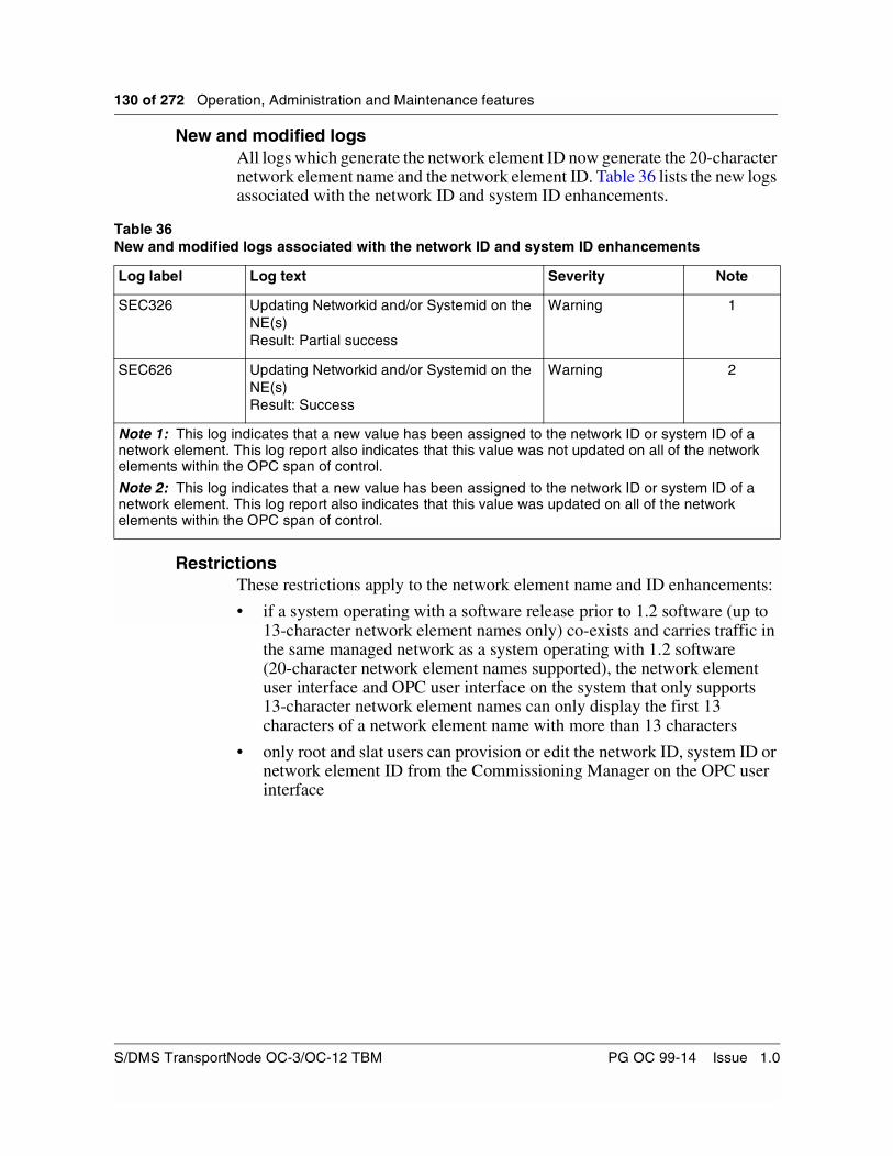
130 of 272 Operation, Administration and Maintenance features
New and modified logsAll logs which generate the network element ID now generate the 20-character network element name and the network element ID. Table 36 lists the new logs associated with the network ID and system ID enhancements.
RestrictionsThese restrictions apply to the network element name and ID enhancements:
• if a system operating with a software release prior to 1.2 software (up to 13-character network element names only) co-exists and carries traffic in the same managed network as a system operating with 1.2 software (20-character network element names supported), the network element user interface and OPC user interface on the system that only supports 13-character network element names can only display the first 13 characters of a network element name with more than 13 characters
• only root and slat users can provision or edit the network ID, system ID or network element ID from the Commissioning Manager on the OPC user interface
Table 36New and modified logs associated with the network ID and system ID enhancements
Log label Log text Severity Note
SEC326 Updating Networkid and/or Systemid on the NE(s)Result: Partial success
Warning 1
SEC626 Updating Networkid and/or Systemid on the NE(s)Result: Success
Warning 2
Note 1: This log indicates that a new value has been assigned to the network ID or system ID of a network element. This log report also indicates that this value was not updated on all of the network elements within the OPC span of control.
Note 2: This log indicates that a new value has been assigned to the network ID or system ID of a network element. This log report also indicates that this value was updated on all of the network elements within the OPC span of control.
S/DMS TransportNode OC-3/OC-12 TBM PG OC 99-14 Issue 1.0

Operation, Administration and Maintenance features 131 of 272
OPC name enhancementsThe OPC name is a unique identifier for the OPC within a network. The OPC name is an 8 alphanumeric parameter provisioned during the commissioning of an OPC. The user is forced to name the OPC with the ‘OPC’ prefix and, prior to the introduction of this feature, to enter all 4 editable alphanumeric characters. The OPC software then appends the letter P for primary OPC and letter B for peer backup OPC. This results in an OPC name of OPCxxxxP/B format. Some customers use the OPC name to indicate the NE ID which is housing the OPC. With the introduction of 5 digit NE ID in the previous software release, some OPC naming convention for our customers have been impacted. A requirement resulted that the OPC name enhancement be aligned with the NE ID enhancement.
With this feature, the OPC name has been enhanced to 9 characters. The first 3 are ‘OPC’. The user can enter up to 5 editable alphanumeric characters. The user can now enter at least 1 alphanumeric character and up to a maximum of 5 alphanumeric characters. The software then appends ‘P’ or ‘B’.
OPC Centralized User Administration (CUA) EnhancementThe following OPC CUA enhancement has been made in Release 14.00:
• New User Group ‘tech’
A new user group called ‘tech’ is defined.
By default, the ‘tech’ user group has access to the following toolset and tools:
— Tech toolset which includes the Alarm Monitor, Backup/Restore Manager, Commissioning Manager, Configuration Manager, Connection Manager, Event Browser, Hardware Baseline, Log Archive, NE Login Manager, Network Browser, Network Summary, Network Upgrade Manager, Load Manager, TBP Commissioning, OPC Date, OPC Save and Restore, OPC Shutdown, OPC Switch, Protection Manager, Reboot/Load Manager.
The Alarm Monitor and Network Summary tools are open by default when the user logs into the OPC.
Security EnhancementsThis feature has been developed to facilitate customers in monitoring the network in terms of security. This feature provides the following capabilities:
• On login to the OPC and NE, account activity information for the user on that node are displayed.
Release 14.00 Planning Guide PG OC 99-14 Issue 1.0
132 of 272 Operation, Administration and Maintenance features
• Account activity information from all nodes in the span of control are summarized and displayed through the Centralized User Administration tool. The administrator is facilitated to view this information from CUA.
• User accounts are disabled if the account is not used for a preset number of days. By default, this feature is disabled.
• The keyboard is automatically locked out, if there has not been any input from the keyboard for a specified period of time (available from both the NE MAPCI and OPCUI).
Account activity information (nodal)Upon successful login to the OPC or NE through a serial or network port, the following information are displayed:
• The date, time and user location identifier of the user’s last successful login to the particular OPC or NE.
• The number of unsuccessful login attempts to the user account on the particular OPC or NE, since last successful login.
Whenever a root and root-like user logs in to the OPC, the user gets the OPC Unix Shell. In such a case, the account activity information (nodal) is displayed along with the welcome message upon login to the OPC. The information is displayed after the copyright agreement but before the shell prompt.
Account Activity Display for OPCUI sessionFor users other than root and root-like users, successful login session results in direct invocation of the OPCUI.
Whenever OPCUI is started, the account activity information for the logged in user on that OPC is displayed in a dialog box.The dialog box automatically closes after 5 seconds. Once the account activity information dialog closes, the OPCUI come ups.
One visible change compared to previous releases is that the user has to wait for 5 seconds for OPCUI to come up. A message, “Opening OPCUI. Please wait.......” is displayed in addition to the account activity information. Refer to Figure 52 for an example.
S/DMS TransportNode OC-3/OC-12 TBM PG OC 99-14 Issue 1.0
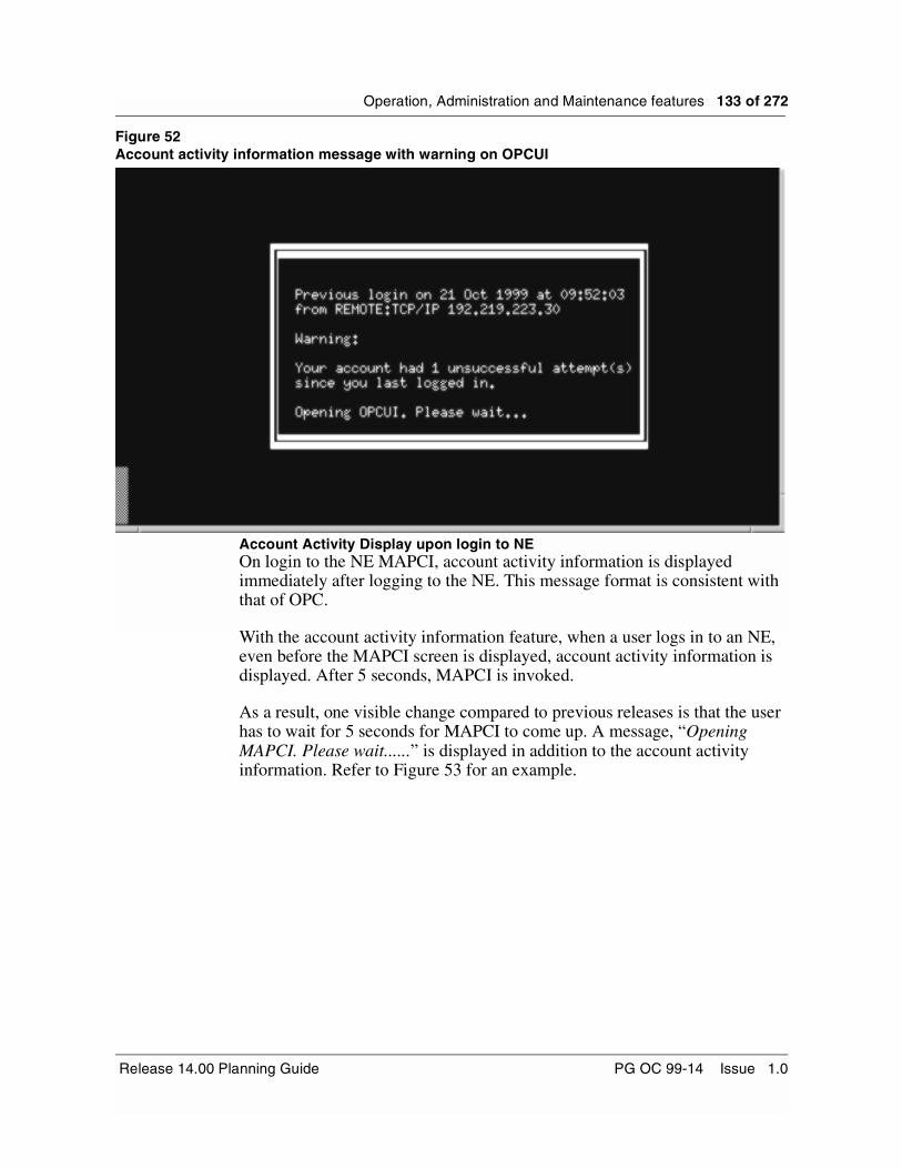
Operation, Administration and Maintenance features 133 of 272
Figure 52Account activity information message with warning on OPCUI
Account Activity Display upon login to NE On login to the NE MAPCI, account activity information is displayed immediately after logging to the NE. This message format is consistent with that of OPC.
With the account activity information feature, when a user logs in to an NE, even before the MAPCI screen is displayed, account activity information is displayed. After 5 seconds, MAPCI is invoked.
As a result, one visible change compared to previous releases is that the user has to wait for 5 seconds for MAPCI to come up. A message, “Opening MAPCI. Please wait......” is displayed in addition to the account activity information. Refer to Figure 53 for an example.
Release 14.00 Planning Guide PG OC 99-14 Issue 1.0

134 of 272 Operation, Administration and Maintenance features
Figure 53Account Activity Information (NE MAPCI) with warning
This functionality facilitates the user logging into the node to know the information about last login for that user. Also, in case of any unsuccessful login attempts made with this user account, it is displayed along with the account activity information. This enables the user to be aware of any unauthorized persons using the account to access the system.
An example of the account activity message follows:
Previous login on 24 Mar 2000 at 10:47:20 from port 2.
In the example, “24 mar 2000 at 10:47:20” is the date and time of last successful login to the node, and “port 2” is the location identifier.
The following warning message is displayed along with the above message.
Warning: Your account had 7 unsuccessful login attempt(s) since you last logged in.
Where “7” is the number of unsuccessful login attempts since the last successful login. In case of no unsuccessful login attempts since the last successful login by the user, no warning message is displayed. The above message format is common for both OPC and NE.
There is provision in CUA to either enable or disable the account activity information. If this feature is disabled, account activity information for MAPCI and OPCUI sessions are not displayed for all users. This feature is enabled by default.
S/DMS TransportNode OC-3/OC-12 TBM PG OC 99-14 Issue 1.0

Operation, Administration and Maintenance features 135 of 272
For users who get an OPC shell prompt, the account activity information feature is displayed always (irrespective of whether the account activity feature is enabled or disabled).
User Interface for Nodal Activity
The new option introduced in the list item menu of the CUA is “Show account activity information...”. This in turn is a cascade menu and has two options of choosing either Nodal basis or SOC basis.
A “Nodal basis” or “SOC basis” option needs to be selected to view the account activity information. Once the administrator selects the “Nodal basis” option, a dialog box is displayed to either select or to enter a node of interest. On selecting a node, the administrator can view the account status of the selected user. The node of interest can be a primary OPC, backup OPC or any NE in the span of control.
If there is no association to the mentioned node, though the account activity information is displayed, it might be obsolete information. A warning message stating that the information might be stale because of lack of association is displayed along with the account activity information.
Refer to Figure 54 and Figure 55 for sample screen captures.
Release 14.00 Planning Guide PG OC 99-14 Issue 1.0
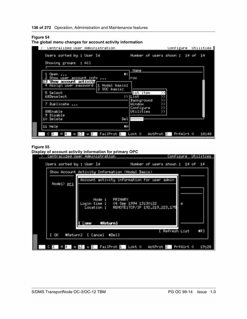
136 of 272 Operation, Administration and Maintenance features
Figure 54The global menu changes for account activity information
Figure 55Display of account activity information for primary OPC
S/DMS TransportNode OC-3/OC-12 TBM PG OC 99-14 Issue 1.0
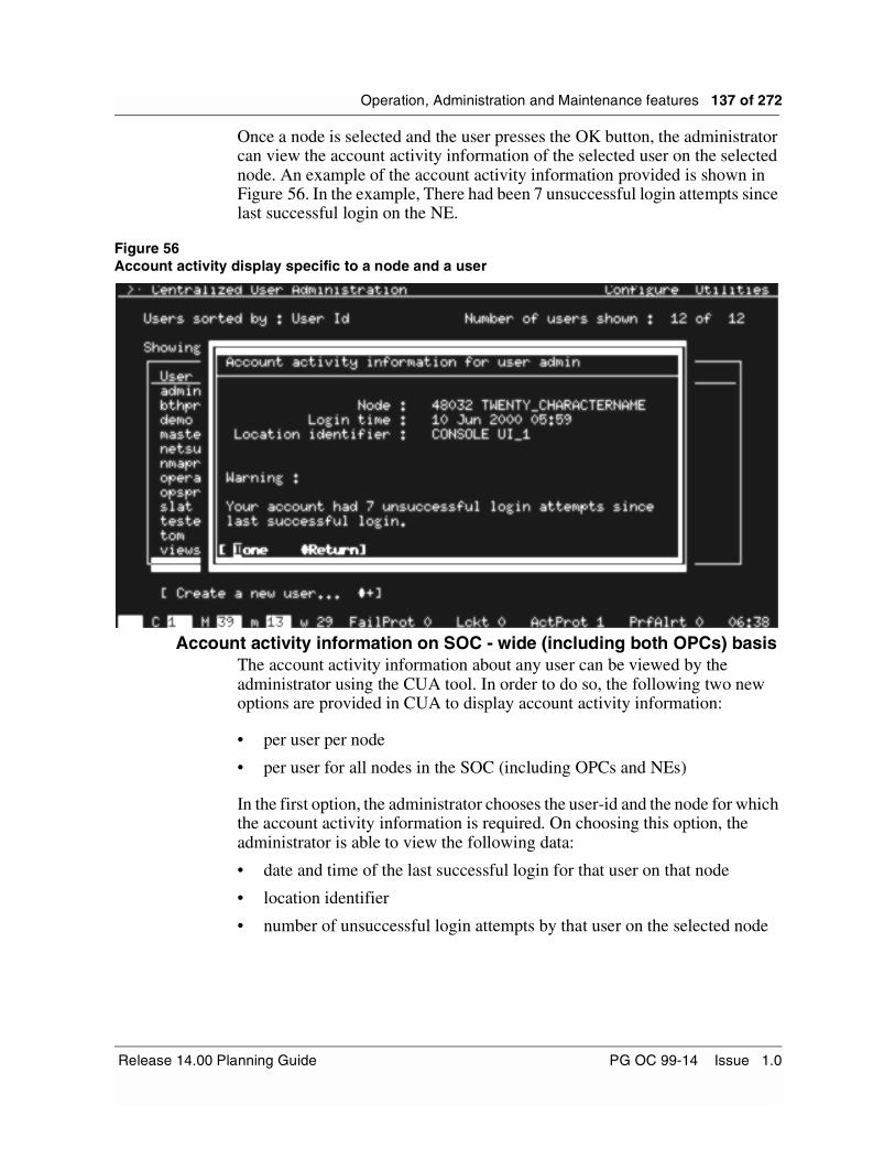
Operation, Administration and Maintenance features 137 of 272
Once a node is selected and the user presses the OK button, the administrator can view the account activity information of the selected user on the selected node. An example of the account activity information provided is shown in Figure 56. In the example, There had been 7 unsuccessful login attempts since last successful login on the NE.
Figure 56Account activity display specific to a node and a user
Account activity information on SOC - wide (including both OPCs) basisThe account activity information about any user can be viewed by the administrator using the CUA tool. In order to do so, the following two new options are provided in CUA to display account activity information:
• per user per node
• per user for all nodes in the SOC (including OPCs and NEs)
In the first option, the administrator chooses the user-id and the node for which the account activity information is required. On choosing this option, the administrator is able to view the following data:
• date and time of the last successful login for that user on that node
• location identifier
• number of unsuccessful login attempts by that user on the selected node
Release 14.00 Planning Guide PG OC 99-14 Issue 1.0

138 of 272 Operation, Administration and Maintenance features
The node can be a primary OPC, backup OPC or any NE in the OPC’s span of control.
In the second option, the administrator chooses the user-id for which the account activity information is required. On choosing this option, the administrator is able to view the following details:
• last node in the SOC the user has successfully logged into
• date, time, and location identifier of the user’s last successful login to that node.
If the same user-id is logged into more than one location at the same time, the last login date, time and location identifier is taken from the most recent login.
Note: Root, root-like, standby and tl1login users belong to a special class of users which are not visible in CUA. Therefore, the administrator is not able to view the account activity information for these special users.
User interface for SOC
To view the account activity information with respect to the whole SOC, the ‘SOC basis’ option has to be selected from the “Show account activity info..” from the List Item Menu of the CUA. If there is no association to any of the nodes in the whole span of control, account activity information is displayed with a warning message that the data may be stale.
UI changes to have Activity Info per SOC
When the SOC basis button of the “Show account activity info.” cascade menu is selected, then the CUA gathers the information about the user account and displays the data on the UI. The data thus displayed is embedded in a dialog that looks similar to the one given in Figure 57.
S/DMS TransportNode OC-3/OC-12 TBM PG OC 99-14 Issue 1.0

Operation, Administration and Maintenance features 139 of 272
Figure 57Account activity information of an user for entire SOC
Dormant Account Disabling This feature provides the ability to automatically disable any user account that has not been accessed for a preset period. If a user account does not have a successful login session on any node in span of control over a preset period, then the user account is disabled on all nodes in the span of control.
A new group “tl1usr” has been introduced as a part of the TL1 security feature in OC-3/OC-12 Release 14.00. The users of this group are specifically used for TL1 sessions and are not permitted to login to the OPC or NEs. The dormant account disabling feature is not considered for all the users belonging to the “tl1usr” group.
Any user account logged in for the entire dormant period is not subject to the dormant account disabling because a logged in account cannot be dormant.
If a dormant user tries to login to a node, then a warning message is displayed. The warning message states that the particular user account has become dormant and has been disabled. For re-enabling dormant user account, the administrator needs to be contacted. The administrator can enable the user account using the CUA tool.
An example of the warning message follows:
“Warning: Your account has become dormant and hence disabled by the system. Contact system administrator to get your account enabled.”
Release 14.00 Planning Guide PG OC 99-14 Issue 1.0

140 of 272 Operation, Administration and Maintenance features
As per the customer need, the warning message can be configured from the CUA on the OPC.
This dormant account disabling feature is turned OFF by default on all the installed systems or on any upgraded systems.
Dormant logs
At the end of the dormant audit (daily at 00:30 hours), an event browser log is generated, listing the dormant user-ids. This log helps the system administrator to be aware of the dormant accounts.
Incremental logs are generated before a user account becomes dormant. The incremental log states that the user account becomes dormant in x days. The parameter x starts from 5 (days) and decrements every day till x becomes 1.
User interfaceProvisioning Text for Dormant Users
The administrator has been provided with a provision to configure the dormant text. This dormant text is displayed as a warning message whenever a dormant user tries to login to a node. The default message that is displayed when a dormant user logs on to the NE/OPC is given below.
“Warning: Your account has become dormant and hence disabled by the system. Contact system administrator to get your account enabled.”
The display message given above can be provisioned from the CUA on the OPC. There is a new item added to the “Utilities” menu in the CUA anchor window which allows the user to provision this text. Dormant text can be up to 255 characters in length.
The administrator does not need to enter the word ‘Warning’ mentioned above in the warning text. When a dormant user attempts to login to a node, a ‘Warning’ tag is attached to the dormant text that is displayed. Refer to Figure 58.
S/DMS TransportNode OC-3/OC-12 TBM PG OC 99-14 Issue 1.0

Operation, Administration and Maintenance features 141 of 272
Figure 58Provisioning dormant text
Dormant Period Parameter provisioning
The administrator is able to provision the dormant period parameter. This dormant account period is provisionable on a per user basis. This parameter can be provisioned from the “Edit User Profile” of CUA. There is an extra field added to the “Edit User Profile” screen to accommodate the dormant period. This parameter defines the number of days a particular account can be idle (without using the account) without being disabled by the system.
Only users who have access to the CUA tool can specify the dormant period. The period can take a value from 45 to 999 days inclusive and is specified on a per-user basis. The default value of the dormant period is 0 (zero) days. A value of 0 (zero) means that the dormant account feature for that user is disabled. Refer to Figure 59 on page 143 for an example of where in the CUA the dormant period is provisioned.
The following users do not become dormant:
• special users
• admin
• users belonging to tl1usr group
• operator
• netsurv
Release 14.00 Planning Guide PG OC 99-14 Issue 1.0

142 of 272 Operation, Administration and Maintenance features
Hence the provision to edit the dormant period for admin, operator, and netsurv users are disabled. Users belonging to tl1usr group also have the dormant period field disabled.
Default Dormant parameter provisioning
The administrator has been provided with an option to provision the default dormant period value. This changed default value can be used as default value for all existing and new users, or dormant period for all new users only. A new user in this case is a user created after changing the default value.
When the administrator changes the default value for the default dormant period, a dialog is invoked. Based on the above mentioned options, a user can select either of the two options. Note that disabled users do not have any user profiles on the NEs.
Dormant users can be enabled using the “Enable” option in the List items menu of CUA. Refer to Figure 61 on page 145 for a screen capture of this feature.
Keyboard Autolock upon InactivityIf, during a session, there has not been any exchange of messages over a port for a specified period of time, the user interface locks that port and prompts the user for password. Only after accepting the password as input is the user allowed to continue with the session. If “logout” is typed while the keyboard is locked, the session is logged out. The following describes the OPCUI, however, the keyboard autolock feature is similar for NE MAPCI.
The keyboard autolock feature is provided for VT-100 mode of the OPCUI. The screen continues to be updated after the keyboard lockout.
For direct login to the OPC UNIX shell, a logout results instead of a keyboard lockout when the idle period expires. The time that a UNIX command is executing is not considered idle time.
The autolock period for User Session Manager sessions and the autologout period for OPC UNIX session are the same.
Whenever a root or a root-like user logs in to the OPC, the user gets a UNIX shell directly and not a OPCUI. For special users, the keyboard idle timeout is provisioned from the Security parameters item in the “Configure Menu” from CUA. This parameter is common to all the special users.
S/DMS TransportNode OC-3/OC-12 TBM PG OC 99-14 Issue 1.0

Operation, Administration and Maintenance features 143 of 272
User interfaceKeyboard autolock period provisioning
The amount of time for which the session can be idle without locking the OPCUI session can be provisioned from the CUA by the administrator. This is referred to as the time-out interval through out in this chapter. The value of the time-out interval is user selectable between 5 and 99 minutes or 0 minutes. A value of 0 minutes disables the feature for that particular user.
The default value of the time-out is 15 minutes. Only users with access to CUA can set the time-out interval.
The parameter provisioned is on a per user basis. There is a provision to modify this parameter in the “Edit User Profile” screen. Figure 59 shows the menu where the provision to enter the data for this particular parameter is available. Note as well that the Dormant account period is set using this screen.
Figure 59Edit user profile for admin class user
Release 14.00 Planning Guide PG OC 99-14 Issue 1.0

144 of 272 Operation, Administration and Maintenance features
There are special users (like root, root1 and standby) who are not visible from the CUA. So if the administrator wants to provision the keyboard time-out period for these users, this cannot be done using the menu mentioned above. However, a provision has bee made to enter data for this particular parameter for all these users. This provision can be done from the “Security parameters” item in the “Configure...” menu. This menu is currently used to provision the parameters such as accredition period, expiration period etc. This also can receive the data about the keyboard time-out period for the special users. The special users are the root, root1 and the standby users. Depending on the data entered in this field, the idle period for the keyboard activity are decided for these users. Refer to Figure 60.
Figure 60Changes for Keyboard lock for special users
All special users have same keyboard idle timeout period. In this case the value of the keyboard lockout for special users can be configured by admin user also. This means that the value of session Idle timeout for root can be changed by all users who have access to CUA.
Also, the keyboard autolock feature on the NE has been modified to use the parameter set from the OPC. The new timeout is considered for the active sessions as well.
Manual AutoLock
It is possible for the user to enter locked mode by a special key sequence. The reason for this feature is to provide an option for the user to lock the terminal. The key sequence is Ctrl K. A separate menu to initiate manual keyboard autolock has also been provided in the OPCUI utilities menu.
S/DMS TransportNode OC-3/OC-12 TBM PG OC 99-14 Issue 1.0

Operation, Administration and Maintenance features 145 of 272
If the keyboard idle timeout parameter is set to 0, the user can still use the manual autolock feature (available from both the NE MAPCI as well as the OPCUI).
The tool used to lock the keyboard manually is kyblock. The kyblock tool must be invoked on a per console basis, to manually lock the console on to which the user is logged. This feature behaves differently when the user is not in MAPCI mode. If the user is not in MAPCI mode, the user is logged out instead of locking the keyboard.
Default Idle Timeout Parameter Provisioning
When the system is either upgraded or installed, the value of the default idle timeout period is set. The default value of idle timeout period is a value of 15 minutes. Whenever a new user is created, these default values are taken for considerations in all the future references to this user. The procedure and the UI changes involved in provisioning these default values is given below.
There is an item “Provision Dormant/Keyboard Defaults” in the “Utilities” menu which is provided to provision the default values for the dormant account timeout and the keyboard timeout. These default values are used whenever a new user is created by the administrator. UI changes to provision the two timeouts are given in Figure 61.
Figure 61Provision to change the default values for dormant accounts and keyboard autolock-out
Once the default value is changed, the administrator is asked whether the changed parameter has to be used for all the existing users and the new users or only for the new users. A new user in this case is a user created after changing the default value.
Release 14.00 Planning Guide PG OC 99-14 Issue 1.0

146 of 272 Operation, Administration and Maintenance features
Operational scenarios for Keyboard Lock
In case of remote sessions, there is an interaction between the local and remote sessions. In the case of X OPCUI sessions and INM or Preside Application Platform sessions, the local session is an X session and the remote session is a window running an NE or OPC session. In the case of CMT OPCUI sessions, the remote session is any instance of the NE login manager tool. In the case of MAPCI sessions, the remote session is any invocation of the rlogin command.
For source (i.e. the machine where remote session is initiated from) sessions, the keyboard autolock feature may or may not be active, as described by the following rules:
• If a CMT OPCUI session is the source session, then the session’s keyboard autolock feature is active. This implies that if you let your terminal idle-out, you have to enter a password into the CMT session, and into each NE login manager tool instance.
• If an X OPCUI session is the source session, then the X-terminal’s autolock feature (this autolock feature is system provided) is active. This implies that if you let your terminal idle-out, you have to enter a password for the X autolock program and for each window that has an NE login manager session running.
• If an INM or Preside Application Platform X session is the source session, then the X-terminal’s autolockout feature (this autolock feature is system provided) is active. This implies that if you let your terminal idle-out, you have to enter a password for the X autolock program and for each window that has an OPC or NE session running.
• If a UNIX shell is the source session, then the autologout feature is inactive while the remote session is active. Upon exiting the remote session, the autologout feature is reactivated.
• If NE MAPCI is the source session, then keyboard autolock on the source session is inactive while the remote session is active. Upon exiting the remote session, the keyboard autolock feature is reactivated.
The User Session Manager has been modified to have two modes of operation: normal mode and locked mode. In normal mode, the user’s session behaves exactly as it did before, except has a background timer on, such that if no input is received from the keyboard within the idle timeout period, the session changes to locked mode.
While in locked mode, the User Session Manager behaves as follows:
• It displays the output of the tool that is in focus.
• It activates a pop-up screen lock dialog upon attempting to use the keyboard on OPCUI.
S/DMS TransportNode OC-3/OC-12 TBM PG OC 99-14 Issue 1.0

Operation, Administration and Maintenance features 147 of 272
• It monitors the keyboard for a string sequence terminated with a carriage return.
• Once it has received this sequence, it verifies the string to the user’s password. If they match, then it returns the session to normal mode. If they differ, then it continues to look for another string sequence
• If “logout” is typed (case sensitive), the User Session Manager logouts the session.
• While the screen lock dialog is being displayed, the alarm banner line is visible.
This keyboard idle timeout feature is turned ON by default on all the installed systems or on any upgraded systems.
Note: Consider root and root-like user login to OPC. A UNIX shell is invoked. OPCUI invoked from UNIX shell also supports the keyboard autolock feature. Upon typing “logout”, the whole OPC session is closed.
Intrusion attempt handlingWhen an intrusion attempt is detected on a primary or backup OPC, an alarm is raised on the active OPC. If intrusion is attempted on an OPC that is inactive, and the connectivity to peer OPC is down, the alarm is not raised.
Intrusion attempt alarms are raised under the following conditions:
• For serial user interface ports on the primary and backup OPCs, an alarm is raised on the active OPC when consecutive failed login attempts on the port exceed the threshold. The alarm is cleared when the port is unlocked.
• For network login sessions to the primary and backup OPCs and NE, an alarm is raised on the active OPC when consecutive failed login attempts on the session exceed the threshold. The alarm is cleared after a provisionable duration.
• The NE locks a network login session when consecutive failed login attempts on the session exceed the threshold. The NE releases the session after a provisionable duration.
Table 37 on page 149 provides a list of the new OPC and NE intrusion attempt alarms.
Intrusion attempt handling: OPC alarms
When an intrusion attempt is detected on a primary or backup OPC, an alarm on that OPC is raised if it is active. If the OPC is inactive, then the intrusion alarm is raised on the peer OPC which is active. In case the OPC on which intrusion attempt is detected is inactive and the connectivity to peer OPC is down, the alarm is not raised.
Release 14.00 Planning Guide PG OC 99-14 Issue 1.0

148 of 272 Operation, Administration and Maintenance features
The alarm, when raised, is cleared after a provisionable duration of alert conditions (seconds). If this duration is configured as zero, intrusion alarms are not raised and the serial port are not locked.
Whenever an OPC reboots, all intrusion alarms for that OPC are cleared. So if the primary OPC reboots, the network and serial port intrusion alarms for the primary OPC is cleared. Likewise, if the backup OPC reboots, the serial and network intrusion alarms for the backup OPC is cleared.
These alarms are provisionable from the OPC alarm provisioning tool.
There is only one alarm for all network intrusion attempts on an OPC. If the alarm is raised, then it implies that at least one intrusion attempt has been made on that OPC. When there is a network intrusion and a network intrusion alarm is already present on the OPC, then the duration of the existing alarm is extended such that it is cleared after the duration of alert condition expires following the detection of the most recent network intrusion.
Intrusion attempt handling: OPC network logins
This activity provides intrusion attempt handling for the network login attempts made on the OPC for the OC-12 product. Following are the network login types supported by this activity (listed priority-wise):
• Telnet sessions over TCP/IP.
• Berkeley rlogin and remsh commands over TCP/IP. These commands are not prompt for a password if the source host is trusted. However, if the source host is not trusted, these commands prompt for a password and intrusion attempt handling applies.
• OPC virtual terminal sessions over OSI (i.e. using the OPC nelogin command or the NE rlogin command).
TCP/IP access can be configured over any of the following interfaces:
• The OPC Ethernet port
• Any OPC port that supports SLIP (for OC-12 OPCs, that is, ports 1 and 2).
• Any port that supports X.25 (for OC-12, that is, ports 1 and 2).
S/DMS TransportNode OC-3/OC-12 TBM PG OC 99-14 Issue 1.0

Operation, Administration and Maintenance features 149 of 272
OSI access can be configured over any of the following interfaces:
• The OPC Ethernet port.
• The OPC CNET port.
Intrusion attempt handling: OC-12 NE network loginsThis activity provides intrusion attempt handling for the network login attempts made on the NE. Following are the network logins available on the NE:• Rlogin performed from another NE.
• Nelogin from the OPC.
The NE locks a remote session when consecutive unsuccessful login attempts on that session reaches a predefined value of maximum invalid login attempts. A locked session implies that the NE discards all input on that session and does not provide any output. The NE releases the session after a predefined duration. While a session is locked, the NE allows other remote sessions to be established.
There is only one alarm for the NE. If the alarm is raised, it implies that at least one network login intrusion attempt was detected on the NE. If there is a network intrusion and already a network intrusion alarm is present on the NE, then the duration of the existing alarm is extended such that it is cleared after the duration of alert condition expires following the detection of the most recent network intrusion.
On all restarts of the NE, the NE’s network login intrusion alarm is cleared and all locked sessions on the NE released. Similarly, all intrusion alarms on an OPC are cleared when the OPC reboots.
Table 37List of new OPC and NE security alarms
Alarm Text Description Severity(Service Code)
Serial intrusion on primary
An intrusion attempt was detected on the serial port of the Primary OPC and that the port is locked out.
minor (nsa)
Serial intrusion on backup
An intrusion attempt was detected on the serial port of the Backup OPC and the port is locked out.
minor (nsa)
Network intrusion on primary
A network port intrusion attempt was detected on Primary OPC.
minor (nsa)
Network intrusion on backup
A network port intrusion attempt was detected on Backup OPC.
minor (nsa)
Network intrusion attempt
An intrusion attempt was detected on a remote NE login session.
minor (nsa)
Release 14.00 Planning Guide PG OC 99-14 Issue 1.0

150 of 272 Operation, Administration and Maintenance features
For personnel to clear the alarms, they must contact the security administrator or wait a specified period of time for the alarm to clear on its own (default: 60 seconds; defined in Centralized User Administration tool).
Intrusion attempt handling: manual release on OPCThe “Clear intrusion alert condition” item has been added to the Utilities list of the Central User Administration (CUA) tool. This menu item clears all outstanding intrusion alert conditions. That is, it clears all outstanding intrusion alarms and release the serial port if it is locked. See Figure 62 for the new CUA utilities menu. The user is prompted to confirm the operation and a message displays the result.
Figure 62New CUA Utilities Menu
Since CUA cannot be run on an Inactive OPC, there is no manual mechanism to unlock the ports on the Inactive OPC. So, although the inactive OPC intrusion alarms are cleared, the inactive OPC ports are locked for the duration of the alert condition.
This mechanism is restricted to system administrators only.
Intrusion attempt handling: manual release on NEA new CI tool has been added to the NE which allows the system administrator to unlock NE serial and network ports, and clear NE intrusion alarms. The mechanism unlocks all serial and network ports on the node. There is no provision to unlock an individual port. The intrusion attempt alarms are automatically cleared when the ports are unlocked.
The mechanism unlocks ports that have been locked by the intrusion attempt handling feature, but it has no impact on ports locked by the keyboard autolock feature. Ports locked by the keyboard autolock feature can be easily unlocked by typing “logout” or the password.
This mechanism is restricted to system administrators only.
1 Audit user profile data...2 Schedule audit ...3 Transfer data to backup OPC ...4 Clear intrusion alert condition ...5 Provision dormant/Keyboard defaults6 Edit dormant account message text7 Help
S/DMS TransportNode OC-3/OC-12 TBM PG OC 99-14 Issue 1.0

Operation, Administration and Maintenance features 151 of 272
Prtunlck CI tool: manual port unlock
The Prtunlck (Port Unlock) CI tool allows admin-class users to manually unlock all serial and network ports, and clear corresponding intrusion attempt alarms. The Prtunlck tool can only be invoked on a per NE basis, and there is no provision to release an individual port.
Intrusion attempt handling: provisioning of parameters
The following changes have been made to handle provisioning of intrusion attempt parameters:
• The existing intrusion attempt parameters are used for network as well as for serial ports.
• The upper bound of the port lockout duration is 999 seconds.
• The default for the MXINV parameters is five attempts.
• The intrusion attempt handling feature is enabled by default.
New logsThe new logs, shown in Table 38, are related to the Security Enhancements feature. They are visible in the event browser.
Table 38Logs visible in the event browser
Log Name NEW/MOD/DELETED
Event / Reason
SEC612 New This log indicates the list of dormant user accounts.
SEC613 New This log indicates the successful completion of dormant data audit.
SEC614 New This log indicated that the keyboard idle timeout for user zzz changed to xx to yy minutes.
SEC615 New This log indicates that the dormant period for user zzz changed to from xx to yy days.
SEC616 New This log indicated that the dormant message text has been changed.
SEC617 New This log would mean that the user zzz will be disabled by the system if the user remains dormant for another yy days.
SEC618 New This log indicates a list of dormant users enabled.
SEC619 New This log indicates that the default value of keyboard idle timeout changed from xx to yy min.
SEC620 New This log indicates that the keyboard idle timeout for special users changed from xx to yy min.
SEC621 New This log indicated that the default value of dormant period changed from xx to yy days.
Release 14.00 Planning Guide PG OC 99-14 Issue 1.0

152 of 272 Operation, Administration and Maintenance features
TCP/IP Access ControlThe Transmission Control Protocol/Internet Protocol (TCP/IP) access control feature allows for better control of user access to the TCP/IP network. This feature prevents unauthorized access to a TCP/IP network from the Operations Controller (OPC). Access to the TCP/IP network is limited to users with authorized access to selected IP addresses.
Some scenarios can exist where equipment from two different customers are present on the same TCP/IP network. The TCP/IP access control feature can be used to limit a customer’s presence on the TCP/IP network.
Figure 63 displays a scenario where two different companies (Company A and Company B) can access the OPCs in two different systems.
SEC622 New This log indicates that the account activity feature status changed.
SEC311 New Dormant audit aborted.
SEC312 New Enabling a dormant account failed.
Log Name NEW/MOD/DELETED
Event / Reason
S/DMS TransportNode OC-3/OC-12 TBM PG OC 99-14 Issue 1.0

Operation, Administration and Maintenance features 153 of 272
Figure 63 Shared systems between two companies
NE
NE
NE
Legend:
= Company A
= Company B
NENE
NENE
NENE
OPC OPC
TCP/IP
INM
NENE
NE
NE
NE
NE
NE
Release 14.00 Planning Guide PG OC 99-14 Issue 1.0

154 of 272 Operation, Administration and Maintenance features
In this scenario, both OPCs and the TCP/IP network belong to Company A, but Company B must have access to both OPCs for operational, administration maintenance and provisioning functions on their own network elements. By accessing the primary OPC, Company B can also execute TCP commands (for example, telnet, ftp, rlogin) to access a third OPC or another system connected to the TCP/IP network of Company A. The TCP/IP access control feature allows Company A to deny Company B access to either selected hosts or all hosts on the TCP/IP network.
User interfaceThe TCP/IP access control feature is provisioned through a command-line driven interface. The network administrator (root user) executes the config_ac command from the UNIX command line to provision the data related to TCP/IP access control.
The TCP/IP access control feature is based on lists that allow or deny users access to host IP addresses. These lists contain the user names and the host IP addresses to which they are allowed or denied access. The network administrator initially provisions these lists. The TCP/IP access control feature is disabled until at least one user is added to the access control lists. The network administrator can also disable this feature after adding users to the access control lists.
If a user is not in the access control lists, this user is denied access to all host IP addresses by default. If a user is allowed and denied access to the same host IP address, then this user is denied access to this host IP address. The network administrator also has the flexibility of providing all users with access to all host IP addresses, while at the same time denying a specific user access to a specific host IP address (or to all host IP addresses).
If you try to enable the TCP/IP access control feature before any users are added to the access control lists, this message is displayed:
Warning: Access control lists are not provisioned. All users (including root) will be denied use of all TCP services.
If a user attempts to execute a TCP command on the OPC, the TCP/IP access control feature determines if this user has access to the destination host given for this command. If the user has access, the access control feature allows the command to be executed and a security warning log (SEC409) is generated.
If the user does not have access, the TCP/IP Access Violation alarm is raised, and a security log (SEC611) is generated. The following message also appears on the user interface:
Sorry, you have been denied access to <host>
S/DMS TransportNode OC-3/OC-12 TBM PG OC 99-14 Issue 1.0

Operation, Administration and Maintenance features 155 of 272
Note: The <host> is either the IP address or the hostname specified by the user when they attempted to execute the TCP command.
You must manually clear the TCP/IP Access Violation alarm if it is raised.
Engineering rulesThe number of name/IP address entries that can be provisioned by this feature is limited to 100 in each access control list (deny list and allow list) on each OPC.
The TCP/IP access control feature is not affected by:
• OPC restarts
• OPC reboots
• OPC data restorations from tape
This feature is also non-intrusive during network upgrades and software downloads. The user access data provisioned on the primary OPC is transferred to the backup OPC through an OPC datasync.
New and modified alarmsTable 39 lists the new alarm associated with the TCP/IP access control feature. This table includes a service code of non-service affecting (nsa) according to whether any traffic is affected.
Table 39 New and modified alarms associated with the TCP/IP access control feature
Alarm label Alarm type Severity Service code
TCP/IP Access Violation
OPC equipment Major (M) nsa
Note 1: This alarm is raised following an access violation from the OPC to the TCP/IP
network. This alarm is raised on the active OPC in the span of control. This alarm can be
provisioned like other OPC alarms.
Note 2: The text in the alarm message indicates the location (primary OPC or backup
OPC) of the access violation. This alarm is raised for each access violation at any given
location.
Release 14.00 Planning Guide PG OC 99-14 Issue 1.0

156 of 272 Operation, Administration and Maintenance features
New and modified logsTable 40 lists the new logs associated with the TCP/IP access control feature.
Table 40 New and modified logs associated with the TCP/IP access control feature
DCC Access ControlThe Data Communication Channel (DCC) access control feature allows for better control of user access to the DCC networks. This feature prevents unauthorized access to a DCC network from the Operations Controller (OPC). Access to the DCC network is limited to users with authorized access to selected network nodes.
Some scenarios can exist where equipment from two different customers are present on the same DCC network. The DCC access control feature can be used to limit a customer’s presence on the DCC networks.
Figure 64 displays a scenario where two different companies (Company A and Company B) can access the OPCs in two different systems.
Log Label Log text Severity Note
SEC409 OPC TCP/IP Access Granted
Warning 1, 2
SEC611 OPC Outgoing TCP/IP Access Violation
Major 1, 2, 3
Note 1: The log lists the name of the user, the destination host and the time when the access request was detected.Note 2: The log is stored in the log database on the active OPC, and can be viewed from the Event Browser (SEC).Note 3: The log SEC611 is generated when the TCP/IP Access Violation alarm is raised.
S/DMS TransportNode OC-3/OC-12 TBM PG OC 99-14 Issue 1.0

Operation, Administration and Maintenance features 157 of 272
Figure 64Shared systems between two companies
NE
NE
NE
Legend:
= Company A
= Company B
NENE
NENE
NENE
OPC OPC
TCP/IP
INM
NENE
NE
NE
NE
NE
NE
Release 14.00 Planning Guide PG OC 99-14 Issue 1.0

158 of 272 Operation, Administration and Maintenance features
In this scenario, both OPCs and the DCC network belong to Company A, but Company B must have access to both OPCs for operational, administration maintenance and provisioning functions on their own network elements. By accessing the primary OPC, Company B can also execute OSI commands (for example, nelogin, rlogin, remotsh) to access a third OPC or another system connected to the DCC network of Company A. The DCC access control feature allows Company A to deny Company B access to either selected nodes, or all nodes in a network.
User interfaceThe DCC access control feature is provisioned through a command-line driven interface. The network administrator (root user) executes the config_dcc_ac command from the UNIX command line to provision the data related to DCC access control.
The DCC access control feature is based on lists that allow or deny users access to network nodes. These lists contain the network nodes to which they are allowed or denied access. The network administrator initially provisions these lists. The DCC access control feature is disabled until at least one network node is added to the access control lists. The network administrator can also disable this feature after adding network nodes to the access control lists.
If a network node is not in the access control lists, this node is denied access to all network nodes by default. If a network node A is allowed and denied access to the same network node (network node B), then network node A is denied access to network node B. The network administrator also has the flexibility of providing all network nodes with access to all network nodes, while at the same time denying a specific network node access to a specific network node (or to all network nodes).
With the DCC access control feature, the network administrator can provision a network node’s access for incoming connection requests (in), outgoing connection requests (out) or both.
If you try to enable the DCC access control feature before any network nodes are added to the access control lists, this message is displayed:
Warning: The following hosts have been enabled with no entries provisioned in either access control list. All incoming and outgoing connection requests will be rejected
If a user attempts to access a host (destination node) from an OPC or network element (source node) on the DCC network, the DCC access control feature determines if the source node has access to the destination node. If access is granted, the access control feature generates a security log (SEC410 or SEC411 for an OPC; SECU410 or SECU411 for a network element).
S/DMS TransportNode OC-3/OC-12 TBM PG OC 99-14 Issue 1.0
Operation, Administration and Maintenance features 159 of 272
In the case that outgoing access to the destination node has been denied in the access control list of the source node, and the feature is enabled on the source node, if the user attempts to access the destination node, the Datacomm Access Violation alarm is raised and a security log (SEC625 for an OPC, or SECU413 for a network element) is generated, at the source node only. The destination node will not generate any logs, regardless of the feature status on that node. The following message is displayed on the command line or on the user interface of the source node:
Sorry, access has been denied to <NSAP address>
In the case that incoming access from the source node has been denied in the access control list of the destination node, and the feature is enabled on the destination node, then a Datacomm Access Violation alarm is raised at the destination node only. A security log (SEC624 for an OPC, or SECU412 for a network element) is generated at the destination node. If the feature is enabled on the source node and if outgoing access to the destination node has been allowed in the access control list of the source node, a security log (SEC410 for an OPC, or SECU411 for a network element) is also generated at the source node. The following message is displayed on the command line or on the user interface of the source node:
Sorry, access has been denied to <NSAP address>
Note: The <NSAP address> is the NSAP address of the OPC or NE specified by the user when attempting access to the destination node through the OSI command.
Clearing Access Violation Alarms on OPC or Network ElementYou must manually clear the Datacomm Access Violation alarm on both the OPC or network element. For the OPC, the alarm is cleared by using the OPC Alarm Provisioning tool. On a network element, the alarm is cleared by using the clrsdccalm command.
Engineering rulesFor the DCC access control feature, you can provision up to 600 OSI host identifiers (IDs) in each access control list (a maximum of 300 nodes in each deny list and allow list) on each network node.
The DCC access control feature is not affected by:
• OPC restarts
• OPC reboots
• OPC data restorations from tape
Release 14.00 Planning Guide PG OC 99-14 Issue 1.0

160 of 272 Operation, Administration and Maintenance features
This feature is also non-intrusive during network upgrades and software downloads. The user access data provisioned on the primary OPC is transferred to the backup OPC through an OPC datasync.
New and modified alarmsTable 41 lists the new alarm associated with the DCC access control feature. This table includes a service code of non-service affecting (nsa) according to whether any traffic is affected.
New and modified logsTable 42 lists the new logs associated with the DCC access control feature.
Table 41New and modified alarms associated with the DCC access control feature
Alarm label Alarm type Severity Service code
Datacomm Access Violation common equipment Major (M) nsa
(notes 1, 2)
Primary: Datacomm Access Violation
Backup: Datacomm Access Violation
OPC equipment Major (M) nsa
(notes 1, 2, 3)
Note 1: These alarms are raised following an access violation on a network node in the DCC network. These alarms are raised on the destination node where access was denied.
Note 2: Only one instance of these alarms can be active at one time. Therefore, an active alarm might indicate more than one access violation.
Note 3: The text in the alarm message indicates the location (primary OPC or backup OPC) of the access violation. This alarm is raised for each access violation at any given location.
Table 42New and modified logs associated with the DCC access control feature
Log label Log text Severity Note
SEC410 Outgoing Datacomm Access Notification Warning 1, 2, 3
SEC411 Incoming Datacomm Access Notification Warning 1, 2, 3
SEC624 Incoming Datacomm Access Violation Major 1, 2, 3, 5
SEC625 Outgoing Datacomm Access Violation Major 1, 2, 3, 5
SECU410 Incoming Datacomm Access Notification Warning 1, 2, 4
SECU411 Outgoing Datacomm Access Notification Warning 1, 2, 4
SECU412 Incoming Datacomm Access Violation Major 1, 2, 4, 5
SECU413 Outgoing Datacomm Access Violation Major 1, 2, 4, 5
S/DMS TransportNode OC-3/OC-12 TBM PG OC 99-14 Issue 1.0
Operation, Administration and Maintenance features 161 of 272
SelectNE Access Restriction ToolThis feature introduces a new CI tool called SNEACC. This tool assists users authorized to access a secret tool supervisor password, to enable or disable the SelectNE functionality. This prevents the invocation of the SelectNE functionality on the NE which has been SelectNE disabled, and prevents the NE from becoming a target of a SelectNE session. The access status of the SelectNE functionality can be toggled between enabled and disabled by the authorized user using the commands introduced by SNEACC.
SNEACC is a TOOLSUP password protected CI in customer loads. Its access is turned ON from the TOOLSUP CI by entering a valid password. Once a user has gained access to the SNEACC tool, the SelectNE access can be enabled or disabled by the use of commands introduced by SNEACC.
FunctionalityThe following summarizes the functional capabilities provided by SNEACC.
• Enable/disable SelectNE through password protected CI.
— The new SNEACC CI tool is used to turn ON or OFF the access status of the SelectNE functionality. SNEACC is password protected in customer loads and is accessible only to authorized users provided with the TOOLSUP password.
• Disable SelectNE access on a per node level.
— SNEACC has to be invoked on each NE when where the SelectNE functionality has to be disabled.
• Disable outward SelectNE sessions
— SelectNE sessions originating from a source NE are rejected if the SelectNE access status is disabled on that NE.
• Enable/disable status to survive NE restarts and powerdowns.
Note 1: The log lists the name of the user, the destination node, and the time when the access request was detected.
Note 2: The log is stored in the log database on the active OPC, and can be viewed from the Event Browser.
Note 3: The log is generated when the destination host is an OPC.
Note 4: The log is generated when the destination host is a network element.
Note 5: The log is generated when the Datacomm Access Violation alarm is raised.
Table 42New and modified logs associated with the DCC access control feature
Log label Log text Severity Note
Release 14.00 Planning Guide PG OC 99-14 Issue 1.0

162 of 272 Operation, Administration and Maintenance features
— The access status is enabled by default. If a user desires, the access can be disabled. However, the disabled default status is preserved over all types of restarts and NE powerdowns.
• SelectNE disables inward direction.
— An NE on which access has been disabled cannot be a target of a SelectNE session from a remote NE.
User interfaceThe SNEACC tool is invoked on a per NE basis to enable/disable access to SelectNE. The possible commands for the SNEACC tool are:
STATUS - displays the SelectNE status.
DISABLE - disables SelectNE.
ENABLE - enables SelectNE (ON by default).
HELP - displays the list of control commands.
QUIT - exits from SNEACC.
Operational considerationsThe default expiry period (duration for which a user can access a password protected tool, from the time the access has been turned ON) for the TOOLSUP password is 12 hours. Users of SNEACC have to turn the access ON after this default period has expired.
Once a user activates SNEACC, the session is not terminated automatically by the tool supervisor, even if the default expiry period ends.
The following apply to SelectNE sessions already in progress:
• a change in the SelectNE access status made from SNEACC does not affect the current session.
• users are prevented from issuing SelectNE back to the current or another NE, if access status has been disabled through SNEACC.
OPC Audit TrailThe OPC Audit Trail feature, like the NE Audit Trail feature, provides the capability to investigate authorized or unauthorized activities after they have occurred. This helps to determine the root cause of a problem, and identify if the incident is due to craft personnel error, or is system related. This capability is provided by the generation of security logs which can be viewed in a new restricted version of the Event Browser, or by being dumped to a file using the new Security Log Dump tool.
S/DMS TransportNode OC-3/OC-12 TBM PG OC 99-14 Issue 1.0

Operation, Administration and Maintenance features 163 of 272
Security logs are generated for all areas identified as security risks. These include logins, provisioning OPC / NE data, and issuing commands to other applications and systems. Only authorized users are able to access these security logs. Figure 65 shows the OPCUI with the new Security Event Browser (SEC) and Security Log Dump tools.
Figure 65OPCUI with new Security Event Browser (SEC) and Security Log Dump tools
OPC Security (SEC) Log contentsFor every recorded event, the security log includes the date and time of the event, user identification (including associated terminal, port, network address, or communication device), type of event, names of resources accessed and success/failure indication of the event. Actual or attempted passwords are not recorded in the security logs.
Log access and protectionThe security logs are protected from unauthorized access, or destruction. The OPC does not provide any mechanism for any user, including an appropriate administrator, to modify or delete a security log. The security logs are recorded using a circular recording mechanism (the newest logs overwriting the oldest). An appropriate administrator is given the capability to retrieve, print, copy and dump the logs to a file for uploading purposes. The security log and its control mechanisms survive system restarts.
New Security Log Dump ToolNew Event Browser to view Security Logs
Release 14.00 Planning Guide PG OC 99-14 Issue 1.0

164 of 272 Operation, Administration and Maintenance features
Access to the new security logs is available only to administrator, root and root-like users by a new restricted version of the Event Browser tool in the OPC Admin toolset, shown in Figure 65 on page 163. This restricted version includes the two new SEC/SECU logs to the Filter Dialog (SEC for the OPC logs, and SECU for the NE logs). The new version of the Event Browser tool may be added to the custom toolsets, and thus custom groups and users.
The capability to retrieve the new log types is provided in the Event Browser Filter dialog. A new SEC checkbox for the OPC security log and a new SECU list entry for the NE security log have been added, as shown in Figure 66. When selected, the new security logs are retrieved and displayed in the Event Browser anchor window.
Figure 66Event Browser Filter Dialog with new security log options
S/DMS TransportNode OC-3/OC-12 TBM PG OC 99-14 Issue 1.0
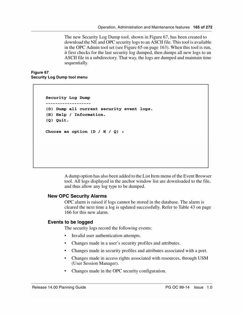
Operation, Administration and Maintenance features 165 of 272
The new Security Log Dump tool, shown in Figure 67, has been created to download the NE and OPC security logs to an ASCII file. This tool is available in the OPC Admin tool set (see Figure 65 on page 163). When this tool is run, it first checks for the last security log dumped, then dumps all new logs to an ASCII file in a subdirectory. That way, the logs are dumped and maintain time sequentially.
Figure 67Security Log Dump tool menu
A dump option has also been added to the List Item menu of the Event Browser tool. All logs displayed in the anchor window list are downloaded to the file, and thus allow any log type to be dumped.
New OPC Security AlarmsOPC alarm is raised if logs cannot be stored in the database. The alarm is cleared the next time a log is updated successfully. Refer to Table 43 on page 166 for this new alarm.
Events to be loggedThe security logs record the following events:
• Invalid user authentication attempts.
• Changes made in a user’s security profiles and attributes.
• Changes made in security profiles and attributes associated with a port.
• Changes made in access rights associated with resources, through USM (User Session Manager).
• Changes made in the OPC security configuration.
Security Log Dump-------------------
(D) Dump all current security event logs.
(H) Help / Information.(Q) Quit.
Choose an option (D / H / Q) :
Release 14.00 Planning Guide PG OC 99-14 Issue 1.0

166 of 272 Operation, Administration and Maintenance features
• Creation and modification of OPC resources performed via standard operations and maintenance procedures, through USM.
• Login/logout for privileged users.
• Authorized access through USM to resources deemed to be critical.
New and modified logs and alarmsTable 43 lists the new OPC security log failure alarms. Table 44 lists new and modified logs created for the OPC audit trail.
Table 43List of new OPC security log failure alarms
Alarm Text Description Severity(Service Code)
Event Logs Lost An event log was not recorded as the log database is either missing or corrupt.
Minor (nsa)
Table 44List of new and modified logs created for OPC Audit Trail
Log Name NEW/MOD Event / Reason
SEC400 New Valid User Login/Logout and Login failure - This log indicates that a user has logged in or logged out from one of the system ports/devices. It also indicates an invalid login attempt on system ports/devices
SEC408 New Intrusion Attempt- This log indicates multiple login failure on system ports/devices. This log will be generated when the login is attempted unsuccessfully for MAXINV_OPC times. MAXINV_OPC is configurable from the Central User Admin UI
SEC601 Modified NAD641 - opclg_cua_user_created
This log report indicates that a new user account has been created by the system administrator. The new user has access to the OPC and is assigned to the OPC group specified in the log report. The new user also has access to the list of network elements specified in the log report.
SEC 602 Modified NAD642 - opclg_cua_user_deleted
This log indicates that a user account has been deleted. The log report specifies the user’s OPC group and the network elements the user can no longer access.
SEC 603 Modified NAD643 - opclg_cua_user_disabled
This log indicates that a user account has been disabled. The user account profile information remains intact, but the user cannot access the OPC or any network elements. The user account can be enabled only by the system administrator.
S/DMS TransportNode OC-3/OC-12 TBM PG OC 99-14 Issue 1.0
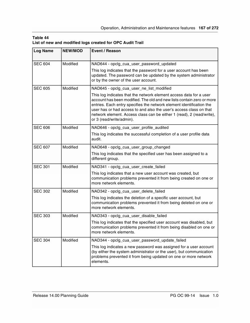
Operation, Administration and Maintenance features 167 of 272
SEC 604 Modified NAD644 - opclg_cua_user_password_updated
This log indicates that the password for a user account has been updated. The password can be updated by the system administrator or by the owner of the user account.
SEC 605 Modified NAD645 - opclg_cua_user_ne_list_modified
This log indicates that the network element access data for a user account has been modified. The old and new lists contain zero or more entries. Each entry specifies the network element identification the user has or had access to and also the user’s access class on that network element. Access class can be either 1 (read), 2 (read/write), or 3 (read/write/admin).
SEC 606 Modified NAD646 - opclg_cua_user_profile_audited
This log indicates the successful completion of a user profile data audit.
SEC 607 Modified NAD648 - opclg_cua_user_group_changed
This log indicates that the specified user has been assigned to a different group.
SEC 301 Modified NAD341 - opclg_cua_user_create_failed
This log indicates that a new user account was created, but communication problems prevented it from being created on one or more network elements.
SEC 302 Modified NAD342 - opclg_cua_user_delete_failed
This log indicates the deletion of a specific user account, but communication problems prevented it from being deleted on one or more network elements.
SEC 303 Modified NAD343 - opclg_cua_user_disable_failed
This log indicates that the specified user account was disabled, but communication problems prevented it from being disabled on one or more network elements.
SEC 304 Modified NAD344 - opclg_cua_user_password_update_failed
This log indicates a new password was assigned for a user account (by either the system administrator or the user), but communication problems prevented it from being updated on one or more network elements.
Table 44List of new and modified logs created for OPC Audit Trail
Log Name NEW/MOD Event / Reason
Release 14.00 Planning Guide PG OC 99-14 Issue 1.0
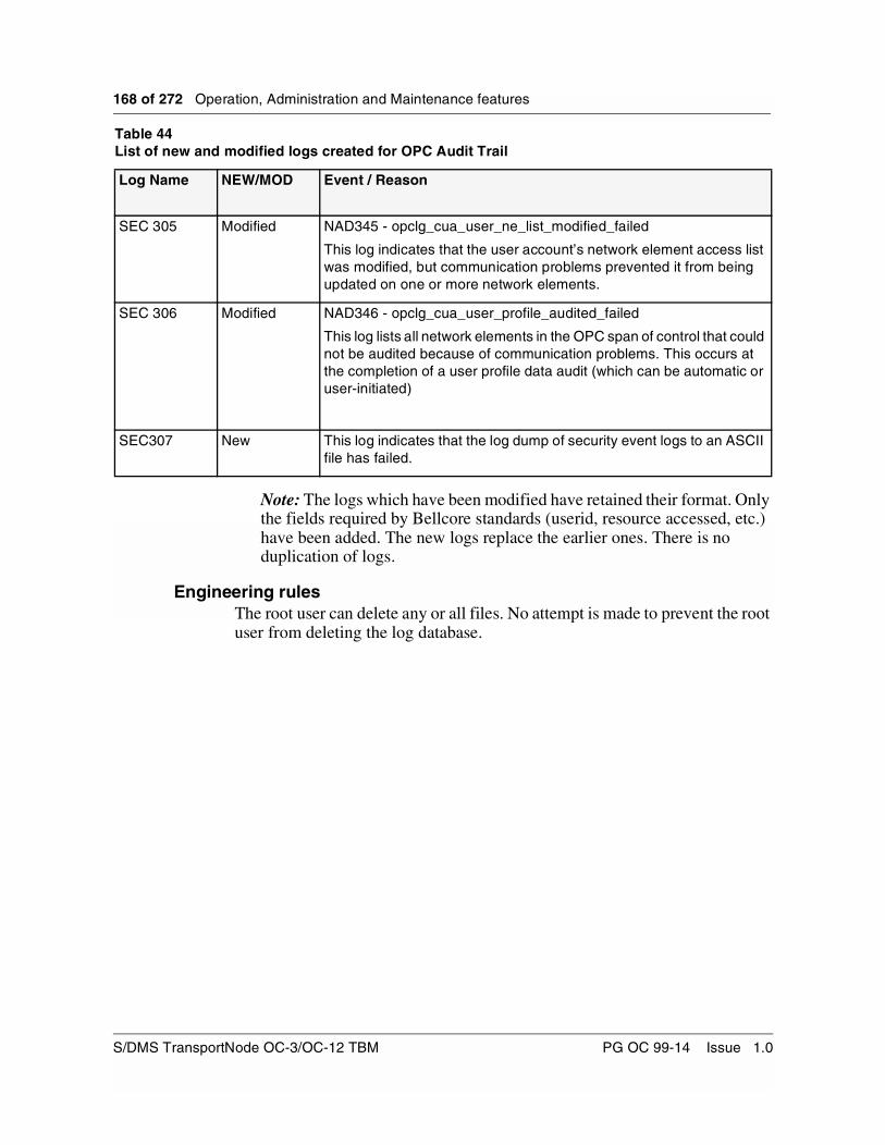
168 of 272 Operation, Administration and Maintenance features
Note: The logs which have been modified have retained their format. Only the fields required by Bellcore standards (userid, resource accessed, etc.) have been added. The new logs replace the earlier ones. There is no duplication of logs.
Engineering rulesThe root user can delete any or all files. No attempt is made to prevent the root user from deleting the log database.
SEC 305 Modified NAD345 - opclg_cua_user_ne_list_modified_failed
This log indicates that the user account’s network element access list was modified, but communication problems prevented it from being updated on one or more network elements.
SEC 306 Modified NAD346 - opclg_cua_user_profile_audited_failed
This log lists all network elements in the OPC span of control that could not be audited because of communication problems. This occurs at the completion of a user profile data audit (which can be automatic or user-initiated)
SEC307 New This log indicates that the log dump of security event logs to an ASCII file has failed.
Table 44List of new and modified logs created for OPC Audit Trail
Log Name NEW/MOD Event / Reason
S/DMS TransportNode OC-3/OC-12 TBM PG OC 99-14 Issue 1.0

Operation, Administration and Maintenance features 169 of 272
NE Audit TrailWhen problematic situations occur, it has been proven difficult to identify whether a situation was initiated as a result of user commands being entered from the system, or because of a system error. This ambiguity resulted in enhanced security features on the Network Element.
The NE Audit Trail feature records a trail of security (SECU) logs on the NE. This allows “after-the-fact” trouble shooting. All valid/invalid login attempts, logouts and user entered commands on both physical and logical ports are recorded on the NE as SECU logs.
The enhanced security functionality offered by the NE Audit Trail feature provides customers with more uses than simply “after the fact” problem resolution. Many potential problems can be identified before they occur by keeping track of events which may impact the system.
Secret NE Security (SECU) Logs The SECU logs may be viewed through use of logutil command. They have the following properties:
• They cannot be read with the “open” command.
• They are visible by means of a new logutil sub-command called opensecret. The opensecret sub-command can be used only by administrative class users. Note that the opensecret sub-command is not displayed in help list of logutil.
• They cannot be impacted by imposed thresholds, or suppressed by the logutil command.
• They cannot be cleared.
• The logutil command refuses the SECU log as its first parameter.
• The listlogs command of logutil does not print the SECU logname.
Log valid/invalid login attempts and logoutsAll valid/invalid user login attempts and logouts are recorded in the new SECU log. The logs are generated at login time, logout time, during any request to kill a CI process, and when a login fails. In all cases, the timestamp, user id, the port to which the user was connected, and the result of the attempt are all logged.
When a login fails, the log records whether the password was wrong for a valid user id, whether the user id was invalid, or whether the password had expired. A log is generated in cases of multiple login failure (intrusion attempt), or a login time out.
Release 14.00 Planning Guide PG OC 99-14 Issue 1.0

170 of 272 Operation, Administration and Maintenance features
Log user account activitiesAll commands entered from the CI command line, and the user interface port (valid command use, invalid command attempts, and user forced out by using forceout command) are recorded in the new SECU log. In all cases, the timestamp, user id, the port to which the user was connected, the command text, and the result are all logged.
Uploading the Security Logs to the OPCIn order to ensure that the logs are not overwritten, the SECU logs are uploaded to the OPC. The log files are uploaded based on a time interval which is provisionable on the OPC by administrative users. The time settings are at 4, 8, 12 and 24 hour intervals. Log archiving can be disabled at the OPC by administrative class (and above) users.
The security logs are general logs in the OPC Event Browser, but are displayed in a secure version of OPC Event Browser (accessible to administrative class users only). For more information on the secure Event Browser, refer to the OPC Audit Trail section “OPC Audit Trail” on page 162.
A SECU log is recorded by the system for each of the following events:
• Valid user logins and logouts
• Invalid user login attempts
• Unauthorized command attempts
• Valid command use
• Login time out
• Multiple login failure
• User forced out (Using the forceout command from the NE CI)
S/DMS TransportNode OC-3/OC-12 TBM PG OC 99-14 Issue 1.0
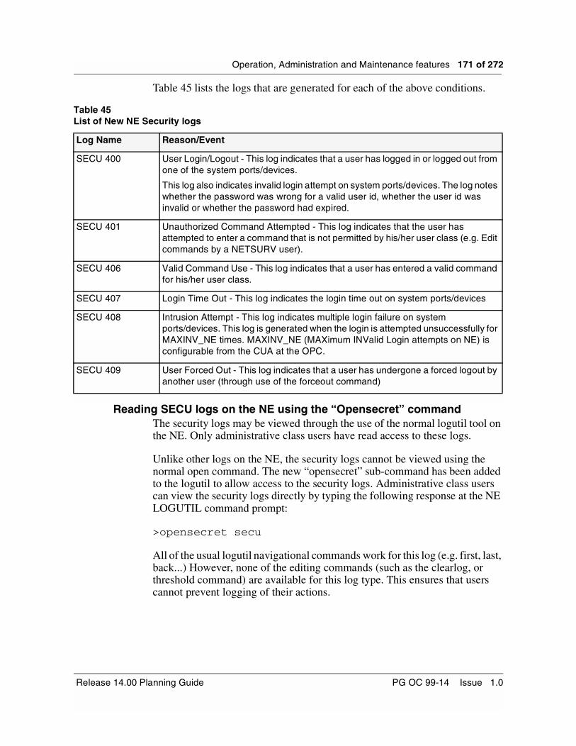
Operation, Administration and Maintenance features 171 of 272
Table 45 lists the logs that are generated for each of the above conditions.
Reading SECU logs on the NE using the “Opensecret” commandThe security logs may be viewed through the use of the normal logutil tool on the NE. Only administrative class users have read access to these logs.
Unlike other logs on the NE, the security logs cannot be viewed using the normal open command. The new “opensecret” sub-command has been added to the logutil to allow access to the security logs. Administrative class users can view the security logs directly by typing the following response at the NE LOGUTIL command prompt:
>opensecret secu
All of the usual logutil navigational commands work for this log (e.g. first, last, back...) However, none of the editing commands (such as the clearlog, or threshold command) are available for this log type. This ensures that users cannot prevent logging of their actions.
Table 45List of New NE Security logs
Log Name Reason/Event
SECU 400 User Login/Logout - This log indicates that a user has logged in or logged out from one of the system ports/devices.
This log also indicates invalid login attempt on system ports/devices. The log notes whether the password was wrong for a valid user id, whether the user id was invalid or whether the password had expired.
SECU 401 Unauthorized Command Attempted - This log indicates that the user has attempted to enter a command that is not permitted by his/her user class (e.g. Edit commands by a NETSURV user).
SECU 406 Valid Command Use - This log indicates that a user has entered a valid command for his/her user class.
SECU 407 Login Time Out - This log indicates the login time out on system ports/devices
SECU 408 Intrusion Attempt - This log indicates multiple login failure on system ports/devices. This log is generated when the login is attempted unsuccessfully for MAXINV_NE times. MAXINV_NE (MAXimum INValid Login attempts on NE) is configurable from the CUA at the OPC.
SECU 409 User Forced Out - This log indicates that a user has undergone a forced logout by another user (through use of the forceout command)
Release 14.00 Planning Guide PG OC 99-14 Issue 1.0
172 of 272 Operation, Administration and Maintenance features
Engineering rulesThe following list identifies the rules applicable to the security log feature:
• Log archiving on the OPC can be disabled by administrative class users and above.
• Security Logs do not appear on the remote NE in cases where the selectne command is used, or if an action is requested from the OPC.
• Security Logs do not appear for scheduled system processes.
• Every valid administrative class user can have read access to Security Logs.
• Security Logs cannot be manually uploaded to the OPC.
• Security Logs do not survive reboots on the NE
NE EnhancementsThe following NE enhancements have been introduced in Release 14.00
New and Enhanced NE AlarmsThe following alarms associated with an NE are new to Release 14.00:
• PM threshold capping active alarm: Release 13.11/13.12 introduced the Performance Monitoring Threshold Crossing Alert (TCA) capping functionality, which enables stopping the generation of any more TCAs when the number of TCAs raised in a timing interval reaches a number equal to the provisioned TCA capping value, which is provisionable using the PMCAPCI tool. Release 14.00 introduces the new “PM threshold capping active” alarm, which will be raised if TCA capping is enabled and new TCAs are not being generated. This alarm will clear automatically at the end of the timing interval.
• DS1/DS3/STS1 protection unavailable, equipment OOS alarms: a minor, nsa alarm will be raised on any DS1, DS3, or STS1 protection circuit pack when the protection equipment is placed OOS. The alarm will be raised regardless of the state or presence of working facilities. The alarm is provisionable with the default as ON. The alarm will be lowered when the DS1/DS3/STS1 protection equipment is placed IS, or when it is deleted.
In addition, the protection switch complete alarm has been enhanced to indicate whether the switch request is local or remote, on a protection switch between an OPTera Metro 3000 shelf and OC-3 tributaries.
S/DMS TransportNode OC-3/OC-12 TBM PG OC 99-14 Issue 1.0
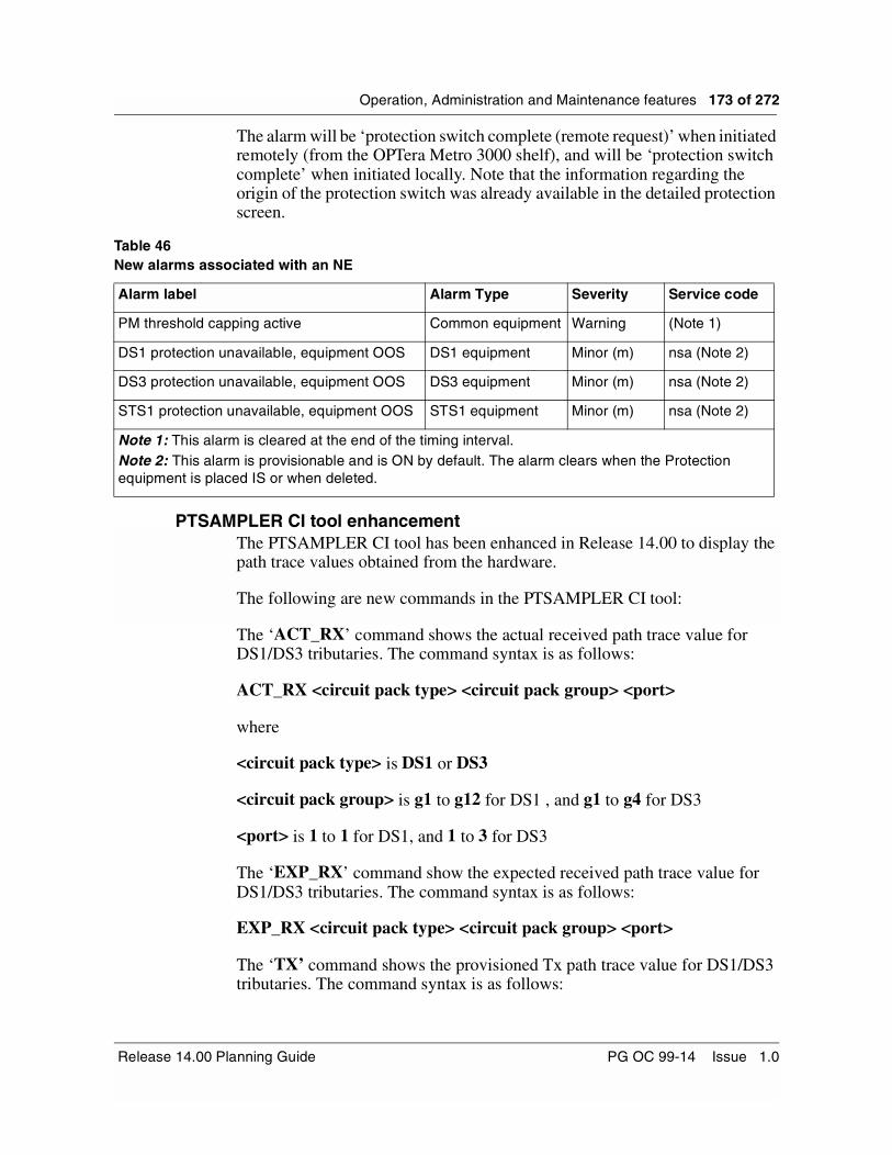
Operation, Administration and Maintenance features 173 of 272
The alarm will be ‘protection switch complete (remote request)’ when initiated remotely (from the OPTera Metro 3000 shelf), and will be ‘protection switch complete’ when initiated locally. Note that the information regarding the origin of the protection switch was already available in the detailed protection screen.
PTSAMPLER CI tool enhancementThe PTSAMPLER CI tool has been enhanced in Release 14.00 to display the path trace values obtained from the hardware.
The following are new commands in the PTSAMPLER CI tool:
The ‘ACT_RX’ command shows the actual received path trace value for DS1/DS3 tributaries. The command syntax is as follows:
ACT_RX <circuit pack type> <circuit pack group> <port>
where
<circuit pack type> is DS1 or DS3
<circuit pack group> is g1 to g12 for DS1 , and g1 to g4 for DS3
<port> is 1 to 1 for DS1, and 1 to 3 for DS3
The ‘EXP_RX’ command show the expected received path trace value for DS1/DS3 tributaries. The command syntax is as follows:
EXP_RX <circuit pack type> <circuit pack group> <port>
The ‘TX’ command shows the provisioned Tx path trace value for DS1/DS3 tributaries. The command syntax is as follows:
Table 46New alarms associated with an NE
Alarm label Alarm Type Severity Service code
PM threshold capping active Common equipment Warning (Note 1)
DS1 protection unavailable, equipment OOS DS1 equipment Minor (m) nsa (Note 2)
DS3 protection unavailable, equipment OOS DS3 equipment Minor (m) nsa (Note 2)
STS1 protection unavailable, equipment OOS STS1 equipment Minor (m) nsa (Note 2)
Note 1: This alarm is cleared at the end of the timing interval.Note 2: This alarm is provisionable and is ON by default. The alarm clears when the Protection equipment is placed IS or when deleted.
Release 14.00 Planning Guide PG OC 99-14 Issue 1.0

174 of 272 Operation, Administration and Maintenance features
TX <circuit pack type> <circuit pack group> <port>
The ‘ALL_SIG’ command shows all the path trace signatures that are shown separately by the above three commands, namely it shows the transmitted value, the actual received value and the expected received value for DS1/DS3 tributaries. The command syntax is as follows:
ALL_SIG <circuit pack type> <circuit pack group> <port>
OPC Alarms EnhancementsThis feature enhances the manner in which OPC alarms are handled. It provides two capabilities, “Alarms on an inactive OPC”, and “Customized Alarms on an NE”.
Alarms on an Inactive OPC This capability gives the active OPC (Primary or Backup) the ability to raise OPC alarms on behalf of the Inactive OPC (Backup or Primary). Problems such as disk/tape failure, tape head needs cleaning, intrusion attempt detected on an Active OPC or on an Inactive OPC are reported to the user via an OPC alarm raised on the Active OPC.
When the Active OPC alarms count is greater than zero, a pointer alarm is raised on the NE that was provisioned for that purpose. Two distinct OPC alarms are raised when the same problem is detected on both active and inactive OPCs. Both alarms are cleared separately.
OPC alarms raised on behalf of an Inactive OPC are cleared automatically by the application which originated them.They also can be cleared manually by the user from the OPC Alarm Provisioning tool on the Active OPC. The manual clear command is available for each new OPC alarm. The manually cleared alarm is raised again when the OPC alarm events handler receives the same raise request.
Alarm monitor alarms list
The Alarms list (see Figure 68) shows an example which contains a one-line summary for each active alarm in the OPC span of control. The Unit field indicates the OPC on which a reported failure was detected. For example, the Unit field would contain “OPCB” when a failure is detected on the Backup OPC. The NE Name field contains the Active OPC (Primary or Backup) name. The OPC name is selected instead of OPC alias to be consistent with the OPC UIs. Both OPC name and alias are specified by the user when an OPC is commissioned. The OPC name is mandatory, but an alias is optional. All other OPC UIs always show the OPC name, but not the OPC alias.
For OPC alarms, the NE# contains “0”. The Sh field is left empty.
S/DMS TransportNode OC-3/OC-12 TBM PG OC 99-14 Issue 1.0

Operation, Administration and Maintenance features 175 of 272
Figure 68Alarms list showing new alarms raised on inactive Backup OPC
Engineering rulesOPC alarms cannot be filtered to be raised on behalf of either the inactive OPC only, or the active OPC only. The historical clear event for OPC alarms raised on behalf of an inactive OPC is shown by the Event Browser on the OPC which was active when the OPC alarm was cleared, i.e. logs data is kept locally on the OPC and is not exchanged between OPCs.
Customized alarm on an NEThis capability introduces a custom alarm which has been added to the set of four existing NE test alarms. The raise/clear commands in the fwaltsci tool have been extended by this capability to allow the user to define a customized alarm. The user is able to enter a customized text which is added to the static portion of the alarm reason.
Detailed Alarm Reports screen on NE for customized alarms
This screen shows details of any active alarm raised on an NE. Figure 69 shows the Detailed Alarm Reports screen layout with details of the custom NE alarm. The user can customize the reason portion of this alarm. In this example the user defined a reason which was added to the static, predefined reason portion (“User:”).
OPCP indicates a problem on the Primary OPC.
OPCB indicates a problem on the Backup OPC.
An Active OPC alias/name which raised an OPC alarm.
Release 14.00 Planning Guide PG OC 99-14 Issue 1.0

176 of 272 Operation, Administration and Maintenance features
The custom alarm is added to the set of existing four NE test alarms: warning, minor, major and critical. The custom alarm is of the Envr (Environmental) type, nsa (non service affecting) and belongs to the Environmental Class of alarms.
The reason field is composed of two portions, one static and the second optional user provisionable portion. The user can enter and add to the reason up to 40 characters. The default alarm text is: “User: manually generated”. The static portion (“User:“) cannot be modified by the user.
The custom alarm can only be raised from the CI tool fwaltsci on an NE. When the custom alarm is raised on an NE, it is included in the Active Alarms screen and details can be accessed via the AlmRpt command on the NE.
Figure 69Alarm details for the custom alarm
New Commands for custom alarmRaise
When the raise command is executed with the new CUSTOM option, the custom alarm is raised on an NE and it is added to the set of active alarms. When raised on an NE, the custom alarm is available to the user via the Active OPC UIs.The user can overwrite the custom text by entering the reason text after the CUSTOM option or by invoking the settext command.
Syntax:
raise <severity>, where severity = [WARNING | MINOR | MAJOR |CRITICAL| CUSTOM]
S/DMS TransportNode OC-3/OC-12 TBM PG OC 99-14 Issue 1.0

Operation, Administration and Maintenance features 177 of 272
Example:
raise custom “This is an optional custom alarm text”Settext
With the new settext command, users can enter up to 40 characters, which are be added to the reason of the custom alarm. Characters in excess of 40 are ignored.
Syntax:settext <user_text>, where user_text = [up to 40 character string]
Example:
settext “new text”
Clear
Clear allows the user to clear the custom alarm or a test alarm. When cleared, the alarm is removed from the set of active NE alarms and from the Active Alarms screen. Also, the custom text is reset to the default value for the next raise command execution. The display command shows the custom alarm state and the custom user text with which the custom warning was raised and/or cleared. This means that when the custom alarm was cleared and the next command executed was ‘raise custom’, the custom alarm is raised with the default text “User: manually generated”.
Syntax:clear <severity>, where severity = [WARNING | MINOR | MAJOR | CRITICAL| CUSTOM]
Example:
clear custom
NE and OPC Area Address ProvisioningReconfiguring the Data Communication Network (DCN) via Area Address manipulation
Area address manipulation can be used to reconfigure the Data Communication Network (DCN) by reshaping the routing domain. This may include expansion of the routing domain due to network growth, or shrinking of the domain as the network is broken up into multiple domains which can be more effectively managed.
The following is a quick overview of how to use the area address add and delete procedures on the OPC and NE to reconfigure the DCN. Note that each situation is dependent on the administrative requirements.
The main scenarios for reconfiguring a routing domain of a DCN are as follows:
Release 14.00 Planning Guide PG OC 99-14 Issue 1.0

178 of 272 Operation, Administration and Maintenance features
• Adding a third party vendor NE into the Nortel Networks OC-12 network. Sometimes it is necessary to add a third party NE into an existing OC-12 network. This is the most common scenario OC-12 experiences where additional area addresses have to be added. As interworking with other third party vendor NEs becomes a reality, additional area addresses have to be added to selected OC-12 NEs in the network to enable routing of third party OAM messages. If the third party vendor NE can operate in the 49+0000 area, there is no need to provision additional area addresses. This, however, is not necessarily true for some vendors. Certain vendors can only operate with the ISO DCC format area address. In order to interoperate with this type of equipment, it is necessary to add the third party area address into the adjacent OC-12 NEs. This effectively merges third party equipment into the Nortel Networks’ OC-12 network as a single Level 1 routing domain.
• Network area address change. This involves changing or renaming the area address, for administrative reasons, of the whole DCN from one area address to another area address. As well, doing so becomes a requirement for OC-3/OC-12 TBM Release 14.00 to interwork with Nortel Networks products that can provide Level 2 routing capability.
• Splitting a single area DCN into two smaller areas DCNs. This step can be iterated to further split the area. The originally single area has grown and can be better managed by splitting it up into a number of smaller areas.
• Merging or joining two separate Level 1 routing domain into a single Level 1 routing domain. This is to combine two separate routing domain into a larger one.
• Adding new nodes into an existing non-49+0000 DCN area.
Introduction to Areas and Area AddressesArea address provisioning can be initiated by a network operator to configure or change the configuration of the Data Communication Network (DCN). By default, a Nortel Networks network element initializes with area address 49+0000 in the absence of commissioning data.
Network element and OPC Area Address provisioning removes the dependency of using the default area address (49+0000) and improves interoperability with third party vendor equipment. This feature was also developed to support Level 2 Routing. As a result, the user can log in remotely to a network element in another Level 1 area.
Note: For more information on Level 2 Routing, refer to the Data Communications Planning Guide.
With this feature, it is possible to provision a new manual area addresses on one OPC (in a span of control) and distribute this information to all network elements in the span of control.
S/DMS TransportNode OC-3/OC-12 TBM PG OC 99-14 Issue 1.0

Operation, Administration and Maintenance features 179 of 272
The Commissioning Manager main anchor window, shown in Figure 70, has been modified to include the new "Provision Area Addresses" Utilities menu item, which replaces "Remote OPC list". The Remote OPC list item has been removed from the Utilities menu because the Remote OPC list is no longer supported.
Figure 70New Commissioning Manager Utilities menu
OPC Area Addressing dialog
The Utilities menu item displays the Area Addresses dialog. See Figure 71. The purpose of this dialog is to display the Manual Area Address (MAA) sets that have been provisioned for the OPC and all the NEs in the OPC’s SOC. These sets are displayed in the top list. The union of all the MAAs that have been provisioned in the SOC are displayed in the bottom left list, and the Computed Area Address set used for routing is displayed in the bottom right list. Note that the maximum number of Computed Area Address is three.
Each node in the SOC can be provisioned with maximum up to three MAAs. A properly provisioned SOC needs only one common MAA provisioned on every node. When merging or splitting an area, a second address is provisioned until the operation is complete.
When interworking with other vendor equipment, a second MAA can be provisioned for the whole span, or the MAA can be provisioned on a single node. This is done by selecting the node in the provisioned MAA set list and using the add menu, or from the NE UI (refer to “NE User Interface” on page 185.)
Release 14.00 Planning Guide PG OC 99-14 Issue 1.0

180 of 272 Operation, Administration and Maintenance features
If some of the NEs have been provisioned improperly, the provisioned MAA set list can be used to determine which NE is in error. The NEs can then be provisioned with the missing MAA.
Figure 71Area Addressing dialog
The Add Manual Area Address command (in both the list title and the bottom right button), invokes the OPC Area Address Provisioning dialog which is described in the next section. When the list is full (three addresses), the Add Manual Area Address operation is denied. If the user wants to add yet another Manual area address, the user first has to delete one of the existing addresses to allow for the new one.
S/DMS TransportNode OC-3/OC-12 TBM PG OC 99-14 Issue 1.0

Operation, Administration and Maintenance features 181 of 272
Note that the user cannot delete a Manual Area Address that is currently in use. To delete it, the user must first select another one and make it as Area Address, and then delete the previous one. Also, if only one Area Address is present, the user is not allowed to delete it. To change the Manual Area Address, the user has to select the new Manual Area Address and perform "Netarea" from the menu to take it into effect. The Refresh command refreshes the contents of the lists to assure the user the data is the very latest view.
Note: When changing a Manual Area Address, it may take up to several minutes per NE to complete.
The Done button closes the dialog and returns the user back to the anchor window.
OPC Area Address Provisioning dialogThis dialog is used to manually provision an area address locally at this OPC. Once provisioned, the manual area address is sent to the NEs in the OPC’s SOC. Figure 72 shows the OPC Area Address Provisioning dialog, from the Commissioning Manager.
Release 14.00 Planning Guide PG OC 99-14 Issue 1.0

182 of 272 Operation, Administration and Maintenance features
Figure 72Area Address Provisioning Dialog
Only the area address portion of the NSAP address needs to be entered. The system Id portion of the address is not shown and not displayed in the Manual or Computed lists.
The Ok button checks whether the added area address is valid, then accepts the address (or not if invalid). First, validation is done to check if the Computed list is full and if the address exists in either the Manual or Computed list. If the Computed list is full, or if the added address already exists, then the address is added once the confirmation dialog is confirmed.
Once the address has been provisioned, it is added to the Manual list and the user is then prompted to perform a datasync to the Backup OPC.
The Cancel button closes the dialog with no changes and returns to the OPC Area Addresses dialog.
S/DMS TransportNode OC-3/OC-12 TBM PG OC 99-14 Issue 1.0
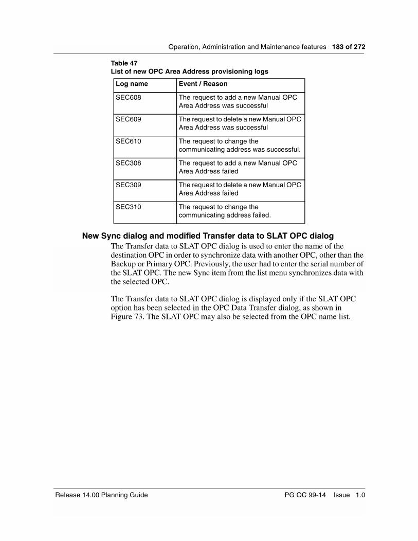
Operation, Administration and Maintenance features 183 of 272
Table 47List of new OPC Area Address provisioning logs
New Sync dialog and modified Transfer data to SLAT OPC dialogThe Transfer data to SLAT OPC dialog is used to enter the name of the destination OPC in order to synchronize data with another OPC, other than the Backup or Primary OPC. Previously, the user had to enter the serial number of the SLAT OPC. The new Sync item from the list menu synchronizes data with the selected OPC.
The Transfer data to SLAT OPC dialog is displayed only if the SLAT OPC option has been selected in the OPC Data Transfer dialog, as shown in Figure 73. The SLAT OPC may also be selected from the OPC name list.
Log name Event / Reason
SEC608 The request to add a new Manual OPC Area Address was successful
SEC609 The request to delete a new Manual OPC Area Address was successful
SEC610 The request to change the communicating address was successful.
SEC308 The request to add a new Manual OPC Area Address failed
SEC309 The request to delete a new Manual OPC Area Address failed
SEC310 The request to change the communicating address failed.
Release 14.00 Planning Guide PG OC 99-14 Issue 1.0
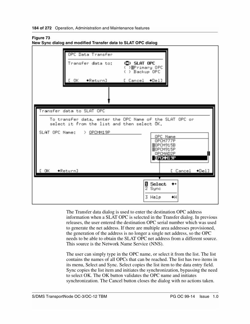
184 of 272 Operation, Administration and Maintenance features
Figure 73New Sync dialog and modified Transfer data to SLAT OPC dialog
The Transfer data dialog is used to enter the destination OPC address information when a SLAT OPC is selected in the Transfer dialog. In previous releases, the user entered the destination OPC serial number which was used to generate the net address. If there are multiple area addresses provisioned, the generation of the address is no longer a single net address, so the OPC needs to be able to obtain the SLAT OPC net address from a different source. This source is the Network Name Service (NNS).
The user can simply type in the OPC name, or select it from the list. The list contains the names of all OPCs that can be reached. The list has two items in its menu, Select and Sync. Select copies the list item to the data entry field. Sync copies the list item and initiates the synchronization, bypassing the need to select OK. The OK button validates the OPC name and initiates synchronization. The Cancel button closes the dialog with no actions taken.
S/DMS TransportNode OC-3/OC-12 TBM PG OC 99-14 Issue 1.0

Operation, Administration and Maintenance features 185 of 272
When provisioning manual area addresses on the primary OPC, these addresses need to be datasynced to the backup OPC. If the datasync operation fails due to a fiber cut or other fault, the backup OPC could become isolated from the primary OPC due to different manual area addresses. The ‘Transfer data to SLAT’ dialog can be used to locate the backup OPC and complete the datasync operation once the fault has been cleared allowing the OPCs to communicate again.
NE User InterfaceIf a manual area address is required on only one NE (i.e. to interop with an OSS), the address can be added to that individual NE from the FWPUI screen. Use the “Facility” submenu and choose the “comm” facility. The following screen, as shown by Figure 74, is displayed.
Figure 74Comm Facility dialog
Choosing the “AreaAddr” menu item displays the following screen, as shown by Figure 75. Now the user can add/delete area addresses.
Release 14.00 Planning Guide PG OC 99-14 Issue 1.0

186 of 272 Operation, Administration and Maintenance features
Figure 75Area Address submenu of Comm Facility dialog
Disabled Alarms Listing ToolPrior to the introduction of Disabled Alarm Listings Tool, a user had to identify and invoke a particular alarm provisioning NE UI screen to determine the status (enabled or disabled) of a particular alarm point. Some unknown provisioning would be difficult to trace (and also quite time-consuming, because one had to cycle through all the NE UI provisioning screens supporting the provisionable alarm points.) The requirement of a tool to enlist all the disabled alarms on an NE was most felt during troubleshooting, and during scenarios such as upgrades, wherein the alarm reports being affected (due to unknown provisioning) was highly undesirable.
A new CI tool, Disabled Alarm Listings (DISALCI), has been developed to solve such problems.
User interfaceThe CI tool, DISALCI, can run in the local NE context only. A user has to explicitly login to a particular NE and then run the DISALCI tool to list the alarms provisioned as disabled on that NE.
The user invokes the DISALCI tool first (to use any of the tool commands), by typing ‘DISALCI’ at the CI level on the NE. The user then can type in any of the DISALCI commands (‘showdisalms’, ‘help’ or ‘quit’).
Critical Major minor warning FailProt Lockout ActProt PrfAlrt Network View . 1 7 . . . . . . 1 4 . . . . . Comm Area A 1.1.575 0 Quit COMM Facility Shelf: 1 2 3 NE Network Address: 39840+82222222222222222222000075E4741900 4 Max Area Addresses: 3 5 ListAlms Supported Area Address 6 AlmRpt <39840+82222222222222222222 > 7 <Nil > 8 <Nil > 9 10 AREAADDR: 11 12 13 Add 14 Delete 15 NetArea 16 17 18 Help NE 575 Time 21:46 >
S/DMS TransportNode OC-3/OC-12 TBM PG OC 99-14 Issue 1.0
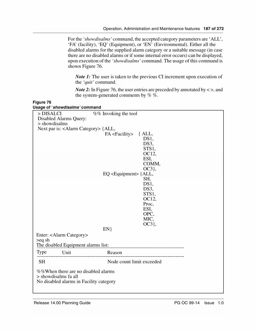
Operation, Administration and Maintenance features 187 of 272
For the ‘showdisalms’ command, the accepted category parameters are ‘ALL’, ‘FA’ (facility), ‘EQ’ (Equipment), or ‘EN’ (Environmental). Either all the disabled alarms for the supplied alarm category or a suitable message (in case there are no disabled alarms or if some internal error occurs) can be displayed, upon execution of the ‘showdisalms’ command. The usage of this command is shown Figure 76.
Note 1: The user is taken to the previous CI increment upon execution of the ‘quit’ command.
Note 2: In Figure 76, the user entries are preceded by annotated by < >, and the system-generated comments by % %.
Figure 76Usage of ‘showdisalms’ command
> DISALCIDisabled Alarms Query:> showdisalmsNext par is: <Alarm Category> {ALL,
The disabled Equipment alarms list:----------------------------------------------------------------------------------------Type ----------------------------------------------------------------------------------------
%%When there are no disabled alarms
%% Invoking the tool
Enter: <Alarm Category>>eq sh
Unit Reason
> showdisalms fa allNo disabled alarms in Facility category
FA <Facility>
SH Node count limit exceeded
DS1,DS3,STS1,OC12,ESI,COMM,OC3},
EQ <Equipment> {ALL,SH,DS1,DS3,STS1,OC12,Proc,ESI,OPC,MIC,OC3},
EN}
{ ALL,
Release 14.00 Planning Guide PG OC 99-14 Issue 1.0
188 of 272 Operation, Administration and Maintenance features
Display of Configuration Mismatch DetailsUnder normal circumstances, configuration data stored on both the OPC and NE are identical (they match). However, there may be scenarios in which a customer wishes to make network configuration changes while in-service, which may allow the configuration data at the OPC and at the NE to mismatch.
For example, one customer frequently performs ring reconfigurations, where one collapsed ring is converted, while it is in-service, to two route diverse rings. During this procedure, the new OPCs are installed. The new OPCs contain the final ring configuration information. A ring configuration audit (while the system is in-service) is performed, to copy the configuration information from the OPCs to the NEs in question. The configuration audit, at this time, overwrites the NE information.
In OC-3/OC-12 TBM Release 14.00, the option is now given to the user to view any mismatch details, prior to deciding on corrective action.
User interfaceThe OPC Configuration Manager UI provides the ability to manually initiate a configuration data audit between the OPC and a ring ADM or all the ADMs in a ring. The results (success/mismatch/error) are displayed to the user via a dialog. If the audit results included one or more ADMs mismatching the OPC’s configuration data, the user is given the opportunity to correct the mismatches by sending the OPC data to overwrite the NE data.
An example of the results dialog, prior to Release 14.00, in use on the OPC with respect to a configuration audit mismatch is shown in Figure 77.
S/DMS TransportNode OC-3/OC-12 TBM PG OC 99-14 Issue 1.0

Operation, Administration and Maintenance features 189 of 272
Figure 77Configuration audit mismatch dialog, prior to Release 14.00
A new option has been provided in the case of a configuration audit mismatch for Release 14.00. A new button, entitled ‘View Mismatch Information’ has been added to the Configuration Audit Mismatch Results Dialog. An example of the new configuration audit mismatch results dialog box is shown in Figure 78.
Figure 78Configuration audit mismatch dialog, with Release 14.00
Note: No configuration data overwriting takes place upon selecting this new option. It is simply information for the user to use to make an informed decision with respect to overwriting the configuration data of the NEs.
The configuration data audit has completed with the following results:
Mismatch(es) found for NE1111, 2222, 3333
Do you wish to correct mismatched data at the indicated ring ADM(s)?
Yes No
The configuration data audit has completed with the following results:
Mismatch(es) found for NE1111, 2222, 3333
Do you wish to correct mismatched data at the indicated ring ADM(s)?
Yes NoView Mismatch Info
Release 14.00 Planning Guide PG OC 99-14 Issue 1.0

190 of 272 Operation, Administration and Maintenance features
Upon selecting the ‘View Mismatch Information’ option from the Configuration Audit Mismatch Results Dialog, an In-Progress message is displayed. Upon completion, a new dialog, the Configuration Audit Mismatch Details dialog, is displayed listing the configuration data information causing the OPC/NE mismatches. An example of such a dialog is shown is Figure 79.
Figure 79Configuration Audit Mismatch Details dialog
Note: Each list pertaining to the ‘Information found at OPC’ and ‘Information found at NE’ fields are sorted in G1 ring order.
The Configuration Audit Mismatch Details dialog has the following format properties:
• A time and date stamp for each view is listed.
• A table differentiating between the information resident on the OPC and the information resident at the NE. Each view can be scrolled to view all the information.
• The table is divided into two major columns, each with two subcolumns. The first major column lists the information resident on the OPC and the second major column lists the information resident at the individual NE.
Configuration Audit Mismatch Details
Done
NE: 1111 Ottawa
Information found at OPC Information found at NE NEid NEid APSid APSid
1111 2 >2222 3 >3333 >4
1111 2 >1 3
>3333 >2222
>4444 >5
Tue Jun 08 11:17:15 1999 Tue Jun 08 11:17:17 1999
S/DMS TransportNode OC-3/OC-12 TBM PG OC 99-14 Issue 1.0

Operation, Administration and Maintenance features 191 of 272
Each major column is subdivided to show the NE id and APS id, sorted in G1 ring order - the order starting at the specified NE and proceeding around the ring in its G1 direction.
• A data selector is provided, listing each NE whose audit result was mismatched. When the dialog is first popped up, the first NE in the data selector list is automatically selected and the contents of its configuration data mismatch information are shown. The OPC (left) column shows the OPC’s view of the NE’s node map. The NE (right) column shows the NE’s view of its node map. Selecting an NE from the data selector shows its corresponding mismatch information in the OPC and NE views.
• The mismatches are highlighted to aid the user.
• When the user selects ‘Done’, the user is returned to the Configuration Audit Mismatch Results dialog, shown in Figure 78.
How to Interpret the Configuration Audit Mismatch Details Dialog
Configuration Audit mismatches can include mismatched NE or APS IDs, a mismatched ring configuration, and extra or missing ring ADMs. This section details how such mismatches are shown on the Configuration Audit Mismatch Details dialog.
• If there are mismatched NE or APS IDs, they are shown as different between the OPC view and the NE view. For example, the Configuration Audit Mismatch Details dialog (shown in Figure 79) shows mismatched APS ID for NE ID 3333.
• If there is a mismatched ring configuration, the order of the NEs listed in G1 ring order is different between the OPC view and the NE view. For example, the Configuration Audit Mismatch Details dialog (shown in Figure 79) shows a different order in the ring node map for NE ID 1111. This may be due to the user not configuring the G1/G2 neighbours of NE ID 1111 correctly on the OPC.
• Any extra or missing ADMs from either the OPC view or the NE view is shown in the corresponding dialog views. For example, the Configuration Audit Mismatch Details dialog (shown in Figure 79 on page 190) shows an extra ADM (NE ID 4444) on the NE’s view of its node map.
All actions related to this feature are user-initiated. The configuration data audit results information dialog is created only upon request by the user during a ‘manual’ audit. Scheduled system-initiated configuration data audits do not result in the creation of the audit result information dialog.
Release 14.00 Planning Guide PG OC 99-14 Issue 1.0
192 of 272 Operation, Administration and Maintenance features
Correction of Connection Mismatches in a Linear SystemThis specific functionality affects the connection audits and correction of connection mismatches on linear systems. On linear systems, end-to-end interfaces such as the OPC Connection Manager or INM/Preside always provide the starting and ending points of a connection, the “NE A” and “NE Z” values in connection services terminology. These are passed to the NEs. When connection data is viewed directly on the NE with tools such as connmap, the NE A and NE Z values correspond to the values shown by the end-to-end interfaces.
TL1 is a nodal interface, and TL1 syntax does not allow it to provide the NE A and NE Z values for connections provisioned on linear configurations. For cross-connects on linear systems, the TL1 application specifies the NE A and NE Z values as the NE ID of the target NE on which the cross-connect is provisioned. The connection services base on the OPC has the intelligence to take the nodal pieces provisioned by TL1, construct complete end-to-end connections, arbitrarily select one end of the connection to be the “A” end, and the other end to be the “Z” end, and thereby fill in the values that TL1 was unable to provide. Although this information is then available to the end-to-end interfaces, and is displayed to the user, it is not sent to the NEs. If the user then uses connmap to view cross-connects on the NE, and compares this with connections provisioned on the OPC, the NE A and NE Z values differ if the connections were provisioned by TL1.
Prior to the introduction of this feature, this discrepancy was allowed to exist, since automatically correcting the NE A and NE Z values on the NEs once these became known was considered inappropriate because of the following reasons:
• the system would automatically perform an “audit correct” operation, an action that should always remain only under full user control
• one interface (Connection Manager) would change the data provisioned by another interface (TL1)
Since discrepancies in the NE A and NE Z values would not be checked in linear configurations, they would not be flagged as a mismatch, and the user would not be given the option of correcting them. Mismatches in the NE A and NE Z values could occur under the following conditions:
• the connection was provisioned by TL1
• one or more NEs were renumbered
• the linear configuration was split
• two linear configurations were merged
S/DMS TransportNode OC-3/OC-12 TBM PG OC 99-14 Issue 1.0
Operation, Administration and Maintenance features 193 of 272
In ring configurations, this behaviour does not exist, because all interfaces must provide the NE A and NE Z values, these values are checked during audits, and users are allowed to correct mismatches if they occur.
This new feature introduced in TBM Release 14.00 provides the following capabilities:
• allows customers to conveniently detect mismatches in NE A and NE Z values in connections provisioned on linear systems and correct them.
• minimizes the impact on existing functionality.
Feature implementationThe Mismatch Check for NEs in a Linear system configuration is initiated under the user’s control. With this option, when the user audits connections provisioned on NEs in a linear configuration, the audit dialog displays the following new check box:
[X] NE A/Z mismatches (non-service affecting)
The “include” option is selected by default so that users get all mismatches with minimum interaction and decision-making. If the configuration being audited is not an OC-12 linear configuration, the check box does not appear because NE A and Z mismatches are always checked in those configurations, and users have no option to disable such checking.
In most cases, customers do not wish to deliberately keep mismatches in their systems, and hence always decide to check for NE A and Z mismatches and correct them. Appropriate warning dialogs appear to indicate that loss of traffic could occur if the OPC view being sent to the NEs is not correct.
A “scheduled audit” is a periodic audit initiated by the system according to the frequency specified by the user. A “discovery audit” is initiated by the system whenever the connections services base starts up, the Configuration Manager is closed, or an association to an NE is established. The scheduled audit as well as the discovery audit does not look for mismatches in NE A or NE Z IDs on linear systems. Hence, the “Connection Audit Failed” alarm is not raised even if a mismatch is actually present on a linear system. On linear systems, there is no option in the scheduled or discovery audit to change the default from “ignore” to “check for” mismatches in NE A and Z values. This behaviour, which existed prior to Release 14.00, has not been changed.
TL1 EnhancementsThis chapter describes the TL1 enhancements that have been introduced with OC-3/OC-12 TBM Release 14.00.
TL1 SecurityThe TL1 security feature allows:
Release 14.00 Planning Guide PG OC 99-14 Issue 1.0

194 of 272 Operation, Administration and Maintenance features
• network administrators to have different levels of users to monitor and provision their networks.
• users to have Accuring Architecture functionality (network administrators can lease a selected number of network elements in a span-of-control to customers, without providing access to the remaining network elements)
• users to have split access network capability (Network users can log in, with the ACT-USER command, only to those network elements from which messages need to be sent or received. This inhibits autonomous messages from all other network elements for these users.)
• a customer to have up to four simultaneous OPS sessions
The TL1 security feature can be enabled or disable with the config_TL1 tool. This feature is disabled by default.
TL1usr user groupThe TL1 security feature introduces the tl1usr user group. This user group provides TL1 users with different user access privileges for each network element and OPC. Table 48 lists the user access privileges for the tl1usr user group.
Note: If a tl1usr user is created, this user has read/write user access privileges by default on all the network elements, and read-only access by default on the OPC. This user also has default access to all network elements and the OPC in the span-of-control.
If the TL1 security parameter is enabled, only a certain set of TL1 commands is available to each user in the tl1usr user group based on their assigned user access privilege.
Table 48User access privileges for tl1usr user group
User access privilege Description
Null User has no accessibility to the OPC or network element, but can issue the RTRV-HDR command to view the target identifier (TID) of a network element or OPC
Read User can issue read-only commands
(commands that do not modify
information)
Read/Write User can issue commands other than administration commands
Read/write/administration commands User can issue all types of commands
S/DMS TransportNode OC-3/OC-12 TBM PG OC 99-14 Issue 1.0
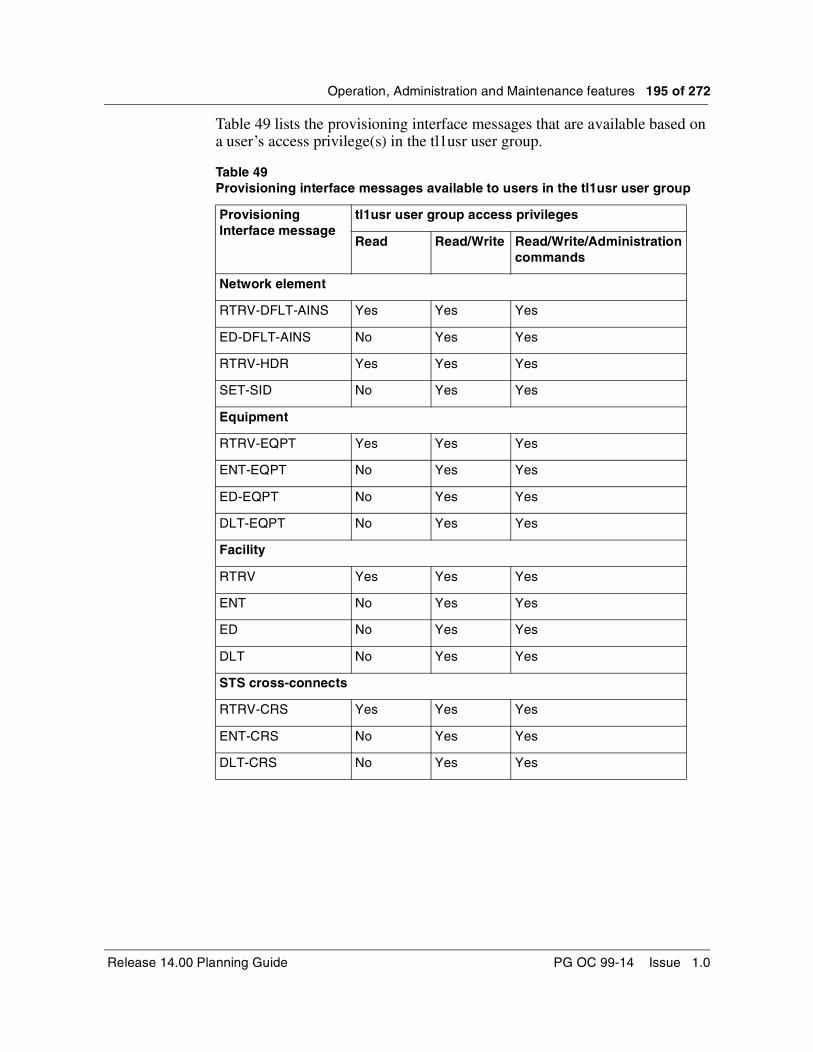
Operation, Administration and Maintenance features 195 of 272
Table 49 lists the provisioning interface messages that are available based on a user’s access privilege(s) in the tl1usr user group.
Table 49Provisioning interface messages available to users in the tl1usr user group
Provisioning Interface message
tl1usr user group access privileges
Read Read/Write Read/Write/Administration commands
Network element
RTRV-DFLT-AINS Yes Yes Yes
ED-DFLT-AINS No Yes Yes
RTRV-HDR Yes Yes Yes
SET-SID No Yes Yes
Equipment
RTRV-EQPT Yes Yes Yes
ENT-EQPT No Yes Yes
ED-EQPT No Yes Yes
DLT-EQPT No Yes Yes
Facility
RTRV Yes Yes Yes
ENT No Yes Yes
ED No Yes Yes
DLT No Yes Yes
STS cross-connects
RTRV-CRS Yes Yes Yes
ENT-CRS No Yes Yes
DLT-CRS No Yes Yes
Release 14.00 Planning Guide PG OC 99-14 Issue 1.0

196 of 272 Operation, Administration and Maintenance features
Table 50 lists the surveillance interface messages that are available based on a user’s access privilege(s) in the tl1usr user group
Table 50Surveillance interface messages available to users in the tl1usr user group
Provisioning interface message
tl1usr user group access privileges
Read Read/Write Read/Write/Administration commands
Autonomous messages
REPT ALM Yes Yes Yes
REPT ALM ENV Yes Yes Yes
REPT COND Yes Yes Yes
REPT EVT Yes Yes Yes
REPT PM Yes Yes Yes
REPT SW Yes Yes Yes
Non-autonomous messages
ALW-MSG No Yes Yes
ALW-PMREPT No Yes Yes
INH-MSG No Yes Yes
INH-PMREPT No Yes Yes
OPR-LPBK No Yes Yes
RLS-LPBK No Yes Yes
OPR-EXT-CONT No Yes Yes
RLS-EXT-CONT No Yes Yes
OPR-SYNCNSW No Yes Yes
RLS-SYNCWS No Yes Yes
RMV No Yes Yes
RST No Yes Yes
RTRV-ALM Yes Yes Yes
RTRV-ALM-ENV Yes Yes Yes
RTRV-COND Yes Yes Yes
RTRV-HDR Yes Yes Yes
S/DMS TransportNode OC-3/OC-12 TBM PG OC 99-14 Issue 1.0

Operation, Administration and Maintenance features 197 of 272
You can provision the TL1 security feature with the config_TL1 tool through these supported interfaces:
• TL1 over X25
• TL1 Telnet TCP/IP
• TL1 True TCP/IP
• TL1 interface router service
You can invoke the config_TL1 tool by selecting the TL1 Configuration menu option from the OPC user interface, or by issuing the command config_TL1 at the OPC prompt.
The tl1usr user group is a default user group in Centralized User Administration (CUA) tool. There are no default users in this user group. When you add a user to the tl1usr user group, this user exists as a valid user for the OPC span of control. User access privileges for a tl1usr user group user are valid for both active and inactive OPCs. Users in the tl1usr user group are not affected by the password expiration and dormant account disabling feature, or the keyboard autolock feature.
RTRV-PM Yes Yes Yes
RTRV-PTHTRC-STS1 Yes Yes Yes
RTRV-TH Yes Yes Yes
SET-SID No Yes Yes
SET-PMMODE No Yes Yes
RTRV-PMMODE Yes Yes Yes
SET-TH No Yes Yes
SW-TOPROTN No Yes Yes
SW-TOWKG No Yes Yes
EX-SW-EQPT No Yes Yes
ED-DAT No Yes Yes
INIT-REG No Yes Yes
Table 50Surveillance interface messages available to users in the tl1usr user group
Provisioning interface message
tl1usr user group access privileges
Read Read/Write Read/Write/Administration commands
Release 14.00 Planning Guide PG OC 99-14 Issue 1.0

198 of 272 Operation, Administration and Maintenance features
Table 51 lists the default values for the tl1usr user group.
If the TL1 security feature is disabled, the tl1usr user is not recognized by the system. If you try to send the ACT-USER command with a tl1usr user identification (ID), the TL1 interface rejects this command.
When the TL1 security feature is enabled, the following rules apply:
• a tl1usr user can send the RTRV-HDR command to obtain the TID of a network element or OPC and to check the association status before sending the ACT-USER command.
• each tl1usr user must perform a login (with the ACT-USER command) using the TID of the network element or OPC in order to issue any other command on this network element or OPC
• only users in the admin, root, and tl1usr user groups can send TL1 commands
• only a subset of the TL1 commands are available to a tl1usr user based on their user access privileges
• for tl1 usr users, autonomous reporting through the TL1 interface is only available from the network element which they logged in to with the ACT-USER command
• an admin group user or a root group user only has to send the ACT-USER command (with any TID) once in order to have read/write/administration access to the entire OPC span of control
• a user can issue the user security commands ED-USER-SECU and RTRV-USER-SECU to all network elements and active OPCs if they logged in to a network element and active OPC with the ACT-USER command
• only a user with read/write/administration privileges can issue the user security commands ENT-USER-SECU and DLT-USER-SECU if they are logged in to the active OPC
Table 51Default values for tl1usr user group
Property Default value
OPC/network element accessibility Yes
OPC user access privileges Read
Network element user access privileges
Read/write
S/DMS TransportNode OC-3/OC-12 TBM PG OC 99-14 Issue 1.0

Operation, Administration and Maintenance features 199 of 272
If a user attempts to send a command to a network element which they have not accessed with the ACT-USER command, the TL1 interface returns an error message with the error code PLNA. If a user attempts to send any command not included in their user access privileges, the TL1 interface returns an error message with the error code PIUI. The TL1 interface only returns these error codes if the TL1 security feature is enabled.
If a loss of association occurs between network elements, a user cannot send any TL1 commands and the TL1 interface returns an error message with the SABT error code. A user’s access to a network element (with the ACT-USER command) is not affected by a loss of association between the OPC and the network elements.
If a switch activity forces the backup OPC to become active, the TL1 surveillance interface session to the active backup OPC becomes active. A user must establish a TL1 session with the backup OPC and perform a login, with the ACT-USER command, to access the backup OPC and the network elements under in its span-of-control.
If a network split occurs, the active primary OPC continues to maintain a user’s access to the active primary OPC. A user must access the active backup OPC with the ACT-USER command, however, if they must send commands to this OPC or to the network elements controlled by this OPC.
Users in the tl1usr user group are excluded from the user audit list.
User interfaceYou can create tl1usr users with the CUA tool or with the ENT-USER-SECU command in the TL1 interface.
In the CUA tool, the following restrictions apply to the tl1usr user group:
• you cannot change the user group parameter for a user that belongs to the tl1usr user group
• you cannot change the user group parameter to tl1usr for an existing user in another user group.
• you cannot duplicate a user name in the tl1usr user group
• the Configure Auto Start menu is disabled for tl1usr users
• you cannot delete the tl1usr user group
• a tl1usr user cannot log in to the OPC or the network elements in its span of control, and can only establish a TL1 session with the OPC
Release 14.00 Planning Guide PG OC 99-14 Issue 1.0

200 of 272 Operation, Administration and Maintenance features
Security status fileThe security status file is a flat file on the OPC that maintains the current TL1 security status (enabled or disabled). The name of this file is tl1_sec_status.text and it is located in the OPC directory /iws/tl1. Only root users and admin users can modify this file.
When you query the current status of the TL1 security feature with the config_TL1 tool, you are viewing the contents of the security status file.
If the security status file is deleted or corrupted during a current TL1 session, an error message is displayed. If you try to configure the TL1 security feature if the security status file is deleted or corrupted, the config_TL1 tool automatically recreates this file with the default security status (disabled).
If you start a TL1 session when the security status file is deleted or corrupted, the TL1 session uses the default security status (disabled).
The security status file is transferred to the inactive OPC through a datasync. As a result, both the primary OPC and backup OPC have the same status for the TL1 security feature. The security status file is also saved to tape or cartridge when you perform a backup of your OPC.
Command mapping fileThe command mapping file is a flat file on the OPC that maintains the commands associated with each user access privilege for the tl1usr user group. The name of this file is tl1_command_map.text and it is located in the OPC directory /iws/tl1. Only root users can modify this file.
Note: The file is maintained by the operational surveillance system (OSS). The OSS transfers this file to the OPC drive using a file transfer protocol (FTP) application. You cannot modify the command mapping file from the OPC.
The command mapping file is read when you start a TL1 session. Any changes to the command mapping file are not reflected during the currently active TL1 session. You must close the current TL1 session and open a new session in order to view these changes.
If a command is missing from the command mapping file, then the default mapping for that command is used.
Note: New commands must be added in the command mapping file as they are introduced to the TL1 interface.
S/DMS TransportNode OC-3/OC-12 TBM PG OC 99-14 Issue 1.0

Operation, Administration and Maintenance features 201 of 272
The command mapping file is transferred to the inactive OPC through a datasync. As a result, both the primary OPC and backup OPC have the same command mapping information for the TL1 security feature. The command mapping file is also saved to tape or cartridge when you perform a backup of your OPC.
AccuRing architectureIf the TL1 security feature is enabled, you can support AccuRing architecture. AccuRing architecture allows network administrators to lease a set of network elements to selected customers. The network administrator provides user ID names (which have access only to the leased network elements) to these customers. These customers, in turn, are denied access to the network elements which are not leased to them. This approach ensures that the network administrator has a secure network through their TL1 interfaces.
TL1 security also provides the functionality of “Split Access Network” where a customer can split their view access to a network. For example, if a customer has leased three network elements (NE A, NE B and NE C) but only wants to view NE A and NE B, this customer can log in to NE A and NE B without receiving autonomous messages from NE C.
The network administrator controls access to a network element by provisioning a user’s access with the ED-USER-SECU command. For AccuRing architecture to work, the network administrator must send the ED-USER-SECU command to one or more network elements, but not to the OPC (provisioning a user’s password on the OPC gives this user access to all network elements in the OPC span of control). If a network element target identifier (TID) is not specified in the ED-USER-SECU command for a user, then this user does not have access to this network element.
With AccuRing architecture, the owner of the network can still send any command to all network elements in the OPC span of control since they have admin command privileges on the OPC.
If a user wants to change their password, they can now use the new command ED-PID. This command is only available if the TL1 security feature is enabled and the user has accessed their network element with the ACT-USER command.
A user password must:
• be exactly 8 characters (valid characters include A to Z, 0 to 9, “$”, and “_”)
• contain at least a numeric character, a “$”, or a underscore (_)
• have the first character as an alphabetical character in lower case.
• not contain the user’s ID
Release 14.00 Planning Guide PG OC 99-14 Issue 1.0
202 of 272 Operation, Administration and Maintenance features
Multiple provisioning interface sessionsThe TL1 security feature allows simultaneous provisioning interface sessions to a maximum of four TL1 sessions (both provisioning and surveillance). Multiple provisioning interface sessions can only occur if the TL1 security feature is enabled.
If the TL1 security parameter is disabled on one interface (either X.25, TCP/IP, TL1 interface router service), then only one TL1 provisioning interface sessions can occur on that interface. If the TL1 security parameter is disabled on one interface (either X.25, TCP/IP, TL1 interface router service), and a TL1 provisioning interface session is open on another interface, then no TL1 provisioning interface session can occur on the interface where the TL1 security parameter is disabled.
If a TL1 provisioning interface session is open on any interface, then no TL1 security-disabled provisioning interface session can occur on any interface. If a TL1 security-disabled provisioning interface session is open on any interface, then no security-enabled provisioning interface session can occur on any interface.
Note 1: If the TL1 security parameter is enabled, and a user with read/write access or read/write/administration access opens a TL1 provisioning interface session on an OPC or network element, then no other user with the same access privileges can open a TL1 provisioning interface session on the same OPC or network element.
Note 2: If the TL1 security parameter is enabled, and an admin group user performs the ACT-USER command on a TL1 provisioning interface session, then no other user with read/write access or read/write/administration access can open any other session.
Reporting of zero PM counts with IDF setThis feature provides the functionality by which zero performance monitoring (PM) counts with IDF set can also be reported through the surveillance interface.
The reporting of zero PM counts with IDF set is available whenever the option is enable through the config_TL1 tool. An option is also available to query the current status (enabled or disabled) of this reporting feature. Zero PM counts with IDF set can be reported by leaving the monitored level parameter (monlev) blank in the RTRV-PM command (this is the equivalent of reporting all counts).
Note: Once a surveillance session is opened, the current status for the reporting of IDF set zero PM counts is static. If you modify the status of this reporting, it is not reflected until you close the current surveillance session and open a new surveillance session.
S/DMS TransportNode OC-3/OC-12 TBM PG OC 99-14 Issue 1.0

Operation, Administration and Maintenance features 203 of 272
TL1 Interface Router Services over TCP/IPThis capability provides TL1 Interface Router Services (TIRS) which has the capability to route the TL1 messages from one SOC (OPC) to another SOC (OPC). This also provides both surveillance and provisioning interfaces on a TCP/IP Port. With this facility, OSS can send and receive TL1 commands/messages from the NE's which are in some other SOC, from the same TCP/IP port.
The TL1 Interface Router service (TIRS) resides on the OPC and provides TL1 gateway functionality for Remote OPCs. This single process handles all the incoming OS connections via a listening socket that is setup during initialization to wait for these incoming connection requests. TP4 connections to the target Remote OPCs (including Local OPC, i.e., Gateway OPC) are established upon OS user's demand. Once an incoming connection request is detected and accepted, it results in the spawning of a new socket which allows other connection requests to still arrive on the original listening socket while TL1 messaging is occurring on the newly created socket.
TIRS routes the message to the remote OPC by parsing the TID from an incoming TL1 message and establishes a new TP4 connection to the associated Remote OPC, and delivers the message to the Remote OPC. A TP4 connection from the Gateway OPC to the Remote OPC is required for each SOC. Once the connection has been established, further messaging between the OS and the Remote OPC occurs over this TP4 socket.
TL1 Alarm FilteringTL1 supports provisioning and surveillance of the network. The current status of the network is autonomously reported to the OSS (Operations Support System) in the form of logs, alarms, and performance monitoring.
With TL1 alarm filtering, introduced in TBM Release 14.00, a user can restrict reporting of autonomous alarms and OPC event logs.This is in addition to the present commands where by user can disable autonomous PM reporting. The filtering can be done on the basis of the TID (Target IDentifier) and severity of the alarm.
To inhibit and allow alarm messaging, two new commands have been introduced to the TL1 command set:
ALW-MSG-ALL:<TID>::<CTAG>::[<NTFCNCDE>];
INH-MSG-ALL:<TID>::<CTAG>::[<NTFCNCDE>];
The ALW and INH MSG commands affect only alarms related to TL1 autonomous messages (via REPT-ALM, REPT-ALM-ENV, REPT-COND, REPT-EVT). This does not mask the autonomous REPT-SW and PM reporting.
Release 14.00 Planning Guide PG OC 99-14 Issue 1.0

204 of 272 Operation, Administration and Maintenance features
The two commands have following properties:
• Both INH and ALW MSG commands are administration commands, i.e., to be able to perform these commands, the user has to perform ACT-USER with an admin group userid and password.
• All the active alarms at the time of restoration and which were not reported earlier as REPT-ALM message, are transmitted to the OSS as REPT-ALM messages. This is in compliance with Bellcore Standard GR-833-CORE Issue 2, November 1996.
• The command has a time out feature. The time-out period is 30 minutes. This enforces a INH-MSG command to be active for a maximum of 30 minutes.
• If the INH/ALW-MSG command is performed before activating an admin user, an error code PICC is returned.
The restoration of the INH-MSG command can be done in two ways. A user can either issue a ALW-MSG command to restore autonomous reporting of alarms, or the TIME-OUT feature automatically restores the autonomous reporting of alarms. Upon restoration of autonomous reporting, all alarms which were not reported through REPT ALM, are reported to the OSS as REPT ALM message. Note that alarms that are not backed up, i.e., the alarms which were raised and cleared during inhibition interval, are not reported to the OSS through REPT ALM message.
The TIME-OUT feature is default ENABLED and cannot be DISABLED. This enforces a INH-MSG command to be effective for a maximum of 30 minutes, or 1800 seconds. This is defined by the INH_MSG_TMOUT variable. This is done specifically for customers who are worried about the INH_MSG command being issued and not reverted back by the user. The time-out is effective from the time last INH-MSG command is issued on a NE.
The autonomous message REPT-SW cannot be masked and appears irrespective of any settings. When a session is closed and a new TL1 session is started, the old settings are lost. For a new TL1 session, the default alarms setting is ON, i.e., all alarms/logs are reported.
The INH/ALW-MSG command has no impact on autonomous reporting of Performance Monitoring parameters. The PM reporting commands, such as INH/ALW-PMREPT, support inhibition and resumption of PM reporting. The functionality of INH/ALW-PMREPT is not changed.
When the inhibit message command is in progress, the response of the following two commands change:RTRV-ALM
RTRV-COND
S/DMS TransportNode OC-3/OC-12 TBM PG OC 99-14 Issue 1.0

Operation, Administration and Maintenance features 205 of 272
When an alarm severity type is inhibited in the response, the <condtype> is notified as <INHMSG-x>, where x is the original condtype. This is done as per the Bellcore Standard GR-833-CORE (issue 2, November 1996).
The settings apply to currently active sessions only. If the session is terminated or a CANC-USER is performed, the settings are restored to the default values. The defaults settings are ON for all alarms types and for all NE’s in the OPC SOC.
Note: The alarm filtering based on AID is not supported.
ALW-MSG-ALL command
This command allows a user to enable autonomous reporting of alarms. The command is available to admin and tl1usr group users with RWA.
Syntax:
ALW-MSG-ALL:<TID>::<CTAG>::[<NTFCNCDE>];
Parameter definitions
<TID>
The Target identifier of the NE or the OPC.
<CTAG>
The correlation tag which is not optional.
<ntfcncde>
This indicates the severity of the alarm. Possible values are:
• CR - Critical alarm. Allow or Inhibit the alarms with severity Critical.
• MJ - Major alarm. Allow or Inhibit the alarms with severity Major.
• MN- Minor alarm. Allow or Inhibit the alarms with severity Minor.
• CL - Clear alarm. Allow or Inhibit the alarms with severity Clear.
• NA- Not alarmed. Allow or Inhibit the warning alarms and OPC event logs (which are reported as REPT EVTs).
Null value defaults to all possible values for the parameter <ntfcncde>. More than one ntfcncde can be specified in a single command.The ntfcncde has to be specified and separated by a comma:
INH-MSG-ALL:1201::atu100::C,MJ;
Release 14.00 Planning Guide PG OC 99-14 Issue 1.0

206 of 272 Operation, Administration and Maintenance features
The syntax of the ALW-MSG normal response output message is:
crlf
lf
^^^<sid>^<date>^<time>crlf
M^^<ctag>^COMPLD crlf;
INH-MSG-ALL command
This command allows a user to disable autonomous reporting of alarms. The command is available to admin and tl1usr group users with RWA.
Syntax:
INH-MSG-ALL:<TID>::<CTAG>::[<NTFCNCDE>];
Null values default to all possible values for the parameter <ntfcncde>. More than one ntfcncde can be specified in a single command. The ntfcncde has to be specified and separated by a comma:
INH-MSG-ALL:1201::atu100::C,MJ;The syntax of the INH-MSG normal response output message is:crlf
lf
^^^<sid>^<date>^<time>crlf
M^^<ctag>^COMPLD crlf;
Alarm reporting to the pointer network element TIDRelease 14.00 introduces a feature which allows you to provision the method in which TL1 reports OPC alarms. If this feature is enabled, TL1 uses the pointer network element TID as the TID in the REPT ALM, REPT EVT, REPT COND, and REPT SW messages (provided the pointer network element has been provisioned with the OPC Alarm Provisioning tool).
TL1 uses the OPC TID as the TID in the REPT ALM, REPT EVT, REPT COND, and REPT SW messages if one of the following occurs:
• this feature is disabled
• the pointer network element has not been provisioned
• association to the pointer network element is lost
Note: You can still query active OPC alarms on the OPC by including the OPC TID with the RTRV-ALM or RTRV-COND command.
S/DMS TransportNode OC-3/OC-12 TBM PG OC 99-14 Issue 1.0
Operation, Administration and Maintenance features 207 of 272
The reporting of OPC alarms to the pointer network element TID is not affected by in-service network element identifier (ID) renumbering. TL1 automatically retrieves any modified network element IDs, so association between a network element ID and its TID is maintained.
If a split in the network occurs, TL1 reports OPC alarms to the TIDs of those network elements newly provisioned as pointer network elements. If no network elements are provisioned as pointer network elements, then TL1 reports the OPC alarms to the OPC TID.
If the TL1 security feature is enabled, a user has to issue the ACT-USER command against the TID of the pointer network element and against the OPC TID in order to retrieve OPC alarms reported to the pointer network element.
User interfaceThe Configure TL1 Parameters menu now includes an option titled “Reporting OPC alarms with POINTER NE TID”. If you select this option, the Reporting OPC alarms with POINTER NE TID menu appears. From this menu, you can enable the reporting of OPC alarms to the pointer network element TID, disable the reporting of OPC alarms to the pointer network element TID, or view the status (enabled or disabled) of this feature.
Note: If you provision the pointer network element and enable the reporting of OPC alarms to the pointer network element TID, you must transfer this information to the inactive OPC by performing a datasync. If you do not perform a datasync and the inactive OPC becomes active, then the OPC alarms are reported to the OPC TID of the newly active OPC.
RestrictionsThe following restrictions apply to this feature:
• a switch to reporting active alarms against the pointer network element TID can result in a mismatch of alarm counts between the OPC user interface and TL1 during the current TL1 session
• if you issue the INH-MSG command against the pointer network element, and the reporting of OPC alarms to the pointer network element TID is enabled, then the OPC alarms and logs cannot be reported (if you then issue the ALW-MSG command against the pointer network element, then the OPC alarms and logs are once again reported against the pointer network element TID)
Active alarm reporting to the newly activated OPCThis feature reports all active alarms in a network to a newly active OPC. Only the alarms of the network elements in the span of control are reported on the newly active OPC.
Release 14.00 Planning Guide PG OC 99-14 Issue 1.0
208 of 272 Operation, Administration and Maintenance features
User interfaceThe Configure TL1 Parameters menu now includes an option titled “TL1 Reporting Configuration”. If you select this option, the TL1 Report Configuration menu appears. From this menu, you can configure the reporting of active alarms on a newly active OPC (option 2) or view the status (enabled or disabled) of this feature (option 3). If you select option 2, the Configure Reporting of active alarms on Switch Activity menu appears. From this menu you can either enable active alarm reporting (option 1) or disable active alarm reporting (option 2). You must enable active alarm reporting on the inactive OPC for the reporting to take place on an OPC activity switch. If you change the status of the active alarm reporting feature during a TL1 surveillance session, this change only becomes active when you close the current surveillance session and open a new session.
RestrictionsThe following restrictions apply to this feature:
• alarms that became active and are cleared before the OPC switch activity is completed are not reported on the newly active OPC
• the active alarm reporting feature is automatically disabled if the TL1 security feature is enabled during a TL1 surveillance session (this occurs even if the status of the active alarm reporting feature is set to enabled)
• if the feature that reports OPC alarms to the pointer network element TID is enabled, then all OPC alarms are reported against the TID of the pointer network element
S/DMS TransportNode OC-3/OC-12 TBM PG OC 99-14 Issue 1.0

Operation, Administration and Maintenance features 209 of 272
TL1 Support for AINSThe following describes TL1 support for the OC-3/OC-12 TBM Release 14.00 Auto In Service (AINS) feature. AINS enables tributary alarm masking when there is no valid signal applied to the input. As soon as a valid signal is applied, AINS goes into a user provisioned “start-up period.” When the “start-up period” expires, and a valid signal is still in place, AINS disables alarm masking, and the facility reverts back to its normal state. AINS then automatically turns itself off for that facility. For more details on AINS, refer to the chapter “Auto-In-Service” on page 20.
TLI commands added and enhanced for AINS support
Two new TL1 commands have been introduced to provision the AINS Start-Up period at an NE level, namely, ED-DFLT-AINS and RTRV-DFLT-AINS. Although these commands are not Bellcore defined, they adhere to the syntax suggested by Bellcore (GR-831-CORE). Also, the TL1 commands ED-FAC and RTRV-FAC have been enhanced (FAC can be T1, T3, STS1 and OC-3). Refer to Table 52, for a list of added and enhanced commands.
The sections that follow provide more information on these commands.
New command: ED-DFLT-AINS
This command is used to provision the Start-Up period at an NE level. More specifically, the value that is provisioned as the Start-Up for the NE is used as a default Start-Up period by the facility when it is initially created. The Start-Up period can take values in DD-HH-MM, where DD = days, HH = hours, and MM = minutes.
Table 52TL1 commands added/enhanced for AINS support
Command Name Type New/Changed Screen ID/Interface
ED-DFLT-AINS Provisioning New OPS/INE
RTRV-DFLT-AINS Provisioning New OPS/INE
ED-T1 Provisioning Changed OPS/INE
ED-T3 Provisioning Changed OPS/INE
RTRV-T1 Provisioning Changed OPS/INE
RTRV-T3 Provisioning Changed OPS/INE
ED-EC1 Provisioning Changed OPS/INE
RTRV-EC1 Provisioning Changed OPS/INE
ED-OC3 Provisioning Changed OPS/INE
RTRV-OC3 Provisioning Changed OPS/INE
Release 14.00 Planning Guide PG OC 99-14 Issue 1.0

210 of 272 Operation, Administration and Maintenance features
Command syntaxED-DFLT-AINS:TID: :CTAG:::STARTPRD = DD-HH-MM;
Parameters values: DD-HH-MM
DD = (0-4) daysHH = (0-23) hoursMM = (0-59) minutes
New command: RTRV-DFLT-AINS
This command is used to retrieve the value of the Start-Up period provisioned at an NE level, in the format DD-HH-MM, where DD = days, HH = hours, and MM = minutes.
Command syntaxRTRV-DFLT-AINS:TID: :CTAG;
Changed command: ED-FAC
Command syntaxED-FAC:TID:AID:CTAG:::f-block:g-block;
Parameters values
Refer to Table 53.
Table 53Parameter values for the ED-FAC command
Parameter Value Description
AID for T1 1-1G[1...12]-[1...14]
AID for T3 1-3G[1...4]-[1...3]
AID for STS1 1-SG[1...4]-[1...3]
AID for OC-3 1-O3G[1...8]
f-block CKTID (string of ASCII) CKTID is a unique identifier for the optical facility.
DIRN (AZ, ZA, null) DIRN indicates the direction of the facility.
f-block (continued)
FMT (UNFR, FR) FMT is the framing format.
LBO (Short, Long) LBO is the Line Build Out Attenuated Signal, depending on the line length.
RXPARITY (N, Y) RXPARITY is the Receive Parity Correction.
TXPARITY (N, Y) TXPARITY is the Transmit Parity Correction.
S/DMS TransportNode OC-3/OC-12 TBM PG OC 99-14 Issue 1.0
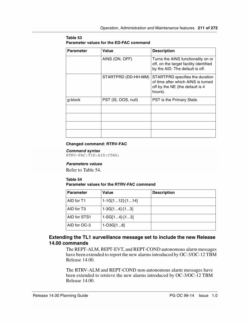
Operation, Administration and Maintenance features 211 of 272
Changed command: RTRV-FAC
Command syntaxRTRV-FAC:TID:AID:CTAG;
Parameters values
Refer to Table 54.
Extending the TL1 surveillance message set to include the new Release 14.00 commands
The REPT-ALM, REPT-EVT, and REPT-COND autonomous alarm messages have been extended to report the new alarms introduced by OC-3/OC-12 TBM Release 14.00.
The RTRV-ALM and REPT-COND non-autonomous alarm messages have been extended to retrieve the new alarms introduced by OC-3/OC-12 TBM Release 14.00.
AINS (ON, OFF) Turns the AINS functionality on or off, on the target facility identified by the AID. The default is off.
STARTPRD (DD-HH-MM) STARTPRD specifies the duration of time after which AINS is turned off by the NE (the default is 4 hours).
g-block PST (IS, OOS, null) PST is the Primary State.
Table 54Parameter values for the RTRV-FAC command
Parameter Value Description
AID for T1 1-1G[1...12]-[1...14]
AID for T3 1-3G[1...4]-[1...3]
AID for STS1 1-SG[1...4]-[1...3]
AID for OC-3 1-O3G[1...8]
Table 53Parameter values for the ED-FAC command
Parameter Value Description
Release 14.00 Planning Guide PG OC 99-14 Issue 1.0

212 of 272 Operation, Administration and Maintenance features
Network element name and ID enhancementsThe 20-character network element name feature increases the network element name from 13 alphanumeric characters to 20 alphanumeric characters.
If a network element does not have a configured target identifier (TID) in the TL1 user interface, the TL1 user interface uses the network element name as the TID. The TL1 user interface already supports a 20-character TID. As a result, the 20-character network element name feature is automatically supported in the TL1 user interface.
If a network element does not have a name or TID, then TL1 uses the network identifier (ID), the system ID, and the network element ID to create the network element TID. This TID appears in the format <xxxxxx>.<yyyyy>.<zzzzz>, where <xxxxx> is the network ID, <yyyyy> is the system ID, and <zzzzz> is the network element ID (for example, 64000.32000.44804).
Note: If a network element has an existing TID, TL1 recognizes and displays this TID.
User interfaceThe Configure TL1 Parameters menu now includes an option titled “TL1 TIDMAP Menu”. If you select this option, the TL1 TIDMAP Menu appears. From this menu, you can:
• display the tidmap
• configure the TID for a network element or an OPC
• change all network element names to their corresponding TIDs
• change all network element TIDs to their corresponding network element names
Note: The tidmap lists the TID and name of the network elements and OPCs within the span of control. The tidmap also lists the network ID, system ID, and network element ID of the network elements within the span of control
RestrictionsYou cannot change all network element names or TIDs from the TL1 TIDMAP menu if:
• two different network elements or OPCs within the same span of control have the same TID or name
• there is a loss of association to one or more network elements within the span of control
S/DMS TransportNode OC-3/OC-12 TBM PG OC 99-14 Issue 1.0

Operation, Administration and Maintenance features 213 of 272
Alarm listing enhancements (lasaldmp, lasdump)The lasaldmp command copies a listing of alarms or current alarms into a log file. In previous OC-12 software releases, you can enter one of two options with the lasaldmp command:
• -a for a listing of historical alarms in a log file
• -c for a listing of current alarms in a log file
In OC-3/OC-12 TBM Release 14.00, the lasaldmp command has been enhanced to allow you to place different aspects of the alarm information in delimited fields within the log file. The following are two new options associated with this enhancement:
• -b for a listing of historical alarms in delimited fields within the log file
• -d for a listing of current alarms in delimited fields within the log file
The lasdump command copies a listing of logs into a log file. In OC-3/OC-12 TBM Release 14.00, the lasdump command has been enhanced to include a new option (-f) so that different aspects of the log information also appear in delimited fields.
Solid-state OPC enhancementsIn previous OC-3/OC-12 TBM software releases, the user interfaces used the term “tape” for the digital data storage (DDS) tapes used to perform backup and restore operations on the operations controller (OPC). In OC-3/OC-12 TBM Release 14.00, the user interfaces refer to DDS tapes and solid-state OPC cartridges as “removable media”.
Figure 80 displays the OPC Save and Restore main window with the term “removable media”.
Release 14.00 Planning Guide PG OC 99-14 Issue 1.0

214 of 272 Operation, Administration and Maintenance features
Figure 80OPC Save and Restore main window with the term “removable media”
New and modified alarmsTable 55 lists the new and modified alarms associated with the solid-state OPC enhancements. This table includes a service code of non-service affecting (nsa) and service affecting (SA) according to whether any traffic is affected.
Table 55New and modified alarms associated with the solid-state OPC enhancements
Alarm label Alarm type Severity Service code
Backup: tape drive cleaning required (see note below)
OPC Warning nsa
Primary: tape drive cleaning required (see note below)
OPC Warning nsa
Note: This alarm is now disabled by default.
S/DMS TransportNode OC-3/OC-12 TBM PG OC 99-14 Issue 1.0

215 of 272
Release 14.00 Baseline Requirements 5-The Release 14.00 hardware baseline requirements remain the same as Release 13.11/13.12. However, there are some features in Release 14.00 which require specific circuit packs. These are listed in Table 56 (for a complete listing of all mappers and circuit packs, call the FAX-on-demand service at 1-800-451-1685):
Table 56Hardware dependencies for Release 14.00 features
Feature Description PEC
DS1 RTU feature NT7E04EA
DS3 Enhancements NT7E08BA
Sonet/SDH Signal Mode Provisioning NT7E01GA/GB
Release 14.00 Planning Guide PG OC 99-14 Issue 1.0

216 of 272 Release 14.00 Baseline Requirements
S/DMS TransportNode OC-3/OC-12 TBM PG OC 99-14 Issue 1.0

217 of 272
OC-3/OC-12 TBM Base Features 6-This section of the planning guide provides a listing and a brief description of previous S/DMS TransportNode OC-3/OC-12 TBM software release features which form the software base for S/DMS TransportNode OC-3/OC-12 TBM Release 14.00 software.
OC-3/OC-12 TBM Release 13.11/13.12 FeaturesThe OC-3/OC-12 TBM Release 13.11/13.12 software load introduced the following features:
Note: Please refer to the OC-3/OC-12 TBM Release 13.11/13.12 Planning Guide PG OC 98-07 for complete details on the features listed below and “Engineering Documentation” on page 247 for planning guide ordering code.
• Matched Nodes on VTM BLSR, providing the ability to interconnect rings using either the Drop and Continue on Working (DCW) or the Drop and Continue on Protection (DCP) matched node protection schemes. Matched nodes provides the ability to interconnect a BLSR with one or more SONET rings by establishing a survivable path between the rings offering greater protection between rings. A survivable path is established on a per STS-1 connection basis.
• Matched Nodes In-Service Edits, providing the ability to perform the following in-service edits:
— Non-matched node connection to matched node connection and vice versa
— DS3 non-matched node connection to STS-1 matched node connection
— Matched-node DCW connection to matched node DCP connection and vice versa
— Edit tributary at the primary or secondary gateway node
• Synchronization Status Messaging Phase II, providing the ability to support
Release 14.00 Planning Guide PG OC 99-14 Issue 1.0

218 of 272 OC-3/OC-12 TBM Base Features
— synchronization status messaging between BITS and an OC-12 network element using the Extended SuperFrame (ESF) framing format
— a provisionable option to insert “Do not use for synchronization” (DUS), instead of ST3, in the S1 byte of the transmitted SONET overhead when the ESI enters a non-NORMAL (Freerun, Holdover, Acquire or Fast) mode.
— DS1 derived from active OC-12 timing source
• STS and VT In-Service Rollover, providing the ability to allow the in-service (IS) movement (rolling) of a circuit from one STS or VT1.5 time slot (source) to another STS or VT1.5 time slot (destination) within a network. Two types of IS Rollover are supported:
— IS Channel Rollover (ISCR): Traffic is moved from one transport channel to a different transport channel in the same direction. ISCR is supported on OC-3 linear, OC-12 linear, OC-12 NWK BLSR, and OC-12 VTM BLSR configurations.
— IS Route Rollover (ISRR): Traffic is moved from one transport channel to a different transport channel in the opposite direction or traffic is moved from one transport channel to the same transport channel but in the opposite direction. ISRR is supported on OC-12 NWK BLSR and OC-12 VTM BLSR configurations.
• Firmware Download Enhancements which include:
— introduction of a Firmware Download Manager on the network element to control the efficient download and maintenance of firmware in the context of Management by Release. Management By Release (or MBR) accomplishes this through Automatic Firmware Downloads.
— New MBRFWDL CI tool and modified TCSFWDL CI tool
— Parallel Firmware Downloading
— VTM compressed firmware loads
— Firmware downloading to In-Service Ring Loopback circuit packs
— New firmware download in progress alarms
— Download NE logs
• Software Upgrade Advancements (SUA) which include:
— new Network Upgrade Manager (NUM) user interface reflecting new upgrade strategy
— Primary OPC upgraded first
— support for single OPC upgrades
— 3 phase upgrade: Validation, Distribution, Activation
S/DMS TransportNode OC-3/OC-12 TBM PG OC 99-14 Issue 1.0
OC-3/OC-12 TBM Base Features 219 of 272
— integration of automated verification into NUM (plus automatic disabling of OPC scheduled events)
— integration of peripheral processor firmware upgrade into a single “pass” of NUM
— “management by release” style upgrades
— backout enhancements to support new upgrade strategy
• Performance Monitoring Enhancements which include:
— addition of 1-minute PM threshold interval for OC-12 facilities
— performance monitoring threshold crossing alert (TCA) capping
• Extended Range NE ID, providing the ability to provision up to 32767 unique NE IDs (1 through 32767) since the NE ID range has been increased from 4 digits to 5 digits.
• AD-2000, providing the ability to properly handle the date range between now and December 31, 2035.
• TARP Transparency on the NE, providing the ability to implement the TARP propagation rules such that TARP-based TL1 messages are propagated to adjacent nodes, rather than being discarded.
• NE Enhancements which include:
— NE User Interface Enhancements
— SS Bits Provisioning
— Troubleshooting VT connection provisioning mismatch alarm using QMISCON CI tool
— Recover Unidirectional Failure (RUF) Changes
— SelectNE Enable/Disable using SNEACC CI tool
— Fan Alarming
— OC-3 Express/OC-192 Remote Login
— Telemetry Enhancements
— Duplicate NE Alarms
• OPC Enhancements which include:
— VT Connection Management UI Dialogs Enhancements
— OPC Tool Changes to Support Management By Release
— 15-minute OPC PM Collection
— Disabling PM Collection using new OPC PM Collection Filter Tool
— OPC Centralized User Administration (CUA) Enhancements
— Root-Like User
— TARP support on the OPC
Release 14.00 Planning Guide PG OC 99-14 Issue 1.0

220 of 272 OC-3/OC-12 TBM Base Features
— OPC/NE Security Enhancements
— OC-3 Load Manager Tool
— OPC Transport Bridge for OC-3 Express TL1 MOA
— NE Login Manager Support for OC-3 Express and OC-192
— OPC Alarms
— OPC Linear Protection Switching Control
— OPC Connection Management Enhancements
— OC-12 TBM to OC-192 Linear Configuration Connection Support
— Log Archive (NE Logs in Event Browser)
— Event Browser Enhancements
— Hardware Baseline Tool
— OPC Data Transfer from Backup OPC to Primary OPC
— OPC Switch Tool
— Enable Clear Com’g Tool
— Ethernet Admin Tool
• TL1 Enhancements which include:
— 15-minute PM Reporting
— Support for VT1.5 and STS-1 Facilities
— Exerciser Request
— TL1 Connection Provisioning on BLSR
— Provisionable PM Mode
— TL1 Interface using 7 layers OSI
— Remote Software Delivery via FTAM
— TL1 Router for OC-3 Express
— Centralized Connection Provisioning Interface
— TL1 Interface Router Services and TL1 Interfaces Merge
— TL1 over TCP/IP Enhancements
— Provisionable Assignment of East and West for the TL1 AID to OC-12 G1 and G2
— TL1 Configuration Tool
S/DMS TransportNode OC-3/OC-12 TBM PG OC 99-14 Issue 1.0

OC-3/OC-12 TBM Base Features 221 of 272
OC-3/OC-12 TBM Release 11.20 FeaturesThe OC-3/OC-12 TBM Release 11.20 software load introduced the following features:
Note: Please refer to the OC-3/OC-12 TBM Release 11.20 Planning Guide PG OC 95-03 for complete details on the features listed below and “Engineering Documentation” on page 247 for planning guide ordering code.
• VT1.5 Time Slot Assignment (TSA) on OC-12 BLSR, providing the ability to provision connections on any DS1 tributary port to any VT time slot on any OC-12 Line interface.
• SONET Performance Monitoring, providing the ability to
— monitor VT1.5 paths (Near-End) that are terminated on DS1 circuit packs providing the following PM parameters: VT Path Errored Seconds (ES-V), VT Path AIS/LOP Seconds (ALS-V), and VT Path Failure Count (FC-V).
— monitor VT-managed STS-1 paths which terminate at a network element. The following Near-End and Far-End STS-1 path parameters are monitored at network elements equipped with the OC-12 Virtual Tributary Bandwidth Management Optical Interface circuit pack (NT7E05): Code Violations (CV), Errored Seconds (ES), Severely Errored Seconds (SES), Unavailable Seconds (UAS), and Failure Count (FC).
— monitor the following Far-End OC-12 line parameters at network elements equipped with the OC-12 Virtual Tributary Bandwidth Management Optical Interface circuit pack (NT7E05): Code Violations (CV), Errored Seconds (ES), Severely Errored Seconds (SES), Unavailable Seconds (UAS), and Failure Count (FC).
— monitor the Optical Power Received (OPR) physical layer performance parameter at network elements equipped with the OC-12 Virtual Tributary Bandwidth Management Optical Interface circuit pack (NT7E05).
• Line timing without the use of ESI units since the synchronization/holdover capability has been added to the new OC-12 Virtual Tributary Bandwidth Management Optical Interface circuit pack (NT7E05).
• S1 Byte Synchronization status messaging, providing the ability to constantly communicate the quality of the current timing source, between network elements, using SONET overhead and automated timing source switching during primary source degradation with user assignable synchronization hierarchy.
• Derived ESI DS1 Output Follows Best Reference, providing the ability for network elements to be provisioned such that the OC-N with the highest
Release 14.00 Planning Guide PG OC 99-14 Issue 1.0

222 of 272 OC-3/OC-12 TBM Base Features
quality synchronization status message is automatically selected as the source for the ESI DS1 output. In case of a tie, the OCA reference is selected.
• Derived DS1 synchronization signals - thresholded AIS generation mode, providing the ability to insert AIS into the derived DS1 timing reference output when the S1 byte synchronization status message in the OC-N line, that is being used as a reference for that derived DS1, is at or below a user selectable quality level.
• ESI Configuration CI tool, providing the ability to easily provision ESI parameters for common ESI configurations.
• OC-12 GR-1230 Ring. This feature is the evolution of the OC-12 TA-1230 Ring feature provided in earlier OC-12 releases. The new OC-12 GR-1230 Ring is a SONET line switched bidirectional ring, designed as per GR-1230-CORE Issue 1.0, and is based on Shared Protection Ring architecture. The OC-12 Bidirectional Line Switched Ring (BLSR) Ring interconnects multiple Ring ADM network elements distributed around a two-fiber loop. VT1.5, STS-1, and STS-3c TSA bandwidth management is supported with the NT7E05AF/AG/AH and NT7E05BF/BG/BH Enhanced VTM circuit packs.
The new OC-12 GR-1230 Ring requires the use of the new OC-12 Virtual Tributary Bandwidth Management Optical Interface circuit pack (NT7E05). The Ring Loopback circuit packs (NT7E35AA) and Overhead Bridge circuit packs (NT7E36AA) required for the TA-1230 version of the ring are no longer required for the GR-1230 version. As a result, extra shelf slots are freed up for tributary or OPC usage.
• Provisionable Wait-to-Restore on OC-12 BLSR, providing the ability to change revertive Automatic Protection Switch (APS) restore time in a OC-12 BLSR system equipped with the new OC-12 Virtual Tributary Bandwidth Management Optical Interface circuit pack (NT7E05).
• OC-12 Circuit Pack Diagnostics from the User Interface, providing the ability to manually invoke diagnostics on the new OC-12 Virtual Tributary Bandwidth Management Optical Interface circuit pack (NT7E05).
• STS-3c Capability in VTM Ring Systems, providing the ability to carry STS-3c signals in VTM ring systems provided that each VTM ring network element within the VTM ring is equipped with the Enhanced Virtual Tributary Bandwidth Management Optical interface circuit packs NT7E05AF/AG/AH and NT7E05BF/BG/BH.
• STS-3c Connection Provisioning Conversion, providing the ability to convert, in-service, an STS-3c connection which was provisioned as three consecutive STS-1 rate connections to an STS-3c connection which is provisioned as a single connection using the STS-3c connection rate.
S/DMS TransportNode OC-3/OC-12 TBM PG OC 99-14 Issue 1.0

OC-3/OC-12 TBM Base Features 223 of 272
• Recover Unidirectional Failure (RUF) in NWK Systems, providing the ability to automatically recover traffic when STS-1 misconnections occur in a system.
• NWK Ring to VTM Ring Reconfiguration, providing the ability to reconfigure, in-service, existing STS-managed NWK based (TA-1230) rings to STS and VT-managed VTM based (GR-1230) rings.
• Adding/Deleting a VTM Ring Network Element, providing the ability to add/delete an OC-12 TBM VTM based (GR-1230) ring ADM network element, in-service, to/from an existing OC-12 TBM BLSR system equipped with OC-12 TBM VTM based (GR-1230) ring ADM network elements.
• STS to VT Connection Conversion, providing the ability to convert, in-service, an existing STS-managed connection to a VT-managed connection using a simple conversion tool.
• OC-12 Virtual Tributary Bandwidth Management Optical Interface circuit pack (NT7E05), provides the ability to support the majority of the features described above.
• Enhancements to the cooling system, providing the necessary cooling to support the new OC-12 Virtual Tributary Management Optical Interface circuit pack (NT7E05). A new cooling shelf (NT4K18BA) and new cooling modules (NT4K17BA) are introduced and must be used in all 1, 2, and 3-shelf configurations utilizing VTM optics to avoid the risk of system overheating. Additionally, 3-shelf bay configurations require the use of the NT4K19AC enhanced TBM shelf in the bottom shelf position.
• Firmware Download to VTM and MIC, providing the capability to download firmware to the new OC-12 Virtual Tributary Bandwidth Management Optical Interface circuit pack (NT7E05) and to the Maintenance Interface card (MIC).
• Support for Network Manager Release 5.01, providing the ability to provision STS connections for BLSR systems. Other capabilities include service assurance for BLSR systems, User Interface enhancements, and CLFI support in alarm and PM displays.
• Support for Network Manager Release 6.01, providing the ability to provision VT1.5 connections for BLSR systems. Other capabilities include STS connection provisioning in linear systems, facility state provisioning, nested groups, flexible groups, NE Alarm Report Suspension, External Alarm Control, and Increased Engineering Limits.
Release 14.00 Planning Guide PG OC 99-14 Issue 1.0

224 of 272 OC-3/OC-12 TBM Base Features
OC-3/OC-12 TBM Release 10.03 FeaturesThe OC-3/OC-12 TBM Release 10.03 software load introduced the following features:
Note: Please refer to the OC-3/OC-12 TBM Release 10.03 Planning Guide PG OC 95-02 for complete details on the features listed below and “Engineering Documentation” on page 247 for planning guide ordering code.
Network Level Features
OC-12 Matched NodesThis feature supports the ability to link two separate NWK based rings at two redundant gateway nodes. Inter-ring traffic exchange via the gateway nodes occurs at the SONET STS-1 tributary level. These redundant gateway nodes provide greater immunity to node failures. The drop and continue capability are supported on working channels only.
Data Communication InteroperabilityData communication interoperability is designed as per TA-NWT-253 which specifies Network Element to Network Element (NE/NE) interfaces at Network and Data Link Layers. It adds more flexibility to Nortel Networks’s FiberWorld products by allowing customers to connect OC-3 and OC-12 products from other vendors to a Nortel Networks OC-12 network by offering the following:
—route data communications messages from one vendor’s product through other vendors’ product
—log in remotely from one Nortel Networks network element to another Nortel Networks network element while there are other vendor’s equipment in between
—provide some OAM interoperability in a mixed vendor SONET network
The data communication interoperability in the current context means the ability to exchange information between systems built by different vendors. This feature involves modifications and enhancements of the data communication software to support the interoperability between Nortel Networks’s S/DMS TBM products and other vendor’s SONET products. Interoperability is provided only at the Network and Data Link Layer with respect to the Open Systems Interconnection (OSI) reference model. Each vendor’s products shall forward messages generated by other vendor’s products, but application software between different vendors shall not communicate.
S/DMS TransportNode OC-3/OC-12 TBM PG OC 99-14 Issue 1.0

OC-3/OC-12 TBM Base Features 225 of 272
S/DMS TransportNode OC-3 Express / TBM InterworkingThis feature provides the First Alert, at the OPC/OS and the base User Interface of TBM network elements, of the alarm conditions on remote S/DMS TransportNode OC-3 Express shelves connected to TBM systems via OC-3 tributaries. This allows any existing alarm conditions on a S/DMS TransportNode OC-3 Express system to be indicated on a TBM system to which it is connected. The alarm indication contains basic information such as alarm type, severity and location.
New Features
TCP/IP over X.25TCP/IP over X.25 enables the user to run TCP/IP applications over an X.25 port to any IP node accessible from the X.25 network. It provides an alternate way of doing software downloads and remote logins through an X.25 port using IP applications. Also, it is responsible for porting the HP-UX software that translates IP packets into X.25 requests and transmits them over the X.25 network, and vise-versa. With this application, network element software delivery using the OPC’s NE Software Delivery tool can now be carried out over this X.25 link.
Enhancements
OCn signal failThe OCn signal fail threshold is a new attribute which is added to existing OCn facility attributes and visible on OCn network element user interface facility screen. The OCn signal fail threshold attribute is used to monitor the integrity of an optical signal and raise an alarm whenever the optical signal is degraded to a point where the bit error rate surpasses this preset non-provisionable threshold value. The OCn facility screen on the network element user interface is used to view the signal fail threshold setting. The alarm raised is a “Signal Fail” alarm (replacing previous BIP-8 Saturation alarm).
Additional DS1 line code valueThe DS1 facility has taken on a additional parameter for Line Coding. In addition to Bipolar with Eight-Zero Substitution (B8ZS) and Alternate Mark Inversion (AMI), Alternate Mark Inversion with Zero Code Suppression (AMI-ZCS) is added.
Single STS path for merged DS1 pairIn the case of DS1 merge, the STS-1 path is terminated on two DS1 circuit packs and protection circuit packs. In previous releases, a separate STS path was created for each DS1 circuit pack. In Release 10.03, this is changed such that only one STS-1 path is created, but it is associated with two DS1 circuit packs. The STS-1 path termination
Release 14.00 Planning Guide PG OC 99-14 Issue 1.0

226 of 272 OC-3/OC-12 TBM Base Features
ID used is the STS-1 path termination ID for one of the DS1 circuit packs from the merged pair. This implies that the STS-1 path is Out-Of-Service (OOS) when all DS1 facilities of the DS1 merged pair are OOS.
Matched Nodes Switch Active Indication at NE UIWhen a Matched Nodes Service Selector Switch is active, the network element user interface banner line displays a ‘*’ in the ActProt field as follows:
The network element protection screen displays ‘Sel’ under the High Bandwidth Active field as follows:
If an OC-12 switch is active as well as a Matched Nodes Selector Switch, the network element protection screen then displays ‘OC-12+’ under the High Bandwidth Active field as follows:
Note: The ‘+’ after OC-12 indicates that there is another switch active of lower priority (in this case a Matched Nodes Selector Switch) along with the OC-12 switch.
Critical Major minor warning FailProt Lockout ActProt PrfAlrtNetwork View . . . . . . * .NE_111 . . . . . . * .
Low Bandwidth High BandwidthNE ID Fail Lockout Active Fail Lockout ActiveNE_111 . . . . . 1 Sel
Low Bandwidth High BandwidthNE ID Fail Lockout Active Fail Lockout ActiveNE_111 . . . . . 1 OC-12+
S/DMS TransportNode OC-3/OC-12 TBM PG OC 99-14 Issue 1.0
OC-3/OC-12 TBM Base Features 227 of 272
TL1 Support
Addition of new Matched Nodes and S/DMS TransportNode OC-3 Express/TBM First Alert autonomous alarm reporting
TL1 is enhanced to include the autonomous messages used to report both new alarms and events introduced in S/DMS TransportNode OC-3/OC-12 TBM Release 10.03.
Miscellaneous Improvements
TL1 over EthernetThis feature ensures that TL1 can be accessed reliably over Ethernet rather than X.25 by providing a tool called tl1shell. This TL1 enhancement offers the following:
—The ability to recover from OPC activity switches (SWACTs) without having to restart the tool.
—a command-line switch which allows the tool to be used by Operations Support Systems (OSS) in the stdin-stdout format.
—Access of the tl1shell tool from a UNIX prompt on the OPC except through OPCUI (i.e. must be a root user). The TL1 tool is invoked by typing the following:
tl1shell <NMA | OPS > where:
—The ability to use a Cisco Protocol Translator (CPT) to bridge X.25 and LANs. Rather than drop X.25 lines to each OPC, users have the ability to access TL1 over their existing LAN. The CPT translates X.25 calls from an OS into a Telnet session on an Ethernet host (i.e. OPC).
NMA To access the surveillance TL1 interface
OPS To access the provisioning TL1 interface
Release 14.00 Planning Guide PG OC 99-14 Issue 1.0
228 of 272 OC-3/OC-12 TBM Base Features
OC-3/OC-12 TBM Release 9.01 FeaturesThe S/DMS TransportNode OC-3/OC-12 TBM Release 9.01 software load introduced the following features:
Note: Please refer to the OC-3/OC-12 TBM Release 9.01 Planning Guide PG OC 94-07 for complete details on the features listed below and “Engineering Documentation” on page 247 for planning guide ordering code.
Network Level Features
Regenerators in BLSR systemsThis activity provides the ability to configure regenerators in OC-12 BLSR systems. Prior to S/DMS OC-3/OC-12 TBM Release 9.01, regenerators were not supported in OC-12 BLSR configurations.
New Features
OC-12 BLSR Lockout on working and protection channelsThis feature provides the lockout of working and protection functionality in OC-12 BLSR configurations. The Protection Details network element user interface screen and the Network Alarm Summary application on the OPC user interface is enhanced to support these new OC-12 protection status displays and commands.
Automatic Daylight Savings Time ChangeThe Automatic Daylight Savings Time feature automatically maintains the correct time for a network element in reference to the advancement or retrogression of time from standard time to savings time regardless of the time zone the network element is situated in.
Enhancements
OPC Save and Restore Tool EnhancementsThis activity enhances the TransportNode OPC Save and Restore Tool to allow the user to schedule backups of the OPC system data and the network element databases to tape as well as have the restore operation automatically initiate an OPC restart.
OPC Date Tool EnhancementThis OPC Date tool enhancement allows the user to maintain an accurate time of day clock and to provide automatic time synchronization between the primary and backup OPCs. This enhancement is due to the implementation of the Network Time Protocol (NTP) on the OPC platform.
S/DMS TransportNode OC-3/OC-12 TBM PG OC 99-14 Issue 1.0
OC-3/OC-12 TBM Base Features 229 of 272
Timing deviation detection and recoveryTogether with the new NT7E27BA ESI unit, the enhanced detection and recovery for ESI timing references provides the following new functionalities:
— Automatic protection switching away from timing references which deviate more than or equal to +/- 4.0 ppm within a 8.2 second period. This is referred to as Dynamic Timing Deviation Detection.
— Automatic protection switching away from timing references which have a cumulative frequency deviation of +/- 5.15 ppm (best case) and +/- 20.5 ppm (worst case). This is referred to as Static Timing Deviation Detection.
— Automatic recovery of failed timing references is guaranteed when frequency is within +/- 4.5 ppm when failure detected by Static Timing Deviation criteria. Failures detected by Dynamic Timing Deviation criteria are automatically cleared when a reference protection switch is performed.
— Both primary and secondary timing references are continuously monitored for detection of and recovery from a Static Timing Deviation condition. Only the active is monitored for Dynamic Timing Deviation failures.
Line timing reference protection switching Existing ESI software is modified to handle failures on the OC-n signal used as the timing reference. When the primary OC-n signal becomes unsuitable as a reference, the ESI switches to the secondary OC-n signal. During this protection switch, a conditioning signal, TxAIS, is sent on the DS1 signal at ESI GxOUT, and gets cleared upon getting a valid secondary OC-n signal.
ESI distribution tracking active OC-n Line The DS1 output source can be provisioned to follow the active optics. With the “Track Active OC-n” feature set to OFF and when the OC-n signal becomes unsuitable as a timing reference for ESI, a conditioning signal, TxAIS, is sent out at ESI GxOUT. With the “Track Active OC-n” feature set to ON, the timing distribution DS1 signal follows the active optics. The default mode is “Track Active OC-n” OFF.
DS1 Path Performance MonitoringDS1 Path PM extends the capability of DS1 Line PM to DS1 Paths in Superframe (SF) or Extended Superframe (ESF) formats where they are terminated on the DS1 Mapper (i.e. Near -End receive parameters only).
OC-12 Line PM OC-12 line performance monitoring is enhanced to include two new near-end parameters: LineUAS and LineFC.
Release 14.00 Planning Guide PG OC 99-14 Issue 1.0

230 of 272 OC-3/OC-12 TBM Base Features
DS1 Provisioning The new NT7E04CA DS1/VT1.5 Mapper offers the option of provisioning the DS1 synchronization from asynchronous (default) to byte synchronous as well as editing the frame format from Superframe to NULL while the DS1 facility is in-service.
Exerciser Result Log Improvement The EQP403 exerciser result log is improved to identify the DS1 port affected when the DS1 exerciser fails.
Universal Path TraceUniversal Path Trace is a redesign to the existing proprietary path trace scheme currently used in the OC-12 TBM FiberWorld platform. This new scheme is designed as per TA-NWT-000253 which requires a user-programmable 64 byte fixed length string for SONET. This allows a craftsperson to provision a unique identifier for any connection established within the FiberWorld network and to confirm that the routing of a connection is correct before adding traffic to the tributaries.
Base Performance Monitoring EnhancementsEnhancements to this feature includes removal of some existing data intervals and data storage bins as well as the consolidation of their functionality with the remaining bins. In order to align Nortel Networks’s performance reporting intervals with Bellcore/ANSI standards, the 1-minute reporting interval is no longer supported.
OC-12 facility deletion on BLSR nodeThis activity provides software support for OC-12 facility deletion on a TBM BLSR configuration of the S/DMS OC-12 TransportNode product. The OC-12 facility deletion was allowed on all OC-12 network elements except on a BLSR node. An Inactive OC-12 card pull out, on a BLSR node, has been supported in earlier releases. This functionality has been extended to allow deprovisioning of the OC-12 facility on BLSR. This functionality is required when converting a NWK based (TA-1230) Ring ADM network element to a VTM based (GR-1230) Ring ADM network element.
OPC Connection Manager enhancement to support STS-3c Concatenated Services
The OPC Connection Manager for TBM based OC-12 network elements is enhanced to support both STS-1 and STS-3c Concatenated services. This includes provisioning/deprovisioning of Add/Drop and Pass-through STS-1 and STS-3c connections.
S/DMS TransportNode OC-3/OC-12 TBM PG OC 99-14 Issue 1.0

OC-3/OC-12 TBM Base Features 231 of 272
Loopback firmware alarm enhancementThe alarm reporting mechanism for loopback firmware mismatch conditions is modified. If the firmware loads on loopbacks G1 and G1S are not the same version, a “Loopback Firmware Mismatch” alarm is raised. If the loopback firmware version is less than the current software standard, a “Firmware/Software Incompatible” alarm is raised instead.
OC-12 Clock Intercard Alarm Enhancement This enhancement is added to improve the robustness of the product by alarming intercard clock failures.
Backplane Parity Error EnhancementThis enhancement is required in order to make the OC-12 TransportNode more robust. This activity replaces the previous ‘Backplane Parity Error’ alarm with the ‘STS-1 Intercard Failure’ alarm.
DS3 and OC-12 Frequency Out Of RangeThis feature adds the DS3 frequency out of range alarm and allows the system to recover from an Out Of Range OC-12 oscillator.
Network Manager Release 4.01 SupportThe OC-3/OC-12 TBM Release 9.01 OPC software supported the Network Manager Release 4.01. Some of the features introduced with Release 4.01 of the Network Manager included Centralized PM, Inventory Collection, Shelf level graphics and User Definable Span Information.
Refer to the Network Manager, Release 4.01, Planning Guide PG 94-08 for a description of all the new functionalities introduced with Release 4.01 of the Network Manager.
Centralized Performance Monitoring This feature provides early detection of a signal degradation in the network before the signal degrades below critical values. Centralized performance monitoring provides both error and switch statistics allowing accelerated preventative maintenance to be performed before service failures occur. For tariffing purposes, centralized performance monitoring provides a means of determining the availability of a service over a period of time.
Release 14.00 Planning Guide PG OC 99-14 Issue 1.0

232 of 272 OC-3/OC-12 TBM Base Features
Centralized Inventory Collection This feature provides the capability of acquiring an accurate view of the equipment provisioned in the network. The centralized inventory feature assists in verifying the hardware baseline compatibility of a network before undertaking an upgrade. The centralized inventory feature can generate inventory reports which may be used for provisioning and accounting purposes when planning or forecasting network activities.
Shelf Level Graphics This feature provides a graphical view of the inventory information for a specified Network Element. Shelf level graphics provide an intuitive, easy to understand view of the Network Element. Shelf level graphics facilitates communication between craft personnel, located in different remote sites, when referring to shelf level details.
User Definable Span Information This feature provides the capability of having additional textual information associated with the OPC spans being monitored by Network Manager. Provisional span information may contain information such as the OPC location, OPC type, notes on the NE or information about the link speed from Network Manager to OPC.
TL1 Support
TL1 Change OPC TimeThis new TL1 command, ED-DAT (edit date) allows the date and time on the OPC to be changed by a surveillance OS via TL1 such that an OS can keep the OPC and NE Time of Day (TOD) clocks synchronized with the OS’s Time of day clock.
TL1 Administration EnhancementsSeveral user administration commands are added to both the surveillance and provisioning TL1 OS interfaces. These include the ability to add, modify, retrieve and delete user accounts over the TL1 interface.
TL1 PM Threshold ProvisioningThis feature provides the ability to set 15-minute (Threshold 1) or 1-day (Threshold 2) threshold values for any PM parameter on any facility using the new SET-TH command. Also, this activity offers the ability to retrieve the threshold values using the new RTRV-TH command.
S/DMS TransportNode OC-3/OC-12 TBM PG OC 99-14 Issue 1.0

OC-3/OC-12 TBM Base Features 233 of 272
TL1 Facility LoopBack Controls and State ManagementThis feature allows the TL1 to control the loopback of facilities (OPERATE-LOOPBACK and RELEASE-LOOPBACK). Since a facility must be Out-Of-Service (OOS) for a loopback to be applied, the TL1 commands to support removing a facility from service (RMV) and restoring a facility to service (RST) are also supported.
TL1 External Controls ManagementThe OC-12 TBM network element has a total of 18 relay outputs that can be operated (closed) or released (opened) using the OPR-EXT-CONT and RLS-EXT-CONT commands.
TL1 Warning and Event EnhancementsThis feature provides support for retrieval of warning alarms by implementing the new retrieve condition TL1 command and properly clearing warning alarms by sending a REPT-EVT command instead of REPT-ALM command. Note that this is not applicable to transient conditions such as threshold crossing alerts or OPC event logs as they were always reported as REPT-ALM messages and never cleared.
TL1 Path Trace Retrieval and SurveillanceThis feature allows a craftsperson to monitor end-to-end integrity of any STS-1 connection traversing a network. The new TL1 Surveillance Retrieve Path Trace allows the craftsperson to extract path trace values on demand at terminating network elements and at intermediate network elements in the network using the RETRIEVE-PATH-TRACE command.
TL1 PM Bin ManagementThis enhanced TL1 surveillance message set provides a new TL1 command to initialize PM registers (INIT-REG). Clearing of network element PM registers is supported per facility SCCM and AID. The time intervals that may be cleared are the current bins, all history, 15-minute as well as 1-day, PM counts on the NE and OPC, or both current and history PM counts.
TL1 DS1 Path PM RetrievalThe new DS1 path performance monitoring parameters introduced in OC-3/OC-12 TBM Release 9.01 can also be retrieved via the TL1 interface. These parameters are not sent out autonomously.
TL1 OC-3 Facility ProvisioningThis feature enhances the TL1 provisioning message set to support the facility provisioning of OC-3 tributaries on a targeted network element.
Release 14.00 Planning Guide PG OC 99-14 Issue 1.0
234 of 272 OC-3/OC-12 TBM Base Features
TL1 Equipment ProvisioningThe TL1 equipment provisioning commands are used to provision selected equipment on the targeted network element and are single ended commands.
TL1 STS-3c Cross Connect ProvisioningThree new TL1 commands are introduced for provisioning STS-3c connections through TL1 instead of using the OPC Connection Manager tool (ENT-CRS-STS3C, DLT-CRS-STS3C, and RTRV-CRS-STS3C). Note that this is only for linear systems, i.e., only terminal and linear ADM nodes. For ring system, it is required to use the OPC STS Connection Manager tool to provision STS-3c connections on the ring.
TL1 Surveillance Robustness and PerformanceThe TL1 surveillance and provisioning message interface is enhanced to handle changes to network element commissioning data without having to take down and re-establish the TL1 connection. Also the number of TL1 provisioning interfaces is set to a maximum of one and the number of simultaneous TL1 sessions is set to a maximum of four.
OSI SupportThe S/DMS TransportNode OC-3/OC-12 TBM product family provides an OSI fault management interface to interface between a Telco’s Operation System (OS) and Nortel Networks’s S/DMS TransportNode networks for the purpose of forwarding the network’s alarms and events information to the OS. The OSI fault management functions are designed as per Bellcore specifications for NMA OSI interface, SR-1665 Issue 4.
OSI Fault Management This activity supports the following functionality: (1) alarm report control, performance spontaneous report control, protection switch report control, alarm report, protection switch report, and performance spontaneous report for all TransportNode products. It also provides OPC switch report. (2) the creation, deletion, editing, m-action, and retrieval of Current Alarm Summary Control as well as supporting the switch to protection/working and ESI control.
OSI Configuration Management Interface for OC-12 BLSR Provisioning
This activity supports nodal OC-12 BLSR cross connection on a 6 node ring. It also provides equipment provisioning of DS1 and DS3 with a limited set of attributes.
S/DMS TransportNode OC-3/OC-12 TBM PG OC 99-14 Issue 1.0

OC-3/OC-12 TBM Base Features 235 of 272
OSI Commissioning ToolThe S/DMS TransportNode OPC provides the OSI interface and the required commissioning tools for OSI fault management. The OSI commissioning tool allows a craftsperson to enter the parameters required to establish an OSI interface between the OPC and the Telco’s OS by configuring the NSAP and AE titles of the OPC.
OSI InteroperabilityThe OSI Interface can be used in conjunction with the TL1 surveillance and/or provisioning interface.
OC-3/OC-12 TBM Release 8.10 FeaturesThe S/DMS TransportNode OC-3/OC-12 TBM Release 8.10 software load introduced the following features:
Note: Please refer to the OC-3/OC-12 TBM Release 8.10 Planning Guide PG 94-01 for complete details on the features listed below and “Engineering Documentation” on page 247 for planning guide ordering code.
Network Level Features
STS-1 TributariesThe STS-1 tributary provides an electrical interface to the SONET network. It allows SONET path overhead continuity to be maintained throughout the network. The STS-1 tributary is supported in linear or ring ADM and Terminal network elements in a protected 1:N (revertive) scheme.
OC-3 Protected TributariesPhase 2 of the OC-3 (and OC-3c) tributary is introduced in the S/DMS OC-3/OC-12 Release 8.10. Phase 1 in Release 7.10 consisted of unprotected OC-3 (and OC-3c) tributary supported in an OC-12 TBM terminal node only. With Release 8.10, the OC-3 (and OC-3c) tributary is protected in a 1+1 (non-revertive) scheme and supported in linear or ring ADM as well as terminal OC-12 network elements. With Phase 2, the Section Datacom channel in the SONET overhead is also supported over OC-3 tributaries.
The protection switching of the optical tributaries is similar to the transport optics protection switching. Each OC-3 tributary working/protection pair may be provisioned as bi-directional or uni-directional. The protection switch can either be user initiated or automatically initiated. Lockout is also provided.
Performance monitoring counts are maintained for protection switches requested and completed, for both automatic and user initiated switches.
Release 14.00 Planning Guide PG OC 99-14 Issue 1.0
236 of 272 OC-3/OC-12 TBM Base Features
Regenerators in linear configurationsThe support for Regenerators is re-introduced in release 8.10. Its primary use is to extend the optical route between terminal or linear ADM network elements. Release 8.10 supports regenerators in linear systems only and not in OC-12 BLSR systems.
New Features
Provisionable SDCC on OC-3 Tribs and OC-12 transport slotsThis activity introduces provisionable Section DCC on both the OC-3 tributary and OC-12 transport optics. The user is given the option of enabling/disabling the SDCC.
Switch Active OPC command (Active/Inactive)A new command is introduced to switch the activity states of OPC pairs in a network. One OPC is active, usually the primary, and the other inactive, usually the backup. This command forces the active OPC to become inactive and the inactive OPC to become active.
OPC boot from tapeThis feature enables FiberWorld OPerations Controller (OPC) craftsperson to initialize a working OPC HP-UX file system (6.5 or 8.0) on an OPC’s hard disk, via the OPC’s integrated Digital Data Storage (DDS), tapedrive. The process is controlled through a menu driven script which prompts the user for input as needed. Once the script has completed the disk initialization process, the craftsperson may then reboot and load the OPC application software.
Enhancements
OC-n Default Protection Switch Mode As of Release 8.10 software, the default switching mode for the high speed optics as well as the new OC-3 protected tributaries is set to uni-directional. In previous releases it was set to bi-directional switching mode by default. Note that the switching mode can be provisioned by the user.
Protection Exerciser inhibitionThe Protection Exerciser is supported with OC-3 optical tributaries and works exactly like the transport optics Exerciser. In Release 8.10 it is possible to inhibit the Exerciser from running on any protection group. That is, any OC-3 tributary protection group or any OC-3 or OC-12 protection group. This is to support a mid-span meet scenario in which the optics (transport or tributary) are connected to equipment which does not support Exerciser functionality.
By entering the ProtExer command (accessible in the network element protection provisioning user interface screen), the user can inhibit the Exerciser for any given OC-12 protection group.
S/DMS TransportNode OC-3/OC-12 TBM PG OC 99-14 Issue 1.0

OC-3/OC-12 TBM Base Features 237 of 272
Electronic Software Delivery Enhancement The Electronic Software Delivery (ESWD) Generation III gives the ability to perform electronic software delivery of both the NE and OPC software loads using the Network Manager Release 3.00.
OPC Naming EnhancementThe OPC name is entered in the OPC Commissioning manager and is used to uniquely identify the OPC. Before this feature, the OPC name had to be of the following format: OPCMnnn where nnn is a 3 digit integer making the OPC name unique within the network. This feature allows alpha-numeric characters and increases the field to 4 characters so that the OPC can adopt the 4 character Network Element number in which it is located. Therefore, the new format is: OPCMzzzz where zzzz is a 4 character alpha-numeric field making the OPC name unique within the network.
Enhancement of X Display Manager (XDM) system on the FiberWorld OAM&P platform (Support of Tektronix and HP X-Terms)
The X Display Manager (XDM) system manages the display of OPC software tools running as X clients on X terminals. Prior to Release 8.10 Software, only NCD19 X-Terminals were supported. Now with this feature, the XDM on the FiberWorld OAM&P platform is enhanced to support HP 700/RX, Tektronix XP18, as well as the NCD19 X-Terminals.
Maximum number of NEs supported in Span of ControlThe maximum number of network elements in an OPC span of control is increased from 16 to 34. However, of these 34 network elements, a maximum of 24 LTEs (i.e., terminals, linear ADMs, or ring ADMs) are allowed with a maximum of 2016 DS1 facilities. The remaining 10 network elements can be regenerators.
NE Shelf Processor NT4K52BB card supported with ring systemsIn Release 7.10, the NT4K52BC processor card supported both linear and ring applications, the NT4K52BB only supported linear application. With the OC-3/OC-12 TBM Release 8.10 software, an enhancement has been made to support the NT4K52BB NE Shelf Processor card with ring ADM Network Elements. This enhancement avoids the need to manually replace NT4K52BB NE Shelf Processor cards with the NT4K52BC card when upgrading an OC-12 linear system to an OC-12 ring system. This is made possible by downloadable firmware to the shelf processor card.
Release 14.00 Planning Guide PG OC 99-14 Issue 1.0

238 of 272 OC-3/OC-12 TBM Base Features
Support for Network Manager Release 3.00The OC-3/OC-12 TBM Release 8.10 OPC software supports the Network Manager Release 3.00. Some of the features being introduced with Release 3.00 of the Network Manager includes Electronic OPC Software Delivery and the capability of displaying both Transport Node (OC-3, OC-12 and OC-48) and Access Node on the graphical user interface.
Refer to the Network Manager, Release 3.00, Planning Guide PG 94-03 for a description of all the new functionalities introduced with Release 3.00 of the Network Manager.
TL1 Support
TL1 20 Character TID/SID The TL1 interface is enhanced to support the Bellcore defined format for network element naming which requires accommodations for 20 character strings.
TL1 SET-SID CommandThe Set Source ID command is changed so that it no longer sets the network element name but the TIDs (Target Identifiers) instead.
TL1 RTRV-HDR Command EnhancementThe RTRV-HDR command is enhanced as follows.
—When no TID is specified, the response is denied and the network element alias local to the OPC is returned in the header of the response.
—The TID is returned in the header of all other responses instead of returning the network element name.
—The network element identifier may be used as a TID. This provides a means of retrieving the alias of a given network element.
The Retrieve Header message is a non-autonomous message used to verify the target identifier of the network element specified in the input message. As an added feature, the network identifier may also be specified in place of the target identifier - this returns the target identifier in the TL1 response. Using the network identifier has the same effect as using the associated target identifier.
TL1 DS1 PM Collection and ReportsThe OPC software is enhanced to collect DS1 Line Performance Monitoring counts from the network element and the TL1 REPT-PM message includes DS1 Line counts. As well, the messages RTRV-PM, INH-PMREPT and ALW-PMREPT may be used for DS1 PM.
S/DMS TransportNode OC-3/OC-12 TBM PG OC 99-14 Issue 1.0
OC-3/OC-12 TBM Base Features 239 of 272
TL1 STS-1 Line PM RetrievalThe OPC software is enhanced to collect STS-1 Line Performance Monitoring counts from the network element and the TL1 REPT-PM message includes STS-1 Line counts. As well, the messages RTRV-PM, INH-PMREPT and ALW-PMREPT may be used for STS-1 PM.
TL1 DS1, DS3 and STS-1 facility provisioningFacility provisioning parameters such as the state (IS or OOS), the AIS encoding (for DS1 facility only), CLFI, framing format (for DS1 and DS3 facility only), Line Build Out (LBO), line coding (for DS1 facility only), Rx and Tx Parity correction (DS3 facility only) may be accessed through TL1 using the DLT, ENT and ED commands
TL1 STS-1 Connection provisioning for linear systemsThree new TL1 commands are introduced for provisioning STS-1 connections through TL1 instead of using the OPC Connection Manager tool (ENT-CRS-STS1, DLT-CRS-STS1, and RTRV-CRS-STS1). Note that this is only for linear systems, i.e., only terminal and linear ADM nodes. For ring system, it is required to use the OPC STS Connection Manager tool to provision STS-1 connections on the ring.
TL1 PM Count Retrieval IntervalThe TL1 interface is redesigned so that TL1 autonomous reporting can send reports as soon as PM data is received at the OPC. PM data is received by the OPC from the network elements after the fifth minute of every hour.
TL1 Support for SONET SCCMs in Surveillance InterfaceThe TL1 Support SONET Second Command Code Modifier (SCCM) was changed from an asynchronous representation to SONET specific values. This change consists of modifying SCCM strings such that SONET specific values are used in messages and command strings.
TL1 commands via the OPC Unix promptThis feature allows the user to enter TL1 commands and to see the appropriate response from within the OPC UNIX shell. Once a user has logged in to the OPC and has access to the UNIX shell, the TL1 interface can be started and then TL1 commands may be entered. A surveillance and a provisioning TL1 interface is provided. The full set of TL1 commands for surveillance is supported by the surveillance interface and the full set of TL1 provisioning commands is supported by the provisioning interface.
Release 14.00 Planning Guide PG OC 99-14 Issue 1.0
240 of 272 OC-3/OC-12 TBM Base Features
OC-3/OC-12 TBM Release 7.10 FeaturesThe S/DMS TransportNode OC-3/OC-12 TBM Release 7.10 software load introduced the following features:
Note: Please refer to the OC-3/OC-12 TBM Release 7.10 Planning Guide PG 94-04 for complete details on the features listed below and “Engineering Documentation” on page 247 for planning guide ordering code.
Network Level Features
TBM OC-12 Bidirectional Line Switched Rings (BLSR)The OC-12 Ring is a SONET line switched bidirectional ring designed as per TA-NWT-001230 and is based on a shared protection ring architecture. The OC-12 BLSR interconnects multiple Ring ADM nodes distributed around a two-fiber loop. Each of the fiber spans provides a bidirectional working traffic capacity equal to half of the entire STS-12 bandwidth (i.e. namely 6 STS-1s for OC-12 Rings). The lowered numbered STS-1 time slots ranging from 1 through 6 are reserved for working, while the higher numbered STS-1 time slots ranging from 7 through 12 are reserved for protection.
OC-3 Tributaries Phase I (unprotected)Phase I of OC-3 tributaries are supported in the unprotected mode on OC-12 Terminal shelf configurations with alarms and performance monitoring features. TL1 and TBOS are enhanced to support the OC-3 tributaries. The OC-3 signal received at the OC-3 tributary card can either be 3 distinct STS-1s multiplexed into an STS-3 signal, or a single STS-3c signal providing a 155 Mb/s interface. In the case of an STS-3 signal, each STS-1s can be assigned independently to the OC-12 transport optics time slots. For example, on an OC-12 linear or ring ADM node, the STS-1 #1 of the OC-3 tributary may be assigned to one of the STS-1 time slot of the primary OC-12 optics while STS-1 #2 and #3 may be assigned to the secondary OC-12 optics.
However, in the case of an STS-3c signal, the three STS-1s must be assigned to the same OC-12 optics, either primary or secondary. Also, they must be assigned to consecutive time slots and be one of the following four possibilities: 1,2,3 or 4,5,6 or 7,8,9 or 10,11,12.
Linear to Ring UpgradeabilityOne of the unique features of Nortel Networks’s OC-12 BLSR is the capability to upgrade in-service from either a Linear ADM Chain, Point-to-Point terminals or Back-to-Back Point-to-Point Terminals as well as modifications to existing Ring configurations (Add/Delete Ring ADM node).
S/DMS TransportNode OC-3/OC-12 TBM PG OC 99-14 Issue 1.0

OC-3/OC-12 TBM Base Features 241 of 272
Regenerators UnsupportedFor OC-3/OC-12 TBM Release 7.10 software, Regenerators are NOT supported in either Linear or Ring configurations.
OAM (Operation, Administration and Maintenance)
OPC Ring Configuration ManagerThe Ring Configuration Manager user interface allows the user to specify how ring add/drop multiplexer nodes (ADMs) are interconnected within the ring and to assign ring Automatic Protection indentifiers (APS id) to the ring nodes which are required to address the ring ADM node in the ring Automatic Protection Switching (APS) protocol.
Multiple Configurations per OPC SOCWith the introduction of rings in Release 7.10, the OPC software is enhanced to support both a ring configuration along with existing linear configurations. This implies that in one OPC SOC, the user can have both ring and linear configurations defined.
Centralized User AdministrationThe Centralized User Administration (CUA) tool allows a system administrator, via an OPC at a central location, to administer user accounts and access privileges on an OPC and the network elements in the OPC’s span of control. The CUA tool is an enhancement and replacement of the Group and User Setup (GUS) tool.
Push Button UpgradeSeveral software enhancements are made to simplify and automate the procedure to perform in-service software upgrades. The enhanced features are introduced to reduce the software upgrade procedure to the simple ‘push of a button’.
Electronic NE Software DeliveryThe Electronic Software Delivery (ESWD) is a feature intended to provide the ability to transfer Network Element (NE) software loads from a source workstation (i.e. a fileserver at Nortel Networks) to in-service OPCs in the field.
X.29/X.3 PADThis software feature, while working in conjunction with a remote PAD (Packet Assembler/Disassembler), allows remote users to access the OPC character mode user interface screens via an X.25 Packet Switching Network (PSN). This can be accomplished via a direct single physical X.25 connection to the OPC ports (without the need for additional network links, modems, serial ports, etc.). This feature functions with either a physical PAD device or a PAD emulation software (i.e. running on a personal computer).
Release 14.00 Planning Guide PG OC 99-14 Issue 1.0

242 of 272 OC-3/OC-12 TBM Base Features
Increased OPC Span Of ControlAs of Release 7.10, the OPC SOC could retrieve and consolidate information from a maximum of 16 network elements (Terminals, Linear and Ring ADMs). Note that regenerators are not supported in OC-3/OC-12 TBM Release 7.10 software.
TL1 Inventory MessagesThe OC-3/OC-12 TBM Release 7.10 software implements TL1 (Transaction Language 1) inventory messages for a provisioning OSS system (operations support system). In addition, the OPS/INE (Operational Processing System/Intelligent Network Element) OSS is also supported with this software load.
Multiple OPC Serial PortsPrevious software releases only supported 1 OPC serial port on the SIL (OPC port 1 - connector J09). This software load also supports the second OPC port (OPC port 2 - connector J07) on the TBM shelf. This extends the availability of the X.25 function that can be supported by the OPC. Port 1 may be configured for a different function (i.e., for X.25, terminal or printer). Port 2 can only be configured for X.25 operation. However, both ports must not be configured for the same function (i.e., both ports for X.25).
OPC Software Failure AlarmThis new minor alarm (‘OPC OAM software fail’) allows the network element to monitor the health of the OPC software. It monitors the Primary and backup OPCs. This feature is used to help detect database corruptions, disk corruptions and media errors. This is a software monitoring alarm. It is separate from the ‘OPC circuit pack fail’ alarm which is intended to alarm hardware problems.
S/DMS TransportNode OC-3/OC-12 TBM PG OC 99-14 Issue 1.0
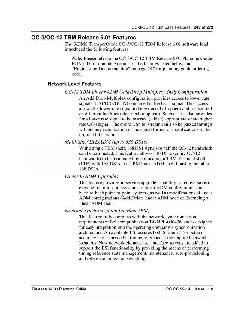
OC-3/OC-12 TBM Base Features 243 of 272
OC-3/OC-12 TBM Release 6.01 FeaturesThe S/DMS TransportNode OC-3/OC-12 TBM Release 6.01 software load introduced the following features:
Note: Please refer to the OC-3/OC-12 TBM Release 6.01 Planning Guide PG 93-05 for complete details on the features listed below and “Engineering Documentation” on page 247 for planning guide ordering code.
Network Level Features
OC-12 TBM Linear ADM (Add-Drop Multiplex) Shelf ConfigurationAn Add-Drop Multiplex configuration provides access to lower rate signals (DS1/DS3/OC-N) contained in the OC-I signal. This access allows the lower rate signal to be extracted (dropped) and transported on different facilities (electrical or optical). Such access also provides for a lower rate signal to be inserted (added) appropriately into higher rate OC-I signal. The entire DSn bit stream can also be passed through without any regeneration of the signal format or modifications to the original bit stream.
Multi-Shelf LTE/ADM (up to 336 DS1s)With a single TBM shelf, 168 DS1 signals or half the OC-12 bandwidth can be terminated. This feature allows 336 DS1s (entire OC-12 bandwidth) to be terminated by collocating a TBM Terminal shelf (LTE) with 168 DS1s to a TBM linear ADM shelf housing the other 168 DS1s.
Linear to ADM UpgradesThis feature provides in-service upgrade capability for conversions of existing point-to-point systems to linear ADM configurations and back-to-back point-to-point systems, as well as modifications of linear ADM configurations (Add/Delete linear ADM node or Extending a linear ADM chain).
External Synchronization Interface (ESI)This feature fully complies with the network synchronization requirements of Bellcore publication TA-NPL-000436, and is designed for easy integration into the operating company’s synchronization architecture. An available ESI assures both Stratum 3 (or better) accuracy and a survivable timing reference at the required network locations. New network element user interface screens are added to support the ESI functionality by providing the means of performing timing reference state management, maintenance, auto-provisioning and reference protection switching.
Release 14.00 Planning Guide PG OC 99-14 Issue 1.0

244 of 272 OC-3/OC-12 TBM Base Features
STS-1 PM for DS1This feature supports CV-P, ES-P and SES-P near end parameters on STS-1 paths terminated on DS1 circuit packs on OC-12 ADM, point-to-point and future BLSR configurations.
DS3 Clear ChannelThe DS3 Clear Channel feature is simply an unframed DS3 signal. All the bits in a DS3 clear channel signal are data or use proprietary framing undetermined by the manufacturer or the terminal equipment. To allow this unframing, a new “Framing” parameter is introduced in the DS3 Facility screens allowing the user to turn the Framing to “Off” at an LTE/ADM site where the framing provisioning is performed at both ends of the DS3 clear channel signal.
OAM (Operation, Administration and Maintenance)
Commissioning EnhancementsWith the introduction of the ADM configuration, the commissioning manager user interface is enhanced to support ADM (i.e., setting the network element function to ADM).
Configuration ManagerA new Configuration Manager user interface is introduced as part of the OPC infrastructure to support OC-12 linear ADMs and future ring configurations.
STS-1 Connection/Path ServicesThe STS Connection Manager tool is an STS-1 provisioning user interface provided by the OPC. This application allows provisioning and audit of STS-1 connections within an OC-12 Linear ADM system through interaction with the NE STS-1 Connection and Path Services application.
TL1 Support for ESI Protection SwitchingThis feature provides the use of the SWITCH TO PROTECTION and SWITCH TO WORKING TL1 messages to allow ESI protection switch control.
TL1 Enhancements for OC-12 ADMThis feature enhances the OPC Performance Monitoring (PM) and TL1 subsystems in support of OC-12 ADM.
Partial Span Upgrades in Network Upgrade ManagerThis activity enhances the Network Upgrade Manager to allow the user to upgrade only selected Network Elements in the OPC span of control.
OC-12 linear ADM NE User InterfaceNetwork element user interfaces are enhanced to display linear ADM functionality (i.e., secondary optics info).
S/DMS TransportNode OC-3/OC-12 TBM PG OC 99-14 Issue 1.0

OC-3/OC-12 TBM Base Features 245 of 272
OC-3/OC-12 TBM Release 5.01 FeaturesThe S/DMS TransportNode OC-3/OC-12 TBM Release 5.01 software load introduced the following features:
Note: Please refer to the OC-3/OC-12 TBM Release 5.01 Planning Guide PG 93-04 for complete details on the features listed below and “Engineering Documentation” on page 247 for planning guide ordering code.
Network Level Features
TBM DS1 Merge (OC-3 84 DS1 or OC-12 168 DS1)This feature permits full use of the STS-1 bandwidth available on the TBM shelf. Previous software releases supported a DS1 card in every second mapper slot on the shelf. Since each DS1 card maps 14 DS1s into an STS-1, only half of the available bandwidth on the STS-1 signal was utilized. The DS1 merge feature allows DS1 cards in both even and odd mapper slots. The output of the DS1 cards is then merged such that all 28 DS1s are mapped into an STS-1, whose bandwidth is now fully utilized. This effectively doubles the shelf capacity from 42 to 84 DS1s for an OC-3 system and from 84 to 168 DS1s for an OC-12 system.
DS1 Performance MonitoringThis feature introduces DS1 PM which monitors the integrity of the DS1 signal through continuous collection and analysis of data (i.e. LineCV, LineES, LineSES only) derived by observing it’s performance. Only Line parameters are collected and not Path values.
TBM DS1/DS3 MixThis feature enables the OC-12 TBM shelves to carry both DS1 and DS3 traffic on the same shelves. This mixing of rates is accomplished with a backplane architecture which allows any type of interface to the TBM shelf, provided the output is an STS-1 rate signal to the backplane.
Path Trace DS1/DS3 Payload Mismatch DetectionWith the introduction of DS1/DS3 Mix services, it is possible for a craftsperson to mistakenly map an STS-1 containing DS3 traffic at the near end, to a DS1 equipment at the far end. To detect this, a proprietary Path Trace feature is developed to raise a ‘Path Trace Failure’ alarm if mismatched payloads are detected.
Release 14.00 Planning Guide PG OC 99-14 Issue 1.0

246 of 272 OC-3/OC-12 TBM Base Features
TBM OC-3 to OC-12 In-Service UpgradeThis feature allows the craftsperson to upgrade the shelf transmission rate at the OPC and have the network element automatically make the transition as the new optic cards are provisioned. The system updates (new cross connects, new user interface screens) concurrently while in-service.
TSS/TBM InterworkingThis feature allows for the interconnection of TBM and TSS systems into a single OPC span of control. This gives the user the ability to connect TBM shelves into existing TSS based networks through a CNET connection for collocated TBM and TSS systems. The result is a consolidated view of the TBM/TSS network via the OPC.
OAM (Operation, Administration and Maintenance) Features
Network-Wide OPC/NE LoginThis feature provides the network elements, in separate OPC spans of control connected together either by way of fiber or SONET DCC bridge (CNET), complete single ended OAM&P by way of a remote login from an OPC.
Accurate OPC TimeOne of the functions of the OPC is to ensure the Time of Day synchronization for the network elements in a span of control. Through the OPC’s Date tool, the user could set the date and time on the OPC according to the applicable Time Zone where it is installed. The OPC time must be accurate in order for logged alarms and events to be properly time-stamped at the OPC as well as for the synchronized network element. Therefore, this feature provides a way for the OPC to keep a more accurate time by being synchronized to a 1 Hz pulse coming from the OC-12 shelf backplane.
Ethernet PortIn previous releases, in order to configure, administrate and maintain an ethernet port, the user had to access the UNIX vi editor and manually change files. Release 5.01 automates this process by introducing the ether_admin tool which is accessible through the OPC’s unix prompt thus allowing a more user friendly approach to administrating the ethernet port.
Conversion of OPC UI to MotifTM Look and FeelThe MotifTM Look and Feel is an industry standard for graphical user interfaces on Unix Workstations. The implementation of this feature for the OPC ensures compliance to the standard for X-terminal user interface displays.
S/DMS TransportNode OC-3/OC-12 TBM PG OC 99-14 Issue 1.0
OC-3/OC-12 TBM Base Features 247 of 272
Increased Span Of ControlPrior to Release 5.01, the OPC’s span of control limit was 4 Terminals and a maximum of 12 network elements (Terminals and Regenerators). In Release 5.01, this number increases to a maximum of 16 Terminals and a maximum of 24 network elements (Terminals and Regenerators).
Software UpgradeIn Release 5.01, it is possible to perform software upgrades from release 4.1, 4.2, and 4.3. Also, the approach is simplified by offering the user an automated approach eliminating several repetitive and manual tasks from the previous procedure.
OC-3/OC-12 TBM Release 4.31 FeaturesThe S/DMS TransportNode OC-3/OC-12 TBM Release 4.31 software load introduced the following features:
Note: Please refer to the OC-3/OC-12 TBM Release 4.31 Feature Description Document for complete details on the features listed below.
Network Level Features
OC-12 TBM RegeneratorThe OC-12 TBM Regenerator shelf configuration provides the necessary signal processing for the intelligent regeneration of optical signals when the distance between two network elements has reached the maximum. Repeater spacings of 40 Km (25 miles) are typically achievable with the OC-12 1310 nm optical interfaces. The OC-12 Regenerator shelf configuration is based on a single shelf, route diversity system.
DS1 ExerciserThe DS1 exerciser is introduced to detect failures on the DS1 protection path by performing a bridge operation on each DS1 circuit pack carrying traffic to the DS1 protection circuit pack.
OC-3 Performance MonitoringThe OC-3 PM counts are user-defined values assigned to particular performance error statistics monitoring the integrity of an OC-3 span. The PM counts are used to generate alerts when the values are reached or exceeded. Thresholds are used to alert maintenance personnel that the number of performance errors has surpassed an acceptable level for a particular PM parameter.
OAM (Operation, Administration and Maintenance)
Network ManagerThe Network Manager is a software package that supplements the existing Operations, Administration, Maintenance and Provisioning (OAM&P) functions in a TransportNode system. It provides a single
Release 14.00 Planning Guide PG OC 99-14 Issue 1.0

248 of 272 OC-3/OC-12 TBM Base Features
point of access for all the OAM&P functions of a multi-span transport network, and it also provides a consolidated view of all alarms on the network through a graphical representation of the network topology.
OC-3/OC-12 TBM Features Introduced Prior to Release 4.31Operations Controller (OPC)
The OPC provides centralized data management (for example, data collection, storage, and consolidation), security, software management, and integrated OAM&P view for sub-network network elements. The OPC module has its own OPC software which is enhanced every release to support the new functionalities.
A redundant OPC module can be equipped in an S/DMS TransportNode span of control to provide intersite OAM&P functionality in the event of an OPC hardware/software failure, cable cuts, or node failures. The backup OPC is optional, but it is recommended for all systems.
Note: If in-service software upgrades are to be performed on a OPC SOC, then a backup OPC is required.
In the event of an OPC hardware/software failure, services provided by one OPC’s span-of-control can be taken over by the backup OPC. The backup OPC provides no services until they are required.
In the event of a cable cut or of a network element failure, service normally provided by the primary OPC to the network elements downstream of the troubled area is be replaced by the backup OPC.
For a complete description of the OPC’s functionality, please refer to the NTPs.
External Synchronization InterfaceThe External Synchronization Interface (ESI) feature is used to provide external timing capability and therefore to achieve synchronous operation within a SONET network. Although it is not an operating requirement for linear systems (no intermediate ADMs), ESI is essential for Ring, Add-Drop Multiplexer (ADM) and Hub/Optical Tributary applications in SONET systems.
The ESI hardware (two ESI interfaces) and software allow the OC-12 to be integrated into a network synchronization timing architecture. This architecture provides a timing reference hierarchy which consists of four Stratum levels of clocks: Stratum 1 being the most accurate and Stratum 4 the least as shown in Table 52 on page 240.
S/DMS TransportNode OC-3/OC-12 TBM PG OC 99-14 Issue 1.0

OC-3/OC-12 TBM Base Features 249 of 272
Table 57 ANSI Standard Clock STRATA Accuracy Required
The Building Integrated Timing Supply(BITS) – (DS1 level timing source, Superframe or Extended Superframe, AMI or B8ZS line coding) concept stipulates that all digital equipment in a building must receive timing from the same master clock in the building. The ESI circuit pack is required for a Network Element:
• to be synchronized to a high quality external timing source
• to derive a timing signal from an incoming SONET signal (OC-3/12) and thus distribute timing from one site to the other.
DS1/DS3 loopbackBoth terminal and facility loopback are available for each DS1/DS3. This command is used when turning up a system or adding a DS1/DS3 facility, and can also be used to sectionalize faults. In the terminal loopback, while the DS1/DS3 from the optics side is looped back, an alarm indication signal is sent to the DS1/DS3 output port. The facility loopback loops the incoming DS1/DS3 line directly back to the outgoing DS1/DS3 port.
DS3 parity correctionThis feature can be provisioned to provide parity correction on a per DS3 facility basis, where the DS3 enters or exits the system. By default, parity correction is disabled (that is, parity is not corrected). Parity correction can be enabled independently at the transmit end or receive end.
Exerciser (DS1, DS3, OC-3/12)The exerciser provides automatic and manual verification of DS1, DS3, (low-speed) and OC-3/12 (high-speed) protection path and resulting alarms, if any, are reported. The automatic exerciser runs by default at 2:00 am every day or it can be scheduled to run at a designated time interval. The manual exerciser can be started by command and does not affect the automatic schedule. It is recommended that each network element in a network have their exerciser scheduled to run at different times with respect to other network elements in the same network.
Stratum LevelMinimum Accuracy
Source for S/DMS TransportNode OC-3/OC-12 TBM
1 +/- 1.0 x 10⁻¹¹ BITS (Building Integrated timing Supply)
2 +/- 1.6 x 10⁻⁸ BITS (Building Integrated timing Supply)
3 +/- 4.6 ppm ESI Interface Card
4 +/- 32 ppm Crystal on OC-12 optical I/F (+/- 20 ppm)
Release 14.00 Planning Guide PG OC 99-14 Issue 1.0
250 of 272 OC-3/OC-12 TBM Base Features
Performance Monitoring (DS3, OC-12)Performance Monitoring is defined as the monitoring (or tracking) of a particular entity’s health through continuous collection and analysis of data derived by observing its performance.
The performance-monitoring capabilities for OC-12 include performance error statistics, protection-switch statistics and optical performance monitoring. These three features enhance system fault locating and clearing.
The protection-switch statistics counters keep track of the automatic and user-initiated protection switches at both DS3 and OC-12 levels. Counters are provided to indicate switch durations, requests, and completions over the current and last intervals.
Configuration Ports
NE User interface ports (up to 2 ports per shelf)The network element User Interface (UI) ports (RS-232) provide an interface to any network element user interface by means of a modem link or directly, using a straight cable with or without a null modem adaptor. This interface provides complete alarm, protection, provisioning and inventory for centralized operations in a single network element or an entire S/DMS span of control. Each port can provide access to all network elements (and OPC) within the network connectivity.
There are a total of four ports available for OAM interfaces: two RS-232 user interface ports and two RS-422 telemetry ports.
Serial telemetry (TBOS) portsThis feature provides access to two 2400-baud RS-422 E2A (TBOS) ports. Each E2A (TBOS) port provides up to eight, 64-point displays for a total of 512 alarm and status points. The assignment of each display is optional and selectable by the operating company. Hence, maximum application flexibility is achieved by allowing any combination of displays to be assigned to each TBOS port.
Parallel telemetry (input/output)The parallel telemetry feature provides up to 11 external customer inputs and 18 outputs for each shelf for system alarms, status, and external equipment controls. Parallel telemetry provisioning is also provided with this feature, allowing external inputs to be labeled from a network element compatible user interface. Inputs may also be mapped to specific outputs for alarm remoting purposes.
S/DMS TransportNode OC-3/OC-12 TBM PG OC 99-14 Issue 1.0
OC-3/OC-12 TBM Base Features 251 of 272
Ethernet port /X.11 terminal interface (requires OPC)The Ethernet port (IEEE 802.3 protocol) on the OPC supports a locally connected X.11 terminal. The same functionality as the OPC VT100 user interface is provided. In addition, OPC-to-OPC login is supported, allowing users to view multiple spans of control from a single X.11 terminal.
TL1 Interface for NMA (version 2.4 and 3.2)The OPC provides a Bellcore compliant TL1 OS to NE interface for OC-3/12 which is compatible with NMA release 2.4 and 3.2. A complete set of TL1 messages are supported to provide fault management, performance monitoring and control capabilities (such as protection switching). The interface is compliant to the CCITT X.25 protocol.
The TL1 interface allows the OPC to communicate with the OS through a physical X.25 port located on the OC-3/12 shelf. The OPC acts as a gateway through which the OS may access the different network elements in the span of control, therefore there is no need to have a separate link to each network element. The features offered with the TL1 interface are: single-ended interface, remote capabilities (no mediation device requirements), standby TL1 interface, switch virtual circuit at a baud rate of up to 19.2 kb/s.
The TL1 port associated with the backup OPC (provided by a separate X.25 physical connection) is the standby TL1 link. It is activated when the backup OPC becomes active. In the event of a cable cut between the network elements housing the primary and backup OPCs, both primary and standby links are activated.
Centralized System Surveillance/Maintenance
SONET DCC bridgeThe SONET Data Communications Channel (DCC) bridge feature permits Operations, Administration, Maintenance, and Provisioning (OAM&P) messages to be exchanged between OC-3/OC-12 TBM systems which are not connected by fiber but have Network Elements (Terminal, linear or ring ADM network elements) located at the same site. The SONET DCC messages from one system are bridged to the other system using the CNet Local Area Network (LAN).
This DCC feature allows a single OPC (or one primary and one backup OPC) to manage two or more systems, provided that the number of Network Elements managed by the OPC pair does not exceed the span of control limitations.
Note: The SONET DCC bridge transmits only the OAM&P messages contained in the SONET section overhead. It does not transmit voice or data services such as DS3 or orderwire.
Release 14.00 Planning Guide PG OC 99-14 Issue 1.0
252 of 272 OC-3/OC-12 TBM Base Features
Central office & Bay, shelf, and unit alarmsCentral office alarm contacts for critical, major, and minor alarms, as well as alarm cut-off activation, are provided on the OC-12 TBM network element. Both audible and visual contacts are available.
Alarm and status indications for the equipment are available at the bay, shelf, and unit levels. These indications include critical, major, and minor alarm lamps, alarm LEDs, and protection/maintenance status LEDs.
Intersite OAM&P (single-ended operations)This feature allows network-wide sharing of operations, administration, maintenance, and provisioning information using the SONET section overhead Data Communications Channels (DCC) and CNET local area networks. From a single network element, from an Operations Controller (OPC) or even from a modem connected to a network element, the user can log into the user interface of any network element in the OPC’s span of control. The OPC and network element software automatically relay the necessary information to, and from, the point of access.
NE Login Manager The NE Login Manager feature allows the user to log in to any network element within the Network’s connectivity. A VT100 network element User Interface session is initiated. A userID (and password) is required to access the network element. Once logged in, the user may perform all operations supported by the network element User Interface.
Remote OPC Login An X.11 graphical terminal is connected to a span of control, by way of Ethernet, and OPC-to-OPC login is then performed to interface with the other spans of control. The X.11 terminal can then display VT100 type screens for each span of control.
Note: This tool is available with an X.11 graphical terminal and the Network Management Windows feature.
Group and User Setup (GUS)The Group and User Setup (GUS) tool allows a system administrator (via an OPC at a central location) to administer user accounts and access privileges on an OPC and the network elements in the OPC’s span of control.
The system administrator (users with root and admin privileges) is able to create new user accounts. They can also delete, disable and re-enable an existing user account. The administrator can control which users can access a specific network element by enabling or disabling their accessibility to the network element.
S/DMS TransportNode OC-3/OC-12 TBM PG OC 99-14 Issue 1.0

OC-3/OC-12 TBM Base Features 253 of 272
Remote Inventory When a specific shelf (local or remote) is interrogated, the S/DMS TransportNode returns the following data for each circuit pack: Card name, NT code, CLEI code, hardware vintage (release), shelf slot location, serial number.
Such pertinent information can improve the overall efficiency of an operating company’s inventory control system. With its remote capability, this feature reduces the manpower and time required for inventory verification.
Software inventory provides the operational NE and OPC software within the sub-network (includes load information). Software load identifiers are provided for both NE and OPC software.
Network Alarm Summary The Network Alarm Summary tool provides a summary of alarms in the OPC span-of-control. Alarm counts for the span of control and for each network element are shown.
Network Browser The network browser tool provides status information for each network element in the OPC span-of-control. Alarm, protection, and performance summaries are provided, as well as shelf details such as the shelf serial number, shelf type, and shelf function.
Alarm monitorThe alarm monitor feature enhances the alarm surveillance features (refer to the two previous features) on the OPC user interface. A one line summary of alarm information is provided for each active alarm within an OPC span-of-control. For alarm details, the user can select an alarm line and choose “alarm details” from the menu. Sorting capabilities (for example, by network element, severity, time) are also available.
Event BrowserThe Event Browser provides a detailed list of logs which capture events related to the OPC. The Event Browser covers events such as:
—communication between the OPC and network elements in the OPC span of control.
—software and data admin events, (e.g. software download and network element backup).
—Primary and backup OPC status changes.
—General OPC level events.
—All raised/cleared alarms in the OPC span of control.
Release 14.00 Planning Guide PG OC 99-14 Issue 1.0

254 of 272 OC-3/OC-12 TBM Base Features
Centralized printingThis feature provides the capability to print the event/alarm history and other OPC generated reports for each span of control. In this way, records can be kept of all events for an OPC span-of-control. This feature is provided in the Alarm Monitor and Event Browser tools.
Local Network Element Surveillance
Alarm history This feature provides a detailed description of the last 50 active and cleared alarms (change of status) that have occurred on the local network element. The alarm report provides the following information: alarm report ID, location ID, descriptive reason of why the alarm occurred, time stamp on when the alarm occurred, severity of the alarm, facility ID address of the actual facility where the alarm occurred.
Event loggerThe event history system records all status changes and alarm occurrences in the OC-3/12 Network Elements. The event log messages are stored, for each shelf, at the network element and can be automatically routed to a printer connected to a local RS-232 port (provisioned as a printer port). Each log provides descriptive change of state information. A search function is provided for locating specific events.
There are five categories of event messages generated by the OC-3/12 Network Element system. These include facility (FAC), equipment (EQP), communications (COML), database (FWDB), and exceptions (miscellaneous - EXCP). Each buffer handles 40 event messages. When a particular buffer is full, a first-in first-out algorithm accommodates additional incoming messages.
Software and Database Management
Reboot/Load Manager The Reboot/Load Manager is used to manage software for each network element in an OPC span-of-control. This consists of performing software release upgrades and determining which software load should reboot the Shelf Processor in a network element in the event of a failure. Downloading software occurs using the SONET section overhead channel and CNET local area networks without affecting traffic (data communication beyond the network element being downloaded is not available during the process).
S/DMS TransportNode OC-3/OC-12 TBM PG OC 99-14 Issue 1.0
OC-3/OC-12 TBM Base Features 255 of 272
Backup/Restore Manager The Backup/Restore Manager allows management of the network element database backup files that the OPC stores automatically from the network element’s non-volatile storage (NVS). These database files are used when restoring a failed network element and after software release upgrades.
Up to two backup copies can be kept on the OPC. The network element database contains all the default and user-provisioned parameters as well as system-defined hardware register values. The network element backups are stored on the OPC and can be updated on scheduled backups, user initiated from the user interface, or when it has reached the database incremental change threshold.
OPC Save and Restore The OPC Save and Restore tool is used to manage the OPC commissioning, OPC database, and network element database backup files. These files are saved to tape and can be restored in the event of data corruption or OPC replacement. The Save and Restore tool is also used to initiate an immediate OPC and network element database transfer from the primary OPC to the backup OPC (datasync occurs automatically every morning at 3:00 a.m.).
Remote OPC Software Installation The Remote OPC Software Installation tool is used to transfer OPC software loads from the local OPC tape drive to the backup OPC disk.
NE Software Delivery Manager The NE Software Delivery Manager controls the transfer of network element software from tape to primary and backup OPC’s, and also from the primary OPC to the backup OPC.
Network Upgrade Manager The Network Upgrade Manager allows the user to automatically upgrade the software load for all network elements in an OPC span-of-control. Network elements are upgraded according to a user-defined sequence. This tool simplifies the management of software upgrades for the network.
Release 14.00 Planning Guide PG OC 99-14 Issue 1.0

256 of 272 OC-3/OC-12 TBM Base Features
S/DMS TransportNode OC-3/OC-12 TBM PG OC 99-14 Issue 1.0

257 of 272
Engineering Documentation 7-Additional information relevant to the S/DMS TransportNode OC-3/OC-12 TBM Release 14.00 can be found in the following documents listed in Table 58 to Table 69. These documents can be ordered through the Nortel Networks regional sales offices. Please refer to the end of this planning guide for telephone numbers.
Table 58S/DMS OC-12 TBM Planning Guides (PG) and Application Guides (AG)
Document Name DocumentNumber
Ordering Code
CPC
Release 14.00 Planning Guide PG 99-14 NTR710AA A0788847
Release 13.11/13.12 Planning Guide PG 98-07 NTR712DI A0759427
Release 11.11/11.20 Planning Guide PG 95-03 NTR710DG A0631156
Release 10.03 Planning Guide PG 95-02 NTR710DF A0631155
Release 9.01 Planning Guide PG 94-07 NTR710DE A0622616
Release 8.10 Planning Guide PG 94-01 NTR710DD A0617168
Release 7.10 Planning Guide PG 94-04 NTR710DC A0615284
Release 6.01 Planning Guide PG 93-05 NTR710DB N/A
Release 5.01 Planning Guide PG 93-04 NTR710DA N/A
An Application and Planning Handbook for VTBM Technology
VTBM 101 56135.11 To order call 1-800-
4 NORTEL
Synchronization Status Messaging and its Applicability to Sonet Networks
AG 96-01 NTR812AL A0659553
Release 14.00 Planning Guide PG OC 99-14 Issue 1.0
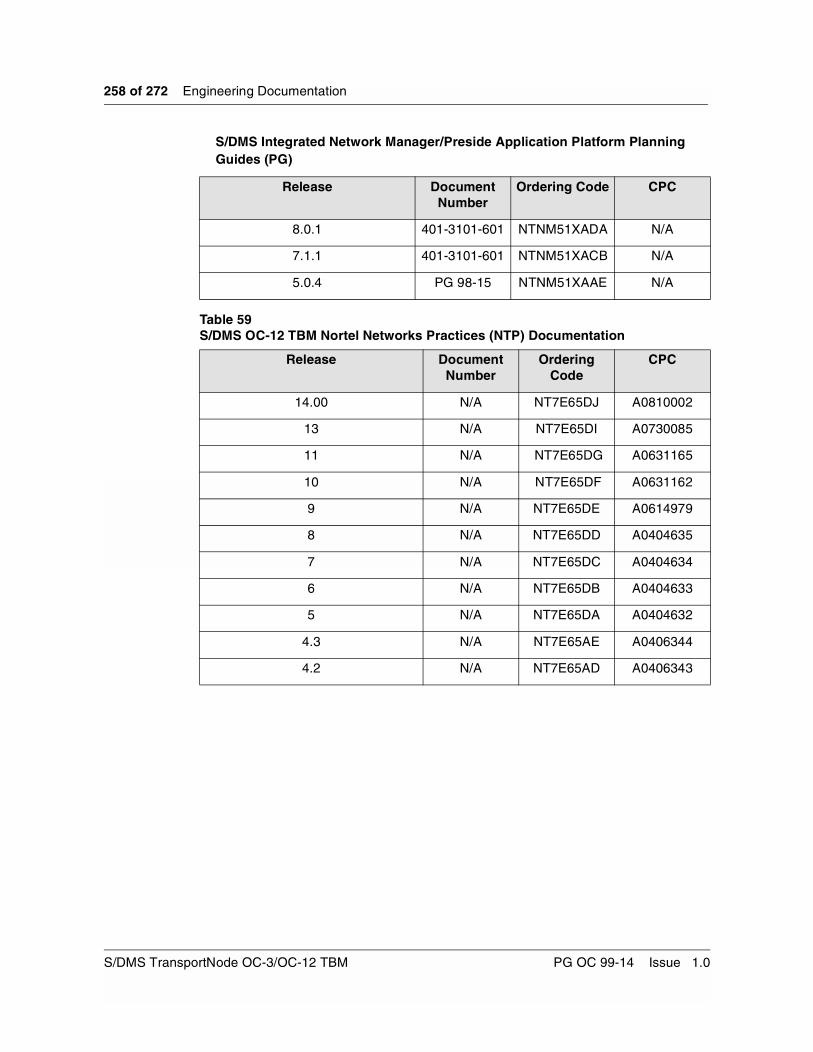
258 of 272 Engineering Documentation
Table 59S/DMS OC-12 TBM Nortel Networks Practices (NTP) Documentation
S/DMS Integrated Network Manager/Preside Application Platform Planning Guides (PG)
Release DocumentNumber
Ordering Code CPC
8.0.1 401-3101-601 NTNM51XADA N/A
7.1.1 401-3101-601 NTNM51XACB N/A
5.0.4 PG 98-15 NTNM51XAAE N/A
Release DocumentNumber
Ordering Code
CPC
14.00 N/A NT7E65DJ A0810002
13 N/A NT7E65DI A0730085
11 N/A NT7E65DG A0631165
10 N/A NT7E65DF A0631162
9 N/A NT7E65DE A0614979
8 N/A NT7E65DD A0404635
7 N/A NT7E65DC A0404634
6 N/A NT7E65DB A0404633
5 N/A NT7E65DA A0404632
4.3 N/A NT7E65AE A0406344
4.2 N/A NT7E65AD A0406343
S/DMS TransportNode OC-3/OC-12 TBM PG OC 99-14 Issue 1.0

Engineering Documentation 259 of 272
Table 60S/DMS OC-12 TBM Nortel Networks Practices (NTP) CD-ROM
Table 61OC-12 TBM System Software Upgrade Change Application Procedures (CAP)
Release DocumentNumber
Ordering Code
CPC
14.00 N/A NT7E64DJ A0810003
13 N/A NT7E64DI A0730091
11 N/A NT7E64DG A0631166
10 N/A NT7E64DF A0631163
9 N/A NT7E64DE A0615006
8 N/A NT7E64DD A0408242
7 N/A NT7E64DC A0408241
6 N/A NT7E64DB A0408240
5 N/A NT7E64DA A0406336
4 N/A NT7E64AC A0406334
To Release DocumentNumber
Ordering Code
CPC
14.00 OC 99-153 NTR721DJ A0802233
13.12 OC 99-107 NTR723DI A0780508
13.11 OC 98-164 NTR722DI A0759395
11.20 (from Releases 8.10, 10.03) OC 95-105 NTR721DG A0638208
11.20 (from Release 11.11) OC 96-122 NTR723DG A0665356
10.03 OC 94-158 NTR721DF A0630647
9.01 OC 94-137 NTR721DE A0623402
8.10 OC 94-148 NTR722DD A0626776
7.10 OC 93-132 NTR721DC A0615288
6.01 OC 93-119 NTR721DB N/A
5.00 OC 93-114 NTR721DA N/A
4.31 OC 93-121 NTR725AE N/A
Release 14.00 Planning Guide PG OC 99-14 Issue 1.0

260 of 272 Engineering Documentation
Table 62 OC-12 TBM Upgrade Backout Change Application Procedures (CAP)
Table 63OC-12 TBM NE ID Renumbering Change Application Procedures (CAP)
From Release DocumentNumber
Ordering Code
CPC
14.00 OC 99-154 NTR725DJ A0802234
13.12 OC 99-108 NTR727DI A0780509
13.11 OC 98-165 NTR726DI A0759396
11.20 (to Releases 8.10, 10.03) OC 95-106 NTR725DG A0638209
11.20 (to Release 11.11) OC 96-123 NTR726DG A0665357
10.03 OC 94-159 NTR725DF A0630648
9.01 OC 94-138 NTR725DE A0623403
8.10 OC 94-149 NTR726DD A0626778
7.10 OC 94-108 NTR725DC A0617182
Document Name Release DocumentNumber
Ordering Code
CPC
In-service NE ID Renumber for Release
14.00
14.00 No longer a CAP. In Release 14.00, this procedure is added to NTP 323-1111-224.
In-service NE ID Renumber for Release
13.11/13.12
13.11/13/12 OC 98-179 NTR792DI A0769203
S/DMS TransportNode OC-3/OC-12 TBM PG OC 99-14 Issue 1.0

Engineering Documentation 261 of 272
Table 64 OC-12 TBM Linear to NWK based (TA-1230) Ring Reconfiguration ChangeApplication Procedures (CAP)
Document Name Release DocumentNumber
Ordering Code
CPC
Linear to NWK Ring Reconfiguration
13.11/13.12 No longer a CAP. In Rel 13.11/13.12, this procedure is added to NTP 323-1111-224
Linear to NWK Ring Reconfiguration
11.20 OC 95-107 NTR761DG A0638700
Linear to Ring Reconfiguration
10.03 OC 95-102 NTR761DF A0638698
Linear T-T System to a 2-fiber BLSR
9.01 OC 95-156A NTR761DE A0628737
Two Linear T-T Systems Upgrade to a
Ring
9.01 OC 95-156B NTR762DE A0628739
Linear ADM System Upgrade to a Ring
9.01 OC 95-156C NTR764DE A0628740
Linear T-T System to a 2-fiber BLSR
8.10 OC 95-143A NTR761DD A0623387
Two Linear T-T Systems Upgrade to a
Ring
8.10 OC 95-143B NTR762DD A0623388
Linear ADM System Upgrade to a Ring
8.10 OC 95-143C NTR764DD A0623390
Linear T-T System to a 2-fiber BLSR
7.10 OC 95-130A NTR761DC A0615290
Two Linear T-T Systems Upgrade to a
Ring
7.10 OC 95-130B NTR762DC A0615291
Linear ADM System Upgrade to a Ring
7.10 OC 95-130C NTR764DC A0615293
Release 14.00 Planning Guide PG OC 99-14 Issue 1.0

262 of 272 Engineering Documentation
Table 65OC-12 TBM VTM based (GR-1230) Ring Reconfiguration Change ApplicationProcedures (CAP)
Table 66OC-12 TBM Upgrade to Enhanced Cooling Change Application Procedures (CAP)
Document Name Release DocumentNumber
Ordering Code
CPC
NWK Ring to VTM Ring Reconfiguration
13.11/13.12 No longer a CAP. In Rel 13.11/13.12, this procedure is added to NTP 323-1111-224
NWK Ring to VTM Ring Reconfiguration
11.20 OC 95-108 NTR762DG A0638701
Adding a VTM Ring Node
13.11/13.12 No longer a CAP. In Rel 13.11/13.12, this procedure is added to NTP 323-1111-224
Adding a VTM Ring Node
11.20 OC 95-121 NTR763DG A0638702
Deleting a VTM Ring Node
13.11/13.12 No longer a CAP. In Rel 13.11/13.12, this procedure is added to NTP 323-1111-224
Deleting a VTM Ring Node
11.20 OC 95-120 NTR764DG A0643478
Document Name Release DocumentNumber
Ordering Code
CPC
Upgrade a 3-TBM Shelf Bay w/ COP CU
N/A OC 95-123 NTR770CG A0647265
Upgrade a TBM Bay w/ Flow-thru CU
N/A OC 95-124 NTR771CG A0647266
S/DMS TransportNode OC-3/OC-12 TBM PG OC 99-14 Issue 1.0

Engineering Documentation 263 of 272
Table 67 OC-3 to OC-12 TBM Linear System Reconfiguration Change ApplicationProcedures (CAP)
Table 68 Other OC-12 TBM Change Application Procedures (CAP)
Table 69 System Reconfigurations in Release 14.00 NTPs
From Release DocumentNumber
Ordering Code
CPC
11.20 No longer a CAP. In Rel 11.20 , this procedure is added to NTP 323-1111-224
10.03 OC 95-103 NTR768DF A0638699
9.01 OC 94-157 NTR768DE A0628741
8.10 OC 94-142 NTR768DD A0623395
7.10 OC 94-117 NTR768DC A0617566
6.01 OC 93-125 NTR763DB A0615266
5.00 OC 93-115 NTR761DA N/A
Document Name DocumentNumber
Ordering Code
CPC
VTBM Card Upgrade in Release 11.11 VTM Ring Systems
OC 96-120 NTR792DG A0665358
STS-3c Connection Provisioning Conversion in Release 11.20
OC 96-127 NTR793DG A0666550
System Expansion Procedure
Span-Of-Control consolidation
Extending a linear ADM chain
Adding/Deleting an linear ADM Node
Adding/Deleting a NWK Ring ADM Node
Adding/Deleting a VTM Ring ADM Node
Merging two linear systems
OC-3 to OC-12 linear system reconfiguration
Linear to NWK Ring reconfiguration
NWK Ring to VTM Ring reconfiguration
Release 14.00 Planning Guide PG OC 99-14 Issue 1.0

264 of 272 Engineering Documentation
Adding Multiple Nodes
Split an OPC Span of Control
In-Service NE ID Renumbering
STS-3c Connection Provisioning
Adding an NE to a SOC
System Expansion Procedure
S/DMS TransportNode OC-3/OC-12 TBM PG OC 99-14 Issue 1.0
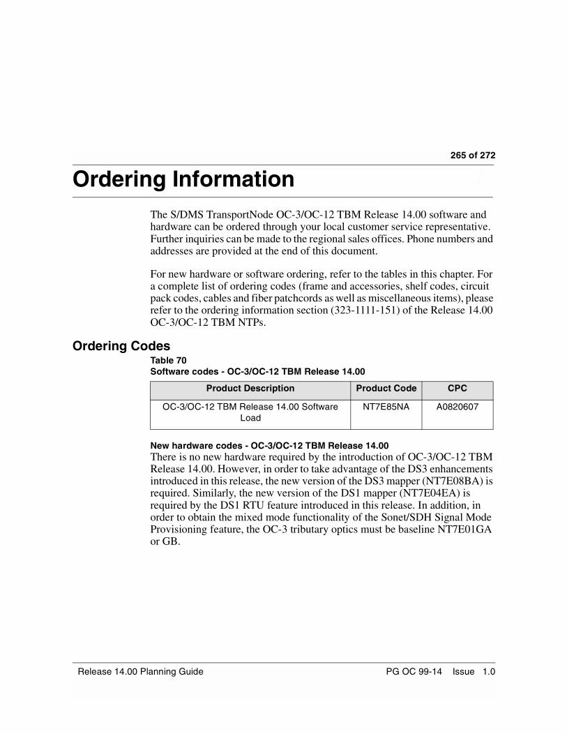
265 of 272
Ordering Information 8-The S/DMS TransportNode OC-3/OC-12 TBM Release 14.00 software and hardware can be ordered through your local customer service representative. Further inquiries can be made to the regional sales offices. Phone numbers and addresses are provided at the end of this document.
For new hardware or software ordering, refer to the tables in this chapter. For a complete list of ordering codes (frame and accessories, shelf codes, circuit pack codes, cables and fiber patchcords as well as miscellaneous items), please refer to the ordering information section (323-1111-151) of the Release 14.00 OC-3/OC-12 TBM NTPs.
Ordering CodesTable 70Software codes - OC-3/OC-12 TBM Release 14.00
New hardware codes - OC-3/OC-12 TBM Release 14.00There is no new hardware required by the introduction of OC-3/OC-12 TBM Release 14.00. However, in order to take advantage of the DS3 enhancements introduced in this release, the new version of the DS3 mapper (NT7E08BA) is required. Similarly, the new version of the DS1 mapper (NT7E04EA) is required by the DS1 RTU feature introduced in this release. In addition, in order to obtain the mixed mode functionality of the Sonet/SDH Signal Mode Provisioning feature, the OC-3 tributary optics must be baseline NT7E01GA or GB.
Product Description Product Code CPC
OC-3/OC-12 TBM Release 14.00 Software Load
NT7E85NA A0820607
Release 14.00 Planning Guide PG OC 99-14 Issue 1.0

266 of 272 Ordering Information
S/DMS TransportNode OC-3/OC-12 TBM PG OC 99-14 Issue 1.0

267 of 272
Abbreviations 9-ADM Add, Drop, MultiplexerAE Application EntityAID Access IdentifierAIS Alarm Indication SignalAINS Automatic In-ServiceALS-V VT Path AIS/LOP SecondsAMI Alternate Mark InversionAMI-ZCS Alternate Mark Inversion with Zero Code SuppressionAPS Automatic Protection SwitchingAPU Application Processor UnitB8ZS Bipolar with Eight-Zero SubstitutionBCV STS-1 Line Bipolar Coding ViolationBER Bit Error RatioBIP Bit Interleaved ParityBIP Breaker Interface PanelBITS Building Integrated Timing SupplyBLSR Bidirectional Line Switched RingCAP Change Application Procedure CBF Customized Baseline FileCI Customer InterfaceCIM Customer Information ManagementCLEI Common Language Equipment IdentifierCLFI Common Language Facility IdentifierCMT Character Mode TerminalCNET Control Network (network providing intra-site communication via a LAN).CPG Circuit Pack GroupCMISE Common Management Information Service ElementCSR Customer Service ReportCSU Channel Service UnitCUA Centralized User AdministrationCV Coding ViolationCV-L Line Coding Violation CV-LFE Far End Line Coding Violation CV-P Path Coding Violation CV-PFE Far End Path Coding Violation CV-S Section Coding Violation CV-V VT Path Coding Violation CV-VFE Far End VT Path Coding Violation DCC Data Communication Channel
Release 14.00 Planning Guide PG OC 99-14 Issue 1.0

268 of 272 Abbreviations
DCE Data Communications EquipmentDCN Data Communication NetworkDCP Drop and Continue on ProtectionDCW Drop and Continue on WorkingDDS Digital Data StorageDSI Disable Alarms ListingDS1 Digital Signal, level 1 (1.544 Mb/s)DS3 Digital Signal, level 3 (44.736 Mb/s)DTE Data Terminal EquipmentDTR Data Terminal ReadyDUS Don’t Use for SynchronizationEB Event BrowserES End SystemsES Errored SecondES-L Line Errored SecondES-LFE Far End Line Errored SecondES-P Path Errored SecondES-PFE Far End Path Errored SecondES-S Section Errored SecondES-V VT Path Errored SecondES-VFE Far End VT Path Errored SecondESF Extended Superframe FormatESI External Synchronization InterfaceEVB Event BrowserFC Failure CountFC-L Line Failure CountFC-LFE Far End Line Failure CountFC-P Path Failure CountFC-PFE Far End Path Failure CountFC-V VT Path Failure CountFC-VFE Far End VT Path Failure CountFS Force SwitchFTAM File Transfer Access and ManagementFTP File Transfer ProtocolGUS Group and User SetupHBT Hardware Baseline ToolHMU Host Messaging UnitID IdentifierIEEE Institute of Electrical and Electronics Engineers IF InterfaceINM Integrated Network ManagerIS In ServiceISCR In-Service Channel RolloverISNR In-Service Network Element RenumberingISRR In-Service Route RolloverIS-IS Intermediate System to Intermediate System Routing Exchange ProtocolKAS Keep Alive SignalLAN Local Area NetworkLBC Laser Bias CurrentLBO Line Build OutLED Light Emitting Diode
S/DMS TransportNode OC-3/OC-12 TBM PG OC 99-14 Issue 1.0
Abbreviations 269 of 272
LTE Line Terminating EquipmentMAP Maintenance and Administration PositionMBR Management By ReleaseMIC Maintenance Interface ControllerMNE Matched Nodes EnhancementsMS Manual SwitchNE Network ElementNEID Network Element IdentifierNMA Network Monitoring and AnalysisNP Network Processor NSAP Network Service Access PointNTP Nortel Networks PublicationNTP Network Time ProtocolNIU Network Interface UnitNUM Network Upgrade ManagerNVS Non Volatile StorageNWK NetworkingOAM Operations, Administration, MaintenanceOAM&P Operations, Administration, Maintenance, and ProvisioningOC-3 Optical Carrier at level 3 (155.52 Mb/s)OC-12 Optical Carrier at level 12 (622.08 Mb/s)OOS Out Of ServiceOPC OPerations ControllerOPR Optical Power ReceivedOPS Operational Processing System OPS/INE Operational Processing System/Intelligent Network ElementOS Operations SystemOSI Open Systems InterconnectionOSS Operations Support SystemsPAD Packet Assembler/DisassemblerPDN Packet Data NetworkPEC Product Engineering CodePG Planning GuidePID Password IdentifierPM Performance MonitoringPSN Packet Switching NetworkPSPE Protection Slot Provisioning ExpansionQRSS Quasi-Random Signal SourceRD Routing DomainRTU Remote Test UnitSDCC Section Data Communication ChannelSDH Synchronous Digital HierarchySE SecuritySES Severely Errored SecondSES-P Path Severely Errored SecondSES-PFE Far End Path Severely Errored SecondSES-V VT Path Severely Errored SecondSF Superframe FormatSF Signal FailSIL Side Interconnect Left CardSOC Span of Control
Release 14.00 Planning Guide PG OC 99-14 Issue 1.0

270 of 272 Abbreviations
SONET Synchronous Optical NETworkSSM Synchronization Status MessagingSTS Synchronous Transport SignalSUA Software Upgrade AdvancementsTARP TID Address Resolution ProtocolTBOS Telemetry Byte Oriented Serial TBM Transport Bandwidth ManagerTCA Threshold Crossing AlertTCP/IP Transmit Control Protocol/Internet ProtocolTID Target IdentifierTIRS TL1 Interface Router ServicesTL1 Transaction Language OneTOD Time Of DayTP4 Transport Protocol Class 4TPB Transport BridgeTSA Time Slot AssignmentTSI Time Slot InterchangeUAS Unavailable SecondUI User interfaceUID User IdentifierUSM User Session ManagerVT Virtual TributaryVT1.5 Virtual Tributary level 1.5VTBM Virtual Tributary Bandwidth ManagementVTM Virtual Tributary ManagementWAN Wide Area NetworkWTR Wait To RestoreX.25 CCITT protocol used for wide-area packet switching. OSI Data communication
standard.XDM X Display Manager
S/DMS TransportNode OC-3/OC-12 TBM PG OC 99-14 Issue 1.0

271 of 272
Appendix 1 Technical support and information 10-
Technical Assistance Service
For problems that affect service:
For 24-hour emergency recovery or software upgrade support, that is for:
• restoral of service for equipment that has been carrying payload and isout of service
• issues that prevent payload protection-switching
• issues that prevent completion of software upgrades
800-275-3827 (800-ASK-ETAS)
For problems that do not affect service:For 24-hour support on issues that require immediate assistance or for technical support and upgrade notification (8 am to 10 pm EST).
United States: 800-275-8726 (800-ASK-TRAN)
Canada: 800-361-2465
International 514-956-3500
For information and non-emergency support:From 8 am to 4 pm, direct requests for information and non-emergency support to the regional Customer Care Services (CCS) support group in your technical assistance service center.
Technical Assistance Service Centers — United StatesNortel Networks2350 Lakeside Blvd.Richardson,Texas75082
(972) 684-8011
Nortel Networks500 Perimeter ParkMorrisville, NC, 27560
1-800-275-3827
Release 14.00 Planning Guide PG OC 99-14 Issue 1.0

272 of 272 Appendix 1 Technical support and information
Technical Assistance Service Centers — CanadaCCS West (Alberta)
Nortel Networks2441 - 37th Ave. NECalgary, Alberta T2E 6Y7
(403) 769-8321
East (Newfoundland)
Nortel Networks63 Thorburn Rd.St. John’s, Newfoundland A1B 3M2
(709) 722-2500
CCS West (Saskatchewan)
Nortel Networks1801 Hamilton Street, Suite 820Regina, Saskatchewan S4P 4B4
(306) 791-7110
CCS West (Alberta)
Nortel Networks10235, 101st StreetFloor 22, Oxford TowerEdmonton, Alberta T5J 3G1
(780) 441-3191 or (780) 441- 3114 or(780) 441-3107
CCS East(Nova Scotia, Prince Edward Island)
Nortel Networks1701 Hollis St., Suite 900Halifax, Nova Scotia B3J 3M8
(902) 421-2305
Quebec
Nortel Networks9300 TransCanada HighwaySt. Laurent, Quebec H4S 1K5
(514) 956-3500 or 1-800-684-3578
CCS Ontario
Nortel Networks8200 Dixie RoadBrampton, Ontario L6T 4B8
(905) 863-4181 or 1-800-684-3578
CCS West (BC, Yukon and NWT)
Nortel Networks13575 Commerce Parkway, Suite 250Richmond, BC V6V 2L1
(604) 244-4177 or (604) 244-4172
East (New Brunswick)
Nortel Networks1 Brunswick Square, Suite 100Saint John, NB E2L 4V1
(506) 632-8271 or (506) 632-8203
CCS West(Manitoba, North-western Ontario)
Nortel Networks360 Main Street, Suite 1400Winnipeg, Manitoba R3C 3Z3
(204) 934-7530
Last page
S/DMS TransportNode OC-3/OC-12 TBM PG OC 99-14 Issue 1.0


SONET Transmission Products
S/DMS TransportNodeOC-3/OC-12 NE—TBMRelease 14.00 Planning Guide
2001 Nortel NetworksAll rights reserved
All information contained in this document is subject to change without notice. Northern Telecom reserves the right to make changes to equipment design or program components, as progress in engineering, manufacturing methods, or other circumstances may warrant.
PG OC 99-14Issue 1.0Jan 2001Printed in Canada