SOMFY DECOFLEX WIREFREE RTS SWITCH Ch...
5
PROGRAMMING - ADDING A DECOFLEX RTS WALL SWITCH - INITIAL INSTALLATION SOMFY DECOFLEX WIREFREE RTS SWITCH Part #’S 1810897 DecoFlex 1 Channel (white) 1810898 INSTRUCTIONS DecoFlex 1 Channel (ivory) 1810899 DecoFlex 1 Channel (black) 1810813 DecoFlex 5 Channel (white) 1810814 DecoFlex 5 Channel (ivory) 1810830 DecoFlex 5 Channel (black) The DecoFlex RTS Switch is a wireless radio transmitter compatible with all Somfy RTS Motors and externally mounted RTS receivers. - - Power: 3V lithium battery, CR 2450 type Commands are transmitted by radio waves at 433.42 MHz. The Somfy DecoFlex RTS switch is a low voltage device which does not require an electrical box. It can be mounted adjacent to an existing Decora style light switch or as a stand-alone device using the (included) SOMFY low voltage mounting bracket (See installation section for details). 1. Using the previously programmed Telis remote, press and hold the programming button on back of remote until window covering “jogs.” (”jog” is a brief back and forth movement of the window covering) Channel Button LED Indicator Programming Button Channel Button LED Indicator Note: During initial programming it is recommended to provide power only to the motor or RTS receiver being programmed. A previously programmed Telis transmitter can be used to add a new DecoFlex RTS Wall Switch to the Motorized Window Covering. If a Telis transmitter has not been previously programmed, please refer to the installation/programming instructions of the relevant RTS motorized window covering. 3. Using a paper clip, or similar device, briefly press the Programming Button (for 1 second) located on the DecoFlex switch until window covering “jogs ” Window covering has now learned the commands of the DecoFlex switch or channel. . 2. Select a channel to be memorized by pressing the appropriate Channel Button. The adjacent LED indicator will illuminate when the channel has been selected. 1. press and hold the Programming Button on the previously addressed DecoFlex switch until window covering “jogs ” Using a paper clip, or similar device, . PROGRAMMING - ADDING ADDITIONAL CHANNELS OR DECOFLEX WALL SWITCHES 3. Using a paper clip, or similar device, briefly press the Programming Button (for 1 second) located on the DecoFlex switch until window covering “jogs ” Window covering has now learned the commands of the new DecoFlex switch or channel. . 2. Select a NEW channel or DecoFlex switch to be memorized by pressing the appropriate Channel Button. The adjacent LED indicator will illuminate when the channel has been selected. Channel Button Programming Button Programming Button LED Indicator Select the Channel Button © Copyright Somfy Systems, Inc. 1/2010 PAGE 1 REV 4 Programming Button C-0006 o o o o - Operating temperature: +5 C/41 F to +40 C/104 F - Range: Up to 65 Ft. - Fits into standard Decora Wall Plates BACK VIEW Programming Button Pen Previously Programmed Remote
Transcript of SOMFY DECOFLEX WIREFREE RTS SWITCH Ch...
PROGRAMMING - ADDING A DECOFLEX RTS WALL SWITCH - INITIAL INSTALLATION
SOMFY DECOFLEX WIREFREE RTS SWITCHPart #’S 1810897 DecoFlex 1 Channel (white)1810898
INSTRUCTIONS
DecoFlex 1 Channel (ivory)1810899 DecoFlex 1 Channel (black)1810813 DecoFlex 5 Channel (white)1810814 DecoFlex 5 Channel (ivory)1810830 DecoFlex 5 Channel (black)
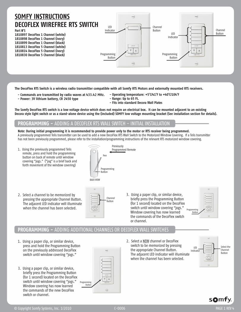
The DecoFlex RTS Switch is a wireless radio transmitter compatible with all Somfy RTS Motors and externally mounted RTS receivers.
- - Power: 3V lithium battery, CR 2450 type
Commands are transmitted by radio waves at 433.42 MHz.
The Somfy DecoFlex RTS switch is a low voltage device which does not require an electrical box. It can be mounted adjacent to an existing Decora style light switch or as a stand-alone device using the (included) SOMFY low voltage mounting bracket (See installation section for details).
1. Using the previously programmed Telis remote, press and hold the programming button on back of remote until window covering “jogs.” (”jog” is a brief back and forth movement of the window covering)
Channel ButtonLED
Indicator
ProgrammingButton
Channel Button
LEDIndicator
Note: During initial programming it is recommended to provide power only to the motor or RTS receiver being programmed.A previously programmed Telis transmitter can be used to add a new DecoFlex RTS Wall Switch to the Motorized Window Covering. If a Telis transmitter has not been previously programmed, please refer to the installation/programming instructions of the relevant RTS motorized window covering.
3. Using a paper clip, or similar device, briefly press the Programming Button (for 1 second) located on the DecoFlex switch until window covering “jogs ” Window covering has now learned the commands of the DecoFlex switch or channel.
.
2. Select a channel to be memorized by pressing the appropriate Channel Button. The adjacent LED indicator will illuminate when the channel has been selected.
1. press and hold the Programming Button on the previously addressed DecoFlex switch until window covering “jogs ”
Using a paper clip, or similar device,
.
PROGRAMMING - ADDING ADDITIONAL CHANNELS OR DECOFLEX WALL SWITCHES
3. Using a paper clip, or similar device, briefly press the Programming Button (for 1 second) located on the DecoFlex switch until window covering “jogs ” Window covering has now learned the commands of the new DecoFlex switch or channel.
.
2. Select a NEW channel or DecoFlex switch to be memorized by pressing the appropriate Channel Button. The adjacent LED indicator will illuminate when the channel has been selected.
Channel Button
ProgrammingButton
ProgrammingButton
LEDIndicator
Select the Channel Button
© Copyright Somfy Systems, Inc. 1/2010 PAGE 1 REV 4
ProgrammingButton
C-0006
o o o o- Operating temperature: +5 C/41 F to +40 C/104 F- Range: Up to 65 Ft.- Fits into standard Decora Wall Plates
BACK VIEW
ProgrammingButton
Pen
PreviouslyProgrammed Remote
PROGRAMMING - SETTING A FAVORITE OR PREFERRED POSITION
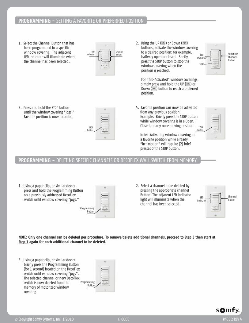
1. Select the Channel Button that has been programmed to a specific window covering. The adjacent LED indicator will illuminate when the channel has been selected.
Channel Button
LEDIndicator
2. Using the UP ( ) or Down ( ) buttons, activate the window covering to a desired position: for example, halfway open or closed. Briefly press the STOP button to stop the window covering when the position is reached.
For “Tilt-Activated” window coverings, simply press and hold the UP ( ) or Down ( ) button to reach a preferred position.
LEDIndicator
Select the Channel Button
3. Press and hold the STOP button until the window covering “jogs.” Favorite position is now recorded.
STOPButton
4. Favorite position can now be activated from any previous position. Example: Briefly press the STOP button while window covering is in a Open, Closed, or any non-moving position.
Note: Activating window covering to a favorite position while already “in- motion” will require (2) brief presses of the STOP button.
STOPButton
1. Using a paper clip, or similar device, press and hold the Programming Button on a previously addressed DecoFlex switch until window covering ”jogs.”
2. Select a channel to be deleted by pressing the appropriate channel Button. The adjacent LED indicator light will illuminate when the channel has been selected.
NOTE: Only one channel can be deleted per procedure. To remove/delete additional channels, proceed to Step 3 then start at Step 1 again for each additional channel to be deleted.
3. Using a paper clip, or similar device, briefly press the Programming Button (for 1 second) located on the DecoFlex switch until window covering “jogs”. The selected channel or new DecoFlex switch is now deleted from the memory of motorized window covering.
ProgrammingButton
LEDIndicator
Channel Button
ProgrammingButton
PROGRAMMING - DELETING SPECIFIC CHANNELS OR DECOFLEX WALL SWITCH FROM MEMORY
© Copyright Somfy Systems, Inc. 1/2010 C-0006 PAGE 2 REV 4
STOP
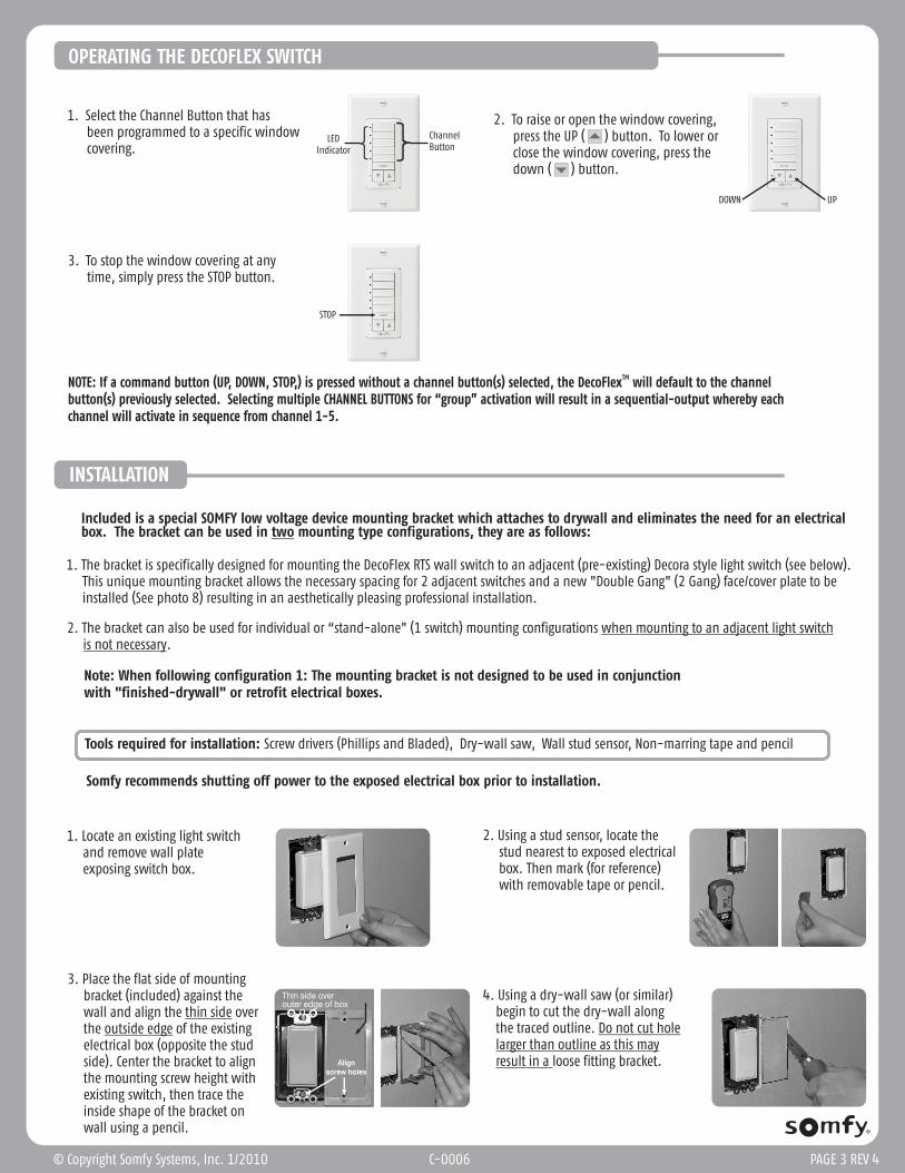
1. Select the Channel Button that has been programmed to a specific window covering.
2. To raise or open the window covering, press the UP ( ) button. To lower or close the window covering, press the down ( ) button.
3. To stop the window covering at any time, simply press the STOP button.
LEDIndicator
Channel Button
UPDOWN
STOP
OPERATING THE DECOFLEX SWITCH
TMNOTE: If a command button (UP, DOWN, STOP,) is pressed without a channel button(s) selected, the DecoFlex will default to the channel button(s) previously selected. Selecting multiple CHANNEL BUTTONS for “group” activation will result in a sequential-output whereby each channel will activate in sequence from channel 1-5.
© Copyright Somfy Systems, Inc. 1/2010 PAGE 3 REV 4
Included is a special SOMFY low voltage device mounting bracket which attaches to drywall and eliminates the need for an electrical box. The bracket can be used in two mounting type configurations, they are as follows:
1. The bracket is specifically designed for mounting the DecoFlex RTS wall switch to an adjacent (pre-existing) Decora style light switch (see below). This unique mounting bracket allows the necessary spacing for 2 adjacent switches and a new "Double Gang" (2 Gang) face/cover plate to be installed (See photo 8) resulting in an aesthetically pleasing professional installation.
2. The bracket can also be used for individual or “stand-alone" (1 switch) mounting configurations when mounting to an adjacent light switch is not necessary.
INSTALLATION
Note: When following configuration 1: The mounting bracket is not designed to be used in conjunctionwith "finished-drywall" or retrofit electrical boxes.
3. Place the flat side of mounting bracket (included) against the wall and align the thin side over the outside edge of the existing electrical box (opposite the stud side). Center the bracket to align the mounting screw height with existing switch, then trace the inside shape of the bracket on wall using a pencil.
1. Locate an existing light switch and remove wall plate exposing switch box.
2. Using a stud sensor, locate the stud nearest to exposed electrical box. Then mark (for reference) with removable tape or pencil.
Thin side over outer edge of box
Align screw holes
Tools required for installation: Screw drivers (Phillips and Bladed), Dry-wall saw, Wall stud sensor, Non-marring tape and pencil
Somfy recommends shutting off power to the exposed electrical box prior to installation.
4. Using a dry-wall saw (or similar) begin to cut the dry-wall along the traced outline. than outline as this may result in a loose fitting bracket.
Do not cut hole larger
C-0006
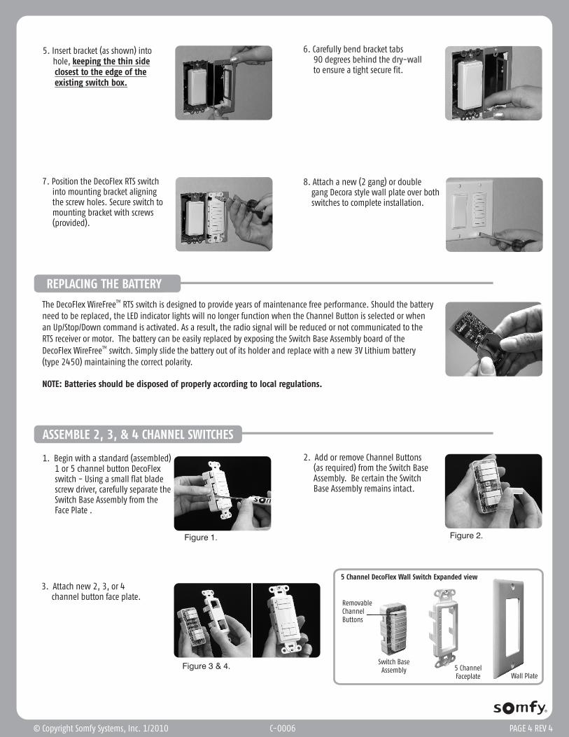
5. Insert bracket (as shown) into hole, keeping the thin side the edge of the existing switch box.
closest to
6. Carefully bend bracket tabs 90 degrees behind the dry-wall to ensure a tight secure fit.
7. Position the DecoFlex RTS switch into mounting bracket aligning the screw holes. Secure switch to mounting bracket with screws (provided).
8. Attach a new (2 gang) or double gang Decora style wall plate over both switches to complete installation.
PAGE 4 REV 4
TMThe DecoFlex WireFree RTS switch is designed to provide years of maintenance free performance. Should the battery need to be replaced, the LED indicator lights will no longer function when the Channel Button is selected or when an Up/Stop/Down command is activated. As a result, the radio signal will be reduced or not communicated to the RTS receiver or motor. The battery can be easily replaced by exposing the Switch Base Assembly board of the
TMDecoFlex WireFree switch. Simply slide the battery out of its holder and replace with a new 3V Lithium battery (type 2450) maintaining the correct polarity.
NOTE: Batteries should be disposed of properly according to local regulations.
REPLACING THE BATTERY
RemovableChannel Buttons
Switch BaseAssembly 5 Channel
Faceplate Wall Plate
5 Channel DecoFlex Wall Switch Expanded view
ASSEMBLE 2, 3, & 4 CHANNEL SWITCHES
1. Begin with a standard (assembled) 1 or 5 channel button DecoFlex switch - Using a small flat blade screw driver, carefully separate the Switch Base Assembly from the Face Plate .
2. Add or remove Channel Buttons (as required) from the Switch Base Assembly. Be certain the Switch Base Assembly remains intact.
3. Attach new 2, 3, or 4 channel button face plate.
Figure 1. Figure 2.
Figure 3 & 4.
© Copyright Somfy Systems, Inc. 1/2010 C-0006
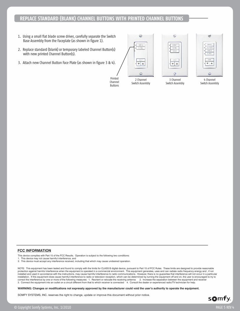
REPLACE STANDARD (BLANK) CHANNEL BUTTONS WITH PRINTED CHANNEL BUTTONS
1. Using a small flat blade screw driver, carefully separate the Switch Base Assembly from the Faceplate (as shown in figure 1).
2. Replace standard (blank) or temporary labeled Channel Button(s) with new printed Channel Button(s).
3. Attach new Channel Button Face Plate (as shown in figure 3 & 4).
4 Channel Switch Assembly
2 Channel Switch Assembly
3 Channel Switch Assembly
FCC INFORMATION
This device complies with Part 15 of the FCC Results. Operation is subject to the following two conditions:1. This device may not cause harmful interference, and2. This device must accept any interference received, including that which may cause undesired operation.
NOTE: This equipment has been tested and found to comply with the limits for CLASS B digital device, pursuant to Part 15 of FCC Rules. These limits are designed to provide reasonable protection against harmful interference when the equipment is operated in a commercial environment. This equipment generates, uses and can radiate radio frequency energy and , if not installed and used in accordance with the instructions, may cause harmful interference to radio communications. However, there is no guarantee that interference will not occur in a particular installation. If this equipment does cause harmful interference to radio or television reception, which can be determined by turning the equipment off and on, the user is encouraged to try to correct the interference by one or more of the following measures: 1. Reorient or relocate the receiving antenna 2. Increase the separation between the equipment and receiver3. Connect the equipment into an outlet on a circuit different from that to which receiver is connected 4. Consult the dealer or experienced radio/TV technician for help.
WARNING: Changes or modifications not expressly approved by the manufacturer could void the user’s authority to operate the equipment.
SOMFY SYSTEMS, INC. reserves the right to change, update or improve this document without prior notice.
PAGE 5 REV 4© Copyright Somfy Systems, Inc. 1/2010
PrintedChannelButtons