Solving Integration Challenges for Flexible Hybrid · PDF fileSolving Integration Challenges...
14
Solving Integration Challenges for Flexible Hybrid Electronics Nano for Defense Conference November 17, 2015 Approved for Public Release
-
Upload
phamnguyet -
Category
Documents
-
view
223 -
download
2
Transcript of Solving Integration Challenges for Flexible Hybrid · PDF fileSolving Integration Challenges...

Solving Integration Challenges for Flexible Hybrid Electronics
Nano for Defense Conference
November 17, 2015
Approved for Public Release
©2015 American Semiconductor, Inc. All rights reserved.
Flexible Hybrid System“Combination of flexible printed materials and
flexible silicon-based ICs to create a new class of flexible electronics.”
Printed ElectronicsLow Cost, R2R, Large
Format
Printed Electronics• Sensors• Interconnects• Substrates• Displays
• Low Cost, Large Format• Roll-To-Roll, Screen, Inkjet Print,
…
What are Flexible Hybrid Electronics?
2
Flexible FleX-ICsHigh Performance, High Density
FleX-ICs• Sensor Signal Processing• Data Processing• Data Storage• Communications
• Low Cost, High Performance• Compatible with Printed Electronics• Foundry CMOS + FleX Processing
Molex flexible substrateAmerican Semiconductor
©2015 American Semiconductor, Inc. All rights reserved.
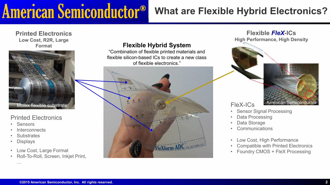
Killer Apps – What are they?
Products are starting to emerge
Asset Monitoring Systems for
structural, quality, and
performance
3Source: Thin Film
Source: FitbitSource: Univ. of Illinois
Source: Google
Next GenerationFully Flexible?
Next GenerationFHE?
Today Future
Source: PakSense Source: Phase IVSource: American
Semiconductor
Wearable monitoring for
Medical and Performance
Consumer product safety,
new features.
©2015 American Semiconductor, Inc. All rights reserved.
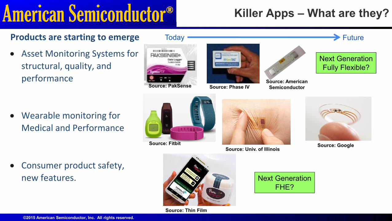
Flexible Hybridization• IC attach• IC interconnect• IC Overcoat• Testing• Lamination• Surface mount• Printing
Basic FHE Manufacturing Process
4
FHE
Semiconductor IC• Pakaged IC • Die IC
- Thin Die: < 50um- Ultra-thin/SoP Die: < 12um
Integration
Sensors/display• Printed material• Surface mount• Unique Material
Flexible Substrate Fabrication• Flexible Circuit
Boards• Screen Print• Roll-2-Roll
©2015 American Semiconductor, Inc. All rights reserved.
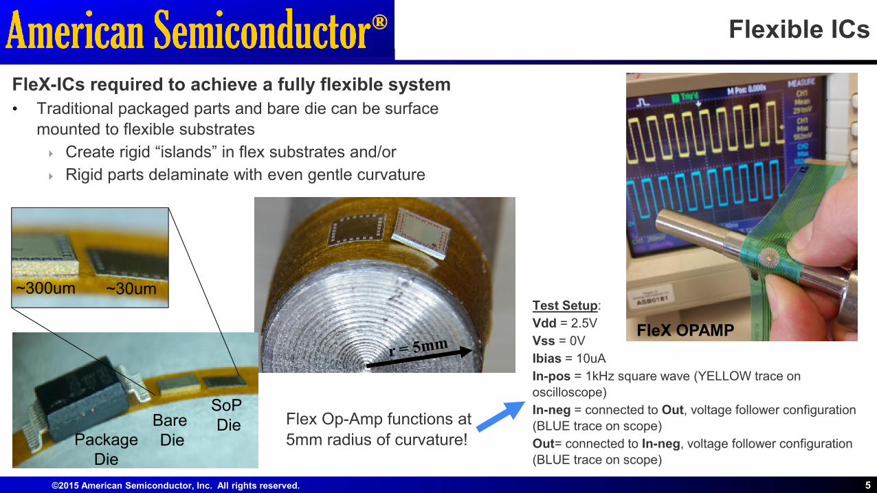
Flexible ICs
FleX-ICs required to achieve a fully flexible system
• Traditional packaged parts and bare die can be surface
mounted to flexible substrates
Create rigid “islands” in flex substrates and/or
Rigid parts delaminate with even gentle curvature
5
FleX OPAMP
Test Setup:
Vdd = 2.5V
Vss = 0V
Ibias = 10uA
In-pos = 1kHz square wave (YELLOW trace on
oscilloscope)
In-neg = connected to Out, voltage follower configuration
(BLUE trace on scope)
Out= connected to In-neg, voltage follower configuration
(BLUE trace on scope)
Package Die
BareDie
SoPDie
~300um ~30um
Flex Op-Amp functions at
5mm radius of curvature!
©2015 American Semiconductor, Inc. All rights reserved.
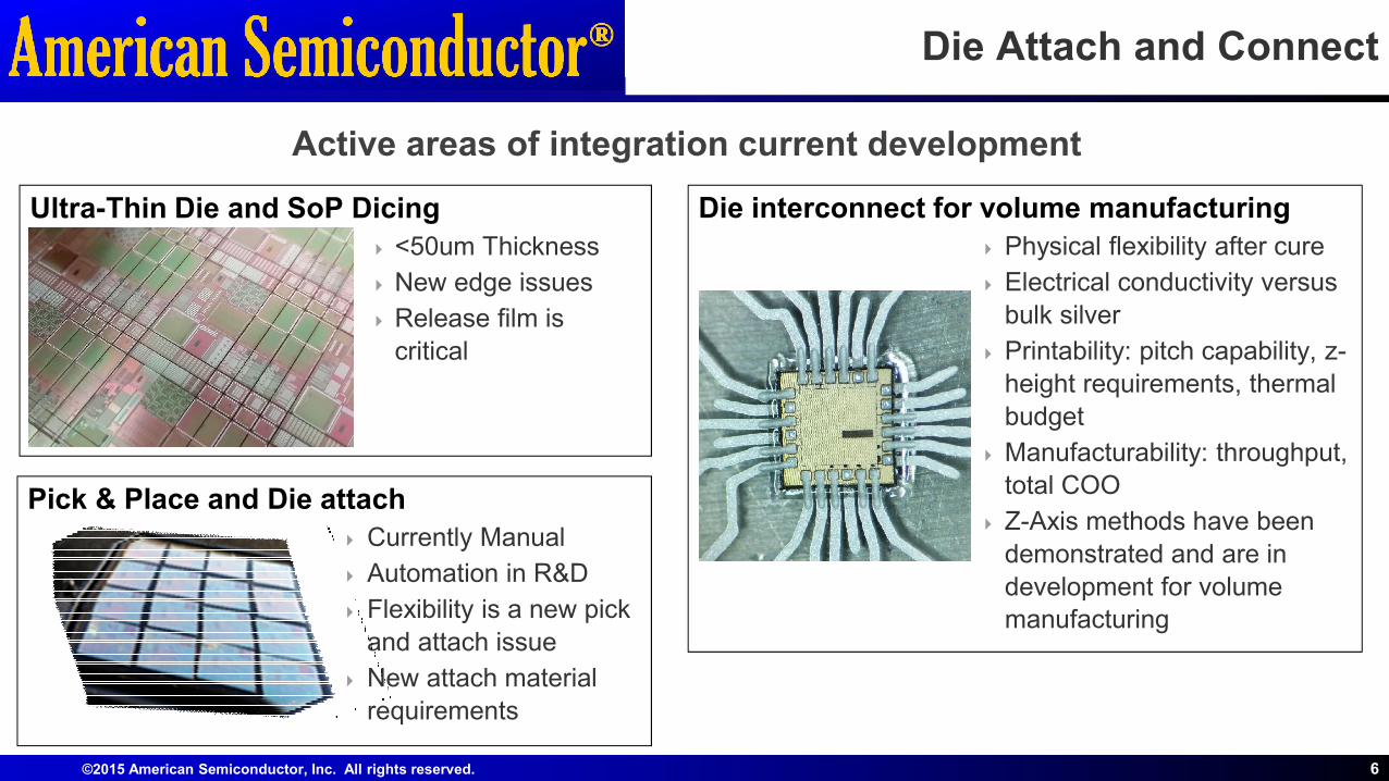
Ultra-Thin Die and SoP Dicing
<50um Thickness
New edge issues
Release film is
critical
Die Attach and Connect
Die interconnect for volume manufacturing
Physical flexibility after cure
Electrical conductivity versus
bulk silver
Printability: pitch capability, z-
height requirements, thermal
budget
Manufacturability: throughput,
total COO
Z-Axis methods have been
demonstrated and are in
development for volume manufacturing
6
Pick & Place and Die attach
Currently Manual
Automation in R&D
Flexibility is a new pick
and attach issue
New attach material
requirements
Active areas of integration current development
©2015 American Semiconductor, Inc. All rights reserved.
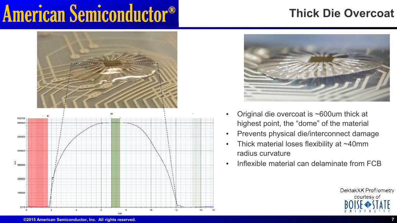
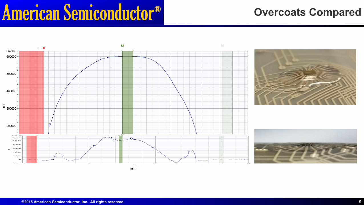
Thick Die Overcoat
7
• Original die overcoat is ~600um thick at
highest point, the “dome” of the material
• Prevents physical die/interconnect damage
• Thick material loses flexibility at ~40mm
radius curvature
• Inflexible material can delaminate from FCB
©2015 American Semiconductor, Inc. All rights reserved.
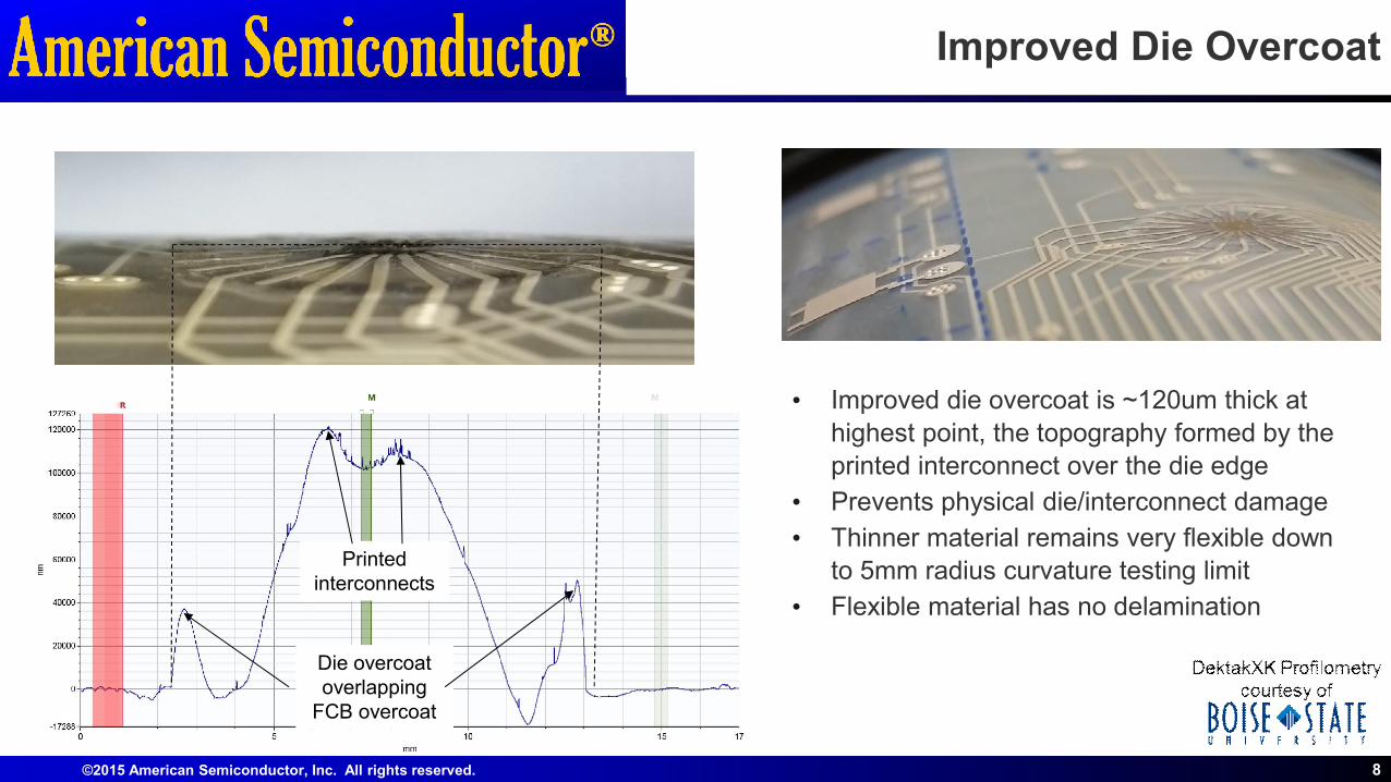
Improved Die Overcoat
8
• Improved die overcoat is ~120um thick at
highest point, the topography formed by the
printed interconnect over the die edge
• Prevents physical die/interconnect damage
• Thinner material remains very flexible down
to 5mm radius curvature testing limit
• Flexible material has no delamination
Die overcoat overlapping
FCB overcoat
Printed interconnects
©2015 American Semiconductor, Inc. All rights reserved.
Overcoats Compared
9

©2015 American Semiconductor, Inc. All rights reserved.
Testing and Reliability
10
Rcurve - radius of curvature testingRcurve Test Mandrels
Reliability Standards and Tests are an
active area of FHE Development.
• FHE provided unique challenges for
testing and reliability
• Standards for FHE have yet to emerge
• Testing methods are being developed
• Test associated with flexibility pioneer
new characteristics.
• Radius of Curvature is one important
new reliability characteristic
• Rcurve is a test method currently being
developed and utilized for early stage
FHE products.
• Unique qualification test requirements
have also been adopted to support the
release of the FleXform-ADC™ Dev Kit.
©2015 American Semiconductor, Inc. All rights reserved.
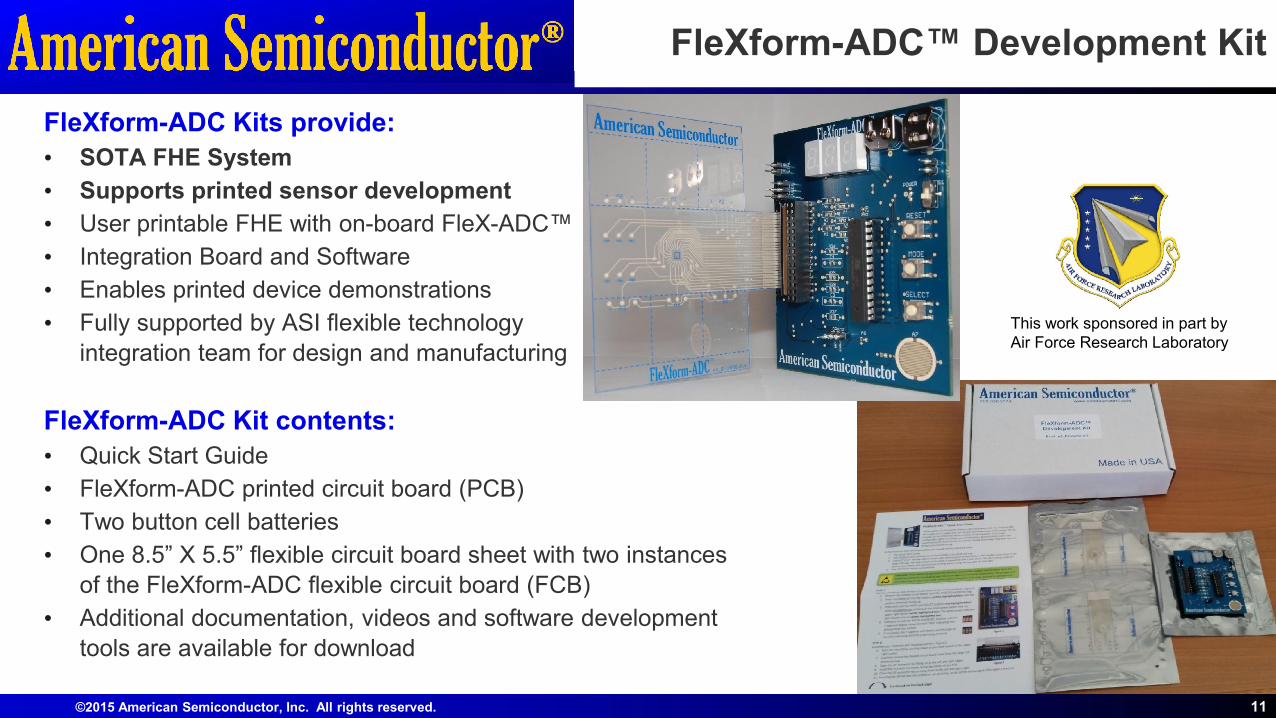
FleXform-ADC™ Development Kit
FleXform-ADC Kits provide:
• SOTA FHE System
• Supports printed sensor development
• User printable FHE with on-board FleX-ADC™
• Integration Board and Software
• Enables printed device demonstrations
• Fully supported by ASI flexible technology
integration team for design and manufacturing
FleXform-ADC Kit contents:
• Quick Start Guide
• FleXform-ADC printed circuit board (PCB)
• Two button cell batteries
• One 8.5” X 5.5” flexible circuit board sheet with two instances
of the FleXform-ADC flexible circuit board (FCB)
• Additional documentation, videos and software development
tools are available for download
11
This work sponsored in part by Air Force Research Laboratory
©2015 American Semiconductor, Inc. All rights reserved. 12
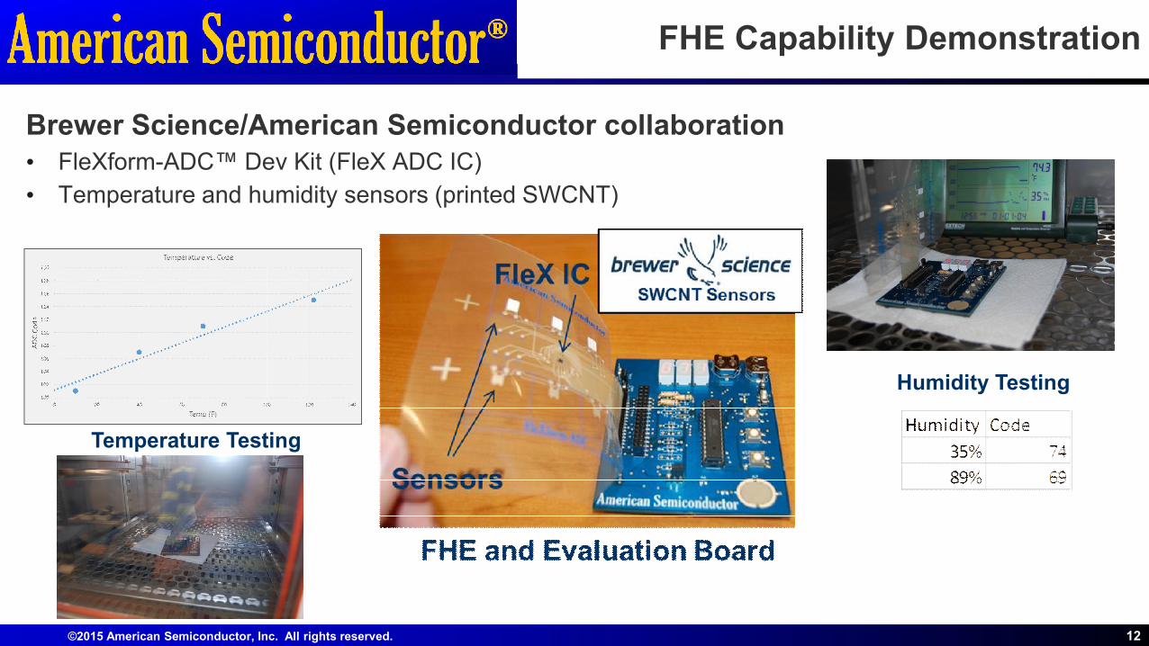
FHE Capability Demonstration
Brewer Science/American Semiconductor collaboration• FleXform-ADC™ Dev Kit (FleX ADC IC)
• Temperature and humidity sensors (printed SWCNT)
Temperature Testing
Humidity Testing
©2015 American Semiconductor, Inc. All rights reserved.
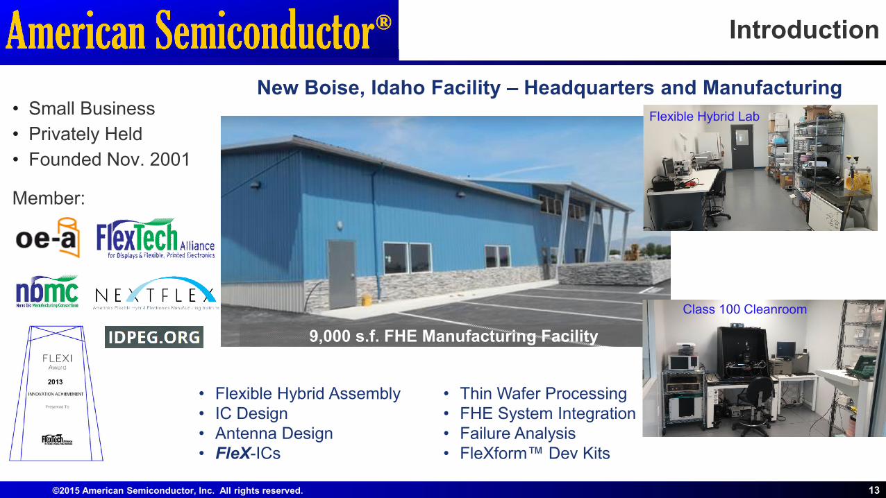
Introduction
13
• Flexible Hybrid Assembly• IC Design• Antenna Design• FleX-ICs
• Thin Wafer Processing• FHE System Integration• Failure Analysis• FleXform™ Dev Kits
9,000 s.f. FHE Manufacturing Facility
Flexible Hybrid Lab
Class 100 Cleanroom
• Small Business
• Privately Held
• Founded Nov. 2001
Member:
New Boise, Idaho Facility – Headquarters and Manufacturing
Thank You
American Semiconductor, Inc.6987 W. Targee St.
Boise, ID 83709Tel: 208.336.2773Fax: 208.336.2752
www.americansemi.com
© 2015 American Semiconductor, Inc. All rights reserved.American Semiconductor is a registered trademark of American Semiconductor, Inc. FleXform, FleXform-ADC, FleX, Silicon-on-Polymer, FleX-ADC, FleX-MCU and FleX-IC are trademarks of American Semiconductor, Inc.
Thank you for attending
Special thanks to :• Air Force Research Lab• Brewer Science• Soligie Molex• Boise State University