Solvent Bench Procedures and Operation Manual Overview The Solvent benches are designed for the use...
27
1 Solvent Bench Procedures and Operation Manual Contents Overview ................................................................................................................................................................................ 3 Safety: General Precautions ................................................................................................................................................. 3 Electrical Safety ................................................................................................................................................................. 3 Chemical Safety ................................................................................................................................................................. 4 Solvent Bench Specific Restrictions and Instructions................................................................................................... 5 Personal Protective Equipment (PPE) ............................................................................................................................ 6 Eye Wash and Safety Shower ........................................................................................................................................... 7 Buddy Policy ...................................................................................................................................................................... 7 Bench Layout ......................................................................................................................................................................... 8 Headcase ................................................................................................................................................................................. 9 Bench Components............................................................................................................................................................. 10 Solvent Bench Safety Interlocks and Alarms ............................................................................................................... 10 Photohelic ........................................................................................................................................................................ 11 Vacuum Chuck ................................................................................................................................................................ 11 Gooseneck Sink ............................................................................................................................................................... 12 Stainless Steel Heated Foil Static Bath ......................................................................................................................... 13 Draining the Water Bath ................................................................................................................................................... 14 Stainless Steel Cup Sinks ................................................................................................................................................ 14 Process Timer ( PROCON 959T)................................................................................................................................... 14 Fire Suppression System ................................................................................................................................................ 15 Operation / Process ............................................................................................................................................................ 18 Heated Solvent Baths ..................................................................................................................................................... 18 Waste Disposal .................................................................................................................................................................. 19 Solvent spills into the water bath ..................................................................................................................................... 19 Hot Plate Usage................................................................................................................................................................. 19 System Requirements ......................................................................................................................................................... 19 Appendices .......................................................................................................................................................................... 20 Appendix A: Specialty chemicals Usage and Information Guide ............................................................................. 20
Transcript of Solvent Bench Procedures and Operation Manual Overview The Solvent benches are designed for the use...

1
Solvent Bench Procedures and Operation Manual
Contents Overview ................................................................................................................................................................................ 3
Safety: General Precautions ................................................................................................................................................. 3
Electrical Safety ................................................................................................................................................................. 3
Chemical Safety ................................................................................................................................................................. 4
Solvent Bench Specific Restrictions and Instructions................................................................................................... 5
Personal Protective Equipment (PPE) ............................................................................................................................ 6
Eye Wash and Safety Shower ........................................................................................................................................... 7
Buddy Policy ...................................................................................................................................................................... 7
Bench Layout ......................................................................................................................................................................... 8
Headcase ................................................................................................................................................................................. 9
Bench Components ............................................................................................................................................................. 10
Solvent Bench Safety Interlocks and Alarms ............................................................................................................... 10
Photohelic ........................................................................................................................................................................ 11
Vacuum Chuck ................................................................................................................................................................ 11
Gooseneck Sink ............................................................................................................................................................... 12
Stainless Steel Heated Foil Static Bath ......................................................................................................................... 13
Draining the Water Bath ................................................................................................................................................... 14
Stainless Steel Cup Sinks ................................................................................................................................................ 14
Process Timer ( PROCON 959T) ................................................................................................................................... 14
Fire Suppression System ................................................................................................................................................ 15
Operation / Process ............................................................................................................................................................ 18
Heated Solvent Baths ..................................................................................................................................................... 18
Waste Disposal .................................................................................................................................................................. 19
Solvent spills into the water bath ..................................................................................................................................... 19
Hot Plate Usage ................................................................................................................................................................. 19
System Requirements ......................................................................................................................................................... 19
Appendices .......................................................................................................................................................................... 20
Appendix A: Specialty chemicals Usage and Information Guide ............................................................................. 20
2
Appendix B: Eye Wash and Safety Shower Locations ................................................................................................ 22
Appendix C: General Wet Chemical Use Procedures ................................................................................................ 23
Appendix D: General Wet Bench Waste Procedures ................................................................................................. 25
Appendix E: Wet Bench Troubleshooting ................................................................................................................... 26
Appendix F: Buddy Policy ............................................................................................................................................. 27

3
Overview The Solvent benches are designed for the use of room temperature and temperature
controlled solvents for substrate cleaning, lift–off pattern transfer schemes and other
fabrication operations using solvents. Due to the fact that many solvents are considered
flammable materials, the solvent benches are equipped with integrated fire suppression
systems. Each bench is configured as follows:
72 inch manual front access wet bench constructed of stainless steel and equipped
with casters, leg levelers and clear polycarbonate face shields.
Two (2) heated foil static baths with lids and double containment.
Two (2) MPC 102 Temperature controllers for the static baths.
One (1) PROCON 959T process timer controller.
Two (2) stainless steel solvent cup sinks that drain to separate carboys for small
volume solvent disposal.
One (1) polypropylene utility sink with gooseneck.
One (1) DI Water and N2 Teflon gun station.
One (1) Wafer vacuum chuck activated by foot pedal switch and vacuum pressure
gauge.
One (1) stainless steel perforated shelf.
One (1) MPC 901 power up controller with system services interlocks and alarms
and a mushroom EMO switch.
One automated / manual fire detection and suppression system.
Safety: General Precautions This system is designed to safely handle hazardous liquid chemicals, specifically
solvents. To perform as designed the system must be operated per the guidelines
described in this manual.
Electrical Safety
This system is powered by electricity. Like any electrically powered device, if it is not
properly used it can cause an electrical shock. Users are not to perform electrical work
on the bench. If there are suspected electrical problems experienced during its use,
please immediately stop bench use and notify the staff.

4
Chemical Safety
The following suggestions are offered as generally safe chemical handling
procedures, and are not meant to supplement or replace the chemical
manufacturer’s MSDS information or facility safety procedures.
Ensure you have read and understand the MSDS sheets for all chemicals
prior to use.
Avoid skin contact with the chemical. Wear chemical-resistant clothing, gloves
and boots when there is a probability of liquid contact.
Proper Personal Protective Equipment (PPE) MUST be worn at this bench
at ALL times . ( See details in following sections)
Chemical-resistant goggles must be worn when using chemicals in this bench.
Keep work area well ventilated and do not inhale fumes.
Open Containers are NEVER to be transported outside of the hood.
All chemicals must be used inside the fume hood. No chemical work (including
pouring chemicals) is allowed outside the hood.
Secondary containment should be used when transporting chemical bottles to and
from the hood or anywhere outside the hood.
5
Pouring/Handling of chemicals and containers must be done with (2) hands at all
times. If something does spill or fall, try to direct the material inside the hood.
Solvent Bench Specific Restrictions and Instructions
The following items apply when using the solvent benches:
You must be signed into the portal to use a bench. Interlocks are installed on the
power, water and nitrogen.
Acids and bases are NEVER to be used in the Solvent benches.
The “Specialty Chemical Usage and Information Guide” (Appendix A) details
which chemicals are approved for each bench. If you don’t find the chemical you
want to use in the Guide, please consult with the staff prior to use.
Two users are allowed to use the solvent benches at one time. Users are required
to check to make sure both are using compatible chemicals.
The bench top cup sinks are for disposal of approved solvents. The “Specialty
Chemical Usage and Information Guide” (Appendix A) is color coded to
indicate which chemicals allowed in the bench can be disposed of into the cup
sinks. The allowed chemicals are in green. The cup sinks are not to be used to
dispose of chlorinated and used lift off solvents that contain solid
materials. If you plan to use an uncommon solvent, please consult with the staff
prior to use to determine exactly how it should be used in the benches.
Chlorinated and used lift off solvents must be disposed of according to the
Appendix D “General Chemical Waste Disposal Procedures”.
Surface of bench must be rinsed and dried with clean wipes after each use.
All lab ware items must be rinsed after use and placed back on the proper storage
rack.
DO NOT LEAVE ITEMS ON THE BENCH! The only item permitted to be left in
the bench without prior staff approval is the provided funnel. Hang the funnel
(Rinse First!) on the provided hooks when not in use.
In general you should always be at the bench when in use. However, if you need to
walk away from the bench for an extended period of time (>5 minutes) you need to
follow the procedures and meet the requirements outlined in the policy in the
General Wet Chemical Use Procedures, Appendix C of this manual) )(do we need
6
to say something here about heated baths or do these procedures apply to all
baths, heated or unheated)
Hot plates are NOT TO BE USED in the solvent benches. The heated water
baths and immersion racks should be used to heat solvents in secondary
containers if needed.
If you find the bench dirty when you log in please report it immediately to the
staff. For off hours use if you feel the bench is unusable, please report it by
submitting a trouble call on RIMS , place a DO NOT USE sign on the bench and
move to another bench.
NOTE: By failing to report issues with benches you are assuming
responsibility for the condition of the bench. Users will be charged staff
time and bench time if staff needs to clean up the bench because the user
failed to do so.
Personal Protective Equipment (PPE)
Wet Bench Personal Protective Equipment (PPE) must be used at all times when in
the Wet Chemistry Bay. Requirements for the solvent bench are as follows:
o Solvent Stainless Steel Benches (All chemicals) – Goggles, Chemical Gloves,
Full Apron.
Personal Protective Equipment must be put on before you can enter the wet
chemistry bay. The PPE is found on racks just outside the bay.
Safety Tape installed on the floor delineates two areas. The first is that area
surrounding the PPE Rack and is the PPE staging area. In the PPE staging area PPE
is put on and removed after use. It is demarcated with Black/white tape on the
floor. The second area delineated is the Wet chemistry bay, where PPE MUST be
worn at all times. It is demarcated with Black/yellow tape on the floor. Please
note that PPE cannot be worn outside of these two areas. It must be
removed prior to entering the remainder of the cleanroom area.

7
Eye Wash and Safety Shower
An Eye wash and Safety shower are available at the head of the Wet Bench Area.
Additional Eye Washes and Safety showers are located through the exit door at the end
of the Wet Chemistry Bay in the exterior hallway. See the location map in Appendix B of
this document.
If exposed, rinse for at least 15 minutes and yell for help from other users or staff
while rinsing.
Buddy Policy
Buddy Policy Rules are in effect at all times when using the solvent benches.
For the Solvent benches you must have another trained user in the lab at all times
in case you need assistance. If you are using the Solvent bench in off hours
(6:00PM-8:00AM) both you and your buddy must sign in to the “Buddy” log in the
cleanroom gowning area. Information on the laboratories “Buddy Policy” can be
found in the Appendix F of this document as well as in the Laboratory Safety
Manual.

8
Bench Layout
Figure 1.0 Solvent Bench Top
Figure 2.0 Solvent Bench Head Case Controls and General Layout
9
Headcase
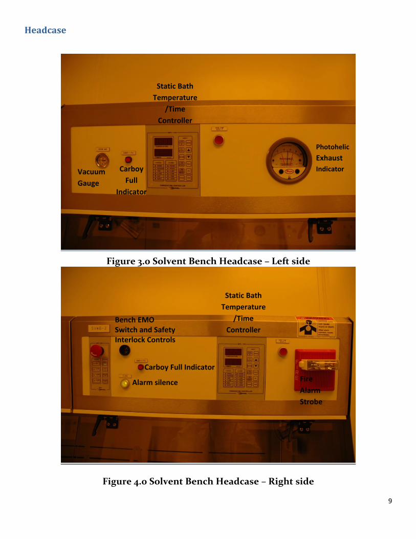
Figure 3.0 Solvent Bench Headcase – Left side
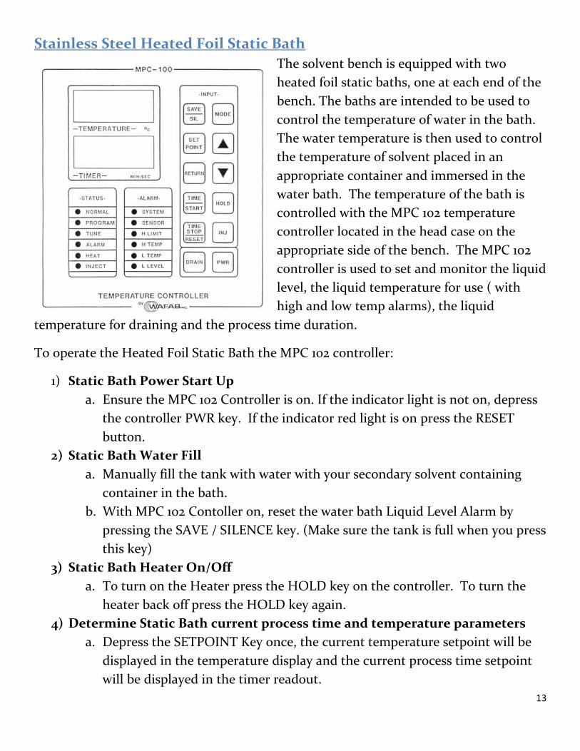
Figure 4.0 Solvent Bench Headcase – Right side
Photohelic
Exhaust
Indicator
Static Bath
Temperature
/Time
Controller
Vacuum
Gauge
Static Bath
Temperature
/Time
Controller Bench EMO Switch and Safety Interlock Controls
Alarm silence Fire
Alarm
Strobe
Carboy Full Indicator
Carboy
Full
Indicator

10
Bench Components
Solvent Bench Safety Interlocks and Alarms
Alarm Condition 1
The solvent benches have safety interlocks on the Exhaust, N2
and CDA. If any of these utilities are missing or out of the
specified acceptable ranges then the bench will go into an
alarm and the Alarm 1 indicator will be lit on the MPC-901
controller. If this situation occurs the power to the bench will
be shut down preventing the bench from being used.
Alarm Condition 2
The solvent benches have safety interlocks on the Head case
door to shut down the bench if its opened during normal
operation. If the door is opened the system will go into an
alarm and the Alarm 2 indicator will be lit on the MPC-901
controller. It this situation occurs the power to the bench will
be shut down preventing the bench from being used.
Alarm Condition 3
The solvent benches have a Float switch on the bottom the bench to detect liquid on the
floor of the bench. This switch will trip and turn the bench off if there is ~2in. of a liquid
in the bottom of the bench and the Alarm 3 indication will be lit on the MPC-901
controller. This will again shut the bench down to prevent operation. Adjacent to the
MPC 901 controller there is an Alarm Silence button to mute the active alarm. If the
alarm is active but silenced the bench will be non-operational. If you have silenced an
active alarm on this bench please contact the staff immediately.

11
Photohelic
The photohelic differential pressure switch/gage measures the difference in pressure
between the bench exhaust and the room. A
low reading on this device indicates there is
an improper condition for normal bench
operation. The measured pressure differential
is indicated by the black needle. The two red
needle indicators represent the normal
operating range of the bench exhaust.
NOTE: Users should NEVER adjust the set
points of the photohelic as it can lead to
personal injury and or death!
Vacuum Chuck
Each solvent bench is equipped with a centrally located vacuum chuck for securing the
user work piece while nitrogen gun drying after rinsing. To operate, place your substrate
on the chuck located at the front of the bench deck immediately in front of the sink and
the Nitrogen and DI water guns. Activate the vacuum to secure your substrate by
stepping down on and holding down the foot pedal located at the bottom of the bench
on the floor. This is a momentary pedal so once it is released the vacuum is turned off.
There is a vacuum gauge mounted in the head case that indicates the level of vacuum
you have on your sample. Ensure you have an adequate vacuum before drying your
sample with nitrogen.

12
Gooseneck Sink
NOTE : Solvent waste should NEVER be disposed of down the drain of the
gooseneck sink. The sink is to be used for pouring waste into waste containers and
for rinsing containers and other lab ware after use and for filling the heated water
baths.
To operate the sink, use the following procedures:
1. To turn on the goose neck sink use the manual
valve located at the base of the gooseneck .
2. To drain the gooseneck sink
13
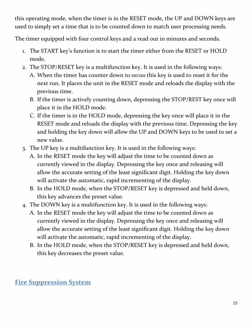
Stainless Steel Heated Foil Static Bath
The solvent bench is equipped with two
heated foil static baths, one at each end of the
bench. The baths are intended to be used to
control the temperature of water in the bath.
The water temperature is then used to control
the temperature of solvent placed in an
appropriate container and immersed in the
water bath. The temperature of the bath is
controlled with the MPC 102 temperature
controller located in the head case on the
appropriate side of the bench. The MPC 102
controller is used to set and monitor the liquid
level, the liquid temperature for use ( with
high and low temp alarms), the liquid
temperature for draining and the process time duration.
To operate the Heated Foil Static Bath the MPC 102 controller:
1) Static Bath Power Start Up
a. Ensure the MPC 102 Controller is on. If the indicator light is not on, depress
the controller PWR key. If the indicator red light is on press the RESET
button.
2) Static Bath Water Fill
a. Manually fill the tank with water with your secondary solvent containing
container in the bath.
b. With MPC 102 Contoller on, reset the water bath Liquid Level Alarm by
pressing the SAVE / SILENCE key. (Make sure the tank is full when you press
this key)
3) Static Bath Heater On/Off
a. To turn on the Heater press the HOLD key on the controller. To turn the
heater back off press the HOLD key again.
4) Determine Static Bath current process time and temperature parameters
a. Depress the SETPOINT Key once, the current temperature setpoint will be
displayed in the temperature display and the current process time setpoint
will be displayed in the timer readout.

14
5) To Change the Static Bath process time
a. Hold the controller SETPOINT Key down, the controller will enter the VIEW mode. Once in this mode the UP and DOWN keys are used to set the Timer Preset to its desired value.
To Change the Static Bath Set Temperature Depress the controller MODE key once.
a. The word “CODE” will appear in the temperature display. b. Enter the PROGRAM access code and depress the mode key to get into the
program mode. Depress the MODE key to cycle through the parameter list until you get to “PS”, the process (Temperature) set point. Use the up arrow and down arrow keys to get to the desired value. Depressing the key once and releasing will allow the accurate setting of the least significant digit. Holding the key down will activate the automatic, rapid incrementing or decrementing of the display depending on the arrow direction.
Draining the Water Bath
Users should not drain the heated water tanks to the Carboys. If you need the tank
drained (significant solvent spillage from user container into bath for example) please
contact a staff member to assist you.
Stainless Steel Cup Sinks
The solvent bench is equipped with two stainless steel cup sinks to be utilized when
disposing of allowed chemicals. Each bench has two cup sinks to be used for non-
chlorinated solvents that do not contain lift off material. Chlorinated solvents and used
lift off solvents, no matter the type must be disposed of in waste disposal containers per
the procedures and protocols described in the Appendix D of this manual.
Solvents that are allowed to be disposed of in the cup sinks are indicated in green in the
Specialty Chemical Usage and Information Guide (Appendix A) in this manual.
Process Timer ( PROCON 959T)
A process (or count down) stand-alone timer is mounted on the head case over each
section (A/B) of the Acid/Base Wet Bench. The timer is set in the MANUAL mode. In
15
this operating mode, when the timer is in the RESET mode, the UP and DOWN keys are
used to simply set a time that is to be counted down to match user processing needs.
The timer equipped with four control keys and a read out in minutes and seconds.
1. The START key’s function is to start the timer either from the RESET or HOLD
mode.
2. The STOP/RESET key is a multifunction key. It is used in the following ways:
A. When the timer has counter down to 00:00 this key is used to reset it for the
next run. It places the unit in the RESET mode and reloads the display with the
previous time.
B. If the timer is actively counting down, depressing the STOP/REST key once will
place it in the HOLD mode.
C. If the timer is in the HOLD mode, depressing the key once will place it in the
RESET mode and reloads the display with the previous time. Depressing the key
and holding the key down will allow the UP and DOWN keys to be used to set a
new value.
3. The UP key is a multifunction key. It is used in the following ways:
A. In the RESET mode the key will adjust the time to be counted down as
currently viewed in the display. Depressing the key once and releasing will
allow the accurate setting of the least significant digit. Holding the key down
will activate the automatic, rapid incrementing of the display.
B. In the HOLD mode, when the STOP/RESET key is depressed and held down,
this key advances the preset value.
4. The DOWN key is a multifunction key. It is used in the following ways:
A. In the RESET mode the key will adjust the time to be counted down as
currently viewed in the display. Depressing the key once and releasing will
allow the accurate setting of the least significant digit. Holding the key down
will activate the automatic, rapid incrementing of the display.
B. In the HOLD mode, when the STOP/RESET key is depressed and held down,
this key decreases the preset value.
Fire Suppression System
16
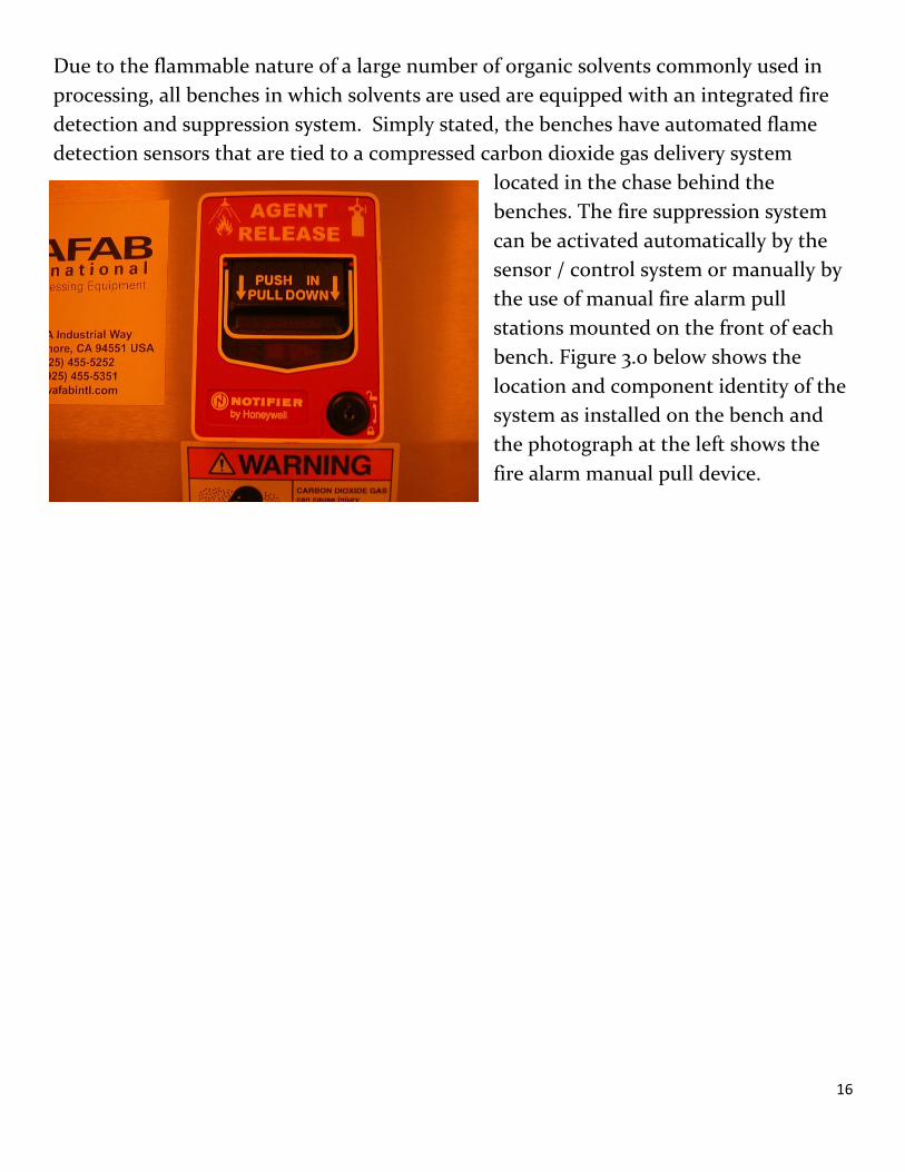
Due to the flammable nature of a large number of organic solvents commonly used in
processing, all benches in which solvents are used are equipped with an integrated fire
detection and suppression system. Simply stated, the benches have automated flame
detection sensors that are tied to a compressed carbon dioxide gas delivery system
located in the chase behind the
benches. The fire suppression system
can be activated automatically by the
sensor / control system or manually by
the use of manual fire alarm pull
stations mounted on the front of each
bench. Figure 3.0 below shows the
location and component identity of the
system as installed on the bench and
the photograph at the left shows the
fire alarm manual pull device.

17
Figure 3.0 Solvent Bench Fire suppression system Layout
PLEASE NOTE: Carbon dioxide gas discharge into nearby space can
collect there. When the alarm operates, either by auto detection or
manually, vacate the cleanroom immediately. Carbon dioxide gas can
cause injury or death. Note that the fire alarms associated with the fire
suppression system for the wet benches are not to be used nor are they
tied to the building fire alarm system. The manual alarms on the
benches are only to be activated if there is a fire in the Solvent
Benches. THE BENCH MOUNTED MANUAL ALARMS DO NOT SET OFF
THE BUILDIGN FIRE ALARM SYSTEMS!

18
Operation / Process
Heated Solvent Baths
All heated solvent baths are to be created using the stainless steel heated foil static
baths. No solvent bath is to be heated directly in the heated foil bath. To create a
heated solvent bath the following procedure must be used:
1. Activate the heated foil static bath by using the procedure in the section
above. Add water if needed to achieve the proper level for operation. ( steps
1-3 in section above)
2. Select a container and an immersion rack for your solvent bath and make
sure the container fits into the rack and can be removed easily.
3. Remove the cover of the heated foil static bath and set the immersion rack
with the empty solvent container into the bath to make sure the water level
is not above the top of the container.
4. Remove the intended solvent container from the rack, leaving the rack in the
water bath.
5. Carefully fill the solvent container with the required solvent needed to cover
your sample.
6. Place the solvent container back in the rack.
7. Place a temperature measurement device into the solvent bath.
8. Turn on the static bath heater controls and set the water bath temperature
to the temperature required for the solvent bath using the controller and the
procedure (Steps 4 and 5) described above.
9. Monitor the solvent bath temperature and increase the water bath
temperature as needed to achieve the required solvent bath temperature.
10. Immerse your sample in the bath for the required time.
11. Remove your sample and rinse and blow dry as needed.
12. Turn off the temperature controller and monitor the solvent temperature.
13. When solvent temperature reaches a temperature of xx C, remove the
solvent bath container from the immersion rack and let cool further in air on
the bench deck.
14. When solvent temperature reaches zz C, dispose of the solvent in the cup
sink or into a waste container per the procedures in Appendix D of this
manual.

19
Waste Disposal
The Solvent benches require both manual and auto (carboy disposal) disposal
methods and procedures. Non-chlorinated non lift-off solvents can be disposed of
directly down the cup sink into the carboys. Chlorinated and all lift-off solvents
must be disposed of into waste containers per the methods described in Appendix
D of this manual apply.
To utilize the cup sinks for solvent disposal:
1. Check the “Carboy” full indicator light on the head case above the cup sink you
intend to use.
2. If the light is on, DO NOT DISPOSE OF YOUR SOLVENT in the cup sink.
Contact the staff and the carboy will be removed and emptied by the staff . If
there is not an immediate carboy replacement available, dispose of your solvent
manually into proper waste containers per Appendix D of this manual.
Solvent spills into the water bath
If for any reason, a significant amount of solvent spills from your secondary bath
container into the temperature controlled water bath, please notify the staff
immediately so that arrangements can be made to empty and refill the water bath
either to continue your use or before another user logs on.
Hot Plate Usage
Hotplate usage is NOT ALLOWED in the solvent benches. Any heating of solvents
must be done using the heated water baths.
System Requirements DI Water: 10 GPM at 35 psi
Nitrogen: 10 SCFM at 40-60 psig
CDA: 10 SCFH at 90-100 psig
AC Power: 208V 3Ф 35 Amp, 5 Wire
Ventilation: 125 CFM at 0.75-1.25in. WC
20
Appendices
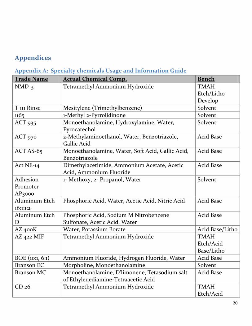
Appendix A: Specialty chemicals Usage and Information Guide
Trade Name Actual Chemical Comp. Bench
NMD-3 Tetramethyl Ammonium Hydroxide TMAH Etch/Litho Develop
T 111 Rinse Mesitylene (Trimethylbenzene) Solvent 1165 1-Methyl 2-Pyrrolidinone Solvent
ACT 935 Monoethanolamine, Hydroxylamine, Water, Pyrocatechol
Solvent
ACT 970 2-Methylaminoethanol, Water, Benzotriazole, Gallic Acid
Acid Base
ACT AS-65 Monoethanolamine, Water, Soft Acid, Gallic Acid, Benzotriazole
Acid Base
Act NE-14 Dimethylacetimide, Ammonium Acetate, Acetic Acid, Ammonium Fluoride
Acid Base
Adhesion Promoter AP3000
1- Methoxy, 2- Propanol, Water Solvent
Aluminum Etch 16:1:1:2
Phosphoric Acid, Water, Acetic Acid, Nitric Acid Acid Base
Aluminum Etch D
Phosphoric Acid, Sodium M Nitrobenzene Sulfonate, Acetic Acid, Water
Acid Base
AZ 400K Water, Potassium Borate Acid Base/Litho
AZ 422 MIF Tetramethyl Ammonium Hydroxide TMAH Etch/Acid Base/Litho
BOE (10:1, 6:1) Ammonium Fluoride, Hydrogen Fluoride, Water Acid Base
Branson EC Morpholine, Monoethanolamine Solvent
Branson MC Monoethanolamine, D'limonene, Tetasodium salt of Ethylenediamine-Tetraacetic Acid
Acid Base
CD 26 Tetramethyl Ammonium Hydroxide TMAH Etch/Acid

21
Base/Litho
Chrome Etch 1020
Cerric Ammonium Nitrate, Nitric Acid Acid Base
Concentrate Developer
Water, Alkaline-phosphate salt, sodium metasilicate pentahydrate
Acid Base/Litho
Copper Etchant 100/200
Hydrochloric Acid, Ferric Chloride, Water Acid Base
Trade Name Actual Chemical Comp. Bench Copper Etch 49-1 Citric Acid, Hydrogen Peroxide, Water Acid Base
Copper Electroplate
Copper Sulfate Pentahydrate, Sulfuric Acid Electroplate
Developer DS2100
Dipropylene glycol dimethyl ether, Naphtha (petroleum)
Solvent
EKC 830 N-Methyl Pyrrolidinone, 2-2 Aminoethoxy Ethanol Solvent Gold Etch TFA Iodine Complex, Potassium Iodide, Water Solvent
GE-6 (Gold Etch) Iodine Complex, Potassium Iodide, Water Solvent
MF 312 Tetramethyl Ammonium Hydroxide Acid Base/Litho MF 351 Sodium Hydroxide, Sodium tetraborate
decahydrate, Inorganic borates Acid Base/Litho
MF 453 Potassium Hydroxide, Water, Inorganic Borates Acid Base/Litho
MF 701 Tetramethyl Ammonium Hydroxide Acid Base/Litho Microposit Thinner Type P
Propylene Glycol Monomethyl Ether Acetate Solvent
NanoRemover PG
N-Methyl Pyrrolidinone, Surfactant Solvent
Nanostrip Sulfuric Acid, Peroxymonosulfuric Acid, Hydrogen peroxide
Acid Base
Nickel Etch I Ferric Chloride, Water, Hydrochloric Acid Acid Base
Nickel Etch TFB Nitric Acid, Potassium Perfluoroalkyl Sulfonate, Water
Acid Base
Nickel Etch TFG Thiourea, Sodium N-Nitro Benzene Sulfonate, Sulfuric Acid
Solvent
Nikelex Nickel Chloride, Sodium Hypophosphite, Sodium Succinate, Water
Solvent
PAD Etch Acetic Acid, Ammonium Fluoride, Surfactant Acid Base
SU-8 Developer 1-Methoxy 2-Propyl acetate Solvent/Litho Techni Gold 25 Sodium Gold Sulfite Electroplate
Titanium Etch TFTN
Hydrochloric Acid Acid Base

22
Appendix B: Eye Wash and Safety Shower Locations
We
t C
hem
ical
Bay

23
Appendix C: General Wet Chemical Use Procedures
Introduction
This document contains general procedures and guidelines for working with chemicals
in lab wet chemical benches. Always be sure to review the required methods for using
specific systems and wet benches prior to use to determine other specific instructions or
restrictions.
Working with Chemicals:
The following procedures are to be followed when using chemicals in the wet chemical
benches.
1. Ensure you are wearing all appropriate PPE.
2. Select and Rinse appropriate lab ware for your process
3. Create a “Chemical Use Label” for each chemical solution you are using
4. Retrieve chemicals from their designated chemical cabinets and transport them to
the bench. Use proper secondary containment for transporting the chemicals to
the bench.
5. Slowly pour the chemical(s) into your lab ware. When creating mixtures or
dilutions be sure to determine the safest way to mix, such as which component
should be poured first and added to.
Example: a general rule of thumb is to always add Acid to Water, not the reverse!
6. When finished pouring the chemical(s), replace the chemical bottles into their
appropriate chemical cabinet. When transporting the chemicals back to the
cabinets you must use the appropriate secondary container.
7. In general you should always be at the bench when in use. However, if you need to
walk away from the bench for an extended period of time (>5 minutes) you need to
follow the procedures outlined in “Unattended Chemicals” below.
8. When you are finished processing with the chemicals you need to dispose of them
into an appropriate waste bottle. Follow the procedures outlined in “ General
Waste Disposal Methods “ document.
9. Prior to leaving the bench you should clean the bench by rinsing it with DI water
and drying it off completely with clean wipes.

24
Unattended Chemicals
If you need to leave your chemicals unattended during your process you must meet the
following requirements:
1. Containers must be covered but still allow vapors to escape.
NOTE: There are teflon covers, as well as pyrex lids that can be used as covers.
Covers should not be air-tight, they are intended to provide protection against
splashing or fuming of the chemical.
2. The Extra Information Section of the Chemical use label MUST be filled out
completely.
3. Prior to logging out of the bench in RIMS, edit your reservation to indicate that the
chemical will stay in the hood, please include: time present, removal time,
chemical and concentration that is contained.
NOTE: Any chemical left on the benches past the date / time in the Extra
Information Section will be removed and samples thrown away!

25
Appendix D: General Wet Bench Waste Procedures
Introduction
The following procedures are to be used when chemical waste is to be handled manually.
That is, when the user or the staff is to dispose of chemicals without the use of
automated systems contained in some of the lab equipment. (carboys with built in
pumping systems or pumping carts for example)
Procedures for Filling a Chemical Waste Bottle
1) Select an appropriate waste bottle for the chemical you are disposing of
from the chemical storage cabinets.
a. If no bottles are available for your chemical, or the bottle is full, you
will need to create a new waste bottle. Follow the procedures below
for creating a new waste bottle.
2) Place the bottle into the gooseneck sink in the bench and then remove
the vented cap.
3) Place a funnel into the bottle.
4) SLOWLY pour the chemical waste into the bottle.
a. ENSURE the chemical is at room temperature before pouring it into
a waste bottle
b. Never over fill a waste bottle. Please refer to the waste bottle
pictogram for the max fill line.
c. Always rinse the funnel thoroughly after use.
5) Put the vented cap back on the bottle.
a. Ensure you do not over tighten the caps as the bottle can still
become pressurized and potentially explode.
6) Get a clean wipe from the storage rack.
7) Pick up bottle and wipe bottom of bottle. Make sure it is dry; do not place
the bottle on the bench top.
8) Transport and place the bottle back in the appropriate chemical waste
cabinet. Be sure to use appropriate secondary containment when
transporting the waste containing bottle.

26
Creating a Waste Bottle
The following are the procedures that should be followed when creating a new waste
bottle.
1. Retrieve an appropriate empty chemical bottle for the chemical you
are disposing of and vented cap (these are located on the Waste Bottle
Storage Rack).
2. Rinse 3 times and empty rinse water into sink.
3. Replace cap with new vented cap from storage shelf.
4. Completely fill out and apply waste label.
5. Follow steps listed above to add waste to the bottle.
6. Wastes are separated into different benches for isolation/safety.
Appendix E: Wet Bench Troubleshooting
1) If power, water, and nitrogen are not working, ensure you have logged in
to the bench on RIMS and that the BLUE light is on.
2) If you are logged in and utilities do not work, submit a trouble call using
RIMS and find a staff member.
27
Appendix F: Buddy Policy
In order to meet the requirements of the Buddy Policy certified cleanroom users
who are working outside the normal business hours of 8AM-6PM must identify
another certified user of the cleanroom who will be responsible for checking in on
the user working in the cleanroom. That second certified user is required to check
on their “Buddy” every 15 minutes to ensure they are safe or to call for assistance if
there is an emergency.
Users and their Buddies must sign into the logbook after normal working hours
(between 6 P.M. and 8 A.M weekdays, and all day on weekends and holidays).
An additional requirement of our buddy program is that when a certified user is
working in the wet chemical bay, their “buddy” must also be in the clean room,
aware of their situation, and close enough to be of assistance in case of an
accident. The individual acting as your buddy does not need to be at your side
constantly, just available and aware.
Use of standard lithography chemicals (i.e. resists, developers, and solvent
based resist strippers) in the Lithography area without a buddy present inside
the clean room is acceptable.