Solvay Advanced Polymers, L.L.C. RADEL - cgtec.eu · Designing for Injection Molding . . . . . . ....
64
design RADEL ® A Polyethersulfone RADEL ® R Polyphenylsulfone ACUDEL ® Polyphenylsulfone Blends Design Guide RADEL
Transcript of Solvay Advanced Polymers, L.L.C. RADEL - cgtec.eu · Designing for Injection Molding . . . . . . ....

Solvay Advanced Polymers, L.L.C.4500 McGinnis Ferry RoadAlpharetta, GA 30005-3914USAPhone: +1.770.772.8200
+1.800.621.4557 (U.S. only)Fax: +1.770.772.8454
Solvay Advanced Polymers, L.L.C. and its affiliates have offices in
the Americas, Europe, and Asia. Please visit our website at
www.solvayadvancedpolymers.com to locate the office nearest to you.
Product and Technical LiteratureTo our actual knowledge, the information contained herein is accurate
as of the date of this document. However, neither Solvay Advanced
Polymers, L.L.C. nor any of its affiliates makes any warranty, express
or implied, or accepts any liability in connection with this information
or its use. This information is for use by technically skilled persons at
their own discretion and risk and does not relate to the use of this
product in combination with any other substance or any other
process. This is not a license under any patent or other proprietary
right. The user alone must finally determine suitability of any informa-
tion or material for any contemplated use, the manner of use and
whether any patents are infringed.
Health and Safety Information Material Safety Data Sheets (MSDS) for products of Solvay Advanced
Polymers are available upon request from your sales representative or
by writing to the address shown on this document. The appropriate
MSDS should be consulted before using any of our products.
RADEL and ACUDEL are registered trademarks
of Solvay Advanced Polymers, L.L.C.
R-50247 © 2004 Solvay Advanced Polymers, L.L.C. All rights reserved. D 02/04
designRADEL® APolyethersulfone
RADEL® RPolyphenylsulfone
ACUDEL® Polyphenylsulfone Blends
Design Guide
RA
DEL

i
Table of ContentsIntroduction . . . . . . . . . . . . . . . . . . . . . . . . . . . . . . . . 1
Chemistry . . . . . . . . . . . . . . . . . . . . . . . . . . . . . . . 2Chemical Structure - Property Relationships . . . . 2
Product Data . . . . . . . . . . . . . . . . . . . . . . . . . . . . . . . 3
Material Selection . . . . . . . . . . . . . . . . . . . . . . . . . 3Nomenclature . . . . . . . . . . . . . . . . . . . . . . . . . . . 4
Approvals. . . . . . . . . . . . . . . . . . . . . . . . . . . . . . . . 5Food Contact. . . . . . . . . . . . . . . . . . . . . . . . . . . . 5United States Pharmacopeia (U.S.P.)* . . . . . . . . . 5National Sanitation Foundation . . . . . . . . . . . . . . 5International Water Contact Standards . . . . . . . . 6
Water Byelaws Scheme - United Kingdom. . . . 6German Federal Health Office . . . . . . . . . . . . . 6
Underwriters’ Laboratories . . . . . . . . . . . . . . . . . 6
Property Data. . . . . . . . . . . . . . . . . . . . . . . . . . . . . . . 6
Short-Term Properties . . . . . . . . . . . . . . . . . . . . . 6Typical Property Tables . . . . . . . . . . . . . . . . . . . . 6Tensile Properties . . . . . . . . . . . . . . . . . . . . . . . . 9Stress-Strain Curves . . . . . . . . . . . . . . . . . . . . . 9Flexural Properties . . . . . . . . . . . . . . . . . . . . . . 11Compressive Properties. . . . . . . . . . . . . . . . . . . 12Shear Properties . . . . . . . . . . . . . . . . . . . . . . . . 13Impact Properties . . . . . . . . . . . . . . . . . . . . . . . 13
Notched Izod. . . . . . . . . . . . . . . . . . . . . . . . . 13Notch Sensitivity . . . . . . . . . . . . . . . . . . . . . . 14Tensile Impact . . . . . . . . . . . . . . . . . . . . . . . 14
Poisson’s Ratio . . . . . . . . . . . . . . . . . . . . . . . . . 15Wear resistance . . . . . . . . . . . . . . . . . . . . . . . . 15
Long-Term Properties . . . . . . . . . . . . . . . . . . . . . 16Creep . . . . . . . . . . . . . . . . . . . . . . . . . . . . . . . . 16
Apparent or Creep Modulus. . . . . . . . . . . . . . 16Isochronous Stress-Strain Curves . . . . . . . . . 17
Fatigue . . . . . . . . . . . . . . . . . . . . . . . . . . . . . . . 18
Thermal Properties . . . . . . . . . . . . . . . . . . . . . . . 18Glass Transition Temperature . . . . . . . . . . . . . . 18Mechanical Property Changes . . . . . . . . . . . . . . 18
Classification of Thermoplastic Resins . . . . . 18Temperature Effects on Modulus. . . . . . . . . . 19Temperature Effects on Tensile Strength. . . . 20
Deflection Temperature under Load . . . . . . . . . 20Testing Variables . . . . . . . . . . . . . . . . . . . . . 20Deflection Temperature Comparisons . . . . . . 20
Thermal Expansion Coefficient . . . . . . . . . . . . . 21Thermal Conductivity . . . . . . . . . . . . . . . . . . . . 21Specific Heat. . . . . . . . . . . . . . . . . . . . . . . . . . . 21Combustion Properties*. . . . . . . . . . . . . . . . . . . 21
UL 94 . . . . . . . . . . . . . . . . . . . . . . . . . . . . . . 21Oxygen Index . . . . . . . . . . . . . . . . . . . . . . . . 22Self-Ignition Temperature . . . . . . . . . . . . . . . 22Smoke Density . . . . . . . . . . . . . . . . . . . . . . . 22
Thermal Stability . . . . . . . . . . . . . . . . . . . . . . . . 22Thermogravimetric Analysis . . . . . . . . . . . . . 22Thermal Aging . . . . . . . . . . . . . . . . . . . . . . . 23UL Thermal Index (RTI) . . . . . . . . . . . . . . . . . 23
Electrical Properties . . . . . . . . . . . . . . . . . . . . . . 24Dielectric Strength . . . . . . . . . . . . . . . . . . . . . . 24Volume Resistivity . . . . . . . . . . . . . . . . . . . . . . . 24Dielectric Constant . . . . . . . . . . . . . . . . . . . . . . 24Dissipation Factor . . . . . . . . . . . . . . . . . . . . . . . 24UL 746A Short-Term Properties. . . . . . . . . . . . . 25
High-Voltage, Low-Current Dry Arc Resistance (D495) . . . . . . . . . . . . . . . . . . . . . . . . . . . . . . . 25Comparative Tracking Index (CTI) . . . . . . . . . 25High-Voltage Arc-Tracking Rate (HVTR) . . . . . 25Hot Wire Ignition (HWI) . . . . . . . . . . . . . . . . . 25High-Current Arc Ignition (HAI) . . . . . . . . . . . 25
Environmental Resistance . . . . . . . . . . . . . . . . . 26Hydrolytic Stability . . . . . . . . . . . . . . . . . . . . . . 26
Steam Sterilization Analysis . . . . . . . . . . . . . 26Chemical Resistance . . . . . . . . . . . . . . . . . . . . . 27
RADEL R Chemical Resistance . . . . . . . . . . . 28Stress Crack Resistance . . . . . . . . . . . . . . . . . . 29Radiation Resistance. . . . . . . . . . . . . . . . . . . . . 32
Physical Properties . . . . . . . . . . . . . . . . . . . . . . . 33Density . . . . . . . . . . . . . . . . . . . . . . . . . . . . . . . 33Water Absorption . . . . . . . . . . . . . . . . . . . . . . . 33
Design Information . . . . . . . . . . . . . . . . . . . . . . . . . 34
Mechanical Design . . . . . . . . . . . . . . . . . . . . . . . 34Stress Levels. . . . . . . . . . . . . . . . . . . . . . . . . . . 34Stress-Strain Calculations . . . . . . . . . . . . . . . . . 34

ii
Design Limits . . . . . . . . . . . . . . . . . . . . . . . . 37Stress Concentrations . . . . . . . . . . . . . . . . . . 37
Designing for Injection Molding . . . . . . . . . . . . . 38Wall Thickness . . . . . . . . . . . . . . . . . . . . . . . . . 38Wall Thickness Variation . . . . . . . . . . . . . . . . . . 38Draft Angle . . . . . . . . . . . . . . . . . . . . . . . . . . . . 38Ribs . . . . . . . . . . . . . . . . . . . . . . . . . . . . . . . . . 38Coring . . . . . . . . . . . . . . . . . . . . . . . . . . . . . . . . 39Bosses . . . . . . . . . . . . . . . . . . . . . . . . . . . . . . . 39
Fabrication. . . . . . . . . . . . . . . . . . . . . . . . . . . . . . . . 40Drying . . . . . . . . . . . . . . . . . . . . . . . . . . . . . . . . 40
Rheology . . . . . . . . . . . . . . . . . . . . . . . . . . . . . . . 41Melt Processing Parameters . . . . . . . . . . . . . . . 43
Injection Molding . . . . . . . . . . . . . . . . . . . . . . . . 44Injection Molding Equipment . . . . . . . . . . . . . . . 44
Screw Design . . . . . . . . . . . . . . . . . . . . . . . . 44Screw Tips and Check Valves . . . . . . . . . . . . 44Nozzles . . . . . . . . . . . . . . . . . . . . . . . . . . . . . 44
Molds . . . . . . . . . . . . . . . . . . . . . . . . . . . . . . . . 44Draft and Ejection . . . . . . . . . . . . . . . . . . . . . 44Gates . . . . . . . . . . . . . . . . . . . . . . . . . . . . . . 44Venting . . . . . . . . . . . . . . . . . . . . . . . . . . . . . 44Mold Temperature Control . . . . . . . . . . . . . . 44
Machine Settings . . . . . . . . . . . . . . . . . . . . . . . 45Injection Molding Temperatures . . . . . . . . . . 45Mold Temperatures. . . . . . . . . . . . . . . . . . . . 45Barrel Temperatures . . . . . . . . . . . . . . . . . . . 45Residence Time in the Barrel . . . . . . . . . . . . 45
Molding Process . . . . . . . . . . . . . . . . . . . . . . . . 45Feed Characteristics . . . . . . . . . . . . . . . . . . . 45Back Pressure. . . . . . . . . . . . . . . . . . . . . . . . 45Screw Speed . . . . . . . . . . . . . . . . . . . . . . . . 45Injection Rate and Venting. . . . . . . . . . . . . . . 46Demolding . . . . . . . . . . . . . . . . . . . . . . . . . . 46Shrinkage . . . . . . . . . . . . . . . . . . . . . . . . . . . 46
Resin Flow Characteristics . . . . . . . . . . . . . . . . . 46
Measuring Residual Stress . . . . . . . . . . . . . . . . . 48
Extrusion . . . . . . . . . . . . . . . . . . . . . . . . . . . . . . . 49Predrying . . . . . . . . . . . . . . . . . . . . . . . . . . . . . 49Extrusion Temperatures . . . . . . . . . . . . . . . . . . 49
Screw Design Recommendations . . . . . . . . . . . 49Die Design . . . . . . . . . . . . . . . . . . . . . . . . . . . . 49Extruded Product Types . . . . . . . . . . . . . . . . . . 49
Wire . . . . . . . . . . . . . . . . . . . . . . . . . . . . . . . 49Film . . . . . . . . . . . . . . . . . . . . . . . . . . . . . . . 49Sheet . . . . . . . . . . . . . . . . . . . . . . . . . . . . . . 50Pipe and Tubing . . . . . . . . . . . . . . . . . . . . . . 50
Start-Up, Shut-Down, and Purging . . . . . . . . . . 50Start-Up Procedure . . . . . . . . . . . . . . . . . . . . 50Shut-Down Procedure. . . . . . . . . . . . . . . . . . 50Purging . . . . . . . . . . . . . . . . . . . . . . . . . . . . . 50
Secondary Operations . . . . . . . . . . . . . . . . . . . . . . . 51
Machining . . . . . . . . . . . . . . . . . . . . . . . . . . . . . . 51Drilling and Tapping . . . . . . . . . . . . . . . . . . . . . 51Sawing . . . . . . . . . . . . . . . . . . . . . . . . . . . . . . . 51Turning . . . . . . . . . . . . . . . . . . . . . . . . . . . . . . . 51Milling and Routing . . . . . . . . . . . . . . . . . . . . . . 51
Finishing and Decorating . . . . . . . . . . . . . . . . . . 51Painting. . . . . . . . . . . . . . . . . . . . . . . . . . . . . . . 51Electroplating . . . . . . . . . . . . . . . . . . . . . . . . . . 51Hot Stamping . . . . . . . . . . . . . . . . . . . . . . . . . . 51Printing . . . . . . . . . . . . . . . . . . . . . . . . . . . . . . . 51Vacuum Metallizing . . . . . . . . . . . . . . . . . . . . . . 52Cathode Sputtering . . . . . . . . . . . . . . . . . . . . . . 52Flame/Arc Spraying. . . . . . . . . . . . . . . . . . . . . . 52
Assembly and Joining. . . . . . . . . . . . . . . . . . . . . 52Ultrasonic Bonding . . . . . . . . . . . . . . . . . . . . . . 52Spin Welding. . . . . . . . . . . . . . . . . . . . . . . . . . . 53Adhesive Bonding . . . . . . . . . . . . . . . . . . . . . . . 53Mechanical Fasteners . . . . . . . . . . . . . . . . . . . . 53
Molded-In Threads . . . . . . . . . . . . . . . . . . . . 54Threaded Inserts . . . . . . . . . . . . . . . . . . . . . . 54Self-Tapping Screws. . . . . . . . . . . . . . . . . . . 55Ultrasonic Inserts . . . . . . . . . . . . . . . . . . . . . 55
Snap-Fits . . . . . . . . . . . . . . . . . . . . . . . . . . . . . 56
Table of Contents - cont.

iii
List of TablesMelt Flow Rates of Neat RADEL Resins . . . . . . . . . . . . . . . . . . . . . . . . . . . 4Glass-Reinforced RADEL Grades. . . . . . . . . . . . . . . . . . . . . . . . . . . . . . . . 4Sulfone Resins Meeting USP Class VI Requirements . . . . . . . . . . . . . . . . . 5NSF Standard 51 Certified Materials . . . . . . . . . . . . . . . . . . . . . . . . . . . . . 5NSF Standard 61 Certified Materials . . . . . . . . . . . . . . . . . . . . . . . . . . . . . 6RADEL Resins Listed as complying with BS 6920 . . . . . . . . . . . . . . . . . . . 6RADEL Grades listed by KTW . . . . . . . . . . . . . . . . . . . . . . . . . . . . . . . . . . 6Typical Properties(1) - U.S. Customary Units . . . . . . . . . . . . . . . . . . . . . . . 7Typical Properties(1) - SI Units . . . . . . . . . . . . . . . . . . . . . . . . . . . . . . . . . . 8Tensile Properties of Neat Resins (ASTM D638) . . . . . . . . . . . . . . . . . . . 11Flexural Properties of Neat Resins . . . . . . . . . . . . . . . . . . . . . . . . . . . . . 12Compressive Properties of Neat Resins. . . . . . . . . . . . . . . . . . . . . . . . . . 12Shear Strength of Neat Resins . . . . . . . . . . . . . . . . . . . . . . . . . . . . . . . . 13Poisson’s Ratios . . . . . . . . . . . . . . . . . . . . . . . . . . . . . . . . . . . . . . . . . . . 15Glass Transition Temperatures . . . . . . . . . . . . . . . . . . . . . . . . . . . . . . . . 18Deflection Temperatures of RADEL Resins and Blends . . . . . . . . . . . . . . 20Smoke Density per ASTM E 662 . . . . . . . . . . . . . . . . . . . . . . . . . . . . . . . 21Coefficient of Linear Thermal Expansion* . . . . . . . . . . . . . . . . . . . . . . . . 21Thermal Conductivity . . . . . . . . . . . . . . . . . . . . . . . . . . . . . . . . . . . . . . . 21Oxygen Indices of RADEL Resins . . . . . . . . . . . . . . . . . . . . . . . . . . . . . . 22Smoke Density . . . . . . . . . . . . . . . . . . . . . . . . . . . . . . . . . . . . . . . . . . . 22Thermogravimetric Analysis Details . . . . . . . . . . . . . . . . . . . . . . . . . . . . 23Relative Thermal Indices per UL 746B* . . . . . . . . . . . . . . . . . . . . . . . . . . 24Electrical Properties of RADEL Resins . . . . . . . . . . . . . . . . . . . . . . . . . . . 24
Electrical Properties of RADEL resins per UL 746A . . . . . . . . . . . . . . . . . 25Resistance to Boiling Water . . . . . . . . . . . . . . . . . . . . . . . . . . . . . . . . . . 26Effects of Prolonged Hot Water Exposure . . . . . . . . . . . . . . . . . . . . . . . . 26Steam Autoclave Resistance. . . . . . . . . . . . . . . . . . . . . . . . . . . . . . . . . . 26General Indication of Chemical Resistance* . . . . . . . . . . . . . . . . . . . . . . 27Chemical Resistance of RADEL R Resin by Immersion* . . . . . . . . . . . . . 28Key to Environmental Stress Cracking Tables . . . . . . . . . . . . . . . . . . . . . 29Environmental Stress Cracking Resistance to Automotive Fluids . . . . . . . 30Environmental Stress Cracking Resistance to Organic Chemicals . . . . . . 31Environmental Stress Cracking Resistance to Inorganic Chemicals . . . . . 32Environmental Stress Cracking Resistance to Aviation Fluids - . . . . . . . . 32Specific Gravity of RADEL Resins . . . . . . . . . . . . . . . . . . . . . . . . . . . . . . 33Maximum Stress and Deflection Equations . . . . . . . . . . . . . . . . . . . . . . . 35Area and Moment Equations for Selected Cross Sections . . . . . . . . . . . . 36Allowable Design Stresses1 for an Intermittent Load . . . . . . . . . . . . . . . . 37Allowable Design Stresses1 for a Constant Load . . . . . . . . . . . . . . . . . . . . . . . . . . . . . . . . . . . . . . . . . 37
Shear Rate - Viscosity Data RADEL A . . . . . . . . . . . . . . . . . . . . . . . . . . . 41Shear Rate - Viscosity Data RADEL R . . . . . . . . . . . . . . . . . . . . . . . . . . . 41Melt Processing Parameters . . . . . . . . . . . . . . . . . . . . . . . . . . . . . . . . . . 43Molding Conditions - Starting Point . . . . . . . . . . . . . . . . . . . . . . . . . . . . 45Health and Safety Considerations . . . . . . . . . . . . . . . . . . . . . . . . . . . . . . 48Residual Stress Test Parameters . . . . . . . . . . . . . . . . . . . . . . . . . . . . . . 48Procedure for Residual Stress Determination . . . . . . . . . . . . . . . . . . . . . 48Maximum Permissible Strains For Snap-Fit Designs . . . . . . . . . . . . . . . . 56
List of FiguresChemical Structures . . . . . . . . . . . . . . . . . . . . . . . . . . . . . . . . . . . . . . . . . 2Bridging Moieties . . . . . . . . . . . . . . . . . . . . . . . . . . . . . . . . . . . . . . . . . . . 2Relative Thermal Capability of RADEL Resins . . . . . . . . . . . . . . . . . . . . . . 3Hydrolytic Stability of RADEL Resins . . . . . . . . . . . . . . . . . . . . . . . . . . . . . 3Resistance of RADEL Resins to Organic Solvents . . . . . . . . . . . . . . . . . . . 3Impact Resistance of RADEL Resins . . . . . . . . . . . . . . . . . . . . . . . . . . . . . 4Typical Stress-Strain Curve . . . . . . . . . . . . . . . . . . . . . . . . . . . . . . . . . . . 9Stress-Strain Curve Insert, Secant vs. Tangent Modulus . . . . . . . . . . . . . . 9RADEL A-300A Stress-Strain Curve to Yield . . . . . . . . . . . . . . . . . . . . . 10RADEL R-5000 Stress-Strain Curve to Yield . . . . . . . . . . . . . . . . . . . . . 10ACUDEL 22000 Stress-Strain Curve to Yield . . . . . . . . . . . . . . . . . . . . . 10ACUDEL 25000 Stress-Strain Curve to Yield . . . . . . . . . . . . . . . . . . . . . 10RADEL AG-320 Stress-Strain Curve to Break . . . . . . . . . . . . . . . . . . . . 10RADEL AG-330 Stress-Strain Curve to Break . . . . . . . . . . . . . . . . . . . . 10Tensile Strength of Glass-Filled RADEL A . . . . . . . . . . . . . . . . . . . . . . . . 11Tensile Modulus of Glass-Filled RADEL A . . . . . . . . . . . . . . . . . . . . . . . . 11Flexural Test Apparatus . . . . . . . . . . . . . . . . . . . . . . . . . . . . . . . . . . . . . 11Flexural Strength of Glass-Filled RADEL A. . . . . . . . . . . . . . . . . . . . . . . . 12Flexural Modulus of Glass-Filled RADEL A. . . . . . . . . . . . . . . . . . . . . . . . 12Compressive Strength of Glass-Filled RADEL A . . . . . . . . . . . . . . . . . . . . 12Compressive Modulus of Glass-Filled RADEL A . . . . . . . . . . . . . . . . . . . . 13Shear Strength of Glass-Filled RADEL A . . . . . . . . . . . . . . . . . . . . . . . . . 13Izod Impact Test Apparatus . . . . . . . . . . . . . . . . . . . . . . . . . . . . . . . . . . 13Notched Izod of Neat Resins . . . . . . . . . . . . . . . . . . . . . . . . . . . . . . . . . . 14Notched Izod Impact as a Function of Notch Radius . . . . . . . . . . . . . . . . 14Tensile Impact Strength of Neat Resins . . . . . . . . . . . . . . . . . . . . . . . . . 14Abrasion Resistance . . . . . . . . . . . . . . . . . . . . . . . . . . . . . . . . . . . . . . . . 15Apparent (Creep) Modulus RADEL AG-230 . . . . . . . . . . . . . . . . . . . . . . . 16Apparent (Creep) Modulus RADEL A-200A . . . . . . . . . . . . . . . . . . . . . . . 16Apparent (Creep) Modulus RADEL R-5000 . . . . . . . . . . . . . . . . . . . . . . . 16Isochronous Stress-Strain Curve RADEL A-200A. . . . . . . . . . . . . . . . . . . 17Isochronous Stress-Strain Curve RADEL AG-230 . . . . . . . . . . . . . . . . . . 17Isochronous Stress-Strain Curve RADEL R-5000. . . . . . . . . . . . . . . . . . . 17Flexural Fatigue Endurance RADEL A . . . . . . . . . . . . . . . . . . . . . . . . . . . 18Typical Change in Modulus with Temperature. . . . . . . . . . . . . . . . . . . . . 19Flexural Modulus vs. Temperature - Neat Resins . . . . . . . . . . . . . . . . . . 19Flexural Modulus vs. Temperature - GF RADEL A Resins. . . . . . . . . . . . . 19Tensile Strength vs. Temperature - Neat Resins . . . . . . . . . . . . . . . . . . . 19Tensile Strength vs. Temperature - GF RADEL A Resins . . . . . . . . . . . . . 19Deflection Temperature of Neat Resins. . . . . . . . . . . . . . . . . . . . . . . . . . 20Specific Heat . . . . . . . . . . . . . . . . . . . . . . . . . . . . . . . . . . . . . . . . . . . . . 21
Thermogravimetric Analysis in Nitrogen . . . . . . . . . . . . . . . . . . . . . . . . . 22Thermogravimetric Analysis in Air . . . . . . . . . . . . . . . . . . . . . . . . . . . . . 23Thermal Aging of RADEL A PES and PEI . . . . . . . . . . . . . . . . . . . . . . . . . 23Thermal Aging of RADEL R Polyphenylsulfone. . . . . . . . . . . . . . . . . . . . . 23Radiation Resistance of RADEL A . . . . . . . . . . . . . . . . . . . . . . . . . . . . . . 33Radiation Resistance of RADEL R . . . . . . . . . . . . . . . . . . . . . . . . . . . . . . 33Resin Volume Varies Inversely with Specific Gravity . . . . . . . . . . . . . . . . 33Water Absorption Immersion at 77°F (23°C) . . . . . . . . . . . . . . . . . . . . . . 33Stress Concentration Factor at Inside Corners. . . . . . . . . . . . . . . . . . . . . 37Wall Thickness Transition . . . . . . . . . . . . . . . . . . . . . . . . . . . . . . . . . . . . 38Draft - Designing for Mold Release . . . . . . . . . . . . . . . . . . . . . . . . . . . . . 38Recommended Rib Design . . . . . . . . . . . . . . . . . . . . . . . . . . . . . . . . . . . 39Boss Design General Guidelines . . . . . . . . . . . . . . . . . . . . . . . . . . . . . . . 39Drying of RADEL A Resin in a Circulating Air Oven . . . . . . . . . . . . . . . . . 40Drying of RADEL R Resin in a Circulating Air Oven . . . . . . . . . . . . . . . . . 40Drying of ACUDEL 22000 Resin in a Circulating Air Oven . . . . . . . . . . . . 40Drying of ACUDEL 25000 Resin in a Circulating Air Oven . . . . . . . . . . . . 40Rheology of RADEL A-200A Resin. . . . . . . . . . . . . . . . . . . . . . . . . . . . . . 42Rheology of RADEL A-300A Resin. . . . . . . . . . . . . . . . . . . . . . . . . . . . . . 42Rheology of RADEL AG-230 Resin. . . . . . . . . . . . . . . . . . . . . . . . . . . . . . 42Rheology of RADEL AG-330 Resin. . . . . . . . . . . . . . . . . . . . . . . . . . . . . . 42Rheology of RADEL R-5000 Resin. . . . . . . . . . . . . . . . . . . . . . . . . . . . . . 42Rheology of RADEL R-5800 Resin. . . . . . . . . . . . . . . . . . . . . . . . . . . . . . 42Screw Design for Injection Molding. . . . . . . . . . . . . . . . . . . . . . . . . . . . . 44Spiral Flow of RADEL A-200A . . . . . . . . . . . . . . . . . . . . . . . . . . . . . . . . 46Spiral Flow of RADEL AG-210 . . . . . . . . . . . . . . . . . . . . . . . . . . . . . . . . . 46Spiral Flow of RADEL A-300A . . . . . . . . . . . . . . . . . . . . . . . . . . . . . . . . . 46Spiral Flow of RADEL AG-230 . . . . . . . . . . . . . . . . . . . . . . . . . . . . . . . . . 47Spiral Flow of RADEL R-5000 . . . . . . . . . . . . . . . . . . . . . . . . . . . . . . . . . 47Spiral Flow of RADEL R-5800 . . . . . . . . . . . . . . . . . . . . . . . . . . . . . . . . . 47Energy Director Design . . . . . . . . . . . . . . . . . . . . . . . . . . . . . . . . . . . . . . 52Joint Designs for Adhesive Bonding . . . . . . . . . . . . . . . . . . . . . . . . . . . . 53Designing for Mechanical Fasteners . . . . . . . . . . . . . . . . . . . . . . . . . . . . 53Internal Threads . . . . . . . . . . . . . . . . . . . . . . . . . . . . . . . . . . . . . . . . . . . 54External Threads . . . . . . . . . . . . . . . . . . . . . . . . . . . . . . . . . . . . . . . . . . 54Boss Design for Self-Tapping Screws . . . . . . . . . . . . . . . . . . . . . . . . . . . 55Boss Design for Ultrasonic Inserts . . . . . . . . . . . . . . . . . . . . . . . . . . . . . 55Snap-Fit Design Using Straight Beam . . . . . . . . . . . . . . . . . . . . . . . . . . . 56Snap-Fit Design Using Tapered Beam. . . . . . . . . . . . . . . . . . . . . . . . . . . 56Proportionality Constant (K) for Tapered Beam . . . . . . . . . . . . . . . . . . . . 56

IntroductionSolvay Advanced Polymers has a broad line of engineering res-ins that offer exceptional value combined with high-perfor-mance properties. Our product portfolio consists of amorphoussulfone polymers, semi-crystalline polymers, and ultra-perfor-mance polymers.
The amorphous sulfone polymers inlcude:UDEL® polysulfoneMINDEL® polysulfone blendsRADEL® A polyethersulfoneRADEL® R polyphenylsulfoneACUDEL® polyphenylsulfone blends.
The semi-crystalline polymers include:AMODEL® polyphthalamideIXEF® polyarylamidePRIMEF® polyphenylene sulfideXYDAR® liquid crystal polymer.
The polymers characterized as ultra-performance resinsbecause they offer exceptional performance in specific areasinclude:
TORLON® polyamide-imideKADEL® aromatic polyketone.
As stated above, the amorphous sulfone polymer familyincludes UDEL polysulfone, MINDEL polysulfone blends, RADELA polyethersulfone, RADEL R polyphenylsulfone, and ACUDELpolyphenylsulfone blends. The UDEL polysulfone Design Guideis the primary reference for information on polysulfone.
This design guide contains specific information about RADEL Apolyethersulfone, RADEL R polyphenylsulfone, and ACCUDELpolyphenylsulfone blends. The purpose of the guide is to pro-vide the design engineer with the specific information he needsto make effective use of these materials. In addition toshort-term mechanical, thermal, electrical, and physical prop-erty data, this Guide includes information about long-term prop-erties, such as creep, fatigue, and thermal stability; resistanceto chemicals and other environmental factors; and informationabout agency approvals. Also included are recommendationsfor processing these materials, for designing parts, and for sec-ondary operations.
This document concentrates on the standard grades of RADELand ACUDEL products. The RADEL R family also includes mate-rials specially formulated to meet the stringent safety require-ments of the commercial aircraft industry. These resins, theR-7000 series, are in compliance with the FAA regulations forheat release, smoke generation, and toxic gas emissions. Thesespecialty grades are considered outside of the scope of thismanual.
For information on the other product lines or the specialtygrades of RADEL R polyphenylsulfone, please consult ourwebsite at www.solvayadvancedpolymers.com or contactyour sales representative.
The RADEL high-temperature resin family and the ACUDELblends offer a superior combination of high-performance prop-erties that include:
• Excellent thermal stability
• Outstanding toughness
• Good environmental stress cracking resistance
• High heat deflection temperature – over 213°C (415°F)
• Combustion resistance without additives
• Transparency
• Approved for food contact and potable water use.
In addition, RADEL R polyphenylsulfone has a notched Izod of13 ft-lbs/in. (690 J/m), virtually unlimited steam sterilizability,and excellent resistance to hot chlorinated water. RADEL Apolyethersulfone has a UL Relative Thermal Index of 190°C(374°F). ACUDEL blends offer cost effective alternatives toRADEL R polyphenylsulfone for some applications.
These properties – combined with easy processing – make thematerials attractive for a wide variety of applications.
Some examples of RADEL A polyethersulfone applications inelectrical/electronic components include molded interconnectdevices (MID's), connectors, burn-in sockets or trays, wire insu-lation, and housings and components of starters or contacters.
Examples of RADEL R polyphenylsulfone applications includesurgical trays, dental instrument holders, medical device com-ponents, and surgical instrument handles, food service equip-ment, and institutional feeding trays.
RADEL R resin applications in transportation include aircraftinterior panels, reflectors, sockets, connectors, and fuse bodies.
RADEL R polyphenylsulfone and ACUDEL polyphenylsulfoneblends have found application in pipe fittings and manifolds forplastic piping systems.
– 1 – RADEL Resins Design Guide

ChemistryRADEL A polyethersulfone and RADEL R polyphenylsulfone arenatural extensions of Solvay’s line of high performance engi-neering thermoplastics. As members of the sulfone polymerfamily exemplified by UDEL polysulfone, they offer many of theexcellent properties typical of UDEL polysulfone. Compared toUDEL polysulfone, RADEL A polyethersulfone has improvedthermal capability, inherent flame resistance, better chemicalresistance, and improved mechanical properties. RADEL R poly-phenylsulfone offers exceptional toughness and resistance toimpact with even better chemical resistance than RADEL Apolyethersulfone.
The chemical structures of UDEL polysulfone, RADEL R poly-phenylsulfone, and RADEL A polyethersulfone are shown inFigure 1.
Chemical Structure - Property Relationships
The stereo chemistry of the sulfone group disrupts any ten-dency for these polymers to melt crystallize, hence they areamorphous and exhibit high clarity and transparency.
These polymers are comprised of aromatic units (phenylenes)bridged with sulfone, ether, and in the case of UDEL polysul-fone, isopropylidene moieties.
These “bridging” moieties, shown in Figure 2, impart specialperformance characteristics to polysulfones; includinghydrolytic stability, thermo-oxidative and melt stability, high usetemperatures, and ductility. The electronegative sulfone group,in which sulfur is at its highest oxidation state, specificallyaffords excellent thermo-oxidative stability to the polymer, andsimultaneously elevates the long-term use temperature.
The phenylene ether segment contributes flexibility to the poly-mer backbone, which is manifested as high toughness, elonga-tion, and ductility, as well as ease of melt fabrication. The out-standing hydrolytic stability that differentiates polysulfonesfrom other engineering thermoplastics is a consequence of theresistance to aqueous hydrolysis of both the phenylene sulfoneand ether groups. In contrast, competitive products, such aspolycarbonates, polyesters, polyarylates, and polyetherimides,all contain bridging groups in their repeating units that arehydrolyzable, and therefore can exhibit molecular weight degra-dation resulting in severe property loss when exposed toaggresive aqueous environments, such as boiling water, steam,caustic or acidic solutions.
Polyethersulfone possesses the highest concentration ofsulfone moieties in the polymer repeat unit. This polar moietyattracts water, with the result that polyethersulfone has thehighest water absorption of the commercial sulfone polymers.
RADEL R has a biphenylene unit that uniquely elevates theimpact strength and reduces the notch sensitivity, resulting innotched Izod values greater than 13 ft-lb/in (690 J/m).
Solvay Advanced Polymers, L.L.C. – 2 –
Chemical Structure - Property Relationships Introduction
Figure 1.
Chemical Structures
Figure 2
Bridging Moieties

Product DataMaterial SelectionThe sulfone polymer family, which includes UDEL polysulfone,RADEL A polyethersulfone, and RADEL R polyphenylsulfone areamorphous resins that combine excellent thermal stability, highstrength and toughness, excellent hydrolytic stability, transpar-ency, and good resistance to environmental stress cracking.MINDEL polysulfone blends and ACUDEL polyphenylsulfoneblends offer additional cost and performance advantages,
This section will highlight the differences between the sulfonepolymers to help you decide which material will best meet yourrequirements. Most of these resins are transparent, but theblends are opaque.
As the lowest cost member of the family, UDEL polysulfone isthe most widely used. It offers the lowest color and highestclarity, and its hydrolytic stabilty is exceeded only by the muchhigher performance RADEL R polyphenylsulfone. More informa-tion about UDEL polysulfone can be found in the UDEL Polysul-fone Design Guide, which can be obtained from your Solvayrepresentative or from our website.
Figure 3 compares the relative thermal capability of the RADELresins and their blends to UDEL polysulfone and polycarbonate,and shows that the RADEL resins are preferred for higher tem-perature environments.
Figure 4 shows a comparison of the hydrolytic stability of theseresins with polycarbonate and polysulfone. Polysulfone hasexcellent hydrolytic stabilty, surpassed only by RADEL R poly-phenylsulfone or the polyphenylsulfone blends.
The relative performance of the RADEL resins when exposed toorganic solvents is shown in Figure 5. The graph shows thatRADEL R polyphenylsulfone has by far the greatest resistanceto attack and/or stress cracking from organic solvents. RADELA polyethersulfone, polyphenylsulfone blends, and UDEL poly-sulfone are clearly better than polycarbonate.
A key property in many applications is impact resistance. Thisproperty is difficult to quantify. Some tests measure sensitivityto notches and others measure resistance to high speed pene-tration. Figure 6 shows an estimate of the practical impactresistance of RADEL resins which includes drop impact ratingsas well as tensile impact results. The figure shows that theseresins are tough, ductile materials and they all have excellentpractical impact resistance.
RADEL A polyethersulfone is available in both unfilled gradesand glass-reinforced grades. Each type is available in a rangeof melt viscosities.
– 3 – RADEL Resins Design Guide
Material Selection Chemical Structure - Property Relationships
Figure 3
Relative Thermal Capability of RADEL Resins
Figure 4
Hydrolytic Stability of RADEL Resins
Figure 5
Resistance of RADEL Resins to Organic Solvents

RADEL A polyethersulfone is indicated when a sulfone polymerwith higher thermal capability, inherent flame resistance, betterchemical resistance, and improved mechanical properties thanpolysulfone are required.
The glass-reinforced grades offer higher stiffness anddimensional stability, with attendant benefits in creep resis-tance, chemical resistance, and lower thermal expansion.RADEL AG-340 and AG-360 resins are especially cost-effective,glass-reinforced blends containing 20% and 30% glass fiberrespectively.
RADEL R polyphenylsulfone is the material of choice for theultimate in toughness with chemical and hydrolysis resistancesuperior to all commercially available transparent resins orwhen resistance to commercial autoclave environments isneeded.
RADEL R polyphenylsulfone is offered in several grades:R-5000, the general purpose transparent grade; R-5100 colors,R-5500, an extrusion grade; and R-5800, a higher flow trans-parent grade.
ACUDEL products are economical, unfilled opaque polyphenyl-sulfone blends designed to satisfy a broad range of challengingapplication design and end-use requirements.
Both RADEL A polyethersulfone and RADEL R polyphenylsulfonecan be color matched to a wide range of colors, both transpar-ent and opaque.
Nomenclature
The nomenclature system for RADEL resins uses a letter toindicate the polymer family, “A” designates thepolyethersulfone family and “R” designates the polyphenylsul-fone family.
For RADEL A resins, the first digit of the grade number is usedto indicate the relative melt viscosity. The mechanical, physical,thermal, and chemical resistance properties of neat andglass-filled RADEL A resins have been shown to be equivalentfor all melt viscosities, except where noted.
Table 1 shows the grade designations of the unfilled RADELgrades and the relative melt viscosities, as measured by ASTMtest method D 1238 expressed as melt flow rate.
The glass-reinforced grades are indicated by adding a “G” tothe basic family descriptor. Table 2 shows the composition andmelt flows of the glass-reinforced RADEL resins.
Solvay Advanced Polymers, L.L.C. – 4 –
Nomenclature Product Data
Figure 6
Impact Resistance of RADEL Resins
Grade NumberTypical Melt Flow Rate,
g/10 minRADEL A resins at 380°C (716°F), 2.16 kgA-100* 12A-200A** 20A-300A 30
ACUDEL resins at 380°C (716°F), 2.16 kg22000 1225000 1735000* 10
RADEL R-5000 series resins At 365°C (689°F), 5.0 kgR-5500* 11R-5000/5100 17R-5800 25
* extrusion grade ** extrusion or injection molding
Table 1.
Melt Flow Rates of Neat RADEL Resins
GradeNumber Composition
Melt Flow Rateat 380°C (716°F), 2.16
kg, g/10 min
AG-220 20% GR RADEL A-200A 10
AG-320 20% GR RADEL A-300A 14
AG-230 30% GR RADEL A-200A 10
AG-330 30% GR RADEL A-300A 12
AG-340 20% GR RADEL A-300A Blend 18
RG-5030 30% GR RADEL R 15*
*Melt flow rate measured at 365°C (689°F), 5.0 kg
Table 2
Glass-Reinforced RADEL Grades

ApprovalsRADEL resins comply with the requirements of several govern-mental and/or regulatory agencies, as shown below. As regula-tory action is an ongoing activity, please contact your SolvayAdvanced Polymers representative for information regarding aspecific application requiring agency approval or recognition.
Food Contact
United States Food and Drug Administration (FDA) - RADEL Apolyethersulfone complies with regulation 21CFR177.1560, andis therefore suitable for direct food contact uses. RADEL R poly-phenylsulfone complies with the Food Contact NotificationNumber 000083, and is suitable to be used in repeat use foodcontact applications with all food types, under FDA conditions Bthrough H.
European Commission Directive 2002/72/EEC – CommissionDirective Relating to Plastic Materials and Articles Intended toCome in Contact with Foodstuffs.
Several grades of RADEL A, RADEL R and ACUDEL are recog-nized under each of these standards. Information on currentlistings for specific grades is available from your SolvayAdvanced Polymers representative.
United States Pharmacopeia (U.S.P.)*
Table 3 lists the grades of sulfone resin that comply with therequirements of Class VI and are therefore suitable for use inClass II and Class III medical devices.
National Sanitation Foundation
NSF International is a not-for-profit, non-governmental organi-zation that develops standards for public health and safety. Italso provides lists of materials that conform to their standards.For more complete information about NSF, please visit theirwebsite at www.nsf.org. Of their many standards, two areespecially important for sulfone polymers, standard 51 “FoodEquipment Materials” and standard 61 “Potable WaterMaterials”.
NSF Standard 51Food Equipment Materials
Table 4 lists the sulfone polymers certified to this standard andthe maximum use temperature for the certification. The stan-dard lists these food types: dry solids, aqueous, acidic, dairyproducts, oil, and alcoholic beverages. The listed materials arecertified for all food types.
– 5 – RADEL Resins Design Guide
Approvals Food Contact
ACUDEL polyphenylsulfone blends25000 GY1037 25000 WH6417 35000 GY103735000 BK937 35000 BU1027
RADEL A polyethersulfoneA-300A NT
RADEL R polyphenylsulfoneR-5000 CL301 R-5100 VT173 R-5500 GY8057R-5000 NT R-5100 YL1028 R-5500 GR1127R-5100 BK935 R-5500 BK937 R-5500 WH837R-5100 BK937 R-5500 BU1027 R-5800 NTR-5100 BU525 R-5500 BU1200 R-5800 CL301R-5100 GY7016 R-5500 GY1037 RG-5030 NTR-5100 RD3031
Table 3.
Sulfone Resins Meeting USP Class VI Requirements
*Solvay Advanced Polymers does not allow or support the use of any of our products inany implant applications. If you have questions regarding our implant policy, pleasecontact your Solvay Advanced Polymers representative.
GradeMaximum Use
Temperature, °C (°F)ACUDEL polyphenylsulfone blend
22000 BK937 100 (212)22000 NT15 100 (212)
RADEL A polyethersulfoneA-200A 191 (375)AG-210 NT 191 (375)AG-220 NT 191 (375)AG-230 NT 191 (375)AG-310 NT 191 (375)AG-320 NT 191 (375)AG-330 NT 191 (375)
RADEL R polyphenylsulfoneR-5000 191 (375)R-5100 NT15 191 (375)R-5900 NT 191 (375)R-5900 BK937 191 (375)
Table 4.
NSF Standard 51 Certified Materials

NSF Standard 61Drinking Water System Components- Health Effects
Table 5 lists the sulfone polymers certified to meet NSF stan-dard 61 at 85°C (185°F).
These tables are provided for your information only. Prior to usein an application requiring certification, you are strongly urgedto go to www.NSF.org/Certified/ to get the latest listing.
International Water Contact Standards
Listings expire periodically and depending on market demandthey may or may not be recertified. Contact your SolvayAdvanced Polymers representative for the latest listing.
Water Byelaws Scheme - United Kingdom
Table 6 lists the RADEL grades that have passed the tests ofeffect on water quality - BS 6920, and are suitable for use incontact with potable water and will be included in the Materialssection, Part Two of the Water Fittings and Materials Directory:
These products are also approved for cold water and hot wateruse up to 85°C (185°F).
German Federal Health Office
Table 7 lists the resins that have been tested and examined andfound to be in accordance with the KTW recommendations ofthe German Federal Health Office at temperatures up to 90°C(194°F):
Underwriters’ Laboratories
Many commercial grades of ACUDEL polyphenylsulfone, RADELA polyethersulfone and RADEL R polyphenylsulfone are listed inUnderwriters’ Laboratories Recognized Component Directory.Data relating to short-term performance are given in Table 20on page 25. Long-term performance ratings are shown in Table18 on page 24. For the most current listing information visit theUnderwriters’ Laboratories, Inc., website at www.UL.com.
Property DataThe mechanical properties of a material are of fundamentalimportance in component design. The designer must match therequirements of the application to the mechanical properties ofthe material to achieve an optimal part design.
With polymeric materials, the mechanical properties are moretime and temperature dependent than those of metals, and insome ways, they are more affected by environmental factors.To design successfully with polymeric materials, the designermust consider not only the short-term mechanical properties,but also the time, temperature, and environmental demands ofeach application.
Short-Term PropertiesThe mechanical properties typically listed in a material sup-plier’s data sheet are short-term properties. In some cases,these values may be considered an indication of the absolutemaximum capability of a material.
Typically, these property values are obtained by preparing aspecial test specimen, then subjecting it to an increasing loaduntil failure, usually rupture, occurs. The test specimens aredesigned for obtaining reproducible results, and may givehigher values than would be obtained if specimens machinedfrom an actual part were tested. Because the tests are runquickly, the time-related effects are minimized.
Environmental factors are eliminated by running the tests in acontrolled environment, thereby avoiding any reduction in prop-erties from chemical exposure. Short-term mechanical proper-ties usually include tensile strength and modulus, flexuralstrength and modulus, notched Izod impact, compressivestrength, shear strength, and surface hardness.
Typical Property Tables
The typical properties of the RADEL engineering resins and theACUDEL polyphenylsulfone blends are shown in Tables 8 and 9.
Solvay Advanced Polymers, L.L.C. – 6 –
International Water Contact Standards Property Data
ACUDEL polyphenylsulfone blend22000 BK937 22000 WH6417 22000 WH740722000 NT15
RADEL A polyethersulfoneAG-330 NT
RADEL R polyphenylsulfoneR-5000 NT R-5100 NT R-5100 WH6417R-5100 BK937 R-5100 BU1197
Table 5.
NSF Standard 61 Certified Materials
A-100 NT AG-320 NT R-5100 NTA-200A NT AG-330 NT R-5100 BK937A-300A NT R-5100 GY1037AG-230 NT R-5000 NT R-5100 BU1197
Table 6.
RADEL Resins Listed as complying with BS 6920
A-100 NT R-5100 BU1197AG-330 NT ACUDEL 22000 GY1037R-5000 NT ACUDEL 22000 BK937R-5100 BK937
Table 7.
RADEL Grades listed by KTW

– 7 – RADEL Resins Design Guide
Short-Term Properties Typical Property Tables
(1) Typical Values - Actual properties of individual batcheswill vary within specification limits.
(2) NB = no break(3) annealed 1/8” bar
(4) The data regarding combustion and combustibility arethe results of small-scale laboratory tests and do notreflect the hazards of these or any other material underactual fire conditions.
(5) units areBTU in
hr ft F
⋅⋅ °2
(6) Value shown is value of major blend component(7) Measured from completely dry
RADEL A RADEL R ACUDEL
PropertyTest
Method Units
A-300AA-200A
A-100AG-320AG-220
AG-330AG-230 AG-340
R-5800R-5500R-5100R-5000 RG-5030 22000 25000 35000
MechanicalTensile Strength D 638 kpsi 12.0 15.2 18.3 17.3 10.1 17.4 11.2 10.1 10.1Tensile Modulus D 638 kpsi 385 825 1,250 980 340 1,330 390 340 340Tensile Elongation D 638 %
at Yield 6.5 3.2 1.9 7.2 6.7 7.2 7.2at Break 25–75 3.2 1.9 3.1 60–120 2.4 25–75 50–100 50–100
Flexural Strength D 790 kpsi 16.1 21.0 26.0 24.5 15.2 25.1 15.7 15.3 15.3Flexural Modulus D 790 kpsi 420 750 1,170 860 350 1,170 400 370 370Compressive Strength D 695 kpsi 14.5 21.9 25.6 14.4Compressive Modulus D 695 kpsi 388 875 1,120Shear Strength D 732 kpsi 8.0 8.8 9.5 8.8 8.4 8.3 8.3Izod Impact Strength D 256 ft-lb/in
notched 1.6 1.1 1.4 1.2 13.0 1.4 2.0 5.0 5.0unnotched NB(2) 12 10 12 NB(2) 12 NB(2) NB(2) NB(2)
Tensile Impact D 1822 ft-lb/in2 160 31 34 190 175 175 175Rockwell Hardness D 785 R127 R121 R124 R122
ThermalDeflection Temperature(3) D 648 °F
at 66 psi 417 424 428 417at 264 psi 399 417 420 405 405 410 387 405 405
Vicat Softening Point D 1525B °F 418 422 424Thermal Expansion Coefficient E 831 µin/in°F 27 17 17 23 31 10 35 33 33Thermal Conductivity E 1530 (5) 1.66 2.08 2.08 1.66 1.66 1.66Glass Transition Temperature DSC °F 428 428 428 428 428 428 428(6) 428(6) 428(6)
Combustion(4)
Oxygen Index D 2863 % 39 40 40 38 38 38 38UL 94 Rating at 0.031 in. UL 94 94 V-0 94 V-0 94 V-0 94 V-0Self-ignition Temperature D 1929 °F 936
ElectricalDielectric Strength D 149 volts/mil 380 440 440 418 360 400 470Volume Resistivity D 257 ohm-cm 1.7x10¹⁵ >1016 >1016 1.9x10¹⁶ >1015 >9x10¹⁵ >9x10¹⁵
Dielectric Constant D 150at 60 Hz 3.51 3.84 4.11 3.44at 103 Hz 3.50 3.84 4.13 3.45at 106 Hz 3.54 3.88 4.17 3.81 3.45 3.90 3.40
Dissipation Factor D 150at 60 Hz 0.0017 0.0015 0.0019 0.0006at 103 Hz 0.0022 0.0018 0.0018at 106 Hz 0.0056 0.0081 0.0094 0.0103 0.0076 0.0090 0.0080
PhysicalSpecific Gravity D 792 1.37 1.51 1.58 1.45 1.29 1.53 1.28 1.28 1.28Refractive Index 1.651 1.672Water Absorption(7) at 24 hr D 570 % 0.5 0.4 0.4 0.3 0.4 0.3 0.3 0.3 0.3Water Absorption(7) at 30 days D 570 % 1.8 0.9 1.1 0.7 0.8 0.9 0.9
Table 8
Typical Properties(1) - U.S. Customary Units

Solvay Advanced Polymers, L.L.C. – 8 –
Typical Property Tables Property Data
(1) Typical Values - Actual properties of individualbatches will vary within specification limits.
(2) NB = no break(3) annealed 3.2 mm bar
(4) The data regarding combustion and combustibilityare the results of small-scale laboratory tests and donot reflect the hazards of these or any other materialunder actual fire conditions.
(5) Value shown is value of major blend component(6) Measured from completely dry
RADEL A RADEL R ACUDEL
PropertyTest
Method Units
A-300AA-200A
A-100AG-320AG-220
AG-330AG-230 AG-340
R-5800R-5500R-5100R-5000 RG-5030 22000 25000 35000
MechanicalTensile Strength D 638 MPa 83 105 126 119 70 120 77 70 70Tensile Modulus D 638 GPa 2.60 5.70 8.60 6.76 2.30 9.17 2.67 2.34 2.34Tensile Elongation D 638 %
at Yield 6.5 3.2 1.9 7.2 6.7 7.2 7.2at Break 25–75 3.2 1.9 3.1 60–120 2.4 25–75 50–100 50–100
Flexural Strength D 790 MPa 111 162 179 169 105 173 134 105 105Flexural Modulus D 790 GPa 2.90 5.20 8.10 5.93 2.40 8.07 2.77 2.54 2.54Compressive Strength D 695 MPa 100 151 177 99Compressive Modulus D 695 GPa 2.68 6.04 7.72Shear Strength D 732 MPa 57 60 65 61 58 57 57Izod Impact Strength D 256 J/m
notched 85 59 75 64 694 75 106 265 265unnotched NB(2) 640 530 625 NB(2) 640 NB(2) NB(2) NB(2)
Tensile Impact D 1822 kJ/m2 336 65 71 400Rockwell Hardness D 785 R127 R121 R124 R122
ThermalDeflection Temperature(3) D 648 °C
at 0.45 MPa 214 218 220 214at 1.82 MPa 204 214 216 207 207 210 197 207 207
Vicat Softening Point D 1525B °C 215 217 218Thermal Expansion Coefficient E 831 µm/m°C 49 31 31 41 56 18 63 59 59Thermal Conductivity E 1530 W/mK 0.24 0.30 0.30 0.24 0.24 0.24Glass Transition Temperature DSC °C 220 220 220 220 220 220 220(5) 220(5) 220(5)
Combustion(4)
Oxygen Index D 2863 % 39 40 40 38 38 38 38UL 94 Rating at 0.8 mm UL 94 94 V-0 94 V-0 94 V-0 94 V-0Self-ignition Temperature D 1929 °C 502
ElectricalDielectric Strength D 149 kV/mm 15 17 17 16 15 16 18Volume Resistivity D 257 ohm-cm 1.7x10¹⁵ >1016 >1016 1.9x10¹⁶ >1015 >9x10¹⁵ >9x10¹⁵
Dielectric Constant D 150at 60 Hz 3.51 3.84 4.11 3.44at 103 Hz 3.50 3.84 4.13 3.45at 106 Hz 3.54 3.88 4.17 3.81 3.45 3.90 3.40
Dissipation Factor D 150at 60 Hz 0.0017 0.0015 0.0019 0.0006at 103 Hz 0.0022 0.0018 0.0018at 106 Hz 0.0056 0.0081 0.0094 0.0103 0.0076 0.0090 0.0080
PhysicalSpecific Gravity D 792 1.37 1.51 1.58 1.45 1.29 1.53 1.28 1.28 1.28Refractive Index 1.651 1.672Water Absorption(6) at 24 hr D 570 % 0.5 0.4 0.4 0.3 0.4 0.3 0.3 0.3 0.3Water Absorption(6) at 30 days D 570 % 1.8 0.9 1.1 0.7 0.8 0.9 0.9
Table 9.
Typical Properties(1) - SI Units

Tensile Properties
Tensile properties are determined by clamping a test specimeninto the jaws of a testing machine and separating the jaws at aspecified rate in accordance with ASTM test method D 638.The force required to separate the jaws divided by the mini-mum cross-sectional area is defined as the tensile stress. Thetest specimen will elongate as a result of the stress, and theamount of elongation divided by the original length is the strain.
If the applied stress is plotted against the resulting strain, acurve similar to that shown in Figure 7. is obtained for ductilepolymers like polysulfones.
The initial portion of the stress/strain curve is of special inter-est, and is shown in Figure 8. This figure shows that strain isdirectly proportional to stress, up to a certain level of stress.This region is known as the “Hookean” region, and the limitingstress is known as the proportional limit. The tensile modulus isthe slope of the stress/strain curve when a specimen is sub-jected to a tensile loading. Measuring the slope of a curved lineis difficult, and some conventions have been developed to stan-dardize the testing and reduce the variability in test results. Onemethod uses the slope of a line drawn tangent to the curve,and another method utilizes the slope of a secant drawnthrough the origin and some arbitrarily designated strain level.The tangent method was used for these data.
Ductile polymers undergo “yield” prior to rupture. At the onsetof jaw separation, the stress or force required to elongate thespecimen is directly proportional to the elongation or strain. Asthe test proceeds, the specimens exhibit greater amounts ofpermanent deformation until the point where additional elonga-tion is achieved with the application of less than the propor-tional amount of stress. This point is called “yield” and thestress level is often referred to as tensile strength at yield. Theelongation is called elongation at yield or yield strain. As thetest proceeds, the specimen is elongated until rupture occurs.The stress level at this point is called tensile strength at breakor ultimate tensile strength. The test method used for determin-ing tensile properties, ASTM D 638, defines tensile strength asthe greater of the stress at yield or the stress at rupture.
Stress-Strain Curves
Typically, tensile property data are presented by tabulating spe-cific data, such as tensile strength, tensile modulus, and elon-gation. While these data are generally adequate for most pur-poses, the actual stress-strain curve provides additionalinformation about a material’s response to load that designengineers may find useful when they estimate the viability of apart design.
The following figures present the stress-strain curves for sev-eral RADEL and ACUDEL resins. The test on unfilled resins wasterminated at yield, while the tests on glass-reinforced resinswere run until rupture.
The curve for RADEL A-300A is shown in Figure 9, for RADELR-5000 in Figure 10, for ACUDEL 22000 in Figure 11, forACUDEL 25000 in Figure 12, for RADEL AG-320 in Figure 13,and for RADEL AG-330 in Figure 14.
– 9 – RADEL Resins Design Guide
Short-Term Properties Tensile Properties
Figure 7.
Typical Stress-Strain Curve
Figure 8.
Stress-Strain Curve Insert, Secant vs. Tangent Modulus

.
Solvay Advanced Polymers, L.L.C. – 10 –
Stress-Strain Curves Property Data
Figure 9.
RADEL A-300A Stress-Strain Curve to Yield
Figure 10.
RADEL R-5000 Stress-Strain Curve to Yield
Figure 11.
ACUDEL 22000 Stress-Strain Curve to Yield
Figure 12.
ACUDEL 25000 Stress-Strain Curve to Yield
Figure 13.
RADEL AG-320 Stress-Strain Curve to Break
Figure 14.
RADEL AG-330 Stress-Strain Curve to Break

Table 10 shows that RADEL A polyethersulfone has a tensilestrength about 20% higher than either UDEL polysulfone orRADEL R polyphenylsulfone. RADEL R polyphenylsulfone hasgreater elongation at both yield and break and a lower mod-ulus, indicating greater ductility. This higher ductility results ingreater toughness and lower sensitivity to stress concentra-tions.
Figure 15 shows the room temperature tensile strength ofglass-reinforced RADEL A polyethersulfone. As expected, add-ing glass fiber reinforcement causes the tensile strength toincrease.
As shown in Figure 16 , the tensile modulus of RADEL Apolyethersulfone increases with glass content.
Flexural Properties
The flexural properties were determined in accordance withASTM D 790 Method I using the three-point loading methodshown in Figure 17. In this method, the 5.0 x 0.5 x 0.125 inch(127 x 13 x 3.2 mm) test specimen is supported on two points,while the load is applied to the center. The specimen isdeflected until rupture occurs or the fiber strain reaches fivepercent.
Flexural testing provides information about a material’s behav-ior in bending. In this test, the bar is simultaneously subjectedto tension and compression.
– 11 – RADEL Resins Design Guide
Short-Term Properties Flexural Properties
GradeStrength,
kpsi (MPa)Modulus,kpsi (GPa)
Elongationat Yield, %
Elongationat Break, %
UDEL 10.2 (70) 360 (2.48) 5 - 6 50 - 100
RADEL A 12.0 (83) 385 (2.65) 6.5 25 - 75
RADEL R 10.1 (70) 340 (2.34) 7.2 60 - 120
ACUDEL22000
11.2 (77) 390 (2.68) 6.7 25 - 75
ACUDEL25000
10.1 (70) 340 (2.34) 7.2 50 - 100
ACUDEL35000
10.1 (70) 340 (2.34) 7.2 50 - 100
Table 10.
Tensile Properties of Neat Resins (ASTM D638)
Figure 15.
Tensile Strength of Glass-Filled RADEL A
Figure 16.
Tensile Modulus of Glass-Filled RADEL A
Figure 17.
Flexural Test Apparatus

As shown in Table 11, RADEL A resin has the greatest flexuralstrength and modulus. The flexibility of RADEL R resin is indi-cated by the lower flexural modulus.
Adding glass fibers improves the flexural strength of RADEL Aresins, as shown in Figure 18.
Figure 19 shows that the glass-filled grades have much highermoduli than the neat materials, suggesting that glass-filledmaterials should be used in applications requiring higher stiff-ness and/or lower creep.
Compressive Properties
Compressive strength and modulus were measured in accor-dance with ASTM D 695. In this test, the test specimen isplaced between parallel plates. The distance between theplates is reduced while the load required to push the platestogether and the plate-to-plate distance is monitored. The max-imum stress endured by the specimen (this will usually be theload at rupture) is the compressive strength, and the slope ofthe stress/strain curve is the compressive modulus.
The compressive strengths of RADEL A polyethersulfone,RADEL R polyphenylsulfone, and UDEL polysulfone, as shown inTable 12, are similar. The compressive modulus of RADEL Apolyethersulfone is very close to that of UDEL polysulfone. Glassfiber substantially increases the compressive strength asshown in Figure 20. The compressive modulus is similarlyincreased, as seen in Figure 21.
Solvay Advanced Polymers, L.L.C. – 12 –
Compressive Properties Property Data
Resin Grade Strength, kpsi (MPa) Modulus, kpsi (GPa)
UDEL 15.4 (106) 390 (2.69)
RADEL A 16.1 (111) 420 (2.90)
RADEL R 15.2 (105) 350 (2.41)
ACUDEL 22000 15.7 (108) 400 (2.76)
ACUDEL 25000 15.3 (105) 370 (2.55)
ACUDEL 35000 15.3 (105) 370 (2.55)
Table 11.
Flexural Properties of Neat Resins
Figure 18.
Flexural Strength of Glass-Filled RADEL A
Figure 19.
Flexural Modulus of Glass-Filled RADEL A
Figure 20.
Compressive Strength of Glass-Filled RADEL A
Property UDEL RADEL A RADEL R
Strength, kpsi (MPa) 13.9 (96) 14.5 (100) 14.3 (99)
Modulus, kpsi (GPa) 374 (2.6) 388 (2.7)
Table 12 .
Compressive Properties of Neat Resins

Shear Properties
Shear strength is determined in accordance with ASTM testmethod D 732. In this test, a plaque is placed on a plate with ahole below the specimen. A punch with a diameter slightlysmaller than the hole is pushed through the material, punchingout a circular disc. The maximum stress is reported as theshear strength.
The shear strengths of the neat sulfone resins are shown inTable 13. Adding glass fiber reinforcement yields higher shearstrengths, as shown in Figure 22.
Impact Properties
Because polymers are visco-elastic, their properties dependupon the rate at which load is applied. When the loading rate israpid, the part is said to be subjected to an impact loading.
An example of a common impact loading is a drop test, inwhich the plastic part is dropped from a known height onto ahard, unyielding surface, such as a concrete floor. If a plasticpart is to survive the collision without damage, it must be ableto absorb the kinetic energy contained by the part prior to thecollision. The ability of a plastic part to absorb energy is a func-tion of its shape, size, thickness, and the type of plastic. Theimpact resistance testing methods currently in use do not pro-vide the designer with information that can be used analytically.The tests are only useful for determining relative impact resis-tance, and comparing notch sensitivities of materials.
Notched Izod
The notched Izod test (ASTM D 256) is one of the most widelyemployed methods for comparing polymeric materials. In thistest, a test specimen is prepared by machining in a notch witha radius of 0.010 in. (0.25 mm), a depth of 0.10 in. (2.5 mm)and an angle of 45°. The notched specimen is then struck by aswinging pendulum, as illustrated in Figure 23. After the impactthe pendulum continues to swing, but with less energy due tothe collision. The amount of energy lost is reported as the Izodimpact strength in units of foot-pounds per inch or Joules permeter of beam thickness.
– 13 – RADEL Resins Design Guide
Short-Term Properties Shear Properties
Shear Strength
kpsi MPa
UDEL polysulfone 9.0 62
RADEL A polyethersulfone 8.3 57
RADEL R polyphenylsulfone 8.8 61
ACUDEL 22000polyphenylsulfone blend
8.4 58
ACUDEL 25000/35000polyphenylsulfone blend
8.3 57
Table 13 .
Shear Strength of Neat Resins
Figure 21.
Compressive Modulus of Glass-Filled RADEL A
Figure 22.
Shear Strength of Glass-Filled RADEL A
Figure 23.
Izod Impact Test Apparatus

As shown in Figure 24, RADEL R polyphenylsulfone exhibitsexceptional impact resistance by the notched Izod method.While UDEL polysulfone and RADEL A polyethersulfone are gen-erally considered to have good impact resistance, the impactresistance of RADEL R polyphenylsulfone is an order of magni-tude higher.
Failure of a material under impact conditions requires that acrack form, then propagate through the specimen. In thenotched Izod test, the notch acts like a crack and the test is pri-marily measuring crack propagation resistance. When the testis run without a notch, a crack must first be formed, then prop-agate. Sulfone resins are extremely resistant to crack forma-tion, as evidenced by the fact that none of the neat resins breakin the un-notched test.
Notch Sensitivity
Another method of evaluating notch sensitivity is to measurenotched Izod using varying notch radii. Materials that are verynotch sensitive will show a strong negative response to sharpernotches, i.e., smaller notch radii.
As shown in Figure 25, RADEL R polyphenylsulfone has verygood resistance to property loss due to sharp notches. In fact, itis similar to polycarbonate in this respect. RADEL A polyether-sulfone is sensitive to sharp notches but shows excellenttoughness when the notch radius is greater that 20 mils (0.5mm). The ACUDEL blends have good toughness when the notchradius is 15 mils (0.4 mm ) or larger.
Tensile Impact
Tensile impact is similar to the Izod impact test in that a pendu-lum is used, but the specimen is subjected to a high speed ten-sile loading rather than the flexural loading of the Izod test.Also, in this test the specimens are not notched. The methoddescribed in ASTM D 1822 was followed. The results give abetter indication of practical impact resistance than the Izodtest.
Figure 26 shows that all three types of sulfone polymers arequite ductile by this test. The ACUDEL blends are also quiteductile.
Solvay Advanced Polymers, L.L.C. – 14 –
Impact Properties Property Data
Figure 24.
Notched Izod of Neat Resins
Figure 25.
Notched Izod Impact as a Function of Notch Radius
Figure 26.
Tensile Impact Strength of Neat Resins

Poisson’s Ratio
Poisson’s ratio is the ratio of lateral strain to longitudinal strainwithin the proportional limit. To illustrate, consider a cylindricalbar subjected to tensile stress, the length (L) increases andsimultaneously its diameter (D) decreases. Poisson’s ratio (υ)would be calculated by :
υ =
−∆
∆
DDL
L
The value of Poisson’s ratio was measured according to ASTMtest method E 132. The results are shown in Table 14.
Wear resistance
To evaluate the relative resistance to abrasive wear, the TaberAbrasion Test was used with a CS-17 wheel and a 1,000 gramload. As shown in Figure 27, the abrasion resistance of RADELA is quite similar to that of UDEL polysulfone, and the inclusionof glass fiber reinforcement has little effect.
– 15 – RADEL Resins Design Guide
Short-Term Properties Poisson’s Ratio
Material υUDEL 0.37
RADEL A 0.41
RADEL AG-230/330 0.42
RADEL R 0.43
ACUDEL 22000 0.41
ACUDEL 25000/35000 0.42
Table 14.
Poisson’s Ratios
Figure 27.
Abrasion Resistance

Long-Term PropertiesThe mechanical properties of materials are affected by strainrate and load application mode. These effects may be moreimportant with polymeric materials than with metals, but theconsequences are similar. The designer must be aware thatconstant stress will result in more deformation than expectedfrom the short-term modulus. He must also be cognizant of theeffect of cyclic loading. This section presents the availableinformation on creep and fatigue.
Creep
When a bar made of a polymeric material is continuouslyexposed to a constant stress, its dimensions will change inresponse to the stress. This phenomenon is commonly called“creep”. In the simplest case, the tensile mode, the test bar willelongate as a function of time under stress. The term “strain” isused for the amount of length increase or elongation divided bythe initial length.
Creep can also be observed and measured in a bending or flex-ural mode, or in a compressive mode. In the flexural mode, thestrain is the amount the surface on the outside of the bendmust stretch. In the compressive mode, the test bar will actu-ally get smaller and the strain is the amount of shortening.
The creep information presented in this manual was developedusing the tensile mode.
Apparent or Creep Modulus
When a component is being designed, the short-term proper-ties such as strength, stiffness, and impact resistance arealways considerations. Normally the maximum deformation isalso calculated because deformation impacts component func-tion. When the component is subjected to constant or long-termstress, the deformations will be greater than those predictedfrom the short-term properties.
To more accurately predict deformations, the apparent or creepmodulus is useful. The apparent modulus is derived by dividingthe applied stress by the measured strain after exposure to loadfor a specified time. Using the apparent modulus gives moreaccurate prediction of deformation values after long-term expo-sure to stress.
Figure 28 presents the modulus data obtained when RADEL Apolyethersulfone was tested at 3,000 psi stress as a function oftime. The amount of dimensional change or creep, and thus theapparent modulus, are also functions of temperature. As thetest temperature is increased, the modulus is decreased.
Figure 29 shows that the addition of glass fiber reinforcementto RADEL A polyethersulfone greatly increases the apparentmodulus. The higher apparent modulus predicts lower defor-mation at equivalent stress.
Solvay Advanced Polymers, L.L.C. – 16 –
Creep Property Data
Figure 28.
Apparent (Creep) Modulus RADEL A-200A
Figure 29.
Apparent (Creep) Modulus RADEL AG-230
Figure 30.
Apparent (Creep) Modulus RADEL R-5000

The apparent modulus data for RADEL R polyphenylsulfone areshown are Figure 30. RADEL R has surprisingly good creepresistance, especially at elevated temperature.
Isochronous Stress-Strain Curves
Another way of presenting creep data is the isochronousstress/strain diagram. To prepare an isochronous diagram, thestrains obtained after a specified time interval are plotted. Thismethod has the advantage of providing a concise summary of alarge amount of data. The apparent modulus at any point canbe calculated by dividing the stress by the strain obtained.(Please note that the figures show strain expressed in percent;actual strain is the plotted value divided by 100.)
Figure 31 shows the stress/strain curves for RADEL Apolyethersulfone at 100 hours of constantly applied load. Theapparent modulus at any point can be calculated by dividingthe stress by the indicated strain.
Figures 32 and 33 present the isochronous curves forglass-reinforced RADEL A resin and for neat RADEL R resinrespectively.
– 17 – RADEL Resins Design Guide
Long-Term Properties Creep
Figure 31.
Isochronous Stress-Strain Curve RADEL A-200A
Figure 32.
Isochronous Stress-Strain Curve RADEL AG-230
Figure 33.
Isochronous Stress-Strain Curve RADEL R-5000

Fatigue
When a material is stressed cyclically, failure or rupture willoccur at stress levels much lower than the short-term ultimatestrength. A good example of an application involving cyclicalstress is a gear. As the driving gear rotates and causes thedriven gear to rotate, each tooth is subject to stress and in turn,followed by a period of time at low or zero stress until thattooth is engaged again. Many applications have a fatigueaspect, where the cyclic loading is not as evident. Other exam-ples are bushings guiding a rotating shaft, parts subject tovibration, or any rotating part in a pump or compressor.
This phenomenon is well known in metals, and metallurgistshave defined the term “Fatigue Endurance Limit” to representthe maximum cyclical stress that a material can be subjected toand still have infinite life. Normally, this stress level correspondsto the highest stress level that does not cause failure in 10 mil-lion (107) load cycles. While the term “Fatigue Endurance Limit”is sometimes used in design discussions involving plasticmaterials, the response of plastics to cyclical stress is morecomplex than the response of metals, and an endurance limit isnot strictly defined.
When measuring and/or comparing the fatigue strength of plas-tic materials, it is critical to specify the mode (tensile, compres-sive, or flexural), the frequency, and the stress profile. Thefatigue endurance data were generated using test methodASTM D 671. This method uses a cantilever beam configurationwith a constant amplitude of force. Specifically, the test speci-men was the type “A” , the frequency was 30 Hz, and themachine was the Sontag Universal Testing Machine, ModelSF-01-U.
The flexural fatigue endurance curves for both neat and glass-rein-forced grades of RADEL A polyethersulfone are shown in Figure 34.While these tests were run on the RADEL A-200A series resins, theA-300A series resins are expected to give similar results.
Thermal PropertiesThe ways a material responds to changing ambient tempera-tures are its thermal properties. These include changes instrength and stiffness; changes in dimensions; chemicalchanges due to thermal or oxidative degradation; softening,melting, or distortion; changes in morphology; and simplechanges in temperature. The properties of the materials whilemolten are discussed in the processing section, and the behav-ior of these materials while burning is discussed in the com-bustion properties section.
Glass Transition Temperature
Typically, when a polymer is heated it will become progressivelyless stiff until it reaches a rubbery state. The temperature atwhich the material goes from a glassy to a rubbery state isdefined as the glass transition temperature (Tg). This tempera-ture is important because several fundamental changes occurat this temperature. These include changes in polymer free vol-ume, refractive index, enthalpy, and specific heat. The followingtable lists the glass transition temperatures of UDEL polysul-fone, RADEL A polyethersulfone, and RADEL R polyphenylsul-fone. The glass transition temperatures of RADEL resins are63°F (35°C) higher than that of UDEL polysulfone. This differ-ence translates into extended thermal capability.
Mechanical Property Changes
As ambient temperatures are increased, thermoplasticsbecome softer and softer until they become fluid. Prior to thatpoint, the softening can be monitored by plotting the elasticmodulus versus the ambient temperature.
Classification of Thermoplastic Resins
Thermoplastics are often divided into two classes: amorphousand semi-crystalline. Figure 35 shows in a generalized mannerthe difference in temperature response between these resintypes. The modulus of amorphous resins generally decreasesslowly with increasing temperature until the glass transitiontemperature (Tg) is reached. Amorphous resins are not normallyused at ambient temperatures higher than their glass transition
Solvay Advanced Polymers, L.L.C. – 18 –
Fatigue
Resin
Glass TransitionTemperature*
°F °C
UDEL 365 185
RADEL A 428 220
RADEL R 428 220
*Glass transition temperature is defined as the onset of change in heat ca-pacity as measured by differential scanning calorimetry. Typically, the mea-sured value is rounded to the nearest 5°C.
Table 15.
Glass Transition Temperatures
Figure 34.
Flexural Fatigue Endurance RADEL A

temperature. The modulus of semi-crystalline resins generallyfollows the behavior of amorphous resins up to the glass transi-tion temperature. At Tg, the modulus shows a rapid decrease toa lower level, but remains at or near the new level until themelting point (Tm) is reached. Semi-crystalline resins are oftenused in ambient temperatures above their glass transition tem-peratures, but below their melting points.
Temperature Effects on Modulus
UDEL polysulfone, RADEL A polyethersulfone, and RADEL Rpolyphenylsulfone are all amorphous resins. The effects of tem-perature upon their flexural moduli can be seen in Figure 36.
– 19 – RADEL Resins Design Guide
Thermal Properties Mechanical Property Changes
Figure 35.
Typical Change in Modulus with Temperature
Figure 36.
Flexural Modulus vs. Temperature - Neat Resins
Figure 37.
Flexural Modulus vs. Temperature - GF RADEL A Resins
Figure 38.
Tensile Strength vs. Temperature - Neat Resins
Figure 39.
Tensile Strength vs. Temperature - GF RADEL A Resins

Of the three polysulfones, RADEL A polyethersulfone has thehighest initial modulus and also the highest modulus at ele-vated temperature. The effect of adding glass fiber to RADEL Aon the retention of flexural modulus is shown in Figure 37.
Temperature Effects on Tensile Strength
As a material loses stiffness due to rising ambient temperature,it also loses strength. Figure 38 shows the effect of tempera-ture on the tensile strength of the neat polysulfones and Figure39 shows this information for glass-filled RADEL A.
Deflection Temperature under Load
One measure of short-term thermal capability is the deflectiontemperature under flexural load test described in ASTM testmethod D 648. In this test, a 5-inch (127 mm)-long bar isplaced on supports 4 inches (102 mm) apart. The bar is loadedto a fiber stress of either 66 psi (0.45 MPa) or 264 psi (1.8MPa). The vertical deformation is monitored while the tempera-ture is increased at a specified rate. When the vertical deforma-tion reaches the specified end point - 0.010 inch (0.25 mm),the temperature is noted and reported as the Deflection Tem-perature (also commonly referred as the heat deflection tem-perature). This test actually measures the temperature at whichthe flexural modulus is approximately 35,000 psi (240 MPa)when the test stress is 66 psi (0.45 MPa), or 140,000 psi (965MPa) when the stress is 264 psi (1.8 MPa).
Testing Variables
Certain test parameters can have a significant influence uponthe results, and the designer should be aware of these effects.These test parameters are specimen thickness and thermalhistory. The test specimens for this test are injection moldedrectangular cross section bars, either 0.125-inch (3.2 mm) or0.25-inch (6.4 mm) thick. The test may be performedas-molded or after heat treating or annealing. Annealing condi-tions are one hour at 338°F (170°C) for UDEL polysulfone or392°F (200°C) for RADEL A or RADEL R resins.
Molding conditions will affect molded-in stress levels, andtherefore the apparent deflection temperature of the as-moldedbars. Annealing relieves molded-in stress and generally causesthe measured deflection temperature to increase. The differ-ence in deflection temperature between as-molded andannealed test specimens is a function of the amount ofmolded-in stress, which is usually higher when the thinner baris used. Because the measured deflection temperature varieswith the amount of molded-in stress, annealing is often used toprovide a more reproducible value. The annealed value moreaccurately reflects the thermal capability of a resin than theas-molded value.
Annealing and specimen thickness effects are seen to a greaterextent with neat resins. The results obtained with glass-filledresins are less affected by these variables.
Deflection Temperature Comparisons
Both RADEL A polyethersulfone and RADEL R polyphenylsulfonehave improved thermal capability compared to UDELpolysulfone.
Table 16 contains the deflection temperature data for neatRADEL A and R, and ACUDEL resins, and for glass-filled RADELA at both stress levels, for 0.125 in. (3.2 mm) bar thicknessannealed.
Figure 40 compares the deflection temperatures of neat UDELpolysulfone, RADEL A polyethersulfone, RADEL R polyphenylsul-fone, and ACUDEL polyphenylsulfone blends. Both RADEL resinshave deflection temperatures that are about 55°F (30°C) higherthan that of polysulfone. The deflection temperature of RADEL Rpolyphenylsulfone is about 5°F (3°C) higher than that of RADELA polyethersulfone.
Solvay Advanced Polymers, L.L.C. – 20 –
Deflection Temperature under Load
RADEL Grade
Stress, psi (MPa)
66 (0.45) 264 (1.82)
°F °C °F °CA-100, A-200A, A-300A 417 214 399 204
AG-320, AG-220 424 218 417 214
AG-330, AG-230 428 220 420 216
AG-340 405 207
AG-360 415 201
R-5000 417 214 405 207
RG-5030 410 210
ACUDEL Grade °F °C °F °C
22000 387 197
25000, 35000 405 207
Table 16.
Deflection Temperatures of RADEL Resins and Blends
Figure 40.
Deflection Temperature of Neat Resins

Thermal Expansion Coefficient
As temperatures rise, most materials increase in size. Themagnitude of the size increase is given by the following:
∆ ∆L L T= α 0
Where L0 is the original length, and ∆L and ∆T are the changein length and temperature respectively. The coefficient of linearthermal expansion (α) was measured in accordance with ASTMD 696.
The coefficients of linear thermal expansion for RADEL Apolyethersulfone, RADEL R polyphenylsulfone, and some com-mon metals are shown in Table 12. Thermal stresses will beinduced in assemblies when materials with different expansioncoefficients are joined. The values shown in Table 12 shouldallow the design engineer to calculate the magnitude of anythermal stresses arising from thermal expansion.
Thermal Conductivity
Polymers in general are poor conductors of heat. For manyapplications, this is desirable because the polymer provides ameasure of thermal isolation. Table 13 shows the relative ther-mal conductivities, as measured by ASTM test method E 1530,of RADEL and UDEL engineering resins as well as some othercommon materials.
Specific Heat
Specific heat is defined as the amount of heat required tochange the temperature of a unit mass one degree. This prop-erty was measured using ASTM test method E-1269. Figure 41shows that the specific heat of RADEL A and R resins is a func-tion of temperature, and that the specific heat changes signifi-cantly at the glass transition temperature. The specific heat ofthe ACUDEL polyphenylsulfone blends also changes with tem-perature but because these are blends the change is moregradual.
Combustion Properties*
UL 94
RADEL A neat resins are rated 94 V-0 at a specimen thicknessof 0.062 inch (1.6 mm). The glass-reinforced grades are rated94 V-0 at a specimen thickness of 0.031 inch (0.8 mm). RADELR grades R-5000, R-5100, and R-5500 are all rated 94 V-0 at aspecimen thickness of 0.031 inch (0.8 mm).
– 21 – RADEL Resins Design Guide
Thermal Properties Thermal Expansion Coefficient
Material in/in°F m/m°CRADEL A 27 49RADEL AG-210/310 20 36RADEL AG-220/320 17 31RADEL AG-230/330 17 31RADEL AG-340 23 41RADEL AG-360 11 20RADEL R 31 56RADEL RG-5030 10 18ACUDEL 22000 35 63ACUDEL 25000 33 59ACUDEL 35000 33 59Zinc die-casting alloy 15 27Aluminum die-casting alloy 14 25Stainless steel 10 18Carbon steel 8 14
*Measured in the flow direction
Table 12
Coefficient of Linear Thermal Expansion*
MaterialThermal Conductivity,
Btu-in/hrft2F (W/mK)UDEL 1.80 0.26RADEL A 1.66 0.24RADEL AG-230/330 2.08 0.30RADEL R 2.08 0.30ACUDEL 22000 1.66 0.24ACUDEL 25000/35000 1.66 0.24Stainless steel 140-250 20-37Carbon 36-60 5-9Wood (Particle Board) 12 1.7Rubber 1.00 0.14
Table 13.
Thermal Conductivity
Figure 41.
Specific Heat

Oxygen Index
The oxygen index is defined by ASTM D 2863 as the minimumconcentration of oxygen, expressed as volume percent, in amixture of oxygen and nitrogen that will support flaming com-bustion of a material initially at room temperature under theconditions of this method.
Since ordinary air contains roughly 21 percent oxygen, a mate-rial whose oxygen index is appreciably higher than 21 is con-sidered flame resistant because it will only burn in an oxy-gen-enriched atmosphere.
RADEL A polyethersulfone, RADEL R polyphenylsulfone, and theACUDEL blends are inherently flame resistant as shown by theoxygen indices in Table 14.
Self-Ignition Temperature
The self-ignition temperature of a material is defined as thelowest ambient air temperature at which, in the absence of anignition source, the self-heating properties of the specimen leadto ignition or ignition occurs of itself, as indicated by an explo-sion, flame, or sustained glow. This property was measuredusing ASTM D 1929.
The self-ignition temperature of RADEL A polyethersulfone is936°F (502°C).
Smoke Density
When a material burns, smoke is generated. The quantity anddensity of the generated smoke is important in many applica-tions. ASTM test method E 662 provides a standard techniquefor evaluating relative smoke density. This test was originallydeveloped by the National Bureau of Standards (NBS), and isoften referred to as the NBS Smoke Density test.
The data presented in Table 15 were generated using theflaming condition. A six-tube burner was used to apply a row offlamelets across the lower edge of the specimen. A photometricsystem aimed vertically is used to measure light transmittanceas the smoke accumulates. The specific optical density (Ds) iscalculated from the light transmittance. The maximum opticaldensity is called Dm.
These data show that both RADEL A polyethersulfone andRADEL R polyphenylsulfone are extremely low smoke genera-tors.
Thermal Stability
Thermogravimetric Analysis
One method for evaluating the thermal stability of a material isthermogravimetric analysis. In this test, a small sample of thetest material is heated while its weight is constantly monitored.The test is usually run with both an inert nitrogen atmosphereand in air. The difference in the results indicates the importanceof oxygen in causing degradation.
Figures 42 and 43 show the thermogravimetric analysis resultsobtained using a heating rate of 18°F (10°C) per minute forUDEL polysulfone, RADEL A polyethersulfone, and RADEL Rpolyphenylsulfone in nitrogen and in air respectively. Theresults show that all five resins have exceptional thermal stabil-ity. There is no significant weight loss below 427°C (800°F)which is over 28°C (50°F) higher than the maximum recom-mended processing temperature. Table 17 gives the tempera-ture at which the listed weight losses were recorded. Thesedata clearly show that RADEL R polyphenylsulfone has the bestthermal stability of the resins tested.
Solvay Advanced Polymers, L.L.C. – 22 –
Thermal Stability
Grade Oxygen IndexA-100 3910% GR resins 4020% GR resins 4030% GR resins 40R-5000 44ACUDEL 22000 38ACUDEL 25000/35000 38
Table 14.
Oxygen Indices of RADEL Resins
Measurement RADEL A RADEL RDs @ 1.5 minutes 0 0.3Ds @ 4.0 minutes 1.0 0.4Dm 5-15 35
Specimen thickness - 0.063 in. (1.6 mm)
Table 15.
Smoke Density
Figure 42.
Thermogravimetric Analysis in Nitrogen

Thermal Aging
Thermo-oxidative stability limits the acceptable long-term usetemperature of polymers. To evaluate the long-term effects ofelevated ambient temperatures on the properties of RADEL Apolyethersulfone, test specimens were oven aged at severaldifferent temperatures. Bars were periodically removed andtested at room temperature for tensile strength. Figure 44shows the results of this testing on neat RADEL A. Data onpolyetherimide (PEI) are included for comparison. RADEL Apolyethersulfone is more thermally stable than polyetherimide.
The evaluation of the thermal aging characteristics of RADEL Rresins is in progress. The results obtained so far are shown inFigure 45. It is evident that the greater thermal stability ofRADEL R polyphenylsulfone seen in TGA is also seen in theseaging tests.
UL Thermal Index (RTI)
Thermal aging data similar to that appearing in the previoussection are used to establish Relative Thermal Indices perUnderwriters’ Laboratories Standard 746B. This method deter-mines the temperature to which a material can be exposed for100,000 hours and still retain fifty percent of its original proper-ties. The index temperature is frequently considered the maxi-mum continuous use temperature. Table 18 gives the indicesthat have been assigned to RADEL A by Underwriters’ Labora-tories. For the most current and complete information, pleaseconsult the Underwriters’ Laboratories website at www.ul.com.
– 23 – RADEL Resins Design Guide
Thermal Properties Thermal Stability
Figure 43.
Thermogravimetric Analysis in Air
Temperature, °C (°F) in NitrogenMaterial Weight Loss, %
1 2 5 10UDEL 480 (896) 489 (912) 500 (932) 509 (948)
RADEL A 472 (882) 487 (909) 511 (952) 530 (986)
RADEL R 504 (939) 519 (966) 541 (1006) 556 (1033)
ACUDEL 22000 491 (916) 498 (928) 512 (954) 521 (970)
ACUDEL 25000 487 (909) 498 (928) 512 (954) 522 (972)
Temperature, °C (°F) in AirUDEL 470 (878) 487 (909) 502 (936) 513 (955)
RADEL A 472 (882) 487 (909) 506 (943) 525 (977)
RADEL R 496 (925) 514 (957) 537 (999) 558 (1036)
ACUDEL 22000 476 (888) 491 (916) 508 (946) 519 (966)
ACUDEL 25000 481 (898) 497 (927) 515 (959) 527 (981)
Table 17.
Thermogravimetric Analysis Details
Figure 44.
Thermal Aging of RADEL A PES and PEI
Figure 45.
Thermal Aging of RADEL R Polyphenylsulfone

Electrical PropertiesMany applications for thermoplastic resins depend upon theirability to function as electrical insulators. Several tests havebeen developed to provide the designer with measures of howwell a particular resin can perform that function.
Dielectric Strength
Dielectric strength is a measure of a materials ability to resisthigh voltage without dielectric breakdown. It is measured byplacing a specimen between electrodes and increasing theapplied voltage through a series of steps until dielectric break-down occurs. Although the results have units of volts/mil(kV/mm), they are not independent of sample thickness. There-fore, data on different materials are comparable only for equiv-alent sample thicknesses.
Volume Resistivity
Volume resistivity is defined as the resistance of a unit cube ofmaterial. The test is run by subjecting the material to 500 voltsfor 1 minute and measuring the current. The higher the volumeresistivity, the more effective a material will be in electricallyisolating components.
Dielectric Constant
Dielectric constant is defined as the ratio of the capacitance ofa condenser using the test material as the dielectric to thecapacitance of the same condenser with a vacuum replacingthe dielectric. Insulating materials are used in two very distinctways: (1) to support and insulate components from each otherand ground, and (2) to function as a capacitor dielectric. In thefirst case, it is desirable to have a low dielectric constant. In thesecond case, a high dielectric constant allows the capacitor tobe physically smaller.
Dissipation Factor
Dissipation Factor (also referred to as loss tangent or tan delta)is a measure of the dielectric loss (energy dissipated) of alter-nating current to heat. In general, low dissipation factors aredesirable.
Solvay Advanced Polymers, L.L.C. – 24 –
Dielectric Strength
RADELGrades
Thickness,mm (in) Electrical
Mechanicalwith
impact
Mechanicalwithoutimpact
A-100 0.75 (0.030) 180
A-100A-200AA-300A
1.5 (0.059)3.0 (0.118)
180 180 180
AG-110AG-210AG-310
0.75 (0.030) 190
AG-110AG-210AG-310
1.5 (0.059)3.0 (0.118)
190 190 190
AG-120AG-220AG-320
0.75 (0.030) 190
AG-120AG-220AG-320
1.5 (0.059)3.0 (0.118)
190 190 190
AG-130AG-230AG-330
0.75 (0.030) 190
AG-130AG-230AG-330
1.5 (0.059)3.0 (0.118)
190 190 190
*Values are °C
Table 18.
Relative Thermal Indices per UL 746B*
GradeDielectric Strength
(D 149)Volume Resistivity
(D 257)
Dielectric Constant (D 150) Dissipation Factor (D 150)
60 Hz I KHz 1 Mhz 60 Hz I KHz 1 Mhz
A-100, A-200A, A-300A 380 (15) 1.7x10¹⁵ 3.51 3.50 3.54 0.0017 0.0022 0.0056
AG-220, AG-320 440 (17) >1016 3.84 3.84 3.88 0.0015 0.0018 0.0081
AG-230, AG-330 440 (17) >1016 4.11 4.11 4.17 0.0019 0.0018 0.0094
AG-340 418 (16) 1.9x10¹⁶ 3.81 0.0103
R-5000, R-5100, R-5500, R-5800 380 (15) 9x10¹⁵ 3.44 3.45 3.45 0.0006 0.0076
ACUDEL 22000 470 (18) >9x10¹⁵ 3.40 0.0080
ACUDEL 25000, 35000 514 (21) 8x10¹⁵ 3.40 0.0090
Units (SI) volts/mil (kV/mm) ohm-cm
Table 19.
Electrical Properties of RADEL Resins

UL 746A Short-Term Properties
Certain electrical properties are included in the Underwriters’Laboratories Standard 746A, entitled Standard for PolymericMaterials Short-Term Property Evaluations and are typicallyreported by Performance Level Class. For each test, UL hasspecified test result ranges and the corresponding performancelevel class. Desired or best performance is assigned to a PLC of0, therefore the lower the number, the better the material’sperformance.
High-Voltage, Low-Current Dry Arc Resistance (D 495)
This test measures the time that an insulating material resiststhe formation of a conductive path due to localized thermal andchemical decomposition and erosion. The test is intended toapproximate service conditions in alternating-current circuitsoperating at high voltage with currents generally limited to lessthan 0.1 ampere.
Comparative Tracking Index (CTI)
This test determines the voltage that causes a permanent elec-trically conductive carbon path when 50 drops of electrolyte isapplied to the specimen at the rate of one drop every 30 sec-onds. This test is used as a measure of the susceptibility of aninsulating material to tracking.
High-Voltage Arc-Tracking Rate (HVTR)
This test determines the susceptibility of an insulating materialto track or form a visible carbonized conducting path over thesurface when subjected to high-voltage, low-current arcing.The high-voltage arc-tracking rate is the rate in millimeters perminute at which a conducting path can be produced on the sur-face of the material under standardized test conditions.
Hot Wire Ignition (HWI)
This test determines the resistance of plastic materials to igni-tion from an electrically heated wire. Under certain operationalor malfunctioning conditions, components become abnormallyhot. When these overheated parts are in intimate contact withthe insulating materials, the insulating materials may ignite.The intention of the test is to determine the relative resistanceof insulating materials to ignition under such conditions.
High-Current Arc Ignition (HAI)
This test measures the relative resistance of insulating materi-als to ignition from arcing electrical sources. Under certain con-ditions, insulating materials may be in proximity to arcing. If theintensity and duration of the arcing are severe, the insulatingmaterial can ignite.
– 25 – RADEL Resins Design Guide
Electrical Properties UL 746A Short-Term Properties
Performance Level Class (0 = best) shown in ()
RADEL Grade Thickness, in (mm) D 495, arcs CTI, volts HVTR, mm/min HWI, sec HAI, arcsA-100, 200, 300 0.031 (0.8) 147 (3) 13 (4) 13 (4)
0.062 (1.6) 99 (3) 25 (3) 11 (4)
0.125 (3.2) 94 (6) 155 (4) 97 (3) 85 (1) 20 (3)
AG-210, AG-310 0.031 (0.8) 13 (4) 4 (4)
0.062 (1.6) 25 (3) 4 (4)
0.125 (3.2) 94 (6) 140 (4) 97 (4) 85 (1) 4 (4)
AG-220, AG-320 0.031 (0.8) 13 (4) 4 (4)
0.062 (1.6) 25 (3) 4 (4)
0.125 (3.2) 94 (6) 140 (4) 97 (4) 85 (1) 4 (4)
AG-230, AG-330 0.031 (0.8) 48 (2) 4 (4)
0.062 (1.6) 77 (1) 4 (4)
0.125 (3.2) 121 (6) 140 (4) 203 (4) 96 (1) 4 (4)
R-5000 0.031 (0.8) >150 (0) >150 (0)
0.125 (3.2) 135 (5) 62 (5) 0 (0)
Table 20.
Electrical Properties of RADEL resins per UL 746A

Environmental ResistanceHydrolytic Stability
Hydrolytic stability can be defined as resistance to hydrolysis,or attack by water. Therefore, hydrolytic stability is a specificinstance of chemical resistance. Hydrolytic stability has specialimportance because water is ubiquitous and is very aggressiveto many polymers. A quick test for hydrolytic stability is immer-sion in boiling water. As shown in Table 21, polysulfones haveexcellent resistance to hydrolysis. Of the polysulfones, RADEL Rpolyphenylsulfone has exceptional performance.
Hydrolytic stability is very important in plumbing applicationsand a longer-term study of the effects of prolonged hot waterexposure on RADEL R-5000 polyphenylsulfone and the poly-phenylsulfone blend ACUDEL 22000 was conducted. Mechani-cal properties of the two resins as molded were determined.Test specimens molded from these materials were thenexposed to 140°F (60°C) and 194°F (90°C) water for periodsup to 8,000 hours (333 days). After exposure, the mechanicalproperties of these specimens were tested. The percent reten-tion of each property was calculated by dividing the final valueby the value before exposure and multiplying by 100.
The results of this study are summarized in Table 22. The prop-erties of both RADEL R-5000 and ACUDEL 22000 were gener-ally unaffected by the hot water exposure. The only propertyshowing a significant decrease is elongation at break, whichcould be interpreted as an indication of embrittlement. How-ever, the tests of impact strength show good retention ofimpact strength indicating that practical toughness ismaintained.
Steam Sterilization Analysis
Because steam autoclaves are widely used to sterilize medicaldevices, resistance to steam sterilization is important for appli-cations in medical devices.
To evaluate this property in a manner consistent with actualpractice, morpholine was added to the steam to simulate thepresence of typical boiler additives, and the test bars werestrained in a cantilever beam arrangement to an outer fiberstress of 1,000 psi (6.9 MPa) to simulate residual or molded-instresses commonly found in most components.
The testing was conducted in a steam autoclave at 27 psig(0.18 MPa) steam which has a temperature of 270°F (132°C).The steam contains morpholine at a concentration of 50 ppm.The specimens were molded bars with dimensions of 5 x 0.5 x0.125 inch (127 x 13 x 3 mm).
The results of the evaluation are shown in Table 23.
Solvay Advanced Polymers, L.L.C. – 26 –
Hydrolytic Stability
Retention of Properties after 10 days, %
ResinTensileStrength
TensileElongation
UDEL 113 21
RADEL A 94 8
RADEL R 99 105
Table 21.
Resistance to Boiling Water
ACUDEL 22000 RADEL R-5000
Retention ofProperty after 16,000 hr,%
140°F(60°C)
194°F(90°C)
140°F(60°C)
194°F(90°C)
Tensile Strength 100.0 104.7 97.2 99.9
Tensile Modulus 90.2 91.9 95.7 94.1
Elongation @ Yield 92.5 85.0 92.5 85.0
Elongation @ Break 56.9 34.7 100.8 30.9
Flexural Strength 100.9 105.5 102.0 105.3
Flexural Modulus 108.2 111.6 103.9 106.0
Notched Izod 64.3 53.6 100.8 117.6
Instrumented Drop Impact 112.9 114.5 102.9 102.9
Table 22.
Effects of Prolonged Hot Water Exposure
ResinCycles
to CrazingCycles
to Rupture
UDEL 80 150
RADEL A 100 275
RADEL R >1,000* >1,000*
*Testing stopped at 1,000 cycles, neither crazing nor rupture occurred.
Table 23.
Steam Autoclave Resistance

Chemical Resistance
In general, polysulfone resins have reasonably good chemicalresistance, especially to aqueous systems. Table 24 gives ageneral indication of the relative chemical resistance to a vari-ety of common reagents. The resistance of both the polysulfonefamily of resins and polyetherimide resin to aqueous acids isexcellent. The polysulfones also resist aqueous caustic solu-tions which severely attack polyetherimide.
RADEL R polyphenylsulfone also exhibits excellent resistance tochlorinated water at elevated temperatures. Exposure to a 90°C(194°F) re-circulating water environment with 5 ppm free chlo-rine for 1500 hours did not produce any reduction in resin ten-sile strength or in the weight of the test bars. Other engineeringresins, including nylon 6,6 and an aliphatic polyketone showedsubstantial weight losses under similar testing.
Some chlorinated hydrocarbons are solvents for the sulfonepolymers and polyetherimide, while others can cause environ-mental stress cracking to varying degrees. In general this class
of chemicals is incompatible with these resins. However, RADELR polyphenylsulfone offers the best resistance profile.
Aromatic solvents and oxygenated solvents, such as ketonesand ethers, can cause stress cracking in both the polysulfonesand the polyetherimide. RADEL R polyphenylsulfone exhibits thebest resistance within this group of resins. Glass fiber rein-forced grades of RADEL R can often be used in many of theseenvironments without stress cracking.
– 27 – RADEL Resins Design Guide
Environmental Resistance Chemical Resistance
ReagentUDEL
polysulfoneRADEL A
polyethersulfoneRADEL R
polyphenylsulfoneACUDEL
25000 / 35000 PEI
n-Butane G E E E E
Iso-octane G E E E E
Benzene P P F F P
Toluene P P F F P
Ethanol G E E E E
Methyl Ethyl Ketone P P P P F
2-Ethoxyethanol P P G F F
1,1,1-Trichloroethane P P G F F
Carbon Tetrachloride P G/E E G E
Hydrochloric Acid (20%) E E E E E
Acetic Acid (20 %) E E E E E
Sulfuric Acid (20 %) E E E E E
Sodium Hydroxide (10 %) E E E E P
Exposure - immersion for seven days at room temperature.
*Rating System
E Excellent Little or no effect
G Good No serious loss of properties
F Fair Some negative effects, some useful properties retained
P Poor Severe attack or rupture
Table 24.
General Indication of Chemical Resistance*

RADEL R Chemical Resistance
Because screening tests indicate that RADEL R polyphenylsul-fone has exceptional chemical resistance, more extensive test-ing was performed. Samples of RADEL R polyphenylsulfonewere immersed in a variety of reagents for seven days at roomtemperature. The effects of the exposure were monitored bymeasuring any change in weight and noting any change in
appearance. The results of that evaluation are shown in Table25. To summarize these data, RADEL R polyphenylsulfone is notseriously affected by organic chemicals, except for ketones. Ofthe inorganic chemicals tested, only concentrated strong acidshad a deleterious effect. Several functional fluids common intransportation were tested. Of these only Skydrol® 500B aircrafthydraulic fluid showed crazing.
Solvay Advanced Polymers, L.L.C. – 28 –
Chemical Resistance
Reagent Concentration, % Weight Change, % Comments
Organic Chemicals
1,1,1 Trichloroethane 100 +0.0 no changeAcetone 100 +9.0 surface softenedBenzene 100 +0.7 cloudyButanol 100 -0.0 no changeButyl Acetate 100 +0.0 no changeCarbitol Solvent 100 -0.0 no changeCarbon Tetrachloride 100 +0.0 no changeCyclohexane 100 +0.0 no changeEthanol 100 +0.3 dark spotsEthyl Acetate 100 +3.7 edges whitenedEthylene Glycol 100 -0.4 no changeFormaldehyde 40 +0.4 no changeGlycerol 100 -0.0 no changeMethanol 100 +0.9 cloudyToluene 100 +0.8 whitenedAcetic Acid - Glacial 100 +0.0 slight attackAcetic Anhydride 100 +1.0 crazedCitric Acid 100 +0.5 no changeFormic Acid 10 +0.6 no change
Inorganic Chemicals
Hydrochloric Acid 20 +0.2 no changeHydrochloric Acid 37 +0.2 bleachedNitric Acid 20 +0.5 no changeNitric Acid 71 +26.9 opaque crackedOleic Acid 100 0.0 no changePotassium Hydroxide 10 +0.5 no changeSodium Hydroxide 10 +0.5 no changeSulfuric Acid 50 +0.1 no changeSulfuric Acid 97 -11.3 etched
Functional Fluids
Brake Fluid 100 -0.2 cloudyGasoline 100 +0.1 no changeHydraulic Oil LO-1 100 +0.0 no changeJet Fuel JP-4 100 +0.0 cloudyKerosene 100 +0.0 no changeMotor Oil 10W-40 100 +0.0 cloudy*7 days at room temperature
Table 25.
Chemical Resistance of RADEL R Resin by Immersion*

Stress Crack Resistance
To evaluate the resistance of RADEL resins to environmentalstress cracking, test specimens five inches (127 mm) long,one-half inch (13 mm) wide, one-eighth inch (3.2 mm) thickwere clamped to curved fixtures. The radius of the fixtureinduces a strain in the specimen. The corresponding stress wascalculated from the tensile modulus of the material. The rea-gents were then applied to the central portion of the fixturedtest specimen. After 24 hours of exposure, the specimens wereexamined for evidence of attack and rated. Table 26 defines theratings that appear in the subsequent environmental stresscrack resistance tables.
The results of this testing in automotive fluids is shown in Table27 on page 30. Testing of organic chemicals is shown in Table28 on page 31. Inorganic chemical results are in Table 29 andaviation chemical results are in Table 30 on page 32.
The variables of importance in environmental stress crackingare temperature, stress level, time, and reagent. If a reagentcauses stress cracking at a given time, temperature, and stresslevel, the following generalizations usually apply. At lowerstress levels, cracking may not occur unless the exposure timeis much longer or the temperature is higher. Higher tempera-tures generally speed cracking. Diluting the reagent may ormay not eliminate stress cracking, depending upon the reagentand its miscibility with the diluent.
For the purpose of part design, it is important to consider thechemical environment, especially if the part will be stressed.
– 29 – RADEL Resins Design Guide
Environmental Resistance Stress Crack Resistance
Symbol Definition
OK No change in appearance, no cracking, no softening, nodiscoloration
D Dissolved, evidence of solvation, softening, or swelling
C Crazing
R Rupture
Table 26.
Key to Environmental Stress Cracking Tables

auto
Solvay Advanced Polymers, L.L.C. – 30 –
Stress Crack Resistance
24 Hours
ReagentConcentration,
%Temperature RADEL
GradeStress Level, psi
°F °C none 1,000 2,000 4,000
Antifreeze (Prestone®)
50
73 23
A-200A OK OK OK OKAG-230/330 OK OK OK OK
R-5000 OK OK OK OKRG-5030 OK OK OK OK
212 100
A-200A OK OK OK OKAG-230/330 OK OK OK OK
R-5000 OK OK OK OKRG-5030 OK OK OK OK
100
73 23
A-200A OK OK OK OKAG-230/330 OK OK OK OK
R-5000 OK OK OK OKRG-5030 OK OK OK OK
212 100
A-200A OK OK OK OKAG-230/330 OK OK OK OK
R-5000 OK OK OK OKRG-5030 OK OK OK OK
Gasoline - Unleaded 100 73 23
A-200A OK OK OK CAG-230/330 OK OK OK OK
R-5000 OK OK OK CRG-5030 OK OK OK OK
Gasohol - 15% Methanol 100 73 23
A-200A OK OK OK CAG-230/330 OK OK OK OK
R-5000 OK OK OK OKRG-5030 OK OK OK OK
Motor Oil 10W-40 100
73 23
A-200A OK OK OK OKAG-230/330 OK OK OK OK
R-5000 OK OK OK OKRG-5030 OK OK OK OK
212 100
A-200A OK OK OK OKAG-230/330 OK OK OK OK
R-5000 OK OK OK OKRG-5030 OK OK OK OK
Power Steering Fluid 100
73 23
A-200A OK OK OK OKAG-230/330 OK OK OK OK
R-5000 OK OK OK OKRG-5030 OK OK OK OK
212 100
A-200A OK OK OK OKAG-230/330 OK OK OK OK
R-5000 OK OK OK OKRG-5030 OK OK OK OK
Reference Fuel C 100 73 23
A-200A OK OK C CAG-230/330 OK OK OK OK
R-5000 OK OK OK CRG-5030 OK OK OK OK
Transmission Fluid 100
73 23
A-200A OK OK OK OKAG-230/330 OK OK OK OK
R-5000 OK OK OK OKRG-5030 OK OK OK OK
212 100
A-200A OK OK OK OKAG-230/330 OK OK OK OK
R-5000 OK OK OK OKRG-5030 OK OK OK OK
Windshield WasherConcentrate 50 73 23
A-200A OK OK OK OKAG-230/330 OK OK OK OK
R-5000 OK OK OK OKRG-5030 OK OK OK OK
Table 27.
Environmental Stress Cracking Resistance to Automotive Fluids

org
– 31 – RADEL Resins Design Guide
Environmental Resistance Stress Crack Resistance
24 Hours
ReagentConcentration,
%Temperature, RADEL
GradeStress Level, psi
°F °C none 1,000 2,000 4,000
Methyl Ethyl Ketone 100 73 23
A-200A R R R R
AG-230/330 D D D D
R-5000 D R R R
RG-5030 D D D D
Trichloroethane 1,1,1 100 73 23
A-200A OK C R R
AG-230/330 OK OK OK OK
R-5000 OK OK OK OK
RG-5030 OK OK OK OK
Toluene 100 73 23
A-200A C R R R
AG-230/330 OK OK OK OK
R-5000 OK OK C C
RG-5030 OK OK OK OK
Methylene Chloride 100 73 23
A-200A D D D D
AG-230/330 D D D D
R-5000 D D D D
RG-5030 D D D D
Methanol 100 73 23
A-200A OK OK OK OK
AG-230/330 OK OK OK OK
R-5000 OK OK OK OK
RG-5030 OK OK OK OK
Isopropanol 100 73 23
A-200A OK OK C C
AG-230/330 OK OK OK OK
R-5000 OK OK OK OK
RG-5030 OK OK OK OK
Acetone 100 73 23
A-200A R R R R
AG-230/330 D D D D
R-5000 D C C C
RG-5030 D D D D
Cellsolve (2-ethoxyethanol) 100 73 23
A-200A C C C C
AG-230/330 OK OK OK OK
R-5000 OK OK C C
RG-5030 OK OK OK OK
Carbitol (Diethylene glycolmonoethyl ether) 100 73 23
A-200A C C R R
AG-230 OK OK OK OK
R-5000 OK OK C C
RG-5030 OK OK OK OK
Table 28.
Environmental Stress Cracking Resistance to Organic Chemicals

Radiation Resistance
RADEL A-200A polyethersulfone was exposed to gamma radia-tion at dosages of 4, 6, and 8 megarads. The properties of theexposed specimens where measured and compared to theproperties of unexposed specimens. RADEL A resin was virtu-ally unaffected by the radiation, as shown in Figure 46.
The gamma radiation resistance of RADEL R polyphenylsulfonewas similarly evaluated using dosages of 5, 7.5, and 10megarads. As shown in Figure 47, the radiation had virtually noeffect on the RADEL R even though higher dosage was used.
Solvay Advanced Polymers, L.L.C. – 32 –
Radiation Resistance
24 Hours
ReagentConcentration,
%Temperature, RADEL
GradeStress Level, psi
°F °C none 1,000 2,000 4,000
Sodium Hydroxide 20
73 23
A-200A OK OK OK OKAG-230/330 OK OK OK OK
R-5000 OK OK OK OKRG-5030 OK OK OK OK
212 100
A-200A OK OK OK OKAG-230/330 OK OK OK OK
R-5000 OK OK OK OKRG-5030 OK OK OK OK
Hydrochloric Acid 20
73 23
A-200A OK OK OK RAG-230/330 OK OK OK OK
R-5000 OK OK OK OKRG-5030 OK OK OK OK
212 100
A-200A C C CAG-230/330 OK OK OK OK
R-5000 OK OK OK OKRG-5030 OK OK OK OK
Sulfuric Acid 50
73 23
A-200A OK OK OK OKAG-230/330 OK OK OK OK
R-5000 OK OK OK OKRG-5030 OK OK OK OK
212 100
A-200A OK OK OK OKAG-230/330 OK OK OK OK
R-5000 OK OK OK OKRG-5030 OK OK OK OK
Table 29.
Environmental Stress Cracking Resistance to Inorganic Chemicals
24 Hours
ReagentConcentration,
%Temperature RADEL
GradeStress Level, psi
°F °C none 1,000 2,000 4,000
Hydraulic Fluid (Skydrol®
500B) 100 73 23
A-200A C R R R
AG-230/330 OK OK OK OK
R-5000 OK OK OK OK
RG-5030 OK OK OK OK
Jet Fuel A 100 73 23
A-200A OK OK OK OK
AG-230/330 OK OK OK OK
R-5000 OK OK OK OK
RG-5030 OK OK OK OK
Aircraft Deicer 100 73 23
A-200A OK OK OK OK
AG-230/330 OK OK OK OK
R-5000 OK OK OK OK
RG-5030 OK OK OK OK
Table 30.
Environmental Stress Cracking Resistance to Aviation Fluids -

Physical PropertiesDensity
Plastic resins are sold by unit weight, but used volumetrically.The property that defines the relationship of volume and weightis density. The term specific gravity refers to a material’s den-sity compared to the density of water, which at 4°C is definedas 1.0000 g/cc. Figure 48 shows that the resin volume per unitweight is inversely related to the resin’s specific gravity. Inother words, the lower the specific gravity, the greater thenumber of items that can be produced from a pound. Table 31lists the specific gravities of RADEL A and R resins.
Water Absorption
Most polymers absorb some water from the environment, butthey vary significantly in the rate of water absorption and theamount of water absorbed. Figure 49 shows the water absorp-tion versus time curves for UDEL, RADEL A, RADEL R, andACUDEL resins generated using specimens with a thickness of0.125 inch (3.2 mm).
UDEL polysulfone is well known for its low water absorption,RADEL R absorbs a slightly greater amount, and RADEL Aabsorbs somewhat more. The water absorption of ACUDEL
resin is higher than that of UDEL resin but less than that ofRADEL R resin.
– 33 – RADEL Resins Design Guide
Physical Properties Density
Figure 46.
Radiation Resistance of RADEL A
Figure 47.
Radiation Resistance of RADEL R
Figure 48.
Resin Volume Varies Inversely with Specific Gravity
Figure 49.
Water Absorption Immersion at 77°F (23°C)
Material Type GradeSpecificGravity
Neat Resins A-100, 200, 300 1.37ACUDEL 22000, 25000, 35000 1.28R-5000, 5100, 5500, 5800 1.29
Glass-Filled Resins AG-210 1.43AG-220/320 1.51AG-230/330 1.58AG-340 1.45RG-5030 1.53
Table 31.
Specific Gravity of RADEL Resins

Design InformationThis section presents basic design principles and general rec-ommendations that the design engineer may find useful indeveloping new components. The goal of plastic part design isto achieve a design that meets the physical strength and defor-mation requirements of the application with a minimum volumeof material, without neglecting the effects of stresses causedby assembly, temperature changes, environmental factors, andprocessing.
Mechanical DesignThe use of classical stress and deflection equations providestarting points for part design. Mechanical design calculationsfor RADEL resins will be similar to those used with any engi-neering material, except that the physical constants used mustreflect the viscoelastic nature of the polymers. The materialproperties vary with strain rate, temperature, and chemicalenvironment. Therefore the physical constants, like elasticmodulus, must be appropriate for the anticipated serviceconditions.
For example, if the service condition involves enduring load fora long period of time, then the apparent or creep modulusshould be used instead of the short-term elastic modulus. Or ifthe loading is cyclical and long-term, the fatigue strength at thedesign life will be the limiting factor.
Stress Levels
The initial steps in the design analysis are the determination ofthe loads to which the part will be subjected and the calculationof the resultant stress and deformation or strain. The loads maybe externally applied loads or loads that result from the partbeing subjected to deformation due to temperature changes orassembly.
An example of an externally applied load might be the weight ofmedical instruments on a sterilizer tray. Deformation loadsmight arise when a switch housing is bolted to a base plate, orwhen the temperature of the assembly increases and thedimensions of the plastic part change more than the metal partto which it is bolted.
Stress-Strain Calculations
To use the classical equations, the following simplifyingassumptions are necessary:
1. The part can be analyzed as one or more simplestructures.
2. The material can be considered linearly elastic andisotropic.
3. The load is a single concentrated or distributed staticload gradually applied for a short time.
4. The part has no residual or molded-in stresses.
A variety of parts can be analyzed using a beam bendingmodel. Table 32 lists the equations for maximum stress anddeflection for some selected beams. The maximum stressoccurs at the surface of the beam furthest from the neutral sur-face, and is given by:
Table 33 gives the cross sectional area (A), the moment of iner-tia (I), the distance from the neutral axis (c), and the sectionmodulus (Z) for some common cross sections.
Solvay Advanced Polymers, L.L.C. – 34 –
Stress Levels Design Information
σ = =McI
MZ
where
M bending moment= , inch pounds
c distance from neutral axis= , inches
I moment of inertia= , inches 4
ZIc
section modulus= = , inches 3

anchor beamstress anchor simply anchor cantil anchor simsup anchor canbeam anchor concent anchor uniform
– 35 – RADEL Resins Design Guide
Mechanical Design Stress-Strain Calculations
Table 32.
Maximum Stress and Deflection Equations
σ = FLZ
(at support)
Y FLEI
=3
3
(at load)
Cantilevered Beam (One End Fixed)Concentrated Load at Free End
σ = FLZ8
(at center)
Y FLEI
= 5384
3
(at center)
Simply Supported BeamUniformly Distributed Load
σ = FLZ2
(at support)
Y FLEI
=3
8
(at support)
Cantilevered Beam (One End Fixed)Uniformly Distributed Load
σ = FLZ8
(at supports)
Y FLEI
=3
192
(at load)
Both Ends FixedConcentrated Load at Center
σ = FLZ12
(at supports)
Y FLEI
=3
384
(at center)
Both Ends FixedUniformly Distributed Load
σ = FLZ4
(at load)
Y FLEI
=3
48
(at load)
Simply Supported BeamConcentrated Load at Center
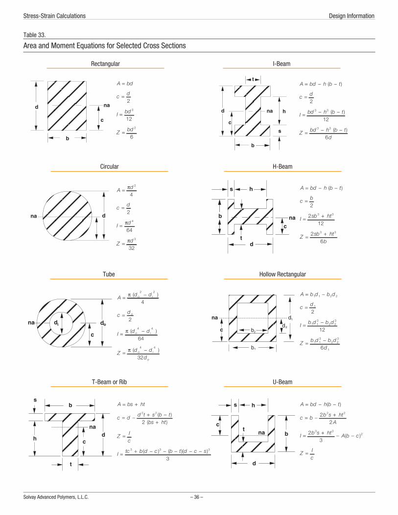
nchor crossection anchor rectang anchor i-beam anchor circular anchor h-beam anchor tube anchor c-beam anchor t-beam anchor u-beam
Solvay Advanced Polymers, L.L.C. – 36 –
Stress-Strain Calculations Design Information
Table 33.
Area and Moment Equations for Selected Cross Sections
A bd=
c d=2
I bd=3
12
Z bd=2
6
Rectangular
A d= π 2
4
c d=2
I d= π 4
64
Z d= π 3
32
Circular
A bs ht= +
c d d t s b tbs ht
= − + −+
2 2
2( )
( )
Z Ic
=
I tc b d c b t d c s= + − − − − −3 3 3
3( ) ( )( )
T-Beam or Rib
A bd h b t= − −( )
c d=2
I bd h b t= − −3 3
12( )
Z bd h b td
= − −3 3
6( )
I-Beam
A bd h b t= − −( )
c b=2
I sb ht= +212
3 3
Z sb htb
= +26
3 3
H-Beam
A d do i= −π ( )2 2
4
c d o=2
I d do i= −π ( )4 4
64
Z d dd
o i
o
= −π ( )4 4
32
Tube
A b d b d= −1 1 2 2
c d= 1
2
I b d b d= −1 13
2 23
12
Z b d b dd
= −1 13
2 23
16
Hollow Rectangular
A bd h b t= − −( )
c b b s htA
= − +22
2 2
I b s ht A b c= + − −23
3 32( )
Z Ic
=
U-Beam

Design Limits
After the designer has calculated the maximum stress level anddeflection, he then compares that stress value to the appropri-ate material property, i.e. tensile, compressive, or shearstrength. He then decides whether the design incorporates asufficient safety factor to be viable or whether the designshould be modified by changing wall thickness or incorporatingribs or contours to increase the section modulus.
The term “design allowable” has been coined for an estimate ofa material’s strength which incorporates the appropriate safetyfactors for the intended loading pattern. Table 34 presents thedesign allowables for short-term intermittent loading. Table 35provides the design allowable stresses for constant loadingwhere creep is a major design consideration. These tables donot consider any environmental factors other than temperature.The presence of chemicals may lower the design allowablesdramatically.
The design given by the application of the mechanical designequations is useful as a starting point, but some critical factorsare simply not considered by this analysis. For example, theimpact resistance of a design is directly related to its ability toabsorb impact energy without fracture. Increasing wall thick-ness generally improves the impact resistance of a moldedpart. However, increased wall thickness could hurt impactresistance by making the part overly stiff and unable to deflectand distribute the impact energy. Therefore, the ability of thedesign to withstand impact must be checked by impact testingof prototype parts.
Stress Concentrations
Stress concentrations may lead to premature failure, particu-larly under impact or fatigue. Minimizing sharp corners reducesstress concentrations and results in parts with greater struc-tural strength. To avoid stress concentration problems, insidecorner radii should be equal to half of the nominal wall thick-ness. A fillet radius of 0.015 inch (0.4 mm) should be consid-ered minimum.
Outside corners should have a radius equal to the sum of theradius of the inside corner and the wall thickness to maintain auniform wall thickness. Figure 50 shows the effect of radius onthe stress concentration factor.
– 37 – RADEL Resins Design Guide
Mechanical Design Stress-Strain Calculations
Grade73°F
(23°C)200°F(93°C)
350°F(177°C)
A-100, 200, 300 6,100 4,570 2,640
AG-210, 310 6,600 4,820 3,550
AG-220, 320 7,710 5,840 3,810
AG-230, 330 9,140 6,850 4,160
R-5000, 5100, 5500, 5800 5,180 3,300 2,5401 Environmental factors may lower allowable stress levels
Table 34.
Allowable Design Stresses1 for an Intermittent Load
Grade73°F
(23°C)200°F(93°C)
350°F(177°C)
A-100, 200, 300 3,000 2,250 1,300
AG-210, 310 3,250 2,375 1,750
AG-220, 320 3,800 2,875 1,875
AG-230, 330 4,500 3,375 2,050
R-5000, 5100, 5500, 5800 2,550 1,625 1,2501 Environmental factors may lower allowable stress levels
Table 35.
Allowable Design Stresses1 for a Constant Load
Figure 50.
Stress Concentration Factor at Inside Corners

Designing for Injection MoldingBecause many of the applications for RADEL resins will beinjection molded components, factors which influencemoldability must be considered in the part design. These fac-tors include wall thickness and wall thickness transitions, draft,ribs, bosses, and coring.
Wall Thickness
In general, parts should be designed with the thinnest wall thathas sufficient structural strength to support the expected loads,keeps deflection within design criteria limits, has adequateflow, and meets flammability and impact requirements. Partsdesigned in this manner will have the lowest possible weight,the shortest molding cycle, and therefore the lowest cost.
Occasionally, wall thicknesses greater than those required bythe mechanical design analysis are required for molding. Theflow of RADEL resins, like other thermoplastics, depends uponthe wall thickness as well as the mold design and process vari-ables, such as injection rate, mold temperature, melt tempera-ture, and injection pressure. The practical limits of wall thick-ness generally lie between 0.030 inches and 0.250 inches. Wallsections of 0.010 inches can be molded if flow lengths areshort. Specific information regarding flow length versus wallthickness of the various RADEL grades can be found on page46.
Wall Thickness Variation
While uniform wall thicknesses are ideal, varying wall thicknessmay be required by structural, appearance, and draft consider-ations. When changes in wall section thickness are necessary,the designer should consider a gradual transition, such as the 3to 1 taper ratio shown in Figure 51. Sharp transitions can cre-ate problems in appearance and dimensional stability due tocooling rate differentials and turbulent flow.
Also, from a structural standpoint, a sharp transition will resultin a stress concentration, which may adversely affect part per-formance under loading or impact.
Draft Angle
To aid in the release of the part from the mold, parts are usuallydesigned with a taper in the direction of mold movement. Thetaper creates a clearance as soon as the mold begins to move,allowing the part to break free. The taper is commonly referredto as “draft”, and the amount of taper referred to as “draftangle”. The use of draft is illustrated in Figure 52.
Adequate draft angle should be provided to allow easy partremoval from the mold. Generally, the designer should allow adraft angle of 1 to 2° per side for both inside and outside wallsfor RADEL resins. In some special cases, smaller draft angleshave been used with draw polish on the mold surface.
More draft should be used for deep draws or when cores areused. Textured finishes increase draft requirements by a mini-mum of 1° per side for each 0.001 inch (0.025 mm) of texturedepth.
Ribs
The structural stiffness of a part design can be increased withproperly designed and located ribs without creating thick walls.Proper rib design allows decreased wall thickness, which inturn saves material and weight, shortens molding cycles andeliminates thick walls, which can cause molding problems likesink marks. Ribs that are correctly positioned may also functionas internal runners, assisting material flow during molding.
In general, these guidelines should be followed when designingwith ribs. The thickness at the rib base should be equal toone-half the adjacent wall thickness. When ribs are oppositeappearance areas, the width should be kept as thin as possible.If there are areas in the molded part where structure is moreimportant than appearance, then ribs are often 75%, or even
Solvay Advanced Polymers, L.L.C. – 38 –
Wall Thickness Design Information
Figure 51.
Wall Thickness Transition
Figure 52.
Draft - Designing for Mold Release

100%, of the outside wall thickness. Whenever possible, ribsshould be smoothly connected to other structural features suchas side walls, bosses, and mounting pads. Ribs need not beconstant in height or width, and are often matched to the stressdistribution in the part. All ribs should have a minimum of ½° ofdraft per side and should have a minimum radius of 0.015 inch(0.4 mm) at the base.
Figure 53 shows recommended rib size relationships.
Coring
Proper design should include uniform wall section thicknessthroughout a part. Heavy sections in a part can extend cycletime, cause sink marks, and increase molded-in stresses.
Heavy sections should be cored to provide uniform wall thick-ness. For simplicity and economy in injection molds, coresshould be parallel to the line of draw of the mold. Cores placedin any other direction usually create the need for some type ofside action or manually loaded and unloaded loose cores.
Cores that extend into the cavity are subject to high pressure.For blind cores with diameters greater than 1/16", the corelengths should not exceed three times the diameter; blind coreswith diameters less than 1/16" the core length should notexceed twice the diameter. These recommendations may bedoubled for through cores. Draft should be added to all coresand all tooling polished for best ejection.
Bosses
Bosses are protrusions off the nominal wall of a part that willeventually be used as mounting or fastening points. The designof bosses is largely dependent upon their role in a given part.Cored bosses can be used with press fits, self-tapping screws,or ultrasonic inserts. These fasteners exert a variable amount ofhoop stress on the wall of the boss.
As a general guideline, the outside diameter of each bossshould be twice the inside diameter of the hole, and the wallthickness of each boss should not exceed that of the part. Fig-ure 54 illustrates these guidelines.
Additional forces imposed on a boss may be transmitted downthe boss and into the nominal wall. For this reason, a minimumradius of 25% of the wall thickness is required at the base ofthe boss to provide strength and reduce stress concentration. Aboss can be further strengthened by using gusset- plate sup-ports around the boss, or attaching it to a nearby wall with aproperly designed rib. Heavy sections should be avoided toprevent the occurrence of sink marks on the surface of thepart.
– 39 – RADEL Resins Design Guide
Designing for Injection Molding Coring
Figure 53.
Recommended Rib Design
Figure 54.
Boss Design General Guidelines

FabricationThe fabrication methods used for RADEL resins and ACUDELblends are injection molding, extrusion, and blow molding.
Drying
RADEL A polyethersulfone, RADEL R polyphenylsulfone, andACUDEL polyphenylsulfone blends should be dried completelyprior to melt processing. Although these polymers are hydrolyti-cally stable and not subject to molecular weight degradation,incomplete drying will result in cosmetic defects in the formedpart, ranging from surface streaks to severe bubbling. However,such parts may be recovered as regrind.
Pellets of RADEL resin can be dried on trays in a circulating airoven or in a hopper dryer. Minimum drying times are: 2.5 hoursat 350°F (177°C), 4 hours at 300°F(149°C), or 4.5 hours at275°F (135°C). Drying below 275°F (135°C) is not recom-mended because drying times would be excessive. Dried resinshould be handled carefully to prevent resorption of moisturefrom the atmosphere by using dry containers and coveredhoppers.
The recommended maximum moisture content is 500 ppm forinjection molding and 100 ppm for extrusion.
Typical drying curves for RADEL A polyethersulfone, RADEL Rpolyphenylsulfone, ACUDEL 22000 resin, and ACUDEL 25000are shown in Figures 55 through 58.
Solvay Advanced Polymers, L.L.C. – 40 –
Drying Fabrication
Figure 55.
Drying of RADEL A Resin in a Circulating Air Oven
Figure 56.
Drying of RADEL R Resin in a Circulating Air Oven
Figure 57.
Drying of ACUDEL 22000 Resin in a Circulating Air Oven
Figure 58.
Drying of ACUDEL 25000 Resin in a Circulating Air Oven

RheologyTo assist the fabricator in the proper design of tools and pro-cessing equipment, the rheology of the RADEL resins has beenmeasured under a variety of conditions. The viscosity versusshear rate data are shown in Tables 36 and 37.
– 41 – RADEL Resins Design Guide
Rheology Drying
RADELGrade
Temp,°C(°F)
Shear Rate,sec-1
TrueViscosity,
PoiseA-200A 345 (653) 100 9,756
1,000 4,66010,000 1,496
365 (689) 100 6,6951,000 3,198
10,000 1,027385 (725) 100 4,595
1,000 2,19510,000 705
AG-230 345 (653) 100 21,0801,000 7,505
10,000 2,170365 (689) 100 13,648
1,000 4,85910,000 1,400
385 (725) 100 8,8351,000 3,145
10,000 910A-300A 340 (644) 100 2,995
1,000 1,0025,000 243
360 (680) 100 1,6091,000 6925,000 228
380 (716) 100 1,0821,000 4995,000 193
400 (752) 100 6391,000 3585,000 183
AG-330 340 (644) 100 2,6331,000 9235,000 256
360 (680) 100 1,4271,000 5565,000 201
380 (716) 100 9021,000 3885,000 172
400 (752) 100 6991,000 3285,000 159
Table 36.
Shear Rate - Viscosity Data RADEL A
RADELGrade
Temp.,°C(°F)
Shear Rate,sec-1
TrueViscosity,
PoiseR-5000/R-5100
340 (644) 30 32,810100 30,474500 15,293
1,000 9,4653,000 3,803
360 (680) 30 16,996100 16,000500 10,244
1,000 6,7803,000 3,084
380 (716) 30 9,669100 9,317500 6,723
1,000 4,8643,000 2,446
400 (752) 30 6,808100 6,451500 4,767
1,000 3,6373,000 2,000
R-5800 340 (644) 30 24,224100 22,725500 12.948
1,000 8,2253,000 3,549
360 (680) 30 11,972100 11,499500 8,071
1,000 5,6133,000 2,699
380 (716) 30 7,165100 7,109500 5,297
1,000 3,9953,000 2,133
400 (752) 30 4,936100 4,768500 3,661
1,000 2,9143,000 1,724
Table 37.
Shear Rate - Viscosity Data RADEL R

The rheology data for RADEL A-200A are plotted in Figure 59,for RADEL A-300A in Figure 60, for glass-filled RADEL AG-230in Figure 61, and for RADEL AG-330 in Figure 62.
The rheology data for RADEL R-5000 are shown in Figure 63,and for RADEL R-5800 in Figure 64.
Solvay Advanced Polymers, L.L.C. – 42 –
Drying Fabrication
Figure 59.
Rheology of RADEL A-200A Resin
Figure 60.
Rheology of RADEL A-300A Resin
Figure 61.
Rheology of RADEL AG-230 Resin
Figure 62.
Rheology of RADEL AG-330 Resin
Figure 63.
Rheology of RADEL R-5000 Resin
Figure 64.
Rheology of RADEL R-5800 Resin

Melt Processing Parameters
The increased use of computer modeling for predicting flowand cooling has created a need for certain material constantsor parameters. These parameters for RADEL resins are shownin Table 38.
– 43 – RADEL Resins Design Guide
Rheology Melt Processing Parameters
RADEL Grade
Property UnitsA-200AA-300A
AG-230AG-330 R-5000
Melt ThermalDiffusivity
cm2/s 9.72 x 10⁻⁴ 9.02 x 10⁻⁴ 1.66 x 10⁻³
Melt SpecificHeat
cal/g-C 0.438 0.408 0.480
Melt Density@ 10,000 psi
g/cm3 1.3432 1.5963 1.2855
No FlowTemperature
°C 220.0 219.7 219.7
FreezingTemperature
°C 206.0 214.0 215.0
Solid density g/cm3 1.3554 1.5633 1.2900
Glass Transition Temperature
Onset °C 220 220 220
End °C 225.9 227.3 221.0
Table 38.
Melt Processing Parameters

Injection MoldingInjection Molding Equipment
The molding characteristics of RADEL resins are similar to those ofUDEL polysulfone resin. RADEL resins can be readily injectionmolded with most screw injection machines.
Screw Design
The typical general-purpose screw will perform satisfactorilywith RADEL resins. A typical screw design for processing theRADEL engineering resins is shown in Figure 65.
Screw Tips and Check Valves
The design of the screw tip and the check valve are importantfor proper processing. The check or non-return valve keeps themelt from flowing backwards over the screw flights duringinjection and holding. If no check valve is used, it will be diffi-cult or impossible to maintain a consistent cushion.
The check valve or check ring system must be designed forsmooth flow, avoiding dead spots or back pressure. Ball checkvalves are not recommended. The screw tip should also bestreamlined to ensure that the quantity of melt stagnant in frontof the screw is minimized.
Nozzles
Open nozzles are preferred to nozzles equipped with shut-offdevices. The configuration of the bore of the nozzle shouldclosely correspond to the screw tip.
Molds
Standard guidelines for mold design are appropriate for theRADEL resins.
Draft and Ejection
In general, the injection molds designed for RADEL resinsshould have 1 to 2° draft. The contact area of ejector pins orstripper plates should be as large as possible to prevent partdeformation or penetration during ejection.
Gates
All conventional gating types, including hot runners, can beused with RADEL resins. Problems may arise with some hotrunner designs, which either encourage long residence times orhave dead spots where material can accumulate and degrade.Gates must be of adequate size to allow part filling without theuse of extremely high injection melt temperatures or pressures.Voids or sink marks may be caused by gates that freeze offbefore packing is complete.
Venting
Molds for RADEL resins must be vented at the ends of runnersand at the position of expected weld lines. The vents shouldhave land lengths of 0.080 to 0.120 inch (2 to 3 mm), withdepths up to 0.003 inches (0.08 mm).
Mold Temperature Control
Controlling the mold temperature is critical to achieving highquality parts. On some especially challenging parts, separatecontrollers may be required for the mold halves. The tempera-tures required for molding RADEL resins can be achieved byusing a fluid heat transfer system with oil as the fluid, or byusing electric heaters.
Fluid heat transfer systems are always preferable to electricheaters. Electric heaters can aid in achieving minimum moldtemperatures, but since they don’t remove heat from the mold,mold temperatures may rise above the desired temperature,especially when molding large parts.
Solvay Advanced Polymers, L.L.C. – 44 –
Injection Molding Equipment Fabrication
Figure 65.
Screw Design for Injection Molding

Machine Settings
Injection Molding Temperatures
The injection molding melt temperatures recommended for var-ious RADEL resins are listed in Table 39. In general, higher tem-peratures should not be used, because of the risk of thermaldegradation. As a fundamental rule, injection molding melt tem-peratures higher than 740°F (393°C) should be avoided.
Mold Temperatures
The mold temperature is an important factor in determining theshrinkage, the warpage, the adherence to tolerances, the qual-ity of the molded part finish, and the level of molded-in stressesin the part.
The mold temperature for RADEL is usually set in the range of250-320°F (120-160°C). The only products that require highertemperatures to achieve an optimum finish are the glass-rein-forced RADEL grades. Table 39 lists the recommended moldtemperatures for the individual RADEL grades.
Heat losses can be reduced by inserting insulation between themold and the platen. High quality molded parts require awell-designed system of cooling channels and correct moldtemperature settings.
Barrel Temperatures
RADEL pellets can be melted under mild conditions, and rela-tively long residence times in the barrel can be tolerated, if thetemperature settings on the band heaters increase in the direc-tion from the hopper to the nozzle. If residence times are short,the same temperature can be set on all the barrel heaters. Atleast one band heater (rated at 200 W to 300 W) is required forthe nozzle, where heat losses to the mold may be severe as aresult of radiation and conductivity. These heat losses can bereduced by insulating the nozzle.
The band heater control system should be monitored. Forinstance, a timely alarm may prevent screw breakage if aheater fails in one of the barrel sections. The feeding of the pel-lets can often be improved by maintaining the temperature inthe vicinity of the hopper at about 175°F (80°C).
Residence Time in the Barrel
The length of time the plastic remains in the plasticizing cylin-der has a significant effect on the quality of the injection mold-ing. If it is too short, the pellets will not be sufficiently melted. Ifit is too long, thermal degradation is likely and is indicated bydiscoloration, dark streaks, and even burned particles in themolded parts. Frequently, the residence time can be reduced byfitting a smaller plasticizing unit. Acceptable residence timeswill be obtained if the shot size is 30-70 % of the barrel capac-ity. At the melt temperatures listed in Table 39, all the RADELresins withstand a residence time of 10 - 20 minutes.
Molding Process
Feed Characteristics
RADEL pellets can be conveyed smoothly along the barrel andhomogeneously plasticized at the recommended temperaturesby screws of the design shown in Figure 65 on page 44.
The temperature in the feed section should not be set too high,because the pellets may melt prematurely, resulting in thescrew flights becoming choked and bridged over.
Back Pressure
Back pressure is usually employed to maintain a constantplasticizing time, to avoid air entrainment, and to improve thehomogeneity of the melt. While some back pressure is gener-ally beneficial, back pressure that is too high can result in highfrictional heating.
Screw Speed
Whenever possible, the screw speed should be set so that thetime available for plasticizing during the cycle is fully utilized. Inother words, the longer the cycle time, the slower the screwspeed. For instance, a screw speed of 60-100 rpm often suf-fices for a 2-inch (50-mm) diameter screw. This is particularlyimportant, when running high melt temperatures to ensure thatthe melt does not remain stationary for an undesirably longtime in the space in front of the screw tip. Low screw speedsalso diminish the temperature increase due to friction.
– 45 – RADEL Resins Design Guide
Injection Molding Machine Settings
RADEL Grade Melt Temperature, °F (°C) Mold Temperature, °F (°C) Shrinkage, %
A-200A 690-730 (365-390) 280-320 (138-160) 0.6 - 0.7
A-300A 660-730 (350-390) 280-320 (138-160) 0.6 - 0.7
AG-210 680-730 (360-390) 280-320 (138-160) 0.5
AG-320 680-730 (360-390) 280-320 (138-160) 0.4
AG-330 680-730 (360-390) 280-320 (138-160) 0.3
R-5000/5100 690-740(365-393) 300-325 (150-163) 0.6 - 0.7
ACUDEL 690-740(365-393) 300-325 (150-163) 0.6 - 0.7
Table 39.
Molding Conditions - Starting Point

Injection Rate and Venting
The injection rate used for filling the mold is another importantfactor in determining the quality of the molded part. Moderateinjection speed should be used; It should be rapid enough toachieve melt homogeneity, but slow enough to avoid shearburning. Rapid injection provides uniform solidification andgood surface finish, especially with the glass-reinforced grades.
The mold must be designed to allow air to readily escape cavi-ties during the injection phase. If this is not done, rapid com-pression of the air in the cavity will create high temperaturescausing localized overheating and burn marks. In order to elim-inate voids, the screw forward time and the holding pressuremust be high enough to compensate for the contraction in vol-ume that will occur during cooling.
Gates must be large enough so the polymer does not solidify intheir vicinity before the holding time has elapsed. Any plugsformed in or near the gate would prevent the holding pressurefrom packing the interior of the mold.
Demolding
RADEL parts can be readily demolded and do not stick to thewalls of the mold, even when they are hot. As a rule, the drafton injection molds for RADEL resins should be 1 to 2°. A some-what larger draft is required for the glass-reinforced products,because of their lower shrinkage. The area of ejectors or strip-per plates should be as large as possible. Ejector pins must notbe too thin, or they may press into the parts and deform themduring rapid cycling or at high mold temperatures.
Shrinkage
Shrinkage is defined as the difference between the dimensionsof the mold and those of the molded part at room temperature.It is primarily a property of the thermoplastic resin and resultsfrom the contraction in volume that occurs when the moldingcompound cools within the mold. Other factors that effect themagnitude of the shrinkage are the geometry of the part, thewall thickness, the size and location of the gates, and the pro-cessing parameters. The interaction of all these factors makesit difficult to predict shrinkage exactly, but close estimates oftypical values appear in Table 39.
Resin Flow CharacteristicsOne method of characterizing a material’s flow is the measure-ment of the length of flow in a spiral cavity at various thick-nesses, temperatures, and molding pressures. These data havebeen generated for RADEL A-200A, A-300A, AG-210, andAG-230. The results for RADEL A-200A are shown in Figure 66,RADEL AG-210 in Figure 67, for RADEL A-300A in Figure 68,and for RADEL AG-230 in Figure 69. Spiral flow data for RADELR-5000 are shown in Figure 70 and for RADEL R-5800 in Fig-ure 71.
Solvay Advanced Polymers, L.L.C. – 46 –
Molding Process Fabrication
Figure 66.
Spiral Flow of RADEL A-200A
Figure 67.
Spiral Flow of RADEL AG-210
Figure 68.
Spiral Flow of RADEL A-300A

– 47 – RADEL Resins Design Guide
Resin Flow Characteristics Molding Process
Figure 69.
Spiral Flow of RADEL AG-230
Figure 70.
Spiral Flow of RADEL R-5000
Figure 71.
Spiral Flow of RADEL R-5800

Measuring Residual StressWhen thermoplastics are injection molded, the process inducesresidual or molded-in stresses in the molded articles. Whilestresses induced in plastic parts by mechanical and thermalloads may be calculated by conventional means, there is noreliable method for predicting residual stress levels. Many per-formance parameters are affected by the level of residualstress present in a part. Since these stresses cannot be calcu-lated, it is important to be able to measure them.
A method for measuring the residual stress level in partsmolded from unfilled RADEL resin has been developed. Itinvolves the exposure of finished parts to chemical reagentswhich are known to produce cracking or crazing of the materialat specific stress levels. Exposure of parts to these reagentsunder no load conditions allows the quantification of the resid-ual stress levels.
The following table details the reagents used for this testingand the stress levels at which they are known to cause thematerial to crack. This information was generated at room tem-perature at 100% reagent concentration with a one-minuteexposure time.
The exposure time required for these reagents to producecracking at the noted stress level is one minute. This exposuretime was employed to facilitate rapid testing and to limit thepossibility of errors due to over or under exposure. Exposure forlonger time periods produces cracking at stress levels lowerthan those specified.
To determine the residual stress level of a molded RADEL part,choose the list appropriate for the RADEL grade from Table 40,and follow the procedure shown, starting with the first reagentin the list.
The stress level in the part lies between the stress level shownfor the reagent which induces cracking and the one directlyabove it in Table 40.
Determining stress levels through the use of reagent exposureis approximate in nature. Small differences in the test condi-tions (ambient temperature, exposure time, or reagent concen-tration, etc) may cause slight variations in the test results.Results should be within 20% of the actual stress level.
Residual stress levels depend on numerous molding parame-ters that may be in flux at the time of molding. For this reason,individual samples may exhibit variations in stress levels.Therefore, testing multiple parts is recommended.
The determination of the acceptable molded-in stress level foran individual part should be made from its end use application,in particular, the chemical environment to which the part will beexposed. RADEL resins are amorphous thermoplastics that areconsidered to have good chemical resistance. Parts whoseresidual stress levels are below 800 psi (5 MPa) may typicallybe considered well molded.
Solvay Advanced Polymers, L.L.C. – 48 –
Consult your supplier’s Material Safety Data Sheet before handlingthe specific reagents selected for testing and follow the manufac-turer’s instructions for handling precautions.
All testing should be conducted in a ventilated laboratory hood, orin a well ventilated area. The reagents are flammable organicchemicals, and should be stored in closed containers away fromopen flames, sparks, or locations where elevated temperaturesmay be expected. Disposal of these materials must be in accor-dance with applicable federal, state, or local regulations.
Health and Safety ConsiderationsReagents
Minimum StressLevel To
Produce Failure, psi (MPa)
RADEL A polyethersulfone2-Ethoxyethanol (Cellosolve) 2,200 (15)
Ethyl Acetate (EA) 1,200 (8)
50%* MEK / 50%* EA 800 (5)
Methyl Ethyl Ketone (MEK) 400 (3)
RADEL R polyphenylsulfoneEthyl Acetate (EA) 1,750 (12)
Methyl Ethyl Ketone (MEK) 1,200 (8)
5%* N-Methyl pyrrolidone / 95%* MEK 800 (5)*% by volume
Table 40.
Residual Stress Test Parameters
1. Allow the parts to cool to room temperature then rinse withisopropyl alcohol.
2. Expose the part to reagent for one minute, then rinse withwater.
3. Inspect the part for cracked or crazed regions under stronglight. Hairline fractures may be difficult to see.
4. If the part has no cracks or crazes, the residual stress level islower than the stress level shown in Table 40 for that reagent.Proceed to the next reagent and repeat steps 2 and 3.
Procedure for Residual Stress Determination

ExtrusionBoth RADEL A polyethersulfone and RADEL R polyphenylsulfonecan be readily extruded on conventional extrusion equipment.
Predrying
RADEL resins must be thoroughly dried prior to extrusion toprevent bubbles in the extrudate. Resin should be dried untilthe moisture content is below 100 ppm. Appropriate dryingtimes and temperatures are shown in Figures 55 and 56 onpage 40. Hopper drying requires sufficient insulation and mini-mal system leakage. Inlet air temperature must be high enoughand inlet air moisture content low enough for polymer pellets tobe maintained above 300°F (149°C) in air with a -40°F (-40°C)dewpoint. This condition must be sustained long enough for thepolymer moisture content to drop to below 100 ppm.
Extrusion Temperatures
Depending upon the specific extrusion operation, the melt tem-perature of the extruded stock should be in the range of 650 to750°F (343 to 400°C).
Actual barrel temperature settings of 625-700°F (330-370°C)at the feed end of the extruder and 625-700°F (330-370°C) atthe head are recommended for most operations. These temper-ature settings along the barrel should yield the requiredextruded stock temperature if maintained uniformly in therange of 650 to 750°F (343 to 400°C).
Higher barrel settings may be necessary if a screw with a rela-tively shallow metering section is used to better control theoperation within the pressure and power limitations of theequipment.
Screw Design Recommendations
In general, screws with length-to-diameter ratios from 20:1 to24:1 are recommended. Compression ratios from 2:1 to 2.5:1have been shown to give acceptable results. Screw pitchshould equal screw diameter, and the transition from feed tometering should be gradual. The transition and metering sec-tions should be longer than the feed section. The transition sec-tion should be the longest to provide sufficient time and heatinput to adequately soften the resin before trying to pump it. Astarting point configuration is 4 flights feed, 14 flights transi-tion, and 6 flights of metering.
Two-stage screws can also be used to allow vacuum ventingwhere optimal compaction of the melt is desired. A two-stagescrew design includes a decompression section to allow vac-uum venting after the first metering section. The decompres-sion section is then followed by another transition zone andanother metering zone, following the design principlesdescribed for the single stage screw.
As a rule, screw designs intended for polyolefins will not giveacceptable results with RADEL resins.
Die Design
The die heaters must be capable of reaching and maintainingtemperatures of 800°F (427°C). Since the viscosity of RADELresins is temperature-sensitive, die temperature must beclosely controlled to provide a uniform extrudate.
Streamlined dies should always be used. Streamlining the flowchannel and incorporating purge plates (i.e., bleeder plugs) inthe ends of sheeting dies eliminate the possibility of hang-up inthe die and melt stagnation.
Dies should be capable of operating continuously at pressuresup to 3,500 psi (24.1 MPa). Flow channels, die lips, and landsshould be highly polished and chromium-plated for optimumextrudate appearance.
Extruded Product Types
Wire
RADEL resins can be extruded onto wire using a semi-tubing ortubing crosshead die. Wire inlet temperatures should approxi-mate that of the polymer melt. High drawdown of the polymermelt tube can be achieved with RADEL resins. Vacuum on thecrosshead is highly recommended to improve adhesion of thepolymer tube to the wire. Coated wire should not be quenchedbut rather cooled slowly using a mister or water bath.
Film
The high melt strength of RADEL resins provides excellentdrawdown properties for the production of thin film. Slot-castfilm possesses high modulus, good impact strength, and goodelectrical properties over a wide temperature range. The film isheat sealable and can be printed without pre-treatment.
Typical film extrusion conditions for a 2.5-inch (5.1-cm)extruder are:
Die: Standard film dies of coat hanger design and straightmanifold-choker bar design are satisfactory. Die lip openingsof 0.025 to 0.040 in. (1 to 1.5 mm) should be used for 1 to 10mil film. Dies must be capable of continuous operation at3,500 psi (24.1 MPa).
Breaker Plates/Screenpacks: Breaker plates are not requiredand can cause “die lines”, but when used in conjunction witha screenpack can result in a consistent, defect-free extrudate.Alternatively, a sleeve can also seal the die adapter to theextruder.
Casting Roll: An 8.5-inch (21.6-cm) diameter roll at 350°F(177°C) is required to prevent wrinkling of the film.
– 49 – RADEL Resins Design Guide
Extrusion Predrying

Sheet
Standard round and teardrop manifold sheet dies with chokerbars are satisfactory. Typically, die openings are 10 to 20 per-cent larger than the desired final thickness. In sheet extrusion,the take-off roll temperature must be maintained high enoughto prevent curl and to minimize strains in the sheet. Either an“S” wrap technique or straight- through calendaring techniqueis satisfactory, providing that roll temperatures of 350 to 450°F(177 to 232°C) can be obtained. Calendaring also requires thata small bank (melt bead) be maintained at the roll nip.
A power shear has been used to cut the sheet to length forsheet thicknesses up to 0.100 inches (2.5 mm). For greaterthicknesses, sawing is recommended.
Pipe and Tubing
RADEL resins can be extruded into pipe and tubing using stan-dard pin and spider assemblies. Control of stock temperature iscritical to achieving high-quality extrudate. Stock temperaturesof 650 to 700°F (343 to 371°C) are suggested.
Sizing plate and vacuum tank methods of dimensional controlare satisfactory. For best melt control, the extrusion die shouldbe 70 to 100 percent larger than the sizing die.
For high-quality extrusion, stress due to processing must beminimized. This is accomplished by minimizing the level ofcooling in the vacuum-sizing bath while maintaining dimen-sional requirements. To this end, a short water bath (1/4th to1/5th the length of that typically used for polyethylene) isdesirable.
Start-Up, Shut-Down, and Purging
Start-Up Procedure
Feed warm pre-dried resin to the preheated extruder with thescrew speed set to 15-20 rpm. As soon as the feed section isfull, decrease speed to 5-10 rpm until material begins to exitthe die. Adjust screw speed to desired extrusion rate.
Shut-Down Procedure
If a shut-down is required during an extrusion run, certain pre-cautions should be taken. It is not good practice to allow resinto sit stagnant in an extruder for prolonged periods of time atextrusion temperatures. Some decomposition is likely to occur,and it may prove difficult to start again and properly purge themachine.
If the shut-down is of a short duration (two hours or less), purgethe extruder with UDEL polysulfone. Run the extruder dry, andthen restart using starve feed. For longer shut-downs, theextruder should be purged with UDEL polysulfone, and then rundry. The extruder heaters should be turned off and allowed tocool to room temperature. To start-up the next day, turn on thedie heaters at least one hour, but preferably two hours, beforeturning on the extruder heaters. Once the extruder reaches 600
to 650°F (315 to 343°C), the screw can be rotated periodicallyuntil extrusion temperatures are reached. Start by starve feed-ing at low screw speeds until material comes out of the die.
Purging
RADEL resins can be purged from extrusion processing equip-ment by a variety of techniques. Because RADEL resins aretough, stable, high-temperature materials, the most effectivepurging procedures replace the RADEL resin with a lower tem-perature plastic that is more easily removed. The generally rec-ommended purging material is polyethylene, but suitable com-mercial purging compounds can also be used.
The most effective procedure is a step-wise purge, beginningwith a natural polysulfone resin, such as UDEL P-1700, and fol-lowing with a low-melt-flow, high-density polyethylene. Thepolysulfone should be fed until it is running clear at the die. Theextruder barrel temperatures may be lowered 30 to 50°F (15 to25°C) as the polysulfone replaces the RADEL resin. The poly-sulfone can then be purged by adding polyethylene to themachine while it is at 625 to 650°F (330° to 343°C) and run-ning until the extrudate appears to be mainly polyethylene.When that point has been reached, the die, adapter, andbreaker plate can be removed and cleaned of the polyethyleneas it cools, and machine purging can continue. When no morepolysulfone is visible in the extruder purge, the temperaturemay be safely lowered to 300°F (150°C). Various cleaning com-pounds may then be used, if desired.
An alternative procedure would be to follow the RADEL resindirectly with the low-melt-index, high-density polyethylenepurge. Upon completion of the RADEL resin extrusion, themachine should be run dry of material and the polyethyleneintroduced and extruded until no RADEL compound is evident inthe extrudate. The die, adapter, and breaker plate can beremoved and cleaned. Polyethylene purging can then be contin-ued until no evidence of RADEL resin is seen in the extrudate,at which point the temperatures can be lowered to 300°F(150°C).
When purging is complete and the extruder has been run to anempty condition, the screw can be removed and both the barreland screw brushed clean. If residual RADEL resin can not beremoved by brushing, it can be burned off using proper care.An alternative technique is soaking the parts in N-methylpyrrolidone (NMP) until the residual resin is softened enough foreasy removal.
Solvay Advanced Polymers, L.L.C. – 50 –
Start-Up, Shut-Down, and Purging

Secondary OperationsMachiningRADEL resins may be machined with normal metal workingtools. Because of their high softening temperatures, relativelyhigh cutting speeds can be used without gumming. The inher-ent toughness of these materials allows deep, smooth cuts tobe made without chipping or shattering. If cooling is required,water spray works well.
Drilling and Tapping
Standard high-speed twist drills are recommended. Cuttingspeeds of 300 ft/min (90 m/min) at feed rates of 0.005 to 0.015in/rev (0.15 to 0.40 mm/rev) are recommended. Tapping shouldbe done with 2-flute or 3-flute high-speed steel spiral pointtaps.
Sawing
Standard band saws with blades containing ten teeth per inchoperated at 3,000 to 5,000 ft/min (900 to 1,500 m/min) sawingrates work well, but other wood cutting configurations can alsobe used.
Turning
Conventional variable-speed, metal-turning lathes with either around-nose or a pointed tool can be used. The recommendedconfiguration for sharp tools is a 3° rake angle, a 10° clearanceangle, and a 5° side angle.
Cutting speeds of 500 to 2000 ft/min (150 to 600 m/min) withfeed rates from 0.002 to 0.010 in/rev (0.05 to 0.25 mm/rev)can be used.
Milling and Routing
Milling and routing are readily accomplished at high speedswithout coolants or lubricants. Tools for aluminum work well.For example, a groove 0.5 inches (13 mm) wide, 0.100 inches(2.5 mm) deep can be end milled at 1,750 rpm with a feed rateof 4.5 in/min (114 mm/min).
Finishing and DecoratingRADEL resins are an excellent substrate for finishes and virtu-ally any decorative or functional finishing requirement can bemet.
Painting
Various colors can be applied to RADEL resin using organicpaints and conventional application techniques. Painting maybe an economical means of achieving a desired appearance.
Good adhesion with no embrittlement is a critical paint require-ment. For proper paint adhesion, removal of foreign matter,such as dirt, oil, grease, and mold release, from the part surfaceis critical. When contaminants are present, parts should becleaned first. Properly handled parts may not need any cleaningand can be painted without such treatment.
Although rolling and dipping are sometimes used, spray paint-ing is the usual method of paint application.
The selection of paint is dependent upon the desired decorativefinish or functional requirement, and the application technique.Among the coatings used are polyurethane, polyester, epoxy,acrylic, and alkyd.
Depending upon the paint, the cure may be air drying or ovenbaking. If baking is required, the high thermal resistance ofRADEL resins allows the use of relatively high oventemperatures.
Electroplating
Electroplated plastic parts are very durable and provide light-weight replacement for die castings and sheet metal. After aspecial pretreatment to form a conductive surface on the plas-tic part, it can be put through electroplating processes similarto those used in plating metals.
Hot Stamping
Hot stamping is a one-step, economical process for transferringa high-quality image to a plastic part. A heated die transfers thepattern from the transfer tape to a flat plastic surface. Patternscan vary from lettering to decorative designs in pigmented,wood grain, or metallic finishes.
RADEL resin can successfully be hot stamped using eitherroll-on or vertical action application equipment. The applicationconditions require no special procedures, and the die tempera-ture, pressure, and dwell time are within conventional ranges.
Printing
RADEL resin can be successfully printed by silk-screen andpad-transfer printing techniques. Pad transfer printing offerseconomies resulting from high speed reproduction. It alsoallows the reproduction of images in one or more colors, usingsimultaneous multi-color printing equipment. The silk screeningprocess is primarily used for limited volumes. Although slowerthan the pad transfer process, silk screening permits the deco-ration of contoured surfaces, making this method ideal formany molded parts.
Printing inks suitable for use on RADEL resin can include a vari-ety of air-dry, plural-component, and ultraviolet-radiation curinginks.
Reinforced grades of RADEL resin are acceptable for lasermarking.
– 51 – RADEL Resins Design Guide
Machining Drilling and Tapping

Vacuum Metallizing
RADEL resins have been successfully vacuum metallized toaccept a decorative or functional metallic coating. Although alu-minum is the most frequently used coating, other metals suchas gold, silver, brass, and copper may also be used.
For most thermoplastics, the first step of the vacuummetallizing process is the application of a base coat of enamelor lacquer to provide leveling of the part surface, whichimproves the surface brilliance. The base coat also functions asan adhesive, linking the molded part and the metallic coating.
The part is then placed in a vacuum chamber in which a metal-lic vapor is created and deposited on the part. A protective,clear top coat is then applied over the thin metal layer for abra-sion and environmental resistance. The high thermal resistanceof RADEL resins allow the use of durable, abrasion resistantcoatings which require high-temperature bake conditions.
The application of metallic surfaces to molded parts tends toemphasize mold defects; therefore mold surfaces should behighly polished.
Cathode Sputtering
The high heat resistance of RADEL resins allows the use ofcathode sputtering. Metals with low vapor pressures like cop-per and silver are used most frequently. Other acceptable met-als are platinum, palladium and gold.
Cathode sputtering permits precise control of the metallic coat-ing thickness and provides improved adhesion of the coating tothe part. Both are critical for applications such as sub-miniatur-ized electrical circuitry.
Flame/Arc Spraying
Flame and arc spraying of metallic coatings may successfullybe used with RADEL resin.
This technique involves the use of pure aluminum, copper, orzinc powder metered into a special spray gun. The metal pow-der is melted by a flame or electric arc and sprayed onto thepart, producing a hard, dense coating.
Assembly and JoiningUltrasonic Bonding
Ultrasonic bonding is an assembly technique that is used tobond plastic parts together. This technique is very rapid andcan be fully automated for high-speed and high-volume pro-duction. Ultrasonic bonding requires attention to details likejoint design, welding variables, fixturing, and moisture content.
The principle involved in ultrasonic joint design is to concen-trate the energy in an initial small contact area. The high fre-quency vibration melts the material, pressure is maintained
when the vibrations stop and the melt solidifies. The bondwhich is now formed may be as strong as the strength of theoriginal material.
Weldability is dependent upon the concentration of the vibratoryenergy per unit area. Compared to polycarbonate, RADEL resinshave higher melting temperatures and require more energy tomelt the material and achieve flow at the joint.
The basic butt joint with energy director is shown in Figure 73.The V-shaped energy director concentrates the ultrasonicenergy to this area, which quickly melts and creates a meltpool as the parts are pressed together. A mating flow channel ispreferred in cases where an hermetic seal is desired.
Some additional suggestions to ensure the best results are asfollows:
• The welding horn should have a suitable contact area.
• The joint/weld area should be located as close as possible tothe point where the welding horn will contact the plastic part.
• Large mating surfaces and close fit joints should be avoided.
• Allow for adequate flow of molten material.
Solvay Advanced Polymers, L.L.C. – 52 –
Vacuum Metallizing Secondary Operations
Figure 73.
Energy Director Design

Spin Welding
Spin welding is a rapid technique for joining parts with circularjoint interfaces. While one part is held fixed, the rotating partcontacts it with a specified pressure. Frictional heat is gener-ated at the joint between the surfaces. After the melting occurs,relative motion is halted and the weld is allowed to solidifyunder pressure.
Adhesive Bonding
Parts molded from RADEL resin can be bonded to other partsmolded from RADEL resin or bonded to other materials usingcommercially available adhesives. The success of adhesivebonding is very dependent on the end use environmental fac-tors, such as operating temperature, joint design, appliedstresses, and chemical exposure.
Adhesives frequently recommended for thermoplastics areepoxies, acrylics, phenolics, polyurethanes, polyesters andvinyl. Specific adhesive recommendations can be obtained fromthe adhesive suppliers. However, the designer should test theperformance of the joint in the actual end use environment.
It is also critical that the surface is free of any contaminants,such as grease, oil, fingerprints and mold release, which canweaken the bond. In some cases, the surfaces of the materialsto be bonded must be chemically etched or mechanicallyroughened to allow the adhesive to gain a firm grip. Clamping
pressure should be sufficient to insure good interface contact,but not so high that the parts are deformed or that solvent isforced from the joint.
The joint area should be designed so that the two parts fit pre-cisely together. Figure 74 shows recommended joint designsfor adhesive bonding. Parts should be molded with low residualstresses and to accurate dimensions.
Mechanical Fasteners
Fasteners frequently used with injection molded plastic partsinclude screws, bolts, nuts, lock washers, and lock nuts. Whenusing metal mechanical fasteners, good design practice shouldbe used to prevent the plastic parts being assembled frombecoming over stressed.
The most obvious procedure for preventing a high-stressassembly is to control the tightening of the mechanical fasten-ers with adjusted torque-limiting drivers. When torque cannotbe controlled, as might be the case with field assembly, shoul-der screws can limit compression on the plastic part. Otheralternatives are the use of flange-head screws, large washers,or shoulder washers. Figure 75 presents some preferreddesigns when using mechanical fasteners.
– 53 – RADEL Resins Design Guide
Assembly and Joining Spin Welding
Figure 74.
Joint Designs for Adhesive Bonding
Figure 75.
Designing for Mechanical Fasteners

Molded-In Threads
With molded-in threads mating male and female threads aremolded into the parts to be assembled. Molded internal threadsusually require some type of unscrewing or collapsing mecha-nism in the tool as shown in Figure 76. In some case externalthreads can be molded by splitting them across the parting lineas shown in Figure 77. Molding very fine threads which exceed28 pitch is usually not practical.
Threaded Inserts
Threaded metal inserts provide permanent metallic machinethreads in the plastic part. The inserts come in a wide variety ofsizes and types. Inserts are usually installed in molded bossesthat have an internal diameter designed for the insert. Someinserts are forced into the boss while others are installed bymethods that create lower stress and stronger attachments.
A very popular type of insert is the ultrasonic type. This type ofinsert is installed with the same equipment used for ultrasonicwelding. Because ultrasonic welding melts material around themetal insert, the installation is usually strong and relatively freeof stress.
Besides female threads, inserts can be threaded male styles,locating pins and bushings. The recommendations on installa-tion procedures and boss dimensions can be provided by theinsert supplier and resin manufacturer.
Solvay Advanced Polymers, L.L.C. – 54 –
Mechanical Fasteners Secondary Operations
Figure 76.
Internal Threads
Figure 77.
External Threads

Self-Tapping Screws
Self-tapping screws are suitable for use with RADEL A andRADEL R resins. Self-Tapping screws provide an economicalmethod for joining plastics because they eliminate the need formolding an internal thread or a separate tapping operation.
The major types of self-tapping screws are thread-forming andthread-cutting. Both types of self-tapping threads have advan-tages and disadvantages, depending on the particular applica-tion. Thread-cutting screws physically remove material, like amachine tap, to form the thread. The thread-cutting screwsprovide lower boss stresses which require lower driving torqueand result in lower stripping torque and pullout strength.Thread-forming screws deform the material into which they aredriven, forming threads in the plastic part. Thread-formingscrews produce higher boss stress, and require higher drivingtorque, but provide higher stripping torque and pullout strength.The recommended screw type is best determined by prototypetesting.
Figure 78 illustrates the basic guidelines for designing withself-tapping screws. These include:
• Use a hole diameter equal to the pitch diameter of the screwfor the highest ratio of stripping to driving torque.
• The standard boss diameter recommendation is 2 times thescrew diameter. Too thin a boss may crack and no increase instripping torque may be achieved with thicker bosses.
• Stripping torque increases rapidly with increasing length of en-gagement and levels off when the engaged length is about 2.5times the pitch diameter of the screw.
• To avoid stripping or high-stress assemblies, torque-controlleddrivers should be used on assembly lines.
• Repeated assembling and disassembling should be avoidedwhen using self-tapping screws. If repeated assembly is re-quired, thread forming screws are recommended.
Ultrasonic Inserts
Metal parts can be ultrasonically inserted into parts of plastic asan alternative to molded-in or pressed-in inserts. With properdesign, ultrasonic insertion results in lower residual stressescompared to other methods of insertion.
There are several varieties of ultrasonic inserts available and allare very similar in design principle. Pressure and ultrasonicvibration of the inserts melt the material at the metal-plasticinterface and drive the insert into a molded or drilled hole. Theplastic, melted and displaced by the large diameter of theinsert, flows into one or more recesses, solidifies and locks theinsert in place.
Figure 79 depicts the recommended insert and boss designsfor use with RADEL resin.
– 55 – RADEL Resins Design Guide
Assembly and Joining Mechanical Fasteners
Figure 78.
Boss Design for Self-Tapping Screws
Figure 79.
Boss Design for Ultrasonic Inserts

Snap-Fits
The ductility of RADEL engineering resins combined with theirstrength make them well suited for snap-fit assembly. In allsnap-fit designs, some portion of the molded part must flex likea spring, usually past a designed interference, and return to itsunflexed position to create an assembly between two or moreparts. The key to snap-fit design is having sufficient holdingpower without exceeding the elastic or fatigue limits of thematerial.
The two most common types of cantilever beam snap-fits arestraight beam and tapered beam. Figure 80 and Figure 81show these typical snap-fit designs and the correspondingequations for calculating the maximum strain during assembly.The proportionality constants for a tapered beam design areshown in Figure 82. The design should not have a maximumstrain greater than the permissible strain shown in Table 41.
It is recommended that the snap-fit fingers be located awayfrom sharp corners, gates or knitlines. If a large number ofassembly cycles is expected, fatigue life could be a consider-ation and a lower strain limit may be required.
Solvay Advanced Polymers, L.L.C. – 56 –
Snap-Fits Secondary Operations
Figure 80.
Snap-Fit Design Using Straight Beam
Maximum StrainYh
Lε =
3
20
2
Figure 81.
Snap-Fit Design Using Tapered Beam
Maximum StrainYh
L Kε =
3
20
2
Figure 82.
Proportionality Constant (K) for Tapered BeamRADEL Grade
MaximumPermissible Strain
A-200A 6.0
AG-310 3.0
AG-320 1.5
AG-330 1.0
R-5000/5100/5200 6.7
Table 41.
Maximum Permissible Strains For Snap-Fit Designs

IndexAAcetic Acid . . . . . . . . . . . . . . . . . . . 27,28Acetic Anhydride . . . . . . . . . . . . . . . . . 28Acetone . . . . . . . . . . . . . . . . . . . . . . 28,31Adhesive Bonding . . . . . . . . . . . . . . . . . 53Aircraft Deicer . . . . . . . . . . . . . . . . . . . 32Antifreeze . . . . . . . . . . . . . . . . . . . . . . . 30Apparent Modulus . . . . . . . . . . . . . . . . 16Approvals . . . . . . . . . . . . . . . . . . . . . . . . 5Assembly and Joining . . . . . . . . . . . . . . 52ASTM D 1238 . . . . . . . . . . . . . . . . . . . . . 4ASTM D 1822 . . . . . . . . . . . . . . . . . . . . 14ASTM D 256 . . . . . . . . . . . . . . . . . . . . . 13ASTM D 2863 . . . . . . . . . . . . . . . . . . . . 22ASTM D 638 . . . . . . . . . . . . . . . . . . . . . . 9ASTM D 648 . . . . . . . . . . . . . . . . . . . . . 20ASTM D 671 . . . . . . . . . . . . . . . . . . . . . 18ASTM D 695 . . . . . . . . . . . . . . . . . . . . . 12ASTM D 696 . . . . . . . . . . . . . . . . . . . . . 21ASTM D 790 . . . . . . . . . . . . . . . . . . . . . 11ASTM E 132 . . . . . . . . . . . . . . . . . . . . . 15ASTM E 662 . . . . . . . . . . . . . . . . . . . . . 22Autoclave Resistance . . . . . . . . . . . . . . 26Aviation Fluids . . . . . . . . . . . . . . . . . . . 32
BBack Pressure . . . . . . . . . . . . . . . . . . . 45Barrel Temperatures . . . . . . . . . . . . . . . 45Beam Bending . . . . . . . . . . . . . . . . . . . 34Benzene . . . . . . . . . . . . . . . . . . . . . 27,28Bosses . . . . . . . . . . . . . . . . . . . . . . . . . 39Brake Fluid . . . . . . . . . . . . . . . . . . . . . . 28Butanol . . . . . . . . . . . . . . . . . . . . . . . . . 28Butyl Acetate . . . . . . . . . . . . . . . . . . . . 28
CCarbitol . . . . . . . . . . . . . . . . . . . . . . . . 31Carbitol Solvent . . . . . . . . . . . . . . . . . . 28Carbon Tetrachloride . . . . . . . . . . . . 27,28Cathode Sputtering . . . . . . . . . . . . . . . . 52Cellsolve . . . . . . . . . . . . . . . . . . . . . . . . 31Check Valves . . . . . . . . . . . . . . . . . . . . 44Chemical Resistance . . . . . . . . . . . . 27,28
General . . . . . . . . . . . . . . . 27Immersion . . . . . . . . . . . . . 28RADEL R . . . . . . . . . . . . . . 28
Chemical Structure . . . . . . . . . . . . . . . . . 2Polyethersulfone . . . . . . . . . . . 2Polyphenylsulfone . . . . . . . . . . 2Polysulfone . . . . . . . . . . . . . . 2Property Relationship . . . . . . . 2,3
Chemistry . . . . . . . . . . . . . . . . . . . . . . . . 2Citric Acid . . . . . . . . . . . . . . . . . . . . . . . 28Classification of Thermoplastic Resins . 18Compressive Modulus . . . . . . . . . . . . . 7,8Compressive Properties . . . . . . . . . . . . 12Compressive Strength . . . . . . . . . . . . . 7,8Coring . . . . . . . . . . . . . . . . . . . . . . . . . 39Creep . . . . . . . . . . . . . . . . . . . . . . . . . . 16Creep Modulus . . . . . . . . . . . . . . . . . . . 16
Comparative Tracking Index . . . . . . . . 25Cyclohexane . . . . . . . . . . . . . . . . . . . . . 28
DDecorating . . . . . . . . . . . . . . . . . . . . . . 51Deflection Temperature . . . . . . . . . . . . 7,8Deflection Temperature Comparisons . . 20Deflection Temperature under Load . . . 20Demolding . . . . . . . . . . . . . . . . . . . . . . 46Density . . . . . . . . . . . . . . . . . . . . 22,33,43Design allowable . . . . . . . . . . . . . . . . . 37Design Limits . . . . . . . . . . . . . . . . . . . . 37Designing for Injection Molding . . . . . . . 38Designing for Mold Release . . . . . . . . . 38Die Design . . . . . . . . . . . . . . . . . . . . . . 49Dielectric Constant . . . . . . . . . . . . . 7,8,24Dielectric Strength . . . . . . . . . . . . . 7,8,24Dissipation Factor . . . . . . . . . . . . . . 7,8,24Draft and Ejection . . . . . . . . . . . . . . . . . 44Draft Angle . . . . . . . . . . . . . . . . . . . . . . 38Drilling and Tapping . . . . . . . . . . . . . . . 51Drying . . . . . . . . . . . . . . . . . . . . . . . . . 40
E2-Ethoxyethanol . . . . . . . . . . . . . . . . . . 27Electrical Properties . . . . . . . . . . . . . 24,25Electroplating . . . . . . . . . . . . . . . . . . . . 51Energy Director Design . . . . . . . . . . . . . 52Environmental Resistance . . . . . . . . . . . 26Environmental Stress Cracking Resistance
Automotive Fluids . . . . . . . . . . 30Aviation Fluids . . . . . . . . . . . 32Inorganic Chemicals . . . . . . . . 32Organic Chemicals . . . . . . . . . 31
ESCRAutomotive Fluids . . . . . . . . . . 30Aviation Fluids . . . . . . . . . . . 32Inorganic Chemicals . . . . . . . . 32Organic Chemicals . . . . . . . . . 31
Ethanol . . . . . . . . . . . . . . . . . . . . . . 27,28Ethyl Acetate . . . . . . . . . . . . . . . . . . . . 28Ethylene Glycol . . . . . . . . . . . . . . . . . . . 28Extruded Product Types . . . . . . . . . . . . 49Extrusion . . . . . . . . . . . . . . . . . . . . . . . 49
Predrying . . . . . . . . . . . . . . 49Extrusion Temperatures . . . . . . . . . . . . 49
FFabrication . . . . . . . . . . . . . . . . . . . 40,51Fatigue . . . . . . . . . . . . . . . . . . . . . . . . . 18Fatigue Endurance Limit . . . . . . . . . . . . 18Feed Characteristics . . . . . . . . . . . . . . . 45Film . . . . . . . . . . . . . . . . . . . . . . . . . . . 49Finishing and Decorating . . . . . . . . . . . 51Flame/Arc Spraying . . . . . . . . . . . . . . . 52Flexural Modulus . . . . . . . . . . . . . . . . . 7,8
Glass-Filled RADEL A . . . . . . . . 12Flexural Properties . . . . . . . . . . . . . . 11,12Flexural Strength . . . . . . . . . . . . . . . . . 7,8
Glass-Filled RADEL A . . . . . . . . 12
Flexural Test Apparatus . . . . . . . . . . . . 11Food and Drug Administration . . . . . . . . 5Formaldehyde . . . . . . . . . . . . . . . . . . . 28Formic Acid . . . . . . . . . . . . . . . . . . . . . 28
GGasoline . . . . . . . . . . . . . . . . . . . . . 28,30Gates . . . . . . . . . . . . . . . . . . . . . . . . 44,46German Federal Health Office . . . . . . . . . 6Glass Transition Temperature . . 7,8,18,43Glass-Reinforced Grades . . . . . . . . . . . . 4Glycerol . . . . . . . . . . . . . . . . . . . . . . . . 28
HHigh-Current Arc Ignition . . . . . . . . . . . 25Heat Distortion Temperature . . . . . . . . . 20Hot Stamping . . . . . . . . . . . . . . . . . . . . 51Hot Water Exposure
Effects of . . . . . . . . . . . . . . 26High-Voltage Arc-Tracking-Rate . . . . . 25Hot Wire Ignition . . . . . . . . . . . . . . . . . 25Hydraulic Fluid . . . . . . . . . . . . . . . . . . . 32Hydraulic Oil . . . . . . . . . . . . . . . . . . . . . 28Hydrochloric Acid . . . . . . . . . . . . 27,28,32Hydrolytic Stability . . . . . . . . . . . . . . . . 26
IImpact Properties . . . . . . . . . . . . . . . . . 13Injection Molding . . . . . . . . . . . . . . . 44,45
Machine Settings . . . . . . . . . . 45Mold Temperature Control . . . . . 44Spiral Flow . . . . . . . . . . . . . 46
Injection Molding Equipment . . . . . . . . . 44Injection Molding Temperatures . . . . . . 45Injection Rate and Venting . . . . . . . . . . 46International Water Contact Standards . . 6Introduction . . . . . . . . . . . . . . . . . . . . . . 1Isochronous Curves . . . . . . . . . . . . . . . 17Isochronous Stress/Strain Curves . . . . . 17Iso-octane . . . . . . . . . . . . . . . . . . . . . . 27Isopropanol . . . . . . . . . . . . . . . . . . . . . 31Izod Impact Strength . . . . . . . . . . . . . . 7,8Izod Impact Test Apparatus . . . . . . . . . 13
JJet Fuel A . . . . . . . . . . . . . . . . . . . . . . . 32Jet Fuel JP-4 . . . . . . . . . . . . . . . . . . . . 28
KKerosene . . . . . . . . . . . . . . . . . . . . . . . 28
LLong Term Properties . . . . . . . . . . . . . . 16
MMachining . . . . . . . . . . . . . . . . . . . . . . 51Maximum Permissible Strains
Snap-Fit Designs . . . . . . . . . . 56Measuring Residual Stress . . . . . . . . . . 48

Mechanical Design . . . . . . . . . . . . . . . . 34Mechanical Fasteners . . . . . . . . . . . . . . 53Mechanical Property Changes . . . . . 18,19Melt Flow Rates . . . . . . . . . . . . . . . . . . . 4Melt Processing Parameters . . . . . . . . . 43Methanol . . . . . . . . . . . . . . . . . . . . . 28,31Methyl Ethyl Ketone . . . . . . . . . . . . . 27,31Methylene Chloride . . . . . . . . . . . . . . . . 31Milling and Routing . . . . . . . . . . . . . . . . 51Modulus
Effect of Temeperature . . . . . . . 19Mold Temperature Control . . . . . . . . . . 44Mold Temperatures . . . . . . . . . . . . . . . 45Molded-In Threads . . . . . . . . . . . . . . . . 54Molding Conditions - Starting Point . . . . 45Molding Process . . . . . . . . . . . . . 45,46,47Molds . . . . . . . . . . . . . . . . . . . . . . . . . . 44Moment of Inertia . . . . . . . . . . . . . . . . . 34Motor Oil . . . . . . . . . . . . . . . . . . . . . 28,30
NNational Sanitation Foundation . . . . . . . . 5NBS Smoke Density . . . . . . . . . . . . . . . 22n-Butane . . . . . . . . . . . . . . . . . . . . . . . 27Nitric Acid . . . . . . . . . . . . . . . . . . . . . . . 28N-methyl pyrrilidone . . . . . . . . . . . . . . . 48Nomenclature . . . . . . . . . . . . . . . . . . . . . 4Notch Sensitivity . . . . . . . . . . . . . . . . . . 14Notched Izod . . . . . . . . . . . . . . . 13,14,26Nozzles . . . . . . . . . . . . . . . . . . . . . . . . 44
OOleic Acid . . . . . . . . . . . . . . . . . . . . . . . 28Oxygen Index . . . . . . . . . . . . . . . . . 7,8,22
PPainting . . . . . . . . . . . . . . . . . . . . . . . . 51Pharmacopeia . . . . . . . . . . . . . . . . . . . . 5Physical Properties . . . . . . . . . . . . . . . . 33Pipe and Tubing . . . . . . . . . . . . . . . . . . 50Poisson’s Ratio . . . . . . . . . . . . . . . . . . . 15Polyetherimide . . . . . . . . . . . . . . . . . . . 27Post-Fabrication Operations . . . . . . . . . 51Potassium Hydroxide . . . . . . . . . . . . . . 28Power Steering Fluid . . . . . . . . . . . . . . 30Printing . . . . . . . . . . . . . . . . . . . . . . . . . 51Product Data . . . . . . . . . . . . . . . . . . . . 3,4Properties
Long-Term . . . . . . . . . . . . . 16Short-Term . . . . . . . . . . . . . 6
Proportionality ConstantTapered Beam . . . . . . . . . . . 56
Purging . . . . . . . . . . . . . . . . . . . . . . . . . 50
RRadiation Resistance
RADEL A . . . . . . . . . . . . . . 33RADEL R . . . . . . . . . . . . . . 33
Reference Fuel C . . . . . . . . . . . . . . . . . 30Refractive Index . . . . . . . . . . . . . . . . . . 7,8Relative Thermal Indices . . . . . . . . . . . . 24
Residence time in the barrel . . . . . . . . . 45Resin Flow Characteristics . . . . . . . . . . 46Resistance to Boiling Water . . . . . . . . . 26Rheology . . . . . . . . . . . . . . . . . . . . . 41,42Rheology data for RADEL R-5000 . . . . . 42Ribs . . . . . . . . . . . . . . . . . . . . . . . . . 38,39Rockwell Hardness . . . . . . . . . . . . . . . 7,8Routing . . . . . . . . . . . . . . . . . . . . . . . . . 51
SSawing . . . . . . . . . . . . . . . . . . . . . . . . . 51Screw Design . . . . . . . . . . . . . . . . . 44,49Screw Design Recommendations . . . . . 49Screw Speed . . . . . . . . . . . . . . . . . . . . 45Screw Tips and Check Valves . . . . . . . . 44Screws . . . . . . . . . . . . . . . . . . . . . . . . . 55Self-ignition Temperature . . . . . . . . . . . . 8Self-Ignition Temperature . . . . . . . . . 7,22Self-tapping Screws . . . . . . . . . . . . . . . 55Self-Tapping Screws . . . . . . . . . . . . . . 55Shear Properties . . . . . . . . . . . . . . . . . . 13Shear Strength . . . . . . . . . . . . . . . . . . 7,8Sheet . . . . . . . . . . . . . . . . . . . . . . . 48,50Short Term Properties . . . . . . . . . . . . . . 25Short-Term Properties . . . . . . . . . . . . . . 6Shrinkage . . . . . . . . . . . . . . . . . . . . 45,46Shut-Down Procedure . . . . . . . . . . . . . 50Smoke Density . . . . . . . . . . . . . . . . . . . 22Snap-fits . . . . . . . . . . . . . . . . . . . . . . . 56Sodium Hydroxide . . . . . . . . . . . 27,28,32Specific Gravity . . . . . . . . . . . . . . . 7,8,33Specific Heat . . . . . . . . . . . . . . . . . . . . 21Spin Welding . . . . . . . . . . . . . . . . . . . . 53Spiral Flow . . . . . . . . . . . . . . . . . . . . . . 46Start-Up Procedure . . . . . . . . . . . . . . . . 50Start-Up, Shut-Down, and Purging . . . . 50Steam Sterilization Analysis . . . . . . . . . 26Stress Concentrations . . . . . . . . . . . . . . 37Stress Crack Resistance . . . . . . . . . . . . 29Stress Levels . . . . . . . . . . . . . . . . . . . . 34Stress/Strain Calculations . . . . . . . . . . . 34Stress-Strain Curve . . . . . . . . . . . . . . . . 9Sulfuric Acid . . . . . . . . . . . . . . . . 27,28,32
T1,1,1-Trichloroethane . . . . . . . . . . . 27,28Taber Abrasion . . . . . . . . . . . . . . . . . . . 15Tapping . . . . . . . . . . . . . . . . . . . . . . . . 51Temperature
Glass Transition . . . . . . . . . . . 18Temperature Effects on Tensile Strength. . . . . . . . . . . . . . . . . . . . . . . . . . . . . . . 20Tensile Elongation . . . . . . . . . . . . . . . . 7,8Tensile Impact . . . . . . . . . . . . . . . . 7,8,14Tensile Modulus . . . . . . . . . . . . . . . . . 7,8
Glass-filled RADEL A . . . . . . . . 11Tensile Properties . . . . . . . . . . . . . . . 9,11Tensile Strength . . . . . . . . . . . . . . . . . 7,8
Effect of Temperature . . . . . . . . 20Tensile Strength
Glass-Filled RADEL A . . . . . . . . 11Testing Variables . . . . . . . . . . . . . . . . . 20
Thermal Aging . . . . . . . . . . . . . . . . . . . 23Thermal Conductivity . . . . . . . . . . . 7,8,21Thermal Expansion Coefficient . . . . 7,8,21Thermal Properties . . . . . . . . . . . . . . . . 18Thermal Stability . . . . . . . . . . . . . . . 22,23Thermogravimetric Analysis . . . . . . 22,23Thermo-oxidative stability . . . . . . . . . . 23Threaded Inserts . . . . . . . . . . . . . . . . . 54Threads
molded in . . . . . . . . . . . . . . 54Toluene . . . . . . . . . . . . . . . . . . . 27,28,31Transmission Fluid . . . . . . . . . . . . . . . . 30Trichloroethane . . . . . . . . . . . . . . . . . . 31Turning . . . . . . . . . . . . . . . . . . . . . . . . . 51Typical Properties SI . . . . . . . . . . . . . . . . 8Typical Property Tables . . . . . . . . . . . . . 6
UUL . . . . . . . . . . . . . . . . . 7,8,21,23,24,25UL 94 Rating . . . . . . . . . . . . . . . . . . . . . 7UL Thermal Index . . . . . . . . . . . . . . . . . 23Ultrasonic Bonding . . . . . . . . . . . . . . . . 52Ultrasonic Inserts . . . . . . . . . . . . . . . . . 55Underwriters' Laboratories . . . . . . 6,23,25United States Pharmacopeia . . . . . . . . . . 5USP . . . . . . . . . . . . . . . . . . . . . . . . . . . . 5
VVacuum Metallizing . . . . . . . . . . . . . . . 52Venting . . . . . . . . . . . . . . . . . . . . . . 44,46Vicat Softening Point . . . . . . . . . . . . . . 7,8Volume Resistivity . . . . . . . . . . . . . 7,8,24
WWall Thickness . . . . . . . . . . . . . . . . . . . 38Wall Thickness Variation . . . . . . . . . . . . 38Water Absorption . . . . . . . . . . . . . . 7,8,33Water Byelaws Scheme . . . . . . . . . . . . . 6Water Byelaws Scheme - United Kingdom 6Water Exposure
Effects of Hot . . . . . . . . . . . . 26Wear resistance . . . . . . . . . . . . . . . . . . 15Windshield Washer Concentrate . . . . . . 30Wire . . . . . . . . . . . . . . . . . . . . . . . . . . . 49


Solvay Advanced Polymers, L.L.C.4500 McGinnis Ferry RoadAlpharetta, GA 30005-3914USAPhone: +1.770.772.8200
+1.800.621.4557 (U.S. only)Fax: +1.770.772.8454
Solvay Advanced Polymers, L.L.C. and its affiliates have offices in
the Americas, Europe, and Asia. Please visit our website at
www.solvayadvancedpolymers.com to locate the office nearest to you.
Product and Technical LiteratureTo our actual knowledge, the information contained herein is accurate
as of the date of this document. However, neither Solvay Advanced
Polymers, L.L.C. nor any of its affiliates makes any warranty, express
or implied, or accepts any liability in connection with this information
or its use. This information is for use by technically skilled persons at
their own discretion and risk and does not relate to the use of this
product in combination with any other substance or any other
process. This is not a license under any patent or other proprietary
right. The user alone must finally determine suitability of any informa-
tion or material for any contemplated use, the manner of use and
whether any patents are infringed.
Health and Safety Information Material Safety Data Sheets (MSDS) for products of Solvay Advanced
Polymers are available upon request from your sales representative or
by writing to the address shown on this document. The appropriate
MSDS should be consulted before using any of our products.
RADEL and ACUDEL are registered trademarks
of Solvay Advanced Polymers, L.L.C.
R-50247 © 2004 Solvay Advanced Polymers, L.L.C. All rights reserved. D 02/04
designRADEL® APolyethersulfone
RADEL® RPolyphenylsulfone
ACUDEL® Polyphenylsulfone Blends
Design Guide
RA
DEL