Solutions Flash Rapid Validation of Turbomachinery ...
12
SF-0029.0 – Abradable Testing © 2020 Oerlikon Metco 1 Solutions Flash Rapid Validation of Turbomachinery Abradable Systems Using Oerlikon Metco’s Rub-Test Facility SF-0029.0 – July 2020
Transcript of Solutions Flash Rapid Validation of Turbomachinery ...

SF-0029.0 – Abradable Testing © 2020 Oerlikon Metco 1
Solutions FlashRapid Validation of Turbomachinery Abradable Systems Using Oerlikon Metco’s Rub-Test Facility
SF-0029.0 – July 2020

SF-0029.0 – Abradable Testing © 2020 Oerlikon Metco 2
The Oerlikon Metco solution
Oerlikon Metco operates a dedicated incursion test facility capable of reproducing engine rub conditions in terms of blade tip velocities up to 500 m/s (1 640 ft/s) and incursion rate of the rotor into the stator of up to 2 000 µm/s (0.079 in/s) at high temperatures up to 1 200 °C (2 192 °F).
The identification of the shroud wear mechanisms and the blade wear for different operating conditions, as well as the frictional heating temperature and the rubbing forces are key information for the validation of all abradable systems developed.
Not only does Oerlikon Metco use this facility to test and vali-date our own abradable material products, this test stand has become the reference point for the turbomachinery
industry, and it is used by many OEMs in the aviation and power generation markets for gas and steam turbines as risk mitigation for new clearance control systems.
Using Oerlikon Metco’s test rig allows rapid testing of abrad-able coatings under a wide range of conditions and produc-es highly correlatable results. When compared to other test-ing protocols, such as test cell, on-wing or in-situ on actual turbine engines, it is recognized as a fast, efficient, cost ef-fective and low risk approach.
The test facility is routinely used to benchmark candidate ma-terial compositions and systems. It can also be used to test the actual sprayed abradable coatings to collect data that will allow spray parameters to be optimized for best effect.
Today’s situation
Growth in the aviation and power industries combined with a demand for increased fuel efficiency under stricter environ-mental regulations push engine manufacturers to further in-crease the efficiency of gas turbines. The use of sacrificial abradables coatings for aero and stationary gas turbines is a means to increase engine efficiency through reduction of the tip clearance between rotor and stator components.
The rubbing behavior and the associated wear mechanisms of abradables that arise during operation are difficult to pre-dict due to the complexity of different engine designs and their specific operating conditions. As abradable coatings are used to improve efficiency from the cold fan section through to the high pressure turbine section, the operating tempera-ture of the clearance control system is an important consid-eration. Other critical factors include the blade substrate composition, rotational speed (e.g., blade tip velocity), incur-sion rates and incursion depths, among others. Not only does a properly designed abradable surface and clearance control system increase engine efficiency, it also increases safety margins by allowing rotating components to rub against a surface that will cause little or no component dam-age in the event of an incursion.
Traditionally, abradable coatings and systems were tested in actual engine tests — first in the test cell and later in-situ in operational turbine engines. Testing protocols such as these are time consuming, can be very risky and are obviously quite expensive. In fact, the requirement for testing on an op-erational engine often resulted in longer certification times for aero turbine engines or post-certification retrofit of a clear-ance control system to an already operational fleet.
Figure 1. The use of abradable coatings to improve gas turbine engine efficien-cy and safety margins have been in use for nearly 70 years. As the technology developed over time, their use has spread throughout the engine.

SF-0029.0 – Abradable Testing © 2020 Oerlikon Metco 3
Solution description and validation
1. General description for standard test setupThe test rig is designed for flexibility such that tests can be adapted to customer needs. The infrastructure is that of a large turbine balancing facility shrouded by a safety bunker. It consists of:
n Rotor n Movable specimen stage n Heating device n Powerful rotor drive n High-speed hydrodynamic bearings n Rotor balance sensors and compensators n Compressed air n Cooling water n Crane n Electrical power points
The standard abradable test (default) setup is shown in Fig-ure 2. The disc is shrouded by an insulating cover that allows for recirculation of the hot gases produced by combustion flame. The dummy blades or knives used in testing are kept in an insulated, hot environment for each rotation cycle. The temperature of the insulating cover can also be measured during each test, thereby giving an indication of the tempera-ture of the circulating hot gases and hence, an estimate of blade temperature. The blade temperature that can be achieved are a function of the test conditions and cannot be
independently adjusted. For specific needs, a high-speed pyrometer can be used to measure blade temperatures re-sulting from frictional heating during the rub event. The stan-dard setup can be used for the entire range of test tempera-tures from. 25 °C to 1 200 °C (77 °F to 2192 °F), on the abradable specimen.
1.1 RotorFor high temperature blade (or knife) tests, a nickel-based al-loy, high temperature-resistant rotor of 750 mm (29.5 in) di-ameter) is employed (Figure 2). The rotor has 60 blade slots, 8 of which are furnished with special attachments for dummy blades. Details of commonly used blade and knife configura-tions are outlined in Table 1 and Figure 3. Blade mass deter-mines the maximum blade tip velocity attainable. Blade tip velocities of up to 500 m/s (1 640 ft/s) are possible when Oerlikon Metco dummy blades are used. Small OEM blades can also be fitted to the rotor using the standard rig configu-ration provided blade clearances are large enough to avoid contact with the disc housing. In general, a blade fixture has to be manufactured for OEM blades so that they are securely held onto the rotor.
1.2 Shroud specimen incursion stage The abradable coating (shroud) specimen stage is mounted on a precision table that is driven by a stepper motor. The
empty blade slot
balancing blade or knife(does not cut)
PLC stepper motor
high velocity flame generator
high velocity gas stream
flame guide
abradable specimen
cutting blade or knife
thermocouple
cooling plate
incursion depth sensordynamometer
disc
Vinc
Vt
Figure 2. Schematic diagram of Oerlikon Metco’s abradable Test Rig
Blade tip velocity: 1 to 500 m/s (3 to 1 640 ft/s)
Incursion rate: 2 to 2 000 µm/s (7.87 E-05 to 0.787 in/s)
Shroud temp.: 25 to 1 200 °C (77 °F to 2192 °F))

SF-0029.0 – Abradable Testing © 2020 Oerlikon Metco 4
step length is very small at 0.15 µm (5.9 µin). The stage ve-locity can be set as low as 2 µm/s (7.87 E-05 in/s) and 2 000 µm/s (0.787 in/s). Most tests are conducted in the range of 5 to 500 µm/s (0.0002 to 0.02 in/s). The torque of the stepper motor is large enough to ensure linear incursion rates. Blades break or buckle before the stage is arrested by speci-mens with poor abradability.
The specimen stage is controlled using a PLC (Programma-ble Logic Controller), which allows preprogramming of the stage position in relation to the rotor, the incursion rate, the incursion depth and the return of the stage immediately after the required depth is reached. The specimen stage has piezoelectric sensors (accelerometers), the output signal of which (acceleration – “g”) gives a qualitative record of the abradable coating cutting efficiency.
These values are indicative of the resulting cutting and/or in-cursion forces and may be used as comparative data be-tween tests. A dynamometer, fitted below the shroud, can also be used to determine the normal and cutting forces during the rub event.
Blade and shroud fixtures are designed to enable rapid changeout of the specimens. Depending on the complexity of the experiments, from 5 to 30 tests can be completed on the test rig within a day.
1.3 Elevated temperature featuresShroud specimen surfaces are heated by means of a high-velocity burner, which attains a thermal gradient similar to that in an engine. The temperature range is from ambient to 1 200 °C (2192 °F). The hot air is introduced above the abradable specimen. Rotor wind pushes the hot gas against the flame guide and abradable specimen. In order to avoid a hot spot on the top surface of the specimen, cold air is intro-duced directly above the specimen. A housing is fitted over the disc for tests with elevated blade tip temperatures. The burner heat is channeled through the closed housing around the disc. The housing is fitted with a number of exhaust openings, which provide a control for var-ious housing gas temperatures with one burner setting. Blade / knife-edge tips can therefore be heated to various temperatures prior to incursion into the shroud. The burner gas controller is fitted with mass flow meters that are con-nected to a PID controller. Burner power and stoichiometry
can be set. By positioning the burner, regulating the power (gas quantity consumed at a fixed stoichiometry) and cold air flow, a wide range of shroud temperatures an be achieved.
For blade or knife-edge tests, temperature calibration is con-ducted under real testing conditions. Hence, the specimen stage is stationary and positioned such that the blades /knife-edges do not strike the calibration plate when at the re-quired tip velocity for which the calibration is being done. The abradable specimen plate is replaced by a calibration plate having the same geometry. It has five thermocouples immedi-ately below the surface to ensure that the abradable surface temperature is recorded rather than the flame radiation effects. The thermocouples lie on the centerline forming a cross. The first is within the top third, the second within the center and the third within the bottom third of the plate. The fourth and fifth thermocouples lie to the left and right of the second ther-mocouple. Temperatures given are thus that of the abradable surface temperatures and not gas temperatures, which are higher. During testing, the calibration plate is removed and a single spring-loaded thermocouple is pushed onto the rear center of the abradable specimen. Shroud surface tempera-tures are also measured by means of an optical pyrometer.
Specimen surface and rear-face Temperatures, housing gas temperature, incursion rate and cutting data are recorded by means of a high speed data logger. A typical example of raw data output of these values is given in Figure 4.
Rig Configuration Test Type Turbine Type Slots on RotorBlade / Knife Orientation Angle
Standard blade testaero or IGT engine simulation (abradable seals)
1 ‘dummy blade’ (up to 8 blades per test)
0° or 9°
Standard knife-edge test aero or IGT engine(knife-edge seals)
1 holder (holds up to 8 knife-edges)
90°
Table 1. Summary of blade and knife-edge configurations for standard test using Oerlikon Metco dummy specimens.
Blade: 9° Blade: 0° Knives: 90°
Axis ofrotation
Figure 3. Blade and knife-edge orientation angles relative to the rotor on the test rig. Note: Rotor diameter is 750 mm (29.5 in) in each case.
SF-0029.0 – Abradable Testing © 2020 Oerlikon Metco 5
Distance Input
Accelerometer Sensor
Acoustic Emission Sensor
Temperature behind Shroud
Shroud Surface Temperature
Housing Gas Temperature
Disc Rotational Speed (RPM)
1.200
1.000
0.800
0.600
[ mm ] 0.000 5.000 10.000 15.000 20.000 25.000 30.000 35.000 40.000 45.000 50.000 55.000 60.000 65.000
800
600
400
200
0
-200
-400[ m/s² ] 0.000 5.000 10.000 15.000 20.000 25.000 30.000 35.000 40.000 45.000 50.000 55.000 60.000 65.000
1800
1600
1400
1200
1000
800
600
400
200
0[ °C ] 0.000 5.000 10.000 15.000 20.000 25.000 30.000 35.000 40.000 45.000 50.000 55.000 60.000 65.000
1100010500
10000
95009000[ /Min ] 0.000 5.000 10.000 15.000 20.000 25.000 30.000 35.000 40.000 45.000 50.000 55.000 60.000 65.000
Figure 4. Typical raw data output of incursion distance, disc RPMs, accelerometer vibration “g”, pyrometer and housing gas temperatures as a function of incursion time for an abradable test. The amplitude of accelerometer signal vibration relative to background vibration is a qualitative indication of cutting efficiency, i.e., high rela-tive amplitude results in a poor cut, low relative amplitude results in a good cut.
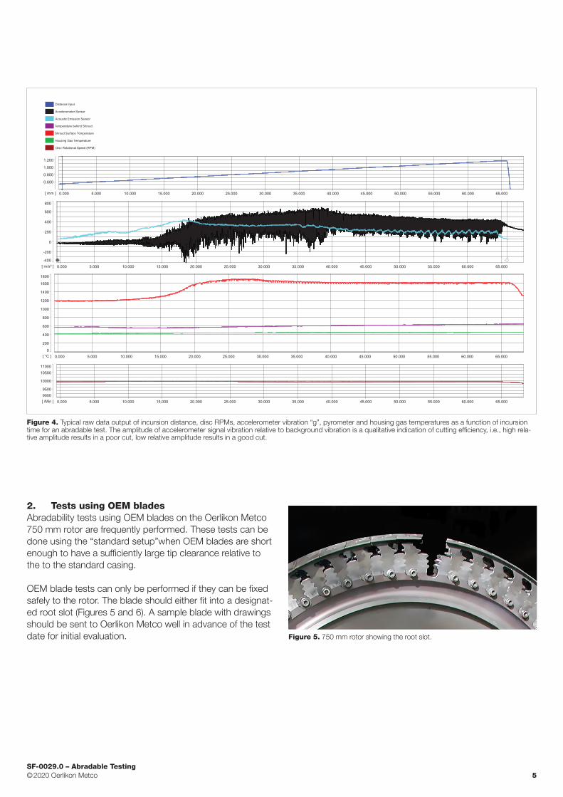
2. Tests using OEM bladesAbradability tests using OEM blades on the Oerlikon Metco 750 mm rotor are frequently performed. These tests can be done using the “standard setup”when OEM blades are short enough to have a sufficiently large tip clearance relative to the to the standard casing.
OEM blade tests can only be performed if they can be fixed safely to the rotor. The blade should either fit into a designat-ed root slot (Figures 5 and 6). A sample blade with drawings should be sent to Oerlikon Metco well in advance of the test date for initial evaluation. Figure 5. 750 mm rotor showing the root slot.

SF-0029.0 – Abradable Testing © 2020 Oerlikon Metco 6
Figure 7. Total incursion = Blade Wear + Normal Incursion
3. Measurement details
3.1 Quantified data for standard testsThe recorded and measured quantities for standard tests are:
n Blade tip velocity n Temperature at the rear of the segment n Segment wear track length (enables precise determina-
tion of incursion depth) n Incursion depth n Incursion rate n Blade height variation n Blade wear as a percentage of incursion depth n Shroud surface temperature measured using an optical
pyrometer n Blade tip temperature (optional module) n Normal and cutting forces evaluation (optional module) n Segment wear track roughness (optional module) n Stage vibration data (accelerometer signal) n Wear mechanisms n Video of tests
3.2 Total incursion depthThe change in blade height is measured using a jig, which al-lows measurement of the blade height from a reference point. The jig is rigged with a digital micrometer. The setup is calibrated with a premeasured calibration blade prior to each measurement series. Measurement precision is of the order of 2 µm (7.8 E-05 in). A precise means of shroud incursion depth determination is to measure the wear scar length and then by means of geometry calculate the wear depth. This is the most reliable method as it avoids measurement difficul-ties arising due to plastic deformation of the region adjacent to the wear track (reference surface). These two measure-ments determine the total incursion depth of a test (Figures 7 and 8).
3.3 Blade wearBlade wear is displayed in the results as a percentage of to-tal incursion depth. Positive values describe wear whereas negative values describe transfer from the shroud. Therefore,
Figure 6. EDM machined root that has been specially adapted to accommodate an OEM blade. In this example, the blade height is short enough such that it can be accommodated on the rotor using Oerlikon Metco’s standard setup with the standard casing and housing. Longer OEM blades can also be affixed using this method up to a specific root size limit. A casing can be manufactured to suit.
Substrate
Coating
Bla
de
Blade wear or transfer
Normal incursion depth (shroud wear)
a value of 100 % means there was no incursion into the coat-ing but all the wear was the result of blade wear. On the oth-er hand, a value of 0 indicates 100 % incursion into the coat-ing without any blade wear. By describing blade wear in this manner provides a value that is directly related to the total
750 mm rotor
50
0
10
20
30
40
1.21.00.80.60.40.20
Incursion depth (mm)
Volu
me
loss
(mm
2 /m
m)
Figure 8. Shroud wear volume calculation

SF-0029.0 – Abradable Testing © 2020 Oerlikon Metco 7
incursion as opposed to an absolute blade wear value that is not. This can allow a predetermined percentage of blade wear which can be tolerated based on the total incursion depth. Furthermore, this avoids discrepancies that may be created due to inconsistent incursions achieved from one test to another.
Table 2 is an example that shows the blade tip or knife-edge wear as a function of incursion depth when 0.1 mm (0.004 in) of blade tip or knife-edge wear has occurred.
Total incursion depth (mm)
Blade wear as a percentage of incursion (%)
0.5 20
1.0 10
1.5 6.7
Table 2. Blade tip / knife-edge wear as a percentage of total incursion when 0.1 mm (0.004 in) of wear has occurred.
4. Test preparation
4.1 Setting up a test matrixOerlikon Metco can assist prospective customers in setting up a test matrix for evaluating abradable coatings. The test matrix exemplar in Table 3 is a typical example of the infor-mation required prior to Oerlikon Metco supplying a quota-tion for abradable testing.
Please also specify if Oerlikon Metco should supply blade, knife-edge and/or backing plate specimens, or if your com-pany will machine and supply these yourselves. A specimen template is available to all customers for use as a final speci-men dimensional check on the dimensions of their speci-mens prior to shipping them to Oerlikon Metco.
Should you require non-standard specimens its best to send diagrams or prototypes to Oerlikon Metco well in advance so their fit for the test rig can be evaluated.
4.2 Specimen geometryDrawings for the geometries of standard test specimens are available for:
n Standard dummy blade for 750 mm rotor n Standard dummy knife-edge n Standard flat abradable wear specimen n Abradable curved liner with backing plate specimen
Note that the tips of the dummy blades and knife-edges can be machined to customer specifications. In general, a 0.7 mm (0.0275 in) thick tip is run for compressor applications. Tips of variable geometry, e.g., 0.1 to 2.0 mm (0.004 to 0.079 in) are often used to simulate, within one test, a variety of shroud contact thicknesses found on blading.
Test No. Coating Backing plate material
Blade Material
Blades per test
Blade Tip Thickness (mm)
Test Temp. (°C)
Incursion Rate (µm/s)
Tip Speed (m/s)
Incursion depth (mm)
1 A 18/8 SS TiAl6V4 1 0.7 300 5 200 1.0
2 A 18/8 SS TiAl6V4 1 0.7 300 50 200 1.0
3 A 18/8 SS TiAl6V4 1 0.7 300 500 200 1.0
4 B 18/8 SS X20Cr13 1 1.0 600 5 350 0.8
5 B 18/8 SS X20Cr13 1 1.0 700 5 350 0.8
6 B 18/8 SS X20Cr13 1 1.0 800 5 350 0.8
7 C 18/8 SS Ti 6242 1 1.5 500 30 150 1.0
8 C 18/8 SS Ti 6242 1 1.5 500 30 360 1.0
9 C 18/8 SS Ti 6242 1 1.5 600 30 150 1.0
10 D Hast X IN 718 1 2.0 1100 5 410 1.0
11 D Hast X IN 718 1 2.0 1100 50 410 1.0
12 D Hast X IN 718 1 2.0 1100 500 410 1.0
Table 3. Typical test matrix for abradability testa of four coatings.

SF-0029.0 – Abradable Testing © 2020 Oerlikon Metco 8
A
B
Figure 9. Standard ‘dummy’ specimens. A: Blade, B: Knife-edge
Figure 10. Image of a curved liner with backing plate coated with an abradable.
Figure 11. Standard wear liner shown with an abradable coating.
5. Available test servicesThe following services are available for abradability testing performed by Oerlikon Metco. Costs will be quoted upon re-ceipt of the customer’s request for quotation (preferably with a customer-supplied draft test matrix):
n Standard abradable test n Rig setup and calibration n Abradable test using standard Oerlikon Metco speci-
men geometry n Non-standard abradable test
n Rig setup and calibration n Abradable test using standard Oerlikon Metco speci-
mens or OEM blade or knife-edge specimens n Instrumented blade tests or labyrinth seal tests
n Abradable testing above 1 100 °C (2012 °F) n Standard ‘dummy’ blades or knife-edge specimens sup-
plied by Oerlikon Metco, available in the following materials:
n IN 718 n X40Cr13 n X20Cr13 n Ti 6Al 4V n Ti 6Al 2Sn 4Zr 2Mo (Ti-6-4-2)
n cBN abrasive-tipped IN 718 blades (standard) available n Standard knife-edge specimens (IN 738)
n For customer-specific material additional machining costs are required
n Standard stainless steel 18/8 backing plate supplied by Oerlikon Metco
n Standard backing plate supplied by Oerlikon Metco n Standard composition: stainless steel 18/8 n Optional compositions: In 718 or Alloy 600
n Coating microstructure evaluation n Solid particle erosion (SPE) testing in accordance with GE
E50TF121” n Standard HR15Y and HR15N hardness tests n Standard coating bond strength tests in accordance with
ASTM C633 n Shipping of specimens to customer n Additional machining of specimens by Oerlikon Metco (if
required)
All test campaigns include a complete report with all test re-sults including photography of wear results and wear mapping.
Oerlikon Metco can also support customers with thermal spray services of abradable coatings to develop spray pa-rameters that meet specific coating requirements and opti-mize parameters for best efficiency and repeatability.

SF-0029.0 – Abradable Testing © 2020 Oerlikon Metco 9
6. Test scheduling and customer visits
6.1 Scheduling considerationsPlease keep the following in mind for scheduling an abrad-able test campaign:
n Provisional bookings can be made for test slots through-out the year with your inquiry..
n Test slots will not be confirmed until all customer-supplied specimens have been delivered to Oerlikon Metco and in good order.
n Please ensure that test specimens arrive at least one week before testing is scheduled to begin to allow Oer-likon Metco to check and confirm specimen dimensions and prepare documentation for the test. Specimens tha arrive late may require that the test slot is rescheduled.
n If your specimens are shipped from multiple vendors or locations, please ensure that all providers are aware of the aforementioned scheduling requirements.
n Any freight, courier or duty charges we receive from your vendors will be added to your invoice.
6.2 Customer visitsCustomers who wish to visit our facilities to witness their tests are welcome to do so; however, please consider the following:
n The test rig control room is relatively small; therefore, please keep the number of people visiting to one or two.
n If you wish to invite third parties, please let us know in ad-vance so we can clear them.
n Rig downtime is costly. Should you wish to interrupt or delay your tests, please let us know at least one week in advance so fill your vacated slot with test for another cus-tomer.
n Filming or photography of the Oerlikon Metco abradable test facility is strictly forbidden; however, Oerlikon Metco can provide our customers and their designated third parties with standard photography, standard videos and schematics of our test facility.
7. Examples of rub results
7.1 Examples of good and poor abradability resultsRub results can be determined by visual examination of the wear plate specimens, as shown in the examples below.
Clean cut: good abradability
Heavy coating rupture after initial blade materi-al transfer
Coating rupture Slight coating rupture mixed with cutting and some blade material transfer
Mixed coating rupture and blade material transfer
Heavy blade material transfer
Figure 12. Post incursion wear plates from a number of ceramic abradable tests. .The wear plate on the left shows very good abradability. The remaining specimens show various types of poor abradability.

SF-0029.0 – Abradable Testing © 2020 Oerlikon Metco 10
7.2 Five-point wear map generationAs the expected blade tip speeds for rub interactions can be estimated with some certainty, the corresponding incursion rates are mostly not known. Therefore a general screening test makes use of a standard wear map consisting of five
different tip speed / incursion rate pairings. When combined with various coating microstructures, the re-sults from these wear maps are a powerful tool for determining ideal abrad-ability to meet the specific design requirements.
clean cut: no blade wear good cut: no blade wear or microrupture
good cut: no blade wear
good cut: no blade wear clean cut: no blade wear
Incu
rsio
n R
ate
[µ
m/s
]
Blade Tip Velocity [m/s]
500
50
5
250 350 410
Figure 13. Example of a 5-point wear map result from the test of a compressor abradable.
Coating Data: � Material: Metco 1602A � Hardness: 73 HR15Y � Tensile strength: 10.3 MPa � Erosion: 5.7 s/0.001 in
Test Conditions: � Shroud temperature: 300 °C � Incursion depth: 1.0 mm � Blade material: Ti 6Al 4V � Tip width: 0.7 mm
Blade Tip Speed (m / s)
500
5
50
410350250
Incu
rsio
n R
ate
(µm
/ s)
transfer; > 60 % blade wear
cutting; < 5 % blade wear
transfer; 20 – 30 % blade wear
coating rupture and transfer; > 60 % blade wear
Figure 14. Examples of computer-generated wear map results for varying parameters and coating microstructures for a ceramic abradable against untipped blades.
500
5
50
410350250
Incu
rsio
n R
ate
(µm
/ s)
500
5
50
410350250
Incu
rsio
n R
ate
(µm
/ s)

SF-0029.0 – Abradable Testing © 2020 Oerlikon Metco 11
Customer benefits
Effective n Abradable testing can be customized to provide excellent
correlation to actual engine testing n Testing is available for clearance control systems to be
used in aerospace gas turbine, power generation and in-dustrial gas turbines and steam turbines
n Testing available for rotating blade tips or knife-edges into abradable coating or surface
n Test can be performed to confirmed Oerlikon Metco abradable materials under customer-specific testing con-ditions or new customer material formulations
n Oerlikon Metco has three decades of abradable testing experience and tests are performed by experienced personnel
n Complete test reports provided to the customer with analysis and wear mapping done by Oerlikon Metco
Economical n Extremely cost effective compared to conventional test
cell and on-wing tests n Risk is substantially reduced n Multiple candidate coatings can be evaluated quickly and
economically
Efficient n Abradable candidates can be tested and reports provid-
ed in just a few days or weeks, therefore results can be obtained much faster than test-cell tests or on-wing testing
n Standard or customized blade, knife-edge and/or wear specimens can be supplied by Oerlikon Metco or by the customer, whichever is preferred
n Abradable coatings on wear specimens can be applied by Oerlikon Metco
Experience n Oerlikon Metco designs and produces abradable materi-
als for critical turbomachinery clearance control applica-tions for more than 50 years
n Oerlikon Metco has more than three decades of abrad-able testing experience
n All abradable tests performed on the Oerlikon Metco abradable test rig are executed by experienced personnel

SF-0029.0 – Abradable Testing © 2020 Oerlikon Metco 12
www.oerlikon.com/metco [email protected]
Information is subject to change without prior notice.
Contact us to schedule your abradable tests
Contact your Oerlikon Metco account manager or:
Coating Test Lab ManagerOerlikon Metco AG SwitzerlandMaterials R&DRigackerstrasse 165610 WohlenSwitzerland
Tel: +41 56 618 8181Fax: +41 56 618 8100E-mail: [email protected] (subject: Abradable Testing)