Solution of Beams and Trusses Problems - Sistemas … 656... · Solution of Beams and Trusses...
24
MAE 656 - Advanced Computer Aided Design 03. Beams and Trusses Solution of Beams and Trusses Problems
Transcript of Solution of Beams and Trusses Problems - Sistemas … 656... · Solution of Beams and Trusses...

MAE 656 - Advanced Computer Aided Design
03. Beams and Trusses
Solution of Beams and Trusses Problems

Introduction
If our structure is made of multiple elements that can be characterized as beams or trusses, the best approach to the problem is with these elements. These should be used whenever it is possible.
Beams: Each node has three possible displacements and three possible rotations. Efforts in the node are three forces (axial and shear) and three moments (torsion and bending)
Trusses: The bar element only handles axial loads. Displacement of the nodes will be along the bar axis.
MAE 656 – cba Dr. Xavier Martinez, 2012 03. Beams & Trusses – Doc 01

Beam Simulations
The simulation of a structure made of beam elements is made with linear elements that represent the beam axis.
MAE 656 – cba Dr. Xavier Martinez, 2012 03. Beams & Trusses – Doc 01
Beam Simulations
The beams can have any possible shape:
MAE 656 – cba Dr. Xavier Martinez, 2012 03. Beams & Trusses – Doc 01
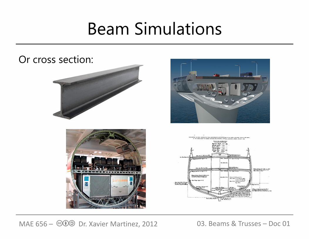
Beam Simulations
Or cross section:
MAE 656 – cba Dr. Xavier Martinez, 2012 03. Beams & Trusses – Doc 01
Beam Simulations
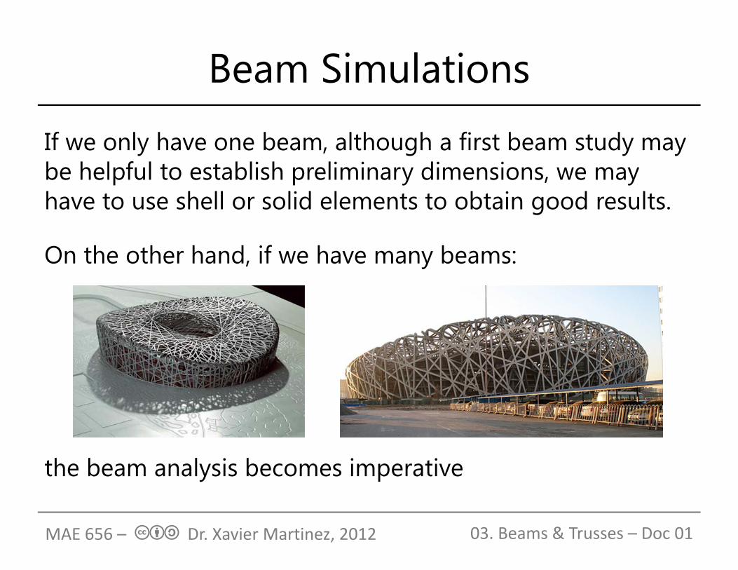
If we only have one beam, although a first beam study may be helpful to establish preliminary dimensions, we may have to use shell or solid elements to obtain good results.
On the other hand, if we have many beams:
the beam analysis becomes imperative
MAE 656 – cba Dr. Xavier Martinez, 2012 03. Beams & Trusses – Doc 01

Simplification of the problem
We want to study the following crane:
MAE 656 – cba Dr. Xavier Martinez, 2012 03. Beams & Trusses – Doc 01

Simplification of the problem
The first thing we have to decide is in which configuration (or configurations) we want to study it. If we are concerned about maximum bending, this can be the worst scenario:
MAE 656 – cba Dr. Xavier Martinez, 2012 03. Beams & Trusses – Doc 01

Simplification of the problem
We must know the problem dimensions:
MAE 656 – cba Dr. Xavier Martinez, 2012 03. Beams & Trusses – Doc 01

Simplification of the problem
We must locate the axis of the different beams, as the structure will be defined according to these axis.Notice that we have some distortions of reality by having to attach the different bar elements along their axis. In this case, the piston becomes larger.
MAE 656 – cba Dr. Xavier Martinez, 2012 03. Beams & Trusses – Doc 01
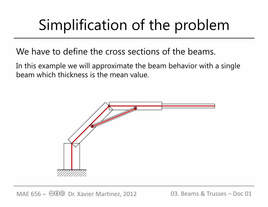
Simplification of the problem
We have to define the cross sections of the beams.In this example we will approximate the beam behavior with a single beam which thickness is the mean value.
MAE 656 – cba Dr. Xavier Martinez, 2012 03. Beams & Trusses – Doc 01

Simplification of the problem
Finally we have to define the structure dimensions and the dimensions of all cross sections of the structure:
MAE 656 – cba Dr. Xavier Martinez, 2012 03. Beams & Trusses – Doc 01
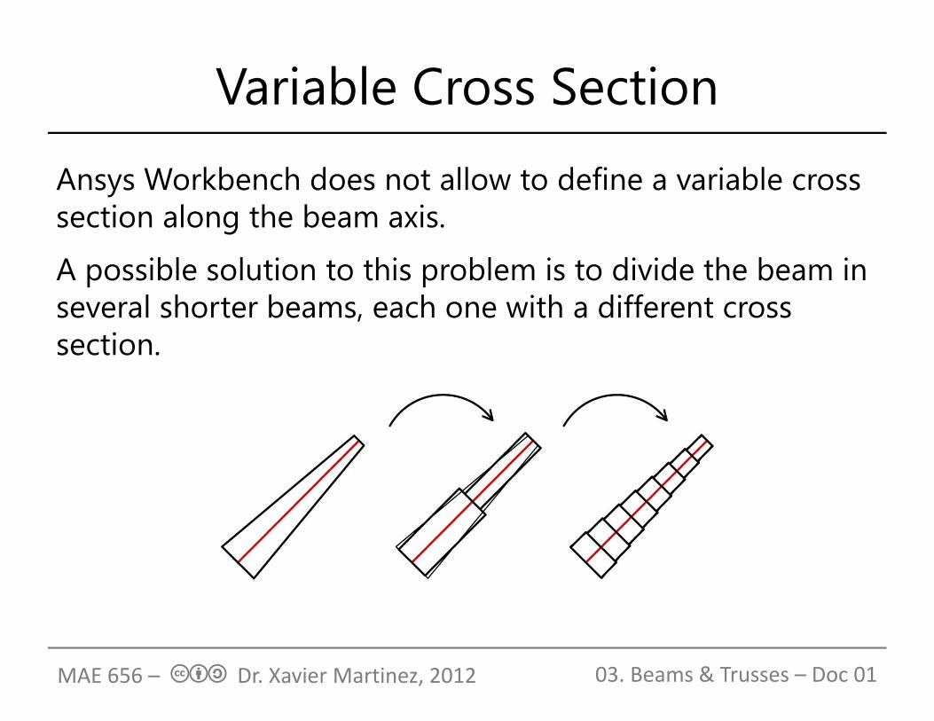
Variable Cross Section
Ansys Workbench does not allow to define a variable cross section along the beam axis.
A possible solution to this problem is to divide the beam in several shorter beams, each one with a different cross section.
MAE 656 – cba Dr. Xavier Martinez, 2012 03. Beams & Trusses – Doc 01

Cross Section Excentricity
There are some structures where the beam axis are not aligned:
The cross section of this structure looks like:
MAE 656 – cba Dr. Xavier Martinez, 2012 03. Beams & Trusses – Doc 01
Cross Section Excentricity
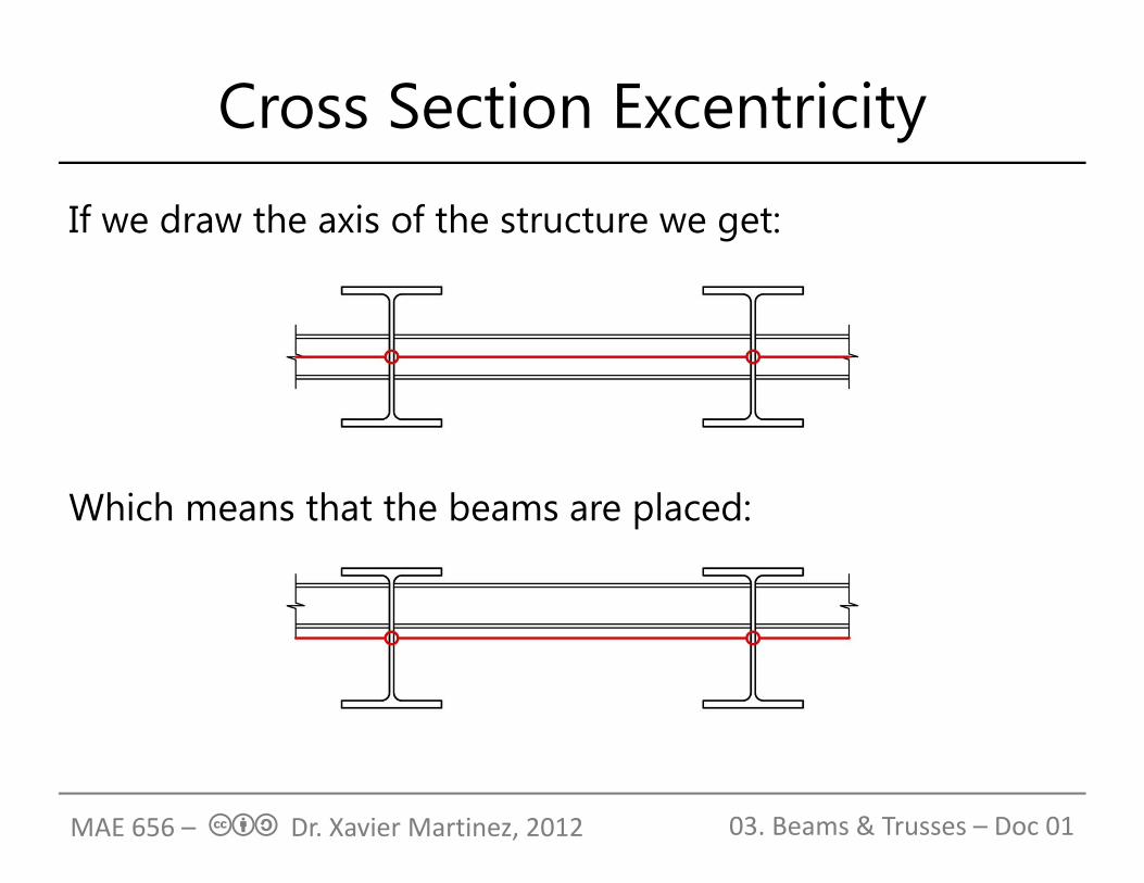
If we draw the axis of the structure we get:
Which means that the beams are placed:
MAE 656 – cba Dr. Xavier Martinez, 2012 03. Beams & Trusses – Doc 01
Cross Section Excentricity
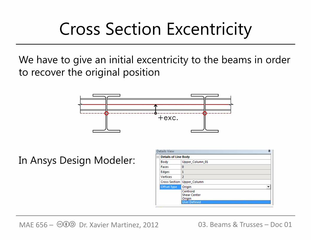
We have to give an initial excentricity to the beams in order to recover the original position
In Ansys Design Modeler:
MAE 656 – cba Dr. Xavier Martinez, 2012 03. Beams & Trusses – Doc 01
Previous knowledge of the problem
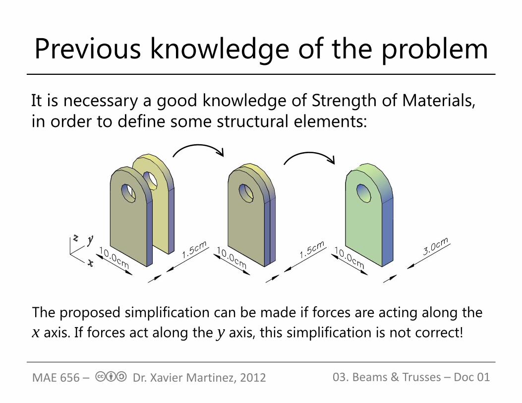
It is necessary a good knowledge of Strength of Materials, in order to define some structural elements:
MAE 656 – cba Dr. Xavier Martinez, 2012 03. Beams & Trusses – Doc 01
The proposed simplification can be made if forces are acting along the x axis. If forces act along the y axis, this simplification is not correct!
Beam Elements in Ansys Workbench
The linear element available in ANSYS Workbench is BEAM 188: (// Element Reference // I. Element Library // BEAM188)(http://www.kxcad.net/ansys/ANSYS/ansyshelp/Hlp_E_BEAM188.html)
This beam element is based on Timoshenko beam theory, which is a first order shear deformation theory: transverse shear strain is constant through the cross-section; that is, cross-sections remain plane and undistorted after deformation.
It is not a TRUSS element. We will have to release node connectivities in order to get a truss performance.
MAE 656 – cba Dr. Xavier Martinez, 2012 03. Beams & Trusses – Doc 01

Body to body connections
It is possible to define the degrees of freedom that are fixed and free in the connection of two different bodies. This is done with body to body connections.
In order to get a “Truss performance” we have to create a revolute joint, which frees the rotation along z axis.
The bodies to be connected must be independent.
MAE 656 – cba Dr. Xavier Martinez, 2012 03. Beams & Trusses – Doc 01

Body to body connections
MAE 656 – cba Dr. Xavier Martinez, 2012 03. Beams & Trusses – Doc 01
In beams elements, a revolute joint is applied to the vertex that is shared by the two elements that are connected.
While a revolute joint frees z rotation. A General joint allows defining the degrees of freedom that are free.

MESHING
The performance of BEAM 188 element is such that it provides a correct solution if each bar is defined with a single finite element.
In case of structures with curved beam elements, or with elements with a variable cross section, it is necessary to define enough elements to have a good representation of the structure geometry
MAE 656 – cba Dr. Xavier Martinez, 2012 03. Beams & Trusses – Doc 01
RESULTS
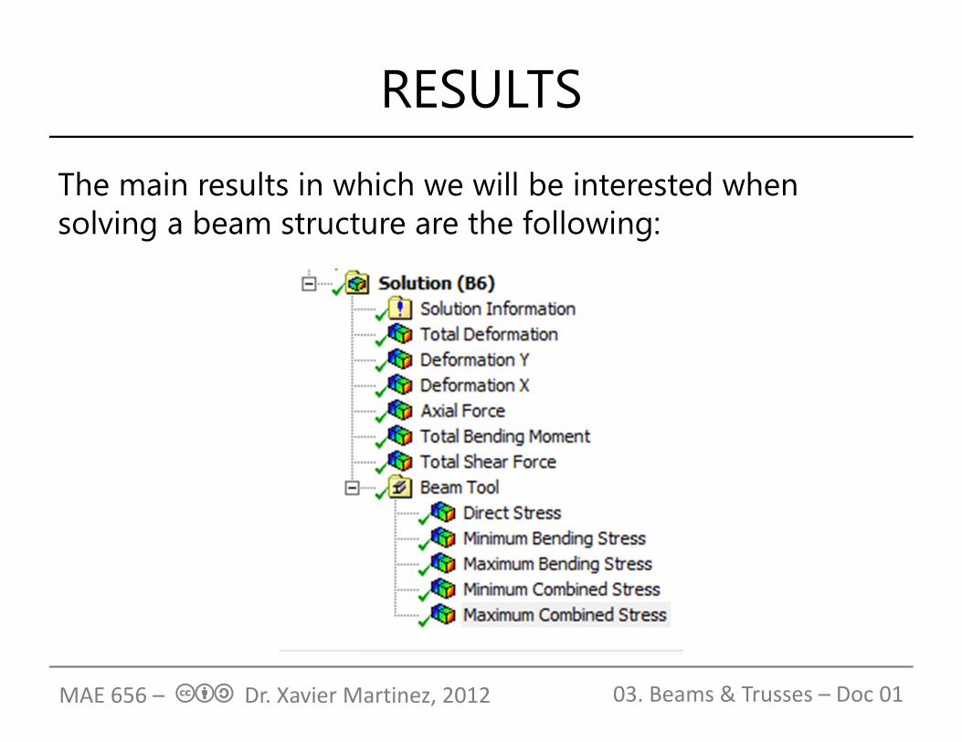
The main results in which we will be interested when solving a beam structure are the following:
MAE 656 – cba Dr. Xavier Martinez, 2012 03. Beams & Trusses – Doc 01

Results
Direct stress is the stress produced by the axial load
Bending stress (maximum and mínimum) is the stress produced by the bending moments
Combined stress is the stress result of the linear combination of the stresses produced by the axial load and the stresses produced by the bending moments.
MAE 656 – cba Dr. Xavier Martinez, 2012 03. Beams & Trusses – Doc 01
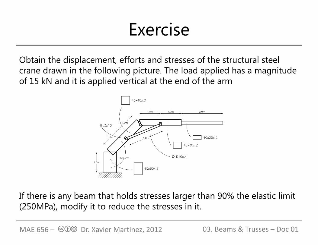
ExerciseObtain the displacement, efforts and stresses of the structural steel crane drawn in the following picture. The load applied has a magnitude of 15 kN and it is applied vertical at the end of the arm
If there is any beam that holds stresses larger than 90% the elastic limit (250MPa), modify it to reduce the stresses in it.
MAE 656 – cba Dr. Xavier Martinez, 2012 03. Beams & Trusses – Doc 01