Solution guide 2014 - Schneider Electric · PDF fileSolution guide 2014 Blokset High...
30
Solution guide 2014 Blokset High dependability and low voltage switchboard
-
Upload
truongkhanh -
Category
Documents
-
view
623 -
download
72
Transcript of Solution guide 2014 - Schneider Electric · PDF fileSolution guide 2014 Blokset High...
Solution guide2014
BloksetHigh dependability and low voltage switchboard

Presentation 2Solution overview 10
Functional units 14
Cubicles 20
Installation 24
Blokset performances 26
1
Contents

2
Presentation Fields of applicationsRequirements and solutions
Refinery, gas, petrochemical
Mines, metallurgy, cement works
Requirements Continuity of supply and safety
Environment and safety
Solutions > Intelligence in the motor control and the electrical distribution.> Dependability.> Rapid restarting after an incident.> Internal arc protection. > Tightness ensured by IP54/IP42 tightness for the dusty and /or damp environment .
> Specific “anti-corrosion” treatment on conductive parts.> Tightness ensured by IP54/IP42 guaranteed parts.
Data center Power generation
Requirements Availability and permanent continuity of service
Continuity of supply and safety
Solutions > Resilient Electrical Architecture.> TVD is tested, validated and documented.> Preventive maintenance leveraging the smart devices.> Plug in base system that reduce MTTR ( mean time to repair).
> Intelligence in the motor control and the electrical distribution. > Withdrawable solutions.
3
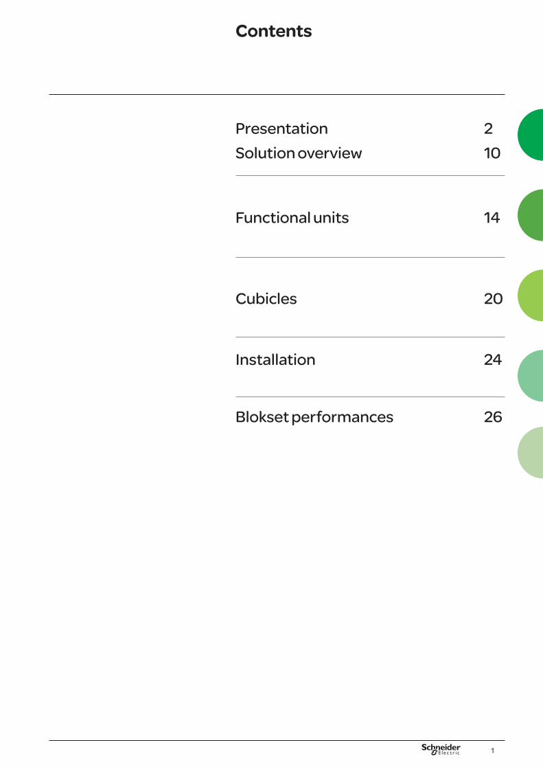
Presentation Fields of applicationsFunctions
Electrical distribution
Power and motor control center
High power incomings

4
Intelligent solutions for fast and easy access to information from anywhere, around the clock
Information for local operation, maintenance and upgrading of your installation Information on electrical distribution, motor operation and power consumption can be accessed.
> MotorSys™ iPMCC solutions can integrate a dedicated human-machine interface (HMI) or communicate via a personal computer directly on the motor starters.
2
Remote control and monitoring of your installationA continuous, real-time communication interface with your control and monitoring systems for energy management and process control.
> MotorSys™ iPMCC solutions communicate with the major industrial local area networks on the market (Ethernet TCP / IP, Profibus-DP, DeviceNet, Modbus, etc.).> With the data delivered in real time, the operational and maintenance staff will have the immediate access to the relevant information to control your motors and the electrical distribution locally or remotely.> Warning messages can be sent automatically to a mobile phone in the event of an alarm or group of alarms.
1
Our MotorSys™ iPMCC solutions for continuous and critical processes were developed through our specific expertise in energy and industrial process control management. Forming the keystone of the energy efficiency of your process units, they incorporate a range of functions to supply power (intelligent Power Control Centre - iPCC), start up, control, protect and monitor your LV network electric motors and loads (intelligent Motor Control Centre - iMCC). The breadth of the range ensures that all types of continuous and critical process as well as the specific requirements are covered.
1
Presentation Blokset solutionMotor Sys™ intelligent Power & Motor Control Center (iPMCC)
Our MotorSys™ iPMCC solutions help your teams optimise the energy efficiency of your assets, offering the following benefits:
b Dependability, even in severe industrial environments,
b Safety of personnel and assets, maintainability and upgradability,
b Lead time management, risk and cost reduction throughout your installation's entire lifecycle.

5
MotorSysTM iPMCC solutions integrate perfectly into your site network infrastructure, whatever the communication protocol is also, into the energy management control systems and the process control systems.
Example of a MotorSysTM iPMCC solution integrated into a site infrastructure
Information for site engineeringWith information delivered to ensure the traceability of electrical distribution, motor operation and power consumption data, installations are constantly improved.
> MotorSys™ iPMCC solutions make it easy to collect all the statistics you need to develop effective plans covering the operation, maintenance, optimisation and upgrading the installations, and the energy efficiency.
3
3
2
Presentation Blokset solutionMotor Sys™ intelligent Power & Motor Control Center (iPMCC)
6
Presentation Blokset solutionInnovation
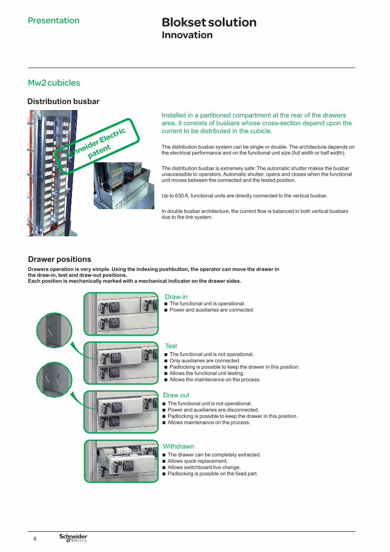
Mw2 cubicles
Draw-in b The functional unit is operational. b Power and auxiliaries are connected.
Test b The functional unit is not operational. b Only auxiliaries are connected. b Padlocking is possible to keep the drawer in this position. b Allows the functional unit testing. b Allows the maintenance on the process.
Draw out b The functional unit is not operational. b Power and auxiliaries are disconnected. b Padlocking is possible to keep the drawer in this position. b Allows maintenance on the process.
Withdrawn b The drawer can be completely extracted. b Allows quick replacement. b Allows switchboard live change. b Padlocking is possible on the fixed part.
Drawers operation is very simple. Using the indexing pushbutton, the operator can move the drawer in the draw-in, test and draw-out positions. Each position is mechanically marked with a mechanical indicator on the drawer sides.
Drawer positions
Distribution busbarInstalled in a partitioned compartment at the rear of the drawers area, it consists of busbars whose cross-section depend upon the current to be distributed in the cubicle.
The distribution busbar system can be single or double. The architecture depends on the electrical performance and on the functional unit size (full width or half width).
The distribution busbar is extremely safe: The automatic shutter makes the busbar unaccessible to operators. Automatic shutter, opens and closes when the functional unit moves between the connected and the tested position.
Up to 630 A, functional units are directly connected to the vertical busbar.
In double busbar architecture, the current flow is balanced in both vertical busbars due to the link system.
Schneider Electric
patent

7
Presentation Blokset solutionImplementation
Reliability and flexibility> The switchboards are type tested assemblies. They have a complete electrical and mechanical inspection in the factory.> The modularity of the cubicle makes the installation of a new functional unit easy.
Safety of people and equipments> Internal arc protection, in compliance with the requirements of the international regulations.> Continuity of supply guaranteed by limitation of the harmful effects of the internal arc in the switchboard.> Quick repair of the area where the arc was confined.> Safety of people and equipment guaranteed during the occurrence of the fault.> Insulated busbars prevents flashover and propagation of the arc.
Withstand the most demanding environments> IP54/IP42 tightness for the dusty and / or damp environments.> Environments with ambient temperatures exceeding 50° C.
Type tested
Blokset is totally type-tested in accordance with IEC 61439-2 • certified by independant labs: CPRI / ERDA. • type-tests carried out: • temperature-rise • dielectric properties, • short-circuit withstand, • effectiveness of the protective circuit, • conformity of the clearance and creepage distances, • mechanical operation, • degree of protection.

8
Presentation Blokset solutionImplementation
Two specific compliances
StandardFor all applications.
Two levels of safety
Cubicle partitioningProtective screens (side partition + vertical busbar screen) prevent tracking of an arc in the cubicle.
Type-tested solutionAt functional unit level, the drawers are type tested.
Two levels of service
Operation
F WShutting down only the concerned functional unit. Shutting down only the concerned functional unit, but
test of the control system possible before the resumed operation.
MaintenanceShutting down the whole switchboard. Shutting down only the concerned functional unit
without connections handlings.
EvolutionShutting down the whole switchboard. Addition of a functional unit without shutting down the
switchboard, free addition in non-equiped spare slots.
Four levels of functional unit (FU) partitioning
Service Index
IndustryInternal arc protection
Available forms 2b 3b 4a 4bBusbars / functional units separation b b b b
Busbars / terminal blocks(1) separation for external conductors b b b b
Separation between functional units - b b b
Separation between terminal blocks(1) for external conductors - - b b
Terminal blocks separation for external conductors / functional units - - - b
(1) They are integral part of the functional unit.

9
Presentation

10
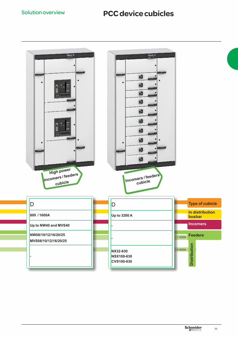
Solution overview PCC device cubicles
y 630A
> 630A
Type of cubicle
In distribution busbar
Incomers
Feeders
Dis
trib
utio
n
D
<4000A
Up to NW40 and MVS40
-
-
D
Up to 6000A
Up to NW63
-
-
High power
incomers cubicle High power
incomers cubicle
11
y 630A
> 630A
Type of cubicle
In distribution busbar
Incomers
Dis
trib
utio
n
D
800 / 1600A
Up to NW40 and MVS40
NW08/10/12/16/20/25 MVS08/10/12/16/20/25
-
High power
incomers / feeders
cubicle Incomers / feeders
cubicle
D
Up to 3200 A
-
-
NX32-630 NSX100-630 CVS100-630
Solution overview PCC device cubicles
Feeders

12
Solution overview
Type of cubicle
In distribution busbar
Incomers
Feeders
PCC / MCC device cubicles
Optimized for
MCC drawers
Mw2
800A
-
b Up to132kW
b Up to 630A
Blokset Mw2For MCC application drawers, Mw2 is an optimized solution, robust, reliable and secure.The Mw2 satisfies the motor control requirements of the most demanding processes.

13
Solution overview

14
Feeder’s Service IndexFunctional units
The switchboard must permit
The application’s continuity of service is:
Making the right choice
Shutting down the whole switchboard
Shutting down the whole switchboard
Shutting down the whole switchboard
Shutting down only the concerned Functional unit Allows “test” position
Shutting down only the concerned Functional unit without connections handling
Addition of a Functional unit without shutting down the switchboard, free addition in non-equipped spare slots
OperationSettingLocking
Padlocking
OperationSetting
Padlocking
MaintenanceCheckingCleaningRepairing
EvolutionAddition
ModificationExpansion
Not required
p p pComposition
3rd letter: auxiliaries connection (coils, contacts, …)
2nd letter: Power downstream connection
1st letter: Power upstream connection
Letters and signification
F Connection is fixed
W Connection is withdrawable
Blokset offers several options to answer the installation needs and the service continuity required.F power upstream and downstream connections are fixed, auxiliaries are fixed.W power upstream and downstream connections are withdrawable, auxiliaries is withdrawable.
F
EssentialW

15
Fixed on mounting plate fixed device
Main functional units typesFunctional units
PCC drawers Mw2 full width drawer
MCC drawers Mw2 half width drawer
Mw2 full width drawer

16
Functional units Electrical distributionIn > 630 A
Selection of the functional unit - rated 415 V - 50 Hz - IP42 /54-50°CIn (A) Icw max (kA) Device Cubicle
800 < In < 4000 65 NW40 MVS40
4000 < In < 6000 65 NW50-63

17
Functional units Electrical distributionIn y 630 A
Withdrawability In (A) Device Functional unit Cubicle
Drawer 16 < In y 630 C60 NX32-630 NSX100-630CVS100-630
Fixed 16 < In y 630 NX32-630 NSX100-630 CVS100-630
Selection of the functional unit - rated 415 V - 50 Hz - IP42 / 54-50°C

Circuit breaker-contactor combination TeSys U b Advantages
v Easy installation: - easy to order: 1 power base + 1 protection (control unit). - easy to install: only one device must be wired, reduced installation times. - easy to set: locally via the LCD and keypad built into the control unit or remotely.
v Continuity of service: - total coordination between protection of the devices. - protection functions modified by simply changing the control unit. - manual or automatic reset following a thermal fault.
v Upgradeability: modular design. Functional modules (communication and protection) can be easily changed at any time without having to rewire the entire assembly.
One component motor feeder
Two components motor feeder
Thermomagnetic circuit-breaker + contactor
b Advantages v Very economic solutions. v Suitable for all types of diagrams. v Manual reset following a thermal fault. v Type 2 coordination.
Three components motor feeder
Advantages b Wide choice of solutions. b Suitable for all types of diagrams. b Manual or automatic reset following a thermal fault. b 2 starting classes (10 and 20). b Type 2 coordination. b Segregation of thermal and magnetic faults.
18
Motor controlFunctional units

Advantages b High breaking capacity. b Separate current and arcing zone. b High short circuit making capacity and withstand the capacity. b Inbuilt phase barriers. b Double break. b Type 2 coordination.
With Fupact - SDF
With MCCB'sAdvantages
b Very economic solutions. b Fault current limitation technology increases life of installations. b Line load reversibility for entire compact NSX range. b Easy upgradability. b Type 2 coordination.
19
Motor controlFunctional units
20
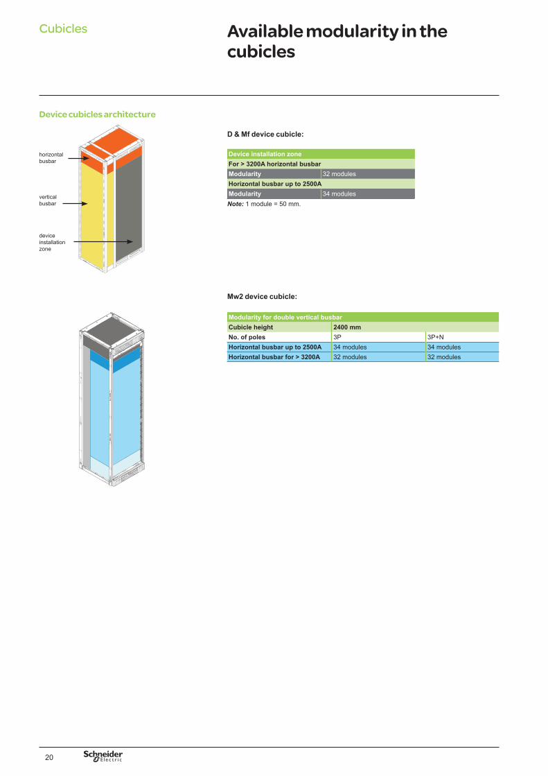
Cubicles Available modularity in the cubicles
Device cubicles architecture
horizontal busbar
vertical busbar
device installation zone
Mw2 device cubicle:
Modularity for double vertical busbarCubicle height 2400 mmNo. of poles 3P 3P+NHorizontal busbar up to 2500A 34 modules 34 modulesHorizontal busbar for > 3200A 32 modules 32 modules
D & Mf device cubicle:
Device installation zoneFor > 3200A horizontal busbarModularity 32 modulesHorizontal busbar up to 2500AModularity 34 modulesNote: 1 module = 50 mm.
21
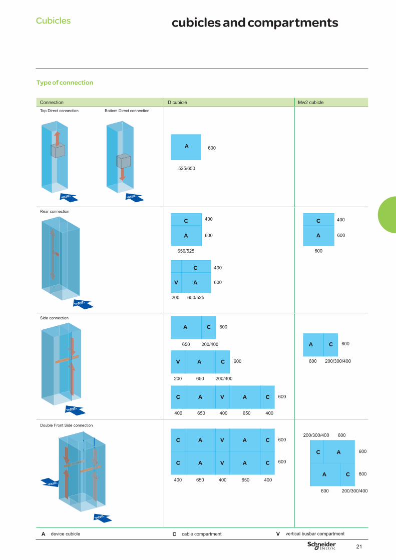
Type of connection
Connection D cubicle Mw2 cubicle
A 600
650/525
C 400
A 600
525/650
A 600
600
C 400
AV 600
650/525200
C 400
A 600
600
C
200/300/400
A
A
600
600
600
600200/300/400
C
C
200/300/400
A
650
600C
200/400
A
650
650
650
400
400
650
650
400
400
600
600
600
600
C
V
V
V
C
C
C
C
200/400200
400
400
Cubicles cubicles and compartments
Bottom Direct connectionTop Direct connection
Side connection
Double Front Side connection
Rear connection
A device cubicle C cable compartment V vertical busbar compartment
A
A
A
A
VC CA A
22
Cubicles Presentation
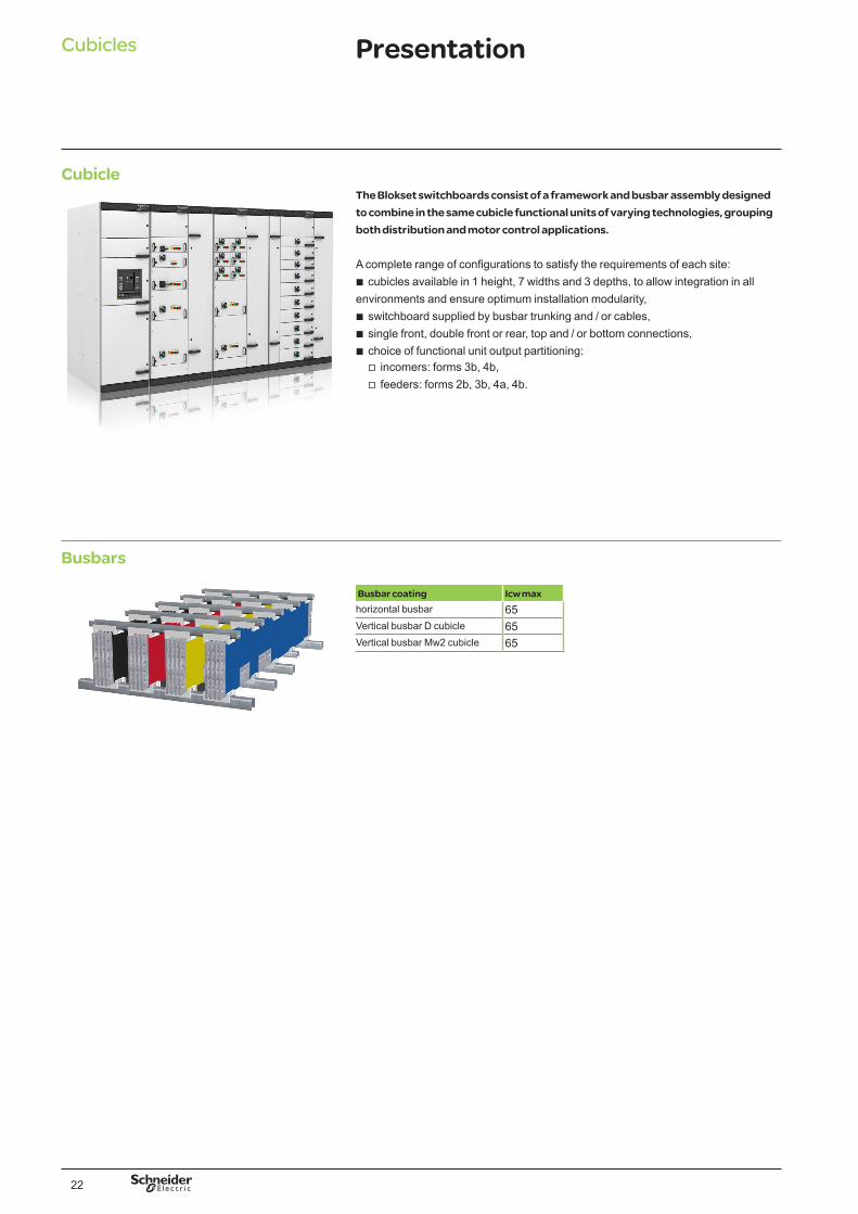
CubicleThe Blokset switchboards consist of a framework and busbar assembly designed to combine in the same cubicle functional units of varying technologies, grouping both distribution and motor control applications.
A complete range of configurations to satisfy the requirements of each site: b cubicles available in 1 height, 7 widths and 3 depths, to allow integration in all
environments and ensure optimum installation modularity, b switchboard supplied by busbar trunking and / or cables, b single front, double front or rear, top and / or bottom connections, b choice of functional unit output partitioning:
Busbars
Busbar coating Icw maxhorizontal busbar 65Vertical busbar D cubicle 65Vertical busbar Mw2 cubicle 65
v incomers: forms 3b, 4b, v feeders: forms 2b, 3b, 4a, 4b.

23
Cubicles Cubicles description
Functional unitMain characteristics
Main characteristics
Main characteristics
Devices Icw max (kA) Vertical busbar In (A)
Type of distribution
NW50-63 65 up to 6000 1 incomer or 1 feeder
2 incomers + 1 coupling
1 busbar coupler
Devices Icw max (kA) Vertical busbar In (A)
Type of distribution
NW08-40 MVS08-40
65 <4000 1 incomer or 1 feeder
2 incomers + 1 coupling
1 busbar coupler
Devices Icw max (kA) Vertical busbar In (A)
Type of functional unit
NX32-630 NSX100-630 CVS100-630
65 630 to 3200 Fixed
Main characteristicsDevices Icw max (kA) Vertical busbar In
(A)Type of functional unit
C60 NX32-630 NSX100-630 CVS100-630
65 Up to 800 Drawer

24
Ground fastening
Cubicle installationFixing points
Installation
Double front connectionRear connection
Side connection
Section width 600
b Section width 650/525
b Section width 900 b Section width 800
b Section width 1200
b Section width 1000
b Section width 1050/925 (650/525 + 400) b Section width 1250/1125(200 + 650/525 + 400)
122,5 25
A
405/280180220 122,5 25
A
955
b Section width 1050/925(200 + 650/525 + 200)
322,5
112.525
A
405/280210
b Section width 850/725 (200 + 650/525)
322,5
112.525
A
405/280
112.5 25
A
405/280220 180
322,5
A: 350 mm for a depth of 400 mm 550 mm for a depth of 600 mm 950 mm for a depth of 1000 mm
405/280122,5 25
A
687,5
737,5 180697,5
550
25
Side connection D cubicle
122,5355
350
625
25
6001000
600
687,5
687,5
180
180
697,5
697,5
800 900 1000
737,5
737,5
550
251000800 900

(mm)
(mm)
2400(mm)
25
Minimum distances around switchboard
b Provide a minimum space of 500 mm above the switchboard for connection by cables or for fishplating the horizontal busbar.
Clearance above the switchboard.
Double front connection.
Rear connection. Front connection.
Cubicle installationSwitchboard positionning
Installation

26
Further technical informationBlokset performances
General dataStandard environment
reference standards IEC IEC 61439-2IEC 60529
climatic resistance damp heat withstand IEC 60068-2-30dry heat withstand IEC 60068-2-2low temperature withstand IEC 60068-21salt spray withstand IEC 60068-2-11
installation indoorenvironment (CEM) type 2
Mechanical datacable entry top / bottomaccess front / reardegree of protection (IP) 42 / 54form 2b / 3b / 4a / 4bwithdrawability FFF / WWWdimensions (mm) height 2400
width 525 / 725 / 925 /650/850/ 1050 / 1200 / 1300
depth 600 / 1000 / 1200installation modularity in a cubicle
36 modules of 50 mm
panel coating epoxy / polyester powderpolymerised
panelling colour RAL 9003
Electrical datarated insulation voltage (Ui) 1000 Vrated operational voltage (Ue) 415 V ACrated frequency (F) 50 / 60 Hzrated impact withstand voltage (Uimp) 12 kVrated auxiliary circuit voltage 230 V AC max.surge category IVdegree of pollution 3rated current (In) 6000Ahorizontal busbar short-term rated current (Icw) 1s 50 / 65 kA rmsvertical busbar short-term rated current (Icw) 1s 65 kA rmsrated conditional short-circuit current (lcc) up to 65 kAearthing diagram TNS-TT-ITcurrent limit of power incoming and outgoing feeders up to 5000 Apower limit of motor control feeders up to 132 kW 415 V


This document has been printed on ecological paper
Schneider Electric India Pvt. Ltd.9th floor, DLF Building No. 10, Tower C, DLF Cyber City, Phase II,Gurgaon 122002 HaryanaPhone: ++91 124 3940400, Fax: ++91 124 4222036http://www.schneider-electric.com
ESBED297701EN
03-2014
© S
chne
ider
Ele
ctric
- A
ll rig
hts
rese
rved
As standards, specifications and designs change from time to time, please ask for confirmation of the information given in this publication.
Publishing: Design: Printing: