Solucionario faires
641
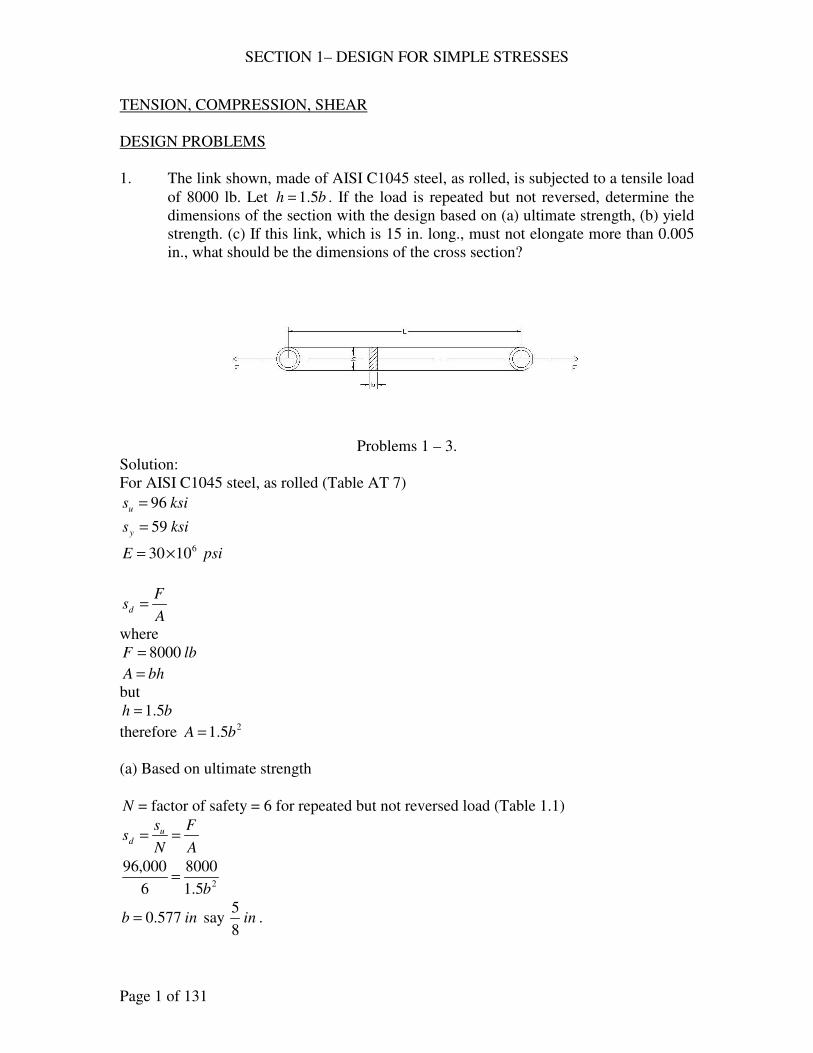
SECTION 1– DESIGN FOR SIMPLE STRESSES Page 1 of 131 TENSION, COMPRESSION, SHEAR DESIGN PROBLEMS 1. The link shown, made of AISI C1045 steel, as rolled, is subjected to a tensile load of 8000 lb. Let b h 5 . 1 = . If the load is repeated but not reversed, determine the dimensions of the section with the design based on (a) ultimate strength, (b) yield strength. (c) If this link, which is 15 in. long., must not elongate more than 0.005 in., what should be the dimensions of the cross section? Problems 1 – 3. Solution: For AISI C1045 steel, as rolled (Table AT 7) ksi s u 96 = ksi s y 59 = psi E 6 10 30 × = A F s d = where lb F 8000 = bh A = but b h 5 . 1 = therefore 2 5 . 1 b A = (a) Based on ultimate strength N = factor of safety = 6 for repeated but not reversed load (Table 1.1) A F N s s u d = = 2 5 . 1 8000 6 000 , 96 b = in b 577 . 0 = say in 8 5 .
-
Upload
juan02468 -
Category
Engineering
-
view
2.360 -
download
287
Transcript of Solucionario faires
SECTION 1– DESIGN FOR SIMPLE STRESSES
Page 1 of 131
TENSION, COMPRESSION, SHEAR
DESIGN PROBLEMS
1. The link shown, made of AISI C1045 steel, as rolled, is subjected to a tensile load
of 8000 lb. Let bh 5.1= . If the load is repeated but not reversed, determine the
dimensions of the section with the design based on (a) ultimate strength, (b) yield
strength. (c) If this link, which is 15 in. long., must not elongate more than 0.005
in., what should be the dimensions of the cross section?
Problems 1 – 3.
Solution:
For AISI C1045 steel, as rolled (Table AT 7)
ksisu 96=
ksisy 59=
psiE 61030×=
A
Fsd =
where
lbF 8000=
bhA =
but
bh 5.1=
therefore 25.1 bA =
(a) Based on ultimate strength
N = factor of safety = 6 for repeated but not reversed load (Table 1.1)
A
F
N
ss u
d ==
25.1
8000
6
000,96
b=
inb 577.0= say in8
5.
SECTION 1– DESIGN FOR SIMPLE STRESSES
Page 2 of 131
inbh16
155.1 ==
(b) Based on yield strength
N = factor of safety = 3 for repeated but not reversed load (Table 1.1)
A
F
N
ss u
d ==
25.1
8000
3
000,59
b=
inb 521.0= say in16
9.
inbh32
275.1 ==
(c) Elongation = AE
FL=δ
where,
in005.0=δ
lbF 8000=
psiE 61030×=
inL 15= 25.1 bA =
then,
AE
FL=δ
( )( )( )( )62 10305.1
158000005.0
×=
b
inb 730.0= say in4
3.
inbh8
115.1 ==
2. The same as 1 except that the material is malleable iron, ASTM A47-52, grade 35
018.
Solution:
For malleable iron, ASTM A47-52, grade 35 018(Table AT 6)
ksisu 55=
ksisy 5.36=
psiE 61025×=
SECTION 1– DESIGN FOR SIMPLE STRESSES
Page 3 of 131
A
Fsd =
where
lbF 8000=
bhA =
but
bh 5.1=
therefore 25.1 bA =
(a) Based on ultimate strength
N = factor of safety = 6 for repeated but not reversed load (Table 1.1)
A
F
N
ss u
d ==
25.1
8000
6
000,55
b=
inb 763.0= say in8
7.
inbh16
515.1 ==
(b) Based on yield strength
N = factor of safety = 3 for repeated but not reversed load (Table 1.1)
A
F
N
ss u
d ==
25.1
8000
3
500,36
b=
inb 622.0= say in16
11.
inbh32
115.1 ==
(c) Elongation = AE
FL=δ
where,
in005.0=δ
lbF 8000=
psiE 61025×=
inL 15= 25.1 bA =
then,
SECTION 1– DESIGN FOR SIMPLE STRESSES
Page 4 of 131
AE
FL=δ
( )( )( )( )62 10255.1
158000005.0
×=
b
inb 8.0= say in8
7.
inbh16
515.1 ==
3. The same as 1 except that the material is gray iron, ASTM 30.
Solution:
For ASTM 30 (Table AT 6)
ksisu 30= , no ys
psiE 6105.14 ×=
Note: since there is no ys for brittle materials. Solve only for (a) and (c)
A
Fsd =
where
lbF 8000=
bhA =
but
bh 5.1=
therefore 25.1 bA =
(a) Based on ultimate strength
N = factor of safety = 7 ~ 8 say 7.5 (Table 1.1)
A
F
N
ss u
d ==
25.1
8000
5.7
000,30
b=
inb 1547.1= say in16
31 .
inbh32
2515.1 ==
(c) Elongation = AE
FL=δ
where,
in005.0=δ
lbF 8000=
psiE 6105.14 ×=
SECTION 1– DESIGN FOR SIMPLE STRESSES
Page 5 of 131
inL 15= 25.1 bA =
then,
AE
FL=δ
( )( )( )( )62 105.145.1
158000005.0
×=
b
inb 050.1= say in16
11 .
inbh32
1915.1 ==
4. A piston rod, made of AISI 3140 steel, OQT 1000 F (Fig. AF 2), is subjected to a
repeated, reversed load. The rod is for a 20-in. air compressor, where the
maximum pressure is 125 psig. Compute the diameter of the rod using a design
factor based on (a) ultimate strength, (b) yield strength.
Solution:
From Fig. AF 2 for AISI 3140, OQT 1000 F
ksisu 5.152=
ksisy 5.132=
( ) ( ) kipslbforceF 27.39270,39125204
2====
π
From Table 1.1, page 20
8=uN
4=yN
(a) Based on ultimate strength
u
u
s
FNA =
( )( )5.152
27.398
4
2 =dπ
ind 62.1= say in8
51
(b) Based on yield strength
y
y
s
FNA =
( )( )5.132
27.394
4
2 =dπ
SECTION 1– DESIGN FOR SIMPLE STRESSES
Page 6 of 131
ind 23.1= say in4
11
5. A hollow, short compression member, of normalized cast steel (ASTM A27-58,
65 ksi), is to support a load of 1500 kips with a factor of safety of 8 based on the
ultimate strength. Determine the outside and inside diameters if io DD 2= .
Solution:
ksisu 65=
8=uN
kipsF 1500=
( ) ( )4
34
44
22222 iiiio
DDDDDA
πππ=−=−=
( )( )65
15008
4
3 2
===u
ui
s
FNDA
π
inDi 85.8= say in8
78
inDD io4
317
8
7822 =
==
6. A short compression member with io DD 2= is to support a dead load of 25 tons.
The material is to be 4130 steel, WQT 1100 F. Calculate the outside and inside
diameters on the basis of (a) yield strength, (b) ultimate strength.
Solution:
From Table AT 7 for 4130, WQT 1100 F
ksisu 127=
ksisy 114=
From Table 1.1 page 20, for dead load
4~3=uN , say 4
2~5.1=yN , say 2
Area, ( ) ( )4
34
44
22222 iiiio
DDDDDA
πππ=−=−=
kipstonsF 5025 ==
(a) Based on yield strength
( )( )114
502
4
3 2
===y
yi
s
FNDA
π
SECTION 1– DESIGN FOR SIMPLE STRESSES
Page 7 of 131
inDi 61.0= say in8
5
inDD io4
11
8
522 =
==
(b) Based on ultimate strength
( )( )127
504
4
3 2
===u
ui
s
FNDA
π
inDi 82.0= say in8
7
inDD io4
31
8
722 =
==
7. A round, steel tension member, 55 in. long, is subjected to a maximum load of
7000 lb. (a) What should be its diameter if the total elongation is not to exceed
0.030 in? (b) Choose a steel that would be suitable on the basis of yield strength if
the load is gradually applied and repeated (not reversed).
Solution:
(a) AE
FL=δ or
E
FLA
δ=
where,
lbF 7000=
inL 55=
in030.0=δ
psiE 61025×=
( )( )( )( )6
2
1030030.0
557000
4 ×== dA
π
ind 74.0= say in4
3
(b) For gradually applied and repeated (not reversed) load
3=yN
( )( )
( )psi
A
FNs
y
y 534,47
75.04
70003
2
===π
ksisy 48≈
say C1015 normalized condition ( ksisy 48= )
8. A centrifuge has a small bucket, weighing 0.332 lb. with contents, suspended on a
manganese bronze pin (B138-A, ½ hard) at the end of a horizontal arm. If the pin
is in double shear under the action of the centrifugal force, determine the diameter
SECTION 1– DESIGN FOR SIMPLE STRESSES
Page 8 of 131
needed for 10,000 rpm of the arm. The center of gravity of the bucket is 12 in.
from the axis of rotation.
Solution:
From Table AT 3, for B138-A, ½ hard
ksisus 48=
rg
WF 2ω=
where
lbW 332.0= 22.32 fpsg =
( )sec1047
60
000,102
60
2rad
n===
ππω
inr 12=
( ) ( ) kipslbrg
WF 3.11300,1111047
2.32
332.0 22 ==== ω
From Table 1.1, page 20
4~3=N , say 4
u
u
s
FNA =
( )( )48
3.114
42 2 =
d
π for double shear
ind 774.0= say in32
25
CHECK PROBLEMS
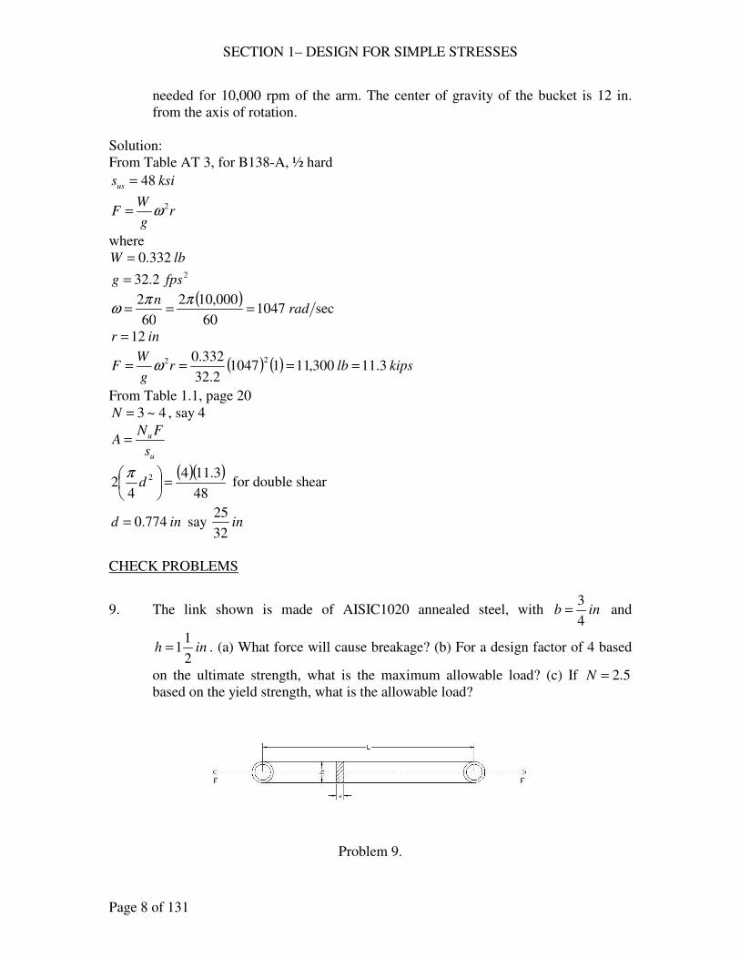
9. The link shown is made of AISIC1020 annealed steel, with inb4
3= and
inh2
11= . (a) What force will cause breakage? (b) For a design factor of 4 based
on the ultimate strength, what is the maximum allowable load? (c) If 5.2=N
based on the yield strength, what is the allowable load?
Problem 9.
SECTION 1– DESIGN FOR SIMPLE STRESSES
Page 9 of 131
Solution:
For AISI C1020 annealed steel, from Table AT 7
ksisu 57=
ksisy 42=
(a) AsF u=
2125.12
11
4
3inbhA =
==
( )( ) kipsF 64125.157 ==
(b) u
u
N
AsF =
4=uN
2125.12
11
4
3inbhA =
==
( )( )kipsF 16
4
125.157==
(c) y
y
N
AsF =
5.2=yN
2125.12
11
4
3inbhA =
==
( )( )kipsF 9.18
2
125.142==
10. A ¾-in.bolt, made of cold-finished B1113, has an effective stress area of 0.334 sq.
in. and an effective grip length of 5 in. The bolt is to be loaded by tightening until
the tensile stress is 80 % of the yield strength, as determined by measuring the
total elongation. What should be the total elongation?
Solution:
E
sL=δ
from Table AT 7 for cold-finished B1113
ksisy 72=
then, ( ) ksiss y 6.57728.080.0 ===
ksipsiE 000,301030 6 =×=
( )( )in
E
sL0096.0
000,30
56.57===δ
SECTION 1– DESIGN FOR SIMPLE STRESSES
Page 10 of 131
11. A 4-lb. weight is attached by a 3/8-in. bolt to a rotating arm 14-in. from the center
of rotation. The axis of the bolts is normal to the plane in which the centrifugal
force acts and the bolt is in double shear. At what speed will the bolt shear in two
if it is made of AISI B1113, cold finish?
Solution:
From Table AT 7, psiksisus 000,6262 ==
( ) 2
2
2209.08
3
4
12 inA =
= π
Asrg
WF us== 2ω
( ) ( )( )2209.0000,62142.32
4 2 =ω
sec74.88 rad=ω
74.8860
2==
nπω
rpmn 847=
12. How many ¾-in. holes could be punched in one stroke in annealed steel plate of
AISI C1040, 3/16-in. thick, by a force of 60 tons?
Solution:
For AISI C1040, from Figure AF 1
ksisu 80=
( ) ksiksiss uus 608075.075.0 ===
tdA π=
kipstonsF 12060 ==
n = number of holes
( )( )9
602209.0
120===
usAs
Fn holes
13. What is the length of a bearing for a 4-in. shaft if the load on the bearing is 6400
lb. and the allowable bearing pressure is 200 psi of the projected area?
Solution:
WpDL =
where
psip 200=
inD 4=
lbW 6400=
SECTION 1– DESIGN FOR SIMPLE STRESSES
Page 11 of 131
( )( ) 64004200 =L
inL 8=
BENDING STRESSES
DESIGN PROBLEMS
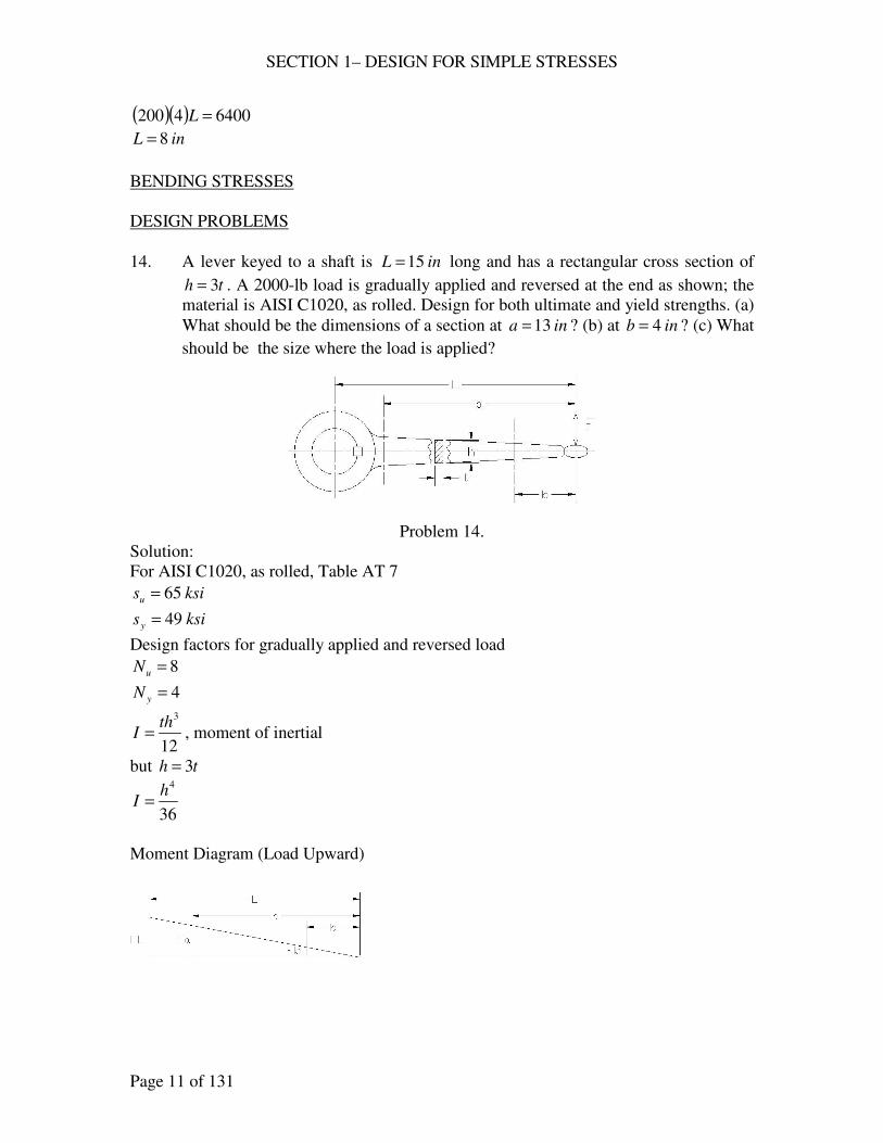
14. A lever keyed to a shaft is inL 15= long and has a rectangular cross section of
th 3= . A 2000-lb load is gradually applied and reversed at the end as shown; the
material is AISI C1020, as rolled. Design for both ultimate and yield strengths. (a)
What should be the dimensions of a section at ina 13= ? (b) at inb 4= ? (c) What
should be the size where the load is applied?
Problem 14.
Solution:
For AISI C1020, as rolled, Table AT 7
ksisu 65=
ksisy 49=
Design factors for gradually applied and reversed load
8=uN
4=yN
12
3th
I = , moment of inertial
but th 3=
36
4h
I =
Moment Diagram (Load Upward)

SECTION 1– DESIGN FOR SIMPLE STRESSES
Page 12 of 131
Based on ultimate strength
u
u
N
ss =
(a) I
Fac
I
Mcs ==
2
hc =
kipslbsF 22000 ==
( )( )
==
36
2132
8
654
h
h
s
inh 86.3=
inh
t 29.13
86.3
3===
say
ininh2
145.4 ==
inint2
115.1 ==
(b) I
Fbc
I
Mcs ==
2
hc =
kipslbsF 22000 ==
( )( )
==
36
242
8
654
h
h
s
inh 61.2=
inh
t 87.03
61.2
3===
say
inh 3=
int 1=
(c)
SECTION 1– DESIGN FOR SIMPLE STRESSES
Page 13 of 131
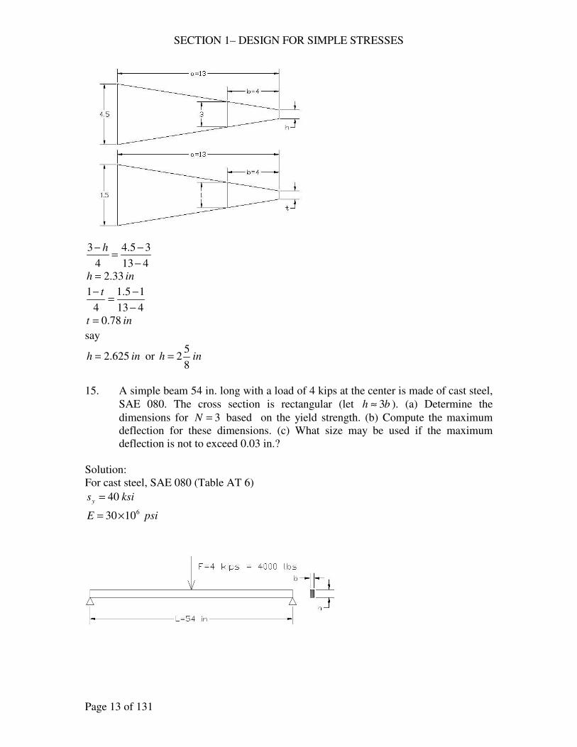
413
35.4
4
3
−
−=
− h
inh 33.2=
413
15.1
4
1
−
−=
− t
int 78.0=
say
inh 625.2= or inh8
52=
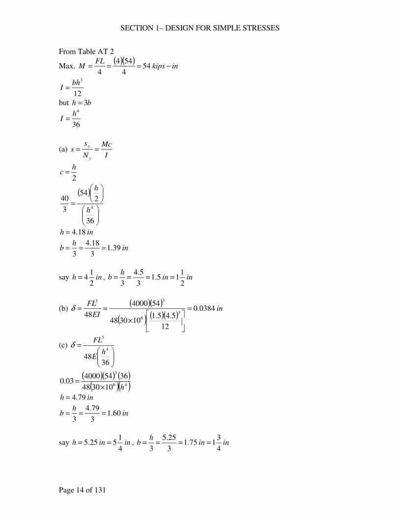
15. A simple beam 54 in. long with a load of 4 kips at the center is made of cast steel,
SAE 080. The cross section is rectangular (let bh 3≈ ). (a) Determine the
dimensions for 3=N based on the yield strength. (b) Compute the maximum
deflection for these dimensions. (c) What size may be used if the maximum
deflection is not to exceed 0.03 in.?
Solution:
For cast steel, SAE 080 (Table AT 6)
ksisy 40=
psiE 61030×=
SECTION 1– DESIGN FOR SIMPLE STRESSES
Page 14 of 131
From Table AT 2
Max. ( )( )
inkipsFL
M −=== 544
544
4
12
3bh
I =
but bh 3=
36
4h
I =
(a) I
Mc
N
ss
y
y==
2
hc =
( )
=
36
254
3
404
h
h
inh 18.4=
inh
b 39.13
18.4
3===
say inh2
14= , inin
hb
2
115.1
3
5.4
3====
(b) ( )( )
( ) ( )( )in
EI
FL0384.0
12
5.45.1103048
544000
48 3
6
33
=
×
==δ
(c)
=
3648
4
3
hE
FLδ
( )( ) ( )( )( )46
3
103048
3654400003.0
h×=
inh 79.4=
inh
b 60.13
79.4
3===
say ininh4
1525.5 == , inin
hb
4
3175.1
3
25.5
3====
SECTION 1– DESIGN FOR SIMPLE STRESSES
Page 15 of 131
16. The same as 15, except that the beam is to have a circular cross section.
Solution:
(a) I
Mc
N
ss
y
y==
64
4d
Iπ
=
2
dc =
34
32
64
2
d
M
d
dM
sππ
=
=
( )3
5432
3
40
dπ=
ind 46.3=
say ind2
13=
(b) EI
FL
48
3
=δ
64
4d
Iπ
=
( )( )( )
( )( )( )in
dE
FL0594.0
5.3103048
54400064
48
6446
3
4
3
=×
==ππ
δ
(c) ( )4
3
48
64
dE
FL
πδ =
( )( )( )( ) 46
3
103048
5440006403.0
dπ×=
ind 15.4=
say ind4
14=
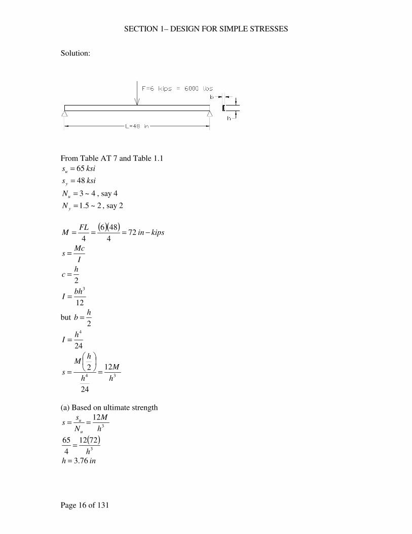
17. A simple beam, 48 in. long, with a static load of 6000 lb. at the center, is made of
C1020 structural steel. (a) Basing your calculations on the ultimate strength,
determine the dimensions of the rectangular cross section for bh 2= . (b)
Determine the dimensions based on yield strength. (c) Determine the dimensions
using the principle of “limit design.”
SECTION 1– DESIGN FOR SIMPLE STRESSES
Page 16 of 131
Solution:
From Table AT 7 and Table 1.1
ksisu 65=
ksisy 48=
4~3=uN , say 4
2~5.1=yN , say 2
( )( )kipsin
FLM −=== 72
4
486
4
I
Mcs =
2
hc =
12
3bh
I =
but 2
hb =
24
4h
I =
34
12
24
2
h
M
h
hM
s =
=
(a) Based on ultimate strength
3
12
h
M
N
ss
u
u ==
( )3
7212
4
65
h=
inh 76.3=
SECTION 1– DESIGN FOR SIMPLE STRESSES
Page 17 of 131
inh
b 88.12
76.3
2===
say ininh4
3375.3 == , inin
hb
8
71875.1
2
75.3
2====
(b) Based on yield strength
3
12
h
M
N
ss
y
y==
( )3
7212
2
48
h=
inh 30.3=
inh
b 65.12
30.3
2===
say ininh2
135.3 == , inin
hb
4
3175.1
2
5.3
2====
(c) Limit design (Eq. 1.6)
4
2bh
sM y=
( )4
24872
2h
h
=
inh 29.2=
inh
b 145.12
29.2
2===
say ininh2
125.2 == , inin
hb
4
1125.1
2
5.2
2====
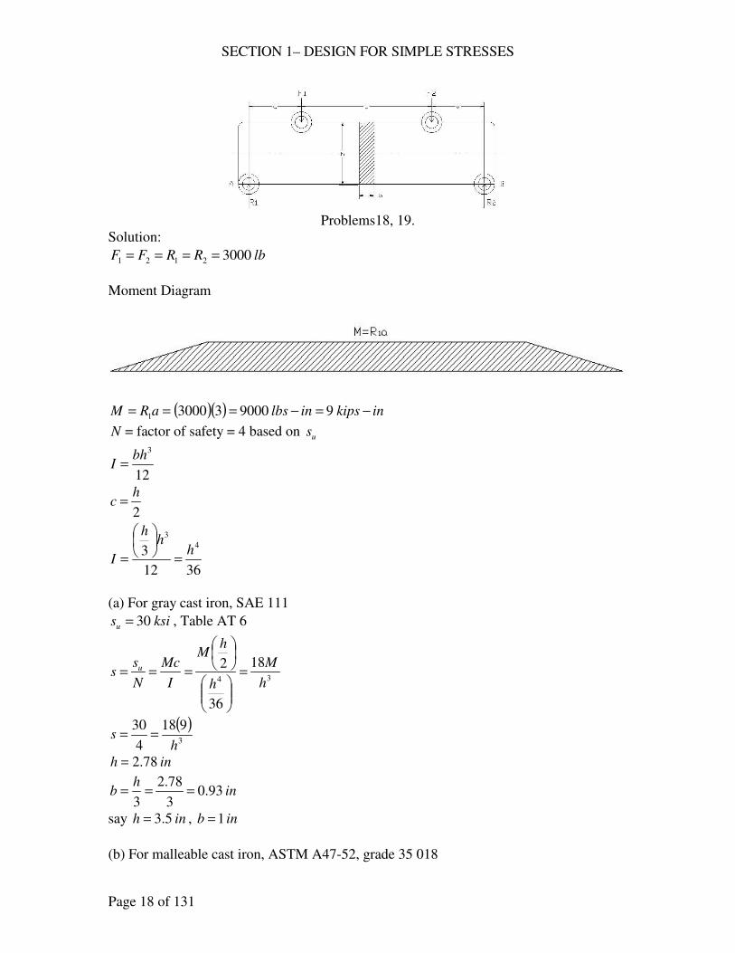
18. The bar shown is subjected to two vertical loads, 1F and 2F , of 3000 lb. each, that
are inL 10= apart and 3 in. ( a , d ) from the ends of the bar. The design factor is 4
based on the ultimate strength; bh 3= . Determine the dimensions h and b if the
bar is made of (a) gray cast iron, SAE 111; (b) malleable cast iron, ASTM A47-
52, grade 35 018; (c) AISI C1040, as rolled (Fig. AF 1). Sketch the shear and
moment diagrams approximately to scale.
SECTION 1– DESIGN FOR SIMPLE STRESSES
Page 18 of 131
Problems18, 19.
Solution:
lbRRFF 30002121 ====
Moment Diagram
( )( ) inkipsinlbsaRM −=−=== 99000330001
N = factor of safety = 4 based on us
12
3bh
I =
2
hc =
3612
34
3
hh
h
I =
=
(a) For gray cast iron, SAE 111
ksisu 30= , Table AT 6
34
18
36
2
h
M
h
hM
I
Mc
N
ss u =
===
( )3
918
4
30
hs ==
inh 78.2=
inh
b 93.03
78.2
3===
say inh 5.3= , inb 1=
(b) For malleable cast iron, ASTM A47-52, grade 35 018
SECTION 1– DESIGN FOR SIMPLE STRESSES
Page 19 of 131
ksisu 55= , Table AT 6
34
18
36
2
h
M
h
hM
I
Mc
N
ss u =
===
( )3
918
4
55
hs ==
inh 28.2=
inh
b 76.03
28.2
3===
say inh4
12= , inb
4
3=
(c) For AISI C1040, as rolled
ksisu 90= , Fig. AF 1
34
18
36
2
h
M
h
hM
I
Mc
N
ss u =
===
( )3
918
4
90
hs ==
inh 93.1=
inh
b 64.03
93.1
3===
say inh8
71= , inb
8
5=
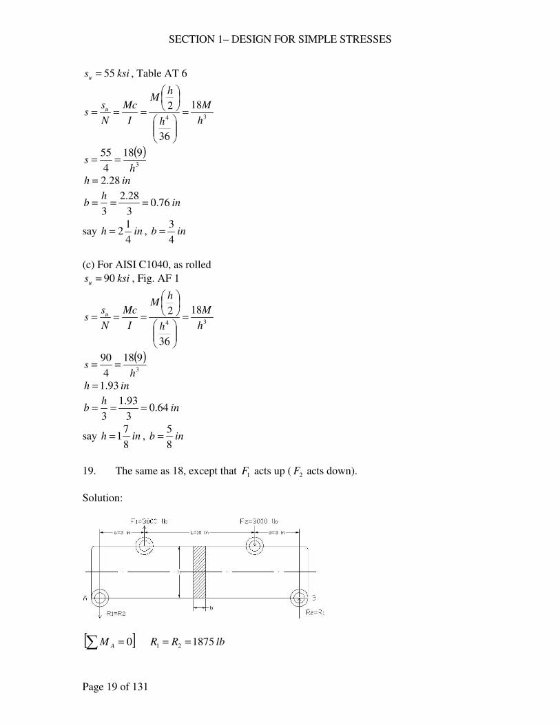
19. The same as 18, except that 1F acts up ( 2F acts down).
Solution:
[ ]∑ = 0AM lbRR 187521 ==
SECTION 1– DESIGN FOR SIMPLE STRESSES
Page 20 of 131
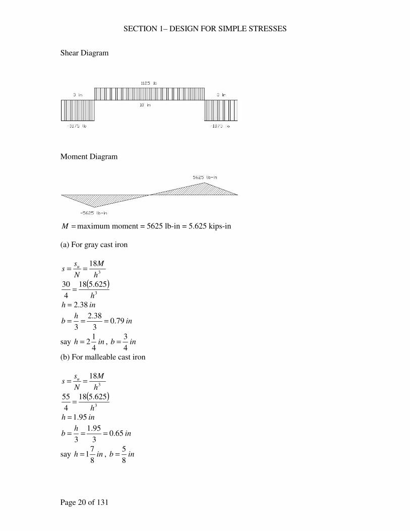
Shear Diagram
Moment Diagram
=M maximum moment = 5625 lb-in = 5.625 kips-in
(a) For gray cast iron
3
18
h
M
N
ss u ==
( )3
625.518
4
30
h=
inh 38.2=
inh
b 79.03
38.2
3===
say inh4
12= , inb
4
3=
(b) For malleable cast iron
3
18
h
M
N
ss u ==
( )3
625.518
4
55
h=
inh 95.1=
inh
b 65.03
95.1
3===
say inh8
71= , inb
8
5=
SECTION 1– DESIGN FOR SIMPLE STRESSES
Page 21 of 131
(c) For AISI C1040, as rolled
3
18
h
M
N
ss u ==
( )3
625.518
4
90
h=
inh 65.1=
inh
b 55.03
65.1
3===
say inh2
11= , inb
2
1=
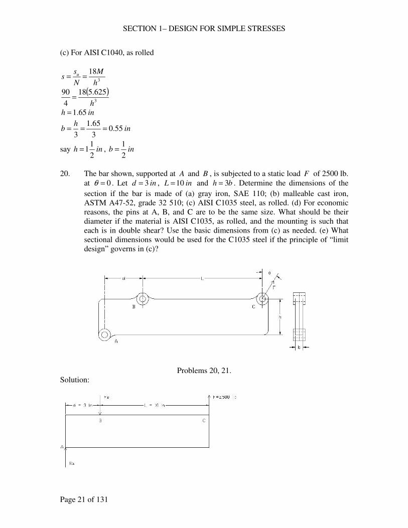
20. The bar shown, supported at A and B , is subjected to a static load F of 2500 lb.
at 0=θ . Let ind 3= , inL 10= and bh 3= . Determine the dimensions of the
section if the bar is made of (a) gray iron, SAE 110; (b) malleable cast iron,
ASTM A47-52, grade 32 510; (c) AISI C1035 steel, as rolled. (d) For economic
reasons, the pins at A, B, and C are to be the same size. What should be their
diameter if the material is AISI C1035, as rolled, and the mounting is such that
each is in double shear? Use the basic dimensions from (c) as needed. (e) What
sectional dimensions would be used for the C1035 steel if the principle of “limit
design” governs in (c)?
Problems 20, 21.
Solution:
SECTION 1– DESIGN FOR SIMPLE STRESSES
Page 22 of 131
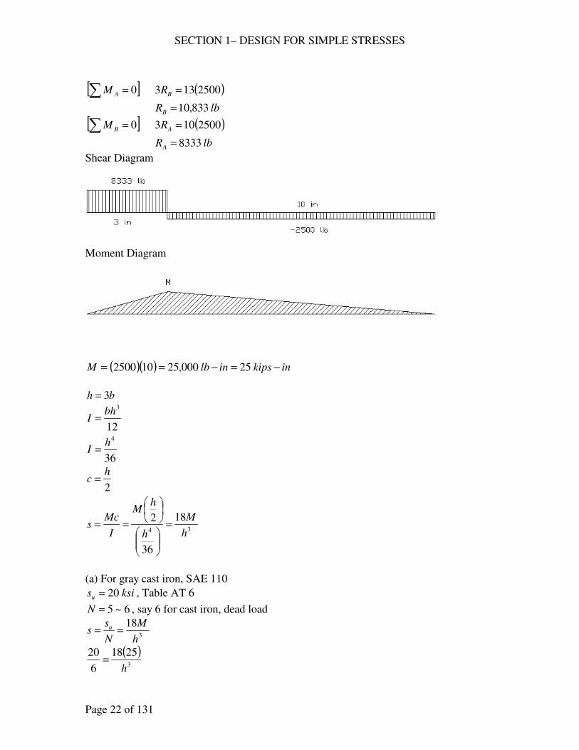
[ ]∑ = 0AM ( )2500133 =BR
lbRB 833,10=
[ ]∑ = 0BM ( )2500103 =AR
lbRA 8333=
Shear Diagram
Moment Diagram
( )( ) inkipsinlbM −=−== 25000,25102500
bh 3=
12
3bh
I =
36
4h
I =
2
hc =
34
18
36
2
h
M
h
hM
I
Mcs =
==
(a) For gray cast iron, SAE 110
ksisu 20= , Table AT 6
6~5=N , say 6 for cast iron, dead load
3
18
h
M
N
ss u ==
( )3
2518
6
20
h=
SECTION 1– DESIGN FOR SIMPLE STRESSES
Page 23 of 131
inh 13.5=
inh
b 71.13
==
say inh4
15= , inb
4
31=
(b) For malleable cast iron, ASTM A47-32 grade 32510
ksisu 52= , ksisy 34=
4~3=N , say 4 for ductile, dead load
3
18
h
M
N
ss u ==
( )3
2518
4
52
h=
inh 26.3=
inh
b 09.13
==
say inh4
33= , inb
4
11=
(c) For AISI C1035, as rolled
ksisu 85= , ksisy 55=
4=N , based on ultimate strength
3
18
h
M
N
ss u ==
( )3
2518
4
85
h=
inh 77.2=
inh
b 92.03
==
say inh 3= , inb 1=
(d) For AISI C1035, as rolled
ksissu 64=
4=N , kipsRB 833.10=
A
R
N
ss Bsu
s ==
22
242 DDA
ππ=
=
2
2
833.10
4
64
D
ss π==
inD 657.0=
SECTION 1– DESIGN FOR SIMPLE STRESSES
Page 24 of 131
say inD16
11=
(e) Limit Design
4
2bh
sM y=
For AISI C1035 steel, ksisy 55=
3
hb =
( )4
35525
2h
h
M
==
inh 76.1=
inh
b 59.03
==
say ininh8
71875.1 == , inb
8
5=
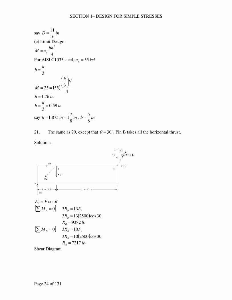
21. The same as 20, except that o30=θ . Pin B takes all the horizontal thrust.
Solution:
θcosFFV =
[ ]∑ = 0AM VB FR 133 =
( ) 30cos2500133 =BR
lbRB 9382=
[ ]∑ = 0BM VA FR 103 =
( ) 30cos2500103 =AR
lbRA 7217=
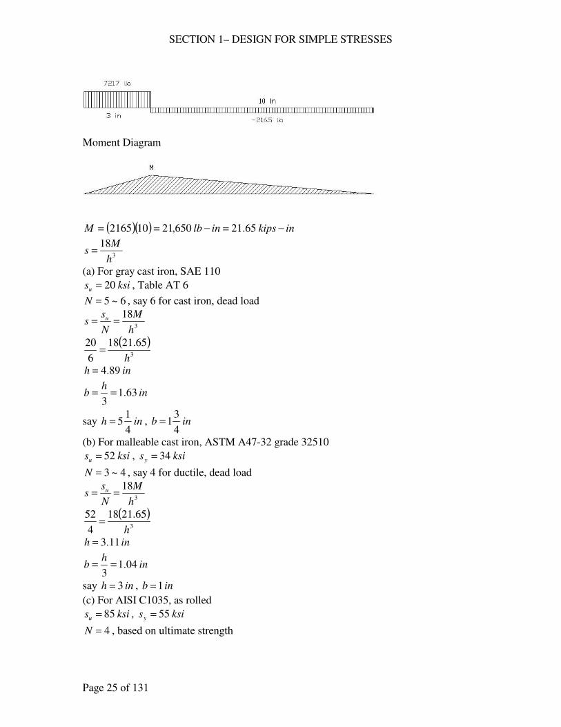
Shear Diagram
SECTION 1– DESIGN FOR SIMPLE STRESSES
Page 25 of 131
Moment Diagram
( )( ) inkipsinlbM −=−== 65.21650,21102165
3
18
h
Ms =
(a) For gray cast iron, SAE 110
ksisu 20= , Table AT 6
6~5=N , say 6 for cast iron, dead load
3
18
h
M
N
ss u ==
( )3
65.2118
6
20
h=
inh 89.4=
inh
b 63.13
==
say inh4
15= , inb
4
31=
(b) For malleable cast iron, ASTM A47-32 grade 32510
ksisu 52= , ksisy 34=
4~3=N , say 4 for ductile, dead load
3
18
h
M
N
ss u ==
( )3
65.2118
4
52
h=
inh 11.3=
inh
b 04.13
==
say inh 3= , inb 1=
(c) For AISI C1035, as rolled
ksisu 85= , ksisy 55=
4=N , based on ultimate strength
SECTION 1– DESIGN FOR SIMPLE STRESSES
Page 26 of 131
3
18
h
M
N
ss u ==
( )3
65.2118
4
85
h=
inh 64.2=
inh
b 88.03
==
say inh8
52= , inb
8
7=
(d) For AISI C1035, as rolled
ksissu 64=
4=N , lbRBV 9382=
lbFFR HBH 125030sin2500sin ==== θ
( ) ( )22222 12509382 +=+= BHBVB RRR
lbRB 9465=
A
R
N
ss Bsu
s ==
22
242 DDA
ππ=
=
2
2
465.9
4
64
D
ss π==
inD 614.0=
say inD8
5=
(e) Limit Design
4
2bh
sM y=
For AISI C1035 steel, ksisy 55=
3
hb =
( )4
35565.21
2h
h
M
==
inh 68.1=
inh
b 56.03
==
say ininh8
71875.1 == , inb
8
5=
SECTION 1– DESIGN FOR SIMPLE STRESSES
Page 27 of 131
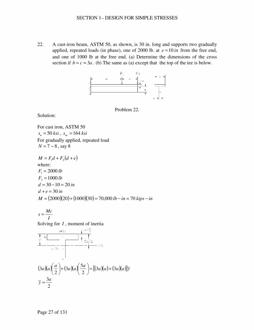
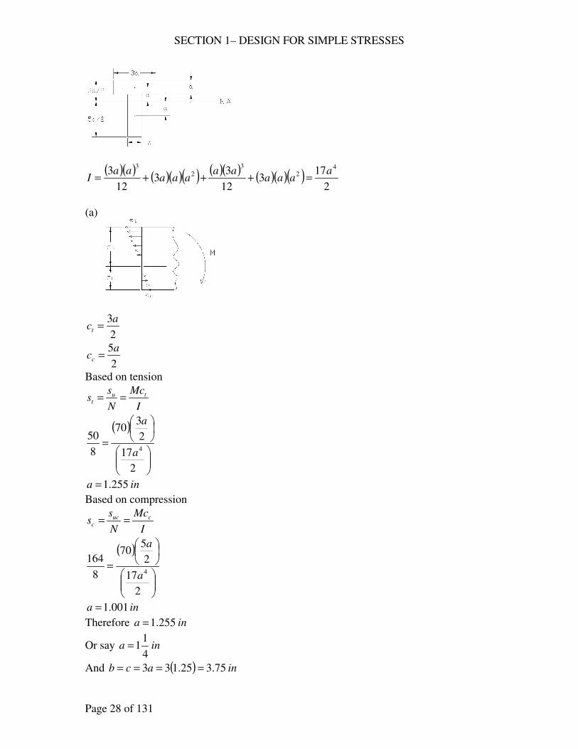
22. A cast-iron beam, ASTM 50, as shown, is 30 in. long and supports two gradually
applied, repeated loads (in phase), one of 2000 lb. at ine 10= from the free end,
and one of 1000 lb at the free end. (a) Determine the dimensions of the cross
section if acb 3≈= . (b) The same as (a) except that the top of the tee is below.
Problem 22.
Solution:
For cast iron, ASTM 50
ksisu 50= , ksisuc 164=
For gradually applied, repeated load
8~7=N , say 8
( )edFdFM ++= 21
where:
lbF 20001 =
lbF 10002 =
ind 201030 =−=
ined 30=+
( )( ) ( )( ) inkipsinlbM −=−=+= 70000,70301000202000
I
Mcs =
Solving for I , moment of inertia
( )( ) ( )( ) ( )( ) ( )( )[ ]yaaaaa
aaa
aa 332
53
23 +=
+
2
3ay =
SECTION 1– DESIGN FOR SIMPLE STRESSES
Page 28 of 131
( )( ) ( )( )( ) ( )( ) ( )( )( )2
173
12
33
12
3 42
3
2
3a
aaaaa
aaaaa
I =+++=
(a)
2
3act =
2
5acc =
Based on tension
I
Mc
N
ss tu
t ==
( )
=
2
17
2
370
8
504
a
a
ina 255.1=
Based on compression
I
Mc
N
ss cuc
c ==
( )
=
2
17
2
570
8
1644
a
a
ina 001.1=
Therefore ina 255.1=
Or say ina4
11=
And ( ) inacb 75.325.133 ====
SECTION 1– DESIGN FOR SIMPLE STRESSES
Page 29 of 131
Or incb4
33==
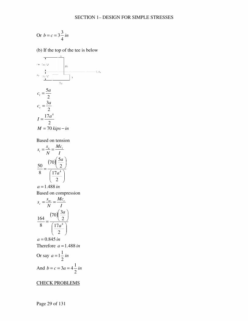
(b) If the top of the tee is below
2
5act =
2
3acc =
2
17 4a
I =
inkipsM −= 70
Based on tension
I
Mc
N
ss tu
t ==
( )
=
2
17
2
570
8
504
a
a
ina 488.1=
Based on compression
I
Mc
N
ss cuc
c ==
( )
=
2
17
2
370
8
1644
a
a
ina 845.0=
Therefore ina 488.1=
Or say ina2
11=
And inacb2
143 ===
CHECK PROBLEMS
SECTION 1– DESIGN FOR SIMPLE STRESSES
Page 30 of 131
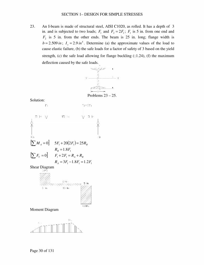
23. An I-beam is made of structural steel, AISI C1020, as rolled. It has a depth of 3
in. and is subjected to two loads; 1F and 12 2FF = ; 1F is 5 in. from one end and
2F is 5 in. from the other ends. The beam is 25 in. long; flange width is
inb 509.2= ; 49.2 inI x = . Determine (a) the approximate values of the load to
cause elastic failure, (b) the safe loads for a factor of safety of 3 based on the yield
strength, (c) the safe load allowing for flange buckling (i1.24), (f) the maximum
deflection caused by the safe loads.
Problems 23 – 25.
Solution:
[ ]∑ = 0AM ( ) BRFF 252205 11 =+
18.1 FRB =
[ ]∑ = 0VF BA RRFF +=+ 11 2
111 2.18.13 FFFRA =−=
Shear Diagram
Moment Diagram
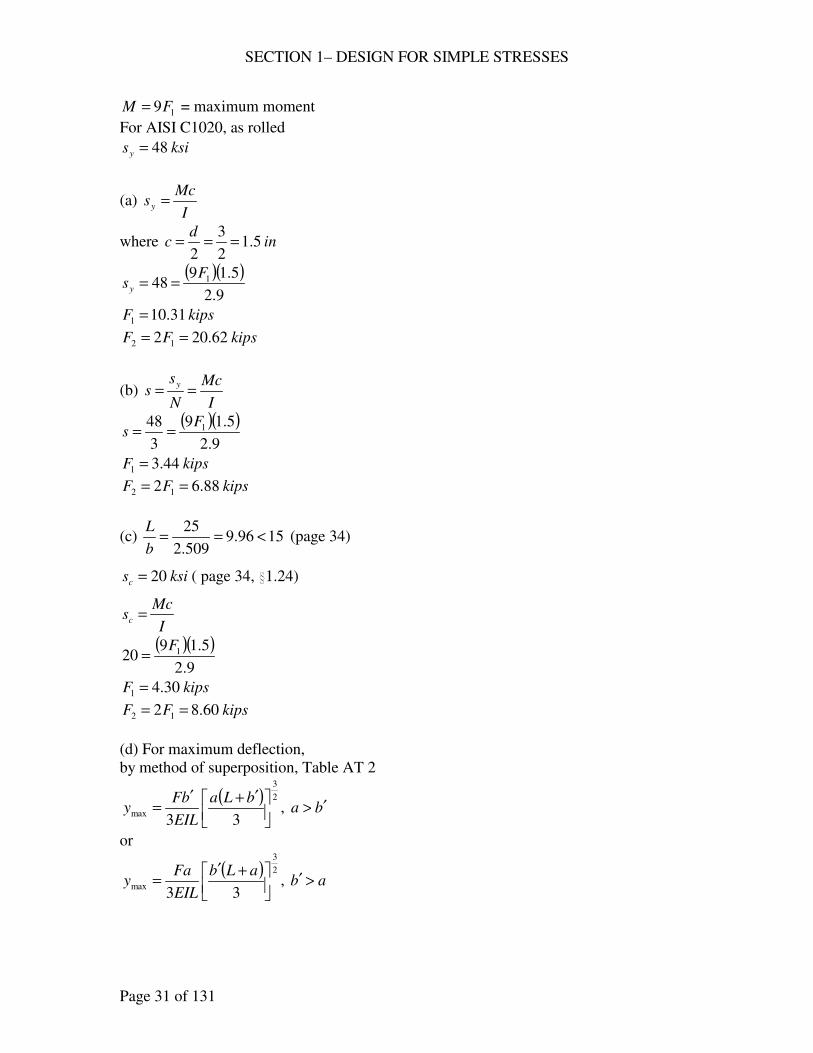
SECTION 1– DESIGN FOR SIMPLE STRESSES
Page 31 of 131
19FM = = maximum moment
For AISI C1020, as rolled
ksisy 48=
(a) I
Mcsy =
where ind
c 5.12
3
2===
( )( )9.2
5.1948 1F
sy ==
kipsF 31.101 =
kipsFF 62.202 12 ==
(b) I
Mc
N
ss
y==
( )( )9.2
5.19
3
48 1Fs ==
kipsF 44.31 =
kipsFF 88.62 12 ==
(c) 1596.9509.2
25<==
b
L (page 34)
ksisc 20= ( page 34, i1.24)
I
Mcsc =
( )( )9.2
5.1920 1F
=
kipsF 30.41 =
kipsFF 60.82 12 ==
(d) For maximum deflection,
by method of superposition, Table AT 2
( ) 2
3
max33
′+′=
bLa
EIL
bFy , ba ′>
or
( ) 2
3
max33
+′=
aLb
EIL
Fay , ab >′
SECTION 1– DESIGN FOR SIMPLE STRESSES
Page 32 of 131
maxy caused by 1F
( ) 2
3
1111max
331
+′=
aLb
EIL
aFy , 11 ab >′
where ksiE 000,30=
ina 51 =
inb 201 =′
inL 25=
49.2 inI =
( )( )( )( )
( )1
2
3
1max 0022.0
3
52520
259.2000,303
51
FF
y =
+=
maxy caused by 2F
( ) 2
3
2222max
332
′+′=
bLa
EIL
bFy , 22 ba ′>
where inb 52 =′
ina 202 =
( )( )( )( )
( )1
2
3
1max 0043.0
3
52520
259.2000,303
522
FF
y =
+=
Total deflection = δ
111maxmax 0065.00043.0022.021
FFFyy =+=+=δ
Deflection caused by the safe loads in (a)
( ) ina 067.031.100065.0 ==δ
Deflection caused by the safe loads in (b)
( ) inb 022.044.30065.0 ==δ
Deflection caused by the safe loads in (c)
( ) inc 028.030.40065.0 ==δ
24. The same as 23, except that the material is aluminum alloy, 2024-T4, heat treated.
Solution:
For aluminum alloy, 2024-T4, heat treated
ksisy 47=
(a) I
Mcsy =

SECTION 1– DESIGN FOR SIMPLE STRESSES
Page 33 of 131
( )( )9.2
5.1947 1F
sy ==
kipsF 10.101 =
kipsFF 20.202 12 ==
(b) I
Mc
N
ss
y==
( )( )9.2
5.19
3
47 1Fs ==
kipsF 36.31 =
kipsFF 72.62 12 ==
(c) 1596.9509.2
25<==
b
L (page 34)
ksisc 20= ( page 34, i1.24)
I
Mcsc =
( )( )9.2
5.1920 1F
=
kipsF 30.41 =
kipsFF 60.82 12 ==
(d) Total deflection = δ
111maxmax 0065.00043.0022.021
FFFyy =+=+=δ
Deflection caused by the safe loads in (a)
( ) ina 066.010.100065.0 ==δ
Deflection caused by the safe loads in (b)
( ) inb 022.036.30065.0 ==δ
Deflection caused by the safe loads in (c)
( ) inc 028.030.40065.0 ==δ
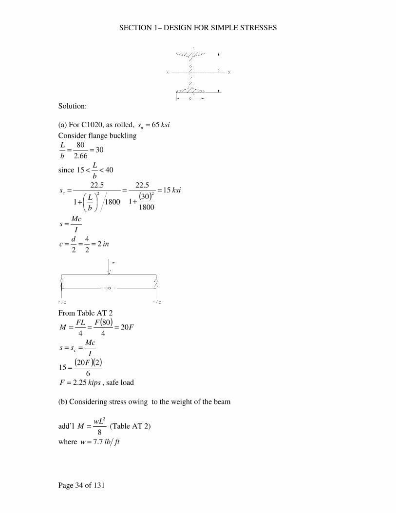
25. A light I-beam is 80 in. long, simply supported, and carries a static load at the
midpoint. The cross section has a depth of ind 4= , a flange width of inb 66.2= ,
and 40.6 inI x = (see figure). (a) What load will the beam support if it is made of
C1020, as-rolled steel, and flange buckling (i1.24) is considered? (b) Consider the
stress owing to the weight of the beam, which is 7.7 lb/ft, and decide whether or
not the safe load should be less.
SECTION 1– DESIGN FOR SIMPLE STRESSES
Page 34 of 131
Solution:
(a) For C1020, as rolled, ksisu 65=
Consider flange buckling
3066.2
80==
b
L
since 4015 <<b
L
( )ksi
b
Lsc 15
1800
301
5.22
18001
5.2222
=
+
=
+
=
I
Mcs =
ind
c 22
4
2===
From Table AT 2
( )F
FFLM 20
4
80
4===
I
Mcss c ==
( )( )6
22015
F=
kipsF 25.2= , safe load
(b) Considering stress owing to the weight of the beam
add’l 8
2wL
M = (Table AT 2)
where ftlbw 7.7=
SECTION 1– DESIGN FOR SIMPLE STRESSES
Page 35 of 131
add’l ( )
inkipsinlbwL
M −=−=
== 513.0513
8
80
12
7.7
8
22
513.020 += FM = total moment
I
Mcss c ==
( )( )6
2513.02015
+=
F
kipsF 224.2=
Therefore, the safe load should be less.
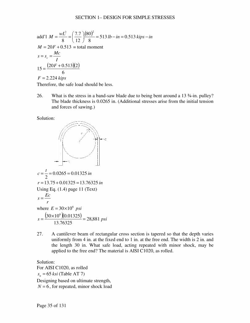
26. What is the stress in a band-saw blade due to being bent around a 13 ¾-in. pulley?
The blade thickness is 0.0265 in. (Additional stresses arise from the initial tension
and forces of sawing.)
Solution:
int
c 01325.00265.02
===
inr 76325.1301325.075.13 =+=
Using Eq. (1.4) page 11 (Text)
r
Ecs =
where psiE 61030×=
( )( )psis 881,28
76325.13
01325.01030 6
=×
=
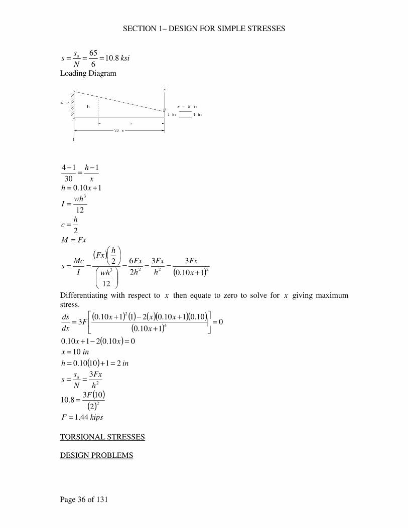
27. A cantilever beam of rectangular cross section is tapered so that the depth varies
uniformly from 4 in. at the fixed end to 1 in. at the free end. The width is 2 in. and
the length 30 in. What safe load, acting repeated with minor shock, may be
applied to the free end? The material is AISI C1020, as rolled.
Solution:
For AISI C1020, as rolled
ksisu 65= (Table AT 7)
Designing based on ultimate strength,
6=N , for repeated, minor shock load
SECTION 1– DESIGN FOR SIMPLE STRESSES
Page 36 of 131
ksiN
ss u 8.10
6
65===
Loading Diagram
x
h 1
30
14 −=
−
110.0 += xh
12
3wh
I =
2
hc =
FxM =
( )
( )2223 110.0
33
2
6
12
2
+===
==x
Fx
h
Fx
h
Fx
wh
hFx
I
Mcs
Differentiating with respect to x then equate to zero to solve for x giving maximum
stress.
( ) ( ) ( )( )( )( )
0110.0
10.0110.021110.03
4
2
=
+
+−+=
x
xxxF
dx
ds
( ) 010.02110.0 =−+ xx
inx 10=
( ) inh 211010.0 =+=
2
3
h
Fx
N
ss u ==
( )( )22
1038.10
F=
kipsF 44.1=
TORSIONAL STRESSES
DESIGN PROBLEMS
SECTION 1– DESIGN FOR SIMPLE STRESSES
Page 37 of 131
28. A centrifugal pump is to be driven by a 15-hp electric motor at 1750 rpm. What
should be the diameter of the pump shaft if it is made of AISI C1045 as rolled?
Consider the load as gradually repeated.
Solution:
For C1045 as rolled,
ksisy 59=
ksisus 72=
Designing based on ultimate strength
N
ss us= , 6=N (Table 1.1)
ksis 126
72==
Torque, ( )
( )kipsinlbinlbft
n
hpT −=−=−=== 540.054045
17502
15000,33
2
000,33
ππ
For diameter,
3
16
d
Ts
π=
( )3
540.01612
dπ=
ind 612.0=
say ind8
5=
29. A shaft in torsion only is to transmit 2500 hp at 570 rpm with medium shocks. Its
material is AISI 1137 steel, annealed. (a) What should be the diameter of a solid
shaft? (b) If the shaft is hollow, io DD 2= , what size is required? (c) What is the
weight per foot of length of each of these shafts? Which is the lighter? By what
percentage? (d) Which shaft is the more rigid? Compute the torsional deflection
of each for a length of 10 ft.
Solution:
( )( )
kipsinlbftn
hpT −=−=== 276036,23
5702
2500000,33
2
000,33
ππ
For AISI 1137, annealed
ksisy 50= (Table AT 8)
ksiss yys 306.0 ==
Designing based on yield strength
3=N for medium shock, one direction
SECTION 1– DESIGN FOR SIMPLE STRESSES
Page 38 of 131
Design stress
ksiN
ss
ys10
3
30===
(a) Let D = shaft diameter
J
Tcs =
32
4D
Jπ
=
2
Dc =
3
16
D
Ts
π=
( )3
2761610
Dπ=
inD 20.5=
say inD4
15=
(b) ( ) ( )[ ]
32
15
32
2
32
44444
iiiio DDDDDJ
πππ=
−=
−=
iio D
DDc ===
2
2
2
34 15
32
32
15 ii
i
D
T
D
TDs
ππ=
=
( )315
2763210
iDπ=
inDi 66.2=
inDD io 32.52 ==
say
inDi8
52=
inDo4
15=
(c) Density, 3284.0 inlb=ρ (Table AT 7)
SECTION 1– DESIGN FOR SIMPLE STRESSES
Page 39 of 131
For solid shaft
=w weight per foot of length
( )( ) ftlbDDw 8.7325.5284.0334
12222 ===
= ππρ
πρ
For hollow shaft
( ) ( ) ( ) ( ) ( )[ ] ftlbDDDDw ioio 3.55625.225.5284.0334
12222222 =−=−=−
= ππρ
πρ
Therefore hollow shaft is lighter
Percentage lightness = ( ) %5.33%1003.55
3.558.73=
−
(d) Torsional Deflection
JG
TL=θ
where
inftL 12010 ==
ksiG 3105.11 ×=
For solid shaft, 32
4D
Jπ
=
( )( )
( ) ( )( ) o2.2
180039.0039.0
105.1125.532
120276
34
=
==
×
=
ππθ rad
For hollow shaft, ( )
32
44
io DDJ
−=
π
( )( )
( ) ( )[ ]( )( ) o4.2
180041.0041.0
105.11625.225.532
120276
344
=
==
×−
=
ππθ rad
Therefore, solid shaft is more rigid, oo 4.22.2 <
30. The same as 29, except that the material is AISI 4340, OQT 1200 F.
Solution:
( )( )
kipsinlbftn
hpT −=−=== 276036,23
5702
2500000,33
2
000,33
ππ
For AISI 4340, OQT 1200 F
ksisy 130=
( ) ksiss yys 781306.06.0 ===
Designing based on yield strength
SECTION 1– DESIGN FOR SIMPLE STRESSES
Page 40 of 131
3=N for mild shock
Design stress
ksiN
ss
ys26
3
78===
(a) Let D = shaft diameter
J
Tcs =
32
4D
Jπ
=
2
Dc =
3
16
D
Ts
π=
( )3
2761626
Dπ=
inD 78.3=
say inD4
33=
(b) ( ) ( )[ ]
32
15
32
2
32
44444
iiiio DDDDDJ
πππ=
−=
−=
iio D
DDc ===
2
2
2
34 15
32
32
15 ii
i
D
T
D
TDs
ππ=
=
( )315
2763226
iDπ=
inDi 93.1=
inDD io 86.32 ==
say
inDi 2=
inDo 4=
(c) Density, 3284.0 inlb=ρ (Table AT 7)
SECTION 1– DESIGN FOR SIMPLE STRESSES
Page 41 of 131
For solid shaft
=w weight per foot of length
( )( ) ftlbDDw 6.3775.3284.0334
12222 ===
= ππρ
πρ
For hollow shaft
( ) ( ) ( ) ( ) ( )[ ] ftlbDDDDw ioio 1.3224284.0334
12222222 =−=−=−
= ππρ
πρ
Therefore hollow shaft is lighter
Percentage lightness = ( ) %1.17%1001.32
1.326.37=
−
(d) Torsional Deflection
JG
TL=θ
where
inftL 12010 ==
ksiG 3105.11 ×=
For solid shaft, 32
4D
Jπ
=
( )( )
( ) ( )( ) o48.8
180148.0148.0
105.1175.332
120276
34
=
==
×
=
ππθ rad
For hollow shaft, ( )
32
44
io DDJ
−=
π
( )( )
( ) ( )[ ]( )( ) o99.6
180122.0122.0
105.112432
120276
344
=
==
×−
=
ππθ rad
Therefore, hollow shaft is more rigid, oo 48.899.6 < .
31. A steel shaft is transmitting 40 hp at 500 rpm with minor shock. (a) What should
be its diameter if the deflection is not to exceed 1o in D20 ? (b) If deflection is
primary what kind of steel would be satisfactory?
Solution:
(a) ( )
( )kipsinlbft
n
hpT −=−=== 04.5420
5002
40000,33
2
000,33
ππ
ksiG 3105.11 ×=
DL 20=
SECTION 1– DESIGN FOR SIMPLE STRESSES
Page 42 of 131
rad180
1π
θ == o
JG
TL=θ
( )( )
( )34
105.1132
2004.5
180×
=
D
D
π
π
inD 72.1=
say inD4
31=
(b) ( )
( )ksi
D
Ts 8.4
75.1
04.5161633
===ππ
Based on yield strength
3=N
( )( ) ksiNssys 4.148.43 ===
ksis
sys
y 246.0
4.14
6.0===
Use C1117 normalized steel ksisy 35=
32. A square shaft of cold-finish AISI 1118 transmits a torsional moment of 1200 in-
lb. For medium shock, what should be its size?
Solution:
For AISI 1118 cold-finish
ksisy 75=
ksiss yys 456.0 ==
3=N for medium shock
Z
T
N
ss
ys
′==
where, bh =
9
2
9
2 32bhb
Z ==′ (Table AT 1)
kipsinlbinT −=−= 2.11200
( )32
92.1
3
45
bs ==
inhb 71.0==
say inhb4
3==
SECTION 1– DESIGN FOR SIMPLE STRESSES
Page 43 of 131
CHECK PROBLEMS
33. A punch press is designed to exert a force sufficient to shear a 15/16-in. hole in a
½-in. steel plate, AISI C1020, as rolled. This force is exerted on the shaft at a
radius of ¾-in. (a) Compute the torsional stress in the 3.5-in. shaft (bending
neglected). (b) What will be the corresponding design factor if the shaft is made
of cold-rolled AISI 1035 steel (Table AT 10)? Considering the shock loading that
is characteristics of this machine, do you thick the design is safe enough?
Solution:
For AISI C1020, as rolled
ksisus 49=
( )DtsF us π=
where inD16
15=
int2
1=
( ) kipsF 2.722
1
16
1549 =
= π
FrT =
where inr4
3=
( ) kipsinT −=
= 2.54
4
32.72
(a) 3
16
d
Ts
π=
where ind 5.3=
( )( )
ksis 44.65.3
2.54163
==π
(b) For AISI 1035 steel, ksisus 64=
for shock loading, traditional factor of safety, 15~10=N
Design factor , 94.944.6
64===
s
sN us , the design is safe ( 10≈N )
34. The same as 33, except that the shaft diameter is 2 ¾ in.
Solution:
SECTION 1– DESIGN FOR SIMPLE STRESSES
Page 44 of 131
ind 75.2=
(a) 3
16
d
Ts
π=
( )( )
ksis 3.1375.2
2.54163
==π
(b) For AISI 1035 steel, ksisus 64=
for shock loading, traditional factor of safety, 15~10=N
Design factor , 8.43.13
64===
s
sN us , the design is not safe ( 10<N )
35. A hollow annealed Monel propeller shaft has an external diameter of 13 ½ in. and
an internal diameter of 6 ½ in.; it transmits 10,000 hp at 200 rpm. (a) Compute the
torsional stress in the shaft (stress from bending and propeller thrust are not
considered). (b) Compute the factor of safety. Does it look risky?
Solution:
For Monel shaft,
ksisus 98= (Table AT 3)
4~3=N , for dead load, based on ultimate strength
(a) J
Tcs =
( ) ( ) ( )[ ] 4
4444
308632
5.65.13
32in
DDJ io =
−=
−=
ππ
inD
c o 75.62
5.13
2===
( )( )
kipsinlbftn
hpT −=−=== 3152606,262
2002
000,10000,33
2
000,33
ππ
( )( )ksis 9.6
3086
75.63152==
(b) Factor of safety,
2.149.6
98===
s
sN us , not risky
SECTION 1– DESIGN FOR SIMPLE STRESSES
Page 45 of 131
STRESS ANALYSIS
DESIGN PROBLEMS
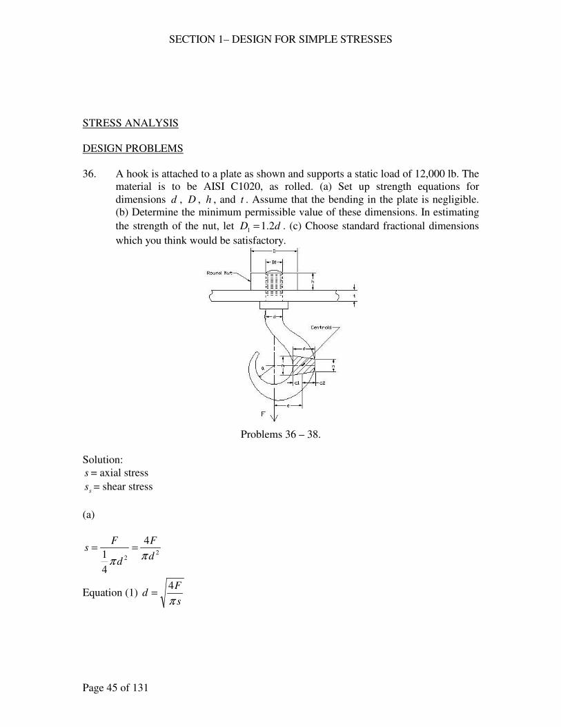
36. A hook is attached to a plate as shown and supports a static load of 12,000 lb. The
material is to be AISI C1020, as rolled. (a) Set up strength equations for
dimensions d , D , h , and t . Assume that the bending in the plate is negligible.
(b) Determine the minimum permissible value of these dimensions. In estimating
the strength of the nut, let dD 2.11 = . (c) Choose standard fractional dimensions
which you think would be satisfactory.
Problems 36 – 38.
Solution:
s = axial stress
ss = shear stress
(a)
22
4
4
1 d
F
d
Fs
ππ==
Equation (1) s
Fd
π
4=
SECTION 1– DESIGN FOR SIMPLE STRESSES
Page 46 of 131
( ) ( ) ( )[ ] ( )22222
1
22
1
2 44.1
4
2.1
44
4
1 dD
F
dD
F
DD
F
DD
Fs
−=
−=
−=
−
=ππππ
Equation (2) 244.14
ds
FD +=
π
dh
F
hD
Fss
ππ 2.11
==
Equation (3) sds
Fh
π2.1=
Dt
Fss
π=
Equation (4) sDs
Ft
π=
(b) Designing based on ultimate strength,
Table AT 7, AISI C1020, as rolled
ksisu 65=
ksisus 49=
4~3=N say 4, design factor for static load
ksiN
ss u 16
4
65===
ksiN
ss us
s 124
49===
kipslbF 12000,12 ==
From Equation (1)
( )( )
ins
Fd 98.0
16
1244===
ππ
From Equation (2)
( )( )
( ) inds
FD 53.198.044.1
16
12444.1
4 22 =+=+=ππ
From Equation (3)
( )( )in
ds
Fh
s
27.01298.02.1
12
2.1===
ππ
From Equation (4)
( )( )in
Ds
Ft
s
21.01253.1
12===
ππ
SECTION 1– DESIGN FOR SIMPLE STRESSES
Page 47 of 131
(c) Standard fractional dimensions
ind 1=
inD2
11=
inh4
1=
int4
1=
37. The same as 36, except that a shock load of 4000 lb. is repeatedly applied.
Solution:
(a) Same as 36.
(b) 15~10=N for shock load, based on ultimate strength
say 15=N , others the same.
ksiN
ss u 4
15
65===
ksiN
ss us
s 315
49===
kipslbF 44000 ==
From Equation (1)
( )( )
ins
Fd 13.1
4
444===
ππ
From Equation (2)
( )( )
( ) inds
FD 76.113.144.1
4
4444.1
4 22 =+=+=ππ
From Equation (3)
( )( )in
ds
Fh
s
31.0313.12.1
4
2.1===
ππ
From Equation (4)
( )( )in
Ds
Ft
s
24.0376.1
4===
ππ
SECTION 1– DESIGN FOR SIMPLE STRESSES
Page 48 of 131
(c) Standard fractional dimensions
ind8
11=
inD4
31=
inh8
3=
int4
1=
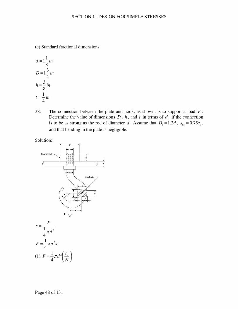
38. The connection between the plate and hook, as shown, is to support a load F .
Determine the value of dimensions D , h , and t in terms of d if the connection
is to be as strong as the rod of diameter d . Assume that dD 2.11 = , uus ss 75.0= ,
and that bending in the plate is negligible.
Solution:
2
4
1d
Fs
π=
sdF2
4
1π=
(1)
=
N
sdF u2
4
1π
SECTION 1– DESIGN FOR SIMPLE STRESSES
Page 49 of 131
( ) ( )222
1
2 44.14
1
4
1dD
F
DD
Fs
−
=
−
=
ππ
( )sdDF22 44.1
4
1−= π
(2) ( )
−=
N
sdDF u22 44.1
4
1π
dh
F
hD
Fss
ππ 2.11
==
sdhsF π2.1=
=
=
N
sdh
N
sdhF uus 75.0
2.12.1 ππ
(3)
=
N
sdhF u5
9.0 π
Dt
Fss
π=
sDtsF π=
=
=
N
sDt
N
sDtF uus 75.0
ππ
(4)
=
N
sDtF uπ75.0
Equate (2) and (1)
( )
=
−=
N
sd
N
sdDF uu 222
4
144.1
4
1ππ
22 44.2 dD =
dD 562.1=
Equate (3) and (1)
=
=
N
sd
N
sdhF uu 2
4
19.0 ππ
( )d
dh 278.0
9.04==
Equate (4) and (1)
=
=
N
sd
N
sDtF uu 2
4
175.0 ππ
( )( )
=
=
N
sd
N
stdF uu 2
4
1562.175.0 ππ
( )( )d
dt 214.0
562.175.04==
SECTION 1– DESIGN FOR SIMPLE STRESSES
Page 50 of 131
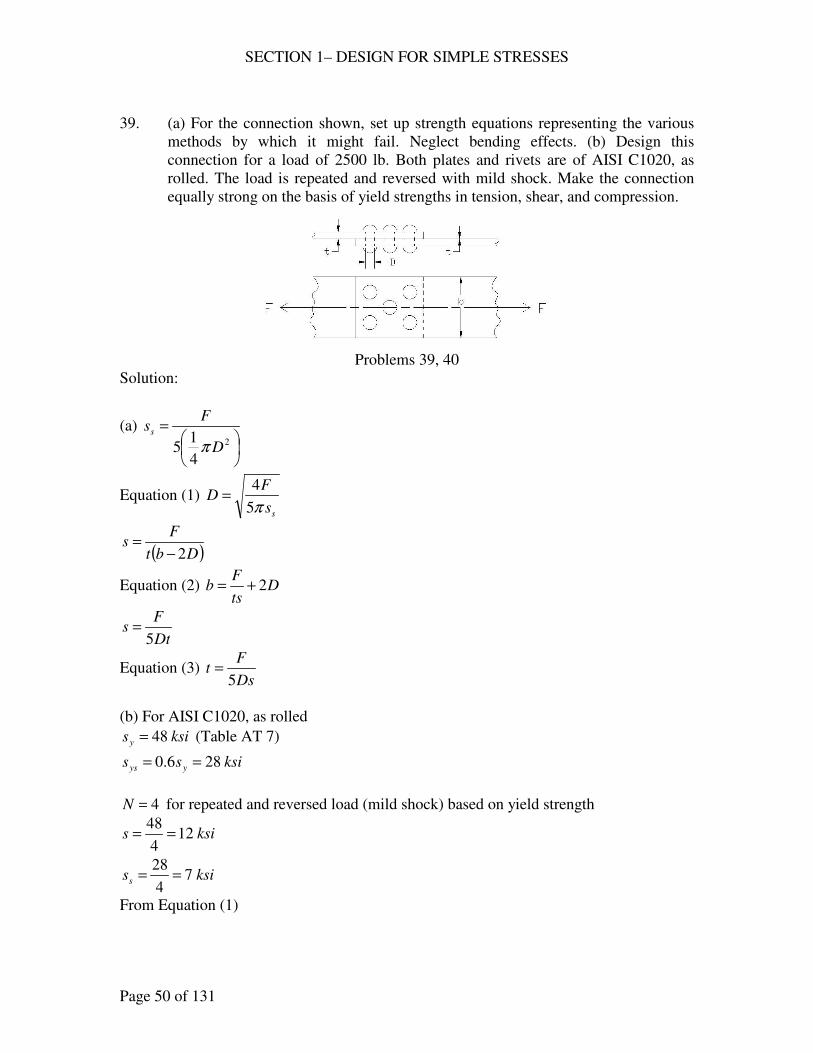
39. (a) For the connection shown, set up strength equations representing the various
methods by which it might fail. Neglect bending effects. (b) Design this
connection for a load of 2500 lb. Both plates and rivets are of AISI C1020, as
rolled. The load is repeated and reversed with mild shock. Make the connection
equally strong on the basis of yield strengths in tension, shear, and compression.
Problems 39, 40
Solution:
(a)
=
2
4
15 D
Fss
π
Equation (1) ss
FD
π5
4=
( )Dbt
Fs
2−=
Equation (2) Dts
Fb 2+=
Dt
Fs
5=
Equation (3) Ds
Ft
5=
(b) For AISI C1020, as rolled
ksisy 48= (Table AT 7)
ksiss yys 286.0 ==
4=N for repeated and reversed load (mild shock) based on yield strength
ksis 124
48==
ksiss 74
28==
From Equation (1)
SECTION 1– DESIGN FOR SIMPLE STRESSES
Page 51 of 131
ss
FD
π5
4=
where
kipslbF 5.22500 ==
( )( )
ins
FD
s
30.075
5.24
5
4===
ππ say in
16
5
From Equation (3)
( )in
Ds
Ft 13.0
1216
55
5.2
5=
== say in
32
5
From Equation (2)
( )inD
ts
Fb 96.1
16
52
1232
5
5.22 =
+
=+= say in2
40. The same as 39, except that the material is 2024-T4, aluminum alloy.
Solution:
(a) Same as 39.
(b) ) For 2024-T4, aluminum alloy
ksisy 47= (Table AT 3)
ksiss yys 2555.0 ==
4=N for repeated and reversed load (mild shock) based on yield strength
ksis 124
47==
ksiss 64
25==
From Equation (1)
ss
FD
π5
4=
where
kipslbF 5.22500 ==
( )( )
ins
FD
s
33.065
5.24
5
4===
ππ say in
8
3
From Equation (3)

SECTION 1– DESIGN FOR SIMPLE STRESSES
Page 52 of 131
( )in
Ds
Ft 11.0
128
35
5.2
5=
== say in
8
1
From Equation (2)
( )inD
ts
Fb 42.2
8
32
128
1
5.22 =
+
=+= say in
2
12
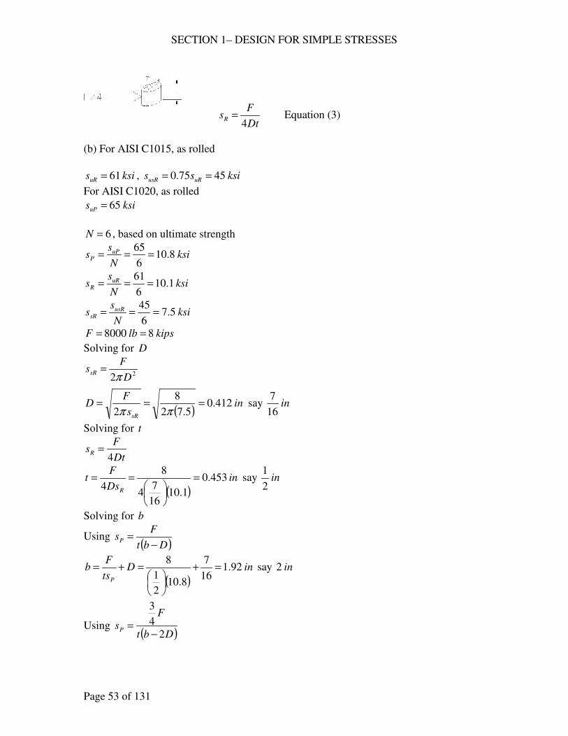
41. (a) For the connection shown, set up strength equations representing the various
methods by which it might fail. (b) Design this connection for a load of 8000 lb.
Use AISI C1015, as rolled, for the rivets, and AISI C1020, as rolled, for the
plates. Let the load be repeatedly applied with minor shock in one direction and
make the connection equally strong on the basis of ultimate strengths in tension,
shear, and compression.
Problem 41.
Solution:
(a)
( )Dbt
FsP
−= or
( )Dbt
F
sP2
4
3
−= Equation (1)
( )24
14 2
=
D
FssR
π
Equation (2)
SECTION 1– DESIGN FOR SIMPLE STRESSES
Page 53 of 131
Dt
FsR
4= Equation (3)
(b) For AISI C1015, as rolled
ksisuR 61= , ksiss uRusR 4575.0 ==
For AISI C1020, as rolled
ksisuP 65=
6=N , based on ultimate strength
ksiN
ss uP
P 8.106
65===
ksiN
ss uR
R 1.106
61===
ksiN
ss usR
sR 5.76
45===
kipslbF 88000 ==
Solving for D
22 D
FssR
π=
( )in
s
FD
sR
412.05.72
8
2===
ππ say in
16
7
Solving for t
Dt
FsR
4=
( )in
Ds
Ft
R
453.0
1.1016
74
8
4=
== say in
2
1
Solving for b
Using ( )Dbt
FsP
−=
( )inD
ts
Fb
P
92.116
7
8.102
1
8=+
=+= say in2
Using ( )Dbt
F
sP2
4
3
−=
SECTION 1– DESIGN FOR SIMPLE STRESSES
Page 54 of 131
( )
( )inD
ts
Fb
P
99.116
72
8.102
14
832
4
3=
+
=+= say in2
Therefore
inb 2=
inD16
7=
int2
1=
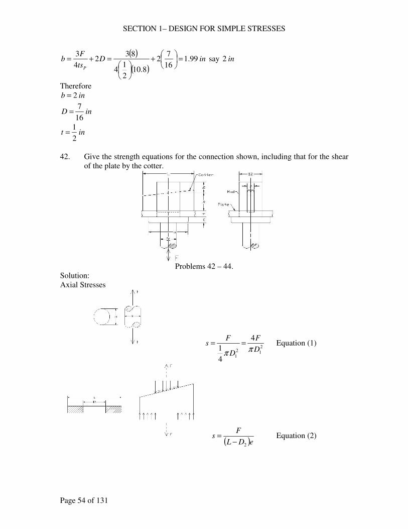
42. Give the strength equations for the connection shown, including that for the shear
of the plate by the cotter.
Problems 42 – 44.
Solution:
Axial Stresses
2
12
1
4
4
1 D
F
D
Fs
ππ== Equation (1)
( )eDL
Fs
2−= Equation (2)
SECTION 1– DESIGN FOR SIMPLE STRESSES
Page 55 of 131
eD
Fs
2
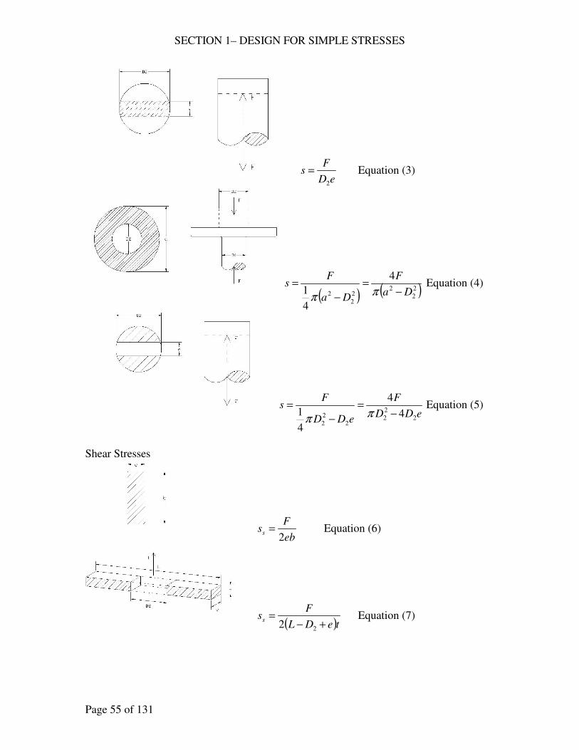
= Equation (3)
( ) ( )2
2
22
2
2
4
4
1 Da
F
Da
Fs
−=
−
=ππ
Equation (4)
eDD
F
eDD
Fs
2
2
22
2
2
4
4
4
1 −=
−
=ππ
Equation (5)
Shear Stresses
eb
Fss
2= Equation (6)
( )teDL
Fss
+−=
22 Equation (7)
SECTION 1– DESIGN FOR SIMPLE STRESSES
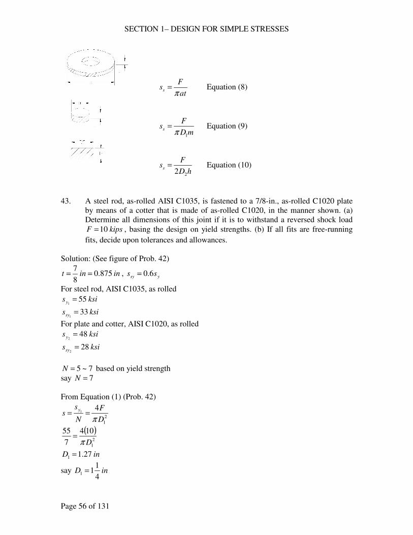
Page 56 of 131
at
Fss
π= Equation (8)
mD
Fss
1π= Equation (9)
hD
Fss
22= Equation (10)
43. A steel rod, as-rolled AISI C1035, is fastened to a 7/8-in., as-rolled C1020 plate
by means of a cotter that is made of as-rolled C1020, in the manner shown. (a)
Determine all dimensions of this joint if it is to withstand a reversed shock load
kipsF 10= , basing the design on yield strengths. (b) If all fits are free-running
fits, decide upon tolerances and allowances.
Solution: (See figure of Prob. 42)
inint 875.08
7== , ysy ss 6.0=
For steel rod, AISI C1035, as rolled
ksisy 551
=
ksissy 331
=
For plate and cotter, AISI C1020, as rolled
ksisy 482
=
ksissy 282
=
7~5=N based on yield strength
say 7=N
From Equation (1) (Prob. 42)
2
1
41
D
F
N
ss
y
π==
( )2
1
104
7
55
Dπ=
inD 27.11 =
say inD4
111 =
SECTION 1– DESIGN FOR SIMPLE STRESSES
Page 57 of 131
From Equation (9)
mD
F
N
ss
sy
s
1
1
π==
m
=
4
11
10
7
33
π
inm 54.0=
say inm16
9=
From Equation (3)
eD
F
N
ss
y
2
1 ==
eDs
2
10
7
55==
273.12 =eD
From Equation (5)
eDD
F
N
ss
y
2
2
2 4
41
−==
π
( )( )273.14
104
7
552
2 −=
Dπ
inD 80.12 =
say inD4
312 =
and 273.12 =eD
273.14
31 =
e
ine 73.0=
say ine4
3=
By further adjustment
Say inD 22 = , ine8
5=
From Equation (8)
at
F
N
ss
sy
sπ
== 2
( )875.0
10
7
28
aπ=
ina 91.0=
say ina 1=
SECTION 1– DESIGN FOR SIMPLE STRESSES
Page 58 of 131
From Equation (4)
( )2
2
2
42
Da
F
N
ss
y
−==
π
( )( )22 2
104
7
48
−=
aπ
ina 42.2=
say ina2
12=
use ina2
12=
From Equation (7)
( )teDL
F
N
ss
sy
s+−
==22
2
( )875.08
522
10
7
28
+−
=
L
inL 80.2=
say inL 3=
From Equation (6)
eb
F
N
ss
sy
s2
2 ==
b
=
8
52
10
7
28
inb 2=
From Equation (10)
hD
F
N
ss
sy
s
22
2 ==
( )h22
10
7
28=
ininh8
5625.0 ==
Summary of Dimensions
inL 3=
inh8
5=
inb 2=
int8
7=
SECTION 1– DESIGN FOR SIMPLE STRESSES
Page 59 of 131
inm16
9=
ina2
12=
inD4
111 =
inD 22 =
ine8
5=
(b) Tolerances and allowances, No fit, tolerance = in010.0±
inL 010.03±=
inh 010.0625.0 ±=
int 010.0875.0 ±=
inm 010.05625.0 ±=
ina 010.0500.2 ±=
inD 010.025.11 ±=
For Free Running Fits (RC 7) Table 3.1
Female Male
inb0000.0
0030.00.2
−
+= inb
0058.0
0040.00.2
−
−=
allowance = 0.0040 in
inD0000.0
0030.00.22
−
+= inD
0058.0
0040.00.22
−
−=
allowance = 0.0040 in
ine0000.0
0016.0625.0
−
+= ine
0030.0
0020.0625.0
−
−=
allowance = 0.0020 in
44. A 1-in. ( 1D ) steel rod (as-rolled AISI C1035) is to be anchored to a 1-in. steel
plate (as-rolled C1020) by means of a cotter (as rolled C1035) as shown. (a)
Determine all the dimensions for this connection so that all parts have the same
ultimate strength as the rod. The load F reverses direction. (b) Decide upon
tolerances and allowances for loose-running fits.
Solution: (Refer to Prob. 42)
(a) For AISI C1035, as rolled
ksisu 851
=
ksisus 641
=
For AISI C1020, as rolled
SECTION 1– DESIGN FOR SIMPLE STRESSES
Page 60 of 131
ksisu 652
=
ksisus 482
=
Ultimate strength
Use Equation (1)
( ) ( ) kipsDsF uu 8.6614
185
4
1 22
11=
=
= ππ
Equation (9)
mDsF usu 11π=
( )( )( )m1648.66 π=
inm 33.0=
say inm8
3=
From Equation (3)
eDsF uu 21=
( ) eD2858.66 =
7859.02 =eD
From Equation (5)
−= eDDsF uu 2
2
24
11
π
( )
−= 7859.0
4
1858.66 2
2Dπ
inD 42.12 =
say inD8
312 =
7859.08
312 =
= eeD
ine 57.0=
say ine16
9=
From Equation (4)
( )
−= 2
2
2
4
12
DasF uu π
( )
−
=
2
2
8
31
4
1658.66 aπ
ina 79.1=
say ina4
31=
From Equation (8)
SECTION 1– DESIGN FOR SIMPLE STRESSES
Page 61 of 131
atsF usu π2
=
( )( )( )( )1488.66 aπ=
ina 44.0=
say ina2
1=
use ina4
31=
From Equation (2)
( )eDLsF uu 22−=
( )
−=
16
9
8
31658.66 L
inL 20.3=
say inL4
13=
From Equation (7)
( )teDLsF usu −−= 222
( ) ( )116
9
8
314828.66
−−= L
inL 51.1=
say inL2
11=
use inL4
13=
From Equation (6)
ebsF usu 12=
( ) b
=
16
96428.66
inb 93.0=
say inb 1=
From Equation (10)
hDsF usu 212=
( ) h
=
8
316428.66
inh 38.0=
say inh8
3=
Dimensions
inL4
13=
SECTION 1– DESIGN FOR SIMPLE STRESSES
Page 62 of 131
inh8
3=
inb 1=
int 1=
inm8
3=
ina4
31=
inD 11 =
inD8
312 =
ine16
9=
(b) Tolerances and allowances, No fit, tolerance = in010.0±
inL 010.025.3 ±=
inh 010.0375.0 ±=
int 010.0000.1 ±=
inm 010.0375.0 ±=
ina 010.075.1 ±=
inD 010.0000.11 ±=
For Loose Running Fits (RC 8) Table 3.1
Female Male
inb0000.0
0035.00.1
−
+= inb
0065.0
0045.00.1
−
−=
allowance = 0.0045 in
inD0000.0
0040.0375.12
−
+= inD
0075.0
0050.0375.12
−
−=
allowance = 0.0050 in
ine0000.0
0028.05625.0
−
+= ine
0051.0
0035.05625.0
−
−=
allowance = 0.0035 in
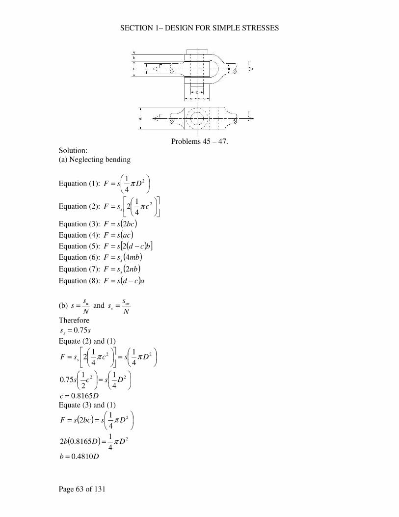
45. Give all the simple strength equations for the connection shown. (b) Determine
the ratio of the dimensions a , b , c , d , m , and n to the dimension D so that the
connection will be equally strong in tension, shear, and compression. Base the
calculations on ultimate strengths and assume uus ss 75.0= .
SECTION 1– DESIGN FOR SIMPLE STRESSES
Page 63 of 131
Problems 45 – 47.
Solution:
(a) Neglecting bending
Equation (1):
= 2
4
1DsF π
Equation (2):
= 2
4
12 csF s π
Equation (3): ( )bcsF 2=
Equation (4): ( )acsF =
Equation (5): ( )[ ]bcdsF −= 2
Equation (6): ( )mbsF s 4=
Equation (7): ( )nbsF s 2=
Equation (8): ( )acdsF −=
(b) N
ss u= and
N
ss us
s =
Therefore
sss 75.0=
Equate (2) and (1)
=
= 22
4
1
4
12 DscsF s ππ
=
22
4
1
2
175.0 Dscs
Dc 8165.0=
Equate (3) and (1)
( )
== 2
4
12 DsbcsF π
( ) 2
4
18165.02 DDb π=
Db 4810.0=

SECTION 1– DESIGN FOR SIMPLE STRESSES
Page 64 of 131
Equate (4) and (1)
== 2
4
1DssacF π
( ) 2
4
18165.0 DDa π=
Da 9619.0=
Equate (5) and (1)
( )[ ]
=−= 2
4
12 DsbcdsF π
( )( ) 2
4
14810.08165.02 DDd π=−
Dd 6329.1=
Equate (6) and (1)
( )
== 2
4
14 DsmbsF s π
( )( ) 2
4
14810.0475.0 DDm π=
Dm 5443.0=
Equate (7) and (1)
( )
== 2
4
12 DsnbsF s π
( )( ) 2
4
14810.0275.0 DDn π=
Dn 0886.1=
Equate (8) and (1)
( )
=−= 2
4
1DsacdsF π
( ) 2
4
18165.06329.1 DaDD π=−−
Da 9620.0=
Summary
Da 9620.0=
Db 4810.0=
Dc 8165.0=
Dd 6329.1=
Dm 5443.0=
Dn 0886.1=
46. The same as 45, except that the calculations are to be based on yield strengths. Let
ysy ss 6.0= .
SECTION 1– DESIGN FOR SIMPLE STRESSES
Page 65 of 131
Solution: (Refer to Prob. 45)
(a) Neglecting bending
Equation (1):
= 2
4
1DsF π
Equation (2):
= 2
4
12 csF s π
Equation (3): ( )bcsF 2=
Equation (4): ( )acsF =
Equation (5): ( )[ ]bcdsF −= 2
Equation (6): ( )mbsF s 4=
Equation (7): ( )nbsF s 2=
Equation (8): ( )acdsF −=
(b) N
ss
y= and
N
ss
sy
s =
Therefore
sss 6.0=
Equate (2) and (1)
=
= 22
4
1
4
12 DscsF s ππ
=
22
4
1
2
16.0 Dscs
Dc 9129.0=
Equate (3) and (1)
( )
== 2
4
12 DsbcsF π
( ) 2
4
19129.02 DDb π=
Db 4302.0=
Equate (4) and (1)
== 2
4
1DssacF π
( ) 2
4
19129.0 DDa π=
Da 8603.0=
Equate (5) and (1)
( )[ ]
=−= 2
4
12 DsbcdsF π
SECTION 2 – VARYING LOADS AND STRESS CONCENTRATIONS
Page 1 of 62
VARYING STRESSES – NO CONCENTRATION
DESIGN PROBLEMS
141. The maximum pressure of air in a 20-in. cylinder (double-acting air compressor)
is 125 psig. What should be the diameter of the piston rod if it is made of AISI
3140, OQT at 1000 F, and if there are no stress raisers and no column action? Let
75.1=N ; indefinite life desired. How does your answer compare with that
obtained for 4?
Solution:
For AISI 3140, OQT 1000 F
ksisu 153=
ksisy 134=
( ) ksiss un 5.761535.05.0 ===
For axial loading, with size factor
( )( )( ) ksiss un 525.7685.08.05.0 ===
Soderberg line
n
a
y
m
s
s
s
s
N+=
1
For double-acting
( ) ( ) kipslbpAFF 27.39270,39204
1252
max ==
===
π
kipsFF 27.39min −=−=
0=ms
( )222
5027.3944
ddd
Fsa ===
ππ
52
50
075.1
11 2
+==d
N
ind 2972.1=
say ind16
51=
comparative to Problem 4.
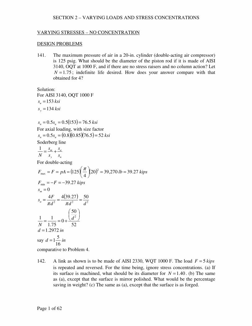
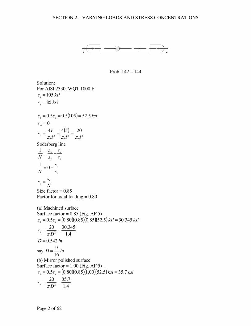
142. A link as shown is to be made of AISI 2330, WQT 1000 F. The load kipsF 5=
is repeated and reversed. For the time being, ignore stress concentrations. (a) If
its surface is machined, what should be its diameter for 40.1=N . (b) The same
as (a), except that the surface is mirror polished. What would be the percentage
saving in weight? (c) The same as (a), except that the surface is as forged.
SECTION 2 – VARYING LOADS AND STRESS CONCENTRATIONS
Page 2 of 62
Prob. 142 – 144
Solution:
For AISI 2330, WQT 1000 F
ksisu 105=
ksisy 85=
( ) ksiss un 5.521055.05.0 ===
0=ms
( )222
20544
ddd
Fsa
πππ===
Soderberg line
n
a
y
m
s
s
s
s
N+=
1
n
a
s
s
N+= 0
1
N
ss n
a =
Size factor = 0.85
Factor for axial loading = 0.80
(a) Machined surface
Surface factor = 0.85 (Fig. AF 5)
( )( )( )( ) ksiksiss un 345.305.5285.085.080.05.0 ===
4.1
345.30202
==D
saπ
inD 542.0=
say inD16
9=
(b) Mirror polished surface
Surface factor = 1.00 (Fig. AF 5)
( )( )( )( ) ksiksiss un 7.355.5200.185.080.05.0 ===
4.1
7.35202
==D
saπ
SECTION 2 – VARYING LOADS AND STRESS CONCENTRATIONS
Page 3 of 62
inD 5.0=
Savings in weight = ( ) %21%100
16
9
2
1
16
9
2
22
=
−
(c) As forged surface
Surface factor = 0.40 (Fig. AF 5)
( )( )( )( ) ksiksiss un 28.145.5240.085.080.05.0 ===
4.1
28.14202
==D
saπ
inD 79.0=
say inD4
3=
143. The same as 142, except that, because of a corrosive environment, the link is
made from cold-drawn silicon bronze B and the number of reversals of the load
is expected to be less than 3 x 10⁷.
Solution:
For cold-drawn silicon bronze, Type B.
ksisn 30= at 3 x 10⁸
ksisy 69=
ksisu 75.93=
ns at 3 x 10⁷ ( ) ksi5.36
103
10330
085.0
7
8
=
×
×=
( )( )( ) ksisn 82.245.3685.080.0 ==
4.1
82.24202
==D
saπ
inD 60.0=
say inD8
5=
144. The same as 142, except that the link is made of aluminum alloy 2024-T4 with a
minimum life of 107 cycles.
Solution:
For AA 2024-T4
ksisy 47=
ksisu 68=
ksisn 20= at 5 x10⁸
SECTION 2 – VARYING LOADS AND STRESS CONCENTRATIONS
Page 4 of 62
ns at 107 ( ) ksi9.27
10
10520
085.0
7
8
=
×
( )( )( ) ksisn 199.2785.080.0 ==
4.1
19202
==D
saπ
inD 685.0=
say inD16
11=
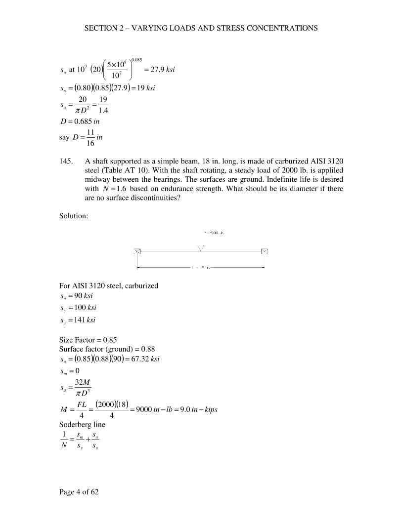
145. A shaft supported as a simple beam, 18 in. long, is made of carburized AISI 3120
steel (Table AT 10). With the shaft rotating, a steady load of 2000 lb. is appliled
midway between the bearings. The surfaces are ground. Indefinite life is desired
with 6.1=N based on endurance strength. What should be its diameter if there
are no surface discontinuities?
Solution:
For AISI 3120 steel, carburized
ksisn 90=
ksisy 100=
ksisu 141=
Size Factor = 0.85
Surface factor (ground) = 0.88
( )( )( ) ksisn 32.679088.085.0 ==
0=ms
3
32
D
Msa
π=
( )( )kipsinlbin
FLM −=−=== 0.99000
4
182000
4
Soderberg line
n
a
y
m
s
s
s
s
N+=
1
SECTION 2 – VARYING LOADS AND STRESS CONCENTRATIONS
Page 5 of 62
n
a
s
s
N+= 0
1
N
ss n
a =
( )6.1
32.679323
=Dπ
inD 2964.1=
say inD4
11=
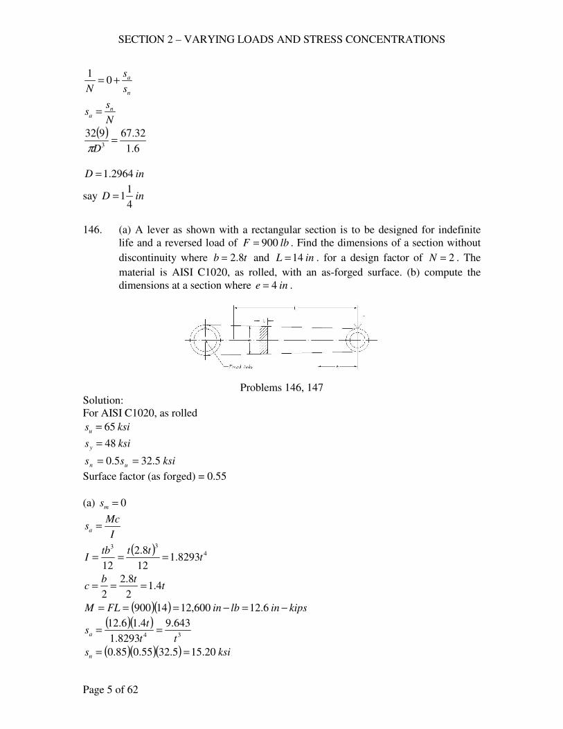
146. (a) A lever as shown with a rectangular section is to be designed for indefinite
life and a reversed load of lbF 900= . Find the dimensions of a section without
discontinuity where tb 8.2= and inL 14= . for a design factor of 2=N . The
material is AISI C1020, as rolled, with an as-forged surface. (b) compute the
dimensions at a section where ine 4= .
Problems 146, 147
Solution:
For AISI C1020, as rolled
ksisu 65=
ksisy 48=
ksiss un 5.325.0 ==
Surface factor (as forged) = 0.55
(a) 0=ms
I
Mcsa =
( ) 4
33
8293.112
8.2
12t
tttbI ===
ttb
c 4.12
8.2
2===
( )( ) kipsinlbinFLM −=−=== 6.12600,1214900
( )( )34
643.9
8293.1
4.16.12
tt
tsa ==
( )( )( ) ksisn 20.155.3255.085.0 ==
SECTION 2 – VARYING LOADS AND STRESS CONCENTRATIONS
Page 6 of 62
Soderberg line
n
a
y
m
s
s
s
s
N+=
1
n
a
s
s
N+= 0
1
N
ss n
a =
2
20.15643.93
=t
int 08.1=
( ) intb 0.308.18.28.2 ===
say int16
11= , inb 0.3=
(b) ( )( ) kipsinlbinFeM −=−=== 6.3600,34900
( )( )34
755.2
18293
4.16.3
tt
tsa ==
2
20.15755.23
=t
int 713.0=
( ) intb 996.1713.08.28.2 ===
say int32
23= , inb 2=
147. The same as 146, except that the reversal of the load are not expected to exceed
105 (Table AT 10).
Solution:
ksisn 5.32=
ns at 105 ( ) ksi5.39
10
105.32
085.0
5
6
=
=
( )( )( ) ksisn 5.185.3955.085.0 ==
(a) N
ss n
a =
2
5.18643.93
=t
SECTION 2 – VARYING LOADS AND STRESS CONCENTRATIONS
Page 7 of 62
int 014.1=
( ) intb 839.2014.18.28.2 ===
say int 1= , inb16
132=
(b) N
ss n
a =
2
5.18755.23
=t
int 6678.0=
( ) intb 870.16678.08.28.2 ===
say int16
11= , inb
8
71=
148. A shaft is to be subjected to a maximum reversed torque of 15,000 in-lb. It is
machined from AISI 3140 steel, OQT 1000 F (Fig. AF 2). What should be its
diameter for 75.1=N ?
Solution:
For AISI 3140 steel, OQT 1000 F
ksisu 152=
ksisy 134=
ksiss un 765.0 ==
For machined surface,
Surface factor = 0.78
Size factor = 0.85
( )( )( )( ) ksisns 3.5313478.085.06.0 ==
( ) ksiss yys 4.801346.06.0 ===
ns
as
ys
ms
s
s
s
s
N+=
1
0=mss
3
16
D
Tsas
π=
kipsinT −= 15
( )33
2401516
DDsas
ππ==
ns
as
s
s
N+= 0
1
N
ss ns
as =
SECTION 2 – VARYING LOADS AND STRESS CONCENTRATIONS
Page 8 of 62
75.1
3.532403
=Dπ
inD 3587.1=
say inD8
31=
149. The same as 148, except that the shaft is hollow with the outside diameter twice
the inside diameter.
Solution:
io DD 2=
( )( )( )
( )[ ] 34444
32
2
2151616
iii
i
io
oas
DDD
D
DD
TDs
πππ=
−=
−=
N
ss ns
as =
75.1
3.53323
=iDπ
inDi 694.0=
say inDi16
11= , inDo
8
31=
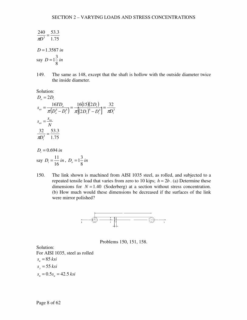
150. The link shown is machined from AISI 1035 steel, as rolled, and subjected to a
repeated tensile load that varies from zero to 10 kips; bh 2= . (a) Determine these
dimensions for 40.1=N (Soderberg) at a section without stress concentration.
(b) How much would these dimensions be decreased if the surfaces of the link
were mirror polished?
Problems 150, 151, 158.
Solution:
For AISI 1035, steel as rolled
ksisu 85=
ksisy 55=
ksiss un 5.425.0 ==
SECTION 2 – VARYING LOADS AND STRESS CONCENTRATIONS
Page 9 of 62
( ) kipsFm 50102
1=+=
( ) kipsFa 50102
1=−=
22 3
10
5.1
5
bbbh
Fs m
m ===
22 3
10
5.1
5
bbbh
Fs a
a ===
(a) Soderberg line
n
a
y
m
s
s
s
s
N+=
1
For machined surface,
Factor = 0.88
Size factor = 0.85
( )( )( )( ) ksisn 4.255.4288.085.080.0 ==
( ) ( )4.253
10
553
10
40.1
122
bb+=
inb 5182.0=
say inb16
9=
inbh32
275.1 ==
(b) Mirror polished,
Factor = 1.00
Size factor = 0.85
( )( )( )( ) ksisn 9.285.4200.185.080.0 ==
( ) ( )9.283
10
553
10
40.1
122
bb+=
inb 4963.0=
say inb2
1=
inbh4
35.1 ==
151. The same as 150, except that the link operates in brine solution. (Note: The
corroding effect of the solution takes precedence over surface finish.)
SECTION 2 – VARYING LOADS AND STRESS CONCENTRATIONS
Page 10 of 62
Solution:
Table AT 10, in brine, AISI 1035,
ksisn 6.24=
ksisy 58=
( )( )( ) ksisn 73.166.2485.080.0 ==
( ) ( )73.163
10
553
10
40.1
122
bb+=
inb 60.0=
say inb8
5=
inbh16
155.1 ==
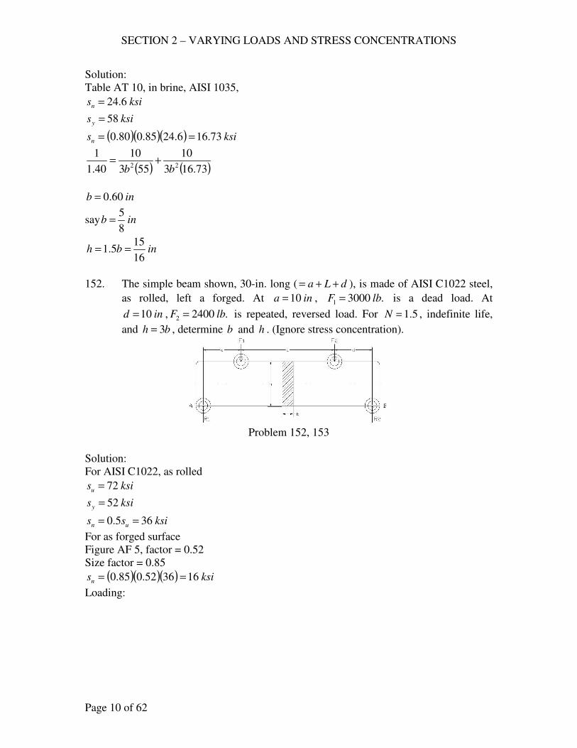
152. The simple beam shown, 30-in. long ( dLa ++= ), is made of AISI C1022 steel,
as rolled, left a forged. At ina 10= , .30001 lbF = is a dead load. At
ind 10= , .24002 lbF = is repeated, reversed load. For 5.1=N , indefinite life,
and bh 3= , determine b and h . (Ignore stress concentration).
Problem 152, 153
Solution:
For AISI C1022, as rolled
ksisu 72=
ksisy 52=
ksiss un 365.0 ==
For as forged surface
Figure AF 5, factor = 0.52
Size factor = 0.85
( )( )( ) ksisn 163652.085.0 ==
Loading:
SECTION 2 – VARYING LOADS AND STRESS CONCENTRATIONS
Page 11 of 62
∑ = 0AM
( ) ( ) 230240020300010 R=+
lbR 26002 =
∑ = 0VF
2121 FFRR +=+
2400300026001 +=+R
lbR 28001 =
Shear Diagram
( )( ) kipsinlbinMC −=−== 28000,28102800
1
( )( ) kipsinlbinM D −=−== 26000,261026001
Then
Loading
∑ = 0AM
( ) ( )24002030300010 2 =+ R
lbR 6002 =
∑ = 0VF
2121 RFFR +=+
600300024001 +=+R
lbR 12001 =
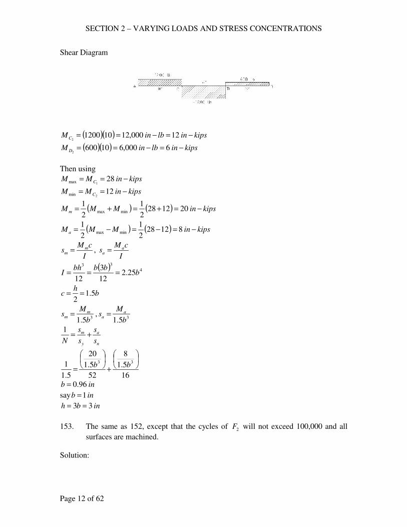
SECTION 2 – VARYING LOADS AND STRESS CONCENTRATIONS
Page 12 of 62
Shear Diagram
( )( ) kipsinlbinMC −=−== 12000,121012002
( )( ) kipsinlbinM D −=−== 6000,6106002
Then using
kipsinMM C −== 281max
kipsinMM C −== 122min
( ) ( ) kipsinMMMm −=+=+= 2012282
1
2
1minmax
( ) ( ) kipsinMMM a −=−=−= 812282
1
2
1minmax
I
cMs m
m = , I
cMs a
a =
( ) 4
33
25.212
3
12b
bbbhI ===
bh
c 5.12
==
35.1 b
Ms m
m = ,35.1 b
Ms a
a =
n
a
y
m
s
s
s
s
N+=
1
16
5.1
8
52
5.1
20
5.1
1 33
+
=bb
inb 96.0=
say inb 1=
inbh 33 ==
153. The same as 152, except that the cycles of 2F will not exceed 100,000 and all
surfaces are machined.
Solution:
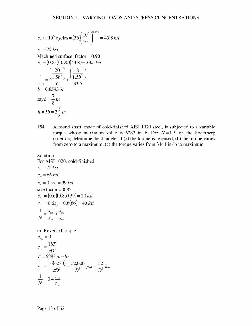
SECTION 2 – VARYING LOADS AND STRESS CONCENTRATIONS
Page 13 of 62
ns at 105 cycles ( ) ksi8.43
10
1036
085.0
5
6
=
=
ksisu 72=
Machined surface, factor = 0.90
( )( )( ) ksisn 5.338.4390.085.0 ==
5.33
5.1
8
52
5.1
20
5.1
1 33
+
=bb
inb 8543.0=
say inb8
7=
inbh8
523 ==
154. A round shaft, made of cold-finished AISI 1020 steel, is subjected to a variable
torque whose maximum value is 6283 in-lb. For 5.1=N on the Soderberg
criterion, determine the diameter if (a) the torque is reversed, (b) the torque varies
from zero to a maximum, (c) the torque varies from 3141 in-lb to maximum.
Solution:
For AISI 1020, cold-finished
ksisu 78=
ksisy 66=
ksiss un 395.0 ==
size factor = 0.85
( )( )( ) ksisns 203985.06.0 ==
( ) ksiss yys 40666.06.0 ===
ns
as
ys
ms
s
s
s
s
N+=
1
(a) Reversed torque
0=mss
3
16
D
Tsas
π=
lbinT −= 6283
( )ksi
Dpsi
DDsas 333
32000,32628316===
π
ns
as
s
s
N+= 0
1
SECTION 2 – VARYING LOADS AND STRESS CONCENTRATIONS
Page 14 of 62
20
32
05.1
1 3
+=D
inD 34.1=
say inD8
31=
(b) 0min =T , lbinT −= 6283max
( ) lbinTm −== 314162832
1
( ) lbinTa −== 314162832
1
( )ksi
Dpsi
DDsms 333
16000,16314116===
π
( )ksi
Dpsi
DDsas 333
16000,16314116===
π
20
16
40
16
5.1
1 33
+
=DD
inD 22.1=
say inD4
11=
(c) lbinT −= 3141min , lbinT −= 6283max
( ) lbinTm −=+= 4712314162832
1
( ) lbinTa −=−= 1571314162832
1
( )ksi
Dpsi
DDsms 333
24000,24471216===
π
( )ksi
Dpsi
DDsas 333
8000,8157116===
π
20
8
40
24
5.1
1 33
+
=DD
inD 145.1=
say inD32
51=
SECTION 2 – VARYING LOADS AND STRESS CONCENTRATIONS
Page 15 of 62
CHECK PROBLEMS
155. A simple beam 2 ft. long is made of AISI C1045 steel, as rolled. The dimensions
of the beam, which is set on edge, are 1 in. x 3 in. At the midpoint is a repeated,
reversed load of 4000 lb. What is the factor of safety?
Solution:
For AISI C1045, as rolled
ksisu 96=
ksisy 59=
( ) ksiss un 48965.05.0 ===
size factor = 0.85
( )( ) ksisn 8.404885.0 ==
n
a
y
m
s
s
s
s
N+=
1
0=ms
2
6
bh
Msa =
inh 3=
inb 1=
( )( )kipsinlbin
FLM −=−=== 24000,24
4
244000
4
( )( )( )
ksisa 1631
2462
==
8.40
160
1+=
N
55.2=N
156. The same as 155, except that the material is normalized and tempered cast steel,
SAE 080.
Solution:
Table AT 6
ksisn 35=′
ksisy 40=
( )( ) ksisn 75.293585.0 ==
75.29
160
1+=
N
86.1=N
157. A 1 ½-in. shaft is made of AISI 1045 steel, as rolled. For 2=N , what repeated
and reversed torque can the shaft sustain indefinitely?
SECTION 2 – VARYING LOADS AND STRESS CONCENTRATIONS
Page 16 of 62
Solution:
For AISI 1045, as rolled
ksisu 96=
ksisy 59=
( ) ksiss un 48965.05.0 ===′
( )( )( ) ksisns 48.244885.06.0 ==
( )( ) ksiss yys 4.35596.06.0 ===
ns
as
ys
ms
s
s
s
s
N+=
1
0=mss
48.240
2
1 ass+=
ksisas 24.12=
24.1216
3==
D
Tsas
π
kipsinT −= 8
VARIABLE STRESSES WITH STRESS CONCENTRATIONS
DESIGN PROBLEMS
158. The load on the link shown (150) is a maximum of 10 kips, repeated and
reversed. The link is forged from AISI C020, as rolled, and it has a ¼ in-hole
drilled on the center line of the wide side. Let bh 2= and 5.1=N . Determine b
and h at the hole (no column action) (a) for indefinite life, (b) for 50,000
repetitions (no reversal) of the maximum load, (c) for indefinite life but with a
ground and polished surface. In this case, compute the maximum stress.
Solution:
For AISI C1020, as rolled
ksisu 65=
ksisy 48=
( ) ksiss un 5.32655.05.0 ===
For as forged surface
Surface factor = 0.55
Size factor = 0.85
( )( )( )( ) ksisn 2.125.3255.085.080.0 ==
n
af
y
m
s
sK
s
s
N+=
1
SECTION 2 – VARYING LOADS AND STRESS CONCENTRATIONS
Page 17 of 62
Fig. AF 8, 1>hb
Assume 5.3=tK
Figure AF 7, inind
r 125.08
1
2===
ina 01.0=
926.0
125.0
01.01
1
1
1=
+
=
+
=
r
aq
( ) ( ) 3.3115.3926.011 =+−=+−= tf KqK
0=ms
( ) ( )25.02
10
−=
−=
bbdhb
Fsa
(a) n
af
s
sK
N+= 0
1
( )( )( )( )2.1225.02
103.30
5.1
1
−+=
bb
06.425.02 2 =− bb
003.2125.02 =−− bb
inb 489.1=
say inb2
11= , inbh 32 ==
(b) For 50,000 repetitions or 50,000 cycles
( ) ksisn 74.15105
102.12
085.0
4
6
=
×=
( ) ( )( )
0.210
105
103.3log
33.3log4
log
3log
=×
==f
f
K
K
fl
nK
n
afl
s
sK
N=
1
( )( )( )( )74.1525.02
100.2
5.1
1
−=
bb
906.125.02 2 =− bb
0953.0125.02 =−− bb
inb 04.1=
say inb16
11= , inbh
8
122 ==
(c) For indefinite life, ground and polished surface
Surface factor = 0.90
SECTION 2 – VARYING LOADS AND STRESS CONCENTRATIONS
Page 18 of 62
( )( )( )( ) ksisn 205.3290.085.080.0 ==
n
af
s
sK
N=
1
( )( )( )( )2025.02
103.3
5.1
1
−=
bb
02375.1125.02 =−− bb
inb 18.1=
say inb16
31= , inbh
8
322 ==
Maximum stress = ( )dhb
FK f
−
1>hb , 105.0375.225.0 ==hd
Figure AF 8
5.3=tK
( ) ( ) 315.3115.3926.011 =+−=+−= tf KqK
( )( )( )
ksis 14.1325.0375.21875.1
10315.3max =
−=
159. A connecting link as shown, except that there is a 1/8-in. radial hole drilled
through it at the center section. It is machined from AISI 2330, WQT 1000 F, and
it is subjected to a repeated, reversed axial load whose maximum value is 5 kips.
For 5.1=N , determine the diameter of the link at the hole (a) for indefinite life;
(b) for a life of 105 repetitions (no column action). (c) In the link found in (a)
what is the maximum tensile stress?
Problem 159
Solution:
For AISI 2330, WQT 1000 F
ksisu 135=
ksisy 126=
( ) ksiss un 5.671355.05.0 ===
For machined surface, Fig. AF 7, surface factor = 0.80
Size factor = 0.85
( )( )( )( ) ksisn 72.365.6780.085.080.0 ==
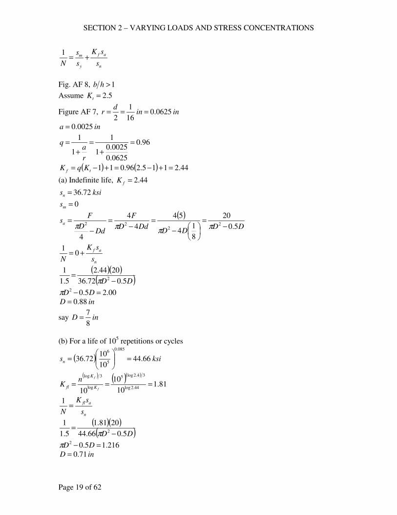
SECTION 2 – VARYING LOADS AND STRESS CONCENTRATIONS
Page 19 of 62
n
af
y
m
s
sK
s
s
N+=
1
Fig. AF 8, 1>hb
Assume 5.2=tK
Figure AF 7, inind
r 0625.016
1
2===
ina 0025.0=
96.0
0625.0
0025.01
1
1
1=
+
=
+
=
r
aq
( ) ( ) 44.2115.296.011 =+−=+−= tf KqK
(a) Indefinite life, 44.2=fK
ksisn 72.36=
0=ms
( )DD
DDDdD
F
DdD
Fsa
5.0
20
8
14
54
4
4
4
22
22−
=
−
=−
=
−
=π
πππ
n
af
s
sK
N+= 0
1
( )( )( )DD 5.072.36
2044.2
5.1
12 −
=π
00.25.02 =− DDπ
inD 88.0=
say inD8
7=
(b) For a life of 105 repetitions or cycles
( ) ksisn 66.4410
1072.36
085.0
5
6
=
=
( ) ( )( )
81.110
10
1044.2log
34.2log5
log
3log
===f
f
K
K
fl
nK
n
afl
s
sK
N=
1
( )( )( )DD 5.066.44
2081.1
5.1
12 −
=π
216.15.02 =− DDπ
inD 71.0=
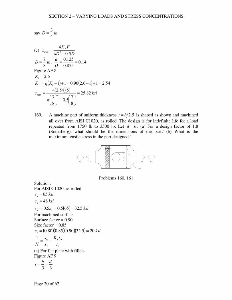
SECTION 2 – VARYING LOADS AND STRESS CONCENTRATIONS
Page 20 of 62
say inD4
3=
(c) DD
FKs
f
5.0
42max
−=
π
inD8
7= , 14.0
875.0
125.0==
D
d
Figure AF 8
6.2=tK
( ) ( ) 54.2116.296.011 =+−=+−= tf KqK
( )( )ksis 82.25
8
75.0
8
7
554.242max =
−
=
π
160. A machine part of uniform thickness 5.2bt = is shaped as shown and machined
all over from AISI C1020, as rolled. The design is for indefinite life for a load
repeated from 1750 lb to 3500 lb. Let bd = . (a) For a design factor of 1.8
(Soderberg), what should be the dimensions of the part? (b) What is the
maximum tensile stress in the part designed?
Problems 160, 161
Solution:
For AISI C1020, as rolled
ksisu 65=
ksisy 48=
( ) ksiss un 5.32655.05.0 ===′
For machined surface
Surface factor = 0.90
Size factor = 0.85
( )( )( )( ) ksisn 205.3290.085.080.0 ==
n
af
y
m
s
sK
s
s
N+=
1
(a) For flat plate with fillets
Figure AF 9
33
dbr ==
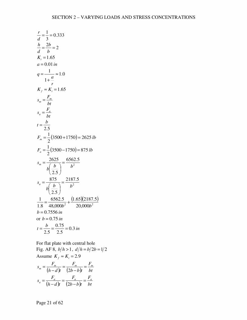
SECTION 2 – VARYING LOADS AND STRESS CONCENTRATIONS
Page 21 of 62
333.03
1==
d
r
22
==b
b
d
h
65.1=tK
ina 01.0=
0.1
1
1≈
+
=
r
aq
65.1=≈ tf KK
bt
Fs m
m =
bt
Fs a
a =
5.2
bt =
( ) lbFm 2625175035002
1=+=
( ) lbFa 875175035002
1=−=
2
5.6562
5.2
2625
bbb
sm =
=
2
5.2187
5.2
875
bbb
sa =
=
( )( )22 000,20
5.218765.1
000,48
5.6562
8.1
1
bb+=
inb 7556.0=
or inb 75.0=
inb
t 3.05.2
75.0
5.2===
For flat plate with central hole
Fig. AF 8, 1>hb , 212 == bbhd
Assume 9.2=≈ tf KK
( ) ( ) bt
F
tbb
F
tdh
Fs mmm
m =−
=−
=2
( ) ( ) bt
F
tbb
F
tdh
Fs aaa
a =−
=−
=2
SECTION 2 – VARYING LOADS AND STRESS CONCENTRATIONS
Page 22 of 62
2
5.6562
5.2
2625
bbb
sm =
=
2
5.2187
5.2
875
bbb
sa =
=
( )( )22 000,20
5.21879.2
000,48
5.6562
8.1
1
bb+=
inb 904.0=
or ininb16
159375.0 ==
inb
t8
3
5.2==
inbd16
15==
use inb16
15= , int
8
3= , ind
16
15=
(b) afm sKss +=max
ind
r32
15
2==
98.0
32
15
01.01
1=
+
=q
9.2=tK
( ) ( ) 86.2119.298.011 =+−=+−= tf KqK
psibbt
Fs m
m 7467
16
15
5.65625.656222
=
===
psibbt
Fs a
a 2489
16
15
5.21875.218722
=
===
( )( ) psisKss afm 586,14248986.27467max =+=+=
162. The beam shown has a circular cross section and supports a load F that
varies from 1000 lb to 3000 lb; it is machined from AISI C1020 steel, as
rolled. Determine the diameter D if Dr 2.0= and 2=N ; indefinite life.
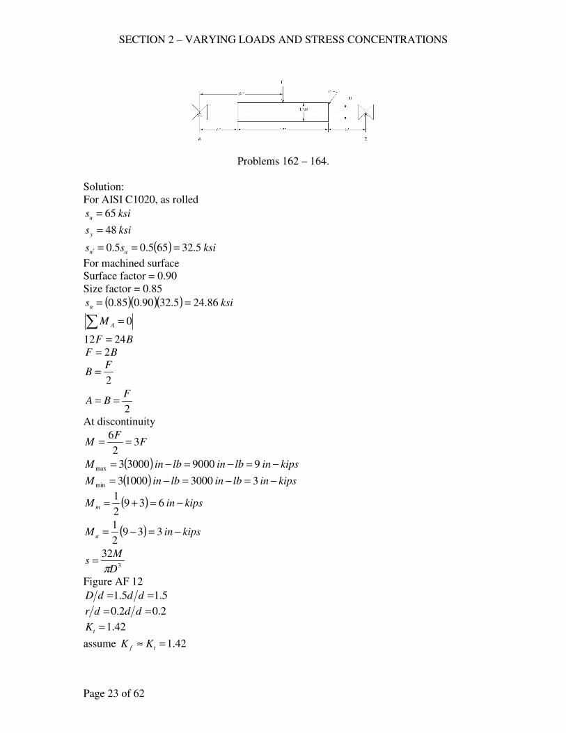
SECTION 2 – VARYING LOADS AND STRESS CONCENTRATIONS
Page 23 of 62
Problems 162 – 164.
Solution:
For AISI C1020, as rolled
ksisu 65=
ksisy 48=
( ) ksiss un 5.32655.05.0 ===′
For machined surface
Surface factor = 0.90
Size factor = 0.85
( )( )( ) ksisn 86.245.3290.085.0 ==
∑ = 0AM
BF 2412 =
BF 2=
2
FB =
2
FBA ==
At discontinuity
FF
M 32
6==
( ) kipsinlbinlbinM −=−=−= 9900030003max
( ) kipsinlbinlbinM −=−=−= 3300010003min
( ) kipsinM m −=+= 6392
1
( ) kipsinM a −=−= 3392
1
3
32
D
Ms
π=
Figure AF 12
5.15.1 == dddD
2.02.0 == dddr
42.1=tK
assume 42.1=≈ tf KK
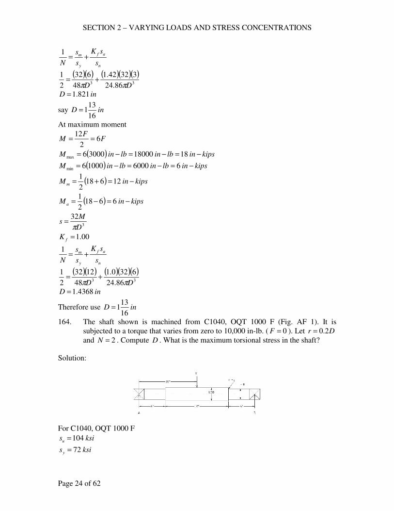
SECTION 2 – VARYING LOADS AND STRESS CONCENTRATIONS
Page 24 of 62
n
af
y
m
s
sK
s
s
N+=
1
( )( ) ( )( )( )33 86.24
33242.1
48
632
2
1
DD ππ+=
inD 821.1=
say inD16
131=
At maximum moment
FF
M 62
12==
( ) kipsinlbinlbinM −=−=−= 181800030006max
( ) kipsinlbinlbinM −=−=−= 6600010006min
( ) kipsinM m −=+= 126182
1
( ) kipsinM a −=−= 66182
1
3
32
D
Ms
π=
00.1=fK
n
af
y
m
s
sK
s
s
N+=
1
( )( ) ( )( )( )33 86.24
6320.1
48
1232
2
1
DD ππ+=
inD 4368.1=
Therefore use inD16
131=
164. The shaft shown is machined from C1040, OQT 1000 F (Fig. AF 1). It is
subjected to a torque that varies from zero to 10,000 in-lb. ( 0=F ). Let Dr 2.0=
and 2=N . Compute D . What is the maximum torsional stress in the shaft?
Solution:
For C1040, OQT 1000 F
ksisu 104=
ksisy 72=
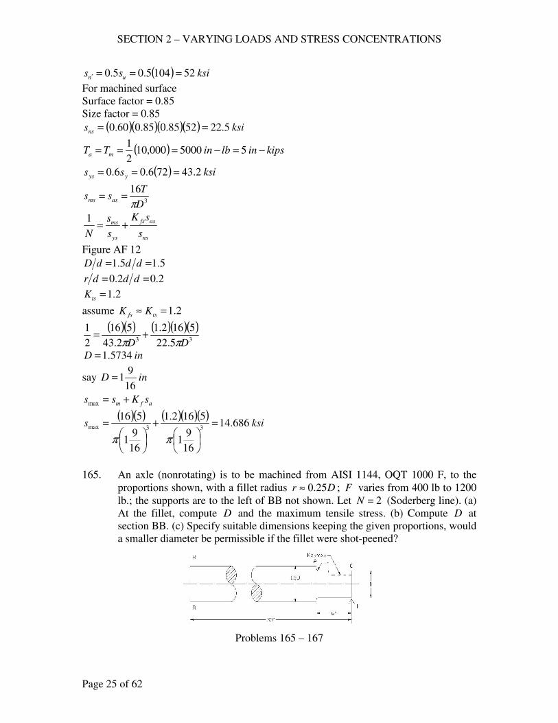
SECTION 2 – VARYING LOADS AND STRESS CONCENTRATIONS
Page 25 of 62
( ) ksiss un 521045.05.0 ===′
For machined surface
Surface factor = 0.85
Size factor = 0.85
( )( )( )( ) ksisns 5.225285.085.060.0 ==
( ) kipsinlbinTT ma −=−=== 55000000,102
1
( ) ksiss yys 2.43726.06.0 ===
3
16
D
Tss asms
π==
ns
asfs
ys
ms
s
sK
s
s
N+=
1
Figure AF 12
5.15.1 == dddD
2.02.0 == dddr
2.1=tsK
assume 2.1=≈ tsfs KK
( )( ) ( )( )( )33 5.22
5162.1
2.43
516
2
1
DD ππ+=
inD 5734.1=
say inD16
91=
afm sKss +=max
( )( ) ( )( )( )ksis 686.14
16
91
5162.1
16
91
51633max =
+
=
ππ
165. An axle (nonrotating) is to be machined from AISI 1144, OQT 1000 F, to the
proportions shown, with a fillet radius Dr 25.0≈ ; F varies from 400 lb to 1200
lb.; the supports are to the left of BB not shown. Let 2=N (Soderberg line). (a)
At the fillet, compute D and the maximum tensile stress. (b) Compute D at
section BB. (c) Specify suitable dimensions keeping the given proportions, would
a smaller diameter be permissible if the fillet were shot-peened?
Problems 165 – 167
SECTION 2 – VARYING LOADS AND STRESS CONCENTRATIONS
Page 26 of 62
Solution:
For AISI 1144, OQT 1000 F
ksisu 118=
ksisy 83=
ksiss un 595.0 ==′
For machined surface
Surface factor = 0.83
Size factor = 0.85
( )( )( ) ksisn 62.415983.085.0 ==
(a) At the fillet
5.15.1 == dddD
25.025.0 == dddr
35.1=tK
assume 35.1=≈ tf KK
FM 6=
( ) kipsinlbinlbinM −=−=−= 2.7720012006max
( ) kipsinlbinlbinM −=−=−= 4.224004006min
( ) kipsinM m −=+= 8.44.22.72
1
( ) kipsinM a −=−= 4.24.22.72
1
3
32
D
Ms
π=
n
af
y
m
s
sK
s
s
N+=
1
( )( ) ( )( )( )33 62.41
4.23235.1
83
8.432
2
1
DD ππ+=
inD 4034.1=
say inD16
71=
(b) At section BB,
FM 30=
( ) kipsinlbinlbinM −=−=−= 3636000120030max
( ) kipsinlbinlbinM −=−=−= 121200040030min
( ) kipsinM m −=+= 8.44.22.72
1
( ) kipsinM a −=−= 4.24.22.72
1
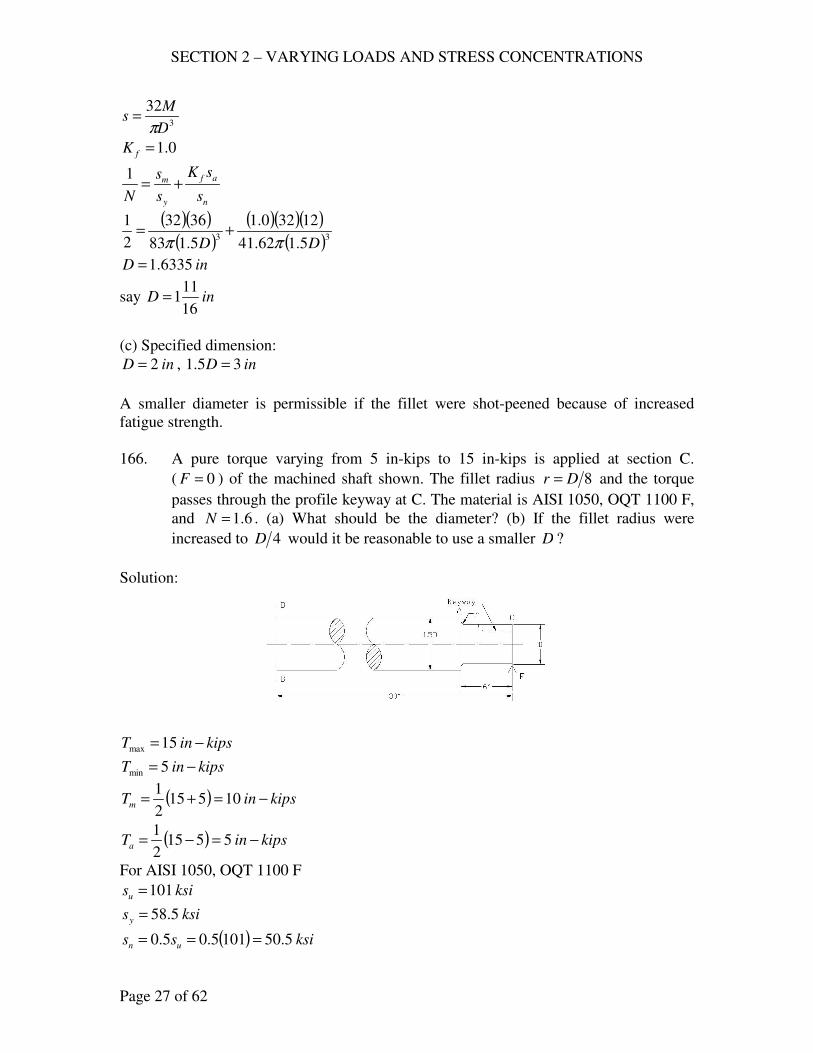
SECTION 2 – VARYING LOADS AND STRESS CONCENTRATIONS
Page 27 of 62
3
32
D
Ms
π=
0.1=fK
n
af
y
m
s
sK
s
s
N+=
1
( )( )( )
( )( )( )( )33
5.162.41
12320.1
5.183
3632
2
1
DD ππ+=
inD 6335.1=
say inD16
111=
(c) Specified dimension:
inD 2= , inD 35.1 =
A smaller diameter is permissible if the fillet were shot-peened because of increased
fatigue strength.
166. A pure torque varying from 5 in-kips to 15 in-kips is applied at section C.
( 0=F ) of the machined shaft shown. The fillet radius 8Dr = and the torque
passes through the profile keyway at C. The material is AISI 1050, OQT 1100 F,
and 6.1=N . (a) What should be the diameter? (b) If the fillet radius were
increased to 4D would it be reasonable to use a smaller D ?
Solution:
kipsinT −= 15max
kipsinT −= 5min
( ) kipsinTm −=+= 105152
1
( ) kipsinTa −=−= 55152
1
For AISI 1050, OQT 1100 F
ksisu 101=
ksisy 5.58=
( ) ksiss un 5.501015.05.0 ===
SECTION 2 – VARYING LOADS AND STRESS CONCENTRATIONS
Page 28 of 62
For machined surface
Surface factor = 0.85
Size factor = 0.85
( )( )( )( ) ksisns 9.215.5085.085.060.0 ==
(a) At the fillet
81=== Drdr
5.1=dD
3.1=tsK
assume 3.1=≈ tsfs KK
At the key profile
6.1=fsK
use 6.1=fsK
( ) ksiss yys 1.355.586.06.0 ===
ns
asfs
ys
ms
s
sK
s
s
N+=
1
( )( ) ( )( )( )33 9.21
5166.1
1.35
1016
6.1
1
DD ππ+=
inD 7433.1=
say inD4
31=
(b) 4Dr =
25.0=Dr
5.1=dD
Figure AF 12
18.1=tsK
6.118.1 <=≈ tsfs KK
Therefore, smaller D is not reasonable.
170. The beam shown is made of AISI C1020 steel, as rolled; ine 8= . The load F is
repeated from zero to a maximum of 1400 lb. Assume that the stress
concentration at the point of application of F is not decisive. Determine the
depth h and width t if th 4≈ ; 1.05.1 ±=N for Soderberg line. Iteration is
necessary because fK depends on the dimensions. Start by assuming a logical
fK for a logical h (Fig. AF 11), with a final check of fK . Considerable
estimation inevitable.
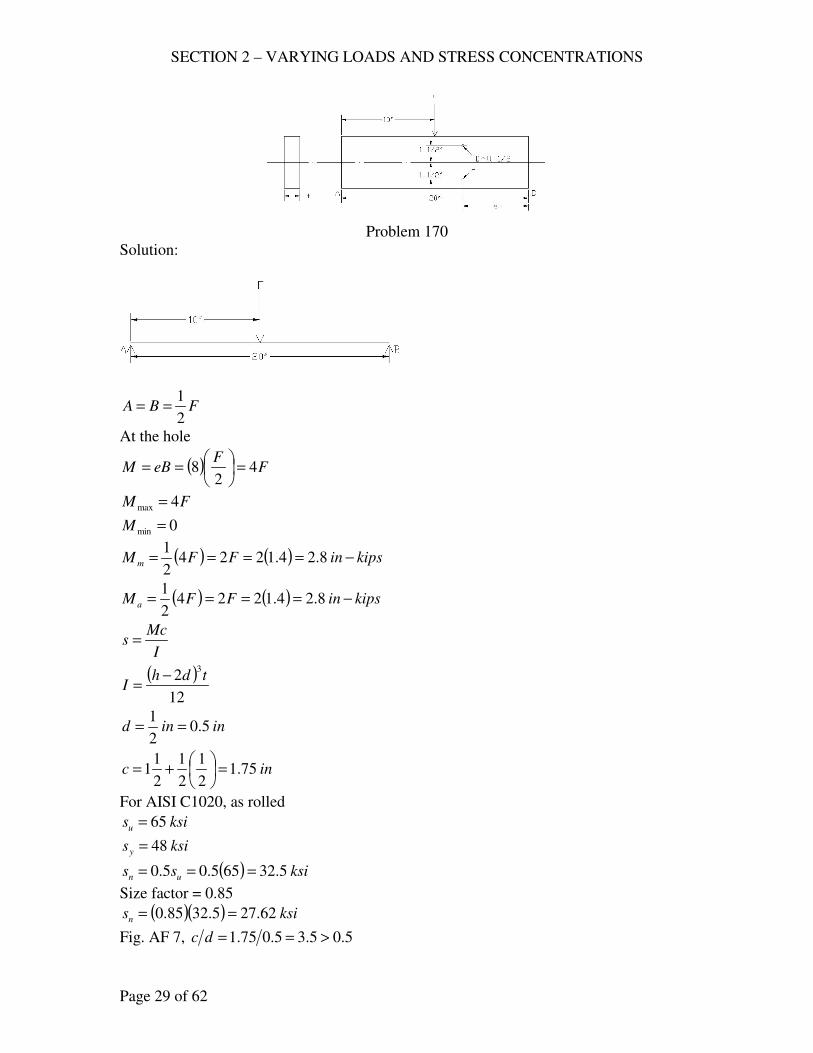
SECTION 2 – VARYING LOADS AND STRESS CONCENTRATIONS
Page 29 of 62
Problem 170
Solution:
FBA2
1==
At the hole
( ) FF
eBM 42
8 =
==
FM 4max =
0min =M
( ) ( ) kipsinFFM m −==== 8.24.12242
1
( ) ( ) kipsinFFM a −==== 8.24.12242
1
I
Mcs =
( )12
23tdh
I−
=
inind 5.02
1==
inc 75.12
1
2
1
2
11 =
+=
For AISI C1020, as rolled
ksisu 65=
ksisy 48=
( ) ksiss un 5.32655.05.0 ===
Size factor = 0.85
( )( ) ksisn 62.275.3285.0 ==
Fig. AF 7, 5.05.35.075.1 >==dc
SECTION 2 – VARYING LOADS AND STRESS CONCENTRATIONS
Page 30 of 62
Assume 5.3=tK
inr 25.02
1
2
1=
=
ina 010.0=
962.0
25.0
010.01
1
1
1=
+
=
+
=
r
aq
( ) ( ) 4.3115.3962.011 =+−=+−= tf KqK
n
af
y
m
s
sK
s
s
N+=
1
( )( )( )
( )( )( )( )( ) tdhtdh
33262.27
75.18.2124.3
248
75.18.212
5.1
1
−+
−=
( ) 70.1223
=− tdh
( )[ ] 70.1250.023
=− th
( ) 70.12143
=− tt
int 8627.0=
say int8
7=
inth 5.34 ==
inh2
1
2
11
2
11 ++>
inh 5.3>
Figure AF 11, 10>dh
( ) indh 550.01010 ===
5.0
2
11
2
52
1
=
−
=b
d
Therefore 5.3=tK , 4.3=fK
Use inh 5= , int4
11=
171. Design a crank similar to that shown with a design factor of 16.06.1 ± based on
the modified Goodman line. The crank is to be forged with certain surfaces
milled as shown and two ¼-in. holes. It is estimated that the material must be of
the order of AISI 8630, WQT 1100 F. The length .17 inL = , .5 ina = , and the
load varies form + 15 kips to –9 kips. (a) Compute the dimensions at section AB
with bh 3= . Check the safety of the edges (forged surfaces). (Iteration involves;
one could first make calculations for forged surfaces and then check safety at
holes.) (b) Without redesigning but otherwise considering relevant factors ,
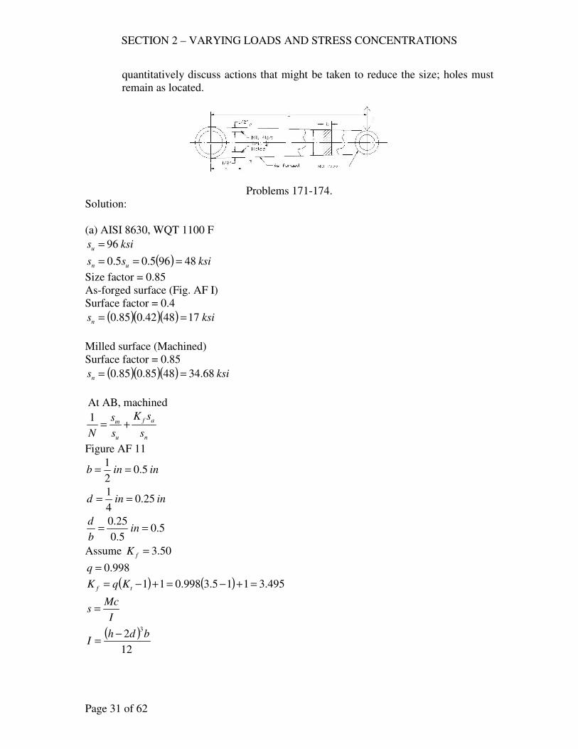
SECTION 2 – VARYING LOADS AND STRESS CONCENTRATIONS
Page 31 of 62
quantitatively discuss actions that might be taken to reduce the size; holes must
remain as located.
Problems 171-174.
Solution:
(a) AISI 8630, WQT 1100 F
ksisu 96=
( ) ksiss un 48965.05.0 ===
Size factor = 0.85
As-forged surface (Fig. AF I)
Surface factor = 0.4
( )( )( ) ksisn 174842.085.0 ==
Milled surface (Machined)
Surface factor = 0.85
( )( )( ) ksisn 68.344885.085.0 ==
At AB, machined
n
af
u
m
s
sK
s
s
N+=
1
Figure AF 11
ininb 5.02
1==
inind 25.04
1==
5.05.0
25.0== in
b
d
Assume 50.3=fK
998.0=q
( ) ( ) 495.3115.3998.011 =+−=+−= tf KqK
I
Mcs =
( )12
23bdh
I−
=
SECTION 2 – VARYING LOADS AND STRESS CONCENTRATIONS
Page 32 of 62
( ) ( )348
1144
8
1
4
11
2
1
4
1
2
1
2
1
2−=+−=
+−=
+−= hhh
hc
bh 3=
( )
12
4
12
348
1
3
bh
hM
s
−
−
=
( )
( ) bb
bM
s3
5.03
3122
3
−
−=
( )( ) bb
bMs
35.03
145.4
−
−=
( )aLFM −=
( )( ) kipsinM −=−= 18051715max
( )( ) kipsinM −=−−= 1085179min
( ) kipsinMm −=−
= 36108180
2
1
( ) kipsinM a −=+
= 144108180
2
1
n
af
u
m
s
sK
s
s
N+=
1
( )( )( )
( )( )( )( )( ) bb
b
bb
b33
5.0368.34
141445.4495.3
5.0396
14365.4
6.1
1
−
−+
−
−=
( )( ) 2.107
1
5.03
143
=−
−
bb
b
( )( )
2.10714
5.033
=−
−
b
bb
inb 6.2=
say inb8
52=
inbh8
773 ==
Checking at the edges (as forged)
( )( ) kipsinM −== 2551715max
( )( ) kipsinM −−=−= 153179min
( ) kipsinMm −=−
= 51153255
2
1
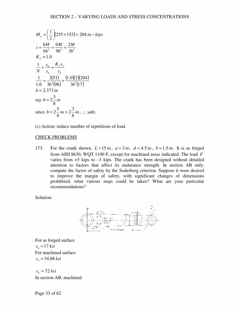
SECTION 2 – VARYING LOADS AND STRESS CONCENTRATIONS
Page 33 of 62
( ) kipsinM a −=+
= 204153255
2
1
332 3
2
9
66
b
M
b
M
bh
Ms ===
0.1≈fK
n
af
u
m
s
sK
s
s
N+=
1
( )( )
( )( )( )( )173
20420.1
963
512
6.1
133
bb+=
inb 373.2=
say inb8
32=
since ininb8
32
8
52 >= , ∴ safe.
(c) Action: reduce number of repetitions of load.
CHECK PROBLEMS
173. For the crank shown, inL 15= , ina 3= , ind 5.4= , inb 5.1= . It is as forged
from AISI 8630, WQT 1100 F, except for machined areas indicated. The load F
varies from +5 kips to –3 kips. The crank has been designed without detailed
attention to factors that affect its endurance strength. In section AB only,
compute the factor of safety by the Soderberg criterion. Suppose it were desired
to improve the margin of safety, with significant changes of dimensions
prohibited, what various steps could be taken? What are your particular
recommendations?
Solution:
For as forged surface
ksisn 17=
For machined surface
ksisn 68.34=
ksisn 72=
In section AB, machined
SECTION 2 – VARYING LOADS AND STRESS CONCENTRATIONS
Page 34 of 62
( )aLFM −=
( )( ) kipsinM −=−+= 603155max
( )( ) kipsinM −−=−−= 363153min
( ) kipsinMm −=−
= 123660
2
1
( ) kipsinM a −=+
= 483660
2
1
inhd 5.4== , inb 5.1=
3=b
h
( )( ) bb
bMs
35.03
145.4
−
−=
( ) ( )[ ]( )[ ] ( )
ksism 8125.25.15.05.13
15.14125.43
=−
−=
( ) ( )[ ]( )[ ] ( )
ksisa 25.115.15.05.13
15.14485.43
=−
−=
n
af
y
m
s
sK
s
s
N+=
1
495.3=fK from Problem 171.
( )( )68.34
25.11495.3
72
8125.21+=
N
185.0 <=N , unsafe
To increase the margin of safety
1. reduce the number of repetitions of loads
2. shot-peening
3. good surface roughness
Recommendation:
No. 1, reducing the number of repetitions of loads.
175. The link shown is made of AISI C1020, as rolled, machined all over. It is loaded
in tension by pins in the inD8
3= holes in the ends; ina
16
9= , int
16
5= ,
inh8
11= . Considering sections at A, B, and C, determine the maximum safe
axial load for 2=N and indefinite life (a) if it is repeated and reversed; (b) if it
is repeated varying from zero to maximum; (c) if it is repeatedly varies or
WF −= to WF 3= . (d) Using the results from (a) and (b), determine the ratio of
the endurance strength for a repeated load to that for a reversed load (Soderberg
line).
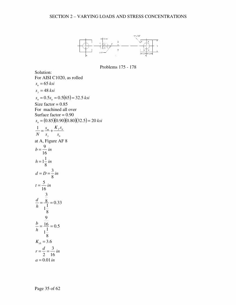
SECTION 2 – VARYING LOADS AND STRESS CONCENTRATIONS
Page 35 of 62
Problems 175 - 178
Solution:
For AISI C1020, as rolled
ksisu 65=
ksisy 48=
( ) ksiss un 5.32655.05.0 ===
Size factor = 0.85
For machined all over
Surface factor = 0.90
( )( )( )( ) ksisn 205.3280.090.085.0 ==
n
af
y
m
s
sK
s
s
N+=
1
at A, Figure AF 8
inb16
9=
inh8
11=
inDd8
3==
int16
5=
33.0
8
11
8
3
==h
d
5.0
8
11
16
9
==h
b
6.3=tAK
ind
r16
3
2==
ina 01.0=

SECTION 2 – VARYING LOADS AND STRESS CONCENTRATIONS
Page 36 of 62
95.0
16
3
01.01
1
1
1=
+
=
+
=
r
aq
( ) ( ) 47.3116.395.011 =+−=+−= tAfA kqk
( ) 15
64
16
5
8
3
8
11
FF
tdh
Fs =
−
=−
=
( )( )( )2015
6447.3
4815
64
2
1 am FF+=
am FF 48.145
81 += at A
At B Figure AF 9
inad16
9==
inh8
11=
inr16
3=
int16
5=
33.0
16
916
3
==d
r
2
16
98
11
==d
h
63.1=tBK
ina 01.0=
95.0
16
3
01.01
1
1
1=
+
=
+
=
r
aq
( ) ( ) 6.11163.195.011 =+−=+−= tBfB kqk
45
256
16
5
16
9
FF
dt
Fs =
==
SECTION 2 – VARYING LOADS AND STRESS CONCENTRATIONS
Page 37 of 62
( )( )
( )2045
2566.1
4845
256
2
1 am FF+=
am FF 455.0135
321 += at B
at C, Figure AF 8, 1>h
b
inD8
1=
inah16
9==
22.0
16
98
1
==h
d
5.3=tCK
ind
r16
1
2==
ina 01.0=
862.0
16
1
01.01
1
1
1=
+
=
+
=
r
aq
( ) ( ) 2.3115.3862.011 =+−=+−= tCfC kqk
( ) 35
256
16
5
8
1
16
9
FF
tdh
Fs =
−
=−
=
( )( )
( )2035
2562.3
4835
256
2
1 am FF+=
am FF 17.1105
321 += at C
Equations
At A, am FF 48.145
81 +=
At B, am FF 455.0135
321 +=
At C, am FF 17.1105
321 +=
SECTION 2 – VARYING LOADS AND STRESS CONCENTRATIONS
Page 38 of 62
(a) Repeated and reversed load
0=mF
FFa =
use at A
am FF 48.145
81 +=
( ) aF48.1045
81 +=
kipF 676.0=
(b) FFF am ==
at A, FF 48.145
81 +=
kipF 603.0=
at B, FF 455.0135
321 +=
kipsF 480.1=
at C, FF 17.1105
321 +=
kipF 678.0=
use kipF 603.0=
(c) WF −=min , WF 3max =
( ) WWWFm =−= 32
1
( ) WWWFa 232
1=+=
at A, ( )WW 248.145
81 +=
kipW 319.0=
at B, ( )WW 2455.0135
321 +=
kipW 884.0=
at C, ( )WW 217.1105
321 +=
kipW 378.0=
use kipW 319.0=
kipF 957.0max =
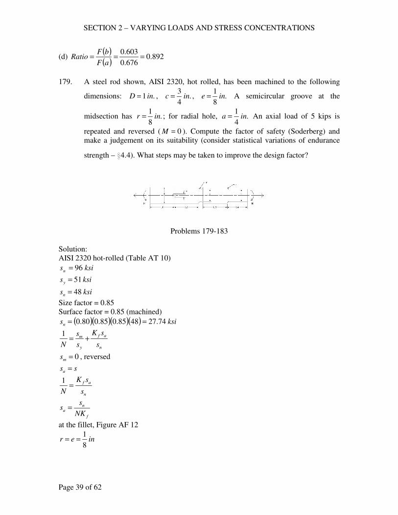
SECTION 2 – VARYING LOADS AND STRESS CONCENTRATIONS
Page 39 of 62
(d) ( )( )
892.0676.0
603.0===
aF
bFRatio
179. A steel rod shown, AISI 2320, hot rolled, has been machined to the following
dimensions: .1 inD = , .4
3inc = , .
8
1ine = A semicircular groove at the
midsection has .8
1inr = ; for radial hole, .
4
1ina = An axial load of 5 kips is
repeated and reversed ( 0=M ). Compute the factor of safety (Soderberg) and
make a judgement on its suitability (consider statistical variations of endurance
strength – i4.4). What steps may be taken to improve the design factor?
Problems 179-183
Solution:
AISI 2320 hot-rolled (Table AT 10)
ksisu 96=
ksisy 51=
ksisn 48=
Size factor = 0.85
Surface factor = 0.85 (machined)
( )( )( )( ) ksisn 74.274885.085.080.0 ==
n
af
y
m
s
sK
s
s
N+=
1
0=ms , reversed
ssa =
n
af
s
sK
N=
1
f
na
NK
ss =
at the fillet, Figure AF 12
iner8
1==
SECTION 2 – VARYING LOADS AND STRESS CONCENTRATIONS
Page 40 of 62
incd4
3==
inD 1=
17.0
4
38
1
==d
r
3.1
4
3
1==
d
D
55.1=tK
ina 010.0=
926.0
8
1
010.01
1
1
1=
+
=
+
=
r
aq
( ) ( ) 51.11155.1926.011 =+−=+−= tf KqK
( )ksissa 32.11
4
3
542
=
==
π
( )( )62.1
51.132.11
74.27===
fa
n
Ks
sN
At the groove, Figure AF 14
inininrDbd4
3
8
1212 =
−=−==
inD 1=
inr8
1=
17.0
4
38
1
==d
r
3.1
4
3
1==
d
D
75.1=tK
ina 010.0=
SECTION 2 – VARYING LOADS AND STRESS CONCENTRATIONS
Page 41 of 62
926.0
8
1
010.01
1
1
1=
+
=
+
=
r
aq
( ) ( ) 7.11175.1926.011 =+−=+−= tf KqK
( )ksi
d
Fssa 32.11
4
3
54422
=
===
ππ
( )( )44.1
7.132.11
74.27===
fa
n
Ks
sN
At the hole, Figure AF8
inhD 1==
inad4
1==
25.014
1
==h
D
44.2=tK
ina 010.0=
926.0
8
1
010.01
1
1
1=
+
=
+
=
r
aq
( ) ( ) 33.21144.2926.011 =+−=+−= tf KqK
( ) ( )ksi
DdD
Fssa 34.9
4
11
4
1
5
4
22=
−
=
−
==ππ
( )( )27.1
33.234.9
74.27===
fa
n
Ks
sN
Factor of safety is 1.27
From i4.4
nss 76.0=
27.1min32.176.0
>==n
n
s
sN
Therefore, dimensions are not suitable.
Steps to be taken:
1. Reduce number of cycle to failure
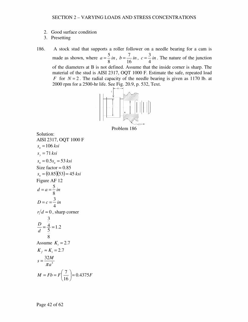
SECTION 2 – VARYING LOADS AND STRESS CONCENTRATIONS
Page 42 of 62
2. Good surface condition
3. Presetting
186. A stock stud that supports a roller follower on a needle bearing for a cam is
made as shown, where ina8
5= , inb
16
7= , inc
4
3= . The nature of the junction
of the diameters at B is not defined. Assume that the inside corner is sharp. The
material of the stud is AISI 2317, OQT 1000 F. Estimate the safe, repeated load
F for 2=N . The radial capacity of the needle bearing is given as 1170 lb. at
2000 rpm for a 2500-hr life. See Fig. 20.9, p. 532, Text.
Problem 186
Solution:
AISI 2317, OQT 1000 F
ksisu 106=
ksisy 71=
ksiss un 535.0 ==
Size factor = 0.85
( )( ) ksisn 455385.0 ==
Figure AF 12
inad8
5==
incD4
3==
0≈dr , sharp corner
2.1
8
54
3
==d
D
Assume 7.2=tK
7.2=≈ tf KK
3
32
a
Ms
π=
FFFbM 4375.016
7=
==
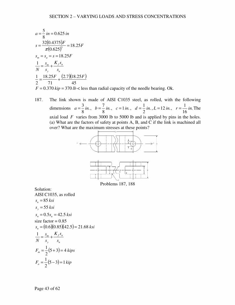
SECTION 2 – VARYING LOADS AND STRESS CONCENTRATIONS
Page 43 of 62
inina 625.08
5==
( )( )
FF
s 25.18625.0
4375.0323
==π
Fsss am 25.18===
n
af
y
m
s
sK
s
s
N+=
1
( )( )45
25.187.2
71
25.18
2
1 FF+=
lbkipF 370370.0 == < less than radial capacity of the needle bearing. Ok.
187. The link shown is made of AISI C1035 steel, as rolled, with the following
dimensions .8
3ina = , .
8
7inb = , .1 inc = , .
2
1ind = , .12 inL = , .
16
1inr = The
axial load F varies from 3000 lb to 5000 lb and is applied by pins in the holes.
(a) What are the factors of safety at points A, B, and C if the link is machined all
over? What are the maximum stresses at these points?
Problems 187, 188
Solution:
AISI C1035, as rolled
ksisu 85=
ksisy 55=
ksiss un 5.425.0 ==
size factor = 0.85
( )( )( ) ksisn 68.215.4285.06.0 ==
n
af
y
m
s
sK
s
s
N+=
1
( ) kipsFm 4352
1=+=
( ) kipFa 1352
1=−=

SECTION 2 – VARYING LOADS AND STRESS CONCENTRATIONS
Page 44 of 62
(a) at A, Figure AF 9
inr16
1=
inad8
3==
inbh8
7==
17.0
8
316
1
==d
r
33.2
8
38
7
==d
h
9.1=tK
ina 010.0=
862.0
16
1
010.01
1
1
1=
+
=
+
=
r
aq
( ) ( ) 78.1119.1862.011 =+−=+−= tf KqK
ac
Fs =
( )ksism 67.10
18
3
4=
=
( )ksisa 67.2
18
3
1=
=
( )( )68.21
67.278.1
55
67.101+=
N
42.2=N
At B, same as A, 78.1=fK
( )cab
Fs
−=
( )ksism 8
18
3
8
7
4=
−
=
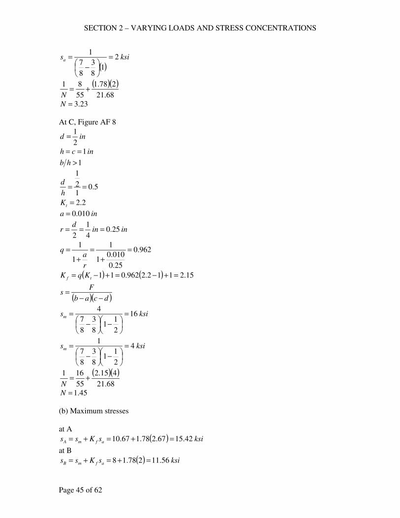
SECTION 2 – VARYING LOADS AND STRESS CONCENTRATIONS
Page 45 of 62
( )ksisa 2
18
3
8
7
1=
−
=
( )( )68.21
278.1
55
81+=
N
23.3=N
At C, Figure AF 8
ind2
1=
inch 1==
1>hb
5.012
1
==h
d
2.2=tK
ina 010.0=
inind
r 25.04
1
2===
962.0
25.0
010.01
1
1
1=
+
=
+
=
r
aq
( ) ( ) 15.2112.2962.011 =+−=+−= tf KqK
( )( )dcab
Fs
−−=
ksism 16
2
11
8
3
8
7
4=
−
−
=
ksism 4
2
11
8
3
8
7
1=
−
−
=
( )( )68.21
415.2
55
161+=
N
45.1=N
(b) Maximum stresses
at A
( ) ksisKss afmA 42.1567.278.167.10 =+=+=
at B
( ) ksisKss afmB 56.11278.18 =+=+=
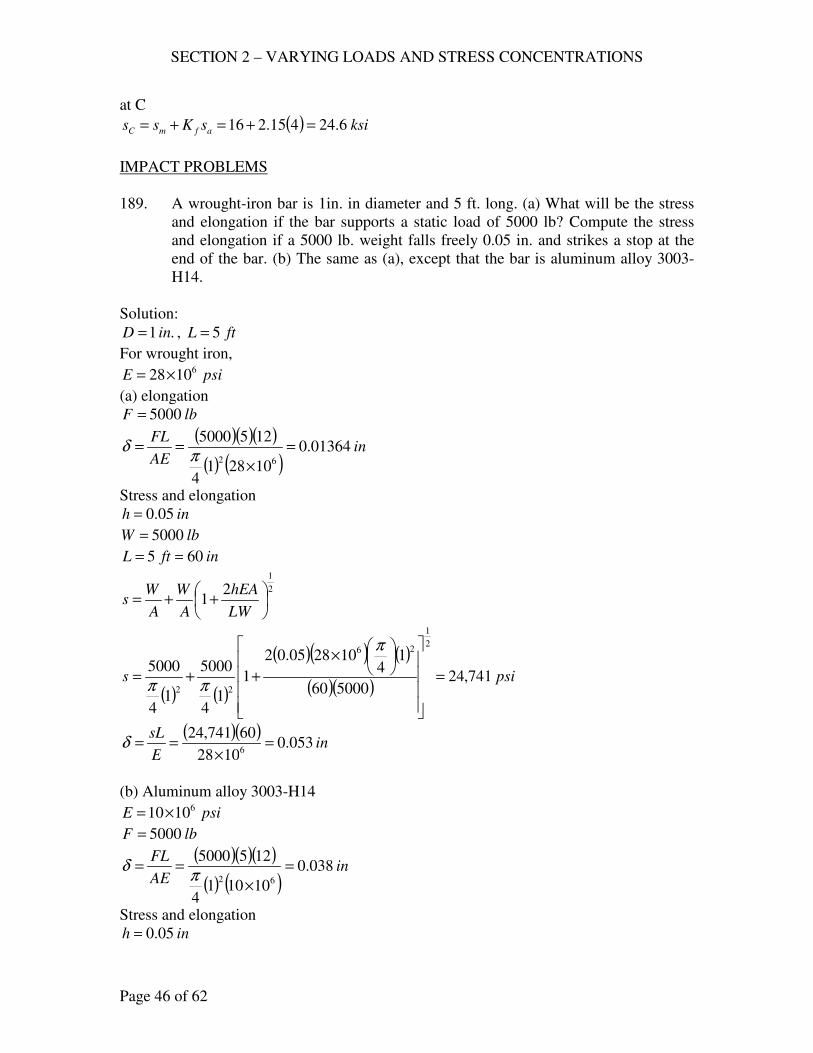
SECTION 2 – VARYING LOADS AND STRESS CONCENTRATIONS
Page 46 of 62
at C
( ) ksisKss afmC 6.24415.216 =+=+=
IMPACT PROBLEMS
189. A wrought-iron bar is 1in. in diameter and 5 ft. long. (a) What will be the stress
and elongation if the bar supports a static load of 5000 lb? Compute the stress
and elongation if a 5000 lb. weight falls freely 0.05 in. and strikes a stop at the
end of the bar. (b) The same as (a), except that the bar is aluminum alloy 3003-
H14.
Solution:
.1 inD = , ftL 5=
For wrought iron,
psiE 61028×=
(a) elongation
lbF 5000=
( )( )( )
( ) ( )in
AE
FL01364.0
102814
1255000
62
=
×
==π
δ
Stress and elongation
inh 05.0=
lbW 5000=
inftL 605 ==
2
1
21
++=
LW
hEA
A
W
A
Ws
( ) ( )
( )( ) ( )
( )( )psis 741,24
500060
14
102805.02
1
14
5000
14
5000
2
1
26
22
=
×
++=
π
ππ
( )( )in
E
sL053.0
1028
60741,246
=×
==δ
(b) Aluminum alloy 3003-H14
psiE 61010×=
lbF 5000=
( )( )( )
( ) ( )in
AE
FL038.0
101014
1255000
62
=
×
==π
δ
Stress and elongation
inh 05.0=
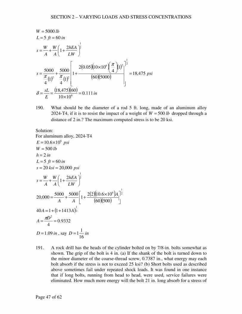
SECTION 2 – VARYING LOADS AND STRESS CONCENTRATIONS
Page 47 of 62
lbW 5000=
inftL 605 ==
2
1
21
++=
LW
hEA
A
W
A
Ws
( ) ( )
( )( ) ( )
( )( )psis 475,18
500060
14
101005.02
1
14
5000
14
5000
2
1
26
22
=
×
++=
π
ππ
( )( )in
E
sL111.0
1010
60475,186
=×
==δ
190. What should be the diameter of a rod 5 ft. long, made of an aluminum alloy
2024-T4, if it is to resist the impact of a weight of lbW 500= dropped through a
distance of 2 in.? The maximum computed stress is to be 20 ksi.
Solution:
For aluminum alloy, 2024-T4
psiE 6106.10 ×=
lbW 500=
inh 2=
inftL 605 ==
psiksis 000,2020 ==
2
1
21
++=
LW
hEA
A
W
A
Ws
( )( )( )( )
2
16
50060
106.10221
50005000000,20
×++=
A
AA
( )2
1
14131140 AA ++=
9332.04
2
==D
Aπ
inD 09.1= , say inD16
11=
191. A rock drill has the heads of the cylinder bolted on by 7/8-in. bolts somewhat as
shown. The grip of the bolt is 4 in. (a) If the shank of the bolt is turned down to
the minor diameter of the coarse-thread screw, 0.7387 in., what energy may each
bolt absorb if the stress is not to exceed 25 ksi? (b) Short bolts used as described
above sometimes fail under repeated shock loads. It was found in one instance
that if long bolts, running from head to head, were used, service failures were
eliminated. How much more energy will the bolt 21 in. long absorb for a stress of
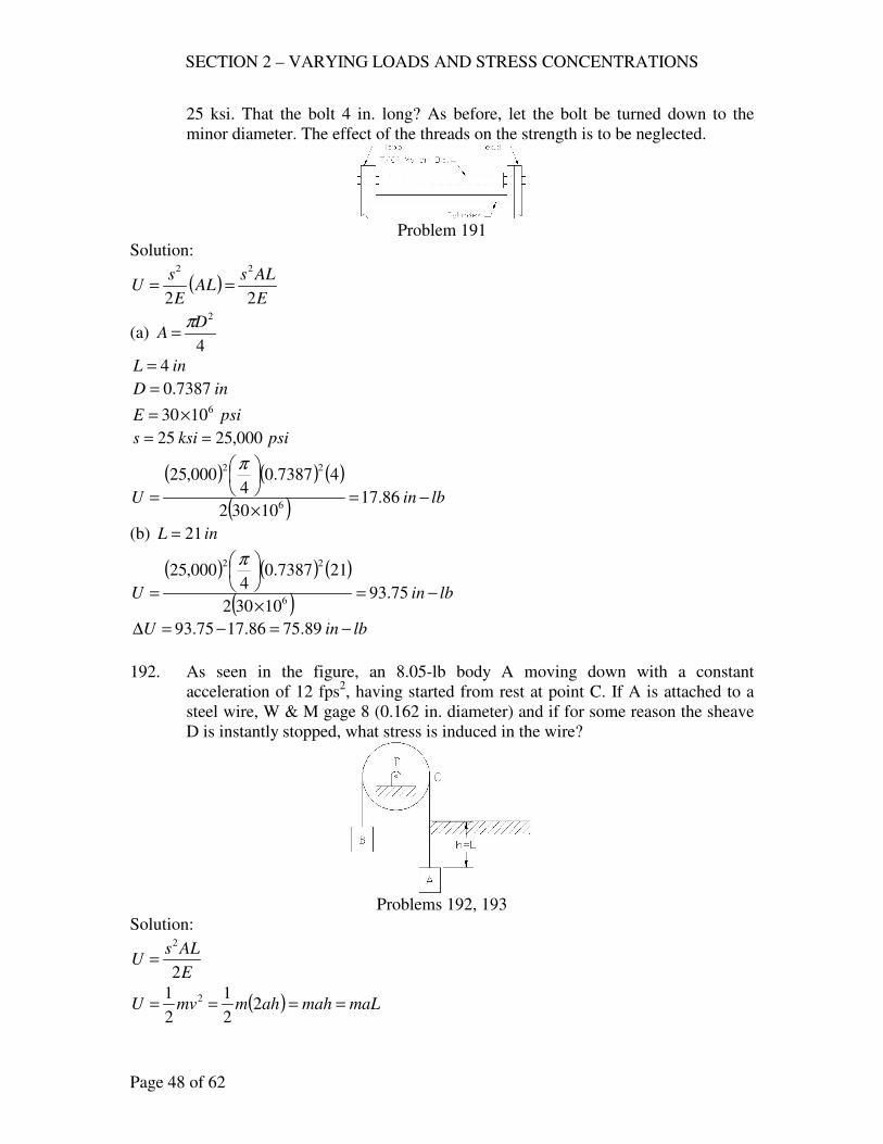
SECTION 2 – VARYING LOADS AND STRESS CONCENTRATIONS
Page 48 of 62
25 ksi. That the bolt 4 in. long? As before, let the bolt be turned down to the
minor diameter. The effect of the threads on the strength is to be neglected.
Problem 191
Solution:
( )E
ALsAL
E
sU
22
22
==
(a) 4
2D
Aπ
=
inL 4=
inD 7387.0=
psiE 61030×=
psiksis 000,2525 ==
( ) ( ) ( )
( )lbinU −=
×
= 86.1710302
47387.04
000,25
6
22 π
(b) inL 21=
( ) ( ) ( )
( )lbinU −=
×
= 75.9310302
217387.04
000,25
6
22 π
lbinU −=−=∆ 89.7586.1775.93
192. As seen in the figure, an 8.05-lb body A moving down with a constant
acceleration of 12 fps2, having started from rest at point C. If A is attached to a
steel wire, W & M gage 8 (0.162 in. diameter) and if for some reason the sheave
D is instantly stopped, what stress is induced in the wire?
Problems 192, 193
Solution:
E
ALsU
2
2
=
( ) maLmahahmmvU ==== 22
1
2
1 2

SECTION 2 – VARYING LOADS AND STRESS CONCENTRATIONS
Page 49 of 62
maLE
ALs=
2
2
gA
WaE
A
maEs
222 ==
lbW 05.8= 212 fpsa = 232 fpsg =
212 fpsb =
psiE 61030×=
4
2D
Aπ
=
( )( )( )( ) ( )32162.0
10301205.8882
6
2
2
ππ
×==
gD
WaEs
psis 741,93=
193. The hoist A shown, weighing 5000 lb. and moving at a constant fpsv 4= is
attached to a 2 in. wire rope that has a metal area of 1.6 sq. in. and a modulus
psiE 61012×= . When fth 100= , the sheave D is instantly stopped by a brake
(since this is impossible, it represents the worst conceivable condition).
Assuming that the stretching is elastic, compute the maximum stress in the rope.
Solution:
E
ALsU
2
2
=
22
22
1v
g
WmvU ==
22
22v
g
W
E
ALs=
gAL
EWvs
22 =
lbW 5000=
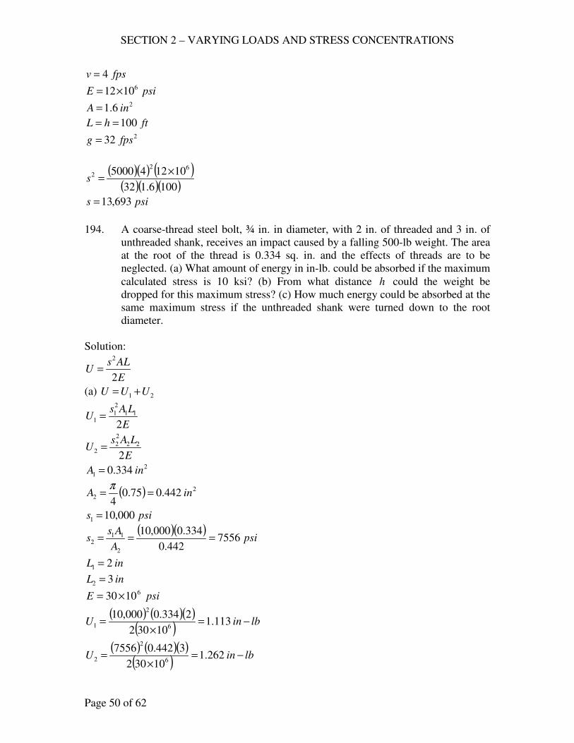
SECTION 2 – VARYING LOADS AND STRESS CONCENTRATIONS
Page 50 of 62
fpsv 4=
psiE 61012×= 26.1 inA =
fthL 100== 232 fpsg =
( )( ) ( )( )( )( )1006.132
101245000 62
2 ×=s
psis 693,13=
194. A coarse-thread steel bolt, ¾ in. in diameter, with 2 in. of threaded and 3 in. of
unthreaded shank, receives an impact caused by a falling 500-lb weight. The area
at the root of the thread is 0.334 sq. in. and the effects of threads are to be
neglected. (a) What amount of energy in in-lb. could be absorbed if the maximum
calculated stress is 10 ksi? (b) From what distance h could the weight be
dropped for this maximum stress? (c) How much energy could be absorbed at the
same maximum stress if the unthreaded shank were turned down to the root
diameter.
Solution:
E
ALsU
2
2
=
(a) 21 UUU +=
E
LAsU
2
11
2
11 =
E
LAsU
2
22
2
22 =
2
1 334.0 inA =
( ) 2
2 442.075.04
inA ==π
psis 000,101 =
( )( )psi
A
Ass 7556
442.0
334.0000,10
2
112 ===
inL 21 =
inL 32 =
psiE 61030 ×=
( ) ( )( )( )
lbinU −=×
= 113.110302
2334.0000,106
2
1
( ) ( )( )( )
lbinU −=×
= 262.110302
3442.075566
2
2
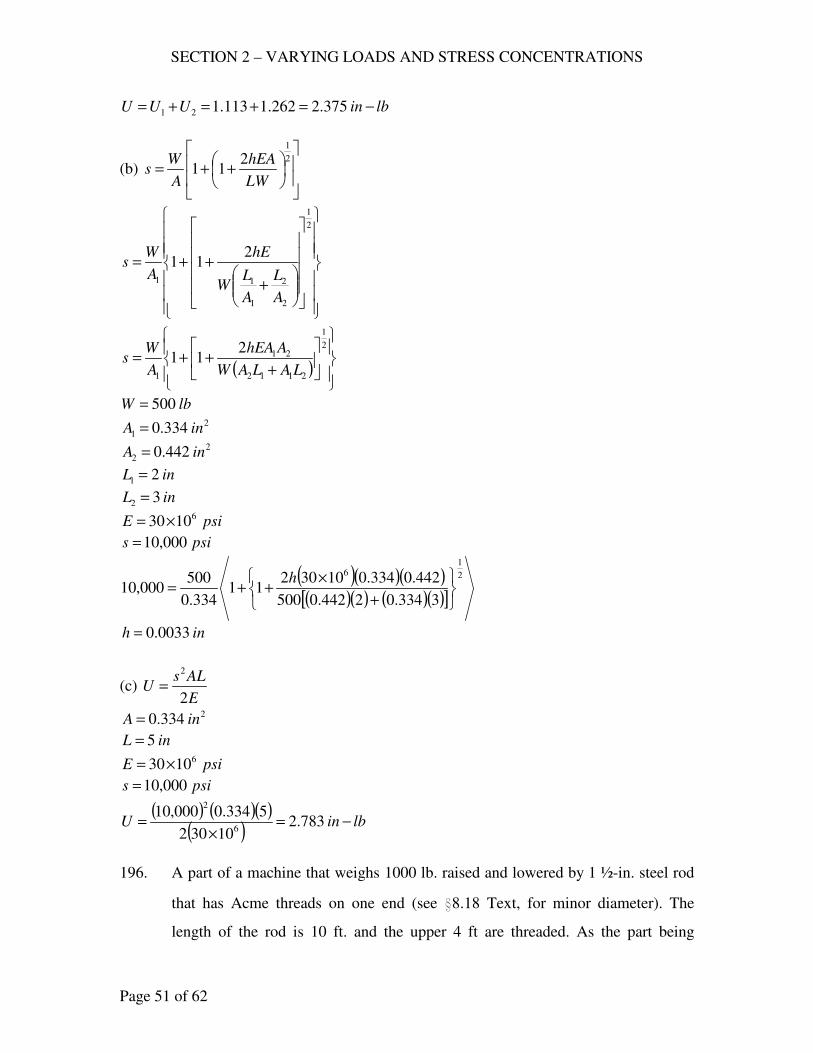
SECTION 2 – VARYING LOADS AND STRESS CONCENTRATIONS
Page 51 of 62
lbinUUU −=+=+= 375.2262.1113.121
(b)
++=
2
1
211
LW
hEA
A
Ws
+
++=
2
1
2
2
1
11
211
A
L
A
LW
hE
A
Ws
( )
+++=
2
1
2112
21
1
211
LALAW
AhEA
A
Ws
lbW 500= 2
1 334.0 inA = 2
2 442.0 inA =
inL 21 =
inL 32 =
psiE 61030×=
psis 000,10=
( )( )( )( )( ) ( )( )[ ]
2
16
3334.02442.0500
442.0334.01030211
334.0
500000,10
+
×++=
h
inh 0033.0=
(c) E
ALsU
2
2
=
2334.0 inA =
inL 5=
psiE 61030×=
psis 000,10=
( ) ( )( )( )
lbinU −=×
= 783.210302
5334.0000,106
2
196. A part of a machine that weighs 1000 lb. raised and lowered by 1 ½-in. steel rod
that has Acme threads on one end (see i8.18 Text, for minor diameter). The
length of the rod is 10 ft. and the upper 4 ft are threaded. As the part being

SECTION 2 – VARYING LOADS AND STRESS CONCENTRATIONS
Page 52 of 62
lowered it sticks, then falls freely a distance of 1/8 in. (a) Compute the maximum
stress in the rod. (b) What would be the maximum stress in the rod if the lower
end had been turned down to the root diameter?
Solution:
++=
2
1
211
LW
hEA
A
Ws
+
++=
2
1
2
2
1
11
211
A
L
A
LW
hE
A
Ws
( )
+++=
2
1
2112
21
1
211
LALAW
AhEA
A
Ws
see i8.18 , inD2
112 = , inD 25.11 =
( ) 2
2
1 227.14
25.1inA ==
π
( ) 2
2
2 767.14
5.1inA ==
π
inL 41 =
inL 62 =
ininh 125.08
1==
lbW 1000=
psiE 61030×=
( )( )( )( )( )( ) ( )( )[ ]
psis 186,286227.14767.11000
767.1227.11030125.0211
227.1
1000 2
16
=
+
×++=
(b)
++=
2
1
211
LW
hEA
A
Ws
2
1 227.1 inAA ==
inLLL 1021 =+=
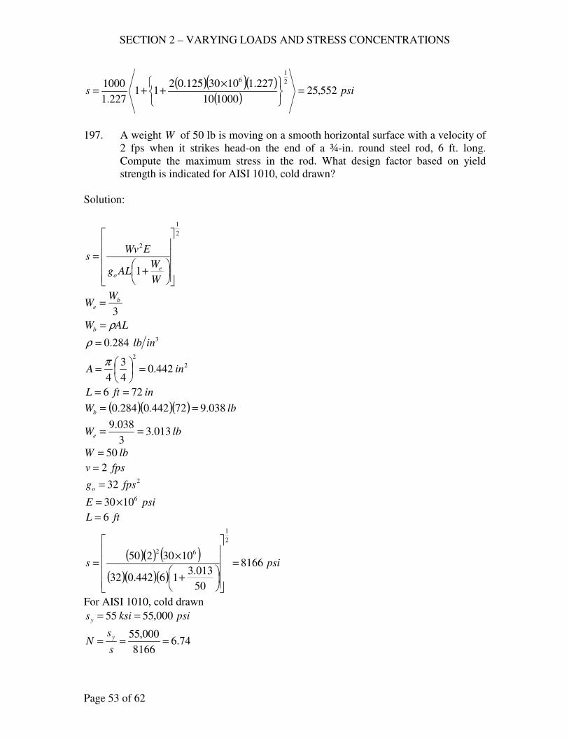
SECTION 2 – VARYING LOADS AND STRESS CONCENTRATIONS
Page 53 of 62
( )( )( )( )
psis 552,25100010
227.11030125.0211
227.1
1000 2
16
=
×
++=
197. A weight W of 50 lb is moving on a smooth horizontal surface with a velocity of
2 fps when it strikes head-on the end of a ¾-in. round steel rod, 6 ft. long.
Compute the maximum stress in the rod. What design factor based on yield
strength is indicated for AISI 1010, cold drawn?
Solution:
2
1
2
1
+
=
W
WALg
EWvs
eo
3
be
WW =
ALWb ρ=
3284.0 inlb=ρ
2
2
442.04
3
4inA =
=
π
inftL 726 ==
( )( )( ) lbWb 038.972442.0284.0 ==
lbWe 013.33
038.9==
lbW 50=
fpsv 2= 232 fpsgo =
psiE 61030×=
ftL 6=
( )( ) ( )
( )( )( )psis 8166
50
013.316442.032
1030250
2
1
62
=
+
×=
For AISI 1010, cold drawn
psiksisy 000,5555 ==
74.68166
000,55===
s
sN
y
SECTION 2 – VARYING LOADS AND STRESS CONCENTRATIONS
Page 54 of 62
199. A rigid weight of 100 lb is dropped a distance of 25 in. upon the center of a 12
in., 50-lb. I-beam ( 46.301 inI x = ) that is simply supported on supports 10 ft
apart. Compute the maximum stress in the I-beam both with and without
allowing for the beam’s weight.
Solution:
Without beams weight
st
sty
yss =
EI
FLy
48
3
=
3
48
L
EI
y
Fk ==
++==
2
1
211
W
hk
k
Wy δ
psiE 61030×=
inftL 12010 == 46.301 inI =
( )( )( )
inlbk 333,251120
6.3011030483
6
=×
=
lbW 100=
inh 25=
( )( )iny 1415.0
100
333,25125211
333,251
100 2
1
=
++
=
( )( )( )( )
inEI
WLyst 0004.0
6.301103048
120100
48 6
33
=×
==
I
Mcsst =
( )( )lbin
WLM −=== 3000
4
120100
4
inh
c 62
12
2===
( )( )psisst 68.59
6.301
63000==
( ) psis 112,210004.0
1415.068.59 =
=
SECTION 2 – VARYING LOADS AND STRESS CONCENTRATIONS
Page 55 of 62
with mass of beam
2
1
21
++=
st
ststy
hyyy
h - correction factor =
W
We+1
1
35
17 be
WW =
( )( ) lbftftlbWb 5001050 ==
( )lbWe 243
35
50017==
h - correction factor = 292.0
100
2431
1=
+
( )( )iny 0764.0
0004.0
292.0252110004.0
2
1
=
++=
( ) psiy
yss
st
st 400,110004.0
0764.068.59 =
==
201. A 3000 lb. automobile (here considered rigid) strikes the midpoint of a guard rail
that is an 8-in. 23-lb. I-beam, 40 ft. long; 42.64 inI = . Made of AISI C1020, as
rolled, the I-beam is simply supported on rigid posts at its ends. (a) What level
velocity of the automobile results in stressing the I-beam to the tensile yield
strength? Compare results observed by including and neglecting the beam’s
mass.
Solution:
For AISI C1020, as rolled
psiksisy 000,4848 ==
og
WvF
22
2
=δ
3
48
L
EIFk ==
δ
I
FLc
I
Mcs
4==
Lc
IsF
4=
( ) 2
2
22
32232
696
16
962 Ec
ILs
EIcL
LsI
EI
LFF===
δ
SECTION 2 – VARYING LOADS AND STRESS CONCENTRATIONS
Page 56 of 62
neglecting mass of beam
og
Wv
Ec
ILsF
262
2
2
2
==δ
ILg
EcWvs
o2
3 222 =
lbW 3000= 232 fpsgo =
inh
c 42
8
2===
psiE 61030×= 42.64 inI =
ftL 40=
psiksiss y 000,4848 ===
( ) ( ) ( )( )( )( )402.6432
4103030003
2
3000,48
2622222 ×
===v
ILg
EcWvs
o
fpsv 62.6=
Including mass of beam
+
=
W
WILg
EcWvs
eo 1
1
2
3 222
35
17 be
WW =
( )( ) lbftftlbWb 9204023 ==
( )lbWe 447
35
92017==
( ) ( ) ( )( )( )( )
+
×===
3000
4471
1
402.6432
4103030003
2
3000,48
2622222 v
ILg
EcWvs
o
fpsv 10.7=
DATA LACKING – DESIGNER’S DECISIONS
202. A simple beam is struck midway between supports by a 32.2-lb. weight that has
fallen 20 in. The length of the beam is 12 ft. If the stress is not to exceed 20 ksi,
what size I-beam should be used?
Solution:
SECTION 2 – VARYING LOADS AND STRESS CONCENTRATIONS
Page 57 of 62
2
1
21
++=
st
ststy
hyyy
st
sty
yss =
inh 20=
psis 000,20=
EI
WLyst
48
3
=
2
1
3
9611
++=
WL
EIh
y
y
st
with correction factor
2
1
3
1
19611
+
++=
W
WWL
EIh
y
y
est
I
WLd
I
Mcsst
8==
35
17wLWe =
+
++=
2
1
3
35
171
19611
8
W
wLWL
EIh
I
WLds
lbW 2.32=
inh 20=
inftL 14412 ==
psiE 61030×=
( )( ) ( )( )( )( )( ) ( )( )
( )
+
×++=
2
1
3
6
2.3235
12171
1
1442.32
2010309611
8
1442.32
w
I
I
ds
+++=
2
1
181.01
159911
6.579
wI
I
ds
From The Engineer’s Manual
By Ralph G. Hudson, S.B.
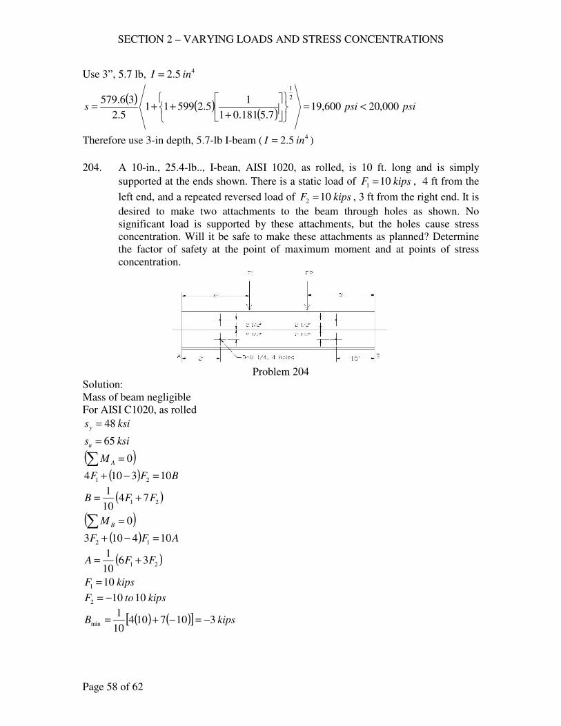
SECTION 2 – VARYING LOADS AND STRESS CONCENTRATIONS
Page 58 of 62
Use 3”, 5.7 lb, 45.2 inI =
( ) ( )( )
psipsis 000,20600,197.5181.01
15.259911
5.2
36.579 2
1
<=
+++=
Therefore use 3-in depth, 5.7-lb I-beam ( 45.2 inI = )
204. A 10-in., 25.4-lb.., I-bean, AISI 1020, as rolled, is 10 ft. long and is simply
supported at the ends shown. There is a static load of kipsF 101 = , 4 ft from the
left end, and a repeated reversed load of kipsF 102 = , 3 ft from the right end. It is
desired to make two attachments to the beam through holes as shown. No
significant load is supported by these attachments, but the holes cause stress
concentration. Will it be safe to make these attachments as planned? Determine
the factor of safety at the point of maximum moment and at points of stress
concentration.
Problem 204
Solution:
Mass of beam negligible
For AISI C1020, as rolled
ksisy 48=
ksisu 65=
( )∑ = 0AM
( ) BFF 103104 21 =−+
( )21 7410
1FFB +=
( )∑ = 0BM
( ) AFF 104103 12 =−+
( )21 3610
1FFA +=
kipsF 101 =
kipstoF 10102 −=
( ) ( )[ ] kipsB 310710410
1min −=−+=
SECTION 2 – VARYING LOADS AND STRESS CONCENTRATIONS
Page 59 of 62
( ) ( )[ ] kipsB 1110710410
1max =+=
( ) ( )[ ] kipsA 310310610
1min =−+=
( ) ( )[ ] kipsA 930710610
1max =+=
Figure AF 11,
ine2
11= ,
ind4
1=
inc 625.14
12
2
11 =
+=
inh 10=
ineh
b 5.32
11
2
10
2=−=−=
07.05.3
25.0==
b
d
5.0625.0
50.1>==
d
e
Use 0.3=tK
926.0
8
1
010.01
1=
+
=q
( ) ( ) 85.2113926.011 =+−=+−= tf KqK
( ) ksiss un 5.32655.05.0 ===
size factor = 0.85
( ) ksisn 6.275.3285.0 ==
left hole, ( )AM 2=
( ) kipsftM −== 1892max
( ) kipsftM −== 632min
I
Mcs =
( ) kipsinkipsftMm −=−=+= 144126182
1
( ) kipsinkipsftM a −=−=−= 7266182
1
inc 625.1= 41.122 inI = (Tables)
SECTION 2 – VARYING LOADS AND STRESS CONCENTRATIONS
Page 60 of 62
( )( )ksism 92.1
1.122
625.1144==
( )( )ksisa 96.0
1.122
625.172==
n
af
y
m
s
sK
s
s
N+=
1
( )( )6.27
96.085.2
48
92.11+=
N
2.7=N
right hole , ( )BM 5.1=
( ) kipsftM −== 5.16115.1max
( ) kipsftM −−=−= 5.435.1min
I
Mcs =
( ) kipsinkipsftMm −=−=−= 7265.45.162
1
( ) kipsinkipsftM a −=−=+= 1265.105.45.162
1
inc 625.1= 41.122 inI = (Tables)
( )( )ksism 96.0
1.122
625.172==
( )( )ksisa 68.1
1.122
625.1126==
n
af
y
m
s
sK
s
s
N+=
1
( )( )6.27
68.185.2
48
96.01+=
N
67.5=N
at maximum moment, or at , 2F
( ) kipsftM −== 33113max
( ) kipsftM −−=−= 933min
I
Mcs =
( ) kipsinkipsftMm −=−=−= 144129332
1
( ) kipsinkipsftM a −=−=+= 252219332
1
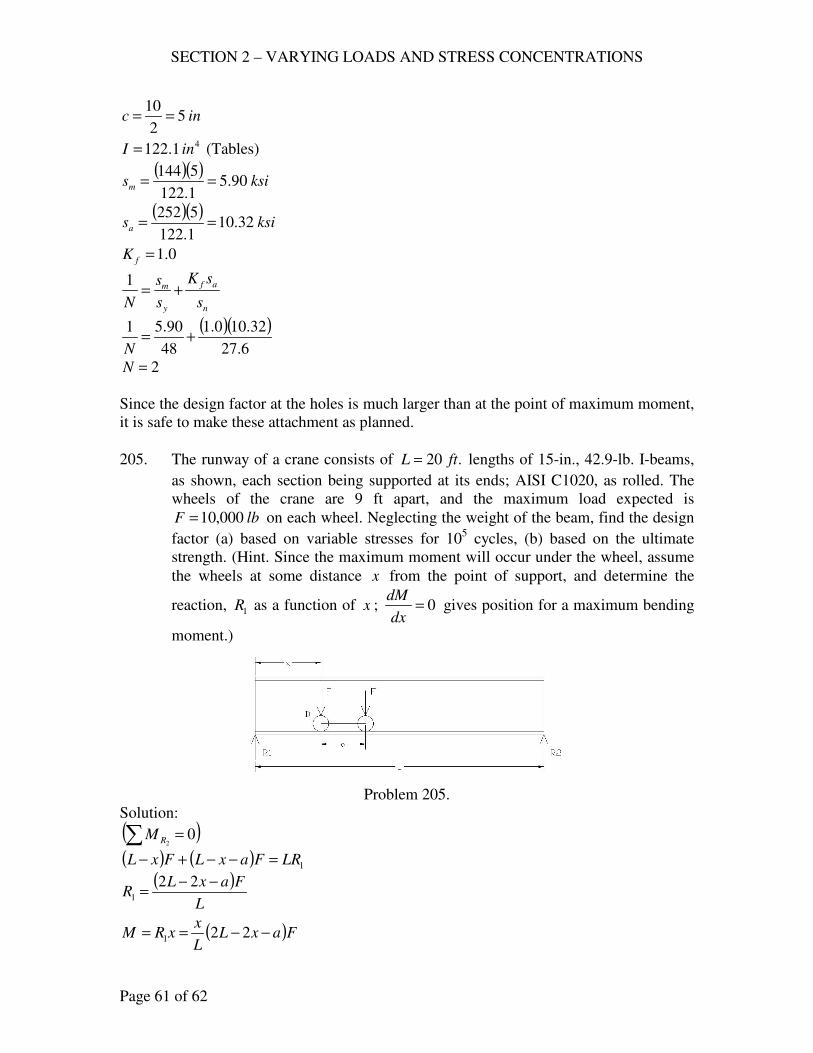
SECTION 2 – VARYING LOADS AND STRESS CONCENTRATIONS
Page 61 of 62
inc 52
10==
41.122 inI = (Tables)
( )( )ksism 90.5
1.122
5144==
( )( )ksisa 32.10
1.122
5252==
0.1=fK
n
af
y
m
s
sK
s
s
N+=
1
( )( )6.27
32.100.1
48
90.51+=
N
2=N
Since the design factor at the holes is much larger than at the point of maximum moment,
it is safe to make these attachment as planned.
205. The runway of a crane consists of .20 ftL = lengths of 15-in., 42.9-lb. I-beams,
as shown, each section being supported at its ends; AISI C1020, as rolled. The
wheels of the crane are 9 ft apart, and the maximum load expected is
lbF 000,10= on each wheel. Neglecting the weight of the beam, find the design
factor (a) based on variable stresses for 105 cycles, (b) based on the ultimate
strength. (Hint. Since the maximum moment will occur under the wheel, assume
the wheels at some distance x from the point of support, and determine the
reaction, 1R as a function of x ; 0=dx
dM gives position for a maximum bending
moment.)
Problem 205.
Solution:
( )∑ = 02RM
( ) ( ) 1LRFaxLFxL =−−+−
( )L
FaxLR
−−=
221
( )FaxLL
xxRM −−== 221
SECTION 2 – VARYING LOADS AND STRESS CONCENTRATIONS
Page 62 of 62
( ) ( )[ ] 0222 =−+−−= xaxLL
F
dx
dM
0222 =−−− xaxL
−=
22
1 aLx
L
Fa
L
Faa
LLL
aL
M2
2
222
2
max
−
=
−
−−
−=
inftL 24020 ==
infta 1089 ==
kipslbF 10000,10 ==
( )
( )kipsinM −=
−
= 75.7202402
102
108240
2
max
For 15-in., 42.9 lb, I-beam 48.441 inI =
inc 5.72
15==
( )( )ksi
I
Mcs 24.12
8.441
5.775.720max ===
For AISI C1029, as rolled
ksisu 65=
ksiss un 5.325.0 ==
size factor = 0.85
( ) ksisn 6.275.3285.0 ==
(a) at 105
cycles
ksisn 3410
106.27
085.0
5
6
=
=
724.12
34===
s
sN n
(b) 31.524.12
65===
s
sN u
- end -

SECTION 3 – SCREW FASTENINGS
Page 1 of 42
SIMPLE TENSION INCLUDING TIGHTENING STRESSES
DESIGN PROBLEMS
221. A 5000-lb. gear box is provided with a steel (as rolled B1113) eyebolt for use
in moving it. What size bolt should be used: (a) if UNC threads are used? (b)
If UNF threads are used? (c) If the 8-thread series is used? Explain the basis
of your choice of design factor.
Solution:
B1113, as rolled
ksisy 45= (Table AT-7)
lbFe 5000=
i5.6, ( ) 21
6s
y
d As
s =
< inD
4
3
For inD4
3=
..35.0 insqAs ≈
( ) 21
35.06
y
d
ss =
10
y
d
ss =
use design factor = 10
10
000,45 psisd =
psisd 4500=
..111.14500
5000insq
s
FA
d
es ===
Table AT 14 and Table 5.1
(a) UNC Threads
Use inD8
31= , ..155.1 insqAs =
SECTION 3 – SCREW FASTENINGS
Page 2 of 42
(b) UNF Threads
Use inD8
31= , ..155.1 insqAs =
(c) 8-Thread Series
Use inD8
31= , ..233.1 insqAs =
222. A motor weighing 2 tons is lifted by a wrought-iron eye bolt which is screwed
into the frame. Decide upon a design factor and determine the size of the
eyebolt if (a) UNC threads are used, (b) UNF threads are used. Note: Fine
threads are not recommended for brittle materials.
Solution:
Table AT-7
Wrought iron, ksisy 25=
Assume design factor = 10
10
y
d
ss =
10
000,25 psisd =
psisd 2500=
( )..60.1
2500
20002insq
s
FA
d
es ===
Table AT 17
(a) UNC Threads
Use inD4
31= , ..90.1 insqAs =
(b) UNF Threads
Use inD2
11= , ..581.1 insqAs =
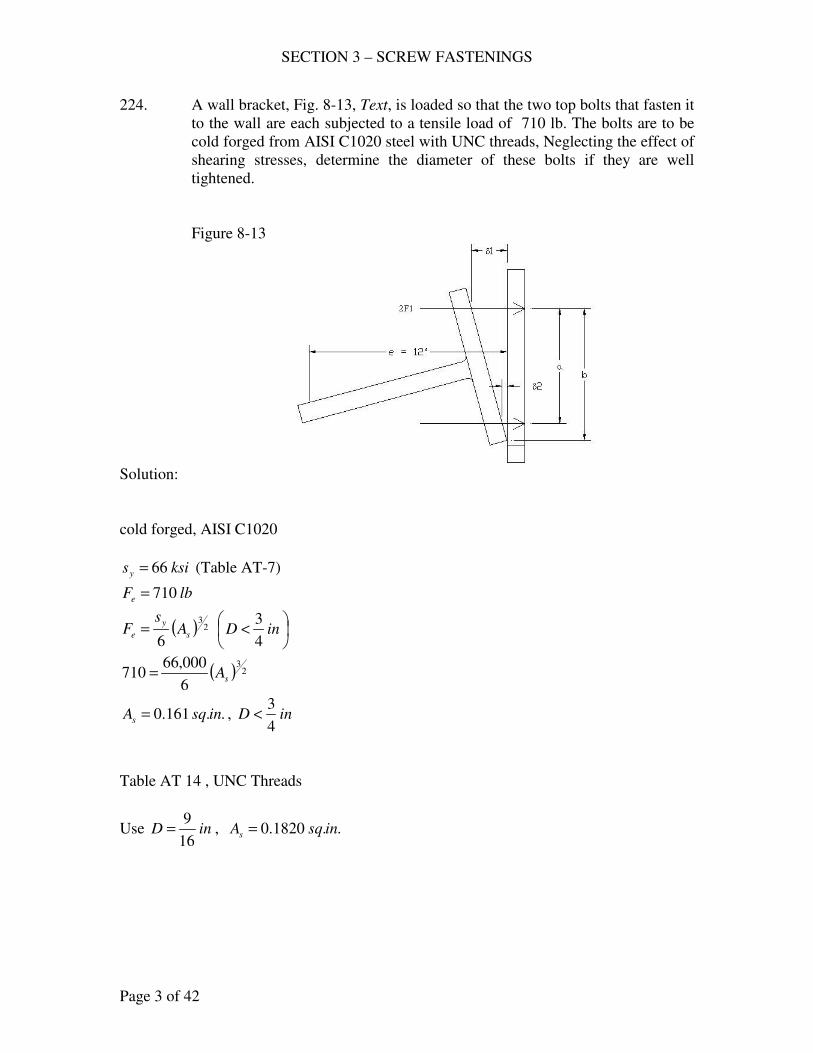
SECTION 3 – SCREW FASTENINGS
Page 3 of 42
224. A wall bracket, Fig. 8-13, Text, is loaded so that the two top bolts that fasten it
to the wall are each subjected to a tensile load of 710 lb. The bolts are to be
cold forged from AISI C1020 steel with UNC threads, Neglecting the effect of
shearing stresses, determine the diameter of these bolts if they are well
tightened.
Figure 8-13
Solution:
cold forged, AISI C1020
ksisy 66= (Table AT-7)
lbFe 710=
( ) 23
6s
y
e As
F =
< inD
4
3
( ) 23
6
000,66710 sA=
..161.0 insqAs = , inD4
3<
Table AT 14 , UNC Threads
Use inD16
9= , ..1820.0 insqAs =
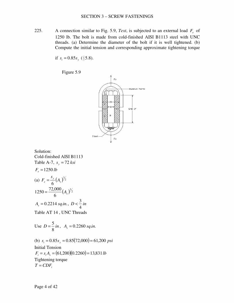
SECTION 3 – SCREW FASTENINGS
Page 4 of 42
225. A connection similar to Fig. 5.9, Text, is subjected to an external load eF of
1250 lb. The bolt is made from cold-finished AISI B1113 steel with UNC
threads. (a) Determine the diameter of the bolt if it is well tightened. (b)
Compute the initial tension and corresponding approximate tightening torque
if yi ss 85.0= (i5.8).
Figure 5.9
Solution:
Cold-finished AISI B1113
Table A-7, ksisy 72=
lbFe 1250=
(a) ( ) 23
6s
y
e As
F =
( ) 23
6
000,721250 sA=
..2214.0 insqAs = , inD4
3<
Table AT 14 , UNC Threads
Use inD8
5= , ..2260.0 insqAs =
(b) ( ) psiss yi 200,61000,7285.085.0 ===
Initial Tension
( )( ) lbAsF sii 831,132260.0200,61 ===
Tightening torque
iCDFT =
SECTION 3 – SCREW FASTENINGS
Page 5 of 42
( ) lbinDFT i −=
== 1729831,13
8
52.02.0
226. The cylinder head of a 10 x 18 in. Freon compressor is attached by 10 stud
bolts made of SAE Grade 5. The cylinder pressure is 200 psi. (a) What size
bolts should be used? (b) What approximate tightening torque should be
needed to induce a tightening stress is of 0.9 times the proof stress?
Solution:
Table 5.2
SAE Grade 5
Assume ksisy 88=
(a)
( )lbFe 1571
10
104
2002
=
=
π
( ) 23
6s
y
e As
F = , inD4
3<
( ) 23
6
000,881571 sA=
..2255.0 insqAs = , inD4
3<
Table AT 14 , UNC Threads
Use inD8
5= , ..2260.0 insqAs =
(b) iCDFT =
2.0=C
pi ss 9.0=
ksisp 85= , (Table 5.2)
( ) psisi 500,76000,859.0 ==
( )( ) lbAsF sii 289,172260.0500,76 ===
Tightening torque
( ) lbinDFT i −=
== 2161289,17
8
52.02.0
227. The American Steel Flange Standard specifies that 8 bolts are to be used on
flanges for 4-in. pipe where the steam or water pressure is 1500 psi. It is also
specified that, in calculating the bolt load, the outside diameter of the gasket,
which is 6 3/16 in., should be used. Determine (a) the diameter of the UNC bolts
if they are well-tightened and made of ASTM 354 BD (Table 5-2), (b) the
approximate torque to tighten the nuts if the initial stress is 90 % of the proof
SECTION 3 – SCREW FASTENINGS
Page 6 of 42
stress. The Standard specifies that 1 1/4 –in. bolts with 8 th./in. be used (these
bolts are also subjected to bending). How does your answer compare?
Solution:
Table 5.2, ASTM 354 BD
ksisp 120=
ksisy 125=
lbFe 56388
16
36
41500
2
=
=
π
(a) ( ) 23
6s
y
e As
F = , inD4
3<
( ) 23
6
000,1255638 sA=
..4184.0 insqAs = , inD4
3<
Table AT 14 , UNC Threads
Use inD8
7= , ..4620.0 insqAs =
inD4
3>
use
( ) ( ) psiss yd 750,18000,12515.085.01 ==−=
..3007.0750,18
5638insq
s
FA
d
es ===
Table AT 14 , UNC Threads
Use inD8
3= , ..334.0 insqAs =
(b) iDFT 2.0=
pi ss 9.0=
( ) psisi 000,108000,1209.0 ==
( )( ) lbAsF sii 072,363340.0000,108 ===
Tightening torque
( ) lbinDFT i −=
== 5411072,36
4
32.02.0
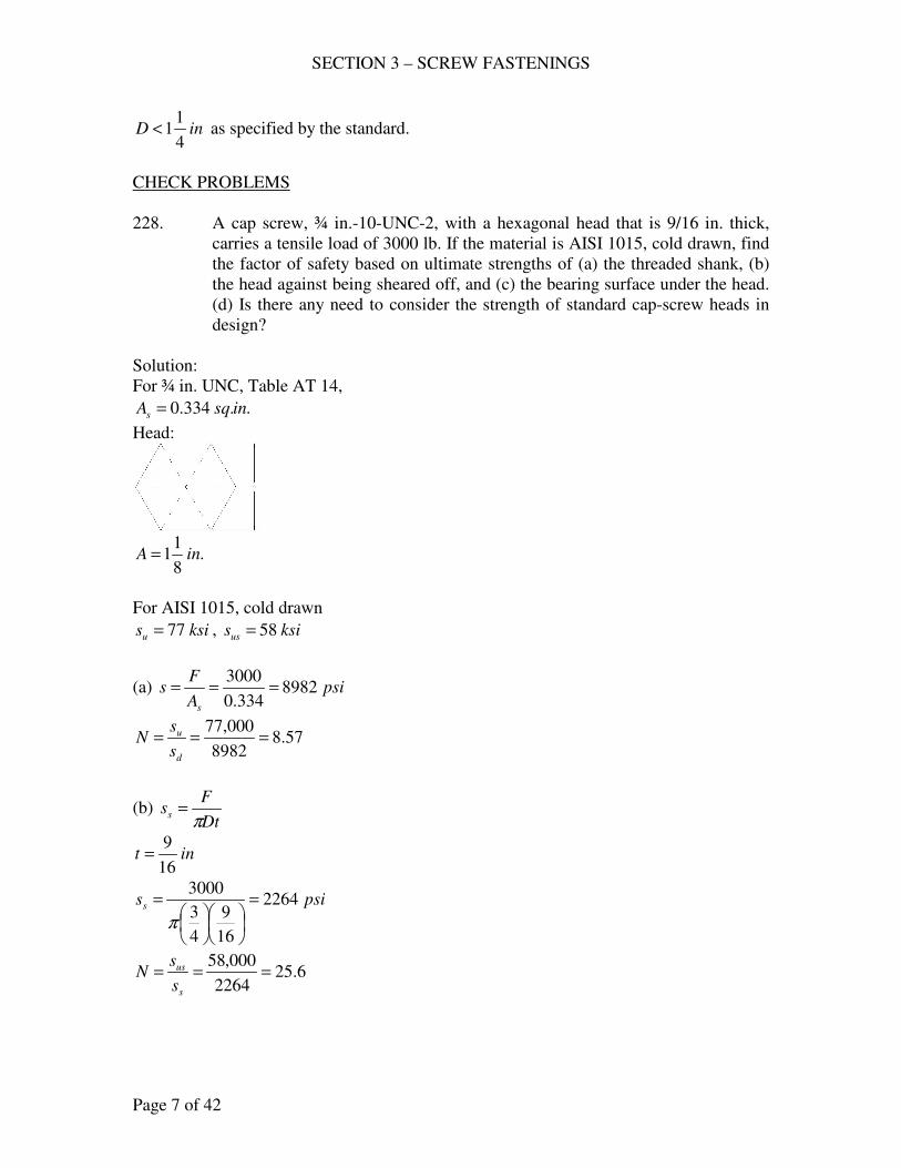
SECTION 3 – SCREW FASTENINGS
Page 7 of 42
inD4
11< as specified by the standard.
CHECK PROBLEMS
228. A cap screw, ¾ in.-10-UNC-2, with a hexagonal head that is 9/16 in. thick,
carries a tensile load of 3000 lb. If the material is AISI 1015, cold drawn, find
the factor of safety based on ultimate strengths of (a) the threaded shank, (b)
the head against being sheared off, and (c) the bearing surface under the head.
(d) Is there any need to consider the strength of standard cap-screw heads in
design?
Solution:
For ¾ in. UNC, Table AT 14,
..334.0 insqAs =
Head:
.8
11 inA =
For AISI 1015, cold drawn
ksisu 77= , ksisus 58=
(a) psiA
Fs
s
8982334.0
3000===
57.88982
000,77===
d
u
s
sN
(b) Dt
Fss
π=
int16
9=
psiss 2264
16
9
4
3
3000=
=
π
6.252264
000,58===
s
us
s
sN
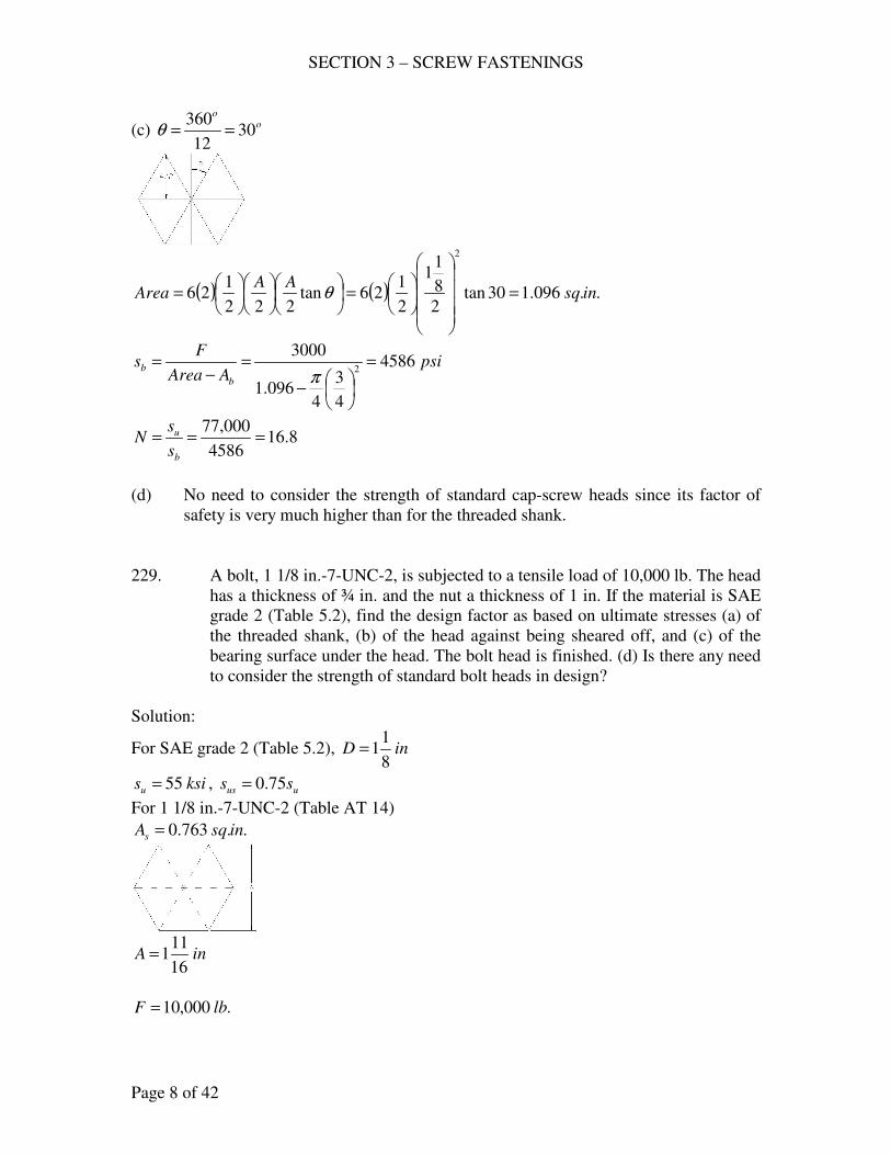
SECTION 3 – SCREW FASTENINGS
Page 8 of 42
(c) oo
3012
360==θ
( ) ( ) ..096.130tan2
8
11
2
126tan
222
126
2
insqAA
Area =
=
= θ
psiAArea
Fs
b
b 4586
4
3
4096.1
30002
=
−
=−
=π
8.164586
000,77===
b
u
s
sN
(d) No need to consider the strength of standard cap-screw heads since its factor of
safety is very much higher than for the threaded shank.
229. A bolt, 1 1/8 in.-7-UNC-2, is subjected to a tensile load of 10,000 lb. The head
has a thickness of ¾ in. and the nut a thickness of 1 in. If the material is SAE
grade 2 (Table 5.2), find the design factor as based on ultimate stresses (a) of
the threaded shank, (b) of the head against being sheared off, and (c) of the
bearing surface under the head. The bolt head is finished. (d) Is there any need
to consider the strength of standard bolt heads in design?
Solution:
For SAE grade 2 (Table 5.2), inD8
11=
ksisu 55= , uus ss 75.0=
For 1 1/8 in.-7-UNC-2 (Table AT 14)
..763.0 insqAs =
inA16
111=
.000,10 lbF =
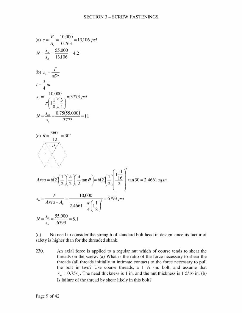
SECTION 3 – SCREW FASTENINGS
Page 9 of 42
(a) psiA
Fs
s
106,13763.0
000,10===
2.4106,13
000,55===
d
u
s
sN
(b) Dt
Fss
π=
int4
3=
psiss 3773
4
3
8
11
000,10=
=
π
( )11
3773
000,5575.0===
s
us
s
sN
(c) oo
3012
360==θ
( ) ( ) ..4661.230tan2
16
111
2
126tan
222
126
2
insqAA
Area =
=
= θ
psiAArea
Fs
b
b 6793
8
11
44661.2
000,102
=
−
=−
=π
1.86793
000,55===
b
u
s
sN
(d) No need to consider the strength of standard bolt head in design since its factor of
safety is higher than for the threaded shank.
230. An axial force is applied to a regular nut which of course tends to shear the
threads on the screw. (a) What is the ratio of the force necessary to shear the
threads (all threads initially in intimate contact) to the force necessary to pull
the bolt in two? Use coarse threads, a 1 ½ -in. bolt, and assume that
uus ss 75.0= . The head thickness is 1 in. and the nut thickness is 1 5/16 in. (b)
Is failure of the thread by shear likely in this bolt?
SECTION 3 – SCREW FASTENINGS
Page 10 of 42
Solution:
1 ½ - in. UNC
..405.1 insqAs =
(a) sF = shear force = Dtsusπ
.2
11 inD =
.16
51 int =
uus ss 75.0=
( )( ) uus ssF 6388.416
51
2
1175.0 =
= π
usu sAsF 405.1==
Ratio = 3.3405.1
6388.4=
u
u
s
s
(b) Ratio > 1, failure by shear is not likely to occur.
231. For bolted structural joints, specifications suggest that ½-in. bolts (high-
strength material) be tightened to an initial tension of lbFi 500,12= . What
should be the approximate tightening torque? How does your answer compare
with lbftT −= 90 ., which is the value in the specification?
Solution:
( ) lbinDFT i −=
== 1250500,12
2
12.02.0
lbinlbinlbftT −<−=−= 1250108090 o.k.
232. One method of estimating the initial tensile stress in a tightened bolt is to turn
the nut until it is snug, but with no significant stress in the bolt. Then the nut is
turned through a predetermined angle that induces a certain unit strain
corresponding to the desired stress. A ¾ - in. bolt of the type shown in Fig.
5.4, Text, is turned down until, for practical purposes, the diameter of the
entire shank is the minor diameter. The material is AISI 4140, OQT 1200 oF.
The grip is 5 in. and the effective strain length is estimated to be 5.3 in. If the
initial tensile stress at the root diameter is to be about 75 % of the yield
strength, through what angle should the nut be turned after it is just snug? The
threads are UNC and the parts being bolted are assumed to be rigid.
Solution:
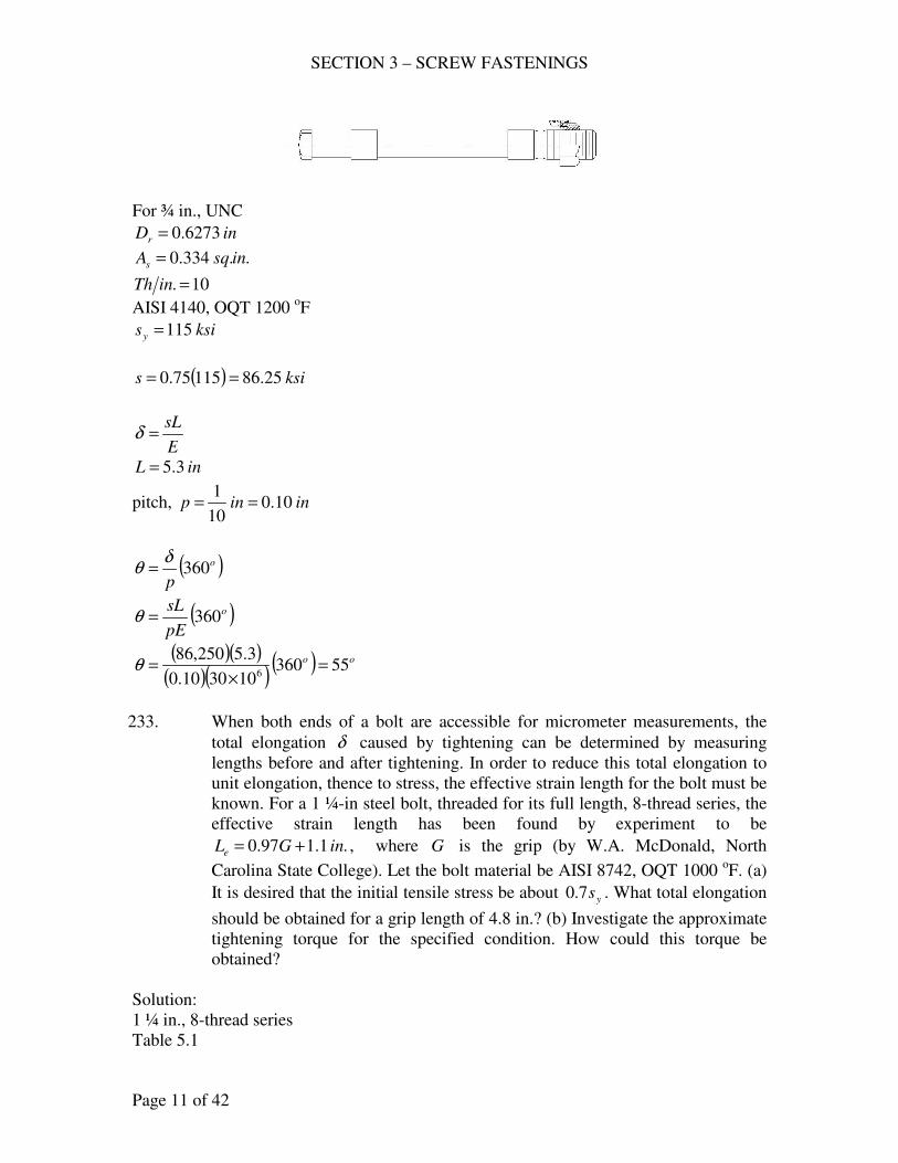
SECTION 3 – SCREW FASTENINGS
Page 11 of 42
For ¾ in., UNC
inDr 6273.0=
..334.0 insqAs =
10. =inTh
AISI 4140, OQT 1200 oF
ksisy 115=
( ) ksis 25.8611575.0 ==
E
sL=δ
inL 3.5=
pitch, ininp 10.010
1==
( )o
p360
δθ =
( )o
pE
sL360=θ
( )( )( )( )
( ) oo 55360103010.0
3.5250,866
=×
=θ
233. When both ends of a bolt are accessible for micrometer measurements, the
total elongation δ caused by tightening can be determined by measuring
lengths before and after tightening. In order to reduce this total elongation to
unit elongation, thence to stress, the effective strain length for the bolt must be
known. For a 1 ¼-in steel bolt, threaded for its full length, 8-thread series, the
effective strain length has been found by experiment to be
.1.197.0 inGLe += , where G is the grip (by W.A. McDonald, North
Carolina State College). Let the bolt material be AISI 8742, OQT 1000 oF. (a)
It is desired that the initial tensile stress be about ys7.0 . What total elongation
should be obtained for a grip length of 4.8 in.? (b) Investigate the approximate
tightening torque for the specified condition. How could this torque be
obtained?
Solution:
1 ¼ in., 8-thread series
Table 5.1
SECTION 3 – SCREW FASTENINGS
Page 12 of 42
inDr 0966.1=
..000.1 insqAs =
8. =inTh
AISI 8742, OQT 1000 oF
ksisy 147=
(a) yi ss 70.0=
( ) psiksisi 900,1029.10214770.0 ===
E
Ls ei=δ
.1.197.0 inGLe +=
inG 8.4=
( ) ininLe 756.5.1.18.497.0 =+=
( )( )in
E
Ls ei 01975.01030
756.5900,1026
=×
==δ
(b) GD
TL
p r
4
64
π
δθ ==
psiG 6105.11 ×=
ininp 125.08
1==
( )( ) ( )64
105.110966.1
756.564
125.0
01975.0
×==
πθ
T
lbinT −= 408,22
ELASTIC CONSIDERATIONS
235. The member C shown is part of a swivel connection that is to be clamped by a
1-in. bolt D to the member B, which has large dimensions in the plane
perpendicular to the paper. Both B and C are aluminum alloy 2024-T4, HT
aged. The bolt is made of AISI C1113, cold-drawn steel; consider the
unthreaded shank to be 2 in. long; it is well tightened with a torque of 250 ft-
lb.; UNC threads, unlubricated. (a) Estimate the initial tension by equation
(5.2), assume elastic action, and compute the bolt elongation and the total
deformation of B and C. Let the effective strain length be 2 in. (b) After
tightening an external axial force eF of 5000 lb. is applied to member C.
Determine the total normal stresses in the bolt and in B and C. (c) Determine
the load required to “open” the connection. Draw a diagram similar to Fig.
5.6, Text, locating points A, B, D and M.
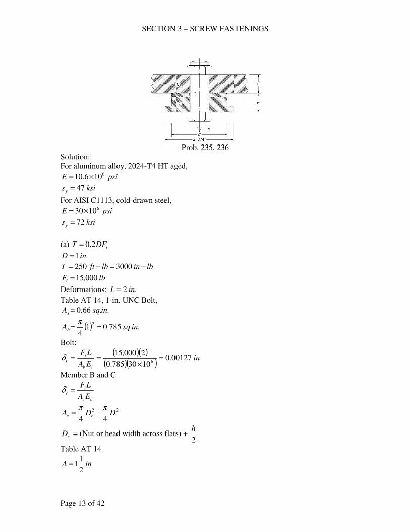
SECTION 3 – SCREW FASTENINGS
Page 13 of 42
Prob. 235, 236
Solution:
For aluminum alloy, 2024-T4 HT aged,
psiE 6106.10 ×=
ksisy 47=
For AISI C1113, cold-drawn steel,
psiE 61030×=
ksisy 72=
(a) iDFT 2.0=
.1 inD =
lbinlbftT −=−= 3000250
lbFi 000,15=
Deformations: .2 inL =
Table AT 14, 1-in. UNC Bolt,
..66.0 insqAs =
( ) ..785.014
2insqAb ==
π
Bolt:
( )( )( )( )
inEA
LF
ib
i
i 00127.01030785.0
2000,156
=×
==δ
Member B and C
cc
ic
EA
LF=δ
22
44DDA ec
ππ−=
eD = (Nut or head width across flats) + 2
h
Table AT 14
inA2
11=
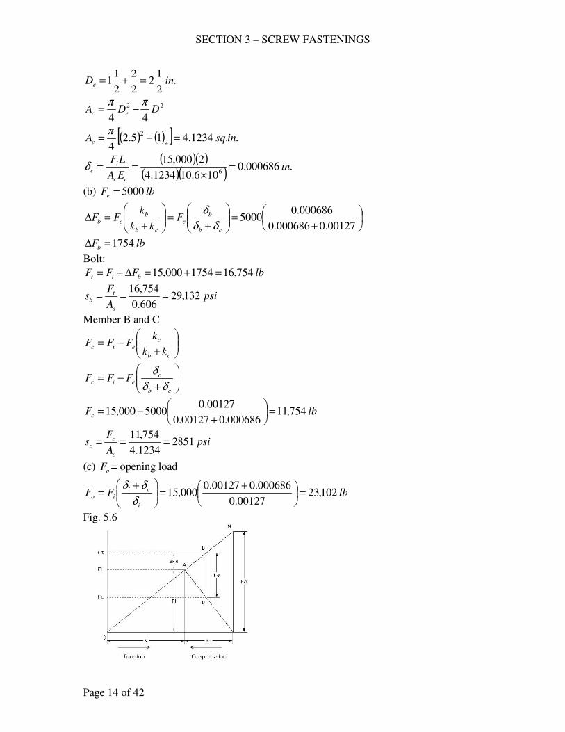
SECTION 3 – SCREW FASTENINGS
Page 14 of 42
.2
12
2
2
2
11 inDe =+=
22
44DDA ec
ππ−=
( ) ( )[ ] ..1234.415.24
2
2insqAc =−=
π
( )( )( )( )
.000686.0106.101234.4
2000,156
inEA
LF
cc
ic =
×==δ
(b) lbFe 5000=
+=
+=
+=∆
00127.0000686.0
000686.05000
cb
be
cb
beb F
kk
kFF
δδ
δ
lbFb 1754=∆
Bolt:
lbFFF bit 754,161754000,15 =+=∆+=
psiA
Fs
s
tb 132,29
606.0
754,16===
Member B and C
+−=
cb
ceic
kk
kFFF
+−=
cb
ceic FFF
δδ
δ
lbFc 754,11000686.000127.0
00127.05000000,15 =
+−=
psiA
Fs
c
cc 2851
1234.4
754,11===
(c) oF = opening load
lbFFi
ciio 102,23
00127.0
000686.000127.0000,15 =
+=
+=
δ
δδ
Fig. 5.6
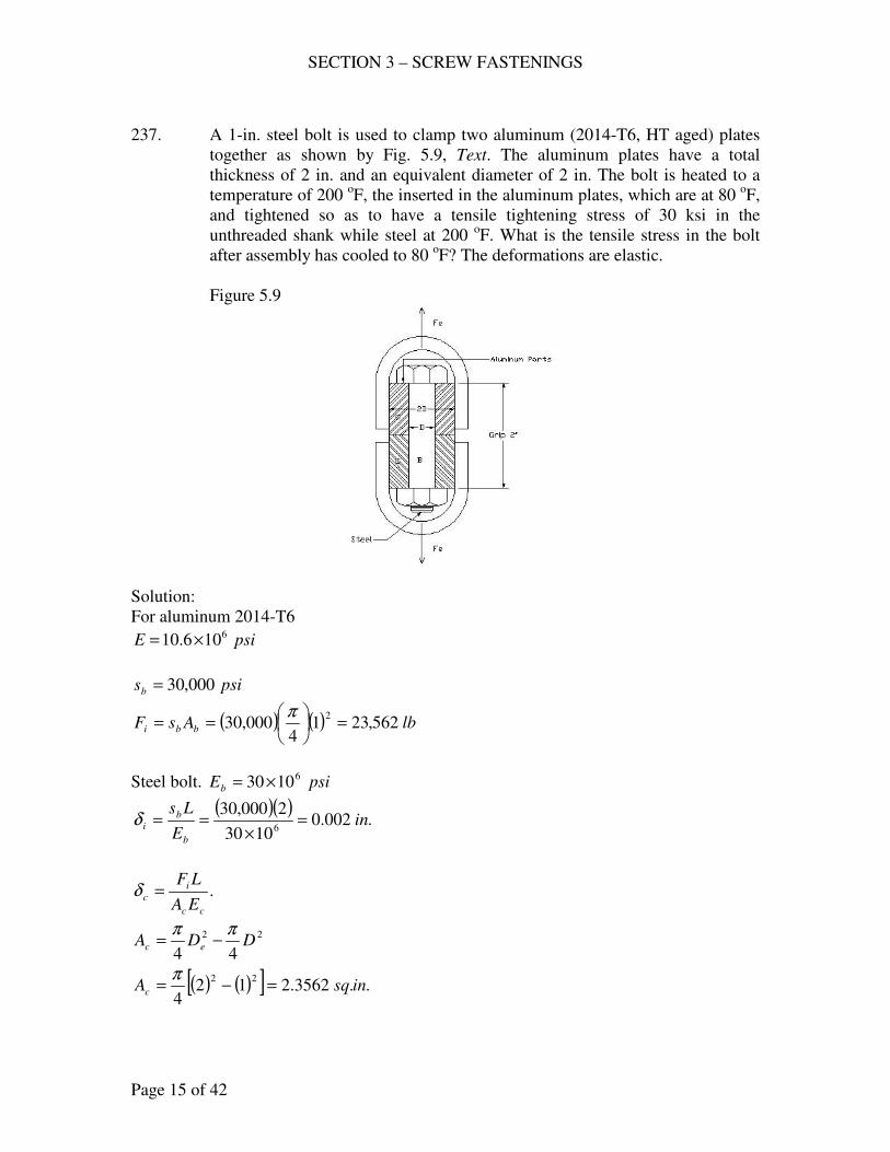
SECTION 3 – SCREW FASTENINGS
Page 15 of 42
237. A 1-in. steel bolt is used to clamp two aluminum (2014-T6, HT aged) plates
together as shown by Fig. 5.9, Text. The aluminum plates have a total
thickness of 2 in. and an equivalent diameter of 2 in. The bolt is heated to a
temperature of 200 oF, the inserted in the aluminum plates, which are at 80
oF,
and tightened so as to have a tensile tightening stress of 30 ksi in the
unthreaded shank while steel at 200 oF. What is the tensile stress in the bolt
after assembly has cooled to 80 oF? The deformations are elastic.
Figure 5.9
Solution:
For aluminum 2014-T6
psiE 6106.10 ×=
psisb 000,30=
( ) ( ) lbAsF bbi 562,2314
000,302
=
==
π
Steel bolt. psiEb
61030×=
( )( ).002.0
1030
2000,306
inE
Ls
b
b
i =×
==δ
.cc
i
cEA
LF=δ
22
44DDA ec
ππ−=
( ) ( )[ ] ..3562.2124
22insqAc =−=
π
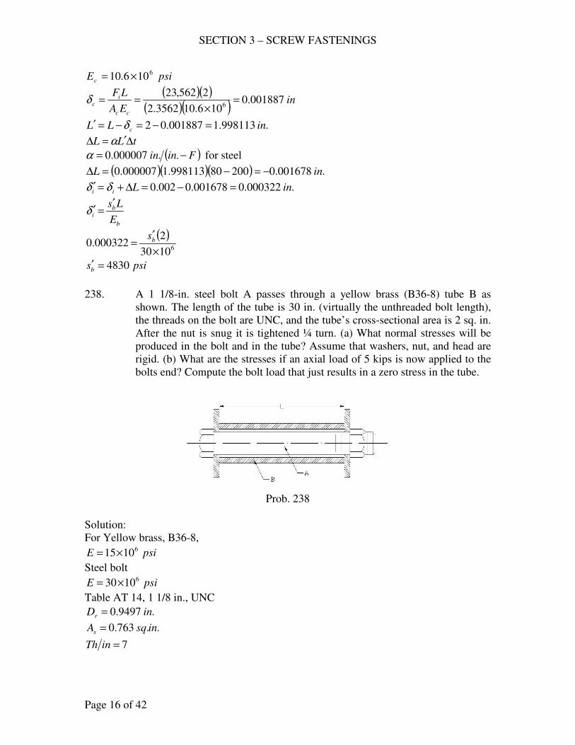
SECTION 3 – SCREW FASTENINGS
Page 16 of 42
psiEc
6106.10 ×=
( )( )( )( )
inEA
LF
cc
ic 001887.0
106.103562.2
2562,236
=×
==δ
.998113.1001887.02 inLL c =−=−=′ δ
tLL ∆′=∆ α
( )Finin −= ..000007.0α for steel
( )( )( ) .001678.020080998113.1000007.0 inL −=−=∆
.000322.0001678.0002.0 inLii =−=∆+=′ δδ
b
bi
E
Ls′=′δ
( )61030
2000322.0
×
′= bs
psisb 4830=′
238. A 1 1/8-in. steel bolt A passes through a yellow brass (B36-8) tube B as
shown. The length of the tube is 30 in. (virtually the unthreaded bolt length),
the threads on the bolt are UNC, and the tube’s cross-sectional area is 2 sq. in.
After the nut is snug it is tightened ¼ turn. (a) What normal stresses will be
produced in the bolt and in the tube? Assume that washers, nut, and head are
rigid. (b) What are the stresses if an axial load of 5 kips is now applied to the
bolts end? Compute the bolt load that just results in a zero stress in the tube.
Prob. 238
Solution:
For Yellow brass, B36-8,
psiE 61015×=
Steel bolt
psiE 61030×=
Table AT 14, 1 1/8 in., UNC
.9497.0 inDr =
..763.0 insqAs =
7=inTh
SECTION 3 – SCREW FASTENINGS
Page 17 of 42
.30 inL =
p
iδθ =
.7
1inp =
4
1=θ turn
.28
1
7
1
4
1ini =
=δ
bb
ii
EA
LF=δ
( )
( )6
2
10308
11
4
30
28
1
×
=
π
iF
lbFi 500,35=
(a) Bolt: psiA
Fs
s
ib 527,46
763.0
500,35===
Tube: c
ic
A
Fs =
..2 insqAc =
psiA
Fs
c
ic 750,17
2
500,35===
(b) lbFe 5000=
( )( )inlb
L
EAk cc
c 000,000,130
10152 6
=×
==
( )inlb
L
EAk bb
b 000,99430
10308
11
4
6
2
=
×
==
π
Bolts:
e
cb
bit F
kk
kFF
++=
( ) lbFt 000,385000000,000,1000,994
000,994500,35 =
++=
psiA
Fs
s
tt 800,49
763.0
000,38===
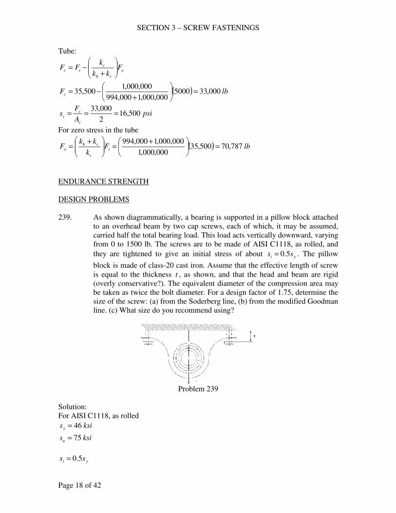
SECTION 3 – SCREW FASTENINGS
Page 18 of 42
Tube:
e
cb
cic F
kk
kFF
+−=
( ) lbFc 000,335000000,000,1000,994
000,000,1500,35 =
+−=
psiA
Fs
c
cc 500,16
2
000,33===
For zero stress in the tube
( ) lbFk
kkF i
c
cbo 787,70500,35
000,000,1
000,000,1000,994=
+=
+=
ENDURANCE STRENGTH
DESIGN PROBLEMS
239. As shown diagrammatically, a bearing is supported in a pillow block attached
to an overhead beam by two cap screws, each of which, it may be assumed,
carried half the total bearing load. This load acts vertically downward, varying
from 0 to 1500 lb. The screws are to be made of AISI C1118, as rolled, and
they are tightened to give an initial stress of about yi ss 5.0= . The pillow
block is made of class-20 cast iron. Assume that the effective length of screw
is equal to the thickness t , as shown, and that the head and beam are rigid
(overly conservative?). The equivalent diameter of the compression area may
be taken as twice the bolt diameter. For a design factor of 1.75, determine the
size of the screw: (a) from the Soderberg line, (b) from the modified Goodman
line. (c) What size do you recommend using?
Problem 239
Solution:
For AISI C1118, as rolled
ksisy 46=
ksisu 75=
yi ss 5.0=
SECTION 3 – SCREW FASTENINGS
Page 19 of 42
( ) psiksisi 000,2323465.0 ===
lbAkipAAsF sssii 000,2323 ===
e
cb
bb F
kk
kF
+=∆
b
bbb
L
EAk =
psiEb
61030×= (steel)
tLb =
c
ccc
L
EAk =
For cast-iron class 20
psiEc
6106.9 ×=
tLc =
22
44DDA ec
ππ−=
2
4DAb
π=
DDe 2=
( ) bc ADDDA 34
3
42
4
222==−=
πππ
b
bbb
L
EAk =
( )t
Ak b
b
61030×=
( )t
Ak b
c
6106.93 ×=
( ) 588
300
106.931030
103066
6
=×+×
×=
+ cb
b
kk
k
01 =∆ bF
lbFkk
kF e
cb
bb 383
2
1500
588
3002 =
=
+=∆
( ) ( ) lbAAFFFF ssbbim 192000,2303832
1000,23
2
112 +=++=∆+∆+=
( ) ( ) lbFFF bba 19203832
1
2
112 =−=∆−∆=
SECTION 3 – SCREW FASTENINGS
Page 20 of 42
( ) psipsiss un 500,37000,755.05.0 ===
For axial loading with size factor
( )( )( ) psipsisn 500,25500,3785.08.0 ==
75.1=N
sss
s
s
mm
AAA
A
A
Fs
192000,23
192000,23+=+==
ss
aa
AA
Fs
192==
Table AT 12, 8.1=fK
(a) Soderberg line
n
af
y
m
s
sK
s
s
N+=
1
( )
500,25
1928.1
000,46
192000,23
75.1
1
+
+
= ss AA
..2482.0 insqAs =
Table AT 14, UNC
Use .4
3inD = , ..334.0 insqAs =
(b) Modifies Goodman line
n
af
u
m
s
sK
s
s
N+=
1
( )
500,25
1928.1
000,75
192000,23
75.1
1
+
+
= ss AA
..0609.0 insqAs =
Table AT 14, UNC
Use .8
3inD = , ..0775.0 insqAs =
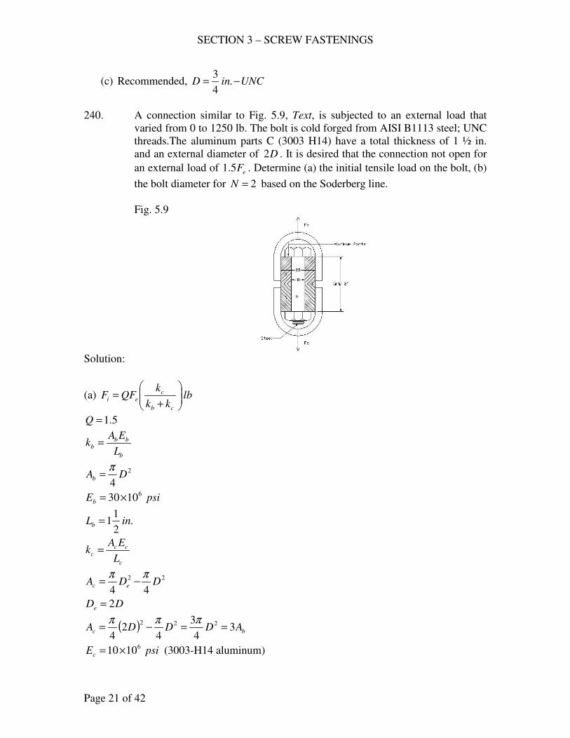
SECTION 3 – SCREW FASTENINGS
Page 21 of 42
(c) Recommended, UNCinD −= .4
3
240. A connection similar to Fig. 5.9, Text, is subjected to an external load that
varied from 0 to 1250 lb. The bolt is cold forged from AISI B1113 steel; UNC
threads.The aluminum parts C (3003 H14) have a total thickness of 1 ½ in.
and an external diameter of D2 . It is desired that the connection not open for
an external load of eF5.1 . Determine (a) the initial tensile load on the bolt, (b)
the bolt diameter for 2=N based on the Soderberg line.
Fig. 5.9
Solution:
(a) lbkk
kQFF
cb
cei
+=
5.1=Q
b
bbb
L
EAk =
2
4DAb
π=
psiEb
61030×=
.2
11 inLb =
c
ccc
L
EAk =
22
44DDA ec
ππ−=
DDe 2=
( ) bc ADDDA 34
3
42
4
222==−=
πππ
psiEc
61010×= (3003-H14 aluminum)
SECTION 3 – SCREW FASTENINGS
Page 22 of 42
.2
11 inLc =
( )
×=
2
11
1030 6
bb
Ak
( )
×=
2
11
10103 6
bc
Ak
( )( )
5.0101031030
1010366
6
=×+×
×=
+ cb
c
kk
k
lbFe 1250=
lbkk
kQFF
cb
cei
+=
( )( )( ) lbFi 5.9375.012505.1 ==
(b) For AISI B1113 steel, cold forged
ksisu 83=
ksisy 72=
( ) psiksiss un 500,415.41835.05.0 ====
For axial loading with size factor
( )( )( ) psipsisn 220,28500,4185.08.0 ==
e
cb
bb F
kk
kF
+=∆
01 =∆ bF
( )( ) lbF
kk
kF e
cb
bb 6251250
101031030
103066
6
2 =
×+×
×=
+=∆
( ) ( ) lbFFFF bbim 125006252
15.937
2
112 =++=∆+∆+=
( ) ( ) lbFFF bba 5.31206252
1
2
112 =−=∆−∆=
ss
mm
AA
Fs
1250==
SECTION 3 – SCREW FASTENINGS
Page 23 of 42
ss
aa
AA
Fs
5.312==
Soderberg line, 8.1=fK Table AT 12
n
af
y
m
s
sK
s
s
N+=
1
( )( )
ss AA 220,28
5.3128.1
000,72
1250
2
1+=
..07459.0 insqAs =
Table AT 14, UNC
Use .8
3inD = , ..0775.0 insqAs =
243. This problem concerns the Freon compressor of 226: size, 10 x 18 in.; 10
studs, UNC; made of C1118, as rolled; 200 psi gas pressure. The initial
tension in the bolts, assumed to be equally loaded, is such that a cylinder
pressure of 300 psi is required for the joint to be on the opening. The bolted
parts are cast steel and for the first calculations, it will be satisfactorily to
assume the equivalent diameter of the compressed parts to be twice the bolt
size. (a) For 2=N on the Soderberg criterion, what bolt size is required? (b)
Compute the torque required for the specified initial tension.
Solution:
( ).2356
10
10
4300
2
lbFo =
=
π
+=
cb
coi
kk
kFF
b
bbb
L
EAk =
2
4DAb
π=
psiEb
61030×=
LLb =
c
ccc
L
EAk =
22
44DDA ec
ππ−=
DDe 2=
SECTION 3 – SCREW FASTENINGS
Page 24 of 42
( ) bc ADDDA 34
3
42
4
222==−=
πππ
Cast Steel, psiEc
61030×=
LLc =
( )L
Ak b
b
61030×=
( )b
bc k
L
Ak 3
10303 6
=×
=
( ) lbkk
k
kk
kFF
bb
b
cb
coi 1767
3
32356 =
+=
+=
(a) e
cb
bb F
kk
kF
+=∆
01 =∆ bF
( ) ( )lb
kk
kF
kk
kF
bb
be
cb
bb 393
10
20010
43
2
2 =
+=
+=∆
π
( ) ( ) lbFFFF bbim 196403932
11767
2
112 =++=∆+∆+=
( ) ( ) lbFFF bba 19603932
1
2
112 =−=∆−∆=
ss
mm
AA
Fs
1964==
ss
aa
AA
Fs
196==
For C1118, as rolled
ksisu 75=
ksisy 46=
( ) psiksiss un 500,375.37755.05.0 ====
For axial loading with size factor
( )( )( ) psipsisn 500,25500,3785.08.0 ==
8.1=fK Table AT 12
n
af
y
m
s
sK
s
s
N+=
1
( )( )
ss AA 500,25
1968.1
000,46
1964
2
1+=
..1131.0 insqAs =
SECTION 3 – SCREW FASTENINGS
Page 25 of 42
Table AT 14, UNC
Use .2
1inD = , ..1419.0 insqAs =
(b) iDFT 2.0=
( ) .7.17617672
12.0 lbinT −=
=
245. A cast-iron (class 35) Diesel-engine cylinder head is held on 8 stud bolts with
UNC threads. These bolts are made of AISI 3140 steel, OQT 1000 oF (Fig.
AF2). Assume that the compressed material has an equivalent diameter twice
the bolt size. The maximum cylinder pressure is 750 psi and the bore of the
engine is 8 in. Let the initial bolt load be such that a cylinder pressure of 1500
psi brings the joint to the point of opening. For a design factor of 2, determine
the bolt diameter (a) using the Soderberg equation, (b) using the Goodman
equation. (c) What approximate torque will be required to induce the desired
initial stress? (d) Determine the ratio of the initial stress to the yield strength.
Considering the lessons of experience (i5.8), what initial stress would you
recommend? Using this value, what factor of safety is computed from the
Soderberg equation?
Solution:
( ).9425
8
8
41500
2
lbFo =
=
π
+=
cb
coi
kk
kFF
b
bbb
L
EAk =
2
4DAb
π=
psiEb
61030×=
LLb =
c
ccc
L
EAk =
22
44DDA ec
ππ−=
DDe 2=
( ) bc ADDDA 34
3
42
4
222==−=
πππ
SECTION 3 – SCREW FASTENINGS
Page 26 of 42
psiEc
6105.14 ×= , for cast-iron (class 35)
LLc =
( )L
Ak b
b
61030×=
( )L
Ak b
c
6105.143 ×=
( ) ( )( )
lbkk
kFF
cb
coi 5578
105.1431030
105.1439425
66
6
=
×+×
×=
+=
e
cb
bb F
kk
kF
+=∆
01 =∆ bF
( )( ) ( )
lbFkk
kF e
cb
bb 1923
8
7508
4105.1431030
10302
66
6
2 =
×+×
×=
+=∆
π
( ) ( ) lbFFFF bbim 6540019232
15578
2
112 =++=∆+∆+=
( ) ( ) lbFFF bba 962019232
1
2
112 =−=∆−∆=
ss
mm
AA
Fs
6540==
ss
aa
AA
Fs
962==
(a) For AISI 3140 steel, OQT 1000 oF
ksisu 153=
ksisy 134=
( ) psiksiss un 500,765.761535.05.0 ====
For axial loading with size factor
( )( )( ) psipsisn 000,52500,7685.08.0 ==
Table AT 12, 3.3=fK (hardened)
Soderberg Equation
n
af
y
m
s
sK
s
s
N+=
1
( )( )
ss AA 000,52
9623.3
000,134
6540
2
1+=
..2197.0 insqAs =
SECTION 3 – SCREW FASTENINGS
Page 27 of 42
Table AT 14, UNC
Use .8
5inD = , ..226.0 insqAs =
(b) Goodman Equation
n
af
u
m
s
sK
s
s
N+=
1
( )( )
ss AA 000,52
9623.3
000,153
6540
2
1+=
..2076.0 insqAs =
Table AT 14, UNC
Use .8
5inD = , ..226.0 insqAs =
(c) iDFT 2.0=
( ) .69755788
52.0 lbinT −=
=
(d) psiA
Fs
s
ii 681,24
226.0
5578===
Ratio = 184.0000,134
681,24==
y
i
s
s
i5.8 ( ) psiss yi 900,113000,13485.085.0 ===
Factor of safety
( )( ) lbAsF sii 742,25226.0900,113 ===
( ) lbFm 704,2619232
1742,25 =+=
( ) lbFa 96219232
1==
psiA
Fs
s
mm 159,118
226.0
704,26===
psiA
Fs
s
aa 4257
226.0
962===
Soderberg Equation
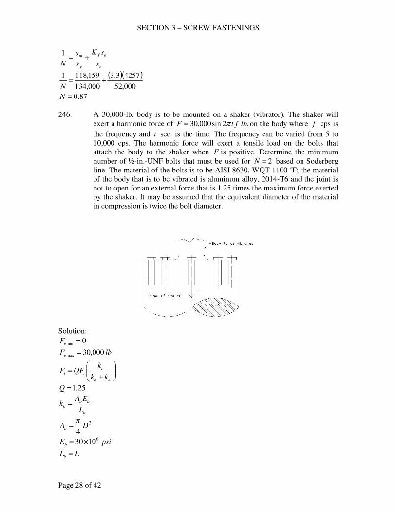
SECTION 3 – SCREW FASTENINGS
Page 28 of 42
n
af
y
m
s
sK
s
s
N+=
1
( )( )000,52
42573.3
000,134
159,1181+=
N
87.0=N
246. A 30,000-lb. body is to be mounted on a shaker (vibrator). The shaker will
exert a harmonic force of .2sin000,30 lbftF π= on the body where f cps is
the frequency and t sec. is the time. The frequency can be varied from 5 to
10,000 cps. The harmonic force will exert a tensile load on the bolts that
attach the body to the shaker when F is positive. Determine the minimum
number of ½-in.-UNF bolts that must be used for 2=N based on Soderberg
line. The material of the bolts is to be AISI 8630, WQT 1100 oF; the material
of the body that is to be vibrated is aluminum alloy, 2014-T6 and the joint is
not to open for an external force that is 1.25 times the maximum force exerted
by the shaker. It may be assumed that the equivalent diameter of the material
in compression is twice the bolt diameter.
Solution:
0min =eF
lbFe 000,30max =
+=
cb
cei
kk
kQFF
25.1=Q
b
bbb
L
EAk =
2
4DAb
π=
psiEb
61030×=
LLb =
SECTION 3 – SCREW FASTENINGS
Page 29 of 42
c
ccc
L
EAk =
22
44DDA ec
ππ−=
DDe 2=
( ) bc ADDDA 34
3
42
4
222==−=
πππ
psiEc
6106.10 ×= , (Aluminum 2014-T6)
LLc =
( )L
A
L
EAk b
b
bbb
61030×==
( )L
A
L
EAk b
c
ccc
6106.103 ×==
+=
cb
cei
kk
kQFF
( )( ) ( )( )
lbFi 296,19106.1031030
106.103000,3025.1
66
6
=
×+×
×=
e
cb
bb F
kk
kF
+=∆
01 =∆ bF
( )( ) lbF
kk
kF e
cb
bb 563,14000,30
106.1031030
103066
6
2 =
×+×
×=
+=∆
( ) ( ) lbFFFF bbim 578,260563,142
1296,19
2
112 =++=∆+∆+=
( ) ( ) lbFFF bba 72820563,142
1
2
112 =−=∆−∆=
s
mm
nA
Fs =
s
a
anA
Fs =
For ½-in.-UNF (Table AT 14)
..1419.0 insqAs =
nnnA
Fs
s
mm
300,187
1419.0
578,26===
SECTION 3 – SCREW FASTENINGS
Page 30 of 42
nnnA
Fs
s
aa
318,51
1419.0
7282===
For AISI 8630, WQT 1100 oF
3.3=fK
ksisu 137=
ksisy 125=
( ) psiksiss un 500,685.681375.05.0 ====
For axial loading with size factor
( )( )( ) psipsisn 580,46500,6885.08.0 ==
Soderberg Equation, 2=N
n
af
y
m
s
sK
s
s
N+=
1
( )( )nn 580,46
318,513.3
000,125
300,187
2
1+=
3.10=n
Minimum number of bolts = 10 bolts
248. The maximum external load on the cap bolts of an automotive connecting rod
end, imposed by inertia forces at top dead center, is taken to be 4000 lb.; the
minimum load is zero at bottom dead center. The material is AISI 4140, OQT
1100oF (qualifying for SAE grade 5); assume that un ss 45.0=′ . The grip for
through bolts is 1.5 in. For design purposed, let each bolt take half the load,
and use an equivalent .8
31 inDe = for the connected parts. The threads extend
a negligible amount into the grip. For the initial computation, use an opening
load eo FF 75.1= . Considering the manner in which the bolt is loaded, we
decide that a design factor of 1.4 (Soderberg) should be quite adequate. (a)
Does a 5/16-24 UNF satisfy this situation? If not, what size do you
recommend? (b) Experience suggests that, in situations such as this, an initial
stress of the order suggested in i5.8, Text, is good insurance against fatigue
failure. Decide upon such an is and recomputed N . How does it change?
Would you be concerned about the safety in this case? Consider the variation
of is as a consequences of the use of torque wrench and also the stress
relaxation with time (due to seating and other factors), and discuss. Compute
the required tightening torque for each is .
SECTION 3 – SCREW FASTENINGS
Page 31 of 42
Solution:
( ) lbFF eo 7000400075.175.1 ===
+=
cb
cei
kk
kFF
b
bbb
L
EAk =
2
4DAb
π=
psiEb
61030×=
.5.1 inLb =
c
ccc
L
EAk =
22
44DDA ec
ππ−=
bc ADDA −=−=−
= 485.1
4485.1
48
31
4
22
2πππ
psiEc
6106.10 ×= , (Aluminum 2014-T6)
.5.1 inLc =
bs AA ≈
( )5.1
1030 6×== b
b
bbb
A
L
EAk
( )( )5.1
1030485.1 6×−== s
c
ccc
A
L
EAk
ss
i AA
F 47147000485.1
485.17000 −=
−=
e
cb
bb F
kk
kF
+=∆
01 =∆ bF
( )s
se
cb
bb A
AF
kk
kF 2694000,4
485.12 =
=
+=∆
( ) ( ) sssbbim AAAFFFF 33677000026942
147147000
2
112 −=++−=∆+∆+=
( ) ( ) ssbba AAFFF 1347026942
1
2
112 =−=∆−∆=
SECTION 3 – SCREW FASTENINGS
Page 32 of 42
Table 5.2
ksisu 120=
ksisy 88=
( ) psiksiss un 000,545412045.045.0 ====′
33677000
−==ss
mm
AA
Fs
1347==s
aa
A
Fs
3.3=fK (hardened, Table AT 12)
Soderberg Equation, 4.1=N
n
af
y
m
s
sK
s
s
N+=
1
( )( )000,54
13473.3
000,88
3367
000,88
7000
4.1
1+−=
sA
..1187.0 insqAs =
Table At14, we inD16
7= , ..1187.0 insqAs =
(a) 5/16-24 UNF will not satisfy the situation. Instead use inD16
7= ,
..1187.0 insqAs =
(b) i5.8, Text
( ) psiksiss yi 800,748.748885.085.0 ====
( )( ) lbAsF sii 88791187.0800,74 ===
( ) ( ) ssbbim AAFFFF 13478879026942
18879
2
112 +=++=∆+∆+=
( ) ( ) ssbba AAFFF 1347026942
1
2
112 =−=∆−∆=
13478879
+==ss
mm
AA
Fs
1347==s
aa
A
Fs
n
af
y
m
s
sK
s
s
N+=
1
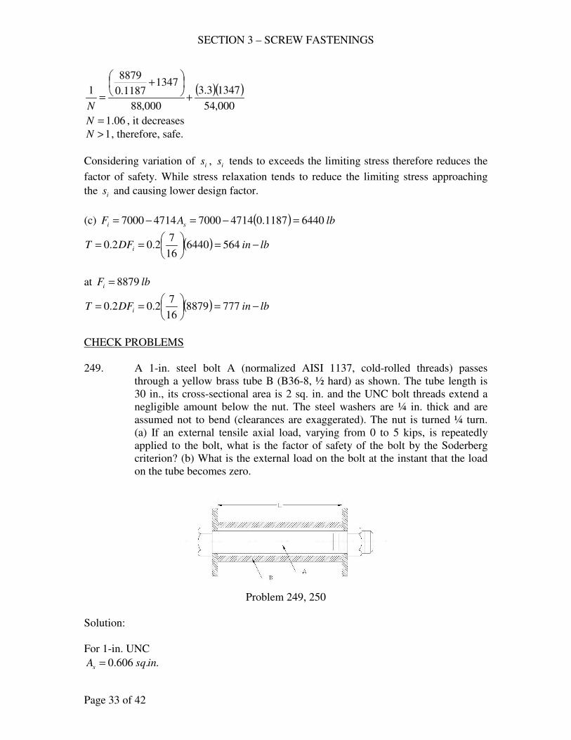
SECTION 3 – SCREW FASTENINGS
Page 33 of 42
( )( )000,54
13473.3
000,88
13471187.0
8879
1+
+
=N
06.1=N , it decreases
1>N , therefore, safe.
Considering variation of is , is tends to exceeds the limiting stress therefore reduces the
factor of safety. While stress relaxation tends to reduce the limiting stress approaching
the is and causing lower design factor.
(c) ( ) lbAF si 64401187.04714700047147000 =−=−=
( ) lbinDFT i −=
== 5646440
16
72.02.0
at lbFi 8879=
( ) lbinDFT i −=
== 7778879
16
72.02.0
CHECK PROBLEMS
249. A 1-in. steel bolt A (normalized AISI 1137, cold-rolled threads) passes
through a yellow brass tube B (B36-8, ½ hard) as shown. The tube length is
30 in., its cross-sectional area is 2 sq. in. and the UNC bolt threads extend a
negligible amount below the nut. The steel washers are ¼ in. thick and are
assumed not to bend (clearances are exaggerated). The nut is turned ¼ turn.
(a) If an external tensile axial load, varying from 0 to 5 kips, is repeatedly
applied to the bolt, what is the factor of safety of the bolt by the Soderberg
criterion? (b) What is the external load on the bolt at the instant that the load
on the tube becomes zero.
Problem 249, 250
Solution:
For 1-in. UNC
..606.0 insqAs =
SECTION 3 – SCREW FASTENINGS
Page 34 of 42
.8466.0 inDr =
8. =inTh
.8
11in
inThp ==
4
1=
p
δ
.32
1
8
1
4
1in=
=δ
.5.304
1230 inLb =
+=
psiEb
61030×=
( )
( ) ( )6210301
4
5.30
32
1
×
==π
δ iF
lbFi 141,24=
+=∆
cb
beb
kk
kFF
( ) ( )525,772
5.30
103014
62
=×
==
π
b
bbb
L
EAk
c
ccc
L
EAk =
..2 insqAc =
.30 inLc =
psiEc
61015×= (Yellow Brass)
( )000,000,1
30
10152 6
=×
=ck
(a) 01 =∆ bF
( ) lbFb 2179000,000,1525,772
525,77250002 =
+=∆
( ) ( ) lbFFFF bbim 230,25021792
1141,24
2
112 =++=∆+∆+=
( ) ( ) lbFFF bba 1090021792
1
2
112 =−=∆−∆=
psiA
Fs
s
mm 227,38
606.0
230,25===
SECTION 3 – SCREW FASTENINGS
Page 35 of 42
psiA
Fs
s
aa 1799
606.0
1090===
For normalized AISI 1137, cold-rolled thread
ksisu 98=
ksisy 58=
( ) psiksiss un 000,4949985.05.0 ====
4.1=fK (Table AT 12)
For axial loading, ( ) psisn 200,39000,498.0 ==
n
af
y
m
s
sK
s
s
N+=
1
( )( )200,39
17994.1
000,58
227,381+=
N
38.1=N
(b)
+=
cb
coi
kk
kFF
+=
000,000,1525,772
000,000,1141,24 oF
lbFo 790,42=
250. A ¾-in. fine-thread bolt, made of AISI 1117, cold drawn, with rolled threads,
passes through a yellow brass tube and two steel washers, as shown. The tube
is 4 in. long, 7/8 in. internal diameter, 1 ¼-in. external diameter. The washers
are each ¼-in. thick. The unthreaded part of the bolt is 3 in. long. Assume that
there is no stretching of the bolt inside the nut in finding its k . The
unlubricated bolt is tightened by a torque of 1800 in-lb. The external load,
varying from 0 to 4 kips, is axially applied to the washers an indefinite
number of times. (a) Compute the factor of safety of the bolt by the Soderberg
criterion. Is there any danger of failure of the bolt? (b) What pull must be
exerted by the washers to remove all load from the brass tube?
Solution:
iDFT 2.0=
iF
=
4
32.01800
lbFi 000,12=
SECTION 3 – SCREW FASTENINGS
Page 36 of 42
+=∆
cb
beb
kk
kFF
21
111
bbb kkk+=
1
1
b
bbb
L
EAk =
.31 inLb =
..4418.04
3
4
2
insqAb =
=
π
psiEb
61030×=
( )( )000,418,4
3
10304418.0 6
1 =×
=bk
2
2
b
bsb
L
EAk =
For ¾-in. UNF (Table AT 14)
..373.0 insqAs =
.5.132
1242 inLb =−
+=
( )( )000,460,7
5.1
1030373.0 6
2 =×
=bk
21
111
bbb kkk+=
000,460,7
1
000,418,4
11+=
bk
733,774,2=bk
c
ccc
L
EAk =
..6259.08
7
4
11
4
22
insqAc =
−
=
π
psiEc
61015×=
.4 inLc =
( )( )125,347,2
4
10156259.0 6
=×
=ck
01 =∆ bF
( ) lbFb 2167125,347,2733,774,2
733,774,240002 =
+=∆
SECTION 3 – SCREW FASTENINGS
Page 37 of 42
( ) ( ) lbFFFF bbim 084,13021672
1000,12
2
112 =++=∆+∆+=
( ) ( ) lbFFF bba 1084021672
1
2
112 =−=∆−∆=
psiA
Fs
s
mm 078,35
373.0
084,13===
psiA
Fs
s
aa 2906
373.0
1084===
For AISI 111, cold drawn, rolled threads
ksisn 40=
ksisy 68=
4.1=fK
( ) psiksisn 000,3232408.0 === , axial loading
(a) n
af
y
m
s
sK
s
s
N+=
1
( )( )000,32
29064.1
000,68
078,351+=
N
56.1=N
(b)
+=
cb
coi
kk
kFF
+=
125,347,2733,774,2
125,347,2000,12 oF
lbFo 186,26=
251. A coupling bolt (i5.13, Text) is used to connect two parts made of cast-iron,
class 35. The diameter of the coarse-thread bolt is ½-in.; its grip is 2 in., which
is also nearly the unthreaded length. The bolt tightened to have an initial
tension of 4000 lb. The parts support an external load eF that tends to separate
them and it varies from zero to 5000 lb. What is the factor of safety,
(Soderberg)?
Solution:
lbFi 4000=
+=∆
cb
beb
kk
kFF
SECTION 3 – SCREW FASTENINGS
Page 38 of 42
b
bbb
L
EAk =
..19635.02
1
4
2
insqAb =
=
π (unthreaded length)
psiEb
61030×=
.2 inLb =
( )( )250,945,2
2
103019635.0 6
=×
=bk
Table AT 14, UNC
.2
1inD =
..1419.0 insqAs =
.4
3inA =
2
hADe +=
.2 inh =
.4
31
2
2
4
3inDe =+=
c
ccc
L
EAk =
..209.22
1
4
31
444
22
22insqDDA ec =
−
=−=
πππ
psiEc
6105.14 ×= , (Cast iron, class 35)
.2 inLc =
( )( )250,015,16
2
105.14209.2 6
=×
=ck
01 =∆ bF
( ) lbFb 777250,015,16250,945,2
250,945,250002 =
+=∆
( ) ( ) lbFFFF bbim 438907772
14000
2
112 =++=∆+∆+=
( ) ( ) lbFFF bba 38907772
1
2
112 =−=∆−∆=
psiA
Fs
s
mm 930,30
1419.0
4389===
psiA
Fs
s
aa 2741
1419.0
389===
SECTION 3 – SCREW FASTENINGS
Page 39 of 42
For ASTM 354 BC (Table 5.2), .2
1inD =
ksisu 125=
ksisy 109=
un ss 5.0=
For axial loading
( )( )( ) psiksisn 000,50501255.08.0 ===
8.1=fK
Soderberg Line
n
af
y
m
s
sK
s
s
N+=
1
( )( )000,50
27418.1
000,109
930,301+=
N
6.2=N
252. The cap on the end of a connecting rod (automotive engine) is held on by two
5/16-in. bolts that are forged integrally with the main connecting rod. These
bolts have UNF threads with a 5/8-in. on an unthreaded length of virtually 5/8
in. The nuts are to be tightened with a torque of 20 ft-lb. and the maximum
external load on one bolt is expected to be 2330 lb. Let the equivalent
diameter of the connected parts be ¾ in. (a) Estimate the maximum force on
the bolt. (b) Compute the opening load. Is this satisfactory? (c) If the bolt
material is AISI 4140, OQT 1000 oF, what is the factor of safety based on the
Soderberg criterion?
Solution:
lbinlbftT −=−= 24020
iDFT 2.0=
iF
=
16
52.0240
lbFi 3840=
+=∆
cb
beb
kk
kFF
b
bbb
L
EAk =
..0767.016
5
4
2
insqAb =
=
π (unthreaded length)
psiEb
61030×=
.8
5inLb =
SECTION 3 – SCREW FASTENINGS
Page 40 of 42
( )( )600,681,3
8
5
10300767.0 6
=
×=bk
c
ccc
L
EAk =
..3651.016
5
4
3
444
22
22insqDDA ec =
−
=−=
πππ
psiEc
61030×= , (Cast iron, class 35)
.8
5inLc =
( )( )800,524,17
8
5
10303651.0 6
=
×=ck
( ) lbFb 405800,524,17600,681,3
600,681,32330 =
+=∆
(a) lbFFF bi 42454053840max =+=∆+=
(b)
+=
cb
coi
kk
kFF
+=
80,524,17600,681,3
800,524,173840 oF
max4647 FlbFo <=
(c) lbF
FF bim 4042
2
4053840
2=+=
∆+=
lbF
F ba 202
2
405
2==
∆=
For AISI 4140, OQT 1000 oF
ksisu 170=
ksisy 155=
Table AT 12, 6.2=fK
un ss 5.0=
For axial loading
( )( )( ) psiksisn 000,68681705.08.0 ===
Soderberg Line
n
af
y
m
s
sK
s
s
N+=
1
SECTION 3 – SCREW FASTENINGS
Page 41 of 42
For 5/16-in.-UNF, Table AT 14, ..0580.0 insqAs =
psiA
Fs
s
mm 690,69
0580.0
4042===
psiA
Fs
s
aa 3843
0580.0
202===
n
af
y
m
s
sK
s
s
N+=
1
( )( )000,68
34836.2
000,155
690,691+=
N
72.1=N
SET SCREWS
254. A 6-in. pulley is fastened to a 1 ¼ in. shaft by a set screw. If a net tangential
force of 75 lb, is applied to the surface of the pulley, what size screw should
be used when the load is steady?
Solution:
Tangential force = ( ) lblb 36525.1
675 =
Assume tangential force = holding force
Table 5.3, use Screw size 8, Holding force = 385 lb.
255. An eccentric is to be connected to a 3-in. shaft by a setscrew. The center of the
eccentric is 1 ¼ in. from the center of the shaft when a tensile force of 1000
lb. is applied to the eccentric rod perpendicular to the line of centers. What
size set screw should be used for a deign factor of 6?
Solution:
Tangential force = ( ) lblb 83323
25.11000 =
Holding force = ( )( ) lb50008336 =
Table 5.3, use Screw size ¾ in.
256. A lever 16 in. long is to be fastened to a 2-in. shaft. A load of 40 lb. is to be
applied normal to the lever at its end. What size of set screw should be used
for a design factor of 5?
Solution:
Torque = ( )( ) lbin −= 6404016
Tangential force = ( )
lb6402
6402=
SECTION 3 – SCREW FASTENINGS
Page 42 of 42
Holding force = ( )( ) lb32006405 =
Table 5.3, use Screw size 9/16 in.
257. A 12-in. gear is mounted on a 2-in. shaft and is held in place by a 7/16 in.
setscrew. For a design factor of 3, what would be the tangential load that
could be applied to the teeth and what horsepower could be transmitted by the
screw.
Solution:
Table 5.3, 7/16 in.
Holding force = 2500 lb
Tangential force = lb8333
2500=
Tangential load on gear = lb13912
2833 =
Assume fpmvm 4500=
Hp transmitted = ( )( )
hp19000,33
4500139=
- end -
SECTION 4 - SPRINGS
Page 1 of 70
HELICAL COMPRESSION SPRINGS
DESIGN – LIGHT, MEDIUM SERVICE
271. A solenoid brake (Fig. 18.2, Text) is to be actuated by a helical compression
spring. The spring should have a free length of approximately 18 in. and is to
exert a maximum force of 2850 lb. when compressed to a length of 15 in. The
outside diameter must not exceed 7 in. Using oil-tempered wire, design a
spring for this brake, (wire diameter, coil diameter, number of active coils,
pitch, pitch angle, “solid stress”). General Electric used a spring made of 1 in.
wire, with an outside diameter of 6 in., and 11 ½ free coils for a similar
application.
Solution:
For oil tempered wire, Table AT 17
ksiD
s
w
u 19.0
146= , [ ]5.0032.0 << wD
“solid stress” = us6.0
design stress, (average service)
usd ss 324.0=
( )ksi
DDs
ww
sd 19.019.0
304.47146324.0==
7≤+ mw DD
kipslbF 85.22850 ==
19.03
304.478
ww
ms
DD
FDKs =
=
π
say 3.1=K
( )( )19.03
304.47785.283.1
ww
ws
DD
Ds =
−=
π
ininDw 5.0062.1 >=
use ( )
ksiksissd 545.0
304.4719.0
==
( )( )54
785.283.1
3=
−=
w
ws
D
Ds
π
inDw 015.1=
say inDw 0.1=
( )( )
541
85.283.1
3=
=
πm
s
Ds
inDm 72.5=
SECTION 4 - SPRINGS
Page 2 of 70
say inDm 0.5=
.760.10.5 ininDDOD wm <=+=+=
50.1
0.5===
w
m
D
DC
δ = Free length – Compressed length = 18 in – 15 in = 3 in.
w
c
GD
NFC38
=δ
ksiG 500,10= , inDw8
3>
( )( )( )( )1500,10
585.283
3
cN==δ
05.11=cN
say 5.11=cN
( )( ) ( )( )( )
in12.31500,10
5.11585.283
==δ
Free length = 15 + 3.12 = 18.12 in
At 2.85 kips
=
3
8
w
ms
D
FDKs
π
5=C ( )( )
3105.15
615.0
454
154615.0
44
14=+
−
−=+
−
−=
CC
CK
( )( )( )
ksiss 55.471
585.283105.1
3=
=
π
Permissible solid stress
( )( )
ksiksiss uso 93.995.0
1466.06.0
19.0===
using δ
Fk =
or let Tδ = Free length – Solid height
Tδ
93.99
12.3
55.47=
inT 56.6=δ
Tδ = Free length – Solid height = ( ) cw NDP −
( )( )5.11156.6 −= P inP 570.1=
SECTION 4 - SPRINGS
Page 3 of 70
use inP2
11=
Pitch angle,
( )oo 125.5
5
5.1tantan 11 <=
== −−
ππλ
D
P, o.k.
For actual solid stress
( )( ) .75.55.1115.1 inT =−=δ
75.512.3
55.47 sos=
ksiksisso 93.9963.87 <= , ok
Summary of answer:
wD = wire diameter = 1 in.
mD = coil diameter = 5 in.
cN = no. of active coils = 11 1/2
P = pitch = 1 ½ in.
γ = pitch angle = 5.5o
sos = solid stress = 87.63 ksi
272. A coil spring is to be used for the front spring of a automobile. The spring is
to have a rate of 400 lb./in., an inside diameter of 4 3/64 in., and a free length
of 14 1/8 in., with squared-and-ground ends. The material is to be oil-
tempered chrome vanadium steel. Decide upon the diameter of the wire and
the number of free coils for a design load of lbF 1500= . Be sure “solid
stress” is all right. How much is the pitch angle?
Solution:
Table AT 17 Cr-V steel
ksiD
s
w
u 166.0
168= , [ ]437.0032.0 wD<
average service
usd ss 324.0=
( )ksi
DDs
ww
sd 166.0166.0
432.54168324.0==
Max “solid stress” = us6.0
SECTION 4 - SPRINGS
Page 4 of 70
ininDDID wm 046875.464
34 ==−=
inDD wm 046875.4+=
sd
w
ms s
D
FDKs =
=
3
8
π
Assume 3.1=K
kipslbF 5.11500 ==
( )( )
+==
3166.0
046875.45.183.1
432.54
w
w
w
sdD
D
Ds
π
ininDw 437.0747.0 >=
use
( )ksiksissd 45.62
437.0
432.5419.0
==
( )( )45.62
046875.45.183.1
3=
+=
w
wsd
D
Ds
π
inDw 724.0=
use inDw4
3=
inDm64
514
64
34
4
3=+=
=
3
8
w
ms
D
FDKs
π
CC
CK
615.0
44
14+
−
−=
4.6
4
3
64
514
≈
==w
m
D
DC
( )( )
235.14.6
615.0
44.64
14.64=+
−
−=K
( )ksiksiss 45.6264.53
4
3
64
5145.18
235.13
<=
=
π
, (o.k.)
w
c
GD
NFC38
=δ
SECTION 4 - SPRINGS
Page 5 of 70
ksiG 500,10= , inDw8
3>
ink
F75.3
400
1500===δ
( )( )
( )
==
4
3500,10
4.65.1875.3
3
cNδ
4.9=cN
Table AT 16, Total coils = 4.1124.92 =+=+cN for square and grounded end.
Summary of answer:
wD = wire diameter = ¾ in.
No. of free coils = 11.4
To check for solid stress.
Permissible solid stress = ( )
( )ksi65.115
437.0
1686.0166.0
=
Free length = wc DPN 2+
Solid height = ( ) ( ) inND cw 55.84.114
32 =
=+
Solid stress = ( ) ksiksi 65.11574.7875.3
55.88
114
64.53 <=
−
(safe)
Pitch:
inDPN wc8
1142 =+
( )8
114
4
324.9 =
+P
ininP32
111343.1 ==
Pitch angle,
oo 121.5
64
514
32
111
tantan 11 <=
== −−
ππ
λD
P, o.k.
SECTION 4 - SPRINGS
Page 6 of 70
273. A coiled compression spring is to fit inside a cylinder 5/8 in. in diameter. For
one position of the piston, the spring is to exert a pressure on the piston
equivalent to 5 psi of piston area, and in this position, the overall length of the
spring must not exceed (but may be less than) 2 in. A pressure of 46 psi on the
piston is to compress the spring ¾ in. from the position described above.
Design a spring for medium service. Specify the cheapest suitable material,
number of total and active coils for square-and-ground ends, and investigate
the pitch angle, and “solid stress”.
Solution:
=
3
8
w
ms
D
FDKs
π
28
5 wwm
DinDDOD −=+=
inDD wm8
55.1 =+
( ) lbF 534.18
5
45
2
1 =
=
π
( ) lbF 647.158
5
4546
2
2 =
+=
π
Using hard-drawn spring wire, Cost Index = 1
( )85.0324.0 usd ss =
ksiD
sw
u 19.0
140=
, [ ]625.0028.0 << wD
Max “solid stress” = ksiDw
19.0
70
( )19.019.0
556.3814085.0324.0
ww
sdDD
s ==
psiD
ksiDD
FCKs
www
s 19.019.02
556,38556.388==
=
π
( ) 81.1556,38647.158
wDC
K =
π ( ) 81.1556,38845.39 wDCK =
625.05.1 =+ wm DD
625.05.1 =+ ww DCD
5.1
625.0
+=
CDw
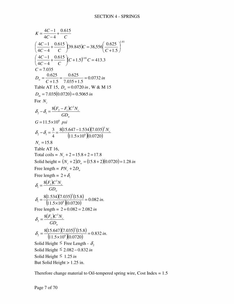
SECTION 4 - SPRINGS
Page 7 of 70
CC
CK
615.0
44
14+
−
−=
( )81.1
5.1
625.0556,38845.39
615.0
44
14
+=
+
−
−
CC
CC
C
( ) 3.4135.1615.0
44
14 81.1=+
+
−
−CC
CC
C
035.7=C
inC
Dw 0732.05.1035.7
625.0
5.1
625.0=
+=
+=
Table AT 15, inDw 0720.0= , W & M 15
( ) inDm 5065.00720.0035.7 ==
For cN
( )
w
c
GD
NCFF3
1212
8 −=−δδ
psiG 6105.11 ×=
( )( )( )( )0720.0105.11
035.7534.1647.158
4
36
3
12×
−==− cN
δδ
8.15=cN
Table AT 16,
Total coils = 8.1728.152 =+=+cN
Solid height = ( ) ( )( ) inDN wc 28.10720.028.152 =+=+
Free length = wc DPN 2+
Free length = 12 δ+
( )
w
c
GD
NCF3
11
8=δ
( )( ) ( )( )( )
.082.00720.0105.11
8.15035.7534.186
3
1 in=×
=δ
Free length = in082.2082.02 =+
( )
w
c
GD
NCF3
22
8=δ
( )( ) ( )( )( )
.832.00720.0105.11
8.15035.7647.1586
3
2 in=×
=δ
Solid Height ≤ Free Length - 2δ
Solid Height ≤ in832.0082.2 −
Solid Height ≤ in25.1
But Solid Height > 1.25 in.
Therefore change material to Oil-tempered spring wire, Cost Index = 1.5
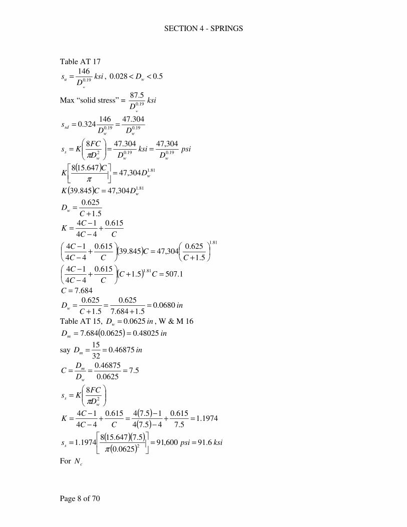
SECTION 4 - SPRINGS
Page 8 of 70
Table AT 17
ksiD
s
w
u 19.0
146= , 5.0028.0 << wD
Max “solid stress” = ksiD
w
19.0
5.87
19.019.0
304.47146324.0
ww
sdDD
s ==
psiD
ksiDD
FCKs
www
s 19.019.02
304,47304.478==
=
π
( ) 81.1304,47647.158
wDC
K =
π ( ) 81.1304,47845.39 wDCK =
5.1
625.0
+=
CDw
CC
CK
615.0
44
14+
−
−=
( )81.1
5.1
625.0304,47845.39
615.0
44
14
+=
+
−
−
CC
CC
C
( ) 1.5075.1615.0
44
14 81.1=+
+
−
−CC
CC
C
684.7=C
inC
Dw 0680.05.1684.7
625.0
5.1
625.0=
+=
+=
Table AT 15, inDw 0625.0= , W & M 16
( ) inDm 48025.00625.0684.7 ==
say inDm 46875.032
15==
5.70625.0
46875.0===
w
m
D
DC
=
2
8
w
sD
FCKs
π
( )( )
1974.15.7
615.0
45.74
15.74615.0
44
14=+
−
−=+
−
−=
CC
CK
( )( )( )
ksipsiss 6.91600,910625.0
5.7647.1581974.1
2==
=
π
For cN
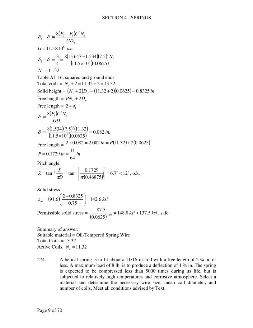
SECTION 4 - SPRINGS
Page 9 of 70
( )
w
c
GD
NCFF3
1212
8 −=−δδ
psiG 6105.11 ×=
( )( )( )( )0625.0105.11
5.7534.1647.158
4
36
3
12×
−==− cN
δδ
32.11=cN
Table AT 16, squared and ground ends
Total coils = 32.13232.112 =+=+cN
Solid height = ( ) ( )( ) inDN wc 8325.00625.0232.112 =+=+
Free length = wc DPN 2+
Free length = 12 δ+
( )
w
c
GD
NCF3
11
8=δ
( )( ) ( )( )( )
.082.00625.0105.11
32.115.7534.186
3
1 in=×
=δ
Free length = ( ) ( )0625.0232.11082.2082.02 +==+ Pin
ininP64
111729.0 ≈=
Pitch angle,
( )oo 127.6
46875.0
1729.0tantan 11 <=
== −−
ππλ
D
P, o.k.
Solid stress
( ) ksisso 6.14275.0
8325.026.91 =
−=
Permissible solid stress = ( )
ksiksi 5.1378.1480625.0
5.8719.0
>= , safe.
Summary of answer:
Suitable material = Oil-Tempered Spring Wire
Total Coils = 13.32
Active Coils, 32.11=cN
274. A helical spring is to fit about a 11/16-in. rod with a free length of 2 ¾ in. or
less. A maximum load of 8 lb. is to produce a deflection of 1 ¾ in. The spring
is expected to be compressed less than 5000 times during its life, but is
subjected to relatively high temperatures and corrosive atmosphere. Select a
material and determine the necessary wire size, mean coil diameter, and
number of coils. Meet all conditions advised by Text.
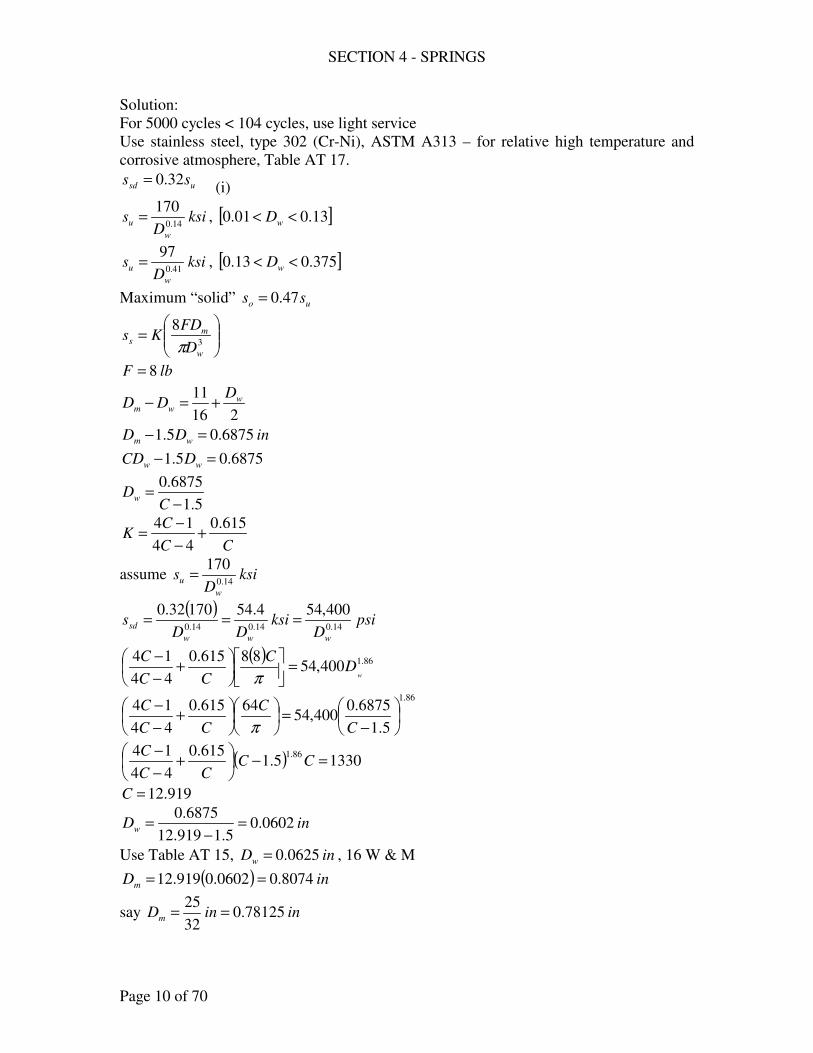
SECTION 4 - SPRINGS
Page 10 of 70
Solution:
For 5000 cycles < 104 cycles, use light service
Use stainless steel, type 302 (Cr-Ni), ASTM A313 – for relative high temperature and
corrosive atmosphere, Table AT 17.
usd ss 32.0= (i)
ksiD
sw
u 14.0
170= , [ ]13.001.0 << wD
ksiD
sw
u 41.0
97= , [ ]375.013.0 << wD
Maximum “solid” uo ss 47.0=
=
3
8
w
ms
D
FDKs
π
lbF 8=
216
11 wwm
DDD +=−
inDD wm 6875.05.1 =−
6875.05.1 =− ww DCD
5.1
6875.0
−=
CDw
CC
CK
615.0
44
14+
−
−=
assume ksiD
sw
u 14.0
170=
( )psi
Dksi
DDs
www
sd 14.014.014.0
400,544.5417032.0===
( ) 86.1400,5488615.0
44
14w
DC
CC
C=
+
−
−
π 86.1
5.1
6875.0400,54
64615.0
44
14
−=
+
−
−
C
C
CC
C
π
( ) 13305.1615.0
44
14 86.1=−
+
−
−CC
CC
C
919.12=C
inDw 0602.05.1919.12
6875.0=
−=
Use Table AT 15, inDw 0625.0= , 16 W & M
( ) inDm 8074.00602.0919.12 ==
say ininDm 78125.032
25==
SECTION 4 - SPRINGS
Page 11 of 70
16
11>− wm DD
6875.00625.078125.0 >−
6875.071875.0 >
203125.06875.071875.0 wD
==− , o.k.
5.120625.0
71875.0===
w
m
D
DC
[ ]13.00625.0 < , therefore, ksiD
sw
u 14.0
170= is o.k.
=
2
8
w
sD
FCKs
π
( )( )
1144.15.12
615.0
45.124
15.124=+
−
−=K
( )( )( )
psiss 648,720625.0
5.12881144.1
2=
=
π
( )
w
c
GD
NCF38
=δ psiG 6106.10 ×=
( )( )( )( )0625.0106.10
5.1288
4
31
6
3
×== cN
δ
3.9=cN
To check for solid stress and pitch
Minimum solid height = ( )( ) inND cw 58125.03.90625.0 ==
Solid stress =
( )ksipsi 90000,90
4
31
58125.04
32648,72
==
−
Permissible solid stress = ( )( )( )
ksiksi 908.1170625.0
17047.014.0
>= , o.k.
Free length = cPN , minimum
( )4
323.9 =P
inP 2957.0=
Pitch angle,
( )oo 125.7
71825.0
2957.0tantan 11 <=
== −−
ππλ
D
P, o.k.
Summary of answer
Material, Stainless Steel, Cr-Ni. ASTM A313
SECTION 4 - SPRINGS
Page 12 of 70
inDw 0625.0= , 16 W & M
inDm32
25=
3.9=cN
275. In order to isolate vibrations, helical compression springs are used to support a
machine. The static load on each spring is 3500 lb., under which the deflection
should be about 0.5 in. The solid deflection should be about 1 in. and the
outside coil diameter should not exceed 6 in. Recommend a spring for this
application; include scale, wire size, static stress, material, number of coils,
solid stress, and pitch of coils.
Solution:
Use Music wire (The best material)
Table AT 17
ksiD
sw
u 154.0
190= , [ ]192.0004.0 << wD
Maximum “solid” uso ss 5.0=
Light service, usd ss 405.0=
( )psi
Dksi
DDs
www
sd 154.0154.0154.0
950,7695.76190405.0===
=
2
8
w
sD
FCKs
π
lbF 3500= inDDOD wm 6=+=
( ) 61 =+ wDC
1
6
+=
CDw
( )154.0
1
6
950,76
1
6
35008615.0
44
14
+
=
+
+
−
−=
CC
C
CC
Css
π
( )[ ] 9.2351615.0
44
14 846.1=+
+
−
−CC
CC
C
635.5=C
ininDw 192.09043.01635.5
6>=
+=
use ( )
psiss 216,99192.0
950.76154.0
==
SECTION 4 - SPRINGS
Page 13 of 70
( )216,99
1
6
35008615.0
44
14=
+
+
−
−=
C
C
CC
Css
π
( ) 8.4001615.0
44
14 2=+
+
−
−CC
CC
C
205.6=C
inDw 8328.01205.6
6=
+=
Say ininDw 8125.016
13==
( )( ) inDm 042.58125.0205.6 ==
Say inDm 5=
154.68125.0
5===
w
m
D
DC
( )( )
2455.1154.6
615.0
4154.64
1154.64=+
−
−=K
=
2
8
w
sD
FCKs
π
( )( )( )
psipsiss 216,99481,1038125.0
154.6350082455.1
2>=
=
π, not o.k.
Use inDm 5.4=
5385.58125.0
5.4===
w
m
D
DC
( )
2763.15385.5
615.0
45385.45
15385.54=+
−
−=K
( )( )( )
psipsiss 216,99435,958125.0
5385.5350082763.1
2>=
=
π, o.k.
To check for solid stress
Permissible solid stress = ( )( )( )
psiksi 488,122488.122192.0
1905.0154.0
==
Solid stress = ( ) psipsi 488,122870,190435,955.0
1>=
, not ok
Use
.
psissd 244,611
5.0488,122 =
=
SECTION 4 - SPRINGS
Page 14 of 70
( )244,61
1
6
35008615.0
44
14=
+
+
−
−=
C
C
CC
Css
π
( ) 4.2471615.0
44
14 2=+
+
−
−CC
CC
C
1.5=C
inDw 9836.011.5
6=
+=
Say inDw 0.1=
( )( ) inDm 1.50.11.5 ==
Say inDm 5=
51
5===
w
m
D
DC
=
2
8
w
sD
FCKs
π
( )( )
3105.15
615.0
454
154=+
−
−=K
( )( )( )
psipsiss 244,61400,580.1
5350083105.1
2>=
=
πo.k.
Use inDw 0.1= , inDm 5=
Solid stress = ( ) psipsi 488,122800,116400,585.0
1<=
, o.k.
( )
w
c
GD
NCF38
=δ
(Table AT 17)
psiG 61012×=
( )( )( )( )0.11012
5350085.0
6
3
×== cN
δ
7143.1=cN
say 75.1=cN
Free length – Solid length = Solid Deflection
inNDPN cwc 1=−
( ) ( )( ) 175.1175.1 =−P
ininP16
915714.1 ≈=
Pitch angle,
SECTION 4 - SPRINGS
Page 15 of 70
( )oo 1268.5
5
16
91
tantan 11 <=
== −−
ππλ
D
P, o.k.
Summary of answer.
Scale, inlbF
k 70005.0
3500===
δ
Wire size, inDw 0.1=
Material = Music Wire
Solid sress = 116,800 psi
Pitch of stress = inP16
91=
CHECK PROBLEMS – LIGHT, MEDIUM SERVICE
276. The front spring of an automobile has a total of 9 ½ coils, 7 3/8 active coils
(square-and-ground ends), an inside diameter of 4 3/64 in., and a free length
of 14 ¼ in. It is made of SAE 9255 steel wire, OQT 1000oF, with a diameter
of 43/64 in. Compute (a) the rate (scale) of the spring; (b) the “solid stress”
and compare with a permissible value (is a stop needed to prevent solid
compression?). (c) Can 95 % of the solid stress be repeated 105 times without
danger of failure? Would you advise shot peening of the spring?
Solution:
(a) w
c
GD
NFC38
=δ
ininDw8
3
64
43>=
psiG 6105.10 ×=
w
m
D
DC =
IDDD wm =−
inDm64
34
64
43=−
inDm32
234=
0233.7
64
4332
234
==C
SECTION 4 - SPRINGS
Page 16 of 70
8
37=cN
( )
( )inlb
NC
GDFratek
c
w 345
8
370233.78
64
43105.10
8 3
6
3=
×
====δ
(b) “Solid Stress”
Solid height = ( )( ) inCoilsTotalDN wc 3828.62
19
64
43=
==
Solid deflection = Free length – Solid height = 14 ¼ - 6.3828 = 7.8672 in.
Solid Force = ( ) lbFso 27143458672.7 ==
Solid Stress =
2
8
w
so
D
CFK
π
CC
CK
615.0
44
14+
−
−=
( )( )
212.10233.7
615.0
40233.74
10233.74=+
−
−=K
( )( )psiss 322,130
64
43
0233.727148212.1
2=
=
π
Permissible value, syyss ss 6.0== , [ ]inDw 5.0>
SAE 9255, OQT 1000 oF
ksisy 160=,
ksisu 180=
( ) psipsiksisys 322,130000,96961606.0 <===
Therefore a stop is needed to prevent solid compression.
(c) usd ss 324.0= (105 cycles)
( ) ksissd 32.58180324.0 ==
( ) ksiksipsisso 32.588.123800,123322,13095.095.0 >===
There is a danger of failure, shot peening is advisable
( )soys spsis 95.0000,120000,9625.1 ≈==
277. An oil-tempered steel helical compression spring has a wire size of No. 3 W
& M, a spring index of 4.13, 30 active coils, a pitch of 0.317 in., ground-and-
squared ends; medium service. (a) What maximum load is permitted if the
recommended stress is not exceeded (static approach)? Compute (b) the
SECTION 4 - SPRINGS
Page 17 of 70
corresponding deflection, (c) “solid stress,”. (d) pitch angle, (e) scale, (f) the
energy absorbed by the spring from a deflection of 0.25 in. to that of the
working load. (g) Is there any danger of this spring buckling? (h) What
maximum load could be used if the spring were shot peened?
Solution:
Table AT 17, oil-tempered
ksiD
sw
u 19.0
146= , [ ]5.0032.0 << wD
Maximum “solid” ksiD
sw
so 19.0
5.87=
usd ss 324.0= (medium service)
Table AT 15, No. 3 W & M
inDw 2437.0=
13.4=C ( ) inCDD wm 0.12437.013.4 ===
(a)
=
2
8
w
ss
D
CFKs
π
CC
CK
615.0
44
14+
−
−=
( )( )
3885.113.4
615.0
413.44
113.44=+
−
−=K
( )
( )psiksiss sds 858,61858.61
2437.0
146324.019.0
====
( )( )( )
==
22437.0
13.483885.1858,61
π
Fss
lbF 252=
w
c
GD
NFC38
=δ
psiG 6105.11 ×= 30=cN
( )( ) ( )( )( )
in52.12437.0105.11
3013.425286
3
=×
=δ
(c) For solid stress . Square-and-ground end)
Free length = ( )( ) ( ) inDPN wc 9974.92437.0230317.02 =+=+
SECTION 4 - SPRINGS
Page 18 of 70
Solid height = ( )( ) inDND wcw 7984.72437.02302 =+=+
Solid deflection = 9.9974 – 7.7984 = 2.199 in.
Solid stress = ( ) psi491,8952.1
199.2858,61 =
Maximum “solid” ( )
ksiksiksiksiD
sw
so 491.894.1142437.0
5.875.8719.019.0
>=== , o.k. safe
(d) ( )
oo 1276.51
317.0tantan 11 <=
== −−
ππλ
D
P, o.k.
(e) inlbF
kscale 16652.1
252====
δ
(f) ( )2
1
2
22
1δδ −= kU s
inlbk 166= in25.01 =δ in52.12 =δ
( ) ( ) ( )[ ] lbinU s −=−= 6.18625.052.11662
1 22
(g) i 6.18 Free length = 9.9974 in
Mean Diameter = inDm 0.1=
49974.90.1
9974.9>==
DiameterMean
lengthFree
There is a danger for spring buckling
(h) Shot peened, Table AT 17
( )( ) psissd 322,7725.1858,61 ==
( )( )( )
==
22437.0
13.483885.1322,77
π
Fss
lbF 314=
280. It is desired to isolate a furnace, weighing 47,300 lb., from the surroundings
by mounting it on helical springs. Under the weight, the springs should deflect
approximately 1 in., and at least 2 in. before becoming solid. It has been
decided to use springs having a wire diameter of 1 in., an outside diameter of
5 3/8 in., 4.3 free coils. Determine (a) the number of springs to be used, (b)
the stress caused by the weight, (c) the “solid stress”. (d) What steel should be
used?
Solution:
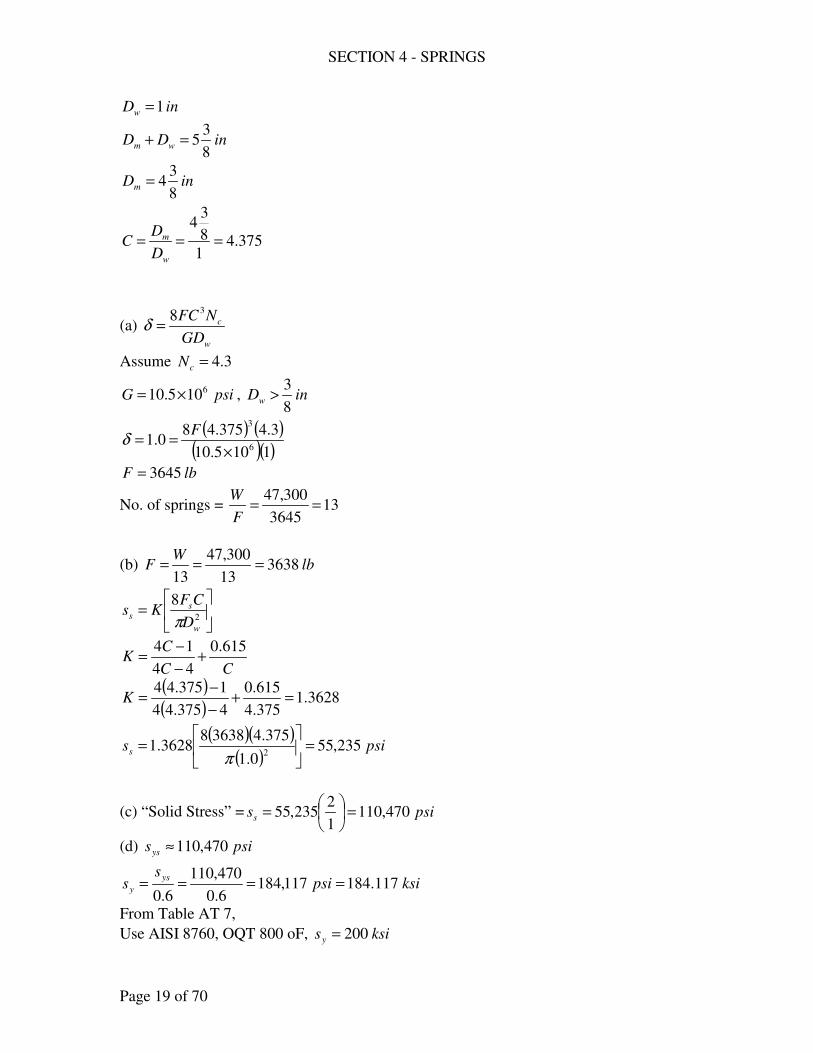
SECTION 4 - SPRINGS
Page 19 of 70
inDw 1=
inDD wm8
35=+
inDm8
34=
375.41
8
34
===w
m
D
DC
(a) w
c
GD
NFC38
=δ
Assume 3.4=cN
psiG 6105.10 ×= , inDw8
3>
( ) ( )( )( )1105.10
3.4375.480.1
6
3
×==
Fδ
lbF 3645=
No. of springs = 133645
300,47==
F
W
(b) lbW
F 363813
300,47
13===
=
2
8
w
ss
D
CFKs
π
CC
CK
615.0
44
14+
−
−=
( )( )
3628.1375.4
615.0
4375.44
1375.44=+
−
−=K
( )( )( )
psiss 235,550.1
375.4363883628.1
2=
=
π
(c) “Solid Stress” = psiss 470,1101
2235,55 =
=
(d) psisys 470,110≈
ksipsis
sys
y 117.184117,1846.0
470,110
6.0====
From Table AT 7,
Use AISI 8760, OQT 800 oF, ksisy 200=
SECTION 4 - SPRINGS
Page 20 of 70
VARYING STRESS APPROACH
DESIGN PROBLEMS
282. A spring, subjected to a load varying from 100 lb. to 250 lb., is to be made of oil-
tempered, cold-wound wire. Determine the diameter of the wire and the mean
diameter of the coil for a design factor of 1.25 based on Wahl’s line. The spring
index is to be at least 5. Conform to good practice, showing checks for all
significant parameters. Let the free length be between 6 and 8.
Solution:
lbF 250max =
lbF 100min =
( ) ( ) kiplbFFFm 175.01751002502
1
2
1minmax ==+=+=
( ) ( ) kiplbFFFa 075.0751002502
1
2
1minmax ==−=−=
Wahl’s line
no
as
ys
asms
s
s
s
ss
N
21+
−=
23
88
w
a
w
maas
D
CKF
D
DKFs
ππ==
23
88
wc
m
wc
mmms
DK
CKF
DK
DKFs
ππ==
5=C
CC
CK
615.0
44
14+
−
−=
( )( )
31.15
615.0
454
154=+
−
−=K
Fig. AF 15, 5=C
19.1=cK
For oil-tempered wire,
19.0
5.87
w
ysD
s =
, [ ]5.0032.0 << wD
1.0
47
w
noD
s =
, [ ]15.0041.0 << wD
34.0
30
w
noD
s =
, [ ]625.015.0 << wD
25.1=N

SECTION 4 - SPRINGS
Page 21 of 70
( )( )( )22
251.15075.031.18
ww
asDD
s ==π
( )( )( )
( ) 22
453.2
19.1
5175.031.18
ww
msDD
s ==π
say ksiD
sw
no 34.0
30=
no
as
ys
asms
s
s
s
ss
N
21+
−=
+
−
=
34.0
2
19.0
2
30
251.12
5.87
251.1453.2
25.1
1
w
w
w
w
D
D
D
D
66.181.1 99.11
1
8.72
1
25.1
1
ww DD+=
ininDw 15.02857.0 >=
Table AT 15, use No. 1, W & M
inDw 2830.0=
( ) inCDD wm 415.12830.05 ===
say inDm16
71=
Check for Free length
6 in < Free length < 8 in
Free length = inDm 75.516
7144 =
=
Increase mD
inDm2
11=
Free length = inDm 62
1144 =
= , o.k.
Summary of answer
inDw 2830.0=
inDm2
11=
283. A carbon-steel spring is to be subjected to a load that varies from 500 to 1200 lb.
The outside diameter should be between 3.5 and 4 in., the spring index between 5
to 10; approximate scale of 500 lb./in. Choose a steel and for a design factor of
1.4 by the Wahl line, find the wire diameter. Also determine the number of active
SECTION 4 - SPRINGS
Page 22 of 70
coils and the free length for squared-and-ground ends. Conform to the general
conditions specified in the Text.
Solution:
For carbon steel, Table AT 17
ksiD
sw
ys 1.0
91= , [ ]25.0093.0 << wD
ksiD
sw
no 15.0
49= , [ ]25.0093.0 << wD
lbF 1200max =
lbF 500min =
( ) ( ) kiplbFFFm 85.085050012002
1
2
1minmax ==+=+=
( ) ( ) kiplbFFFa 35.035050012002
1
2
1minmax ==−=−=
inOD 0.4~5.3=
10~5=C Wahl’s line
no
as
ys
asms
s
s
s
ss
N
21+
−=
Figure AF 15, 10~5=C
Assume 2.1=K , 125.1=cK
3
8
w
maas
D
DKFs
π=
3
8
wc
mmms
DK
DKFs
π=
inOD 75.3≈
wm DD −= 75.3
( )( )( ) ( )33
75.30695.175.335.02.18
w
w
w
was
D
D
D
Ds
−=
−=
π
( )( )( )( )
( )33
75.33088.2
125.1
75.385.02.18
w
w
w
wms
D
D
D
Ds
−=
−=
π
( ) ( )
−
+
−−
=
15.0
3
1.0
3
49
75.30695.12
91
75.30695.13088.2
4.1
1
w
w
w
w
w
w
D
D
D
D
D
D
85.29.2 9079.22
75.3
4285.73
75.3
4.1
1
w
w
w
w
D
D
D
D −+
−=
ininDw 25.06171.0 >=
Use
SECTION 4 - SPRINGS
Page 23 of 70
( )ksisys 53.104
25.0
911.0
==
( )ksisno 33.60
25.0
4915.0
==
( ) ( )
33.60
75.30695.12
53.104
75.30695.13088.2
4.1
133
−
+
−−
= w
w
w
w
D
D
D
D
33 205.28
75.3
346.84
75.3
4.1
1
w
w
w
w
D
D
D
D −+
−=
3137.21
75.3
4.1
1
w
w
D
D−=
inDw 5935.0=
use
inDw32
19=
inDD wm4
33≈+
inDm4
33
32
19=+
inDm32
53=
316.5
32
19
32
53
=
==w
m
D
DC
. o.k.
Wire Diameter inDw32
19= , Carbon Steel
Number of coils:
w
c
GD
NFC38
=δ
ksipsiG 500,10105.10 6 =×= , inDw8
3>
c
w
NC
GDk
F38
==δ
( )
( )cN
3
6
316.58
32
19105.10
500
×
=
4.10=cN
Table AT 16, square-and-ground ends
SECTION 4 - SPRINGS
Page 24 of 70
Free length = wc DPN 2+
Solid height = wcw DND 2+
Total Coils = 2+cN
Solid height = ( ) inDND wcw 3625.732
1924.102 =
+=+
ink
F4.2
500
1200===δ
Min. Free length = 2.4 + 7.3625 in = 9.7625 in
Use Free length = 10 in
To check for pitch angle.
Free length = wc DPN 2+
( ) 1032
1924.10 =
+P
inP 8474.0=
oo 12885.4
32
53
8474.0tantan 11 <=
== −−
ππ
λmD
P, o.k.
Solid stress:
indeflectionsolidT 6375.23625.710 =−==δ ( )( ) lbkF T 13196375.2500 === δ
CC
CK
615.0
44
14+
−
−=
( )( )
29.1316.5
615.0
4316.54
1316.54=+
−
−=K
( )( )( )ksisksipsi
D
KFDs ys
w
ms 53.104033.23033,23
32
19
32
53131929.18
833
=<==
==
ππ
284. A helical compression spring, made of oil-tempered, cold-wound carbon steel, is
to be subjected to a working load varying from 100 to 300 lb. for an indefinite
time (severe). A mean coil diameter of 2 in. should be satisfactory. (a) Using the
static approach, compute a wire diameter. (b) For this wire size, compute the
factor of safety as given by the Wahl line.
Solution:
SECTION 4 - SPRINGS
Page 25 of 70
Table AT 16,
For carbon steel,
ksiD
sw
u 1.0
182= , [ ]25.0093.0 << wD
Max. “solid” ksiD
sw
ys 1.0
91=
ksiD
sw
ys 1.0
91=
ksiD
sw
no 15.0
49= , [ ]25.0093.0 << wD
.2 inDm = lbF 300max =
lbF 100min =
(a) kiplbF 3.0300 ==
severe service, ( )( )
ksiDD
ssww
usd 1.01.0
866.47182263.0263.0 ===
=
2
8
w
ss
D
CFKs
π
CC
CK
615.0
44
14+
−
−=
w
m
D
DC =
CC
DD m
w
2==
( )( )1.03
2
866.47
2
23.08615.0
44
14
=
+
−
−=
CC
CC
Css
π
84.233615.0
44
14 9.2 =
+
−
−C
CC
C
075.6=C
ininDw 25.03292.0075.6
2>==
Therefore use ( )
ksissd 984.5425.0
866.471.0
==
SECTION 4 - SPRINGS
Page 26 of 70
( )( )984.54
2
23.08615.0
44
143
=
+
−
−=
C
CC
Css
π
9.287615.0
44
14 3 =
+
−
−C
CC
C
136.6=C
inDw 3259.0136.6
2==
say inDw64
21=
(b) ( )
ksisys 53.10425.0
911.0
==
( )ksisno 33.60
25.0
4915.0
==
( ) ( ) kiplbFFFm 2.02001003002
1
2
1minmax ==+=+=
( ) ( ) kiplbFFFa 1.01001003002
1
2
1minmax ==−=−=
095.6
64
21
2=
==
w
m
D
DC
Figure AF 15
15.1=cK
25.1=K
=
3
8
w
mm
c
msD
DF
K
Ks
π
( )( )ksisms 34.31
64
21
22.08
15.1
25.13
=
=
π
3
8
w
maas
D
DKFs
π=
SECTION 4 - SPRINGS
Page 27 of 70
( )( )ksisas 02.18
64
21
21.0825.1
3=
=
π
Wahl’s line
no
as
ys
asms
s
s
s
ss
N
21+
−=
( )
33.60
02.182
53.104
02.1834.311+
−=
N 38.1=N
285. A helical spring of hard-drawn wire with a mean diameter of 1 ½ in. and square-
and-ground ends is to be subjected to a maximum load of 325 lb. (a) Compute the
wire diameter for average service. (b) How many total coils are required if the
scale is 800 lb./in.? (c) For a minimum load of 100 lb., what is the factor of safety
according to Wahl line? Would it be safe for an indefinite life?
Solution:
Table AT 17,
Hard-drawn wire,
ksiD
sw
u 19.0
140= , [ ]625.0028.0 << wD
Maximum “solid” ksiD
ssw
yss 19.0
70==
( )( )ksi
Ds
w
no 1.0
479.0= , [ ]15.0041.0 << wD
( )( )ksi
Ds
w
no 34.0
309.0= , [ ]625.015.0 << wD
Average service
(a) ( ) ( )ksi
DDsss
ww
uusd 19.019.0
556.381402754.02754.0324.085.0 ====
kiplbF 325.0325 ==
inDm2
11=
=
3
8
w
ms
D
FDKs
π
SECTION 4 - SPRINGS
Page 28 of 70
CC
CK
615.0
44
14+
−
−=
CDw
5.1=
( )( )19.03
5.1
556.38
5.1
5.1325.08615.0
44
14
=
+
−
−=
CC
CC
Css
π
05.97615.0
44
14 81.2 =
+
−
−C
CC
C
586.4=C
ininC
Dw 625.03271.0586.4
5.15.1<===
inDw64
21=
(b) 57.4
64
21
5.1=
==
w
m
D
DC
( )( )
345.157.4
615.0
457.44
157.44=+
−
−=K
w
c
GD
NFC38
=δ
c
w
NC
GDk
F38
==δ
inkipinlbk 8.0800 ==
( )
cN357.84
64
21500,11
8.0
=
2.6=cN
(c) ksisys 5.86
64
21
7019.0
=
=
( )( )ksisno 44.39
64
21
309.019.0
=
= , inDw 15.0>
( ) kiplbFm 2125.05.2121003252
1==+=
SECTION 4 - SPRINGS
Page 29 of 70
( ) kiplbFa 1125.05.1121003252
1==−=
212.1=cK , Fig. AF 15
345.1=K
( )( )ksi
D
DF
K
Ks
w
mm
c
ms 5.25
64
21
5.12125.08
212.1
345.1833
=
=
=
ππ
( )( )ksi
D
DFKs
w
mmas 36.16
64
21
5.11125.08345.1
833
=
=
=
ππ
( )44.39
36.162
5.86
36.165.2521+
−=+
−=
no
as
ys
asms
s
s
s
ss
N
[ ]min15.107.1 NN <=
Not safe for indefinite life.
286. A helical spring is to be subjected to a maximum load of 200 lb. (a) Determine
the wire size suitable for medium service if the material is carbon steel ASTM
A230; 6=C . Determine the factor of safety of this spring according to the Wahl
line (b) If the minimum force is 150 lb., (c) if the minimum force is 100 lb., (d) if
the minimum force is 25 lb.
Solution:
For carbon steel ASTM A230
Table AT 17
ksiD
sw
u 1.0
182= , [ ]25.0093.0 << wD
ksiD
sw
ys 1.0
91= , [ ]25.0093.0 << wD
ksiD
sw
no 15.0
49= , [ ]25.0093.0 << wD
Medium Service
usd ss 324.0=
(a) psiD
ksiDD
swww
sd 1.01.01.0
968,58968.58182324.0 ==
=
SECTION 4 - SPRINGS
Page 30 of 70
=
3
8
w
ms
D
FDKs
π
CC
CK
615.0
44
14+
−
−=
( )( )
2525.16
615.0
464
164=+
−
−=K
lbF 200=
( )( )1.02
968,58620082525.1
ww
sDD
s =
=
π
inDw 2371.0=
Table At 15, use inDw 2437.0= , No. 3 W & M
ininDw 25.02437.0 <= , o.k.
Factor of safety.
( )ksiksiksi
Ds
w
ys 8.1042437.0
91911.01.0
===
( )ksiksiksi
Ds
w
no 56.602437.0
494915.0
===
(a) ( ) kiplbFm 175.01751502002
1==+=
( ) kiplbFa 025.0251502002
1==−=
Figure AF 15, 156.1=cK
( )( )( )
ksiD
CF
K
Ks
w
m
c
ms 8.482437.0
6175.08
156.1
2525.1822
=
=
=
ππ
( )( )( )
ksiD
CFKs
w
aas 1.8
2437.0
6025.082525.1
822
=
=
=
ππ
no
as
ys
asms
s
s
s
ss
N
21+
−=
( )56.60
1.82
8.104
1.88.481+
−=
N
525.1=N
(b) ( ) kiplbFm 15.01501002002
1==+=
( ) kiplbFa 05.0501002002
1==−=
SECTION 4 - SPRINGS
Page 31 of 70
Figure AF 15, 156.1=cK
( )( )( )
ksiD
CF
K
Ks
w
m
c
ms 8.412437.0
615.08
156.1
2525.1822
=
=
=
ππ
( )( )( )
ksiD
CFKs
w
aas 11.16
2437.0
605.082525.1
822
=
=
=
ππ
no
as
ys
asms
s
s
s
ss
N
21+
−=
( )56.60
11.162
8.104
11.168.411+
−=
N
287.1=N
(c) ( ) kiplbFm 1125.05.112252002
1==+=
( ) kiplbFa 0875.05.87252002
1==−=
Figure AF 15, 156.1=cK
( )( )( )
ksiD
CF
K
Ks
w
m
c
ms 36.312437.0
61125.08
156.1
2525.1822
=
=
=
ππ
( )( )( )
ksiD
CFKs
w
aas 2.28
2437.0
60875.082525.1
822
=
=
=
ππ
no
as
ys
asms
s
s
s
ss
N
21+
−=
( )56.60
20.282
8.104
20.2836.311+
−=
N
04.1=N
CHECK PROBLEMS
A Diesel valve spring is made of 3/8-in. chrome-vanadium steel wire, shot-peened; inside
diameter is 3 in., 7 active coils, free length is 7 3/8 in., solid length is 4 1/8 in., length
with valve closed, 6 ¼ in., length when open, 5 1/8 in. (a) Compute the spring constant
and the factor of safety as defined by the Wahl criterion (see § 6.13, Text). (b) Is there
any danger of damage to the spring if it is compressed solid? (c) What is the natural
frequency? If this spring is used on a 4-stroke Diesel engine at 450 rpm, is there any
danger of surge? Compute the change of stored energy between working lengths.
Solution:
For chrome-vanadium steel wire, shot-peened, Table AT 17

SECTION 4 - SPRINGS
Page 32 of 70
( )( )ksi
Ds
w
u 166.0
16825.1= , [ ]437.0032.0 << wD
( )( )ksi
Ds
w
ys 166.0
10025.1= , [ ]437.0032.0 << wD
( )( )ksi
Ds
w
no 15.0
4925.1= , [ ]5.0028.0 << wD
ininDw 375.08
3==
( )( )( )
ksiksisys 1.147375.0
10025.1166.0
==
( )( )( )
ksiksisno 96.70375.0
4925.115.0
==
(a) w
c
GD
NFC38
=δ
c
w
NC
GDk
F38
==δ
psiG 6105.11 ×=
7=cN
inDw 375.0=
inIDDD wm 3==−
inDm 375.3=
9375.0
375.3===
w
m
D
DC
nstantcospringk =
( )( )( ) ( )
inlbNC
GDk
c
w 64.105798
375.0105.11
83
6
3=
×==
in25.38
14
8
371 =−=δ
( )( ) lbkF 33.34325.364.10511 === δ
in125.14
16
8
372 =−=δ
( )( ) lbkF 85.118125.164.10522 === δ
( ) kiplbFm 231.009.23185.11833.3432
1==+=
( ) kiplbFa 11224.024.11285.11833.3432
1==−=
=
2
8
w
m
c
msD
CF
K
Ks
π

SECTION 4 - SPRINGS
Page 33 of 70
CC
CK
615.0
44
14+
−
−=
( )( )
162.19
615.0
494
194=+
−
−=K
Figure AF 15, 10.1=cK
( )( )( )
ksiD
CF
K
Ks
w
m
c
ms 8.39375.0
9231.08
10.1
162.1822
=
=
=
ππ
( )( )( )
ksiD
CFKs
w
aas 3.21
375.0
911224.08162.1
822
=
=
=
ππ
no
as
ys
asms
s
s
s
ss
N
21+
−=
( )96.70
3.212
1.147
3.218.391+
−=
N
377.1=N
(b) max. “solid” ksiss yss 1.147==
Min. Solid Height = ( )( ) inND cw 625.27375.0 ==
Solid deflection = .75.4625.28
37 in=−
( )( ) kiplbkF 5018.08.50175.464.105 ==== δ
Solid stress = ( )( )
( )ksiksi
D
FCKs
w
s 1.14795375.0
95018.08162.1
822
<=
=
=
ππ
There is no danger of damage
(c) Natural frequency
For steel
cpsDN
D
mc
w
2
050,14=φ
cpsDCN wc
2
050,14=φ
( )( ) ( )cpscps 66
375.097
050,142
==φ
For 450 rpm, cps4760
2450 =
=
πφ
124.147
66<= , there is danger of surging.
SECTION 4 - SPRINGS
Page 34 of 70
(d) ( ) ( ) ( ) ( )[ ] lbinkU s −=−=−= 491125.125.364.1052
1
2
1 222
2
2
1 δδ
289. A helical spring is hot wound from 5/8-in. carbon-steel wire with an outside
diameter of 3 ¼ in. A force of 3060 lb. is required to compress the spring 1 ¾
in to the solid heigh. In service the spring is compressed so that its
deformation varies form ½ in. to1 1/8 in. (a) What is the factor of safety by
the Wahl criterion? (b) Is the “solid stress” safe? Compute (c) the pitch angle,
(d) the change of stored energy between the working lengths, (e) the factor of
safety if the spring is peened?
Solution:
For hot-wound carbon steel wire
inDw8
5=
Table AT 17
ksiD
sw
ys 1.0
91= , [ ]25.0093.0 << wD
( )ksiksisys 5.104
25.0
911.0
== , .25.0 inDw >
ksiD
sw
no 15.0
49= , [ ]25.0093.0 << wD
( )ksiksisno 33.60
25.0
4915.0
== , .25.0 inDw >
Permissible solid stress = ksiD
sw
s 31.0
117= , [ ].375.0 inDw > § 6.3
( )ksiksiss 4.35
625.0
11731.0
==
(a) inlbF
k 6.174875.1
3060===
δ
( ) lbkF 3.8742
16.174811 =
== δ
( ) lbkF 2.19678
116.174822 =
== δ
( ) kiplbFm 4207.17.14203.8742.19672
1==+=
( ) kiplbFa 5464.04.5463.8742.19672
1==−=

SECTION 4 - SPRINGS
Page 35 of 70
ininDw 625.08
5==
inDD wm4
13=+
inDm 625.2=
2.4625.0
625.2===
w
m
D
DC
CC
CK
615.0
44
14+
−
−=
( )( )
3808.12.4
615.0
42.44
12.44=+
−
−=K
234.1=cK
( )( )( )
ksiD
CF
K
Ks
w
m
c
ms 5.43625.0
2.44207.18
234.1
3808.1822
=
=
=
ππ
( )( )( )
ksiD
CFKs
w
aas 7.20
625.0
2.45464.083808.1
822
=
=
=
ππ
no
as
ys
asms
s
s
s
ss
N
21+
−=
( )33.60
7.202
5.104
7.205.431+
−=
N
106.1=N
(b) Permissible solid stress = 135.4 ksi
kipF 060.3=
Solid stress, ( )( )
( )ksiksi
D
FCKs
w
s 4.1357.115625.0
2.4060.383808.1
822
<=
=
=
ππ, safe
(c) Solid deflection = in4
31
( ) inNDP cw 75.1=−
w
c
GD
NFC38
=δ
psiG 6105.10 ×= , hot-wound
c
w
NC
GDFk
38==
δ
SECTION 4 - SPRINGS
Page 36 of 70
( )( )( )
cN3
6
2.48
625.0105.106.1748
×=
332.6=cN
( )( ) 75.1332.6625.0 =−P
inP 9014.0=
Pitch angle
wm CD
P
D
P
ππλ ==tan
( )( )o24.6
625.02.4
9014.0tantan 11 =
== −−
ππλ
wCD
P
(d) ( ) ( ) ( ) ( )[ ] lbinkU s −=−=−= 8885.0125.16.17482
1
2
1 222
2
2
1 δδ
(e) When peened
( ) ksisys 6.1305.1045.12 ==
( ) ksisno 4.7533.6025.1 ==
( )4.75
7.202
6.130
7.205.431+
−=
N
38.1=N
ENERGY STORAGE
293. A 10-lb. body falls 10 in. and then strikes a helical spring. Design a hard-
drawn carbon steel spring that will absorb this shock occasionally without
permanent damage. Determine appropriate values of wire diameter, coil
diameter, pitch, free length, closed length, and the maximum stress under the
specified conditions, and scale. Let 7=C .
Solution:
For hard-drawn carbon steel, Table AT 17
ksiD
sw
u 1.0
182= , [ ]25.0093.0 << wD
Max. “solid” ksiD
sw
s 1.0
91= , [ ]25.0093.0 << wD
( )( ) ksiD
ssw
usd 1.0
855.36405.050.0 ==
GK
VsU s
s 2
2
4=
SECTION 4 - SPRINGS
Page 37 of 70
CC
CK
615.0
44
14+
−
−=
( )( )
213.17
615.0
474
174=+
−
−=K
( )cm
w NDD
V ππ
≈
4
2
4
22
cmw NDDV
π=
wm CDD =
4
32
cwNCDV
π=
w
c
GD
NFC38
=δ
( )δ+= hWU s
=
2
8
w
sD
FCKs
π
KC
DsF ws
8
2π=
=
w
cws
GD
NC
KC
Ds32 8
8
πδ
KG
NCDs cws
2πδ =
GK
NCDs
KG
NCDshWU
ccwss
ws
2
3222
16
ππ=
+=
KG
WCDs
GK
CDs
WhN
wsws
c 2
2
222
16
ππ−
=
when ksiD
sw
s 1.0
855.36=
( )KG
WCD
GK
CD
WhN
ww
c 29.0
2
8.222 855.36
16
855.36 ππ−
=
( )( )
( ) ( )( ) ( )
( ) ( )( )( )500,11213.1
010.07855.36
500,11213.116
7855.36
10010.029.0
2
8.222
wDD
N
w
cππ
−
=
9.08.2 004067.03466.0
10.0
wDD
Nw
c−
=
SECTION 4 - SPRINGS
Page 38 of 70
combination of wD and cN
Gage No. W & M wD cN cwND
12 0.1055 991.2 105
11 0.1205 312.1 37.6
10 0.1350 166.1 22.4
9 0.1483 108.0 16.0
8 0.1620 75.2 12.2
7 0.1770 53.7 9.5
6 0.1920 40.2 7.7
5 0.2070 31 6.4
4 0.2253 23.4 5.3
3 0.2437 18.1 4.4
Use ininDw 25.02437.0 <= , 1.18=cN
( ) ininDD wm64
4517059.12437.077 ====
( ) ( ) ( )( )( )
inKG
NCD
KG
NCDs ccws w 066.2500,11213.1
1.1872437.0855.36855.36 29.029.02
====πππ
δ
( )ksiss 44.42
2437.0
855.361.0
==
( )ksi
Ds
w
so 8.1042437.0
91911.01.0
===
Solid deflection
( ) in1.5066.244.42
8.104=
=
( ) 1.5=− cw NDP
( )( ) 1.51.182437.0 =−P
inP 5255.0=
say inP 53125.032
17==
Minimum Solid Height = ( )( ) inND cw 41.41.182437.0 ==
Assume squared and ground end
Solid height = ( )( ) ( ) inDND wcw 0.52437.021.182437.02 =+=+
Solid deflection = ( )( ) in2.51.182437.053125.0 =−
Free length = 5.0 in + 5.2 in = 10.2in
Summary of answer:
inDw 2437.0= , No. 3 W & M
SECTION 4 - SPRINGS
Page 39 of 70
inDm64
451=
inP32
17=
Free length = 10.2 in
Closed length = 5 in
Maximum stress = 42.44 ksi
294. A helical spring, of hard-drawn steel wire, is to absorb 75 in-lb of energy
without being stressed beyond the recommended value of average service. Let
6=C . Decide upon satisfactory dimensions; wD , mD , cN , free length, pitch
angle, solid stress, volume of metal, possibility of spring buckling.
Solution:
For hard-drawn steel wire, shock load, average service
ksiD
sw
u 19.0
140= , [ ]625.0028.0 << wD
Max. “solid” ksiD
sw
s 19.0
70= , [ ]625.0028.0 << wD
( )( )( ) ( )( )( ) ksiDD
ssww
usd 19.019.0
278.19140324.085.050.0324.085.050.0 =
==
GK
CNDs
GK
VsU cwss
s 2
322
2
2
164
π==
6=C
CC
CK
615.0
44
14+
−
−=
( )( )
2525.16
615.0
464
164=+
−
−=K
kipinlbinU s −=−= 075.075
( )( ) ( )500,112525.116
6278.19075.0
2
32
19.0
cw
w
s
ND
DU
π
==
cw ND62.29837.0 =
Table AT-15
W & M wD cN cwND
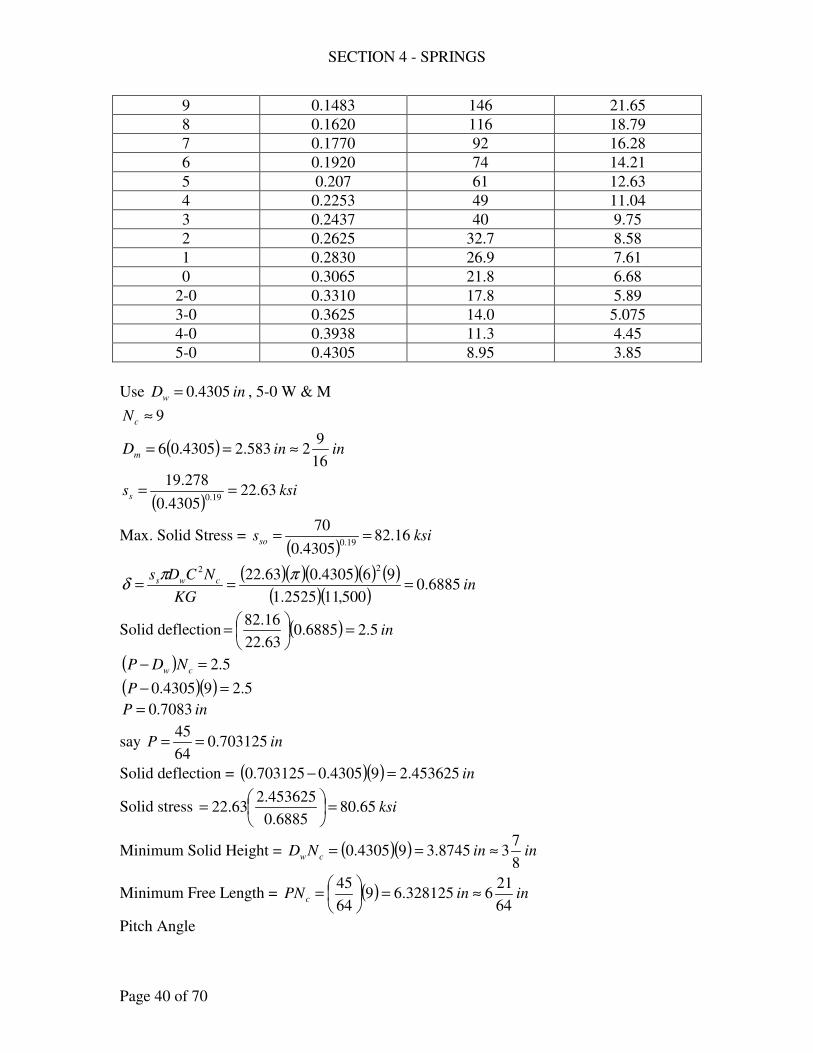
SECTION 4 - SPRINGS
Page 40 of 70
9 0.1483 146 21.65
8 0.1620 116 18.79
7 0.1770 92 16.28
6 0.1920 74 14.21
5 0.207 61 12.63
4 0.2253 49 11.04
3 0.2437 40 9.75
2 0.2625 32.7 8.58
1 0.2830 26.9 7.61
0 0.3065 21.8 6.68
2-0 0.3310 17.8 5.89
3-0 0.3625 14.0 5.075
4-0 0.3938 11.3 4.45
5-0 0.4305 8.95 3.85
Use inDw 4305.0= , 5-0 W & M
9≈cN
( ) ininDm16
92583.24305.06 ≈==
( )ksiss 63.22
4305.0
278.1919.0
==
Max. Solid Stress = ( )
ksisso 16.824305.0
7019.0
==
( )( )( )( ) ( )( )( )
inKG
NCDs cws 6885.0500,112525.1
964305.063.2222
===ππ
δ
Solid deflection ( ) in5.26885.063.22
16.82=
=
( ) 5.2=− cw NDP
( )( ) 5.294305.0 =−P
inP 7083.0=
say inP 703125.064
45==
Solid deflection = ( )( ) in453625.294305.0703125.0 =−
Solid stress ksi65.806885.0
453625.263.22 =
=
Minimum Solid Height = ( )( ) ininND cw8
738745.394305.0 ≈==
Minimum Free Length = ( ) ininPNc64
216328125.69
64
45≈=
=
Pitch Angle
SECTION 4 - SPRINGS
Page 41 of 70
oo 125
16
92
64
45
tantan 11 <=
== −−
ππ
λmD
P
Volume
( ) ( ) ( ) 3
22
55.10916
92
4
4305.0
4inND
DV cm
w =
=
≈ π
ππ
π
Summary of answer:
inDw 4305.0= , No. 5-0 W & M
inDm16
92=
9=cN
Free length = in64
216
Pitch Angle = o5=λ
Solid Stress = 80.65 ksi
Volume of metal = 10.55 in3
Possibility of spring buckling
447.2
16
92
64
216
<= , no possibility
CONCENTRIC HELICAL SPRINGS
297. Two concentric helical springs are to be subjected to a load that varies from a
maximum of 235 lb. to a maximum of 50 lb. They are to fit inside a 1 5/8 in.
cylinder. The maximum deflection is to be ¾ in., and the deflection when
compressed solid is to be approximately 1 in. Using the “static approach” for
severe service (maximum load), determine the wire diameter, mean coil
diameter, number of coils, solid length, and free length of both springs. (Start
with oil-tempered wire and assume a diametral clearance between the outer
spring and the cylinder of 2
wD, assume a similar clearance between springs.
Search for a suitable spring index and wire size.)
Solution:
For oil-tempered wire
Table AT 17
SECTION 4 - SPRINGS
Page 42 of 70
ksiD
sw
u 19.0
146= , [ ]5.0032.0 << wD
Max. “solid” ksiD
sw
s 19.0
5.87= , [ ]5.0032.0 << wD
Severe service
( )ksi
DDss
ww
usd 19.019.0
398.38146263.0263.0 ===
kiplbF 235.0235 ==
io δδ =
wi
iii
wo
cooo
GD
NCF
GD
NCF33 88
=
Assume, io CC =
co
woo
NC
GDF
332
3=
ci
wii
NC
GDF
332
3=
=
2
8
wo
oso
D
CFKs
π
=
2
8
wi
isi
D
CFKs
π
wi
mi
wo
mo
D
D
D
DC ==
CC
CK
615.0
44
14+
−
−=
wimiwi
womo DDD
DD +=−−2
wiwomimo DDDD 5.1+=−
womowo DD
D+=−
2625.1
625.15.1 =+ womo DD
625.15.1 =+ wowo DCD
5.1
625.1
+=
CDwo
5.1
625.1
+=
C
CDmo
wiwowiwo DDCDCD 5.1+=−
( ) ( ) wiwo DCDC 5.11 +=−
SECTION 4 - SPRINGS
Page 43 of 70
( )( )2
5.1
1625.1
+
−=
C
CDwi
( )( )2
5.1
1625.1
+
−=
C
CCDmi
ksiDD
CFKs
wowo
oso 19.02
398.388=
=
π
KC
DF wo
o
81.108.15=
ksiDD
CFKs
wiwi
isi 19.02
398.388=
=
π
KC
DF wi
i
81.108.15=
kipFFF io 235.0==+
235.008.1508.15 81.181.1
=+KC
D
KC
D wiwo
KCDD wiwo 235.008.1508.15 81.181.1 =+
( )KC
C
C
C235.0
5.1
1625.108.15
5.1
625.108.15
81.181.1
=
+
−+
+
( )( )
( )C
CC
C
C
C
C
+
−
−=
+
−+
+
615.0
44
14235.0
5.1
1
5.1
152.154
62.3
81.1
81.1
328.5=C
( )( )
inDwi 1509.05.1328.5
1328.5625.12
=+
−=
inDwo 2380.05.1328.5
625.1=
+=
Table AT 15, use inDwi 1620.0= , No. 8 W & M and inDwo 2625.0= , No. 2 W & M
( )( ) ininCDD womo32
1313986.12625.0328.5 ≈===
( )( ) ininCDD wimi8
78631.01620.0328.5 ≈===
401.51620.0
8
7
=
==wi
mii
D
DC
357.52625.0
32
131
=
==wo
moo
D
DC
SECTION 4 - SPRINGS
Page 44 of 70
oo
woo
CK
DF
81.108.15=
( )( )
287.1357.5
615.0
1357.54
1357.54=+
−
−=oK
( )( )( )
kipFo 194.0357.5287.1
2625.008.1581.1
==
ii
wii
CK
DF
81.108.15=
( )( )
2843.1401.5
615.0
1401.54
1401.54=+
−
−=iK
( )( )( )
kipFi 081.0401.52843.1
1620.008.15==
kipkipFF io 235.0275.0071.0194.0 >=+=+ , ok
co
woo
NC
GDF
332
3=
( )( )( )
coN3
357.532
2625.0500,113194.0 =
5.9=coN
ci
wii
NC
GDF
332
3=
( )( )( )
ciN3
401.532
1620.0500,113071.0 =
6.15=ciN
Max. solid stress, ksiD
sw
ss 19.0
5.87= ,
( )ksissso 82.112
2625.0
5.8719.0
==
( )ksisssi 65.123
1620.0
5.8719.0
==
Stress
( )ksissi 26.54
1620.0
398.3819.0
==
( )ksisso 51.49
2625.0
398.3819.0
==
Solid stress
ksiksisso 82.11201.6675.0
151.49 <=
=
SECTION 4 - SPRINGS
Page 45 of 70
ksiksissi 65.12335.7275.0
126.54 <=
=
Solid length
( )( ) inND cowo 5.25.92625.0 ==
( )( ) inND ciwi 53.26.151620.0 ==
assume solid length = 3 in
( ) ( )( ) inxxND iiciwi 36.151620.0 =+=+
92.2=ix
Total coils = 15.6 + 2.92 = 18.52
( ) ( )( ) inxxND oocowo 35.92625.0 =+=+
93.1=ox
Total coils = 9.5 + 1.93 = 11.43
Free Length = 3 in + 1 in = 4 in
Summary of answer:
Outside wire.
inDwo 2625.0= , No. 2 W & M
inDmo32
131=
43.11=toN
Solid length = 3 in
Free length = 4 in
Inside wire.
inDwi 1620.0= , No. 8 W & M
inDmi8
7=
52.18=tiN
Solid length = 3 in
Free length = 4 in
298. Two concentric, helical compression springs are used on a freight car. The
larger spring has an outside diameter of 7 in., a free length of 7 1/8 in., and is
made of a 1 ¾ in. steel bar. The smaller has an outside diameter of 4 1/8 in., a
free length of 6 13/16 in. , and is made of 7/8 in. steel bar. The solid height of
each spring is 5 ¼ in. and the forces required to compress them solid are
15,530 lb. and 7,000 lb., respectively. The working load on the two springs is
11,350 lb. Determine (a) the number of free coils in each spring, (b) the stress
in each spring when compressed solid, (c) the stresses induced by the working
SECTION 4 - SPRINGS
Page 46 of 70
load. Notice that the outer spring deflects 5/16 in. before the inner one takes a
load. (d) What energy is absorbed while changing deflection from that at the
working load to that when the springs are compressed “solid”?
Solution:
inODo 7=
inDwo8
31=
inFLo8
17=
inODi8
14=
inDwi8
7=
inFLi16
136=
(a) Solid height = inND Tw4
15=
82.3375.1
25.5==ToN
6875.0
25.5==TiN
(b) lbFo 530,15=
lbFi 7000=
=
2
8
w
sD
FCKs
π
inDmo 625.58
317 =−=
091.4375.1
625.5===
wo
moo
D
DC
( )( )
393.1091.4
615.0
4091.44
1091.44=+
−
−=oK
inDmi 25.38
7
8
14 =−=
714.3875.0
25.3===
wi
mii
D
DC
( )( )
442.1714.3
615.0
4714.34
1714.34=+
−
−=iK
SECTION 4 - SPRINGS
Page 47 of 70
Solid stress
( )( )( )
psisso 203,119375.1
091.4530,158393.1
2=
=
π
( )( )( )
psissi 689,124875.0
714.370008442.1
2=
=
π
(b) Stresses induced by working load
lbFF oi 350,11=+
inlbko 8283
4
15
8
17
530,15=
−
=
inlbko 4480
4
15
16
136
7000=
−
=
inio 3125.016
5==−δδ
iiii kF δδ 4480==
( )iooo kF δδ +== 3125.08283
( ) lbkFF iioooi 350,113125.082834480 =++==+ δδδ
ini 6865.0=δ
ino 9990.06865.03125.0 =+=δ
( )( ) lbFi 30766865.04480 ==
( )( ) lbFo 82759990.08283 ==
Stresses
( )( )( )
psisso 516,63375.1
091.482758393.1
2=
=
π
( )( )( )
psissi 792,54875.0
714.330768442.1
2=
=
π
(d) Energy
( )2
1
2
22
1oooso kU δδ −=
ino 875.14
15
8
172 =−=δ
ino 9990.01 =δ
( ) ( ) ( )[ ] lbinU so −=−= 427,10999.0875.182832
1 22
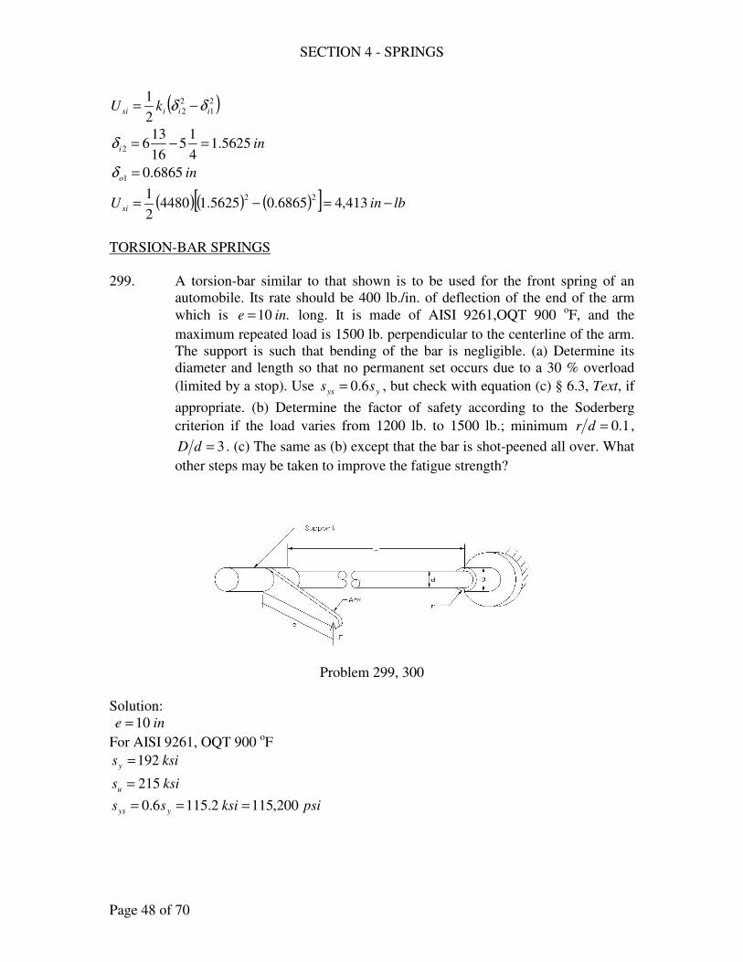
SECTION 4 - SPRINGS
Page 48 of 70
( )2
1
2
22
1iiisi kU δδ −=
ini 5625.14
15
16
1362 =−=δ
ino 6865.01 =δ
( ) ( ) ( )[ ] lbinU si −=−= 413,46865.05625.144802
1 22
TORSION-BAR SPRINGS
299. A torsion-bar similar to that shown is to be used for the front spring of an
automobile. Its rate should be 400 lb./in. of deflection of the end of the arm
which is .10 ine = long. It is made of AISI 9261,OQT 900 oF, and the
maximum repeated load is 1500 lb. perpendicular to the centerline of the arm.
The support is such that bending of the bar is negligible. (a) Determine its
diameter and length so that no permanent set occurs due to a 30 % overload
(limited by a stop). Use yys ss 6.0= , but check with equation (c) § 6.3, Text, if
appropriate. (b) Determine the factor of safety according to the Soderberg
criterion if the load varies from 1200 lb. to 1500 lb.; minimum 1.0=dr ,
3=dD . (c) The same as (b) except that the bar is shot-peened all over. What
other steps may be taken to improve the fatigue strength?
Problem 299, 300
Solution:
ine 10=
For AISI 9261, OQT 900 oF
ksisy 192=
ksisu 215=
psiksiss yys 200,1152.1156.0 ===
SECTION 4 - SPRINGS
Page 49 of 70
(a) 3
16
d
Tss
π=
( )( )( ) lbinFeT −=== 500,191015003.1
( )3
500,1916200,115
dπ=
ind 95.0=
use ind 1=
§ 6.3 ( ) ys
w
s sksiD
s ≈=== 1171
1171173.03.0
(b) Soderberg Criterion
ns
asf
ys
ms
s
sK
s
s
N+=
1
( )( )( ) ksisns 5.642155.06.0 ==
Figure AF 12, 1.0=dr , 3=dD
45.1=tK
45.1=≈ tf KK
( ) lbFm 1350120015002
1=+=
( )( ) kipsinlbinTm −=−== 5.13500,13101350
( )( )
ksisms 8.681
5.13163
==π
( ) lbFa 150120015002
1=−=
( )( ) kipsinlbinTa −=−== 5.1150010150
( )( )
ksisas 64.71
5.1163
==π
( )( )5.64
64.745.1
2.115
8.681+=
N
30.1=N
(c) Shot-peened
( ) ksisys 1442.11525.1 ==
( ) ksisns 6.805.6425.1 ==
( )( )6.80
64.745.1
144
8.681+=
N
625.1=N
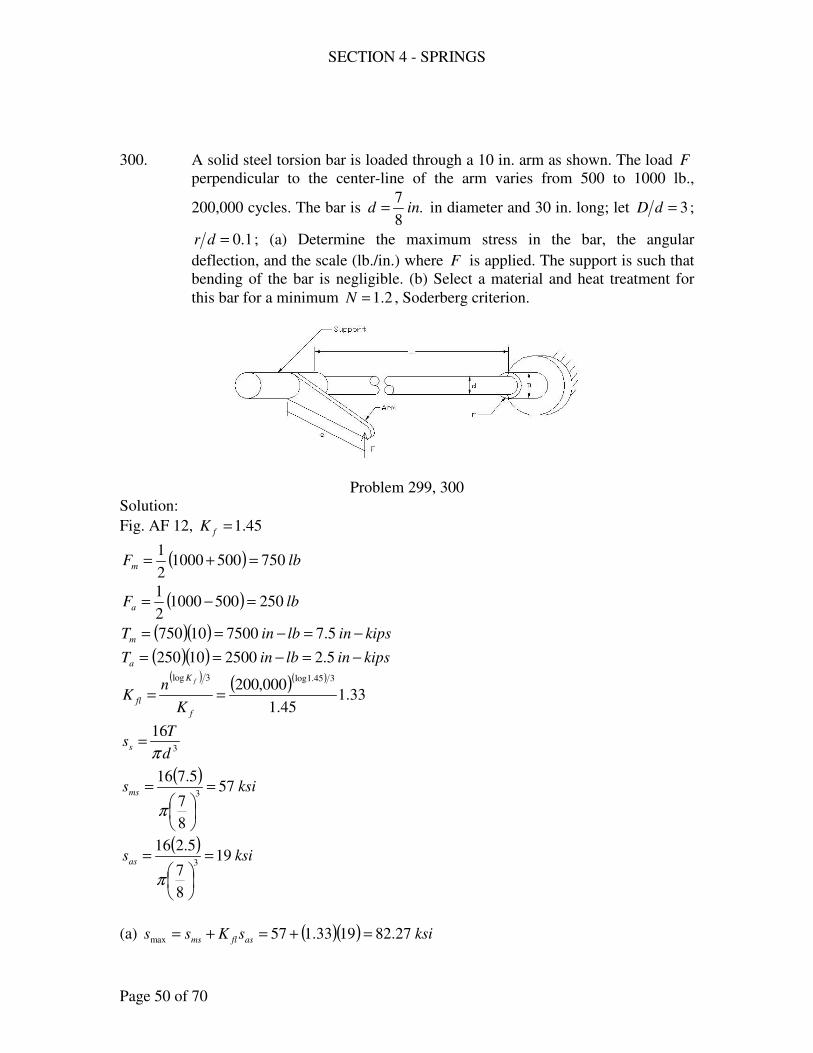
SECTION 4 - SPRINGS
Page 50 of 70
300. A solid steel torsion bar is loaded through a 10 in. arm as shown. The load F
perpendicular to the center-line of the arm varies from 500 to 1000 lb.,
200,000 cycles. The bar is .8
7ind = in diameter and 30 in. long; let 3=dD ;
1.0=dr ; (a) Determine the maximum stress in the bar, the angular
deflection, and the scale (lb./in.) where F is applied. The support is such that
bending of the bar is negligible. (b) Select a material and heat treatment for
this bar for a minimum 2.1=N , Soderberg criterion.
Problem 299, 300
Solution:
Fig. AF 12, 45.1=fK
( ) lbFm 75050010002
1=+=
( ) lbFa 25050010002
1=−=
( )( ) kipsinlbinTm −=−== 5.7750010750
( )( ) kipsinlbinTa −=−== 5.2250010250
( ) ( )( )
33.145.1
000,200345.1log3log
==f
K
flK
nK
f
3
16
d
Tss
π=
( )ksisms 57
8
7
5.7163
=
=
π
( )ksisas 19
8
7
5.2163
=
=
π
(a) ( )( ) ksisKss asflms 27.821933.157max =+=+=
SECTION 4 - SPRINGS
Page 51 of 70
Gd
TL
JG
TL4
64
πθ ==
( )( )( )
( )rad4533.0
105.118
7
301050064min
6
4=
×
=
π
θ
( )( )( )
( )rad9066.0
105.118
7
3010100064max
6
4=
×
=
π
θ
( )( )inlb
e
Fscale 3.110
109066.0
1000===
θ
(c) ns
asf
ys
ms
s
sK
s
s
N+=
1
( )( )uuns sss 344.0
000,200
105.06.0
085.06
=
=
yys ss 6.0=
( )( )
uy ss 344.0
1933.1
6.0
57
2.1
1+=
Use AISI 8760, OQT 800 oF
ksisy 200=
ksisu 220=
24.1=N
HELICAL SPRINGS – NON CIRCULAR SECTION
301. A spring is to be designed of square oil-tempered steel wire and subjected to a
repeated maximum load of 325 lb.; mean coil diameter, 1 ½ in.; deflection,
13/32 in. Determine (a) the wire size for average service, (b) the required
number of active coils, (c) the solid height, free length, and pitch (the ends are
squared and ground, the “solid stress” must be satisfactory, and the pitch angle
not excessive). (d) What amount of energy is stored when the load is 325 lb.?
Express in in-lb. and Btu.
Solution:
For oil-tempered wire,
19.0
146
w
uD
s = , [ ]5.0032.0 << wD
Max. “solid” us ss 6.0=
SECTION 4 - SPRINGS
Page 52 of 70
(a) average service,
wDb = , bt =
( )322
4.2
2
8.13
b
FDK
tb
tbFDKs m
q
mq
s =+
=
usd ss 324.0= , average service
( )19.03
146324.0
2
4.2
bb
FDK m
q =
kipF 325.0=
inDm2
11=
25.1=qK (assumed)
( )( ) ( )19.03
146324.05.1325.04.225.1
bb=
inb 2902.0=
Table AT 15, use inb 313.0= , # 1 wire size
8.4313.0
5.1===
b
DC m
Figure AF 15, 275.1=qK
(b) ( ) 4
3
3
3
44.0
45.2
56.0
45.2
Gb
NFD
tbGt
NFD cmcm =−
=δ
( )( )( )( )4
3
313.0500,1144.0
5.1325.045.2
32
13 cN=
34.7=cN
(c) Solid height = ( ) ( ) inNb c 92.2234.7313.02 =+=+
Free length = bPNc 2+
lbF 325.0=
( )( )( )
ksib
FDKs m
qs 65.48313.0
5.1325.04.2275.1
4.233
=
=
=
solid stress = ( )
( )ksi2.109
313.0
1466.019.0
==
solid deflection = in91.032
13
65.48
2.109=
=
( ) 91.0=− cNbP
( )( ) 91.034.7313.0 =−P
inP 437.0=
SECTION 4 - SPRINGS
Page 53 of 70
use inP16
7=
Free length = ( ) ( ) ininbPNc32
273837.3313.0234.7
16
72 ≈=+
=+
( )5.1
16
7
tanππ
λ
==mD
P
oo 103.5 <=λ
(d) ( ) lbinkipinFkU s −=−=
=== 66066.0
32
13325.0
2
1
2
1
2
1 2 δδ
BtuU s 085.0778
66==
302. A coil spring, of hard-drawn carbon steel, is to deflect 1 in. under a load of
100 lb. The outside coil diameter is to be 1 in. Compute the number of active
coils, (a) if the wire is round, 5/32 in. in diameter, (b) if the wire is square,
5/32 in. on the side, (c) if the wire is rectangular 1/8 x 3/16 in., long
dimension parallel to the axis, (d) If the wire is rectangular 3/16 x 1/8 in.,
short dimension parallel to the axis. (e) What is the maximum stress in each of
the above springs under the 100-lb load? (f) What is the ratio of the
approximate volumes, square- or rectangular-wire to round wire spring?
Solution:
inDD wm 1=+
(a) inDw32
5=
inDm32
27
32
51 =−=
4.5
32
5
32
27
=
==w
m
D
DC
w
c
GD
NFC38
=δ
( )( )
( )
×
=
32
5105.11
4.510081
6
3
cN
3.14=cN
SECTION 4 - SPRINGS
Page 54 of 70
(b) Square, inb32
5=
inDm32
27
32
51 =−=
4
3
44.0
45.2
Gb
NFD cm
=δ
( )
( )4
6
3
32
5105.1144.0
32
2710045.2
1
×
=cN
5.20=cN
(c) inb16
3= , int
8
1=
intDm8
7
8
111 =−=−=
( )tbGt
NFD cm
56.0
45.23
3
−=δ
( )
( )
−
×
=
8
156.0
16
3
8
1105.11
8
710045.2
13
6
3
cN
1.16=cN
(d) inb8
1= , int
16
3=
intDm16
13
16
311 =−=−=
( )tbGt
NFD cm
56.0
45.23
3
−=δ
( )
( )
−
×
=
16
356.0
8
1
16
3105.11
16
1310045.2
13
6
3
cN
5.11=cN
(e) Maximum Stress
SECTION 4 - SPRINGS
Page 55 of 70
For (a) 3
8
w
sD
FCKs
π=
( )( )
284.14.5
615.0
44.54
14.54=+
−
−=K
( )( )psiss 320,72
32
5
4.51008284.1
3=
=
π
For (b) ( )
322
4.2
2
8.13
b
FDK
tb
tbFDKs m
qm
qs =+
=
4.5
32
5
32
27
=
==b
DC m
25.1=qK
( )psiss 355,66
32
5
32
271004.2
25.13
=
=
For (c) ( )
222
8.13
tb
tbFDKs m
qs
+=
7
8
1
8
7
=
==t
DC m
1.1=qK
( )psiss 992,68
8
18.1
16
33
8
1
16
32
8
7100
1.122
=
+
=
For (d) ( )
222
8.13
tb
tbFDKs m
qs
+=
33.4
16
3
16
13
=
==t
DC m
SECTION 4 - SPRINGS
Page 56 of 70
2.1=qK
( )psiss 232,63
16
38.1
8
13
16
3
8
12
16
13100
2.122
=
+
=
(e) Ratio of the approximate volumes
For (a) Round wire
( ) cmwa NDDV ππ
= 2
4
( ) 3
2
727.03.1432
27
32
5
4inVa =
= π
π
For (b) Square wire
( ) cmb NDbV π2=
( ) 3
2
327.15.2032
27
32
5inVb =
= π
For (c) rectangular wire
( ) cmc NDbtV π=
( ) 3037.11.168
7
8
1
16
3inVc =
= π
For (d) rectangular wire
( ) cmd NDbtV π=
( ) 3688.05.1116
13
16
3
8
1inVd =
= π
Ratio of volume
Square to round wire
825.1727.0
327.1===
a
b
V
V
Rectangular to round wire (long dimension parallel to the axis)
426.1727.0
037.1===
a
c
V
V
Rectangular to round wire (short dimension parallel to the axis)
946.0727.0
688.0===
a
d
V
V
SECTION 4 - SPRINGS
Page 57 of 70
TENSION SPRINGS
305. Design two tension springs for a spring balance with a capacity of 200 lb.
Each spring supports a maximum load of 100 lb. The outside diameter must
not exceed 1 ¼ in. and the total length including end loops must not exceed 9
½ in. Select a material and determine the dimension, including wire diameter,
number of coils, and free length.
Solution:
Table AT 17, assume oil tempered wire
ksiD
sw
u 19.0
146=
ksiD
sw
ys 19.0
5.87=
( )ksi
DDs
ww
sd 19.019.0
705.878.0== , [ ]5.0032.0 << wD
δkFF i +=
3
8
w
mcs
D
FDKs
π=
w
m
w
m
D
D
D
rC ==
2
w
ca
DG
NCF38
=δ
NC
DGk w
38=
a
w
caw FGD
NCF
NC
DGk =
=
3
3
8
8δ
kiplbFa 10.0100 ==
Figure AF 15, assume 2.1=cK
33
88
w
mac
w
mics
D
DFK
D
DFKs
ππ+=
2
8
w
acics
D
CFKsKs
π+=
inDDOD wm 25.1=+=
1
25.1
+=
CDw
§ 6.21, assume ksisi 18=
ssd ss =
SECTION 4 - SPRINGS
Page 58 of 70
( )( ) ( )( )219.0
1.02.18182.1
70
ww D
C
D π+=
( )( )
( )( ) ( )( )2
2
19.0
19.0
25.1
11.02.186.21
25.1
170
π
++=
+ CCC
( ) ( )219.011956.06.2111.67 ++=+ CCC
( ) ( ) 6.2111956.011.67219.0
=+−+ CCC
7.6=C
inC
Dw 1623.017.6
25.1
1
25.1=
+=
+=
Table AT 15, use inDw 1620.0= , 8 W & M
( )( ) inCDD wm 085.11620.07.6 ===
say inDm 0.1=
17.61620.0
0.1===
w
m
D
DC
ksisi 7.17=
To check, Fig. AF 15, 15.1=cK
( ) ( )( )( )( )
ksiss 20.891620.0
17.610.015.187.1715.1
2=+=
π
( )ksiksissd 20.8992.98
1620.0
7019.0
>== , o.k.
Total length = ( )wmcw DDND ++ 2
( ) ( )162.00.12162.05.9 ++= cN
coilsNc 3.44=
Free length = ( )( ) inND cw 18.73.441620.0 ==
Summary of answer:
Material, oil-tempered wire
inDw 1620.0= , 8 W & M
coilsNc 3.44=
Free length = 7.18 in.
306. Two helical tension springs are to be used in scales for weighing milk. The
capacity of the scales is 30 lb., each spring carries 15 lb. with a deflection of 3
9/16 in. The springs are made of No. 14, W & M steel wire, outside diameter,
29/32 in. (a) how many coils should each spring have? (b) What is the
maximum stress in the wire? What material should be used?
SECTION 4 - SPRINGS
Page 59 of 70
Solution:
lbk 15=δ
in16
93=δ
(a) Table AT 15, No. 14 W &M
inDw 0800.0=
inDODD wm 82625.00800.032
29=−=−=
328.100800.0
82625.0===
w
m
D
DC
( )
w
c
GD
NCk38 δ
δ =
( )( )( )( )080.0105.11
328.10158
16
93
6
3
×= cN
8.24=cN
(b) δkFF i +=
m
wii
D
DsF
8
3π=
§ 6.21, 328.10=C
psisi 272,11=
( )( )( )
lbFi 743.282625.08
08.0272,113
==π
lbF 743.1715743.2 =+=
Figure AF 15, 09.1=cK
( )( )( )( )
psiD
FDKs
w
mcs 476,79
080.0
82625.0743.1709.18833
===ππ
ksipsis
s sys 345.99345,99
8.0
476,79
8.0===≈
Table AT 17, use Hard drawn wire
( )ksiksi
Ds
w
ys 345.99113080.0
707019.019.0
>===
307. A tension spring for a gas-control lever is made of inDw 078.0= steel wire;
inside diameter, 0.609 in.; number of coils, 55; free length including end
loops, 5 9/16 in. When the spring is extended to a length of 6 5/16 in., it must
exert a force 5 ½ lb.; it must extend to (a) the initial tension, (b) the stress in
the spring caused by the initial tension (compare with the recommended
SECTION 4 - SPRINGS
Page 60 of 70
maximum values), (c) the stress caused by the 5 ½-lb load, (d) the maximum
stress. What material should be used? (e) What energy is absorbed from the
point where the load is the initial tension until the spring’s length is 6 5/16 in.?
(Data courtesy Worthington Corporation.)
Solution:
inDw 078.0=
inDD wm 609.0=−
inDm 687.0078.0609.0 =+=
8.8078.0
687.0===
w
m
D
DC
55=cN
w
c
GD
NFC38
=δ
lbF2
15=
in75.016
95
16
56 =−=δ
( )( ) ( )( )( )078.0105.11
58.8875.0
6
3
×==
δδ
k
lbk 244.2=δ
(a) lbkFFi 256.3244.25.5 =−=−= δ
(b) ( )( )
( )psi
D
CFs
w
ii 000,12
078.0
8.8256.38822
===ππ
§ 6.21, 8.8=C
psipsisi 000,12300,13 >= , ok
(c) lbF 5.5=
2
8
w
cs
D
FCKs
π=
8.8=C
Figure AF 15
1.1=cK
( )( )( )( )
psiss 284,22078.0
8.85.51.182
==π
(d) maximum stress
inlbk
k 992.275.0
244.2===
δ
δ
SECTION 4 - SPRINGS
Page 61 of 70
δ ′= kF
in75.316
95
16
59 =−=′δ
( )( ) lbkFF i 476.1475.3992.2256.3 =+=′+= δ
( )( )( )( )
psiD
FCKs
w
cs 651,58
078.0
8.8476.141.18822
===ππ
Table AT 16
ksipsis
s sys 3.73300,73
8.0
651,58
8.0===≈
Table AT 17, use Hard drawn wire
( )ksiksi
Ds
w
ys 3.73658.113078.0
707019.019.0
>===
(e) ( )( ) lbinkU s −=== 8415.075.0992.22
1
2
1 22δ
TORSION SPRINGS
308. A carbon-steel (ASTM A230) torsion spring is to resist a force of 55 lb. at a
radius of 2 in.; the mean diameter is to be 2 ½ in. Compute (a) the diameter of
the wire for average service, (b) the number of coils for a deflection of 180o
under the given torque, (c) the energy the spring has absorbed when the force
is 55 lb.
Solution:
FaMT ==
lbF 55=
ina 2=
( )( ) lbinMT −=== 110255
inDm 5.2=
Table AT 17, ksiD
sw
u 1.0
182= , [ ]25.0093.0 << wD
Average service
( )( ) psiD
ksiDD
sswww
ud 1.01.01.0
936,117936.117182648.0405.06.1 ==
==
(a) I
KMcss =
For round wire, assume 08.1== cic KK , Table AT 18
2
wDc =
SECTION 4 - SPRINGS
Page 62 of 70
32
3
wD
c
I π=
( )( )( )1.03
936,1173211008.1
ww
sDD
s ==π
ininDw 25.02060.0 <=
Table AT 15, use inDw 2070.0= , No. 5 W & M
To check: 966.92070.0
2>===
w
m
D
D
c
r, ok
Table AT 18, 08.1=K
( )( )( )( )
psiss 430,1362070.0
3211008.13
==π
( )psipsissd 430,136054,138
2070.0
936,1171.0
>==
Therefore, use No. 5 W & M, inDw 2070.0=
(b) EI
NDM cmπθ =
psiE 61030×=
64
4
wDI
π=
πθ == o180
4
64
w
cm
ED
NMD=θ
( )( )( )( )46 2070.01030
211064
×= cN
π
29.12=cN
(c) ( )( ) lbinTU s −=== 8.1721102
1
2
1πθ
312. A pivoted roller follower is held in contact with the cam by a torsion spring.
The moment exerted by the spring varies from 20 lb-in to 50 lb-in. as the
follower oscillates through 30o. The spring is made of AISI 6152 steel, OQT
1000 oF. What should be the value of wD , mD , and cN if the factor of safety
is 1.75 based on the Soderberg line? Would this be a conservative or risky
approach?
Solution:
AISI 6152, OQT 1000 oF
ksisu 184=
SECTION 4 - SPRINGS
Page 63 of 70
ksisy 173=
ksiss un 925.0 ==
( ) inlbM m −=+= 3520502
1
( ) inlbM a −=−= 1520502
1
assume 08.1=K
( )( )psi
DDD
KMs
www
mm 333
3853508.13232===
ππ
( )( )psi
DDD
KMs
www
aa 333
1651508.13232===
ππ
n
a
y
m
s
s
s
s
N+=
1
33 000,92
165
000,173
385
75.1
1
ww DD+=
inDw 1916.0=
Table AT 15, use inDw 1920.0= , No. 6 W & M
To solve for K
( )( )
psiKK
sm 369,501920.0
35323
==π
( )( )
psiKK
sa 587,211920.0
15323
==π
000,92
587,20
000,173
369,50
75.1
1 KK+=
0868.1=K
Table AT 18 0868.1== KKci
932.9 >==w
m
D
D
c
r, ok
( ) inDm 7894.11920.032.9 ==
use ininDm 875.18
71 ==
4
64
w
cmcm
ED
NMD
EI
NDM ∆=
∆=∆
πθ
( )( )( )( )46 1920.01030
875.1205064
180
30
×
−= cNπ
93.5=cN
Summary of answer:
inDw 1920.0= , No. 6 W & M
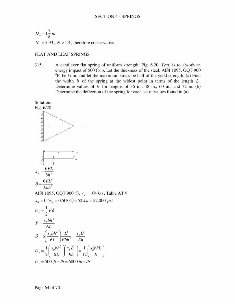
SECTION 4 - SPRINGS
Page 64 of 70
inDm8
71=
93.5=cN , 4.1>N , therefore conservative.
FLAT AND LEAF SPRINGS
315. A cantilever flat spring of uniform strength, Fig. 6.20, Text, is to absorb an
energy impact of 500 ft-lb. Let the thickness of the steel, AISI 1095, OQT 900 oF, be ½ in. and let the maximum stress be half of the yield strength. (a) Find
the width b of the spring at the widest point in terms of the length L .
Determine values of b for lengths of 36 in., 48 in., 60 in., and 72 in. (b)
Determine the deflection of the spring for each set of values found in (a).
Solution.
Fig. 6/20
2
6
bh
FLsB =
3
36
Ebh
FL=δ
AISI 1095, OQT 900 oF, ksisy 104= , Table AT 9
( ) psiksiss yB 000,52521045.05.0 ====
δFU s2
1=
L
bhsF B
6
2
=
Eh
Ls
Ebh
L
L
bhs BB
2
3
32
66 =
=δ
=
=
E
bhLs
Eh
Ls
L
bhsU BBB
s
222
12
1
62
1
lbinlbftU s −=−= 6000500

SECTION 4 - SPRINGS
Page 65 of 70
( )
6
2
1030
2
1000,52
12
16000
×
=
Lb
21598 inbL =
L
inb
21598=
inL 36= , inin
inb 4.44
36
1598 2
==
inL 48= , inin
inb 3.33
48
1598 2
==
inL 60= , inin
inb 6.26
60
1598 2
==
inL 72= , inin
inb 2.22
72
1598 2
==
(b) Eh
LsB
2
=δ
inL 36= , ( )( )
( )in4928.4
2
11030
36000,52
6
2
=
×
=δ
inL 48= , ( )( )
( )in9872.7
2
11030
48000,52
6
2
=
×
=δ
inL 60= , ( )( )
( )in48.12
2
11030
60000,52
6
2
=
×
=δ
inL 72= , ( )( )
( )in9712.17
2
11030
72000,52
6
2
=
×
=δ
317. One of the carbon contacts on a circuit breaker is mounted on the free end of
a phosphor-bronze beam ( 35.0=µ ). This beam has the shape of the beam
shown in Fig. 6.24, Text, with .1 inb = , .16
9inb =′ , .
2
14 inL = , and .
16
1inh =
When the contacts are closed, the beam deflects ¾ in. Compute (a) the force
on the contacts, (b) the maximum stress.
Solution:
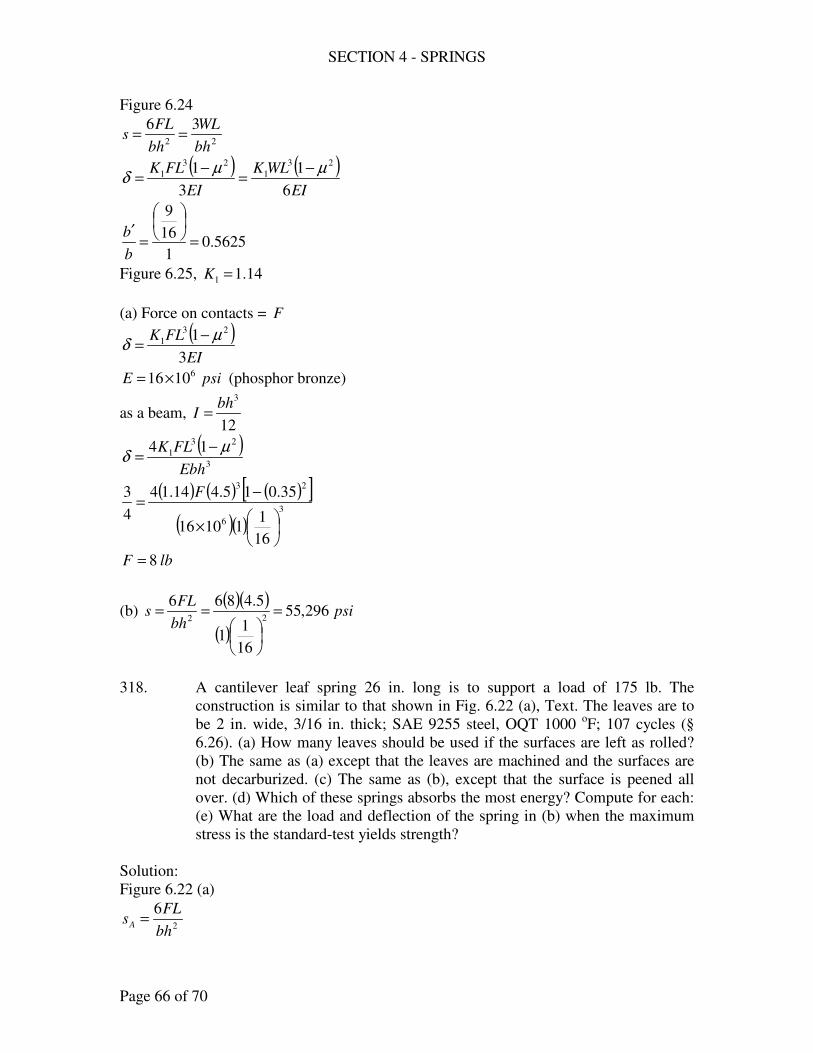
SECTION 4 - SPRINGS
Page 66 of 70
Figure 6.24
22
36
bh
WL
bh
FLs ==
( ) ( )EI
WLK
EI
FLK
6
1
3
1 23
1
23
1 µµδ
−=
−=
5625.01
16
9
=
=′
b
b
Figure 6.25, 14.11 =K
(a) Force on contacts = F
( )EI
FLK
3
1 23
1 µδ
−=
psiE 61016×= (phosphor bronze)
as a beam, 12
3bh
I =
( )3
23
1 14
Ebh
FLK µδ
−=
( ) ( ) ( )[ ]( )( )
3
6
23
16
111016
35.015.414.14
4
3
×
−=
F
lbF 8=
(b) ( )( )
( )psi
bh
FLs 296,55
16
11
5.486622
=
==
318. A cantilever leaf spring 26 in. long is to support a load of 175 lb. The
construction is similar to that shown in Fig. 6.22 (a), Text. The leaves are to
be 2 in. wide, 3/16 in. thick; SAE 9255 steel, OQT 1000 oF; 107 cycles (§
6.26). (a) How many leaves should be used if the surfaces are left as rolled?
(b) The same as (a) except that the leaves are machined and the surfaces are
not decarburized. (c) The same as (b), except that the surface is peened all
over. (d) Which of these springs absorbs the most energy? Compute for each:
(e) What are the load and deflection of the spring in (b) when the maximum
stress is the standard-test yields strength?
Solution:
Figure 6.22 (a)
2
6
bh
FLsA =
SECTION 4 - SPRINGS
Page 67 of 70
3
36
Ebh
FLA =δ
bNb ′= 1
lbF 175=
inb 2=′
inh16
3=
inL 26=
§ 6.26, SAE 9255, OQT 1000 oF
ksisu 180=
ksisy 160=
inint 1875.016
3==
ksisd 75.83=
(a) As rolled, Figure AF 5
Surface factor = 0.275
( ) psiksisd 000,232375.83275.0 ===
2
6
bh
FLsA =
( )( )
( )2
116
32
261756000,23
=
N
88.161 =N
say 171 =N
(b) Machined, Figure AF 5
Surface factor = 0.75
( ) psiksisd 800,628.6275.8375.0 ===
2
6
bh
FLsA =
( )( )
( )2
116
32
261756800,62
=
N
2.61 =N
say 71 =N
(c) Peened surface, (b)
SECTION 4 - SPRINGS
Page 68 of 70
( ) psiksisd 500,785.788.6225.1 ===
2
6
bh
FLsA =
( )( )
( )2
116
32
261756500,78
=
N
95.41 =N
say 51 =N
(d) δFU s2
1=
lbF 175=
3
1
36
hbEN
FL
′=δ
For (a) 171 =N
( )( )
( )( )( )in745.2
16
32171030
2617563
6
3
=
×
=δ
( )( ) lbinU s −== 240745.21752
1
For (b) 71 =N
( )( )
( )( )( )in666.6
16
3271030
2617563
6
3
=
×
=δ
( )( ) lbinU s −== 583666.61752
1
For (c) 51 =N
( )( )
( )( )( )in332.9
16
3251030
2617563
6
3
=
×
=δ
( )( ) lbinU s −== 817332.91752
1
answer – spring (c)
(e) ksiss yd 160== , 71 =N (b)
SECTION 4 - SPRINGS
Page 69 of 70
2
1
2
66
hbN
FL
bh
FLsd ′
==
( )
( )( )2
16
327
266000,160
=
F
load lbF 505=
( )( )
( )( )( )in24.19
16
3271030
2650563
6
3
=
×
=δ
319. The rear spring of an automobile has 9 leaves, each with an average thickness
of 0.242 in. and a width of 2 in.; material is SAE 9261, OQT 1000 oF. The
length of the spring is 56 in. and the total weight on the spring is 1300 lb.
Assume the spring to have the form shown in Fig. 6.22 (b), Text. Determine
(a) the rate of the spring, (b) the maximum stress caused by the dead weight.
(c) What approximate repeated maximum force (0 to maxF ) would cause
impending fatigue in 105 cycles, the number of applications of the maximum
load expected during the ordinary life of a car? (If the leaves are cold rolled
to induce a residual compressive stress on the surfaces, the endurance limit as
2us should be conservative.)
Solution:
Figure 6.22 (b)
22
3
bh
FLsA =
3
3
8
3
Ebh
FLA =δ
lbF 1300=
inh 242.0=
91 =N
inb 2=′
inL 56=
(a) Rate , 3
3
3
8
L
EbhFk
A
==δ
( )( )( )( )( )
inlbL
hbENk 21.116
563
242.02910308
3
83
36
3
3
1 =×
=′
=
(b) ( )( )
( )( )( )psi
hbN
FLsA 590,103
242.0292
5613003
2
322
1
==′
=
SECTION 4 - SPRINGS
Page 70 of 70
(c) SAE 9261. OQT 1000 oF
ksisu 192=
ksisn 962
192==
2
12
3
hbN
FLsA ′
=
( )( )( )( )2
242.0292
563000,96
F=
lbF 1200=
321. The front spring of an automobile is made similar to Fig. 6.23, Text. The
average thickness for each of the 6 leaves, 0.213 in.; material is SAE 9255,
OQT 1000 oF. The load caused by the weight of the car is 775 lb. (a) What
stress is caused by a force of twice the dead weight? (b) What load would
stress the spring to the yield strength?
Solution:
Figure 6.23
2
1
22
336
hbN
WL
bh
WL
bh
FLs
′===
lbW 775= , 61 =N , inb 2=′ , inh 213.0=
inin
L 182
36==
(a) ( ) lbW 15507752 ==
( )( )( )( )( )
psis 740,153213.026
18155032
==
(b) SAE 9255, OQT 1000 oF
ksisy 160=
2
1
22
336
hbN
WL
bh
WL
bh
FLs
′===
( )( )( )( )2
213.026
183000,160
W=
lbW 1613=
- end -
SECTION 5 – COLUMNS
Page 1 of 18
DESIGN PROBLEMS
334. A round steel rod made of structural steel, AISI C1020, as rolled, is to be used as
a column, centrally loaded with 10 kips; 3=N . Determine the diameter for (a)
.25 inL = , (b) .50 inL = (c) The same as (a) and (b) except that the material is
AISI 8640, OQT 1000 F. Is there any advantage in using this material rather than
structural steel?
Solution:
For AISI C1020,as rolled
ksis y 48=
kipsF 10=
3=N
(a) .25 inLLe ==
Consider first J.B. Johnson
−==E
k
Ls
AsNFF
ey
yc 2
2
41
π
4
2D
Aπ
=
4
Dk =
ksiE 31030×=
( )( ) ( )
( )
( )
×
−
=
32
2
2
10304
4
2548
14
48103π
πD
D
−=
22
2 411230
DD
ππ
ππ
481230 2 −= D
inD 096.1=
say ininD 0625.116
11 ==
SECTION 5 – COLUMNS
Page 2 of 18
∴<=
= 12094
4
0625.1
25
k
Le o.k.
(b) .50 inLLe ==
Consider Euler’s Equation
2
2
==
k
L
EANFF
e
c
π
( )( )( )
2
232
4
50
41030
103
×
=
D
Dππ
431875.030 Dπ=
inD 507.1=
say ininD 5.12
11 ==
∴>=
= 120133
4
5.1
50
k
Le o.k.
(c) For AISI 8640, OQT 1000 F
ksisy 150=
2
1
22
=
y
e
s
E
k
L π
( )83.62
150
10302 2
132
=
×=
π
k
Le
For (a) .25 inLLe ==
Consider first J.B. Johnson
−==E
k
Ls
AsNFF
ey
yc 2
2
41
π
SECTION 5 – COLUMNS
Page 3 of 18
( )( ) ( )
( )
( )
×
−
=
32
2
2
10304
4
25150
14
150103π
πD
D
−=
22
2 5.1215.3730
DD
ππ
ππ
75.4685.3730 2 −= D
inD 23.1=
say inD 25.1=
∴>=
= 83.6280
4
25.1
25
k
Le use Euler’s equation
2
2
==
k
L
EANFF
e
c
π
( )( )( )
2
232
4
25
41030
103
×
=
D
Dππ
4375.030 Dπ=
inD 0657.1=
say ininD 0625.116
11 ==
∴>=
= 83.6294
4
0625.1
25
k
Le ok
For (b) .50 inLLe ==
Consider Euler’s Equation
2
2
==
k
L
EANFF
e
c
π
SECTION 5 – COLUMNS
Page 4 of 18
( )( )( )
2
232
4
50
41030
103
×
=
D
Dππ
431875.030 Dπ=
inD 507.1=
say ininD 5.12
11 ==
∴>=
= 83.62133
4
5.1
50
k
Le o.k.
There is no advantage.
335. A hollow circular column, made of AISI C1020, structural steel, as rolled, is to
support a load of 10,000 lb. Let inL 40= , oi DD 75.0= , and 3=N . Determine
oD by (a) using either Euler’s or the parabolic equation; (b) using the straight-
line equation. (c) What factor of safety is given by the secant formula for the
dimensions found in (a)?
Solution:
For AISI C1020, as rolled
ksisy 48=
inLLe 40==
kipslbF 10000,10 ==
3=N
oi DD 75.0=
A
Ik =
( ) ( )[ ] 44444
033556.075.064
oooio DDD
DDI =−=
−= π
π
( ) ( )[ ] 2
2222
343612.04
75.0
4o
ooio DDDDD
A =−
=−
=ππ
o
o
o DD
Dk 3125.0
343612.0
033556.02
4
==
SECTION 5 – COLUMNS
Page 5 of 18
(a) Consider parabolic equation
−==E
k
Ls
AsNFF
ey
yc 2
2
41
π
( )( ) ( )( )
( )
( )
×
−=32
2
2
10304
4
3125.0
2548
1343612.048103π
o
o
D
D
9519.10493376.1630 2 −= oD
inDo 576.1=
say ininDo 5625.116
91 ==
( )∴<== 12082
5625.13125.0
40
k
Le o.k.
(b) Straight-line equation
k
L
A
F70000,16 −=
−=
oo DD 3125.0
4070000,16
343612.0
000,102
oo DD 30785498000,10 2 −=
inDo 6574.1=
say ininDo 625.18
51 ==
( )∴<== 1208.78
625.13125.0
40
k
Le o.k.
(c) Secant formula
+=
EA
NF
k
L
k
ec
A
NFs e
y2
sec12
inDo 5625.1=
inDk o 4883.03125.0 == 22 8389.0343612.0 inDA o ==
SECTION 5 – COLUMNS
Page 6 of 18
25.02
=k
ec, (i7.8)
( )( ) ( )( )
×+=
8389.01030
10
4883.02
40sec25.01
8389.0
1048
3
NN
( )[ ]NN 81645.0sec25.0192.1148 +=
289.2=N
336. A column is to be built up of ½-in., AISI C1020, rolled-steel plates, into a square
box-section. It is 6 ft long and centrally loaded to 80,000 lb. (a) Determine the
size of section for 74.2=N . (b) Compute N from the secant formula for the
size found and compare with 2.74.
Solution:
For AISI C1020, rolled-steel plate
ksisy 48=
( ) ( )12
1
12
1
12
4444 −−=
−−=
bbbbI
( )22 1−−= bbA
( )( )[ ]22
44
112
1
−−
−−==
bb
bb
A
Ik
inftLLe 726 ===
kipslbF 80000,80 ==
(a) 74.2=N
Consider J.B. Johnson
−=E
k
Ls
AsNF
ey
y 2
2
41
π
( )( ) ( )( )
( )
×
−=32
2
10304
7248
1488074.2π
kA
2
085.10482.219
k
AA −=
SECTION 5 – COLUMNS
Page 7 of 18
try inb 23.3=
( ) ( )( ) ( )[ ] ink 1331.1
123.323.312
123.323.322
44
=−−
−−=
( ) ( ) ( ) 22222 46.5123.323.31 inbbA =−−=−−=
( ) ( )( )
2.2191331.1
46.5085.1046.5482.219
2=−= ok
Therefore use inb 23.3=
∴<== 12054.631331.1
72
k
Le o.k.
inb 23.3= or inb4
13=
(b)
+=
EA
NF
k
L
k
ec
A
NFs e
y2
sec12
25.02
=k
ec, (i7.8)
( )( ) ( )( )
×+=
46.51030
80
1331.12
72sec25.01
46.5
8048
3
NN
( )[ ]NN 70214.0sec25.01652.1448 +=
74.22.2 <=N
337. A column is to be made of ½-in structural steel plates (AISI 1020, as rolled),
welded into an I-section as shown in Table AT 1 with HG = . The column, 15 ft
long, is to support a load of 125 kips. (a) Determine the cross-sectional
dimensions from the straight-line equation. (Using either Johnson’s or Euler’s
equation, compute the equivalent stress and the factor of safety. (c) Compute N
from the secant formula.
Solution:
For AISI C1020, as rolled
ksisy 48=
inftLLe 18015 ===
kipsF 125=

SECTION 5 – COLUMNS
Page 8 of 18
Table AT 1.
HG =
( )( ) ( ) ( )135.05.05.15.05.115.0 222 −=−=+−−=−−−=−= HHHHHHHHghGHA
( )( )( )
( )( )( )136
15.0
135.0
15.0
12
1
12
1343433
−
−−−=
−
−−−=
−
−=
H
HHH
H
HHH
ghGH
ghGHk
(a) Straight-line equation
−=
k
LAF 0044.01000,16
( )
−=
kA
1800044.01000,16000,125
−=
kA
792.018125.7
use inH 37.7=
( ) ( )( )( )( )
ink 04527.3137.736
137.75.037.737.734
=−
−−−=
( )[ ] inA 555.10137.735.0 =−=
81.704527.3
792.01555.108125.7 =
−≈
Therefore use inH 37.7=
Or ininH 375.78
37 ==
(b) Consider J.B. Johnson, 1205904527.3
180<==
k
Le
N
ss
y
e =
( )
( )
ksi
E
k
Ls
A
Fs
ey
e 8.13
10304
04527.3
18048
1555.10
125
41
32
2
2
2=
×
−
=
−
=
ππ
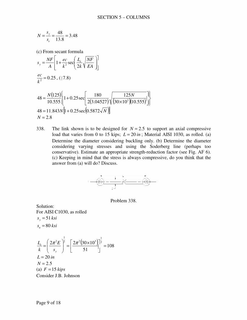
SECTION 5 – COLUMNS
Page 9 of 18
48.38.13
48===
e
y
s
sN
(c) From secant formula
+=
EA
NF
k
L
k
ec
A
NFs e
y2
sec12
25.02
=k
ec, (i7.8)
( )( ) ( )( )
×+=
555.101030
125
04527.32
180sec25.01
555.10
12548
3
NN
( )[ ]NN 5872.0sec25.01843.1148 +=
8.2=N
338. The link shown is to be designed for 5.2=N to support an axial compressive
load that varies from 0 to 15 kips; inL 20= ; Material AISI 1030, as rolled. (a)
Determine the diameter considering buckling only. (b) Determine the diameter
considering varying stresses and using the Soderberg line (perhaps too
conservative). Estimate an appropriate strength-reduction factor (see Fig. AF 6).
(c) Keeping in mind that the stress is always compressive, do you think that the
answer from (a) will do? Discuss.
Problem 338.
Solution:
For AISI C1030, as rolled
ksisy 51=
ksisu 80=
( )108
51
103022 2
1322
1
2
=
×=
=
ππ
y
e
s
E
k
L
inL 20=
5.2=N
(a) kipsF 15=
Consider J.B. Johnson
SECTION 5 – COLUMNS
Page 10 of 18
−=E
k
Ls
AsNF
ey
y 2
2
41
π
4
Dk =
4
2D
Aπ
=
inLLe 20==
( )( ) ( )
( )
( )
×
−
=
32
2
2
10304
4
2051
14
51155.2π
πD
D
−=
22
2 72.2175.125.37
DD
ππ
ππ
68.3475.125.37 2 −= D
inD 101.1=
say ininD 1875.116
31 ==
∴<== 10868
4
1875.1
20
k
Le o.k.
(b) Variable stresses
( ) ksiss un 40805.05.0 ===
Size factor = 0.85
( ) ksisn 344085.0 ==
8.2=fK (Figure AF 6)
n
af
y
m
s
sK
s
s
N+=
1
F = 0 to 15 kips
kipsFF am 5.7==
eaem ss =
( )34
8.2
515.2
1 emem ss+=
ksisem 923.3=
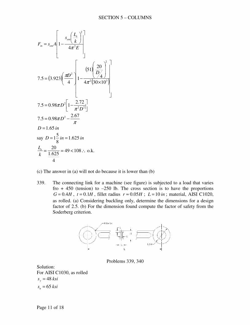
SECTION 5 – COLUMNS
Page 11 of 18
−=E
k
Ls
AsF
eem
emm 2
2
41
π
( )
( )
( )
×
−
=
32
2
2
10304
4
2051
14
923.35.7π
πD
D
−=
22
2 72.2198.05.7
DD
ππ
ππ
67.298.05.7 2 −= D
inD 65.1=
say ininD 625.18
51 ==
∴<== 10849
4
625.1
20
k
Le o.k.
(c) The answer in (a) will not do because it is lower than (b)
339. The connecting link for a machine (see figure) is subjected to a load that varies
fro + 450 (tension) to –250 lb. The cross section is to have the proportions
HG 4.0= , Ht 1.0= , fillet radius Hr 05.0≈ ; inL 10= ; material, AISI C1020,
as rolled. (a) Considering buckling only, determine the dimensions for a design
factor of 2.5. (b) For the dimension found compute the factor of safety from the
Soderberg criterion.
Problems 339, 340
Solution:
For AISI C1030, as rolled
ksisy 48=
ksisu 65=
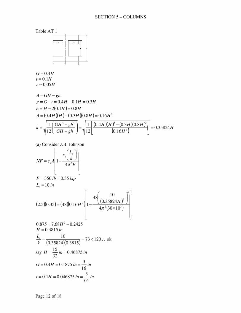
SECTION 5 – COLUMNS
Page 12 of 18
Table AT 1
HG 4.0=
Ht 1.0=
Hr 05.0≈
ghGHA −=
HHHtGg 3.01.04.0 =−=−=
( ) HHHh 8.01.02 =−=
( )( ) ( )( ) 216.08.03.04.0 HHHHHA =−=
( )( ) ( )( )( )
HH
HHHH
ghGH
ghGHk 35824.0
16.0
8.03.04.0
12
1
12
12
3333
=
−=
−
−=
(a) Consider J.B. Johnson
−=E
k
Ls
AsNF
ey
y 2
2
41
π
kiplbF 35.0350 ==
inLe 10=
( )( ) ( )( ) ( )( )
×
−=32
2
2
2
10304
35824.0
1048
116.04835.05.2π
HH
2425.068.7875.0 2 −= H
inH 3815.0=
( )( )∴<== 12073
3815.035824.0
10
k
Le ok
say ininH 46875.032
15==
ininHG16
31875.04.0 ===
ininHt64
3046875.01.0 ===
SECTION 5 – COLUMNS
Page 13 of 18
(b) with inH 46875.0=
( ) 220352.046875.016.0 inA ==
( ) ink 1679.046875.035824.0 ==
( )
ksipsi
E
k
Ls
A
F
ss
ey
e 6.11600,11
10304
1679.0
1048
1
0352.0
350
41
32
2
2
2
min
min −=−=
×
−
−
=
−
==
ππ
psipsiA
Fs 8.12800,12
0352.0
450maxmax +=+=
+==
( ) ksism 6.06.118.122
1=−=
( ) ksisa 1.126.118.122
1=+=
( ) ksiss nu 5.32655.05.0 ===
Size factor = 0.85
( ) ksiksisu 62.275.3285.0 ==
Figure AF 9, ( ) 023.046875.005.005.0 === Hr
( ) inHh 7031.046875.0.155.1 ===
inHd 4688.0==
05.005.0
==H
H
d
r
5.15.1
==H
H
d
h
65.2=tK
70.0
023.0
01.01
1
01.01
1=
+
=
+
=
r
q
( ) 2.21165.270.0 =+−=fK
n
qf
y
m
s
sK
s
s
N+=
1
( )( )62.27
1.122.2
48
6.01+=
N
024.1=N
CHECK PROBLEMS
341. The link shown is subjected to an axial compressive load of 15 kips. Made of
AISI C1030, as rolled, it has sectional length of 20 in. Assume a loose fit with the
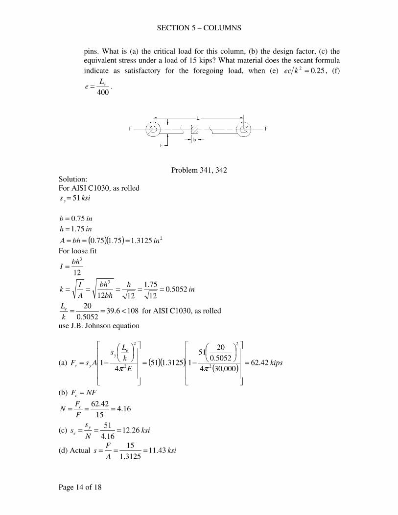
SECTION 5 – COLUMNS
Page 14 of 18
pins. What is (a) the critical load for this column, (b) the design factor, (c) the
equivalent stress under a load of 15 kips? What material does the secant formula
indicate as satisfactory for the foregoing load, when (e) 25.02 =kec , (f)
400
eLe = .
Problem 341, 342
Solution:
For AISI C1030, as rolled
ksis y 51=
inb 75.0=
inh 75.1=
( )( ) 23125.175.175.0 inbhA ===
For loose fit
12
3bh
I =
inh
bh
bh
A
Ik 5052.0
12
75.1
1212
3
=====
1086.395052.0
20<==
k
Le for AISI C1030, as rolled
use J.B. Johnson equation
(a) ( )( )( )
kipsE
k
Ls
AsF
ey
yc 42.62000,304
5052.0
2051
13125.1514
12
2
2
2
=
−=
−=ππ
(b) NFFc =
16.415
42.62===
F
FN c
(c) ksiN
ss
y
e 26.1216.4
51===
(d) Actual ksiA
Fs 43.11
3125.1
15===
SECTION 5 – COLUMNS
Page 15 of 18
Secant Formula
+=
EA
NF
k
L
k
ec
A
NFs e
y2
sec12
(e) 25.02
=k
ec
( ) ( )( )ksisy 4.64
3125.11030
42.62
5052.02
20sec25.01
3125.1
42.623
=
×+=
use AISI C1020, cold drawn, ksisy 66=
(f) inL
e e 05.0400
20
400===
inh
c 875.02
75.1
2===
( )( )( )
1714.05052.0
875.005.022
==k
ec
( ) ( )( )ksisy 12.59
3125.11030
42.62
5052.02
20sec1714.01
3125.1
42.623
=
×+=
use AISI C1045, cold drawn, ksisy 59=
343. A schedule-40, 4-in. pipe is used as a column. Some of its properties are:
inDo 5.4= , inDi 026.4= , ..174.3 insqI = , ftL 15= ; material equivalent to
AISI C1015, as rolled. The total load to be carried is 200 kips. (a) What
minimum number of these columns should be used if a design factor of 2.5 is
desired and the load evenly distributed among them? For the approximately fixed
ends, use LLe 65.0= as recommended by AISC. (b) What is the equivalent stress
in the column?
Solution:
For AISI C1015, as rolled
ksis y 5.45=
( )114
5.45
103022 2
1322
1
2
=
×=
=
ππ
y
e
s
E
k
L
inftL 18015 ==
( ) inLLe 11718065.065.0 ===
1145.77509.1
117<==
k
Le
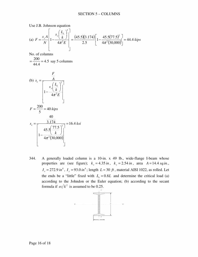
SECTION 5 – COLUMNS
Page 16 of 18
Use J.B. Johnson equation
(a) ( )( ) ( )
( )kips
E
k
Ls
N
AsF
ey
y4.44
000,304
5.775.451
5.2
174.35.45
41
2
2
2
2
=
−=
−=ππ
No. of columns
5.44.44
200== say 5 columns
(b)
−
=
E
k
Ls
A
F
s
ey
e
2
2
41
π
kipsF 405
200==
( )
ksi
k
se 4.16
000,304
5.775.45
1
174.3
40
2
2=
−
=
π
344. A generally loaded column is a 10-in. x 49 lb., wide-flange I-beam whose
properties are (see figure); inkx 35.4= , ink y 54.2= , area ..4.14 insqA = ,
49.272 inI x = , 40.93 inI y = ; length ftL 30= , material AISI 1022, as rolled. Let
the ends be a “little” fixed with LLe 8.0= and determine the critical load (a)
according to the Johndon or the Euler equation; (b) according to the secant
formula if 2kec is assumed to be 0.25.
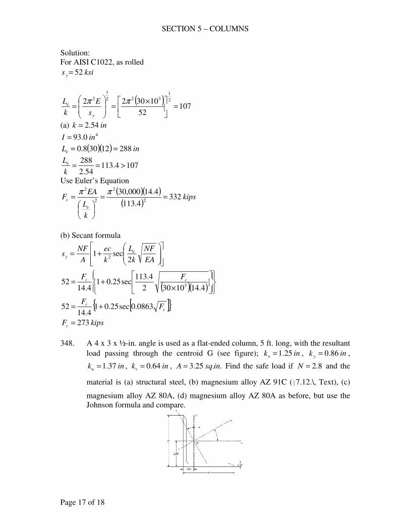
SECTION 5 – COLUMNS
Page 17 of 18
Solution:
For AISI C1022, as rolled
ksis y 52=
( )107
52
103022 2
1322
1
2
=
×=
=
ππ
y
e
s
E
k
L
(a) ink 54.2= 40.93 inI =
( )( ) inLe 28812308.0 ==
1074.11354.2
288>==
k
Le
Use Euler’s Equation
( )( )( )
kips
k
L
EAF
e
c 3324.113
4.14000,302
2
2
2
==
=
ππ
(b) Secant formula
+=
EA
NF
k
L
k
ec
A
NFs e
y2
sec12
( )( )
×+=
4.1410302
4.113sec25.01
4.1452
3
cc FF
[ ]{ }cc F
F0863.0sec25.01
4.1452 +=
kipsFc 273=
348. A 4 x 3 x ½-in. angle is used as a flat-ended column, 5 ft. long, with the resultant
load passing through the centroid G (see figure); inkx 25.1= , ink y 86.0= ,
inku 37.1= , inkv 64.0= , ..25.3 insqA = Find the safe load if 8.2=N and the
material is (a) structural steel, (b) magnesium alloy AZ 91C (i7.12.\, Text), (c)
magnesium alloy AZ 80A, (d) magnesium alloy AZ 80A as before, but use the
Johnson formula and compare.
SECTION 5 – COLUMNS
Page 18 of 18
Solution:
( )( )in
LLe 30
2
125
2===
inkk 64.0min ==
875.4664.0
30==
k
Le
(a) Structural steel, ksisy 48=
120875.46 <=k
Le
use J.B. Johnson
( )( ) ( )( )
kipsE
k
Ls
N
AsF
ey
y75.50
000,304
875.46481
8.2
25.348
41
2
2
2
2
=
−=
−=ππ
(b) magnesium alloy AZ 91C
6
2
104.641
×
+
=
k
LC
C
A
NF
e
000,57=C
( )( )( )
psiF
6
2
104.64
875.46000,571
000,57
25.3
8.2
×+
=
kipslbF 467.22467,22 ==
(c) magnesium alloy AZ 80A
900,82=C
( )( )( )
psiF
6
2
104.64
875.46900,821
900,82
25.3
8.2
×+
=
kipslbF 134.25134,25 ==
(d) By J.B. Johnson
For magnesium alloy AZ 80A, ksisy 36=
( )( ) ( )( )
kipskipsE
k
Ls
N
AsF
ey
y134.2539
000,304
875.46361
8.2
25.336
41
2
2
2
2
>=
−=
−=ππ
- end -
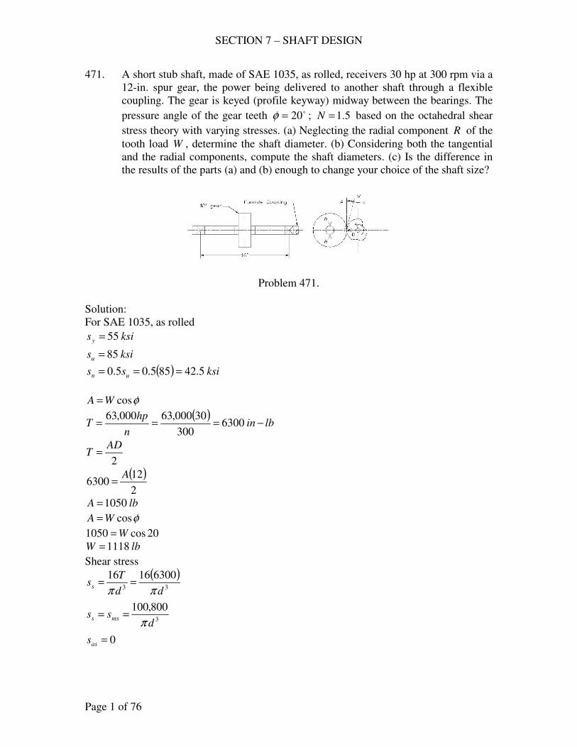
SECTION 7 – SHAFT DESIGN
Page 1 of 76
471. A short stub shaft, made of SAE 1035, as rolled, receivers 30 hp at 300 rpm via a
12-in. spur gear, the power being delivered to another shaft through a flexible
coupling. The gear is keyed (profile keyway) midway between the bearings. The
pressure angle of the gear teeth o20=φ ; 5.1=N based on the octahedral shear
stress theory with varying stresses. (a) Neglecting the radial component R of the
tooth load W , determine the shaft diameter. (b) Considering both the tangential
and the radial components, compute the shaft diameters. (c) Is the difference in
the results of the parts (a) and (b) enough to change your choice of the shaft size?
Problem 471.
Solution:
For SAE 1035, as rolled
ksisy 55=
ksisu 85=
( ) ksiss un 5.42855.05.0 ===
φcosWA =
( )lbin
n
hpT −=== 6300
300
30000,63000,63
2
ADT =
( )2
126300
A=
lbA 1050=
φcosWA =
20cos1050 W=
lbW 1118=
Shear stress
( )33
63001616
dd
Tss
ππ==
3
800,100
dss mss
π==
0=ass
SECTION 7 – SHAFT DESIGN
Page 2 of 76
bending stress
From Table AT 2
4
FLM =
(a) Negligible R :
( )( )lbin
ALM −=== 4200
4
161050
4
( )333
400,13442003232
ddd
Ms
πππ===
0=ms
3
400,134
dssa
π==
SF
sKs
s
ss
af
m
y
ne +=
For profile keyway
0.2=fK
6.1=fsK
85.0=SF
( )( )( )( ) 33
661,100
85.0
400,1340.2
ddSF
sKs
af
e ===π
SF
sKs
s
ss
asfs
ms
ys
nses +=
294.1
1
55
5.42===
y
n
ys
ns
s
s
s
s
33
796,24800,100
294.1
1
dds
s
ss ms
ys
nses =
==
π
Octahedral-shear theory
2
122
577.0
1
+
=
n
es
n
e
s
s
s
s
N
( )
2
12
3
2
3 500,42577.0
796,24
500,42
661,100
5.1
1
+
=
dd
ind 569.1=
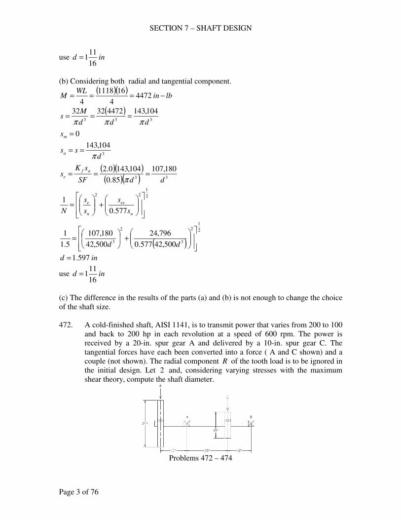
SECTION 7 – SHAFT DESIGN
Page 3 of 76
use ind16
111=
(b) Considering both radial and tangential component.
( )( )lbin
WLM −=== 4472
4
161118
4
( )333
104,14344723232
ddd
Ms
πππ===
0=ms
3
104,143
dssa
π==
( )( )( )( ) 33
180,107
85.0
104,1430.2
ddSF
sKs
af
e ===π
2
122
577.0
1
+
=
n
es
n
e
s
s
s
s
N
( )
2
12
3
2
3 500,42577.0
796,24
500,42
180,107
5.1
1
+
=
dd
ind 597.1=
use ind16
111=
(c) The difference in the results of the parts (a) and (b) is not enough to change the choice
of the shaft size.
472. A cold-finished shaft, AISI 1141, is to transmit power that varies from 200 to 100
and back to 200 hp in each revolution at a speed of 600 rpm. The power is
received by a 20-in. spur gear A and delivered by a 10-in. spur gear C. The
tangential forces have each been converted into a force ( A and C shown) and a
couple (not shown). The radial component R of the tooth load is to be ignored in
the initial design. Let 2 and, considering varying stresses with the maximum
shear theory, compute the shaft diameter.
Problems 472 – 474
SECTION 7 – SHAFT DESIGN
Page 4 of 76
Solution:
For AISI 1141, cold-finished
ksisy 90=
ksisn 50=
8.1
1=
y
n
s
s
85.0=SF
n
hpT
000,63=
( )lbinT −== 000,21
600
200000,63max
( )lbinT −== 500,10
600
100000,63min
( ) ( ) lbinTTTm −=+=+= 750,15500,10000,212
1
2
1minmax
( ) ( ) lbinTTTa −=−=−= 250,5500,10000,212
1
2
1minmax
3
16
d
Tss
π=
( )33
000,252750,1516
ddsms
ππ==
( )33
000,24525016
ddsas
ππ==
SF
sKs
s
ss
asfs
ms
ys
nses +=
For profile keyway
0.2=fK
6.1=fsK
8.1
1==
y
n
ys
ns
s
s
s
s
( )( )333
894,94
85.0
000,846.1000,252
8.1
1
dddses =+
=
ππ
Bending stress, negligible radial load
lbinT −= 000,21 at 200 hp
For A:
TA =
2
20
( ) 000,2110 =A
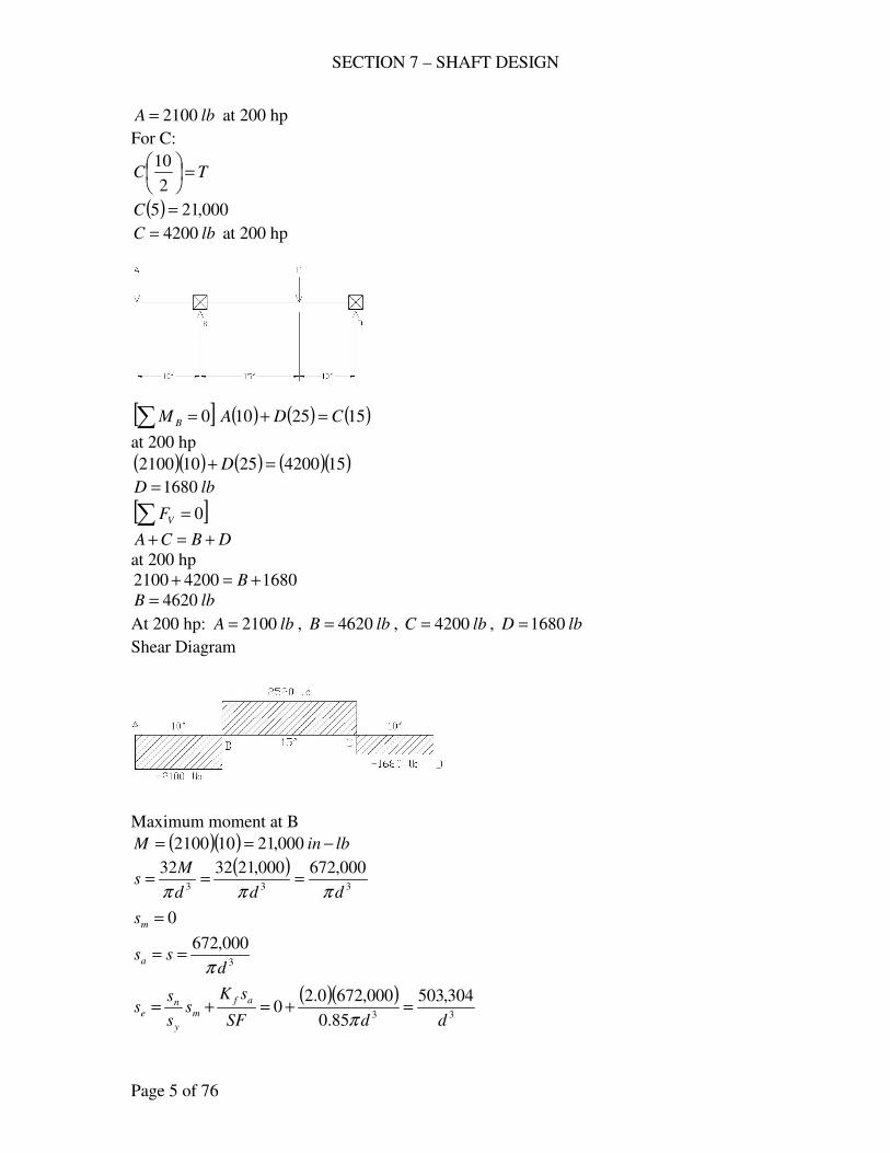
SECTION 7 – SHAFT DESIGN
Page 5 of 76
lbA 2100= at 200 hp
For C:
TC =
2
10
( ) 000,215 =C
lbC 4200= at 200 hp
[ ]∑ = 0BM ( ) ( ) ( )152510 CDA =+
at 200 hp
( )( ) ( ) ( )( )15420025102100 =+ D
lbD 1680=
[ ]∑ = 0VF
DBCA +=+
at 200 hp
168042002100 +=+ B
lbB 4620=
At 200 hp: lbA 2100= , lbB 4620= , lbC 4200= , lbD 1680=
Shear Diagram
Maximum moment at B
( )( ) lbinM −== 000,21102100
( )333
000,672000,213232
ddd
Ms
πππ===
0=ms
3
000,672
dssa
π==
( )( )33
304,503
85.0
000,6720.20
ddSF
sKs
s
ss
af
m
y
ne =+=+=
π
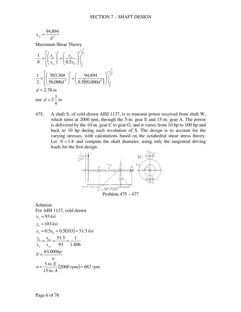
SECTION 7 – SHAFT DESIGN
Page 6 of 76
3
894,94
dses =
Maximum Shear Theory
2
122
5.0
1
+
=
n
es
n
e
s
s
s
s
N
( )
2
12
3
2
3 000,505.0
894,94
000,50
304,503
2
1
+
=
dd
ind 78.2=
use ind4
32=
475. A shaft S, of cold-drawn AISI 1137, is to transmit power received from shaft W,
which turns at 2000 rpm, through the 5-in. gear E and 15-in. gear A. The power
is delivered by the 10-in. gear C to gear G, and it varies from 10 hp to 100 hp and
back to 10 hp during each revolution of S. The design is to account for the
varying stresses, with calculations based on the octahedral shear stress theory.
Let 8.1=N and compute the shaft diameter, using only the tangential driving
loads for the first design.
Problem 475 – 477
Solution.
For AISI 1137, cold drawn
ksisy 93=
ksisu 103=
( ) ksiss un 5.511035.05.0 ===
806.1
1
93
5.51===
ys
ns
y
n
s
s
s
s
n
hpT
000,63=
( ) rpmrpmAin
Einn 6672000
.15
.5==
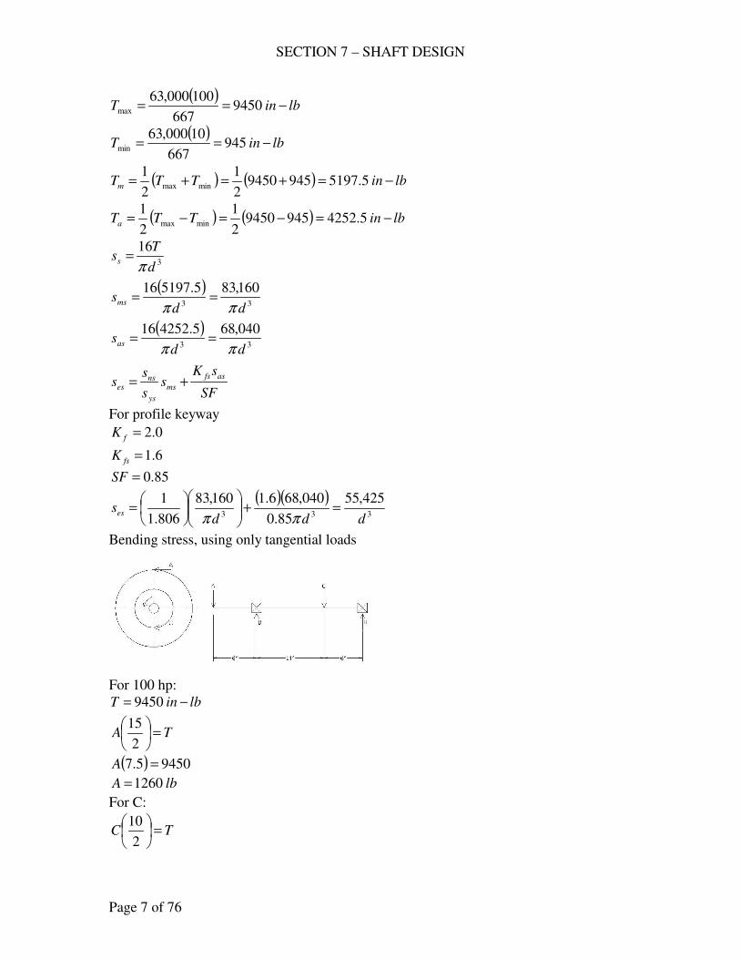
SECTION 7 – SHAFT DESIGN
Page 7 of 76
( )lbinT −== 9450
667
100000,63max
( )lbinT −== 945
667
10000,63min
( ) ( ) lbinTTTm −=+=+= 5.519794594502
1
2
1minmax
( ) ( ) lbinTTTa −=−=−= 5.425294594502
1
2
1minmax
3
16
d
Tss
π=
( )33
160,835.519716
ddsms
ππ==
( )33
040,685.425216
ddsas
ππ==
SF
sKs
s
ss
asfs
ms
ys
nses +=
For profile keyway
0.2=fK
6.1=fsK
85.0=SF
( )( )333
425,55
85.0
040,686.1160,83
806.1
1
dddses =+
=
ππ
Bending stress, using only tangential loads
For 100 hp:
lbinT −= 9450
TA =
2
15
( ) 94505.7 =A
lbA 1260=
For C:
TC =
2
10
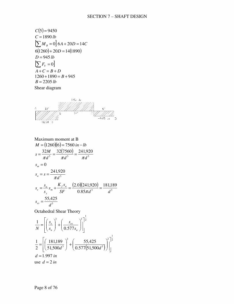
SECTION 7 – SHAFT DESIGN
Page 8 of 76
( ) 94505 =C
lbC 1890=
[ ]∑ = 0BM CDA 14206 =+
( ) ( )1890142012606 =+ D
lbD 945=
[ ]∑ = 0VF
DBCA +=+
94518901260 +=+ B
lbB 2205=
Shear diagram
Maximum moment at B
( )( ) lbinM −== 756061260
( )333
920,24175603232
ddd
Ms
πππ===
0=ms
3
920,241
dssa
π==
( )( )33
189,181
85.0
920,2410.2
ddSF
sKs
s
ss
af
m
y
ne ==+=
π
3
425,55
dses =
Octahedral Shear Theory
2
122
577.0
1
+
=
n
es
n
e
s
s
s
s
N
( )
2
12
3
2
3 500,51577.0
425,55
500,51
189,181
2
1
+
=
dd
ind 997.1=
use ind 2=
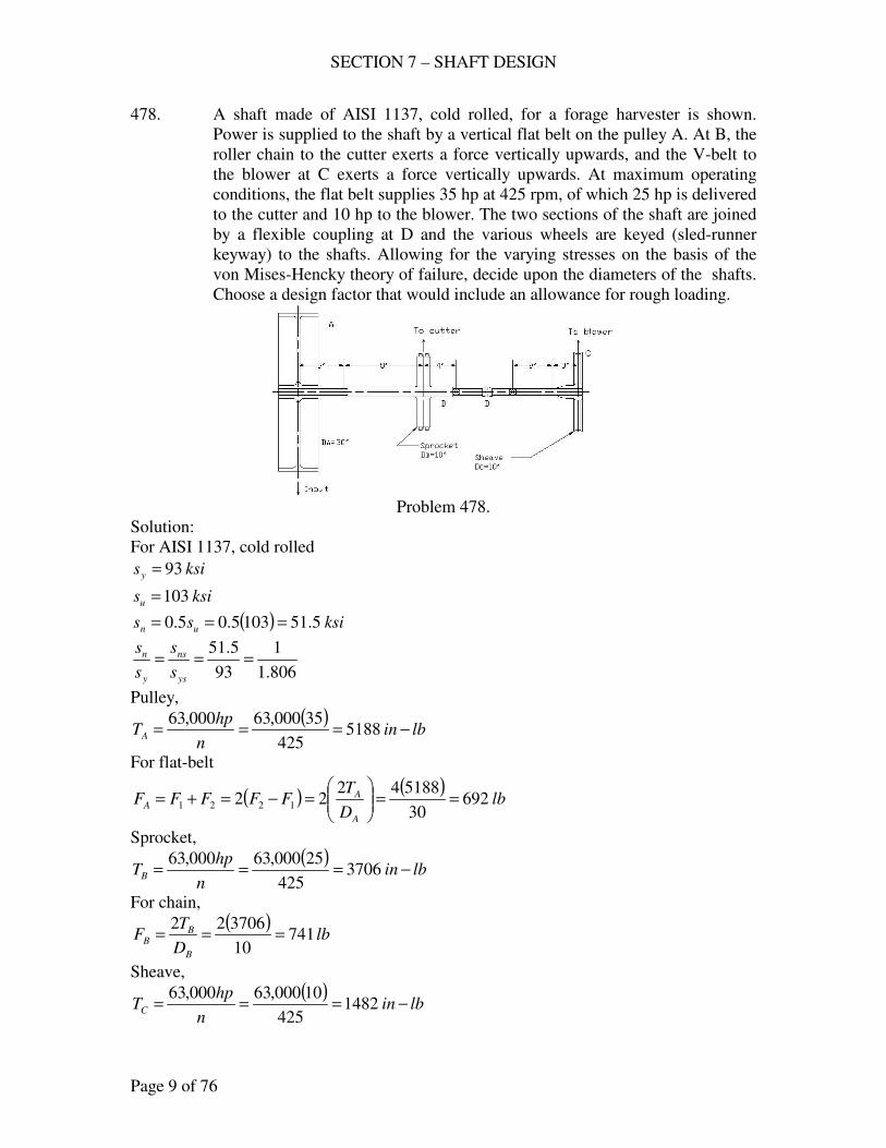
SECTION 7 – SHAFT DESIGN
Page 9 of 76
478. A shaft made of AISI 1137, cold rolled, for a forage harvester is shown.
Power is supplied to the shaft by a vertical flat belt on the pulley A. At B, the
roller chain to the cutter exerts a force vertically upwards, and the V-belt to
the blower at C exerts a force vertically upwards. At maximum operating
conditions, the flat belt supplies 35 hp at 425 rpm, of which 25 hp is delivered
to the cutter and 10 hp to the blower. The two sections of the shaft are joined
by a flexible coupling at D and the various wheels are keyed (sled-runner
keyway) to the shafts. Allowing for the varying stresses on the basis of the
von Mises-Hencky theory of failure, decide upon the diameters of the shafts.
Choose a design factor that would include an allowance for rough loading.
Problem 478.
Solution:
For AISI 1137, cold rolled
ksisy 93=
ksisu 103=
( ) ksiss un 5.511035.05.0 ===
806.1
1
93
5.51===
ys
ns
y
n
s
s
s
s
Pulley,
( )lbin
n
hpTA −=== 5188
425
35000,63000,63
For flat-belt
( ) ( )lb
D
TFFFFF
A
AA 692
30
51884222 1221 ==
=−=+=
Sprocket,
( )lbin
n
hpTB −=== 3706
425
25000,63000,63
For chain,
( )lb
D
TF
B
BB 741
10
370622===
Sheave,
( )lbin
n
hpTC −=== 1482
425
10000,63000,63
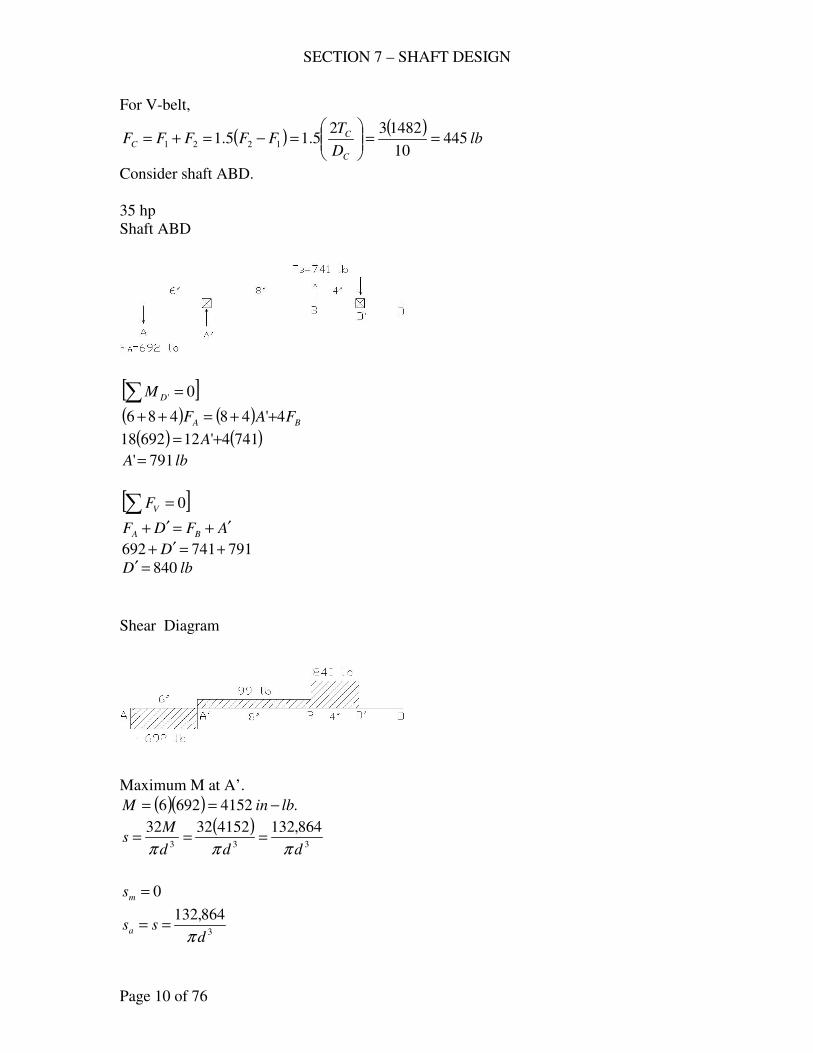
SECTION 7 – SHAFT DESIGN
Page 10 of 76
For V-belt,
( ) ( )lb
D
TFFFFF
C
CC 445
10
1482325.15.1 1221 ==
=−=+=
Consider shaft ABD.
35 hp
Shaft ABD
[ ]∑ = 0'DM
( ) ( ) BA FAF 4'48486 ++=++
( ) ( )7414'1269218 += A
lbA 791'=
[ ]∑ = 0VF
AFDF BA′+=′+
791741692 +=′+ D
lbD 840=′
Shear Diagram
Maximum M at A’.
( )( ) .41526926 lbinM −==
( )333
864,13241523232
ddd
Ms
πππ===
0=ms
3
864,132
dssa
π==
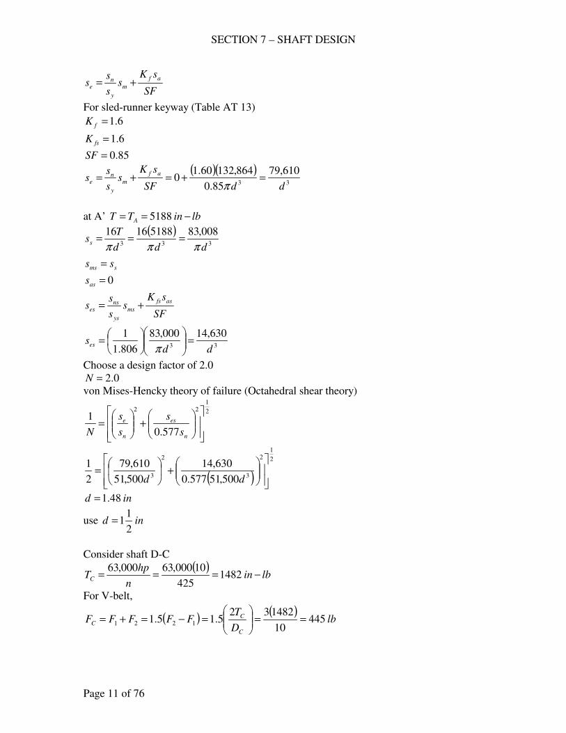
SECTION 7 – SHAFT DESIGN
Page 11 of 76
SF
sKs
s
ss
af
m
y
ne +=
For sled-runner keyway (Table AT 13)
6.1=fK
6.1=fsK
85.0=SF
( )( )33
610,79
85.0
864,13260.10
ddSF
sKs
s
ss
af
m
y
ne =+=+=
π
at A’ lbinTT A −== 5188
( )333
008,8351881616
ddd
Tss
πππ===
sms ss =
0=ass
SF
sKs
s
ss
asfs
ms
ys
nses +=
33
630,14000,83
806.1
1
ddses =
=
π
Choose a design factor of 2.0
0.2=N
von Mises-Hencky theory of failure (Octahedral shear theory)
2
122
577.0
1
+
=
n
es
n
e
s
s
s
s
N
( )
2
12
3
2
3 500,51577.0
630,14
500,51
610,79
2
1
+
=
dd
ind 48.1=
use ind2
11=
Consider shaft D-C
( )lbin
n
hpTC −=== 1482
425
10000,63000,63
For V-belt,
( ) ( )lb
D
TFFFFF
C
CC 445
10
1482325.15.1 1221 ==
=−=+=
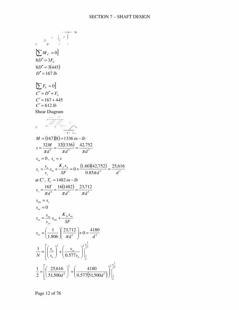
SECTION 7 – SHAFT DESIGN
Page 12 of 76
[ ]∑ = 0'CM
CFD 38 =′′
( )44538 =′′D
lbD 167=′′
[ ]∑ = 0VF
CFDC +′′=′
445167 +=′C
lbC 612=′
Shear Diagram
( )( ) lbinM −== 13368167
( )333
752,4213363232
ddd
Ms
πππ===
0=ms , ssa =
( )( )33
616,25
85.0
752,4260.10
ddSF
sKs
s
ss
af
m
y
ne =+=+=
π
at C’, lbinTC −=1482
( )333
712,2314821616
ddd
Tss
πππ===
sms ss =
0=ass
SF
sKs
s
ss
asfs
ms
ys
nses +=
33
41800
712,23
806.1
1
ddses =+
=
π
2
122
577.0
1
+
=
n
es
n
e
s
s
s
s
N
( )
2
12
3
2
3 500,51577.0
4180
500,51
616,25
2
1
+
=
dd
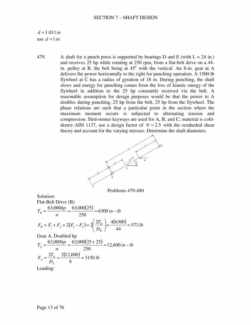
SECTION 7 – SHAFT DESIGN
Page 13 of 76
ind 011.1=
use ind 1=
479. A shaft for a punch press is supported by bearings D and E (with L = 24 in.)
and receives 25 hp while rotating at 250 rpm, from a flat-belt drive on a 44-
in. pulley at B, the belt being at 45o with the vertical. An 8-in. gear at A
delivers the power horizontally to the right for punching operation. A 1500-lb
flywheel at C has a radius of gyration of 18 in. During punching, the shaft
slows and energy for punching comes from the loss of kinetic energy of the
flywheel in addition to the 25 hp constantly received via the belt. A
reasonable assumption for design purposes would be that the power to A
doubles during punching, 25 hp from the belt, 25 hp from the flywheel. The
phase relations are such that a particular point in the section where the
maximum moment occurs is subjected to alternating tension and
compression. Sled-runner keyways are used for A, B, and C; material is cold-
drawn AISI 1137, use a design factor of 5.2=N with the octahedral shear
theory and account for the varying stresses. Determine the shaft diameters.
Problems 479-480
Solution:
Flat-Belt Drive (B)
( )lbin
n
hpTB −=== 6300
250
25000,63000,63
( ) ( )lb
D
TFFFFF
B
BB 573
44
63004222 2121 ==
=−=+=
Gear A, Doubled hp
( )lbin
n
hpTA −=
+== 600,12
250
2525000,63000,63
( )lb
D
TF
A
AA 3150
8
600,1222===
Loading:
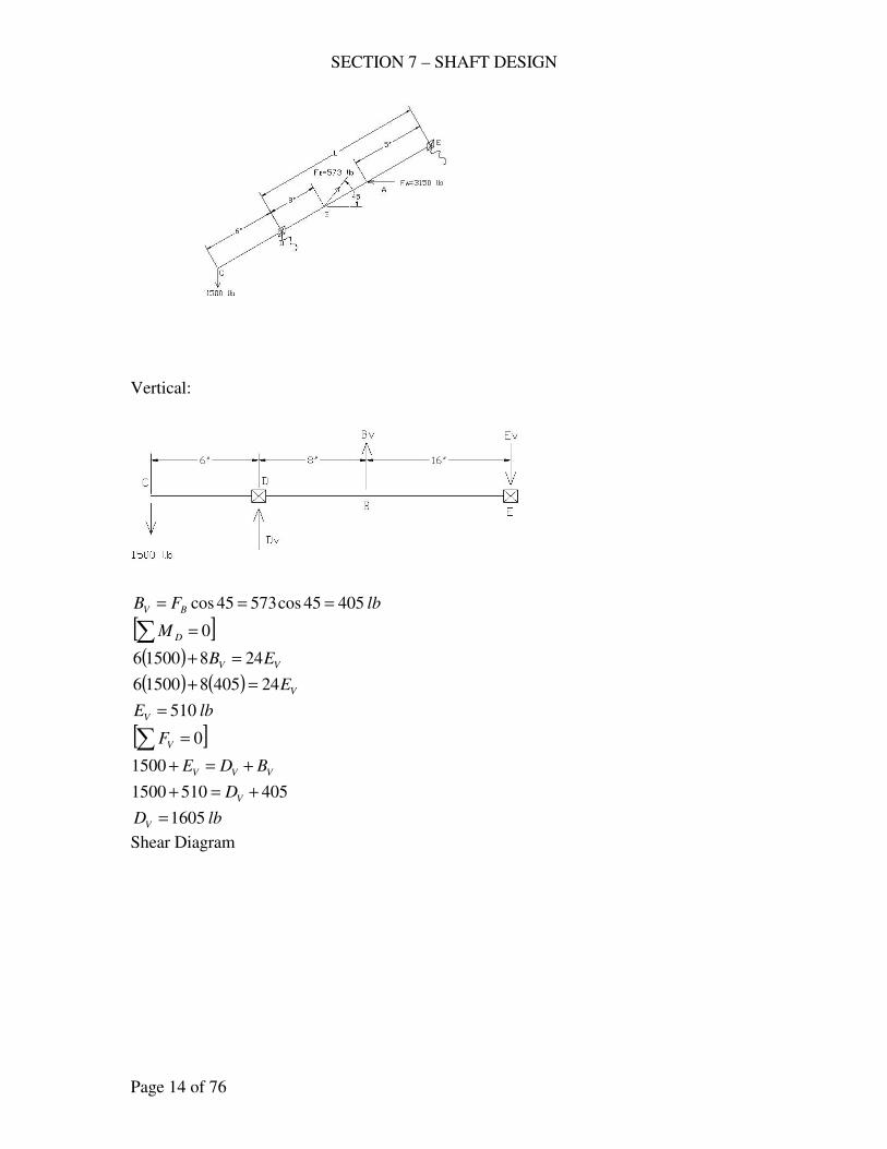
SECTION 7 – SHAFT DESIGN
Page 14 of 76
Vertical:
lbFB BV 40545cos57345cos ===
[ ]∑ = 0DM
( ) VV EB 24815006 =+
( ) ( ) VE24405815006 =+
lbEV 510=
[ ]∑ = 0VF
VVV BDE +=+1500
4055101500 +=+ VD
lbDV 1605=
Shear Diagram
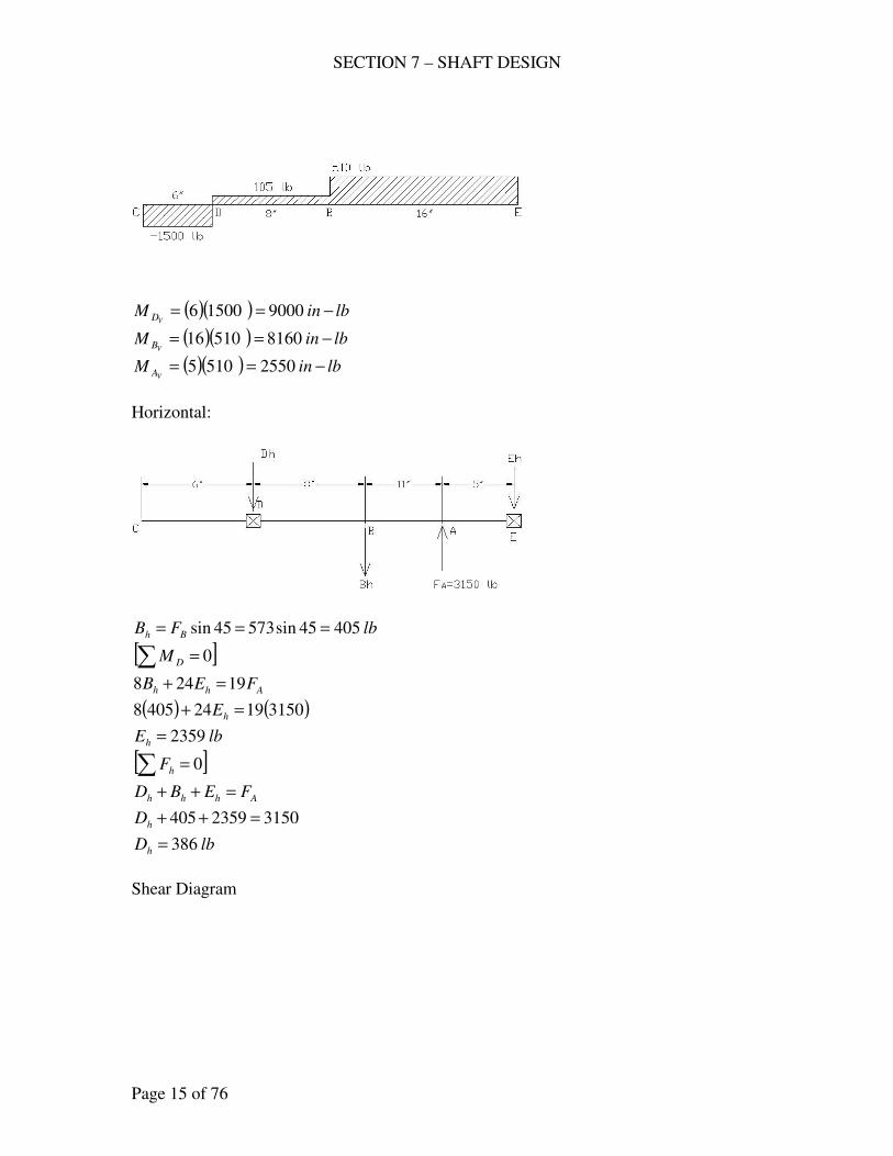
SECTION 7 – SHAFT DESIGN
Page 15 of 76
( )( ) lbinM
VD −== 900015006
( )( ) lbinMVB −== 816051016
( )( ) lbinMVA −== 25505105
Horizontal:
lbFB Bh 40545sin57345sin ===
[ ]∑ = 0DM
Ahh FEB 19248 =+
( ) ( )315019244058 =+ hE
lbEh 2359=
[ ]∑ = 0hF
Ahhh FEBD =++
31502359405 =++hD
lbDh 386=
Shear Diagram
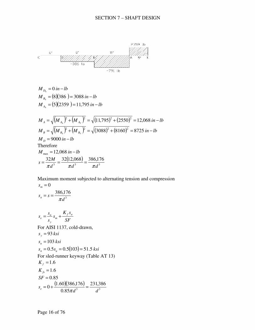
SECTION 7 – SHAFT DESIGN
Page 16 of 76
lbinM
hD −= 0
( )( ) lbinMhB −== 30883868
( )( ) lbinMhA −== 795,1123595
( ) ( ) ( ) ( ) lbinMMMVh AAA −=+=+= 068,122550795,11
2222
( ) ( ) ( ) ( ) lbinMMMVh BBB −=+=+= 872581603088
2222
lbinM D −= 9000
Therefore
lbinM −= 068,12max
( )333
176,386068,123232
ddd
Ms
πππ===
Maximum moment subjected to alternating tension and compression
0=ms
3
176,386
dssa
π==
SF
sKs
s
ss
af
m
y
ne +=
For AISI 1137, cold-drawn,
ksisy 93=
ksisu 103=
( ) ksiss un 5.511035.05.0 ===
For sled-runner keyway (Table AT 13)
6.1=fK
6.1=fsK
85.0=SF
( )( )33
386,231
85.0
176,38660.10
ddse =+=
π

SECTION 7 – SHAFT DESIGN
Page 17 of 76
At A, 50 hp max. and 25 hp min.
50 hp
( )lbin
n
hpTA −=
+== 600,12
250
2525000,63000,63
( )lb
D
TF
A
AA 3150
8
600,1222===
( )333max
600,201600,121616
ddd
Tss
πππ===
25 hp
( )lbin
n
hpTA −=== 300,6
250
25000,63000,63
( )lb
D
TF
A
AA 1575
8
300,622===
( )333min
800,100300,61616
ddd
Tss
πππ===
( )33minmax
200,151800,100600,201
2
1
2
1
ddsss ssms
ππ=
+=+=
( )33minmax
400,50800,100600,201
2
1
2
1
ddsss ssas
ππ=
−=−=
SF
sKs
s
ss
asfs
ms
ys
nses +=
( )( )333
848,56
85.0
400,506.1200,151
806.1
1
dddses =+
=
ππ
2
122
577.0
1
+
=
n
es
n
e
s
s
s
s
N
( )
2
12
3
2
3 500,51577.0
848,56
500,51
386,231
2
1
+
=
dd
ind 14.2=
say ind16
32=
THRUST LOADS
SECTION 7 – SHAFT DESIGN
Page 18 of 76
481. A cold-drawn monel propeller shaft for a launch is to transmit 400 hp at 1500
rpm without being subjected to a significant bending moment; and 40<kLe .
The efficiency of the propeller is 70 % at 30 knots (1.152 mph/knot). Consider
that the number of repetitions of the maximum power at the given speed is 2x
105. Let 2=N based on the maximum shear theory with varying stress.
Compute the shaft diameter.
Solution:
For cold-drawn monel shaft, Table AT 10
ksisy 75=
ksisn 42= at 108
at 2 x 10⁵
ksisn 23.71102
1042
085.0
5
8
=
×≈
053.1
1
75
23.71===
ys
ns
y
n
s
s
s
s
( )lbin
n
hpT −=== 800,16
1500
400000,63000,63
( )333
800,268800,161616
DDD
Tss
πππ===
sms ss =
0=ass
SF
sKs
s
ss
asfs
ms
ys
nses +=
85.0=SF
assume 0.1== fsf KK
33
255,810
800,268
053.1
1
DDses =+
=
π
hpFvm η=
000,33
( )( )( )( ) fpmhrmiftknotmphknotsvm 3041min6015280152.130 ==
( ) ( )( )40070.0000,33
3041=
F
lbF 3040=
( )222
160,12304044
DDD
Fs
πππ===
ssm=
0=as
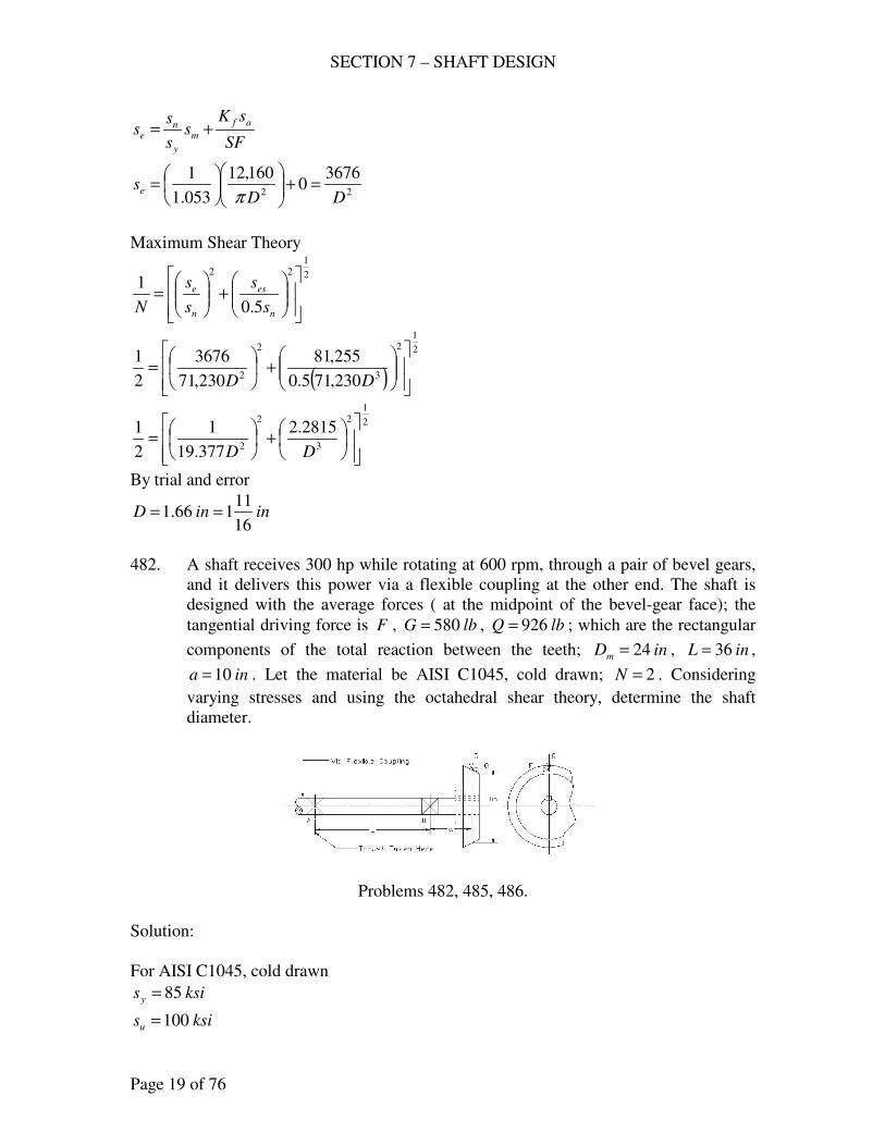
SECTION 7 – SHAFT DESIGN
Page 19 of 76
SF
sKs
s
ss
af
m
y
ne +=
22
36760
160,12
053.1
1
DDse =+
=
π
Maximum Shear Theory
2
122
5.0
1
+
=
n
es
n
e
s
s
s
s
N
( )
2
12
3
2
2 230,715.0
255,81
230,71
3676
2
1
+
=
DD
2
12
3
2
2
2815.2
377.19
1
2
1
+
=
DD
By trial and error
ininD16
11166.1 ==
482. A shaft receives 300 hp while rotating at 600 rpm, through a pair of bevel gears,
and it delivers this power via a flexible coupling at the other end. The shaft is
designed with the average forces ( at the midpoint of the bevel-gear face); the
tangential driving force is F , lbG 580= , lbQ 926= ; which are the rectangular
components of the total reaction between the teeth; inDm 24= , inL 36= ,
ina 10= . Let the material be AISI C1045, cold drawn; 2=N . Considering
varying stresses and using the octahedral shear theory, determine the shaft
diameter.
Problems 482, 485, 486.
Solution:
For AISI C1045, cold drawn
ksisy 85=
ksisu 100=
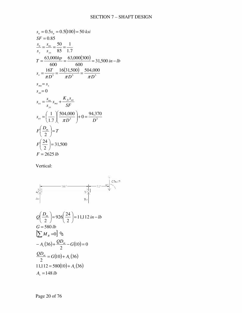
SECTION 7 – SHAFT DESIGN
Page 20 of 76
( ) ksiss un 501005.05.0 ===
85.0=SF
7.1
1
85
50===
ys
ns
y
n
s
s
s
s
( )lbin
hpT −=== 500,31
600
300000,63
600
000,63
( )333
000,504500,311616
DDD
Tss
πππ===
sms ss =
0=ass
SF
sKs
s
ss
asfs
ms
ys
nses +=
33
370,940
000,504
7.1
1
DDses =+
=
π
TD
F m =
2
500,312
24=
F
lbF 2625=
Vertical:
lbinD
Q m −=
=
112,11
2
24926
2
lbG 580=
[ ]0∑ =BM �
( ) ( ) 0102
36 =−+− GQD
A mv
( ) ( )36102
vm AG
QD+=
( ) ( )3610580112,11 vA+=
lbAv 148=
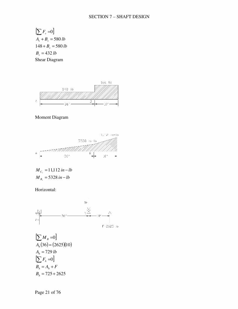
SECTION 7 – SHAFT DESIGN
Page 21 of 76
[ ]0∑ =vF
lbBA vv 580=+
lbBv 580148 =+
lbBv 432=
Shear Diagram
Moment Diagram
lbinM
vC −= 112,11
lbinMvB −= 5328
Horizontal:
[ ]0∑ =BM
( ) ( )( )10262536 =hA
lbAh 729=
[ ]0∑ =hF
FAB hh +=
2625725 +=hB
SECTION 7 – SHAFT DESIGN
Page 22 of 76
lbBh 3354=
Shear Diagram
0=
hCM
( )( ) lbinMhB −== 244,2672936
Maximum M
( ) ( ) ( ) ( ) lbinMMMMVh BBB −=+=+== 780,265328244,26
2222
( ) ( )232323max
704,3960,8569264780,2632432
DDDDD
Q
D
Ms
ππππππ+=+=+=
3232min
960,8563704324
DDD
M
D
Qs
ππππ−=−=
( )minmax2
1sssm +=
23223
3704960,85637043704960,856
2
1
DDDDDsm
πππππ=
−++=
( )minmax2
1sssa −=
3
960,856
Dsa
π=
SF
sKs
s
ss
af
m
y
ne +=
assume 0.1=fK at B
3232
916,320964960,856
85.0
0.13704
7.1
1
DDDDse +=
+
=
ππ
Octahedral Shear Theory
2
122
577.0
1
+
=
n
es
n
e
s
s
s
s
N
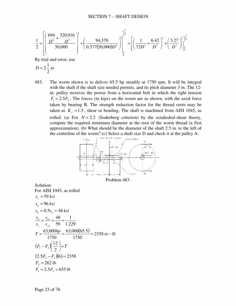
SECTION 7 – SHAFT DESIGN
Page 23 of 76
( )
2
12
3
2
32
2
1
2
3
2
32 27.342.6
72
1
000,50577.0
370,94
000,50
916,320694
2
1
+
+=
+
+
=DDDD
DD
By trial and error, use
inD2
12=
483. The worm shown is to deliver 65.5 hp steadily at 1750 rpm. It will be integral
with the shaft if the shaft size needed permits, and its pitch diameter 3 in. The 12-
in. pulley receives the power from a horizontal belt in which the tight tension
21 5.2 FF = . The forces (in kips) on the worm are as shown, with the axial force
taken by bearing B. The strength reduction factor for the thread roots may be
taken as 5.1=fK , shear or bending. The shaft is machined from AISI 1045, as
rolled. (a) For 2.2=N (Soderberg criterion) by the octahedral-shear theory,
compute the required minimum diameter at the root of the worm thread (a first
approximation). (b) What should be the diameter of the shaft 2.5 in. to the left of
the centerline of the worm? (c) Select a shaft size D and check it at the pulley A.
Problem 483.
Solution:
For AISI 1045, as rolled
ksisy 59=
ksisu 96=
ksiss un 485.0 ==
229.1
1
59
48===
ys
ns
y
n
s
s
s
s
( )lbin
hpT −=== 2358
1750
5.65000,63
1750
000,63
( ) TFF =
−
2
1221
( )( ) 235865.2 22 =− FF
lbF 2622 =
lbFF 6555.2 21 ==
SECTION 7 – SHAFT DESIGN
Page 24 of 76
lbFFFA 91726265521 =+=+=
Horizontal
[ ]0∑ =BM
( )( ) ( )( ) hE135.615706917 =+
lbEh 1208=
[ ]0∑ =hF
1570917 +=+ hh BE
15701208917 +=+ hB
lbBh 555=
Shear Diagram
0=
hAM
( )( ) lbinMhB −== 55026917
( )( ) lbinMhC −== 78525.61208
Vertical:
( ) lbinM −=
=′ 3810
2
32540
[ ]0∑ =EM
( )( ) vBM 135.61170 =+′
( )( ) vB135.611703810 =+
lbBv 878=
SECTION 7 – SHAFT DESIGN
Page 25 of 76
[ ]0∑ =vF
1170=+ vv BE
1170878 =+vE
lbEv 292=
Shear Diagram
Moment Diagram
0=
vAM
0=vBM
lbinMvC −= 5707
( ) ( )22
vh MMM +=
( ) ( ) 00022
=+=AM
( ) ( ) lbinM B −=+= 55020550222
( ) ( ) lbinMC −=+= 97075707785222
(a) Minimum diameter at the root of the warm thread.
5.1== fsf KK
lbinMM C −== 9707
lbF 2540=
( ) ( )232323max
160,10624,31025404970732432
rrrrrr DDDDD
F
D
Ms
ππππππ+=+=+=
SECTION 7 – SHAFT DESIGN
Page 26 of 76
23min
160,10624,310
rr DDs
ππ+−=
( )minmax2
1sssm +=
2
160,10
r
mD
sπ
=
( )minmax2
1sssa −=
3
624,310
r
aD
sπ
=
SF
sKs
s
ss
af
m
y
ne +=
3232
485,1742632624,310
85.0
5.1160,10
229.1
1
rrrr
eDDDD
s +=
+
=
ππ
( )333
000,1223581616
rrr
sDDD
Ts ===
ππ
sms ss =
0=ass
SF
sKs
s
ss
asfs
ms
ys
nses +=
33
97640
000,12
229.1
1
rr
esDD
s =+
=
2.2=N , Octahedral shear theory
2
122
577.0
1
+
=
n
es
n
e
s
s
s
s
N
( )
2
12
3
2
32
2
1
2
3
2
32
84.2
1635.3
24.18
1
000,48577.0
9764
000,48
485,1742632
2.2
1
+
+=
+
+
=rrrr
rr
DDDD
DD
By trial and error
inDr 023.2=
say inDr16
12=
(b) D – shaft diameter 2.5 in. to the left of the center line of worm
SECTION 7 – SHAFT DESIGN
Page 27 of 76
inr16
3=
Figure AF 12
1.0
16
322023.2
16
3
≈
−
=d
r
2.1
16
322023.2
023.2=
−
=d
D
65.1== tf KK
34.1== tsfs KK
at 2.5 in to the shaft
( )( ) ( )( ) lbinM h −=−+= 69505.25.63626917
( )( ) lbinM v −=−= 35125.25.6878
( ) ( ) lbinM −=+= 77873512695022
2
160,10
Dsm
π=
( )333
184,24977873232
DDD
Msa
πππ===
SF
sKs
s
ss
af
m
y
ne +=
3232
970,1532632184,249
85.0
65.1160,10
229.1
1
DDDDse +=
+
=
ππ
3
9764
Dses =
2
122
577.0
1
+
=
n
es
n
e
s
s
s
s
N
( )
2
12
3
2
32
2
1
2
3
2
32
84.2
121.3
24.18
1
000,48577.0
9764
000,48
970,1532632
2.2
1
+
+=
+
+
=DDDD
DD
By trial and error
inD 9432.1=
say inD16
151=

SECTION 7 – SHAFT DESIGN
Page 28 of 76
(c) Selecting ininD 9375.116
151 ==
At the pulley A, or 3 in. right of centerline
( )( ) lbinM h −== 27513917
0=vM
lbinM −= 2751
For sled runner keyway
6.1=fK
6.1=fsK
0=ms
( )( )
psiD
Msa 3853
9375.1
2751323233
===ππ
SF
sKs
s
ss
af
m
y
ne +=
( ) psise 7253385385.0
6.10 =
+=
( )psises 1343
9375.1
97643
==
2
122
577.0
1
+
=
n
es
n
e
s
s
s
s
N
( )
2
122
000,48577.0
1343
000,48
72531
+
=
N
2.230.6 >=N , therefore o.k.
484. A propeller shaft as shown is to receive 300 hp at 315 rpm from the right through
a flexible coupling. A 16-in. pulley is used to drive an auxiliary, taking 25 hp.
The belt pull BF is vertically upward. The remainder of the power is delivered to
a propeller that is expected to convert 60% of it into work driving the boat, at
which time the boat speed is 1500 fpm. The thrust is to be taken by the right-hand
bearing. Let 2=N ; material cold-worked stainless 410. Use the octahedral shear
theory with varying stresses. (a) Determine the shaft size needed assuming no
buckling. (b) Compute the equivalent column stress. Is this different enough to
call for another shaft size? Compute N by the maximum shear stress theory,
from both equations (8.4) and (8.11).
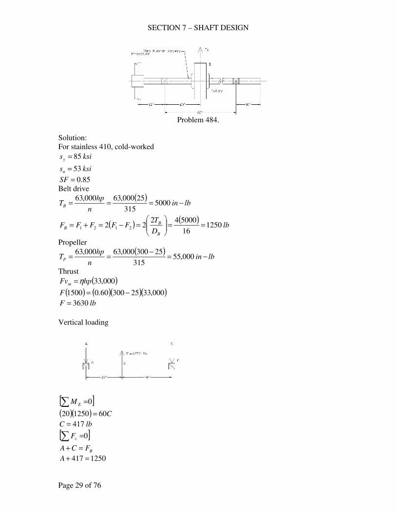
SECTION 7 – SHAFT DESIGN
Page 29 of 76
Problem 484.
Solution:
For stainless 410, cold-worked
ksisy 85=
ksisn 53=
85.0=SF
Belt drive
( )lbin
n
hpTB −=== 5000
315
25000,63000,63
( ) ( )lb
D
TFFFFF
B
BB 1250
16
50004222 2121 ==
=−=+=
Propeller
( )lbin
n
hpTP −=
−== 000,55
315
25300000,63000,63
Thrust
( )000,33hpFvm η=
( ) ( )( )( )000,332530060.01500 −=F
lbF 3630=
Vertical loading
[ ]0∑ =EM
( )( ) C60125020 =
lbC 417=
[ ]0∑ =vF
BFCA =+
1250417 =+A

SECTION 7 – SHAFT DESIGN
Page 30 of 76
lbA 833=
Shear Diagram
( )( ) lbinM B −== 660,1683320
Maximum T at B
lbinTTT PB −=+= 000,60
(a) Shaft size assuming no buckling
lbinM −= 660,16
lbF 3630=
( )222
520,14363044
DDD
Fsm
πππ===
( )333
120,533660,163232
DDD
Msa
πππ===
For sled-runner keyway
6.1=fK
6.1=fsK
604.1
1
85
53===
ys
ns
y
n
s
s
s
s
SF
sKs
s
ss
af
m
y
ne +=
3232
430,3192882120,533
85.0
6.1520,14
604.1
1
DDDDse +=
+
=
ππ
( )333
000,960000,601616
DDDss mss
πππ====
0=ass
SF
sKs
s
ss
asfs
ms
ys
nses +=
32
510,1900
000,960
604.1
1
DDses =+
=
π
SECTION 7 – SHAFT DESIGN
Page 31 of 76
2
122
1
+
=
ns
es
n
e
s
s
s
s
N
2=N , Octahedral Shear Theory, nns ss 577.0=
2
122
577.0
1
+
=
n
es
n
e
s
s
s
s
N
( )
2
12
3
2
32
2
1
2
3
2
32 230.6027.6
39.18
1
000,53577.0
510,190
000,53
430,3192882
2
1
+
+=
+
+
=DDDD
DD
By trial and error
inD 6.2=
say ininD 625.28
52 ==
(b) Equivalent Column Stress
απ 2
4
D
Fs =
inLe 82106012 =++=
( ) inDk 65625.0625.24
1
4
1===
12012565625.0
82>==
k
Le
Use Euler’s equation
( )( )
486.41030
1258532
2
2
2
=×
=
=ππ
αE
k
Ls e
y
( )( )
( ) psiD
Fs 3000486.4
625.2
36304422
===π
απ
Since 1>α , it is different enough to call for another shaft size.
Solving for N by maximum shear theory.
( ) ( )psi
DDse 078,18
625.2
430,319
625.2
2882430,31928823232
=+=+=
( )psises 533,10
625.2
510,1903
==
Equation (8.4)
SECTION 7 – SHAFT DESIGN
Page 32 of 76
( ) psis
ss 880,132
078,18533,10
2
2
12
22
12
2 =
+=
+=τ
( )91.1
880,13
000,535.05.0===
τns
N
Equation (8.11) nns ss 5.0=
( )
2
1222
122
000,535.0
533,10
000,53
078,181
+
=
+
=
ns
s
n s
s
s
s
N
91.1=N
CHECK PROBLEMS
485. A 3-in. rotating shaft somewhat as shown (482) carries a bevel gear whose mean
diameter is inDm 10= and which is keyed (profile) to the left end. Acting on the
gear are a radial force lbG 8.1570= , a driving force lbQ 6.3141= . The thrust
force is taken by the right-hand bearing. Let ina 5= and inL 15= ; material,
AISI C1040, annealed. Base calculations on the maximum shearing stress theory
with variable stress. Compute the indicated design factor N . With the use of a
sketch, indicate the exact point of which maximum normal stress occurs.
Solution:
For AISI C1040, annealed, Figure AF 1
ksisy 48=
ksisu 80=
ksiss un 405.0 ==
2.1
1
48
40===
ys
ns
y
n
s
s
s
s
( )( )lbin
FDT m −=== 416,31
2
102.6283
2
( )( )
psiD
Tss 5926
3
416,31161633
===ππ
sms ss =
0=ass
SF
sKs
s
ss
asfs
ms
ys
nses +=
( ) psises 4940059262.1
1=+
=
Vertical
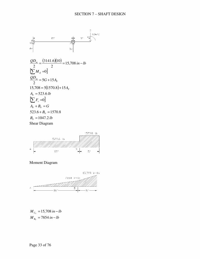
SECTION 7 – SHAFT DESIGN
Page 33 of 76
( )( )
lbinQDm −== 708,15
2
106.3141
2
[ ]0∑ =EM
Vm AG
QD155
2+=
( ) VA158.15705708,15 +=
lbAV 6.523=
[ ]0∑ =vF
GBA VV =+
8.15706.523 =+ VB
lbBV 2.1047=
Shear Diagram
Moment Diagram
lbinMVC −= 708,15
lbinMVB −= 7854
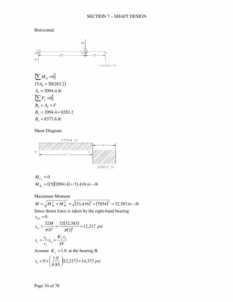
SECTION 7 – SHAFT DESIGN
Page 34 of 76
Horizontal
[ ]0∑ =BM
( )2.6283515 =hA
lbAh 4.2094=
[ ]0∑ =hF
FAB hh +=
2.62834.2094 +=hB
lbBh 6.8377=
Shear Diagram
0=
hCM
( )( ) lbinMhB −== 416,314.209415
Maximum Moment
( ) ( ) lbinMMM BvBh−=+=+= 383,327854416,31
2222
Since thrust force is taken by the right-hand bearing
0=mss
( )( )
psiD
Msas 217,12
3
383,32323233
===ππ
SF
sKs
s
ss
af
m
y
ne +=
Assume 0.1=fK at the bearing B
( ) psise 373,14217,1285.0
0.10 =
+=
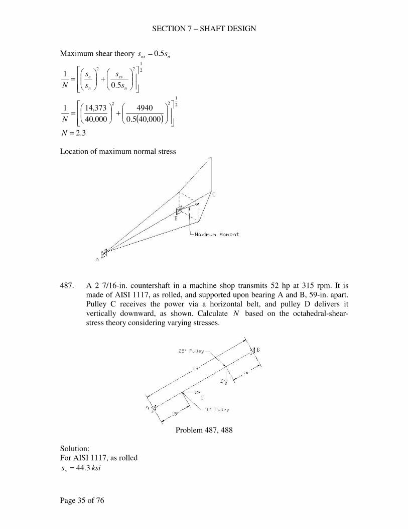
SECTION 7 – SHAFT DESIGN
Page 35 of 76
Maximum shear theory nns ss 5.0=
2
122
5.0
1
+
=
n
es
n
e
s
s
s
s
N
( )
2
122
000,405.0
4940
000,40
373,141
+
=
N
3.2=N
Location of maximum normal stress
487. A 2 7/16-in. countershaft in a machine shop transmits 52 hp at 315 rpm. It is
made of AISI 1117, as rolled, and supported upon bearing A and B, 59-in. apart.
Pulley C receives the power via a horizontal belt, and pulley D delivers it
vertically downward, as shown. Calculate N based on the octahedral-shear-
stress theory considering varying stresses.
Problem 487, 488
Solution:
For AISI 1117, as rolled
ksisy 3.44=
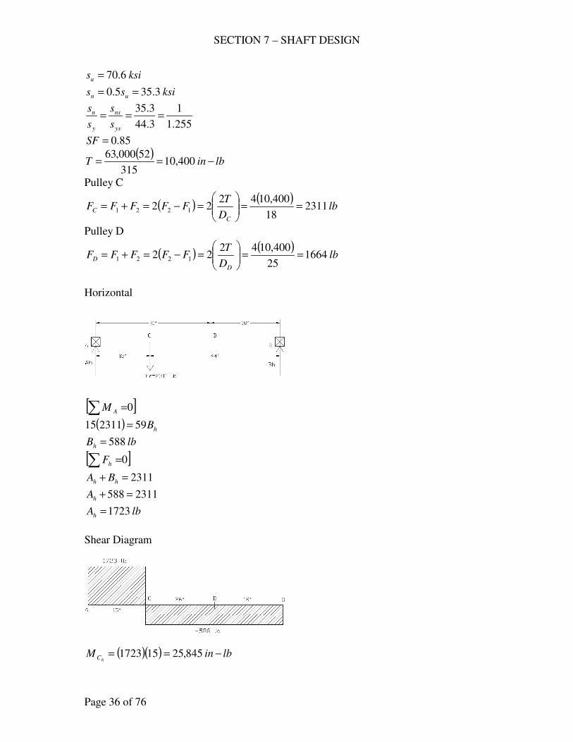
SECTION 7 – SHAFT DESIGN
Page 36 of 76
ksisu 6.70=
ksiss un 3.355.0 ==
255.1
1
3.44
3.35===
ys
ns
y
n
s
s
s
s
85.0=SF
( )lbinT −== 400,10
315
52000,63
Pulley C
( ) ( )lb
D
TFFFFF
C
C 231118
400,104222 1221 ==
=−=+=
Pulley D
( ) ( )lb
D
TFFFFF
D
D 166425
400,104222 1221 ==
=−=+=
Horizontal
[ ]0∑ =AM
( ) hB59231115 =
lbBh 588=
[ ]0∑ =hF
2311=+ hh BA
2311588 =+hA
lbAh 1723=
Shear Diagram
( )( ) lbinM
hC −== 845,25151723
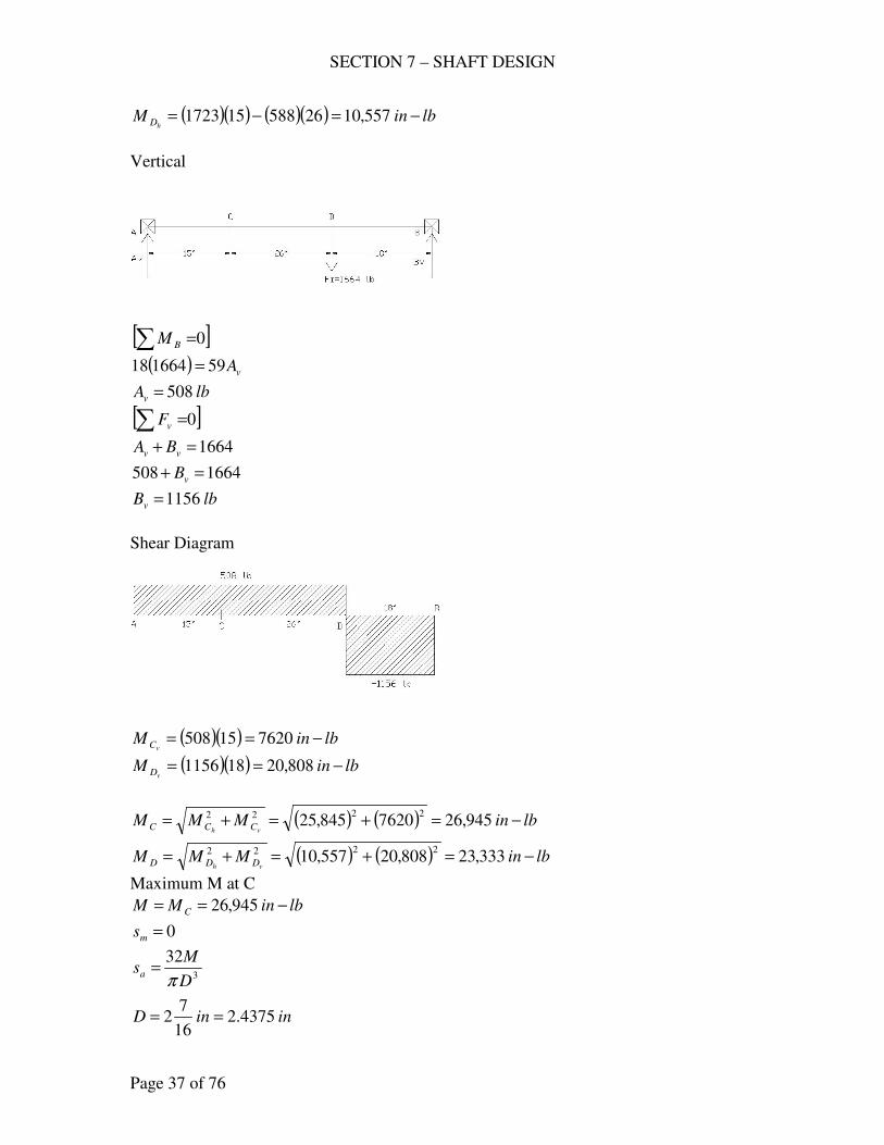
SECTION 7 – SHAFT DESIGN
Page 37 of 76
( )( ) ( )( ) lbinMhD −=−= 557,1026588151723
Vertical
[ ]0∑ =BM
( ) vA59166418 =
lbAv 508=
[ ]0∑ =vF
1664=+ vv BA
1664508 =+ vB
lbBv 1156=
Shear Diagram
( )( ) lbinMvC −== 762015508
( )( ) lbinMvD −== 808,20181156
( ) ( ) lbinMMMvh CCC −=+=+= 945,267620845,25
2222
( ) ( ) lbinMMMvh DDD −=+=+= 333,23808,20557,10
2222
Maximum M at C
lbinMM C −== 945,26
0=ms
3
32
D
Msa
π=
ininD 4375.216
72 ==
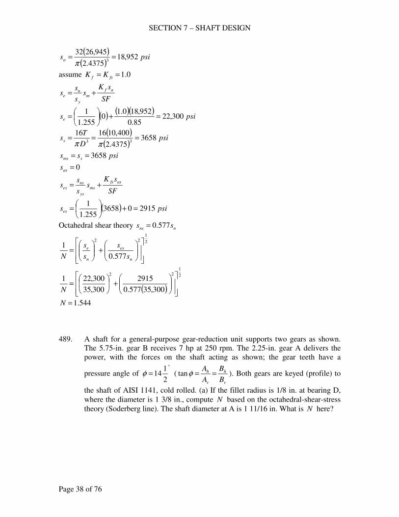
SECTION 7 – SHAFT DESIGN
Page 38 of 76
( )( )
psisa 952,184375.2
945,26323
==π
assume 0.1== fsf KK
SF
sKs
s
ss
af
m
y
ne +=
( ) ( )( )psise 300,22
85.0
952,180.10
255.1
1=+
=
( )( )
psiD
Tss 3658
4375.2
400,10161633
===ππ
psiss sms 3658==
0=ass
SF
sKs
s
ss
asfs
ms
ys
nses +=
( ) psises 291503658255.1
1=+
=
Octahedral shear theory nns ss 577.0=
2
122
577.0
1
+
=
n
es
n
e
s
s
s
s
N
( )
2
122
300,35577.0
2915
300,35
300,221
+
=
N
544.1=N
489. A shaft for a general-purpose gear-reduction unit supports two gears as shown.
The 5.75-in. gear B receives 7 hp at 250 rpm. The 2.25-in. gear A delivers the
power, with the forces on the shaft acting as shown; the gear teeth have a
pressure angle of
o
2
114=φ (
v
h
v
h
B
B
A
A==φtan ). Both gears are keyed (profile) to
the shaft of AISI 1141, cold rolled. (a) If the fillet radius is 1/8 in. at bearing D,
where the diameter is 1 3/8 in., compute N based on the octahedral-shear-stress
theory (Soderberg line). The shaft diameter at A is 1 11/16 in. What is N here?
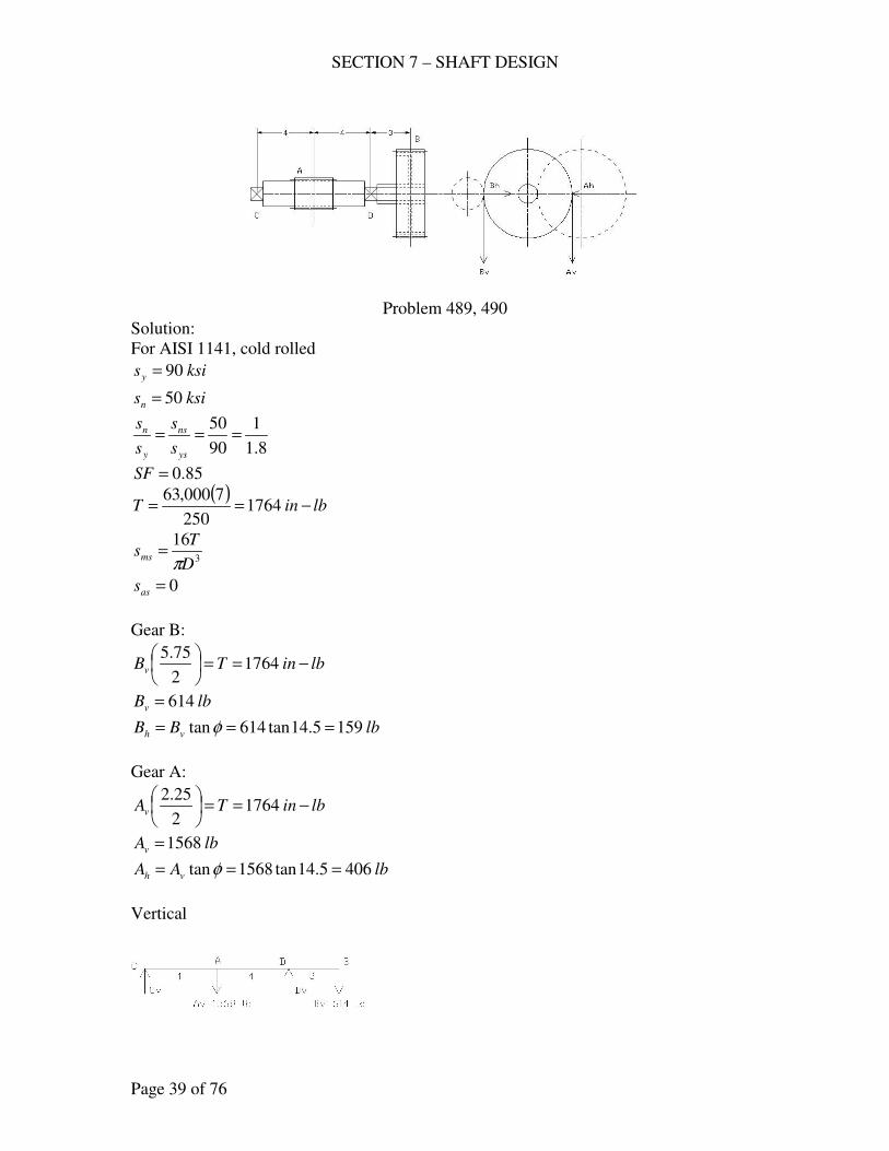
SECTION 7 – SHAFT DESIGN
Page 39 of 76
Problem 489, 490
Solution:
For AISI 1141, cold rolled
ksisy 90=
ksisn 50=
8.1
1
90
50===
ys
ns
y
n
s
s
s
s
85.0=SF
( )lbinT −== 1764
250
7000,63
3
16
D
Tsms
π=
0=ass
Gear B:
lbinTBv −==
1764
2
75.5
lbBv 614=
lbBB vh 1595.14tan614tan === φ
Gear A:
lbinTAv −==
1764
2
25.2
lbAv 1568=
lbAA vh 4065.14tan1568tan === φ
Vertical
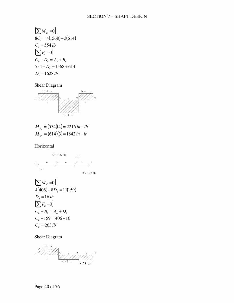
SECTION 7 – SHAFT DESIGN
Page 40 of 76
[ ]0∑ =DM
( ) ( )6143156848 −=vC
lbCv 554=
[ ]0∑ =vF
vvvv BADC +=+
6141568554 +=+ vD
lbDv 1628=
Shear Diagram
( )( ) lbinMvA −== 22164554
( )( ) lbinMvD −== 18423614
Horizontal
[ ]0∑ =CM
( ) ( )1591184064 =+ hD
lbDh 16=
[ ]0∑ =hF
hhhh DABC +=+
16406159 +=+hC
lbCh 263=
Shear Diagram
SECTION 7 – SHAFT DESIGN
Page 41 of 76
( )( ) lbinMhA −== 10524263
( )( ) lbinMhD −== 4773159
( ) ( ) lbinMMMvh AAA −=+=+= 245322161052
2222
( ) ( ) lbinMMMvh DDD −=+=+= 19031842477
2222
(a) At bearing D
inr8
1=
ind8
31=
10.0375.1
125.0≈=
d
r
2.1375.1
25.0375.1≈
+=
d
D
6.1=≈ ft KK
34.1=≈ fsts KK
DMM =
0=ms
( )( )
psid
Msa 7456
375.1
1903323233
===ππ
SF
sKs
s
ss
af
m
y
ne +=
( )( )psise 035,14
85.0
74566.10 =+=
( )( )
psiD
Tsms 3456
375.1
1764161633
===ππ
0=ass
SF
sKs
s
ss
asfs
ms
ys
nses +=
( ) psises 1920034568.1
1=+
=
Octahedral shear theory
2
122
577.0
1
+
=
n
es
n
e
s
s
s
s
N
SECTION 7 – SHAFT DESIGN
Page 42 of 76
( )
2
122
000,50577.0
3456
000,50
035,141
+
=
N
28.3=N
(b) At A
For profile keyway
0.2=fK , 6.1=fsK
inind 6875.116
111 ==
lbinMM A −== 2453
0=ms
( )( )
psid
Msa 5200
6875.1
2453323233
===ππ
SF
sKs
s
ss
af
m
y
ne +=
( )( )psise 235,12
85.0
52000.20 =+=
( )( )
psiD
Tsms 1870
6875.1
1764161633
===ππ
0=ass
SF
sKs
s
ss
asfs
ms
ys
nses +=
( ) psises 1040018708.1
1=+
=
Octahedral shear theory
2
122
577.0
1
+
=
n
es
n
e
s
s
s
s
N
( )
2
122
000,50577.0
1040
000,50
235,121
+
=
N
043.4=N
THRUST LOADS
491. The high-speed shaft of a worm-gear speed reducer, made of carburized AISI
8620, SOQT 450 F, is subjected to a torque of 21,400 in-lb. Applied to the right
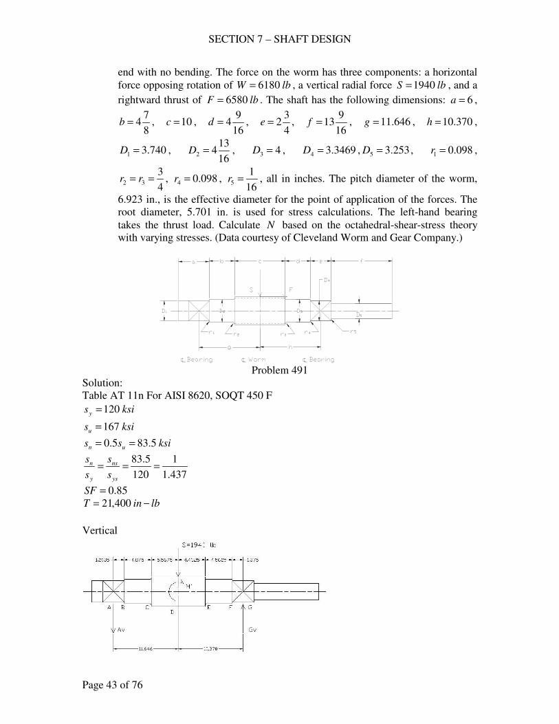
SECTION 7 – SHAFT DESIGN
Page 43 of 76
end with no bending. The force on the worm has three components: a horizontal
force opposing rotation of lbW 6180= , a vertical radial force lbS 1940= , and a
rightward thrust of lbF 6580= . The shaft has the following dimensions: 6=a ,
8
74=b , 10=c ,
16
94=d ,
4
32=e ,
16
913=f , 646.11=g , 370.10=h ,
740.31 =D , 16
1342 =D , 43 =D , 3469.34 =D , 253.35 =D , 098.01 =r ,
4
332 == rr , 098.04 =r ,
16
15 =r , all in inches. The pitch diameter of the worm,
6.923 in., is the effective diameter for the point of application of the forces. The
root diameter, 5.701 in. is used for stress calculations. The left-hand bearing
takes the thrust load. Calculate N based on the octahedral-shear-stress theory
with varying stresses. (Data courtesy of Cleveland Worm and Gear Company.)
Problem 491
Solution:
Table AT 11n For AISI 8620, SOQT 450 F
ksisy 120=
ksisu 167=
ksiss un 5.835.0 ==
437.1
1
120
5.83===
ys
ns
y
n
s
s
s
s
85.0=SF
lbinT −= 400,21
Vertical
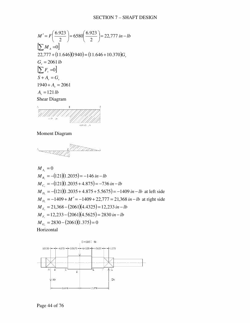
SECTION 7 – SHAFT DESIGN
Page 44 of 76
lbinFM −=
=
=′ 777,22
2
923.66580
2
923.6
[ ]0∑ =AM
( )( ) ( ) vG370.10646.111940646.11777,22 +=+
lbGv 2061=
[ ]0∑ =vF
vv GAS =+
20611940 =+ vA
lbAv 121=
Shear Diagram
Moment Diagram
0=
vAM
( )( ) lbinMvB −−=−= 1462035.1121
( )( ) lbinMvC −−=+−= 736875.42035.1121
( )( ) lbinMvD −−=++−= 14095675.5875.42035.1121 at left side
lbinMMvD −=+−=′+−= 368,21777,2214091409 at right side
( )( ) lbinMvE −=−= 233,124325.42061368,21
( )( ) lbinMvF −=−= 28305625.42061233,12
( )( ) 0375.120612830 =−=vGM
Horizontal
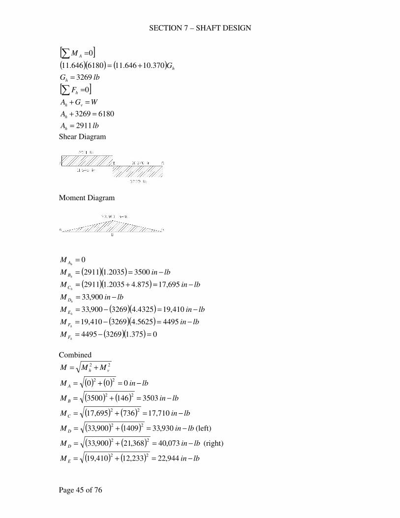
SECTION 7 – SHAFT DESIGN
Page 45 of 76
[ ]0∑ =AM
( )( ) ( ) hG370.10646.116180646.11 +=
lbGh 3269=
[ ]0∑ =hF
WGA vh =+
61803269 =+hA
lbAh 2911=
Shear Diagram
Moment Diagram
0=
hAM
( )( ) lbinMhB −== 35002035.12911
( )( ) lbinMhC −=+= 695,17875.42035.12911
lbinMhD −= 900,33
( )( ) lbinMhE −=−= 410,194325.43269900,33
( )( ) lbinMhF −=−= 44955625.43269410,19
( )( ) 0375.132694495 =−=hFM
Combined
22
vh MMM +=
( ) ( ) lbinM A −=+= 00022
( ) ( ) lbinM B −=+= 3503146350022
( ) ( ) lbinMC −=+= 710,17736695,1722
( ) ( ) lbinM D −=+= 930,331409900,3322
(left)
( ) ( ) lbinM D −=+= 073,40368,21900,3322
(right)
( ) ( ) lbinM E −=+= 944,22233,12410,1922
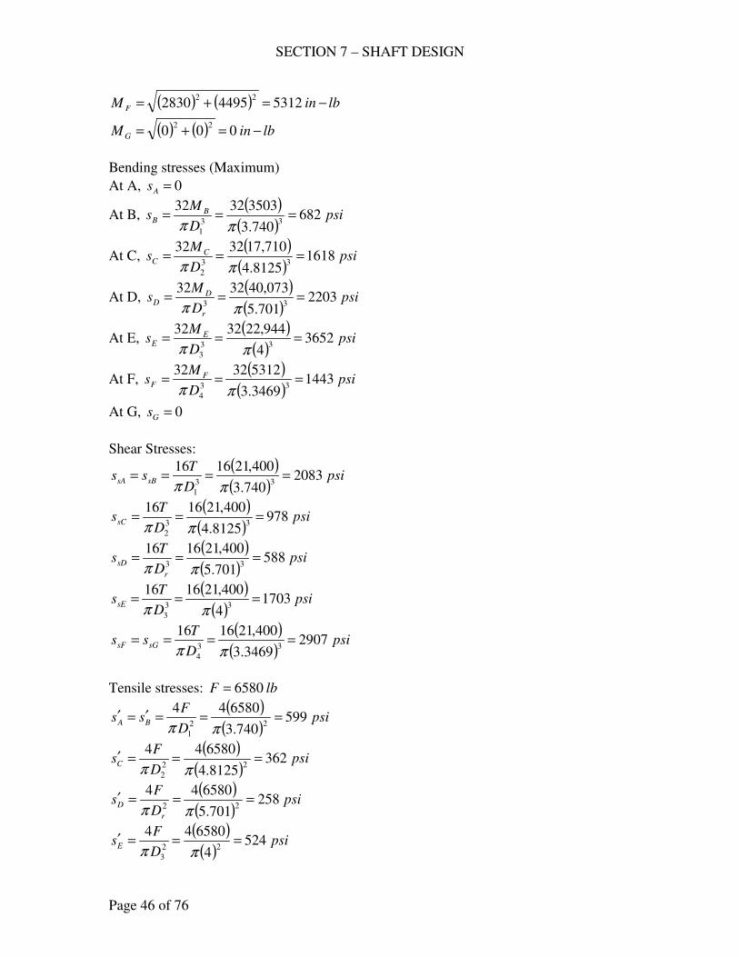
SECTION 7 – SHAFT DESIGN
Page 46 of 76
( ) ( ) lbinM F −=+= 53124495283022
( ) ( ) lbinMG −=+= 00022
Bending stresses (Maximum)
At A, 0=As
At B, ( )
( )psi
D
Ms B
B 682740.3
3503323233
1
===ππ
At C, ( )
( )psi
D
Ms C
C 16188125.4
710,17323233
2
===ππ
At D, ( )( )
psiD
Ms
r
DD 2203
701.5
073,40323233
===ππ
At E, ( )
( )psi
D
Ms E
E 36524
944,22323233
3
===ππ
At F, ( )
( )psi
D
Ms F
F 14433469.3
5312323233
4
===ππ
At G, 0=Gs
Shear Stresses:
( )( )
psiD
Tss sBsA 2083
740.3
400,21161633
1
====ππ
( )( )
psiD
TssC 978
8125.4
400,21161633
2
===ππ
( )( )
psiD
Ts
r
sD 588701.5
400,21161633
===ππ
( )( )
psiD
TssE 1703
4
400,21161633
3
===ππ
( )( )
psiD
Tss sGsF 2907
3469.3
400,21161633
4
====ππ
Tensile stresses: lbF 6580=
( )( )
psiD
Fss BA 599
740.3
65804422
1
===′=′ππ
( )( )
psiD
FsC 362
8125.4
65804422
2
===′ππ
( )( )
psiD
Fs
r
D 258701.5
65804422
===′ππ
( )( )
psiD
FsE 524
4
65804422
3
===′ππ
SECTION 7 – SHAFT DESIGN
Page 47 of 76
( )( )
psiD
Fss FE 748
3469.3
65804422
4
===′=′ππ
At B: 03.0740.3
098.0
1
1 ==D
r
3.1740.3
8125.4
1
2 ==D
D
Figure AF 12
3.2=≈ tf KK
7.1=≈ tsfs KK
SF
sKs
s
ss
af
m
y
ne +=
psiss Bm 599=′=
psiss Ba 682==
( ) ( )( )psise 2262
85.0
6823.2599
437.1
1=+
=
SF
sKs
s
ss
asfs
ms
ys
nses +=
psiss sBms 2083==
0=ass
( ) psises 145002083437.1
1=+
=
Octahedral shear theory
2
122
577.0
1
+
=
n
es
n
e
s
s
s
s
N
( )
2
122
500,83577.0
1450
500,83
22621
+
=
N
7.24=N
At C: 16.08125.4
75.0
2
2 ==D
r
2.18125.4
701.5
2
==D
Dr
Figure AF 12
5.1=≈ tf KK
2.1=≈ tsfs KK
SECTION 7 – SHAFT DESIGN
Page 48 of 76
SF
sKs
s
ss
af
m
y
ne +=
psism 362=
psisa 1618=
( ) ( )( )psise 3107
85.0
16185.1362
437.1
1=+
=
SF
sKs
s
ss
asfs
ms
ys
nses +=
psiss sCms 978==
0=ass
( ) psises 6810978437.1
1=+
=
Octahedral shear theory
2
122
577.0
1
+
=
n
es
n
e
s
s
s
s
N
( )
2
122
500,83577.0
681
500,83
31071
+
=
N
1.25=N
At D:
Assume 5.1=fK as in Prob. 483
SF
sKs
s
ss
af
m
y
ne +=
psism 258=
psisa 2203=
( ) ( )( )psise 4067
85.0
22035.1258
437.1
1=+
=
SF
sKs
s
ss
asfs
ms
ys
nses +=
psiss sDms 588==
0=ass
( ) psises 4090588437.1
1=+
=
Octahedral shear theory
SECTION 7 – SHAFT DESIGN
Page 49 of 76
2
122
577.0
1
+
=
n
es
n
e
s
s
s
s
N
( )
2
122
500,83577.0
409
500,83
40671
+
=
N
2.20=N
At E: 19.04
75.0
3
3 ==D
r
43.14
701.5
3
==D
Dr
Figure AF 12
45.1=≈ tf KK
25.1=≈ tsfs KK
SF
sKs
s
ss
af
m
y
ne +=
psiss Em 524=′=
psiss Ea 3652==
( ) ( )( )psise 6595
85.0
365245.1524
437.1
1=+
=
SF
sKs
s
ss
asfs
ms
ys
nses +=
psiss sEms 1703==
0=ass
( ) psises 118501703437.1
1=+
=
Octahedral shear theory
2
122
577.0
1
+
=
n
es
n
e
s
s
s
s
N
( )
2
122
500,83577.0
1185
500,83
65951
+
=
N
12=N
At F: 03.03469.3
098.0
4
4 ==D
r
SECTION 7 – SHAFT DESIGN
Page 50 of 76
2.13469.3
4
4
3 ==D
D
Figure AF 12
3.2=≈ tf KK
7.1=≈ tsfs KK
SF
sKs
s
ss
af
m
y
ne +=
psiss Fm 748=′=
psiss Fa 1443==
( ) ( )( )psise 4425
85.0
14433.2748
437.1
1=+
=
SF
sKs
s
ss
asfs
ms
ys
nses +=
psiss sFms 2907==
0=ass
( ) psises 202302907437.1
1=+
=
Octahedral shear theory
2
122
577.0
1
+
=
n
es
n
e
s
s
s
s
N
( )
2
122
500,83577.0
2023
500,83
44251
+
=
N
8.14=N
Then 12=N at inr4
33 = (E)
492. The slow-speed shaft of a speed reducer shown, made of AISI 4140, OQT 1200
F, transmits 100 hp at a speed of 388 rpm. It receives power through a 13.6 in.
gear B. The force on this gear has three components: a horizontal tangential
driving force lbFt 2390= , a vertical radial force lbS 870= , and a thrust force
lbQ 598= taken by the right-hand bearing. The power is delivered to a belt at
F that exerts a downward vertical force of 1620 lb.; sled runner keyways. Use
the octahedral shear theory with the Soderberg line and compute N at sections C
and D. (Data courtesy of Twin Disc Clutch Company.)

SECTION 7 – SHAFT DESIGN
Page 51 of 76
Problem 492, 493
Solution:
For AISI 4140, OQT 1200 F
ksisy 83=
ksisu 112=
ksiss un 565.0 ==
482.1
1
83
56===
ys
ns
y
n
s
s
s
s
85.0=SF
( )lbinT −== 237,16
388
100000,63
Vertical
( ) lbinQM −=
=
=′ 4.4066
2
6.13598
2
6.13
[ ]0∑ =AM
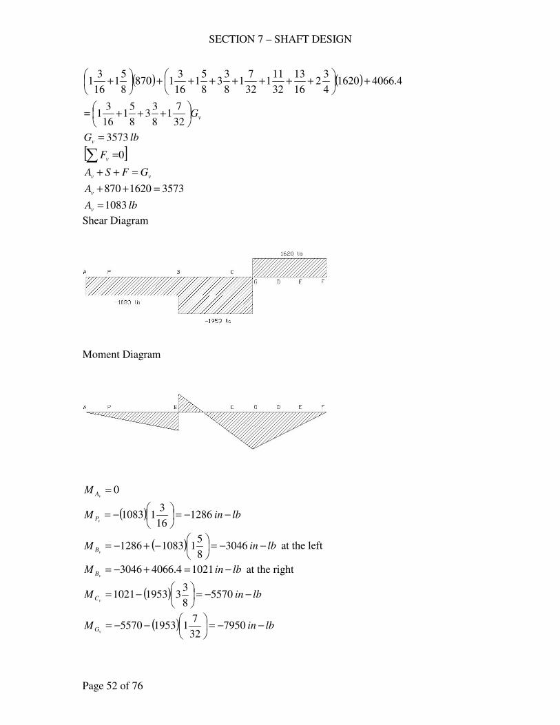
SECTION 7 – SHAFT DESIGN
Page 52 of 76
( ) ( )
vG
+++=
+
+++++++
+
32
71
8
33
8
51
16
31
4.406616204
32
16
13
32
111
32
71
8
33
8
51
16
31870
8
51
16
31
lbGv 3573=
[ ]0∑ =vF
vv GFSA =++
35731620870 =++vA
lbAv 1083=
Shear Diagram
Moment Diagram
0=
vAM
( ) lbinMvP −−=
−= 1286
16
311083
( ) lbinMvB −−=
−+−= 3046
8
5110831286 at the left
lbinMvB −=+−= 10214.40663046 at the right
( ) lbinMvC −−=
−= 5570
8
3319531021
( ) lbinMvG −−=
−−= 7950
32
7119535570
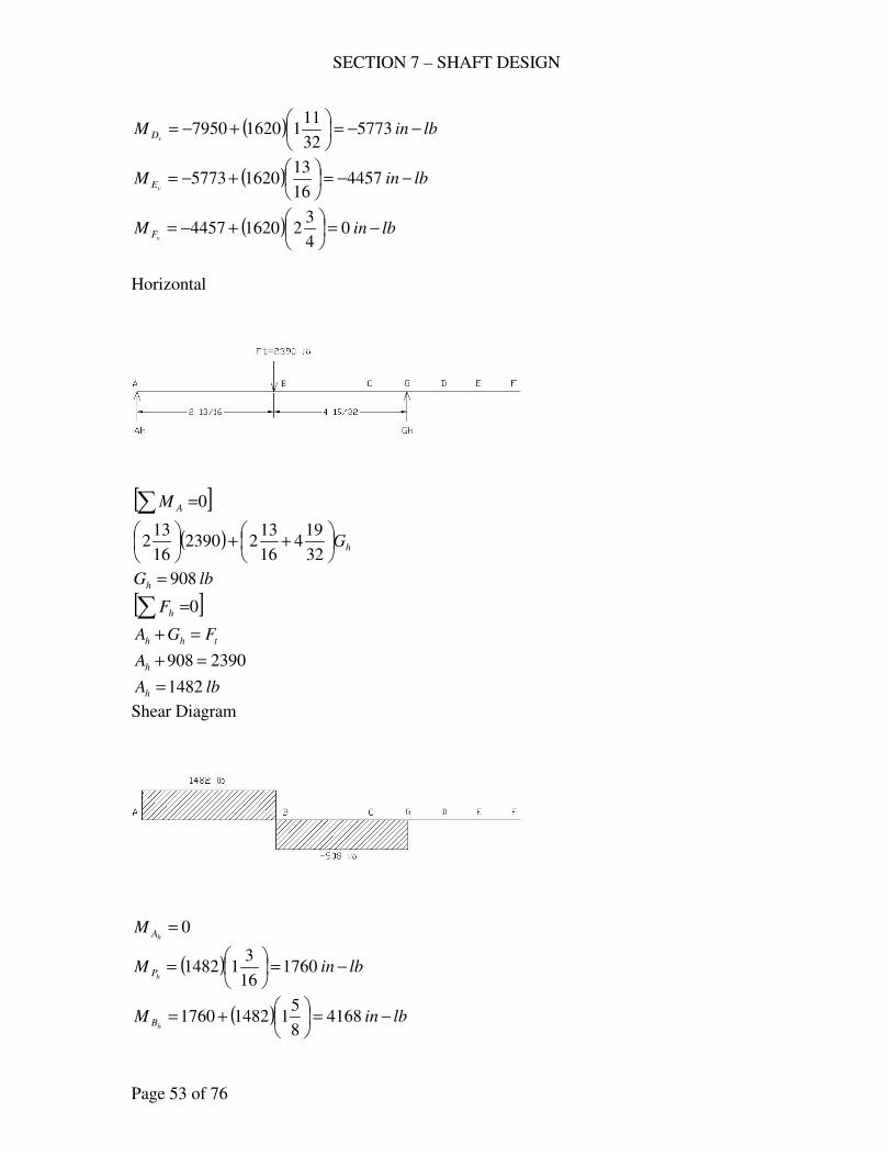
SECTION 7 – SHAFT DESIGN
Page 53 of 76
( ) lbinMvD −−=
+−= 5773
32
11116207950
( ) lbinMvE −−=
+−= 4457
16
1316205773
( ) lbinMvF −=
+−= 0
4
3216204457
Horizontal
[ ]0∑ =AM
( ) hG
++
32
194
16
1322390
16
132
lbGh 908=
[ ]0∑ =hF
thh FGA =+
2390908 =+hA
lbAh 1482=
Shear Diagram
0=
hAM
( ) lbinMhP −=
= 1760
16
311482
( ) lbinMhB −=
+= 4168
8
5114821760
SECTION 7 – SHAFT DESIGN
Page 54 of 76
( ) lbinMhC −=
−= 1104
8
339084168
( ) lbinMhC −=
−= 0
32
719081104
lbinMhD −= 0
lbinMhE −= 0
lbinMhF −= 0
Combined
22
vh MMM +=
lbinM A −= 0
( ) ( ) lbinM P −=+= 21801286176022
( ) ( ) lbinM B −=+= 51633046416822
( ) ( ) lbinMC −=+= 56785570110422
( ) ( ) lbinM D −=+= 57735773022
( ) ( ) lbinM E −=+= 44574457022
( ) ( ) lbinM F −=+= 00022
at C: ininr 125.08
1==
ind 750.2=
inD 953.2=
05.0750.2
125.0==
d
r
10.1750.2
953.2==
d
D
Figure AF 12
9.11 =≈ tf KK
3.11 =≈ tsfs KK
For sled runner keyway
6.12 =fK
6.12 =fsK
( )( ) 4.26.19.18.08.0 21 === fff KKK
( )( ) 7.16.13.18.08.0 21 === fsfsfs KKK
SECTION 7 – SHAFT DESIGN
Page 55 of 76
SF
sKs
s
ss
af
m
y
ne +=
( )( )
psid
Qsm 101
750.2
5984422
===ππ
( )( )
psid
Ms C
a 2781750.2
5678323233
===ππ
( ) ( )( )psise 7920
85.0
27814.2101
482.1
1=+
=
SF
sKs
s
ss
asfs
ms
ys
nses +=
( )( )
psid
Tsms 3976
750.2
237,16161633
===ππ
0=ass
( ) psises 268303976482.1
1=+
=
Octahedral shear theory
2
122
577.0
1
+
=
n
es
n
e
s
s
s
s
N
( )
2
122
000,56577.0
2683
000,56
79201
+
=
N
6=N
at D: ininr 0625.016
1==
ind 953.2=
ininD 375.38
33 ==
02.0953.2
0625.0==
d
r
14.1953.2
375.3==
d
D
Figure AF 12
4.2=≈ tf KK
6.1=≈ tsfs KK
SF
sKs
s
ss
af
m
y
ne +=
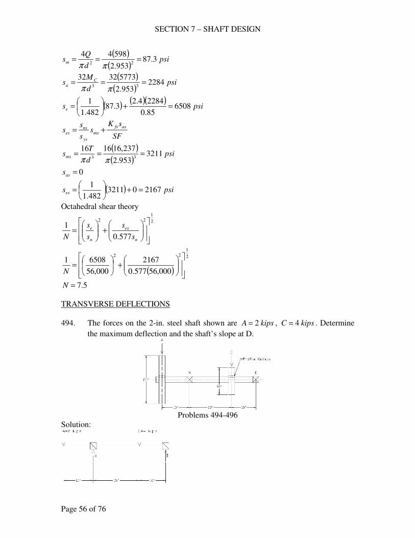
SECTION 7 – SHAFT DESIGN
Page 56 of 76
( )( )
psid
Qsm 3.87
953.2
5984422
===ππ
( )( )
psid
Ms C
a 2284953.2
5773323233
===ππ
( ) ( )( )psise 6508
85.0
22844.23.87
482.1
1=+
=
SF
sKs
s
ss
asfs
ms
ys
nses +=
( )( )
psid
Tsms 3211
953.2
237,16161633
===ππ
0=ass
( ) psises 216703211482.1
1=+
=
Octahedral shear theory
2
122
577.0
1
+
=
n
es
n
e
s
s
s
s
N
( )
2
122
000,56577.0
2167
000,56
65081
+
=
N
5.7=N
TRANSVERSE DEFLECTIONS
494. The forces on the 2-in. steel shaft shown are kipsA 2= , kipsC 4= . Determine
the maximum deflection and the shaft’s slope at D.
Problems 494-496
Solution:
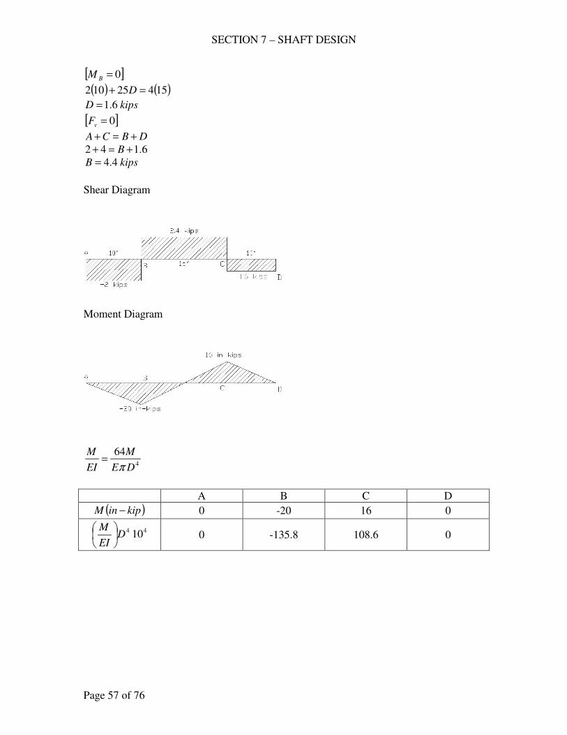
SECTION 7 – SHAFT DESIGN
Page 57 of 76
[ ]0=BM
( ) ( )15425102 =+ D
kipsD 6.1=
[ ]0=vF
DBCA +=+
6.142 +=+ B
kipsB 4.4=
Shear Diagram
Moment Diagram
4
64
DE
M
EI
M
π=
A B C D
( )kipinM − 0 -20 16 0
44 10DEI
M
0 -135.8 108.6 0
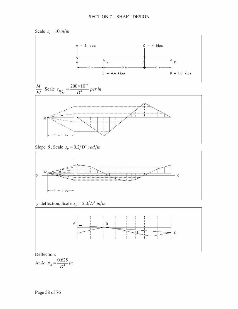
SECTION 7 – SHAFT DESIGN
Page 58 of 76
Scale ininss 10=
EI
M, Scale inper
Ds
EIM 4
410200 −×=
Slope θ , Scale inradDs
42.0=θ
y deflection, Scale ininDsy
40.2=
Deflection:
At A: inD
yA 4
625.0=
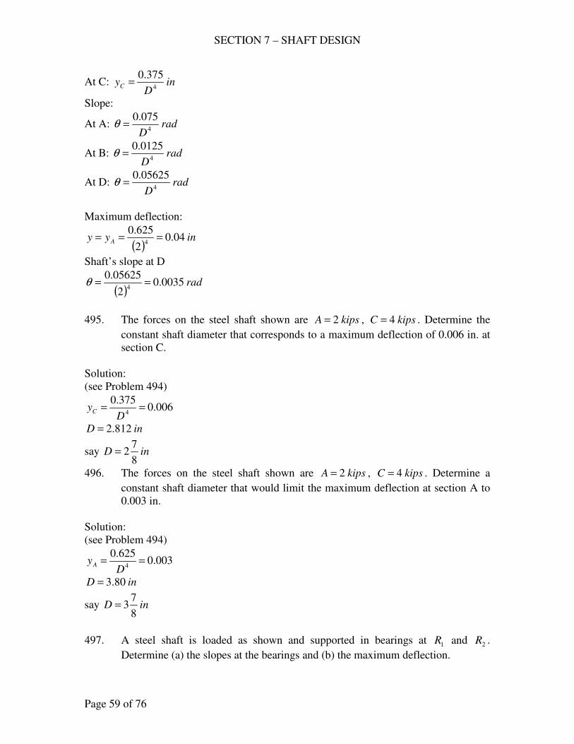
SECTION 7 – SHAFT DESIGN
Page 59 of 76
At C: inD
yC 4
375.0=
Slope:
At A: radD
4
075.0=θ
At B: radD
4
0125.0=θ
At D: radD
4
05625.0=θ
Maximum deflection:
( )inyy A 04.0
2
625.04
===
Shaft’s slope at D
( )rad0035.0
2
05625.04
==θ
495. The forces on the steel shaft shown are kipsA 2= , kipsC 4= . Determine the
constant shaft diameter that corresponds to a maximum deflection of 0.006 in. at
section C.
Solution:
(see Problem 494)
006.0375.0
4==
DyC
inD 812.2=
say inD8
72=
496. The forces on the steel shaft shown are kipsA 2= , kipsC 4= . Determine a
constant shaft diameter that would limit the maximum deflection at section A to
0.003 in.
Solution:
(see Problem 494)
003.0625.0
4==
DyA
inD 80.3=
say inD8
73=
497. A steel shaft is loaded as shown and supported in bearings at 1R and 2R .
Determine (a) the slopes at the bearings and (b) the maximum deflection.
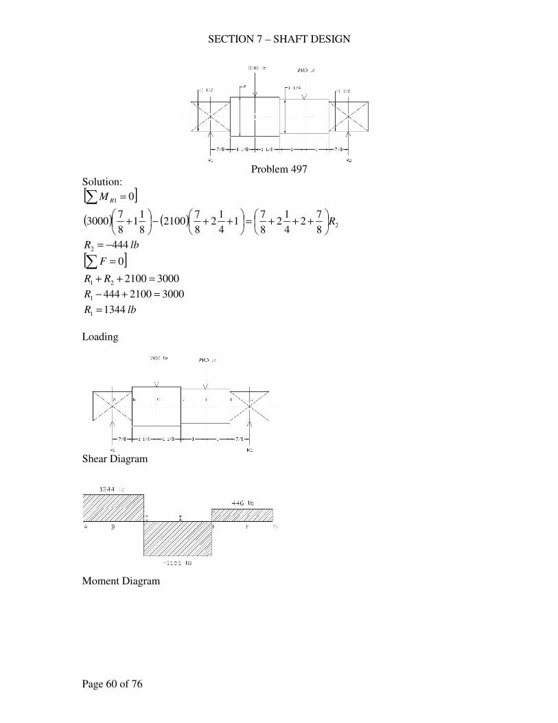
SECTION 7 – SHAFT DESIGN
Page 60 of 76
Problem 497
Solution:
[ ]∑ = 01RM
( ) ( ) 28
72
4
12
8
71
4
12
8
72100
8
11
8
73000 R
+++=
++−
+
lbR 4442 −=
[ ]∑ = 0F
3000210021 =++ RR
300021004441 =+−R
lbR 13441 =
Loading
Shear Diagram
Moment Diagram
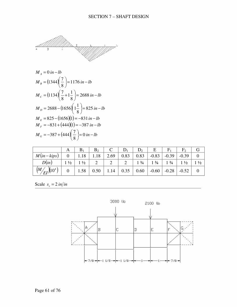
SECTION 7 – SHAFT DESIGN
Page 61 of 76
lbinM A −= 0
( ) lbinM B −=
= 1176
8
71344
( ) lbinMC −=
+= 2688
8
11
8
71134
( ) lbinM D −=
−= 825
8
1116562688
( )( ) lbinM E −−=−= 83111656825
( )( ) lbinM F −−=+−= 3871444831
( ) lbinMG −=
+−= 0
8
7444387
A B1 B2 C D1 D2 E F1 F2 G
( )kipsinM − 0 1.18 1.18 2.69 0.83 0.83 -0.83 -0.39 -0.39 0
( )inD 1 ½ 1 ½ 2 2 2 1 ¾ 1 ¾ 1 ¾ 1 ½ 1 ½
( )( )410EI
M 0 1.58 0.50 1.14 0.35 0.60 -0.60 -0.28 -0.52 0
Scale ininss 2=
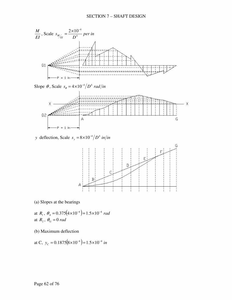
SECTION 7 – SHAFT DESIGN
Page 62 of 76
EI
M, Scale inper
Ds
EIM 4
4102 −×=
Slope θ , Scale inradDs
44104 −×=θ
y deflection, Scale ininDsy
44108 −×=
(a) Slopes at the bearings
at 1R , ( ) radA
44 105.1104375.0 −− ×=×=θ
at 2R , radG 0=θ
(b) Maximum deflection
at C, ( ) inyC
44 105.11081875.0 −− ×=×=
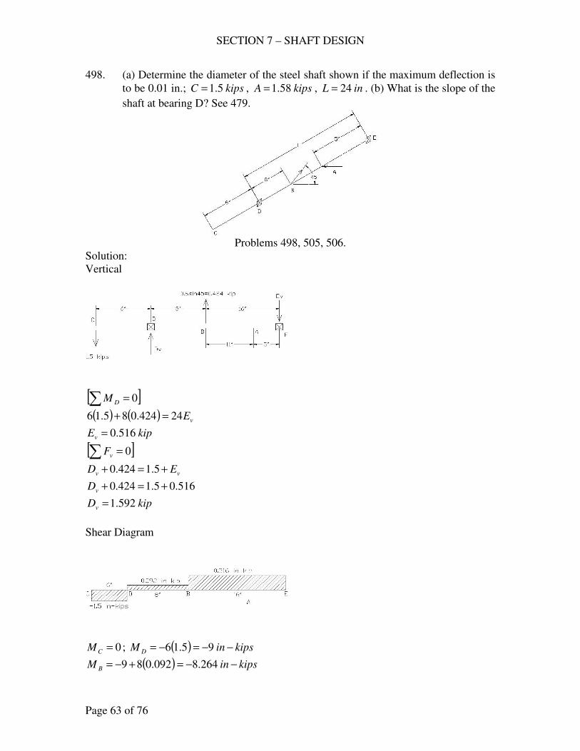
SECTION 7 – SHAFT DESIGN
Page 63 of 76
498. (a) Determine the diameter of the steel shaft shown if the maximum deflection is
to be 0.01 in.; kipsC 5.1= , kipsA 58.1= , inL 24= . (b) What is the slope of the
shaft at bearing D? See 479.
Problems 498, 505, 506.
Solution:
Vertical
[ ]∑ = 0DM
( ) ( ) vE24424.085.16 =+
kipEv 516.0=
[ ]∑ = 0vF
vv ED +=+ 5.1424.0
516.05.1424.0 +=+vD
kipDv 592.1=
Shear Diagram
0=CM ; ( ) kipsinM D −−=−= 95.16
( ) kipsinM B −−=+−= 264.8092.089
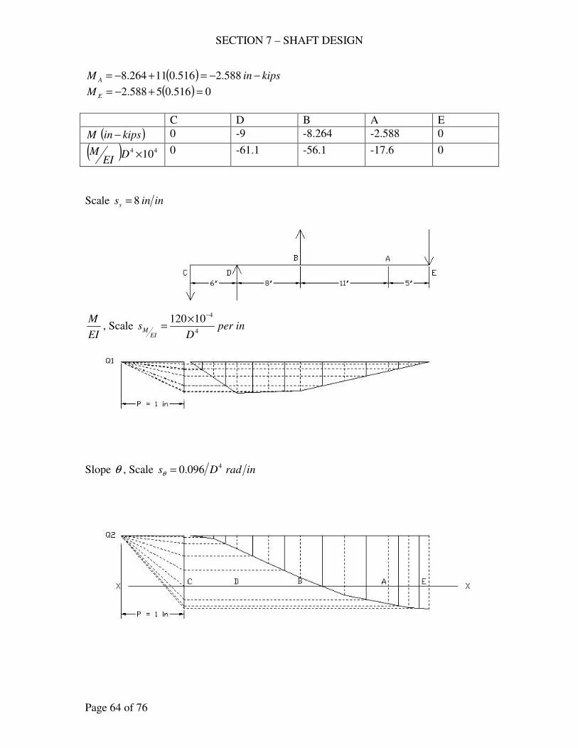
SECTION 7 – SHAFT DESIGN
Page 64 of 76
( ) kipsinM A −−=+−= 588.2516.011264.8
( ) 0516.05588.2 =+−=EM
C D B A E
( )kipsinM − 0 -9 -8.264 -2.588 0
( ) 44 10×DEI
M 0 -61.1 -56.1 -17.6 0
Scale ininss 8=
EI
M, Scale inper
Ds
EIM 4
410120 −×=
Slope θ , Scale inradDs4096.0=θ
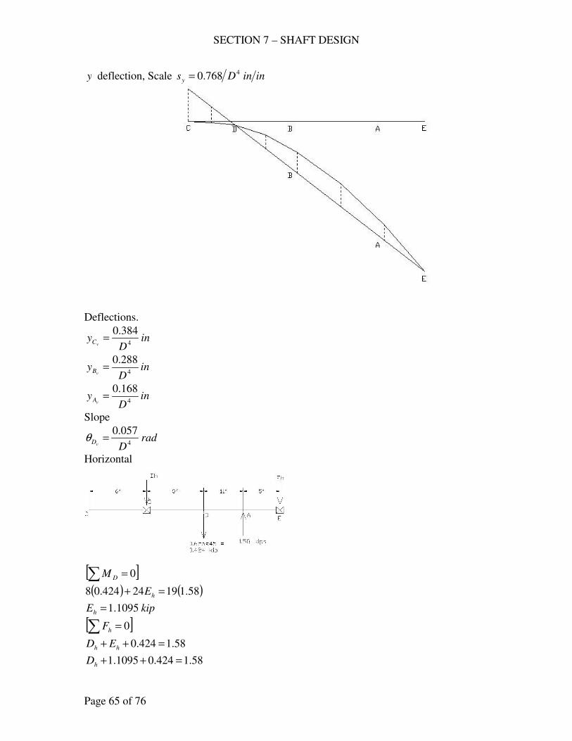
SECTION 7 – SHAFT DESIGN
Page 65 of 76
y deflection, Scale ininDsy
4768.0=
Deflections.
inD
yvC 4
384.0=
inD
yvB 4
288.0=
inD
yvA 4
168.0=
Slope
radDvD 4
057.0=θ
Horizontal
[ ]∑ = 0DM
( ) ( )58.11924424.08 =+ hE
kipEh 1095.1=
[ ]∑ = 0hF
58.1424.0 =++ hh ED
58.1424.01095.1 =++hD
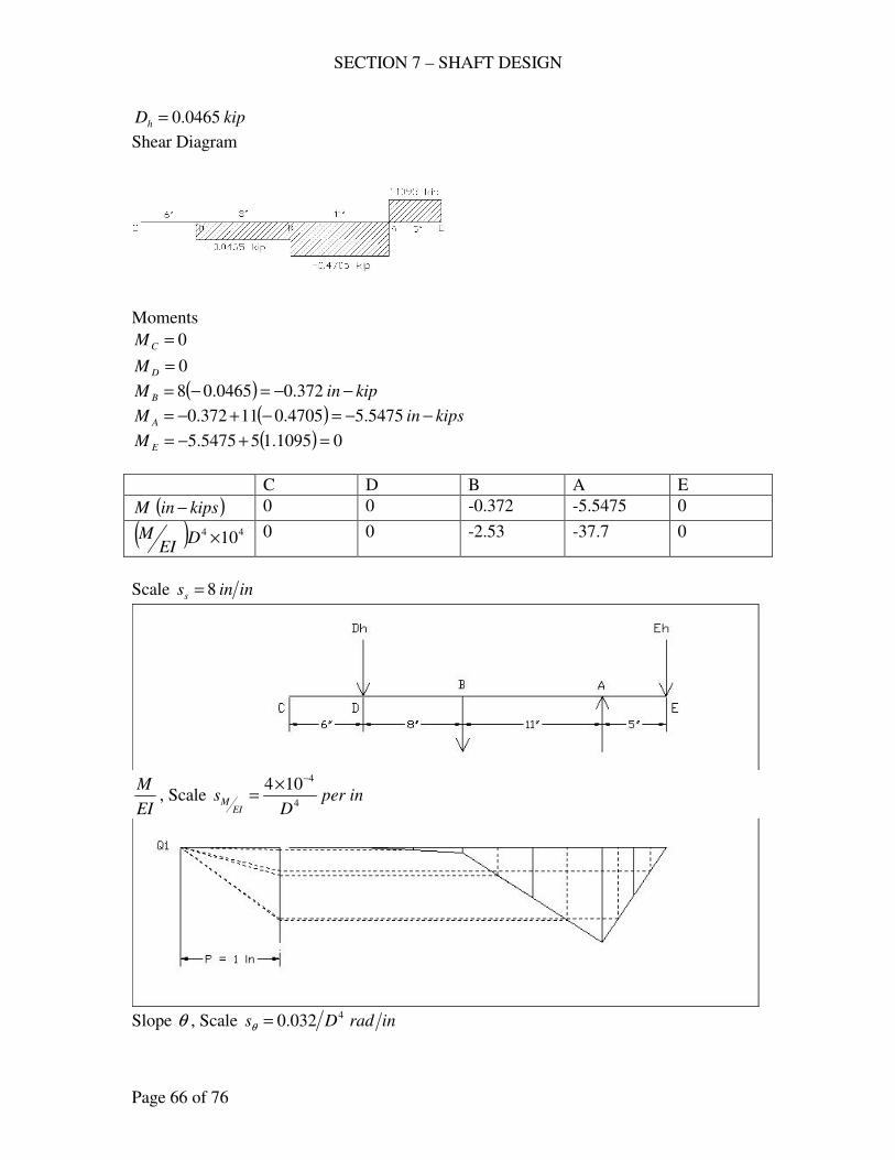
SECTION 7 – SHAFT DESIGN
Page 66 of 76
kipDh 0465.0=
Shear Diagram
Moments
0=CM
0=DM
( ) kipinM B −−=−= 372.00465.08
( ) kipsinM A −−=−+−= 5475.54705.011372.0
( ) 01095.155475.5 =+−=EM
C D B A E
( )kipsinM − 0 0 -0.372 -5.5475 0
( ) 44 10×DEI
M 0 0 -2.53 -37.7 0
Scale ininss 8=
EI
M, Scale inper
Ds
EIM 4
4104 −×=
Slope θ , Scale inradDs
4032.0=θ
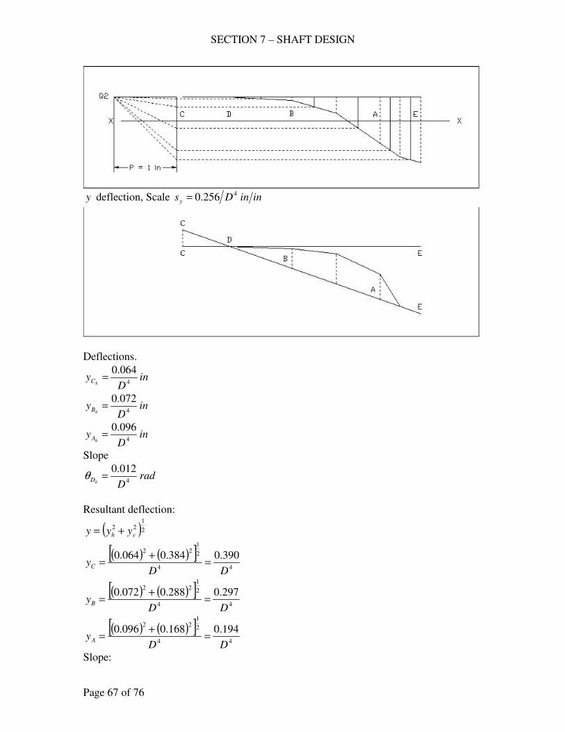
SECTION 7 – SHAFT DESIGN
Page 67 of 76
y deflection, Scale ininDsy
4256.0=
Deflections.
inD
yhC 4
064.0=
inD
yhB 4
072.0=
inD
yhA 4
096.0=
Slope
radDhD 4
012.0=θ
Resultant deflection:
( )2
122
vh yyy +=
( ) ( )[ ]44
2
122
390.0384.0064.0
DDyC =
+=
( ) ( )[ ]44
2
122
297.0288.0072.0
DDyB =
+=
( ) ( )[ ]44
2
122
194.0168.0096.0
DDyA =
+=
Slope:
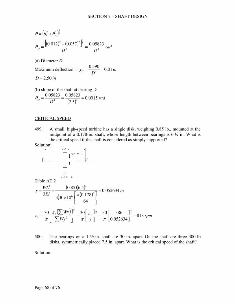
SECTION 7 – SHAFT DESIGN
Page 68 of 76
( )2
122
vh θθθ +=
( ) ( )[ ]rad
DDD 44
2
122
05823.0057.0012.0=
+=θ
(a) Diameter D.
Maximum deflection = inD
yC 01.0390.0
4==
inD 50.2=
(b) slope of the shaft at bearing D
( )rad
DD 0015.0
5.2
05823.005823.044
===θ
CRITICAL SPEED
499. A small, high-speed turbine has a single disk, weighing 0.85 lb., mounted at the
midpoint of a 0.178-in. shaft, whose length between bearings is 6 ½ in. What is
the critical speed if the shaft is considered as simply supported?
Solution:
Table AT 2
( )( )
( ) ( )in
EI
WLy 052634.0
64
178.010303
5.685.0
3 4
6
33
=
×
==π
( )rpm
y
g
Wy
Wygn oo
c 818052634.0
386303030 2
1
2
12
1
2=
=
=
=
∑∑
πππ
500. The bearings on a 1 ½-in. shaft are 30 in. apart. On the shaft are three 300-lb
disks, symmetrically placed 7.5 in. apart. What is the critical speed of the shaft?
Solution:
SECTION 7 – SHAFT DESIGN
Page 69 of 76
Table AT 2
Deflection of B.
321 BBBB yyyy ++=
( )( )( ) ( ) ( ) ( )[ ]( ) ( ) ( )
inyB 01273.0
3064
5.110306
5.75.22305.75.223004
6
222
1=
×
−−=
π
( )( )( ) ( ) ( ) ( )[ ]( ) ( ) ( )
inyB 01556.0
3064
5.110306
5.715305.7153004
6
222
2=
×
−−=
π
( )( )( ) ( ) ( ) ( )[ ]( ) ( ) ( )
inyB 00990.0
3064
5.110306
5.75.7305.75.73004
6
222
3=
×
−−=
π
inyB 03819.001556.000990.001273.0 =++=
Deflection of C.
321 CCCC yyyy ++=
( )( )( ) ( ) ( ) ( )[ ]( ) ( ) ( )
inyC 01556.0
3064
5.110306
15305.73015305.73004
6
222
1=
×
−−−−=
π
( )( )( ) ( ) ( ) ( )[ ]( ) ( ) ( )
inyC 02264.0
3064
5.110306
153015301530153004
6
222
2=
×
−−−−=
π
( )( )( ) ( ) ( ) ( )[ ]( ) ( ) ( )
inyC 01556.0
3064
5.110306
155.730155.73004
6
222
3=
×
−−=
π
inyC 05376.001556.002264.001556.0 =++=
Deflection of D.
321 DDDD yyyy ++=
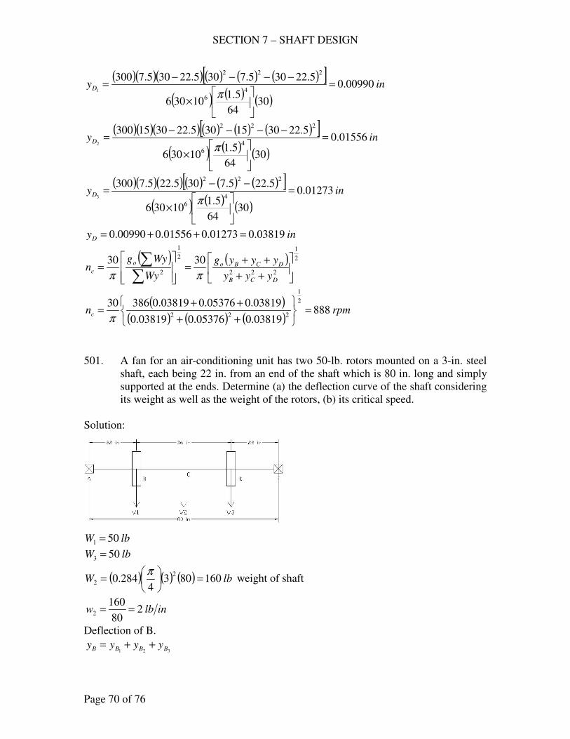
SECTION 7 – SHAFT DESIGN
Page 70 of 76
( )( )( ) ( ) ( ) ( )[ ]( ) ( ) ( )
inyD 00990.0
3064
5.110306
5.22305.7305.22305.73004
6
222
1=
×
−−−−=
π
( )( )( ) ( ) ( ) ( )[ ]( ) ( ) ( )
inyD 01556.0
3064
5.110306
5.223015305.2230153004
6
222
2=
×
−−−−=
π
( )( )( ) ( ) ( ) ( )[ ]( ) ( ) ( )
inyD 01273.0
3064
5.110306
5.225.7305.225.73004
6
222
3=
×
−−=
π
inyD 03819.001273.001556.000990.0 =++=
( ) ( ) 2
1
222
2
1
2
3030
++
++=
=
∑∑
DCB
DCBoo
cyyy
yyyg
Wy
Wygn
ππ
( )( ) ( ) ( )
rpmnc 88803819.005376.003819.0
03819.005376.003819.038630 2
1
222=
++
++=
π
501. A fan for an air-conditioning unit has two 50-lb. rotors mounted on a 3-in. steel
shaft, each being 22 in. from an end of the shaft which is 80 in. long and simply
supported at the ends. Determine (a) the deflection curve of the shaft considering
its weight as well as the weight of the rotors, (b) its critical speed.
Solution:
lbW 501 =
lbW 503 =
( ) ( ) ( ) lbW 1608034
284.02
2 =
=
π weight of shaft
inlbw 280
1602 ==
Deflection of B.
321 BBBB yyyy ++=
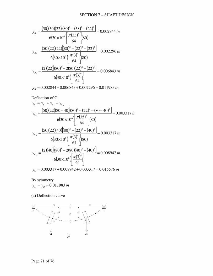
SECTION 7 – SHAFT DESIGN
Page 71 of 76
( )( )( ) ( ) ( ) ( )[ ]( ) ( ) ( )
inyB 002844.0
8064
3510306
2258802250504
6
222
1=
×
−−=
π
( )( )( ) ( ) ( ) ( )[ ]( ) ( ) ( )
inyB 002296.0
8064
310306
2222802222504
6
222
3=
×
−−=
π
( )( ) ( ) ( )( ) ( )[ ]( ) ( )
inyB 006843.0
64
310306
2222802802224
6
323
2=
×
−−=
π
inyB 011983.0002296.0006843.0002844.0 =++=
Deflection of C.
321 CCCC yyyy ++=
( )( )( ) ( ) ( ) ( )[ ]( ) ( ) ( )
inyC 003317.0
8064
3510306
40802280408022504
6
222
1=
×
−−−−=
π
( )( )( ) ( ) ( ) ( )[ ]( ) ( ) ( )
inyC 003317.0
8064
310306
4022804022504
6
222
3=
×
−−=
π
( )( ) ( ) ( )( ) ( )[ ]( ) ( )
inyC 008942.0
64
310306
4040802804024
6
323
2=
×
−−=
π
inyC 015576.0003317.0008942.0003317.0 =++=
By symmetry
inyy BD 011983.0==
(a) Deflection curve
SECTION 7 – SHAFT DESIGN
Page 72 of 76
(b) Critical speed
( ) 2
1
2
30
=
∑∑Wy
Wygn
o
cπ
( )( ) ( )( ) ( )( ) 69046.3011983.050015576.0160011983.050 =++=∑Wy
( )( ) ( )( ) ( )( ) 053177.0011983.050015576.0160011983.0502222
=++=∑Wy
( )rpmnc 1563
053177.0
69046.338630 2
1
=
=
π
ASME CODE
502. A cold-rolled transmission shaft, made of annealed AISI C1050, is to transmit a
torque of 27 in-kips with a maximum bending moment of 43 in-kips. What
should be the diameter according to the Code for a mild shock load?
Solution:
For AISI C1050, annealed
ksisy 53=
ksisu 92=
ksisy 9.153.0 =
ksisu 56.1618.0 =
use ksisyd 9.153.0 ==τ
kipsinM −= 43
kipsinT −= 27
( )( ) ( ) 2
12
22
4
3
8
1
1
16
+++
−=
BFDMKTK
BD ms
d
α
πτ
Reduce to
( )( ) ( )[ ]2
122
4
3
1
16MKTK
BD ms
d
+−
=πτ
For mild shock load, rotating shafts
75.1=mK
25.1=sK
0=B
( )( )( )[ ] ( )( )[ ]{ }2
1223 000,4375.1000,2725.1
900,15
16+=
πD
inD 98.2=
say inD 3=
SECTION 7 – SHAFT DESIGN
Page 73 of 76
503. A machinery shaft is to transmit 82 hp at a speed of 1150 rpm with mild shock.
The shaft is subjected to a maximum bending moment of 7500 in-lb. and an axial
thrust load of 15,000 lb. The material is AISI 3150, OQT 1000 F. (a) What
should be the diameter when designed according to the Code? (b) Determine the
corresponding conventional factor of safety (static-approach and maximum-shear
theory).
Solution:
For AISI 3150, OQT 1000 F
ksisy 130=
ksisu 151=
ksisy 393.0 =
ksisu 18.2718.0 =
use ksisud 18.2718.0 ==τ
( )lbinT −== 4492
1150
8263000
lbinM −= 7500
lbF 000,15=
(a) ( )
( ) ( ) 2
12
22
4
3
8
1
1
16
+++
−=
BFDMKTK
BD ms
d
α
πτ
For mild shock load
75.1=mK
25.1=sK
0=B
1=α
( )( )( )[ ] ( )( )
( )( ) 2
12
23
8
000,151750075.1449225.1
27180
16
++=
DD
π
[ ]{ }2
123 875.1125.1353.311874.0 DD ++=
inD 4668.1=
say inD 5.1=
(b) ( )( )
( )( )
ksipsiD
F
D
Ms 124.31124,31
5.1
000,154
5.1
7500324322323
==+=+=ππππ

SECTION 7 – SHAFT DESIGN
Page 74 of 76
( )( )
ksipsiD
Tss 7785.65.6778
5.1
4492161633
====ππ
+
=
22
1
ys
s
y s
s
s
s
N
Maximum shear theory
yys ss 5.0=
( )
+
=
22
1305.0
7785.6
130
124.311
N
83.3=N
504. short stub shaft, made of SAE 1035, as rolled, receives 30 hp at 300 rpm via a
12-in. spur gear, the power being delivered to another shaft through a flexible
coupling. The gear is keyed midway between the bearings and its pressure angle o20=φ . See the figure for 471. (a) Neglecting the radial component of the tooth
load, determine the shaft diameter for a mild shock load. (b) Considering both
tangential and radial components, compute the shaft diameter. (c) Is the
difference in the foregoing results enough to change your choice of the shaft
size?
Solution:
Figure for 471.
For SAE 1035, as rolled
ksisy 55=
ksisu 85=
ksisy 5.163.0 =
ksisu 3.1518.0 =
use ksisud 3.1518.0 ==τ
SECTION 7 – SHAFT DESIGN
Page 75 of 76
Data are the same as 471.
From Problem 471.
(a) kipsinlbinM −=−= 2.44200
kipsinlbinT −=−= 3.66300
( )( ) ( ) 2
12
22
4
3
8
1
1
16
+++
−=
BFDMKTK
BD ms
d
α
πτ
Reduce to
( )( ) ( )[ ]2
122
4
3
1
16MKTK
BD ms
d
+−
=πτ
For mild shock load, rotating shafts
75.1=mK
25.1=sK
0=B
( )( )( )[ ] ( )( )[ ]{ }2
1223 2.475.13.625.1
3.15
16+=
πD
inD 5306.1=
say inD16
91=
(b) kipsinlbinM −=−= 472.44472
kipsinlbinT −=−= 3.66300
( )( )( )[ ] ( )( )[ ]{ }2
1223 472.475.13.625.1
3.15
16+=
πD
inD 5461.1=
say inD16
91=
(c) Not enough to change the shaft size.
505. Two bearings D and E, a distance inD 24= . Apart, support a shaft for a punch
press on which are an 8-in. gear A, a 44-in. pulley B, and a flywheel C, as
indicated (498). Weight of flywheel is 1500 lb.; pulley B receives the power at an
angle of 45o to the right of the vertical; gear A delivers it horizontally to the right.
The maximum power is 25 hp at 250 rpm is delivered, with heavy shock. For
cold-finish AISI 1137, find the diameter by the ASME Code.
Solution:
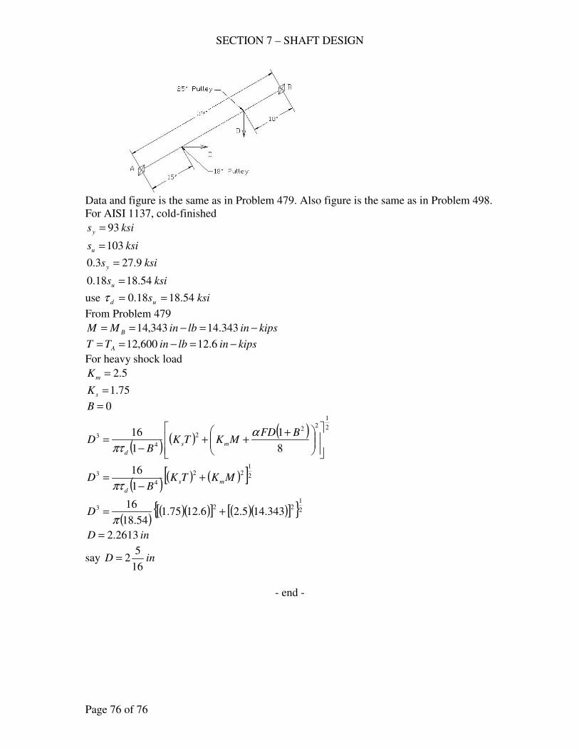
SECTION 7 – SHAFT DESIGN
Page 76 of 76
Data and figure is the same as in Problem 479. Also figure is the same as in Problem 498.
For AISI 1137, cold-finished
ksisy 93=
ksisu 103=
ksisy 9.273.0 =
ksisu 54.1818.0 =
use ksisud 54.1818.0 ==τ
From Problem 479
kipsinlbinMM B −=−== 343.14343,14
kipsinlbinTT A −=−== 6.12600,12
For heavy shock load
5.2=mK
75.1=sK
0=B
( )( ) ( ) 2
12
22
4
3
8
1
1
16
+++
−=
BFDMKTK
BD ms
d
α
πτ
( )( ) ( )[ ]2
122
4
3
1
16MKTK
BD ms
d
+−
=πτ
( )( )( )[ ] ( )( )[ ]{ }2
1223 343.145.26.1275.1
54.18
16+=
πD
inD 2613.2=
say inD16
52=
- end -
SECTION 9 – JOURNAL AND PLANE-SURFACE BEARINGS
Page 1 of 63
LIGHTLY LOADED BEARINGS
551. (a) A 3 x 3 – in. full bearing supports a load of 900 lb., 0015.0=Dcd ,
rpmn 400= . The temperature of the SAE 40 oil is maintained at 140 oF.
Considering the bearing lightly loaded (Petroff), compute the frictional torque,
fhp, and the coefficient of friction. (b) The same as (a) except that the oil is
SAE 10W.
Solution.
(a) ( )
=
22
D
c
DLvT
d
ips
f
µπ
inL 3=
inD 3=
( )( )ips
Dnvips π
ππ20
60
4003
60===
0015.0=Dcd
SAE 40 oil, 140 oF, Figure A16.
reynsµµ 25.7=
( )( )( )( )( )( )
( )lb
c
DLvF
d
ips173.17
20015.0
20331025.7
2
6
=×
==− ππµπ
( ) lbinD
FT f −=
=
= 76.25
2
3173.17
2
000,33
mFvfhp =
( )( )fpm
Dnvm 16.314
12
4003
12===
ππ
( )( )hp
Fvfhp m 1635.0
000,33
16.314173.17
000,33===
0191.0900
173.17===
W
Ff
(b) SAE 10W oil, 140 oF, Figure A16.
reynreyns 6102.22.2 −×== µµ
( )( )( )( )( )( )
( )lb
c
DLvF
d
ips211.5
20015.0
2033102.2
2
6
=×
==− ππµπ
( ) lbinD
FT f −=
=
= 817.7
2
3211.5
2
000,33
mFvfhp =
SECTION 9 – JOURNAL AND PLANE-SURFACE BEARINGS
Page 2 of 63
( )( )fpm
Dnvm 16.314
12
4003
12===
ππ
( )( )hp
Fvfhp m 0496.0
000,33
16.314211.5
000,33===
00579.0900
211.5===
W
Ff
553. The average pressure on a 6-in. full bearing is 50 psi, .003.0 incd = , 1=DL .
While the average oil temperature is maintained at 160 oF with rpmn 300= ,
the frictional force is found to be 13 lb. Compute the coefficient of friction
and the average viscosity of the oil. To what grade of oil does this
correspond?
Solution:
LD
Wp =
.6 inD =
1=DL
.6 inL =
( )( )( ) lbpLDW 18006650 ===
lbF 13=
Coefficient of Friction
0072.01800
13===
W
Ff
( )2d
ips
c
DLvF
µπ=
( )( )ips
Dnvips π
ππ30
60
3006
60===
( )( )( )( )( )
( )lb
c
DLvF
d
ips13
2003.0
3066
2===
ππµµπ
reynsreyn µµ 8.1108.1 6 =×= −
Figure AF 16, 160 oF use SAE 10W or SAE 20W
FULL BEARINGS
554. The load on a 4-in. full bearing is 2000 lb.,
rpmn 320= ; 1=DL ; 0011.0=Dcd ; operating temperature = 150 oF;
inho 00088.0= . (a) Select an oil that will closely accord with the started
conditions. For the selected oil determine (b) the frictional loss (ft-lb/min), (c)
the hydrodynamic oil flow through the bearing, (d) the amount of end leakage,
SECTION 9 – JOURNAL AND PLANE-SURFACE BEARINGS
Page 3 of 63
(e) the temperature rise as the oil passes through the bearing, (f) the maximum
pressure.
Solution:
(a) inD 4=
1=DL
inL 4=
( ) inDcd 0044.040011.00011.0 ===
inho 00088.0=
( )6.0
0044.0
00088.021
21 =−=−=
d
o
c
hε
Table AT 20
6.0=ε , 1=DL
Sommerfield Number 2
=
d
s
c
D
p
nS
µ
rpsns 333.560
320==
( )( )psi
LD
Wp 125
44
2000===
0011.0=Dcd
( ) 2
0011.0
1
125
333.5121.0
=
µ
reynsreyn µµ 4.3104.3 6 =×= −
Figure AF-16, 150 oF, use SAE 30 or SAE 20 W
Select SAE 30, the nearest
reyn6109.3 −×=µ
(b) Table AT 20, 1=DL , 6.0=ε
22.3=fc
r
r
0011.0
1==
dr c
D
c
r
22.30011.0
1=
f
003542.0=f
( )( ) lbWfF 084.72000003542.0 ===
SECTION 9 – JOURNAL AND PLANE-SURFACE BEARINGS
Page 4 of 63
( )( )fpm
Dnvm 1.335
12
3204
12===
ππ
Frictional loss = ( )( ) minlbftFvm −= 23741.335084.7
(c) Table AT 20, 1=DL , 6.0=ε
33.4=Lnrc
q
sr
inD
r 0.22
==
inc
c dr 0022.0
2
0044.0
2===
rpsns 333.5=
inL 4=
( )( )( )( ) secinLnrcq sr
34064.04333.50022.00.233.433.4 ===
(d) Table AT 20, 1=DL , 6.0=ε
680.0=q
qs
( ) secinqqs
32764.04064.0680.0680.0 ===
(e) Table AT 20, 1=DL , 6.0=ε
2.14=∆
p
tc oρ
112=cρ , psip 125=
( )F
c
pto
o85.15112
1252.142.14===∆
ρ
(f) Table AT 20, 1=DL , 6.0=ε
415.0max
=p
p
psip 2.301415.0
125max ==
555. A 4-in., 360o bearing, with 1.1=DL (use table and chart values for 1), is to
support 5 kips with a minimum film thickness 0.0008 in.; .004.0 incd = ,
rpmn 600= . Determine (a) the needed absolute viscosity of the oil .(b)
Suitable oil if the average film temperature is 160 F, (c) the frictional loss in
hp. (d) Adjusting only oh to the optimum value for minimum friction,
determine the fhp and compare. (e) This load varies. What could be the
magnitude of the maximum impulsive load if the eccentricity ration ε
becomes 0.8? Ignore “squeeze” effect.
SECTION 9 – JOURNAL AND PLANE-SURFACE BEARINGS
Page 5 of 63
Solution:
inD 4=
( ) inDL 4.441.11.1 ===
( )( )psi
LD
Wp 284
44.4
5000===
inho 0008.0=
.004.0 incd =
( )6.0
004.0
0008.021
21 =−=−=
d
o
c
hε
rps1060
600==η
(a) Table AT20, 1=DL , 6.0=ε
121.0=S 22
=
=
d
ss
r c
D
p
n
p
n
c
rS
µµ
( ) 2
004.0
4
284
10121.0
=
µ
reyn6104.3 −×=µ
(b) Figure AF16, 160 F
Use SAE 30, reyn6102.3 −×=µ
(c) Table AT 20, 1=DL , 6.0=ε
22.3=fc
r
r
22.3=fc
D
d
22.3004.0
4=
f
00322.0=f
( )( ) lblbWfF 1.16500000322.0 ===
( )( )fpm
Dnvm 3.628
12
6004
12===
ππ
SECTION 9 – JOURNAL AND PLANE-SURFACE BEARINGS
Page 6 of 63
( )( )hp
Fvfhp m 3065.0
000,33
3.6281.16
000,33===
(d) adjusting oh , .004.0 incd =
Table AT 20, 1=DL
30.0=ro ch optimum value for minimum friction
46.2=fc
r
r
46.2=fc
D
d
46.2004.0
4=
f
00246.0=f
( )( ) lblbWfF 3.12500000246.0 ===
( )( )fpm
Dnvm 3.628
12
6004
12===
ππ
( )( ) ( )cfhphpFv
fhp m <=== 234.0000,33
3.6283.12
000,33
(e) 8.0=ε , Table AT 20, 1=DL
0446.0=S 22
=
=
d
ss
r c
D
p
n
p
n
c
rS
µµ
( )( ) 26
004.0
410102.30446.0
×=
−
p
psip 5.717=
( )( )( ) lbpDLW 628,124.445.717 ===
556. For an 8 x 4 – in. full bearing, .0075.0 incr = , rpmn 2700= , average
reyn6104 −×=µ . (a) What load may this bearing safely carry if the minimum
film thickness is not to be less than that given by Norton, i11.14, Text? (b)
Compute the corresponding frictional loss (fhp). (c) Complete calculations for
the other quantities in Table AT 20, φ , q , sq , ot∆ , maxp . Compute the
maximum load for an optimum (load) bearing (d) if rc remains the same, (e)
if oh remains the same.
SECTION 9 – JOURNAL AND PLANE-SURFACE BEARINGS
Page 7 of 63
Solution:
48×=× LD
21=DL
incr 0075.0=
inDr 42 ==
reyn6104 −×=µ
(a) by Norton, ( ) inDho 002.0800025.000025.0 ===
27.00075.0
002.0==
r
o
c
h
Table AT 20, 21=DL , 27.0=r
o
c
h
172.0=S
p
n
c
rS s
r
µ2
=
rpsns 4560
2700==
( )( )p
S45104
0075.0
4172.0
62 −×
==
psip 298=
( )( )( ) lbpDLW 953648298 ===
(b) Table AT 20, 21=DL , 27.0=r
o
c
h
o5.38=φ
954.4=fc
r
r
954.4=fc
D
d
954.4004.0
4=
f
0093.0=f
( )( ) lblbWfF 7.8895360093.0 ===
( )( )fpm
Dnvm 5655
12
27008
12===
ππ
( )( )hp
Fvfhp m 2.15
000,33
56557.88
000,33===
SECTION 9 – JOURNAL AND PLANE-SURFACE BEARINGS
Page 8 of 63
(c) Table AT 20, 21=DL , 27.0=r
o
c
h
o5.38=φ
214.5=Lnrc
q
sr
( )( )( )( ) sec2.284450075.04214.5214.5 3inLnrcq sr ===
824.0=q
qs
( ) sec2.232.28824.0 3inqs ==
26.20=∆
p
tcρ
( )Ft
o54112
29826.20==∆
3013.0max
=p
p
psip 9893013.0
298max ==
To solve for maximum load, Table AT 20, 21=DL , 43.0=r
o
c
h
388.0
2
=
=
p
n
c
rS s
r
µ
(d) incr 0075.0=
( )( )p
S45104
0075.0
4388.0
62 −×
==
psip 132=
( )( )( ) lbpDLW 422448132 ===
(e) inho 002.0=
43.0=r
o
c
h
incr 00465.043.0
002.0==
( )( )p
S45104
00465.0
4388.0
62 −×
==
psip 3.343=
( )( )( ) lbpDLW 986,10483.343 ===
SECTION 9 – JOURNAL AND PLANE-SURFACE BEARINGS
Page 9 of 63
557. A 6 x 6 – in full bearing has a frictional loss of 11=fhp when the load is
68,500 lb. and rpmn 1600= ; 001.0=rcr . (a) Compute the minimum film
thickness. Is this in the vicinity of that for an optimum bearing? (b) What is
the viscosity of the oil and a proper grade for an operating temperature of 160
F? (c) For the same oh , but for the maximum-load optimum, determine the
permissible load and the fhp.
Solution:
inL 6=
inD 6=
1=DL
inDr 32 ==
001.0=rcr
rpmn 1600=
( )( )fpm
Dnvm 2513
12
16003
12===
ππ
000,33
mFvfhp =
( )lbF 45.144
2513
11000,33==
00211.0500,68
45.144===
W
Ff
(a) ( ) 11.200211.0001.0
1=
=f
c
r
r
Table AT 20, 1=DL , 11.2=fc
r
r
Near the vicinity of optimum bearing
( ) inrcr 003.03001.0001.0 ===
( ) inch ro 0008.0003.0254.0254.0 ===
(b) Table AT 20, 1=DL , 11.2=fc
r
r
0652.0=S
388.0
2
=
=
p
n
c
rS s
r
µ
rpsns 67.2660
1600==
( )( )psi
LD
Wp 8.1902
66
500,68===
SECTION 9 – JOURNAL AND PLANE-SURFACE BEARINGS
Page 10 of 63
( )( )8.1902
67.26
001.0
10652.0
2µ
==S
reyn6107.4 −×=µ
Figure AF 16, 160 F, use SAE 40.
(c) Table AT 20, 1=DL
optimum bearing, maximum load, 53.0=r
o
c
h
oh the same, inh
c or 0015.0
53.0
0008.0
53.0===
53.0=r
o
c
h, 214.0=S , 89.4=f
c
r
r
p
n
c
rS s
r
µ2
=
( )( )p
S67.26107.4
0015.0
3214.0
62 −×
==
psip 2343=
( )( )( ) lbpDLW 348,84662343 ===
89.4=fc
r
r
89.40015.0
3=
f
00245.0=f
( ) lbWfF 65.206348,8400245.0 ===
fpmvm 2513=
( )( )hp
Fvfhp m 74.15
000,33
251365.206
000,33===
558. The maximum load on a 2.25 x 1.6875 in. main bearing of an automobile is
3140 lb. with wide-open throttle at 1000 rpm. If the oil is SAE 20W at 210 F,
compute the minimum film thickness for a bearing clearance of (a) 0.0008 in.
and (b) 0.0005 in. Which clearance results in the safer operating conditions?
Note: Since a load of this order exists for only 20-25o of rotation, the actual
oh does not reach this computed minimum (squeeze effect).
Solution:
inLD 6875.125.2 ×=×
75.025.2
6875.1==
D
L
SECTION 9 – JOURNAL AND PLANE-SURFACE BEARINGS
Page 11 of 63
SAE 20 W at 210 oF
reyn61096.0 −×=µ
lbW 3140=
rpmn 1000=
( )( )psi
DL
Wp 827
6875.125.2
3140===
rpsns 67.1660
1000==
inD
r 125.12
==
2
=
r
s
c
r
p
nS
µ
(a) incr 0008.0=
( )( )038.0
0008.0
125.1
827
67.161096.026
=
×=
−
S
Table AT 20, 43=DL , 038.0=S
DL ro ch S
1 0.2 0.0446
½ 0.2 0.0923
¾ 0.2 0.0685
DL ro ch S
1 0.1 0.0188
½ 0.1 0.0313
¾ 0.1 0.0251
At 43=DL
( ) 13.01.01.02.00251.00685.0
0251.0038.0=+−
−
−=
r
o
c
h
( ) inch ro 0001.00008.013.013.0 ===
(b) incr 0005.0=
( )( )098.0
0005.0
125.1
827
67.161096.026
=
×=
−
S
Table AT 20, 43=DL , 098.0=S
SECTION 9 – JOURNAL AND PLANE-SURFACE BEARINGS
Page 12 of 63
DL ro ch S
1 0.2 0.0446
½ 0.2 0.0923
¾ 0.2 0.0685
DL ro ch S
1 0.4 0.121
½ 0.4 0.319
¾ 0.4 0.220
At 43=DL
( ) 239.02.02.04.00685.0220.0
0685.0098.0=+−
−
−=
r
o
c
h
( ) inch ro 00012.00005.0239.0239.0 ===
use incr 0005.0= , inho 00012.0=
561. A 360o bearing supports a load of 2500 lb.; .5 inD = , .5.2 inL = ,
.003.0 incr = , rpmn 1800= ; SAE 20 W oil entering at 100 F. (a) Compute
the average temperature avt of the oil through the bearing. (An iteration
procedure. Assume µ ; compute S and the corresponding ot∆ ; then the
average oil temperature 2oiav ttt ∆+= . If this avt and the assumed µ do not
locate a point in Fig. AF 16 on the line for SAE 20 W oil, try again.) Calculate
(b) the minimum film thickness, (c) the fhp, (d) the amount of oil to be
supplied and the end leakage.
Solution:
inD 5=
inL 5.2=
5.05
5.2==
D
L
incr 003.0=
(a) Table AT 20
Parameter, p
tc o∆ρ, 112=cρ
p
n
c
rS s
r
µ2
=
SECTION 9 – JOURNAL AND PLANE-SURFACE BEARINGS
Page 13 of 63
( )( )psi
DL
Wp 200
5.25
2500===
rpsns 3060
1800==
inD
r 5.22
==
incr 003.0=
Fig. AF 16, SAE 20 W, Table AT 20, 5.0=DL , Fti
o100=
Trial µ ( Ft o ), reyns S p
tc o∆ρ Fto
o∆ Fttt oiav
o2∆+=
3.5 x 10⁻⁶
(130 F) 0.365 36.56 65 132.5
3.2 x 10⁻⁶
(134 F) 0.333 34.08 61 130.5
3.4 x 10⁻⁶
(132 F) 0.354 35.71 64 132.0
Therefore, use Ftav
o132= , 354.0=S
(b) Table AT 20, 5.0=DL , 354.0=S
415.0=r
o
c
h
( ) inho 00125.0003.0415.0 ==
(c) Table AT 20, 5.0=DL , 354.0=S
777.8=fc
r
r
777.8003.0
5.2=
f
0105.0=f
( ) lbWfF 25.2625000105.0 ===
( )( )fpm
Dnvm 2356
12
18005
12===
ππ
( )( )hp
Fvfhp m 874.1
000,33
235625.26
000,33===
(d) Table AT 20, 5.0=DL , 354.0=S
807.4=Lnrc
q
sr
( )( )( )( ) sec704.25.230003.05.2807.4807.4 3inLnrcq sr ===
7165.0=q
qs
SECTION 9 – JOURNAL AND PLANE-SURFACE BEARINGS
Page 14 of 63
( ) sec937.1704.27165.0 3inqs ==
PARTIAL BEARINGS
562. A 2 x 2-in. bearing has a clearance incr 001.0= , and .0004.0 inho = ,
rpmn 2400= , and for the oil, reyn6103 −×=µ . Determine the load, frictional
horsepower, the amount of oil to enter, the end leakage of oil, and the
temperature rise of the oil as it passes through for : (a) a full bearing, partial
bearings of (b) 180o, (c) 120
o, (d) 90
o, (e) 60
o.
Solution:
inLD 2==
1=DL
incr 001.0=
inDr 12 ==
rpmn 2400=
rpsns 40=
reyn6103 −×=µ
.004.0 inho =
4.0001.0
0004.0==
r
o
c
h
( )( )fpm
Dnvm 1257
12
24002
12===
ππ
(a) Full bearing
Table AT 20, 1=DL , 4.0=ro ch
121.0=S
22.3=rc
rf
33.4=Lnrc
q
sr
680.0=q
qs
2.14=∆
p
tc oρ
415.0max
=p
p
Load W
SECTION 9 – JOURNAL AND PLANE-SURFACE BEARINGS
Page 15 of 63
p
n
c
rS s
r
µ2
=
( )( )p
40103
001.0
1121.0
62 −×
=
psip 992=
( )( )( ) lbpDLW 396822992 ===
fhp:
WfF =
22.3=rc
rf
22.3001.0
1=
f
00322.0=f
( )( ) lbWfF 78.12396800322.0 ===
( )( )hp
Fvfhp m 4868.0
000,33
125778.12
000,33===
Oil flow, q
33.4=Lnrc
q
sr
( )( )( )( )33.4
240001.01.0=
q
sec3464.0 3inq =
End leakage
680.0=q
qs
( ) sec2356.03464.068.0 3inqs ==
Temperature rise, ot∆
2.14=∆
p
tc oρ
( )2.14
992
112=
∆ ot
Fto
o126=∆
(b) 180o Bearing
Table AT 21, 1=DL , 4.0=ro ch
128.0=S
SECTION 9 – JOURNAL AND PLANE-SURFACE BEARINGS
Page 16 of 63
28.2=rc
rf
25.3=Lnrc
q
sr
572.0=q
qs
4.12=∆
p
tc oρ
Load W
p
n
c
rS s
r
µ2
=
( )( )p
40103
001.0
1128.0
62 −×
=
psip 5.937=
( )( )( ) lbpDLW 3750225.937 ===
fhp:
WfF =
28.2=rc
rf
28.2001.0
1=
f
00228.0=f
( )( ) lbWfF 55.8375000228.0 ===
( )( )hp
Fvfhp m 3257.0
000,33
125755.8
000,33===
Oil flow, q
25.3=Lnrc
q
sr
( )( )( )( )25.3
240001.01.0=
q
sec26.0 3inq =
End leakage
572.0=q
qs
( ) sec1487.026.0572.0 3inqs ==
Temperature rise, ot∆
SECTION 9 – JOURNAL AND PLANE-SURFACE BEARINGS
Page 17 of 63
4.12=∆
p
tc oρ
( )4.12
5.937
112=
∆ ot
Fto
o104=∆
(c) 12o Bearing
Table AT 22, 1=DL , 4.0=ro ch
162.0=S
16.2=rc
rf
24.2=Lnrc
q
sr
384.0=q
qs
15=∆
p
tc oρ
Load W
p
n
c
rS s
r
µ2
=
( )( )p
40103
001.0
1162.0
62 −×
=
psip 741=
( )( )( ) lbpDLW 296422741 ===
fhp:
WfF =
16.2=rc
rf
16.2001.0
1=
f
00216.0=f
( )( ) lbWfF 4.6296400216.0 ===
( )( )hp
Fvfhp m 2438.0
000,33
12574.6
000,33===
Oil flow, q
SECTION 9 – JOURNAL AND PLANE-SURFACE BEARINGS
Page 18 of 63
24.2=Lnrc
q
sr
( )( )( )( )24.2
240001.01.0=
q
sec1792.0 3inq =
End leakage
384.0=q
qs
( ) sec0688.01792.0384.0 3inqs ==
Temperature rise, ot∆
15=∆
p
tc oρ
( )15
741
112=
∆ ot
Fto
o99=∆
(d) 60o Bearing
1=DL , 4.0=ro ch
450.0=S
29.3=rc
rf
56.1=Lnrc
q
sr
127.0=q
qs
2.28=∆
p
tc oρ
Load W
p
n
c
rS s
r
µ2
=
( )( )p
40103
001.0
1450.0
62 −×
=
psip 267=
( )( )( ) lbpDLW 106822267 ===
fhp:
WfF =
SECTION 9 – JOURNAL AND PLANE-SURFACE BEARINGS
Page 19 of 63
29.3=rc
rf
29.3001.0
1=
f
00329.0=f
( )( ) lbWfF 514.3106800329.0 ===
( )( )hp
Fvfhp m 1339.0
000,33
1257514.3
000,33===
Oil flow, q
56.1=Lnrc
q
sr
( )( )( )( )56.1
240001.01.0=
q
sec1248.0 3inq =
End leakage
127.0=q
qs
( ) sec0158.01248.0127.0 3inqs ==
Temperature rise, ot∆
2.28=∆
p
tc oρ
( )2.28
267
112=
∆ ot
Fto
o67=∆
563. A 2 x 2 in. bearing sustains a load of .5000 lbW = ; .001.0 incr = ;
rpmn 2400= ; reyn6103 −×=µ . Using Figs. AF 17 and AF 18, determine the
minimum film thickness and the frictional loss (ft-lb/min.) for (a) a full
bearing, and for partial bearings of (b) 180o, (c) 120
o, (d) 90
o, (e) 60
o.
Solution:
inL 2=
inD 2=
lbW 5000=
.001.0 incr =
rpmn 2400=
rpsns 40=
reyn6103 −×=µ
inDr 12 ==
SECTION 9 – JOURNAL AND PLANE-SURFACE BEARINGS
Page 20 of 63
( )( )psi
LD
Wp 1250
22
5000===
( )( )10.0
1250
40103
001.0
1 622
=×
=
=
−
p
n
c
rS s
r
µ
( )( )fpm
Dnvm 1257
12
24002
12===
ππ
Using Fig. AF 17 and AF 18
(a) Full Bearing
346.0=r
o
c
h
8.2=fc
r
r
( ) inho 000346.0001.0346.0 ==
8.2001.0
1=
f
0028.0=f
( )( ) lbWfF 1450000028.0 ===
( )( ) min600,17125714 lbftFvm −==
(b) 180o Bearing
344.0=r
o
c
h
0.2=fc
r
r
( ) inho 000344.0001.0344.0 ==
0.2001.0
1=
f
0020.0=f
( )( ) lbWfF 1050000020.0 ===
( )( ) min570,12125710 lbftFvm −==
(c) 120o Bearing
302.0=r
o
c
h
SECTION 9 – JOURNAL AND PLANE-SURFACE BEARINGS
Page 21 of 63
7.1=fc
r
r
( ) inho 000302.0001.0302.0 ==
7.1001.0
1=
f
0017.0=f
( )( ) lbWfF 5.850000017.0 ===
( )( ) min685,1012575.8 lbftFvm −==
(d) 60o Bearing
20.0=r
o
c
h
4.1=fc
r
r
( ) inho 0002.0001.020.0 ==
4.1001.0
1=
f
0014.0=f
( )( ) lbWfF 750000014.0 ===
( )( ) min800,812577 lbftFvm −==
564. A 120o partial bearing is to support 4500 lb. with .002.0 inho = ; 1=DL ;
.4 inD = ; .010.0 incd = ; rpmn 3600= . Determine (a) the oil’s viscosity,(b)
the frictional loss (ft-lb/min), (c) the eccentricity angle, (d) the needed oil
flow, (e) the end leakage, (f) the temperature rise of the oil as it passes
through, (g) the maximum pressure. (h) If the clearance given is the average,
what approximate class of fit (Table 3.1) is it? (i) What maximum impulsive
load would be on the bearing if the eccentricity ratio suddenly went to 0.8?
Ignore “squeeze” effect.
Solution:
lbW 4500=
inho 002.0=
1=DL
inD 4=
inL 4=
inDr 22 ==
.010.0 incd =
rpmn 3600=

SECTION 9 – JOURNAL AND PLANE-SURFACE BEARINGS
Page 22 of 63
rpsns 6060
3600==
( )( )fpm
Dnvm 3770
12
36002
12===
ππ
( )( )psi
LD
Wp 25.281
44
4500===
( )4.0
010.0
002.022===
r
o
r
o
c
h
c
h
Table AT 22, 1=DL , 4.0=ro ch
162.0=S o65.35=φ
16.2=fc
r
r
24.2=Lnrc
q
sr
384.0=q
qs
0.15=∆
p
tc oρ
356.0max
=p
p
(a) p
n
c
rS s
r
µ2
=
p
n
c
DS s
d
µ2
=
( )25.281
60
010.0
4162.0
2µ
=
reyn61075.4 −×=µ
(b) 16.2=fc
r
r
16.2=fc
D
d
16.2010.0
4=
f
0054.0=f
( ) lbWfF 30.2445000054.0 ===
SECTION 9 – JOURNAL AND PLANE-SURFACE BEARINGS
Page 23 of 63
( )( ) min611,91377030.24 lbftFvm −==
(c) o65.35=φ
(d) 24.24
==LnDc
q
Lnrc
q
sdsr
( )( )( )( )24.2
460010.04
4=
q
sec4.5 3inq =
(e) 384.0=q
qs
( ) sec07.24.5384.0 3inqs ==
(f) 0.15=∆
p
tc oρ
( )0.15
25.281
112=
∆ ot
Fto
o38=∆
(g) 356.0max
=p
p
psip 790356.0
25.281max ==
(h) incd 010.0= , inD 4=
Table 3.1
RC 8, Hole, average = + 0.0025
Shaft, average = - 0.00875
incd 010.001125.000875.00025.0 ≈=+=
Class of fit = RC 9
(i) 80.0=ε
Table AT 22, , 1=DL
162.0=S
p
n
c
DS s
d
µ2
=
( )( )p
60103
010.0
40531.0
62 −×
=
psip 542=
SECTION 9 – JOURNAL AND PLANE-SURFACE BEARINGS
Page 24 of 63
( )( )( ) lbpDLW 867244542 ===
565. A 120o partial bearing is to support 4500 lb., .3 inD = , .003.0 incd = ;
rpmn 3600= ; SAE 20W entering at 110 F. Calculate (a) the average
temperature of the oil as it passes through,(b) the minimum film thickness, (c)
the fhp, (d) the quantity of oil to be supplied. HINT: In (a) assume µ and
determine the corresponding values of S and ot∆ ; then 2oiav ttt ∆+= . If
assumed µ and avt do not locate a point in Fig. AF 16 that falls on line for
SAE 20W, iterate.
Solution:
lbW 4500=
inD 3=
inL 3=
1=DL
.003.0 incd =
p
n
c
DS s
d
µ2
=
rpsns 6060
3600==
( )( )psi
DL
Wp 500
33
4500===
p
tc o∆ρ, (SAE 20W)
(a) Using Table AT22, 1=DL , 112=cρ , Fti
o110=
Trial µ t , oF S
p
tc o∆ρ
ot∆ 2oiav ttt ∆+=
3.5 x 10⁻⁶
130 0.42 19.8 88 154
2.0 x 10⁻⁶
160 0.24 15.4 68 144
2.6 x 10⁻⁶
145 0.312 17.7 79 149.5
2.35 x 10⁻⁶
150 0.282 17.2 76 148
2.4 x 10⁻⁶
149 0.288 17.3 78 149
∴ Use Ftav
o149=
(b) Table AT 22, 1=DL , 288.0=S
SECTION 9 – JOURNAL AND PLANE-SURFACE BEARINGS
Page 25 of 63
513.0=r
o
c
h
513.02
=d
o
c
h
( )003.0513.02 =oh
inho 00077.0=
(c) Table At 22, 1=DL , 288.0=S
974.2=fc
r
r
974.2003.0
3== ff
c
D
r
002974.0=f
( )( ) lbWfF 383.134500002974.0 ===
000,33
mFvfhp =
( )( )fpm
Dnvm 2827
12
36003
12===
ππ
( )( )hp
Fvfhp m 15.1
000,33
2827383.13
000,33===
(d) Table At 22, 1=DL , 288.0=S
528.2=Lnrc
q
sr
528.24
=LnDc
q
sd
( )( )( )( )528.2
360003.03
4=
q
sec024.1 3inq =
566. The 6000-lb. reaction on an 8 x 4 –in., 180o partial bearing is centrally
applied; rpmn 1000= ; inho 002.0= . For an optimum bearing with minimum
friction determine (a) the clearance, (b) the oil’s viscosity, (c) the frictional
horsepower. (d) Choose a Dcd ratio either smaller or larger than that
obtained in (a) and show that the friction loss is greater than that in the
optimum bearing. Other data remain the same.
Solution:
lbW 6000=
SECTION 9 – JOURNAL AND PLANE-SURFACE BEARINGS
Page 26 of 63
inD 8=
inL 4=
rpmn 1000=
rpsns 67.1660
1000==
21=DL
inho 002.0=
(a) Table AT 21, 21=DL
Optimum value (minimum friction)
23.0=ro ch
incr 0087.023.0
002.0==
(b) Table AT 21, 21=DL , 23.0=ro ch
126.0=S
p
n
c
rS s
r
µ2
=
( )( )psi
DL
Wp 5.187
84
6000===
inD
r 42
==
( )5.187
67.16
0087.0
4126.0
2µ
==S
reyn61070.6 −×=µ
(c) Table AT 21, 21=DL , 23.0=ro ch
97.2=fc
r
r
97.20087.0
4=
f
00646.0=f
( )( ) lbWfF 76.38600000646.0 ===
( )( )fpm
Dnvm 2094
12
10008
12===
ππ
SECTION 9 – JOURNAL AND PLANE-SURFACE BEARINGS
Page 27 of 63
( )( )hp
Fvfhp m 46.2
000,33
209476.38
000,33===
For (a) ( )
0022.08
0087.022===
D
c
D
c rd
0022.0>D
cd
0030.0=D
cd
( ) incd 0240.080030.0 ==
incr 0120.0=
1667.0012.0
002.0==
r
o
c
h
Table AT 21, 21=DL
67.1=fc
r
r
67.10016.0
4=
f
00668.0=f
( )( ) lbWfF 08.40600000668.0 ===
( )( )fpm
Dnvm 2094
12
10008
12===
ππ
( )( )hphp
Fvfhp m 46.254.2
000,33
209408.40
000,33>===
0022.0<D
cd
0020.0=D
cd
( ) incd 0160.080020.0 ==
incr 0080.0=
25.0008.0
002.0==
r
o
c
h
Table AT 21, 21=DL
26.3=fc
r
r
26.30016.0
4=
f
00652.0=f
SECTION 9 – JOURNAL AND PLANE-SURFACE BEARINGS
Page 28 of 63
( )( ) lbWfF 12.39600000652.0 ===
( )( )fpm
Dnvm 2094
12
10008
12===
ππ
( )( )hphp
Fvfhp m 46.248.2
000,33
209412.39
000,33>===
567. A 120o partial bearing supports 3500 lb. when rpmn 250= ; .5 inD = ,
.5 inL = ; reyn6103 −×=µ . What are the clearance and minimum film
thickness for an optimum bearing (a) for maximum load, (b) for minimum
friction? (c) On the basis of the average clearance in Table 3.1, about what
class fit is involved? Would this fit be on the expensive or inexpensive side?
(d) Find the fhp for each optimum bearing.
Solution:
.5 inD =
.5 inL =
1=D
L
rpmn 250=
rpsns 17.460
250==
reyn6103 −×=µ
lbW 3500=
( )( )psi
DL
Wp 140
55
3500===
(a) Table AT 22, 1=D
L, max. load 46.0=
r
o
c
h
229.0=S
p
n
c
rS s
r
µ2
=
inD
r 5.22
==
( )( )140
17.4100.35.2229.0
62
−×
==
rcS
incr 00156.0=
( ) inch ro 00072.000156.046.046.0 ===
SECTION 9 – JOURNAL AND PLANE-SURFACE BEARINGS
Page 29 of 63
(b) Table AT 22, 1=D
L, min. friction 40.0=
r
o
c
h
162.0=S
p
n
c
rS s
r
µ2
=
inD
r 5.22
==
( )( )140
17.4100.35.2162.0
62
−×
==
rcS
incr 00186.0=
( ) inch ro 00074.000186.040.046.0 ===
(c) ( ) incd 00312.000156.021 ==
( ) incd 00372.000186.022 ==
Use Class RC4, ave. incd 00320.0= , expensive side
(d) Table AT 22, 1=D
L, max. load 46.0=
r
o
c
h
592.2=fc
r
r
592.200156.0
5.2=
f
00162.0=f
( )( ) lbWfF 67.5350000162.0 ===
( )( )fpm
Dnvm 25.327
12
2505
12===
ππ
( )( )hp
Fvfhp m 0562.0
000,33
25.32767.5
000,33===
For minimum friction, 40.0=r
o
c
h
16.2=fc
r
r
16.200186.0
5.2=
f
00161.0=f
( )( ) lbWfF 635.5350000161.0 ===
SECTION 9 – JOURNAL AND PLANE-SURFACE BEARINGS
Page 30 of 63
( )( )fpm
Dnvm 25.327
12
2505
12===
ππ
( )( )hp
Fvfhp m 0559.0
000,33
25.327635.5
000,33===
570. A 180o partial bearing is to support 17,000 lb. with psip 200= ,
rpmn 1500= , inho 003.0= , 1=DL . (a) Determine the clearance for an
optimum bearing with minimum friction. (b) Taking this clearance as the
average, choose a fit (Table 3.1) that is approximately suitable. (c) Select an
oil for an average temperature of 150 F. (d) Compute fhp.
Solution:
lbW 000,17=
psip 200=
rpmn 1500=
rpsns 2560
1500==
1=DL
DL =
DL
Wp =
2
000,17200
D=
inLD 22.9==
inD
r 61.42
22.9
2===
(a) For optimum bearing with minimum friction
Table AT 21, 1=DL , 44.0=ro ch
44.0=ro ch
44.0003.0
=rc
incr 00682.0=
(b) Table 3.1, inD 22.9=
( ) incc rd 01364.000682.022 ===
Use Class RC7, average incd 01065.0=
Or use Class RC8, average incd 01575.0=
(c) Table AT 21, 1=DL , 44.0=ro ch
158.0=S
SECTION 9 – JOURNAL AND PLANE-SURFACE BEARINGS
Page 31 of 63
p
n
c
rS s
r
µ2
=
( )200
25
00682.0
61.4158.0
2µ
=
reyn6108.2 −×=µ
Fig. AF 16, at 150 F
Use Either SAE 20W or SAE 30.
(d) Table AT 21, 1=DL , 44.0=ro ch
546.2=fc
r
r
546.200682.0
61.4=
f
00377.0=f
( )( )fpm
Dnvm 3621
12
150022.9
12===
ππ
( )( ) lbWfF 09.64000,1700377.0 ===
( )( )hp
Fvfhp m 0.7
000,33
362109.64
000,33===
571. The reaction on a 120o partial bearing is 2000 lb. The 3-in journal turns at
1140 rpm; .003.0 incd = ; the oil is SAE 20W at an average operating
temperature of 150 F. Plot curves for the minimum film thickness and the
frictional loss in the bearing against the ratio DL , using =DL 0.25, 0.5, 1,
and 2. (Note: This problem may be worked as a class problem with each
student being responsible for a particular DL ratio.)
Solution:
lbW 2000=
.3 inD =
rpmn 1140=
rpsns 1960
1140==
incd 003.0=
incr 0015.0=
For SAE 20W, 150 F
reyn61075.2 −×=µ
(a) 25.0=D
L
SECTION 9 – JOURNAL AND PLANE-SURFACE BEARINGS
Page 32 of 63
( ) inDL 75.0325.025.0 ===
( )( )psi
DL
Wp 889
75.03
2000===
Table AT 22, 25.0=D
L
inD
r 5.12
==
( )( )0588.0
889
191075.2
0015.0
5.1 622
=×
=
=
−
p
n
c
rS s
r
µ
083.0=r
o
c
h
( ) inho 000125.00015.0083.0 ==
193.2=fc
r
r
193.20015.0
5.1=
f
002193.0=f
( )( ) lbWfF 386.42000002193.0 ===
( )( )fpm
Dnvm 895
12
11403
12===
ππ
( )( )hp
Fvfhp m 119.0
000,33
895386.4
000,33===
(b) 5.0=D
L
( ) inDL 5.135.05.0 ===
( )( )psi
DL
Wp 444
5.13
2000===
Table AT 22, 5.0=D
L
inD
r 5.12
==
( )( )1177.0
444
191075.2
0015.0
5.1 622
=×
=
=
−
p
n
c
rS s
r
µ
2159.0=r
o
c
h
( ) inho 000324.00015.02159.0 ==
35.2=fc
r
r
SECTION 9 – JOURNAL AND PLANE-SURFACE BEARINGS
Page 33 of 63
35.20015.0
5.1=
f
00235.0=f
( )( ) lbWfF 7.4200000235.0 ===
( )( )fpm
Dnvm 895
12
11403
12===
ππ
( )( )hp
Fvfhp m 1275.0
000,33
8957.4
000,33===
(c) 1=D
L
inDL 3==
( )( )psi
DL
Wp 222
33
2000===
Table AT 22, 1=D
L
inD
r 5.12
==
( )( )2354.0
222
191075.2
0015.0
5.1 622
=×
=
=
−
p
n
c
rS s
r
µ
4658.0=r
o
c
h
( ) inho 000699.00015.04658.0 ==
634.2=fc
r
r
634.20015.0
5.1=
f
002634.0=f
( )( ) lbWfF 268.52000002634.0 ===
( )( )fpm
Dnvm 895
12
11403
12===
ππ
( )( )hp
Fvfhp m 1429.0
000,33
895268.5
000,33===
(d) 2=D
L
( ) inDL 6322 ===
( )( )psi
DL
Wp 111
63
2000===
Table AT 22, 2=D
L
SECTION 9 – JOURNAL AND PLANE-SURFACE BEARINGS
Page 34 of 63
inD
r 5.12
==
( )( )47.0
111
191075.2
0015.0
5.1 622
=×
=
=
−
p
n
c
rS s
r
µ
718.0=r
o
c
h
( ) inho 00108.00015.0718.0 ==
8118.3=fc
r
r
8118.30015.0
5.1=
f
003812.0=f
( )( ) lbWfF 624.72000003812.0 ===
( )( )fpm
Dnvm 895
12
11403
12===
ππ
( )( )hp
Fvfhp m 2068.0
000,33
895624.7
000,33===
D
L inho , fhp
0.25 0.000125 0.119
0.5 0.000324 0.128
1.0 0.000699 0.143
2.0 0.001080 0.207
SECTION 9 – JOURNAL AND PLANE-SURFACE BEARINGS
Page 35 of 63
STEADY-STATE TEMPERATURE
572. A 180o partial bearing is subjected to a load of 12,000 lb.; .88 inLD ×=× ,
0015.0=rcr , .0024.0 inho ≈ , rpmn 500= . The air speed about the bearing
is expected to be in excess of 1000 fpm (on moving vehicle) and the effective
radiating area is DL20 . Determine: (a) the eccentricity factor, (b) µreyns, (c)
the frictional loss (ft-lb/min), (d) the estimated temperature of oil and bearing
( a self-contained oil-bath unit) for steady-state operation, and a suitable
oil.(e) Compute ot∆ of the oil passing through the load-carrying area, remark
on its reasonableness, and decide upon whether some redesign is desirable.
Solution:
.8 inD =
.8 inL =
1=DL
lbW 000,12=
inD
r 42
==
( ) inrcr 0060.040015.00015.0 ===
4.00060.0
0024.0==
r
o
c
h
rpmn 500=
rpsns 33.860
500==
Table AT 21, 4.0=ro ch , 1=DL
128.0=S
28.2=fc
r
r
4.12=∆
p
tc oρ
( )( )psi
DL
Wp 5.187
88
000,12===
(a) 6.04.011 =−=−=r
o
c
hε
(b) p
n
c
rS s
r
µ2
=
( )5.187
33.8
0060.0
4128.0
2µ
==S
reyn6105.6 −×=µ
SECTION 9 – JOURNAL AND PLANE-SURFACE BEARINGS
Page 36 of 63
(c) 28.2=fc
r
r
28.20060.0
4=
f
00342.0=f
( )( ) lbWfF 04.41000,1200342.0 ===
( )( )fpm
Dnvm 1047
12
5008
12===
ππ
( )( )hp
Fvfhp m 302.1
000,33
104704.41
000,33===
Frictional loss = 43,000 ft-lb/min
(d) bbcr tAhQ ∆= ft-lb/min
min000,43 lbftQ −=
rccr hhh +=
Finsqlbfthr −−−= ..min108.0
4.0
6.0
017.0D
vh a
c = , fpmva 1000≥
( )( )
Finsqlbfthc −−−== ..min467.08
1000017.0
4.0
6.0
Finsqlbfthcr −−−=+= ..min575.0108.0467.0
( )( ) ..1280882020 insqDLAb ===
bbcr tAhQ ∆=
( )( )( )bt∆= 1280575.0000,43
Ftb 42.58=∆
Oil-bath, 1000 fpm
( )( )( )boa tt ∆≈∆ 3.12.1
( )( )( ) Ftoa 1.9142.583.12.1 ==∆
assume 100 F ambient temperature
FFtb 42.15842.58100 =+=
FFtb 1.1911.91100 =+=
(c) 4.12=∆
p
tc oρ
( )4.12
5.187
112=
∆ ot
Fto 8.20=∆
Solve for 2ot
SECTION 9 – JOURNAL AND PLANE-SURFACE BEARINGS
Page 37 of 63
( ) Ftt oo 2.3821.191221 ==+
21 2.382 oo tt −=
Ftt oo 8.2012 =−
8.202.362 22 =+− oo tt
FFto 2005.2012 ≈=
∴ not reasonable since the oil oxidizes more rapidly above 200 F, a redesign is
desireable.
573. A 2 x 2-in. full bearing (ring-oiled) has a clearance ratio 001.0=Dcd . The
journal speed is 500 rpm, reyn6104.3 −×=µ , and .0005.0 inho = The ambient
temperature is 100 F; DLAb 25= , and the transmittance is taken as
FftsqhrBtuhcr −−= ..2 . Calculate (a) the total load for this condition; (b)
the frictional loss, (c) the average temperature of the oil for steady-state
operation. Is this temperature satisfactory? (d) For the temperature found,
what oil do you recommend? For this oil will oh be less or greater than the
specified value? (e) Compute the temperature rise of the oil as it passes
through the bearing. Is this compatible with other temperatures found? (f)
What minimum quantity of oil should the ring deliver to the bearing?
Solution:
.2 inL =
.2 inD =
001.0=Dcd
( )( ) incd 0020.02001.0 ==
reyn6104.3 −×=µ
.0005.0 inho =
incr 0010.0=
5.00010.00005.0 ==ro ch
Table AT 20, 1=DL , 5.0=ro ch , Full Bearing
1925.0=S
505.4=fc
r
r
16.4=Lnrc
q
sr
25.19=∆
p
tc oρ
(a) 1925.0=S
SECTION 9 – JOURNAL AND PLANE-SURFACE BEARINGS
Page 38 of 63
p
n
c
rS s
r
µ2
=
inD
r 12
==
rpsns 33.860
500==
( )( )p
S330.8104.3
0010.0
11925.0
62 −×
==
psip 147=
( )( )( ) lbpDLW 58822147 ===
(b) 505.4=fc
r
r
505.4001.0
1=
f
004505.0=f
( )( ) lbWfF 649.2588004505.0 ===
( )( )fpm
Dnvm 8.261
12
5002
12===
ππ
( )( ) min5.6938.261649.2 lbftFvU mf −===
(c) bbcr tAhQ ∆=
FinsqlbftFftsqhrBtuhcr −−−=−−= ..min18.0..2
( )( ) ..100222525 insqDLAb ===
fUQ =
( )( )( ) 5.69310018.0 =∆ bt
Ftb 53.38=∆
( ) Ftt boa 7753.3822 ==∆=∆
Fto 17710077 =+= , near 160 F
∴ satisfactory.
(d) Fto 177= , reyn6104.3 −×=µ
Figure AF 16
Use SAE 40 oil, reyn6103.3 −×=µ
p
n
c
rS s
r
µ2
=
SECTION 9 – JOURNAL AND PLANE-SURFACE BEARINGS
Page 39 of 63
( )( )187.0
147
33.8103.3
0010.0
1 62
=×
=
−
S
Table AT 20, 1=DL , 187.0=S
4923.0=ro ch
( ) ( )inhinh oo 0005.000049.00010.04923.0 =<==
(e) 25.19=∆
p
tc oρ
( )25.19
147
112=
∆ ot
Fto 3.25=∆
( ) Ftt oo 354177221 ==∆+∆
Ftt oo 3.2512 =∆−∆
3.253542 2 +=∆ ot
FFto 2001902 <=∆
∴ compatible.
(f) 16.4=Lnrc
q
sr
( )( )( )( )16.4
233.8001.01=
q
sec0693.0 3inq =
574. An 8 x 9-in. full bearing (consider 1=DL for table and chart use only)
supports 15 kips with rpmn 1200= ; 0012.0=rcr ; construction is medium
heavy with a radiating-and-convecting area of about DL18 ; air flow about the
bearing of 80 fpm may be counted on (nearby) pulley; ambient temperature is
90 F. Decide upon a suitable minimum film thickness. (a) Compute the
frictional loss and the steady state temperature. Is additional cooling needed
for a reasonable temperature? Determine (b) the temperature rise of the oil as
it passes through the load-carrying area and the grade of oil to be used if it
enters the bearing at 130 F, (c) the quantity of oil needed.
Solution:
.8 inD =
.9 inL =
.000,15 lbW =
.1200 rpmn =
rpsns 2060
1200==
0012.0=rcr
SECTION 9 – JOURNAL AND PLANE-SURFACE BEARINGS
Page 40 of 63
inDr 42 ==
( ) incr 0048.040012.0 ==
By Norton: ( ) inDho 002.0800025.000025.0 ===
4.00048.0
002.0==
r
o
c
h
Table AT 20, 1=DL , 4.0=ro ch
121.0=S
22.3=fc
r
r
33.4=Lnrc
q
sr
2.14=∆
p
tc oρ
(a) 22.3=fc
r
r
22.30048.0
4=
f
003864.0=f
( )( ) lbWfF 96.57000,15003864.0 ===
( )( )fpm
Dnvm 2513
12
12008
12===
ππ
( )( ) min654,145251396.57 lbftFvU mf −===
bbcr tAhQ ∆=
Finsqlbfthr −−−= ..min108.0
FinsqlbftD
vh a
c −−−= ..min017.04.0
6.0
( )( )
Finsqlbfthc −−−== ..min103.08
80017.0
4.0
6.0
Finsqlbfthhh rccr −−−=+=+= ..min211.0108.0103.0
( )( ) ..1296981818 insqDLAb ===
QU f =
( )( ) bt∆= 1296211.0654,145
Ftb 533=∆ , very high, additional cooling is necessary.
(b) 2.14=∆
p
tc oρ
SECTION 9 – JOURNAL AND PLANE-SURFACE BEARINGS
Page 41 of 63
( )( )psi
DL
Wp 208
98
000,15===
( )2.14
208
112=
∆ ot
Fto 26=∆
Fti 130=
Fto 156=
( ) Ftave 14315613021 =+=
p
n
c
rS s
r
µ2
=
( )208
20
0048.0
4121.0
2µ
==S
reyn6108.1 −×=µ
Figure AF 16, reynsµµ 8.1= , 143 F
Use SAE 10W
(c) 33.4=Lnrc
q
sr
( )( )( )( )33.4
9200048.04=
q
sec96.14 3inq =
575. A 3.5 x 3.5-in., 360o bearing has 0012.0=rcr ; rpmn 300= ; desired
minimum inho 0007.0≈ . It is desired that the bearing be self-contained (oil-
ring); air-circulation of 80 fpm is expected; heavy construction, so that
DLAb 25≈ . For the first look at the bearing, assume reyn6108.2 −×=µ and
compute (a) the frictional loss (ft-lb/min), (b) the average temperature of the
bearing and oil as obtained for steady-state operation, (c) ot∆ as the oil passes
through the load-carrying area (noting whether comparative values are
reasonable). (d) Select an oil for the steady-state temperature and decide
whether there will be any overheating troubles.
Solution:
.5.3 inD =
.5.3 inL =
0012.0=rcr
.75.12 inDr ==
( )( ) incr 0021.075.10012.0 ==
inho 0007.0≈
SECTION 9 – JOURNAL AND PLANE-SURFACE BEARINGS
Page 42 of 63
333.00021.00007.0 ==ro ch
Table AT 20, 360o Bearing, 1=DL , 333.0=ro ch
0954.0=S
71.2=fc
r
r
12.12=∆
p
tc oρ
(a) p
n
c
rS s
r
µ2
=
rpsns 560
300==
reyn6108.2 −×=µ
( )( )p
S5108.2
0021.0
75.10954.0
62 −×
==
psip 102=
( )( )( ) lbpDLW 12505.35.3102 ===
71.2=fc
r
r
71.20021.0
75.1=
f
00325.0=f
( )( ) lbWfF 0625.4125000325.0 ===
( )( )fpm
Dnvm 275
12
3005.3
12===
ππ
( )( ) min11172750625.4 lbftFvU mf −===
(b) bbcr tAhQ ∆=
Finsqlbfthr −−−= ..min108.0
FinsqlbftD
vh a
c −−−= ..min017.04.0
6.0
( )( )
Finsqlbfthc −−−== ..min143.05.3
80017.0
4.0
6.0
Finsqlbfthhh rccr −−−=+=+= ..min251.0108.0143.0
( )( ) ..25.3065.35.32525 insqDLAb ===
QU f =
( )( ) bt∆= 25.306251.01117
SECTION 9 – JOURNAL AND PLANE-SURFACE BEARINGS
Page 43 of 63
Ftb 5.14=∆
( ) Ftt boa 295.1422 ==∆=∆
assume ambient temperature of 100 F
Ftb 5.114=
Fto 129=
(c) 12.12=∆
p
tc oρ
( )12.12
102
112=
∆ ot
Fto 11=∆
( ) Ftt oo 258129221 ==+
Ftt oo 1112 =−
Fto 2692 2 =
FFto 1401352 <=
∴ reasonable
(d) Fto 129= , reyn6108.2 −×=µ
use SAE 10W
Figure AF 16, Fto 126=
Ftoa 26100126 =−=∆
boa tt ∆=∆ 2
Ftb 132
26==∆
( )( )( )fbbcr UlbfttAhQ <−==∆= min9991325.306251.0
∴ there is an overheating problem.
576. A 10-in. full journal for a steam-turbine rotor that turns 3600 rpm supports a
20-kip load with psip 200= ; 00133.0=rcr . The oil is to have
reyn61006.2 −×=µ at an average oil temperature of 130 F. Compute (a) the
minimum film thickness (comment on its adequacy), (b) the fhp, (c) the
altitude angle, the maximum pressure, and the quantity of oil that passes
through the load-carrying area (gpm).(d) At what temperature must the oil be
introduced in order to have 130 F average? (e) Estimate the amount of heat
lost by natural means from the bearing (considered oil bath) with air speed of
300 fpm. If the amount of oil flow computed above is cooled back to the
entering temperature, how much heat is removed? Is this total amount of heat
enough to care for frictional loss? If not, what can be done (i11.21)?
SECTION 9 – JOURNAL AND PLANE-SURFACE BEARINGS
Page 44 of 63
Solution:
.10 inD =
rpmn 3600=
rpsns 6060
3600==
lbW 000,20=
psip 200=
DL
Wp =
L10
000,20200 =
inL 10=
1=DL
inD
r 52
==
00133.0=rcr
( ) incr 00665.0500133.0 ==
reyn61006.2 −×=µ
Ftave 130=
p
n
c
rS s
r
µ2
=
( )( )35.0
200
601006.2
00665.0
5 62
=×
=
−
S
Table AT 20, 1=DL , 35.0=S
647.0=ro ch
o66.65=φ
433.7=fc
r
r
90.3=Lnrc
q
sr
495.0max
=p
p
8.30=∆
p
tc oρ
446.0=q
qs
(a) ( ) inch ro 00430.000665.0647.0647.0 ===
SECTION 9 – JOURNAL AND PLANE-SURFACE BEARINGS
Page 45 of 63
Norton’s recommendation = ( ) ininD 00430.000250.01000025.000025.0 <==
∴ adequate
(b) 433.7=fc
r
r
433.700665.0
5=
f
0099.0=f
( )( ) lbWfF 198000,200099.0 ===
( )( )fpm
Dnvm 9425
12
360010
12===
ππ
( )( )hp
Fvfhp m 55.56
000,33
9425198
000,33===
(c) o66.65=φ
psip
p 404495.0
200
495.0max ===
Lnrcq sr90.3=
( )( )( )( ) sec805.77106000665.0590.3 3inq ==
( )( )( ) gpmingpminq 21.0minsec602311sec805.77 33 ==
(d) 8.30=∆
p
tc oρ
( )8.30
200
112=
∆ ot
Fto 55=∆
2
oiave
ttt
∆+=
2
55130 += it
Fti 5.102=
(e) bbcr tAhQ ∆=
Finsqlbfthr −−−= ..min108.0
FinsqlbftD
vh a
c −−−= ..min017.04.0
6.0
( )( )
Finsqlbfthc −−−== ..min207.05.3
300017.0
4.0
6.0
Finsqlbfthhh rccr −−−=+=+= ..min315.0108.0207.0
Assume
SECTION 9 – JOURNAL AND PLANE-SURFACE BEARINGS
Page 46 of 63
( )( ) ..250010102525 insqDLAb ===
Ftoa 30100130 =−=∆
boa tt ∆=∆ 3.1
Ftb 233.1
30==∆
( )( )( ) min113,18232500315.0 lbftQ −==
( ) seclbintqqcQ osr −∆−= ρ
( )( )( )( )( )( ) min602,327,16012155805.77446.01112 lbftQr −=−=
min735,345,1602,327,1113,18 lbftQQQ rT −=+=+=
( )( )Tmf QlbftFvU >−=== min150,866,19425198
not enough to care for frictional loss, use pressure feed (i11.21).
DESIGN PROBLEMS
578. A 3.5-in. full bearing on an air compressor is to be designed for a load of 1500
lb.; rpmn 300= ; let 1=DL . Probably a medium running for would be
satisfactory. Design for an average clearance that is decided by considering both
Table 3.1 and 11.1. Choose a reasonable oh , say one that gives 5.0≈ro ch .
Compute all parameters that are available via the Text after you have decided on
details. It is desired that the bearing operate at a reasonable steady-state
temperature (perhaps ring-oiled medium construction), without special cooling.
Specify the oil to be used and show all calculations to support your conclusions.
What could be the magnitude of the maximum impulsive load if the eccentricity
ration ε becomes 0.8, “squeeze” effect ignored?
Solution:
1=DL
inD 5.3=
inL 5.3=
lbW 1500=
rpmn 300=
rpsns 560
300==
( )( )psi
DL
Wp 45.122
5.35.3
1500===
Table 3.1, medium running fit,
inD 5.3=
RC 5 or RC 6
Use RC 6
Average incd 0052.0=
SECTION 9 – JOURNAL AND PLANE-SURFACE BEARINGS
Page 47 of 63
Table 11.1, air-compressor
General Machine Practice
Average incd 0055.0=
Using incd 0055.0=
incr 00275.0=
( ) inch ro 001375.000275.05.05.0 ===
Table AT 20, 1=DL , 5.0=ro ch
5.0=ε
1925.0=S o84.56=φ
505.4=fc
r
r
16.4=Lnrc
q
sr
25.19=∆
p
tc oρ
4995.0max
=p
p
Specifying oil:
bbcr tAhQ ∆=
mf FvU =
505.4=fc
r
r
505.400275.0
75.1=
f
00708.0=f
( )( ) lbWfF 62.10150000708.0 ===
( )( )fpm
Dnvm 275
12
3005.3
12===
ππ
( )( ) min292127562.10 lbftFvU mf −===
bbcr tAhQ ∆=
Assume Finsqlbfthcr −−−= ..min516.0
Medium construction
( )( ) ..875.1895.35.35.155.15 insqDLAb ===
Oil-ring bearing
boa tt ∆=∆ 2
fUQ =
( )( )( ) 2921875.189516.0 =∆ bt
SECTION 9 – JOURNAL AND PLANE-SURFACE BEARINGS
Page 48 of 63
Ftb 30=∆
( ) Ftt boa 603022 ==∆=∆
assume ambient temperature = 90 F
Fto 150=
p
n
c
rS s
r
µ2
=
( )45.122
5
00275.0
75.11925.0
2µ
==S
reyn6106.11 −×=µ
Figure AF 16, 150 F, reyn6106.11 −×≈µ
Use SAE 70 oil
Maximum load, W with 8.0=ε
Table AT 20, 1=DL
0446.0=S
p
n
c
rS s
r
µ2
=
( )( )p
S5106.11
00275.0
75.10446.0
62 −×
==
psip 527=
( )( )( ) 64565.35.3527 === pDLW
580. A 2500-kva generator, driven by a water wheel, operates at 900 rpm. The weight
of the rotor and shaft is 15,100 lb. The left-hand, 5 –in, full bearing supports the
larger load, lbR 8920= . The bearing should be above medium-heavy
construction (for estimating bA ). (a) Decide upon an average clearance
considering both Table 3.1 and 11.1, and upon a minimum film thickness
( 5.0≈ro ch is on the safer side). (b) Investigate first the possibility of the
bearing being a self-contained unit without need of special cooling. Not much air
movement about the bearing is expected. Then make final decisions concerning
oil-clearance, and film thickness and compute all the parameters given in the text,
being sure that everything is reasonable.
Solution:
rpmn 900=
rpsns 1560
900==
inD 5=
lbRW 8920==
SECTION 9 – JOURNAL AND PLANE-SURFACE BEARINGS
Page 49 of 63
(a) Table 3.1, inD 5=
RC 5, average incd 0051.0=
incr 00255.0=
( ) inch ro 00128.000255.05.05.0 ===
(b) Use 1=DL
inL 5=
inD
r 5.22
==
( )( )psi
DL
Wp 8.356
55
8920===
Table AT 20, 1=DL , 5.0=ro ch
1925.0=S
505.4=fc
r
r
16.4=Lnrc
q
sr
25.19=∆
p
tc oρ
p
n
c
rS s
r
µ2
=
( )8.356
15
00255.0
5.21925.0
2µ
==S
reyn6108.4 −×=µ
505.4=fc
r
r
505.400255.0
5.2=
f
00460.0=f
( )( ) lbWfF 032.41892000460.0 ===
( )( )fpm
Dnvm 1178
12
9005
12===
ππ
( )( ) min336,481178032.41 lbftFvU mf −===
bbcr tAhQ ∆=
Medium-Heavy
( )( ) ..25.5065525.2025.20 insqDLAb ===
Assume Finsqlbfthcr −−−= ..min516.0
fUQ =
SECTION 9 – JOURNAL AND PLANE-SURFACE BEARINGS
Page 50 of 63
( )( )( ) 336,4825.506516.0 =∆ bt
Ftb 185=∆ , very high
Therefore, special cooling is needed.
25.19=∆
p
tc oρ
( )25.19
8.356
112=
∆ ot
Fto 61=∆
Assume Fti 100=
Ftave 1302
61100 ≈+=
Figure AF 16, reynsµµ 8.4= , 130 F
Select SAE 30 oil. reynsµµ 0.6=
p
n
c
rS s
r
µ2
=
( )( )242.0
8.356
15100.6
00255.0
5.2 62
=×
=
−
S
Table AT 20, 1=DL , 242.0=S
SAE 30 oil at 130 F
569.0=r
o
c
h
o17.61=φ
395.5=fc
r
r
04.4=Lnrc
q
sr
75.22=∆
p
tc oρ
4734.0max
=p
p
Oil, SAE 30
incr 00255.0=
( ) inho 00145.000255.0569.0 ==
PRESSURE FEED
581. An 8 x 8-in. full bearing supports 5 kips at 600 rpm of the journal; .006.0 incr = ;
let the average reyn6105.2 −×=µ . (a) Compute the frictional loss fU . (b) The
SECTION 9 – JOURNAL AND PLANE-SURFACE BEARINGS
Page 51 of 63
oil is supplied under a 40-psi gage pressure with a longitudinal groove at the
point of entry. Assuming that other factors, including fU , remain the same and
that the heat loss to the surrounding is negligible, determine the average
temperature rise of the circulating oil.
Solution:
inL 5=
inD 5=
lbW 5000=
rpmn 600=
rpsns 1060
600==
incr 006.0=
reyn6105.2 −×=µ
1=DL
( )( )psi
DL
Wp 125.78
88
5000===
p
n
c
rS s
r
µ2
=
( )( )1422.0
125.78
10105.2
006.0
4 62
=×
=
−
S
(a) Table AT 20, 1=DL , 1422.0=S
6.3=fc
r
r
, 57.0=ε
6.3006.0
4=
f
0054.0=f
( )( ) lbWfF 2750000054.0 ===
( )( )fpm
Dnvm 1257
12
6008
12===
ππ
( )( ) min940,33125727 lbftFvU mf −===
(b) Longitudinal Groove.
( ) sec5.112
tan3
5.2 3213
inL
rpcq ir ε
π
µ+
= −
psipi 40=
( ) ( )( )
( ) ( )[ ] sec57.05.118
42tan
105.23
40006.05.2 321
6
3
inq +
×= −
−
π
SECTION 9 – JOURNAL AND PLANE-SURFACE BEARINGS
Page 52 of 63
sec41.5 3inq =
of tcqU ∆= ρ
( )( )( ) ( )( ) otftinlbft ∆=− 41.512sec60min112min940,33
Fto 2.11=∆
583. A 4-in. 360o bearing, with 1=DL , supports 2.5 kips with a minimum film of
.0008.0 inho = , .01.0 incd = , .600 rpmn = The average temperature rise of the oil
is to be about 25 F. Compute the pressure at which oil should be pumped into the
bearing if (a) all bearing surfaces are smooth, (b) there is a longitudinal groove at
the oil-hole inlet. (c) same as (a) except that there is a 360o circumferential
groove dividing the bearing into 2-in. lengths.
Solution:
inD 4=
inL 4=
inr 2=
lbW 2500=
incd 010.0=
incr 005.0=
rpmn 600=
rpsns 1060
600==
Fto 25=∆
( )( )psi
DL
Wp 25.156
44
2500===
inho 00080.0=
16.0005.0
0008.0==
r
o
c
h
Table AT 20, 1=DL , 16.0=ro ch
44.1=fc
r
r
, 84.0=ε
44.1005.0
2=
f
0036.0=f
( )( ) lbWfF 925000036.0 ===
( )( )fpm
Dnvm 628
12
6004
12===
ππ
( )( ) sec1130min56526289 lbinlbftFvU mf −=−===
0343.0=S
SECTION 9 – JOURNAL AND PLANE-SURFACE BEARINGS
Page 53 of 63
p
n
c
rS s
r
µ2
=
( )25.156
10
005.0
20343.0
2µ
==S
reyn61035.3 −×=µ
of tcqU ∆= ρ
( )( )( )251121130 q=
sec404.0 3inq =
(a) Smooth
( ) sec5.112
tan3
3213
inL
rpcq ir ε
π
µ+
= −
( ) ( )( )
( ) ( )[ ] sec84.05.114
22tan
1035.33
005.0404.0 321
6
3
inpi +
×= −
−
π
psipi 5.12=
(b) Longitudinal groove
( ) sec5.112
tan3
5.2 3213
inL
rpcq ir ε
π
µ+
= −
( ) ( )( )
( ) ( )[ ] sec84.05.114
22tan
1035.33
005.05.2404.0 321
6
3
inpi +
×= −
−
π
psipi 5=
(c) Circumferential groove
( ) sec5.113
2 323
inL
prcq ir ε
µ
π+=
( )( ) ( )( )( )
( )[ ] sec84.05.1141035.33
005.022404.0 32
6
3
inpi +
×=
−
π
psipi 5=
BEARING CAPS
584. An 8-in. journal, supported on a 150o partial bearing, is turning at 500 rpm;
bearing length = 10.5 in., incd 0035.0= ., inho 00106.0= . The average
temperature of the SAE 20 oil is 170 F. Estimate the frictional loss in a 160o
cap
for this bearing.
Solution:
SECTION 9 – JOURNAL AND PLANE-SURFACE BEARINGS
Page 54 of 63
inho 00106.0=
incd 0035.0=
incr 00175.0=
inc
hch
r
orav
−+=
2
174.01
( ) inhav 00195.000175.0
00106.0174.0100175.0
2
=
−+=
For SAE 20, 170 F
reyn6107.1 −×=µ
av
ips
h
AvF
µ=
DLA θ2
1=
inD 8=
inL 5.10=
9
8
180
160160
ππθ === o
( )( ) ..3.1175.1089
8
2
1insqA =
=
π
( ) ipsDnv sips 5.20960
5008 =
== ππ
( )( )( )lbF 424.21
00195.0
5.2093.117107.1 6
=×
=−
( )( )fpm
Dnvm 1047
12
5008
12===
ππ
( )( ) sec1130min430,221047424.21 lbinlbftFvU mf −=−===
585. A partial 160o bearing has a 160
o cap; inD 2= .,
inL 2= ., incd 002.0= ., inho 0007.0= ., rpmn 500= , and reyn6105.2 −×=µ .
For the cap only, what is the frictional loss?
Solution:
incd 002.0=
incr 001.0=
inho 0007.0=
7.0001.0
0007.0==
r
o
c
h
SECTION 9 – JOURNAL AND PLANE-SURFACE BEARINGS
Page 55 of 63
3.07.011 =−=−=r
o
c
hε
( ) ( ) ( )[ ] inch rav 001067.03.074.01001.074.0122 =+=+= ε
av
ips
h
AvF
µ=
( )( )fpm
Dnvm 8.261
12
5002
12===
ππ
( ) ipsvips 36.5260
128.261 =
=
( )( )( ) ..585.522180
160
2
1
180
160
2
1insqDLA =
=
= ππ
( )( )( )lbF 685.0
001067.0
36.52585.5105.2 6
=×
=−
( )( ) min3.1798.261685.0 lbftFvU mf −===
586. The central reaction on a 120o partial bearing is 10 kips; inD 8= .,
1=DL ., 001.0=rcr . Let rpmn 400= and reyn6104.3 −×=µ . The bearing has
a 150o cap. (a) For the bearing and the cap, compute the total frictional loss by
adding the loss in the cap to that in the bearing. (b) If the bearing were 360o,
instead of partial, calculate the frictional loss and compare.
Solution:
p
n
c
rS s
r
µ2
=
rpsns 67.660
400==
( )( )psi
DL
Wp 25.156
88
000,10===
( )( )145.0
25.156
67.6104.3
001.0
1 62
=×
=
−
S
(a) Table AT 22, 1=DL , 145.0=S
021.2=fc
r
r
6367.0=ε
021.2=fc
r
r
021.2001.0
1=
f
002021.0=f

SECTION 9 – JOURNAL AND PLANE-SURFACE BEARINGS
Page 56 of 63
( )( ) lbWfF 21.20000,10002021.0 ===
( )( )fpm
Dnvm 838
12
4008
12===
ππ
( )( ) min936,1683821.201 lbftFvU mf −===
CAP:
( )274.01 ε+= rav ch
rcr 001.0=
inD
r 42
==
( ) incr 004.04001.0 ==
( ) ( ) ( )[ ] inch rav 0052.06367.074.01004.074.0122 =+=+= ε
av
ips
h
AvF
µ=
( ) ipsvips 6.16760
12838 =
=
( )( )( ) ..78.8388180
150
2
1
180
150
2
1insqDLA =
=
= ππ
( )( )( )lbF 18.9
0052.0
6.16778.83104.3 6
=×
=−
( )( ) min769383818.92 lbftFvU mf −===
Total Frictional Loss
= min629,247693936,1621 lbftUU ff −=+=+
(b) 360o Bearing, 1=DL , 145.0=S
65.3=fc
r
r
5664.0=ε
BEARING:
65.3001.0
1=
f
00365.0=f
( )( ) lbWfF 5.36000,1000365.0 ===
( )( )fpm
Dnvm 838
12
4008
12===
ππ
( )( ) min587,308385.361 lbftFvU mf −===
CAP:
( )274.01 ε+= rav ch
( ) ( ) ( )[ ] inch rav 00495.05664.074.01004.074.0122 =+=+= ε
SECTION 9 – JOURNAL AND PLANE-SURFACE BEARINGS
Page 57 of 63
av
ips
h
AvF
µ=
( )( )( )lbF 645.9
00495.0
6.16778.83104.3 6
=×
=−
( )( ) min8083838645.92 lbftFvU mf −===
Total Frictional Loss
= min670,388083587,3021 lbftUU ff −=+=+
587. The central reaction on a 120o partial bearing is a 10 kips; .8 inD = , 1=DL ,
001.0=rcr ; rpmn 1200= . Let reyn6105.2 −×=µ . The bearing has a 160o cap.
(a) Compute oh and fhp for the bearing and for the cap to get the total fhp. (b)
Calculate the fhp for a full bearing of the same dimensions and compare.
Determine (c) the needed rate of flow into the bearing, (d) the side leakage sq .
(e) the temperature rise of the oil in the bearing both by equation (o), i11.13,
Text, and by Table AT 22. (f) What is the heat loss from the bearing if the oil
temperature is 180 F? Is the natural heat loss enough to cool the bearing? (g) It is
desired to pump oil through the bearing with a temperature rise of 12 F. How
much oil is required? (h) For the oil temperature in (f), what is a suitable oil to
use?
Solution:
p
n
c
rS s
r
µ2
=
rpsns 2060
1200==
( )( )psi
DL
Wp 25.156
88
000,10===
( )( )32.0
25.156
20105.2
001.0
1 62
=×
=
−
S
(a) Table AT 22, 1=DL , 32.0=S
5417.0=ε
4583.0=r
o
c
h
18.3=fc
r
r
60.2=Lnrc
q
sr
SECTION 9 – JOURNAL AND PLANE-SURFACE BEARINGS
Page 58 of 63
305.0=q
qs
834.17=∆
p
tc oρ
38434.0max
=p
p
( )( ) inch ro 00183.04001.04583.04583.0 ===
BEARING:
18.3=fc
r
r
18.3001.0
1=
f
00318.0=f
( )( ) lbWfF 8.31000,1000318.0 ===
( )( )fpm
Dnvm 2513
12
12008
12===
ππ
( )( ) min913,7925138.311 lbftFvU mf −=== , hp42.2
CAP:
( )274.01 ε+= rav ch
rcr 001.0=
inD
r 42
==
( ) incr 004.04001.0 ==
( ) ( ) ( )[ ] inch rav 00487.05417.074.01004.074.0122 =+=+= ε
av
ips
h
AvF
µ=
( ) ipsvips 50360
122513 =
=
( )( )( ) ..36.8988180
160
2
1
180
160
2
1insqDLA =
=
= ππ
( )( )( )lbF 1.23
00487.0
503636.89105.2 6
=×
=−
( )( ) min050,5825131.232 lbftFvU mf −=== , hp76.1
Total Frictional Loss
= min963,137050,58913,7921 lbftUU ff −=+=+
hpU
fhpf
18.4000,33
963,137
000,33===
(b) Full Bearing, 1=DL , 32.0=S

SECTION 9 – JOURNAL AND PLANE-SURFACE BEARINGS
Page 59 of 63
Table AT 20
6305.0=r
o
c
h
86.6=fc
r
r
3695.0=ε
( ) inho 002522.0004.06305.0 ==
BEARING:
86.6=fc
r
r
86.6001.0
1=
f
00686.0=f
( )( ) lbWfF 6.68000,1000686.0 ===
( )( ) min392,17225136.681 lbftFvU mf −=== , hp224.5
CAP:
( )274.01 ε+= rav ch
( ) ( ) ( )[ ] inch rav 00440.03695.074.01004.074.0122 =+=+= ε
av
ips
h
AvF
µ=
( )( )( )lbF 54.25
00440.0
50336.89105.2 6
=×
=−
( )( ) min182,64251354.252 lbftFvU mf −=== , hp946.1
Total Frictional Loss
= min574,236182,64392,17221 lbftUU ff −=+=+
hpU
fhpf
17.7000,33
574,236
000,33===
(c) 120o Bearing
60.2=Lnrc
q
sr
( )( )( )( )60.2
820004.04=
q
sec656.6 3inq =
(d) 305.0=q
qs
305.0656.6
=sq
SECTION 9 – JOURNAL AND PLANE-SURFACE BEARINGS
Page 60 of 63
sec03.2 3inqs =
(e) Equation(o)
of tcqU ∆= ρ1
sec983,15sec60
12913,79min913,791 lbinlbinlbftU f −=−
=−=
( )( ) of tU ∆== 656.6112983,151
Fto 4.21=∆
Table 22.
834.17=∆
p
tc oρ
834.1725.156
112=
∆ ot
Fto 9.24=∆
(f) bbcr tAhQ ∆=
assume Finsqlbfthcr −−−= ..min516.0
( )( ) ..1600882525 insqDLAb ===
2
oab
tt
∆=∆
assume ambient = 100 F
Ftb 402
100180=
−=∆
( )( )( ) 1min024,33401600516.0 fUlbftQ <−==
Therefore not enough to cool the bearing.
(g) 21 ffr UUQQ +=+
963,137024,33 =+rQ
min939,104 lbftQr −=
sec988,20 lbinQr −=
or tcqQ ∆= ρ
( ) ( )12112988,20 q=
sec62.15 3inq =
(h) Fig. AF 16, 180 F, reyn6105.2 −×=µ
use SAE 30 oil
SECTION 9 – JOURNAL AND PLANE-SURFACE BEARINGS
Page 61 of 63
IMPERFECT LUBRICATION:
588. A 0.5 x 0.75-in. journal turns at 1140 rpm. What maximum load may be
supported and what is the frictional loss if the bearing is (a) SAE Type I, bronze
base, sintered bearing, (b) nylon (Zytel) water lubricated, (c) Teflon, with
intermittent use, (d) one with carbon graphite inserts.
Solution:
(a) 12.0=f
( )( )fpm
Dnvm 23.149
12
11405.0
12===
ππ
000,50=mpv
( ) 000,5023.149 =p
psip 335=
( )( )( ) lbpDLW 12675.05.0335 ===
( )( ) lbWfF 12.1512612.0 ===
( )( ) min225623.14912.15 lbftFvU mf −===
(b) 18.0~14.0=f , use 16.0=f
2500=mpv , water
( ) 250023.149 =p
psip 75.16=
( )( )( ) lbpDLW 28.675.05.075.16 ===
( )( ) lbWfF 005.128.616.0 ===
( )( ) min15023.149005.1 lbftFvU mf −===
(c) fpmvm 100>
25.0=f
000,20=mpv , intermittent
( ) 000,2023.149 =p
psip 134=
( )( )( ) lbpDLW 25.5075.05.0134 ===
( )( ) lbWfF 5625.1225.5025.0 ===
( )( ) min187523.1495625.12 lbftFvU mf −===
(d) 000,15=mpv
( ) 000,1523.149 =p
psip 5.100=
( )( )( ) lbpDLW 69.3775.05.05.100 ===
assume 20.0=f
SECTION 9 – JOURNAL AND PLANE-SURFACE BEARINGS
Page 62 of 63
( )( ) lbWfF 54.769.3720.0 ===
( )( ) min112523.14954.7 lbftFvU mf −===
590. A bearing to support a load of 150 lb at 800 rpm is needed; .1 inD = ; semi-
lubricated. Decide upon a material and length of bearing, considering sintered
metals, Zytel, Teflon, and graphite inserts.
Solution:
( )( )fpm
Dnvm 44.209
12
8001
12===
ππ
assume, inDL 1==
( )( )psi
DL
Wp 150
11
150===
( )( ) 416,3144.209150 ==mpv
Use sintered metal, limit 000,50=mpv
THRUST BEARINGS
592. A 4-in. shaft has on it an axial load of 8000 lb., taken by a collar thrust
bearing made up of five collars, each with an outside diameter of 6 in. The
shaft turns 150 rpm. Compute (a) the average bearing pressure, (b) the
approximate work of friction.
Solution:
(a) ( )
( )psi
D
Wp
o
2836
80004422
===ππ
(b) assume 065.0=f , average
( )( ) lbWfF 5208000065.0 ===
( )( )fpm
Dnvm 81.117
12
1503
12===
ππ
( )( )( ) min306,30681.1175205 lbftnFvU mf −===
593. A 4-in. shaft, turning at 175 rpm, is supported on a step bearing. The bearing
area is annular, with a 4-in. outside diameter and a 3/4 –in. inside diameter.
Take the allowable average bearing pressure as 180 psi. (a) What axial load
may be supported? (b) What is the approximate work of friction?
Solution:
12
Dnvm
π=
SECTION 9 – JOURNAL AND PLANE-SURFACE BEARINGS
Page 63 of 63
( ) inD 375.275.042
1=+=
( )( )fpm
Dnvm 81.108
12
175375.2
12===
ππ
assume 065.0=f , average
(a) ( )22
4
io DD
Wp
−=
π
( ) ( ) lbW 21821804
34
4
2
2=
−=
π
(b) ( )( )( ) min433,1581.1082182065.0 lbftWvfU mf −===
- end -
SECTION 10 - BALL AND ROLLER BEARINGS
Page 1 of 17
601. The radial reaction on a bearing is 1500 lb.; it also carries a thrust of 1000 lb.;
shaft rotates 1500 rpm; outer ring stationary; smooth load, 8-hr./day service, say
15,000 hr. (a) Select a deep-groove ball bearing. (b) What is the rated 90 % life
of the selected bearing? (c) For 34.1=b , compute the probability of the selected
bearing surviving 15,000 hr.
Solution:
lbFx 1500=
lbFy 1000=
( )( )( )( ) mrB 135010150060000,15 6
10 == −
ztxre FCFCF += 56.0
1=rC , outer ring stationary
assume 8.1=tC
( )( ) ( )( ) lbF e 264010008.11500156.0 =+=
( ) ( ) lbFB
BF e
r
r 178,2926401350 3
13
1
10 ==
=
(a) Table 12.3
use 320, lbFr 900,29=
lbFs 900,29=
To check:
0340.0400,29
1000==
s
z
F
F
Table 12.2, 93.1=tC , 2286.0=Q
( )( )Q
FC
F
xr
z >== 667.015000.1
1000
ztxre FCFCF += 56.0
( )( ) ( )( ) lbF e 2770100093.11500156.0 =+=
( ) ( ) lbFB
BF e
r
r 614,3027701350 3
13
1
10 ==
=
2.4 % higher than 29,900 lb. Safe.
Therefore use Bearing 320, Deep-Groove Ball Bearing.
(b) lbFr 900,29=
lbF e 2770=
( ) lbmr
B614,302770
1900,29
3
1
10 =
=
mrB 125810 =
SECTION 10 - BALL AND ROLLER BEARINGS
Page 2 of 17
( )( )( )( ) 125810150060 6
10 == −HRB
hrHR 000,14≈
(c)
b
P
P
B
B
1
10
10 1ln
1ln
=
=
9.0
1ln
1ln
10P
mrB 125810 =
mrB 1350=
34.1
1
9.0
1ln
1ln
1258
1350
=P
891.0=P
602. A certain bearing is to carry a radial load of 500 lb. and a thrust of 300 lb. The
load imposes light shock; the desired 90 % life is 10 hr./day for 5 years at
rpmn 3000= . (a) Select a deep-groove ball bearing. What is its bore? Consider
all bearings that may serve. (b) What is the computed rated 90 % life of the
selected bearing? (c) What is the computed probability of the bearing surviving
the specified life? (d) If the loads were changed to 400 and 240 lb., respectively,
determine the probability of the bearing surviving the specified life, and the 90 %
life under the new load.
Solution:
lbFx 500=
lbFz 300=
Assume 1=rC
( )( )6.0
5000.1
300==
xr
z
FC
F
Table 12.2, QFC
F
xr
z >
(a) ztxre FCFCF += 56.0
1=rC
Assume 8.1=tC
( )( ) ( )( ) lbF e 82030093.1500156.0 =+=
SECTION 10 - BALL AND ROLLER BEARINGS
Page 3 of 17
For light shock, service factor ~ 1.1
( )( ) lbF e 9028201.1 ==
( ) ( ) lbFB
BF e
r
r 614,3027701350 3
13
1
10 ==
=
( )( )( )( )( )( ) mrB 328510300060103655 6
10 == −
( ) ( ) lbFB
BF e
r
r 409,139023285 3
13
1
10 ==
=
Table 12.3,
Bearing No. rF , lb sF , lb Bore
217 14,400 12,000 85 mm
312 14,100 10,900 60 mm
Select, Bearing No. 312
lbFr 100,14=
lbFs 900,10=
(b) Table 12.2
0285.0900,10
300==
s
z
F
F
99.1=tC
22.0=Q
ztxre FCFCF += 56.0
( )( ) ( )( ) lbF e 87730099.1500156.0 =+=
( )( ) lbF e 9658771.1 ==
e
r
r FB
BF
3
1
10
=
( )9651
100,143
1
10
=
B
mrB 311910 =
( )( )( )( )( )( ) 31191030006010365 6
10 == −YRB
yearsYR 75.4=
(c)
b
P
P
B
B
1
10
10 1ln
1ln
=
SECTION 10 - BALL AND ROLLER BEARINGS
Page 4 of 17
use 125.1=b
mrB 311910 =
mrB 3285=
125.1
1
9.0
1ln
1ln
3119
3285
=P
8943.0=P
(d) lbFx 400=
lbFz 240=
1=rC
( )( )6.0
4000.1
240==
xr
z
FC
F
Table 12.2
15.2=tC
6.021.0 <=Q
ztxre FCFCF += 56.0
( )( ) ( )( ) lbF e 74024015.2400156.0 =+=
( )( ) lbF e 8147401.1 ==
e
r
r FB
BF
3
1
10
=
( )8141
100,143
1
10
=
B
mrB 519710 =
b
P
P
B
B
1
10
10 1ln
1ln
=
125.1
1
9.0
1ln
1ln
5197
3285
=P
939.0=P
Life:
( )( )( )( )( )( ) 51971030006010365 6
10 == −YRB
SECTION 10 - BALL AND ROLLER BEARINGS
Page 5 of 17
yearsYR 8=
603. The smooth loading on a bearing is 500-lb radial, 100 lb. thrust; rpmn 300= . An
electric motor drives through gears; 8 hr./day, fully utilized. (a) Considering
deep-groove ball bearings that may serve, choose one end specify its bore. For
the bearing chosen, determine (b) the rated 90 % life and (c) the probability of
survival for the design lufe.
Solution:
lbFx 500=
lbFz 100=
Table 12.1, 8 hr./day fully utilized, assume 25,000 hr
( )( )( )( ) mrB 4501030060000,25 6
10 == −
(a) assume 1=rC
( )( )2.0
5000.1
100==
xr
z
FC
F
consider xr
z
FC
FQ >
( )( ) lbFCF xre 5005000.1 ===
( ) ( ) lbFB
BF e
r
r 3832500450 3
13
1
10 ==
=
Table 12.3
Bearing No. rF , lb sF , lb
207 4440 3070
306 4850 3340
305 3660 2390
Select 305, lbFr 3660= , lbFs 2390=
Bore (Table 12.4) = 25 mm
(a) 0418.02390
100==
s
z
F
F
Table 12.2, 26.022.0 Q<
xr
z
FC
FQ >
( )( ) lbFCF xre 5005000.1 ===
( )5001
36603
1
10
=
B
mrB 39210 =
Rated Life:
SECTION 10 - BALL AND ROLLER BEARINGS
Page 6 of 17
( )( )( )( ) 3921030060 6
10 == −HRB
hrHR 000,22≈
(c)
b
P
P
B
B
1
10
10 1ln
1ln
=
125.1=b
125.1
1
9.0
1ln
1ln
392
450
=P
884.0=P
605. A No. 311, single-row, deep-groove ball bearing is used to carry a radial load of
1500 lb. at a speed of 500 rpm. (a) What is the 90 % life of the bearing in hours?
What is the approximate median life? What is the probability of survival if the
actual life is desired to be (b) 105 hr., (c) 10
4 hr.?
Solution:
Table 12.3, No. 311
lbFs 9400=
lbFr 12400=
lbFx 1500=
assume 1=rC
( )( ) lbFCF xre 150015001 ===
(a) e
r
r FB
BF
3
1
10
=
( )15001
124003
1
10
=
B
mrB 56510 =
( )( )( )( ) 5651050060 6
10 == −HRB
hrHR 800,18≈
For median life = 5( 90 % life) = ( ) hr000,94800,185 =
SECTION 10 - BALL AND ROLLER BEARINGS
Page 7 of 17
(b) ( )( )( )( ) mrB 3000105006010 65 == −
b
P
P
B
B
1
10
10 1ln
1ln
=
125.1=b
125.1
1
9.0
1ln
1ln
565
3000
=P
502.0=P
(c) 104 hr
( )( )( )( ) mrB 300105006010 64 == −
b
P
P
B
B
1
10
10 1ln
1ln
=
125.1=b
125.1
1
9.0
1ln
1ln
565
300
=P
950.0=P
606. The load on an electric-motor bearing is 350 lb., radial; 24 hr. service,
rpmn 1200= ; compressor drive; outer race stationary. (a) Decide upon a deep-
groove ball bearing, giving its significant dimensions. Then compute the selected
bearing’s 90 % life, and the probable percentage of failures that would occur
during the design life. What is the approximate median life of this bearing? (b)
The same as (a), except that a 200 series roller bearing is to be selected.
Solution:
lbFx 350=
xre FCF =
outer race stationary, 1=rC
( )( ) lbFe 3503501 ==
SECTION 10 - BALL AND ROLLER BEARINGS
Page 8 of 17
Table 12.1
90 % Life, hrs = 50,000 hrs
( )( )( )( ) mrB 360010120060000,50 6 == −
(a) ( ) ( ) lbFB
BF e
r
r 53643503600 3
13
1
10 ==
=
Table AT 12.3
earing No. rF , lb sF , lb
208 5040 3520
209 5660 4010
306 4850 3340
307 5750 4020
Use No. 209 lbFr 5660=
Table 12.4, Dimension
Bore = 45 mm
O.D. = 85 mm
Width of Races = 19 mm
Max. Fillet r = 0.039 mm
90 % Life:
e
r
r FB
BF
3
1
10
=
( )3501
56603
1
10
=
B
mrB 422910 =
( )( )( )( ) 422910120060 6
10 == −HRB
hrHR 740,58≈
Probability.
b
P
P
B
B
1
10
10 1ln
1ln
=
125.1=b
125.1
1
9.0
1ln
1ln
4229
3600
=P
916.0=P
% failures = 1 – 0.916 = 0.084 = 8.4 %
SECTION 10 - BALL AND ROLLER BEARINGS
Page 9 of 17
Median Life = 5(58,740) = 293,700 hrs
(b) Table 12.3, lbFr 5364=
use No. 207, lbFr 5900=
Bore = 35 mm
O.D. = 72 mm
Width of Races = 17 mm
90 % life:
e
r
r FB
BF
3
1
10
=
( )3501
59003
1
10
=
B
mrB 479010 =
( )( )( )( ) 479010120060 6
10 == −HRB
hrHR 530,66≈
Probability.
b
P
P
B
B
1
10
10 1ln
1ln
=
125.1=b
125.1
1
9.0
1ln
1ln
4790
3600
=P
926.0=P
% failures = 1 – 0.926 = 0.074 = 7.4 %
Median Life = 5(66,530) = 332,650 hrs
608. A deep-groove ball bearing on a missile, supporting a radial load of 200 lb., is to
have a design life of 20 hr.; with only a 0.5 % probability of failure while
rpmn 4000= . Using a service factor of 2.1 , choose a bearing. ( A 5- or 6- place
log table is desirable.)
Solution: No need to use log table.
lbFx 200=
assume 1=rC
SECTION 10 - BALL AND ROLLER BEARINGS
Page 10 of 17
( )( ) lbFCF xre 2002000.1 ===
( )( ) lbFe 2402002.1 ==
( )( )( )( ) mrB 8.41040006020 6
10 == −
995.0005.01 =−=P
b
P
P
B
B
1
10
10 1ln
1ln
=
125.1=b
125.1
1
10
9.0
1ln
995.0
1ln
8.4
=B
mrB 7210 =
( ) ( ) lbFB
BF e
r
r 4.99824072 3
13
1
10 ==
=
Table 12.3
Select No. 201, lbFr 1180=
VARIABLE LOADS
610. A certain bearing is to carry a radial load of 10 kip at a speed of 10 rpm for 20 %
of the time, a load of 8 kips at a speed of 50 rpm for 50 % of the time, and a load
of 5 kips at 100 rpm during 30 % of the time, with a desired life of 3000 hr.; no
thrust. (a) What is the cubic mean load? (b) What ball bearings may be used?
What roller bearings?
Solution:
(a) 3
1
3
3
32
3
21
3
1
+++=
∑n
nFnFnFFm
L
321 nnnn ++=∑
For 1 min.
( )( ) revn 2102.01 ==
( )( ) revn 25505.02 ==
( )( ) revn 301003.03 ==
revn 5730252 =++=∑
kipsF 101 =
SECTION 10 - BALL AND ROLLER BEARINGS
Page 11 of 17
kipsF 82 =
kipsF 53 =
( ) ( ) ( ) ( ) ( ) ( )kipsFm 88.6
57
305258210 3
1333
=
++=
(b) lbkipsFx 688088.6 ==
assume 1=rC
( )( ) lbFe 688068800.1 ==
1 min = 57 rev
( )( )( )( ) mrB 26.101057603000 6
10 == −
( ) ( ) lbFB
BF e
r
r 950,14688026.10 3
13
1
10 ==
=
Table 12.3, Ball Bearing
Use Bearing No. 217, lbFr 400,14=
(c) Table 12.3 (Roller Bearing)
Use Bearing No. 213, lbFr 900,14=
612. A deep-groove ball bearing No. 215 is to operate 30 % of the time at 500 rpm
with lbFx 1200= and lbFz 600= , 55 % of the time at 800 rpm with
lbFx 1000= and lbFz 500= , and 15 % of the time at 1200 rpm with
lbFx 800= and lbFz 400= . Determine (a) the cubic mean load; (b) the 90 % life
of this bearing in hours, (c) the average life in hours.
Solution:
Bearing No. 215, lbFr 400,11= , lbFs 250,9=
Table 12.2, sz FF
At 30 % of the time, 500 rpm
065.09250
600==
s
z
F
F
66.1=tC
266.0=Q
( )( )Q
FC
F
xr
z >== 5.012001
600
( )( ) ( )( ) lbFCFCF ztcre 166860066.11200156.056.01 =+=+=
At 55 % of the time, 800 rpm
054.09250
500==
s
z
F
F
SECTION 10 - BALL AND ROLLER BEARINGS
Page 12 of 17
73.1=tC
257.0=Q
( )( )Q
FC
F
xr
z >== 5.010001
500
( )( ) ( )( ) lbFCFCF ztcre 142550073.11000156.056.02 =+=+=
At 15 % of the time, 1200 rpm
043.09250
400==
s
z
F
F
84.1=tC
242.0=Q
( )( )Q
FC
F
xr
z >== 5.08001
400
( )( ) ( )( ) lbFCFCF ztcre 118440084.1800156.056.01 =+=+=
(a) 3
1
3
3
32
3
21
3
1
+++=
∑n
nFnFnFFm
L
321 nnnn ++=∑
lbF 16681 =
lbF 14252 =
lbF 11843 =
For 1 min.
( )( ) revn 1505003.01 ==
( )( ) revn 44080055.02 ==
( )( ) revn 180120015.03 ==
revn 770180440150 =++=∑
( ) ( ) ( ) ( ) ( ) ( )kipsFm 1434
770
180118444014251501668 3
1333
=
++=
(b) lbFF me 1434==
e
r
r FB
BF
3
1
10
=
( )14341
400,113
1
10
=
B
mrB 50310 =
For 1 min = 770 rev
SECTION 10 - BALL AND ROLLER BEARINGS
Page 13 of 17
( )( )( )( ) 5031077060 6
10 == −HRB
hrHR 000,11≈
(c) Average life = 5(11,000) = 55,000 hrs
MANUFACTURER’S CATALOG NEEDED
614. A shaft for the general-purpose gear-reduction unit described in 489 has radial
bearing reactions of lbRC 613= and lbRD 1629= ; rpmn 250= . Assume that
the unit will be fully utilized for at least 8 hr./day, with the likelihood of the same
uses involving minor shock. (a) Select ball bearings for this shaft. (b) Select
roller bearings. (c) What is the probability of both bearings C and D surviving for
the design life?
Solution:
Problem 489, ininD 375.18
31 ==
Ref: Design of Machine Members, Doughtie and Vallance
( )rtspolac FKKKKKKF =
at C. lbRF Cr 613==
0.1=tK
0.1=pK
0.1=oK
3
c
ars
N
NKK =
rpmNa 250=
rpmNc 500=
5.1=rK
( )( )90856.0
500
2505.13 ==sK
0.1=aK
3
relc
al
KH
HK =
Table 12.1, 8 hr/day, fully utilized, Text
hrHa 000,25=
hrHc 000,10=
assume 0.1=relK for 90 % reliability
3572.1000,10
000,253 ==lK
SECTION 10 - BALL AND ROLLER BEARINGS
Page 14 of 17
( )rtspolac FKKKKKKF =
( )( )( )( )( )( )( ) lbFc 7566130.190856.00.10.13572.10.1 ==
Table 9-7, Doughtie and Vallance,
Two-row spherical Type, No. 207
Bore = 1.3780 in, lbFc 880=
At D. lbRF Dr 1629==
( )rtspolac FKKKKKKF =
( )( )( )( )( )( )( ) lbFc 200916290.190856.00.10.13572.10.1 ==
Table 9-7, Doughtie and Vallance,
Two-row spherical Type, No. 407
Bore = 1.3780 in, lbFc 2290=
(b) at C, lbFc 756=
Table 9.8, Doughtie and Vallance
Use No. 207, Bore = 1.3780 in, lbFc 1540=
at C, lbFc 2009=
Table 9.8, Doughtie and Vallance
Use No. 307, Bore = 1.3780 in, lbFc 2660=
(c) For probability:
(c.1) at C, Bearing No. 207, Two-row spherical bearing, lbFc 880=
( ) ( )( )( )( )( )613190856.0111880 lc KlbF ==
58.1=lK
3
relc
al
KH
HK =
3
000,10
000,2558.1
relK=
634.0=relK
Table 9-3, Reference
Probability = 95.8 %
at D, Bearing No. 407, Deep-groove bearing, lbFc 2290=
( ) ( )( )( )( )( )1627190856.01112290 lc KlbF ==
547.1=lK
3
relc
al
KH
HK =
SECTION 10 - BALL AND ROLLER BEARINGS
Page 15 of 17
3
000,10
000,25547.1
relK=
675.0=relK
Table 9-3, Reference
Probability = 93.3 %
(c.2) at C, Roller Bearing No. 207, lbFc 1540=
( ) ( )( )( )( )( )613190856.01111540 lc KlbF ==
765.2=lK
3
relc
al
KH
HK =
3
000,10
000,25765.2
relK=
118.0=relK
Table 9-3, Reference
Probability = 98.8 %
at D, Roller Bearing No. 407, lbFc 2660=
( ) ( )( )( )( )( )1627190856.01112660 lc KlbF ==
80.1=lK
3
relc
al
KH
HK =
3
000,10
000,2580.1
relK=
43.0=relK
Table 9-3, Reference
Probability = 95.7 %
615. A shaft similar to that in 478 has the following radial loads on the bearings, left
to right: 803 lb, 988 lb, 84 lb, and 307 lb; no thrust. The minimum shaft diameter
at the bearings are 1.250 in, 1.125 in, 1.000 in, and 1.0625 in. Assume that the
service will not be particularly gentle; intermittently used, with rpmn 425= . (a)
Select ball bearing for this shaft. (b) Select roller bearings.
Solution:
Ref: Design of Machine Members by Doughtie and Vallance
( )rtspolac FKKKKKKF =
0.1=aK
SECTION 10 - BALL AND ROLLER BEARINGS
Page 16 of 17
3
relc
al
KH
HK =
hrHc 000,10=
Table 12.1, Text, hrHa 000,10= (intermittent)
90 % reliability, 0.1=relK
0.1000,10
000,103 ==lK
0.1=oK
0.1=pK
5.1=rK assumed
3
c
ars
N
NKK =
rpmNa 425=
rpmNc 500=
( )( )0844.1
500
4255.13 ==sK
0.1=tK
(a) Ball Bearing
(a.1) 803 lb, inD 250.1=
( )( )( )( )( )( )( ) lbFc 8708030.10844.10.10.10.10.1 ==
Table 9-7, Ref.
Two-row spherical type, 207
lbFc 880=
Bore = 1.3780 in
(a.2) 988 lb, inD 125.1=
( )( )( )( )( )( )( ) lbFc 10719880.10844.10.10.10.10.1 ==
Table 9-7, Ref.
Two-row spherical type, 306
lbFc 1050=
Bore = 1.1811 in
(a.3) 84 lb, inD 000.1=
( )( )( )( )( )( )( ) lbFc 91840.10844.10.10.10.10.1 ==
SECTION 10 - BALL AND ROLLER BEARINGS
Page 17 of 17
Table 9-7, Ref.
Deep-groove type, 106
lbFc 544=
Bore = 1.1811 in
(a.4) 307 lb, inD 0625.1=
( )( )( )( )( )( )( ) lbFc 3333070.10844.10.10.10.10.1 ==
Table 9-7, Ref.
Deep-groove type, 106
lbFc 544=
Bore = 1.1811 in
(b) Roller Bearing
(b.1) 803 lb, inD 250.1=
lbFc 870= , Bore = 1.3780 in
use No. 207, lbFc 1540=
(b.2) 988 lb, inD 125.1=
lbFc 1071= , Bore = 1.1811 in
use No. 206, lbFc 1320=
(b.3) 84 lb, inD 000.1=
lbFc 91= , Bore = 1.1811 in
use No. 206, lbFc 1320=
(b.4) 307 lb, inD 0625.1=
lbFc 333= , Bore = 1.1811 in
use No. 206, lbFc 1320=
- end -

SECTION 12 – HELICAL GEARS
Page 1 of 14
DESIGN PROBLEMS
701. For continuous duty in a speed reducer, two helical gears are to be rated at 7.4 hp
at a pinion speed of 1750 rpm; 75.2≈wm ; the helix angle 15o ; 20
o F.D. teeth in
the normal plane; let 21=pN teeth, and keep pDb 2< . Determine the pitch, face,
gN , and the material and heat treatment. Use through-hardened teeth with a
maximum of 250 BHM (teeth may be cut after heat treatment).
Solution: o15=ψ o
n 20=φ
12
pp
m
nDv
π=
dd
p
pPP
ND
21==
rpmnp 1750=
( )
d
d
mP
Pv
9621
12
175021
=
=
π
( )( )d
d
m
t P
P
v
hpF 38.25
9621
4.7000,33000,33=
==
pDb 2≤
dd PPb
42212 =
=
( )
( )lb
CbFv
CbFvFF
tm
tmtd
2
12
2
cos05.0
coscos05.0
ψ
ψψ
++
++=
Table AT 25
Assume 1660=C o15=ψ
lb
PP
P
PP
PPF
d
d
d
d
d
d
dd
2
1
2
2
15cos42
166038.259621
05.0
15cos15cos42
166038.259621
05.0
38.25
++
+
+=
SECTION 12 – HELICAL GEARS
Page 2 of 14
lb
PP
P
PP
PPF
d
d
d
d
d
d
dd
2
1
6505038.25
481
6505038.25
465
38.25
++
+
+=
For continuous service: dw FF ≥
ψ2cos
gp
w
QKbDF =
( )467.1
175.2
75.22
1
2=
+=
+=
g
g
m
mQ
Table At 26, Bhn = 250
Sum of BHN = 500, o
n 20=φ
131=gK
( )( )22
670,181
15cos
131467.12142
ddd
wPPP
F =
=
dw FF ≥
By trial and error method
dP dF wF
7 3967 3708
6 4758 5046
use 6=dP
inP
Dd
p 5.36
2121===
inP
bd
76
4242===
fpmP
vd
m 16046
96219621===
Fig. AF 19, permissible error = 0.0018 in
Fig. AF 20
Use carefully cut gears, 6=dP
Error = 0.001 in is o.k.
For material
Strength
df
sPK
sbYF
ψcos=
SECTION 12 – HELICAL GEARS
Page 3 of 14
2315cos
21
cos 33===
ψp
ep
NN
Table AT 24, Load near middle
23=epN , FDn
o20=φ
565.0=Y
assume 0.2=fK
dsfs FNF =
assume 0.2=sfN
( )( )( )( )
( )( )2475862
15cos565.07=
s
psis 892,29=
use 3
un
ss =
( ) psisu 676,89892,293 ==
Use C1050, OQT 1100 F,
ksisu 122= , 250248 <=BHN
Ans.
6=dP
inb 7=
( )( ) 582175.2 === pwg NmN
Material. C1050, OQT 1100 F
703. A pair of helical gears, subjected to heavy shock loading, is to transmit 50 hp at
1750 rpm of the pinion.; 25.4=gm ; o15=ψ ; minimum .4
34 inDp = ; continuous
service, 24 hr/day; 20o F.D. teeth in the normal plane, carefully cut; through-
hardened to a maximum BHN = 350. Decide upon the pitch, face width, material
and its treatment.
Solution:
( )( )fpmvm 2176
12
175075.4==
π
( )( )( )
lbv
hpF
m
t 7582176
50000,33000,33===
Dynamic load:
( )
( )lb
CbFv
CbFvFF
tm
tmtd
2
12
2
cos05.0
coscos05.0
ψ
ψψ
++
++=
Fig. AF 19, fpmvm 2176=
Permissible error = 0.0014 in
SECTION 12 – HELICAL GEARS
Page 4 of 14
Use carefully cut gears, ine 001.0= , 5=dP as standard
Table AT 25,
Steel and steel, 20o FD
1660=C
( )( )
( ) ( )lb
b
bFd
2
12
2
15cos1660758217605.0
15cos15cos1660758217605.0758
++
++=
( )
( )lb
b
bFd
2
1
8.15487588.108
8.15487581.105758
++
++=
Wear load:
ψ2cos
gp
w
QKbDF =
( )619.1
125.4
25.42
1
2=
+=
+=
g
g
m
mQ
Table At 26, 20o FD,
Sum of BHN =2(350)=700
270=gK
( )( )( )b
bFw 2225
15cos
270619.175.42
==
dw FF ≥ , .69.4tan
22min in
PPb
d
a ===ψ
π
By trial and error method
b dF wF
5 5203 11125
6 5811 13350
use inb 5=
Material:
Strength:
dfdnf
sPK
sbY
PK
sbYF
ψcos==
ψ3cos
p
ep
NN =
( )( ) 22375.45 === pdp DPN
2515cos
223
==epN
Table AT 24, Load near middle
SECTION 12 – HELICAL GEARS
Page 5 of 14
25=epN , FDn
o20=φ
580.0=Y
assume 7.1=fK
( )( )( )( )
ss
Fs 32955.057.1
15cos580.05==
dsfs FNF =
for 24 hr/day service, heavy shock loading
75.1=sfN
( )( )520375.132955.0 =s
psis 629,27=
use 3
un
ss =
( ) psisu 887,82629,273 ==
Table AT 9
Use 4150, OQT 1200 F,
ksisu 159= , 350331<=BHN
Ans.
5=dP
inb 5=
Material. 4150, OQT 1200 F
705. Design the teeth for two herringbone gears for a single-reduction speed reducer
with 80.3=wm . The capacity is 36 hp at 3000 rpm of the pinion; o30=ψ ; F.D.
teeth with o20=nφ . Since space is at a premium, the initial design is for 15=pN
teeth and carburized teeth of AISI 8620; preferably pDb 2< .
Solution:
dd
p
pPP
ND
15==
pDb 2≈
d
pP
Db30
2 ==
12
pp
m
nDv
π=
( )
d
d
mP
Pv
781,11
12
300015
=
=
π
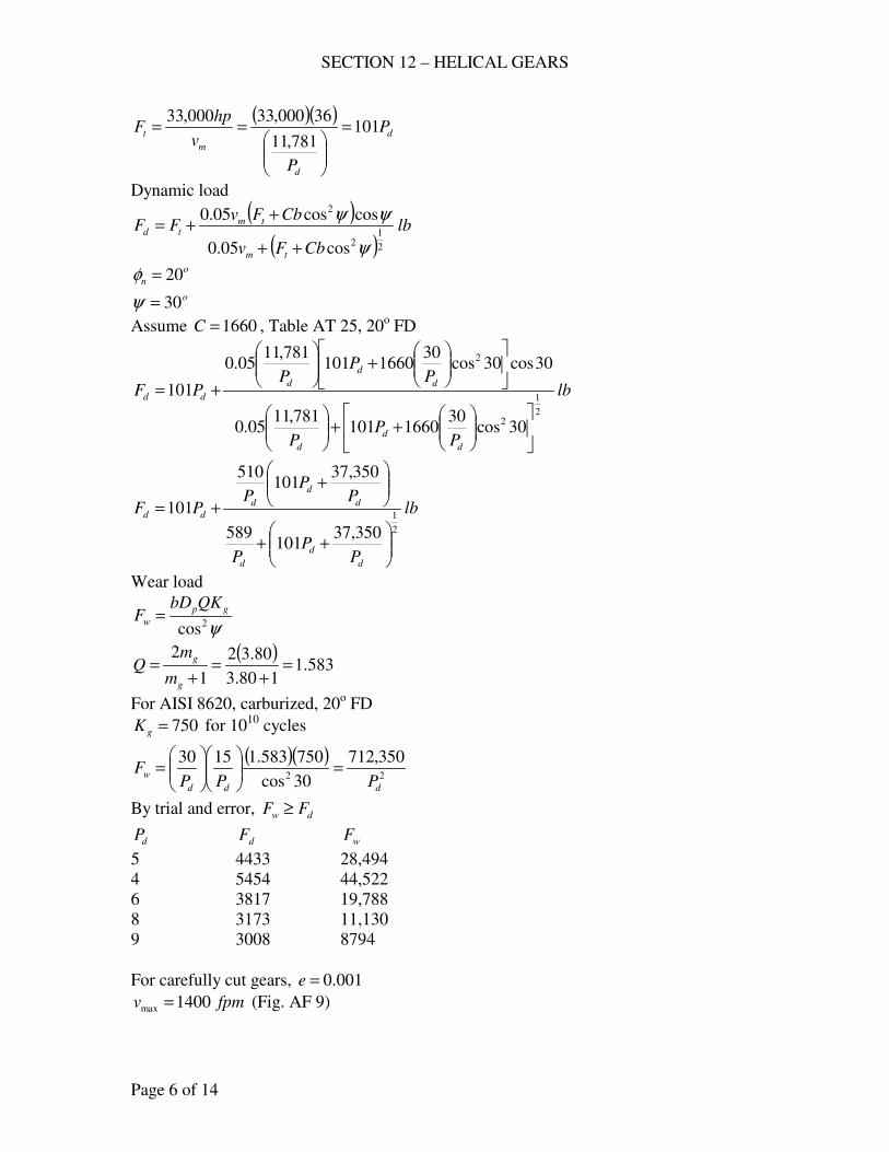
SECTION 12 – HELICAL GEARS
Page 6 of 14
( )( )d
d
m
t P
P
v
hpF 101
781,11
36000,33000,33=
==
Dynamic load
( )
( )lb
CbFv
CbFvFF
tm
tmtd
2
12
2
cos05.0
coscos05.0
ψ
ψψ
++
++=
o
n 20=φ
o30=ψ
Assume 1660=C , Table AT 25, 20o FD
lb
PP
P
PP
PPF
d
d
d
d
d
d
dd
2
1
2
2
30cos30
1660101781,11
05.0
30cos30cos30
1660101781,11
05.0
101
++
+
+=
lb
PP
P
PP
PPF
d
d
d
d
d
d
dd
2
1
350,37101
589
350,37101
510
101
++
+
+=
Wear load
ψ2cos
gp
w
QKbDF =
( )583.1
180.3
80.32
1
2=
+=
+=
g
g
m
mQ
For AISI 8620, carburized, 20o FD
750=gK for 1010
cycles
( )( )22
350,712
30cos
750583.11530
ddd
wPPP
F =
=
By trial and error, dw FF ≥
dP dF wF
5 4433 28,494
4 5454 44,522
6 3817 19,788
8 3173 11,130
9 3008 8794
For carefully cut gears, 001.0=e
fpmv 1400max = (Fig. AF 9)
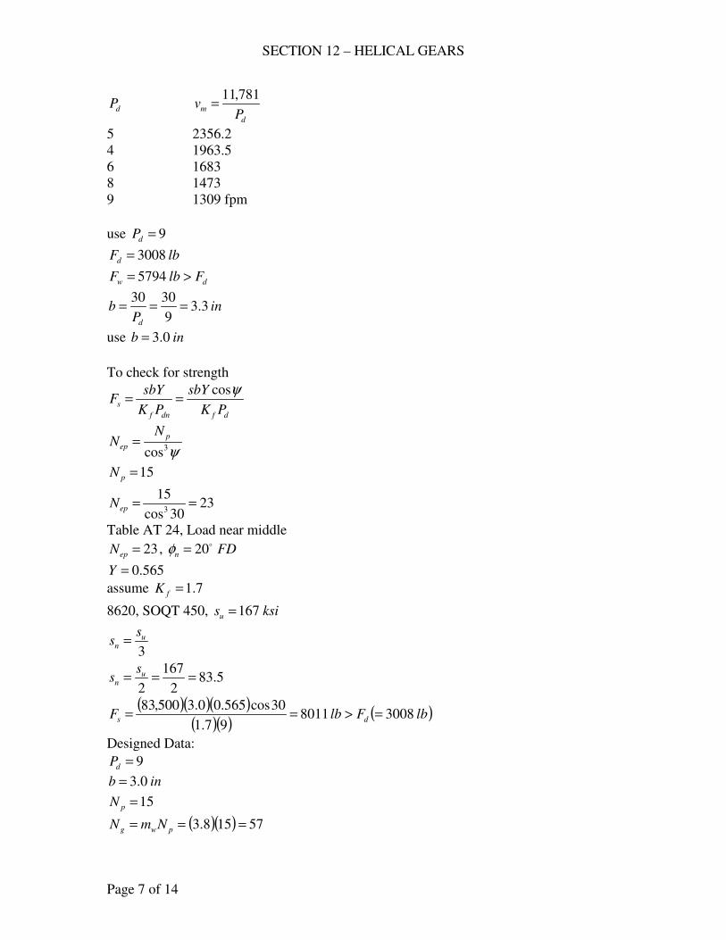
SECTION 12 – HELICAL GEARS
Page 7 of 14
dP d
mP
v781,11
=
5 2356.2
4 1963.5
6 1683
8 1473
9 1309 fpm
use 9=dP
lbFd 3008=
dw FlbF >= 5794
inP
bd
3.39
3030===
use inb 0.3=
To check for strength
dfdnf
sPK
sbY
PK
sbYF
ψcos==
ψ3cos
p
ep
NN =
15=pN
2330cos
153
==epN
Table AT 24, Load near middle
23=epN , FDn
o20=φ
565.0=Y
assume 7.1=fK
8620, SOQT 450, ksisu 167=
3
un
ss =
5.832
167
2=== u
n
ss
( )( )( )( )( )
( )lbFlbF ds 3008801197.1
30cos565.00.3500,83=>==
Designed Data:
9=dP
inb 0.3=
15=pN
( )( ) 57158.3 === pwg NmN
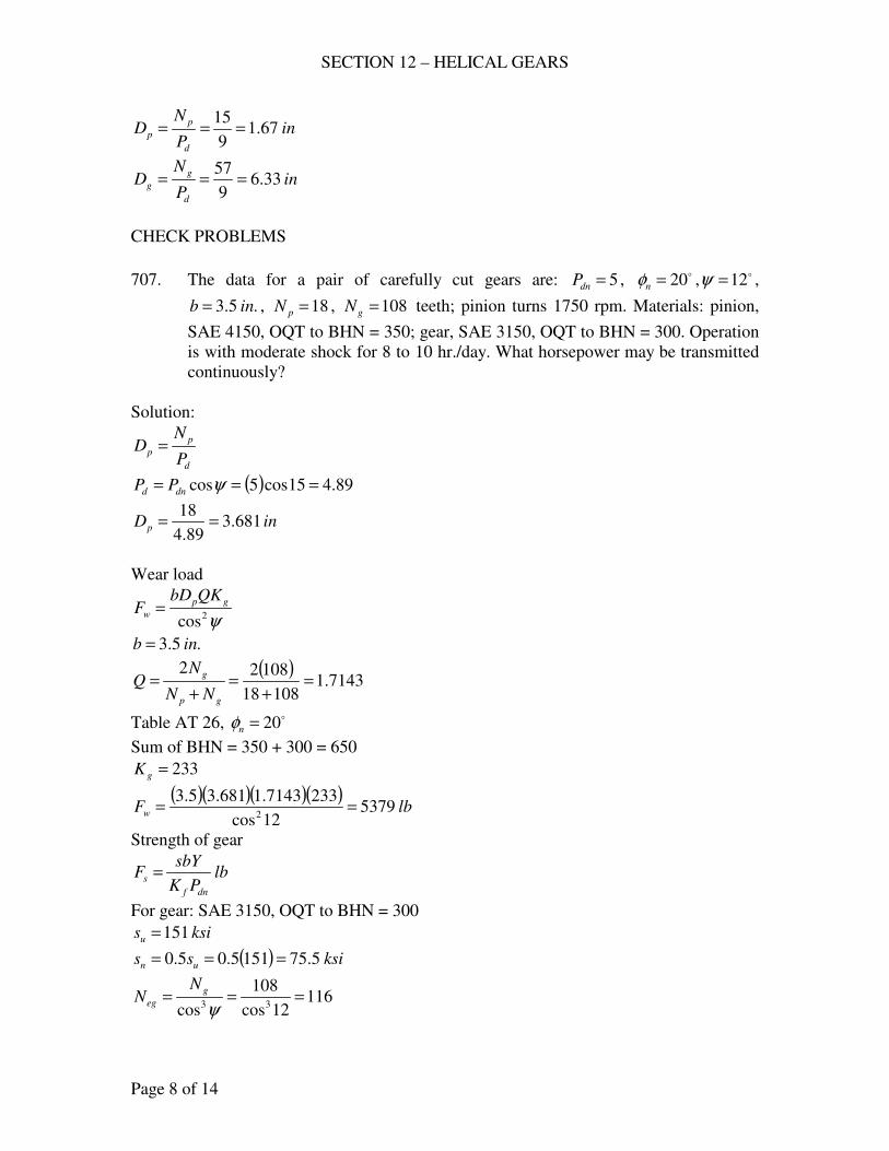
SECTION 12 – HELICAL GEARS
Page 8 of 14
inP
ND
d
p
p 67.19
15===
inP
ND
d
g
g 33.69
57===
CHECK PROBLEMS
707. The data for a pair of carefully cut gears are: 5=dnP , o20=nφ , o12=ψ ,
.5.3 inb = , 18=pN , 108=gN teeth; pinion turns 1750 rpm. Materials: pinion,
SAE 4150, OQT to BHN = 350; gear, SAE 3150, OQT to BHN = 300. Operation
is with moderate shock for 8 to 10 hr./day. What horsepower may be transmitted
continuously?
Solution:
d
p
pP
ND =
( ) 89.415cos5cos === ψdnd PP
inDp 681.389.4
18==
Wear load
ψ2cos
gp
w
QKbDF =
.5.3 inb =
( )7143.1
10818
10822=
+=
+=
gp
g
NN
NQ
Table AT 26, o20=nφ
Sum of BHN = 350 + 300 = 650
233=gK
( )( )( )( )lbFw 5379
12cos
2337143.1681.35.32
==
Strength of gear
lbPK
sbYF
dnf
s =
For gear: SAE 3150, OQT to BHN = 300
ksisu 151=
( ) ksiss un 5.751515.05.0 ===
11612cos
108
cos 33===
ψg
eg
NN
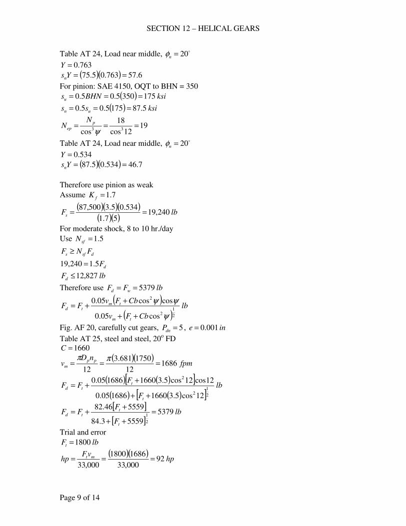
SECTION 12 – HELICAL GEARS
Page 9 of 14
Table AT 24, Load near middle, o20=nφ
763.0=Y
( )( ) 6.57763.05.75 ==Ysn
For pinion: SAE 4150, OQT to BHN = 350
( ) ksiBHNsu 1753505.05.0 ===
( ) ksiss un 5.871755.05.0 ===
1912cos
18
cos 33===
ψp
ep
NN
Table AT 24, Load near middle, o20=nφ
534.0=Y
( )( ) 7.46534.05.87 ==Ysn
Therefore use pinion as weak
Assume 7.1=fK
( )( )( )( )( )
lbFs 240,1957.1
534.05.3500,87==
For moderate shock, 8 to 10 hr./day
Use 5.1=sfN
dsfs FNF ≥
dF5.1240,19 =
lbFd 827,12≤
Therefore use lbFF wd 5379==
( )
( )lb
CbFv
CbFvFF
tm
tmtd
2
12
2
cos05.0
coscos05.0
ψ
ψψ
++
++=
Fig. AF 20, carefully cut gears, 5=dnP , ine 001.0=
Table AT 25, steel and steel, 20o FD
1660=C
( )( )fpm
nDv
pp
m 168612
1750681.3
12===
ππ
( ) ( )[ ]( ) ( )[ ]
lb
F
FFF
t
ttd
2
12
2
12cos5.31660168605.0
12cos12cos5.31660168605.0
++
++=
[ ]
[ ]lb
F
FFF
t
ttd 5379
55593.84
555946.82
2
1=
++
++=
Trial and error
lbFt 1800=
( )( )hp
vFhp mt 92
000,33
16861800
000,33===
SECTION 12 – HELICAL GEARS
Page 10 of 14
708. Two helical gears are used in a single reduction speed reducer rated at 27.4 hp at
a motor speed of 1750 rpm; continuous duty. The rating allows an occasional 100
% momentary overload. The pinion has 33 teeth. 10=dnP , .2 inb = , o20=nφ ,
o20=ψ , 82.2=wm . For both gears, the teeth are carefully cut from SAE 1045
with BHN = 180. Compute (a) the dynamic load, (b) the endurance strength;
estimate 7.1=fK . Also decide whether or not the 100 % overload is damaging.
(c) Are these teeth suitable for continuous service? If they are not suitable
suggest a cure. (The gears are already cut.)
Solution:
d
p
pP
ND =
( ) 66.915cos10cos === ψdnd PP
inDp 42.366.9
33==
( )( )fpm
nDv
pp
m 156712
175042.3
12===
ππ
( )lb
v
hpF
m
t 5771567
4.27000,33000,33===
(a) Dynamic load
( )
( )lb
CbFv
CbFvFF
tm
tmtd
2
12
2
cos05.0
coscos05.0
ψ
ψψ
++
++=
Fig. AF 20, carefully cut gears, 10=dnP , ine 001.0=
Table AT 25, steel and steel, 20o FD
1660=C
inb 2=
( ) ( )[ ]( ) ( )[ ]
lbFd 2578
15cos21660577156705.0
15cos15cos21660577156705.0577
2
12
2
=
++
++=
(b) Endurance strength
lbPK
sbYF
dnf
s =
For SAE 1045, BHN = 180
( ) ksiBHNsu 901805.05.0 ===
( ) ksiss un 45905.05.0 ===
3715cos
33
cos 33===
ψp
ep
NN
Table AT 24, Load near middle, o20=nφ
SECTION 12 – HELICAL GEARS
Page 11 of 14
645.0=Y
7.1=fK
( )( )( )( )( )
lbPK
sbYF
dnf
s 3415107.1
645.02000,45===
For 100 % overload
( ) lbFt 11545772 ==
( )
( )lb
CbFv
CbFvFF
tm
tmtd
2
12
2
cos05.0
coscos05.0
ψ
ψψ
++
++=
( ) ( )[ ]( ) ( )[ ]
lbFd 3475
15cos216601154156705.0
15cos15cos216601154156705.01154
2
12
2
=
++
++=
Since ds FF ≈ , 100 % overload is not damaging
(c) ψ2cos
gp
w
QKbDF =
.2 inb =
( )476.1
182.2
82.22
1
2=
+=
+=
w
w
m
mQ
Table AT 26, o20=nφ
Sum of BHN = 2(180) = 360
5.62=gK
( )( )( )( ) ( )lbFlbF dw 257867615cos
5.62476.142.322
=<==
Therefore not suitable for continuous service.
Cure: Through hardened teeth
For Bhn
( ) 2385.62676
2578==gK
min Bhn = 0.5(650) = 325
709. Two helical gears are used in a speed reducer whose input is 100 hp at 1200 rpm,
from an internal combustion engine. Both gears are made of SAE 4140, with the
pinion heat treated to a BHN 363 – 415, and the gear to 321 – 363; let the teeth
be F.D.; 20o
pressure angle in the normal plane; carefully cut; helix angle o15=ψ ; 22=pN , 68=gN teeth; 5=dP , inb 4= . Calculate the dynamic load,
the endurance strength load, and the limiting wear load for the teeth. Should these
gears have long life if they operate continuously? (Data courtesy of the Twin
Disc Clutch Co.)
Solution:

SECTION 12 – HELICAL GEARS
Page 12 of 14
inP
ND
d
p
p 4.45
22===
( )( )fpm
nDv
pp
m 138212
12004.4
12===
ππ
( )lb
v
hpF
m
t 23881382
100000,33000,33===
Dynamic load
( )
( )lb
CbFv
CbFvFF
tm
tmtd
2
12
2
cos05.0
coscos05.0
ψ
ψψ
++
++=
Fig. AF 20, carefully cut gears, 5=dnP , ine 001.0=
Table AT 25, steel and steel, 20o FD
1660=C
inb 4=
( ) ( )[ ]( ) ( )[ ]
lbFd 5930
15cos416602388138205.0
15cos15cos416602388138205.02388
2
12
2
=
++
++=
Endurance strength load
lbPK
sbYF
df
s
ψcos=
Assume 7.1=fK
Pinion
( ) ksiBHNsn 75.9036325.025.0 ===
2515cos
22
cos 33===
ψp
ep
NN
Table AT 24, Load near middle, o20=nφ
580.0=Y
( )( )( )( )( )
lbPK
sbYF
df
s 925,2357.1
15cos580.04750,90cos===
ψ
Gear
( ) ksiBHNsn 25.8032125.025.0 ===
7515cos
68
cos 33===
ψp
ep
NN
Table AT 24, Load near middle, o20=nφ
735.0=Y
( )( )( )( )( )
lbPK
sbYF
df
s 811,2657.1
15cos735.04250,80cos===
ψ
use lbFs 925,23=
SECTION 12 – HELICAL GEARS
Page 13 of 14
Limiting Wear Load
ψ2cos
gp
w
QKbDF =
Table AT 26, o20=nφ
Sum of BHN = 684 to 778 use 700
270=gK
( )511.1
6822
6822=
+=
+=
gp
g
NN
NQ
( )( )( )( )lbFw 7696
15cos
270511.14.442
==
Since ( ) ( )lbFlbF dw 59307696 =>= these gears have long life if they operate
continuously.
CROSSED HELICAL
710. Helical gears are to connect two shafts that are at right angles
( 201 =N , 402 =N , 10=dnP , o4521 ==ψψ ). Determine the center distance.
Solution:
1111
1 coscos
ψψπ
DPP
DN dn
cn
==
( )( ) 45cos1020 1D=
inD 83.21 =
222 cosψDPN dn=
( )( ) 45cos1040 2D=
inD 66.52 =
( ) ( ) inDDC 25.466.583.221
2121 =+=+=
712. Two shafts that are at right angles are to be connected by helical gears. A
tentative design is to use 201 =N , 602 =N , 10=dnP , and a center distance of 6
in. What must be the helix angles?
Solution: o9021 =+=Σ ψψ
1
11
cosψdnP
ND =
2
22
cosψdnP
ND =
( )2121 DDC +=
SECTION 12 – HELICAL GEARS
Page 14 of 14
2
2
1
1
coscos2
ψψ dndn P
N
P
NC +=
( )21 cos10
60
cos10
2062
ψψ+=
21 cos
6
cos
212
ψψ+=
21 cos
3
cos
16
ψψ+=
By trial and error method
11 sin
3
cos
16
ψψ+=
o5.391 =ψ o5.502 =ψ
- end -
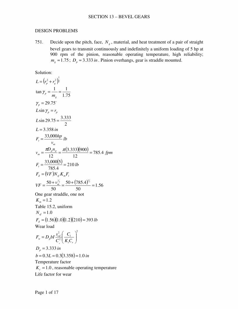
SECTION 13 – BEVEL GEARS
Page 1 of 17
DESIGN PROBLEMS
751. Decide upon the pitch, face, gN , material, and heat treatment of a pair of straight
bevel gears to transmit continuously and indefinitely a uniform loading of 5 hp at
900 rpm of the pinion, reasonable operating temperature, high reliability;
75.1≈gm ; inDp 333.3≈ . Pinion overhangs, gear is straddle mounted.
Solution:
( )2
122
gp rrL +=
75.1
11tan ==
g
pm
γ
o75.29=pγ
pp rL =γsin
2
333.375.29sin =L
inL 358.3=
lbv
hpF
m
t
000,33=
( )( )fpm
nDv
pp
m 4.78512
900333.3
12===
ππ
( )lbFt 210
4.785
5000,33==
( )tmsfd FKNVFF =
( )56.1
50
4.78550
50
50 21
21
=+
=+
= mvVF
One gear straddle, one not
2.1=mK
Table 15.2, uniform
0.1=sfN
( )( )( )( ) lbFd 3932102.10.156.1 ==
Wear load 2
2
2
=
rt
lcdpw
CK
C
C
sbIDF
e
inDp 333.3=
( ) inLb 0.1358.33.03.0 ===
Temperature factor
0.1=tK , reasonable operating temperature
Life factor for wear
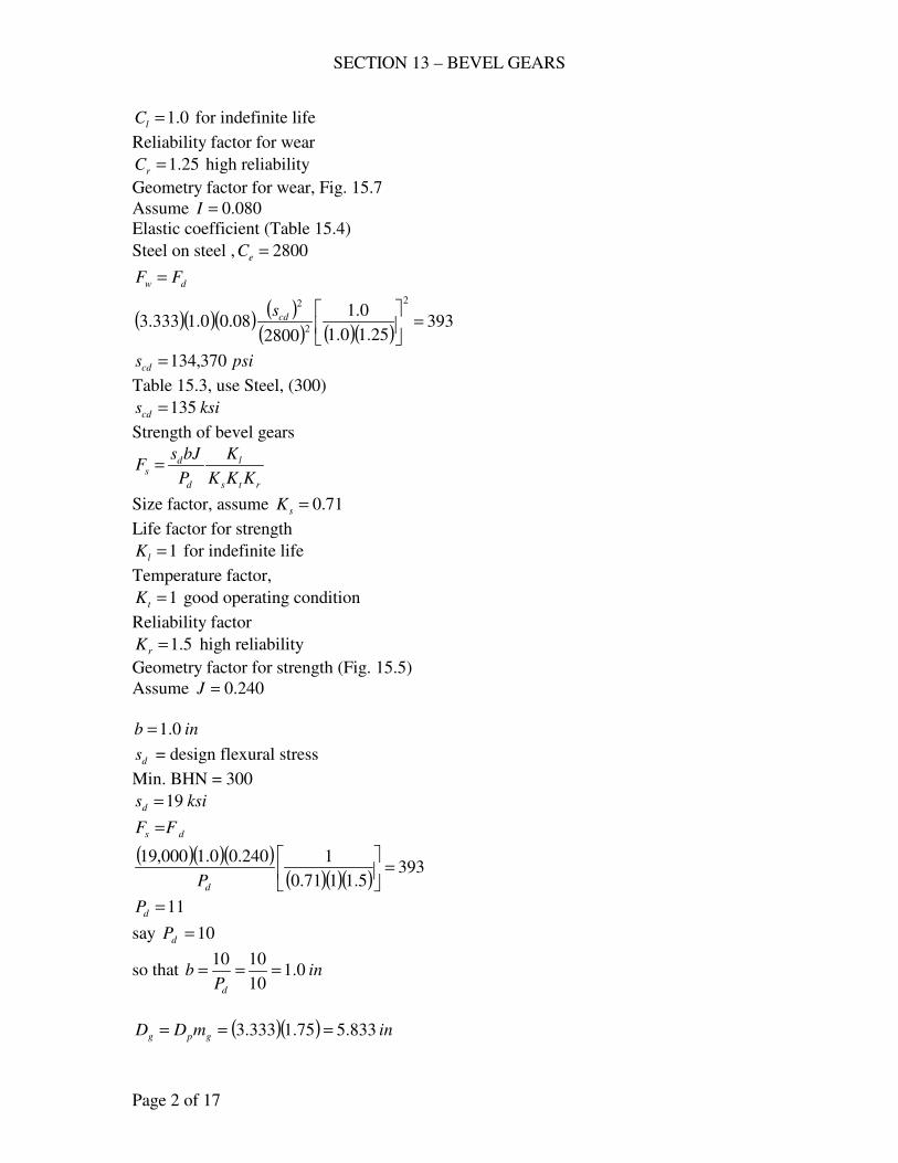
SECTION 13 – BEVEL GEARS
Page 2 of 17
0.1=lC for indefinite life
Reliability factor for wear
25.1=rC high reliability
Geometry factor for wear, Fig. 15.7
Assume 080.0=I
Elastic coefficient (Table 15.4)
Steel on steel , 2800=eC
dw FF =
( )( )( ) ( )( ) ( )( )
39325.10.1
0.1
280008.00.1333.3
2
2
2
=
cds
psiscd 370,134=
Table 15.3, use Steel, (300)
ksiscd 135=
Strength of bevel gears
rts
l
d
ds
KKK
K
P
bJsF =
Size factor, assume 71.0=sK
Life factor for strength
1=lK for indefinite life
Temperature factor,
1=tK good operating condition
Reliability factor
5.1=rK high reliability
Geometry factor for strength (Fig. 15.5)
Assume 240.0=J
inb 0.1=
ds = design flexural stress
Min. BHN = 300
ksisd 19=
ds FF =
( )( )( )( )( )( )
3935.1171.0
1240.00.1000,19=
dP
11=dP
say 10=dP
so that inP
bd
0.110
1010===
( )( ) inmDD gpg 833.575.1333.3 ===
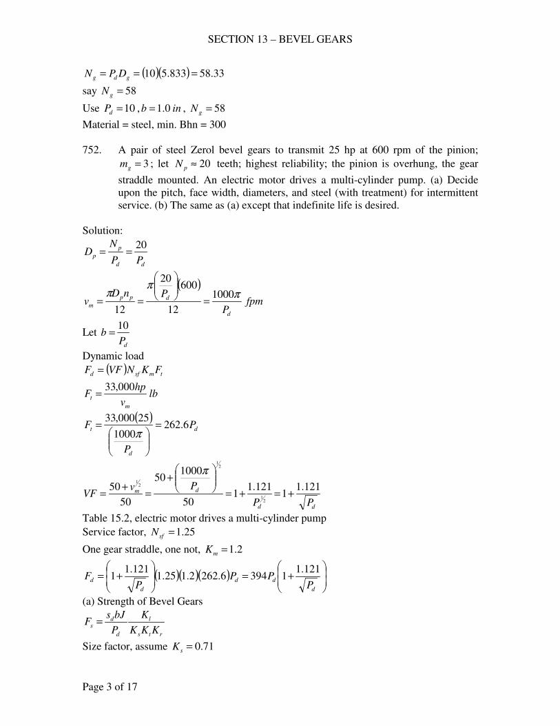
SECTION 13 – BEVEL GEARS
Page 3 of 17
( )( ) 33.58833.510 === gdg DPN
say 58=gN
Use 10=dP , inb 0.1= , 58=gN
Material = steel, min. Bhn = 300
752. A pair of steel Zerol bevel gears to transmit 25 hp at 600 rpm of the pinion;
3=gm ; let 20≈pN teeth; highest reliability; the pinion is overhung, the gear
straddle mounted. An electric motor drives a multi-cylinder pump. (a) Decide
upon the pitch, face width, diameters, and steel (with treatment) for intermittent
service. (b) The same as (a) except that indefinite life is desired.
Solution:
dd
p
pPP
ND
20==
( )fpm
P
PnDv
d
dpp
m
ππ
π 1000
12
60020
12=
==
Let dP
b10
=
Dynamic load
( ) tmsfd FKNVFF =
lbv
hpF
m
t
000,33=
( )d
d
t P
P
F 6.2621000
25000,33=
=
π
dd
dm
PP
PvVF
121.11
121.11
50
100050
50
502
1
21
21
+=+=
+
=+
=
π
Table 15.2, electric motor drives a multi-cylinder pump
Service factor, 25.1=sfN
One gear straddle, one not, 2.1=mK
( )( )( )
+=
+=
d
dd
d
dP
PPP
F121.1
13946.2622.125.1121.1
1
(a) Strength of Bevel Gears
rts
l
d
ds
KKK
K
P
bJsF =
Size factor, assume 71.0=sK
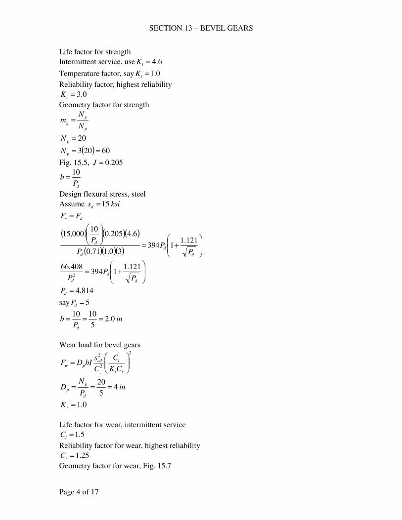
SECTION 13 – BEVEL GEARS
Page 4 of 17
Life factor for strength
Intermittent service, use 6.4=lK
Temperature factor, say 0.1=tK
Reliability factor, highest reliability
0.3=rK
Geometry factor for strength
p
g
gN
Nm =
20=pN
( ) 60203 ==pN
Fig. 15.5, 205.0=J
dPb
10=
Design flexural stress, steel
Assume ksisd 15=
ds FF =
( ) ( )( )
( )( )( )
+=
d
d
d
d
PP
P
P 121.11394
30.171.0
6.4205.010
000,15
+=
d
d
d PP
P
121.11394
408,662
814.4=dP
say 5=dP
inP
bd
0.25
1010===
Wear load for bevel gears 2
2
2
=
rt
lcdpw
CK
C
C
sbIDF
e
inP
ND
d
p
p 45
20===
0.1=tK
Life factor for wear, intermittent service
5.1=lC
Reliability factor for wear, highest reliability
25.1=rC
Geometry factor for wear, Fig. 15.7
SECTION 13 – BEVEL GEARS
Page 5 of 17
20=pN , 60=gN
083.0=I
Elastic coefficient, steel on steel (Table 15.4)
2800=eC
5=dP
dw FF =
( )( )( )( ) ( )( )
( )
+=
5
121.115394
25.10.1
5.1
2800083.024
2
2
2
cds
psiscd 730,155=
Table 15.3
Use steel, min. BHN = 360, ksiscd 160=
5=dP
inb 2=
inDp 4=
( )( ) inDmD pgg 1243 ===
steel, min. BHN = 360
(b) For indefinite life,
0.1=lK , life factor for strength
0.1=lC , life factor for wear
Strength:
rts
l
d
ds
KKK
K
P
bJsF =
ds FF =
( ) ( )( )
( )( )( )
+=
d
d
d
d
PP
P
P 121.11394
30.171.0
0.1205.010
000,15
+=
d
d
d PP
P
121.11394
437,142
799.2=dP
say 3=dP
inP
bd
33.33
1010===
Wear load
SECTION 13 – BEVEL GEARS
Page 6 of 17
2
2
2
=
rt
lcdpw
CK
C
C
sbIDF
e
inP
ND
d
p
p 67.63
20===
dw FF =
( )( )( )( ) ( )( )
( )
+=
3
121.113394
25.10.1
0.1
2800083.033.367.6
2
2
2
cds
psiscd 744,113=
Table 15.3
Use steel, min. BHN = 240, ksiscd 115=
3=dP
inb 33.3=
inDp 67.6=
( )( ) inDmD pgg 2067.63 ===
steel, min. BHN = 240
753. Decide upon the pitch, face, and number of teeth for two spiral-bevel gears for a
speed reducer. The input to the pinion is 20 hp at 1750 rpm; 9.1≈gm ; pinion
overhung, gear-straddle mounted. It is hoped not to exceed a maximum pD of 4
3/8-in.; steel gears with minimum 245 BHN on pinion and 210 BHN on gear.
The gear is motor-driven, subject to miscellaneous drives involving moderate
shock; indefinite life against breakage and wear with high reliability. If the gears
designed for the foregoing data are to be subjected to intermittent service only,
how much power could they be expected to transmit?
Solution:
(a) ( )( )
fpmnD
vpp
m 200012
1750375.4
12===
ππ
( )lb
v
hpF
m
t 3302000
20000,33000,33===
Dynamic load
( )tmsfd FKNVFF =
One gear straddle, one not
2.1=mK
Table 15.2
Motor-driven, moderate shock
SECTION 13 – BEVEL GEARS
Page 7 of 17
25.1=sfN
21
21
70
70
+= mv
VF , spiral
( )254.1
70
2000702
1
21
=
+=VF
( )( )( )( ) lbFd 6213302.125.1254.1 ==
Wear load 2
2
2
=
rt
lcdpw
CK
C
C
sbIDF
e
inDp 375.4=
Temperature Factor, 0.1=tK
Design contact stresses,
245=BHN , pinion
ksiscd 116=
Life factor for wear
0.1=lC , indefinite life
Reliability factor for wear
25.1=rC , high reliability
Geometry factor for wear, Fig. 15.8
Assume 12.0=I
Elastic coefficient, steel on steel (Table 15.4)
2800=eC
( )( )( ) ( )( ) ( )( )
bbFw 72125.10.1
0.1
2800
000,11612.0375.4
2
2
2
=
=
dw FF =
621721 =b
inb 8613.0=
say ininb 875.08
7==
Strength of gear
rts
l
d
ds
KKK
K
P
bJsF =
ds = design flexural stress
min. BHN = 210
ksisd 4.15=
Size factor, assume 71.0=sK
SECTION 13 – BEVEL GEARS
Page 8 of 17
Life factor for strength
1=lK for indefinite life
Temperature factor,
1=tK
Reliability factor
5.1=rK high reliability
Geometry factor Fig. 15.6
Assume 28.0=J
( )( )( )( )( )( ) dd
sPP
F3543
5.1171.0
128.0875.0400,15=
=
ds FF =
6213543
=dP
7.5=dP
say 6=dP
Then, 6=dP , inb8
7= , ( )( ) 266375.4 === dpp PDN
( )( ) 50269.1 === pwg NmN
(b) Intermittent service only
Strength
rts
l
d
ds
KKK
K
P
bJsF =
psisd 400,15= (Gear)
For 6=dP , 64.0=sK
For indefinite service, 6.4=lK
0.1=tK , 5.1=rK
Geometry factor, Fig. 15.6, 26=pN , 50=gN
292.0=J
( )( )( )( )( )( )
lbFs 31425.1171.0
6.4
6
292.0875.0400,15=
=
Wear load 2
2
2
=
rt
lcdpw
CK
C
C
sbIDF
e
inDp 375.4=
0.1=tK
ksiscd 116=
2800=eC
SECTION 13 – BEVEL GEARS
Page 9 of 17
5.1=lC intermittent service
25.1=rC
Geometry factor for wear, Fig. 15.8
26=pN , 50=gN
116.0=I
( )( )( ) ( )( ) ( )( )
lbFw 109825.10.1
5.1
2800
000,116116.0875.0375.4
2
2
2
=
=
use dw FF =
( )tmsfd FKNVFF =
( )( )( ) tF2.1125254.11098 =
lbFt 584=
( )( )hp
vFhp mt 35
000,33
2000584
000,33===
CHECK PROBLEMS
755. A pair of straight-bevel gears are to transmit a smooth load of 45 hp at 500 rpm
of the pinion; 3=gm . A proposed design is .15 inDg = , .8
32 inb = , 4=dP .
Teeth are carburized AISI 8620, SOQT 450 F. The pinion overhangs, the gear is
straddle-mounted. Would these gears be expected to perform with high reliability
in continuous service? If not would you expect more than 1 failure in 100?
Solution:
inm
DD
g
g
p 53
15===
( )( )fpm
nDv
pp
m 65512
5005
12===
ππ
( )lb
v
hpF
m
t 2267655
45000,33000,33===
Dynamic load
( )tmsfd FKNVFF =
( )512.1
50
65550
50
50 21
21
=+
=+
= mvVF
One gear straddle, one not
2.1=mK
Smooth load, 0.1=sfN
( )( )( )( ) lbFd 411322672.10.1512.1 ==
SECTION 13 – BEVEL GEARS
Page 10 of 17
Strength of bevel gears
rts
l
d
ds
KKK
K
P
bJsF =
Size factor, for 4=dP ,
71.0=sK
Life factor for strength
1=lK
Temperature factor,
1=tK
Geometry factor for strength (Fig. 15.5)
( )( ) 2054 === pdp DPN
( )( ) 60154 === gdg DPN
205.0=J
ksisd 30= (55 – 63 Rc) for carburized teeth
( )( )( )( )( )( )
rr
sKK
F5143
171.0
1
4
205.0375.2000,30=
=
ds FF =
41135143
=rK
5.125.1 <=rK will not perform high reliability.
Wear load 2
2
2
=
rt
lcdpw
CK
C
C
sbIDF
e
inDp 5=
inb 375.2=
Table 15.3, ksiscd 225=
Table 15.4, 2800=eC
Geometry factor for wear, Figure 15.7
20=pN , 60=gN
083.0=I
1=tK
life factor for wear 1=lC
( )( )( ) ( )( ) ( )( ) 2
2
2
26364
1
1
2800
000,225083.0375.25
rr
wCC
F =
=
dw FF =
SECTION 13 – BEVEL GEARS
Page 11 of 17
41136364
2=
rC
25.1244.1 ≈=rC , high reliability
Since 5.1<rK ,this will not perform high reliability but 1 in 100, 25.112.1 <≈rK
756. A gear catalog rates a pair of cast-iron, straight-bevel gears at 15.26 hp at 800
rpm of the 16-tooth pinion; 5.3=gm , .3 inb = , 3=dP ; pinion overhangs,
straddle-mounted gear. Assume the cast iron to be class 30. If the load is smooth
is this rating satisfactory, judging by the design approach of the Text for good
reliability (a) when strength alone is considered, (b) when long continuous
service is desired?
Solution:
inP
ND
d
p
p 333.53
16===
( )( )fpm
nDv
pp
m 111712
800333.5
12===
ππ
( )lb
v
hpF
m
t 4511117
26.15000,33000,33===
Dynamic load
( )tmsfd FKNVFF =
( )668.1
50
111750
50
50 21
21
=+
=+
= mvVF
One gear straddle, one not
2.1=mK
Smooth load, 0.1=sfN
( )( )( )( ) lbFd 9034512.10.1668.1 ==
(a) Strength
rts
l
d
ds
KKK
K
P
bJsF =
3=dP ,
76.0=sK
1=lK
1=tK
5.1=rK
ksisd 6.4= , cast-iron class 30
16=pN
SECTION 13 – BEVEL GEARS
Page 12 of 17
( )( ) 56165.3 === pwg NmN
184.0=J
( )( )( )( )( )( )
( )ds FlblbF =<=
= 903742
5.1176.0
1
3
184.03600,4
with
4.1=lK for 106 cycles
( )( ) ( )ds FlblbF =>== 90310407424.1
Therefore satisfactory for 106 cycles.
(b) Continuous service
Wear load 2
2
2
=
rt
lcdpw
CK
C
C
sbIDF
e
inDp 333.5=
inb 3=
Table 15.3, ksiscd 50= , cast-iron class 30
Table 15.4, cast-iron and cast-iron 2250=eC
1=lC
1=tK
25.1=rC
Geometry factor for wear, Figure 15.7
16=pN , 56=gN
077.0=I
( )( )( ) ( )( ) ( )( )
( )lbFlbF dw 90338925.11
1
2250
000,50077.03333.5
2
2
2
=<=
=
Therefore, not satisfactory for long continuous service.
757. An 870-rpm motor drives a belt conveyor through bevel gears having 18 and 72
teeth; 6=dP , inb4
31= . Both gears are straddle-mounted. What horsepower may
these gears transmit for an indefinite life with high reliability if both gears are (a)
cast-iron, class 40; (b) AISI 5140, OQT 1000 F; (c) AISI 5140, OQT 1000 F,
flame hardened (d) AISI 8620, SOQT 450 F?
Solution:
inP
ND
d
p
p 36
18===
( )( )fpm
nDv
pp
m 68312
8703
12===
ππ
Dynamic load
SECTION 13 – BEVEL GEARS
Page 13 of 17
( )tmsfd FKNVFF =
Both gears straddle mounted
0.1=mK
Table 15.2, 0.1=sfN
( )523.1
50
68350
50
50 21
21
=+
=+
= mvVF
( )( )( ) ttd FFF 523.10.10.1523.1 ==
(a) Cast-iron, class 40
Strength
rts
l
d
ds
KKK
K
P
bJsF =
ksisd 7= , cast-iron class 40
inb4
31=
1=lK , indefinite life
6=dP
64.0=sK
1=tK
5.1=rK , high reliability
Figure 15.5, 18=pN , 72=gN
204.0=J
( )( )( )( )( )( )
lbFs 4345.1164.0
1
6
204.075.17000=
=
Wear: 2
2
2
=
rt
lcdpw
CK
C
C
sbIDF
e
inDp 3=
inb4
31=
Table 15.3, ksiscd 65= , cast-iron class 40
Table 15.4, cast-iron and cast-iron 2250=eC
1=lC , indefinite life
1=tK
25.1=rC , high reliability
Geometry factor for wear, Figure 15.7
18=pN , 72=gN
082.0=I
SECTION 13 – BEVEL GEARS
Page 14 of 17
( )( )( ) ( )( ) ( )( )
lbFw 23025.11
1
2250
000,65082.075.13
2
2
2
=
=
wd FF =
230523.1 =tF
lbFt 151=
( )( )hp
vFhp mt 3
000,33
683151
000,33===
(b) AISI 5140, OQT 1000 F, BHN = 300
Strength
psisd 000,19=
( )( )( )( )( )( )
lbFs 11785.1164.0
1
6
204.075.1000,19=
=
Wear: 2
2
2
=
rt
lcdpw
CK
C
C
sbIDF
e
Table 15.3, ksiscd 135=
Table 15.4, steel and steel, 2800=eC
( )( )( ) ( )( ) ( )( )
lbFw 64025.11
1
2800
000,135082.075.13
2
2
2
=
=
wd FF =
640523.1 =tF
lbFt 420=
( )( )hp
vFhp mt 7.8
000,33
683420
000,33===
(c) AISI 5140, OQT 1000 F, Flame Hardened
Strength
ksisd 5.13=
( )( )( )( )( )( )
lbFs 8375.1164.0
1
6
204.075.1500,13=
=
Wear: 2
2
2
=
rt
lcdpw
CK
C
C
sbIDF
e
Table 15.3, ksiscd 190=
Table 15.4, steel and steel, 2800=eC
SECTION 13 – BEVEL GEARS
Page 15 of 17
( )( )( ) ( )( ) ( )( )
lbFw 126925.11
1
2800
000,190082.075.13
2
2
2
=
=
sd FF =
837523.1 =tF
lbFt 550=
( )( )hp
vFhp mt 4.11
000,33
683550
000,33===
(d) AISI 86200, SOQT 450 F, carburized
Strength
ksisd 30= (55 – 63 Rc)
( )( )( )( )( )( )
lbFs 18595.1164.0
1
6
204.075.1000,30=
=
Wear: 2
2
2
=
rt
lcdpw
CK
C
C
sbIDF
e
Table 15.3, ksiscd 225=
Table 15.4, steel and steel, 2800=eC
( )( )( ) ( )( ) ( )( )
lbFw 177925.11
1
2800
000,225082.075.13
2
2
2
=
=
wd FF =
1779523.1 =tF
lbFt 1168=
( )( )hp
vFhp mt 2.24
000,33
6831168
000,33===
758. A pair of straight-bevel gears transmits 15 hp at a pinion speed of 800 rpm;
5=dP , 20=pN , 60=pN , inb 2= . Both gears are made of AISI 4140 steel,
OQT 800 F. What reliability factor is indicated for these gears for strength and
for wear (a) for smooth loads, (b) for light shock load from the power source and
heavy shock on the driven machine?
Solution:
inP
ND
d
p
p 45
20===
( )( )fpm
nDv
pp
m 83812
8004
12===
ππ
SECTION 13 – BEVEL GEARS
Page 16 of 17
( )lb
v
hpF
m
t 591838
15000,33000,33===
( )tmsfd FKNVFF =
( )579.1
50
83850
50
50 21
21
=+
=+
= mvVF
assume 0.1=mK
( )( )( )( )sfsfd NNF 9335910.1579.1 ==
Strength of bevel gear
rts
l
d
ds
KKK
K
P
bJsF =
For AISI 4140, OQT 800 F, BHN = 429
ksisd 24=
assume 1=lK
1=tK
5=dP
675.0=sK
Figure 15.5, 20=pN , 60=gN
205.0=J
( )( )( )( )( )( )
rr
sKK
F2916
1675.0
1
5
205.02000,24=
=
ds FF =
sf
r
NK
9332916
=
sf
rN
K1254.3
=
Wear load: 2
2
2
=
rt
lcdpw
CK
C
C
sbIDF
e
BHN = 429
Table 15.3, ksiscd 190=
Table 15.4, steel and steel, 2800=eC
inDp 4=
inb 2=
Assume 0.1=lC , 0.1=tK
Fig. 15.7, 20=pN , 60=gN
083.0=I
SECTION 13 – BEVEL GEARS
Page 17 of 17
( )( )( ) ( )( ) ( )( ) 2
2
2
23058
1
1
2800
000,190083.024
rr
wCC
F =
=
wd FF =
2
3058933
r
sfC
N =
sf
rN
C810.1
=
(a) Table 15.2, smooth load
0.1=sfN
For strength, 1254.31
1254.31254.3===
sf
rN
K
For wear, 810.11
810.1810.1===
sf
rN
C
(b) Table 15.2, light shock source, heavy shock driven
0.2=sfN
For strength, 5627.12
1254.31254.3===
sf
rN
K
For wear, 2799.12
810.1810.1===
sf
rN
C
- end -
SECTION 14 – WORM GEARS
Page 1 of 19
DESIGN PROBLEMS
791. (a) Determine a standard circular pitch and face width for a worm gear drive with
an input of 2 hp at 1200 rpm of the triple-threaded worm; the 1.58-in. ( wD ) is
steel with a minimum BHN = 250; gear is manganese bronze (Table AT 3);
12=wm . Consider wear and strength only. Use a nφ to match the lead angle λ .
(See i16.13, Text.) (b) compute the efficiency.
Solution:
a) lbFv
F t
mg
d
+=
1200
1200
mg
tv
hpF
000,33=
12
gg
mg
nDv
π=
rpmm
nn
w
wg 100
12
1200===
λtanwwg DmD =
w
ct
D
PN
πλ =tan
( )( )c
ccwt
w
ctwwg P
PPmN
D
PNDmD 46.11
123===
=
πππ
( )( )c
cmg P
Pv 300
12
10045.11==
π
( )
cc
tPP
F220
300
2000,33==
( )lb
P
P
P
PF
c
c
c
cd
+=
+=
455220
1200
3001200
Wear load
wgw bKDF =
say cPb 2= ,
cg PD 46.11=
dw FF =
( )( )( ) ( )
c
cwcc
P
PKPP
+=
455246.11
( )
c
cwc
P
PKP
+=
45592.22 2
SECTION 14 – WORM GEARS
Page 2 of 19
( )( ) cc
ww
gP
P
Dm
D60443.0
58.112
46.11tan ===λ
By trial and error and using Table AT 27 ( λφ ≈n )
wK cP cP (std) λ maxλ i16.11 nφ
36 0.678 ¾ 24.4 16 14 ½
50 0.605 5/8 20.7 25 20
Use o20=nφ , o7.20=λ , inPc8
5=
dw FF =
( )( )( ) ( )
c
cwc
P
PKbP
+=
45546.11
( ) ( )( )
8
5
8
5455
508
546.11
+
=
b
inb 1365.1=
say inb32
51=
To check for strength.
π
λ
π
cosccns
sYbPsYbPF ==
For manganese bronze,
psis 000,30=
o20=nφ
392.0=Y o7.20=λ
inPc8
5=
inb32
51=
( )( )ds FlbF >=
= 2530
7.20cos8
5
32
51392.0000,30
π
use inPc8
5=
inb32
51=
SECTION 14 – WORM GEARS
Page 3 of 19
(b)
+
−=
f
fe
n
n
λφ
λφλ
tancos
tancostan
o20=nφ o7.20=λ
( )( )fpmfpm
nDv ww
r 705317.20cos12
120058.1
cos12>===
π
λ
π
( )0334.0
531
32.032.036.036.0
===rv
f
%2.90902.00334.07.20tan20cos
7.20tan0334.020cos7.20tan ==
+
−=e
792. A high-efficiency worm-gear speed reducer is desired, to accept 20 hp from a
1750-rpm motor. The diameter wD of the integral worm has been estimated to be
.8
71 in ; the next computations are to be for a steel worm with a minimum BHN =
250; phosphor-bronze gear (Table AT 3); 11=wm . Probably, the worm should
not have less than 4 threads. (a) Considering wear and strength only (i16.13),
decide upon a pitch and face width that satisfies these requirements (i16.11,
Text); specifying the pressure angle, diameters, and center distance. How does
wD used compare with that from equation (m), i16.11, Text? What addendum
and dedendum are recommended by Dudley? Compute a face length for the
worm. (b) Compute the efficiency. What do you recommend as the next trial for
a “better” reducer?
Solution:
mg
tv
hpF
000,33=
12
gg
mg
nDv
π=
rpmm
nn
w
wg 1.159
11
1750===
( )( )c
ctwcgc
g PPNmPNP
D 14411
====πππ
( )( )c
cmg P
Pv 583
12
1.15914==
π
( )
cc
tPP
F1132
583
20000,33==
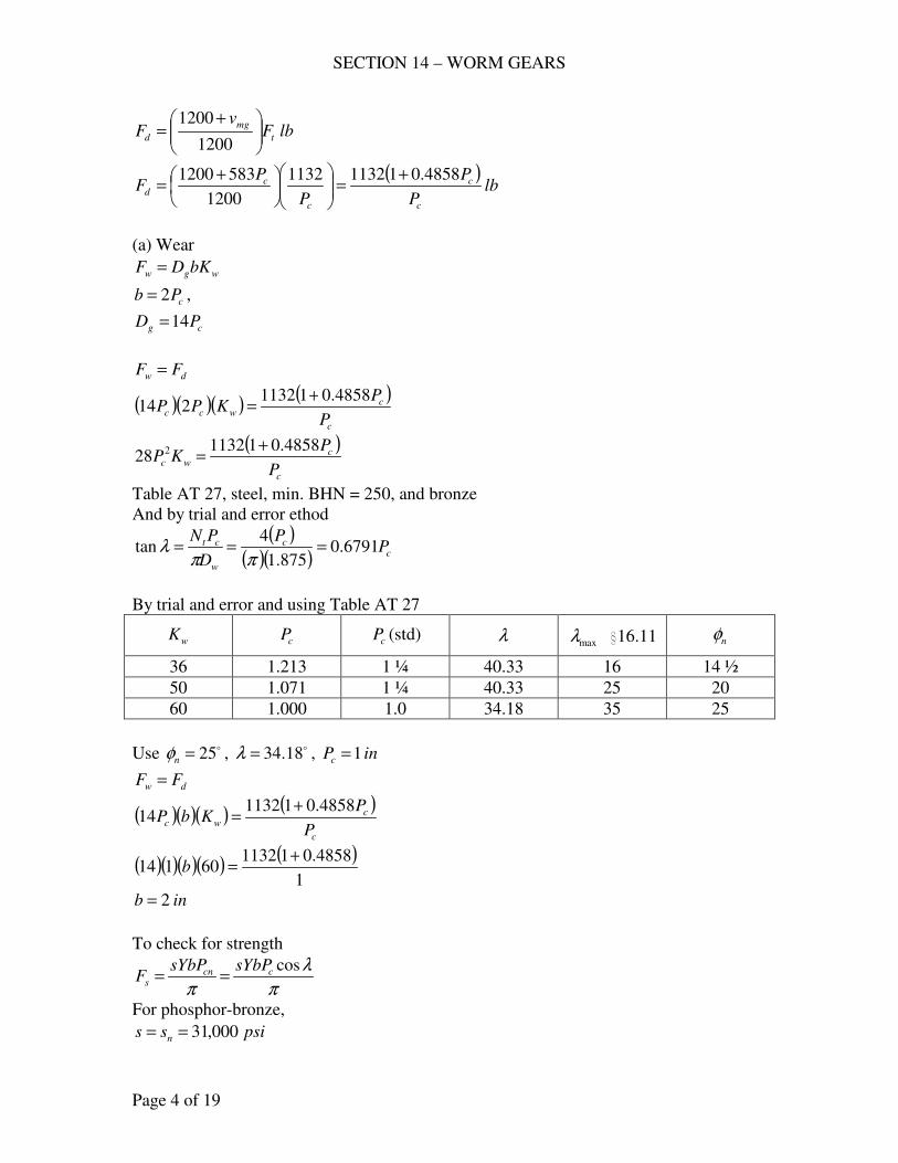
SECTION 14 – WORM GEARS
Page 4 of 19
lbFv
F t
mg
d
+=
1200
1200
( )lb
P
P
P
PF
c
c
c
cd
4858.0111321132
1200
5831200 +=
+=
(a) Wear
wgw bKDF =
cPb 2= ,
cg PD 14=
dw FF =
( )( )( ) ( )
c
cwcc
P
PKPP
4858.011132214
+=
( )
c
cwc
P
PKP
4858.01113228 2 +
=
Table AT 27, steel, min. BHN = 250, and bronze
And by trial and error ethod
( )( )( ) c
c
w
ct PP
D
PN6791.0
875.1
4tan ===
ππλ
By trial and error and using Table AT 27
wK cP cP (std) λ maxλ i16.11 nφ
36 1.213 1 ¼ 40.33 16 14 ½
50 1.071 1 ¼ 40.33 25 20
60 1.000 1.0 34.18 35 25
Use o25=nφ , o18.34=λ , inPc 1=
dw FF =
( )( )( ) ( )
c
cwc
P
PKbP
4858.01113214
+=
( )( )( )( ) ( )1
4858.01113260114
+=b
inb 2=
To check for strength
π
λ
π
cosccns
sYbPsYbPF ==
For phosphor-bronze,
psiss n 000,31==
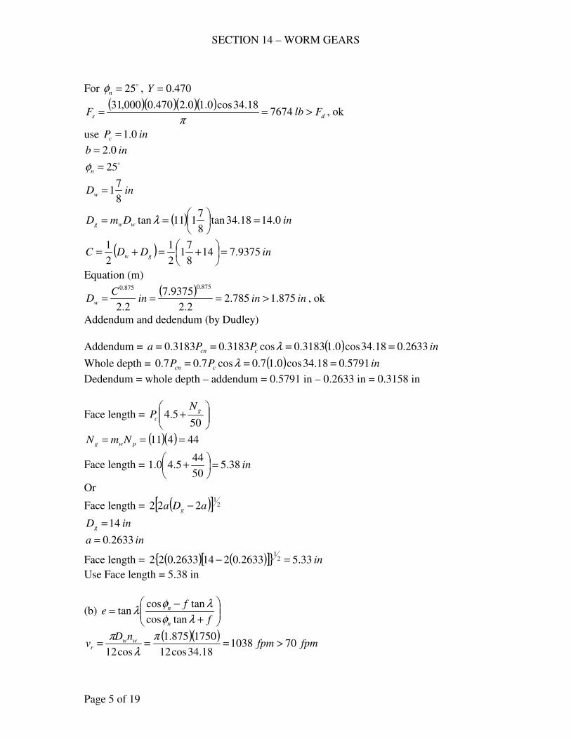
SECTION 14 – WORM GEARS
Page 5 of 19
For o25=nφ , 470.0=Y
( )( )( )( )ds FlbF >== 7674
18.34cos0.10.2470.0000,31
π, ok
use inPc 0.1=
inb 0.2= o25=nφ
inDw8
71=
( ) inDmD wwg 0.1418.34tan8
7111tan =
== λ
( ) inDDC gw 9375.7148
71
2
1
2
1=
+=+=
Equation (m)
( )ininin
CDw 875.1785.2
2.2
9375.7
2.2
875.0875.0
>=== , ok
Addendum and dedendum (by Dudley)
Addendum = ( ) inPPa ccn 2633.018.34cos0.13183.0cos3183.03183.0 ==== λ
Whole depth = ( ) inPP ccn 5791.018.34cos0.17.0cos7.07.0 === λ
Dedendum = whole depth – addendum = 0.5791 in – 0.2633 in = 0.3158 in
Face length =
+
505.4
g
c
NP
( )( ) 44411 === pwg NmN
Face length = in38.550
445.40.1 =
+
Or
Face length = ( )[ ] 21
222 aDa g −
inDg 14=
ina 2633.0=
Face length = ( ) ( )[ ]{ } in33.52633.02142633.022 21
=−
Use Face length = 5.38 in
(b)
+
−=
f
fe
n
n
λφ
λφλ
tancos
tancostan
( )( )fpmfpm
nDv ww
r 70103818.34cos12
1750875.1
cos12>===
π
λ
π
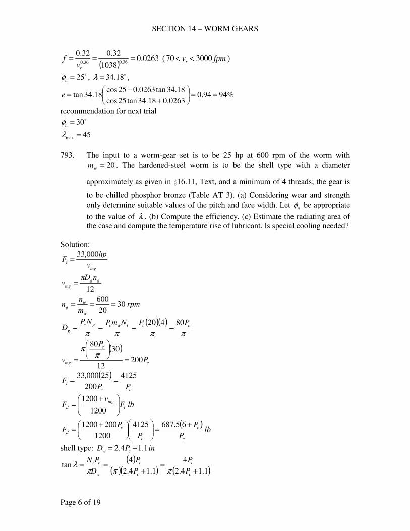
SECTION 14 – WORM GEARS
Page 6 of 19
( )0263.0
1038
32.032.036.036.0
===rv
f ( fpmvr 300070 << )
o25=nφ , o18.34=λ ,
%9494.00263.018.34tan25cos
18.34tan0263.025cos18.34tan ==
+
−=e
recommendation for next trial o30=nφ
o45max =λ
793. The input to a worm-gear set is to be 25 hp at 600 rpm of the worm with
20=wm . The hardened-steel worm is to be the shell type with a diameter
approximately as given in i16.11, Text, and a minimum of 4 threads; the gear is
to be chilled phosphor bronze (Table AT 3). (a) Considering wear and strength
only determine suitable values of the pitch and face width. Let nφ be appropriate
to the value of λ . (b) Compute the efficiency. (c) Estimate the radiating area of
the case and compute the temperature rise of lubricant. Is special cooling needed?
Solution:
mg
tv
hpF
000,33=
12
gg
mg
nDv
π=
rpmm
nn
w
wg 30
20
600===
( )( )ππππ
cctwcgc
g
PPNmPNPD
80420====
( )c
c
mg P
P
v 20012
3080
=
=π
π
( )
cc
tPP
F4125
200
25000,33==
lbFv
F t
mg
d
+=
1200
1200
( )lb
P
P
P
PF
c
c
c
cd
+=
+=
65.6874125
1200
2001200
shell type: inPD cw 1.14.2 +=
( )( )( ) ( )1.14.2
4
1.14.2
4tan
+=
+==
c
c
c
c
w
ct
P
P
P
P
D
PN
πππλ
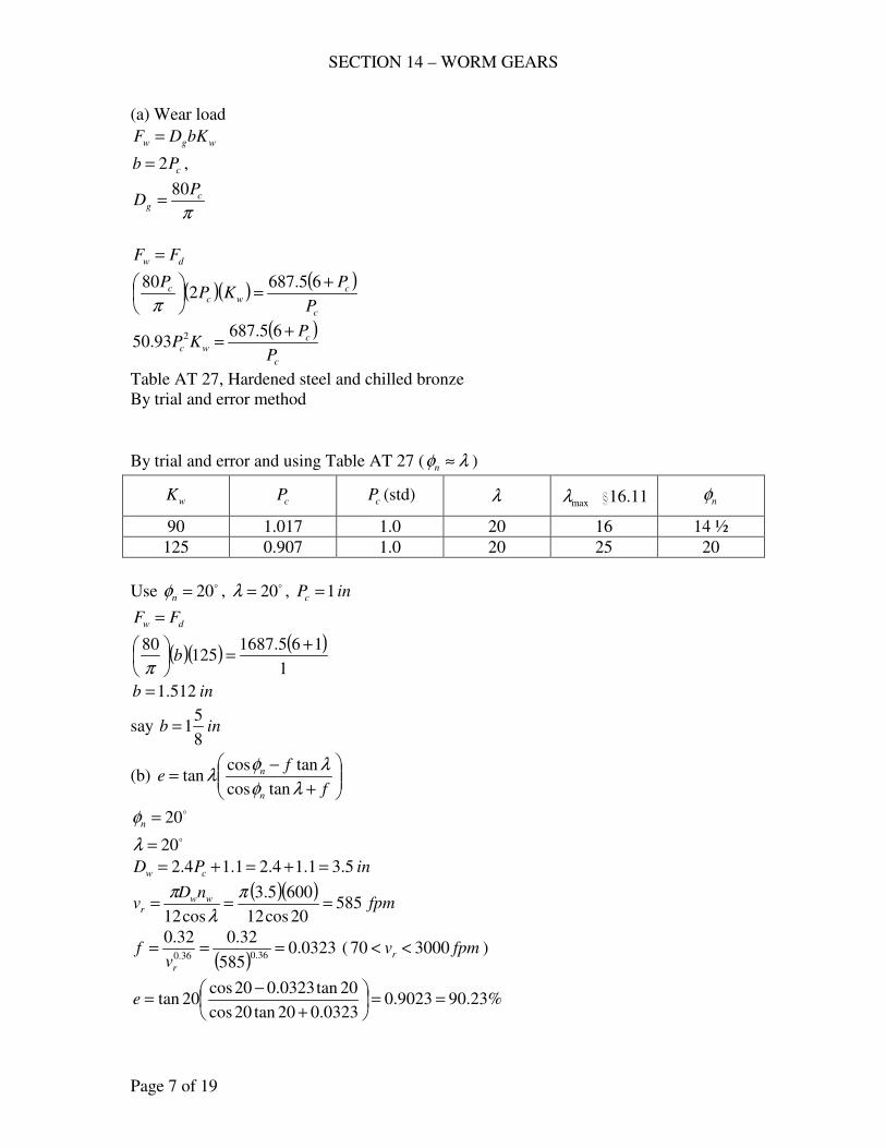
SECTION 14 – WORM GEARS
Page 7 of 19
(a) Wear load
wgw bKDF =
cPb 2= ,
πc
g
PD
80=
dw FF =
( )( ) ( )
c
cwc
c
P
PKP
P +=
65.6872
80
π
( )
c
cwc
P
PKP
+=
65.68793.50 2
Table AT 27, Hardened steel and chilled bronze
By trial and error method
By trial and error and using Table AT 27 ( λφ ≈n )
wK cP cP (std) λ maxλ i16.11 nφ
90 1.017 1.0 20 16 14 ½
125 0.907 1.0 20 25 20
Use o20=nφ , o20=λ , inPc 1=
dw FF =
( )( ) ( )1
165.1687125
80 +=
b
π
inb 512.1=
say inb8
51=
(b)
+
−=
f
fe
n
n
λφ
λφλ
tancos
tancostan
o20=nφ
o20=λ
inPD cw 5.31.14.21.14.2 =+=+=
( )( )fpm
nDv ww
r 58520cos12
6005.3
cos12===
π
λ
π
( )0323.0
585
32.032.036.036.0
===rv
f ( fpmvr 300070 << )
%23.909023.00323.020tan20cos
20tan0323.020cos20tan ==
+
−=e
SECTION 14 – WORM GEARS
Page 8 of 19
(c) Radiating area 7.1
min 2.43 CA =≈ sq. in.
( )gw DDC +=2
1
inDw 5.3=
( )in
PD c
g 5.2518080
===ππ
( ) inC 5.145.255.32
1=+=
( ) ..40725.142.437.1
min insqA ==
Temperature rise = t∆
minlbfttAhQ crc −∆=
( )( ) ( )( ) ( ) min600,80min000,334425.2259023.011 lbfthplbfthphpeQ i −=−−=−=−=
Figure AF 21, ..3.28..4072 ftsqinsqA ==
Finsqlbfthcr −−−= ..min42.0
cQQ =
( )( )( )t∆= 407242.0600,80
Ft 47=∆
with Ft 1001 =
FFt 1501472 <=
Therefore, no special cooling needed.
794. A 50-hp motor turning at 1750 rpm is to deliver its power to a worm-gear
reducer, whose velocity ratio is to be 20. The shell-type worm is to be made of
high-test cast iron; since a reasonably good efficiency is desired, use at least 4
threads; manganese –bronze gear (Table AT 3). (a) Decide upon wD and nφ , and
determine suitable values of the pitch and face width. Compute (b) the efficiency,
(c) the temperature rise of the lubricant. Estimate the radiating area of the case. Is
special cooling needed?
Solution:
mg
tv
hpF
000,33=
12
gg
mg
nDv
π=
rpmm
nn
w
wg 5.87
20
1750===
( )( )ππππ
cctwcgc
g
PPNmPNPD
80420====

SECTION 14 – WORM GEARS
Page 9 of 19
( )c
c
mg P
P
v 58312
5.8780
=
=π
π
( )
cc
tPP
F2830
583
50000,33==
(a) lbFv
F t
mg
d
+=
1200
1200
( )lb
P
P
P
PF
c
c
c
cd
+=
+=
06.213752830
1200
5831200
Wear load
wgw bKDF =
cPb 2= ,
πc
g
PD
80=
dw FF =
( )( ) ( )
c
cwc
c
P
PKP
P +=
06.213752
80
π
( )
c
cwc
P
PKP
+=
06.2137593.50 2
w
ct
D
PN
πλ =tan
Shell-type
inPD cw 1.14.2 +=
( )1.14.2
4tan
+=
c
c
P
P
πλ
Table AT 27, high-test cast-iron and manganese bronze
By trial and error and using Table AT 27 ( λφ ≈n )
wK cP cP (std) λ maxλ i16.11 nφ
80 1.012 1.0 20 16 14 ½
115 0.885 7/8 19.2 25 20
Use o2.19=λ , o20=nφ , inPc8
7=
inPD cw 2.31.18
74.21.14.2 =+
=+=
dw FF =
SECTION 14 – WORM GEARS
Page 10 of 19
( )( )
8
7
8
706.21375
1158
780
+
=
b
π
inb 80.1=
say inb8
71=
(b)
+
−=
f
fe
n
n
λφ
λφλ
tancos
tancostan
o2.19=λ o20=nφ
λ
π
cos12
wwr
nDv =
rpmnw 1750=
inDw 2.3=
( )( )fpm
nDv ww
r 15522.19cos12
17502.3
cos12===
π
λ
π
( )0227.0
1552
32.032.036.036.0
===rv
f ( fpmvr 300070 << )
%73.929273.00227.02.19tan20cos
2.19tan0227.020cos2.19tan ==
+
−=e
(c) ( )( ) ( )( ) min955,119635.3509273.011 lbfthphpeQ i −==−=−=
minlbfttAhQ crc −∆=
..2.43 7.1
min insqCAA ==
( )gw DDC +=2
1
inDw 2.3=
inP
D cg 3.22
8
780
80=
==ππ
( ) inC 75.1235.222.32
1=+=
( ) ..327275.122.437.1
insqA ==
Figure AF 1
27.22144
3272ftA ==
Finsqlbfthcr −−−= ..min43.0
SECTION 14 – WORM GEARS
Page 11 of 19
cQQ =
( )( )( )t∆= 327243.0955,119
Ft 85=∆
with Ft 1001 =
FFt 1501852 >=
Therefore, special cooling is needed.
CHECK PROBLEMS
795. A worm-gear speed reducer has a hardened-steel worm and a manganese-bronze
gear (Table AT 3); triple-threaded worm with .15278.1 inPc = , .136.3 inDw = ,
o25=nφ , .4
12 inb = , 12=wm , rpmnw 580= . The output is 16 hp. Compute (a)
the dynamic load, (b) the endurance strength of the teeth and the indicated
service factor on strength, (c) the limiting wear load (is it good for indefinitely
continuous service?), (d) the efficiency and input hp, (e) the temperature rise of
the oil (estimate case area as minA , i16.6). (f) Determine the tangential and radial
components of the tooth load. (g) Is this drive self-locking?
Solution:
mg
tv
hpF
000,33=
12
gg
mg
nDv
π=
rpmm
nn
w
wg 3.48
20
580===
( )( )( )in
NmPNPD twcgc
g 21.1331215278.1
====πππ
( )( )fpmvmg 167
12
3.4821.13==
π
(a) t
mg
d Fv
F
+=
1200
1200
td FF
+=
1200
1671200
( )lbFt 3162
167
16000,33==
( ) lbFd 360231621200
1671200=
+=
SECTION 14 – WORM GEARS
Page 12 of 19
(b) π
λ
π
cosccns
sYbPsYbPF ==
( )( )( )136.3
15278.13tan
ππλ ==
w
ct
D
PN
o34.19=λ
For manganese-bronze, psiss n 000,30==
For o25=nφ , 470.0=Y
( )( ) ( )lbFs 984,10
34.19cos15278.14
12470.0000,30
=
=π
Service factor
05.33602
984,10===
d
ssf
F
FN
(c) wgw bKDF =
inDg 21.13=
inb 25.2=
Table AT 27, hardened-steel worn and manganese bronze gear o25=nφ
100=wK
( )( )( ) ( )lbFlbF dw 3602297210025.221.13 =<==
Therefore, not good for indefinitely continuous service
(d)
+
−=
f
fe
n
n
λφ
λφλ
tancos
tancostan
( )( )fpm
nDv ww
r 5.18534.19cos12
58015278.1
cos12===
π
λ
π
( )0488.0
5.185
32.032.036.036.0
===rv
f ( fpmvr 300070 << )
%8585.00488.034.19tan25cos
34.19tan0488.025cos34.19tan ==
+
−=e
hphp
e
hphp o
i 82.1885.0
16===
(e) Temperature rise, t∆
( )( ) ( )( )( ) min159,93000,3382.1885.011 lbfthpeQ i −=−=−=
minlbfttAhQ crc −∆=
..2.43 7.1
min insqCAA ==
SECTION 14 – WORM GEARS
Page 13 of 19
( )gw DDC +=2
1
( ) inC 18.721.1315278.12
1=+=
( ) ..123318.72.437.1
insqA ==
Figure AF 1
26.8144
1233ftA ==
Finsqlbfthcr −−−= ..min47.0
cQQ =
( )( )( )t∆= 123347.0159,93
Ft 161=∆
(f) Tangential components on the worm
lbf
fFW
n
ntt 1305
34.19sin0488.034.19cos25cos
34.19cos0488.034.19sin25cos3162
sincoscos
cossincos=
−
+=
−
+=
λλφ
λλφ
on the gear
lbFt 3162=
radial components
lbf
FS
n
nt 159334.19sin0488.034.19cos25cos
25sin3162
sincoscos
sin=
−=
−=
λλφ
φ
(g) oo 534.19 >=λ , not self-locking
797. A worm-gear speed reducer has a hardened-steel worm and a phosphor-bronze
gear. The lead angle of the 5-threaded worm '5728o=λ , .2812.1 inPc = ,
o25=nφ , .2
12 inb = , 8=wm ; worm speed = 1750 rpm. The gear case is 35 3/8
in. high, 22 in. wide, 14 in. deep. Compute (a) the efficiency, (b) the limiting
wear load, the strength load, and the corresponding safe input and output
horsepowers. (c) The manufacturer rates this reducer at 53-hp input. Is this rating
conservative or risky? (d) What is the calculated temperature rise of the oil with
no special cooling? (e) The manufacturer specifies that for continuous service
power should not exceed 36.5 hp if there is to be no artificial cooling and if t∆ is
to be less than 90 F. Make calculations and decide whether the vendor is on the
safe side. (Data courtesy of the Cleveland Worm Gear Co.)
Solution:
SECTION 14 – WORM GEARS
Page 14 of 19
(a)
+
−=
f
fe
n
n
λφ
λφλ
tancos
tancostan
oo 95.28'5728 ==λ o25=nφ
λ
π
cos12
wwr
nDv =
rpmnw 1750=
πcg
g
PND =
( )( ) 4058 === twg NmN
( )( )inDg 31.16
2812.140==
π
w
ct
D
PN
πλ =tan
( )( )
wDπ
2812.1595.28tan =
inDw 686.3=
( )( )fpmvr 1923
'5728cos12
150686.3==
o
π
( )0210.0
1923
32.032.036.036.0
===rv
f ( fpmvr 300070 << )
%75.949475.00210.095.28tan25cos
95.28tan0210.025cos95.28tan ==
+
−=e
(b) wgw bKDF =
inDg 31.16=
inb 5.2=
Table AT 27, hardened-steel worn and phosphor bronze gear o25=nφ
100=wK
( )( )( ) lbFw 40781005.231.16 ==
π
λ
π
cosccns
sYbPsYbPF ==
For phosphor-bronze, psiss n 000,31==
For o25=nφ , 470.0=Y
( )( )( )( )lbFs 000,13
95.28cos2812.15.2470.0000,31==
π
SECTION 14 – WORM GEARS
Page 15 of 19
For safe input and output
t
mg
d Fv
F
+=
1200
1200
12
gg
mg
nDv
π=
rpmm
nn
w
wg 75.218
8
1750===
( )( )fpmvmg 934
12
75.21831.16==
π
dw FF =
tF
+=
1200
93412004078
lbFt 2293=
safe output = ( )( )
hpvF
hpmgt
o 9.64000,33
9342293
000,33===
safe input = hpe
hphp o
i 5.689475.0
9.64===
(c) 53-hp input < 68.5 hp. ∴ conservative.
(d) ( )( ) ( )( )( ) min676,118000,335.689475.011 lbfthpeQ i −=−=−=
minlbfttAhQ crc −∆=
( )( ) ( )( )[ ] ..5.2172375.352214222 insqA =+=
Figure AF 1
215144
5.2172ftA ==
Finsqlbfthcr −−−= ..min45.0
cQQ =
( )( )( )t∆= 5.217245.0676,118
Ft 4.121=∆
(e) Ft 90=′∆
t
t
hp
ph
i
i
∆
′∆=
′
124
90
5.68=
′iph
hpph i 8.50=′
Since 36.5 hp < 50.8 hp, therefore on the safe side.
SECTION 14 – WORM GEARS
Page 16 of 19
HEATING
799. The input to a worm-gear reducer is 50.5 hp at 580 rpm of the 4-threaded worm.
The gear case is 22 x 31 x 45 in. in size; o
n 25=φ , inPc 5.1= , inDw 432.4= ,
035.0=f , room temperature = 80 F. Compute the steady-state temperature for
average cooling.
Solution:
( )( )432.4
5.14tan
ππλ ==
w
ct
D
PN
o3.23=λ
+
−=
f
fe
n
n
λφ
λφλ
tancos
tancostan
9025.0035.03.23tan25cos
3.23tan035.025cos3.23tan =
+
−=e
( )( ) ( )( )( ) min484,162000,335.509025.011 lbfthpeQ i −=−=−=
minlbfttAhQ crc −∆=
( )( ) ( )( )[ ] ..4154453131222 insqA =+=
Figure AF 1
285.28144
4154ftA ==
Finsqlbfthcr −−−= ..min42.0
cQQ =
( )( )( )t∆= 415442.0484,162
Ft 93=∆
Ft 801 =
Ft 1732 =
801. A hardened-steel, 4-threaded worm drives a bronze gear; inDw 875.1= ,
inDg 14≈ , inPc 0.1= , o
n 25=φ , area of case ..1500 insq≈ , fpmvr 1037≈ ;
input = 20 hp at 1750 rpm of the worm; room temperature = 80 F. Compute the
steady-state temperature of the lubricant for average ventilation.
Solution:
( )( )875.1
0.14tan
ππλ ==
w
ct
D
PN
o2.34=λ
( )0263.0
1037
32.032.036.036.0
===rv
f ( fpmvr 300070 << )
SECTION 14 – WORM GEARS
Page 17 of 19
+
−=
f
fe
n
n
λφ
λφλ
tancos
tancostan
94.00263.02.34tan25cos
2.34tan0263.025cos2.34tan =
+
−=e
( )( ) ( )( )( ) min600,39000,332094.011 lbfthpeQ i −=−=−=
minlbfttAhQ crc −∆=
..1500 insqA =
Figure AF 1
24.10144
1500ftA ==
Finsqlbfthcr −−−= ..min46.0
cQQ =
( )( )( )t∆= 150046.0600,39
Ft 57=∆
Ft 801 =
Ft 1372 =
802. The input to a 4-threaded worm is measured to be 20.8 hp; inPc 0.1= , inDw 2= , o
n 25=φ . The area of the case is closely 1800 sq. in.; ambient temperature = 100
F; oil temperature = 180 F. Operation is at a steady thermal state. Compute the
indicated coefficient of friction.
Solution:
minlbfttAhQ crc −∆=
Figure AF 1
25.12144
1800ftA ==
Finsqlbfthcr −−−= ..min46.0
..1800 insqA =
Ft 80100180 =−=∆
( )( )( ) min240,6680180046.0 lbfttAhQ crc −==∆=
( )( )( ) min000,331 lbfthpeQ i −−=
cQQ =
( )( )( ) 240,66000,331 =− ihpe
9035.0=e
+
−=
f
fe
n
n
λφ
λφλ
tancos
tancostan
SECTION 14 – WORM GEARS
Page 18 of 19
( )( )2
0.14tan
ππλ ==
w
ct
D
PN
o5.32=λ
+
−=
f
f
5.32tan25cos
5.32tan25cos5.32tan9035.0
ff 4059.05774.09035.05217.0 −=+
0425.0=f
FORCE ANALYSIS
804. The input to a 4-threaded worm is 21 hp at 1750 rpm; %90=e , inDw4
12= ,
inDg 14= , 44=gN , o
n 25=φ . (a) From the horsepowers in and out, compute
the tangential forces on the worm tW and the gear tF . (b) Using this value of tF ,
compute tW from equation (k), i16.8, Text. (Check?) (c) Compute the separating
force. (d) What is the end thrust on the worm shaft? On the gear shaft?
Solution:
hphpi 21=
( )( ) ( )( ) hpehphp io 9.1890.021 ===
λtanw
g
t
g
wD
D
N
Nm ==
λtan4
12
14
4
44
=
o5.29=λ
+
−=
f
fe
n
n
λφ
λφλ
tancos
tancostan
+
−=
f
f
5.29tan25cos
5.29tan25cos5.29tan90.0
ff 32.05128.090.04615.0 −=+
0420.0=f
12
gg
mg
nDv
π=
g
t
w
g
N
N
n
n=
SECTION 14 – WORM GEARS
Page 19 of 19
44
4
1750=
gn
rpmng 159=
( )( )fpmvmg 583
12
15914==
π
(a) ( )
lbv
hpF
mg
ot 1070
583
9.18000,33000,33===
w
it
v
hpW
000,33=
( )( )fpm
nDv ww
w 103112
175025.2
12===
ππ
( )lbWt 672
1031
21000,33==
(b) lbf
fFW
n
ntt 672
5.29sin0420.05.29cos25cos
5.29cos0420.05.29sin25cos1070
sincoscos
cossincos=
−
+=
−
+=
λλφ
λλφ
(c) lbf
FS
n
nt 5895.29sin0420.05.29cos25cos
25sin1070
sincoscos
sin=
−=
−=
λλφ
φ
(d) End thrust
Worm shaft = lbFt 1070=
Gear shaft = lbWt 672=
- end -
SECTION 15 – FLEXIBLE POWER-TRANSMITTING ELEMENTS
Page 1 of 56
LEATHER BELTS
DESIGN PROBLEMS
841. A belt drive is to be designed for 321 =FF , while transmitting 60 hp at 2700
rpm of the driver 1D ; 85.1≈wm ; use a medium double belt, cemented joint, a
squirrel-cage, compensator-motor drive with mildly jerking loads; center distance
is expected to be about twice the diameter of larger pulley. (a) Choose suitable
iron-pulley sizes and determine the belt width for a maximum permissible
psis 300= . (b) How does this width compare with that obtained by the ALBA
procedure? (c) Compute the maximum stress in the straight port of the ALBA
belt. (d) If the belt in (a) stretches until the tight tension lbF 5251 = ., what is
21 FF ?
Solution:
(a) Table 17.1, Medium Double Ply,
Select inD 71 = . min.
int64
20=
( )( )fpm
nDvm 4948
12
27007
12
11 ===ππ
fpmfpmfpm 600049484000 <<
( )000,33
21 mvFFhp
−=
( )( )000,33
494860 21 FF −
=
lbFF 40021 =−
21 3FF =
lbFF 4003 22 =−
lbF 2002 =
( ) lbFF 60020033 21 ===
sbtF =1
η300=ds
For cemented joint, 0.1=η
psisd 300=
( )( )
==
64
203006001 bF
inb 4.6=
say inb 5.6=
SECTION 15 – FLEXIBLE POWER-TRANSMITTING ELEMENTS
Page 2 of 56
(b) ALBA Procedure
( )( )( )L21
1.17., ffpm CCCbCTableinhphp =
Table 17.1, fpmvm 4948=
Medium Double Ply
448.12=inhp
Table 17.2
Squirrel cage, compensator, starting
67.0=mC
Pulley Size, inD 71 =
6.0=pC
Jerky loads, 83.0=fC
( )( )( )( )( )83.06.067.0448.1260 bhp ==
inb 5.14=
say inb 15=
(c)
( )( )psi
bt
Fs 128
64
20151
6001 =
==
η
(d) ( ) ( )2
1
2
12
1
22
1
12
1
2006002 +=+= FFFo
lbFo 2.373=
lbF 5251 =
( ) ( ) 2
1
22
1
2
1
5252.3732 F+=
lbF 2472 =
1255.2247
525
2
1 ==F
F
842. A 20-hp, 1750 rpm, slip-ring motor is to drive a ventilating fan at 330 rpm. The
horizontal center distance must be about 8 to 9 ft. for clearance, and operation is
continuous, 24 hr./day. (a) What driving-pulley size is needed for a speed
recommended as about optimum in the Text? (b) Decide upon a pulley size (iron
or steel) and belt thickness, and determine the belt width by the ALBA tables. (c)
Compute the stress from the general belt equation assuming that the applicable
coefficient of friction is that suggested by the Text. (d) Suppose the belt is
installed with an initial tension inlbFo 70= . (§17.10), compute 21 FF and the
stress on the tight side if the approximate relationship of the operating tensions
and the initial tensions is 2
1
2
1
22
1
1 2 oFFF =+ .
SECTION 15 – FLEXIBLE POWER-TRANSMITTING ELEMENTS
Page 3 of 56
Solution:
fpmtovm 45004000=
assume fpmvm 4250=
12
11nDvm
π=
( )12
17504250 1Dπ
=
inD 26.91 =
say inD 101 =
(b) Using Heavy Double Ply Belt, int64
23=
Minimum pulley diameter for fpmvm 4250≈ , inD 101 =
Use inD 101 =
( )( )fpm
nDvm 4581
12
175010
12
11 ===ππ
ALBA Tables
( )( )( )L21
1.17., ffpm CCCbCTableinhphp =
8.13=inhp
Slip ring motor, 4.0=mC
Pulley Size, inD 101 =
7.0=pC
Table 17.7, 24 hr/day, continuous
8.1=sfN
Assume 74.0=fC
( )( ) ( )( )( )( )( )74.07.04.08.13208.1 bhp ==
inb 59.12=
use inb 13=
(c) General belt equation
−
−=−
θ
θρf
f
s
e
evsbtFF
1
2.32
12 2
21
fpsvs 35.7660
4581==
..035.0 inculb=ρ for leather
int64
23=
inb 13=
SECTION 15 – FLEXIBLE POWER-TRANSMITTING ELEMENTS
Page 4 of 56
( )( )lbFF 260
4581
208.1000,3321 ==−
3.0=f on iron or steel
C
DD 12 −±≈ πθ
ftC 9~8= use 8.5 ft
( ) inD 5310330
17502 =
=
( )rad72.2
125.8
1053=
−−= πθ
( )( ) 816.072.23.0 ==θf
5578.011
816.0
816.0
=−
=−
e
e
e
ef
f
θ
θ
( ) ( )( ) ( )5578.02.32
35.76035.012
64
2313260
2
21
−
==− sFF
psis 176=
(d) 2
1
2
1
22
1
1 2 oFFF =+
( )( ) lbininlbFo 9101370 ==
lbFF 26021 =−
lbFF 26012 −=
( ) ( ) 33.609102260 2
1
2
1
12
1
1 ==−+ FF
lbF 10451 =
lbF 78526010452 =−=
( )psi
bt
Fs 224
64
2313
10451 =
==
331.1785
1045
2
1 ==F
F
843. A 100-hp squirrel-cage, line-starting electric motor is used to drive a Freon
reciprocating compressor and turns at 1140 rpm; for the cast-iron motor pulley,
inD 161 = ; inD 532 = , a flywheel; cemented joints;l ftC 8= . (a) Choose an
appropriate belt thickness and determine the belt width by the ALBA tables. (b)
Using the design stress of §17.6, compute the coefficient of friction that would be
needed. Is this value satisfactory? (c) Suppose that in the beginning, the initial
tension was set so that the operating 221 =FF . Compute the maximum stress in
a straight part. (d) The approximate relation of the operating tensions and the
SECTION 15 – FLEXIBLE POWER-TRANSMITTING ELEMENTS
Page 5 of 56
initial tension oF is 2
1
2
1
22
1
1 2 oFFF =+ . For the condition in (c), compute oF . Is it
reasonable compared to Taylor’s recommendation?
Solution:
(a) Table 17.1
( )( )fpm
nDvm 4775
12
114016
12
11 ===ππ
Use heavy double-ply belt
int64
23=
1.14=inhp
( )( )( )L21
1.17., ffpm CCCbCTableinhphp =
line starting electric motor , 5.0=mC
Table 17.7, squirrel-cage, electric motor, line starting, reciprocating compressor
4.1=sfN
inD 161 = , 8.0=pC
assume, 74.0=fC
( )( ) hphp 1401004.1 ==
( )( )( )( )( )74.08.05.01.14140 bhp ==
inb 5.33=
use inb 34=
(b) §17.6, η400=ds
00.1=η for cemented joint.
psisd 400=
−
−=−
θ
θρf
f
s
e
evsbtFF
1
2.32
12 2
21
fpsvs 6.7960
4775==
..035.0 inculb=ρ for leather
int64
23=
inb 34=
( )( )lbFF 968
4775
1004.1000,3321 ==−
( ) ( )( )
−
−
==−
θ
θ
f
f
e
eFF
1
2.32
6.79035.012400
64
2334968
2
21
SECTION 15 – FLEXIBLE POWER-TRANSMITTING ELEMENTS
Page 6 of 56
2496.01
=−θ
θ
f
f
e
e
28715.0=θf
C
DD 12 −±≈ πθ
ftC 8=
( )rad7562.2
128
1653=
−−= πθ
( ) 28715.07562.2 =f
3.01042.0 <=f
Therefore satisfactory.
(c) lbFF 96821 =−
21 2FF =
lbFF 9682 22 =−
( ) lbFF 193696822 21 ===
( )psi
bt
Fs 159
64
2334
19361 =
==
(d) lbF 19361 = , lbF 9682 =
2
1
22
1
12
1
2 FFFo +=
( ) ( )2
1
2
12
1
96819362 +=oF
lbFo 1411=
inlbFo 5.4134
1411== of width is less than Taylor’s recommendation and is reasonable.
844. A 50-hp compensator-started motor running at 585 rpm drives a reciprocating
compressor for a 40-ton refrigerating plant, flat leather belt, cemented joints. The
diameter of the fiber driving pulley is 13 in., inD 702 = ., a cast-iron flywheel;
.11.6 inftC = Because of space limitations, the belt is nearly vertical; the
surroundings are quite moist. (a) Choose a belt thickness and determine the width
by the ALBA tables. (b) Using recommendations in the Text, compute s from
the general belt equation. (c) With this value of s , compute 1F and 21 FF . (d)
Approximately, 2
1
2
1
22
1
1 2 oFFF =+ , where oF is the initial tension. For the
condition in (c), what should be the initial tension? Compare with Taylor, §17.10.
(e) Compute the belt length. (f) The data are from an actual drive. Do you have
any recommendations for redesign on a more economical basis?
SECTION 15 – FLEXIBLE POWER-TRANSMITTING ELEMENTS
Page 7 of 56
Solution:
(a) ( )( )
fpmnD
vm 294412
86513
12
11 ===ππ
Table 17.1, use Heavy Double Ply,
inD 9min = for fpmvm 2944=
belts less than 8 in wide
int64
23=
( )( )( )L21
1.17., ffpm CCCbCTableinhphp =
86.9=inhp
Table 17.2
67.0=mC
8.0=pC
( )( ) 592.080.074.0 ==fC
Table 17.7, electric motor, compensator-started (squirrel cage) and reciprocating
compressor
4.1=sfN
( )( ) hphp 70504.1 ==
( )( )( )( )( )592.08.067.086.970 bhp ==
inb 4.22=
use inb 25=
(b) General Belt Equation
−
−=−
θ
θρf
f
s
e
evsbtFF
1
2.32
12 2
21
inb 25=
int64
23=
..035.0 inculb=ρ for leather
fpsvs 1.4960
2944==
Leather on iron, 3.0=f
C
DD 12 −−= πθ
( )rad35.2
126
1370=
−−= πθ
( )( ) 705.035.23.0 ==θf
SECTION 15 – FLEXIBLE POWER-TRANSMITTING ELEMENTS
Page 8 of 56
5059.011
705.0
705.0
=−
=−
e
e
e
ef
f
θ
θ
( )( )lbFF 785
2944
504.1000,3321 ==−
( ) ( )( ) ( )5059.02.32
1.49035.012
64
2325785
2
21
−
==− sFF
psis 204=
Cemented joint, 0.1=η
psis 204=
(c) ( )( ) lbsbtF 183364
23252041 =
==
lbF 104878518332 =−=
749.11048
1833
2
1 ==F
F
(d) 2
1
22
1
12
1
2 FFFo +=
( ) ( )2
1
2
12
1
104818332 +=oF
lbFo 1413=
inlbFo 5.5625
1413==
Approximately less than Taylor’s recommendation ( = 70 lb/in.)
(e) ( ) ( )C
DDDDCL
457.12
2
1212
−+++≈
( )( ) ( ) ( )( )( )
inL 2861264
1370137057.11262
2
=−
+++=
(f) More economical basis
12
11nDvm
π=
( )12
8654500 1Dπ
=
inD 87.191 =
use inD 201 =
SECTION 15 – FLEXIBLE POWER-TRANSMITTING ELEMENTS
Page 9 of 56
CHECK PROBLEMS
846. An exhaust fan in a wood shop is driven by a belt from a squirrel-cage motor that
runs at 880 rpm, compensator started. A medium double leather belt, 10 in. wide
is used; inC 54= .; inD 141 = . (motor), inD 542 = ., both iron. (a) What
horsepower, by ALBA tables, may this belt transmit? (b) For this power,
compute the stress from the general belt equation. (c) For this stress, what is
21 FF ? (d) If the belt has stretched until psis 200= on the tight side, what is
21 FF ? (e) Compute the belt length.
Solution:
(a) For medium double leather belt
int64
20=
( )( )fpm CCCbinhphp =
Table 17.1 and 17.2
67.0=mC
8.0=pC
74.0=fC
inb 10=
( )( )fpm
nDvm 3225
12
88014
12
11 ===ππ
6625.6=inhp
( )( )( )( )( ) hphp 43.2674.08.067.0106625.6 ==
(b)
−
−=−
θ
θρf
f
s
e
evsbtFF
1
2.32
12 2
21
inb 10=
int64
20=
..035.0 inculb=ρ
fpsvs 75.5360
3225==
C
DD 12 −−= πθ
rad4.254
1454=
−−= πθ
Leather on iron 3.0=f
( )( ) 72.04.23.0 ==θf
SECTION 15 – FLEXIBLE POWER-TRANSMITTING ELEMENTS
Page 10 of 56
51325.011
72.0
72.0
=−
=−
e
e
e
ef
f
θ
θ
( )lbFF 270
3225
43.26000,3321 ==−
( ) ( )( ) ( )51325.02.32
75.53035.012
64
2010270
2
21
−
==− sFF
psis 206=
(c) ( )( ) lbsbtF 64464
20102061 =
==
lbF 3742706442 =−=
72.1374
644
2
1 ==F
F
(d) psis 200=
( )( ) lbsbtF 62564
20102001 =
==
lbF 3552706252 =−=
76.1355
625
2
1 ==F
F
(e) ( ) ( )C
DDDDCL
457.12
2
1212
−+++≈
( ) ( ) ( )( )
inL 222544
1454145457.1542
2
=−
+++=
847. A motor is driving a centrifugal compressor through a 6-in. heavy, single-ply
leather belt in a dusty location. The 8-in motor pulley turns 1750 rpm;
inD 122 = . (compressor shaft); ftC 5= . The belt has been designed for a net
belt pull of inlbFF 4021 =− of width and 321 =FF . Compute (a) the
horsepower, (b) the stress in tight side. (c) For this stress, what needed value of
f is indicated by the general belt equation? (d) Considering the original
data,what horsepower is obtained from the ALBA tables? Any remarks?
Solution:
(a) ( )( )
fpmnD
vm 366512
17508
12
11 ===ππ
inb 6=
( )( ) lbFF 24064021 ==−
SECTION 15 – FLEXIBLE POWER-TRANSMITTING ELEMENTS
Page 11 of 56
( ) ( )( )hp
vFFhp m 65.26
000,33
3665240
000,33
21 ==−
=
(b) 21 3FF =
lbFF 2403 22 =−
lbF 1202 =
lbF 3601 =
bt
Fs 1=
For heavy single-ply leather belt
int64
13=
( )psis 295
64
136
360=
=
(c)
−
−=−
θ
θρf
f
s
e
evsbtFF
1
2.32
12 2
21
..035.0 inculb=ρ
fpsvs 1.6160
3665==
lbFF 24021 =−
( ) ( )( )
−
−
==−
θ
θ
f
f
e
eFF
1
2.32
1.61035.012295
64
136240
2
21
7995.01
=−θ
θ
f
f
e
e
C
DD 12 −−= πθ
( )rad075.3
125
812=
−−= πθ
9875.4=θfe
607.1=θf
( ) 607.1075.3 =f
5226.0=f
(d) ALBA Tables (Table 17.1 and 17.2)
( )( )fpm CCCbinhphp =
fpmvm 3665=
965.6=inhp
SECTION 15 – FLEXIBLE POWER-TRANSMITTING ELEMENTS
Page 12 of 56
inb 10=
0.1=mC (assumed)
6.0=pC
74.0=fC
( )( )( )( )( ) hphphp 65.266.1874.06.00.16965.6 <==
848. A 10-in. medium double leather belt, cemented joints, transmits 60 hp from a 9-
in. paper pulley to a 15-in. pulley on a mine fab; dusty conditions. The
compensator-started motor turns 1750 rpm; inC 42= . This is an actual
installation. (a) Determine the horsepower from the ALBA tables. (b) Using the
general equation, determine the horsepower for this belt. (c) Estimate the service
factor from Table 17.7 and apply it to the answer in (b). Does this result in better
or worse agreement of (a) and (b)? What is your opinion as to the life of the belt?
Solution:
( )( )fpm
nDvm 4123
12
17509
12
11 ===ππ
(a) ( )( )fpm CCCbinhphp =
Table 17.1 and 17.2
Medium double leather belt
int64
20=
fpmvm 4123=
15.11=inhp
67.0=mC
7.0=pC
74.0=fC
inb 10=
( )( )( )( )( ) hphp 7.3874.07.067.01015.11 ==
(b)
−
−=−
θ
θρf
f
s
e
evsbtFF
1
2.32
12 2
21
inb 10=
..035.0 inculb=ρ
η400=s
0.1=η cemented joint
psis 400=
C
DD 12 −−= πθ
SECTION 15 – FLEXIBLE POWER-TRANSMITTING ELEMENTS
Page 13 of 56
rad9987.242
915=
−−= πθ
Leather on paper pulleys, 5.0=f
( )( ) 5.19987.25.0 ==θf
77687.01
=−θ
θ
f
f
e
e
fpsvs 72.6860
4123==
( ) ( )( ) ( ) lbFF 82277687.02.32
72.68035.012400
64
2010
2
21 =
−
=−
( ) ( )( )hp
vFFhp m 7.102
000,33
4123822
000,33
21 ==−
=
(c) Table 17.7
6.1=sfN
hphphp 7.1022.646.1
7.102<==
Therefore, better agreement
Life of belt, not continuous, hphp 7.3860 > .
MISCELLANEOUS
849. Let the coefficient of friction be constant. Find the speed at which a leather belt
may transmit maximum power if the stress in the belt is (a) 400 psi, (b) 320 psi.
(c) How do these speeds compare with those mentioned in §17.9, Text? (d)
Would the corresponding speeds for a rubber belt be larger or smaller? (HINT:
Try the first derivative of the power with respect to velocity.)
Solution:
−
−=−
θ
θρf
f
s
e
evsbtFF
1
2.32
12 2
21
( )000,33
21 mvFFhp
−=
( )000,33
60 21 svFFhp
−=
−
−=
θ
θρf
f
ss
e
evs
btvhp
1
2.32
12
000,33
60 2
ss
f
f
vv
se
ebthp
−
−=
2.32
121
000,33
60 2ρθ
θ

SECTION 15 – FLEXIBLE POWER-TRANSMITTING ELEMENTS
Page 14 of 56
( )( )
02.32
24
2.32
121
000,33
60 22
=
−
−
−= ss
f
f
s
vvs
e
ebt
vd
hpd ρρθ
θ
2.32
36 2
svs
ρ=
..035.0 inculb=ρ
(a) psis 400=
( )2.32
035.036400
2
sv=
fpsvs 105.101=
fpmvm 6066=
(b) psis 320=
( )2.32
035.036320
2
sv=
fpsvs 431.90=
fpmvm 5426=
(c) Larger than those mentioned in §17.9 (4000 – 4500 fpm)
(d) Rubber belt, ..045.0 inculb=ρ
(a) psis 400=
( )2.32
045.036400
2
sv=
fpsvs 166.89=
fpmfpmvm 60665350 <=
Therefore, speeds for a rubber belt is smaller.
850. A 40-in. pulley transmits power to a 20-in. pulley by means of a medium double
leather belt, 20 in. wide; ftC 14= , let 3.0=f . (a) What is the speed of the 40-in
pulley in order to stress the belt to 300 psi at zero power? (b) What maximum
horsepower can be transmitted if the indicated stress in the belt is 300 psi? What
is the speed of the belt when this power is transmitted? (See HINT in 849).
Solution:
−
−=−
θ
θρf
f
s
e
evsbtFF
1
2.32
12 2
21
SECTION 15 – FLEXIBLE POWER-TRANSMITTING ELEMENTS
Page 15 of 56
( )000,33
60 21 svFFhp
−=
ss
f
f
vv
se
ebthp
−
−=
2.32
121
000,33
60 2ρθ
θ
( )( )
02.32
24
2.32
121
000,33
60 22
=
−
−
−= ss
f
f
s
vvs
e
ebt
vd
hpd ρρθ
θ
2.32
36 2
svs
ρ= for maximum power
(a) At zero power:
2.32
12 2
svs
ρ=
psis 300=
..035.0 inculb=ρ
( )2.32
035.012300
2
sv=
fpsvs 6575.151=
fpmvm 9100=
Speed, 40 in pulley, ( )( )
rpmD
vn m 869
40
91001212
2
2 ===ππ
(b) Maximum power
2.32
36 2
svs
ρ=
( )2.32
035.036300
2
sv=
fpsvs 5595.87=
fpmvm 5254=
ss
f
f
vv
se
ebthp
−
−=
2.32
121
000,33
60 2ρθ
θ
int64
20=
inb 20=
C
DD 12 −−= πθ
( )rad0225.3
1214
2040=
−−= πθ
3.0=f
SECTION 15 – FLEXIBLE POWER-TRANSMITTING ELEMENTS
Page 16 of 56
( )( ) 90675.00225.33.0 ==θf
5962.01
=−θ
θ
f
f
e
e
( )( ) ( )( ) ( ) 64.1185595.87
2.32
5595.87035.0123005962.0
000,33
64
202060 2
=
−
=hp
fpmvm 5254=
AUTOMATIC TENSION DEVICES
851. An ammonia compressor is driven by a 100-hp synchronous motor that turns
1200 rpm; 12-in. paper motor pulley; 78-in. compressor pulley, cast-iron;
inC 84= . A tension pulley is placed so that the angle of contact on the motor
pulley is 193o and on the compressor pulley, 240
o. A 12-in. medium double
leather belt with a cemented joint is used. (a) What will be the tension in the
tight side of the belt if the stress is 375 psi? (b) What will be the tension in the
slack side? (c) What coefficient of friction is required on each pulley as indicated
by the general equation? (d) What force must be exerted on the tension pulley to
hold the belt tight, and what size do you recommend?
Solution:
(a) sbtF =1
inb 12=
int64
20=
( )( )
=
64
20123751F
(b) mv
hpFF
000,3321 =−
( )( )fpm
nDvm 3770
12
120012
12
11 ===ππ
Table 17.7, 2.1=sfN
( )( )lbFF 1050
3770
1002.1000,3321 ==−
lbFF 35610501406105012 =−=−=
(c)
−
−=−
θ
θρf
f
s
e
evsbtFF
1
2.32
12 2
21
fpsvs 83.6260
3770==
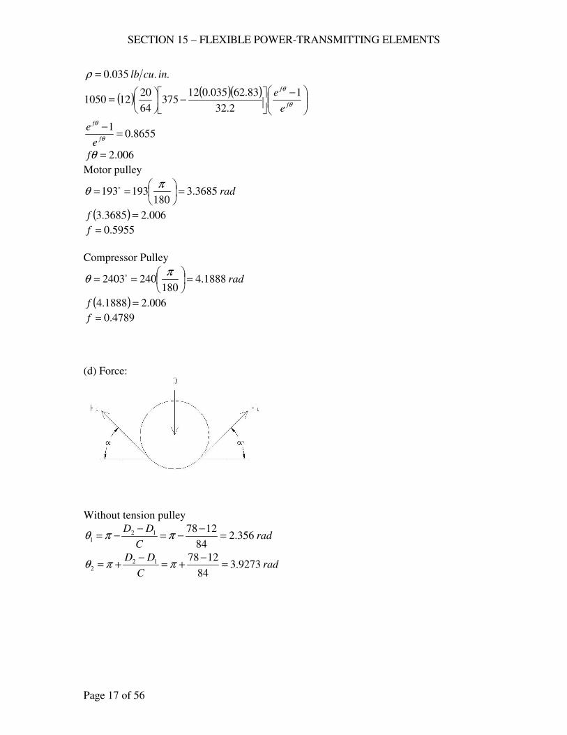
SECTION 15 – FLEXIBLE POWER-TRANSMITTING ELEMENTS
Page 17 of 56
..035.0 inculb=ρ
( ) ( )( )
−
−
=
θ
θ
f
f
e
e 1
2.32
83.62035.012375
64
20121050
8655.01
=−θ
θ
f
f
e
e
006.2=θf
Motor pulley
rad3685.3180
193193 =
==
πθ o
( ) 006.23685.3 =f
5955.0=f
Compressor Pulley
rad1888.4180
2402403 =
==
πθ o
( ) 006.21888.4 =f
4789.0=f
(d) Force:
Without tension pulley
radC
DD356.2
84
1278121 =
−−=
−−= ππθ
radC
DD9273.3
84
1278122 =
−+=
−+= ππθ
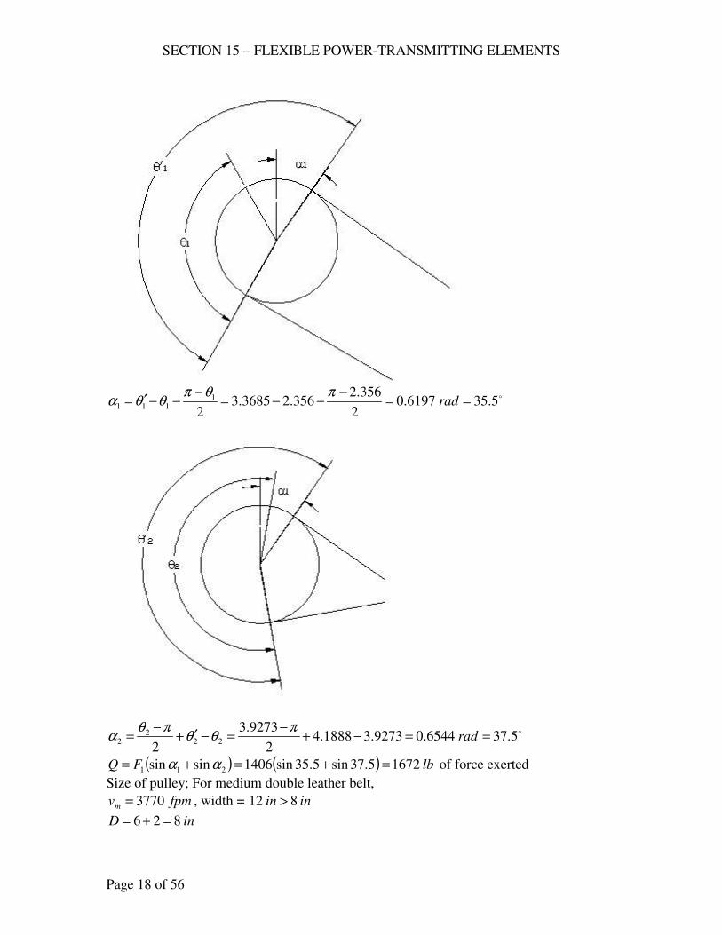
SECTION 15 – FLEXIBLE POWER-TRANSMITTING ELEMENTS
Page 18 of 56
o5.356197.0
2
356.2356.23685.3
2
1111 ==
−−−=
−−−′= rad
πθπθθα
o5.376544.09273.31888.42
9273.3
222
22 ==−+
−=−′+
−= rad
πθθ
πθα
( ) ( ) lbFQ 16725.37sin5.35sin1406sinsin 211 =+=+= αα of force exerted
Size of pulley; For medium double leather belt,
fpmvm 3770= , width = inin 812 >
inD 826 =+=
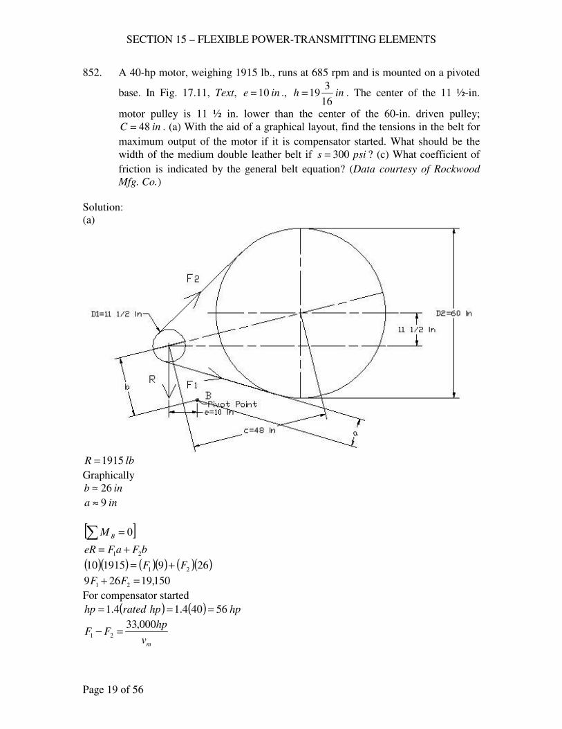
SECTION 15 – FLEXIBLE POWER-TRANSMITTING ELEMENTS
Page 19 of 56
852. A 40-hp motor, weighing 1915 lb., runs at 685 rpm and is mounted on a pivoted
base. In Fig. 17.11, Text, ine 10= ., inh16
319= . The center of the 11 ½-in.
motor pulley is 11 ½ in. lower than the center of the 60-in. driven pulley;
inC 48= . (a) With the aid of a graphical layout, find the tensions in the belt for
maximum output of the motor if it is compensator started. What should be the
width of the medium double leather belt if psis 300= ? (c) What coefficient of
friction is indicated by the general belt equation? (Data courtesy of Rockwood
Mfg. Co.)
Solution:
(a)
lbR 1915=
Graphically
inb 26≈
ina 9≈
[ ]∑ = 0BM
bFaFeR 21 +=
( )( ) ( )( ) ( )( )269191510 21 FF +=
150,19269 21 =+ FF
For compensator started
( ) ( ) hphpratedhp 56404.14.1 ===
mv
hpFF
000,3321 =−
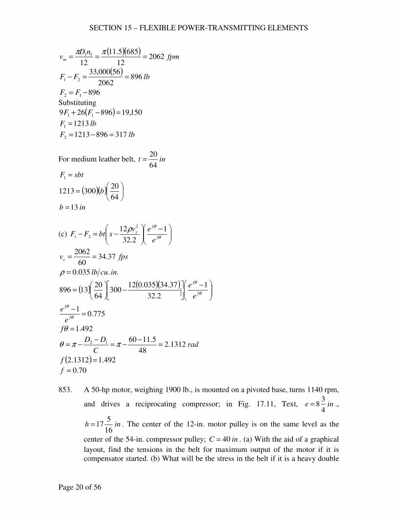
SECTION 15 – FLEXIBLE POWER-TRANSMITTING ELEMENTS
Page 20 of 56
( )( )fpm
nDvm 2062
12
6855.11
12
11 ===ππ
( )lbFF 896
2062
56000,3321 ==−
89612 −= FF
Substituting
( ) 150,19896269 11 =−+ FF
lbF 12131 =
lbF 31789612132 =−=
For medium leather belt, int64
20=
sbtF =1
( )( )
=
64
203001213 b
inb 13=
(c)
−
−=−
θ
θρf
f
s
e
evsbtFF
1
2.32
12 2
21
fpsvs 37.3460
2062==
..035.0 inculb=ρ
( ) ( )( )
−
−
=
θ
θ
f
f
e
e 1
2.32
37.34035.012300
64
2013896
775.01
=−θ
θ
f
f
e
e
492.1=θf
radC
DD1312.2
48
5.116012 =−
−=−
−= ππθ
( ) 492.11312.2 =f
70.0=f
853. A 50-hp motor, weighing 1900 lb., is mounted on a pivoted base, turns 1140 rpm,
and drives a reciprocating compressor; in Fig. 17.11, Text, ine4
38= .,
inh16
517= . The center of the 12-in. motor pulley is on the same level as the
center of the 54-in. compressor pulley; inC 40= . (a) With the aid of a graphical
layout, find the tensions in the belt for maximum output of the motor if it is
compensator started. (b) What will be the stress in the belt if it is a heavy double
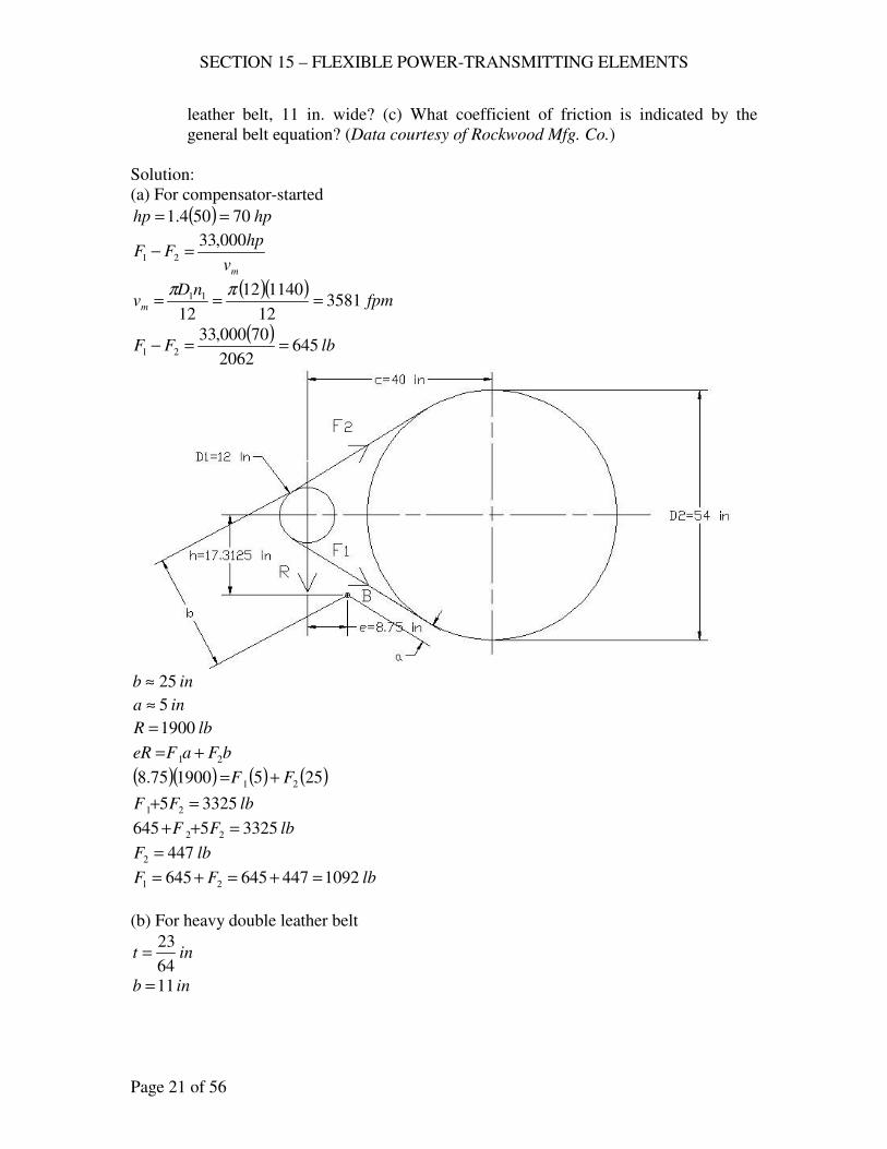
SECTION 15 – FLEXIBLE POWER-TRANSMITTING ELEMENTS
Page 21 of 56
leather belt, 11 in. wide? (c) What coefficient of friction is indicated by the
general belt equation? (Data courtesy of Rockwood Mfg. Co.)
Solution:
(a) For compensator-started
( ) hphp 70504.1 ==
mv
hpFF
000,3321 =−
( )( )fpm
nDvm 3581
12
114012
12
11 ===ππ
( )lbFF 645
2062
70000,3321 ==−
inb 25≈
ina 5≈
lbR 1900=
bFaFeR 21 +=
( )( ) ( ) ( )255190075.8 21 FF +=
lbFF 33255 21 =+
lbFF 33255645 22 =++
lbF 4472 =
lbFF 1092447645645 21 =+=+=
(b) For heavy double leather belt
int64
23=
inb 11=
SECTION 15 – FLEXIBLE POWER-TRANSMITTING ELEMENTS
Page 22 of 56
( )psi
bt
Fs 276
64
2011
10921 =
==
(c)
−
−=−
θ
θρf
f
s
e
evsbtFF
1
2.32
12 2
21
fpsvs 68.5960
3581==
..035.0 inculb=ρ
( ) ( )( )
−
−
=
θ
θ
f
f
e
e 1
2.32
68.59035.012276
64
2311645
241.1=θf
radC
DD092.2
40
125412 =−
−=−
−= ππθ
( ) 492.1092.2 =f
60.0=f
RUBBER BELTS
854. A 5-ply rubber belt transmits 20 horsepower to drive a mine fan. An 8-in., motor
pulley turns 1150 rpm; inD 362 = ., fan pulley; ftC 23= . (a) Design a rubber
belt to suit these conditions, using a net belt pull as recommended in §17.15,
Text. (b) Actually, a 9-in., 5-ply Goodrich high-flex rubber belt was used. What
are the indications for a good life?
Solution:
(a) ( )
o174040.31223
83612 ==−
−=−
−= radC
DDππθ
976.0=θK
2400
θKNbvhp
pm=
976.0=θK
( )( )fpm
nDvm 2409
12
11508
12
11 ===ππ
5=pN
( )( )( )2400
976.05240920
bhp ==
inb 1.4=
min. inb 5=
SECTION 15 – FLEXIBLE POWER-TRANSMITTING ELEMENTS
Page 23 of 56
(b) With inb 9= is safe for good life.
855. A 20-in., 10-ply rubber belt transmits power from a 300-hp motor, running at 650
rpm, to an ore crusher. The center distance between the 33-in. motor pulley and
the 108-in. driven pulley is 18 ft. The motor and crusher are so located that the
belt must operate at an angle 75o with the horizontal. What is the overload
capacity of this belt if the rated capacity is as defined in §17.15, Text?
Solution:
2400
pmNbvhp =
inb 20=
( )( )fpm
nDvm 5616
12
65033
12
11 ===ππ
10=pN
( )( )( )hphp 468
2400
10561620==
Overlaod Capacity = ( ) %56%100300
300468=
−
V-BELTS
NOTE: If manufacturer’s catalogs are available, solve these problems from catalogs as
well as from data in the Text.
856. A centrifugal pump, running at 340 rpm, consuming 105 hp in 24-hr service, is to
be driven by a 125-hp, 1180-rpm, compensator-started motor; intoC 4943= .
Determine the details of a multiple V-belt drive for this installation. The B.F.
Goodrich Company recommended six C195 V-belts with 14.4-in. and 50-in.
sheaves; inC 2.45≈ .
Solution:
Table 17.7
4.12.02.1 =+=sfN (24 hr/day)
Design hp = sfN (transmitted hp) = ( )( ) hp1751254.1 =
Fig. 17.4, 175 hp, 1180 rpm
inD 13min = , D-section
4.14
50
340
1180
1
2 ==D
D
use ininD 134.141 >=
inD 502 =
SECTION 15 – FLEXIBLE POWER-TRANSMITTING ELEMENTS
Page 24 of 56
( )( )fpm
nDvm 4449
12
11804.14
12
11 ===ππ
36
2
1
09.03
1010
10 mm
dm
vve
DK
c
vahpRated
−−
=
Table 17.3, D-section
788.18=a , 7.137=c , 0848.0=e
Table 17.4, 47.31
2 =D
D
14.1=dK
( )( )( ) ( )
hphpRated 294.2810
4449
10
44490848.0
4.1414.1
7.137
4449
10788.18
36
209.03
=
−−
=
Back to Fig. 17.14, C-section must be used.
792.8=a , 819.38=c , 0416.0=e
36
2
1
09.03
1010
10 mm
dm
vve
DK
c
vahpRated
−−
=
( )( )( ) ( )
hphpRated 0.2010
4449
10
44490416.0
4.1414.1
819.38
4449
10792.8
36
209.03
=
−−
=
Adjusted rated hp = ( )hpratedKK Lθ
Table 17.5,
77.046
4.145012 =−
=−
C
DD
88.0=θK
Table 17.6
( ) ( )C
DDDDCL
457.12
2
1212
−+++≈
( ) ( ) ( )( )
inL 200464
4.14504.145057.1462
2
=−
+++=
use C195, inL 9.197=
07.1=LK
Adjusted rated hp = ( )( )( ) hp83.182007.188.0 =
beltshpratedAdjusted
hpDesignbeltsofNo 3.9
83.18
175. === use 9 belts
Use 9 , C195 V-belts with 14.4 in and 50 in sheaves
SECTION 15 – FLEXIBLE POWER-TRANSMITTING ELEMENTS
Page 25 of 56
( )16
322
12
2 DDBBC
−−+=
( ) ( ) ( ) inDDLB 2.3874.145028.69.197428.64 12 =+−=+−=
( ) ( )inC 9.44
16
4.1450322.3872.38722
=−−+
=
857. A 50-hp, 1160-rpm, AC split-phase motor is to be used to drive a reciprocating
pump at a speed of 330 rpm. The pump is for 12-hr. service and normally
requires 44 hp, but it is subjected to peak loads of 175 % of full load; inC 50≈ .
Determine the details of a multiple V-belt drive for this application. The Dodge
Manufacturing Corporation recommended a Dyna-V Drive consisting of six
5V1800 belts with 10.9-in. and 37.5-in. sheaves; inC 2.50≈ .
Solution:
Table 17.7, (12 hr/day)
2.12.04.1 =−=sfN
Design hp = ( )( )( ) hp1055075.12.1 =
Fig. 17.4, 105 hp, 1160 rpm
inD 13min = , D-section
2.13
4.46
330
1160
1
2 ≈=D
D
use ininD 132.131 >=
inD 4.462 =
( )( )fpm
nDvm 4009
12
11602.13
12
11 ===ππ
36
2
1
09.03
1010
10 mm
dm
vve
DK
c
vahpRated
−−
=
Table 17.3, D-section
788.18=a , 7.137=c , 0848.0=e
Table 17.4, 5.32.13
4.46
1
2 ==D
D
14.1=dK
( )( )( ) ( )
hphpRated 32.2410
4009
10
40090848.0
2.1314.1
7.137
4009
10788.18
36
209.03
=
−−
=
Back to Fig. 17.14, C-section must be used.
792.8=a , 819.38=c , 0416.0=e
inD 9min =
SECTION 15 – FLEXIBLE POWER-TRANSMITTING ELEMENTS
Page 26 of 56
1.9
32
330
1160
1
2 ≈=D
D
use inD 1.91 =
( )( )fpm
nDvm 2764
12
11601.9
12
11 ===ππ
( )( )( ) ( )
hphpRated 96.1010
2764
10
27640416.0
1.914.1
819.38
2764
10792.8
36
209.03
=
−−
=
Adjusted rated hp = ( )hpratedKK Lθ
Table 17.5,
458.050
1.93212 =−
=−
C
DD
935.0=θK
Table 17.6
( ) ( )C
DDDDCL
457.12
2
1212
−+++≈
( ) ( ) ( )( )
inL 167504
1.9321.93257.1502
2
=−
+++=
use C158, inL 9.160=
02.1=LK
Adjusted rated hp = ( )( )( ) hp45.1096.1002.1935.0 =
beltshpratedAdjusted
hpDesignbeltsofNo 10
43.10
105. ===
( )16
322
12
2 DDBBC
−−+=
( ) ( ) ( ) inDDLB 5.3851.93228.69.160428.64 12 =+−=+−=
( ) ( )inC 8.46
16
1.932325.3855.38522
=−−+
=
Use 10-C158 belts, inD 1.91 =
inD 322 = , inC 8.46=
858. A 200-hp, 600-rpm induction motor is to drive a jaw crusher at 125 rpm; starting
load is heavy; operating with shock; intermittent service; intoC 123113= .
Recommend a multiple V-flat drive for this installation. The B.F. Goodrich
Company recommended eight D480 V-belts with a 26-in. sheave and a 120.175-
in. pulley; inC 3.116≈ .
Solution:
SECTION 15 – FLEXIBLE POWER-TRANSMITTING ELEMENTS
Page 27 of 56
Table 17.7
4.12.06.1 =−=sfN
( )( ) hphp 2802004.1 ==
Fig. 17.14, 280 hp, 600 rpm
Use Section E
But in Table 17.3, section E is not available, use section D
13min =D
8.4125
600
1
2 ==D
D
For max1D :
121
2min D
DDC +
+=
111
2
8.4113 D
DD+
+=
inD 281 =
2min DC =
inD 1132 =
inD 5.238.4
1131 ==
use ( ) inD 185.23132
11 =+≈
( )( ) inD 4.86188.42 ==
( ) ( )C
DDDDCL
457.12
2
1212
−+++≈
( ) ( ) ( )( )
inL 4101184
184.86184.8657.11182
2
=−
+++=
using inD 191 = , inD 2.912 = , inC 118=
( ) ( ) ( )( )
inL 4201184
192.91192.9157.11182
2
=−
+++=
Therefore use D420 sections
inD 191 = , inD 2.912 =
( )( )fpm
nDvm 2985
12
60019
12
11 ===ππ
36
2
1
09.03
1010
10 mm
dm
vve
DK
c
vahpRated
−−
=
Table 17.3, D-section
788.18=a , 7.137=c , 0848.0=e
Table 17.4, 8.41
2 =D
D
SECTION 15 – FLEXIBLE POWER-TRANSMITTING ELEMENTS
Page 28 of 56
14.1=dK
( )( )( ) ( )
hphpRated 6.2910
2985
10
29850848.0
1914.1
7.137
2985
10788.18
36
209.03
=
−−
=
Therefore, Fig. 17.14, section D is used.
Adjusted rated hp = ( )hpratedKK Lθ
Table 17.5,
612.0118
192.9112 =−
=−
C
DD
83.0=θK (V-flat)
Table 17.6, D420
inL 8.420=
12.1=LK
Adjusted rated hp = ( )( )( ) hp52.276.2912.183.0 =
beltshpratedAdjusted
hpDesignbeltsofNo 10
52.27
280. ===
Use10 , D420, inD 191 = , inD 2.912 = , inC 118=
859. A 150-hp, 700-rpm, slip-ring induction motor is to drive a ball mill at 195 rpm;
heavy starting load; intermittent seasonal service; outdoors. Determine all details
for a V-flat drive. The B.F. Goodrich Company recommended eight D270 V-
belts, 17.24-in sheave, 61-in. pully, inC 7.69≈ .
Solution:
Table 17.7,
4.12.06.1 =−=sfN
Design hp = ( )( ) hp2101504.1 =
Fig. 17.4, 210 hp, 700 rpm
inD 13min = , D-section
36
2
1
09.03
1010
10 mm
dm
vve
DK
c
vahpRated
−−
=
For Max. Rated hp, ( )
0
103
=
mvd
hpd
3
33
1
91.0
3 101010
−
−
= mm
d
m ve
v
DK
cvahpRated
Let 310
mvX =
SECTION 15 – FLEXIBLE POWER-TRANSMITTING ELEMENTS
Page 29 of 56
3
1
91.0eXX
DK
caXhp
d
−−=
( )3
1
3
11
3 1012
700
101210 ×=
×==
DnDvX m ππ
π700
1012 3
1
XD
×=
3
3
91.0
1012
700eX
K
caXhp
d
−×
−=π
( )( )
0391.0 209.0 =−= − eXaXXd
hpd
e
aX
3
91.009.2 =
Table 17.3, D-section
788.18=a , 7.137=c , 0848.0=e
( )( )0848.03
788.1891.0
10
09.2
3
09.2 =
= mv
X
fpmvm 7488=
748812
11 ==nD
vm
π
( )7488
12
7001 ==D
vm
π
inD 86.401 =
max inD 86.401 =
ave. ( ) inD 93.2686.40132
11 =+=
use inD 221 =
22
79
195
700
1
2 ≈=D
D
inD 221 = , inD 792 =
Min. inDDD
C 5.72222
7922
21
21 =++
=++
=
Or Min. inDC 792 ==
( ) ( )C
DDDDCL
457.12
2
1212
−+++≈
( ) ( ) ( )( )
inL 327794
2279227957.1792
2
=−
+++=
use D330, inL 8.330=
( )16
322
12
2 DDBBC
−−+=
SECTION 15 – FLEXIBLE POWER-TRANSMITTING ELEMENTS
Page 30 of 56
( ) ( ) ( ) inDDLB 689227928.68.330428.64 12 =+−=+−=
( ) ( )inC 12.81
16
22793268968922
=−−+
=
( )( )fpm
nDvm 4032
12
70022
12
11 ===ππ
14.1=dK
( )( )( ) ( )
hphpRated 124.3910
4032
10
40320848.0
2214.1
7.137
4032
10788.18
36
209.03
=
−−
=
Adjusted rated hp = ( )hpratedKK Lθ
Table 17.5,
70.012.81
227912 =−
=−
C
DD
84.0=θK (V-flat)
Table 17.6
D330
07.1=LK
Adjusted rated hp = ( )( )( ) hp165.35124.3907.184.0 =
beltshpratedAdjusted
hpDesignbeltsofNo 97.5
165.35
210. === use 6 belts
Use 6 , D330 V-belts , inD 221 = , inD 792 = , inC 1.81≈
860. A 30-hp, 1160-rpm, squirrel-cage motor is to be used to drive a fan. During the
summer, the load is 29.3 hp at a fan speed of 280 rpm; during the winter, it is 24
hp at 238 rpm; inC 5044 << .; 20 hr./day operation with no overload. Decide
upon the size and number of V-belts, sheave sizes, and belt length. (Data
courtesy of The Worthington Corporation.)
Solution:
Table 17.7
8.12.06.1 =+=sfN
Design hp = ( )( ) hp54308.1 =
Speed of fan at 30 hp
( ) rpmn 286238238280243.29
24302 =+−
−
−=
at 54 hp, 1160 rpm. Fig. 17.4
use either section C or section D
Minimum center distance:
2DC =
SECTION 15 – FLEXIBLE POWER-TRANSMITTING ELEMENTS
Page 31 of 56
or 121
2D
DDC +
+=
056.4286
1160
1
2 ==D
D
use 1056.4 DC =
inCin 5044 << , use inC 47=
inD 6.11056.4
47max1 ==
use C-section, inD 9min =
Let inD 101 = , inD 411 =
( ) ( )C
DDDDCL
457.12
2
1212
−+++≈
( ) ( ) ( )( )
inL 3.179474
1.10411.104157.1472
2
=−
+++=
use C137, inL 9.175=
( )16
322
12
2 DDBBC
−−+=
( ) ( ) ( ) inDDLB 7.3281.104128.69.175428.64 12 =+−=+−=
( ) ( )ininC 442.45
16
1.1041327.3827.38222
≈=−−+
=
C173, satisfies inCin 5044 << 3
33
1
91.0
3 101010
−
−
= mm
d
m ve
v
DK
cvahpRated
( )( )fpm
nDvm 3067
12
11601.10
12
11 ===ππ
Table 17.4
056.41
2 =D
D, 14.1=dK
Table 17.3, D-section
792.8=a , 819.38=c , 0416.0=e
( )( )( ) ( )
hphpRated 838.1210
3067
10
30670416.0
1.1014.1
819.38
3067
10792.8
36
209.03
=
−−
=
Adjusted rated hp = ( )hpratedKK Lθ
Table 17.5,
68.02.45
1.104112 =−
=−
C
DD
90.0=θK
SECTION 15 – FLEXIBLE POWER-TRANSMITTING ELEMENTS
Page 32 of 56
Table 17.6
9.175=L , C173
04.1=LK
Adjusted rated hp = ( )( )( ) hp02.12838.1204.190.0 =
beltshpratedAdjusted
hpDesignbeltsofNo 5.4
02.12
54. === use 5 belts
Use 5 , C173 V-belts , inD 1.101 = , inD 412 =
POWER CHAINS
NOTE: If manufacturer’s catalogs are available, solve these problems from catalogs as
well as from data in the Text.
861. A roller chain is to be used on a paving machine to transmit 30 hp from the 4-
cylinder Diesel engine to a counter-shaft; engine speed 1000 rpm, counter-shaft
speed 500 rpm. The center distance is fixed at 24 in. The cain will be subjected to
intermittent overloads of 100 %. (a) Determine the pitch and the number of
chains required to transmit this power. (b) What is the length of the chain
required? How much slack must be allowed in order to have a whole number of
pitches? A chain drive with significant slack and subjected to impulsive loading
should have an idler sprocket against the slack strand. If it were possible to
change the speed ratio slightly, it might be possible to have a chain with no
appreciable slack. (c) How much is the bearing pressure between the roller and
pin?
Solution:
(a) ( ) hphpdesign 60302 == intermittent
2500
1000
2
1
1
2 ==≈n
n
D
D
12 2DD =
inD
DC 242
12 =+=
242
2 11 =+
DD
inD 6.91 =
( ) inDD 2.196.922 12 ===
( )( )fpm
nDvm 2513
12
10006.9
12
11 ===ππ
Table 17.8, use Chain No. 35,
Limiting Speed = 2800 fpm
SECTION 15 – FLEXIBLE POWER-TRANSMITTING ELEMENTS
Page 33 of 56
Minimum number of teeth
Assume 211 =N
422 12 == NN
[Roller-Bushing Impact]
8.0
5.1100
Pn
NKhp ts
r
=
Chain No. 35
inP8
3=
21=tsN
rpmn 1000=
29=rK
( )hphp 3.40
8
3
1000
2110029
8.05.1
=
=
[Link Plate Fatigue] P
ts PnNhp07.039.008.1004.0 −=
( ) ( ) hphp 91.28
3100021004.0
8
307.03
9.008.1=
=
−
No. of strands = 2191.2
60==
hprated
hpdesign
Use Chain No. 35, inP8
3= , 21 strands
(b) ( )
C
NNNNCL
4022
2
1221 −+
++≈ pitches
64
8
3
24=
=C
211 =N
422 =N
( ) ( )( )
pitchespitchesL 16067.1596440
2142
2
4221642
2
≈=−
++
+=
Amount of slack
( )2
122433.0 LSh −=
inCL 24==
SECTION 15 – FLEXIBLE POWER-TRANSMITTING ELEMENTS
Page 34 of 56
( )in
in
inS 062.242
8
367.159160
24 =
−
+=
( ) ( )[ ] ininh4
375.024062.24433.0 2
122
==−=
(c) bp = bearing pressure
Table 17.8, Chain No. 25
inC 141.0=
inE16
3=
inJ 05.0=
( ) ( ) 204054.005.0216
3141.02 inJECA =
+=+=
hpFV
60000,33
=
( )hp
F60
000,33
2513=
lbF 9.787=
strandlbF 5.3721
9.787==
psipb 92504054.0
5.37==
862. A conveyor is driven by a 2-hp high-starting-torque electric motor through a
flexible coupling to a worm-gear speed reducer, whose 35≈wm , and then via a
roller chain to the conveyor shaft that is to turn about 12 rpm; motor rpm is 1750.
Operation is smooth, 8 hr./day. (a) Decide upon suitable sprocket sizes, center
distance, and chain pitch. Compute (b) the length of chain, (c) the bearing
pressure between the roller and pin. The Morse Chain Company recommended
15- and 60-tooth sprockets, 1-in. pitch, inC 24= ., pitchesL 88= .
Solution:
Table 17.7
0.12.02.1 =−=sfN (8 hr/day)
( ) hphpdesign 0.220.1 ==
rpmn 5035
17501 ==
rpmn 122 =
Minimum number of teeth = 12
SECTION 15 – FLEXIBLE POWER-TRANSMITTING ELEMENTS
Page 35 of 56
Use 121 =N
[Link Plate Fatigue] P
ts PnNhp07.039.008.1004.0 −=
( ) ( )0.1
5012004.0
0.2
004.09.008.19.008.1
307.03 ===≈−
nN
hpPP
ts
P
Use Chain No. 80, inP 0.1=
To check for roller-bushing fatigue
8.0
5.1100
Pn
NKhp ts
r
=
29=rK
( ) ( ) hphphp 2274711000
1210017
8.0
5.1
>=
=
(a) 121 =N
( ) teethNn
nN 5012
12
501
2
12 =
=
=
2
12
DDC +=
( )( )in
PND 82.3
120.111 ==≈
ππ
( )( )in
PND 92.15
500.112 ==≈
ππ
inC 83.172
82.392.15 =+≈
use inC 18=
pitchesC 18=
chain pitch = 1.0 in, Chain No. 80
(b) ( )
C
NNNNCL
4022
2
1221 −+
++≈
( ) ( )( )
691840
1250
2
5912182
2
=−
++
+≈L pitches
use pitchesL 70=
(c) bp = bearing pressure
Table 17.8, Chain No. 80
inC 312.0=
inE8
5=
SECTION 15 – FLEXIBLE POWER-TRANSMITTING ELEMENTS
Page 36 of 56
inJ 125.0=
( )( )( )fpm
nPNv ts
m 5012
50121
12
1 ===
( ) ( ) 204054.005.0216
3141.02 inJECA =
+=+=
hpFV
60000,33
=
( )lbF 1320
50
2000,33==
( ) ( )psi
JEC
Fpb 4835
125.028
5312.0
1320
2=
+
=+
=
863. A roller chain is to transmit 5 hp from a gearmotor to a wood-working machine,
with moderate shock. The 1-in output shaft of the gearmotor turns rpmn 500= .
The 1 ¼-in. driven shaft turns 250 rpm; inC 16≈ . (a) Determine the size of
sprockets and pitch of chain that may be used. If a catalog is available, be sure
maximum bore of sprocket is sufficient to fit the shafts. (b) Compute the center
distance and length of chain. (c) What method should be used to supply oil to the
chain? (d) If a catalog is available, design also for an inverted tooth chain.
Solution:
Table 17.7
2.1=sfN
( ) hphpdesign 652.1 ==
2250
500
1
2 ==D
D
2
12
DDC +=
2216 1
1
DD +=
inD 4.61 =
( ) inDD 8.124.622 12 ===
( )( )fpm
nDvm 838
12
5004.6
12
11 ===ππ
(a) Link Plate Fatigue P
ts PnNhp07.039.008.1004.0 −=
( )PPP
DNNts
11.204.611 ==≈=
ππ
SECTION 15 – FLEXIBLE POWER-TRANSMITTING ELEMENTS
Page 37 of 56
( ) PPP
hp 07.039.0
08.1
50011.20
004.0 −
=
PP
07.092.147.276 −=
inP 45.0=
use inP2
1= , Chain No. 40
( )40
2
1
4.611 =
=≈
ππ
P
DN
802 12 == NN
Size of sprocket, 401 =N , 802 =N , inP2
1= .
(b) inC 16=
pitches
in
inC 32
2
1
16==
( )C
NNNNCL
4022
2
1221 −+
++≈
( ) ( )( )
25.1253240
4080
2
8040322
2
=−
++
+≈L pitches
use pitchesL 126=
(c) Method: fpmvm 838= .
Use Type II Lubrication ( fpmv 1300max = ) – oil is supplied from a drip lubricator to link
plate edges.
864. A roller chain is to transmit 20 hp from a split-phase motor, turning 570 rpm, to a
reciprocating pump, turning at 200 rpm; 24 hr./day service. (a) Decide upon the
tooth numbers for the sprockets, the pitch and width of chain, and center
distance. Consider both single and multiple strands. Compute (b) the chain
length, (c) the bearing pressure between the roller and pin, (d) the factor of safety
against fatigue failure (Table 17.8), with the chain pull as the force on the chain.
(e) If a catalog is available, design also an inverted-tooth chain drive.
Solution:
Table 17.7
2.04.1 +=sfN (24 hr/day)
( ) hphpdesign 32206.1 ==
(a) 85.2200
570
2
1 ==n
n
SECTION 15 – FLEXIBLE POWER-TRANSMITTING ELEMENTS
Page 38 of 56
85.22
1
1
2 =≈n
n
D
D
Considering single strand P
ts PnNhp07.039.008.1004.0 −=
min 17=tsN
( ) ( ) PPhp 07.039.008.157017004.032 −==
24.107.03 =− PP
inP 07.1=
use inP 0.1=
( ) ( ) ( ) ( )107.039.008.1
1 1570004.032−
== Nhp
211 =N
( ) 6021200
5702 =
=N
Roller width = in8
5
2
12
DDC +=
( )( )in
PND 685.6
21111 ==≈
ππ
( )( )in
PND 10.19
60122 ==≈
ππ
inC 44.222
685.610.19 =+=
Use inC 23=
pitchesC1
23=
Considering multiple strands
Assume, inP2
1=
P
ts PnNhp07.039.008.1004.0 −=
( ) ( ) ( ) ( )hphp 148.45.057021004.0
5.007.039.008.1==
−
No. of strands = 7.7148.4
32=
hp
hp
Use 8 strands
(b) Chain Length
( )C
NNNNCL
4022
2
1221 −+
++≈
SECTION 15 – FLEXIBLE POWER-TRANSMITTING ELEMENTS
Page 39 of 56
( ) ( )( )
15.882340
2160
2
6021232
2
=−
++
+≈L pitches
use pitchesL 88=
(c) bp = bearing pressure
Table 17.8, inP 1=
inE8
5=
inJ 125.0=
inC 312.0=
mv
hpF
000,33=
( )( )fpm
nDvm 998
12
570685.6
12
11 ===ππ
( )lbF 1058
998
32000,33==
( ) ( )psi
JEC
Fpb 3876
125.028
5312.0
1058
2=
+
=+
=
(d) Factor of Safety = F
Fu
4, based on fatigue
lbFu 500,14= , Table 17.8
Factor of Safety = ( )
43.310584
500,14
4==
F
Fu
865. A 5/8-in. roller chain is used on a hoist to lift a 500-lb. load through 14 ft. in 24
sec. at constant velocity. If the load on the chain is doubled during the speed-up
period, compute the factor of safety (a) based on the chain’s ultimate strength, (b)
based on its fatigue strength. (c) At the given speed, what is the chain’s rated
capacity ( teethN s 20= ) in hp? Compare with the power needed at the constant
speed. Does it look as though the drive will have a “long” life?
Solution:
Table 17.8
inP8
5=
lbFu 6100=
SECTION 15 – FLEXIBLE POWER-TRANSMITTING ELEMENTS
Page 40 of 56
(a) Factor of Safety =F
Fu
( )( ) lbF 10002500 ==
Factor of Safety = 1.61000
6100=
(b) Factor of Safety = F
Fu
4 (fatigue)
Factor of Safety = ( )
5.110004
6100=
(c) fpmft
vm 35min1
sec60
sec24
14=
=
20=sN
inP8
5=
Rated P
ts PnNhp07.039.008.1004.0 −= [Link Plate Fatigue]
( )fpm
nnPN
v sm 35
12
208
5
12=
==
rpmn 6.33=
Rated ( ) ( ) hphp 6.08
56.3320004.0
8
507.03
9.008.1=
=
−
Hp needed at constant speed
( )( )hphp
Fvhp m 6.053.0
000,33
35500
000,33<===
Therefore safe for “long” life.
WIRE ROPES
866. In a coal-mine hoist, the weight of the cage and load is 20 kips; the shaft is 400
ft. deep. The cage is accelerated from rest to 1600 fpm in 6 sec. A single 6 x 19,
IPS, 1 ¾-in. rope is used, wound on an 8-ft. drum. (a) Include the inertia force
but take the static view and compute the factor of safety with and without
allowances for the bending load. (b) If 35.1=N , based on fatigue, what is the
expected life? (c) Let the cage be at the bottom of the shaft and ignore the effect
of the rope’s weight. A load of 14 kips is gradually applied on the 6-kip cage.
How much is the deflection of the cable due to the load and the additional energy
absorbed? (d) For educational purposes and for a load of uF2.0 , compute the
energy that this 400-ft rope can absorb and compare it with that for a 400-ft., 1
¾-in., as-rolled-1045 steel rod. Omit the weights of the rope and rod. What is the
energy per pound of material in each case?
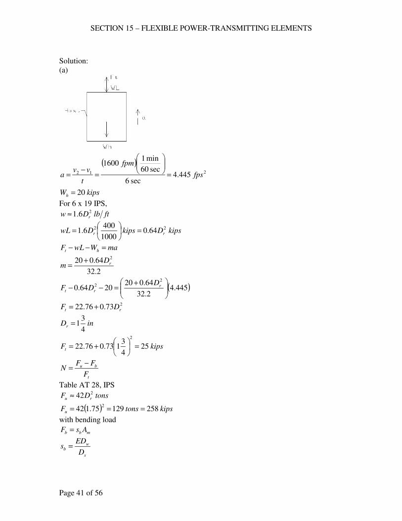
SECTION 15 – FLEXIBLE POWER-TRANSMITTING ELEMENTS
Page 41 of 56
Solution:
(a)
( )212 445.4
sec6
sec60
min11600
fps
fpm
t
vva =
=−
=
kipsWh 20=
For 6 x 19 IPS,
ftlbDw r
26.1≈
kipsDkipsDwL rr
22 64.01000
4006.1 =
=
maWwLF ht =−−
2.32
64.020 2
rDm
+=
( )445.42.32
64.0202064.0
22
+=−− r
rt
DDF
273.076.22 rt DF +=
inDr4
31=
kipsFt 254
3173.076.22
2
=
+=
t
bu
F
FFN
−=
Table AT 28, IPS
tonsDF ru
242≈
( ) kipstonsFu 25812975.1422
===
with bending load
mbb AsF =
s
wb
D
EDs =
SECTION 15 – FLEXIBLE POWER-TRANSMITTING ELEMENTS
Page 42 of 56
s
wmb
D
DEAF =
Table At 28, 6 x 19 Wire Rope
( ) inDD rw 11725.075.1067.0067.0 ===
inftDs 968 ==
ksiE 000,30= 24.0 rm DA ≈
( ) insqAm 225.175.14.02
==
( )( )( )( )
kipsFb 4596
11725.0225.1000,30==
52.825
45258=
−=
−=
t
bu
F
FFN
without bending load
32.1025
258===
t
u
F
FN
(b) 35.1=N on fatigue
IPS, ksisu 260≈
( ) uu
tsr
ssp
NFDD
2=
( )( ) ( )( )( )( )260
2535.129675.1
usp=
0015.0=usp
Fig. 17.30, 6 x 19 IPS
Number of bends to failure = 7 x 10⁵
(c) rmEA
FL=δ
insqAm 225.1=
ksiEr 000,12≈ (6 x 19 IPS)
kipsF 14=
inftL 4800400 ==
( )( )( )( )
in57.4000,12225.1
480014==δ
( )( ) kipsinFU −=== 3257.4142
1
2
1δ
(d) ( ) kipsFF u 6.512582.02.0 ===

SECTION 15 – FLEXIBLE POWER-TRANSMITTING ELEMENTS
Page 43 of 56
rmEA
FL=δ
( )( )( )( )
in85.16000,12225.1
48006.51==δ
( )( ) kipsinFU −=== 43485.166.512
1
2
1δ
For 1 ¾ in, as-rolled 1045 steel rod
ksisu 96=
( ) ( ) kipsAsF uu 9.23075.14
962
=
==
π
( ) kipsFF u 2.469.2302.02.0 ===
AE
FL=δ
( )( )
( ) ( )in073.3
000,3075.14
48002.46
2
=
=
πδ
( )( ) UkipsinFU <−=== 71073.32.462
1
2
1δ of wire rope.
868. A hoist in a copper mine lifts ore a maximum of 2000 ft. The weight of car, cage,
and ore per trip is 10 kips, accelerated in 6 sec. to 2000 fpm; drum diameter is 6
ft. Use a 6 x 19 plow-steel rope. Determine the size (a) for a life of 200,000
cycles and 3.1=N on the basis of fatigue, (b) for 5=N by equation (v), §17.25,
Text. (c) What is the expected life of the rope found in (b) for 3.1=N on the
basis of fatigue? (d) If a loaded car weighing 7 kips can be moved gradually onto
the freely hanging cage, how much would the rope stretch? (e) What total energy
is stored in the rope with full load at the bottom of te shaft? Neglect the rope’s
weight for this calculation. (f) Compute the pressure of the rope on the cast-iron
drum. Is it reasonable?
Solution:
( )212 56.5
sec6
sec60
min12000
fps
fpm
t
vva =
=−
=
SECTION 15 – FLEXIBLE POWER-TRANSMITTING ELEMENTS
Page 44 of 56
For 6 x 19 IPS,
ftlbDw r
26.1≈
kipsDkipsDwL rr
22 2.31000
20006.1 =
=
kipsWh 10=
aWwL
WwLF hht
+=−−
2.32
( ) ( ) ( )102.317267.1102.312.32
56.51
2.32
22 +=+
+=+
+= rrht DDWwL
aF
(a) ( ) uu
tsr
ssp
NFDD
2=
Fig. 17.30, 200,000 cycles, 6 x 19
0028.0=usp
PS: ksisu 225≈
inftDs 726 ==
3.1=N
( ) ( )( )( )( )( )2250028.0
102.317267.13.1272
2 += r
r
DD
49.307566.936.45 2 += rr DD
01251.364916.42 =+− rr DD
inDr 815.0=
say inDr8
7=
(b) by 5=N , Equation (v)
t
bu
F
FFN
−=
s
wb
D
EDs =
rw DD 067.0=
( )( )r
rb D
Ds 92.27
72
067.0000,30==
mbb AsF = 24.0 rm DA =
( )( ) 32 17.114.092.27 rrrb DDDF ==
tonsDF ru
236= for PS
kipsDF ru
272=
tbu NFFF =−
SECTION 15 – FLEXIBLE POWER-TRANSMITTING ELEMENTS
Page 45 of 56
( )( )( )102.317267.1517.1172 232 +=− rrr DDD
( )( )102.38634.517.1172 232 +=− rrr DDD
inDr 216.1=
use inDr4
11=
(c) ( ) uu
tsr
ssp
NFDD
2=
( )( ) ( )( ) ( )[ ]( )( )225
1025.12.317267.13.127225.1
2
usp
+=
00226.0=usp
Fig. 17.20
Expected Life = 3 x 10⁵ cycles
(d) kipsF 7=
ksiEr 000,12=
inftL 000,242000 ==
For (a) inDr8
7=
rmEA
FL=δ
insqDA rm 30625.08
74.04.0
2
3 =
=≈
( )( )( )( )
in7.45000,1230625.0
000,247==δ
For (b) inDr4
11=
rmEA
FL=δ
insqDA rm 625.04
114.04.0
2
3 =
=≈
( )( )( )( )
in4.22000,12625.0
000,247==δ
(e) For (a) ( )( ) kipsinFU −=== 1607.4572
1
2
1δ
For (b) ( )( ) kipsinFU −=== 4.784.2272
1
2
1δ
(f) Limiting pressure, cast-iron sheaves, 6 x19, psip 500= .
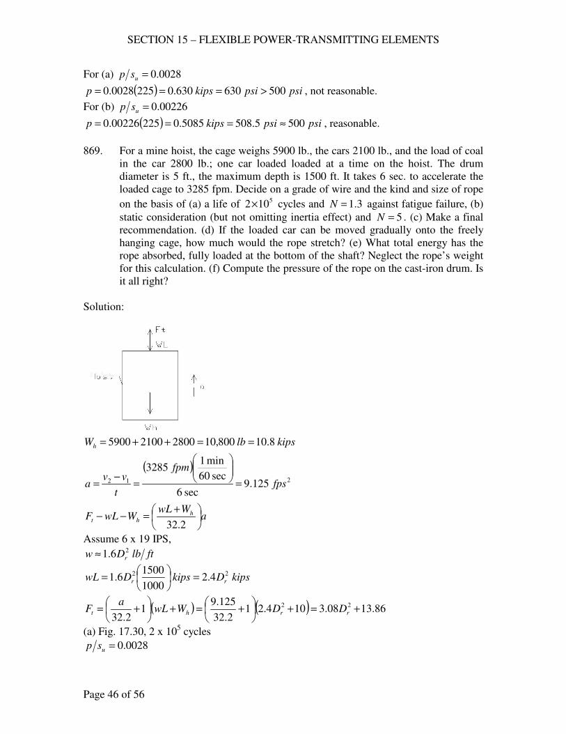
SECTION 15 – FLEXIBLE POWER-TRANSMITTING ELEMENTS
Page 46 of 56
For (a) 0028.0=usp
( ) psipsikipsp 500630630.02250028.0 >=== , not reasonable.
For (b) 00226.0=usp
( ) psipsikipsp 5005.5085085.022500226.0 ≈=== , reasonable.
869. For a mine hoist, the cage weighs 5900 lb., the cars 2100 lb., and the load of coal
in the car 2800 lb.; one car loaded loaded at a time on the hoist. The drum
diameter is 5 ft., the maximum depth is 1500 ft. It takes 6 sec. to accelerate the
loaded cage to 3285 fpm. Decide on a grade of wire and the kind and size of rope
on the basis of (a) a life of 5102× cycles and 3.1=N against fatigue failure, (b)
static consideration (but not omitting inertia effect) and 5=N . (c) Make a final
recommendation. (d) If the loaded car can be moved gradually onto the freely
hanging cage, how much would the rope stretch? (e) What total energy has the
rope absorbed, fully loaded at the bottom of the shaft? Neglect the rope’s weight
for this calculation. (f) Compute the pressure of the rope on the cast-iron drum. Is
it all right?
Solution:
kipslbWh 8.10800,10280021005900 ==++=
( )212 125.9
sec6
sec60
min13285
fps
fpm
t
vva =
=−
=
aWwL
WwLF hht
+=−−
2.32
Assume 6 x 19 IPS,
ftlbDw r
26.1≈
kipsDkipsDwL rr
22 4.21000
15006.1 =
=
( ) ( ) 86.1308.3104.212.32
125.91
2.32
22 +=+
+=+
+= rrht DDWwL
aF
(a) Fig. 17.30, 2 x 10⁵ cycles
0028.0=usp
SECTION 15 – FLEXIBLE POWER-TRANSMITTING ELEMENTS
Page 47 of 56
( ) uu
tsr
ssp
NFDD
2=
inftDs 605 ==
rs DD 45≈
inDr 33.145
60max ==
use inDr4
11=
kipsFt 67.1886.134
1108.3
2
=+
=
( )( )
( ) ( )ksisu 231
604
110028.0
67.183.12=
=
Use Plow Steel, 6 x 19 Wire Rope, inDr4
11= .
(b) t
bu
F
FFN
−=
s
wb
D
EDs =
inDD rw 08375.04
11067.0067.0 =
==
inDs 60=
ksiE 000,30=
( )( )ksisb 875.41
60
08375.0000,30==
2
2
2 625.04
114.04.0 inDA rm =
==
( )( ) kipsAsF mbb 17.26625.0875.41 ===
5=N
( )( ) tonskipsFNFF btu 76.5952.11917.2667.185 ==+=+=
25.38
4
11
76.5922
=
=
r
u
D
F
Table AT 28,
Use IPS, 6 x 19, 25.38422
>=r
u
D
F
SECTION 15 – FLEXIBLE POWER-TRANSMITTING ELEMENTS
Page 48 of 56
(c) Recommendation:
6 x 19, improved plow steel, inDr4
11=
(d) rmEA
FL=δ
lbF 490028002100 =+=
psiEr
61012×≈
inftL 000,181500 ==
( )( )( )( )
in76.111012625.0
000,1849006
=×
=δ
(e) ( )( ) lbinFU −=== 800,2876.1149002
1
2
1δ
(f) 0028.0=usp
ksisu 231=
( ) psip 8.646000,2310028.0 ==
For cast-iron sheave, limiting pressure is 500 psi
psipsip 5008.646 >= , not al right.
870. The wire rope of a hoist with a short lift handles a total maximum load of 14 kips
each trip. It is estimated that the maximum number of trips per week will be
1000. The rope is 6 x 37, IPS, 1 3/8 in. in diameter, with steel core. (a) On the
basis of 1=N for fatigue, what size drum should be used for a 6-yr. life? (n)
Because of space limitations, the actual size used was a 2.5-ft. drum. What is the
factor of safety on a static basis? What life can be expected ( 1=N )?
Solution:
(a)
No. of cycles = ( ) cyclescycleswk
trips
days
wk
yr
daysyr
5103857,3121
1000
7
1
1
3656 ×≈=
Figure 17.30, 6 x 37, IPS
00225.0=usp
( ) uu
tsr
ssp
NFDD
2=
For IPS, ksisu 260≈
kipsFt 14=
0.1=N
inDr 375.1=
( ) uu
tsr
ssp
NFDD
2=
SECTION 15 – FLEXIBLE POWER-TRANSMITTING ELEMENTS
Page 49 of 56
( ) ( )( )( )( )26000225.0
140.12375.1 =sD
inDs 8.34=
(b) inftDs 302 ==
Static Basis
t
bu
F
FFN
−=
Table AT 28, 6 x 37
( ) inDD rw 066.0375.1048.0048.0 ==≈
( ) 222 75625.0375.14.04.0 inDA rm ==≈
( )( ) kipsAsF muu 6.19675625.0260 ===
( )( )( )kips
D
AEDAsF
s
mwmbb 9.49
30
75625.0066.0000,30====
5.105.10
9.496.196=
−=
−=
t
bu
F
FFN
Life: 0.1=N (fatigue)
( ) uu
tsr
ssp
NFDD
2=
( )( ) ( )( )( )( )260
140.1230375.1
usp=
0026.0=usp
Figure 17.30, Life cycles5105.2 ×≈ , 6 x 37.
871. A wire rope passes about a driving sheave making an angle of contact of 540o, as
shown. A counterweight of 3220 lb. is suspended from one side and the
acceleration is 4 fps2. (a) If 1.0=f , what load may be noised without slipping on
the rope? (b) If the sheave is rubber lined and the rope is dry, what load may be
raised without slipping? (c) Neglecting the stress caused by bending about the
sheave, find the size of 6 x 19 MPS rope required for 6=N and for the load
found in (a). (d) Compute the diameter of the sheave for indefinite life with say
1.1=N on fatigue. What changes could be made in the solution to allow the use
of a smaller sheave?
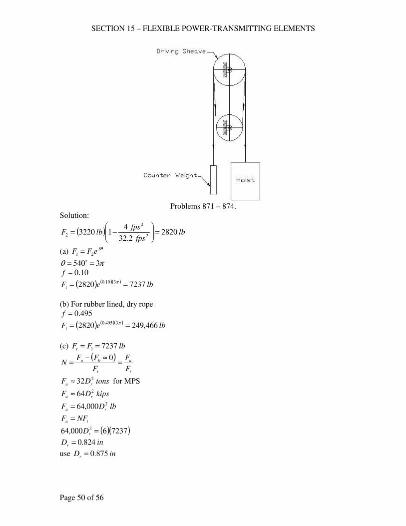
SECTION 15 – FLEXIBLE POWER-TRANSMITTING ELEMENTS
Page 50 of 56
Problems 871 – 874.
Solution:
( ) lbfps
fpslbF 2820
2.32
413220
2
2
2 =
−=
(a) θfeFF 21 =
πθ 3540 == o
10.0=f
( ) ( )( ) lbeF 72372820 310.0
1 == π
(b) For rubber lined, dry rope
495.0=f
( ) ( )( ) lbeF 466,2492820 3495.0
1 == π
(c) lbFFt 72371 ==
( )
t
u
t
bu
F
F
F
FFN =
≈−=
0
tonsDF ru
232≈ for MPS
kipsDF ru
264≈
lbDF ru
2000,64=
tu NFF =
( )( )72376000,64 2 =rD
inDr 824.0=
use inDr 875.0=
SECTION 15 – FLEXIBLE POWER-TRANSMITTING ELEMENTS
Page 51 of 56
(d) ( ) uu
tsr
ssp
NFDD
2=
Indefinite life, 0015.0=usp
MPS: psiksisu 000,195195 =≈
( ) ( )( )( )( )000,1950015.0
72371.12875.0 =sD
inDs 2.62=
To reduce the size of sheave, increase the size of rope.
872. A traction elevator with a total weight of 8 kips has an acceleration of 3 fps2; the
6 cables pass over the upper sheave twice, the lower one once, as shown..
Compute the minimum weight of counterweight to prevent slipping on the
driving sheave if it is (a) iron with a greasy rope, (b) iron with a dry rope, (c)
rubber lined with a greasy rope. (d) Using MPS and the combination in (a),
decide upon a rope and sheave size that will have indefinite life ( 1=N will do).
(e) Compute the factor of safety defined in the Text. (f) If it were decided that 5105× bending cycles would be enough life, would there be a significant
difference in the results?
Solution:
( ) kipsfps
fpskipsF 745.8
2.32
318
2
2
1 =
+=
( ) πθ 31803 == o
θfe
FF 1
2 =
cW = weight of counterweight
22 10274.1
2.32
31
FF
Wc =
−
=
θfce
FW 110274.1
=
(a) Iron sheave, greasy rope, 07.0=f
( )( )( ) kips
eWc 986.4
745.810274.1307.0
==π
(b) Iron sheave, dry rope, 12.0=f
( )( )( ) kips
eWc 112.3
745.810274.1312.0
==π
(c) Rubber lined with a greasy rope, 205.0=f
( )( )( ) kips
eWc 397.1
745.810274.13205.0
==π
SECTION 15 – FLEXIBLE POWER-TRANSMITTING ELEMENTS
Page 52 of 56
(d) ( ) uu
tsr
ssp
NFDD
2=
Indefinite life, 0015.0=usp
kipsFFt 745.81 == total
kipsFt 458.16
745.8== each rope
lbsFt 1458=
1=N
Table AT 28, 6 x 19
rs DD 45≈
( ) ( )( )( )( )000,1950015.0
14581245 =rr DD
inDr 47.0=
Use ininDr 5.02
1==
(e) t
bu
F
FFN
−=
Table AT 28, MPS
( ) lblblbDtonsDF rru 000,165.0000,64000,6432222 ====
s
mwb
D
AEDF =
psiE 61030×=
6 x 19, rw DD 067.0=
rs DD 45≈
( ) ..1.05.04.04.022
insqDA rm ===
( )( )( )lbFb 4467
45
1.0067.01030 6
=×
=
91.71458
4467000,16=
−=N
(f) 5 x 10⁵ cycles
Fig. 17.30, 6 x 19.
0017.0=usp
( ) uu
tsr
ssp
NFDD
2=
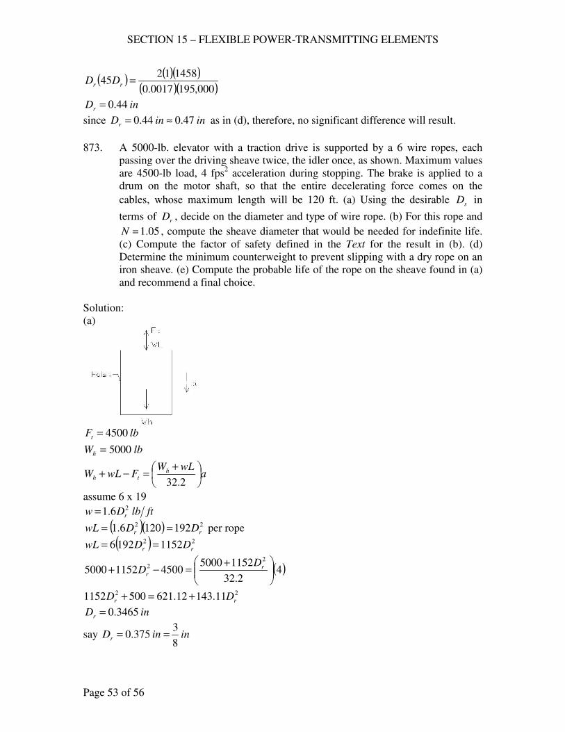
SECTION 15 – FLEXIBLE POWER-TRANSMITTING ELEMENTS
Page 53 of 56
( ) ( )( )( )( )000,1950017.0
14581245 =rr DD
inDr 44.0=
since ininDr 47.044.0 ≈= as in (d), therefore, no significant difference will result.
873. A 5000-lb. elevator with a traction drive is supported by a 6 wire ropes, each
passing over the driving sheave twice, the idler once, as shown. Maximum values
are 4500-lb load, 4 fps2 acceleration during stopping. The brake is applied to a
drum on the motor shaft, so that the entire decelerating force comes on the
cables, whose maximum length will be 120 ft. (a) Using the desirable sD in
terms of rD , decide on the diameter and type of wire rope. (b) For this rope and
05.1=N , compute the sheave diameter that would be needed for indefinite life.
(c) Compute the factor of safety defined in the Text for the result in (b). (d)
Determine the minimum counterweight to prevent slipping with a dry rope on an
iron sheave. (e) Compute the probable life of the rope on the sheave found in (a)
and recommend a final choice.
Solution:
(a)
lbFt 4500=
lbWh 5000=
awLW
FwLW hth
+=−+
2.32
assume 6 x 19
ftlbDw r
26.1=
( )( ) 22 1921206.1 rr DDwL == per rope
( ) 22 11521926 rr DDwL ==
( )42.32
11525000450011525000
22
+=−+ r
r
DD
22 11.14312.6215001152 rr DD +=+
inDr 3465.0=
say ininDr8
3375.0 ==
SECTION 15 – FLEXIBLE POWER-TRANSMITTING ELEMENTS
Page 54 of 56
inDD rs8
716
8
34545 =
=≈
Six – 6 x 19 rope, inDr8
3=
(a) ininDr8
3375.0 ==
lbFt 7506
4500==
05.1=N
( ) uu
tsr
ssp
NFDD
2=
assume IPS, psiksisu 000,260260 ==
Indefinite life, 0015.0=usp
( ) ( )( )( )( )000,2600015.0
75005.12375.0 =sD
inDs 77.10=
(c) t
bu
F
FFN
−=
lbFt 750=
IPS
lblblbDtonsDF rru 813,118
3000,84000,8442
2
22 =
==≈
s
mwb
D
AEDF =
6 x 19,
inDs 77.10= as in (b)
inDD rw 025.08
3067.0067.0 =
==
..05625.08
34.04.0
2
2 insqDA rm =
==
psiE 61030×=
( )( )( )lbFb 3917
77.10
05625.0025.01030 6
=×
=
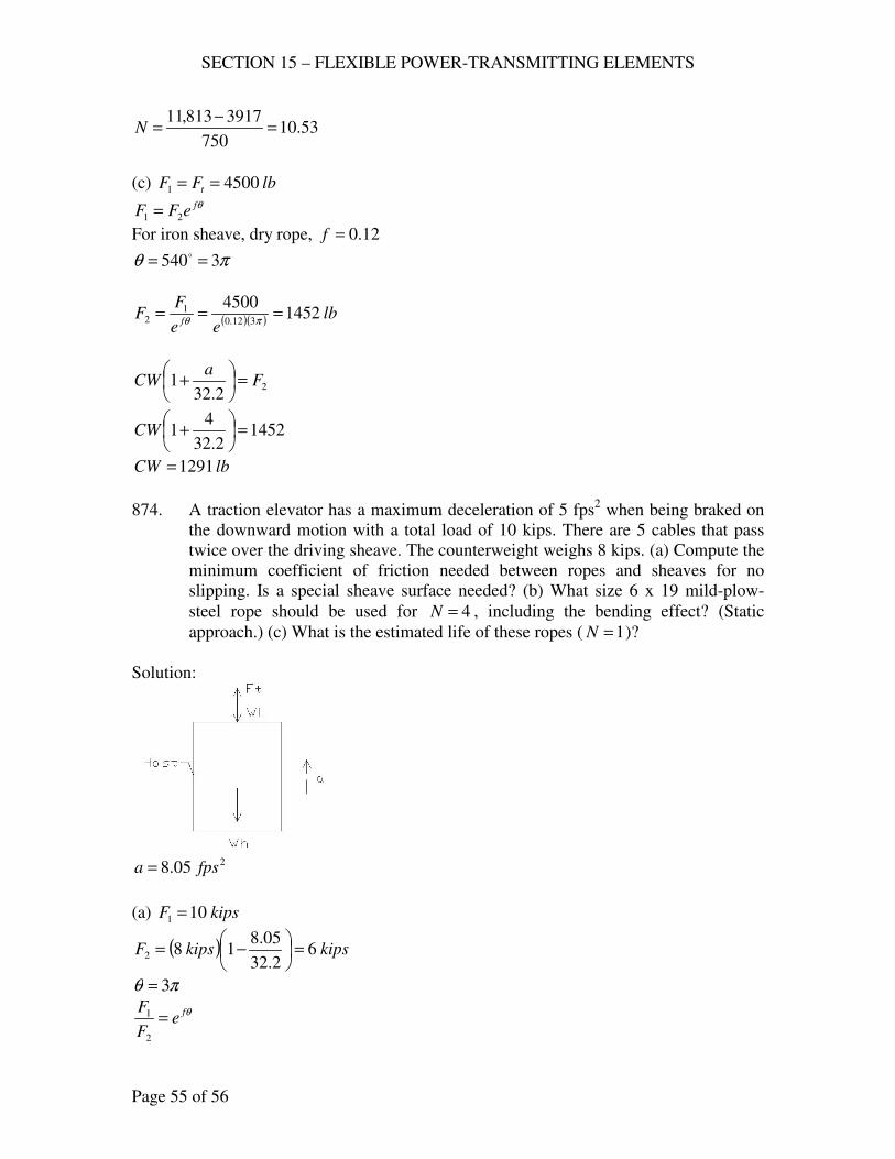
SECTION 15 – FLEXIBLE POWER-TRANSMITTING ELEMENTS
Page 55 of 56
53.10750
3917813,11=
−=N
(c) lbFF t 45001 ==
θfeFF 21 =
For iron sheave, dry rope, 12.0=f
πθ 3540 == o
( )( ) lbee
FF
f1452
4500312.0
12 ===
πθ
22.32
1 Fa
CW =
+
14522.32
41 =
+CW
lbCW 1291=
874. A traction elevator has a maximum deceleration of 5 fps2 when being braked on
the downward motion with a total load of 10 kips. There are 5 cables that pass
twice over the driving sheave. The counterweight weighs 8 kips. (a) Compute the
minimum coefficient of friction needed between ropes and sheaves for no
slipping. Is a special sheave surface needed? (b) What size 6 x 19 mild-plow-
steel rope should be used for 4=N , including the bending effect? (Static
approach.) (c) What is the estimated life of these ropes ( 1=N )?
Solution:
205.8 fpsa =
(a) kipsF 101 =
( ) kipskipsF 62.32
05.8182 =
−=
πθ 3=
θfe
F
F=
2
1
SECTION 15 – FLEXIBLE POWER-TRANSMITTING ELEMENTS
Page 56 of 56
( )π3
6
10 fe=
0542.0=f
Special sheave surface is needed for this coefficient of friction, §17.21.
(b) t
bu
F
FFN
−=
kipsFt 25
10==
s
mwb
D
AEDF =
Table AT 28, 6 x 19, MPS
rw DD 067.0=
rs DD 45≈ 24.0 rm DA ≈
psiE 61030×=
( )( )( )kipsD
D
DDF r
r
rrb
226
87.1745
4.0067.01030=
×=
kipsDtonsDF rru
22 6432 =≈
2
87.17644
22
rr DDN
−==
inDr 4164.0=
use inDr16
7=
(c) inDD rs 2016
74545 =
=≈
( ) uu
tsr
ssp
NFDD
2=
kipsFt 2= each rope
MPS, ksisu 195=
0.1=N
( ) ( )( )( )( )195
20.1220
16
7
usp=
0023.0=usp
Expected life, Figure 17.30, 3 x 10⁵ bending cycles.
- end -
SECTION 16 – BRAKES AND CLUTCHES
Page 1 of 97
ENERGY TO BRAKES
881. A motor operates a hoist through a pair of spur gears, with a velocity ratio of 4.
The drum on which the cable wraps is on the same shaft as the gear, and the
torque cause by the weight of the load and hoist is 12,000 ft-lb. The pinion is on
the motor shaft. Consider first on which shaft to mount the brake drum; in the
process make trial calculations, and try to think of pros and cons. Make a
decision and determine the size of a drum that will not have a temperature rise
greater than Fto150=∆ when a 4000-lb. load moves down 200 ft. at a constant
speed. Include a calculation for the frp/sq. in. of the drum’s surface.
Solution:
Consider that brake drum is mounted on motor shaft that has lesser torque.
lbinlbftlbft
T f −=−=−
= 000,3630004
000,12
From Table AT 29,
Assume 35.0=f , psip 75= , max. fpmvm 5000=
2
FDT f =
D
TfNF
f2==
Df
TN
f2=
A
Np =
DbA π=
( )( )
7535.0
000,362222
====bDbfD
T
Db
Np
f
πππ
8732 =bD
use 8732 =bD
2
873
Db =
Then,
cW
lbftUFt
m
f −=∆ o
Assume a cast-iron, 3253.0 inlb=ρ
101=c
VWm ρ=
SECTION 16 – BRAKES AND CLUTCHES
Page 2 of 97
+=+=
44
22 D
DbttDDbtV ππ
π
( )( ) lbftU f −== 000,8002004000
Fto150=∆
tc
UVW
f
m∆
== ρ
( )( )101150
000,800253.0 =V
37.208 inV =
But
+=
4
2DDbtV π
2
873
Db =
+=
4
873 2D
DtV π
For minimum V :
02
8732
=
+
−=
D
Dt
dD
dVπ
( )87323 =D
inD 12=
For t :
( )
+==
4
12
12
8737.208
2
tV π
int 611.0=
say int8
5=
( )ininb
16
160625.6
12
8732
===
Therefore use inD 12= , int8
5= , inb
16
16=
For A
fhpinsqfhp =..
000,33
mFvfhp =
SECTION 16 – BRAKES AND CLUTCHES
Page 3 of 97
( )lb
D
TF
f6000
12
000,3622===
fpmvm 5000= (max.)
( )( )hpfhp 909
000,33
50006000==
( ) 2
16
1612 inDbA
== ππ
98.355.228
909.. ===
A
fhpinsqfhp (peak value)
882. A 3500-lb. automobile moving on level ground at 60 mph, is to be stopped in a
distance of 260 ft. Tire diameter is 30 in.; all frictional energy except for the
brake is to be neglected. (a) What total averaging braking torque must be
applied? (b) What must be the minimum coefficient of friction between the tires
and the road in order for the wheels not to skid if it is assumed that weight is
equally distributed among the four wheels (not true)? (c) If the frictional energy
is momentarily stored in 50 lb. of cast iron brake drums, what is the average
temperature rise of the drums?
Solution:
(a) Solving for the total braking torque.
( )22
212ssf vv
g
WKEU −=∆−=
lbW 3500=
fpsmphvs 88601
==
fpsmphvs 002
==
22.32 fpsg =
( )( ) lbftU f −=−= 000,421088
2.322
3500 22
( ) ( )000,63000,33
nlbinTlbftTfhp
fmf −=
−=
ω
( )( )
2
222
892.142602
880
2
12 fpss
vva
ss−=
−=
−=
sec91.5892.14
88012 =
−
−=
−=
a
vvt
ss
( )( ) ( )hp
t
U
t
KEfhp
f130
91.5550
000,421
550550===
∆−=
SECTION 16 – BRAKES AND CLUTCHES
Page 4 of 97
( )( )rpm
ft
fps
D
vn m 336
12
30
minsec60882
1
=
==
ππ
000,63
nTfhp
f=
( )lbinT f −== 375,24
336
130000,63
(b) N
Ff =
for each wheel, lbN 8754
3500==
lbinT f −== 60944
375,24
( )lbin
D
TF
f−=== 406
30
609422
464.0875
406===
N
Ff
(c) cW
Ut
m
f=∆
lbftU f −= 000,421
lbWm 50=
Flblbftc −−=101 for cast-iron
( )( )Ft o4.83
10150
000,421==∆
884. An overhead traveling crane weighs 160,000 lb. with its load and runs 253 fpm.
It is driven by a 25-hp motor operating at 1750 rpm.The speed reduction from the
motor to the 18-in. wheels is 32 to 1. Frictional energy other than at the brake is
negligible. (a) How much energy must be absorbed by the brake to stop this crane
in a distance of 18 ft.? (b) Determine the constant average braking torque that
must be exerted on the motor shaft. (c) If all the energy is absorbed by the rim of
the cast-iron brake drum, which is 8 in. in diameter, 1 ½ in. thick, with a 3 ¼-in.
face, what will be its temperature rise? (d) Compute the average rate at which the
energy is absorbed during the first second (fhp). Is it reasonable?
Solution:
SECTION 16 – BRAKES AND CLUTCHES
Page 5 of 97
( )22
212ssf vv
g
WKEU −=∆−=
lbW 000,160= 22.32 fpsg =
fpsfpmvs 22.42531
==
fpsvs 02
=
( )( )[ ] lbftU f −=−= 245,44022.4
2.322
000,160 22
(b) ( )
n
fhpT f
000,63=
( )( )
2
222
495.0182
22.40
2
12 fpss
vva
ss−=
−=
−=
sec53.8495.0
22.4012 =
−
−=
−=
a
vvt
ss
( )hp
t
Ufhp
f43.9
53.8550
245,44
550===
( ) ( )( )
( )lbin
n
fhpT f −=== 68
17502
1
000,6343.9000,63 on the motor shaft.
(c) cW
Ut
m
f=∆
DbtV π= (rim only) on the motor shaft
inD 8=
inb 25.3=
int 5.0=
( )( )( ) 384.405.025.38 inV == π
VWm ρ=
3253.0 inlb=ρ for cast iron
Flblbftc −−=101 for cast-iron
( )( ) lbWm 33.1084.40253.0 ==
( )( )Ft o4.42
10133.10
245,44==∆
(d) First second:
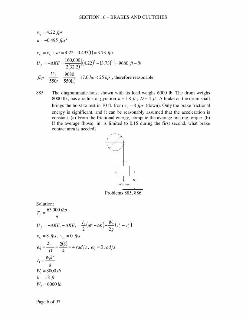
SECTION 16 – BRAKES AND CLUTCHES
Page 6 of 97
fpsvs 22.41
=
2495.0 fpsa −=
( ) fpsatvv ss 73.31495.022.412
=−=+=
( )( ) ( )[ ] lbftKEU f −=−=∆−= 968073.322.4
2.322
000,160 22
( )hphp
t
Ufhp
f256.17
1550
9680
550<=== , therefore reasonable.
885. The diagrammatic hoist shown with its load weighs 6000 lb. The drum weighs
8000 lb., has a radius of gyration ftk 8.1= ; ftD 4= . A brake on the drum shaft
brings the hoist to rest in 10 ft. from fpsvs 8= (down). Only the brake frictional
energy is significant, and it can be reasonably assumed that the acceleration is
constant. (a) From the frictional energy, compute the average braking torque. (b)
If the average fhp/sq. in. is limited to 0.15 during the first second, what brake
contact area is needed?
Problems 885, 886
Solution:
n
fhpT f
000,63=
( ) ( )2222
2
2
11
21 1122ssf vv
g
WIKEKEU −+−=∆−∆−= ωω
fpsvs 81
= , fpsvs 02
=
( )srad
D
vs4
4
8221
1 ===ω , srad02 =ω
g
kWI
2
11 =
lbW 80001 =
ftk 8.1=
lbW 60002 =
SECTION 16 – BRAKES AND CLUTCHES
Page 7 of 97
22.32 fpsg =
( ) ( ) ( )( )
( )( )
( ) lbftvvg
WIU ssf −=+=−+−= 400,128
2.322
600004
2.322
8.180000
22
222
2222
2
2
11
11ωω
s
vva
ss
2
22
12−
=
fts 10=
( )2
22
2.3102
80fpsa −=
−=
sec5.22.3
8012 =
−
−=
−=
a
vvt
ss
( )hp
t
Ufhp
f9
5.2550
400,12
550===
rpmnπ
ω
2
60=
( ) 02042
1−=−= sradsradω
( )rpmn 1.19
2
260==
π
( )lbin
n
fhpT f −=== 700,29
1.19
9000,63000,63
(b) 15.0.. =insqfhp (first second)
( ) fpsatvv ss 8.412.3812
=−=+=
( )sec4.2
4
8.4222
2 radD
vs===ω
( )( )
( ) ( )[ ]( )
( ) ( )[ ] lbftU f −=−+−= 61068.482.322
600004.24
2.322
8.180000 22222
( )hp
t
Ufhp
f10.11
1550
6106
550===
27415.0
10.11
..in
insqfhp
fhpA ===
887. The same as 885, except that a traction drive, arranged as shown, is used; the
counterweight weighs 4000 lb. The ropes pass twice about the driving sheave; the
brake drum is on this same shaft.
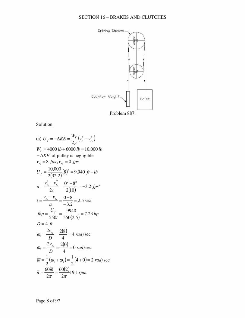
SECTION 16 – BRAKES AND CLUTCHES
Page 8 of 97
Problem 887.
Solution:
(a) ( )22
212ss
Tf vv
g
WKEU −=∆−=
lblblbWT 000,1060004000 =+=
KE∆− of pulley is negligible
fpsvs 81
= , fpsvs 02
=
( )( ) lbftU f −== 940,98
2.322
000,10 2
( )2
2222
2.3102
80
2
12 fpss
vva
ss−=
−=
−=
sec5.22.3
8012 =
−
−=
−=
a
vvt
ss
( )hp
t
Ufhp
f23.7
5.2550
9940
550===
ftD 4=
( )sec4
4
8221
1 radD
vs===ω
( )sec0
4
0222
2 radD
vs===ω
( ) ( ) sec2042
1
2
121 rad=+=+= ωωω
( )rpmn 1.19
2
260
2
60
ππ
ω==
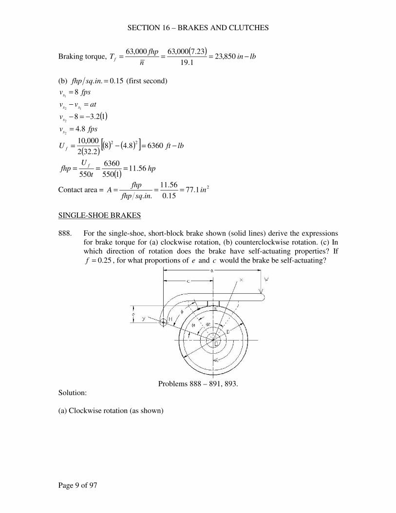
SECTION 16 – BRAKES AND CLUTCHES
Page 9 of 97
Braking torque, ( )
lbinn
fhpT f −=== 850,23
1.19
23.7000,63000,63
(b) 15.0.. =insqfhp (first second)
fpsvs 81
=
atvv ss =−12
( )12.382
−=−sv
fpsvs 8.42
=
( )( ) ( )[ ] lbftU f −=−= 63608.48
2.322
000,10 22
( )hp
t
Ufhp
f56.11
1550
6360
550===
Contact area = 21.7715.0
56.11
..in
insqfhp
fhpA ===
SINGLE-SHOE BRAKES
888. For the single-shoe, short-block brake shown (solid lines) derive the expressions
for brake torque for (a) clockwise rotation, (b) counterclockwise rotation. (c) In
which direction of rotation does the brake have self-actuating properties? If
25.0=f , for what proportions of e and c would the brake be self-actuating?
Problems 888 – 891, 893.
Solution:
(a) Clockwise rotation (as shown)
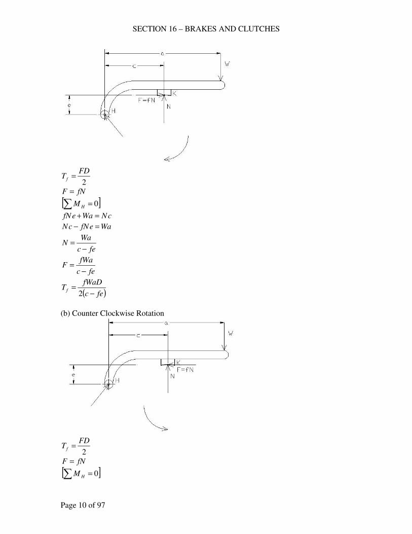
SECTION 16 – BRAKES AND CLUTCHES
Page 10 of 97
2
FDT f =
fNF =
[ ]∑ = 0HM
cNWaefN =+
WaefNcN =−
fec
WaN
−=
fec
fWaF
−=
( )fec
fWaDT f
−=
2
(b) Counter Clockwise Rotation
2
FDT f =
fNF =
[ ]∑ = 0HM
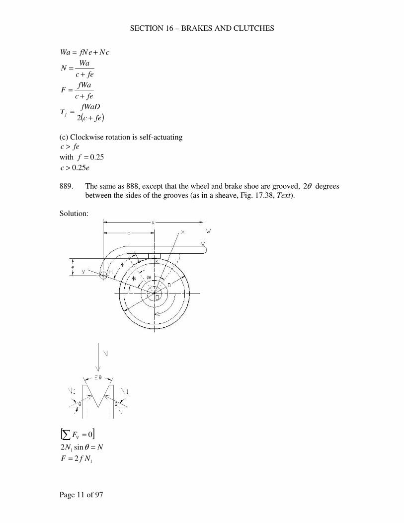
SECTION 16 – BRAKES AND CLUTCHES
Page 11 of 97
cNefNWa +=
fec
WaN
+=
fec
fWaF
+=
( )fec
fWaDT f
+=
2
(c) Clockwise rotation is self-actuating
fec >
with 25.0=f
ec 25.0>
889. The same as 888, except that the wheel and brake shoe are grooved, θ2 degrees
between the sides of the grooves (as in a sheave, Fig. 17.38, Text).
Solution:
[ ]∑ = 0VF
NN =θsin2 1
12 NfF =
SECTION 16 – BRAKES AND CLUTCHES
Page 12 of 97
θθ sinsin22
NfNfF =
=
(a) Clockwise rotation
fec
WaN
−=
( ) θsinfec
fWaF
−=
( ) θsin2 fec
fWaDT f
−=
(b) Counter clockwise rotation
fec
WaN
+=
( ) θsinfec
fWaF
+=
( ) θsin2 fec
fWaDT f
+=
(c) Clockwise rotation is self-actuating
fec >
with 25.0=f
ec 25.0>
890. Consider the single-shoe, short-block brake shown (solid lines) with the drum
rotating clockwise; let e be positive measured downward and cD 6.1= . (a) Plot
the mechanical advantage MA (ordinate) against f values of 0.1, 0.2, 0.3, 0.4,
0.5 (abscissa) when ce has values 2, 0.5, 0, -0.5, -1. (b) If f may vary from 0.3
to 0.4, which proportions give the more nearly constant brake response? Are
proportions good? (c) What proportions are best if braking is needed for both
directions of rotation?
Solution:
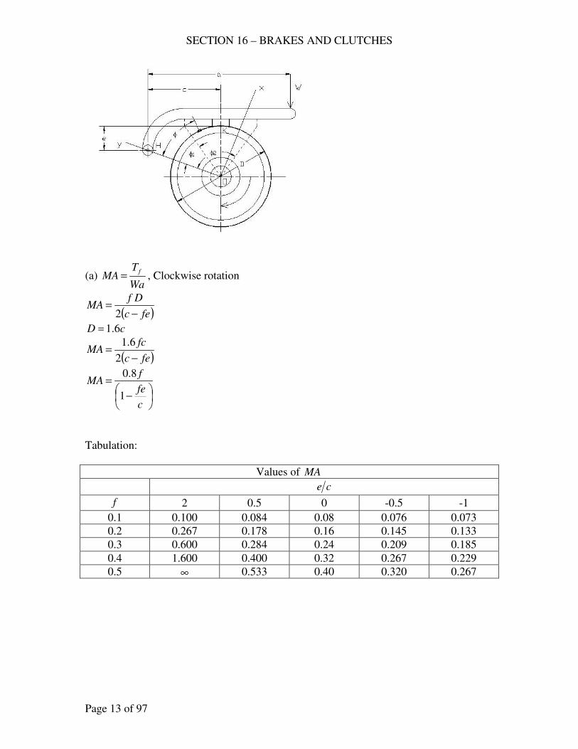
SECTION 16 – BRAKES AND CLUTCHES
Page 13 of 97
(a) Wa
TMA
f= , Clockwise rotation
( )fec
DfMA
−=
2
cD 6.1=
( )fec
fcMA
−=
2
6.1
−
=
c
fe
fMA
1
8.0
Tabulation:
Values of MA
ce
f 2 0.5 0 -0.5 -1
0.1 0.100 0.084 0.08 0.076 0.073
0.2 0.267 0.178 0.16 0.145 0.133
0.3 0.600 0.284 0.24 0.209 0.185
0.4 1.600 0.400 0.32 0.267 0.229
0.5 ∞ 0.533 0.40 0.320 0.267
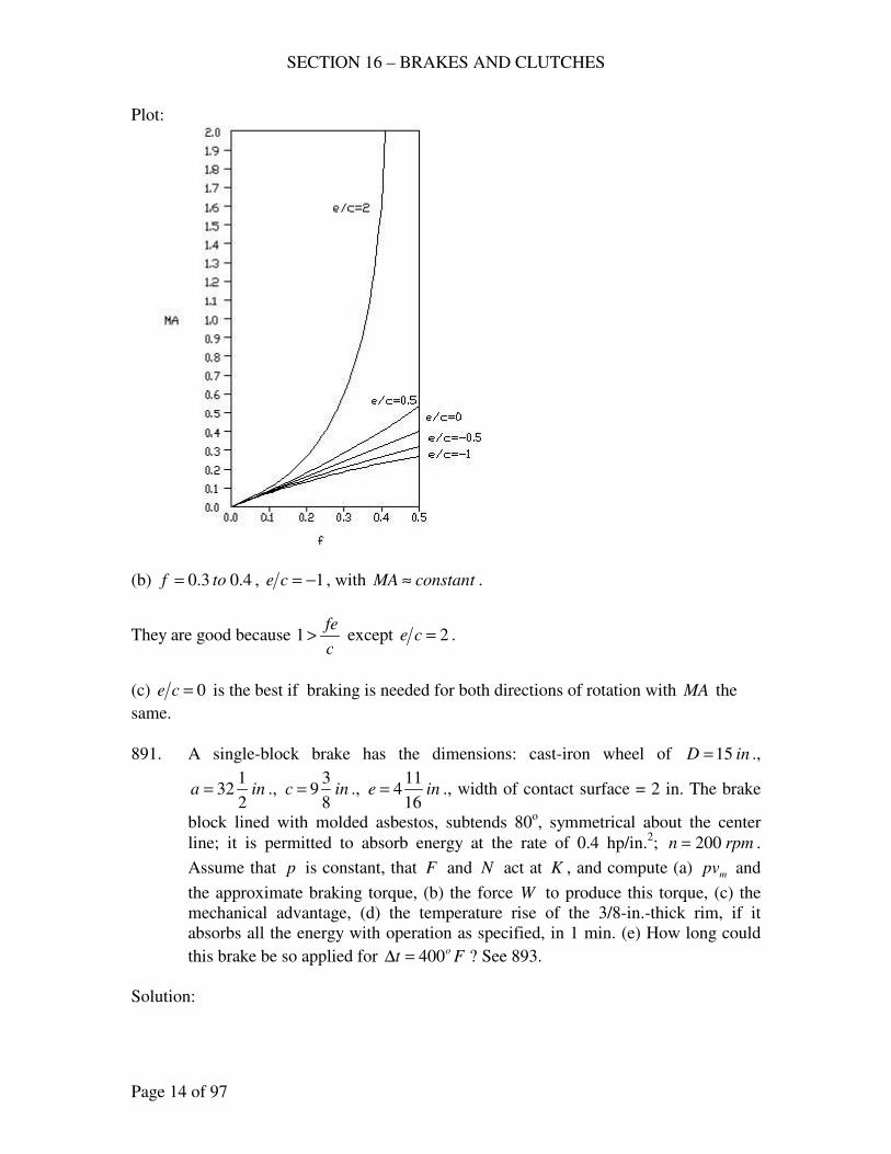
SECTION 16 – BRAKES AND CLUTCHES
Page 14 of 97
Plot:
(b) 4.03.0 tof = , 1−=ce , with ttanconsMA ≈ .
They are good because c
fe>1 except 2=ce .
(c) 0=ce is the best if braking is needed for both directions of rotation with MA the
same.
891. A single-block brake has the dimensions: cast-iron wheel of inD 15= .,
ina2
132= ., inc
8
39= ., ine
16
114= ., width of contact surface = 2 in. The brake
block lined with molded asbestos, subtends 80o, symmetrical about the center
line; it is permitted to absorb energy at the rate of 0.4 hp/in.2; rpmn 200= .
Assume that p is constant, that F and N act at K , and compute (a) mpv and
the approximate braking torque, (b) the force W to produce this torque, (c) the
mechanical advantage, (d) the temperature rise of the 3/8-in.-thick rim, if it
absorbs all the energy with operation as specified, in 1 min. (e) How long could
this brake be so applied for Fto400=∆ ? See 893.
Solution:
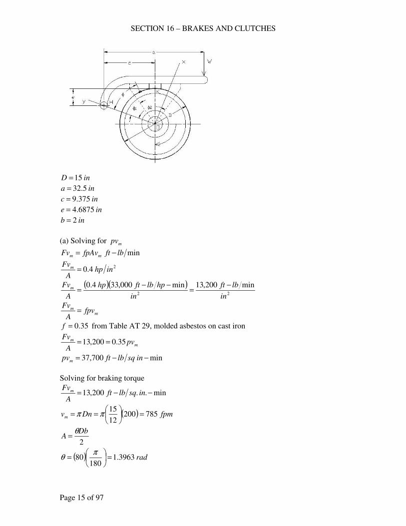
SECTION 16 – BRAKES AND CLUTCHES
Page 15 of 97
inD 15=
ina 5.32=
inc 375.9=
ine 6875.4=
inb 2=
(a) Solving for mpv
minlbftfpAvFv mm −=
24.0 inhpA
Fvm =
( )( )22
min200,13min000,334.0
in
lbft
in
hplbfthp
A
Fvm −=
−−=
mm fpv
A
Fv=
35.0=f from Table AT 29, molded asbestos on cast iron
mm pv
A
Fv35.0200,13 ==
min700,37 −−= insqlbftpvm
Solving for braking torque
min..200,13 −−= insqlbftA
Fvm
( ) fpmDnvm 78520012
15=
== ππ
2
DbA
θ=
( ) rad3963.1180
80 =
=
πθ
SECTION 16 – BRAKES AND CLUTCHES
Page 16 of 97
( )( )( )..21
2
2153963.1
2insq
DbA ===
θ
( )200,13
21
785=
F
lbF 353=
( )( )lbin
FDT f −=== 2650
2
15353
2
(b) Solving for W
fec
WafF
−=
lbF 353=
35.0=f
ina 5.32=
ine 6875.4=
inc 375.9=
( ) ( ) ( )( )[ ]( )( )
lbfa
fecFW 240
5.3235.0
6875.435.0375.9353=
−=
−=
(c) Solving for MA
( )( )( )
( )( )[ ]34.0
6875.435.0375.92
1535.0
2=
−=
−=
fec
DfMA
(d) Solving for t∆
cW
lbftUFt
m
f −=∆
,o
DbtWm ρπ=
inD 15=
inb 2=
inint 375.08
3==
3253.0 inlb=ρ for cast iron
( )( )( )( )( ) lbWm 942.8375.0215253.0 == π
Flblbftc −−= 101 for cast iron
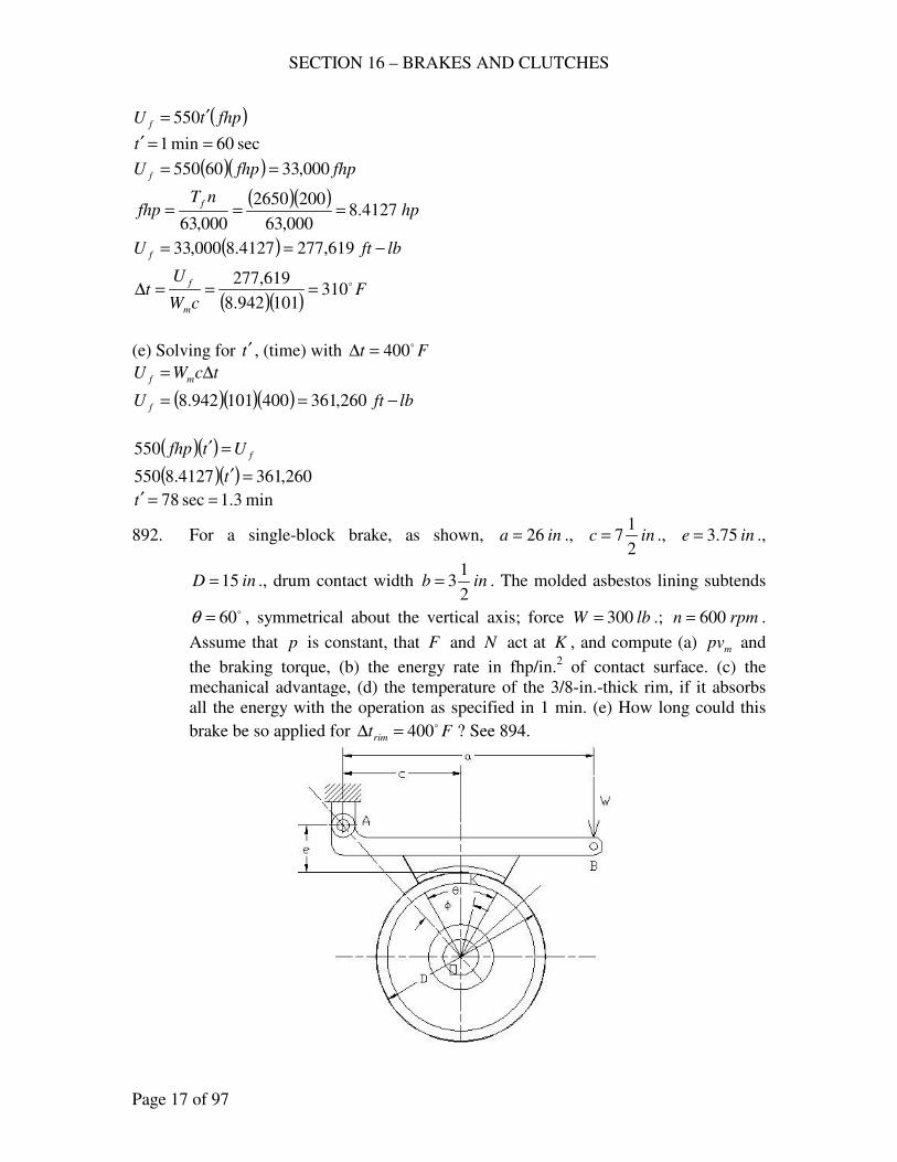
SECTION 16 – BRAKES AND CLUTCHES
Page 17 of 97
( )fhptU f′= 550
sec60min1 ==′t
( )( ) fhpfhpU f 000,3360550 ==
( )( )hp
nTfhp
f4127.8
000,63
2002650
000,63===
( ) lbftU f −== 619,2774127.8000,33
( )( )F
cW
Ut
m
f o310101942.8
619,277===∆
(e) Solving for t′ , (time) with Fto400=∆
tcWU mf ∆=
( )( )( ) lbftU f −== 260,361400101942.8
( )( )fUtfhp =′550
( )( ) 260,3614127.8550 =′t
min3.1sec78 ==′t
892. For a single-block brake, as shown, ina 26= ., inc2
17= ., ine 75.3= .,
inD 15= ., drum contact width inb2
13= . The molded asbestos lining subtends
o60=θ , symmetrical about the vertical axis; force lbW 300= .; rpmn 600= .
Assume that p is constant, that F and N act at K , and compute (a) mpv and
the braking torque, (b) the energy rate in fhp/in.2 of contact surface. (c) the
mechanical advantage, (d) the temperature of the 3/8-in.-thick rim, if it absorbs
all the energy with the operation as specified in 1 min. (e) How long could this
brake be so applied for Ftrim
o400=∆ ? See 894.
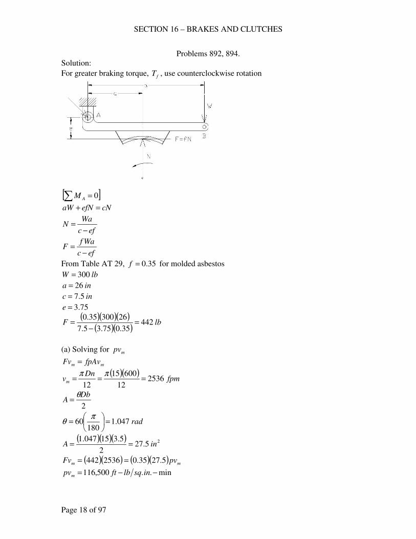
SECTION 16 – BRAKES AND CLUTCHES
Page 18 of 97
Problems 892, 894.
Solution:
For greater braking torque, fT , use counterclockwise rotation
[ ]∑ = 0AM
cNefNaW =+
efc
WaN
−=
efc
WafF
−=
From Table AT 29, 35.0=f for molded asbestos
lbW 300=
ina 26=
inc 5.7=
75.3=e
( )( )( )( )( )
lbF 44235.075.35.7
2630035.0=
−=
(a) Solving for mpv
mm fpAvFv =
( )( )fpm
Dnvm 2536
12
60015
12===
ππ
2
DbA
θ=
rad047.1180
60 =
=
πθ
( )( )( ) 25.272
5.315047.1inA ==
( )( ) ( )( ) mm pvFv 5.2735.02536442 ==
min..500,116 −−= insqlbftpvm
SECTION 16 – BRAKES AND CLUTCHES
Page 19 of 97
Solving for the braking torque,
( )( )lbin
FDT f −=== 3315
2
15442
2
(b) Energy rate, fhp.in2.
( )( )hp
nTfhp
f6.31
000,63
6003315
000,63===
25.27 inA =
2
2
2 15.15.27
6.31inhp
in
hpinfhp ==
(c) ( )( )
425.026300
3315===
Wa
TMA
f
(d) cW
lbftUFt
m
f −=∆
,o
DbtWm ρπ=
inint 375.08
3==
inD 15=
inb 5.3= 3253.0 inlb=ρ for cast iron
Flblbftc −−= 101 for cast iron
( )( )( )( )( ) lbWm 648.15375.05.315253.0 == π
For 1 min
( )( ) ( )( ) lbftfhpU f −=== 800,042,16.311000,331000,33
( )( )Ft o660
101648.15
800,042,1==∆
(e) Ftrim
o400=∆
( )( )( ) lbftU f −== 179,632101648.15400
( )min61.0
6.31000,33
179,632
000,33min ===′
fhp
Ut
f
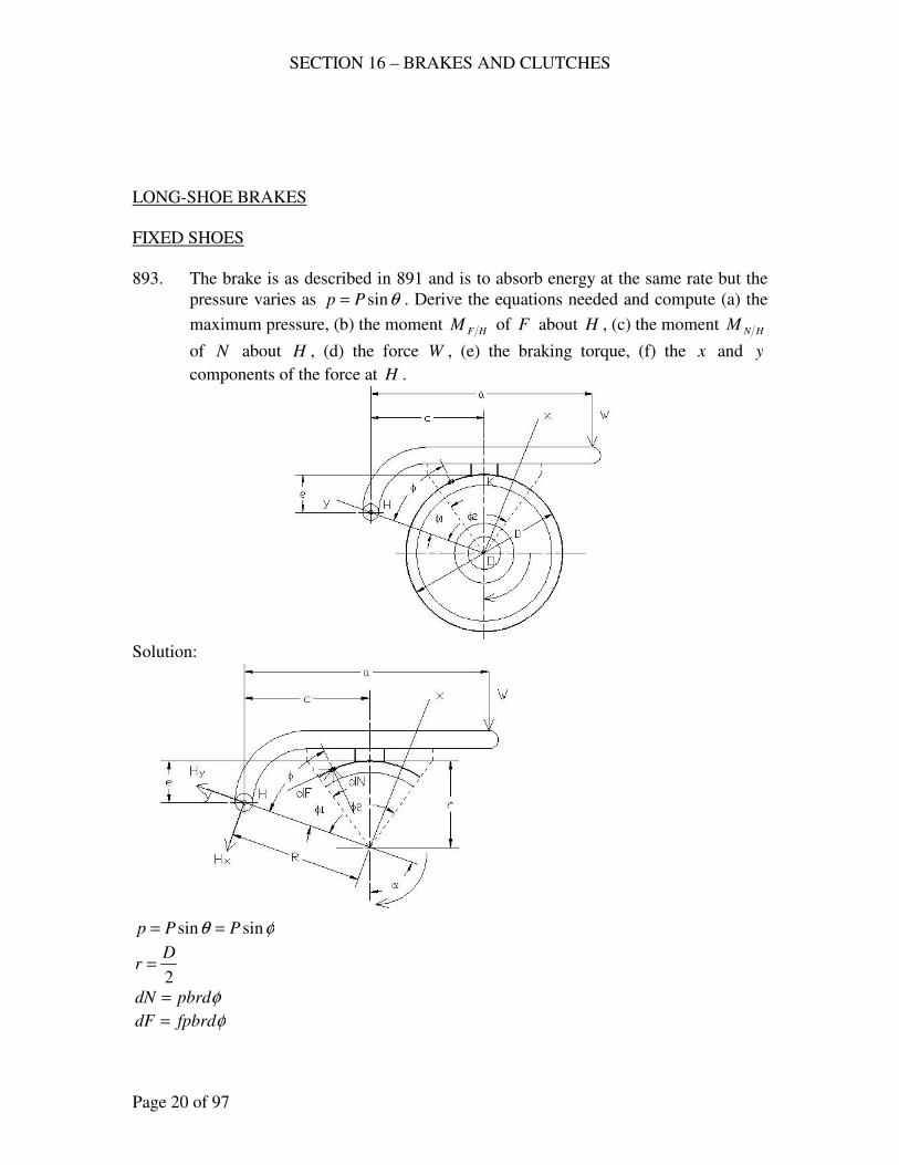
SECTION 16 – BRAKES AND CLUTCHES
Page 20 of 97
LONG-SHOE BRAKES
FIXED SHOES
893. The brake is as described in 891 and is to absorb energy at the same rate but the
pressure varies as θsinPp = . Derive the equations needed and compute (a) the
maximum pressure, (b) the moment HFM of F about H , (c) the moment HNM
of N about H , (d) the force W , (e) the braking torque, (f) the x and y
components of the force at H .
Solution:
φθ sinsin PPp ==
2
Dr =
φpbrddN =
φfpbrddF =
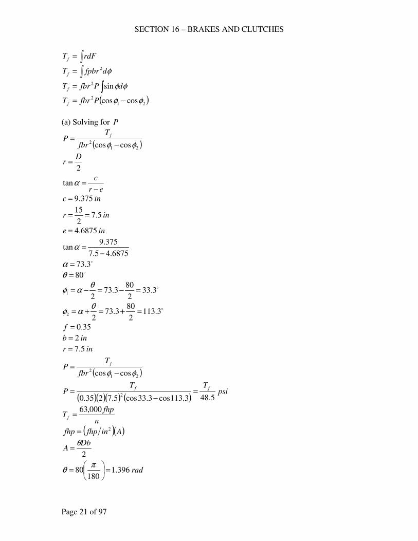
SECTION 16 – BRAKES AND CLUTCHES
Page 21 of 97
∫= rdFT f
∫= φdfpbrT f
2
∫= φφdPfbrT f sin2
( )21
2 coscos φφ −= PfbrT f
(a) Solving for P
( )21
2 coscos φφ −=
fbr
TP
f
2
Dr =
er
c
−=αtan
inc 375.9=
inr 5.72
15==
ine 6875.4=
6875.45.7
375.9tan
−=α
o3.73=α o80=θ
o3.332
803.73
21 =−=−=
θαφ
o3.1132
803.73
22 =+=+=
θαφ
35.0=f
inb 2=
inr 5.7=
( )21
2 coscos φφ −=
fbr
TP
f
( )( )( ) ( )psi
TTP
ff
5.483.113cos3.33cos5.7235.02
=−
=
n
fhpT f
000,63=
( )( )Ainfhpfhp 2=
2
DbA
θ=
rad396.1180
80 =
=
πθ
SECTION 16 – BRAKES AND CLUTCHES
Page 22 of 97
( )( )( ) 2212
215396.1inA ==
4.02 =infhp
( )( ) hpfhp 4.8214.0 ==
rpmn 200=
( )lbinT f −== 2646
200
4.8000,63
( )o90.max555.48
2646
5.482 >==== φPpsi
TP
f
(b) ( )∫ −= dFRrM HF φcos
( )∫ −=2
1
sincosφ
φφφφ dfbrPRrM HF
( )∫ −=2
1
cossinsinφ
φφφφφ dRrfbrPM HF
2
1
2sin2
cos
φ
φ
φφ
−−=
RrfbrPM HF
( ) ( )
−−−= 1
2
2
2
21 sinsin2
coscos φφφφR
rfbrPM HF
( ) ( ) ( ) inercR 788.96875.45.7375.92222 =−+=−+=
( )( )( )( ) ( ) ( )
−−−= 3.33sin3.113sin
2
788.93.113cos3.33cos5.7555.7235.0 22
HFM
lbinM HF −=1900
(c) ∫= dNRM HN φsin
∫=2
1
2sinφ
φφφbrdRPM HN
∫=2
1
2sinφ
φφφdbrRPM HN
( )∫ −=2
1
2cos12
φ
φφφ d
brRPM HN
2
1
2sin2
1
2
φ
φ
φφ
−=
brRPM HN
( ) ( )[ ]1212 2sin2sin24
φφφφ −−−=brRP
M HN
rad396.112 ==− θφφ
( ) o6.2263.11322 2 ==φ
( ) o6.663.3322 1 ==φ
SECTION 16 – BRAKES AND CLUTCHES
Page 23 of 97
( )( )( )( ) ( ) ( )[ ]6.66sin6.226sin396.124
55788.95.72−−=HNM
lbinM HN −= 8956
(d) ∑ = 0HM
0=−+ HNHF MMWa
ina 5.32=
( ) 0895619005.32 =−+W
lbW 217=
(e) lbinT f −= 2646
(f) ∑ = 0xF
∫ ∫ =++−− 0cossincos φφα dFdNWH x
∫∫ −−=−2
1
2
1
cossinsincos 2φ
φ
φ
φφφφφφα dfPbrdPbrWH x
( ) ( )[ ] ( )1
2
2
2
1212 sinsin2
2sin2sin24
cos φφφφφφα −−−−−−=−fbrPbrP
WH x
( )( )( ) ( ) ( )[ ]
( )( )( )( ) ( )3.113sin3.113sin2
555.7235.0
6.66sin6.226sin396.124
555.723.73cos217
22 −−
−−−=− xH
lbH x 931−=−
lbH x 931=
∑ = 0yF
∫ ∫ =+−+− 0sincossin φφα dFdNWH y
αφφφφφφ
φ
φ
φsinsincossin
2
1
2
1
2 WdfbrPdbrPH y −−=− ∫∫
( ) ( ) ( )[ ] αφφφφφφ sin2sin2sin24
sinsin2
12121
2
2
2W
fbrPbrPH y −−−−−−=−
( )( )( ) ( )
( )( )( )( ) ( ) ( )[ ] 3.73sin2176.66sin6.226sin396.124
555.7235.0
3.33sin3.113sin2
555.72 22
−−−−
−=− yH
lbH y 305−=−
lbH y 305=
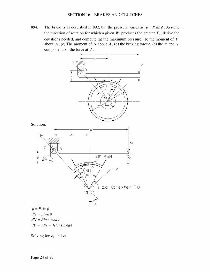
SECTION 16 – BRAKES AND CLUTCHES
Page 24 of 97
894. The brake is as described in 892, but the pressure varies as φsinPp = . Assume
the direction of rotation for which a given W produces the greater fT , derive the
equations needed, and compute (a) the maximum pressure, (b) the moment of F
about A , (c) The moment of N about A , (d) the braking torque, (e) the x and y
components of the force at A .
Solution:
φsinPp =
φpbrddN =
φφdPbrdN sin=
φφdfPbrfdNdF sin==
Solving for 1φ and 2φ
SECTION 16 – BRAKES AND CLUTCHES
Page 25 of 97
er
c
+=αtan
inD
r 5.72
==
75.35.7
5.7tan
+=α
o69.33=α
o69.32
6069.33
21 =−=−=
θαφ
o69.632
6069.33
21 =+=+=
θαφ
( )∫ −= dFrRM AF φcos
( ) φφφφ
φdfPbrrRM AF sincos
2
1∫ −=
( ) φφφφφ
φdrRfPbrM AF ∫ −=
2
1
sincossin
( ) ( )
−+−= 121
2
2
2 coscossinsin2
φφφφ rR
fPbrM AF
( ) ( ) ( ) inrecR 52.135.775.35.72222 =++=++=
( ) ( )( ) ( ) ( )
−+−
= 69.3cos69.63cos5.769.3sin69.63sin
2
52.135.75.335.0 22
PM AF
PM AF 43.11=
∫= dNRM AN φsin
∫=2
1
2sinφ
φφφdRPbrM AN
( )∫ −=2
1
2cos12
φ
φφφ d
brPRM AN
( ) ( )[ ]1212 2sin2sin24
φφφφ −−−=brPR
M AN
rad047.112 ==− θφφ
( ) o38.12769.6322 2 ==φ
( ) o38.769.322 1 ==φ
( )( ) ( ) ( ) ( )[ ]38.7sin38.127sin047.124
52.135.75.3−−=
PM AN
PM AN 68.126=
(a) ∑ = 0AM
0=−+ ANAF MMWa
lbW 300=
SECTION 16 – BRAKES AND CLUTCHES
Page 26 of 97
ina 26=
( )( ) 068.12643.1126300 =−+ PP
psiP 68.67=
max. psiPp 67.6069.63sin68.67sin 2 === φ
(b) ( ) lbinM AF −== 77468.6743.11
(c) ( ) lbinM AN −== 857568.6768.126
(d) ∫= rdFT f
∫=2
1
sin2φ
φφφdfPbrT f
( )21
2 coscos φφ −= fPbrT f
( )( )( )( ) ( )69.63cos69.3cos5.75.368.6035.02
−=fT
lbinT f −= 2587
(e) [ ]∑ = 0xF
∫ ∫ =−+−− 0cossincos φφα dFdNWH x
∫∫ +−=−2
1
2
1
cossinsincos 2φ
φ
φ
φφφφφφα dfPbrdPbrWH x
( ) ( )[ ] ( )1
2
2
2
1212 sinsin2
2sin2sin24
cos φφφφφφα −+−−−−=−fPbrPbr
WH x
( )( )( ) ( ) ( )[ ]
( )( )( )( ) ( )69.3sin69.63sin2
5.75.368.6735.0
38.7sin38.127sin047.124
5.75.368.6769.33cos300
22 −+
−−−=− xH
lbH x 136−=−
lbH x 136=
[ ]∑ = 0yF
∫ ∫ =−−+ 0sincossin φφα dFdNWH y
αφφφφφφ
φ
φ
φsinsincossin
2
1
2
1
2 WdfPbrdPbrH y −+= ∫∫
( ) ( ) ( )[ ] αφφφφφφ sin2sin2sin24
sinsin2
12121
2
2
2W
fPbrPbrH y −−−−+−=
( )( )( ) ( )
( )( )( )( ) ( ) ( )[ ] 69.33sin30038.7sin38.127sin047.124
5.75.368.6735.0
69.3sin69.63sin2
5.75.368.67 22
−−−+
−=yH
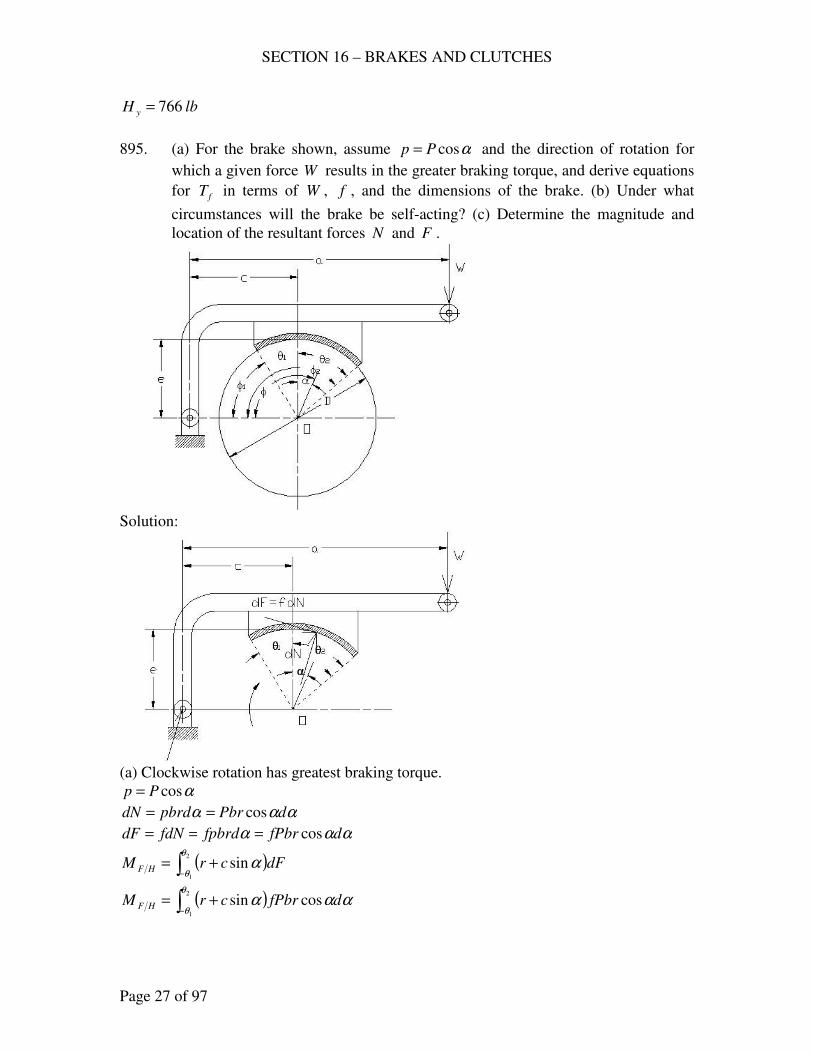
SECTION 16 – BRAKES AND CLUTCHES
Page 27 of 97
lbH y 766=
895. (a) For the brake shown, assume αcosPp = and the direction of rotation for
which a given force W results in the greater braking torque, and derive equations
for fT in terms of W , f , and the dimensions of the brake. (b) Under what
circumstances will the brake be self-acting? (c) Determine the magnitude and
location of the resultant forces N and F .
Solution:
(a) Clockwise rotation has greatest braking torque.
αcosPp =
ααα dPbrpbrddN cos==
ααα dfPbrfpbrdfdNdF cos===
( )∫− +=2
1
sinθ
θα dFcrM HF
( )∫− +=2
1
cossinθ
θααα dfPbrcrM HF
SECTION 16 – BRAKES AND CLUTCHES
Page 28 of 97
( )∫− +=2
1
cossincosθ
θαααα dcrfPbrM HF
2
1
2sin2
1sin
θ
θ
αα−
+= crfPbrM HF
( ) ( )[ ] ( ) ( )[ ]
−−+−−= 1
2
2
2
12 sinsin2
1sinsin θθθθ crfPbrM HF
( ) ( )
−++= 1
2
2
2
12 sinsin2
1sinsin θθθθ crfPbrM HF
∫−=2
1
cosθ
θαdNM HN
∫−=2
1
2cosθ
θααdcPbrM HN
( )∫− +=2
1
2cos12
θ
θαα d
cPbrM HN
[ ] 2
12sin2
4
θ
θα −+=cPbr
M HN
( ) ( )[ ]1212 2sin2sin24
θθθθ +++=cPbr
M HN
[ ]∑ = 0HM
0=−+ HNHF MMWa
( ) ( ) ( ) ( )[ ]12121
2
2
2
12 2sin2sin24
sinsin2
1sinsin θθθθθθθθ +++=
−+++
cPbrcrfPbrWa
( ) ( )[ ] ( ) ( )[ ]1
2
2
2
121212 sinsinsinsin22
2sin2sin24
θθθθθθθθ −++−+++
=
crfbrcbr
WaP
( ) ( )[ ] ( ) ( )[ ]{ }1
2
2
2
121212 sinsinsinsin222sin2sin2
4
θθθθθθθθ −++−+++=
crfcbr
WaP
∫= rdFT f
∫−=2
1
cos2θ
θααdfPbrT f
[ ] 2
1sin2 θ
θα −= fPbrT f
( )12
2 sinsin θθ += fPbrT f
( )( ) ( )[ ] ( ) ( )[ ]{ }1
2
2
2
121212
12
2
sinsinsinsin222sin2sin2
sinsin4
θθθθθθθθ
θθ
−++−+++
+=
crfcbr
fWabrT f
( )( ) ( )[ ] ( ) ( )[ ]1
2
2
2
121212
12
sinsinsinsin222sin2sin2
sinsin4
θθθθθθθθ
θθ
−++−+++
+=
crfc
fWarT f
where 2
Der ==
SECTION 16 – BRAKES AND CLUTCHES
Page 29 of 97
(b) ( ) ( )[ ] ( ) ( )[ ]1
2
2
2
121212 sinsinsinsin222sin2sin2 θθθθθθθθ −++>+++ crfc
( )( ) ( ) ( )1
2
2
2
1212
12
sinsin22sin2sin2
sinsin4
θθθθθθ
θθ
−−+++
+>
f
frc
(c) ∫= dNN
∫−=2
1
cosθ
θααdPbrN
[ ] 2
1sin
θ
θα −= PbrN
( )12 sinsin θθ += PbrN
fNF =
( )12 sinsin θθ += fPbrF
Solving for the location of F and N .
Let A = vertical distance from O .
( )∫∑−
−=2
1
cos.
θ
θα dFrAM LocF
( )∫∑−
−=2
1
2
. coscosθ
θααα fbrdrAPM LocF
( )∫∑−
−=2
1
2
. coscosθ
θααα drAPfbrM LocF
( )∫∑−
+−=
2
1
2cos12
1cos.
θ
θααα drAPfbrM LocF
2
1
2sin2
1
2
1sin.
θ
θ
ααα−
+−=∑ rAPfbrM LocF
( )[ ] ( ) ( )
+++−+=∑ 121212. 2sin2sin
2
1
2
1sinsin θθθθθθ rAPfbrM LocF
Then 0. =∑ LocFM
( )[ ] ( ) ( ) 02sin2sin2
1
2
1sinsin 121212 =
+++−+ θθθθθθ rA
( ) ( ) ( )
+++=+ 121212 2sin2sin
2
1
2
1sinsin θθθθθθ rA
( ) ( )
( )12
1212
sinsin
2sin2sin2
1
2
1
θθ
θθθθ
+
+++
=
r
A
( ) ( )[ ]( )12
1212
sinsin4
2sin2sin2
θθ
θθθθ
+
+++=
rA
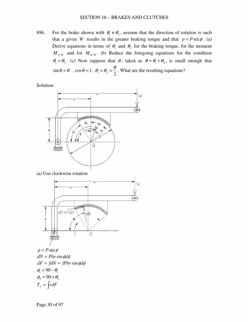
SECTION 16 – BRAKES AND CLUTCHES
Page 30 of 97
896. For the brake shown with 21 θθ ≠ , assume that the direction of rotation is such
that a given W results in the greater braking torque and that φsinPp = . (a)
Derive equations in terms of 1θ and 2θ for the braking torque, for the moment
HFM and for HNM . (b) Reduce the foregoing equations for the condition
21 θθ = . (c) Now suppose that θ , taken as 21 θθθ += , is small enough that
θθ ≈sin , 1cos ≈θ , 2
21
θθθ == . What are the resulting equations?
Solution:
(a) Use clockwise rotation
φsinPp =
φφdPbrdN sin=
φφdfPbrfdNdF sin==
11 90 θφ −=
22 90 θφ +=
∫= rdFT f
SECTION 16 – BRAKES AND CLUTCHES
Page 31 of 97
∫=2
1
sin2φ
φφφdfPbrT f
( )21
2 coscos φφ −= fPbrT f
( ) ( )[ ]21
2 90cos90cos θθ +−−= fPbrT f
( )21
2 sinsin θθ += fPbrT f
( )dFcrM HF ∫ −= φcos
( ) φφφφ
φdcrPrfbM HF sincos
2
1∫ −=
( ) φφφφφ
φdcrfPbrM HF ∫ −=
2
1
cossinsin
2
1
2sin2
1cos
φ
φ
φφ
−−= crfPbrM HF
( ) ( )
−−−= 1
2
2
2
21 sinsin2
1coscos φφφφ crfPbrM HF
( ) ( )[ ] ( ) ( )[ ]
−−+−+−−= 1
2
2
2
21 90sin90sin2
190cos90cos θθθθ crfPbrM HF
( ) ( )
−−+= 1
2
2
2
21 coscos2
1sinsin θθθθ crfPbrM HF
( ) ( ) ( )[ ]
−−−−+= 1
2
2
2
21 sin1sin12
1sinsin θθθθ crfPbrM HF
( ) ( )
−++= 1
2
2
2
21 sinsin2
1sinsin θθθθ crfPbrM HF
dNrM HN φ∫= sin
φφφ
φdPrbM HN ∫=
2
1
22 sin
( ) φφφ
φd
PbrM HN ∫ −=
2
1
2cos12
2
[ ] 2
12sin2
4
2φ
φφ−=Pbr
M HN
( ) ( )[ ]1212
2
2sin2sin24
φφφφ −−−=Pbr
M HN
( ) ( )[ ] ( ) ( )[ ]{ }1212
2
902sin902sin909024
θθθθ −−+−−−+=Pbr
M HN
( ) ( )[ ]1212
2
2sin2sin24
θθθθ −−−+=Pbr
M HN
SECTION 16 – BRAKES AND CLUTCHES
Page 32 of 97
( ) ( )[ ]1212
2
2sin2sin24
θθθθ +++=Pbr
M HN
(b) 21 θθ =
( )21
2 sinsin θθ += PrfbT f
1
2 sin2 θPrfbT f =
( ) ( )
−++= 1
2
2
2
21 sinsin2
1sinsin θθθθ crfPbrM HF
1
2 sin2 θfPbrM HF =
( ) ( )[ ]1212
2
2sin2sin24
θθθθ −−−+=Pbr
M HN
( )11
2
2sin244
θθ +=bPr
M HN
( )111
2
cossin444
θθθ +=bPr
M HN
( )111
2 cossin θθθ += bPrM HN
(c) 21 θθθ +=
θθ ≈sin
1cos ≈θ
221
θθθ ==
1
2 sin2 θPrfbT f =
θθθ 222
22
2sin2 PrfbPrfbPrfbT f =
=
=
1
2 sin2 θfPbrM HF =
θθθ 222
22
2sin2 PrfbPrfbPrfbM HF =
=
=
( )111
2 cossin θθθ += bPrM HN
( ) θθθ 2
HN bPrbPrM =
+= 1
22
2
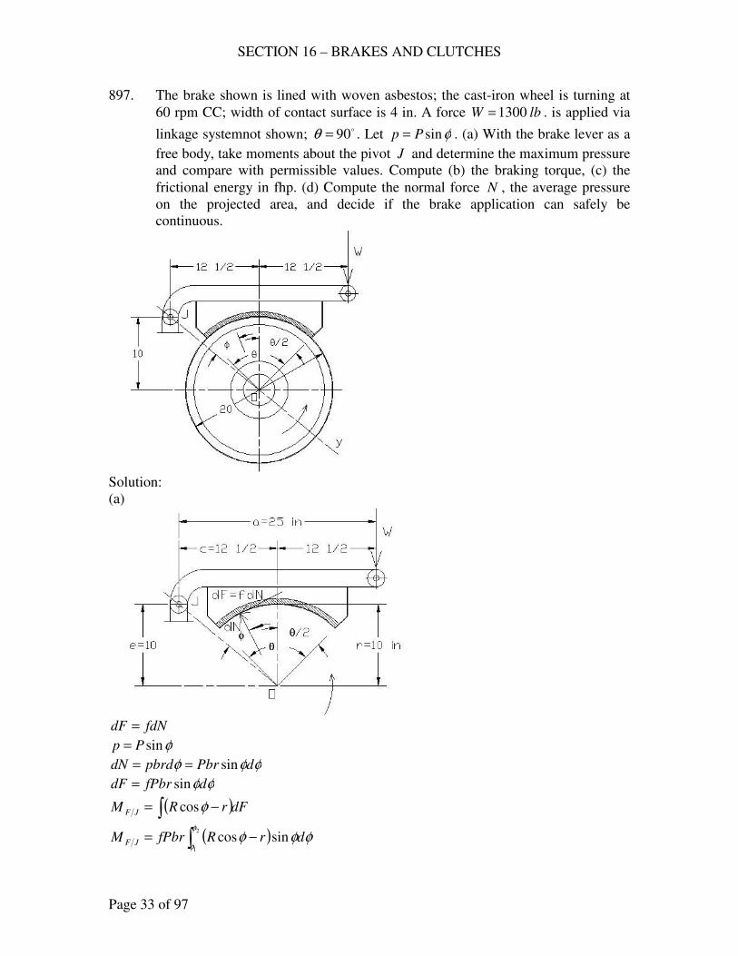
SECTION 16 – BRAKES AND CLUTCHES
Page 33 of 97
897. The brake shown is lined with woven asbestos; the cast-iron wheel is turning at
60 rpm CC; width of contact surface is 4 in. A force lbW 1300= . is applied via
linkage systemnot shown; o90=θ . Let φsinPp = . (a) With the brake lever as a
free body, take moments about the pivot J and determine the maximum pressure
and compare with permissible values. Compute (b) the braking torque, (c) the
frictional energy in fhp. (d) Compute the normal force N , the average pressure
on the projected area, and decide if the brake application can safely be
continuous.
Solution:
(a)
fdNdF =
φsinPp =
φφφ dPbrpbrddN sin==
φφdfPbrdF sin=
( )dFrRM JF ∫ −= φcos
( )∫ −=2
1
sincosφ
φφφφ drRfPbrM JF
SECTION 16 – BRAKES AND CLUTCHES
Page 34 of 97
( )∫ −=2
1
sincossinφ
φφφφφ drRfPbrM JF
2
1
cossin2
1 2
φ
φ
φφ
+= rRfPbrM JF
( ) ( )
−+−= 121
2
2
2 coscossinsin2
1φφφφ rRfPbrM JF
10
5.12tan =β
o34.51=β
21
θβφ −=
o90=θ
o34.62
9034.511 =−=φ
o34.962
9034.51
21 =+=+=
θβφ
inb 4=
inr 10=
for woven asbestos 4.0=f (Table At 29)
( ) ( ) inR 16105.1222
=+=
( ) ( )
−+−= 121
2
2
2 coscossinsin2
1φφφφ rRfPbrM JF
( ) ( )( ) ( ) ( )
−+−= 34.6cos34.96cos1034.6sin34.96sin
2
161044.0 22
PM JF
PM JF 81.51−=
∫= dNRM JN φsin
∫=2
1
2sinφ
φφφdPbrRM JN
[ ] 2
12cos1
2
φ
φφ−=PbrR
M JN
( ) ( )[ ]1212 2sin2sin24
φφφφ −−−=PbrR
M JN
( )( )( )( ) ( ) ( )( )
−−
−= 34.62sin34.962sin
18034.634.962
4
16104 πPM JN
PM JN 9.572=
0=−+=∑ JNJFJ MMWaM
SECTION 16 – BRAKES AND CLUTCHES
Page 35 of 97
( )( ) ( ) 09.57281.51251300 =−−+ PP
psiP 52=
max. psiPp 52== , 902 >φ
From Table AT 29, permissible psip 50=
Therefore epermissiblpp ≈max
(b) ∫= rdFT f
∫=2
1
sinφ
φφφdfPbrT f
( )21 coscos φφ −= fPbrT f
( )( )( )( )( ) lbinT f −=−= 918834.96cos34.6cos104524.0
(c) 000,63
nTfhp
f= , rpmn 60=
( )( )hpfhp 75.8
000,63
609188==
(d) ∫= dNN
∫=2
1
sinφ
φφφdPbrN
( )21 coscos φφ −= PbrN
( )( )( )( ) lbN 229734.96cos34.6cos10452 =−=
2sin2
.θ
br
Npave =
o90=θ
( )( )psipave 6.40
2
90sin1042
2297. ==
( ) ( )( ) min..755,12602012
6.4012
−−=
=
= insqlbft
Dnppvm
ππ
since min..000,28 −−< insqlbftpvm (§18.4)
Application is continuous.
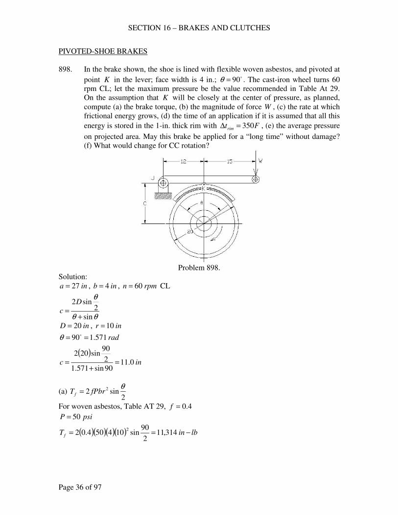
SECTION 16 – BRAKES AND CLUTCHES
Page 36 of 97
PIVOTED-SHOE BRAKES
898. In the brake shown, the shoe is lined with flexible woven asbestos, and pivoted at
point K in the lever; face width is 4 in.; o90=θ . The cast-iron wheel turns 60
rpm CL; let the maximum pressure be the value recommended in Table At 29.
On the assumption that K will be closely at the center of pressure, as planned,
compute (a) the brake torque, (b) the magnitude of force W , (c) the rate at which
frictional energy grows, (d) the time of an application if it is assumed that all this
energy is stored in the 1-in. thick rim with Ftrim 350=∆ , (e) the average pressure
on projected area. May this brake be applied for a “long time” without damage?
(f) What would change for CC rotation?
Problem 898.
Solution:
ina 27= , inb 4= , rpmn 60= CL
θθ
θ
sin
2sin2
+=
D
c
inD 20= , inr 10=
rad571.190 == oθ
( )inc 0.11
90sin571.1
2
90sin202
=+
=
(a) 2
sin2 2 θfPbrT f =
For woven asbestos, Table AT 29, 4.0=f
psiP 50=
( )( )( )( ) lbinT f −== 314,112
90sin104504.02
2
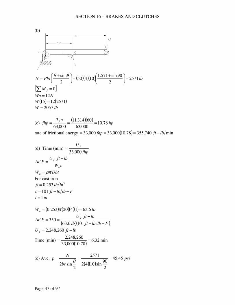
SECTION 16 – BRAKES AND CLUTCHES
Page 37 of 97
(b)
( )( )( ) lbPbrN 25712
90sin571.110450
2
sin=
+=
+=
θθ
[ ]∑ = 0JM
NWa 12=
( ) ( )25711215 =W
lbW 2057=
(c) ( )( )
hpnT
fhpf
78.10000,63
60314,11
000,63===
rate of frictional energy ( ) min740,35578.10000,33000,33 lbftfhp −===
(d) Time (min) fhp
U f
000,33=
cW
lbftUFt
m
f −=∆ o
DbtWm ρπ=
For cast iron 3253.0 inlb=ρ
Flblbftc −−= 101
int 1=
( ) ( )( )( ) lbWm 6.631420253.0 == π
( )( )Flblbftlb
lbftUFt
f
−−
−==∆
1016.63350o
lbftU f −= 260,248,2
Time (min) ( )
min32.678.10000,33
260,248,2==
(e) Ave.
( )( )psi
br
Np 45.45
2
90sin1042
2571
2sin2
===θ
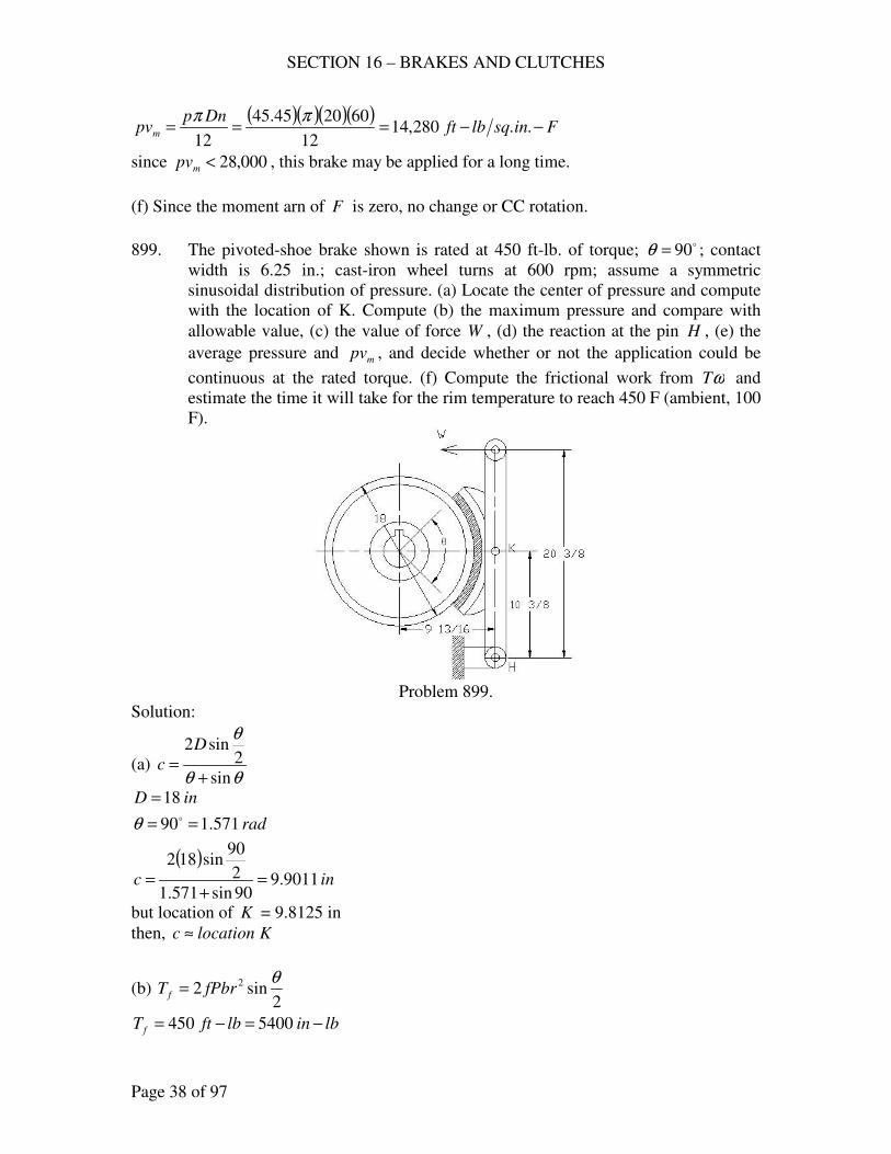
SECTION 16 – BRAKES AND CLUTCHES
Page 38 of 97
( )( )( )( )Finsqlbft
Dnppvm −−=== ..280,14
12
602045.45
12
ππ
since 000,28<mpv , this brake may be applied for a long time.
(f) Since the moment arn of F is zero, no change or CC rotation.
899. The pivoted-shoe brake shown is rated at 450 ft-lb. of torque; o90=θ ; contact
width is 6.25 in.; cast-iron wheel turns at 600 rpm; assume a symmetric
sinusoidal distribution of pressure. (a) Locate the center of pressure and compute
with the location of K. Compute (b) the maximum pressure and compare with
allowable value, (c) the value of force W , (d) the reaction at the pin H , (e) the
average pressure and mpv , and decide whether or not the application could be
continuous at the rated torque. (f) Compute the frictional work from ωT and
estimate the time it will take for the rim temperature to reach 450 F (ambient, 100
F).
Problem 899.
Solution:
(a) θθ
θ
sin
2sin2
+=
D
c
inD 18=
rad571.190 == oθ
( )inc 9011.9
90sin571.1
2
90sin182
=+
=
but location of K = 9.8125 in
then, Klocationc ≈
(b) 2
sin2 2 θfPbrT f =
lbinlbftT f −=−= 5400450
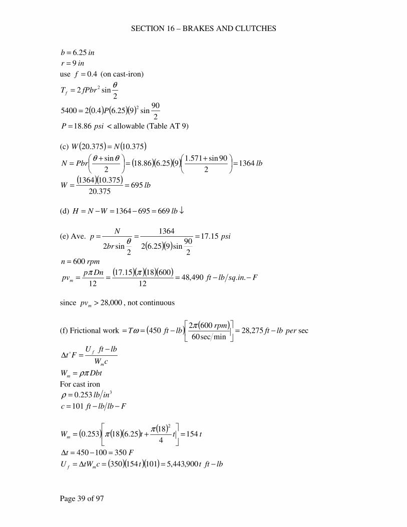
SECTION 16 – BRAKES AND CLUTCHES
Page 39 of 97
inb 25.6=
inr 9=
use 4.0=f (on cast-iron)
2sin2 2 θ
fPbrT f =
( ) ( )( )2
90sin925.64.025400
2P=
psiP 86.18= < allowable (Table AT 9)
(c) ( ) ( )375.10375.20 NW =
( )( )( ) lbPbrN 13642
90sin571.1925.686.18
2
sin=
+=
+=
θθ
( )( )lbW 695
375.20
375.101364==
(d) ↓=−=−= lbWNH 6696951364
(e) Ave.
( )( )psi
br
Np 15.17
2
90sin925.62
1364
2sin2
===θ
rpmn 600=
( )( )( )( )Finsqlbft
Dnppvm −−=== ..490,48
12
6001815.17
12
ππ
since 000,28>mpv , not continuous
(f) Frictional work ( ) ( )sec275,28
minsec60
6002450 perlbft
rpmlbftT −=
−==
πω
cW
lbftUFt
m
f −=∆ o
DbtWm ρπ=
For cast iron 3253.0 inlb=ρ
Flblbftc −−= 101
( ) ( )( ) ( )tttWm 154
4
1825.618253.0
2
=
+=
ππ
Ft 350100450 =−=∆
( )( )( ) lbftttctWU mf −==∆= 900,443,5101154350
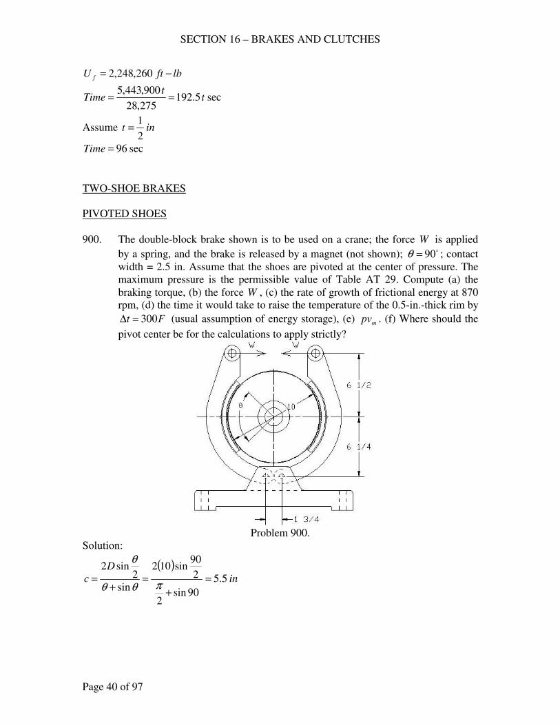
SECTION 16 – BRAKES AND CLUTCHES
Page 40 of 97
lbftU f −= 260,248,2
sec5.192275,28
900,443,5t
tTime ==
Assume int2
1=
sec96=Time
TWO-SHOE BRAKES
PIVOTED SHOES
900. The double-block brake shown is to be used on a crane; the force W is applied
by a spring, and the brake is released by a magnet (not shown); o90=θ ; contact
width = 2.5 in. Assume that the shoes are pivoted at the center of pressure. The
maximum pressure is the permissible value of Table AT 29. Compute (a) the
braking torque, (b) the force W , (c) the rate of growth of frictional energy at 870
rpm, (d) the time it would take to raise the temperature of the 0.5-in.-thick rim by
Ft 300=∆ (usual assumption of energy storage), (e) mpv . (f) Where should the
pivot center be for the calculations to apply strictly?
Problem 900.
Solution:
( )in
D
c 5.5
90sin2
2
90sin102
sin
2sin2
=
+
=+
=πθθ
θ
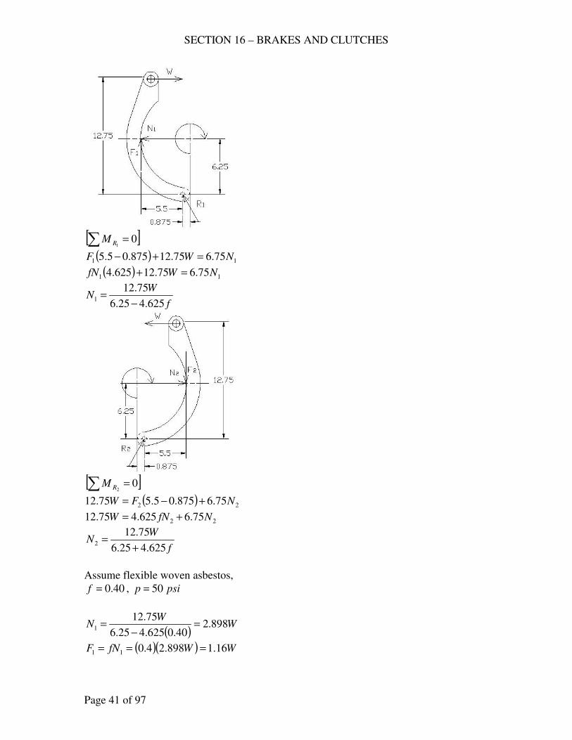
SECTION 16 – BRAKES AND CLUTCHES
Page 41 of 97
[ ]∑ = 0
1RM
( ) 11 75.675.12875.05.5 NWF =+−
( ) 11 75.675.12625.4 NWfN =+
f
WN
625.425.6
75.121
−=
[ ]∑ = 0
2RM
( ) 22 75.6875.05.575.12 NFW +−=
22 75.6625.475.12 NfNW +=
f
WN
625.425.6
75.122
+=
Assume flexible woven asbestos,
40.0=f , psip 50=
( )W
WN 898.2
40.0625.425.6
75.121 =
−=
( )( ) WWfNF 16.1898.24.011 ===
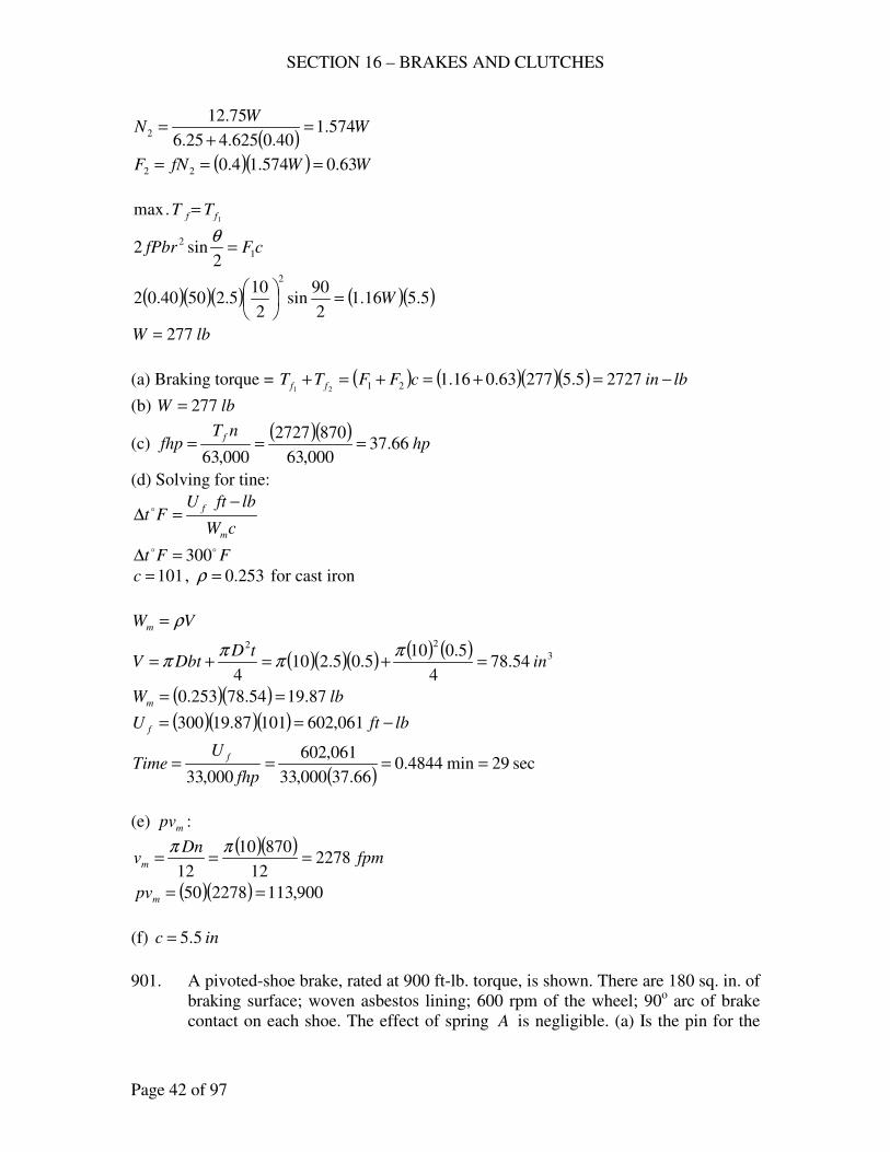
SECTION 16 – BRAKES AND CLUTCHES
Page 42 of 97
( )W
WN 574.1
40.0625.425.6
75.122 =
+=
( )( ) WWfNF 63.0574.14.022 ===
1.max ff TT =
cFfPbr 1
2
2sin2 =
θ
( )( )( ) ( )( )5.516.12
90sin
2
105.25040.02
2
W=
lbW 277=
(a) Braking torque = ( ) ( )( )( ) lbincFFTT ff −=+=+=+ 27275.527763.016.12121
(b) lbW 277=
(c) ( )( )
hpnT
fhpf
66.37000,63
8702727
000,63===
(d) Solving for tine:
cW
lbftUFt
m
f −=∆ o
FFtoo 300=∆
101=c , 253.0=ρ for cast iron
VWm ρ=
( )( )( ) ( ) ( ) 3
22
54.784
5.0105.05.210
4in
tDDbtV =+=+=
ππ
ππ
( )( ) lbWm 87.1954.78253.0 ==
( )( )( ) lbftU f −== 061,60210187.19300
( )sec29min4844.0
66.37000,33
061,602
000,33====
fhp
UTime
f
(e) mpv :
( )( )fpm
Dnvm 2278
12
87010
12===
ππ
( )( ) 900,113227850 ==mpv
(f) inc 5.5=
901. A pivoted-shoe brake, rated at 900 ft-lb. torque, is shown. There are 180 sq. in. of
braking surface; woven asbestos lining; 600 rpm of the wheel; 90o arc of brake
contact on each shoe. The effect of spring A is negligible. (a) Is the pin for the
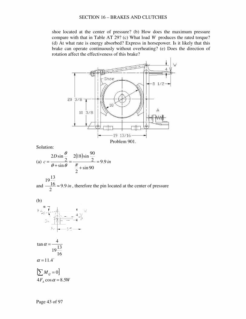
SECTION 16 – BRAKES AND CLUTCHES
Page 43 of 97
shoe located at the center of pressure? (b) How does the maximum pressure
compare with that in Table AT 29? (c) What load W produces the rated torque?
(d) At what rate is energy absorbed? Express in horsepower. Is it likely that this
brake can operate continuously without overheating? (e) Does the direction of
rotation affect the effectiveness of this brake?
Problem 901.
Solution:
(a)
( )in
D
c 9.9
90sin2
2
90sin182
sin
2sin2
=
+
=+
=πθθ
θ
and in9.92
16
1319
≈ , therefore the pin located at the center of pressure
(b)
16
1319
4tan =α
o4.11=α
[ ]∑ = 0QM
WFA 5.8cos4 =α
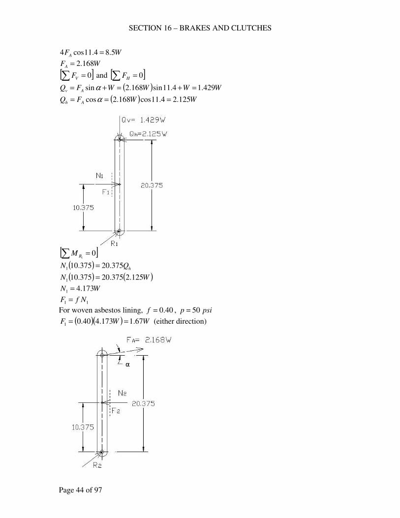
SECTION 16 – BRAKES AND CLUTCHES
Page 44 of 97
WFA 5.84.11cos4 =
WFA 168.2=
[ ]∑ = 0VF and [ ]∑ = 0HF
( ) WWWWFQ Av 429.14.11sin168.2sin =+=+= α
( ) WWFQ Ah 125.24.11cos168.2cos === α
[ ]∑ = 0
1RM
( ) hQN 375.20375.101 =
( ) ( )WN 125.2375.20375.101 =
WN 173.41 =
11 NfF =
For woven asbestos lining, 40.0=f , psip 50=
( )( ) WWF 67.1173.440.01 == (either direction)
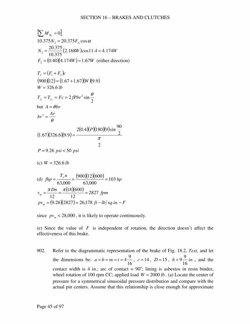
SECTION 16 – BRAKES AND CLUTCHES
Page 45 of 97
[ ]∑ = 02RM
αcos375.20375.10 2 AFN =
( ) WWN 174.44.11cos168.2375.10
375.202 ==
( )( ) WWF 67.1174.440.02 == (either direction)
( )cFFT f 21 +=
( )( ) ( )( )( )9.967.167.112900 W+=
lbW 6.326=
2sin2 2
21
θfPbrFcTT ff ===
but brA θ=
θ
Arbr =2
( )( )( )( )( )( )( )
2
2
90sin91804.02
9.96.32667.1π
P
=
psipsiP 5026.9 <=
(c) lbW 6.326=
(d) ( )( )( )
hpnT
fhpf
103000,63
60012900
000,63===
( )( )fpm
Dnvm 2827
12
60018
12===
ππ
( )( ) Finsqlbftpvm −−== ..178,26282726.9
since 000,28<mpv , it is likely to operate continuously.
(e) Since the value of F is independent of rotation, the direction doesn’t affect the
effectiveness of this brake.
902. Refer to the diagrammatic representation of the brake of Fig. 18.2, Text, and let
the dimensions be: 16
94==== tmba , 14=c , 15=D , inh
16
99= ., and the
contact width is 4 in.; arc of contact = 90o; lining is asbestos in resin binder,
wheel rotation of 100 rpm CC; applied load lbW 2000= . (a) Locate the center of
pressure for a symmetrical sinusoidal pressure distribution and compare with the
actual pin centers. Assume that this relationship is close enough for approximate
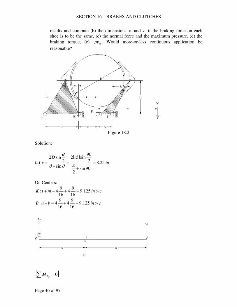
SECTION 16 – BRAKES AND CLUTCHES
Page 46 of 97
results and compute (b) the dimensions k and e if the braking force on each
shoe is to be the same, (c) the normal force and the maximum pressure, (d) the
braking torque, (e) mpv . Would more-or-less continuous application be
reasonable?
Figure 18.2
Solution:
(a)
( )in
D
c 25.8
90sin2
2
90sin152
sin
2sin2
=
+
=+
=πθθ
θ
On Centers:
cinmtK >=+=+ 125.916
94
16
94:
cinbaB >=+=+ 125.916
94
16
94:
[ ]∑ = 0CRM
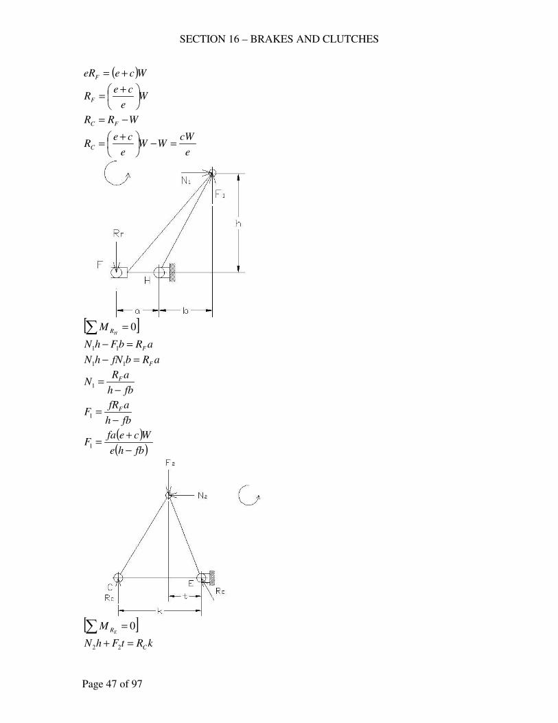
SECTION 16 – BRAKES AND CLUTCHES
Page 47 of 97
( )WceeRF +=
We
ceRF
+=
WRR FC −=
e
cWWW
e
ceRC =−
+=
[ ]∑ = 0
HRM
aRbFhN F=− 11
aRbfNhN F=− 11
fbh
aRN F
−=1
fbh
afRF F
−=1
( )( )fbhe
WcefaF
−
+=1
[ ]∑ = 0
ERM
kRtFhN C=+ 22
SECTION 16 – BRAKES AND CLUTCHES
Page 48 of 97
kRtfNhN C=+ 22
fth
kRN C
+=2
fth
kfRF C
−=2
( )fthe
fkcWF
+=2
(b) 21 ff TT =
cFcF 21 =
21 FF =
( )( ) ( )fthe
fkcW
fbhe
Wcefa
+=
−
+
( )fth
kc
fbh
cea
+=
−
+
For asbestos in resin binder,
35.0=f , Table AT 29
inina 5625.416
94 ==
ininb 5625.416
94 ==
ininm 5625.416
94 ==
inint 5625.416
94 ==
inc 14=
ininh 5625.916
99 ==
( )( )
( )( )5625.435.05625.9
14
5625.435.05625.9
145625.4
+=
−
+ ke
ke 1903.214 =+
but emk =+
or 5625.4+= ke
then kk 1903.2145625.4 =++
ink 6.15=
ine 1625.205625.46.15 =+=
(c) ( )
( )( )( )( ) ( )[ ]
lbfthe
kcWNNN 2720
5625.435.05625.91625.20
2000146.1521 =
−=
+===
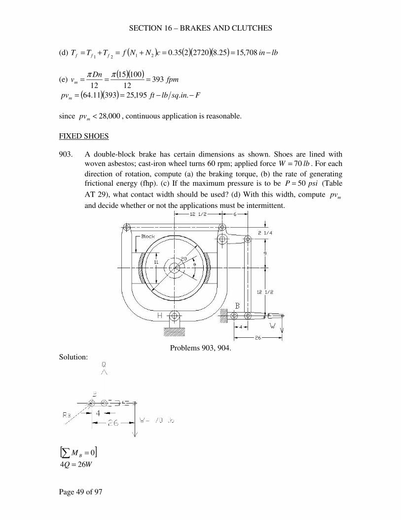
SECTION 16 – BRAKES AND CLUTCHES
Page 49 of 97
(d) ( ) ( )( )( ) lbincNNfTTT fff −==+=+= 708,1525.82720235.02121
(e) ( )( )
fpmDn
vm 39312
10015
12===
ππ
( )( ) Finsqlbftpvm −−== ..195,2539311.64
since 000,28<mpv , continuous application is reasonable.
FIXED SHOES
903. A double-block brake has certain dimensions as shown. Shoes are lined with
woven asbestos; cast-iron wheel turns 60 rpm; applied force lbW 70= . For each
direction of rotation, compute (a) the braking torque, (b) the rate of generating
frictional energy (fhp). (c) If the maximum pressure is to be psiP 50= (Table
AT 29), what contact width should be used? (d) With this width, compute mpv
and decide whether or not the applications must be intermittent.
Problems 903, 904.
Solution:
[ ]0=∑ BM
WQ 264 =
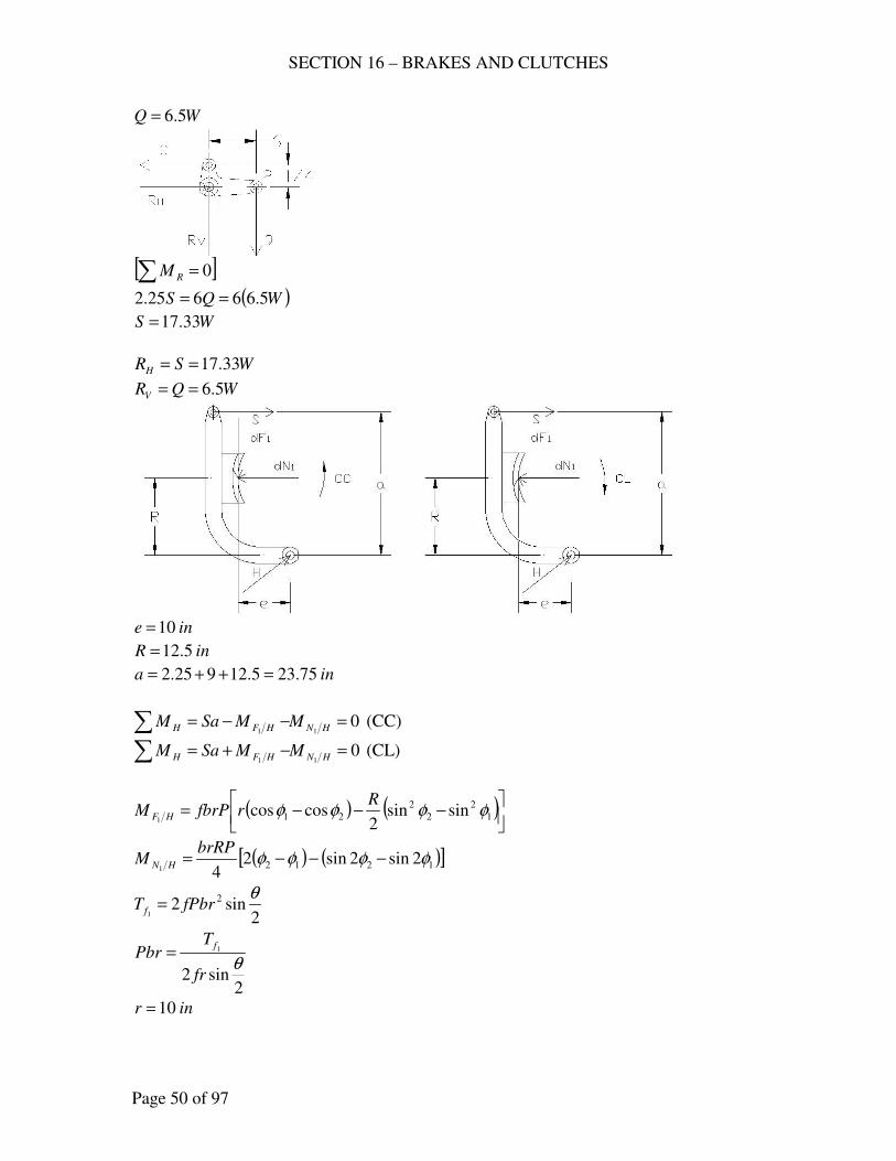
SECTION 16 – BRAKES AND CLUTCHES
Page 50 of 97
WQ 5.6=
[ ]0=∑ RM
( )WQS 5.66625.2 ==
WS 33.17=
WSRH 33.17==
WQRV 5.6==
ine 10=
inR 5.12=
ina 75.235.12925.2 =++=
011
=−−=∑ HNHFH MMSaM (CC)
011
=−+=∑ HNHFH MMSaM (CL)
( ) ( )
−−−= 1
2
2
2
21 sinsin2
coscos1
φφφφR
rfbrPM HF
( ) ( )[ ]1212 2sin2sin241
φφφφ −−−=brRP
M HN
2sin2 2
1
θfPbrT f =
2sin2
1
θfr
TPbr
f=
inr 10=
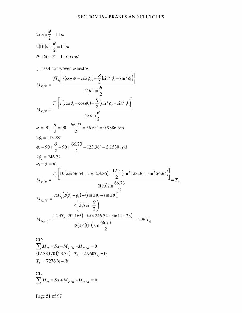
SECTION 16 – BRAKES AND CLUTCHES
Page 51 of 97
inr 112
sin2 =θ
( ) in112
sin102 =θ
rad165.143.66 == oθ
4.0=f for woven asbestos
( ) ( )
2sin2
sinsin2
coscos 1
2
2
2
211
1 θ
φφφφ
fr
RrfT
Mf
HF
−−−
=
( ) ( )
2sin2
sinsin2
coscos 1
2
2
2
211
1 θ
φφφφ
r
RrT
Mf
HF
−−−
=
rad9886.064.562
73.6690
2901 ==−=−= oθ
φ
o28.1132 1 =φ
rad1530.236.1232
73.6690
2902 ==+=+= oθ
φ
o72.2462 2 =φ
θφφ =− 12
( ) ( )
( )1
1
1
2
73.66sin102
64.56sin36.123sin2
5.1236.123cos64.56cos10 22
f
f
HF T
T
M =
−−−
=
( ) ( )[ ]
−−−=
2sin24
2sin2sin2 12121
1 θ
φφφφ
fr
RTM
f
HN
( ) ( )[ ]
( )( )1
1
196.2
2
73.66sin104.08
28.113sin72.246sin165.125.12f
f
HN TT
M =−−
=
CC:
011
=−−=∑ HNHFH MMSaM
( )( )( ) 0960.275.237033.1711
=−− ff TT
lbinT f −= 72761
CL:
011
=−+=∑ HNHFH MMSaM
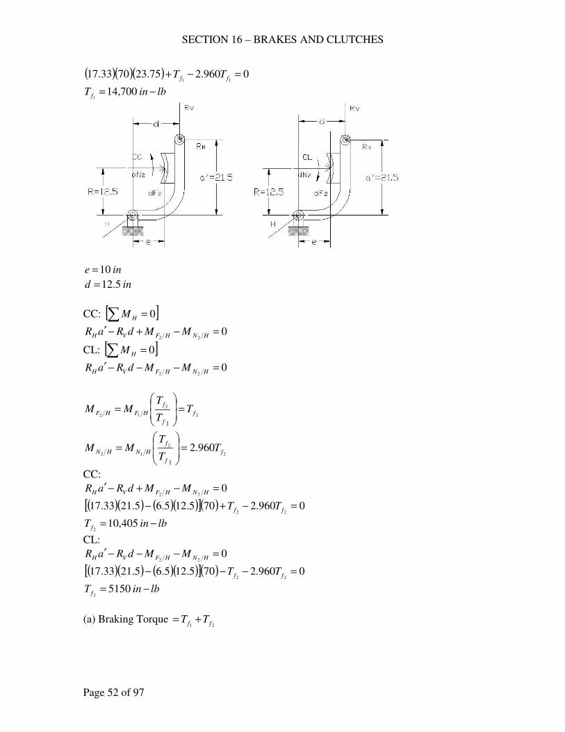
SECTION 16 – BRAKES AND CLUTCHES
Page 52 of 97
( )( )( ) 0960.275.237033.1711
=−+ ff TT
lbinT f −= 700,141
ine 10=
ind 5.12=
CC: [ ]∑ = 0HM
022
=−+−′HNHFVH MMdRaR
CL: [ ]∑ = 0HM
022
=−−−′HNHFVH MMdRaR
2
2
12
1
f
f
f
HFHF TT
TMM =
=
2
2
12960.2
1
f
f
f
HNHN TT
TMM =
=
CC:
022
=−+−′HNHFVH MMdRaR
( )( ) ( )( )[ ]( ) 0960.2705.125.65.2133.1722
=−+− ff TT
lbinT f −= 405,102
CL:
022
=−−−′HNHFVH MMdRaR
( )( ) ( )( )[ ]( ) 0960.2705.125.65.2133.1722
=−−− ff TT
lbinT f −= 51502
(a) Braking Torque 21 ff TT +=
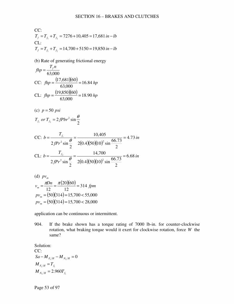
SECTION 16 – BRAKES AND CLUTCHES
Page 53 of 97
CC:
lbinTTT fff −=+=+= 681,17405,10727621
CL:
lbinTTT fff −=+=+= 850,195150700,1421
(b) Rate of generating frictional energy
000,63
nTfhp
f=
CC: ( )( )
hpfhp 84.16000,63
60681,17==
CL: ( )( )
hpfhp 90.18000,63
60850,19==
(c) psip 50=
2sin2 2
21
θfPbrTorT ff =
CC:
( )( )( )in
Prf
Tb
f73.4
2
73.66sin10504.02
405,10
2sin2
22
1 ===θ
CL:
( )( )( )in
Prf
Tb
f68.6
2
73.66sin10504.02
700,14
2sin2
22
2 ===θ
(d) mpv
( )( )fpm
Dnvm 314
12
6020
12===
ππ
( )( ) 000,55700,1531450 <==mpv
( )( ) 000,28700,1531450 <==mpv
application can be continuous or intermittent.
904. If the brake shown has a torque rating of 7000 lb-in. for counter-clockwise
rotation, what braking torque would it exert for clockwise rotation, force W the
same?
Solution:
CC:
011
=−− HNHF MMSa
11 fHF TM =
11960.2 fHN TM =
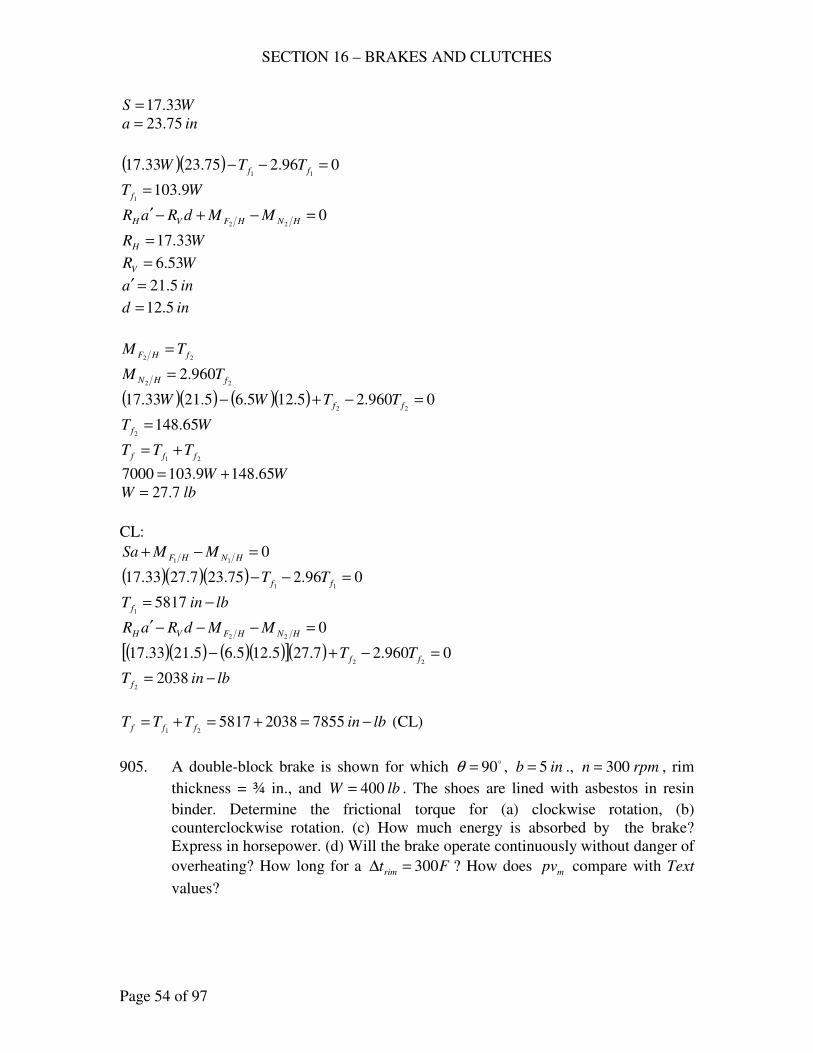
SECTION 16 – BRAKES AND CLUTCHES
Page 54 of 97
WS 33.17=
ina 75.23=
( )( ) 096.275.2333.1711
=−− ff TTW
WT f 9.1031
=
022
=−+−′HNHFVH MMdRaR
WRH 33.17=
WRV 53.6=
ina 5.21=′
22 fHF TM =
22960.2 fHN TM =
( )( ) ( )( ) 0960.25.125.65.2133.1722
=−+− ff TTWW
WT f 65.1482
=
21 fff TTT +=
WW 65.1489.1037000 +=
lbW 7.27=
CL:
011
=−+ HNHF MMSa
( )( )( ) 096.275.237.2733.1711
=−− ff TT
lbinT f −= 58171
022
=−−−′HNHFVH MMdRaR
( )( ) ( )( )[ ]( ) 0960.27.275.125.65.2133.1722
=−+− ff TT
lbinT f −= 20382
lbinTTT fff −=+=+= 78552038581721
(CL)
905. A double-block brake is shown for which o90=θ , inb 5= ., rpmn 300= , rim
thickness = ¾ in., and lbW 400= . The shoes are lined with asbestos in resin
binder. Determine the frictional torque for (a) clockwise rotation, (b)
counterclockwise rotation. (c) How much energy is absorbed by the brake?
Express in horsepower. (d) Will the brake operate continuously without danger of
overheating? How long for a Ftrim 300=∆ ? How does mpv compare with Text
values?
ind 5.12=
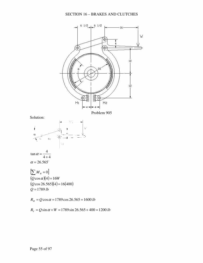
SECTION 16 – BRAKES AND CLUTCHES
Page 55 of 97
Problem 905
Solution:
44
4tan
+=α
o565.26=α
[ ]0=∑ RM
( )( ) WQ 164cos =α
( )( ) ( )400164565.26cos =Q
lbQ 1789=
lbQRH 1600565.26cos1789cos === α
lbWQRV 1200400565.26sin1789sin =+=+= α
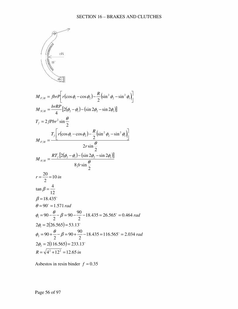
SECTION 16 – BRAKES AND CLUTCHES
Page 56 of 97
( ) ( )
−−−= 1
2
2
2
21 sinsin2
coscos φφφφR
rfbrPM HF
( ) ( )[ ]1212 2sin2sin24
φφφφ −−−=brRP
M HN
2sin2 2 θ
fPbrT f =
( ) ( )
2sin2
sinsin2
coscos 1
2
2
2
21
θ
φφφφ
r
RrT
Mf
HF
−−−
=
( ) ( )[ ]
2sin8
2sin2sin2 1212
θ
φφφφ
fr
RTM
f
HN
−−−=
inr 102
20==
12
4tan =β
o435.18=β
rad571.190 == oθ
rad464.0565.26435.182
9090
2901 ==−−=−−= oβ
θφ
( ) o13.53565.2622 1 ==φ
rad034.2565.116435.182
9090
2902 ==−+=−+= oβ
θφ
( ) o13.233565.11622 2 ==φ
inR 65.12124 22 =+=
Asbestos in resin binder 35.0=f
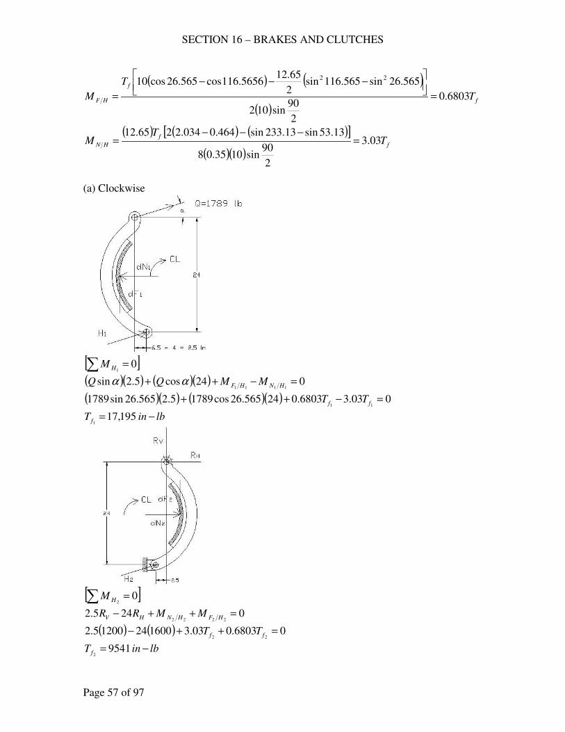
SECTION 16 – BRAKES AND CLUTCHES
Page 57 of 97
( ) ( )
( )f
f
HF T
T
M 6803.0
2
90sin102
565.26sin565.116sin2
65.125656.116cos565.26cos10 22
=
−−−
=
( ) ( ) ( )[ ]
( )( )f
f
HN TT
M 03.3
2
90sin1035.08
13.53sin13.233sin464.0034.2265.12=
−−−=
(a) Clockwise
[ ]∑ = 0
1HM
( )( ) ( )( ) 024cos5.2sin1111
=−++ HNHF MMQQ αα
( )( ) ( )( ) 003.36803.024565.26cos17895.2565.26sin178911
=−++ ff TT
lbinT f −= 195,171
[ ]∑ = 0
2HM
0245.22222
=++− HFHNHV MMRR
( ) ( ) 06803.003.316002412005.222
=++− ff TT
lbinT f −= 95412
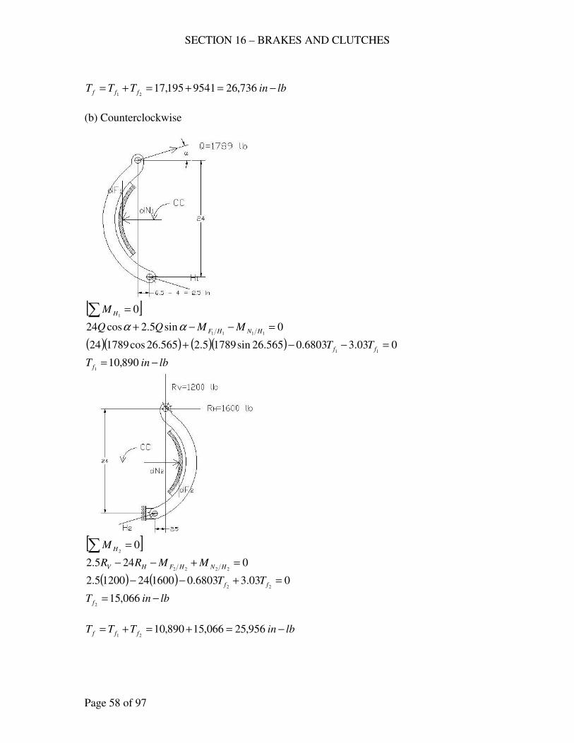
SECTION 16 – BRAKES AND CLUTCHES
Page 58 of 97
lbinTTT fff −=+=+= 736,269541195,1721
(b) Counterclockwise
[ ]∑ = 0
1HM
0sin5.2cos241111
=−−+ HNHF MMQQ αα
( )( ) ( )( ) 003.36803.0565.26sin17895.2565.26cos17892411
=−−+ ff TT
lbinT f −= 890,101
[ ]∑ = 0
2HM
0245.22222
=+−− HNHFHV MMRR
( ) ( ) 003.36803.016002412005.222
=+−− ff TT
lbinT f −= 066,152
lbinTTT fff −=+=+= 956,25066,15890,1021
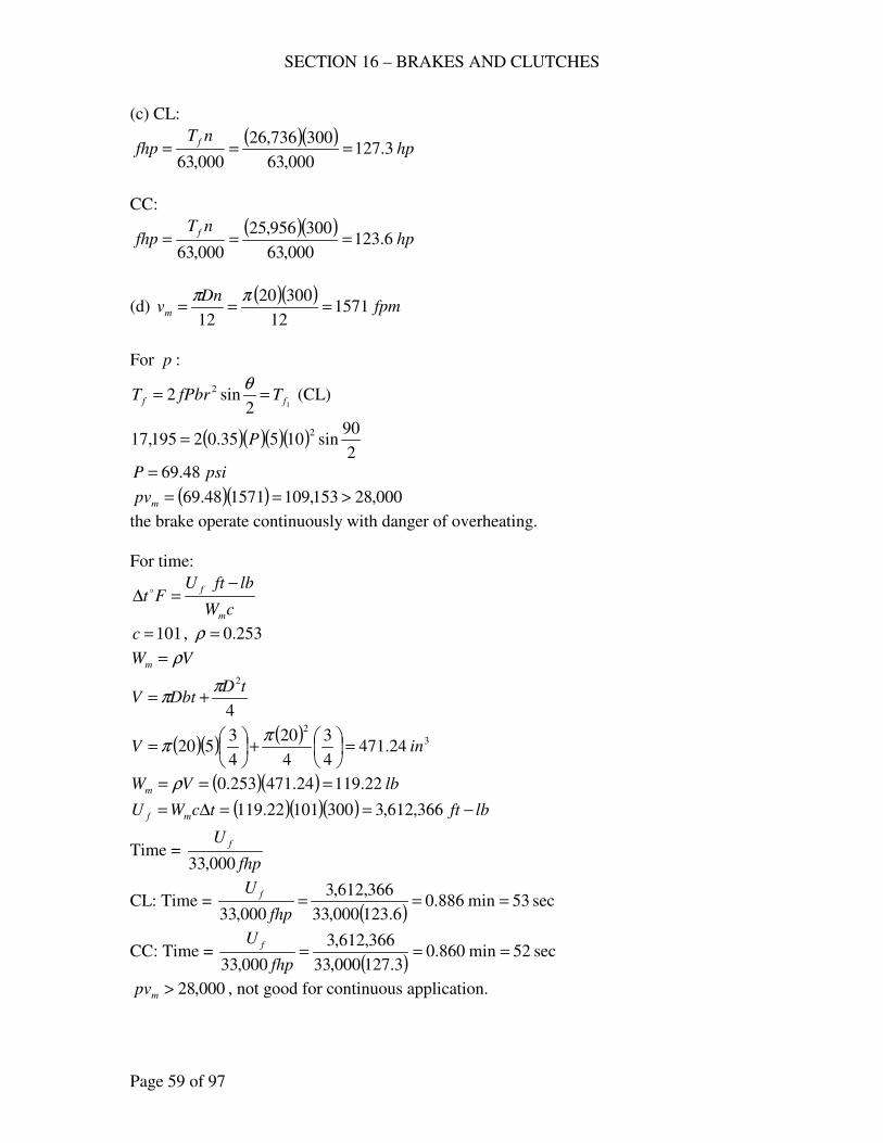
SECTION 16 – BRAKES AND CLUTCHES
Page 59 of 97
(c) CL:
( )( )hp
nTfhp
f3.127
000,63
300736,26
000,63===
CC:
( )( )hp
nTfhp
f6.123
000,63
300956,25
000,63===
(d) ( )( )
fpmDn
vm 157112
30020
12===
ππ
For p :
12sin2 2
ff TfPbrT ==θ
(CL)
( )( )( )( )2
90sin10535.02195,17
2P=
psiP 48.69=
( )( ) 000,28153,109157148.69 >==mpv
the brake operate continuously with danger of overheating.
For time:
cW
lbftUFt
m
f −=∆ o
101=c , 253.0=ρ
VWm ρ=
4
2tD
DbtVπ
π +=
( )( ) ( ) 3
2
24.4714
3
4
20
4
3520 inV =
+
=
ππ
( )( ) lbVWm 22.11924.471253.0 === ρ
( )( )( ) lbfttcWU mf −==∆= 366,612,330010122.119
Time = fhp
U f
000,33
CL: Time = ( )
sec53min886.06.123000,33
366,612,3
000,33===
fhp
U f
CC: Time = ( )
sec52min860.03.127000,33
366,612,3
000,33===
fhp
U f
000,28>mpv , not good for continuous application.
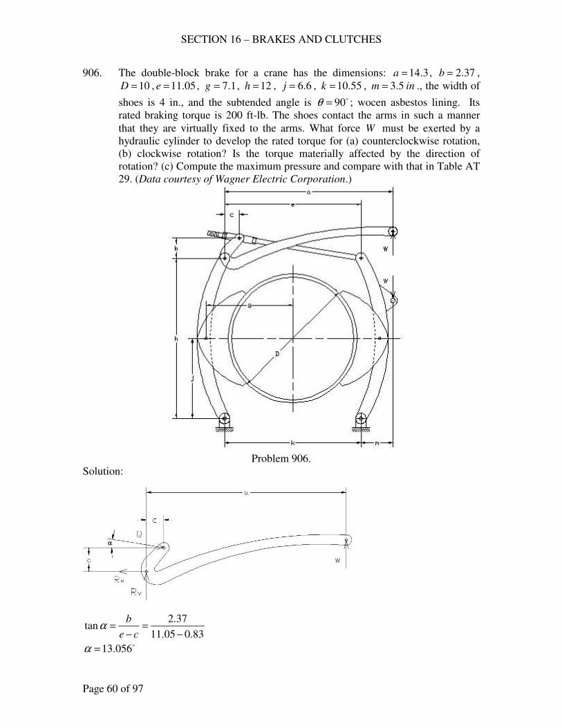
SECTION 16 – BRAKES AND CLUTCHES
Page 60 of 97
906. The double-block brake for a crane has the dimensions: 3.14=a , 37.2=b ,
10=D , 05.11=e , 1.7=g , 12=h , 6.6=j , 55.10=k , inm 5.3= ., the width of
shoes is 4 in., and the subtended angle is o90=θ ; wocen asbestos lining. Its
rated braking torque is 200 ft-lb. The shoes contact the arms in such a manner
that they are virtually fixed to the arms. What force W must be exerted by a
hydraulic cylinder to develop the rated torque for (a) counterclockwise rotation,
(b) clockwise rotation? Is the torque materially affected by the direction of
rotation? (c) Compute the maximum pressure and compare with that in Table AT
29. (Data courtesy of Wagner Electric Corporation.)
Problem 906.
Solution:
83.005.11
37.2tan
−=
−=
ce
bα
o056.13=α
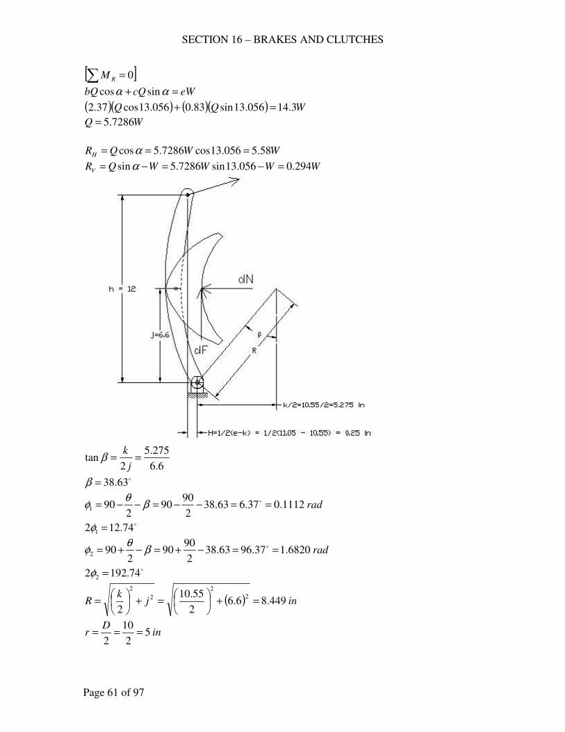
SECTION 16 – BRAKES AND CLUTCHES
Page 61 of 97
[ ]∑ = 0RM
eWcQbQ =+ αα sincos
( )( ) ( )( ) WQQ 3.14056.13sin83.0056.13cos37.2 =+
WQ 7286.5=
WWQRH 58.5056.13cos7286.5cos === α
WWWWQRV 294.0056.13sin7286.5sin =−=−= α
6.6
275.5
2tan ==
j
kβ
o63.38=β
rad1112.037.663.382
9090
2901 ==−−=−−= oβ
θφ
o74.122 1 =φ
rad6820.137.9663.382
9090
2902 ==−+=−+= oβ
θφ
o74.1922 2 =φ
( ) injk
R 449.86.62
55.10
2
2
2
2
2
=+
=+
=
inD
r 52
10
2===
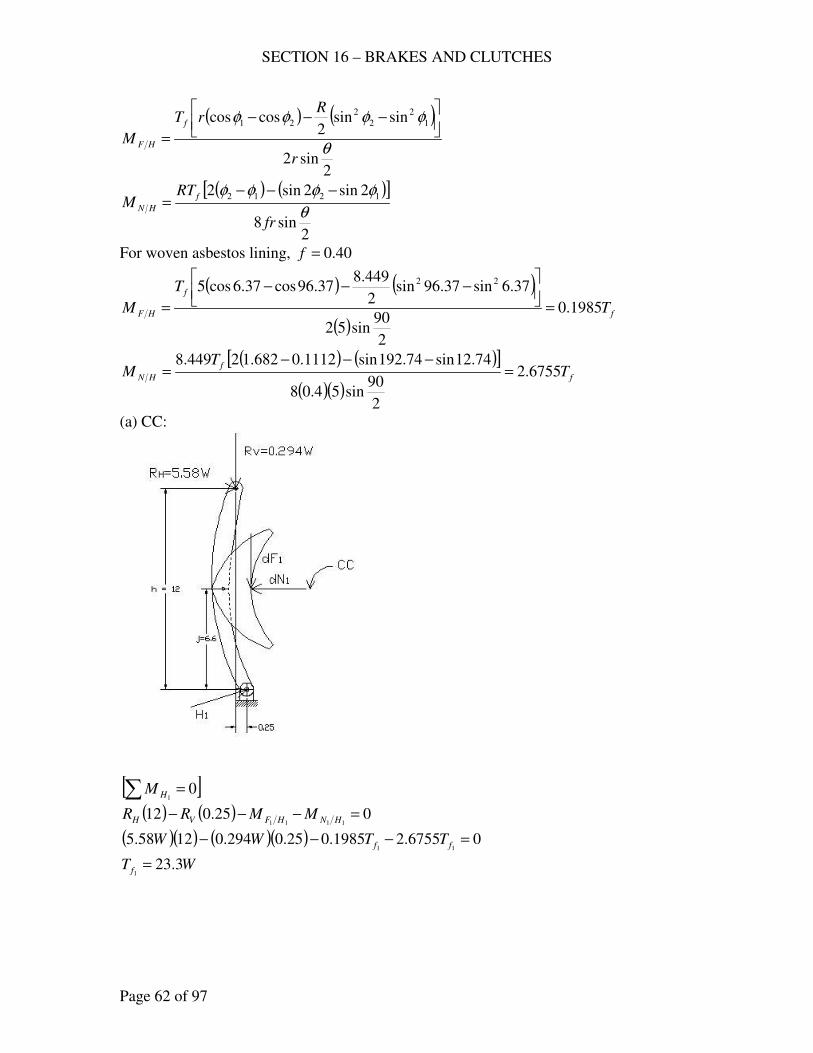
SECTION 16 – BRAKES AND CLUTCHES
Page 62 of 97
( ) ( )
2sin2
sinsin2
coscos 1
2
2
2
21
θ
φφφφ
r
RrT
Mf
HF
−−−
=
( ) ( )[ ]
2sin8
2sin2sin2 1212
θ
φφφφ
fr
RTM
f
HN
−−−=
For woven asbestos lining, 40.0=f
( ) ( )
( )f
f
HF T
T
M 1985.0
2
90sin52
37.6sin37.96sin2
449.837.96cos37.6cos5 22
=
−−−
=
( ) ( )[ ]
( )( )f
f
HN TT
M 6755.2
2
90sin54.08
74.12sin74.192sin1112.0682.12449.8=
−−−=
(a) CC:
[ ]∑ = 01HM
( ) ( ) 025.0121111
=−−− HNHFVH MMRR
( )( ) ( )( ) 06755.21985.025.0294.01258.511
=−−− ff TTWW
WT f 3.231
=
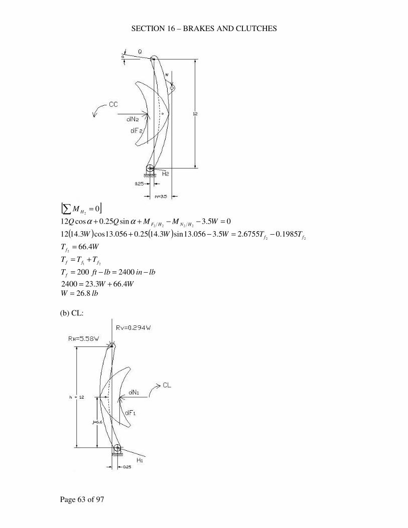
SECTION 16 – BRAKES AND CLUTCHES
Page 63 of 97
[ ]∑ = 0
2HM
05.3sin25.0cos122222
=−−++ WMMQQ HNHFαα
( ) ( )22
1985.06755.25.3056.13sin3.1425.0056.13cos3.1412 ff TTWWW −=−+
WT f 4.662
=
21 fff TTT +=
lbinlbftT f −=−= 2400200
WW 4.663.232400 +=
lbW 8.26=
(b) CL:
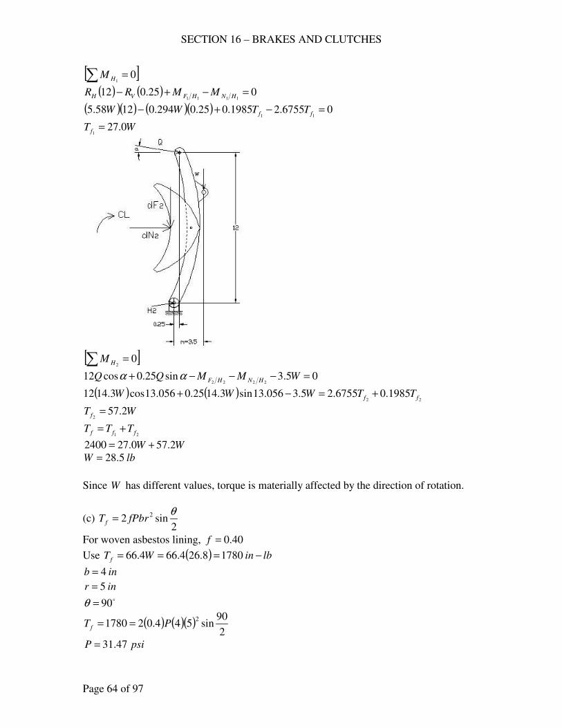
SECTION 16 – BRAKES AND CLUTCHES
Page 64 of 97
[ ]∑ = 01HM
( ) ( ) 025.0121111
=−+− HNHFVH MMRR
( )( ) ( )( ) 06755.21985.025.0294.01258.511
=−+− ff TTWW
WT f 0.271
=
[ ]∑ = 0
2HM
05.3sin25.0cos122222
=−−−+ WMMQQ HNHFαα
( ) ( )22
1985.06755.25.3056.13sin3.1425.0056.13cos3.1412 ff TTWWW +=−+
WT f 2.572
=
21 fff TTT +=
WW 2.570.272400 +=
lbW 5.28=
Since W has different values, torque is materially affected by the direction of rotation.
(c) 2
sin2 2 θfPbrT f =
For woven asbestos lining, 40.0=f
Use ( ) lbinWT f −=== 17808.264.664.66
inb 4=
inr 5= o90=θ
( ) ( )( )2
90sin544.021780
2PT f ==
psiP 47.31=
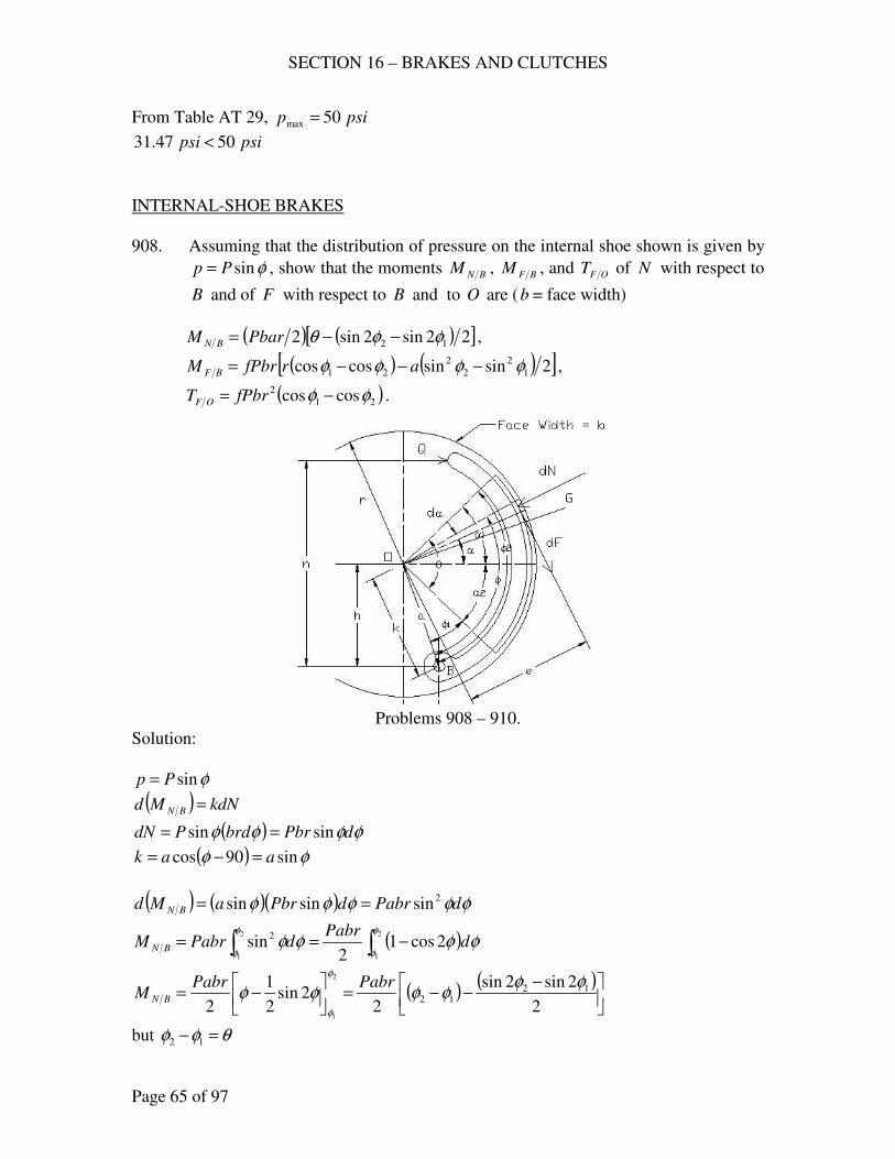
SECTION 16 – BRAKES AND CLUTCHES
Page 65 of 97
From Table AT 29, psip 50max =
psipsi 5047.31 <
INTERNAL-SHOE BRAKES
908. Assuming that the distribution of pressure on the internal shoe shown is given by
φsinPp = , show that the moments BNM , BFM , and OFT of N with respect to
B and of F with respect to B and to O are (b = face width)
( ) ( )[ ]22sin2sin2 12 φφθ −−= PbarM BN ,
( ) ( )[ ]2sinsincoscos 1
2
2
2
21 φφφφ −−−= arfPbrM BF ,
( )21
2 coscos φφ −= fPbrT OF .
Problems 908 – 910.
Solution:
φsinPp =
( ) kdNMd BN =
( ) φφφφ dPbrbrdPdN sinsin ==
( ) φφ sin90cos aak =−=
( ) ( )( ) φφφφφ dPabrdPbraMd BN
2sinsinsin ==
( )∫∫ −==2
1
2
1
2cos12
sin2φ
φ
φ
φφφφφ d
PabrdPabrM BN
( ) ( )
−−−=
−=
2
2sin2sin
22sin
2
1
2
1212
2
1
φφφφφφ
φ
φ
PabrPabrM BN
but θφφ =− 12
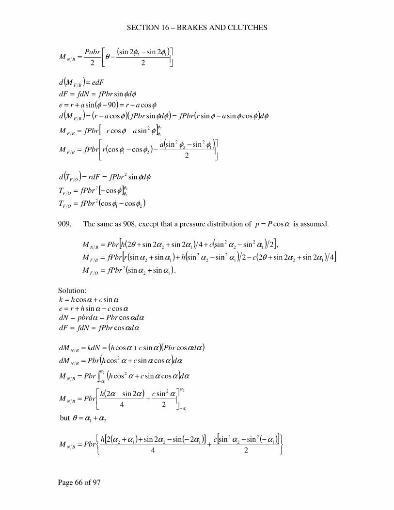
SECTION 16 – BRAKES AND CLUTCHES
Page 66 of 97
( )
−−=
2
2sin2sin
2
12 φφθ
PabrM BN
( ) edFMd BF =
φφdfPbrfdNdF sin==
( ) φφ cos90sin arare −=−+=
( ) ( )( ) ( ) φφφφφφφ darfPbrdfPbrarMd BF cossinsinsincos −=−=
[ ] 2
1
2sincosφ
φφφ arfPbrM BF −−=
( ) ( )
−−−=
2
sinsincoscos 1
2
2
2
21
φφφφ
arfPbrM BF
( ) φφdfPbrrdFTd OF sin2==
[ ] 2
1cos2 φ
φφ−= fPbrT OF
( )21
2 coscos φφ −= fPbrT OF
909. The same as 908, except that a pressure distribution of αcosPp = is assumed.
( ) ( )[ ]2sinsin42sin2sin2 1
2
2
2
12 ααααθ −+++= chPbrM BN ,
( ) ( ) ( )[ ]42sin2sin22sinsinsinsin 121
2
2
2
12 ααθαααα ++−−++= chrfPbrM BF
( )12
2 sinsin αα += fPbrM OF .
Solution:
αα sincos chk +=
αα cossin chre −+=
ααα dPbrpbrddN cos==
ααdfPbrfdNdF cos==
( )( )αααα dPbrchkdNdM BN cossincos +==
( ) αααα dchPbrdM BN cossincos2 +=
( )∫− +=2
1
cossincos2α
ααααα dchPbrM BN
( ) 2
1
2
sin
4
2sin2 2α
α
ααα
−
+
+=
chPbrM BN
but 21 ααθ +=
( ) ( )[ ] ( )[ ]
−−
+−−++
=2
sinsin
4
2sin2sin2 1
2
2
2
1212 αααααα chPbrM BN
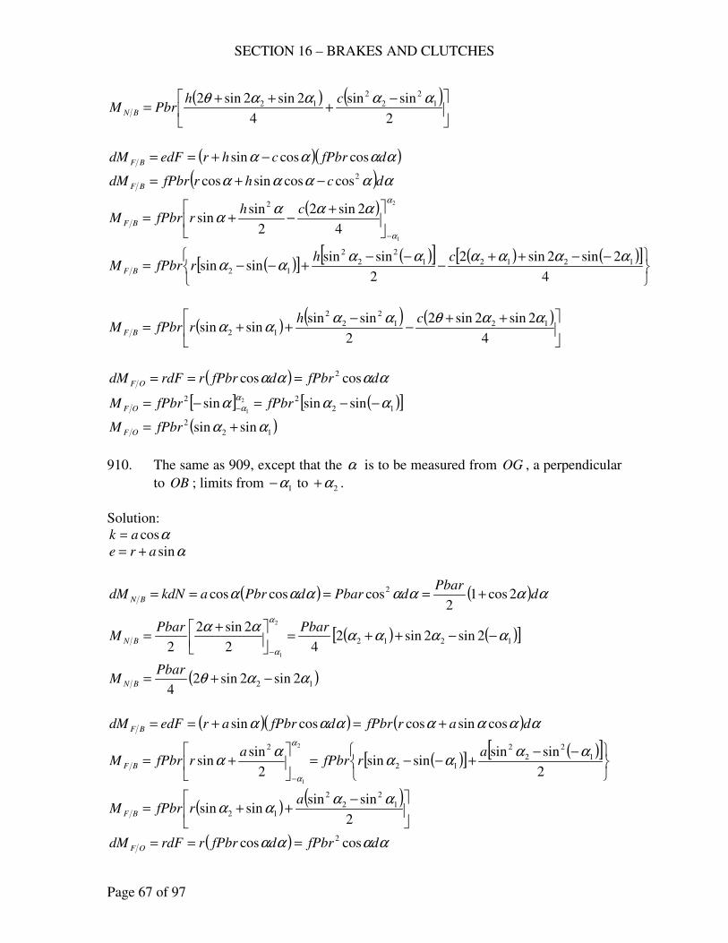
SECTION 16 – BRAKES AND CLUTCHES
Page 67 of 97
( ) ( )
−+
++=
2
sinsin
4
2sin2sin2 1
2
2
2
12 ααααθ chPbrM BN
( )( )αααα dfPbrchredFdM BF coscossin −+==
( ) ααααα dchrfPbrdM BF
2coscossincos −+=
( ) 2
1
4
2sin2
2
sinsin
2α
α
αααα
−
+−+=
chrfPbrM BF
( )[ ] ( )[ ] ( ) ( )[ ]
−−++
−−−
+−−=4
2sin2sin2
2
sinsinsinsin 12121
2
2
2
12
αααααααα
chrfPbrM BF
( ) ( ) ( )
++−
−++=
4
2sin2sin2
2
sinsinsinsin 121
2
2
2
12
ααθαααα
chrfPbrM BF
( ) αααα dfPbrdfPbrrrdFdM OF coscos 2===
[ ] ( )[ ]12
22 sinsinsin 2
1ααα
α
α −−=−= − fPbrfPbrM OF
( )12
2 sinsin αα += fPbrM OF
910. The same as 909, except that the α is to be measured from OG , a perpendicular
to OB ; limits from 1α− to 2α+ .
Solution:
αcosak =
αsinare +=
( ) ( ) ααααααα dPbar
dPbardPbrakdNdM BN 2cos12
coscoscos 2 +====
( ) ( )[ ]1212 2sin2sin242
2sin2
2
2
1
αααααα
α
α
−−++=
+=
−
PbarPbarM BN
( )12 2sin2sin24
ααθ −+=Pbar
M BN
( )( ) ( ) ααααααα darfPbrdfPbraredFdM BF cossincoscossin +=+==
( )[ ] ( )[ ]
−−
+−−=
+=
−2
sinsinsinsin
2
sinsin 1
2
2
2
12
2 2
1
αααα
αα
α
α
arfPbr
arfPbrM BF
( ) ( )
−++=
2
sinsinsinsin 1
2
2
2
12
αααα
arfPbrM BF
( ) αααα dfPbrdfPbrrrdFdM OF coscos 2===
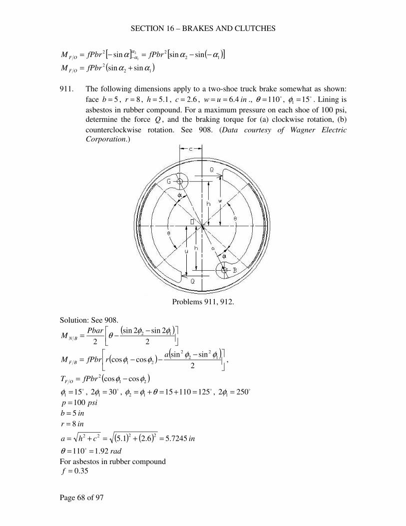
SECTION 16 – BRAKES AND CLUTCHES
Page 68 of 97
[ ] ( )[ ]12
22 sinsinsin 2
1ααα
α
α −−=−= − fPbrfPbrM OF
( )12
2 sinsin αα += fPbrM OF
911. The following dimensions apply to a two-shoe truck brake somewhat as shown:
face 5=b , 8=r , 1.5=h , 6.2=c , inuw 4.6== ., o110=θ , o151 =φ . Lining is
asbestos in rubber compound. For a maximum pressure on each shoe of 100 psi,
determine the force Q , and the braking torque for (a) clockwise rotation, (b)
counterclockwise rotation. See 908. (Data courtesy of Wagner Electric
Corporation.)
Problems 911, 912.
Solution: See 908.
( )
−−=
2
2sin2sin
2
12 φφθ
PbarM BN
( ) ( )
−−−=
2
sinsincoscos 1
2
2
2
21
φφφφ
arfPbrM BF ,
( )21
2 coscos φφ −= fPbrT OF
o151 =φ , o302 1 =φ , o1251101512 =+=+= θφφ , o2502 1 =φ
psip 100=
inb 5=
inr 8=
( ) ( ) incha 7245.56.21.52222 =+=+=
rad92.1110 == oθ
For asbestos in rubber compound
35.0=f
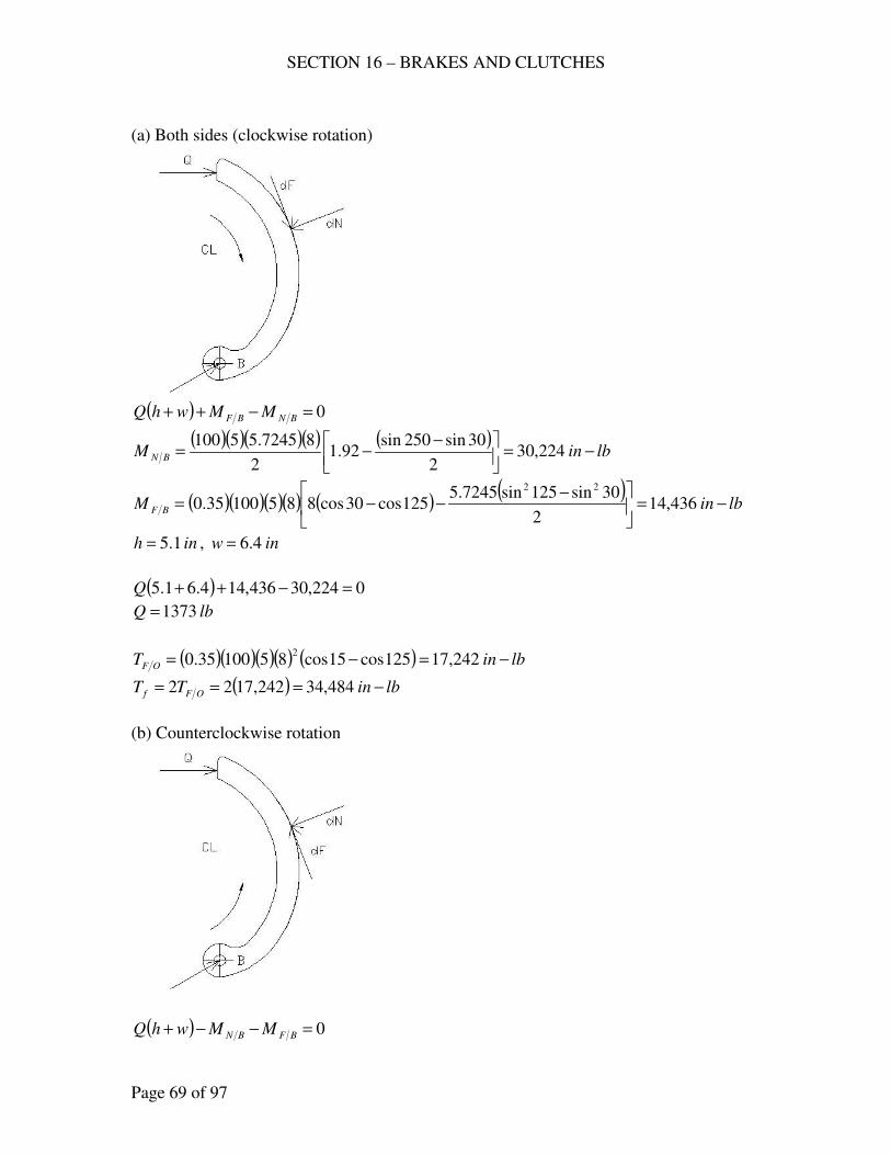
SECTION 16 – BRAKES AND CLUTCHES
Page 69 of 97
(a) Both sides (clockwise rotation)
( ) 0=−++ BNBF MMwhQ
( )( )( )( ) ( )lbinM BN −=
−−= 224,30
2
30sin250sin92.1
2
87245.55100
( )( )( )( ) ( ) ( )lbinM BF −=
−−−= 436,14
2
30sin125sin7245.5125cos30cos88510035.0
22
inh 1.5= , inw 4.6=
( ) 0224,30436,144.61.5 =−++Q
lbQ 1373=
( )( )( )( ) ( ) lbinT OF −=−= 242,17125cos15cos8510035.02
( ) lbinTT OFf −=== 484,34242,1722
(b) Counterclockwise rotation
( ) 0=−−+ BFBN MMwhQ
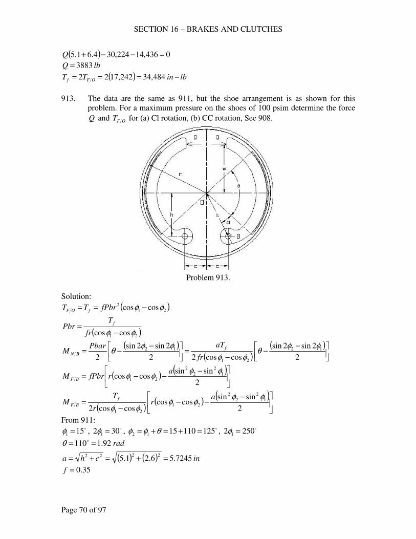
SECTION 16 – BRAKES AND CLUTCHES
Page 70 of 97
( ) 0436,14224,304.61.5 =−−+Q
lbQ 3883=
( ) lbinTT OFf −=== 484,34242,1722
913. The data are the same as 911, but the shoe arrangement is as shown for this
problem. For a maximum pressure on the shoes of 100 psim determine the force
Q and OFT for (a) Cl rotation, (b) CC rotation, See 908.
Problem 913.
Solution:
( )21
2 coscos φφ −== fPbrTT fOF
( )21 coscos φφ −=
fr
TPbr
f
( )( )
( )
−−
−=
−−=
2
2sin2sin
coscos22
2sin2sin
2
12
21
12 φφθ
φφ
φφθ
fr
aTPbarM
f
BN
( ) ( )
−−−=
2
sinsincoscos 1
2
2
2
21
φφφφ
arfPbrM BF
( )( ) ( )
−−−
−=
2
sinsincoscos
coscos2
1
2
2
2
21
21
φφφφ
φφ
ar
r
TM
f
BF
From 911: o151 =φ , o302 1 =φ , o1251101512 =+=+= θφφ , o2502 1 =φ
rad92.1110 == oθ
( ) ( ) incha 7245.56.21.52222 =+=+=
35.0=f
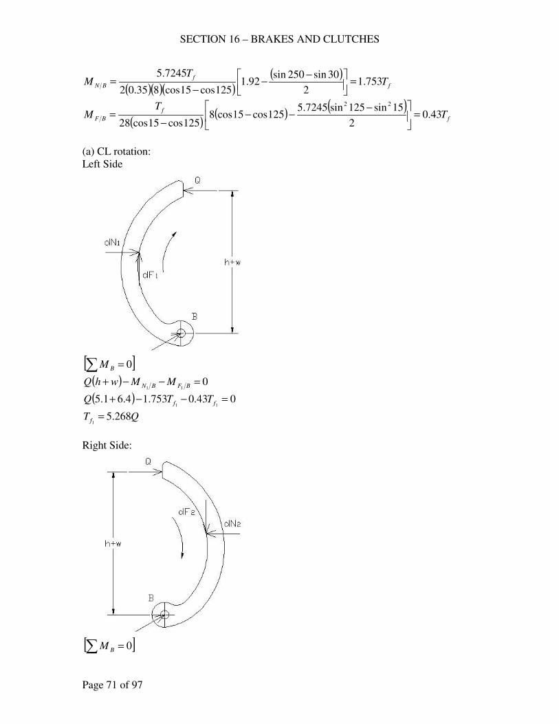
SECTION 16 – BRAKES AND CLUTCHES
Page 71 of 97
( )( )( )( )
f
f
BN TT
M 753.12
30sin250sin92.1
125cos15cos835.02
7245.5=
−−
−=
( )( ) ( )
f
f
BF TT
M 43.02
15sin125sin7245.5125cos15cos8
125cos15cos28
22
=
−−−
−=
(a) CL rotation:
Left Side
[ ]∑ = 0BM
( ) 011
=−−+ BFBN MMwhQ
( ) 043.0753.14.61.511
=−−+ ff TTQ
QT f 268.51
=
Right Side:
[ ]∑ = 0BM
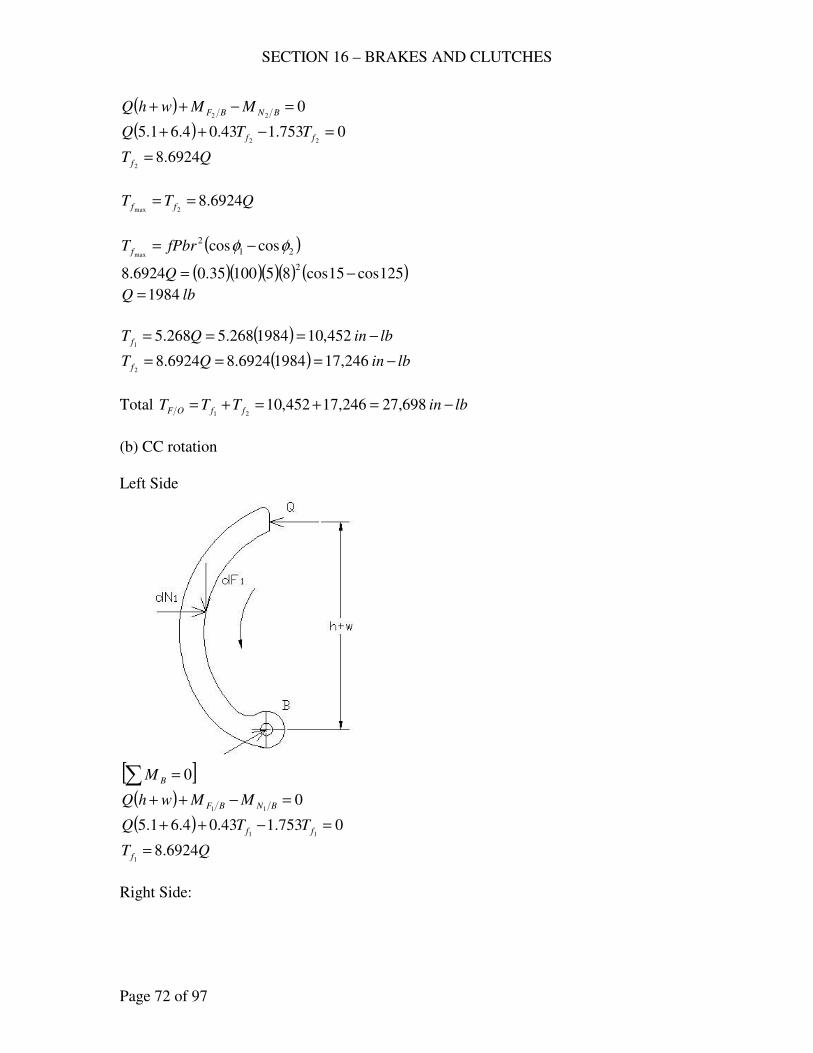
SECTION 16 – BRAKES AND CLUTCHES
Page 72 of 97
( ) 022
=−++ BNBF MMwhQ
( ) 0753.143.04.61.522
=−++ ff TTQ
QT f 6924.82
=
QTT ff 6924.82max
==
( )21
2 coscosmax
φφ −= fPbrT f
( )( )( )( ) ( )125cos15cos8510035.06924.82
−=Q
lbQ 1984=
( ) lbinQT f −=== 452,101984268.5268.51
( ) lbinQT f −=== 246,1719846924.86924.82
Total lbinTTT ffOF −=+=+= 698,27246,17452,1021
(b) CC rotation
Left Side
[ ]∑ = 0BM
( ) 011
=−++ BNBF MMwhQ
( ) 0753.143.04.61.511
=−++ ff TTQ
QT f 6924.81
=
Right Side:
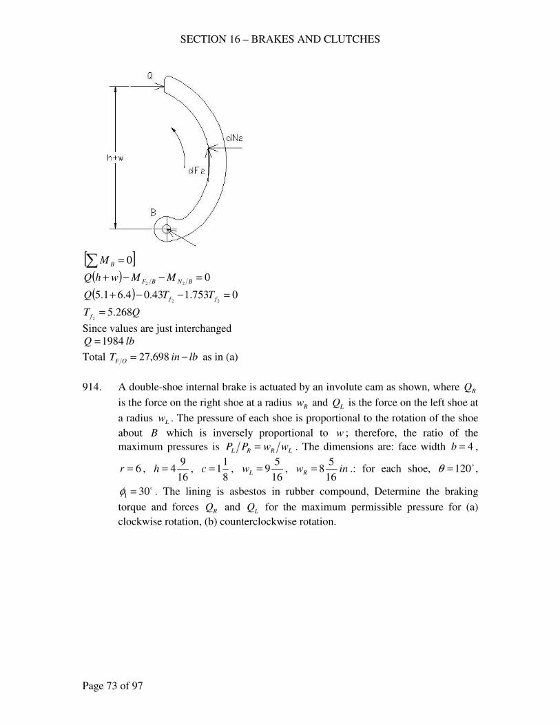
SECTION 16 – BRAKES AND CLUTCHES
Page 73 of 97
[ ]∑ = 0BM
( ) 022
=−−+ BNBF MMwhQ
( ) 0753.143.04.61.522
=−−+ ff TTQ
QT f 268.52
=
Since values are just interchanged
lbQ 1984=
Total lbinT OF −= 698,27 as in (a)
914. A double-shoe internal brake is actuated by an involute cam as shown, where RQ
is the force on the right shoe at a radius Rw and LQ is the force on the left shoe at
a radius Lw . The pressure of each shoe is proportional to the rotation of the shoe
about B which is inversely proportional to w ; therefore, the ratio of the
maximum pressures is LRRL wwPP = . The dimensions are: face width 4=b ,
6=r , 16
94=h ,
8
11=c ,
16
59=Lw , inwR
16
58= .: for each shoe, o120=θ ,
o301 =φ . The lining is asbestos in rubber compound, Determine the braking
torque and forces RQ and LQ for the maximum permissible pressure for (a)
clockwise rotation, (b) counterclockwise rotation.
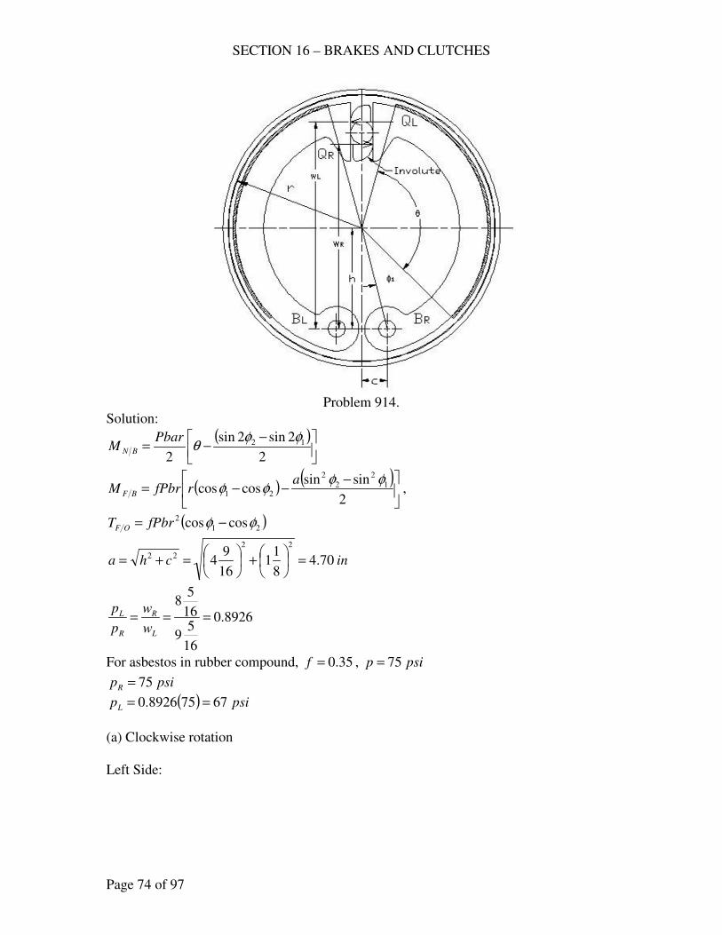
SECTION 16 – BRAKES AND CLUTCHES
Page 74 of 97
Problem 914.
Solution:
( )
−−=
2
2sin2sin
2
12 φφθ
PbarM BN
( ) ( )
−−−=
2
sinsincoscos 1
2
2
2
21
φφφφ
arfPbrM BF ,
( )21
2 coscos φφ −= fPbrT OF
incha 70.48
11
16
94
22
22 =
+
=+=
8926.0
16
59
16
58
===L
R
R
L
w
w
p
p
For asbestos in rubber compound, 35.0=f , psip 75=
psipR 75=
( ) psipL 67758926.0 ==
(a) Clockwise rotation
Left Side:
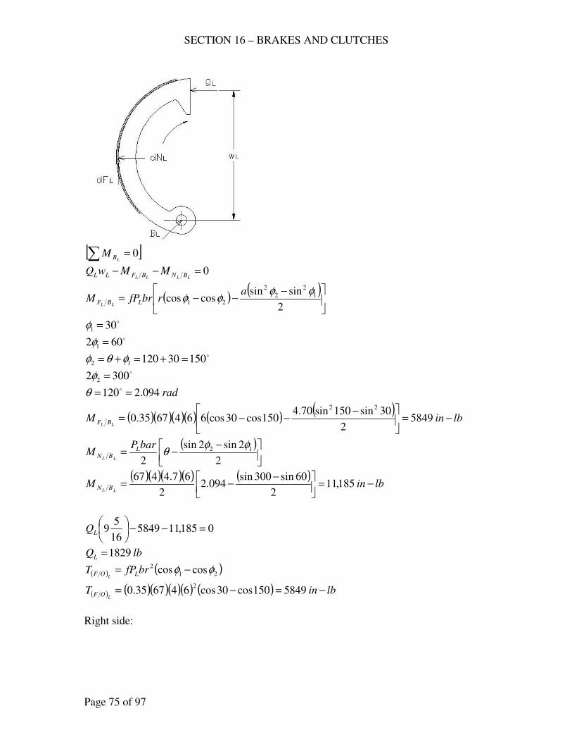
SECTION 16 – BRAKES AND CLUTCHES
Page 75 of 97
[ ]∑ = 0
LBM
0=−−LLLL BNBFLL MMwQ
( ) ( )
−−−=
2
sinsincoscos 1
2
2
2
21
φφφφ
arbrfPM LBF LL
o301 =φ o602 1 =φ
o1503012012 =+=+= φθφ o3002 2 =φ
rad094.2120 == oθ
( )( )( )( ) ( ) ( )lbinM
LL BF −=
−−−= 5849
2
30sin150sin70.4150cos30cos6646735.0
22
( )
−−=
2
2sin2sin
2
12 φφθ
barPM L
BNLL
( )( )( )( ) ( )lbinM
LL BN −=
−−= 185,11
2
60sin300sin094.2
2
67.4467
0185,11584916
59 =−−
LQ
lbQL 1829=
( ) ( )21
2 coscos φφ −= brfPT LOFL
( ) ( )( )( )( ) ( ) lbinTL
OF −=−= 5849150cos30cos646735.02
Right side:
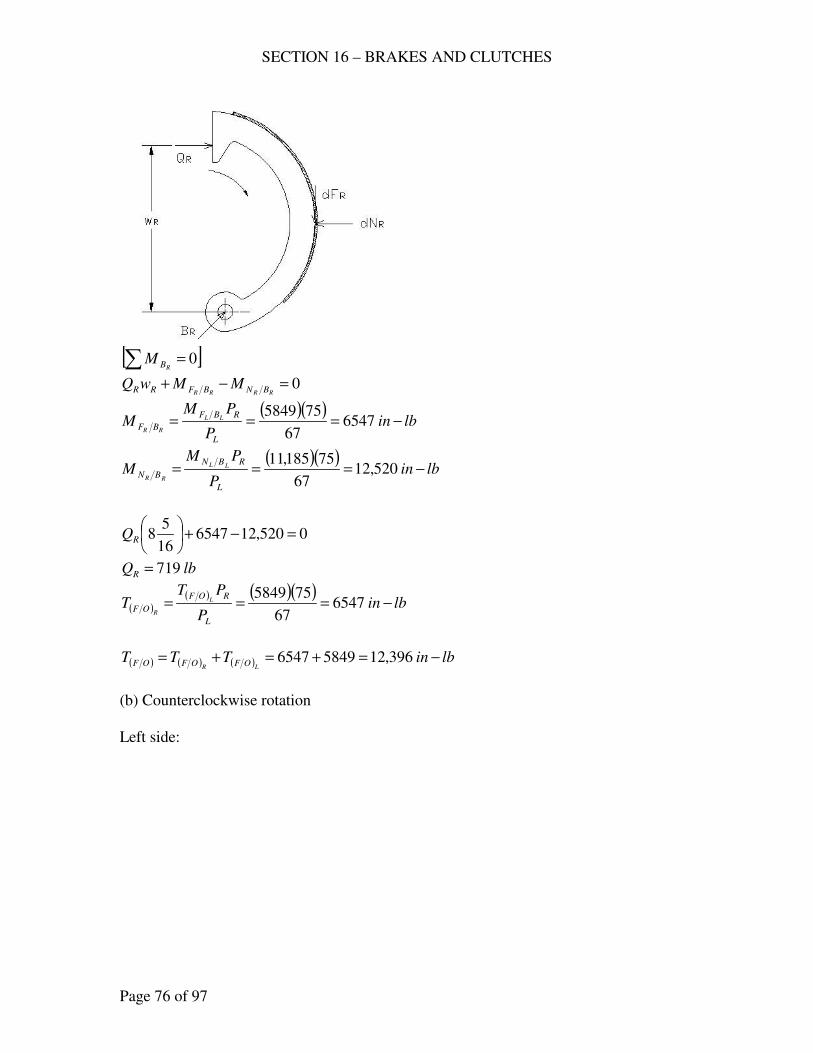
SECTION 16 – BRAKES AND CLUTCHES
Page 76 of 97
[ ]∑ = 0
RBM
0=−+RRRR BNBFRR MMwQ
( )( )lbin
P
PMM
L
RBF
BFLL
RR−=== 6547
67
755849
( )( )lbin
P
PMM
L
RBN
BNLL
RR−=== 520,12
67
75185,11
0520,12654716
58 =−+
RQ
lbQR 719=
( )( ) ( )( )
lbinP
PTT
L
ROF
OFL
R−=== 6547
67
755849
( ) ( ) ( ) lbinTTTLR
OFOFOF −=+=+= 396,1258496547
(b) Counterclockwise rotation
Left side:
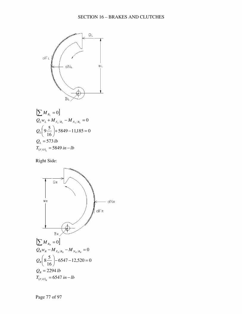
SECTION 16 – BRAKES AND CLUTCHES
Page 77 of 97
[ ]∑ = 0LBM
0=−+LLLL BNBFLL MMwQ
0185,11584916
59 =−+
LQ
lbQL 573=
( ) lbinTL
OF −= 5849
Right Side:
[ ]∑ = 0
RBM
0=−−RRRR BNBFRR MMwQ
0520,12654716
58 =−−
RQ
lbQR 2294=
( ) lbinTR
OF −= 6547
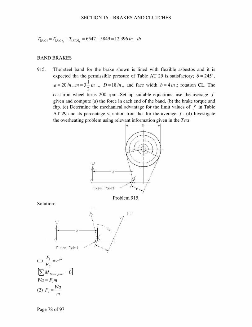
SECTION 16 – BRAKES AND CLUTCHES
Page 78 of 97
( ) ( ) ( ) lbinTTTLR
OFOFOF −=+=+= 396,1258496547
BAND BRAKES
915. The steel band for the brake shown is lined with flexible asbestos and it is
expected tha the permissible pressure of Table AT 29 is satisfactory; o245=θ ,
ina 20= ., inm2
13= ., inD 18= ., and face width inb 4= .; rotation CL. The
cast-iron wheel turns 200 rpm. Set up suitable equations, use the average f
given and compute (a) the force in each end of the band, (b) the brake torque and
fhp. (c) Determine the mechanical advantage for the limit values of f in Table
AT 29 and its percentage variation fron that for the average f . (d) Investigate
the overheating problem using relevant information given in the Text.
Problem 915.
Solution:
(1) θfe
F
F=
2
1
[ ]∑ = 0intpoFixedM
mFWa 2=
(2) m
WaF =2
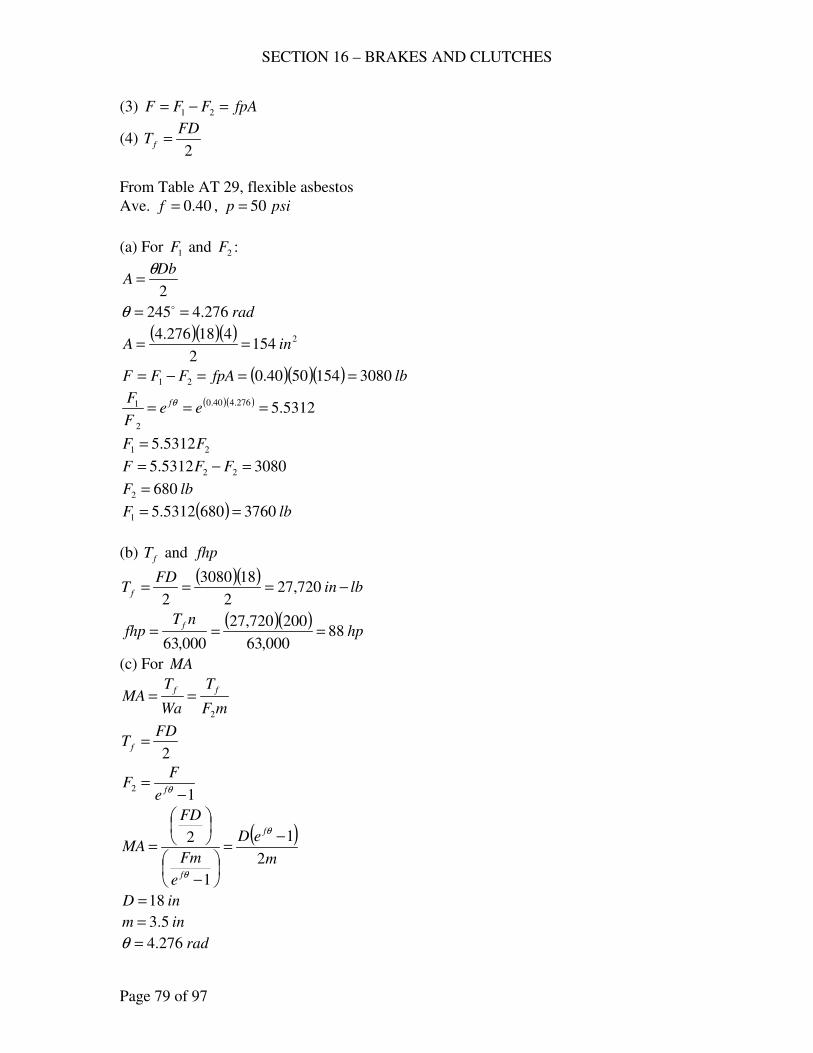
SECTION 16 – BRAKES AND CLUTCHES
Page 79 of 97
(3) fpAFFF =−= 21
(4) 2
FDT f =
From Table AT 29, flexible asbestos
Ave. 40.0=f , psip 50=
(a) For 1F and 2F :
2
DbA
θ=
rad276.4245 == oθ
( )( )( ) 21542
418276.4inA ==
( )( )( ) lbfpAFFF 30801545040.021 ===−=
( )( ) 5312.5276.440.0
2
1 === eeF
F fθ
21 5312.5 FF =
30805312.5 22 =−= FFF
lbF 6802 =
( ) lbF 37606805312.51 ==
(b) fT and fhp
( )( )lbin
FDT f −=== 720,27
2
183080
2
( )( )hp
nTfhp
f88
000,63
200720,27
000,63===
(c) For MA
mF
T
Wa
TMA
ff
2
==
2
FDT f =
12
−=
θfe
FF
( )m
eD
e
Fm
FD
MAf
f
2
1
1
2 −=
−
=θ
θ
inD 18=
inm 5.3=
rad276.4=θ

SECTION 16 – BRAKES AND CLUTCHES
Page 80 of 97
Limit values (Table AT 29) 35.0=f to 45.0 .
35.0=f ( )( )[ ]
( )914.8
5.32
118 276.435.0
=−
=e
MA
45.0=f ( )( )[ ]
( )042.15
5.32
118 276.445.0
=−
=e
MA
with 40.0=f (average) ( )( )[ ]
( )652.11
5.32
118 276.440.0
=−
=e
MA
Percentage variation from 40.0=f .
35.0=f
( ) %5.23%100652.11
914.8652.11var% =
−=
45.0=f
( ) %1.29%100652.11
652.11042.15var% =
−=
(d) Overheating problem
257.0154
88infhp
A
fhp==
Therefore, a problem of overheating is expected as Rasmussen recommends 0.2 to 0.3
fhp per square inch of brake contact area.
916. (a) For the band brake shown, derive the expressions for the braking torque in
terms of W , etc., for CL rotation and for CC rotation, and specify the ratio bc
for equal effectiveness in both directions of rotation. Are there any proportions of
b and c as shown that would result in the brae being self locking? (b) When o270=θ , ina 16= ., incb 3== ., and inD 12= ., it was found that a
force lbW 50= . Produced a frictional torque of 1000 in-lb. Compute the
coefficient of friction.
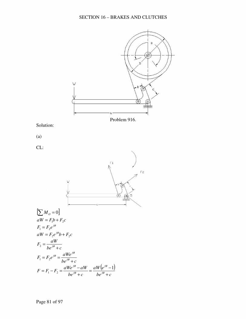
SECTION 16 – BRAKES AND CLUTCHES
Page 81 of 97
Problem 916.
Solution:
(a)
CL:
[ ]∑ = 0OM
cFbFaW 21 += θfeFF 21 =
cFbeFaW f
22 += θ
cbe
aWF
f +=
θ2
cbe
aWeeFF
f
ff
+==
θ
θθ
21
( )cbe
eaW
cbe
aWaWeFFF
f
f
f
f
+
−=
+
−=−=
θ
θ
θ
θ 121
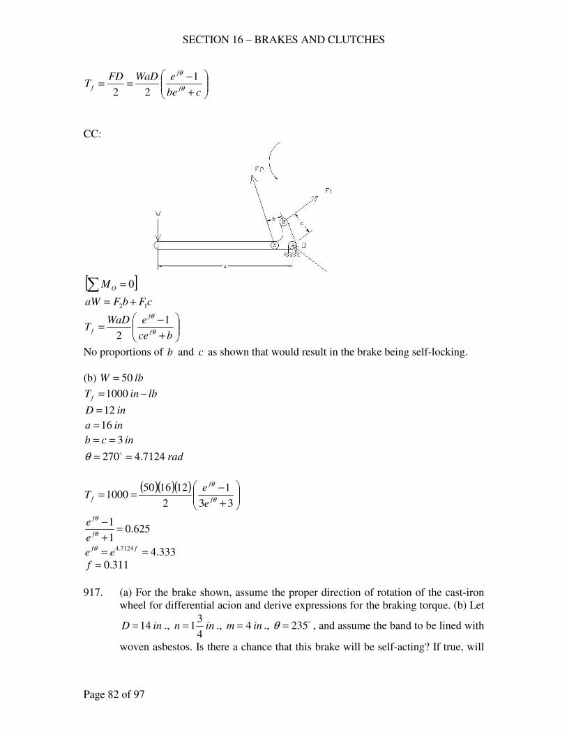
SECTION 16 – BRAKES AND CLUTCHES
Page 82 of 97
+
−==
cbe
eWaDFDT
f
f
f θ
θ 1
22
CC:
[ ]∑ = 0OM
cFbFaW 12 +=
+
−=
bce
eWaDT
f
f
f θ
θ 1
2
No proportions of b and c as shown that would result in the brake being self-locking.
(b) lbW 50=
lbinT f −=1000
inD 12=
ina 16=
incb 3==
rad7124.4270 == oθ
( )( )( )
+
−==
33
1
2
1216501000
θ
θ
f
f
fe
eT
625.01
1=
+
−θ
θ
f
f
e
e
333.47124.4 == ffee
θ
311.0=f
917. (a) For the brake shown, assume the proper direction of rotation of the cast-iron
wheel for differential acion and derive expressions for the braking torque. (b) Let
inD 14= ., inn4
31= ., inm 4= ., o235=θ , and assume the band to be lined with
woven asbestos. Is there a chance that this brake will be self-acting? If true, will
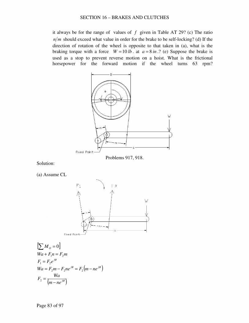
SECTION 16 – BRAKES AND CLUTCHES
Page 83 of 97
it always be for the range of values of f given in Table AT 29? (c) The ratio
mn should exceed what value in order for the brake to be self-locking? (d) If the
direction of rotation of the wheel is opposite to that taken in (a), what is the
braking torque with a force lbW 10= . at ina 8= .? (e) Suppose the brake is
used as a stop to prevent reverse motion on a hoist. What is the frictional
horsepower for the forward motion if the wheel turns 63 rpm?
Problems 917, 918.
Solution:
(a) Assume CL
[ ]∑ = 0OM
mFnFWa 21 =+ θfeFF 21 =
( )θθ ff nemFneFmFWa −=−= 222
( )θfnem
WaF
−=2
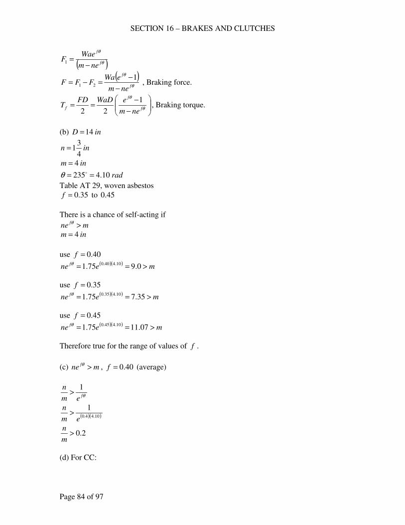
SECTION 16 – BRAKES AND CLUTCHES
Page 84 of 97
( )θ
θ
f
f
nem
WaeF
−=1
( )θ
θ
f
f
nem
eWaFFF
−
−=−=
121 , Braking force.
−
−==
θ
θ
f
f
fnem
eWaDFDT
1
22, Braking torque.
(b) inD 14=
inn4
31=
inm 4=
rad10.4235 == oθ
Table AT 29, woven asbestos
35.0=f to 45.0
There is a chance of self-acting if
mnef >θ
inm 4=
use 40.0=f ( )( )
menef >== 0.975.1 10.440.0θ
use 35.0=f ( )( )
menef >== 35.775.1 10.435.0θ
use 45.0=f ( )( )
menef >== 07.1175.1 10.445.0θ
Therefore true for the range of values of f .
(c) mnef >θ , 40.0=f (average)
θfem
n 1>
( )( )10.44.0
1
em
n>
2.0>m
n
(d) For CC:
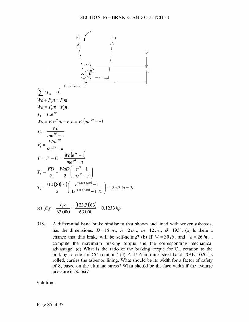
SECTION 16 – BRAKES AND CLUTCHES
Page 85 of 97
[ ]∑ = 0OM
mFnFWa 12 =+
nFmFWa 21 −= θfeFF 21 =
( )nmeFnFmeFWa ff −=−= θθ222
nme
WaF
f −=
θ2
nme
WaeF
f
f
−=
θ
θ
1
( )nme
eWaFFF
f
f
−
−=−=
θ
θ 121
−
−==
nme
eWaDFDT
f
f
f θ
θ 1
22
( )( )( ) ( )( )
( )( ) lbine
eT f −=
−
−= 3.123
75.14
1
2
1481010.440.0
10.440.0
(e) ( )( )
hpnT
fhpf
1233.0000,63
633.123
000,63===
918. A differential band brake similar to that shown and lined with woven asbestos,
has the dimensions: inD 18= ., inn 2= ., inm 12= ., o195=θ . (a) Is there a
chance that this brake will be self-acting? (b) If lbW 30= . and ina 26= . ,
compute the maximum braking torque and the corresponding mechanical
advantage. (c) What is the ratio of the braking torque for CL rotation to the
braking torque for CC rotation? (d) A 1/16-in.-thick steel band, SAE 1020 as
rolled, carries the asbestos lining. What should be its width for a factor of safety
of 8, based on the ultimate stress? What should be the face width if the average
pressure is 50 psi?
Solution:
SECTION 16 – BRAKES AND CLUTCHES
Page 86 of 97
(a) For CL:
mnef >θ
rad4.3195 == oθ
inm 12=
inn 2=
4.0=f
( )
me <= 8.72 4.34.0 , not self-acting
For CC: θf
men >
nmef <θ
( )ne >= 8.4612 4.34.0 , not self-acting
Therefore, there is no change that this brake will be self-acting.
(b) ff TT =max
(CL)
( )( )( ) ( )
( ) lbine
e
nem
eWadT
f
f
f −=
−
−
=
−
−
= 4832
212
1
2
1826301
2 4.34.0
4.34.0
θ
θ
( )( )2.6
2630
4832===
Wa
TMA
f
(c) ( ) lbinCLT f −= 4832
( ) ( )( )( ) ( )
( ) lbine
e
nme
eWadCCT
f
f
f −=
−
−
=
−
−
= 454
212
1
2
1826301
2 4.34.0
4.34.0
θ
θ
( )( )
64.10454
4832===
CCT
CLTRatio
f
f
(d) For SAE 1020, as rolled.
ksisu 65=
psiksiN
ss u 8125125.8
8
65====
bt
Fs 1=
inint 0625.016
1==
max. θ
θ
f
f
nem
WaeF
−=1 (CL)
( )( ) ( )
( ) lbe
eF 3.722
212
26304.34.0
4.34.0
1 =−
=
SECTION 16 – BRAKES AND CLUTCHES
Page 87 of 97
( )0625.0
3.7228125
bs ==
inb 422.1=
With psip 50=
fpAF =
2
bDA
θ=
max. ( ) ( )( ) ( )( )
( ) lbe
e
nem
eWaF
f
f
9.536212
1263014.34.0
4.34.0
=−
−=
−
−=
θ
θ
2
bDfpF
θ=
( )( )( )( )( )2
184.3504.09.536
b=
inb 88.0=
919. A differential band brake is to be design to absorb 10 fhp at 250 rpm. (a)
Compute the maximum and minimum diameters from both equations (z) and (a),
p. 495, Text. Decide on a size. (b) The band is to be lined with woven asbestos.
The Rasmussen recommendation (§18.4) will help in deciding on the face width.
Also check the permissible pressure in Table AT 29. Choose dimensions of the
lever, its location and shape and the corresponding θ . Be sure the brake is not
self locking. What is the percentage variation of the mechanical advantage from
the minimum value ( minf ) for the f limits in Table AT 29?
Solution:
( )lbin
n
hpT f −=== 2520
250
10000,63000,63
(a) Eq. (z)
inT
Df
96.75
2520
5
3
1
3
1
min =
=
=
inT
Df
57.84
2520
4
3
1
3
1
max =
=
=
Eq. (a)
( ) ( )[ ] infhpD 44.8106060 3
1
3
1
min ===
( ) ( )[ ] infhpD 28.9108080 3
1
3
1
min ===
use inD 5.8=
(b) By Rasmussen
Energy absorption capacity = 0.2 to 0.3 fhp per sq. in. of brake contact area.
SECTION 16 – BRAKES AND CLUTCHES
Page 88 of 97
Say 0.25 fhp per sq. in.
2
bDA
θ=
hpfhp 10=
inD 5.8=
assume radπθ == o180
A
fhpinfhp =2
( )
=
2
5.8
1025.0
bπ
inb 3=
From Table AT 29, 40.0=f , psipper 50. =
fA
Fp =
( )( ) 2402
5.83inA ==
π
( )lb
D
TF
f593
5.8
252022===
( )psipsip 501.37
404.0
593<== (OK)
For MA :
( )( )θ
θ
f
ff
bec
eD
WA
TMA
−
−==
2
1
Not self-locking θf
bec >
θfe
b
c>
π4.0e
b
c>
5.3>b
c
say 4=b
c or bc 4=
For 40.0=f
( )( )
( )( ) bbeb
e
bec
eD
WA
TMA
f
ff 96.21
42
15.8
2
14.0
4.0
=−
−=
−
−==
π
π
θ
θ
For min35.0 ff ==
SECTION 16 – BRAKES AND CLUTCHES
Page 89 of 97
( )( )
( )( ) bbeb
e
bec
eD
WA
TMA
f
ff 54.8
42
15.8
2
135.0
35.0
=−
−=
−
−==
π
π
θ
θ
( ) %157%10054.8
54.896.21% =
−=iationvar
DISK CLUTCHES
920. An automobile engine develops its maximum brake torque at 2800 rpm when the
bhp = 200. A design value of 25.0=f is expected to be reasonable for the
asbestos facing and it is desired that the mean diameter not exceed 8.5 in.;
permissible pressure is 35 psi. Designing for a single plate clutch, Fig. 18.10,
Text, determine the outer and inner diameters of the disk.
Solution:
( ) inDDD iom 5.82
1=+=
inrr io 5.8=+
( )lbin
n
hpT f −=== 4500
2800
200000,63000,63
psip 35=
( )2
iof
rrNfT
+=
( )( )( )2
5.825.04500
N=
lbN 4235=
ave. ( )22
io rr
Np
−=
π
( )22
423535
io rr −=
π
5.3822 =− io rr
io rr −= 5.8
( ) 5.385.8 22=−− ii rr
5.381725.72 22 =−+− iii rrr
inri 985.1=
say inri 0.2=
inro 5.60.25.8 =−=
( ) inrD oo 135.622 ===
( ) inrD ii 40.222 ===
SECTION 16 – BRAKES AND CLUTCHES
Page 90 of 97
921. An automobile engine can develop a maximum brake torque of 2448 in-lb.
Which of the following plate clutches, which make up a manufacturer’s standard
“line,” should be chosen for this car? Facing sizes: (a) 8
78=oD , inDi
8
16= ., (b)
10=oD , inDi8
16= ., (c)
16
111=oD , inDi
8
16= . In each case, assume 3.0=f .
The unit pressures are (a) 34 psi, (b) 30 psi, and (c) 26.2 psi.
Solution:
( )2
iof
rrNfT
+=
( )4
iof
DDNfT
+=
( )22
4ioave DDpN −
=
π
( )( )16
22
ioioavef
DDDDpT
+−=
π
(a) inDo 875.8= ; inDi 125.6= , psip 34= , 3.0=f
( )( )16
22
ioioavef
DDDDpT
+−=
π
( )( ) ( ) ( )[ ]( )lbinT f −=
+−= 1239
16
125.6875.8125.6875.8343.022
π
(b) inDo 10= ; inDi 125.6= , psip 30= , 3.0=f
( )( )16
22
ioioavef
DDDDpT
+−=
π
( )( ) ( ) ( )[ ]( )lbinT f −=
+−= 1780
16
125.610125.610303.022
π
(c) inDo 0625.11= ; inDi 125.6= , psip 2.26= , 3.0=f
( )( )16
22
ioioavef
DDDDpT
+−=
π
( )( ) ( ) ( )[ ]( )lbinT f −=
+−= 2251
16
125.60625.11125.60625.112.263.022
π
use (c)
SECTION 16 – BRAKES AND CLUTCHES
Page 91 of 97
922. A single-disk clutch for an industrial application, similar to that in Fig. 18.11,
Text, except that there are two disks attached to one shaft and one attached to the
other. The clutch is rated at 50 hp at 500 rpm. The asbestos-in-resin-binder facing
has a inDo2
18= . and inDi
4
34= . What must be the axial force and average
pressure? How does this pressure compare with that recommended by Table AT
29?
Solution:
2=n pairs in contact
35.0=f (Table AT 29)
psip 75=
( )lbin
n
hpT
m
f −=== 6300500
50000,63000,63
inDo 5.8=
inDi 75.4=
( )2
iof
rrNnfT
+=
( )4
iof
DDNnfT
+=
( )( )( )( )4
75.45.835.026300
+=
N
lbN 2717=
ave. ( )
( )( ) ( )[ ] psipsi
DD
Np
io
756.6975.45.8
2717442222
<=−
=−
=ππ
923. A multiple-disk clutch similar to Fig. 18.11, Text, is rated at 22 hp at 100 rpm.
The outside and inside diameters of the disks are 14 and 7 ½ in., respectively. If
25.0=f , find (a) the axial force required to transmit the rated load, and (b) the
unit pressure between the disks.
Solution:
(a) Fig. 18-11, 4=n pairs in contact
( )lbin
n
hpT
m
f −=== 860,13100
22000,63000,63
( )4
iof
DDNnfT
+=
inDo 14=
inDi 5.7=
( )( )( )4
5.71425.04860,13
+=
N
SECTION 16 – BRAKES AND CLUTCHES
Page 92 of 97
lbN 2579=
(b) ( )
( )( ) ( )[ ] psi
DD
Np
io
5.235.714
2579442222
=−
=−
=ππ
924. A multiple-disk clutch for a machine tool operation has 4 phosphor-bronze
driving disks and 5 hardened-steel driven disks. This clutch is rated at 5.8 hp at
100 rpm when operated dry. The outside and inside diameters of the disks are 5
½ and 4 3/16 in., respectively. (a) If the pressure between the disks is that
recommended for metal on metal in Table AT 29, what coefficient of friction is
required to transmit the rated power? (b) What power may be transmitted for f
and p as recommended in Table AT 29?
Solution:
inDo 5.5=
inDi 1875.4=
( )lbin
n
hpT
m
f −=== 3654100
8.5000,63000,63
8=n pairs in contact
(a) Table AT 29, psip 150= , metal to metal
( )4
iof
DDNnfT
+=
( ) ( ) ( )[ ] lbDDpN io 14981875.45.54
1504
2222 =−
=−
=
ππ
( )( )( )( )4
1875.45.5149883654
+==
fT f
126.0=f
(b) from Table AT 29, psip 150= , 2.0=f
( )( )( )( )lbinT f −=
+= 5805
4
1875.45.514982.08
( )( )hp
nThp
mf2.9
000,63
1005805
000,63===
925. A multiple-disk clutch with three disks on one shaft and two on the other, similar
to that in Fig. 18.11, Text, is rated at 53 hp at 500 rpm. (a) What is the largest
value of iD if f and p are given by Table AT 29 for asbestos in resin binder
and inDo 5.10= . (b) For the diameter used of inDi 7= .,what is the required
axial force and the average pressure?
Solution:
SECTION 16 – BRAKES AND CLUTCHES
Page 93 of 97
Table AT 29, asbestos in resin binder, 3.0=f , psip 75=
( )2
iof
rrNnfT
+=
( )4
iof
DDNnfT
+=
( )io
f
DDnf
TN
+=
4
but
( )22
4io DDpN −
=
π
( )( )ioiof DDDDnfpT +−
= 22
44
π
( )lbin
n
hpT
m
f −=== 6678500
53000,63000,63
4=n pairs in contact
( )( )ioiof DDDDnfpT +−
= 22
44
π
( ) ( )( )( ) ( )[ ]( )ii DD +−
= 5.105.10
4753.0466784 22π
inDi 5607.9=
(b) inDi 7=
( )4
iof
DDNnfT
+=
( )( )( )( )4
75.103.046678
+=
N
lbN 1272=
ave. ( )
( )( ) ( )[ ] psi
DD
Np
io
44.2675.10
1272442222
=−
=−
=ππ
MISCELLANEOUS CLUTCHES AND BRAKES
926. For the cone brake shown, find an expression for the braking torque for a given
applied force W on the bell crank. Consider the force F ′ , Fig. 18.12, Text, in
obtaining the expression.
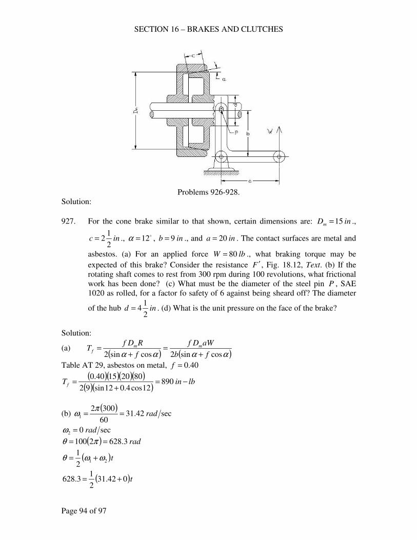
SECTION 16 – BRAKES AND CLUTCHES
Page 94 of 97
Problems 926-928.
Solution:
927. For the cone brake similar to that shown, certain dimensions are: inDm 15= .,
inc2
12= ., o12=α , inb 9= ., and ina 20= . The contact surfaces are metal and
asbestos. (a) For an applied force lbW 80= ., what braking torque may be
expected of this brake? Consider the resistance F ′ , Fig. 18.12, Text. (b) If the
rotating shaft comes to rest from 300 rpm during 100 revolutions, what frictional
work has been done? (c) What must be the diameter of the steel pin P , SAE
1020 as rolled, for a factor fo safety of 6 against being sheard off? The diameter
of the hub ind2
14= . (d) What is the unit pressure on the face of the brake?
Solution:
(a) ( ) ( )αααα cossin2cossin2 fb
aWDf
f
RDfT mm
f+
=+
=
Table AT 29, asbestos on metal, 40.0=f
( )( )( )( )( )( )
lbinT f −=+
= 89012cos4.012sin92
80201540.0
(b) ( )
sec42.3160
30021 rad==
πω
sec02 rad=ω
( ) rad3.6282100 == πθ
( )t212
1ωωθ +=
( )t042.312
13.628 +=
SECTION 16 – BRAKES AND CLUTCHES
Page 95 of 97
sec40=t
( ) rpmnm 15003002
1=+=
( )( )hp
nTfhp
mf119.2
000,63
150890
000,63===
( )( ) ( )( ) lbfttfhpU f −=== 618,4640119.2550550
(c) For SAE 1020, as rolled,
ksissu 49=
ksiN
ss su
s 17.86
49===
2
4
d
Rss
π=
( )( )lb
b
aWR 8.177
9
8020===
( )2
8.17748170
dss
π==
ind 1665.0=
say ind16
3=
(d) cD
Np
mπ=
lbf
RN 297
12cos4.012sin
8.177
cossin=
+=
+=
αα
( )( )psip 52.2
5.215
297==
π
928. A cone clutch for industrial use is to transmit 15 hp at 400 rpm. The mean
diameter of the clutch is 10 in. and the face angle o10=α ; let 3.0=f for the
cast-iron cup and the asbestos lined cone; permissible psip 35= . Compute (a)
the needed axial force, (b) the face width, (c) the minimum axial force to achieve
engagement under load.
Solution:
( )lbin
n
hpT f −=== 5.2362
400
15000,63000,63
(a) ( )αα cossin2 f
RDfT m
f+
=
SECTION 16 – BRAKES AND CLUTCHES
Page 96 of 97
( )( )( )10cos3.010sin2
103.05.2362
+=
R
lbR 739=
(b) cD
Np
mπ=
lbf
RN 1575
10cos3.010sin
739
cossin=
+=
+=
αα
( )c15
157535
π=
inc 44.1=
(c) max. 4.0=f (Table AT 29)
( )αα cossin2 f
RDfT m
f+
=
( )( )( )10cos4.010sin2
104.05.2362
+=
R
lbR 670= , minimum.
929. An “Airflex” clutch, Fig. 18.15, Text, has a 16-in drum with a 5-in. face. This
clutch is rated at 110 hp at 100 rpm with an air pressure of 75 psi. What must be
the coefficient of friction if the effect of centrifugal force is neglected? (Data
courtesy of Federal Fawick Corporation.)
Solution:
inD 16=
inb 5=
hphp 110=
rpmrpm 100=
psip 75=
( )lbin
n
hpT f −=== 300,69
100
110000,63000,63
2
FDT f =
( )2
16300,69
F=
lbF 5.8662=
( ) ( )( )( )( ) lbDbpN 850,1851675 === ππ
46.0850,18
5.8662===
N
Ff
SECTION 16 – BRAKES AND CLUTCHES
Page 97 of 97
930. The same as 929 except that the diameter is 6 in., the face width is 2 in., and the
rated horsepower is 3.
Solution:
( )lbin
n
hpT f −=== 1890
100
3000,63000,63
2
FDT f =
( )2
6300,69
F=
lbF 630=
( ) ( )( )( )( ) lbDbpN 28272675 === ππ
22.02827
630===
N
Ff
- end -
SECTION 18 – MISCELLANEOUS PROBLEMS
Page 1 of 25
THIN SHELLS, EXTERNAL PRESSURE
981. A closed cylindrical tank is used for a steam heater. The inner shell, 200 in.
outside diameter and 50 ft. long, is subjected to an external pressure of 40 psi.
The material is equivalent to SA 30 (ASME Pressure-Vessel Code: min.
ksisu 55= ); assume an elastic limit of 2uy ss = ; let 5=N . (a) What thickness
of shell is needed from a stress standpoint? (b) For this thickness, what must be
the maximum length of unsupported section to insure against collapse? (c)
Choose a spacing L to give a symmetric arrangement and determine the moment
of inertia of the steel stiffening rings. (d) For a similar problem, the Code
recommends that int 76.0≥ , inL 50= , and 496 inI = . How do these values
check with those obtained above? (e) Without stiffening rings, what thickness
would be needed?
Solution:
(a) Solving for the thickness of shell,
y
c
s
Dpt
2=
( ) psippc 2004055 ===
psis
s uy 500,27
2
000,55
2===
inD 200=
( )( )( )
ins
Dpt
y
c 73.0500,272
200200
2===
say int 75.0=
(b) Solving for the maximum length of unsupported section, use Eq. (20-1)
psi
D
t
D
L
D
tE
pc
2
1
2
5
45.0
60.2
−
=
2
12
5
45.0
60.2
+
=D
t
p
D
tE
D
L
c
psiE 61030×=
psipc 200=
int 75.0=
SECTION 18 – MISCELLANEOUS PROBLEMS
Page 2 of 25
inD 200=
( )2
12
5
6
200
75.045.0
200
200
75.0103060.2
200
+
×
=L
inL 68.72=
(c) Solving for the moment of inertia of the steel stiffening rings.
Choosing inL 60= for 50 ft long shell
( ) ( )( ) 4
6
33
1121030
20060200035.0035.0in
E
LpDI c =
×==
(d) For int 76.0≥ - above minimum
inL 50= - below maximum 496 inI = - lighter than above.
(e) inftL 60050 ==
Solving for thickness without stiffening rings
By Saunders and Windenburg, Eq. 20-1
psi
D
t
D
L
D
tE
pc
2
1
2
5
45.0
60.2
−
=
E
D
t
D
Lp
D
tc
60.2
45.02
1
2
5
−
=
( )6
2
1
2
5
103060.2
20045.0
200
600200
200 ×
−
=
t
t
2
1
2
5
364.6600886.137 tt −=
600364.6886.137 2
1
2
5
=+ tt
int 791.1=
SECTION 18 – MISCELLANEOUS PROBLEMS
Page 3 of 25
say int16
131=
982. The same as 981, except that psip 175= , ftD 4= , and the length of the tank is
18 ft.
(a) Solving for the thickness of shell,
y
c
s
Dpt
2=
( ) psippc 87517555 ===
psis
s uy 500,27
2
000,55
2===
inftD 484 ==
( )( )( )
ins
Dpt
y
c 53.1500,272
48875
2===
say int 5625.116
91 ==
(b) Solving for the maximum length of unsupported section, use Eq. (20-1)
psi
D
t
D
L
D
tE
pc
2
1
2
5
45.0
60.2
−
=
2
12
5
45.0
60.2
+
=D
t
p
D
tE
D
L
c
psiE 61030×=
psipc 875=
int 5625.1=
inD 48=
( )2
12
5
6
48
5625.145.0
875
48
5625.1103060.2
48
+
×
=L
inL 822=
(c) Since length of shell = 18 ft = 216 in < 822 in, there is no need for stiffeners.
SECTION 18 – MISCELLANEOUS PROBLEMS
Page 4 of 25
(d) inL 216=
Solving for thickness without stiffening rings
By Saunders and Windenburg, Eq. 20-1
psi
D
t
D
L
D
tE
pc
2
1
2
5
45.0
60.2
−
=
E
D
t
D
Lp
D
tc
60.2
45.02
1
2
5
−
=
( )6
2
1
2
5
103060.2
4845.0
48
216875
48 ×
−
=
t
t
2
1
2
5
833.565.3937428.4886 tt −=
5.3937833.56428.4886 2
1
2
5
=+ tt
int 9122.0=
say int16
15=
but minimum int16
191=
use int16
191=
Approximate ratio of weight of this shell to the weight of the shell found in (a) =
thickness of shell without stiffening rings / thickness of shell with stiffening rings
= 0.34375 / 0.09375 = 3.6667
STEEL TUBES, EXTERNAL PRESSURE
983. A closed cylindrical tank, 6 ft in diameter, 10 ft long, is subjected to an internal
pressure of 1 psi absolute. The atmospheric pressure on the outside is 14.7 psi.
The material is equivalent to SA 30 (ASME Pressure Vessel Code:
min ksisu 55= ); assume an elastic limit of 2uy ss = ; let 5=ppc . (a) What
thickness of shell is needed for the specified design stress? (b) For this thickness,
what must be the maximum length of unsupported section to insure against
collapse? (c) Choose a symmetric spacing L of stiffening rings, and compute
SECTION 18 – MISCELLANEOUS PROBLEMS
Page 5 of 25
their moment of inertia and the cross-sectional dimensions h and b if they are
rectangular with bh 2= . (d) Suppose that the tank had no stiffening rings. What
thickness of shell would be needed? What is the approximate ratio of the weight
of the shell found in (a)? Material costs are roughly proportional to the weight.
Solution:
(a) Solving for the thickness of shell
y
c
s
Dpt
2=
( ) psippc 5.6817.1455 =−==
psis
s uy 500,27
2
000,55
2===
inftD 726 ==
( )( )( )
ins
Dpt
y
c 08967.0500,272
725.68
2===
say int 09375.032
3==
(b) Solving for the maximum length of unsupported section, use Eq. (20-1)
psi
D
t
D
L
D
tE
pc
2
1
2
5
45.0
60.2
−
=
2
12
5
45.0
60.2
+
=D
t
p
D
tE
D
L
c
psiE 61030×=
psipc 5.68=
int 09375.0=
inD 72=
( )2
12
5
6
72
09375.045.0
5.68
72
09375.0103060.2
72
+
×
=L
inL 2.6=
(c) For the length of shell = 10 ft = 120 in.
use inL 0.6=
SECTION 18 – MISCELLANEOUS PROBLEMS
Page 6 of 25
Moment of inertia of stiffening rings.
( ) ( )( ) 4
6
33
1790.01030
5.68672035.0035.0in
E
LpDI c =
×==
Solving for cross-sectional dimension
bh 2=
4443
1790.03
2
12
8
12in
bbbhI ====
inb 72.0=
say inb4
3=
inh2
11
4
32 =
=
(d) inftL 12010 ==
Solving for thickness without stiffening rings
By Saunders and Windenburg, Eq. 20-1
psi
D
t
D
L
D
tE
pc
2
1
2
5
45.0
60.2
−
=
E
D
t
D
Lp
D
tc
60.2
45.02
1
2
5
−
=
( )6
2
1
2
5
103060.2
7245.0
72
1205.68
72 ×
−
=
t
t
2
1
2
5
053.0667.18865.25 tt −=
667.1053.08865.25 2
1
2
5
=+ tt
int 3314.0=
say inint 34375.032
11==
SECTION 18 – MISCELLANEOUS PROBLEMS
Page 7 of 25
984. A long lap-welded steel tube, 8-in. OD, is to withstand an external pressure of
120 psi. with 5=N . (a) What should be the thickness of the wall of the tube? (b)
What is the ratio tD ? Is it within the range of the Stewart equation? (c)
Assuming the internal pressure to be negligible relative to the external pressure,
calculate the maximum principal stress from equation (8.13), p. 255, text. What
design factor is given by this stress compared with ys for AISI C1015 annealed?
(d) Compute the stress from the thin shell formula.
Solution:
(a) Solving for the thickness of the wall
Stewart’s formula 3
000,200,50
=
D
tpc
( )( ) psiNppc 6001205 ===
3
8000,200,50600
=
t
int 1829.0=
say inint 1875.016
3==
(b) ratio 67.421875.0
8==
t
D
or tD 67.42=
outside the range of the Steward equation ( tD 40< )
(c) Using eq. (8.13) (Lame’s formula)
( )22
22222
io
oioiooiit
rr
rpprrrprp
−
−+−=σ
psipo 120=
0≈ip
inOD
ro 42
8
2===
inri 8125.31875.04 =−=
irr =
( ) ( )( )( ) ( )
psirr
rp
rr
prrp
io
oo
io
oooot 2621
8125.34
412022022
2
22
2
22
22
−=−
−=
−
−=
−
−+−=σ
ys of AISI C1015, annealed = 42 ksi
SECTION 18 – MISCELLANEOUS PROBLEMS
Page 8 of 25
Design factor, 162621
000,42===
t
y
y
sN
σ
(d) Solving for the stress from the thin shell formula
( )( )( )
psit
pDs 2560
1875.02
8120
2===
985. A long lap-welded steel tube, 3 –in. OD, is to withstand an external pressure of
150 psi with 5=N . Parts (a) – (c) are the same as in 984.
Solution:
(a) Solving for the thickness of the wall
Stewart’s equation 3
000,200,50
=
D
tpc
( )( ) psiNppc 7501505 ===
3
3000,200,50750
=
t
int 074.0=
say inint 078125.064
5==
(b) ratio 4.38078125.0
3==
t
D
or tD 4.38=
within the range of the Steward equation ( tD 40< )
(c) Using eq. (8.13) (Lame’s formula)
psipo 150=
inOD
ro 5.12
3
2===
inri 421875.1078125.05.1 =−=
( )( )( ) ( )
psirr
rp
io
oot 2957
421875.15.1
5.11502222
2
22
2
−=−
−=
−
−=σ
ys of AISI C1015, annealed = 42 ksi
Design factor, 2.142927
000,42===
t
y
y
sN
σ
SECTION 18 – MISCELLANEOUS PROBLEMS
Page 9 of 25
986. A long lap-welded tube, 3-in. OD, is made of SAE 1015, annealed. Let the shell
thickness 40Dt = and 5=N . (a) What is the corresponding safe external
pressure? (b) Compute the maximum principal stress (p. 255, Text), assuming a
negligible internal pressure. What design factor is given by this stress compared
with ys ? (c) Compare with stress computed from the thin-shell formula.
Solution:
(a) Solving for safe external pressure,
3
000,200,50
=
D
tpc
40
1=
D
t
psipc 78440
1000,200,50
3
=
=
psiN
pp c 157
5
784===
(b) Solving for maximum principal stress, neglecting internal pressure
psipo 157=
inOD
ro 5.12
3
2===
inD
t 075.040
3
40===
inri 425.1075.05.1 =−=
( )( )( ) ( )
psirr
rp
io
oot 3221
425.15.1
5.11572222
2
22
2
−=−
−=
−
−=σ
ys of SAE 1015 annealed = 42 ksi
Design factor, 0.133221
000,42===
t
y
y
sN
σ
(c) Solving for stress from the thin-shell formula
( )( )( )
psit
pDs 3140
075.02
3157
2===
FLAT PLATES
987. A circular plate 24 in. in diameter and supported but not fixed at the edges, is
subjected to a uniformly distributed load of 125 psi. The material is SAE 1020, as
SECTION 18 – MISCELLANEOUS PROBLEMS
Page 10 of 25
rolled, and 5.2=N based on the yield strength. Determine the thickness of the
plate.
Solution:
Solving for the thickness of the plate
psit
rps
2
=
for SAE 1020,a s rolled, ksisy 48=
psiN
ss
y200,19
5.2
000,48===
psip 125=
inr 122
24==
212
125200,19
==
ts
int 968.0=
say int 1=
988. The cylinder head of a compressor is a circular cast-iron plate (ASTM class 20),
mounted on a 12-in. cylinder in which the pressure is 250 psi. Assuming the head
to be supported but not fixed at the edges, compute its thickness for 6=N based
on ultimate strength.
Solution:
Solving for the thickness of the head
psit
rps
2
=
for cast-iron (ASTM class 20), ksisu 20=
psiN
ss u 3333
6
000,20===
psip 250=
inr 62
12==
26
2503333
==
ts
int 6432.1=
say inint 65625.132
211 ==
SECTION 18 – MISCELLANEOUS PROBLEMS
Page 11 of 25
989. A 10x15-in. rectangular opening in the head of a pressure vessel, whose internal
pressure is 175 psi, is covered with a flat plate of SAE 1015, annealed. Assuming
the plate to be supported at the edges, compute its thickness for 6=N based on
ultimate strength.
Solution:
Solving for the thickness of the head
( )psi
bat
pbas
222
22
2 +=
for SAE 1015, annealed, ksisu 56=
psiN
ss u 9333
6
000,56===
ina 10=
inb 15=
psip 175=
( ) ( ) ( )( ) ( )[ ] psi
ts
222
22
15102
17515109333
+==
int 8056.0=
say inint 8125.016
13==
CAMS
990. The force between a 5/8-in. hardened steel roller and a cast-iron (140 BHN) cam
is 100 lb.; radius of cam curvature at this point is 1 ¼ in. Compute the contact
width.
Solution:
Solving for the contact width
+
=
21
11
rrN
bKP c
From Table 20-2, hardened steel and a cast-iron, BHN = 400
Use 9002
=cK
lbP 100=
inr 3125.08
5
2
11 =
=
inr 25.14
112 ==
15.1=N
SECTION 18 – MISCELLANEOUS PROBLEMS
Page 12 of 25
+
=
25.1
1
3125.0
115.1
900100
b
inb 511.0=
991. A radial cam is to lift a roller follower 3 in. with harmonic motion during a 150o
turn of the cam; 1 1.2-in. roller of hardened steel. The reciprocating parts weigh
10 lb., the spring force is 175 lb., the external force during the lift is 250 lb. The
cast-iron (225 BHN) cam turns 175 rpm. The cam curvature at the point of
maximum acceleration is 1 ½-in. radius. Compute the contact width.
Solution:
Neglecting frictional forces
φcosPFFFQ resg =+++
Q = external force during lift = 250 lb
gF = weight of reciprocating parts = 10 lb
sF = spring force = 175 lb
reF = reversed effective force qma−=
maFre 2−= for harmonic motion
== θ
β
π
β
πωcos
2
2
Lxa &&
inL 3=
( )sec326.18
60
1752rad==
πω
rad618.2180
150150 === πβ o
at maximum acceleration
( ) 2
2
sec726618.2
326.18
2
3inx =
=
π&&
xmFFFQP resg&&217510250cos −++=+++=φ
( )( ) in
lb
ftinft
lb
g
Fm
g2
2
sec
4.386
10
12sec2.32
10 −===
assume 1cos ≈φ
( ) lbP 3977264.386
102435 =
−=
SECTION 18 – MISCELLANEOUS PROBLEMS
Page 13 of 25
Solving for the contact width
+
=
21
11
rrN
bKP c
From Table 20-2, hardened steel and a cast-iron, BHN = 225
Use 21002
=cK
ininr 5.12
111 ==
ininr 5.12
112 ==
15.1=N
+
=
5.1
1
5.1
115.1
2100397
b
inb 29.0=
992. The same as 991, except that the motion of the follower is cycloidal.
Solution: maFre 1.1−= for cycloidal motion
As a continuation of 991, but
== θ
β
π
β
ωπ 2sin
22
2L
xa && for cycloidal
inL 3=
( )sec326.18
60
1752rad==
πω
rad618.2180
150150 === πβ o
at maximum acceleration
( )( )( )
2
2
2
2
2
sec924618.2
326.18322in
Lx ===
π
β
ωπ&&
( ) lbP 4099244.386
101.1435 =
−=
Solving for the contact width
+
=
21
11
rrN
bKP c
From Table 20-2, hardened steel and a cast-iron, BHN = 225
Use 21002
=cK
SECTION 18 – MISCELLANEOUS PROBLEMS
Page 14 of 25
ininr 5.12
111 ==
ininr 5.12
112 ==
15.1=N
+
=
5.1
1
5.1
115.1
2100409
b
inb 30.0=
993. The same as 991, except that the motion of the follower is parabolic.
Solution: maFre 3−= for parabolic motion
As a continuation of 991, but 2
2
==
β
ωLxa && for parabolic
inL 3=
( )sec326.18
60
1752rad==
πω
rad618.2180
150150 === πβ o
at maximum acceleration
( ) ( ) 2
2
sec588618.2
326.1823 inx =
=&&
( ) lbP 3895884.386
103435 =
−=
Solving for the contact width
+
=
21
11
rrN
bKP c
From Table 20-2, hardened steel and a cast-iron, BHN = 225
Use 21002
=cK
ininr 5.12
111 ==
ininr 5.12
112 ==
15.1=N
SECTION 18 – MISCELLANEOUS PROBLEMS
Page 15 of 25
+
=
5.1
1
5.1
115.1
2100389
b
inb 284.0=
FLYWHEELS AND DISK
994. A cast-iron flywheel with a mean diameter of 36 in. changes speed from 400 rpm
to 380 rpm while it gives up 8000 ft-lb of energy. What is the coefficient of
fluctuation, the weight, and the approximate sectional area of the rim?
Solution:
Solving for coefficient of fluctuation
n
nnC f
21 −=
2
21 nnn
+=
( )
21
212
nn
nnC f
+
−=
rpmn 4001 =
rpmn 3802 =
( )0513.0
380400
3804002=
+
−=fC
Solving for the weight
2
2.32
sf vC
KEw
∆=
lbftKE −=∆ 8000
0513.0=fC
( )6012
Dnvs
π=
inD 36=
rpmn 3902
380400=
+=
( )( )( )
fpsvs 26.616012
39036==
π
( )( )
lbw 133826.610513.0
80002.322
==
SECTION 18 – MISCELLANEOUS PROBLEMS
Page 16 of 25
Solving for the approximate sectional area of the rim
Vw ρ=
assume 3254.0 inlb=ρ for cast iron
DAV π=
inD 36=
DAw ρπ=
( )A36254.01338 π= 236 inA =
995. The energy required to shear a 1-in. round bar is approximately 1000 ft-lb. In use,
the shearing machine is expected to make a maximum of 40 cutting strokes a
minute. The frictional losses should not exceed 15 % of the motor output. The
shaft carrying the flywheel is to average 150 rpm. (a) What motor horsepower is
required? (b) Assuming a size of flywheel and choosing appropriate fC , find the
mass and sectional dimensions of the rim of a cast-iron flywheel. The width of
the rim is to equal the depth and is not to exceed 3 ½ in. It would be safe to
assume that all the work of shearing is supplied by the kinetic energy given up by
the flywheel.
Solution:
(a) Solving for the horsepower required
( )( )( )( )min000,331
min
−−−=
hplbftlossesFrictional
perStrokesrequiredEnergyhp
( )( )( )
hphplbft
hp 426.1min000,3315.01
401000=
−−−=
(b) Solving for the mass of the rim and size of section
2
2.32
sf vC
KEw
∆=
Vw ρ=
assume 3254.0 inlb=ρ for cast iron
DAV π=
2
2.32
sf vC
KEDAw
∆== ρπ
assume 06.0=fC (Table 20-3)
lbftKE −=∆ 1000
SECTION 18 – MISCELLANEOUS PROBLEMS
Page 17 of 25
( )6012
Dnvs
π=
rpmn 150=
2
24
5
2.32
∆==
DC
KEDAw
f
πρπ
AC
KED
f ρππ
2
3
24
5
2.32
∆=
using width = depth = 3 ½ in
( )( ) 225.125.35.3 inA ==
( )
( )( )( )25.12254.024
506.0
10002.322
3
ππ
=D
inD 42.50=
assume inD 51=
( )fpsvs 38.33
24
515==
π
( )( )
lbw 48238.3306.0
10002.322
==
slugsg
wm 15
2.32
482===
( )( )( )
284.1151254.0
482in
D
wwidthdepthA ====
πρπ
ininwidthdepth 44.384.11 2 ===
say inwidthdepth2
13==
996. The same as 995, except that the capacity of the machine is such as to cut 1 ½-in.
round brass rod, for which the energy required is about 400 ft-lb./sq. in. of
section.
Solution:
(a) Solving for the horsepower required
( )( )( )( )min000,331
min
−−−=
hplbftlossesFrictional
perStrokesrequiredEnergyhp
SECTION 18 – MISCELLANEOUS PROBLEMS
Page 18 of 25
( ) ( ) lbftininlbftrequiredEnergy −=
−= 7075.1
4400
22 π
( )( )( )( )
hphplbft
hp 01.1min000,3315.01
40707=
−−−=
(b) Solving for the mass of the rim and size of section
AC
KED
f ρππ
2
3
24
5
2.32
∆=
lbftKE −=∆ 707
06.0=fC
3254.0 inlb=ρ
( )( ) 225.125.35.3 inA ==
( )
( )( )( )25.12254.024
506.0
7072.322
3
ππ
=D
inD 45=
use inD 45=
2
2.32
sf vC
KEw
∆=
( )fps
Dvs 45.29
24
455
24
5===
ππ
( )( )
lbw 43845.2906.0
7072.322
==
slugsg
wm 6.13
2.32
438===
( )( )( )
220.1245254.0
438in
D
wwidthdepthA ====
πρπ
ininwidthdepth 49.320.12 2 ===
say inwidthdepth2
13==
997. A 75-hp Diesel engine, running at 517 rpm, has a maximum variation of output
of energy of 3730 ft-lb. The engine has three 8 x 10 ½ in. cylinders and is
directly connected to an a-c generator. (a) What should be the weight and
sectional area of the flywheel rim if it has an outside diameter of 48-in.? (b) The
actual flywheel and generator have 22 6787 ftlbWk −= . Compute the
corresponding coefficient of fluctuation and compare.
SECTION 18 – MISCELLANEOUS PROBLEMS
Page 19 of 25
Solution:
(a) Solving for the weight ad sectional areas
lbvC
KEw
sf
2
2.32 ∆=
assume 0035.0=fC , Table 20-3
lbftKE −=∆ 3730
( )6012
Dnvs
π=
rpmn 570=
assume inD 48=
( )( )( )
rpsvs 28.1086012
51748==
π
( )( )( )
lbw 292728.1080035.0
37302.322
==
DAw ρπ=
D
wA
ρπ=
assume 3254.0 inlb=ρ (cast iron)
( )( )( )242.76
48254.0
2927inA ==
π
(b) Solving for coefficient of fluctuation 22 6787 ftlbWkIg −==
( )lbft
IKE −
−=∆
2
2
2
2
1 ωω
( )lbft
g
WkKE −
−=∆
2
2
2
2
1
2 ωω
( ) ( )lbft
g
WkKE −
+−=∆
2
2121
2 ωωωω
( )ω
ωω=
+
2
21
( )sec14.54
60
5172rad==
πω
lbftKE −=∆ 3730
( ) 14.542.32
67873730 21 ωω −==∆KE
327.021 =−ωω
SECTION 18 – MISCELLANEOUS PROBLEMS
Page 20 of 25
0035.0006.014.54
327.021 >==−
=ω
ωωfC
998. A 4-ft flywheel, with an rim 4 in. thick and 3 in. wide, rotates at 400 rpm. If there
are 6 arms, what is the approximate stress in the rim? Is this a safe stress? At
what maximum speed should this flywheel rotate if it is made of cast iron, class
30?
Solution:
Solving for the approximate stress,
psig
vs
o
s
144
2ρ=
( )( )fps
Dnvs 78.83
60
4004
60===
ππ
3254.0 inlb=ρ (class 30, cast iron)
( )( ) 333 4391728254.0254.0 ftlbftlbinlb ===ρ 22.32 sftgo =
( ) ( )( )
psis 6652.32144
43978.832
==
since ( )( ) fpmfpmfpmv 600050276078.83 <== (cast iron)
this is a safe stress
Solving for maximum speed, max. fpmv 6000=
( ) fpmnDnv 60004 === ππ
maximum, rpmn 477=
999. A hollow steel shaft with inDo 6= and inDi 3= rotates at 10,000 rpm. (a) What
is the maximum stress in the shaft due to rotation? Will this stress materially
affect the strength of the shaft? (b) The same as (a), except that the shaft is solid.
Solution:
(a) Solving for maximum stress
( ) ( )[ ] psirrg
s io
o
t
222
134
µµρω
−++=
where
inD
r oo 3
2
6
2===
inD
r ii 5.1
2
3
2===
SECTION 18 – MISCELLANEOUS PROBLEMS
Page 21 of 25
for steel, 3284.0 inlb=ρ , 30.0=µ
sec386 ingo =
sec104760
000,102 rad=
= πω
( ) ( )[ ] psirrg
s io
o
t
222
134
µµρω
−++=
( )( )( )
( )( ) ( )( )[ ] psist 63065.13.0133.033864
1047284.0 222
=−++=
(does not affect the strength of the shaft)
(b) Solving for the maximum stress for solid
( ) ( )( ) ( )( )( )
psig
rs
o
ot 2994
3864
33.031047284.0
4
32222
=+
=+
=µρω
1000. A circular steel disk has an outside diameter inDo 10= and an inside diameter
inDi 2= . Compute the maximum stress for a speed of (a) 10,000 rpm, (b)
20,000 rpm. (c) What will be the maximum speed without danger of permanent
deformation if the material is AISI 3150, OQT at 1000 F?
Solution:
( ) ( )[ ] psirrg
s io
o
t
222
134
µµρω
−++=
where 3284.0 inlb=ρ
30.0=µ
inD
r oo 5
2
10
2===
inD
r ii 1
2
2
2===
sec386 ingo =
(a) Solving for maximum stress for a speed of 10,000 rpm
sec104760
000,102 rad=
= πω
( )( )( )
( )( ) ( )( )[ ] psist 776,1613.0153.033864
1047284.0 222
=−++=
SECTION 18 – MISCELLANEOUS PROBLEMS
Page 22 of 25
(b) Solving for maximum stress for a speed of 10,000 rpm
sec209460
000,202 rad=
= πω
( )( )( )
( )( ) ( )( )[ ] psist 104,6713.0153.033864
2094284.0 222
=−++=
(c) Solving for maximum speed, ω .
For AISI 3150, OQT at 1000 F, ksisy 130=
( ) ( )[ ] psirrg
ss io
o
yt
222
134
µµρω
−++==
( )( )
( )( ) ( )( )[ ]222
13.0153.033864
284.0000,130 −++=
ω
sec57.2914 rad=ω
( )rpmRPM 832,27
2
57.291460
2
60===
ππ
ω
1001. The same as 1000, except that inDi 1= .
Solution:
inDi 1=
ininD
r ii 5.0
2
1
2===
use other data as in 1000.
(a) Solving for maximum stress for a speed of 10,000 rpm
sec104760
000,102 rad=
= πω
( )( )( )
( )( ) ( )( )[ ] psist 670,165.03.0153.033864
1047284.0 222
=−++=
(b) Solving for maximum stress for a speed of 10,000 rpm
sec209460
000,202 rad=
= πω
( )( )( )
( )( ) ( )( )[ ] psist 680,665.03.0153.033864
2094284.0 222
=−++=
(c) Solving for maximum speed, ω .
SECTION 18 – MISCELLANEOUS PROBLEMS
Page 23 of 25
For AISI 3150, OQT at 1000 F, ksisy 130=
( ) ( )[ ] psirrg
ss io
o
yt
222
134
µµρω
−++==
( )( )
( )( ) ( )( )[ ]222
5.03.0153.033864
284.0000,130 −++=
ω
sec8.2923 rad=ω
( )rpmRPM 920,27
2
8.292360
2
60===
ππ
ω
1002. A circular steel disk, with inDo 8= and inDi 2= , is shrunk onto a solid steel
shaft with an interference of metal ini 002.0= . (a) At what speed will the
pressure in the fit become zero as a result of the rotation? Assume that the shaft is
unaffected by centrifugal action. (This effect is relatively small.) (b) Compute the
maximum stress in the disk and the pressure at the interface when the speed is
10,000 rpm. Note: The maximum stress in the disk is obtained by adding
equations (8.15) of i8.26, Text, and (n of i20.9. The resulting equation together
with equation (s) of i8.27 can then be used to obtain ip and thσ ; where
its p−=σ for a solid shaft.
Solution:
(a) Solving for speed, 0=ip
From equation 8.15, i8.26, Text.
+−
+=
s
ists
h
ihthi
E
p
E
pDi
µσµσ
inDi 2=
ini 002.0=
psiEE sh
61030×==
30.0== sh µµ
0=−= its pσ
( )( ) ( )( )
×
+−
×
+==
66 1030
03.00
1030
03.02002.0 thi
σ
psith 000,30=σ
ttith s+= σσ
From Equation 8-15
( )22
222 2
io
ooioiti
rr
rprrp
−
−+=σ
SECTION 18 – MISCELLANEOUS PROBLEMS
Page 24 of 25
but 0=op
( )22
22
io
ioiti
rr
rrp
−
+=σ
inD
r oo 4
2
8
2===
inD
r ii 1
2
2
2===
0=ip
0=tiσ
From Equation (n) i20.9
( ) ( )[ ] psirrg
s io
o
t
222
134
µµρω
−++=
3284.0 inlb=ρ
30.0=µ
inro 4=
inri 1=
sec386 ingo =
ttith s+= σσ
( )( )
( )( ) ( )( )[ ]222
13.0143.033864
284.00000,30 −+++=
ω
sec1746 rad=ω
( )rpmRPM 673,16
2
174660
2
60===
ππ
ω
(b) Solving for the maximum stress in the disk and the pressure within the interface.
+−
+=
s
ists
h
ihthi
E
p
E
pDi
µσµσ
( )
×
+−−
×
+=
1030
3.0
1030
3.02002.0
6
iiith pppσ
ith p+= σ000,30
ith p−= 000,30σ
ttith s+= σσ
( )ii
io
ioiti pp
rr
rrp
15
17
14
1422
22
22
22
=
−
+=
−
+=σ
( ) ( )[ ] psirrg
s io
o
t
222
134
µµρω
−++=
SECTION 18 – MISCELLANEOUS PROBLEMS
Page 25 of 25
( )sec1047
60
000,102rad==
πω
( )( )( )
( )( ) ( )( )[ ] psist 788,1013.0143.033864
1047284.0 222
=−++=
ttith s+= σσ
788,1015
17000,30 +=−= iith ppσ
psipi 9000= (interface pressure)
psipith 000,219000000,30000,30 =−=−=σ (maximum stress)
- end -