Solids Processing Understanding Bends R B - doucetair.com · a pneumatic conveying system, bends...
8
P neumatic conveying of bulk solids has been successfully practiced — in industries as diverse as chemical, agricul- tural, pharmaceutical, plastics, food, mineral processing, cement and power generation — for more than a century. Pneumatic conveying provides advan- tages over mechanical conveying sys- tems in many applications, including those that require complex routing, multiple source-destination combina- tions and product containment. Pneumatic conveying transfer lines are often routed over pipe racks and around large process equipment, giving process operators great layout flexibility. Such de- sign flexibility is made possible by the use of bends (such as elbows and sweeps, dis- cussed below) between straight sections (both horizontal or vertical), which enable convenient change of direction in the flow of the conveyed solids. However, among all the components of a pneumatic conveying system, bends — despite their apparent simplicity — are probably the least understood and most potentially problematic for process op- erators. Findings from various research studies are often not consistent, and often times public findings do not match field experience. The importance of bends in any pneu- matic conveying assembly cannot be over- stated since — if not properly selected and designed — they can contribute sig- nificantly to overall pressure drop, prod- uct attrition (degradation) and system maintenance (due to erosive wear). Historically, a basic long-radius bend (shown in Figures 1 and 2, and discussed below) has been the bend of choice for de- signers of pneumatic conveying systems, for a variety of reasons: • Long-radius bends provide the most gradual change in direction for solids, and hence are most similar to a straight section of piping • The angle of impact on the pipe wall is relatively small, which helps to mini- mize the risk of attrition or erosion • For lack of other experience, to main- tain the status quo Years of field experience and a variety of studies conducted to troubleshoot com- mon problems — such as line plugging, excessive product attrition (degradation), unacceptably high bend wear and higher- than-expected pressure drop — clearly indicate that the flow through bends in pneumatic piping is very complex. One should refrain from generalizing the find- ings until the underlying physics are well understood. This complexity is exacerbated when innovative designs are introduced to ad- dress existing issues with common-radius bends (also discussed below). Today, most of the data still resides with vendors and there is a need for fair, unbiased and tech- nically sound comparative evaluation. The purpose of this article is to summa- rize the key concepts, outline key metrics used to evaluate bend performance, and provide guidance for their selection. We will limit our discussion to dilute-phase conveying. (Issues related to pipe bends for dense-phase conveying systems will be addressed at a future date.) Background Bends are installed in a pneumatic con- veying system wherever a change in di- rection is required along the conveying route. They can be broadly classified into three major categories: a. Common-radius bends (including el- bows, short-radius, long-radius and long-sweep bends) b. Common fittings (including tee bends, mitered bends and elbows) c. Specialized bends and innovative de- signs (such as the Gamma™ bend, Ham- mertek Smart Elbow™, Pellbow™, wear- back designs, and lined bends, which are described in the next section) a. Common-radius bends. Common- radius bends (as shown in Figures 1 and 2) are made by bending standard tubes or pipes. The radius of curvature (R B ) may range from 1D to 24D (where D is the diameter of the tube or pipe). Common- radius bends can be loosely classified as follows: Elbow: RB/D = 1 to 2.5 Short radius: RB/D = 3 to 7 Long radius: RB/D = 8 to 14 Long sweep: RB/D = 15 to 24 53 CHEMICAL ENGINEERING WWW.CHE.COM APRIL 2009 Solids Processing Impact / wear zones Reacceleration zone D R B + R B / D = 8 to 14 Understanding Bends In Pneumatic Conveying Systems FIGURE 1. Flow in a standard, long-radius bend is illustrated here, with typi- cal flow patterns, wear points and reacceleration zone shown Despite their apparent simplicity, bends are often poorly understood and unless properly designed, they are potentially problematic Impact / wear zones R B + Reacceleration zone D Ricocheting Pattern LEGEND FOR FIGURES 1 AND 2 Sliding Pattern D = Pipe diameter R B = Bend radius R B /D = 3 to 7 FIGURE 2. Flow in a standard, short-radius bend is illustrated here, with typical flow patterns, wear points and reacceleration zone shown Shrikant Dhodapkar The Dow Chemical Co. Paul Solt Pneumatic Conveying Consultants George Klinzing University of Pttsburgh
Transcript of Solids Processing Understanding Bends R B - doucetair.com · a pneumatic conveying system, bends...

Pneumatic conveying of bulk solids has been successfully practiced — in industries as diverse as chemical, agricul-
tural, pharmaceutical, plastics, food, mineral processing, cement and power generation — for more than a century. Pneumatic conveying provides advan-tages over mechanical conveying sys-tems in many applications, including those that require complex routing, multiple source-destination combina-tions and product containment.
Pneumatic conveying transfer lines are often routed over pipe racks and around large process equipment, giving process operators great layout flexibility. Such de-sign flexibility is made possible by the use of bends (such as elbows and sweeps, dis-cussed below) between straight sections (both horizontal or vertical), which enable convenient change of direction in the flow of the conveyed solids.
However, among all the components of a pneumatic conveying system, bends — despite their apparent simplicity — are probably the least understood and most potentially problematic for process op-erators. Findings from various research studies are often not consistent, and often times public findings do not match field experience.
The importance of bends in any pneu-matic conveying assembly cannot be over-stated since — if not properly selected and designed — they can contribute sig-
nificantly to overall pressure drop, prod-uct attrition (degradation) and system maintenance (due to erosive wear).
Historically, a basic long-radius bend (shown in Figures 1 and 2, and discussed below) has been the bend of choice for de-signers of pneumatic conveying systems, for a variety of reasons:•Long-radius bends provide the most
gradual change in direction for solids, and hence are most similar to a straight section of piping
•Theangleofimpactonthepipewallisrelatively small, which helps to mini-mize the risk of attrition or erosion
•For lack of other experience, tomain-tain the status quo
Years of field experience and a variety of studies conducted to troubleshoot com-mon problems — such as line plugging, excessive product attrition (degradation), unacceptably high bend wear and higher-than-expected pressure drop — clearly indicate that the flow through bends in pneumatic piping is very complex. One should refrain from generalizing the find-ings until the underlying physics are well understood.
This complexity is exacerbated when innovative designs are introduced to ad-dress existing issues with common-radius bends (also discussed below). Today, most of the data still resides with vendors and there is a need for fair, unbiased and tech-nically sound comparative evaluation.
The purpose of this article is to summa-
rize the key concepts, outline key metrics used to evaluate bend performance, and provide guidance for their selection. We will limit our discussion to dilute-phase conveying. (Issues related to pipe bends for dense-phase conveying systems will be addressed at a future date.)
BackgroundBends are installed in a pneumatic con-veying system wherever a change in di-rection is required along the conveying route. They can be broadly classified into three major categories:a. Common-radius bends (including el-
bows, short-radius, long-radius and long-sweep bends)
b. Common fittings (including tee bends, mitered bends and elbows)
c. Specialized bends and innovative de-signs (such as the Gamma™ bend, Ham-mertek Smart Elbow™, Pellbow™, wear-back designs, and lined bends, which are described in the next section)
a. Common-radius bends. Common-radius bends (as shown in Figures 1 and 2) are made by bending standard tubes or pipes. The radius of curvature (RB) may range from 1D to 24D (where D is the diameter of the tube or pipe). Common-radius bends can be loosely classified as follows:Elbow: RB/D = 1 to 2.5Short radius: RB/D = 3 to 7Longradius: RB/D = 8 to 14Longsweep: RB/D = 15 to 24
Solids Processing
53 ChemiCal engineering www.Che.Com april 2009
Solids Processing
Impact /wearzones
Reaccelerationzone
D
RB
+
Ricocheting PatternSliding Pattern
D = Pipe diameter, RB = Bend radius
RB /D = 8 to 14
Understanding Bends In Pneumatic Conveying Systems
Figure 1. Flow in a standard,
long-radius bend is illustrated
here, with typi-cal flow patterns, wear points and
reacceleration zone shown
Despite their apparent simplicity, bends are often poorly understood
and unless properly designed, they are potentially problematic Impact /wear
zones
RB
+
Reaccelerationzone
D
Ricocheting Pattern
LEGEND FOR FIGURES 1 AND 2
Sliding Pattern
D = Pipe diameterRB = Bend radius
RB/D = 3 to 7
Figure 2. Flow in a standard, short-radius bend is illustrated here,
with typical flow patterns, wear points and reacceleration zone shown
Shrikant DhodapkarThe Dow Chemical Co.
Paul SoltPneumatic Conveying
Consultants
George KlinzingUniversity of Pttsburgh

These bends are available in wide range of materials of construction and thicknesses, similar to the straight sec-tion of pipe (tangent) that is provided on either side of the curved section. The conveyed material may undergo multiple impacts with the pipe wall, or may slide along the outer radius, depending on ma-terial properties, solids loading and gas velocity. Bend wear and material attrition comonly occur at the impact zones.b. Common fittings. The most com-monly used fitting to accomplish a change in flow direction is a blind tee bend. In this design, one of the outlets is plugged thereby allowing conveyed solids to accu-mulate in the pocket (Figure 3). The ben-efit of this design is that the accumulated pocket of material cushions the impact of the incoming material, significantly re-ducing the potential for wear and product attrition. The extent of accumulation in the pocket will depend on the orientation of the bend, solids loading, gas velocity and material properties (such as particle size and cohesiveness).
However, in a tee bend, the conveyed solids lose most of their momentum dur-ing the impact and thus must be reacceler-ated downstream of the bend. As a result, pressure drop across a blind tee can be as much as three times that of a long-radius bend. Several variations of tee bends are shown in Figure 4.c. Specialized bends. Today, a variety of specialized designs are available to control flow within the bend, in order to minimize attrition and wear. This is often achieved by creating a self-cleaning or replenishing pocket or layer of material, upon which the incoming stream impinges. Wear in-side the piping is minimized by redirect-ing the gas-solid suspension away from typical wear points. Several of the most commonly used specialized bends are dis-cussed in the following section.
Gamma™ Bend. The Gamma Bend from Coperion (coperion.com) is shown in Figure 5. Its innovative design relies on creating particle-particle impact in the impact zone and prevents sliding motion of particles along the outer ra-dius to minimize particle smearing, so it is especially effective in preventing the formation of streamers or angel hair in polymer pellets. A minimum solids loading of 5 (defined as mass of solids/mass of air) — which depends on the bulk density of the product, is
required to ensure accumulation of material in the impact zone. In the absence of this layer, the particles will directly impact the target plate within the bend and may result in both par-ticle attrition and pipe erosion. These bends are typically fabricated from stainless steel, and provide a very tight bend radius (RB/D = 4 to 6). The pressure drop is higher (20-40%) than that experienced by a typical short-radius bend (RB/D = 3 to 7).
Pellbow™ Bend. The Pellbow Bend from Pelletron Corp. (pelletroncorp.com) is shown in Figure 6. It is similar to a short-radius bend but has an ex-panded pocket. The pocket is meant to accumulate a small amount of solids at the primary impact location so that most of the impact is between particles themselves. To ensure adequate accu-mulation of material in this pocket, the minimum recommended solids loading is 3 (mass of solids/mass of air). According to the vendor, pressure drop will be slight higher than that ex-perienced by a short-radius bend. It is available in wide range of materials of construction.
Vortice-Ell Smart Elbow or Ham-mertek - Smart Elbow™. The Vor-tice-Ell Smart Elbow from Rotaval (rotaval.co.uk) and the Hammertek Smart Elbow™ from Hammertek Corp. (hammertek.com), are similar in design (Figure 7). Both have a bul-bous extension on the heel. Depending on the orientation and inlet gas veloc-ity, the incoming material will either fill the chamber or circulate within the chamber before exiting. In either
case, it results in significant reduction in wear and attrition of material. It is available in 45- and 90-degree designs and in various materials of construc-tion.
Wearback designs. There are two major types of wearback elbow de-signs (as shown in Figure 8):a. Equipped with a wear plate with
a sacrificial and replaceable back plate:
•Thereplaceablebackplateismadefrom hardened material, typically with Brinell hardness greater than 400 (e.g., Ni hard)
•Typicallyavailableinshort-radiusdesigns (RB/D = 2 to 6) and mul-tiple angles 22.5, 45, 60 and 90 de-grees
•Segmented designs are available,which allows for partial replace-ment of the elbow body
•Commonly used in the flyash in-dustry
b. Tube-in-tube (pipe-in-pipe) arrange-ments:
•Thespacebetween the innerandouter casings can be left unfilled or filled with concrete or porcelain or another abrasion-resistant ma-terial
•For the unfilled design, once theinner core wears out, the product fills the cavity. Thereafter, the ma-terial impacts on a packed bed, which continuously gets replen-ished. This design is not suitable for abrasive products that tend to degrade, or where cross-contami-nation is a concern
•Forthefilleddesign,oncetheinner
54 ChemiCal engineering www.Che.Com april 2009
Solids Processing
Radius bend
Arrows indicatelocation of wear points
Blinded lateral
Blinded tee Blinded bend
Mitered bend Mitered bend
Figure 4. Several variations of com-mon fittings are provided here, with
typical wear points highlighted
Continuous renewal
Stagnantpocket
Plug toeliminate stagnantpocket
Continuous renewal
Figure 3. The effect of loading and gas velocity on flow patterns in a blind tee (hori-zontal-vertical orientation) is shown here

core wears out, the abrasion-resis-tant filling provides a longer bend life compared with many regular bends
Bends with liners. Bends with abra-sion-resistant liners are used for highly abrasive products. A wide range of proprietary lining materials are available. Examples include high-density alumina ceramics, zirconium corundum, hardened cast iron, silicon carbide and tungsten carbide. The presence of a liner also extends the upper limit of operating temperature for the bend component.
Evaluating bend performance: Competing metricsA variety of metrics are available to help process operators to evaluate bend performance in pneumatic con-veying systems. These include:1. Pressure drop related to the bend2. Attrition or product degradation3. Wear, erosion or bend life
Each is discussed below.Method 1. Evaluating pressure drop. Single-phase flow of a fluid through a bend (or any component causing directional change) will re-sult in additional pressure drop. This behavior is well understood and re-ported [2]. The pressure drop in a bend
depends on the ratio of bend radius to pipe diameter (RB/D), the gas velocity (Ug) and the internal roughness (k) of the pipe (Figure 9).
When a two-phase, gas-solid suspen-sion undergoes a directional change, such as in a bend, the bend naturally acts as a segregator or separator of the two phases. Due to the centrifu-gal forces acting on the particles, they are concentrated along the outer wall of the bend. For instance, in the case of fine coal, an unusual phenomenon of “roping” (the formation of concen-trated strands) is observed. Depending on material properties, solids loading, gas velocity and pipe-wall interac-tions, the particles may have multiple impacts within the body of the bend.
As a result of particle-particle and particle-wall impacts, and the friction along the pipe wall, the particles exit the body of the bend at a velocity that is lower than their steady-state velocity. The steady-state velocity of particles in a gas-solids suspension is typically in the range of 70–90% of gas veloc-ity. The particles must re-accelerate to their steady-state velocity after they exit the bend. The energy required for re-acceleration manifests itself as ad-ditional pressure loss after the bend, and the extent of the pressure drop de-
pends on the extent to which the solids have been slowed during the transit.
Simply put, the pressure drop due to a bend in gas-solid flow is due to the combi-nation of frictional loss in the bend itself plus the energy required to re-accelerate the solids back to their steady state velocity. It should be noted that the friction coef-ficient within the bend will be different than the corre-sponding friction coefficient in adjacent straight section.
Meanwhile, additional losses due to static head (e.g. in horizontal-vertical and vertical-horizontal orientation) are usually minor but must also be ac-counted for.
The pressure drop in a bend is most accurately quantified if the static pressures along the conveying line are measured before and after the bend lo-cation (see Figure 10). The static pres-sure decreases linearly in the straight section preceding the bend. The pres-sure gradient increases in the body of the bend and continues to be non-lin-ear even after the flow exits the bend. It may take considerable distance downstream of the bend (up to 15-20 ft; 5-6 m) for the flow to reach steady state pressure and for the gradient to become linear again.
The pressure drop incurred by a bend can be correctly estimated by ex-trapolating the linear pressure gradi-ent downstream of the bend until the imaginary outlet of the pipe bend (Fig-ure 10). As shown in Figure 11, if two pressure taps are placed just across the body of the bend at locations C & D, an incorrect estimation of pressure drop would be made. This is a common mistake which leads to much confu-sion in the literature.
Calculation of bend pressure drop
ChemiCal engineering www.Che.Com april 2009 55
Incoming material
Primary impact zone
Secondary impact zone
Acceler-ation zone
Multitransition elbow in dilute phase
Primary impact zone Bernoulli step
Coveying-phasetransition zone
Incoming material
Acceler-ation zone
Primary impact zone
Secondary impact zone
Acceleration zone
Vortex chamber
Materialrotation
Incoming material
Space for abrasion- resistant filling
Figure 5. In the Gamma™ Bend design, ac-cumulation of material in the primary impact zone prevents direct impact of material on the bend wall, reducing erosive damage to the pipe
Figure 6. The formation of a pocket of ma- terial at the primary impact zone helps to min- imize attrition and erosion in a Pellbow™ bends
Figure 7. In a Vortice Ell or Hammertek Smart Elbow™ bend, a bulbous extension creates a circulating flow pattern or a pocket of material, which cushions the impact on incoming stream
Figure 8. A wearback elbow design can ei-ther be a replaceable hardened piece or a wear-able inner core with abrasion-resistant filling

(EEUA). A simple ap-proach to estimate the pressure drop resulting from standard radius bends was proposed in “EEUA Handbook” [7]. The bend coefficient (B) can be estimated by regression using actual data. In the absence of experimental data, use the values given in Table 1.
where,∆PB = Total pressure drop due to a
radius bendB = Bend loss coefficientµ = Solids loading (mass of solids /
mass of conveying gas)ρg = Gas density at bend locationUg = Superficial gas velocity at bend
locationEquivalent-length approach. An al-
ternate approach to represent the pres-sure drop due to a bend is to quote an equivalent length of straight section that would result in the same pressure drop as the bend in question. The total effect of bends on system pressure drop can be estimated by multiplying the number of bends by equivalent length, and adding it to the total length of straight sections (horizontal and verti-cal). An equivalent length of 20 ft (6 m) is a good first guess. This approach is practical and easy but difficult to gen-eralize for new materials.
Qualitative comparison of bend pressure drop. Combining published data and practical experience, we have compiled a ranking for various types of available bends based on pressure drop characteristics (Table 2). It should be noted that several studies suggest that there is no difference in pressure drop resulting from tee bends and short-radius elbows. Also, excess pres-sure drop in long-sweep bends may be attributed to their greater overall physical length.
Various factors affecting bend pres-sure drop have been summarized in Table 3.
It is important to consider the pres-sure drop contribution of the bends in the perspective of the overall system pressure drop. The total contribution
of bends to the overall system pressure drop will depend on the number of bends per unit length. If their contribution is rela-tively small, then replac-ing one type of bend with another will make little difference to the overall pressure drop (or on the conveying capacity). One must then select the bends based on other attributes.
Despite numerous stud-ies on bends and the pres-ence of large amounts of operating data, why do we still have confusion and disagreements on pres-sure drop that is attributable to vari-ous bend geometries (as shown in Figure 12)?
Various reasons can be cited:•The techniques for measurement
and data analysis are not standard-ized. Some studies use the static pressure profile approach described above, while others estimate pres-sure drop due to bends by swapping one bend type with the other
•Itisnotpossibletocriticallyevalu-ate all the studies since details are not always available
•Most studies are done on systemswith multiple bends. The effect of location and interaction between numerous bends due to insufficient straight sections between them is a common problem
•Itisdifficulttogeneralizetheresultssince individual studies often focus on few materials and limited range of operating conditions (e.g. solids loading, gas velocity, orientation)
•Large-scale test data sets are veryfew. Most studies are conducted on pilot-scale systems
Method 2. Evaluating attrition or particle degradationThe attrition or degradation of mate-rials during pneumatic conveying is a significant concern to the industry. At-trition generally refers to the forma-tion of “unwanted” fractions or species in the conveyed material, which may adversely affect its value.
Attrition or product degradation can manifest itself in various ways: • Changeinparticlesizeandshape
distribution•Surfaceabrasionofparticlesresult-
ing in a loss of gloss•Degradation of product due to im-
pact heating•Smearingonthewall,whichcanre-
sult in cross-contamination•Undesirable loss of surface coating
or additivesGeneration of fines due to breakage, chipping or surface abrasion can also
56 ChemiCal engineering www.Che.Com april 2009
Solids Processing
A
∆
Distance
B
D
E
F
Bend
Pbend
A B CC
D
E
F
Reaccelerationregion
Imaginary bend outlet
Steady-stateconveying
Steady-stateconveying
D*
Sta
tic
pre
ssu
re in
co
nvey
ing
lin
e
A
∆
Distance
B
D
E
F
Bend
PbendA B C
CD
E
F
Reaccelerationregion
Steady-stateconveying
Steady-stateconveyingS
tati
c p
ress
ure
in c
onv
eyin
g li
ne
10.90.80.70.60.50.40.30.20.1
00 2 4 6 8 10 12 14
Smooth bendRough bend (k/D = 0.004)
2
2gg
Bg
UP
k /D
Figure 9. Shown is the effect of bend geometry and internal pipe roughness on the number of velocity heads (λ) for bend pressure drop
Figure 10. This static pressure profile in a bend region shows the pressure gradient in the bend and in the reacceleration region
Figure 11. Bend pressure drop is often improperly measured (as described in the text)

create downstream processing issues, such as dusting, poor flowability and increased caking tendency. It may also lead to increased potential for dust ex-plosion or increased exposure to respi-rable dust.
During pneumatic transport of bulk solids, particles undergo multiple im-pacts on the pipe wall, especially at the bends. The key parameters affect-ing particle attrition during pneumatic conveying are summarized below.Process-related factors:•Modeofconveying(densevs.dilute
phase)•Gasvelocityorparticlevelocity•Solidsconcentration(orsolidsload-
ing)•Temperatureofgasandsolids(cou-
pled with material properties)•Conveyingdistance•Materialsofconstructionofstraight
pipeline sections and bends•Surfacefinishofpipelineandbends•Number of bends (change in direc-
tion)•Bendgeometryandflowpatternat
the bend
Material-related factors:•Particlesize•Particleshape•Particle strength or modulus or
Vicker’s hardness•Elasticityofparticles•Breakagefunctionofmaterial•Attrition and degradation issues
impact bend performance in several ways:
Attrition in tee bends will be low if the primary mechanism of break-age is particle fracture due to impact loading. In tee bends, the particles are
essentially impacting on a loose bed of accumulated material, which acts like a cushion. However, if the process conditions do not result in the forma-tion of a suitable bed (i.e., the stream velocity is too high, or solids loading is too low), then particle attrition can still be significant•Attritioninshort-radiusbendsorel-
bows is generally high due to impact on the bend wall
•Attrition in long-radius bends orlong-sweep bends can be high if chipping or surface abrasions are primary mechanisms. Multiple im-pacts or ricocheting inside the bend can aggravate the problem
•Attrition in specialized transitiondesigns, such as the Gamma Bend, or Pellbow (discussed above), tends to be low, as long as material accu-mulation occurs in the transition cavity. Overall performance will de-pend on the orientation of the bend
The specific definition of attrition var-ies with the application and the prod-uct being conveyed. For agricultural products, attrition may refer to dam-aged or split grains, whereas for poly-mer pellets, attrition often manifests itself in terms of the formation of poly-mer dust or chips during conveying.
Based on our experience, we recom-mend the following measures to miti-gate attrition in existing pneumatic conveying systems:•Reduce conveying velocity or in-
crease the solids-loading ratio•Reducethenumberofbendsbysim-
plifying the line layout wherever possible
•Replacebendswithdesignsthatareless prone to attrition
Method 3. Evaluate erosion at the bendsEach time the particles impact the pipe and bend walls, energy is trans-ferred to the point of impact. Depend-ing on the comparative strength of
particle and wall materials, either the particle is damaged (attrition) or the pipe/bend wears out.
There are numerous ways to quan-tify and analyze the wear data. For instance, In research studies, wear may be characterized by erosion rate (total mass of bend eroded), specific erosion rate (mass of bend eroded per unit of mass of conveyed material), penetration rate (depth of penetration per unit mass of conveyed material) and bend life (time required to lose containment).
While the conclusions reached de-pend on the applied metric, there is general agreement that the major fac-tors associated with erosion in bends are:•Bend geometry: Affects the number
and location of impact zones•Orientation: Affects the location of
impact zones•Flow pattern inside bend: Deter-
mines the penetration rate and uni-formity of wear
•Material of construction (hardness): Erosion rate is inversely propor-tional to the hardness of bend mate-rial
•Particle hardness: Erosion rate is proportional to particle hardness
• Particle size and shape † Specific erosion rate increases
with particle size until a critical particle size, then the rate does not change
† Bend failure due to penetration occurs faster with smaller size particles
† Angular particles will increase erosion rate
• Conveyingvelocity: The specific ero-sion rate is a strong function of gas velocity (Ug (2.5 to 4) )
• Particle concentration: Significant reduction in specific erosion rate occurs at higher particle concentra-tions (due to greater cushioning ef-fect)
ChemiCal engineering www.Che.Com april 2009 57
0 3 6 9 12 15 18
1
2
3
Scatter of published data
Pre
ss
ure
dro
p r
ela
tive
to
s
ho
rt-r
ad
ius
be
nd
(RB
/D =
6)
RB /D
Table 1. EffEct of bEnd radius on bEnd loss coEfficiEnt (b)
rb / d b2 1.54 0.75
>/= 6 0.50
Table 2. comparison of prEssurE drop charactEristics
bend type ranking for pressure drop
Long sweep HighestBlind tee IVortice Ell or Ham-mertek Smart Elbow I
Mitered bend IGamma™ bend or Pellbow™ V
Short-radius and long-radius bend Lowest
Figure 12. Shown here is the effect of bend curvature on pressure drop in pneumatic conveying bends
Table 3. factors affEcting bEnd prEssurE drop
factor affecting bend pressure drop
Effect on bend pressure drop with increase in value of
factorGas velocity at bend inlet
Solids flowrate (at constant gas velocity)
Particle elasticity
Particle size
Pipe roughness
Radius bend: RB / D ( 0 – 24)
(RB/D </=12) (RB/D >12)

58 ChemiCal engineering www.Che.Com april 2009
From a wear standpoint, bends can be classified into three groups:Class I (Most resistant to erosion): Blind tee, Vortice Ell or Hammertek Smart Elbow™, Pellbow™, Radius bends with abrasion-resistant liners, wearback designsClass II (Medium resistance to ero-sion): Mitered bend, Gamma™ bend, LongsweepClass III (Very susceptible to ero-
sion): Common-radius bends (short and long)
It should be noted that significant wear can sometimes be observed in the straight section downstream (up to 10 pipe diameters) of a bend depending on the flow pattern within the bend.
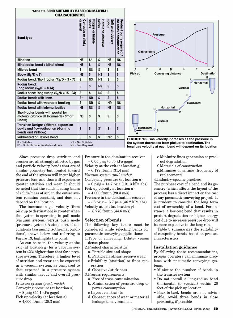
The impact of bend locationRegardless of the type of conveying sys-tem (pressure or vacuum) or the mode
of conveying (dense or dilute phase), the pressure always decreases from pickup location to destination. As dictated by theIdealGasLaw,thegasvelocitywillproportionally increase from pick up location to the destination (see Figure 13). Therefore, any bends located to-ward the end of the conveying system will experience velocities (gas and par-ticle) that are higher than those closer to the pickup location.
Table 4. comparison of bEndsbend type advantages disadvantagesBlind tee • Low cost
• Erosion / wear resistant• Short turn radius; compact design• Easy to retrofit• Low particle attrition (no chipping or surface abra-
sion)
• High pressure drop• Not suitable for moist, cohesive or sticky materials• May result in cross-contamination if the pocket does not
clean
Blind radius bend • Better erosion resistance than radius bend • Same as blind tee• Secondary impact (wear) zone on the inner radius
Blind lateral • Better erosion resistance than blinded radius and significantly better than radius bends
• Same as blind tee
Mitered bend • Short turn radius • High particle attrition (due to particle impact breakage)• Not suitable for moist, cohesive or sticky materials
Elbow (RB/D < 3) • Short turn radius • High particle attrition (due to particle impact breakage)• Not suitable for moist, cohesive or sticky materials
Radius bend:Short radius (RB/D = 3 – 7)
• Available in various materials of construction and radius
• No accumulation in the bend – less chances of cross-contamination
• Pressure drop comparable to long radius bend
• High product degradation / attrition due to impact• Low wear resistance
Radius bend:Long radius (RB/D = 8-14)
• Available in various materials of construction and radius
• No accumulation in the bend, so less chance of cross-contamination
• Pressure drop comparable to short-radius bends
• Extended particle contact on the pipe wall can result in smearing (e.g. streamers with polyethylene pellets)
• Erosive wear on ductile materials due to low impact angle• Large space requirements
Radius bend:Long sweep (RB/D = 15 – 24)
• Available in many materials of construction and radius dimensions
• No accumulation in the bend, so less chance of cross-contamination
• Highest pressure drop among bends
• Extended particle contact on the pipe wall can result in smearing (e.g. streamers with polyethylene pellets)
• Erosive wear on ductile materials due to low impact angle• Large space requirements
Radius bends with liners
• Longer wear life than comparable bends• Liner material can be chosen to minimize abrasion,
and thus minimize product contamination• No accumulation or cross-contamination• Suitable for high-temperature applications
• High cost• Difficult to replace• Could be heavy and may need additional line support
Radius bend with wearable backing
• Less expensive than lined bends• Easy to replace wearable backing• Easy to maintain
• Potential for product contamination due to wearable backing
• Difficult to predict failure• Potential for spillage
Radius bend with internal baffles
• Erosion / wear resistant• More expensive than conventional bends
• Higher pressure drop• Not suitable for moist, sticky or cohesive materials• Cross-contamination
Short-radius bends with pocket for material (Vortice Ell, Hammertek Smart Elbow, Pellbow™)
• Erosion / wear resistant• Short-turn radius• Generally low particle attrition • The pocket will clean out when flow stops • Low noise
• Higher cost than radius bends and blind tees• Pressure drop comparable to blind tees
• Not suitable for moist, sticky and cohesive materials
Transition designs (mitered, expansion-cavity and flow-redi-rection, such as the Gamma ™ bend)
• Short turn radius, good for layout• Low particle attrition (no chipping or surface abra-
sion)• Prevents streamer generation during conveying of
plastic pellets; unlike radius bends, does not requre treatment (shotpeening) to prevent streamers
• Self cleaning• Erosion/wear resistant if a stable material layer can
be formed • Low noise
• Higher cost• Pressure drop slightly higher (20-40%) than short-radius
bends• Minimum solids loading ratio 5:1 (solids:air) recom-
mended for proper operation; depends on the bulk den-sity of material
Rubberized or flex-ible bends
• Excellent for soft sticky powders to prevent buildup• Good wear resistance
• Potential for product contamination due to wearing of the rubber lining
ChemiCal engineering www.Che.Com april 2009 59
Since pressure drop, attrition and erosion are all strongly affected by gas and particle velocity, bends that are of similar geometry but located toward the end of the system will incur higher pressure loss, and thus will experience greater attrition and wear. It should be noted that the solids loading (mass of solids/mass of air) in the entire sys-tem remains constant, and does not depend on the location.
The increase in gas velocity (from pick up to destination) is greater when the system is operating in pull mode (vacuum system) versus push mode (pressure system). A simple set of cal-culations (assuming isothermal condi-tions), shown below and referring to Figure 13, highlights the point.
As can be seen, the velocity at the exit (at location g) for a vacuum sys-tem is 42% higher than that for a pres-sure system. Therefore, a higher level of attrition and wear can be expected in a vacuum system, as compared to that expected in a pressure system with similar layout and overall pres-sure drop. Pressure system (push mode): Conveying pressure (at location a) = 8 psig (55.1 kPa gage)Pick up velocity (at location a) = 4,000 ft/min (20.3 m/s)
Pressure in the destination receiver = 0.05 psig (0.35 kPa gage)Velocity at the exit (at location g) = 6,177 ft/min (31.4 m/s)Vacuum system (pull mode): Conveying pressure (at location a) = 0 psig = 14.7 psia (101.3 kPa abs)Pick up velocity at location a) = 4,000 ft/min (20.3 m/s)Pressure in the destination receiver = - 8 psig = 6.7 psia (46.2 kPa abs)Velocity at exit (at location g) = 8,776 ft/min (44.6 m/s)
Selection of bendsThe following key issues must be considered while selecting bends for pneumatic conveying applications: 1. Type of conveying: Dilute- versus
dense-phase2. Product characteristics a. Particle size and shape b. Particle hardness (erosive wear) c. Friability (attrition) or fines gen-
eration d. Cohesive / stickiness3. Process requirements a. Free of cross-contamination b. Minimization of pressure drop or
power consumption c.Layoutconstraints d. Consequences of wear or material
leakage to environment
e. Minimize fines generation or prod-uct degradation
f. Materials of construction g. Minimize downtime (frequency of
replacement)4. Industry-specific practicesThe purchase cost of a bend and its ge-ometry (which affects the layout of the process) has a direct impact on the cost of any pneumatic conveying project. It is prudent to consider the long term cost of ownership of a bend. For in-stance, a low-cost bend that results in product degradation or higher energy cost due to increase pressure drop will be more expensive in the long run.
Table 5 summarizes the suitability of competing bends, based on product characteristics.
Installation guidanceBy following these recommendations, process operators can minimize prob-lems with pneumatic conveying sys-tems.•Minimize the number of bends in
the transfer system•Do not install a long-radius bend
(horizontal to vertical) within 20 feet of the pick up location
•Back-to-back bends are not advis-able. Avoid three bends in close proximity, if possible
Table 5. bEnd suitability basEd on matErial charactEristics
bend type
cohesive or sticky
or moist
fragile or friable solids
hard and abrasive
solids
soft and rubbery solids
product purity required / no cross contam
ination
Blind tee NS S* S NS NSBlind radius bend / blind lateral NS S S NS NSMitered bend S NS S S SElbow (RB/D < 3) NS S NS S SRadius bend: Short radius (RB/D = 3 – 7) S NS NS S SRadius bend: Long radius (RB/D = 8-14) S S NS S S
Radius bend: Long sweep (RB/D = 15 – 24) S S NS S SRadius bends with liners S* NR S S SRadius bend with wearable backing S NR S NR NSRadius bend with internal baffles NS NS S NS NSShort-radius bends with pocket for material (Vortice Ell, Hammertek Smart Elbow)
NS S S S S
Transition Designs (Mitered, expansion-cavity and flow-redirection (Gamma Bends and Pellbow)
S S S* S S
Rubberized or Flexible Bend S S S NR SS = Suitable NS = Not Suitable S* = Suitable under limited conditions NR = Not Required
B
C
E
FG
Conveying distanceA
A
B C D
D
E F G
Pick up Destination
Horizontal
Vertical
Horizontal
Vertical
Horizontal
Horizontal
Gas velocity
Pressure
Figure 13. Gas velocity increases as the pressure in the system decreases from pickup to destination. The local gas velocity at each bend will depend on its location

Solids Processing
•More bends toward the end of thetransfer will increase pressure drop, erosion and attrition. Consider di-rectional changes earlier in the lay-out, if possible. Consider stepping up the line size, if the pressure ratio permits, to minimize the velocity to-ward the end of the system
•Misaligned bends will increase at-trition and wear
•Installcriticalbendssuchthattheycan be easily serviced (accessible and replaceable)
•Considerinsulatingpipeandbendswhen noise is an issue (esp. indoors) or select appropriate type of bends. For outdoor installations, insulation can reduce the tendency of the ma-terial (e.g. plastic pellets) to smear inside the bend
•Paycloseattention to thedirectionof flow in specialized bends during installation
Final thoughtsBends are a critical aspect of any pneumatic conveying system layout, and selection of the most appropriate bend configurations is a critical aspect of system design and operation. Im-proper selection of bends can result in conveying capacity limitations (due to excessive pressure drop), high product degradation/attrition, and high wear rates, which can create additional maintenance, safety and environmen-tal issues.
Optimal longterm cost of ownership can be achieved if the product charac-teristics and process constraints are more appropriately matched. A thor-ough evaluation often reveals that specialized bends may not be the best option.
Available information on pipe bends in the open literature can be confus-ing, and these findings often conflict with field experience. Industry need to continue studying various aspects of pneumatic flow using modern tools for flow visualization and computational fluid dynamics for modeling. ■
Edited by Suzanne Shelley
AuthorsShrikant V. Dhodapkar is a technical leader in the Pro-cess Fundamentals Group at The Dow Chemical Co. (2301 North Brazosport Blvd., B4810, Freeport, TX 77541; Phone: 979-238-7940; Fax: 979-238-7463; E-mail: [email protected]). He received his B.Tech. in chemical engi-neering from I.I.T-Delhi (India) and his M.S.Ch.E. and Ph.D.
from the University of Pittsburgh. During the past 18 years, he has published numerous papers in particle technology and contributed chapters to several handbooks. He has extensive industrial experience in powder characterization, fluidiza-tion, pneumatic conveying, silo design, gas-solid separation, mixing, coating, computer modeling and the design of solids processing plants. He is a member of AIChE and chair of the Particle Tech-nology Forum.
Paul Solt has been involved in pneumatic conveying since 1950, currently as a consul-tant with Pneumatic Convey-ing Consultants (529 S Berks Street Allentown, PA 18104 Email: [email protected]). He was formerly employed by Fuller Company for 34 years where he held positions in the service, sales and research de-partments. His experience in-
cludes all aspects of the conveying field, including design, components, and control logic. He received his mechanical engineering degree from LehighUniversity. He is on the Editorial Advisory Board of the Powder and Bulk Engineering and member of International Freight Pipeline Society. He holds 13 patents on pneumatic conveying techniques, equipment and systems.
George E. Klinzing is pro-fessor of chemical engineering and vice-provost for research at the University of Pitts-burgh (826CLUniversity ofPittsburgh, Pittsburgh, PA 15260; Phone: 412-624-0784; Email: [email protected]. edu). He earned his B.S. degree in chemical engineering from the University of Pittsburgh, and holds a Ph.D. in chemical
engineering from Carnegie Mellon University. He has been active in the pneumatic conveying re-search community, and has published numerous papers, books and book chapters on the subject. Presently Klinzing is exploring pressure signa-tures for flow analysis. He is a Fellow of the Ameri-can Institute of Chemical Engineers, and a mem-ber of the AIChE’s Particle Technology Forum, and serves as an accreditation reviewer for ABET.
Circle 44 on p. 70 or go to adlinks.che.com/23013-44
References1. Bradley, M.S.A., Pressure losses caused by
bends in pneumatic conveying pipelines, Powder Handling and Processing, Vol. 2, No. 4, November 1990.
2. Ito, H., Friction factors for turbulent flow in curved pipes, Journal of Basic Engineering, pp. 123-134, June 1959.
3. Mills, D., Mason, J.S., Conveying velocity ef-fects in bend erosion, Journal of Pipelines, Vol. 1, pp. 69-81, 1981.
4. Morikawa, Y., Tsuji, Y., Matsui, K., Jittani, Y., Pressure drop due to pipe bends in air-solids two phase flows, International Journal Mul-tiphase Flow, Vol. 4, pp. 573-583, 1978.
5. Park, Y., Zenz, F., Pressure loss in horizontal-to-vertical upflow elbows, Paper D3, Pneu-motransport 5 — International Conference on The Pneumatic Transport of Solids in Pipes, 1980.
6. Solt, P., Bend location and pressure drop — An in-depth study, Powder and Bulk Engi-neering, November 2006.
7. The Engineering Equipment Users Associa-tion, Pneumatic Handling of Powdered Mate-rials, EEUA Handbook No. 15, Constable and CompanyLtd.,1963.
8. Wagner, P., Selecting elbows for pneumatic conveying systems, Chemical Engineering Progress, pp. 28-32, September 2007.