SOLID TANTA LU M CAPA C ITORS - Weltroniker
44
July 2012 WELTRON Elektronik GmbH // Tel: 09852 6727-0 // Fax: 09852 6727-67 // E-Mail: [email protected] WELTRON Elektronik GmbH // Tel: 09852 6727-0 // Fax: 09852 6727-67 // E-Mail: [email protected]
Transcript of SOLID TANTA LU M CAPA C ITORS - Weltroniker

SOLID TANTALUMCAPACITORS
July 2012
solid tantalum 2012.7.23 2:41 PM ˘ ` 2
WELTRON Elektronik GmbH // Tel: 09852 6727-0 // Fax: 09852 6727-67 // E-Mail: [email protected]
WELTRON Elektronik GmbH // Tel: 09852 6727-0 // Fax: 09852 6727-67 // E-Mail: [email protected]

We declare that all our tantalum capacitors are produced in accordance with EU ROHS and REACH Directive.1. RoHS ComplianceThe following restricted materials are not used in packaging materials as well as products in compliance with the law and restriction.- Cd, Pb, Hg, Cr+6, PBB, PBDE
2. No use of materials breaking Ozone layerThe following ODS materials are not used in our fabrication process.- ODS material : Freon, Haron, 1-1-1 TCE, CCl4, HCFC
If you want more detailed Information,Please Visit Samsung Electro-mechanics Website [http://www.semlcr.com]
solid tantalum 2012.7.23 2:41 PM ˘ ` 3
WELTRON Elektronik GmbH // Tel: 09852 6727-0 // Fax: 09852 6727-67 // E-Mail: [email protected]
WELTRON Elektronik GmbH // Tel: 09852 6727-0 // Fax: 09852 6727-67 // E-Mail: [email protected]

CONTENTS
SCN Series -Standard series
SCS Series -Extended series
SCS P Series -2012 size miniaturized
SCM Series -1608 size ultra miniaturized
SCF Series -Face-Down type
SCE Series -Low-ESR
SCL Series -Low-Profile
PCS Series -Ultra Low-ESR
PCL Series -Low-ESR, Low-Profile
Marking Specification
Taping Specification
Precautions in using Tantalum Capacitors
4 Characteristics Explanation
Manganese Dioxide Type
Conductive Polymer Type
Marking & Taping Specification
SCN Series
4 CharacteristicsExplanation
Precautions in usingTantalum Capacitors
SCS Series
SCS P Series
SCM Series
SCF Series
SCE Series
SCL Series
PCS Series
Taping Specification
MarkingSpecification
PCL Series
4
8
14
17
21
23
25
26
29
33
34
35
40
solid tantalum 2012.7.23 2:41 PM ˘ ` 4
WELTRON Elektronik GmbH // Tel: 09852 6727-0 // Fax: 09852 6727-67 // E-Mail: [email protected]
WELTRON Elektronik GmbH // Tel: 09852 6727-0 // Fax: 09852 6727-67 // E-Mail: [email protected]

Precautions in using TantalumCapacitors
The operational attentions to the use of the tantalum capacitors are as follows:•Electrical •Environmental•Conditions for mounting on equipment and circuit boards•Mechanical vibration, shock
If the tantalum capacitors are used without satisfying any one of these conditions, the probability of short-circuiting, current leakage or other problems to occur increases. To avoid suchproblems, observe the following precautions when using thetantalum capacitors.
Correct Use[Guality grades]Samsung devices are classified into the following quality grades in accordance with their applications. The quality grade of all devices in this document is "standard"; the devices in this document cannot be used for "special" or "specific" quality grade applications.Customers who intend to use a product or products in this document for applications other than those specified under the"standard" quality grade must contact Samsung sales representative in advance.
Standard: This quality grade is intended for applications in which failure of malfunction of the device is highly unlikely to cause harm to persons or damage to property, or be the source of any negative effects or problems in the wider community.
Special: This quality grade is intended for special applications that have common requirements, such specifi industrial fields. Devices with a "special" quality grade are designed, manufactured, and tested using a more stringent quality assurance program than that used for "stardard" grade devices. There is a high possibility thatfailure or malfunction of the device when used for applications in this category will cause harm to persons or damage to property, or create negative effects or problems in the wider community.
Specific: Devices with a "specific" quality grade are designed, manufactured, and tested using a quality assurance program that is designed by the customer or that is created in accordance with the customer's specifications. There is an extremely high possibility that failure of malfunction of the device when being used for applications in the wider community. Customers who use Samsung's products for these "specific"application must conclude an individual quality agreement and /or development agreement with Samsung. A quality assurance program designated by the customer must alsobe determined in advance
[Cautions]Samsung devices are classified into the following three quality grades:"Standard," "Special," and "Specific."The Specific quality grade applies only to devices developed based on a customer-designated quality assurance program for a specific application.The recommended applications of a device depend on its quality grade, as indicated below. Customers must check the quality grade of each device before using it in a particular application.
Standard: Computers, office equipment, communications equipment, test and measurement equipment, audio and visual equipment, home electronic appliances, machine tools, personal electronic equipment, and industrial robots
Special : Transportation equipment(automobiles, trains, ships, etc.), traffic control systems, anti-disaster systems, anti-crime systems, safety equipment, and medical equipment (not specifically designed for life support)
※ Low-impedance circuits
Power supply filter Power supply bypass
Powersupplycircuit
Fig. 1 Fig. 2
IC~+
-
+
-
+ +
Specific: Aircraft, aerospace equipment, submersiblerepeaters, nuclear reactor control systems, life supportsystems, or medical equipment for life support, etc.
The quality grade of Samsung devices is "Standard" unlessotherwise specified in Samsung's data sheets or data books. if customers intend to use Samsung devices for applicationsother than those specified for Standard quality grade, theyshould contact an Samsung sales representative in advance.
Operational Attentions
Circuit designing cautions[Manganese dioxide type]Low voltage application or High resistance connected to the capacitor in series A problem could possibly result if the following applicationexists:Low voltage, high resistance connected to the capacitor inseries, and a circuit sensitive to leakagecurrent. A problem could occur due to the lower recovery ofthe leakage current characteristic oftantalum capacitor, caused by heat stress during the solderingprocess.
[Polymer type]Prohibited circuitsSince problems can be expected, polymer products cannot beused on the following circuits.1) High impedance voltage retention circuits2) Coupling circuits3) Time constant circuits4) Circuits greatly affected by leakage current5)The circuit in which two or more samsung polymer
products are connected in a series so as to raise the endurance voltage
1. Operating Voltage1) The voltage derating factor should be as great
as possible.Under normal conditions, the operating voltage should be reduced to 50% or less of the rating. It is recommended that the operating voltage be 30% or less of the rating, particularly when the tantalum capacitors are used in a low-impedance circuit(see Figs. 1, 2, and 3).
2) For circuits in which a switching, charging, discharging,
or other momentary current flows, it is recommended
that the operating voltage be 30% or less of the rating,
with a resistor connected in series to limit the current
to 300 mA or less.3) When the tantalum capacitors are to be used at anambient temperature of higher than 85, the recommended operating range shown in Fig. 3 should not be exceeded
solid tantalum 2012.7.23 2:41 PM ˘ ` 5
WELTRON Elektronik GmbH // Tel: 09852 6727-0 // Fax: 09852 6727-67 // E-Mail: [email protected]
WELTRON Elektronik GmbH // Tel: 09852 6727-0 // Fax: 09852 6727-67 // E-Mail: [email protected]

Ambienttemperature() J,Q,K
255585
0.0150.0100.005
0.0150.0100.005
0.0300.0190.010
0.0300.0190.010
0.0300.0190.010
0.0500.0320.018
P,R A,S B,T C D0.0150.0100.005
U
PMAX(W)
Frequency1204001k10k20k40k100k1M
1.00.80.650.500.450.430.400.35
K
Tan δ2πfC
20%
0
40%
60%
80%
100%
-40 -20-55 0 40 6020 80 100 125
Operating temperature()Fig. 3
Recommended range
Upper limit
Volta
ge d
elat
ing
(rate
d vo
ltage
×%
)
2. RippleThe maximum permissible ripple voltage and current are related to the ratings case size. Please consult us detail informations.
2.1 Ripple CurrentThe maximum permissible ripple current, IMAX, is calculated as follows:
IMAx =√PMAXESR(f)
K-fa
ctor
0.01
0.1
1.0
10
100 1K 10K 100K 1MFrequency (Hz)
Fig. 4 Correction coefficient(K)4
5
where:IMAX : Maximum permissible capacitor ripple current (Arms).PMAX : Maximum permissible capacitor power loss (W).
Varies with the ambient temperature and case size.Calculated according to Table 1.
ESR (f ):Capacitor equivalent series resistance (Ω).
Since the ESR(f) value varies with the ripple frequency, however, the following correction must be made in accordance with the operating frequency (see Fig. 4).
ESR(f) = K•ESR(120) K: Coefficient for the operating frequency ( Fig. 4).
ESR(120) = Tan δ• Xc =
where:ESR (120) : Equivalent series resistance at 120 Hz (Ω).
Xc : Capacitive reactance at 120 Hz (Ω).C : Electrostatic capacitance at 120 Hz (μF).f : Operating frequency (Hz).
Precautions in usingTantalum Capacitors
4 CharacteristicsExplanation
SCN Series
SCS Series
SCS-P Series
SCM Series
SCF Series
SCE Series
Taping Specification
MarkingSpecification
SCL Series
PCS Series
PCL Series
0.1
1
10
100
0.1 1 10 100
Max
imum
per
mis
sibl
erip
ple
volta
ge
Fig. 6 Maximum permissibleripple voltage(P, A, B)
FrequencyFig. 7 Maximum permissible
ripple voltage(C, D)
Frequency
Case sizeP, A, BUA, UB@25
Case sizeC, UE, EF, UC@25
1) The tantalum capacitors must be used in such a conditions that the sum of the Working voltage and ripple voltage peak values does not exceed the rated voltage (Fig. 5)
2) Ensure that an reverse voltage due to superimposed voltages is not applied to the capacitors.
3) The maximum permissible ripple voltage varies with the rated voltage. Ensure that ripple voltage does not exceed the values shown in Figs.6 and 7. If, however, the capacitors are used at a high temperature,the maximum permissible ripple voltage must be calculated as follows:
Vrms(at 55) = 0.7 × Vrms(at 25)Vrms(at 85) = 0.5 × Vrms(at 25)Vrms(at 125) = 0.3 × Vrms(at 25)
3. Reverse VoltageSolid tantalum capacitors are polarized device and may be perma-nently damaged or destroyed, if connected with the wrong polarity.
1) The tantalum capacitors must not be operated and changed inreverse mode. And also the capacitors must not be used in an only AC circuit.
2) The tantalum capacitor dielectric has a rectifying characteristics.Therefore, when a reverse voltage is applied to it, a large current flows even at a low reverse voltage.As a result,it may spontan-eously generate heat and lead to shorting.
3) Make sure that the polarity and voltage is correct when applying a multimeter or similar testing instrument to the capacitors because a reverse voltage or overvoltage can beaccidentally applied.
4) When using the capacitors in a circuit in which a reverse voltage is applied, consult your local SAMSUNG ELECTRO- MECHANICS agent. If the application of an reverse voltage is
50V35V25V20V16V10V
6.3V/7V4V
2.5V
0.1
1
10
100
0.1 1 10 100
50V35V25V20V16V10V
6.3V/7V4V
2.5V
2.2 Ripple VoltageIf an excessive ripple voltage is applied to the tantalum capacitors,their internal temperature rises due to Joule heat, resulting in the detriment of their reliability.
Time (sec)Fig. 5
Volta
ge
OperatingVoltage
Rating Voltage
Ripple Voltage
Working Voltage
Table 1 Maximum permissible power loss values (PMAX) by case size
solid tantalum 2012.7.23 2:41 PM ˘ ` 6
WELTRON Elektronik GmbH // Tel: 09852 6727-0 // Fax: 09852 6727-67 // E-Mail: [email protected]
WELTRON Elektronik GmbH // Tel: 09852 6727-0 // Fax: 09852 6727-67 // E-Mail: [email protected]

Ope
ratin
g Te
mpe
ratu
re (T
)
120
110
100
90
80
70
60
50
40
30
20T
Connect the temperature and applied voltage ratio of interest with a straightedge. The multiplier of failure rate is given at theintersection of this line withthe model scale.
Given T1&V1 Read failure rate multiplier F1Given T&F2 Read voltage V2Given F3&V3 Read allowabletemp T3
Fig. 9 Reliability Nomograph
Circuit Impedance(ohms/ volt)
0.10.20.40.60.81.02.0
3 or greater
Failure Rate Impedance(multiplying factor)
1.00.80.60.40.30.20.10.07
F V
102
101
100
10-1
10-2
10-3
10-4
10-5
1.0
0.7
0.5
0.4
0.3
0.2
0.1
Failu
re R
ate
Mul
tiplie
r (F)
App
lied
Volta
ge R
atio
(V/V
O)
4.3 Reliability Prediction Solid tantalum capacitors exhibit no degration failure mode during shelf storage and show a constantly decreasing failure rate(i.e., absence of wearout mechanism) during life tests. This failure rate is dependent upon three important application conditions:DCvoltage, temperature, and circuit impedance.Estimates of these respective effects are provided by the reliabilitynomograph.(Figure 9.)The nomograph relates failure rate to voltage and temperature while the table relates failure rate to impedance.These estimates apply to steady-state DC condition, and they assume usage within all other rated conditions.
Standard conditions, which produce a unity failure rate factor, are rated voltage, +85, and 0.1 ohm-per-volt impedance. While voltage and temperature are straight-forward, there is some-times difficulty in determining impedance. What is required is thecircuit impedance seen by the capacitor. If several capacitors areconnected in parallel, the impedance seen by each is lowered bythe source of energy stored in the other capacitors. Energy is sim-ilarly stored in series inductors.
It is possible to lose more via higher inherent failure rate thanis gained by voltage derating. SAMSUNG typically recommends50% derating, especially in low impedance circuits.
Failure rate is conventionally expressed in units of percent perthousand hours. As a sample calculation, suppose a particularbatch of capacitors has a failure rate of 0.5%/ Khr under sta-ndard conditions.
What would be the predicted failure rate at 0.7times rated voltage,60 and 0.6Ω/ V?
The nomgraph gives a factor of 7×10⁻² and the table gives a factor of 0.4.
The failure rate estimate is then :0.5×7×10-2×0.4 = 1.4×10⁻² or 0.014%/ Khr
Table 4 Circuit Impedance Reliability Factors
·Failure rate calculation formulaλuse = λ85 × KV × KR
λuse: Estimated capacitor failure rate under the operating conditions.
λ85: Basic failure rate (Table 3)KV: Failure rate correction coefficient by the ambient
temperature and derating factor.KR: Failure rate correction coefficient by the circuit resistance,
which is the series-connected resistance divided by the voltage applied to the capacitor. This resistance is connected in series when the power supply side is viewed from the capacitor side. K (derating factor)=operating voltage/rated voltage
Type ClassificationFace - down type
Low ESR typeUltra-Miniature type (0603)
Low profile typeSmall type
Standard typeConductive Polymer type
1%/1000h
Basic failure rateSCFSCESCMSCLSCSSCN
PCS,PCL
unavoidable, it must not exceed the following values:At 20°C: 10% of the rated voltage of 1 V, whichever smaller.At 85°C: 5% of the rated voltage or 0.5 V, whichever smaller.
4. Reliability of Tantalum Capacitors4.1 GeneralThe failure rate of the tantalum capacitor varies with the deratingratio, ambient temperature, circuit resistance, circuit application, etc. Therefore, when proper selections are made so as to afford additional margins, higher reliabilities can be derived from the tantalum capacitors. Some examples of actual failure rates are presented below for your reference.
4.2 Failure Rate Calculation FormulaThe tantalum capacitors are designed to work at their basic failure rates shown in Table 3 that prevail when the rated voltage is applied for 1000 hours at 85.
Table 3 Basic failure rate
Voltage “de-rating” is a common and useful approach to improvedreliability. It can be persued too far, however, when it leads to in-stallation of higher voltage capacitors of much larger size.
solid tantalum 2012.7.23 2:42 PM ˘ ` 7
WELTRON Elektronik GmbH // Tel: 09852 6727-0 // Fax: 09852 6727-67 // E-Mail: [email protected]
WELTRON Elektronik GmbH // Tel: 09852 6727-0 // Fax: 09852 6727-67 // E-Mail: [email protected]
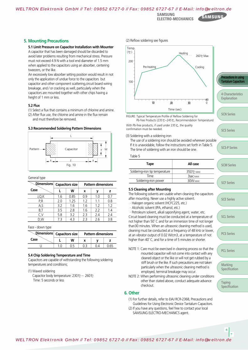
5. Mounting Precautions5.1 Limit Pressure on Capacitor Installation with MounterA capacitor that has been damaged should be discarded to avoid later problems resulting from mechanical stress. Pressure must not exceed 4.9 N with a tool end diameter of 1.5 mm when applied to the capacitors using an absorber, centering tweezers, or the like.An excessively low absorber setting position would result in not only the application of undue force to the capacitors but capacitor and other component scattering,circuit board wiring breakage, and / or cracking as well, particularly when the capacitors are mounted together with other chips having a height of 1 mm or less.
5.2 Flux(1) Select a flux that contains a minimum of chlorine and amine.(2) After flux use, the chlorine and amine in the flux remain
and must therefore be removed.
5.3 Recommended Soldering Pattern Dimensions
Pattern Capacitor
Fig. 10
L
z x
y W
x
6
7
Precautions in usingTantalum Capacitors
4 CharacteristicsExplanation
SCN Series
SCS Series
SCS-P Series
SCM Series
SCF Series
SCE Series
Taping Specification
MarkingSpecification
SCL Series
PCS Series
PCL Series
5.5 Cleaning after MountingThe following solvents are usable when cleaning the capacitors after mounting. Never use a highly active solvent.·Halogen organic solvent (HCFC225, etc.)·Alcoholic solvent (IPA, ethanol, etc.)·Petroleum solvent, alkali saponifying agent, water, etc.Circuit board cleaning must be conducted at a temperature of not higher than 50°C and for an immersion time of not longer than30 minutes. When an ultrasonic cleaning method is used, cleaning must be conducted at a frequency of 48 kHz or lower, at an vibrator output of 0.02 W/cm3, at a temperature of not higher than 40°C, and for a time of 5 minutes or shorter.
NOTE 1: Care must be exercised in cleaning process so that themounted capacitor will not come into contact with any cleaned object or the like or will not get rubbed by a stiff brush or the like. If such precautions are not takenparticularly when the ultrasonic cleaning method isemployed, terminal breakage may occur.
NOTE 2: When performing ultrasonic cleaning under conditions other than stated above, conduct adequate advance checkout.
(1) For further details, refer to EIAJ RCR-2368, Precautions andGuidelines for Using Electronic Device Tantalum Capacitors.
(2) If you have any questions, feel free to contact your local SAMSUNG ELECTRO-MECHANICS agent.
6. Other
General type
5.4 Chip Soldering Temperature and TimeCapacitors are capable of withstanding the following soldering temperatures and conditions;
(1) Waved soldering Capacitor body temperature: 230∼ 260Time: 5 seconds or less
(3) Soldering with a soldering ironThe use of a soldering iron should be avoided wherever possible If it is unavoidable, follow the instructions set forth in Table 5. The time of soldering with an iron should be one.
Table 5
Dimensions
Case
J,Q,KP,RA,SB,TC,VD,W
1.62.03.23.55.87.3
0.851.251.62.83.24.3
0.91.21.61.62.32.3
1.01.11.22.22.42.6
0.70.81.21.42.43.8
Capacitors size
L W x y z
Pattern dimensions
Face - down type
Dimensions
Case
U 1.0 0.5 0.3 0.4 0.65
Capacitors size
L W x y z
Pattern dimensions
FIGURE: Typical Temperature Profile of Reflow Soldering forPb-free Products (235~245, Recommendation Temperature)
With Pb-free products, if used under 235 , the quality confirmation must be needed.
100
200
100 0 0 020 3040
Temp. ( )
Time (sec)
Heating260Max
CoolingPre-heating
Tape
350MAX
3sec MAX
30W MAX
All case
Soldering-iron tip temperatureTime
Soldering-iron power
(2) Reflow soldering see figures
solid tantalum 2012.7.23 2:42 PM ˘ ` 8
WELTRON Elektronik GmbH // Tel: 09852 6727-0 // Fax: 09852 6727-67 // E-Mail: [email protected]
WELTRON Elektronik GmbH // Tel: 09852 6727-0 // Fax: 09852 6727-67 // E-Mail: [email protected]

4 Characteristics Explanation
1-1. Rated Capacitance(CR)This is the nominal rated capacitance.capacitance is measured at 120, 1.0V RMS, DC Bias 1.0V~2.0V
1-2. Capacitance toleranceThis is the permissible variation of the actual value of thecapacitance from the rated value.Available in standard EIA nominal values with ±20% & ±10%tolerance.
1-3. Temperature dependence of capacitance.The capacitance of a tantalum capacitance varies with temperature.
1-4. Frequency dependence of capacitanceThe effective capacitance decrease as frequency increases.Beyond 100 the capacitance continues to drop until resonanceis reached.
15
10
5
0
-5
-10
-15
-55 -25 0 25 50 75 100 125
Temperature()
TYPICAL CAPACITANCE VS. TEMPERATURE
% C
apac
itanc
e
250
200
150
100
50
0100 1000 10000 100000 1000000
Frequency()
CAPACITANCE VS. FREQUENCY
Capa
citan
ce(
)
1. Capacitance 2. Voltage2-1. Rated voltage(VR)This is the rated d.c. voltage for continuous operation at 85.
2-2. Category voltage(VC)Tantalum capacitors are designed to operate continuously over the temperature range of -55 to +85 with operating voltage. these capacitance may be operated at 125 with 2/3 derated voltage as shown in fig.
2-3. Surge voltage(VS)Surge voltage is the maximum voltage to which the capacitor can be subjected under transient conditions: including the sumof peak AC ripple, DC bias and any transients.the surge voltage must not be used as a parameter in the design of circuits in which, in the normal course of operation, the capacitor is periodically charged and discharged.
2-4. Reverse voltage and polarity.Solid tantalum capacitors are polarized device and may be perm-anently damaged or destryed if connected with the wrong polarity.They are intended to cover short term reversals of polarity, such as those occuring during switching transients of during a minor portion of an impressed waveform.
85Rated
Voltage(Vdc)Surge
Voltage(Vdc)
125
2.54
6.3101620253550
3.15.28132026324665
CategoryVoltage(Vdc)
SurgeVoltage(Vdc)
1.62.7441013172333
2.03.52
581216202840
100%80%60%40%20%
-40 0 40 80 120
Operating Temperature()
Figure 1 Working DC Voltage Change With Temperature
solid tantalum 2012.7.23 2:42 PM ˘ ` 9
WELTRON Elektronik GmbH // Tel: 09852 6727-0 // Fax: 09852 6727-67 // E-Mail: [email protected]
WELTRON Elektronik GmbH // Tel: 09852 6727-0 // Fax: 09852 6727-67 // E-Mail: [email protected]

8
9
Precautions in usingTantalum Capacitors
4 CharacteristicsExplanation
SCN Series
SCS Series
SCS-P Series
SCM Series
SCF Series
SCE Series
Taping Specification
MarkingSpecification
SCL Series
PCL Series
PCS Series
continuous application of reverse voltage without normal polarization will result in a degration of leakage current.The peak reverse polarity voltage applied to the capacitor must not exceed:
at +20, 10% of rated voltageat +85, 5% of rated voltage
or 1V,whichever is greater.
If higher voltages of reverse polarity occur, then two capacitors with the same norminal capacitance and rated voltage should be connected in series in such a way as to form a non-polar combi-nation(back-to-back configuration with the negative terminationsconnected together). when d.c. voltage are switched, measures must be taken to ensure that the reverse polarized capacitance avoid a reduction in its life expectancy.
2-5.Super imposed A.C. voltage(Vr.m.s) Ripple voltage.This is the maximum r.m.s alternating voltage ;superimposed on ad.c. voltage, that may be applied to a capacitor.
1) The sum of the working voltage and ripple voltage peak valuedoes not exceed the rated d.c working voltage.
2) Ensure that an reverse voltage due to super imposed voltages isnot applied to the capacitors.
3) If,hoeever,the capacitors are used at a high temperature, the maximum permissible ripple voltage must be calculated as follows :
Vrms (at 55) =0.7×Vrms(at 25)Vrms (at 85)=0.5×Vrms(at 25)Vrms (at 125)=0.3×Vrms(at 25)
3.Dissipation factor (D.F.)Refer to part number tables for maximum DF limits.Dissipation factor is measured at 120 Hz, 1.0Volt RMSand 1.0~2.0 volts DC at +25.The application of dc bias causes a small reduction in DF, about 0.2% when full rated voltage is applied DF increases with increasing frequency.
Dissipation factor is a very useful low frequency (120hz) measure-ment of the resistive component of a capacitor.It is the ratio of the equivalent series resistance(esr) to the capacitivereactance, (Xc) and is usually expressed as a percentage.It is directly proportional to both capacitance and frequency. dissipation factor loses its importance at higher frequencies, (aboveabout 1 khz), when impedance. (z) and equivalent series resistance(esr) are the normal parameters of concern.DF= R/Xc =2πfCRwhere DF=dissipation factor
R=equivalent series resistance(ohms)Xc=capactive reactance(ohms)f =frequency(hertz)C=series capacitance(farads)
DF is also referred to as tanδor “loss tangent.”The “quality factor” “Q” is the reciprocal of DF.DF increases with temperature above +25 and may also increase at lower temperatures. Unfortunately, one general limit for DF cannot be specified for all capacitance/voltage combinations, nor can response to temperature be simply stated.
1086420
-2-4-6-8
-10-20 0 20 40 60 80 100
Applied Voltage(Volts)
LEAKAGE CURRENT VS. BIAS VOLTAGE
Leak
age
Cur
rent
()
50
5
1
0.10.1 1 10 100
Frequency(kHz)
TYPICAL DF vs FREQUENCY
DF M
ultip
lier
3. Dissipation Factor (D.F.)
solid tantalum 2012.7.23 2:42 PM ˘ ` 10
WELTRON Elektronik GmbH // Tel: 09852 6727-0 // Fax: 09852 6727-67 // E-Mail: [email protected]
WELTRON Elektronik GmbH // Tel: 09852 6727-0 // Fax: 09852 6727-67 // E-Mail: [email protected]

The leakage current is dependent on the voltage applied, the elapsed time since the voltage was applied the component temp.it is measured at +25 with the rated voltage applied. the rated d.c voltage shall be applied to terminals across the test capacitor Cx. by the method as shown below.
5-1 Temperature dependence of the leakage current
when operating at high temperature range from 85 to 125,the operation shall be carried out at a derated voltage or less.Derating voltage Vt at any temperature between 85 and 125shall be calculated by the following equation.
when Vt : Derated voltage at any temp.Vr : Rated voltageVd :Derated voltage at 125
5-2 Leakage Current vs Rated voltageThe leakage current drops rapidly below the value correspondingto the rated voltage VR When reduced voltage are applied.The effect of voltage derating on the leakage current is shown in the graph.This will also give a significant increase in the reliability for anyapplication.
Vt = Vr - ( T - 85)Vr - Vd
40
++
S1
S2
V
A
Cx
RS
-
-
Temperature()
Leak
age
Curre
nt R
atio
10
1
0.1-55 -40 -20 0 20 40 60 80 100 125
Percent of Rated Voltage
Voltage vs DC Leakage Current
Mul
tiplie
r of L
eaka
ge C
urre
nt
1.0
0
0.01
0.0010 10 20 30 40 50 60 70 80 90 100 110
4. D. C. Leakage Current
solid tantalum 2012.7.23 2:42 PM ˘ ` 11
WELTRON Elektronik GmbH // Tel: 09852 6727-0 // Fax: 09852 6727-67 // E-Mail: [email protected]
WELTRON Elektronik GmbH // Tel: 09852 6727-0 // Fax: 09852 6727-67 // E-Mail: [email protected]

4. Impedauce(Z), and Equivalent Series Resistance(ESR)4-1 Impedance(Z)The impedance is measured at 25 and 100KHZ.this is the ratio of voltage to current at a specified frequency. three factors contribute to the impedance of a tantalum capacitor; the resistance of the semiconductor layer; the capacitance value and the inductance of the electrode and leads. at high frequencies the inductance of leads becomes a limiting factor.
Total impedance of the capacitor is the vector sum of capacitivereactance(Xc) and ESR, below resonance; above resonance totalimpedance is the vector sum of inductive reactance(XL) and ESR(Figure 5 and 6).
Typical impedance versus frequency curve is shown in Figure.
4-2. Equivalent Series Resistance (ESR)The ESR is measured at 25 and 100KHZ.Resistance losses occur in all practical forms capacitors.Equivalent Series Resistance (ESR) is the preferred high-frequencystatement of the resistance unavoidably appearing in these capacitors. ESR is not a pure resistance, and it decreases with increasing frequency.The ESR is frequency dependent and can be found by using therelationship;
ESR = tan δ/ 2πfCESR is the contributing factors to impedance, and at high frequen-cies (100KHZ and above) It becomes the dominant factor.
1.81.71.61.51.41.31.21.1
10.90.8
-55 -5 45 95Temperature(Celcius)
DF M
ultip
lier
TYPICAL DF VS TEMPERATURE
100
10
1
0.10.1 1 10 100 1000
Frequency(kHz)
Impe
danc
e M
ultip
lier
TYPICAL IMPEDANCE VS FREQUENCY
54.5
43.5
32.5
21.5
10.5
00.1 1 10 100 1000
Frequency(kHz)
ESR
Mul
tiplie
r
TYPICAL ESR VS FREQUENCY
100
10
1
0.10.1 1 10 100 1000
Frequency(kHz)
Impe
danc
e M
ultip
lier
TYPICAL ESR VS FREQUENCY
Total impedance of the Capacitor above Resonance
ESR
XC= R2πf C
ohm
where:f=frequency, HertzC=capacitance, Farad
Ø
δ
XC Z
Total impedance of the Capacitor above Resonance
ESR
XL=2πf L
where:f=frequency, HertzL=inductance, Henries
Ø
δ
XC
Z
5. Impedance(Z) & ESR
1011
Precautions in usingTantalum Capacitors
4 CharacteristicsExplanation
SCN Series
SCS Series
SCS-P Series
SCM Series
SCF Series
SCE Series
Taping Specification
MarkingSpecification
SCL Series
PCS Series
PCL Series
solid tantalum 2012.7.23 2:42 PM ˘ ` 12
WELTRON Elektronik GmbH // Tel: 09852 6727-0 // Fax: 09852 6727-67 // E-Mail: [email protected]
WELTRON Elektronik GmbH // Tel: 09852 6727-0 // Fax: 09852 6727-67 // E-Mail: [email protected]

Case Code EIA Code L W1 W2 H Z 10051005
1608 -10
1608 -9
1608 -9
2012L201220123216L32163528L352860327343
1.0±0.21.0±0.21.6+0.15
0.11.6±0.11.6+0.15
0.12.0±0.22.0±0.22.0±0.23.2±0.33.2±0.23.5±0.23.5±0.26.0±0.37.3±0.3
0.5±0.20.5±0.2
0.85+0.150.1
0.85±0.10.85+0.15
0.11.25±0.21.25±0.21.25±0.21.6±0.21.6±0.22.8±0.22.8±0.23.2±0.34.3±0.3
0.4±0.050.4±0.05
0.6±0.1
0.6±0.1
0.6±0.1
0.9±0.10.9±0.10.9±0.11.2±0.11.2±0.12.2±0.12.2±0.12.2±0.12.4±0.1
0.60 max0.55 max0.85+0.15
- 0.10.8±0.1
0.90max
0.95 max1.1±0.11.2 max1.1±0.11.6±0.21.2 max1.9±0.22.5±0.32.8±0.3
0.25±0.10.25±0.1
0.4±0.1
0.4±0.1
0.4±0.1
0.5±0.20.45±0.10.5±0.20.8±0.30.8±0.30.8±0.30.8±0.31.3±0.31.3±0.3
UI
J
K
K
RPPSATBCD
Unit : mm
L
Ta2O5
C / AgMnO2
H
W1 Z Z
W2
L
H
W1Z Z
W2
Tantalum CapacitorType of seriesRated Voltage CodeCapacitance CodeCapacitance Tolerance CodeCase Size CodePacking Code
Packing Polarity CodeMaximum ESR in Milliohms
TC SCE 0J 107 M D A R 0150
(A=7 inches, C=13 inches)
Normal type Face - down type
Dielectric Negative
Tantalum wireTantalum Power
Positive
Lead FrameEMC
Feature
Configuration And Dimension
Part Number Code
Case Code (Face-down type)
Manganese Dioxide Type
solid tantalum 2012.7.23 2:42 PM ˘ ` 13
WELTRON Elektronik GmbH // Tel: 09852 6727-0 // Fax: 09852 6727-67 // E-Mail: [email protected]
WELTRON Elektronik GmbH // Tel: 09852 6727-0 // Fax: 09852 6727-67 // E-Mail: [email protected]

Manganese Dioxide Type Series System Diagram
12
13
SCFFace down type
SCM1608 Miniaturized
SCSExtended series
SCNStandard series
SCLLow Profile
SCELow ESR
1005size Uitra miniaturized1608, 2012size High CapacitanceFace down terminal type
1608size Miniaturized
3216~7343sizeLow Capacitance
Low Profile2102~7343size
Low ESR3216~7343size
Precautions in usingTantalum Capacitors
4 CharacteristicsExplanation
SCN Series
SCS Series
SCS-P Series
SCM Series
SCF Series
SCE Series
Taping Specification
MarkingSpecification
SCL Series
PCS Series
PCL Series
solid tantalum 2012.7.23 2:42 PM ˘ ` 14
WELTRON Elektronik GmbH // Tel: 09852 6727-0 // Fax: 09852 6727-67 // E-Mail: [email protected]
WELTRON Elektronik GmbH // Tel: 09852 6727-0 // Fax: 09852 6727-67 // E-Mail: [email protected]

SCN(Standard Tantalum Chip Capacitors)
Capacitance
DissipationFactor (Tan δ)
Rated Voltage(VR)Category Voltage
RangeTolerance
T≤8585〈 T≤125
Surge Voltage(V)
Operating Temperature
T≤8585〈 T≤125
C≤1.01.5≤C≤6.810≤C≤68
C≥100Leakage Current between 0.01CV and 0.5, whichever is larger
-55 to 125
4.02.55.23.2
D.F≤4.0%D.F≤6.0%D.F≤8.0%D.F≤10.0%
0.15 to 68±20%(M), ±10%(K)
6.34.08.05.0
106.313.08.0
16.010.020.013.0
20.013.025.016.0
25.016.032.020.0
35.022.044.028.0
The product is a standard type that has been most widely used among tantalum chip capacitors.·Molded case available in four case codes.·Compatible with automatic pick and place equipment.·Meets or exceeds EIA standard 535BAAC.·Environment-Friendly(Pb-free) tantalum capacitor.
Feature
Specifications
0.150.220.330.470.681.01.52.23.34.76.8101522334768
154224334474684105155225335475685106156226336476686
4V(0G)
A
A
BCCCDD
6.3V(0J)
AA
BCCCDD
Cap.() R . V 10V(1A)
AA
BCCCDD
16V(1C)
AA
BCCCDD
20V(1D)
AA
BCCCDD
25V(1E)
A
A
B
CCDD
35V(1V)
AAAB
B
CCD
D
Standard Value and Case Size
solid tantalum 2012.7.23 2:42 PM ˘ ` 15
WELTRON Elektronik GmbH // Tel: 09852 6727-0 // Fax: 09852 6727-67 // E-Mail: [email protected]
WELTRON Elektronik GmbH // Tel: 09852 6727-0 // Fax: 09852 6727-67 // E-Mail: [email protected]

1415
Precautions in usingTantalum Capacitors
4 CharacteristicsExplanation
SCN Series
SCS Series
SCS-P Series
SCM Series
SCF Series
SCE Series
Taping Specification
MarkingSpecification
SCL Series
PCS Series
PCL Series
TCSCN0G225*AARTCSCN0G335*AARTCSCN0G106*BARTCSCN0G156*CARTCSCN0G226*CARTCSCN0G336*CARTCSCN0G476*DARTCSCN0G686*DAR
AABCCCDD
2.23.3101522334768
0.50.50.50.60.91.31.92.7
66666666
10.08.03.52.51.81.81.00.8
TCSCN0J155*AARTCSCN0J225*AARTCSCN0J685*BARTCSCN0J106*CARTCSCN0J156*CARTCSCN0J226*CARTCSCN0J336*DARTCSCN0J476*DAR
AABCCCDD
1.52.26.81015223347
0.50.50.50.60.91.42.03.0
66666666
10.08.03.53.01.81.81.50.8
Part Number
4 volt Rating@+85(2.5 volt Rating@+125)
6.3 volt Rating@+85(4 volt Rating@+125)
10 volt Rating@+85(6.3 volt Rating@+125)
16 volt Rating@+85(10 volt Rating@+125)
CaseSize
Capacitance(μF)
DC Leakage
(μA)@+25Max.
DF (%)@+25120Hz Max.
ESR (Ω)@+25
100KHz Max.
TCSCN1A105*AARTCSCN1A155*AARTCSCN1A475*BARTCSCN1A685*CARTCSCN1A106*CARTCSCN1A156*CARTCSCN1A226*DARTCSCN1A336*DAR
AABCCCDD
1.01.54.76.810152233
0.50.50.50.71.01.52.23.3
46666666
12.08.03.53.01.81.81.20.8
TCSCN1C684*AARTCSCN1C105*AARTCSCN1C335*BARTCSCN1C475*CARTCSCN1C685*CARTCSCN1C106*CARTCSCN1C156*DARTCSCN1C226*DAR
AABCCCDD
0.681.03.34.76.8101522
0.50.50.50.71.01.62.43.5
44666666
12.010.03.53.01.91.81.20.8
20 volt Rating@+85(13 volt Rating@+125)
TCSCN1D474*AARTCSCN1D684*AARTCSCN1D225*BARTCSCN1D335*CARTCSCN1D475*CARTCSCN1D685*CARTCSCN1D106*DARTCSCN1D156*DAR
AABCCCDD
0.470.682.23.34.76.81015
0.50.50.50.71.01.42.03.0
44666666
15.012.03.53.52.41.91.31.0
Ratings & Part Number Reference
solid tantalum 2012.7.23 2:42 PM ˘ ` 16
WELTRON Elektronik GmbH // Tel: 09852 6727-0 // Fax: 09852 6727-67 // E-Mail: [email protected]
WELTRON Elektronik GmbH // Tel: 09852 6727-0 // Fax: 09852 6727-67 // E-Mail: [email protected]

Part Number CaseSize
Capacitance(μF)
DC Leakage
(μA)@+25Max.
DF (%)@+25120Hz Max.
ESR (Ω)@+25
100KHz Max.
TCSCN1V154*AAR
TCSCN1V224*AAR
TCSCN1V334*AAR
TCSCN1V474*BAR
TCSCN1V105*BAR
TCSCN1V225*CAR
TCSCN1V335*CAR
TCSCN1V475*DAR
TCSCN1V685*DAR
A
A
A
B
B
C
C
D
D
0.15
0.22
0.33
0.47
1.0
2.2
3.3
4.7
6.8
0.5
0.5
0.5
0.5
0.5
0.7
1.2
1.6
2.3
4
4
4
4
4
6
6
6
6
19.0
18.0
15.0
8.0
5.0
3.5
2.5
1.5
1.3
25 volt Rating@+85(16 volt Rating@+125)
35 volt Rating@+85(22 volt Rating@+125)
TCSCN1E334*AAR
TCSCN1E474*AAR
TCSCN1E155*BAR
TCSCN1E335*CAR
TCSCN1E475*CAR
TCSCN1E685*DAR
TCSCN1E106*DAR
A
A
B
C
C
D
D
0.33
0.47
1.5
3.3
4.7
6.8
10
0.5
0.5
0.5
0.8
1.2
1.7
2.5
4
4
6
6
6
6
6
15.0
14.0
5.0
2.5
2.4
1.4
1.0
All technical data relates to an ambient temperature of +25.Capacitance and DF are measured at 120Hz, 0.5V RMS with a maximum DC bias of 2.0 volts.DCL is measured at rated voltage after 5 minutes.* Insert K for ±10% tolerance and M for ±20%.
solid tantalum 2012.7.23 2:42 PM ˘ ` 17
WELTRON Elektronik GmbH // Tel: 09852 6727-0 // Fax: 09852 6727-67 // E-Mail: [email protected]
WELTRON Elektronik GmbH // Tel: 09852 6727-0 // Fax: 09852 6727-67 // E-Mail: [email protected]

1617
Capacitance
Dissipation Factor (Tan δ)
Rated Voltage(VR)Category Voltage(V)
RangeTolerance
T≤8585〈 T≤125
Surge Voltage(V)
Operating Temperature
T≤8585〈 T≤125
Leakage Current Refer to Specification
-55 to 125
6.34.08.05.0
2.51.63.12
Refer to Specification
0.47 to 680±20%(M), ±10%(K)
10.06.313.08.0
16.010.020.013.0
20.013.025.016.0
25.016.032.020.0
35.022.044.028.0
0.150.220.330.470.681.01.52.23.34.76.8101522334768100150220330470680
154224334474684105155225335475685106156226336476686107157227337477687
4V(0G)
AAA
A, BA, BA, B
A, B, C B, C
A, B,C,DC, D
B, C, DDD
2.5V(0E)
B
6.3V(0J)
AAA
A, BA, BA, B
A, B, CA, B, CB, C, DB, C, DC, DC, D
DD
Cap.() R . V 10V(1A)
AAA
A, BA, BA, B
A, B, CA, B, C
A, B, C, DC, DC, D
DD
16V(1C)
AAA
A, BA, BA, BB, CB, C
B, C, DC, DC, D
D
20V(1D)
AAA
A, BA, B
BB, CC
B, C, DC, D
DDD
25V(1E)
AAA
A, BA, B
BB, CB, CC, DC, D
D
35V(1V)
AAA
A, BBBCC
C, DC, D
DD
Miniaturized tantalum chip capacitors with extened capacitance.(Reduced size 1/2 to 1/3 in comparison with SCN.)
·Molded case available in four case codes.·New low profile size.·Compatible with automatic pick and place equipment.·Meets or exceeds EIA standard 535BAAC.·Environment-Friendly(Pb-free) tantalum capacitor.
Feature
Specifications
Standard Value and Case Size
SCS(Miniaturized Tantalum
Chip Capacitors)
Precautions in usingTantalum Capacitors
4 CharacteristicsExplanation
SCN Series
SCS Series
SCS-P Series
SCM Series
SCF Series
SCE Series
Taping Specification
MarkingSpecification
SCL Series
PCS Series
PCL Series
solid tantalum 2012.7.23 2:42 PM ˘ ` 18
WELTRON Elektronik GmbH // Tel: 09852 6727-0 // Fax: 09852 6727-67 // E-Mail: [email protected]
WELTRON Elektronik GmbH // Tel: 09852 6727-0 // Fax: 09852 6727-67 // E-Mail: [email protected]

AAAABABABABCBCABCDCDBCDDD
4.76.8101515222233334747476868100100100100150150220220220330470
0.50.50.50.60.60.90.91.31.31.91.91.92.72.74.04.04.04.06.06.08.88.88.813.218.8
8888888888888830888881888810
8.06.06.04.03.54.03.54.03.52.03.51.81.81.62.00.81.60.81.20.80.50.60.90.70.6
TCSCS0J335*AARTCSCS0J475*AARTCSCS0J685*AARTCSCS0J106*AARTCSCS0J106*BARTCSCS0J156*AARTCSCS0J156*BARTCSCS0J226*AARTCSCS0J226*BARTCSCS0J336*AARTCSCS0J336*BARTCSCS0J336*CARTCSCS0J476*AARTCSCS0J476*BARTCSCS0J476*CARTCSCS0J686*BARTCSCS0J686*CARTCSCS0J686*DARTCSCS0J107*BARTCSCS0J107*CARTCSCS0J107*DARTCSCS0J157*CARTCSCS0J157*DARTCSCS0J227*CARTCSCS0J227*DARTCSCS0J337*DARTCSCS0J477*DAR
AAAABABABABCABCBCDBCDCDCDDD
3.34.76.8101015152222333333474747686868100100100150150220220330470
0.50.50.50.60.60.90.91.41.4222333
4.34.34.36.36.36.39.59.513.913.920.829.6
888888888688128888810888888810
8.06.06.04.03.54.03.52.03.52.03.01.82.01.31.63.51.20.80.80.80.81.30.90.60.70.50.3
Part Number
4 volt Rating@+85(2.5 volt Rating@+125)
2.5 volt Rating@+85(1.6 volt Rating@+125)
6.3 volt Rating@+85(4 volt Rating@+125)
CaseSize
Capacitance(μF)
DCLeakage
(μA)@+25Max.
DF(%)@+25120Hz Max.
ESR(Ω)@+25
100KHz Max.
TCSCS0G475*AARTCSCS0G685*AARTCSCS0G106*AARTCSCS0G156*AARTCSCS0G156*BARTCSCS0G226*AARTCSCS0G226*BARTCSCS0G336*AARTCSCS0G336*BARTCSCS0G476*AARTCSCS0G476*BARTCSCS0G476*CARTCSCS0G686*BARTCSCS0G686*CARTCSCS0G107*AARTCSCS0G107*BARTCSCS0G107*CARTCSCS0G107*DARTCSCS0G157*CARTCSCS0G157*DARTCSCS0G227MBARTCSCS0G227*CARTCSCS0G227*DARTCSCS0G337*DARTCSCS0G477*DAR
B 220 5.5 18 1.2TCSCS0E227*BAR
Ratings & Part Number Reference
solid tantalum 2012.7.23 2:42 PM ˘ ` 19
WELTRON Elektronik GmbH // Tel: 09852 6727-0 // Fax: 09852 6727-67 // E-Mail: [email protected]
WELTRON Elektronik GmbH // Tel: 09852 6727-0 // Fax: 09852 6727-67 // E-Mail: [email protected]
1819
Precautions in usingTantalum Capacitors
4 CharacteristicsExplanation
SCN Series
SCS Series
SCS-P Series
SCM Series
SCF Series
SCE Series
Taping Specification
MarkingSpecification
SCL Series
PCS Series
PCL Series
Part Number
10 volt Rating@+85(6.3 volt Rating@+125)
CaseSize
Capacitance(μF)
DCLeakage
(μA)@+25Max.
DF(%)@+25120Hz Max.
ESR(Ω)@+25
100KHz Max.
TCSCS1A225*AARTCSCS1A335*AARTCSCS1A475*AARTCSCS1A685*AARTCSCS1A685*BARTCSCS1A106*AARTCSCS1A106*BARTCSCS1A156*AARTCSCS1A156*BARTCSCS1A226*AARTCSCS1A226*BARTCSCS1A226*CARTCSCS1A336*AARTCSCS1A336*BARTCSCS1A336*CARTCSCS1A476MAARTCSCS1A476*BARTCSCS1A476*CARTCSCS1A476*DARTCSCS1A686*CARTCSCS1A686*DARTCSCS1A107*CARTCSCS1A107*DARTCSCS1A157*DARTCSCS1A227*DAR
AAAABABABABCABCABCDCDCDDD
2.23.34.76.86.810101515222222333333474747476868100100150220
0.50.50.50.70.711
1.51.52.22.22.23.33.33.39.44.74.74.76.86.810101522
888888888888128820888888888
8.06.06.06.03.52.03.54.03.52.03.01.82.01.81.63.01.61.20.80.90.81.20.70.80.4
AAAABABABBCBCBCDCDCDD
1.52.23.34.74.76.86.810101515222233333347476868100
0.50.50.50.70.71.01.01.61.62.42.43.53.55.35.35.37.57.510.910.916
888888888888888888888
8.06.06.04.03.53.53.53.03.53.01.82.31.61.41.50.81.40.81.40.80.7
16 volt Rating@+85(10 volt Rating@+125)
TCSCS1C155*AARTCSCS1C225*AARTCSCS1C335*AARTCSCS1C475*AARTCSCS1C475*BARTCSCS1C685*AARTCSCS1C685*BARTCSCS1C106*AARTCSCS1C106*BARTCSCS1C156*BARTCSCS1C156*CARTCSCS1C226*BARTCSCS1C226*CARTCSCS1C336*BARTCSCS1C336*CARTCSCS1C336*DARTCSCS1C476*CARTCSCS1C476*DARTCSCS1C686*CARTCSCS1C686*DARTCSCS1C107*DAR
solid tantalum 2012.7.23 2:42 PM ˘ ` 20
WELTRON Elektronik GmbH // Tel: 09852 6727-0 // Fax: 09852 6727-67 // E-Mail: [email protected]
WELTRON Elektronik GmbH // Tel: 09852 6727-0 // Fax: 09852 6727-67 // E-Mail: [email protected]

All technical data relates to an ambient temperature of +25.Capacitance and DF are measured at 120Hz, 0.5V RMS with a maximum DC bias of 2.0 volts.DCL is measured at rated voltage after 5 minutes.* Insert K for ±10% tolerance and M for ±20%.
TCSCS1D105*AARTCSCS1D155*AARTCSCS1D225*AARTCSCS1D335*AARTCSCS1D335*BARTCSCS1D475*AARTCSCS1D475*BARTCSCS1D685*BARTCSCS1D106*BARTCSCS1D106*CARTCSCS1D156*CARTCSCS1D226*BARTCSCS1D226*CARTCSCS1D226*DARTCSCS1D336*CARTCSCS1D336*DARTCSCS1D476*DARTCSCS1D686*DARTCSCS1D107*DAR
AAAABABBBCCBCDCDDDD
1.01.52.23.33.34.74.76.810101522222233334768100
0.50.50.50.70.71.01.01.42.02.03.04.44.44.46.66.69.413.620.0
6888888888868888888
10.08.07.04.03.53.53.53.53.01.81.71.81.60.81.20.80.70.70.9
Part Number
20 volt Rating@+85(13 volt Rating@+125)
25 volt Rating@+85(16 volt Rating@+125)
CaseSize
Capacitance(μF)
DCLeakage
(μA)@+25Max.
DF(%)@+25120Hz Max.
ESR(Ω)@+25
100KHz Max.
TCSCS1E684*AARTCSCS1E105*AARTCSCS1E155*AARTCSCS1E225*AARTCSCS1E225*BARTCSCS1E335*AARTCSCS1E335*BARTCSCS1E475*BARTCSCS1E685*BARTCSCS1E685*CARTCSCS1E106*BARTCSCS1E106*CARTCSCS1E156*CARTCSCS1E156*DARTCSCS1E226*CARTCSCS1E226*DARTCSCS1E336*DAR
AAAABABBBCBCCDCDD
0.681.01.52.22.23.33.34.76.86.810101515222233
0.50.50.50.60.60.80.81.21.71.72.52.53.73.75.55.58.2
66888688888888888
10.08.08.06.04.53.73.53.02.81.91.81.51.51.01.20.80.7
35 volt Rating@+85(22 volt Rating@+125)
TCSCS1V474*AARTCSCS1V684*AARTCSCS1V105*AARTCSCS1V155*AARTCSCS1V155*BARTCSCS1V225*BARTCSCS1V335*BARTCSCS1V475*CARTCSCS1V685*CARTCSCS1V106*CARTCSCS1V106*DARTCSCS1V156*CARTCSCS1V156*DARTCSCS1V226*DARTCSCS1V336MDAR
AAAABBBCCCDCDDD
0.470.681.01.51.52.23.34.76.8101015152233
0.50.50.50.50.50.71.21.62.33.53.55.35.27.711.5
666888888888886
12.010.07.57.55.04.23.52.52.01.61.01.40.80.90.9
solid tantalum 2012.7.23 2:42 PM ˘ ` 21
WELTRON Elektronik GmbH // Tel: 09852 6727-0 // Fax: 09852 6727-67 // E-Mail: [email protected]
WELTRON Elektronik GmbH // Tel: 09852 6727-0 // Fax: 09852 6727-67 // E-Mail: [email protected]

2021
0.22
0.33
0.47
0.68
1.0
1.5
2.2
3.3
4.7
6.8
10
15
22
33
47
100
224
334
474
684
105
155
225
335
475
685
106
156
226
336
476
107
P
P
P
P
P
P
P
P
P
P
4V(0G)
P
P
P
P
P
P
P
P
P
P
P
6.3V(0J)Cap.() R . V
P
P
P
P
P
P
P
P
10V(1A)
P
P
P
P
P
16V(1C)
P
P
20V(1D)
Reduced to about 1/3 the cubic volume of the SCN.·New low profile case size.
(0805 size tantalum chip capacitors)·Compatible with automatic pick and place equipment.·Meets or exceeds EIA standard 535BAAC.
Feature
Specifications
Standard value and case size
Capacitance
Dissipation Factor (Tan δ)
Rated Voltage(VR)Category Voltage(V)
RangeTolerance
T≤8585〈 T≤125
Surge Voltage(V)
Operating Temperature
T≤8585〈 T≤125
Leakage Current between 0.01CV and 0.5, whichever is larger
-55 to 125
6.34.08.05.0
4.02.55.23.2
Refer to Specification
0.22 to 22±20%(M), ±10%(K)
10.06.313.08.0
16.010.020.013.0
20.013.025.016.0
25.016.032.020.0
35.022.044.028.0
SCS-P CASE(2012 Size Tantalum
Chip Capacitors)
Precautions in usingTantalum Capacitors
4 CharacteristicsExplanation
SCN Series
SCS Series
SCS-P Series
SCM Series
SCF Series
SCE Series
Taping Specification
MarkingSpecification
SCL Series
PCS Series
PCL Series
solid tantalum 2012.7.23 2:42 PM ˘ ` 22
WELTRON Elektronik GmbH // Tel: 09852 6727-0 // Fax: 09852 6727-67 // E-Mail: [email protected]
WELTRON Elektronik GmbH // Tel: 09852 6727-0 // Fax: 09852 6727-67 // E-Mail: [email protected]

All technical data relates to an ambient temperature of +25.Capacitance and DF are measured at 120Hz, 0.5V RMS with a maximum DC bias of 2.0 volts.DCL is measured at rated voltage after 5 minutes.* Insert K for ±10% tolerance and M for ±20%.
PPPPPPPPPP
0.220.470.68
12.23.34.76.81022
0.50.50.50.50.50.50.50.50.50.9
4446668688
252520201589863
TCSCS0J224*PARTCSCS0J474*PARTCSCS0J684*PARTCSCS0J105*PARTCSCS0J225*PARTCSCS0J335*PARTCSCS0J475*PARTCSCS0J685*PARTCSCS0J106*PARTCSCS0J226MPARTCSCS0J336MPAR
PPPPPPPPPPP
0.220.470.68
12.23.34.76.8102233
0.50.50.50.50.50.50.50.50.61.42.1
444666868818
2525202015898542
Part Number
4 volt Rating@+85(2.5 volt Rating@+125)
6.3 volt Rating@+85(4 volt Rating@+125)
10 volt Rating@+85(6.3 volt Rating@+125)
CaseSize
Capacitance(μF)
DCLeakage
(μA)@+25Max.
DF(%)@+25120Hz Max.
ESR(Ω)@+25
100KHz Max.
TCSCS1A224*PARTCSCS1A474*PARTCSCS1A684*PARTCSCS1A105*PARTCSCS1A225*PARTCSCS1A335*PARTCSCS1A475*PARTCSCS1A106*PAR
PPPPPPPP
0.220.470.68
12.23.34.710
0.50.50.50.50.50.50.51.0
44466688
2525202015846
16 volt Rating@+85(10 volt Rating@+125)
20 volt Rating@+85(13 volt Rating@+125)
TCSCS1C224*PARTCSCS1C474*PARTCSCS1C684*PARTCSCS1C105*PARTCSCS1C225*PAR
PPPPP
0.220.470.681.02.2
0.50.50.50.50.5
66666
252520206.5
TCSCS1D474*PARTCSCS1D684*PAR
PP
0.470.68
0.50.5
44
2520
TCSCS0G224*PARTCSCS0G474*PARTCSCS0G684*PARTCSCS0G105*PARTCSCS0G225*PARTCSCS0G335*PARTCSCS0G475*PARTCSCS0G685*PARTCSCS0G106*PARTCSCS0G226*PAR
Ratings & Part Number Reference
solid tantalum 2012.7.23 2:42 PM ˘ ` 23
WELTRON Elektronik GmbH // Tel: 09852 6727-0 // Fax: 09852 6727-67 // E-Mail: [email protected]
WELTRON Elektronik GmbH // Tel: 09852 6727-0 // Fax: 09852 6727-67 // E-Mail: [email protected]

2223
SCM(Ultra-Miniaturization(1608)
Tantalum Chip Capacitors)
4V(0G) 6.3V(0J)Cap.()
R . V10V(1A) 16V(1C) 20V(1D) 25V(1E)
Reduced to about 40% the cubic volume of P Case.·New low profile case size.·Compatible with automatic pick and place equipment.·Meets or Exceeds EIA standard 535BAAC.·Environment-Friendly(Pb-free) tantalum capacitor.
Feature
Specifications
Standard Value and Case Size
1.0 105 J J J J, K
1.5 155
2.2 225 J J J J
3.3 335
4.7 475 J J, K J
6.8 685 J J
10 106 J , K J J
15 156
22 226
Capacitance
Dissipation Factor (Tan δ)
Rated Voltage(VR)Category Voltage(V)
RangeTolerance
T≤8585〈 T≤125
Surge Voltage(V)
Operating Temperature
T≤8585〈 T≤125
Leakage Current between 0.01CV and 0.5, whichever is larger
-55 to 125
6.34.08.05.0
4.02.55.23.2
Refer to Specification
1.0 to 10±20%(M)
10.06.313.08.0
16.010.020.013.0
20.013.025.016.0
25.016.032.020.0
35.022.044.028.0
Precautions in usingTantalum Capacitors
4 CharacteristicsExplanation
SCN Series
SCS Series
SCS-P Series
SCM Series
SCF Series
SCE Series
Taping Specification
MarkingSpecification
SCL Series
PCS Series
PCL Series
solid tantalum 2012.7.23 2:42 PM ˘ ` 24
WELTRON Elektronik GmbH // Tel: 09852 6727-0 // Fax: 09852 6727-67 // E-Mail: [email protected]
WELTRON Elektronik GmbH // Tel: 09852 6727-0 // Fax: 09852 6727-67 // E-Mail: [email protected]

TCSCM0G106MKAR K 10 0.5 20.0 6
J
J
J
J
J
1.0
2.2
4.7
6.8
10
0.5
0.5
0.5
0.5
0.5
8.0
8.0
8.0
8.0
8.0
15
10
10
6
6
TCSCM0J105MJAR
TCSCM0J225MJAR
TCSCM0J475MJAR
TCSCM0J475MKAR
TCSCM0J685MJAR
TCSCM0J106MJAR
J
J
J
K
J
J
1.0
2.2
4.7
4.7
6.8
10
0.5
0.5
0.5
0.5
0.5
0.63
8.0
8.0
8.020.0
8.0
8.0
15
10
10
8
6
4
Part Number
4 volt Rating@+85(2.5 volt Rating@+125)
6.3 volt Rating@+85(4 volt Rating@+125)
10 volt Rating@+85(6.3 volt Rating@+125)
CaseSize
Capacitance(μF)
DCLeakage
(μA)@+25Max.
DF(%)@+25120Hz Max.
ESR(Ω)@+25
Max.
TCSCM1A105MJAR
TCSCM1A225MJAR
TCSCM1A475MJAR
TCSCM1A106MJAR
J
J
J
J
1.0
2.2
4.7
10
0.5
0.5
0.5
1
8.0
8.0
8.0
20
10
10
6
7
All technical data relates to an ambient temperature of +25.Capacitance and DF are measured at 120Hz, 0.5V RMS with a maximum DC bias of 2.0 volts.DCL is measured at rated voltage after 5 minutes.Insert M tolerance for ±20%.
16 volt Rating@+85(10 volt Rating@+125)
TCSCM1C105MJAR
TCSCM1C105MKAR
TCSCM1C225MJAR
J
K
J
1.0
1.0
2.2
0.5
0.5
0.5
8.0
10
8.0
15
25
7.5
TCSCM0G105MJAR
TCSCM0G225MJAR
TCSCM0G475MJAR
TCSCM0G685MJAR
TCSCM0G106MJAR
Ratings & Part Number Reference
solid tantalum 2012.7.23 2:42 PM ˘ ` 25
WELTRON Elektronik GmbH // Tel: 09852 6727-0 // Fax: 09852 6727-67 // E-Mail: [email protected]
WELTRON Elektronik GmbH // Tel: 09852 6727-0 // Fax: 09852 6727-67 // E-Mail: [email protected]

Insert K for ±10% tolerance and M for ±20%.
2425
Precautions in usingTantalum Capacitors
4 CharacteristicsExplanation
SCN Series
SCS Series
SCS-P Series
SCM Series
SCF Series
SCE Series
Taping Specification
MarkingSpecification
SCL Series
PCS Series
PCL Series
SCF(Face-down Tantalum
Chip Capacitor)
105
225
475
226
156
226
U, I
Cap.() R . V 4V(0G) 6.3V(0J) 10V(1A) 16V(1C)1
2.2
4.7
22
33
47
TCSCF0G475MIAR
TCSCF0G475MUAR
*TCSCF0J105KIAR
TCSCF0J225MUAR
TCSCF0J475MUAR
TCSCF0J228MKAR
TCSCF0J476MPAR
TCSCF1A336MPAR
TCSCF1A476MPAR
I
U
I
U
U
K
P
P
P
4.7
4.7
1.0
2.2
4.7
22
47
33
47
0.5
0.5
0.5
0.5
2.96
1.4
2.96
3.3
23.5
15
10.0
6.0
6.0
15
20
20
20
20
15
15
15
15
20
6
3
4
3
I
U
U
K
P
P
P
( ) : Under Development
Specifications
Standard Value and Case Size
SCF type is face down type with excellent performancecharacteristics for filtering, by-passing, coupling, blockingcircuits ·Designed for very slim and high capacitance 1005 size·Molded Case available·Environmental Friendly Component(Halogen free)
Feature
Part Number CaseSize
Capacitance(μF)
DCLeakage (μA)@+25Max.
DF(%)@+25
120Hz Max.4 volt Rating@+85(2.5 volt Rating@+125)
6.3 volt Rating@+85(4 volt Rating@+125)
10 volt Rating@+85(6.3 volt Rating@+125)
ESR(Ω)@+25
Max.
Ratings & Part Number Reference
Capacitance
Dissipation Factor (Tan δ)
Rated Voltage(VR)Category Voltage(V)
RangeTolerance
T≤8585〈 T≤125
Surge Voltage(V)
Operating Temperature
T≤8585〈 T≤125
Leakage Current Refer to Specification
-55 to 125
6.34.08.05.0
4.02.55.23.2
Refer to Specification
1.0 to 47±20%(M)
10.06.313.08.0
16.010.020.013.0
20.013.025.016.0
25.016.032.020.0
35.022.044.028.0
solid tantalum 2012.7.23 2:42 PM ˘ ` 26
WELTRON Elektronik GmbH // Tel: 09852 6727-0 // Fax: 09852 6727-67 // E-Mail: [email protected]
WELTRON Elektronik GmbH // Tel: 09852 6727-0 // Fax: 09852 6727-67 // E-Mail: [email protected]

105
155
225
335
475
685
106
156
226
336
476
686
107
227
337
477
A(3500)
A(3500)
A(3000)B(2000)
B(800/1000)C (600)
B(800)
C (400/500)
C(400)D(400)
C(350)D(200)
D(150)
A(3000)
A(2500)
B(1000)
C (700)
A(3000)B(2000)
B(3000)
B(2000)
B(1500)
D(300)
A(3000)
B(2000)
C(1000)
D(600)
D(400)
A(3000)
A(1800)
A(1800)
A(1800/2000)B(1000)
A(1500)
B(700)
B(650)C(500)
B(500/650)C(500)D(400)C(300)D(300)C(250)
D(100/150)
D(150)
A(1800)
A(1500)
A(1500)
A(1200)
A(1000)B(600)
A(1000)B(500)
B(500)
B(500)C(300)
C(250)
D(100/200)
Cap. R . V 4V(0G) 6.3V(0J) 10V(1A) 16V(1C) 20V(1D) 25V(1E) 35V(1V)1.0
1.5
2.2
3.3
4.7
6.8
10
15
22
33
47
68
100
220
330
470
NOTE: The EIA & CECC standards for low ESR Solid Tantalum Capacitorsallow an ESR movement to 1.25 times catalogue limit post mounting.
ESR limits quoted in brakets are in milliohms
Specifications
Standard Value and Case Size
Designed for very Low ESR.·Molded case available in four case codes.·Extended range values.·Compatible with automatic pick and place equipment.·Meets or exceeds EIA standard 535BAAC.·Suitable for high frequency as high speed PC, Switching
Regulators, DC /DC converter, and etc.·Environment-Friendly(Pb-free) tantalum capacitor.
Feature
SCE(Low-ESR Tantalum Chip Capacitors)
Capacitance
Dissipation Factor (Tan δ)
Rated Voltage(VR)Category Voltage(V)
RangeTolerance
T≤8585〈 T≤125
Surge Voltage(V)
Operating Temperature
T≤8585〈 T≤125
Leakage Current between 0.01CV and 0.5, whichever is larger
-55 to 125
6.34.08.05.0
4.02.55.23.2
Refer to Specification
1.0 to 470±20%(M), ±10%(K)
10.06.313.08.0
16.010.020.013.0
20.013.025.016.0
25.016.032.020.0
35.022.044.028.0
solid tantalum 2012.7.23 2:42 PM ˘ ` 27
WELTRON Elektronik GmbH // Tel: 09852 6727-0 // Fax: 09852 6727-67 // E-Mail: [email protected]
WELTRON Elektronik GmbH // Tel: 09852 6727-0 // Fax: 09852 6727-67 // E-Mail: [email protected]

2627
Precautions in usingTantalum Capacitors
4 CharacteristicsExplanation
SCN Series
SCS Series
SCS-P Series
SCM Series
SCF Series
SCE Series
Taping Specification
MarkingSpecification
SCL Series
PCS Series
PCL Series
AAAAAABBBBCCDD
6.81015223347334768100100220470470
0.50.61.01.42.13.02.03.04.36.36.313.929.6
88888128888881010
1.81.51.51.21.01.00.60.50.50.50.30.250.21.0
Part Number
6.3 volt Rating@+85(4 volt Rating@+125)
10 volt Rating@+85(6.3 volt Rating@+125)
CaseSize
Capacitance(μF)
DCLeakage
(μA)@+25Max.
DF(%)@+25120Hz Max.
ESR(Ω)@+25
Max.
TCSCE1A225*AAR3000TCSCE1A475*AAR1800TCSCE1A685*AAR1800TCSCE1A106*AAR2000TCSCE1A106*AAR1800TCSCE1A106*BAR1000TCSCE1A156*AAR1500TCSCE1A226*BAR0700TCSCE1A336*BAR0650TCSCE1A336*CAR0500TCSCE1A476*BAR0650TCSCE1A476*BAR0500TCSCE1A476*CAR0500TCSCE1A476*DAR0400TCSCE1A686*CAR0300TCSCE1A686*DAR0300TCSCE1A107*CAR0250TCSCE1A107*DAR0150TCSCE1A107*DCR0100TCSCE1A227*DAR0150
AAAAABABBCBBCDCDCDDD
2.24.76.810101015223333474747476868100100100220
0.50.50.71.01.01.01.52.23.33.34.74.74.74.76.86.810.06.310.022.0
88888888888888888888
3.01.81.82.01.81.01.50.70.650.50.650.50.50.40.30.30.250.150.10.15
16 volt Rating@+85(10 volt Rating@+125)
TCSCE1C225*AAR3500TCSCE1C335*AAR3500TCSCE1C475*AAR3000TCSCE1C475*BAR2000TCSCE1C106*BAR1000TCSCE1C106*BAR0800TCSCE1C106*CAR0600TCSCE1C156*BAR0800TCSCE1C226*CAR0500TCSCE1C226*CAR0400TCSCE1C336*CAR0400TCSCE1C336*DAR0400TCSCE1C476*CAR0350TCSCE1C476*DAR0200TCSCE1C107*DCR0150
AAABBBCBCCCDCDD
2.23.34.74.710101015222233334747100
888888888888888
3.53.53.02.01.00.80.60.80.50.40.40.40.350.20.15
TCSCE0J685*AAR1800TCSCE0J106*AAR1500TCSCE0J156*AAR1500TCSCE0J226*AAR1200TCSCE0J336*AAR1000TCSCE0J476*AAR1000TCSCE0J336*BAR0600TCSCE0J476*BAR0500TCSCE0J686*BAR0500TCSCE0J107*BAR0500TCSCE0J107*CAR0300TCSCE0J227*CAR0250TCSCE0J477*DAR0200TCSCE0J477*DCR0100
0.50.50.80.81.61.61.62.43.53.55.35.37.57.516
Ratings & Part Number Reference
solid tantalum 2012.7.23 2:42 PM ˘ ` 28
WELTRON Elektronik GmbH // Tel: 09852 6727-0 // Fax: 09852 6727-67 // E-Mail: [email protected]
WELTRON Elektronik GmbH // Tel: 09852 6727-0 // Fax: 09852 6727-67 // E-Mail: [email protected]

Part Number CaseSize
Capacitance(μF)
DCLeakage
(μA)@+25Max.
DF(%)@+25120Hz Max.
ESR(Ω)@+25
Max.
2.2
3.3
6.8
10
TCSCE1D225*AAR3000
TCSCE1D335*AAR2500
TCSCE1D685*BAR1000
TCSCE1D106*CAR0700
A
A
B
C
0.5
0.5
1.4
2.0
8
8
8
8
3.0
2.5
1.0
0.7
20 volt Rating@+85(13 volt Rating@+125)
25 volt Rating@+85(16 volt Rating@+125)
1.5
1.5
2.2
3.3
4.7
22
8
8
8
8
8
8
3.0
2.0
3.0
2.0
1.5
0.3
35 volt Rating@+85(22 volt Rating@+125)
TCSCE1V105*AAR3000
TCSCE1V225*BAR2000
TCSCE1V475*CAR1000
TCSCE1V156*DAR0600
TCSCE1V226*DAR0400
A
B
C
D
D
1.0
2.2
4.7
15
22
0.5
0.7
1.6
5.3
7.7
8
8
8
8
8
3.0
2.0
1.0
0.6
0.4
All technical data relates to an ambient temperature of +25.Capacitance and DF are measured at 120Hz, 0.5V RMS with a maximum DC bias of 2.0 volts.DCL is measured at rated voltage after 5 minutes.* Insert K for ±10% tolerance and M for ±20%.
TCSCE1E155*AAR3000
TCSCE1E155*BAR2000
TCSCE1E225*BAR3000
TCSCE1E335*BAR2000
TCSCE1E475*BAR1500
TCSCE1E226*DAR0300
A
B
B
B
B
D
0.5
0.5
0.6
0.8
1.2
5.5
solid tantalum 2012.7.23 2:42 PM ˘ ` 29
WELTRON Elektronik GmbH // Tel: 09852 6727-0 // Fax: 09852 6727-67 // E-Mail: [email protected]
WELTRON Elektronik GmbH // Tel: 09852 6727-0 // Fax: 09852 6727-67 // E-Mail: [email protected]

2829
Specifications
Standard Value and Case Size
- Low -Profile case size- Reduced thickness up to 64% of SCS series- Molded Case available in four case codes.- Compatible with automatic pick and place equipment.- Meets or Exceeds EIA Standard 535BAAC.- Terminations: 100 % Sn , RoHS Compliant
Feature
10
22
33
47
68
100
150
106
226
336
476
686
107
157
4V(0G) 6.3V(0J)Cap.()R . V 10V(1A) 16V(1C) 20V(1D) 25V(1E)
Capacitance
Dissipation Factor (Tan δ)
Rated Voltage(VR)Category Voltage(V)
RangeTolerance
T≤8585〈 T≤125
Surge Voltage(V)
Operating Temperature
T≤8585〈 T≤125
Leakage Current between 0.01CV and 0.5, whichever is larger
-55 to 125
6.34.08.05.0
4.02.55.23.2
Refer to Specification
10 to 100±20%(M)
10.06.313.08.0
16.010.020.013.0
20.013.025.016.0
25.016.032.020.0
35.022.044.028.0
SCL (Low-Profile Tantalum
Chip Capacitors)
Precautions in usingTantalum Capacitors
4 CharacteristicsExplanation
SCN Series
SCS Series
SCS-P Series
SCM Series
SCF Series
SCE Series
Taping Specification
MarkingSpecification
SCL Series
PCS Series
PCL Series
solid tantalum 2012.7.23 2:42 PM ˘ ` 30
WELTRON Elektronik GmbH // Tel: 09852 6727-0 // Fax: 09852 6727-67 // E-Mail: [email protected]
WELTRON Elektronik GmbH // Tel: 09852 6727-0 // Fax: 09852 6727-67 // E-Mail: [email protected]

Part Number CaseSize
Capacitance(μF)
DCLeakage (μA)@+25Max.
DF(%)@+25
120Hz Max.
ESR(Ω)@+25
Max.
33
100
TCSCL0G336MSAR
TCSCL0G107MTAR
S
T
1.32
4.00
10
20
2.0
1.3
4 Volt Rating @+85 (2.5 Volt Rating @+125)
6.3 Volt Rating @+85 (4Volt Rating @+125)
33 10 2.0
10 Volt Rating @+85 (6.3Volt Rating @+125)
TCSCL01A106MRAR
TCSCL01A336MSAR
R
S
10
33
1.0
3.3
8
10
3.0
1.1
TCSCL0J336MSAR S 2.07
Ratings & Part Number Reference
solid tantalum 2012.7.23 2:42 PM ˘ ` 31
WELTRON Elektronik GmbH // Tel: 09852 6727-0 // Fax: 09852 6727-67 // E-Mail: [email protected]
WELTRON Elektronik GmbH // Tel: 09852 6727-0 // Fax: 09852 6727-67 // E-Mail: [email protected]

3031
Conductive polymer Type
Case Code EIA Code L W1 W2 H Z
2012
3528L
3528
3528
2.0±0.2
3.5±0.2
3.5±0.2
3.5±0.2
1.25±0.2
2.8±0.2
2.8±0.2
2.8±0.2
0.9±0.1
2.2±0.1
2.2±0.1
2.2±0.1
1.2 max
1.2 max
1.5 max
1.9±0.1
0.5±0.2
0.8±0.3
0.8±0.3
0.8±0.3
P
T
L
B
Unit : mm
L
Ta2O5
C / AgConductive polymer
H
W1 Z Z
W2
Tantalum CapacitorType of seriesRated Voltage CodeCapacitance Code(“157”:150)Capacitance Tolerance Code(“M”:20%)Case Size CodePacking CodePacking Polarity CodeMaximum ESR in Milliohms
TC PCS 0J 157 M B A R 0200
Normal type
Dielectric Negative
Tantalum wireTantalum Power
Positive
Lead Frame
EMC
Feature
Configuration And Dimension
Part Number Code
4 CharacteristicsExplanation
SCN Series
SCS Series
SCS-P Series
SCM Series
SCF Series
SCE Series
Taping Specification
MarkingSpecification
SCL Series
PCS Series
PCL Series
Precautions in usingTantalum Capacitors
solid tantalum 2012.7.23 2:42 PM ˘ ` 32
WELTRON Elektronik GmbH // Tel: 09852 6727-0 // Fax: 09852 6727-67 // E-Mail: [email protected]
WELTRON Elektronik GmbH // Tel: 09852 6727-0 // Fax: 09852 6727-67 // E-Mail: [email protected]
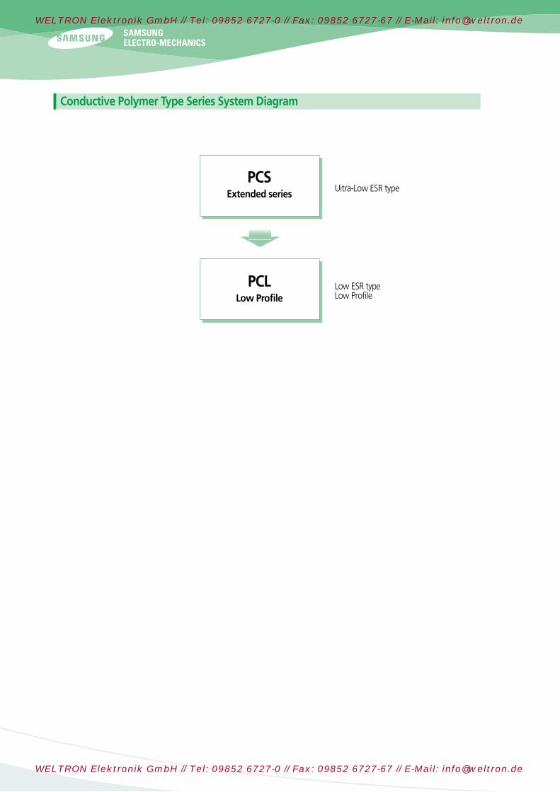
Conductive Polymer Type Series System Diagram
PCSExtended series
PCLLow Profile
Uitra-Low ESR type
Low ESR typeLow Profile
solid tantalum 2012.7.23 2:42 PM ˘ ` 33
WELTRON Elektronik GmbH // Tel: 09852 6727-0 // Fax: 09852 6727-67 // E-Mail: [email protected]
WELTRON Elektronik GmbH // Tel: 09852 6727-0 // Fax: 09852 6727-67 // E-Mail: [email protected]

3233
4 CharacteristicsExplanation
SCN Series
SCS Series
SCS-P Series
SCM Series
SCF Series
SCE Series
Taping Specification
MarkingSpecification
SCL Series
PCS Series
PCL Series
Precautions in usingTantalum Capacitors
PCS(Conductive Polymer Tantalum
Chip Capacitors)
475
107
157
227
337
B(35)
(B)
B(40/45/70)
B(35/70)L(200)
P(1000)
Cap.() R . V 2.5V(0E) 6.3V(0J) 10V(1A)4.7
100
150
220
330
TCPCS0E227MBAR0035
TCPCS0E227MBAR0055
TCPCS0J107MBAR0070
TCPCS0J107MBAR0045
TCPCS0J107MBAR0040
TCPCS0J157MBAR0035
TCPCS0J157MBAR0070
TCPCS0J157MLAR0200
TCPCS1A475MPAR1000
B(3528)
B(3525)
B(3528)
B(3528)
B(3528)
B(3528)
B(3528)
L(3825)
P(2012)
220
220
100
100
100
150
150
150
4.7
55
55
63
63
63
94.5
94.5
94.5
5
8
8
8
8
8
8
8
10
6
35
55
70
45
40
35
70
200
1000
( ) : Under Development
Specifications
Standard Value and Case Size
The Polymer Capacitor(PCS Series) have inherently low ESR(equivalentseries resistance) and are capable of higher ripple current handling, producing lower ripple voltages, less power and heat dissipation thanstandard product for the most efficient use of circuit power.
The Polymer Capacitor has the same structure as a Mn02 type chiptantalum capacitor. It has conductive polymer cathode as a substitutefor Mn02 type.
Feature
Part Number CaseSize
Capacitance(μF)
DCLeakage (μA)@+25Max.
DF(%)@+25
120Hz Max.
ESR( )@+25
Max.
Ratings & Part Number Reference
Capacitance
Dissipation Factor (Tan δ)
Rated Voltage(VR)Category
Voltage(V)
RangeTolerance
T≤8585〈 T≤105
SurgeVoltage(V)
Operating Temperature
T≤8585〈 T≤105
Leakage Current Refer to Specification
-55 to 105
2.52.52.03.12.5
Refer to Specification
4.7 to 330±20%(M)
6.36.35.08.06.3
10.010.08.013.010.0
2.5 volt Rating@+85(2.0 volt Rating@+105)
6.3 volt Rating@+85(5.0 volt Rating@+105)
10 volt Rating@+85(8 volt Rating@+105)
The Polymer Capacitor(PCS Series) have inherently low ESR(equivalentseries resistance) and are capable of higher ripple current handling, producing lower ripple voltages, less power and heat dissipation thanstandard product for the most efficient use of circuit power.
The Polymer Capacitor has the same structure as a Mn02 type chiptantalum capacitor. It has conductive polymer cathode as a substitutefor Mn02 type.
solid tantalum 2012.7.23 2:42 PM ˘ ` 34
WELTRON Elektronik GmbH // Tel: 09852 6727-0 // Fax: 09852 6727-67 // E-Mail: [email protected]
WELTRON Elektronik GmbH // Tel: 09852 6727-0 // Fax: 09852 6727-67 // E-Mail: [email protected]

476 T(70)
Cap.() R . V 6.3V(0J)47
TCPCL0J476MTAR0070 T(3528) 47 29.6 8 70
( ) : Under Development
Specifications
Standard Value and Case Size
- Low -Profile case size- Reduced thickness up to 63% of PCS series- Compatible with automatic pick and place equipment.- Terminations: 100 % Sn , RoHS Compliant
Feature
Part Number CaseSize
Capacitance(μF)
DCLeakage (μA)@+25Max.
DF(%)@+25
120Hz Max.
ESR( )@+25
Max.
Ratings & Part Number Reference
Capacitance
Dissipation Factor (Tan δ)
Rated Voltage(VR)Category
Voltage(V)
RangeTolerance
T≤8585〈 T≤105
SurgeVoltage(V)
Operating Temperature
T≤8585〈 T≤105
Leakage Current Refer to Specification
-55 to 105
Refer to Specification
47±20%(M)
6.36.35.08.06.3
6.3 volt Rating@+85(5 volt Rating@+105)
PCL(Low-Profile Conductive Polymer Tantalum Chip Capacitors)
solid tantalum 2012.7.23 2:42 PM ˘ ` 35
WELTRON Elektronik GmbH // Tel: 09852 6727-0 // Fax: 09852 6727-67 // E-Mail: [email protected]
WELTRON Elektronik GmbH // Tel: 09852 6727-0 // Fax: 09852 6727-67 // E-Mail: [email protected]

3435
4 CharacteristicsExplanation
SCN Series
SCS Series
SCS-P Series
SCM Series
SCF Series
SCE Series
Taping Specification
MarkingSpecification
SCL Series
PCS Series
PCL Series
Precautions in usingTantalum Capacitors
MarkingSpecification
A336 A336SCN, SCS, SCE series SCL series
Capacitance Code in Rated Voltage(G: 4V J: 6.3V A: 10V C: 16V D: 20V E:25V V: 35V)Polarity (White)
A, S(Low-Profile) case
SCN, SCS, SCE series SCL series
Capacitance Code in
Rated Voltage
Polarity (White)
B, T (Low-Profile) case
1025V
Capacitance in
Rated Voltage
Polarity (White)
C, D case
3310V
3310V
A, B, C, D, S, T Case
solid tantalum 2012.7.23 2:42 PM ˘ ` 36
WELTRON Elektronik GmbH // Tel: 09852 6727-0 // Fax: 09852 6727-67 // E-Mail: [email protected]
WELTRON Elektronik GmbH // Tel: 09852 6727-0 // Fax: 09852 6727-67 // E-Mail: [email protected]

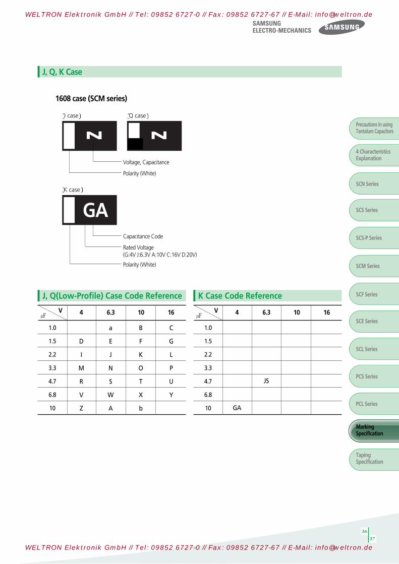
AA AACapacitance Code(A: 1.0 E: 1.5 J: 2.2 N: 3.3 S: 4.7 W: 6.8)
Rated Voltage(G: 4V J: 6.3V A: 10V C: 16V D: 20V)Polarity (White)
P, R(Low-Profile) case
0.22
0.47
0.68
1.0
1.5
2.2
3.3
4.7
6.8
10
22
33
gj
gs
gw
Ga
Gj
Gn
Gs
Gw
GA
GJ
4
j j
js
jw
Ja
SJ
Jn
Js
Jw
JA
JJ
JN
6.3 V
aj
as
aw
Aa
Aj
An
As
AA
10
cj
cs
cw
Ca
Cj
16
ds
dw
20
P, R Case
Code Reference
SCS series SCL series
solid tantalum 2012.7.23 2:42 PM ˘ ` 37
WELTRON Elektronik GmbH // Tel: 09852 6727-0 // Fax: 09852 6727-67 // E-Mail: [email protected]
WELTRON Elektronik GmbH // Tel: 09852 6727-0 // Fax: 09852 6727-67 // E-Mail: [email protected]
3637
Precautions in usingTantalum Capacitors
4 CharacteristicsExplanation
SCN Series
SCS Series
SCS-P Series
SCM Series
SCF Series
SCE Series
Taping Specification
MarkingSpecification
SCL Series
PCS Series
PCL Series
1.0
1.5
2.2
3.3
4.7
6.8
10
D
I
M
R
V
Z
4
a
E
J
N
S
W
A
6.3V
B
F
K
O
T
X
b
10
C
G
L
P
U
Y
16
z zVoltage, Capacitance
Polarity (White)
1608 case (SCM series)
J, Q, K Case
J, Q(Low-Profile) Case Code Reference
J case Q case
GACapacitance Code
Rated Voltage(G:4V J:6.3V A:10V C:16V D:20V)
Polarity (White)
K case
1.0
1.5
2.2
3.3
4.7
6.8
10 GA
4
JS
6.3V 10 16
K Case Code Reference
solid tantalum 2012.7.23 2:42 PM ˘ ` 38
WELTRON Elektronik GmbH // Tel: 09852 6727-0 // Fax: 09852 6727-67 // E-Mail: [email protected]
WELTRON Elektronik GmbH // Tel: 09852 6727-0 // Fax: 09852 6727-67 // E-Mail: [email protected]

As
Rated Voltage(G: 4V J: 6.3V A: 10V C: 16V D: 20V)
Capacitance Code(A:1.0 E: 1.5 J: 2.2 N: 3.3 S: 4.7 W:6.8)
Polarity (White Stripe)
P case
Capacitance (150)
Rated Voltage(6.3V)
Polarity
B, L, T case
+
+1506V
Conductive Polymer Type
solid tantalum 2012.7.23 2:42 PM ˘ ` 39
WELTRON Elektronik GmbH // Tel: 09852 6727-0 // Fax: 09852 6727-67 // E-Mail: [email protected]
WELTRON Elektronik GmbH // Tel: 09852 6727-0 // Fax: 09852 6727-67 // E-Mail: [email protected]

3839
Precautions in usingTantalum Capacitors
4 CharacteristicsExplanation
SCN Series
SCS Series
SCS-P Series
SCM Series
SCF Series
SCE Series
Taping Specification
MarkingSpecification
SCL Series
PCS Series
PCL Series
Face Down Type
Rated Voltage, Capacitane Code
Polarity
r
U case(1005mm size)
Rated Voltage, Capacitane Code
r
I case(1005mm size)
1.0
2.2
3.3
4.7
RV
r
4
a
j
s
6.3 10
Rated Voltage, Capacitane Code
Polarity
J
K case(1608mm size)
Rated Voltage, Capacitane Code
Polarity
t
P case(2012mm size)
22
33
47
RV
M
4
J
S
O
t
6.3 10
solid tantalum 2012.7.23 2:42 PM ˘ ` 40
WELTRON Elektronik GmbH // Tel: 09852 6727-0 // Fax: 09852 6727-67 // E-Mail: [email protected]
WELTRON Elektronik GmbH // Tel: 09852 6727-0 // Fax: 09852 6727-67 // E-Mail: [email protected]

CaseCode
U, I
Q
J,K
R
P
S
A
T
B
C
D
8 3.54
2
1.75 2 44 0.25Ø1.5
12 5.5 8 Ø1.5
Ø0.5 0.74±0.1
1.28±0.1
0.62±0.1
Ø0.6 0.98
1.4 2.3
1.9 3.5
3.3 3.8
1.800.82
1.0
1.1
1.4
1.3
1.9
1.3
2.1
3.0
3.3
6.4
7.7
3.7
4.8
Ø1.0
W±0.3 F±0.1 E±0.1 P0±0.1 P1±0.1 P2±0.1 D1+0.1 A±0.2 B±0.2 K±0.2D2Min. t
Cover Tape F
Romoval Speed
50mm/sec
15。
K
D1
A
B
EmbossedWF
E
D2P1
Direction of Feed
P2P0t
Right handOrientation available Embossed Carrier
The tantalum chip capacitors shall be packaged in tape and reel from for effective use.
Tape: Semitransparent embossed plasticCover tape: Attached with press, polyesterThe tension of removing the cover tape, F=10~70g
Unit: mm(inch)
Taping Specification
Carrier Tape Dimension
EMBOSSED PLASTIC TAPE
TapingSpecification
solid tantalum 2012.7.23 2:42 PM ˘ ` 41
WELTRON Elektronik GmbH // Tel: 09852 6727-0 // Fax: 09852 6727-67 // E-Mail: [email protected]
WELTRON Elektronik GmbH // Tel: 09852 6727-0 // Fax: 09852 6727-67 // E-Mail: [email protected]

4041
Case Code 178mm(7”)reel 330mm(13”)reel
U, I
J (Q), K
P (R)
A (S), B (T)
C, D
10,000 pcs / Reel
4,000 pcs / Reel
3,000 pcs / Reel
2,000 pcs / Reel
500 pcs / Reel
-
-
-
8,000 pcs / Reel
2,500 pcs / Reel
Unit : mm(inch)
Unit: mm
Tape Width A B C D Symbol
7" Reel
13" Reel
8mm
12mm
8mm
12mm
Ø180+0/-3
Ø180+0/-3
Ø330±2.0
Ø330±2.0
Ø60+1/-0
Ø60+1/-0
Ø80±1.0
Ø80±1.0
Ø13±0.3
Ø13±0.3
Ø13±0.3
Ø13±0.3
Ø4±0.2
Ø4±0.2
Ø4±0.2
Ø4±0.2
Tape Width E W t Symbol
7" Reel
13" Reel
8mm
12mm
8mm
12mm
2.0±0.5
2.0±0.5
2.0±0.5
2.0±0.5
9±0.5
13±0.5
9±0.5
13±0.5
1.2±0.2
1.2±0.2
2.2±0.2
2.2±0.2
Reel Dimension
Quantity Per Reel
Precautions in usingTantalum Capacitors
4 CharacteristicsExplanation
SCN Series
SCS Series
SCS-P Series
SCM Series
SCF Series
SCE Series
Taping Specification
MarkingSpecification
SCL Series
PCS Series
PCL Series
E
C
C B
A
D
Wt
solid tantalum 2012.7.23 2:43 PM ˘ ` 42
WELTRON Elektronik GmbH // Tel: 09852 6727-0 // Fax: 09852 6727-67 // E-Mail: [email protected]
WELTRON Elektronik GmbH // Tel: 09852 6727-0 // Fax: 09852 6727-67 // E-Mail: [email protected]

Inner Box Outer Box
TYPE Inch
Taping Packaging
Front
Front
Box Packaging
Inner Box Outer BoxPackaging
Code ReelsReels Quantity
MaxQuantity
1005
1608
2012
3216
3528
6032
7343
0402
0603
0805
1206
1311
2312
2818
AR
AR
AR
AR
CR
AR
CR
AR
CR
AR
CR
7”
7”
7”
7”
13”
7”
13”
7”
13”
7”
13”
10,000
4,000
3,000
2,000
8,000
2,000
8,000
500
2,500
500
2,500
5
5
5
5
5
5
5
4
4
4
4
50,000
20,000
15,000
10,000
40,000
10,000
40,000
2,000
10,000
2,000
10,000
InnerBox
QuantityMax
10
10
10
10
5
10
5
10
5
10
5
500,000
200,000
150,000
100,000
200,000
100,000
200,000
20,000
50,000
20,000
50,000
180±1.0
66±1.0
375±5.0
352±5.0
197±5.0
Outer Box
Front
475±3.0
355±3.0
229±3.0
185±1.0
30±1.0
Inner Box
Front
230±1.0
68±1.0
220±1.0
25±1.0
(Unit : mm)
Packaging Table
General type
Polymer type
(Unit : mm)
solid tantalum 2012.7.23 2:43 PM ˘ ` 43
WELTRON Elektronik GmbH // Tel: 09852 6727-0 // Fax: 09852 6727-67 // E-Mail: [email protected]
WELTRON Elektronik GmbH // Tel: 09852 6727-0 // Fax: 09852 6727-67 // E-Mail: [email protected]
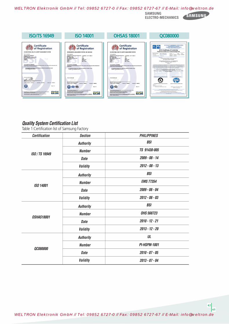
3435
4243
ISO / TS 16949
ISO 14001
OSHAS18001
QC080000
2012 - 08 - 03
2009 - 08 - 04
EMS 77354
BSI
OHS 568723
Date
Validity
Number
Certification Section PHILIPPINES
Authority
Date
Validity
Number
Authority
Date
Validity
Number
Authority
Date
Validity
Number
Authority
2010 - 12 - 21
2013 - 12 - 20
UL
PI-HSPM-1001
2010 - 07 - 05
2013 - 07 - 04
BSI
BSI
TS 91430-005
2009 - 08 - 14
2012 - 08 - 13
Quality System Certification ListTable 1:Certification list of Samsung Factory
ISO/TS 16949 ISO 14001 OHSAS 18001 QC080000
solid tantalum 2012.7.23 2:43 PM ˘ ` 44
WELTRON Elektronik GmbH // Tel: 09852 6727-0 // Fax: 09852 6727-67 // E-Mail: [email protected]
WELTRON Elektronik GmbH // Tel: 09852 6727-0 // Fax: 09852 6727-67 // E-Mail: [email protected]

All information indicated in this catalog is as of July. 2012
* The specifications and designs contained herein may be subject to change without notice.
Head office206, Cheomdansaneop Road,Yeongtong-gu, Suwon-city, Gyeonggi province, Korea, 443-743
EuropeTe l:+82-31-210 -6328E-mail:[email protected]
AmericaTe l:+82-31-210 -6803E-mail:[email protected]
AsiaTe l:+82-31-210 -6791E-mail:[email protected]
DomesticTe l:+82-31-210 -5074E-mail:[email protected]
Manufacturing sitesSuwon Plant (Korea)206, Cheomdansaneop Road,Yeongtong-gu, Suwon-city, Gyeonggi province, Korea, 443-743Te l:+82-31-210-5074E-mail:[email protected]
Busan Plant (Korea)1623-2, Songjeong-dong,Gangseo-gu, Busan, Korea, 618-270Te l:+82-51-970-7671E-mail:[email protected]
Tianjin Plant (China)27, Heiniucheng-Road, Hexi District,Tianjin, 300210 China Te l:+86-22-2397-9000(310)E-mail:[email protected]
High Tech (China)Xiqing Dist. Micro-Electronics Industrial Park, Jingang Highway, Tianjin, China 300485Tel:+ 022-23979000-313E-mail: [email protected]
Binhai Plant(China) 80, XiaQing Road, West area of BinHai development zone, TianJin, 300458, China Te l:+86-22-6686-3333(1300)E-mail:[email protected]
Philippines Plant (Philippines)Block No.5, Calamba Premiere International Park, Batino, Calamba, Laguna, Manila, Philippines 4027Te l:+63-49-545-0422E-mail:[email protected]
Asia sales officesShenzhen Office46 F, New World Center,Yitian Road, Futian District,Shenzhen, 518026 China Te l:86-755-8608-5571E-mail:[email protected]
Shanghai OfficeRm. 1211, Shanghai InternationalTrade Center, No. 2201 Yan an(W) Rd.,Shanghai, 200335 China Te l:86-21-6270-4168(274)E-mail:[email protected]
HongKong Office8/F.,Central Plaza, 18 Harbour Road,Wanchai, Hongkong, ChinaTe l:852-28626344E-mail:[email protected]
Qingdao OfficeRm 1201. Growne Plaza Qingdao 76, Xiang Gang Zhong Rd, Qingdao, 266071 ChinaTe l:86-532-85779102E-mail:[email protected]
Taiwan Office9F-1, Np. 399 Ruey Kuang Rd., Neihu District, Taipei City, Taiwan, 114Te l:886-2-2656-8356E-mail:[email protected]
Singapore Office3 Church Street Samsung Hub,#23-02 Singapore 049483Te l:65-6833-3228E-mail:[email protected]
Bangkok Office23rd Floor, Lake Rajada Office Complex193/89 Rachadapisek Road, Khet Klongtoey, Bangkok 10110, ThailandTe l:66-2-661-8004~5E-mail:[email protected]
America sales officeIrvine Office3333 Michelson Drive,Suite 500, Irvine, CA 92612, USATe l:1-949-797-8016E-mail:[email protected]
Europe sales officesFrankfurt OfficeSamsung Haus, Am Kronberger Hang 6,D-65824 Schwalbach/Ts. GermanyTe l:49-6196-66-7255E-mail:[email protected]
Hungary OfficeH-2310, Leshegy utca 2-4, Szigetszentmiklos, Pest megye, HungaryTe l:36-24-551-148E-mail:[email protected]
Domestic DistributorsKorchip Corporation 817-38, Anyang 2-dong, Manan-gu, Anyang-city, Gyeonggi province, Korea, 430-812Te l:+82-31-361-8100E-mail:[email protected]
SAMTDaekyung Bldg., 983-10, Daechi-dong,Gangnam-gu, Seoul, KoreaTe l:+82-2-3458-9000E-mail:[email protected]
CHUNGMAC301 Gwonseon Medivill, 544-14Gokbanjeong-dong, Gwonseon-gu,Suwon-si, Gyeonggi-do KoreaTe l:+82-31-234-2367~8E-mail:[email protected]
YOUNGDUKGasan-Dong 632, Seobusaetgil,Geumcheon-Gu, Seoul, KoreaTe l:+82-2-2107-7860E-mail:[email protected]
Passive components sales offices
solid tantalum 2012.7.23 2:41 PM ˘ ` 1
WELTRON Elektronik GmbH // Tel: 09852 6727-0 // Fax: 09852 6727-67 // E-Mail: [email protected]
WELTRON Elektronik GmbH // Tel: 09852 6727-0 // Fax: 09852 6727-67 // E-Mail: [email protected]