Solid-state Contactor Specifications · Technical Data Solid-state Contactor Specifications...
50
Technical Data Solid-state Contactor Specifications Bulletin Number 156 Additional Resources These documents contain additional information concerning related products from Rockwell Automation. You can view or download publications at http://www.rockwellautomation.com/global/literature-library/ overview.page . To order paper copies of technical documentation, contact your local Allen-Bradley distributor or Rockwell Automation sales representative. Topic Page Topic Page Catalog Number Explanation 2 Dual- and Three-phase Devices 25 Single-phase Devices 3 Product Selection 25 Product Selection 3 Specifications 25 Specifications 3 Current Derating 31 Application Diagrams 16 Application Diagrams 42 Load Curves 18 Wiring Diagrams 44 Wiring Diagrams 21 Approximate Dimensions 45 Approximate Dimensions 22 Resource Description Industrial Automation Wiring and Grounding Guidelines, publication 1770-4.1 Provides general guidelines for installing a Rockwell Automation industrial system. Product Certifications website, http://www.rockwellautomation.com/global/ certification/overview.page Provides declarations of conformity, certificates, and other certification details.
-
Upload
nguyenngoc -
Category
Documents
-
view
253 -
download
1
Transcript of Solid-state Contactor Specifications · Technical Data Solid-state Contactor Specifications...

Technical Data
Solid-state Contactor SpecificationsBulletin Number 156
Additional Resources
These documents contain additional information concerning related products from Rockwell Automation.
You can view or download publications at http://www.rockwellautomation.com/global/literature-library/overview.page. To order paper copies of technical documentation, contact your local Allen-Bradley distributor or Rockwell Automation sales representative.
Topic Page Topic Page
Catalog Number Explanation 2 Dual- and Three-phase Devices 25
Single-phase Devices 3 Product Selection 25
Product Selection 3 Specifications 25
Specifications 3 Current Derating 31
Application Diagrams 16 Application Diagrams 42
Load Curves 18 Wiring Diagrams 44
Wiring Diagrams 21 Approximate Dimensions 45
Approximate Dimensions 22
Resource Description
Industrial Automation Wiring and Grounding Guidelines, publication 1770-4.1 Provides general guidelines for installing a Rockwell Automation industrial system.
Product Certifications website, http://www.rockwellautomation.com/global/certification/overview.page Provides declarations of conformity, certificates, and other certification details.
2 Rockwell Automation Publication 156-TD002B-EN-P - May 2018
Solid-state Contactor Specifications
Catalog Number ExplanationExamples in this section are not intended to be used for product selection. Not all combinations will produce a valid catalog number.
Table 1 - Fan Option Compatibility
156 – C1P 20 N A D Aa b c d e f g
a b c dBulletin Number No. of Poles Contactor Rating, AC-51 @ 40 °C (104°F) Enclosure Type
Code Description Code Description Code Description Code Description156 Solid-state Contactor C1P Control 1 pole in 1-pole body 20 20 A N Open/None
C2P Control 2 poles in 3-pole body 25 25 AC3P Control 3 poles in 3-pole body 30 30 A
40 40 A43 43 A65 65 A75 75 A85 85 A
e f g(1) (See Table 1)
(1) Cat. Nos. 156-C2P75, 156-C3P40, and 156-C3P65 only.
Rated Voltage Control Voltage Fan Control Voltage OptionsCode Description Code Description Code Description
A 230V AC D 5…32V DC D 24V DC fan controlC 600V AC B 20…275V AC; 24…190V DC A 90…250V AC fan control
Control Voltage Option Compatible Fan Control OptionB AD A, B
Solid-state Contactor Specifications
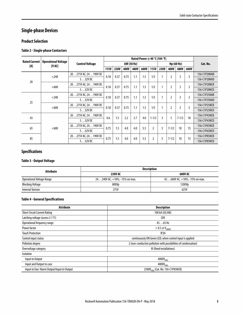
Single-phase Devices
Product Selection
Table 2 - Single-phase Contactors
Specifications
Table 3 - Output Voltage
Table 4 - General Specifications
Rated Current [A]
Operational Voltage [V AC]
Control VoltageRated Power @ 40 °C (104 °F)
Cat. No.kW (50 Hz) Hp (60 Hz)115V 230V 400V 480V 600V 115V 230V 400V 480V 600V
20<240
20…275V AC; 24…190V DC0.18 0.37 0.75 1.1 1.5 1/3 1 2 3 3
156-C1P20NAB5…32V DC 156-C1P20NAD
<60020…275V AC; 24…190V DC
0.18 0.37 0.75 1.1 1.5 1/3 1 2 3 3156-C1P20NCB
5…32V DC 156-C1P20NCD
25<240
20…275V AC; 24…190V DC0.18 0.37 0.75 1.1 1.5 1/3 1 2 3 3
156-C1P25NAB5…32V DC 156-C1P25NAD
<60020…275V AC; 24…190V DC
0.18 0.37 0.75 1.1 1.5 1/3 1 2 3 3156-C1P25NCB
5…32V DC 156-C1P25NCD
43
<600
20…275V AC; 24…190V DC0.6 1.5 2.2 3.7 4.0 1-1/2 3 5 7-1/2 10
156-C1P43NCB5…32V DC 156-C1P43NCD
6520…275V AC; 24…190V DC
0.75 1.5 4.0 4.0 5.5 2 5 7-1/2 10 15156-C1P65NCB
5…32V DC 156-C1P65NCD
8520…275V AC; 24…190V DC
0.75 1.5 4.0 4.0 5.5 2 5 7-1/2 10 15156-C1P85NCB
5…32V DC 156-C1P85NCD
AttributeDescription
230V AC 600V ACOperational Voltage Range 24…240V AC, +10%, -15% on max. 42…660V AC, +10%, -15% on max.Blocking Voltage 800Vp 1200VpInternal Varistor 275V 625V
Attribute DescriptionShort Circuit Current Rating 100 kA (UL508)Latching voltage (across L1-T1) 20VOperational frequency range 45…65 HzPower factor > 0.5 @ Vrated
Touch Protection IP20Control input status continuously ON Green LED, when control input is appliedPollution degree 2 (non-conductive pollution with possibilities of condensation)Overvoltage category III (fixed installations)Isolation
Input to Output 4000Vrms
Input and Output to case 4000Vrms
Input to Fan/ Alarm Output/Input to Output 2500Vrms (Cat. No. 156-C1P85NCB)
Rockwell Automation Publication 156-TD002B-EN-P - May 2018 3

Solid-state Contactor Specifications
Table 5 - Standards Compliance and Certifications
Table 6 - Environmental Specifications
Table 7 - Weights
Table 8 - Output Specifications @ 25°C (unless otherwise specified)
Standards Compliance Certifications
EN 62314 UL508 Listed (E96956)
EN 60947-4-2 cUL Listed (E96956)
EN 60947-4-3 VDE 0660-109
EN 50581 GL (156-C1P20, 156-C1P25, 156-C1P43)
Attribute DescriptionOperating Temperature(1)
(1) Operating temperature range for overtemperature protection is -30…70 °C (-22…158 °F)
-40…80 °C (-40…176 °F)—derate above 40 °C (104 °F)Storage Temperature -40…100 °C (-40…212 °F)RoHS Compliance (2002/95/EC) YesVibration resistance 2G per axis (2…100 Hz) (per IEC60068-2-6, EN50155, EN61373)Impact resistance 15/11 g/ms (per EN50155, EN61373)Relative humidity 95% noncondensing @ 40 °CUL flammability rating (housing) UL 94 V0GWIT & GWFI conforms to EN 60335-1requirementsInstallation altitude 0…1000 m. Above 1000 m , derate linearly by 1% of FLC per 100 m up to maximum of 2000 m
Cat. No. Approximate Weight [g (lbs)]156-C1P20 260 (0.57)156-C1P25 260 (0.57)156-C1P43 515 (1.14)156-C1P65 972 (2.14)156-C1P85 1100 (2.43)
AttributeDescription
156-C1P20 156-C1P25 156-C1P43 156-C1P65 156-C1P85Rated operational current(1)
(1) See derating curves
AC-51 rating @ Ta = 25 °C [A] 20 30 50 75 85AC-51 rating @ Ta = 40 °C [A] 20 25 43 65 85AC-53a rating @ Ta = 40 °C [A] 5 5 16 20 20
Number of motor starts (x:6, Tx:6 s, F:50%) at 40 ˚C(2)
(2) Overload current profile definition: x: multiple of AC53a rating, Tx: duration of current surge, F: duty cycle
30 30 30 30 30Min. operational current [mA] 150 250 500 500 500Rep. overload current - (Motor Rating)PF = 0.4… 0.5 UL508: TAMB=40 °C, tON=1 s, tOFF=9 s, 50 cycles
[A] 51 51 126 168 168
Maximum transient surge current (ITSM), t = 10 ms [Ap] 325 600 1900 1900 1900Maximum off-state leakage current at rated voltage [mA] 3 3 3 3 3I2t for fusing (t = 10 ms) Minimum [A2s] 525 1800 18,000 18,000 18,000Crititcal dv/dt (@ Tj init = 40 °C) [V/s] 1000 1000 1000 1000 1000
4 Rockwell Automation Publication 156-TD002B-EN-P - May 2018
Solid-state Contactor Specifications
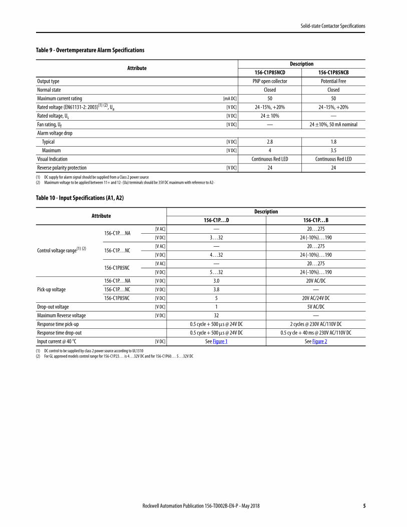
Table 9 - Overtemperature Alarm Specifications
Table 10 - Input Specifications (A1, A2)
AttributeDescription
156-C1P85NCD 156-C1P85NCBOutput type PNP open collector Potential FreeNormal state Closed ClosedMaximum current rating [mA DC] 50 50Rated voltage (EN61131-2: 2003)(1) (2), Ua
(1) DC supply for alarm signal should be supplied from a Class 2 power source(2) Maximum voltage to be applied between 11+ and 12- (Ua) terminals should be 35V DC maximum with reference to A2-
[V DC] 24 -15%, +20% 24 -15%, +20%Rated voltage, Us [V DC] 24 ± 10% —Fan rating, Uf [V DC] — 24 ±10%, 50 mA nominalAlarm voltage drop
Typical [V DC] 2.8 1.8Maximum [V DC] 4 3.5
Visual Indication Continuous Red LED Continuous Red LEDReverse polarity protection [V DC] 24 24
AttributeDescription
156-C1P…D 156-C1P…B
Control voltage range(1) (2)
(1) DC control to be supplied by class 2 power source according to UL1310(2) For GL approved models control range for 156-C1P23… is 4…32V DC and for 156-C1P60… 5…32V DC
156-C1P…NA[V AC] — 20…275[V DC] 3…32 24 (-10%)…190
156-C1P…NC[V AC] — 20…275[V DC] 4…32 24 (-10%)…190
156-C1P85NC[V AC] — 20…275[V DC] 5…32 24 (-10%)…190
Pick-up voltage156-C1P…NA [V DC] 3.0 20V AC/DC156-C1P…NC [V DC] 3.8 —156-C1P85NC [V DC] 5 20V AC/24V DC
Drop-out voltage [V DC] 1 5V AC/DCMaximum Reverse voltage [V DC] 32 —Response time pick-up 0.5 cycle + 500 s @ 24V DC 2 cycles @ 230V AC/110V DCResponse time drop-out 0.5 cycle + 500 s @ 24V DC 0.5 cy cle + 40 ms @ 230V AC/110V DCInput current @ 40 °C [V DC] See Figure 1 See Figure 2
Rockwell Automation Publication 156-TD002B-EN-P - May 2018 5

Solid-state Contactor Specifications
Figure 1 - 156-C1P…D Input Current vs. Input Voltage
2 4 6 8 10 12 14 16 18 20 22 24 26 28 30 32 34
x
5
10
15
20
25
2 4 6 8 10 12 14 16 18 20 22 24 26 28 30 32 345
10
15
20
25
Input Voltage [V DC]
Input Voltage [V DC]
Inpu
t Cur
rent
[mA]
A1 Characteristics
IN1 Characteristics
156-C1P…D, (Normal Operation)
156-C1P…D, (Active Operation)
156-C1P…D
156-C1P…D, (Normal Operation)
156-C1P…D, (Active Operation)
Inpu
t Cur
rent
[mA]
6 Rockwell Automation Publication 156-TD002B-EN-P - May 2018
Solid-state Contactor Specifications
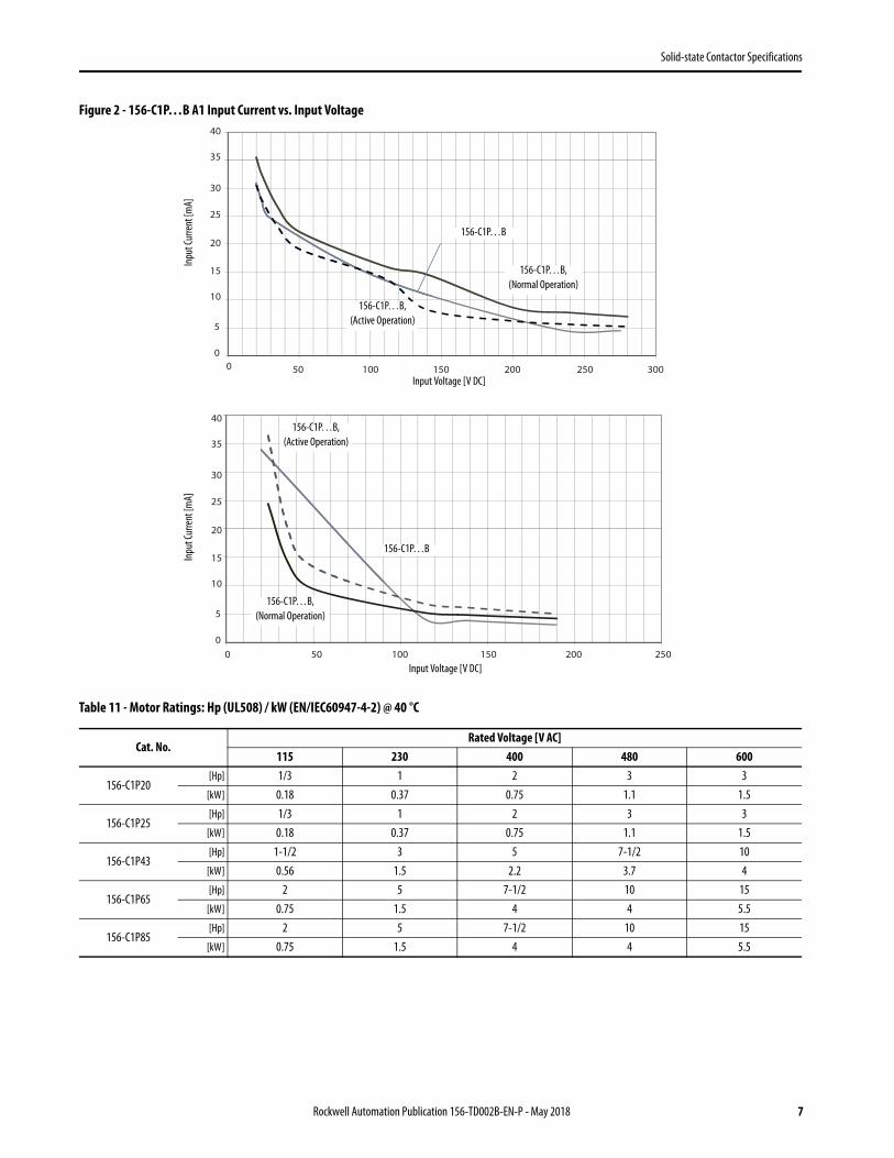
Figure 2 - 156-C1P…B A1 Input Current vs. Input Voltage
Table 11 - Motor Ratings: Hp (UL508) / kW (EN/IEC60947-4-2) @ 40 °C
Cat. No.Rated Voltage [V AC]
115 230 400 480 600
156-C1P20[Hp] 1/3 1 2 3 3
[kW] 0.18 0.37 0.75 1.1 1.5
156-C1P25[Hp] 1/3 1 2 3 3
[kW] 0.18 0.37 0.75 1.1 1.5
156-C1P43[Hp] 1-1/2 3 5 7-1/2 10
[kW] 0.56 1.5 2.2 3.7 4
156-C1P65[Hp] 2 5 7-1/2 10 15
[kW] 0.75 1.5 4 4 5.5
156-C1P85[Hp] 2 5 7-1/2 10 15
[kW] 0.75 1.5 4 4 5.5
40
30025020015010050
0
5
10
15
20
25
30
35
0
250200150100500
40
0
5
10
15
20
25
30
35
Input Voltage [V DC]
156-C1P…B, (Normal Operation)
156-C1P…B, (Active Operation)
156-C1P…B
156-C1P…B, (Normal Operation)
156-C1P…B, (Active Operation)
156-C1P…B
Input Voltage [V DC]
Inpu
t Cur
rent
[mA]
Inpu
t Cur
rent
[mA]
Rockwell Automation Publication 156-TD002B-EN-P - May 2018 7

Solid-state Contactor Specifications
Figure 3 - Detailed Overtemperature Alarm Procedure (for Cat. No. 156-C1P85NC)
NOTE:• Alarm condition resets whenever the voltage signal is removed from terminal A1 (+)• If the voltage signal is not applied across A1(+) and A2 (-) terminals, the overtemperature detection and functionality is lost (including fan
operation and alarm signaling)• It is necessary to supply IN2 and IN3 with 24V DC for fan operation.• Alarm procedure follows ‘Alarm signal only’ flow since fan is continuously operating.• Alarm condition automatically resets ONLY when power semiconductor temperature < 80°C• Temperatures indicated are typical figures.
START
FAN: ON
Is Chip temperature >
115°C ?
Chip temperature <
85°C ?
START
SSR output: OFFRed LED: ONAlarm Signal: ON
Chiptemperature <
80°C?
FAN: OFF
Chip temperature
limit reached?
SSR output: ONRed LED: OFFAlarm Signal: OFF
Chip temperature
limit reached?
SSR output: OFFRed LED: ONAlarm Signal: ON
ALARM Signal and Fan ALARM Signal only
START
No
Yes
No No
YesYes
No
Yes
No
Yes
No
Yes
START
Is chip temperature >115 °C?
Fan: ON
Is chip temperature <85 °C?
Is chip temperature limit reached?
Fan: OFF
Is chip temperature <80 °C?
SSR output: OFF
Red LED: ON
Alarm Signal: ON
SSR output: ON
Red LED: OFF
Alarm Signal: OFF
Fan: OFF
SSR output: ON
Red LED: OFF
Alarm Signal: OFF
Is chip temperature <80 °C?
SSR output: OFF
Red LED: ON
Alarm Signal: ON
Is chip temperature limit reached?
8 Rockwell Automation Publication 156-TD002B-EN-P - May 2018

Solid-state Contactor Specifications
Figure 4 - Output Power Dissipation
0
10
20
30
40
50
60
70
80
90
100
0 105 15 20 25 30 35 40 45 50 55 60 65 70 75 80 85 90
Load Current [Arms]
Powe
r Diss
ipatio
n [W
]
156-C1P20
156-C1P25
156-C1P43
156-C1P65 156-C1P85
Rockwell Automation Publication 156-TD002B-EN-P - May 2018 9
Solid-state Contactor Specifications
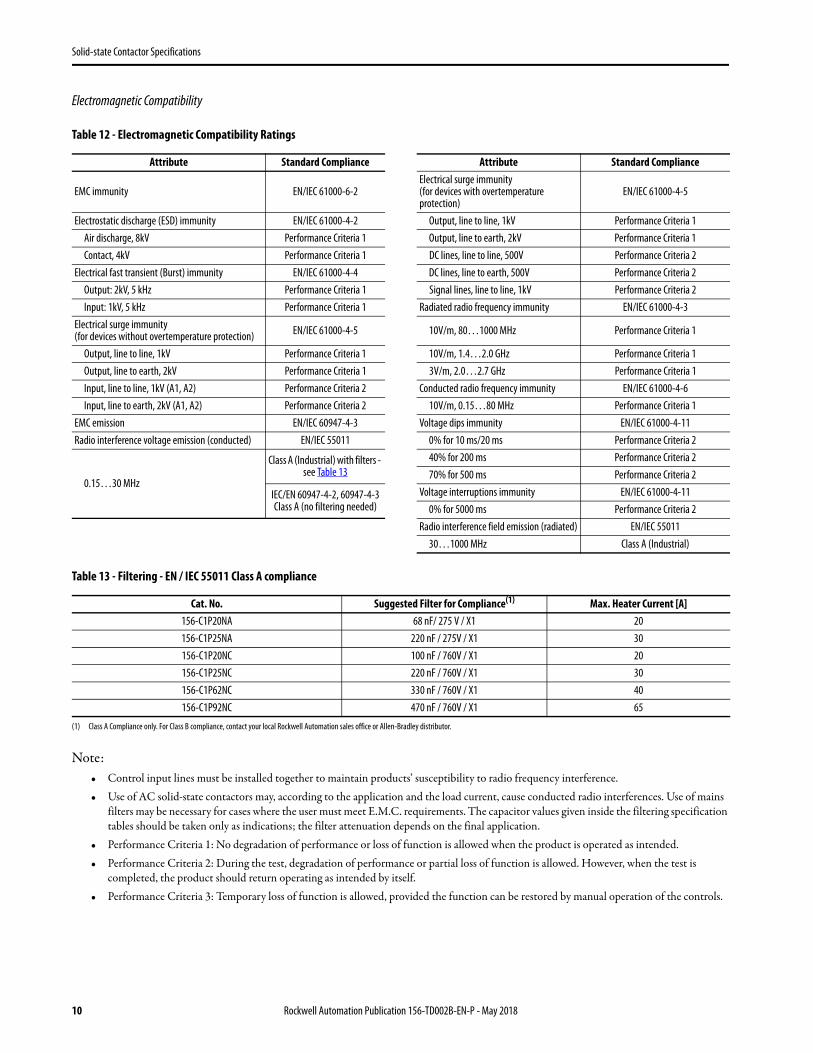
Electromagnetic Compatibility
Table 12 - Electromagnetic Compatibility Ratings
Table 13 - Filtering - EN / IEC 55011 Class A compliance
Note:• Control input lines must be installed together to maintain products’ susceptibility to radio frequency interference.• Use of AC solid-state contactors may, according to the application and the load current, cause conducted radio interferences. Use of mains
filters may be necessary for cases where the user must meet E.M.C. requirements. The capacitor values given inside the filtering specification tables should be taken only as indications; the filter attenuation depends on the final application.
• Performance Criteria 1: No degradation of performance or loss of function is allowed when the product is operated as intended.• Performance Criteria 2: During the test, degradation of performance or partial loss of function is allowed. However, when the test is
completed, the product should return operating as intended by itself.• Performance Criteria 3: Temporary loss of function is allowed, provided the function can be restored by manual operation of the controls.
Attribute Standard Compliance Attribute Standard Compliance
EMC immunity EN/IEC 61000-6-2Electrical surge immunity (for devices with overtemperature protection)
EN/IEC 61000-4-5
Electrostatic discharge (ESD) immunity EN/IEC 61000-4-2 Output, line to line, 1kV Performance Criteria 1Air discharge, 8kV Performance Criteria 1 Output, line to earth, 2kV Performance Criteria 1Contact, 4kV Performance Criteria 1 DC lines, line to line, 500V Performance Criteria 2
Electrical fast transient (Burst) immunity EN/IEC 61000-4-4 DC lines, line to earth, 500V Performance Criteria 2Output: 2kV, 5 kHz Performance Criteria 1 Signal lines, line to line, 1kV Performance Criteria 2Input: 1kV, 5 kHz Performance Criteria 1 Radiated radio frequency immunity EN/IEC 61000-4-3
Electrical surge immunity (for devices without overtemperature protection) EN/IEC 61000-4-5 10V/m, 80…1000 MHz Performance Criteria 1
Output, line to line, 1kV Performance Criteria 1 10V/m, 1.4…2.0 GHz Performance Criteria 1Output, line to earth, 2kV Performance Criteria 1 3V/m, 2.0…2.7 GHz Performance Criteria 1Input, line to line, 1kV (A1, A2) Performance Criteria 2 Conducted radio frequency immunity EN/IEC 61000-4-6Input, line to earth, 2kV (A1, A2) Performance Criteria 2 10V/m, 0.15…80 MHz Performance Criteria 1
EMC emission EN/IEC 60947-4-3 Voltage dips immunity EN/IEC 61000-4-11Radio interference voltage emission (conducted) EN/IEC 55011 0% for 10 ms/20 ms Performance Criteria 2
0.15…30 MHz
Class A (Industrial) with filters - see Table 13
40% for 200 ms Performance Criteria 270% for 500 ms Performance Criteria 2
IEC/EN 60947-4-2, 60947-4-3 Class A (no filtering needed)
Voltage interruptions immunity EN/IEC 61000-4-110% for 5000 ms Performance Criteria 2
Radio interference field emission (radiated) EN/IEC 5501130…1000 MHz Class A (Industrial)
Cat. No. Suggested Filter for Compliance(1)
(1) Class A Compliance only. For Class B compliance, contact your local Rockwell Automation sales office or Allen-Bradley distributor.
Max. Heater Current [A]156-C1P20NA 68 nF/ 275 V / X1 20156-C1P25NA 220 nF / 275V / X1 30156-C1P20NC 100 nF / 760V / X1 20156-C1P25NC 220 nF / 760V / X1 30156-C1P62NC 330 nF / 760V / X1 40156-C1P92NC 470 nF / 760V / X1 65
10 Rockwell Automation Publication 156-TD002B-EN-P - May 2018
Solid-state Contactor Specifications
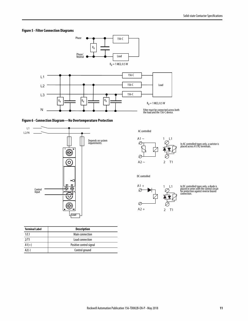
Figure 5 - Filter Connection Diagrams
Figure 6 - Connection Diagram—No Overtemperature Protection
L1
L2
L3
N
Phase
Phase/ Neutral
156-C
Load
Rd
Rd = 1 M, 0.5 W
Rd = 1 M, 0.5 W
Load
156-C
156-C
156-C
Rd Rd Rd
Filter must be connected across both the load and the 156-C device.
L1L2/N
A1 ~
A2 ~
1
2
L1
T1
1
2
L1
T1
A1 +
A2 +
In AC controlled types only, a varistor is placed across A1/A2 terminals.
In DC controlled types only, a diode is placed in series with the control circuit for protection against reverse biased connection.
Terminal Label Description1/L1 Main connection2/T1 Load connectionA1(+) Positive control signalA2(-) Control ground
Control Input
Load
Depends on system requirements.
AC controlled
DC controlled
Rockwell Automation Publication 156-TD002B-EN-P - May 2018 11
Solid-state Contactor Specifications
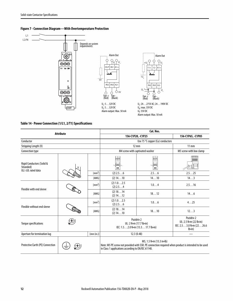
Figure 7 - Connection Diagram—With Overtemperature Protection
Table 14 - Power Connection (1/L1, 2/T1) Specifications
AttributeCat. Nos.
156-C1P20, -C1P25 156-C1P65, -C1P85Conductor Use 75 °C copper (Cu) conductorsStripping Length (X) 12 mm 11 mmConnection type M4 screw with captivated washer M5 screw with box clamp
Rigid Conductors (Solid & Stranded)UL/ cUL rated data
[mm2] (2) 2.5…6 2.5…6 2.5…25[AWG] (2) 14…10 14…10 14…3
Flexible with end sleeve[mm2]
(2) 1.0…2.5(2) 2.5…4 1.0…4 2.5…16
[AWG](2) 18…14(2) 14…12 18…12 14…6
Flexible without end sleeve[mm2]
(2) 1.0…2.5(2) 2.5…6 1.0…6 4…25
[AWG](2) 18…14(2) 14…10 18…10 12…3
Torque specificationsPozidriv 2
UL: 2 N•m (17.7 lb•in)IEC: 1.5…2.0 N•m (13.3…17.7 lb•in)
Pozidriv 2UL: 2.5 N•m (22 lb•in)
IEC: 2.5…3.0 N•m (22…26.6 lb•in)
Aperture for termination lug [mm (in.)] 12.3 (0.48) —
Protective Earth (PE) ConnectionM5, 1.5 N•m (13.3 in•lb)
Note: M5 PE screw not provided with SSR. PE connection required when product is intended to be used in Class 1 applications according to EN/IEC 61140.
L1L2/N
1
2
L1
T1
hctiw
Setat
Sdi lo
SG
R
FAULT
C ONT R OL
A1
A2G NDG ND
S UP P LYALAR MALAR M
11 + 12 -
0V
0V
IN2 IN3 A2-
A1+IN1OUT
UcUs
IN2 IN3 A2-
A1+12-11+
+UaUc
-Ua
Uf+-
Uc
Load
Depends on system requirements.
Alarm Out Alarm Out
Fan + (Red)
Fan - (Black) Fan +
(Red)Fan - (Black)
Uc: 5…32V DCUs: 5…32V DCAlarm output: Max. 50 mA
Uc: 24…275V AC; 24…190V DCUa: max. 35V DCUf: 35V DCAlarm output: Max. 50 mA
X
12 Rockwell Automation Publication 156-TD002B-EN-P - May 2018

Solid-state Contactor Specifications
Table 15 - Control Connection (A1+, A2-) Specifications
Table 16 - Control Connection (A1(+), A2(-), IN1, IN2, IN3, 11(+), 12(-), OUT) Specifications
Attribute DescriptionConductor Use 60/75 °C copper (Cu) conductors
Rigid Conductors (Solid & Stranded)UL/ cUL rated data
[mm2] (2) 1…2.5 1…2.5[AWG] (2) 18…14 18…14
Flexible with end sleeve[mm2] (2) 1…2.5 1…2.5
[AWG] (2) 18…14 18…14
Torque specificationsM3, Pozidriv 1
UL: 0.5 N•m (4.4 lb•in)IEC: 0.4…0.5 N•m (3.5…4.4 lb•in)
Stripping Length (X) 8 mm
Attribute DescriptionConductor Use 60/75 °C copper (Cu) conductorsStripping Length (X) 6 mm
Rigid Conductors (Solid & Stranded)UL/ cUL rated data
[mm2] (2) 1…2.5 1…2.5[AWG] (2) 18…14 18…14
Flexible with end sleeve[mm2] (2) 1…2.5 1…2.5
[AWG] (2) 18…14 18…14
Torque specificationsM3, Pozidriv 1
UL: 0.5 N•m (4.4 lb•in)IEC: 0.4…0.5 N•m (3.5…4.4 lb•in)
X
X
Rockwell Automation Publication 156-TD002B-EN-P - May 2018 13
Solid-state Contactor Specifications
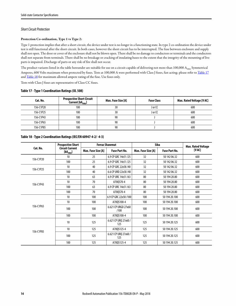
Short Circuit Protection
Protection Co-ordination, Type 1 vs Type 2:
Type 1 protection implies that after a short circuit, the device under test is no longer in a functioning state. In type 2 co-ordination the device under test is still functional after the short circuit. In both cases, however the short circuit has to be interrupted. The fuse between enclosure and supply shall not open. The door or cover of the enclosure shall not be blown open. There shall be no damage to conductors or terminals and the conductors shall not separate from terminals. There shall be no breakage or cracking of insulating bases to the extent that the integrity of the mounting of live parts is impaired. Discharge of parts or any risk of fire shall not occur.
The product variants listed in the table hereunder are suitable for use on a circuit capable of delivering not more than 100,000 Arms Symmetrical Amperes, 600 Volts maximum when protected by fuses. Tests at 100,000 A were performed with Class J fuses, fast acting; please refer to Table 17 and Table 18 for maximum allowed ampere rating of the fuse. Use fuses only.
Tests with Class J fuses are representative of Class CC fuses.
Table 17 - Type 1 Coordination Ratings (UL 508)
Table 18 - Type 2 Coordination Ratings (IEC/EN 60947-4-2/ -4-3)
Cat. No. Prospective Short Circuit Current [kArms] Max. Fuse Size [A] Fuse Class Max. Rated Voltage [V AC]
156-C1P20 100 30 J or CC 600156-C1P25 100 30 J or CC 600156-C1P43 100 90 J 600156-C1P65 100 90 J 600156-C1P85 100 90 J 600
Cat. No.Prospective Short
Circuit Current [kArms]
Ferraz Shawmut Siba Max. Rated Voltage [V AC]Max. Fuse Size [A] Fuse Part No. Max. Fuse Size [A] Fuse Part No.
156-C1P2010 25 6.9 CP GRC 14x51 /25 32 50 142 06.32 600
100 25 6.9 CP GRC 14x51 /25 32 50 142 06.32 600
156-C1P2510 40 6.9 CP GRC 22x58 /40 32 50 142 06.32 600
100 40 6.6 CP URD 22x58 /40 32 50 142 06.32 600
156-C1P43
10 63 6.9 CP URC 14x51 /63 80 50 194 20.80 60010 70 A70QS70-4 80 50 194 20.80 600
100 63 6.9 CP URC 14x51 /63 80 50 194 20.80 600100 70 A70QS70-4 80 50 194 20.80 600
156-C1P65
10 100 6.9 CP GRC 22x58 /100 100 50 194 20.100 60010 100 A70QS100-4 100 50 194 20.100 600
100 100 6.621 CP URGD 27x60 /100 100 50 194 20.100 600
100 100 A70QS100-4 100 50 194 20.100 600
156-C1P85
10 125 6.621 CP URQ 27x60 /125 125 50 194 20.125 600
10 125 A70QS125-4 125 50 194 20.125 600
100 125 6.621 CP URQ 27x60 /125 125 50 194 20.125 600
100 125 A70QS125-4 125 50 194 20.125 600
14 Rockwell Automation Publication 156-TD002B-EN-P - May 2018
Solid-state Contactor Specifications
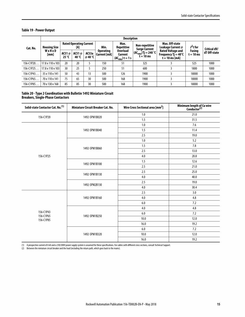
Table 19 - Power Output
Table 20 - Type 2 Coordination with Bulletin 1492 Miniature Circuit Breakers, Single-Phase Contactors
Cat. No.
Description
Housing Size W x H x D
[mm]
Rated Operating Current [A] Min.
Operating Current [mA]
Max. Repetitive Overload Current
(ACrms) t = 1 s
Non-repetitive Surge Current
(ACrms) Tj = 240 °C t = 10 ms
Max. Off-state Leakage Current @ Rated Voltage and
Frequency Tj = 40°C t = 10 ms [mA]
I2t for Fusing
t = 10 msCritical dV/
dT Off-stateAC51 @ 25 °C
AC51 @ 40 °C
AC53a @ 40 °C
156-C1P20… 17.8 x 110 x 103 20 20 5 150 51 325 3 525 1000156-C1P25… 17.8 x 110 x 103 30 25 5 250 51 600 3 1800 1000156-C1P43… 35 x 110 x 141 50 43 13 500 126 1900 3 18000 1000156-C1P65… 70 x 110 x 141 75 65 30 500 168 1900 3 18000 1000156-C1P85… 70 x 130 x 168 85 85 30 500 168 1900 3 18000 1000
Solid-state Contactor Cat. No.(1) Miniature Circuit Breaker Cat. No. Wire Cross Sectional area [mm2] Minimum length of Cu wire Conductor(2)
156-C1P20 1492-SPM1B0201.0 21.01.5 31.5
156-C1P25
1492-SPM1B0401.0 7.61.5 11.42.5 19.0
1492-SPM1B060
1.0 5.21.5 7.82.5 13.04.0 20.8
1492-SPM1B1001.5 12.62.5 21.0
1492-SPM1B1302.5 25.04.0 40.0
1492-SPM2B1302.5 19.04.0 30.4
156-C1P43156-C1P65156-C1P85
1492-SPM1B1602.5 3.04.0 4.86.0 7.2
1492-SPM1B250
4.0 4.86.0 7.2
10.0 12.016.0 19.2
1492-SPM1B3206.0 7.2
10.0 12.016.0 19.2
(1) A prospective current of 6 kA and a 230/200V power supply system is assumed for these specifications. For cables with different cross sections, consult Technical Support.(2) Between the miniature circuit breaker and the load (including the return path, which goes back to the mains).
Rockwell Automation Publication 156-TD002B-EN-P - May 2018 15

Solid-state Contactor Specifications
Application Diagrams
Applications for Non-motor Loads
Figure 8 - Single-phase Contactor, Line-Neutral/Line-Line Connection Figure 9 - Two Single-phase Contactors in Single Application, Delta and Star Connection
P= IL*UL
P=1.73*IL*UL
16 Rockwell Automation Publication 156-TD002B-EN-P - May 2018

Solid-state Contactor Specifications
Figure 10 - Three Single-phase Contactors in 3-phase Application, Delta, Star, Star with Neutral Connection
P=1.73*IL*UL
Rockwell Automation Publication 156-TD002B-EN-P - May 2018 17
Solid-state Contactor Specifications
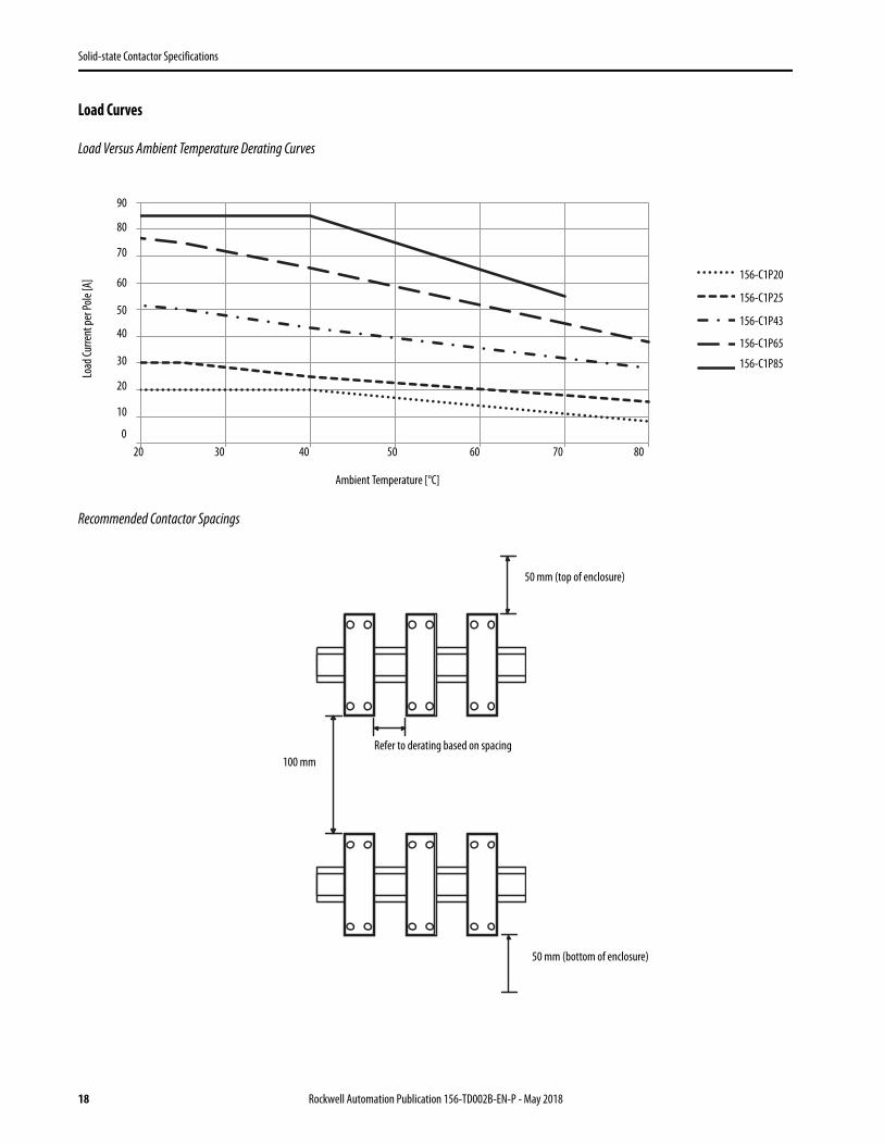
Load Curves
Load Versus Ambient Temperature Derating Curves
Recommended Contactor Spacings
0 25 40 70 80 Y C20 20 20 11.15 8.2 -0.295 31.830 30 25 17.875 15.5 -0.2375 34.557.5 50 43 31.75 28 -0.375 5884 75 65.4 44.85 38 -0.685 92.885 85 85 55
Ambient Temperature [°C]
Load
Curre
nt pe
r Pole
[A] 156-C1P20
156-C1P25
156-C1P43
156-C1P65
156-C1P85
20 30 40 50 60 70 800
10
20
30
40
50
60
70
80
90
50 mm (top of enclosure)
Refer to derating based on spacing100 mm
50 mm (bottom of enclosure)
18 Rockwell Automation Publication 156-TD002B-EN-P - May 2018
Solid-state Contactor Specifications
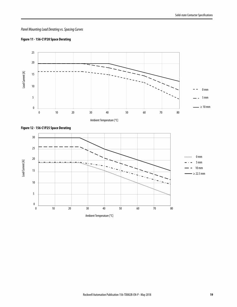
Panel Mounting Load Derating vs. Spacing Curves
Figure 11 - 156-C1P20 Space Derating
Figure 12 - 156-C1P25 Space Derating
Ambient Temperature [°C]
Load
Curre
nt [A
]
0 mm
5 mm
≥ 10 mm
20 30 40 50 60 70 800
5
10
15
20
25
100
Load
Curre
nt [A
]
0 mm
5 mm
≥ 22.5 mm
20 30 40 50 60 70 800
5
10
15
20
25
100
10 mm
30
Ambient Temperature [°C]
Rockwell Automation Publication 156-TD002B-EN-P - May 2018 19

Solid-state Contactor Specifications
Figure 13 - 156-C1P43 Space Derating
Figure 14 - 156-C1P65 Space Derating
Load
Curre
nt [A
] 0 mm
≥ 22.5 mm
20 30 40 50 60 70 80
0
10
20
30
40
50
100
Ambient Temperature [°C]
Ambient Temperature [°C]
Load
Curre
nt [A
]
0 mm
≥ 10 mm
Standalone unit
20 30 40 50 60 70 80030
35
40
45
50
55
60
65
70
20
75
20 Rockwell Automation Publication 156-TD002B-EN-P - May 2018
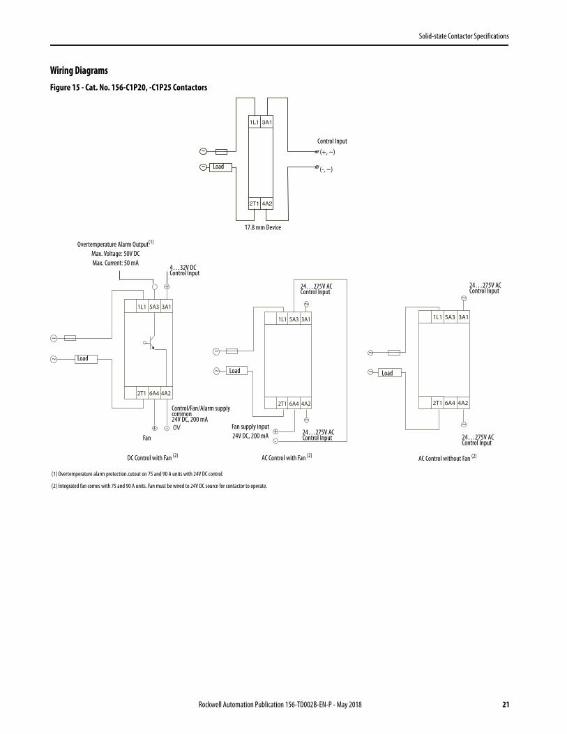
Solid-state Contactor Specifications
Wiring DiagramsFigure 15 - Cat. No. 156-C1P20, -C1P25 Contactors
~
4A22T1
3A11L1
~
17.8 mm Device
~
~
+
+ 0V-
2T1
1L1 3A15A3
4A26A4
~
~
2T1
1L1 3A15A3
4A26A4
~
~
+-
~
~
2T1
1L1 3A15A3
4A26A4
~
~
(1) Overtemperature alarm protection.cutout on 75 and 90 A units with 24V DC control.
(2) Integrated fan comes with 75 and 90 A units. Fan must be wired to 24V DC source for contactor to operate.
Control Input
Load
(+, ~)
Load
Load Load
4…32V DC Control Input
24…275V AC Control Input
24…275V AC Control Input
(-, ~)
DC Control with Fan (2) AC Control with Fan (2) AC Control without Fan (2)
24…275V AC Control Input 24…275V AC
Control Input
Overtemperature Alarm Output(1)
Max. Voltage: 50V DCMax. Current: 50 mA
Control/Fan/Alarm supply common24V DC, 200 mA
Fan supply input24V DC, 200 mAFan
Rockwell Automation Publication 156-TD002B-EN-P - May 2018 21

Solid-state Contactor Specifications
Approximate DimensionsDimensions in millimeters (inches). Dimensions are not intended for manufacturing purposes.
Figure 16 - Cat. No. 156-C1P20…, -C1P25…
Figure 17 - Cat. No. 156-C1P43…
T12
L11
98.5 (3.88)
100.
4 (3
.95)
110
(4.3
3)
90 (3
.54)
4.4 dia.
(0.17
)
4.4 (0.17)
17.8 (0.70)
5.4(0.21)4.5 (0.18)
51 (2.01)
3.2 (0.13)
43.8
(1.7
2)
35.5 (1.40)
8(0.31)
L11
T12
100.
4 (3
.95)
110
(4.3
3)
90 (3
.54)
4.4 dia.
(0.17
)
4.4 (0.17)
43.8
(1.7
2)
17.8 (0.70)
5.4(0.21)
4.5 (0.18)
43.7 (1.72)
8(0.31)
51 (2.01)
3.2 (0.13)
35.6 [1.40"]
136 (5.35)
22 Rockwell Automation Publication 156-TD002B-EN-P - May 2018

Solid-state Contactor Specifications
Figure 18 - Cat. No. 156-C1P65…
Figure 19 - Cat. No. 156-C1P85…
L11
T12
43.8
(1.7
2)
43.7 (1.72)51 (2.01)
3.2(0.13)
136 (5.35)
100.
4 (3
.95)
110
(4.3
3)
90 (3
.54)
4.4 dia. (0.17)
70 (2.76)
4.4 (0.17)43.2 (1.70)
17.8 (0.70)
5.4 (0.21)4.5 (0.18)
8(0.31)
17.8 (0.70)
4.4 (0.17)
8(0.31)
17.8 (0.70)
L11
T12
TEACH
100.
4 (3
.95)
110
(4.3
3)
90 (3
.54)
4.4 dia. (0.17)
8(0.31)70 (2.76)
4.4 (0.17)43.2 (1.70)
17.8 (0.70)5.4
(0.21)4.5 (0.18)78 (3.07)
163 (6.42)
43.7 (1.72)
60.5
(2.3
8)
130
(5.1
2)
4.4 (0.17)8
(0.31)
Rockwell Automation Publication 156-TD002B-EN-P - May 2018 23
Solid-state Contactor Specifications
Notes:
24 Rockwell Automation Publication 156-TD002B-EN-P - May 2018
Solid-state Contactor Specifications
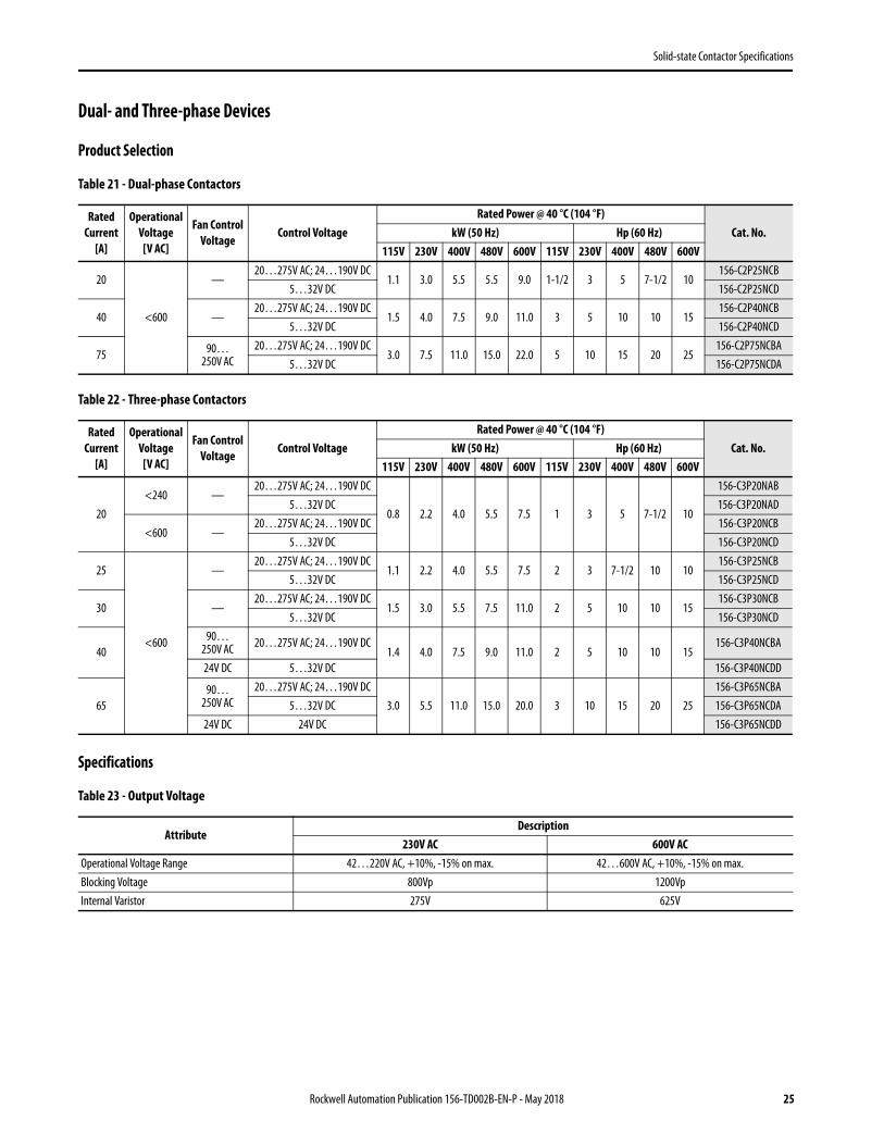
Dual- and Three-phase Devices
Product Selection
Table 21 - Dual-phase Contactors
Table 22 - Three-phase Contactors
Specifications
Table 23 - Output Voltage
Rated Current
[A]
Operational Voltage
[V AC]
Fan Control Voltage
Control VoltageRated Power @ 40 °C (104 °F)
Cat. No.kW (50 Hz) Hp (60 Hz)115V 230V 400V 480V 600V 115V 230V 400V 480V 600V
20
<600
—20…275V AC; 24…190V DC
1.1 3.0 5.5 5.5 9.0 1-1/2 3 5 7-1/2 10156-C2P25NCB
5…32V DC 156-C2P25NCD
40 —20…275V AC; 24…190V DC
1.5 4.0 7.5 9.0 11.0 3 5 10 10 15156-C2P40NCB
5…32V DC 156-C2P40NCD
75 90… 250V AC
20…275V AC; 24…190V DC3.0 7.5 11.0 15.0 22.0 5 10 15 20 25
156-C2P75NCBA5…32V DC 156-C2P75NCDA
Rated Current
[A]
Operational Voltage
[V AC]
Fan Control Voltage
Control VoltageRated Power @ 40 °C (104 °F)
Cat. No.kW (50 Hz) Hp (60 Hz)115V 230V 400V 480V 600V 115V 230V 400V 480V 600V
20<240 —
20…275V AC; 24…190V DC
0.8 2.2 4.0 5.5 7.5 1 3 5 7-1/2 10
156-C3P20NAB5…32V DC 156-C3P20NAD
<600 —20…275V AC; 24…190V DC 156-C3P20NCB
5…32V DC 156-C3P20NCD
25
<600
—20…275V AC; 24…190V DC
1.1 2.2 4.0 5.5 7.5 2 3 7-1/2 10 10156-C3P25NCB
5…32V DC 156-C3P25NCD
30 —20…275V AC; 24…190V DC
1.5 3.0 5.5 7.5 11.0 2 5 10 10 15156-C3P30NCB
5…32V DC 156-C3P30NCD
4090…
250V AC 20…275V AC; 24…190V DC1.4 4.0 7.5 9.0 11.0 2 5 10 10 15
156-C3P40NCBA
24V DC 5…32V DC 156-C3P40NCDD
6590…
250V AC20…275V AC; 24…190V DC
3.0 5.5 11.0 15.0 20.0 3 10 15 20 25156-C3P65NCBA
5…32V DC 156-C3P65NCDA24V DC 24V DC 156-C3P65NCDD
AttributeDescription
230V AC 600V ACOperational Voltage Range 42…220V AC, +10%, -15% on max. 42…600V AC, +10%, -15% on max.Blocking Voltage 800Vp 1200VpInternal Varistor 275V 625V
Rockwell Automation Publication 156-TD002B-EN-P - May 2018 25
Solid-state Contactor Specifications
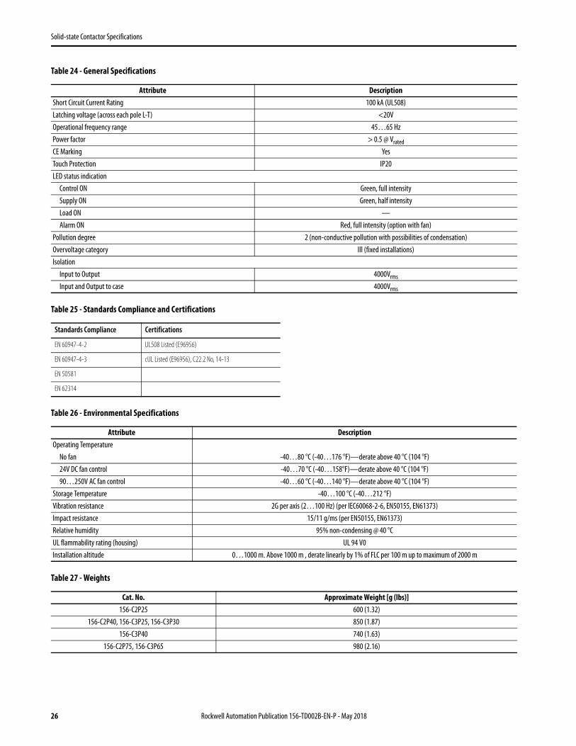
Table 24 - General Specifications
Table 25 - Standards Compliance and Certifications
Table 26 - Environmental Specifications
Table 27 - Weights
Attribute DescriptionShort Circuit Current Rating 100 kA (UL508)Latching voltage (across each pole L-T) <20VOperational frequency range 45…65 HzPower factor > 0.5 @ Vrated
CE Marking YesTouch Protection IP20LED status indication
Control ON Green, full intensitySupply ON Green, half intensityLoad ON —Alarm ON Red, full intensity (option with fan)
Pollution degree 2 (non-conductive pollution with possibilities of condensation)Overvoltage category III (fixed installations)Isolation
Input to Output 4000Vrms
Input and Output to case 4000Vrms
Standards Compliance Certifications
EN 60947-4-2 UL508 Listed (E96956)
EN 60947-4-3 cUL Listed (E96956), C22.2 No, 14-13
EN 50581
EN 62314
Attribute DescriptionOperating Temperature
No fan -40…80 °C (-40…176 °F)—derate above 40 °C (104 °F)24V DC fan control -40…70 °C (-40…158°F)—derate above 40 °C (104 °F)90…250V AC fan control -40…60 °C (-40…140 °F)—derate above 40 °C (104 °F)
Storage Temperature -40…100 °C (-40…212 °F)Vibration resistance 2G per axis (2…100 Hz) (per IEC60068-2-6, EN50155, EN61373)Impact resistance 15/11 g/ms (per EN50155, EN61373)Relative humidity 95% non-condensing @ 40 °CUL flammability rating (housing) UL 94 V0Installation altitude 0…1000 m. Above 1000 m , derate linearly by 1% of FLC per 100 m up to maximum of 2000 m
Cat. No. Approximate Weight [g (lbs)]156-C2P25 600 (1.32)
156-C2P40, 156-C3P25, 156-C3P30 850 (1.87)156-C3P40 740 (1.63)
156-C2P75, 156-C3P65 980 (2.16)
26 Rockwell Automation Publication 156-TD002B-EN-P - May 2018
Solid-state Contactor Specifications
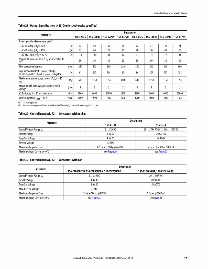
Table 28 - Output Specifications @ 25°C (unless otherwise specified)
Table 29 - Control Input (A1, A2)—Contactors without Fan
Table 30 - Control Input (A1, A2)—Contactors with Fan
AttributeDescription
156-C2P25 156-C2P40 156-C2P75 156-C3P20 156-C3P25 156-C3P30 156-C3P40 156-C3P65Rated operational current per pole(1)
(1) See derating curves
AC-51 rating @ Ta = 25 °C [A] 32 50 85 25 32 37 42 71AC-51 rating @ Ta = 40 °C [A] 27 40 75 20 28 30 42 66AC-53a rating @ Ta = 40 °C [A] 11.5 16.5 28 10 11 14 17 25
Number of motor starts (x:6, Tx:6 s, F:50%) at 40 ˚C(2)
(2) Overload current profile definition: x: multiple of AC53a rating, Tx: duration of current surge, F: duty cycle
30 30 30 30 30 30 30 30
Min. operational current [mA] 250 400 500 250 250 400 400 500Rep. overload current - (Motor Rating)UL508: TAMB=40 °C, tON=1 s, tOFF=9 s, 50 cycles [A] 61 107 154 61 84 107 107 154
Maximum transient surge current (ITSM), t = 10 ms [Ap] 600 1150 1750 600 600 1150 1150 1750
Maximum off-state leakage current at rated voltage [mA] 5 5 5 5 5 5 5 5
I2t for fusing (t = 10 ms) Minimum [A2s] 1800 6600 15000 1800 1800 6600 6600 15000Crititcal dv/dt (@ Tj init = 40 °C) [V/s] 1000 1000 1000 1000 1000 1000 1000 1000
AttributeDescription
156-C…D 156-C…AControl Voltage Range, Uc 5…32V DC 20…275V AC/24 (-10%)…190V DCPick Up Voltage 4.8V DC 20V AC/DCDrop Out Voltage 1.0V DC 5V AC/DCReverse Voltage 32V DC —Maximum Response Time 0.5 Cycle + 500 s @24V DC 2 Cycles @ 230V AC/110V DCMaximum Input Current @ 40 °C see Figure 20 see Figure 21
AttributeDescription
156-C3P40NCDD, 156-C3P65NCBA, 156-C3P65NCDD 156-C3P40NCBA, 156-C3P65NCBDControl Voltage Range, Uc 5…32V DC 20…275V ACPick Up Voltage 4.8V DC 20V AC/DCDrop Out Voltage 1.0V DC 5V AC/DCMax. Reverse Voltage 32V DC —Maximum Response Time 1Cycle + 500 s @24V DC 5 Cycles @ 230V ACMaximum Input Current @ 40 °C see Figure 22 see Figure 23
Rockwell Automation Publication 156-TD002B-EN-P - May 2018 27
Solid-state Contactor Specifications
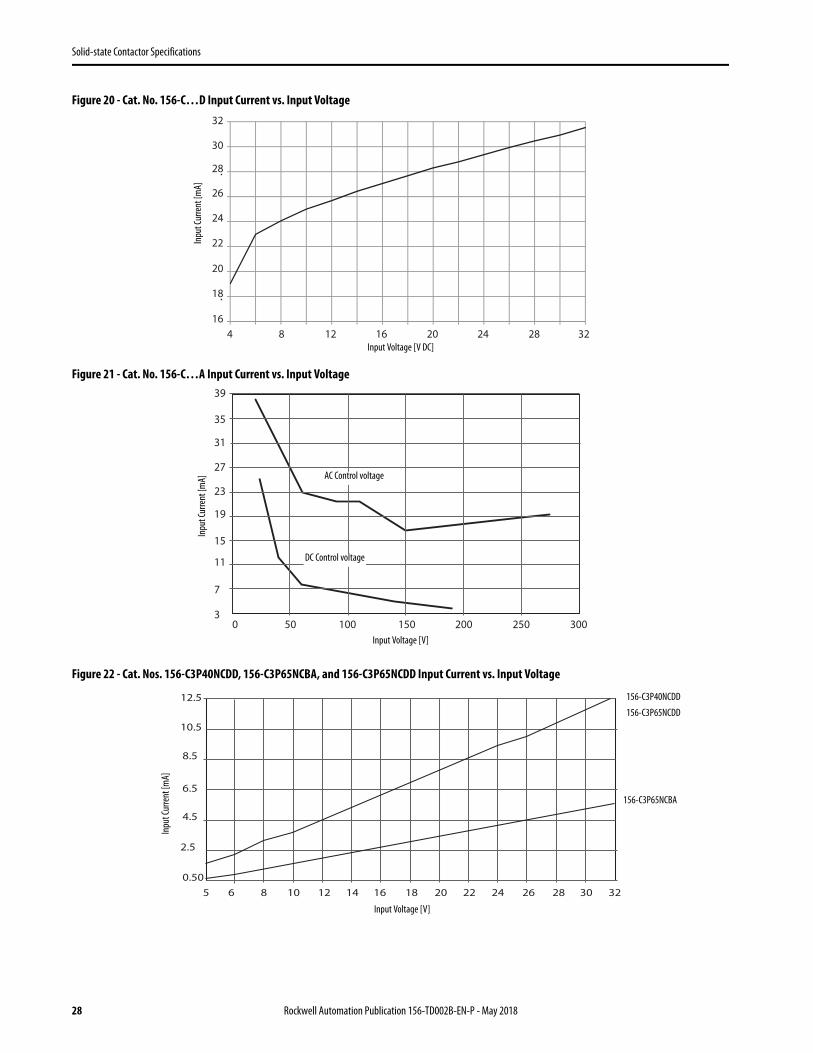
Figure 20 - Cat. No. 156-C…D Input Current vs. Input Voltage
Figure 21 - Cat. No. 156-C…A Input Current vs. Input Voltage
Figure 22 - Cat. Nos. 156-C3P40NCDD, 156-C3P65NCBA, and 156-C3P65NCDD Input Current vs. Input Voltage
32
16
18
20
22
24
26
28
30
4 8 12 16 20 24 28 32Input Voltage [V DC]
Inpu
t Cur
rent
[mA]
39
35
31
27
23
19
15
11
7
30 50 100 150 200 250 300
Input Voltage [V]
Inpu
t Cur
rent
[mA] AC Control voltage
DC Control voltage
12.5
10.5
8.5
6.5
4.5
2.5
0.505 6 8 10 12 14 16 18 20 22 24 26 28 30 32
Input Voltage [V]
Inpu
t Cur
rent
[mA]
156-C3P40NCDD
156-C3P65NCDD
156-C3P65NCBA
28 Rockwell Automation Publication 156-TD002B-EN-P - May 2018
Solid-state Contactor Specifications
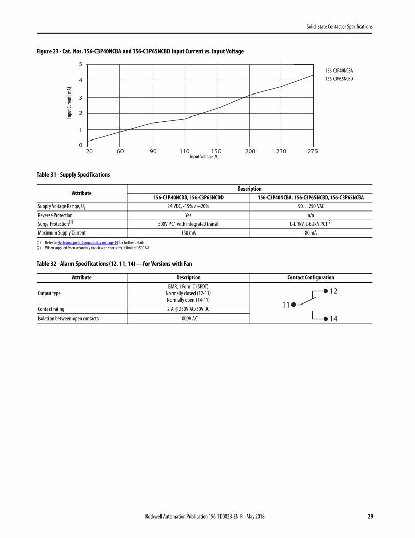
Figure 23 - Cat. Nos. 156-C3P40NCBA and 156-C3P65NCBD Input Current vs. Input Voltage
Table 31 - Supply Specifications
Table 32 - Alarm Specifications (12, 11, 14) —for Versions with Fan
AttributeDescription
156-C3P40NCDD, 156-C3P65NCDD 156-C3P40NCBA, 156-C3P65NCBD, 156-C3P65NCBASupply Voltage Range, Us 24 VDC, -15% / +20% 90…250 VACReverse Protection Yes n/aSurge Protection(1)
(1) Refer to Electromagnetic Compatibility on page 34 for further details
500V PC1 with integrated transil L-L 1kV, L-E 2kV PC1(2)
(2) When supplied from secondary circuit with short circuit limit of 1500 VA
Maximum Supply Current 150 mA 80 mA
Attribute Description Contact Configuration
Output typeEMR, 1 Form C (SPDT)
Normally closed (12-11)Normally open (14-11)
Contact rating 2 A @ 250V AC/30V DC
Isolation between open contacts 1000V AC
5
4
3
2
1
027520 60 90 110 150 200 230
Input Voltage [V]
Inpu
t Cur
rent
[mA]
156-C3P40NCBA
156-C3P65NCBD
11
12
14
Rockwell Automation Publication 156-TD002B-EN-P - May 2018 29
Solid-state Contactor Specifications
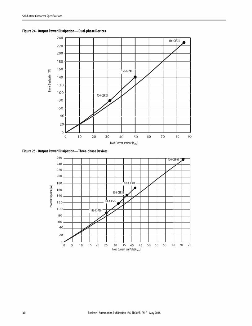
Figure 24 - Output Power Dissipation—Dual-phase Devices
Figure 25 - Output Power Dissipation—Three-phase Devices
0
20
120
140
160
180
200
220
240
0 10 20 30 40 50 60 70 80 90
100
80
60
40
Load Current per Pole [Arms]
Powe
r Diss
ipatio
n [W
]
156-C2P25
156-C2P40
156-C2P75
0
20
120
140
160
180
200
220
240
0 5 10 15 20 25 30 35 40 45
100
80
60
40
260
50 55 60 65 70 75Load Current per Pole [Arms]
Powe
r Diss
ipatio
n [W
]
156-C3P25
156-C3P40
156-C3P65
156-C3P20
156-C3P35
30 Rockwell Automation Publication 156-TD002B-EN-P - May 2018
Solid-state Contactor Specifications
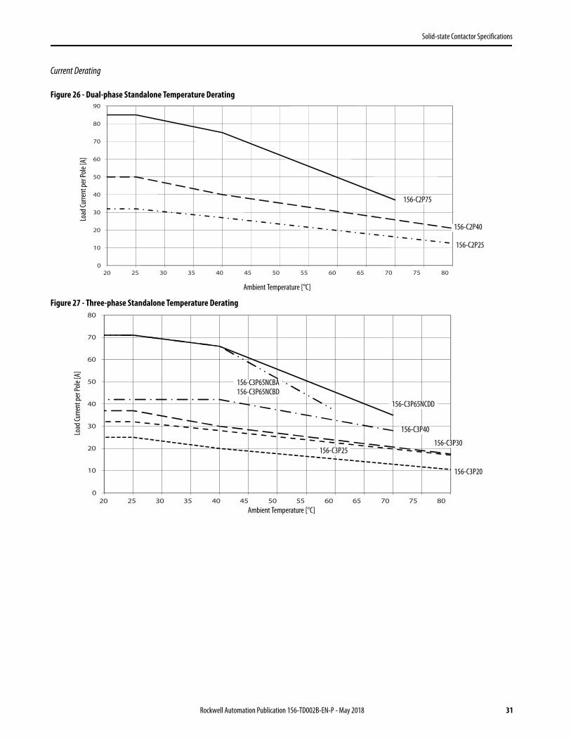
Current Derating
Figure 26 - Dual-phase Standalone Temperature Derating
Figure 27 - Three-phase Standalone Temperature Derating
0
10
20
30
40
50
60
70
80
90
20 25 30 35 40 45 50 55 60 65 70 75 80
Ambient Temperature [°C]
Load
Curre
nt pe
r Pole
[A]
156-C2P75
156-C2P40
156-C2P25
0
10
20
30
40
50
60
70
80
20 25 30 35 40 45 50 55 60 65 70 75 80Ambient Temperature [°C]
Load
Curre
nt pe
r Pole
[A]
156-C3P65NCDD
156-C3P20
156-C3P25156-C3P30
156-C3P40
156-C3P65NCBA156-C3P65NCBD
Rockwell Automation Publication 156-TD002B-EN-P - May 2018 31
Solid-state Contactor Specifications
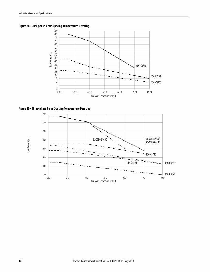
Figure 28 - Dual-phase 0 mm Spacing Temperature Derating
Figure 29 - Three-phase 0 mm Spacing Temperature Derating
05
10152025303540455055606570758085
20°C 30°C 40°C 50°C 60°C 70°C 80°CAmbient Temperature [°C]
Load
Curre
nt [A
]
156-C2P75
156-C2P40
156-C2P25
RGC3_3020mm
0
10
20
30
40
50
60
70
20 30 40 50 60 70 80Ambient Temperature [°C]
Load
Curre
nt [A
]
156-C3P65NCDD
156-C3P20
156-C3P25 156-C3P30
156-C3P40
156-C3P65NCBA156-C3P65NCBD
32 Rockwell Automation Publication 156-TD002B-EN-P - May 2018

Solid-state Contactor Specifications
Table 33 - Motor Ratings: Hp (UL508) / kW (EN/IEC60947-4-2) @ 40 °C
Cat. No.Rated Voltage [V AC]
115 230 400 480 600
156-C2P25[Hp] 1-1/2 3 5 7-1/2 10
[kW] 1.1 3.0 5.5 5.5 9.0
156-C2P40[Hp] 3 5 10 10 15
[kW] 1.5 4.0 7.5 9.0 11.0
156-C2P75[Hp] 5 10 15 20 25
[kW] 3.0 7.5 11.0 15.0 22.0
156-C3P20[Hp] 1 3 5 7-1/2 10
[kW] 0.75 2.2 4.0 5.5 7.5
156-C3P25[Hp] 2 3 7-1/2 10 10
[kW] 1.1 2.2 4.0 5.5 7.5
156-C3P30[Hp] 2 5 10 10 15
[kW] 1.5 3.0 5.5 7.5 11.0
156-C3P40[Hp] 2 5 10 10 15
[kW] 1.5 4.0 7.5 9.0 11.0
156-C3P65[Hp] 3 10 15 20 25
[kW] 3.0 5.5 11.0 15.0 20.0
Rockwell Automation Publication 156-TD002B-EN-P - May 2018 33

Solid-state Contactor Specifications
Electromagnetic Compatibility
Table 34 - Electromagnetic Compatibility Ratings
Note:
• Control input lines must be installed together to maintain products susceptibility to Radio Frequency Interference.• Use of AC solid-state contactors may according to the application and the load current, cause conducted radio interferences. Use of mains
filters may be necessary for cases where the user must meet E.M.C requirements. The capacitor values given inside the filtering specification tables are only indications, the filter attenuation depends on the final application.
• This product has been designed for Class A equipment. Use of this product in domestic environments may cause radio interference, in which case the user may be required to employ additional mitigation methods.
• Surge tests were carried out with the signal line impedance network. In case the line impedance is less than 40Ω, it is suggested that AC supply is provided through a secondary circuit where the short circuit limit between conductors or between conductors and ground is 1500VA or less.
Performance Criteria Definitions:
• Performance Criteria 1 (Performance Criteria A): No degradation of performance or loss of function is allowed when the product is operated as intended.
• Performance Criteria 2 (Performance Criteria B): During the test, degradation of performance or partial loss of function is allowed. However, when the test is completed, the product should return operating as intended by itself.
• Performance Criteria 3 (Performance Criteria C): Temporary loss of function is allowed, provided the function can be restored by manual operation of the control.
Table 35 - Filtering - EN / IEC 55011 Class A compliance
Attribute Standard Compliance Attribute Standard Compliance
EMC immunity EN/IEC 61000-6-2 Radio interference voltage emission (conducted) EN/IEC 55011
Electrostatic discharge (ESD) immunity EN/IEC 61000-4-2 0.15…30 MHz Class A (Industrial) with filters - see Table 35
Air discharge, 8kV Performance Criteria 2 Radiated radio frequency immunity EN/IEC 61000-4-3Contact, 4kV Performance Criteria 2 10V/m, 80…1000 MHz Performance Criteria 1
Electrical fast transient (Burst) immunity EN/IEC 61000-4-4 10V/m, 1.4…2.0 GHz Performance Criteria 1Output: 2kV, 5 kHz Performance Criteria 1 10V/m, 2.0…2.7 GHz Performance Criteria 1Input: 1kV, 5 kHz Performance Criteria 1 Conducted radio frequency immunity EN/IEC 61000-4-6
Electrical surge immunity EN/IEC 61000-4-5 10V/m, 0.15…80 MHz Performance Criteria 1Output, line to line, 1kV Performance Criteria 1 Voltage dips immunity EN/IEC 61000-4-11Output, line to earth, 2kV Performance Criteria 1 0% for 0.5/1cycle Performance Criteria 2Input, line to line, 1kV (A1, A2) Performance Criteria 2 40% for 10 cycles Performance Criteria 2Input, line to earth, 2kV (A1, A2) Performance Criteria 2 70% for 250 cycles Performance Criteria 211, 12, 14, line to line, 1kV Performance Criteria 1 Voltage interruptions immunity EN/IEC 61000-4-1111, 12, 14, line to earth, 2kV (versions with fan only) Performance Criteria 1 0% for 5000 ms Performance Criteria 2
EMC emission EN/IEC 60947-4-3(1)
(1) For conformance to EN/IEC 61000-6-4, an external capacitor class X1, 220nF, 275VAC is to be connected across the input control lines A1-A2 for AC control versions.
Radio interference field emission (radiated) EN/IEC 5501130…1000 MHz Class A (Industrial)
Cat. No. Suggested Filter for Compliance Max. Heater Current [A]156-C2P25NA 220nF / 275V /X1 25156-C2P25NC 220nF / 760V /X1 25156-C2P40NC 330nF / 760V /X1 40156-C2P75NC 470nF / 760V /X1 65156-C3P20NA 220nF / 275V /X1 25156-C3P20NC 220nF / 760V /X1 25156-C3P25NC 330nF / 760V /X1 25
34 Rockwell Automation Publication 156-TD002B-EN-P - May 2018
Solid-state Contactor Specifications
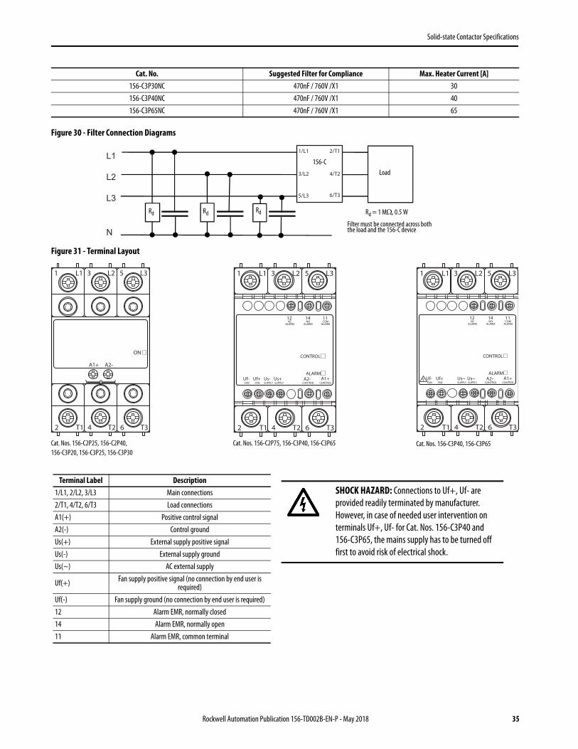
Figure 30 - Filter Connection Diagrams
Figure 31 - Terminal Layout
156-C3P30NC 470nF / 760V /X1 30156-C3P40NC 470nF / 760V /X1 40156-C3P65NC 470nF / 760V /X1 65
Cat. No. Suggested Filter for Compliance Max. Heater Current [A]
L1
L2
L3
N
1/L1
3/L2
5/L3
2/T1
4/T2
6/T3
156-C
Rd = 1 M, 0.5 W
Load
Rd Rd Rd
Filter must be connected across both the load and the 156-C device
2 T1 4 T2 6 T3
1 L1 3 L2 5 L3
A1+ A2-
ON
Cat. Nos. 156-C2P25, 156-C2P40, 156-C3P20, 156-C3P25, 156-C3P30
2 T1 4 T2 6 T3
1 L1 3 L2 5 L3
Uf- Uf+ Us- Us+FAN FAN SUPPLY SUPPLY
A1+A2-CONTROL CONTROL
CONTROL
ALARM
12 14 11NC
ALARMNO
ALARMCOM
ALARM
Cat. Nos. 156-C2P75, 156-C3P40, 156-C3P65 Cat. Nos. 156-C3P40, 156-C3P65
2 T1 4 T2 6 T3
1 L1 3 L2 5 L3
Uf- Uf+ Us~ Us~FAN FAN SUPPLY SUPPLY
A1+A2-CONTROL CONTROL
CONTROL
ALARM
12 14 11NC
ALARMNO
ALARMCOM
ALARM
Terminal Label Description1/L1, 2/L2, 3/L3 Main connections2/T1, 4/T2, 6/T3 Load connectionsA1(+) Positive control signalA2(-) Control groundUs(+) External supply positive signalUs(-) External supply groundUs(~) AC external supply
Uf(+) Fan supply positive signal (no connection by end user is required)
Uf(-) Fan supply ground (no connection by end user is required)12 Alarm EMR, normally closed14 Alarm EMR, normally open11 Alarm EMR, common terminal
SHOCK HAZARD: Connections to Uf+, Uf- are provided readily terminated by manufacturer. However, in case of needed user intervention on terminals Uf+, Uf- for Cat. Nos. 156-C3P40 and 156-C3P65, the mains supply has to be turned off first to avoid risk of electrical shock.
Rockwell Automation Publication 156-TD002B-EN-P - May 2018 35
Solid-state Contactor Specifications
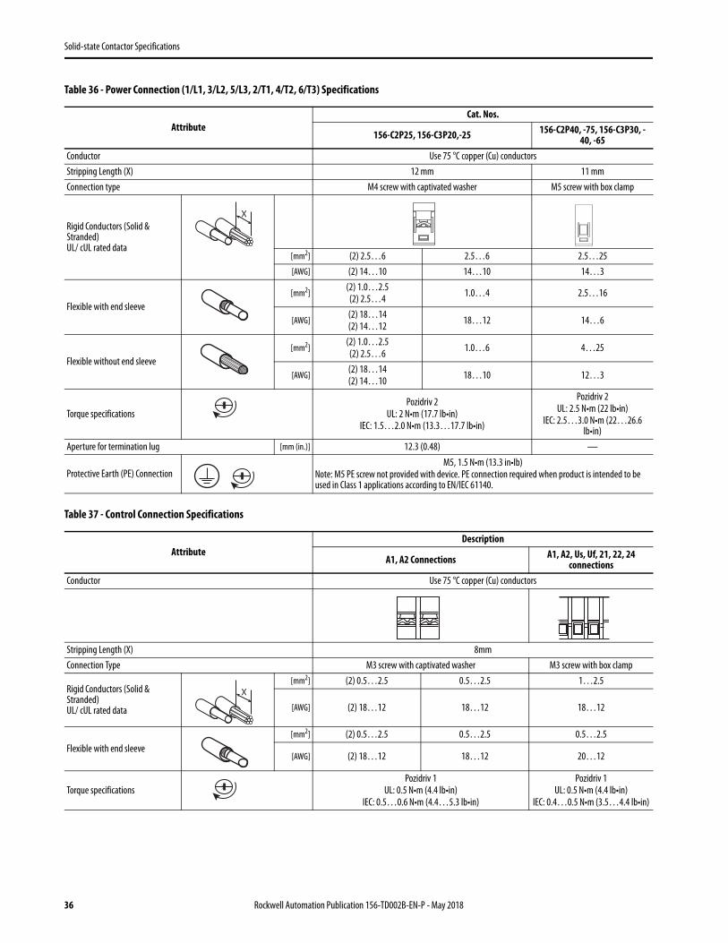
Table 36 - Power Connection (1/L1, 3/L2, 5/L3, 2/T1, 4/T2, 6/T3) Specifications
Table 37 - Control Connection Specifications
AttributeCat. Nos.
156-C2P25, 156-C3P20,-25 156-C2P40, -75, 156-C3P30, -40, -65
Conductor Use 75 °C copper (Cu) conductorsStripping Length (X) 12 mm 11 mmConnection type M4 screw with captivated washer M5 screw with box clamp
Rigid Conductors (Solid & Stranded)UL/ cUL rated data
[mm2] (2) 2.5…6 2.5…6 2.5…25[AWG] (2) 14…10 14…10 14…3
Flexible with end sleeve[mm2]
(2) 1.0…2.5(2) 2.5…4 1.0…4 2.5…16
[AWG](2) 18…14(2) 14…12 18…12 14…6
Flexible without end sleeve[mm2]
(2) 1.0…2.5(2) 2.5…6 1.0…6 4…25
[AWG](2) 18…14(2) 14…10 18…10 12…3
Torque specificationsPozidriv 2
UL: 2 N•m (17.7 lb•in)IEC: 1.5…2.0 N•m (13.3…17.7 lb•in)
Pozidriv 2UL: 2.5 N•m (22 lb•in)
IEC: 2.5…3.0 N•m (22…26.6 lb•in)
Aperture for termination lug [mm (in.)] 12.3 (0.48) —
Protective Earth (PE) ConnectionM5, 1.5 N•m (13.3 in•lb)
Note: M5 PE screw not provided with device. PE connection required when product is intended to be used in Class 1 applications according to EN/IEC 61140.
AttributeDescription
A1, A2 Connections A1, A2, Us, Uf, 21, 22, 24 connections
Conductor Use 75 °C copper (Cu) conductors
Stripping Length (X) 8mmConnection Type M3 screw with captivated washer M3 screw with box clamp
Rigid Conductors (Solid & Stranded)UL/ cUL rated data
[mm2] (2) 0.5…2.5 0.5…2.5 1…2.5
[AWG] (2) 18…12 18…12 18…12
Flexible with end sleeve[mm2] (2) 0.5…2.5 0.5…2.5 0.5…2.5
[AWG] (2) 18…12 18…12 20…12
Torque specificationsPozidriv 1
UL: 0.5 N•m (4.4 lb•in)IEC: 0.5…0.6 N•m (4.4…5.3 lb•in)
Pozidriv 1UL: 0.5 N•m (4.4 lb•in)
IEC: 0.4…0.5 N•m (3.5…4.4 lb•in)
X
X
36 Rockwell Automation Publication 156-TD002B-EN-P - May 2018
Solid-state Contactor Specifications
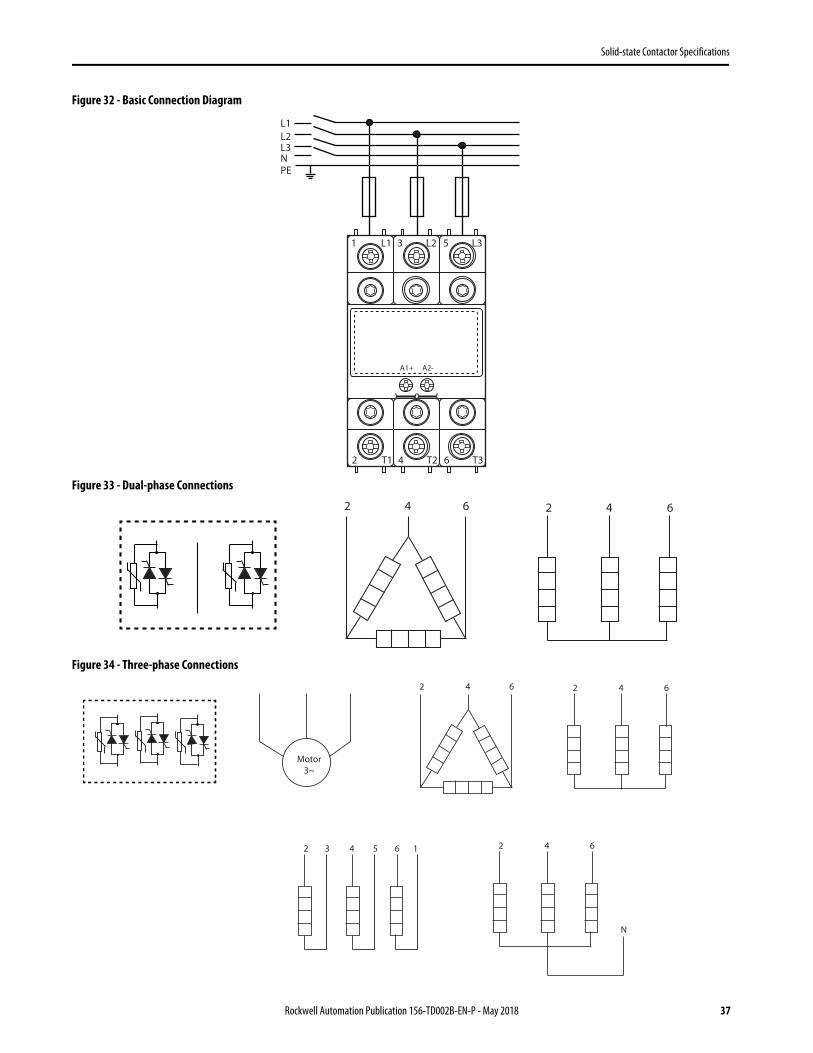
Figure 32 - Basic Connection Diagram
Figure 33 - Dual-phase Connections
Figure 34 - Three-phase Connections
2 T1 4 T2 6 T3
1 L1 3 L2 5 L3
A1+ A2-
L1
PE
L2
NL3
2 4 6 2 4 6
2 4 6 2 4 6
Motor3~
2 4 6
N
2 4 63 5 1
Rockwell Automation Publication 156-TD002B-EN-P - May 2018 37

Solid-state Contactor Specifications
Figure 35 - Fan Operation for Versions with Integrated Fan
Table 38 - Red LED Alarm Indications
Flashes Description of Fault Timing Diagram
2 Mains loss
3 Load loss or SSR short circuit
4 SSR open circuit
Steady SSR overtemperature
START
No
Yes
Is chip temperature >115 °C?
No
Yes
No
Yes
No
Yes
Fan: ON
Is chip temperature <85 °C?
Is chip temperature limit reached?
Fan: OFFSSR output: OFF
Red LED: ONAlarm Signal: ON
SSR output: ONRed LED: OFF
Alarm Signal: OFFFan: OFF
Is chip temperature <80 °C?
3 s
0.5 s
3 s
0.5 s
3 s
38 Rockwell Automation Publication 156-TD002B-EN-P - May 2018
Solid-state Contactor Specifications
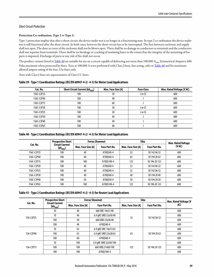
Short Circuit Protection
Protection Co-ordination, Type 1 vs Type 2:
Type 1 protection implies that after a short circuit, the device under test is no longer in a functioning state. In type 2 co-ordination the device under test is still functional after the short circuit. In both cases, however the short circuit has to be interrupted. The fuse between enclosure and supply shall not open. The door or cover of the enclosure shall not be blown open. There shall be no damage to conductors or terminals and the conductors shall not separate from terminals. There shall be no breakage or cracking of insulating bases to the extent that the integrity of the mounting of live parts is impaired. Discharge of parts or any risk of fire shall not occur.
The product variants listed in Table 40 are suitable for use on a circuit capable of delivering not more than 100,000 Arms Symmetrical Amperes, 600 Volts maximum when protected by fuses. Tests at 100,000 A were performed with Class J fuses, fast acting; refer to Table 40 and for maximum allowed ampere rating of the fuse. Use fuses only.
Tests with Class J fuses are representative of Class CC fuses.
Table 39 - Type 1 Coordination Ratings (IEC/EN 60947-4-2/ -4-3) for Motor Load Applications
Table 40 - Type 2 Coordination Ratings (IEC/EN 60947-4-2/ -4-3) for Motor Load Applications
Table 41 - Type 2 Coordination Ratings (IEC/EN 60947-4-2/ -4-3) for Heater Load Applications
Cat. No. Short Circuit Current [kArms] Max. Fuse Size [A] Fuse Class Max. Rated Voltage [V AC]156C-C2P25 100 30 J or CC 600156C-C2P40 100 40 J 600156C-C2P75 100 60 J 600156C-C3P20 100 30 J or CC 600156C-C3P25 100 30 J or CC 600156C-C3P30 100 40 J 600156C-C3P40 100 40 J 600156C-C3P65 100 60 J 600
Cat. No.Prospective Short
Circuit Current [kArms]
Ferraz Shawmut Siba Max. Rated Voltage [V AC]Max. Fuse Size [A] Fuse Part No. Max. Fuse Size [A] Fuse Part No.
156C-C2P25 100 40 A70QS40-4 32 50 142 06 32 600156C-C2P40 100 60 A70QS60-4 63 50 194 20 63 600156C-C2P75 100 100 A70QS100-4 125 50 196 20 125 600156C-C3P20 100 40 A70QS40-4 32 50 142 06 32 600156C-C3P25 100 40 A70QS40-4 32 50 142 06 32 600156C-C3P30 100 40 A70QS40-4 40 50 194 20 40 600156C-C3P40 100 50 A70QS50-4 50 50 194 20 50 600156C-C3P65 100 100 A70QS100-4 125 50 196 20 125 600
Cat. No.Prospective Short
Circuit Current [kArms]
Ferraz Shawmut Siba Max. Rated Voltage [V AC]Max. Fuse Size [A] Fuse Part No. Max. Fuse Size [A] Fuse Part No.
156-C2P25
10 40 660 URC 14x51/40
32 50 142 06 32
60010 40 6.9 gRC URD 22x58/40 600
100 40 660 URD 22x58/40 600100 40 A70QS40-4 600
156-C2P4010 63 6.9 gRC URC 14x51/63
63 50 194 20 63600
100 63 6.9 gRC URD 22x58/63 600100 60 A70QS60-4 600
156-C2P7510 100 6.9 gRC URD 22x58/100
125 50 196 20 125600
100 100 660 URQ 27x60/100 600100 100 A70QS100-4 600
Rockwell Automation Publication 156-TD002B-EN-P - May 2018 39
Solid-state Contactor Specifications
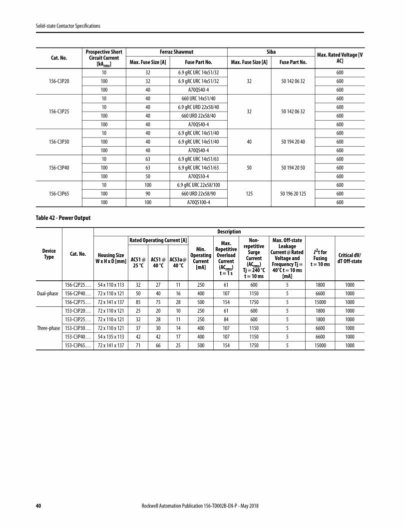
Table 42 - Power Output
156-C3P2010 32 6.9 gRC URC 14x51/32
32 50 142 06 32600
100 32 6.9 gRC URC 14x51/32 600100 40 A70QS40-4 600
156-C3P25
10 40 660 URC 14x51/40
32 50 142 06 32
60010 40 6.9 gRC URD 22x58/40 600
100 40 660 URD 22x58/40 600100 40 A70QS40-4 600
156-C3P3010 40 6.9 gRC URC 14x51/40
40 50 194 20 40600
100 40 6.9 gRC URC 14x51/40 600100 40 A70QS40-4 600
156-C3P4010 63 6.9 gRC URC 14x51/63
50 50 194 20 50600
100 63 6.9 gRC URC 14x51/63 600100 50 A70QS50-4 600
156-C3P6510 100 6.9 gRC URC 22x58/100
125 50 196 20 125600
100 90 660 URD 22x58/90 600100 100 A70QS100-4 600
Device Type Cat. No.
Description
Housing Size W x H x D [mm]
Rated Operating Current [A]Min.
Operating Current
[mA]
Max. Repetitive Overload Current (ACrms) t = 1 s
Non-repetitive
Surge Current (ACrms)
Tj = 240 °C t = 10 ms
Max. Off-state Leakage
Current @ Rated Voltage and
Frequency Tj = 40°C t = 10 ms
[mA]
I2t for Fusing
t = 10 msCritical dV/
dT Off-stateAC51 @ 25 °C
AC51 @ 40 °C
AC53a @ 40 °C
Dual-phase156-C2P25… 54 x 110 x 113 32 27 11 250 61 600 5 1800 1000156-C2P40… 72 x 110 x 121 50 40 16 400 107 1150 5 6600 1000156-C2P75… 72 x 141 x 137 85 75 28 500 154 1750 5 15000 1000
Three-phase
153-C3P20… 72 x 110 x 121 25 20 10 250 61 600 5 1800 1000153-C3P25… 72 x 110 x 121 32 28 11 250 84 600 5 1800 1000153-C3P30… 72 x 110 x 121 37 30 14 400 107 1150 5 6600 1000153-C3P40… 54 x 135 x 113 42 42 17 400 107 1150 5 6600 1000153-C3P65… 72 x 141 x 137 71 66 25 500 154 1750 5 15000 1000
Cat. No.Prospective Short
Circuit Current [kArms]
Ferraz Shawmut Siba Max. Rated Voltage [V AC]Max. Fuse Size [A] Fuse Part No. Max. Fuse Size [A] Fuse Part No.
40 Rockwell Automation Publication 156-TD002B-EN-P - May 2018
Solid-state Contactor Specifications
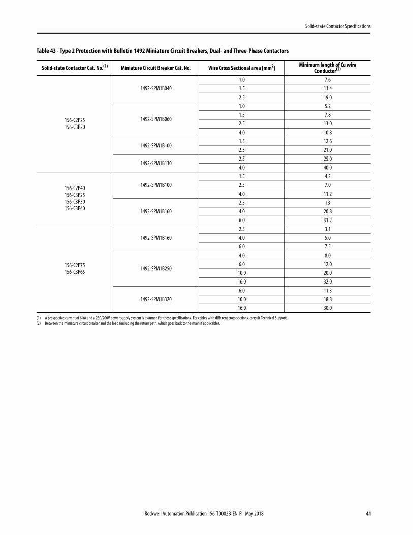
Table 43 - Type 2 Protection with Bulletin 1492 Miniature Circuit Breakers, Dual- and Three-Phase Contactors
Solid-state Contactor Cat. No.(1)
(1) A prospective current of 6 kA and a 230/200V power supply system is assumed for these specifications. For cables with different cross sections, consult Technical Support.
Miniature Circuit Breaker Cat. No. Wire Cross Sectional area [mm2] Minimum length of Cu wire Conductor(2)
(2) Between the miniature circuit breaker and the load (including the return path, which goes back to the main if applicable).
156-C2P25156-C3P20
1492-SPM1B0401.0 7.61.5 11.42.5 19.0
1492-SPM1B060
1.0 5.21.5 7.82.5 13.04.0 10.8
1492-SPM1B1001.5 12.62.5 21.0
1492-SPM1B1302.5 25.04.0 40.0
156-C2P40156-C3P25156-C3P30156-C3P40
1492-SPM1B1001.5 4.22.5 7.04.0 11.2
1492-SPM1B1602.5 134.0 20.86.0 31.2
156-C2P75156-C3P65
1492-SPM1B1602.5 3.14.0 5.06.0 7.5
1492-SPM1B250
4.0 8.06.0 12.0
10.0 20.016.0 32.0
1492-SPM1B3206.0 11.3
10.0 18.816.0 30.0
Rockwell Automation Publication 156-TD002B-EN-P - May 2018 41
Solid-state Contactor Specifications
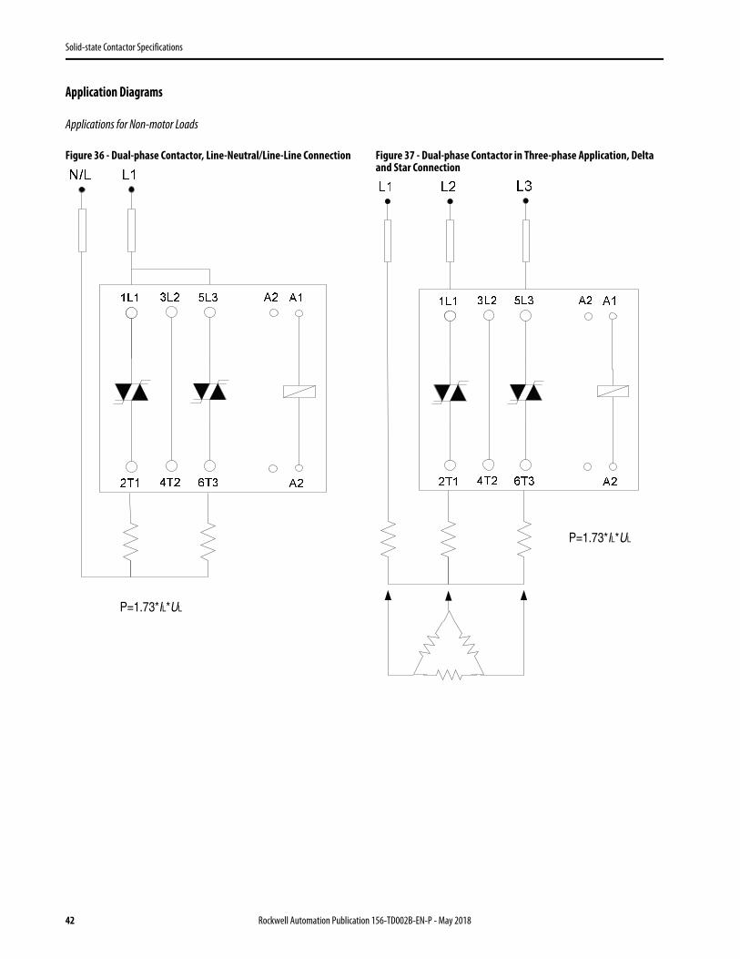
Application Diagrams
Applications for Non-motor Loads
Figure 36 - Dual-phase Contactor, Line-Neutral/Line-Line Connection Figure 37 - Dual-phase Contactor in Three-phase Application, Delta and Star Connection
P=1.73*IL*UL
P=1.73*IL*UL
42 Rockwell Automation Publication 156-TD002B-EN-P - May 2018

Solid-state Contactor Specifications
Figure 38 - Three-phase Contactor, Delta and Star Connection Recommended Contactor Spacings
P=1.73*IL*UL
50 mm (top of enclosure)
refer to derating based on spacing100 mm
50 mm (bottom of enclosure)
Rockwell Automation Publication 156-TD002B-EN-P - May 2018 43
Solid-state Contactor Specifications
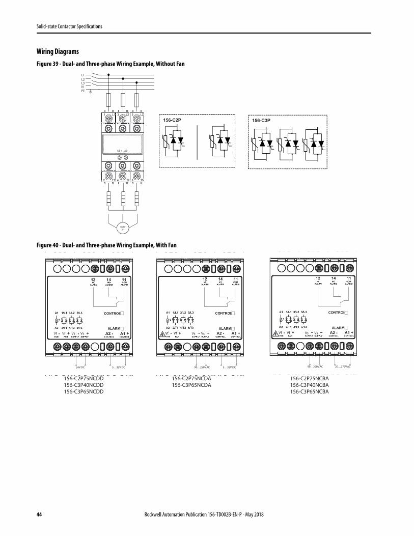
Wiring DiagramsFigure 39 - Dual- and Three-phase Wiring Example, Without Fan
Figure 40 - Dual- and Three-phase Wiring Example, With Fan
156-C2P
156-C3P
L1L2L3NPE
Motor 3 ~
A1 + A2-
1 L1 3 L2 5 L3
2 T1 4 T2 6 T3
156-C2P 156-C3P
24V DC 5…32V DC 90…250V AC 5…32V DC 90…250V AC 20…275V AC
156-C2P75NCDD156-C3P40NCDD156-C3P65NCDD
Vf Vf Vf VfVfVf Vs Vs Vs VsVs Vs
156-C2P75NCDA156-C3P65NCDA
156-C2P75NCBA156-C3P40NCBA156-C3P65NCBA
44 Rockwell Automation Publication 156-TD002B-EN-P - May 2018
Solid-state Contactor Specifications
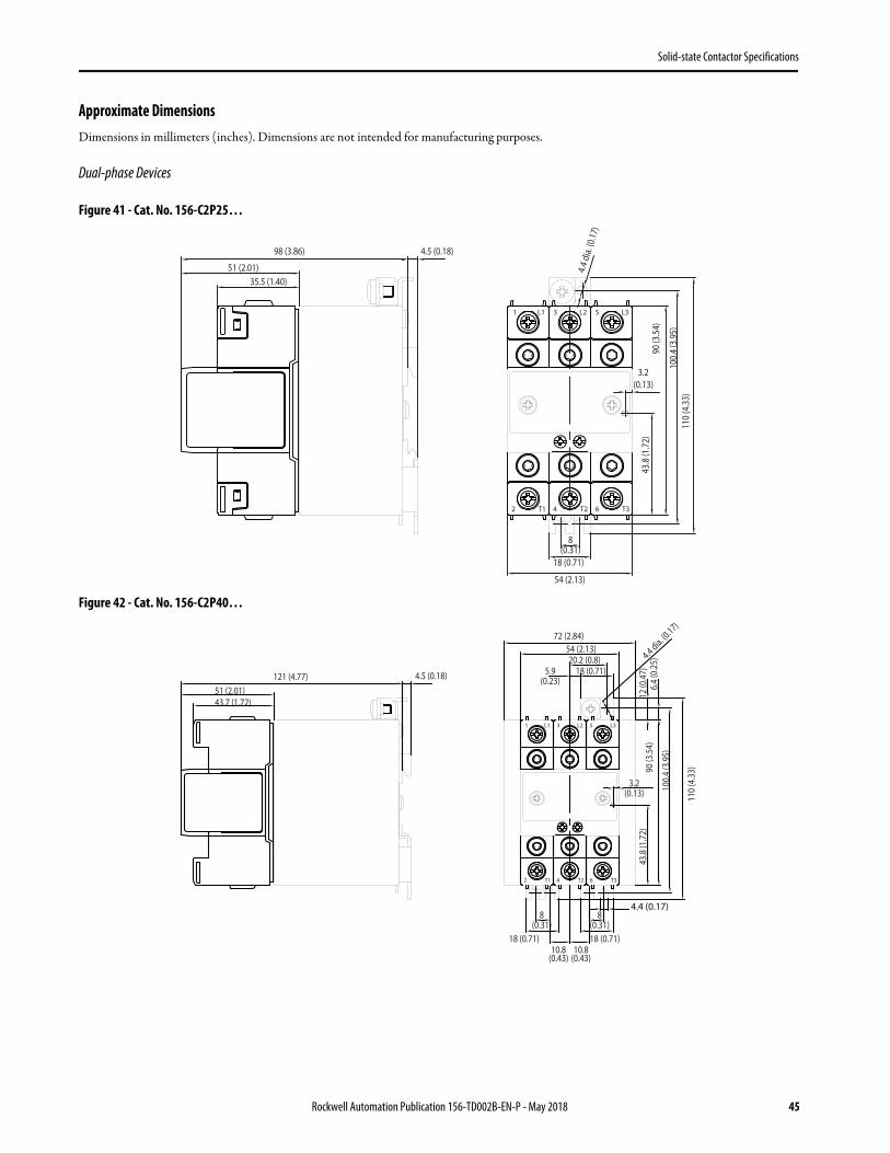
Approximate DimensionsDimensions in millimeters (inches). Dimensions are not intended for manufacturing purposes.
Dual-phase Devices
Figure 41 - Cat. No. 156-C2P25…
Figure 42 - Cat. No. 156-C2P40…
T12
L11
T24
L23
T36
L35
98 (3.86)
35.5 (1.40)
8(0.31)
18 (0.71)
54 (2.13)
110
(4.3
3)
43.8
(1.7
2)
51 (2.01)
3.2(0.13)
100.
4 (3
.95)
90 (3
.54)
4.4 d
ia. (0
.17)
4.5 (0.18)
T12
L11
T24
L23
T36
L35
43.7 (1.72)
8(0.31)
18 (0.71)10.8
(0.43)
110
(4.3
3)
43.8
(1.7
2)
51 (2.01)
100.
4 (3
.95)
90 (3
.54)
4.4 dia. (0.17)
18 (0.71)
8(0.31)
10.8(0.43)
4.4 (0.17)
3.2(0.13)
18 (0.71)
72 (2.84)
121 (4.77)
54 (2.13)20.2 (0.8)
5.9(0.23) 6.
4 (0
.25)
12 (0
.47)4.5 (0.18)
Rockwell Automation Publication 156-TD002B-EN-P - May 2018 45
Solid-state Contactor Specifications
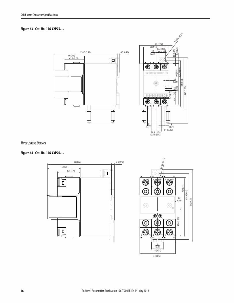
Figure 43 - Cat. No. 156-C2P75…
Three-phase Devices
Figure 44 - Cat. No. 156-C3P20…
T12
L11
T24
L23
T36
L35
43.7 (1.72)
8(0.31)
10.8(0.43)
110
(4.3
3)10
0.4
(3.9
5)90
(3.5
4)4.4 dia. (0
.17)
8(0.31)
10.8(0.43)
4.4 (0.17)
18 (0.71)
72 (2.84)54 (2.13)
20.2 (0.8)5.9
(0.23) 6.4
(0.2
5)12
(0.4
7)
4.5 (0.18)
31.4
(1.2
4)
6(0.24)
9.4
(0.3
8)
4.7
(0.1
9)
66 (2.6)
141
(5.5
5)
136.5 (5.38)
T12
L11
T24
L23
T36
L35
18 (0.71)
110
(4.3
3)100.
4 (3
.95)90
(3.5
4)
4.4 d
ia. (0
.17)
8(0.31)
54 (2.13)
4.5 (0.18)
43.8
(1.7
2)
3.2(0.13)
98 (3.86)
35.5 (1.4)
51 (2.01)
46 Rockwell Automation Publication 156-TD002B-EN-P - May 2018
Solid-state Contactor Specifications
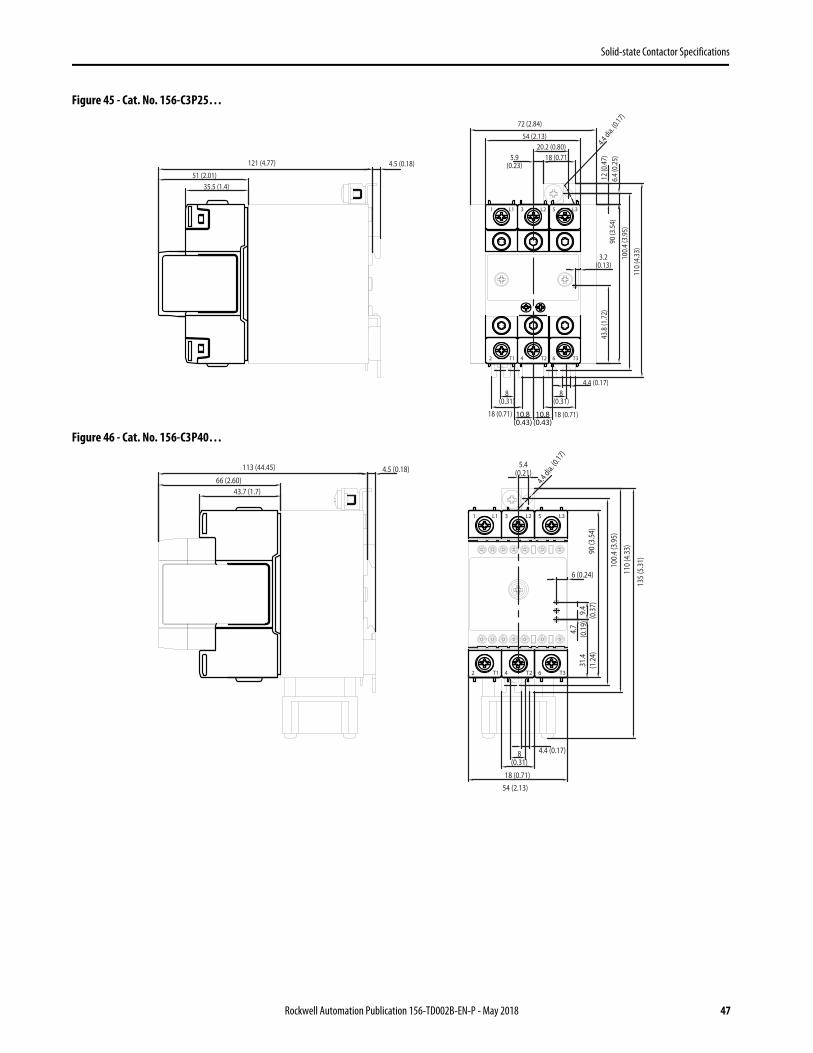
Figure 45 - Cat. No. 156-C3P25…
Figure 46 - Cat. No. 156-C3P40…
T12
L11
T24
L23
T36
L35
18 (0.71)
110
(4.3
3)10
0.4
(3.9
5)
90 (3
.54)
4.4 dia. (0
.17)
8(0.31)
54 (2.13)
4.5 (0.18)
43.8
(1.7
2)
3.2(0.13)
35.5 (1.4)51 (2.01)
18 (0.71)
18 (0.71)
8(0.31)
10.8(0.43)
10.8(0.43)
72 (2.84)
121 (4.77)
20.2 (0.80)5.9
(0.23)
6.4
(0.2
5)12
(0.4
7)
4.4 (0.17)
T12
L11
T24
L23
T36
L35
110
(4.3
3)
100.
4 (3
.95)
90 (3
.54)
4.4 dia. (0
.17)
4.5 (0.18)
8(0.31)
4.4 (0.17)
18 (0.71)
31.4
(1.2
4)
6 (0.24)
66 (2.60)
9.4
(0.3
7)
4.7
(0.1
9)
43.7 (1.7)
54 (2.13)
113 (44.45) 5.4(0.21)
135
(5.3
1)
Rockwell Automation Publication 156-TD002B-EN-P - May 2018 47
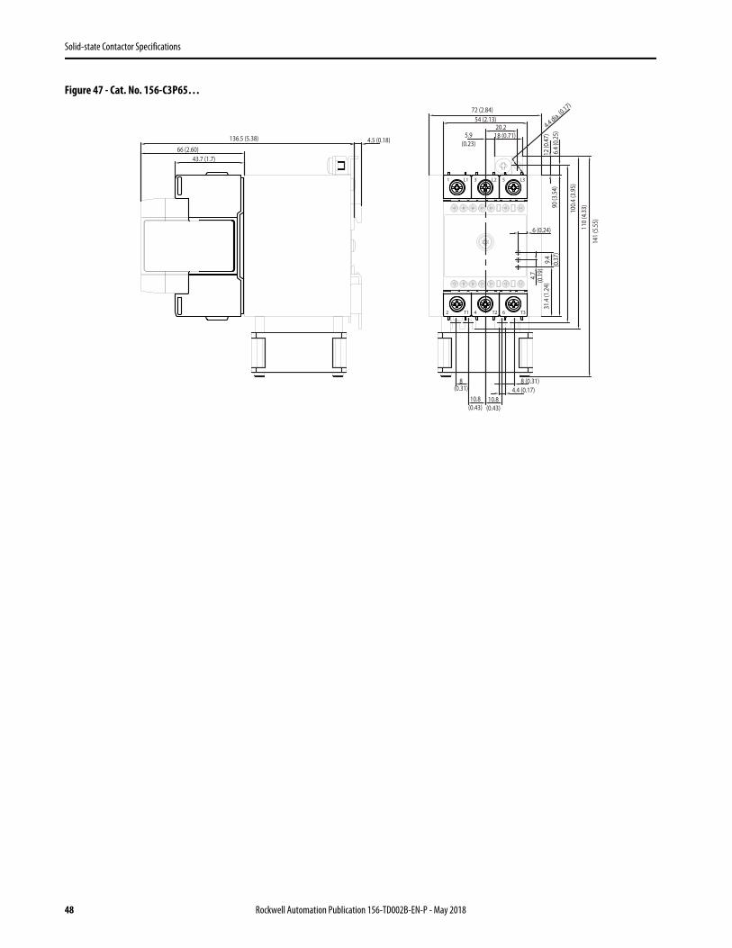
Solid-state Contactor Specifications
Figure 47 - Cat. No. 156-C3P65…
T12
L11
T24
L23
T36
L35
110
(4.3
3)100.
4 (3
.95)
90 (3
.54)
4.4 dia. (0.17)
4.5 (0.18)
8(0.31) 4.4 (0.17)
18 (0.71)
31.4
(1.2
4)
6 (0.24)
66 (2.60)
9.4
(0.3
7)
4.7
(0.1
9)
43.7 (1.7)
54 (2.13)
141
(5.5
5)
8 (0.31)
20.25.9
(0.23)
10.8(0.43)
72 (2.84)
136.5 (5.38)
10.8(0.43)
6.4
(0.2
5)12
(0.4
7)
48 Rockwell Automation Publication 156-TD002B-EN-P - May 2018

Solid-state Contactor Specifications
Notes:
Rockwell Automation Publication 156-TD002B-EN-P - May 2018 49

Allen-Bradley, Rockwell Software, Rockwell Automation, and LISTEN. THINK. SOLVE are trademarks of Rockwell Automation, Inc.Trademarks not belonging to Rockwell Automation are property of their respective companies.
Publication 156-TD002B-EN-P - May 2018
Rockwell Automation SupportUse the following resources to access support information.
Documentation FeedbackYour comments will help us serve your documentation needs better. If you have any suggestions on how to improve this document, complete the How Are We Doing? form at http://literature.rockwellautomation.com/idc/groups/literature/documents/du/ra-du002_-en-e.pdf.
Technical Support Center Knowledgebase Articles, How-to Videos, FAQs, Chat, User Forums, and Product Notification Updates. www.rockwellautomation.com/knowledgebase
Local Technical Support Phone Numbers Locate the phone number for your country. www.rockwellautomation.com/global/support/get-support-now.page
Direct Dial CodesFind the Direct Dial Code for your product. Use the code to route your call directly to a technical support engineer.
www.rockwellautomation.com/global/support/direct-dial.page
Literature Library Installation Instructions, Manuals, Brochures, and Technical Data. www.rockwellautomation.com/literature
Product Compatibility and Download Center (PCDC)
Get help determining how products interact, check features and capabilities, and find associated firmware.
www.rockwellautomation.com/global/support/pcdc.page
Rockwell Otomasyon Ticaret A.Ş., Kar Plaza İş Merkezi E Blok Kat:6 34752 İçerenköy, İstanbul, Tel: +90 (216) 5698400
Rockwell Automation maintains current product environmental information on its website at http://www.rockwellautomation.com/rockwellautomation/about-us/sustainability-ethics/product-environmental-compliance.page.
Supersedes Publication 156-TD002A-EN-P - January 2017 Copyright © 2018 Rockwell Automation, Inc. All rights reserved. Printed in the U.S.A.