Solid polymer electrolyte membranes for fuel cell ... · Journal of Membrane Science 259 (2005)...
17
Journal of Membrane Science 259 (2005) 10–26 Solid polymer electrolyte membranes for fuel cell applications—a review B. Smitha, S. Sridhar, A.A. Khan ∗ Membrane Separations Group, Chemical Engineering Division, Indian Institute of Chemical Technology, Hyderabad 500007, India Received 23 March 2004; received in revised form 5 January 2005; accepted 21 January 2005 Available online 27 June 2005 Abstract Fuel cells represent a clean alternative to current technologies for utilizing hydrocarbon fuel resources. Polymer electrolyte membrane fuel cells (PEMFCs) have acquired due importance as they are best suited for applications where a quick start up is required such as in automobiles. The prime requirements of fuel cell membranes are high proton conductivity, low methanol/water permeability, good mechanical and thermal stability and moderate price. Membranes and the operating parameters together have a profound influence on performance of PEMFCs. Perfluorinated ionomers, hydrocarbon and aromatic polymers and acid–base complexes have been described in the review. The performance of this special class of polymers, considering their structure–property relationship and the current research involving their applicability in fuel cell systems are presented. Modifications made to Nafion ® membranes, the conceptual design of substitutes for perfluorosulfonic acid materials and modifications made to aromatic membranes to render them suitable for this application have been summarized. Promising avenues for further research in this area have been identified. © 2005 Published by Elsevier B.V. Keywords: PEM fuel cell; Proton conductivity; Ion exchange membranes; Membrane preparation and structure 1. Introduction Throughout the world, the need of the hour is power gen- eration with environmental protection. This has prompted research in various aspects of fuel cells. Savings in fossil fuels, due to high efficiency of energy conversion, low pol- lution level, low noise and low maintenance costs render fuel cells preferable over other energy conversion devices. Fig. 1 shows a comparison of fuel cell performance with other energy conversion systems. Although fuel cells are not a recent development, the use of polymeric membranes as elec- trolytes has received a tremendous impetus in the recent past. It is because of this development that fuel cells are the premier candidates as portable source of power for light duty vehicles and buildings and as replacement for rechargeable batter- ies [1]. In addition to the development of materials for the fuel cell stack, PEMFC systems development has seen quite ∗ Corresponding author. Tel.: +91 40 7193139; fax: +91 40 7190387. E-mail address: aakhan [email protected] (A.A. Khan). revolutionary advances. Modeling activities have enhanced both the efficiency as well as the reliability of the systems. Recently, some exciting modeling work has been published [2,3] that should find use in facilitating the design of advanced unit fuel cell components. For example, an impressive growth in worldwide patent activity indicates a significant growth in technological advancement. Fig. 2 illustrates the increase in patent applications for PEMFC-related inventions that has occurred in recent years. The PEM fuel cell gained prominence after an ion- exchange resin was incorporated as an electrolyte for space application by General Electric (GE), in 1959. This enabled the PEMFC over a period to surpass the solar cells and other alternatives. Based upon its perceived simplicity of design and weight advantages, combined with optimum compatibil- ity [4]. PEMFC currently finds a wide range of applications. In this context, a membrane that complies with the basic requirements of fuel cells and is inexpensive at the same time has been the principal goal of research. Before a review of current polymer membranes applied to fuel cells, a brief overview of fuel cells is appropriate. 0376-7388/$ – see front matter © 2005 Published by Elsevier B.V. doi:10.1016/j.memsci.2005.01.035
Transcript of Solid polymer electrolyte membranes for fuel cell ... · Journal of Membrane Science 259 (2005)...

Journal of Membrane Science 259 (2005) 10–26
Solid polymer electrolyte membranes for fuel cellapplications—a review
B. Smitha, S. Sridhar, A.A. Khan∗
Membrane Separations Group, Chemical Engineering Division, Indian Institute of Chemical Technology, Hyderabad 500007, India
Received 23 March 2004; received in revised form 5 January 2005; accepted 21 January 2005Available online 27 June 2005
Abstract
Fuel cells represent a clean alternative to current technologies for utilizing hydrocarbon fuel resources. Polymer electrolyte membrane fuelcells (PEMFCs) have acquired due importance as they are best suited for applications where a quick start up is required such as in automobiles.The prime requirements of fuel cell membranes are high proton conductivity, low methanol/water permeability, good mechanical and thermalstability and moderate price. Membranes and the operating parameters together have a profound influence on performance of PEMFCs.Perfluorinated ionomers, hydrocarbon and aromatic polymers and acid–base complexes have been described in the review. The performanceo icability inf ic acidm . Promisinga©
K
1
erflfFortIcaif
ncedms.shedced
owthin
inhas
on-spacebledothersigntibil-ns.asicameviewrief
0d
f this special class of polymers, considering their structure–property relationship and the current research involving their appluel cell systems are presented. Modifications made to Nafion® membranes, the conceptual design of substitutes for perfluorosulfonaterials and modifications made to aromatic membranes to render them suitable for this application have been summarized
venues for further research in this area have been identified.2005 Published by Elsevier B.V.
eywords:PEM fuel cell; Proton conductivity; Ion exchange membranes; Membrane preparation and structure
. Introduction
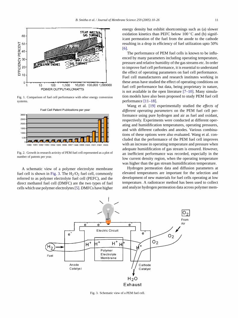
Throughout the world, the need of the hour is power gen-ration with environmental protection. This has promptedesearch in various aspects of fuel cells. Savings in fossiluels, due to high efficiency of energy conversion, low pol-ution level, low noise and low maintenance costs renderuel cells preferable over other energy conversion devices.ig. 1 shows a comparison of fuel cell performance withther energy conversion systems. Although fuel cells are not aecent development, the use of polymeric membranes as elec-rolytes has received a tremendous impetus in the recent past.t is because of this development that fuel cells are the premierandidates as portable source of power for light duty vehiclesnd buildings and as replacement for rechargeable batter-
es [1]. In addition to the development of materials for theuel cell stack, PEMFC systems development has seen quite
∗ Corresponding author. Tel.: +91 40 7193139; fax: +91 40 7190387.E-mail address:[email protected] (A.A. Khan).
revolutionary advances. Modeling activities have enhaboth the efficiency as well as the reliability of the systeRecently, some exciting modeling work has been publi[2,3] that should find use in facilitating the design of advanunit fuel cell components. For example, an impressive grin worldwide patent activity indicates a significant growthtechnological advancement.Fig. 2 illustrates the increasepatent applications for PEMFC-related inventions thatoccurred in recent years.
The PEM fuel cell gained prominence after an iexchange resin was incorporated as an electrolyte forapplication by General Electric (GE), in 1959. This enathe PEMFC over a period to surpass the solar cells andalternatives. Based upon its perceived simplicity of deand weight advantages, combined with optimum compaity [4]. PEMFC currently finds a wide range of applicatioIn this context, a membrane that complies with the brequirements of fuel cells and is inexpensive at the stime has been the principal goal of research. Before a reof current polymer membranes applied to fuel cells, a boverview of fuel cells is appropriate.
376-7388/$ – see front matter © 2005 Published by Elsevier B.V.oi:10.1016/j.memsci.2005.01.035
B. Smitha et al. / Journal of Membrane Science 259 (2005) 10–26 11
Fig. 1. Comparison of fuel cell performance with other energy conversionsystems.
Fig. 2. Growth in research activity of PEM fuel cell represented as a plot ofnumber of patents per year.
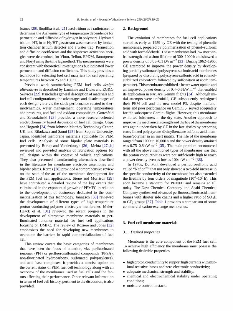
A schematic view of a polymer electrolyte membranefuel cell is shown inFig. 3. The H2/O2 fuel cell, commonlyreferred to as polymer electrolyte fuel cell (PEFC), and thedirect methanol fuel cell (DMFC) are the two types of fuelcells which use polymer electrolytes[5]. DMFCs have higher
energy density but exhibit shortcomings such as (a) sloweroxidation kinetics than PEFC below 100◦C and (b) signif-icant permeation of the fuel from the anode to the cathoderesulting in a drop in efficiency of fuel utilization upto 50%[6].
The performance of PEM fuel cells is known to be influ-enced by many parameters including operating temperature,pressure and relative humidity of the gas streams etc. In orderto improve fuel cell performance, it is essential to understandthe effect of operating parameters on fuel cell performance.Fuel cell manufacturers and research institutes working inthese areas have studied the effect of operating conditions onfuel cell performance but data, being proprietary in nature,is not available in the open literature[7–10]. Many simula-tion models have also been proposed to study PEM fuel cellperformance[11–18].
Wang et al.[19] experimentally studied theeffects ofdifferent operating parameterson the PEM fuel cell per-formance using pure hydrogen and air as fuel and oxidant,respectively. Experiments were conducted at different oper-ating and humidification temperatures, operating pressures,and with different cathodes and anodes. Various combina-tions of these options were also evaluated. Wang et al. con-cluded that the performance of the PEM fuel cell improveswith an increase in operating temperature and pressure whenadequate humidification of gas stream is ensured. However,a thel turew ture.
rs ate andd lowt ollecta mem-
ic view
Fig. 3. Schematn inefficient performance was recorded, especially inow current density region, when the operating temperaas higher than the gas stream humidification temperaHydrogen permeation data and diffusion paramete
levated temperatures are important for the selectionevelopment of new materials for fuel cells operating at
emperature. A radiotracer method has been used to cnd analyze hydrogen permeation data across polymer
of a PEM fuel cell.
12 B. Smitha et al. / Journal of Membrane Science 259 (2005) 10–26
branes[20]. Stodilka et al.[21] used tritium as a radiotracer todetermine the Arrhenius type of temperature dependence forpermeation and diffusion of hydrogen in polymers. Hydratedtritium, HT, in an H2/HT gas stream was measured by ioniza-tion chamber tritium detector and a water trap. Permeationand diffusion coefficients and the respective activation ener-gies were determined for Viton, Teflon, EPDM, Santopreneand Noryl using the time lag method. The measurements wereconsistent with theoretical investigations but indicated lowerpermeation and diffusion coefficients. This study provides atechnique for selecting fuel cell materials for cell operatingtemperatures between 25 and 150◦C.
Previous work summarizing PEM fuel cellsdesignalternativesis described by Larminie and Dicks and EG&GServices[22]. It includes general description of materials andfuel cell configurations, the advantages and disadvantages ofeach design vis-a-vis the stack performance related to ther-modynamics, water management, operating temperaturesand pressures, and fuel and oxidant composition. Gottesfeldand Zawodzinski[23] provided a more research-orientedelectrochemistry based discussion of fuel cell design. Glipaand Hogarth[24] from Johnson Matthey Technology Center,UK, and Rikukawa and Sanui[25] from Sophia University,Japan, identified membrane materials applicable for PEMfuel cells. Analysis of some bipolar plate materials ispresented by Borup and Vanderborgh[26]. Mehta [27a,b]r forc ns.T ribedi andb ewo t forth thatc iont com-mt turep ier-H thed per-fl nsfe es too fuelc
anest atedi SA),n es),a te ont ano fac-t tioni alsop
2. Background
The evolution of membranes for fuel cell applicationsstarted as early as 1959 by GE with the testing of phenolicmembranes, prepared by polymerization of phenol–sulfonicacid with formaldehyde. These membranes had low mechan-ical strength and a short lifetime of 300–1000 h and showed apower density of 0.05–0.1 kW m−2 [33]. During 1962–1965,GE attempted to improve the power density by develop-ing partially sulfonated polystyrene sulfonic acid membranes(prepared by dissolving polystyrene sulfonic acid in ethanol-stabilized chloroform followed by sulfonation at room tem-perature). This membrane exhibited a better water uptake andan improved power density of 0.4–0.6 kW m−2 that enabledits application in NASA’s Gemini flights[34]. Although ini-tial attempts were unfruitful, GE subsequently redesignedtheir PEM cell and the new model P3, despite malfunc-tions and poor performance on Gemini 5, served adequatelyfor the subsequent Gemini flights. However, this membraneexhibited brittleness in the dry state. Another approach toimprove the mechanical strength and the life of the membranewas again undertaken by GE in the late sixties by preparingcross-linked polystyrene-divinylbenzene sulfonic acid mem-brane/polymer in an inert matrix. The life of the membraneranged from 1000 to 10,000 h and the power density attainedwas 0.75–0.8 kW m−2 [35]. The main problem encounteredw thatt acha
acidc int ndedts o tillt icalC em-b Ot ec
3
3
cell.T s thef
• in-
•• ting
•
eviewed and provided analysis of fabrication optionsell designs within the context of vehicle applicatiohey also presented manufacturing alternatives desc
n the literature for membrane electrode assembliesipolar plates. Kerres[28] provided a comprehensive revin the state-of-the-art of the membrane developmen
he PEM fuel cell applications. Stone and Morrison[29]ave contributed a detailed review of the key eventsulminated in the exponential growth of PEMFC in relato the development of businesses dedicated to theercialization of this technology. Jannasch[30] reviewed
he developments of different types of high-temperaroton conducting polymer electrolyte membranes. Meaack et al. [31] reviewed the recent progress inevelopment of alternative membrane materials touorinated ionomer material for fuel cell applicatioocusing on DMFC. The review of Roziere and Jones[32]mphasizes the need for developing new membranvercome the barriers in rapid commercialization ofell.
This review covers the basic categories of membrhat have been the focus of attention, viz. perfluorinonomer (PFI) or perfluorosulfonated compounds (PFon-fluorinated hydrocarbons, sulfonated poly(arylennd acid–base complexes. It provides a concise upda
he current status of PEM fuel cell technology along withverview of the membranes used in fuel cells and theors affecting their performance. Other relevant informan terms of fuel cell history, pertinent to the discussion, isrovided.
ith all the above mentioned types of membranes washe proton conductivities were not sufficiently high to repower density even as low as 100 mW cm−2 [36].In 1970s, Du Pont developed a perfluorosulfonic
alled “Nafion®” that not only showed a two-fold increasehe specific conductivity of the membrane but also extehe lifetime by four orders of magnitude (104–105 h). Thisoon became a standard for PEMFC and remains soday. The Dow Chemical Company and Asahi Chemompany synthesized advanced perfluorosulfonic acid mranes with shorter side chains and a higher ratio of S3H
o CF2 groups[37]. Table 1provides a comparison of somommercial cation-exchange membranes.
. Fuel cell membrane materials
.1. Desired properties
Membrane is the core component of the PEM fuelo achieve high efficiency the membrane must possesollowing desirable properties
high proton conductivity to support high currents with mimal resistive losses and zero electronic conductivity;adequate mechanical strength and stability;chemical and electrochemical stability under operaconditions;moisture control in stack;

B. Smitha et al. / Journal of Membrane Science 259 (2005) 10–26 13
Table 1Properties of commercial cation-exchange membranes
Membrane Membrane type IEC (mequiv./g) Thickness (mm) Gel water (%) Conductivity (S/cm) at 30◦C and 100% RH
Asahi Chemical Industry Company Ltd., Chiyoda-ku, Tokyo, JapanK 101 Sulfonated polyarylene 1.4 0.24 24 0.0114
Asahi Glass Company Ltd., Chiyoda-ku, Tokyo, JapanCMV Sulfonated polyarylene 2.4 0.15 25 0.0051DMV Sulfonated polyarylene – 0.15 – 0.0071Flemion Perfluorinated – 0.15 – –
Ionac Chemical Company, Sybron Corporation, USAMC 3470 – 1.5 0.6 35 0.0075MC 3142 – 1.1 0.8 – 0.0114
Ionics Inc., Watertown, MA 02172, USA61AZL386 – 2.3 0.5 46 0.008161AZL389 – 2.6 1.2 48 –61CZL386 – 2.7 0.6 40 0.0067
Du Pont Company, Wilmington, DE 19898, USAN 117 Perfluorinated 0.9 0.2 16 0.0133N 901 Perfluorinated 1.1 0.4 5 0.01053
Pall RAI Inc., Hauppauge, NY 11788, USAR-1010 Perfluorinated 1.2 0.1 20 0.0333
• extremely low fuel or oxygen by-pass to maximizecoulombic efficiency;
• production costs compatible with intended application.
Although interest in synthesizing polymers for differentapplications has been observed for about a century, majordevelopments in this field were made only in the recent past[38]. Advances in the synthesis and characterization of poly-mers eventually resulted in improvements in thermal andmechanical properties of the polymers. Ascientificapproach,based on (a) structure–property relationship prevailing in thepolymers, (b) the application of thermodynamics, mass trans-fer kinetics and (c) surface science (that controls complexmorphologies) must be considered in order to ensure satisfac-tory performance of the membrane[39]. However, the factorsaffecting the performance of these alternatives, viz., level ofhydration and thickness of the membrane, play an importantrole in deciding their suitability for application in fuel cell.
3.1.1. Factors affecting performance of membranes3.1.1.1. Hydration.The performance of a membrane isdependent on proton conductivity, which in turn depends onprevailing levels of hydration. Higher conductivity is sup-ported by higher levels of hydration. However, for operationswith wet membranes, there is a possibility of the cathodeb hisi e-n udiedb fi-c ion,i d perpe fort also
showed that the drag is mainly a function of water contentand is independent of the type of Nafion® membrane used.
3.1.1.2. Thickness.One of the ways to avoid water drag orwater crossover is to reduce the membrane thickness therebyenabling an improvement in the fuel cell performance. Otheradvantages of reduced thickness include lower membraneresistance (and therefore an enhancement in membrane con-ductivity), lower cost and rapid hydration. However, thereis a limit to the extent to which membrane thickness canbe reduced because of difficulties with durability and fuelby-pass. An ideal way to balance this would be to spatiallycontrol the acidic regions or increase the charge density in thechemical microstructure of the proton exchange membraneto obtain highly conductive materials. Charge density canbe enhanced by synthesizing the membranes in asymmet-ric or thin film composite form. For example, asymmetricfilms of partially sulfonated polystyrene or poly(phenyleneoxide) can be cast using chloroform as solvent and methanolas non-solvent[41]. Spatial control of the acidic regions canbe brought about by surface modification of the membranes.For example, Chitosan can be surface modified by soakingit in an aqueous bath of sulfuric acid of suitable concentra-tion to obtain the desired number of acidic regions[42]. Theabove mentioned techniques viz., spatial control of the acidicr r filmn bles ast raft[ saie thata pro-d nt ofe They
eing flooded which slows down the oxidation reaction. Ts in particular a problem with Nafion®, because of a phomenon known as electro-osmotic drag that has been sty Zadowzinski et al.[40]. The electro-osmotic drag coefient [EODC], which is a quantitative measure of hydrats defined as the number of water molecules transporteroton. Their studies indicate that for Nafion 117 (175�m)quilibrated with water vapor the EODC is about 1, while
hat immersed in water is about 2.5. Zadowzinski et al.
egions and increasing the charge density in the polymeot only reduces the membrane thickness but also enauitable enhancement in the proton conductivity.Fig. 4showshe electron micrograph of a PEM prepared by Holdc43], which illustrates the control of microstructure. Sut al. concluded from their studies of PEFC optimizationthinner membrane might promote back diffusion and
uce a greater concentration gradient of water, on accounhanced rate of dehydration at higher temperatures.

14 B. Smitha et al. / Journal of Membrane Science 259 (2005) 10–26
Fig. 4. A transmission electron micrograph of a proton exchange membrane (reproduced from ref.[43]).
Fig. 5. Classification of membrane materials.
also reasoned that using a thinner membrane would allow thefuel cell to be run at lower humidity[44].
3.2. Types of membrane materials
Fig. 5 gives the classification of the membrane materi-als used for fuel cells. Membrane materials used till date forPEM fuel cells generally fall into different membrane sys-tems, which can be classified as
• perfluorinated ionomers,• partially fluorinated polymers,• non-fluorinated membranes with aromatic backbone,• non-fluorinated hydrocarbons,• acid–base blends.
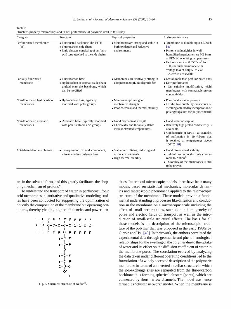
Table 2 [45,46]compares the structure, and physical prop-erties of the different membrane systems to their in situperformance. From the table it can be noticed that the perflu-orinated ionomers posses most of the desired properties andhence appear to be promising for fuel cell applications.
4. Perfluorinated membranes
The perfluorinated sulfonic acid membranes have beenthe subject of intense research. The key polymers used
currently in portable fuel cell applications have perfluori-nated structures with attached sulfonic acid groups[47].The perfluorinated polymer used most extensively and pro-duced by DuPont goes by the trade name of Nafion®. Sim-ilar polymers are Flemion® produced by Asahi Glass andAciplex-S® produced by Asahi Chemical. Among the threemajor types, the DuPont product is considered to be superiorbecause of its high proton conductivity, good chemical sta-bility and mechanical strength[48]. Its structure is shown inFig. 6.
Two research areas currently of interest on Nafion® are thetransport phenomena within the membrane and modificationsmade to the membrane to increase its performance as wellas water retention capacity. Proton transport in Nafion® inthe presence of variations in operating parameters such astemperature, membrane thickness, and water content havebeen analyzed.
4.1. Transport phenomena
Level of hydration is a critical parameter in Nafion® mem-brane that has to be maintained in order to retain its per-formance at temperatures above 100◦C (Section2). In thepresence of water, protons as well as the sulfonic acid groups
B. Smitha et al. / Journal of Membrane Science 259 (2005) 10–26 15
Table 2Structure–property relationships and in situ performance of polymers dealt in this study
Category Structure Physical properties In situ performance
Perfluorinated membranes(pf)
• Fluorinated backbone like PTFE• Fluorocarbon side chain• Ionic clusters consisting of sulfonic
acid ions attached to the side chains
• Membranes are strong and stable inboth oxidative and reductiveenvironments
• Membrane is durable upto 60,000 h[45]
• Proton conductivities in wellhumidified membranes are 0.2 S/cmat PEMFC operating temperatures
• Cell resistance of 0.05� cm2 for100�m thick membrane withvoltage loss of only 50 mV at1 A/cm2 is achievable
Partially fluorinatedmembrane
• Fluorocarbon base • Membranes are relatively strong incomparison to pf, but degrade fast
• Less durable than perfluorinated ones• Hydrocarbon or aromatic side chain
grafted onto the backbone, whichcan be modified
• Low performance• On suitable modification, yield
membranes with comparable protonconductivities
Non-fluorinated hydrocarbonmembranes
• Hydrocarbon base, typicallymodified with polar groups
• Membranes posses goodmechanical strength
• Poor chemical and thermal stability
• Poor conductors of protons• Exhibit low durability on account of
swelling obtained by incorporation ofpolar groups into the polymer matrix
Non-fluorinated aromaticmembranes
• Aromatic base, typically modifiedwith polar/sulfonic acid groups
• Good mechanical strength • Good water absorption• Chemically and thermally stable
even at elevated temperatures• Relatively high proton conductivity is
attainable• Conductance of SPPBP at 65 mol%
of sulfonation is 10−2 S/cm thatis retained at temperatures above100◦C [46]
Acid–base blend membranes • Incorporation of acid component,into an alkaline polymer base
• Stable in oxidizing, reducing andacidic environments
• High thermal stability
• Good dimensional stability• Exhibit proton conductivity compa-
rable to Nafion®
• Durability of the membranes is stillto be proven
are in the solvated form, and this greatly facilitates the “hop-ping mechanism of protons”.
To understand the transport of water in perfluorosulfonicacid membranes, quantitative and qualitative modeling stud-ies have been conducted for supporting the optimization ofnot only the composition of the membrane but operating con-ditions, thereby yielding higher efficiencies and power den-
Fig. 6. Chemical structure of Nafion®.
sities. In terms of microscopic models, there have been manymodels based on statistical mechanics, molecular dynam-ics and macroscopic phenomena applied to the microscopicstructure of the membrane. These models provide a funda-mental understanding of processes like diffusion and conduc-tion in the membrane on a microscopic scale including theeffect of small perturbations, such as non-homogeneity ofpores and electric fields on transport as well as the intro-duction of small-scale structural effects. The basis for allthese models is the description of the microscopic struc-ture of the polymer that was proposed in the early 1980s byGierke and Hsu[49]. In their work, the authors correlated theexperimental data through geometric and phenomenologicalrelationships for the swelling of the polymer due to the uptakeof water and its effect on the diffusion coefficient of water inthe membrane pores. The correlation evolved by analyzingthe data taken under different operating conditions led to theformulation of a widely accepted description of the polymericmembrane in terms of an inverted micellar structure in whichthe ion-exchange sites are separated from the fluorocarbonbackbone thus forming spherical clusters (pores), which areconnected by short narrow channels. The model was hencetermed as ‘cluster network’ model. When the membrane is

16 B. Smitha et al. / Journal of Membrane Science 259 (2005) 10–26
dry, an average cluster has a radius of about 1.8 nm and itcontains about 26 SO3− groups distributed on the inner poresurface. In the swollen state the diameter increases to about4 nm and the number of fixed SO3
− groups goes upto∼70.Under these conditions, each pore is filled with about 1000water molecules and the connecting channels have a diameterand a length of about 1 nm. Gierke and Hsu also proposed theuse of percolation theory for the correlation of electrical con-ductivity with the water content of the membrane. Accordingto this theory, there is a critical amount of water available inthe membrane, below which ion transport is extremely dif-ficult due to the absence of extended pathways. Above andnear the threshold, the conductivity,σ follows the law:
σ = σ0(c − c0)n
wherec is the volume fraction of the aqueous phase,c0 thepercolation threshold for the water content in the membrane,n a universal constant which depends on the dimensions ofthe system (usually about 1.5 in 3-D systems) andσ0 a pre-factor related to the molecular interactions that can only becomputed from specific microscopic models. A comparisonbetween experimental results and percolation theory showedan extremely good agreement. After the seminal work byGierke and Hsu, other investigators have focused their atten-tion on modeling of the microstructure and of the percolativef m-b ctureh -t % oft witht andt ary,t
cola-t tercm eli end-i allyb ithint tiono theh thep onsu ought tonst usternH ringe uldb icf omn ther riedo
In addition to proton transport, considerable interest hasbeen shown by investigators to the transport of other speciesin Nafion® membranes. Transport of ionic species throughNafion® was investigated by Gardner and Anantraman[54].It was noticed that the conductance of Nafion® is anisotropicand the tangential component of conductivity of Nafion 117membrane was 8.56× 10⁻² S/cm. at 100% relative humiditywhereas the normal component depended linearly on pres-sure. This has important consequences for Nafion® use inthat this phenomenon can lead to energy losses in the tan-gential direction because of lower resistance. Gardner andAnantaraman also suggested that the anisotropy could be dueto the clustering of ionic species near the interface away fromthe hydrophobic phase or could be a result of orientation ofpolymer chains during extrusion.
4.2. Modifications made to Nafion®
Several efforts have been made to improve performanceof Nafion® and to ascertain water retention at higher tem-peratures. The influence of addition of silica to Nafion®, asstudied by Antonucci et al.[6], was to improve the retentionof water in the membrane and to enable the operation of thefuel cell above 130◦C. Such a membrane could be used ina DMFC at 145◦C with power density of 240 mW/cm2. Asimilar method for retaining water in Nafion® at higher tem-p xidei ass as notr
ofa os-p om-p lc soverb thy-l sa -b TFEsa nm wasa
a atedi t-e olyb-d da ni thei H)i dogo[ s6 tot tan-
eatures of ionic conductivity in perfluorosulfonic acid meranes. Interesting results on the modeling of microstruave been reported by Okada et al.[50], who, by interpola
ion of experimental data, demonstrated that around 50he water molecules in the membrane were associatedhe SO3
− sites (primary hydration layer) or the protons,he remaining 50% are “semi-free” in the pores (secondertiary, etc., hydration layers).
Recent studies propose an interpretation of the perion properties of proton conductivity as a function of waontent using a “random network model”[51], which is aodification of the “cluster network model”. This mod
ncludes an intermediate region wherein the side chainsng with pendant sulfonic acid groups, that are ioniconded to the perfluorinated backbone, tend to cluster w
he overall structure of the material resulting in the formaf hydrated regions. Unlike the “cluster network model”,ydrated regions in this model are distributed randomly inolymer matrix, which facilitates quicker transport of protpon the rotation of these side chains. In this case alth
he hydrated regions drift apart, the traverse motion of prohrough the membrane is possible. A schematic of the cletwork and random network models is depicted inFig. 7.aubold et al. verified through small angle X-ray scattexperiments (SAXS) that the “random network model” coe applied to Nafion® [52]. James et al. deployed the atom
orce microscopy (AFM) technique and found the “randetwork model” to be generally acceptable, especially inegion of 9–34% relative humidity. This study was carut on the commonly available Nafion 117[53].
eratures by incorporating silica as well as titanium dionto a Nafion® composite to enable its use in DMFC wtudied by Baradie et al.[55]. This membrane exhibitedignificant improvement in proton conductivity but didetard methanol crossover.
Wasmus et al.[56] sought to improve the performanceDMFC by equilibrating Nafion 117 membrane with phhoric acid. An improvement in the reaction kinetics accanied by high conductivity up to 200◦C and lower methanorossover were observed. A reduction in methanol crosy coating a thin layer of plasma polymerized tetrafluoroe
ene (with vinyl phosphoric acid) on Nafion® membrane wattempted by Mex and Muller[57]. Finsterwalder and Hamitzer investigated a similar method of depositing a Pource with chlorosulfonic acid on Nafion® in order to obtainlow methanol crossover[58]. A significant reduction iethanol crossover at the cost of a drop in conductivitychieved.
A significant improvement in the conductivity of Nafion®,t elevated temperatures, by incorporating perfluorin
onomers in Nafion® matrix and by doping it with heropolyacids such as phosphotungstic acid, phosphomenic acid, phosphotin acid in Nafion® was targeted anchieved by Bahar et al.[59]. A similar attempt to attai
mproved ionic conductivity and high power density withncorporation of silicotungstic acid (SA) and thiophene (Tn Nafion 117 membrane was made by Tazi and Sava60]. Water uptake in the Nafion® incorporated with SA wa0% and with both SA and TH it was 40% compared
he normal value of 27% for Nafion 117. Thus a subs

B. Smitha et al. / Journal of Membrane Science 259 (2005) 10–26 17
Fig. 7. (a) Transport phenomena of species in Nafion® membranes; (b) schematic view of modified cluster network model.
tial improvement in ionic conductivity was observed. Nafion117 combined with TH showed highest current density with amaximum of 810 mA/cm2 at 600 mV compared with a valueof 640 mA/cm2 for Nafion 117.
4.3. Limitations of Nafion® membrane
From the preceding discussion, it is clear that Nafion® andrelated polymers are still being intensely examined in viewof the complex cell requirements of high proton conductivityand outstanding chemical stability combined with longevityof 60,000 h at 80◦C. The major disadvantages of these PFSAmaterials are
• the high cost of membrane amounting to US$ 700 persquare meter[61],
• lack of safety during its manufacture and use[62],• requirement of supporting equipment[63],• temperature related limitations[25].
Safety concerns arise from evolution of toxic interme-diates and corrosive gases liberated at temperatures above150◦C. Decomposition products could be a concern duringthe manufacturing process or vehicle accidents and couldlimit fuel cell recycling options.
Supporting equipment requirements for uses with PFSAmembranes are extensive as described by Gilpa and Hogarth[ theh ity tot
Degradation of PFSA membrane properties at elevatedtemperatures is another serious drawback. Conductivity at80◦C is reduced by more than 10 folds relative to that at60◦C [25]. Also, the phenomena related to membrane dehy-dration, reduction of ionic conductivity, decreased affinity forwater, loss of mechanical strength due to softening of poly-mer backbone and increased parasitic losses through highfuel permeation are observed at temperatures above 80◦C.
With regard to the application in direct methanol fuelcells (DMFC), Nafion® exhibits a high methanol perme-ability greater 80,000 Barrers at 80◦C, which drasticallyreduces the DMFC performance and renders it unsuitable forDMFCs[65]. Efforts are directed to eliminate the disadvan-tages such as crossover problems and loss of hydration above100◦C.
Despite its shortcomings, Nafion® is still the polymer ofchoice for most PEFC and DMFC applications. However,it is likely that Nafion® will be replaced by an alternativemembrane in the future[66]. In order to overcome few of thedisadvantages of the PFSA membranes enumerated above,the authors are also carrying out research work to identifypromising alternatives[67,68]. Rikukawa and Sanui[25] sug-gest that in order to produce materials that are less expensivethan Nafion, some sacrifice in material lifetime and mechani-cal properties may be acceptable, provided the cost factors arecommercially realistic. Hence the use of hydrocarbon poly-m d duet wedi
24] and Crawford[64]. Among the equipment needed,ydration system adds considerable cost and complex
he vehicle power train.
ers, even though they had been previously abandoneo low thermal and chemical stability, has attracted renenterest.

18 B. Smitha et al. / Journal of Membrane Science 259 (2005) 10–26
Table 3Design information of membranes considered as alternatives to PFS (reproduced from ref.[27b])
S. no. Membrane type (category) Design methodology
1 Gore-SelectTM membrane (f) Ultra-thin integral composite consisting of a base material preferablymade of expanded PTFE that supports an ion exchange material such asperfluorinated sulfonic acid resin, perfluorinated carboxylic acid resin,PVA, divinyl benzene (DVB), etc. A surfactant is usually employed toensure impregnation[59]
2 Perfluorocarboxylic acid (f) Copolymer of tetrafluoroethylene (TFE) and perfluorovinyl ether(PFVE). The molar ratio of PFVE to TFE gives a measure of ionexchange capacity[71]
3 Bis(perfluoroalkylsulfonyl) Imide (f) Copolymerization of sodium 3,6-dioxa-4-trifluoro methyl perfluo-rooctyl trifluoromethyl with TFE[72]
4 �,�,�-Trifluorostyrene grafted membrane (pf) Grafting of�,�,�-trifluorostyrene and PTFE/ethylene copolymers[23]5 Styrene grafted and sulfonated poly(vinylidene fluoride) membranes
[PVDF-G-PSSA] (pf)Pre-irradiation grafting of styrene onto a matrix of PVDF after elec-tron beam irradiation. The proton conductivity can be increased bycrosslinking with DVB[73]
6 BAM3G membrane (Ballard advance material of third generationmembrane) (nf)
Polymerization of�,�,�-trifluorostyrene, includes monomers selectedfrom a group of substituted�,�,�-trifluorostyrene[74]
7 Membrane of base-doped with S-polybenzimidazoles (PBI) (nf com-posites)
Introduction of organic and inorganic bronsted bases to sulfonated PBI[75]
8 Crosslinked/non-crosslinked (SPEEK) (nf) Direct sulfonation of PEEK in conc. sulfuric acid medium yields highproton conductivity along with thermal stability[76]
9 Imidazole doped sulfonated polyetherketone (SPEK) (nf) Complexation with imidazoles to obtain high proton conductivities[77]10 & 11 Methylbenzenesulfonated PBI/methylbenzenesulfonate poly(p-
phenylene terephthal amide) membranes (nf)These alkylsulfonated aromatic polymer electrolyte posses very goodthermal stability and proton conductivity when compared to PFSAmembranes, even above 80◦C [25]
12 Sulfonated napthalenic polyimide membrane (nf) Based on sulfonated aromatic diamines and dihydrides. Its performanceis similar to PFSA[78]
13 Sulfonated poly(4-phenoxybenzoyl-1,4-phenylene) (SPPBP) (nf) Derived from poly(p-phenylene) and structurally similar to PEEK.Direct sulfonation results in a proton conductive polymer[79]
14 Supported composite membrane (other) Made of ion conducting polymer and poly-p-phenylene benzobisoxa-zole (PBO) substrate[80]
15 Poly(2-acrylamido-2-methylpropanesulfonic acid) (other) Made from polymerization of AMPS monomer. AMPS monomer ismade from acrylonitrile, isobutylene and sulfuric acid[81]
f, Fluorinated; nf, non-fluorinated; pf, partially fluorinated.
5. Hydrocarbon membranes
Hydrocarbon membranes provide some definite advan-tages over PFSA membranes. They are less expensive,commercially available and their structure permits theintroduction of polar sites as pendant groups in order toincrease the water uptake. In association with Rikukawaand Sanui, Gilpa and Hogarth identified 60 alternatives toPFSA membranes. Among these 15 membranes showedpotential for replacing Nafion® membranes[69,70]. Table 3summarizes information on synthesis of these 15 candidatematerials[71–81]. The structures of prominent ones underthis category are given inFigs. 8 and 9.
Pivovar et al. studied the applicability of pervaporationmembranes in DMFC[82]. Poly(vinyl alcohol) (PVA) mem-
Fig. 8. Structure of poly(butadiene styrene) block copolymer.
Fig. 9. Structure of grafted membranes: (a) FEP main; (b) sulfonatedpolystyrene side chain.
branes are known to be good methanol barriers. Based on thisobservation, a method of crosslinking PVA was suggested sothat the extent of swelling in water could be controlled. It wasalso felt that the high water permeability should signal highproton conductivity atleast when the membranes are equili-brated with phosphoric acid.
6. Aromatic polymers
In order to enhance stability at elevated temperatures,aromatic hydrocarbons can be (a) incorporated directly intothe backbone of a hydrocarbon polymer or (b) polymersmodified with bulky groups in the backbone to render them

B. Smitha et al. / Journal of Membrane Science 259 (2005) 10–26 19
Table 4Modification of aromatic polymers
S. no. Membrane type Modification information Ref.
1 Sulfonated polystyrene Sulfonating polystyrene using acetyl sulfate as sulfonating agent.On increasing sulfonation, the ionic conductivity were comparableto Nafion® (10−3 to 10−2 S/cm). However, discontinuity in theproperties at 15% sulfonation was noted
Carretta et al.[86]
2 Hydrogenated poly(butadiene-styrene) (HPBS)
Synthesized by heterogeneous sulfonation ofpoly(butadiene-styrene). On blending with polypropylene anenhancement in both the thermal properties and proton conductivityresulted
Bashir et al.[87]
3 Styrenic system of styrene divinylbenzene (SDVB)
Grafting SDVB to poly(fluoroethylene-co-hexafluoropropylene)(FEP), followed by sulfonation thereby obtaining membranes verysimilar to PFSA
Buchi et al.[88]
4 Polystyrene graft polymer Crosslinking styrene/acrylonitrile ore obtained fromN-vinylpyrrolidone/2-acrylamide-2-methyl-1-propane sulfonic acidgraft polymer using divinylbenzene in order to obtain betterstability in an oxidative environment
Becker and Schmidt-Naake[89]
5 Sulfonated polysulfone Synthesized using sulfur trioxide-triethyl phosphate complex as thesulfonating agent. Relatively high IEC and good mechanicalproperties were attained
Noshay and Robenson[90]
6 Sulfonated poly ethersulfone(SPES)
SPES was synthesized and covalently crosslinked using substituteddiamine-sulfone to provide additional mechanical strength and highproton conductivity for operations above 100◦C
Kice and Puls[91]
7 Sulfonated polyaryls Polyetherketones were modified by blending with polymerscontaining immobilized heterocycles such as imidazole, pyrazoleor benzimidazole as proton solvating species for obtaining highproton conductivity. The water cross-over drastically reduced whilemaintaining high proton conductivity
Kreuer[92]
8 Impregnating fleeces on polyte-trafluoro ethylene (PTFE) matrix
Impregnating polysulfone, microglass fibre as well as a compositematrix constituting of both the fleeces on a PTFE matrix. Unlikethe two impregnated fleeces, the composite membranes did notexhibit a comparable or lower resistance than Nafion 117
Stefan Haufe and Ulrich Stimming[93]
9 Sulfonated polyetheretherketone(SPEEK)and sulfonatedpoly(4-phenoxybenzoyl-1,4-phenylene)
Sulfonating PEEK and PPBP using concentrated sulfuric acid.Thermal stability upto atleast 200◦C was obtained and aconductance of about 10−2 S/cm at 65 mol% Sulfonation in case ofSPPBP observed while SPEEK showed conductance two orders ofmagnitude lower for the same mol% of sulfonation
Kobayashi et al.[94]
10 Sulfonated poly [bis(3-methylphenoxy) Phoszene]
Sulfonating the base polymer with sulfur trioxide followed bycrosslinking, yielding higher proton conductivity, lower water andmethanol diffusion co-efficient besides excellent chemical andthermo mechanical stability when compared to Nafion®
Guo et al.[95]
11 Sulfonated polyimide (PI) Sulfonating PI using sulfur trioxide to obtain properties comparableto Nafion 117
Vallejo et al.[96]
12 Poly(arylene) Synthesis of sulfonated napthalene type polyimide to obtain highproton conductivity and low water/methanol diffusion coefficientsunlike PFSA
Gebel et al.[97]
13 Sulfonimide compound Crosslinking sulfonimide synthesized using a macromolecularsubstitution approach to produce phosphazene bearing pendantsulfonimide groups to obtain high proton conductivities
Hofman et al.[98]
14 Poly[aryloxyphosphazene] poly-mers
Treatment of the aryloxyphosphazenes bearing bromo-phenoxyside groups with t-butyllithium followed bydiphenylchlorophosphonate followed by conversion to phenylphosphonic acid groups
Allock et al. [99]
suitable for conduction of protons. Polyarylenes are hightemperature rigid polymers withTg > 200◦C owing to thepresence of inflexible and bulky aromatic groups[83]. Thearomatic rings offer the possibility of electrophilic as wellas nucleophilic substitution. Polyethersulfones (PESF),polyether ketones (PEK) with varying number of ether andketone functionalities (such as PEEK, PEKK, PEKEKK,etc.), poly(arylene ethers), polyesters and polyimides (PI) are
some of the relevant examples of main chain polyarylenes[84].
Studies reveal that polyesters must be avoided, as theester group imparts instability in aqueous acids whilepolyaromatics are often preferred for fuel cell applicationdue to their thermal stability. The specialty polymers onsuitable modification are not only thermally stable but exhibitstability in oxidizing, reducing and acidic environments
20 B. Smitha et al. / Journal of Membrane Science 259 (2005) 10–26
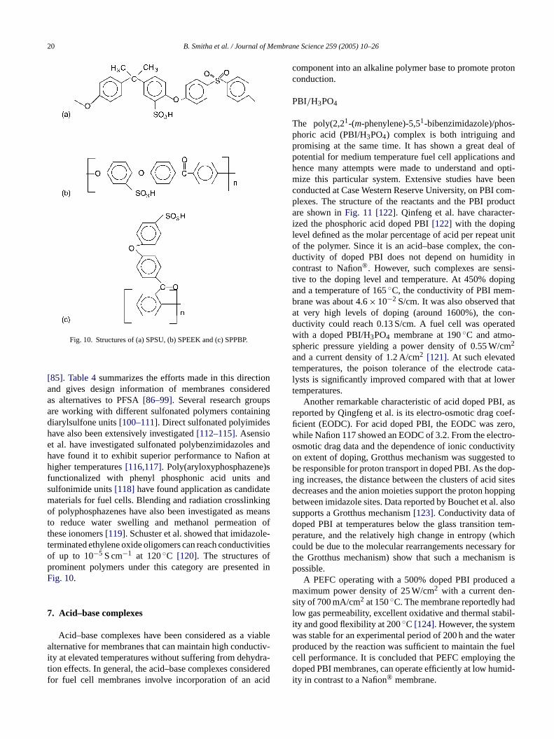
Fig. 10. Structures of (a) SPSU, (b) SPEEK and (c) SPPBP.
[85]. Table 4summarizes the efforts made in this directionand gives design information of membranes consideredas alternatives to PFSA[86–99]. Several research groupsare working with different sulfonated polymers containingdiarylsulfone units[100–111]. Direct sulfonated polyimideshave also been extensively investigated[112–115]. Asensioet al. have investigated sulfonated polybenzimidazoles andhave found it to exhibit superior performance to Nafion athigher temperatures[116,117]. Poly(aryloxyphosphazene)sfunctionalized with phenyl phosphonic acid units andsulfonimide units[118] have found application as candidatematerials for fuel cells. Blending and radiation crosslinkingof polyphosphazenes have also been investigated as meanto reduce water swelling and methanol permeation ofthese ionomers[119]. Schuster et al. showed that imidazole-terminated ethylene oxide oligomers can reach conductivitiesof up to 10−5 S cm−1 at 120◦C [120]. The structures ofprominent polymers under this category are presented inFig. 10.
7. Acid–base complexes
Acid–base complexes have been considered as a viablealternative for membranes that can maintain high conductiv-i dra-t deredf cid
component into an alkaline polymer base to promote protonconduction.
PBI/H3PO4
The poly(2,21-(m-phenylene)-5,51-bibenzimidazole)/phos-phoric acid (PBI/H3PO4) complex is both intriguing andpromising at the same time. It has shown a great deal ofpotential for medium temperature fuel cell applications andhence many attempts were made to understand and opti-mize this particular system. Extensive studies have beenconducted at Case Western Reserve University, on PBI com-plexes. The structure of the reactants and the PBI productare shown inFig. 11 [122]. Qinfeng et al. have character-ized the phosphoric acid doped PBI[122] with the dopinglevel defined as the molar percentage of acid per repeat unitof the polymer. Since it is an acid–base complex, the con-ductivity of doped PBI does not depend on humidity incontrast to Nafion®. However, such complexes are sensi-tive to the doping level and temperature. At 450% dopingand a temperature of 165◦C, the conductivity of PBI mem-brane was about 4.6× 10⁻² S/cm. It was also observed thatat very high levels of doping (around 1600%), the con-ductivity could reach 0.13 S/cm. A fuel cell was operatedwith a doped PBI/H3PO4 membrane at 190◦C and atmo-spheric pressure yielding a power density of 0.55 W/cm2
a dt cata-l ert
I, asr oef-fi ero,w tro-o tivityo ed tob dop-i sitesd ppingb . alsos fd tem-p hichc ry fort m isp
d am -s adl bil-i mw aterp fuelc thed mid-i
ty at elevated temperatures without suffering from dehyion effects. In general, the acid–base complexes consior fuel cell membranes involve incorporation of an a
s
nd a current density of 1.2 A/cm2 [121]. At such elevateemperatures, the poison tolerance of the electrodeysts is significantly improved compared with that at lowemperatures.
Another remarkable characteristic of acid doped PBeported by Qingfeng et al. is its electro-osmotic drag ccient (EODC). For acid doped PBI, the EODC was zhile Nafion 117 showed an EODC of 3.2. From the elecsmotic drag data and the dependence of ionic conducn extent of doping, Grotthus mechanism was suggeste responsible for proton transport in doped PBI. As the
ng increases, the distance between the clusters of acidecreases and the anion moieties support the proton hoetween imidazole sites. Data reported by Bouchet et alupports a Grotthus mechanism[123]. Conductivity data ooped PBI at temperatures below the glass transitionerature, and the relatively high change in entropy (would be due to the molecular rearrangements necessahe Grotthus mechanism) show that such a mechanisossible.
A PEFC operating with a 500% doped PBI produceaximum power density of 25 W/cm2 with a current den
ity of 700 mA/cm2 at 150◦C. The membrane reportedly how gas permeability, excellent oxidative and thermal staty and good flexibility at 200◦C [124]. However, the systeas stable for an experimental period of 200 h and the wroduced by the reaction was sufficient to maintain theell performance. It is concluded that PEFC employingoped PBI membranes, can operate efficiently at low hu
ty in contrast to a Nafion® membrane.

B. Smitha et al. / Journal of Membrane Science 259 (2005) 10–26 21
Fig. 11. Structure of (a) tetraaminobiphenyl, (b) diphenylisopthalate and (c) poly[2,21-(m-phenylene)-5,51 bibenzimidazole].
Samms et al. complexed PBI with acids such as sulfu-ric acid, hydrochloric and phosphoric acid to achieve animprovement in conductivity. For H2/O2 fuel cell, a protonconductivity of 9× 10⁻³ S/cm for PBI acidified with H3PO4was recorded which is higher than 8× 10⁻⁴ S/cm obtainedfor pure PBI membranes[125]. Doped PBI membranes showconsiderable potential for fuel cells operating at moderatetemperatures. It is also anticipated that in near future, mem-branes in this category may be made suitable alternatives toNafion® for DMFC applications as they are known to havelower methanol permeability than Nafion®. Various poly-mers besides PBI have been evaluated for use in these types ofmembranes[126–129]. Bozkurt and Meyer have, for exam-ple, investigated poly(4-vinylimidazole)-H3PO4 complexesand found its stability through thermogravimetric studies tobe about 150◦C [126]. Lassegues et al. found complexes ofamorphous polyamide with H3PO4 to have high conductivitybut poor mechanical strength and chemical stability at tem-peratures above 90◦C [127]. Hasiotis et al. have preparedblends of sulfonated polysulfones and PBI which were dopedwith H3PO4 [130,131]. These membranes showed improvedmechanical properties and conductivities above 10−2 S cm−1
at 160◦C at 80% relative humidity, which was higher thanfor acid-doped PBI membranes under the same conditions.
The long-term stability of doped PBI membranes isyet to be proven despite their excellent attributes for fuelc red nta en inF
8
thatd stric-t arilyc ate-
rial, keeping in view the desired membrane properties, andaccelerating the commercialization of the technology. Thepotential routes to overcome these drawbacks can be identi-fied by considering the following aspects.
Fig. 12. Structure of basic polymers (a–d) and acidic polymers (e, f).
ell applications[121–124]. Other acid base blends aescribed inTable 5 [132–137]. The structures of prominecidic and basic polymers and their complexes are givig. 12.
. Future prospects
From the aforementioned discussions, it can be notedespite the advancement in the PEMFC field, some re
ions are still encountered. The constraints can be primlassified as identification of appropriate membrane m

22 B. Smitha et al. / Journal of Membrane Science 259 (2005) 10–26
Table 5Acid–base blends
S. no. Membrane materials Blend ratio Physical properties Observations In situ performance Ref.
1 SPEEK/PBI 90/10 High temperaturetolerance at 350◦C;thermally stable; goodmiscibility
Short-term tests (300 h) yieldcomparable performance toNafion 112
Higher voltages of650 mV obtainable athigh current densitiesof 1000 mA/cm2 forhydrogen fuel cell
Keres andcoworkers[104,132–136]Figs. 9 and 10
2 PVA/H3PO4 Highly doped Good mechanicalstrength
With decreasing acidconcentration, grotthustransport mechanismdecreases
Low open cell voltage(a max. of 436 mVwith very low currentdensity of 1 mA/cm2)
Vargas et al.[137]
Thermally stable upto70◦C
Mechanism likely at lowtemperatures
Maximumconductivity of10−1 S/cm at 100 MV
3 PBI/H2SO4 500% doping Good mechanicalstrength; thermallystable
Doped PBI shows greaterpotential for fuel celloperating at moderatetemperatures
Conductivity of6× 10−2 S/cmachievable
Samms et al.[125]
8.1. Identification of alternate membrane materials
In spite of the extensive research effort globally, the needfor new polymers which could satisfactorily serve as suitableinexpensive alternatives to Nafion®, still exists. A review ofthe literature yields the following suggestions for the devel-opment of efficient proton conducting membranes.
• The acid–base blends (Table 5) of specialty polymershave not been explored as yet. The main advantage ofusing high temperature specialty polymers is related notonly to the thermal stability, but more to the expectedstability in oxidative, reducing and acidic environments.Hence, sulfonated bisphenol-A-polysulfone (SPSU) orsulfonated polyphenylene oxide (SPPO) and their deriva-tives could be the choice of membrane materials as candi-dates for acid–base blends for final use in proton exchangefuel cell. SPSF and SPPO could be ionically crosslinkedwith a polybase such as poly(ethyleneimine) (PEI) orpoly(benzimidazole) (PBI), to produce useful acid–baseblends. These blends are expected to offer good mechan-ical, chemical and thermal stability to the membrane incombination with high proton exchange capacity.
• Membranes based entirely on aromatic high perfor-mance polymers such as poly ether ketone (PEK) andpoly(phenylene oxide) can offer an interesting substitute
icalfor
lec-stingical.
• os-hos-
rotonipi-n
van-
i. elimination of the dissolution of the membrane materialformed by the direct swelling of the polymers selected;
ii. proper mixing of inorganic and organic components atmolecular level offering good mechanical stability com-pared with purely organic membrane;
iii. since proton conductivity is the result of transport ofprotons on the surface of the proton conductor particles,an increase in surface area (smaller particle size) willincrease the conductivity obtained for a mixed matrixmembrane;
iv. these membranes may cost the same as the conventionalpolymers;
v. with increasing proportion of metal particles, appre-ciable degree of improvements in proton conductivityspecially at high temperature can be anticipated. How-ever, the influence of metal particles on mechanicalcharacteristics needs to be investigated.
Hence, submicron size inner transition metal phosphatescould be prepared and doped in the matrices of specialtypolymers such as bis-phenol-A-PSF or PPO.
8.2. Accelerating the commercialization of thetechnology
The fuel cell market is estimated to have risen to $1.3 bil-l 8.W iesr e toa ver-a patedt nu-f ll beb d2 willb sert willb
for Nafion®. These polymers demonstrate good chemstability in association with other crucial requirementsa fuel cell membrane. Some of them allow direct etrophilic sulfonation and subsequent membrane cafrom organic solutions, which may prove to be economIncorporation of submicron particles of metal(IV) phphates such as zirconium phosphate (ZrP) and tin pphate (SnP) in polymer matrices tend to increase the pconductivity of the polymers. For this purpose, prectation from a solution containing M(IV) ions, within aappropriate polymer matrix, can offer a number of adtages:
ion in 2003[138]up from an estimated $355 million in 199ith commercialization of most of the fuel cell technolog
apidly falling in place, this market is expected to increasn estimated $3.3 billion by 2005 suggesting an AAGR (age annual growth rate) of 18.7%. It has also been antici
hat fuel cells for residential accommodations will be maactured in the range 1–10 kW and portable fuel cells wiuilt in the sub-watt to 5 kW range[139]. Between 2000 an010, an estimated 130 GW of new generating capacitye installed in the US. In world markets, within a much clo
ime frame, an estimated 550 GW of generating capacitye added as per these projections.

B. Smitha et al. / Journal of Membrane Science 259 (2005) 10–26 23
For the fuel cell markets to be profitable a significant num-ber of development activities, both academic and commercialare essential. Presently the academic organizations are tar-geting improved performance and reliability, dramatic costreduction, ease of manufacture, optimization for use in spe-cific applications, operation under reduced or zero externalhumidification and at higher temperatures. Academicians canalso support the development of demonstration projects thatshowcase fuel cell technology, validate product reliabilityand output and provide data necessary for commercialization[136]. Industry on the other hand can engage in standardiz-ing the specifications of the fuel cell components, increasingproduction volumes, which can result in reduction of produc-tion costs. The sooner this demand is generated, the fasterthe industry will be able to reduce costs and access new mar-kets. Industries should also support research and developmentand product development thereby accelerating the process forcommercializing the technology.
9. Conclusions
Based on literature survey, the various solid polymer elec-trolytes tested for fuel cell applications as proton conduct-ing membranes are reviewed. From the work carried outso far world wide, fuel cell membranes could be dividedinto four broad categories viz. perfluorinated ionomers,n anda thatN iles andp omis-i uire-m vity,c bil-i ds toi wed.T -b ails ot d onn ento -r andf and ine odeo hesem esea basedo ne ifica-t tive,p
A
ndI ect.
The authors acknowledge the contributions of Dr. B. Srid-har of CESCA, Dr. Madhavendra Sakunthala of SEM, Mr.Saibabu of Design Engineering, Mr. Nandagopalam and Mrs.Krupa Devi of Instrumentation Division of IICT. The constantsupport and encouragement. of Dr. M. Ramakrishna and Dr.K. Babu Rao of Chemical Engineering Division are thank-fully acknowledged. The authors also thank the AmericanChemical Society and the authors of 95 (1), (1995), 191–207,Chemical Reviews for allowing us to use one of theirfigures.
Nomenclature
BAM3G ballard advance material of third generationmembrane
I-d-SPEK imidazole doped sulfonated poly(etherketone)
MBSPBI methyl benzensulfonated polybenzi-midazoles
MBSPPTA methyl benzensulfonated poly(p-phenyleneterephthalamide)
NPI naphthalenic polyimidePBI polybenzimidazolePEI poly(ethyleneimine)PFCA perfluorocarboxylic acid
R
nge
in000)
er-180,
00)
on-fluorinated hydrocarbons, sulfonated polyarylenescid–base complexes. From the review, it is evidentafion® is the prominent polymer in the first category; wh-PPBP shows the best potential for the third categoryhosphoric acid doped PBI membranes appear most pr
ng in the fourth category. These polymers meet the reqents of fuel cell membranes such as ionic conducti
hemical and thermal stability besides low fuel permeaty. Studies on the transport phenomena and methomprove the performance of these membranes are reviehe review reveals that Nafion® is a more “mature” memrane. Much research has been conducted on the det
he transport of protons through the polymer matrix anovel methods of improving its properties but developmf a sturdy inexpensive substitute to Nafion® is yet to mateialize. Progress in the third (sulfonated polyarylenes)ourth (acid–base blends) categories has been steady,ach case work is still focused on investigating the mf proton transport and on the practical applications of tembranes in a PEM fuel cell. However, with studies in threas continuing extensively, the class of membranesn acid–base complexes appears competitive to Nafio® inase of preparation and cost-effectiveness. Suitable mod
ions might render these complexes a promising alternarovided that the long-term endurance is proved.
cknowledgments
The authors would like to thank Council of Scientific andustrial Research, India for funding the Fuel Cell Proj
f
PFSA perfluorosulfonic acidPFSI bis(perfluoroalkylsulfonyl)imidePoly-AMPS poly(2-acrylamido-2-
methylpropanesulfonic acid)PSU(NH2)2 ortho-sulfone aminated polysulfonePTFE-g-TFS �,�,�-trifluorostyrene grafted onto
poly(tetrafluoroethylene) with postsulfonation
PVDF-g-PSSA styrene grated on sulfonatedpoly(vinylidiene fluoride)
P4VP poly(4-vinyl pyrrolidone)SPEEK sulfonated poly(ether ether ketone)SPPBP sulfonated poly(4-phenoxy benzoyl-1,4-
phenylene)SPSU sulfonated polysulfone
eferences
[1] F. Babir, T. Gomez, Efficiency and economics of proton exchamembrane fuel cells, Int. J. Hyd. Energy 21 (1996) 891.
[2] S. Motupally, A.J. Becker, J.W. Weidner, Diffusion of waterNafion 115 membranes, J. Electrochem. Soc. 147 (9) (23171–3177.
[3] T.D. Gierke, W.Y. Hsu, in: A. Eisenberg, H.L. Yeager (Eds.), Pfluorinated Ionomer Membranes, ACS Symposium Series No.American Chemical Society, Washington, DC, 1982, p. 283.
[4] V. Guarau, F. Barbir, H. Liu, J. Electrochem. Soc. 147 (7) (202468.
24 B. Smitha et al. / Journal of Membrane Science 259 (2005) 10–26
[5] M. Rikukawa, K. Sanui, Proton-conducting polymer electrolytemembranes based on hydrocarbon polymers, Prog. Polym. Sci. 25(2000) 1463–1502.
[6] P.L. Antonucci, A.S. Arico, P. Creti, E. Ramunni, V. Antonucci,Investigation of a direct methanol fuel cell based on a compositeNafion-silica electrolyte for high temperature operation, Solid StateIonics 125 (1999) 431–437.
[7] P.D. Beattie, V.I. Basura, S. Holderoft, Temperature and pressuredifference of O2 reduction at Pt/Nafion 117 and Pt/BAM 407 inter-faces, J. Electroanal. Chem. 468 (1999) 180–192.
[8] L.R. Jordan, A.K. Shukla, T. Behrsing, N.R. Avery, B.C. Muddle,M. Forsyth, Diffusion layer parameters influencing optimal fuelcell performance, J. Power Sources 86 (2000) 250–254.
[9] M. Cappadonia, J.W. Erning, S.M.S. Niaki, U. Stimming, Conduc-tance of Nafion 117 membranes as a function of temperature andwater content, Solid State Ionics 77 (1995) 65–69.
[10] P. Sridhar, R. Perumal, N. Rajalakshmi, M. Raja, K.S. Dhatatreyan,Humidification studies on polymer electrolyte membrane fuel cell,J. Power Sources 101 (2001) 72–78.
[11] V. Gurau, H. Liu, S. Kakae, Two-dimensional model for protonexchange membrane fuel cells, AIChE J. 44 (1998) 2410–2422.
[12] D.M. Bernardi, M.W. Verbrugee, A mathematical model of thesolid-polymer electrode fuel cell, J. Electrochem. Soc. 139 (1992)2477–2490.
[13] J.C. Amphlett, R.M. Baumert, R.F. Mann, B.A. Peppley, P.R.Roberge, Performance modeling of the Ballard Mark IV solidpolymer electrolyte fuel cell. I. Mechanic model development, J.Electrochem. Soc. 142 (1995) 1–8.
[14] T.E. Springer, T.A. Zadowzinski, S. Gottesfeld, Polymer electrolytefuel cell model, J. Electrochem. Soc. 138 (1991) 2334–2344.
[15] L. You, H. Liu, A parametric study of the cathode catalyst layer ofHyd.
ton2001)
the77–
alf-00)
of03)
tion,inertcuum
tri-rme-29–
cto-
dv.
ge,
lyteci. 25
ipo-ingsls forapac-
[27] (a) V. Mehta, Analysis of design and manufacturing of protonexchange membrane fuel cells, M.S. Thesis, University of Wash-ington, Washington, DC, 2002;(b) V. Mehta, J.S. Cooper, Review and analysis of PEM fuel celldesign and manufacturing, J. Power Sources 113 (2005) 32–55.
[28] Kerres, State of art of membrane development, J. Membr. Sci. 185(2001) 1.
[29] C. Stone, A.E. Morrison, From “Curiosity to power” to change theworld, Solid State Ionics 152–153 (2002) 1–13.
[30] P. Jannasch, Recent developments in high-temperature proton con-ducting polymer electrolyte membranes, Curr. Opin. Colloid Interf.Sci. 8 (2003) 96–102.
[31] J. Meier-Haack, A. Taeger, C. Vogel, K. Schlenstedt, W. Lenk,D. Lehmann, Membranes from sulfoanted block copolymers foruse in fuel cells, Sep. Purification Technol. 41 (3) (2005) 207–220.
[32] J. Roziere, D.J. Jones, Ann. Rev. Mater. Sci. 33 (2003) 503.[33] H.J.R. Magnet, in: C. Berger (Ed.), Handbook of Fuel Cell Tech-
nology, Prentice-Hall, Englewood Cliffs, NJ, USA, 1968, p. 425.[34] J.O’M. Bockris, S. Srinivasan, Fuel Cells: Their Electrochemistry,
McGraw-Hill, New York, 1969.[35] W.G. Grot, Discovery and development of Nafion perfluorinated
membranes, Chem. Ind. 19 (1985) 647.[36] M. Wakizoe, O.A. Velev, S. Srinivasan, Electrochim. Acta 40
(1995) 335.[37] P. Costamagna, S. Srinivasan, Quantum jumps in the PEMFC
science and technology from the 1960s to the year 2000 Part I. Fun-damental scientific aspects, J. Power Sources 102 (2001) 242–252.
[38] F. Lipnizki, S. Hausmanns, P.-K. Ten, R.W. Field, G. Laufenberg,Organophilic pervaporation: prospects and performance, Chem.Eng. J. 73 (1999) 113–129.
and
atercting
nn,l form-
t, H.iley-
(2)
uel/
ake,idify-lyte
eed-for
mer
, Pro-erials–10,
ter000)
s.),eries982,
PEM fuel cells using a pseudo-homogeneous model, Int. J.Energy 26 (2001) 991–999.
[16] T. Zhou, H. Liu, A general three-dimensional model for proexchange membrane fuel cell, Int. J. Trans. Phenomena 3 (177–198.
[17] L. You, H. Liu, A two-phase flow and transport model forcathode of PEM fuel cells, Int. J. Mass Transfer 45 (2002) 222287.
[18] V. Gaurau, F. Barbir, H. Liu, an analytical solution of a hcell model for PEM fuel cells, J. Electrochem. Soc. 147 (202468–2477.
[19] L. Wang, A. Husar, T. Zhou, H. Liu, A parametric studyPEM fuel cell performances, Int. J. Hyd. Energy 28 (11) (201263–1272.
[20] H. Miyake, M. Matsuyama, K. Ashida, K. Watanabe, Permeadiffusion, and solution of hydrogen isotopes, methane, andgases in/through tetrafluoroethylene and polyethylene, J. VaSci. Technol. 1 (3) (1983) 1447–1451.
[21] D.O. Stodilka, N.P. Kherani, W.T. Shmayda, S.J. Thorpe, Atium tracer technique for the measurement of hydrogen peation in polymeric materials, Int. J. Hyd. Energy 25 (2000) 111136.
[22] EG&G Services, Fuel Cell Handbook, 5th ed., Parsons Inc., Ober, 2000.
[23] S. Gottesfeld, T. Zawodzinski, Polymer electrolyte fuel cell, AElectrochem. Sci. Eng. 5 (1997) 195–381.
[24] X. Glipa, M. Hogarth, Dept. of Trade and Industry Homepa2001.
[25] M. Rikukawa, K. Sanui, Proton conducting polymer electromembranes based on hydrocarbon polymers, Prog. Polym. S(2000) 1463–1502.
[26] R. Borup, N. Vanderborgh, Design and testing criteria for blar plate materials for PEM fuel cell applications, in: Proceedof the Materials Research Society Symposium on the materiaElectrochemical Energy Storage and Conversion I-Batteries, Citors and Fuel Cells, vol. 393, 1995, pp. 151–155.
[39] A.J. Appleby, F.R. Foulkes, Fuel Cell Handbook, Van NostrReinhold, New York, 1989.
[40] T. Zadowzinski, J. Davey, J. Valerio, S. Gottesfeld, The wcontent dependence of electro-osmotic drag in proton condupolymer electrolytes, Electrochim. Acta 40 (1995) 297–302.
[41] J. Meier-Haack, T. Rieser, W. Lenk, S. Berwald, D. LehmaBuild-up of polyelectrolyte multilayer assemblies: a useful toocontrolled modification of microfiltration and pervaporation mebranes, in: K. Grassie, E. Tenckhoff, G. Wegner, J. HaußelHanselka (Eds.), Functional Materials Euromat ’99, vol. 13, WVCH, 2000, pp. 316–322.
[42] K. Soontrapa, N. Srinapawong, J. Sci. Res. Chula. Univ. 26(2001) 59–70.
[43] S. Holdcraft, Research Interests in Solid Polymer FCells, Simon Fraser University,www.sfu.ca/chemistry/facultyHoldcroft/researchFuelcells.html.
[44] T. Susai, M. Kaneko, K. Nakatoa, T. Isono, A. Hamada, Y. MiyOptimization of proton exchange membranes and the huming conditions to improve cell performance for polymer electromembranes, Int. J. Hyd. Energy 26 (2001) 631–637.
[45] A. Steck, in: O. Savadago, P.R. Roberge, T.N. Veziroglu, Procings of the First International Symposium on New MaterialsFuel Cell Systems, Montreal, July 9–13, 1995, p. 74.
[46] N. Ogata, M. Rikukawa, Sulfonated polymers for solid polyelectrolytes, US Patent 5,403,675 (April 1995).
[47] A.E. Steck, C. Stone, in: O. Savadago, P.R. Roberge (Eds.)ceedings of the Second International Symposium on New Matfor Fuel Cell and Modern Battery Systems, Montreal, July 61997, p. 792.
[48] S. Motupally, A.J. Becker, J.W. Weidner, Diffusion of Wain Nafion 115 membranes, J. Electrochem. Soc. 147 (9) (23171–3177.
[49] T.D. Gierke, W.Y. Hsu, in: A. Eisenberg, H.L. Yeager (EdPerfluorinated Ionomer Membranes, ACS Symposium SNo. 180, American Chemical Society, Washington, DC, 1p. 283.
B. Smitha et al. / Journal of Membrane Science 259 (2005) 10–26 25
[50] T. Okada, G. Xie, O. Gorseth, S. Kjelstrup, N. Nakamura, T.Arimura, Effect of water uptake and relative humidity on Nafion,Electrochem. Acta 43 (1998) 3741–3747.
[51] M. Eikerling, A.A. Kornyshev, U. Stimming, J. Phys. Chem. B 101(1997) 10807.
[52] H.G. Haubold, T. Vad, H. Jungbluth, P. Hiller, Nano structure ofNafion: a SAXS study, Electrochim. Acta 46 (2001) 1559–1563.
[53] P.J. James, T.J. McMaster, J.M. Newton, M.J. Miles, In situ rehy-dration of perfluorosulfonate ion-exchange membrane studied byAFM, Polymer 41 (2000) 4223–4231.
[54] C.L. Gardner, A.V. Anantraman, Studies on ion-exchange mem-branes, J. Electroanal. Chem. 449 (1998) 209–214.
[55] B. Baradie, J.P. Dodelet, P. Guay, Hybrid Nafion®-inorganic mem-brane with potential applications for polymer electrolyte fuel cells,J. Electroanal. Chem. 489 (1998) 209–214.
[56] S. Wasmus, A. Valeriu, G.D. Mateescu, D.A. Tryk, R.F. Savinell,Characterization of H3PO4-equlibriated Nafion 117 membranesusing 1H and 31P NMR spectroscopy, J. Membr. Sci. 185 (2000)78–85.
[57] L. Mex, J. Muller, Plasma-polymerized electrolyte membrane forminiaturized DMFC, Membr. Technol. 115 (1999) 5–9.
[58] F. Finsterwalder, G. Hambitzer, Proton conductive thin films pre-pared by plasma polymerization, J. Membr. Sci. 185 (2001)105–124.
[59] B. Bahar, A.R. Hobson, J.A. Kolde, D. Zuckerbrod, Ultrathin inte-gral composite membrane, US Patent, 5,547,551 (1996).
[60] B. Tazi, O. Savadago, New cation exchange membranes based onNafion, Silicotungstic acid and thiophene, J. New Mater. Elec-trochem. Syst., in press (cf. JMS 185 (2001) 3–27).
[61] X. Gilpa, M. Hogarth, Department of Trade and Indus-try (UK) Homepage, 2001. Available on: http://www.dti-
r 2,
heetl
est
el,1.Gasc. 132
uel
ationmbr.
s ofro-
,
ja, M.G.
hases oflym.
fluo-ranes
ell,cid
doped polybenzimidazole, Electrochim. Acta 43 (1998) 1289–1294.
[76] F. Helmer-Metzman, F. Osan, A. Schneller, H. Ritter, K. Ledjeff,R. Nolte, R. Thorwirth, Polymer electrolyte membrane, and processfor the production thereof, US Patent 5,438,082 (August 1995).
[77] K.D. Kreuer, On the development of proton conducting membranesfor fuel cell applications, J. Membr. Sci. 185 (2001) 13.
[78] X. Glipa, E-mail to author, October 31, 2001.[79] R. Lawrence, US Patent 4,214,969 (July 1980).[80] Los Almos Laboratory homepage (1998). Available on:
http://www.ott.doe.gov/pdfs/contractor.pdf. Last retrieved onNovember 4, 2001.
[81] A. Clark, Lubrizol Corporation, Wickliffe, OH, E-mail to author,August 28, 2001.
[82] S. Bryan, Pivovar, Y. Wang, E.L. Cussler, Pervaporation membranesin direct methanol fuel cells, J. Membr. Sci. 154 (1999) 155–162.
[83] T. Soczka-Guth, et al., International Patent WO99/29763 (1999).[84] V.R. Gowariker, N.V. Vishwanathan, J. Sridhar, Polymer Science,
New Age International, New Delhi, 1999.[85] G. Hoogers, Fuel Cell Technology Handbook, CRC Press, Wash-
ington, DC, 2003.[86] N. Carretta, V. Tricoli, F. Picchioni, Ionomeric membranes based
on partially sulfonated poly(styrene): synthesis, proton conductionand methanol permeation, J. Membr. Sci. 166 (2000) 189–197.
[87] H. Bashir, A. Linares, J.L. Acosta, Heterogeneous sulfonation ofblend systems based on hydrogenated poly butadiene-styrene blockcopolymer. Electrical and structural characterization, Solid StateIonics 139 (2001) 189–197.
[88] F. Buchi, B. Gupta, O. Haas, G. Scherer, Study of radiation graftedFEP-g-polystyrene membranes as polymer electrolytes in fuel cells,Electrochim. Acta 40 (1995) 345–353.
s byf the. 25
ppl.
xi-em.
mer. Sci.
nesSci.
on-ly(4-998)
ross-es, J.
eri,anes,dial-Sci.
ted
.Y.with93.u,izeds for3.
gov.uk/renewable/pdf/f0200189.pdf. Last retrieved Novembe2001.
[62] Ion Power Homepage, Nafion ® Material Safety Data S(MSDS) Available on: http://ion-power.com/nafion/naf001.htm.Last retrieved November 2, 2001.
[63] J. Larminie, A. Dicks, Fuel Cell Systems Explained, Wiley, WSussex, 2000.
[64] J. Crawford, Towards a PEM Fuel Cell Bill of Materials ModM.S. Thesis, University of Washington, Washington, DC, 200
[65] T. Sakari, H. Takenaka, N. Wakabayashi, Y. Kawami, K. Tori,permeation properties of SPE membranes, J. Electrochem. So(1985) 1328.
[66] D.S. Watkins, in: L.J.M.J. Blomen, M.N. Mugerwa (Eds.), FCell Systems, Plenum Press, New York, 1993, p. 493.
[67] B. Smitha, S. Sridhar, A.A. Khan, Synthesis and characterizof proton conducting polymer membranes for fuel cells, J. MeSci. 225 (2003) 63–76.
[68] B. Smitha, S. Sridhar, A.A. Khan, Polyelectrolyte complexechitosan and poly(acrylic acid) for fuel cell applications, Macmolecules 37 (2004) 2233–2239.
[69] X. Gilpa, E-mail to author, October 31, 2001.[70] M. Rikukawa, E-mail to author, October 31, 2001.[71] H. Miyake, The design and development of Flemion® membranes
Modern Chlor-Alkali Technology 5 (1980) 59–67.[72] D. DesMarteau, E-mail to author, October 31, 2001.[73] S. Heitala, M. Paronen, S. Holmberg, J. Nasman, J. Juhano
Karjalainen, R. Serimaa, M. Tivola, T. Lehtinen, K. Parovuori,Sundholm, H. Ericson, B. Mattsson, L. Torell, F. Sundholm, PSeparation and crystallinity in proton conducting membranestyrene grafted and sulfonated poly(vinylidene fluoride), J. PoSci. 37 (1999) 1741–1753.
[74] J. Wei, C. Stone, A.Steck, Trifluorostyrene and substituted trirostyrene copolymeric compositions and Ion-Exchange membformed therefrom, US Patent 5,422,411 (June 1995).
[75] J.S. Wainright, J.J. Fontanella, M.C. Wintersgill, R.F. SavinM. Litt, High pressure electrical conductivity studies of a
[89] W. Becker, G. Schmidt-Naake, Proton exchange membraneirradiation grafting of styrene onto FEP and ETFE: influences ocrosslinkerN,N-methylene-bis-acrylamide, Chem. Eng. Technol(2002) 4.
[90] A. Noshay, L.M. Robenson, Sulfonated Polysulfone, J. APolym. Sci. 20 (1976) 1885–1903.
[91] J.L. Kice, A.R. Puls, The reaction of hypochlorite with various odized derivatives of disulfides and with sulfinations, J. Am. ChSoc. 99 (1977) 3455.
[92] K.D. Kreuer, On the development of proton conducting polymembranes for hydrogen and methanol fuel cells, J. Membr185 (2001) 29–39.
[93] Stefan Haufe, Ulrich Stimming, Proton conducting membrabased on electrolyte filled microporous matrices, J. Membr.185 (2001) 95–103.
[94] T. Kobayashi, M. Rikukawa, K. Sanui, N. Ogata, Proton cducting polymers derived from poly(etherether-ketone) and pophenoxybenzoyl-1,4-phenylene), Solid State Ionics 106 (1219–225.
[95] Q. Guo, P.N. Pintauro, H. Tang, S. O’Connor, Sulfonated and clinked polyphosphazene based polymer electrolyte membranMembr. Sci. 154 (1999) 175–181.
[96] E. Vallejo, G. Pourcelly, C. Gavach, R. Mercier, M. PinSulfonated polyimide as proton conductor exchange membrphysicochemical properties and separating H+/Mz+ by electroysis comparison with perfluorosulfonic membranes, J. Membr.160 (1999) 127–137.
[97] G. Gebel, P. Aldebert, M. Pineri, Swelling study of perfluorinaionomer membrane, Polymer 34 (1993) 333.
[98] M.A. Hofmann, C.M. Ambler, A.E. Maher, E. Chalkova, XZhou, S.N. Lvov, H.R. Allock, Synthesis of polyphosphazenessulfonimide side groups, Macromolecules 35 (2002) 6490–64
[99] H.R. Allock, M.A. Hofmann, C.M. Ambler, C. Elena, X.Y. ZhoS.N. Lvov, J. Weston, Phenyl phosphonic acid functionalpoly[aryloxyphosphazenes] as proton-conducting membranedirect methanol fuel cells, J. Membr. Sci. 112 (2001) 137–14

26 B. Smitha et al. / Journal of Membrane Science 259 (2005) 10–26
[100] F. Wang, M. Hickner, Y.S. Kim, T.A. Zawodzinski, J.E. McGrath,Direct polymerization of sulfonated poly(arylene ether sulfone) ran-dom (statistical) copolymers: candidates for new proton exchangemembranes, J. Membr. Sci. 197 (2002) 231–242.
[101] D. Poppe, H. Frey, K.D. Kreuer, A. Heinzel, R. Mulhaupt,Carboxylated and sulfonated poly(arylene-co-arylene sulfone)s:thermostable polyelectrolytes for fuel cell applications, Macro-molecules 35 (2002) 7936–7941.
[102] B. Lafitte, L.E. Karlsson, P. Jannasch, Sulfophenylation of polysul-fones for proton conducting fuel cell membranes, Rapid Macromol.Commun. 23 (2002) 896–900.
[103] Y.Z. Meng, S.C. Tjong, A.S. Hay, S.J. Wang, Synthesis and protonconductivities of phosphoric acid containing poly-(arylene ether)s,J. Polym. Sci., Part A: Polym. Chem. 39 (2001) 3218–3226.
[104] L. Jonissen, V. Gogel, J. Kerres, J. Garche, New membranes fordirect methanol fuel cells, J. Power Sources 105 (2002) 267–273.
[105] Li, J. Zhang, Y Wang, sulfonated poly(ether ether ketone) mem-branes for direct methanol fuel cell, J. Membr. Sci. 226 (2003)159.
[106] Y.A. Elabd, E. Napadensky, J.M. Sloan, D.M. Crawford, C.W.walker, Triblock copolymer ionomer membranes. Part I. Methanoland proton transport, J. Membr. Sci. 217 (1–2) (2003) 227–242.
[107] A. Taeger, C. Vogel, D. Lehmann, D. Jehnichen, H. Komber, J.Meier-Haack, N.A. Ochoa, S.P. Nunes, K. Peinmann, Ion Exchangemembranes derived from sulfonated polyimides, React. Funct.Polym. 57 (2003) 77.
[108] M. Kang, Y. Chio, I. Choi, T. Yoon, S. Moon, Electrochemicalcharacterization of sulfoanted poly(arylene ether sulfone) (S-PES)cation exchange membranes, J. Membr. Sci. 216 (2003) 39.
[109] A. Taeger, C. Vogel, D. Lehmann, W. Lenk, K. Schlenstedt, J.Meier-Haack, Macromol. Symp. 210 (2004) 175.
bilityating
veltion.-bis
35
eri,roton
ul-eous
s forater.
poly-les, J.
wa,roton-olid
ofcules
osp-ells,
[120] M. Schuster, W.H. Meyer, G. Wegner, et al., Proton mobility inoligomer-bound proton solvents: imidazole immobilization via flex-ible spacers, Solid State Ionics 145 (2001) 85–92.
[121] P. Steiner, R. Sandor, Polybenzimidazole prepreg: improved ele-vated temperature properties with autoclave processability, HighPerform. Polym. 3 (1991) 139–150.
[122] L. Qinfeng, H.A. Hjirker, N.J. Bjerrum, Phosphoric acid dopedpolybenzimidazole membranes, J. Appl. Electrochem. 31 (2001)773–779.
[123] R. Bouchet, S. Miller, M. Deulot, J.L. Sonquet, A thermodynamicapproach to proton conductance in acid-doped polybenzimidazole,Solid State Ionics 145 (2001) 69–78.
[124] J.J. Wang, R.F. Savinell, J. Wainright, M. Litt, H. Yu., A H2/O2 fuelcell using acid doped polybenzimidazole as polymer electrolyte,Electrochim. Acta 41 (1996) 193–197.
[125] S.R. Samms, S. Wasmus, R.F. Savinell, Thermal stability of protonsconducting acid doped PBI in simulated fuel cell environments, J.Electrochem. Soc. 143 (1996) 1225.
[126] A. Bozkurt, W.H. Meyer, Proton conducting blends of poly(4-vinylimidazole) with phosphoric acid, Solid State Ionics 138 (2001)259–265.
[127] J.C. Lassegues, J. Grondin, M. Hernandez, B. Maree, Proton con-ducting polymer blends and hybrid organic inorganic materials,Solid State Ionics 145 (2001) 37–45.
[128] H. Pu, W.H. Meyer, G. Wegner, Proton conductivity in acidblended poly(4-vinylimidazole), Macromol. Chem. Phys. 202(2001) 1478–1482.
[129] A. Bozkurt, W.H. Meyer, Proton-conducting poly(vinyl-pyrrolidone)-phosphoric acid blends, J. Polym. Sci., Polym. Phys.39 (2001) 1987–1994.
[130] C. Hasiotis, V. Deimede, C. Kontoyannis, New polymer electrolytesida-
on-of
poly-001)
har-n in
mersfone)m.
afion
ew
nalreal,
ar-ase229–
uct-4
Nor-
[110] G. Xiao, G. Sun, D. yan, Polym. Bull. 48 (2002) 309.[111] C. Vogel, J. Meier-Haack, A. Taeger, D. Lehmann, On the sta
of selected monomeric and polymeric aryl sulfonic acids on hein water (Part I), Fuel Cells 4 (4) (2004) 320–327.
[112] X. Guo, J. Fang, T. Watari, K. Tanaka, H. Kita, K. Okamoto, Nosulfonated polyimides as polyelectrolytes for fuel cell applica2. Synthesis and proton conductivity of polyimides from 9,9(4-aminophenyl)fluorene-2,7-disulfonic acid, Macromolecules(2002) 6707–6713.
[113] C. Genies, R. Mercier, B. Sillion, N. Cornet, G. Gebel, M. PinSoluble sulfonated naphthalenic polyimides as materials for pexchange membranes, Polymer 42 (2001) 359–373.
[114] C. Genies, R. Mercier, B. Sillion, et al., Stability study of sfonated phthalic and naphthalenic polyimide structures in aqumedium, Polymer 42 (2001) 5097–5105.
[115] S. Besse, P. Capron, O. Diat, et al., Sulfonated polyimidefuel cell electrode membrane assemblies (EMA), J. New MElectrochem. Syst. 5 (2002) 109–112.
[116] J.A. Asensio, S. Borros, Romero Gomez, Proton conductingmers based on benzimidazole and sulfonated benzimidazoPolym. Sci. Part A: Polym. Chem. 40 (2002) 3703–3710.
[117] J.M. Bae, I. Honma, M. Murata, T. Yamamoto, M. RikukaN. Ogata, Properties of selected sulfonated polymers as pconducting electrolytes for polymer electrolyte fuel cells, SState Ionics 147 (2002) 189–194.
[118] M.A. Hofmann, C.M. Ambler, A.E. Maher, et al., Synthesispolyphosphazenes with sulfonimide side groups, Macromole35 (2002) 6490–6493.
[119] R. Carter, R. Wycisk, H. Yoo, P.N. Pintauro, Blended polyphhazeneypolyacrylonitrile membranes for direct methanol fuel cElectrochem. Solid State Lett. 5 (2002) A195–A197.
based on blends of sulfonated polysulfones with polybenzimzole, Electrochim. Acta 46 (2001) 2401–2406.
[131] C. Hasiotis, L. Qingfeng, V. Deimede, J.K. Kallitsis, C.G. Ktoyannis, N.J. Bjerrum, Development and characterizationacid-doped polybenzimidazoleysulfonated polysulfone blendmer electrolytes for fuel cells, J. Electrochem. Soc. 148 (2A513–A519.
[132] J. Kerres, A. Ullrich, F. Meier, T. Haring, Synthesis and cacterization of novel acid–base polymer blends for applicatiomembrane fuel cells, Solid State Ionics 125 (1999) 243–249.
[133] J. Kerres, W. Zhang, W. Cui, New sulfonated engineering polyvia the metalation route.2. Sulfinated-sulfonated poly(ethersulPSU Udel® and its crosslinking, J. Polym. Sci. A: Polym. Che36 (1998) 1441–1448.
[134] T. Xue, J.S. Trent, K. Osseo-Asare, Characterization of Nmembranes by TEM, J. Membr. Sci. 45 (1989) 261.
[135] W. Priedel, M. Baldauf, U. Gebhardt, J. Kerres, A. Ullrich, Nionomer membranes and their FC applications. 2. H2 fuel cell andDMFC application, in: Extended Abstracts of Third InternatioSymposium New Materials for Electrochemical Systems, MontCanada, 4-8 July, 1999, pp. 233–234.
[136] J. Kerres, A. Ullrich, T. Haring, W. Priedel, M. Baldauf, Prepatio, Characterization and fuel cell application of new acid–bblend membranes, J. New Mater. Electrochem. Syst. 3 (2000)239.
[137] M.A. Vargas, R.A. Vargas, B.-E. Mellander, New proton conding membranes based on PVAL/H3PO2·H2O, Electrochim. Acta 4(1999) 4227–4232.
[138] Fuel Cell Industry Review, May 2003.[139] Business Communications Company Inc. 25 Van Zant Street,
walk, CT 06855.