Sole Power: Pedal Phone Charger Final Report
81
Dr. Joseph Mello Senior Project Advisor 31 MAY 2012 Nicole Hensley, ME Anthony Ruh, ME Krista Schmidt, ME Joseph Garcia, EE Pedal Phone Charger Final Report Sole power
Transcript of Sole Power: Pedal Phone Charger Final Report

0 | P a g e
Dr. Joseph Mello
Senior Project Advisor
31 MAY 2012
Nicole Hensley, ME Anthony Ruh, ME
Krista Schmidt, ME Joseph Garcia, EE
Pedal Phone Charger Final Report
Sole power

1 | P a g e
Statement of Disclaimer This project is a result of a class assignment; therefore it has been graded and accepted as fulfillment of the course requirements. Acceptance does not imply technical accuracy or reliability. Any use of the information in this report is done at the risk of the user. These risks may include catastrophic failure of the device or infringement of patent or copyright laws. California Polytechnic State University at San Luis Obispo and its staff cannot be held liable for any use or misuse of the project.

2 | P a g e
Table of Contents List of Figures .......................................................................................................................................... 3 List of Tables ........................................................................................................................................... 4 List of Nomenclature ............................................................................................................................... 5 Executive Summary ................................................................................................................................. 6 Chapter 1: Introduction ........................................................................................................................... 7
Customer Background and Needs ........................................................................................................ 7 Problem Definition .............................................................................................................................. 7 Objective/Specification Development .................................................................................................. 8 Project Management Plan ................................................................................................................... 8
Chapter 2: Background .......................................................................................................................... 10 Existing Products ............................................................................................................................... 10 Current State of the Art Technology .................................................................................................. 12 Specific Technical Data ...................................................................................................................... 13 List of Applicable Standards ............................................................................................................... 13
Chapter 3: Design Development ............................................................................................................ 14 Discussion of Conceptual Designs ...................................................................................................... 14 Concept Selection .............................................................................................................................. 20 Supporting Preliminary Analysis ......................................................................................................... 21 Proof of Concept Analysis and Testing ............................................................................................... 22
Chapter 4: Final Design .......................................................................................................................... 24 Solid Model ....................................................................................................................................... 25 Detailed Design Description ............................................................................................................... 25 Analysis Results ................................................................................................................................. 28 Cost Analysis...................................................................................................................................... 32 Material, Geometry, Component Selection ........................................................................................ 32 Wiring Diagrams ................................................................................................................................ 33 Safety Considerations ........................................................................................................................ 34 Maintenance and Repair Considerations............................................................................................ 34
Chapter 5: Product Realization .............................................................................................................. 35 Manufacturing Processes ................................................................................................................... 35 Future Manufacturing Considerations................................................................................................ 40
Chapter 6: Design Verification ............................................................................................................... 41 Test Descriptions ............................................................................................................................... 41 Design Verification ............................................................................................................................ 43
Chapter 7: Conclusion and Recommendations ....................................................................................... 47 APPENDIX .............................................................................................................................................. 49
Appendix A: Decision Matrix and Quality Function Deployment Diagram ........................................... 50 Appendix B: SolidWorks Drawings ..................................................................................................... 52 Appendix C: List of Vendors, Contact Information Pricing................................................................... 55 Appendix D: Vendor supplied data sheets .......................................................................................... 66 Appendix E: Detailed Supporting Analysis .......................................................................................... 67 Appendix F: EES Code for Shaft Sizing ................................................................................................ 76 Appendix G: Gantt Chart .................................................................................................................... 80

3 | P a g e
List of Figures Figure 1: The American Red Cross MICROLINK FR160 by Eton ................................................................ 10
Figure 2: The Trademark Deluxe Solar Power Charger Bag Cell Phone from Kmart ................................. 11
Figure 3: The Revolve Electronics xeMicro Hybrid USB Charger and Battery Backup also from Kmart ..... 11
Figure 4: YoGen MAX foot powered charger (concept) .......................................................................... 12
Figure 5: First-generation "squeeze phone" hand-squeeze-powered generator ..................................... 14
Figure 6: Improved squeeze phone model ............................................................................................. 15
Figure 7: Ergonomics study on the original squeeze phone design ......................................................... 16
Figure 8: Concept sketch showing the first developments in harnessing foot power .............................. 17
Figure 9: Subsequent foot-powered design, inspired by bicycle riding ................................................... 18
Figure 10: A concept sketch by Anthony that was popular with communities in India ............................ 19
Figure 11: Treadle power is a common and historically effective method of turning foot motion into
rotation for machinery .......................................................................................................................... 20
Figure 12: Drill motor from DeWalt drill ................................................................................................. 22
Figure 13: Set-up of drill motor in drill press .......................................................................................... 22
Figure 14: Set-up of small wind generator in drill press prior to testing .................................................. 23
Figure 15: Adapter machined to hold stator in lathe .............................................................................. 24
Figure 16: Set-up for stator and rotor testing in lathe ............................................................................ 24
Figure 17: Detailed SolidWorks Model ................................................................................................... 25
Figure 18: Maximum stresses in the connector link ............................................................................... 29
Figure 19: Maximum stresses in the crank and crank shaft .................................................................... 30
Figure 20: Maximum stresses in the pedal reinforcement ...................................................................... 31
Figure 21: Alternator, Bridge Rectifier, LM317T, Cell phone load ........................................................... 34
Figure 22: Using the spade bit to manufacture counterbore holes ......................................................... 35
Figure 23: Turning the rotor adapter ..................................................................................................... 36
Figure 24: Pouring the concrete in the flywheel mold ............................................................................ 37
Figure 25: Grinding the links .................................................................................................................. 38
Figure 26: Final Assembly ...................................................................................................................... 38
Figure 27: Assembling the housing ........................................................................................................ 39
Figure 28: Team SolNAK after testing ..................................................................................................... 39
Figure 29: The voltage output test setup ............................................................................................... 44
Figure 30: Foot force test setup ............................................................................................................. 45
Figure 31: Proof of concept test setup ................................................................................................... 46
Figure 32: Quality Function Deployment Diagram (QFD) ........................................................................ 51
Figure 33: Vendor Drawing Sheet for 72 tooth sprocket from McMaster-Carr........................................ 66
Figure 34: Vendor Drawing Sheet for 14 tooth sprocket from McMaster-Carr........................................ 66
Figure 35: Gantt Chart created in Microsoft Project ............................................................................... 80

4 | P a g e
List of Tables Table 1: Design results, after FE analysis was performed on the model. .............................................28
Table 2: Test description and Requirement Summary Table ..............................................................41
Table 3: Test results summary table ...............................................................................................43
Table 4: Summary of trial run results for foot force required test ......................................................45
Table 5: Decision Matrix ...............................................................................................................50
Table 6: Complete Bill of Materials ................................................................................................65

5 | P a g e
List of Nomenclature
AC - Alternating current, characterized by a sinusoidal change in voltage. AC voltages are
expressed in RMS values.
DC - Direct current: the type of power that electronics and batteries use to function. Provides a
steady voltage.
QFD - Quality Function Deployment: a method for determining driving design factors
Rotor - Also referred to as a flywheel on most two-wheeled vehicles. This device includes
magnets and is designed to be placed on the main crankshaft of a motorcycle or scooter
to provide power for its electrical systems.
Stator - the static component of the motorcycle generator: this consists of groups of coils that
face the inside of the rotor. Magnets passing over the coils produces AC power.
USB - Universal Serial Bus: an emerging standard for cell phone power charging and
connectivity. USB power is generally 5VDC and 0.5A.

6 | P a g e
Executive Summary
The pedal powered phone charger was developed as a joint mechanical-electrical engineering
senior project.
The device design was conceived to meet the energy needs of rural populations in India. These
communities have cell phones but lack access to reliable grid power, especially during monsoon
season. The charger is designed to be affordable, durable, and easily repairable for each owner
family. It uses off-the-shelf components and is intended to be replicated by backyard
manufacturing startups in developing countries.
Its purpose is to efficiently transfer human foot motion via a treadle, four-bar-linkage, and
sprocket-chain step-up to drive a rotor & stator generator from a common gas scooter. The
single-phase alternating current from the generator is passed into an electrical circuit to be
rectified and stepped up to the necessary voltage for charging a phone by USB power.
Preliminary research and testing indicates that USB chargers tend to be rated to deliver 5V of
potential and 550 mA-1A of current. Initial testing of the scooter generator gave 4.5V and 1A at
450 RPM; charging cell phones at relatively low speeds is within the capabilities of the
generator. The linkage and drivetrain have been designed such that 120 RPM input (a
comfortable brisk pedal rate) shall yield 600 RPM at the second shaft. 600 RPM at the rotor
excites the stator coils sufficiently, producing enough power to charge a cellphone.
Testing results of the charger show that it met all design requirements and it is capable of
charging a cellphone easily under human power alone. Further work with the electrical system
is needed to integrate a battery and solar panel into the project. Nevertheless, the mechanical
aspects of this project were completed to the satisfaction of the team.

7 | P a g e
Chapter 1: Introduction
Customer Background and Needs
Cell phones play a significant role in village life in India, much as they do in fast-paced western
lifestyles. People use these phones to connect across vast distances in hilly terrain that would
otherwise be expensive and timely to traverse. Indian brides leave their home village upon
marriage and can only hope to see their family only every few years. Aside from voice calls, cell
phones provide the evening entertainment consisting of videos and games on their small
screens. And during travel, whether it is walking or on a bus, young Indians of all walks of life
love to blast the latest Bollywood beats on their phone’s loudspeakers. Phones are easily more
important than many other possessions in Indian villages because of the wide range of
purposes they serve.
Background research started with a look into the customer, who lives in the rural communities
of India. 70 percent of India’s 1.15 billion inhabitants live in rural villages across India. While
these people often work long hours farming and live in cramped, poor conditions, almost every
household owns at least one cell phone. Many communities only have access to electricity for a
few hours a day, and often the power can be cut during the evening when families are spending
time at home together. The frequency of power cuts increases during monsoon as storms
wreak havoc on rickety power lines. The only way to avoid power outages is for villagers to
purchase costly battery backup inverter systems costing upwards. To charge their phones
during power outages, villagers are forced to congregate at those houses owning inverters in
the hopes that the owners there will share their battery backup.
Problem Definition
The goal of this project was to design and build a human and solar powered cell phone charger
for rural communities in India. Most of rural India does not have access to reliable electricity,
yet cell phones play a very significant role in daily life: they provide communication,
entertainment, and even social status. It is critical for villagers to have their phones working
even when the power is not.
The group for this interdisciplinary project was a team of mechanical and electrical engineering
undergraduate students. All students working on this project were also fulfilling their senior
project requirement for undergraduate degree. The project integrated both mechanical and
electrical systems to provide reliable and convenient charging for these cell phones. This
project allowed both disciplines of engineering student to work with technologies that they had

8 | P a g e
not previously covered in their academic courses and learn to integrate them into a unique
system design.
The project was also a way for Cal Poly students to use their engineering abilities to help people
from around the world. With the success of this project, designs of this cell phone charger could
be used for other applications as well, such as in disaster relief kits or in other countries where
such technologies are emerging.
Objective/Specification Development
The formal list of objectives and specifications was developed throughout Fall Quarter. Both
Nicole and Krista did extensive research of the rural Indian population, in addition to electrical
requirements, human factors and small solar systems. Meanwhile, Anthony spent the quarter
in India doing field research, talking to local villagers in rural areas and to manufacturers in
Delhi. The desired objectives of the customer were formed mostly from Anthony’s field
research, while the list of specifications was formed based off of Nicole and Krista’s data
collection. Once the list was completed, the team developed a Quality Function Deployment
diagram that integrated the desired objectives of the customer and the specifications (please
see Appendix A for complete QFD). The QFD showed the relationship between the objectives
and the specifications, and which particular objective or specification was more critical.
Project Management Plan
The responsibilities of each team member were assigned by individual skill and location at the
time. The role titles that each member had were as follows:
Krista Schmidt, Mechanical Engineering Department—Team Coordinator
Nicole Hensley, Mechanical Engineering Department—Cost Account Manager
Anthony Ruh, Mechanical Engineering Department—Lead Manufacturer
Joe Garcia, Electrical Engineering Department—Electrical and Photovoltaic Systems
Krista, as team coordinator, was the team member mostly in charge of documentation of
project progress. With a team of four, she has a more managerial role in that she ensured that
all four team members worked together to test and build the design. She monitored the team’s
progress with respect to deliverables, making sure the team stayed on schedule. She also aided
Nicole and Anthony with the analysis, the manufacturing, and the testing of the design.
Nicole, as cost account manager, was in charge of the materials and fabrication of the
prototype. She worked to keep the team within budget as well as oversee the design of the
prototype with the knowledge of cost and available parts. Nicole assisted Anthony and Krista
with the analysis, actual manufacturing and testing of the prototype.

9 | P a g e
Anthony, as lead manufacturer, was responsible for working on the SolidWorks model of the
design. Being the team member with the most experience working in the machine shop, he
provided his expertise and guidance to Nicole and Krista in testing as well as manufacturing. He
assisted Nicole and Krista with the mechanical analysis in addition to assisting Joe with
researching the electrical systems.
Joe Garcia joined the team at the beginning of winter quarter 2012. Joe was in charge of the
power system design and integration of the power system with the generator, as well as the
size and housing requirements. Joe also helped with incorporating the photovoltaic system into
the power system. He was in charge of the electrical systems as the rest of the team moved
into the building and testing phase.

10 | P a g e
Chapter 2: Background
Existing Products
Many products exist that could potentially meet some of the needs of the customer. Many of
the simple or low-cost renewable energy chargers either solar or human powered, not both,
while the few that include both power sources are sophisticated and expensive. The project
seeks to combine multiple energy sources in a single, affordable package.
Figure 1: The American Red Cross MICROLINK FR160 by Eton
The American Red Cross MICROLINK FR160 (see Figure 1) has both a small solar panel and a
hand crank charger, but is far too complicated for the team’s application. It has a radio,
flashlight, earphone jacks, a back-up rechargeable battery and a USB phone-charging jack. It
also retails for $39.95 in the United States and is therefore more expensive than the rural
customer would be able to afford without dedicated savings.

11 | P a g e
Figure 2: The Trademark Deluxe Solar Power Charger Bag Cell Phone from Kmart
The Trademark Deluxe Solar Power Charger Bag (see Figure 2) is by far the most economical
renewable energy charger that was found, at $10.99 from Kmart. It fits the idea of simple and
affordable but it only runs on solar power, which is not acceptable for the customer. It also
needs a specialty adapter for each type of phone it charges and does not come with all the
types used in India.
Figure 3: The Revolve Electronics xeMicro Hybrid USB Charger and Battery Backup also from Kmart
The Revolve Electronics xeMicro Hybrid USB Charger (see Figure 3) is very simple and easy to
use but only runs off of hand power. It is also very expensive at $39.95 from Kmart.

12 | P a g e
Figure 4: YoGen MAX foot powered charger (concept)
The YoGen MAX pedal charger (see Figure 4) uses a treadle motion to charge a laptop or other
device. YoGen was working on trying to keep the device low cost and release was scheduled for
2009. Research indicates that this product never came on the market and the company
became insolvent.
Current alternate energy technology available to rural villagers is all solar-panel-based. Solar
powered LED lights are a common sight in the villages. They come from non-governmental
manufacturing organizations like Kavita Solar, D’Light, and Cosmos Ignite Innovations, which are
all based in Delhi. These manufacturers also all provide lights that double as phone chargers.
These chargers often start at Rs.1000 and can cost as much as Rs.1600 (~$20-30). To put this
into perspective, this could mean as much as a whole month’s wages for a lower-caste family.
Despite this, solar charging products sell well in rural areas. They often feature a combination
adapter that can fit six common makes of phones. Their batteries are large enough to charge
multiple phones, though they take all day to charge and require foresight to stay topped-up.
Leaving these devices out in the village is also an invitation to have them stolen. Larger units
often have a separate solar panel to increase the photovoltaic surface area. Until now,
mechanical charging aids have not been successful in these markets because of their high cost,
flimsiness, or difficulty of use.
Current State of the Art Technology
In terms of hardware, phones used in rural India are commonly older styles than those used in
the United States. Most all have a candy-bar-style form factor characteristic of older Nokia
models. Rural villagers do not use smartphones, though their cell phones are still quite

13 | P a g e
sophisticated. The phones are capable of delivering pictures, movies, and music to their users
via color screens and loudspeakers. The leading cell provider in India is Airtel, followed by
companies like Vodafone and Tata DoCoMo. The most popular phones in rural India are Nokia,
Samsung and Sony Ericsson. Other, Taiwanese companies like G’Five and Lava produce similar
phones at lower prices, and many are designed to accept Nokia chargers and batteries.
The goal of this project is to produce an extremely low-cost and durable phone charger that is
powered by human foot power and serviceable within India with basic electrical and
mechanical training. The internal mechanism is critical in reliably converting manual input into
electrical power by passing magnets through coils of wire. Added pluses include the ability to
function fully off one or more power sources, including solar, human, and hydroelectric input.
Ideally a single user could operate the device while he or she is also using the phone with one
hand.
Specific Technical Data
For the charger to operate on USB power and charge a cell phone there are several technical
specifications that have to be met. The output to the phone must be 5 volt at 0.5 to 1 amperes.
Therefore, the power required to charge the phone is equal to 2.5 to 5W. This must be
constant DC power, as fluctuation or oscillation in the power signal will cause the phone to not
charge properly.
List of Applicable Standards
Even though the team did extensive research, SolNAK was unable to find many applicable
standards that exist for the device. This is mostly due to the fact that this type of mechanism
does not exist. However, if this device were to go into production in India it would need to be
certified safe by UL India Private Limited, a company affiliated with Underwriters Laboratories
Inc. SolNAK seeks to design the pedal charger to UL standards so that very few modifications
would have to be made to commercially produce the device.

14 | P a g e
Chapter 3: Design Development
Discussion of Conceptual Designs
The first quarter of senior project the team spent time doing background research and
brainstorming concept ideas. The ideas sketched and described below are a culmination of the
team’s brainstorming efforts.
The first concept design and the basis of the project was a device from Anthony and Krista’s Mechanical Engineering Design II project (see Figure 5). This device uses a squeeze motion to move a rack and pinion and produce power. The phone would be attached to the rack and pinion housing creating a very compact design. Solar panel would be located on the back of the mechanism housing to allow for charging when the device is not being charged by hand.
Figure 5: First-generation "squeeze phone" hand-squeeze-powered generator

15 | P a g e
The design continued to be improved from the original sketch. The design pictured in Figure 6 is a modification of the first concept. The lever is modified to be more ergonomic and provide equal force from all fingers. The phone is now connected with an external USB adapter so that it can be placed farther away from moving parts to reduce the background noise heard from the user from the rack and pinion gearing. The solar panels are moved to the front panel so that they can be operational when the device is being charged with the hand power, as the front is not covered by the operator’s hand. There are also more solar panels as well as a second electric generator.
Figure 6: Improved squeeze phone model

16 | P a g e
The next concept (see Figure 7) was developed after talking with Dr. Niku about the ergonomics
of a hand-powered device. It was found that the squeezing motion of the other two previous
designs was one of the hardest motions to sustain, changing the motion to a handle crank
allows for the user to produce power more comfortably. This design also has an added
ergonomic handle for your other hand to provide stability to the device while in use. The
handle also allows the solar panels to be unobstructed by shading that may occur from fingers
that may wrap around the edge of the other previous devices.
Figure 7: Ergonomics study on the original squeeze phone design

17 | P a g e
Ideas involving foot power were also developed. The idea shown in Figure 8 was created after
discussing human factors with Dr. Niku due to the fact that the leg and foot muscle group is
stronger when compared to the hand and arm muscle groups. This idea would use a pedal and
solar panel connected in parallel to charge the phone either individually with solar or foot
power that could be used in conjunction with one another to provide power to the phone
simultaneously.
Figure 8: Concept sketch showing the first developments in harnessing foot power

18 | P a g e
Another foot powered idea was similar to a bicycle pedal mechanism (see Figure 9). The user
would sit on a chair of the floor and strap their feet onto the pedals on either side of the device.
The pedal motion would be as easy to maintain as riding a bike. The solar panels would be
mounted on top of the housing for the mechanical and electrical system to allow for
unobstructed solar energy collection.
Figure 9: Subsequent foot-powered design, inspired by bicycle riding
The device concept seen in Figure 10 would not be able to collect energy from both foot and
solar power at the same time but was very attractive because of the compact design. The pedal
would operate when the device was folded in half and would produce power when the
operator applied and released pressure to the pedal with their foot. When the operator wanted
to use the solar part of the device it would be unfolded and left out in the sun to collect solar
energy and charge the phone.

19 | P a g e
Figure 10: A concept sketch by Anthony that was popular with communities in India
The last concept is based on the design of an old-fashioned sewing machine treadle. The pedal
is connected to a flywheel, which powers gearing to a generator. The generator powers the cell
phone. This design could also be modified to include as solar panel attachment.

20 | P a g e
Figure 11: Treadle power is a common and historically effective method of turning foot motion into rotation for
machinery
Concept Selection
The concept selection process began by constructing a decision matrix for the top four designs
and a Quality Function Deployment (QFD) diagram. Both are listed in Appendix A. The decision
matrix was an extremely useful tool in comparing the different mechanisms that were a
possible solution in creating a successful design. The four mechanisms that were compared
were a rack and pinion, a bicycle design, a treadle design and the hand crank design that was
originally proposed. The categories of durability, simple design and ease of use were given the
highest weight with regards to importance. When compared in the decision matrix, the
mechanism with the highest rating was the treadle design.
The QFD diagram provided valuable information through determining design characteristics
that were of higher importance than others. As seen in the relative weight row at the bottom of
the QFD, the two design characteristics that had a higher weight of importance were the
housing size and the link material selection. This assisted with the design process in
determining which design characteristics were most critical. The link material that was
eventually selected was steel, due to cost, durability and availability. The importance of the
housing size led to the selection of a more compact design to minimize the size.
Once it was determined that the housing size (compactness) and the link material were the
more critical components, the decision matrix was modified to reflect values of higher weighted
importance for both the durability factor as well as the compact factor. This revised decision

21 | P a g e
matrix is the one presented in Appendix A. With these changes, the treadle design still proved
to have the highest favorable rating.
The greatest obstacle that was faced during the process of concept selection was choosing an
appropriate method of power generation. It was extremely challenging due to the fact that
alternative power generation is a very new field, and there is little documentation available.
Initially, the team was researching the idea of using a motor as a generator by running it in
reverse. Through the testing of a drill motor and further research including contacting various
companies that manufacture small DC motors, it was determined that using a motor would be
an inefficient method to generate power (please see Proof of Concept Analysis and Testing
section). The next concept that was approached was using a small generator, for example a
generator built for a small wind turbine. At first this seemed to be the answer because a
generator was found where the value given for power output at a particular speed was exactly
what the preliminary analysis proved was required. However, the generator also proved to be
an inefficient method of power generation (please see Proof of Concept Analysis and Testing
section). Toward the end of Winter Quarter, SolNAK was able to connect with an electrical
engineering team, Yuri and Ervin Castillo, whose senior project was creating a manual on how
to rewire an alternator to produce a desired power output. This led the focus to small
alternators. While the electrical engineering team was using a car alternator in their manual, it
was decided that a smaller alternator from a motorized scooter would be more appropriate for
the concept design. Testing a stator and rotor from a GY6 motorcycle proved that it would be
an effective choice for alternative power generation (please see Proof of Concept Analysis and
Testing section).
Supporting Preliminary Analysis
The goal of the team’s analysis was to break the model into a simplified system. A steady state
analysis was performed on the system looking at just the torque from the generator and the
torque from the four bar linkage system on the flywheel, with the flywheel rotating at a
constant speed (Appendix E). From this point, reasonable values were chosen for the link
lengths, the materials, the applied forces etc. and formulated equations to find the relationship
between different parameters and the resulting torques. Preliminary calculations to find out if
the foot force required to pedal the device would be able to be feasible to sustain for the
required time to charge a phone. Slight modifications to the four bar linkage design were
necessary after the first iteration of calculations produced much too high or torques for a
human to easily sustain.
Another approach that was used to try and determine the relationship between input
rotational speed and output voltage and power, and the necessary size of the flywheel was

22 | P a g e
Simulink. After the schematic was created, it was decided that in order the size the flywheel,
the specifications of the power generation were required. Thus, the Simulink diagram was more
beneficial later on in the design process once those specifications were determined.
Proof of Concept Analysis and Testing
There were several tests performed in the process of deciding on a suitable method for power
generation. During the first test, the team recorded the voltage and current of a DeWalt DW995
drill motor (see Figure 12) at different rotational speeds. The voltage across a load was
observed and the current was recorded as the rotational speed was steadily increased using a
drill press (see Figure 13). The results from this test were that the voltage was too low and the
current was too high. Additionally, the speed required to get the power to reach a reasonably
close value was too high for what the design was capable of.
The second test was very similar to the first in the purpose as well as the setup, however a
small generator was tested instead of a drill motor (see Figure 14). While the values found for
power were significantly closer to the necessary value to charge a cell phone. After only 10
seconds of running and a reduced speed, the generator was extremely warm to the touch.
From this it was concluded that the generator was not at all appropriate for the extended duty
cycles necessary to charge a cell phone.
Figure 12: Drill motor from DeWalt drill Figure 13: Set-up of drill motor in drill press

23 | P a g e
Figure 14: Set-up of small wind generator in drill press prior to testing
The third test performed led to the selection of a stator and rotor from a GY6 engine. A fixture
was designed to hold the stator steady while the rotor was turned in a lathe chuck (see Figure
15). As seen in Figure 16, the rotor was clamped into the chuck with very small clearance. The
machined fixture allowed for the placement of the stator inside of the rotor while keeping the
protruding wires from impeding motion. From this procedure it was demonstrated that precise
concentricity between the stator and the rotor is not necessary for the components to work
properly, as long as they do not physically touch during rotation. The results from testing the
stator and the rotor proved to meet the required parameters. A reasonable voltage of 3.6 volts
was reached at the relatively low speed of 360 rpm. With a simple gearing ratio added, the
required input speed from the pedal could be reduced and the speed that the rotor is rotating
at could be increasing, therefore increasing the output voltage. This data confirmed the
decision in using the stator and the rotor.

24 | P a g e
Figure 15: Adapter machined to hold stator
in lathe Figure 16: Set-up for stator and rotor testing in lathe
Figure 15 Figure 16

25 | P a g e
Chapter 4: Final Design
Solid Model
Figure 17: Detailed SolidWorks Model
Detailed Design Description
The design was developed with a focus on low-cost materials and high-manufacturability.
Dimensions were chosen to create a device that is safe and sturdy, and whose components are
easily substituted to maximize the design’s adaptability. Most all of the parts are easily
produced with a saw and a drill; those that are not shall be easy to manufacture in a basic
machine shop or, failing that, mass produced quickly and cheaply. The focus behind the
charger’s design is that not only will it be marketed and used in poor communities, but that it
will also be produced in them as well. In this way, the charger can benefit the community
throughout its life cycle.
Pedal
Reinforcement
Pedal
Pedal Link
Stator/Rotor
72 Tooth
Sprocket
Flywheel
Crank
Connector Link
Frame
14 Tooth Sprocket
(Hidden)

26 | P a g e
The base is comprised of a large flat board. This iteration has a base of poplar, but any similar
base material may be used. All of the shaft mounts double as frame members and are
constructed of widely available basic planks. In this case, the 2 x 4 surrounding the rotating
components provide both support and protection to the mechanism. Scraps from the ¾” wood
used in the base will be used to fashion side and top coverings for the flywheel and charger
mechanism inside.
The driving component of the device, the pedal, is located in the top left corner of the device. It
has been situated so that its pivot is in line with the crankshaft, which improves the device’s
range of motion for ease of force input. For operation by a user sitting on the ground, the
device would ideally have the pedal closer to ground level instead of being elevated four
inches; though lowering this would vastly increase the size of the design. Steel bar stock bolted
through the width of the pedal provides rigidity and reduces stress and torsion on the wood
during pedaling. On the drive side, the steel bars transmit most of the force from the user’s foot
through the frame, pivoting on a half-inch round bar welded through the ends and resting on
bronze bushings press-fit in the frame. These bushings are less costly than bearings for this
relatively low-stress pivot position. Extended bar sections on the left side of the pedal comprise
the pedal link, which transmits the forces through the linkages towards the charging system.
After the pedal, the connector link and crank link transmit forces and torques to the rotating
components. The links are all produced easily from ¼”x1” bar stock on a chop saw and drill
press and finished with a grinder. Small brass inserts of a standard size are press-fit into the
pivot holes (5 total) to reduce friction on the components and extend service life. The crank link
length has been doubled over previous design dimensions to provide extra torque to the
system, which will help in driving the high-speed rotor system. Short sections of ¼” round steel
are used as connector links and held in place with retaining rings and ¼” washers.
The crank link is welded to the half-inch round steel bar serving as the crankshaft. The
crankshaft rotates between two economy, sealed, flanged bearings press-fit into upright 2 x 4
members. The half-inch bar was selected for durability and economy. It also contains
weldments to reinforce the flywheel, as well as space for the large sprocket. It is long enough to
span the width of the machine. The half-inch shaft also does not require keyways to mate to
the selected ANSI sprockets, reducing the need for specialty parts or machining.
On the crankshaft are the first two components of the rotating mechanism: the flywheel
composed of concrete and the versatile large sprocket. The flywheel is cast of concrete inside a
cutout base of a large liquid container (in this case, a seven-inch diameter bleach bottle was
used). The bleach bottle section serves both as the mold and as a component in the final design

27 | P a g e
to ensure flywheel structural integrity during operation. The use of low-cost, easy-to-cast
concrete for the flywheel was inspired by a corn-grinder project from ME 329 Mechanical
Engineering Design II, in which a concrete grinding stone was successfully used to pulverize
corn.
The sprockets and corresponding ANSI ¼” pitch roller chain were selected from McMaster-Carr
for the wide range of sizes available. A 5-to-1 ratio of steel-finished bore sprocket was used to
transmit the highest shaft speeds possible to the generator. The sprockets simply slide onto the
shafts and are held in place by set screws. No keyways are used or needed for smaller shafts
such as this, which keeps part cost and complexity low. The chain is sized to length between the
two sprockets and held together with a removable connecting link. Chain tension was set
during construction, where the position of the shafts themselves removed slack in the chain
line. This was determined to be the best way to keep costs and project complexity to a
minimum. The drivetrain is covered on the upper side by a formed section of 3/16” steel
screwed into the base. This shroud protects the drivetrain from damage while shielding the
user from moving parts.
The rotor and stator pair, which converts the mechanical rotation into an alternating current, is
the final component of the mechanical system. They were sized from a standard, 150cc scooter
engine design, the GY6, a common design worldwide that may be adaptable to other similar
scooter power generators. A generator from a two-wheeled vehicle was desirable because of
their prevalence and affordability in developing areas around the world. These devices work by
passing rotating magnets around a series of stationary coils, thereby producing single-phase
alternating current. The design is desirable because, unlike DC motors or generators, its
operation does not rely on contact between any moving parts (such as brushes and
commutators). Further, it is developed for long duty cycles and its coils will not heat up from
the current, as those in previously tested DC motors did. The stator coils will be attached by
bolts into the 2” x 4” walls, while the rotor’s tapered shaft will be secured by a woodruff key on
a custom-machined steel adaptor, held in place on the ½” shaft by set screws. This adaptor will
be the most complex component to be manufactured, though it only requires the use of a
hand-mill and lathe. It could easily be produced in a machine shop in medium cities in these
developing countries.
From the stator, the electrical current passes through the electrical system to be rectified and
regulated into a DC current that cell-phones can accept without any other charger adapter. A
USB power port is provided in addition to multi-plug adaptors to fit a wide range of cell phone
types. Users will be able to charge their cell phones readily without worry of damaging sensitive
electronics, thanks to the power-regulating circuitry of the machine.

28 | P a g e
Analysis Results
The calculations that supported the final design were completed through techniques including
finite element analysis. While the FE code was performed on a previous model configuration,
the four-bar link geometry differed little in the final prototype design. The FE code showed that
the design should include two pedal links side-by-side, in order to reduce the load on each link
and to put the connecting pin in double shear. The dimensions of the steel for the pedal links
was determined to be appropriate, as specified in Table 1. The abstract of the report, published
on March 14, 2012 by Anthony Ruh and Krista Schmidt, provides details on the findings from
the ABAQUS analysis:
Worst-case static and dynamic load tests on a pedal-powered electricity generator were
conducted with ABAQUS/Standard using 20,840 elements and 175,547 degrees of
freedom on the five idealized main components of the assembly. The linkage was
connected with idealized, non-deformable hinge joints. Convergence studies of each
isolated part in pure bending or tension were performed to determine the appropriate
mesh size. As this product is being developed for rural areas of India, it is critical that the
device be both durable and constructible from a wide range of locally available
materials. The 50 lbf static load design study indicated that the pedal link thickness
should be increased to ¼”. All other materials and dimensions are suitable for the
design.
Further, the FE code showed that the initial design thickness for the steel crank and connector
links of 1” wide by ¼” thick were appropriate for the model. The maximum stress concentration
in the principal material directions was found to be 2200 psi in the pedal link and 1100 psi in
the connector link. The crank link’s maximum stress was found to be 560 psi. These numbers
were within carbon steel’s (1018) limits of 32 kpsi from table A-22 in Shigley’s 9th Ed. In-plane
stress magnitude at the interface between the crank and the crankshaft indicated that a weld
would be suitable to keep the parts from rotating relative to each other.
Table 1: Design results, after FE analysis was performed on the model. Lengths are measured center-to-center.
Crank Connector Link Pedal Link (2x)
1” x ¼” x 3” L 1” x ¼” x 6” L ¾” x ⅛” x 9” L

29 | P a g e
Figure 18: Maximum stresses in the connector link at the lower locking point of the mechanism

30 | P a g e
Figure 19: Maximum stresses in the crank and crank shaft at the lower locking point of the mechanism

31 | P a g e
Figure 20: Maximum stresses in the pedal reinforcement at the lower locking point of the mechanism
The process for determining the different shaft diameters was written out using the
methodology found in Shigley’s Mechanical Engineering Design 9th Ed (Appendix E). These
equations and processes were entered into Engineering Equation Solver in order to facilitate
changing parameters and producing the correct shaft sizing more efficiently (Appendix F). From
this analysis, it was determined that a ½ inch steel shaft for the crankshaft would be sufficient
to withstand the loads and speeds of the machine. All shaft sizing included a factor of safety of
at least two since the device needed to be durable and safe for rural applications. It was also
determined that concrete would be an optimal material for the flywheel with respect to weight,
cost and workability.

32 | P a g e
Cost Analysis
The team has a budget graciously provided by the mechanical engineering department of a
maximum of $500. Of that $500 the team has spent $363. The only components left to
purchase are a few electrical system parts and the solar panels. This should cost no more than
$100, bringing the grand total for the project to just under $475. The mechanical system
prototype has material components totaling to a value of $173.23. The other $189.77 was
spent on other items, such things as testing apparatuses. Additionally, in the process of
manufacturing the system, problems were encountered that required addition material and
parts to be purchased and fabricated to ensure device integrity. Also, due to minimum
purchase requirements on some items, such as a bag of washers or the length of wood, extra
material had to be purchased to get the necessary components for construction. For a list of
device components purchased and pricing see Appendix C.
Material, Geometry, Component Selection
For the material selection the team chose to make the design out of inexpensive materials that
could be found in India. The entire housing is made out of wood, while the shafts, bearings,
sprocket and chains are all made of steel. Steel was chosen because of its high strength and
durability, while also being very inexpensive. Using wood for the housing is very appropriate
since it just needs to provide a barrier between the high-speed gearing and the user and will
not experience much stress. The flywheel will be made of concrete because it has the mass
properties that the system requires, while also being very inexpensive and easy to work with.
Calculations to size the generator and flywheel shafts were done before the team could
complete the design of the system. They were able to apply the knowledge, processes and
equations that they learned from Shigley’s Mechanical Engineering Design 9th Ed. The
calculations were completed using lengths from the SolidWorks model and speeds obtained
from testing done on the stator and rotor (please see Appendix E: Detailed Supporting Analysis
for the detailed calculations). The pedaling speed was based on reasonable human pedaling
frequency of around 120 RPM. The stator and rotor testing determined that a 5:1 gear ratio
was needed to obtain the necessary power. After calculations were complete and checked all
the equations were put into EES so that modifications could be made, with quick results. From
the analysis the team chose to use ½ inch shafts for both the generator shaft and the flywheel
shaft. This gives the design a comfortable factor of safety of 2.
Preliminary calculations on the four bar linkage have been done to assess if the torque required
to operate the foot pedal is sufficiently small for a human to overcome easily. The team used
an online four bar linkage simulator as well as their SolidWorks model to determine if the
appropriate range of motion could be achieved with the design.

33 | P a g e
Wiring Diagrams
The circuit design was completed by electrical engineering senior, Jospeh Garcia, who
developed the circuit to the specifications of the system. Fine tuning of the ciruit design is
ongoing and will be completed as Joesph’s senior project in fall of 2012.
The LM317T is a linear voltage regulator. Linear voltage regulators dissipate heat in order to set
the desired output voltage. The following is used to set Vout:
Vref = 1.25V
(
)
(
)
The LM317T requires a reference voltage, set by R1. A value in between 100 Ω - 1 kΩ is most
often used, and a value of R1 = 240 Ω results in the reference voltage of 1.25V. R2 is calculated
using the equation for voltage division, and we find a value of 720 Ω to output a constant 5V. A
1µF capacitor is added in parallel to the load resistors for output smoothing.
Our alternator generates about 7-9 V open-circuit after rectification. Efficiency is calculated:
The reason efficiency is sacrificed for a stable output is because various issues are presented
when trying to deal with a varying DC voltage input. DC-DC circuits need a constant input
voltage. It is likely that the generator is capable of producing an excess of power for charging
phones, in which case it will be used to charge a backup battery or dissipated as heat via a
resistor. The simulations that were performed resulted in either too much or too little voltage
depending on the input voltage so it was decided that a linear voltage regulator was the best
option for this application.

34 | P a g e
Figure 21: Alternator, Bridge Rectifier, LM317T, Cell phone load
Safety Considerations
There are several safety issues that had to be considered while the team was in the design
process. On the electrical side, the charging circuit had to have voltage and current regulation.
Having the voltage and current regulation will protect the circuit as well as the phone charging
from overloading that could occur from the user putting too much power into the device from
excessive pedaling or from high solar irradiance. This safety feature will also protect the user
from being exposed to unnecessarily high voltages or currents that could potentially be
harmful. On the mechanical side, there are high-speed shafts and gearing that have to be
encased in a housing to prevent injury to the user.
Maintenance and Repair Considerations
Since the purpose of the design to so be used in rural India, the team wanted most parts to be
easily found and serviceable in India. One of the design considerations going into this project
was to make the device as durable as possible so that it would not have to be repaired often.
When the device did break down, if ever, the team wanted the device to be a simple enough
design so that the user could do most of his or her own repairs with minimal training or
knowledge of the system.

35 | P a g e
Chapter 5: Product Realization
Manufacturing Processes
The manufacturing of the device took place in April and May, 2012. Most work was done in the
Mustang ‘60 machine shop as well as several work days taking place in the Aero Hanger. Since
Anthony was the only one in the group with a yellow tag certification, he did all the lathe, mill,
and welding work, while Krista and Nicole assisted with all other aspects of the manufacturing
process.
To begin the assembly, each wood piece was cut using a tablesaw or a vertical band saw. A drill
press was used to create counterbore through holes in the 2 x 4’s using a ⅝” drill bit and a
spade bit, respectively (see Figure 22).The bearings were secured in the counterbores of the 2 x
4 with epoxy. To attach the 2 x 4’s to the base, brackets on the inside corners as well as wood
screws are driven up through the bottom, which were pre-drilled and screwed in using a
cordless drill and clamps.
Figure 22: Using the spade bit to manufacture counterbore holes
The two most complicated parts, the rotor adaptor and the flywheel reinforcement, were
manufactured on the mill and the lathe by Anthony. In Figure 23 below, Anthony is drilling the
generator shaft hole in the rotor adaptor using a lathe in the Aero Hangar. Both the rotor
adaptor and the flywheel reinforcement contain set screw holes that were drilled and tapped
by Anthony as well. The flywheel reinforcement had rebar welded to it after it was

36 | P a g e
manufactured on the lathe. The rebar was also welded in various places to ensure that it did
not move within the concrete flywheel.
Figure 23: Turning the rotor adapter
Once the flywheel adapter was complete, Krista and Nicole manufactured a mold to cast the
flywheel out of concrete (See Figure 24). For the mold base, they used a piece of poplar wood
remaining from the wood bought for the housing. A counterbore was drilled into the base using
a spade bit to fit the portion of the flywheel adapter that would be sticking out of the side of
the flywheel. The set screw holes were covered with tape to ensure that no concrete would get
inside. A section of a bleach bottle was used for the circumference of the flywheel. The
concrete was poured carefully to make certain that the concrete reached under the
reinforcement rebar and filled the mold’s corners.

37 | P a g e
Figure 24: Pouring the concrete in the flywheel mold
The shafts and the links all required used an abrasive chopsaw to cut the length and grinding to
round the ends of the links and remove burrs (see Figure 25). The holes for the connector pins
were drilled and lined up as closely as possible. Brass bushings were press-fit into the holes
before their centers were reamed out to ensure a clean, tight fit. The ends of all links were
rounded on a grinding wheel for safety and aesthetics. The crank link and pedal links were then
carefully welded to their respective shafts to ensure their perpendicularity. Welds were ground
down in regions where the shaft interfaced with bushings or bearings in order to prevent
interference. The links were connected with small ¼” pins, washers, and retaining rings.

38 | P a g e
Figure 25: Grinding the links
Once all parts were manufactured, the shafts were carefully aligned and the chain was
tensioned manually by slight adjustments of the 2x4 placement (see Figure 26 for assembly).
Screw holes were pre-drilled and a Phillips head screwdriver was used to fasten the wooden
components of the frame together.
Figure 26: Final Assembly

39 | P a g e
Finally, a housing was constructed around the device to enclose the rotating parts of the
device. The housing was secured with a latch on one side and a hinge on the other to make the
rotating machinery easily accessible for maintenance and repair.
Figure 27: Assembling the housing
Figure 28: Team SolNAK after testing. From left to right: Joseph Garcia, Anthony Ruh, Krista Schmidt, and Nicole
Hensley

40 | P a g e
Future Manufacturing Considerations
During manufacturing, the team discovered multiple areas of improvement in both planning
and the production process. In translating the computer solid model into a physical wooden
model, it was apparent that the warping and the expansion of the wood were not factors that
could have been accounted for on the computer, and a number of parts had to be sanded down
or done over. The production of the flywheel was also vulnerable to distortion of the bleach
container mold. Any shifting in the plastic would yield imperfections in the flywheel, though at
the target 100RPM, the wobble is negligible. If the problem exacerbates, the team still has the
option of improving its circularity by sanding the flywheel as it is rotated in the mechanism. A
spade bit was used to drill the large bearing recesses on the 2x4’s, and it was difficult for the
team to center the bit. A jig for drilling would have greatly increased the accuracy of drilling,
thereby aiding in shaft alignment. Finally, during the assembly of the generator shaft, the team
found that the order in which the components were slid onto the shaft and placed in the device
was critical, and that there was one specific order to accomplishing everything. A manual will
have to be produced detailing this process before the device would be able to be mass-
produced.

41 | P a g e
Chapter 6: Design Verification
Test Descriptions
The following is a list of requirements that were set for the device during the ideations phase of
the project. Each has an appropriate test that must be completed to ensure the device meets
the objectives set out by the team:
Table 2: Design verification test description and requirement summary table
Test Test Description Requirement
Voltage Output Leads from the stator were attached to a multimeter
5 Volt Minimum
Current Output Used a 10Ω resistor load and the multimeter measuring current in series to simulate cell phone load
1 Amp Maximum
Weight of Device Placed on a calibrated scale 20 lbs Maximum
Foot Force Required A spring scale was attached to pedal and pulled perpendicular to pedal until pedal began to move
10-20 lbs Range
Flywheel Size Measured with a ruler 8 in. Diameter Max
Pedal Size Measured with a ruler 6 in. Length Min
Exterior Housing Size Measured with a ruler 1000 in3 Max
Proof of Concept
Stator wires connected to a 6 Volt, 0.5 Amp light bulb and pedaled to see if light was produced.
Device lights 6V/0.5A bulb
Test plans were developed for each parameter and are detailed as follows:
Voltage Output Test The voltage test requires that the device be able to produce a minimum of 5 volts at the output.
The voltage output test is a critical test for the device to pass since 5 volts are required to
charge a cell phone. To measure the voltage the electrical leads from the stator were attached
to a multimeter to measure output AC voltage.
Current Output Test
The current output test requires that the device produce a maximum of 1 Amp. This
requirement is due to the fact that the electronics in the circuit as well as the phone itself
cannot withstand currents much larger than 1 Amp. The optimal range for device operation is
between 0.5 and 1 Amp. To measure the current output the electrical leads from the stator
were attached to a 10 ohm resistor and the multimeter in series with each other. The 10 ohm

42 | P a g e
resistor simulated the load the cell phone would have on the system and the multimeter
measured output AC current.
Device Weight Test
The device weight requirement states that the charger should not weigh more than 20 lbs. This
requirement is due to the fact that the device is designed to be relatively portable. To test the
weight of the device, it was simply placed on a scale to measure its weight in pounds.
Foot Force Test The foot force test requires that the device pedal should not operate when an initial force
below 10 pounds is applied to the pedal. The requirement is a safety consideration so that
those not actually meaning to pedal the device, such as young children, could not hurt
themselves. The device should also not be so difficult that it could not be pedaled by the
average adult, so a 20 pound maximum force to operate was also factored into the design. To
test the force applied to the pedal, a spring scale was attached to the pedal and force was
applied to the pedal by pulling on the spring scale perpendicular to the pedal until the pedal
began to move. The maximum force applied to the pedal, before motion, from the spring scale
was the foot force required to operate.
Pedal Size Test
The pedal size requirement states that the foot pedal shall be at least six inches in length. The
pedal size is important for the device user’s comfort, since a very small pedal would be hard to
place a foot on. Additionally, if the pedal is too short then the device would be difficult to pedal
since the required moment arm from the top of the pedal to the pedal pivot needs to be at
least six inches to overcome the torque from the stator and rotor assembly. The pedal was
measured to make sure it was within the proper design requirement.
Flywheel Size Test The device flywheel size requirement states that the flywheel shall be no larger than 8 inches in
diameter. This is so the device can remain small and lightweight. After the flywheel was cast
out of concrete, it was measured to ensure that it was within the required dimensions.
Housing Size Test The housing size test requires that the device exterior housing size should not exceed 1000
cubic inches. This requirement establishes a metric for portability and compactness. The
computer solid model volume was measured to confirm that this requirement was met.

43 | P a g e
Proof of Concept Test
Since the mechanical system was complete long before the circuit for charging an actual cell
phone was complete, the team developed the proof of concept test. The proof of concept test
was to show that the output from the device could produce enough power to charge a cell
phone. To determine this, the device’s stator wires were connected to a 6 Volt, 0.5 Amp light
bulb. The device was pedaled to see if the power produced by the charger would be enough to
light the bulb. If the device could keep the light bulb lit, then it could charge a phone with
similar power requirements.
Design Verification
The following is a list of the various tests performed and the results, ensuring that the design
was sufficient in all the necessary requirements:
Table 3: Design verification test results summary table
Test Test Description Requirement Test Result Pass / Fail
Voltage Output Leads from the stator were attached to a multimeter
5 Volt Minimum 10 Volts Pass
Current Output
Used a 10Ω resistor load and the multimeter measuring current in series to simulate cell phone load
1 Amp Maximum 0.5 Amps Pass
Weight of Device Placed on a calibrated scale 20 lbs Maximum 20 lbs Pass
Foot Force Required
A spring scale was attached to pedal and pulled perpendicular to pedal until pedal began to move
10-20 lbs Range 14.12 lbs Pass
Flywheel Size Measured with a ruler 8 in. Diameter Max 6.25 in. Pass
Pedal Size Measured with a ruler 6 in. Length Min 7 in. Pass
Exterior Housing Size
Measured with a ruler 1000 in3 Max 700 in3 Pass
Proof of Concept
Stator wires connected to a 6 Volt, 0.5 Amp light bulb and pedaled to see if light was produced.
Device lights 6V/0.5A bulb
Light bulb lit Pass
Voltage Output Test
The voltage output test was run three times for several minutes each time. Once the system
was being pedaled at steady state it produced between 8 and 12 Volts of open circuit AC
power. Averaging the values together the device produced 10 Volts AC in the open circuit.

44 | P a g e
Figure 29: The voltage output test setup
Current Output Test
The current output test was conducted with a demonstration circuit including a diode bridge
rectifier and a capacitor in parallel with the 10 Ohm dummy load. The AC input current from the
positive and negative leads of the stator was converted to DC power while the capacitor helped
even out fluctuations in the voltage. A measured drop in the range of 4.9-5.2 volts indicates
that the charger and circuit produced a current of just under 0.5 amperes. This indicates that
the circuit is capable of charging a phone. It also falls well below the maximum current limit of 1
amp.
Device Weight Test The device was weighed with a standard bathroom scale in the Mustang ‘60 shop. The team
calibrated the scale for accuracy before weighing the device to ensure accurate results. It was
determined that the device weight was 20 pounds.
Foot Force Test
The foot force test was completed three times with each run averaged to find an accurate value
for the force required to operate. The average foot force required to operate the device is 14.1
pounds. Table 4 summarizes the test runs.

45 | P a g e
Table 4: Summary of trial run results for foot force required test
Run Force (lbs)
1 14.6
2 13.9
3 13.9
AVERAGE 14.1
Figure 30: Foot force test setup
Pedal Size Test The pedal size was measured to be 7 inches long from the pedal mount blocks to the tip of the
pedal.
Flywheel Size Test
The flywheel’s measured diameter averaged 6¼”, falling well within the requirements.
Housing Size Test The housing was measured to have a size of approximately 700 cubic inches.

46 | P a g e
Proof of Concept Test
The proof of concept test was run several times, all with the same result. Once the pedal began
to move, the light bulb lit up. Once the device was at a steady state speed, the light continued
to stay lit the entire time the device was pedaled. The device was proved to work. Once the
circuit is complete we should be able to charge an actual cell phone.
Figure 31: Proof of concept test setup

47 | P a g e
Chapter 7: Conclusion and Recommendations
After manufacturing and testing the design, the team determined that the design of the Sole
Power device meets all requirements set out at the beginning of the project, except for the cost
to produce. However, the device is a one-of prototype and therefore much more expensive to
make than the exact same device would be if it were mass produced in a factory in India. Since
all materials used to manufacture the charger are relatively cheap and readily available in India,
the team is confident that the final product could be manufactured and sold for a reasonable
price that would enable many Indian citizens to afford it.
During the manufacturing and testing phases of the project, the team came up with a few
modifications to the existing design that could improve the overall functionality or safety. The
following modifications should be implemented in future iterations of the design: A chain
tensioning system for the sprocket chain, a spring or mechanism to avoid stalling at the locking
point of the 4-bar four bar linkage, and a housing to encase the 4-bar linkage system. The
process we used for tensioning the chain was to just align the shafts to the proper distance and
screw each 2 x 4 down. This process, while effective, provides a challenge if the chain ever
needs re-tensioning. Using an idler for chain tensioning would be a better choice for future
designs. While pedaling the device during testing, we discovered that the 4-bar linkage system
would sometimes get stuck at its locking point; putting a spring under the pedal to make it
impossible for the device to stall this point should be implemented in the future. Finally, a
housing should encase the 4-bar linkage for safety reasons. The prototype did not have this
feature for simplicity, as well as for showcase purposes. If the team encased the 4-bar linkage in
a housing, it would be harder to show the internal workings of the device. Had the team had
more time and money for the design, these three aspects could easily be introduced into the
prototype.
Over the course of the entire project the team learned several important lessons about working
with a team to design and build a project from start to finish. First of all, even though the team
was small, scheduling times to meet and work on the project all together proved more difficult
than previously thought, especially during the third quarter of the project when there was not a
designated class time to meet. During the manufacturing phase, the team learned that no
matter how many calculations and drawings are produced of a system there will almost always
be unexpected problems that will be encountered in the assembly, such as warping and
expansion of materials. During the design phase of the project the team discovered that their
initial guesses of sizing calculations were often quite accurate and many of the problems that
arose during manufacturing were often solved very quickly with solutions that required very
few actual design calculations. This fact initially surprised them, as they discovered their

48 | P a g e
engineering intuition was much more developed than they previously thought.
In conclusion, the team should be able to address the needs of these rural villagers with an
appropriate technology charger. It is recognized that cell phones are a vital part of village life,
and that their use is often hampered by power cuts or lack of sunny weather, or both. The goal
is to have this product mass-produced and introduced into the rural homes of India and other
nearby countries. It’s a low-cost, low-tech project that takes little initial investment and meets
the needs of an enormous market with almost unlimited beneficiaries. The pedal charger will
empower the humanitarian side of engineering, and provide accessible technological aid for the
other, often-neglected 90% of the world’s citizens. With this project, the team will demonstrate
that Cal Poly students are proud and responsible world citizens.

49 | P a g e
APPENDIX

50 | P a g e
Appendix A: Decision Matrix and Quality Function Deployment Diagram
Table 5: Decision Matrix
Concept Idea Ease of
Use Simple Design
Manufacturability Compact Readily
Available Parts
Durability Ease of Repair
Price Total (%)
Weight (% total) 10 5 15 20 10 20 5 15 100
Rack and Pinion 1 1 1 4 1 1 1 1 40.00
Hand Crank 2 3 2 3 2 2 2 4 63.75
Bicycle 3 2 4 1 4 3 4 2 67.50
Treadle 4 4 3 2 3 4 3 3 78.75

51 | P a g e
Figure 32: Quality Function Deployment Diagram (QFD)

52 | P a g e
Appendix B: SolidWorks Drawings

53 | P a g e

54 | P a g e

55 | P a g e

56 | P a g e

57 | P a g e

58 | P a g e

59 | P a g e

60 | P a g e

61 | P a g e

62 | P a g e

63 | P a g e

64 | P a g e

65 | P a g e
Appendix C: List of Vendors, Contact Information Pricing
Table 6: Complete Bill of Materials
Item Quantity Unit Cost Cost Source
Wood
1x12 Poplar (/ft) 2 $3.07 $6.14 Home Depot
1x4 Poplar (/ft) 2 $1.47 $2.94 Home Depot
2x4 Pine (/ft) 2 $0.32 $0.64 Home Depot
Steel
1/4" Round (per 6") 1 $0.55 $0.55 Home Depot
1/2" Round (/ft) 2 $1.92 $3.84 Home Depot
1" Round (8290T181) /in 2 $0.87 $1.74 McMaster-Carr
3/4"x1/8" Bar (3ft) 1 $4.21 $4.21 Home Depot
1"x1/4" Bar (/ft) 1 $2.43 $2.43 Home Depot
Brass
9/32x12" Hollow Rod (0.253"ID) 1 $2.49 $2.49 Beverly's
Concrete
10 lb Mortar 1 2.99 $2.99 Ace Hardware
Drive Components
GY6 Rotor/Stator 8 pole 1 phase 1 $35.99 $35.99 EBAY:az1imports
72T #25 Steel 1/2" Bore Sprocket (2737T361) 1 $22.51 $22.51 McMaster-Carr
14T #25 Steel 1/2" Bore Sprocket (2737T107) 1 $6.41 $6.41 McMaster-Carr
4' #25 (1/4" pitch) roller chain (6261K284) 1 $14.92 $14.92 McMaster-Carr
#25 connecting link 1 $0.96 $0.96 McMaster-Carr
Clorox bleach bottle (96oz) 1 $1.99 $1.99 Home Depot
Fasteners & Other Components
1/2" Bearings 4 $4.06 $16.24 Ace Hardware
1/2" Bronze bushings 2 $0.93 $1.86 Ace Hardware
2 1/2" x 1" Simpson Strong Tie GA 1 Angle 4 0.99 $3.96 Ace Hardware
1/4" Washers (bag) 2 $1.18 $2.36 Home Depot
1/4" Retaining ring (outside) 3 $0.52 $1.56 Home Depot
1/4-20 nuts 1 $1.18 $1.18 Home Depot
1/4" washers (bag) 1 $1.18 $1.18 Home Depot
#6 x 5/8" Screws 1 $1.18 $1.18 Home Depot
Hex Bolt 1/4-20 x4 1/2" (ARC) 2 $0.36 $0.72 Home Depot
1 1/2" x1" hinge 1 3.59 3.59 Ace Hardware
3"x3/8" Flat brace 2 $3.59 $7.18 Ace Hardware
1 1/2" Corner Brace set 1 $3.59 $3.59 Ace Hardware
Hook-Eyelet clasp 1 $2.59 2.59 Ace Hardware
1/4" outside retaining ring 4 $0.25 $1.00 Home Depot
1 1/2" Deck Screws 12 0.01 0.12 Ace Hardware
Woodruff Key 1 0.97 0.97 Ace Hardware
Electrical Components
TBD
Subtotal $160.03
Tax $13.20
Total $173.23

66 | P a g e
Appendix D: Vendor supplied data sheets
Figure 33: Vendor Drawing Sheet for 72 tooth sprocket from McMaster-Carr
Figure 34: Vendor Drawing Sheet for 14 tooth sprocket from McMaster-Carr

67 | P a g e
Appendix E: Detailed Supporting Analysis

68 | P a g e

69 | P a g e

70 | P a g e

71 | P a g e

72 | P a g e

73 | P a g e

74 | P a g e
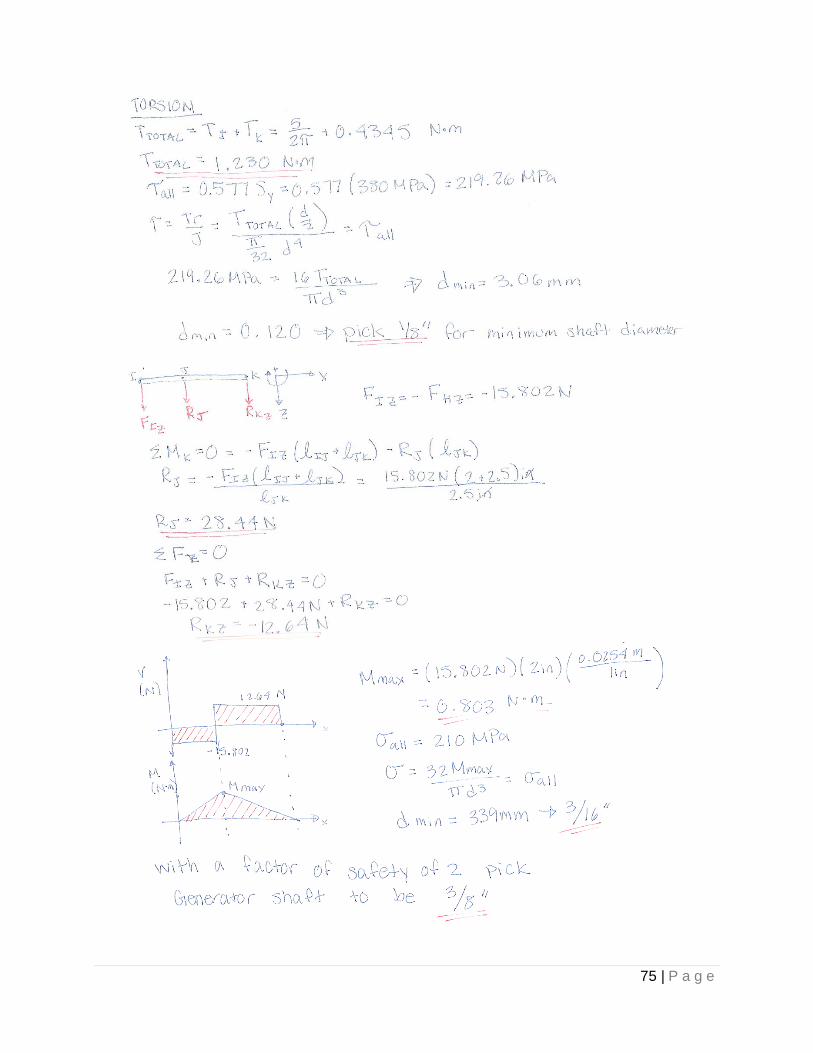
75 | P a g e

76 | P a g e
Appendix F: EES Code for Shaft Sizing

77 | P a g e

78 | P a g e

79 | P a g e
EES Sample Solution Set:

80 | P a g e
Appendix G: Gantt Chart
Figure 35: Gantt Chart created in Microsoft Project