ICB1FL01G Smart Ballast Control IC for Fluorescent Lamp - Digikey

Weller University | © 2007 Cooper Industries, Ltd. Proprietary CONFIDENTIAL | 1
Soldering Tips & Lifetime Issues“Coping with Lead-Free”

Weller University | © 2007 Cooper Industries, Ltd. Proprietary CONFIDENTIAL | 2
Why are we here?To make sales and marketing personnel more valuable to their customerby providing some basic knowledge to them about Lead-free solder andit’s effect on tip life and hand soldering applications.
Content

Weller University | © 2007 Cooper Industries, Ltd. Proprietary CONFIDENTIAL | 3
Tip Construction
Wettablearea
Chromiumplating
Copper
Fe
Cross Section LTC tip
• Architecture of a Soldering Tip– Copper Core
Responsible for the high heatconductivity of the soldering tip.
– Iron LayerResponsible for high wear resistance.
– Chromium (Chrome) LayerResponsible for confining the wettablearea.
– Tinned Working AreaResponsible for the wettability of thesoldering tip.
– Lead-Free TinningResponsible for protecting the workingarea of the tip when it is new.

Weller University | © 2007 Cooper Industries, Ltd. Proprietary CONFIDENTIAL | 4
50µm50µm
Fe SnFe Sn
Intermetallic phaseIntermetallic phase
Wettable area
Tip Construction
• Wettable Area of the SolderingTip
– The wettable area is the workingarea and is responsible for the heattransfer.
– Tinning produces an intermetallicbond between the Iron (Fe) layerand the solder alloy (Sn, Pb, Ag,etc.).
– When the intermetallic bond iscreated, the tip is properly Tinnedand remains wettable.
– The thickness of the intermetalliclayer grows with time and heat.Temperature accelerates the growthrate. This will Lead to moredissolution of the Iron, more erosionand a higher risk of oxidation.

Weller University | © 2007 Cooper Industries, Ltd. Proprietary CONFIDENTIAL | 5
Soldering tip defectsWhat does a “degraded” soldering tip look like?
What does an “oxidized” tip look like?
Tip Appearance

Weller University | © 2007 Cooper Industries, Ltd. Proprietary CONFIDENTIAL | 6
Tip Appearance
• Soldering Tip Defects– The change from a Lead bearing solder alloy to Lead Free has a
significant influence on the durability of soldering tips in handsoldering applications. The higher percentage of Tin and the highermelting temperature of the Lead Free solders act moreaggressively on the soldering tip and accelerate the reduction of tiplife. In addition, Lead-free solders typically use a more aggressiveflux formulation to compensate for the higher melting point alloys.
– The most significant reasons for soldering tip defects:• Non-wettability of the Iron layer due to oxidation or surface
contamination.• Erosion of the Iron layer due to Flux activity level,
mechanical degradation, cracks / voids, etc.– With proper care of the soldering tip, life expectancy can be
increased to a reasonable level, even when using Lead Freesolders.

Weller University | © 2007 Cooper Industries, Ltd. Proprietary CONFIDENTIAL | 7
Solderingprocess
LTC Soldering Tip “New” LTC Soldering Tip
“Eroded”
Customer feedback
What does a “degraded” soldering tip look like?
Tip Appearance

Weller University | © 2007 Cooper Industries, Ltd. Proprietary CONFIDENTIAL | 8
Hole caused bycorrosion
Cross section of a degraded LTC soldering tip
Well used LTC tip
Tip Appearance
– Eventually, the soldering tip is degraded by thesoldering application. This means that the Ironlayer that protects the Copper core iscompromised. The exposed Copper erodesquickly because of the extremely hightemperature and corrosion rate of Copper.
– The durability of the soldering tip is directlyrelative to the Iron layer thickness.
– As soon as the Iron layer is compromised, tip lifeis over and the condition will be indicated by anoticeable hole in the Copper core.
– The tip wearing process can be segregated intothree levels:
• Corrosion caused by flux activity• Erosion of the Iron plating into the solder
alloy (increased by high Sn content).• Mechanical stress caused by abrasive
cleaning or “aggressive” soldering.– A soldering tip is a consumable component
(much like the tires on a car) and a degraded tipis not an actual tip defect.

Weller University | © 2007 Cooper Industries, Ltd. Proprietary CONFIDENTIAL | 9
Tip Appearance
• Surface Contamination of aSoldering Tip– A soldering tip becomes contaminated
and produces a non-wettable surface– The typical appearance of a
contaminated soldering tip is shown inthe these photos
– The tips exhibit a “blackened or charred”surface finish that is very difficult toremove
– A contaminated tip can normally berejuvenated by a low solids, mildly activewire core solder, Tip Activator (Tinner)orWeller Polishing Bar (WPB1)
– The heat transfer of a contaminatedsoldering tip is significantly reduced
– The risk of surface contamination growsconsiderably when using higher tiptemperatures (840°F < 30 Sec.’s)

Weller University | © 2007 Cooper Industries, Ltd. Proprietary CONFIDENTIAL | 10
Tip Appearance
• Surface Contamination of a SolderingTip
– A properly tinned tip will protect the wettablesurface of the tip and will displace any surfacecontamination that may otherwise occur
– Proper maintenance of the soldering tip willreduce the risk of surface contamination andnon-wettability.
– In many cases, surface contamination mayshow up as a form of “rust”, which is indicativeof a customer using “tap” water supplies thatcontain high mineral contents (iron, magnesium,etc.)
– When “rust” is evident on the Iron platedworking area, the Chromium layer above theIron plating and the Tip Retainer, it is time torecommend using a “Distilled or Deionized”water supply
– Tips exhibiting “rust” should be discarded due tothe fact that the rust will also contaminate thesoldering connection
Chromearea
IronPlating

Weller University | © 2007 Cooper Industries, Ltd. Proprietary CONFIDENTIAL | 11
Tip Appearance
• Oxidation of a Soldering Tip– A non-tinned soldering tip will oxidize
when left exposed to air and will createa non-wettable surface
– An oxidized tip cannot normally bereactivated by standard flux andremains non-wettable
– The heat transfer capability of a non-wettable soldering tip is significantlylowered
– The risk of oxidation grows as tiptemperatures increase (840°F < 1min)
– A properly tinned tip will protect thewettable surface of the tip and preventoxidation from occurring
– Proper maintenance of the soldering tipwill reduce the risk of oxidation andnon-wettability.

Weller University | © 2007 Cooper Industries, Ltd. Proprietary CONFIDENTIAL | 12
Tip Appearance
• Oxidation of a Soldering Tip– An oxidized soldering tip typically shows no
“blackening or darkening” of the wettable areaor of the Chrome area
– The wettable area exhibits a dull grey, grainyappearance
– The Chrome (Chromium) area may turn to a“Bronze or Blue / Bronze” which indicates thatit has been heated
– There is nothing in the metallurgical make-upof a soldering tip that will allow the metals toturn “black” (see Contaminated SolderingTips)
– This also holds true for the Stainless Steel onthe Tip Retainer

Weller University | © 2007 Cooper Industries, Ltd. Proprietary CONFIDENTIAL | 13
Soldering tip after 20,000 cycles with Sn / Pb
Soldering tip after 10,000 cycles with Lead Free SAC
Tip Lifetime
• Soldering Tip Life Cycle– A new tip has a Copper core
covered by an Iron layer. The Ironlayer protects tips against corrosioncaused by the flux and intermetallicmigration caused by the solderalloy
– The high Tin content of Lead-freesolder alloys begins to dissolve theIron layer much quicker than Leadbearing solders
– Mechanical stress / pressure alsocontributes to the abrasion of theIron plated surface
– More aggressive solders and fluxes,along with higher temperatures,increases the corrosion rate
– After the Iron layer is penetrated, thetip is rendered useless as theCopper core will quickly dissolve

Weller University | © 2007 Cooper Industries, Ltd. Proprietary CONFIDENTIAL | 14
Tip Life Test Equipment
Solder Feed Testequipment assists withlong term customer Alloy/ Flux testing
Test equipment deliversreliable and consistenttest results
Test equipment used todetermine optimumblend of Iron platingversus tip geometry.
However, the variablesassociated with theoperator are non-existent in this type of tiplife testing
Fume Extraction
Soldering Tip
TipCleaning
Solder Feeder
Tip Lifetime
Weller University | © 2007 Cooper Industries, Ltd. Proprietary CONFIDENTIAL | 15
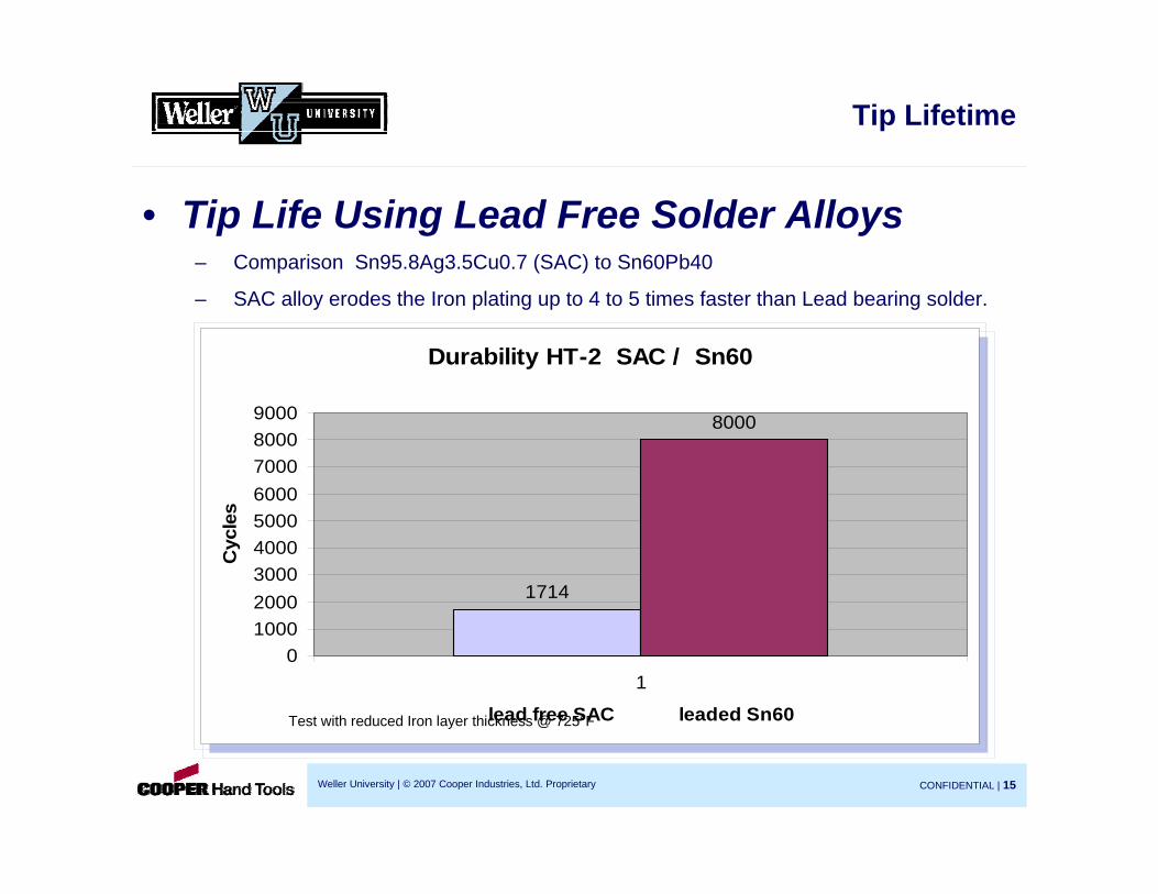
Tip Lifetime
Durability HT-2 SAC / Sn60
1714
8000
0100020003000400050006000700080009000
1
lead free SAC leaded Sn60
Cyc
les
Durability HT-2 SAC / Sn60
1714
8000
0100020003000400050006000700080009000
1
lead free SAC leaded Sn60
Cyc
les
Test with reduced Iron layer thickness @ 725°F
• Tip Life Using Lead Free Solder Alloys– Comparison Sn95.8Ag3.5Cu0.7 (SAC) to Sn60Pb40
– SAC alloy erodes the Iron plating up to 4 to 5 times faster than Lead bearing solder.

Weller University | © 2007 Cooper Industries, Ltd. Proprietary CONFIDENTIAL | 16
Durability HT-2
500
1000
1500
2000
2500
3000
3500
4000
15 30 50 75 100 120
Iron layer thickness µm
Cyc
les
Durability HT-2
500
1000
1500
2000
2500
3000
3500
4000
15 30 50 75 100 120
Iron layer thickness µm
Cyc
les
Durability test of a HT 2 soldering tip withSn/Ag/Cu (SAC) solder alloy. Tip temperature @725°F
Tip Lifetime
• Reviewing the Iron Layer of aSoldering Tip
– Weller Soldering tips have an Ironlayer thickness of between 0.006”and 0.0157” (150µm and 400µm)per side, depending on thegeometry of the tip.
– The Iron electroplating process isa highly sophisticated platingoperation.
– There is a linear relationshipbetween the Iron thickness andthe life of a tip.
– The Iron layer has 3 importantcharacteristics.
• +Plus—Long Life• +Plus - Excellent wettability• - Minus - Heat conductivity is
five times lower than Copper.

Weller University | © 2007 Cooper Industries, Ltd. Proprietary CONFIDENTIAL | 17
Tip Lifetime
Comparison : LTD 400µm / LTD 200µm
15568
6325
02000400060008000
10000120001400016000
1 2
LT-400 LT-200
Cycles
Comparison : LTD 400µm / LTD 200µm
15568
6325
02000400060008000
10000120001400016000
1 2
LT-400 LT-200
Cycles
• Results of Increasing the Iron Layer of aSoldering Tip
– Weller has increased the Iron layer thickness to an optimal valuefor performance and durability without increasing end user tip cost.

Weller University | © 2007 Cooper Industries, Ltd. Proprietary CONFIDENTIAL | 18
Cross section of LT1S
Sn
Cu
Tip Lifetime
• Impact of the Geometry of a Tipto the Iron Layer Thickness
– The Iron layer thickness is dependent on thegeometry of the soldering tip.
– Fine Pointed Tips have more Iron on thefront of the tip versus more equal Iron onChisel and Screwdriver shaped tip styles
– A thick Iron layer reduces heat transfer. Thisapplies especially to fine pointed tips (conicaland long shank tip styles).
– Fine pointed tips form an area with more Ironon the end of the tip. Underneath the workingarea of the tip there is no Copper toefficiently transfer heat.
– For that reason the Iron layer thickness islimited by the geometry and is approximately0.006” (150µm) for fine pointed tips.
– This represents the optimal balance betweenperformance and durability.
Solder Follows the Heat Source,
preventing solder from adhering to the point of
the tip
Chrome layerblocks flowof solder

Weller University | © 2007 Cooper Industries, Ltd. Proprietary CONFIDENTIAL | 19
Tip Lifetime
Wettable Area
Copper
IronCross section LT1S 150µm Fe
• The Ideal Iron Layer of a Fine Pointed Tip.– An Iron layer of 0.006” (150µm) over the Copper core ensures the best possible heat
transfer / thermal performance.
– However, the thinner Iron reduces the life of the tip in a Lead Free environment.
Chrome

Weller University | © 2007 Cooper Industries, Ltd. Proprietary CONFIDENTIAL | 20
Relationship between Iron Thickness and Performance - Comparison of an LTA with200µm and 400µm Iron layer
Comparison LTA 200 / LTA 400 Performance test
0
50
100
150
200
250
300
350
400
0 20 40 60 80 100 120 140 160 180 200
Zeit sec.
Tem
pera
tur °
C
LTA 400µmLTA 200µm
200µm Iron 400µm Iron137sec. 174sec
Tip Lifetime
More Iron = longer life= reduced performance.

Weller University | © 2007 Cooper Industries, Ltd. Proprietary CONFIDENTIAL | 21
Tip Lifetime
Tip Life Comparison Showing the Impact of theSolder Alloy Used
Comparison SnAgCu - SnCu - SnAg at 725°F
3368
24782163
0
500
1000
1500
2000
2500
3000
3500
4000
SAC / SC / SA
Zykl
en
SACSCSA
Comparison SnAgCu - SnCu - SnAg at 725°F
3368
24782163
0
500
1000
1500
2000
2500
3000
3500
4000
SAC / SC / SA
Zykl
en
SACSCSA
• The wear process is also dependent on thekind of solder alloy that’s used.
• Comparison between three common alloys.
• Sn 95,8 Ag 3,5 Cu 0,7 (SAC)
• Sn 99,3 Cu 0,7 (SC)
• Sn 96,5 Ag 3,5 (SA)
• Compared to a SAC alloy, the Tin -Copperand Tin-Silver alloys reduce the lifetime by:
• SC - 25%
• SA - 35%
HT2 Soldering tip / 725°F

Weller University | © 2007 Cooper Industries, Ltd. Proprietary CONFIDENTIAL | 22
Tip Lifetime
Lifetime Comparison Showing the Impact of TipTemperature
Cycles at different temperatures with SnCu alloy
19000
13850
7450
0
5000
10000
15000
20000
680°F 725°F 770°F
Cycles
Cycles at different temperatures with SnCu alloy
19000
13850
7450
0
5000
10000
15000
20000
680°F 725°F 770°F
Cycles • Tip temperature has a significant influenceon the tip lifetime.
• The corrosion and migration rates increasedisproportionately.
• By using a Sn Cu alloy at 770°F versus680°F the durability decreases by about 60%

Weller University | © 2007 Cooper Industries, Ltd. Proprietary CONFIDENTIAL | 23
Tip Lifetime
Impact of the Solder Alloy and Tip Temperature
Comparison SnCu - SnAgCu alloy
19000
7450 8390
31953
05000
10000150002000025000
3000035000
1
360°+410° SnCu / 410°+360° SnAgCu
Cyc
les
SnCu Lot bei 360°
SnCu Lot bei 410°
SnAgCu Lot bei 410°
SnAgCu Lot bei 360°
Comparison SnCu - SnAgCu alloy
19000
7450 8390
31953
05000
10000150002000025000
3000035000
1
360°+410° SnCu / 410°+360° SnAgCu
Cyc
les
SnCu Lot bei 360°
SnCu Lot bei 410°
SnAgCu Lot bei 410°
SnAgCu Lot bei 360°
The influence of the temperature also differswith the solder alloy. We compared Sn Cu toSAC solder alloy.
• SC solder at 770 °F---lasted for 7450 cycles
• SC solder at 680 °F---lasted for 19000 cycles
• SAC solder at 770 °F---lasted for 8390 cycles
• SAC solder at 680 °F---lasted for 31953 cycles
This equates to a 77% spread between bestand worst.

Weller University | © 2007 Cooper Industries, Ltd. Proprietary CONFIDENTIAL | 24
Tip Lifetime
Erosion depending on flux content
1170
2250
2610
4300
0
500
1000
1500
2000
2500
3000
3500
4000
4500
5000
1 2 3 4
Solder material
Cyc
les
New Solder Alloys with Micro Additives have been developed to reduce Migrationfrom the Soldering Tip, Components and Boards
• Additives reduce the migration of the Iron layerinto the solder.
• The additives are nickel, cobalt or rare earth invery low percentages which do not change thephysical characteristics of the solder.
• Together with the new flux composition used inthe micro alloys, the impact to tip lifetime issignificant ( up to 4 times ).
• Rosin flux compositions (Kristall) create morecorrosion than halogen compositions (KS115).
More info on the Weller blog in the articletitled: “Lead Free - What To Do?”
w/o flowTin® with flowTin® w/o flowTin® with flowTin® Kristall 2,2% Kristall 2,2% KS115 3% KS115 3%

Weller University | © 2007 Cooper Industries, Ltd. Proprietary CONFIDENTIAL | 25
Tip Lifetime
New Lead Free Flux with High Solids Content
• In many cases, rosin based flux is used with a high percentage of solids content.
• A portion of the flux remains on the tip and contaminates the surface.
• The tip can no longer be used since it is non-wettable.
• The flux residues are highly aggressive and create corrosion even when the soldering Iron is in the stand.
• Proper cleaning is the most important part of tipmaintenance.

Weller University | © 2007 Cooper Industries, Ltd. Proprietary CONFIDENTIAL | 26
Tip Lifetime
Sponge Cleaning of the Soldering Tip• Thermal shock of a hot tip making contact with awet sponge may create minute fractures in the tipplating, providing openings for the alloy and flux toattack the Copper core
• Sponges remove more of the protective Tincoating from the tip than when used with a WDCDry Tip Cleaner (sponges are better for LeadedSolders / not as good for Lead Free alloys)
• Operators normally forget to re-Tin the tip afterwiping on the sponge
• Because of the cooling effect of a wet sponge,flux residues are not effectively eliminated,increasing the risk of oxidation and corrosion.
• Tap water can create non-wettable tips becausethey contain mineral deposits. Use Distilled or De-ionized water when using sponges.
Effects of operator habits on tip life

Weller University | © 2007 Cooper Industries, Ltd. Proprietary CONFIDENTIAL | 27
Tip Lifetime
Weller Dry Tip Cleaning Solutions for extending tip life
Siliconrubber bar
Metal wool
• The risk of oxidation and flux residues require an optimal cleaning procedure.
• Dry cleaning with metal wool (WellerWDC & WDC2) is a significantimprovement over wet sponge cleaning.
• Flux residues are removed and somesolder remains on the tip surface aftercleaning. This reduces the risk of oxidationand corrosion.
• To remove excessive solder on the tip, theWDC also includes a Silicon Rubber Bar,that can be used to gently tap off excesssolder.
• Always re-Tin the tip with a sufficientamount of solder before placing the Ironback into the tool holder.

Weller University | © 2007 Cooper Industries, Ltd. Proprietary CONFIDENTIAL | 28
Tip Lifetime
WDC WDH10T / WDH20T WHP3000 WP80 Tip Activator and WPB1
Accessories that can be used to Help Increase Tip Life• Stop and Go Tool Holders (WDH10T & WDH20T) - switches on the soldering tool when
removed from the holder.• WDC2 Dry Tip Cleaner is an optional accessory for all WDH series tool holders.• WHP3000 Preheating Plate reduces the amount of heat required from the soldering tip by
heating up the PCB to a pre-selected temperature. A highly efficient IR heater with equalheat distribution will improve the hand soldering process without the risk of partial over-heat.
• Tip Activator can be used to rejuvenate oxidized or contaminated soldering tips.• WPB1 Polishing bar cleans and renews soldering tips ( use only when tip is cold). Re-Tin
after use with Tip Activator at a low temperature to prevent oxidation.

Weller University | © 2007 Cooper Industries, Ltd. Proprietary CONFIDENTIAL | 29
Tip Lifetime
WIIFYC & WIIFYWhen visiting your customers, offer to help them solve their tip lifeproblems when using Lead-free solder. Here’s a quick summary:
• Choose the right solder tips…,the largest possible for the application. Larger tips provide better heattransfer. Larger dimensioned tips have more Iron plating, which helps to extend tip life.
• Do not exceed 725°F. Lead-free solder does not require a higher soldering temperature. Hightemperature increases tip plating erosion. Fluxes degrade faster at high temperatures and black residuesremain on the tip surface. Lowering the soldering temperature reduces oxidation and reduces fluxsplattering.
• Chose the right solder alloy (SAC or Micro additive if possible) and flux to reduce wear of soldering tips.
• High powered soldering tools (80 - 150 Watts) with optimum temperature control can in most cases do thejob at lower temperatures. Weller WP 80 and WSP150 combine high power with optimized heat transfer.
• Dry cleaning with the Weller WDC keeps the tip wettable longer. Wet sponges cause thermal shock,remove the majority of the Tinning and doesn’t properly remove flux residues.
• Always Tin the tip to prevent oxidation and surface contamination. Always apply a thin coating ofsolder to the tip after cleaning, and before placing in the soldering tool holder.
• Use all available functions and accessories to reduce the tip temperature (Standby, Auto-Off,Temperature Pre-sets, Stop and Go tool holders, etc.) or switch the soldering tools off during breaks.

Weller University | © 2007 Cooper Industries, Ltd. Proprietary CONFIDENTIAL | 30
Tip Lifetime
Competitor Claims and Positions
• OKI– Auto-sleep work stands
• Both wet and dry cleaning offered
– Smart Heat Power Tip• Increased Iron plating• Green band around the tip to indicate Lead Free

Weller University | © 2007 Cooper Industries, Ltd. Proprietary CONFIDENTIAL | 31
Tip Lifetime
Competitor Claims and Positions
• Hakko– First company to promote dry tip cleaning– Nitrogen generator (which is not true Nitrogen
88 - 89 % efficient)– Brass Tip Polisher– Rotating V Groove Solder Cleaner to reduce
flux splatter

Weller University | © 2007 Cooper Industries, Ltd. Proprietary CONFIDENTIAL | 32
Tip Lifetime
Competitor Claims and Positions
• Pace– Nitrogen generators (more efficient than
Hakko - 98 % efficient)– Diamond soldering tips (no true advantage)
• JBC– Increased Iron plating