SOLCON MOTOR CONTROL IS OUR NATURE - VFDs.com · Basic diagram of HRVS-DN medium voltage soft...
20
MOTOR CONTROL IS OUR NATURE SOLCON
Transcript of SOLCON MOTOR CONTROL IS OUR NATURE - VFDs.com · Basic diagram of HRVS-DN medium voltage soft...
MOTOR CONTROL IS OUR NATURESOLCON

HRVS-DN Catalog 100408 / V2.0 Solcon USA-1-
Overview
Why Soft Starters?Three-phase AC induction motors are commonly used in a wide variety of indus-trial applications. Due to their starting characteristics, in many cases these motors cannot be connected directly to the power supply system. When starting direct on line (DOL) the motor can see a very high surge current reaching up to 6 times the rated motor current. This excessive current puts stress on the supply system and the switchgear. Also, when starting direct on line, a very high peak torque can occur stressing the driven motor, the mechanical system including auxiliary power transmission parts (V-belt, gears, etc.).
There are several methods for reducing the damaging effects of this excessive starting current. Conventional methods include reactors and autotransform-ers. But these methods only allow the voltage to be reduced in steps whereas a soft starter provides step-free acceleration of the drive system by continuously increasing the voltage over a selected period of time. This approach to starting minimizes the effect of high inrush current on the supply system, the motor and the driven load.
Soft starters provide the following benefi ts:
• Reduced starting current eliminates voltage drops and dips of the supply network
• Smoother acceleration of loads eliminates process or product damage
• Extended lifetime of all mechanical components, e.g. eliminating gearbox damage and resulting in less maintenance and downtime
• Extended motor life
• Reduced maintenance and operating costs
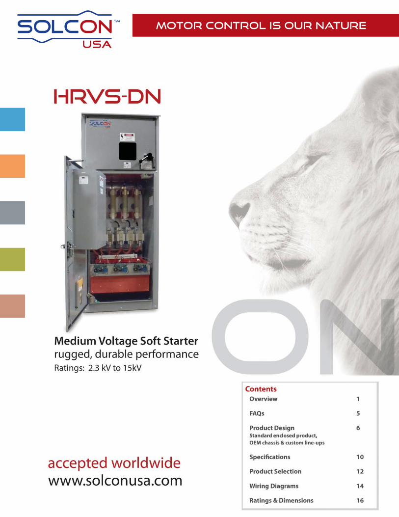
HRVS-DN - Setting a New StandardThe HRVS-DN is an innovative product that provides a fl exible, low cost alterna-tive to fi xed speed (DOL) starting.
Designed for use with standard medium voltage three-phase squirrel cage induc-tion motors, this high-performance digital soft starter ensures smooth acceleration and deceleration.
HRVS-DN is available in all standard internationally recognized medium voltage ratings: 2.3 kV, 3.3 kV, 4.16 kV, 6 kV and 6.6 kV, 10kV, 11kV, 13.8kV and 15kV.
The standard current output range capability is from 60 - 2700A (200 kW to 50 MW).
HRVS-DN is designed and built to meet international standards including:
• IEC • EN
• DIN VDE • NEMA
• UL/CUL • IEEE
The HRVS-DN soft starters are manufactured to the highest quality level. The entire design, production and delivery process has been certifi ed DIN ISO 9001.2000.
The enclosed versions of the HRVS-DN are provided as ready-to-connect en-closed type units (shown in Figures 1 and 2) or - for OEMs and qualifi ed integra-tors only - chassis type OEM kits are available for building the unit into custom enclosures or other relevant equipment.
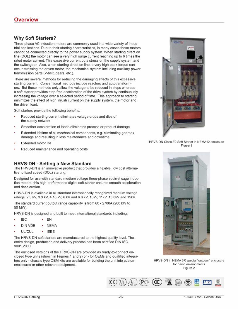
HRVS-DN Class E2 Soft Starter in NEMA12 enclosureFigure 1
HRVS-DN in NEMA 3R special “outdoor” enclosure for harsh environments
Figure 2

HRVS-DN Catalog 100408 / V2.0 Solcon USA-2-
OverviewHow Soft Starters WorkBy using thyristors (SCRs) in a phase angle control mode, reduced voltage control can be achieved. Phase control makes it possible to gradually increase the motor terminal voltage from an initial set point up to the system supply voltage level. The related starting current and the starting torque can be optimally adjusted to the motor/load conditions.
In addition, the Solcon HRVS-DN soft starters provide the “soft stopping” function as a standard feature. Similar to the reduced voltage start, upon a stop command the motor voltage is gradually decreased over time until the motor load stops. Abrupt stopping is avoided,a particular advantage in pumping applications to prevent the damaging effects of water hammer and on conveyor belts where the loadmay be damaged by an abrupt stop.
Basic diagram of HRVS-DN medium voltage soft starter Phase control of the line voltage using semiconductor (SCR) devices
M3 ~
VL1-L3
Starting and Stopping CharacteristicsInitial voltage
Determines motor’s initial starting torque (the torque is directly pro-portional to the square of the voltage). Adjustable from 10 – 50% of nominal motor voltage VR (with option to extend to 80 % VR).
This adjustment also determines the inrush current and mechani-cal shock. A setting which is too high may cause excessive initial mechanical shock and high inrush current (even if current limit is set low, as the initial voltage setting overrides current limit setting). A setting which is too low may result in prolonged start time before the motor shaft will begin to turn. Ideally, the motor shaft should slowly begin to turn immediately after a start signal is initiated.
Current limitDetermines highest allowable current during starting. Adjustable from 100 – 400% of nominal motor current IR (with option to extend to 500 % IR).
Too high a current limit setting will cause excessive current draw from the mains and faster acceleration. A setting which is too low may prevent the motor from completing the acceleration process and reaching full speed. In general this setting should be set to a value that is high enough to prevent the motor from stalling.
Note: Current limit is not operational during run mode or during soft stop.
time0
50 %
VR
10 %
Initialvoltage
0
VR
VStart
Istart
tsoft start
RPM
100 %
400 % VC.L
time
currentlimit
HRVS-DN Catalog 100408 / V2.0 Solcon USA-3-
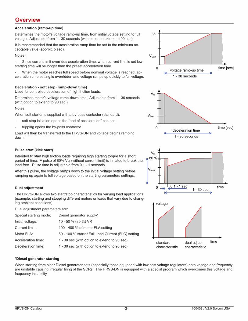
OverviewAcceleration (ramp-up time)Determines the motor’s voltage ramp-up time, from initial votage setting to full voltage. Adjustable from 1 - 30 seconds (with option to extend to 90 sec).
It is recommended that the acceleration ramp time be set to the minimum ac-ceptable value (approx. 5 sec).
Notes:
- Since current limit overrides acceleration time, when current limit is set low starting time will be longer than the preset acceleration time.
- When the motor reaches full speed before nominal voltage is reached, ac-celeration time setting is overridden and voltage ramps up quickly to full voltage.
Deceleration - soft stop (ramp-down time)Used for controlled deceleration of high friction loads.
Determines motor’s voltage ramp-down time. Adjustable from 1 - 30 seconds (with option to extend to 90 sec.)
Notes:
When soft starter is supplied with a by-pass contactor (standard):
- soft stop initiation opens the “end of acceleration” contact,
- tripping opens the by-pass contactor.
Load will then be transferred to the HRVS-DN and voltage begins ramping down.
Pulse start (kick start)Intended to start high friction loads requiring high starting torque for a short period of time. A pulse of 80% VR (without current limit) is initiated to break the load free. Pulse time is adjustable from 0.1 - 1 seconds.
After this pulse, the voltage ramps down to the initial voltage setting before ramping up again to full voltage based on the starting parameters settings.
Dual adjustmentThe HRVS-DN allows two start/stop characteristics for varying load applications (example: starting and stopping different motors or loads that vary due to chang-ing ambient conditions).
Dual adjustment parameters are:
Special starting mode: Diesel generator supply*
Initial voltage: 10 - 50 % (80 %) VR
Current limit: 100 - 400 % of motor FLA setting
Motor FLA: 50 - 100 % starter Full Load Current (FLC) setting
Acceleration time: 1 - 30 sec (with option to extend to 90 sec)
Deceleration time: 1 - 30 sec (with option to extend to 90 sec)
*Diesel generator startingWhen starting from older Diesel generator sets (especially those equipped with low cost voltage regulators) both voltage and frequencyare unstable causing irregular fi ring of the SCRs. The HRVS-DN is equipped with a special program which overcomes this voltage and frequency instability.
time [sec]0
VR
VStart
deceleration time1 - 30 seconds
0
VR
VStart
time
80 %
0.1 - 1 sec1 - 30 sec
timestandardcharacteristic
dual adjustcharacteristic
voltage
time [sec]0
VR
VStart
1 - 30 secondsvoltage ramp-up time
HRVS-DN Catalog 100408 / V2.0 Solcon USA-4-
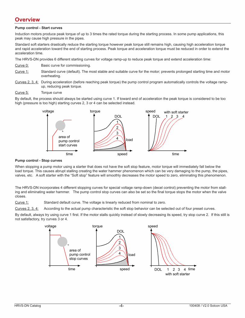
OverviewPump control - Start curvesInduction motors produce peak torque of up to 3 times the rated torque during the starting process. In some pump applications, thispeak may cause high pressure in the pipes.
Standard soft starters drastically reduce the starting torque however peak torque still remains high, causing high acceleration torque and rapid acceleration toward the end of starting process. Peak torque and acceleration torque must be reduced in order to extend the acceleration time.
The HRVS-DN provides 6 different starting curves for voltage ramp-up to reduce peak torque and extend acceleration time:
Curve 0: Basic curve for commissioning.
Curve 1: Standard curve (default). The most stable and suitable curve for the motor; prevents prolonged starting time and motor overheating.
Curves 2, 3, 4: During acceleration (before reaching peak torque) the pump control program automatically controls the voltage ramp- up, reducing peak torque.
Curve 5: Torque curve
By default, the process should always be started using curve 1. If toward end of acceleration the peak torque is considered to be too high (pressure is too high) starting curves 2, 3 or 4 can be selected instead.
Pump control - Stop curvesWhen stopping a pump motor using a starter that does not have the soft stop feature, motor torque will immediately fall below theload torque. This causes abrupt stalling creating the water hammer phenomenon which can be very damaging to the pump, the pipes,valves, etc. A soft starter with the “Soft stop” feature will smoothly decreases the motor speed to zero, eliminating this phenomenon.
The HRVS-DN incorporates 4 different stopping curves for special voltage ramp-down (decel control) preventing the motor from stall-ing and eliminating water hammer. The pump control stop curves can also be set so the fi nal torque stops the motor when the valve closes.
Curve 1: Standard default curve. The voltage is linearly reduced from nominal to zero.
Curves 2, 3, 4: According to the actual pump characteristic the soft stop behavior can be selected out of four preset curves.
By default, always try using curve 1 fi rst. If the motor stalls quickly instead of slowly decreasing its speed, try stop curve 2. If this still is not satisfactory, try curves 3 or 4.
time
voltage
speed
torqueDOL1234 load
time
speedDOL 1 2 3 4
with soft starter
area ofpump controlstart curves
time
voltage
speed
torqueDOL1234 load
time
speed
DOL 1 2 3 4with soft starter
area ofpump controlstop curves

HRVS-DN Catalog 100408 / V2.0 Solcon USA-5-
FAQs
Question Answer
Can an HRVS-DN soft starter be used to start a heavy-duty load or a load with a high moment of inertia if the motor will not start direct-on-line (DOL)?
YesBut we need certain data to calculate the minimal starting conditions. Contact technical support for assistance.
Can an HRVS-DN soft starter be connected to the medium voltage bus without using a loadbreak disconnect switch?
-YesThe HRVS-DN can be provided without a load break switch (with inline and bypass contactors only). A fused load-break disconnect switch at the medium-voltage feeder is sufficient. The fuses are only used as cable protection and protection against catastrophic failure. The motor protection relay is usually included in the circuit breaker or the soft-starter can be equipped with a comprehensive motor protection relay (MPS3000 or equivalent) If an existing circuit-breaker is used, this can remain closed or switches in the no-current condition (exception: under fault conditions)
Can an HRVS-DN soft-starter also be used to start synchronous motors?
YesA non-excited synchronous motor behaves essentially the same as a squirrel-cage induction motor. If the motor has reached the rated speed in a non-excited condition (rated slip in induction motor operation), the excitation system (which can be supplied by Solcon) is switched-in and the motor then pulls into synchronized mode.
Is the HRVS-DN soft-starter available in an explosion-proof version?
Yes with certification (EEx-D)[ia]I
Can the HRVS-DN soft-starter be used to start several different motors or can one HRVS-DN soft starterbe used to start more than one motor?
YesTwo parameter settings can be programmed using the "Dual Adjustment" function. This means that two different motor types can be started. However, there may be little difference in the actual motor output. Several identical motors can be started. However, due to the higher thermal load, a larger soft-starter (always equipped with a fan), must be used. One (or several) additional cabinets with vacuum contactors can be provided for sequential starting of multiple motors.
When is a tachometer (shaft encoder) required to be used with the HRVS-DN soft-starter?
A tachometer is generally not required for standard applications, only for special cases:
Soft stopping with shutdown (power-off) at a specific speed Starting and/or stopping with an adjustable speed profile If it has to be accurately determined when the motor has reached full speed
Is the HRVS-DN soft-starter also available in an outdoor versions ?
Yes NEMA 3R, 4, 4X (IP67)
Is the HRVS-DN soft-starter designed to meet industry sector-specific and local standards
YesIEC, NEMA UL / CUL DNV and ABS or similar upon request
Is it possible to use HRVS-DN soft-starters on synchronous or slip ring motors?
YesUnless the slip ring motor was originally specified due to especially high starting torque requirements. Under these circumstances, a soft-starter cannot be used !
Can you use the HRVS-DN soft starter with any manufacturer’s motor?
YesIn especially critical cases, increased pulsating torques can be observed with some motor designs. The non-sinusoidal current and voltage waveform of the soft starter does not represent a risk.
Can HRVS-DN soft starters operate at high altitudes (i.e. locations 4000m above sea level)?
YesBut the nominal voltage and current have to be reduced based on the derating table (please refer to page 10) and the starting frequency (number of starts per unit time) may need to be reduced.
Can the HRVS-DN soft-starter be operated with supply voltages which are not listed in the table (intermediate values)?
YesIn this case, the next higher voltage class should be selected, and the actual supply voltage specified when ordering.
Can an HRVS-DN soft starter be operated into a step-up transformer?
YesBut why should a step-up transformer be used when Solcon offers the HRVS-DN in ratings up to 15kV?
Does an HRVS-DN soft-starter generate harmonics which are fed back into the supply?
YesBut only for a very brief period of time until the bypass contactor closes (low level
Solcon is the only MV soft starter manufacturer in the world to offer this certification.
harmonies only)
HRVS-DN Catalog 100408 / V2.0 Solcon USA-6-
Product Design Standard HRVS-DN Soft Starter Design
The Standard HRVS-DN soft starter is supplied in a NEMA12 enclosure ready to be installed and operated. Optional NEMA 3R and other enclosure types are also available.
The design includes:
• Digital soft starter, high-voltage and low-voltage compartment
• Disconnect switch (load break - fault make switch with fuses), line and bypass vacuum contactors.
• Low voltage controls
• Modbus RS485 communications
Optional communication protocols are available including Profi bus, DeviceNet and others allowing for:
• Remote control (start, stop, etc.)
• Remote supervision
HRVS-DNSoft-StarterControl Panel
HRVS-DNSoft-StarterPowerModule
I 1
I 2
I 3
EPT-RxReceiver
EPT - TxTransmitter
1311
{
{
{
CT34
89
1314
13
11
Electric Wire Harness (6 wires)
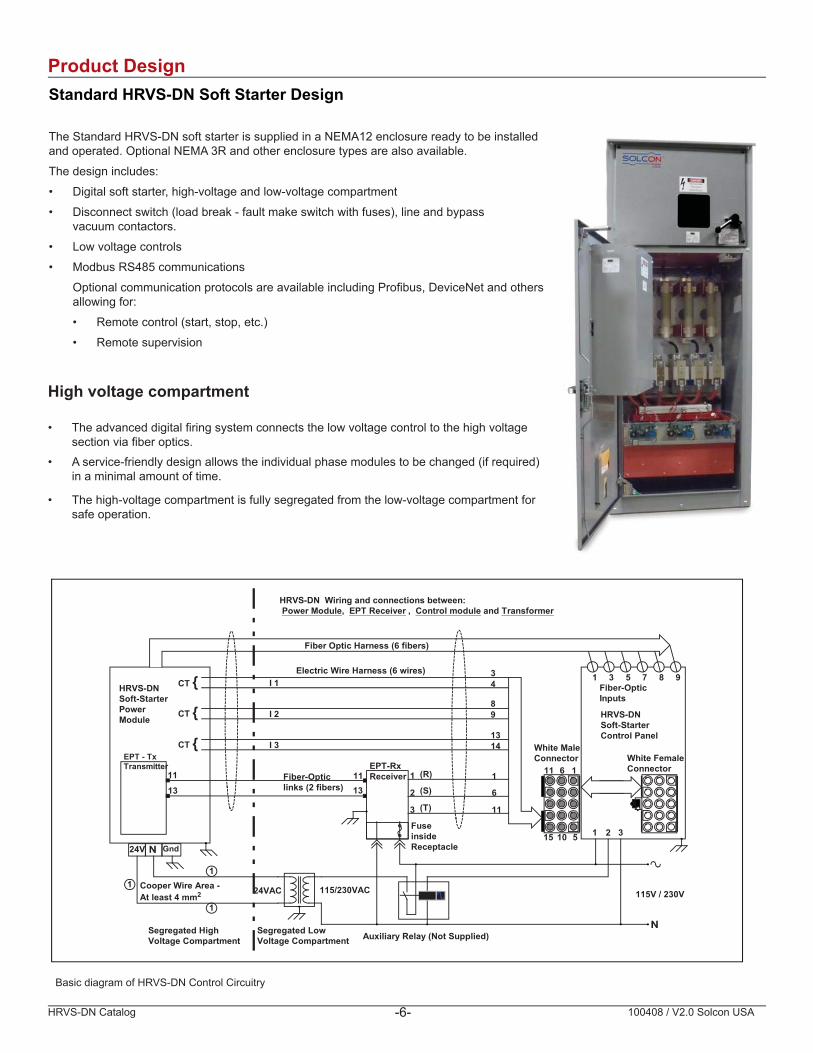
HRVS-DN Wiring and connections between: Power Module, EPT Receiver , Control module and Transformer
1 3 5 7 8 9
Fiber Optic Harness (6 fibers)
Fiber-OpticInputs
24VAC 115/230VAC
24V Gnd
1 2 3
Auxiliary Relay (Not Supplied)
1
2
3
1
6
11
(R)
(S)
(T)
115V / 230VCooper Wire Area -At least 4 mm2
1
1
1
Fiber-Opticlinks (2 fibers)
15 10 5
11 6 1
White MaleConnector White Female
Connector
FuseinsideReceptacle
Segregated LowVoltage Compartment
Segregated HighVoltage Compartment
CT
CT
Basic diagram of HRVS-DN Control Circuitry
High voltage compartment
• The advanced digital fi ring system connects the low voltage control to the high voltage section via fi ber optics.
• A service-friendly design allows the individual phase modules to be changed (if required) in a minimal amount of time.
• The high-voltage compartment is fully segregated from the low-voltage compartment for safe operation.
HRVS-DN Catalog 100408 / V2.0 Solcon USA-7-
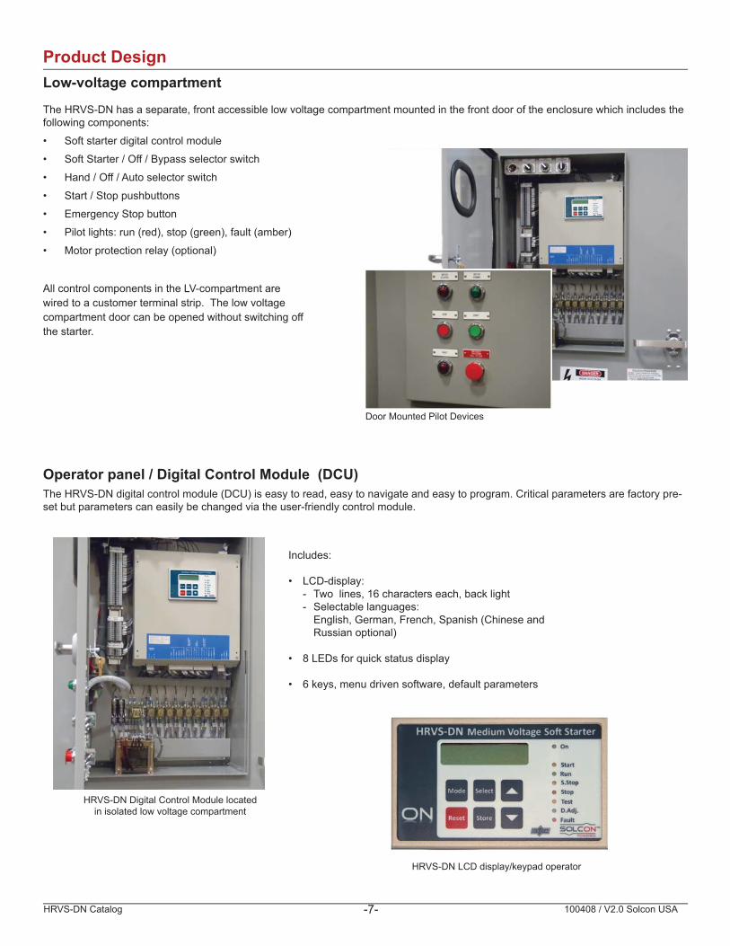
Product DesignLow-voltage compartment
The HRVS-DN has a separate, front accessible low voltage compartment mounted in the front door of the enclosure which includes thefollowing components:
• Soft starter digital control module
• Soft Starter / Off / Bypass selector switch
• Hand / Off / Auto selector switch
• Start / Stop pushbuttons
• Emergency Stop button
• Pilot lights: run (red), stop (green), fault (amber)
• Motor protection relay (optional)
All control components in the LV-compartment are wired to a customer terminal strip. The low voltage compartment door can be opened without switching off the starter.
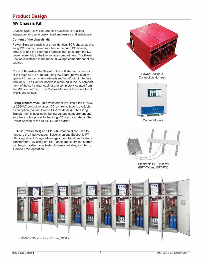
Operator panel / Digital Control Module (DCU)The HRVS-DN digital control module (DCU) is easy to read, easy to navigate and easy to program. Critical parameters are factory pre-set but parameters can easily be changed via the user-friendly control module.
HRVS-DN Digital Control Module locatedin isolated low voltage compartment
Includes:
• LCD-display: - Two lines, 16 characters each, back light - Selectable languages: English, German, French, Spanish (Chinese and Russian optional)
• 8 LEDs for quick status display
• 6 keys, menu driven software, default parameters
HRVS-DN LCD display/keypad operator
Door Mounted Pilot Devices
HRVS-DN Catalog 100408 / V2.0 Solcon USA-8-
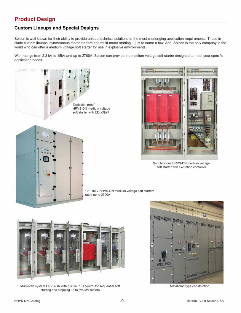
Product Design MV Chassis Kit
Chassis type “OEM kits” are also available to qualifi ed integrators for use in customized enclosures and switchgear.
Content of the chassis kit:Power Section consists of three identical SCR phase stacks, fi ring PC boards, power supplies to the fi ring PC boards, three CTs and the fi ber optic harness that goes from the MV power assembly to the low voltage compartment. The Power Section is installed in the medium voltage compartment of the cabinet.
Control Module is the “brain” of the soft starter. It consists of the main CPU PC board, fi ring PC board, power supply, option PC boards (when ordered) and input/output interface terminals. The Control Module is mounted in the LV compart-ment of the soft starter cabinet and completely isolated from the MV compartment. The Control Module is the same for all HRVS-DN ratings.
Firing Transformer. This transformer is suitable for 115VAC or 230VAC control voltages. DC control voltage is available as an option (contact Solcon USA for details). The Firing Transformer is installed in the low voltage compartment and supplies control power to the fi ring PC boards located in the Power Section of the HRVS-DN soft starter.
EPT-Tx (transmitter) and EPT-Rx (receiver) are used to measure the input voltage. Solcon’s unique Electronic PT offers signifi cant design advantages over ‘traditional’ voltage transformers. By using the EPT, each and every soft starter can be partial discharge tested to insure reliable, long term, ‘Corona Free’ operation.
Power Section &Connection Harness
Control Module
Electronic P/T Receiver(EPT-TX and EPT-RX)
HRVS-DN “Custom Line Up” using OEM kit
HRVS-DN Catalog 100408 / V2.0 Solcon USA-9-
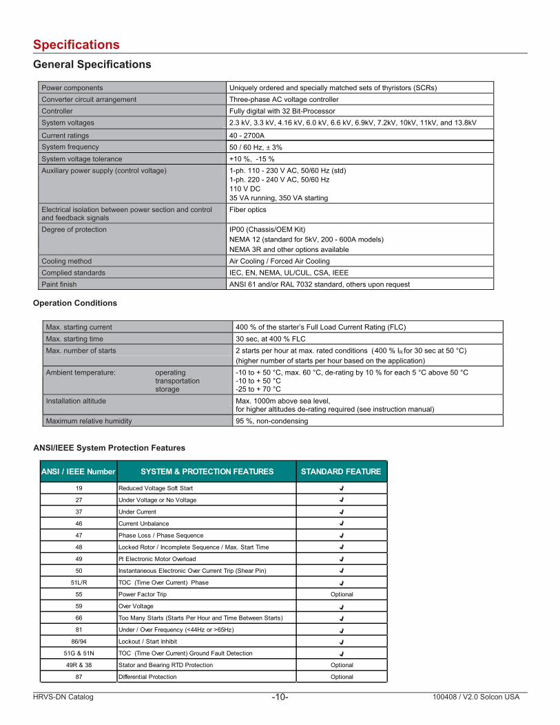
Product Design Custom Lineups and Special Designs
Solcon is well known for their ability to provide unique technical solutions to the most challenging application requirements. These in-clude custom linueps, synchronous motor starters and multi-motor starting... just to name a few. And, Solcon is the only company in the world who can offer a medium voltage soft starter for use in explosive environments.
With ratings from 2.3 kV to 15kV and up to 2700A, Solcon can provide the medium voltage soft starter designed to meet your specifi c application needs.
Explosion proof HRVS-DN medium voltage soft starter with EEx-D[ia]I
Synchronous HRVS-DN medium voltagesoft starter with excitation controller
10 - 15kV HRVS-DN medium voltage soft starters rated up to 2700A
Metal-clad type constructionMulti-start system HRVS-DN with built in PLC control for sequential soft starting and stopping up to fi ve MV motors
HRVS-DN Catalog 100408 / V2.0 Solcon USA-10-
Specifi cations General Specifi cations
Power components Uniquely ordered and specially matched sets of thyristors (SCRs) Converter circuit arrangement Three-phase AC voltage controller Controller Fully digital with 32 Bit-Processor System voltages 2.3 kV, 3.3 kV, 4.16 kV, 6.0 kV, 6.6 kV, 6.9kV, 7.2kV, 10kV, 11kV, and 13.8kV
System frequency 50 / 60 Hz, ± 3% Current ratings 40 - 2700A
System voltage tolerance +10 %, -15 % Auxiliary power supply (control voltage) 1-ph. 110 - 230 V AC, 50/60 Hz (std)
1-ph. 220 - 240 V AC, 50/60 Hz 110 V DC 35 VA running, 350 VA starting
Electrical isolation between power section and control and feedback signals
Fiber optics
Degree of protection IP00 (Chassis/OEM Kit) NEMA 12 (standard for 5kV, 200 - 600A models)NEMA 3R and other options available
Cooling method Air Cooling / Forced Air Cooling Complied standards IEC, EN, NEMA, UL/CUL, CSA, IEEE Paint finish ANSI 61 and/or RAL 7032 standard, others upon request
Max. starting current 400 % of the starter’s Full Load Current Rating (FLC)Max. starting time 30 sec, at 400 % FLC Max. number of starts 2 starts per hour at max. rated conditions (400 % IR for 30 sec at 50 °C)
(higher number of starts per hour based on the application) Ambient temperature: operating
transportationstorage
-10 to + 50 °C, max. 60 °C, de-rating by 10 % for each 5 °C above 50 °C-10 to + 50 °C -25 to + 70 °C
Installation altitude Max. 1000m above sea level, for higher altitudes de-rating required (see instruction manual)
Maximum relative humidity 95 %, non-condensing
Operation Conditions
ANSI/IEEE System Protection Features
ANSI / IEEE Number SYSTEM & PROTECTION FEATURES STANDARD FEATURE
19 Reduced Voltage Soft Start
27 Under Voltage or No Voltage
37 Under Current
46 Current Unbalance
47 Phase Loss / Phase Sequence
48 Locked Rotor / Incomplete Sequence / Max. Start Time
49 I²t Electronic Motor Overload
50 Instantaneous Electronic Over Current Trip (Shear Pin)
51L/R TOC (Time Over Current) Phase
55 Power Factor Trip Optional
59 Over Voltage
66 Too Many Starts (Starts Per Hour and Time Between Starts)
81 Under / Over Frequency (<44Hz or >65Hz)
86/94 Lockout / Start Inhibit
51G & 51N TOC (Time Over Current) Ground Fault Detection
49R & 38 Stator and Bearing RTD Protection Optional
87 Differential Protection Optional
HRVS-DN Catalog 100408 / V2.0 Solcon USA-11-
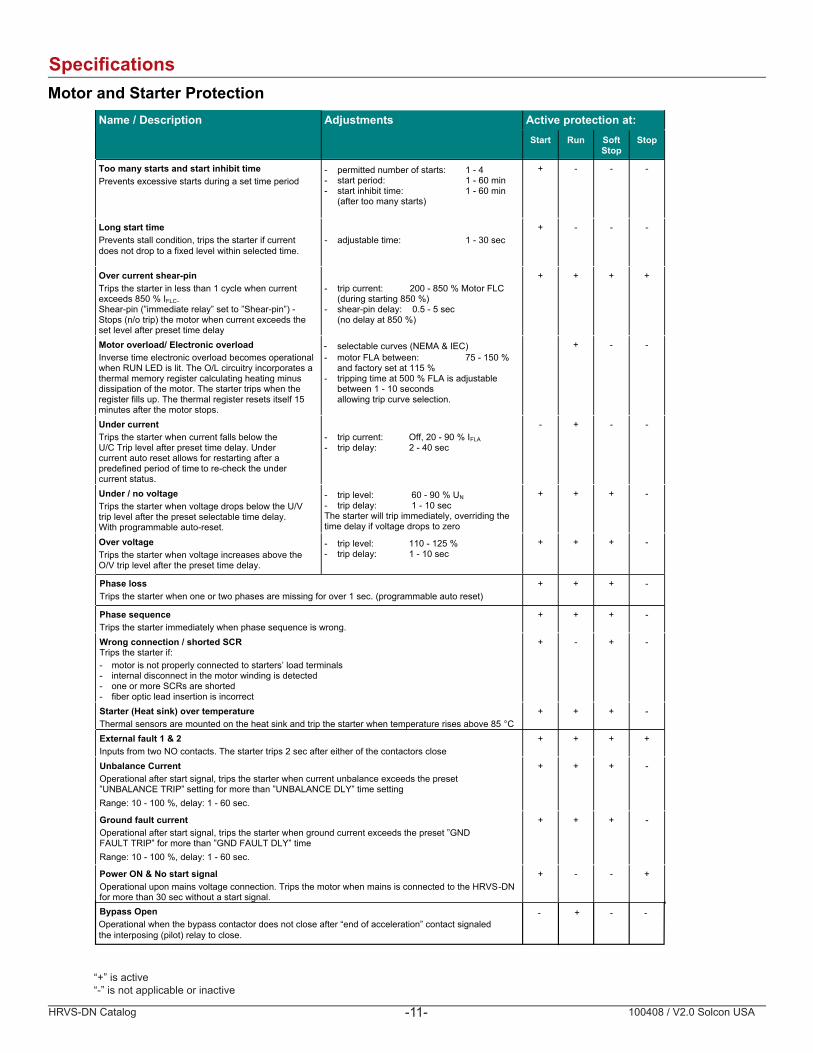
Specifi cations Motor and Starter Protection
Name / Description Adjustments Active protection at: Start Run Soft
StopStop
Too many starts and start inhibit timePrevents excessive starts during a set time period
- permitted number of starts: 1 - 4 - start period: 1 - 60 min - start inhibit time: 1 - 60 min
(after too many starts)
+ - - -
Long start time Prevents stall condition, trips the starter if current does not drop to a fixed level within selected time.
- adjustable time: 1 - 30 sec + - - -
Over current shear-pin Trips the starter in less than 1 cycle when current exceeds 850 % IFLC.Shear-pin (”immediate relay” set to ”Shear-pin”) - Stops (n/o trip) the motor when current exceeds the set level after preset time delay
- trip current: 200 - 850 % Motor FLC (during starting 850 %)
- shear-pin delay: 0.5 - 5 sec (no delay at 850 %)
+ + + +
Motor overload/ Electronic overloadInverse time electronic overload becomes operational when RUN LED is lit. The O/L circuitry incorporates a thermal memory register calculating heating minus dissipation of the motor. The starter trips when the register fills up. The thermal register resets itself 15 minutes after the motor stops.
-- motor FLA between:
selectable curves (NEMA & IEC) 75 - 150 %
and factory set at 115 % - tripping time at 500 % FLA is adjustable
between 1 - 10 seconds allowing trip curve selection.
+ - -
Under current Trips the starter when current falls below the U/C Trip level after preset time delay. Under current auto reset allows for restarting after a predefined period of time to re-check the under current status.
- trip current: Off, 20 - 90 % IFLA- trip delay: 2 - 40 sec
- + - -
Under / no voltageTrips the starter when voltage drops below the U/V
.yaledemitelbatcelesteserpehtretfalevelpirtWith programmable auto-reset.
- trip level: 60 - 90 % UN- trip delay: 1 - 10 sec The starter will trip immediately, overriding the time delay if voltage drops to zero
+ + + -
Over voltageTrips the starter when voltage increases above the O/V trip level after the preset time delay.
- trip level: 110 - 125 % - trip delay: 1 - 10 sec
+ + + -
Phase lossTrips the starter when one or two phases are missing for over 1 sec. (programmable auto reset)
+ + + -
Phase sequenceTrips the starter immediately when phase sequence is wrong.
+ + + -
Wrong connection / shorted SCRTrips the starter if: - motor is not properly connected to starters’ load terminals - internal disconnect in the motor winding is detected - one or more SCRs are shorted - fiber optic lead insertion is incorrect
+ - + -
Starter (Heat sink) over temperatureThermal sensors are mounted on the heat sink and trip the starter when temperature rises above 85 °C
+ + + -
External fault 1 & 2 esolcsrotcatnocehtforehtieretfaces2spirtretratsehT.stcatnocONowtmorfstupnI
+ + + +
Unbalance CurrentOperational after start signal, trips the starter when current unbalance exceeds the preset ”UNBALANCE TRIP” setting for more than ”UNBALANCE DLY” time settingRange: 10 - 100 %, delay: 1 - 60 sec.
+ + + -
Ground fault currentOperational after start signal, trips the starter when ground current exceeds the preset ”GND
emit”YLDTLUAFDNG”nahteromrof”PIRTTLUAFRange: 10 - 100 %, delay: 1 - 60 sec.
+ + + -
Power ON & No start signal
Bypass Open
Operational upon mains voltage connection. Trips the motor when mains is connected to the HRVS
Operational when the bypass contactor does not close after “end of acceleration” contact signaledthe interposing (pilot) relay to close.
-DNfor more than 30 sec without a start signal.
+ - - +
- + - -
“+” is active“-” is not applicable or inactive

HRVS-DN Catalog 100408 / V2.0 Solcon USA-12-
Product Selection Standard Scope of Supply
Control input voltage 115VAC Input / output cable entry Top or bottom entry Standard on all enclosed units
Main isolation switch Class E2 starter version Main fuses Class E2 starter versionLine contactor Fixed, vacuum Standard, option for VCB at higher ratingsBypass contactor Fixed, vacuum Standard, option for VCB at higher ratings
RTD Option Optional TPR 6-14 accepts up to 14 - PT100 RTD inputs Motor protection relay Optional MPS3000 or other models available depending on application requirements Digital panel meter Optional Space heater Optional Standard in NEMA 3R outdoor design, thermostat controlled Cooling fan Optional
Standard, 240VAC or 110-220VDC or 24VDC optional
Standard, option for VCB at higher ratingsStandard
Available OptionsHere are just a few of the many options and accessories available from Solcon. Contact us for your specifi c application requirements.
How to Order
Code Name / Description Comment
Electrical options 3P RS-485 communication with PROFIBUS Fan Fan on top, air entry at bottom with filter and circuit breaker For excessive starts per hour requirements
No bridge required
5 Analog output module MPS3000 Motor protection relay with 10 PT100 inputs 400 400 V test voltage for LV-motor test * (460V standard)
575 575 V test voltage for LV-motor test * 690 690 V test voltage for LV-motor test *
* Complete functional test of the soft starter can be carried out using a small LV motor (3 to 5HP).
Mechanical options Thickpaint
Special painting, extra thick Specify mil thickness and paint color
TIN TinSpace heater with thermostat
-plated copper bus barsH1 M Suitable for marine applicationsMulti-start
For multi-motor applications Contact factory for details
Spare part packages Spares 1 year
Spare parts package 1 Includes:1 - Phase power section module 1 - Digital controller module 1 - Vacuum contactor1 - Current transformer1 - Electronic PT (Tx and Rx)1 - Firing power supply board
Spares -2 years
Spare part package 2 Includes:2 - Phase power section modules 1 - Digital controller module 1 - Vacuum contactor 1 - Current transformer 2 - Electronic PT (Tx and Rx) 1 - Firing power supply board
HRVS-DN 200 - 4160 - 115 - 3M - 5 - R - N12
Amperage(See pg 16)
LineVoltage
ControlVoltage
Communications3M = Modbus (Std)
3P = ProfibusAnalogOutputCard
Relay Card for remote start/stop
EnclosureType
Example:
HRVS-DN Catalog 100408 / V2.0 Solcon USA-13-
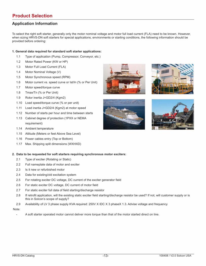
Product Selection Application Information
To select the right soft starter, generally only the motor nominal voltage and motor full load current (FLA) need to be known. However, when sizing HRVS-DN soft starters for special applications, environments or starting conditions, the following information should be provided before ordering:
1. General data required for standard soft starter applications: 1.1 Type of application (Pump, Compressor, Conveyor, etc.)
1.2 Motor Rated Power (KW or HP)
1.3 Motor Full Load Current (FLA)
1.4 Motor Nominal Voltage (V)
1.5 Motor Synchronous speed (RPM)
1.6 Motor current vs. speed curve or Ist/In (% or Per Unit)
1.7 Motor speed/torque curve
1.8 Tmax/Tn (% or Per Unit)
1.9 Rotor inertia J=GD2/4 (Kgm2)
1.10 Load speed/torque curve (% or per unit)
1.11 Load inertia J=GD2/4 (Kgm2) at motor speed
1.12 Number of starts per hour and time between starts
1.13 Cabinet degree of protection (1PXX or NEMA
requirement)
1.14 Ambient temperature
1.15 Altitude (Meters or feet Above Sea Level)
1.16 Power cables entry (Top or Bottom)
1.17 Max. Shipping split dimensions (WXHXD)
2. Data to be requested for soft starters requiring synchronous motor exciters: 2.1 Type of exciter (Rotating or Static)
2.2 Full nameplate data of motor and exciter
2.3 Is it new or refurbished motor
2.4 Data for existing/old excitation system
2.5 For rotating exciter DC voltage, DC current of the exciter generator fi eld
2.6 For static exciter DC voltage, DC current of motor fi eld
2.7 For static exciter full data of fi eld starting/discharge resistor
2.8 If retrofi t application, will the existing static exciter fi eld starting/discharge resistor be used? If not, will customer supply or is this in Solcon’s scope of supply?
2.9 Availability of LV 3 phase supply KVA required: 250V X IDC X 3 phaseX 1.3. Advise voltage and frequency
Note:
- A soft starter operated motor cannot deliver more torque than that of the motor started direct on line.
HRVS-DN Catalog 100408 / V2.0 Solcon USA-14-
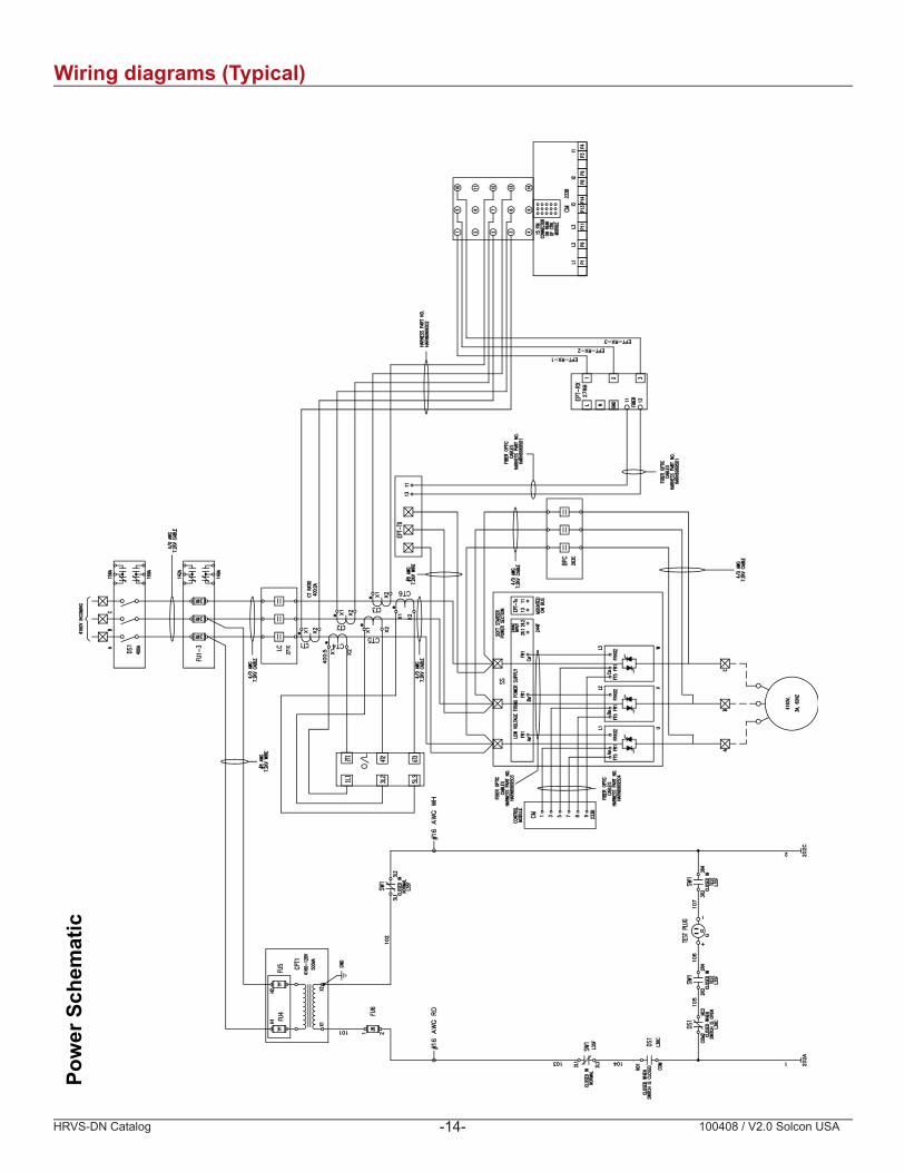
Wiring diagrams (Typical)Po
wer
Sch
emat
ic

HRVS-DN Catalog 100408 / V2.0 Solcon USA-15-
Con
trol
Sch
emat
ic
Wiring diagrams (Typical)

HRVS-DN Catalog 100408 / V2.0 Solcon USA-16-
Ratings & Dimensions Typical Ratings and Dimensions for Chassis and Enclosed UnitsThe starter must be selected based on the motor’s Full Load Ampere (FLA) as indicated on its nameplate (even if the motor is not fully loaded). The kW and HP ratings given in the following selection table are related to standard motors and are for reference only.
Starter Chassis (IP00) Nema 1-3R,4,4X (IP31-67)System Voltage
Starter Current Motor HP Motor
KW H W D Lbs H W D Lbs
2300110 500 360 23.0 30.0 18.5 284 92.0 36.0 30.0 1100200 900 660 23.0 30.0 18.5 290 92.0 36.0 30.0 1100400 1750 1330 23.0 30.0 17.0 356 92.0 36.0 30.0 1254600 2500 2000 31.5 26.0 19.3 440 92.0 72.0 30.0 2400800 3425 2660 44.1 35.4 24.4 770 92.0 96.0 36.0 35001000 4275 3330 44.1 35.4 24.4 990 92.0 96.0 36.0 3500
3300110 675 520 22.8 30.0 18.5 334 92.0 36.0 30.0 1210200 1225 950 22.8 30.0 18.5 336 92.0 36.0 30.0 1210400 2500 1910 22.8 30.0 19.8 449 92.0 36.0 30.0 1254
600 3675 2850 33.1 31.4 23.6 770 92.0 72.0 30.0 2400800 4900 3820 44.1 35.4 24.4 880 92.0 78.0 36.0 28001000 6125 4780 44.1 35.4 24.4 880 92.0 96.0 36.0 3500
4160
110 900 660 22.8 30.0 18.5 334 92.0 36.0 30.0 1210200 1500 1200 22.8 30.0 18.5 337 92.0 36.0 30.0 1210
400 3250 2400 22.8 30.0 19.8 449 92.0 36.0 30.0 1300
600 4500 3610 33.1 31.4 23.6 770 92.0 72.0 30.0 2400800 6175 4820 44.1 35.4 24.4 990 92.0 78.0 36.0 2800
1000 7725 6030 44.1 35.4 24.4 1100 92.0 96.0 36.0 3500
660070 850 670 29.1 30.0 18.5 440 92.0 36.0 30.0 1300140 1725 1340 29.1 30.0 18.5 447 92.0 36.0 30.0 1300250 3000 2390 29.1 30.0 18.5 449
92.092.0 45.0 30.0 1700
300 3500 2870 30.1 30.0 21.3 550 45.0 30.0 1700400 5000 3820 30.1 30.0 21.3 557 92.0 45.0 30.0 1700500 6000 4700 30.1 30.0 24.4 561 92.0 72.0 30.0 2600
700 8575 6740 47.2 47.2 28.1 990 92.0 96.0 36.0 3500800 9800 7650 47.2 47.2 28.1 1210 92.0 96.0 36.0 3500
1000 12250 9570 47.2 47.2 28.1 1430 92.0 96.0 36.0 35001200 14700 11500 47.2 47.2 28.1 1430 92.0 96.0 44.0 4000
11,00070 1500 1100 49.6 35.7 26.6 1100 92.0 126.0 44.0 4620140 3000 2200 49.6 35.7 26.6 1100 92.0 126.0 44.0 4620250 5100 4000 49.6 35.7 26.6 1100 92.0 126.0 44.0 4620300 6125 4800 49.6 35.7 26.6 1100 92.0 126.0 44.0 4620400 8175 6300 49.6 35.7 26.6 1100 92.0 126.0 44.0 4620700 14300 11200 67.0 59.1 29.5 1980 92.0 137.8 55.0 5940800 16350 12800
1600019200
67.0 59.1 29.5 2090 92.0 137.8 55.0 59401000 20425 67.0 59.1 29.5 2200 92.0 137.8 55.0 61601200 24525 67.0 59.1 29.5 2200 92.0 137.8 55.0 6160
13,80070 1800 1400 66.9 44.7 25.2 1980 92.0 126.0 44.0 6160140 3600 2800 66.9 44.7 25.2 1980 92.0 126.0 44.0 6160250 6400 5000 66.9 44.7 25.2 1980 92.0 126.0 44.0 6160300 8000 6000 66.9 44.7 25.2 2090 92.0 126.0 44.0 6160400 10000 8000 66.9 44.7 25.2 2200 92.0 126.0 44.0 6160700 18000 14000 55.1 118.1 29.5 2530 92.0 126.0 55.0 638080010001200
20000 16000 55.1 118.1 29.5 2530 92.0 165.4 55.0 638025000 20000 55.1 118.1 29.5 3080 92.0 165.4 55.0 682030000 24000 55.1 118.1 29.5 3300 92.0 165.4 55.0 6820
500 3000 2340 22.8 30.0 21.3 550 92.0 72.0 30.0 2400
360 3000 2238 22.8 30.0 19.8 449 92.0 36.0 30.0 1300
60 500 360 22.8 30.0 18.5 330 92.0 36.0 30.0 1210
500 4000 3000 22.8 30.0 21.3 550 92.0 72.0 30.0 2400
600 6750 5600 40.9 28.5 30.9 820 92.0 72.0 36.0 3100
Note: Weights and dimensions are for reference only and are subject to change. Dimensions are in inches. Contact Solcon USA for actual weight and dimensions.
HRVS-DN Catalog 100408 / V2.0 Solcon USA-17-
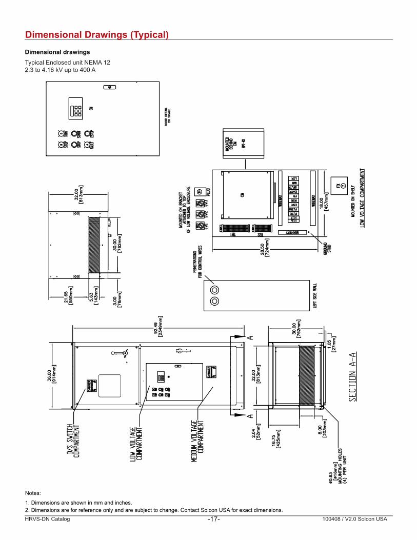
Dimensional drawingsTypical Enclosed unit NEMA 12 2.3 to 4.16 kV up to 400 A
Dimensional Drawings (Typical)
Notes:
1. Dimensions are shown in mm and inches.2. Dimensions are for reference only and are subject to change. Contact Solcon USA for exact dimensions.
100408/ V2.0 Solcon USA
So Starters Motor Protec on Power Controllers
T: +1 724.473.1301 F: +1 724.473.9506 E: [email protected] W: www.solconusa.com
2528 Lovi Road, Building 2-2A, Freedom, Pennsylvania 15042 USA
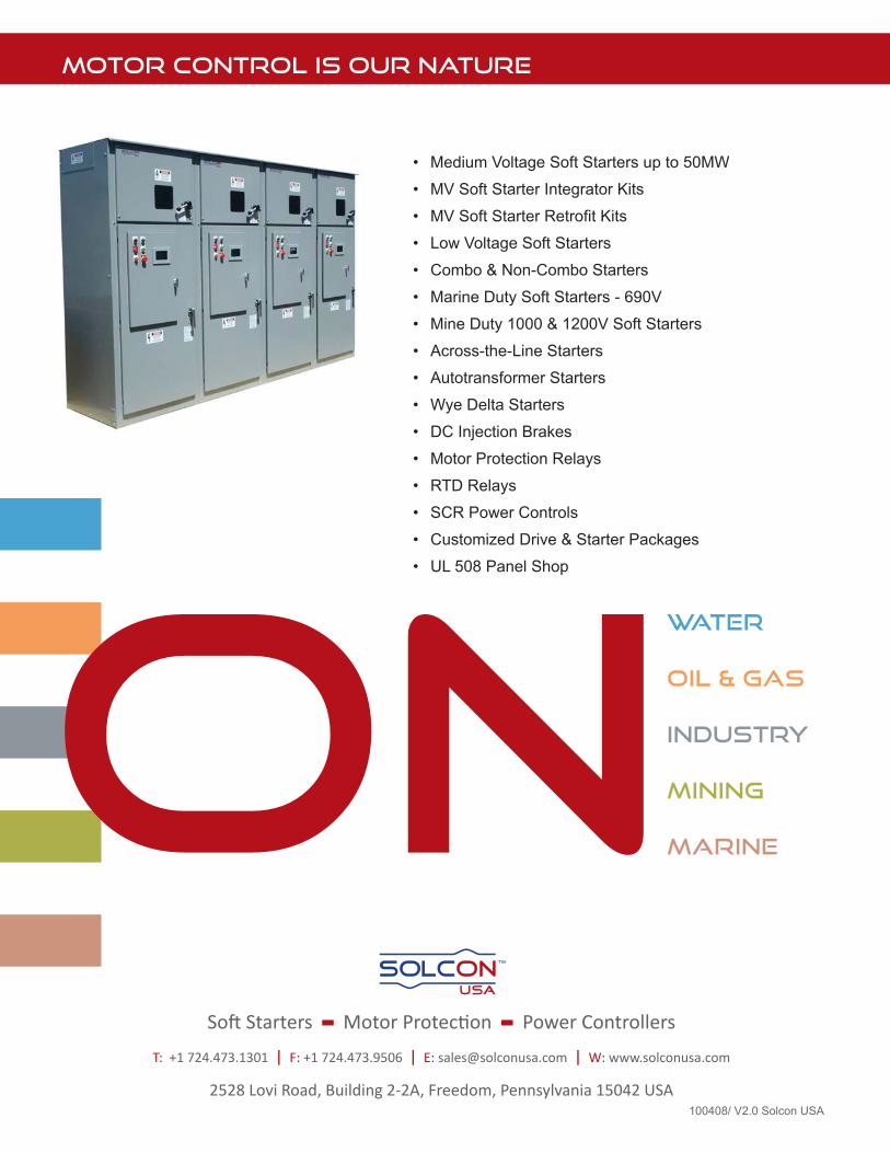
MOTOR CONTROL IS OUR NATURE
• Medium Voltage Soft Starters up to 50MW
• MV Soft Starter Integrator Kits
• MV Soft Starter Retrofi t Kits
• Low Voltage Soft Starters
• Combo & Non-Combo Starters
• Marine Duty Soft Starters - 690V
• Mine Duty 1000 & 1200V Soft Starters
• Across-the-Line Starters
• Autotransformer Starters
• Wye Delta Starters
• DC Injection Brakes
• Motor Protection Relays
• RTD Relays
• SCR Power Controls
• Customized Drive & Starter Packages
• UL 508 Panel Shop
WATER
OIL & GAS
INDUSTRY
MINING
MARINE
SOLCON