SOLAR-THERMAL POWERED AIRCONDITIONER FOR … · SOLAR-THERMAL POWERED AIRCONDITIONER FOR ELECTRIC...
101
EML 4905 Senior Design Project A B.S. THESIS PREPARED IN PARTIAL FULFILLMENT OF THE REQUIREMENT FOR THE DEGREE OF BACHELOR OF SCIENCE IN MECHANICAL ENGINEERING SOLAR-THERMAL POWERED AIRCONDITIONER FOR ELECTRIC TROLLEY Final Report Adrian F. Gonzalez Daniel Pico Advisor: Professor Andres Tremante November 23, 2016 This B.S. thesis is written in partial fulfillment of the requirements in EML 4905. The contents represent the opinion of the authors and not the Department of Mechanical and Materials Engineering.
Transcript of SOLAR-THERMAL POWERED AIRCONDITIONER FOR … · SOLAR-THERMAL POWERED AIRCONDITIONER FOR ELECTRIC...

EML 4905 Senior Design Project
A B.S. THESIS
PREPARED IN PARTIAL FULFILLMENT OF THE
REQUIREMENT FOR THE DEGREE OF
BACHELOR OF SCIENCE
IN
MECHANICAL ENGINEERING
SOLAR-THERMAL POWERED
AIRCONDITIONER FOR ELECTRIC
TROLLEY
Final Report
Adrian F. Gonzalez
Daniel Pico
Advisor: Professor Andres Tremante
November 23, 2016
This B.S. thesis is written in partial fulfillment of the requirements in EML 4905.
The contents represent the opinion of the authors and not the Department of
Mechanical and Materials Engineering.

ii
Ethics Statement and Signatures
The work submitted in this B.S. thesis is solely prepared by a team consisting of Adrian Gonzalez
and Daniel Pico and it is original. Excerpts from others’ work have been clearly identified, their
work acknowledged within the text and listed in the list of references. All of the engineering
drawings, computer programs, formulations, design work, prototype development and testing
reported in this document are also original and prepared by the same team of students.
Signature1
Adrian F. Gonzalez
Team Leader
Daniel Pico
Team Member
Advisor Signature
Dr. Andres Tremante
Faculty Advisor
iii
Contents Ethics Statement and Signatures ............................................................................................................... ii
Abstract ........................................................................................................................................................ 2
1. Introduction ..................................................................................................................................... 3
1.1 Problem Statement ........................................................................................................................ 3
1.2 Motivation ..................................................................................................................................... 6
1.3 Literature Survey .......................................................................................................................... 6
1.4 Survey of Related Standards ......................................................................................................... 9
1.5 Discussion ................................................................................................................................... 10
2. Project Formulation ...................................................................................................................... 11
2.1 Overview ..................................................................................................................................... 11
2.2 Project Objectives ....................................................................................................................... 11
2.3 Design Specifications .................................................................................................................. 12
2.4 Addressing Global Design .......................................................................................................... 13
2.5 Constraints and Other Considerations ......................................................................................... 13
2.6 Discussion ................................................................................................................................... 14
3. Design Alternatives ....................................................................................................................... 15
3.1 Overview of Conceptual Designs Developed ............................................................................. 15
3.2 Design Alternate 1 ...................................................................................................................... 15
3.3 Design Alternate 2 ...................................................................................................................... 16
3.4 Design Alternate 3 ...................................................................................................................... 16
3.5 Integration of Global Design Elements ....................................................................................... 17
3.6 Feasibility Assessment ................................................................................................................ 18
3.7 Proposed Design ......................................................................................................................... 18
3.8 Discussion ................................................................................................................................... 19
3.9 Discussion ................................................................................................................................... 19
4. Project Management ..................................................................................................................... 20
4.1 Overview ..................................................................................................................................... 20
4.2 Breakdown of Work into Specific Tasks .................................................................................... 20
4.3 Gantt Chart for the Organization of Work and Timeline ............................................................ 24
(Timeline for Senior Design Organization and Senior Design time frame) ........................................... 24
4.4 Breakdown of Responsibilities Among Team Members ............................................................ 26
(Indicate Each Member’s Major and Support Roles for Each Task) ...................................................... 26
iv
4.5 Patent/Copyright Application ..................................................................................................... 26
4.6 Commercialization of the Final Product ..................................................................................... 27
4.7 Discussion ................................................................................................................................... 27
5. Engineering Design and Analysis ................................................................................................ 27
5.1 Overview ..................................................................................................................................... 27
5.2 Kinematic Analysis and Animation ............................................................................................ 32
5.2.1 Sub-Project Objectives ............................................................................................................ 32
5.2.2 Design Specifications .............................................................................................................. 33
5.2.3 Base Frame .............................................................................................................................. 33
5.2.4 Front Frame ............................................................................................................................. 34
5.2.5 Back Frame ............................................................................................................................. 34
5.3 Dynamic/Vibration Analysis of the System ................................................................................ 35
5.4 Structural Design ........................................................................................................................ 36
5.4.1 The Base .................................................................................................................................. 36
5.4.2 The Front Frame...................................................................................................................... 38
5.4.3 The Back Frame ...................................................................................................................... 41
5.5 Material Selection ....................................................................................................................... 44
5.5.1 Structural Steel Selection ........................................................................................................ 44
5.5.2 Hardware and Damping Components ..................................................................................... 46
5.6 Component Design/Selection ...................................................................................................... 49
5.6.1 Piping Network Design ........................................................................................................... 51
5.6.2 Solar Collector Design ............................................................................................................ 54
5.6.2.1 Different types of Solar Collectors ......................................................................................... 54
5.6.2.2 Design Specifications .............................................................................................................. 57
5.6.2.3 Design Considerations ............................................................................................................ 57
6. Prototype Construction ................................................................................................................ 64
6.1 Overview ..................................................................................................................................... 64
6.2 Description of Prototype ............................................................................................................. 64
6.3 Prototype Design ......................................................................................................................... 64
6.4 Parts List ..................................................................................................................................... 65
6.5 Construction ................................................................................................................................ 66
6.6 Prototype Cost Analysis .............................................................................................................. 66
6.7 Discussion ................................................................................................................................... 67
v
7. Design Considerations .................................................................................................................. 67
7.1 Health and Safety ........................................................................................................................ 67
7.2 Assembly and Disassembly ........................................................................................................ 68
7.3 Manufacturability ........................................................................................................................ 68
7.4 Maintenance of the System ......................................................................................................... 69
7.4.1.1 Maintenance of Chiller ............................................................................................................ 69
7.4.1.2 Maintenance of Fan Coil ......................................................................................................... 70
7.5 Environmental Impact and Sustainability ................................................................................... 71
7.6 Economic Impact ........................................................................................................................ 72
7.7 Risk Assessment ......................................................................................................................... 72
8. Design Experience ......................................................................................................................... 72
8.1 Overview ..................................................................................................................................... 73
8.2 Standards Used in the Project ..................................................................................................... 73
8.2.1 ANSI/ASHRAE Standard 15: Safety Standard for Refrigeration Systems ............................ 74
8.2.3 ANSI/IIAR 2-2008: American National Standard for Equipment, Design, and ..................... 74
8.2.5 ASME B31.8 Gas Transportation and Distribution Piping System ........................................ 74
8.2.6 ASME B31.5 Refrigeration Piping ......................................................................................... 75
8.3 Contemporary Issues ................................................................................................................... 75
8.4 Impact of Design in a Global and Societal Context .................................................................... 75
8.5 Professional and Ethical Responsibility ...................................................................................... 76
8.6 Life-Long Learning Experience .................................................................................................. 76
9. Conclusion ..................................................................................................................................... 76
9.1 Conclusion and Discussion ......................................................................................................... 76
9.2 Evaluation of Integrated Global Design Aspects ........................................................................ 78
9.3 Evaluation of Intangible Experiences ......................................................................................... 78
9.4 Commercialization Prospects of the Product .............................................................................. 79
9.5 Future Work ................................................................................................................................ 79
10. References ...................................................................................................................................... 80
10.1 Literary References ..................................................................................................................... 80
References .................................................................................................................................................. 80
10.2 Index of Figures .......................................................................................................................... 81
10.3 Index of Tables ........................................................................................................................... 83
11. Appendices ..................................................................................................................................... 83
vi
A. Detailed Engineering Drawings of All Parts, Subsystems and Assemblies .................................... 83
B. Multilingual User’s Manuals .......................................................................................................... 83
C. Excerpts of Guidelines Used in the Project .................................................................................... 83
(Standards, Codes, Specifications and Technical Regulations; Quotes with references, or scanned
material as appropriate) ........................................................................................................................... 83
D. Copies of Used Commercial Machine Element Catalogs (Scanned Material) ............................... 84
E. Detailed Raw Design Calculations and Analysis (Scanned Material) ............................................ 87
12. Project Photo Album .................................................................................................................... 96
2
Abstract
As the climate continues to change due to human expansion of the “greenhouse effect”
and the reserves of nonrenewable resources keep decreasing, the use of alternative forms
of energy becomes imperative for a sustainable future. Today, more than ever, there is a
growing concern about the environmental pollution caused by burning fossil fuels and an
awareness of the need of developing new technologies capable of exploiting renewable
sources of energy that can meet the world growing demands at competitive prices. To
mitigate these environmental concerns, the transportation system in the United States is
increasingly promoting the use of battery-powered buses to diminish the emission of
carbon dioxide to the atmosphere and, thus, improve the air quality. One solution to this
problem is the implementation of battery- powered electric buses. The problem with this
solution is that electric vehicles have a very limited driving range. Compared to an
electric car, the mass of a bus is much larger so the effective range is much lower (it can
be as little as 30 miles). Moreover, in an electric vehicle with no internal combustion
engine to drive the A/C compressor, the air-conditioning has to be run electrically just
like a residential air-conditioning system. This represents a challenge since running a bus
A/C requires several kilowatts of power and taking it from the battery will drastically
reduce the driving range. The city of Sweetwater wants to address this problem by using
an air-conditioning system powered by solar energy. Therefore, our challenge is to find
and implement a solution that is both efficient, cost-effective, and environmentally
friendly. This challenge will be carried out by two teams. One team will design a solar
water heat panel which will be used by our team to provide the required heat necessary to
power the chosen absorption chiller.
3
This project represents the combination of several technologies to create a vehicle which
uses little-to-no fossil fuels. Increasingly important is the implementation of renewable
energy with the purpose of reducing the pollution of the city. Public transportation is an
important part of life in a large city. This project combines an Absorption Chiller with a
Solar Collector so that the climate control apparatus does not pull power from the
propulsion system of the vehicle. This will raise the efficiency of the vehicle and
eliminate the use of synthetic refrigerants. Furthermore, once the climate control
apparatus is finalized, the technology used may be applied to the design of an alternative-
energy propulsion system. This report focuses on the first phase of the project: the retrofit
of an existing absorption chiller to the trolley.
1. Introduction
1.1 Problem Statement
Most vehicles on the road today have air conditioning provided to the user/occupant. Most,
if not all, of these vehicles utilize a compressor to drive the air conditioning system using
the Carnot Cycle. While these systems boast relatively high efficiency (when compared to
the Absorption Cycle-based counterparts), the design of such systems does not allow for
the direct use of renewable energy. Implementing a form of renewable energy offers the
possibility of capturing an abundant energy source that replenishes itself continuously
without affecting the Earth’s resources (U.S. Department of Energy, 2016). The sun is the
largest source of energy known to our planet. As such, a solar heat powered absorption
chiller can provide cooling to any scenario. In this case, it will provide air conditioning to

4
an electric Trolley. The design will consist of an absorber, a generator, a hot water pump,
a chilled water pump, and a water heating device located on the roof of the trolley. These
items come together to provide cooling comfort to the residents of Sweetwater while still
protecting the environment. The system will be composed of three main phases in the
energy generation cycle. These are the evaporation, absorption, and power cycles. First,
the liquid refrigerant selected will evaporate under low pressure in order to extract heat
from its surroundings. Second, during the absorption process, the liquid substance is
absorbed by another substance allowing more refrigerant to be processed. Third, the
mixture is heated thereby increasing its partial pressure without affecting the overall
pressure of the system. Finally, the refrigerant is condensed through the heating device to
continue supplying the evaporator with refrigerant in order to cool (ROBUR, 2016).
The design and construction of a vehicle which is powered by renewable energy is a
complex challenge because of the myriad of requirements which constitute a “practical”
design. Most of these requirements are founded on the expectations of the end user. Such
requirements include but are not limited to:
1) Reasonable, Operational Range
2) Amenities within:
a. Air Conditioning
b. Support for Electronic Devices (ex; power outlets, wifi, etc.)
c. Comfortable Seating
d. Accessibility
3) Performance
a. Power
b. Acceleration
c. Stability
d. Smooth Response
e. Precise Control
f. Low Noise
g. Mechanical Efficiency
5
Apart from the demands of the end user are the requirements for creating a vehicle
which utilizes alternative energy. The concept of an alternative energy vehicle is an
ideal model. The features of such a model include the following additional
requirements:
1) Minimal production of Chemical Waste and Pollutants
2) Power Efficiency
3) The utilization of an Alternative Energy Source
4) The supplemental use of Electrical/Thermal Energy to eliminate the reliance
on Fossil Fuels
Superseding both of the previously mentioned sets of requirements are the demands for
safety and reliability. Many alternative energy devices in existence today utilize rare earth
resources or utilize chemicals which require special handling and safety measures. The
reactiveness of the chemicals used and the relative stability of the environment in which
they will be used, are important factors that can either foster or hamper the feasibility of a
design.
In this project, we face the challenge of designing a practical, environmentally-friendly,
and efficient air conditioning system to power a fully electrical trolley. The reason for an
external source of energy to power this trolley is that using its own battery will result on a
more limited driving range which will be very inconvenient. The required external source
of energy is solar heat since it is free, renewable, and easy to harvest. A team will be
designing and implementing a solar water heat panel which will be used by our team to
provide the required heat necessary to power our system which consists of a 5-ton gas fired
absorption chiller by Robur Industries.
6
1.2 Motivation
This project will be used to prove/disprove whether or not solar/thermal energy can be
used to power one of several peripheral systems present on most vehicles. If the project
is successful, the research and testing can be used as the basis for further development
of the overall concept and other projects as well.
The purpose of this project is to create a vehicle which requires less energy to operate
and to further the concept in the future by making the entire vehicle run on alternative
energy. The motivation for these parameters are as follows:
1) To create a vehicle which provides air conditioning to its passengers by use of
alternative energy. This will allow the vehicle to use less fuel even if the propulsion
system is driven by fossil fuels.
2) To modify an absorptive chiller unit so that the generator component is driven by
hot water instead of the burning of gas. This is an important modification which will
minimize the dependency of the vehicle on combustible fuels.
3) To enable the selection and design of a suitable, alternative energy, propulsion
system. Once the A/C system is perfected, the overall vehicle may be analyzed and a
suitable alternative energy power system may be selected and designed.
1.3 Literature Survey
There are many forms of alternative energy available to the world today. These sources
include solar, wind, hydro-electric, plant-based fuels, hydrogen, nuclear, etc. In recent
years, there has been a push to promote electric vehicle propulsion. Manufacturers,
7
such as Ford, General Motors, and Tesla, have all made battery electric vehicles
commercially available. The reduction in pollution and the long-term cost savings
obtained by not using pricey fossil fuels, has motivated consumers and businesses to
rethink their personal and work vehicles. This is not to say that that fossil fuels are not
being used to charge the batteries, but there is energy spent in the refinement of fossil
fuels as well.
Most power plants use Hydro-Carbon fossil fuels, while others use radioactive
materials to generate electricity to send to homes and businesses (U.S. Department of
Energy, 2016). Although these centrally placed power-plants are the main supplier of
energy, there has been an increase in the variety of products which are commercially
available to convert the building/home into a “Green” structure, relying on little or no
fossil-fuels/grid electricity. They only need to be further developed and implemented
and society will benefit from this.
In addition to the power consumption of buildings and homes, personal and commercial
vehicles add greatly to the amount of carbon in our atmosphere. Most vehicles run on
gasoline or diesel-gasoline fuel. Nearly all vehicles utilize an air conditioning system
which is powered by the rotations of the motor. In this layout, which is typical of most
vehicles, the power is used in a “parasitic” mode where the Compressor of the A/C
system is using power that would otherwise be sent to the drivetrain of the vehicle. This
extra demand placed on the motor results in more fuel burned to travel the same
distance. In all air conditioning systems which utilize the Carnot Cycle, a compressor
8
does the job of pushing the coolant through the plumbing and expansion/compression
valves. In this project, the air conditioning system will utilize an Absorption Chiller.
Like the compressor in an electric vapor pressure cycle, the absorption system utilizes
its thermal compressor, which consists of the generator, absorber, pump and heat
exchanger, to boil the water vapor out of a solution and compress the refrigerant vapor
to a higher pressure. Increasing the refrigerant pressure likewise increases its
condensing temperature (ROBUR, 2016). The refrigerant vapor condenses to a fluid at
this higher pressure and temperature. Since this condensing temperature is hotter than
the surrounding temperature, heat moves from the condenser to the ambient air and is
rejected. The high-pressure fluid then goes through a throttling valve that decreases its
pressure. Decreasing its pressure likewise diminishes its boiling point temperature. The
low-weight fluid then goes into the evaporator and is boiled at this lower temperature
and pressure. Since the boiling temperature at this time is lower than the temperature
of the conditioned air, heat moves from the conditioned air stream into the evaporator
and causes this fluid to boil. Expelling heat from the air in this way causes the air to be
cooled. The refrigerant vapor then goes into the absorber where it comes back to a
liquid state as it is pulled into the lithium bromide solution (the absorption process).
The diluted lithium bromide solution is pumped back to the generator. Since lithium
bromide (the absorbent) does not boil, water (the refrigerant) is effortlessly isolated by
adding heat. The resultant water vapor goes into the condenser, the absorbent solution
comes back to the absorber, and the same procedure start again.
By using the Absorption Chiller, the power demand is removed from the Propulsion
System of the vehicle, which raises the efficiency of its operation. The stand-alone air
9
conditioning system can then be powered by other means, electricity or renewable
energy. In the case of this project, the Absorption Chiller uses Liquid Propane Gas or
Natural Gas to heat the Generator Vessel. Although this system is still using fossil-
fuels, these two types supply reasonable power while releasing a smaller quantity of
harmful pollutants. According to the U.S. Energy Information Administration, Coal
(typically used to generate electricity in steam power plants) produces almost 2 times
(1.95) the amount of CO2 that Natural Gas (NG) does, and 1.64 times that of Liquid
Propane Gas (LPG). More relevant to this project, Gasoline produces roughly 13%
more CO2 than LPG while Diesel-based fuels produce 16% more (U.S. Department of
Energy, 2016).
1.4 Survey of Related Standards
Standards are documents that are established by consensus and approved by a recognized
entity to ensure the reliability of documents, products, and services people use every day.
Standards are developed to support and facilitate the implementation of integrated
solutions. They reduce unnecessary variety in the marketplace and simplify product
development. They also enable economies of scale which result in a reduction in the cost
of producing a product. Standards also offer many benefits such as safety and reliability
as well as interconnection and interoperability.
SAE J2683_201603, Refrigerant Purity and Container Requirement for Carbon Dioxide
Used in Mobile Air-Conditioning Systems
ASME B31.8 Gas Transportation and Distribution Piping Systems

10
ASME B31.5 Refrigeration Piping
1.5 Discussion
As was previously mentioned, LPG and NG fuels release 13-16% less the amount of
pollutants that the combustion of Gasoline or Diesel fuel does. Although this is a
relatively small energy savings, the true value of the Absorption Chiller comes from the
potential modifications which can be made. In the case of this design, the Generator
Vessel is heated to the requisite 305° by means of another thermal source; a closed, “Hot
Water” loop. By changing the source to a heated liquid, several input-sources may be
used to heat the same medium. This design uses a combination of sources; a Solar
Collector, a Hot Exhaust Gas Scavenger and an auxiliary LPG/NG Burner. The burner
still provides a means of heating the system completely, but the other two sources reduce
the consumption of the Burner. The reduction of fuel consumption has two main
advantages, and yet a third which is implicitly related to the second. The first benefit is
the reduction of harmful pollutants which will, inevitably be released into the
atmosphere. The second advantage is the lowering of the operational costs, due to a
reduction in consumption. The third advantage is the possibility of return on investment.
If the Exhaust Thermal Scavenger and Solar Collector are efficient and effective enough,
the amount of money saved can help reimburse a portion of the initial investment and
may even generate an income after the break-even point.
In order for this concept to work, a Heat Exchanger must be used to interface the
Generator Vessel with the heated fluid. Based on design histories, we know that the
11
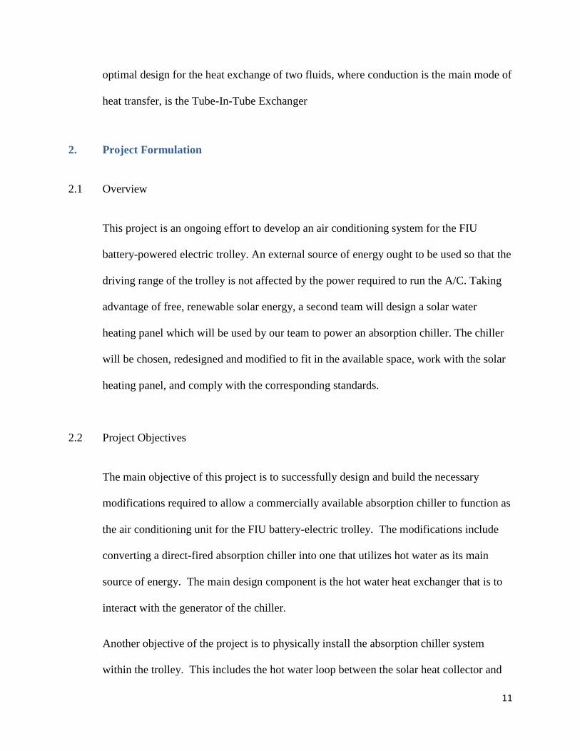
optimal design for the heat exchange of two fluids, where conduction is the main mode of
heat transfer, is the Tube-In-Tube Exchanger
2. Project Formulation
2.1 Overview
This project is an ongoing effort to develop an air conditioning system for the FIU
battery-powered electric trolley. An external source of energy ought to be used so that the
driving range of the trolley is not affected by the power required to run the A/C. Taking
advantage of free, renewable solar energy, a second team will design a solar water
heating panel which will be used by our team to power an absorption chiller. The chiller
will be chosen, redesigned and modified to fit in the available space, work with the solar
heating panel, and comply with the corresponding standards.
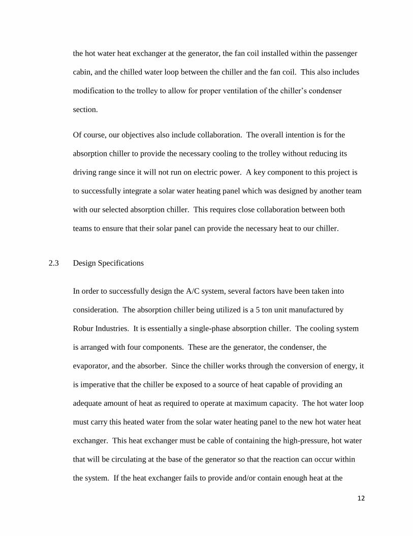
2.2 Project Objectives
The main objective of this project is to successfully design and build the necessary
modifications required to allow a commercially available absorption chiller to function as
the air conditioning unit for the FIU battery-electric trolley. The modifications include
converting a direct-fired absorption chiller into one that utilizes hot water as its main
source of energy. The main design component is the hot water heat exchanger that is to
interact with the generator of the chiller.
Another objective of the project is to physically install the absorption chiller system
within the trolley. This includes the hot water loop between the solar heat collector and
12
the hot water heat exchanger at the generator, the fan coil installed within the passenger
cabin, and the chilled water loop between the chiller and the fan coil. This also includes
modification to the trolley to allow for proper ventilation of the chiller’s condenser
section.
Of course, our objectives also include collaboration. The overall intention is for the
absorption chiller to provide the necessary cooling to the trolley without reducing its
driving range since it will not run on electric power. A key component to this project is
to successfully integrate a solar water heating panel which was designed by another team
with our selected absorption chiller. This requires close collaboration between both
teams to ensure that their solar panel can provide the necessary heat to our chiller.
2.3 Design Specifications
In order to successfully design the A/C system, several factors have been taken into
consideration. The absorption chiller being utilized is a 5 ton unit manufactured by
Robur Industries. It is essentially a single-phase absorption chiller. The cooling system
is arranged with four components. These are the generator, the condenser, the
evaporator, and the absorber. Since the chiller works through the conversion of energy, it
is imperative that the chiller be exposed to a source of heat capable of providing an
adequate amount of heat as required to operate at maximum capacity. The hot water loop
must carry this heated water from the solar water heating panel to the new hot water heat
exchanger. This heat exchanger must be cable of containing the high-pressure, hot water
that will be circulating at the base of the generator so that the reaction can occur within
the system. If the heat exchanger fails to provide and/or contain enough heat at the
13
generator, the cooling cycle will fail to generate enough chilled water to cool the air
passing through the fan coil within the trolley.
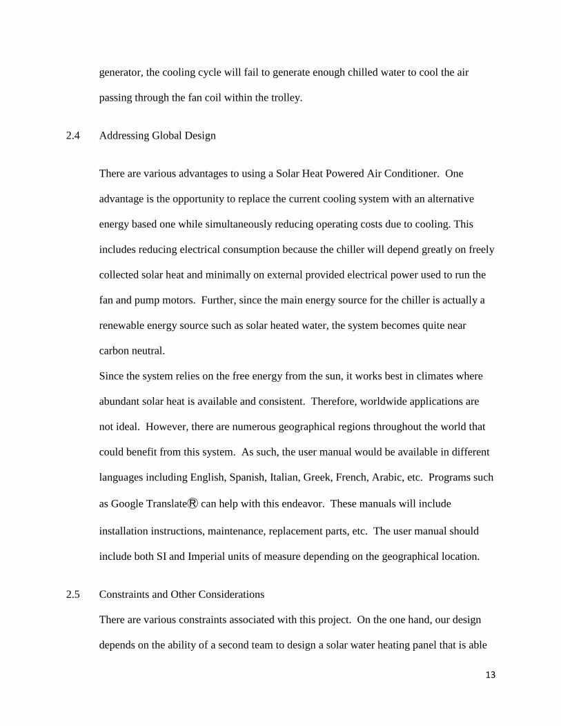
2.4 Addressing Global Design
There are various advantages to using a Solar Heat Powered Air Conditioner. One
advantage is the opportunity to replace the current cooling system with an alternative
energy based one while simultaneously reducing operating costs due to cooling. This
includes reducing electrical consumption because the chiller will depend greatly on freely
collected solar heat and minimally on external provided electrical power used to run the
fan and pump motors. Further, since the main energy source for the chiller is actually a
renewable energy source such as solar heated water, the system becomes quite near
carbon neutral.
Since the system relies on the free energy from the sun, it works best in climates where
abundant solar heat is available and consistent. Therefore, worldwide applications are
not ideal. However, there are numerous geographical regions throughout the world that
could benefit from this system. As such, the user manual would be available in different
languages including English, Spanish, Italian, Greek, French, Arabic, etc. Programs such
as Google TranslateⓇ can help with this endeavor. These manuals will include
installation instructions, maintenance, replacement parts, etc. The user manual should
include both SI and Imperial units of measure depending on the geographical location.
2.5 Constraints and Other Considerations
There are various constraints associated with this project. On the one hand, our design
depends on the ability of a second team to design a solar water heating panel that is able
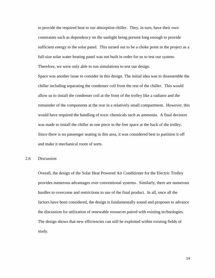
14
to provide the required heat to our absorption chiller. They, in turn, have their own
constraints such as dependency on the sunlight being present long enough to provide
sufficient energy to the solar panel. This turned out to be a choke point in the project as a
full-size solar water heating panel was not built in order for us to test our system.
Therefore, we were only able to run simulations to test our design.
Space was another issue to consider in this design. The initial idea was to disassemble the
chiller including separating the condenser coil from the rest of the chiller. This would
allow us to install the condenser coil at the front of the trolley like a radiator and the
remainder of the components at the rear in a relatively small compartment. However, this
would have required the handling of toxic chemicals such as ammonia. A final decision
was made to install the chiller as one piece in the free space at the back of the trolley.
Since there is no passenger seating in this area, it was considered best to partition it off
and make it mechanical room of sorts.
2.6 Discussion
Overall, the design of the Solar Heat Powered Air Conditioner for the Electric Trolley
provides numerous advantages over conventional systems. Similarly, there are numerous
hurdles to overcome and restrictions to use of the final product. In all, once all the
factors have been considered, the design is fundamentally sound and proposes to advance
the discussion for utilization of renewable resources paired with existing technologies.
The design shows that new efficiencies can still be exploited within existing fields of
study.
15
3. Design Alternatives
3.1 Overview of Conceptual Designs Developed
A number of different concepts were developed during the design phase of this project.
These concepts included alternate sources of heat, alternate refrigerants, alternate
physical layouts, and others. Each option was thoroughly discussed for pros and cons as
well as vetted for inclusion in this design or suggested for future iterations of the project.
3.2 Design Alternate 1
The first design alternative considered was to convert the chiller to use Lithium Bromide
as the refrigerant in lieu of the Ammonia. This alternative makes the system more
environmentally friendly once in mass production. Any unwanted leaks due to system
failure or physical damage would not expose the user to the toxicity of the Ammonia.
Unfortunately, this conversion proved to be too expensive. The only commercially
available chiller that was attainable within the budget was designed to use Ammonia. As
it is, the chiller used up most of the resources that were available including a grant as well
as a private donation by a local company. Further, draining the Ammonia from the
system could prove to be dangerous to the team as the team is not properly trained to
handle toxic chemicals. Lastly, despite the drawbacks, Ammonia is actually quite
accessible throughout the world. Fortunately, this adds to the Global Design aspect.

16
3.3 Design Alternate 2
The second design alternative was to include a Hybrid Hot Water / Gas Fired option. The
premise behind this option is to overcome situation when the solar water heater fails to
provide enough heat or a high enough temperature to allow the absorption process to
occur within the chiller. The Gas Fired portion of this option would provide an in-line
gas-fired water heater, installed on the section of pipe running from the solar water heater
to the generator inlet. If the temperature is not ideal, the controller would activate the
secondary heating stage to boost the temperature of the incoming water to ensure the
reaction occurs. This option would greatly increase the usable reach of the design as it
would no longer be limited to areas that have consistent solar heat available. However,
this option would rely on a removable or refillable natural gas or propane tank to fuel the
gas water heater. Note, the system will still benefit from the solar water heater, but it
would also be able to function when the solar water heater falls short of the design
performance. However, this option could prove to be quite cumbersome in application.
Constant replacing or refilling of the tank is not ideal. The principle is sound, but the
execution still needed more work.
3.4 Design Alternate 3
The third design alternative is to include a battery and drive motor heat recovery option.
Depending on the design, one major design constraint for electric drive systems is heat
generated by the batteries and drive motor. Some electric cars use ambient air to cool the
batteries, but as they heat up, the efficiency drops. Some cars use the on-board air
17
conditioner to cool the batteries, but this is a double-edged sword as the air conditioner
drains the batteries while in use. The third design alternative would include a heat
recovery system run between the battery banks as well as around the drive motor. This
would help to keep the components of the electric drive system operating at ideal
temperatures and efficiencies while also providing additional heat to run the chiller. This
design would further increase the effective efficiency of the system as it incorporates an
additional free heat source. However, as the electric drivetrain has not been designed,
this option was not available for incorporation into the project.
3.5 Integration of Global Design Elements
The fourth design alternative was considered by the team to be the ideal design. This
design is for incorporating the absorption chiller into a Plug-In Hybrid trolley. The
trolley would have a battery-powered electric drivetrain as well as an on-board natural-
gas fueled generator to charge the batteries should the need arise. This option extends the
usable range of the trolley. As for the chiller, the system would utilize the solar water
heater as well as a heat recovery system for the internal combustion engine and the gas-
fired heat exchanger from Design Alternative 2. Fortunately, in lieu of the separate tank,
the system could utilize the same natural gas tank that fuels the generator. Unfortunately,
as before, the drivetrain for the trolley is not yet finalized. Therefore, this design
alternative must be shelved for future iterations.

18
3.6 Feasibility Assessment
The final design incorporates the use of freely available solar heat as its main energy
source. Further, the refrigerant, despite its drawbacks, is readily available worldwide.
The core of the system is extremely adaptable to many applications, and the technology
behind the design is very well established. The concept of using existing technology and
combining it with readily available renewable energy has immeasurable global reach.
The key to the success of this design is to present it to the various markets showing how
it can be adapted. This includes presenting the designs, manuals, etc. in various
languages.
3.7 Proposed Design
The final is design should be quite feasible. The major components, such as the chiller,
fan coil, pumps, etc., are readily available in the market, and the funds were acquired to
push the project forward. However, as previously mentioned, it does depend on the
success of other teams. In order to test the final design, it is imperative that a full-scale
solar water heater be constructed and incorporated into the trolley. Further, proper power
for the pump and fan motors would depend on finalizing the battery bank for the electric
trolley.
19
3.8 Discussion
The proposed design is modify the gas-fired absorption chiller to function on hot water
that is to be supplied by a roof-mounted solar water heating panel as designed by other.
The design includes a new hot water heat exchanger to encase the generator portion of
the absorption chiller. The chiller is to be installed in the rear section of the trolley where
there is no passenger compartment. The rear space is to be partitioned off from the
passenger space. The rear section is to become a mechanical plenum for the condenser
section of the chiller including louvers for intake and exhaust. A chilled-water fan coil is
to installed within the passenger area. This fan coil is to piped to the chiller so that it can
provide cold air the passenger area.
3.9 Discussion
Despite many superior alternate designs that could not be implemented, the fundamental
basics of the design provide an excellent basis from which to build for future iterations.
The design show proof of concept for the integration of existing technologies with
renewable resources to find new efficiencies. Also, despite the costly components
required, the design prototype shows excellent promise and continues to draw interest
from various organizations and local markets.
20
4. Project Management
4.1 Overview
From the outset of this project, it was understood that completion would require the
integration of previous research with the current research and related system components.
The previous research on solar collectors was supposed to be harnessed so that a working
prototype collector could be built and tested, with the intention of integrating it to the
Absorption Chiller for a full prototype. After reviewing the previous research, it was
determined that the data collected was unsatisfactory and the prototype would not be
efficient enough to be considered for the demands of the Absorption Chiller. As such,
further research would need to be conducted on solar collectors. Another crucial aspect of
this system, which was originally underestimated, is the design and implementation of a
heat exchanger which could receive the thermal transport medium (liquid; water,
ammonia, lithium bromide) and adequately transfer the necessary thermal power, at the
requisite temperature. This aspect of the project took more time and effort in formulation
and simulation, than was previously expected.
4.2 Breakdown of Work into Specific Tasks
After performing preliminary research and gaining an awareness of the sub-tasks
associated to each facet of this project, it has become clear that the overall project
requires further compartmentalization and development. Each facet could be its own
project. Below is a breakdown of specific sub-tasks and the major components of the
project to which it contributes;
21
Modification of Robur Absorption Chiller
Extraction/Purging of existing Ammonia-Water solution from Primary
loop of Chiller
Removal of LPG/NG Burner
Installation of Heat Exchanger
Recharging of Primary Loop with proper Ammonia-Water
Solution/concentration
4.2.1 Design of Heat Exchanger
Collect Information from User Manual and Manufacturer, about specific
system conditions which must be known for a proper analysis to be
conducted
Define the required Output Parameters
Define the Problem using an existing Thermodynamics Model
Make Reasonable Assumptions where applicable
Consider Worst-Case Scenario
Determine Required Input Parameters using Existing Thermodynamic
Models and principles
Select Design Type (based on other research and Thermodynamic
Principles)
Create CAD Model
22
Create Simulation
Cross-Compare Results
4.2.2 Design of Solar Collector
Design History Study/Research
Comparative Analysis
Combined-Design Study
Selection/Optimization
Simulation
Construction
Testing/Validation
4.2.3 Design of Plumbing and Requisite System Components
Design Plumbing Network
Design of Additional Coils/Exchangers (maximize efficiency through
thermal recovery/recirculation)
Determine Metering and Throttling Locations
Integral Component Selection
Construction
Bench Testing
23
4.2.4 Reintegration of LPG-NG Burner (Installed in Series to the Heat Exchanger,
integral part of the Plumbing System)
4.2.5 Retrofitting of Absorption Chiller to the Trolley
Space Allocation
Modeling/Mapping of Interior
Static Analysis/Supporting Frame Design
Dynamic/Vibration Analysis (Damper/Isolator Selection)
Installation of Plumbing and Auxiliary Components
“Dry Test” Then connect Absorber
Testing/Validation
24
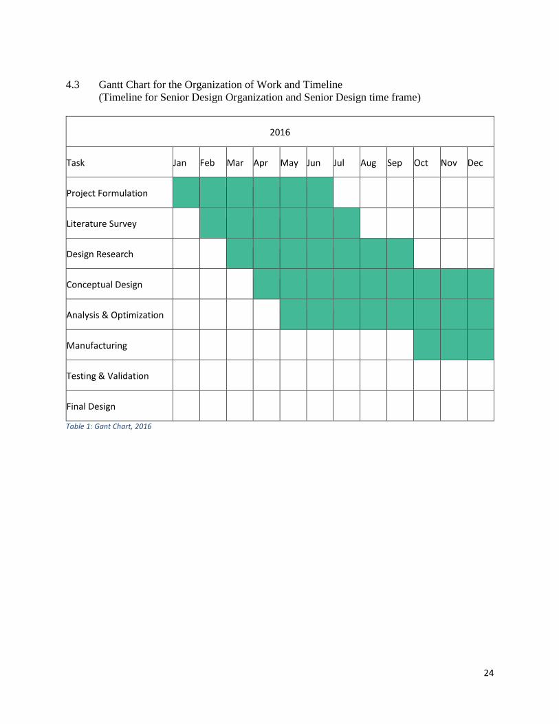
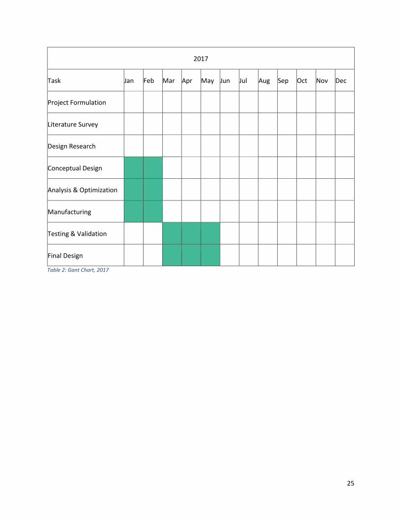
4.3 Gantt Chart for the Organization of Work and Timeline
(Timeline for Senior Design Organization and Senior Design time frame)
2016
Task Jan Feb Mar Apr May Jun Jul Aug Sep Oct Nov Dec
Project Formulation
Literature Survey
Design Research
Conceptual Design
Analysis & Optimization
Manufacturing
Testing & Validation
Final Design Table 1: Gant Chart, 2016
25
2017
Task Jan Feb Mar Apr May Jun Jul Aug Sep Oct Nov Dec
Project Formulation
Literature Survey
Design Research
Conceptual Design
Analysis & Optimization
Manufacturing
Testing & Validation
Final Design Table 2: Gant Chart, 2017
26
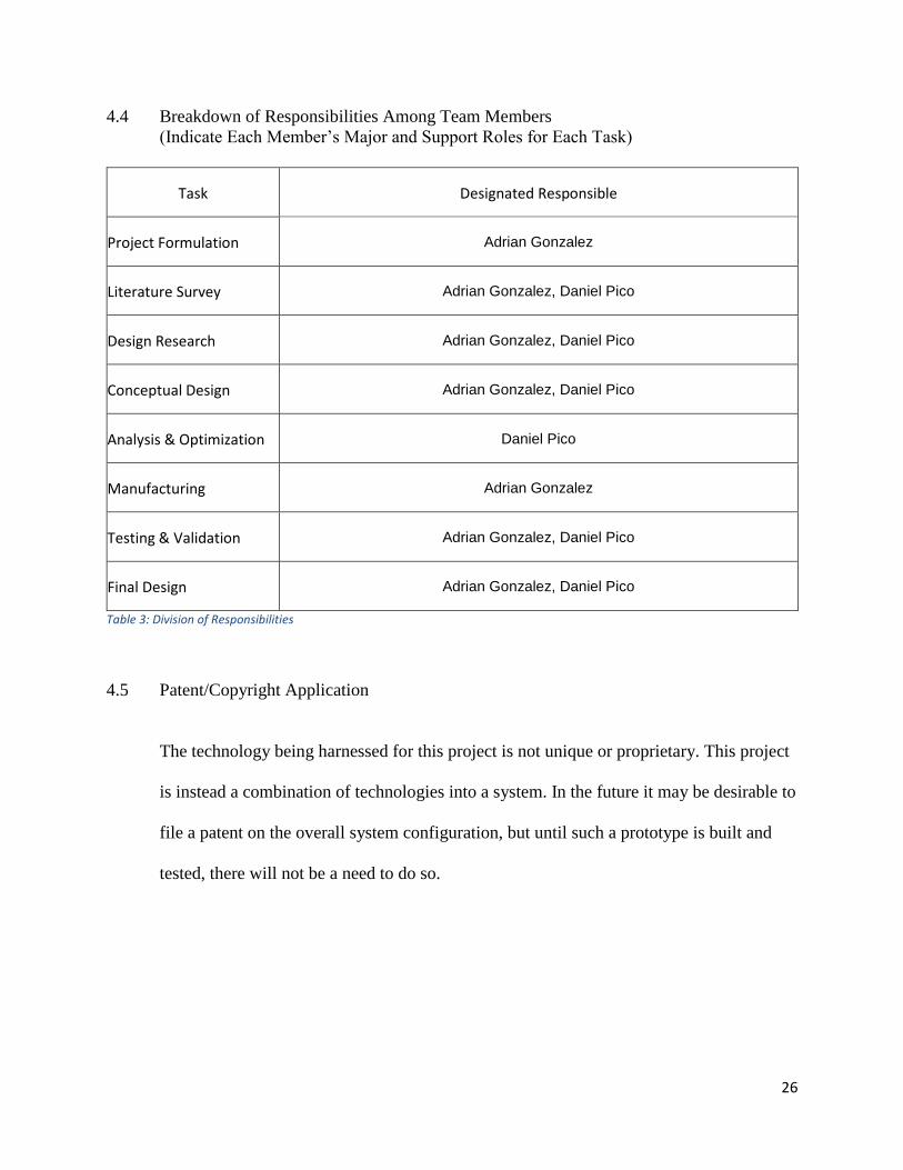
4.4 Breakdown of Responsibilities Among Team Members
(Indicate Each Member’s Major and Support Roles for Each Task)
Task Designated Responsible
Project Formulation Adrian Gonzalez
Literature Survey Adrian Gonzalez, Daniel Pico
Design Research Adrian Gonzalez, Daniel Pico
Conceptual Design Adrian Gonzalez, Daniel Pico
Analysis & Optimization Daniel Pico
Manufacturing Adrian Gonzalez
Testing & Validation Adrian Gonzalez, Daniel Pico
Final Design Adrian Gonzalez, Daniel Pico
Table 3: Division of Responsibilities
4.5 Patent/Copyright Application
The technology being harnessed for this project is not unique or proprietary. This project
is instead a combination of technologies into a system. In the future it may be desirable to
file a patent on the overall system configuration, but until such a prototype is built and
tested, there will not be a need to do so.
27
4.6 Commercialization of the Final Product
If the preliminary configuration of this trolley proves to be promising, it is safe to say that
the future of this project is for it to be applied to various mass-transportation vehicles.
The vehicles may vary in size and operating conditions (climate), and there will need to
be adjustments made which will better facilitate its application to a spectrum of vehicles.
Commercialization is the goal. The first “client” will be FIU, as this technology will be
applied to the CATS Shuttle. Thereafter, the same research will be retrofitted to work
with the “Trolley” buses which provide public transportation to the City of Sweetwater
residents.
4.7 Discussion
Although this phase of the project is still pending testing, the requirements appear
reasonable. The calculations point in the direction of using Ammonia or Lithium
Bromide as the conducting medium, simply because these two options have better
enthalpy than water. However, it is the goal of this project to push away from the use of
rare/harsh materials and to make a vehicle that operates cleanly, using more readily
available substances.
5. Engineering Design and Analysis
5.1 Overview
Create a mounting frame for an object in an open space is not as complex as creating it
for a big Ac unit including a big size duct to be mounted in tiny space in the back of a
small trolley. Therefore, in this project, exact dimensions are tolerances are very critical
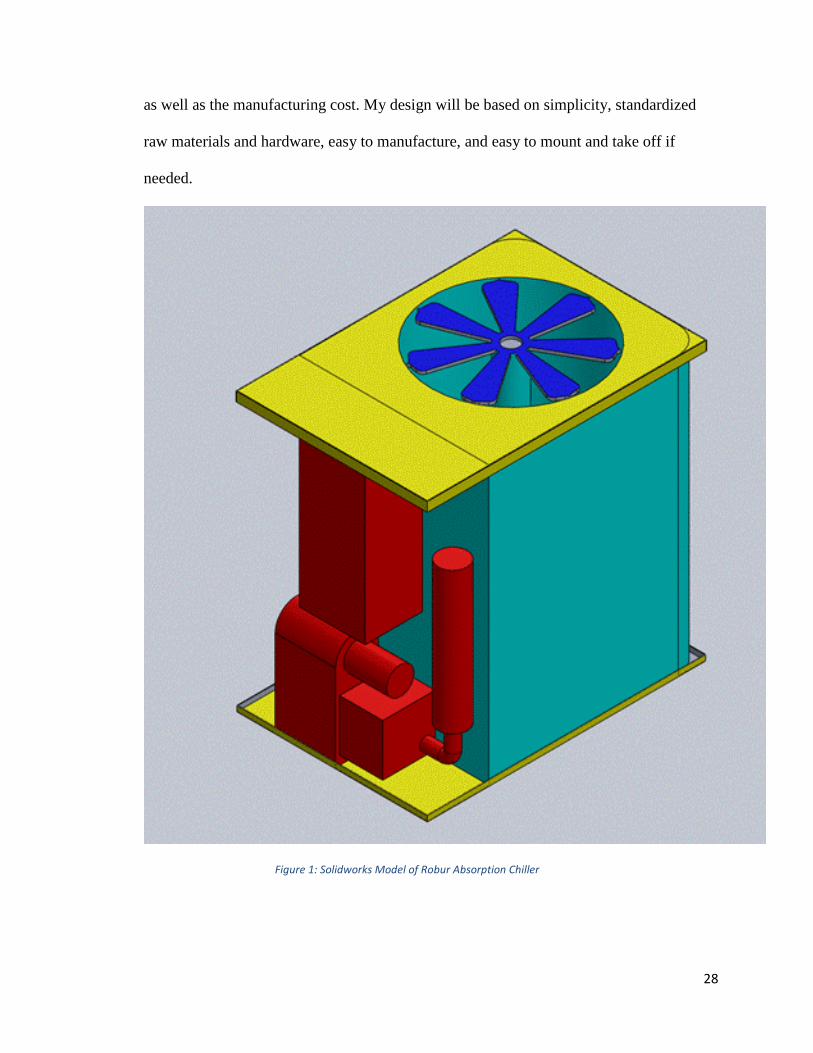
28
as well as the manufacturing cost. My design will be based on simplicity, standardized
raw materials and hardware, easy to manufacture, and easy to mount and take off if
needed.
Figure 1: Solidworks Model of Robur Absorption Chiller

29
Figure 2: Solidworks Model of A/C Duct
30
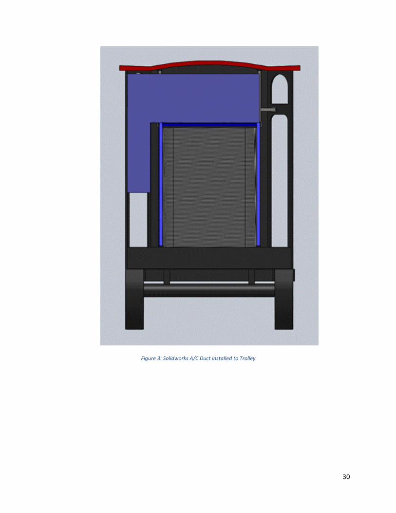
Figure 3: Solidworks A/C Duct installed to Trolley
31
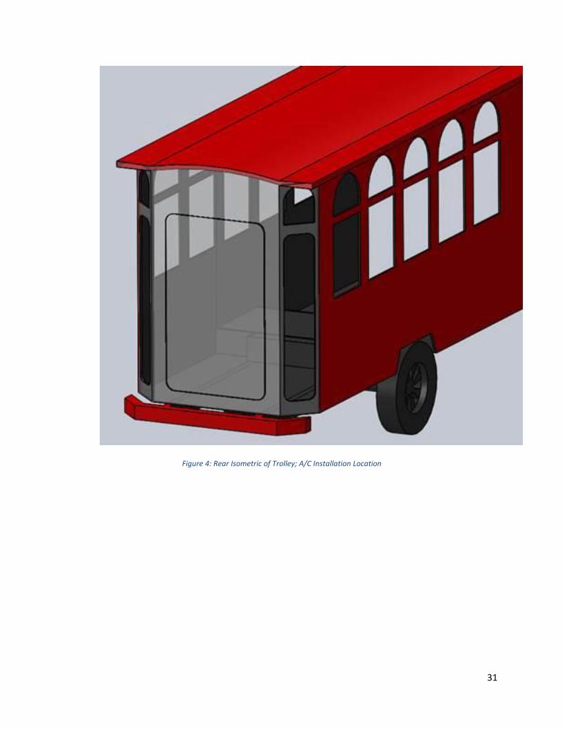
Figure 4: Rear Isometric of Trolley; A/C Installation Location
32
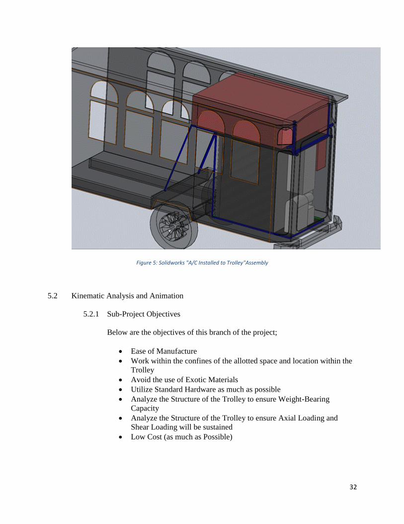
Figure 5: Solidworks "A/C Installed to Trolley"Assembly
5.2 Kinematic Analysis and Animation
5.2.1 Sub-Project Objectives
Below are the objectives of this branch of the project;
Ease of Manufacture
Work within the confines of the allotted space and location within the
Trolley
Avoid the use of Exotic Materials
Utilize Standard Hardware as much as possible
Analyze the Structure of the Trolley to ensure Weight-Bearing
Capacity
Analyze the Structure of the Trolley to ensure Axial Loading and
Shear Loading will be sustained
Low Cost (as much as Possible)
33
5.2.2 Design Specifications
To make the design as simple as possible, I had to make multiple designs and
ask the same question over and over which is: Is the design doable? Is it
mountable? The answer to the question was to create three different frames
and mount them together when they are inside the trolley. Therefore, I created
three frames that I call, Base Frame which seats on the floor and supports the
weight of the Ac unit, Front frame which will be used to hold both the unit
and the duct, and lock them in place during the trolley rides which creates lots
of vibrations, especially during braking moments, and finally, the back frame
which will be responsible for holding the unit against sliding to the back of the
trolley as well as minimize vertical movements when the trolley vibrates
vertically.
5.2.3 Base Frame
The base frame is designed to sustain the weight of the entire unit and duct.
The total weight that it has to sustain is between 300 to 400 lb. Most of the Ac
unit active and heavy components are located in the side that will face the rear
door of the trolley, therefore, the base has to be reinforced in that side. Also,
the frame needs to be fixed to trolley, and the only way to do that is by using
long bolts and fix it the trolley’s long beams that goes from the back to the
front holding the entire trolley’s weight. The beams are separated by 28 inches
and have 2 inches wide which will be enough to drill and thread holes to make
the mounting possible.
34
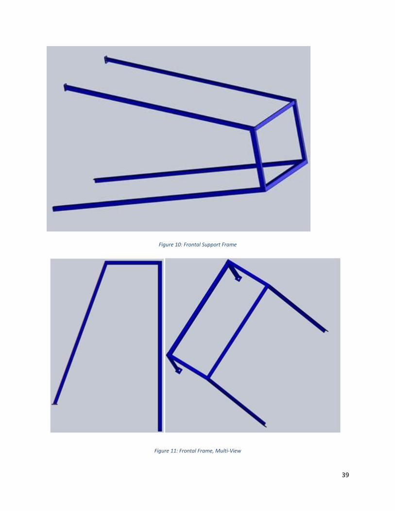
5.2.4 Front Frame
The front frame is designed to hold both the as unit and the duct placed on top
of it. At the same time, it must hold them from falling and sliding during high
vibrations and braking. The frame will be made by 1x1x1/4-inch L plain bar,
ant it will have two angled supporting bars to sustain and create a counter
force the horizontal forces that tends to push the unit and prevent it from
falling.
5.2.5 Back Frame
The back frame will be holding the ac unit and prevent it from shaking,
sliding, and falling during acceleration. It will create counter forces along
three directions:
Hold the ac unit to the bottom frame.
Create a counter force against side forces and prevent the unit from falling
to the trolley’s side walls.
Create a counter force against the front back forces and prevent the unit
from falling to the back of the trolley’s wall.
Create a vertical counter force to the vertical forces created by intense
vibrations and prevent the Ac unit from vertical displacements.

35
5.3 Dynamic/Vibration Analysis of the System
A moving vehicle generates lots of intense vibrations along all directions, and having an object
mounted inside requires a mount that can handle all the forces. In Fig.1, we can see the amount
of permanent and momentary forces that frames have to counter in order to lock the Ac unit in
place.
Figure 6: FBD of A/C Unit in Trolley
36
5.4 Structural Design
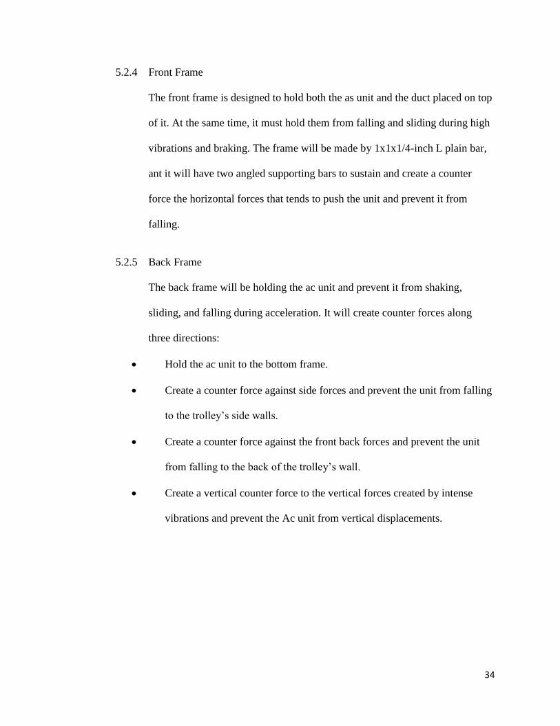
5.4.1 The Base
The base is mainly constructed by a 1x1x1/4 in 1020 Hot Rolled L shape bar.
I selected this type of material because not only offers toughness and rigidity,
it is available at a very good price comparing to lots of other materials. The
beams will be joined be welding only. the design considered the concentration
of weight caused by the different Unit components. The frame is designed to
sit on 8 rubber vibration isolators that will be mounted on the 8 0.5 in holes of
the frame
Figure 7: Base Frame Isometric
37
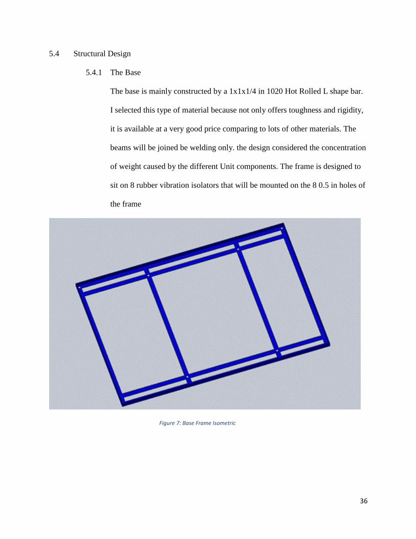
Figure 8: Base Frame, Top View
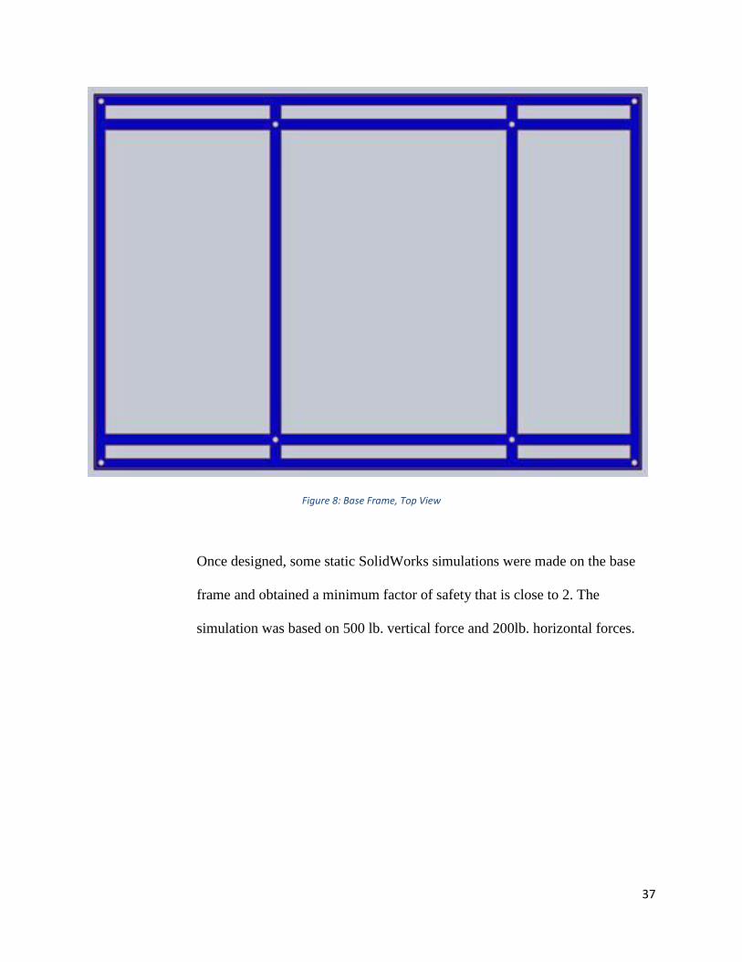
Once designed, some static SolidWorks simulations were made on the base
frame and obtained a minimum factor of safety that is close to 2. The
simulation was based on 500 lb. vertical force and 200lb. horizontal forces.
38
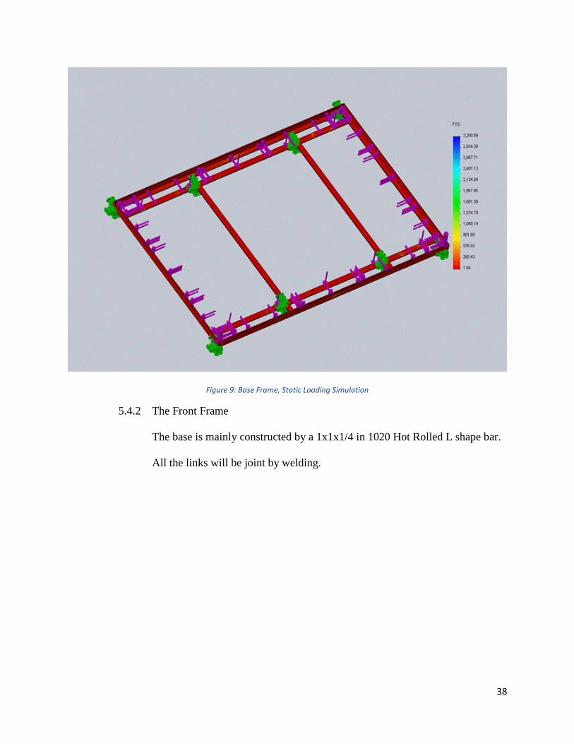
Figure 9: Base Frame, Static Loading Simulation
5.4.2 The Front Frame
The base is mainly constructed by a 1x1x1/4 in 1020 Hot Rolled L shape bar.
All the links will be joint by welding.
39
Figure 10: Frontal Support Frame
Figure 11: Frontal Frame, Multi-View
40
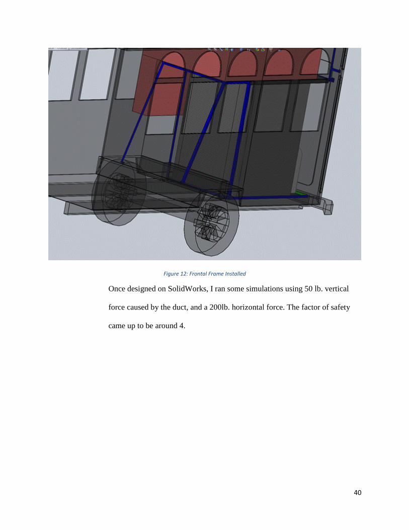
Figure 12: Frontal Frame Installed
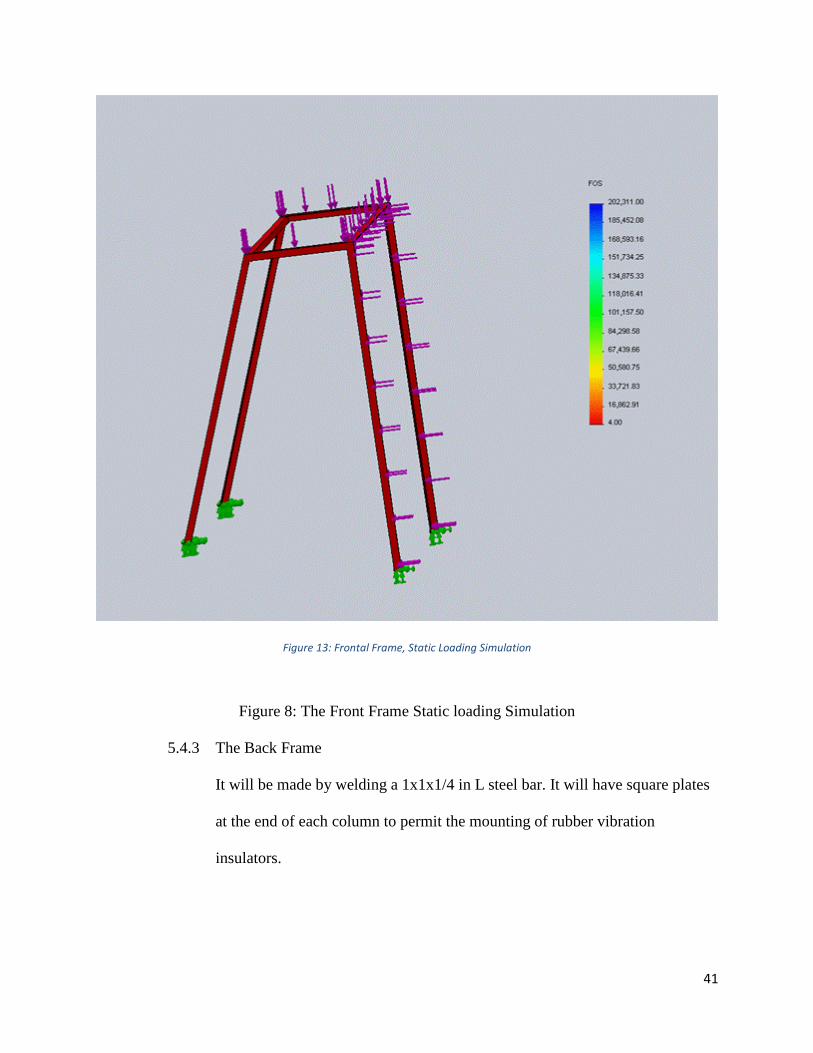
Once designed on SolidWorks, I ran some simulations using 50 lb. vertical
force caused by the duct, and a 200lb. horizontal force. The factor of safety
came up to be around 4.
41
Figure 13: Frontal Frame, Static Loading Simulation
Figure 8: The Front Frame Static loading Simulation
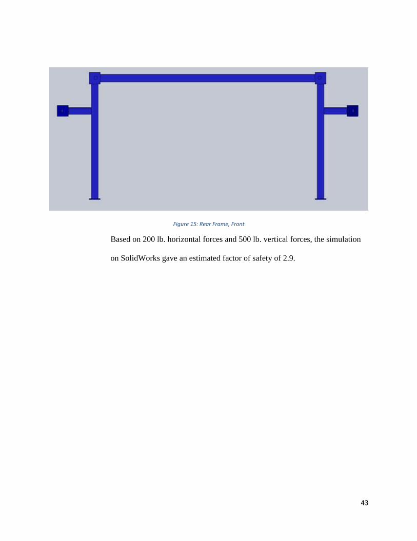
5.4.3 The Back Frame
It will be made by welding a 1x1x1/4 in L steel bar. It will have square plates
at the end of each column to permit the mounting of rubber vibration
insulators.

42
Figure 14: Rear Frame, Isometric
43
Figure 15: Rear Frame, Front
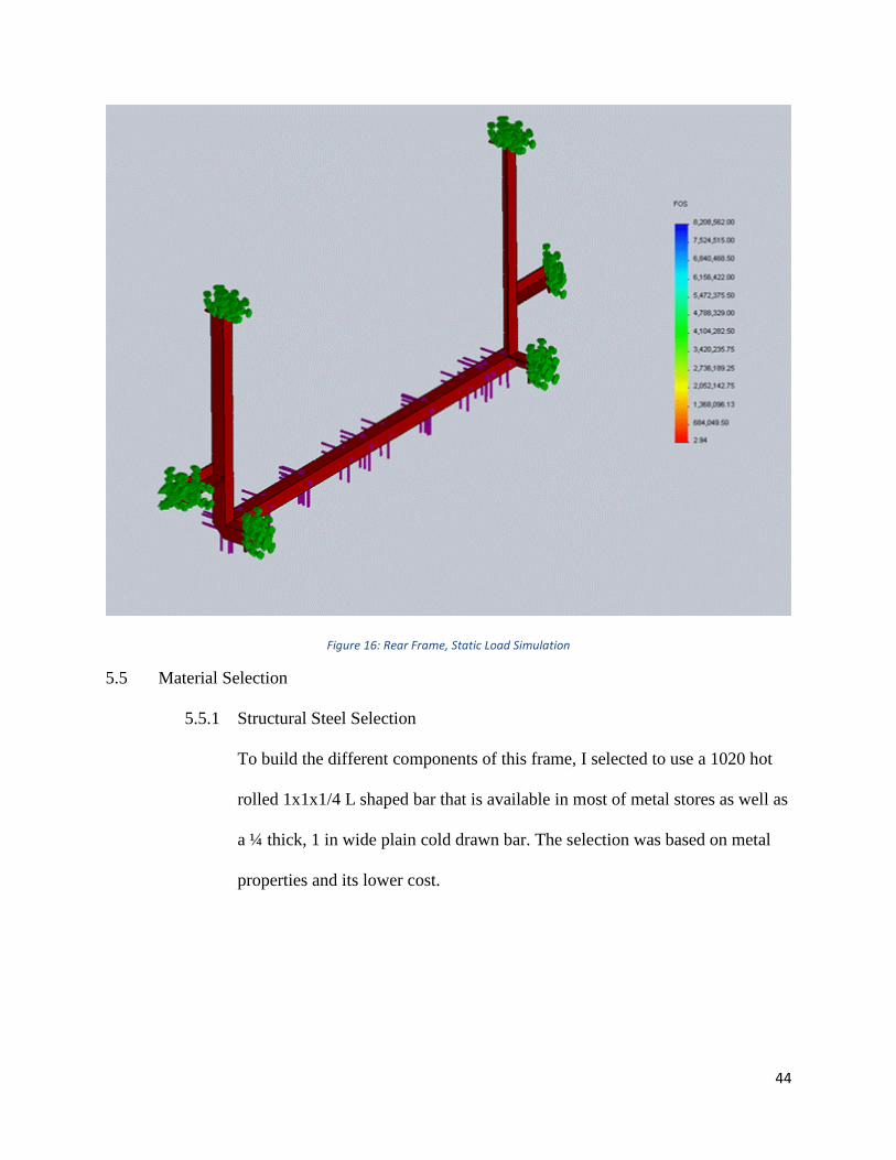
Based on 200 lb. horizontal forces and 500 lb. vertical forces, the simulation
on SolidWorks gave an estimated factor of safety of 2.9.
44
Figure 16: Rear Frame, Static Load Simulation
5.5 Material Selection
5.5.1 Structural Steel Selection
To build the different components of this frame, I selected to use a 1020 hot
rolled 1x1x1/4 L shaped bar that is available in most of metal stores as well as
a ¼ thick, 1 in wide plain cold drawn bar. The selection was based on metal
properties and its lower cost.

45
Figure 17: McMaster-Carr, Angle Bar Stock
Figure 18: McMaster-Carr, Solid Bar Stock
46
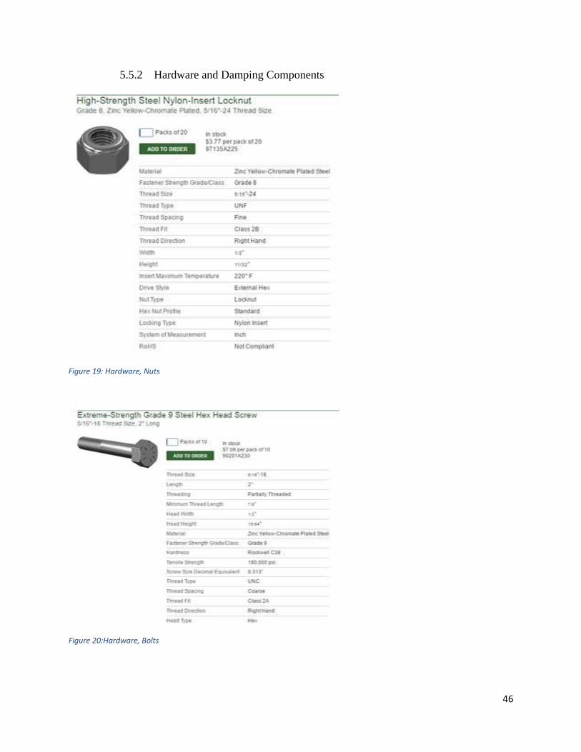
5.5.2 Hardware and Damping Components
Figure 19: Hardware, Nuts
Figure 20:Hardware, Bolts

47
Figure 21: Bushing Stud
48
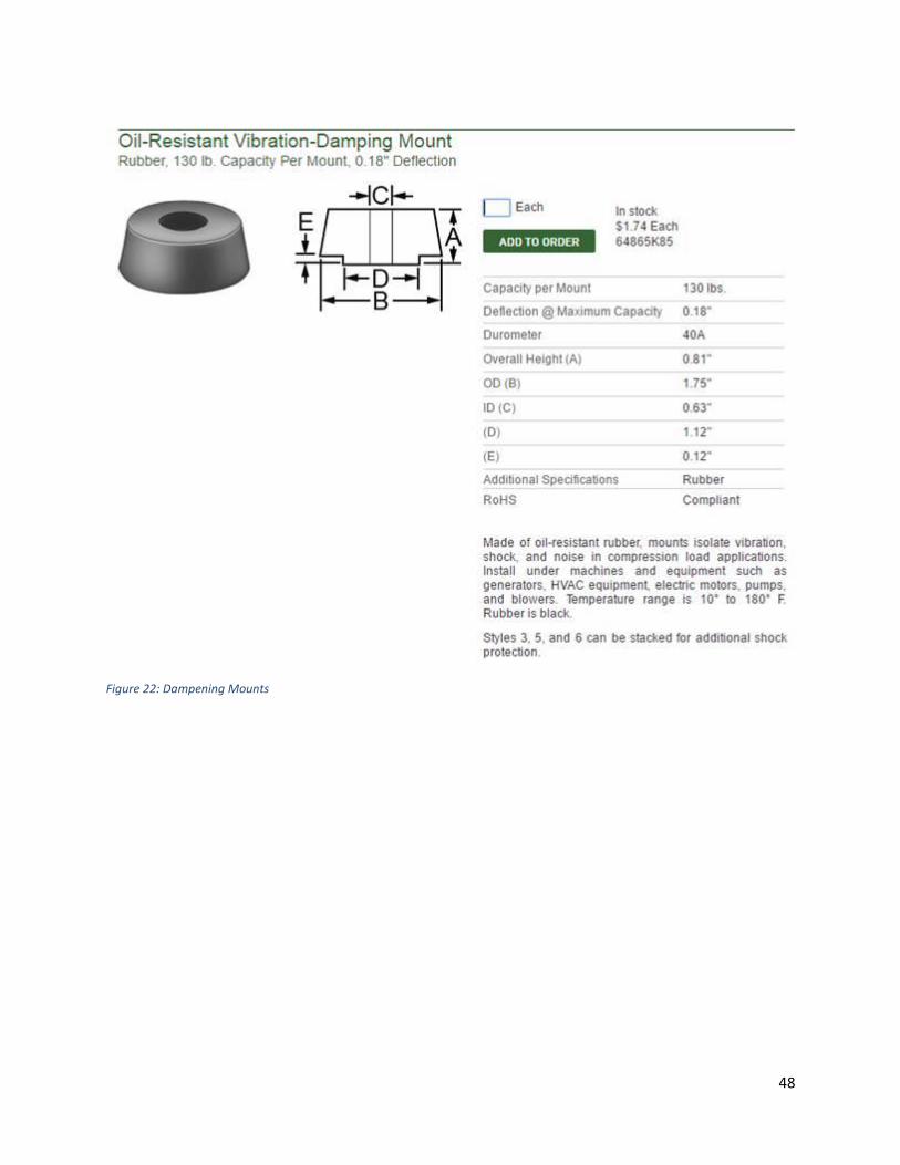
Figure 22: Dampening Mounts
49
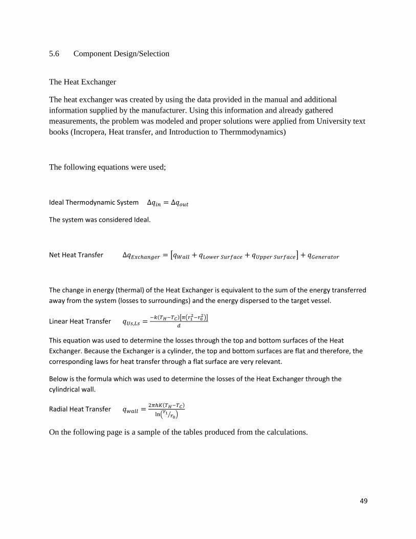
5.6 Component Design/Selection
The Heat Exchanger
The heat exchanger was created by using the data provided in the manual and additional
information supplied by the manufacturer. Using this information and already gathered
measurements, the problem was modeled and proper solutions were applied from University text
books (Incropera, Heat transfer, and Introduction to Thermmodynamics)
The following equations were used;
Ideal Thermodynamic System ∆𝑞𝑖𝑛 = ∆𝑞𝑜𝑢𝑡
The system was considered Ideal.
Net Heat Transfer ∆𝑞𝐸𝑥𝑐ℎ𝑎𝑛𝑔𝑒𝑟 = [𝑞𝑊𝑎𝑙𝑙 + 𝑞𝐿𝑜𝑤𝑒𝑟 𝑆𝑢𝑟𝑓𝑎𝑐𝑒 + 𝑞𝑈𝑝𝑝𝑒𝑟 𝑆𝑢𝑟𝑓𝑎𝑐𝑒] + 𝑞𝐺𝑒𝑛𝑒𝑟𝑎𝑡𝑜𝑟
The change in energy (thermal) of the Heat Exchanger is equivalent to the sum of the energy transferred
away from the system (losses to surroundings) and the energy dispersed to the target vessel.
Linear Heat Transfer 𝑞𝑈𝑠,𝐿𝑠 =−𝑘(𝑇𝐻−𝑇𝐶)[𝜋(𝑟1
2−𝑟02)]
𝑑
This equation was used to determine the losses through the top and bottom surfaces of the Heat
Exchanger. Because the Exchanger is a cylinder, the top and bottom surfaces are flat and therefore, the
corresponding laws for heat transfer through a flat surface are very relevant.
Below is the formula which was used to determine the losses of the Heat Exchanger through the
cylindrical wall.
Radial Heat Transfer 𝑞𝑤𝑎𝑙𝑙 =2𝜋ℎ𝐾(𝑇𝐻−𝑇𝐶)
ln(𝑟1
𝑟0⁄ )
On the following page is a sample of the tables produced from the calculations.
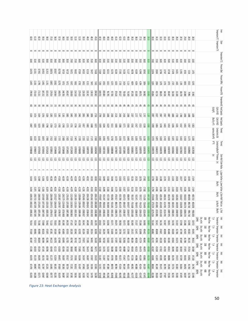
50
Figure 23: Heat Exchanger Analysis
Inner
Temperature (F°) Outer
Temperature (°F) Temperature (°C)Pressure (Bar)
Pressure (MPa)Pressure (PSI)
Temperature(K)Heat Capacity
(Cph) of H2O
(kJ/kg*K)
Heat Capacity
(Cph) of H2O
(Btu/lb_m°F)
Thermal
Conductivity 316
stainless (W/m*K)
Thermal
Conductivity(Btu/hr*
ft*°F)
Outer Wall
Thickness
(in)
Outer Radius
(in)
q_Upper Surface
(Btu/hr)
q_Lower Surface
(Btu/hr)
q_Outer Wall
(Btu/hr)
Total Loss
(q: Btu/hr)
q_Total
(Btu/hr)
Inlet
Temperature
T_ih
Mass Flow:
1000
(lbs_m/hr)
(2GPM)
Inlet
Temperature
T_ih
Mass Flow:
1500
(lbs_m/hr)
(3GPM)
Inlet
Temperature
T_ih
Mass Flow:
2000
(lbs_m/hr)
(4GPM)
Inlet
Temperature
T_ih
Mass Flow:
2500
(lbs_m/hr)
(5GPM)
Inlet
Temperature
T_ih
Mass Flow:
3000
(lbs_m/hr)
(6GPM)
Inlet
Temperature
T_ih
Mass Flow:
3500
(lbs_m/hr)
(7GPM)
Inlet
Temperature
T_ih
Mass Flow:
4000
(lbs_m/hr)
(8GPM)
260.3330
126.852.4755
0.247635.9042
4001.6008
0.382315.2000
0.0617835880.125
4-17.6474
-17.6474-4600.7110
-4636.0058-99636.0058
520.9723434.0915
390.6512364.5869
347.2108334.7992
325.4906
269.3330
131.855.5154
0.551579.9941
4051.6488
0.393715.2775
0.0620986030.125
4-18.4305
-18.4305-4804.8550
-4841.7160-99841.7160
522.9085438.3823
396.1192370.7614
353.8562341.7810
332.7246
278.3330
136.858.5553
0.8555124.0840
4101.6968
0.405215.3550
0.0624136180.125
4-19.2206
-19.2206-5010.8323
-5049.2734-100049.2734
525.2488442.9425
401.7894377.0975
360.6363348.8782
340.0597
287.3330
141.8511.5952
1.1595168.1739
4151.7448
0.416715.4325
0.0627286330.125
4-20.0177
-20.0177-5218.6427
-5258.6780-100258.6780
527.9598447.7499
407.6449383.5819
367.5399356.0814
347.4875
296.3330
146.8514.6351
1.4635212.2638
4201.7928
0.428115.5100
0.0630436480.125
4-20.8218
-20.8218-5428.2863
-5469.9299-100469.9299
531.0119452.7846
413.6710390.2028
374.5573363.3820
355.0005
305.3330
151.8517.6749
1.7675256.3538
4251.8408
0.439615.5875
0.0633586630.125
4-21.6330
-21.6330-5639.7630
-5683.0291-100683.0291
534.3783458.0289
419.8542396.9493
381.6794370.7724
362.5921
314.3330
156.8520.7148
2.0715300.4437
4301.8887
0.451015.6650
0.0636736780.125
4-22.4512
-22.4512-5853.0730
-5897.9755-100897.9755
538.0351463.4668
426.1826403.8121
388.8984378.2458
370.2563
323.3330
161.8523.7547
2.3755344.5336
4351.9367
0.462515.7425
0.0639886930.125
4-23.2765
-23.2765-6068.2161
-6114.7691-101114.7691
541.9607469.0838
432.6454410.7823
396.2069385.7959
377.9877
332.3330
166.8526.7946
2.6795388.6235
4401.9847
0.474015.8200
0.0643037080.125
4-24.1088
-24.1088-6285.1924
-6333.4100-101333.4100
546.1356474.8671
439.2328417.8522
403.5985393.4173
385.7814
341.3330
171.8529.8345
2.9834432.7134
4452.0327
0.485415.8975
0.0646187230.125
4-24.9481
-24.9481-6504.0019
-6553.8981-101553.8981
550.5421480.8048
445.9361425.0149
411.0674401.1049
393.6330
350.3330
176.8532.8744
3.2874476.8034
4502.0807
0.496915.9750
0.0649337380.125
4-25.7944
-25.7944-6724.6446
-6776.2334-101776.2334
555.1643486.8862
452.7471432.2637
418.6081408.8541
401.5386
359.3330
181.8535.9143
3.5914520.8933
4552.1287
0.508316.0525
0.0652487530.125
4-26.6478
-26.6478-6947.1205
-7000.4160-102000.4160
559.9874493.1016
459.6587439.5930
426.2158416.6607
409.4944
368.3330
186.8538.9542
3.8954564.9832
4602.1767
0.519816.1300
0.0655637680.125
4-27.5082
-27.5082-7171.4295
-7226.4459-102226.4459
564.9983499.4422
466.6641446.9973
433.8861424.5209
417.4971
377.3330
191.8541.9940
4.1994609.0731
4652.2247
0.531316.2075
0.0658787830.125
4-28.3756
-28.3756-7397.5717
-7454.3229-102454.3229
570.1848505.8998
473.7574454.4719
441.6149432.4314
425.5437
386.3330
196.8545.0339
4.5034653.1630
4702.2727
0.542716.2850
0.0661937980.125
4-29.2501
-29.2501-7625.5471
-7684.0473-102684.0473
575.5357512.4671
480.9328462.0123
449.3986440.3888
433.6314
395.3330
201.8548.0738
4.8074697.2530
4752.3207
0.554216.3625
0.0665088130.125
4-30.1316
-30.1316-7855.3557
-7915.6188-102915.6188
581.0409519.1372
488.1854469.6143
457.2336448.3902
441.7577
404.3330
206.8551.1137
5.1114741.3429
4802.3686
0.565616.4400
0.0668238280.125
4-31.0201
-31.0201-8086.9974
-8149.0377-103149.0377
586.6909525.9040
495.5105477.2744
465.1170456.4331
449.9202
413.3330
211.8554.1536
5.4154785.4328
4852.4166
0.577116.5175
0.0671388430.125
4-31.9157
-31.9157-8320.4723
-8384.3037-103384.3037
592.4772532.7615
502.9036484.9889
473.0457464.5149
458.1168
422.3330
216.8557.1935
5.7193829.5227
4902.4646
0.588616.5950
0.0674538580.125
4-32.8183
-32.8183-8555.7804
-8621.4170-103621.4170
598.3918539.7046
510.3609492.7547
481.0173472.6334
466.3455
431.3330
221.8560.2334
6.0233873.6126
4952.5126
0.600016.6725
0.0677688730.125
4-33.7279
-33.7279-8792.9217
-8860.3776-103860.3776
604.4274546.7283
517.8787500.5690
489.0291480.7864
474.6043
440.3330
226.8563.2733
6.3273917.7026
5002.5606
0.611516.7500
0.0680838880.125
4-34.6446
-34.6446-9031.8962
-9101.1853-104101.1853
610.5771553.8280
525.4535508.4288
497.0790488.9720
482.8918
449.3330
231.8566.3131
6.6313961.7925
5052.6086
0.622916.8275
0.0683989030.125
4-35.5683
-35.5683-9272.7039
-9343.8404-104343.8404
616.8346560.9997
533.0823516.3318
505.1649497.1884
491.2061
458.3330
236.8569.3530
6.93531005.8824
5102.6566
0.634416.9050
0.0687139180.125
4-36.4990
-36.4990-9515.3447
-9588.3426-104588.3426
623.1941568.2394
540.7620524.2756
513.2847505.4340
499.5460
467.3330
241.8572.3929
7.23931049.9723
5152.7046
0.645916.9825
0.0690289330.125
4-37.4367
-37.4367-9759.8187
-9834.6922-104834.6922
629.6502575.5434
548.4901532.2581
521.4367513.7072
507.9100
476.3330
246.8575.4328
7.54331094.0622
5202.7526
0.657317.0600
0.0693439480.125
4-38.3815
-38.3815-10006.1259-10082.8889
-105082.8889636.1978
582.9085556.2639
540.2771529.6193
522.0065516.2969
485.3330
251.8578.4727
7.84731138.1522
5252.8006
0.668817.1375
0.0696589630.125
4-39.3333
-39.3333-10254.2662-10332.9329
-105332.9329642.8322
590.3314564.0811
548.3309537.8307
530.3306524.7055
494.3330
256.8581.5126
8.15131182.2421
5302.8485
0.680217.2150
0.0699739780.125
4-40.2922
-40.2922-10504.2398-10584.8242
-105584.8242649.5490
597.8093571.9395
556.4176546.0697
538.6783533.1347
503.3330
261.8584.5525
8.45521226.3320
5352.8965
0.691717.2925
0.0702889930.125
4-41.2581
-41.2581-10756.0465-10838.5627
-105838.5627656.3441
605.3394579.8371
564.5357554.3347
547.0483541.5835
512.3330
266.8587.5924
8.75921270.4219
5402.9445
0.703217.3700
0.0706040080.125
4-42.2310
-42.2310-11009.6864-11094.1484
-106094.1484663.2138
612.9192587.7719
572.6835562.6246
555.4397550.0509
521.3330
271.8590.6322
9.06321314.5118
5452.9925
0.714617.4475
0.0709190230.125
4-43.2109
-43.2109-11265.1595-11351.5814
-106351.5814670.1544
620.5462595.7422
580.8597570.9381
563.8512558.5361
530.3330
276.8593.6721
9.36721358.6018
5503.0405
0.726117.5250
0.0712340380.125
4-44.1979
-44.1979-11522.4658-11610.8616
-106610.8616677.1625
628.2183603.7462
589.0630579.2742
572.2821567.0381
539.3330
281.8596.7120
9.67121402.6917
5553.0885
0.737517.6025
0.0715490530.125
4-45.1919
-45.1919-11781.6052-11871.9890
-106871.9890684.2350
635.9333611.7825
597.2920587.6317
580.7314575.5562
548.3330
286.8599.7519
9.97521446.7816
5603.1365
0.749017.6800
0.0718640680.125
4-46.1929
-46.1929-12042.5779-12134.9638
-107134.9638691.3690
643.6893619.8495
605.5456596.0097
589.1983584.0897
557.3330
291.85102.7918
10.27921490.8715
5653.1845
0.760517.7575
0.0721790830.125
4-47.2010
-47.2010-12305.3837-12399.7857
-107399.7857698.5616
651.4844627.9458
613.8226604.4072
597.6819592.6379
566.3330
296.85105.8317
10.58321534.9614
5703.2325
0.771917.8350
0.0724940980.125
4-48.2161
-48.2161-12570.0227-12666.4549
-107666.4549705.8103
659.3169636.0702
622.1221612.8234
606.1815601.2001
575.3330
301.85108.8716
10.88721579.0514
5753.2805
0.783417.9125
0.0728091130.125
4-49.2383
-49.2383-12836.4948-12934.9713
-107934.9713713.1126
667.1851644.2213
630.4430621.2575
614.6965609.7757
584.3330
306.85111.9115
11.19111623.1413
5803.3284
0.794817.9900
0.0731241280.125
4-50.2674
-50.2674-13104.8002-13205.3350
-108205.3350720.4662
675.0875652.3981
638.7845629.7087
623.2261618.3640
593.3330
311.85114.9513
11.49511667.2312
5853.3764
0.806318.0675
0.0734391430.125
4-51.3036
-51.3036-13374.9387-13477.5459
-108477.5459727.8689
683.0226660.5994
647.1455638.1763
631.7697626.9647
602.3330
316.85117.9912
11.79911711.3211
5903.4244
0.817818.1450
0.0737541580.125
4-52.3469
-52.3469-13646.9104-13751.6041
-108751.6041735.3186
690.9890668.8243
655.5254646.6595
640.3267635.5771
611.3330
321.85121.0311
12.10311755.4110
5953.4724
0.829218.2225
0.0740691730.125
4-53.3971
-53.3971-13920.7153-14027.5095
-109027.5095742.8134
698.9856677.0717
663.9233655.1578
648.8967644.2008
620.3330
326.85124.0710
12.40711799.5010
6003.5204
0.840718.3000
0.0743841880.125
4-54.4544
-54.4544-14196.3533-14305.2622
-109305.2622750.3514
707.0109685.3407
672.3385663.6705
657.4790652.8353
51
5.6.1 Piping Network Design
In order to satisfy the system’s needs the team will use an accumulator. An
accumulator is a pressure storage reservoir in which non-compressible water
is held under pressure that is applied by compressed air in the other side of the
diaphragm. The accumulator will be able to withstand the incoming pressure
and temperature from the air conditioning unit and pass it along to the solar
collector and provide many advantages to the system. An accumulator is
usually a two chamber spherical tank where divided by a diaphragm is in
between the fluid and compressed air. This compressed air can help during
pressure fluctuations and absorb shocks in the system, such as water hammer.
(http://hydraulicspneumatics.com/200/TechZone/Accumulators/Article/False/
6446/TechZone-Accumulators)
The team will use SAE and NPT standards for all pipe and threads. The
accumulators typically found in off the shelf suppliers such as McMaster-Carr
are all SAE threads, in order to safely move this water at over 3000 psi and
temperatures ranging from 360 to 600 degrees Fahrenheit, the team will use
compression stainless steel tubing in order to prevent leaks and thermal
breakdown of other less capable materials. All these stainless steel tubing and
threads follow NPT standards. Adapters will need to be used in order to
connect all components together.
52
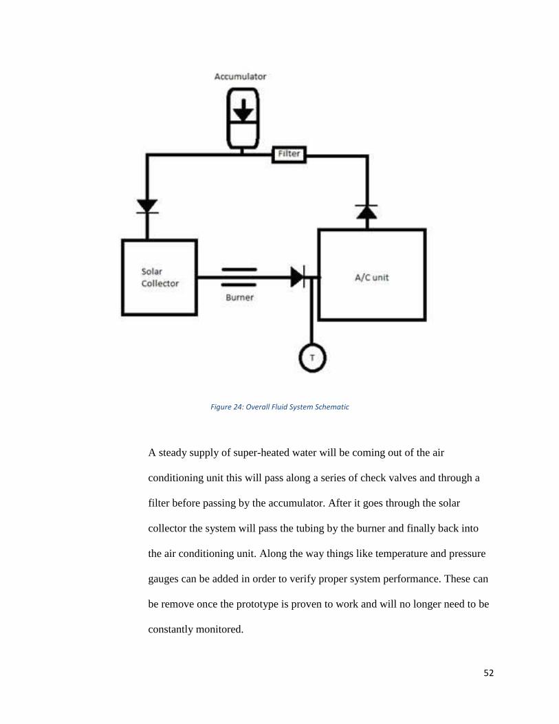
Figure 24: Overall Fluid System Schematic
A steady supply of super-heated water will be coming out of the air
conditioning unit this will pass along a series of check valves and through a
filter before passing by the accumulator. After it goes through the solar
collector the system will pass the tubing by the burner and finally back into
the air conditioning unit. Along the way things like temperature and pressure
gauges can be added in order to verify proper system performance. These can
be remove once the prototype is proven to work and will no longer need to be
constantly monitored.

53
The team chose a 32 oz. piston style accumulator part number 716K52 from
the McMaster-Carr catalog for this project. The reasoning being it is that it is
able to maintain 4000 psi and has the ability to work with superheated water.
304 Stainless steel tubing can handle all of the previously mentioned
parameters for this project. As well as any other fittings that will be required
during assembly of the system.
A flow analysis was conducted by applying Bernoulli’s extended equation to
characterize the water flowing through the system. Bernoulli’s equation
expresses the total energy of a system in the form of head. Fluid head is
essentially represented as a column of water. Given the inputs of the system,
the output pressure of the water flowing into the IDG can be calculated using
Bernoulli’s equation.
The following is Bernoulli’s extended equation expressed in head where z
represents height, v is velocity, P is pressure, ρ is density of the fluid, g is
gravity, Hp is pump head and HL is the total sum of Head loss throughout the
system.
The following is an expression for the combination of major and minor head
losses. Major Head loss is associated with the friction factor f, the length of
the piping L, and the diameter of the pipe D. The minor losses are associated
with the sum of coefficients K which represent the various bends, expansions,
and joints in the network.
54
A full analysis will be conducted to take into account all major and minor
losses, as well as taking into account losses due to temperature, height
differences, and pressure losses in the system.
5.6.2 Solar Collector Design
Renewable energy resources exist over wide geographical areas, in contrast to
other energy sources, which are concentrated in a limited number of countries.
Rapid deployment of renewable energy and energy efficiency is resulting in
significant energy security, climate change mitigation, and economic benefits.
The results of a recent review of the literature concluded that as greenhouse
gas (GHG) emitters begin to be held liable for damages resulting from GHG
emissions resulting in climate change, a high value for liability mitigation
would provide powerful incentives for deployment of renewable energy
technologies. A solar thermal collector collects heat by absorbing sunlight. A
collector is a device for capturing solar radiation (Marken, 2009). Solar
radiation is energy in the form of electromagnetic radiation from the infrared
(long) to the ultraviolet (short) wavelengths. The quantity of solar energy
striking the Earth's surface (solar constant) averages about 1,000 watts per
square meter under clear skies, depending upon weather conditions, location
and orientation.
5.6.2.1 Different types of Solar Collectors
Flat-Plate and Evacuated-Tube Solar Collectors are used to collect heat for
space heating, domestic hot water or cooling with an absorption chiller.
Below is a list of the many types of Solar Collectors
Flat plate collector.
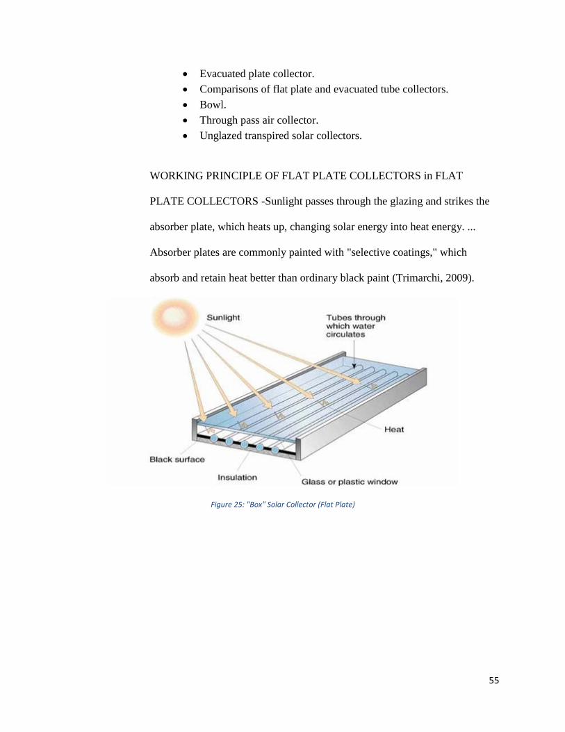
55
Evacuated plate collector.
Comparisons of flat plate and evacuated tube collectors.
Bowl.
Through pass air collector.
Unglazed transpired solar collectors.
WORKING PRINCIPLE OF FLAT PLATE COLLECTORS in FLAT
PLATE COLLECTORS -Sunlight passes through the glazing and strikes the
absorber plate, which heats up, changing solar energy into heat energy. ...
Absorber plates are commonly painted with "selective coatings," which
absorb and retain heat better than ordinary black paint (Trimarchi, 2009).
Figure 25: "Box" Solar Collector (Flat Plate)
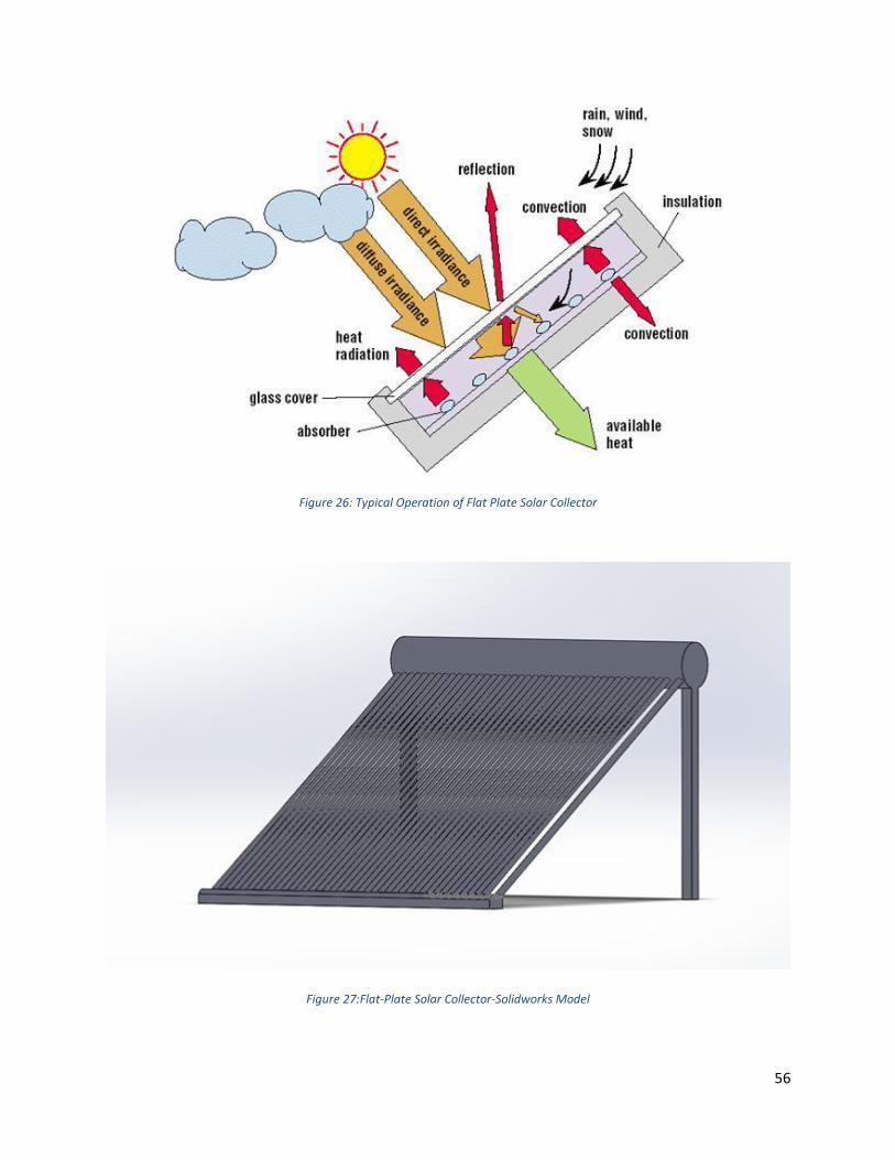
56
Figure 26: Typical Operation of Flat Plate Solar Collector
Figure 27:Flat-Plate Solar Collector-Solidworks Model
57
5.6.2.2 Design Specifications
From and estimated overall width of the trolley of 6 feet, and a length of
10 feet, the main dimensions of the thermal collector follow the same
overall dimensions of the trolley. The overall width of the thermal
collector is of 6 feet if seen from the front of the trolley, and the length is
10 feet, if seen from the side. Being that the trolley has an offset elevated
area on the roof; the structure of the system must be in the form of a
parabola. The parabola shape that forms the structure, while following the
main dimensions, has a radius of 120 inches. The approximated surface
area of the structure would be of 61 square feet. The coiled copper piping
on top of the structure which is composed of two identical sections, if
stretched out, each section is of approximately 55 feet. The 8 piping as
well as the structure follows the 120-inch radius that gives it the curved
appearance. The outer diameter of the piping is of 1.5 inches and the inner
diameter is of 1 inch. The approximated surface area that each section of
piping is going to cover is of 23 square feet.
5.6.2.3 Design Considerations
First Design for our Solar collector was using a parabolic shaped glass
covered at the top the reason for selecting this design was, wherever the
sun was located the solar collector would be able to come in contact with
the surface (Marken, 2009). The thermal collector would then have a
copper tubing running from top to bottom and wrapping around its outer
58
surface. A copper pipe represents the most ideal material to be used,
because it does not expand much while facing extreme heat. Also, copper
is known for being a good heat conductor, so the pipe would be able to
absorb an important amount of heat from radiation, therefore increasing by
conduction the temperature of the fluid running through the piping system.
The last reason for selecting copper is that it is easily shapeable, making
the manufacturing process easier to get the shape that we desire.
Second Design was using a flat shaped glass instead of a parabolic shaped
glass because of including a Fresnel lens which helps, the design allows
the construction of lenses of large aperture and short focal length without
the mass and volume of material that would be required by a lens of
conventional design. A Fresnel lens can be made much thinner than a
comparable conventional lens, in some cases taking the form of a flat
sheet. A Fresnel lens can capture more oblique light from a light source,
thus allowing the light from a lighthouse equipped with one to be visible
over greater distances.
Final Design after discussing with the team was to come up with a Flat
shaped glass covered at the top of the solar collector, which had increased
number of coils, which gives more time to liquid to travel from inlet to
outlet.
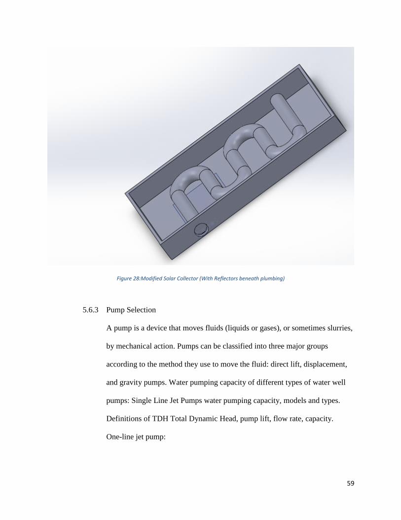
59
Figure 28:Modified Solar Collector (With Reflectors beneath plumbing)
5.6.3 Pump Selection
A pump is a device that moves fluids (liquids or gases), or sometimes slurries,
by mechanical action. Pumps can be classified into three major groups
according to the method they use to move the fluid: direct lift, displacement,
and gravity pumps. Water pumping capacity of different types of water well
pumps: Single Line Jet Pumps water pumping capacity, models and types.
Definitions of TDH Total Dynamic Head, pump lift, flow rate, capacity.
One-line jet pump:

60
A one-line jet pump can typically raise water from depths of just a few feet
(or "0" depth) to about 25 feet in depth, and at water delivery rates of 4 gpm
up to as much as 25 gpm depending on the variables we list below the well
pump capacity tables shown.
A nice example table of shallow well 1-Line Jet Pump Capacities for 1/2 hp,
3/4, and 1 hp shallow well pumps is provided in the water jet. Jet Pump
Installation Manual and excerpted below to illustrate the factors that
determine well pump capacity. Both of the charts below are for one-line jet
pumps produced by Water Ace. 1-Line jet pumps intended for shallow well
use and made by other manufacturers can be expected to have similar
capacities.
Figure 29: Shallow Well, Pump Capacities
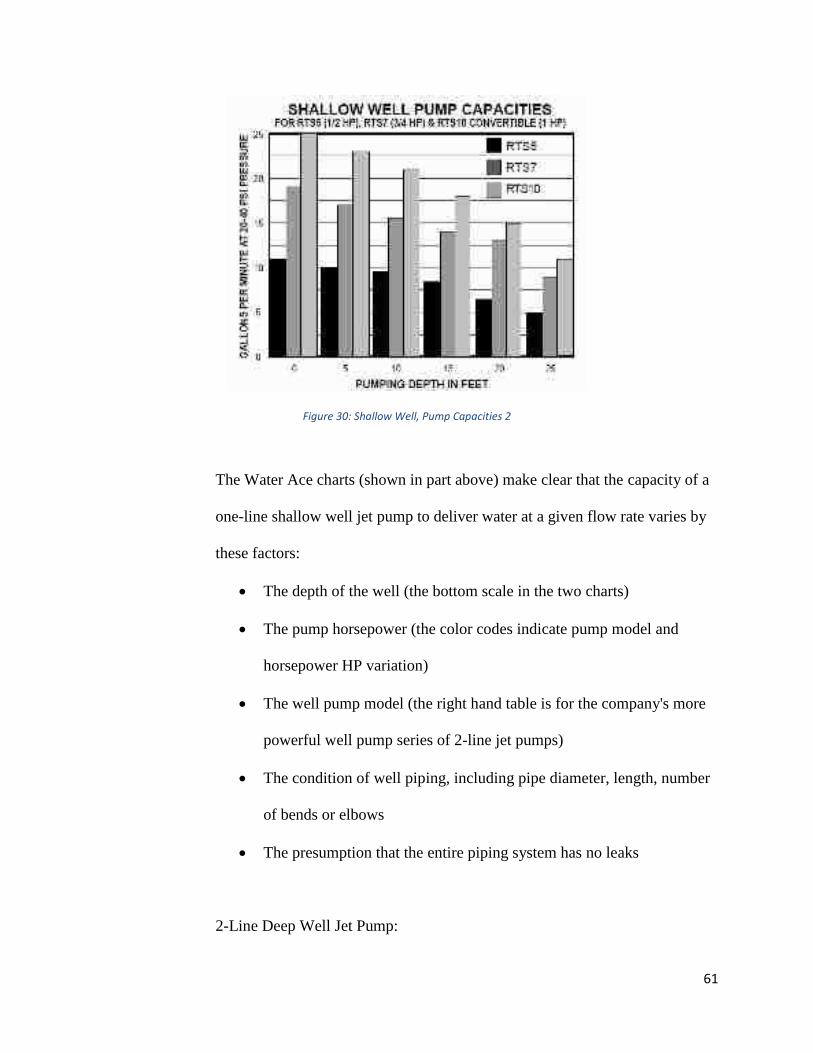
61
Figure 30: Shallow Well, Pump Capacities 2
The Water Ace charts (shown in part above) make clear that the capacity of a
one-line shallow well jet pump to deliver water at a given flow rate varies by
these factors:
The depth of the well (the bottom scale in the two charts)
The pump horsepower (the color codes indicate pump model and
horsepower HP variation)
The well pump model (the right hand table is for the company's more
powerful well pump series of 2-line jet pumps)
The condition of well piping, including pipe diameter, length, number
of bends or elbows
The presumption that the entire piping system has no leaks
2-Line Deep Well Jet Pump:
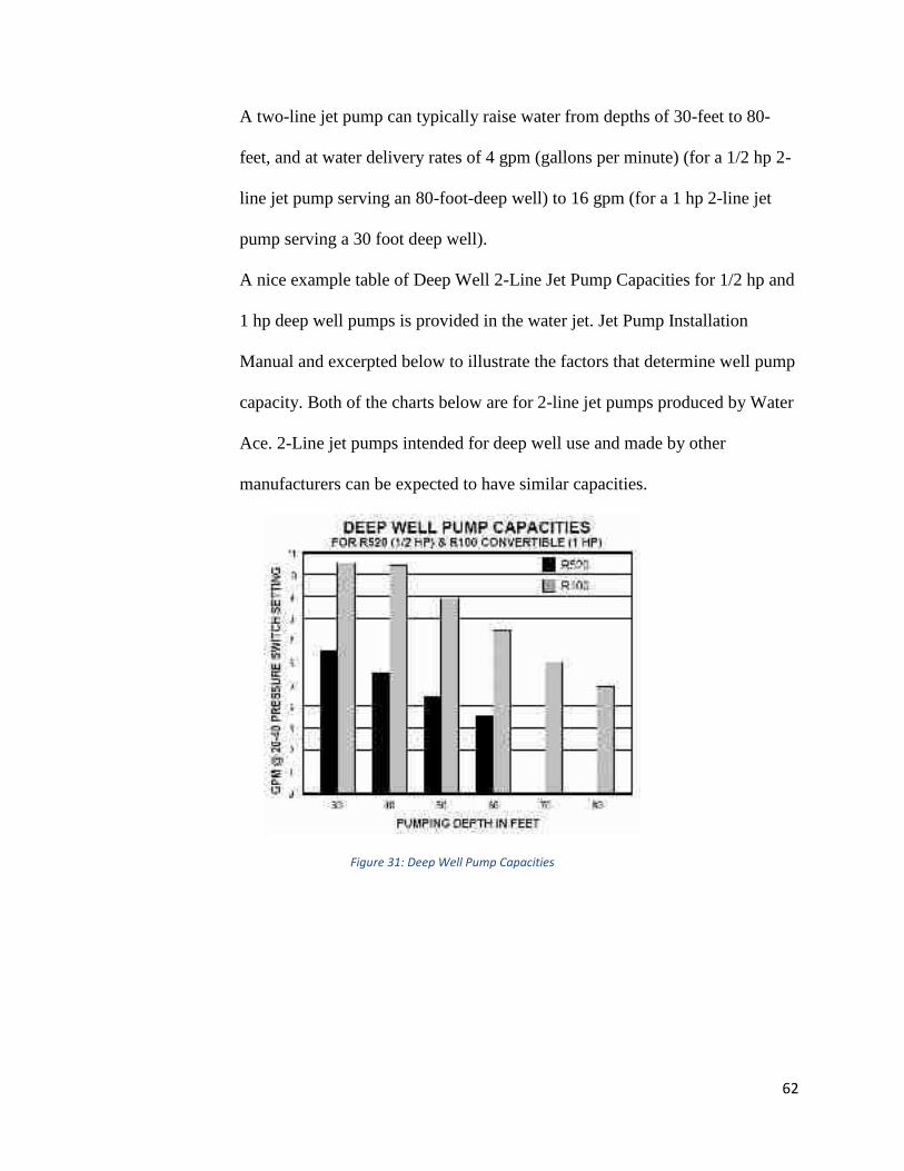
62
A two-line jet pump can typically raise water from depths of 30-feet to 80-
feet, and at water delivery rates of 4 gpm (gallons per minute) (for a 1/2 hp 2-
line jet pump serving an 80-foot-deep well) to 16 gpm (for a 1 hp 2-line jet
pump serving a 30 foot deep well).
A nice example table of Deep Well 2-Line Jet Pump Capacities for 1/2 hp and
1 hp deep well pumps is provided in the water jet. Jet Pump Installation
Manual and excerpted below to illustrate the factors that determine well pump
capacity. Both of the charts below are for 2-line jet pumps produced by Water
Ace. 2-Line jet pumps intended for deep well use and made by other
manufacturers can be expected to have similar capacities.
Figure 31: Deep Well Pump Capacities

63
Figure 32: Deep Well, Pump Capacities2
The Water Ace charts (shown in part above) make clear that the capacity of a
deep well pump to deliver water at a given flow rate varies by these factors:
The depth of the well (the bottom scale in the two charts)
The pump horsepower (the color codes indicate pump model and
horsepower HP variation)
The well pump model (the right hand table is for the company's more
powerful well pump series of 2-line jet pumps)
The condition of well piping, including pipe diameter, length, number
of bends or elbows
The presumption that the entire piping system has no leaks.
From the calculations made by the team, mass flow rate was 5GPM, according
to that the pump was selected.
64
From the manufacturer’s guide for 5GPM we selected North Star NSQ
Series2V On-Demand Diaphragm Pump with Quick-Connect Ports — 5.5
GPM @ 60 PSI.
6. Prototype Construction
6.1 Overview
A fully functional prototype is to be built using incorporating the absorption chiller into a
passenger trolley. All associated components and required parts must be included for the
system to work properly.
6.2 Description of Prototype
The prototype for this design begins with the trolley that was donated to FIU. A gas-fired
absorption chiller as manufactured by Robur Industries was purchased using a
combination of grant money as well as private donations. A chilled water fan coil as
manufactured by Multi-Aqua was also purchased with private donations. The chiller is to
be modified as previously discussed to operate on hot water in lieu of flammable gas.
This includes fabricating and installing a hot water heat exchanger at the base of the
generator. The chiller is be installed within the trolley, and the hot water and chilled
water piping, as well as the supply and exhaust air, are to be connected to the chiller. The
hot water piping is to run to the solar water heater. The chilled water piping is to be run
to the fan coil. The exhaust air is to connected to the exhaust louvers. Special care is to
be taken that the exhaust exits the vehicle opposite the passenger entry/exit side of the
trolley.
6.3 Prototype Design
65
The prototype for this design begins with the trolley that was donated to FIU. A gas-fired
absorption chiller as manufactured by Robur Industries was purchased using a
combination of grant money as well as private donations. A chilled water fan coil as
manufactured by Multi-Aqua was also purchased with private donations. The chiller is to
be modified as previously discussed to operate on hot water in lieu of flammable gas.
This includes fabricating and installing a hot water heat exchanger at the base of the
generator. The chiller is be installed within the trolley, and the hot water and chilled
water piping, as well as the supply and exhaust air, are to be connected to the chiller. The
hot water piping is to run to the solar water heater. The chilled water piping is to be run
to the fan coil. The exhaust air is to connected to the exhaust louvers. Special care is to
be taken that the exhaust exits the vehicle opposite the passenger entry/exit side of the
trolley.
6.4 Parts List
Trolley (Donated to FIU)
5-Ton Absorption Chiller by Robur
Fan Coil by Mult-Aqua
Solar Water Heating Panel (by another team)
Black Steel Hot Water Pipe
Black Steel Chilled Water Pipe
Armaflex Pipe Insulation
Black Steel Hot Water Heat Exchanger Prototype
Mounting Hardware
Vibration Isolation Pads
66
Intake and Exhaust Louvers by Greenheck
Exhaust Plenum
6.5 Construction
Beginning with the Robur Chiller, the system was disassembled to explore and study the
internal components. Once a design was finalized, the chiller was modified to fit within
the designated space at the back of the trolley. The rear windows of the trolley were
removed to allow for the installation of the supply and exhaust louvers required for the
condenser section of the chiller. Next, the hot water heat exchanger was fabricated to
meet the design specifications. Unfortunately, since there was no solar water heater
available, this component was unable to be tested within the chiller. Instead, simulations
were run to test the functionality of this component. The chiller was then installed within
the designated space. A partition was installed between the mechanical space for the
chiller and the passenger compartment of the trolley. The fan coil was mounted the
partition. The chilled water lines were run from the chiller to the fan coil. Those lines
were insulated using the aforementioned Armaflex insulation to prevent sweating. The
discharge at the top of the chiller was ducted to the exhaust louvers on the side of the
trolley opposite the passenger ingress/egress. Since the hot water conversion was unable
to be tested, the chiller was once again converted to run on flammable gas. The gas
piping was connected to a propane tank to allow for testing of the cooling of the system.
The fan and pump motors were connected to building power since the batteries of the
trolley are not yet installed. Once everything was connected, the system was tested.
6.6 Prototype Cost Analysis
Component Cost

67
Absorption Chiller (5 Ton) $6,500
Water Pumps (2) $1,000
Chilled Water Fan Coil $2,000
Misc. – Piping, Insulation, Wiring $4,000
Total Material Costs $13,500
Labor Costs
160 work hours
5 hours per week x 32 weeks
Average salary for an engineer: $41.31/hour*
Total estimated labor cost: $6,609.60
Total estimated Materials and Labor Costs = $20,109.60
6.7 Discussion
Building of the prototype proved to be more difficult than anticipated due to the project’s
dependence on aspects designed and built by others. In lieu of physical testing of the hot
water heat exchanger, we had to settle for simulations. Fortunately, we were able to test
the other components of the chilled water system. Hopefully, future iterations of the
project will be able to advance our research, build a fully functional prototype including
the solar water heater, and maybe even incorporate some of our alternate designs.
7. Design Considerations
7.1 Health and Safety
Due to health and safety concerns, some aspects of the original design were omitted.
Since the chiller uses Ammonia, which is toxic, as the refrigerant, we were not able
modify the internal piping designs of the chiller without taking unnecessary risks.
68
Instead, the layout was modified to allow for the chiller to be installed whole. Further, all
safety precautions were taken such as wearing work gloves to prevent cuts and burns as
well as wearing safety goggles to prevent injury to the eyes. The work was performed at
the shop of a licensed air conditioning contractor with the supervision of a certified
pipefitter and welder. Also, long pants and long sleeves were worn to prevent injury to
the arms and legs. The work was performed outdoors in a well-ventilated location. As
for the propane burner, again, all safety gear was worn and the test was performed
outdoors.
7.2 Assembly and Disassembly
The chiller by Robur was fairly simple to disassemble and reassemble. The unit was
designed to be easily serviced by a licensed professional. All work was performed using
simple hand tools with the exception of the water piping. This required a pipe threader.
The system will be easy to disassemble should someone choose to continue researching
and testing this product.
7.3 Manufacturability
Considering that the chiller is commercially available, it is quite easy to manufacture this
modified system. However, it would most effective for someone to negotiate with this,
or another, manufacturer to allow for the incorporation of the hot water heat exchanger
design into their product offerings. It is a simple modification to their existing design,
but it can be used for a number of possible scenarios. A unit that is designed specifically
for trolleys would require quite a bit more design as not every trolley has the extra space
in the rear of the compartment. The system would have to be designed from the ground
69
up to fit in a much more compact space, probably beneath the floor of the passenger
compartment.
7.4 Maintenance of the System
7.4.1.1 Maintenance of Chiller
Correct maintenance prevents problems, guarantees maximum operating efficiency of the
appliance and allows running costs to be reduced. Before carrying out any operation on
the appliance, switch it off via the appropriate on/off commands (or via the DDC, if
connected and in controller mode) and wait for the shutdown cycle to terminate. When
the appliance is off, disconnect it from the gas and electricity mains via the external
disconnecting switch (GS) and the gas valve.
Caution: Label all wires prior to disconnection when servicing controls. Wiring errors
can cause improper and dangerous operation. Verify proper operation after servicing.
Any operation that regards internal components of the appliance must be carried out by
an authorized Robur Technical Assistance Center (TAC), according to the instructions
supplied by the manufacturer.
Perform the operations described below at least once a year. An authorized Robur
Technical Assistance Center (TAC) will check the unit for correct operation every two
years. If the unit is subjected to particularly heavy use (for example in processing plants
or in other conditions of continuous operation), these maintenance operations must be
performed more often.
Inspection and cleaning of the flue gas passage:
You will need: the unit shut off
1. Turn off gas and electric supply to the unit.
70
2. Remove front panel.
3. Clean the base pan around the generator housing of any debris.
4. Look at the flue outlet of the generator housing and clear any debris that may be
obstructing the opening.
5. Look at the air intake chute for combustion air and clear any debris that may be
obstructing the opening.
6. Reinstall front door.
7. Turn on gas and electric supply to the unit.
8. Start unit to check for correct operation.
The manufacturer will not accept contractual or non-contractual liability for damages
caused to people, animals, or things due to incorrect installation and improper use of the
unit and also by not observing the indications and instructions provided by the
manufacturer.
7.4.1.2 Maintenance of Fan Coil
Warning:
Disconnect and lockout the power before making any repair or any services.
Sharp edges and coil surfaces area a potential injury hazard. Avoid contact with these.
Maintenance:
Disconnect Power
Ensure no water is moving through the unit.
Remove the batteries from the remote control.
Check Before Operation:
Check if the air filter is installed and the air outlet is not blocked.
71
Connect Power.
Replace the remote control batteries.
Cleaning the Fan Coil Unit
External weekly cleaning is to be done with a dry cloth soaked with fresh water and mild
soap. Avoid using any other type of detergent.
The frame grill with deco panel can be removed. Clean with warm water not over 120ͦ F
and wipe with dry cloth.
Do not use a chemically treated cloth or duster to clean the unit.
Do not use benzene, thinner, polishing chemical, or similar solvents for cleaning. These
may cause surface discoloration, cracks, or deformation.
Cleaning Air Filters
Dirty and clogged filters reduce the cooling efficiency of the unit. It is recommended to
clean the filters once every two weeks.
Open the deco panel by grasping the rounded grooves and pulling towards you.
Hold the tabs of the air filter and raise it slightly. Then pull the filter downwards.
Clean the air filters with a vacuum cleaner or wash with water then dry.
Do not use benzene, thinner, polishing chemical, or similar solvents for cleaning. These
may cause the surfaces to crack or deform.
Install the air filter vice versa of dismantling procedure. The correct filter side is
indicated by words “FRONT” marked on the filter. The “FRONT” side should be facing
you.
7.5 Environmental Impact and Sustainability
72
The potential impact that further development of this project can have on the
environment is extremely promising. The projects looks to help revolutionize public
transportation by breaking down one of the most energy-consuming features and
converting it to run on renewable and/or waste energy. By doing so, the municipalities
will be able to reach and service many more people without increasing the carbon
footprint of the public transport. Further, this system can be adapted to work on many
other modes of transport such as trains, buses, etc.
7.6 Economic Impact
The economic impact of the system is also far reaching. Since the basics of the system
do not rely on expensive materials and/or processes, it should be fairly inexpensive to
implement once a final, compact design is completed. As such, mass production is not a
farfetched idea. Further, as electrification of transportation becomes more and more
popular, alternate solutions to reduce the load on the batteries become more and more
attractive. The savings offered by an air conditioning system that is powered by solar
heat are immense.
7.7 Risk Assessment
There is very little risk in the current design. The only dangerous component is the
Ammonia circulating with the chiller. As the chiller has been located inside the trolley, it
is not subject to risk of damage by impact. Using neoprene isolation pads, the system has
been isolated from the vibrations of the road and, therefore, carries a reduced risk of
failure at the joints.
8. Design Experience
73
8.1 Overview
The experience gained during the design and build of this project was enlightening. In
addition to the theoretical design process, which includes modeling, calculations,
research, and proofs, this project allowed the team to experience firsthand many aspects
of the physical world of mechanical engineering. Beginning with the economic realities
of such a large project, the team was forced to fundraise in order to purchase the
equipment necessary. Further, the team was involved in the structural modifications to
the trolley. In order to complete the piping portions, the team learned how to thread steel
pipe. Also, in order to build the prototype for the hot water heat exchanger, the team
learned about ERW (Electric Resistance Welding).
8.2 Standards Used in the Project
In the United States, there are numerous regulations that apply to refrigerants used in
mobile air conditioners. System designs must meet safety standards from OSHA.
Further, equipment must meet various safety standards from approved agencies such as
UL, which tests equipment for safety in controlled situations. UL standards may have
additional requirements for tested equipment that use certain refrigerants. Many of the
requirements for alternative refrigerants are based on ASHRAE Standard 15, the Safety
Standard for Refrigeration Systems. The EPA recommends that users follow the
requirements and recommendations as specified in ASHRAE Standard 15 in its ruling on
carbon dioxide as an acceptable refrigerant in retail food refrigeration and cold storage
warehouse applications. Changes in ASHRAE Standard 15 have also been used to justify
changes in UL standards. The regulations are listed alphabetically. A number of
74
standards were reviewed during the design and construction of this project. Below is a
list of the most relevant and how they were applied to the project.
8.2.1 ANSI/ASHRAE Standard 15: Safety Standard for Refrigeration Systems
The purpose of the standard is to specify the safe design, construction,
installation, and operation of refrigeration systems.
8.2.2 ANSI/ASHRAE Standard 34: Designation and Safety Classification of
Refrigerants
The purpose of the standard is to provide a system for referencing refrigerants
and classifying refrigerants based on toxicity and flammability.
8.2.3 ANSI/IIAR 2-2008: American National Standard for Equipment, Design, and
Installation of Ammonia Mechanical Refrigerating Systems
The purpose of the standard is to guide the design, manufacture, installation,
and use of ammonia mechanical refrigerating systems with industrial
occupancies. The standard applies to any closed circuit mechanical
refrigerating systems using ammonia as a refrigerant.
8.2.4 SAE Standard J2773: Refrigerant Guidelines for Safety and Risk Analysis for
use in Mobile Air Conditioning Systems
This SAE standard enumerates the processes and methods required to prove
the compliance of relevant safety measures for complex technical systems.
8.2.5 ASME B31.8 Gas Transportation and Distribution Piping System
ASME's B31.8 Gas Transmission and Distribution covers the design,
fabrication, installation, inspection, testing, and other safety aspects of
operation and maintenance of gas transmission and distribution systems,
75
including gas pipelines, gas compressor stations, gas metering and regulation
stations, gas mains, and service lines up to the outlet of the customer’s meter
set assembly. The scope of this Code includes gas transmission and gathering
pipelines, including appurtenances, that are installed offshore for the purpose
of transporting gas from production facilities to onshore locations; gas storage
equipment of the closed pipe type that is fabricated or forged from pipe or
fabricated from pipe and fittings, and gas storage lines.
8.2.6 ASME B31.5 Refrigeration Piping
ASME B31.5 covers refrigerant, heat transfer components, and secondary
coolant piping for temperatures as low as -320°F (-196°C), whether erected on
the premises or factory assembled.
8.3 Contemporary Issues
Despite the many benefits of using the Solar Heat collection to provide the energy for the
absorption chiller, society today will be reluctant to embrace the absorption chiller en
masse. The inherently low COP of the absorption chiller will dissuade many. Despite the
ability to discount the “free” energy absorbed from the sun (or other waste heat sources)
many designers will continue to pursue the compression system over the absorption
system.
8.4 Impact of Design in a Global and Societal Context
Should the system prove to be practical and wide reaching, the Global and Societal
benefits can be far reaching. With the push toward electrification of all modes of
transportation together with the push toward mass transit over personal automobiles,
engineers must find ways to extend the battery life of these electric vehicles. Other than

76
the obvious improvement of energy capacity of the batteries, more efficient systems that
use the energy are just as important. This application of a cooling system that removes
itself from battery dependency is revolutionary.
8.5 Professional and Ethical Responsibility
As engineers, it will be the responsibility of the members of this team to push the
boundaries of design for the purpose of finding better functionality and efficiency.
Further, it is the ethical responsibility of each team member to consider the long-term
ramifications of the design. This project meets both these goals by finding new
functionality and efficiencies for the existing absorption chiller.
8.6 Life-Long Learning Experience
As discussed previously, the team was exposed to many practical processes during the
construction of the prototype. These experiences will go a long way to furthering the
engineering careers of the team members. Further, the research conducted into the many
standards that applied to this project has expanded the horizons of the members and how
design must meet the safety criteria first and foremost.
9. Conclusion
9.1 Conclusion and Discussion
Today, electricity is the most utilized source of energy because of its reliability and
efficiency. There are numerous ways to generate electricity. Despite other, more
environmentally friendly ways, the ways that are most prolific continue to rely on oil,
coal, and natural gas as their main source of energy. However, advances in electricity
generation have led to renewable energy systems, such as the photovoltaic panels, wind
turbines, geothermal, etc., which use naturally occurring energies as a source to generate
77
electricity. This electricity must be stored for future use. Energy storage is typically
done via chemical batteries. Battery advancements have allowed for the
commercialization of battery-powered electric vehicles. However, the multitude of
systems that depend on the batteries significantly drain the charge of these batteries
reducing the driving range of the vehicles.
This project looks at how solar energy and solar radiation can be harvested to provide the
heat required to power an air conditioning system that depends on absorption in lieu of
compression. As a result of the electricity being replaced by renewable energy sources
that are being implemented, there is a reduction in the carbon emission due to the
generation of the electricity. This system allows for operation without carbon emission,
and therefore, it produces less damage to the environment. Another beneficial element of
the system is that the use of solar heat allows for the functioning of the unit across many
parts of the world. Unfortunately, this same solar-dependent system fails to work in parts
of the world where solar heat is not consistent. This is why the team explored the
alternate designs for capture of other sources of waste heat.
Renewable energy sources such as solar heat tend are available for next to nothing
EXCEPT for the cost related to the extraction equipment. For this reason, the
implementation of the project stalled due to the cost of the solar water heating panel. The
proposed system uses a panel designed and built by another team, but due to cost, the full
scale model of the water heating panel was never built.
One of the objectives of this project was to create a device that could be easily
implemented into a mass transit vehicle such as the trolley. The team was able to install
the chiller in the trolley, but the design is not compact enough to work in most other mass
78
transit vehicles. If the team would have been able to rework the ammonia/water piping
circuit, this goal could have been achieved. However, due to cost and safety
considerations, this was temporarily abandoned.
In spite of the expected obstacles, the team successfully built a system as proposed
allowing for further design of this prototype for demonstration. Further design and
development by future senior design teams can be made to advance the benefits and
drawbacks mentioned above.
As the need for more clean energy sources develops, new efficiencies within existing
technologies are going to play a vital role in the future of engineering. This project has
set groundwork for technological advances that may assist in reducing carbon emissions
as well as improve the quality of life for people throughout the world.
9.2 Evaluation of Integrated Global Design Aspects
The overall Project is a great example of a “Globally Aware” Product. Everything from
the building materials to the heat-transfer medium was selected such that the end result is
a device which is easy to use, relatively low-cost, and easy to maintain. Exotic chemicals,
though ideal for this device, are difficult to contain and handle. They are also very
expensive to refine and install. By using water, steel, and iron, combined with the correct
treatment/processes, the overall design will be reliable and user-friendly.
9.3 Evaluation of Intangible Experiences
Since the system relies on the free energy from the sun, it works best in climates where
abundant solar heat is available and consistent. Therefore, worldwide applications are
not ideal. However, there are numerous geographical regions throughout the world that
79
could benefit from this system. As such, the user manual would be available in different
languages including English, Spanish, Italian, Greek, French, Arabic, etc. Programs such
as Google TranslateⓇ can help with this endeavor. These manuals will include
installation instructions, maintenance, replacement parts, etc. The user manual should
include both SI and Imperial units of measure depending on the geographical location.
Further, by using internationally recognized standards, the system can easily be adapted
to work just about anywhere.
9.4 Commercialization Prospects of the Product
The product has far-reaching commercialization possibilities. However, one would have
to find a chiller manufacturer that is willing to become a partner. Currently, the team was
unable to purchase the chiller parts separately. Therefore, a complete chiller was
purchased. This did not allow for optimization of design and layout of the components.
If this obstacle can be overcome, future iterations that include the alternate designs
discussed can be marketed to mass transit manufactures such as BYD who makes electric
buses.
9.5 Future Work
Future work on this project would include implementation of the alternate designs.
Further, with funding from agencies such as DOT, FDOT, MDTA, etc., the full scale
water heating panel can be built for a true test of the system.

80
10. References
10.1 Literary References
References Florida Solar Energy Center. (2010, January). Florida Standards for Design and Installation of Solar
Thermal Systems FSEC Standard 104-10. Retrieved from fsec.ucf.edu:
http://www.fsec.ucf.edu/en/publications/pdf/standards/FSECstd_104-10.pdf
Florida Solar Energy Center. (2010, January). Operation of the Solar Thermal Collector Certification
Program, FSEC Standard 101-10. Retrieved from fsec.ucf.edu:
http://www.fsec.ucf.edu/en/publications/pdf/standards/FSECstd_101-10.pdf
Hardesty, L. (2015, June 18). Efficiency Standards for Commercial Air Conditioners Coming Soon.
Retrieved from Energy Manager Today: http://www.energymanagertoday.com/efficiency-
standards-commercial-air-conditioners-coming-soon-0112967/
Marken, C. (2009, November). Solar collectors: Behind the Glass. Retrieved from Home Power:
http://www.homepower.com/articles/solar-water-heating/equipment-products/solar-
collectors-behind-glass
McMaster Inc. (2016). Product Catalogue. Retrieved from McMaster Carr:
https://www.mcmaster.com/#
Not Specified. (2014). Accumulators. Retrieved from Hydraulics and Pneumatics.com:
http://hydraulicspneumatics.com/200/TechZone/Accumulators/Article/False/6446/TechZone-
Accumulators
Rheem Commercial. (2016, November 3). RACA14, RACA15 (2-5 Ton). Retrieved from Rheem:
http://www.rheem.com/product/commercial-package-ac-raca14-raca15-2-5-ton
ROBUR. (2016). Installation, Use and Maintenance Manual.
Shaftel, H., Jackson, R., & Tenenbaum, L. (2016, May 12). Global Climate Change Vital Signs of the
Planet. Retrieved from Climate Change and Global Warming: http://climate.nasa.gov/
Trimarchi, M. (2009, June 24). How Solar Thermal Power Works. Retrieved from How Stuff Works
Science: http://science.howstuffworks.com/environmental/green-tech/energy-
production/solar-thermal-power.htm
U.S. Department of Energy. (2016, October 12). Air Conditioning. Retrieved from Energy.Gov:
http://energy.gov/energysaver/air-conditioning
81
U.S. Department of Energy. (2016, October 20). EIA Independent Statistics & Analysis U.S. Energy
Information Administration. Retrieved from Coal:
https://www.eia.gov/coal/production/quarterly/co2_article/co2.html
U.S. Department of Energy. (2016, September 23). Fequently Asked Questions: How much coal, natural
gas, or petroleum is used to generate a kilowatthour of electricity? Retrieved from EIA
Independent Statistics & Analysis U.S. Energy Information Administration:
https://www.eia.gov/tools/faqs/faq.cfm?id=667&t=2
U.S. Department of Energy. (2016, September 6). Frequently Asked Questions. Retrieved from EIA
Indepedent Statistics & Analysis U.S. Energy Information Administration:
https://www.eia.gov/tools/faqs/faq.cfm?id=73&t=11
Unknown. (2016). Threads: A detailed Explanation. Retrieved from Engineerily:
https://www.engineerily.com/1304161-bsp-and-npt-threads-detailed-explanation-
differences.htm
Unspecified, Multiple Organizations. (2016, September 18). COPs, EERs, and SEERs, How Efficient is Your
Air Conditioning System. Retrieved from Power Knot: http://www.powerknot.com/how-
efficient-is-your-air-conditioning-system.html
10.2 Index of Figures
Figure 1: Solidworks Model of Robur Absorption Chiller ........................................................................... 28
Figure 2: Solidworks Model of A/C Duct ..................................................................................................... 29
Figure 3: Solidworks A/C Duct installed to Trolley ...................................................................................... 30
Figure 4: Rear Isometric of Trolley; A/C Installation Location .................................................................... 31
Figure 5: Solidworks "A/C Installed to Trolley"Assembly ........................................................................... 32
Figure 6: FBD of A/C Unit in Trolley ............................................................................................................ 35
Figure 7: Base Frame Isometric ................................................................................................................... 36
Figure 8: Base Frame, Top View .................................................................................................................. 37
Figure 9: Base Frame, Static Loading Simulation ........................................................................................ 38
Figure 10: Frontal Support Frame ............................................................................................................... 39
Figure 11: Frontal Frame, Multi-View ......................................................................................................... 39
Figure 12: Frontal Frame Installed .............................................................................................................. 40
Figure 13: Frontal Frame, Static Loading Simulation .................................................................................. 41
Figure 14: Rear Frame, Isometric ................................................................................................................ 42
Figure 15: Rear Frame, Front ...................................................................................................................... 43
Figure 16: Rear Frame, Static Load Simulation ........................................................................................... 44
Figure 17: McMaster-Carr, Angle Bar Stock ................................................................................................ 45
Figure 18: McMaster-Carr, Solid Bar Stock ................................................................................................. 45

82
Figure 19: Hardware, Nuts .......................................................................................................................... 46
Figure 20:Hardware, Bolts .......................................................................................................................... 46
Figure 21: Bushing Stud .............................................................................................................................. 47
Figure 22: Dampening Mounts ................................................................................................................... 48
Figure 23: Heat Exchanger Analysis ............................................................................................................ 50
Figure 24: Overall Fluid System Schematic ................................................................................................. 52
Figure 25: "Box" Solar Collector (Flat Plate) ............................................................................................... 55
Figure 26: Typical Operation of Flat Plate Solar Collector .......................................................................... 56
Figure 27:Flat-Plate Solar Collector-Solidworks Model .............................................................................. 56
Figure 28:Modified Solar Collector (With Reflectors beneath plumbing) .................................................. 59
Figure 29: Shallow Well, Pump Capacities .................................................................................................. 60
Figure 30: Shallow Well, Pump Capacities 2 ............................................................................................... 61
Figure 31: Deep Well Pump Capacities ....................................................................................................... 62
Figure 32: Deep Well, Pump Capacities2 .................................................................................................... 63
Figure 17: McMaster-Carr, Angle Bar Stock ................................................... Error! Bookmark not defined.
Figure 18: McMaster-Carr, Solid Bar Stock ................................................................................................. 84
Figure 19: Hardware, Nuts .......................................................................................................................... 85
Figure 20:Hardware, Bolts .......................................................................................................................... 85
Figure 21: Bushing Stud .............................................................................................................................. 86
Figure 22: Dampening Mounts ................................................................................................................... 87
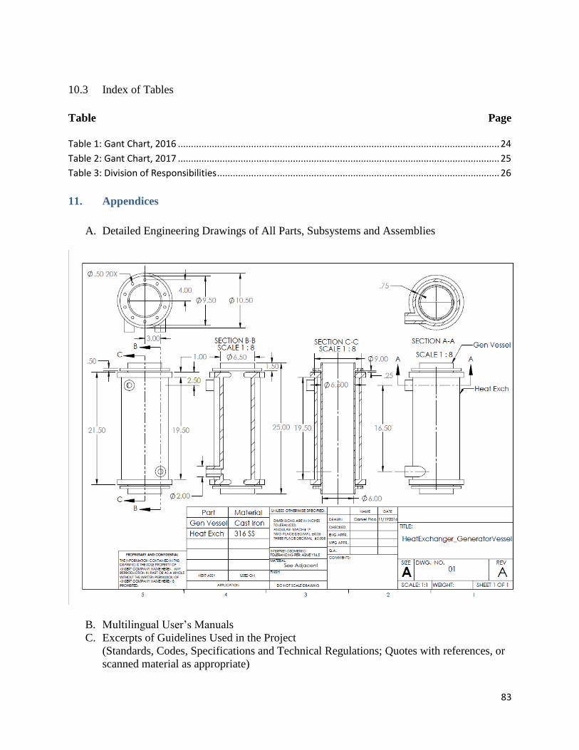
83
10.3 Index of Tables
Table Page
Table 1: Gant Chart, 2016 ........................................................................................................................... 24
Table 2: Gant Chart, 2017 ........................................................................................................................... 25
Table 3: Division of Responsibilities ............................................................................................................ 26
11. Appendices
A. Detailed Engineering Drawings of All Parts, Subsystems and Assemblies
B. Multilingual User’s Manuals
C. Excerpts of Guidelines Used in the Project
(Standards, Codes, Specifications and Technical Regulations; Quotes with references, or
scanned material as appropriate)
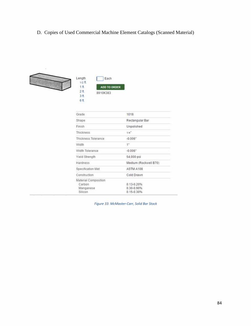
84
D. Copies of Used Commercial Machine Element Catalogs (Scanned Material)
Figure 33: McMaster-Carr, Solid Bar Stock

85
Figure 34: Hardware, Nuts
Figure 35:Hardware, Bolts
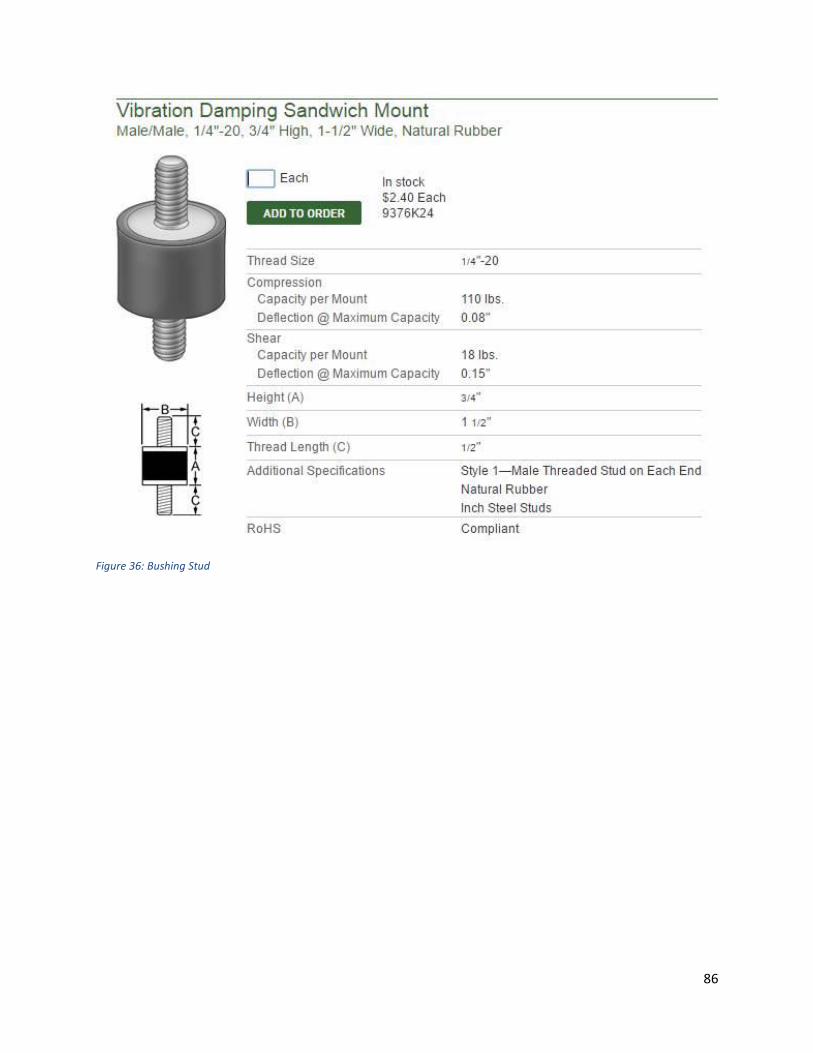
86
Figure 36: Bushing Stud

87
Figure 37: Dampening Mounts
E. Detailed Raw Design Calculations and Analysis (Scanned Material)
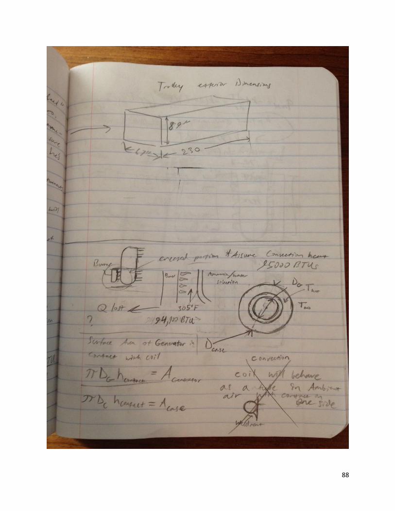
88

89
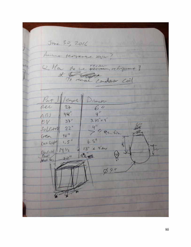
90
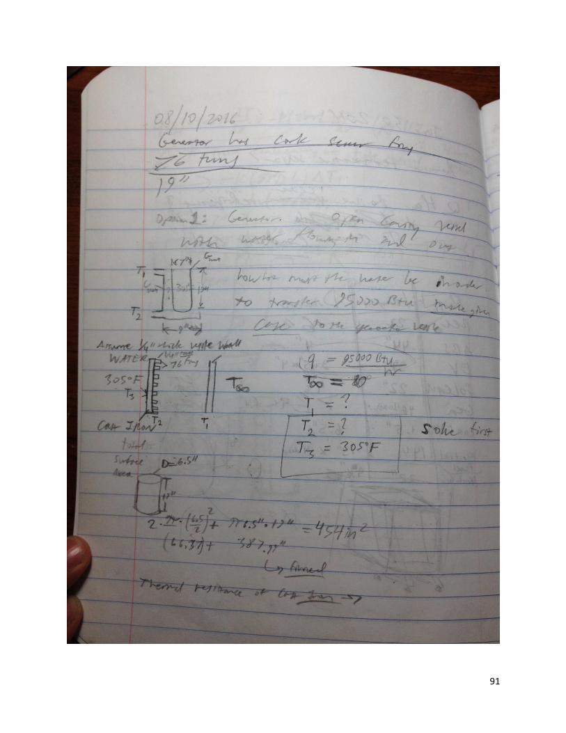
91
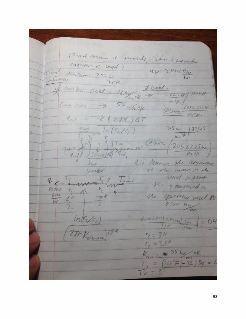
92
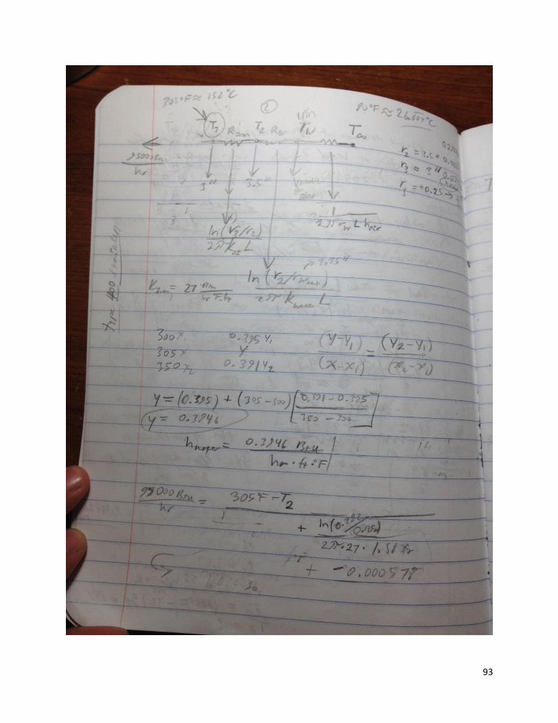
93

94

95

96
12. Project Photo Album