Solar Sail Project AEM 4332W – Spacecraft Design
71
Eric Blake Jon Braam Raymond Haremza Michael Hiti Kory Jenkins Daniel Kaseforth Brian Miller Alex Ordway Casey Shockman Lucas Veverka Megan Williams (Team Lead) Solar Sail Project AEM 4332W – Spacecraft Design Preliminary Design Review March 28, 2007
-
Upload
valdemar-astrid -
Category
Documents
-
view
37 -
download
6
description
Solar Sail Project AEM 4332W – Spacecraft Design. Preliminary Design Review March 28, 2007. Eric Blake Jon Braam Raymond Haremza Michael Hiti Kory Jenkins Daniel Kaseforth Brian Miller Alex Ordway Casey Shockman Lucas Veverka Megan Williams (Team Lead). Team Organization. - PowerPoint PPT Presentation
Transcript of Solar Sail Project AEM 4332W – Spacecraft Design

Eric BlakeJon BraamRaymond HaremzaMichael HitiKory JenkinsDaniel KaseforthBrian MillerAlex OrdwayCasey ShockmanLucas VeverkaMegan Williams (Team Lead)
Solar Sail Project AEM 4332W – Spacecraft
Design
Preliminary Design ReviewMarch 28, 2007

AEM 4332W - Solar Sail 2
Team Organization
• Systems Integration & Management: Megan Williams
• Orbit Control: Eric Blake, Daniel Kaseforth, Lucas Veverka
• Structures: Jon Braam, Kory Jenkins• Attitude Control: Brian Miller, Alex
Ordway• Communications: Casey Shockman• Thermal: Raymond Haremza• Power: Michael Hiti
AEM 4332W - Solar Sail 3
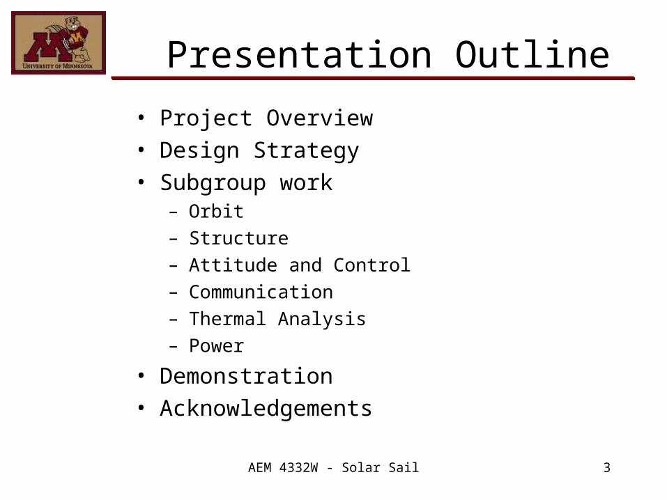
Presentation Outline
• Project Overview• Design Strategy• Subgroup work
– Orbit– Structure– Attitude and Control– Communication– Thermal Analysis– Power
• Demonstration• Acknowledgements

AEM 4332W - Solar Sail 4
Project Overview
Top Level Requirements• The payload mass is 34 kg • The payload average power draw is
24.5 Watts • The final orbit should have a semi-major
axis of 0.48 AU and an inclination of 60 deg
• The launch vehicle will provide a hyperbolic escape velocity of 0.5 km/s. A Delta II 7425 will be used for launch.
• The structure will fit inside the selected launch vehicle.

AEM 4332W - Solar Sail 5
Project OverviewMAJOR TASKS1) Develop control law for semi-major axis change and inclination
change to determine solar sail orientation. 2) Analyze transfer time for different sail sizes to determined
optimum sail size. 3) Conduct a trade study between sliding mass and tip thruster
attitude control systems.4) Determine the data transfer rate and power requirements for
data downlinks to Earth. Assume 2 downlinks per week to the DSN.
5) Conduct a trade study between conformal solar array and normal-pointing solar array.
6) Size the solar array to meet total power requirements.7) Analyze the thermal properties of the solar sail spacecraft.8) Choose a configuration and compute the total mass and
moment of inertia.9) Design a payload module.10) Design for the satellite actuation.11) Calculation and testing of attitude control law.

AEM 4332W - Solar Sail 6
Project OverviewOrbit• Non-Keplarian orbit
– Inclination 60°– Semi-major axis 0.48AU
Structure• Target mass: 500 kg• Sail size: 100m x 100m• Inflatable boom structure, heated curingAttitude Control• Sliding mass configuration with secondary tip thruster control• Interstellar compass – primary ADS Communications• Ka-Band (32 GHz) Horn antennaeThermal• Carbon mesh sail material• Multifunctional Structure (MFS) configurationPower• Power Requirements approximately 878 W• Normal Pointing Solar Array area: 2.39 meters• Silver-Cadmium (Ad-Cd) battery mass: 13.92 kg
AEM 4332W - Solar Sail 7
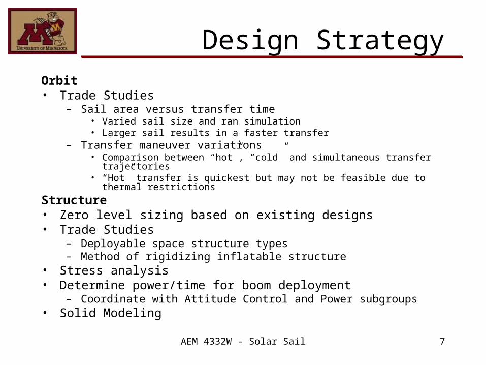
Design StrategyOrbit• Trade Studies
– Sail area versus transfer time• Varied sail size and ran simulation• Larger sail results in a faster transfer
– Transfer maneuver variations• Comparison between “hot”, “cold” and simultaneous transfer
trajectories• “Hot” transfer is quickest but may not be feasible due to thermal
restrictions
Structure• Zero level sizing based on existing designs• Trade Studies
– Deployable space structure types– Method of rigidizing inflatable structure
• Stress analysis• Determine power/time for boom deployment
– Coordinate with Attitude Control and Power subgroups• Solid Modeling

AEM 4332W - Solar Sail 8
Design StrategyAttitude Control• Trade Study
– Sliding mass vs Tip thruster ACS• Simulink modelingCommunication• Researched communication devicesThermal• Trade Study
– Solar Sail material: Mylar vs Carbon fiber mesh• Research into thermal management of spacecraftPower• Zero level sizing for power requirements• Trade Study
– Normal vs. Conformal Solar Array• Solar Array sizing• Battery sizing
AEM 4332W - Solar Sail 9
Orbit Control
Eric Blake (Simulation)Daniel Kaseforth (Control Law –Simulation
)Lucas Veverka (Control Law – Orbits)
AEM 4332W - Solar Sail 10
Orbit Control
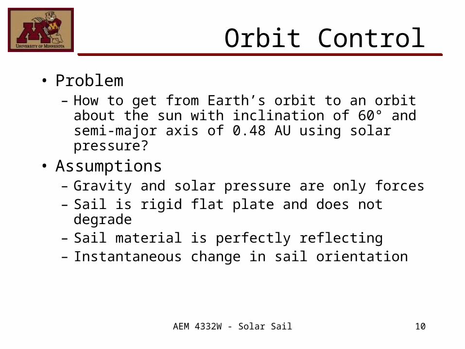
• Problem– How to get from Earth’s orbit to an orbit
about the sun with inclination of 60° and semi-major axis of 0.48 AU using solar pressure?
• Assumptions– Gravity and solar pressure are only forces– Sail is rigid flat plate and does not degrade– Sail material is perfectly reflecting– Instantaneous change in sail orientation

AEM 4332W - Solar Sail 11
Orbit Control• Technical flow of work
– Simulation• Two-body force interaction (Sun, spacecraft)
– Force of gravity
– Force of Solar pressure
2r
mGMF satsun
grav
sailsolar Ar
rcF
2
00
AEM 4332W - Solar Sail 12
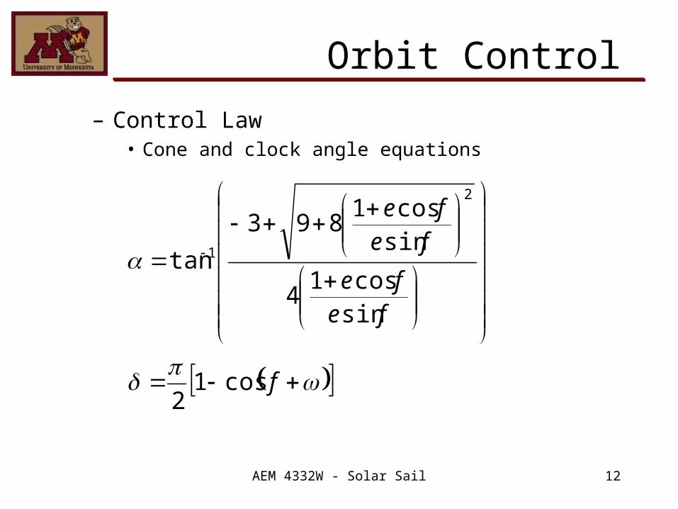
Orbit Control
– Control Law• Cone and clock angle equations
f
fefe
fefe
cos12
sincos1
4
sincos1
893
tan
2
1
AEM 4332W - Solar Sail 13
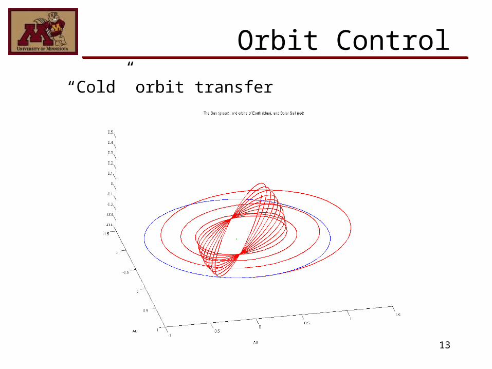
Orbit Control
“Cold” orbit transfer

AEM 4332W - Solar Sail 14
Orbit Control
Orbital elements

AEM 4332W - Solar Sail 15
Orbit Control
• Conclusions– Simulation works– Control law functions as desired
• Recommendations for further work– Sail shape analysis– Optimize transfer trajectory– Simulate sail degradation effects
AEM 4332W - Solar Sail 16
Orbit Control
• FDR Presentation– Discuss control law and simulation
assumptions.– Discuss possible transfer orbits.– Show simulation results.– Justify selected transfer orbit.– Discuss further work.

AEM 4332W - Solar Sail 17
Structural Design
Jon BraamKory Jenkins

AEM 4332W - Solar Sail 18
Solar Sail Structure and Deployment
Challenge:
Design a deployable structure to support the sail and deliver a scientific payload.
Solution:
The sail support structure consists of four inflatable, rigidizable booms attached to a payload module.
Based on L’Garde solar sail demonstrator design.

AEM 4332W - Solar Sail 19
Aluminum Module
• Aluminum Unistrut– Ti Weld
• Unistrut Washer• Titanium Hardware• Rubber Washer
– Vibration Damping
AEM 4332W - Solar Sail 20
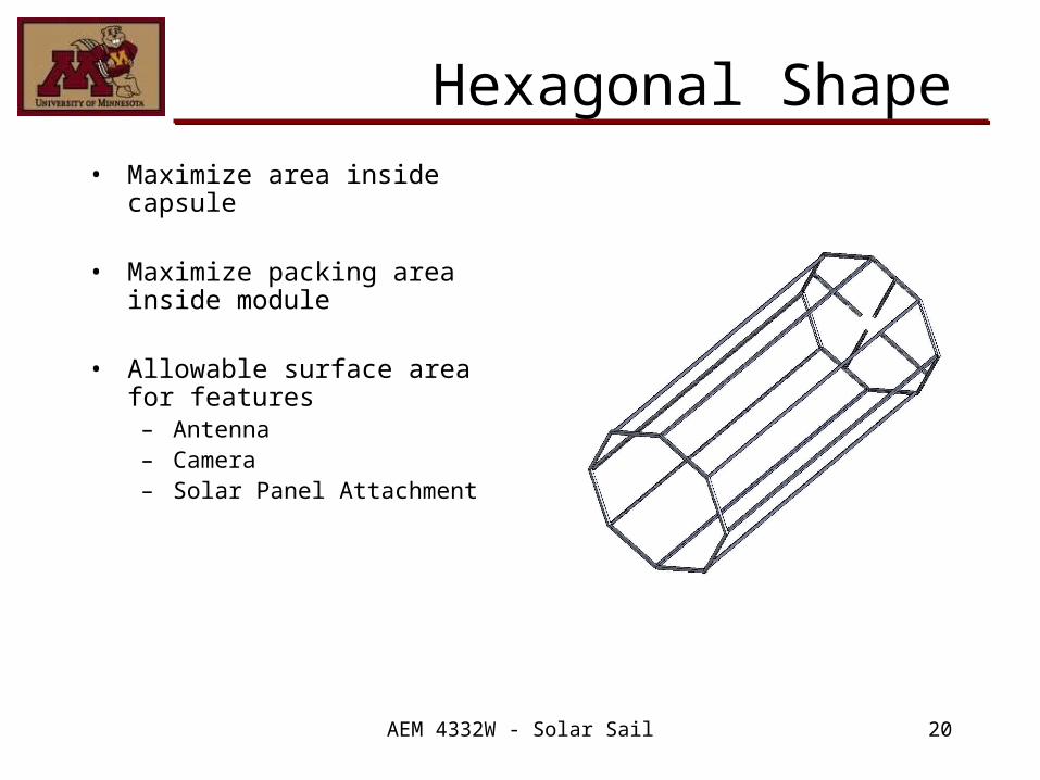
Hexagonal Shape• Maximize area inside
capsule
• Maximize packing area inside module
• Allowable surface area for features– Antenna– Camera– Solar Panel Attachment

AEM 4332W - Solar Sail 21
Sail Mount
• Hexagonal Shape– Mounting– Strength
• FEA– Add Gussets– Starburst Mount
» Add connections
• Center Hole– Routing
• Wiring• Propellant

AEM 4332W - Solar Sail 22
Boom Geometry• Packing constraints require
tapered geometry.• Laminate thickness t = 0.25
mm. • r = 10 cm.• R = 16 cm.• l = 30 cm.• n = number of folds.• L = 72 m. • Mass ≈ 20 Kg/boom
R = r + t ( l/L)

AEM 4332W - Solar Sail 23
Estimate Worst Case Loading
Assumptions:• Solar Pressure at 0.48 AU =
19.8 µN/m^2.• Tip thruster forces of 150 µN.• Worst case force = 0.05 N.• Deployment load of 20 N in
compression. • Thin wall tubes.• Sail quadrant loading is evenly
distributed between 3 attachment points.
• Quadrant area 2500 m^2.• Homogeneous material
properties.• Safety factor of 3.

AEM 4332W - Solar Sail 24
Boom Material
• [0/90] carbon fiber laminate.• Polymer film inflation gas barrier.• IM7 carbon fiber, E = 276 GPa.
– Low CTE.• TP407 polyurethane matrix, E = 1.3 GPa.
– Tg = 55 degrees C.
mmffL EVEVE 1
m
m
f
fT E
V
E
VE mmffc VV

AEM 4332W - Solar Sail 25
0 10 20 30 40 50 60 70 800
200
400bending stress
x (m)
stre
ss (
KP
a)
0 10 20 30 40 50 60 70 800
200
400buckling
x (m)
P c
ritic
al (
N)
0 10 20 30 40 50 60 70 800.5
1
1.5shear
x (m)
She
ar S
tres
s (K
Pa)
0 10 20 30 40 50 60 70 800.5
1
1.5max inflation pressure
x (m)
burs
t pr
essu
re (
MP
a)
• Expected deployment loads of 20 N in compression dictate boom sizing.• Conclusion: Booms sized to meet this requirement easily meet other criteria.

AEM 4332W - Solar Sail 26
Deployment• Booms heated to 75 degrees C.• Inflation gas pressurizes booms
for deployment.• Booms rigidize as they cool to
Sub-Tg (glass transition) temperatures.
• Deployment speed is controlled by a single motor which pays out the tensioning cables at 1 cm/sec.
• Motor retracts tension cables after booms are rigidized to pull out the sail.

AEM 4332W - Solar Sail 27
Deployed Boom with Micro PPT Tip Thrusters

AEM 4332W - Solar Sail 28
Future Work and FDR Deliverables
• Future Work:– Sliding mass
• Size• Placement
– Effects of structural deformation on attitude control.
– Investigate low frequency vibration modes.
– Volume of inflation gas needed.
– Proper laminate analysis.
FDR Deliverables: • Configuration: Solid Model
stowed and deployed• Total Mass/Moment of
inertia• Deployment Methodology• Structural Analysis

AEM 4332W - Solar Sail 29
Attitude Control
Alex OrdwayBrian Miller
AEM 4332W - Solar Sail 30
Attitude Control
• Detailed description of trade study– Sliding Mass characteristics
• Power consumption– 10 W
• Approximate control torques– Being calculated; will be sufficient
• Mass required– 10 kg, open for refinement
– Tip thruster characteristics• Power Consumption
– 100 W• Mass required
– 10 kg
AEM 4332W - Solar Sail 31
Attitude Control
• Detailed description of ACS• Primary use of sliding mass• Tip thrusters utilized as secondary ACS• Configuration chosen for a number of reasons
– Thrusters require more power to operate (~1kw)– Ion ejection from ions could interfere with solar
arrays– Operational life of thrusters limited to 3000 hours
• Sliding mass offers comparable transfer times without aforementioned drawbacks
• Tip thrusters chosen offer smaller force at lower power usage, no significant life restrictions, lower probability of system interference
AEM 4332W - Solar Sail 32
Attitude Control
Detailed description ACS cont…– Tip Thruster Selection
• Micro Plasma Pulsed Thruster (Micro PPT)– Solid polymer fuel bar
» Eliminates need for auxiliary fuel transport infrastructure
– Can be utilized in off-nominal attitude situations in addition to being an available ACS when the solar sail is not deployed

AEM 4332W - Solar Sail 33
Attitude Control
ADS• Primary
– Interstellar Compass (ISC)• Low power
– 3.5 W
• Exceptional Accuracy– 0.1 deg (1σ)
• Low mass– 2.5 kg
– Technology has not flown• Developed by Draper Laboratory

AEM 4332W - Solar Sail 34
Attitude Control
ADS• Secondary
– Sun Sensors• Located on all solar oriented exterior planes• Reorient space craft in off-nominal attitude
situations• Provide data to orient solar arrays for optimal
solar collection
AEM 4332W - Solar Sail 35
Future Work
• Finish attitude control simulation• Calculate final required mass for ACS• Refine simulation using information from
structures group• Consider sail ejection once orbit is achieved
– Independent module ACS» Reaction wheels most likely candidate

Communications
Casey Shockman
AEM 4332W - Solar Sail 37
Frequency
• X-Band: 8.4 GHz– This is the typical frequency used, so DSN is
becoming overloaded at this frequency.
• Ka-Band: 32 GHz– Due to overloaded X-Band frequency, the
DSN is migrating to Ka-Band frequency.– Can transfer data much more quickly than
X-Band.
AEM 4332W - Solar Sail 38
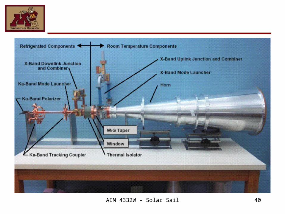
Antenna
• Horn– High data transfer rate with low power
required.– Works directly with recently developed
Small Deep Space Transponder.– New design works with X-Band and Ka-Band
transmit as well as X-Band receive.– Lighter and smaller than parabolic reflector
or array. – High gain.

AEM 4332W - Solar Sail 39
AEM 4332W - Solar Sail 40

AEM 4332W - Solar Sail 41
Current/Future Work
• Currently, I am working on a design space to optimize values for power required, antenna sizing, pointing accuracy, and signal to noise ratio.
• Problems include finding accurate equations for horn antenna systems.

AEM 4332W - Solar Sail 42
Thermal Analysis
Raymond Haremza

AEM 4332W - Solar Sail 43
Carbon Fiber Mesh
• Carbon Fiber Mesh developed by ESLI
• Mesh is composed of a network of carbon fibers crisscross linked into a matrix that is mostly empty space.
• 200 times thicker than the thinnest solar sail material, but so porous that it weighs the same

AEM 4332W - Solar Sail 44
Common Problems
• Traditional materials – tear easily– require heavy support structure to maintain
tension– can build up static electricity– UV degrades and melt at high temperatures

AEM 4332W - Solar Sail 45
Carbon Fiber Mesh
• Can tolerate temps as high as 4,500 deg F• Small areal mass density: 30μm thickness
compared to 2μm with same area density (~5g/m^2)
• Immune to UV degradation • Ability to self-deploy, the carbon scrub-pad
material could be packed so it pops out flat once released. This can eliminate the need for any complicated mechanical deployment mechanism, which decrease mass of the craft.
• Easier to deploy because it doesn’t cling or wrinkle
• Higher Melting Point

AEM 4332W - Solar Sail 46
Carbon Fiber vs. Traditional Material
Fz A0 E inc 20.8N
Using sample microtruss which is formedfrom perfectly electrical conducting (PEC) wires. The time-average force on the sailcan be found using physical optics assumingmicrotruss is illuminated by a uniform planewave (UPW) and
E inc 3kV /m
Carbon Fiber Aluminum Coated Mylar
0.00E+00
5.00E-02
1.00E-01
1.50E-01
2.00E-01
2.50E-01
3.00E-01
3.50E-01
4.00E-01
7.00E+109.00E+101.10E+111.30E+111.50E+11
Distance From Sun
Forc
e (
N)
Force at 0.48AU = 0.348N
0 8.89 10 12
AEM 4332W - Solar Sail 47
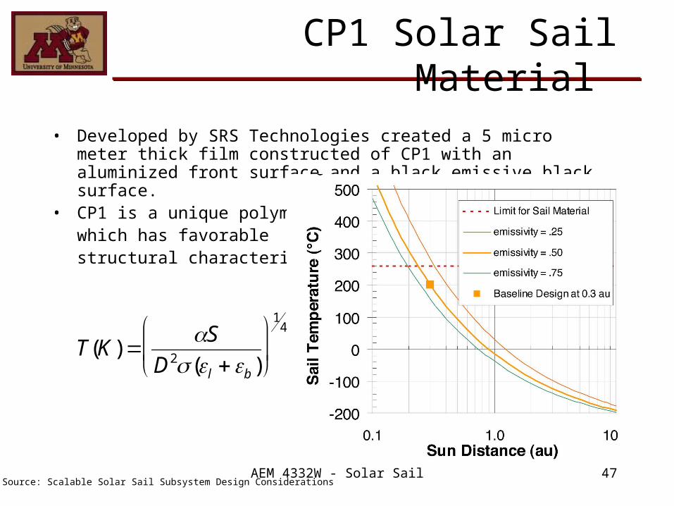
CP1 Solar Sail Material
• Developed by SRS Technologies created a 5 micro meter thick film constructed of CP1 with an aluminized front surface and a black emissive black surface.
• CP1 is a unique polymer which has favorable structural characteristics.
T(K) S
D2(l b )
14
Source: Scalable Solar Sail Subsystem Design Considerations

AEM 4332W - Solar Sail 48
Thermal Analysis of Payload Module
• Found an innovative way to configure spacecraft parts which eliminate chassis, cables and connectors.
• MFS (Multifunctional Structures) achieves this by using MCM (multichip modules) and dissipating its heat through a thermal core fill, and utilizing aluminum honeycomb sandwiched between 2 fiber reinforced cyanate ester composite faceplates.
• This high density configuration increases payload-mass fraction and provides major weight volume and cost savings.

AEM 4332W - Solar Sail 49
MFS Configuration
Thermal copper strap used to transfer heat to radiator surface.
Multichip Module -Specialized electronic package where multipleintegrated circuits are packaged to do many jobs with onemodule.
Hi-K facesheets(K13C2U)
Aluminum Honeycomb
Edge corefill
High Conductivity FillerKz = 700 W/mK
High K Isotropic Carbon-Carbon Doubler
Kz

AEM 4332W - Solar Sail 50
Thermal Control of MFS
• In order to dissipate waste heat from the MCM along with solar energy loads on the outer skin.
Q AS(TR4 TS
4 )
Q KAx (Tbp TR )
L
T bpL
KAx
As (TR4 TS
4 ) TR
Q
Radiation Equation
Lateral Conductance
Setting equal and solving for temp of baseplate yields
K
Ax
TR
L
TS
Tbp
Rate of heat flow
Effective rad environment
Emissivity of radiator
Temp of base plate
Heat flow path length
Average radiator temp
Cross sectional area
Material thermal conductivity
AEM 4332W - Solar Sail 51
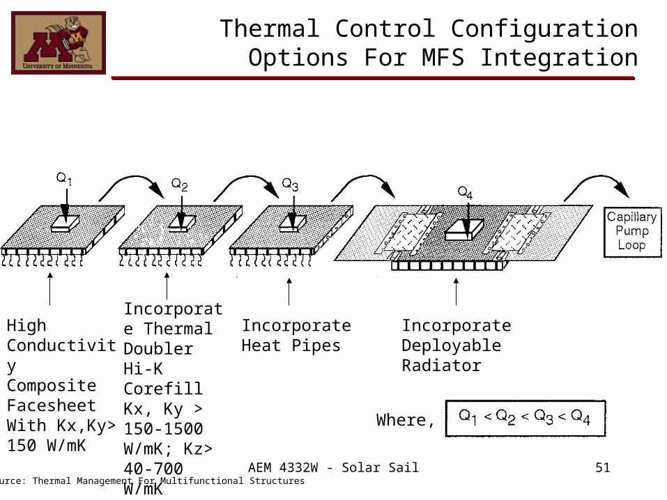
Thermal Control Configuration Options For MFS Integration
High ConductivityComposite FacesheetWith Kx,Ky>150 W/mK
Incorporate Thermal Doubler Hi-K Corefill Kx, Ky > 150-1500 W/mK; Kz> 40-700 W/mK
Incorporate Heat Pipes
Incorporate Deployable Radiator
Where,
Source: Thermal Management For Multifunctional Structures

AEM 4332W - Solar Sail 52
Confirmation of MFS
• The Multifunctional Structure was successful based on the data returned from the Deep Space 1 mission. This mission the MFS was tested by powering it up once every two weeks which provided a data set containing health and status information, electrical-conductivity test data, and thermal-gradient measurements. The thermal-gradient data proved to stay within operating conditions.

AEM 4332W - Solar Sail 53
Thermal Analysis of Boom Supports
• Carbon fiber booms need to maintain temperatures below 40 deg C.
• To achieve this a coating will be applied to the outside of the carbon fiber.
• By using the radiation equation and basic thermodynamics the required coefficient of absorbtivity, emmisivity can be found that satisfy these constraints. From these coefficients a coating can be chosen.

AEM 4332W - Solar Sail 54
Thermal Properties of Carbon Fiber Boom
Ý Q rad
Carbon fiber properties:R=13 cmThickness = .25mmLength = 72 mK = 400 W/mDensity = 1490 kg/m^3
Intensity 4 *1026W
4 (.48AU)9594.12
W
m2
TS 89801SAS
1/ 4
Qsun Intensity * * A 89801
Qrad ASS (TS4 TR
4 )
Setting equal to each other and solving for temperature of the surface of the boom yields:
TS
t
R
Surface Temp vs Absortivity and Emmissivity
0
0.2
0.4
0.6
0.8
1
1.2
0 200 400 600 800
Surface Temp of Boom (K)
Em
msiv
ity a
nd
Ab
sort
ivit
y
Emmisivity
Absortivity
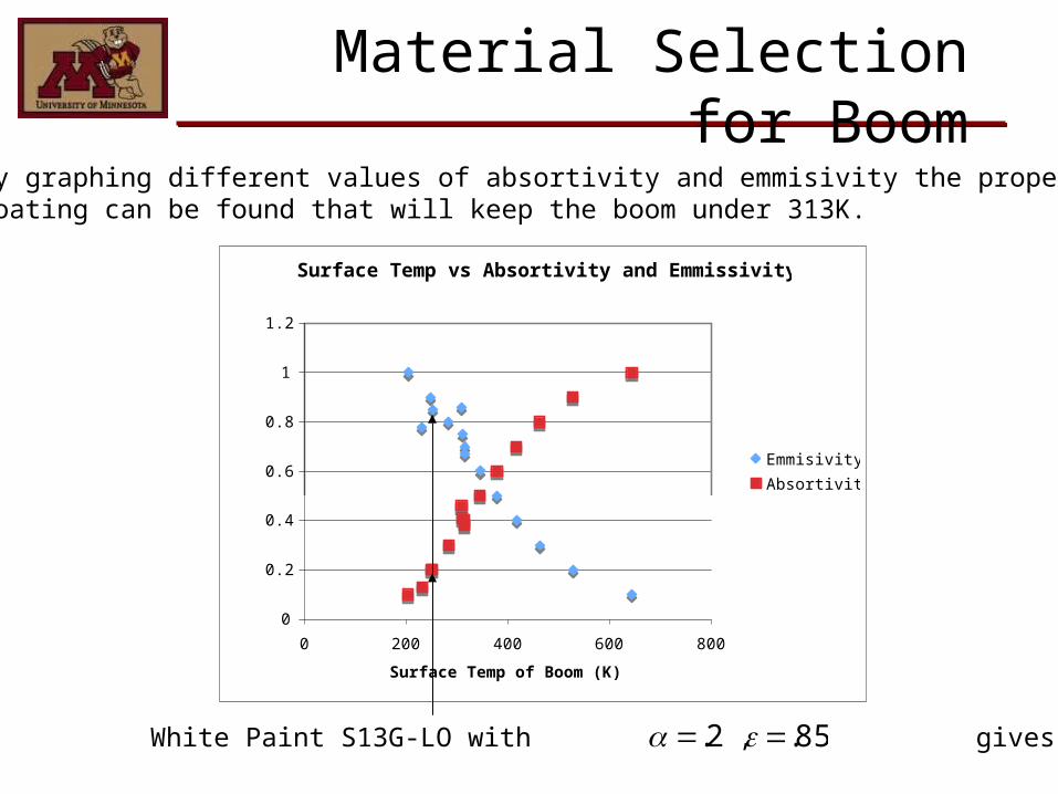
Material Selection for Boom
By graphing different values of absortivity and emmisivity the proper Coating can be found that will keep the boom under 313K.
White Paint S13G-LO with , gives T =252K
.2
.85

AEM 4332W - Solar Sail 56
Surface Temp vs Absortivity and Emmissivity
0
0.2
0.4
0.6
0.8
1
1.2
0 200 400 600 800
Surface Temp of Boom (K)
Em
msiv
ity a
nd
Ab
sort
ivit
y
Emmisivity
Absortivity
Material Selection for Boom
By graphing different values of absortivity and emmisivity the proper coating can be found that will keep the boom under 313K.
White Paint (S13G-LO) with , gives T =252K
.2
.85

AEM 4332W - Solar Sail 57
Future Work
• I plan on further investigating and analyzing the spacecraft components such as the fuel tank, additional thermal control methods, and complete analysis of MFS integration into the spacecraft configuration.
• Also working together with orbit group to run simulations with Aluminized Mylar, Kapton Carbon Fiber, and CP1 solar sails and find best material for our mission.

Power
Michael Hiti

AEM 4332W - Solar Sail 59
Objectives
• Determine the amount of power required to support the payload, and all other components of the spacecraft.
• Perform a trade study to determine whether to use a normal-pointing solar array or a fixed solar array.
• Determine the size and type of the solar array
• Determine the size and type of the batteries that will be used

AEM 4332W - Solar Sail 60
Power Requirements
• BOL Power Requirement : ~878W
• EOL Power Requirement: ~ 203W
Power (W)
Remote Sensing Instruments
Coronagraph 4
All Sky Camera 5
EUV Imager 6
Magnetograph-Helioseismograph 4
IN-SITU Instruments
Magnetometer 2
Solar Wind Ion Composition and Electron Spectrometer 3.5
Energetic Particle 3
CommunicationsSatellite/Data Transmission 50
Attitude Control 125
Structure Heat Curing Booms 675
MiscSliding Mass, Adjusting Array/Satellite/Antenna 50
TOTAL 877.5

AEM 4332W - Solar Sail 61
Normal Pointing Solar Array
• Benefits:– A fold out array can be used to utilize its
reflectance and thermal characteristics for thermal management
– A sun tracker will already be being used– Able to collect maximum possible solar
energy– Panels could be positioned to minimize
thermal and radiation damage

AEM 4332W - Solar Sail 62
Solar Array Sizing
General Formulas:
Pchg = Vchg* Ichg = (Vchg* Cchg)/15h
PEOL = PL + Pchg
PEOL = ηrad* ηangle* ηtemp* PBOL
Aarray = PBOL / (ηGaAs* IS * ηpack)
AEM 4332W - Solar Sail 63
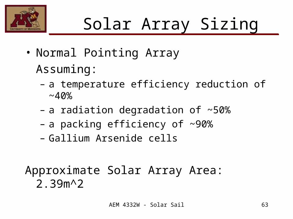
Solar Array Sizing
• Normal Pointing ArrayAssuming:– a temperature efficiency reduction of ~40%– a radiation degradation of ~50%– a packing efficiency of ~90%– Gallium Arsenide cells
Approximate Solar Array Area: 2.39m^2
AEM 4332W - Solar Sail 64
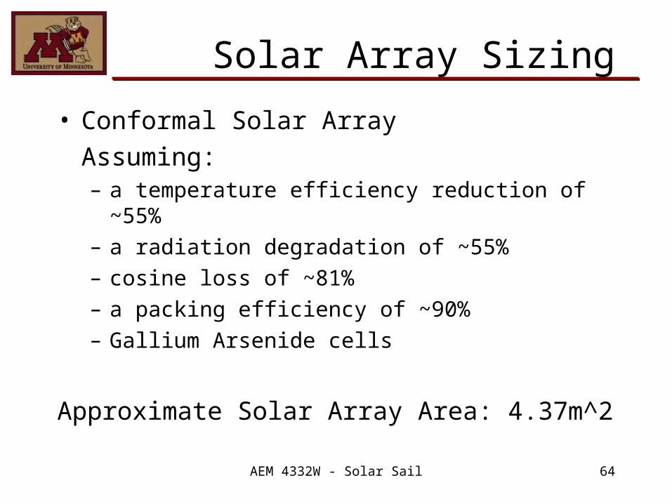
Solar Array Sizing
• Conformal Solar ArrayAssuming:– a temperature efficiency reduction of ~55%– a radiation degradation of ~55%– cosine loss of ~81%– a packing efficiency of ~90%– Gallium Arsenide cells
Approximate Solar Array Area: 4.37m^2
AEM 4332W - Solar Sail 65
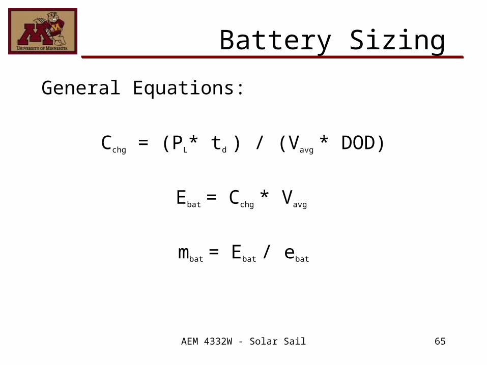
Battery Sizing
General Equations:
Cchg = (PL* td ) / (Vavg * DOD)
Ebat = Cchg * Vavg
mbat = Ebat / ebat

AEM 4332W - Solar Sail 66
Battery Sizing
• Ag-Cd batteries will be used for their reasonable energy density and cycle life
• Assuming:– a bus voltage of 28V– a DOD of ~25%– a maximum load duration of 2.0h
Battery Mass = 13.92 kg
AEM 4332W - Solar Sail 67
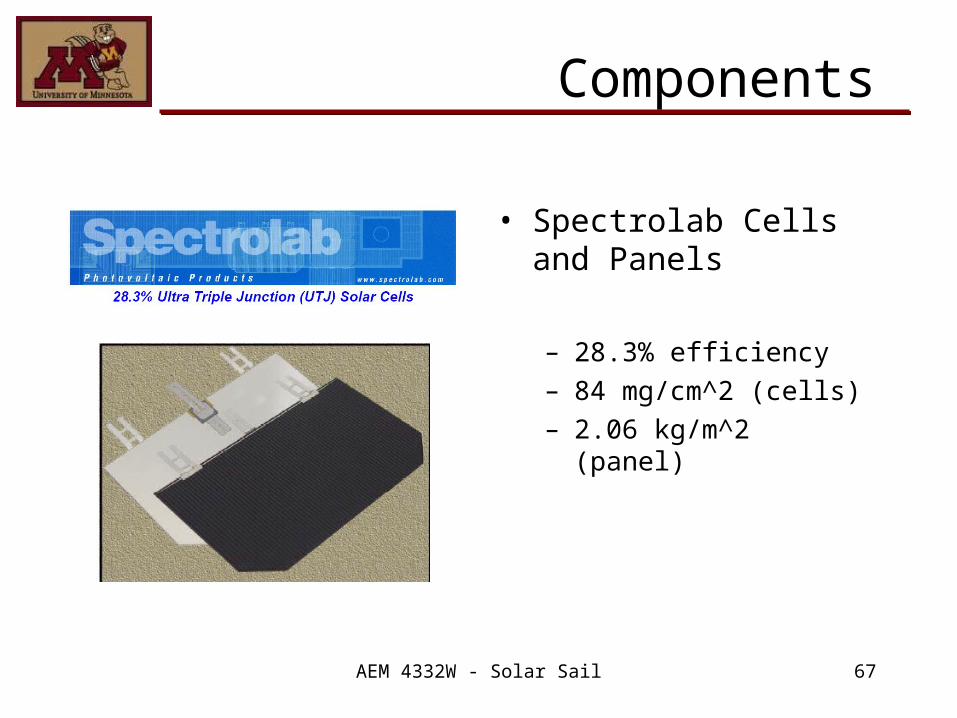
Components
• Spectrolab Cells and Panels
– 28.3% efficiency– 84 mg/cm^2 (cells)– 2.06 kg/m^2 (panel)

AEM 4332W - Solar Sail 68
Components
• Moog Solar Array Drives
– Two-axis solar array drive
– Power = 4W per axis– Mass = 4.2 kg

AEM 4332W - Solar Sail 69
Future Work
• Refining sizing of battery and solar panel with more specific power requirements

AEM 4332W - Solar Sail 70
Demonstration
• For FDR, we plan to have a demonstrated orbit which includes pointing requirements and attitude control.

AEM 4332W - Solar Sail 71
Acknowledgements
• Stephanie Thomas, Princeton Satellite Systems
• Professor Joseph Mueller, University of Minnesota
• Professor Jeff Hammer, University of Minnesota
• Dr. William Garrard, University of Minnesota
• Kit Ruzicka, University of Minnesota