SOLAR POWERED MICRO MOUSE T. VINOD KUMAR A/L …eprints.utar.edu.my/642/1/3E-2012-0707514-1.pdf ·...
104
SOLAR POWERED MICRO MOUSE T. VINOD KUMAR A/L K. THANASAMY A project report submitted in partial fulfilment of the requirements for the award of Bachelor of Engineering (Hons.) Electrical & Electronic Engineering Faculty of Engineering and Science Universiti Tunku Abdul Rahman September 2012
Transcript of SOLAR POWERED MICRO MOUSE T. VINOD KUMAR A/L …eprints.utar.edu.my/642/1/3E-2012-0707514-1.pdf ·...

SOLAR POWERED MICRO MOUSE
T. VINOD KUMAR A/L K. THANASAMY
A project report submitted in partial fulfilment of the
requirements for the award of Bachelor of Engineering
(Hons.) Electrical & Electronic Engineering
Faculty of Engineering and Science
Universiti Tunku Abdul Rahman
September 2012

ii
DECLARATION
I hereby declare that this project report is based on my original work except for
citations and quotations which have been duly acknowledged. I also declare that it
has not been previously and concurrently submitted for any other degree or award at
UTAR or other institutions.
Signature : _________________________
Name : T. VINOD KUMAR A/L K. THANASAMY
ID No. : 07UEB07514
Date : _________________________

iii
APPROVAL FOR SUBMISSION
I certify that this project report entitled “SOLAR POWERED MICRO MOUSE”
was prepared by T. VINOD KUMAR A/L K. THANASAMY has met the required
standard for submission in partial fulfilment of the requirements for the award of
Bachelor of Engineering (Hons.) Electrical & Electronic Engineering at Universiti
Tunku Abdul Rahman.
Approved by,
Signature : _________________________
Supervisor : Dr Balamuralithara A/L Balakrishnan
Date : _________________________

iv
The copyright of this report belongs to the author under the terms of the
copyright Act 1987 as qualified by Intellectual Property Policy of University Tunku
Abdul Rahman. Due acknowledgement shall always be made of the use of any
material contained in, or derived from, this report.
© 2012, T. Vinod Kumar A/L K. Thanasamy. All right reserved.

v
Specially dedicated to
my beloved family, lecturer, friends and those who have guided and inspired me
throughout my journey of education

vi
ACKNOWLEDGEMENTS
I would like to thank everyone who had contributed to the successful completion of
this project. I would like to dedicate my deepest appreciation to my research
supervisor, Dr Balamuralithara A/L Balakrishnan for his invaluable advice, guidance,
encouragement, critics, friendship and his enormous patience throughout the
development of the research.
In addition, I would also like to express my gratitude to my loving parents for
their moral support, love and encouragement given to me. I would also like to extend
my gratitude to my housemates and friends for their continuous moral support
throughout the research. Finally thanks to God, His blessing made it possible for the
completion of my research and more importantly my undergraduate degree.

vii
SOLAR POWERED MICRO MOUSE
ABSTRACT
The micro mouse, also called a small autonomous mobile robot, which the goal is to
navigate through an unknown maze and locate the centre. The overall capability of
micro mouse are judged by the time it takes them to locate the centre. In this project,
the Solar Powered Micro Mouse is developed to run using solar energy as its primary
source to solve the maze. The components that are being used in this project are
power, sensors, control, and drive train. The power system consists of 3 solar panels
and a rechargeable battery pack in the circuit. The sensors are the means through
which the micro mouse detects walls and traverses the maze with proper alignment in
the centre of a pathway. The drive train includes the motors and motor controller,
which produce the motion of the robot. The control unit is responsible for controlling
each of the other components. Finally, a modified wall following algorithm has been
developed to enable the micro mouse locate the centre of the maze, which is the main
aim of this project. Each of these parts in the project has undergone a thorough
process of design, analysis and component selection. The micro mouse is developed
to be powered by solar energy, which can be improved to solve unmanned tasks in
future. A Solar Powered Micro Mouse has been successfully built based on the initial
design, meeting the objectives of this project.

viii
TABLE OF CONTENTS
DECLARATION ii
APPROVAL FOR SUBMISSION iii
ACKNOWLEDGEMENTS vi
ABSTRACT vii
TABLE OF CONTENTS viii
LIST OF TABLES xi
LIST OF FIGURES xii
LIST OF SYMBOLS / ABBREVIATIONS xv
LIST OF APPENDICES xvii
LIST OF APPENDICES xvii
CHAPTER
1 INTRODUCTION 1
1.1 Introduction 1
1.2 Problem Statement 2
1.3 Project Aim and Objectives 3
1.4 Project Outline 4
1.5 Project Overview and Expected Outcome 5
1.6 Thesis Outline 6
2 LITERATURE REVIEW 7
2.1 Micro Mouse History 7

ix
2.2 Literature Review 9
2.3 Micro Mouse Algorithm 15
3 METHODOLOGY 18
3.1 Introduction 18
3.2 Components Selection 21
3.2.1 Solar Panel 21
3.2.2 LM358 IC 22
3.2.3 4013N IC 23
3.2.4 IRF9530 MOSFET 24
3.2.5 LM7805 Voltage Regulator 25
3.2.6 Transistor 2N3904 26
3.2.7 IR Transmit and Receive Sensors 27
3.2.8 PIC16F877A Microcontroller 28
3.2.9 L293 Motor Driver 29
3.2.10 PC817 Optocoupler 30
3.2.11 DC Motor 31
3.2.12 Line Following Sensor 32
3.3 Design of the Solar Powered Micro Mouse 33
3.3.1 Solar Charger Circuit 37
3.3.2 IR Sensor Circuit 41
3.3.3 The Solar Powered Micro Mouse Control Circuit 42
3.4 PIC Flow Chart 46
3.5 Maze Design 48
4 RESULTS AND DISCUSSIONS 49
4.1 Technical and Physical Features of the Solar Powered Micro
Mouse 49
4.2 The Route of the Robot Move In the Maze 50
4.3 Infrared Distance Testing 50
4.4 Discussion on the Robot Move inside the Real Maze with
Solar Panel 53

x
5 CONCLUSION AND RECOMMENDATIONS 60
5.1 Conclusion 60
5.2 Future Recommendations 61
REFERENCES 63
APPENDICES 67

xi
LIST OF TABLES
TABLE TITLE PAGE
3.1 Technical information about the solar panel used
in the project 21
3.2 Technical information about the LM358 IC 22
3.3 Technical information about 4013 IC 23
3.4 Technical information about the IRF9530 24
3.5 Technical information about the LM7805 voltage
regulator 25
3.6 Technical information about the 2N3904 transistor 26
3.7 Technical information about the IR transmit &
receive sensor 27
3.8 Technical information of PIC16F877A
microcontroller 28
3.9 Technical information about L293D motor driver 29
3.10 Technical information about the optocoupler 30
3.11 Technical information of DC motor 31
3.12 Technical information about the line sensor 32
3.13 The control of the robot motion from the L293
motor driver 44
4.1 Technical features of the Solar Powered Mouse 49
4.2 Testing with white paper 51

xii
LIST OF FIGURES
FIGURE TITLE PAGE
1.1 Flowchart of the Whole Planning for Project I & II 4
1.2 The Sketch of Micro Mouse 5
2.1 Micro Mouse Edgar 9
2.2 Cybernatic Mouse 11
2.3 Micro Mouse Quester 12
2.4 Micro Mice Moonlight Special, Moonlight Express
& Moonlight Flash 13
2.5 Micro Mouse Rooter 14
2.6 Wall Following Robot 14
2.7 General Basic Algorithm for Micro Mouse 16
3.1 Summary on Methodology to Complete the Solar
Powered Micro Mouse 18
3.2 Solar Panel 21
3.3 LM358 IC 22
3.4 4013N IC 23
3.5 IRF9530 Power MOSFET 24
3.6 LM7805 Voltage Regulator 25
3.7 2N3904 Transistor 26
3.8 IR Transmit & Receive Sensor 27
3.9 PIC16F877A Microcontroller 28

xiii
3.10 Motor Driver IC 29
3.11 PC817 Optocoupler 30
3.12 DC Motor 31
3.13 Line Sensor 32
3.14 Design of the Solar Powered Micro Mouse Circuit 33
3.15 The Working Mechanism of the Micro Mouse 35
3.16 Operation of Micro Mouse without using Solar
Energy 36
3.17 Solar Charger Circuit 37
3.18 Simulation Result for the Solar Charger 40
3.19 IR Sensor 41
3.20 The Solar Powered Micro Mouse Control Circuit 42
3.21 Waveform to Control the Motion of the Robot 45
3.22 PIC Program Flow Chart to Control the Mouse
Motion 46
3.23 Maze Design 48
4.1 Front & Side View of Solar Powered Micro Mouse 49
4.2 The Robot Route inside the Maze 50
4.3 Voltage vs Distance Graph 52
4.4 Picture of Micro Mouse Solving Maze Part 1 53
4.5 Picture of Micro Mouse Solving Maze Part 2 53
4.6 Picture of Micro Mouse Solving Maze Part 3 54
4.7 Picture of Micro Mouse Solving Maze Part 4 54
4.8 Picture of Micro Mouse Solving Maze Part 5 55
4.9 Picture of Micro Mouse Solving Maze Part 6 55
4.10 Picture of Micro Mouse Solving Maze Part 7 56

xiv
4.11 Picture of Micro Mouse Solving Maze Part 8 56
4.12 Picture of Micro Mouse Solving Maze Part 9 57
4.13 Picture of Micro Mouse Solving Maze Part 10 57
4.14 Picture of Micro Mouse Solving Maze Part 11 58

xv
LIST OF SYMBOLS / ABBREVIATIONS
PCB – Printed Circuit Board
PWM – Pulse Width Modulator
MOSFET – Metal-Oxide-Semiconductor Field-Effect Transistor
EMI – Electromagnetic Interference
SMD – Surface Mount Device
IEEE – Institute of Electrical and Electronics Engineers
US – United States
IR – Infrared
DC – Direct Current
AC – Alternating Current
PIC – Peripheral Interface Controller
USA – United States of America
CCD – Charge-Coupled Device (type of image sensor)
UK – United Kingdom
Ni-MH – Nickel-Metal Hydride
Ni-Cad – Nickel-Cadmium
RC – Resistance-Capacitance
PN –Positive Negative Junction
DPDT – Double Pole Double Throw
SPST – Single Pole, Single Throw
EEPROM – Electrically Eraseable Programmable Read Only Memories
Vss – Voltage Source Source
LCD – Liquid Crystal Display
Vdd – Voltage Drain Drain
Vcc – Voltage Collector Collector
k – Kilo
– Micro

xvi
LED – Light-Emitting Diode
m – Mili
CMOS – Complementary Metal Oxide Semiconductor
p – Pico
F – Farad
A – Ampere
V – Voltage
W – Watt
Wh – Watt per hour
BJT – Bipolar Junction Transistor
RDS – Resistance Drain Source
EMF – Electromagnetic Field
NPN – Negative - Positive - Negative
IC – Integrated Circuit
MCUs – Microcontroller Unit

xvii
LIST OF APPENDICES
APPENDIX TITLE PAGE
APPENDIX A: PIC Program Coding 67
APPENDIX B: RC Servo Motor-C36R 73
APPENDIX C: Microcontroller-PIC16F877A 76
APPENDIX D: Line Following Sensor 78
APPENDIX E: IR Transmitter & Receiver Sensor 81
APPENDIX F: PCB 85

1
CHAPTER 1
INTRODUCTION
1.1 Introduction
Autonomous robots have wide reaching applications, from bomb sniffing to find
humans in wreckage to human automation. For many years, engineers have been
facing power and reliable sensing mechanism problems in unfamiliar terrains robotic
competitions which have inspired in the development of new technology to
overcome those issues. Competitions are being held all around the world based on
autonomous robots. One of the competitions with the richest history is the micro
mouse. In May 1977, the micro mouse was introduced to the world. IEEE Spectrum
Magazine came up with the concept of a self-contained robot that navigates through
a complicated maze (IEEE Micromouse Competition Rules, 2007).
The micro mouse competition has now become a famous event which is held
in different colleges around the world. The same rules applied at each event.
Contestants are given 15 minutes to solve the maze by using the micro mouse to
locate the centre. Little is known about the maze before the competition begins. The
maze is a squared shaped; 12 feet x 6 feet element structure where each element is 30
cm x 30 cm. The side of the walls are painted white and the top of the wall is red.
The dimensions of the walls are 10 cm high and 1.3 cm thick. This gives a 28.8 cm x
28.8 cm passageway between the walls. The final destination is the centre of the
maze and the initial point is from any one of the four corners. Specifications are also
placed on the robot. It must be self-contained and the dimension of the robot must

2
not be larger than 30 cm x 30 cm. There is no height or weight restriction. These
basic rules are the foundations for the competition (IEEE Micromouse Competition
Rules, 2007).
1.2 Problem Statement
There are many problems that arouse in building the Solar Powered Micro Mouse.
Previously, from 1972 to 2006, a problem that frequently appeared in the
construction of a micro mouse was for it being too big, with some even reaching the
height of 50 cm. Size does matters in a micro mouse. The smaller the micro mouse
is, the faster the mobility of the micro mouse will be. The lower the point of gravity,
the more stable the micro mouse will be. A micro mouse has to be fit in a 30 cm x 30
cm maze. The height is not fixed since when the shorter the mouse, the more stable it
is to move. In order to solve this problem, proper designing of the circuits should be
used. The circuits should be able to work and all necessary components should be
compact within a circuit.
The other major problem aroused is in the power supply system. The micro
mouse requires a lot of current which alkaline batteries could not provide in the
required current for a long time. In order to solve this problem, renewable energy
such as wind energy or solar energy has to be considered in this project. Solar energy
is more preferable because it is not possible to build wind energy in a micro mouse
as it requires a turbine. Solar panels are cheap for smaller scale design and it supplies
the micro mouse with sufficient power. Furthermore, the introduction of
rechargeable battery in this project will enable the storage of energy from the solar
panel. In this case, the micro mouse will be able to work in the dark as well.

3
1.3 Project Aim and Objectives
Aim
The aim of this project is to design a self-contained, autonomous, solar powered
vehicle called as ‘Solar Powered Micro Mouse’, which will be able to navigate
through a path to the centre of the maze.
Objectives
These are the main objectives of the Solar Powered Micro Mouse:
To design a solar panel circuit to obtain the solar energy as the power
source for this project.
To design a motor control circuit by using power devices to control the
motors.
To develop a software for the microcontroller to analyse and find a way to the
centre of the maze autonomously.
To design a maze for the Solar Powered Micro Mouse.
To determine the movement of Solar Powered Micro Mouse without collision
between walls in the maze.
4
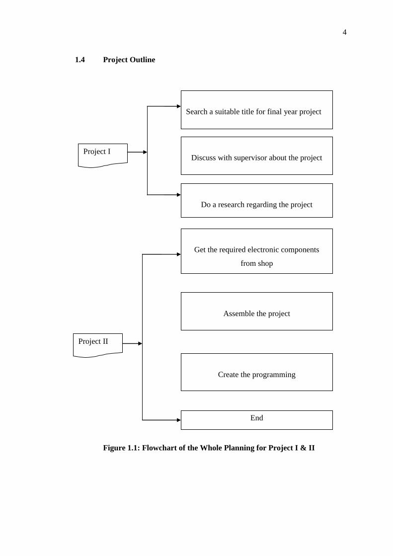
1.4 Project Outline
Project I
Search a suitable title for final year project
Discuss with supervisor about the project
Do a research regarding the project
Get the required electronic components
from shop
Assemble the project
Create the programming
End
Project II
Figure 1.1: Flowchart of the Whole Planning for Project I & II
5
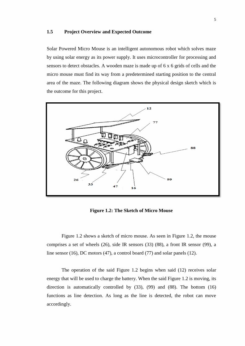
1.5 Project Overview and Expected Outcome
Solar Powered Micro Mouse is an intelligent autonomous robot which solves maze
by using solar energy as its power supply. It uses microcontroller for processing and
sensors to detect obstacles. A wooden maze is made up of 6 x 6 grids of cells and the
micro mouse must find its way from a predetermined starting position to the central
area of the maze. The following diagram shows the physical design sketch which is
the outcome for this project.
Figure 1.2: The Sketch of Micro Mouse
Figure 1.2 shows a sketch of micro mouse. As seen in Figure 1.2, the mouse
comprises a set of wheels (26), side IR sensors (33) (88), a front IR sensor (99), a
line sensor (16), DC motors (47), a control board (77) and solar panels (12).
The operation of the said Figure 1.2 begins when said (12) receives solar
energy that will be used to charge the battery. When the said Figure 1.2 is moving, its
direction is automatically controlled by (33), (99) and (88). The bottom (16)
functions as line detection. As long as the line is detected, the robot can move
accordingly.

6
1.6 Thesis Outline
This report consists of five chapters; it contains information from initial motivation
for the project until the intended design aspect of the Solar Powered Micro Mouse.
Chapter 1 illustrates the project collective methods. It presents the
background information necessary for the reader to gain a proper understanding of
the reasons behind the perusal of this project. It also explains about the problem
statement, overview and the objectives of the project.
Chapter 2 explains about the literature review which discusses the
theoretical aspects leading to the implementation of the project. This involves the
basic idea of this project. This chapter also presents about basic concepts of software
that is used in this project.
Chapter 3 contain detailed descriptions on the techniques used where it
explains clearly about the block diagram and so on. The design and implementation
of the components in this project and project evaluation of hardware explains more
about the hardware to be built in this project as well as the software used to design
the circuit and PCB design.
Chapter 4 summaries the final result obtained from the project problems
encountered. This chapter also discusses about the critical analysis and the alterations
of some of the components in this project.
Chapter 5 is the final chapter that explains the conclusion for the project
besides a several suggestions to increase the capability of the system of the project.

7
CHAPTER 2
LITERATURE REVIEW
2.1 Micro Mouse History
The first mechanical micro mouse was designed in 1972 which appeared in a
magazine entitled “ Machine Design “ which sponsored a contest to see the mouse
stamina by spring-powered mechanism against another mouse by travelling in the
longest distance down the track. The winner of the contest was the “mouse mobile”
which was the one that travelled up to 825.3 feet (Le Mouse 5000, 1972).
The concept of Micro Mouse by using microprocessor-controller was
revealed in 1977 by the IEEE Spectrum magazine. The mouse was able to decipher
and navigate a complicated maze because it is imbued with the intelligence. The
Spectrum announced the first US Amazing Micro Mouse Maze Contest in May 1977,
which dated in June 1979, at New York. Surprisingly just only 15 micro mice
competed out of 6000 entries received. This was due to common problems such as
“brain failure” and other claimant being the mouse to “blow-up”. In addition, the
competition get tougher as the interest in the design and construction of an intelligent
micro mouse has spiked than what most people would have imagined
(Micromouseonline, 2010).
At Euro mice 80’s century, the European version of such contest was
launched at the Euro mice ’80 in London, but unfortunately none of the 18 micro
mice was able to solve the maze. The first All-Japan Micro Mouse Contest was
launched in Japan by the spectators that were from the Japan Education and Science.

8
They took the rules back to Tokyo and subsequently organised the contest
(Sunshines, 2010).
The history continues as in August 1985, in Tsukuba, Japan, which was
where the First World Micro Mouse Contest was held. Since all of the Micro mouse
came from all over the western countries such as from Europe and the USA, it have
been employed with sensors ranging from infra-red to ultrasonic to CCD, and driving
mechanisms from stepper motors to DC servo motors. Even so, every top prizes were
seized by the micro mice from Japan with Noriko-1emerging as the world champion
(Micromouseonline, 2010).
The Institution of Electrical Engineers held another World Micro Mouse
Championship, in London on 1987; with exactly 13 micro mice competed for top
place honours. The winner of the competition was David Otten from the
Massachusetts Institution of Technology (MIT), USA. He won the first and second
prizes with his two entries, by the name of the mouse Mitee Mouse I and Mitee
Mouse II. On top of that, a new system of scoring was also implied, designed to
reward the intelligence, efficiency of maze-solving and self-reliance of the micro
mouse (Micromouseonline, 2010).
Unbelievably, a Singaporean team won in July 1989 from the 2nd Singapore
Micro Mouse Contest which was held in London. The best part is that the Singapore
entries clinched 6 of the top 8 prizes in the contest. Sadly, David Otten’s Mitee
Mouse III was relegated to 2nd place whereas Enterprise from UK took the 5th
place
(Sunshines, 2010).
Since the initial US contest which was organised in 1977, there has been no
turning back. Not only does the micro mouse get smarter and smarter from year to
year, but so does the maze designers (Sunshines, 2010).
9
2.2 Literature Review
The Solar Powered Micro Mouse has one main advantage compared to the rest of the
micro mouse created; it uses solar power as a renewable energy. There has never
been a Micro Mouse that was created or used in any IEEE competition by using any
sorts of natural renewable energy. In support of the Global Green Campaign, solar
panels have been installed to charge up the rechargeable batteries.
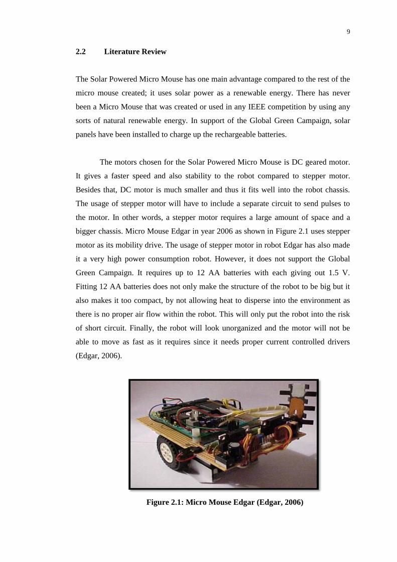
The motors chosen for the Solar Powered Micro Mouse is DC geared motor.
It gives a faster speed and also stability to the robot compared to stepper motor.
Besides that, DC motor is much smaller and thus it fits well into the robot chassis.
The usage of stepper motor will have to include a separate circuit to send pulses to
the motor. In other words, a stepper motor requires a large amount of space and a
bigger chassis. Micro Mouse Edgar in year 2006 as shown in Figure 2.1 uses stepper
motor as its mobility drive. The usage of stepper motor in robot Edgar has also made
it a very high power consumption robot. However, it does not support the Global
Green Campaign. It requires up to 12 AA batteries with each giving out 1.5 V.
Fitting 12 AA batteries does not only make the structure of the robot to be big but it
also makes it too compact, by not allowing heat to disperse into the environment as
there is no proper air flow within the robot. This will only put the robot into the risk
of short circuit. Finally, the robot will look unorganized and the motor will not be
able to move as fast as it requires since it needs proper current controlled drivers
(Edgar, 2006).
Figure 2.1: Micro Mouse Edgar (Edgar, 2006)

10
The first micro mouse as shown Figure 2.2 was created by Johan de Boer.
The name of the micro mouse was Cybernetic Mouse. It was created around 1968. Its
driven system works like a car. Two servo motor are used in this mouse. One servo
motor is placed below the body, connecting a wheel at each end. This means the back
wheels are stagnant and only moves forward. The other servo is placed in the front
wheel, working as a steering wheel. This only allows the robot to turn at a very large
angle. The body of the mouse is connected with bumper sensors to send signals to
the microcontroller if there is collision. This means the robot has 80 percent chances
of colliding with the maze (Boer, 1968).
The robot doesn’t have any algorithm so it uses two sensitive cells that direct
the robot to the centre of the maze which has a light bulb connected to it. The robot
moves around the maze according to the level of light sensitivity it receives from the
light bulb. This robot can only work in a room with very less ambient light as
ambient light can disrupt the light sensitivity it receives, giving wrong information to
the robot. The Solar Powered Micro Mouse has many advantages compared to
Cybernetics Mouse. Firstly, Solar Powered Micro Mouse uses DC motor which is
faster than the servo motor. Solar Powered Micro Mouse has two DC motors that are
connected to two wheels and two castors to support the front and back (Boer, 1968).
The turning angle of Solar Powered Micro Mouse is very small compared to
Cybernetics Mouse. It’s forward, right, left and u-turn movements are all controlled
by a motor controller circuit. Solar Powered Micro Mouse uses infrared sensors as
eyes to direct the robot to the centre of the maze. The infrared sensors are placed at
the front, left and right. The sensors will detect if there is a wall blocking the path of
the micro mouse before the micro mouse bumped into the maze. This results in zero
collision. Solar Powered Micro Mouse operates based on an algorithm. The usage of
any transmitter is not necessary so that the mouse could find the centre of the maze
autonomously (Boer, 1968).
11
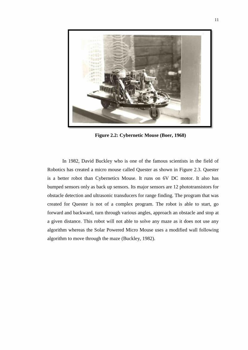
Figure 2.2: Cybernetic Mouse (Boer, 1968)
In 1982, David Buckley who is one of the famous scientists in the field of
Robotics has created a micro mouse called Quester as shown in Figure 2.3. Quester
is a better robot than Cybernetics Mouse. It runs on 6V DC motor. It also has
bumped sensors only as back up sensors. Its major sensors are 12 phototransistors for
obstacle detection and ultrasonic transducers for range finding. The program that was
created for Quester is not of a complex program. The robot is able to start, go
forward and backward, turn through various angles, approach an obstacle and stop at
a given distance. This robot will not able to solve any maze as it does not use any
algorithm whereas the Solar Powered Micro Mouse uses a modified wall following
algorithm to move through the maze (Buckley, 1982).

12
Figure 2.3: Micro Mouse Quester (Buckley, 1982)
In 1979, Arthur Boland created the first micro mouse that was able to solve
the maze. In his time, he has created three micro mice, Moonlight Special, Moonlight
Express and Moonlight Flash as shown in Figure 2.4. All three mice use right wall
hugger or right wall following algorithm. However, there are some trouble-shootings
whereby the mouse could not execute the algorithm perfectly. Thus, the robot takes a
lot of time to solve the maze. Compared to Solar Powered Micro Mouse, the right
wall following algorithm was modified giving preference to forward view instead of
right view. This allows the mouse to solve the maze faster. Besides that, the Solar
Powered Micro Mouse uses Ni-MH batteries instead of the batteries which were used
by the Moonlight which was Ni-Cad batteries. Ni-MH batteries last longer, weighs
lighter and most importantly provides more current rather than Ni-Cad batteries
(Boland, 1979).

13
Figure 2.4: Micro Mice Moonlight Special, Moonlight Express and
Moonlight Flash (Boland, 1979)
Rooter, a micro mouse maze solving robot of Figure 2.5 was created in 2006
by Bob Clough. It uses a stepper motor as its driving system. Stepper motor requires
a lot more circuitry. A high power driver chip is needed, along with a method of
sequencing the output. As size is very important in this project, having extra circuits
is not an option. The Solar Powered Micro Mouse uses DC geared motor as its
driving system. DC motors are much faster compared with stepper motors. Solar
Powered Micro Mouse uses L293 and optocoupler as its switching devices. This will
be explained more in Chapter 3 (Clough, 2006).

14
Figure 2.5: Micro Mouse Rooter (ThinkL33T , 2007)
In the year 2006, students from the University of Moratuwa created a wall
following robot as shown in Figure 2.6. The robot uses an ultrasonic sensor to detect
the obstacle in the front and bumper switches to give signal to the microcontroller if
the robot hits the wall. The Solar Powered Micro Mouse uses IR sensors and it could
detect the wall in the front, left and right. It is much cheaper and the wall collision is
minimized compared to the wall following robot created by the students of
University of Moratuwa (University of Moratuwa, 2006).
Figure 2.6: Wall Following Robot (University of Moratuwa, 2006)

15
2.3 Micro Mouse Algorithm
In many micro mice working system, there is always a sensor installed to prevent
bumping of mouse to the obstacles. To control the micro mouse motion without
hitting any obstacle, an algorithm design is very important. The algorithms that are
analyzed in detail are Wall Following, Depth-First Search and Flood-Fill.
The source code to implement the algorithm can be in C or assembly
language. No matter which language the system used, the basic control of algorithm
should have read, write and making decision.
The read command is used to detect various signals from the sensors. Such
signals can be analogue or digital. As such, in many microcontrollers there is a need
to declare the signal either digital or analogue in the ADC ports.
The write command is used to send digital HIGH or LOW signals out to
control external peripherals connected. These peripherals most properly are the DC
motor. When the digital HIGH signal is send out, the DC motor will be activated.
When the digital LOW signal is send out, the DC motor will stop working.
The decision making is used for compare the input read value with the pre-
programmed value. Decision making is important to make the mouse robot turn left,
right, move forward or backward.
The general algorithm for most of the micro mouse is shown in Figure 2.7.
This algorithm is a basic algorithm that moves the mouse forward, turn left and right
automatically without hitting an obstacle.

16
Figure 2.7: General Basic Algorithm for Micro Mouse Motion
From Figure 2.7, the infinite loop function is a “while”, “do” or “for” functions.
These functions are in C language which causes the microcontroller continue reads
and detect the input signals.

17
The reads command can have many and depends on the micro mouse design
itself. All the read signal will be compared with the pre-programmed value in the “if”
decision making function. The “if” function acts as logic function which response
according to condition TRUE or NOT TRUE. If the condition in the “if” decision
making is TRUE, the program will continue execute the next lines. Otherwise it will
bypass the TRUE condition and jump to NOT TRUE which using “else if” function.
Apart from the decision making, the delay also plays an important role in the
algorithm design. Delay can make the micro mouse motor stop and make decision on
time. It also can control the mouse motion accurately turn left and right. Without
delay, the micro mouse is hard to control its turning.

18
CHAPTER 3
METHODOLOGY
3.1 Introduction
This chapter presents the complete methodology on how the solar powered micro
mouse is fabricated. The general methodology to complete the solar powered robot
can be seen and summarized into a flow chart shown in Figure 3.1.
Figure 3.1: Summary on Methodology to Complete the Solar Powered Micro
Mouse Project
Literature Review on Solar Powered Mouse
Circuit and Program Designs
Simulation
Circuit Build On Breadboard
PCB Construction
Prototype Construction

19
In this whole project, literature review plays an important role to get started.
Literature review enables the collection of information related with the project.
Without enough information, a complete project cannot be achieved.
For this solar powered micro mouse project, the information was obtained
from:
1. Internet
2. Textbooks
3. Conference paper
4. Journal
5. Advice from the experts
6. Guideline from lecturers
7. Past final year project report
Internet is a vast electronic library. Internet contains plenty of information
that can be found which is related to micro mouse project. There are two powerful
search engines, Google and Yahoo which are useful to seek information. However,
the content of texts in this report was not plagiarized from the internet. Only pictures
obtained from the internet were used in the report. References for each picture are
recorded.
Textbook is another useful resource to look for information related with Solar
Powered Micro Mouse especially on circuit explanation as well as the mathematical
tools to describe the results. Many electronic and electrical textbooks found to have
plenty of explanation on current flows, voltage drops and power consume in the
circuit. Some equations such as Ohm’s law and Kirchhoff’s law were found useful to
explain the current flows in the circuit. Other textbooks like calculus and statistic
were useful to explain the results in mathematical form.

20
Conference and journal papers provide useful information which comprises
up to current research works for Solar Powered Micro Mouse. These papers provide
latest technology related information for the project. However, the disadvantage of
conference and journal papers is that they do not provide much technical details in
the design of the system.
Getting advice from experts regarding the technical design of the micro
mouse project is also useful to obtain the relevant information. Robotic experts
sometimes will show the guideline on how to build a robot. As from the experts in
electronics, guidance in components used in the project is obtained.
Last but not least is the information source obtained from crucial past year’s
final year project report. Since micro mouse is not new in the scene, there were many
universities and colleges by which the engineering students had come across it. Thus,
there are a good number of brilliantly written documents regarding the project. Past
final year project reports normally can be found in libraries or digital libraries. The
following shows that digital libraries kept the past E&E final year project reports
since year 1999 (Scott, 2008).
Once the information has been collected, studied and when the working
principles have been understood, the next step of doing the project is to prepare a
design of a circuit to control the mouse. The circuit is then tested by using either
simulation or by constructing the circuit on breadboard.
Finally, PCB layout is designed and printed which is ready to make the PCB.
PCB enables the circuit to firmly stick on the board and work in a stable mode.

21
3.2 Components Selection
Selecting the right component to build the control circuit is extremely important.
Wrong selection of components may result in the robot not to move or damages other
neighbouring components. This section presents some important components that are
necessary to build a solar powered micro mouse.
3.2.1 Solar Panel
Figure 3.2: Solar Panel (Kyocera, 2012)
Table 3.1: Technical information about the solar panel used in the project
Parameters Technical information
Output power 1mW
Output voltage 12V
Output current 0.45mA
Size 10cm x 5cm
Weight 20g

22
Solar panel is the main component used to charge the battery of the micro
mouse. The solar panel will be mounted on top of the micro mouse so that it can
receive more solar energy. Typical specification of a solar panel includes it to be
light in weight so it will not have much loading effect toward the mouse.
3.2.2 LM358 IC
Figure 3.3: LM358 Op-amp IC (Freaklabs, 2012)
Table 3.2: Technical information about the LM358 IC
Parameters Technical information
Operating voltage 5V DC
Maximum operating current 1A
Gain 120
No. of pins 8
Type DIP Through hole
Maximum power dissipation 1W
The LM358 IC is an operational amplifier IC. This IC has 8 pins and it is
mainly used to amplify a small signal. The IC normally reads the signal from sensor
output and amplifies it before sending it to the next stage of the circuit.

23
3.2.3 4013N IC
Figure 3.4: 4013IC (4013-IC, 2012)
Table 3.3: The technical information about 4013 IC
Parameters Technical information
Operating voltage 5V ~ 12V DC
Current 1 – 1.5A
Power 1W
No. of pins 14
4013N IC is a dual D type flip-flop. This type of IC used in the project is to
charge the battery. The reason to use this IC is because it can control the charging
rate by turning it ON and OFF. Typical IC can be seen in solar charger circuit.

24
3.2.4 IRF9530 MOSFET
Figure 3.5: IRF9530 Power MOSFET (HEXFET, 2012)
Table 3.4: Technical information about the IRF9530
Parameters Technical information
IDSS maximum 20A
VGS -50V
Maximum power 3W
TurnON time 5s
Type N channel
This IRF9530 is a power MOSFET. It is used in the solar charger circuit to
draw a current so that it can charge higher rating of battery. The reason for choosing
this MOSFET is that it can handle higher current and gives better control when
charging the battery.

25
3.2.5 LM7805 Voltage Regulator
Figure 3.6: LM7805 Voltage Regulator (LM7805, 2012)
Table 3.5: Technical information about the LM7805 voltage regulator
Parameters Technical information
Maximum power rating 1W
Maximum current 1.5A
Minimum input voltage 5V
Maximum input voltage 13V
Maximum output voltage 5V
A voltage regulator is used to reduce the higher voltage down to desired
voltage level. For LM7805, it regulates the voltage down to 5V as the output. The
output voltage is then supplied to other IC and microcontroller.

26
3.2.6 Transistor 2N3904
Figure 3.7: 2N3904 Transistor (2N3904, 2010)
Table 3.6: Technical information about the 2N3904 transistor
Parameters Technical information
Vce 15V
Ic maximum 2A
IB maximum 500A
Vcc 20V
DC gain 40
The 2N3904 transistor is of NPN silicon type. It is used to amplify the
collector current so that it can be used to control the MOSFET in the charger circuit.
The reason for choosing this kind of transistor is to provide suitable current gain
which will not bring the output voltage to go into saturation.

27
3.2.7 IR Transmit and Receive Sensors
(a) IR transmit sensor (b) IR receive sensor
Figure 3.8: IR Transmit and Receive Sensor (Kytron, 2011)
Table 3.7: Technical information about the IR transmit and receive sensor
Parameters Technical information
Power dissipation 1mW
Maximum current 5mA
Maximum voltage 3.7V
Junction breakdown 5V
The IR sensor is an optical device used to sense an obstacle. The working
principle is that when the transmit sensor sends the IR light, the receiver will detect
the reflected IR light. If the IR light reflected can be detected, a HIGH voltage is
produced at the receiving sensor. This indicates that an obstacle is detected.

28
3.2.8 PIC16F877A Microcontroller
Figure 3.9: PIC16F877A Microcontroller (PIC16F877A, 2003)
Table 3.8: Technical information of PIC16F877A microcontroller
Parameters Technical information
Package 40 pins
Number of bits 8
Operating voltage 5V DC
Operating current 0.5mA ~ 20mA
Number of PORTS A, B, C, D, E
Operating clock frequency DC ~ 20MHz
Memory 368kB
PIC16F877A microcontroller is used in the project to detect the IR signal and
thus to make decision to control the motor in the wheel. PIC16F877A was chosen
because of the following:
1. High memory
2. Low in cost
3. Available in the market
4. Stable in operation

29
3.2.9 L293 Motor Driver
Figure 3.10: Motor Driver IC (L293, 2002)
Table 3.9: Technical information about L293D motor driver
Parameters Technical information
Maximum current 2A
Maximum voltage 12V
Maximum power dissipation 1.5W
Breakdown current > 2A
Control motor Forward and reverse direction
Motor driver is very useful to control the motor turning direction. The turning
of the motor can be done by reversing the pulse amplitude. Hence, the motor driver is
only suitable to control the DC motor.

30
3.2.10 PC817 Optocoupler
Figure 3.11: PC817 Optocoupler (PC817, 2012)
Table 3.10: Technical information about the Optocoupler
Parameters Technical information
Maximum operating voltage 5V
Operating current 100mA
Power dissipation 1W
Optocoupler is used to isolate high current and low current circuit. It is
mainly used to control the current in the DC motor.

31
3.2.11 DC Motor
Figure 3.12: DC Motor (DC Motor, 2012)
Table 3.11: Technical information of DC motor
Parameters Technical information
Input voltage 12V
Operating current 1.5A
Power dissipation 0.6W
The DC motor will be used to run the robot. The DC motor is mounted on the
two side of the wheel. The DC motor will be controlled by the microcontroller.
32
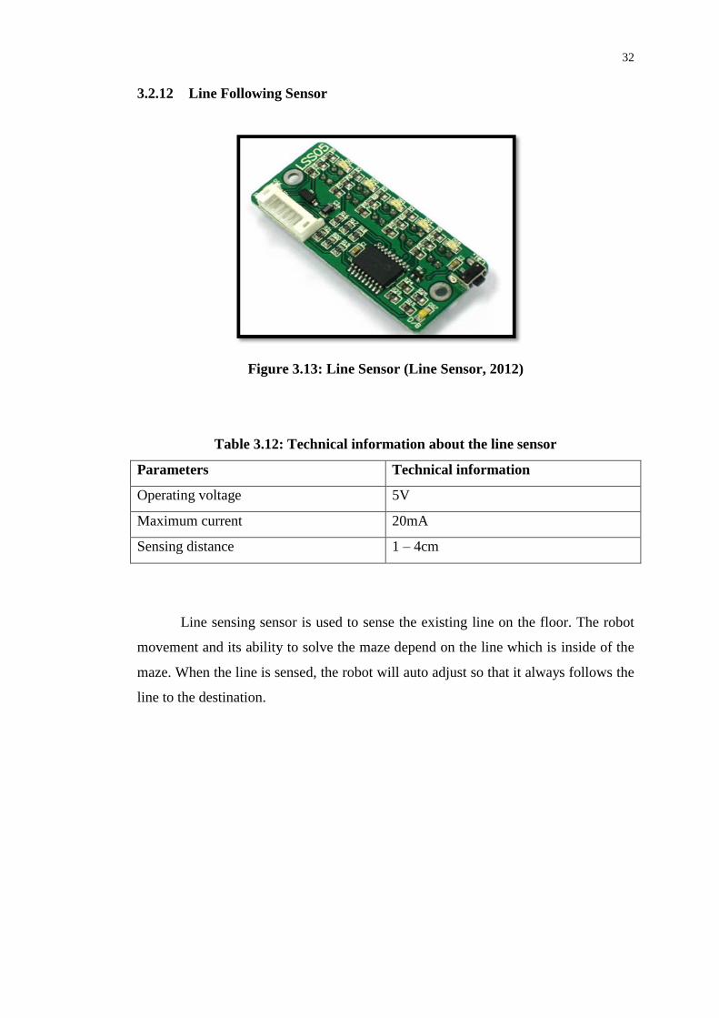
3.2.12 Line Following Sensor
Figure 3.13: Line Sensor (Line Sensor, 2012)
Table 3.12: Technical information about the line sensor
Parameters Technical information
Operating voltage 5V
Maximum current 20mA
Sensing distance 1 – 4cm
Line sensing sensor is used to sense the existing line on the floor. The robot
movement and its ability to solve the maze depend on the line which is inside of the
maze. When the line is sensed, the robot will auto adjust so that it always follows the
line to the destination.

33
3.3 Design of the Solar Powered Micro Mouse
Figure 3.14 shows the technical block diagram for the solar powered mouse circuit
design.
Figure 3.14: Design of the Solar Powered Micro Mouse Circuit
Figure 3.14 shows the complete block diagram designed for the solar
powered micro mouse. As seen in Figure 3.14, the solar panel receives the solar
Solar panel
MPPT circuit
4013N IC Oscillator circuit
Power MOSFET
3V or 9V Rechargeable Battery
LM7805 220uF 220uF
16F877A microcontroller
4MHz crystal oscillator 22pF 22pF
Buzzer
PC817
PC817
PC817 PC817
L293D
IR sensor
Line sensor
Motor1
1
Motor 2

34
energy and is converted into electrical energy to charge a rechargeable battery
through a solar charger control circuit.
The solar charger control circuit consists of maximum power point
tracking circuit (MPPT), 4013N IC, oscillator and power MOSFET.
The main component in MPPT is the regulator. It keeps a constant voltage
at the output so that it can be used to charge the battery. The 4013N IC together with
oscillator provides a charging rate control. The MOSFET controls the charging
current so that it will not exceed to charge a battery and also prevents the battery
current flows back to the charger.
Once the battery is charged, it is then used to power up the motor. The
microcontroller used is PIC16F877A and it is supported by 4MHz crystal oscillator.
The microcontroller will constantly read the input signals from the sensor and make
decision to control DC motor 1 and 2. The control of DC motor was done using
L293D motor driver as mentioned before.

35
In general, the micro mouse working mechanism for the entire project is
shown below:
Figure 3.15: The Working Mechanism of the Micro Mouse
In case the micro mouse does not use solar energy, the battery can support
operation of the micro mouse. Under this condition, the block diagram is shown in
Figure 3.16.

36
Figure 3.16: Operation of Micro Mouse without Using Solar Energy
From Figure 3.15 switch to Figure 3.16 can be achieved using the power
MOSFET as a switching device. Therefore, even if solar energy not available, the
robot still will be able to move by sourcing power from the battery.
Line sensor
IR sensor 3V or 9V Rechargeable Battery
220uF LM7805 220uF
Buzzer 16F877A microcontroller
PC817
22pF 22pF 4MHz crystal oscillator
PC817
Motor1 PC817 PC817
Motor 2 L293D
Line sensor
IR sensor 3V or 9V Rechargeable Battery
220uF LM7805

37
3.3.1 Solar Charger Circuit
Figure 3.17: Solar Charger Circuit
Figure 3.17 shows the charger circuit design based on block diagram in Figure 3.14.
As seen in the schematic diagram, X1-1 and X1-2 are the two points connected to
12V solar panel (not shown). The other two points X2-1 and X2-2 are connected to
battery for charging.
The charging of the battery begins when the solar panel deliver voltage across
104 capacitor. This capacitor was used to prevent a rush of voltage or sudden
increase of input voltage. The charging current will then flows into transistor 2N3906

38
PNP. This transistor turns on only when the voltage of solar panel output reaches
12V. The switching on of transistor 2N3906 is controlled by 12V zener diode. As
such, when the output voltage reaches 12V, the current produced to the input of the
LM7805 is:
I = 12V/330
= 0.036A
The 104 capacitor is once again used to prevent sudden rush of voltage from
going into LM7805 voltage regulator. With another two 104 capacitor and 470uF, a
further constant voltage can be produced no matter how the solar panel output
voltage fluctuated.
There is also a switch S1 where it is used to turn on the charger. As the
switch is pressed and in position 1, the voltage from the battery will be fed into
LM358 via the resistor R1, VR1, R3, 104 and R2. When this happens, the L358N
acts as comparator circuit. Hence, the voltage bias to the input pin 2 of LM358 is:
VBias = ( 75k/(270k + 100k + 75k))× 12
= 2.02V
The voltage at pin 3 of LM358 is:
Vpin 3 = (100k//180k/(100k//180k + 100k) ×12V
= 4.69V
Since the 2.02V < 4.69V, the LM358 produce output is HIGH and this
indicates that it needs to charge the battery. The two 15MΩ are used to control the
gain of the LM358.
When the output of LM358 is HIGH, it triggers the 4013N flip-flop where the
output will be a square wave to turn in the LED1.

39
The flip-flop operation is controlled by phase shift oscillator using LM358
op-amp as shown in the schematic diagram. The frequency of phase shift oscillator is
given by:
F = 1/2×100k×0.01uF
= 159Hz
Hence, the LEDs blink according to these values and the charging time will be:
T = 1/159Hz
= 6.3ms approximately
At the output of the flip-flop, it is connected to the MOSFET charger circuit
where it controls the N-channel or the gate of the MOSFET through transistor
2N3904. The two resistors R14 and R18 control the Vgs across the MOSFET and
diode D1 forces the current to charge the battery and avoid the current from returning
back to the circuit.
Figure 3.18 shows the simulation for the circuit in Figure 3.17 using Proteus.
Simulation is needed for that particular circuit to ensure that it works.

40
Figure 3.18: Simulation Result for the Solar Charger
As seen in Figure 3.18, the blue LED is lighted up and this indicates that the
charging is in progress. Hence, the circuit design in Figure 3.17 works.

41
3.3.2 IR Sensor Circuit
Figure 3.19: IR Sensor
Another circuit like IR sensor circuit was also build on the robot. This IR sensor
circuit consists of transmitter and receiver of IR sensors. The schematic of such
circuit is shown in Figure 3.19.
From the diagram, the IRTX is transmitting sensor where it obtains 5V Vcc
from the supply. For the transmit circuit, a current:
390
V5I
= 0.0128A
will flow into the sensor and transmit optical light. At the receiver, a current of:
k1//k22
V5I
= 5.23mA

42
will flow into LM358 when an optical light is detected. Notice that the reason to use
22k and 1k resistance is because of that 5mA is needed by the LM358 Op-amp.
At the input of LM358 (pin 2), there is a potentiometer with 10k maximum of
resistance being used. This 10k potentiometer is used to adjust the sensitivity of the
receiving IR sensor. By varying the resistance, the voltage across pin 2 will be
changed and it will be compared with the voltage in pin 3.
As such, if the voltage at pin 2 and 3 are the same, the LM358 will generate
output voltage at 1. Thus, indirectly, the circuit becomes a comparator circuit.
3.3.3 The Solar Powered Micro Mouse Control Circuit
Figure 3.20: The Solar Powered Micro Mouse Control Circuit

43
The heart of the circuit shown in Figure 3.20 is the PIC16F877A microcontroller.
From the microcontroller point of view, pin 1 is a reset pin and it is connected to
switch S1. If the switch is pressed, a reset of program will happen. This is because,
the current is forced into the ground. However, if the switch S1 is not pressed, the
current that goes into pin 1 of the PIC16F877A microcontroller will be:
I = 5V/1k
= 5mA
Selection of 1kΩ resistor is needed because pin 1 could only accept 5mA to
15mA of current input.
When pin 1 receives a current of 5mA, it starts to execute the program inside
the microcontroller.
Pin 2 to 3 are programmed to be connected to three IR transceiver sensors.
Each sensor was installed with an LED for power indication. Pin 4 to 10 are
programmed to be connected to line sensor LSS05. These pins serve as input pins.
Pin 13 and 14 are connected to 4MHz crystal oscillator. The 22pF capacitors
are used to attenuate the overshoot of oscillation frequency. When these two
capacitors connected in shunt, the resonance will become in parallel rather than in
series. The microcontroller needs 4MHz as a reference frequency to execute the data.
Pin 19 is connected to buzzer to give out alert when obstacle is detected while
pin 20 is connected to LEDs for indication of buzzer when it is turned on.
Pin 27 to 30 are the output pins that are connected to Optocouplers IC. These
pins are basically produces digital HIGH 5V so that Optocoupler can be turned on to
drive the L293 motor driver IC.
The current flow into each Optocoupler is:
I = 5mA

44
When the Optocoupler output is turned ON, a voltage of:
Vdrop = 12V – 5mA × 1k
= 7V
will be fed into L293D to control the motor direction. One motor will need two
Optocouplers to drive. The control of motor to turn left, right, forward, stop and ‘U’
turn is based on the output voltage as shown below:
Table 3.13: The control of robot motion from the L293 motor driver
Input voltage
from pin 27 and
28 of PIC16F877
to L293D
(V)
Input voltage 2
from pin 29 and
30 of PIC16F877
to L293D
(V)
Output
voltage 1
from
L293D
(V)
Output
voltage 2
from
L293
(V)
Condition
of the
robot
7 7 12 12 Move
forward
0 7 0 12 Turn left
7 0 12 0 Turn right
0 0 0 0 Stop
-7 7 -12 -12 U turn
Figure 3.21 depicts the waveform to describe the motion of the robot when
L293 motor drivers change its voltage level under the control of PIC16F877A
microcontroller.

45
Figure 3.21: Waveform to Control the Motion of the Robot
The voltage level actually gives the power to the DC motor so that it works to
move the robot. However, the duration needed for the DC motor to work is
controlled by the time. The time control of voltage output can be done in the
programming.

46
3.4 PIC Flow Chart
Figure 3.22: PIC Program Flow Chart to Control the Mouse Motion

47
From the flow chart, the programming designed to control the mouse motion begins
from I/O port configuration. This was necessary because the microcontroller should
know which pins are for input and which are for output.
When the system is turned ON, the microcontroller will check the line sensor
and IR sensors. If all the sensors give signal to the microcontroller, the
microcontroller will then stop the DC motor and hence stop the mouse motion.
However, if the IR sensor which is located at front, left and right gives signal
to the microcontroller, the microcontroller will trigger the motor in a way it goes “U”
turn.
If IR sensor at front and left gives input signal to the microcontroller, the
robot then will turn right. To turn left, the front IR sensor and right IR sensor should
be activated.
However, if only front sensor is detected, the robot moves right or if only left
and right sensor gives out signal to the microcontroller, the robot will then move
forward. The complete operation of the program is written in C and it can be seen in
the appendix.

48
3.5 Maze Design
Figure 3.23: Maze Design
The maze is designed to have a total of 17 grids of cells, 9 turns and 1 “U” turn from
left starting point. The design is mainly for different speed observation.
The right starting in the maze has a total of 14 grids of cell, 6 turns and 1
“U” turn. The design is to show the different speed compared to the left starting point.
In general, the total size of the maze design is 6×6 grids of cell by which each
grid is 20cm × 20cm large. The base is built from 2 plank wood with the length of 4
feet and the width of 2 feet each. Then the wood is covered by white sheets of paper.
The wall was built by using polyester. The top of the wall is painted red. The wall is
10 cm height with half an inch in thickness.

49
CHAPTER 4
RESULTS AND DISCUSSIONS
4.1 Technical and Physical Features of the Solar Powered Micro Mouse
Table 4.1: Technical features of the Solar Powered Mouse
Parameters Requirements
Input voltage to the control board 9V
Solar panel 12V @ 5mA
Types of microcontroller 16F877A
IR sensors 1mW, 500mA
Motor drives Use motor driver circuit
Figure 4.1: Front and Side View of Solar Powered Micro Mouse

50
4.2 The Route of the Robot Move In the Maze
Figure 4.2: The Robot Route inside the Maze
Figure 4.2 shows the maze designed for the robot to complete the route. The
designed maze has two entrance points as shown in the Figure 4.2. The dotted line
represents the robot route that has been tested to come to the end point. There are two
points where the robot need to “U” turn before it comes to the end point. These
points were created where the sensor sense the obstacle in far distance. As such, the
robot will move forward until the next obstacle is sensed and return back by means
of “U” turn.
4.3 Infrared Distance Testing
According to the datasheet, the photodiode is supposed to detect objects in the range
of 1 cm to 15 cm away. To verify this statement and to gain additional insight into
how the sensor functions, several laboratory tests were performed on the sensor.

51
The IR sensor was placed facing a white sheet of paper upright and the output
voltage is measured at several incremental distances from the sheet of paper by using
a ruler. Table 4.1 shows the result of the three trials conducted, as well as an average
of the three:
Table 4.1: Testing with white paper
Distance
(cm)
Voltage
(Trial 1)
(V)
Voltage
(Trial 2)
(V)
Voltage
(Trial 3)
(V)
Voltage
(Average of
Trials)
(V)
3 1.917 1.882 2.011 1.937
3.5 2.187 2.266 2.029 2.161
4 2.811 2.876 2.560 2.749
4.5 3.083 3.084 3.058 3.075
5 3.031 3.003 3.067 3.034
5.5 2.811 2.777 2.909 2.832
6 2.577 2.543 2.671 2.597
6.5 2.369 2.369 2.437 2.392
7 2.222 2.205 2.266 2.231
7.5 2.064 2.046 2.117 2.076
8 1.918 1.907 1.972 1.932
8.5 1.811 1.793 1.846 1.817
9 1.703 1.684 1.721 1.703
9.5 1.592 1.592 1.629 1.604
10 1.501 1.501 1.538 1.513
11 1.368 1.350 1.387 1.368
12 1.239 1.239 1.257 1.245
13 1.127 1.127 1.146 1.133
14 1.064 1.046 1.064 1.058
15 0.988 0.988 0.988 0.988

52
Figure 4.3: Voltage vs Distance Graph
Using the results from Table 4.1, the following voltage versus distance graph
is plotted in Figure 4.3. From the graph, it is obvious that the output from the sensor
is non-linear. This is due to the basic trigonometry within the triangle from the
emitter to the ilumination spot to the detector. Moreover, as expected from the the
device specifications, there is a range, mainly when it is close than 4cm to the wall,
where the distance can be accurately measured.

53
4.4 Discussion on the Robot Move inside the Real Maze with Solar Panel
There are twelve figures that describes on how the Solar Powered Micro Mouse
solves the maze.
Figure 4.4: Picture of Micro Mouse Solving Maze Part 1
Figure 4.4 shows the robot start to move at the right side of starting point. In
this situation, the robot power and the solar panel is turned on.
Figure 4.5: Picture of Micro Mouse Solving Maze Part 2
Figure 4.5 shows the robot reaches the first obstacle and begins to turn. Just
before it turns, the robot will stop for a while. This is because the microcontroller
needs time to make decision and scan for the next obstacle.

54
Figure 4.6: Picture of Micro Mouse Solving Maze Part 3
Figure 4.6 shows the robot has already solved the first obstacle and then it
moves straight. In the second obstacle, the robot makes detection and thus made a
turning.
Figure 4.7: Picture of Micro Mouse Solving Maze Part 4
Figure 4.7 shows the robot reaching the “U” point. At this point, the front and
the two sides of the robot have obstacles, but its back does not have any obstacles.
Therefore the robot turns in “U” motion to move back and seek for another exit point.
55
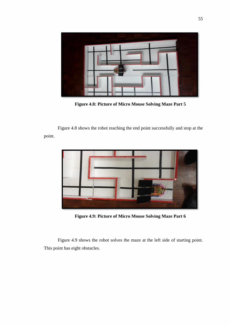
Figure 4.8: Picture of Micro Mouse Solving Maze Part 5
Figure 4.8 shows the robot reaching the end point successfully and stop at the
point.
Figure 4.9: Picture of Micro Mouse Solving Maze Part 6
Figure 4.9 shows the robot solves the maze at the left side of starting point.
This point has eight obstacles.

56
Figure 4.10: Picture of Micro Mouse Solving Maze Part 7
Figure 4.10 shows the robot solves for the first obstacle and moves forward.
The sensor at this point is actively detecting the side and front object.
Figure 4.11: Picture of Micro Mouse Solving Maze Part 8
Figure 4.11 shows the robot solves for second obstacle. At this point, the
robot turns right, left, left again and then right, right and left again to come out from
the obstacle.
57
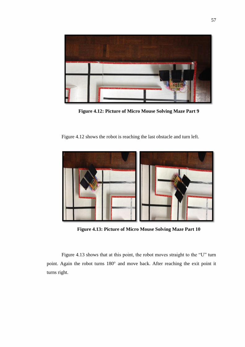
Figure 4.12: Picture of Micro Mouse Solving Maze Part 9
Figure 4.12 shows the robot is reaching the last obstacle and turn left.
Figure 4.13: Picture of Micro Mouse Solving Maze Part 10
Figure 4.13 shows that at this point, the robot moves straight to the “U” turn
point. Again the robot turns 180 and move back. After reaching the exit point it
turns right.

58
Figure 4.14: Picture of Micro Mouse Solving Maze Part 11
Figure 4.14 shows the robot has successfully reached the end point.
From the experimental test, it shows that without a solar panel, when the
robot starts at left starting point, it takes approximately about 1 minute 61 second for
it to reach the end point. The total distance traveled is 335cm. The speed of the robot
is:
121
35.3Speed
= 0.027m/s
From the right starting point, the time for the robot to reach the end point was
51 seconds with a total distance traveled of 279cm. The speed of the robot under this
case is:
51
79.2Speed
= 0.055m/s

59
When the solar panel was installed, the robot that starts at left starting point
takes 109s to reach the end point. The distance traveled is 335cm. The speed under
this is:
109
35.3Speed
= 0.03m/s
From the right starting point being with solar panel installed, the time for the
robot to reach the end point is 89 second. The speed is:
89
79.2Speed
= 0.0313m/s
From the speed results, it can be seen that when the panel is installed, the
robot moved slower. This is because the robot is heavy under loading condition.
However, the robot was observed to move faster without the panel.
This particular developed robot can be used in space exploration to explore
the surfaces of the planets by using solar energy. Besides, this robot can also be
applied to power up ships and thus reduce the dependency on fuel. Moreover, this
robot can also be used as land transportation such as bus by powering up the shuttle
so that it can be used as a normal shuttle to carry the passengers. All these
applications can be achieved by designing this robot in a bigger scale.

60
CHAPTER 5
CONCLUSION AND RECOMMENDATIONS
5.1 Conclusion
The ultimate goal of this project is to design and build a fully functional Solar
Powered Micro Mouse. In this project, a self-contained, autonomous, solar powered
vehicle called a “Solar Powered Micro Mouse”, which is able to navigate through a
path to the centre of a maze was built. A fully functional Solar Powered Micro
Mouse has been successfully built based on the initial design. This basic micro
mouse can be improved in future to suit any requirements for solving a task.

61
5.2 Future Recommendations
Firstly, the circuit should be designed by using the SMD components and to make it
more compact on PCB. This can reduce the total power consumption of the robot and
thus save the input energy.
Firstly the power supply should be increased so that the Solar Powered Micro
Mouse can last longer. The Solar Powered Micro Mouse should be small in size so
that it can go through tight mazes or sharp angles in unknown terrain. However, the
battery capacity used in Solar Powered Micro Mouse can be increased. The solar
panel should have a power of at least 1W and above it with at least 900mA of current.
This can effectively power up the DC motor of the robot.
The other parts which can be explored are the IR sensors. Currently the IR
sensors that are used are the normal IR transmitter and photo diode. Instead of using
normal IR sensors, Sharp GP2D12 IR sensor can be used to replace them. This is the
most popular Sharp reflective IR distance sensor. It provides an analog voltage which
the value is proportional to the distance of the detected object. This will give an
accurate value of distance to the Solar Powered Micro Mouse to maintain its distance
from the wall. Another type of sensor that can be used is the ultrasonic sensor. It can
also be used to measure the distance of the robot from the wall. Furthermore it is not
affected by ambient light. With this feature, the Solar Powered Micro Mouse can
work under the sunlight.
Another improvement that can be done is upgrading the drive system.
Currently, Solar Powered Micro Mouse uses a DC geared motor. The drive system
can be upgraded by using a faster and smaller DC motor. Introducing the PWM
circuit will be able to control the speed of the DC motor. In this way, the Solar
Powered Micro Mouse will be able to solve the maze faster.

62
Finally, to speed up the processing of microcontroller, the 4MHz crystal can
be upgraded into 20MHz crystal. When microcontroller encounters higher frequency
of clock, it can make decision faster compared to 4MHz crystal oscillator.

63
REFERENCES
[Journals]
Mishra, Bande, S. (2008), ‘Maze Solving Algorithms for Micro Mouse’, Signal
Image Technology and Internet Based Systems, IEEE International Conference, pp.
86-93.
Solar Energy, Vol.56, No.1 (1996), pp. 111-118
Tanaka, T. (2002), ‘A comparative study of advanced MOSFET concepts’, Electron
Devices, IEEE Transactions on, Vol.43, No.10, pp. 1742-1753
Wang, D. (2008), Audio, Language and Image Processing, International Conference
on In Audio, Language and Image Processing, pp. 784-787
[Online]
2N3904 (2010), NPN General Purpose Amplifier. Retrieved July 18, 2012, from
http://www.fairchildsemi.com/ds/2N/2N3904.pdf
4013-IC (2012). Retrieved July 18, 2012, from
www.electronickitsbychaneyelectronics.com/4013-IC
Azooz A.A., Sulayman J.M. (2005), Electronic Control Circuit

64
For Solar Battery Charging. Retrieved January 14, 2012, from
http://rrp.infim.ro/2007_59_1/art07Azooz.pdf
Boer J. D. (1968), Cybernetics Zoo. Retrieved January 8, 2012, from
http://cyberneticzoo.com/?p=4045
Boland A. (1979), Cybernetics Zoo. Retrieved January 12, 2012, from
http://cyberneticzoo.com?cat=535
Buckley D. (1982), Quester. Retrieved January 8, 2012, from
http://davidbuckley.net/DB/Quester.htm
Clough B. (2006), Rooter. Retrieved January 12, 2012, from
http://think133t.co.uk/uploads/diss/ Writeup/Dissertation.pdf
DC Motor (2012). Retrieved July 18, 2012, from
http://www.nskelectronics.in/servo_motor.html
Edgar (2006), Micromouse Online. Retrieved January 8, 2012, from
http://www.micromouseonline.com/ book/micromouse-book/actual-mice/edgar
Electric Motors (2003). Retrieved January 14, 2012, from
http://www.electricmotors.machinedesign.com/
Freaklabs S. (2012), LM358 Single Supply Op Amp . Retrieved July 16, 2012, from
http://www.freaklabsstore.com/index.php?main_page=product_info&products_id=11
4
HEXFET (2012), Power MOSFET. Retrieved July 18, 2012, from
http://pdf1.alldatasheet.com/datasheet-pdf/view/199104/IRF/IRF9530PBF.html
IEEE Micromouse Competition Rules (2007), Region 2 Student Activities
Conference - 2007. Retrieved January 8, 2012, from
http://www.ieee.uc.edu/main/files/sac2007/mm_rules.pdf

65
Introduction to Power MOSFETs and Their Applications (1988). Retrieved January
14, 2012, from http://bitsavers.org/pdf/national/_appNotes/AN-0558.pdf
Introduction to Solar Electricity (2011). Retrieved January 14, 2012, from
http://www.altestore.com/howto/Renewable-Energy-Energy-Efficiency/Introduction-
to-Solar-Electricity/a89/
Kyocera S.P. (2012), Installing Low Maintenance Kyocera Solar Panels. Retrieved
July 16, 2012, from http://kyocerasolarpanels.net/
Kytron E. (2011), Infrared Sensor. Retrieved July 18, 2012, from
http://kytron.blogspot.com/2011/11/sensor-optical-infrared-sensor.html
L293 (2002). Retrieved July 18, 2012, from
http://idmax.free.fr/Aide/Stepper/l293.pdf
Le Mouse 5000 (1972), Machine Design LeMouse-5000, Chicago, IL 1972.
Retrieved January 10, 2012, from
http://www.sciencephotography.com/andy/mousecar.htm
Line Sensor (2012). Retrieved July 18, 2012, from www.cytron.com.my
LM7805 (2012). Retrieved July 18, 2012, from
http://www.fairchildsemi.com/ds/LM/LM7805.pdf
Micromouse Contest (2011), The Micromouse Contest In The Beginning. Retrieved
January 10, 2012, from http://www.ee.cityu.edu.hk/~rtbrad/micromouse.html
Micromouseonline (2010), History. Retrieved January 10, 2012, from
http://www.micromouseonline.com/micromouse-
book/history/?doing_wp_cron=1345610400.7872860431671142578125#axzz24DFff
vwA

66
Motha, K. (2009), H-Bridge Circuit. Retrieved January 14, 2012, from
http://kartikmohta.com/wiki/Tech/ HBridge
Omkar (2008), How to Make IR Sensor Modules. Retrieved January 17, 2012, from
http://electrom.wordpress.com/2008/02/19/how-to-make-simple-infrared-sensor-
modules/
PC817 (2012). Retrieved July 18, 2012, from
http://www.datasheetcatalog.org/datasheet/Sharp/mXruvuu.pdf
PIC16F877A (2003). Retrieved July 18, 2012, from
http://ww1.microchip.com/downloads/en/devicedoc/39582b.pdf
Placek D, Gonski P (2007), Smart Solar Battery Charger. Retrieved January 14, 2012,
from
http://courses.engr.illinois.edu/ece445/projects/spring2007/project4_design_review.d
oc solar battery recharge circuit
Roman (2012), DC Motors Direction and Speed Control. Retrieved January 14, 2012,
from http://letsmakerobots.com/files/MotorDriverL293Dnet.pdf
Scott P.C (2008), Senior Design. Retrieved July 18, 2012, from
http://courses.engr.illinois.edu/ece445/?f=Projects&sem=fall2006
Sunshines. S. (2010), Micro Mouse History. Retrieved January 14, 2012, from
http://www.shiningsunshines.com/micromousehistory/
ThinkL33T (2007), R1V2-Rooter Version 2-Worklog Part 1. Retrieved July 14, 2012,
from http://thinkl33t.co.uk/tag/micromouse/page/4
University of Moratuwa (2006), Wall following robot. Retrieved January 13, 2012,
from http://ent.mrt.ac.lk/ iml/projects/2006/2k6EN407P3/index.htm

67
APPENDICES
APPENDIX A: PIC Program Coding
//define pin used
#define sensor_f PORTA.F1
#define sensor_l PORTA.F2
#define sensor_r PORTA.F0
//motor pins
#define m_lf_fw PORTD.F4
#define m_lf_rw PORTD.F5
#define m_rf_fw PORTD.F6
#define m_rf_rw PORTD.F7
//line sensor
#define l5 PORTA.F3
#define l4 PORTA.F4
#define l3 PORTA.F5
#define l2 PORTE.F0
#define l1 PORTE.F1
//led & buzzer
#define led PORTC.F0
#define buzzer PORTD.F0
//variable
char x;
//subroutine
void forward(void);
void reverse(void);
void turn_left(void);
void turn_right(void);
void stop(void);
void u_turn(void);
void beep(void);
void left(void);
void right(void);
void follow(void);

68
//main loop
void main(void)
ADCON1=0x06;
TRISA=0xFF; //porta is input
TRISB=0x00; //portb is output
TRISC=0x00; //portc is output
TRISD=0x00; //portd is output
TRISE=0b00000111; //porte is input
INTCON=0xA0;
PORTA=PORTB=PORTC=PORTD=0x00;
beep(); //beep 2x
beep();
//main loop
do
follow(); //call follow loop
if((l1 && l2 && l3 && l4 && l5) || (!sensor_f && !sensor_l && !sensor_r))
//when all sensor detect line or all sensor front left & right detect
stop();
//stop motor
if(!sensor_f && !sensor_l && !sensor_r) //when all 3 sensor detct then uturn
u_turn();
else if(!sensor_f && !sensor_l && sensor_r) //when forward and left detect then
turn right
turn_right();
else if(!sensor_f && sensor_l && !sensor_r) //when forward and right detect
then tuen left
turn_left();
else if(!sensor_f && sensor_l && sensor_r) //when forward only then turn
right
turn_right();

69
else if(sensor_f && !sensor_l && !sensor_r) //when left and right detect then
forward
forward();
else if(sensor_f && !sensor_l && sensor_r) //when only left detect then
forward
forward();
else if(sensor_f && sensor_l && !sensor_r) //when only right detect then
forward
forward();
else //if none of above the forward
forward();
while(1);
//*****************************************************************
//follow the line
void follow(void)
if(!l1 && l2 && l3 && !l4 && !l5) //when sensor2 & 3 detect will forward
forward();
else if((!l1 && !l2 && l3 && !l4 && !l5)|| (!l1 && !l2 && l3 && l4 && !l5))
//when sensor3 or sensor 3&4 then turn left
left();
else if((!l1 && l2 && !l3 && !l4 && !l5) || (l1 && l2 && !l3 && !l4 && !l5))
//when sensor2 or sensor 1&2 then turn right
right();
else if(!l1 && !l2 && !l3 && !l4 && !l5) //else no sensor detect then stop
70
stop();
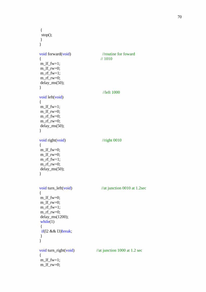
void forward(void) //routine for foward
// 1010
m_lf_fw=1;
m_lf_rw=0;
m_rf_fw=1;
m_rf_rw=0;
delay_ms(50);
//left 1000
void left(void)
m_lf_fw=1;
m_lf_rw=0;
m_rf_fw=0;
m_rf_rw=0;
delay_ms(50);
void right(void) //right 0010
m_lf_fw=0;
m_lf_rw=0;
m_rf_fw=1;
m_rf_rw=0;
delay_ms(50);
void turn_left(void) //at junction 0010 at 1.2sec
m_lf_fw=0;
m_lf_rw=0;
m_rf_fw=1;
m_rf_rw=0;
delay_ms(1200);
while(1)
if(l2 && l3)break;
void turn_right(void) //at junction 1000 at 1.2 sec
m_lf_fw=1;
m_lf_rw=0;
71
m_rf_fw=0;
m_rf_rw=0;
delay_ms(1200);
while(1)
if(l2 && l3)break;
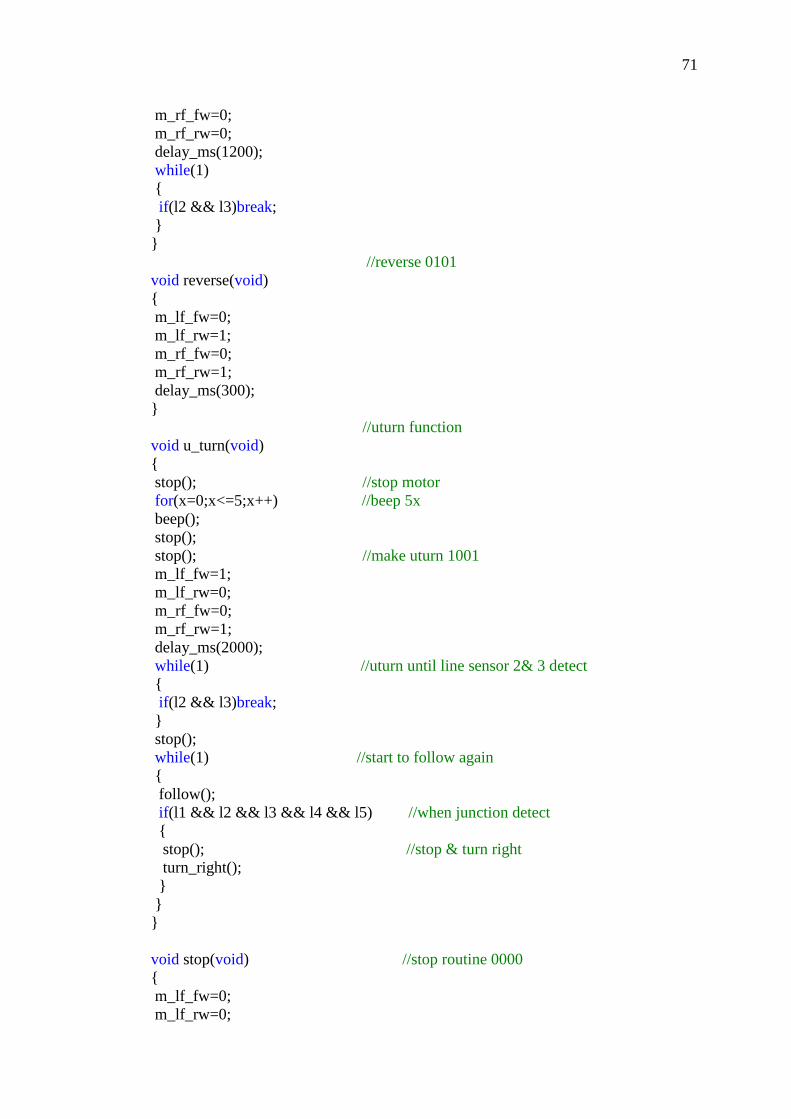
//reverse 0101
void reverse(void)
m_lf_fw=0;
m_lf_rw=1;
m_rf_fw=0;
m_rf_rw=1;
delay_ms(300);
//uturn function
void u_turn(void)
stop(); //stop motor
for(x=0;x<=5;x++) //beep 5x
beep();
stop();
stop(); //make uturn 1001
m_lf_fw=1;
m_lf_rw=0;
m_rf_fw=0;
m_rf_rw=1;
delay_ms(2000);
while(1) //uturn until line sensor 2& 3 detect
if(l2 && l3)break;
stop();
while(1) //start to follow again
follow();
if(l1 && l2 && l3 && l4 && l5) //when junction detect
stop(); //stop & turn right
turn_right();
void stop(void) //stop routine 0000
m_lf_fw=0;
m_lf_rw=0;

72
m_rf_fw=0;
m_rf_rw=0;
delay_ms(200);
void beep(void) //beep buzzer
buzzer=1;
led=1;
delay_ms(100);
buzzer=0;
led=0;
delay_ms(100);

73
APPENDIX B: RC Servo Motor-C36R

74

75

76
APPENDIX C: Microcontroller-PIC16F877A

77

78
APPENDIX D: Line Following Sensor

79

80

81
APPENDIX E: IR Transmitter and Receiver Sensor

82

83

84

85
APPENDIX F: PCB
IR Sensor Circuit

86
Control Circuit

87
Solar Charger Circuit