


Solar Power design manual - Free Shop...
65
Solar Power Design Manual Richard Stubbs
Transcript of Solar Power design manual - Free Shop...

Solar Power
Design Manual
Richard Stubbs

1
http://www.solar-power-answers.co.uk/
Solar Power Design Manual
© 2006 Richard Stubbs
All rights reserved.
Although every precaution has been taken in the preparation of this book,the author assumes no responsibility for errors or omissions. Nor is anyliability assumed for damages resulting from the use of the informationcontained herein.
2
http://www.solar-power-answers.co.uk/
1 Introduction ....................................................................................... 3
1.1 Scope ..................................................................................................................31.2 Experience..........................................................................................................31.3 Disclaimer ..........................................................................................................3
2 Basic Principles.................................................................................. 4
2.1 Volts, Amps and Watts ......................................................................................42.2 The Photovoltaic Effect......................................................................................52.3 Modules..............................................................................................................52.4 Energy Storage ...................................................................................................62.5 Control and Conversion .....................................................................................62.6 Operation............................................................................................................7
3 Suitability ........................................................................................... 8
3.1 Energy requirement ............................................................................................83.2 Other power sources...........................................................................................83.3 Solar resource.....................................................................................................9
4 System Components ........................................................................ 10
4.1 Modules............................................................................................................104.2 Batteries............................................................................................................114.3 Controllers........................................................................................................134.4 Inverters............................................................................................................13
5 Design ............................................................................................... 15
5.1 The design process ...........................................................................................155.2 Initial estimates ................................................................................................155.3 Site Survey .......................................................................................................175.4 System sizing....................................................................................................215.5 Component selection ........................................................................................285.6 Wiring...............................................................................................................37
6 Installation and Commissioning .................................................... 41
6.1 Safety................................................................................................................416.2 Array.................................................................................................................426.3 Battery ..............................................................................................................446.4 Control equipment............................................................................................486.5 System Commissioning....................................................................................49
7 Maintenance..................................................................................... 51
8 Appendices ....................................................................................... 52
8.1 Appendix 1 – Insolation Maps .........................................................................528.2 Appendix 2 – Battery Voltages ........................................................................588.3 Appendix 3 – Cable Data .................................................................................608.4 Appendix 4 – Example wiring diagrams..........................................................628.5 Appendix 5 – Power ratings of common appliances........................................64

3
http://www.solar-power-answers.co.uk/
1 Introduction
1.1 Scope
This book is intended to give the reader sufficient knowledge to designand install a stand-alone solar power system anywhere in the world. Itcovers the principles of photovoltaic power generation and energyconversion and goes on to outline the necessary design and installationprocedures. The resources required are included where necessary andthere are illustrations as appropriate. It is recommended that you read theentire book before attempting any of the procedures within.
1.2 Experience
The reader is assumed to have a certain amount of knowledge andprevious experience including basic electrical and mechanical knowledge.Experience of common tools will be an advantage. Some calculations arerequired although every attempt has been made to make the process ofsystem design as simple as possible.
1.3 Disclaimer
Every care has been taken to ensure that the information contained in thisbook is correct. However, it is based on personal experience and may notbe applicable to every situation. No responsibility is accepted for any losssuffered, either directly or indirectly, as a result of the informationcontained in this eBook.

4
http://www.solar-power-answers.co.uk/
2 Basic Principles
2.1 Volts, Amps and Watts
Throughout this book there are references to Voltage, Current, Power andResistance. It is important to understand what each of these means andhow they relate to each other. The units for each are:
• Voltage: The potential difference between two points. Is measured inVolts (V) and has the symbol ‘V’.
• Current: The flow of electrons in a circuit. Is measured in Amps (A)and has the symbol ‘I’.
• Resistance: A material’s opposition to an electrical current. Is
measured in Ohms (Ω) and has the symbol ‘R’.
• Power: The rate of doing work. Is measured in Watts and has thesymbol ‘P’.
• Energy: The capacity for work, the product of power and time. Has thesymbol ‘E’. The basic unit of energy is the Joule, but electrical energyis normally expressed in Watt hours (Wh) or kilo Watt hours (kWh).One kWh is 1000 Wh.
The relationship between these units is:
Power equals voltage multiplied bycurrent. This can also be expressed inthe other two forms shown.
Voltage equals current multiplied byresistance. Again there are two otherforms shown. This is known as ‘Ohm’slaw’.
Power equals current squaredmultiplied by resistance.
P = VI
or V = P/I or I = P/V
V = IR
or I = V/R or V = I/R
P = I2R

5
http://www.solar-power-answers.co.uk/
2.2 The Photovoltaic Effect
The photovoltaic effect is themeans by which solar panels or‘photovoltaic modules’ generateelectricity from light. A solar cellis made from a semiconductormaterial such as silicon.Impurities are added to this tocreate two layers, one of n-typematerial, which has too many
electrons and one of p-type material which has two few. The junctionbetween the two is known as a p-n junction. This process is known asdoping and is the same technique used to manufacture transistors andintegrated circuits (silicon chips).
Light consists of packets of energy called photons. When these photonshit the cell, they are either reflected, absorbed or pass straight through,depending on their wavelength. The energy from those which areabsorbed is given to the electrons in the material which causes some ofthem to cross the p-n junction. If an electrical circuit is made between thetwo sides of the cell a current will flow. This current is proportional to thenumber of photons hitting the cell and therefore the light intensity.
2.3 Modules
A photovoltaic or PV module is commonly madefrom a number of cells connected together inseries. This is because each cell only produces avoltage of about 0.5 Volts. It is usual for there tobe 36 cells connected together to provide avoltage of about 18 – 20 Volts. This forms amodule which can be used to charge a 12 Voltbattery. Figure 2 shows a typical module. The
separate cells can clearly be seen.
There are also ‘thin film’ moduleswhere the separate cells areformed as part of the manufacturing process. Figure 3shows such a module. This technique is employed for thesmall solar panels which are fitted to calculators andsimilar devices. They are much cheaper to manufacturebut deliver lower efficiency. This means that less of thelight which hits them is converted to electricity. Recentadvances in technology, however, have made larger and
Light
A
n-type
p-type
junction
figure 1: the photovoltaic effect
figure 2: Crystalline
module
figure 3: thin-
film module
6
http://www.solar-power-answers.co.uk/
more efficient thin-film modules available.
Often a number of modules will be connected together into an array inorder to provide more power than a single module can provide.
2.4 Energy Storage
Photovoltaic modules generate electricity only whenthere is light falling on them, and the amount ofpower generated is proportional to the lightintensity. This means that a way has to be found ofstoring the electricity generated and releasing itwhen it is needed. The normal method is to use thesurplus power to charge a lead-acid battery. This isthe same type of battery as used in cars, although thedifferent requirements mean that a car battery is notsuitable, instead a deep-cycle battery is needed.
A battery is made up of a number of cells, eachconsisting of two lead plates in a container of dilute sulphuric acid. Eachcell has a nominal voltage of 2 Volts, so a number are connected in series,for example 6 cells forms a 12 Volt battery.
2.5 Control and Conversion
The electricity generated by the photovoltaic effect is low voltage directcurrent (DC) whereas mainselectricity is much higher voltagealternating current (AC). This meansthat additional devices may be neededto control the battery chargingprocess and convert the power to thecorrect voltage. The two mostcommonly used devices are thephotovoltaic controller and the
inverter. The controller makes sure that the battery is neither over-charged or over-discharged. The purpose of an inverter is to convert lowvoltage DC into higher voltage AC. It does this by first turning the DCpower into AC and then using a transformer to step up to a highervoltage.
V
Lead Plates
Sulphuric
Acid
figure 4: lead-acid
cell
figure 5: controller operation

7
http://www.solar-power-answers.co.uk/
2.6 Operation
The principles ofoperation of atypical stand-alonesolar power systemare shown in figure6. Electricity isgenerated in theform of lowvoltage DC by thephotovoltaicmodules wheneverlight falls on them.
This power isrouted through a controller, which feeds whatever power is necessary toany DC appliances such as lights and uses any surplus to charge a battery.When there is less power being generated than the appliances are using,power flows from the battery to the appliances. The controller monitorsthe battery state of charge and disconnects the appliances if the batterybecomes very discharged.
Any AC (mains) appliances are connected to the inverter. This is notconnected to the controller but directly to the battery. It incorporates itsown control mechanism to ensure that the battery is not over-discharged.
figure 6: power flow

8
http://www.solar-power-answers.co.uk/
3 Suitability
Before starting to design a solar power system it is important to assesswhether solar power provides the best solution to the problem at hand.Solar power is best suited to applications where:
• The energy requirement is modest.
• There is no other source of power available.
• There is a good solar resource.
Despite this, there may be other good reasons for using solar power, forinstance a concern for either the local or global environment, planningconstraints or similar issues.
3.1 Energy requirement
The amount of energy which is required has a direct bearing on the sizeand cost of any proposed solar power system. The energy requirementcan be reduced as discussed in a later chapter, however there are someapplications for which solar generated electricity is very rarely suited.These include space heating, cooking, water heating and any otherapplication where a large amount of heat is required. It may be possible tomeet some of these requirements by more direct capture of solar energy,such as solar water heating systems or passive solar building design.These techniques are outside the scope of this manual, but see the SolarPower Answers website for more information.
There are some applications which easily lend themselves to solar power,such as lighting and computing, but most things will need to be assessedon a case-by-case basis.
3.2 Other power sources
One of the major factors affecting the choice of solar power is theavailability of other potential sources of power. These may include suchthings as gas, diesel, kerosene and firewood. The most important howeveris mains electricity. If mains electricity is available it is very unlikely thatsolar power will be economically viable except for very small energyrequirements where the standing charge is likely to greatly outweigh thecost of the energy. It may, however, still be considered for environmentalor other reasons.
The usefulness of any other source of power is determined by the natureof the energy form required. It isn’t usually sensible to use electricity forheating, as heat is best obtained either directly by solar heating panels orby burning fuel, ideally wood from managed forests as this is a renewable

9
http://www.solar-power-answers.co.uk/
resource. Light is almost certainly better delivered by solar or possiblywind power.
The reasons for choosing a certain fuel may be complex. For example,bottled gas may be a good fuel in a village close to a main road, howeverin a mountain village the cost of transport may make it impractical.
3.3 Solar resource
The availability of a good solar resource has a strong influence on thecost-effectiveness of a solar power system. A country in equatorial Africaoffers great possibilities for solar power, not just because of the lack ofother forms of power but also because of the high levels of sunshinethroughout the year.
This does not mean, however, that solar power is impractical in countriesfurther from the equator. In some remote parts of Great Britain, forexample, the cost of connecting to mains electricity can be prohibitive. Inthis context solar power can be very competitive for moderate energyrequirements.
Ultimately it may be impossible to decide whether or not solar power issuited to a particular application without following the design process.This way an estimate of the likely cost over the life of the project can beproduced, which can then be compared with the costs of the alternatives.The capital costs of solar power systems tend to be high, however therunning costs are low owing to the lack of any fuel costs and low regularmaintenance requirements.

10
http://www.solar-power-answers.co.uk/
4 System Components
In order to design a solar power system it is helpful to have a basicunderstanding of the various system components and their operation. Thefollowing paragraphs describe those components which will commonlybe encountered.
4.1 Modules
4.1.1 Types
As already discussed there are two basic types of solar module,crystalline and thin-film. The characteristics of these are similar but themethod of manufacture is very different.
4.1.1.1 Crystalline
A crystalline module is made from a number of discrete cells, usually 36for a 12 Volt module. These cells have to be assembled and solderedtogether by hand, which goes some way to explaining the relatively highprice of crystalline modules. Each cell is made from a wafer, composedeither of a single crystal (monocrystalline) or many crystals(polycrystalline) of a semiconductor material, usually silicon. Themonocrystalline method produces cells of slightlyhigher efficiency, but for all practical purposes they canbe regarded as the same. Polycrystalline modules can bedistinguished by the obvious crystalline appearance ofthe cells.
4.1.1.2 Thin film
Thin film or “amorphous” modules are made by adifferent process. A thin film of semiconductor materialis deposited on a substrate, usually glass. This substrateforms the body of the module. A laser is then used to score the material inorder to produce individual cells, which produces the characteristicstriped appearance. This method uses less of the semiconductor materialand is easier to automate. The modules thus produced are therefore lowercost. Currently, however, commercially available thin film modulesdisplay significantly lower efficiencies than crystalline modules. Thislimits their use to applications where there is no size restriction on thearray and adds to the cost of installation.
figure 7: thin-film
modules
11
http://www.solar-power-answers.co.uk/
4.1.2 Operation
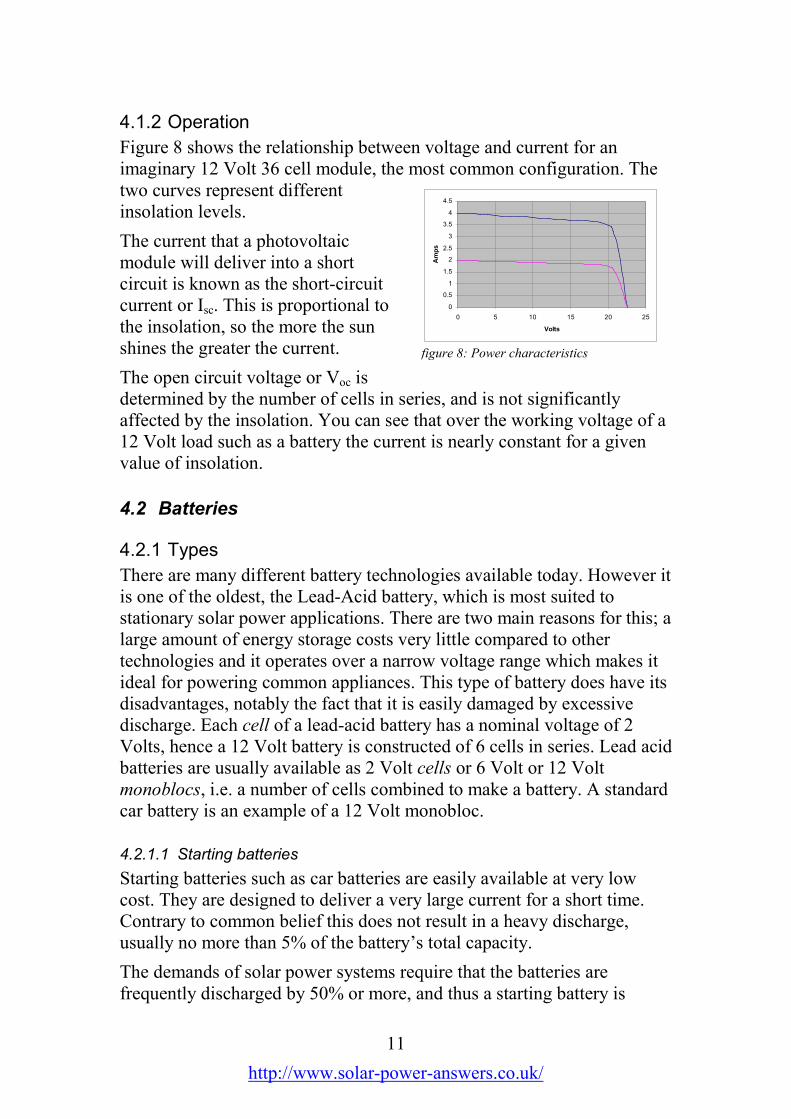
Figure 8 shows the relationship between voltage and current for animaginary 12 Volt 36 cell module, the most common configuration. Thetwo curves represent differentinsolation levels.
The current that a photovoltaicmodule will deliver into a shortcircuit is known as the short-circuitcurrent or Isc. This is proportional tothe insolation, so the more the sunshines the greater the current.
The open circuit voltage or Voc isdetermined by the number of cells in series, and is not significantlyaffected by the insolation. You can see that over the working voltage of a12 Volt load such as a battery the current is nearly constant for a givenvalue of insolation.
4.2 Batteries
4.2.1 Types
There are many different battery technologies available today. However itis one of the oldest, the Lead-Acid battery, which is most suited tostationary solar power applications. There are two main reasons for this; alarge amount of energy storage costs very little compared to othertechnologies and it operates over a narrow voltage range which makes itideal for powering common appliances. This type of battery does have itsdisadvantages, notably the fact that it is easily damaged by excessivedischarge. Each cell of a lead-acid battery has a nominal voltage of 2Volts, hence a 12 Volt battery is constructed of 6 cells in series. Lead acidbatteries are usually available as 2 Volt cells or 6 Volt or 12 Voltmonoblocs, i.e. a number of cells combined to make a battery. A standardcar battery is an example of a 12 Volt monobloc.
4.2.1.1 Starting batteries
Starting batteries such as car batteries are easily available at very lowcost. They are designed to deliver a very large current for a short time.Contrary to common belief this does not result in a heavy discharge,usually no more than 5% of the battery’s total capacity.
The demands of solar power systems require that the batteries arefrequently discharged by 50% or more, and thus a starting battery is
0
0.5
1
1.5
2
2.5
3
3.5
4
4.5
0 5 10 15 20 25
Volts
Amps
figure 8: Power characteristics

12
http://www.solar-power-answers.co.uk/
unsuitable. Attempts to use starting batteries in this way results in a veryshort life and is a false economy.
4.2.1.2 Deep-cycle batteries
The term ‘deep-cycle’ refers to batteries that are designed for regulardischarging by 50% or more. The term is applied to many different formsof battery from small 6 or 12 Volt batteries to much larger batteriesconsisting of separate 2 Volt cells. Most traction batteries, that is thosedesigned to propel electric vehicles such as fork-lift trucks, can also beconsidered to be deep-cycle. The majority of deep-cycle batteries have aliquid electrolyte (acid) which is vented to the atmosphere. Sealed typeswith the electrolyte in the form of a gel are also available, although theirhigher cost limits their use.
4.2.1.3 Leisure batteries
The term ‘leisure battery’ refers to a battery which is a compromisebetween the low cost of a car battery and the long life of a true deep-cyclebattery. They have a much longer life than a car battery when regularlydischarged and are much less expensive than a true deep-cycle battery.Their use is common in applications such as caravans, where the usagepattern is not as intensive.
4.2.2 Operation
4.2.2.1 Charging
The voltage at which a lead-acidbattery is charged must be strictlyregulated. If the charging voltage istoo high, then excessive gassing willoccur, leading to loss of electrolyteand possible plate damage. On theother hand, too low a voltage will leadto the plates becoming ‘sulphated’which causes a loss of capacity.Figure 9 shows the relationship between voltage and current in a constantvoltage charging regime.
0 2 4 6 8 10 12
Time
Voltage Current
figure 9: charging
13
http://www.solar-power-answers.co.uk/
4.2.2.2 Discharging
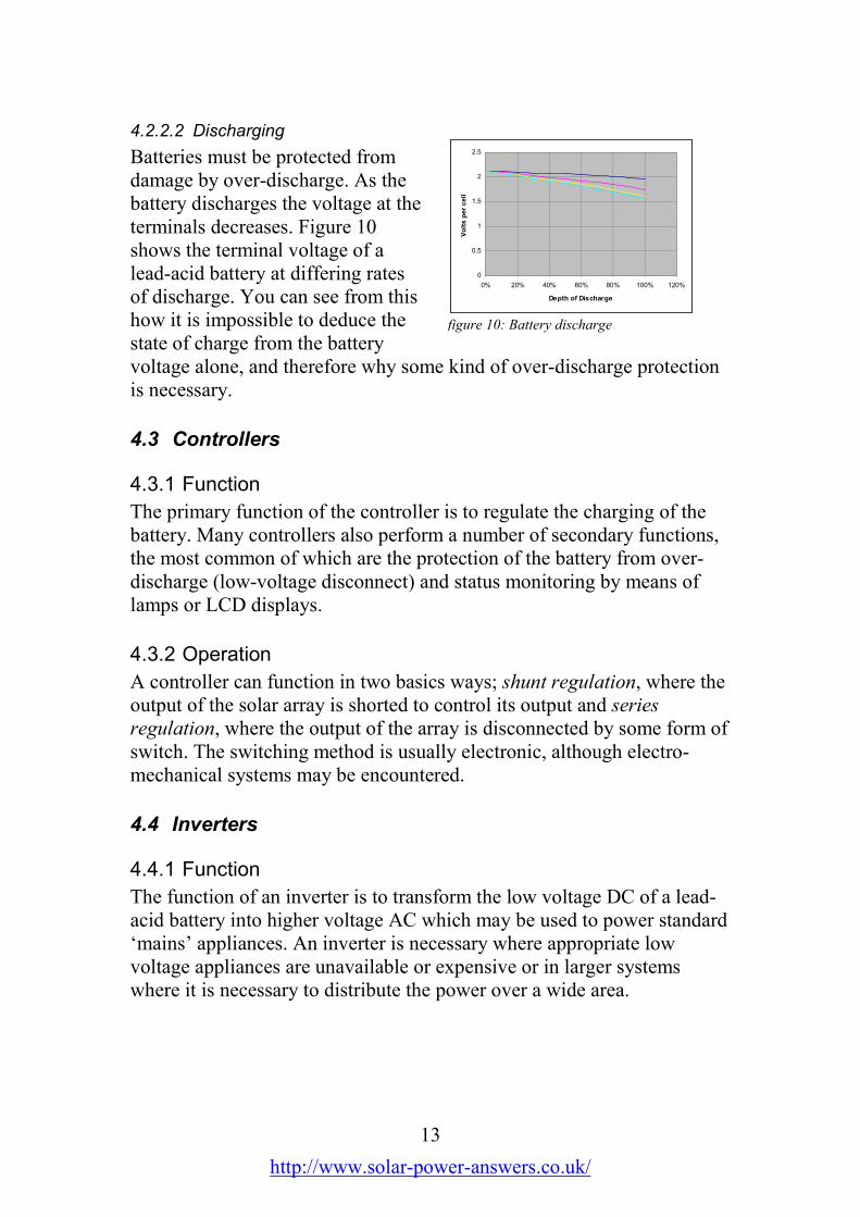
Batteries must be protected fromdamage by over-discharge. As thebattery discharges the voltage at theterminals decreases. Figure 10shows the terminal voltage of alead-acid battery at differing ratesof discharge. You can see from thishow it is impossible to deduce thestate of charge from the batteryvoltage alone, and therefore why some kind of over-discharge protectionis necessary.
4.3 Controllers
4.3.1 Function
The primary function of the controller is to regulate the charging of thebattery. Many controllers also perform a number of secondary functions,the most common of which are the protection of the battery from over-discharge (low-voltage disconnect) and status monitoring by means oflamps or LCD displays.
4.3.2 Operation
A controller can function in two basics ways; shunt regulation, where theoutput of the solar array is shorted to control its output and seriesregulation, where the output of the array is disconnected by some form ofswitch. The switching method is usually electronic, although electro-mechanical systems may be encountered.
4.4 Inverters
4.4.1 Function
The function of an inverter is to transform the low voltage DC of a lead-acid battery into higher voltage AC which may be used to power standard‘mains’ appliances. An inverter is necessary where appropriate lowvoltage appliances are unavailable or expensive or in larger systemswhere it is necessary to distribute the power over a wide area.
0
0.5
1
1.5
2
2.5
0% 20% 40% 60% 80% 100% 120%
Depth of Discharge
Volts per cell
figure 10: Battery discharge
14
http://www.solar-power-answers.co.uk/
4.4.2 Operation
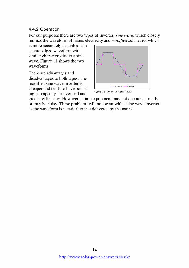
For our purposes there are two types of inverter; sine wave, which closelymimics the waveform of mains electricity and modified sine wave, whichis more accurately described as asquare-edged waveform withsimilar characteristics to a sinewave. Figure 11 shows the twowaveforms.
There are advantages anddisadvantages to both types. Themodified sine wave inverter ischeaper and tends to have both ahigher capacity for overload andgreater efficiency. However certain equipment may not operate correctlyor may be noisy. These problems will not occur with a sine wave inverter,as the waveform is identical to that delivered by the mains.
Sinew ave Modified
figure 11: inverter waveforms

15
http://www.solar-power-answers.co.uk/
5 Design
5.1 The design process
The system design process consists of four major steps. These are:
• Initial estimates
• Site survey
• System sizing
• Component selection
The order in which these are performed will depend on the amount ofinformation available in advance and factors such as the ease of visitingthe site. If detailed information regarding the location of the site and theintended loads are available then it may be possible to size the systembefore a site visit takes place.
5.2 Initial estimates
Before the commencement of the design process proper, you will need tohave at least a rough idea of what you hope to achieve, for example: “Toprovide lighting and refrigeration for a holiday home”. From this it willbe possible to produce initial estimates to feed into the system designprocess. The following paragraphs expand on this example.
5.2.1 Load estimates
In order to estimate the load requirement we need to get an idea of thetype of usage the system will be put to. For the above example of aholiday home we should be able to discover how many rooms it has andhow many people will be likely to be in residence. If we make thefollowing assumptions:
• There are 3 rooms, one of which is a bedroom, therefore;
• There will be no more than 2 people in residence.
Then we can estimate the lighting and refrigeration as follows.
5.2.1.1 Lighting
From the above we know that there are three rooms, so the total numberof lights required is 3. Now we need to estimate the average daily usageof each light.
The first thing we can deduce is that, if there are two people then thereneed not be more than 2 lights on at any one time. Then we can make an

16
http://www.solar-power-answers.co.uk/
estimate of the amount of time between darkness falling and the residentsretiring. Let us say that is 8 hours.
Now, let us assume that the occupants spend half of this time together. Inthat case one of the lamps will be on for half of the time (4 hours) and theother for all of the time (8 hours). So this gives us a figure of 3 lamps anda total of 12 hours, hence each lamp is on for an average of 4 hours perday.
Lastly, you need to estimate the power consumption of each lamp. This isa matter of picking a type of lamp which you think will be suitable byexamining the lamps available to you. For this example let’s assume thatan 11 Watt, 12 Volt fluorescent lamp is selected.
5.2.1.2 Refrigeration
Estimating the refrigeration requirement is rather more straightforward.All that is necessary is to find a suitable (12 Volt) refrigerator in amanufacturer’s catalogue and look up its daily energy consumption. Thiswill be determined by the ambient temperature so an estimate of that willbe helpful. For the purposes of this example let’s assume an energyconsumption of 600 Wh/day at a 25°C average.
5.2.1.3 Other loads
The energy requirement for any other loads is calculated in the same wayas that for the lighting. The power consumption of each item is multipliedby the number of hours it will be used in a day to give the energyconsumption in Wh/day.
5.2.1.4 Phantom loads
Phantom loads is the name given to those appliances which use powereven when they are switched off. Example include audio-visualequipment such as televisions and video recorders and anything whichhas the power supply built into the plug. Anything that falls into thiscategory should be unplugged when not in use or provision made toswitch off its supply. However there may be appliances which need toremain plugged in. The standby consumption of any such appliance mustbe treated as an additional load which is in use for all the hours of the daythat the appliance itself is not in use.
5.2.2 Location
The intended location of the system will determine the solar resourcewhich is available. This in turn will allow the size of the solar array to be

17
http://www.solar-power-answers.co.uk/
calculated. For the purpose of this example, let’s assume that the holidayhome is in northern Portugal.
5.2.3 First iteration
From the initial problem:
“To provide lighting and refrigeration for a holiday home”
we have now arrived at:
“To design a solar power system to be installed in northern Portugal, to
power three 11 Watt lamps for an average of 4 hours per day and a
refrigerator with an energy requirement of 600 Watt-hours per day”
Following the system sizing process (section 5.4) will show whether thisis a practical system. If not, then make changes to the requirements andstart again. For instance, in this example the refrigerator consumes farmore energy than the lighting. If the system is likely to be too expensive,then consider using a gas refrigerator instead. The capital cost will belower, but there will be a fuel cost to take into account.
5.3 Site Survey
In some cases it may be necessary to complete the design without havingvisited the site, in which case certain assumptions will need to be made.In these circumstances it would be advantageous to obtain photographs ofthe site and the surrounding area if possible, or failing that a detaileddescription.
The various points of the site survey are covered in the followingparagraphs. It will be helpful to take photographs of the site for referencelater. Pay particular attention to those areas chosen for the various systemcomponents; as the design progresses these will be invaluable.
5.3.1 Shading
The first and most obvious check is to ensure that the sun actually shineson the site. From the projected position of the system survey the horizonover the entire arc of the sun. In the northern hemisphere you should belooking towards the south, east and west and in the southern hemispherethe north, east and west. Very close to the equator the sun passes virtuallyoverhead, so only the east and west are important.

18
http://www.solar-power-answers.co.uk/
You should be looking for anything which will shade the solar array atany time of the year, including such things as:
• Trees. If it is winter when you visit, remember that some trees willlook very different in summer. Also include sufficient space for 20years of growth.
• Hedges. Again allow for these to grow significantly during the life ofthe system.
• Mountains and hills. Remember that the sun will be much closer to thehorizon in the winter. If it is summer when you visit, ask someonelocal where the sun rises and sets in the winter.
• Buildings. Ask around to ensure that no building work is plannedwhich will obscure the site.
• Climate. Find out if there is anything unusual about the climate in thelocal area such as sea mist.
Try to imagine what the site will look like all the year round and in yearsto come. You may find it helpful to make a sketch of the surrounding areafor later reference.
5.3.2 Array location
It will be necessary to find a position for mounting the solar panel orarray. If the system is to be installed in a building, then it is common forthe array to mounted on theroof of the building asdescribed below. If this isnot possible then analternative site will need tobe found.
5.3.2.1 Roof
The ideal is for a roof with aslope towards the south if inthe northern hemisphere orthe north if in the southernhemisphere. The angle ofthis slope to the horizontal needs to be about equivalent to the angle oflatitude plus 15°. It is very unlikely that these conditions will be met,however the roof is still likely to be the best place if it slopes in roughlythe right direction or is flat. If it is flat, however, it will be necessary toarrange some type of angled support such as that used for groundmounting.
25° N
40°
S
Array
figure 12: roof mounting

19
http://www.solar-power-answers.co.uk/
If possible gain access to the roof in order to survey it more thoroughly.
Check the following:
• Shading. See section5.3.1.
• Direction. Use a compassto check what direction theroof slopes towards.
• Angle of slope. Use aspirit level to measure theangle of the roof from thehorizontal.
• Material of construction. If necessary also check underneath the roofto see what fixings will be needed and ensure that the structure isstrong enough to support the weight of the array.
• Area. Measure and record the dimensions of the usable part of thesurface of the roof. Estimate whether this will be sufficient for the sizeof array that is likely to be needed.
If it appears that the roof will not be suitable then it will be necessary tofind a site for an alternative form of support.
5.3.2.2 Ground mounting
In the absence of a roof or similar structure to mount the array on it willbe necessary to use some form of support structure. Solar equipmentsuppliers sell different types of structure or it may be possible to fabricatea support on site. There are two basic types as illustrated in figure 14:
• Ground mounted, wherethe structure is a framemounted on the groundwhich requires afoundation, and
• Pole mounted, which canbe attached to anexisting pole or a poleerected for the purpose.
figure 13: solar roof
figure 14: support structures

20
http://www.solar-power-answers.co.uk/
The survey should take account of:
• Shading.
• Ground conditions, for the purposeof building foundations.
• Available area of ground.
• Distance from location of batteriesfor cable sizing.
• Any suitable poles.
5.3.2.3 Other options
There may be other mounting systems available.For example, figure 16 shows a system wherethe modules are mounted with other systemcomponents on a south-facing gable end. If thereis no potential for roof or ground mounting thenit may be that there is another solution whichwill suit the needs of the planned installation.
5.3.3 Batteries
5.3.3.1 Location
A suitable position must be found for the batteries. This may be a roomwithin a building, a separate building or a place where some kind ofhousing can be erected. The following conditions need to be met:
• Environmental protection. The batteries need to protected fromrainfall, direct sunlight and extremes of temperature.
• Ventilation. All lead-acid batteries, even sealed types, need to beadequately ventilated in case of gassing.
• Protection from sources of ignition. When under charge vented lead-acid batteries give off an explosive mixture of hydrogen and oxygen,so must not be exposed to any sources of ignition such as nakedflames.
• Personal safety. Because of the explosive gasses given off and thepotential for extremely high currents, batteries must be kept in asecure place away from children.
Consideration should also be given to the likely location of the othersystem components. The aim should be to ensure that the cable runs arekept as short as possible.
figure 15: ground mounted array
figure 16: gable end

21
http://www.solar-power-answers.co.uk/
5.3.3.2 Mounting
Where a suitable location indoors has been identified, it will often beacceptable to place the batteries directly on the floor. If not, it may benecessary to mount the batteries in a battery box or on racking in order tomake best use of the available space or to offer them adequate protection.
Consideration should be given to the likely shape of any such boxes orracking, and the area measured to ensure that the batteries will fit asintended.
5.3.4 Control equipment
It is usual for the controller, inverter and other control equipment to bewall-mounted. An indoor location will be needed, as close to the batteriesas possible. There is often a restriction on how long the battery cables canbe, so it is important to ensure that this can be met.
Inverters in particular are often quite heavy. Assess the chosen wall so asto ensure that it will be able to take the likely weight of the equipment.
5.3.5 Loads
The site survey provides an opportunity to more accurately assess theloads, for instance the lighting requirement, where the system is to beinstalled in an existing building. If possible ask people about the use towhich each room is put and times during which it is occupied.
It is possible that there may be existing electrical wiring, for example if agenerator is used. It may be possible to use all or part of this for the solarapplication. If this is the intention, then inspect the wiring and record itsconfiguration.
5.3.6 Cabling
Take the opportunity to consider likely routes for the cabling, especiallythe heavy cables running from the controller to the array and the batteries.Measure the approximate length of these cables so that they can becorrectly sized.
5.4 System sizing
System sizing is the process of determining the size of the various systemcomponents, for instance the peak power rating of the array or the currentrating of the controller. The selection of the components themselves iscovered in section 5.5.
I have written a Microsoft Excel template, ‘Solar sizing.xlt’, whichperforms the calculations described in this chapter, which is available for

22
http://www.solar-power-answers.co.uk/
download from the Solar Power Answers website. If this is not availablefor whatever reason then the calculations can be performed by hand orwith an electronic calculator.
There are a number of steps to be followed. It may also be necessary toperform a number of iterations; if the result of the sizing process is not asexpected it may be necessary to repeat the process a number of times.
5.4.1 Loads
The first part of the process is tocalculate the daily energyrequirement of the proposedsystem in Watt-hours per day.
5.4.1.1 Assessment
For each load determine thepower rating in Watts. This maybe found on the appliance or inthe manufacturer’s data. Thepower rating may also be stated in kilowatts or kW where 1 kW = 1000W. If this information is not available then appendix 5 gives approximatepower ratings for common appliances. Now determine now many of eachappliance is needed and the average daily hours of use. Enter thesefigures in the appropriate columns as shown in figure 17 or use thisequation:
E = n x P x T
Where:
E is the energy requirement in Wh/dayn is the number of appliancesP is the power rating in WattsT is the average usage in hours
For any mains voltage or AC appliances it is necessary to account forinverter efficiency. This is because some power is lost when an inverterconverts low voltage DC into high voltage AC. Divide the result aboveby 0.9 (90%) unless you know the efficiency of the actual inverter thatwill be used.
Now total the results for all the loads:
ET = E1 + E2 + …
Where:
ET is the total energy requirementE1, E2,… are the energy requirements of the individual loads
This will give a total figure for the energy requirement of the system.
Appliance Quantity Rating (W) Usage (h) Wh/day each Total Wh/day
Lamp 3 11.00 4.0 44 132
Computer 0 0
Television 0 0
Radio 0 0
Fridge 1 600 600
Other 0 0
0 0
0 0
0 0
0 0
0 0
0 0
0 0
Total 732
figure 17: load calculation

23
http://www.solar-power-answers.co.uk/
For the example above the result is 732 Wh/day.
5.4.1.2 Optimisation
It is worth paying some attention to optimising the load, that is decreasingthe energy consumption to its practical minimum. From the figures aboveit will be apparent which of the loads are the most significant in terms ofenergy consumption. Consider whether there are any gains to be made,for instance by using a smaller number or more efficient appliances, using12 Volt instead of 230 Volt appliances or using a different energy sourcefor some appliances.
Repeating the steps at sections 5.4.1.1 and 5.4.1.2 until the optimum isreached will pay dividends later in the process.
5.4.1.3 System voltage
At this stage it will help to decide on the system voltage, that is thevoltage of the battery bank. The choice is normally dependent on theloads which it is necessary to power. If there are loads which are 12 Volt,then obviously it makes sense for the system voltage to be 12 Volts.However if there is a large 230 Volt requirement then it may be necessaryto consider 24 Volts or even 48 Volts in order to obtain a suitableinverter.
There are no fixed rules for the choice of system voltage. On balance it isprobably best to use 12 Volts unless there are compelling reasons to use adifferent voltage. This choice may also affect your choice of loads, and itmay therefore be necessary to repeat the assessment and optimisationprocesses.
5.4.2 Solar array
The size of the solar array is determined by the daily energy requirementand the solar resource or insolation available to the system. The greaterthe energy requirement the larger the solar array needs to be and thegreater the insolation the smaller the array.

24
http://www.solar-power-answers.co.uk/
5.4.2.1 Insolation
Insolation is a measure of theamount of solar energyfalling on an area. The usualmeasure is kWh/m
2/day. That
is kilowatt-hours (thousandsof Wh) per square metre perday.
Insolation data may beobtained from a variety ofdifferent sources such asmeteorological agencies. Figure 18 is an example of an insolation mapgenerated by NASA’s web site at http://eosweb.larc.nasa.gov/sse/. It iswell worth subscribing to this service which is free at the time of writing.
If local data is not available then appendix 1 provides a set of globalinsolation maps derived from the NASA data which will providesufficient accuracy for most purposes.
The aim is to determine a figure for ‘design insolation’. This is theminimum daily average insolation available to the system. The figureused should be from the month with the least insolation, based onwhichever months of the year the system is intended to be used. Thefigure arrived at is likely to be between 1 and 6 kWh/m2/day.
For our holiday home example, assuming that it may be used at any timeduring the year, a figure of 3.5 kWh/m2/day is appropriate. Thisrepresents the lowest monthly average insolation for Portugal, from theinsolation maps in appendix 1.
5.4.2.2 Efficiency
Having determined a figure for design insolation the efficiency of thebattery charging process must be considered. There are two factors totake into account; power point efficiency and charge cycle efficiency.
5.4.2.2.1 Power point efficiency
As shown in figure 19, the peakpower output of a solar module isproduced at the ‘knee’ of the outputcurve. In this example this is at 20Volts, where the current is 3.5 Amps.Therefore the peak power output is:
20 x 3.5 = 70 Watts
figure 18: insolation map
0
0.5
1
1.5
2
2.5
3
3.5
4
4.5
0 5 10 15 20 25
Volts
Amps
figure 19: typical output

25
http://www.solar-power-answers.co.uk/
However the battery charging voltage is likely to be between 13 and 14Volts. From the graph we can see that at 14 Volts the current isapproximately 3.75 Amps. This gives a power output of:
14 x 3.75 = 52.5 Watts
Hence the efficiency is:
52.5 / 70 = 0.75 or 75%
If you have a copy of the output curve for the particular modules whichyou intend to use, then calculate the efficiency as described. Otherwiseuse the figure of 0.75 as this is a reasonable approximation for thepurposes of system sizing.
5.4.2.2.2 Charge cycle efficiency
The charge cycle efficiency is a measure of the proportion of the energyused to charge a battery which is returned when the battery is discharged.The actual efficiency of a particular battery may be obtained from themanufacturer, however an approximation will suffice. For this purposeassume an efficiency of 0.95 or 95%.
5.4.2.3 Sizing calculation
All the variables necessary to size the solar array are now known. Enterthe values into the spreadsheet asshown in figure 20, or proceed asfollows:
The sizing calculation is:
S = (E / i) / (epv x ebat)
Where:
S = Array size in peak Wattsor Wp
E = Daily energy requirementin Wh/day from section 5.4.1i = Insolation in kWh/m2/dayepv = Power point efficiencyebat = Charge cycle efficiency
It can be seen that the result of this calculation is not dependent on thesystem voltage, as it refers to the power output of the array rather thanthe current or voltage.
Figure 20 gives the result of this calculation for the example holidayhome system.
Insolation 3.5 kWh/m2/day
Charge cycle 95% % efficiency
Power point 75% % mismatch
Load 732 Wh/day
Holdover 3 Days
System Voltage 12 Volts
Depth of discharge 50% % d.o.d.
PV requirement 294 Wp
Battery requirement 366 Ah
figure 20: sizing calculation

26
http://www.solar-power-answers.co.uk/
5.4.3 Battery
Battery sizing is the process of ensuring that there is sufficient batterycapacity to support the loads during such times as there is insufficientenergy available from the solar array. As battery capacity is relativelycheap, it may be thought that it is impossible to have too great a batterycapacity. This is a fallacy, as it is important to ensure that the battery isfully charged on a regular basis to prevent damage through sulphation.An overly large battery in comparison to the size of the array will notreach full charge as it will require a greater charging current than thearray can deliver.
Battery capacity is measured in Ampere-hours (Ah) at the system voltage,and is derived as a function of the daily energy requirement, the‘holdover’ requirement and the ‘depth of discharge’ limit.
5.4.3.1 Holdover
The holdover is simply defined as the number of days that the load isrequired to operate without any charging input from the solar array. Itshould be noted, however, that at most latitudes there is no such thing as aday with no sun. Even overcast winter days can provide some usefulcharging input, so no system will ever be required to operate entirelyfrom the battery for the holdover period.
The required holdover period is determined by the security of supplyrequired. There is no hard and fast rule, but for general applications suchas lighting and domestic purposes a figure of 3 days should be adequate.For more critical application such as medical refrigeration a period of 7days should be considered. If there is another source of charging inputsuch as a diesel or wind generator then it is possible to reduce theholdover. If a modular battery system is chosen then it will be relativelyeasy to increase the battery capacity at a later date should it provenecessary.
5.4.3.2 Depth of discharge
The depth of discharge is the proportion of the battery’s capacity that canbe used by the loads without recharging. It is the opposite of the state ofcharge; a depth of discharge of 80% is equivalent to a state of charge of20%.
The design depth of discharge is determined by the type of battery usedand the expected life, balanced against the cost of the battery. A leisuretype battery will typically be used to a depth of discharge of between30% and 50%, whereas a deep-cycle or traction battery will be dischargedto between 50% and 80%. This should be considered a practical

27
http://www.solar-power-answers.co.uk/
maximum, as there is no type of lead-acid battery which can safely becompletely discharged on a regular basis.
It is a fallacy that lead-acid batteries last longer when regularly deeplydischarged. The life of a lead-acid battery is shortened by each charge /discharge cycle, by an amount roughly proportional to the depth ofdischarge of that cycle.
5.4.3.3 Sizing calculation
Once you have arrived at figures for the holdover and depth of discharge,enter these into the spreadsheet (figure 20). Alternatively follow thismethod:
The sizing calculation is:
C = (E x h / d) / V
Where:
C = Battery capacity in ampere-hours (Ah)E = Daily energy requirement in Wh/day from section 5.4.1h = Holdover in daysd = Depth of discharge expressed as a decimalV = System voltage
See figure 20 for the results of the battery sizing calculation for ourexample.
5.4.4 Allowing for expansion
Depending on the use that the system is going to be put to, you may needto consider the possibility of future expansion. In this case, the controllerin particular should be sized to meet the future maximum size of thearray. Batteries and modules can be added to, although it’s always best touse only components that are the same as the ones already installed.
In the case of a later expansion of battery capacity, it is important toconsider whether the existing battery is close to the end of its life. If it is,then it would be better to replace the entire battery with one of largercapacity, rather than add to an old battery, only to have to replace theexisting cells a short time later.
5.4.5 Hybrid systems
It is common to combine solar power with other forms of generation,either renewable or conventional. Any supplemental battery chargingsource must be connected directly to the battery terminals and not via thesolar charge regulator. The most common types of hybrid systems arecovered briefly here.

28
http://www.solar-power-answers.co.uk/
5.4.5.1 Wind turbines
Wind turbines offer a good complement to solar photovoltaics. After all,there aren’t many days which are neither sunny nor windy. In order tocalculate the solar component of such a system it is necessary to know themonthly output of the wind turbine. Once this is known, then the solarpart of the system can be sized as above, performing a separatecalculation for each month of the year, and subtracting the dailycontribution from the wind turbine (monthly output divided by number ofdays in the month) from the load requirement. You will also need to usethe insolation figure for that particular month.
5.4.5.2 Diesel generators
In many systems a diesel or petrol engined generator is used either toensure security of supply or to supplement the solar output during thewinter months. The generator is usually wired through a changeover relayto replace the inverter when running, and also to a battery charger so thatthe batteries will be replenished at the same time.
The battery charger chosen should be a model designed for this type ofapplication, and sized in consultation with the generator manufacturers.The maximum sized battery charger that a given generator can operatewill be significantly smaller than the generator rating suggests.
Some inverters are capable of remotely starting a generator when thebattery needs charging, thus allowing the system to be completelyautomated. Some incorporate a battery charger with automatic switchingbetween inverter and generator.
5.5 Component selection
The selection of the components of a solar power system is determined bytheir electrical characteristics. However there are other factors includingprice, availability and the necessity for any parts to fit in the spaceavailable.
5.5.1 Solar array
The solar array consists of more than just the modules. There is also thesupport structure and cabling to consider. The selection of the solar arraydepends on the particular installation as follows.
5.5.1.1 Modules
The prime consideration when choosing modules is usually their cost perWatt. This is the price of the module divided by the peak wattage, forexample if a 50 Wp module costs $200, then it is said to cost $4 per watt.
29
http://www.solar-power-answers.co.uk/
This is not the only consideration however. The following points shouldalso be taken into account:
• Physical size. It is likely that thin-film modules will be bigger thancrystalline for the same power rating. Likewise a large number ofsmall modules is likely to occupy a larger area than a small number oflarge modules. The space available for mounting may thereforedetermine which modules are chosen.
• Support structure. If it is intended to purchase a ready-made supportstructure then they may only be available for certain combinations ofmodules. Also a support structure for many small modules is likely tocost more than one for a few larger modules. The greater flexibilitymay, however, outweigh this disadvantage.
• Cabling and installation. Again there will be more cabling for a largernumber of modules. This will increase the time needed for installationand the quantity of cable required.
• Fit to system. How closely it is possibleto meet the system requirements shouldbe considered. For instance, if aminimum of 60 Watts at 12 Volts isneeded, then three 20 Watt moduleswould be a better fit than two 50 Wattmodules, and may be cheaper. However, if the system were 24 Volts,then four 20 Watt modules would be needed, which would be moreexpensive.
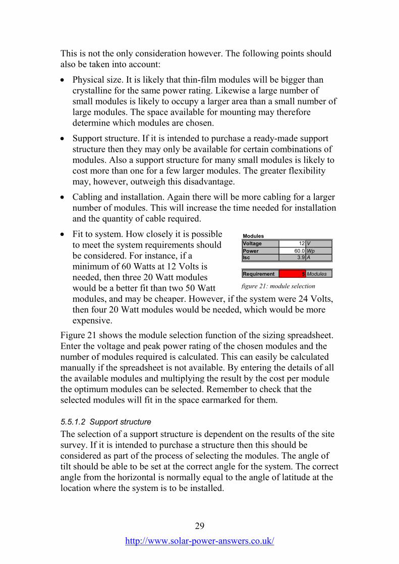
Figure 21 shows the module selection function of the sizing spreadsheet.Enter the voltage and peak power rating of the chosen modules and thenumber of modules required is calculated. This can easily be calculatedmanually if the spreadsheet is not available. By entering the details of allthe available modules and multiplying the result by the cost per modulethe optimum modules can be selected. Remember to check that theselected modules will fit in the space earmarked for them.
5.5.1.2 Support structure
The selection of a support structure is dependent on the results of the sitesurvey. If it is intended to purchase a structure then this should beconsidered as part of the process of selecting the modules. The angle oftilt should be able to be set at the correct angle for the system. The correctangle from the horizontal is normally equal to the angle of latitude at thelocation where the system is to be installed.
Modules
Voltage 12 V
Power 60.0 Wp
Isc 3.9 A
Requirement 5 Modules
figure 21: module selection

30
http://www.solar-power-answers.co.uk/
It is perfectly feasible to manufacture a support system on site from steelor aluminium or even wood. Galvanised perforated steel angle is ideal.The design of the structure must take account of the worst case windloading, which will be significant, especially if the structure is roof-mounted.
5.5.1.3 Cabling
It may be possible to purchase ready-made cables known as arrayinterconnects. These are short cables cut to the correct lengths to connectthe modules together and are resistant to ultra-violet light. Alternatively itis possible to make these on site; this is covered in the section oninstallation.
5.5.2 Battery
There are many options for the system battery, and for systems with abattery requirement of much more than a few hundred Amp-hours it isbest to seek the advice of a specialist battery supplier. Batteries areavailable as individual cells or as ‘monobloc’, that is a number of cells ina single battery in the same way as a car battery.
5.5.2.1 Configuration
A battery can be made up in many ways. For example a 24 Volt, 200Amp-hour battery may be configured as,for example:
1. Four 12 V, 100 Ah monoblocs inseries / parallel.
2. Four 6 V, 200 Ah monoblocs inseries.
3. Twelve 200 Ah cells in series.
For low cost domestic applications the normal choice is leisure batteries.These are usually 12 Volt monoblocs with a capacity between about 60Ah and 110 Ah.
Remember that, as the battery capacity is expressed in Amp-hours, twicethe number of cells will be required for the same capacity at 24 Volts thanat 12 Volts. For example, a 12 V, 100 Ah battery may consist of a singlemonobloc. Two of these monoblocs in series would constitute a 24 V,100 Ah battery.
Figure 24 shows the battery selection table of the sizing spreadsheet.
Batteries
Voltage 12 V
Capacity 100 Ah
Requirement 4 Batteries
figure 22: battery selection

31
http://www.solar-power-answers.co.uk/
5.5.2.2 Lifetime
The life of a battery is normally expressed in two ways. ‘Life in floatservice’ is the life of a battery in years if it is always on charge and neverdischarged. This is the practical maximum life. ‘Cycle life’ is expressedas a number of cycles to a particular depth of discharge, e.g. 300 cycles to80% d.o.d. This is sometimes available from the manufacturer in the formof a graph or table showing the cycle life versus the depth of dischargesuch as that in figure 23.
Determining the life of a battery ina solar power system is notstraightforward. It is difficult toaccurately predict the number ordepth of discharges as this isdetermined by the weather and theusage pattern. An approximationcan be made by dividing thenumber of days in the year (365) bythe number of days holdover in thesystem, so a system with 3 daysholdover would perform approximately 120 cycles annually.
From this information can be determined the expected life of the battery,for example a battery with a cycle life of 1000 cycles to 50% d.o.d., in asystem designed for 3 days holdover to 50% d.o.d., will last around 8 to8½ years. The optimum battery life is reached when the cycle life is equalto the life in float service. Any further increase in capacity will not extendthe life of the battery.
5.5.2.3 Sealed or vented
Traditional lead acid batteries usually include vented caps which allowlost electrolyte to be replenished. Many modern batteries are sealed.Sealed batteries come in three types; liquid, AGM and Gel. Many of thebatteries which are generally referred to as ‘gel’ batteries are in fact AGMbatteries, where the electrolyte (acid) is contained in an absorbentmaterial between the plates, preventing spillage. In a true gel battery theelectrolyte is a jelly. As a general principle AGM batteries can provide ahigher current where gel batteries have a longer cycle life, although this isby no means universal.
0
200
400
600
800
1000
1200
1400
1600
1800
2000
0 20 40 60 80 100 120
Depth of Discharge
Cycles
figure 23: cycle life

32
http://www.solar-power-answers.co.uk/
In general, it is better to use a traditional vented battery whereverpossible. Reasons for using a sealed battery include:
• Freedom from explosive gasses
• Maintenance free
• Ease of transporting
However these are outweighed in many applications by the significantlyhigher cost and frequently shorter lifespan, especially at high ambienttemperatures.
5.5.3 Controller
The selection of the controller is determined by four factors; the systemvoltage, the array (input) current, the load (output) current and the type ofbattery. If it is not possible to find a controller with the correctspecifications, then it may be necessary to change the system voltage andrepeat the sizing calculations.
5.5.3.1 Voltage
The chosen controller must be able to operate at the system voltagechosen in the section on sizing. Many controllers can operate at morethan one voltage; some automatically select the correct voltage.
5.5.3.2 Array current
The maximum array current is the short circuit current (Isc) of anindividual module multiplied by the number of modules in parallel. Forexample, in a 12 Volt system with four modules with a short-circuitcurrent of 4 Amps each, the array current is 16 Amps. For a 24 Voltsystem with the same modules, there are only two in parallel so the arraycurrent is 8 Amps.
5.5.3.3 Load current
If the system has low voltage DC loads, such as lamps, then it is generallynecessary to wire these via the controller. For this purpose it is necessaryto select a controller with a battery protection or low voltage disconnectfacility which automatically disconnects the loads. The load or outputcurrent is determined by calculating the maximum number of applianceswhich are likely to be switched on at the same time and adding up thecurrent consumption of them all.

33
http://www.solar-power-answers.co.uk/
5.5.3.4 Battery type
If it is decided to use sealed batteries, then it is important that thecontroller chosen is suitable. Vented batteries require a higher voltage‘boost charge’ periodically which would damage a sealed battery.Suitable controllers have a facility which disables this boost charge.
5.5.4 Inverter
There are four things to consider when choosing an inverter; input,output, power rating and waveform.
5.5.4.1 Input
As with the controller, the input voltage of the inverter is determined bythe system voltage. Larger inverters tend to be more expensive or have alower rating in 12 Volt versions than 24 or 48 Volt, so it may be worthconsidering a higher system voltage if there is a lot of AC load.
5.5.4.2 Output
The output voltage and frequency are determined by the input voltage ofthe appliances that the system is designed to power. This is generallydetermined by the mains supply of the country that it is to be installed inor where the appliances were bought. For example, in Europe the outputwould need to be 230 Volts at 50 Hertz, whereas in the USA it would be110 Volts at 60 Hertz. It is very important that this is correct.
5.5.4.3 Power rating
The power rating is the maximum continuous power that can be suppliedto the loads. This is determined by adding up the power consumption inWatts of all the appliances that are likely to be switched on at any onetime. Many inverters have a large overload capacity, which means thatthey can provide substantially more than the rated output for short periodsof time. This is useful where motors have to be started, particularly inrefrigeration systems.

34
http://www.solar-power-answers.co.uk/
5.5.4.4 Waveform
The choice between a modified sinewave and pure sine wave inverter isnot straightforward. The advantages ofa modified sine wave are:
• Low cost
• High overload capacity
• High efficiency
And of a pure sine wave are:
• Low noise
• Compatible with all appliances
Recent advances have reduced the cost and increased the efficiency ofpure sine wave inverters so that the differences are less clear-cut,especially in the case of larger inverters.
The types of appliances that are incompatible with a modified sine waveinverter are those with a crude power supply, such as certain small batterychargers and those requiring a noise-free supply, such as musicequipment.
5.5.5 Appliances
The selection of most appliances will already have been consideredduring the initial estimation stage of the design process. With theinformation now available it should be possible to decide upon the actualappliances to be used.
5.5.5.1 Lighting
There are many types of lamp to choose from, but the most importantchoice is whether the lighting is to be low voltage DC or mains voltageAC. The advantages of choosing AC are:
• Reduction in cabling cost
• Local availability of lamps
• May use existing wiring
Sinew ave Modified
figure 24: inverter waveforms
figure 25: types of lamp

35
http://www.solar-power-answers.co.uk/
Whereas the disadvantages are:
• Cost and complexity of inverter
• Safety in places where electricity is unfamiliar
• Higher power consumption
Generally, AC lighting will normally be chosen in larger systems, wherean inverter is already required for other loads.
If AC lighting is chosen then avoid ordinary filament light bulbs.Fluorescent lamps are the best choice as they produce far more light forthe power they consume. Any type can be used, including low-energylight bulbs and strip lights, but if strip lights are chosen make sure thatthey are fitted with an electronic ballast.
There are a variety of low voltage DC lamps available owing to their usefor leisure purposes such as boating and caravanning. For reasons ofefficiency the first choice should always be fluorescent lamps. These areavailable in a wide range of styles, including striplight and 2D types.
In some cases fluorescent lamps may not be suitable, for example where aspotlight is required. In these cases a halogen lamp may be used. Thereare fittings which are designed for low voltage application available fromcaravan and boat suppliers. Another option is to use dichroic lamps andfittings. These are normally used with 12 Volts AC from a transformer,but they will work just as well from 12 Volts DC. If they are used in anAC system then an electronic transformer is better than a conventionalone.
Despite their low cost, standard incandescent light bulbs should never beused, either in AC or DC applications. Their power consumption is 5times that of a compact fluorescent lamp for the same light output, sowould need five times as many modules and batteries to supply it.
5.5.5.2 Refrigeration
The choice of a refrigerator for solar power operation is subject to aparticular set of conditions unlike any other appliance. The powerconsumption of a refrigerator is quite low when compared with manyother devices, but the fact that it has to be powered continuously meansthat its energy consumption is quite high.
5.5.5.2.1 DC refrigerators
There are three basic types of DC refrigerators; compression, absorptionand peltier effect.
36
http://www.solar-power-answers.co.uk/
Peltier effect coolers use a solid state heatpump and are usually small,designed for use in cars. They are quite inefficient, consuming a lot ofpower for their size, and are really only suitable for mobile applicationssuch as motorhomes where they will be powered by the alternator on theengine most of the time.
The absorption type of fridge is commonly found in caravans, owing toits ability to operate from different energy sources, usually AC and DCpower and bottled gas, and also in remote medical centres. While thistype of fridge is quite effective when operating from gas or kerosene theyshould not be considered for constant electrical operation as theirperformance is poor.
Compressor type fridges are by far the most efficient, especially in low-voltage form. They are more expensive than most other types, but shouldbe the first choice as the extra cost will be repaid many times by theirmuch lower energy requirement.
5.5.5.2.2 AC refrigerators
An AC refrigerator should only be considered if a suitable DCcompressor refrigerator is not available. They are generally less efficientthan their DC alternatives especially when inverter efficiency is takeninto account.
A further consideration is that the starting current of an AC fridgecompressor tends to be very high compared to its DC counterpart, andthis can lead to problems operating from an inverter. Advice should besought from the inverter manufacturer as to whether their inverter issuitable to operate the intended appliance.
5.5.5.3 Microwave ovens
If a microwave oven is to be part of the system, it should be noted that therated power of the oven is usually the output power and shouldn’t beconfused with the input power. This is normally to be found on the ratingplate on the rear of the appliance and is significantly higher.
Low voltage microwaves are now available and may prove to be moresuitable, despite their lower output power which may mean longercooking times.
5.5.5.4 Other appliances
Other appliances should be chosen primarily on the basis of their powerconsumption. Greater emphasis should be given to those applianceswhich are likely to require the most energy, for example those with a high

37
http://www.solar-power-answers.co.uk/
power rating or those which will be on for the longest period. Seeappendix 5 for a list of common appliances and their power ratings.
5.6 Wiring
5.6.1 Wiring diagram
A wiring diagram should bedrawn for even the simplestsystem, as it helps to ensure thatnothing has been overlooked. Itwill also assist with the cablesizing process and will beessential to the installationprocess.
The wiring diagram will bedifferent for every system and is drawn with reference to themanufacturers instructions for the various system components. If they arenot all available at first, draw a general diagram and fill in the detailslater.
Some example wiring diagrams are included in appendix 4, and thefollowing rules will assist:
5.6.1.1 Array
If the system voltage and the module voltage are the same (usually 12Volts) then all the modules are wired in parallel. If the system voltage isgreater than the module voltage then the modules are wired in strings(pairs in series for 24 Volts, four for 48 Volts) and then the stringsconnected in parallel.
5.6.1.2 Batteries
The batteries are wired in the same way as the array. For example, anumber of 12 Volt batteries can be wired in parallel in a 12 Volt systemor a number of 2 Volt cells in series to produce 12, 24 or 48 Volts.
5.6.1.3 Controller
A typical controller will have connections to the array, battery and DCloads. It will normally be mounted close to the battery as measurement ofthe battery voltage is important to its operation.
figure 26: example wiring
38
http://www.solar-power-answers.co.uk/
5.6.1.4 Inverter
If there is an inverter in the system, it is connected directly to the batteryusing substantial cables.
5.6.1.5 Appliances
Lights and other appliances are either connected to the inverter output, ifthey are mains voltage, or to the controller output if they are DC. This isto take advantage of the low-voltage disconnect voltage function of thecontroller. There are certain appliances, notably low-voltagesrefrigerators, which must be connected directly to the battery. Consult themanufacturer’s instructions for more information.
5.6.1.6 Circuit protection
Circuit protection is essential in any system to avoid fire caused by thehigh currents that a battery can deliver into a short-circuit. The basicprinciples are the same for both AC and DC systems, but in a DC systemthere is the added requirement to protect the user from electrocution.
5.6.1.6.1 DC systems
In a simple DC system where all the loads are connected via thecontroller, then the fuse incorporated into the controller may be sufficient.In larger systems it is necessary to incorporate a fuse on the batterypositive terminal and ensure that all current from the battery has to passthrough it.
In larger DC systems it may also be necessary to incorporate separatefusing for individual circuits. This protection can be normal 230 Voltfuses and circuit breakers for 12 and 24 Volt systems but higher voltagesmust use special DC fuses.
Provision should be made to earth the battery negative terminal in orderto ensure that the system does not float at high voltages.
5.6.1.6.2 AC systems
The requirements for battery fusing are the same as in larger DC systems,but the loads should be fused using a normal 230 Volt consumer unit.This should incorporate a Residual Current Device to protect the users ofthe system. A good earth should be provided to the consumer unit inaddition to that provided at the battery.

39
http://www.solar-power-answers.co.uk/
5.6.1.7 Wiring accessories
For AC systems, the wiring in the building should follow normal wiringpractices, with reference to any regulations in force in the country inwhich the system is to be installed.
For DC systems where there is any wiring beyond the controller, thesame applies with the following differences:
• Larger cable should be used wherever possible, for example 2.5 mm2
cable for lighting circuits instead of 1.5 mm2.
• Standard sockets should not be used to connect low-voltageappliances, because of the risk of them being connected to the mainsin error. Plugs and sockets designed for DC should be used, or anobsolete system such as the British 15 Amp round-pin plug.
• Standard mains wiring accessories such as light switches and juctionboxes can normally be used at voltages up to 30 Volts DC. Consult themanufacturers if in any doubt.
• A separate earth connection to each appliance is normally unnecessaryas the negative is earthed.
40
http://www.solar-power-answers.co.uk/
5.6.2 Cable sizing
Unlike mains wiring, low voltage DC systems lose a significant part ofthe generated power in the cabling. That’s because a lower voltage meansthat the current is higher, and the power dissipated in the cable isproportional to the square of the current (section 2.1). This means that itis sometimes necessary to use a largercable than is necessary to carry thecurrent.
If you are using the sizingspreadsheet, enter the lengths of thecables you want to calculate the sizesof into the fields on the Design Datapage and the results are displayed onthe Components page. See figure 27.
If you are not using the spreadsheet,then calculate as follows:
A = L x I x 0.04 / V
Where:
A = Cross-sectional area of thecable in mm2
L = Length of cable in metresI = Current in AmperesV= Maximum permissible voltagedrop in Volts
The maximum permissiblevoltage drop should be 5% of thesystem voltage, that is 0.6 V for a12 Volt system and 1.2 V for a 24Volt system.
Cable is available in various sizes depending on the country you are in.The cable used should be the same size or larger then the result of thecalculation, never smaller. See appendix 3 for a conversion table betweenmetric and other systems of cable sizing.
Cable lengths
Array 10.0 m
Inverter 1.0 m
Lamp 10.0 m
Computer m
Television m
Radio m
Fridge 5.0 m
Other m
m
m
m
m
m
m
m
Cabling
Array 16.3 mm2
Inverter 0.0 mm2
Lamp 0.6 mm2
Computer 0.0 mm2
Television 0.0 mm2
Radio 0.0 mm2
Fridge 1.4 mm2
Other 0.0 mm 2
0.0 mm 2
0.0 mm 2
0.0 mm 2
0.0 mm2
0.0 mm2
0.0 mm2
0.0 mm2
figure 27: cable sizing

41
http://www.solar-power-answers.co.uk/
6 Installation and Commissioning
Before commencing the installation it is important to familiarise yourselfwith the manufacturer’s instructions supplied with each of thecomponents. The site visit will have allowed you to identify a mountingposition for each item. It will be helpful to draw a wiring diagram beforestarting the installation. Every system will be different, but see appendix4 for example wiring diagrams.
There is no correct order for the installation of the various systemcomponents, only their eventual connection and commissioning.
6.1 Safety
At all times during the installation, the safety of the installers and publicmust be paramount. Keep the public away from the installation site at alltimes, using barriers or fencing where necessary. Pay particular attentionto the safety of children.
6.1.1 Electrical
Although solar power systems are generally low voltage, always observethe wiring regulations for the country of installation. Bear in mind thefollowing:
• Inverter output is mains voltage AC and can be lethal. Treat as for anyother mains supply.
• Solar arrays generate electricity when exposed to the sun, whetherconnected to control equipment or not. Treat array output cables aslive and cover array when making connections.
• The open circuit voltage of a solar array is significantly greater thanthe system voltage. For example a 48 Volt array can have an opencircuit voltage of nearly 90 Volts, which can be lethal to children, theelderly or anyone with a heart condition.
• Batteries can produce currents of hundreds or even thousands of ampsgiving rise to the risk of fire. Take great care to protect the batteryterminals from shorting by tools and remove all jewellery.
If in any doubt about your abilities, or if required by local regulations,then a qualified electrician must be employed.
6.1.2 Chemical
Lead acid batteries contain dilute sulphuric acid and liberate hydrogenwhen charging. Observe the following precautions:

42
http://www.solar-power-answers.co.uk/
• Take great care when filling batteries with electrolyte; wear suitableprotective clothing including eye protection and carry out in a wellventilated area, preferably outdoors.
• Do not smoke near batteries and ensure room is well ventilated.
• Take care to prevent arcing near battery terminals as explosion mayresult.
• Keep first aid and eyewash equipment close at hand when working onbatteries.
6.1.3 Handling
Batteries and solar arrays present certain hazards in handling as follows:
• Lead acid batteries are extremely heavy. Use appropriate lifting gearand ensure adequate help is available.
• Most solar panels are made from glass. Treat as fragile.
• Installing arrays may involve working at height. Observe all necessaryprecautions and employ the services of a qualified rigger or roofer ifnecessary.
6.2 Array
The installation of the array is determined by the type of supportstructure, but is normally completed in three stages. The photographsaccompanying this section were taken during a solar power course inAngola, and illustrate some of the difficulties faced when certain toolsand equipment are unavailable.
6.2.1 Assembly
Before fixing to the roof or ground the modules must be mounted to thesupport rails to create a single unit. In larger systems the array may besplit into sub-arrays. Each of these is treated as a separate array.
If a proprietary support structure is used then the correct nuts and boltswill be supplied. Otherwise use high-tensile nuts and bolts the correct sizefor the mounting holes in the modules, and ensure that either lockingwashers or self-locking nuts are used to prevent loosening as a result ofvibration due to the wind.
Lay the modules face down in the correct alignment. Ensure that theground is flat; a grassed area is ideal. Place a blanket or similar on theground to avoid any damage to the glass. Bolt the mounting rails to themodules, taking care to ensure that no strain is placed upon the modules.Do not put any weight on the modules themselves.
43
http://www.solar-power-answers.co.uk/
6.2.2 Connection
It is usually easiest to connect the individual modules together andconnect the long output cable to them before putting them into position,especially if they are to be roof mounted. Connect all the modulestogether first; either in one, two or four groups depending on the systemvoltage and then connect the output cable. Check that all connections aresound before replacing the terminal box covers as this is hopefully thelast time you will see them.
6.2.3 Testing
It is best to test the array before mounting to avoid having to take it downagain. To do this, turn it over and lay it on the ground face up. Make sureyou have enough people helping to avoidtwisting or dropping the array.
Using a multimeter set to an appropriate DCVoltage range, measure the voltage betweenthe two cores of the output cable. It should beequivalent to the open-circuit voltage of onemodule multiplied by the number of modulesin series. That is, about 20 V for a 12 Vsystem, 40 V for a 24 V system and 80 V for a48 V system. 80 Volts is a dangerously high voltage, and 40 Volts isenough to give a nasty shock in the wrong circumstances; take care whenperforming these measurements and cover the array with an opaquematerial before connecting the meter if in any doubt.
Once this test is complete it is advisable to make the array safe beforelifting it into place. There are two ways of doing this; either cover it withan opaque material or connect the cores ofthe output cable together to short-circuit thearray. This will not cause any damage and ismy preference.
6.2.4 Mounting
Once you are certain that the array iscorrectly assembled it is time to lift it intoplace and secure it. Usually there are anumber of rails to be mounted to the roof orfoundations first. Ensure that these areorientated correctly so that the array willpoint towards the equator once mounted; thatis towards the south in the northern
figure 28: array testing
figure 29: lifting array

44
http://www.solar-power-answers.co.uk/
hemisphere and towards the north in the southern hemisphere. Useappropriate fixings and follow safe working practices for working onroofs where appropriate.
Assemble a team of sufficient number to lift the array into place withoutbending it. Often the best method is to place two ladders parallel to eachother and walk up them with the array in between. Often there is only oneladder in the village though, so you may have to improvise.
Carefully lift the array into position on the mounting rails. Assembleusing the correct nuts and bolts. If the mounting structure is adjustable fortilt, now is the time to set it. Support the array whilst making anyadjustments and set the tilt based on thelatitude of the location as follows:
• Optimised for winter, e.g. lighting systemsin temperate zones: Angle of latitude +15ºfrom the horizontal.
• Optimised for summer, e.g. holiday homes:Angle of latitude -15º from the horizontal.
• All year round performance, e.g. medicalsystems in the tropics: Angle from thehorizontal equal to angle of latitude.
Do not set the tilt to less than 10º from the horizontal whatever thelatitude, as a tilt of less than this will allow dirt to build up on the arraywhich will reduce its performance.
6.3 Battery
Installation of the battery may be as simple as taking a wet-charged orsealed battery out of a box and placing it on a firm and level surface.Alternatively it may involve mixing acid to the right concentration andfilling the batteries on site.
6.3.1 Siting
The batteries need to be mounted such that they are secure, i.e. they can’tfall over, they are protected from unauthorised access and away fromsources of ignition. The room or container that they are in should beventilated so as to allow the hydrogen produced by charging to escape.This applies even to sealed batteries as they are able to vent excess gassesshould the charging system malfunction.
figure 30: mounted array

45
http://www.solar-power-answers.co.uk/
Practically this is most likely to mean one of two things:
1. On a solid floor or racking within a locked and well ventilated room.
2. In a purpose designed battery box.
It is important that it is possible to gainaccess to the batteries in order toperform maintenance. In the case of asealed battery this means the terminals,but for a vented battery it may meanaccess to the level markings on the sideand the filling caps.
6.3.2 Commissioning
It may be necessary to commission thebatteries either before taking them tosite or once at site. Always follow themanufacturer’s instructions and, if it isnot possible to do exactly as instructed,ask the manufacturer or supplier foradvice. Correct battery commissioningis vital to the proper performance of the battery. General instructions areas follows.
6.3.2.1 Sealed batteries
Sealed batteries of both gel and AGM types are always supplied filledand usually charged. It may be necessary to give them a refresher chargebefore putting them into service. This should be performed with aregulated mains charger if possible. If this can’t be done for any reasonthen the system should be used as little as possible for the first 24 hoursin order to allow the batteries to become fully charged.
6.3.2.2 Wet batteries
When batteries are supplied already filled with electrolyte, they areusually charged and are treated in the same way as described for sealedbatteries.
6.3.2.3 Dry-charged batteries
Some wet batteries are supplied dry-charged. This means that they havebeen charged, the electrolyte emptied out and the battery dried andsealed. It is important that it remains sealed if it is to be stored beforebeing put into service. Once it is required, the seals should be removedand dilute sulphuric acid of the correct specific gravity used to fill the
figure 31: battery installation
Picture courtesy of Bright Light
Solar Ltd

46
http://www.solar-power-answers.co.uk/
cells to the filling mark. The acid will usually be supplied with thebattery. The battery should then be allowed to stand for a period of timeto allow any air to escape.
A dry charged battery, once filled, will achieve about an 80% state ofcharge. For this reason it must be charged before putting into service.Normally this will be specified by the manufacturer as being at a specificvoltage for a particular amount of time. Again it should be accomplishedby means of a mains operated charger if possible, although it may bepossible to use the solar system to provide this charge if the loads aredisabled for a certain amount of time.
6.3.2.4 Dry uncharged batteries
Sometimes batteries, normally large cells, are supplied in a dry unchargedstate. It is critical that the manufacturer’s instructions are followed to theletter as the initial charge is important to the formation of the platestructure. Normally they will be filled as with dry-charged batteries andthen subjected to an extended charge, often taking some days. This mustbe performed with the correct type of charger and it is advisable to avoidpurchasing batteries in this state if possible. If wet batteries have to betransported by sea or air the best option is to obtain them in a dry-chargedstate with the acid in suitable packaging as advised by your shippingcompany.
6.3.2.5 Mixing acid
It may sometimes be necessary to mix your own electrolyte fromconcentrated sulphuric acid and distilled water. This should be avoidedunless absolutely necessary, for instance in developing countries where itmay be impossible to purchase ready made electrolyte and shipping itfrom the manufacturer is impractical. It is essential that the sulphuric acidand distilled water are of the highest purity.

47
http://www.solar-power-answers.co.uk/
Before you start collect together the following items:
• Safety clothing, including a chemical splashes apron, face shield andsuitable gloves.
• A suitable non-metallic mixing vesseland stirrer. Glass is ideal although youmay have to use whatever is availablesuch as a plastic bucket and woodenstick. I write from experience on this.
• A glass thermometer calibrated from at least 10 - 80º C.
• A battery hydrometer, which can be bought from a battery specialist ortool shop.
• A container to hold the finished electrolyte. A plastic drum is idealand should be marked “Sulphuric acid. Highly corrosive.”
It is important that you always add acid to water and never the other wayround. In this way, you are never diluting concentrated acid, which cancause it to boil explosively with very serious consequences. Mix a little ata time, add the acid in small amounts and stir thoroughly. Bear in mindthat it will become hot.
Each time you add some acid, check the specific gravity by drawing alittle electrolyte into the hydrometer and expelling it, then drawing inenough just to lift the float. Read off the specific gravity from the scaleand record. Then measure the temperature of the electrolyte and add0.001 to the reading on the hydrometer for each degree Celsius above thespecified temperature.
For example:
The battery manufacturer calls for an electrolyte with a specific gravity
of 1.240 at 25º C. The hydrometer reads 1.230 and the thermometer 35º
C. The electrolyte is therefore correctly mixed; 1.230 plus 10 (35-25)
times 0.001 is 1.240.
If at any time the electrolyte reaches a temperature of 60º C, go and havea cup of tea until it cools down again. You really don’t want it to boil.
Once each batch of electrolyte is mixed, add it to the waiting containeruntil sufficient has been mixed. Allow to cool to room temperature beforeusing. Ensure that it is all mixed thoroughly so that there is no variationbetween the strength of electrolyte across the cells of the battery. I haveachieved this in the past by an eight-hour canoe journey; you may chooseto invert the (sealed) container a few times. Store the container securely ifit is not to be used immediately.
figure 32: Battery hydrometer

48
http://www.solar-power-answers.co.uk/
6.3.3 Connection
Once the battery has been put in place, the individual batteries or cellscan be connected together to form a single battery. If possible use batteryinterconnect cables supplied by the battery manufacturer or supplier; ifyou have to make your own then use the thickest cable that is practical.
Take great care when connecting the batteries; remember that they arenever switched off and the current from a single cell can be sufficient toheat tools to red heat in moments. Remove all metal jewellery beforestarting and use insulated tools where available. Do not connect theoutput cables at this point.
6.3.4 Earthing
Provision should be made to earth the battery negative terminal. If nosuitable earth is available, then an earth rod must be driven into theground outside as near as possible to the battery. This is connected to thebattery negative terminal via green and yellow earth cable of at least 2.5mm2 and preferably 6 mm2 cross-sectional area.
6.4 Control equipment
The controller, inverter and any other control and monitoring equipmentcan now be installed.
6.4.1 Mounting
The control equipment is generallymounted on a vertical surface to aidcooling. See the instructions for yourparticular units. In a building, the normalposition is on the wall above the batteries.Bear in mind that inverters in particular canbe very heavy, and ensure that the wall isstrong enough to support the weight.
6.4.2 Wiring
The wiring may now be put in place, following the diagram and cablesizes arrived at in section 5.6. Take great care to observe the correctpolarity, and ensure that all connections are well tightened. Use crimpeyelets to connect to stud terminals, and attach them with the correctcrimp tool, not a pair of pliers. Clip the cables securely to the wall wherepossible to keep them out of harm’s way and make them look neat. Donot make any of the final positive connections to battery, array or load atthis stage.
figure 33: control equipment
Picture courtesy of Bright Light
Solar Ltd

49
http://www.solar-power-answers.co.uk/
All wiring must be installed in conformity with local electricalregulations, by a qualified electrician where necessary. See section5.6.1.7 for recommendations for DC wiring.
6.5 System Commissioning
System commissioning is the process of checking and testing theinstallation and putting it into service. It may be tempting to hurry thisprocedure; time may be running short and the user may be impatient tosee the system working. However, the future reliability of the entiresystem depends on careful commissioning. If the equipment you areusing has any specific commissioning instructions then follow those inpreference to the instructions below.
6.5.1 Visual check
With the wiring diagram in your hand, carefully examine the system toensure that everything is as it should be. Pay particular attention to thepolarity of connections and don’t forget the battery earth.
6.5.2 Connections
Check the security of all the connections to the control gear and any otherconnections that have been made already, such as the battery negative andearth connections. Even if you’ve just connected them, check them again.
6.5.3 Applying power
With any load isolators or circuit breakers switched off, connect the loadsto the controller and / or inverter.
Next, measure and record the battery terminal voltage and connect thebattery positive terminal. Insert the battery fuse if fitted. Be aware that aspark is likely to occur, so ensure that the room is well ventilated andblow across the battery caps first to clear any hydrogen if the battery is ofthe vented type. Measure the voltage at the battery connections of thecontroller and inverter. This should be the same as the battery terminalvoltage. If not, check all the connections and the battery fuse.
Finally, connect the photovoltaic array. Before you do this you may wantto cover it with an opaque material if possible; remove this as soon as theconnection is secure. Measure the voltage at the input terminals of thecontroller – this should be the same as or slightly higher than the batteryterminal voltage.
If there is a reasonable amount of daylight then the controller shouldshow that the battery is charging. If it’s gone dark already then you reallyneed to come back tomorrow. Check that the battery is actually charging

50
http://www.solar-power-answers.co.uk/
by measuring the terminal voltage, which should be higher than thatinitially recorded and rising.
Now switch on the loads. Go round and test them all, if there are morethan one, to make sure that they all work. Make sure you switch offanything that is not in use afterwards.
The commissioning process is now complete.
6.5.4 Handover
If you are not to be the eventual user yourself, then an explanation of theoperation of the system should be given to the end user before leaving thesite.
This explanation should cover the following:
• Principles of operation
• Effect of weather and season on available energy
• Importance of keeping energy usage to a minimum
• Operation of low voltage disconnect
• Meaning of indications on control equipment
• Safety aspects of batteries
The user should also be given copies of the instruction manuals for thecomponents.
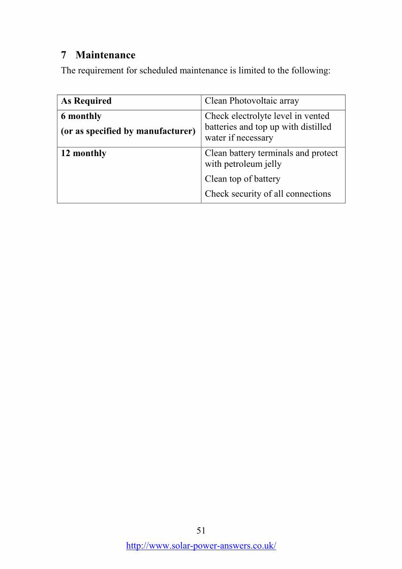
51
http://www.solar-power-answers.co.uk/
7 Maintenance
The requirement for scheduled maintenance is limited to the following:
As Required Clean Photovoltaic array
6 monthly
(or as specified by manufacturer)
Check electrolyte level in ventedbatteries and top up with distilledwater if necessary
12 monthly Clean battery terminals and protectwith petroleum jelly
Clean top of battery
Check security of all connections
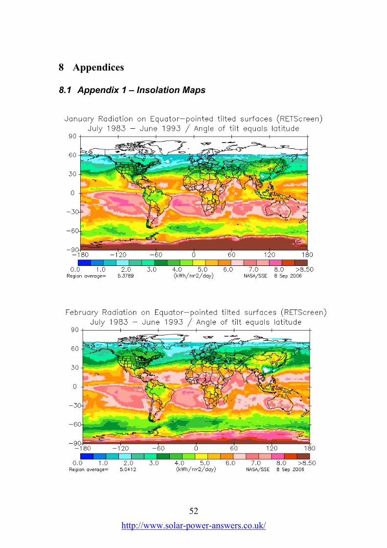
52
http://www.solar-power-answers.co.uk/
8 Appendices
8.1 Appendix 1 – Insolation Maps
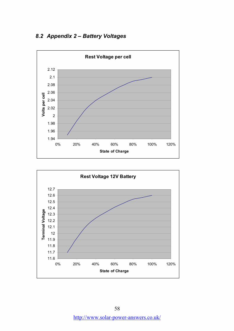
58
http://www.solar-power-answers.co.uk/
8.2 Appendix 2 – Battery Voltages
Rest Voltage per cell
1.94
1.96
1.98
2
2.02
2.04
2.06
2.08
2.1
2.12
0% 20% 40% 60% 80% 100% 120%
State of Charge
Volts per cell
Rest Voltage 12V Battery
11.6
11.7
11.8
11.9
12
12.1
12.2
12.3
12.4
12.5
12.6
12.7
0% 20% 40% 60% 80% 100% 120%
State of Charge
Term
inal Voltage
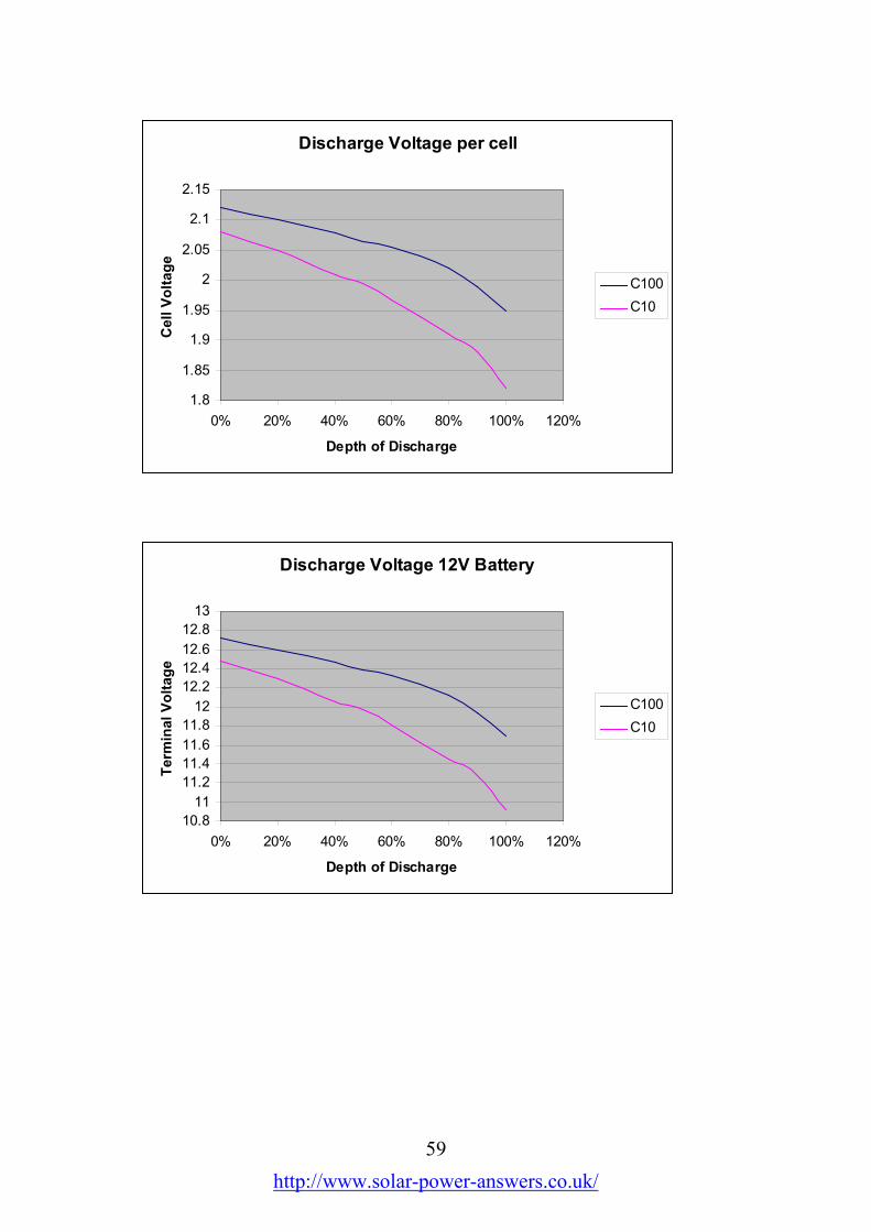
59
http://www.solar-power-answers.co.uk/
Discharge Voltage per cell
1.8
1.85
1.9
1.95
2
2.05
2.1
2.15
0% 20% 40% 60% 80% 100% 120%
Depth of Discharge
Cell Voltage
C100
C10
Discharge Voltage 12V Battery
10.8
11
11.2
11.4
11.6
11.8
12
12.2
12.4
12.6
12.8
13
0% 20% 40% 60% 80% 100% 120%
Depth of Discharge
Term
inal Voltage
C100
C10

60
http://www.solar-power-answers.co.uk/
8.3 Appendix 3 – Cable Data
8.3.1 Equivalence and Ratings
CSA mm2 (VDE) AWG Rated Current (A)
1.0 17 13
1.5 15 17
2.5 13 24
4 11 32
6 9 41
10 7 57
16 5 76
25 3 101
35 2 125
50 1/0 151
70 2/0 192
95 4/0 232
120 5/0 269
150 6/0 300

61
http://www.solar-power-answers.co.uk/
8.3.2 Voltage drop tables
Current 1 Ampere
1 1.5 2.5 6 10 16 25 35 50 75 95 120 150
1 0.04 0.03 0.02 0.01 0.00 0.00 0.00 0.00 0.00 0.00 0.00 0.00 0.00
2 0.08 0.05 0.03 0.01 0.01 0.01 0.00 0.00 0.00 0.00 0.00 0.00 0.00
5 0.20 0.13 0.08 0.03 0.02 0.01 0.01 0.01 0.00 0.00 0.00 0.00 0.00
10 0.40 0.27 0.16 0.07 0.04 0.03 0.02 0.01 0.01 0.01 0.00 0.00 0.00
20 0.80 0.53 0.32 0.13 0.08 0.05 0.03 0.02 0.02 0.01 0.01 0.01 0.01
50 2.00 1.33 0.80 0.33 0.20 0.13 0.08 0.06 0.04 0.03 0.02 0.02 0.01
100 4.00 2.67 1.60 0.67 0.40 0.25 0.16 0.11 0.08 0.05 0.04 0.03 0.03
Current 10 Ampere
1 1.5 2.5 6 10 16 25 35 50 75 95 120 150
1 0.40 0.27 0.16 0.07 0.04 0.03 0.02 0.01 0.01 0.01 0.00 0.00 0.00
2 0.80 0.53 0.32 0.13 0.08 0.05 0.03 0.02 0.02 0.01 0.01 0.01 0.01
5 2.00 1.33 0.80 0.33 0.20 0.13 0.08 0.06 0.04 0.03 0.02 0.02 0.01
10 4.00 2.67 1.60 0.67 0.40 0.25 0.16 0.11 0.08 0.05 0.04 0.03 0.03
20 8.00 5.33 3.20 1.33 0.80 0.50 0.32 0.23 0.16 0.11 0.08 0.07 0.05
50 20.00 13.33 8.00 3.33 2.00 1.25 0.80 0.57 0.40 0.27 0.21 0.17 0.13
100 40.00 26.67 16.00 6.67 4.00 2.50 1.60 1.14 0.80 0.53 0.42 0.33 0.27
Current 100 Ampere
1 1.5 2.5 6 10 16 25 35 50 75 95 120 150
1 4.00 2.67 1.60 0.67 0.40 0.25 0.16 0.11 0.08 0.05 0.04 0.03 0.03
2 8.00 5.33 3.20 1.33 0.80 0.50 0.32 0.23 0.16 0.11 0.08 0.07 0.05
5 20.00 13.33 8.00 3.33 2.00 1.25 0.80 0.57 0.40 0.27 0.21 0.17 0.13
10 40.00 26.67 16.00 6.67 4.00 2.50 1.60 1.14 0.80 0.53 0.42 0.33 0.27
20 80.00 53.33 32.00 13.33 8.00 5.00 3.20 2.29 1.60 1.07 0.84 0.67 0.53
50 200.00 133.33 80.00 33.33 20.00 12.50 8.00 5.71 4.00 2.67 2.11 1.67 1.33
100 400.00 266.67 160.00 66.67 40.00 25.00 16.00 11.43 8.00 5.33 4.21 3.33 2.67
Cable cross-sectional area (mm2)
Length (m)
Length (m)
Length (m)
Cable cross-sectional area (mm2)
Cable cross-sectional area (mm2)
Cable Voltage drop (V)
Cable Voltage drop (V)
Cable Voltage drop (V)
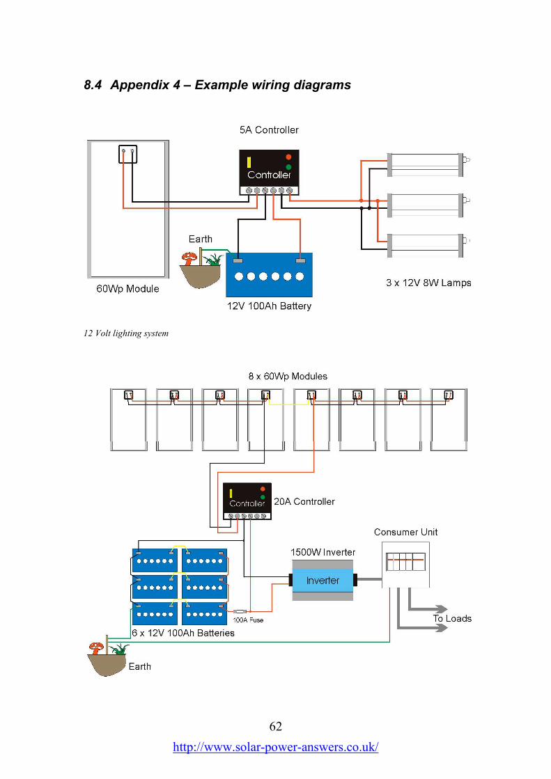
62
http://www.solar-power-answers.co.uk/
8.4 Appendix 4 – Example wiring diagrams
12 Volt lighting system

63
http://www.solar-power-answers.co.uk/
24 Volt inverter system
Module wiring for 24 Volt systems

64
http://www.solar-power-answers.co.uk/
8.5 Appendix 5 – Power ratings of common appliances
Typical power consumption for a range of appliances. Powerconsumption for 12 Volt versions is given where appropriate.
Appliance Power Rating (W)
230V Supply
Power Rating (W)
12V Supply
Light (energy saving) 15 10
Television 80 35
Refrigerator 90 50
Washing Machine 3000 -
Dishwasher 3000 -
Fan Heater 2000 -
Central Heating Pump 60 -