Solar Photovoltaic Glint and Glare Study - South...
45
Solar Photovoltaic Glint and Glare Study Prepared for: TGC Renewables Sutton Bridge Solar PV Installation July, 2013
Transcript of Solar Photovoltaic Glint and Glare Study - South...
Solar Photovoltaic Glint and Glare Study Prepared for:
TGC Renewables
Sutton Bridge Solar PV Installation July, 2013

Solar Photovoltaic Glint and Glare Study Sutton Bridge PV Installation 2
ADMINISTRATION PAGE
Job Reference: 7840A
Date: July, 2013
Prepared for: TGC Renewables
Author: Danny Scrivener
Telephone: 01787 319001
Email: [email protected]
First Reviewer: Jan Georgopoulos
Date: July, 2013
Telephone: 01787 319001
Email: [email protected]
Second Reviewer: Mike Watson
Date: July, 2013
Telephone: 01787 319001
Email: [email protected]
Issue Date Detail of Changes
1 July, 2013 Initial Issue
Confidential: The contents of this document may not be disclosed to others without permission.
Copyright © Pager Power Limited 2013
Unless stated otherwise, all maps are reproduced by permission of Ordnance Survey on behalf of The
Controller of Her Majesty’s Stationery Office © Crown copyright. All rights reserved. Licence number LIG0631
Pager Power Limited, New Mill, Bakers Court, Gt Cornard, Sudbury, Suffolk CO10 0GG T:01787 319001 F:01787 319007 E:[email protected] W:www.pagerpower.co.uk
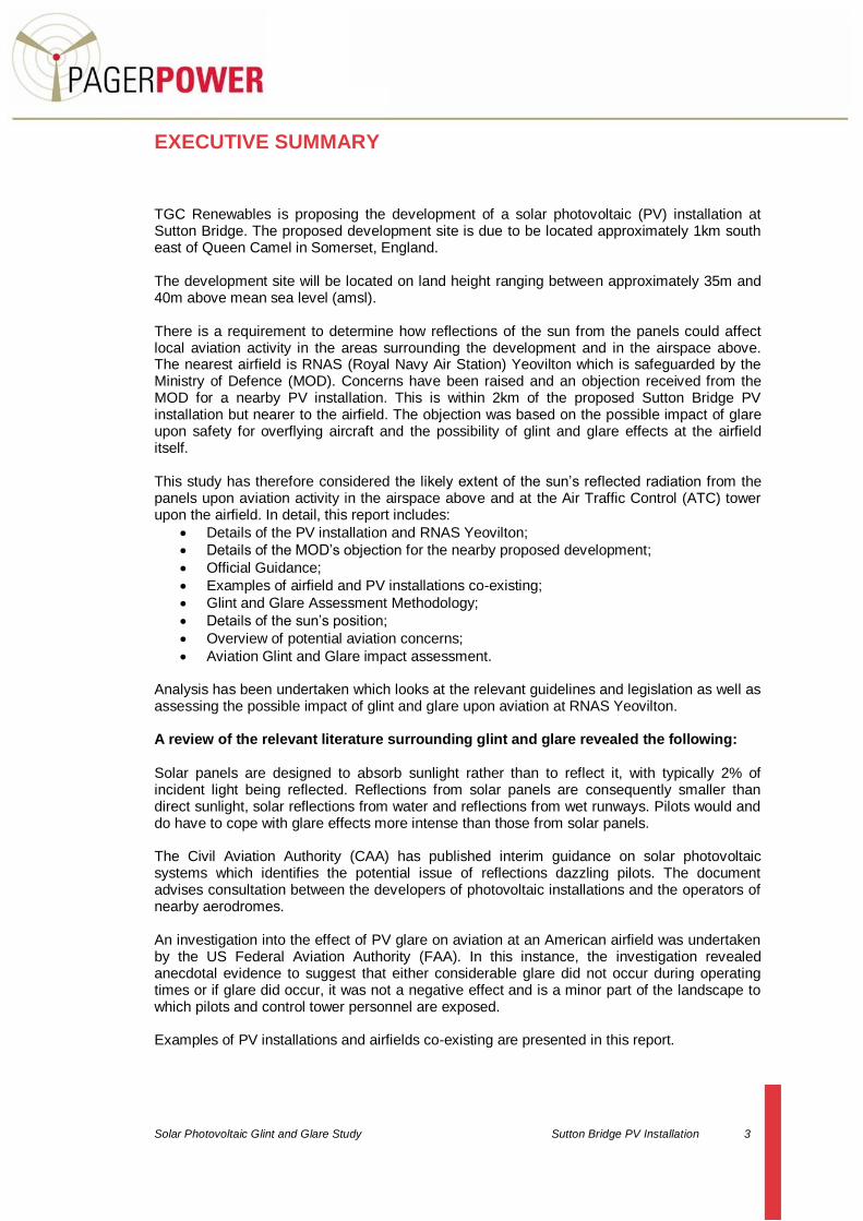
Solar Photovoltaic Glint and Glare Study Sutton Bridge PV Installation 3
EXECUTIVE SUMMARY
TGC Renewables is proposing the development of a solar photovoltaic (PV) installation at Sutton Bridge. The proposed development site is due to be located approximately 1km south east of Queen Camel in Somerset, England. The development site will be located on land height ranging between approximately 35m and 40m above mean sea level (amsl). There is a requirement to determine how reflections of the sun from the panels could affect local aviation activity in the areas surrounding the development and in the airspace above. The nearest airfield is RNAS (Royal Navy Air Station) Yeovilton which is safeguarded by the Ministry of Defence (MOD). Concerns have been raised and an objection received from the MOD for a nearby PV installation. This is within 2km of the proposed Sutton Bridge PV installation but nearer to the airfield. The objection was based on the possible impact of glare upon safety for overflying aircraft and the possibility of glint and glare effects at the airfield itself. This study has therefore considered the likely extent of the sun’s reflected radiation from the panels upon aviation activity in the airspace above and at the Air Traffic Control (ATC) tower upon the airfield. In detail, this report includes:
Details of the PV installation and RNAS Yeovilton;
Details of the MOD’s objection for the nearby proposed development;
Official Guidance;
Examples of airfield and PV installations co-existing;
Glint and Glare Assessment Methodology;
Details of the sun’s position;
Overview of potential aviation concerns;
Aviation Glint and Glare impact assessment.
Analysis has been undertaken which looks at the relevant guidelines and legislation as well as assessing the possible impact of glint and glare upon aviation at RNAS Yeovilton. A review of the relevant literature surrounding glint and glare revealed the following: Solar panels are designed to absorb sunlight rather than to reflect it, with typically 2% of incident light being reflected. Reflections from solar panels are consequently smaller than direct sunlight, solar reflections from water and reflections from wet runways. Pilots would and do have to cope with glare effects more intense than those from solar panels. The Civil Aviation Authority (CAA) has published interim guidance on solar photovoltaic systems which identifies the potential issue of reflections dazzling pilots. The document advises consultation between the developers of photovoltaic installations and the operators of nearby aerodromes. An investigation into the effect of PV glare on aviation at an American airfield was undertaken by the US Federal Aviation Authority (FAA). In this instance, the investigation revealed anecdotal evidence to suggest that either considerable glare did not occur during operating times or if glare did occur, it was not a negative effect and is a minor part of the landscape to which pilots and control tower personnel are exposed. Examples of PV installations and airfields co-existing are presented in this report.

Solar Photovoltaic Glint and Glare Study Sutton Bridge PV installation 4
It has been determined that glint and glare would only affect pilots or air traffic controllers if:
There were sunny and clear flying conditions (no substantial cloud or haze);
The aircraft was flying at a particular altitude;
The sun was at a certain angle in the sky;
The pilot/ATC was looking towards or in the vicinity of the PV installation;
The pilot/ATC is in line of sight of the PV installation.
Aviators cope with reflections from the sun on a day to day basis. This includes:
Direct sunlight, reflections from water, wet runways and other man-made structures;
Aircraft wings and structures reflecting sunlight if the sun is to the side or behind at certain angles;
Reflection from the propeller of a light aircraft could cause glare and even a stroboscopic effects;
Clouds generating glare from reflections of the sun. A small level of solar reflections and glare is a normal and acceptable part of flying. It is therefore unlikely that glare should considerably affect a pilot’s performance. Existing structures and surfaces (such as glass windows) are likely to exist in the surrounding environment which are more reflective than the proposed PV installation. The results of the investigation into the possible effects of glint and glare upon aviation activity at RNAS Yeovilton are as follows: An initial geometric assessment determined the general volumes of airspace in which pilots could be exposed to solar reflections from any of the photovoltaic panels. This was undertaken for panels with a set angle of 25 and 30 degrees. The volume of airspace which may be affected is quite small because of the slope of the panels and because the highest angle the sun ever reaches at the development latitude is 62.3 degrees. The analysis has shown that the angle of the sun necessary to create a reflection from the proposed PV installation will not occur for aircraft on the appropriate approach route for runway 27. It is therefore concluded that there will be no significant glare effects expected for aircraft approaching runway 27. Aircraft departing runway 09 would have the nose of the aircraft pointing skywards and the pilot would not be looking towards the ground. It is for this reason that no glint and glare effects will be experienced by pilots departing runway 09. The only scenario where glint and glare may affect pilots would be with the sun due east in the sky. In this scenario a pilot would be looking towards the sun anyway, a much greater source of light then the solar panels and a situation that a pilot would have to cope with under normal conditions. The results of the line of sight analysis showed that the PV installation would be visible to the ATC tower however some parts may be obstructed by trees and bushes close to the PV installation. Being visible to personnel with the ATC tower is not considered a problem because it would be no different to any other development being visible to the ATC in the surrounding landscape. The results of the geometric calculations have shown that there will be no reflections of the sun visible to personnel who are within the ATC control tower for both 25° and 30° panels. As a result it is considered that there will be no glint and glare effects at the tower and therefore no detrimental impact and safety concerns for ATC controllers within the tower due to the presence of the PV installation.
Solar Photovoltaic Glint and Glare Study Sutton Bridge PV installation 5
Overall Conclusion Overall it is not believed that a considerable impact upon aviation safety at RNAS Yeovilton will occur. A pilot will come across more intense reflections in the landscape than those produced by those from the PV installation. It is considered to be a minor impact because such reflections will always exist for pilots whilst flying. Reflections of greater intensity will already exist within the surrounding landscapes which are not considered to be a hazard to safety. Pilots should however be made aware of the PV installation as a precaution.

Solar Photovoltaic Glint and Glare Study Sutton Bridge PV installation 6
LIST OF CONTENTS
Administration Page ....................................................................................................2
Executive Summary ....................................................................................................3
List of Contents ...........................................................................................................6
List of Figures .............................................................................................................7
List of Tables ..............................................................................................................8
1 Introduction ......................................................................................................9
2 Sutton Bridge PV Installation .........................................................................10
2.1 Sutton Bridge General Location ...................................................................... 10
2.2 Sutton Bridge PV Installation Aerial Image ...................................................... 11
3 Photovoltaic Panel Mounting Arrangements ..................................................12
3.1 Introduction .................................................................................................... 12
3.2 Solar Panel Orientation ................................................................................... 12
3.3 Glint / Glare and the Nature of Reflections ...................................................... 13
4 RNAS Yeovilton Information ..........................................................................14
4.1 Runways ........................................................................................................ 15
4.2 Airfield Usage ................................................................................................. 15
4.3 Airfield Summary ............................................................................................ 15
5 MOD Objection Overview ..............................................................................16
5.1 Objection Letter- Key Points ........................................................................... 16
5.2 Objection Letter- Conclusions ......................................................................... 16
6 Official Guidance ...........................................................................................17
6.1 UK CAA Guidance .......................................................................................... 17
6.2 United States FAA Guidance .......................................................................... 18
6.3 Official Guidance Summary ............................................................................ 19
7 Co-exisiting PV installations and Aerodromes ................................................20
7.1 Solar Developments on Airfields ..................................................................... 20
7.2 Solar Developments near Airfields .................................................................. 23
7.3 Overall Conclusions ........................................................................................ 23
8 Glint and Glare Assessment Methodology .....................................................24
8.1 Sun’s Position................................................................................................. 24
8.2 Sun Tracks ..................................................................................................... 25
8.3 Solar Reflection Elevation for a 25° Panel ....................................................... 25
8.4 Solar Reflection Elevation for a 30° Panel ....................................................... 26
8.5 Graph Showing Solar Reflections for 25 Degree Panel ................................... 27
8.6 Graph Showing Solar Reflections for 30 Degree Panel ................................... 28
Solar Photovoltaic Glint and Glare Study Sutton Bridge PV installation 7
9 Glint and Glare Assessment for aviation Activity ............................................29
10 Aircraft on Approach and Departure of Runway 27 ........................................30
10.1 Aircraft Departing Runway 09 ......................................................................... 32
10.2 Runway 27 Approach and Departure Analysis Conclusions ............................ 32
11 Air Traffic Control Tower Impact Assessment ................................................33
11.1 ATC Tower Line of Sight ................................................................................. 34
11.2 Glint Glare Calculator for the ATC Tower ........................................................ 35
11.3 ATC Tower Reflections Conclusions ............................................................... 37
12 Aviation Impact Conclusions ..........................................................................38
13 Conclusions ...................................................................................................39
Appendix A- Analysis Tables for Aircraft Approaching Runway 27 ............................41
LIST OF FIGURES
Figure 1 Approximate location of the Sutton Bridge PV installation ...........................10
Figure 2 Proposed PV installation layout aerial image ...............................................11
Figure 3 Panel layout design .....................................................................................12
Figure 4 Aerodrome map ..........................................................................................14
Figure 5 Aerodrome map in relation to the proposed PV installation .........................14
Figure 6 Reflectivity produced by different surfaces ..................................................19
Figure 7 Solar panels at Birmingham Airport .............................................................20
Figure 8 Solar panels at Chattanooga Airport............................................................20
Figure 9 Solar panels at Denver International Airport ................................................21
Figure 10 Solar panels at Fresno Yosemite International Airport ...............................21
Figure 11 Solar panels at San Francisco International Airport ...................................22
Figure 12 Solar panels at Oakland International Airport ............................................22
Figure 13 Diagram showing geometry (when solar elevation is 30 degrees with a 25 degree panel) ............................................................................................................25
Figure 14 Height agl in metres at which reflections could be experienced (25 degree panel) ........................................................................................................................27
Figure 15 Height agl in metres at which reflections could be experienced (30 degree panel) ........................................................................................................................28
Figure 16 Runway 09/27 (highlighted blue) ...............................................................29
Figure 17 Runway 27 approach path ........................................................................30
Figure 18 ATC Tower LOS ........................................................................................34
Figure 19 ATC tower reflection for 25° panel .............................................................35
Figure 20 ATC tower reflection for 30° panel .............................................................36
Solar Photovoltaic Glint and Glare Study Sutton Bridge PV installation 8
LIST OF TABLES
Table 1 Solar azimuth and elevation on specific days at Sutton Bridge PV installation .................................................................................................................................24
Table 2 Heights agl (m) at the panel location at which reflections could be experienced (25 degree panel) .................................................................................26
Table 3 Heights agl (m) at the panel location at which reflections could be experienced (30 degree panel) .................................................................................26
Table 4 Position and altitudes of approaching aircraft to runway 27 ..........................31
Table 5 PV installation co-ordinates for assessment .................................................31
Table 6 Runway 27 approach glint glare assessment summary ................................32
Table 7 ATC tower details .........................................................................................33
Solar Photovoltaic Glint and Glare Study Sutton Bridge PV installation 9
1 INTRODUCTION
TGC Renewables is proposing the development of a solar photovoltaic (PV) installation at Sutton Bridge. The proposed development site is due to be located approximately 1km south east of Queen Camel in Somerset, England. The development site will be located on land height ranging between approximately 35m and 40m above mean sea level (amsl). There is a requirement to determine how reflections of the sun from the panels could affect local aviation activity in the areas surrounding the development and in the airspace above. The nearest airfield is RNAS (Royal Navy Air Station) Yeovilton which is safeguarded by the Ministry of Defence (MOD). Concerns have been raised and an objection received from the MOD for a nearby PV installation. This is within 2km of the proposed Sutton Bridge PV installation but nearer to the airfield. The objection was based on the possible impact of glare upon safety for overflying aircraft and the possibility of glint and glare effects at the airfield itself. This study has therefore considered the likely extent of the sun’s reflected radiation from the panels upon aviation activity in the airspace above and at the Air Traffic Control (ATC) tower upon the airfield. In detail, this report includes:
Details of the PV installation and RNAS Yeovilton;
Details of the MOD’s objection for the nearby proposed development;
Official Guidance;
Examples of airfield and PV installations co-existing;
Glint and Glare Assessment Methodology;
Details of the sun’s position;
Overview of potential aviation concerns;
Aviation Glint and Glare impact assessment.
Please note that any reference to visual impact made within this report should be read in the context of potential glint and glare. The relevant technical analysis is presented in each section. Following the assessment, Pager Power’s conclusions and recommendations are made.

Solar Photovoltaic Glint and Glare Study Sutton Bridge PV installation 10
2 SUTTON BRIDGE PV INSTALLATION
2.1 Sutton Bridge General Location
The general location of the proposed Sutton bridge development site is illustrated on the map below:
Figure 1 Approximate location of the Sutton Bridge PV installation
Proposed PV
Installation

Solar Photovoltaic Glint and Glare Study Sutton Bridge PV installation 11
2.2 Sutton Bridge PV Installation Aerial Image
The PV installation and associated infrastructure are due to be located as depicted on the following satellite image:
Figure 2 Proposed PV installation layout aerial image1
1 © 2013 Google, Image © 2013 Getmapping plc
Proposed PV
Installations

Solar Photovoltaic Glint and Glare Study Sutton Bridge PV installation 12
3 PHOTOVOLTAIC PANEL MOUNTING ARRANGEMENTS
3.1 Introduction
The proposed PV installation will be mounted to ground via a metal frame. It is believed that these will be erected in rows facing South with the panels aligned in portrait with a double layer per row. The distance between each row is unknown however it is assumed that the cells will be within 5-10m of each. It is estimated that the proposed PV installation will be a maximum of 3m above ground level (agl).
3.2 Solar Panel Orientation
The panels are oriented to maximize electrical generation and will have a fixed position throughout the year. The PV installation will face due south and will be positioned at an angle between 25 and 30 degrees from the horizontal. The figure below shows the proposed design:
Figure 3 Panel layout design

Solar Photovoltaic Glint and Glare Study Sutton Bridge PV installation 13
3.3 Glint / Glare and the Nature of Reflections
This document is intended to provide guidance on expected reflection effects exhibited by solar photovoltaic panels when in direct sunlight. The reflection of a glass surface is highly dependent on the angle of incidence and surface conditions. It is understood that as the angle of incidence increases, the amount of reflected light also increases.
Glare and dazzle effects due to reflection from solar panels are expected to be minimal and comparable to glass facades. Solar panels generally appear darker than glass in nearly all conditions. Typical soiling of the solar panel surface will further reduce the observed light reflection, and this also has an effect on the efficiency of the panel. Photovoltaic panels are designed to absorb light and not reflect it. They have a smooth surface, however, which means that incident light from a specific direction is reradiated in a specific direction. This means that photovoltaic panels can cause reflections which are however considerably less intense than direct sunlight. Photovoltaic panels typically reflect 2% of incident light
2.
Direct solar reflections will not occur when the sun is obscured by cloud.
2 FAA, November 2010, Technical Guidance for Evaluating Selected Solar Technologies on Airports

Solar Photovoltaic Glint and Glare Study Sutton Bridge PV installation 14
4 RNAS YEOVILTON INFORMATION
RNAS Yeovilton is the nearest airfield to the proposed solar PV installation and is shown in the aerial photograph below:
Figure 4 Aerodrome map3
An aerial photograph showing the location of the Sutton Bridge development and the airfield is shown below. The location of the PV installation which received an objection from the MOD is also shown
Figure 5 Aerodrome map in relation to the proposed PV installation4
There is approximately 5km between the centre of both runways and the proposed Sutton Bridge PV installation.
3 © 2013 Google, Image © 2013 Getmapping plc
4 © 2013 Google, Image © 2013 Getmapping plc
Proposed PV installation
Southfields PV installation which
received an objection

Solar Photovoltaic Glint and Glare Study Sutton Bridge PV installation 15
4.1 Runways
RNAS Yeovilton has two runways both running approximately north east to south west. The bearings and dimensions of the two runways are as follows:
04/22 at 2292m long by 46m wide;
09/27 1463m long by 46m wide.
4.2 Airfield Usage
The airfield is run by the Royal Navy (safeguarded by the MOD) and is home to two helicopter units and houses over 100 aircraft. The airfield is operational and is of significant importance to the Royal Navy for active and training purposes. Helicopters and jet aircraft are flown at this base. Information regarding flight procedures is available on the Military AIP (Air Information Procedures). These are discussed later.
4.3 Airfield Summary
RNAS Yeovilton is an important airbase to the Royal Navy and is the airfield from which the objection for the Southfields PV installation was based. Further assessment will be undertaken with regard to the RNAS Yeovilton and potential glare effects due to the proposed PV installation.

Solar Photovoltaic Glint and Glare Study Sutton Bridge PV installation 16
5 MOD OBJECTION OVERVIEW
An objection was received from the MOD for a nearby proposed PV installation called Southfields. This development is approximately 2km east of the centre of the 2 runways and approximately 3km west of the proposed Sutton Bridge development. It is therefore between RNAS Yeovilton and Sutton Bridge as shown previously in section 4, figure 5. A similar objection is expected for the proposed Sutton Bridge PV installation and therefore the key points from the Southfields objection are to be reviewed and addressed in light of this. The MOD objection reference is D/DIO/42/2/100 (2013/352).
5.1 Objection Letter- Key Points
Reference made to guidelines set by the United States Federal Aviation Authority (FAA) and the UK Civil Aviation authority (CAA) interim guidance concerning the development of solar arrays in a previous assessment (these are presented later in this report);
The objection letter states that flash blindness could occur based on the typical light emissions for the panels ‘affecting aircrew and therefore causing a hazard to air traffic safety;
It is stated in the objection letter that ‘the guidance identifies the need for an individual glare analysis to be completed by a solar array developer for schemes near aerodromes. Such an assessment may entail qualitative assessments of potential impacts; geometric analysis to determine periods when an impact is expected and field trials of solar panels at the development site identified’;
It is stated that the expected level of light emissions have not been identified;
It is stated that ‘the applicant has not followed the process identified in the technical guidance and undertaken any specific assessment of the potential effect of glare emissions from the solar array’;
The MOD state ‘the MOD does not consider there to be any substantiated basis to the statement made … that it is highly unlikely that there will be any likelihood of glint or glare effecting air traffic using the eastern runway because solar array will be constructed using anti-reflective PV panels’;
‘In view of the location of the proposed development beneath the air traffic approach to runway 27 at RNAS Yeovilton, the MOD considers such an assessment as essential to determine the likely impacts.’
5.2 Objection Letter- Conclusions
The proposed Southfields solar PV is approximately 2km closer to RNAS Yeovilton when compared to the Sutton Bridge development. The MOD requires a further qualitative or technical assessment for PV installations in close proximity to their airfields.
Solar Photovoltaic Glint and Glare Study Sutton Bridge PV installation 17
6 OFFICIAL GUIDANCE
6.1 UK CAA Guidance
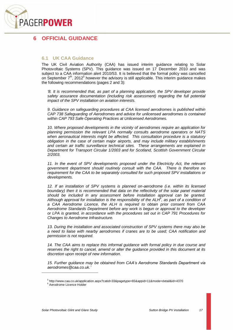
The UK Civil Aviation Authority (CAA) has issued interim guidance relating to Solar Photovoltaic Systems (SPV). This guidance was issued on 17 December 2010 and was subject to a CAA information alert 2010/53. It is believed that the formal policy was cancelled on September 7
th, 2012
5 however the advisory is still applicable. This interim guidance makes
the following recommendations (pages 2 and 3):
‘8. It is recommended that, as part of a planning application, the SPV developer provide safety assurance documentation (including risk assessment) regarding the full potential impact of the SPV installation on aviation interests. 9. Guidance on safeguarding procedures at CAA licensed aerodromes is published within CAP 738 Safeguarding of Aerodromes and advice for unlicensed aerodromes is contained within CAP 793 Safe Operating Practices at Unlicensed Aerodromes. 10. Where proposed developments in the vicinity of aerodromes require an application for planning permission the relevant LPA normally consults aerodrome operators or NATS when aeronautical interests might be affected. This consultation procedure is a statutory obligation in the case of certain major airports, and may include military establishments and certain air traffic surveillance technical sites. These arrangements are explained in Department for Transport Circular 1/2003 and for Scotland, Scottish Government Circular 2/2003. 11. In the event of SPV developments proposed under the Electricity Act, the relevant government department should routinely consult with the CAA. There is therefore no requirement for the CAA to be separately consulted for such proposed SPV installations or developments. 12. If an installation of SPV systems is planned on-aerodrome (i.e. within its licensed boundary) then it is recommended that data on the reflectivity of the solar panel material should be included in any assessment before installation approval can be granted. Although approval for installation is the responsibility of the ALH
6, as part of a condition of
a CAA Aerodrome Licence, the ALH is required to obtain prior consent from CAA Aerodrome Standards Department before any work is begun or approval to the developer or LPA is granted, in accordance with the procedures set out in CAP 791 Procedures for Changes to Aerodrome Infrastructure. 13. During the installation and associated construction of SPV systems there may also be a need to liaise with nearby aerodromes if cranes are to be used; CAA notification and permission is not required. 14. The CAA aims to replace this informal guidance with formal policy in due course and reserves the right to cancel, amend or alter the guidance provided in this document at its discretion upon receipt of new information. 15. Further guidance may be obtained from CAA’s Aerodrome Standards Department via [email protected].’
5 http://www.caa.co.uk/application.aspx?catid=33&pagetype=65&appid=11&mode=detail&id=4370
6 Aerodrome Licence Holder

Solar Photovoltaic Glint and Glare Study Sutton Bridge PV installation 18
6.2 United States FAA Guidance
In November 2010 the United States Federal Aviation Authority (FAA) issued a document entitled Technical Guidance for Evaluating Selected Solar Technologies on Airports. The main purpose of this document is to advise airports on how to safely and economically set up a PV installation at an airport. Section 3.1.2 covers the reflectivity issues associated with solar installations and as of June 26, 2012, the FAA has been reviewing the section based on new information and field experience. This section is based on the version at the time of writing however the FAA warn that content may be subject to change. A summary
7 of key points is
listed below:
The potential impacts of reflectivity are glint and glare (referred to henceforth just as glare) which can cause a brief loss of vision (also known as flash blindness).
Reflectivity from solar panels could cause flash blindness episodes on pilots or air traffic controllers when 7-11 W/m
2 reaches the eye.
Today’s solar panels reflect as little as 2% of the incoming sunlight meaning roughly 20 W/m
2 are reflected off as typical PV panel.
PV solar panels reflect less light than other substances such as snow, vegetation and water.
Reflections from PV panels are specular because of their smooth surfaces – meaning that reflected light from a specific source is reflected in a single direction.
Glare analysis can include one or more of:
o A qualitative analysis of potential impact in consultation with the Control Tower, pilots and airport officials
o A demonstration field test with solar panels at the proposed site in coordination with FAA Tower personnel
o A geometric analysis to determine days and times when an impact is predicted.
The extent of reflectivity analysis required to assess potential impacts will depend on the specific project site and system design.
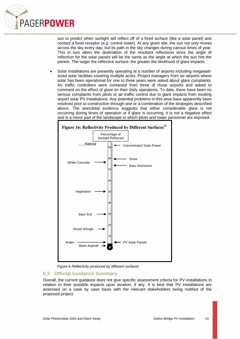
Reflection in the form of glare is present in current aviation operations. The existing sources of glare come from glass windows, auto surface parking, rooftops, and water bodies. Figure 16 (figure 6 in this report- on the following page) shows the percent of incoming sunlight that is reflected off of a variety of surfaces. At airports, existing reflecting surfaces may include hangar roofs, surface parking, and glassy office buildings. To minimize unexpected glare, windows of air traffic control towers and airplane cockpits are coated with anti-reflective glazing and operators will wear polarized eye wear. Potential glare from solar panels should be viewed in this context. Any airport considering a PV installation should first review existing sources of glare at the airport and the effectiveness of measures used to mitigate that glare.
Geometric studies are the most technical approach for reflectivity issues that are difficult to assess. Studies of glare can employ geometry and the known path of the
7 It is recommended that the complete section of the document be referred to for a more comprehensive
understanding. It can be downloaded from
http://www.faa.gov/airports/environmental/policy_guidance/media/airport_solar_guide.pdf
Solar Photovoltaic Glint and Glare Study Sutton Bridge PV installation 19
sun to predict when sunlight will reflect off of a fixed surface (like a solar panel) and contact a fixed receptor (e.g. control tower). At any given site, the sun not only moves across the sky every day, but its path in the sky changes during various times of year. This in turn alters the destination of the resultant reflections since the angle of reflection for the solar panels will be the same as the angle at which the sun hits the panels. The larger the reflective surface, the greater the likelihood of glare impacts.
Solar installations are presently operating at a number of airports including megawatt-sized solar facilities covering multiple acres. Project managers from six airports where solar has been operational for one to three years were asked about glare complaints. Air traffic controllers were contacted from three of those airports and asked to comment on the effect of glare on their daily operations. To date, there have been no serious complaints from pilots or air traffic control due to glare impacts from existing airport solar PV installations. Any potential problems in this area have apparently been resolved prior to construction through one or a combination of the strategies described above. The anecdotal evidence suggests that either considerable glare is not occurring during times of operation or if glare is occurring, it is not a negative effect and is a minor part of the landscape to which pilots and tower personnel are exposed.
Figure 6 Reflectivity produced by different surfaces
6.3 Official Guidance Summary
Overall, the current guidance does not give specific assessment criteria for PV installations in relation to their possible impacts upon aviation, if any. It is best that PV installations are assessed on a case by case basis with the relevant stakeholders being notified of the proposed project.
Material
Bare Aluminium
Vegetation
Bare Soil
PV Solar Panels
Wood Shingle
Black Asphalt
Concentrated Solar Power
White Concrete Snow
Percentage of
Sunlight Reflected
Water

Solar Photovoltaic Glint and Glare Study Sutton Bridge PV installation 20
7 CO-EXISITING PV INSTALLATIONS AND AERODROMES
This section presents examples of PV installations co-existing with airfields in the UK and the USA.
7.1 Solar Developments on Airfields
7.1.1 Birmingham Airport, UK
Birmingham Airport has recently completed the installation of 200 solar panels measuring 1.6mx1m on the roof of one of its terminal buildings. The panels are highlighted in the figure below.
Figure 7 Solar panels at Birmingham Airport
7.1.2 Chattanooga Airport, USA
A 5 acre one megawatt ground mount solar farm is located in the south west corner of the Chattanooga Airport. This location next to runway 02/20 was unusable for aviation purposes due to its close proximity to the runway. The panels are highlighted in the figure below.
Figure 8 Solar panels at Chattanooga Airport
Solar Panels
Solar Panels

Solar Photovoltaic Glint and Glare Study Sutton Bridge PV installation 21
7.1.3 Denver international Airport, USA
Denver International Airport (DIA) has completed the installation of its third large scale solar project comprising of 19,000 photovoltaic panels. The solar farm spans 7.5 acres at the DIA’s main terminal entrance. In a study of possible glint or glare impacts from a photovoltaic panel it was concluded that the possible glint glare from PV systems were at safe level and that reflections are usually decisively lower than other standard residential and commercial reflective surfaces. Glint and glare to aircraft was deemed not to be an issue. The panels are highlighted in the figure below.
Figure 9 Solar panels at Denver International Airport
7.1.4 Fresno Yosemite International Airport, USA
Fresno Yosemite International Airport (FYI) is the site of one of the largest airport-based solar farm installation in the United States. Permits had to be obtained from the FAA to ensure that the operational solar farm was not a hazard to aviation at the airport. The best location for the solar arrays was deemed to be off the end and to the side of the approach to the main FYI runway (29R). The solar PV installation covers approximately 5 hectares. The panels are highlighted in the figure below.
Figure 10 Solar panels at Fresno Yosemite International Airport
Solar Panels
Solar Panels

Solar Photovoltaic Glint and Glare Study Sutton Bridge PV installation 22
7.1.5 San Francisco International Airport, USA
San Francisco International Airport has completed the installation of a 500kW PV installation that consists of approximately 3,000 solar panels. These have been placed on the roof of terminal 3. The panels are highlighted in the figure below.
Figure 11 Solar panels at San Francisco International Airport
7.1.6 Oakland International Airport, USA
The Oakland International Airport PV installation features 5,769 solar panels covering 81,000 square feet of airport rooftop. The panels are highlighted in the figure below.
Figure 12 Solar panels at Oakland International Airport
7.1.7 Gatwick Airport
Gatwick Airport has installed 212 solar panels 150m from the main runway.
7.1.8 Indianapolis Airport
Indianapolis Airport constructed 28,000 solar panels at the entrance of the airport with this number expecting to rise to 44,000 panels to be installed on 75 acres of land.
Solar Panels
Solar Panels

Solar Photovoltaic Glint and Glare Study Sutton Bridge PV installation 23
7.1.9 Nellis Air Force Base, Nevada
The Nellis Solar Power Plant is located within Nellis Air Force Base in Clark County, Nevada, occupying 140 acres (57 hectares) of land at the north eastern corner of the base. It consists of approximately 70,000 solar panels
7.2 Solar Developments near Airfields
7.2.1 Chapel Lane, Parley
The Chapel Lane PV installation will cover 48 hectares and be within 1.6km of Bournemouth Airport.
7.2.2 Mill field Farm, Caddington
The Millfield Farm site covers an area of approximately 11.4 hectares and is located approximately 2.5km to the south west of Luton Airport.
7.2.3 Burrowton farm, Exeter
The Burrowton farm development will occupy 30 acres of land consisting of solar panels 3.2km from Exeter Airport.
7.2.4 Chalcroft Farm, Southampton
The Chalcroft Farm PV installation will consist of 25,632 panels, covering approximately 40 acres of land, 4.8km from Southampton Airport.
7.2.5 Warleigh Barton Farm, Plymouth
The Warleigh Barton PV installation is 4.8km from Plymouth Airport and covers 25 acres.
7.2.6 Sturtwood Farm, Surrey
The Sturtwood Farm development consists of 150 solar panels distributed over two south facing barn roofs. There are 60 panels on one roof, 90 on the other. This PV installation is approximately 7.2km from Gatwick airport.
7.2.7 British Gas Building, Stockport
The PV installation will consist of 360 solar panels on the roof of the British Gas building in Stockport covering an area of approximately 950m
2. The development will be 10.46km from
Manchester Airport.
7.3 Overall Conclusions
The results of this investigation have revealed that PV installations can and do co-exist with airfields, be it international airports or military airfields (Nellis Air Force Base). Many of the developments in this section are closer to an airport/airfield (if not on it) and larger than the proposed Sutton Bridge PV installation. It is not suggested that the installation of these panels has been taken lightly in respect to aviation safety however, with appropriate analysis, it can be shown that the installation of solar panels will not cause significant glint or glare and detrimentally impact upon aviation safety.

Solar Photovoltaic Glint and Glare Study Sutton Bridge PV installation 24
8 GLINT AND GLARE ASSESSMENT METHODOLOGY
A geometric assessment has been undertaken to determine whether aviation activity at RNAS Yeovilton may be exposed to direct solar reflections from the proposed solar panels. In particular this includes aviation activity approaching and departing runway 09/27 and ATC personnel in the ATC control room on the airfield itself. The following section outlines details regarding the sun’s positions and reflections for both 25° and 30° panels.
8.1 Sun’s Position
The sun’s position in the sky can be accurately described by its azimuth and elevation. Azimuth is a direction relative to true north (e.g. 160 degrees) and elevation describes the sun’s vertical angle relative to the horizon (e.g. 20 degrees). The sun’s position can be accurately calculated for a specific location. The following data being used for the calculation:
Time
Date
Latitude
Longitude The following is true at the location of Sutton Bridge PV installation:
The sun rises in the east (approximately8);
The sun sets in the west (approximately9);
The sun is at its highest around midday and is to the south at this time;
The sun rises highest on June 21st reaching a maximum elevation of 62.3 degrees;
On December 21st the maximum elevation reached by the sun is only 15.5 degrees.
Position parameters for selected dates are shown in the table below:
Date Solar elevation at Solar Noon Azimuth at Sunrise Azimuth at Sunset
21 March 39.3 degrees 88.5 degrees 271.9 degrees
21 June 62.3 degrees 49.0 degrees 311.0 degrees
21 September 39.5 degrees 88.0 degrees 272.0 degrees
21 December 15.5 degrees 128.0 degrees 232.0 degrees
Table 1 Solar azimuth and elevation on specific days at Sutton Bridge PV installation
It is understood that the highest angle the sun ever reaches in the sky at this location is 62.3 degrees.
8 In summer it is northeast and in winter southeast
9 In summer it is northwest and in winter southwest

Solar Photovoltaic Glint and Glare Study Sutton Bridge PV installation 25
8.2 Sun Tracks
It is known in general terms that the sun rises in the east and sets in the west however this is not always strictly true throughout the year. The sun can rise in positions between north east and south east, with the sun setting in locations between the south west and north west in the UK. The location and angle of the sun in the sky will determine what angle reflections will occur, if at all. The diagram below simply shows how to calculate the reflection angle for a panel mounted at 25 degrees with a sun positioned at 30 degrees above the horizontal.
Figure 13 Diagram showing geometry (when solar elevation is 30 degrees with a 25 degree panel)
This analysis can be taken further to determine the height (in metres agl) at which reflections could be experienced. The following tables show the results of this analysis giving these heights out to 5km from the panels for a range of solar elevation angles
10. The assessment
has been undertaken for panel angles of 25 and 30 degrees. If the panels are set at an angle between 25 and 30 degrees then the specific distance will be between the values presented in the tables below.
8.3 Solar Reflection Elevation for a 25° Panel
Distance (km)
Distance (nm)
Solar reflection
elevation agl at 0 degrees
(m)
Solar reflection
elevation agl at 30 degrees
(m)
Solar reflection
elevation agl at 50 degrees
(m))
Solar reflection
elevation agl at 62.3 degrees
(m)
0.10 0.05 121.1754 569.1282 569.1282 245.8252
0.25 0.13 299.9384 1419.82 1419.82 611.563
0.50 0.27 597.8768 2837.641 2837.641 1221.126
1.00 0.54 1193.754 5673.282 5673.282 2440.252
2.00 1.08 2385.507 11344.56 11344.56 4878.504
10 Calculations are determined with the sun due south of the development. In reality the sun will not always lie
directly south of the panels and therefore this is only an indication of reflection heights which will be experienced.
55°
100° 30° 25°
70° 55°

Solar Photovoltaic Glint and Glare Study Sutton Bridge PV installation 26
Distance (km)
Distance (nm)
Solar reflection
elevation agl at 0 degrees
(m)
Solar reflection
elevation agl at 30 degrees
(m)
Solar reflection
elevation agl at 50 degrees
(m))
Solar reflection
elevation agl at 62.3 degrees
(m)
3.00 1.62 3577.261 17015.85 17015.85 7316.756
5.00 2.70 5960.768 28358.41 28358.41 12193.26
Table 2 Heights agl (m) at the panel location at which reflections could be experienced (25 degree panel)
8.4 Solar Reflection Elevation for a 30° Panel
Distance (km)
Distance (nm)
Solar reflection
elevation agl at 0 degrees
(m)
Solar reflection
elevation agl at 30 degrees
(m)11
Solar reflection
elevation agl at 50 degrees
(m))
Solar reflection
elevation agl at 62.3 degrees
(m)
0.10 0.05 175.2051 n/a 276.7477 160.1844
0.25 0.13 435.0127 n/a 688.8694 397.4609
0.50 0.27 868.0254 n/a 1375.739 792.9218
1.00 0.54 1734.051 n/a 2749.477 1583.844
2.00 1.08 3466.102 n/a 5496.955 3165.687
3.00 1.62 5198.152 n/a 8244.432 4747.531
5.00 2.70 8662.254 n/a 13739.39 7911.218
Table 3 Heights agl (m) at the panel location at which reflections could be experienced (30 degree panel)
The charts on the following pages show a visual representation of the altitudes at which reflections will be experienced based on various angles of the sun in the sky.
11 A solar elevation of 30° coupled with a panel angle of 30° creates a vertical reflection at 90° to the horizontal

Solar Photovoltaic Glint and Glare Study Sutton Bridge PV installation 27
8.5 Graph Showing Solar Reflections for 25 Degree Panel
Figure 14 Height agl in metres at which reflections could be experienced (25 degree panel)

Solar Photovoltaic Glint and Glare Study Sutton Bridge PV installation 28
8.6 Graph Showing Solar Reflections for 30 Degree Panel
Figure 15 Height agl in metres at which reflections could be experienced (30 degree panel)

Solar Photovoltaic Glint and Glare Study Sutton Bridge PV Installation 29
9 GLINT AND GLARE ASSESSMENT FOR AVIATION ACTIVITY
Reflections may occur should an aircraft pass in relative close proximity PV installation as the figures on the following pages suggest. For a significant reflection to occur however, a number of criteria would need to be met for this to actually happen, these are:
Sunny, clear flying conditions (no substantial cloud or haze);
The aircraft will have to flying at a particular altitude;
The sun will have to be at a certain angle in the sky;
The pilot will have to be looking towards or in the vicinity of the PV installation;
The pilot would not be flying above where the PV installation is out of sight. Based on the combination of factors necessary to achieve an actual reflection in the pilot’s eyes, it is already unlikely that such criteria will be met all at one time and if so for a considerable time period. Reflections may occur at higher altitudes near to the PV installation however these are considered to be negligible because the pilot will not be looking directly below, nor will a pilot be looking to land the aircraft. The MOD however have raised concerns regarding the possibility of glint and glare effecting pilots aircraft approaching and departing runway 09/27 of RNAS Yeovilton. The runway is highlighted on the following satellite image:
Figure 16 Runway 09/27 (highlighted blue)
Calculations have been undertaken based on an aircraft approaching runway 27 on the designated approach route shown in the Military AIP (Aeronautical Information Publication). Comments upon departing aircraft have also been made. A line of sight assessment and sun angle calculation has also been undertaken to determine whether glare may be experienced by personnel within the ATC tower itself. This analysis is presented in the following sections.
N
Solar Photovoltaic Glint and Glare Study Sutton Bridge PV installation 30
10 AIRCRAFT ON APPROACH AND DEPARTURE OF RUNWAY 27
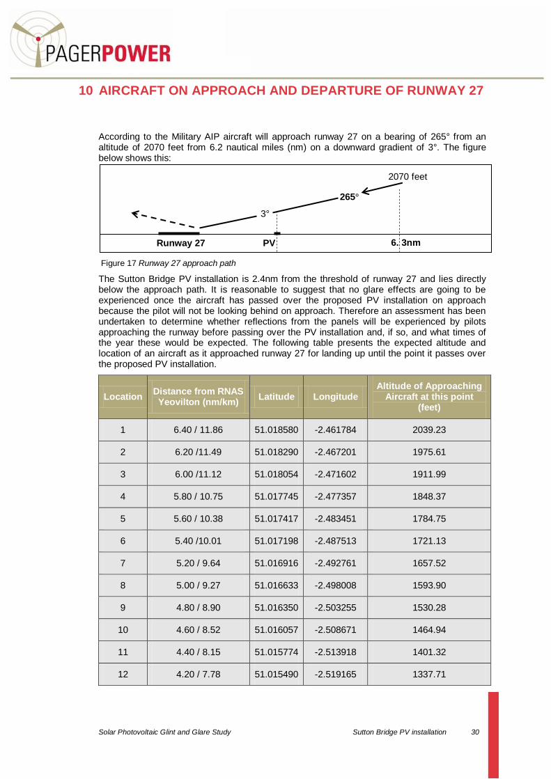
According to the Military AIP aircraft will approach runway 27 on a bearing of 265° from an altitude of 2070 feet from 6.2 nautical miles (nm) on a downward gradient of 3°. The figure below shows this:
Figure 17 Runway 27 approach path
The Sutton Bridge PV installation is 2.4nm from the threshold of runway 27 and lies directly below the approach path. It is reasonable to suggest that no glare effects are going to be experienced once the aircraft has passed over the proposed PV installation on approach because the pilot will not be looking behind on approach. Therefore an assessment has been undertaken to determine whether reflections from the panels will be experienced by pilots approaching the runway before passing over the PV installation and, if so, and what times of the year these would be expected. The following table presents the expected altitude and location of an aircraft as it approached runway 27 for landing up until the point it passes over the proposed PV installation.
Location Distance from RNAS Yeovilton (nm/km)
Latitude Longitude Altitude of Approaching
Aircraft at this point (feet)
1 6.40 / 11.86 51.018580 -2.461784 2039.23
2 6.20 /11.49 51.018290 -2.467201 1975.61
3 6.00 /11.12 51.018054 -2.471602 1911.99
4 5.80 / 10.75 51.017745 -2.477357 1848.37
5 5.60 / 10.38 51.017417 -2.483451 1784.75
6 5.40 /10.01 51.017198 -2.487513 1721.13
7 5.20 / 9.64 51.016916 -2.492761 1657.52
8 5.00 / 9.27 51.016633 -2.498008 1593.90
9 4.80 / 8.90 51.016350 -2.503255 1530.28
10 4.60 / 8.52 51.016057 -2.508671 1464.94
11 4.40 / 8.15 51.015774 -2.513918 1401.32
12 4.20 / 7.78 51.015490 -2.519165 1337.71
3°
265°
2070 feet
Runway 27 6. 3nm PV installation
Solar Photovoltaic Glint and Glare Study Sutton Bridge PV installation 31
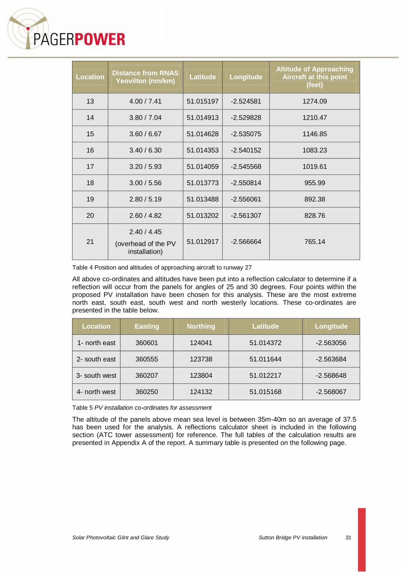
Location Distance from RNAS Yeovilton (nm/km)
Latitude Longitude Altitude of Approaching
Aircraft at this point (feet)
13 4.00 / 7.41 51.015197 -2.524581 1274.09
14 3.80 / 7.04 51.014913 -2.529828 1210.47
15 3.60 / 6.67 51.014628 -2.535075 1146.85
16 3.40 / 6.30 51.014353 -2.540152 1083.23
17 3.20 / 5.93 51.014059 -2.545568 1019.61
18 3.00 / 5.56 51.013773 -2.550814 955.99
19 2.80 / 5.19 51.013488 -2.556061 892.38
20 2.60 / 4.82 51.013202 -2.561307 828.76
21
2.40 / 4.45
(overhead of the PV installation)
51.012917 -2.566664 765.14
Table 4 Position and altitudes of approaching aircraft to runway 27
All above co-ordinates and altitudes have been put into a reflection calculator to determine if a reflection will occur from the panels for angles of 25 and 30 degrees. Four points within the proposed PV installation have been chosen for this analysis. These are the most extreme north east, south east, south west and north westerly locations. These co-ordinates are presented in the table below.
Location Easting Northing Latitude Longitude
1- north east 360601 124041 51.014372 -2.563056
2- south east 360555 123738 51.011644 -2.563684
3- south west 360207 123804 51.012217 -2.568648
4- north west 360250 124132 51.015168 -2.568067
Table 5 PV installation co-ordinates for assessment
The altitude of the panels above mean sea level is between 35m-40m so an average of 37.5 has been used for the analysis. A reflections calculator sheet is included in the following section (ATC tower assessment) for reference. The full tables of the calculation results are presented in Appendix A of the report. A summary table is presented on the following page.
Solar Photovoltaic Glint and Glare Study Sutton Bridge PV installation 32
Location Angle of Panel Reflection Expected Time of Expected
Reflection
1- north east 25°/ 30° No for both angles n/a
2- south east 25°/ 30° No for both angles n/a
3- south west 25°/ 30° No for both angles n/a
4- north west 25°/ 30° No for both angles n/a
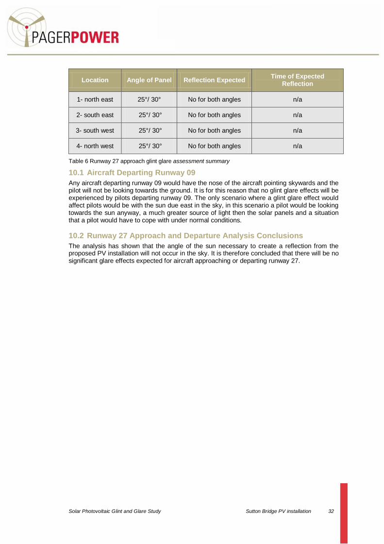
Table 6 Runway 27 approach glint glare assessment summary
10.1 Aircraft Departing Runway 09
Any aircraft departing runway 09 would have the nose of the aircraft pointing skywards and the pilot will not be looking towards the ground. It is for this reason that no glint glare effects will be experienced by pilots departing runway 09. The only scenario where a glint glare effect would affect pilots would be with the sun due east in the sky, in this scenario a pilot would be looking towards the sun anyway, a much greater source of light then the solar panels and a situation that a pilot would have to cope with under normal conditions.
10.2 Runway 27 Approach and Departure Analysis Conclusions
The analysis has shown that the angle of the sun necessary to create a reflection from the proposed PV installation will not occur in the sky. It is therefore concluded that there will be no significant glare effects expected for aircraft approaching or departing runway 27.

Solar Photovoltaic Glint and Glare Study Sutton Bridge PV installation 33
11 AIR TRAFFIC CONTROL TOWER IMPACT ASSESSMENT
A line of sight from the ATC tower on the airfield to a single point within the proposed PV installation has been undertaken. The details for the ATC tower are provided in the table below.
Easting Northing Height agl (m) Ground Height (m) Overall Height AMSL (m)
355356 123184 16 20 36
Table 7 ATC tower details
The height and the co-ordinates of the ATC tower have been extrapolated from aerial photography following identification of the tower on the airfield in the Military AIP. The co-ordinates for the point within the PV installation are 360328E 123975N. A line of site and glint glare calculation is presented below to determine:
1. If the PV installation would be visible to the control tower, and; 2. If the tower is visible, would there be a chance of glare effects affecting the control
tower personnel. The line of sight chart is presented on the following page.
Solar Photovoltaic Glint and Glare Study Sutton Bridge PV installation 34
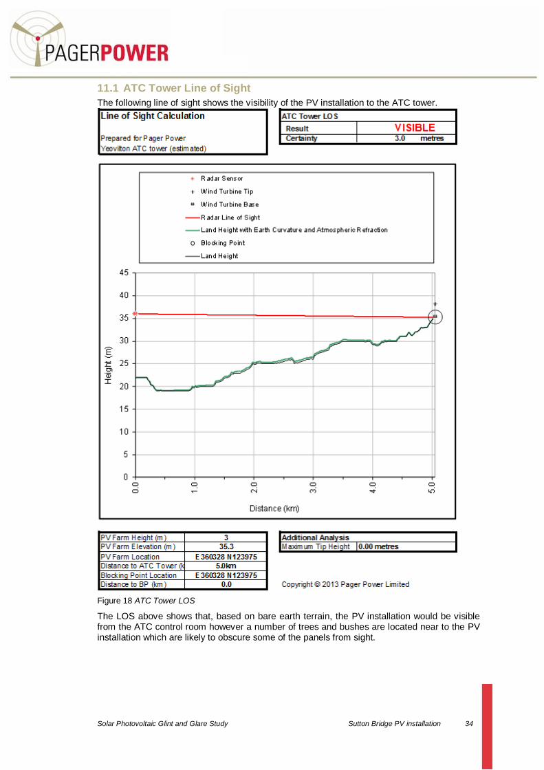
11.1 ATC Tower Line of Sight
The following line of sight shows the visibility of the PV installation to the ATC tower.
Figure 18 ATC Tower LOS
The LOS above shows that, based on bare earth terrain, the PV installation would be visible from the ATC control room however a number of trees and bushes are located near to the PV installation which are likely to obscure some of the panels from sight.

Solar Photovoltaic Glint and Glare Study Sutton Bridge PV installation 35
11.2 Glint Glare Calculator for the ATC Tower
The following section presents the results of the glint glare calculator which determines if glint glare effects will be noticed at the ATC tower and if so at what time of the year. This has been done for 25° and 30°. The calculator determines the specific time and date solar glare will occur at a certain position for a specific reflector (if at all)
11.2.1 25° Panel Refection for ATC Tower
Figure 19 ATC tower reflection for 25° panel

Solar Photovoltaic Glint and Glare Study Sutton Bridge PV installation 36
11.2.2 30° Panel Refection for ATC Tower
Figure 20 ATC tower reflection for 30° panel
Solar Photovoltaic Glint and Glare Study Sutton Bridge PV installation 37
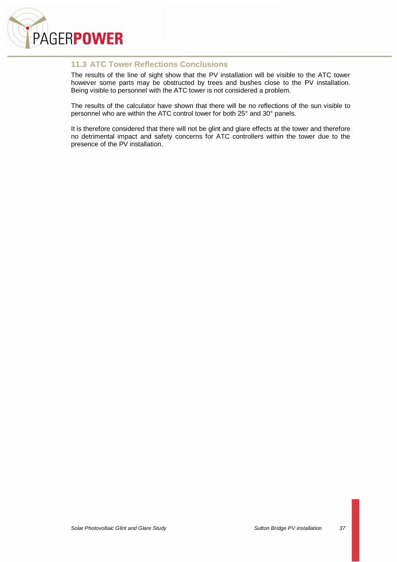
11.3 ATC Tower Reflections Conclusions
The results of the line of sight show that the PV installation will be visible to the ATC tower however some parts may be obstructed by trees and bushes close to the PV installation. Being visible to personnel with the ATC tower is not considered a problem. The results of the calculator have shown that there will be no reflections of the sun visible to personnel who are within the ATC control tower for both 25° and 30° panels. It is therefore considered that there will not be glint and glare effects at the tower and therefore no detrimental impact and safety concerns for ATC controllers within the tower due to the presence of the PV installation.

Solar Photovoltaic Glint and Glare Study Sutton Bridge PV installation 38
12 AVIATION IMPACT CONCLUSIONS
All of the PV panels at Sutton Bridge will be fixed and aligned at the same angle (either 25 or 30 degrees). If reflections were therefore to occur, glint and glare would be concentrated and would continue as aircraft passed through the PV installation if it did occur. As stated previously, photovoltaic panels are designed to absorb light and not to reflect it. They have a smooth surface, however, which means that incident light from a specific direction is reradiated in a specific direction. This means that photovoltaic panels can cause reflections which are considerably less intense than direct sunlight. Photovoltaic panels typically reflect 2% of incident light. The analysis in this report suggests that the proposed PV installation will not cause significant glint and glare for aircraft approaching or departing runway 27 or air traffic controllers within the tower on the airfield. This is because the angle at which the sun would need to be at relative to the panels does not occur.

Solar Photovoltaic Glint and Glare Study Sutton Bridge PV installation 39
13 CONCLUSIONS
Analysis has been undertaken which looks at the relevant guidelines and legislation as well as assessing the possible impact of glint and glare upon aviation at RNAS Yeovilton. A review of the relevant literature surrounding glint and glare revealed the following: Solar panels are designed to absorb sunlight rather than to reflect it, with typically 2% of incident light being reflected. Reflections from solar panels are consequently smaller than direct sunlight, solar reflections from water and reflections from wet runways. Pilots would and do have to cope with glare effects more intense than those from solar panels. The Civil Aviation Authority (CAA) has published interim guidance on solar photovoltaic systems which identifies the potential issue of reflections dazzling pilots. The document advises consultation between the developers of photovoltaic installations and the operators of nearby aerodromes. An investigation into the effect of PV glare on aviation at an American airfield was undertaken by the US Federal Aviation Authority (FAA). In this instance, the investigation revealed anecdotal evidence to suggest that either considerable glare did not occur during operating times or if glare did occur, it was not a negative effect and is a minor part of the landscape to which pilots and control tower personnel are exposed. Examples of PV installations and airfields co-existing are presented in this report. It has been determined that glint and glare would only affect pilots or air traffic controllers if:
There were sunny and clear flying conditions (no substantial cloud or haze);
The aircraft was flying at a particular altitude;
The sun was at a certain angle in the sky;
The pilot/ATC was looking towards or in the vicinity of the PV installation;
The pilot/ATC is in line of sight of the PV installation.
Aviators cope with reflections from the sun on a day to day basis. This includes:
Direct sunlight, reflections from water, wet runways and other man-made structures;
Aircraft wings and structures reflecting sunlight if the sun is to the side or behind at certain angles;
Reflection from the propeller of a light aircraft could cause glare and even a stroboscopic effects;
Clouds generating glare from reflections of the sun. A small level of solar reflections and glare is a normal and acceptable part of flying. It is therefore unlikely that glare should considerably affect a pilot’s performance. Existing structures and surfaces (such as glass windows) are likely to exist in the surrounding environment which are more reflective than the proposed PV installation.

Solar Photovoltaic Glint and Glare Study Sutton Bridge PV installation 40
The results of the investigation into the possible effects of glint and glare upon aviation activity at RNAS Yeovilton are as follows: An initial geometric assessment determined the general volumes of airspace in which pilots could be exposed to solar reflections from any of the photovoltaic panels. This was undertaken for panels with a set angle of 25 and 30 degrees. The volume of airspace which may be affected is quite small because of the slope of the panels and because the highest angle the sun ever reaches at the development latitude is 62.3 degrees. The analysis has shown that the angle of the sun necessary to create a reflection from the proposed PV installation will not occur for aircraft on the appropriate approach route for runway 27. It is therefore concluded that there will be no significant glare effects expected for aircraft approaching runway 27. Aircraft departing runway 09 would have the nose of the aircraft pointing skywards and the pilot will not be looking towards the ground. It is for this reason that no glint and glare effects will be experienced by pilots departing runway 09. The only scenario where glint and glare may affect pilots would be with the sun due east in the sky. In this scenario a pilot would be looking towards the sun anyway, a much greater source of light then the solar panels and a situation that a pilot would have to cope with under normal conditions. The results of the line of sight analysis showed that the PV installation would be visible to the ATC tower however some parts may be obstructed by trees and bushes close to the PV installation. Being visible to personnel with the ATC tower is not considered a problem because it would be no different to any other development being visible to the ATC in the surrounding landscape. The results of the geometric calculations have shown that there will be no reflections of the sun visible to personnel who are within the ATC control tower for both 25° and 30° panels. As a result it is considered that there will be no glint and glare effects at the tower and therefore no detrimental impact and safety concerns for ATC controllers within the tower due to the presence of the PV installation. Overall Conclusion Overall it is not believed that a considerable impact upon aviation safety at RNAS Yeovilton will occur. A pilot will come across more intense reflections in the landscape than those produced by those from the PV installation. It is considered to be a minor impact because such reflections will always exist for pilots whilst flying. Reflections of greater intensity will already exist within the surrounding landscapes which are not considered to be a hazard to safety. Pilots should however be made aware of the PV installation as a precaution.

Solar Photovoltaic Glint and Glare Study Sutton Bridge PV installation 41
APPENDIX A - ANALYSIS TABLES FOR AIRCRAFT APPROACHING RUNWAY 27
Results of Glint Glare Calculator from the North Eastern Corner
Location Angle sun would have to be relative to
reflector to be seen by pilot (25° / 30° panel) Reflection Expected
Time of Expected Reflection
1 125.29 / 115.29 No n/a
2 125.19 / 115.19 No n/a
3 125.13 / 115.13 No n/a
4 124.99 / 114.99 No n/a
5 124.80 / 114.80 No n/a
6 124.74 / 114.74 No n/a
7 124.57 / 114.57 No n/a
8 124.38 / 114.38 No n/a
9 124.15 / 114.15 No n/a
10 123.87 / 113.87 No n/a
11 123.53 / 113.53 No n/a
12 123.12 / 113.12 No n/a
13 122.57 / 112.57 No n/a
14 121.88 / 111.88 No n/a
15 120.93 / 110.93 No n/a
16 119.64 / 109.64 No n/a
17 117.40 / 107.40 No n/a
18 113.52 / 103.52 No n/a
19 104.81 / 94.81 No n/a
20 79.68 / 69.68 No n/a
21 96.84 / 86.84 No n/a

Solar Photovoltaic Glint and Glare Study Sutton Bridge PV installation 42
Results of Glint Glare Calculator from the South Eastern Corner
Location Angle sun would have to be relative to
reflector to be seen by pilot (25° / 30° panel)
Reflection
Expected
Time of Expected
Reflection
1 125.34 / 115.34 No n/a
2 125.24 / 125.24 No n/a
3 125.19 / 115.19 No n/a
4 125.05 / 115.05 No n/a
5 124.87 / 114.87 No n/a
6 124.81 / 114.81 No n/a
7 124.65 / 114.65 No n/a
8 124.46 / 114.46 No n/a
9 124.24 / 114.24 No n/a
10 123.98 / 113.98 No n/a
11 123.66 / 113.66 No n/a
12 123.28 / 113.28 No n/a
13 122.78 / 112.78 No n/a
14 122.12 / 112.12 No n/a
15 121.25 / 111.25 No n/a
16 120.07 / 110.07 No n/a
17 118.08 / 108.08 No n/a
18 114.73 / 104.73 No n/a
19 107.67 / 97.67 No n/a
20 88.12 / 78.12 No n/a
21 92.14 / 82.14 No n/a
Solar Photovoltaic Glint and Glare Study Sutton Bridge PV installation 43
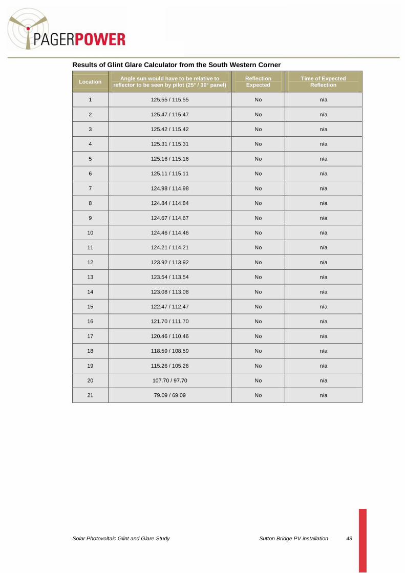
Results of Glint Glare Calculator from the South Western Corner
Location Angle sun would have to be relative to
reflector to be seen by pilot (25° / 30° panel)
Reflection
Expected
Time of Expected
Reflection
1 125.55 / 115.55 No n/a
2 125.47 / 115.47 No n/a
3 125.42 / 115.42 No n/a
4 125.31 / 115.31 No n/a
5 125.16 / 115.16 No n/a
6 125.11 / 115.11 No n/a
7 124.98 / 114.98 No n/a
8 124.84 / 114.84 No n/a
9 124.67 / 114.67 No n/a
10 124.46 / 114.46 No n/a
11 124.21 / 114.21 No n/a
12 123.92 / 113.92 No n/a
13 123.54 / 113.54 No n/a
14 123.08 / 113.08 No n/a
15 122.47 / 112.47 No n/a
16 121.70 / 111.70 No n/a
17 120.46 / 110.46 No n/a
18 118.59 / 108.59 No n/a
19 115.26 / 105.26 No n/a
20 107.70 / 97.70 No n/a
21 79.09 / 69.09 No n/a

Solar Photovoltaic Glint and Glare Study Sutton Bridge PV installation 44
Results of Glint Glare Calculator from the North Western Corner
Location Angle sun would have to be relative to
reflector to be seen by pilot (25° / 30° panel)
Reflection
Expected
Time of Expected
Reflection
1 125.51 / 115.51 No n/a
2 125.43 / 115.43 No n/a
3 125.38 / 115.38 No n/a
4 125.26 / 115.26 No n/a
5 125.11 / 115.11 No n/a
6 125.06 / 115.06 No n/a
7 124.93 / 114.93 No n/a
8 124.77 / 114.77 No n/a
9 124.59 / 114.59 No n/a
10 124.37 / 114.37 No n/a
11 124.12 / 114.12 No n/a
12 123.82 / 113.82 No n/a
13 123.42 / 113.42 No n/a
14 122.93 / 112.93 No n/a
15 122.30 / 112.30 No n/a
16 121.48 / 111.48 No n/a
17 120.17 / 110.17 No n/a
18 118.20 / 108.20 No n/a
19 114.74 / 104.20 No n/a
20 107.55 / 97.55 No n/a
21 93.92 / 83.92 No n/a

Solar Photovoltaic Glint and Glare Study Sutton Bridge PV installation 45