Solar Drone Final Report
22
Solar Drone ECE445 Final Report Team 3 Jinming Zhang Jie Wang Yingkan Ni TA: Ryan May Prof. A. C. Singer December 11, 2012
Transcript of Solar Drone Final Report
Solar Drone ECE445 Final Report Team 3 Jinming Zhang Jie Wang Yingkan Ni TA: Ryan May Prof. A. C. Singer December 11, 2012
2
Table of Contents
I. INTRODUCTION .................................................................................. 3 A. PROBLEM DESCRIPTION ......................................................................................... 3 B. OBJECTIVES ............................................................................................................ 3 C. SYSTEM BLOCK DIAGRAM ...................................................................................... 4
II. DESIGN .............................................................................................. 4 A. POWER MANAGEMENT SYSTEM ............................................................................. 4
1. Circuit Diagram ............................................................................................................. 4 2. Components Selection ..................................................................................................... 5 3. Circuit Schematic ........................................................................................................... 6 4. Control Algorithm .......................................................................................................... 7
B. ELECTRICAL COMPONENTS .................................................................................... 8 1. Motor ............................................................................................................................ 8 2. Electronic Speed Controller (ESC) ................................................................................... 8 3. Battery .......................................................................................................................... 9
C. FLIGHT CONTROLLER AND INTERFACE .................................................................. 9 1. Overview ....................................................................................................................... 9 2. Motion Update Loop .................................................................................................... 10 3. Communication With Ground Station .......................................................................... 11
III. REQUIREMENTS AND VERIFICATIONS ............................................... 11 A. POWER MANAGEMENT SYSTEM ........................................................................... 11
1. Requirements ............................................................................................................... 11 2. Test Cases and Procedures ............................................................................................. 12 3. Results ........................................................................................................................ 12 4. Discussion ................................................................................................................... 12
B. ELECTRICAL COMPONENTS .................................................................................. 13 1. Requirements ............................................................................................................... 13 2. Test Procedures ............................................................................................................ 13 3. Results ........................................................................................................................ 14 4. Discussion ................................................................................................................... 16
C. FLIGHT CONTROLLER AND INTERFACE ................................................................ 16 1. Test Procedures and Results .......................................................................................... 16 2. Discussion ................................................................................................................... 17
IV. COSTS .............................................................................................. 17 A. PARTS .................................................................................................................. 17 B. LABOR .................................................................................................................. 18
V. CONCLUSION .................................................................................... 18 A. ACCOMPLISHMENT ............................................................................................... 18 B. DIFFICULTIES AND UNCERTAINTIES ..................................................................... 19 C. ETHICAL CONSIDERATIONS .................................................................................. 19 D. FUTURE WORK .................................................................................................... 20
VI. REFERENCES .................................................................................... 20
VII. APPENDIX ....................................................................................... 21
3
I. Introduction
A. Problem Description
Unmanned Aerial Vehicle (UAV), or commonly known as drone, is a type of aircraft
without a human pilot on board, as the name suggested, but controlled
autonomously by computers and/or taking commands from remote stations. The
UAVs are perfect candidates for tasks that are tedious or dangerous for human, for
example, patrolling along boarder lines, wild fire control, aerial surveillance and etc.
The applications of UAV, as described above, generally require long flight time and
reliable power supply. However, current UAV designs utilizing traditional battery or
fuel cells usually struggles to meet such requirement.
B. Objectives
This project aims to provide an innovative solution to this problem by introducing
the current popular photovoltaic system into the UAV power system design. It
focuses on the electrical system design and the product will be a platform for future
development on solar powered UAVs. The design is to be modular for easy module
upgrade and replacement.
The UAV has a vast variety of configurations. The type of UAV chosen for this
project is quadrotor helicopter, or called quadcopter, for its benefit as being easy to
configure and having space for solar panel placement.
A prototype software flight controller will also be designed to be the interface
between human and the electrical system.
4
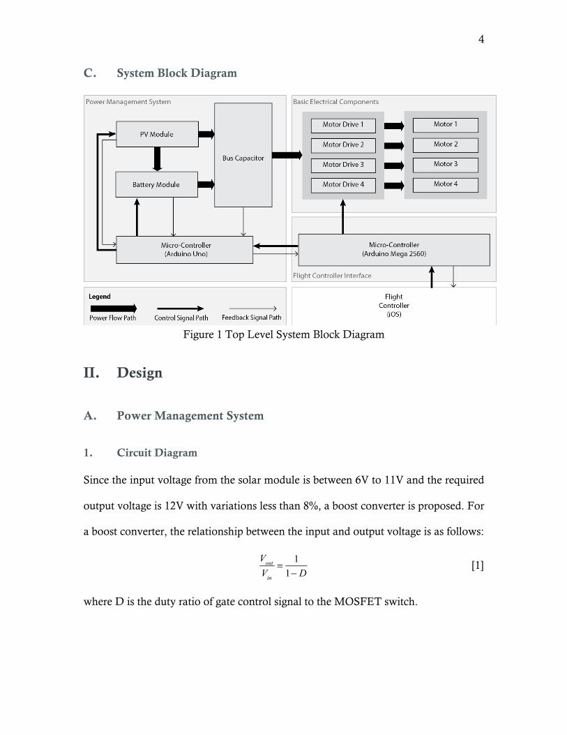
C. System Block Diagram
Figure 1 Top Level System Block Diagram
II. Design
A. Power Management System
1. Circuit Diagram
Since the input voltage from the solar module is between 6V to 11V and the required
output voltage is 12V with variations less than 8%, a boost converter is proposed. For
a boost converter, the relationship between the input and output voltage is as follows:
Vout
Vin
= 11− D
[1]
where D is the duty ratio of gate control signal to the MOSFET switch.
5
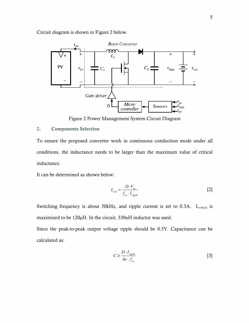
Circuit diagram is shown in Figure 2 below.
Figure 2 Power Management System Circuit Diagram
2. Components Selection
To ensure the proposed converter work in continuous conduction mode under all
conditions, the inductance needs to be larger than the maximum value of critical
inductance.
It can be determined as shown below:
Lcrit =
D ⋅Vin
fsw ⋅ Iripple
[2]
Switching frequency is about 50kHz, and ripple current is set to 0.3A. Lcritical is
maximized to be 120µH. In the circuit, 330uH inductor was used.
Since the peak-to-peak output voltage ripple should be 0.5V. Capacitance can be
calculated as:
C ≥
D ⋅ Iripple
Δv ⋅ fsw
[3]
6
The capacitor needs to be at least 1.5 µF to keep the voltage ripple within 0.5V. In
this converter, the capacitor is chosen to be 470 µF to filter out additional high
frequency noise.
As to the other components, the voltage and current requirements for them are 12 V
and 20A.
Below is a table of other components used in the circuit and their ratings:
Table 1. MOSFET and Diode Rating Components Model Voltage Rating (V) Current Rating (A)
Diode B40250TG 240 40
MOSFET IRFPS3810 100 170
Apparently, components have ratings higher than required.
However, a basic boost converter itself cannot be used to function as a MPPT.
Voltage sensors, current sensor, MOSFET driver and microcontroller should be
added to the circuit. Sensors are used to sense voltage and current so that the
microcontroller can calculate the power based on the values from the sensors.
Voltage divider circuit was used to function as a voltage sensor since the Arduino can
only take up to 5V as input signal. Current sensor was built by using a current sensor
chip.
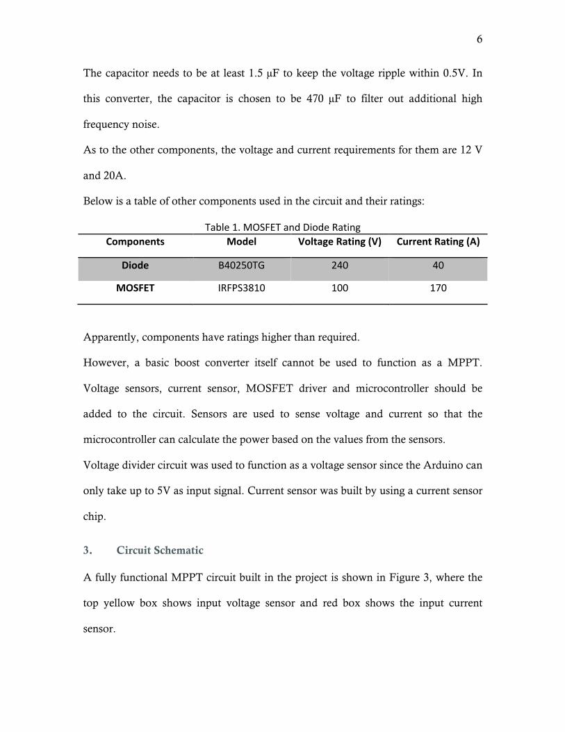
3. Circuit Schematic
A fully functional MPPT circuit built in the project is shown in Figure 3, where the
top yellow box shows input voltage sensor and red box shows the input current
sensor.
7
Figure 3 Power Management System Circuit Schematic
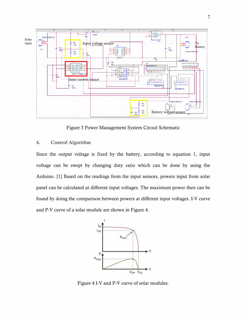
4. Control Algorithm
Since the output voltage is fixed by the battery, according to equation 1, input
voltage can be swept by changing duty ratio which can be done by using the
Arduino. [1] Based on the readings from the input sensors, powers input from solar
panel can be calculated at different input voltages. The maximum power then can be
found by doing the comparison between powers at different input voltages. I-V curve
and P-V curve of a solar module are shown in Figure 4.
Figure 4 I-V and P-V curve of solar modules.
Battery voltage sensor
Input voltage sensor
Input current sensor
Solar input To
Battery
8
From the figure, it can be seen that the algorism of the MPPT looks like climbing a
hill. According to equation 1, if the input voltage is low, it will keep increasing by
decreasing the duty ratio until the power hits its maximum value.
Sample codes are shown below:
If (old_power < power) { duty_ratio -= 1; } else duty_ratio += 1;
B. Electrical Components
1. Motor
A lightweight yet powerful DC motor is desired for this application. The motor
needs to have low KV rating, thus higher torque capability, for heavy payload
carrying. The specific motor chosen is Turnigy Aerodrive SK3 1185kv Brushless
Outrunner Motor [2]. And the detailed specifications are tabulated in Table 2.
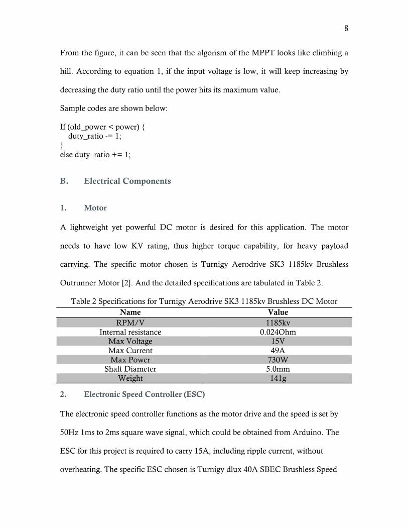
Table 2 Specifications for Turnigy Aerodrive SK3 1185kv Brushless DC Motor Name Value
RPM/V 1185kv Internal resistance 0.024Ohm
Max Voltage 15V Max Current 49A Max Power 730W
Shaft Diameter 5.0mm Weight 141g
2. Electronic Speed Controller (ESC)
The electronic speed controller functions as the motor drive and the speed is set by
50Hz 1ms to 2ms square wave signal, which could be obtained from Arduino. The
ESC for this project is required to carry 15A, including ripple current, without
overheating. The specific ESC chosen is Turnigy dlux 40A SBEC Brushless Speed
9
Controller. [3] This model has large heat sink for heat dissipation, high current rating
and low battery protection function. The specifications for this ESC are tabulated in
Table 3 below.
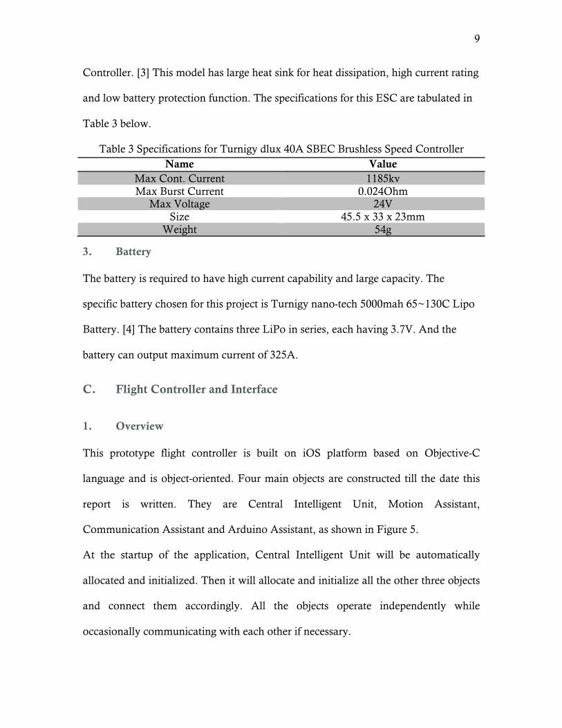
Table 3 Specifications for Turnigy dlux 40A SBEC Brushless Speed Controller Name Value
Max Cont. Current 1185kv Max Burst Current 0.024Ohm
Max Voltage 24V Size 45.5 x 33 x 23mm
Weight 54g
3. Battery
The battery is required to have high current capability and large capacity. The
specific battery chosen for this project is Turnigy nano-tech 5000mah 65~130C Lipo
Battery. [4] The battery contains three LiPo in series, each having 3.7V. And the
battery can output maximum current of 325A.
C. Flight Controller and Interface
1. Overview
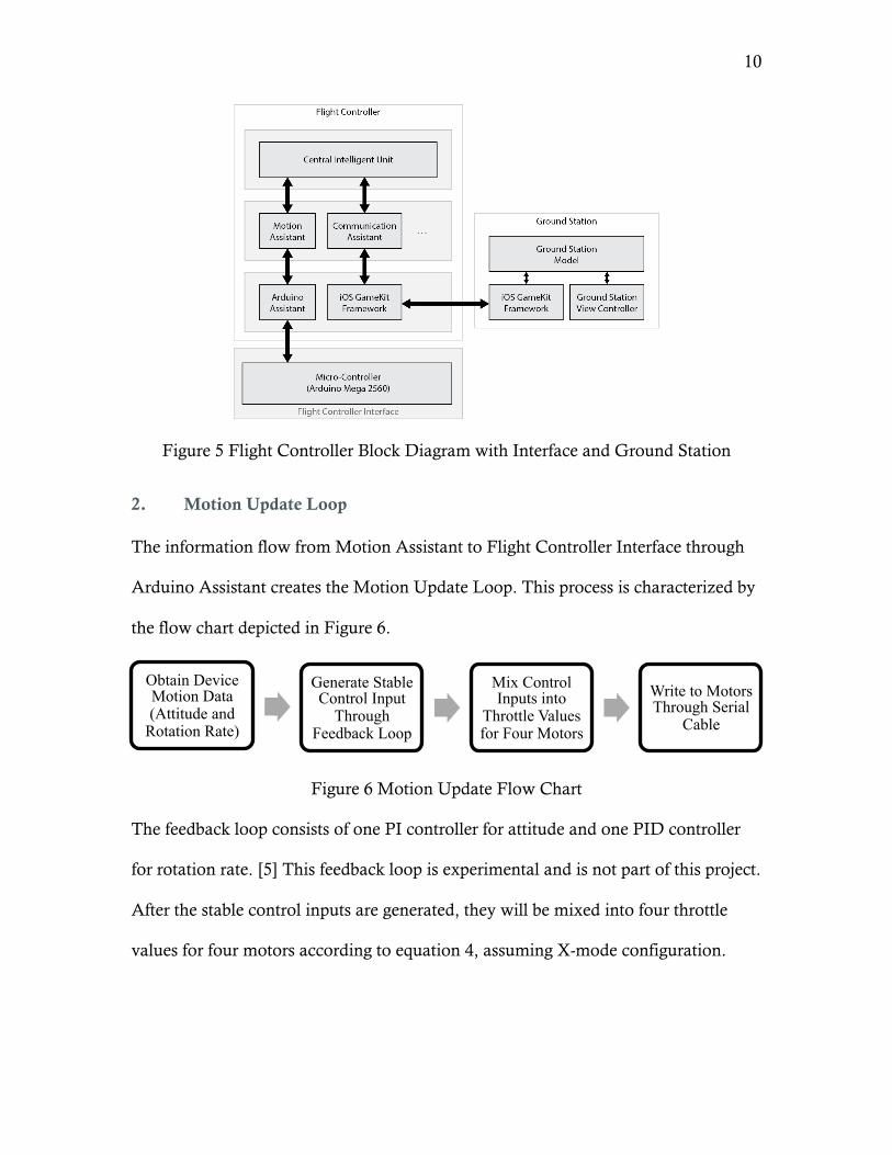
This prototype flight controller is built on iOS platform based on Objective-C
language and is object-oriented. Four main objects are constructed till the date this
report is written. They are Central Intelligent Unit, Motion Assistant,
Communication Assistant and Arduino Assistant, as shown in Figure 5.
At the startup of the application, Central Intelligent Unit will be automatically
allocated and initialized. Then it will allocate and initialize all the other three objects
and connect them accordingly. All the objects operate independently while
occasionally communicating with each other if necessary.
10
Figure 5 Flight Controller Block Diagram with Interface and Ground Station
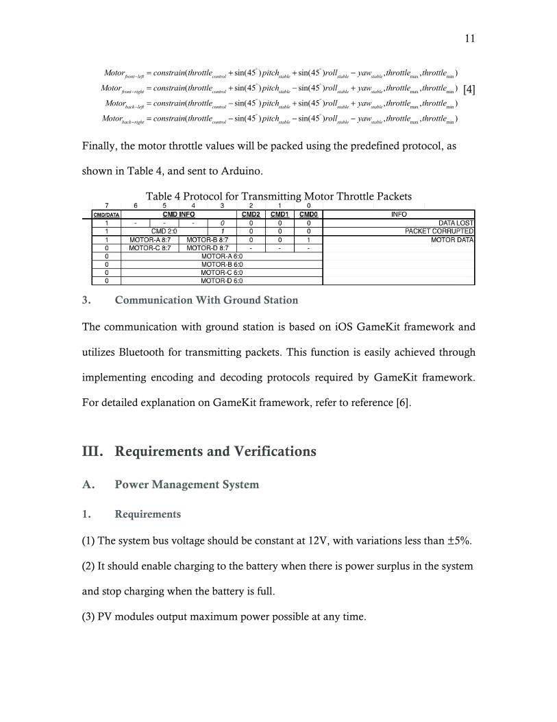
2. Motion Update Loop
The information flow from Motion Assistant to Flight Controller Interface through
Arduino Assistant creates the Motion Update Loop. This process is characterized by
the flow chart depicted in Figure 6.
Figure 6 Motion Update Flow Chart
The feedback loop consists of one PI controller for attitude and one PID controller
for rotation rate. [5] This feedback loop is experimental and is not part of this project.
After the stable control inputs are generated, they will be mixed into four throttle
values for four motors according to equation 4, assuming X-mode configuration.
Obtain Device Motion Data (Attitude and
Rotation Rate)
Generate Stable Control Input
Through Feedback Loop
Mix Control Inputs into
Throttle Values for Four Motors
Write to Motors Through Serial
Cable
11
Motorfront−left = constrain(throttlecontrol + sin(45° ) pitchstable + sin(45° )rollstable − yawstable ,throttlemax ,throttlemin )
Motorfront−right = constrain(throttlecontrol + sin(45° ) pitchstable − sin(45° )rollstable + yawstable ,throttlemax ,throttlemin )
Motorback−left = constrain(throttlecontrol − sin(45° ) pitchstable + sin(45° )rollstable + yawstable ,throttlemax ,throttlemin )
Motorback−right = constrain(throttlecontrol − sin(45° ) pitchstable − sin(45° )rollstable − yawstable ,throttlemax ,throttlemin )
[4]
Finally, the motor throttle values will be packed using the predefined protocol, as
shown in Table 4, and sent to Arduino.
Table 4 Protocol for Transmitting Motor Throttle Packets
3. Communication With Ground Station
The communication with ground station is based on iOS GameKit framework and
utilizes Bluetooth for transmitting packets. This function is easily achieved through
implementing encoding and decoding protocols required by GameKit framework.
For detailed explanation on GameKit framework, refer to reference [6].
III. Requirements and Verifications
A. Power Management System
1. Requirements
(1) The system bus voltage should be constant at 12V, with variations less than ±5%.
(2) It should enable charging to the battery when there is power surplus in the system
and stop charging when the battery is full.
(3) PV modules output maximum power possible at any time.
12
2. Test Cases and Procedures
20W, which is under the irradiance of 1000W/m2, PV module was connected to the
MPPT circuit input connectors. Output connectors of the MPPT circuit were
connected to a constant current of 2A electronic load. Additionally, a DC power
supply with 12 V simulating the battery was connected to the electronic load. A
1200W lamp was used to simulate sunlight. The PV module, which was borrowed
from power lab, tested on was labeled to have a maximum power voltage of 9.5V
3. Results
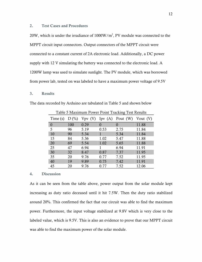
The data recorded by Arduino are tabulated in Table 5 and shown below
Table 5 Maximum Power Point Tracking Test Results
4. Discussion
As it can be seen from the table above, power output from the solar module kept
increasing as duty ratio deceased until it hit 7.5W. Then the duty ratio stabilized
around 20%. This confirmed the fact that our circuit was able to find the maximum
power. Furthermore, the input voltage stabilized at 9.8V which is very close to the
labeled value, which is 9.5V. This is also an evidence to prove that our MPPT circuit
was able to find the maximum power of the solar module.
Time (s) D (%) Vpv (V) Ipv (A) Pout (W) Vout (V)
0 100 0.29 0 0 11.88 5 96 5.19 0.53 2.75 11.84 10 90 5.34 1 5.34 11.84 15 84 5.36 1.02 5.47 11.88 20 69 5.54 1.02 5.65 11.88 25 47 6.94 1 6.94 11.91 30 32 8.47 0.87 7.37 11.95 35 20 9.76 0.77 7.52 11.95 40 19 9.89 0.75 7.42 11.91 45 20 9.76 0.77 7.52 12.06
13
The reason for not getting rated power at 20W may come from the non-ideal light
source. The reason may be the fact that the lamp was consuming 1.2 kW of input
power but was producing much less power in the form of visible light than that since
an incandescent light bulb is not very efficient. Thus, it would not be surprising to
find that the power output was much lower.
B. Electrical Components
1. Requirements
(1) The battery should be able to provide 600W power output when the PV module is
completely offline.
(2) Four motors when paired with 15inches propeller with 4inches pitch should be
able to provide more than 2kg of thrust with less than 600W of power consumption.
(3) Each ESC should be able to handle 15A of continuous current without failing
when the power system is operating at max power condition (600W).
2. Test Procedures
Step 1: Install each motor on testing bracket, which is placed on weigh scales
respectively.
Step 2: Setup the ESC according to user manual so that the propeller would generate
a force downward, pushing the weight scale.
Step 3: Load Servo testing program onto Arduino Mega, which allows user to control
the throttle output via computer.
14
Step 4: Connect the battery to power distribution board through a watt meter, which
then connects to the four ESCs through watt meters measuring individual current
flowing in each channel.
Step 5: Connect JR connectors on ESCs to pin2, pin5, pin12 and pin13 on Arduino
board.
Step 6: Record readings from weigh scale and wattmeter.
3. Results
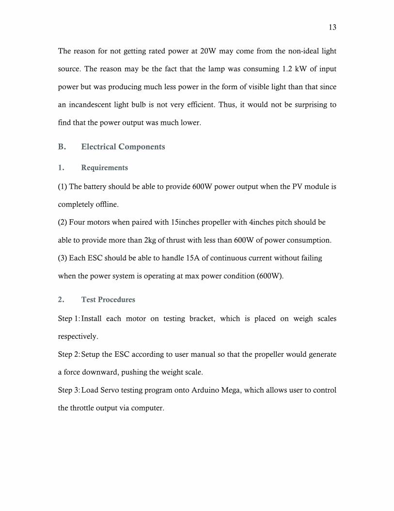
Figure 7 Current vs Throttle
Figure 7 shows the current flowing into the ESC at 10% to 60% throttle. 4 motors
behave almost the same with minor variations. Maximum current motor draws at
60% throttle is 11.7A
0
2
4
6
8
10
12
5% 15% 25% 35% 45% 55% 65%
Cur
rent
(A
)
Throttle (%)
Motor 1
Motor 2
Motor 3
Motor 4
15
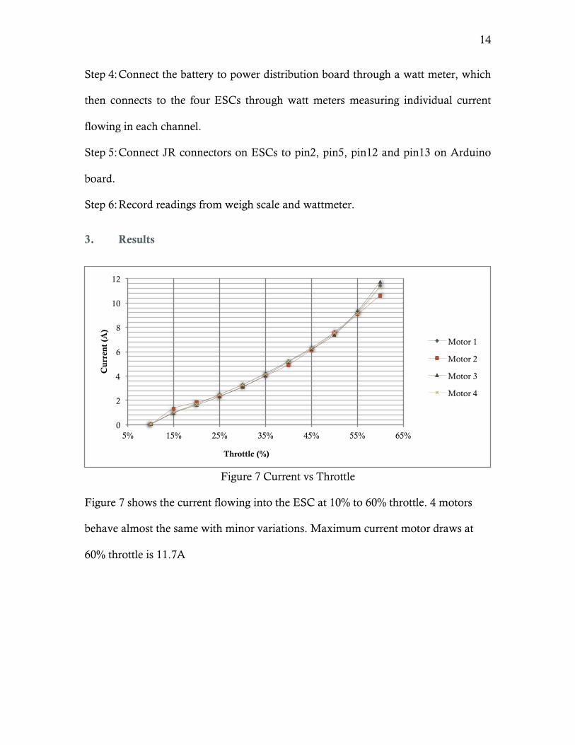
Figure 8 Thrust vs Throttle
This figure shows the thrust each motor can generate from 10% to 60% throttle. 4
motors behave almost the same. Thrust each motor can generate at 60% throttle is
approximately 1kg, which is equal to 10N.
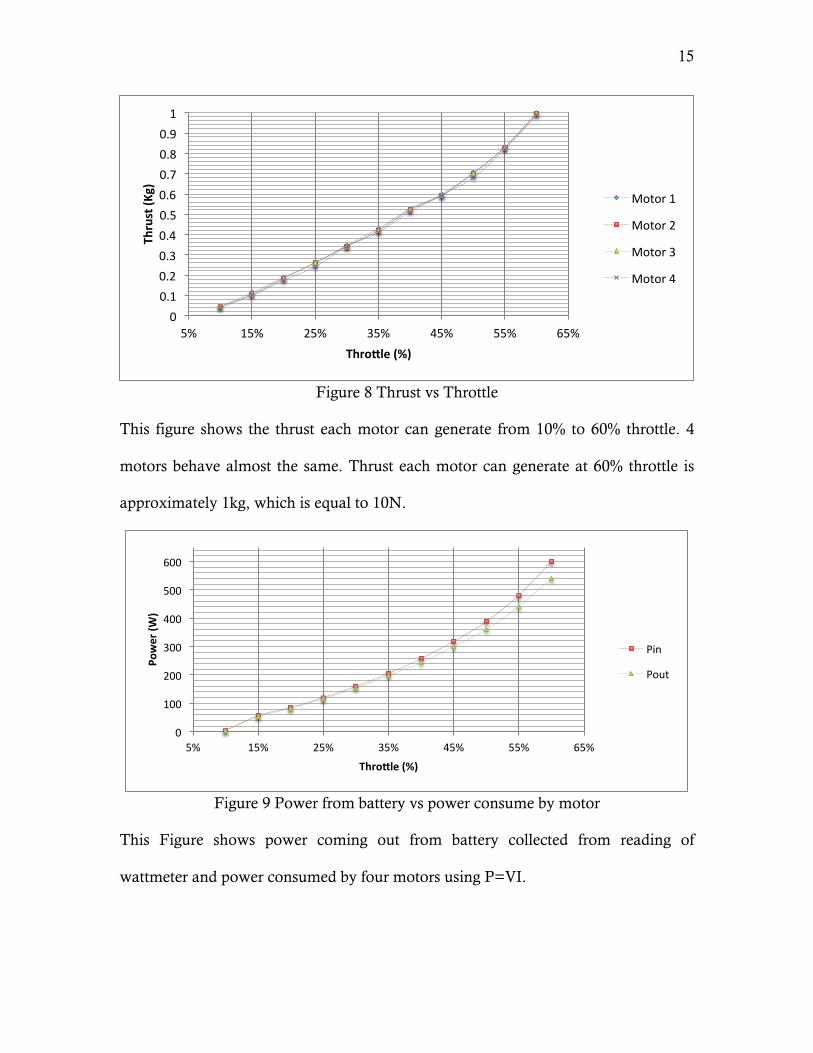
Figure 9 Power from battery vs power consume by motor
This Figure shows power coming out from battery collected from reading of
wattmeter and power consumed by four motors using P=VI.
0 0.1 0.2 0.3 0.4 0.5 0.6 0.7 0.8 0.9 1
5% 15% 25% 35% 45% 55% 65%
Thrust (K
g)
Thro?le (%)
Motor 1
Motor 2
Motor 3
Motor 4
0
100
200
300
400
500
600
5% 15% 25% 35% 45% 55% 65%
Power (W
)
Thro?le (%)
Pin
Pout
16
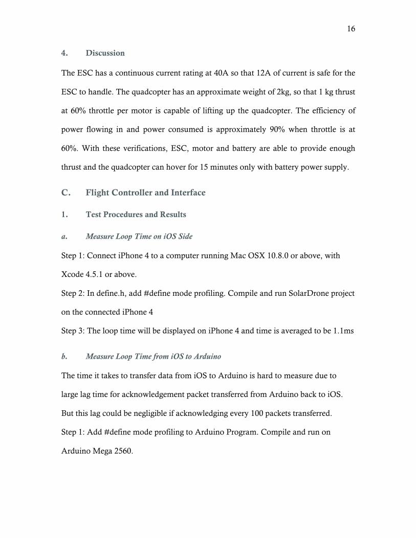
4. Discussion
The ESC has a continuous current rating at 40A so that 12A of current is safe for the
ESC to handle. The quadcopter has an approximate weight of 2kg, so that 1 kg thrust
at 60% throttle per motor is capable of lifting up the quadcopter. The efficiency of
power flowing in and power consumed is approximately 90% when throttle is at
60%. With these verifications, ESC, motor and battery are able to provide enough
thrust and the quadcopter can hover for 15 minutes only with battery power supply.
C. Flight Controller and Interface
1. Test Procedures and Results
a. Measure Loop Time on iOS Side
Step 1: Connect iPhone 4 to a computer running Mac OSX 10.8.0 or above, with
Xcode 4.5.1 or above.
Step 2: In define.h, add #define mode profiling. Compile and run SolarDrone project
on the connected iPhone 4
Step 3: The loop time will be displayed on iPhone 4 and time is averaged to be 1.1ms
b. Measure Loop Time from iOS to Arduino
The time it takes to transfer data from iOS to Arduino is hard to measure due to
large lag time for acknowledgement packet transferred from Arduino back to iOS.
But this lag could be negligible if acknowledging every 100 packets transferred.
Step 1: Add #define mode profiling to Arduino Program. Compile and run on
Arduino Mega 2560.
17
Step 2: Similar to part a above, compile and run SolarDrone project on iPhone 4, all
the acknowledgement packet sent from Arduino will be logged in log console with
accurate time stamp.
Step 3: Take neighboring two logs, calculate the time difference and divided by 100,
the result will be transfer time plus 10ms loop interval. And the final result is
averaged to be 0.3ms.
2. Discussion
The results from both part a and part b add up to 1.4 ms, which is far less than 10ms
individual loop time. This guarantees that the loop will be completed on time before
the next invocation. This proves the iPhone 4 is capable to stabilize the quadcopter
and be the flight controller.
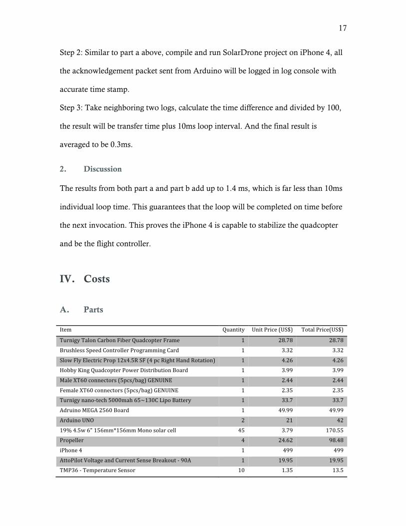
IV. Costs
A. Parts
Item Quantity Unit Price (US$) Total Price(US$)
Turnigy Talon Carbon Fiber Quadcopter Frame 1 28.78 28.78
Brushless Speed Controller Programming Card 1 3.32 3.32
Slow Fly Electric Prop 12x4.5R SF (4 pc Right Hand Rotation) 1 4.26 4.26
Hobby King Quadcopter Power Distribution Board 1 3.99 3.99
Male XT60 connectors (5pcs/bag) GENUINE 1 2.44 2.44
Female XT60 connectors (5pcs/bag) GENUINE 1 2.35 2.35
Turnigy nano-‐tech 5000mah 65~130C Lipo Battery 1 33.7 33.7
Adruino MEGA 2560 Board 1 49.99 49.99
Arduino UNO 2 21 42
19% 4.5w 6" 156mm*156mm Mono solar cell 45 3.79 170.55
Propeller 4 24.62 98.48
iPhone 4 1 499 499
AttoPilot Voltage and Current Sense Breakout -‐ 90A 1 19.95 19.95
TMP36 -‐ Temperature Sensor 10 1.35 13.5
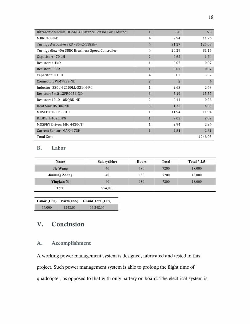
18
Ultrasonic Module HC-‐SR04 Distance Sensor For Arduino 1 6.8 6.8
MBRB4030-‐D 4 2.94 11.76
Turnigy Aerodrive SK3 -‐ 3542-‐1185kv 4 31.27 125.08
Turnigy dlux 40A SBEC Brushless Speed Controller 4 20.29 81.16
Capacitor: 470 uH 2 0.62 1.24
Resistor: 4.1kΩ 1 0.07 0.07
Resistor:1.5kΩ 1 0.07 0.07
Capacitor: 0.1uH 4 0.83 3.32
Connector: WM7853-‐ND 2 2 4
Inductor: 330uH 2100LL-‐331-‐H-‐RC 1 2.63 2.63
Resistor: 5mΩ 12FR005E-‐ND 3 5.19 15.57
Resistor: 10kΩ 10KQBK-‐ND 2 0.14 0.28
Heat Sink HS106-‐ND 3 1.35 4.05
MOSFET: IRFPS3810 1 11.94 11.94
DIODE: B40250TG 1 2.02 2.02
MOSFET Driver: MIC 4420CT 1 2.94 2.94
Current Sensor: MAX4173H 1 2.81 2.81
Total Cost 1248.05
B. Labor
Name Salary($/hr) Hours Total Total * 2.5
Jie Wang 40 180 7200 18,000
Jinming Zhang 40 180 7200 18,000
Yingkan Ni 40 180 7200 18,000
Total $54,000
Labor (US$) Parts(US$) Grand Total(US$)
54,000 1248.05 55,248.05
V. Conclusion
A. Accomplishment
A working power management system is designed, fabricated and tested in this
project. Such power management system is able to prolong the flight time of
quadcopter, as opposed to that with only battery on board. The electrical system is

19
also designed and assembled for functionality testing. Besides, a prototype software
flight controller is designed for future development.
B. Difficulties and Uncertainties
(1) Mounting solar panels onto the quadcopter is hard to achieve since solar panels
are fragile and vulnerable, it is easy to cause damage to the solar panels.
(2) Currently, the best solar cells available in the market possess an efficiency of
approximately 20%, which is only able to prolong the flight time.
(3) The PID system embedded in the quadcopter is hard to tune due to lack of
modeling information for the .
C. Ethical Considerations
We abide to the IEEE code of Ethics in designing and testing the system as follows:
1. to accept responsibility in making decisions consistent with the safety, health,
and welfare of the public, and to disclose promptly factors that might endanger the
public or the environment;
3. to be honest and realistic in stating claims or estimates based on available
data.
7. to seek, accept, and offer honest criticism of technical work, to acknowledge
and correct errors, and to credit properly the contributions of others
9. to avoid injuring others, their property, reputation, or employment by false or
malicious action.
Since each motor is able to spin at 11850 rpm at full throttle, it turns out to be very
dangerous incase it lost control. So we start with using three motors to test the self-
20
balancing system and hangs the quadcopter to a rod to make sure it would not fly all
around and cause damage.
D. Future Work
We have achieved most of goals we set at the beginning of the semester. There are
still some issues regarding stability of the quadcopter. We need to set up a model for
this system to model the behavior of in-flight characteristics of the quadcopter so that
we will be able to find the right pole locations for the PID system.
Since we used iOS as our developing language, we are able to build a platform for
other developers to join us, who can contribute more features.
VI. References
[1] Buckley, Bryan. “mppt: a maximum power point tracking photovoltaic system.”
<http://bama.ua.edu/~bwbuckley/projects/mppt.html>
[2] Hobbyking “Turnigy Aerodrive SK3 - 3542-1185kv Brushless Outrunner Motor”
<http://www.hobbyking.com/hobbyking/store/uh_viewItem.asp?idProduct=30851 >
[3] Hobbyking “Turnigy dlux 40A SBEC Brushless Speed Controller”
<http://www.hobbyking.com/hobbyking/store/uh_viewItem.asp?idProduct=18922>
[4] Hobbyking “Turnigy nano-tech 5000mah 3S 65~130C Lipo Pack”
<http://www.hobbyking.com/hobbyking/store/uh_viewItem.asp?idProduct=19153>
[5] ArduCopter <http://code.google.com/p/arducopter/>
[6] Apple Documentations for GameKit <http://developer.apple.com/library/ios/#documentation/GameKit/Reference/GameKit_Collectio
n/_index.html >
21
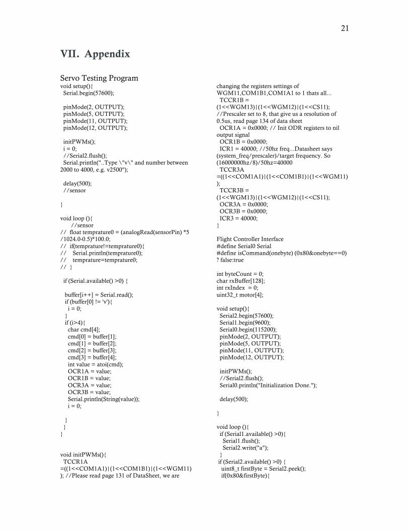
VII. Appendix
Servo Testing Program void setup(){ Serial.begin(57600); pinMode(2, OUTPUT); pinMode(5, OUTPUT); pinMode(11, OUTPUT); pinMode(12, OUTPUT); initPWMs(); i = 0; //Serial2.flush(); Serial.println("..Type \"v\" and number between 2000 to 4000, e.g. v2500"); delay(500); //sensor } void loop (){ //sensor // float temprature0 = (analogRead(sensorPin) *5 /1024.0-0.5)*100.0; // if(temprature!=temprature0){ // Serial.println(temprature0); // temprature=temprature0; // } if (Serial.available() >0) { buffer[i++] = Serial.read(); if (buffer[0] != 'v'){ i = 0; } if (i>4){ char cmd[4]; cmd[0] = buffer[1]; cmd[1] = buffer[2]; cmd[2] = buffer[3]; cmd[3] = buffer[4]; int value = atoi(cmd); OCR1A = value; OCR1B = value; OCR3A = value; OCR3B = value; Serial.println(String(value)); i = 0; } } } void initPWMs(){ TCCR1A =((1<<COM1A1)|(1<<COM1B1)|(1<<WGM11)); //Please read page 131 of DataSheet, we are
changing the registers settings of WGM11,COM1B1,COM1A1 to 1 thats all... TCCR1B = (1<<WGM13)|(1<<WGM12)|(1<<CS11); //Prescaler set to 8, that give us a resolution of 0.5us, read page 134 of data sheet OCR1A = 0x0000; // Init ODR registers to nil output signal OCR1B = 0x0000; ICR1 = 40000; //50hz freq...Datasheet says (system_freq/prescaler)/target frequency. So (16000000hz/8)/50hz=40000 TCCR3A =((1<<COM1A1)|(1<<COM1B1)|(1<<WGM11)); TCCR3B = (1<<WGM13)|(1<<WGM12)|(1<<CS11); OCR3A = 0x0000; OCR3B = 0x0000; ICR3 = 40000; } Flight Controller Interface #define Serial0 Serial #define isCommand(onebyte) (0x80&onebyte==0) ? false:true int byteCount = 0; char rxBuffer[128]; int rxIndex = 0; uint32_t motor[4]; void setup(){ Serial2.begin(57600); Serial1.begin(9600); Serial0.begin(115200); pinMode(2, OUTPUT); pinMode(5, OUTPUT); pinMode(11, OUTPUT); pinMode(12, OUTPUT); initPWMs(); //Serial2.flush(); Serial0.println("Initialization Done."); delay(500); } void loop (){ if (Serial1.available() >0){ Serial1.flush(); Serial2.write("a"); } if (Serial2.available() >0) { uint8_t firstByte = Serial2.peek(); if(0x80&firstByte){
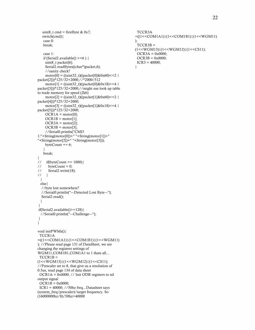
22
uint8_t cmd = firstByte & 0x7; switch(cmd){ case 0: break; case 1: if (Serial2.available() >=6 ) { uint8_t packet[6]; Serial2.readBytes((char*)packet,6); //sanity check? motor[0] = ((uint32_t)((packet[0]&0x60)<<2 | packet[2]))*125/32+2000;//*2000/512 motor[1] = ((uint32_t)((packet[0]&0x18)<<4 | packet[3]))*125/32+2000;//might use look up table to trade memory for speed (2kb) motor[2] = ((uint32_t)((packet[1]&0x60)<<2 | packet[4]))*125/32+2000; motor[3] = ((uint32_t)((packet[1]&0x18)<<4 | packet[5]))*125/32+2000; OCR1A = motor[0]; OCR1B = motor[1]; OCR3A = motor[2]; OCR3B = motor[3]; //Serial0.println("CMD 1:"+String(motor[0])+" "+String(motor[1])+" "+String(motor[2])+" "+String(motor[3])); byteCount += 6; } break; } // if(byteCount >= 1000){ // byteCount = 0; // Serial2.write(18); // } } else{ //byte lost somewhere? //Serial0.println("---Detected Lost Byte---"); Serial2.read(); } } if(Serial2.available()>=128){ //Serial0.println("---Challenge---"); } } void initPWMs(){ TCCR1A =((1<<COM1A1)|(1<<COM1B1)|(1<<WGM11)); //Please read page 131 of DataSheet, we are changing the registers settings of WGM11,COM1B1,COM1A1 to 1 thats all... TCCR1B = (1<<WGM13)|(1<<WGM12)|(1<<CS11); //Prescaler set to 8, that give us a resolution of 0.5us, read page 134 of data sheet OCR1A = 0x0000; // Init ODR registers to nil output signal OCR1B = 0x0000; ICR1 = 40000; //50hz freq...Datasheet says (system_freq/prescaler)/target frequency. So (16000000hz/8)/50hz=40000
TCCR3A =((1<<COM1A1)|(1<<COM1B1)|(1<<WGM11)); TCCR3B = (1<<WGM13)|(1<<WGM12)|(1<<CS11); OCR3A = 0x0000; OCR3B = 0x0000; ICR3 = 40000; }