SOILS AND FOUNDATIONS Lesson 07 - ce.udel.edu 667 Geotech Design... · SOILS AND FOUNDATIONS...
117
SOILS AND FOUNDATIONS SOILS AND FOUNDATIONS Testing Experience Theory Lesson 07 Lesson 07 Chapter 7 Chapter 7 – – Approach Roadway Deformations Approach Roadway Deformations
Transcript of SOILS AND FOUNDATIONS Lesson 07 - ce.udel.edu 667 Geotech Design... · SOILS AND FOUNDATIONS...

SOILS AND FOUNDATIONSSOILS AND FOUNDATIONS
Testing
Experience
Theory
Lesson 07Lesson 07Chapter 7 Chapter 7 –– Approach Roadway DeformationsApproach Roadway Deformations

TopicsTopics
ggTopic 1 (Section 7.0 to 7.6)Topic 1 (Section 7.0 to 7.6)-- Approach roadway deformationsApproach roadway deformations
ggTopic 2 (Section 7.7, 7.8, 7.9)Topic 2 (Section 7.7, 7.8, 7.9)-- Mitigation of approach roadway deformationMitigation of approach roadway deformation-- Construction monitoring and quality assuranceConstruction monitoring and quality assurance
APPROACH ROADWAY APPROACH ROADWAY DEFORMATIONSDEFORMATIONS
Lesson 07 Lesson 07 -- Topic 1Topic 1Approach Roadway DeformationsApproach Roadway Deformations
Section 7.0 Section 7.0 –– 7.67.6
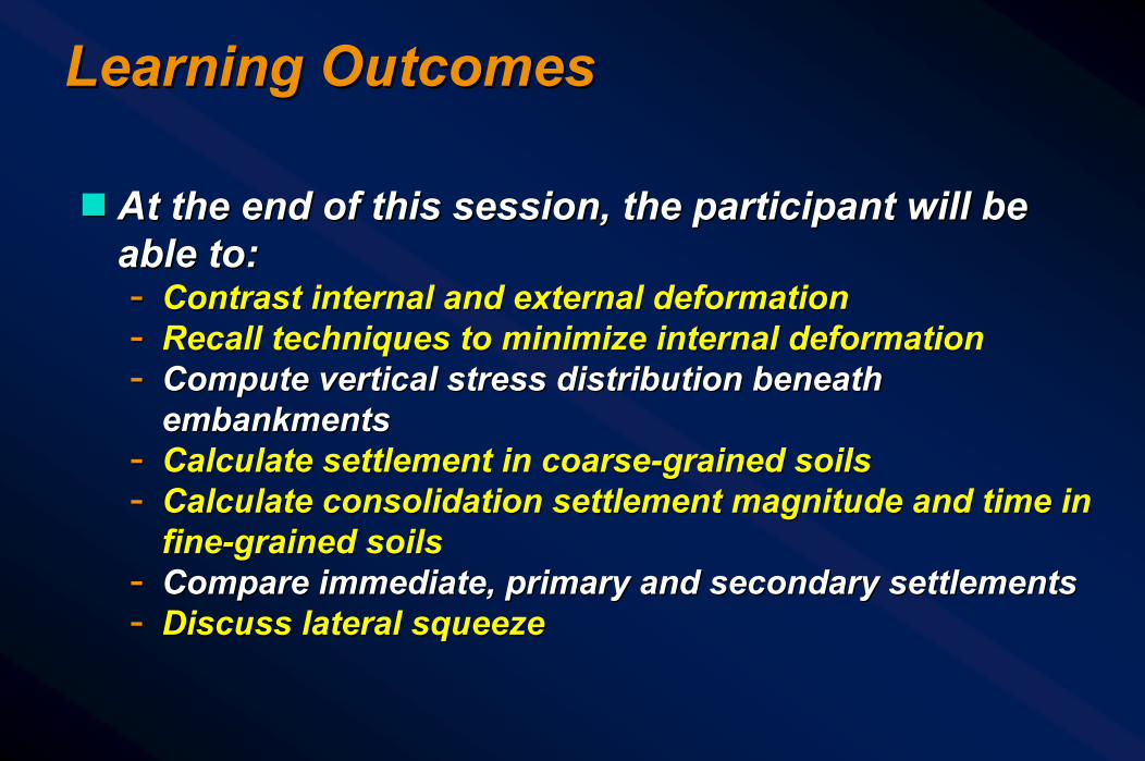
Learning OutcomesLearning Outcomes
gg At the end of this session, the participant will be At the end of this session, the participant will be able to:able to:-- Contrast internal and external deformationContrast internal and external deformation-- Recall techniques to minimize internal deformationRecall techniques to minimize internal deformation-- Compute vertical stress distribution beneath Compute vertical stress distribution beneath
embankmentsembankments-- Calculate settlement in coarseCalculate settlement in coarse--grained soilsgrained soils-- Calculate consolidation settlement magnitude and time in Calculate consolidation settlement magnitude and time in
finefine--grained soilsgrained soils-- Compare immediate, primary and secondary settlementsCompare immediate, primary and secondary settlements-- Discuss lateral squeezeDiscuss lateral squeeze

Stresses Imposed by StructuresStresses Imposed by Structures
ggThe approach embankments induce stresses The approach embankments induce stresses in the foundation soilin the foundation soil

Approach Roadway EmbankmentsApproach Roadway EmbankmentsMajor Design ConsiderationsMajor Design ConsiderationsggStabilityStabilityggDeformationsDeformations
-- VerticalVertical-- LateralLateral
ggEffects on the StructureEffects on the Structure-- Bump at the end of the bridgeBump at the end of the bridge-- TiltingTilting
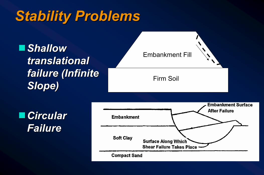
Stability ProblemsStability Problems
Embankment Fill
Firm Soil
ggShallow Shallow translational translational failure (Infinite failure (Infinite Slope)Slope)
ggCircular Circular FailureFailure
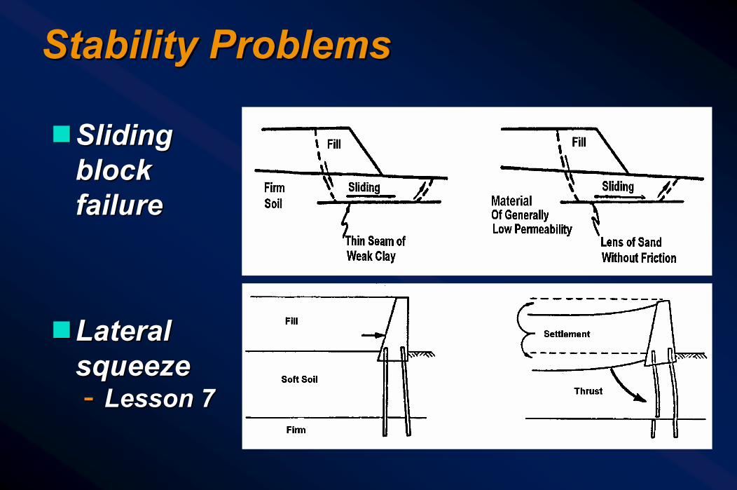
Stability ProblemsStability Problems
ggSliding Sliding block block failurefailure
ggLateral Lateral squeezesqueeze-- Lesson 7Lesson 7

Approach Roadway DeformationsApproach Roadway Deformations
gg InternalInternal-- Within the embankment fillWithin the embankment fill
•• Due to compression of the fill materialsDue to compression of the fill materials•• Poor drainagePoor drainage
ggExternalExternal-- In the native soils below the embankment fillIn the native soils below the embankment fill
•• Vertical and lateral deformation of native soilsVertical and lateral deformation of native soils•• Vertical: Immediate and consolidation settlementsVertical: Immediate and consolidation settlements•• Lateral: Squeeze (cause tilting of structures)Lateral: Squeeze (cause tilting of structures)

Internal DeformationsInternal Deformations
Avoiding Internal DeformationsAvoiding Internal Deformations
ggNo organic or miscellaneous fill material No organic or miscellaneous fill material allowedallowed
ggControl fineControl fine--grained material usegrained material useggRequire compaction with proper moisture Require compaction with proper moisture
control control ggCompaction control testsCompaction control tests
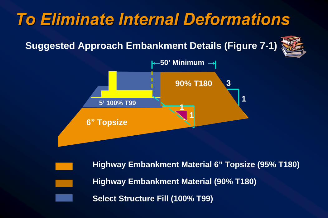
To Eliminate Internal DeformationsTo Eliminate Internal Deformations
Select Structure Fill (100% T99)
Highway Embankment Material (90% T180)
Highway Embankment Material 6” Topsize (95% T180)
Suggested Approach Embankment Details (Figure 7-1)
6” Topsize
90% T180
50’ Minimum
5’ 100% T99
1
1
3
11
1

Bump at the End of a BridgeBump at the End of a Bridge

Reasons for “the Bump at the Reasons for “the Bump at the End of the Bridge”End of the Bridge”ggPoor compaction of embankment material Poor compaction of embankment material
near the structurenear the structureggMigration of fines into drainage material Migration of fines into drainage material
behind abutment behind abutment backwallbackwall
ggWhat is the solution?What is the solution?ggApproach slabApproach slab

““Bump at the End of the Bump at the End of the Approach Slab”Approach Slab”

To Prevent Bump at End of Bridge To Prevent Bump at End of Bridge
gg Use select structural fillUse select structural fillgg Use Use underdrainunderdrain filter filter
material material gg Use durable well Use durable well
graded granular for graded granular for high density w/min. high density w/min. compactivecompactive effort effort
gg Figure 7Figure 7--22
Underdrain Filter Material (6” Lifts)
Select Structural Fill (100 % T99)
Heel Projection + 3 ft
1’6”

Select Material SpecificationsSelect Material Specifications
ggSpecification ItemSpecification Item-- 6”6”--8” Lift Thickness8” Lift Thickness
-- Topsize RestrictionTopsize Restriction
-- Gradation RequirementGradation Requirement
-- Limit Percent FinesLimit Percent Fines
ggReason for ItemReason for Item-- Small Compaction Small Compaction
EquipmentEquipment
-- Less than 3/4 Lift Less than 3/4 Lift ThicknessThickness
-- CompactibilityCompactibility
-- Density/PipingDensity/Piping

Select Material Specification (Cont’d)Select Material Specification (Cont’d)
ggSpecification ItemSpecification Item-- DurabilityDurability
-- T99 Density ControlT99 Density Control
-- Compatible to Drain Compatible to Drain MaterialMaterial
ggReason for ItemReason for Item-- Minimize BreakdownMinimize Breakdown
-- Small Compaction Small Compaction EquipmentEquipment
-- Prevent PipingPrevent Piping

External DeformationsExternal Deformations
Avoid Major Subsoil SettlementAvoid Major Subsoil Settlement
gg Identify and provide treatment for organic Identify and provide treatment for organic soilssoils
ggAnalyze clay subsoil depositsAnalyze clay subsoil deposits
Types of DeformationsTypes of Deformations
gg Immediate (shortImmediate (short--term) deformationterm) deformationggConsolidation (longConsolidation (long--term) deformationterm) deformation
gg Immediate deformation occurs in ALL soils Immediate deformation occurs in ALL soils whether cohesive or whether cohesive or cohesionlesscohesionless
ggConsolidation deformation occurs only in Consolidation deformation occurs only in fine grained soils that are saturated at the fine grained soils that are saturated at the time of application of loadstime of application of loads

First Step in Evaluation of First Step in Evaluation of DeformationsDeformationsggUnder applied external loadings, estimate Under applied external loadings, estimate
the stress distribution with depththe stress distribution with depth
ggChapter 2: Stress and Strain in SoilsChapter 2: Stress and Strain in Soils-- Section 2.5Section 2.5-- Section 2.6Section 2.6

Vertical Vertical Stress Due Stress Due to External to External LoadingsLoadings
p = γthh
0.6p
0.4p
0.8p
0.2p
ggDepth of Depth of Significant Significant Influence Influence (DOSI), D(DOSI), Dss

Do you think there is a settlement Do you think there is a settlement problem for the case shown below?problem for the case shown below?
Soft Clay
Granular Fill
γ = 120 pcf24’
23’Sandy Gravel
γ = 120 pcf (γ’ = 60 pcf)
Sand6’

Combined Plot of StressesCombined Plot of StressesFigure 2Figure 2--1313
zw
po pt
Δp
Pressure
Depth, z
Legend:zw = depth to groundwaterpo = effective overburden pressurept = total overburden pressureΔp = pressure due to external loadspf = p0 + Δp
pf

Fundamental PrinciplesFundamental Principles
ggStresses induced in the soil from an Stresses induced in the soil from an embankment load are distributed with depth embankment load are distributed with depth in proportion to embankment widthin proportion to embankment width
ggThe additional stresses in the soil decrease The additional stresses in the soil decrease with depthwith depth
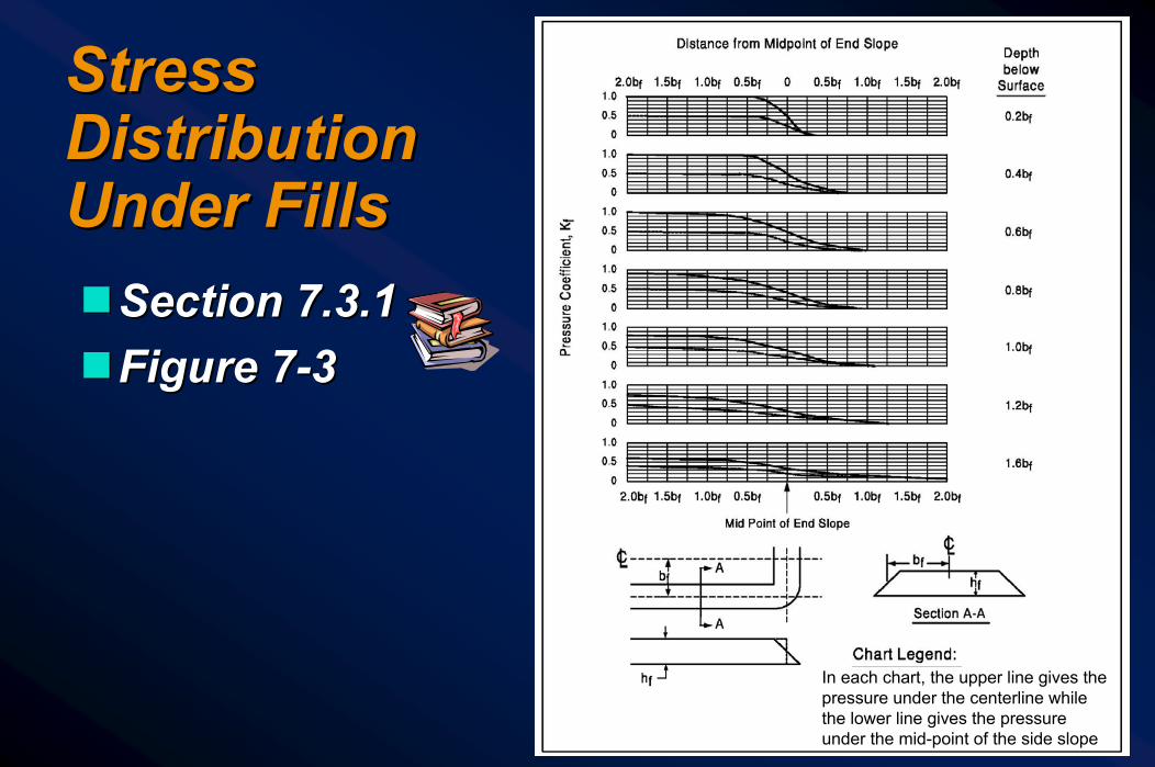
Stress Stress Distribution Distribution Under FillsUnder Fills
In each chart, the upper line gives the pressure under the centerline while the lower line gives the pressure under the mid-point of the side slope
ggSection 7.3.1Section 7.3.1ggFigure 7Figure 7--33
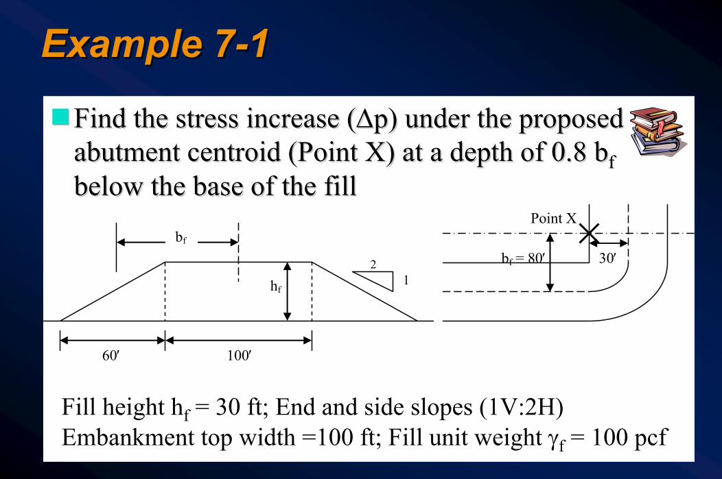
Example 7Example 7--11
ggFind the stress increase (Find the stress increase (ΔΔp) under the proposed p) under the proposed abutment abutment centroidcentroid (Point X) at a depth of 0.8 b(Point X) at a depth of 0.8 bffbelow the base of the fillbelow the base of the fill
Point X
30′ bf = 80′ 1
2
60′ 100′
hf
bf
Fill height hf = 30 ft; End and side slopes (1V:2H)Embankment top width =100 ft; Fill unit weight γf = 100 pcf

Stress Distribution Under FillsStress Distribution Under Fillsgg bbff=(100 ft /2) + (60 ft/2) = 80 ft=(100 ft /2) + (60 ft/2) = 80 ftgg Use chart for 0.8bUse chart for 0.8bff = 0.8 (80 ft)=64 ft and a distance = 0.8 (80 ft)=64 ft and a distance
measured from midmeasured from mid--point of end slope to Point X as multiple point of end slope to Point X as multiple of bof bff =(30 ft/80 =(30 ft/80 ft)bft)bff = 0.38b= 0.38bff
gg KKff=0.7=0.7gg ΔΔp= p= KKffγγffhhff = (0.7)(100 pcf)(30 ft)== (0.7)(100 pcf)(30 ft)=2,100 2,100 psfpsf
0.5
Mid Point ofEnd Slope
1.0
Mid Point ofSide Slope
0
1.0bf 0.5bf 0.5bf 1.0bf
Centerline0.38b
0.7
0.8bf = 64 ftDepth Below SurfacePr
essu
re C
oeff
icie
nt K
f

Computation of Immediate Computation of Immediate Settlement (Vertical Deformation)Settlement (Vertical Deformation)ggMany methods for estimating immediate Many methods for estimating immediate
settlement are availablesettlement are available
ggAll methods are based on some form of All methods are based on some form of estimate of soil compressibilityestimate of soil compressibility-- “Bearing Capacity Index”, “Compression Index”, “Bearing Capacity Index”, “Compression Index”,
“Elastic Modulus”, “Constrained Modulus”, etc.“Elastic Modulus”, “Constrained Modulus”, etc.

Computation of Immediate Computation of Immediate Settlement (Vertical Deformation)Settlement (Vertical Deformation)ggFor embankments use Hough’s methodFor embankments use Hough’s method
-- Simple to useSimple to use-- Settlement estimates are conservative by a Settlement estimates are conservative by a
factor of 2 (FHWA 1987)factor of 2 (FHWA 1987)
ggFor footings use more refined methodsFor footings use more refined methods-- SchmertmannSchmertmann (1978) (1978) ------------ Chapter 8Chapter 8
•• Considers strain distribution with depthConsiders strain distribution with depth-- D’AppoloniaD’Appolonia (1968)(1968)
•• Considers effect of Considers effect of preconsolidationpreconsolidation

Hough’s MethodHough’s Method
Step 1:Step 1: Determine bearing capacity index, CDetermine bearing capacity index, C′′,,Use N1Use N16060 value in Hough’s chartvalue in Hough’s chart
Step 2:Step 2: Subdivide soil layer into 10 ft Subdivide soil layer into 10 ft ±±increments and sum settlements for increments and sum settlements for all layers using following equation all layers using following equation for each layerfor each layer
0
010 p
Δpplog
C1HΔH
+⎟⎠⎞
⎜⎝⎛
′=
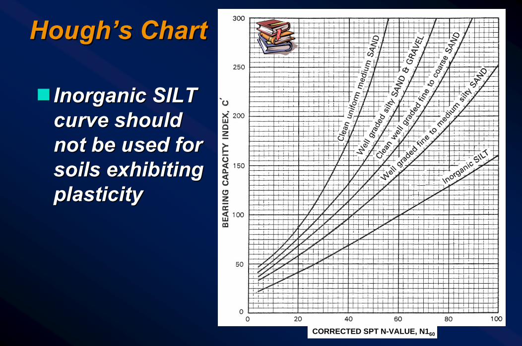
Hough’s ChartHough’s Chart
gg Inorganic SILT Inorganic SILT curve should curve should not be used for not be used for soils exhibiting soils exhibiting plasticityplasticity
CORRECTED SPT N-VALUE, N160
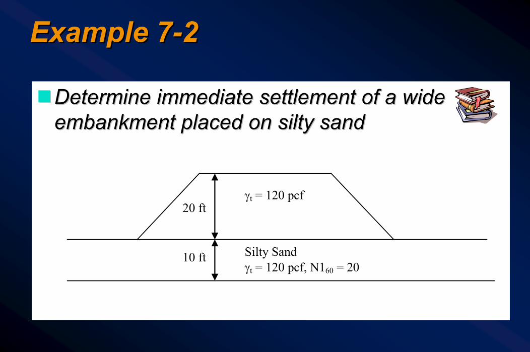
Example 7Example 7--22
ggDetermine immediate settlement of a wide Determine immediate settlement of a wide embankment placed on embankment placed on siltysilty sandsand
20 ft
10 ft
γt = 120 pcf
Silty Sand γt = 120 pcf, N160 = 20

Example 7Example 7--2 2 –– Draw Draw ppoo diagramdiagramggAssume no dissipation of stress under the Assume no dissipation of stress under the
centerline of a “wide” embankmentcenterline of a “wide” embankment
pf po
0
Depth (ft)
Pressure (psf)
4000 3000 2000 1000
10
5 600 3000
Δp = 2400

Example 7Example 7--2 2 –– Draw Draw ppoo diagramdiagram
ggFor For N1N16060 = 20= 20 and and SiltySilty Sand, CSand, C′′ ≈≈ 58 from 58 from Figure 7Figure 7--4 (Hough4 (Hough’’s chart) s chart)
ggFind settlementFind settlement
600psf2400psf600psflog
581ft10ΔH 10
+⎟⎠⎞
⎜⎝⎛=
in1.44ft0.12ΔH ==
0
010 p
Δpplog
C1HΔH
+⎟⎠⎞
⎜⎝⎛
′=

Vertical Vertical Stress Due Stress Due to External to External LoadingsLoadings
p = γthh
0.6p
0.4p
0.8p
0.2p
gg Note the Note the variation of variation of vertical vertical stress under stress under a narrow a narrow embankmentembankment

Implications of Embankment Implications of Embankment SettlementSettlementggAt end of embankment construction, At end of embankment construction,
additional fill is required to reach final gradeadditional fill is required to reach final gradegg1 inch of settlement over 1 mile of 601 inch of settlement over 1 mile of 60--ft wide ft wide
embankment will need approximately 1000 embankment will need approximately 1000 cubic yards of additional fillcubic yards of additional fill
ggThis is sometimes referred to as This is sometimes referred to as “Compaction Factor” and is included in bid “Compaction Factor” and is included in bid documentsdocuments
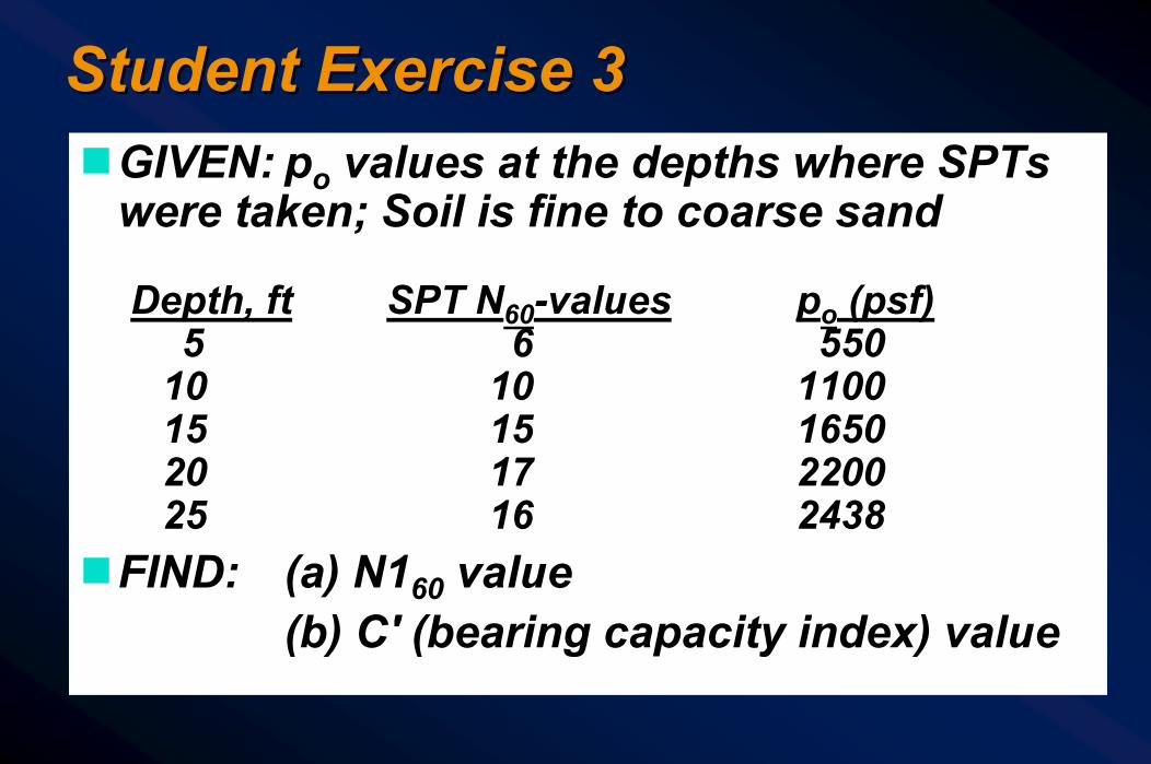
Student Exercise 3Student Exercise 3gGIVEN: po values at the depths where SPTs
were taken; Soil is fine to coarse sand
Depth, ft SPT N60-values po (psf)5 6 550
10 10 110015 15 165020 17 220025 16 2438
gFIND: (a) N160 value(b) C′ (bearing capacity index) value

Student ExerciseStudent Exercise
ggSolutionSolution
Consolidation (LongConsolidation (Long--term) Deformationterm) Deformation
ggConsolidation deformation occurs only in Consolidation deformation occurs only in fine grained soils that are saturated at the fine grained soils that are saturated at the time of application of loadstime of application of loads
ggLaboratory estimates of settlements are Laboratory estimates of settlements are often inaccurateoften inaccurate
ggUse consolidation approach when S > 90%Use consolidation approach when S > 90%ggEffect of consolidation is 3Effect of consolidation is 3--D for limited D for limited
loaded areas typical of transportation loaded areas typical of transportation structuresstructures
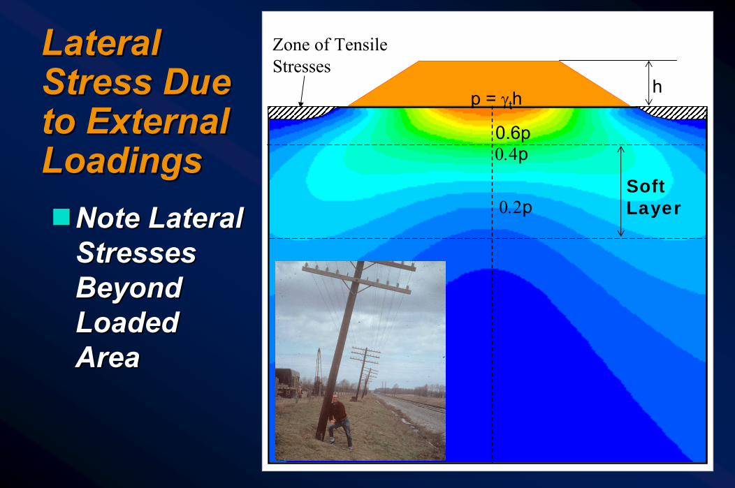
Lateral Lateral Stress Due Stress Due to External to External LoadingsLoadingsggNote Lateral Note Lateral
Stresses Stresses Beyond Beyond Loaded Loaded AreaArea
Zone of Tensile Stresses
0.2p
0.4p0.6p
p = γthh
SoftLayer

Consolidation (LongConsolidation (Long--term) Deformationterm) Deformation
ggVertical component of 3Vertical component of 3--D D consoldationconsoldation is is estimated based on data from 1estimated based on data from 1--D laboratory D laboratory consolidation testconsolidation test
ggChapter 5, Section 5.4Chapter 5, Section 5.4
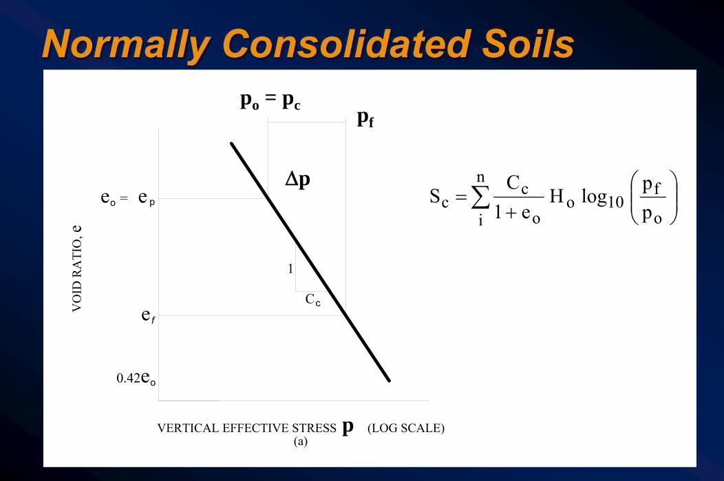
Normally Consolidated SoilsNormally Consolidated Soils
VERTICAL EFFECTIVE STRESS σ' v (LOG SCALE)
e = eo p
e f
o0.42e
(a)
Cc
1
VO
ID R
ATI
O, e
σ' = σ' p vo
Δσ' v
σ' vf
⎟⎟⎠
⎞⎜⎜⎝
⎛+
=∑o
f10o
n
i o
cc p
p log H
e1C
S
pfpo = pc
Δp
p

Over Consolidated (Over Consolidated (PreconsolidatedPreconsolidated) ) SoilsSoils
)pp log C
pp logC (
e 1H S
c
f10c
o
c10r
o
on
1+
+∑=
VERTICAL EFFECTIVE STRESS σ' v (LOG SCALE)
0.42e o
(a)
VO
ID R
ATI
O, e
e f
e p
c
1
C
Δσ' v vfσ'
o e1
γC
pσ'
σ' vo
pc
po Δp pf
p
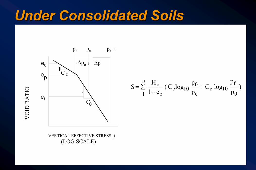
Under Consolidated SoilsUnder Consolidated Soils
)pp
log C pp logC (
e 1H S
0
f10c
c
010c
o
on
1+
+∑=
VERTICAL EFFECTIVE STRESS p(LOG SCALE)
VO
ID R
ATI
O
ef
p
c1
C
1rC
σ´v 0σ´p
Δσ´v0
σ´v f
Δσ ve0
e
Δp
pc po pf
Δpo
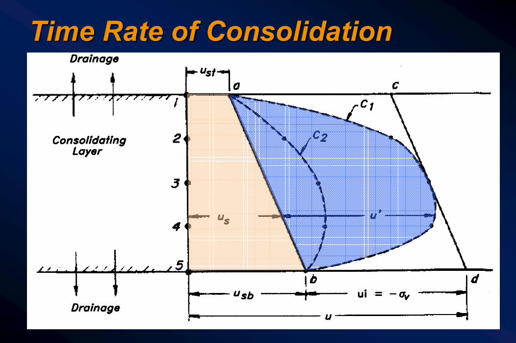
Time Rate of ConsolidationTime Rate of Consolidation
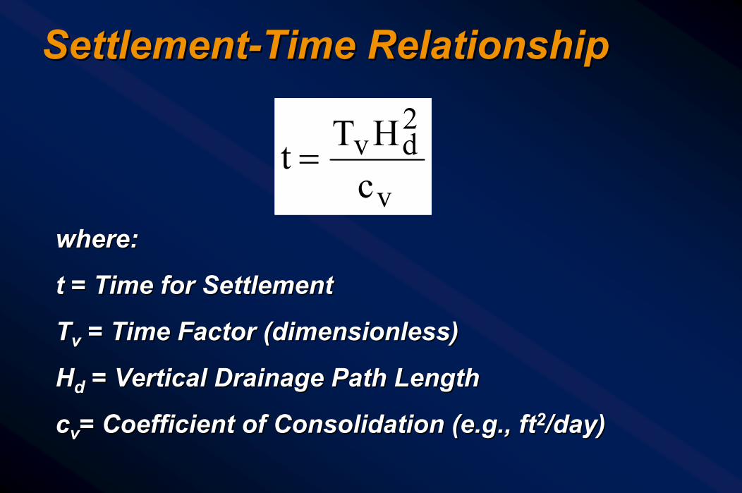
SettlementSettlement--Time RelationshipTime Relationship
where:where:
t = Time for Settlementt = Time for Settlement
TTvv = Time Factor (dimensionless)= Time Factor (dimensionless)
HHdd = Vertical Drainage Path Length= Vertical Drainage Path Length
ccvv= Coefficient of Consolidation (e.g., ft= Coefficient of Consolidation (e.g., ft22/day)/day)
v
2dv
cHTt =

Embankment on Clay Subsoil Embankment on Clay Subsoil TimeTime--Settlement CurveSettlement Curve
Time (Months)Time (Months)11 22 33 44 55 66 77 88 99
00
1.01.02.02.0
3.03.0
4.04.0
5.05.0
6.06.0
7.07.0
Settl
emen
t (In
ches
)Se
ttlem
ent
(Inch
es)
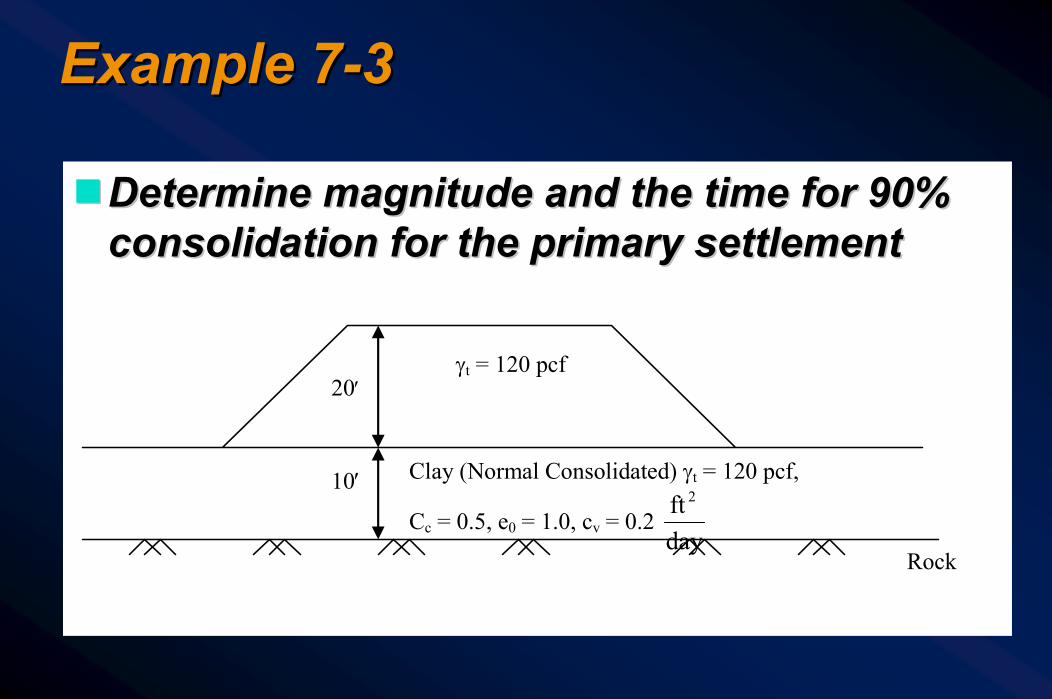
Example 7Example 7--33
ggDetermine magnitude and the time for 90% Determine magnitude and the time for 90% consolidation for the primary settlementconsolidation for the primary settlement
20′
10′
γt = 120 pcf
Clay (Normal Consolidated) γt = 120 pcf,
Cc = 0.5, e0 = 1.0, cv = 0.2 dayft 2
Rock

Example 7Example 7--33
ggppoo diagramdiagram
pf po
0
Depth (ft)
Pressure (psf)
4000 3000 2000 1000
10
5 600 3000
Δp = 2400
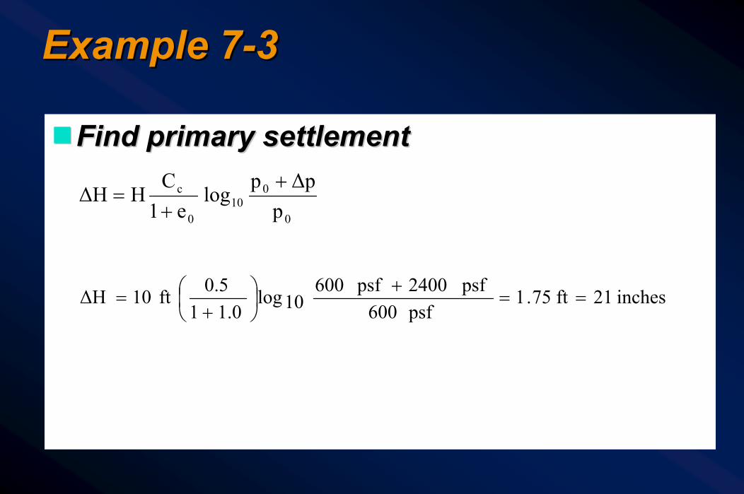
Example 7Example 7--33
ggFind primary settlementFind primary settlement
0
010
0
c
pΔpp
loge1
CHΔH
++
=
inches21ft75.1psf600
psf2400psf60010log
1.010.5ft10ΔH ==
+⎟⎠⎞
⎜⎝⎛
+=
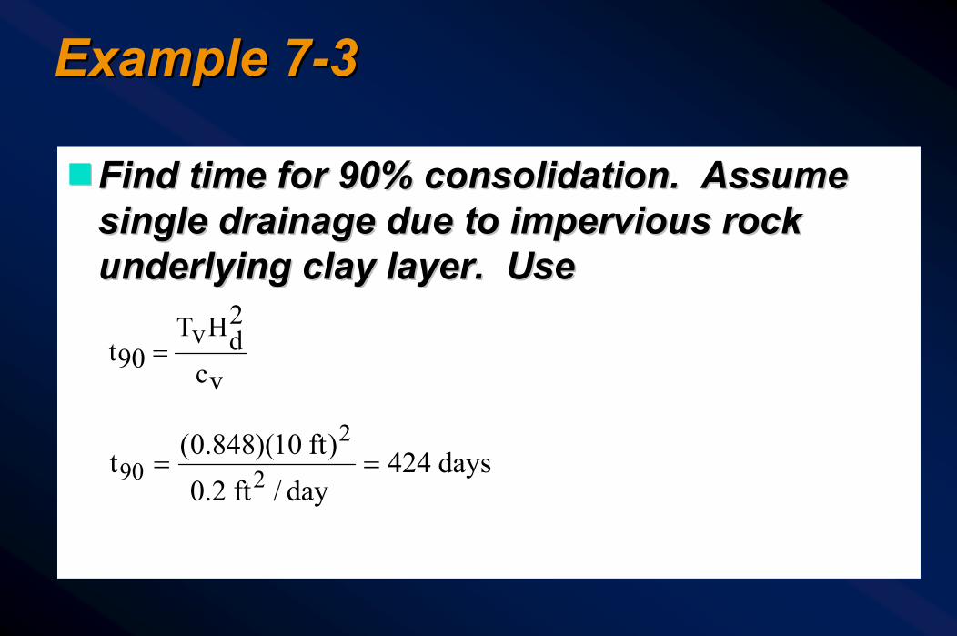
Example 7Example 7--33
ggFind time for 90% consolidation. Assume Find time for 90% consolidation. Assume single drainage due to impervious rock single drainage due to impervious rock underlying clay layer. Use underlying clay layer. Use
vc
2dHvT
90t =
days424day/ft2.0
)ft10)(848.0(t 2
290 ==

Student Student Exercise 4Exercise 4
Soil Profile
Pressure Diagram
24'
23'
6'
Granular Fill= 120 pcf
Sandy Gravel
T = 122 pcf
Soft Clay T = 104 pcf, e = 2.1, Cc = 1.1Sando Cv = 0.0175 ft2 /day
24'
23'
6'
Granular Fill= 120 pcf
Sandy Gravel
T = 122 pcf
Soft Clay T = 104 pcf, e = 2.1, Cc = 1.1Sando Cv = 0.0175 ft2 /day
po pF
Middle of clay layer
SandyGravel
ClayΔp
23’
29’
po pF
Middle of clay layer
SandyGravel
ClayΔp
23’
29’
Compute:Compute:(a)(a) Primary Primary
settlement settlement of NC clayof NC clay
(b)(b) Time in Time in months for months for 90% 90% primary primary settlementsettlement
Secondary CompressionSecondary Compression
ggSee Section 7.5.4See Section 7.5.4

Lateral SqueezeLateral Squeeze
Fill
be

Lateral Lateral SqueezeSqueezeggShortShort--term term
undrainedundrainedbearing bearing capacity capacity failurefailure
ggLongLong--term term drained 3drained 3--D D creepcreep
Zone of Tensile Stresses
0.2p
0.4p0.6p
p = γthh
SoftLayer

Abutment Tilting Due to Lateral Abutment Tilting Due to Lateral SqueezeSqueeze

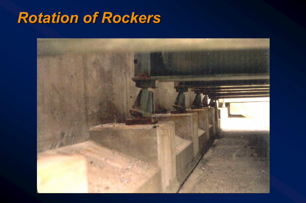
Rotation of RockersRotation of Rockers

((γγFILLFILL)(H )(H FILLFILL) > 3c) > 3cuu
Threshold Condition for Lateral Threshold Condition for Lateral SqueezeSqueeze

Safety Factor against Lateral SqueezeSafety Factor against Lateral Squeeze
⎥⎦
⎤⎢⎣
⎡γ
+⎥⎦
⎤⎢⎣
⎡θγ
=H
c14.4tanDc2FS u
S
uSQ
Get fill settlement out before abutment deep Get fill settlement out before abutment deep foundations are constructedfoundations are constructed
Lateral Squeeze: Lateral Squeeze: How to Prevent Abutment RotationHow to Prevent Abutment Rotation

Learning OutcomesLearning Outcomes
gg At the end of this session, the participant will be At the end of this session, the participant will be able to:able to:-- Contrast internal and external deformationContrast internal and external deformation-- Recall techniques to minimize internal deformationRecall techniques to minimize internal deformation-- Compute vertical stress distribution beneath Compute vertical stress distribution beneath
embankmentsembankments-- Calculate settlement in coarseCalculate settlement in coarse--grained soilsgrained soils-- Calculate consolidation settlement magnitude and time in Calculate consolidation settlement magnitude and time in
finefine--grained soilsgrained soils-- Compare immediate, primary and secondary settlementsCompare immediate, primary and secondary settlements-- Discuss lateral squeezeDiscuss lateral squeeze

Any Questions?Any Questions?
THE ROAD TOUNDERSTANDING
SOILSAND
FOUNDATIONS

APPROACH ROADWAY APPROACH ROADWAY DEFORMATIONSDEFORMATIONS
Lesson 07 Lesson 07 -- Topic 2Topic 2Mitigation of Approach Roadway DeformationsMitigation of Approach Roadway DeformationsConstruction Monitoring and Quality AssuranceConstruction Monitoring and Quality Assurance
Section 7.7, 7.8, 7.9Section 7.7, 7.8, 7.9

Learning OutcomesLearning Outcomes
ggAt the end of this session, the participant will At the end of this session, the participant will be able to:be able to:-- Recall techniques for reducing settlement Recall techniques for reducing settlement
magnitudemagnitude-- Describe techniques for reducing time rate of Describe techniques for reducing time rate of
settlementsettlement-- Identify types of performance monitoring Identify types of performance monitoring
instrumentationinstrumentation-- Discuss importance of proper compactionDiscuss importance of proper compaction

Solutions for Settlement ProblemsSolutions for Settlement Problems
ggReduce Amount of SettlementReduce Amount of Settlement-- Category 1: Increasing the resistanceCategory 1: Increasing the resistance-- Category 2: Reducing the loadCategory 2: Reducing the load
ggReduce Settlement TimeReduce Settlement Time-- SurchargeSurcharge-- Vertical DrainsVertical Drains

Reduce Amount of SettlementReduce Amount of Settlement
ggCategory 1: Increasing the resistanceCategory 1: Increasing the resistance-- Excavation and Excavation and recompactionrecompaction-- Excavation and replacementExcavation and replacement-- Vertical inclusions, e.g., stone columnsVertical inclusions, e.g., stone columns-- Horizontal inclusions, e.g., geosyntheticsHorizontal inclusions, e.g., geosynthetics-- GroutingGrouting-- Dynamic compactionDynamic compaction

Reducing Amount of SettlementReducing Amount of Settlement
ggCategory 2: Reducing the loadCategory 2: Reducing the load-- Reduce grade lineReduce grade line-- Use lightweight fill, e.g., expanded shale, foamed Use lightweight fill, e.g., expanded shale, foamed
concrete, concrete, geofoamgeofoam-- Bypass soft layer with a deep foundationBypass soft layer with a deep foundation
•• Need load transfer platformNeed load transfer platform

Reducing Settlement TimeReducing Settlement Time
ggSurcharge treatmentSurcharge treatmentggVertical drainsVertical drains

Embankment on Clay FoundationEmbankment on Clay FoundationEffect of Surcharge TreatmentEffect of Surcharge Treatment
Without SurchargeWithout Surcharge
With SurchargeWith Surcharge
TimeTime Time for Total Settlement Without SurchargeTime for Total Settlement Without Surcharge
Time for Equivalent Settlement With Surcharge – Remove Surcharge at This Time
Time for Equivalent Settlement With Surcharge – Remove Surcharge at This Time
Settl
emen
tSe
ttlem
ent
SurchargeSurcharge
ClayClay
FillFill

Acceleration of Consolidation Acceleration of Consolidation Using Vertical DrainageUsing Vertical Drainage
Sand
Clay

Vertical DrainsVertical Drains
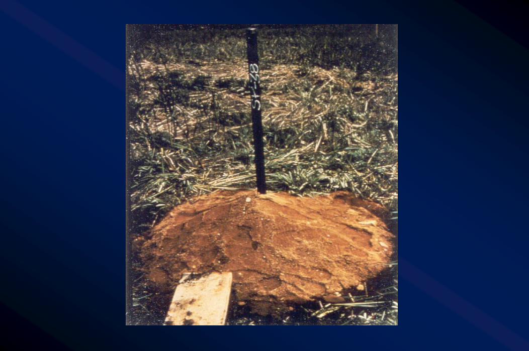
Settlement Platform Settlement Platform
Permanent Fill Permanent Fill
Soft Clay Soft Clay
Vertical Vertical Drain Drain
Surcharge Surcharge
Drainage Blanket Drainage Blanket
Piezometers Piezometers
Firm Soil Firm Soil
Not to ScaleNot to Scale


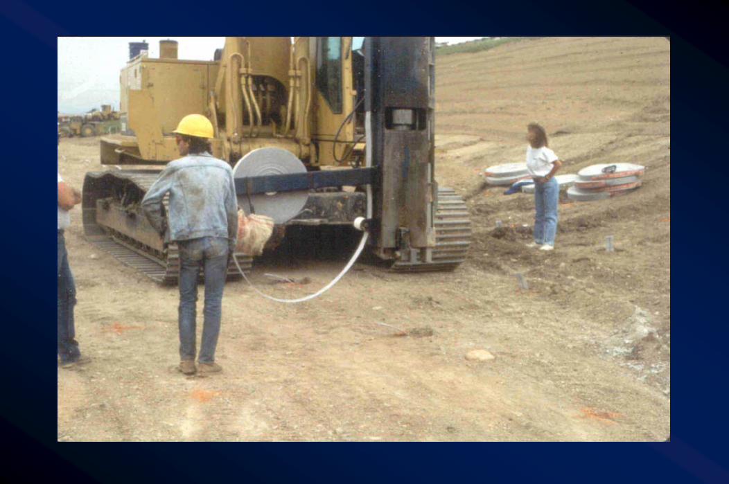
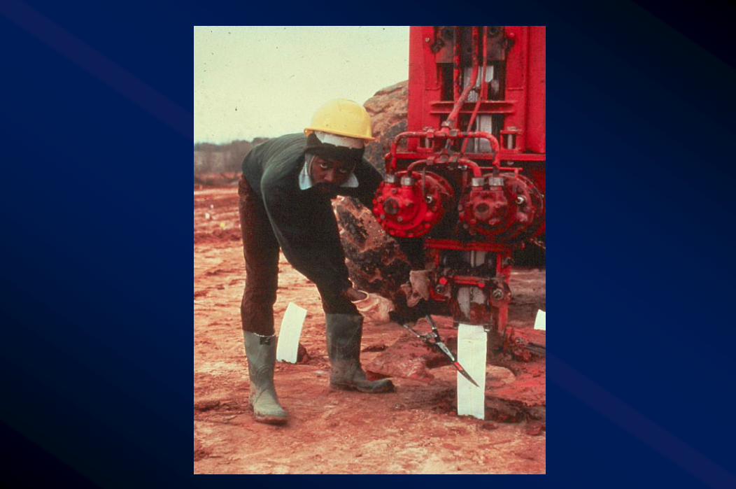
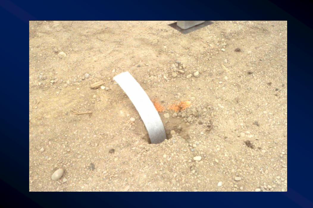
gg Position rig at drain locationPosition rig at drain locationgg Place anchor on drain endPlace anchor on drain endgg Penetrate mandrel to desired depthPenetrate mandrel to desired depthgg Withdraw mandrelWithdraw mandrelgg Cut drain material above drainage blanketCut drain material above drainage blanket
Vertical Drain Installation Vertical Drain Installation SequenceSequence


Construction Monitoring and QAConstruction Monitoring and QA
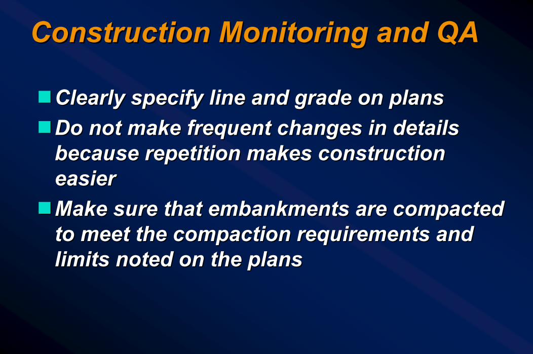
ggClearly specify line and grade on plansClearly specify line and grade on plansggDo not make frequent changes in details Do not make frequent changes in details
because repetition makes construction because repetition makes construction easiereasier
ggMake sure that embankments are compacted Make sure that embankments are compacted to meet the compaction requirements and to meet the compaction requirements and limits noted on the planslimits noted on the plans
Construction Monitoring by Construction Monitoring by InstrumentationInstrumentationggPiezometersPiezometersggSettlement platesSettlement platesgg InclinometersInclinometers
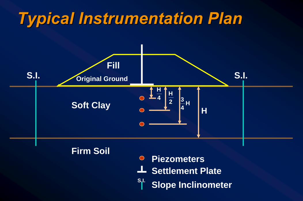
Typical Instrumentation PlanTypical Instrumentation Plan
Fill S.I. S.I.Original Ground
Soft Clay
Firm Soil Piezometers Settlement Plate Slope Inclinometer S.I.
H 4H
2H
H43

Settlement Platform SchematicSettlement Platform Schematic

Vertical InclinometerVertical Inclinometer
Embankment
Compressible Soil
Firm Soil


Principle of Inclinometer OperationPrinciple of Inclinometer Operation
ΣL Sinθ
L Sinθ
L θ
L = Distance between readings θ = Angle measured by sensor

PiezometerPiezometer
Compressible Soil
Embankment


Learning OutcomesLearning Outcomes
ggAt the end of this session, the participant will At the end of this session, the participant will be able to:be able to:-- Recall techniques for reducing settlement Recall techniques for reducing settlement
magnitudemagnitude-- Describe techniques for reducing time rate of Describe techniques for reducing time rate of
settlementsettlement-- Identify types of performance monitoring Identify types of performance monitoring
instrumentationinstrumentation-- Discuss importance of proper compactionDiscuss importance of proper compaction

Any Questions?Any Questions?
THE ROAD TOUNDERSTANDING
SOILSAND
FOUNDATIONS

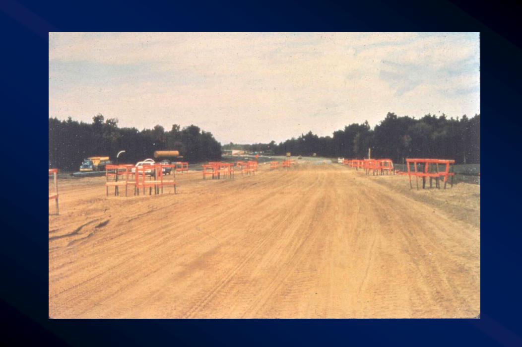
Interstate 0 Interstate 0 –– Apple FreewayApple FreewayNote: Scale shown in Station FormNote: Scale shown in Station Form
Baseline Stationing
Baseline Stationing
S.B. Apple Frwy
N.B. Apple Frwy
Proposed Toe of SlopeProposed Toe of Slope
Existing Ground SurfaceExisting Ground Surface
12
Proposed Final GradeProposed Final GradeProposed AbutmentProposed Abutment
Interstate 0Interstate 0
9090 9191 9292 9393
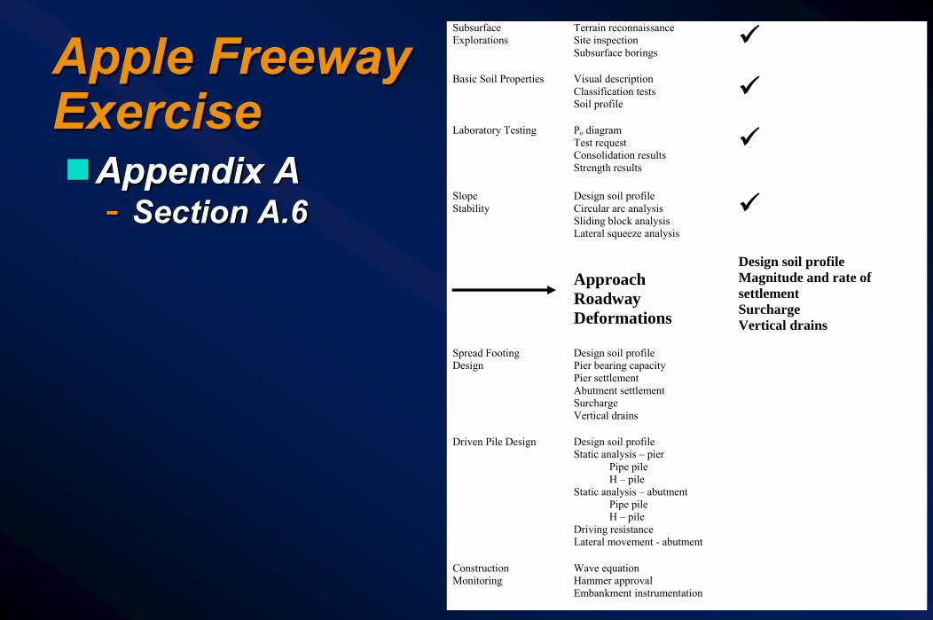
Apple Freeway Apple Freeway ExerciseExerciseggAppendix AAppendix A
-- Section A.6Section A.6
Subsurface Explorations
Terrain reconnaissance Site inspection Subsurface borings
Basic Soil Properties Visual description
Classification tests Soil profile
Laboratory Testing Po diagram
Test request Consolidation results Strength results
Slope Stability
Design soil profile Circular arc analysis Sliding block analysis Lateral squeeze analysis
Approach Roadway Deformations
Design soil profile Magnitude and rate of settlement Surcharge Vertical drains
Spread Footing Design
Design soil profile Pier bearing capacity Pier settlement Abutment settlement Surcharge Vertical drains
Driven Pile Design Design soil profile
Static analysis – pier Pipe pile H – pile Static analysis – abutment Pipe pile H – pile Driving resistance Lateral movement - abutment
Construction Monitoring
Wave equation Hammer approval Embankment instrumentation

Design Soil Profile (East Approach Design Soil Profile (East Approach Embankment Settlement)Embankment Settlement)
2:1Fill
= 130 pcf= 400
c = 030'
3'7'
35'
Organic = 90 pcf w = 120% s.g. = 1.6
Sand = 110 pcf N = 17= 50pcf C' = 90
5'
Clay= 65 pcf
Cc = 0.35Cr = 0.035Cv = 0.6 ft 2 /dayw = 35%
s.g. = 2.78
Incompressible
2:1Fill
= 130 pcf= 400
c = 030'
3'7'
35'
Organic = 90 pcf w = 120% s.g. = 1.6
Sand = 110 pcf N = 17= 50pcf C' = 90
5'
Clay= 65 pcf
Cc = 0.35Cr = 0.035Cv = 0.6 ft 2 /dayw = 35%
s.g. = 2.78
Incompressible

pc
Po Diagram Pressure (psf)0 1000 2000 3000 4000 5000 6000
10
20
30
40po
xx
x
x
xx
x
x
x
x
135 4100
570
1020
1630
4460
4950
5300
58003600 pFx
OrganicSand
x4450Clay
2460
pc
Po Diagram Pressure (psf)0 1000 2000 3000 4000 5000 6000
10
20
30
40po
xx
x
x
xx
x
x
x
x
135 4100
570
1020
1630
4460
4950
5300
58003600 pFx
OrganicSand
x4450Clay
2460x
OrganicSand
x4450Clay
2460

Compute Total SettlementCompute Total Settlement
Total Settlement
Layer 1 - Organic (0' -3')
Layer 2 - Sand (3' - 10')
Layer 3 - Clay (10' - 18')
Clay (18' - 28')
Clay (28' - 45')
19.54"
0.83"
1.17"
2.55"
8.11"
Total 32.20"H
Total Settlement
Layer 1 - Organic (0' -3')
Layer 2 - Sand (3' - 10')
Layer 3 - Clay (10' - 18')
Clay (18' - 28')
Clay (28' - 45')
19.54"
0.83"
1.17"
2.55"
8.11"
Total 32.20"H

TimeTime--Settlement PlotSettlement Plot
100
90
Time - Settlement Plot
100 200 300 400 500
5
10
15
Time (days)
11.39"for sand +for clay
@ 433 days)
12.66" (max. H)
0.83
100
90
Time - Settlement Plot
100 200 300 400 500
5
10
15
Time (days)
11.39"for sand +for clay
@ 433 days)
12.66" (max. H)
0.83

Assume:10’ high compacted surcharge ( = 130 pcf)Δ P of emb. (PF) + surch. (Ps) = 5200 psf
Assume:10’ high compacted surcharge ( = 130 pcf)Δ P of emb. (PF) + surch. (Ps) = 5200 psf
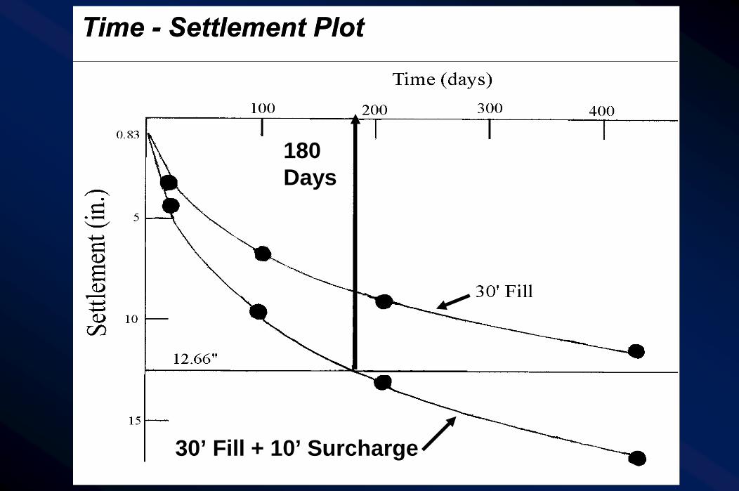
Time - Settlement Plot
30’ Fill + 10’ Surcharge
180 Days
Time - Settlement Plot
30’ Fill + 10’ Surcharge
180 Days

Recheck stability of 30’ Fill With 10' SurchargeF.S. = 1.33Bishop
Fill33'
7' Sand
35' Clay
DenseGravel
10'
25'
2:1
F.S. w/surcharge = 1.33 (1.63 w/o surcharge)
Recheck stability of 30’ Fill With 10' SurchargeF.S. = 1.33Bishop
Fill33'
7' Sand
35' Clay
DenseGravel
10'
25'
2:1Fill33'
7' Sand
35' Clay
DenseGravel
10'
25'
2:1
F.S. w/surcharge = 1.33 (1.63 w/o surcharge)

Time - Settlement Plot
100 200 300 400 500
5
10
15
Time (days)
0.83
12.66"
180days
30' Fill
30' Fill + 10' Surcharge30' Fill w/Drains
Treatment
Fill only
Fill w/10' surcharge
fill w/ wick drain
90 (mo.)
14
6
2
Extra Cost
-
$120,000
$172,000
t
Time - Settlement Plot
100 200 300 400 500
5
10
15
Time (days)
0.83
12.66"
180days
30' Fill
30' Fill + 10' Surcharge30' Fill w/Drains
Time - Settlement Plot
100 200 300 400 500
5
10
15
Time (days)
0.83
12.66"
180days
30' Fill
30' Fill + 10' Surcharge30' Fill w/Drains
Treatment
Fill only
Fill w/10' surcharge
fill w/ wick drain
90 (mo.)
14
6
2
Extra Cost
-
$120,000
$172,000
t

SummarySummary Design Soil Profile
Soil layer consolidationproperties selected
Settlement
Vertical Drains
60 days for t90Cost $172,000 -> $385,000
Cost $120,000, F.S. = 1.33 O.K.10' surcharge improves t90 to 190 days
Time-Rate
Surcharge
32" settlement predictedRecommend organic excavationRec. waiting period @ abut.
433 days for t90
Design Soil Profile
Soil layer consolidationproperties selected
Settlement
Vertical Drains
60 days for t90Cost $172,000 -> $385,000
Cost $120,000, F.S. = 1.33 O.K.10' surcharge improves t90 to 190 days
Time-Rate
Surcharge
32" settlement predictedRecommend organic excavationRec. waiting period @ abut.
433 days for t90
Any Questions?Any Questions?
THE ROAD TOUNDERSTANDING
SOILSAND
FOUNDATIONS