Software Requirements Specification Documentlisarossdesign.com/pdf/SRS.pdf · ·...
46
Software Requirements Specification Document for CS641 Software Requirements Engineering Version 5.0 Prepared by Lisa Ross Colorado Technical University December 19, 2016 Prepared for Client:
Transcript of Software Requirements Specification Documentlisarossdesign.com/pdf/SRS.pdf · ·...

Software Requirements Specification Document
for
CS641 Software Requirements Engineering
Version 5.0
Prepared by Lisa Ross
Colorado Technical University
December 19, 2016
Prepared for Client:

2
Revision History
Revision Date Name Description of Changes
1 11/20/2016 Lisa Ross Initial revision
2 11/29/2016 Lisa Ross Elicitation technique explanations, Stakeholders and roles identification, Elicitation result documentation, Pros and cons of elicitation techniques implemented, Visio diagram
3 12/05/2016 Lisa Ross Analysis of Use-Case Relationship Diagram, Sequence Diagram, and State Transition Diagram. Summary of analysis, flow of events, pros and cons of each method, and Visio diagrams for each method.
4 12/11/2016 Lisa Ross Software Quality importance, definition and measures. Quality characteristics and examples. Update of SRS
5 12/19/2016 Lisa Ross Requirements Management explanation, Verification and Validation review process and techniques, tracing requirements and traceability matrix, Update SRS, Update Use Case Analysis, Updated/corrected Software quality metrics
3
Table of Contents
1 Purpose and Scope ................................................................................................ 6 1.1 Purpose ...................................................................................................................... 6
1.1.1 System Requirements Specifications Purpose ........................................................ 6 1.1.2 System Requirements Specifications Intended Audience ........................................ 6
1.2 Scope ......................................................................................................................... 6 1.2.1 Products for Production ........................................................................................... 6 1.2.2 Inclusions ................................................................................................................ 6 1.2.3 Exclusions ............................................................................................................... 6 1.2.4 Application Benefits, Objectives and Goals.............................................................. 6
1.3 Definitions, Acronyms, and Abbreviations .............................................................. 7 1.3.1 Definitions................................................................................................................ 7 1.3.2 Acronyms ................................................................................................................ 7
1.4 Overview .................................................................................................................... 8
2 Requirements Elicitation and Gathering .............................................................. 9 2.1 Elicitation Methods.................................................................................................... 9
2.1.1 Brainstorming .......................................................................................................... 9 2.1.2 Surveys and Questionnaires .................................................................................... 9 2.1.3 Joint Application Development ............................................................................... 10
2.2 Stakeholders ............................................................................................................ 10 2.2.1 Stakeholders and Roles ......................................................................................... 10 Table 2.2.1 Stakeholders and Roles............................................................................... 11
2.3 Elicitation Technique Summary ............................................................................. 12 2.3.1 Brainstorming ........................................................................................................ 12 Figure 2.3.1 Brainstorming ............................................................................................. 12 2.3.2 Surveys ................................................................................................................. 13 Figure 2.3.1 Survey Elicitation ....................................................................................... 13 2.3.3 Elicitation Questionnaires ...................................................................................... 13 Figure 2.3.2 Elicitation Questionnaires ......................................................................... 14 2.3.4 Joint Application Development ............................................................................... 15 2.3.5 Suggestions for Improvement ................................................................................ 15 2.3.6 Elicitation Summary Documentation ...................................................................... 15
2.4 Elicited Document Summary .................................................................................. 15 2.4.1 Functional Requirements ....................................................................................... 15 2.4.2 Non-Functional Requirements ............................................................................... 16 Figure 2.4.1 Elicitation Summary Documentation Diagram ......................................... 17
3 Requirements Analysis and Methodology ......................................................... 18 3.1 Analysis Methods .................................................................................................... 18 3.2 Analysis with UML Use-Case Model ...................................................................... 18
Figure 3.2.1 Use-Case Diagram ...................................................................................... 19 3.2.1 UML Use-Case Descriptions ................................................................................. 19
3.3 Analysis with State Transition Method .................................................................. 21 Figure 3.3.1 ATM Initialization State Transition Model ................................................. 22 Figure 3.3.2 Transaction State Transition Model .......................................................... 22
3.4 Analysis with Sequence Diagram Model ............................................................... 23 Figure 3.4.1 Session Use Case Sequence Diagram ...................................................... 23 Figure 3.4.2 Session Use Case Sequence Diagram ...................................................... 24 Table 3.4.1 Flow of Events .............................................................................................. 24
3.5 Analysis Summary .................................................................................................. 26 3.5.1 Use Case Model .................................................................................................... 26
4
3.5.2 State Transition Model ........................................................................................... 26 3.5.3 Sequence Model.................................................................................................... 26
4 Requirements and Software Quality Measurements ......................................... 27 4.1 Software Quality ...................................................................................................... 27 4.2 Required Software Quality Attributes .................................................................... 27
4.2.1 Functionality .......................................................................................................... 27 4.2.2 Reliability ............................................................................................................... 27 4.2.3 Usability ................................................................................................................. 27 4.2.4 Standards Compliancy........................................................................................... 28 4.2.5 Interoperability ....................................................................................................... 28
4.3 Quality Metrics ......................................................................................................... 28 4.3.1 Product (Functional) Quality .................................................................................. 28 4.3.2 Process (Structural) Quality ................................................................................... 28 4.3.3 Project Quality ....................................................................................................... 29
4.4 Software Quality Metrics ......................................................................................... 29 4.4.1 Functionality and Reliability Metric ......................................................................... 29 4.4.2 Usability Metric ...................................................................................................... 29 4.4.3 Standards Compliancy Metric ................................................................................ 30 4.4.4 Interoperability Metric ............................................................................................ 30 Figure 4.4.1 Software Quality Weighted Attribute Metrics ........................................... 30
4.5 Quality of End Product ............................................................................................ 31 Figure 4.5.1 The Priority-Severity Matrix. ...................................................................... 32
5 Requirements Validation and Verification .......................................................... 33 5.1 Requirements Management .................................................................................... 33 5.2 Validation ................................................................................................................. 33 5.3 Verification ............................................................................................................... 33 5.4 Traceability Technique ............................................................................................ 34
Table 5.4.1 Traceability Matrix ........................................................................................ 34
6 Requirements Specifications .............................................................................. 40 6.1 Introduction ............................................................................................................. 40
6.1.1 Purpose ................................................................................................................. 40 6.1.2 Scope .................................................................................................................... 40 6.1.3 Overview ............................................................................................................... 40
6.2 Overall description .................................................................................................. 40 6.2.1 Profile Database .................................................................................................... 40
6.3 Specific requirements ............................................................................................. 41 6.3.1 ATM Terminal Interface ......................................................................................... 41
6.4 Functions of Biometric Logon ................................................................................ 41 6.5 Analysis Method ...................................................................................................... 41 6.6 Performance requirements ..................................................................................... 41 6.7 Logical database requirements: N/A or To be added later ................................... 41 6.8 Design constraints: N/A or To be added later ....................................................... 41 6.9 Software Quality Attributes .................................................................................... 41
6.9.1 Functionality .......................................................................................................... 41 6.9.2 Usability ................................................................................................................. 42 6.9.3 Reliability ............................................................................................................... 42 6.9.4 Interoperability ....................................................................................................... 42 6.9.5 Standards Compliancy: Security and Investigatability ............................................ 42
6.10 Requirements Management .................................................................................... 42 6.10.1 Validation ........................................................................................................... 42 6.10.2 Verification ......................................................................................................... 42
5
6.11 Supporting Documents ........................................................................................... 43
7 Appendix ............................................................................................................... 44 7.1 Terms ....................................................................................................................... 44
8 References ............................................................................................................ 45
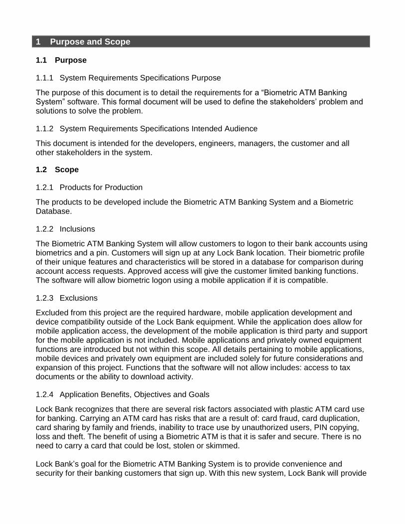
1 Purpose and Scope
1.1 Purpose
1.1.1 System Requirements Specifications Purpose
The purpose of this document is to detail the requirements for a “Biometric ATM Banking System” software. This formal document will be used to define the stakeholders’ problem and solutions to solve the problem.
1.1.2 System Requirements Specifications Intended Audience
This document is intended for the developers, engineers, managers, the customer and all other stakeholders in the system.
1.2 Scope
1.2.1 Products for Production
The products to be developed include the Biometric ATM Banking System and a Biometric Database.
1.2.2 Inclusions
The Biometric ATM Banking System will allow customers to logon to their bank accounts using biometrics and a pin. Customers will sign up at any Lock Bank location. Their biometric profile of their unique features and characteristics will be stored in a database for comparison during account access requests. Approved access will give the customer limited banking functions. The software will allow biometric logon using a mobile application if it is compatible.
1.2.3 Exclusions
Excluded from this project are the required hardware, mobile application development and device compatibility outside of the Lock Bank equipment. While the application does allow for mobile application access, the development of the mobile application is third party and support for the mobile application is not included. Mobile applications and privately owned equipment functions are introduced but not within this scope. All details pertaining to mobile applications, mobile devices and privately own equipment are included solely for future considerations and expansion of this project. Functions that the software will not allow includes: access to tax documents or the ability to download activity.
1.2.4 Application Benefits, Objectives and Goals
Lock Bank recognizes that there are several risk factors associated with plastic ATM card use for banking. Carrying an ATM card has risks that are a result of: card fraud, card duplication, card sharing by family and friends, inability to trace use by unauthorized users, PIN copying, loss and theft. The benefit of using a Biometric ATM is that it is safer and secure. There is no need to carry a card that could be lost, stolen or skimmed. Lock Bank’s goal for the Biometric ATM Banking System is to provide convenience and security for their banking customers that sign up. With this new system, Lock Bank will provide
7
greater services than their competition in order to stay competitive. Account access monitoring accuracy will be increased since biometric authentication is based on a customer’s unique characteristics.
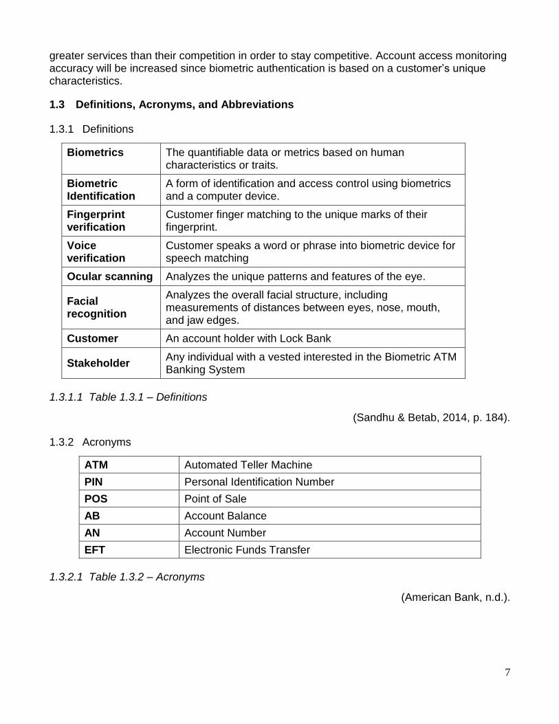
1.3 Definitions, Acronyms, and Abbreviations
1.3.1 Definitions
Biometrics The quantifiable data or metrics based on human characteristics or traits.
Biometric Identification
A form of identification and access control using biometrics and a computer device.
Fingerprint verification
Customer finger matching to the unique marks of their fingerprint.
Voice verification
Customer speaks a word or phrase into biometric device for speech matching
Ocular scanning Analyzes the unique patterns and features of the eye.
Facial recognition
Analyzes the overall facial structure, including measurements of distances between eyes, nose, mouth, and jaw edges.
Customer An account holder with Lock Bank
Stakeholder Any individual with a vested interested in the Biometric ATM Banking System
1.3.1.1 Table 1.3.1 – Definitions
(Sandhu & Betab, 2014, p. 184).
1.3.2 Acronyms
ATM Automated Teller Machine
PIN Personal Identification Number
POS Point of Sale
AB Account Balance
AN Account Number
EFT Electronic Funds Transfer
1.3.2.1 Table 1.3.2 – Acronyms
(American Bank, n.d.).
8
1.4 Overview
This document is broken down into six sections and a reference list. This section provides and overview of the project. Definitions, acronyms, stakeholders, application goals and benefits, purpose and scope are identified. Section two explains what elicitation is and different elicitation methods. Different types of stakeholders, their role and interaction with the system and their importance is also covered. Section three provides an overview of the system functionality and system interaction with other systems and identified during elicitation. Different analysis methods are discussed and an analysis methodology is implemented for stakeholder understanding and review. Section four covers application requirements and quality requirements intended for developers and designers. Required quality measures are provided. Section five is used to ensure that the system meets the defined requirements. This is done using verification and validation. A traceability matrix is used for this process. The fourth chapter deals with the prioritization of the requirements. It includes a motivation for the chosen prioritization methods and discusses why other alternatives were not chosen. The Appendixes in the end of the document include the all results of the requirement prioritization and a release plan based on them.
9
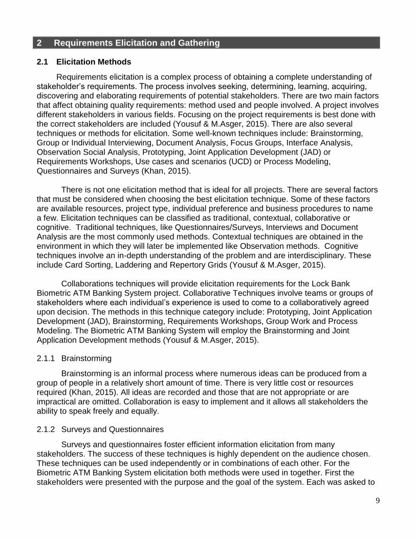
2 Requirements Elicitation and Gathering
2.1 Elicitation Methods
Requirements elicitation is a complex process of obtaining a complete understanding of stakeholder’s requirements. The process involves seeking, determining, learning, acquiring, discovering and elaborating requirements of potential stakeholders. There are two main factors that affect obtaining quality requirements: method used and people involved. A project involves different stakeholders in various fields. Focusing on the project requirements is best done with the correct stakeholders are included (Yousuf & M.Asger, 2015). There are also several techniques or methods for elicitation. Some well-known techniques include: Brainstorming, Group or Individual Interviewing, Document Analysis, Focus Groups, Interface Analysis, Observation Social Analysis, Prototyping, Joint Application Development (JAD) or Requirements Workshops, Use cases and scenarios (UCD) or Process Modeling, Questionnaires and Surveys (Khan, 2015).
There is not one elicitation method that is ideal for all projects. There are several factors that must be considered when choosing the best elicitation technique. Some of these factors are available resources, project type, individual preference and business procedures to name a few. Elicitation techniques can be classified as traditional, contextual, collaborative or cognitive. Traditional techniques, like Questionnaires/Surveys, Interviews and Document Analysis are the most commonly used methods. Contextual techniques are obtained in the environment in which they will later be implemented like Observation methods. Cognitive techniques involve an in-depth understanding of the problem and are interdisciplinary. These include Card Sorting, Laddering and Repertory Grids (Yousuf & M.Asger, 2015).
Collaborations techniques will provide elicitation requirements for the Lock Bank Biometric ATM Banking System project. Collaborative Techniques involve teams or groups of stakeholders where each individual’s experience is used to come to a collaboratively agreed upon decision. The methods in this technique category include: Prototyping, Joint Application Development (JAD), Brainstorming, Requirements Workshops, Group Work and Process Modeling. The Biometric ATM Banking System will employ the Brainstorming and Joint Application Development methods (Yousuf & M.Asger, 2015).
2.1.1 Brainstorming
Brainstorming is an informal process where numerous ideas can be produced from a group of people in a relatively short amount of time. There is very little cost or resources required (Khan, 2015). All ideas are recorded and those that are not appropriate or are impractical are omitted. Collaboration is easy to implement and it allows all stakeholders the ability to speak freely and equally.
2.1.2 Surveys and Questionnaires
Surveys and questionnaires foster efficient information elicitation from many stakeholders. The success of these techniques is highly dependent on the audience chosen. These techniques can be used independently or in combinations of each other. For the Biometric ATM Banking System elicitation both methods were used in together. First the stakeholders were presented with the purpose and the goal of the system. Each was asked to
10
consider their own experience using an ATM for banking processes. Then they were prompted to provide details about ATM banking positives and negatives based on their own experience. The survey identified caution areas to consider during development. The survey also provided the stakeholders with information for introspection.
Following the survey, stakeholders were presented with a questionnaire. The questionnaire provided ideas and design considerations that were suggested during the brainstorming elicitation. The questionnaire was very specific, well defined and provide domain information.
2.1.3 Joint Application Development
The Joint Application Development (JAD) method involves a 4 or 5-day organized collaboration workshop that produces a proper set of user requirements. Key participants are specifically selected and participant roles and system goals are predefined. The use of visual aids fosters interactive sessions and an end of session prototype accelerates the design of a system. JAD sessions lead to creative output and greater user satisfaction. Participants remain in session until a complete set of requirements is developed, documented and agreed upon. The biggest benefit of JAD sessions is the increased communication between stakeholders, analysist and other professionals involved in the development process. Pitfalls of the JAD method include the need for a trained facilitator and the extensive amount of planning and effort required. If preplanning is not done sufficiently or properly, this method could lead to a great waste of time and resources (Yousuf & M.Asger, 2015).
2.2 Stakeholders
A stakeholder is any entity that has a vested or declared interest in the success or failure of a system or software being developed. Stakeholder Analysis (SA) during a software or system elicitation process since a stakeholder has a “stake” in the end product. SA is a method that accounts for and often incorporates the needs of the stakeholders. Understanding the stakeholders’ role, interests and weight that their input carries will facilitate realistic and sustainable development.
During system elicitation, selected stakeholders are needed to provide divergent viewpoints, shed light on the impact, identify opposing opinions, and address any potential issues with the expected solution being developed. Stakeholders range in form, size and capacity and can be individuals, organizations or unorganized groups.
2.2.1 Stakeholders and Roles
The new Lock Bank Biometric ATM Banking System has both internal and external stakeholders that should be considered during elicitation. In the following Table 2.2.1 Stakeholders and Roles, key stakeholders are identified and their roles are defined.

11
Table 2.2.1 Stakeholders and Roles
Lock Bank Biometric ATM Banking System Stakeholders
Acquirers Develop a plan and oversee procurement of the system that will
meet the goals of and address the problem presented by Lock Bank.
Assessors Ensure that the system conforms to the needs, standards and legal
regulations.
Bank managers Oversee the bank personnel and are responsible for ensuring they
adhere to policies and job role duties. Also responsible for issue
resolution at branch location.
Communicators Contributors that communicate with, document and provide training
to stakeholders germane to the system.
Competition Representatives of other banks
Counter staff Bank tellers that assist or account specialists that assist with various
banking needs.
Customer Sometimes referred to as the client, the customer pays for the
development. The customer often includes "C" level management
(e.g. CEO, CFO, CIO) and can hinder development usability over
costs.
Database
administrators
Develop, configure, identify and resolve issues of all features and
capabilities of the database system.
Developers Use system specifications to develop or lead a team in the
development of the system.
Maintainers Responsible for managing the system as it evolves once
operational.
Production
Engineers
Design, deploy, and manage the hardware and software the system
will be built, tested, and run on.
Security
managers
Oversees security of the system by leading a security that monitors
the system use and network traffic. Security teams watch and
respond to security system alerts.
Suppliers Provide necessary components for which the system will run (e.g.
hardware, software, infrastructure, etc.).
Supporters Helps the user with the system once it is in place and operational.
System
administrators
Keep the system operational, administer users, and perform system
configuration.
Testers Test the system to verify it is ready for use.
User Users can be divided into two types: content providers and content
consumers. Content providers (e.g. bank personnel) input
information into the system. Content consumers (e.g. bank account
holders) use the system to access and consume system resources.
12
2.3 Elicitation Technique Summary
The greatest challenge is including the correct stakeholders for input. Including the wrong stakeholders only yields a long document of input that has to be omitted because it is irrelevant or not feasible. With the correct stakeholder there is a quality of information elicitation.
2.3.1 Brainstorming
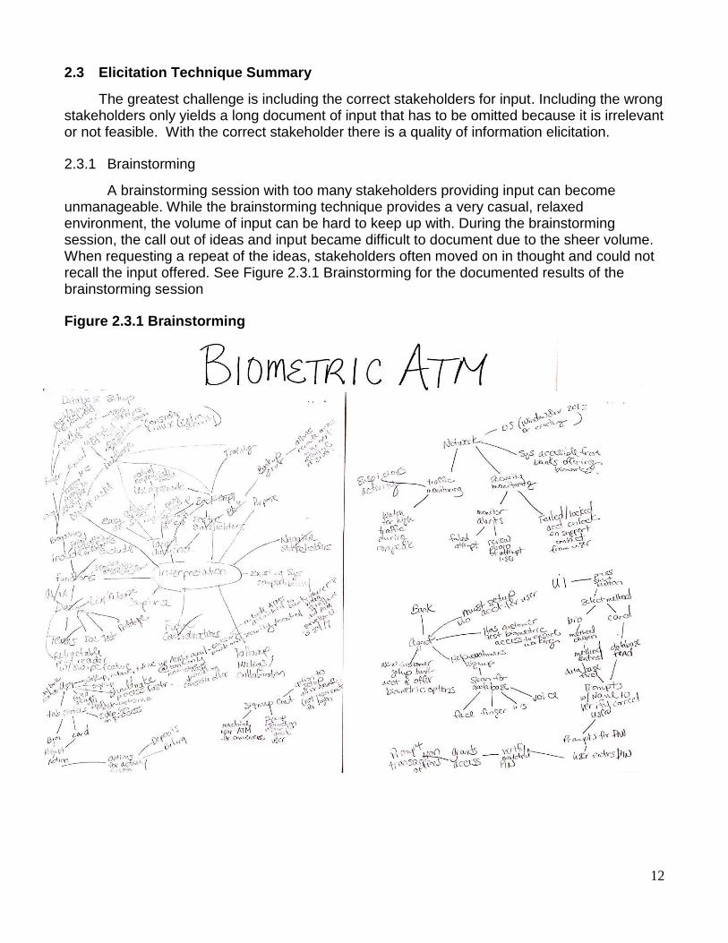
A brainstorming session with too many stakeholders providing input can become unmanageable. While the brainstorming technique provides a very casual, relaxed environment, the volume of input can be hard to keep up with. During the brainstorming session, the call out of ideas and input became difficult to document due to the sheer volume. When requesting a repeat of the ideas, stakeholders often moved on in thought and could not recall the input offered. See Figure 2.3.1 Brainstorming for the documented results of the brainstorming session
Figure 2.3.1 Brainstorming

13
2.3.2 Surveys
Surveys made it possible to reach a large audience within a short amount of time. Because the survey was provided to individuals and not performed in a group setting, the returned results were unbiased. This was an economical technique that draws from the participant’s personal experiences. See Figure 2.3.1 Survey Elicitation for the presented survey participation request. This method does not require overseeing the process and participants can participate at their convenience. All responses were submitted promptly.
Figure 2.3.1 Survey Elicitation
2.3.3 Elicitation Questionnaires
Questionnaires are effective, economical and wide reaching. The questionnaire consisted of collection of questions and ideas for consideration. This was mass distributed with instructions for directions, guidelines and deadline. This eliminated the need to individually explain the purpose, process and constraints. Questionnaires, like the surveys, made it possible to reach a large audience within a short amount of time. See Figure 2.3.2 Elicitation Questionnaires for examples of returned questionnaires.

14
Figure 2.3.2 Elicitation Questionnaires

15
2.3.4 Joint Application Development
The Joint Application Development (JAD) would have be developed based on ideas elicited from the brainstorming, survey and questionnaire techniques. Due to time constraints and inability to gathers stakeholders in one location for a multiday session, it was not feasible.
2.3.5 Suggestions for Improvement
Brainstorming negatives of this method is that it can be very time consuming if not properly organized, idea quantity do not equal idea quality and it is easy for extroverts to monopolize the session with their ideas (Yousuf & M.Asger, 2015).
Group Work or Focus Group techniques are an alternative to the brainstorming technique. As with brainstorming, stakeholders are gathered to share, suggest, discuss and consider suggestions from all attendees. Participants are encouraged to interactively engage with each other to generate new ideas and discuss as many topics possible in depth. A group work session is more formal than brainstorming and requires a moderator to keep the group focused and maintain order. Generating thoughts freely is encouraged but there is a risk of disproportionality if the moderator is unable balance participation resulting in a group influenced by dominant participants.
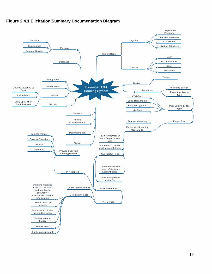
2.3.6 Elicitation Summary Documentation
The combination of the elicitation techniques provided features and functions that the stakeholders felt were important. Some will still need to be addressed and considered for feasibility and necessity. Documentation is essential for successful development. Figure 2.4.1 Elicitation Summary Documentation Diagram provides a summary diagram of the compiled results. For a larger detailed double click on the inserted Diagram 2.4.1 Visio Elicitation Summary below. This documentation will be further analyzed in Section 3.
2.4 Elicited Document Summary
2.4.1 Functional Requirements
User Setup: In order to use the biometric system, the user will have to create a biometric profile. Profile must be created at a bank location with a bank agent during normal business hours. The profile will be stored on a dedicated biometric database server.
Welcome Screen User Interface: The welcome screen will prompt the user to choose either a Biometric Profile or ATM card account identification.
Biometric Profile Selection: If user selects biometric profile they will be prompted with a list of options including fingerprint, iris, voice or facial recognition.
Fingerprint Selection: User will be prompted to place their finger on the scanner until the system has recognized their finger print.

16
Iris Selection: User will be prompted to stand with their eye approximately three inches from the camera and remain until the system recognizes their scan.
Facial Selection: User will be prompted to stand in front of the camera approximately one foot from the machine for facial scanning until recognized.
ATM card selection: User will be prompted to enter their ATM card and then remove.
Successful Identification: The system will welcome the user by name that matches the record on file and prompt to confirm it is their account.
PIN: After user confirms that the correct account has been found the system will prompt for a second form of identification, a PIN.
Successful Logon Options: Upon successful logon user will be prompted to choose a transaction. The options are balance inquiry, balance transfer, withdraw cash and deposit.
Failed attempt logon: System will allow user three logon attempts. After the third failed attempt the system will take a photo of the user to send to a forensics team, lock the users account, notify account holder and bank of failed logon attempts. A message will display notifying the user that the account has been locked and provide a number to contact for support.
2.4.2 Non-Functional Requirements
Locations: Biometric ATMs will be located on bank property only. They will be inside the bank, attached to the outside of the bank or in a bank drive through lane. Attributes: Security, Convenience and Increased service.
17
Figure 2.4.1 Elicitation Summary Documentation Diagram
Biometric ATM
Banking System
Stakeholders
Future
Considerations
Design
Purpose
Documentation
Database
Signup
Integration
Location
Collaboration
Network
Security
Negative
Positive
User
Account Holder
Bank
Personnel
Disgruntled
Personnel
Former Personnel
Competition
System Attackers
Functions
Teams
Security
Convenience
Superior Service
Welcome Screen
Prompt for Logon
Type
User Selects Logon
Type
ATM Card
Finger Print
Voice Recognition
Face Recognition
Iris Scan
Scanner Cleaning
Fingerprint Scanning
User Guide
1. Instruct User to
place finger on scan
pad
2. Instruct to remain
until successful read
Successful Read
User confirms the
name of the bank
account holder
User prompted to
enter PIN
User enters PIN
PIN Accepted
PIN Denied
Count failed attempt
3 failed attempts
Locks user account
Notifies bank
Notifies account
holder
Takes photo of user
attempting logon
Sends photo to
security
Displays message
about account lock
and number to
contact for
assistance / unlock
information
Provide User with
Banking Options
Balance Inquiry
Balance Transfer
Deposit
Withdraw
Outside attached to
Bank
Inside Bank
Drive up ATM on
Bank Property

18
3 Requirements Analysis and Methodology
3.1 Analysis Methods
Analyzing requirements is the process of identifying what is needed in order to fulfill a need or solve a problem. It includes understanding the problem domain and solutions that can address the problem. During requirements analysis, design teams review requirements to determine if they are actionable, measurable, testable, relative to domain needs, and sufficient in detail for system design.
Computer-aided software engineering (CASE) tools are important for systems analysts.
These tools provide the Unified Modeling Language (UML) and the different diagrams used to break down the UML. Some features of a system are fixed. This means that there are elements that do not change and are a part of the structures system. The structure model gives a general design of the system as a whole. To visually represent the different behaviors and define the rationale behind the tasks or responses of the system, UML uses different diagrams in order to break down the structure and behaviors (Tutorials Point, n.d.).
There are several modeling diagrams that can be used to assist systems analyst the opportunity to break down the functionality of the system. This can make the system easier to organize and identify complexities to simplify for greater understanding. Some of the structure model types are the class, component, object and deployment diagrams (Tutorials Point, n.d.). Behavioral modeling of UML, diagrams the interactions in a system. A behavioral model represents the generalized dynamic nature of a system. The activity, timing, sequence, use case, state machine, and communication diagrams show the constraints and assumptions of the system and the system’s users.
This section will explain three selected types of behavioral modeling: use case, sequence, and state machine. A diagram of each is included to represent specific functions of the system. A flow of events and use case definitions provide an in depth analysis of the biometric ATM system.
3.2 Analysis with UML Use-Case Model
A use case is a description of actions or events that take place between an actor and a system to solve a problem or meet a goal. Use-cases in UML can be visually represented using use case diagrams. A use case diagram can graphically depict actors, use cases, associations, dependencies and the system boundary (Strohmeier & Sendall, 2001).
There are three relationships in a use case diagram: extends, includes and
generalization. The ‘includes’ relationship indicates that the behavior of a child use case is part of the parent use case behavior. The ‘extends’ relationship indicates that the behavior of a child use case is part of another use case that is at a specified location. A ‘generalization’ relationship is between a general parent and a more specific child entity (Strohmeier & Sendall, 2001).
A use case model includes a use case diagram and descriptions. The Use Case diagram
gives an overview of individual use cases and how they pertain to the system as a whole. The

19
actors for the biometric ATM bank system include the account holder (user), agent, database, ATM, operator and technician. See Figure 3.2.1 Use-Case Diagram.
Figure 3.2.1 Use-Case Diagram
LockBank Acct Holder
ATM Tech/Operator
Session
Power ATM
Identify Acct
Holder
Transaction
<<include>>
<<include>>
<<include>>
ID Method
Enter PIN
<<include>> <<extend>>
Invalid PIN
<<include>> Withdrawal
<<include>>
Deposit
Transfer
<<include>>
<<include>>
Inquiry
Create Profile
Bank Agent
Database
Database
<<include>>
<<include>>
Service ATM
<<include>>
3.2.1 UML Use-Case Descriptions
The biometric ATM bank system assumes that all users of the system have a valid Lock Bank account. To create a biometric profile, it is also assumed that the user has visited the Lock Bank location during normal business hours. There are three main actors in the use-case model: Teller, Account holder and ATM Tech/Operator. A final assumption is that the software is installed on both the teller’s computer for sign up and the ATM.
3.2.1.1 Create Profile
Biometric profile setup requires two actors: a bank agent and an account holder (user). An agent will assist user in creating the biometric profile using the biometric equipment. The user will choose one or both (facial/finger) biometric(s) profile to create. For a facial profile the agent will scan the user’s facial features and send the record to the database. For a finger print, the user will place their finger on a scanner while the agent accepts a clean scan. The

20
agent then sends the scan to the database. The agent will then walk the user through a test logon using their newly created biometric profile. Problems with access may require rescanning or else an ATM Tech will be requested to resolve the issue.
3.2.1.2 Power ATM Use Case
The system is powered up when the ATM Operator flips the switch to the "on" position. The ATM connects to the networked database. The ATM is then at the Welcome screen and available for use. When the ATM needs to be serviced the ATM Operator begins the shutdown procedure after he verifies it is not in use. Then the operator flips the switch to the "off" position. The network connection to the database is closed.
3.2.1.3 Service ATM Use Case
The ATM Operator is responsible for replenishing paper and cash, removing all deposits, etc. The ATM Operator must check the card reader to make sure there is nothing the slot. If the ATM needs additional servicing it must be shut down first.
3.2.1.4 Session Use Case
A session is started when a user chooses an ID logon method. If the user selects biometrics they will select the type of biometric to use. A finger print selection will prompt the user to place their finger on the scanner until a scan is accepted. A facial selection will prompt the user to stand in front of the camera about a one foot back until the camera scan is accepted. If either scan is unsuccessful the user will be prompted again. After three failed scan attempts the session will end and the ATM will return to the welcome screen. If the user selects ATM card, then he is prompted to insert the card into the card reader slot. The ATM accepts and reads the card. Unsuccessful read will eject card and end session. The ATM will return to the Welcome screen. After the user has completed a biometric scan or inserted an ATM card, the database will identify the user and request that he enter a PIN. Successful verification of PIN will prompt user for a transaction selection. Failure to verify the PIN will initial the Invalid PIN extension. Session ends when the user selects not further transactions requested.
3.2.1.5 Transaction Use Case
A transaction use case prompts the user to select a transaction type from a menu of possible transactions. Transactions include withdrawal, inquiry, deposit, and transfer. The flow of transactions can be seen in the State Chart Diagrams. Transactions can be cancelled when the user presses the Cancel key as described in each individual type of transaction below.
3.2.1.6 Withdrawal Use Case
A withdrawal prompts the user to select account to withdraw from and a dollar amount from a menu of possible amounts or by entering an amount in intervals of $20 up to a max of $300. The system verifies account has sufficient funds. If insufficient funds, user is informed and prompted retry another amount. If funds are available, withdrawal is approved, the amount is dispensed, the amount is posted to the account, and a receipt is printed. The transfer can be cancelled when the user presses the Cancel key prior to entering a dollar amount.
21
3.2.1.7 Deposit Use Case
A deposit prompts the user to choose account to deposit to from a menu and enter a dollar amount on the keypad. The user is prompted to insert deposit envelope, the machine accepts from the user, and then prints a receipt. The deposit is posted as pending until funds are verified. The transfer can be cancelled when the user presses the Cancel key prior to inserting the envelope containing the deposit.
3.2.1.8 Transfer Use Case
A transfer prompts the use to choose the to/from accounts for the transfer. Then the user is prompted to enter a dollar amount on the keypad. Once the bank processes the transfer, the ATM prints the receipt. The transfer can be cancelled when the user presses the Cancel key prior to entering a dollar amount.
3.2.1.9 Inquiry Use Case
An inquiry prompts the user to select from a menu the account that the user is requesting balance information about. Once the bank returns the balance the ATM prints the receipt. The inquiry can be cancelled when the user presses the Cancel key prior to account selection.
3.2.1.10 Invalid PIN Extension
An invalid PIN extension is started from within a session when the entered PIN is not match the database profile. The customer is prompted to re-enter the PIN and an authorization request is sent to the database again. If approved, the original use case transaction is continued; otherwise the user prompt to re-enter PIN is repeated. A successful PIN entry is used for the current and subsequent transactions in the session. A user failure to enter correct PIN three times cancels transaction, locks account, account holder and bank are notified, camera takes user photo, and ATM returns photo for forensics. ATM returns to Welcome screen.
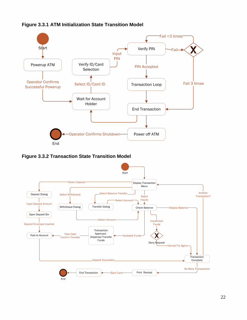
3.3 Analysis with State Transition Method
The biometric ATM banking system is made up of states and behaviors. A state is the current condition of the ATM. The behavior is the transition trigged by an internal or external event between the states. State chart diagrams include an initial and a final state or the start and end events. The system is broken into two objects: Initialization and Transaction State Transition Models. These two objects have more complex behaviors that are easier to follow in a state transition diagram. See Figure 3.3.1 ATM Initialization State Transition Model and Figure 3.3.2 Transaction State Transition Model.
22
Figure 3.3.1 ATM Initialization State Transition Model
Start
Wait for Account
Holder
Transaction Loop
End Transaction
End
Operator Confirms
Successful Powerup
Verify ID/Card
Selection
Select ID/Card ID
Verify PIN
PIN Accepted
Fail
Fail 3 times
Powerup ATM
Power off ATMOperator Confirms Shutdown
Input
PIN
Fail <3 times
Figure 3.3.2 Transaction State Transition Model
Start
Display Transaction
Menu
Withdrawal Dialog
End Transaction
End
Eject Card
Deposit Dialog
Select Deposit
Select
Inquiry
Check Balance
Select Withdrawal
Transfer Dialog
Select Balance Transfer
Select Account
Select Amount
Display Balance
Print Receipt
Deposit Successful
Post to Account
Insufficient
Funds
Input Deposit Amount
Another
Transaction?
Transaction
Complete
No More Transactions
Available Funds
Deny RequestCancel/Try Again
Transaction
Approved -
Dispense/Transfer
Funds
Take Cash
Confirm Transfer
Open Deposit Bin
Deposit Envelope Inserted
23
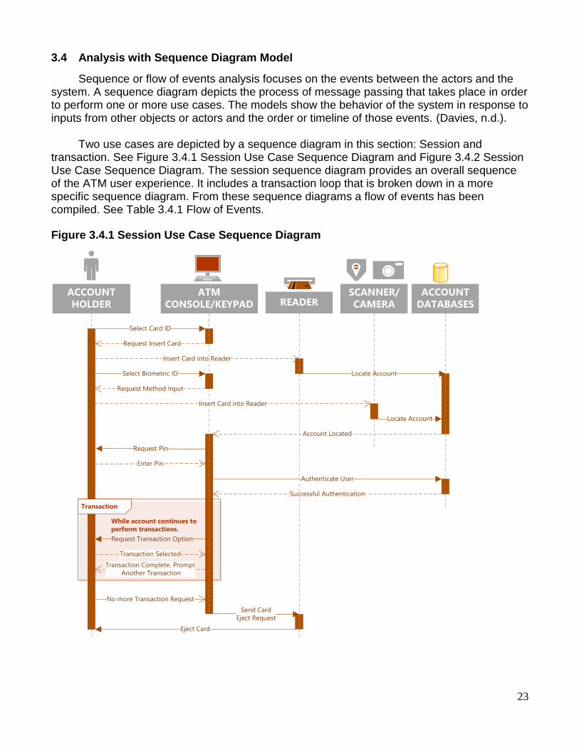
3.4 Analysis with Sequence Diagram Model
Sequence or flow of events analysis focuses on the events between the actors and the system. A sequence diagram depicts the process of message passing that takes place in order to perform one or more use cases. The models show the behavior of the system in response to inputs from other objects or actors and the order or timeline of those events. (Davies, n.d.).
Two use cases are depicted by a sequence diagram in this section: Session and
transaction. See Figure 3.4.1 Session Use Case Sequence Diagram and Figure 3.4.2 Session Use Case Sequence Diagram. The session sequence diagram provides an overall sequence of the ATM user experience. It includes a transaction loop that is broken down in a more specific sequence diagram. From these sequence diagrams a flow of events has been compiled. See Table 3.4.1 Flow of Events.
Figure 3.4.1 Session Use Case Sequence Diagram
ACCOUNT
HOLDER
Select Card ID
Successful Authentication
ACCOUNT
DATABASES
Request Insert Card
Insert Card into Reader
Locate Account
Account Located
Enter Pin
Request Pin
Authenticate User
Request Transaction Option
Transaction
While account continues to
perform transactions.
Transaction Selected
Transaction Complete. Prompt
Another Transaction
No more Transaction Request
Eject Card
READERSCANNER/
CAMERA
ATM
CONSOLE/KEYPAD
Send Card
Eject Request
Select Biometric ID
Request Method Input
Locate Account
Insert Card into Reader

24
Figure 3.4.2 Session Use Case Sequence Diagram
TRANSACTION
Select Transaction
Successful Authentication
ACCOUNT
DATABASES
Request Method Input
Insert Card / Facial Scan / Fingerprint Scan
Locate Account
Account Located
Enter Pin
Request Pin
Authenticate User
Request Transaction Option
Transaction Selected
Transaction Complete. Prompt
Another Transaction
Transactions Complete
End Session
Eject Card
PRINTERATM
CONSOLE/KEYPAD
Table 3.4.1 Flow of Events
Actors Agent, Account Holder, Operator, Technician
Preconditions 1. Account holder met with agent to create profile 2. ATM is Powered on. 3. ATM is connected to networked database 4. Card reader is empty 5. ATM has paper 6. ATM has money 7. User has a Lock Bank Account

25
Flow of Events
1. ATM operation begins at Welcome Screen 2. User chooses ID Method 3. If user choose ATM card, then he inserts ATM card into reader 4. If user chooses Biometric ID, then he chooses biometric choice
a. User selects fingerprint, ATM requests user to place his registered finger on the fingerprint reader
b. User selects facial recognition, ATM requests user to stand 1 foot from camera for a facial scan.
5. ATM requests user to enter PIN 6. If ATM has 3 failed authentication attempts, then ATM:
a. Takes photo of user b. Notifies the account holder c. Notifies the bank d. Locks the account e. Ejects the card
7. ATM requests user to make an operation selection choice 8. If user selects ‘balance inquiry’, then ATM
a. Sends request to database to retrieve current balance b. Returns account balance to display and prints
9. If user selects ‘deposit’, then ATM a. Prompts user to enter deposit amount b. Accepts amount and prompts the user to insert deposit c. Accepts deposit and posts pending deposit to account.
10. If user selects ‘withdrawal’, then ATM a. Ask user for amount in increments of $20 and maximum of $300 b. Accepts amount and sends verification of funds request to
database c. If sufficient funds, then ATM dispenses requested amount and
posts to account d. If insufficient funds, then ATM notifies user to try again.
11. If user selects ‘transfer’, then ATM a. Ask user for whole dollar amount. b. Accepts amount and sends verification of funds request to
database c. If sufficient funds, then ATM transfers requested amount and
posts to account d. If insufficient funds, then ATM notifies user to try again.
12. ATM prompts user for another transaction. a. If user chooses another transaction, then ATM b. If user chooses no, then ATM prints receipt of activity
13. ATM ejects ATM card 14. ATM returns to Welcome screen
Post Conditions
1. Operator Powers down the ATM 2. Deposits are removed and given to Agent 3. Deposits are verified and posted to account 4. Operator checks paper and refills if needed 5. Operator checks cash available in machine.
26
3.5 Analysis Summary
In this section, three behavioral analysis methods were used: use case, state transition and sequence. Each have their own benefits and challenges. This section will discuss the benefits and challenges of each.
3.5.1 Use Case Model
The Use Case method provides a very high level diagram overview that makes it simple to understand the key elements and behaviors of the system. The Use Case definitions add value to the model by providing details of all processes included in each use case. The definitions also provide boundaries to the system by providing alternatives. The challenge in this method is the level of detail that is needed to extract quality requirements. Each Use Case consists of many interactions and each must be considered carefully which is not depicted in the visual diagram. The other challenge is knowing when and how to use the relationships.
3.5.2 State Transition Model
The state transition model gives a graphical representation of the use cases with the inputs and outputs that occur between. This method provided the most insight for the requirements. The simplicity of the design makes it easy to see the use cases and the interactions between them. State transition models can be broken down in to smaller state transition models to make it easier to follow. The only challenge of this model was the fail loop or extension in the use case model. Since it loops back to itself it does not seem clear what is taking place.
3.5.3 Sequence Model
The sequence model is a great representation of the events order. It provides a depiction all actors, system, input and output. A well designed sequence diagram is very beneficial in understanding the processes and needed steps for the system goals. The diagram is very easy to follow and this makes flow of event definition easy. The challenges of this method is that the dependencies must be known and it is not a useful tool if dependencies are left out.

27
4 Requirements and Software Quality Measurements
4.1 Software Quality
Software quality in a project determines the success or failure of a system. Poor quality requirements and poor specifications documents are key contributors to project failure. Software quality is the foundation of the development process. Detection of poor quality requirements later in the development process result in costly redesign and rework (Chappell, 2012).
Dependence on software is present in all aspects of life therefore quality is imperative in
all software projects for success. Specifications for software quality focus on software attributes and quality metrics (Elam, 2016).
4.2 Required Software Quality Attributes
Quality attributes are used to evaluate the performance of a software including behaviour, design and user experience. These non-functional requirements also known as “ilities”. There are many types of software quality attributes and vary in importance based on the software product.
To determine which “ilities” are important and required there are several factors to
consider. Key considerations include goal of the project, business goals and future development. Industry standards compliance also drives required quality attributes. For a financial institution there are many compliance regulations including Gramm-Leach-Bliley Act (GLBA) and the Electric Funds Transfer Act (EFTA) ("Federal Regulations for Financial Institutions | CSI," n.d.).
The key required software quality attributes identified for the biometric ATM banking system include: functionality, reliability, usability, standards compliancy and interoperability. The software quality attributes are not all inclusive, rather focus on the key requirements for the Lock Bank biometric ATM software.
4.2.1 Functionality
The functionality of the software is the essential purpose of the biometric ATM banking system. Unlike other quality characteristics, functionality is either present or not present. The other quality characteristics are present to a certain degree.
4.2.2 Reliability
Once the ATM software is live and functional the system must be capable of maintaining service under defined conditions and time periods. An important reliability feature is fault tolerance or the ability to function in the event of component failure. A reliable software is available and recoverable.
4.2.3 Usability
Usability is a factor of functionality and addresses the ease of use of the software. Option menus and system help features aid in account holder understanding and use. A system that cannot be learned is not useful or usable.

28
4.2.4 Standards Compliancy
4.2.4.1 Security
Software security protects the software from accidental or malicious access, use, modification or destruction. Security also refers to who has access or the access level that is granted to bank personnel. The security of a bank customer’s collected personal financial and confidential information is protected by enforcement of GLBA compliance.
4.2.4.2 Inspectability
EFTA, also known as Regulation E compliance, focuses on investigative procedures of consumer claims and electronic fund transfer errors. The industry standards for the ATM software will require security and inspectability.
4.2.5 Interoperability
Lock Bank is an existing business with in place hardware and software. This includes the operating systems, servers, databases and more. Interoperability is the software’s ability to integrate with another system successfully and free from error.
4.3 Quality Metrics
Software development has a specific approach for quality measurements since it is the process of building the software rather than purchasing an already existing system. The three key aspects of software quality include: product, process and project quality (Chappell, 2012).
4.3.1 Product (Functional) Quality
The functional quality of software ensures that they software performs it’s intended
tasks. Functional requirements include the goals of the stakeholders, following compliance
and regulatory guidelines, quality performance, reliability, and usability. During elicitation, it is
not uncommon to gather requirements that are not necessary. These features should be
identified and addressed. The software should meet the requirements and not what a user
wants to see from the software. Software that has defects, fails during operation or is difficult to
use provides no benefit. The software must also work with existing systems (Boult, n.d.).
4.3.2 Process (Structural) Quality
The structural quality of software ensures that structure of the code is well developed.
Quality software has code that is testable, maintainable and understandable. Software
requirements or software needs often change over the life of software development. This
means that the code must be easily maintainable or editable without introducing errors. Even
following the development of a software, it must be maintained. The original developer of the
system may not be the one that edits, maintains or modifies the code. If the code is not
understandable, this can present unnecessary costs and time delays. Code security should
also be considered as part of structural quality requirements. Poor coding can leave a system
vulnerable to attacks. For the ATM banking system this is a risk that could be very costly
(Boult, n.d.).
29
4.3.3 Project Quality
The development process quality impact users, the development team and sponsors.
Timely delivery and meeting budget constraints are examples of process quality factors.
Stakeholders are given a timeline on which they expect delivery and delays can cause
frustration. For the ATM system, the bank has notified its customers of the system release.
Delays will reflect poorly on Lock Banks ability to fulfill promised services. Customers
anticipating services will be disappointed as well as question the banks’ ability to deliver.
Delays can also cause development teams stress which can frustrate members causing them
to quit. Exceeding allocated funds can cause delays, create a need for trade-offs that can
impact quality, or result in the need to cut features decreasing the value of the system (Boult,
n.d.).
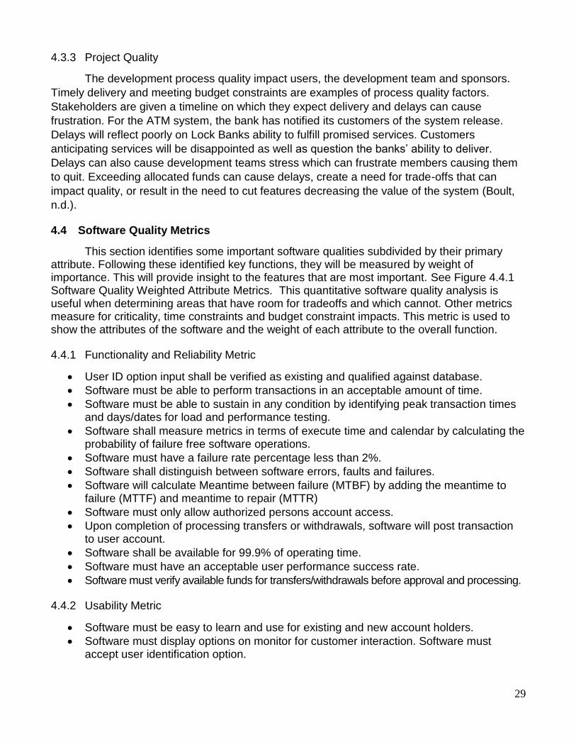
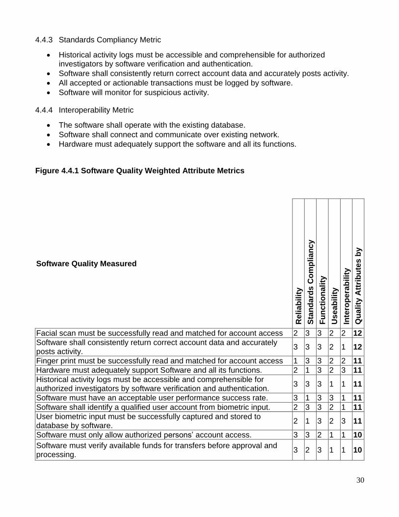
4.4 Software Quality Metrics
This section identifies some important software qualities subdivided by their primary attribute. Following these identified key functions, they will be measured by weight of importance. This will provide insight to the features that are most important. See Figure 4.4.1 Software Quality Weighted Attribute Metrics. This quantitative software quality analysis is useful when determining areas that have room for tradeoffs and which cannot. Other metrics measure for criticality, time constraints and budget constraint impacts. This metric is used to show the attributes of the software and the weight of each attribute to the overall function.
4.4.1 Functionality and Reliability Metric
User ID option input shall be verified as existing and qualified against database.
Software must be able to perform transactions in an acceptable amount of time.
Software must be able to sustain in any condition by identifying peak transaction times and days/dates for load and performance testing.
Software shall measure metrics in terms of execute time and calendar by calculating the probability of failure free software operations.
Software must have a failure rate percentage less than 2%.
Software shall distinguish between software errors, faults and failures.
Software will calculate Meantime between failure (MTBF) by adding the meantime to failure (MTTF) and meantime to repair (MTTR)
Software must only allow authorized persons account access.
Upon completion of processing transfers or withdrawals, software will post transaction to user account.
Software shall be available for 99.9% of operating time.
Software must have an acceptable user performance success rate.
Software must verify available funds for transfers/withdrawals before approval and processing.
4.4.2 Usability Metric
Software must be easy to learn and use for existing and new account holders.
Software must display options on monitor for customer interaction. Software must accept user identification option.
30
4.4.3 Standards Compliancy Metric
Historical activity logs must be accessible and comprehensible for authorized investigators by software verification and authentication.
Software shall consistently return correct account data and accurately posts activity.
All accepted or actionable transactions must be logged by software.
Software will monitor for suspicious activity.
4.4.4 Interoperability Metric
The software shall operate with the existing database.
Software shall connect and communicate over existing network.
Hardware must adequately support the software and all its functions.
Figure 4.4.1 Software Quality Weighted Attribute Metrics
Software Quality Measured
Reli
ab
ilit
y
Sta
nd
ard
s C
om
plia
nc
y
Fu
ncti
on
ali
ty
Use
ab
ilit
y
Inte
rop
era
bilit
y
Qu
ali
ty A
ttri
bu
tes
by
Req
uir
em
en
ts
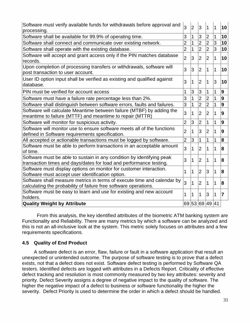
Facial scan must be successfully read and matched for account access 2 3 3 2 2 12
Software shall consistently return correct account data and accurately posts activity.
3 3 3 2 1 12
Finger print must be successfully read and matched for account access 1 3 3 2 2 11
Hardware must adequately support Software and all its functions. 2 1 3 2 3 11
Historical activity logs must be accessible and comprehensible for authorized investigators by software verification and authentication.
3 3 3 1 1 11
Software must have an acceptable user performance success rate. 3 1 3 3 1 11
Software shall identify a qualified user account from biometric input. 2 3 3 2 1 11
User biometric input must be successfully captured and stored to database by software.
2 1 3 2 3 11
Software must only allow authorized persons’ account access. 3 3 2 1 1 10
Software must verify available funds for transfers before approval and processing.
3 2 3 1 1 10
31
Software must verify available funds for withdrawals before approval and processing.
3 2 3 1 1 10
Software shall be available for 99.9% of operating time. 3 1 3 2 1 10
Software shall connect and communicate over existing network. 2 1 2 2 3 10
Software shall operate with the existing database. 2 1 2 2 3 10
Software will accept and grant access only if the PIN matches database records.
2 3 2 2 1 10
Upon completion of processing transfers or withdrawals, software will post transaction to user account.
3 3 2 1 1 10
User ID option input shall be verified as existing and qualified against database.
3 1 2 1 3 10
PIN must be verified for account access 1 3 3 1 1 9
Software must have a failure rate percentage less than 2%. 3 1 2 2 1 9
Software shall distinguish between software errors, faults and failures. 3 1 2 2 1 9
Software will calculate Meantime between failure (MTBF) by adding the meantime to failure (MTTF) and meantime to repair (MTTR)
3 1 2 2 1 9
Software will monitor for suspicious activity. 2 3 2 1 1 9
Software will monitor use to ensure software meets all of the functions defined in Software requirements specification.
2 1 3 2 1 9
All accepted or actionable transactions must be logged by software. 2 3 1 1 1 8
Software must be able to perform transactions in an acceptable amount of time.
3 1 2 1 1 8
Software must be able to sustain in any condition by identifying peak transaction times and days/dates for load and performance testing.
3 1 2 1 1 8
Software must display options on monitor for customer interaction. Software must accept user identification option.
1 1 2 3 1 8
Software shall measure metrics in terms of execute time and calendar by calculating the probability of failure free software operations.
3 1 2 1 1 8
Software must be easy to learn and use for existing and new account holders.
1 1 1 3 1 7
Quality Weight by Attribute 69 53 69 49 41
From this analysis, the key identified attributes of the biometric ATM banking system are Functionality and Reliability. There are many metrics by which a software can be analyzed and this is not an all-inclusive look at the system. This metric solely focuses on attributes and a few requirements specifications.
4.5 Quality of End Product
A software defect is an error, flaw, failure or fault in a software application that result an unexpected or unintended outcome. The purpose of software testing is to prove that a defect exists, not that a defect does not exist. Software defect testing is performed by Software QA testers. Identified defects are logged with attributes in a Defects Report. Criticality of effective defect tracking and resolution is most commonly measured by two key attributes: severity and priority. Defect Severity assigns a degree of negative impact to the quality of software. The higher the negative impact of a defect to business or software functionality the higher the severity. Defect Priority is used to determine the order in which a defect should be handled.
32
Assignment of priority is based on the cost and time to fix. A higher priority defect must be addressed and resolved sooner ("Defect Priority, Defect Severity and their Differences | Better Software Testing," n.d.).
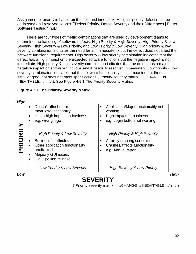
There are four types of metric combinations that are used by development teams to
determine the handling of software defects: High Priority & High Severity, High Priority & Low Severity, High Severity & Low Priority, and Low Priority & Low Severity. High priority & low severity combination indicates the need for an immediate fix but the defect does not affect the software functional requirements. High severity & low priority combination indicates that the defect has a high impact on the expected software functions but the negative impact is not immediate. High priority & high severity combination indicates that the defect has a major negative impact on software functions and it needs to resolved immediately. Low priority & low severity combination indicates that the software functionality is not impacted but there is a small degree that does not meet specifications ("Priority-severity matrix | ..::CHANGE is INEVITABLE::.," n.d.). See Figure 4.5.1 The Priority-Severity Matrix.
Figure 4.5.1 The Priority-Severity Matrix.
("Priority-severity matrix | ..::CHANGE is INEVITABLE::.," n.d.)
High
PR
IOR
ITY
Doesn’t affect other modules/functionality
Has a high impact on business
e.g. wrong logo
High Priority & Low Severity
Application/Major functionality not working
High impact on business.
e.g. Login button not working
High Priority & High Severity
Business unaffected
Other application functionality unaffected
Majoorly GUI issues
E.g. Spelling mistake
Low Priority & Low Severity
A rarely orcuring scneraio
Crashes/affects functionality
e.g. Annual report
High Severity & Low Priority
Low
SEVERITY
High

33
5 Requirements Validation and Verification
5.1 Requirements Management
Requirements are gathered and expanded on throughout the SDLC. Prior to
management, requirements have been elicited, analyzed, elaborated, negotiated, specified
and validated to meet the customer’s need. Requirements are also verified to determine if they
are necessary, complete, consistent, unambiguous, attainable and verifiable. The next stage is
to manage the requirements.
Before the software requirements document can be handed over to a development or
design team, requirements must be organized and managed. There are standards on which
requirements management are based including: IEEE Standard 1233, IEEE Standard 830 and
SEI CMMI. The requirements management process includes identifying, controlling and
tracking requirements as the project proceeds. Requirements can be organized and managed
by verification and validation (Elam, 2016).
Validation and verification are the final processes that are used to ensure that both the processes of the software and the quality of requirements are met. These two processes are a review to make sure nothing is missed or overlooked. The key differences between verification and validation reviews are the focus and participants during review processes.
5.2 Validation
Validation is a process that proves software does what it is intended to do. This takes
place throughout the SDLC. This type of process is also known as iterative or an agile
environment. Validation first begins prior to prototyping where no design has been formulated.
The requirements are defined with the stakeholders to ensure they meet the customer needs.
Validation focuses on process requirements. The validation review is done with stakeholders to
make sure that the software meets the needs of the end user (Elam, 2016).
The validation review process begins with the requirements description and is validated against how the customer explained it. This process began at the elicitation stage. By correctly validating requirements as explained by the customer, a complete picture of the customers’ needs is obtained.
5.3 Verification
Verification makes sure that the requirements are necessary, complete, unambiguous,
consistent, attainable and verifiable. The focus of verification is to review the documented
requirements quality. Quality of writing means that requirements are provided in compliance
with standards. Implementation or design details are not given during verification. The
verification process is necessary to prevent revisiting the customer for requirements. The
customer provides input at a very high level. This is not sufficient for implementation and
design (Elam, 2016).
34
5.4 Traceability Technique
There are several techniques used for verification and validation reviews. Some types
include peer reviews, formal inspections and check lists. A traceability matrix is a simple
check review technique. A simple check takes the requirements document and verify that all
elicited information from stakeholders are covered. There are different levels of requirements
included in this document. These include business requirements, analysis requirements and
requirements specifications. At each phase of the document development additional
information was added or modified to better meet the user’s needs. A traceability matrix will
reveal requirements that may have been missed during the process of evolution. It is also a
way of revisiting any requirements omitted that the user requires to meet business needs
(Collofello, James S, 1988).
The elicited customer requirements, the analysis requirements and the requirements
specifications gathered throughout this software requirements specifications document, a
traceability check was performed. This check identified each stage of requirements and
evolution to check the quality, accuracy and completeness to ensure they meet the customer’s
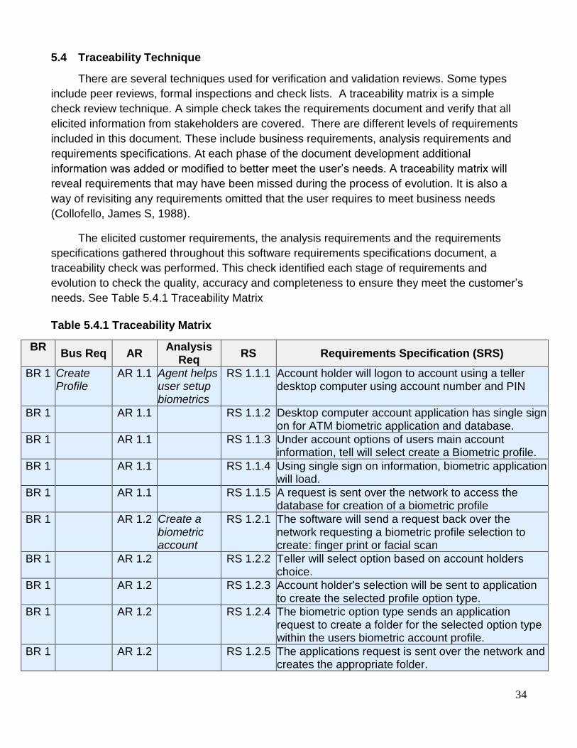
needs. See Table 5.4.1 Traceability Matrix
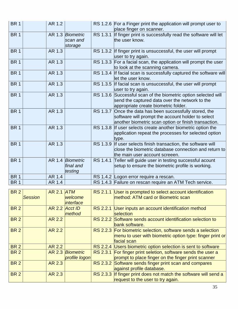
Table 5.4.1 Traceability Matrix
BR
Bus Req AR Analysis
Req RS Requirements Specification (SRS)
BR 1 Create Profile
AR 1.1 Agent helps user setup biometrics
RS 1.1.1 Account holder will logon to account using a teller desktop computer using account number and PIN
BR 1 AR 1.1 RS 1.1.2 Desktop computer account application has single sign on for ATM biometric application and database.
BR 1 AR 1.1 RS 1.1.3 Under account options of users main account information, tell will select create a Biometric profile.
BR 1 AR 1.1 RS 1.1.4 Using single sign on information, biometric application will load.
BR 1 AR 1.1 RS 1.1.5 A request is sent over the network to access the database for creation of a biometric profile
BR 1 AR 1.2 Create a biometric account
RS 1.2.1 The software will send a request back over the network requesting a biometric profile selection to create: finger print or facial scan
BR 1 AR 1.2 RS 1.2.2 Teller will select option based on account holders choice.
BR 1 AR 1.2 RS 1.2.3 Account holder's selection will be sent to application to create the selected profile option type.
BR 1 AR 1.2 RS 1.2.4 The biometric option type sends an application request to create a folder for the selected option type within the users biometric account profile.
BR 1 AR 1.2 RS 1.2.5 The applications request is sent over the network and creates the appropriate folder.
35
BR 1 AR 1.2 RS 1.2.6 For a Finger print the application will prompt user to place finger on scanner.
BR 1 AR 1.3 Biometric scan and storage
RS 1.3.1 If finger print is successfully read the software will let the user know.
BR 1 AR 1.3 RS 1.3.2 If finger print is unsuccessful, the user will prompt user to try again.
BR 1 AR 1.3 RS 1.3.3 For a facial scan, the application will prompt the user to look at the scanning camera.
BR 1 AR 1.3 RS 1.3.4 If facial scan is successfully captured the software will let the user know.
BR 1 AR 1.3 RS 1.3.5 If facial scan is unsuccessful, the user will prompt user to try again.
BR 1 AR 1.3 RS 1.3.6 Successful scan of the biometric option selected will send the captured data over the network to the appropriate create biometric folder.
BR 1 AR 1.3 RS 1.3.7 Once the data has been successfully stored, the software will prompt the account holder to select another biometric scan option or finish transaction.
BR 1 AR 1.3 RS 1.3.8 If user selects create another biometric option the application repeat the processes for selected option type.
BR 1 AR 1.3 RS 1.3.9 If user selects finish transaction, the software will close the biometric database connection and return to the main user account screeen.
BR 1 AR 1.4 Biometric final and testing
RS 1.4.1 Teller will guide user in testing successful acount setup to ensure the biometric profile is working.
BR 1 AR 1.4 RS 1.4.2 Logon error require a rescan.
BR 1 AR 1.4 RS 1.4.3 Failure on rescan require an ATM Tech service.
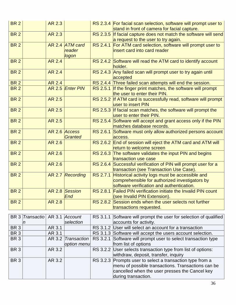
BR 2 Session
AR 2.1 ATM welcome interface
RS 2.1.1 User is prompted to select account identification method: ATM card or Biometric scan
BR 2 AR 2.2 Acct ID method
RS 2.2.1 User inputs an account identification method selection
BR 2 AR 2.2 RS 2.2.2 Software sends account identification selection to bank software.
BR 2 AR 2.2 RS 2.2.3 For biometric selection, software sends a selection menu to user with biometric option type: finger print or facial scan
BR 2 AR 2.2 RS 2.2.4 Users biometric option selection is sent to software
BR 2 AR 2.3 Biometric profile logon
RS 2.3.1 For finger print seletion, software sends the user a prompt to place finger on the finger print scanner
BR 2 AR 2.3 RS 2.3.2 Software sends finger print scan and compares against profile database.
BR 2 AR 2.3 RS 2.3.3 If finger print does not match the software will send a request to the user to try again.
36
BR 2 AR 2.3 RS 2.3.4 For facial scan selection, software will prompt user to stand in front of camera for facial capture.
BR 2 AR 2.3 RS 2.3.5 If facial capture does not match the software will send a request to the user to try again.
BR 2 AR 2.4 ATM card reader logon
RS 2.4.1 For ATM card selection, software will prompt user to insert card into card reader
BR 2 AR 2.4 RS 2.4.2 Software will read the ATM card to identify account holder.
BR 2 AR 2.4 RS 2.4.3 Any failed scan will prompt user to try again until accepted
BR 2 AR 2.4 RS 2.4.4 Three failed scan attempts will end the session.
BR 2 AR 2.5 Enter PIN RS 2.5.1 If the finger print matches, the software will prompt the user to enter their PIN.
BR 2 AR 2.5 RS 2.5.2 If ATM card is successfully read, software will prompt user to insert PIN
BR 2 AR 2.5 RS 2.5.3 If facial scan matches, the software will prompt the user to enter their PIN.
BR 2 AR 2.5 RS 2.5.4 Software will accept and grant access only if the PIN matches database records.
BR 2 AR 2.6 Access Granted
RS 2.6.1 Software must only allow authorized persons account access.
BR 2 AR 2.6 RS 2.6.2 End of session will eject the ATM card and ATM will return to welcome screen
BR 2 AR 2.6 RS 2.6.3 The software validates the input PIN and begins transaction use case
BR 2 AR 2.6 RS 2.6.4 Successful verification of PIN will prompt user for a transaction (see Transaction Use Case).
BR 2 AR 2.7 Recording RS 2.7.1 Historical activity logs must be accessible and comprehensible for authorized investigators by software verification and authentication.
BR 2 AR 2.8 Session End
RS 2.8.1 Failed PIN verification initiate the Invalid PIN count (see Invalid PIN Extension).
BR 2 AR 2.8 RS 2.8.2 Session ends when the user selects not further transactions requested.
BR 3 Transaction
AR 3.1 Account selection
RS 3.1.1 Software will prompt the user for selection of qualified accounts for activity.
BR 3 AR 3.1 RS 3.1.2 User will select an account for a transaction
BR 3 AR 3.1 RS 3.1.3 Software will accept the users account selection.
BR 3 AR 3.2 Transaction option menu
RS 3.2.1 Software will prompt user to select transaction type from list of options
BR 3 AR 3.2 RS 3.2.2 User selects transaction type from list of options: withdraw, deposit, transfer, inquiry
BR 3 AR 3.2 RS 3.2.3 Prompts user to select a transaction type from a menu of possible transactions. Transactions can be cancelled when the user presses the Cancel key during transaction.

37
BR 3 AR 3.2 RS 3.2.4 Completion of a transaction will prompt user to select transaction or end session.
BR 3 AR 3.2 RS 3.2.5 If user selects no more transactions all activity is printed and ATM card is ejected
BR 3 AR 3.3 Transaction end
RS 3.3.1 Transaction is closed and software returns to close session.
BR 4 Withdrawal
AR 4.1 User selects Withdrawal
RS 4.1.1 User selects ‘Withdrawal’ from option menu and withdraws cash
BR 4
AR 4.1 RS 4.1.2 Software prompts user to select account to withdraw from
BR 4
AR 4.2 Funds verification
RS 4.2.1 User is prompted to enter a dollar amount.
BR 4 AR 4.2 RS 4.2.2 Software sends amount to verify available funds
BR 4 AR 4.2 RS 4.2.3 If funds are available, withdrawal is approved
BR 4 AR 4.2 RS 4.2.4 Approved funds are dispensed to user
BR 4 AR 4.2 RS 4.2.5 If insufficient funds, user is prompted retry another amount.
BR 4 AR 4.3 Post transaction
RS 4.3.1 Dispensed amounts are posted as a deduction from users account
BR 4 AR 4.4 Transaction end
RS 4.4.1 User is prompted for another transaction (see Transaction Use Case)
BR 4 AR 4.4 RS 4.4.2 A withdrawal can be cancelled when user presses the Cancel key prior to entering a dollar amount.
BR 5 Transfer
AR 5.1 User selects Transfer
RS 5.1.1 User selects ‘Transfer’ from menu options and makes transfer between selected accounts.
AR 5.1 RS 5.1.2 A user transfer selection sends a transfer request to software
BR 5 AR 5.1 RS 5.1.3 Software prompts user to select account to transfer from.
BR 5 AR 5.1 RS 5.1.4 Software prompts user to select account to transfer to.
BR 5 AR 5.2 Funds verification
RS 5.2.1 User is prompted to enter a dollar amount.
BR 5 AR 5.2 RS 5.2.2 Software verifies available funds for transfer
BR 5 AR 5.2 RS 5.2.3 If insufficient funds, user is prompted retry another amount.
BR 5 AR 5.3 Transfer of funds
RS 5.3.1 If funds are available, transfer is approved
BR 5 AR 5.3 RS 5.3.2 Approved transfer amounts on from account are deducted and posted.
BR 5 AR 5.3 RS 5.3.3 Approved transfer amounts on to account are credited and posted.
BR 5 AR 5.4 Transfer ends
RS 5.4.1 User is prompted for another transaction (see Transaction Use Case)
BR 5 AR 5.4 RS 5.4.2 A transfer can be cancelled when user presses the Cancel key prior to entering a dollar amount.

38
BR 6 Deposit
AR 6.1 User selects Deposit
RS 6.1.1 User selects 'Deposit’ from option menu and deposits cash or checks
AR 6.1 RS 6.1.2 Software prompts the user with an account selection for deposit.
BR 6 AR 6.2 Input deposit
RS 6.2.1 User is prompted to enter a dollar amount.
BR 6 AR 6.2 RS 6.2.2 User is prompted to insert deposit envelope
BR 6 AR 6.2 RS 6.2.3 The ATM machine drawer accepts envelope.
BR 6 AR 6.3 Deposit ends
RS 6.3.1 User is prompted for another transaction (see Transaction Use Case)
BR 6 AR 6.3 RS 6.3.2 Transfer can be cancelled when the user presses the Cancel key prior to inserting the envelope containing the deposit.
BR 7 Inquiry
AR 3.7 User selects balance inquiry
RS 3.7.1 User selects 'Inquiry' from options menu and account balance is displayed
BR 7 AR 3.8 RS 3.8.1 Software prompts user to select account for inquiry.
BR 7 AR 3.8 RS 3.8.2 Software returns the balance to the monitor display.
BR 7 AR 3.8 RS 3.8.3 User is prompted for another transaction (see Transaction Use Case)
BR 7 AR 3.8 RS 3.8.4 Inquiry can be cancelled when the user presses the Cancel key prior to account selection.
BR 8 PIN Error
AR 8.1 Invalid PIN Extension
RS 8.1.1 Initiated within a session when PIN does not match the database profile.
BR 8 AR 8.1 RS 8.1.2 From the first failed PIN entry, the software will count +1 for each iteration.
BR 8 AR 8.1 RS 8.1.3 After failure the user is prompted to re-enter the PIN.
BR 8 AR 8.1 RS 8.1.4 PIN approval returns to session to begin transaction.
BR 8 AR 8.1 RS 8.1.5 On third failed attempt session is cancelled and account is locked.
BR 8 AR 8.1 RS 8.1.6 On an account lock a photo of user is taken for forensic, the account holder and bank are notified.
BR 9 Power ATM
AR 9.1 Connection to database
RS 9.1.1 ATM Operator flips the switch to the "on" position to power on.
BR 9 AR 9.1 RS 9.1.2 ATM connects to the networked database.
BR 9 AR 9.1 RS 9.1.3 ATM displays Welcome screen once successfully online and ready for use.
BR 9 AR 9.2 Disconnect from database
RS 9.2.1 ATM service requires the ATM Operator to power off the ATM.
BR 9 AR 9.2 RS 9.2.2 ATM Operator makes sure the ATM is not use.
BR 9 AR 9.2 RS 9.2.3 ATM Operator flips the switch to the "off" position.
BR 9 AR 9.2 RS 9.2.4 The ATM network connection to the database is closed on power off.
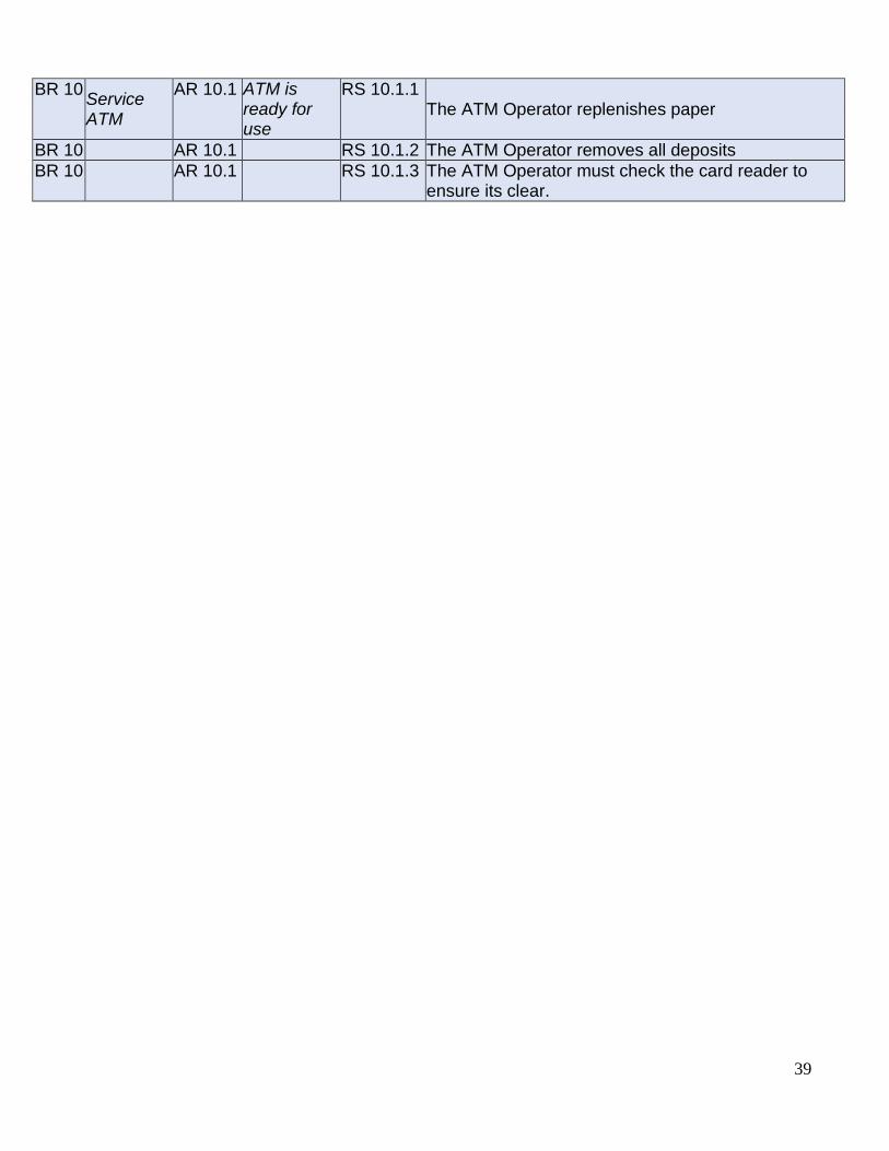
39
BR 10 Service ATM
AR 10.1 ATM is ready for use
RS 10.1.1 The ATM Operator replenishes paper
BR 10 AR 10.1 RS 10.1.2 The ATM Operator removes all deposits
BR 10 AR 10.1 RS 10.1.3 The ATM Operator must check the card reader to ensure its clear.
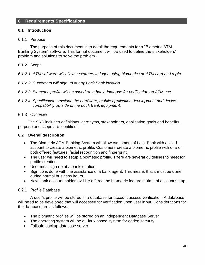
40
6 Requirements Specifications
6.1 Introduction
6.1.1 Purpose
The purpose of this document is to detail the requirements for a “Biometric ATM Banking System” software. This formal document will be used to define the stakeholders’ problem and solutions to solve the problem.
6.1.2 Scope
6.1.2.1 ATM software will allow customers to logon using biometrics or ATM card and a pin.
6.1.2.2 Customers will sign up at any Lock Bank location.
6.1.2.3 Biometric profile will be saved on a bank database for verification on ATM use.
6.1.2.4 Specifications exclude the hardware, mobile application development and device compatibility outside of the Lock Bank equipment.
6.1.3 Overview
The SRS includes definitions, acronyms, stakeholders, application goals and benefits, purpose and scope are identified.
6.2 Overall description
The Biometric ATM Banking System will allow customers of Lock Bank with a valid account to create a biometric profile. Customers create a biometric profile with one or both offered features: facial recognition and fingerprint.
The user will need to setup a biometric profile. There are several guidelines to meet for profile creation.
User must sign up at a bank location
Sign up is done with the assistance of a bank agent. This means that it must be done during normal business hours.
New bank account holders will be offered the biometric feature at time of account setup.
6.2.1 Profile Database
A user’s profile will be stored in a database for account access verification. A database will need to be developed that will accessed for verification upon user input. Considerations for the database are as follows.
The biometric profiles will be stored on an independent Database Server
The operating system will be a Linux based system for added security
Failsafe backup database server
41
6.3 Specific requirements
6.3.1 ATM Terminal Interface
The Terminal window will follow steps to guide the user. The first screen the user will see is the Welcome screen which will ask how the user wants to log on: Biometrics or ATM Card.
6.4 Functions of Biometric Logon
Customer can inquire about their account balance
Funds can be transferred between Lock Bank accounts
Deposits can be made into any qualified account.
Customer can withdraw cash.
6.5 Analysis Method
Create Profile
Initialize ATM Use Case
Shutdown Use Case
Session Use Case
Transaction Use Case
Withdrawal Use Case
Deposit Use Case
Transfer Use Case
Inquiry Use Case
Invalid PIN Extension
6.6 Performance requirements
• Session Initialization
Power up ATM
Verify ID/Card Selection
Wait for Account holder
Verify PIN
Transaction Loop
End Transaction
Power off ATM
6.7 Logical database requirements: N/A or To be added later
6.8 Design constraints: N/A or To be added later
6.9 Software Quality Attributes
6.9.1 Functionality
the system shall provide four banking options: transfer, deposit, withdrawal, and inquiry.
the system will be able to identify a Lock Bank user using ATM card or biometric options.
The software shall accept and read a cash card

42
The software will communicate with the bank computer to carry out the transaction
Software shall dispense cash and print receipts
the system post transactions and update a user’s account
6.9.2 Usability
the system will have an easy to follow user interface.
the system shall provide a help option to guide ATM users.
Use tools to test with a user interface.
the system shall provide instructions for the selected biometric method when in use.
6.9.3 Reliability
the software will mirror the database for fault tolerance in the event of drive failure.
6.9.4 Interoperability
Software runs on Windows Operating system.
Software can communicate with SQL database.
Hardware, software and other components support software.
6.9.5 Standards Compliancy: Security and Investigatability
the system shall prevent SQL injection.
Develop an investigative digital forensics plan
Perform static code analysis to examine code for security issues.
6.10 Requirements Management
6.10.1 Validation
Stakeholders include Lock Bank personnel and Tech Rep, Inc. This iterative review resulted in an agreed upon list of customer requirements based on their needs as below.
Create Profile
Session
Transaction
Withdrawal
Transfer
Deposit
Inquiry
PIN Error
Power ATM
Service ATM
6.10.2 Verification
Prior to releasing this document to the design and development teams it has been reviewed to check the quality of requirements specifications. Tech Rep has met with the development and design teams to go over the requirements specification to ensure all requirements are clearly defined before development begins.

43
6.11 Supporting Documents
Use Case Diagram
State Transition Model
Sequence Diagram
Flow of Events Table
Software Quality Weighted Attribute Metric
Traceability Matrix
44
7 Appendix
7.1 Terms
Metric: A quantitative measurement of an attribute of a system, software or process.
Measure: An indication of the size, quantity or amount of a quality attribute of a system,
software or process.
Failure: The result of a fault.
Fault: An incorrect step, process or data definition in a software application.
Error: The difference between a computed result and the expected result
MTTF: Meantime to failure
MTTR: Meantime to repair
MTBF: Meantime between failure is equal to the MTTF and MTTR.
Operating Time: Period in which a system is working with an acceptable level to the operator.
Mistake: An action by a user that produces an incorrect result.
45
8 References
American Bank. (n.d.). Bank acronyms. Retrieved from https://www.ambnk.com/custom/fi/ambnk/fb/disclosure/BANK-ACRONYMS.pdf
Boult, T. E. (n.d.). Software Requirements Specification (SRS) Template. Retrieved from
University of Colorado Colorado Springs website: www.uccs.edu/Documents/tboult/srs.doc
Chappell, D. (2012, March 16). The three aspects of software quality: Functional, structural,
and process [PDF]. Retrieved from http://www.davidchappell.com/writing/white_papers/The_Three_Aspects_of_Software_Quality_v1.0-Chappell.pdf
Collofello, James S. (1988). Introduction to software verification and validation. Pittsburgh,
PA: Carnegie Mellon University, Software Engineering Institute. Davies, P. J. (n.d.). Requirements analysis and use-case diagrams [PPT]. Retrieved from
https://web.cs.dal.ca/~hawkey/3130/UseCaseDiagrams.ppt Defect Priority, Defect Severity and their Differences | Better Software Testing. (n.d.).
Retrieved from http://bettersoftwaretesting.blogspot.com/2009/12/defect-priority-defect-severity-and.html
Elam, D. (2016, December 5). CS641 161205 - Unit 4 [Adobe Live Chat]. Retrieved from
http://ctuadobeconnect.careeredonline.com/p28guolmhzb/?session=breezo29nswu6dwc8sp7m
Elam, D. (2016, December 12). CS641 161205 - Unit 5 [Adobe Live Chat]. Retrieved from
http://ctuadobeconnect.careeredonline.com/p6xwkvamfkv/?session=breez5q4ch46rwnbo4gqf
Federal Regulations for Financial Institutions | CSI. (n.d.). Retrieved from
http://www.csiweb.com/solutions/regulatory-compliance/federal-regulations How to Set Defect Priority and Severity (with Defect Triage Process). (n.d.). Retrieved from
http://www.softwaretestinghelp.com/how-to-set-defect-priority-and-severity-with-defect-triage-process/
Khan, I. H. (2015, August 4). Software requirement elicitation techniques. Retrieved from http://www.slideshare.net/Imranhussainkhan/software-requirement-elicitation-
techniques Priority-severity matrix | ..::CHANGE is INEVITABLE::.. (n.d.). Retrieved from
http://kedar.nitty-witty.com/blog/tag/priority-severity-matrix Sandhu, R. K., & Betab, G. (2014). Fingerprints in automated teller machine-a
survey. International Journal of Engineering and Advanced Technology (IJEAT), 3(4),
46
184. Retrieved from http://citeseerx.ist.psu.edu/viewdoc/download?doi=10.1.1.678.2716&rep=rep1&type=pdf
Strohmeier, A., & Sendall, S. (2001). Requirements analysis with use cases. Swiss Federal
Institute of Technology, 1.0. Retrieved from http://www.uml.org.cn/requirementproject/pdf/re-a2-theory.pdf
Tutorials Point. (n.d.). UML - Statechart Diagrams. Retrieved from
https://www.tutorialspoint.com/uml/uml_statechart_diagram.htm Tutorials Point. (n.d.). UML - Use Case Diagrams. Retrieved from
https://www.tutorialspoint.com/uml/uml_use_case_diagram.htm Yousuf, M., & M.Asger, M. (2015). Comparison of various requirements elicitation
techniques. International Journal of Computer Applications, 116(4), 8-15. doi:10.5120/20322-2408