Software Consultancy Training · 2019-04-30 · SME awards for Scotland and, in 2009, we were...
19
Software Consultancy Training
Transcript of Software Consultancy Training · 2019-04-30 · SME awards for Scotland and, in 2009, we were...

SoftwareConsultancyTraining

Contents
WHO WE ARE
Our history ..................................................................................... 5
Our ethics ....................................................................................... 5
Our people .................................................................................... 5
WHAT WE DO
Consultancy .................................................................................. 6
Training ........................................................................................... 8
Software ....................................................................................... 12
• Overview ................................................................................................... 12
• Move Core Application....................................................................... 14
• 2D Kinematic Modelling ..................................................................... 16
• 3D Kinematic Modelling ..................................................................... 18
• Geomechanical Modelling .............................................................. 20
• Fracture Modelling .............................................................................. 22
• Fault Response Modelling ............................................................... 24
• Fault Analysis ......................................................................................... 26
• Stress Analysis ...................................................................................... 28
• Move Link for Petrel, OpenWorks & GST .................................30
• FieldMove and FieldMove Clino ................................................... 33
• Software Development ..................................................................... 34
Petroleum Experts Ltd.Petex House, 10 Logie Mill, Edinburgh, EH7 4HG
t: +44 131 474 7030f: +44 131 474 7031e: [email protected]
petex.com
4 5
We are the global standard in petroleum engineering and structural geology software tools.
Who we are
WHO WE ARE WHO WE ARE
Business• The success of our business is down to a highly-
focused and – more importantly – sustained
drive towards incremental and measurable
steps in innovation of new engineering modelling
techniques. Our drive has brought direct, bottom-
line production gains to our clients in the oil and gas
industry. Key to the company’s long-term business
success has been our ability to guide our clients.
We offer our clients constructive, holistic advice on
how to best adopt our technology, enabling them
to enhance their organisation; maximising not only
production but also technical efficiency. This can be
evidenced by our extensive list of industry leaders
who we are proud to call our clients.
Financials• Since the very beginning, our financial performance
has been outstanding. Petroleum Experts has
enjoyed a consistent increase in both turnover
and profit. All of our product development is self-
financed, which enables us to focus on technical
innovation and quality technology; instead of
reliance on external funding. Petroleum Experts
was awarded Company of the Year 2010 at the
SME awards for Scotland and, in 2009, we were
awarded Business of the Year for Scotland. In
previous years we have won several awards for
business growth, including European Business
Awards “Ruban d’Honneur” in 2009 as well as the
fastest growing technology companies for six of the
seven years that Deloitte Fast 50 Awards were run
in Scotland.
Market Position• Petroleum Experts has over 420 clients worldwide.
In fact, more than 80% of the revenue comes from
outside Europe. Our company is recognised across
the international oil and gas industry as the technical
market leader within its area of expertise and has
been ranked number one in all technical evaluations
across the industry for more than eight years.
Petroleum Experts (Petex) started in business in 1990. All members of the team have been
involved in the development of software engineering products, as well as having extensive
experience in petroleum engineering. The corporate strategy developed from this
experience and a long-term business outlook were fundamental to the prompt success of
Petroleum Experts.
6 7
It’s all about reducing the uncertainty in the structural model.
Consultancy
CONSULTANCY CONSULTANCY
Our experienced team of structural geologists and petroleum engineers has worked on
a wide range of projects both onshore and offshore, on all continents, and in all structural
settings. Each project involves input from multiple members of the team and is designed
around the specific requirements of the client. We use Move every day as an essential tool
in our project work.
Our aim is to work in close collaboration with our client throughout the project. Often
the knowledge of local geology comes directly from the client and we provide insights,
techniques and expertise in structural modelling to help answer specific questions about
the geological evolution, and reduce the uncertainty in the geological model.
• Building geometrically consistent geological
models in 2D and 3D space.
• Testing, validating and improving your existing
interpretation using the kinematic modelling tools
in Move (restoration and forward modelling).
• Determining the timing, geometry and kinematics
of trap formation, fault movement and salt
tectonics.
• Stress and Strain Analysis and Fault Response
Modelling.
• Fracture analysis and fracture network prediction.
• Reservoir or ore body volumetrics and
compartmentalisation.
• Fault seal analysis.
• Reconstructing palaeobathymetry and
depositional modelling.
• Rock mass characterisation for underground
mining and block caving.
• Digital field mapping.
The scope of our consulting projects includes:
Consulting projects range in duration from a few days to several months and we routinely build in
a component of training and technology transfer so that you are able to replicate the workflows
used in the project, and if required, undertake a complete project independently in the future.
If you have a project that you would like to discuss then please don’t hesitate to call us or use the contact page on our website – get the experts on your side.

8 9
Learn from our experts and build your knowledge in the application of Move to structural geology.
Training
TRAINING TRAINING
In-House TrainingIf you are unable to attend our Move software training in either Edinburgh or Houston, for your convenience we
can come to your company premises.
Just like our Move software training, our in-house training follows a fixed course structure using Move, strucutral
modelling and analysis software.
A company in-house training course can include any of the Move software training topics in the outline shown
overleaf, customised to suit specific requirements.
If you would like to discuss in-house training, please email us at [email protected]
Technical TransferWe can design a technical transfer session specific to your needs, showing the most effective application of Move
to address your requirements. We can provide our tutorials and data to achieve this or incorporate your own data
into the training.
Courses can vary in length from one or two days up to five days. Generally, the course is split into two parts: the
first part focuses on software training in Move, and the second part focuses on structural geology techniques and
workflows, which are tailored to be specific to the client and their data.
If you would like to discuss a technical tansfer, please email us at [email protected]
Training course costsAs courses are tailored to your needs, costsvary depending on length and location of training. Please contact us
directly to discuss the best option for you and your organisation and to get a quote.
Email us at [email protected]
We offer three types of training courses to suit all levels, learning styles and budgets: Move
software training; technical transfer; and in-house training. The courses are relevant for
all geoscientists working in a variety of sectors and can be tailored to both individual and
company requirements.
Move Software TrainingNormally held in either Edinburgh or Houston, our Move software training follows a fixed course structure
over two to five days using Move, structural modelling and analysis software. The course covers all products
in the Move Software Suite and is largely hands-on, using exercises and data from our software tutorials with
supporting presentations and on-screen demonstrations. The Move software training course outline and
learning aims are shown on the following pages.
For more information on our training courses, visit petex.com/services/training-courses
10 11
Day 1: Introduction to modelling structural evolution to improve geological models
and model building techniques using Move
Introduction to Move - Understand the aim of the training and Petex’s approach to structural modelling
- Be aware of the available documentation/support files
- Understand the approaches to uncertainty in geological modelling
Importing, conditioning and digitizing your data
- Be aware of the available import options in Move, including seismic and well data
- Have a basic understanding of display options (lighting, background and well data highlight colour)
- Be able to import maps and sections as images
- Be able to set up a stratigraphic database
- Have a working knowledge of the Tidy tool in 2D (points, lines and polygons)
- Have a basic understanding of the 3D surface creation and editing tools
- Have a working knowledge of the data conditioning tools in 2D/3D (Tidy tool and Topology tool)
Constrained model building in 2D and 3D, constructing cross-sections
- Be able to use the stereonet plot for preferred section orientation (analysis)
- Be able to generate a section and extract a section from a 3D model
- Be able to project data onto a section and surfaces
- Have an understanding of geometric tools available to aid model construction from surface data
(horizon and fault construction tools)
- Be able to modify data in a 2D and 3D environment
Updating models in real-time - Have a basic understanding of the well import options
- Be able to import and extend well track / drill hole data
- Have a working understanding of the Reshape tool for updating and modifying existing geological
models
Data export and Move links - Understand data export options including: Animation tool and direct data export links
(Move Link for Petrel*, Move Link for GST and Move Link for OpenWorks capabilities
(*Mark of Schlumberger) )
Day 2: Validation techniques to improve geological models using Move,
2D Kinematic Modelling and 3D Kinematic Modelling
Introduction: Validation techniques to improve geological models
- Have an understanding of restoration strategies that involve using kinematic tools
(Decompaction, Unfolding and Move-on-Fault)
- Understand the uses of forward modelling for guiding interpretation
Kinematic validation techniques: Line length balance, block restoration and jigsaw fit
- Be able to carry out a line length balance
- Have a working knowledge of jigsaw fitting and editing tools to resolving space problems
Modelling kinematic evolution: Sequential restoration and forward modelling
- Have a working knowledge of using the Decompaction, Unfolding and Move-on-Fault tools in 2D and 3D
- Be able to generate a layer cake stratigraphy in 2D and 3D
- Be aware of the 2D and 3D forward modelling algorithms for horizon deformation over faults
- Be aware of the tools that allow handling of sedimentation and erosion during forward modelling in 2D
Day 3: Advanced Session - 2D Kinematic Modelling
In this advanced session*, attendees will be guided through a complete 2D Kinematic Modelling workflow by our structural geologists. This session will cover restoration and analysis of a 2D section, based on our extensive experience working globally with varied data. We will cover data conditioning, constrained model building, forward modelling, and sequential restoration. Best-practice workflows will be highlighted and experienced users will enhance their existing 2D restoration and analysis skills.
Focus - Conditioning of subsurface data and raw horizon interpretations;
- Using constrained model building and structural validation techniques to improve interpretations in areas of poor or
incomplete data;
- Forward modelling and concept testing to validate an interpretation and better understand structural evolution;
- Sequential restoration to reduce the risk associated with exploration and production;
- Advanced structural analysis for addressing more complex exploration and production issues.
Day 4: Advanced Session - 3D Kinematic Modelling
In this advanced session*, attendees will be guided through a complete 3D Kinematic Modelling workflow by our structural geologists. This session will introduce and apply 3D structural analysis and restoration techniques in a range of geological settings. Geometric restoration will be used to investigate the validity of a 3D interpretation of a field-scale model, while kinematic restoration and forward-modelling will allow interrogation of the timing and style of 3D structural development of a regional, basin-scale model.
Focus - Use Move’s Model Analysis tool to statically interrogate 3D models in different geological settings;
- Apply 3D structural validation techniques to improve interpretation around a salt body;
- Combine kinematic restoration and forward modelling techniques to evaluate the development of an extensional fault system;
- Use restoration results to consider potential petroleum systems and drilling targets.
Day 5: Advanced Session - Fault Analysis
In this advanced session*, attendees will be guided through fault analysis workflows by our structural geologists. Participants will use Move’s Fault Analysis module to interrogate and validate the distribution of fault throw in a 3D structural model. The validated results will allow sealing capacity to be visually and statistically analysed using a combination of lithological juxtaposition diagrams, triangular juxtaposition and sealing proxy plots. Move’s restoration tools will be used to sequentially restore the model, allowing fault throw and seal distributions to be estimated through time.
Focus - Introduce theory behind the Fault Analysis tool in Move.
- Use of different aspects of the Fault Analysis tool to validate and improve fault and horizon interpretations.
- Statistical analyses of fault throw and how these can be used to inform the genesis of structures and to
infer tectonic events through geological time.
- The importance of spatial and temporal variations in fault seal in understanding the full impact of faults on
a hydrocarbon or mineral prospect.
- Optimal methods of displaying the results of temporal displacement and seal analysis studies graphically, and in 2D and 3D.
TRAINING TRAINING
* Please note that Advanced Session training courses are aimed at Move users who are familiar with the basic techniques and workflows available. It is expected that attendees of these have either previously completed a Move training course, or are proficient users with some knowledge of the 2D Kinematic Modelling concepts and toolset.
Learning outcomes:
• An improved understanding of constrained model building and interpretation.
• An ability to create and test alternative scenarios and to assess uncertainty and risk.
• Results can be used for advanced analysis, including stress-strain calculation, fault analysis, fault response modelling and Discrete Fracture Network creation.
Standard five-day Move Software Training Course
Training

12 13
Structural modelling and analysis software for reducing risk and uncertainty in geological models.
Move Software Suite Overview
modelling modelling
modelling
modellingmodelling
ADVANCED MODULES
KINEMATIC MODULES
The Move suite is the most complete structural modelling and analysis toolkit available.
It provides a full digital environment for best practice structural modelling to reduce risk
and uncertainty in geological models.
The Move suite provides a platform for integrating
and interpreting data, cross-section construction, 3D
model building, kinematic restoration and validation,
geomechanical modelling, fracture modelling, fault
response modelling, and fault and stress analysis.
The software is designed by geoscientists working
in close collaboration with software developers and
enables you to create valid geological models. Move
reduces uncertainty by going beyond static models,
which may be no more than an artist’s impression.
By addressing time, development of structure and
checking geometric and evolutionary feasibility you are
three times more likely to produce the correct result.*
Move can be applied to any geological province or
tectonic setting, including extensional, compressional,
and strike-slip basins, as well as areas that have
undergone inversion, thermal subsidence and salt
tectonics.
With the Knowledge Base, we off er our users access to
fully integrated help and tutorials. Move is easy to use,
bringing your ideas and concepts alive. The software
provides you with the tools to check the geometric and
evolutionary feasibility of your geological models.
*Bond et al 2012, “What makes an expert eff ective at interpreting
seismic images?”, Geology, January 2012, v40, no1, p75-78.
SOFT WARE SOFT WARE

14 15
• Multiple data imports including GIS, OBJ and ASCII
• Integrated 2D and 3D model building
• Cross-section construction
• Attribute analysis including SCAT
• Section, Map, 3D, and Google Map views of data
• Photogrammetry support
Move is the core application of the Move suite. It provides a powerful stand-alone environment for data integration, cross-section construction and 3D model building, and forms the base for our specialist structural modules including 2D and 3D Kinematic Modelling, Geomechanical Modelling, Fracture Modelling and Fault
Response Modelling, as well as Fault Analysis and Stress Analysis.
The Move application provides a platform which integrates geo-referenced 2D and 3D views, allowing over 100 diff erent data formats to be combined. The integrated views can be used to construct geologically valid cross-sections and 3D models using manual and
automated tools.
The 2D/3D space provides a best practice environment to develop models, which can then be directly tested and validated using the kinematic modules. Orientation plots, cross plots, stereonets, rose diagrams and object property tables can then be used to thoroughly investigate and analyse the model and construction process. Move is used by geoscientists and engineers with the intention of getting maximum value from their data, in any tectonic regime and across a variety of industry sectors.
Fully integrated 2D and 3D model building and analysis.
Move Core Application
Move: The complete 2D and 3D model building package.
The Move user interface: simultaneous 3D model, cross-section and map views.
Move: The complete 2D and 3D model building package.
• Import and intergrate a wide variety of data types
including: digital fi eld data, digital elevation models,
seismic data, well and borehole data, geological
maps, annotated fi eld images, scanned cross-
sections, grav/mag and remotely sensed data,
ASCII, GIS shape and DXF fi les.
• Quickly create 2D maps and sections and 3D
models in fully geo-referenced space, using
automated and manual digitization tools.
• Create 3D surfaces, shapes and volumes from a
wide variety of data types.
• Photogrammetry support including the projection
and draping of photographic outcrop images on an
existing mesh.
• Create and slice 2D sections at any angle and
orientation through your model.
• Project data onto sections and surfaces or manually
transform objects.
• Condition and check your model and systematically
improve its integrity.
• Full attribute analysis with multiple graphical plots
including SCAT.
• Update your model in real-time using the Reshape
tool to rapidly modify surfaces, whilst maintaining
structural geometry.
• Display and analyse well and borehole data
effi ciently with the Well Track and Well Marker
analysers.
• Visualize your data and model with advanced tools,
including animation, lighting and the ability to save
camera views.
• Create and export MBTiles from Move for use
in our digital mapping software, FieldMove and
FieldMove Clino.
• Export your data in a variety of formats for further
analysis and modelling.
• Use the Move Core application as your platform for
the advanced structural modules: 2D Kinematic
Modelling, 3D Kinematic Modelling, Geomechanical
Modelling, Fracture Modelling, Fault Response
Modelling, Fault Analysis and Stress Analysis, and for
links to third-party products: Move Link for Petrel*,
Move Link for OpenWorks and Move Link for GST.
* Mark of Schlumberger
SOFT WARE SOFT WARE

16 17
• Comprehensive suite of 2D kinematic algorithms
• Interactive tools to help generate balanced sections
• Restore, forward model and analyse sections
• Apply to any tectonic setting including salt
• Depth to detachment
• Fault and horizon construction
• Decompaction• Depth conversion• Thermal
Subsidence
Our 2D Kinematic Modelling module provides a comprehensive
range of tools to build, balance, restore and analyse cross-
sections at a local and regional scale. Take into account the
importance of geological time and its impact on your decisions on
the present-day structure.
Kinematic algorithms are used to restore and remove deformation
in geological cross-sections. It allows the un-deformed state to
be defi ned, while staying true to line length and area balancing
principles.
Tools in the 2D Kinematic Modelling module can be used to
interactively determine deformation rates, check the geometric
and evolutionary feasibility of your model, highlight areas of
geological uncertainty and constrain the evolution.
World-leading forward and reverse modelling tools for validating your interpretation and reducing uncertainty.
2D Kinematic Modelling
Top: Section Analysis featuring calculation of vertical thickness and line length.
Bottom: 2D Kinematic model building - Non-Planar Trishear in the Move-on-Fault tool.
• Work in 2D plus geological time. Evolve models
backwards and forwards through time and assess
the timing of critical geological events.
• Use kinematic algorithms for both restoration and
forward modelling including:
- Block Restoration
- Flexural Slip Unfolding
- Simple Shear Unfolding
- Simple Shear Move-on-Fault
- Trishear (planar and non-planar faults)
Move-on-Fault
- Fault Parallel Flow Move-on-Fault
- Fault Bend Folding Move-on-Fault
• Include sedimentation, erosion and salt movements.
• Backstripping techniques including compaction,
thermal subsidence and isostasy.
• Seismic data and images can be carried through
the restoration.
• Interactively defi ne fault displacement, shear angle,
regional level, position, propagation angle, trishear
angle, sediment erosion and deposition when
forward modelling.
• Test and validate geological interpretations and
produce balanced cross-sections.
• Develop realistic fault trajectories and depths
to detachment.
Kinematic restoration using Decompaction and 2D Move-on-Fault algorithms from the Gulf of Suez (a-f). BP/GUPCO
are acknowledged for providing data.
a) b)
c) d)
e) f)
modelling
SOFT WARE SOFT WARE
18 19
modelling
• Comprehensive suite of 3D kinematic algorithms
• Enhanced structural understanding
• Model real-world scenarios
• Predict unseen structures and reduce uncertainty
• Depth conversion
• Decompaction
• Thermal Subsidence
Forward modelling using the 3D Move-on-Fault Trishear algorithm
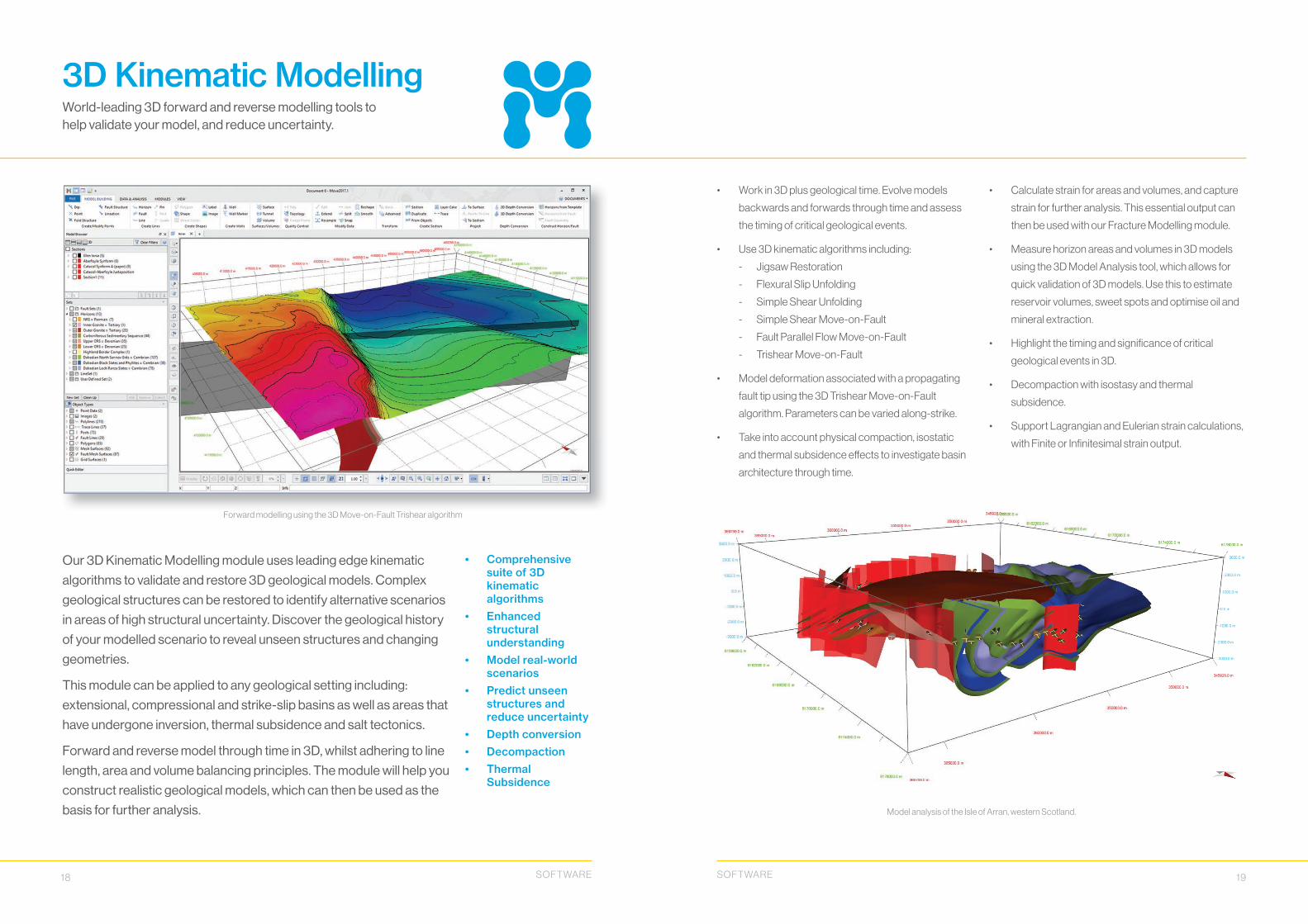
Our 3D Kinematic Modelling module uses leading edge kinematic
algorithms to validate and restore 3D geological models. Complex
geological structures can be restored to identify alternative scenarios
in areas of high structural uncertainty. Discover the geological history
of your modelled scenario to reveal unseen structures and changing
geometries.
This module can be applied to any geological setting including:
extensional, compressional and strike-slip basins as well as areas that
have undergone inversion, thermal subsidence and salt tectonics.
Forward and reverse model through time in 3D, whilst adhering to line
length, area and volume balancing principles. The module will help you
construct realistic geological models, which can then be used as the
basis for further analysis.
World-leading 3D forward and reverse modelling tools to help validate your model, and reduce uncertainty.
3D Kinematic Modelling
Forward modelling using the 3D Move-on-Fault Trishear algorithm
• Work in 3D plus geological time. Evolve models
backwards and forwards through time and assess
the timing of critical geological events.
• Use 3D kinematic algorithms including:
- Jigsaw Restoration
- Flexural Slip Unfolding
- Simple Shear Unfolding
- Simple Shear Move-on-Fault
- Fault Parallel Flow Move-on-Fault
- Trishear Move-on-Fault
• Model deformation associated with a propagating
fault tip using the 3D Trishear Move-on-Fault
algorithm. Parameters can be varied along-strike.
• Take into account physical compaction, isostatic
and thermal subsidence eff ects to investigate basin
architecture through time.
• Calculate strain for areas and volumes, and capture
strain for further analysis. This essential output can
then be used with our Fracture Modelling module.
• Measure horizon areas and volumes in 3D models
using the 3D Model Analysis tool, which allows for
quick validation of 3D models. Use this to estimate
reservoir volumes, sweet spots and optimise oil and
mineral extraction.
• Highlight the timing and signifi cance of critical
geological events in 3D.
• Decompaction with isostasy and thermal
subsidence.
• Support Lagrangian and Eulerian strain calculations,
with Finite or Infi nitesimal strain output.
Model analysis of the Isle of Arran, western Scotland.
SOFT WARE SOFT WARE

20 21
• Realistic 3D rock deformation
• Save scenarios• Rapid run times• Strain capture• Multiple outputs for
Fracture Modelling
Our Geomechanical Modelling module uses elastic mechanical
properties and physical laws of motion (Mass-Spring methodology)
to mimic 3D rock deformation. The Mass-Spring algorithm
calculates forces on the point masses, which govern the point mass
trajectories and simulate physical behaviour of the surfaces during
heterogeneous strain (this diff ers from the approach used in kinematic
modelling – where geometric rules govern point trajectories).
Multiple scenarios with diff erent mechanical properties, pin and fault
displacement parameters can be tested and saved in the workfl ow for
rapid sensitivity testing of diff erent model assumptions.
Use the strain magnitude captured during modelling as an input for
Fracture Modelling.
Mass-spring restoration of surfaces and volumes using physical properties.
Geomechanical Modelling
Within the Geomechanical module, pre-defi ned fault cut-off constraints are shown as red fault surfaces bounded by
green (upper) and red (lower) cut-off s.
• Use a fl exible workfl ow with well-defi ned steps to
complete the restoration.
• Model rock deformation using Young’s Modulus and
Poisson’s Ratio.
• Defi ne fault displacement cut-off s to close fault gaps
on the selected surface.
• Apply boundary conditions: projection to target,
restore fault displacements, change area/volume.
• Have explicit control of shear components,
in order to mimic natural rock behaviour.
• Control how quickly the restoration converges
on a solution, and is deemed to be complete.
• Export strain attributes for Fracture Modelling.
Strain attributes visualized on a horizon. Left: Horizontal displacement Right: E1:E3
modelling
SOFT WARE SOFT WARE

22 23
• 3D DFN modelling• Generate realistic
fracture models• Applications in
many sectors• For reservoir
simulation and geotechnical engineering studies
The Fracture Modelling module can use deformation calculated
at incremental time-steps as proxies to model evolution of the
fracture system and its properties through time.
Our approach uses sequential restoration and forward modelling to
understand the cause(s) of fracturing, and links observed fractures
to a deformation phase. By creating a geologically realistic discrete
fracture network model, you can confi dently predict into areas
without direct observations using geological proxies, including static
and dynamic attributes.
This module is an essential tool for geoscientists working in
fractured rock scenarios, who are required to make cost critical
drilling decisions for use in reservoir simulation, gas storage,
fracking, mining or geotechnical engineering projects.
Discrete fracture network (DFN) generation, analysis and direct output of properties on a GeoCellular model.
Fracture Modelling
Discrete Fracture Network (DFN) modelling using strain (calculated from restoration) and well data analysis.
• Use stress and strain values derived from the 3D
Kinematic Modelling or Geomechanical Modelling
modules, and static attributes such as curvature,
as proxies for intensity and orientation.
• Use multiple direct inputs such as: well or borehole
data, fi eld and underground measurements to
constrain the DFN.
• Various fracture types can be modelled, including
those due to exhumation, thermal contraction,
compaction and tectonic deformation (faulting
and folding).
• Use theoretical models derived from restoration
or forward modelling to defi ne the fracture ‘recipe’.
• Multiple scenarios can be tested against available
fi eld and well or borehole data; these scenarios can
be ranked and fi ne-tuned so that the parameters
are adjusted for a best-fi t scenario.
• Characterise fracture networks by carrying out
quantitative analysis with volumetric and directional
outputs for reservoir simulation, and geotechnical
engineering studies.
Generated fracture sets shown with a GeoCellular volume, faults and surfaces. Inset shows cluster generation analysis, a powerful tool
to assess preferential trends in measured and modelled fracture orientation data. Data provided courtesy of Petrobas S. A. Caracas.
modelling
SOFT WARE SOFT WARE

24 25
• Displacement on faults is simulated using an
analytical solution for triangular dislocations in an
elastic half-space, which allows the depth of faults to
be considered in the model.
• Use of triangular dislocation elements allows
complex geometries of faults and other
discontinuities to be modelled, including enclosed
bodies like salt diapirs and igneous intrusions.
• Displacement on faults can be defi ned for individual
triangular elements of meshes or calculated from
a regional stress fi eld.
• Pressure perturbations around reservoirs can be
simulated by calculating the displacement induced
by pressure acting on a triangulated surface.
• Displacement, strain and stress are calculated at
observation points in surrounding rock volume with
defi ned elastic and mechanical properties.
• Diff erent fracture sets can be generated and
compared to the orientations of real fractures.
• Shear and normal stress components can be
calculated for fault and fracture systems.
• Optimal fracture orientations can be derived by using
the shear and normal stress components to identify
the fracture with highest Coulomb Stress.
• Relationships between shear and normal stress can
provide information about fracture intensity, mode of
failure and reactivation potential.
• Fracture sets can be fi ltered based on fracture
stability and Coulomb Stress failure, allowing the
fractures exceeding the failure criteria to be easily
visualized.
Predicted orientations of joints and shear fractures around a relay ramp in a normal fault system.
The surface is colour mapped based on Maximum Displacement.
• Calculate the displacement on faults from a regional stress fi eld
• Compute and visualize displacement, strain and stress induced by faulting
• Predict spatial distributions of sub-seismic fault and fracture systems
• Assess the reactivation potential of faults and fractures
The Fault Response Modelling module is a highly versatile tool that
can be used to validate your interpretation, identify highly fractured
zones and realistically model stress perturbations around faults and
other discontinuities.
The module considers mechanical properties to reproduce fault-
related deformation and provides a quantitative assessment of the
surrounding fracture system. Faulting is simulated using a boundary
element method with triangular elastic dislocations. This approach
allows complex faulting scenarios to be quickly tested and evaluated.
Strain and stress fi elds calculated using the boundary element
approach, or derived from the Strain Capture tool in Move, can be
used to predict fracture orientations. Resolving the shear and normal
stress components allows failure potential of individual fractures and
nearby faults to be assessed.
Boundary element modelling to simulate displacement on faults, and geomechanical analysis of surrounding fracture systems.
Fault Response Modelling
Observational surfaces displaying the results of a simulation on thrust faults with a tapered slip distribution, colour mapped on faults.
The induced displacement vectors are shown by the black arrows in the maximum lengthening direction (E1), colour mapped on the surfaces.
modelling
SOFT WARE SOFT WARE

26 27
• Complete temporal fault displacement and seal analysis
• Visualize throw, juxtaposition and shale gouge ratio on fault surfaces
• Statistical analysis of fault scaling properties
Our Fault Analysis module allows rapid evaluation of throw
distribution, across-fault juxtaposition and fault sealing capacity in 3D.
Combined with statistical analysis of fault displacement and scaling
relationships, the tool provides powerful validation of geological
interpretations and insights into the economic signifi cance of faults.
Uniquely, the module can be integrated with restoration workfl ows
using Move’s 3D Kinematic Modelling and Stress Analysis modules
to provide a complete temporal fault displacement and seal
investigation. This workfl ow delivers key information on potential
baffl es or conduits to fl ow at the time of hydrocarbon generation and
migration. The sealing potential of faults and joints encountered in a
wide range of mineral and ore systems can also be investigated using
this approach.
Quantitative analysis of fault throw, juxtaposition and seal through geological time.
Fault Analysis
Faults colour mapped for throw (furthest away surface) and for sand-shale juxtaposition created from a projected well (nearest surface).
• Create hanging wall and footwall fault cut-off s
highlighting interpretation inconsistencies and
allowing subsequent analysis.
• Plot 3D throw colour maps and create 2D strike
projections (throw profi les) for multiple faults.
• Defi ne lithologies and Vshale in the Stratigraphy and
Rock Properties database to create juxtaposition
diagrams and plot shale gouge ratio in 3D.
• Statistically analyse fault scaling properties,
including throw/length and cumulative frequency.
• Calculate heave polygons for all faults and horizons
in a model.
• Create instantaneous fault-growth curves to review
movement history of faults.
• Restore model to analyse palaeo-juxtaposition
and fault sealing.
• Create triangle diagrams that account for across-
fault thickness variations, or using two wells.
Displacement analysis plots showing along-strike throw profi les for multiple faults (green) and a cumulative profi le for all faults (black).
Triangle diagram coloured for Shale Gouge Ratio (SGR) for a well-derived sedimentary sequence with simulated across-fault growth. The cross
section to the right shows lithological juxtaposition and SGR, denoted by a black line, for a defi ned value of throw .
SOFT WARE SOFT WARE

28 29
• Stereoplot and Mohr diagram
• Colour map multiple stress attributes
• Input well log data• Pressure profi le
plot• Output stress
attributes
The Stress Analysis module enables you to rapidly visualize and
evaluate 3D stress states and potential fault and fracture activity.
This information can then be used to build and analyse a wide range
of scenarios encountered in reservoir and mine planning, CO2
storage, waste disposal and other engineering applications, where it
is essential to understand the likely failure envelope of key structural
features.
Evaluate the risk of leakage within reservoir seals, predict
mineralisation potential and geotechnical failure. Test a series of
principal stresses and pressure profi les through depth, taking into
consideration hydrostatic, pore and lithostatic pressures.
A graphical tool for analysing and understanding the stress response behaviour of fault and fracture systems.
Stress Analysis
Top: Fracture set coloured according to stress attributes. Bottom: Colour mapped stereoplot and Mohr diagram.
• Compute stress attributes for slip tendency, dilation
tendency, fracture stability, slip stability, retention
capacity and leakage factor of planes and lines.
• Visualize and evaluate critically stressed planes
in a 3D view. Any orientation data selected on the
stereoplot or Mohr diagram is simultaneously
selected in the 3D model.
• Visually display shear and normal stress values for
ease of use on the Mohr diagram when moving the
cursor over the stereonet plot.
• Use colour mapping to show a colour scale of the
current displayed stress attribute that is plotted on
the stereonet plot and Mohr diagram at a specifi c depth.
• Defi ne and display pore pressure profi les.
• Quickly estimate which fracture sets and fault planes
are more likely to fail or reactivate by looking at the colour
map: warmer colours indicate the faults more favourably
orientated to failure in a user-defi ned stress state.
• Inversion of fault kinematic indicators to derive
a regional stress state.
Faults colour mapped for slip stability using the Stress Analysis module. Data provided courtesy of Petrobas S. A. Caracas.
SOFT WARE SOFT WARE

30 31
A fast, direct data link between the Move and the Petrel* application. Utilise the power of the Move suite from Petrel.
Move Link for Petrel
• Achieve fast, direct transfer of data from Petrel to
Move and back again.
• The Petrel input data tree and model data tree
navigation are fully integrated inside Move.
• Interactively add and remove data objects from the
session, even if the connection between Move and
Petrel is closed.
• Provides support for grids, surfaces, point set,
triangle mesh, fault sticks, fault and horizon
interpretation, fracture sets, 2D/3D seismic data and
wells including markers.
• Automatically detects changes to geometry and
attributes and allows these to be saved back to
Petrel.
Move Link for Petrel provides a means for Petrel users to share data with Petex’s structural
modelling and analysis software suite.
Once data is in Move, it is possible to perform the full range of restoration, validation, balancing
and advanced structural modelling workfl ows.
The Petrel input data tree and model data tree are now duplicated within Move, as can be seen on the left within the Move Model Browser. A
3D model featuring the Petrel demo dataset and colour mapping capabilities in Move is shown above. Changes to geometry and attributes are
automatically detected.
*Mark of Schlumberger
• Validate your models without the need to export
ASCII using the Move Link for OpenWorks.
• Achieve fast, direct transfer of data from R5000 to
Move.
• Interactively add and remove data objects from the
session.
• Pull a subset of objects from R5000 via a Move
standard tree view.
• Supports geometry and attributes.
• Provides support for data types including faults,
grid surfaces, horizon 2D data, horizon 3D data,
2D/3D seismic data and well tracks.
• Provides a detailed OpenWorks model description
and attributes output.
A fast, direct data link between Move and a Landmark OpenWorks R5000 data store. Utilise the power of the Move suite from OpenWorks.
Move Link for OpenWorks
The Move Link for OpenWorks lets Move users import their data directly from a Landmark
OpenWorks R5000 data store.
Once in Move, it is possible to perform the full range of restoration, validation, balancing and
advanced structural modelling operations.
There is support for multiple OpenWorks data object types including seismic data and fault
plus horizon extraction.
View Landmark OpenWorks R5000 data directly in MoveView Landmark OpenWorks R5000 data directly in Move
SOFT WARE SOFT WARE

32 33
A fast, direct data link between Move and a GST database system. Utilise the power of the Move suite alongside GST.
Move Link for GST
Share Project data across your organisation using the Move Link for GST.
The Move Link for GST provides a direct, two-way link to Giga Info Systems
(www.giga-infosystems.com) GST (Geosciences in Space and Time) Database solution. This
allows you to share the results of Move’s full range of restoration, validation, balancing and
advanced structural modelling workfl ows across your organisation and via GST’s web-portal.
Multiple users can view, edit and query data held within GST directly from the Move desktop.
• Fast retrieval of features based on spatial locations,
geometry type and schema.
• Supports point, line, polygon, mesh and volume data.
• Features retrieved from GST are fully integrated with
standard Move tools.
• Edits can be saved back to GST storage or kept
within Move.
• Using full or partial locking, multiple users can make
and save changes at the same time.
• Changes to GST features made by other user’s can
be applied to update existing Move documents with
a single click.
• Data is held securely within corporate database
systems and can be shared with other Move users or
via GST Desktop and Web Interface.
Example of the Move Link for GST interface
FieldMove Clinofor smartphones (Apple and Android)
More than a digital compass-clinometer, you can also capture and store geo-referenced text notes and photographs. It’s free and in the iOS version you can create lines and polygons while you are in the fi eld.
FieldMove for tablets (iOS, Android and Windows)
NOW FREE! All of the functionality of Clino, but for larger screens. You can also create sketches,
annotate photographs and edit linework.
Available to download from the following app stores
Collect data in the fi eld ten times faster than with traditional methods with our two applications for fi eld geologists.
Digital Field Mapping
SOFT WARE SOFT WARE
34 35
Turning your ideas into a reality through feedback and bespoke projects.
Software Development
We rely on the large community of Move users around the world to help guide the future
development programme for the software.
The information that we gather from our annual user meetings, face-to-face conversations with
our clients and their daily interaction with the help desk are reviewed on a regular basis so
as to ensure that we are building software that closely meets the needs of our clients. At the
same time, our team of experienced consulting geologists at Petex are pushing the technology
forwards by applying their own innovative ideas to improve the workfl ows and functionality in
Move.
We are always keen to hear from you if you have
comments, ideas and suggestions that you would like
to see implemented in the software.
The majority of the improvements and new
functionality in the software are funded directly from
the annual maintenance payments. However, you
can also infl uence the direction of Move by funding a
bespoke development programme. This might be a
small modifi cation to an existing tool or workfl ow, or
a large, more complex project that will provide your
organisation with a new module or data link to help
streamline your workfl ow.
Recent client funded projects have included
modifi cations to the Reshape (surfaces) tool and the
Construct Horizon from Template (Ribbon method)
tool, in addition to linking Move to a client country-wide
GST 3D database allowing spatial data querying.
Our latest client funded development project involves
an innovative, open 3D solution to data interoperability
from Switzerland’s Federal Offi ce of Topography
and its GeoMol cross-border data modelling project.
This demonstrates how the current interoperability
in Petex’s structural modelling and analysis software
Move, can be extended easily to work with new 3D
data stores such as GiGa Info Systems revolutionary
Geosciences in Space and Time (GST) system.
Over the past thirty years we have provided focussed
software development solutions to a wide range of
industry clients and government-funded research
organisations.
If you have a project that you would like to discuss then please don’t hesitate to call us or email [email protected]
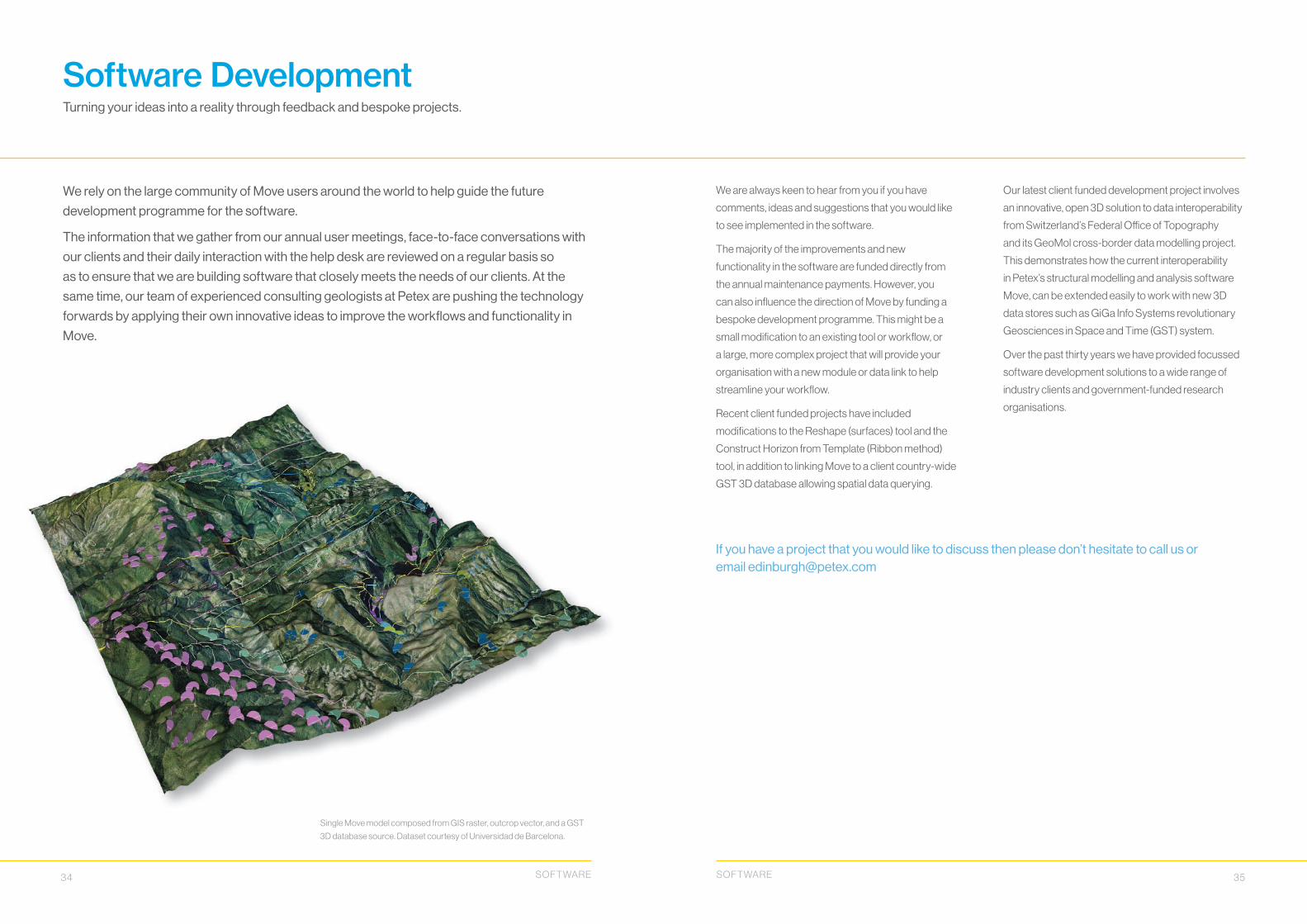
Single Move model composed from GIS raster, outcrop vector, and a GST
3D database source. Dataset courtesy of Universidad de Barcelona.
SOFT WARE SOFT WARE

Petroleum Experts Ltd.Petex House, 10 Logie Mill,
Edinburgh, EH7 4HG
t: +44 131 474 7030f: +44 131 474 7031
petex.com