
Soft Polymer Magnetic Nanocomposites: Microstructure ... · Soft Polymer Magnetic Nanocomposites:...
5
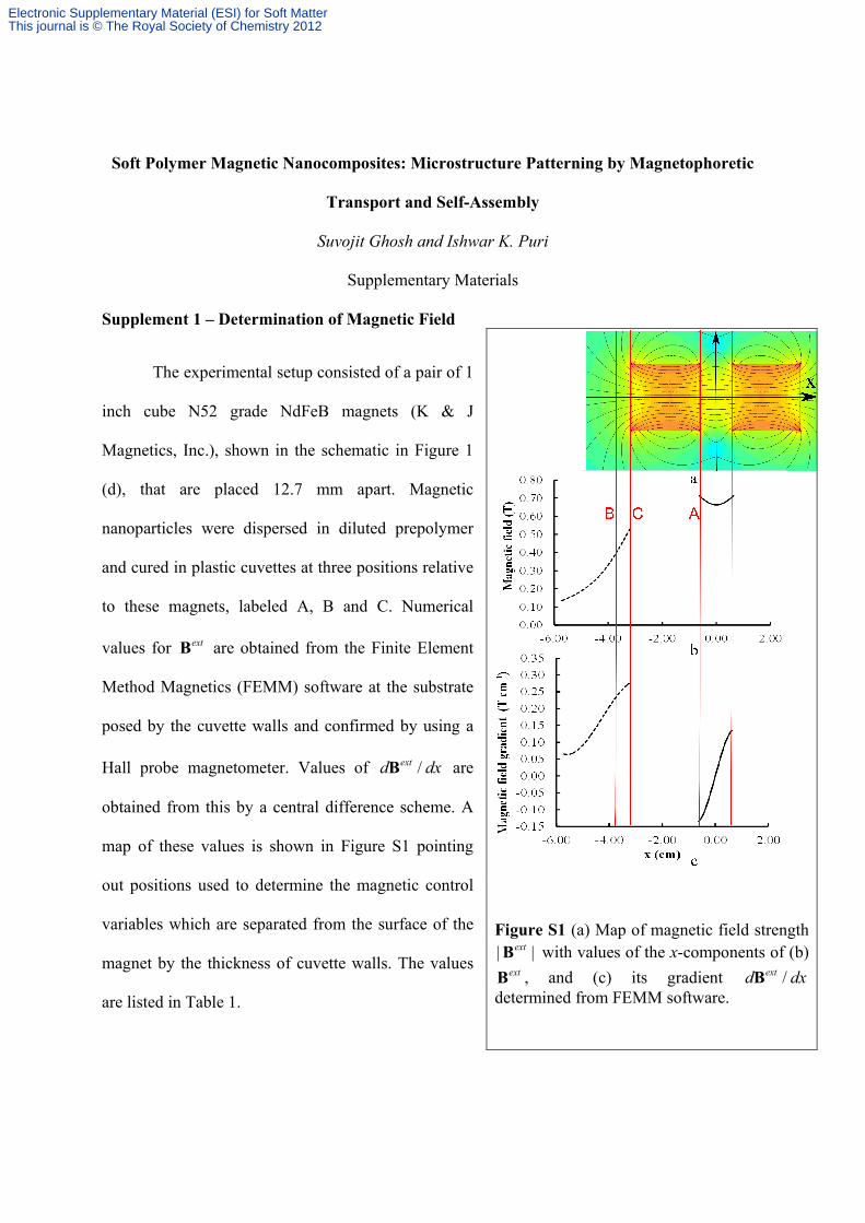
Soft Polymer Magnetic Nanocomposites: Microstructure Patterning by Magnetophoretic Transport and Self-Assembly Suvojit Ghosh and Ishwar K. Puri Supplementary Materials Supplement 1 – Determination of Magnetic Field The experimental setup consisted of a pair of 1 inch cube N52 grade NdFeB magnets (K & J Magnetics, Inc.), shown in the schematic in Figure 1 (d), that are placed 12.7 mm apart. Magnetic nanoparticles were dispersed in diluted prepolymer and cured in plastic cuvettes at three positions relative to these magnets, labeled A, B and C. Numerical values for ext B are obtained from the Finite Element Method Magnetics (FEMM) software at the substrate posed by the cuvette walls and confirmed by using a Hall probe magnetometer. Values of / ext d dx B are obtained from this by a central difference scheme. A map of these values is shown in Figure S1 pointing out positions used to determine the magnetic control variables which are separated from the surface of the magnet by the thickness of cuvette walls. The values are listed in Table 1. Figure S1 (a) Map of magnetic field strength | | ext B with values of the x-components of (b) ext B , and (c) its gradient / ext d dx B determined from FEMM software. Electronic Supplementary Material (ESI) for Soft Matter This journal is © The Royal Society of Chemistry 2012
Transcript of Soft Polymer Magnetic Nanocomposites: Microstructure ... · Soft Polymer Magnetic Nanocomposites:...
Soft Polymer Magnetic Nanocomposites: Microstructure Patterning by Magnetophoretic
Transport and Self-Assembly
Suvojit Ghosh and Ishwar K. Puri
Supplementary Materials
Supplement 1 – Determination of Magnetic Field
The experimental setup consisted of a pair of 1
inch cube N52 grade NdFeB magnets (K & J
Magnetics, Inc.), shown in the schematic in Figure 1
(d), that are placed 12.7 mm apart. Magnetic
nanoparticles were dispersed in diluted prepolymer
and cured in plastic cuvettes at three positions relative
to these magnets, labeled A, B and C. Numerical
values for extB are obtained from the Finite Element
Method Magnetics (FEMM) software at the substrate
posed by the cuvette walls and confirmed by using a
Hall probe magnetometer. Values of /extd dxB are
obtained from this by a central difference scheme. A
map of these values is shown in Figure S1 pointing
out positions used to determine the magnetic control
variables which are separated from the surface of the
magnet by the thickness of cuvette walls. The values
are listed in Table 1.
Figure S1 (a) Map of magnetic field strength | |extB with values of the x-components of (b)
extB , and (c) its gradient /extd dxB determined from FEMM software.
Electronic Supplementary Material (ESI) for Soft MatterThis journal is © The Royal Society of Chemistry 2012

Supplement 2 – Scaling analysis relating magnetophoretic velocity to particle size
Each dipole is an MNP cluster of submicron length. The particle inertia thus plays a
negligible role in its dynamics so that the magnetophoretic force is balanced only by the fluid
drag. From Stokes’ formulation, the drag on a spherical particle in a fluid
6 a F U , (S2.1)
where a denotes the particle radius and the dynamic viscosity of the fluid. For nonspherical
particles, the drag force ~F aU where a is an estimate of the particle size. This equals the
magnetophoretic force, i.e.,
· )| ( |~ aUm B . (S2.2)
The magnetic moment 3| |~ sa Mm where Ms is the saturation magnetization of the constituent
material. Thus, it follows from Eq. S2.2 that the magnetophoretic speed of a particle scales as
2~U a . (S2.3)
Supplement 3 – Scaling Analysis for Structure Anisotropy
The anisotropy metric is a representative measure of the cone angle of the filaments.
Thus, a lower value of indicates higher shape anisotropy. Its lowest value is achieved for a
single chain of dipoles that represents the highest conceivable shape anisotropy. The source of
microstructure anisotropy is the long range orientation of the dipole-dipole bonds in the direction
of the field. A larger | |extB induces greater alignment of these bonds and thus leads to smaller
. However, increases monotonically with the gradient of the external magnetic field
| / |extd dxB , as seen in Figure 2 (i), while its variation with | |extB is not monotonic. This is
Electronic Supplementary Material (ESI) for Soft MatterThis journal is © The Royal Society of Chemistry 2012

seemingly counterintuitive but is clarified by considering that
dipole-dipole bonds are oriented not along | |extB but along the
local direction of the magnetic field. This above analysis is thus
valid only when | |extB ~ | |dipB . For a nonhomogeneous field,
the magnetophoretic force due to the magnetic field gradient also
influences the anisotropy. In order to analyze the dependence of
microstructure anisotropy on the magnetic control variables
| |extB and | / |extd dxB , we consider a simple system comprised
of the two dipoles shown in Figure S2.
In a homogeneous external field, stronger magnetic fields induce greater alignment of the
dipoles and thus a higher anisotropy. However, as the field strength increases above a critical
value, the degree of alignment saturates. This critical value can be estimated by comparing
| |extB with the field produced at a point due to neighboring dipoles, as noted above. For the
configuration in Figure S2 (b), the magnetic field at the center of dipole 1 due to the presence of
its neighbor is 1 0 / 24 dips xMB e . Considering magnetite particles, 3446 10sM Am-1 leads
to 1| |~ 0.023dipB T, which is an order of magnitude smaller than the applied value of | |extB in our
experiments. As extB is directed along (–x), the net magnetic field experienced by dipole 1 is
also similarly directed towards the externally imposed field. It is reasonable to assume that all
dipoles in the system encounter a local magnetic field that is directed along (–x), and the
alignment effect of the magnetic field is well past saturation.
Figure S2 A simplified two particle system demonstrates how anisotropy increases with increasing gradient of the magnetic field.
Electronic Supplementary Material (ESI) for Soft MatterThis journal is © The Royal Society of Chemistry 2012

Corresponding to our experiments, we consider ( )extxB x B e . The total potential
energy of the system
1 2 1 23 5
· 3( · )( · )· )
4(ext o
tot i ii r r
U
m m m r m rm B r , (S3.1)
where r denotes the position vector of one dipole relative to the other. Thus, the potential
energies for cases (a) and (b) in Figure S2 are, respectively,
2
03
( ( ) (3 ))4 4
atot
mU m B a B a
a
, and (S3.2)
2
03
2 ( )4 8
btot
mmB a
aU
. (S3.3)
Here, a denotes the radius of the dipolar particle. The difference between these two values
indicates whether anisotropic chains are formed along the magnetic field or if all nanoparticles
are pulled to the substrate. This difference,
2
03
3( ) (3 )
4 8tot
mU m B a B a
a
. (S3.4)
A two-particle chain transitions to a morphology where both particles lie on the substrate when
0totU . Approximating ( ) (3 ) ~| / | (2 )B a B a dB dx a , the criteria for this transition is,
0
16 | / |1
s
a d dx
M
B
. (S3.5)
Thus, a larger magnitude of the magnetic field gradient renders a smaller anisotropy in the
resultant structure. In more complicated systems that consist of several dipoles, simplified
Electronic Supplementary Material (ESI) for Soft MatterThis journal is © The Royal Society of Chemistry 2012

expressions for such equations cannot be determined. However, the dimensionless number
obtained from Eq. (S3.5),
0
| / |
s
a d dx
M
B
(S3.6)
provides guidance about the anisotropy of the system. Smaller values of lead to higher
anisotropy in the microstructure, forming long filaments with small whereas a high value of
will drag all dipoles to the substrate forming an uniform coating with the highest conceivable
value of .
Electronic Supplementary Material (ESI) for Soft MatterThis journal is © The Royal Society of Chemistry 2012