SOFA Astrometry Tools - Standards of Fundamental Astronomy · International Astronomical Union...
100
International Astronomical Union Standards Of Fundamental Astronomy SOFA Astrometry Tools Software version 14 Document revision 1.8 Version for Fortran programming language http://www.iausofa.org 2017 December 10
Transcript of SOFA Astrometry Tools - Standards of Fundamental Astronomy · International Astronomical Union...
International Astronomical Union
Standards Of Fundamental Astronomy
SOFA Astrometry Tools
Software version 14Document revision 1.8
Version for Fortran programming language
http://www.iausofa.org
2017 December 10

SOFA BOARD MEMBERS
John Bangert United States Naval Observatory (retired)Steven Bell Her Majesty’s Nautical Almanac OfficeMark Calabretta Australia Telescope National Facility (retired)Nicole Capitaine Paris ObservatoryWilliam Folkner Jet Propulsion LaboratoryCatherine Hohenkerk Her Majesty’s Nautical Almanac Office (chair)Li Jinling Shanghai Astronomical ObservatoryBrian Luzum United States Naval Observatory (IERS)Zinovy Malkin Pulkovo Observatory, St PetersburgJeffrey Percival University of WisconsinScott Ransom National Radio Astronomy ObservatoryPatrick Wallace RAL Space (retired)
c⃝ Copyright 2013-17 International Astronomical Union. AllRights Reserved. Reproduction, adaptation, or translationwithout prior written permission is prohibited, except as al-lowed under the copyright laws.
CONTENTS iii
Contents
1 Preliminaries 1
1.1 Introduction . . . . . . . . . . . . . . . . . . . . . . . . . . . . . . . . . . . . . . . 1
1.2 Quick start . . . . . . . . . . . . . . . . . . . . . . . . . . . . . . . . . . . . . . . 1
2 The supported coordinate systems 4
2.1 Catalog coordinates . . . . . . . . . . . . . . . . . . . . . . . . . . . . . . . . . . 4
2.2 Current coordinates . . . . . . . . . . . . . . . . . . . . . . . . . . . . . . . . . . 5
2.3 Observed coordinates . . . . . . . . . . . . . . . . . . . . . . . . . . . . . . . . . . 5
3 Design principles 7
4 Algorithms and accuracy 9
4.1 Time scales . . . . . . . . . . . . . . . . . . . . . . . . . . . . . . . . . . . . . . . 9
4.2 Space motion and parallax . . . . . . . . . . . . . . . . . . . . . . . . . . . . . . . 9
4.3 Light deflection . . . . . . . . . . . . . . . . . . . . . . . . . . . . . . . . . . . . . 10
4.4 Aberration . . . . . . . . . . . . . . . . . . . . . . . . . . . . . . . . . . . . . . . 10
4.5 Earth attitude and rotation . . . . . . . . . . . . . . . . . . . . . . . . . . . . . . 11
4.6 Terrestrial position and velocity . . . . . . . . . . . . . . . . . . . . . . . . . . . . 11
4.7 Diurnal aberration and parallax . . . . . . . . . . . . . . . . . . . . . . . . . . . . 11
4.8 Atmospheric refraction . . . . . . . . . . . . . . . . . . . . . . . . . . . . . . . . . 12
4.9 Overall accuracy . . . . . . . . . . . . . . . . . . . . . . . . . . . . . . . . . . . . 12
5 Working via a precomputed context 13
5.1 The star-independent astrometry context . . . . . . . . . . . . . . . . . . . . . . 13
5.2 Transformations using the context . . . . . . . . . . . . . . . . . . . . . . . . . . 13
5.3 Using the “update time” routines . . . . . . . . . . . . . . . . . . . . . . . . . . . 14
6 Example 15
7 Gnomonic projection 23
8 Alphabetical list of routines 27
iau_AB . . . . . . . . . . . . . . . . . . . . . . . . . . . . . . . . . . . . . . . . . . . . 28
iau_AE2HD . . . . . . . . . . . . . . . . . . . . . . . . . . . . . . . . . . . . . . . . . . 29
iau_APCG . . . . . . . . . . . . . . . . . . . . . . . . . . . . . . . . . . . . . . . . . . 30
iau_APCG13 . . . . . . . . . . . . . . . . . . . . . . . . . . . . . . . . . . . . . . . . . 31
iau_APCI . . . . . . . . . . . . . . . . . . . . . . . . . . . . . . . . . . . . . . . . . . . 32
iau_APCI13 . . . . . . . . . . . . . . . . . . . . . . . . . . . . . . . . . . . . . . . . . . 33
iau_APCO . . . . . . . . . . . . . . . . . . . . . . . . . . . . . . . . . . . . . . . . . . 34
iau_APCO13 . . . . . . . . . . . . . . . . . . . . . . . . . . . . . . . . . . . . . . . . . 36
iau_APCS . . . . . . . . . . . . . . . . . . . . . . . . . . . . . . . . . . . . . . . . . . . 38
iau_APCS13 . . . . . . . . . . . . . . . . . . . . . . . . . . . . . . . . . . . . . . . . . 40
iau_APER . . . . . . . . . . . . . . . . . . . . . . . . . . . . . . . . . . . . . . . . . . . 41
iau_APER13 . . . . . . . . . . . . . . . . . . . . . . . . . . . . . . . . . . . . . . . . . 42
iau_APIO . . . . . . . . . . . . . . . . . . . . . . . . . . . . . . . . . . . . . . . . . . . 43
iau_APIO13 . . . . . . . . . . . . . . . . . . . . . . . . . . . . . . . . . . . . . . . . . . 44
iau_ATCI13 . . . . . . . . . . . . . . . . . . . . . . . . . . . . . . . . . . . . . . . . . . 46

iv CONTENTS
iau_ATCIQ . . . . . . . . . . . . . . . . . . . . . . . . . . . . . . . . . . . . . . . . . . 48iau_ATCIQN . . . . . . . . . . . . . . . . . . . . . . . . . . . . . . . . . . . . . . . . . 49iau_ATCIQZ . . . . . . . . . . . . . . . . . . . . . . . . . . . . . . . . . . . . . . . . . 51iau_ATCO13 . . . . . . . . . . . . . . . . . . . . . . . . . . . . . . . . . . . . . . . . . 52iau_ATIC13 . . . . . . . . . . . . . . . . . . . . . . . . . . . . . . . . . . . . . . . . . . 55iau_ATICQ . . . . . . . . . . . . . . . . . . . . . . . . . . . . . . . . . . . . . . . . . . 57iau_ATICQN . . . . . . . . . . . . . . . . . . . . . . . . . . . . . . . . . . . . . . . . . 58iau_ATIO13 . . . . . . . . . . . . . . . . . . . . . . . . . . . . . . . . . . . . . . . . . . 60iau_ATIOQ . . . . . . . . . . . . . . . . . . . . . . . . . . . . . . . . . . . . . . . . . . 63iau_ATOC13 . . . . . . . . . . . . . . . . . . . . . . . . . . . . . . . . . . . . . . . . . 65iau_ATOI13 . . . . . . . . . . . . . . . . . . . . . . . . . . . . . . . . . . . . . . . . . . 68iau_ATOIQ . . . . . . . . . . . . . . . . . . . . . . . . . . . . . . . . . . . . . . . . . . 71iau_HD2AE . . . . . . . . . . . . . . . . . . . . . . . . . . . . . . . . . . . . . . . . . . 72iau_HD2PA . . . . . . . . . . . . . . . . . . . . . . . . . . . . . . . . . . . . . . . . . . 73iau_LD . . . . . . . . . . . . . . . . . . . . . . . . . . . . . . . . . . . . . . . . . . . . 74iau_LDN . . . . . . . . . . . . . . . . . . . . . . . . . . . . . . . . . . . . . . . . . . . 75iau_LDSUN . . . . . . . . . . . . . . . . . . . . . . . . . . . . . . . . . . . . . . . . . . 76iau_PMPX . . . . . . . . . . . . . . . . . . . . . . . . . . . . . . . . . . . . . . . . . . 77iau_PMSAFE . . . . . . . . . . . . . . . . . . . . . . . . . . . . . . . . . . . . . . . . . 78iau_PVTOB . . . . . . . . . . . . . . . . . . . . . . . . . . . . . . . . . . . . . . . . . . 80iau_REFCO . . . . . . . . . . . . . . . . . . . . . . . . . . . . . . . . . . . . . . . . . . 81iau_TPORS . . . . . . . . . . . . . . . . . . . . . . . . . . . . . . . . . . . . . . . . . . 84iau_TPORV . . . . . . . . . . . . . . . . . . . . . . . . . . . . . . . . . . . . . . . . . . 86iau_TPSTS . . . . . . . . . . . . . . . . . . . . . . . . . . . . . . . . . . . . . . . . . . 88iau_TPSTV . . . . . . . . . . . . . . . . . . . . . . . . . . . . . . . . . . . . . . . . . . 89iau_TPXES . . . . . . . . . . . . . . . . . . . . . . . . . . . . . . . . . . . . . . . . . . 90iau_TPXEV . . . . . . . . . . . . . . . . . . . . . . . . . . . . . . . . . . . . . . . . . . 91
9 Abbreviations 92
10 References 93
Appendix 94

1
1 Preliminaries
1.1 Introduction
SOFA stands for Standards Of Fundamental Astronomy. The SOFA software is a collection ofFortran 77 and ANSI C subprograms that implement official IAU algorithms for fundamental-astronomy computations. At the present time the SOFA software comprises 164 astronomyroutines supported by 55 utility (mainly vector/matrix) routines. The core documentation forthe SOFA collection consists of classified and alphabetic lists of subroutine calls plus detailedpreamble comments in the source code of individual routines.
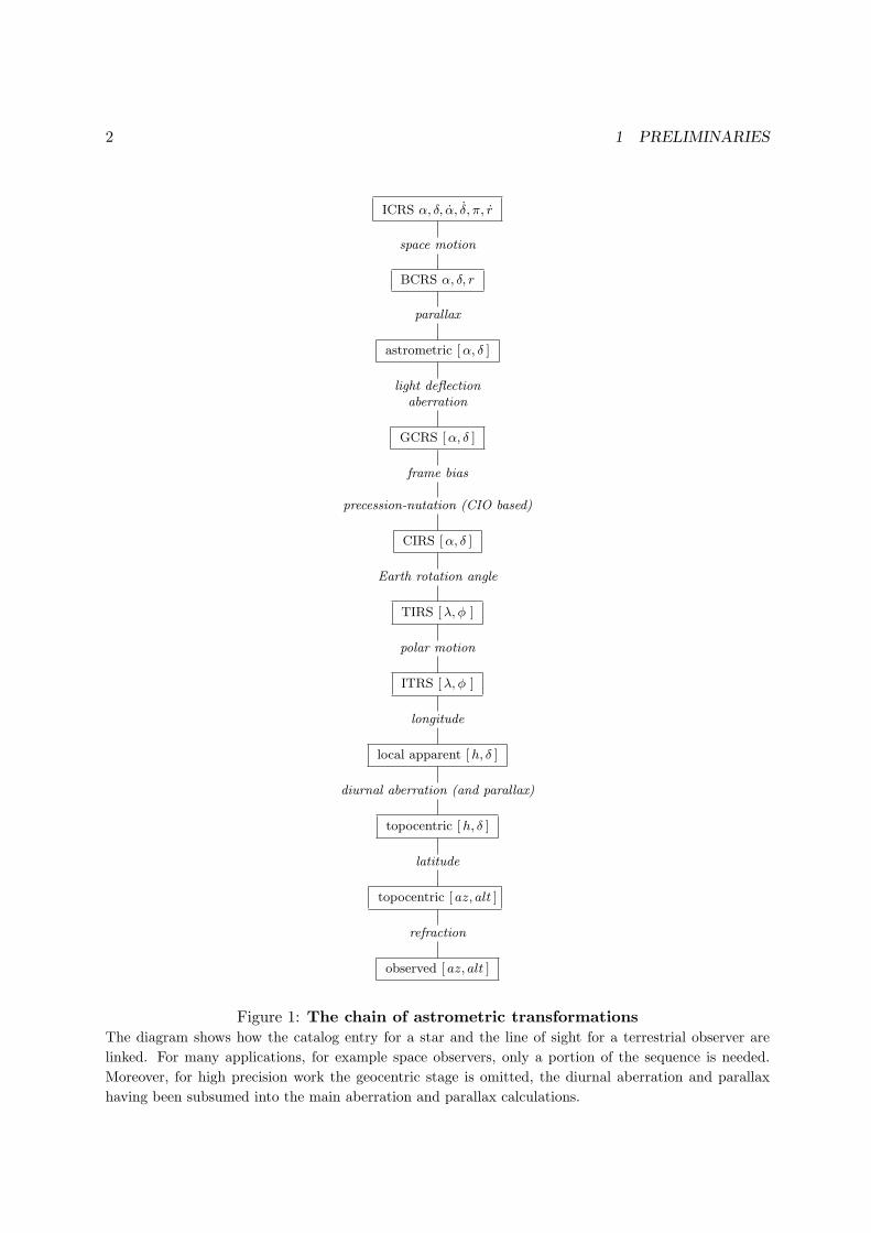
The present document looks at a selection of SOFA routines that deal with the chain of astro-metric transformations linking (i) star data from a catalog and (ii) the observed direction ofthe incoming radiation. The scheme is shown in Figure 1 on page 2. The document provides atutorial introduction and describes the main astrometric reference systems used by astronomers.Short examples demonstrate how to call SOFA routines to perform the sorts of transformationsneeded in applications that have to deal with the directions to celestial targets.
1.2 Quick start
Many application developers will be able to read this section of the document and ignore therest. Some may need only one or two routines, namely iau_ATCO13 or iau_ATCI13 and/oriau_ATIO13, and these can simply be looked up in the alphabetical listing (Section 8).
Figure 1 shows the chain of transformations that link the catalog coordinates of a star to thedirection in which the star is seen by an observer. The SOFA astrometry routines support allof the transformations in this chain.1
Many applications will not need the whole chain. In particular it is often convenient to dealseparately with the geocentric and topocentric segments, and the SOFA routines facilitate thisapproach. The following call performs the transformation from a star’s catalog entry to itsapparent coordinates at a given date, called CIRS [α, δ ] in Figure 1:
CALL iau_ATCI13 ( RC, DC, PR, PD, PX, RV, DATE1, DATE2,
: RI, DI, EO )
RC,DC are the ICRS right ascension and declination at the catalog epoch, in radians; PR,PD arethe proper motions (α, δ) in radians per TT Julian year, PX is the parallax in arcseconds; andRV is the radial velocity in km/s. DATE1+DATE2 is the TT Julian Date. The results RI,DI arethe [α, δ ]in the celestial intermediate reference system (CIRS), in radians. EO is the equation ofthe origins, and the classical geocentric apparent place is RI-EO,DI.
The CIRS [α, δ ] RI,DI can be transformed into the observed direction, which is where a (me-chanically and optically perfect) telescope would be pointed to see the star, using the followingcall:
1For simple applications, routines iau_AE2HD and iau_HD2AE carry out straightforward transformations between[h, δ ] and [Az,El ]. A companion routine iau_HD2PA provides parallactic angle.
2 1 PRELIMINARIES
ICRS α, δ, α, δ, π, r
space motion
BCRS α, δ, r
parallax
astrometric [α, δ ]
light deflectionaberration
GCRS [α, δ ]
frame bias
precession-nutation (CIO based)
CIRS [α, δ ]
Earth rotation angle
TIRS [λ, ϕ ]
polar motion
ITRS [λ, ϕ ]
longitude
local apparent [h, δ ]
diurnal aberration (and parallax)
topocentric [h, δ ]
latitude
topocentric [ az, alt ]
refraction
observed [ az, alt ]
Figure 1: The chain of astrometric transformationsThe diagram shows how the catalog entry for a star and the line of sight for a terrestrial observer are
linked. For many applications, for example space observers, only a portion of the sequence is needed.
Moreover, for high precision work the geocentric stage is omitted, the diurnal aberration and parallax
having been subsumed into the main aberration and parallax calculations.
1.2 Quick start 3
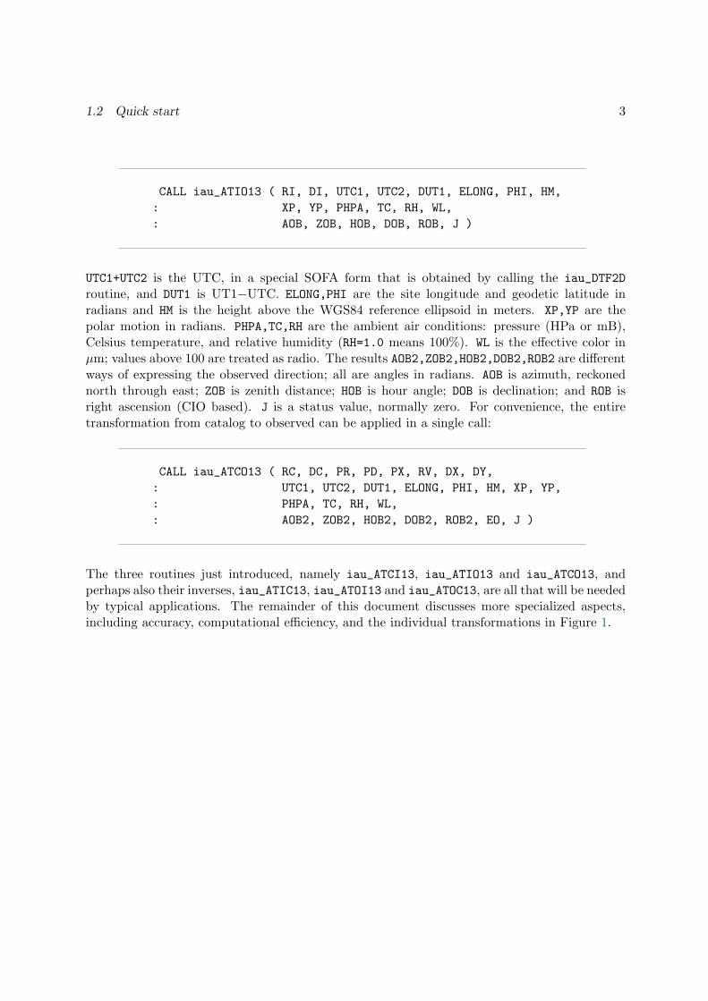
CALL iau_ATIO13 ( RI, DI, UTC1, UTC2, DUT1, ELONG, PHI, HM,
: XP, YP, PHPA, TC, RH, WL,
: AOB, ZOB, HOB, DOB, ROB, J )
UTC1+UTC2 is the UTC, in a special SOFA form that is obtained by calling the iau_DTF2D
routine, and DUT1 is UT1−UTC. ELONG,PHI are the site longitude and geodetic latitude inradians and HM is the height above the WGS84 reference ellipsoid in meters. XP,YP are thepolar motion in radians. PHPA,TC,RH are the ambient air conditions: pressure (HPa or mB),Celsius temperature, and relative humidity (RH=1.0 means 100%). WL is the effective color inµm; values above 100 are treated as radio. The results AOB2,ZOB2,HOB2,DOB2,ROB2 are differentways of expressing the observed direction; all are angles in radians. AOB is azimuth, reckonednorth through east; ZOB is zenith distance; HOB is hour angle; DOB is declination; and ROB isright ascension (CIO based). J is a status value, normally zero. For convenience, the entiretransformation from catalog to observed can be applied in a single call:
CALL iau_ATCO13 ( RC, DC, PR, PD, PX, RV, DX, DY,
: UTC1, UTC2, DUT1, ELONG, PHI, HM, XP, YP,
: PHPA, TC, RH, WL,
: AOB2, ZOB2, HOB2, DOB2, ROB2, EO, J )
The three routines just introduced, namely iau_ATCI13, iau_ATIO13 and iau_ATCO13, andperhaps also their inverses, iau_ATIC13, iau_ATOI13 and iau_ATOC13, are all that will be neededby typical applications. The remainder of this document discusses more specialized aspects,including accuracy, computational efficiency, and the individual transformations in Figure 1.
4 2 THE SUPPORTED COORDINATE SYSTEMS
2 The supported coordinate systems
The positions of astronomical targets need to be expressed in different ways for different pur-poses. In the case of stars, and a terrestrial observer, three distinct needs have to be satisfied:
• A star catalog must describe the position in a way that is valid over a long period of time.The usual method is to provide the direction at a specified epoch in a coordinate systemthat is fixed relative to the distant background, supplemented with information about thestar’s space motion that allow the position to be extrapolated to any given date.
• Terrestrial observers need coordinates that are independent of location on the Earth, thatare correct for the current date, and that are in a coordinate system convenient for localpredictions.
• Pointing a telescope or interpreting observations requires knowledge of the ever-changingdirection of the star as seen from the observing site.
The main purpose of the SOFA astrometry routines is to carry out transformations between thesethree types of coordinates, which we shall refer to here as catalog, current and observed, respec-tively. For space observers, only a portion of the chain is relevant, from ICRS to the GeocentricCelestial Reference System (GCRS). Other applications, such as groundbased interferometers,may stop at topocentric coordinates, omitting refraction.
2.1 Catalog coordinates
A star catalog can be constructed using any coordinate system that is fixed relative to thecosmological background: the choices of pole and longitude zero-point are essentially arbitrary.For some purposes galactic coordinates are convenient, while for some classical applicationsecliptic coordinates are a natural choice, based on the mean (i.e. precessing) ecliptic pole andequinox at some particular epoch. Most historical star catalogs have used a reference systembased on the mean pole and equinox for a specified standard epoch such as B1950.0 or J2000.0.The choice is convenient for casual use as the tabulated mean right ascensions and declinationsare sufficiently close to current [α, δ ] for rough (within a degree or two) predictions of observeddirection without the bother of applying precession corrections.
The SOFA astrometry routines support just one catalog system, namely the International Ce-lestial Reference System (ICRS). This can be seen as the start of the chain shown in Figure 1.
When the ICRS was set up, a completely arbitrary orientation of the coordinate axes couldhave been chosen. However, to ease the transition, the new system was nominally oriented tomatch J2000.0 mean [α, δ ]: the accuracy achieved was of order 25 milliarcseconds (mas). Thetwo systems are sufficiently close that for many everyday applications the distinction betweenthe two can be ignored. However, for precise applications, such as interferometry, other SOFAroutines provide high-accuracy transformations between mean J2000.0 [α, δ ] (and also the FK5realization) and ICRS.
2.2 Current coordinates 5
Where ICRS coordinates are the end point rather than the starting point, they are referredto as “astrometric”. Such positions clearly have no space motion or parallax information andare indistinguishable from the coordinates of a cosmological source lying in the same apparentdirection on the date in question.2
2.2 Current coordinates
The “current” coordinates are the intermediary stage between a star’s catalog entry and thedirection seen by the observer. The SOFA astrometry routines use the Celestial IntermediateReference System (CIRS) for this purpose. The pole is the celestial intermediate pole (CIP), andthe α zero-point the kinematically-defined celestial intermediate origin (CIO). In this system,hour angle h is related to right ascension through the local Earth rotation angle: h = θ − α,where θ is ERA + λ and λ is longitude (east positive).
The classical system, also supported by the SOFA routines but in an ancillary capacity, is geo-centric apparent place. This has the same pole as CIRS, namely the CIP, and hence declinationsin the two systems are the same. However, the α zero-point in this case is the equinox, whichis defined geometrically as the ascending node of the ecliptic of date on the CIP equator. Theformula linking h and α is the same as for CIRS, namely h = θ − α, except that now θ is thelocal apparent sidereal time.
Both the classical and CIRS methods yield identical hour angles. But the advantage of CIRS isthat precession-nutation affects only the orientation of the Earth’s axis: the α zero-point is anentirely separate matter. In the classical approach, the α zero-point undergoes a complicatedand comparatively rapid motion, only to be cancelled out by the inclusion in the Greenwichapparent sidereal time (GST) formula of a complicated set of polynomial and Poisson terms.The CIRS α zero-point is almost stationary3 and the Earth rotation measure, in this case ERA,is just a linear transformation of universal time UT1. The bridge between the classical and CIRSsystems is the equation of the origins, which is ERA−GST or equivalently αCIRS −αapparent; itsvalue is returned by several of the SOFA astrometry routines in case it is needed.
2.3 Observed coordinates
The “observed” [ az, alt ] means the direction in which a mechanically and optically perfecttheodolite4 would be pointed in order to see the target. This is the natural coordinate systemin which to express the observed position as it differs from the topocentric, i.e. unrefracted,position only by a change in altitude. However, it is just as valid to apply the standard altaz-to-equatorial transformation and so obtain observed [h, δ ], and then to combine this with anEarth rotation measure to yield an observed [α, δ ]. In the [h, δ ] and [α, δ ] cases the direction
2The SOFA astrometry routines implement astrometric place quite literally, and when transforming them tocurrent coordinates includes light deflection as well as stellar aberration. Applications that deal with targetsin the inner solar system will need to cope with the case of transits across the Sun, where very large spuriousdeflections will occur, corresponding to sources lying behind the Sun.
3Throughout the 20th and 21st centuries the CIO remains within 0′′.1 of the ICRS meridian.4aligned to ITRS north and the geodetic vertical
6 2 THE SUPPORTED COORDINATE SYSTEMS
is as seen by a mechanically and optical perfect equatorial telescope, with its polar axis alignedto the CIP.
The SOFA astrometry routines support all of these different options. However, instead of al-titude, zenith distance is returned. The main reason for this is to remove any ambiguity overwhich horizon (apparent, astronomical, geometric etc.) is being used, making it clear that suchdistinctions are the responsibility of the application. Another reason is to sidestep the inter-changeable use of “altitude” and “elevation”: the former is considered more correct but thelatter is more common, especially in radio astronomy.

7
3 Design principles
The SOFA astrometry routines design principles are these:
1. The transformations that are most commonly needed should be achievable in a single call.
2. Where practical, the highest standards of accuracy should be available. . .
3. . . . but this must not be at the expense of ease of use.
4. Computational efficiency matters but should not complicate applications where this aspectis unimportant.
The ways these needs are addressed are as follows:
1. The transformations catalog to current, current to observed, and catalog to observed, plusinverses, are each implemented as a single routine.
2. There are two sets of routines. One set uses the latest SOFA models; the other acceptsvalues (for example Earth ephemerides or refraction constants) that the user supplies.
3. Rigorous algorithms, consistent with special and general relativity, are used. However,aspects that only a specialist would need and that would complicate the programming in-terfaces unacceptably (for example requiring detailed solar system ephemerides or weatherinformation) are not provided for. Even then, the interfaces are flexible enough to allowexpert users to overcome these limitations.
4. To achieve computational efficiency, the problem is separated into two components: (i) pop-ulating a context containing star-independent parameters and (ii) using the precomputedcontext to carry out a specific transformation quickly. Thus in a case where the sametransformation is to be applied to many different stars, (i) is carried out just once and (ii)is applied to the stars one by one. In a case where efficiency is not important, a singleroutine is called that simply performs (i) followed by (ii).
The single-call transformations using standard SOFA models are the following:
iau_ATCI13 ICRS to CIRS, 2013 modelsiau_ATCO13 ICRS to observed, 2013 modelsiau_ATIC13 CIRS to ICRS astrometric, 2013 modelsiau_ATIO13 CIRS to observed, 2013 modelsiau_ATOC13 observed to ICRS astrometric, 2013 modelsiau_ATOI13 observed to CIRS, 2013 models
There are no counterparts for the case where the user wishes to substitute his own models.Instead he simply sets up the context himself before calling the appropriate “quick” transfor-mation.
To populate the context using standard SOFAmodels, a range of routines is provided. The choicedepends on the observer (terrestrial, geocentric, space) and which segment of the transformationchain is required:
8 3 DESIGN PRINCIPLES
iau_APCG13 astrometry parameters, ICRS-GCRS, geocenter, 2013iau_APCI13 astrometry parameters, ICRS-CIRS, 2013 modelsiau_APCO13 astrometry parameters, ICRS-observed, 2013 modelsiau_APCS13 astrometry parameters, ICRS-GCRS, space observer, 2013 modelsiau_APIO13 astrometry parameters, CIRS-observed, 2013 models
In addition, there is a routine that updates only the Earth rotation angle. This is useful inapplications such as telescope control, where it is acceptable to update the catalog to currenttransformation less frequently than the Earth rotation:
iau_APER13 astrometry parameters: update time, 2013
There is a full set of counterparts that accept models supplied by the user:
iau_APCG astrometry parameters, ICRS-GCRS, geocenteriau_APCI astrometry parameters, ICRS-CIRSiau_APCO astrometry parameters, ICRS-observediau_APCS astrometry parameters, ICRS-GCRS, space observeriau_APIO astrometry parameters, CIRS-observed
and:
iau_APER astrometry parameters: update time
The above are all the routines that populate the context. The routines that use the context toperform an individual transformation are as follows:
iau_ATCIQ quick ICRS to CIRSiau_ATCIQN quick ICRS to CIRS, multiple deflectionsiau_ATCIQZ quick astrometric ICRS to CIRSiau_ATICQ quick CIRS to ICRS astrometriciau_ATICQN quick CIRS to ICRS astrometric, multiple deflectionsiau_ATIOQ quick CIRS to observediau_ATOIQ quick observed to CIRS
The remaining routines, less likely to be called directly by applications, are as follows:
iau_AB stellar aberrationiau_LD light deflection by a single solar-system bodyiau_LDN light deflection by multiple solar-system bodiesiau_LDSUN light deflection by the Suniau_PMPX proper motion and parallaxiau_PMSAFE proper motion with low-parallax precautionsiau_PVTOB position/velocity of terrestrial stationiau_REFCO refraction constants for given ambient conditions
9
4 Algorithms and accuracy
The SOFA astrometry routines use modern and rigorous models as far as possible, and arecapable of reaching microarcsecond accuracy in favourable cases. The one major exception isatmospheric refraction, for which definitive models do not exist.
Notes on some of the transformation steps shown in Figure 1 follow; for references see Page 93.For a definitive description of the algorithms is the source code itself should be consulted.
4.1 Time scales
The different SOFA astrometry routines require times to be expressed in the appropriate timescale, which can be TDB, UTC or in one case UT1.
Although many of the routines ask for barycentric dynamical time, TDB, it is always acceptableto use instead the more accessible terrestrial time, TT. The difference is always less than 2ms,wholly negligible for computing aberration and precession for the types of application underconsideration here. TDB is complicated and expensive to compute (see iau_DTDB) and therecommendation is simply to use TT instead.
However, the distinction between UTC and TT/TDB, currently over a minute, is significant, atleast for applications that require milliarcsecond precision or better.
Where observed place is concerned, universal time must of course be used, and this meansknowing not just UTC but the current UT1−UTC, which is available from IERS bulletins. Inthe case of iau_APER13, UT1 itself is required rather than UTC.
4.2 Space motion and parallax
Starting with the star’s catalog data, the routine iau_PMPX computes its coordinate direction byallowing for proper motion and parallax.
A conventional non-relativistic proper motion is used, which assumes constant speed throughspace. The algorithm is an adaptation of Eq. (7.24) in Urban & Seidelmann (2013). For astar with non-zero radial velocity, there is a foreshortening effect caused by the changing lighttime, so that the star’s path is not as given by the conventional algorithm. However, once thechanging light time is applied to the extrapolation interval, the effect cancels out. Consequently,the simple algorithm in fact delivers the correct result.
The algorithm is conveniently tolerant of physically impossible star data, in particular combi-nations of small parallax and finite proper motion that imply superluminal speed. It also agreesto microarcsecond accuracy with a fully relativistic treatment. However, should an applicationprefer the latter, suitable code is provided in Appendix A.
One departure from normal practice is that the proper motion calculation includes a first-ordercorrection for the Rømer effect. This is the small modulation (annual for terrestrial observers)of the proper motion caused by the changing light time. The effect exceeds 100µas only in thecase of Barnard’s Star.
10 4 ALGORITHMS AND ACCURACY
4.3 Light deflection
The deflection of the light from the target as it passes through the gravitational field of a solar-system body is calculated by the routine iau_LD. Applying the total of all such deflections to thecoordinate direction yields natural direction. For typical applications only the Sun (at most) needbe considered, and, for convenience, a separate routine is provided for that purpose: iau_LDSUN.A further routine, iau_LDN, provides a deflection calculation for multiple solar-system bodies,for example Sun + Jupiter + Saturn.
The routine iau_LD is quite general. The algorithm is based on Eq. (70) in Klioner (2003) andEq. (7.63) in Urban & Seidelmann (2013), with some rearrangement to minimize the impact ofmachine precision. Its arguments include (among other things) the mass of the body and fulldetails of the geometrical arrangement. The latter means the routine is valid for solar-systemtargets as well as distant objects, which is not strictly true for either iau_LDSUN or iau_LDN.
The precise calculation of light deflection close to a solar-system body is complicated, and theSOFA routines do not attempt the complete treatment set out in Klioner (2003). However,effects such as quadrupole field can be allowed for by making an ad hoc adjustment to the massargument, based on the relative disposition of the body and the light ray.
In an advanced application where multiple gravitating bodies are being included, the routineiau_LD can be called for each body in succession (in the order in which the light passed thedifferent bodies on its way to the observer, though this is not critical). Alternatively, for starsand other distant targets the iau_LDN routine can be called, with the data for the successivebodies supplied in an array. The calculation relies on accurate ephemerides, at least when thetarget and deflecting body are close together in the sky, and the application needs access to asuitable solar-system ephemeris such as DE405.
The algorithm used by iau_LD is merely an analytical approximation: a rigorous treatment wouldinvolve numerical integration along the path of the light-ray and is impractical. Consequently,a question arises concerning what time to use when interrogating the body’s ephemeris. Aconvenient option that gives good results is to use the time at which the light passed closestto the body, and this is what iau_LDN, does, using the body’s barycentric velocity at the timeof observation to back-track its position by the time since the light passed by (but only if thesource lies behind the body). In the case of iau_LDSUN, this step is omitted, in accordance withconvention. This is justifiable because the Sun’s barycentric velocity is small and because ingrazing cases other approximations dominate (at the 0.5mas level). However, if iau_LDN used,the Sun is treated in the same way as the planets, and so the light-time correction is applied,making at most a 0.1mas difference compared with the iau_LDSUN result.
4.4 Aberration
Stellar aberration can be applied to the natural direction using the iau_AB routine. The resultis called the proper direction and is the direction in which the radiation is seen. The algorithm isbased on Eq. (7.40) in Urban & Seidelmann (2013), but with two improvements. First, rigorousrather than approximate normalization is applied at the end; second, the 0.4µas gravitationalpotential term from Eq. (7) in Klioner (2003) is added, evaluated for the Sun alone. The

4.5 Earth attitude and rotation 11
algorithm is capable of sub-microarcsecond accuracy. However, the limitation in practice islikely to be the accuracy of the supplied Earth (or observer) velocity. For example, if the SOFAiau_EPV00 routine is used, errors of up to 5µas can occur.
If the velocity of the geocenter is specified, the call to iau_AB computes the conventional annualaberration, to which diurnal aberration will later be added as part of the topocentric calcula-tion. If instead the observer’s velocity is specified, the entire aberration is computed in onego and no diurnal aberration will be needed. The latter approach is in fact more rigorous andavoids spurious cross terms that can exceed 30µas. (Another 30µas effect that is conventionallyneglected is diurnal parallax, and this can also be avoided by working directly to the observerrather than using geocentric coordinates as an intermediate stage.)
4.5 Earth attitude and rotation
The orientation of the CIRS in the GCRS requires knowledge of both the pole coordinates andthe location of the α zero-point. The pole is the CIP, and its position includes the offset atJ2000.0, called frame bias, the accumulated precession from that epoch to date, and the currentnutation. The SOFA astrometry routines use the CIO as the α zero-point. In the completelygeneral SOFA astrometry routines such as iau_APCO, the orientation is specified as the CIPcoordinates (X,Y ) and the value of the CIO locator s. Rigorous vector methods are usedthroughout.
In the routines that for convenience use current SOFA models, such as iau_APCO13, the bias andprecession come from IAU 2006 models and the nutation is IAU 2000A. The IAU 2006/2000Amodels are (at present) accurate to 1mas, limited by the unmodeled free core nutation, anaccuracy that is adequate for most applications. Applications that require the utmost accuracyshould instead call iau_APCO etc. and supply CIP (X,Y ) using data published by the InternationEarth Rotation and Reference systems Service (IERS).
4.6 Terrestrial position and velocity
The position and velocity of the terrestrial observer in the CIRS are calculated using theiau_PVTOB routine. This is called even by the general routines, not just those using SOFAmodels, as the effects of small differences such as choice of reference ellipsoid are always toosmall to matter: iau_PVTOB assumes the WGS84 ellipsoid and the Earth rotation rate from theIAU 2000 ERA formula. However, the use of the iau_SP00 routine to compute the TIO locators′ is reserved for the SOFA-model routines. Polar motion is taken into account, and along withs′ is applied using rigorous vector methods.
4.7 Diurnal aberration and parallax
Where the user has elected to break the chain at the CIRS stage, diurnal aberration is appliedseparately using a simple first-order vector expression and diurnal parallax is neglected. The end-to-end ICRS↔ observed transformations eliminate the intermediate step, adding the observer’sposition and velocity to the Earth’s and eliminating these compromises.
12 4 ALGORITHMS AND ACCURACY
4.8 Atmospheric refraction
As mentioned earlier, no definitive models for atmospheric refraction exist. The available mod-els differ in accuracy, computational overheads, wavelength coverage, performance in differentzenith-distance ranges and convenience of use. The simple model used by SOFA in the routinesiau_REFCO, iau_ATIOQ and iau_ATOIQ is concise, fast and more than accurate enough for mostpractical applications. However, more-demanding users have the option to substitute somethingbetter suited to their particular needs.
The SOFA model uses the familiar A tan ζ + B tan3 ζ formula, but with special measures toimprove the results near the horizon. The constants A and B are obtained by calling iau_REFCO;the arguments are the pressure, temperature and relative humidity at the observer, plus theobserving wavelength. Sufficiently long wavelengths (greater than 0.1mm) are interpreted asradio.
In tests over a wide range of trial conditions, and down to ζ = 75◦, the accuracy of the algorithmwas compared with a more rigorous raytracing method. In the optical/IR the results were betterthan 10mas RMS and about 60mas worst case, while in the radio the figures were better than50mas RMS and about 300mas worst case.
For more on the refraction-constant algorithm and detailed test results, see the iau_REFCO
description on Page 81.
4.9 Overall accuracy
The accuracy delivered by the SOFA routines depends on circumstances:
• All transformations that involve observed place are limited by the refraction predictions.This is likely to be true even if better refraction constants are supplied than those from thevery basic model used by iau_REFCO. Even the best available refraction models probablyin practice struggle to achieve 0′′.1 tan ζ.
• For transformations not involving refraction, the IAU 2000A/2006 precession-nutationmodel limits the accuracy to about 1mas at the time of writing.
• Over much of the sky, SOFA’s predictions of light deflection by the Sun are accurate to1µas. Close to the Sun the errors may approach the 0.5mas level. Close to other solar-system bodies, unmodeled deflections of several milliarcseconds can arise, for exampleover 16mas at Jupiter’s limb. This can be avoided by using the routines iau_ATCIQN,iau_ATICQN and iau_LDN.
• If the iau_EPV00 routine is used for the Earth ephemeris, errors in the aberration predic-tions of up to 5µas can occur. Note that an error in the observer’s speed of 1.5mm/s givesan aberration error of about 1µas.
Care is taken to ensure that given transformations and their inverses match to high precision.Where this is not achievable simply through rigor (by the use of vector methods for example)iteration is used. Without refraction, the inversions are self-consistent to better than 1µas allover the celestial sphere. With refraction included, consistency falls off at high zenith distances,but is still better than 0′′.05 at ζ = 85◦.

13
5 Working via a precomputed context
The SOFA astrometry routines operate in two stages:
• First a set of star-independent parameters is set up;
• then this pre-computed context is used to perform the required transformations for aparticular target.
Internally, this is how the convenient one-call routines work, but the technique can also be usedat the application level. The usual reason to do so is that there is a large number of targetsto be transformed and the overheads of repeating onerous computations (such as evaluationof lengthy nutation series) are best avoided. However, another advantage of the scheme isflexibility, giving access to more transformation options than the pre-packaged single calls cover.An example is where the user has access to more accurate data (Earth ephemeris, precession-nutation, refraction) than is available merely by evaluating standard SOFA models.
5.1 The star-independent astrometry context
The context, which is simply a DOUBLE PRECISION array, provides for the whole chain of astro-metric transformations ICRS↔ GCRS↔ CIRS↔ observed. However, it is not necessary topopulate the context in full when only a partial transformation is needed. The location of theobserver also affects how much of the content is needed. The following table shows all of thevarious options:
routines observer transformation
iau_APIO iau_APIO13 terrestrial CIRS ↔ observediau_APCI iau_APCI13 terrestrial ICRS ↔ CIRSiau_APCG iau_APCG13 geocentric ICRS ↔ GCRSiau_APCS iau_APCS13 space ICRS ↔ GCRSiau_APCO iau_APCO13 terrestrial ICRS ↔ observediau_APER iau_APER13 terrestrial update Earth rotation alone
As set out in Figure 1, the transformation from ICRS to GCRS covers space motion, parallax,light deflection, and aberration; that from GCRS to CIRS comprises frame bias and precession-nutation; that from CIRS to observed takes account of Earth rotation, polar motion, diurnalaberration and parallax (unless subsumed into the ICRS↔GCRS transformation), and atmo-spheric refraction. Those routines with names ending in “13” use contemporary SOFA modelsto compute the various ephemerides. The others accept ephemerides supplied by the caller.
5.2 Transformations using the context
After populating the context, the transformation for each target is carried out as follows:
14 5 WORKING VIA A PRECOMPUTED CONTEXT
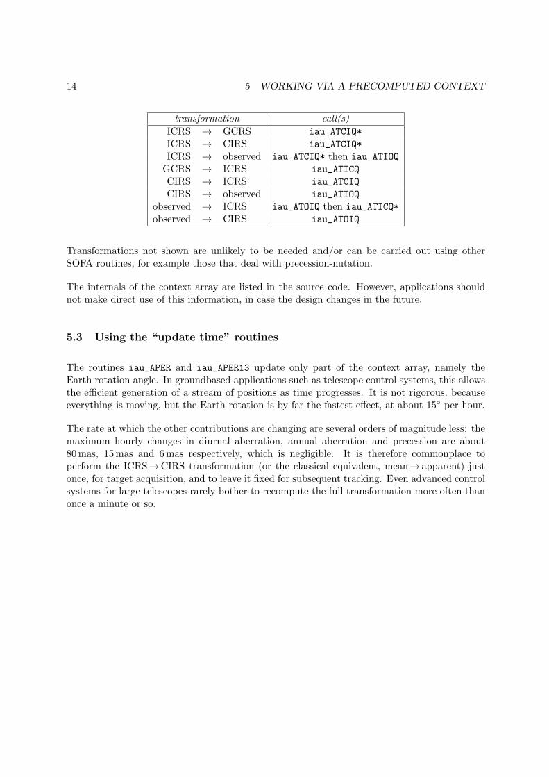
transformation call(s)
ICRS → GCRS iau_ATCIQ*
ICRS → CIRS iau_ATCIQ*
ICRS → observed iau_ATCIQ* then iau_ATIOQ
GCRS → ICRS iau_ATICQ
CIRS → ICRS iau_ATCIQ
CIRS → observed iau_ATIOQ
observed → ICRS iau_ATOIQ then iau_ATICQ*
observed → CIRS iau_ATOIQ
Transformations not shown are unlikely to be needed and/or can be carried out using otherSOFA routines, for example those that deal with precession-nutation.
The internals of the context array are listed in the source code. However, applications shouldnot make direct use of this information, in case the design changes in the future.
5.3 Using the “update time” routines
The routines iau_APER and iau_APER13 update only part of the context array, namely theEarth rotation angle. In groundbased applications such as telescope control systems, this allowsthe efficient generation of a stream of positions as time progresses. It is not rigorous, becauseeverything is moving, but the Earth rotation is by far the fastest effect, at about 15◦ per hour.
The rate at which the other contributions are changing are several orders of magnitude less: themaximum hourly changes in diurnal aberration, annual aberration and precession are about80mas, 15mas and 6mas respectively, which is negligible. It is therefore commonplace toperform the ICRS→CIRS transformation (or the classical equivalent, mean→ apparent) justonce, for target acquisition, and to leave it fixed for subsequent tracking. Even advanced controlsystems for large telescopes rarely bother to recompute the full transformation more often thanonce a minute or so.
15
6 Example
Starting with catalog data for a star, the demonstration program listed below performs a wholeseries of transformations, namely:
1. ICRS to CIRS.
2. The reverse, giving the astrometric place.
3. Astrometric place to CIRS.
4. Geocentric apparent place via the equation of the origins.
5. CIRS to topocentric, i.e. CIRS to observed but with zero air pressure.
6. CIRS to observed.
7. ICRS to observed in a single call.
8. ICRS to CIRS using JPL DE405 for the Earth ephemeris.
9. The same but including light deflection by Jupiter and Saturn.
10. The reverse, to check agreement with Step 2.
The code is complete, ready to compile and run, and may be a useful template for furtherexperiments. A real-life application would of course be far simpler than this quite complicateddemonstration, with the use of SOFA astrometry routines limited to perhaps a single call.
The test circumstances are as follows. It must be stressed that all the numbers have beenadopted purely for the sake of the demonstration and have no other significance. Althoughquite representative of real data, all of the values used must be assumed to be fictitious.
The site coordinates are:
Latitude and longitude = S 15◦ 57′ 42′′.8 W 5◦ 41′ 54′′.2
Height above the reference ellipsoid = 625m
Here are the catalog data for the test star:
ICRS [α, δ ] = 14h 34m 16s.81183 −12◦ 31′ 10′′.3965
proper motions: µα = −354.45mas/y, µδ = +595.35mas/y
parallax = 0′′.16499
radial velocity (recession speed) = 0 km/s
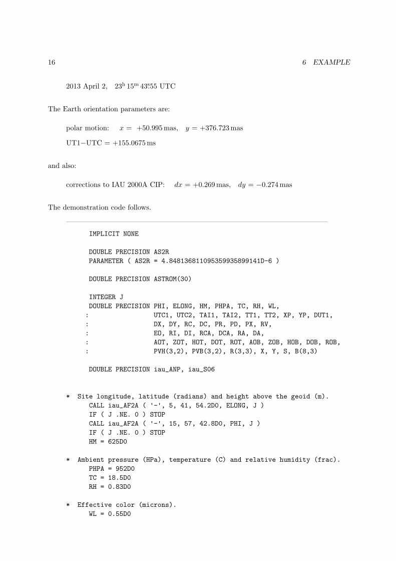
The date and time are:
16 6 EXAMPLE
2013 April 2, 23h 15m 43s.55 UTC
The Earth orientation parameters are:
polar motion: x = +50.995mas, y = +376.723mas
UT1−UTC = +155.0675ms
and also:
corrections to IAU 2000A CIP: dx = +0.269mas, dy = −0.274mas
The demonstration code follows.
IMPLICIT NONE
DOUBLE PRECISION AS2R
PARAMETER ( AS2R = 4.848136811095359935899141D-6 )
DOUBLE PRECISION ASTROM(30)
INTEGER J
DOUBLE PRECISION PHI, ELONG, HM, PHPA, TC, RH, WL,
: UTC1, UTC2, TAI1, TAI2, TT1, TT2, XP, YP, DUT1,
: DX, DY, RC, DC, PR, PD, PX, RV,
: EO, RI, DI, RCA, DCA, RA, DA,
: AOT, ZOT, HOT, DOT, ROT, AOB, ZOB, HOB, DOB, ROB,
: PVH(3,2), PVB(3,2), R(3,3), X, Y, S, B(8,3)
DOUBLE PRECISION iau_ANP, iau_S06
* Site longitude, latitude (radians) and height above the geoid (m).
CALL iau_AF2A ( '-', 5, 41, 54.2D0, ELONG, J )
IF ( J .NE. 0 ) STOP
CALL iau_AF2A ( '-', 15, 57, 42.8D0, PHI, J )
IF ( J .NE. 0 ) STOP
HM = 625D0
* Ambient pressure (HPa), temperature (C) and relative humidity (frac).
PHPA = 952D0
TC = 18.5D0
RH = 0.83D0
* Effective color (microns).
WL = 0.55D0
17
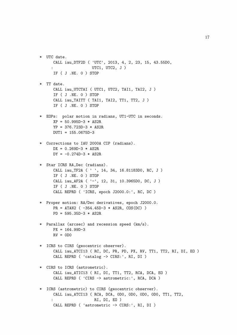
* UTC date.
CALL iau_DTF2D ( 'UTC', 2013, 4, 2, 23, 15, 43.55D0,
: UTC1, UTC2, J )
IF ( J .NE. 0 ) STOP
* TT date.
CALL iau_UTCTAI ( UTC1, UTC2, TAI1, TAI2, J )
IF ( J .NE. 0 ) STOP
CALL iau_TAITT ( TAI1, TAI2, TT1, TT2, J )
IF ( J .NE. 0 ) STOP
* EOPs: polar motion in radians, UT1-UTC in seconds.
XP = 50.995D-3 * AS2R
YP = 376.723D-3 * AS2R
DUT1 = 155.0675D-3
* Corrections to IAU 2000A CIP (radians).
DX = 0.269D-3 * AS2R
DY = -0.274D-3 * AS2R
* Star ICRS RA,Dec (radians).
CALL iau_TF2A ( ' ', 14, 34, 16.81183D0, RC, J )
IF ( J .NE. 0 ) STOP
CALL iau_AF2A ( '-', 12, 31, 10.3965D0, DC, J )
IF ( J .NE. 0 ) STOP
CALL REPRD ( 'ICRS, epoch J2000.0:', RC, DC )
* Proper motion: RA/Dec derivatives, epoch J2000.0.
PR = ATAN2 ( -354.45D-3 * AS2R, COS(DC) )
PD = 595.35D-3 * AS2R
* Parallax (arcsec) and recession speed (km/s).
PX = 164.99D-3
RV = 0D0
* ICRS to CIRS (geocentric observer).
CALL iau_ATCI13 ( RC, DC, PR, PD, PX, RV, TT1, TT2, RI, DI, EO )
CALL REPRD ( 'catalog -> CIRS:', RI, DI )
* CIRS to ICRS (astrometric).
CALL iau_ATIC13 ( RI, DI, TT1, TT2, RCA, DCA, EO )
CALL REPRD ( 'CIRS -> astrometric:', RCA, DCA )
* ICRS (astrometric) to CIRS (geocentric observer).
CALL iau_ATCI13 ( RCA, DCA, 0D0, 0D0, 0D0, 0D0, TT1, TT2,
: RI, DI, EO )
CALL REPRD ( 'astrometric -> CIRS:', RI, DI )
18 6 EXAMPLE
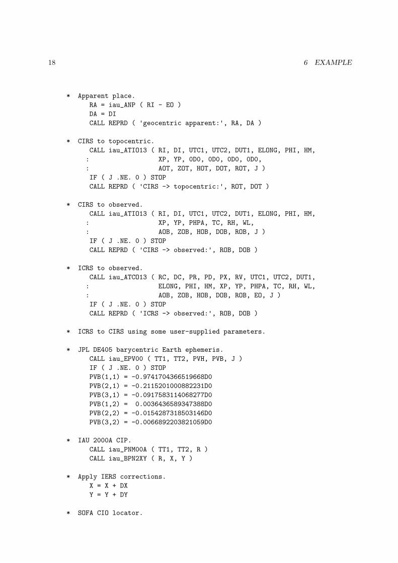
* Apparent place.
RA = iau_ANP ( RI - EO )
DA = DI
CALL REPRD ( 'geocentric apparent:', RA, DA )
* CIRS to topocentric.
CALL iau_ATIO13 ( RI, DI, UTC1, UTC2, DUT1, ELONG, PHI, HM,
: XP, YP, 0D0, 0D0, 0D0, 0D0,
: AOT, ZOT, HOT, DOT, ROT, J )
IF ( J .NE. 0 ) STOP
CALL REPRD ( 'CIRS -> topocentric:', ROT, DOT )
* CIRS to observed.
CALL iau_ATIO13 ( RI, DI, UTC1, UTC2, DUT1, ELONG, PHI, HM,
: XP, YP, PHPA, TC, RH, WL,
: AOB, ZOB, HOB, DOB, ROB, J )
IF ( J .NE. 0 ) STOP
CALL REPRD ( 'CIRS -> observed:', ROB, DOB )
* ICRS to observed.
CALL iau_ATCO13 ( RC, DC, PR, PD, PX, RV, UTC1, UTC2, DUT1,
: ELONG, PHI, HM, XP, YP, PHPA, TC, RH, WL,
: AOB, ZOB, HOB, DOB, ROB, EO, J )
IF ( J .NE. 0 ) STOP
CALL REPRD ( 'ICRS -> observed:', ROB, DOB )
* ICRS to CIRS using some user-supplied parameters.
* JPL DE405 barycentric Earth ephemeris.
CALL iau_EPV00 ( TT1, TT2, PVH, PVB, J )
IF ( J .NE. 0 ) STOP
PVB(1,1) = -0.9741704366519668D0
PVB(2,1) = -0.2115201000882231D0
PVB(3,1) = -0.0917583114068277D0
PVB(1,2) = 0.0036436589347388D0
PVB(2,2) = -0.0154287318503146D0
PVB(3,2) = -0.0066892203821059D0
* IAU 2000A CIP.
CALL iau_PNM00A ( TT1, TT2, R )
CALL iau_BPN2XY ( R, X, Y )
* Apply IERS corrections.
X = X + DX
Y = Y + DY
* SOFA CIO locator.
19
S = iau_S06 ( TT1, TT2, X, Y )
* Populate the context.
CALL iau_APCI ( TT1, TT2, PVB, PVH, X, Y, S, ASTROM )
* Carry out the transformation and report the results.
CALL iau_ATCIQ ( RC, DC, PR, PD, PX, RV, ASTROM, RI, DI )
CALL REPRD ( 'ICRS -> CIRS (JPL, IERS):', RI, DI )
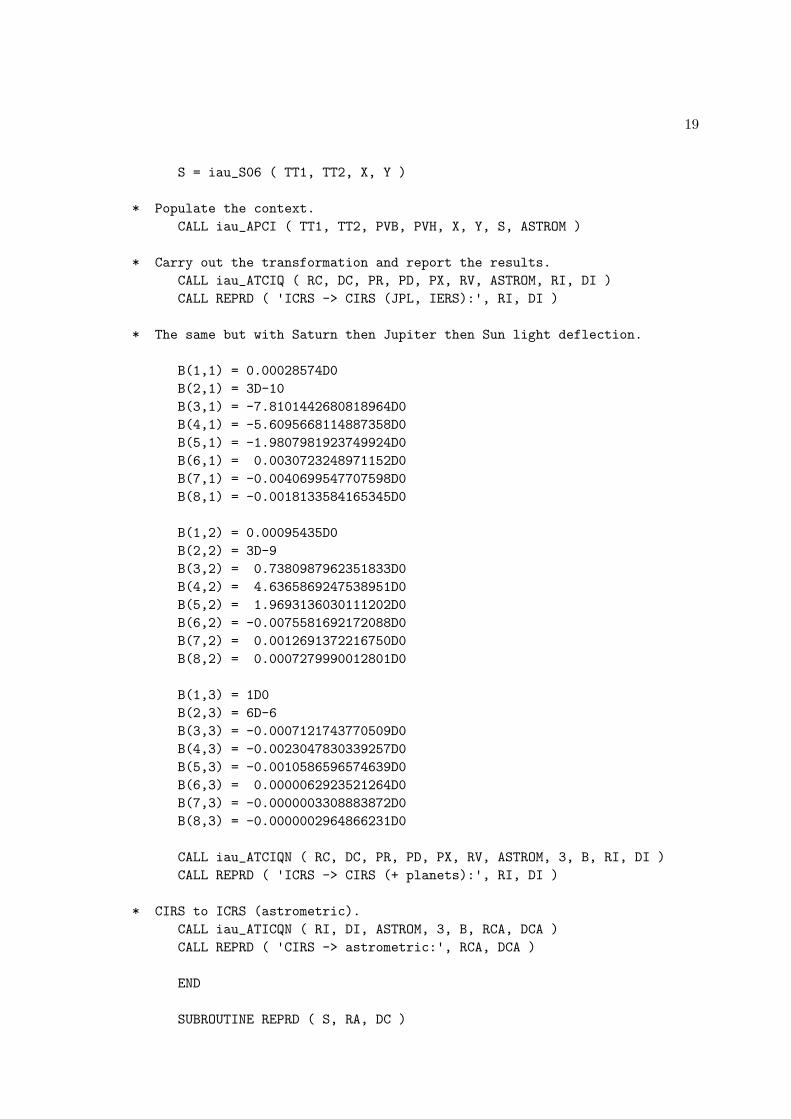
* The same but with Saturn then Jupiter then Sun light deflection.
B(1,1) = 0.00028574D0
B(2,1) = 3D-10
B(3,1) = -7.8101442680818964D0
B(4,1) = -5.6095668114887358D0
B(5,1) = -1.9807981923749924D0
B(6,1) = 0.0030723248971152D0
B(7,1) = -0.0040699547707598D0
B(8,1) = -0.0018133584165345D0
B(1,2) = 0.00095435D0
B(2,2) = 3D-9
B(3,2) = 0.7380987962351833D0
B(4,2) = 4.6365869247538951D0
B(5,2) = 1.9693136030111202D0
B(6,2) = -0.0075581692172088D0
B(7,2) = 0.0012691372216750D0
B(8,2) = 0.0007279990012801D0
B(1,3) = 1D0
B(2,3) = 6D-6
B(3,3) = -0.0007121743770509D0
B(4,3) = -0.0023047830339257D0
B(5,3) = -0.0010586596574639D0
B(6,3) = 0.0000062923521264D0
B(7,3) = -0.0000003308883872D0
B(8,3) = -0.0000002964866231D0
CALL iau_ATCIQN ( RC, DC, PR, PD, PX, RV, ASTROM, 3, B, RI, DI )
CALL REPRD ( 'ICRS -> CIRS (+ planets):', RI, DI )
* CIRS to ICRS (astrometric).
CALL iau_ATICQN ( RI, DI, ASTROM, 3, B, RCA, DCA )
CALL REPRD ( 'CIRS -> astrometric:', RCA, DCA )
END
SUBROUTINE REPRD ( S, RA, DC )
20 6 EXAMPLE
IMPLICIT NONE
CHARACTER *(*) S
DOUBLE PRECISION RA, DC
CHARACTER PM
INTEGER IHMSF(4), IDMSF(4)
CALL iau_A2TF ( 7, RA, PM, IHMSF )
CALL iau_A2AF ( 6, DC, PM, IDMSF )
WRITE ( *, '(A25,3I3.2,''.'',I7.7,1X,A,I2.2,2I3.2,''.'',I6.6)' )
: S, IHMSF, PM, IDMSF
END
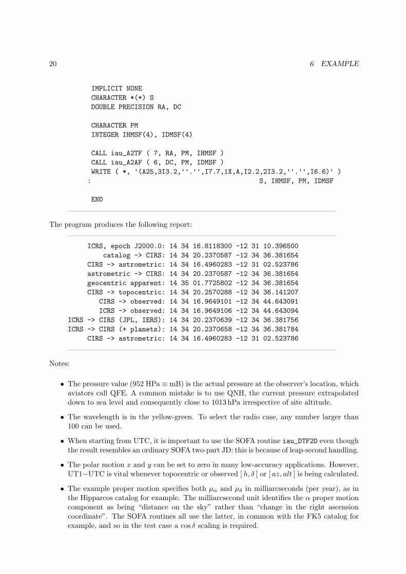
The program produces the following report:
ICRS, epoch J2000.0: 14 34 16.8118300 -12 31 10.396500
catalog -> CIRS: 14 34 20.2370587 -12 34 36.381654
CIRS -> astrometric: 14 34 16.4960283 -12 31 02.523786
astrometric -> CIRS: 14 34 20.2370587 -12 34 36.381654
geocentric apparent: 14 35 01.7725802 -12 34 36.381654
CIRS -> topocentric: 14 34 20.2570288 -12 34 36.141207
CIRS -> observed: 14 34 16.9649101 -12 34 44.643091
ICRS -> observed: 14 34 16.9649106 -12 34 44.643094
ICRS -> CIRS (JPL, IERS): 14 34 20.2370639 -12 34 36.381756
ICRS -> CIRS (+ planets): 14 34 20.2370658 -12 34 36.381784
CIRS -> astrometric: 14 34 16.4960283 -12 31 02.523786
Notes:
• The pressure value (952 HPa ≡ mB) is the actual pressure at the observer’s location, whichaviators call QFE. A common mistake is to use QNH, the current pressure extrapolateddown to sea level and consequently close to 1013 hPa irrespective of site altitude.
• The wavelength is in the yellow-green. To select the radio case, any number larger than100 can be used.
• When starting from UTC, it is important to use the SOFA routine iau_DTF2D even thoughthe result resembles an ordinary SOFA two-part JD: this is because of leap-second handling.
• The polar motion x and y can be set to zero in many low-accuracy applications. However,UT1−UTC is vital whenever topocentric or observed [h, δ ] or [ az, alt ] is being calculated.
• The example proper motion specifies both µα and µδ in milliarcseconds (per year), as inthe Hipparcos catalog for example. The milliarcsecond unit identifies the α proper motioncomponent as being “distance on the sky” rather than “change in the right ascensioncoordinate”. The SOFA routines all use the latter, in common with the FK5 catalog forexample, and so in the test case a cos δ scaling is required.
21
• The first result:
14h 34m 16s.8118300 −12◦ 31′ 10′′.396500.
. . . is simply the supplied catalog [α, δ ].
• Next, the ICRS to (geocentric) CIRS transformation using the “single call” approach isdemonstrated, in this case iau_ATCI13. The result is:
14h 34m 20s.2370587−12◦ 34′ 36′′.381654
If multiple stars were involved, and computational efficiency important, it would be betterto call iau_APCI13 once followed by multiple calls to iau_ATCIQ.
• Next, the reverse transformation uses iau_ATIC13 to give the “astrometric” place:
14h 34m 16s.4960283−12◦ 31′ 02′′.523786
This differs from the catalog [α, δ ] in the first line of the report because the astrometricplace includes the effects of the star’s proper motion from J2000.0 to date.
• The astrometric place is itself then transformed into CIRS by calling iau_ATCI13 again,but this time with zero proper motion, parallax and radial velocity. The result. . .
14h 34m 20s.2370587−12◦ 34′ 36′′.381654
. . . is as before.
• Next, the classical (equinox based) apparent place is obtained, simply by taking the equa-tion of the origins returned by the iau_ATCI13 routine and subtracting it from the (CIObased) CIRS α, leaving δ unchanged:
14h 35m 01s.7725802−12◦ 34′ 36′′.381654
• The CIRS position is transformed into topocentric [α, δ ] by calling the CIRS→ observediau_ATIO13 routine with zero air pressure:
14h 34m 20s.2570288−12◦ 34′ 36′′.141207
• Calling iau_ATIO13 routine again but this time with the ambient conditions specified givesthe observed [α, δ ]:
14h 34m 16s.9649101−12◦ 34′ 44′′.643091
• The two-stage transformation ICRS→CIRS→ observed, although convenient in many ap-plications, involves diurnal corrections that are non-rigorous. The iau_ATCO13 routineperforms the direct ICRS→ observed transformation to reach this slightly different result:
14h 34m 16s.9649106−12◦ 34′ 44′′.643094
• Next, the ICRS to CIRS transformation that we started with is repeated, but this timeusing the JPL DE405 solar-system ephemeris to obtain the Earth position and velocity,instead of the SOFA routine iau_EPV00, and using the CIP published in IERS bulletins.This is accomplished by performing the transformation in two steps, first by populatingthe astrometry context and then using it on the test target. This involves the routines

22 6 EXAMPLE
iau_APCI followed by iau_ATCIQ. iau_APCI will require not just the barycentric vectorsbut also the heliocentric position, so the first step is to compute the Earth ephemerisusing SOFA routines and then substitute the DE405 barycentric vector components: seethe code for the numerical values. We obtain the best possible CIP by adding correctionsdx, dy published by the IERS to their reference bias-precession-nutation model, namelyIAU 2000A, and finally use SOFA to obtain the CIO locator s. We can then call iau_APCIspecifying the mixture of SOFA/JPL/IERS data, followed by iau_Atciq to perform thetransformation. The result is:
14h 34m 20s.2370639−12◦ 34′ 36′′.381756
Almost all of the difference between this and the previous CIRS results is because of theIERS CIP corrections, which for the most part are to provide the (unmodeled) free corenutation. A very small contribution comes from the improved Earth velocity and its effecton the aberration, but this is never more than about 5µas.
• All the transformations up to now have taken into account the light deflection by theSun, a refinement that on its own exceeds the accuracy demands of most applications.However, applications requiring the utmost accuracy should in addition take account ofthe planets, and to this end the example includes Jupiter and Saturn. For each of thesebodies, plus the Sun, the code specifies the mass and the barycentric position and velocityat the epoch of observation; as before, values from DE405 are used. Also needed is a cutoffparameter, chosen to be within the disk of the body as seen by the observer, within whichthe calculation is suppressed to avoid numerical difficulties.
The transformation from catalog coordinates to CIRS is performed by an extended form ofthe iau_ATCIQ routine, namely iau_ATCIQN call. This requires two additional arguments,namely the number of solar-system bodies to be taken into account and an array of thatmany per-body parameter sets. In this example the order is Saturn then Jupiter then Sun.The result of the transformation is:
14h 34m 20s.2370658−12◦ 34′ 36′′.381784
The small differences with respect to the Sun-only calculation are, in this case, due toSaturn, which is about 0◦.38 from the star, compared with 148◦ and 153◦ for Jupiter andthe Sun respectively.
• Finally, that result is transformed back into astrometric place. The result agrees with thatobtained earlier:
14h 34m 16s.4960283−12◦ 31′ 02′′.523786
23
7 Gnomonic projection
In order to publish pictures of the sky it is necessary to choose a map projection. Projections usedfor maps of the Earth’s surface have particular advantages and disadvantages such as whetherareas or shapes are distorted, and which is best for a particular application often depends onhow large an area is to be presented; for example different choices might be made for maps ofa city, a continent and the whole globe. Exactly the same considerations apply for maps of thesky, when the projections chosen for a tiny starfield, an individual constellation or for the wholecelestial sphere might be very different (see Calabretta & Greisen 2002). In both terrestrial andastronomical work, an extremely common case is where only a small area is to be mapped, andhere the choice of projection tends to be less critical. One choice for such applications is thegnomonic, or tangent-plane, projection. This has a special advantage for astrometric work inthat it is the projection geometry that is produced by a pinhole camera, which in turn is close tothat produced by classical long-focus astrographs. Indeed, for most astronomical cameras it isconvenient to use the tangent-plane projection as the basis, adding small distortion correctionsas required.
Each star on an astrographic exposure has celestial spherical coordinates and its image hasCartesian coordinates. The third element in the projection is the celestial position of the platecenter or “tangent-point”. The spherical coordinate system is always assumed to be generic[α, δ ] (with no stipulation about whether mean, apparent, ICRS etc.), though it would beequally valid to use galactic, ecliptic or any other spherical coordinate system. The Cartesiansystem has the tangent-point as the origin, an η-axis pointing north and a ξ-axis pointing east;the units amount to radians near the tangent-point. These are called “standard coordinates”.
There are standard formulas that predict [ ξ, η ] given [α, δ ] for the star and tangent-pointrespectively, and others that predict the star’s [α, δ ] given the [ ξ, η ] of the image and the [α, δ ]of the tangent-point. Both of these transformations are supported by SOFA routines, which alsoprovide a means to solve for the tangent point given a star’s [α, δ ] and the [ ξ, η ] of its image.
For practical astrometry the geometrical relationship between [α, δ ] and [ ξ, η ] is merely thestarting point, and it is traditional to add a “plate model” that incorporates not only instru-mental effects such as focal plane tilt and radial distortion but also astronomical ones such asprecessional rotation, differential aberration and differential refraction. However, in the modernera it is arguably better to keep these details separate from the idealized sky projection, andtreating them with more rigor.
In practice, the relationship between [ ξ, η ] and plate [x, y ], or equivalently camera pixel coor-dinates, is often expressed as an affine transformation:
x = a+ b ξ + c η
y = d+ e ξ + f η
Given matching [x, y ] and [ ξ, η ] coordinates for a set of reference stars, the six coefficientsa, b, c, d, e and f are found by least-squares fitting, whereupon the model can be applied to“unknown” stars. It is not uncommon for mean [α, δ ]s to be plugged into the formulas, relyingon the affine fit to deal with differential aberration and refraction etc., as already described.
24 7 GNOMONIC PROJECTION
star catalog [α, δ ]
observing circumstancesfundamental-astronomy transformations
observed [α, δ ]
gnomonic projection
tangential coordinates [ ξ, η ]
optical distortion
affine transformation
detector [x, y ]
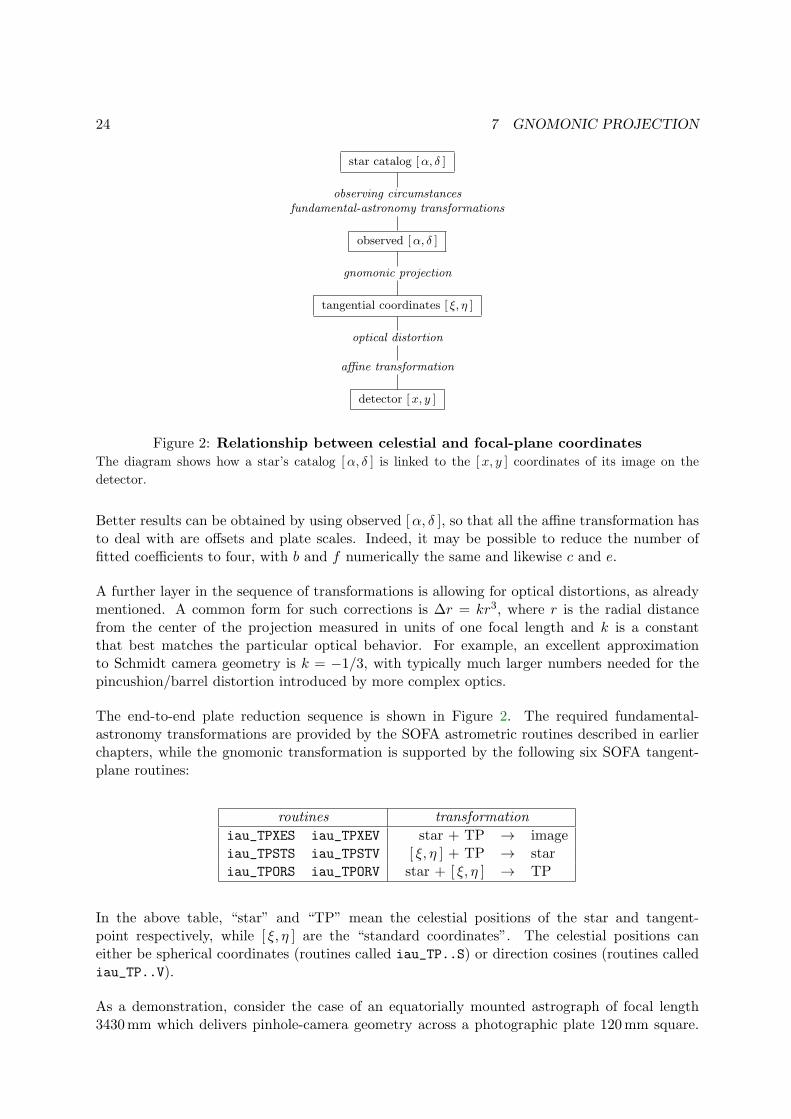
Figure 2: Relationship between celestial and focal-plane coordinatesThe diagram shows how a star’s catalog [α, δ ] is linked to the [x, y ] coordinates of its image on the
detector.
Better results can be obtained by using observed [α, δ ], so that all the affine transformation hasto deal with are offsets and plate scales. Indeed, it may be possible to reduce the number offitted coefficients to four, with b and f numerically the same and likewise c and e.
A further layer in the sequence of transformations is allowing for optical distortions, as alreadymentioned. A common form for such corrections is ∆r = kr3, where r is the radial distancefrom the center of the projection measured in units of one focal length and k is a constantthat best matches the particular optical behavior. For example, an excellent approximationto Schmidt camera geometry is k = −1/3, with typically much larger numbers needed for thepincushion/barrel distortion introduced by more complex optics.
The end-to-end plate reduction sequence is shown in Figure 2. The required fundamental-astronomy transformations are provided by the SOFA astrometric routines described in earlierchapters, while the gnomonic transformation is supported by the following six SOFA tangent-plane routines:
routines transformation
iau_TPXES iau_TPXEV star + TP → imageiau_TPSTS iau_TPSTV [ ξ, η ] + TP → stariau_TPORS iau_TPORV star + [ ξ, η ] → TP
In the above table, “star” and “TP” mean the celestial positions of the star and tangent-point respectively, while [ ξ, η ] are the “standard coordinates”. The celestial positions caneither be spherical coordinates (routines called iau_TP..S) or direction cosines (routines callediau_TP..V).
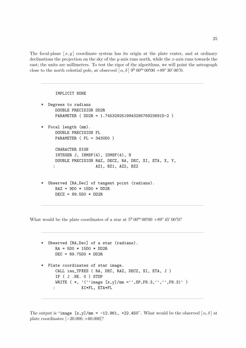
As a demonstration, consider the case of an equatorially mounted astrograph of focal length3430mm which delivers pinhole-camera geometry across a photographic plate 120mm square.
25
The focal-plane [x, y ] coordinate system has its origin at the plate center, and at ordinarydeclinations the projection on the sky of the y-axis runs north, while the x-axis runs towards theeast; the units are millimeters. To test the rigor of the algorithms, we will point the astrographclose to the north celestial pole, at observed [α, δ ] 9h 00m 00s.00 +89◦ 30′ 00′′.0.
IMPLICIT NONE
* Degrees to radians
DOUBLE PRECISION DD2R
PARAMETER ( DD2R = 1.745329251994329576923691D-2 )
* Focal length (mm).
DOUBLE PRECISION FL
PARAMETER ( FL = 3430D0 )
CHARACTER SIGN
INTEGER J, IHMSF(4), IDMSF(4), N
DOUBLE PRECISION RAZ, DECZ, RA, DEC, XI, ETA, X, Y,
: AZ1, BZ1, AZ2, BZ2
* Observed [RA,Dec] of tangent point (radians).
RAZ = 9D0 * 15D0 * DD2R
DECZ = 89.5D0 * DD2R
What would be the plate coordinates of a star at 5h 00m 00s.00 +89◦ 45′ 00′′.0?
* Observed [RA,Dec] of a star (radians).
RA = 5D0 * 15D0 * DD2R
DEC = 89.75D0 * DD2R
* Plate coordinates of star image.
CALL iau_TPXES ( RA, DEC, RAZ, DECZ, XI, ETA, J )
IF ( J .NE. 0 ) STOP
WRITE ( *, '(''image [x,y]/mm ='',SP,F8.3,'','',F8.3)' )
: XI*FL, ETA*FL
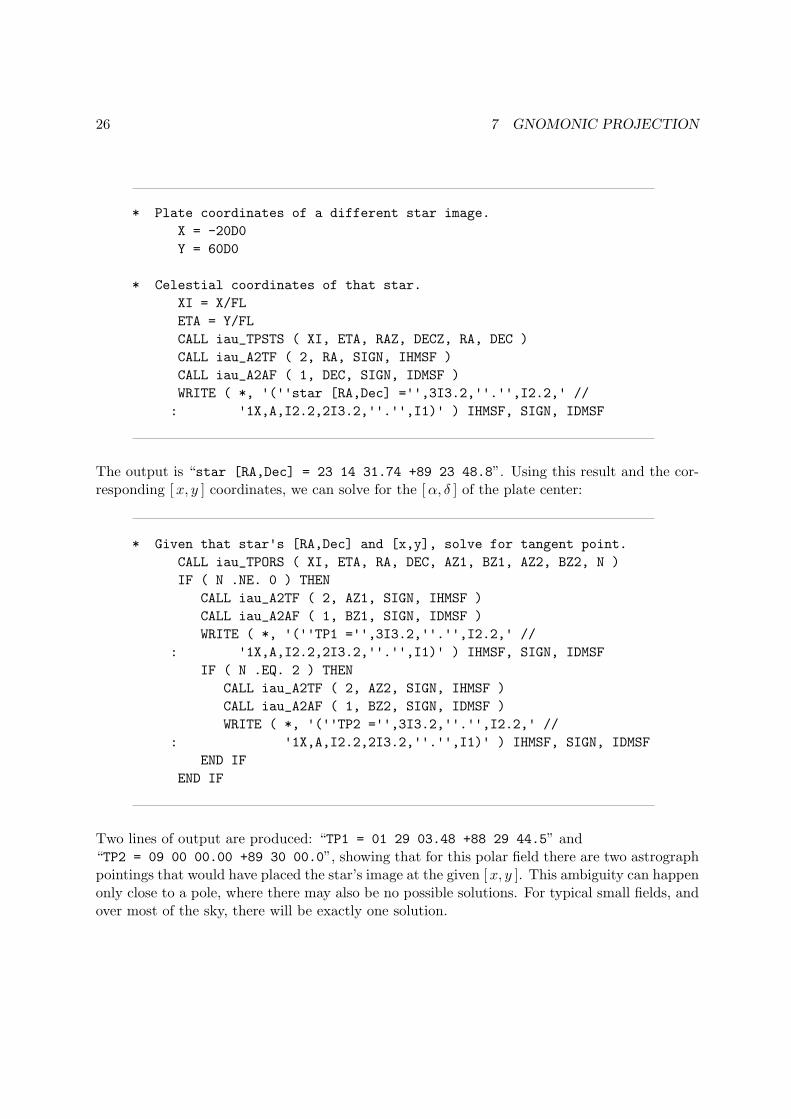
The output is “image [x,y]/mm = -12.961, +22.450”. What would be the observed [α, δ ] atplate coordinates [−20.000,+60.000]?
26 7 GNOMONIC PROJECTION
* Plate coordinates of a different star image.
X = -20D0
Y = 60D0
* Celestial coordinates of that star.
XI = X/FL
ETA = Y/FL
CALL iau_TPSTS ( XI, ETA, RAZ, DECZ, RA, DEC )
CALL iau_A2TF ( 2, RA, SIGN, IHMSF )
CALL iau_A2AF ( 1, DEC, SIGN, IDMSF )
WRITE ( *, '(''star [RA,Dec] ='',3I3.2,''.'',I2.2,' //
: '1X,A,I2.2,2I3.2,''.'',I1)' ) IHMSF, SIGN, IDMSF
The output is “star [RA,Dec] = 23 14 31.74 +89 23 48.8”. Using this result and the cor-responding [x, y ] coordinates, we can solve for the [α, δ ] of the plate center:
* Given that star's [RA,Dec] and [x,y], solve for tangent point.
CALL iau_TPORS ( XI, ETA, RA, DEC, AZ1, BZ1, AZ2, BZ2, N )
IF ( N .NE. 0 ) THEN
CALL iau_A2TF ( 2, AZ1, SIGN, IHMSF )
CALL iau_A2AF ( 1, BZ1, SIGN, IDMSF )
WRITE ( *, '(''TP1 ='',3I3.2,''.'',I2.2,' //
: '1X,A,I2.2,2I3.2,''.'',I1)' ) IHMSF, SIGN, IDMSF
IF ( N .EQ. 2 ) THEN
CALL iau_A2TF ( 2, AZ2, SIGN, IHMSF )
CALL iau_A2AF ( 1, BZ2, SIGN, IDMSF )
WRITE ( *, '(''TP2 ='',3I3.2,''.'',I2.2,' //
: '1X,A,I2.2,2I3.2,''.'',I1)' ) IHMSF, SIGN, IDMSF
END IF
END IF
Two lines of output are produced: “TP1 = 01 29 03.48 +88 29 44.5” and“TP2 = 09 00 00.00 +89 30 00.0”, showing that for this polar field there are two astrographpointings that would have placed the star’s image at the given [x, y ]. This ambiguity can happenonly close to a pole, where there may also be no possible solutions. For typical small fields, andover most of the sky, there will be exactly one solution.
27
8 Alphabetical list of routines
A complete list of the SOFA astrometry routines5 follows, arranged alphabetically. There arethree main categories:
1. Those with names beginning iau_AP populate a context array with star-independent pa-rameters that prepare the way for transformations on one or more targets. Various combi-nations of observer location and transformation type are provided for: it is vital to choosethe right one for the job in hand: otherwise the results are undefined. The “populate”routines come in two sorts:
(a) Those with names ending in 13 are the most commonly used. The caller specifiesdata such as site coordinates, and other SOFA routines are then used internally tocompute Earth ephemerides, precession-nutation, refraction constants and so on.
(b) The rest are “special”, in that they allow the caller to supply his own parameters, forinstance looked up in a numerical ephemeris or calculated using a favorite refractionmodel.
2. Those routines with names beginning iau_AT perform a particular transformation. Thereare two sorts of “transform” routines:
(a) Those names ending in Q or QZ are the “quick” routines that perform transforma-tions using a pre-computed star-independent context. These are most useful whenperforming the same transformation on multiple targets.
(b) The others are single calls that perform the specified transformation on a single target.
3. The remaining routines support particular transformation steps.
To avoid unnecessary proliferation, not all combinations are supported. For example there areno “special” versions of the convenient one-call transformation routines: if the user wishes touse his own ephemeris, refraction, etc., it will be necessary to use the two-call approach.
Most applications will need only the handful of easy-to-use Type 2b routines.
5All are classed as “support routines”: although they are meant to represent good practice, they do not claimto implement IAU standards or resolutions.
28 8 ALPHABETICAL LIST OF ROUTINES
iau_AB stellar aberration iau_AB
CALL :
CALL iau_AB ( PNAT, V, S, BM1, PPR )
ACTION :
Apply aberration to transform natural direction into proper direction.
GIVEN :
PNAT d(3) natural direction to the source (unit vector)V d(3) v: observer barycentric velocity in units of cS d distance between the Sun and the observer (au)
BM1 d (1− |v|2))1/2: reciprocal of Lorenz factor
RETURNED :
PPR d(3) proper direction to source (unit vector)
NOTES :
1. The algorithm is based on Eq. (7.40) in the Explanatory Supplement (Urban & Sei-delmann 2013), but with the following changes:
• Rigorous rather than approximate normalization is applied.
• The gravitational potential term from Eq. (7) in Klioner (2003) is added, takinginto account only the Sun’s contribution. This has a maximum effect of about0.4µas.
2. In almost all cases, the maximum accuracy will be limited by the supplied velocity.For example, if the SOFA routine iau_EPV00 is used, errors of up to 5µas couldoccur.

29
iau_AE2HD [Az,El ] to [h, δ ] iau_AE2HD
CALL :
CALL iau_AE2HD ( AZ, EL, PHI, HA, DEC )
ACTION :
Horizon to equatorial coordinates: transform azimuth and altitude to hour angle anddeclination.
GIVEN :
AZ d azimuthEL d elevation (≡ altitude)PHI d site latitude (Note 4)
RETURNED :
HA d hour angleDEC d declination
NOTES :
1. All the arguments are angles in radians.
2. The sign convention for azimuth is north zero, east +π/2.
3. HA is returned in the range ±π. Declination is returned in the range ±π/2.
4. The latitude PHI is π/2 minus the angle between the Earth’s rotation axis and theadopted zenith (Note 6). In many applications it will be sufficient to use the publishedgeodetic latitude of the site. In very precise (sub-arcsecond) applications, PHI can becorrected for polar motion.
5. The azimuth AZ must be with respect to the rotational north pole, as opposed to theITRS pole, and an azimuth with respect to north on a map of the Earth’s surfacewill need to be adjusted for polar motion if sub-arcsecond accuracy is required.
6. Should the user wish to work with respect to the astronomical horizon rather thanthe geodetic horizon, PHI will need to be adjusted for deflection of the vertical (oftentens of arcseconds), and the zero point of HA will also be affected.
7. The transformation is the same as Ve = Ry(ϕ − π/2)Rz(π)Vh, where Ve and Vh
are lefthanded unit vectors in the [h, δ ] and [Az,El ] systems respectively and Rz
and Ry are rotations about first the z-axis and then the y-axis. (n.b. Rz(π) simplyreverses the signs of the x and y components.) For efficiency, the algorithm is writtenout rather than calling other utility functions. For applications that require evengreater efficiency, additional savings are possible if constant terms such as functionsof latitude are computed once and for all.
8. Again for efficiency, no range checking of arguments is carried out.

30 8 ALPHABETICAL LIST OF ROUTINES
iau_APCG prepare for ICRS↔GCRS, geocentric, special iau_APCG
CALL :
CALL iau_APCG ( DATE1, DATE2, EB, EH, ASTROM )
ACTION :
For a geocentric observer, prepare star-independent astrometry parameters for transfor-mations between ICRS and GCRS coordinates. The Earth ephemeris is supplied by thecaller.
GIVEN :
DATE1 d TDB as a 2-part. . .DATE2 d . . . Julian Date (Note 1)EB d(3,2) Earth barycentric position/velocity (au, au/day)EH d(3,2) Earth heliocentric position/velocity (au, au/day)
RETURNED :
ASTROM d(30) star-independent astrometry parameters
NOTES :
1. The TDB date DATE1+DATE2 is a Julian Date, apportioned in any convenient waybetween the arguments DATE1 and DATE2. For example, JD(TDB)=2450123.7 couldbe expressed in any of these ways, among others:
DATE1 DATE2
2450123.7 0.0 (JD method)2451545.0 −1421.3 (J2000 method)2400000.5 50123.2 (MJD method)2450123.5 0.2 (date & time method)
The JD method is the most natural and convenient to use in cases where the loss ofseveral decimal digits of resolution is acceptable. The J2000 method is best matchedto the way the argument is handled internally and will deliver the optimum resolution.The MJD method and the date & time methods are both good compromises betweenresolution and convenience. For most applications of this routine the choice will notbe at all critical.
TT can be used instead of TDB without any significant impact on accuracy.
2. All the vectors are with respect to BCRS axes.
3. The context array ASTROM produced by this routine is used by iau_ATCIQ* andiau_ATICQ*.
31
iau_APCG13 prepare for ICRS↔GCRS, geocentric iau_APCG13
CALL :
CALL iau_APCG13 ( DATE1, DATE2, ASTROM )
ACTION :
For a geocentric observer, prepare star-independent astrometry parameters for transfor-mations between ICRS and GCRS coordinates. The caller supplies the date, and SOFAmodels are used to predict the Earth ephemeris.
GIVEN :
DATE1 d TDB as a 2-part. . .DATE2 d . . . Julian Date (Note 1)
RETURNED :
ASTROM d(30) star-independent astrometry parameters
NOTES :
1. The TDB date DATE1+DATE2 is a Julian Date, apportioned in any convenient waybetween the arguments DATE1 and DATE2. For example, JD(TDB)=2450123.7 couldbe expressed in any of these ways, among others:
DATE1 DATE2
2450123.7 0.0 (JD method)2451545.0 −1421.3 (J2000 method)2400000.5 50123.2 (MJD method)2450123.5 0.2 (date & time method)
The JD method is the most natural and convenient to use in cases where the loss ofseveral decimal digits of resolution is acceptable. The J2000 method is best matchedto the way the argument is handled internally and will deliver the optimum resolution.The MJD method and the date & time methods are both good compromises betweenresolution and convenience. For most applications of this routine the choice will notbe at all critical.
TT can be used instead of TDB without any significant impact on accuracy.
2. All the vectors are with respect to BCRS axes.
3. In cases where the caller wishes to supply his own Earth ephemeris, the routineiau_APCG can be used instead of the present routine.
4. The context array ASTROM produced by this routine is used by iau_ATCIQ* andiau_ATICQ*.
32 8 ALPHABETICAL LIST OF ROUTINES
iau_APCI prepare for ICRS↔CIRS, terrestrial, special iau_APCI
CALL :
CALL iau_APCI ( DATE1, DATE2, EB, EH, X, Y, S, ASTROM )
ACTION :
For a terrestrial observer, prepare star-independent astrometry parameters for transforma-tions between ICRS and geocentric CIRS coordinates. The Earth ephemeris and CIP/CIOare supplied by the caller.
GIVEN :
DATE1 d TDB as a 2-part. . .DATE2 d . . . Julian Date (Note 1)EB d(3,2) Earth barycentric position/velocity (au, au/day)EH d(3,2) Earth heliocentric position/velocity (au, au/day)X,Y d CIP X,Y (components of unit vector)S d the CIO locator s (radians)
RETURNED :
ASTROM d(30) star-independent astrometry parameters
NOTES :
1. The TDB date DATE1+DATE2 is a Julian Date, apportioned in any convenient waybetween the arguments DATE1 and DATE2. For example, JD(TDB)=2450123.7 couldbe expressed in any of these ways, among others:
DATE1 DATE2
2450123.7 0.0 (JD method)2451545.0 −1421.3 (J2000 method)2400000.5 50123.2 (MJD method)2450123.5 0.2 (date & time method)
The JD method is the most natural and convenient to use in cases where the loss ofseveral decimal digits of resolution is acceptable. The MJD method and the date &time methods are both good compromises between resolution and convenience. Formost applications of this routine the choice will not be at all critical.
TT can be used instead of TDB without any significant impact on accuracy.
2. All the vectors are with respect to BCRS axes.
3. In cases where the caller does not wish to provide the Earth ephemeris and CIP/CIO,the routine iau_APCI13 can be used instead of the present routine. This computesthe required quantities using other SOFA routines.
4. The context array ASTROM produced by this routine is used by iau_ATCIQ* andiau_ATICQ*.

33
iau_APCI13 prepare for ICRS↔CIRS, terrestrial iau_APCI13
CALL :
CALL iau_APCI13 ( DATE1, DATE2, ASTROM, EO )
ACTION :
For a terrestrial observer, prepare star-independent astrometry parameters for transfor-mations between ICRS and geocentric CIRS coordinates. The caller supplies the date, andSOFA models are used to predict the Earth ephemeris and CIP/CIO.
GIVEN :
DATE1 d TDB as a 2-part. . .DATE2 d . . . Julian Date (Note 1)
RETURNED :
ASTROM d(30) star-independent astrometry parametersEO d equation of the origins (ERA−GST)
NOTES :
1. The TDB date DATE1+DATE2 is a Julian Date, apportioned in any convenient waybetween the arguments DATE1 and DATE2. For example, JD(TDB)=2450123.7 couldbe expressed in any of these ways, among others:
DATE1 DATE2
2450123.7 0.0 (JD method)2451545.0 −1421.3 (J2000 method)2400000.5 50123.2 (MJD method)2450123.5 0.2 (date & time method)
The JD method is the most natural and convenient to use in cases where the loss ofseveral decimal digits of resolution is acceptable. The J2000 method is best matchedto the way the argument is handled internally and will deliver the optimum resolution.The MJD method and the date & time methods are both good compromises betweenresolution and convenience. For most applications of this routine the choice will notbe at all critical.
TT can be used instead of TDB without any significant impact on accuracy.
2. All the vectors are with respect to BCRS axes.
3. In cases where the caller wishes to supply his own Earth ephemeris and CIP/CIO,the routine iau_APCI can be used instead of the present routine.
4. The context array ASTROM produced by this routine is used by iau_ATCIQ* andiau_ATICQ*.
34 8 ALPHABETICAL LIST OF ROUTINES
iau_APCO prepare for ICRS↔ observed, terrestrial, special iau_APCO
CALL :
CALL iau_APCO ( DATE1, DATE2, EB, EH, X, Y, S,
THETA, ELONG, PHI, HM, XP, YP, SP, REFA, REFB, ASTROM )
ACTION :
For a terrestrial observer, prepare star-independent astrometry parameters for transforma-tions between ICRS and observed coordinates. The caller supplies the Earth ephemeris,the Earth rotation information and the refraction constants as well as the site coordinates.
GIVEN :
DATE1 d TDB as a 2-part. . .DATE2 d . . . Julian Date (Note 1)EB d(3,2) Earth barycentric pos/vel (au, au/day, Note 2)EH d(3,2) Earth heliocentric pos/vel (au, au/day, Note 2)X,Y d CIP X,Y (components of unit vector)S d the CIO locator s (radians)THETA d Earth rotation angle (radians)ELONG d longitude (radians, east-positive, Note 3)PHI d latitude (geodetic, radians, Note 3)HM d height above ellipsoid (m, geodetic, Note 3)XP,YP d polar motion coordinates (radians, Note 4)SP d the TIO locator s’ (radians, Note 4)REFA d refraction constant A (radians, Note 5)REFB d refraction constant B (radians, Note 5)
RETURNED :
ASTROM d(30) star-independent astrometry parameters
NOTES :
1. The TDB date DATE1+DATE2 is a Julian Date, apportioned in any convenient waybetween the arguments DATE1 and DATE2. For example, JD(TDB)=2450123.7 couldbe expressed in any of these ways, among others:
DATE1 DATE2
2450123.7 0.0 (JD method)2451545.0 −1421.3 (J2000 method)2400000.5 50123.2 (MJD method)2450123.5 0.2 (date & time method)
The JD method is the most natural and convenient to use in cases where the loss ofseveral decimal digits of resolution is acceptable. The MJD method and the date &time methods are both good compromises between resolution and convenience. Formost applications of this routine the choice will not be at all critical.
TT can be used instead of TDB without any significant impact on accuracy.
35
2. The vectors EB, EH, and all the ASTROM vectors, are with respect to BCRS axes.
3. The geographical coordinates are with respect to the WGS84 reference ellipsoid. Takecare with the longitude sign: the longitude required by the present routine is east-positive (i.e. right-handed), in accordance with geographical convention.
4. The polar motion XP,YP can be obtained from IERS bulletins. The values are thecoordinates (in radians) of the Celestial Intermediate Pole with respect to the Inter-national Terrestrial Reference System (see IERS Conventions 2003), measured alongthe meridians 0◦ and 90◦ west respectively. For many applications, XP and YP can beset to zero.
5. The refraction constants REFA and REFB are for use in a ∆ζ = A tan ζ + B tan3 ζmodel, where ζ is the observed (i.e. refracted) zenith distance and ∆ζ is the amountof refraction.
6. It is advisable to take great care with units, as even unlikely values of the inputparameters are accepted and processed in accordance with the models used.
7. In cases where the caller does not wish to provide the Earth Ephemeris, the Earthrotation information and refraction constants, the routine iau_APCO13 can be usedinstead of the present routine. This starts from UTC and weather readings etc. andcomputes suitable values using other SOFA routines.
8. The context array ASTROM produced by this routine is used by iau_ATIOQ,iau_ATOIQ, iau_ATCIQ* and iau_ATICQ*.

36 8 ALPHABETICAL LIST OF ROUTINES
iau_APCO13 prepare for ICRS↔ observed, terrestrial iau_APCO13
CALL :
CALL iau_APCO13 ( UTC1, UTC2, DUT1, ELONG, PHI, HM, XP, YP,
PHPA, TC, RH, WL, ASTROM, EO, J )
ACTION :
For a terrestrial observer, prepare star-independent astrometry parameters for transforma-tions between ICRS and observed coordinates. The caller supplies UTC, site coordinates,ambient air conditions and observing wavelength, and SOFA models are used to obtainthe Earth ephemeris, CIP/CIO and refraction constants.
GIVEN :
UTC1 d UTC as a 2-part. . .UTC2 d . . . quasi Julian Date (Notes 1,2)DUT1 d UT1−UTC (seconds)ELONG d longitude (radians, east-positive, Note 3)PHI d geodetic latitude (radians, Note 3)HM d height above ellipsoid (m, geodetic Notes 4,6)XP,YP d polar motion coordinates (radians, Note 5)PHPA d pressure at the observer (hPa ≡ mB, Note 6)TC d ambient temperature at the observer (deg C)RH d relative humidity at the observer (range 0-1)WL d wavelength (micrometers, Note 7)
RETURNED :
ASTROM d(30) star-independent astrometry parametersEO d equation of the origins (ERA−GST)J i status: +1 = dubious year (Note 2)
0 = OK−1 = unacceptable date
NOTES :
1. UTC1+UTC2 is quasi Julian Date (see Note 2), apportioned in any convenient waybetween the two arguments, for example where UTC1 is the Julian Day Number andUTC2 is the fraction of a day. However, JD cannot unambiguously represent UTCduring a leap second unless special measures are taken. The convention in the presentroutine is that the JD day represents UTC days whether the length is 86399, 86400or 86401 SI seconds.
Applications should use the routine iau_DTF2D to convert from calendar date and timeof day into two-part quasi Julian Date, as it implements the leap-second-ambiguityconvention just described.
37
2. The warning status “dubious year” flags UTCs that predate the introduction of thetime scale or that are too far in the future to be trusted. See iau_DAT for furtherdetails.
3. UT1−UTC is tabulated in IERS bulletins. It increases by exactly one second at theend of each positive UTC leap second, introduced in order to keep UT1−UTC within±0.9 s. n.b. This practice is under review, and in the future UT1−UTC may growessentially without limit.
4. The geographical coordinates are with respect to the WGS84 reference ellipsoid. Takecare with the longitude sign: the longitude required by the present routine is east-positive (i.e. right-handed), in accordance with geographical convention.
5. The polar motion XP,YP can be obtained from IERS bulletins. The values are thecoordinates (in radians) of the Celestial Intermediate Pole with respect to the Inter-national Terrestrial Reference System (see IERS Conventions 2003), measured alongthe meridians 0◦ and 90◦ west respectively. For many applications, XP and YP can beset to zero.
6. If h, the height above the ellipsoid of the observing station in meters, is not knownbut p, the pressure in hPa (≡mB), is available, an adequate estimate of h can beobtained from the expression
h = −29.3 t0 log(p/1013.25)
where t0 is the approximate sea-level air temperature in K (See Astrophysical Quan-tities, C.W.Allen, 3rd edition, Section 52). Similarly, if the pressure p is not known,it can be estimated from the height of the observing station, h, as follows:
p = 1013.25 e−h/(29.3t0)
Note, however, that the refraction is nearly proportional to the pressure and that anaccurate p value is important for precise work.
7. The argument WL specifies the observing wavelength in micrometers. The transitionfrom optical to radio is assumed to occur at 100µm (about 3000GHz).
8. It is advisable to take great care with units, as even unlikely values of the inputparameters are accepted and processed in accordance with the models used.
9. In cases where the caller wishes to supply his own Earth ephemeris, Earth rotationinformation and refraction constants, the routine iau_APCO can be used instead ofthe present routine.
10. The context array ASTROM produced by this routine is used by iau_ATIOQ,iau_ATOIQ, iau_ATCIQ* and iau_ATICQ*.
38 8 ALPHABETICAL LIST OF ROUTINES
iau_APCS prepare for ICRS↔GCRS, space, special iau_APCS
CALL :
CALL iau_APCS ( DATE1, DATE2, PV, EB, EH, ASTROM )
ACTION :
For an observer whose geocentric position and velocity are known, prepare star-independentastrometry parameters for transformations between ICRS and GCRS. The Earth ephemerisis supplied by the caller.
GIVEN :
DATE1 d TDB as a 2-part. . .DATE2 d . . . Julian Date (Note 1)PV d(3,2) observer’s geocentric pos/vel (m, m/s)EB d(3,2) Earth barycentric pos/vel (au, au/day)EH d(3,2) Earth heliocentric pos/vel (au, au/day)
RETURNED :
ASTROM d(30) star-independent astrometry parameters
NOTES :
1. The TDB date DATE1+DATE2 is a Julian Date, apportioned in any convenient waybetween the arguments �DATE1 and DATE2. For example, JD(TDB)=2450123.7 couldbe expressed in any of these ways, among others:
DATE1 DATE2
2450123.7 0.0 (JD method)2451545.0 −1421.3 (J2000 method)2400000.5 50123.2 (MJD method)2450123.5 0.2 (date & time method)
The JD method is the most natural and convenient to use in cases where the loss ofseveral decimal digits of resolution is acceptable. The J2000 method is best matchedto the way the argument is handled internally and will deliver the optimum resolution.The MJD method and the date & time methods are both good compromises betweenresolution and convenience. For most applications of this routine the choice will notbe at all critical.
TT can be used instead of TDB without any significant impact on accuracy.
2. All the vectors are with respect to BCRS axes.
3. Providing separate arguments for (i) the observer’s geocentric position and velocityand (ii) the Earth ephemeris is done for convenience in the geocentric, terrestrialand Earth orbit cases. For deep space applications it maybe more convenient tospecify zero geocentric position and velocity and to supply the observer’s positionand velocity information directly instead of with respect to the Earth. However, notethe different units: m and m/s for the geocentric vectors, au and au/day for theheliocentric and barycentric vectors.
39
4. In cases where the caller does not wish to provide the Earth ephemeris, the routineiau_APCS13 can be used instead of the present routine. This computes the Earthephemeris using the SOFA routine iau_EPV00.
5. The context array ASTROM produced by this routine is used by iau_ATCIQ* andiau_ATICQ*.
40 8 ALPHABETICAL LIST OF ROUTINES
iau_APCS13 prepare for ICRS↔CIRS, space iau_APCS13
CALL :
CALL iau_APCS13 ( DATE1, DATE2, PV, ASTROM )
ACTION :
For an observer whose geocentric position and velocity are known, prepare star-independentastrometry parameters for transformations between ICRS and GCRS. The Earth ephemerisis from SOFA models.
GIVEN :
DATE1 d TDB as a 2-part. . .DATE2 d . . . Julian Date (Note 1)PV d(3,2) observer’s geocentric position/velocity (Note 3)
RETURNED :
ASTROM d(30) star-independent astrometry parameters
NOTES :
1. The TDB date DATE1+DATE2 is a Julian Date, apportioned in any convenient waybetween the arguments DATE1 and DATE2. For example, JD(TDB)=2450123.7 couldbe expressed in any of these ways, among others:
DATE1 DATE2
2450123.7 0.0 (JD method)2451545.0 −1421.3 (J2000 method)2400000.5 50123.2 (MJD method)2450123.5 0.2 (date & time method)
The JD method is the most natural and convenient to use in cases where the loss ofseveral decimal digits of resolution is acceptable. The J2000 method is best matchedto the way the argument is handled internally and will deliver the optimum resolution.The MJD method and the date & time methods are both good compromises betweenresolution and convenience. For most applications of this routine the choice will notbe at all critical.
TT can be used instead of TDB without any significant impact on accuracy.
2. All the vectors are with respect to BCRS axes.
3. The observer’s position and velocity PV are geocentric but with respect to BCRS axes,and in units of m and m/s. No assumptions are made about proximity to the Earth,and the routine can be used for deep space applications as well as Earth orbit andterrestrial.
4. In cases where the caller wishes to supply his own Earth ephemeris, the routineiau_APCS can be used instead of the present routine.
5. The context array ASTROM produced by this routine is used by iau_ATCIQ* andiau_ATICQ*.

41
iau_APER insert ERA into context iau_APER
CALL :
CALL iau_APER ( THETA, ASTROM )
ACTION :
In the star-independent astrometry parameters, update only the Earth rotation angle,supplied by the caller explicitly.
GIVEN :
THETA d Earth rotation angle (radians, Note 2)ASTROM d(30) star-independent astrometry parameters
RETURNED :
ASTROM d(30) star-independent astrometry parameters
NOTES :
1. This routine exists to enable sidereal-tracking applications to avoid wasteful recompu-tation of the bulk of the astrometry parameters: only the Earth rotation is updated.
2. For targets expressed as equinox based positions, such as classical geocentric apparent[α, δ ], the supplied THETA can be Greenwich apparent sidereal time rather than Earthrotation angle.
3. The routine iau_APER13 can be used instead of the present routine, and starts fromUT1 rather than ERA itself.
42 8 ALPHABETICAL LIST OF ROUTINES
iau_APER13 update context for Earth rotation iau_APER13
CALL :
CALL iau_APER13 ( UT11, UT12, ASTROM )
ACTION :
In the star-independent astrometry parameters, update only the Earth rotation angle: thecaller provides UT1 (n.b. not UTC) and the IAU 2000 ERA formula is used.
GIVEN :
UT11 d UT1 as a 2-part. . .UT12 d . . . Julian Date (Note 1)ASTROM d(30) star-independent astrometry parameters
RETURNED :
ASTROM d(30) star-independent astrometry parameters
NOTES :
1. The UT1 date UT11+UT12 is a Julian Date, apportioned in any convenient way be-tween the arguments UT11 and UT12. For example, JD(UT1)=2450123.7 could beexpressed in any of these ways, among others:
UT11 UT12
2450123.7 0.0 (JD method)2451545.0 −1421.3 (J2000 method)2400000.5 50123.2 (MJD method)2450123.5 0.2 (date & time method)
The JD method is the most natural and convenient to use in cases where the loss ofseveral decimal digits of resolution is acceptable. The J2000 and MJD methods aregood compromises between resolution and convenience. The date & time method isbest matched to the algorithm used: maximum precision is delivered when the UT11argument is for 0hUT1 on the day in question and the UT12 argument lies in therange 0 to 1, or vice versa.
2. If the caller wishes to provide the Earth rotation angle itself, the routine iau_APER
can be used instead. One use of this technique is to substitute Greenwich apparentsidereal time and thereby to support equinox based transformations directly.
43
iau_APIO prepare for CIRS↔ observed, terrestrial, special iau_APIO
CALL :
CALL iau_APIO ( SP, THETA, ELONG, PHI, HM, XP, YP, REFA, REFB, ASTROM )
ACTION :
For a terrestrial observer, prepare star-independent astrometry parameters for transforma-tions between CIRS and observed coordinates. The caller supplies the Earth orientationinformation and the refraction constants as well as the site coordinates.
GIVEN :
SP d the TIO locator s′ (radians, Note 1)THETA d Earth rotation angle (radians)ELONG d longitude (radians, east-positive, Note 2)PHI d geodetic latitude (radians, Note 2)HM d height above ellipsoid (m, geodetic Note 2)XP,YP d polar motion coordinates (radians, Note 3)REFA d refraction constant A (radians, Note 4)REFB d refraction constant B (radians, Note 4)
RETURNED :
ASTROM d(30) star-independent astrometry parameters
NOTES :
1. SP, the TIO locator s′, is a tiny quantity needed only by the most precise applications.It can either be set to zero or predicted using the SOFA routine iau_SP00.
2. The geographical coordinates are with respect to the WGS84 reference ellipsoid. Takecare with the longitude sign: the longitude required by the present routine is east-positive (i.e. right-handed), in accordance with geographical convention.
3. The polar motion XP,YP can be obtained from IERS bulletins. The values are thecoordinates (in radians) of the Celestial Intermediate Pole with respect to the Inter-national Terrestrial Reference System (see IERS Conventions 2003), measured alongthe meridians 0◦ and 90◦ west respectively. For many applications, XP and YP can beset to zero.
4. The refraction constants REFA and REFB are for use in a ∆ζ = A tan ζ + B tan3 ζmodel, where ζ is the observed (i.e. refracted) zenith distance and ∆ζ is the amountof refraction.
5. It is advisable to take great care with units, as even unlikely values of the inputparameters are accepted and processed in accordance with the models used.
6. In cases where the caller does not wish to provide the Earth rotation informationand refraction constants, the routine iau_APIO13 can be used instead of the presentroutine. This starts from UTC and weather readings etc. and computes suitablevalues using other SOFA routines.
7. The context array ASTROM produced by this routine is used by iau_ATIOQ and iau_ATOIQ.

44 8 ALPHABETICAL LIST OF ROUTINES
iau_APIO13 prepare for CIRS↔ observed, terrestrial iau_APIO13
CALL :
CALL iau_APIO13 ( UTC1, UTC2, DUT1, ELONG, PHI, HM, XP, YP,
PHPA, TC, RH, WL, ASTROM, J )
ACTION :
For a terrestrial observer, prepare star-independent astrometry parameters for transforma-tions between CIRS and observed coordinates. The caller supplies UTC, site coordinates,ambient air conditions and observing wavelength.
GIVEN :
UTC1 d UTC as a 2-part. . .UTC2 d . . . quasi Julian Date (Notes 1,2)DUT1 d UT1−UTC (seconds)ELONG d longitude (radians, east-positive, Note 3)PHI d geodetic latitude (radians, Note 3)HM d height above ellipsoid (m, geodetic Notes 4,6)XP,YP d polar motion coordinates (radians, Note 5)PHPA d pressure at the observer (hPa ≡ mB, Note 6)TC d ambient temperature at the observer (deg C)RH d relative humidity at the observer (range 0-1)WL d wavelength (micrometers, Note 7)
RETURNED :
ASTROM d(30) star-independent astrometry parametersJ i status: +1 = dubious year (Note 2)
0 = OK−1 = unacceptable date
NOTES :
1. UTC1+UTC2 is quasi Julian Date (see Note 2), apportioned in any convenient waybetween the two arguments, for example where UTC1 is the Julian Day Number andUTC2 is the fraction of a day. However, JD cannot unambiguously represent UTCduring a leap second unless special measures are taken. The convention in the presentroutine is that the JD day represents UTC days whether the length is 86399, 86400or 86401 SI seconds.
Applications should use the routine iau_DTF2D to convert from calendar date and timeof day into two-part quasi Julian Date, as it implements the leap-second-ambiguityconvention just described.
2. The warning status “dubious year” flags UTCs that predate the introduction of thetime scale or that are too far in the future to be trusted. See iau_DAT for furtherdetails.
45
3. UT1−UTC is tabulated in IERS bulletins. It increases by exactly one second at theend of each positive UTC leap second, introduced in order to keep UT1−UTC within±0.9 s. n.b. This practice is under review, and in the future UT1−UTC may growessentially without limit.
4. The geographical coordinates are with respect to the WGS84 reference ellipsoid. Takecare with the longitude sign: the longitude required by the present routine is east-positive (i.e. right-handed), in accordance with geographical convention.
5. The polar motion XP,YP can be obtained from IERS bulletins. The values are thecoordinates (in radians) of the Celestial Intermediate Pole with respect to the Inter-national Terrestrial Reference System (see IERS Conventions 2003), measured alongthe meridians 0◦ and 90◦ west respectively. For many applications, XP and YP can beset to zero.
6. If h, the height above the ellipsoid of the observing station in meters, is not knownbut p, the pressure in hPa (≡mB), is available, an adequate estimate of h can beobtained from the expression
h = −29.3 t0 log(p/1013.25)
where t0 is the approximate sea-level air temperature in K (See Astrophysical Quan-tities, C.W.Allen, 3rd edition, Section 52). Similarly, if the pressure p is not known,it can be estimated from the height of the observing station, h, as follows:
p = 1013.25 e−h/(29.3t0)
Note, however, that the refraction is nearly proportional to the pressure and that anaccurate p value is important for precise work.
7. The argument WL specifies the observing wavelength in micrometers. The transitionfrom optical to radio is assumed to occur at 100µm (about 3000GHz).
8. It is advisable to take great care with units, as even unlikely values of the inputparameters are accepted and processed in accordance with the models used.
9. In cases where the caller wishes to supply his own Earth rotation information andrefraction constants, the routine iau_APIO can be used instead of the present routine.
10. The context array ASTROM produced by this routine is used by iau_ATIOQ and iau_ATOIQ.
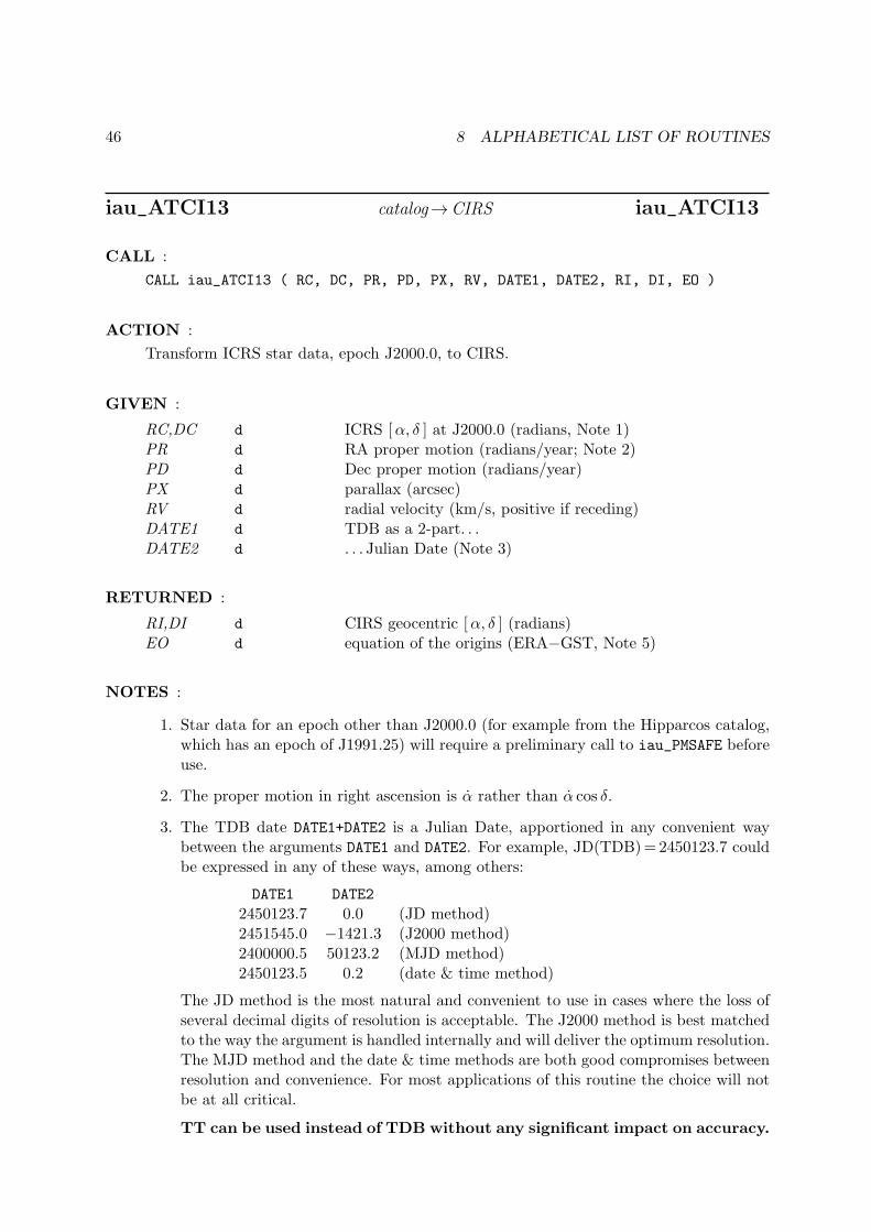
46 8 ALPHABETICAL LIST OF ROUTINES
iau_ATCI13 catalog→CIRS iau_ATCI13
CALL :
CALL iau_ATCI13 ( RC, DC, PR, PD, PX, RV, DATE1, DATE2, RI, DI, EO )
ACTION :
Transform ICRS star data, epoch J2000.0, to CIRS.
GIVEN :
RC,DC d ICRS [α, δ ] at J2000.0 (radians, Note 1)PR d RA proper motion (radians/year; Note 2)PD d Dec proper motion (radians/year)PX d parallax (arcsec)RV d radial velocity (km/s, positive if receding)DATE1 d TDB as a 2-part. . .DATE2 d . . . Julian Date (Note 3)
RETURNED :
RI,DI d CIRS geocentric [α, δ ] (radians)EO d equation of the origins (ERA−GST, Note 5)
NOTES :
1. Star data for an epoch other than J2000.0 (for example from the Hipparcos catalog,which has an epoch of J1991.25) will require a preliminary call to iau_PMSAFE beforeuse.
2. The proper motion in right ascension is α rather than α cos δ.
3. The TDB date DATE1+DATE2 is a Julian Date, apportioned in any convenient waybetween the arguments DATE1 and DATE2. For example, JD(TDB)=2450123.7 couldbe expressed in any of these ways, among others:
DATE1 DATE2
2450123.7 0.0 (JD method)2451545.0 −1421.3 (J2000 method)2400000.5 50123.2 (MJD method)2450123.5 0.2 (date & time method)
The JD method is the most natural and convenient to use in cases where the loss ofseveral decimal digits of resolution is acceptable. The J2000 method is best matchedto the way the argument is handled internally and will deliver the optimum resolution.The MJD method and the date & time methods are both good compromises betweenresolution and convenience. For most applications of this routine the choice will notbe at all critical.
TT can be used instead of TDB without any significant impact on accuracy.

47
4. The available accuracy is better than 1 milliarcsecond, limited mainly by the precession-nutation model that is used, namely IAU 2000A/2006. Very close to solar systembodies, additional errors of up to several milliarcseconds can occur because of unmod-eled light deflection; however, the Sun’s contribution is taken into account, to firstorder. The accuracy limitations of the SOFA routine iau_EPV00 (used to computeEarth position and velocity) can contribute aberration errors of up to 5 microarc-seconds. Light deflection at the Sun’s limb is uncertain at the 0.4 milliarcsecondlevel.
5. Should the transformation to (equinox based) apparent place be required rather than(CIO based) intermediate place, subtract the equation of the origins from the returnedright ascension: αapparent = αCIRS −EO. (The iau_ANP routine can then be applied,as required, to keep the result in the conventional 0-2π range.)

48 8 ALPHABETICAL LIST OF ROUTINES
iau_ATCIQ quick ICRS→CIRS iau_ATCIQ
CALL :
CALL iau_ATCIQ ( RC, DC, PR, PD, PX, RV, ASTROM, RI, DI )
ACTION :
Quick ICRS, epoch J2000.0, to CIRS transformation, given precomputed star-independentastrometry parameters. Use of this routine is appropriate when efficiency is important andwhere many star positions are to be transformed for one date.
GIVEN :
RC,DC d ICRS [α, δ ] at J2000.0 (radians, Note 1)PR d RA proper motion (radians/year; Note 2)PD d Dec proper motion (radians/year)PX d parallax (arcsec)RV d radial velocity (km/s, positive if receding)ASTROM d(30) star-independent astrometry parameters
RETURNED :
RI,DI d CIRS geocentric [α, δ ] (radians)
NOTES :
1. Star data for an epoch other than J2000.0 (for example from the Hipparcos catalog,which has an epoch of J1991.25) will require a preliminary call to iau_PMSAFE beforeuse.
2. The proper motion in right ascension is α rather than α cos δ.
3. If the parallax and proper motions are zero, (or the supplied [α, δ ] is an astrometricplace) the iau_ATCIQZ routine can be used instead.
4. The star-independent parameters can be obtained by calling one of the routinesiau_APIO[13], iau_APCG[13], iau_APCO[13] or iau_APCS[13].

49
iau_ATCIQN quick ICRS→CIRS, multiple deflections iau_ATCIQN
CALL :
CALL iau_ATCIQN ( RC, DC, PR, PD, PX, RV, ASTROM, N, B, RI, DI )
ACTION :
Quick ICRS, epoch J2000.0, to CIRS transformation, given precomputed star-independentastrometry parameters plus a list of light-deflecting bodies. Use of this routine is appro-priate when efficiency is important and where many star positions are to be transformedfor one date.
GIVEN :
RC,DC d ICRS [α, δ ] at J2000.0 (radians, Note 1)PR d RA proper motion (radians/year; Note 2)PD d Dec proper motion (radians/year)PX d parallax (arcsec)RV d radial velocity (km/s, positive if receding)ASTROM d(30) star-independent astrometry parametersN i number of bodies (Note 5)B d(8,N) data for each of the N bodies (Notes 5-9)
RETURNED :
RI,DI d CIRS geocentric [α, δ ] (radians)
NOTES :
1. Star data for an epoch other than J2000.0 (for example from the Hipparcos catalog,which has an epoch of J1991.25) will require a preliminary call to iau_PMSAFE beforeuse.
2. The proper motion in right ascension is α rather than α cos δ.
3. If the only light-deflecting body to be taken into account is the Sun, the iau_ATCIQ
routine can be used instead. If in addition the parallax and proper motions are zero,the iau_ATCIQZ routine can be used.
4. The star-independent parameters can be obtained by calling one of the routinesiau_APIO[13], iau_APCG[13], iau_APCO[13] or iau_APCS[13].
5. The array B contains N entries, one for each body to be considered. If N = 0, nogravitational light deflection will be applied, not even for the Sun.
6. The array B should include an entry for the Sun as well as for any planet or otherbody to be taken into account. The entries should be in the order in which the lightpasses the body.
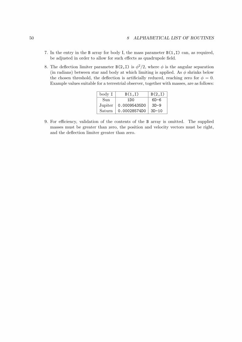
50 8 ALPHABETICAL LIST OF ROUTINES
7. In the entry in the B array for body I, the mass parameter B(1,I) can, as required,be adjusted in order to allow for such effects as quadrupole field.
8. The deflection limiter parameter B(2,I) is ϕ2/2, where ϕ is the angular separation(in radians) between star and body at which limiting is applied. As ϕ shrinks belowthe chosen threshold, the deflection is artificially reduced, reaching zero for ϕ = 0.Example values suitable for a terrestrial observer, together with masses, are as follows:
body I B(1,I) B(2,I)
Sun 1D0 6D-6
Jupiter 0.00095435D0 3D-9
Saturn 0.00028574D0 3D-10
9. For efficiency, validation of the contents of the B array is omitted. The suppliedmasses must be greater than zero, the position and velocity vectors must be right,and the deflection limiter greater than zero.
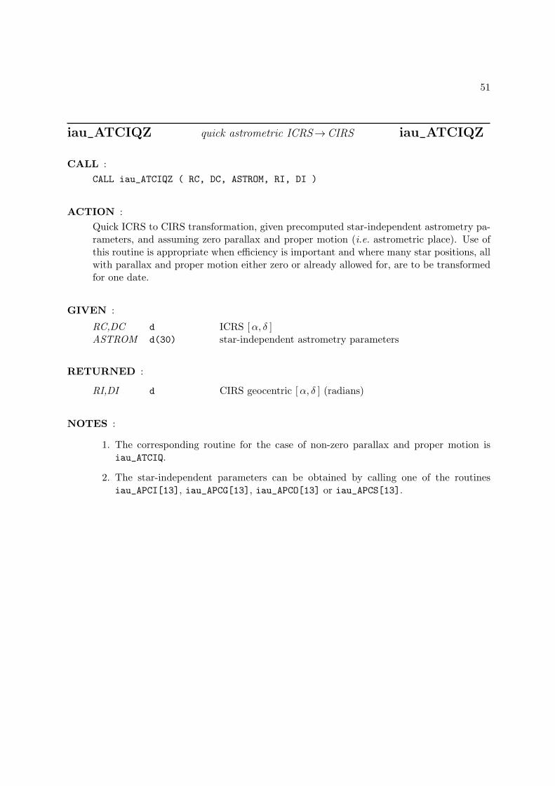
51
iau_ATCIQZ quick astrometric ICRS→CIRS iau_ATCIQZ
CALL :
CALL iau_ATCIQZ ( RC, DC, ASTROM, RI, DI )
ACTION :
Quick ICRS to CIRS transformation, given precomputed star-independent astrometry pa-rameters, and assuming zero parallax and proper motion (i.e. astrometric place). Use ofthis routine is appropriate when efficiency is important and where many star positions, allwith parallax and proper motion either zero or already allowed for, are to be transformedfor one date.
GIVEN :
RC,DC d ICRS [α, δ ]ASTROM d(30) star-independent astrometry parameters
RETURNED :
RI,DI d CIRS geocentric [α, δ ] (radians)
NOTES :
1. The corresponding routine for the case of non-zero parallax and proper motion isiau_ATCIQ.
2. The star-independent parameters can be obtained by calling one of the routinesiau_APCI[13], iau_APCG[13], iau_APCO[13] or iau_APCS[13].
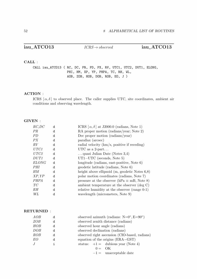
52 8 ALPHABETICAL LIST OF ROUTINES
iau_ATCO13 ICRS→ observed iau_ATCO13
CALL :
CALL iau_ATCO13 ( RC, DC, PR, PD, PX, RV, UTC1, UTC2, DUT1, ELONG,
PHI, HM, XP, YP, PHPA, TC, RH, WL,
AOB, ZOB, HOB, DOB, ROB, EO, J )
ACTION :
ICRS [α, δ ] to observed place. The caller supplies UTC, site coordinates, ambient airconditions and observing wavelength.
GIVEN :
RC,DC d ICRS [α, δ ] at J2000.0 (radians, Note 1)PR d RA proper motion (radians/year; Note 2)PD d Dec proper motion (radians/year)PX d parallax (arcsec)RV d radial velocity (km/s, positive if receding)UTC1 d UTC as a 2-part. . .UTC2 d . . . quasi Julian Date (Notes 3,4)DUT1 d UT1−UTC (seconds, Note 5)ELONG d longitude (radians, east-positive, Note 6)PHI d geodetic latitude (radians, Note 6)HM d height above ellipsoid (m, geodetic Notes 6,8)XP,YP d polar motion coordinates (radians, Note 7)PHPA d pressure at the observer (hPa ≡ mB, Note 8)TC d ambient temperature at the observer (deg C)RH d relative humidity at the observer (range 0-1)WL d wavelength (micrometers, Note 9)
RETURNED :
AOB d observed azimuth (radians: N=0◦, E=90◦)ZOB d observed zenith distance (radians)HOB d observed hour angle (radians)DOB d observed declination (radians)ROB d observed right ascension (CIO-based, radians)EO d equation of the origins (ERA−GST)J i status: +1 = dubious year (Note 4)
0 = OK−1 = unacceptable date
53
NOTES :
1. Star data for an epoch other than J2000.0 (for example from the Hipparcos catalog,which has an epoch of J1991.25) will require a preliminary call to iau_PMSAFE beforeuse.
2. The proper motion in right ascension is α rather than α cos δ.
3. UTC1+UTC2 is quasi Julian Date (see Note 2), apportioned in any convenient waybetween the two arguments, for example where UTC1 is the Julian Day Number andUTC2 is the fraction of a day. However, JD cannot unambiguously represent UTCduring a leap second unless special measures are taken. The convention in the presentroutine is that the JD day represents UTC days whether the length is 86399, 86400or 86401 SI seconds.
Applications should use the routine iau_DTF2D to convert from calendar date and timeof day into two-part quasi Julian Date, as it implements the leap-second-ambiguityconvention just described.
4. The warning status “dubious year” flags UTCs that predate the introduction of thetime scale or that are too far in the future to be trusted. See iau_DAT for furtherdetails.
5. UT1−UTC is tabulated in IERS bulletins. It increases by exactly one second at theend of each positive UTC leap second, introduced in order to keep UT1−UTC within±0.9 s. n.b. This practice is under review, and in the future UT1−UTC may growessentially without limit.
6. The geographical coordinates are with respect to the WGS84 reference ellipsoid. Takecare with the longitude sign: the longitude required by the present routine is east-positive (i.e. right-handed), in accordance with geographical convention.
7. The polar motion XP,YP can be obtained from IERS bulletins. The values are thecoordinates (in radians) of the Celestial Intermediate Pole with respect to the Inter-national Terrestrial Reference System (see IERS Conventions 2003), measured alongthe meridians 0◦ and 90◦ west respectively. For many applications, XP and YP can beset to zero.
8. If h, the height above the ellipsoid of the observing station in meters, is not knownbut p, the pressure in hPa (≡mB), is available, an adequate estimate of h can beobtained from the expression
h = −29.3 t0 log(p/1013.25)
where t0 is the approximate sea-level air temperature in K (See Astrophysical Quan-tities, C.W.Allen, 3rd edition, Section 52). Similarly, if the pressure p is not known,it can be estimated from the height of the observing station, h, as follows:
p = 1013.25 e−h/(29.3t0)
Note, however, that the refraction is nearly proportional to the pressure and that anaccurate p value is important for precise work.
54 8 ALPHABETICAL LIST OF ROUTINES
9. The argument WL specifies the observing wavelength in micrometers. The transitionfrom optical to radio is assumed to occur at 100µm (about 3000GHz).
10. “Observed” azimuth and zenith distance means the position that would be seen by aperfect geodetically aligned theodolite. (Zenith distance is used rather than altitudein order to reflect the fact that no allowance is made for depression of the horizon.)This is related to the observed [h, δ ] via the standard rotation, using the geodeticlatitude (corrected for polar motion), while the observed h and α are related simplythrough the Earth rotation angle and the site longitude. “Observed” [α, δ ] or [h, δ ]thus means the position that would be seen by a perfect equatorial with its polar axisaligned to the Earth’s axis of rotation.
11. The accuracy of the result is limited by the corrections for refraction, which use asimple A tan ζ +B tan3 ζ model. Providing the meteorological parameters are knownaccurately and there are no gross local effects, the predicted observed coordinatesshould be within 0′′.05 (optical) 1′′ (radio) for ζ < 70◦, better than 30′′ (optical orradio) at 85◦ and better than 0◦.3 (optical) or 0◦.5 (radio) at the horizon.
Without refraction, the complementary routines iau_ATCO13 and iau_ATOC13 areself-consistent to better than 1µas all over the celestial sphere. With refractionincluded, consistency falls off at high zenith distances, but is still better than 0′′.05 atζ = 85◦.
12. It is advisable to take great care with units, as even unlikely values of the inputparameters are accepted and processed in accordance with the models used.
55
iau_ATIC13 CIRS→ ICRS iau_ATIC13
CALL :
CALL iau_ATIC13 ( RI, DI, DATE1, DATE2, RC, DC, EO )
ACTION :
Transform [α, δ ] from geocentric CIRS to ICRS astrometric.
GIVEN :
RI,DI d CIRS geocentric [α, δ ] (radians)DATE1 d TDB as a 2-part. . .DATE2 d . . . Julian Date (Note 1)
RETURNED :
RC,DC d ICRS astrometric [α, δ ]EO d equation of the origins (ERA−GST, Note 4)
NOTES :
1. The TDB date DATE1+DATE2 is a Julian Date, apportioned in any convenient waybetween the arguments DATE1 and DATE2. For example, JD(TDB)=2450123.7 couldbe expressed in any of these ways, among others:
DATE1 DATE2
2450123.7 0.0 (JD method)2451545.0 −1421.3 (J2000 method)2400000.5 50123.2 (MJD method)2450123.5 0.2 (date & time method)
The JD method is the most natural and convenient to use in cases where the loss ofseveral decimal digits of resolution is acceptable. The J2000 method is best matchedto the way the argument is handled internally and will deliver the optimum resolution.The MJD method and the date & time methods are both good compromises betweenresolution and convenience. For most applications of this routine the choice will notbe at all critical.
TT can be used instead of TDB without any significant impact on accuracy.
2. Iterative techniques are used for the aberration and light deflection corrections sothat the routines iau_ATIC13 (or iau_ATICQ) and iau_ATCI13 (or iau_ATCIQ) areaccurate inverses; even at the edge of the Sun’s disk the discrepancy is only about1 nanoarcsecond.
3. The available accuracy is better than 1 milliarcsecond, limited mainly by the precession-nutation model that is used, namely IAU 2000A/2006. Very close to solar systembodies, additional errors of up to several milliarcseconds can occur because of unmod-eled light deflection; however, the Sun’s contribution is taken into account, to firstorder. The accuracy limitations of the SOFA routine iau_EPV00 (used to computeEarth position and velocity) can contribute aberration errors of up to 5 microarc-seconds. Light deflection at the Sun’s limb is uncertain at the 0.4 milliarcsecondlevel.
56 8 ALPHABETICAL LIST OF ROUTINES
4. Should the transformation to (equinox based) J2000.0 mean place be required ratherthan (CIO based) ICRS coordinates, subtract the equation of the origins from thereturned right ascension: αapparent = αCIRS − EO. (The iau_ANP routine can thenbe applied, as required, to keep the result in the conventional 0-2π range.)
57
iau_ATICQ quick CIRS→ ICRS iau_ATICQ
CALL :
CALL iau_ATICQ ( RI, DI, ASTROM, RC, DC )
ACTION :
Quick CIRS to ICRS astrometric place transformation, given the star-independent astrom-etry parameters. Use of this routine is appropriate when efficiency is important and wheremany star positions are all to be transformed for one date.
GIVEN :
RI,DI d CIRS geocentric [α, δ ] (radians)ASTROM d(30) star-independent astrometry parameters
RETURNED :
RC,DC d ICRS astrometric [α, δ ]
NOTES :
1. Only the Sun is taken into account in the light deflection correction.
2. Iterative techniques are used for the aberration and light deflection corrections sothat the routines iau_ATIC13 (or iau_ATICQ) and iau_ATCI13 (or iau_ATCIQ) areaccurate inverses; even at the edge of the Sun’s disk the discrepancy is only about1 nanoarcsecond.
3. The star-independent astrometry parameters can be obtained by calling one of theroutines iau_APCI[13], iau_APCG[13], iau_APCO[13] or iau_APCS[13].
58 8 ALPHABETICAL LIST OF ROUTINES
iau_ATICQN quick CIRS→ ICRS, multiple deflections iau_ATICQN
CALL :
CALL iau_ATICQN ( RI, DI, ASTROM, N, B, RC, DC )
ACTION :
Quick CIRS to ICRS astrometric place transformation, given precomputed star-independentastrometry parameters plus a list of light-deflecting bodies. Use of this routine is appro-priate when efficiency is important and where many star positions are to be transformedfor one date.
GIVEN :
RI,DI d CIRS [α, δ ] (radians)ASTROM d(30) star-independent astrometry parametersN i number of bodies (Note 4)B d(8,N) data for each of the N bodies (Notes 4-8)
RETURNED :
RC,DC d ICRS [α, δ ] at J2000.0 (radians
NOTES :
1. Iterative techniques are used for the aberration and light deflection corrections so thatthe routines iau_ATICQN and iau_ATCIQN are accurate inverses; even at the edge ofthe Sun’s disk the discrepancy is only about 1 nanoarcsecond.
2. If the only light-deflecting body to be taken into account is the Sun, the iau_ATICQ
routine can be used instead.
3. The star-independent parameters can be obtained by calling one of the routinesiau_APIO[13], iau_APCG[13], iau_APCO[13] or iau_APCS[13].
4. The array B contains N entries, one for each body to be considered. If N = 0, nogravitational light deflection will be applied, not even for the Sun.
5. The array B should include an entry for the Sun as well as for any planet or otherbody to be taken into account. The entries should be in the order in which the lightpasses the body.
6. In the entry in the B array for body I, the mass parameter B(1,I) can, as required,be adjusted in order to allow for such effects as quadrupole field.
7. The deflection limiter parameter B(2,I) is ϕ2/2, where ϕ is the angular separation(in radians) between star and body at which limiting is applied. As ϕ shrinks belowthe chosen threshold, the deflection is artificially reduced, reaching zero for ϕ = 0.Example values suitable for a terrestrial observer, together with masses, are as follows:
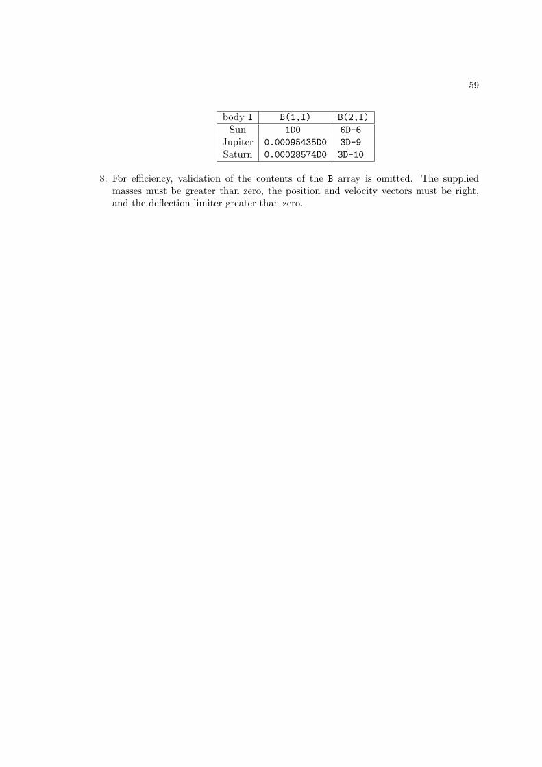
59
body I B(1,I) B(2,I)
Sun 1D0 6D-6
Jupiter 0.00095435D0 3D-9
Saturn 0.00028574D0 3D-10
8. For efficiency, validation of the contents of the B array is omitted. The suppliedmasses must be greater than zero, the position and velocity vectors must be right,and the deflection limiter greater than zero.
60 8 ALPHABETICAL LIST OF ROUTINES
iau_ATIO13 CIRS→ observed iau_ATIO13
CALL :
CALL iau_ATIO13 ( RI, DI, UTC1, UTC2, DUT1,
ELONG, PHI, HM, XP, YP,
PHPA, TC, RH, WL, AOB, ZOB, HOB, DOB, ROB, J )
ACTION :
CIRS [α, δ ] to observed place. The caller supplies UTC, site coordinates, ambient airconditions and observing wavelength.
GIVEN :
RI,DI d CIRS [α, δ ] (radians)UTC1 d UTC as a 2-part. . .UTC2 d . . . quasi Julian Date (Notes 1,2)DUT1 d UT1−UTC (seconds)ELONG d longitude (radians, east-positive, Note 3)PHI d geodetic latitude (radians, Note 3)HM d height above ellipsoid (m, geodetic Notes 4,6)XP,YP d polar motion coordinates (radians, Note 5)PHPA d pressure at the observer (hPa ≡ mB, Note 6)TC d ambient temperature at the observer (deg C)RH d relative humidity at the observer (range 0-1)WL d wavelength (micrometers, Note 7)
RETURNED :
AOB d observed azimuth (radians: N=0◦, E=90◦)ZOB d observed zenith distance (radians)HOB d observed hour angle (radians)DOB d observed declination (radians)ROB d observed right ascension (CIO-based, radians)J i status: +1 = dubious year (Note 2)
0 = OK−1 = unacceptable date
NOTES :
1. UTC1+UTC2 is quasi Julian Date (see Note 2), apportioned in any convenient waybetween the two arguments, for example where UTC1 is the Julian Day Number andUTC2 is the fraction of a day. However, JD cannot unambiguously represent UTCduring a leap second unless special measures are taken. The convention in the presentroutine is that the JD day represents UTC days whether the length is 86399, 86400or 86401 SI seconds.
Applications should use the routine iau_DTF2D to convert from calendar date and timeof day into two-part quasi Julian Date, as it implements the leap-second-ambiguityconvention just described.

61
2. The warning status “dubious year” flags UTCs that predate the introduction of thetime scale or that are too far in the future to be trusted. See iau_DAT for furtherdetails.
3. UT1−UTC is tabulated in IERS bulletins. It increases by exactly one second at theend of each positive UTC leap second, introduced in order to keep UT1−UTC within±0.9 s. n.b. This practice is under review, and in the future UT1−UTC may growessentially without limit.
4. The geographical coordinates are with respect to the WGS84 reference ellipsoid. Takecare with the longitude sign: the longitude required by the present routine is east-positive (i.e. right-handed), in accordance with geographical convention.
5. The polar motion XP,YP can be obtained from IERS bulletins. The values are thecoordinates (in radians) of the Celestial Intermediate Pole with respect to the Inter-national Terrestrial Reference System (see IERS Conventions 2003), measured alongthe meridians 0◦ and 90◦ west respectively. For many applications, XP and YP can beset to zero.
6. If h, the height above the ellipsoid of the observing station in meters, is not knownbut p, the pressure in hPa (≡mB), is available, an adequate estimate of h can beobtained from the expression
h = −29.3 t0 log(p/1013.25)
where t0 is the approximate sea-level air temperature in K (See Astrophysical Quan-tities, C.W.Allen, 3rd edition, Section 52). Similarly, if the pressure p is not known,it can be estimated from the height of the observing station, h, as follows:
p = 1013.25 e−h/(29.3t0)
Note, however, that the refraction is nearly proportional to the pressure and that anaccurate p value is important for precise work.
7. The argument WL specifies the observing wavelength in micrometers. The transitionfrom optical to radio is assumed to occur at 100µm (about 3000GHz).
8. “Observed” azimuth and zenith distance means the position that would be seen by aperfect geodetically aligned theodolite. (Zenith distance is used rather than altitudein order to reflect the fact that no allowance is made for depression of the horizon.)This is related to the observed [h, δ ] via the standard rotation, using the geodeticlatitude (corrected for polar motion), while the observed h and α are related simplythrough the Earth rotation angle and the site longitude. “Observed” [α, δ ] or [h, δ ]thus means the position that would be seen by a perfect equatorial with its polar axisaligned to the Earth’s axis of rotation.
9. The accuracy of the result is limited by the corrections for refraction, which use asimple A tan ζ +B tan3 ζ model. Providing the meteorological parameters are knownaccurately and there are no gross local effects, the predicted observed coordinatesshould be within 0′′.05 (optical) 1′′ (radio) for ζ < 70◦, better than 30′′ (optical orradio) at 85◦ and better than 0◦.3 (optical) or 0◦.5 (radio) at the horizon.
62 8 ALPHABETICAL LIST OF ROUTINES
Without refraction, the complementary routines iau_ATIO13 and iau_ATOI13 areself-consistent to better than 1µas all over the celestial sphere. With refractionincluded, consistency falls off at high zenith distances, but is still better than 0′′.05 atζ = 85◦.
10. It is advisable to take great care with units, as even unlikely values of the inputparameters are accepted and processed in accordance with the models used.
63
iau_ATIOQ quick CIRS→ observed iau_ATIOQ
CALL :
CALL iau_ATIOQ ( RI, DI, ASTROM, AOB, ZOB, HOB, DOB, ROB )
ACTION :
Quick CIRS to observed place transformation.
GIVEN :
RI,DI d CIRS [α, δ ] (radians)ASTROM d(30) star-independent astrometry parameters
RETURNED :
AOB d observed azimuth (radians: N=0◦, E=90◦)ZOB d observed zenith distance (radians)HOB d observed hour angle (radians)DOB d observed declination (radians)ROB d observed right ascension (CIO-based, radians)
NOTES :
1. This routine returns zenith distance rather than altitude in order to reflect the factthat no allowance is made for depression of the horizon.
2. The accuracy of the result is limited by the corrections for refraction, which use asimple A tan ζ +B tan3 ζ model. Providing the meteorological parameters are knownaccurately and there are no gross local effects, the predicted observed coordinatesshould be within 0′′.05 (optical) 1′′ (radio) for ζ < 70◦, better than 30′′ (optical orradio) at 85◦ and better than 0◦.3 (optical) or 0◦.5 (radio) at the horizon.
Without refraction, the complementary routines iau_ATIOQ and iau_ATOIQ are self-consistent to better than 1µas all over the celestial sphere. With refraction included,consistency falls off at high zenith distances, but is still better than 0′′.05 at ζ = 85◦.
3. It is advisable to take great care with units, as even unlikely values of the inputparameters are accepted and processed in accordance with the models used.
4. The CIRS [α, δ ] is obtained from a star catalog mean place by allowing for spacemotion, parallax, the Sun’s gravitational lens effect, annual aberration and precession-nutation. For star positions in the ICRS, these effects can be applied by means of theiau_ATCI13 (etc.) routines. Starting from classical “mean place” systems, additionaltransformations will be needed first.
5. “Observed” azimuth and zenith distance means the position that would be seen by aperfect geodetically aligned theodolite. (Zenith distance is used rather than altitudein order to reflect the fact that no allowance is made for depression of the horizon.)This is related to the observed [h, δ ] via the standard rotation, using the geodeticlatitude (corrected for polar motion), while the observed h and α are related simplythrough the Earth rotation angle and the site longitude. “Observed” [α, δ ] or [h, δ ]thus means the position that would be seen by a perfect equatorial observer and withits polar axis aligned to the Earth’s axis of rotation.
64 8 ALPHABETICAL LIST OF ROUTINES
6. The star-independent astrometry parameters in ASTROMmay be computed with iau_APIO[13]or iau_APCO[13]. If nothing has changed significantly except the time, iau_APER[13]may be used to perform the requisite adjustment to the ASTROM array.
65
iau_ATOC13 observed→ astrometric ICRS iau_ATOC13
CALL :
CALL iau_ATOC13 ( TYPE, OB1, OB2, UTC1, UTC2, DUT1,
ELONG, PHI, HM, XP, YP, PHPA, TC, RH, WL, RC, DC, J )
ACTION :
Observed place at a groundbased site to ICRS astrometric [α, δ ]. The caller supplies UTC,site coordinates, ambient air conditions and observing wavelength.
GIVEN :
TYPE c*(*) type of coordinates – R, H or A (Notes 1,2)OB1 d observed Az, HA or RA (radians; Az is N=0◦, E=90◦)OB2 d observed ZD or Dec (radians)UTC1 d UTC as a 2-part. . .UTC2 d . . . quasi Julian Date (Notes 3,4)DUT1 d UT1−UTC (seconds, Note 5)ELONG d longitude (radians, east-positive, Note 6)PHI d geodetic latitude (radians, Note 6)HM d height above ellipsoid (m, geodetic Notes 6,8)XP,YP d polar motion coordinates (radians, Note 7)PHPA d pressure at the observer (hPa ≡ mB, Note 8)TC d ambient temperature at the observer (deg C)RH d relative humidity at the observer (range 0-1)WL d wavelength (micrometers, Note 9)
RETURNED :
RC,DC d ICRS astrometric [α, δ ]J i status: +1 = dubious year (Note 4)
0 = OK−1 = unacceptable date
NOTES :
1. “Observed” azimuth and zenith distance means the position that would be seen by aperfect geodetically aligned theodolite. (Zenith distance is used rather than altitudein order to reflect the fact that no allowance is made for depression of the horizon.)This is related to the observed [h, δ ] via the standard rotation, using the geodeticlatitude (corrected for polar motion), while the observed h and α are related simplythrough the Earth rotation angle and the site longitude. “Observed” [α, δ ] or [h, δ ]thus means the position that would be seen by a perfect equatorial with its polar axisaligned to the Earth’s axis of rotation.

66 8 ALPHABETICAL LIST OF ROUTINES
2. Only the first character of the TYPE argument is significant. ‘R’ or ‘r’ indicates thatOB1 and OB2 are the observed right ascension and declination; ‘H’ or ‘h’ indicatesthat they are hour angle (west-positive) and declination; anything else (‘A’ or ‘a’ isrecommended) indicates that OB1 and OB2 are azimuth (north zero, east degi90) andzenith distance.
3. UTC1+UTC2 is quasi Julian Date (see Note 4), apportioned in any convenient waybetween the two arguments, for example where UTC1 is the Julian Day Number andUTC2 is the fraction of a day. However, JD cannot unambiguously represent UTCduring a leap second unless special measures are taken. The convention in the presentroutine is that the JD day represents UTC days whether the length is 86399, 86400or 86401 SI seconds.
Applications should use the routine iau_DTF2D to convert from calendar date and timeof day into two-part quasi Julian Date, as it implements the leap-second-ambiguityconvention just described.
4. The warning status “dubious year” flags UTCs that predate the introduction of thetime scale or that are too far in the future to be trusted. See iau_DAT for furtherdetails.
5. UT1−UTC is tabulated in IERS bulletins. It increases by exactly one second at theend of each positive UTC leap second, introduced in order to keep UT1−UTC within±0.9 s. n.b. This practice is under review, and in the future UT1−UTC may growessentially without limit.
6. The geographical coordinates are with respect to the WGS84 reference ellipsoid. Takecare with the longitude sign: the longitude required by the present routine is east-positive (i.e. right-handed), in accordance with geographical convention.
7. The polar motion XP,YP can be obtained from IERS bulletins. The values are thecoordinates (in radians) of the Celestial Intermediate Pole with respect to the Inter-national Terrestrial Reference System (see IERS Conventions 2003), measured alongthe meridians 0◦ and 90◦ west respectively. For many applications, XP and YP can beset to zero.
8. If h, the height above the ellipsoid of the observing station in meters, is not knownbut p, the pressure in hPa (≡mB), is available, an adequate estimate of h can beobtained from the expression
h = −29.3 t0 log(p/1013.25)
where t0 is the approximate sea-level air temperature in K (See Astrophysical Quan-tities, C.W.Allen, 3rd edition, Section 52). Similarly, if the pressure p is not known,it can be estimated from the height of the observing station, h, as follows:
p = 1013.25 e−h/(29.3t0)
Note, however, that the refraction is nearly proportional to the pressure and that anaccurate p value is important for precise work.
9. The argument WL specifies the observing wavelength in micrometers. The transitionfrom optical to radio is assumed to occur at 100µm (about 3000GHz).
67
10. The accuracy of the result is limited by the corrections for refraction, which use asimple A tan ζ +B tan3 ζ model. Providing the meteorological parameters are knownaccurately and there are no gross local effects, the predicted observed coordinatesshould be within 0′′.05 (optical) 1′′ (radio) for ζ < 70◦, better than 30′′ (optical orradio) at 85◦ and better than 0◦.3 (optical) or 0◦.5 (radio) at the horizon.
Without refraction, the complementary routines iau_ATCO13 and iau_ATOC13 areself-consistent to better than 1µas all over the celestial sphere. With refractionincluded, consistency falls off at high zenith distances, but is still better than 0′′.05 atζ = 85◦.
11. It is advisable to take great care with units, as even unlikely values of the inputparameters are accepted and processed in accordance with the models used.
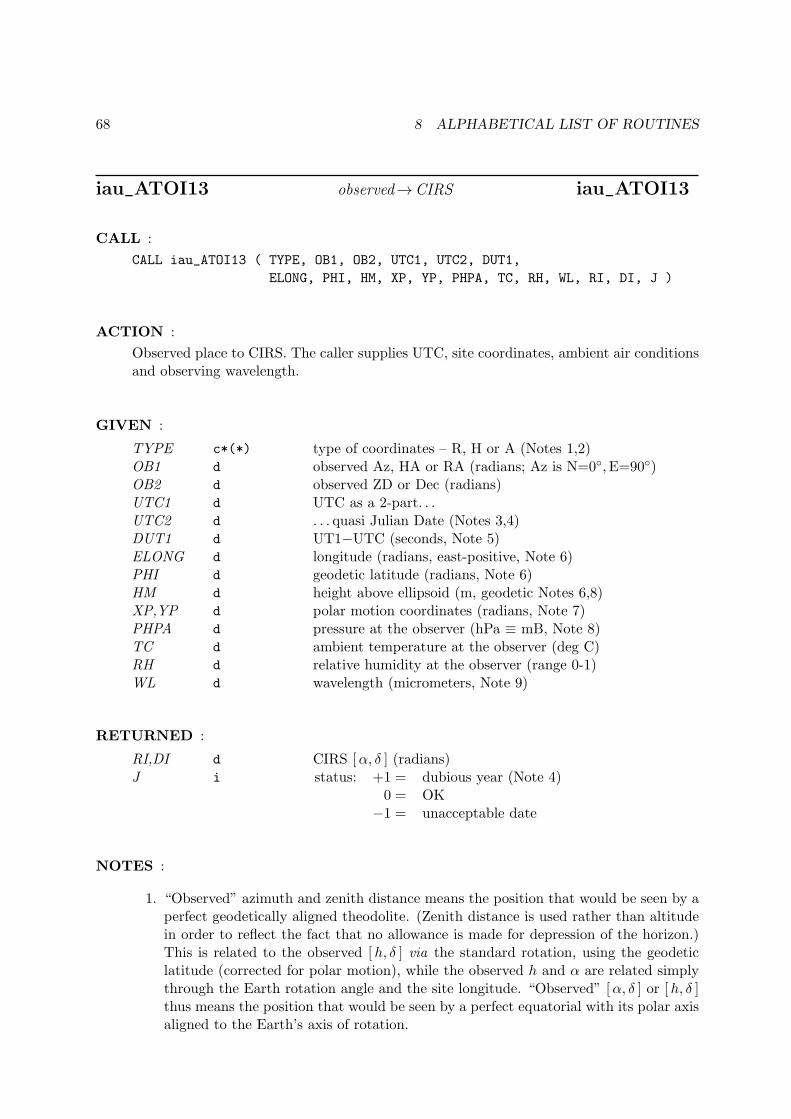
68 8 ALPHABETICAL LIST OF ROUTINES
iau_ATOI13 observed→CIRS iau_ATOI13
CALL :
CALL iau_ATOI13 ( TYPE, OB1, OB2, UTC1, UTC2, DUT1,
ELONG, PHI, HM, XP, YP, PHPA, TC, RH, WL, RI, DI, J )
ACTION :
Observed place to CIRS. The caller supplies UTC, site coordinates, ambient air conditionsand observing wavelength.
GIVEN :
TYPE c*(*) type of coordinates – R, H or A (Notes 1,2)OB1 d observed Az, HA or RA (radians; Az is N=0◦, E=90◦)OB2 d observed ZD or Dec (radians)UTC1 d UTC as a 2-part. . .UTC2 d . . . quasi Julian Date (Notes 3,4)DUT1 d UT1−UTC (seconds, Note 5)ELONG d longitude (radians, east-positive, Note 6)PHI d geodetic latitude (radians, Note 6)HM d height above ellipsoid (m, geodetic Notes 6,8)XP,YP d polar motion coordinates (radians, Note 7)PHPA d pressure at the observer (hPa ≡ mB, Note 8)TC d ambient temperature at the observer (deg C)RH d relative humidity at the observer (range 0-1)WL d wavelength (micrometers, Note 9)
RETURNED :
RI,DI d CIRS [α, δ ] (radians)J i status: +1 = dubious year (Note 4)
0 = OK−1 = unacceptable date
NOTES :
1. “Observed” azimuth and zenith distance means the position that would be seen by aperfect geodetically aligned theodolite. (Zenith distance is used rather than altitudein order to reflect the fact that no allowance is made for depression of the horizon.)This is related to the observed [h, δ ] via the standard rotation, using the geodeticlatitude (corrected for polar motion), while the observed h and α are related simplythrough the Earth rotation angle and the site longitude. “Observed” [α, δ ] or [h, δ ]thus means the position that would be seen by a perfect equatorial with its polar axisaligned to the Earth’s axis of rotation.
69
2. Only the first character of the TYPE argument is significant. ‘R’ or ‘r’ indicates thatOB1 and OB2 are the observed right ascension and declination; ‘H’ or ‘h’ indicatesthat they are hour angle (west-positive) and declination; anything else (‘A’ or ‘a’ isrecommended) indicates that OB1 and OB2 are azimuth (north zero, east degi90) andzenith distance.
3. UTC1+UTC2 is quasi Julian Date (see Note 4), apportioned in any convenient waybetween the two arguments, for example where UTC1 is the Julian Day Number andUTC2 is the fraction of a day. However, JD cannot unambiguously represent UTCduring a leap second unless special measures are taken. The convention in the presentroutine is that the JD day represents UTC days whether the length is 86399, 86400or 86401 SI seconds.
Applications should use the routine iau_DTF2D to convert from calendar date and timeof day into two-part quasi Julian Date, as it implements the leap-second-ambiguityconvention just described.
4. The warning status “dubious year” flags UTCs that predate the introduction of thetime scale or that are too far in the future to be trusted. See iau_DAT for furtherdetails.
5. UT1−UTC is tabulated in IERS bulletins. It increases by exactly one second at theend of each positive UTC leap second, introduced in order to keep UT1−UTC within±0.9 s. n.b. This practice is under review, and in the future UT1−UTC may growessentially without limit.
6. The geographical coordinates are with respect to the WGS84 reference ellipsoid. Takecare with the longitude sign: the longitude required by the present routine is east-positive (i.e. right-handed), in accordance with geographical convention.
7. The polar motion XP,YP can be obtained from IERS bulletins. The values are thecoordinates (in radians) of the Celestial Intermediate Pole with respect to the Inter-national Terrestrial Reference System (see IERS Conventions 2003), measured alongthe meridians 0◦ and 90◦ west respectively. For many applications, XP and YP can beset to zero.
8. If h, the height above the ellipsoid of the observing station in meters, is not knownbut p, the pressure in hPa (≡mB), is available, an adequate estimate of h can beobtained from the expression
h = −29.3 t0 log(p/1013.25)
where t0 is the approximate sea-level air temperature in K (See Astrophysical Quan-tities, C.W.Allen, 3rd edition, Section 52). Similarly, if the pressure p is not known,it can be estimated from the height of the observing station, h, as follows:
p = 1013.25 e−h/(29.3t0)
Note, however, that the refraction is nearly proportional to the pressure and that anaccurate p value is important for precise work.
9. The argument WL specifies the observing wavelength in micrometers. The transitionfrom optical to radio is assumed to occur at 100µm (about 3000GHz).
70 8 ALPHABETICAL LIST OF ROUTINES
10. The accuracy of the result is limited by the corrections for refraction, which use asimple A tan ζ +B tan3 ζ model. Providing the meteorological parameters are knownaccurately and there are no gross local effects, the predicted observed coordinatesshould be within 0′′.05 (optical) 1′′ (radio) for ζ < 70◦, better than 30′′ (optical orradio) at 85◦ and better than 0◦.3 (optical) or 0◦.5 (radio) at the horizon.
Without refraction, the complementary routines iau_ATIO13 and iau_ATOI13 areself-consistent to better than 1µas all over the celestial sphere. With refractionincluded, consistency falls off at high zenith distances, but is still better than 0′′.05 atζ = 85◦.
11. It is advisable to take great care with units, as even unlikely values of the inputparameters are accepted and processed in accordance with the models used.

71
iau_ATOIQ quick observed→CIRS iau_ATOIQ
CALL :
CALL iau_ATOIQ ( TYPE, OB1, OB2, ASTROM, RI, DI )
ACTION :
Quick observed place to CIRS transformation, given the star-independent astrometry pa-rameters.
GIVEN :
TYPE c*(*) type of coordinates – R, H or A (Notes 1,2)OB1 d observed Az, HA or RA (radians; Az is N=0◦, E=90◦)OB2 d observed ZD or Dec (radians)ASTROM d(30) star-independent astrometry parameters
RETURNED :
RI,DI d CIRS [α, δ ] (radians)
NOTES :
1. Only the first character of the TYPE argument is significant. ‘R’ or ‘r’ indicates thatOB1 and OB2 are the observed right ascension and declination; ‘H’ or ‘h’ indicatesthat they are hour angle (west-positive) and declination; anything else (‘A’ or ‘a’ isrecommended) indicates that OB1 and OB2 are azimuth (north zero, east degi90) andzenith distance.
2. “Observed” azimuth and zenith distance means the position that would be seen by aperfect geodetically aligned theodolite. (Zenith distance is used rather than altitudein order to reflect the fact that no allowance is made for depression of the horizon.)This is related to the observed [h, δ ] via the standard rotation, using the geodeticlatitude (corrected for polar motion), while the observed h and α are related simplythrough the Earth rotation angle and the site longitude. “Observed” [α, δ ] or [h, δ ]thus means the position that would be seen by a perfect equatorial with its polar axisaligned to the Earth’s axis of rotation.
3. The accuracy of the result is limited by the corrections for refraction, which use asimple A tan ζ +B tan3 ζ model. Providing the meteorological parameters are knownaccurately and there are no gross local effects, the predicted observed coordinatesshould be within 0′′.05 (optical) 1′′ (radio) for ζ < 70◦, better than 30′′ (optical orradio) at 85◦ and better than 0◦.3 (optical) or 0◦.5 (radio) at the horizon.
Without refraction, the complementary routines iau_ATIOQ and iau_ATOIQ are self-consistent to better than 1µas all over the celestial sphere. With refraction included,consistency falls off at high zenith distances, but is still better than 0′′.05 at ζ = 85◦.
4. It is advisable to take great care with units, as even unlikely values of the inputparameters are accepted and processed in accordance with the models used.
5. The star-independent astrometry parameters in ASTROMmay be computed with iau_APIO[13]or iau_APIO[13]. If nothing has changed significantly except the time, iau_APER[13]may be used to perform the requisite adjustment to the ASTROM array.
72 8 ALPHABETICAL LIST OF ROUTINES
iau_HD2AE [h, δ ] to [Az,El ] iau_HD2AE
CALL :
CALL iau_HD2AE ( HA, DEC, PHI, AZ, EL )
ACTION :
Horizon to equatorial coordinates: transform hour angle and declination to azimuth andaltitude.
GIVEN :
HA d hour angleDEC d declinationPHI d site latitude (Note 3)
RETURNED :
AZ d azimuthEL d elevation (≡ altitude)
NOTES :
1. All the arguments are angles in radians.
2. Azimuth is returned in the range 0− 2π; north is zero, and east is +π/2. Altitude isreturned in the range ±π/2.
3. The latitude PHI is π/2 minus the angle between the Earth’s rotation axis and theadopted zenith (Note 5). In many applications it will be sufficient to use the publishedgeodetic latitude of the site. In very precise (sub-arcsecond) applications, PHI can becorrected for polar motion.
4. The returned azimuth AZ is with respect to the rotational north pole, as opposedto the ITRS pole, and for sub-arcsecond accuracy will need to be adjusted for polarmotion if it is to be with respect to north on a map of the Earth’s surface.
5. Should the user wish to work with respect to the astronomical horizon rather thanthe geodetic horizon, PHI will need to be adjusted for deflection of the vertical (oftentens of arcseconds), and the zero point of HA will also be affected.
6. The transformation is the same as Vh = Rz(π)Ry(π/2 − ϕ)Ve, where Vh and Ve
are lefthanded unit vectors in the [Az,El ] and [h, δ ] systems respectively and Ry
and Rz are rotations about first the y-axis and then the z-axis. (n.b. Rz(π) simplyreverses the signs of the x and y components.) For efficiency, the algorithm is writtenout rather than calling other utility functions. For applications that require evengreater efficiency, additional savings are possible if constant terms such as functionsof latitude are computed once and for all.
7. Again for efficiency, no range checking of arguments is carried out.
73
iau_HD2PA parallactic angle iau_HD2PA
CALL :
PA = iau_HD2PA ( HA, DEC, PHI )
ACTION :
Parallactic angle for a given hour angle and declination.
GIVEN :
HA d hour angleDEC d declinationPHI d site latitude (Note 5)
RETURNED (function value) :
d parallactic angle
NOTES :
1. All the arguments, and the result, are angles in radians.
2. The parallactic angle at a point in the sky is the position angle of the vertical, i.e. theangle between the directions to the north celestial pole and to the zenith respectively.
3. The result is returned in the range ±π.
4. At the pole itself a zero result is returned.
5. The latitude PHI is π/2 minus the angle between the Earth’s rotation axis and theadopted zenith (Note 6). In many applications it will be sufficient to use the publishedgeodetic latitude of the site. In very precise (sub-arcsecond) applications, PHI can becorrected for polar motion.
6. Should the user wish to work with respect to the astronomical zenith rather than thegeodetic zenith, PHI will need to be adjusted for deflection of the vertical (often tensof arcseconds), and the zero point of the hour angle HA will also be affected.
74 8 ALPHABETICAL LIST OF ROUTINES
iau_LD light deflection by a solar-system body iau_LD
CALL :
CALL iau_LD ( BM, P, Q, E, EM, DLIM, P1 )
ACTION :
Apply light deflection by a solar-system body, as part of transforming coordinate directioninto natural direction.
GIVEN :
BM d mass of the gravitating body (solar masses)P d(3) direction from observer to source (unit vector)Q d(3) direction from body to source (unit vector)E d(3) direction from body to observer (unit vector)EM d distance from body to observer (au)DLIM d deflection limiter (Note 4)
RETURNED :
P1 d(3) observer to deflected source (unit vector)
NOTES :
1. The algorithm is based on Eq. (70) in Klioner (2003) and Eq. (7.63) in Urban &Seidelmann (2013), with some rearrangement to minimize the effects of machine pre-cision.
2. The mass parameter BM can, as required, be adjusted in order to allow for such effectsas quadrupole field.
3. The barycentric position of the deflecting body should ideally correspond to the timeof closest approach of the light ray to the body.
4. The deflection limiter parameter DLIM is ϕ2/2, where ϕ is the separation (in radians)between star and body at which limiting is applied. As ϕ shrinks below the chosenthreshold, the deflection is artificially reduced, reaching zero for ϕ = 0.
5. The returned vector P1 is not normalized, but the consequential departure from unitmagnitude is always negligible.
6. To accumulate total light deflection taking into account the contributions from severalbodies, call the present routine for each body in succession, in decreasing order ofdistance from the observer.
7. For efficiency, validation is omitted. The supplied vectors must be of unit magnitude,and the deflection limiter non-zero and positive.

75
iau_LDN light deflection by n solar-system bodies iau_LDN
CALL :
CALL iau_LDN ( N, B, OB, SC, SN )
ACTION :
For a star, apply light deflection by multiple solar-system bodies, as part of transformingcoordinate direction into natural direction.
GIVEN :
N i number of bodies (Note 1)B d(8,N) data for each of the N bodies (Notes 1,2)OB d(3) barycentric position of the observer (au)SC d(3) observer to star coordinate direction (unit vector)
RETURNED :
SN d(3) observer to deflected star (unit vector)
NOTES :
1. The array B contains N entries, one for each body to be considered. If N = 0, nogravitational light deflection will be applied, not even for the Sun.
2. The array B should include an entry for the Sun as well as for any planet or otherbody to be taken into account. The entries should be in the order in which the lightpasses the body.
3. In the entry in the B array for body I, the mass parameter B(1,I) can, as required,be adjusted in order to allow for such effects as quadrupole field.
4. The deflection limiter parameter B(2,I) is ϕ2/2, where ϕ is the angular separation(in radians) between star and body at which limiting is applied. As ϕ shrinks belowthe chosen threshold, the deflection is artificially reduced, reaching zero for ϕ = 0.Example values suitable for a terrestrial observer, together with masses, are as follows:
body I B(1,I) B(2,I)
Sun 1D0 6D-6
Jupiter 0.00095435D0 3D-9
Saturn 0.00028574D0 3D-10
5. For cases where the starlight passes the body before reaching the observer, the bodyis placed back along its barycentric track by the light time from that point to theobserver. For cases where the body is “behind” the observer no such shift is applied.If a different treatment is preferred, the user has the option of instead using theiau_LD routine. Similarly, iau_LD can be used for cases where the source is nearby,not a star.
6. The returned vector SN is not normalized, but the consequential departure from unitmagnitude is always negligible.
7. For efficiency, validation is omitted. The supplied masses must be greater than zero,the position and velocity vectors must be right, and the deflection limiter greaterthan zero.
76 8 ALPHABETICAL LIST OF ROUTINES
iau_LDSUN light deflection by the Sun iau_LDSUN
CALL :
CALL iau_LDSUN ( P, E, EM, P1 )
ACTION :
Deflection of starlight by the Sun.
GIVEN :
P d(3) direction from observer to star (unit vector)E d(3) direction from body to observer (unit vector)EM d distance from body to observer (au)
RETURNED :
P1 d(3) observer to deflected star (unit vector)
NOTES :
1. The source is presumed to be sufficiently distant that its directions seen from the Sunand the observer are essentially the same.
2. The deflection is restrained when the angle between the star and the center of theSun is less than a threshold value, falling to zero deflection for zero separation. Thechosen threshold value is within the solar limb for all solar-system applications, andis about 5 arcminutes for the case of a terrestrial observer.

77
iau_PMPX proper motion & parallax iau_PMPX
CALL :
CALL iau_PMPX ( RC, DC, PR, PD, PX, RV, PMT, POB, PCO )
ACTION :
Proper motion and parallax.
GIVEN :
RC,DC d ICRS [α, δ ] at catalog epoch (radians)PR d RA proper motion (radians/year; Note 1)PD d Dec proper motion (radians/year)PX d parallax (arcsec)RV d radial velocity (km/s, positive if receding)PMT d proper motion time interval (SSB, Julian years)POB d(3) SSB to observer vector (au)
RETURNED :
PCO d(3) coordinate direction (BCRS unit vector)
NOTES :
1. The proper motion in right ascension is α rather than α cos δ.
2. To avoid the need for iteration, the Rømer effect (i.e. the small annual modulationof the proper motion coming from the changing light time) is applied approximately,using the direction of the star at the catalog epoch.
3. The algorithm used is non-relativistic: see the 1984 Astronomical Almanac, pp B39-B41, and Chapter 3 in Urban & Seidelmann (2013). An alternative implementationthat uses an SR-compliant algorithm is given in Appendix A.

78 8 ALPHABETICAL LIST OF ROUTINES
iau_PMSAFE star µ with low parallax precautions iau_PMSAFE
CALL :
CALL iau_PMSAFE ( RA1, DEC1, PMR1, PMD1, PX1, RV1,
EP1A, EP1B, EP2A, EP2B,
RA2, DEC2, PMR2, PMD2, PX2, RV2, J )
ACTION :
Star proper motion: update star catalog data for space motion, with special handling tohandle the zero parallax case.
GIVEN :
RA1 d α (radians), beforeDEC1 d δ (radians), beforePMR1 d α proper motion (radians/year), beforePMD1 d δ proper motion (radians/year), beforePX1 d parallax (arcseconds), beforeRV1 d radial velocity (km/s, +ve = receding), beforeEP1A d “before” epoch, part A (Note 1)EP1B d “before” epoch, part B (Note 1)EP2A d “after” epoch, part A (Note 1)EP2B d “after” epoch, part B (Note 1)
RETURNED :
RA2 d α (radians), afterDEC2 d δ (radians), afterPMR2 d α proper motion (radians/year), afterPMD2 d δ proper motion (radians/year), afterPX2 d parallax (arcseconds), afterRV2 d radial velocity (km/s, +ve = receding), afterJ i status: −1 = system error (should not occur)
0 = no warnings or errors1 = distance overridden (Note 6)2 = excessive velocity (Note 7)4 = solution didn’t converge (Note 8)
else = binary logical OR of the above warnings
NOTES :
1. The starting and ending TDB epochs EP1A+EP1B and EP2A+EP2B are Julian Dates,apportioned in any convenient way between the two parts (A and B). For example,JD(TDB)=2450123.7 could be expressed in any of these ways, among others:
79
EPnA EPnB
2450123.7 0.0 (JD method)2451545.0 −1421.3 (J2000 method)2400000.5 50123.2 (MJD method)2450123.5 0.2 (date & time method)
The JD method is the most natural and convenient to use in cases where the loss ofseveral decimal digits of resolution is acceptable. The J2000 method is best matchedto the way the argument is handled internally and will deliver the optimum resolution.The MJD method and the date & time methods are both good compromises betweenresolution and convenience. For most applications of this function the choice will notbe at all critical.
2. In accordance with normal star-catalog conventions, the object’s right ascension anddeclination are freed from the effects of secular aberration. The frame, which isaligned to the catalog equator and equinox, is Lorentzian and centered on the SSB.
3. The proper motions are the rate of change of the right ascension and declination atthe catalog epoch and are in radians per TDB Julian year.
4. The parallax and radial velocity are in the same frame.
5. Care is needed with units. The star coordinates are in radians and the proper motionsin radians per Julian year, but the parallax is in arcseconds.
6. The α proper motion is in terms of coordinate angle, not true angle on the sky. If thecatalog uses arcseconds (or mas etc.) not just for µδ but for µα as well, the tabulatedα proper motion will need to be divided by cos δ before use with the present routine.
7. Straight-line motion at constant speed, in the inertial frame, is assumed.
8. An extremely small (or zero or negative) parallax is overridden to ensure that theobject is at a finite but very large distance, but not so large that the proper motionis equivalent to a large but safe speed (about 0.1c using the chosen constant). Awarning status of 1 is added to the status if this action has been taken.
9. If the space velocity is a significant fraction of c (see the constant VMAX in the routineiau_STARPV), it is arbitrarily set to zero. When this action occurs, 2 is added to thestatus.
10. The relativistic adjustment carried out in the iau_STARPV routine involves an iterativecalculation. If the process fails to converge within a set number of iterations, 4 isadded to the status.
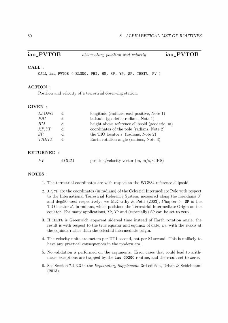
80 8 ALPHABETICAL LIST OF ROUTINES
iau_PVTOB observatory position and velocity iau_PVTOB
CALL :
CALL iau_PVTOB ( ELONG, PHI, HM, XP, YP, SP, THETA, PV )
ACTION :
Position and velocity of a terrestrial observing station.
GIVEN :
ELONG d longitude (radians, east-positive, Note 1)PHI d latitude (geodetic, radians, Note 1)HM d height above reference ellipsoid (geodetic, m)XP,YP d coordinates of the pole (radians, Note 2)SP d the TIO locator s’ (radians, Note 2)THETA d Earth rotation angle (radians, Note 3)
RETURNED :
PV d(3,2) position/velocity vector (m, m/s, CIRS)
NOTES :
1. The terrestrial coordinates are with respect to the WGS84 reference ellipsoid.
2. XP,YP are the coordinates (in radians) of the Celestial Intermediate Pole with respectto the International Terrestrial Reference System, measured along the meridians 0◦
and degi90 west respectively; see McCarthy & Petit (2003), Chapter 5. SP is theTIO locator s′, in radians, which positions the Terrestrial Intermediate Origin on theequator. For many applications, XP, YP and (especially) SP can be set to zero.
3. If THETA is Greenwich apparent sidereal time instead of Earth rotation angle, theresult is with respect to the true equator and equinox of date, i.e. with the x-axis atthe equinox rather than the celestial intermediate origin.
4. The velocity units are meters per UT1 second, not per SI second. This is unlikely tohave any practical consequences in the modern era.
5. No validation is performed on the arguments. Error cases that could lead to arith-metic exceptions are trapped by the iau_GD2GC routine, and the result set to zeros.
6. See Section 7.4.3.3 in the Explanatory Supplement, 3rd edition, Urban & Seidelmann(2013).
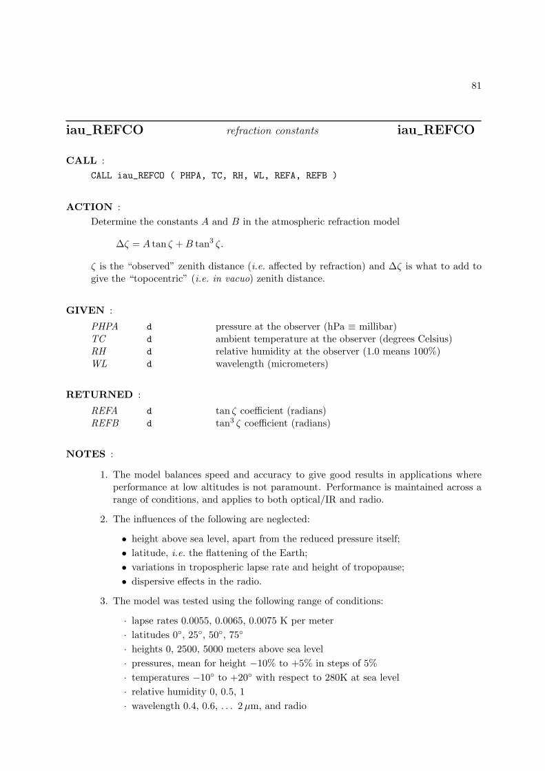
81
iau_REFCO refraction constants iau_REFCO
CALL :
CALL iau_REFCO ( PHPA, TC, RH, WL, REFA, REFB )
ACTION :
Determine the constants A and B in the atmospheric refraction model
∆ζ = A tan ζ +B tan3 ζ.
ζ is the “observed” zenith distance (i.e. affected by refraction) and ∆ζ is what to add togive the “topocentric” (i.e. in vacuo) zenith distance.
GIVEN :
PHPA d pressure at the observer (hPa ≡ millibar)TC d ambient temperature at the observer (degrees Celsius)RH d relative humidity at the observer (1.0 means 100%)WL d wavelength (micrometers)
RETURNED :
REFA d tan ζ coefficient (radians)REFB d tan3 ζ coefficient (radians)
NOTES :
1. The model balances speed and accuracy to give good results in applications whereperformance at low altitudes is not paramount. Performance is maintained across arange of conditions, and applies to both optical/IR and radio.
2. The influences of the following are neglected:
• height above sea level, apart from the reduced pressure itself;
• latitude, i.e. the flattening of the Earth;
• variations in tropospheric lapse rate and height of tropopause;
• dispersive effects in the radio.
3. The model was tested using the following range of conditions:
· lapse rates 0.0055, 0.0065, 0.0075 K per meter
· latitudes 0◦, 25◦, 50◦, 75◦
· heights 0, 2500, 5000 meters above sea level
· pressures, mean for height −10% to +5% in steps of 5%
· temperatures −10◦ to +20◦ with respect to 280K at sea level
· relative humidity 0, 0.5, 1
· wavelength 0.4, 0.6, . . . 2µm, and radio
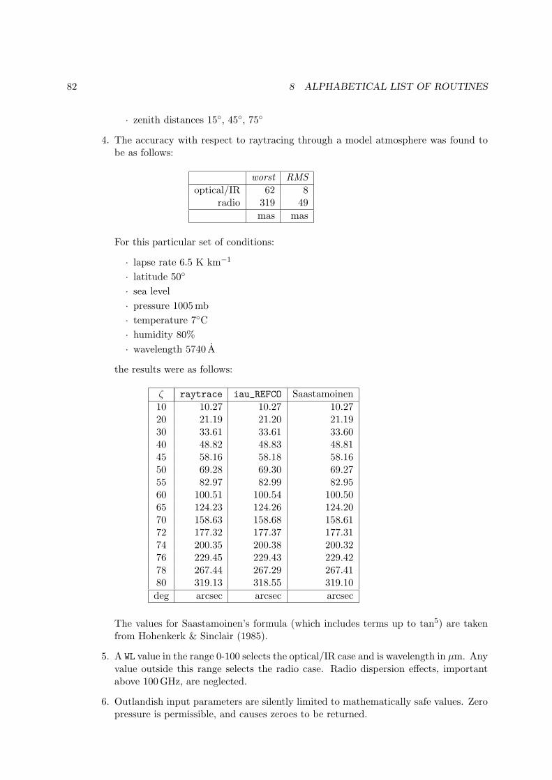
82 8 ALPHABETICAL LIST OF ROUTINES
· zenith distances 15◦, 45◦, 75◦
4. The accuracy with respect to raytracing through a model atmosphere was found tobe as follows:
worst RMS
optical/IR 62 8radio 319 49
mas mas
For this particular set of conditions:
· lapse rate 6.5 K km−1
· latitude 50◦
· sea level
· pressure 1005mb
· temperature 7◦C
· humidity 80%
· wavelength 5740 A
the results were as follows:
ζ raytrace iau_REFCO Saastamoinen
10 10.27 10.27 10.2720 21.19 21.20 21.1930 33.61 33.61 33.6040 48.82 48.83 48.8145 58.16 58.18 58.1650 69.28 69.30 69.2755 82.97 82.99 82.9560 100.51 100.54 100.5065 124.23 124.26 124.2070 158.63 158.68 158.6172 177.32 177.37 177.3174 200.35 200.38 200.3276 229.45 229.43 229.4278 267.44 267.29 267.4180 319.13 318.55 319.10
deg arcsec arcsec arcsec
The values for Saastamoinen’s formula (which includes terms up to tan5) are takenfrom Hohenkerk & Sinclair (1985).
5. A WL value in the range 0-100 selects the optical/IR case and is wavelength in µm. Anyvalue outside this range selects the radio case. Radio dispersion effects, importantabove 100GHz, are neglected.
6. Outlandish input parameters are silently limited to mathematically safe values. Zeropressure is permissible, and causes zeroes to be returned.
83
• The formula for the saturation vapour pressure of water as a function of temper-ature and temperature is taken from Equations (A4.5-A4.7) of Gill (1982).
• The formula for the water vapour pressure, given the saturation pressure and therelative humidity is from Crane (1976), Equation (2.5.5).
• The refractivity of air is a function of temperature, total pressure, water-vapourpressure and, in the case of optical/IR, wavelength. The formulae for the twocases are developed from Hohenkerk & Sinclair (1985) and Rueger (2002).
• The formula for β (= H0/r0) is an adaption of Equation (9) from Stone (1996).The adaptations, arrived at empirically, consist of (i) a small adjustment to thecoefficient and (ii) a humidity term for the radio case only.
• The formulae for the refraction constants as a function of n − 1 and β are fromGreen (1987), Equation (4.31).
7. The sign conventions for the coefficients are such that A is positive and B (muchsmaller) is negative.
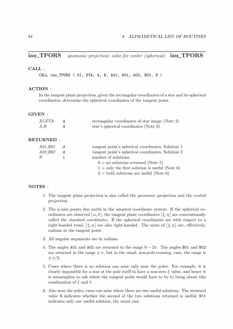
84 8 ALPHABETICAL LIST OF ROUTINES
iau_TPORS gnomonic projection: solve for center (spherical) iau_TPORS
CALL :
CALL iau_TPORS ( XI, ETA, A, B, A01, B01, A02, B02, N )
ACTION :
In the tangent plane projection, given the rectangular coordinates of a star and its sphericalcoordinates, determine the spherical coordinates of the tangent point.
GIVEN :
XI,ETA d rectangular coordinates of star image (Note 2)A,B d star’s spherical coordinates (Note 3)
RETURNED :
A01,B01 d tangent point’s spherical coordinates, Solution 1A02,B02 d tangent point’s spherical coordinates, Solution 2N i number of solutions:
0 = no solutions returned (Note 5)1 = only the first solution is useful (Note 6)2 = both solutions are useful (Note 6)
NOTES :
1. The tangent plane projection is also called the gnomonic projection and the centralprojection.
2. The η-axis points due north in the adopted coordinate system. If the spherical co-ordinates are observed [α, δ ], the tangent plane coordinates [ ξ, η ] are conventionallycalled the standard coordinates. If the spherical coordinates are with respect to aright-handed triad, [ ξ, η ] are also right-handed. The units of [ ξ, η ] are, effectively,radians at the tangent point.
3. All angular arguments are in radians.
4. The angles A01 and A02 are returned in the range 0 − 2π. The angles B01 and B02
are returned in the range ±π, but in the usual, non-pole-crossing, case, the range is±π/2.
5. Cases where there is no solution can arise only near the poles. For example, it isclearly impossible for a star at the pole itself to have a non-zero ξ value, and hence itis meaningless to ask where the tangent point would have to be to bring about thiscombination of ξ and δ.
6. Also near the poles, cases can arise where there are two useful solutions. The returnedvalue N indicates whether the second of the two solutions returned is useful; N=1
indicates only one useful solution, the usual case.
85
7. The basis of the algorithm is to solve the spherical triangle PSC, where P is the northcelestial pole, S is the star and C is the tangent point. The spherical coordinates of thestar and tangent point are [a, b] and [a0, b0]; writing ρ2 = (ξ2+ η2) and r2 = (1+ ρ2),side c is then (π/2− b), side p is (ξ2 + η2)1/2 and side s (to be found) is (π/2− b0).Angle C is given by sinC = ξ/ρ and cosC = η/ρ. Angle P (to be found) is thelongitude difference between star and tangent point (a− a0).
8. This routine is a member of the following set:
spherical vector solve for
iau_TPXES iau_TPXEV imageiau_TPSTS iau_TPSTV stariau_TPORS iau_TPORV origin
86 8 ALPHABETICAL LIST OF ROUTINES
iau_TPORV gnomonic projection: solve for center (vector) iau_TPORV
CALL :
CALL iau_TPORV ( XI, ETA, V, V01, V02, N )
ACTION :
In the tangent plane projection, given the rectangular coordinates of a star and its directioncosines, determine the direction cosines of the tangent point.
GIVEN :
XI,ETA d rectangular coordinates of star image (Note 2)V d(3) star’s direction cosines (Note 3)
RETURNED :
V01 d(3) tangent point’s direction cosines, Solution 1V02 d(3) tangent point’s direction cosines, Solution 2N i number of solutions:
0 = no solutions returned (Note 4)1 = only the first solution is useful (Note 5)2 = both solutions are useful (Note 5)
NOTES :
1. The tangent plane projection is also called the gnomonic projection and the centralprojection.
2. The η-axis points due north in the adopted coordinate system. If the direction cosinesrepresent observed [α, δ ], the tangent plane coordinates [ ξ, η ] are conventionallycalled the standard coordinates. If the direction cosines are with respect to a right-handed triad, [ ξ, η ] are also right-handed. The units of [ ξ, η ] are, effectively, radiansat the tangent point.
3. The vector V must be of unit length or the result will be wrong.
4. Cases where there is no solution can arise only near the poles. For example, it isclearly impossible for a star at the pole itself to have a non-zero ξ value, and henceit is meaningless to ask where the tangent point would have to be.
5. Also near the poles, cases can arise where there are two useful solutions. The returnedvalue N indicates whether the second of the two solutions returned is useful; N=1
indicates only one useful solution, the usual case.
6. The basis of the algorithm is to solve the spherical triangle PSC, where P is the northcelestial pole, S is the star and C is the tangent point. The spherical coordinates of thestar and tangent point are [a, b] and [a0, b0]; writing ρ2 = (ξ2+ η2) and r2 = (1+ ρ2),side c is then (π/2− b), side p is (ξ2 + η2)1/2 and side s (to be found) is (π/2− b0).Angle C is given by sinC = ξ/ρ and cosC = η/ρ. Angle P (to be found) is thelongitude difference between star and tangent point (a− a0).
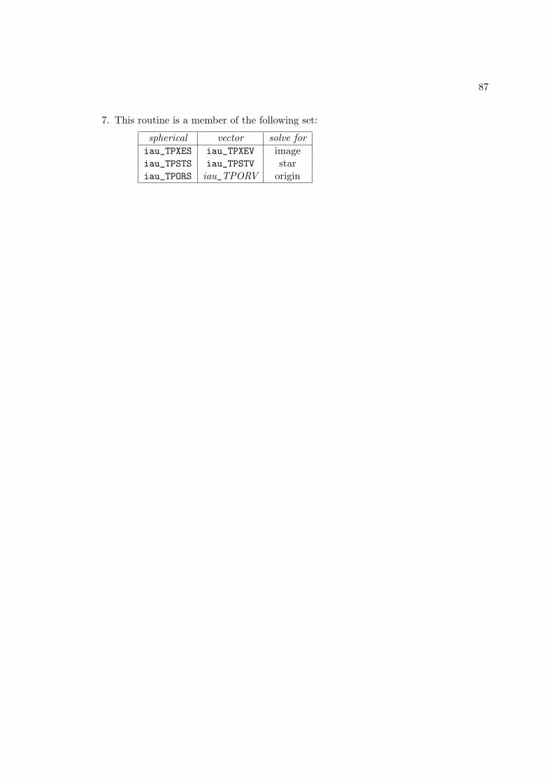
87
7. This routine is a member of the following set:
spherical vector solve for
iau_TPXES iau_TPXEV imageiau_TPSTS iau_TPSTV stariau_TPORS iau_TPORV origin
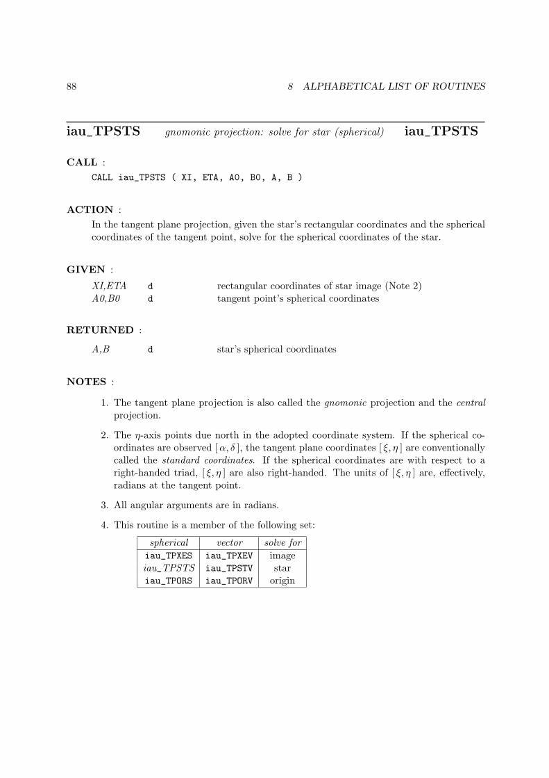
88 8 ALPHABETICAL LIST OF ROUTINES
iau_TPSTS gnomonic projection: solve for star (spherical) iau_TPSTS
CALL :
CALL iau_TPSTS ( XI, ETA, A0, B0, A, B )
ACTION :
In the tangent plane projection, given the star’s rectangular coordinates and the sphericalcoordinates of the tangent point, solve for the spherical coordinates of the star.
GIVEN :
XI,ETA d rectangular coordinates of star image (Note 2)A0,B0 d tangent point’s spherical coordinates
RETURNED :
A,B d star’s spherical coordinates
NOTES :
1. The tangent plane projection is also called the gnomonic projection and the centralprojection.
2. The η-axis points due north in the adopted coordinate system. If the spherical co-ordinates are observed [α, δ ], the tangent plane coordinates [ ξ, η ] are conventionallycalled the standard coordinates. If the spherical coordinates are with respect to aright-handed triad, [ ξ, η ] are also right-handed. The units of [ ξ, η ] are, effectively,radians at the tangent point.
3. All angular arguments are in radians.
4. This routine is a member of the following set:
spherical vector solve for
iau_TPXES iau_TPXEV imageiau_TPSTS iau_TPSTV stariau_TPORS iau_TPORV origin

89
iau_TPSTV gnomonic projection: solve for star (vector) iau_TPSTV
CALL :
CALL iau_TPSTV ( XI, ETA, V0, V )
ACTION :
In the tangent plane projection, given the star’s rectangular coordinates and the directioncosines of the tangent point, solve for the direction cosines of the star.
GIVEN :
XI,ETA d rectangular coordinates of star image (Note 2)V0 d(3) tangent point’s direction cosines (Note 4)
RETURNED :
V d(3) star’s direction cosines
NOTES :
1. The tangent plane projection is also called the gnomonic projection and the centralprojection.
2. The η-axis points due north in the adopted coordinate system. If the direction cosinesrepresent observed [α, δ ], the tangent plane coordinates [ ξ, η ] are conventionallycalled the standard coordinates. If the direction cosines are with respect to a right-handed triad, [ ξ, η ] are also right-handed. The units of [ ξ, η ] are, effectively, radiansat the tangent point.
3. The method used is to complete the star vector in the [ ξ, η ] based triad and normalizeit, then rotate the triad to put the tangent point at the pole with the x-axis alignedto zero longitude. Writing [a0, b0] for the celestial spherical coordinates of the tangentpoint, the sequence of rotations is (b0−π/2) around the x-axis followed by (−a0−π/2)around the z-axis.
4. If vector V0 is not of unit length, the returned vector V will be wrong.
5. If vector V0 points at a pole, the returned vector V will be based on the arbitraryassumption that the longitude coordinate of the tangent point is zero.
6. This routine is a member of the following set:
spherical vector solve for
iau_TPXES iau_TPXEV imageiau_TPSTS iau_TPSTV stariau_TPORS iau_TPORV origin

90 8 ALPHABETICAL LIST OF ROUTINES
iau_TPXES gnomonic projection: solve for image (spherical) iau_TPXES
CALL :
CALL iau_TPXES ( A, B, A0, B0, XI, ETA, J )
ACTION :
In the tangent plane projection, given celestial spherical coordinates for a star and thetangent point, solve for the star’s rectangular coordinates in the tangent plane.
GIVEN :
A,B d star’s spherical coordinatesA0,B0 d tangent point’s spherical coordinates
RETURNED :
XI,ETA d rectangular coordinates of star image (Note 2)J i status: 0 = OK
1 = star too far from axis2 = antistar on tangent plane3 = antistar too far from axis
NOTES :
1. The tangent plane projection is also called the gnomonic projection and the centralprojection.
2. The η-axis points due north in the adopted coordinate system. If the spherical co-ordinates are observed [α, δ ], the tangent plane coordinates [ ξ, η ] are conventionallycalled the standard coordinates. If the spherical coordinates are with respect to aright-handed triad, [ ξ, η ] are also right-handed. The units of [ ξ, η ] are, effectively,radians at the tangent point.
3. All angular arguments are in radians.
4. This routine is a member of the following set:
spherical vector solve for
iau_TPXES iau_TPXEV imageiau_TPSTS iau_TPSTV stariau_TPORS iau_TPORV origin
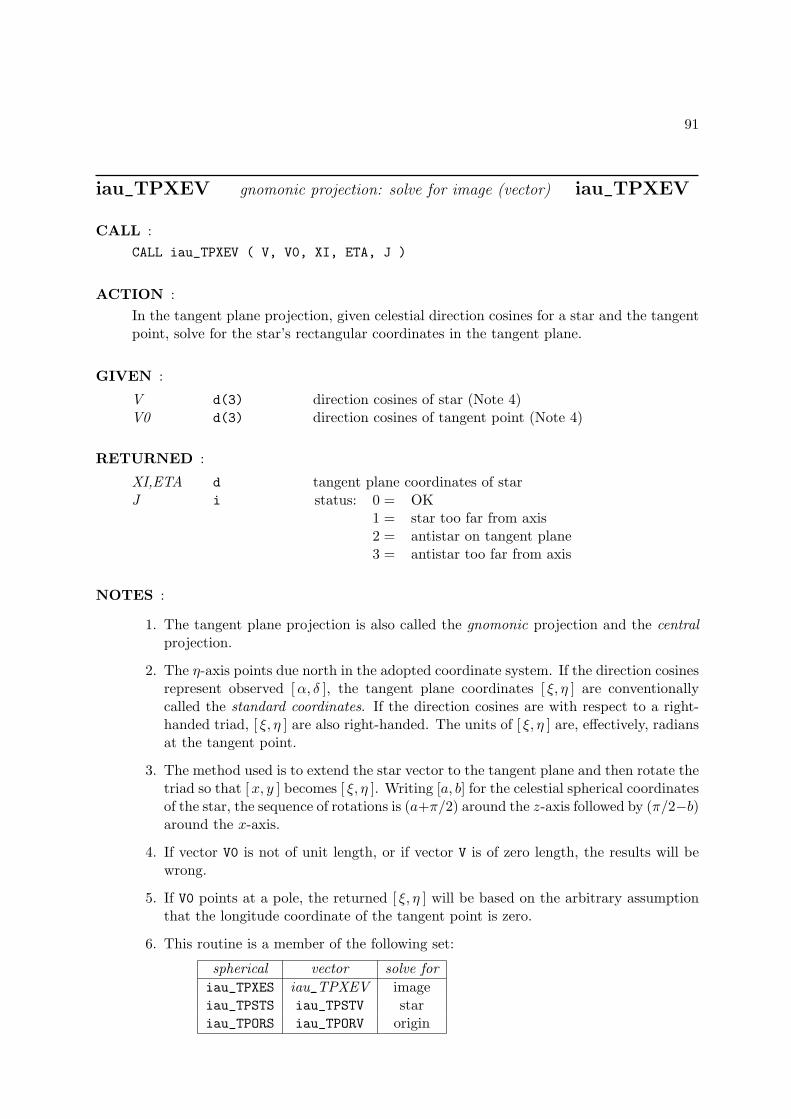
91
iau_TPXEV gnomonic projection: solve for image (vector) iau_TPXEV
CALL :
CALL iau_TPXEV ( V, V0, XI, ETA, J )
ACTION :
In the tangent plane projection, given celestial direction cosines for a star and the tangentpoint, solve for the star’s rectangular coordinates in the tangent plane.
GIVEN :
V d(3) direction cosines of star (Note 4)V0 d(3) direction cosines of tangent point (Note 4)
RETURNED :
XI,ETA d tangent plane coordinates of starJ i status: 0 = OK
1 = star too far from axis2 = antistar on tangent plane3 = antistar too far from axis
NOTES :
1. The tangent plane projection is also called the gnomonic projection and the centralprojection.
2. The η-axis points due north in the adopted coordinate system. If the direction cosinesrepresent observed [α, δ ], the tangent plane coordinates [ ξ, η ] are conventionallycalled the standard coordinates. If the direction cosines are with respect to a right-handed triad, [ ξ, η ] are also right-handed. The units of [ ξ, η ] are, effectively, radiansat the tangent point.
3. The method used is to extend the star vector to the tangent plane and then rotate thetriad so that [x, y ] becomes [ ξ, η ]. Writing [a, b] for the celestial spherical coordinatesof the star, the sequence of rotations is (a+π/2) around the z-axis followed by (π/2−b)around the x-axis.
4. If vector V0 is not of unit length, or if vector V is of zero length, the results will bewrong.
5. If V0 points at a pole, the returned [ ξ, η ] will be based on the arbitrary assumptionthat the longitude coordinate of the tangent point is zero.
6. This routine is a member of the following set:
spherical vector solve for
iau_TPXES iau_TPXEV imageiau_TPSTS iau_TPSTV stariau_TPORS iau_TPORV origin
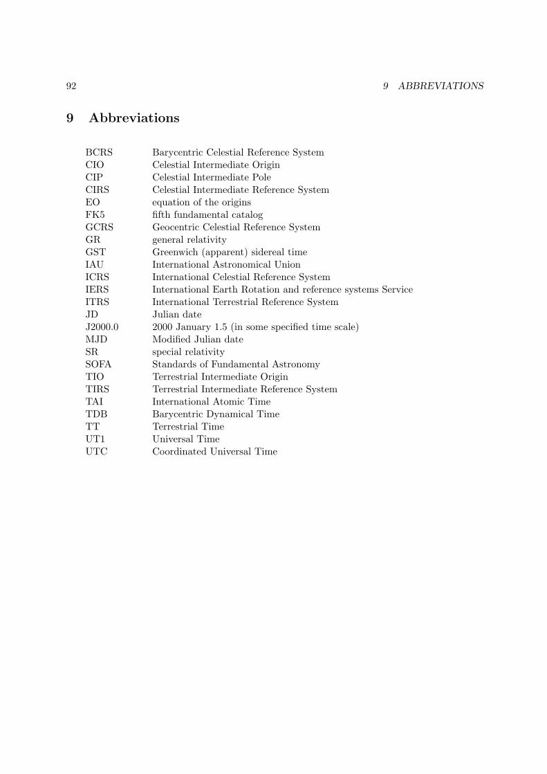
92 9 ABBREVIATIONS
9 Abbreviations
BCRS Barycentric Celestial Reference SystemCIO Celestial Intermediate OriginCIP Celestial Intermediate PoleCIRS Celestial Intermediate Reference SystemEO equation of the originsFK5 fifth fundamental catalogGCRS Geocentric Celestial Reference SystemGR general relativityGST Greenwich (apparent) sidereal timeIAU International Astronomical UnionICRS International Celestial Reference SystemIERS International Earth Rotation and reference systems ServiceITRS International Terrestrial Reference SystemJD Julian dateJ2000.0 2000 January 1.5 (in some specified time scale)MJD Modified Julian dateSR special relativitySOFA Standards of Fundamental AstronomyTIO Terrestrial Intermediate OriginTIRS Terrestrial Intermediate Reference SystemTAI International Atomic TimeTDB Barycentric Dynamical TimeTT Terrestrial TimeUT1 Universal TimeUTC Coordinated Universal Time
93
10 References
Allen, C.W., (1976). Astrophysical Quantities, University of London, The Athlone Press,3rd ed.
Calabretta, M.R., Greisen, E.W. (2002). Representations of celestial coordinates in FITS,Astron.Astrophys., 395, 1077.
Crane, R.K., Meeks, M.L. (eds) (1976). Refraction Effects in the Neutral Atmosphere, Methodsof Experimental Physics: Astrophysics 12B, Academic Press.
Gill, Adrian E. (1982). Atmosphere-Ocean Dynamics, Academic Press.
Green, R.M. (1987). Spherical Astronomy, Cambridge University Press.
Hohenkerk, C.Y., & Sinclair, A.T. (1985). NAO Technical Note No. 63.
Klioner, Sergei A. (2003). A practical relativistic model for microarcsecond astrometry in space,Astr. J. 125, 1580-1597.
McCarthy, D. D., Petit, G. (eds.) (2004). IERS Conventions (2003), IERS Technical NoteNo. 32, Bundesamt fur Kartographie und Geodasie.
Rueger, J.M. (2002). Refractive Index Formulae for Electronic Distance Measurement withRadio and Millimetre Waves, in Unisurv Report S-68, School of Surveying and SpatialInformation Systems, University of New South Wales, Sydney, Australia.
Stone, Ronald C. (1996). P.A.S.P. 108, 1051-1058.
Urban, Sean, & Seidelmann, P. Kenneth (eds.) (2013). Explanatory Supplement to the Astro-nomical Almanac, 3rd ed., University Science Books.
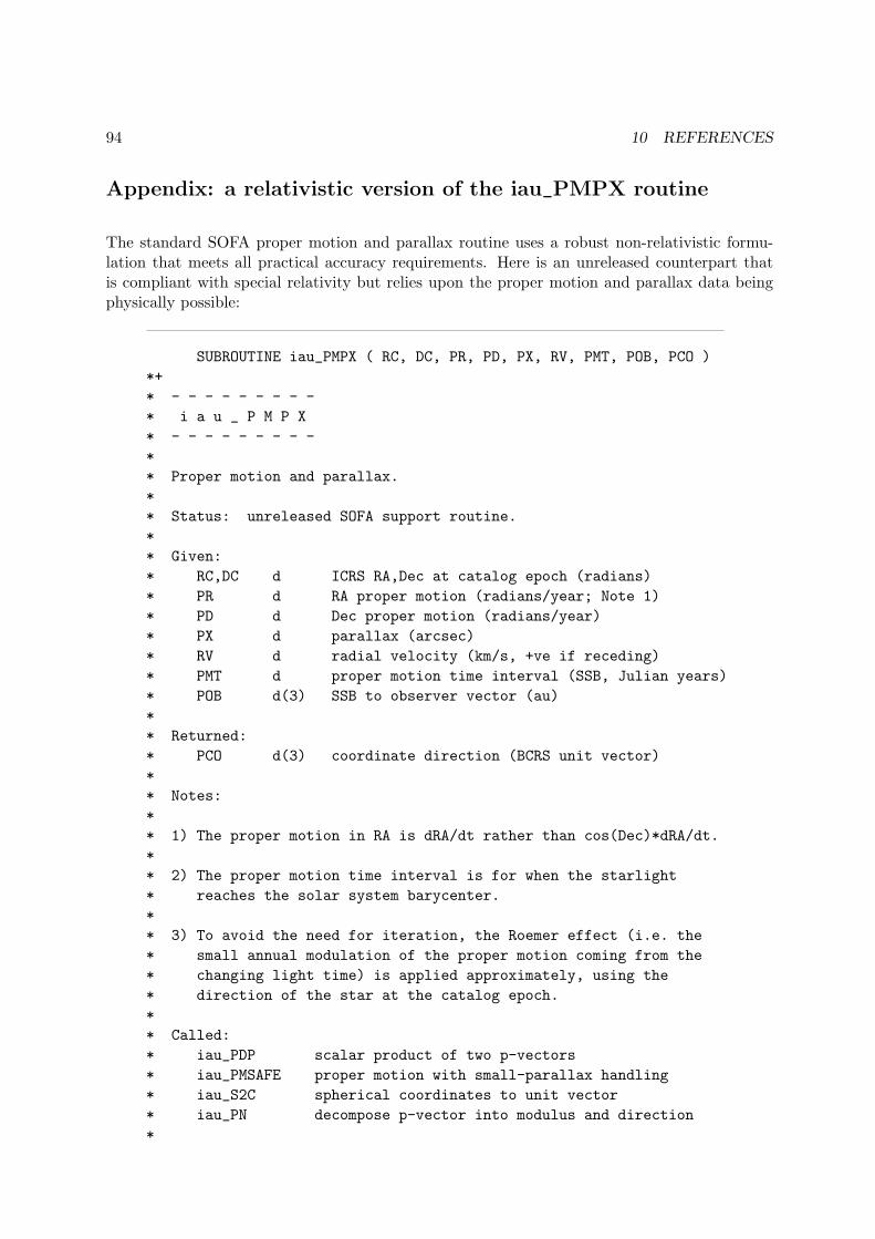
94 10 REFERENCES
Appendix: a relativistic version of the iau_PMPX routine
The standard SOFA proper motion and parallax routine uses a robust non-relativistic formu-lation that meets all practical accuracy requirements. Here is an unreleased counterpart thatis compliant with special relativity but relies upon the proper motion and parallax data beingphysically possible:
SUBROUTINE iau_PMPX ( RC, DC, PR, PD, PX, RV, PMT, POB, PCO )
*+
* - - - - - - - - -
* i a u _ P M P X
* - - - - - - - - -
*
* Proper motion and parallax.
*
* Status: unreleased SOFA support routine.
*
* Given:
* RC,DC d ICRS RA,Dec at catalog epoch (radians)
* PR d RA proper motion (radians/year; Note 1)
* PD d Dec proper motion (radians/year)
* PX d parallax (arcsec)
* RV d radial velocity (km/s, +ve if receding)
* PMT d proper motion time interval (SSB, Julian years)
* POB d(3) SSB to observer vector (au)
*
* Returned:
* PCO d(3) coordinate direction (BCRS unit vector)
*
* Notes:
*
* 1) The proper motion in RA is dRA/dt rather than cos(Dec)*dRA/dt.
*
* 2) The proper motion time interval is for when the starlight
* reaches the solar system barycenter.
*
* 3) To avoid the need for iteration, the Roemer effect (i.e. the
* small annual modulation of the proper motion coming from the
* changing light time) is applied approximately, using the
* direction of the star at the catalog epoch.
*
* Called:
* iau_PDP scalar product of two p-vectors
* iau_PMSAFE proper motion with small-parallax handling
* iau_S2C spherical coordinates to unit vector
* iau_PN decompose p-vector into modulus and direction
*
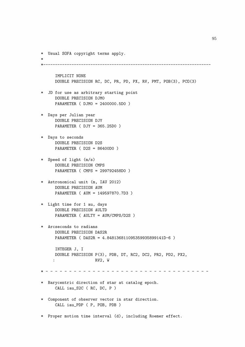
95
* Usual SOFA copyright terms apply.
*
*-----------------------------------------------------------------------
IMPLICIT NONE
DOUBLE PRECISION RC, DC, PR, PD, PX, RV, PMT, POB(3), PCO(3)
* JD for use as arbitrary starting point
DOUBLE PRECISION DJM0
PARAMETER ( DJM0 = 2400000.5D0 )
* Days per Julian year
DOUBLE PRECISION DJY
PARAMETER ( DJY = 365.25D0 )
* Days to seconds
DOUBLE PRECISION D2S
PARAMETER ( D2S = 86400D0 )
* Speed of light (m/s)
DOUBLE PRECISION CMPS
PARAMETER ( CMPS = 299792458D0 )
* Astronomical unit (m, IAU 2012)
DOUBLE PRECISION AUM
PARAMETER ( AUM = 149597870.7D3 )
* Light time for 1 au, days
DOUBLE PRECISION AULTD
PARAMETER ( AULTY = AUM/CMPS/D2S )
* Arcseconds to radians
DOUBLE PRECISION DAS2R
PARAMETER ( DAS2R = 4.848136811095359935899141D-6 )
INTEGER J, I
DOUBLE PRECISION P(3), PDB, DT, RC2, DC2, PR2, PD2, PX2,
: RV2, W
* - - - - - - - - - - - - - - - - - - - - - - - - - - - - - - - - - - -
* Barycentric direction of star at catalog epoch.
CALL iau_S2C ( RC, DC, P )
* Component of observer vector in star direction.
CALL iau_PDP ( P, POB, PDB )
* Proper motion time interval (d), including Roemer effect.
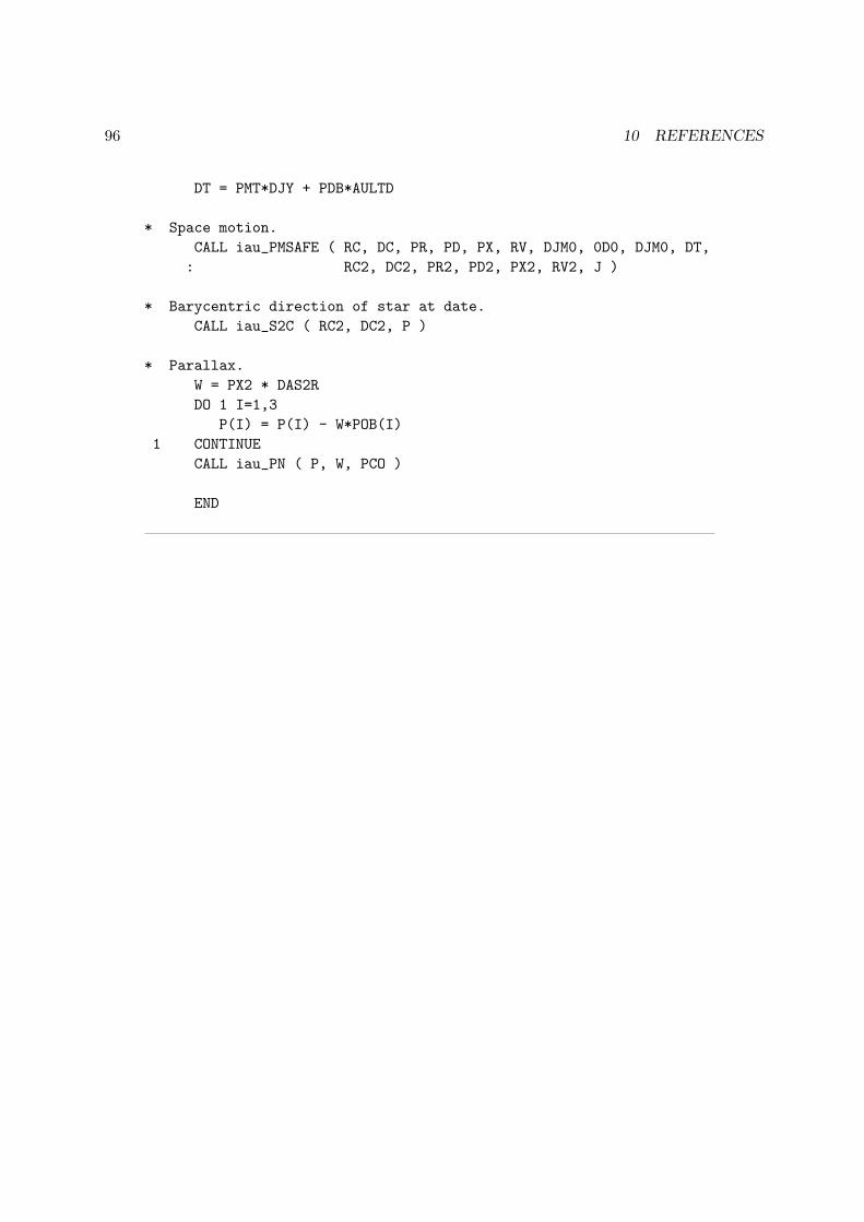
96 10 REFERENCES
DT = PMT*DJY + PDB*AULTD
* Space motion.
CALL iau_PMSAFE ( RC, DC, PR, PD, PX, RV, DJM0, 0D0, DJM0, DT,
: RC2, DC2, PR2, PD2, PX2, RV2, J )
* Barycentric direction of star at date.
CALL iau_S2C ( RC2, DC2, P )
* Parallax.
W = PX2 * DAS2R
DO 1 I=1,3
P(I) = P(I) - W*POB(I)
1 CONTINUE
CALL iau_PN ( P, W, PCO )
END