SoC/SoPC development using MDD and MARTE profile · SoC/SoPC development using MDD and MARTE...
22
SoC/SoPC development using MDD and MARTE profile Denis Aulagnier 1 — Ali Koudri 1 — Stéphane Lecomte 2 — Philippe Soulard 3 — Joël Champeau 4 — Jorgiano Vidal 5 — Gilles Perrouin 6 — Pierre Leray 7 1 Thales Aerospace Division 10, avenue de la 1ère DFL 29283 Brest - France {denis.aulagnier, ali.koudri}@fr.thalesgroup.com 2 Thomson R&D France Corporate Research - Networking Lab. 1, Avenue de Belle Fontaine 35576 Cesson-Sévigné Cedex - France [email protected] 3 Sodius 6, rue de Cornouaille 44300 Nantes - France [email protected] 4 ENSIETA 2, rue François Verny 29806 Brest Cedex 9 - France [email protected] 5 Université de Bretagne Sud Lab-STICC 56321 Lorient Cedex - France [email protected] 6 INRIA Campus de Beaulieu F-35042 Rennes - France [email protected] 7 Supélec Avenue de la Boulaie B.P. 81127 35511 Cesson-Sévigné Cedex - France [email protected] ABSTRACT. This paper presents a new methodology to develop SoC/SoPC applications. This methodology is based on UML and MDD and capitalizes the achievements of "Electronic Sys- tem Level" community by taking into account the new MARTE profile dedicated to real-time em- bedded systems. In the MOPCOM SoC/SoPC research project, a tooling has been developed to support this SoC/SoPC methodology, the MARTE profile, HDL code generation and documen- tation generation. A Cognitive Radio demonstrator is presented to illustrate the methodology and the tooling. KEYWORDS: UML, MDD, MDA, MARTE, ESL, SoC/SoPC, FPGA L’objet – 8/2009, pages 45 à 57
Transcript of SoC/SoPC development using MDD and MARTE profile · SoC/SoPC development using MDD and MARTE...

SoC/SoPC development using MDDand MARTE profile
Denis Aulagnier1 — Ali Koudri1 — Stéphane Lecomte2 — PhilippeSoulard3 — Joël Champeau4 — Jorgiano Vidal5 — Gilles Perrouin6
— Pierre Leray7
1Thales Aerospace Division10, avenue de la 1ère DFL29283 Brest - France{denis.aulagnier,ali.koudri}@fr.thalesgroup.com
2Thomson R&D FranceCorporate Research - Networking Lab.1, Avenue de Belle Fontaine35576 Cesson-Sévigné Cedex - [email protected]
3Sodius6, rue de Cornouaille44300 Nantes - [email protected]
4ENSIETA2, rue François Verny29806 Brest Cedex 9 - [email protected]
5Université de Bretagne SudLab-STICC56321 Lorient Cedex - [email protected]
6INRIACampus de BeaulieuF-35042 Rennes - [email protected]
7SupélecAvenue de la Boulaie B.P. 8112735511 Cesson-Sévigné Cedex - [email protected]
ABSTRACT. This paper presents a new methodology to develop SoC/SoPC applications. Thismethodology is based on UML and MDD and capitalizes the achievements of "Electronic Sys-tem Level" community by taking into account the new MARTE profile dedicated to real-time em-bedded systems. In the MOPCOM SoC/SoPC research project, a tooling has been developed tosupport this SoC/SoPC methodology, the MARTE profile, HDL code generation and documen-tation generation. A Cognitive Radio demonstrator is presented to illustrate the methodologyand the tooling.
KEYWORDS: UML, MDD, MDA, MARTE, ESL, SoC/SoPC, FPGA
L’objet – 8/2009, pages 45 à 57
46 L’objet – 8/2009.
1. Introduction
Thanks to the ever-increasing performance of digital electronics, an entire embed-ded System can now be integrated on a single Chip: i.e. a SoC – System on Chip – ora SoPC – System on Programmable Components – for FPGA – Field ProgrammableGate Array – reconfigurable components.
In parallel, to catch up with this components complexity, a dramatic enhancementof hardware design productivity is required to avoid a "productivity gap" [ITR 07].ESL – Electronic System Level – tools have emerged in order to tackle this issue byimproving the level of abstraction of hardware developments. For example, some ESLtooling, enable to simulate a design at TLM – Transaction Level Modeling – withSystemC language or to synthesize hardware architecture directly from C functionalcode rather than from a RTL – Register Transfer Level – description.
Besides ESL modeling approaches, UML – Unified Modeling Language – [OMG 06b]originally dedicated to Software development has extended its scope to System orreal time embedded application development through SysML – System Modeling Lan-guage – [OMG 08a] and MARTE – Modeling and Analysis of Real-Time Embeddedsystems – [OMG 07] profiles.
Moreover, MDA – Model Driven Architecture – [OMG 03], promotes a develop-ment methodology based on models transformations at several levels of abstractionand that follows the well known Y-Chart co-design approach: at each level, a PIM– Platform Independent Model – representing the application is mapped onto a PM– Platform Model – representing the target architecture to obtain a PSM – PlatformSpecific Model – representing the implementation.
As the development of SoC/SoPC components covers system, software and hard-ware engineering activities, from the system requirement capture, up to the fineanalysis of the hardware logic timing, a SoC/SoPC development methodology shouldtake advantage of these new UML profiles and MDA methodology in capitalizing, aswell, the achievements of the ESL community.
An experimentation of this approach has been carried out in the frame of the MOP-COM SoC/SoPC project [MOP 07, KOU 08] and is presented in this paper. Section 2is a state-of-art overview. The following sections present the different types of modelsidentified in MOPCOM SoC/SoPC development methodology and the MARTE pro-file elements used at each level. An example of Cognitive Radio application is used toillustrate this process in section 4. Finally, sections 9 and 10 describe MOPCOM tool-ing developed to support the design process and the generation of – HDL – HardwareDesign Language – as well as the documentation automatic generation.
2. Related Works
As explained above, developments of SoC/SoPC and RTES – Real Time EmbeddedSystems – in general is related to the ESL community. Only a reliable methodology,

SoC/SoPC 47
based on appropriate languages and tools can help to handle market pressure (time-to-market, competitiveness), increasing evolution of the technology or standards (DO-178B, DO-254, etc.) [GER 03] related to such developments.
In order to address the market constraints and obsolescence issues, separation ofconcerns is needed to allow the concurrent development of applications and executionplatforms. This kind of approach have been first proposed in the Gajski and Kuhn Y-Chart model [GAJ 83], generalized by the Model Driven Development approach andstandardized by the Model Driven Architecture OMG’s standard . Moreover, in orderto allow faster design space exploration, system under study must be modeled andvalidated at several levels of abstraction [SAN 04]. There is no real consensus aboutthe number of required abstraction levels even if there are some efforts to define andstandardize abstraction levels and their related services and interfaces [KAS 07].
Several languages enable the description of behavioral or structural parts and theallocation of the system under development. The most important factors influencingthe choice of a language in a modeling or analysis activity are its expressiveness powerand its tooling. For instance, SystemC [OSC 05] is a language allowing functional andplatform modeling at several levels of abstraction, and is supported by several free orcommercial tools dedicated to analysis or compilation / synthesis.
In addition to separation of concerns and definition of levels of abstraction, there isa need to favor reusability in order to improve the productivity. Indeed, large systemsdevelopment has to rely on libraries of proved and well-documented IPs at each levelof abstraction. Interconnection and exchange between IPs is based on the use of stan-dard interfaces and protocols. In some cases, Ad-doc IPs can be wrapped to conformto standards [KOU 05].
Developments of RTES include modeling activities, using languages based on ei-ther grammars or metamodels, as well as analysis activities such as formal validationor simulation. The main issues when modeling RTES are the description of concur-rency / communication [GER 02], execution platform, possibly represented at severallevels of abstraction, and QoS – Quality of Service. Modeling and Analysis activitiesmust be replaced in the context of a well-defined methodology. For that, there are twodifferent approaches:
– use several DSL – Domain Specific Language – fitting for each modeling oranalysis activity,
– use a general purpose modeling language, such as UML, with dedicated profilesto support the required concepts.
Additional mechanisms such as annotations are also required in order to add rele-vant information needed by analysis tools (example: resource usage for schedulabilityanalysis).
Based on the use of selected formalisms, several methodologies and tools havebeen developed to support RTES development. Few examples are given below.
48 L’objet – 8/2009.
The methodology MCSE – Méthodologie de Conception des Systèmes Electron-iques – [CAL 08] proposed by the University of Nantes, enables design space explo-ration through the use of the SystemC TLM language. The French company CofluentDesign [COF ], in partnership with MCSE Team, has developed the ESL design tool"Cofluent Studio", based on Eclipse environment, which supports MCSE methodol-ogy.
The Ptolemy environment from UC Berkeley [BUC 02] allows description of sys-tems mixing several MoC – Models of Computation – through the notions of actorsand directors. A director defines a domain of execution for its actors enabling the mix-ing of several models of computation in the same model. This is an important issuebecause real-time systems usually mix analog and digital devices and possibly severaltime domains.
Syndex from INRIA is a tool implementing the Architecture Adequation Algo-rithm [KAO 04] addressing the allocation issue.
In the context of the UML, several profiles have been proposed to extend UMLcapabilities in order to handle modeling and analysis of RTES or SoC. Among them,we can cite:
– the SPT – Schedulability Performance Time – OMG’s profile [OMG 05a] whichwas based on the version 1.4 of UML and completed by the QoS and Fault ToleranceOMG’s profile [OMG 08b] for the non-functional aspects,
– the UML4SOC OMG’s profile is dedicated to describe SoC [OMG 05b],– the UML for SystemC profile proposed in [RIC 05] gathers the capabilities of
UML and SystemC,– the UML for MARTE OMG’s profile [OMG 07] can be viewed as an improve-
ment of the SPT profile (cf. section 3),– the Gaspard profile is specific to parallel and distributed computing applications
implemented into SoC [PIE 08].
Based on the use of UML profiles, examples of RTES or SoC design environmentsare given below.
The ACCORD/UML methodology [GER 02] aims at using UML concepts to de-sign RTES. It was originally based on the use of the SPT profile and now relies onMARTE profile. It is supported by the eclipse-based PAPYRUS tool [CEA ].
The University of Milan, in collaboration with STMicroelectronics, proposes adevelopment process for embedded systems and SoC called UPES – Unified Processfor Embedded Systems – , based on UML for SystemC profile [RIC 07].
The Gaspard Methodology [PIE 08] is intended to provide a framework for devel-oping parallel and distributed applications implemented on SoC. This methodology isan implementation of the MDA approach in the eclipse framework and provides a setof transformation rules allowing generation of optimized SystemC Code for repetitivestructure architecture.
SoC/SoPC 49
3. MOPCOM Process and Models
Our SoC/SoPC development process is based on a MDD approach. It relies on twoelements: a conventional System Engineering methodology for the System Analysis,including Requirement Capture and Functional Analysis activities, and a dedicatedprocess for the SoC/SoPC architecture definition. This process emphasizes:
– Separation of concerns: as explained in the previous sections, separation of theapplication (PIM) from the platform (PM) and description of the mapping to generatethe implementation (PSM), as in a classical Y-chart co-design pattern,
– Analysis Driven Development: the previous pattern can be reproduced with sev-eral execution platform abstractions, depending on the kind and the number of analysisone needs to perform. For instance, in the MOPCOM methodology, we have definethree abstraction levels for the target platform as explained below.
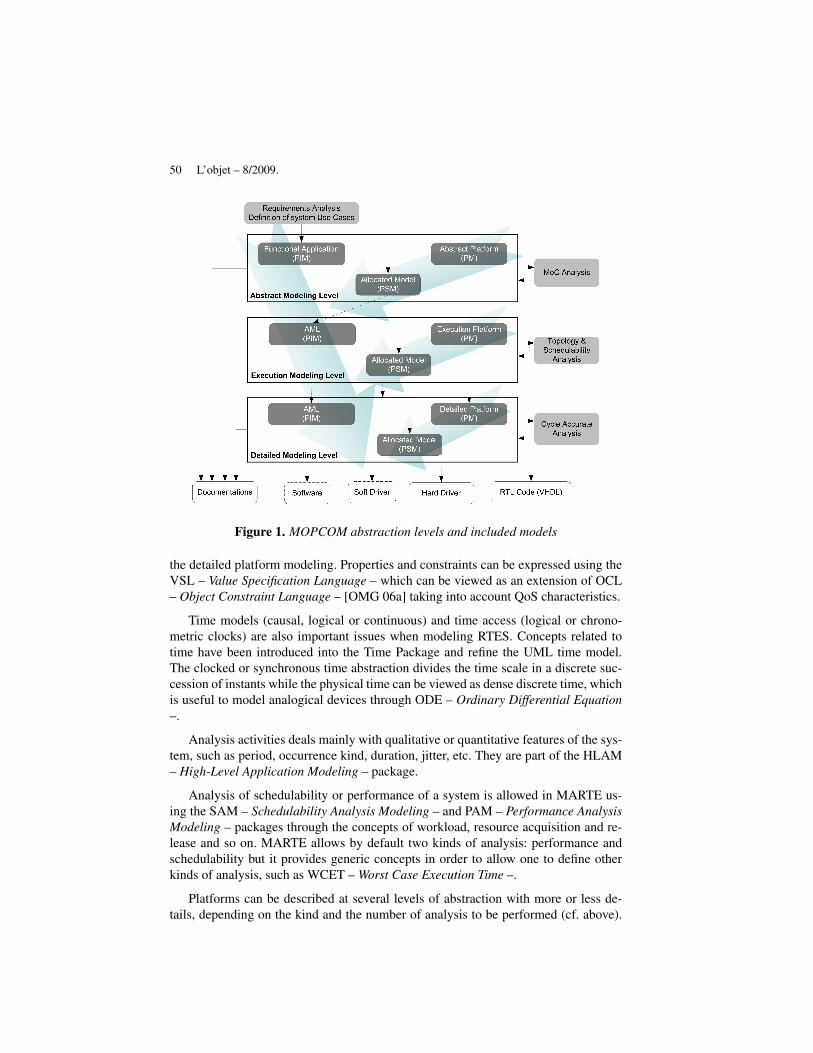
The set of input / output models of our process is presented in the figure 1.
– AML – Abstract Modeling Level – is intended to describe a virtual executionplatform where expected concurrency, pipeline and communication policy are explic-itly defined. The allocation model describes the mapping of the application onto theModel of Computation defined by the AML platform.
– EML – Executable Modeling Level – provides a coarse definition of the physi-cal platform. At this stage, the platform is composed by generic components such asProcessing or Memory Units. Allocation model describes the mapping between thepreviously generated model onto the platform. This results in a topology descriptionallowing performance or schedulability analysis.
– DML – Detailed Modeling Level – refines the definition of the platform with thenecessary information for Software and RTL HDL code generation. The Allocationconsists in mapping the previous PSM AML model onto a more precise description ofthe platform.
Besides automatic code generation, other artifacts, such as documentation, can be pro-duced automatically.
Each stage is validated against simulations. The main benefits of such approachare the minimization of the risks as emphasized in a classical iterative developmentprocess [BOE 88] and the optimization of the development time, through concurrentdevelopments.
Another goal of our work is to evaluate the relevance of the UML MARTE profilein term of concepts: the MARTE profile encloses a large set of concepts to modeland analyze Real Time Embedded Systems. Those concepts are organized in severalhierarchical sub-profile packages, following concerns they are related to.
For instance, the design of RTES deals with the modeling of properties that quan-tify offered and provided services by a resource to the application. In this purpose,there is a package dedicated to the description of NFP – Non Functional Properties –.The NFP constraints are applied all along the process from the requirements capture to
50 L’objet – 8/2009.
Figure 1. MOPCOM abstraction levels and included models
the detailed platform modeling. Properties and constraints can be expressed using theVSL – Value Specification Language – which can be viewed as an extension of OCL– Object Constraint Language – [OMG 06a] taking into account QoS characteristics.
Time models (causal, logical or continuous) and time access (logical or chrono-metric clocks) are also important issues when modeling RTES. Concepts related totime have been introduced into the Time Package and refine the UML time model.The clocked or synchronous time abstraction divides the time scale in a discrete suc-cession of instants while the physical time can be viewed as dense discrete time, whichis useful to model analogical devices through ODE – Ordinary Differential Equation–.
Analysis activities deals mainly with qualitative or quantitative features of the sys-tem, such as period, occurrence kind, duration, jitter, etc. They are part of the HLAM– High-Level Application Modeling – package.
Analysis of schedulability or performance of a system is allowed in MARTE us-ing the SAM – Schedulability Analysis Modeling – and PAM – Performance AnalysisModeling – packages through the concepts of workload, resource acquisition and re-lease and so on. MARTE allows by default two kinds of analysis: performance andschedulability but it provides generic concepts in order to allow one to define otherkinds of analysis, such as WCET – Worst Case Execution Time –.
Platforms can be described at several levels of abstraction with more or less de-tails, depending on the kind and the number of analysis to be performed (cf. above).

SoC/SoPC 51
The GRM package – General Resource Modeling – provides concepts allowing themodeling of the platform at a high abstraction level while those concepts are refinedin the SRM and HRM packages. The SRM package – Software Resource Modeling– provides details related to the description of software platform such as RTOS ormiddleware. The HRM package – hardware resource modeling – provides conceptsrelated to the description of physical platform such as Buses, FPGA, Processor, etc.
The MOPCOM methodology provides the rational to use all those MARTE con-cepts in a consistent manner. Indeed to enforce the definition of our methodology,we select some MARTE elements for each abstraction level in our SoC/SoPC de-velopment process. We have defined the usage scope of those concepts by addingconstraints to the metatype of the UML/MARTE language. Those set of constraintsspecialize the language (UML/MARTE) to the SoC/SoPC domain and are capitalizedinto the model of the process itself.
In the next sections, we present each level of our MDD process with its associatedset of MARTE concepts.
4. Application
The development process presented above has been experimented through a CRS– Cognitive Radio System –. A CRS is a radiocommunication equipment which is ableto adapt its functionality according to the Radio environment [MIT 01, HAC 07]. ACRS for instance can identify the RAT – Radio Access Technologies – available anddetermines their characteristics such as bandwidth and load as well as environmentcharacteristics such as localization. The more suitable available RAT in the area isthen selected and the CRS receiver chain is configured to communicate through thecorresponding protocol.
This type of system is quite complex and for the demonstrator only two Use Casesare analyzed:
– the "Locate RAT Source" Use Case developed by Thales with Supelec localizesthe Direction Of Arrival of the available RAT. The RAT identification is carried outafter a Spectrum analysis of the RF environment and a blind standard recognition ofthe communication protocol. The detected radiocommunication signals are recognizedby analyzing some discriminating parameters that characterize the protocol such as:channel bandwidth, frequency hoping, single/multicarrier signal, etc. The localizationis carried out with a beamformer and removes the eventual multipaths to only keep theDirect Line-Of-Sight direction.
– the "Wireless transmission" Use Case developed by Thomson Corporate Re-search [LEB 08] implements a wireless stack based on standard 802.16 and uses theTDMA – Time Division Multiple Access – MIMO/OFDM – Orthogonal FrequencyDivision Multiplexing – technologies. For the demonstrator, the Use Case focuses onbaseband processing and more specifically on the algorithms and the architectures ofMIMO – Multiple Input Multiple Output – decoding.

52 L’objet – 8/2009.
The Cognitive Radio System is made up of 4 antennas, a baseband processing, andan Ethernet connection. The targeted platform for the implementation is a reconfig-urable component that can demonstrate self-reconfiguration.
5. System Analysis
The first activity of our design process is the System Analysis. This activity isnot specific to SoC/SoPC development and can rely on an existing System Engi-neering methodology such as the Telelogic Harmony/SETM [ART 08] methodology.Harmony/SETM is a SySML based methodology that consists mainly in two steps:Requirements Capture and Functional Analysis to which we add MARTE improve-ments, essentially related to real-time features.
5.1. Requirement Analysis
A Requirements Analysis captures system functional and non-functional require-ments and merges them into Use-Cases. Use-cases define services provided by thesystem to external entities (actors).
The operational contracts (scenarios) and the interfaces between the actors and thesystem are formalized at high abstraction level using for example textual descriptionsor models such as Sequence Diagrams or Activity Diagrams.
At this stage, we use the stereotypes of the packages NFP, VSL, Time of MARTE.Figure 2 is an example of a Sequence Diagram related the Use Case "Locate RATSource" that relies on�TimedInstantObservation� and�TimedConstraint� stereo-types. The TimedConstraint, specifying a duration constraint, is expressed using theVSL syntax.
Figure 2. Sequence Diagram of UC "LocateRAT Source"
SoC/SoPC 53
5.2. Functional Analysis
Compared to the requirements Analysis, the functional analysis focuses on thefunctional decomposition of the Use Cases. Use Cases are split into functions. Thisfunctional decomposition is captured through Class and Object Diagrams whereas thebehavior of the Use Cases is defined with Activity, Statechart and Sequence Diagramsrefining the internal interactions between the different functions.
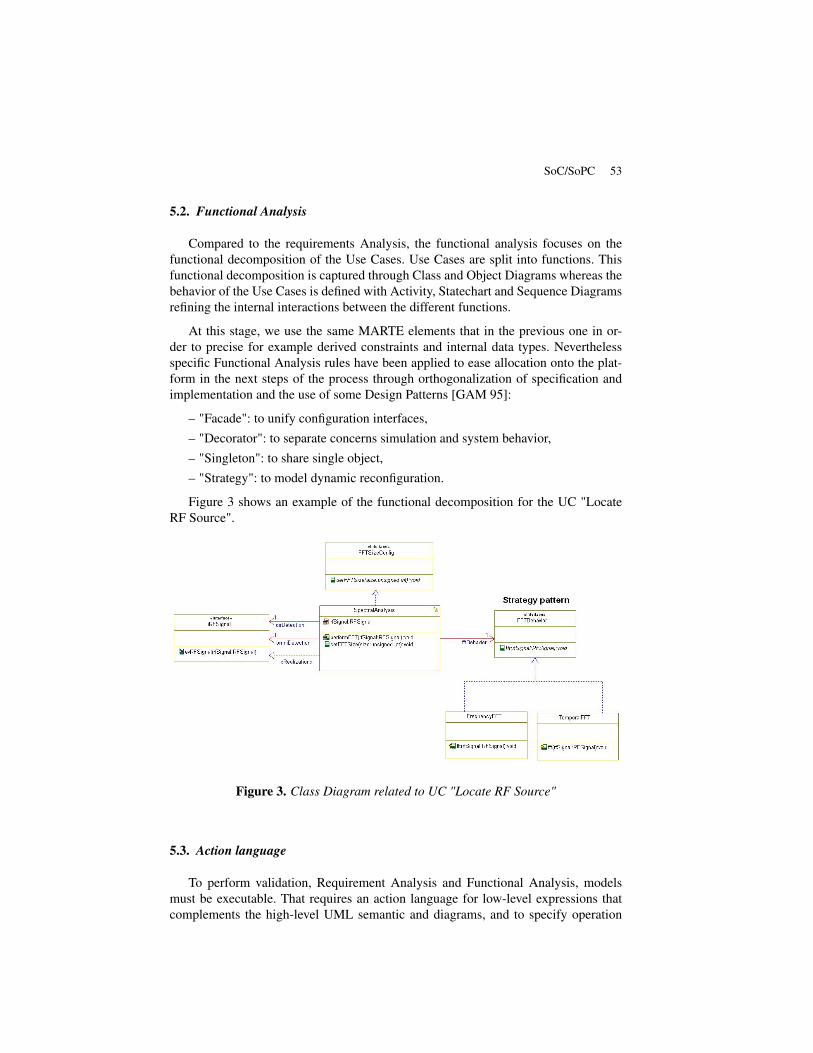
At this stage, we use the same MARTE elements that in the previous one in or-der to precise for example derived constraints and internal data types. Neverthelessspecific Functional Analysis rules have been applied to ease allocation onto the plat-form in the next steps of the process through orthogonalization of specification andimplementation and the use of some Design Patterns [GAM 95]:
– "Facade": to unify configuration interfaces,– "Decorator": to separate concerns simulation and system behavior,– "Singleton": to share single object,– "Strategy": to model dynamic reconfiguration.
Figure 3 shows an example of the functional decomposition for the UC "LocateRF Source".
Figure 3. Class Diagram related to UC "Locate RF Source"
5.3. Action language
To perform validation, Requirement Analysis and Functional Analysis, modelsmust be executable. That requires an action language for low-level expressions thatcomplements the high-level UML semantic and diagrams, and to specify operation

54 L’objet – 8/2009.
bodies, trigger/guard/action on transition and in states, and data declarations. The se-lection of the most suitable action language action language raises questions abouttextual or graphical notation, and general versus HDL-specific language that shouldbe accessible to system, software and hardware designers without to many problemsrelated to its learning curve.
After analysis, C++ language turned out to be the most convenient choice. Indeed,It is a wide-spread and standard object-oriented language, supported by many high-performance development environments (including Rhapsody-in-C++ suite).
Only a C++ subset is used in the models (along with some macros for event andport handling). C language is fully mastered by hardware designers (similar syntaxfor non-OO subset) and next-generation SystemC language is basically a C++ librarydedicated to hardware applications.
6. Abstract Modeling Level
While the aim of the functional analysis was the definition of the behavior of thesystem and its functional breakdown into functional blocks, the aim of this level is toidentify the needed level of concurrency and define the way concurrent blocks commu-nicate. The underlying goal of those identifications is analysis that can be performedlike consistency or deadlocks analysis.
The notion of concurrency in UML is supported by the "isActive" meta-attributemeaning that corresponding classes manage their own thread of execution, but it doesnot say so much about what kind of interactions can occur between active classes.Still, there are missing information to make relevant analysis needed at this level.Fortunately, the MARTE profile completes the definition introducing the concepts ofRTUnits or RTeConnectors in the HLAM package.
The RTUnit is a refinement of the Block concept introduced in SysML with ad-ditional real-time features. An RTUnit provides and requires an set of real-time ser-vices. In order to realize those services, a RTUnit owns a set of real-time behaviorswith bounded or unbounded message queue for each of those behaviors. An RTU-nit can also own a set of schedulable resources which are typed by other RTUnits,connected through RTeConnectors, allowing hierarchical description of the system.Then, the owning RTUnit provides an execution context (domain) for each of thesesub-RTUnits and is responsible for managing their interactions and concurrency.
Since the AML model provides an execution framework for the system understudy, it can be considered as the highest abstraction of the execution platform. In-deed, its identification constitutes the first step of the design space exploration.
At this level, every concurrent unit is stereotyped «RTUnit» characterized by itsprovided / required services set and its real-time behaviors. RTUnits communicatethrough real-time connectors «RTeConnector». Actions performed by an RTUnit are

SoC/SoPC 55
stereotyped «RTAction». For each of those concepts, a quantitative or qualitative as-pect information is provided: duration, priority, occurrence kind, etc.
The AML platform aggregates the set of needed functional objects to implementthe system with additional information about concurrency and communication. Togenerate the real-time units, one needs to provide the functional design and allocationwith associated constraints. Figure 4 describes the process of allocation while figure5 gives, in MQL language (cf. section 9), an excerpt of the transformation rules thathave been applied to generate the allocated platform.
Figure 4. Process of Allocation
Figure 5. Excerpt of Allocation to Allocated Model Transformation in MQL Syntax
Functional blocks are turn into AML blocks stereotyped�RTUnit�and �Allocated� in purpose of traceability. Connectors binding ports implementscommunications related to the MoC indicated on the allocation constraints of the link.Special blocks are inferred for (de)multiplexing data between RTUnits when severalfunctional blocks are executed sequentially.
56 L’objet – 8/2009.
7. Execution Modeling Level
The MOPCOM Execution Modeling Level (EML) is made up of three differentmodels (Figure 1). The main goal of this level is to model the topology of the virtualhardware platform and to analyze the system scheduling.
7.1. The Platform Independent Model/Application Model in EML
The PIM model in EML is similar to the PSM model in AML with a refactoringif necessary. We can transform the functional structure in order to allocate the PIMonto PM. In fact, if the analysis results do not respect the specifications, the functionalstructure or/and the topology of the virtual hardware platform must be changed.
7.2. The Platform Model in EML
In EML, PM only represents the topology of the virtual hardware platform basedon high-level generic components. Indeed, the objective of the virtual platform is tohide the physical platform to the application. This PM cuts itself of superfluous de-tails such as the protocols description, the type of computing resources and storageresources used in the physical platform model. The first interest of such a modelingis to represent the nodes of computation, of storage, of communication and the ser-vices offered by the platform to the application. A natural modeling concept of PMin EML is a transactional-level modeling, as promoted by Gajski and SystemC com-munity in general. Thus the communications between the components of the platformare represented by calls of functions and not by a detailed modeling of the protocoland the connectivity which are represented in the RTL level. The MOPCOM method-ological tool at this level is MARTE GRM – Generic Resource Modeling – sub-profile. Figure 6 shows an example of PM with the following stereotypes of MARTE:�ComputingResource�,�StorageResource� and�CommunicationMedia�.
7.3. The Platform Specific Model/Allocation Model in EML
In the PSM, the MoC components (of the PIM) are mapped onto the componentsof the PM. The allocated methodology is the same as for AML (Figure 4). Moreover,the mapping of PIM onto the PM to form the PSM must not damage the semantic ofthe MoC. Actually, if more than two MoC components are mapped onto one com-ponent of the PM, the semantics of the point-to-point communication between theMoC components is not affected. But if two MoC components, which communicatebetween them, are mapped onto two different components of the PM, the semantic isnot assured because the link of the communication between both hardware compo-

SoC/SoPC 57
Figure 6. An example of PM in EML with MARTE stereotypes
nents can be a bus and not a point-to-point link. Therefore the semantics have to beguaranteed in a bus communication.
Figure 7. An example of PSM with SAM stereotypes of MARTE
7.4. Analysis model
To analyze the scheduling and the performances of the system, some informationmust be added on the models of this level. What is the signification of schedulabilityanalysis? It provides the ability to evaluate time constraints and guarantee worst-casebehavior of a real-time system. For the schedulability analysis, MARTE SAM sub-profile is recommended. This sub-profile offers the elements to add annotations in thedifferent views of the model in order to evaluate the scheduling. The way to use theSAM sub-profile is explained below:
58 L’objet – 8/2009.
– In the PIM, the behavioral descriptions are annotated by time constraints and bythe size of exchanged messages with the stereotypes of SAM; the sequence diagram iswell adapted to add these annotations; the different scenarios of behavioral descriptionform the workload behavioral model;
– In the PSM, the objects diagram is annotated in order to indicate the type ofscheduling resource of each element of the model (Figure 7);
– The last step is to add a view in order to model the analysis context and theparametric analysis context. The analysis context model indicates the start and the stopconditions of the different behavioral scenarios. And the parametric analysis contextis an instance of this analysis context model in which the values are set in order tosimulate the scheduling.
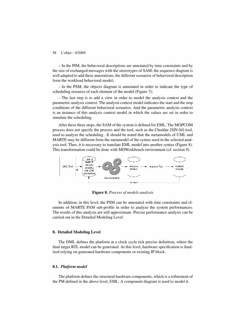
After these three steps, the SAM of the system is defined for EML. The MOPCOMprocess does not specify the process and the tool, such as the Cheddar [SIN 04] tool,used to analyze the scheduling . It should be noted that the metamodels of UML andMARTE may be different from the metamodel of the syntax used in the selected anal-ysis tool. Thus, it is necessary to translate EML model into another syntax (Figure 8).This transformation could be done with MDWorkbench environment (cf. section 9).
Figure 8. Process of models analysis
In addition, in this level, the PSM can be annotated with time constraints and el-ements of MARTE PAM sub-profile in order to analyze the system performances.The results of this analysis are still approximate. Precise performance analysis can becarried out in the Detailed Modeling Level.
8. Detailed Modeling Level
The DML defines the platform at a clock cycle tick precise definition, where thefinal target RTL model can be generated. At this level, hardware specification is final-ized relying on generated hardware components or existing IP block.
8.1. Platform model
The platform defines the structural hardware components, which is a refinement ofthe PM defined in the above level, EML. A component diagram is used to model it.
SoC/SoPC 59
MARTE HRM – Hardware Resource Modeling – sub-profile is used to definewhich kind of elements each object represents, such as ASIC – Application SpecificIntegrated Circuit –, PLD – Programmable Logic Device –, Clock, etc. MARTE SRM– Software Resource Modeling – sub-profile is used to model operating system prop-erties, like tasks and virtual memory. MARTE SRM elements are not addressed here.All components of the platform must be stereotyped with MARTE HRM elements.
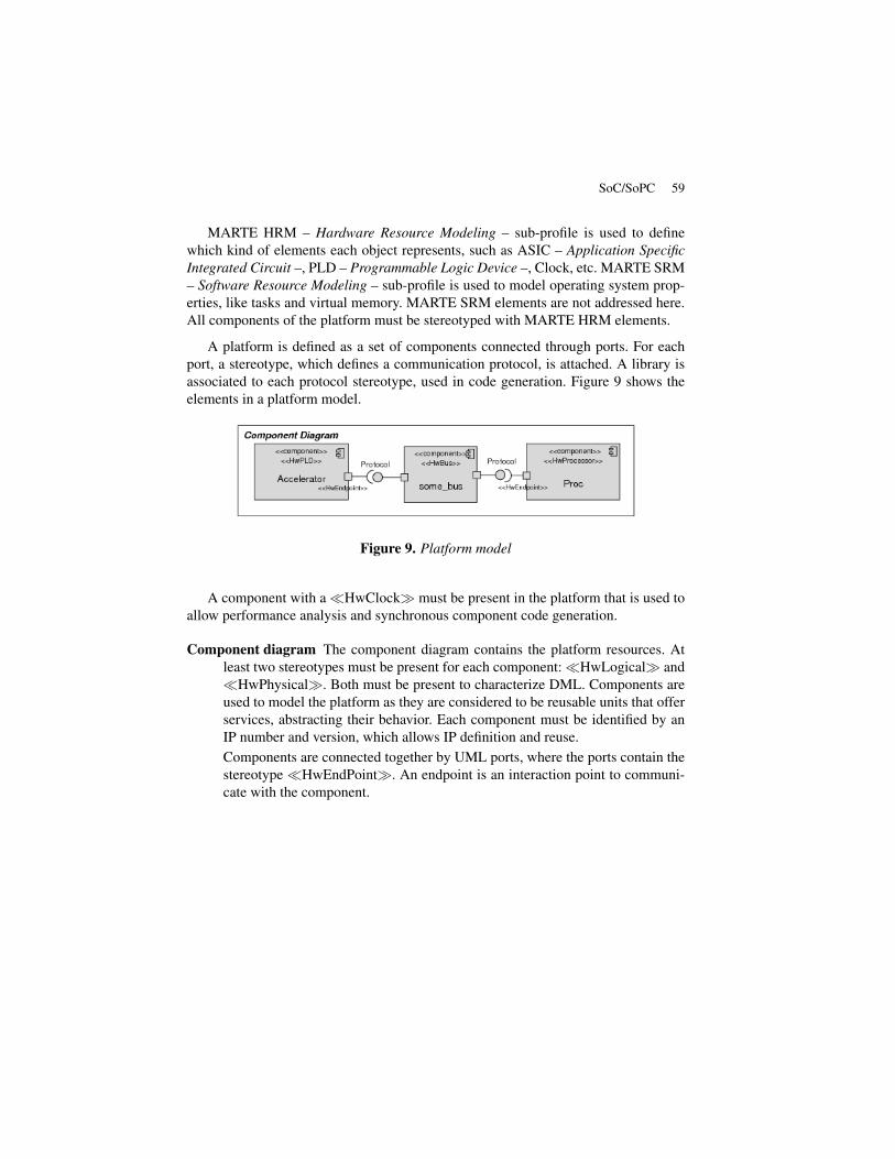
A platform is defined as a set of components connected through ports. For eachport, a stereotype, which defines a communication protocol, is attached. A library isassociated to each protocol stereotype, used in code generation. Figure 9 shows theelements in a platform model.
Figure 9. Platform model
A component with a�HwClock� must be present in the platform that is used toallow performance analysis and synchronous component code generation.
Component diagram The component diagram contains the platform resources. Atleast two stereotypes must be present for each component:�HwLogical� and�HwPhysical�. Both must be present to characterize DML. Components areused to model the platform as they are considered to be reusable units that offerservices, abstracting their behavior. Each component must be identified by anIP number and version, which allows IP definition and reuse.Components are connected together by UML ports, where the ports contain thestereotype �HwEndPoint�. An endpoint is an interaction point to communi-cate with the component.
60 L’objet – 8/2009.
Protocol definition Inter-component communication is done by communication pro-tocols. Protocols are defined as interfaces, where buses ports offer a protocoland other components ports require it. The set of available protocols is platform-dependent and the code generation tool must be aware of the available protocols.
8.2. Allocation model
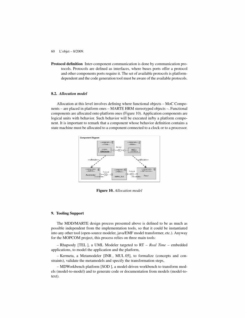
Allocation at this level involves defining where functional objects – MoC Compo-nents – are placed in platform ones – MARTE HRM stereotyped objects –. Functionalcomponents are allocated onto platform ones (Figure 10). Application components arelogical units with behavior. Such behavior will be executed in/by a platform compo-nent. It is important to remark that a component whose behavior definition contains astate machine must be allocated to a component connected to a clock or to a processor.
Figure 10. Allocation model
9. Tooling Support
The MDD/MARTE design process presented above is defined to be as much aspossible independent from the implementation tools, so that it could be instantiatedinto any other tool (open-source modeler, java/EMF model transformer, etc.). Anywayfor the MOPCOM project, this process relies on three main tools:
– Rhapsody [TEL ], a UML Modeler targeted to RT – Real Time – embeddedapplications, to model the application and the platform,
– Kermeta, a Metamodeler [INR , MUL 05], to formalize (concepts and con-straints), validate the metamodels and specify the transformation steps,
– MDWorkbench platform [SOD ], a model-driven workbench to transform mod-els (model-to-model) and to generate code or documentation from models (model-to-text).

SoC/SoPC 61
Figure 11 depicts our tooling workflow; all tools being based on MDA standardsfrom OMG (MDA, UML, MOF, XMI) and Eclipse (EMF, EMOF, ECore). For MOP-COM, an implementation of MARTE profile in Rhapsody has been developed.
Figure 11. MOPCOM process tools interactions
9.1. Process validation through metamodeling with Kermeta
Kermeta environment from INRIA is devoted to model manipulations (composi-tion, merge, etc.). It relies on an imperative object-oriented language and gives oper-ational semantics to metamodels in a non invasive way, taking advantage of a built-inaspect mechanism to weave Kermeta code to Ecore model elements. For model val-idation, Kermeta provides the same capacities than OCL to define rules and checkmodels. So, a Model Checker based on Kermeta environment has been developed.It was used to validate models transformations and to check models compliance toMOPCOM modeling rules at each step of the MOPCOM process (cf. figure 1).
9.2. Model transformation and generation with MDWorkbench platform
MDWorkbench platform from Sodius includes a complete environment to han-dle metamodels and models, and to design, execute, test and deploy model-to-modeltransformation rules and model-to-text generation rules. It is seamlessly integratedinto Rhapsody, known as RulesPlayer and RulesComposer. The RulesPlayer can be

62 L’objet – 8/2009.
seen as a black-box runtime generation engine, while the RulesComposer is the ruleeditor, for designing and modifying the transformation and generation rule sets. MD-Workbench is delivered as an Eclipse plugin, and built as a model-driven extensionto this powerful environment with many helpful capabilities (edition, windowing, de-bug, data handling, versioning, etc.). It includes the required mechanisms based onEMF/Ecore, to build, browse and import/export any metamodel, such as the Rhap-sody metamodel, and model.
The generator is delivered as a white-box Rhapsody add-on. All transformationand generation rules are available for customization with MQL – Model Query Lan-guage – dedicated to model transformation, and TGL – Text Generation Language –for code or doc generation. MQL and TGL offer java-like main constructs (declara-tions, selections and loops) and a high-level dotted notation to handle lists of modelelements.
MDWorkbench incorporates a powerful document generator, based on a gatewaywith Microsoft Word R©. An XML – Extensible Markup Language – document schemais provided that enables users to define their own document templates within Word,in compliance with their company’s graphic policy or with any standard. This greatlyenhances the power of a model-driven design approach where the application/platformmodels become the reference, and where the development documentation is automat-ically generated from the model.
10. HDL Code Generation
Code generation is a capacity generally supported by a MDD process. For ESL,the target language is an HDL such as VHDL or SystemC. A VHDL code generatorfor Rhapsody, presented hereafter, has been developed in the MOPCOM project.
10.1. VHDL code generation
VHDL code generator input is a DML model, lowest abstraction level within theprocess, which includes the application and platform packages, as well as the allo-cation of the application class instances on the platform class instances. As usual,package class/object and statechart diagrams feed code generation, which targets syn-thesizable VHDL code.
The structure part is derived from the platform model, where VHDL entities arederived from instances (and instance hierarchy) of platform classes. Obviously, a UMLport is not at all mapped to a VHDL port, but corresponds to a communication chan-nel between system blocks, which also represents the entity port set. Data and controlVHDL ports are determined according to the UML port and its mapping on a modelof computation (and communication protocol) and can be imported from existing li-braries. Additional VHDL properties enable definition of a clock (with edge), andoptional asynchronous/synchronous resets (with polarity).
SoC/SoPC 63
The behavioral part is derived from the application model, where VHDL architec-tures are mainly issued from attributes, operations and state machines. All the requireddata types are defined into associated packages, according to the UML types (enumer-ations, language-defined, structure and hierarchical types, constants, etc.). The VHDLprocesses handle internal signals and variables that are declared according to data def-initions in the scope of each class. Nearly all concepts of UML state machines aresupported by the generator. Briefly, a finite state machine leads to the definition of anenumerated type for the active state, one per composite state (containing sub-states).The code structure is based on an edge-clocked case VHDL statement, and all trig-ger, guard and action expressions (on transitions, entering, in or exiting states) can begenerated either in line, or in single procedures.
The allocation package brings additional information about the mapping of the ap-plication on the platform. The generator combines the declared entity ports and thedata/control needs of the architecture to map the components and if required (if notpoint-to-point), instantiate the control code (or state machine) of the communicationchannel protocols. Depending on the communication channel, several basic mecha-nisms are provided to handle events (transient or registered) and the required gluelogic is automatically inserted.
The generation process consists on two steps: the first step is a model transforma-tion from Rhapsody to an intermediate hardware model; the second step is a generationfrom hardware model to VHDL code. The hardware model is in conformance with ahardware metamodel which gathers the main semantic concepts that are required todescribe a complex electronic device at the Register Transfer Level.
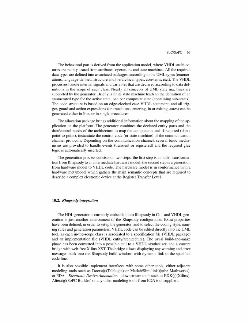
10.2. Rhapsody integration
The HDL generator is currently embedded into Rhapsody in C++ and VHDL gen-eration is just another environment of the Rhapsody configuration. Extra propertieshave been defined, in order to setup the generator, and to select the coding style, nam-ing rules and generation parameters. VHDL code can be edited directly into the UMLtool, as each in-the-scope class is associated to a specification file (VHDL package)and an implementation file (VHDL entity/architecture). The usual build-and-makephase has been converted into a possible call to a VHDL synthesizer, and a currentbridge with web-free Xilinx XST. The bridge allows displaying any warning and errormessages back into the Rhapsody build window, with dynamic link to the specifiedcode line.
It is also possible implement interfaces with some other tools, either adjacentmodeling tools such as Doors R©(Telelogic) or Matlab/Simulink R©(the Mathworks),or EDA – Electronic Design Automation – downstream tools such as EDK R©(Xilinx),Altera R©(SoPC Builder) or any other modeling tools from EDA tool suppliers.
64 L’objet – 8/2009.
Figure 12. VHDL code generator integration into Rhapsody
11. Conclusion
In this paper, we have discussed an ESL process based on MDD and MARTEprofile. This process emphasizes application and platform modeling at different levelsof abstraction and the allocation of the application models to the platform models. Foreach level, we presented the selected MARTE stereotypes and the constraints relatedto their use. We have also outlined the MDD tooling developed to support the process:for example a MARTE profile implementation in a UML modeler, and a VHDL codegenerator.
We reckon that the emergence of MARTE profile will widespread the use of MDDmethodology in ESL domain. UML and MDD methodology are supported by a largenumber of commercial and freeware development tools that will offer new possibilitiesto the ESL community.
Acknowledgements
The UML/MDD approach presented above is experimented in the RNTL researchprogram MOPCOM SoC/SoPC supported by the French Agence Nationale de laRecherche (contract 2006 TLOG 022 01), the "Media and Networks" "cluster of clus-ters" and the Brittany and Pays de la Loire regions.

SoC/SoPC 65
12. References
[ART 08] ARTHURS G., “White paper: Model-based system engineering”, IBM, October2008.
[BOE 88] BOEHM B. W., “A Spiral Model of Software Development and Enhancement”,Computer, May 1988, p. 61-72.
[BUC 02] BUCK J., HA S., LEE E. A., MESSERSCHMITT D. G., “Ptolemy: a framework forsimulating and prototyping heterogeneous systems”, IEEE, vol. 10, 2002, p. 527–543,Kluwer Academic Publishers.
[CAL 08] CALVEZ J., “The MCSE Methodology overview”, report , 2008, Cofluent Design.
[CEA ] CEA, “Papyrus UML2 Modeler”, http://www.papyrusuml.org.
[COF ] COFLUENT_DESIGN, “CoFluent Studio”, http://www.cofluentdesign.com/.
[GAJ 83] GAJSKI D. D., KUHN R. H., “New VLSI Tools”, Computer, vol. 16, num. 12,1983, p. 11–14, IEEE Computer Society Press.
[GAM 95] GAMMA E., HELM R., JOHNSON R., VLISSIDES J., Design Patterns: Elements ofReusable Object-Oriented Software, Num. ISBN 0-201-63361-2, Addison-Wesley, 1995.
[GER 02] GERARD S., TERRIER F., TANGUY Y., “Using the Model Paradigm for Real-TimeSystems Development: ACCORD/UML”, SPRINGLINK, Ed., Advances in Object-OrientedInformation Systems, vol. 2426/2002 of Lecture Notes in Computer Science, 2002, p. 260-269.
[GER 03] GERARD S., TERRIER F., “UML for real-time: which native concepts to use?”,ACM, vol. 13, 2003, p. 17–51, Kluwer Academic Publishers.
[HAC 07] HACHEMANI R., PALICOT J., MOY C., “A new standard recognition sensor forcognitive radio terminals”, EURASIP, KESSARIANI, GREECE, 2007.
[INR ] INRIA, “Kermeta metaprogramming environment”, http://www.kermeta.org.
[ITR 07] ITRS, “Design”, report , 2007, INTERNATIONAL TECHNOLOGY ROADMAPFOR SEMICONDUCTORS.
[KAO 04] KAOUANE L., AKIL M., GRANDPIERRE T., SOREL Y., “A methodology to imple-ment real-time applications onto reconfigurable circuits”, J. Supercomput., vol. 30, num. 3,2004, p. 283–301, Kluwer Academic Publishers.
[KAS 07] KASUYA A., TESFAYE T., “Verification methodologies in a TLM-to-RTL designflow”, DAC ’07: Proceedings of the 44th annual conference on Design automation, NewYork, NY, USA, 2007, ACM, p. 199–204.
[KOU 05] KOUDRI A., MEFTALI S., DEKEYSER J.-L., “IP integration in embedded systemsmodeling”, 14th IP Based SoC Design Conference (IP-SoC 2005), Grenoble, France, Dec.2005.
[KOU 08] KOUDRI A., AL., “Using MARTE in a Co-Design Methodology”, DATE, 2008,Workshop MARTE.
[LEB 08] LE BOLZER F., GUILLOUARD S., GUGUEN C., FONTAINE P., MONNIER R.,“Prodim@ges - A new Video Production Environment based on IP wireless and opticallinks”, NEM’SUMMIT, Saint-Malo, FRANCE, October 2008.
[MIT 01] MITOLA JOSEPH I., “Cognitive radio for flexible mobile multimedia communica-tions”, Mob. Netw. Appl., vol. 6, num. 5, 2001, p. 435–441, Kluwer Academic Publishers.
[MOP 07] MOPCOM, “MoPCoM SoC/SoPC Project”, http://www.mopcom.fr, 2007.

66 L’objet – 8/2009.
[MUL 05] MULLER P.-A., FLEUREY F., JÉZÉQUEL J.-M., “Weaving Executability intoObject-Oriented Meta-Languages”, Proc. of MODELS/UML, LNCS, Montego Bay, Ja-maica, 2005, Springer.
[OMG 03] OMG, “MDA Guide Version 1.0.1”, report , 2003, Object Management Group.
[OMG 05a] OMG, “UML Profile for Schedulability, Performance, and Time, version 1.1”,report num. formal/2005-01-02, 2005, Object Management Group.
[OMG 05b] OMG, “A UML Profile for SoC”, report num. Realtime - 2005-04-12, 2005.
[OMG 06a] OMG, “Object Constraint Language”, report num. formal/2006-05-01, 2006,Object Management Group.
[OMG 06b] OMG, “UML 2.1 Infrastructure”, report num. ptc/06-04-03, 2006, Object Man-agement Group.
[OMG 07] OMG, “UML Profile for MARTE, Beta 1”, report num. ptc/07-08-04, 2007, ObjectManagement Group.
[OMG 08a] OMG, “Systems Modeling Language Specification v1.1”, report num. ptc/2008-05-16, 2008, Object Management Group.
[OMG 08b] OMG, “UML Profile for Modeling QoS and Fault Tolerance Characteristics andMechanisms”, report num. formal-2008-04-05, 2008, Object Management Group.
[OSC 05] OSCI, “IEEE Standard SystemC Language Reference Manual”, report num. IEEEStd 1666-2005, 2005, IEEE Computer Society.
[PIE 08] PIEL E., ATTITALAH R. B., MARQUET P., MEFTALI S., NIAR S., ETIEN A.,DEKEYSER J.-L., BOULET P., “Gaspard2: from MARTE to SystemC Simulation”, , 2008.
[RIC 05] RICCOBENE E., SCANDURRA P., ROSTI A., BOCCHIO S., “A SoC Design Method-ology Involving a UML 2.0 Profile for SystemC”, Proc. of the conference on Design,Automation and Test in Europe, Washington, DC, USA, 2005, IEEE Computer Society,p. 704-709.
[RIC 07] RICCOBENE E., SCANDURRA P., ROSTI A., BOCCHIO S., “Designing a UnifiedProcess for Embedded Systems”, In the Fourth International Workshop on Model-BasedMethodologies for Pervasive and Embedded Software (MOMPES), Braga, PORTUGAL,March 2007, IEEE Computer Society.
[SAN 04] SANGIOVANNI-VINCENTELLI A., CARLONI L., BERNARDINIS F. D., SGROI M.,“Benefits and challenges for platform-based design”, DAC ’04: Proceedings of the 41stannual conference on Design automation, New York, NY, USA, 2004, ACM, p. 409–414.
[SIN 04] SINGHOFF F., LEGRAND J., NANA L., MARCÉ L., “Cheddar : a Flexible Real TimeScheduling Framework”, Proc. of International Conference on Special Interest Group onAda (SIGAda), Atlanta, Georgia, USA, November 2004, ACM.
[SOD ] SODIUS, “MDWorkbench platform”, http://www.mdworkbench.com.
[TEL ] TELELOGIC, “Rhapsody UML modeler”, http://www.telelogic.com/products/rhapsody/index.cfm.